# 48283B006 Page 1 Save these instructions for future reference INSTALLATION AND MAINTENANCE INSTRUCTIONS 2SCU13 Series Split System Air Conditioner Sharp metal edges can cause injury. When installing the unit, use care to avoid sharp edges. WARNING Installation and servicing of air conditioning equipment can be hazardous due to internal refrigerant pressure and live electrical com- ponents. Only trained and qualified service personnel should install or service this equip- ment. Installation and service performed by unqualified persons can result in property damage, personal injury, or death. WARNING Risk of electrical shock. Disconnect all remote power supplies before installing or servicing any portion of the system. Failure to disconnect power supplies can result in property damage, personal injury, or death. WARNING The equipment covered in this manual is to be installed by trained and experienced service and installation technicians. Improper installation, modification, service, or use can cause electrical shock, fire, explosion, or other conditions which may cause personal injury, death, or property damage. Use appropriate safety gear including safety glasses and gloves when installing this equipment. WARNING Manufactured By A.A.C. A Lennox International Inc. Company 421 Monroe Street Bellevue, OH 44811 TABLE OF CONTENTS INSTALLATION ...................................... 2 START-UP ............................................ 10 OPERATION ........................................ 14 MAINTENANCE ................................... 14 CONNECTION DIAGRAMS ................. 16 WARRANTY ......................................... 18 *48283B006*

Welcome message from author
This document is posted to help you gain knowledge. Please leave a comment to let me know what you think about it! Share it to your friends and learn new things together.
Transcript

# 48283B006 Page 1
Save these instructions for future reference
INSTALLATION AND MAINTENANCEINSTRUCTIONS2SCU13 Series
Split System Air Conditioner
Sharp metal edges can cause injury. Wheninstalling the unit, use care to avoid sharpedges.
WARNING
Installation and servicing of air conditioningequipment can be hazardous due to internalrefrigerant pressure and live electrical com-ponents. Only trained and qualified servicepersonnel should install or service this equip-ment. Installation and service performed byunqualified persons can result in propertydamage, personal injury, or death.
WARNING
Risk of electrical shock. Disconnect allremote power supplies before installing orservicing any portion of the system. Failureto disconnect power supplies can result inproperty damage, personal injury, or death.
WARNING
The equipment covered in this manual is to be installed by trained and experiencedservice and installation technicians. Improper installation, modification, service, oruse can cause electrical shock, fire, explosion, or other conditions which may causepersonal injury, death, or property damage. Use appropriate safety gear includingsafety glasses and gloves when installing this equipment.
WARNING
Manufactured ByA.A.C.
A Lennox International Inc. Company421 Monroe Street
Bellevue, OH 44811
TABLE OF CONTENTS
INSTALLATION ...................................... 2
START-UP ............................................ 10
OPERATION ........................................ 14
MAINTENANCE ................................... 14
CONNECTION DIAGRAMS ................. 16
WARRANTY......................................... 18
*48283B006*

Page 2 # 48283B006
INSTALLATION Location of Unit
Outdoor units operate under a wide range of weatherconditions; therefore, multiple factors must be consideredwhen positioning the unit. The unit must be positioned togive adequate clearances for sufficient airflow and servic-ing. Refer to Figure 1 for installation clearances.
General
Read this entire instruction manual, as well as theinstructions supplied in separate equipment, beforestarting the installation. Observe and follow all warn-ings, cautions, instructional labels, and tags. Failureto comply with these instructions could result in anunsafe condition and/or premature component failure.
These instructions are intended as a general guide onlyfor use by qualified personnel and do not supersede anynational or local codes in any way. The installation mustcomply with all provincial, state, and local codes as well asthe National Electrical Code (U.S.) or Canadian ElectricalCode (Canada). Compliance should be determined priorto installation.
When servicing or repairing HVAC components, ensurethe fasteners are appropriately tightened. Table 1 showstorque values for fasteners.
Inspection of Shipment
Upon receipt of equipment, carefully inspect it for possibleshipping damage. If damage is found, it should be notedon the carrier’s freight bill. Take special care to examinethe unit inside the carton if the carton is damaged. Anyconcealed damage discovered should be reported to thelast carrier immediately, preferably in writing, and shouldinclude a request for inspection by the carrier’s agent.
If any damages are discovered and reported to the carrierDO NOT INSTALL THE UNIT, as claim may be denied.
Check the unit rating plate to confirm specificationsare as ordered.
Figure 1
Installation Clearances
* A service clearance of 30" must be maintained onone of the sides adjacent to the control box.Clearance to one of the other three sides must be36". Clearance to one of the remaining two sidesmay be 12" and the final side may be 6".
A clearance of 24" must be maintained between units.
48" clearance required on top of unit. Maximum soffitoverhang is 36".
36 *�
36�
36�36 *�
Slab Mounting
When installing unit at grade level, install on slab highenough above grade to allow adequate drainage of water(see Figure 2). Top of slab should be located so runoffwater from higher ground will not collect around unit.Refer to roof mounting section for barrier construction ifunit must face prevailing winter winds.
Roof Mounting
Install unit at a minimum of 4" above surface of the roof.Care must be taken to ensure weight of unit is properlydistributed over roof joists and rafters. Either redwood orsteel supports are recommended.
If unit coil cannot be mounted away from prevailing winterwinds, a wind barrier should be constructed (see Figure 3).Size barrier at least the same height and width as theoutdoor unit. Mount barrier 24" from the sides of the unit inthe direction of the prevailing winds.
Torque Table
Table 1
renetsaF euqroT
spaCmetS .sbl.tf8
spaCtroPecivreS .sbl.tf8
swercSlateMteehS .sbl.ni61
swercSenihcaM8# .sbl.ni61
swercSenihcaM01# .sbl.ni82
stloBrosserpmoC .sbl.ni09
# 48283B006 Page 3
Figure 2
Slab Mounting
2° or 2" per 5' slope tolerance away from buildingstructure.
Discharge Air
Mounting Slab
Ground Level
BuildingStructure
Figure 3
Wind Barrier ConstructionPrevailing Winter Winds
24"
Wind BarrierInlet Air
Inlet Air
Inlet Air
Electrical Wiring
All field wiring must be done in accordance with theNational Electrical Code (NEC) recommendations,Canadian Electrical Code (CEC) and CSA Standards, orlocal codes, where applicable.
Unit must be grounded in accordance withnational and local codes. Failure to ground unitproperly can result in personal injury or death.
WARNING
Refer to the furnace or blower coil Installation Instructionsfor additional wiring application diagrams and refer to unitrating plate for minimum circuit ampacity and maximumovercurrent protection size.
1. Install line voltage power supply to unit from a properlysized disconnect switch. Any excess high voltage fieldwiring should be trimmed or secured away from thelow voltage field wiring.
2. Ground unit at unit disconnect switch or to an earthground. To facilitate conduit, a hole is in the bottom ofthe control box. Connect conduit to the control box usinga proper conduit fitting. Units are approved for use onlywith copper conductors. 24V Class II circuit connectionsare made to the low voltage pigtails. A complete unitwiring diagram is located inside the unit control boxcover (see also pages 16 and 17 of this instruction).
3. Install room thermostat on an inside wall that is notsubject to drafts, direct sunshine, or other heat sources.
4. Install low voltage wiring from outdoor to indoor unit andfrom thermostat to indoor unit (see Figure 4).
5. Do not bundle any excess 24V control wire inside controlbox. Run control wire through installed wire tie and tightenwire tie to provide low voltage strain relief and to maintainseparation of field-installed low and high voltage circuits.
Refrigerant Piping
Field refrigerant piping consists of liquid and suction linesfrom the outdoor unit (sweat connections) to the indoorcoil (flare or sweat connections).
Select line set diameters from Table 2 on page 4 toensure that oil returns to the compressor. Size vertical
Thermostat Designations
Figure 4
See unit wiring diagram for power supply connections.If the indoor unit is not equipped with a blower relay,one must be field supplied and installed.Do not connect C (common) connection betweenindoor unit and thermostat except when required bythe indoor thermostat. Refer to thermostat installationinstructions. C (common) connection between indoorunit and outdoor unit required for proper operation.
Power
Indoor UnitThermostat
OutdoorUnit
Y1 Outdoor Unit
Heat
Cooling
Indoor Blower
R
W1
Y
G
C
R
W
Y
G
CC Outdoor Unit
Page 4 # 48283B006
Table 2
Refrigerant Line Set Diameters (in.)
For installations exceeding 50', contactTechnical Services at (419) 483-4840.
eniLnoitcuS
HUTBeziSdnahtgneLteSeniL
.tf21 .tf52 .tf05 .tf57 .tf001
000,81 4/3 4/3 4/3 4/3 4/3
000,42 4/3 4/3 4/3 4/3 8/7
000,03 4/3 4/3 4/3 8/7 8/7
000,63 8/7 8/7 8/7 8/7 8/1-1
000,24 8/7 8/7 8/7 8/1-1 8/1-1
000,84 8/7 8/7 8/7 8/1-1 8/1-1
000,06 8/1-1 8/1-1 8/1-1 8/1-1 8/1-1
eniLdiuqiL
HUTBeziSdnahtgneLteSeniL
.tf21 .tf52 .tf05 .tf57 .tf001
000,81 8/3 8/3 8/3 8/3 8/3
000,42 8/3 8/3 8/3 8/3 8/3
000,03 8/3 8/3 8/3 8/3 2/1
000,63 8/3 8/3 8/3 8/3 2/1
000,24 8/3 8/3 8/3 2/1 2/1
000,84 8/3 8/3 8/3 2/1 2/1
000,06 8/3 8/3 8/3 2/1 2/1
Installing Refrigerant Line
During the installation of an air conditioning system, it isimportant to properly isolate the refrigerant line to preventunnecessary vibration. Line set contact with the structure(wall, ceiling, or floor) may cause objectionable noisewhen vibration is translated into sound. As a result, more
suction riser to maintain minimum velocity at minimumcapacity. Recommended line length is 50' or less. If morethan 50' line set is required, contact Technical Services at(419) 483-4840.
Table 2 shows the diameters for line sets up to 100'although vertical lift applications and trapping require-ments need to be reviewed with Technical Services forline sets over 50'.
energy or vibration can be expected. Close attention toline set isolation must be observed.
Following are some points to consider when placing andinstalling a high-efficiency outdoor unit:
Placement
Be aware that some localities are adopting sound ordinancesbased on how noisy the unit is at the neighbor’s home, not atthe original installation. Install the unit as far as possible fromthe property line. When possible, do not install the unitdirectly outside a bedroom window. Glass has a very highlevel of sound transmission. Figure 5 shows how to place theoutdoor unit and line set to reduce line set vibration.
Outside Unit Placementand Installation
Figure 5
Install unit awayfrom windows
Two 90° elbows installed in linesetwill reduce lineset vibration
Line Set Isolation
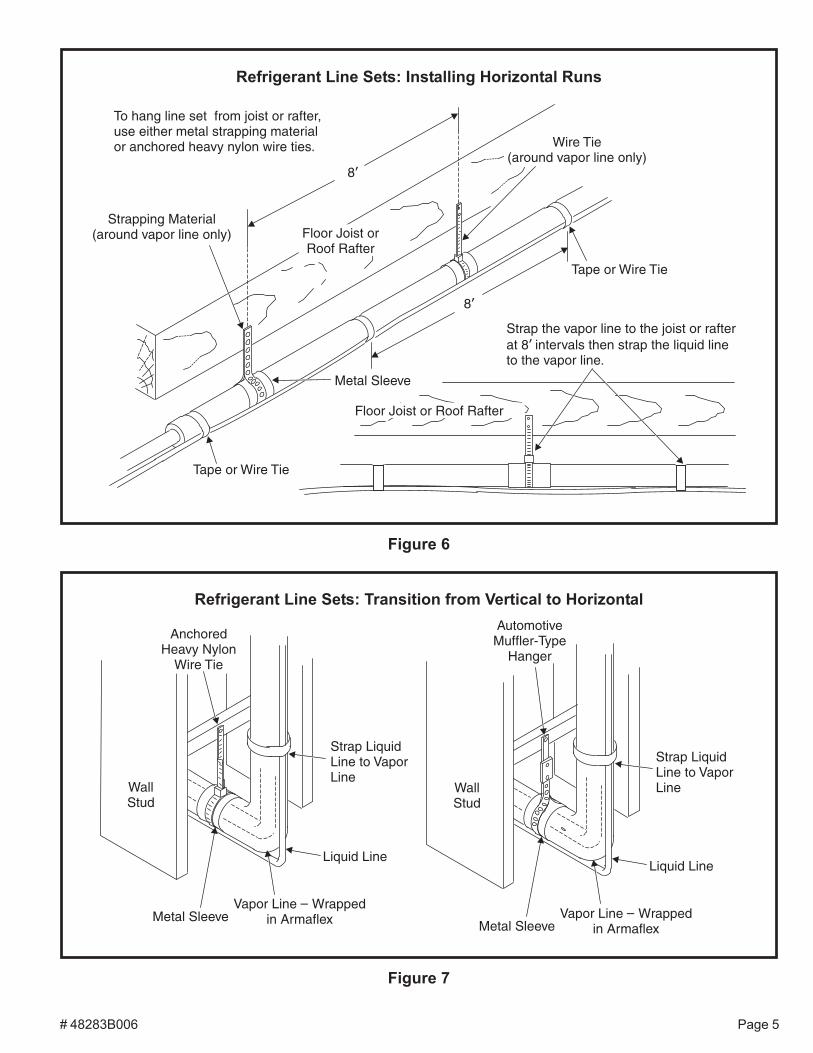
Illustrations on the following pages demonstrate proce-dures which ensure proper refrigerant line set isolation.Figure 6 shows how to install line sets on horizontal runs.Figure 7 shows how to make a transition from horizontalto vertical. Figure 8 on page 6 shows how to install linesets on vertical runs.
Brazing Connection Procedure
1. Cut ends of refrigerant lines square (free from nicksor dents). Debur the ends. The pipe must remainround; do not pinch end of line.
2. Before making line set connections, use dry nitrogen topurge the refrigerant piping. This will help to preventoxidation and the introduction of moisture into the system.
# 48283B006 Page 5
Figure 6
To hang line set from joist or rafter,use either metal strapping materialor anchored heavy nylon wire ties.
Strapping Material(around vapor line only)
8’
8’
Tape or Wire Tie
Strap the vapor line to the joist or rafterat 8 intervals then strap the liquid lineto the vapor line.
’
Floor Joist orRoof Rafter
Metal Sleeve
Floor Joist or Roof Rafter
Tape or Wire Tie
Wire Tie(around vapor line only)
Refrigerant Line Sets: Installing Horizontal Runs
Figure 7
Refrigerant Line Sets: Transition from Vertical to Horizontal
AnchoredHeavy Nylon
Wire Tie
WallStud
Metal SleeveVapor Line Wrapped
in Armaflex–
Liquid Line
WallStud
AutomotiveMuffler-Type
Hanger
Strap LiquidLine to VaporLine
Metal SleeveVapor Line Wrapped
in Armaflex–
Liquid Line
Strap LiquidLine to VaporLine

Page 6 # 48283B006
Figure 8
Refrigerant Line Sets: Installing Vertical Runs (new construction shown)
Outside Wall
Wood BlockBetween Studs
IMPORTANT: Refrigerantlines must not contact wall.
Vapor Line Liquid Line
Wire Tie
Inside Wall
Strap
Sleeve
Wire Tie
Wire Tie
Strap
Wood Block
Sleeve
Vapor Line Wrappedwith Armaflex
Liquid Line
Caulk
PVC Pipe FiberglassInsulation
Outside WallIMPORTANT:
Refrigerantlines must not
contact structure.
NOTE: Similar installation practicesshould be used if line set is to beinstalled on exterior of outside wall.
3. Use silver alloy brazing rods (5% or 6% silver alloy forcopper-to-copper brazing or 45% silver alloy forcopper-to-brass or copper-to-steel brazing) which arerated for use with HCFC-22 refrigerant.
4. Remove the Schrader core assemblies before brazingto protect them from damage due to extreme heat.Replace the cores when brazing is complete.
5. Wrap a wet cloth around the valve body and copper tubestub to protect them from heat damage during brazing.
6. Braze the line set to the service valve. Quench the jointswith water or a wet cloth to prevent heat damage to thevalve core and opening port. The tube end must staybottomed in the fitting during final assembly toensure proper seating, sealing, and rigidity.
7. Install the factory-supplied fixed orifice (or thermalexpansion valve which is sold separately and which isapproved for use with HCFC-22 refrigerant) in theliquid line at the indoor coil.
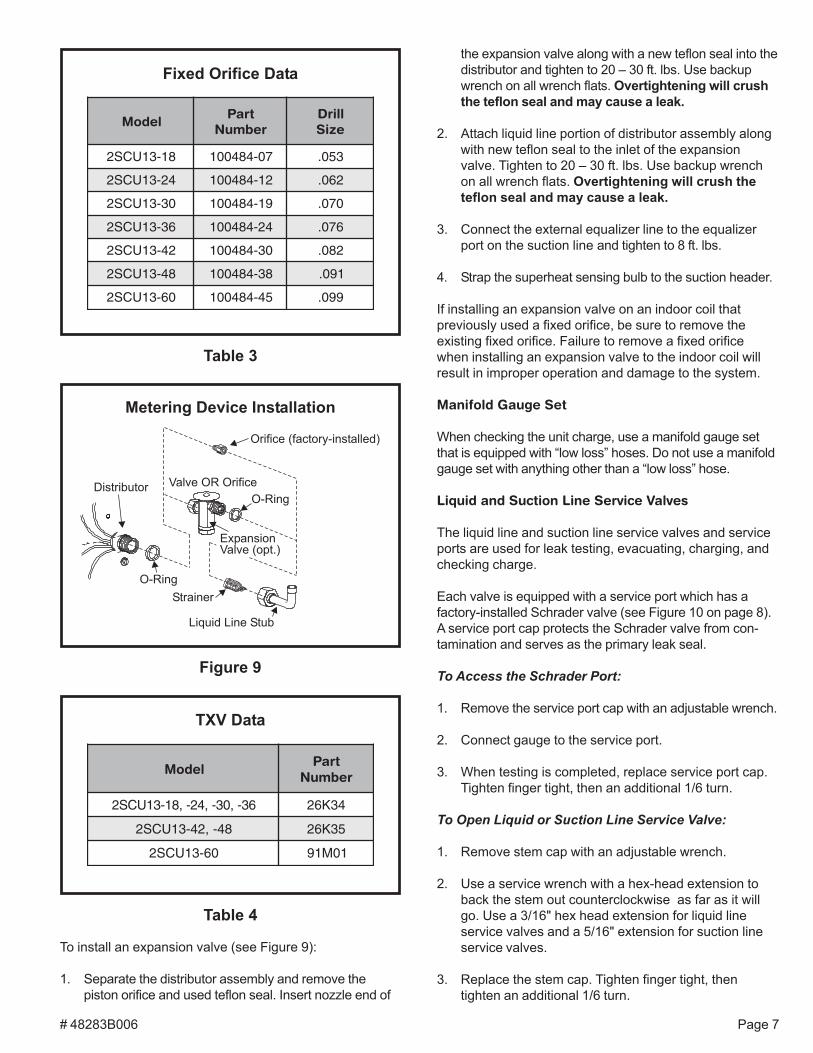
Refrigerant Metering Device
2SCU13 units are designed for use with either fixed orificeor TXV systems. Refer to the appropriate following sectionfor information on installing the chosen refrigerant meter-ing device.
Fixed Orifice Systems
2SCU13 units are shipped with a fixed orifice refrigerantmetering device. Replace the existing indoor unit fixedorifice with the orifice supplied with this unit. Place thesupplied fixed orifice sticker on the indoor cabinet afterinstallation. See Table 3 for the proper fixed orifice size foreach unit. In nonstandard applications, the provided fixedorifice may not be appropriately sized.
Install the fixed orifice as shown in Figure 9. Do not twist captubes when loosening the seal nut from the orifice housing.Use wrench to back up the distributor.
Expansion Valve Systems
Expansion valves equipped with Chatleff-type fittings areavailable from the manufacturer. See Table 4 for properTXV for each unit.
# 48283B006 Page 7
To install an expansion valve (see Figure 9):
1. Separate the distributor assembly and remove thepiston orifice and used teflon seal. Insert nozzle end of
Figure 9
Metering Device Installation
the expansion valve along with a new teflon seal into thedistributor and tighten to 20 – 30 ft. lbs. Use backupwrench on all wrench flats. Overtightening will crushthe teflon seal and may cause a leak.
2. Attach liquid line portion of distributor assembly alongwith new teflon seal to the inlet of the expansionvalve. Tighten to 20 – 30 ft. lbs. Use backup wrenchon all wrench flats. Overtightening will crush theteflon seal and may cause a leak.
3. Connect the external equalizer line to the equalizerport on the suction line and tighten to 8 ft. lbs.
4. Strap the superheat sensing bulb to the suction header.
If installing an expansion valve on an indoor coil thatpreviously used a fixed orifice, be sure to remove theexisting fixed orifice. Failure to remove a fixed orificewhen installing an expansion valve to the indoor coil willresult in improper operation and damage to the system.
Manifold Gauge Set
When checking the unit charge, use a manifold gauge setthat is equipped with “low loss” hoses. Do not use a manifoldgauge set with anything other than a “low loss” hose.
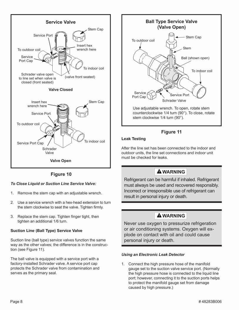
Liquid and Suction Line Service Valves
The liquid line and suction line service valves and serviceports are used for leak testing, evacuating, charging, andchecking charge.
Each valve is equipped with a service port which has afactory-installed Schrader valve (see Figure 10 on page 8).A service port cap protects the Schrader valve from con-tamination and serves as the primary leak seal.
To Access the Schrader Port:
1. Remove the service port cap with an adjustable wrench.
2. Connect gauge to the service port.
3. When testing is completed, replace service port cap.Tighten finger tight, then an additional 1/6 turn.
To Open Liquid or Suction Line Service Valve:
1. Remove stem cap with an adjustable wrench.
2. Use a service wrench with a hex-head extension toback the stem out counterclockwise as far as it willgo. Use a 3/16" hex head extension for liquid lineservice valves and a 5/16" extension for suction lineservice valves.
3. Replace the stem cap. Tighten finger tight, thentighten an additional 1/6 turn.
Fixed Orifice Data
Table 3
ledoMtraP
rebmuNllirDeziS
81-31UCS2 70-484001 350.
42-31UCS2 21-484001 260.
03-31UCS2 91-484001 070.
63-31UCS2 42-484001 670.
24-31UCS2 03-484001 280.
84-31UCS2 83-484001 190.
06-31UCS2 54-484001 990.
Table 4
TXV Data
ledoMtraP
rebmuN
63-,03-,42-,81-31UCS2 43K62
84-,24-31UCS2 53K62
06-31UCS2 10M19
Page 8 # 48283B006
To Close Liquid or Suction Line Service Valve:
1. Remove the stem cap with an adjustable wrench.
2. Use a service wrench with a hex-head extension to turnthe stem clockwise to seat the valve. Tighten firmly.
3. Replace the stem cap. Tighten finger tight, thentighten an additional 1/6 turn.
Suction Line (Ball Type) Service Valve
Suction line (ball type) service valves function the sameway as the other valves; the difference is in the construc-tion (see Figure 11).
The ball valve is equipped with a service port with afactory-installed Schrader valve. A service port capprotects the Schrader valve from contamination andserves as the primary seal.
Leak Testing
After the line set has been connected to the indoor andoutdoor units, the line set connections and indoor unitmust be checked for leaks.
Ball Type Service Valve(Valve Open)
Figure 11
Use adjustable wrench. To open, rotate stemcounterclockwise 1/4 turn (90°). To close, rotatestem clockwise 1/4 turn (90°).
Using an Electronic Leak Detector
1. Connect the high pressure hose of the manifoldgauge set to the suction valve service port. (Normallythe high pressure hose is connected to the liquid lineport; however, connecting it to the suction ports helpsto protect the manifold gauge set from damagecaused by high pressure.)
Figure 10
Service Valve
Valve Closed
Valve Open
Never use oxygen to pressurize refrigerationor air conditioning systems. Oxygen will ex-plode on contact with oil and could causepersonal injury or death.
WARNING
Refrigerant can be harmful if inhaled. Refrigerantmust always be used and recovered responsibly.Incorrect or irresponsible use of refrigerant canresult in personal injury or death.
WARNING
# 48283B006 Page 9
5. Evacuate the line set and indoor unit to a minimum of 500microns or lower. During the early stages of evacuation, itis desirable to close the manifold gauge valve at leastonce to determine if there is a rapid rise in pressure. Arapid rise in pressure indicates a relatively large leak. Ifthis occurs, the leak testing procedure must be repeated.
6. When 500 microns or lower is maintained, close themanifold gauge valves, turn off the vacuum pump, anddisconnect the manifold gauge center port hose fromthe vacuum pump. Attach the manifold gauge centerport hose to a nitrogen cylinder with pressure regulatorset to 150 psig and purge the hose. Open the manifoldgauge valves to break the vacuum in the line set andindoor unit. Close the manifold gauge valves.
7. Shut off the nitrogen cylinder and remove the manifoldgauge hose from the cylinder. Open the manifoldgauge valves to release the nitrogen from the line setand indoor unit.
8. Reconnect the manifold gauge to the vacuum pump,turn the pump on, and continue to evacuate the lineset and indoor unit until 500 microns is maintainedwithin a 20-minute period after shutting off thevacuum pump and closing the manifold gauge valves.
9. When the requirements above have been met,disconnect the manifold hose from the vacuum pump.Open the service valves to break the vacuum in theline set and indoor unit.
2. With both manifold valves closed, connect the cylin-der of HCFC-22 refrigerant. Open the valve on theHCFC-22 cylinder (vapor only).
3. Open the high pressure side of the manifold to allowHCFC-22 into the line set and indoor unit. Weigh in atrace amount of HCFC-22. (A trace amount is amaximum of 2 oz. of refrigerant or 3 lbs. pressure.)Close the valve on the HCFC-22 cylinder and thevalve on the high pressure side of the manifold gaugeset. Disconnect the HCFC-22 cylinder.
4. Connect a cylinder of nitrogen with a pressure regulat-ing valve to the center port of the manifold gauge set.When using high pressure gas such as nitrogenfor this purpose, be sure to use a regulator thatcan control the pressure down to 1 or 2 psig.
5. Adjust nitrogen pressure to 150 psig. Open the valveon the high side of the manifold gauge set to pressur-ize the line set and the indoor coil.
Evacuation
Evacuating the system of noncondensables is critical forproper operation of the unit. Noncondensables are definedas any gas that will not condense under temperatures andpressures present during operation of an air conditioningsystem. Noncondensables and water vapor combine withrefrigerant to produce substances that corrode copperpiping and compressor parts.
Do not use a compressor to evacuate a sys-tem. Avoid deep vacuum operation. Extremelylow vacuums can cause internal arcing andcompressor failure. Danger of equipmentdamage. Damage caused by deep vacuumoperation will void warranty.
WARNING
Use a thermocouple or thermistor electronic vacuumgauge that is calibrated in microns. Use an instrument thatreads down to 50 microns.
1. Connect the manifold gauge set to the service valveports as follows:
• Low pressure gauge to suction line service valve• High pressure gauge to liquid line service valve
2. Connect micron gauge.
3. Connect the vacuum pump (with vacuum gauge) tothe center port of the manifold gauge set.
4. Open both manifold valves and start vacuum pump.
Page 10 # 48283B006
If the system is void of refrigerant, clean the system usingthe procedure described below.
1. Use dry nitrogen to pressurize the system and checkfor leaks. Repair leaks, if possible.
2. Evacuate the system to remove as much of themoisture as possible.
3. Use dry nitrogen to break the vacuum.
4. Evacuate the system again.
5. Weigh the appropriate amount of HCFC-22 refrigerant(listed on unit nameplate) into the system.
6. Monitor the system to determine the amount ofmoisture remaining in the oil. Use a test kit to verifythat the moisture content is within the kit’s dry colorrange. It may be necessary to replace the filter drierseveral times to achieve the required dryness level. Ifsystem dryness is not verified, the compressorwill fail in the future.
The outdoor unit should be charged during warm weather.However, applications arise in which charging must occurin the colder months. The method of charging is deter-mined by the unit’s refrigerant metering device and theoutdoor ambient temperature.
Measure the liquid line temperature and the outdoorambient temperature as outlined below:
1. Connect the manifold gauge set to the service valveports as follows:
• Low pressure gauge to suction line service valve• High pressure gauge to liquid line service valve
2. Close manifold gauge set valves. Connect the centermanifold hose to an upright cylinder of HCFC-22.
3. If room temperature is below 70°F, set the room thermo-stat to call for heat. This will create the necessary loadfor properly charging the system in the cooling cycle.
4. Use a digital thermometer to record the outdoorambient temperature.
5. When the heating demand has been satisfied, switchthe thermostat to cooling mode with a set point of68°F. When pressures have stabilized, use a digitalthermometer to record the liquid and suction linetemperatures.
6. The outdoor temperature will determine which charg-ing method to use. Proceed with the appropriatecharging method.
START-UP
1. Rotate fan to check for frozen bearings or binding.
2. Inspect all factory and field-installed wiring for looseconnections.
3. After evacuation is complete, open liquid line andsuction line service valves to release refrigerantcharge (contained in outdoor unit) into system.
4. Replace the stem caps and secure finger tight, thentighten an additional 1/6 of a turn.
5. Check voltage supply at the disconnect switch. Thevoltage must be within the range listed on the unitnameplate. If not, do not start equipment until thepower company has been consulted and the voltagecondition corrected.
6. Set thermostat for cooling demand, turn on power toindoor blower and close the outdoor unit disconnectswitch to start the unit.
7. Recheck unit voltage with unit running. Power must bewithin range shown on unit nameplate.
Refrigerant Charging
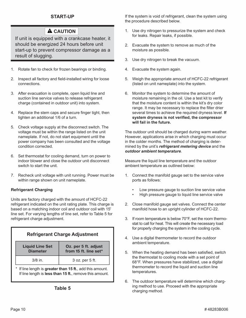
Units are factory charged with the amount of HCFC-22refrigerant indicated on the unit rating plate. This charge isbased on a matching indoor coil and outdoor coil with 15'line set. For varying lengths of line set, refer to Table 5 forrefrigerant charge adjustment.
If unit is equipped with a crankcase heater, itshould be energized 24 hours before unitstart-up to prevent compressor damage as aresult of slugging.
CAUTION
Refrigerant Charge Adjustment
* If line length is greater than 15 ft., add this amount.If line length is less than 15 ft., remove this amount.
Table 5
teSeniLdiuqiLretemaiD
tsujda.tf5rep.zO*tesenil.tf51morf
.ni8/3 .tf5rep.zo3
# 48283B006 Page 11
Charge Using Weigh-In Method (Fixed Orifice/TXVSystems)
If the system is void of refrigerant, or if the outdoor ambienttemperature is cool, first locate and repair any leaks thenuse the weigh-in method to charge the unit.
1. Recover the refrigerant from the unit.
2. Conduct a leak check, then evacuate as previouslyoutlined.
3. Weigh in the charge according to the total amountshown on the unit nameplate.
If weighing facilities are not available or if unit is beingcharged during warm weather, follow one of the otherprocedures outlined below.
Charge Using Subcooling Method (Fixed Orifice/TXVSystems) – Outdoor Temperatures 65°F or Above
If charging a fixed orifice or TXV system when the outdoorambient temperature is 65°F or above, the subcoolingmethod can be used to charge the unit.
1. With the manifold gauge hose on the liquid serviceport and the unit operating stably, use a digital ther-mometer to record the liquid line temperature.
2. At the same time, record the liquid line pressure reading.
3. Use a temperature/pressure chart for HCFC-22 todetermine the saturation temperature for the liquid linepressure reading.
4. Subtract the liquid line temperature from the satura-tion temperature (according to the chart) to determinesubcooling.
3. Use a temperature/pressure chart for HCFC-22 todetermine the saturation temperature for the suctionline pressure reading.
4. Subtract the saturation temperature (according to thechart) from the suction line temperature to determinethe superheat.
_____ ° Suction Line Temperature °F
_____ ° Saturation Temperature °F
_____ ° Superheat Value °F
–
=
_____ ° Saturation Temperature °F
_____ ° Liquid Line Temperature °F
_____ ° Subcooling Value °F
–
=
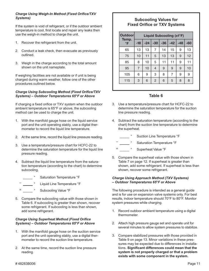
roodtuO.pmeT
F°
)F°1±(gniloocbuSdiuqiL
81- 42- 03- 63- 24- 84- 06-
56 31 31 7 41 51 9 31
57 01 11 5 31 31 9 21
58 8 01 5 11 11 9 11
59 7 01 4 9 9 9 01
501 6 9 3 8 7 9 9
511 3 6 2 6 5 8 8
Subcooling Values forFixed Orifice or TXV Systems
Table 6
5. Compare the subcooling value with those shown inTable 6. If subcooling is greater than shown, recoversome refrigerant. If subcooling is less than shown,add some refrigerant.
Charge Using Superheat Method (Fixed OrificeSystems) – Outdoor Temperatures 65°F or Above
1. With the manifold gauge hose on the suction serviceport and the unit operating stably, use a digital ther-mometer to record the suction line temperature.
2. At the same time, record the suction line pressurereading.
5. Compare the superheat value with those shown inTable 7 on page 12. If superheat is greater thanshown, add some refrigerant. If superheat is less thanshown, recover some refrigerant.
Charge Using Approach Method (TXV Systems)– Outdoor Temperatures 65°F or Above
The following procedure is intended as a general guideand is for use on expansion valve systems only. For bestresults, indoor temperature should 70°F to 80°F. Monitorsystem pressures while charging.
1. Record outdoor ambient temperature using a digitalthermometer.
2. Attach high pressure gauge set and operate unit forseveral minutes to allow system pressures to stabilize.
3. Compare stabilized pressures with those provided inTable 9 on page 13. Minor variations in these pres-sures may be expected due to differences in installa-tions. Significant differences could mean that thesystem is not properly charged or that a problemexists with some component in the system.
Page 12 # 48283B006
Pressures higher than those listed indicate that thesystem is overcharged. Pressures lower than thoselisted indicate that the system is undercharged. Verifyadjusted charge using the approach method.
4. Use the same digital thermometer to check liquid linetemperature.
5. Subtract the outdoor ambient temperature from theliquid line temperature to determine the approachtemperature.
_____ ° Liquid Line Temperature °F
_____ ° Outdoor Ambient Temperature °F
_____ ° Approach Temperature °F
–
=
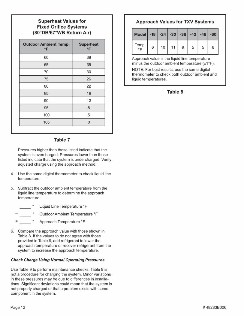
.pmeTtneibmAroodtuOF°
taehrepuSF°
06 83
56 53
07 03
57 62
08 22
58 81
09 21
59 8
001 5
501 0
Superheat Values forFixed Orifice Systems
(80°DB/67°WB Return Air)
Table 7
Approach Values for TXV Systems
Approach value is the liquid line temperatureminus the outdoor ambient temperature (±1°F).NOTE: For best results, use the same digitalthermometer to check both outdoor ambient andliquid temperatures.
Table 8
ledoM 81- 42- 03- 63- 24- 84- 06-
.pmeTF°
6 01 11 9 5 5 8
6. Compare the approach value with those shown inTable 8. If the values to do not agree with thoseprovided in Table 8, add refrigerant to lower theapproach temperature or recover refrigerant from thesystem to increase the approach temperature.
Check Charge Using Normal Operating Pressures
Use Table 9 to perform maintenance checks. Table 9 isnot a procedure for charging the system. Minor variationsin these pressures may be due to differences in installa-tions. Significant deviations could mean that the system isnot properly charged or that a problem exists with somecomponent in the system.
# 48283B006 Page 13
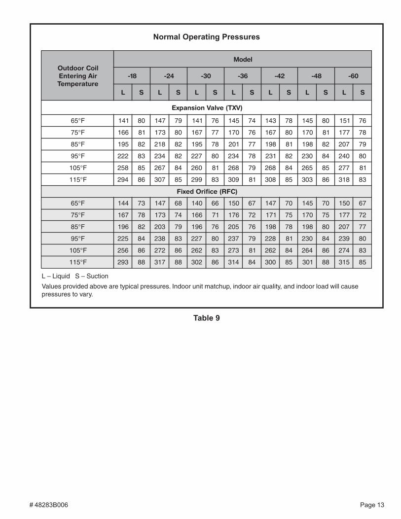
Normal Operating Pressures
Table 9
lioCroodtuOriAgniretnEerutarepmeT
ledoM
81- 42- 03- 63- 24- 84- 06-
L S L S L S L S L S L S L S
)VXT(evlaVnoisnapxE
F°56 141 08 741 97 141 67 541 47 341 87 541 08 151 67
F°57 661 18 371 08 761 77 071 67 761 08 071 18 771 87
F°58 591 28 812 28 591 87 102 77 891 18 891 28 702 97
F°59 222 38 432 28 722 08 432 87 132 28 032 48 042 08
F°501 852 58 762 48 062 18 862 97 862 48 562 58 772 18
F°511 492 68 703 58 992 38 903 18 803 58 303 68 813 38
)CFR(ecifirOdexiF
F°56 441 37 741 86 041 66 051 76 741 07 541 07 051 76
F°57 761 87 371 47 661 17 671 27 171 57 071 57 771 27
F°58 691 28 302 97 691 67 502 67 891 87 891 08 702 77
F°59 522 48 832 38 722 08 732 97 822 18 032 48 932 08
F°501 652 68 272 68 262 38 372 18 262 48 462 68 472 38
F°511 392 88 713 88 203 68 413 48 003 58 103 88 513 58
L – Liquid S – Suction
Values provided above are typical pressures. Indoor unit matchup, indoor air quality, and indoor load will causepressures to vary.

Page 14 # 48283B006
OPERATION
Outdoor unit and indoor blower cycle on demand from theroom thermostat. When the thermostat blower switch ismoved to the ON position, the indoor blower operatescontinuously.
Maintenance and service must be performed by a quali-fied installer or service agency.
At the beginning of each cooling season, the systemshould be checked as follows:
1. Clean and inspect condenser coil. Coil may beflushed with a water hose. Be sure the power is offbefore using water to clean the coil.
2. Outdoor fan motor is pre-lubricated and sealed. Nofurther lubrication is needed.
3. Visually inspect connecting lines and coils for evi-dence of oil leaks.
4. Check wiring for loose connections.
5. Check for correct voltage at unit (with unit operating).
6. Check amp-draw outdoor fan motor.
Unit nameplate _________ Actual _________
NOTE – If owner complains of insufficient cooling, theunit should be gauged and refrigerant charge checked.Refer to the Refrigerant Charging section on page 10.
Indoor Coil
1. Clean coil, if necessary.
2. Check connecting lines and coils for evidence of oilleaks.
3. Check condensate pan line and clean, if necessary.
Indoor Unit
1. Clean or change filters.
2. Adjust blower speed for cooling. Measure the pressuredrop over the coil to determine the correct blower CFM.
3. Belt drive blowers: Check belt for wear and propertension.
4. Check all wiring for loose connections.
MAINTENANCE
Before performing maintenance operations onsystem, turn the electric power to unit OFF atdisconnect switch(es). Unit may have multiplepower supplies. Electrical shock could causepersonal injury or death.
WARNING

# 48283B006 Page 15
5. Check for correct voltage at unit (with unit operating).
6. Check amp-draw on blower motor.
Unit nameplate _________ Actual _________
Start-Up and Performance Checklist
Job Name _______________________________ Job No. ________________ Date ______________
Job Location _____________________________ City ___________________ State ______________
Installer _________________________________ City ___________________ State ______________
Unit Model No.______________ Serial No. ___________________
Service Technician ________________________________________ Nameplate Voltage ______________
Rated Load Ampacity ________ Compressor _______________ Outdoor Fan ___________________
Maximum Fuse or Circuit Breaker________________________
Electrical Connections Tight? Indoor Filter Clean? Supply Voltage (Unit Off) ________________
Indoor Blower RPM _____________ S.P. Drop Over Indoor (Dry) ____________
Outdoor Coil Entering Air Temperature _____________ Voltage with Compressor Operating _____________
Discharge Pressure___________ Vapor Pressure ____________
Refrigerant Charge Checked? Outdoor Fan Checked?
Refrigerant Lines: Leak Checked? Properly Insulated?
Service Valves: Fully Opened? Caps Tight?
Thermostat: Calibrated? Properly Set? Level?

Page 16 # 48283B006Figure 12
H C F
1
DESCRIPTIONKEY COMPONENTA4 CONTROL - TIMED OFFB1 COMPRESSORB4 MOTOR - OUTDOOR FAN
C12 CAPACITOR - DUALHR1 HEATER - COMPRESSORK1-1 CONTACTOR - COMPRESSORS4 SWITCH - HIGH PRESSURE
S24 SWITCH - LOSS OF CHARGE
FOR USE WITH COPPER CONDUCTORS ONLY. REFER TO UNIT RATINGPLATE FOR MINIMUM CIRCUIT AMPACITY AND MAXIMUM OVERCURRENTPROTECTION SIZE.
WARNING--ELECTRIC SHOCK HAZARD, CAN CAUSE INJURY OR DEATH.UNIT MUST BE GROUNDED IN ACCORDANCE WITH NATIONALAND LOCAL CODES.
OUTDOORFAN
F C H
12 3
R S C
C
2
3
1
EQUIPMENTGROUND
HR1
L2
208-230/60/1
L1
K1-1
BLACK
YELLOW
RED
RE
D
C12
BLACK
ORANGE
B4
PURPLE
K1
S4 S24A4
C Y1
TO 24 VACPOWER SOURCE20 VA MINIMUMNEC CLASS 2
S4 HIGHPRESSURE
SWITCH(IF USED)
S24 LOSSOF CHARGE
SWITCH(IF USED)
B1
GROUNDLUG
GROUND
L2
L1208-230/60/1
C Y1
TO 24 VACPOWER SOURCE20 VA MINIMUMNEC CLASS 2
A4TIMED OFFCONTROL(IF USED)
DUALCAPACITOR
RE
D
COMPRESSORCONTACTOR
BLACK
COMPRESSOR
CRANKCASE HEATER(IF USED)
PURPLE
BLACK
ORANGE
RED
YELLOW
S R
LINE VOLTAGE FACTORY INSTALLED
1
LINE VOLTAGE FIELD INSTALLED
24 VOLT FACTORY INSTALLED
CLASS II VOLTAGE FIELD INSTALLED
Single Phase Wiring Diagram P/N 48352-001
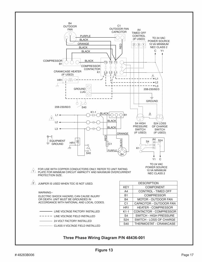
# 48283B006 Page 17Figure 13
Three Phase Wiring Diagram P/N 48436-001
B4OUTDOOR
FANC1
OUTDOOR FANCAPACITOR
A4TIMED OFFCONTROL(IF USED)
PURPLEBLACK
ORANGEBLACK
BLACK
RE
D
T3 T2 T1BLACK
L3 L2 L1
COMPRESSORB1
CRANKCASE HEATER(IF USED)
HR1
2 3 1
TO 24 VACPOWER SOURCE10 VA MINIMUMNEC CLASS 2
C Y1
L1L2L3
208-230/60/3
GROUND
2
S4 HIGHPRESSURE
SWITCH(IF USED)
S24 LOSSOF CHARGE
SWITCH(IF USED)
S4A4 S24
K1
231
Y1 C
TO 24 VACPOWER SOURCE10 VA MINIMUMNEC CLASS 2
S40208-230/60/3
GROUNDLUG
COMPRESSORCONTACTOR
K1
1L1
L2
L3
EQUIPMENTGROUND HR1
S40
K1-1 BLACK
BLACK
B1
BLACK
ORANGE
BLA
CK
B4
C1
PURPLE
RE
D
1FOR USE WITH COPPER CONDUCTORS ONLY. REFER TO UNIT RATINGPLATE FOR MINIMUM CIRCUIT AMPACITY AND MAXIMUM OVERCURRENTPROTECTION SIZE.
WARNING--ELECTRIC SHOCK HAZARD, CAN CAUSE INJURYOR DEATH. UNIT MUST BE GROUNDED INACCORDANCE WITH NATIONAL AND LOCAL CODES.
LINE VOLTAGE FACTORY INSTALLED
LINE VOLTAGE FIELD INSTALLED
24 VOLT FACTORY INSTALLED
CLASS II VOLTAGE FIELD INSTALLED
2 JUMPER IS USED WHEN TOC IS NOT USED. DESCRIPTIONKEY COMPONENTA4 CONTROL - TIMED OFFB1 COMPRESSORB4 MOTOR - OUTDOOR FANC1 CAPACITOR - OUTDOOR FAN
HR1 HEATER - COMPRESSORK1-1 CONTACTOR - COMPRESSORS4 SWITCH - HIGH PRESSURES24 SWITCH - LOSS OF CHARGES40 THERMOSTAT - CRANKCASE
1

Page 18 # 48283B006
Limited WarrantyAugust 1, 1997
This warranty gives you specific legal rights and you may have other rightswhich vary from state/province to state/province.
Warrantor: Armstrong Air Conditioning Inc., 421 Monroe St., Bellevue, OH 44811Armstrong Air Conditioning Inc. products are available under the following names: Air Ease, Armstrong Air, American Aire, Concord
Subject to the limitations stated in this warranty, we warrant to the first buyer for use the residential heating, cooling or heat pump unit, wheninstalled, operated and maintained as required by this warranty, to be free of defects in workmanship or material for a period of 5 years(1 year for commercial equipment) from the time of installation. We will replace any defective component without cost or expense to youexcept for the costs of delivery and labor for removal and replacement of the defective component.
The 2SCU13LB Series air conditioners carry a 5-year compressor warranty. The 2SCU13LE Series air conditioners carry a 10-yearcompressor warranty.
Warranty BeginsThe warranty period begins when the installation is complete and the product is ready to operate. You must be able to verify this datewhenever a warranty claim is made. Original bill of sale, installer’s invoice or other similar document will suffice. If the beginning datecannot be verified, we will consider warranty coverage to begin 6 months after the date the product was shipped from our factory.
Limitations on Implied WarrantiesImplied warranties of merchantability or, to the extent applicable, fitness for a particular purpose are limited to 5 years, the same durationas the basic limited written warranty provided herein. Some states/provinces do not allow limitations on how long an implied warranty ofmerchantability or fitness lasts, so the above limitations or exclusions may not apply to you.
Only WarrantyThis written Limited Warranty is the only warranty made by the warrantor; this warranty is in lieu of and excludes all other warranties,express or implied. The warrantor does not authorize any person to provide any other warranty or to assume for it any further obligation inconnection with the warranted product.
What is NOT Covered1. Cabinets or cabinet pieces.2. Normal maintenance items such as filters, fan belts, fuses or other consumable items.3. Damage caused by misuse, failure to maintain properly, accidents or acts of God.4. External wiring, piping, venting or attachment of accessory products not integral to our product, including without limitation,
humidifier, air cleaner, vent damper, thermostat or other mechanical devices not manufactured by the warrantor.5. Products that have been operated in a corrosive atmosphere where a concentration of acids, halogenated hydrocarbons or
other corrosive elements causes deterioration to metal surfaces or integral components. NOTE: Operation in a corrosiveatmosphere is considered abuse and voids this warranty.
6. Products that have NOT been installed in accordance with our published installation instructions, applicable local, state/provincial or national codes, ACCA published standards.
7. Products that have NOT been installed by competent, qualified installers.8. Products that have been moved from their original place of installation.
Warranty on Replacement ComponentsAny replacement component furnished by us will assume the remaining (unused) portion of the Limited Warranty.
Consequential DamagesThe warrantor shall not be responsible for any consequential damages caused by any defect in the product. Some state/provinces do notallow the exclusion or limitations of incidental or consequential damages, so the above limitation or exclusion may not apply to you.
This product must be installed, used and cared for in accordance with the instruction manual. You are responsible for required periodicmaintenance or service, such as changing or cleaning of air filters and lubrication or cleaning of components. Failure to properly install,operate or maintain your unit voids this warranty.
Related Documents