Volume 2B Section 3 Chapter 1: 2G Radio Design and Planning Prepared for: Hanoi Telecom Joint Stock Company EGSM Mobile Telecommunication Network Project Prepared by: ZTE Corporation Technical Proposal

Welcome message from author
This document is posted to help you gain knowledge. Please leave a comment to let me know what you think about it! Share it to your friends and learn new things together.
Transcript

Volume 2B Section 3
Chapter 1: 2G Radio Design and Planning
Prepared for:
Hanoi Telecom Joint Stock Company
EGSM Mobile Telecommunication Network Project
Prepared by: ZTE Corporation
Tech
nica
l Pr
opos
al

2G Radio Design and Planning
ZTE Confidential ProprietaryII
April 2008This document contains proprietary information of ZTE Corporation and is not to be disclosed or used except in accordance with applicable agreementsThe offer of ZTE is valid for 12 months on submission.

2G Radio Design andPlanning

2G Radio Design and Planning
Table of Contents
1 Overview....................................................42 System Requirement Analysis.................................4
2.1 Available Frequency Range........................42.2 Traffic Model for Voice..........................52.3 Subscriber Forecast..............................52.4 Signal Level & Coverage Probability..............62.5 GPRS & EDGE Requirements.........................7
3 Planning guideline..........................................73.1 ZTE GSM Network Planning Procedure...............73.2 Area Classification..............................9
4 Coverage Planning...........................................94.1 ZTE Products....................................104.2 Link Budget.....................................10
4.2.1.....................................Uplink / Downlink10
4.2.2...................Link Budget parameter explaination14
4.3 Propagation Model and Coverage Radius Prediction 184.3.1...................Propagation model Testing & Tuning
194.3.2............................Propagation Model Formula
194.3.3...........................Coverage Radius Prediction
204.4 Antenna Selection...............................21
4.4.1......Antenna Selection within Urban, Sub Urban Area21
4.4.2.....Antenna Selection within Rural and Highway area22
4.5 EDGE Coverage Planning..........................234.5.1.......................EDGE System and Coding Schemes
234.5.2.....................................Coverage Planning
234.6 BTS Sub-system deployment.......................24
ZTE Confidential Proprietary I

2G Radio Design and Planning
4.6.1.........................BTS type selection principle24
4.6.2...............Preliminary Planning of BTS Deployment25
4.6.3...................BTS deployment result and Anlaysis25
4.7 Population Coverage Percentage..................275 Capacity Planning..........................................27
5.1 Principles of Capacity Planning.................275.2 Channel planning................................28
5.2.1...............................SDCCH Channel Planning28
5.2.2................................PDCH Channel Planning28
5.2.3.......................Voice Service Channel Planning29
5.3 Capacity planning result........................306 Roll Out...................................................347 Frequency Planning.........................................35
7.1 BCCH planning...................................357.2 TCH planning....................................367.3 Automatic Frequency Planning and C/I,C/A Algorithm36
7.3.1...............Automatic Frequency Planning Algorithm36
7.3.2................................C/I and C/A Algorithm37
8 Parameter Design...........................................389 Sites Distribution and Simulation..........................38
9.1 Planned Network Sites Distribution..............389.2 Coverage Simulation.............................399.3 Interference Simulation.........................399.4 EDGE Coverage Simulation........................39
10 Conclusion.................................................39
ZTE Confidential Proprietary II

2G Radio Design and Planning
Figures and Tables
FiguresFigure 1 Penetration loss (Indoor First Wall)....16Figure 2 Body Loss...............................17Figure 3 DB856DG65EXY antenna pattern............22Figure 4 DB858DG65ESY antenna pattern............22
TablesTable 1 Site and subscriber statistics by phase and regions4
ZTE Confidential Proprietary III

2G Radio Design and Planning
Table 2 Subscriber forecast...............................5Table 3 List of Provinces required EDGE deployment........7Table 4 Area classification...............................9Table 5 ZTE Macro base station specification.............10Table 6 ZTE Micro base station specificationn............10Table 7 EGSM Uplink/Downlink Link Budget for Urban.......10Table 8 EGSM Uplink/Downlink Link Budget for Sub Urban...12Table 9 EGSM Uplink/Downlink Link Budget for Rural and Road
13Table 10 Typical Feeder Loss per 100 meters......14Table 11 Slow Fading Margin......................15Table 12 Penetration Loss........................16Table 13 MS output power in GSM specification....17Table 14 CW testing points in different provinces 19
Table 15 K parameters value in Standard MacroPropagation Model................................20
Table 16 Radius prediction in different areas....20Table 17 Selected antenna list for different
clutters 23Table 18 MS and BTS sensitivity in different MCS. 24Table 19 BTS type selection principle............24
Table 20 Site deployment result in differentclutters 25
Table 21 Sites Deployment Analysis...............26Table 22 Design Population Coverage Percentage...27Table 23 SDCCH Channel Planning..................28Table 24 PDCH(GPRS) configuration................28Table 25 PDCH(GPRS+EDGE) configuration...........29Table 26 Channel Planning with No HR.............29Table 27 Channel Planning with HR................30Table 28 North capacity planning result..........30Table 29 Central capacity planning result........32Table 30 South capacity planning result..........33Table 31 Roll out for different Regions..........34Table 32 Characteristic of different Morphoclass. 35
ZTE Confidential Proprietary IV

2G Radio Design and Planning
1 OVERVIEWTo cater with the GSM Network implementation plan from HTC, we,ZTE proposes a comprehensive network solution in accordance withthe GSM Network requirements.
As a main part of this proposal, the radio network planning schemeis developed after detailed analysis on the HTC network model,careful hypothesis and exhaustive calculation in terms of thesuccessful network construction experiences of ZTE.
This document provides the wireless network planning scheme ofwhole Vietnam country of 7 phases (Phase1A to Phase5), includingthe physical cell configurations, frequency planning, coverageprediction map and interference simulation map. Beside, most ofthe important National Highways are covered too.
To satisfy the coverage and capacity requirement in 7 phases (P1Ato P5), totally 7681 sites are deployed. Site quantity andsubscriber quantity of different years and regions is showed infollowing table.
Table 1 Site and subscriber statistics by phase and regions
YearNorth Central South
SiteNo. Sub.
SiteNo. Sub. Site No. Sub.
Phase1A 491
436482 149
132174 610 534788
Phase1B 746
921880 325
412988 937
1234276
Phase1C 1122
1559876 443
605712 1451
2227604
Phase2 1515
2128684 849
1108336 2038
3047520
Phase3 1890
2734184 1056
1388388 2545
3893042
Phase4 2214
3531524 1263
1685260 3060
5127474
Phase5 2618
4101820 1478
2004632 3585
6456178
We are glad to announce that this document presents a dedicatednetwork design exclusively for HTC, any technical and commercial
ZTE Confidential Proprietary 5

2G Radio Design and Planning
information is highly confidential that either HTC or ZTE shouldbear the disclosure responsibility.
2 SYSTEM REQUIREMENT ANALYSIS 2.1 Available Frequency Range
The spectrum assigned to HTC is:
Uplink: 882MHz - 890MHz
Downlink: 927MHz – 935MHz
Channel Numbers: 985 – 1024
Channel number 985 and 1024 will be used as a guard band to otheroperators by HTC. Additionally at least six channels shall not beutilized for macro sites in the first phase. These channels shallbe reserved for micro or indoor sites.
2.2 Traffic Model for Voice
According to requirements of HTC, traffic model of this planningnetwork is as follows:
Radio Network GOS: GOS = 2%.
Subscribers Traffic (Erlang): 0.025Erl
Half Rate Capacity: 50%
2.3 Subscriber Forecast
Network planning has been done according to HTC requirements shownas below table.
Table 2 Subscriber forecast
ProvinceRegio
n
Priority
withinRegion
Subscriber Forecast
Phase1A
Phase1B
Phase1C
Phase2
Phase3 Phase4
Phase5
Ha Noi North 1 69,112 191,421 366,890 467,918 584,897 800,2461,004,9
60Ha Tay North 2 5,409 33,373 63,966 81,579 101,974 139,519 175,210Hai Phong North 3 10,162 35,888 68,785 87,726 109,658 150,032 188,412Hai Duong North 4 4,578 31,894 61,130 77,962 97,453 133,334 167,442
ZTE Confidential Proprietary 6

2G Radio Design and Planning
Thanh Hoa North 5 2,361 29,929 57,364 73,160 91,450 125,120 157,128Nghe An North 6 3,451 25,898 49,638 63,307 79,134 108,269 135,966Nam Dinh North 7 1,901 29,911 57,329 73,116 91,395 125,044 157,032Thai Binh North 8 4,909 25,714 49,285 62,856 78,571 107,499 134,998Bac Giang North 9 915 20,422 39,141 49,920 62,399 85,374 107,214Quang Ninh North 10 8,003 20,856 39,974 50,981 63,726 87,189 109,493Thai Nguyen North 11 1,479 13,947 26,732 34,093 42,616 58,306 73,222Bac Ninh North 12 1,712 27,440 52,594 67,076 83,846 114,716 144,062Hung Yen North 13 9,564 28,275 54,194 69,117 86,396 118,206 148,444Phu Tho North 14 2,311 18,966 36,352 46,362 57,952 79,289 99,573Ninh Binh North 15 1,174 23,418 44,884 57,243 71,554 97,899 122,943Ha Nam North 16 1,809 19,307 37,005 47,195 58,994 80,715 101,363Tuyen Quang North 17 1,544 11,583 22,201 28,315 35,394 48,425 60,813Ha Tinh North 18 2,941 15,170 29,075 37,082 46,352 63,418 79,641Hoa Binh North 19 930 11,491 22,024 28,089 35,111 48,038 60,327Vinh Phuc North 20 2,619 24,477 46,914 59,833 74,791 102,327 128,504Son La North 21 897 9,649 18,494 23,587 29,483 40,339 50,658Lang Son North 22 2,845 8,126 15,575 19,864 24,830 33,972 42,663Lao Cai North 23 1,079 7,087 13,583 17,324 21,654 29,627 37,206Yen Bai North 24 1,118 11,618 22,267 28,399 35,499 48,568 60,993Ha Giang North 25 438 7,686 14,731 18,788 23,485 32,131 40,351Cao Bang North 26 1,509 10,271 19,686 25,107 31,384 42,939 53,923Dien Bien North 27 173 9,846 18,872 24,069 30,086 41,163 51,693Lai Chau North 28 173 5,358 10,269 13,097 16,371 22,399 28,129Bac Kan North 29 467 10,979 21,043 26,837 33,547 45,898 57,639
Da NangCentral 1 17,190 43,292 86,584 126,990 158,737 222,232 285,727
Thua Thien Hue
Central 2 5,303 10,783 21,567 31,631 39,539 55,354 71,170
Quang NamCentral 3 1,418 9,839 19,678 28,862 36,077 50,508 64,939
Khanh HoaCentral 4 15,857 8,561 17,121 25,111 31,389 43,945 56,501
Dak LakCentral 5 4,370 12,919 25,839 37,897 47,371 66,319 85,268
Binh DinhCentral 6 2,165 13,244 26,487 38,848 48,560 67,984 87,408
Quang Ngai
Central 7 2,477 9,508 19,017 27,891 34,864 48,810 62,756
Gia LaiCentral 8 2,002 8,502 17,005 24,941 31,176 43,646 56,116
Phu YenCentral 9 3,611 7,572 15,144 22,211 27,764 38,869 49,975
Quang Binh
Central 10 2,913 7,506 15,012 22,018 27,522 38,531 49,540
Quang TriCentral 11 2,599 6,696 13,392 19,641 24,551 34,372 44,192
Dak NongCentral 12 596 5,826 11,651 17,089 21,361 29,905 38,450
Kon TumCentral 13 1,100 5,751 11,503 16,871 21,089 29,524 37,960
Ho Chi Minh South 1 142,733 206,542 432,755 590,121 737,651
1,055,661
1,386,784
Dong Nai South 2 26,789 24,829 52,023 70,940 88,675 126,904 166,709Can Tho South 3 4,496 27,533 57,688 78,666 98,332 140,725 184,865Binh South 4 10,182 17,195 36,028 49,129 61,412 87,887 115,454
ZTE Confidential Proprietary 7

2G Radio Design and Planning
DuongBa Ria Vung Tau South 5 12,809 17,245 36,133 49,272 61,590 88,143 115,790An Giang South 6 8,273 24,802 51,967 70,864 88,580 126,767 166,530Dong Thap South 7 2,834 19,628 41,126 56,081 70,102 100,323 131,791Tien Giang South 8 6,457 24,404 51,133 69,726 87,158 124,732 163,857Kien Giang South 9 8,773 24,777 51,915 70,793 88,491 126,640 166,363Long An South 10 10,159 24,594 51,531 70,269 87,837 125,704 165,133Ca Mau South 11 7,244 22,023 46,144 62,923 78,654 112,563 147,870Ben Tre South 12 8,853 22,920 48,023 65,486 81,857 117,146 153,891Soc Trang South 13 7,613 19,809 41,505 56,598 70,748 101,248 133,006Tay Ninh South 14 5,847 15,588 32,660 44,536 55,670 79,670 104,659Lam Dong South 15 1,874 12,601 26,402 36,003 45,004 64,405 84,607Binh Thuan South 16 2,043 26,614 55,763 76,040 95,050 136,028 178,695Vinh Long South 17 6,227 21,097 44,204 60,278 75,347 107,830 141,653Tra Vinh South 18 7,431 18,139 38,005 51,826 64,782 92,710 121,790Binh Phuoc South 19 1,436 13,176 27,606 37,645 47,056 67,343 88,466Bac Lieu South 20 4,958 16,581 34,742 47,375 59,219 84,749 111,331Hau Giang South 21 4,488 20,651 43,268 59,002 73,752 105,547 138,654Ninh Thuan South 22 1,303 9,251 19,383 26,431 33,039 47,283 62,114
Total 500,0001,500,0
003,000,0
004,000,0
005,000,0
007,000,0
009,000,0
00
2.4 Signal Level & Coverage Probability
The signal levels and coverage probability for the related polygonclassification are:
Deep Indoor: >-71dBm in 95% of polygon area
Indoor: >=-76dBm in 95% of polygon area
First Wall: >=-82dBm in 95% of polygon area
In-Car: >=-87dBm in 90% of polygon area
The acceptance for the road polygons is linked to continuouscoverage on the road, highway or railway, to meet the followingcriteria.
Flat Area: 98% of the length of the highway, road or railway >=-91dBm
Hilly Area: 90% of the length of the highway, road or railway >=-91dBm
ZTE Confidential Proprietary 8

2G Radio Design and Planning
2.5 GPRS & EDGE Requirements
According to RFP, for each cell in “Urban” clusters there must beone timeslot reserved for GPRS traffic on dedicate basis. The restof Morphological classes shall have dynamic GPRS timeslotallocation.
For each cell in provinces listed below, there must be twotimeslots reserved for EDGE traffic on dedicate basis. The listof provinces required EDGE deployment is as follow.
Table 3 List of Provinces required EDGE deploymentNo City Region1 Ha Noi North2 Quang Ninh North3 Ha Tay North4 Hai Phong North5 Hai Duong North6 Thanh Hoa North7 Nghe An North8 Lang Son North9 Nam Dinh North10 Da Nang Central11 Thua Thien Hue Central12 Khanh Hoa Central13 HCM City South14 Dong Nai South15 Can Tho South16 Binh Duong South17 Ba Ria Vung Tau South18 An Giang South19 Lam Dong South20 Ca Mau South21 Dong Thap South22 Tien Giang South23 Kien Giang South
According to HTC requirements EDGE need to be designed to coverthe “Urban” area of the main district of each province.
ZTE Confidential Proprietary 9

2G Radio Design and Planning
3 PLANNING GUIDELINE3.1 ZTE GSM Network Planning Procedure
As a GSM infrastructure equipment vendor, ZTE can provide not onlyhigh-quality equipment but also considerate network planning andoptimization service. ZTE deployed networks worldwide using thefollowing process:
Preliminary Planning Network Simulation Site Survey System Design Installation and Equipment Testing Network Optimization
For the GSM network proposed to HTC GSM, we have done the majorwork in the preliminary planning, and report the results in thisdocument. As the first procedure in the process, preliminaryplanning roughly estimates the network configuration based on theinitial customer requirements and projections. This procedureconsists of the following steps:
Performance Criteria Definition Service Modelling Coverage Planning Capacity Planning Network Configuration
The planning results for the target network are presented in thefollowing sections. The Radio Network Planning Tools include thefollowing element.
ASSET Software used for Coverage Prediction,Frequency Planning, Interference Simulation, etc.
MapInfo Software used for Sites Planning, CheckingSites information in different clutters, Drive TestData Analysis, etc.
TEMS DT kits Drive Test and analysis.
ZTE Confidential Proprietary 10

2G Radio Design and Planning
In order to get most valuable return with least investment,following planning principle is complied in RF network planningfor HTC.
1. Holistic planning, construction by stages
Holistic planning: Fully considering operator’s present networkresources and future network development vision, plan all networkelements at one time. In HTC project, we will fully consider thecapacity and coverage requirement in 7 phases, and the key networkelements such as MSC, MGW and BSC will be planned in one time. Byholistic planning, huge network adjustment in future, such as Re-homing and Re-parenting can be avoided effectively.
Construction by stages: Fully considering the actual requirementof different period, only necessary device is rolled out incorresponding period. In initial stage, specified coverage is mainrequirement, only the necessary BTS, BSC, MSC, and appropriatequantity of boards for them should be deployed. In developmentstage, based on holistic planning, new site will be add, andexisting site will be expanded according to actual situation. Thisis benefit for quickly achieving destination in period, anddecreasing CAPEX and OPEX.
2. Coverage First Strategy
Due to lack of detailed subscriber distribution in reality, thesite quantity can’t be fully decided by capacity requirement. Thesubscriber forecast of each province only can be use for validateif total capacity requirement can be met.
So, when site is deployed, coverage is considered firstly.According to the link budget result of different morphoclass,calculate site quantity, and then to meet the capacity requirementaccording to site configuration of different morphoclass thatspecified by HTC in RFP. In case, the capacity requirement can’tbe met by the specified site configuration and the planned sitequantity, AMR HR will be activated; if it still doesn’t meet thecapacity requirements, it will need to add site.
3.2 Area Classification
Area classification in radio network planning is to classify theplanning target region according to the specified rules. Eachclass has its specified planning principle and service grade.
ZTE Confidential Proprietary 11

2G Radio Design and Planning
All the area can be classified as 4 groups, as showed in followingtable.
As sub class of rural and road, small road and remote rural, wherethere are few subscriber, traffic is very low, coverage is primaryrequirement. With continuous development of network, these areasthat normally ignored before, is increasingly taken into accountby operator. So the solution of coverage in remote, rural andsmall road are more and more paid special attention to.
Table 4 Area classificationCLASS AREA SUB CLASS DESCRIPTION
URBAN
Dense urban Traffic highlycentralizedCoverage level: deepindoorNormally limit tocapacity
Mean urban highBuildingBuilding BlocksIndustrial andcommercial
SUB URBAN
Residential Traffic centralizedCoverage level: Indoor orFirst wallNormally Coverage andcapacity are balanceable
Open in urbanParks
RURAL
Villages Traffic comparatively lowCoverage level: Firstwall or In-CarNormally limited tocoverage
Inland waterOpen land
Road
HighwayTraffic comparatively lowCoverage level: In-CarNormally limited tocoverage
Major RoadRail wayRoadSmall Road
4 COVERAGE PLANNINGZTE provides complete coverage solutions including antennaselection, link budget, and a series of various base stationproducts for applications in different situations.
4.1 ZTE Products
ZTE provides base station products: ZXG10 B8018, ZXG10 B8112,ZXG10 M8206, detailed specification as below tables:
ZTE Confidential Proprietary 12

2G Radio Design and Planning
Table 5 ZTE Macro base station specification ZXG10 B8018 ZXG10 B8112
location Indoor outdoorCapacity 18 TRX 12 TRX
TRX Output Power 60W(GMSK)/40W(8PSK) 60W(GMSK)/40W(8PSK)Receiver
Sensitivity -112dBm -112dBm
Power Supply 220VAC/110VAC/-48VDC 220VAC/110VAC/-48VDCPower Consumption 3000W(60W,900M) 2660W(60W,900M)
Volume 1600x600x550 1800×900×780Weight 270kg(18TRX) 325kg(12TRX)
TargetedApplications
high traffic area (dense urbanetc)
high traffic area (denseurban etc)
Max Configuration S18\18\18 S12\12\12
Table 6 ZTE Micro base station specificationnZXG10 M8206
location outdoorCapacity 6 TRX
TRX OutputPower 40W(GMSK)/22W(8PSK)
ReceiverSensitivity -112dBm
Power Supply 220VAC/110VAC/-48VDCPower
Consumption 620W(40W,900M)
Volume 640x555x330Weight 78kg (6TRX)Targeted
Applications coverage area( rural, high way etc)
MaxConfiguration S6\6\6 or O6
4.2 Link Budget
The GSM link budget depends on four types of parameter: systemparameter, BTS parameter, MS parameter, and margin.
4.2.1 Uplink / Downlink
A Link budget contains most of the coverage objectives parametersand technical assumptions. According to the system parameters anddesign parameters available in the context, it is possible toanalyze the uplink/downlink power balance under differentconditions. Subsequently, it is then from the balanced linkbudget, the maximum allowable path loss is calculated and appliedonto the various propagation models with respect to differentenvironments.
ZTE Confidential Proprietary 13

2G Radio Design and Planning
Link budget within Urban, Sub Urban, Rural and Road as followingtable:
Table 7 EGSM Uplink/Downlink Link Budget for Urban
Item
Link Budget 1 Link Budget 2
EGSM, Urban (B8018) EGSM, Urban (M8206)
Uplink
Downlink Uplink Downlin
kRX Parameter
RX Sensitivity -112.0 -102.0 dBm -112.0 -102.0 dBm
Duplexer 0.0 dB 0.0 dBAntenna Diversity Gain 3.0 dB 3.0 dBTotal Feeder Loss 2.22 dB 2.22 dB1.Feeder Loss 1.36 dB 1.36 dB2.Jumper Loss 0.36 dB 0.36 dB3.Connector Loss 0.30 dB 0.30 dB4.Lightening rod Loss 0.20 dB 0.20 dBTMA Contribution 0.00 dB 0.00 dBRX Antenna Gain 17.0 0 dBi 17.0 0 dBiFWDR 0.0 dB 0.0 dBIRC 0.0 0.0
Isotropic Power-
129.78
-102.00 dBm -
129.78 -102.00 dBm
TX Parameter TX Rank-top Output Power 33.0 43.4 dBm 33.0 43.8 dBmFeeder Loss Total 2.22 dB 2.22 dB1.Feeder Loss 1.36 dB 1.36 dB2.Jumper Loss 0.36 dB 0.36 dB3.Connector Loss 0.30 dB 0.30 dB4.Lightening rod Loss 0.20 dB 0.20 dBTMA Insertion Loss 0.0 dB 0.0 dBTX Antenna Gain 0 17.0 dB 0 17.0 dBDDT 0.0 dB 0.0 dBEIRP 33.0 58.2 dBm 33.0 58.5 dBmMargins Slow Fading(Log-Normal) Margin 7.3 dB 7.3 dB
Interference Margin 3 dB 3 dBBody Loss 3 dB 3 dBPenetration Margin(indoor, incar) 25 dB 25 dB
Total Margins(indoor) 38.30 dB 38.30 dBTotal Margins(outdoor) 13.30 dB 13.30 dBResults
Path Loss per Link(indoor) 124.48 121.86 dB 124.48 122.25 dB
Path Loss per Link(outdoor) 149.48 146.86 dB 149.48 147.25 dB
Uplink-Downlink 2.62 dB 2.23 dB
ZTE Confidential Proprietary 14

2G Radio Design and Planning
Limited DL Limited DL LimitedMaximum Allowable Pathloss(indoor) 121.86 dB 122.25 dB
Maximum Allowable Pathloss(outdoor) 146.86 dB 147.25 dB
Acceptance Level -71 dBm -71 dBm
Design Level -63.7 dBm -63.7 dBmPropagation BTS Antenna Height 30 m 30 mMS Antenna Height 1.5 m 1.5 mArea Coverage Probability 95.00% % 95.00% %Cell Radius(indoor) 0.65 km 0.67 kmCell Radius(outdoor) 3.53 km 3.62 km
Table 8 EGSM Uplink/Downlink Link Budget for Sub Urban
Item
Link Budget 3 Link Budget 4EGSM, SubUrban(B8018)
EGSM, SubUrban(M8206)
Uplink
Downlink Uplink Downlin
kRX Parameter
RX Sensitivity -112.0 -102.0 dBm -112.0 -102.0 dBm
Duplexer 0.0 dB 0.0 dBAntenna Diversity Gain 3.0 dB 3.0 dBTotal Feeder Loss 2.61 dB 2.61 dB1.Feeder Loss 1.75 dB 1.75 dB2.Jumper Loss 0.36 dB 0.36 dB3.Connector Loss 0.30 dB 0.30 dB4.Lightening rod Loss 0.20 dB 0.20 dBTMA Contribution 0.00 dB 0.00 dBRX Antenna Gain 17.0 0 dBi 17.0 0 dBiFWDR 0.0 dB 0.0 dBIRC 0.0 0.0
Isotropic Power-
129.39
-102.00 dBm -
129.39 -102.00 dBm
TX Parameter TX Rank-top Output Power 33.0 43.4 dBm 33.0 43.8 dBmFeeder Loss Total 2.61 dB 2.61 dB1.Feeder Loss 1.75 dB 1.75 dB2.Jumper Loss 0.36 dB 0.36 dB3.Connector Loss 0.30 dB 0.30 dB4.Lightening rod Loss 0.20 dB 0.20 dBTMA Insertion Loss 0.0 dB 0.0 dBTX Antenna Gain 0 17.0 dB 0 17.0 dBDDT 0.0 dB 0.0 dBEIRP 33.0 57.8 dBm 33.0 58.2 dBmMargins Slow Fading(Log-Normal) Margin 7.3 dB 7.3 dB
Interference Margin 3 dB 3 dB
ZTE Confidential Proprietary 15
2G Radio Design and Planning
Body Loss 3 dB 3 dBPenetration Margin(indoor, incar) 20 dB 20 dB
Total Margins(indoor) 33.30 dB 33.30 dBTotal Margins(outdoor) 13.30 dB 13.30 dBResults
Path Loss per Link(indoor) 129.09 126.47 dB 129.09 126.86 dB
Path Loss per Link(outdoor) 149.09 146.47 dB 149.09 146.86 dB
Uplink-Downlink 2.62 dB 2.23 dBLimited DL Limited DL LimitedMaximum Allowable Pathloss(indoor) 126.47 dB 126.86 dB
Maximum Allowable Pathloss(outdoor) 146.47 dB 146.86 dB
Acceptance Level -76 dBm -76 dBm
Design Level -68.7 dBm -68.7 dBmPropagationBTS Antenna Height 40 m 40 mMS Antenna Height 1.5 m 1.5 mArea Coverage Probability 95.00% % 95.00% %Cell Radius(indoor) 1.28 km 1.32 kmCell Radius(outdoor) 6.36 km 6.56 km
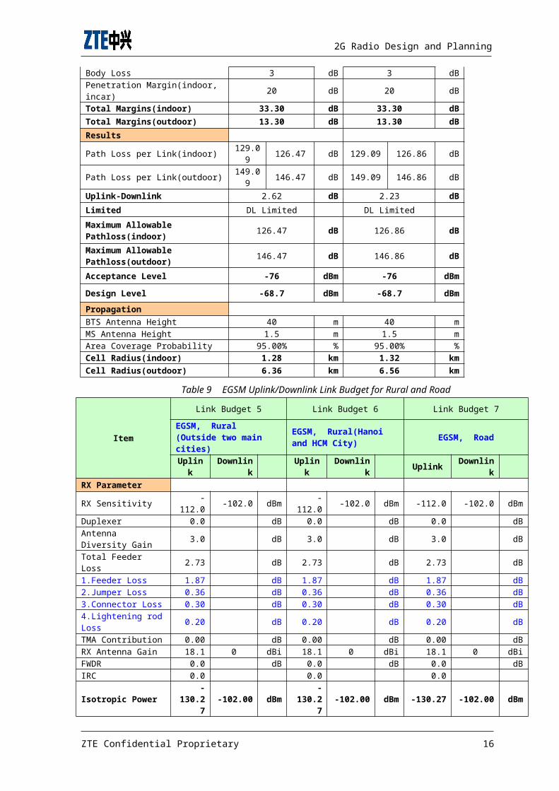
Table 9 EGSM Uplink/Downlink Link Budget for Rural and Road
Item
Link Budget 5 Link Budget 6 Link Budget 7EGSM, Rural (Outside two main cities)
EGSM, Rural(Hanoi and HCM City) EGSM, Road
Uplink
Downlink
Uplink
Downlink Uplink Downlin
kRX Parameter
RX Sensitivity -112.0 -102.0 dBm -
112.0 -102.0 dBm -112.0 -102.0 dBm
Duplexer 0.0 dB 0.0 dB 0.0 dBAntenna Diversity Gain 3.0 dB 3.0 dB 3.0 dB
Total Feeder Loss 2.73 dB 2.73 dB 2.73 dB
1.Feeder Loss 1.87 dB 1.87 dB 1.87 dB2.Jumper Loss 0.36 dB 0.36 dB 0.36 dB3.Connector Loss 0.30 dB 0.30 dB 0.30 dB4.Lightening rodLoss 0.20 dB 0.20 dB 0.20 dB
TMA Contribution 0.00 dB 0.00 dB 0.00 dBRX Antenna Gain 18.1 0 dBi 18.1 0 dBi 18.1 0 dBiFWDR 0.0 dB 0.0 dB 0.0 dBIRC 0.0 0.0 0.0
Isotropic Power-
130.27
-102.00 dBm-
130.27
-102.00 dBm -130.27 -102.00 dBm
ZTE Confidential Proprietary 16

2G Radio Design and Planning
TX Parameter TX Rank-top Output Power 33.0 46.8 dBm 33.0 46.8 dBm 33.0 46.8 dBm
Feeder Loss Total 2.73 dB 2.73 dB 2.73 dB
1.Feeder Loss 1.87 dB 1.87 dB 1.87 dB2.Jumper Loss 0.36 dB 0.36 dB 0.36 dB3.Connector Loss 0.30 dB 0.30 dB 0.30 dB4.Lightening rodLoss 0.20 dB 0.20 dB 0.20 dB
TMA Insertion Loss 0.0 dB 0.0 dB 0.0 dB
TX Antenna Gain 0 18.1 dB 0 18.1 dB 0 18.1 dBDDT 0.0 dB 0.0 dB 0.0 dBEIRP 33.0 62.1 dBm 33.0 62.1 dBm 33.0 62.1 dBmMargins Slow Fading(Log-Normal) Margin 7.3 dB 7.3 dB 4.4 dB
Interference Margin 3 dB 3 dB 3 dB
Body Loss 3 dB 3 dB 3 dBPenetration Margin(indoor, incar)
14 dB 17 dB 6 dB
Total Margins(indoor) 27.30 dB 30.30 dB 16.40 dB
Total Margins(outdoor) 13.30 dB 13.30 dB 10.40 dB
Results Path Loss per Link(indoor)
135.97 136.75 dB 132.9
7 133.75 dB 146.87 147.65 dB
Path Loss per Link(outdoor)
149.97 150.75 dB 149.9
7 150.75 dB 152.87 153.65 dB
Uplink-Downlink -0.78 dB -0.78 dB -0.78 dBLimited UL Limited DL Limited UL LimitedMaximum Allowable Pathloss(indoor)
135.97 dB 132.97 dB 146.87 dB
Maximum Allowable Pathloss(outdoor)
149.97 dB 147.97 dB 152.87 dB
Acceptance Level -82 dBm -82 dBm -87 dBm
Design Level -74.7 dBm -74.7 dBm -82.6 dBm
Propagation
BTS Antenna Height 43 m 43 m 43 m
MS Antenna Height 1.5 m 1.5 m 1.5 m
Area Coverage Probability 95.00% % 95.00% % 90.00% %
Cell Radius(indoor) 5.87 km 4.58 km 11.99 km
ZTE Confidential Proprietary 17

2G Radio Design and Planning
Cell Radius(outdoor) 18.57 km 18.57 km 19.64 km
4.2.2 Link Budget parameter explaination
Power Budget Basic Inputs:
TX Output Power
This is BTS Output Power in dBm. The value is normally adjusted byuser in order to achieve a balance between downlink and uplink.
For B8018 and B8112, the TRX output power is 60w (47.8dBm);Therack-top output power should be subtracted from the TRX outputpower, considering the Combiner Loss. For M8206 rack-top outputpower is 30w, considering by pass CDU and duplexer loss value is1dB.
Combiner Loss
This is the BTS combiner loss in dB. Usually the value depends onthe combiner type i.e. hybrid or filter and the number of TRXinvolved.
When CDU is bypassed, especially when configuration in each cellis less than 2 TRX, only duplexer loss is considered. Typicallythe duplexer loss value is 1dB.
When CDU is not bypassed, where the configuration in each cell islarger than 2 TRX or possibly to be expanded in the future networkexpansion, both duplexer and combiner loss are taken intoconsideration. Typically the duplexer and combiner loss for usingonly CDU in the cell is 4.4dB in EGSM/900MHz.
Feeder, connector, jumper Loss
This is the RF cable transmission loss in dB, including the feederloss, connector loss and the jumper loss. It depends on the lengthand diameter of the cable implementing, connector and the jumperbeing used.
Following is the typical loss per 100m. Actually, this value maybe varied within an acceptable range, usually±0.5dB/100m. Butconsidering the engineering aspect, the actual loss for thefeeders, connectors and jumpers could be more than the typicalloss.
ZTE Confidential Proprietary 18

2G Radio Design and Planning
Table 10 Typical Feeder Loss per 100 metersFeeder Type 900 MHz Unit1/2jumper 7.22
dB/100m
7/8Feeder 3.89
dB/100m
15/8Feeder 2.34
dB/100m
During the planning phase, the actual feeder length is notpossible to evaluate. Always we evaluate feeder and jumper lengthusing the following formula:
Evaluated Feeder Length (7/8) = Antenna Height+ 5m.
0.2dB lightening rod loss is also considered.
The typical value of connector loss is 0.05dB for each one, whichmakes totally 0.3dB connector loss in the link budget.
Antenna Gain
This is the BTS antenna gain in unit of “dBi”. It depends on theantenna type and model.
In Urban and Suburban, the antenna of 17dBi, 65deg horizontal beamwidth is used.
In Rural and Highway, the antenna of 18.1dBi, 65deg horizontalbeam width is used.
Slow Fading Margin
Shadow fading is also called Slow Fading (Log-Normal) and normallyconsidered that it complies with logarithm normal distribution incalculating radio coverage range. In order to obtain the specifiedcoverage probability, we have to reserve transmitter (BTS orterminal) a certain power to overcome fading in radio networkplanning. Reserved power is called shadow fading margin, its valueis related to communication probability at sector edge and shadowfading standard deviation.
In urban environment, the standard deviation σ (Sigma) of thisdistribution is typically around 8 dB, in sub urban environment, σis typically around 7, in rural and road environment, σ istypically around 6.
ZTE Confidential Proprietary 19

2G Radio Design and Planning
Table 11 Slow Fading MarginEnvironment Urban Suburban Rural RoadSigma 8 7 6 6
Path loss exponent 3.5 3.5 3.5 3.5Area CoverageProbability
95.00%
95.00%
95.00%
90.00%
Slow FadingMargin(dB) 7.3 7.3 7.3 4.4
Interference Margin
Interference margin is receiving level increase, which set forinsuring the same voice quality when only internal receiver noiseexists, under the circumstance that multi-path propagation effectand man-made noise (mainly vehicle’s spark interference) exist.
In GSM system, interference margins of voice service and dataservice are both 3dB.
Penetration Loss (Indoor / In car)
Penetration margins (penetration loss) are included in the linkbudget to consider additional attenuation due to the walls ofbuildings or windows of cars. No penetration loss is used foroutdoor coverage. The penetration losses depends the individualbuildings, any value given has therefore to be understood asaverage.
1 In-car Penetration Loss, no car-kit
In case the mobile is used inside the car without connection to anoutside antenna.
2 In-car Penetration Loss, with car-kit
No penetration loss is considered for mobiles connected to anantenna installed on the exterior of the car.
3 Indoor Penetration Loss (Indoor First Wall)
Indoor coverage refers to the coverage at ground floor level.
If we just talk about indoor, we usually mean indoor first wall.The rooms at the outer side of the building are covered. Coveragefor rooms deeper inside the building is not guaranteed.
ZTE Confidential Proprietary 20

2G Radio Design and Planning
Figure 1 Penetration loss (Indoor First Wall)
For buildings in urban areas, a higher loss is usually taken asthe buildings are usually more “solid” and closer together. Forrural areas, lower losses are usually taken. Penetration lossfigures are taken as HTC requirements:
Table 12 Penetration Loss Area Type Signal required Penetration loss(dB)
Urban Deep Indoor 25Sub-Urban Indoor 20
Small City/RuralArea First wall
17 (Hanoi and HCMCity), 14 (outsidetwo main cities)
Road Coverage In-car 6 (Road polygon),10 (city polygon)
Body Loss
The body loss is a margin included in the link budget to considerthe losses introduced into the signal path by the human body, thehead to be more precise.
When thinking about the body loss, you should keep in mind that weare not only working with the direct line of sight, which may beblocked by the head of the user. There are lots of multi-pathcomponents contributing to the total signal, which are reflectedaround the head. This is visualized in the below schematic:
ZTE Confidential Proprietary 21

2G Radio Design and Planning
Figure 2 Body Loss
For body loss, we would have to distinguish between build-up areaswhere lots of multi-path components equal out the body loss tocertain extend, and open areas where the dominating path is theline of sight path. For network designs, this difference isneglected.
The recommended body loss is specified in GSM 03.30 [8] as 3 dB.
MS .Sensitivity
This is the MS receiver sensitivity in dBm. It depends on the MStypes.
Usually, the MS sensitivity is considered -102dBm.
MS Output Power
This is the MS output power in dBm. It depends on the MS class. InGSM Specification, the MS output power is as following:
Table 13 MS output power in GSM specification
Power classGSM 900 NominalMaximum output
power
DCS 1800Nominal Maximumoutput power
PCS 1900Nominal
Maximum outputpower
1 -------------- 1W(30dBm) 1W(30dBm)
2 8W(39dBm) 0.25W(24dBm) 0.25W(24dBm)
3 5W(37dBm) 4W(36dBm) 2W(33dBm)
4 2W(33dBm) --------------
--------------
5 0.8W(29dBm) ---------- ---------
ZTE Confidential Proprietary 22

2G Radio Design and Planning
---- -----
Usually, we use class 4 of 900MHz in the link budget; making theMS Output Power in 900MHz is 33dBm.
Diversity Gain
Antenna diversity gain is a type of gain brought by utilization ofBTS diversity technology. Generally, diversity gain can beconsidered with receiver sensitivity or taken into accountseparately. When BTS uses two path receive diversity, diversitygain is 2~3dB.
In the link budget, 3dB is taken as diversity gain.
BTS Sensitivity
The Rx sensitivity means the minimum signal power that the inputport of the Rx must get to, with the purpose to guarantee thesuccessfully signal detecting and encoding (or to keep the neededFER).
The Rx sensitivity in the communication system = the noisespectrum density (dBm/Hz) + the bandwidth (dBm/Hz) + the noisecoefficient (dB) + C/I (dB).
The system noise = the noise spectrum density + the bandwidth +the noise coefficient. The C/I is the requirement of the SNR in Umport, in the narrowband system the C/I is the requirement of theRx baseband demodulation performance, which usually a positivevalue; when it adopts a spread spectrum communication system,because of the spread spectrum gain, the C/I is much smaller thanthe baseband demodulation performance requirement, so it usuallyis a negative value.
The Rx sensitivity include the MS one and the BTS one, for the uplink, the BTS is the receiver, so the Rx sensitivity is about tothe BTS. Such as the Rx sensitivity of the voice service = thenoise spectrum density (dBm/Hz) + the bandwidth (dBHz) + the noisecoefficient (dB) + C/I(dB) = -174+53+8+9 = -104dBm. Where thebandwidth (dBH) =10lg(200000)=53dBHz; and the value of the noisespectrum density, the noise coefficient and the C/I(dB) isdetermined as the content forenamed.
In the same way, from the formula forenamed, it can be calculatedthe theoretical reference values of the BTS Rx in each condition;
ZTE Confidential Proprietary 23

2G Radio Design and Planning
in fact, the BTS Rx sensitivity is influenced by every factors, sothe BTS Rx sensitivity that the equipment can get to is often muchbetter than the theoretical reference calculating values.
ZTE B8018, B8112 and M8206 can achieve BTS sensitivity (static) as-112dBm.
4.3 Propagation Model and Coverage Radius Prediction
ZTE makes use of the planning tool ASSET to implement the coverageprediction. In this planning tool, propagation modeling algorithmis extremely flexible and allows the user to incorporate a varietyof different types of empirical propagation model in frequenciesbetween 150MHz and 2GHz.
Of all communication propagation environments, the radiocommunication environment is the most complicated. In addition tothe path loss in free space, it also affected by slow fading andmulti-path propagation, while may cause the occurrence of spaceselective fading, time selective fading and frequency selectivefading, and thus greatly deteriorates the uplink/downlinkreceiving signals. In the design of radio network, therefore,choosing an approximate propagation model will lay a foundationfor coverage planning and prediction emulation.
4.3.1 Propagation model Testing & Tuning
An accurate propagation model is needed if we want to have a goodforecast of signal coverage. We have chosen testing sites in allkinds of environments for CW test and model tuning. The areas tobe tested include various clutters and terrains.
The detailed propagation model testing tasks include testing sitessurvey, testing routes selection, testing environmentconstruction, testing data collection, testing data acceptance,testing summarization, etc. We select testing sites according todifferent landform and environment, and then collect propagationmodel testing data for the following propagation model tuning.
Our purpose is to attain a more suitable model for the complexclutters in Vietnam by means of this test work; on the other hand,to summarize the features of radio wave propagation by way ofwhich we can carry out our radio network planning. We testedfollowing in following provinces at different area types:
ZTE Confidential Proprietary 24

2G Radio Design and Planning
Table 14 CW testing points in different provinces
City TestPoint No. Area(Model) type
Ha Noi 6 Plain U, Plain SU, Plain RUCan Tho 2 River CityDa Nang 6 Plain U, Plain SU, Hilly RUDienBien 6 Mountain U, Mountain SU, Mountain RU
QuangNinh 7 Hilly U, Hilly SU, Hilly RU, Highway (Quang
Ninh-Ha Noi)
Lang Son 7 Mountain U, Mountain SU, Mountain RU,Highway(Lang Son-Ha Noi)
HaiPhong 3 Seaside City
HCM City 6 Plain U ,Plain SU
4.3.2 Propagation Model Formula
Following is the standard propagation model for macro cell inAIRCOM format:
Received Power (dBm)=Transmit Power (dBm)-Path loss(dB)
And,
PathLoss=k1+k2log(d)+k3(Hms)+k4log(Hms)+k5log(Heff)+k6log(Heff)log(d)+k7diffn+C_loss
Where:
d is the distance from the base station to mobilestation (km).
Hms is the height of the mobile station above theground (m). This figure may be specified eitherglobally or for individual clutter categories.
Heff is the effective base station antenna height(m).
diffn is the diffraction loss calculated using eitherEpstein, Peterson, Deygout or Bullington equivalentknife edge methods.
K1&k2 is the intercept and slope. These factorscorrespond to a constant offset (in dBm) and a
ZTE Confidential Proprietary 25

2G Radio Design and Planning
multiplying factor for the log of the distancebetween the base station and mobile station.
K3 is the mobile antenna height factor. Correctionfactor used to take into account the effective mobileantenna height.
K4 is the Okumura-Hata multiplying factor for Hms. K5 is the effective antenna height gain. This is the
multiplying factor for the log of the effectiveantenna height.
K6 is the is the Okumura-Hata type multiplying factorfor log(Heff)log(d)
K7 is a multiplying factor for diffractioncalculations. A choice of diffraction methods isavailable.
C_loss is the clutter loss. Clutter specificationssuch as heights and separation are also taken intoaccount in the calculation process when setting therelative parameters.
Table 15 K parameters value in Standard Macro Propagation Model
Model K1 K2 K3 K4 K5 K6 K7
Plain U152.39 43.83 -2.55 0.00
-13.82 -6.55 0.05
Plain SU149.33 39.25 -2.55 0.00
-13.82 -6.55 0.05
Plain RU140.87 38.68 -2.55 0.00
-13.82 -6.55 0.04
Hilly U140.88 42.00 -2.55 0.00
-13.82 -6.55 0.10
Hilly SU139.73 41.25 -2.55 0.00
-13.82 -6.55 0.09
Hilly RU137.36 39.50 -2.55 0.00
-13.82 -6.55 0.04
MountainU
144.93 41.50 -2.55 0.00
-13.82 -6.55 0.06
MountainSU
141.35 39.25 -2.55 0.00
-13.82 -6.55 0.14
MountainRU
138.93 38.75 -2.55 0.00
-13.82 -6.55 0.02
Highway139.11 38.24 -2.55 0.00
-13.82 -6.55 0.00
Seaside 141. 40.25 -2.55 0.00 - -6.55 0.04
ZTE Confidential Proprietary 26

2G Radio Design and Planning
City 82 13.82RiverCity
143.66 40.00 -2.55 0.00
-13.82 -6.55 0.02
Note: Due to the much more complicated radio propagationenvironment in practical network, the simulation results on thebasis of above parameters may not be totally same with the DTresults. As a result, simulation results presented in this reportcan only be viewed as references, not the standard of coverage KPIat final network acceptance and checking process.
4.3.3 Coverage Radius Prediction
Get the maximum allowed path loss according to the syntheticuplink/downlink signal analysis. By using the correctionalelectric wave propagation empirical model, estimate the cellcoverage radius under different terrains in this planning asfollowing table:
Table 16 Radius prediction in different areas
Propagation
Environment
U SU
RU((Hanoi andHCM
City)
RU(Outside twomain
cities)
Road
Radius
BTSAnt.Height(m)
30 40 43 43 43
Radius(km) 0.65 1.2
8 4.58 5.87 11.99
Distancebetweentwosites(km)
0.975
1.92 6.87 8.805 17.9
85
AcceptanceSignalLevel(dBm)
-71 -76 -82 -82 -87
DesignSignalLevel(dBm)
-63.7
-68.7
-74.7 -74.7 -82.6
Above mentioned table depicts the predicted coverage radius ateach signal level.
ZTE Confidential Proprietary 27

2G Radio Design and Planning
For details of Link Budget and Coverage Radius Prediction, pleaserefer to Chapter 1 Appendix 2 HTC EGSM network Planning –Guideline.(with hyperlink to file)
4.4 Antenna Selection
Antenna selection is a very important part of GSM radio networkplanning, and is mainly based on requirements on coverage, antennaselection priority and installation space. As HTC requirement, ZTEuses the antenna model for existing CDMA BTS which will be swappedby GSM BTS. For new sites ZTE uses the following antenna selectionprinciple.
4.4.1 Antenna Selection within Urban, Sub Urban Area
In Urban and Sub Urban area sites are quite congested/ dense, soit’s suggested that the coverage range of the base station shouldbe small as requirement and moreover overlapping coverage amongcells need to be strictly reduced so that interference among siteswill also be reduced and effectiveness of frequency reuse will behigher.
1. As it is hard to select Site location and enough space for installing antenna in Urban and Sub Urban area, so dual-polarization antenna needs to be chosen.
2. To have higher effectiveness of frequency reuse sector antenna should be chosen.
3. To restrain interference among cells it’s suggested to choose 60~65° horizontal beam width antenna.
4. Generally in Urban area demand of capacity requirement is more considerable rather than coverage requirement, so it’s suggested to use medium gain of antenna and to choose 17dBi antenna. If micro cells are implemented, then it needs to choose lower gain of antenna.
So in Urban and Sub Urban area, ZTE suggests 65-degree dualpolarization antennas with medium gain of 17dBi which can goodcoverage performance and the system interference can be controlledeasily. During this project ZTE suggests using DB856DG65EXYantenna for Urban and Sub Urban area sites. Moreover this antennasupported both CDMA and GSM frequency band, so it’s used forexisting network sites (905 sites) as HTC requirement.
Below figure depicts the antenna pattern of DB856DG65EXY:
ZTE Confidential Proprietary 28

2G Radio Design and Planning
Figure 3 DB856DG65EXY antenna pattern
4.4.2 Antenna Selection within Rural and Highway area
In Rural and Highway area sites are sparsely distributed, andrequired large coverage. Especially in rural or remote area thereis only one site, in that case coverage becomes the key point ofchoosing antenna. Moreover, in Vietnam most of the highway ormajor roads are passed through rural( village) area, that means inmost cases there are population both sides of major roads.
1. Choose vertical polarization or dual-polarization antenna
2. The sector antenna with 65° horizontal beam width isused.
3. The antenna with high gain (18.1dBi) is suggested, to provide good coverage performance.
So in Rural and Highway (major roads) area, ZTE suggests same kindof antenna, 65-degree dual polarization antennas with 18.1dBi gainwhich can provide good coverage performance. During this projectZTE suggests using DB858DG65ESY antenna for Rural and Highway areasites.
Below figure depicts the antenna pattern of DB858DG65ESY:
ZTE Confidential Proprietary 29

2G Radio Design and Planning
Figure 4 DB858DG65ESY antenna pattern
Here is the detail list of selected antenna for differentclutters:
Table 17 Selected antenna list for different clutters
Frequency(MHz) Clutter Model Gain(dBi)
AzimuthBW(Deg.)
ElecTilt(Deg
.)EGSM(806-
960)Urban,Suburban DB856DG65EXY 17 65 0
EGSM(870-960)
Rural,Highway(MajorRoads)
DB858DG65ESY 18.1 65 0
4.5 EDGE Coverage Planning
GPRS networks are able to handle higher bit rates than GSMnetworks, but the data rates still fall short of what is requiredto make existing GSM networks deliver services at a speedcomparable to that promised by third-generation networks. Thedelay in the deployment of third-generation systems led to theemergence of a technology known as EDGE.
4.5.1 EDGE System and Coding Schemes
The EDGE system is quite similar to the GPRS system, but with thecapability for higher data rates. The most important change is thenew modulation scheme. In GSM and GPRS, the GMSK modulation schemewas used. In GMSK modulation, only one bit per symbol is used. Inan EDGE network, octagonal phase-shift keying (8-PSK) modulationis used which enables a threefold higher gross data rate. GMSK is
ZTE Confidential Proprietary 30

2G Radio Design and Planning
a constant-amplitude modulation while 8-PSK has variations in theamplitude. This amplitude variation changes the radio performancecharacteristics.
As already mentioned, the EDGE system is an enhancement to theexisting GPRS system. There are nine modulation and coding schemes(MCS-1 to MCS-9) that provide different throughputs. For codingschemes MCS-1 to MCS-4, modulation is still GMSK; for MCS-5 toMCS-9 it is 8-PSK.
4.5.2 Coverage Planning
The basic process of radio network planning remains the same as inGPRS networks. However, because of the changes in the modulationand coding schemes, there are some changes in the coverage,capacity, and parameter planning of EDGE radio networks.
The link budget has a direct impact on coverage. As the EDGEnetwork focuses more on PS data, the delay tolerance becomes acritical factor in defining system quality level. Some factorsthat affect link budget calculations specifically in EDGE arenoted below.
Body Loss
When a mobile comes near to the human body, the signal level goesdown. This is known as body loss. In GSM 900/EGSM, this loss istypically 3 dB. No body loss is taken into account for packet dataservices in an EDGE network.
MS and BTS Sensitivity
Signal strength in radio networks can be expressed in relation tointerference signals. Link budget calculations can be done byusing MCS and BLER. However, received signal strength can becalculated for some specified data rates as well. Es/No can beused for throughput (per time slot) calculations in a cell. Asseen in earlier voice Link Budget, the received signal strength isdependent upon the transmitted signal strength, losses, antennaheights and gains (TX and RX) and distance traveled by the signal.Loss in the signal strength gives the cell range.
During planning, ZTE uses MS and BTS sensitivity in different MCSis as following table:
Table 18 MS and BTS sensitivity in different MCSMCS Modulation BTS RX MS RX
ZTE Confidential Proprietary 31

2G Radio Design and Planning
Sensitivity(dBm) Sensitivity(dBm)TU50(no SFH) TU50
MCS1 GMSK -102 -102MCS2 GMSK -100 -100MCS3 GMSK -96 -96MCS4 GMSK -91 -91MCS5 8-PSK -96 -93MCS6 8-PSK -94 -91MCS7 8-PSK -89 -84MCS8 8-PSK -84 -83MCS9 8-PSK -80 -78
For details of EDGE-Link Budget calculation, please refer to“Chapter 1 Appendix 1 HTC EGSM Network Planning - Guideline”.(withhyperlink to file)
4.6 BTS Sub-system deployment
4.6.1 BTS type selection principle
Macro cellular BTS types include Omni directional, single sector,2 sectors, 3 sectors, 6 sectors and other types. The sector numberof BTS decides antenna selection, coverage range, system capacity,handover, etc. The BTS type selection principle is listed infollowing table.
Table 19 BTS type selection principleSector
Configuration
Suitable Principle Typical Region
3 sectors
Main type of sectorconfiguration, supportingheavy traffic load, andwidely applied for everykind of area.
Dense urban,urban, prosperoustowns, etc.
singlesectors &2 sectors
Usually used to cover thearea with great trafficrequirement and definitivecoverage requirement.
Main road,buildingindoor(e.g.underground parkarea)
OmniUsually used to cover theplane area with low trafficrequirement.
Rural and hillyarea
SplitSector
Usually used to cover thearea with low trafficrequirement and definitive
Small towns anddevelopingindustrial
ZTE Confidential Proprietary 32

2G Radio Design and Planning
coverage requirement. region.
In this project, based on the coverage priority principle it’smainly utilized the 3 sectors and 2 sectors BTS. In most of thearea sites with 3 sectors are selected, only in highway or majorroads and narrow & long shaped area sites with 2 sectors areselected.
4.6.2 Preliminary Planning of BTS Deployment
For the purpose that meeting the good coverage, site is deployedaccording to following principle:
Referring to other operator’s site distribution For area (Urban, Sub Urban) polygon: site distributed
as even as possible and planned dedicated site forisolated area to ensure the coverage KPI. Howeverduring planning, by survey and distribution of otheroperator’s sites and in Google Earth we have foundthat few are the polygons specially Sub Urban aredrawn by HTC in rural or mountain area which is notcorrect or reasonable as certain environment andclutter type in reality.
In Urban area with the high traffic, most of the siteis configured to maximum to have the better qualityservice and capacity. The antenna height of urbanarea is configured as 30m. In Sub Urban area, sitesare configured as having better service with goodcoverage. So, the antenna height is configured as40m.
In Vietnam most of the highway or major roads arepassed through rural (village) area, which means inmost cases there are population both sides of majorroads. So in Rural and Highway (major roads) areait’s mainly considered for coverage, so in theseareas the antenna height is configured as 43m-45m.
Sites exact location with antenna height anddeployment will be adjusted by the situation duringimplementation process.
ZTE Confidential Proprietary 33

2G Radio Design and Planning
4.6.3 BTS deployment result and Anlaysis
Site deployment result as Coverage requirements in differentclutters is shown as following table:
Table 20 Site deployment result in different cluttersRegion Phase Urban Sub Urban Rural Highway Total Sites
North
Phase1A 160 161 149 21 491
Phase1B 216 264 228 38 746
Phase1C 310 367 384 61 1122
Phase2 398 482 552 83 1515
Phase3 515 548 721 106 1890
Phase4 636 612 836 130 2214
Phase5 731 684 988 215 2618
Central
Phase1A 49 45 37 18 149
Phase1B 80 97 96 52 325
Phase1C 122 111 144 66 443
Phase2 221 198 323 107 849
Phase3 291 255 393 117 1056
Phase4 380 317 447 119 1263
Phase5 459 406 480 133 1478
South Phase1A 251 162 172 25 610
Phase1B 377 224 304 32 937
Phase1C 575 359 480 37 1451
Phase2 823 495 672 48 2038
Phase3 1055 589 849 52 2545
Phase4
1307 705 988 60 3060
ZTE Confidential Proprietary 34

2G Radio Design and Planning
Phase5 1581 782 1148 74 3585
Detailed site list please refer to Chapter 1 Appendix 2 HTC EGSMnetwork planning – Site List. ( w ith hyperlink to file)
During Sites deployment in different phases we considered asfollowing:
In Phase1A ZTE replace the CDMA sites by GSM sites;since these are two different systems, coverage willnot be same. So during planning we marked those areaswhere is no continuous coverage, and in future phasesthose non covered area have been covered by newsites.
In Phase1B & Phase1C, during planning ZTE considersthe important provinces such as Hanoi, HCM, Da Nang,Can Tho, HaiPhong , and few tourist areas such as PhuQuoc island ( in Kien Giang province), Vung Tautourist city, Thua Thien Hue tourist city, Nha Trang(in Khan Hoa province) tourist city, Da Lat touristcity ( in Lam Dong province) etc. At the same time inthese phases ZTE deeply consider one importanthighway called “1A” which has been linked from northto south passing through almost all of the regions inright of the country.
In Phase2 & Phase3, ZTE consider both coverage andcapacity of those main provinces, and at the sametime we consider the major roads which passes all ofthe regions and rural areas. So in these two phasesmost of major roads are covered, but still notcontinuous coverage in major roads, for that it needsto deploy sites in next phases. Moreover duringplanning it’s also considered to cover the industrialareas such as Thai Nguyen, Binh Duong, Dong Naiprovinces, Lao Cai & Lang Son foreign trade cities;and continuously cover those tourist cities to ensuregood coverage. So, in these phases we deploy moresites compare previous phases.
ZTE Confidential Proprietary 35

2G Radio Design and Planning
In previous phases coverage is considered firstly; inPhase4 & Phase5 ZTE check those main provinces wherecapacity has large requirements, so in thoseimportant provinces ZTE deploy sites as capacityrequirements. Then we continuously give theconsideration those important tourist, industrial,trade cities. And in these two phases ZTE alsoconsider those major roads and rural areas where isno continuous coverage in previous phases.
In simply ZTE follows the following areas to ensure good coverage:
Table 21 Sites Deployment Analysis
Area Type Area Name
Important Provinces Ha Noi, Hai Phong, Da Nang, HCM city, Can Tho
Industrial area Binh Duong, Dong Nai,Thai Nguyen, Lao Cai, Lang Son
Tourist place/city
Ha Long, Nha Trang(Khan Hoa province),HUE(Thua ThienHue province),Da Lat(Lam Dong province), Mu Ne (BinhThuan province),Vung Tau( Ba Ria Vung Tau province),Rach Gia & Phu Quoc (Kien Giang province),
Major Roads
1B, 279, 4,12, 6, 2, 3, 5, 18, 4A, 4B, 10, 1A (linkedfrom north to South), 7, 8, 15, 9, 14, 19, 25, 26, 27,20, 13, 51, 22, 91, Me Cong River (HCM City - My Tho -Vinh Long - Can Tho) passing by highway
Other Provinces Important areas/places where there is population andneeds continuous and well coverage.
For details of Sites Distribution and Coverage Simulation pleaserefer to Chapter 1 Appendix 3 HTC EGSM Network Planning –simulation.(with hyperlink to file)
4.7 Population Coverage Percentage
After planning and deploying sites, population coverage percentageis as following:
Table 22 Design Population Coverage Percentage
PhaseNumber of
Site by HTC
Target PopulationCoverage Percentage
by HTC
Design Numberof Site by ZTE
Design PopulationCoveragePercentage
1B 2,000 74% 2008 74.08%1C 3,000 79% 3016 79.21%2 3,700 83% 4402 85.69%3 5,000 88% 5491 91.05%
ZTE Confidential Proprietary 36

2G Radio Design and Planning
4 6,000 91% 6537 93.97%5 7,000 93% 7681 95.28%
Here it’s noted that, in ASSET planning tool by comparingpopulation density (with population number of each area) digitalmap and coverage simulation we evaluated and designed thepopulation coverage percentage.
5 CAPACITY PLANNINGIn this part, capacity planning has been depicted for following 7Phases (Phase1A – Phase5). Network planning has been doneaccording to HTC’s requirements.
5.1 Principles of Capacity Planning
Following is the prime principles during capacity planning in thisproject:
The total capacity for each province in every phaseis based on the sub projection file HTC released.
The same traffic model mentioned in RFQ is commonlyused in Phase1A to Phase5.
HTC provided target capacity of each phase for eachprovince. During planning we referred to populationdensity digital map in MapInfo© format and otheroperator’s site distribution during planning where wecan check the other operator’s sites’ congestion orsubscriber’s density.
After careful study on the coverage range indifferent cluster type, by referring the digital map,network coverage is the first important thing toconsider. On the basis of coverage, the BTSconfiguration should be meet the requirement ofcapacity, with some certain redundancy because theBTS due to the coverage requirement is possibly morethan that due to the capacity requirement.
ZTE Confidential Proprietary 37

2G Radio Design and Planning
According to site dimension result, capacityrequirement of each province can be met phase byphase. During planning whenever the planned capacityis less than required capacity, AMR HR is activatedto meet the total requirement. 50% HR penetrate rateis considered in radio network planning for HTC. Hereit’s noted that in Phase1A, it’s not necessary toactivate HR as design planning satisfy the capacityrequirement.
5.2 Channel planning
5.2.1 SDCCH Channel Planning
In addition to the service channel TCH in the GSM system, there isanother important channel: Standalone Dedicated control channel(SDCCH).It is largely related with the user location update, IMSIattachment/detachment, call setup, short message, fax servicesetup and various supplementary services. As a result, every cellshould be configured with SDCCHs of certain quantity according tothe cell capacity.
As per that principle, the configured quantities of SDCCH channelsin the cells with various numbers of carriers are listed in thetable below:
Table 23 SDCCH Channel PlanningNumber ofCarriers
Number ofChannels
SDCCH ChannelStructure
Number of ControlChannels /FR/(BCCH+SDCCH)
2 16 SDCCH/8 1+13 24 SDCCH/8 1+24 32 2×SDCCH/8 1+25 40 2×SDCCH/8 1+36 48 2×SDCCH/8 1+3
SDCCH configuration showed in above table is for the average cell,for the LAC border cell, 1 more SDCCH should be configured.
5.2.2 PDCH Channel Planning
According to RFQ( in province where only GPRS is initiated), inUrban we will configure 1 dedicated channel in Uplink, andconsidering the data requirement is unbalance in Uplink andDownlink, 3 more dynamic channel is configured in Downlink. In
ZTE Confidential Proprietary 38

2G Radio Design and Planning
Suburban, 2 dynamic channels are configured; in Rural and Road,only 1 dynamic channel is configured. PDCH configuration shows infollowing table, please refer to:
Table 24 PDCH(GPRS) configuration
Area Uplink Downlink
Dedicated Dynamic Dedicate
d Dynamic
URBAN 1 0 1 3SUB URBAN 0 2 0 2
RURAL 0 1 0 1ROAD 0 1 0 1
According to RFQ( in province where both GPRS and EDGE areinitiated), in Urban we will configure 3 dedicated channel inUplink, and considering the data requirement is unbalance inUplink and Downlink, 1 more dynamic channel is configured inDownlink. In Suburban, 2 dynamic channels are configured; in Ruraland Road, only 1 dynamic channel is configured. PDCH configurationshows in following table, please refer to:
Table 25 PDCH(GPRS+EDGE) configuration
Area Uplink Downlink
Dedicated Dynamic Dedicate
d Dynamic
URBAN 3 0 3 1SUB URBAN 0 2 0 2RURAL 0 1 0 1ROAD 0 1 0 1
5.2.3 Voice Service Channel Planning
When no HR is considered, the channel planning is as follows.
Table 26 Channel Planning with No HRNo HR, and No PDCH is considered
TRX Number TotalChannel BCCH SDCCH/8 TCH/FR
GOS=2%Subs
Erl1 8 1 1 6 2.28 922 16 1 1 14 8.2 3283 24 1 2 21 14.03 5624 32 1 2 29 21.04 842
No HR , and PDCH for GPRS is consideredTRX Number Total BCCH SDCCH/8 Static TCH/FR GOS=2% Subs
ZTE Confidential Proprietary 39

2G Radio Design and Planning
Channel PDCH Erl1 8 1 1 1 5 1.66 67
2 16 1 1 1 13 7.4296
3 24 1 2 1 20 13.2528
4 32 1 2 1 28 20.2808
No HR, and PDCH for both GPRS and EDGE is considered
TRX Number TotalChannel BCCH SDCCH/8 Static
PDCH TCH/FR GOS=2% SubsErl
1 8 1 1 3 3 0.602 25
2 16 1 1 3 11 5.84 234
3 24 1 2 3 18 11.5 460
4 32 1 2 3 26 18.4 736
After implementing 50% HR, the quantity of TCH channels (TCH/FR,TCH/HR) per carrier are planned as follows:
Table 27 Channel Planning with HRHR, and No PDCH is considered
TRXNumbe
r
TotalChanne
lBCCH SDCCH/8 HR
Ratio TCH/FR TCH/HRGOS=2%
SubsErl
1 8 1 1 50% 4 4 3.63 1462 16 1 1 50% 10 8 11.5 4603 24 1 2 50% 14 14 20.2 8084 32 1 2 50% 20 18 29.2 1168
HR, and PDCH for GPRS is consideredTRX
Number
TotalChanne
lBCCH SDCCH/8 Static
PDCHHR
Ratio TCH/FR TCH/HRGOS=2%
SubsErl
1 8 1 1 1 50% 4 2 2.28 922 16 1 1 1 50% 9 8 10.7 4283 24 1 2 1 50% 14 12 18.4 736
4 32 1 2 1 50% 19 18 28.31132
HR, and PDCH for both GPRS & EDGE is consideredTRX
Number
TotalChanne
lBCCH SDCCH/8 Static
PDCHHR
Ratio TCH/FR TCH/HRGOS=2%
SubsErl
1 8 1 1 3 50% 2 2 1.09 442 16 1 1 3 50% 8 6 8.2 328
ZTE Confidential Proprietary 40

2G Radio Design and Planning
3 24 1 2 3 50% 12 12 16.6 664
4 32 1 2 3 50% 18 16 25.51020
5.3 Capacity planning result
To satisfy the capacity requirement in every phase and year,mainly depends on newly added site and expand existing site incorresponding phase and year. Most of sites planned an initialconfiguration of 2/2/2 in area polygon and 2/2 in road polygon.With network development, most of the sites will be upgradedaccording to actual capacity requirement.
The general capacity planning principle mentioned above also iscoincident with the natural network development rule. In initialstage, the main purpose is realizing coverage of objective area,with network development, more and more peoples knows and enjoysthe HTC network service, the capacity will be increased,correspondingly, the site will should be upgraded. The detailedsite capacity planned result shows in following table. Detailedsite list Please refer to Chapter 1 Appendix 2 HTC EGSM networkplanning – Site List. ( w ith hyperlink to file)
Table 28 North capacity planning result
Phase
Region NorthNew addsite
Configuration
UpgradeMode
New add Upgrade
Total SubSiteQty Sub Qty
SiteQty Sub Qty
Phase1A
S22 21 13776 13776
S222S222toS33
3 469 421122 421122
S333S333toS44
4 1 1584 1584
S444S222toS44
4 0 0Increaser Total 491 436482 0 0 436482Cumulative Total 491 436482 0 0 436482
Phase1B S22 17 11152 11152
S222S222toS33
3 202 244656 7 10080 254736
S333S333toS44
4 4 8184 0 8184S444 S222toS44
432 97920 2 5016 102936
ZTE Confidential Proprietary 41

2G Radio Design and Planning
Increaser Total 255 361912 9 15096 377008Cumulative Total 746 798394 9 15096 813490
Phase1C
S22 23 15088 15088
S222S222toS33
3 276 311796 113 114408 426204
S333S333toS44
4 53 118968 0 118968
S444S222toS44
4 24 77136 0 77136
Increaser Total 376 522988 113114408 637396
Cumulative Total 11221321382 122
129504
1450886
Phase2
S22 22 114432 114432
S222S222toS33
3 313 359160 41 41496 400656
S333S333toS44
4 24 51480 0 51480
S444S222toS44
4 32 100272 0 100272Increaser Total 391 625344 41 41496 666840
Cumulative Total 15131946726 163
171000
2117726
Phase3
S22 23 15088 15088
S222S222toS33
3 254 277356 38 39672 317028
S333S333toS44
4 36 81648 0 81648
S444S222toS44
4 62 191736 0 191736Increaser Total 375 565828 38 39672 605500
Cumulative Total 18882512554 201
210672
2723226
Phase4
S22 24 15744 15744
S222S222toS33
3 200 224112 0 224112
S333S333toS44
4 18 36936 240 258384 295320
S444S222toS44
4 82 262164 0 262164
Increaser Total 324 538956 240258384 797340
Cumulative Total 22123051510 441
469056
3520566
ZTE Confidential Proprietary 42

2G Radio Design and Planning
Phase5
S22 85 55760 55760
S222S222toS33
3 236 258456 0 258456
S333S333toS44
4 13 26544 0 26544
S444S222toS44
4 70 229536 0 229536Increaser Total 404 570296 0 0 570296
Cumulative Total 26163621806 441
469056
4090862
Table 29 Central capacity planning result
Phase
Region CentralNew addsite
Configuration
UpgradeMode
New add Upgrade
Total SubSiteQty Sub Qty
SiteQty Sub Qty
Phase1A
S22 18 11808 11808
S222 S222toS333 131 120366 120366
S333 S333toS444 0 0
S444 S222toS444 0 0
Increaser Total 149132174 0 0 132174
Cumulative Total 149132174 0 0 132174
Phase1B
S22 34 22304 22304
S222 S222toS333 127 149964 12 15480 165444
S333 S333toS444 12 23904 0 23904
S444 S222toS444 3 10296 14 33810 44106
Increaser Total 176206468 26 49290 255758
Cumulative Total 325338642 26 49290 387932
Phase1C
S22 14 9184 9184
S222 S222toS333 79 88080 0 87684
S333 S333toS444 11 21912 24 25632 47544
S444 S222toS444 14 43956 0 43956
Increaser Total 118162736 24 25632 188368
Cumulative Total 443501378 50 74922 576300
ZTE Confidential Proprietary 43

2G Radio Design and Planning
Phase2
S22 41 26896 26896
S222 S222toS333 335 381912 0 381912
S333 S333toS444 9 17928 11 11748 29676
S444 S222toS444 21 68496 0 68496
Increaser Total 406495232 11 11748 506980
Cumulative Total 849996610 61 86670
1083280
Phase3
S22 10 6560 6560
S222 S222toS333 176 208968 0 208968
S333 S333toS444 10 19920 9 9612 29532
S444 S222toS444 11 34992 0 34992
Increaser Total 207270440 9 9612 280052
Cumulative Total 10561267050 70 96282
1363332
Phase4
S22 2 1312 1312
S222 S222toS333 176 211452 0 211452
S333 S333toS444 16 31872 10 10680 42552
S444 S222toS444 13 41556 0 41556
Increaser Total 207286192 10 10680 296872
Cumulative Total 12631553242 80
106962
1660204
Phase5
S22 14 9184 9184
S222 S222toS333 171 213948 0 213948
S333S333toS444 16 31872 16 17088 48960
S444S222toS444 14 47280 0 47280
Increaser Total 215302284 16 17088 319372
Cumulative Total 14781855526 96
124050
1979576
Table 30 South capacity planning resultPhase Region South
New addsite
UpgradeMode
New add Upgrade Total SubSite Sub Qty Site Sub Qty
ZTE Confidential Proprietary 44

2G Radio Design and Planning
Qty Qty
Phase1A
S22 25 16400 16400
S222S222toS33
3 573 501828 501828
S333S333toS44
4 12 16560 16560
S444S222toS44
4 0 0
Increaser Total 610534788 0 0 534788
Cumulative Total 610534788 0 0 534788
Phase1B
S22 7 4592 4592
S222S222toS33
3 273 299196 157 20388
0 503076
S333S333toS44
4 47 94920 0 94920
S444S222toS44
4 0 0 0
Increaser Total 327398708 157
203880 602588
Cumulative Total 937933496 157
203880
1137376
Phase1C
S22 5 3280 3280
S222S222toS33
3 407 459672 12 11088 468780
S333S333toS44
4 20 46536 204 217872 264408
S444S222toS44
4 82 250920 0 250920
Increaser Total 514758428 216
228960 987388
Cumulative Total 14511691924 373
432840
2124764
Phase2 S22 11 7216 7216
S222S222toS33
3 480 539784 0 539784
S333S333toS44
4 18 40176 0 40176
S444S222toS44
4 78 238680 0 238680
Increaser Total 587825856 0 0 825856
Cumulative Total 2038 25177 373 43284 295062
ZTE Confidential Proprietary 45

2G Radio Design and Planning
80 0 0
Phase3
S22 4 2624 2624
S222S222toS33
3 398 443868 145 15103
8 594906
S333S333toS44
4 98 198240 25 27000 225240
S444S222toS44
4 7 22752 0 22752
Increaser Total 507667484 170
178038 845522
Cumulative Total 25453185264 543
610878
3796142
Phase4
S22 8 5248 5248
S222S222toS33
3 297 331992 229 22589
4 557886
S333S333toS44
4 97 212178 94 10051
2 312690
S444S222toS44
4 113 356448 0 356448
Increaser Total 515905866 323
326406
1232272
Cumulative Total 30604091130 866
937284
5028414
Phase5
S22 14 9184 9184
S222S222toS33
3 301 329076 101 10004
4 429120
S333S333toS44
4 76 163704 257 27918
0 442884
S444S222toS44
4 134 417816 0 417816
Increaser Total 525919780 358
379224
1299004
Cumulative Total 35855010910 1224
1316508
6327418
6 ROLL OUTBased on the hypothesis, analysis and calculation values all theway above, the radio planning result for the GSM network issummarized below, including the BTS categories, quantities and thedesigned capacity towards each province each year.
Please find the details roll out list as below table:
ZTE Confidential Proprietary 46

2G Radio Design and Planning
Table 31 Roll out for different Regions
Region SitesStatus Site Cell
North
Phase1A 491 1448Phase1B 255 741Phase1C 376 1105Phase2 393 1157Phase3 375 1102Phase4 324 948Phase5 404 1127Total 2618 7628
Central
Phase1A 149 426Phase1B 176 492Phase1C 118 340Phase2 406 1177Phase3 207 611Phase4 207 619Phase5 215 631Total 1478 4296
South
Phase1A 610 1805Phase1B 327 972Phase1C 514 1537Phase2 587 1750Phase3 507 1517Phase4 515 1537Phase5 525 1561Total 3585 10679
For details please find the Chapter 1 Appendix 1 HTC EGSM networkPlanning - Guideline.(with hyperlink to file)
7 FREQUENCY PLANNINGAccording to RFP, there are totally 40 frequencies available. Forthe purpose of effective utilizing the spectrum and avoidinginterference, we will adopt MRP, DFCA, and SFH technology infrequency plan.
ZTE Confidential Proprietary 47

2G Radio Design and Planning
7.1 BCCH planning
In order to avoid Co-channel and Adjacent-channel interference aspossible as can, we must fully consider the site density, sitedistribution and antenna azimuth of different cluster, as shows infollowing table:
Table 32 Characteristic of different Morphoclass
Morphoclass URBAN SUBURBAN RURAL ROAD
SiteDensity High
middle Low Low
SiteDistributio
nIrregular
middle
Regular
Regular
AntennaAzimuth
Irregular
middle
Regular
Regular
For the cluster where site density is high, site distribution andantenna Azimuth is irregular, the low efficiency frequency reusemode should be applied, otherwise, we should select the highefficiency frequency reuse mode, based on this rule, but in thisproject due to less frequency we selected 4*3 reuse pattern forall kind of areas.
BCCH use 4*3 reuse pattern, dividing the 12 frequencies into4groups (A, B, C, and D), each of which is allocated to separatecells.
Group A1 B1 C1 D1 A2 B2 C2 D2 A3 B3 C3 D3
BCCH 1012
1013
1014
1015
1016
1017
1018
1019
1020
1021
1022
1023
7.2 TCH planning
For TCH planning, ZTE uses new technology GPS synchronization,DFCA technology where frequency will be automatically allocated.
However in initial phase most of the sites are small configurationsites, in that case ZTE adopts Synthesized Frequency Hopping (SFH1*1) technique. The three elements of planning hopping network areHSN, MA List and MAIO. HSN ranges from 1 to 63, not using value of0 (cyclic hopping). The main principle is to guarantee less co-channel collision in one base station and adjacent cell. MA listwill be from 995 – 1010.
Frequency 986-991 reserved for micro or indoor sites.
ZTE Confidential Proprietary 48

2G Radio Design and Planning
Frequency 985 and 1024 used for isolating frequency with otheroperator.
Frequency 1011 is used for the isolating frequency between BCCHand TCH.
Details please refer to “Chapter 1 Appendix 1 HTC EGSM NetworkPlanning - Guideline.xls”. (with hyperlink to file)
7.3 Automatic Frequency Planning and C/I,C/A Algorithm
ZTE uses ASSET 3G module of AIRCOM Enterprise as the automaticfrequency planning tool for BCCH carrier with necessary manualadjustment, and done interference simulation.
7.3.1 Automatic Frequency Planning Algorithm
ILSA (Intelligent Local Search Algorithm) is ASSET3g's optionalfrequency planning tool. ILSA uses an extremely advanced heuristicsearch algorithm, where the latest techniques in combinatorialmathematics evaluate the "penalty cost" of a particular frequencyplan and change the frequency allocations to minimize the cost.
The algorithm is based on a user-specified Cost Matrix, whichassociates a set of constraints with variable penalty costs.Constraints with higher associated costs are less likely to bebroken. Therefore the importance of each constraint should beproportional to its penalty cost. The primary constraints (but notthe only ones) in the cost matrix are concerned with a minimumseparation between frequencies on:
The same cell The same site but different cell Neighbors of the site
The frequency planner uses an Intelligent Local Search Algorithm(ILSA) to search for an optimum or zero cost plan using the latestideas from Combinatorial Optimization Theory. The interference inthe network is measured by the value in the Cost of Current Planfield. Typically, this decreases very rapidly during the earlypart of the process. Thereafter, the average rate of decrease willbe less and decreases will be more sporadic. In fact the cost isoften stationary for a while before undergoing another stage ofrapid decrease.
ZTE Confidential Proprietary 49

2G Radio Design and Planning
The principle behind the algorithm used in the frequency planningtool is that the effectiveness of any particular frequency plan ismeasured by a single number (the cost). The algorithm then triesto minimize the cost over the set of all possible frequency plans.The cost function measures how much interference there is in thenetwork, and also allows for the different weights that you mayhave imposed.
For a given frequency plan the value of the cost function is givenby the formula:
7.3.2 C/I and C/A Algorithm
Worst Interferer Array Calculation Method:
The Worst Interferer Array calculates the C/I per frequency,summing over all interferers, and selects the frequency with thelowest C/I. It also finds the interferer that causes the mostinterference on that frequency.
Note: This array does not take into account fractional loading.
The most interfered frequency and its corresponding C/I arecalculated as follows:
ZTE Confidential Proprietary 50

2G Radio Design and Planning
Where: For each (non-hopping) carrier f1 in the serving sub-cell, C/I(f1)is calculated. The worst interferer is calculated as follows:
Total Interference Array Calculation Method:
The Total Interference Array calculates the C/I per frequency,summing over all interferers, and then sums the C/I for each frequency at theserving cell. Note : This array does not take into account fractional loading. The total interference is calculated as follows:
Where: For each (non-hopping) carrier fi in the serving sub-cell, C/I(fi)is calculated.
8 PARAMETER DESIGNParameter design is an important task for both planning andoptimization. By adjusting parameter it’s possible to improve thenetwork quality and satisfy the subscriber perceived QOS. ZTEsuggests the following parameter set for implementation in the HTCnetwork; however the parameterization here is designed based onearlier experience of network implementation and is not to beregarded as a final recommendation. A detailed parameteradjustment should be done according to measurements and requireddata collection from the installed network.
ZTE Confidential Proprietary 51

2G Radio Design and Planning
Please find the details as “Chapter 1 Appendix 4- ZTE BSSParameters Design”.(with hyperlink to file)
9 SITES DISTRIBUTION AND SIMULATION9.1 Planned Network Sites Distribution
Please refer to Chapter 1 Appendix 3 HTC EGSM Network Planning -simulation. (with hyperlink to file)
9.2 Coverage Simulation
Please refer to Chapter 1 Appendix 3 HTC EGSM Network Planning -simulation. (with hyperlink to file)
9.3 Interference Simulation
Please refer to Chapter 1 Appendix 3 HTC EGSM Network Planning -simulation. (with hyperlink to file)
9.4 EDGE Coverage Simulation
Please refer to Chapter 1 Appendix 3 HTC EGSM Network Planning -simulation. (with hyperlink to file)
10 CONCLUSIONIn GSM radio network design, BTS location & configuration,engineering parameters, RF configuration, antenna parameters,tuning propagation model factors, frequency planning, etc. are themost important basic factors.
On the other hand, there are a large number of system features andparameters available, which allow the possibility to handle manydifferent environments and situations.
Based on the deliberate network planning and experiencedoptimization, ZTE can ensure to provide a perfect network withbest service quality for HTC.
ZTE Confidential Proprietary 52
Related Documents


