Measurement Measurement System System Measurement System 1 Physical Measurement Method (Metode Pengukuran Fisika) SF 091306 Gatut Yudoyono Physics department

Welcome message from author
This document is posted to help you gain knowledge. Please leave a comment to let me know what you think about it! Share it to your friends and learn new things together.
Transcript
Measurement Measurement SystemSystem
Measurement System 1
Physical Measurement Method
(Metode Pengukuran Fisika)SF 091306Gatut Yudoyono
Physics department
Measurement System 2
Measure what can be measured and make measurable what cannot be measured
(Galileo Galilei, 1600)
A measurement system is comprised of the equipment used to sense an experiment’s enviroment, to change and condition what is sensed into a recordable form, and to record its values. A measurement system’s main purpose is to produce
an accurate numerical value an accurate numerical value of the measurand.
Ideally, the recorded value should be the exact value of the physical variable sensed by the
measurement system.
Measurement System 3
Present-day applications of measuring measuring instruments instruments can be classified into three major areas.
The firstfirst of these is their use in regulatingregulating trade, applyinginstruments that measure physical quantities such as length, volume and mass in terms of standard units.The secondsecond application area of measuring instruments is in monitoring functionsmonitoring functions.
The gardener uses a thermometer to determine whether he should turn the heat on in his
greenhouse or open the windows if it is too hot.
Use as part of automatic feedback control automatic feedback control systemssystems forms the third application area of measurement systems.
Measurement System 4
Pengelompokan alat ukur 0:Some quantities can thus be measured directly, other can be measured only indirectly.
The great majority of physics measurements are indirect measurements.
The Young’s modulus of a brass wire cannot be experimentally determinated by finding how many times the unit of Young’s modulus, usually determinated by measuring a force and three lengths, and from them calculating the Young’s modulus.
Measurement System 5
Pengelompokan alat ukur 1:1.Monitoring suatu proses dan operasi
Contoh:a.Termometer, barometer, anemometer yg digunakan BMG untuk melihat kondisi cuaca lingkungan.
Hanya membaca/ display bukan kontrol
b. Alat ukur air, gas, listrik di rumah tangga
2.Mengontrol suatu proses dan operasi Hasil ukur sebagai variabel umpan balik
Measurement System 6
3. Analisis EksperimentalMenyelesaikan problem engineering:Teoritis (Hasil bersifat umum, Perlu asumsi model matematis, Tanpa alat ukur)
Eksperimental (Hasil bersifat khusus, Tanpa asumsi, Perlu peralatan yg akurat)
Analisis eksperimental / integrasi teori dan eksperimental (Uji validasi prediksi teoritis; Formulasi kondisi empiris; Menentukan bahan, komponen, parameter sistem: variabel, performens; Studi fenomena untuk pengembangan teori)
Komputasi
Measurement System 7
Pengelompokan alat ukur 2:1. Alat ukur absolut (mutlak, standar)Alat ukur yg menunjukkan besaran dari komponen/besaran yg diukur dg batas pada konstanta dan penyimpangan alat itu sendiri.
Tidak perlu ditera/ kalibrasi atau dibandingkan dg alat ukur lain
Contoh: Galvanometer, mengukur arus yg ukuran nilainya sesuai dg:Busur dari simpanganJari-jari (panjang jarum)Jumlah lilitanKomponen horisontal dari permukaan bumi
Measurement System 8
2. Alat ukur sekunderalat ukur yg menunjukkan harga besaran yg diukur dan dapat ditentukan hanya dari simpangan alat ukur setelah dikalibrasi
"Tanpa kalibrasi alat ini tidak berguna”Alat ukur sekunder digolongkan:alat ukur penunjuk
menunjukkan nilai sesaat pada waktu pengukurancontoh: ammeter, voltmeter
Alat ukur pencatatMenunjukkan rekaman selama waktu tertentu
Alat ukur terintegrasi
Measurement System 9
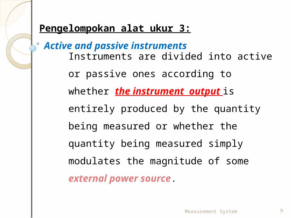
Pengelompokan alat ukur 3: Active and passive instruments
Instruments are divided into active or passive ones according to whether the instrument output is entirely produced by the quantity being measured or whether the quantity being measured simply modulates the magnitude of some external power source.
Measurement System 10
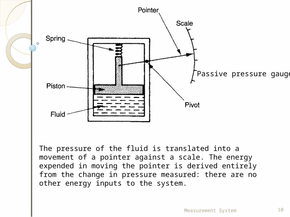
Passive pressure gauge.
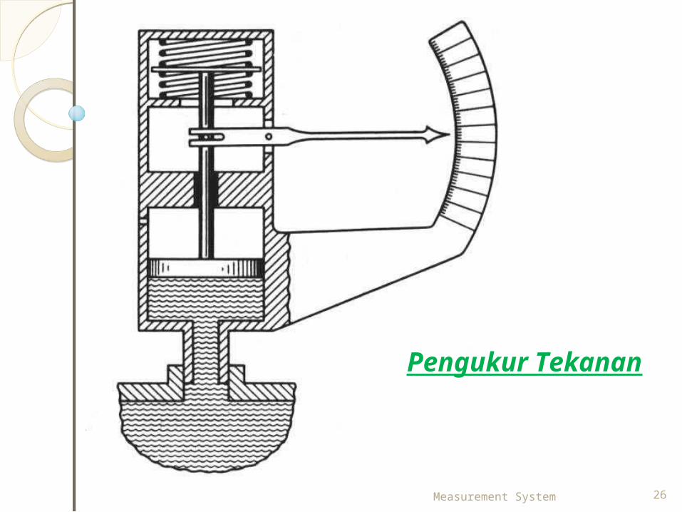
The pressure of the fluid is translated into a movement of a pointer against a scale. The energy expended in moving the pointer is derived entirely from the change in pressure measured: there are no other energy inputs to the system.
Measurement System 11
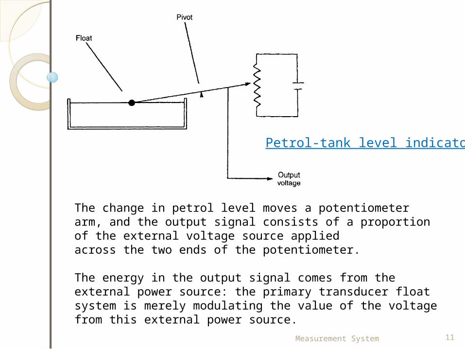
Petrol-tank level indicator.
The change in petrol level moves a potentiometer arm, and the output signal consists of a proportion of the external voltage source appliedacross the two ends of the potentiometer.
The energy in the output signal comes from the external power source: the primary transducer float system is merely modulating the value of the voltage from this external power source.
Measurement System 12
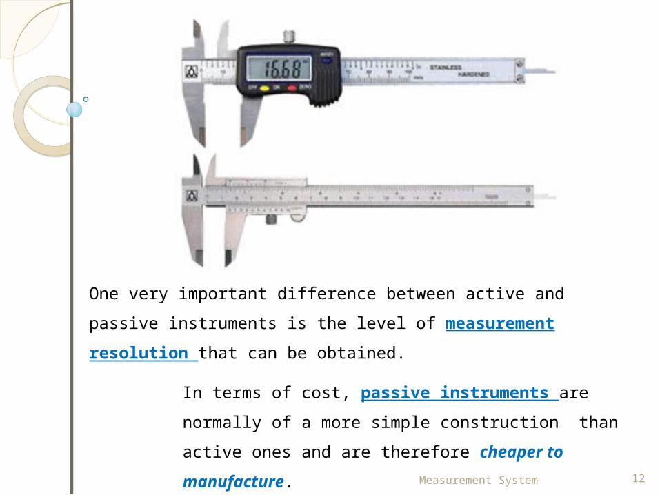
One very important difference between active and passive instruments is the level of measurement resolution that can be obtained.
In terms of cost, passive instruments are normally of a more simple construction than active ones and are therefore cheaper to manufacture.
Measurement System 13
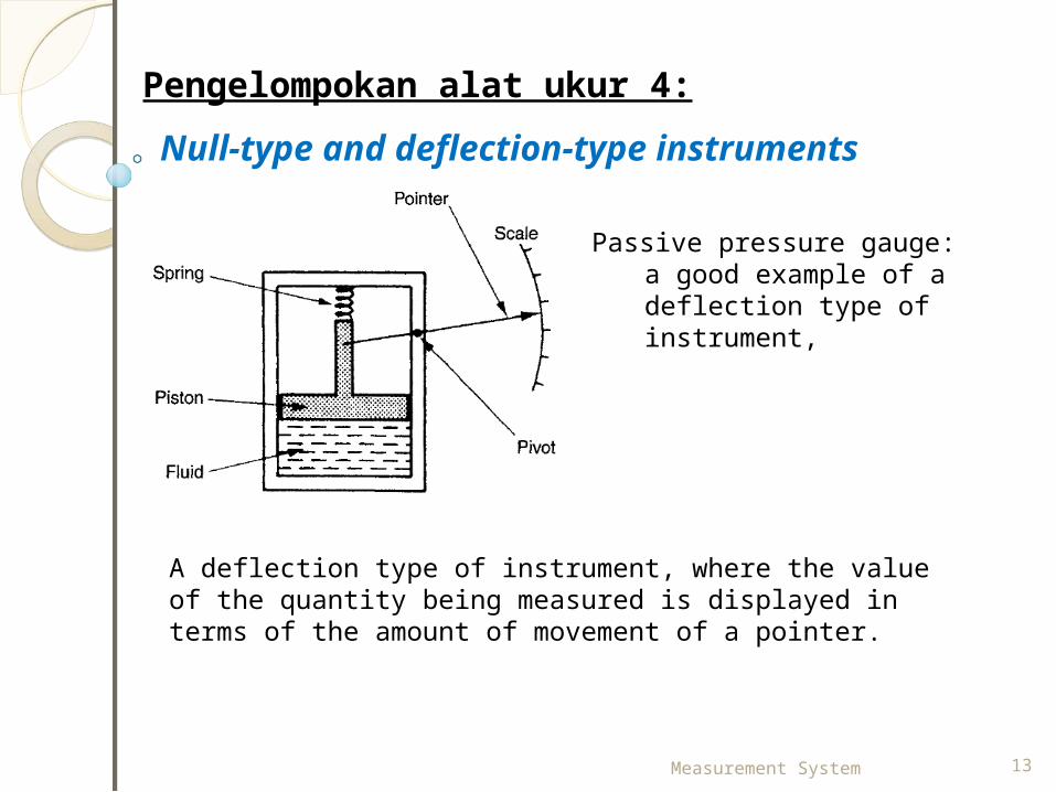
Pengelompokan alat ukur 4: Null-type and deflection-type instruments
Passive pressure gauge:a good example of a deflection type of instrument,
A deflection type of instrument, where the value of the quantity being measured is displayed in terms of the amount of movement of a pointer.

Measurement System 14
Deadweight pressure gauge:a null-type instrument.
Weights are put on top of the piston until the downward force balances the fluid pressure.
Weights are added until the piston reaches a datum level, known as the null point.
Pressure measurement is made in terms of the value of the weights needed to reach this null position.
Measurement System 15
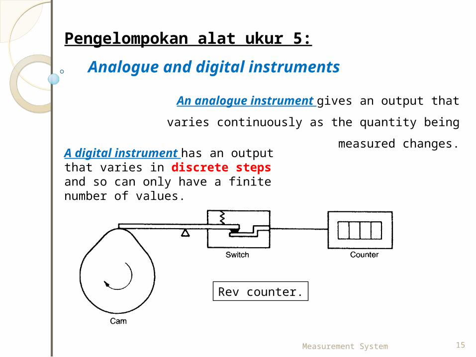
Pengelompokan alat ukur 5:Analogue and digital instruments
An analogue instrument gives an output that varies continuously as the quantity being
measured changes.A digital instrument has an output that varies in discrete steps and so can only have a finite number of values.
Rev counter.
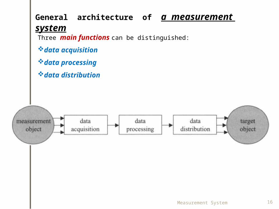
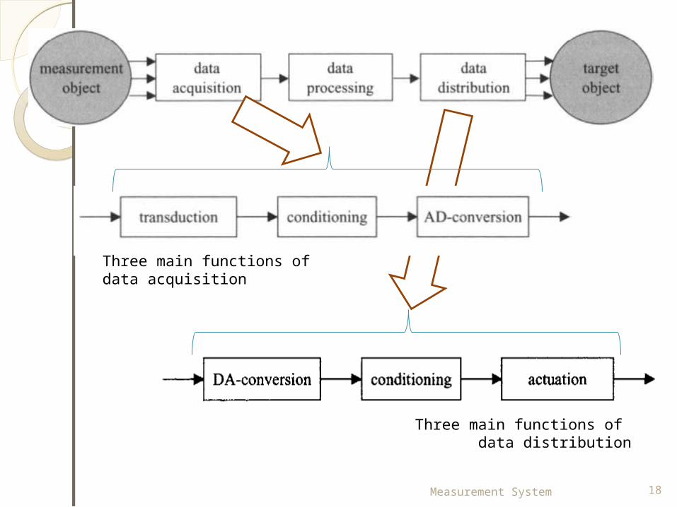
General architecture of a measurement systemThree main functions can be distinguished: data acquisitiondata processing data distribution
Measurement System 16
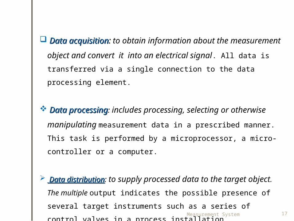
Data acquisitionData acquisition:: to obtain information about the measurement object and convert it into an electrical signal. All data is transferred via a single connection to the data processing element.
Data processingData processing: includes processing, selecting or otherwise manipulating measurement data in a prescribed manner. This task is performed by a microprocessor, a micro-controller or a computer.
Data distributionData distribution: to supply processed data to the target object. The multiple output indicates the possible presence of several target instruments such as a series of control valves in a process installation.Measurement System 17
Measurement System 18
Three main functions of data acquisition
Three main functions of data distribution
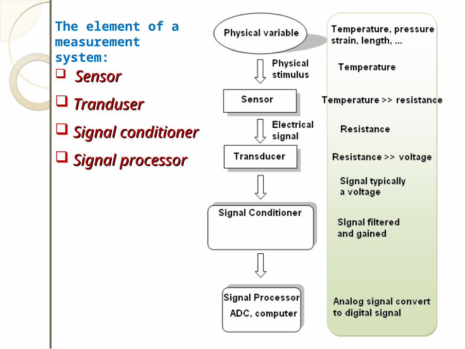
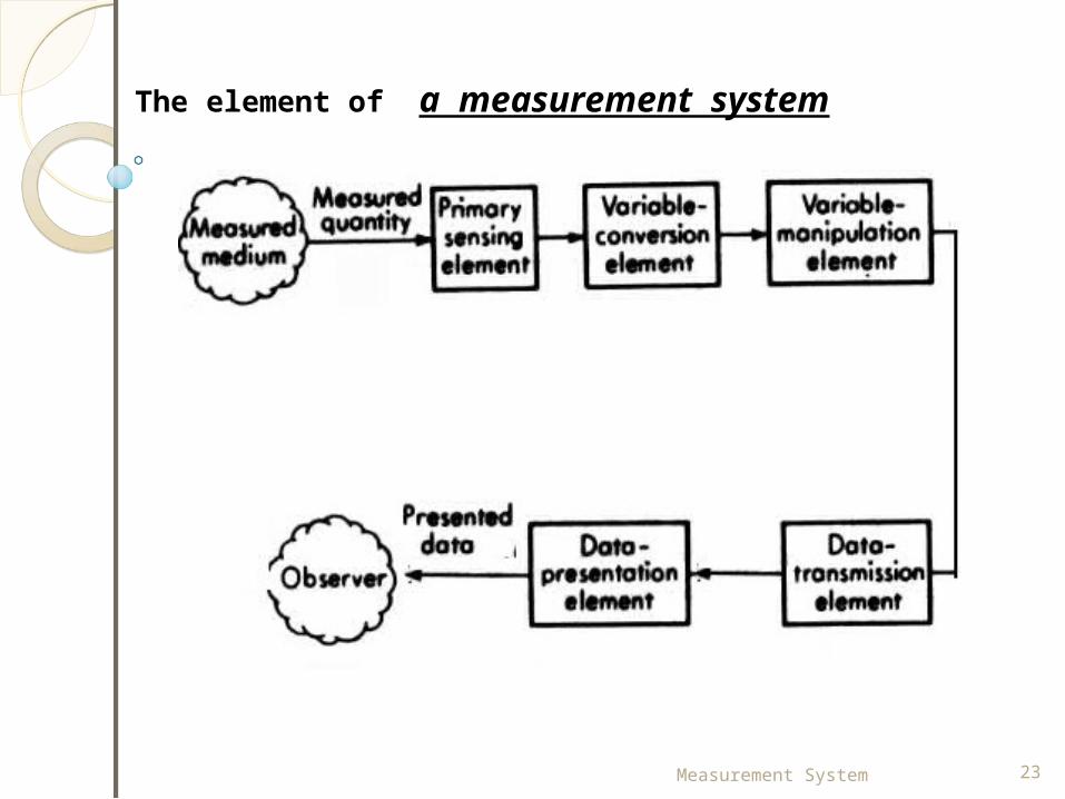
The element of a measurement system: SensorSensor TranduserTranduser Signal conditionerSignal conditioner Signal processorSignal processor
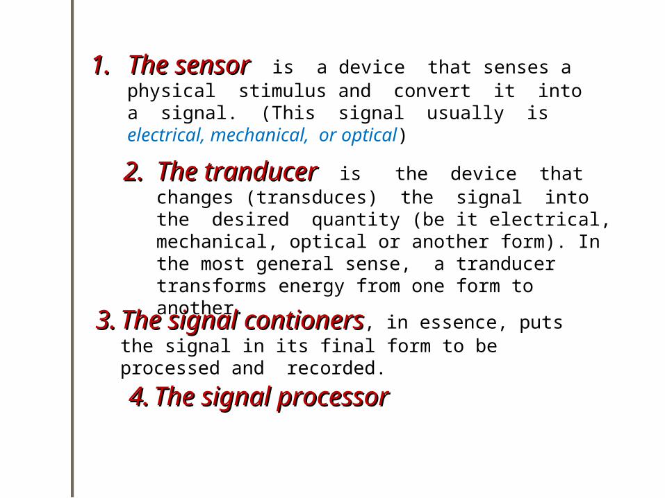
1.1. The sensorThe sensor is a device that senses a physical stimulus and convert it into a signal. (This signal usually is electrical, mechanical, or optical)
2.2. The tranducerThe tranducer is the device that changes (transduces) the signal into the desired quantity (be it electrical, mechanical, optical or another form). In the most general sense, a tranducer transforms energy from one form to another.3.3. The signal contionersThe signal contioners, in essence, puts
the signal in its final form to be processed and recorded.4.4. The signal processor The signal processor
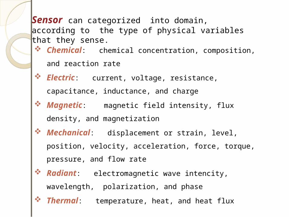
Sensor can categorized into domain, according to the type of physical variables that they sense. Chemical: chemical concentration, composition,
and reaction rate Electric: current, voltage, resistance,
capacitance, inductance, and charge Magnetic: magnetic field intensity, flux
density, and magnetization Mechanical: displacement or strain, level,
position, velocity, acceleration, force, torque, pressure, and flow rate
Radiant: electromagnetic wave intencity, wavelength, polarization, and phase
Thermal: temperature, heat, and heat flux
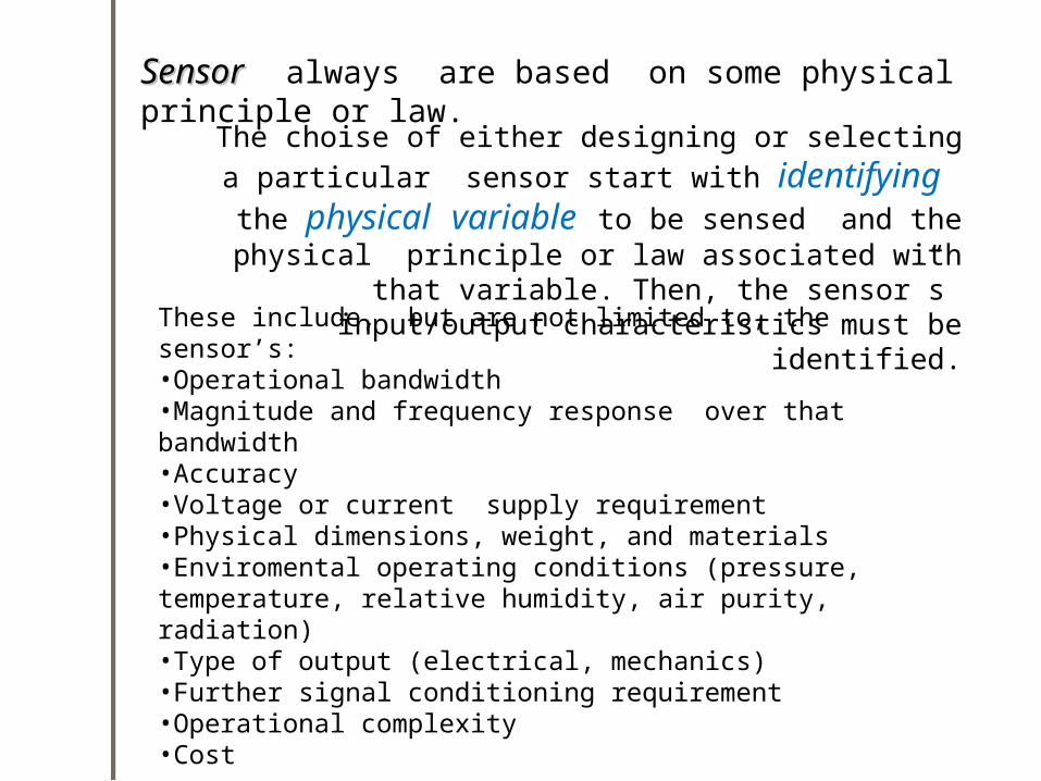
SensorSensor always are based on some physical principle or law.
These include, but are not limited to, the sensor’s:•Operational bandwidth•Magnitude and frequency response over that bandwidth•Accuracy•Voltage or current supply requirement•Physical dimensions, weight, and materials•Enviromental operating conditions (pressure, temperature, relative humidity, air purity, radiation)•Type of output (electrical, mechanics)•Further signal conditioning requirement•Operational complexity•Cost
The choise of either designing or selecting a particular sensor start with identifying the physical variable to be sensed and the physical principle or law associated with
that variable. Then, the sensor”s input/output characteristics must be
identified.
Measurement System 23
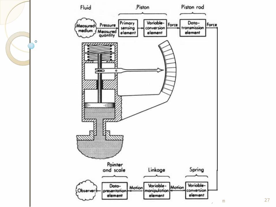
The element of a measurement system
Measurement System 24
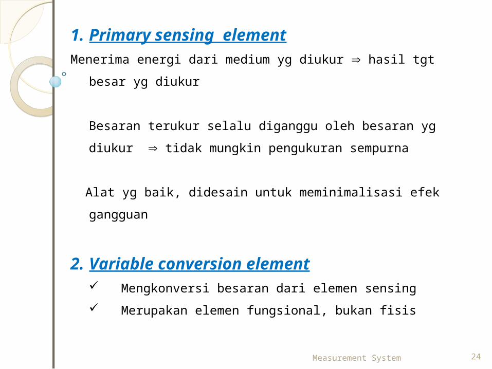
1. Primary sensing elementMenerima energi dari medium yg diukur hasil tgt
besar yg diukur
Besaran terukur selalu diganggu oleh besaran yg diukur tidak mungkin pengukuran sempurna
Alat yg baik, didesain untuk meminimalisasi efek
gangguan
2. Variable conversion element Mengkonversi besaran dari elemen sensing Merupakan elemen fungsional, bukan fisis
Measurement System 25
3. Variable Manipulation ElementMemanipulasi variabel dari elemen sebelumnyaContoh : sinyal yg lemah diperkuat
4. Data Transmission Element
5. Data Presentation Element
Measurement System 26
Pengukur Tekanan
Measurement System 27
Calibration and ResponseCalibration and Response
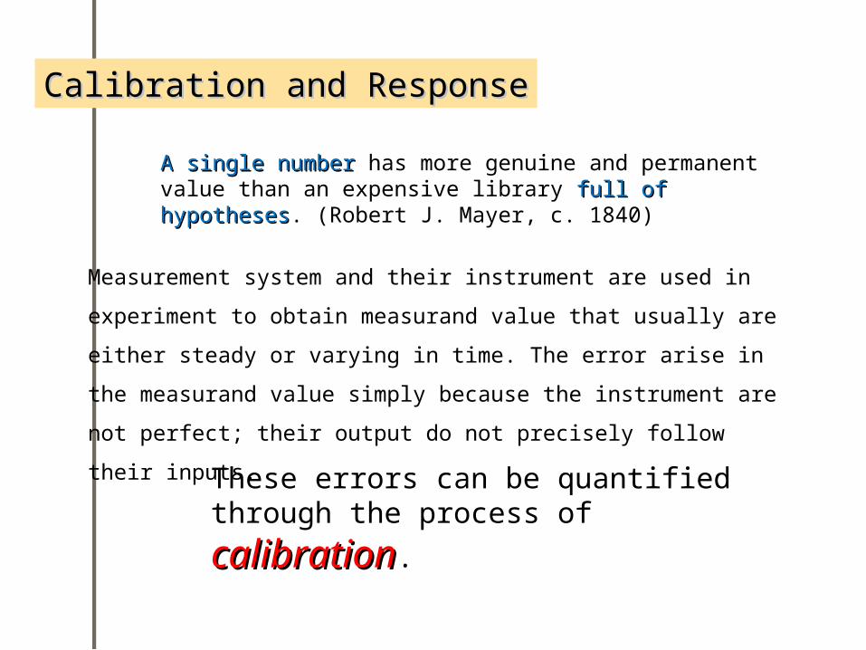
A single numberA single number has more genuine and permanent value than an expensive library full of full of hypotheseshypotheses. (Robert J. Mayer, c. 1840)
Measurement system and their instrument are used in experiment to obtain measurand value that usually are either steady or varying in time. The error arise in the measurand value simply because the instrument are not perfect; their output do not precisely follow their inputs.These errors can be quantified
through the process of calibrationcalibration.
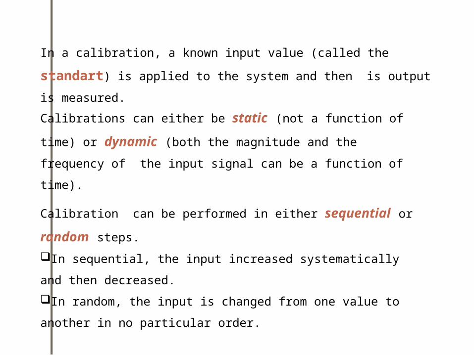
In a calibration, a known input value (called the standart) is applied to the system and then is output is measured.Calibrations can either be static (not a function of time) or dynamic (both the magnitude and the frequency of the input signal can be a function of time).
Calibration can be performed in either sequential or random steps.In sequential, the input increased systematically and then decreased. In random, the input is changed from one value to another in no particular order.
Measurement System 30
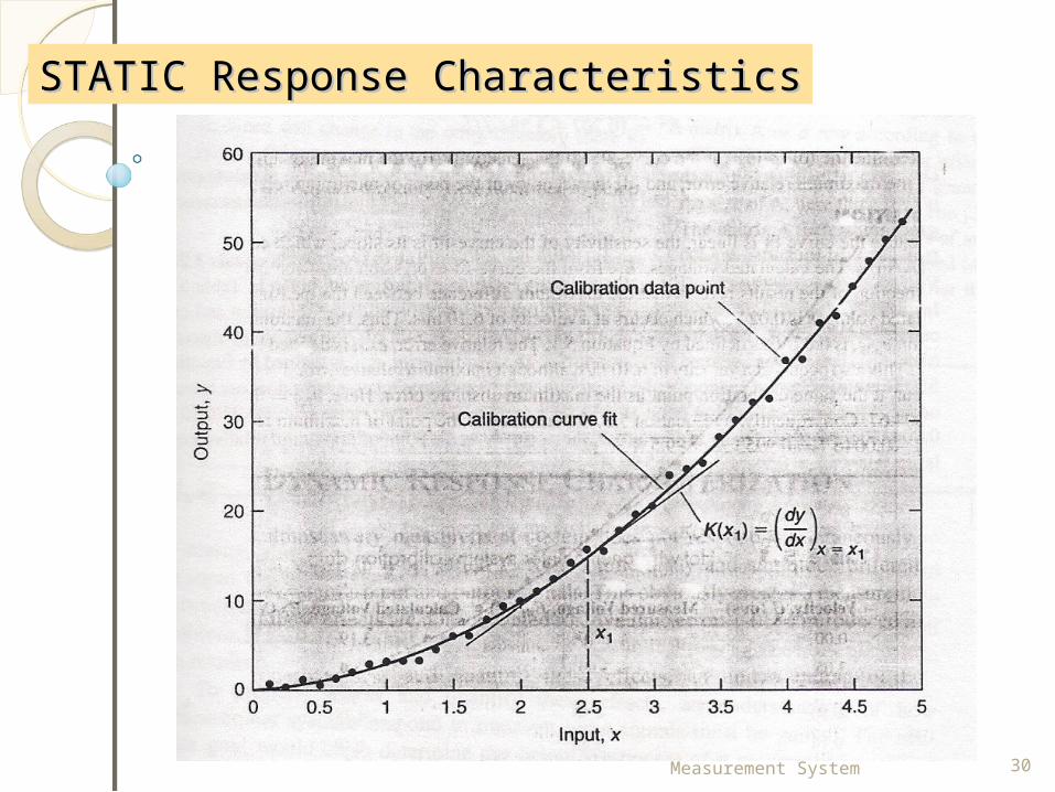
STATIC Response CharacteristicsSTATIC Response Characteristics
Measurement System 31
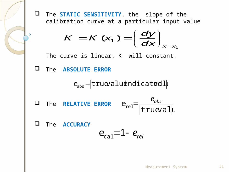
The STATIC SENSITIVITY, the slope of the calibration curve at a particular input value
The curve is linear, K will constant.
The ABSOLUTE ERROR
The RELATIVE ERROR
The ACCURACY
1
)( 1xxdx
dyxKK
valueindicated - valuetrue eabs
valuetrueerel abse
rele1ecal
Measurement System 32
1. Accuracy and inaccuracy (measurement uncertainty)
The accuracy of an instrument is a measure of how close the output reading of the instrument is to the correct value.
Inaccuracy is the extent to which a reading might be wrong, and is often quoted as a percentage of the full-scale (f.s.) reading of an instrument.
If, for example, a pressure gauge of range 0-10 bar has a quoted inaccuracy of ±1.0% f.s. (± 1% of full-scale reading), then the maximum error to be expected in any reading is 0.1 bar. This means that when the instrument is reading 1.0 bar, the possible error is 10% of this value.
The term measurement uncertainty is frequently used in place of inaccuracy.
Measurement System 33
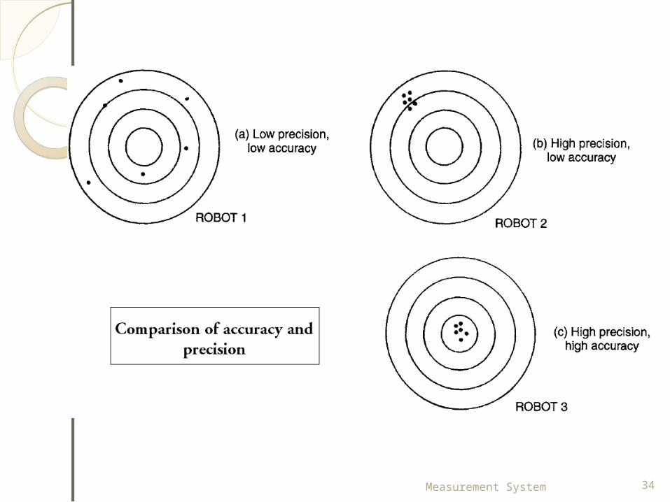
2. Precision/repeatability/reproducibilityPrecision is a term that describes an instrument's degree of freedom from random errors.
If a large number of readings are taken of the same quantity by a high precision instrument, then the spread of readings will be very small.
Repeatability describes the closeness of output readings when the same input is applied repetitively over a short period of time, with the same measurement conditions, same instrument and observer, same location and same conditions of use maintained throughout.
Reproducibility describes the closeness of output readings for the same input when there are changes in the method of measurement, observer, measuring instrument, location, conditions of use and time of measurement.
Measurement System 34
Measurement System 35
3. Tolerance
Tolerance is a term that is closely related to accuracy and defines the maximum error that is to be expected in some value.
The electric circuit components such as resistors have tolerances of perhaps 5%. One resistor chosen at random from a batch having a nominal value 1000 and tolerance 5% might have an actual value anywhere between 950 and 1050 .
4. Range or span
The range or span of an instrument defines the minimum and maximum values of a quantity that the instrument is designed to measure.
Measurement System 36
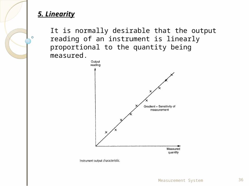
5. Linearity
It is normally desirable that the output reading of an instrument is linearly proportional to the quantity being measured.
Measurement System 37
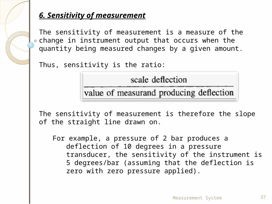
6. Sensitivity of measurement
The sensitivity of measurement is a measure of the change in instrument output that occurs when the quantity being measured changes by a given amount.
Thus, sensitivity is the ratio:
The sensitivity of measurement is therefore the slope of the straight line drawn on.
For example, a pressure of 2 bar produces a deflection of 10 degrees in a pressure transducer, the sensitivity of the instrument is 5 degrees/bar (assuming that the deflection is zero with zero pressure applied).
Measurement System 38
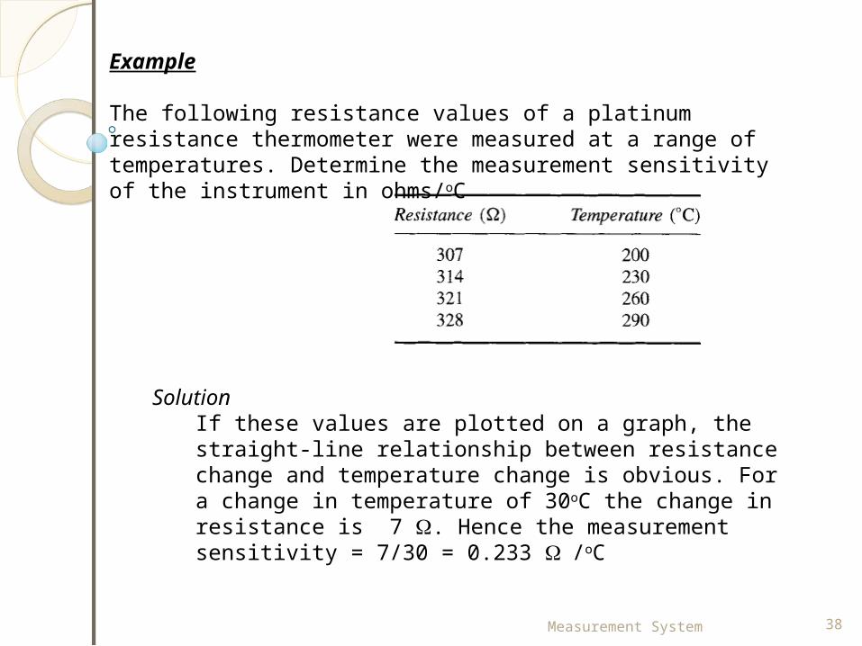
Example
The following resistance values of a platinum resistance thermometer were measured at a range of temperatures. Determine the measurement sensitivity of the instrument in ohms/oC
SolutionIf these values are plotted on a graph, the straight-line relationship between resistance change and temperature change is obvious. For a change in temperature of 30oC the change in resistance is 7 . Hence the measurement sensitivity = 7/30 = 0.233 /oC

Measurement System 39
7. Threshold
This minimum level of input is known as the threshold of the instrument.
As an illustration, a car speedometer typically has a threshold of about 15 km/h. This means that, if the vehicle starts from rest and accelerates, no output reading is observed on the speedometer until the speed reaches 15 km/h.
8. Resolution
When an instrument is showing a particular output reading, there is a lower limit on the magnitude of the change in the input measured quantity that produces an observable change in the instrument output.
Using a car speedometer as an example again, this has subdivisions of typically 20 km/h. This means that when the needle is between the scale markings,we cannot estimate speed more accurately than to the nearest 5 km/h. This figure of 5 km/h thus represents the resolution of the instrument.
Measurement System 40
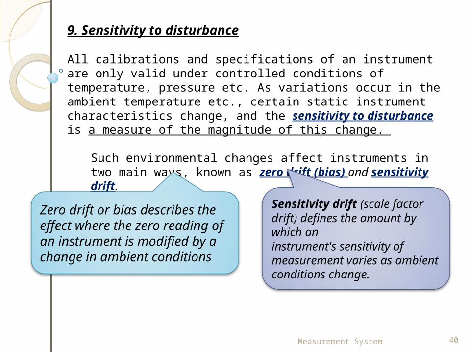
9. Sensitivity to disturbance
All calibrations and specifications of an instrument are only valid under controlled conditions of temperature, pressure etc. As variations occur in the ambient temperature etc., certain static instrument characteristics change, and the sensitivity to disturbance is a measure of the magnitude of this change.
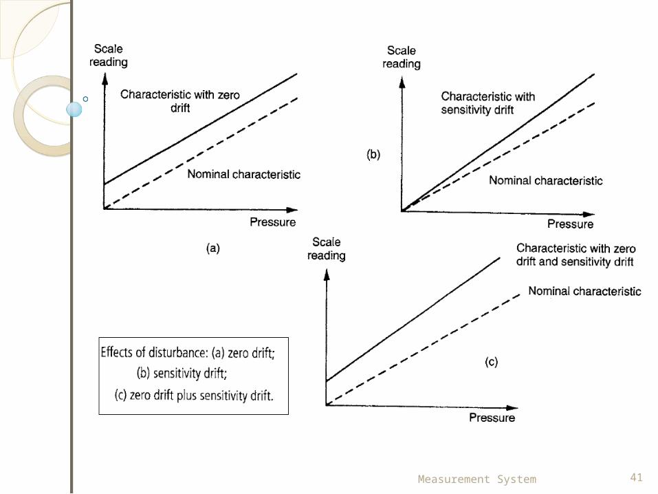
Such environmental changes affect instruments in two main ways, known as zero drift (bias) and sensitivity drift.
Zero drift or bias describes the effect where the zero reading of an instrument is modified by a change in ambient conditions
Sensitivity drift (scale factor drift) defines the amount by which aninstrument's sensitivity of measurement varies as ambient conditions change.
Measurement System 41
Measurement System 42
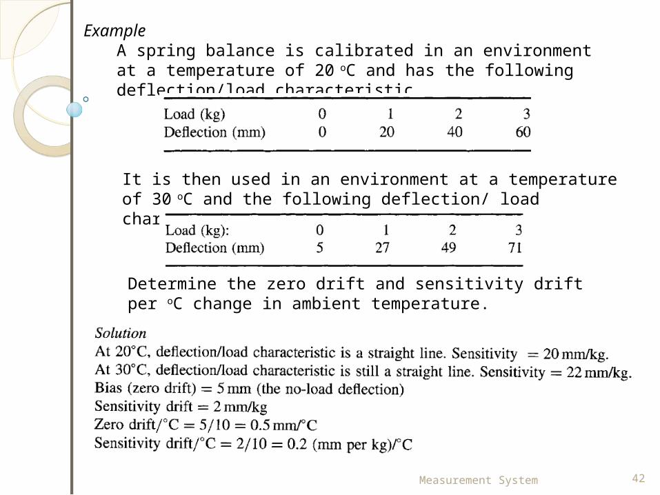
Example A spring balance is calibrated in an environment at a temperature of 20 oC and has the following deflection/load characteristic.
It is then used in an environment at a temperature of 30 oC and the following deflection/ load characteristic is measured.
Determine the zero drift and sensitivity drift per oC change in ambient temperature.
Measurement System 43
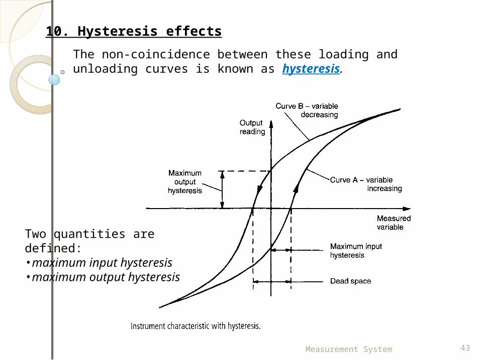
10. Hysteresis effectsThe non-coincidence between these loading and unloading curves is known as hysteresis.
Two quantities are defined: •maximum input hysteresis •maximum output hysteresis
Measurement System 44
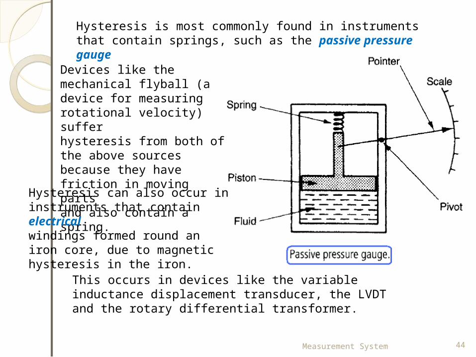
Hysteresis is most commonly found in instruments that contain springs, such as the passive pressure gauge
Devices like the mechanical flyball (a device for measuring rotational velocity) sufferhysteresis from both of the above sources because they have friction in moving partsand also contain a spring.
Hysteresis can also occur in instruments that contain electricalwindings formed round an iron core, due to magnetic hysteresis in the iron.
This occurs in devices like the variable inductance displacement transducer, the LVDT and the rotary differential transformer.
Measurement System 45
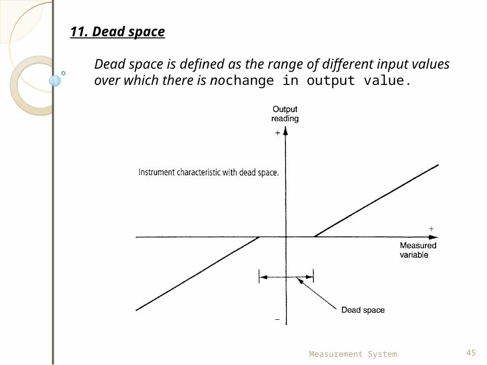
11. Dead space
Dead space is defined as the range of different input values over which there is nochange in output value.
Measurement System 46
DYNAMIC CharacteristicsDYNAMIC Characteristics
The dynamic characteristics of a measuring instrument describe its behaviour between the time a measured quantity changes value and the time when the instrument output attains a steady value in response.
As with static characteristics, any values for dynamic characteristics quoted in instrument data sheets only apply when the instrument is used under specified environmental conditions. Outside these calibration conditions, some variation in the dynamic parameters can be expected.
Measurement System 47
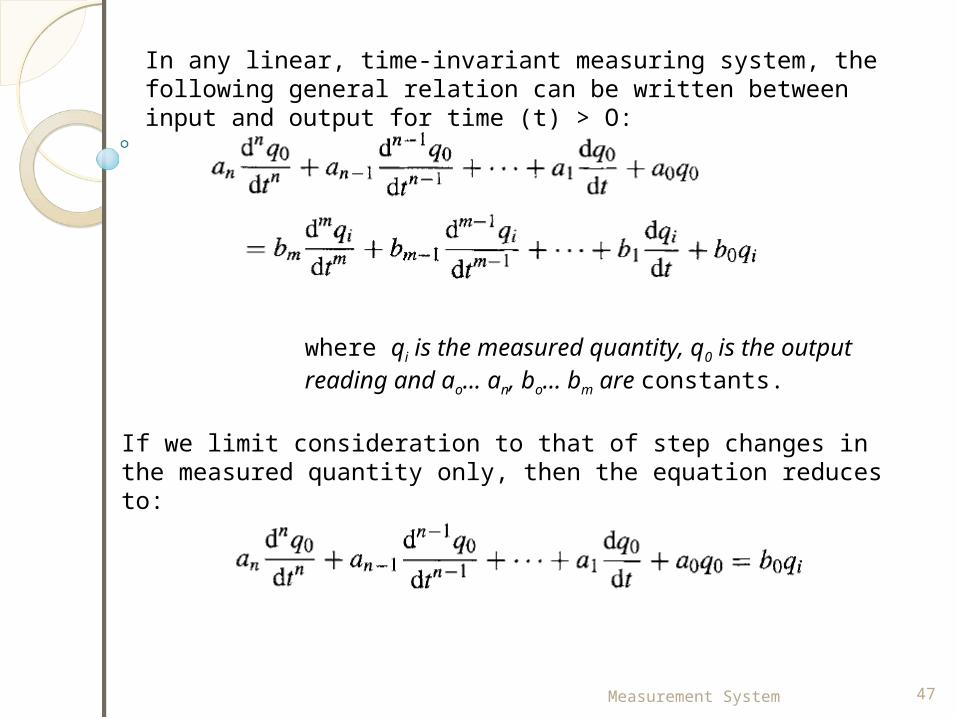
In any linear, time-invariant measuring system, the following general relation can be written between input and output for time (t) > O:
where qi is the measured quantity, q0 is the output reading and ao... an, bo... bm are constants.
If we limit consideration to that of step changes in the measured quantity only, then the equation reduces to:
Measurement System 48
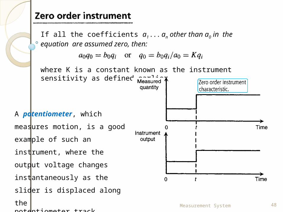
If all the coefficients a1 . . . an other than a0 in the equation are assumed zero, then:
where K is a constant known as the instrument sensitivity as defined earlier.
A potentiometer, which measures motion, is a good example of such an instrument, where the output voltage changes instantaneously as the slider is displaced along thepotentiometer track.
Measurement System 49
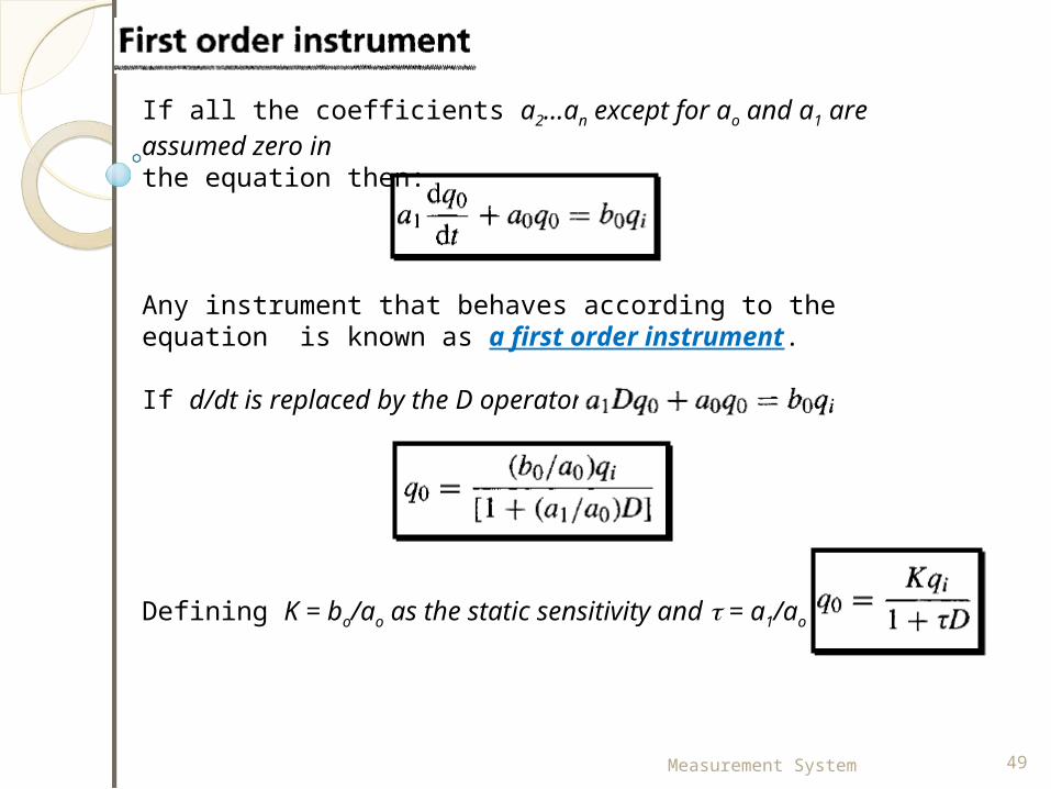
If all the coefficients a2...an except for ao and a1 are assumed zero inthe equation then:
Any instrument that behaves according to the equation is known as a first order instrument.
If d/dt is replaced by the D operator:
Defining K = bo/ao as the static sensitivity and = a1/ao
Measurement System 50
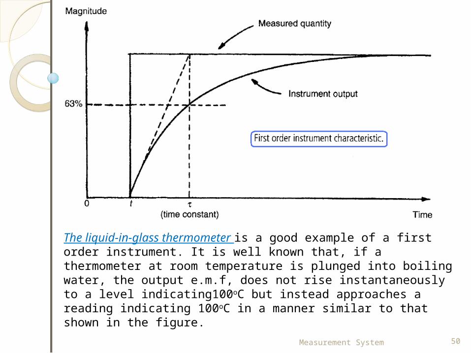
The liquid-in-glass thermometer is a good example of a first order instrument. It is well known that, if a thermometer at room temperature is plunged into boiling water, the output e.m.f, does not rise instantaneously to a level indicating100oC but instead approaches a reading indicating 100oC in a manner similar to that shown in the figure.
Measurement System 51
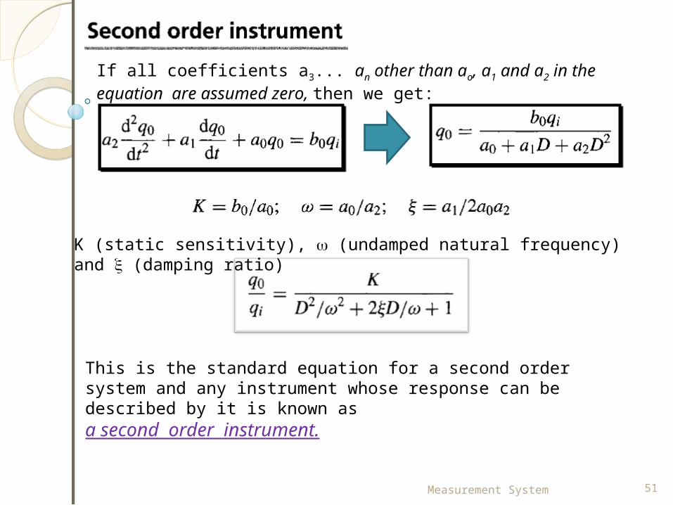
If all coefficients a3... an other than ao, a1 and a2 in the equation are assumed zero, then we get:
K (static sensitivity), (undamped natural frequency) and (damping ratio)
This is the standard equation for a second order system and any instrument whose response can be described by it is known as a second order instrument.
Measurement System 52
Measurement System 53
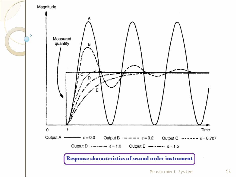
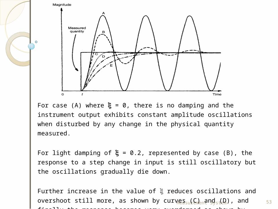
For case (A) where = 0, there is no damping and the instrument output exhibits constant amplitude oscillations when disturbed by any change in the physical quantity measured.
For light damping of = 0.2, represented by case (B), the response to a step change in input is still oscillatory but the oscillations gradually die down.
Further increase in the value of reduces oscillations and overshoot still more, as shown by curves (C) and (D), and finally the response becomes very overdamped as shown by curve (E) where the output reading creepsup slowly towards the correct reading.
Measurement System 54
Clearly, the extreme response curves (A) and (E) are grossly unsuitable for any measuring instrument. If an instrument were to be only ever subjected to step inputs, then the design strategy would be to aim towards a damping ratio of 0.707, which gives the critically damped response (C).
As the form of the input variable changes, so the best value for varies, and choice of becomes one of compromise between those values that are best for each type of input variable behaviour anticipated. Commercial second order instruments, of which the accelerometer is a common example, are generally designed to have a damping ratio () somewhere in the range of 0.6-0.8.
Measurement System 55
•Directly / indirectly.•Monitoring/kontrol/ Analisis•Absolut/sekunder•Active and passive •Null-type and deflection-type•Analogue and digital instruments
Related Documents