MANUAL OF CONTRACT DOCUMENTS FOR HIGHWAY WORKS VOLUME 1 SPECIFICATION FOR HIGHWAY WORKS Amendment – July 2019 1 SERIES 900 ROAD PAVEMENTS – BITUMINOUS BOUND MATERIALS Contents Clause Title Page 900 (05/18) General 3 901 (05/18) Bituminous Mixtures 3 902 (05/18) Reclaimed Asphalt 5 903 (05/18) Placing and Compaction of Bituminous Mixtures 6 904 (05/18) Hot Rolled Asphalt Base 9 905 (05/18) Hot Rolled Asphalt Binder Course (Recipe Mixtures) 9 906 (05/18) Dense Base and Binder Course Asphalt Concrete with Paving Grade Bitumen (Recipe Mixtures) 9 907 (05/18) Regulating Course 10 908 (05/18) Not Used 10 909 (05/18) 6 mm Dense Asphalt Concrete Surface Course 10 910 (05/18) Hot Rolled Asphalt Surface Course (Recipe Mixtures) 10 #911 (05/18) Hot Rolled Asphalt Surface Course (Design Mixtures) 11 912 (05/18) Close Graded Asphalt Concrete Surface Course 12 913 (05/18) Not Used 12 914 (05/18) Fine Graded Asphalt Concrete Surface Course 12 915 (05/18) Coated Chippings for Application to Hot Rolled Asphalt Surfacings 12 916 & 917 (05/18) Not Used 12 918 (05/18) Slurry Surfacing Incorporating Microsurfacing 12 919 (05/18) Surface Dressing: Recipe Specification 16 920 (05/18) Bond Coats, Tack Coats and Other Bituminous Sprays 19 921 (05/18) Surface Macrotexture of Bituminous Surface Courses 20 1 Clause Title Page 922 (05/18) Surface Dressing: Design, Application and End Product Performance 22 923 (05/18) Cold Applied Ultra-Thin Surfacing 24 924 (05/18) High Friction Surfaces 27 925 (05/18) Testing of Bituminous Mixtures 28 926 (05/18) In Situ Recycling: The Repave Process 28 927 & 928 (05/18) Not Used 28 929 (05/18) Dense Base and Binder Course Asphalt Concrete (Design Mixtures) 28 930 (05/18) EME2 Base and Binder Course Asphalt Concrete 30 931 to 935 (07/19) Not Used 33 936 (07/19) Geosynthetics and Steel Meshes: Installation and End Product Performance 33 937 (05/18) Stone Mastic Asphalt (SMA) Binder Course and Regulating Course 36 938 (05/18) Porous Asphalt 37 939 to 941 (05/18) Not Used 38 #942 (05/18) Thin Surface Course Systems 38 943 (05/18) Hot Rolled Asphalt Surface Course and Binder Course (Performance- Related Design Mixtures) 44 944 (05/18) Not Used 45 945 (05/18) Weather Conditions for Laying of Bituminous Mixtures 45 946 (05/18) Local Repairs 46 947 (05/18) In Situ Cold Recycled Bound Material 48 948 (05/18) Ex Situ Cold Recycled Bound Material 56 949 (05/18) Not Used 61 950 (05/18) Surface Preservation Systems 61

Welcome message from author
This document is posted to help you gain knowledge. Please leave a comment to let me know what you think about it! Share it to your friends and learn new things together.
Transcript
MANUAL OF CONTRACT DOCUMENTS FOR HIGHWAY WORKS VOLUME 1 SPECIFICATION FOR HIGHWAY WORKS
Amendment – July 2019 1
SERIES 900 ROAD PAVEMENTS – BITUMINOUS BOUND MATERIALS
Contents
Clause Title Page
900 (05/18) General 3
901 (05/18) Bituminous Mixtures 3
902 (05/18) Reclaimed Asphalt 5
903 (05/18) Placing and Compaction of Bituminous Mixtures 6
904 (05/18) Hot Rolled Asphalt Base 9
905 (05/18) Hot Rolled Asphalt Binder Course (Recipe Mixtures) 9
906 (05/18) Dense Base and Binder Course Asphalt Concrete with Paving Grade Bitumen (Recipe Mixtures) 9
907 (05/18) Regulating Course 10
908 (05/18) Not Used 10
909 (05/18) 6 mm Dense Asphalt Concrete Surface Course 10
910 (05/18) Hot Rolled Asphalt Surface Course (Recipe Mixtures) 10
#911 (05/18) Hot Rolled Asphalt Surface Course (Design Mixtures) 11
912 (05/18) Close Graded Asphalt Concrete Surface Course 12
913 (05/18) Not Used 12
914 (05/18) Fine Graded Asphalt Concrete Surface Course 12
915 (05/18) Coated Chippings for Application to Hot Rolled Asphalt Surfacings 12
916 & 917 (05/18) Not Used 12
918 (05/18) Slurry Surfacing Incorporating Microsurfacing 12
919 (05/18) Surface Dressing: Recipe Specification� 16
920 (05/18) Bond Coats, Tack Coats and Other Bituminous Sprays 19
921 (05/18) Surface Macrotexture of Bituminous Surface Courses 20
1
Clause Title Page
922 (05/18) Surface Dressing: Design, Application and End Product Performance 22
923 (05/18) Cold Applied Ultra-Thin Surfacing 24
924 (05/18) High Friction Surfaces 27
925 (05/18) Testing of Bituminous Mixtures 28
926 (05/18) In Situ Recycling: The Repave Process 28
927 & 928 (05/18) Not Used 28
929 (05/18) Dense Base and Binder Course Asphalt Concrete (Design Mixtures) 28
930 (05/18) EME2 Base and Binder Course Asphalt Concrete 30
931 to 935 (07/19) Not Used 33
936 (07/19) Geosynthetics and Steel Meshes: Installation and End Product Performance 33
937 (05/18) Stone Mastic Asphalt (SMA) Binder Course and Regulating Course 36
938 (05/18) Porous Asphalt 37
939 to 941 (05/18) Not Used 38
#942 (05/18) Thin Surface Course Systems 38
943 (05/18) Hot Rolled Asphalt Surface Course and Binder Course (Performance-Related Design Mixtures) 44
944 (05/18) Not Used 45
945 (05/18) Weather Conditions for Laying of Bituminous Mixtures 45
946 (05/18) Local Repairs 46
947 (05/18) In Situ Cold Recycled Bound Material 48
948 (05/18) Ex Situ Cold Recycled Bound Material 56
949 (05/18) Not Used 61
950 (05/18) Surface Preservation Systems 61
MANUAL OF CONTRACT DOCUMENTS FOR HIGHWAY WORKS VOLUME 1 SPECIFICATION FOR HIGHWAY WORKS
2Amendment – July 2019
Clause Title Page
951 (05/18) Torque Bond Test 62
952 & 953 (05/18) Not Used 63
954 (05/18) Method for Laboratory Determination of Interface Properties Using�the�Modified�Leutner�Shear�Test� 63
955 (05/18)�Ageing�Profile�Test�Using�a� Modified�Rolling�Thin�Film�Oven�Test�(MRTFOT) 67
956 & 957 (05/18) Not Used 77
958 (05/18)�Modified�Binder�Storage� Stability Test 77
NATIONAL ALTERATIONS OF THE OVERSEEING ORGANISATIONS OF SCOTLAND, WALES AND NORTHERN IRELANDClause Title Page
911TS/WG (05/18) Hot Rolled Asphalt Surface Course (Design Mixtures) 79F
942TS (05/18) Stone Mastic Asphalt Surface Course (TS2010) 79F
#� denotes�a�Clause�or�Sample�Contract�Specific�Appendix�which�has�a�substitute�National�Clause�or�Sample�Contract�Specific�Appendix for one or more of the Overseeing Organisations of Scotland, Wales or Northern Ireland.
Volume 1 Series 900 Specification for Highway Works Road Pavements – Bituminous Bound Materials
Amendment – May 2018 3
ROAD PAVEMENTS – BITUMINOUS BOUND MATERIALS
900 (05/18) General
1 (05/18)�This�Series�is�part�of�the�Specification�for�Highway�Works.�Whilst�this�Series�is�particularly�relevant�to�the subject matter in its title it must be read in conjunction with the general requirements in Series 000 and 100 and with�all�other�Series�relevant�to�the�specification�for�the�particular�works�to�be�undertaken.
901 (05/18) Bituminous Pavement Mixtures
(05/18) General
1 (05/18) This Clause gives general requirements for the properties of the aggregates and bitumen used in plant-produced bituminous mixtures. These requirements apply to all plant produced bituminous mixtures unless otherwise�specified�in�contract�specific�Appendix�7/1�or�where�other�requirements�are�given�in�specific�Clauses�in�this Series.
2 (05/18) Bituminous mixtures shall be laid by organisations registered to and operating in compliance with the ‘Sector Scheme 16 for the Laying of Asphalt Mixes’ listed in Appendix A. All mixtures supplied in accordance with BS EN 13108 shall be CE marked and the Contractor shall submit the declaration of performance which shall demonstrate�that�the�mixture�provides�the�performance�required�by�the�specification.
(05/18) Aggregates for Bituminous Mixtures
3 (05/18)�Natural,�recycled�unbound�and�manufactured�(artificial)�aggregates�shall�be�clean,�hard�and�durable�and�shall comply with BS EN 13043:2002 and be CE marked and have a declared performance which demonstrates that the�aggregate�meets�the�requirements�of�the�specification.�Where�recycled�coarse�aggregate�or�recycled�concrete�aggregate is used in bituminous mixtures, it shall have been tested in accordance with Clause 710 and the content of other materials (Class X) including wood, plastic and metal shall not exceed 1% by mass. Reclaimed asphalt shall comply with Clause 902.
4 (05/18) The use of aggregate derived as a by-product during the extraction of china clay is permitted. It shall comply with the requirements of this Clause, BS EN 13043:2002 and the examples of the relevant annex of BSI PD 6691.
5 (05/18) The use of crushed slate aggregate is permitted in base and binder course layers. It shall comply with the requirements of this Clause, BS EN 13043:2002 and the examples of the relevant annex of BSI PD 6691, except for the�flakiness�category,�which�shall�be�subject�to�prior�approval�by�the�Overseeing�Organisation.�Mixtures�of�crushed�slate aggregate with coarse aggregate of a different geological type shall not be permitted.
(05/18) Resistance to Fragmentation (Hardness)
6 (05/18)�Unless�otherwise�stated�in�contract�specific�Appendix�7/1�the�coarse�aggregates�for�bituminous�mixtures�shall meet the following criteria:
(i)� the�resistance�to�fragmentation�category�of�the�coarse�aggregate�as�defined�in�clause�4.2.2�of�BS EN 13043:2002 shall be LA30 or better for natural aggregates and LA50 or better for blast furnace slag;
or
(ii) crushed rock aggregate has a Los Angeles Value greater than 30 but less than 35, where evidence can be presented to the Overseeing Organisation of previous satisfactory use of the source in asphalt.
Volume 1 Series 900 Specification for Highway Works Road Pavements – Bituminous Bound Materials
4Amendment – July 2019
Natural�and�manufactured�(artificial)�aggregates�recovered�from�a�previous�use�in�an�unbound�form�shall�comply�with the requirements of this Clause.
(05/18) Resistance to Freezing and Thawing (Durability)
7 (05/18)�When�required�in�contract�specific�Appendix�1/5,�the�resistance�of�the�coarse�aggregate�to�freezing�and�thawing�shall�be�declared.�The�freezing�and�thawing�(soundness)�category,�as�defined�in�BS�EN�13043:2002,�clause 4.2.9.2, shall be MS25�unless�otherwise�specified�in�contract�specific�Appendix�7/1.�The�water�absorption�value of the coarse aggregate shall be determined in accordance with BS EN 13043:2002, clause 4.2.9.1. If the water absorption value of the coarse aggregate is greater than WA242, the soundness test shall be carried out on the material delivered to site. The requirements for water absorption do not apply to blast furnace slag aggregate.
(05/18) Cleanness
8 (05/18)�Unless�otherwise�specified�in�contract�specific�Appendix�7/1,�the�proportion�of�coarse�and�fine�aggregates�for�bituminous�mixtures�passing�the�0.063�mm�test�sieve�(fines�content)�shall�not�exceed�the�limits�stated in BSI PD 6691 Annex B, Annex C and Annex D, when tested in accordance with the washing and sieving method of BS EN 933-1.
(05/18) Resistance to Polishing and Surface Abrasion
9 (05/18)�When�specified�in�the�appropriate�Clause�or�contract�specific�Appendix�7/1,�the�aggregate�shall�conform�to the required declared PSV category in accordance with BS EN 13043:2002 clause 4.2.3 and BSI PD 6682-2 clause 4.3.2.
10 (05/18) The resistance to surface abrasion of coarse aggregate used in surface courses in accordance with BS EN 13043 clause 4.2.3 and BSI PD 6682-2 clause 3.3.3, shall conform to category AAV10 unless otherwise specified�in�the�appropriate�Clause�or�in�contract�specific�Appendix�7/1.
(05/18) Chemical Requirements
(05/18) Dicalcium Silicate Disintegration
11 (05/18) Air-cooled blast furnace slag aggregates shall be free from iron dicalcium silicate disintegration as defined�in�BS�EN�13043:2002,�clause�4.3.4.1.
(05/18) Iron Disintegration
12 (05/18)�Air-cooled�blast�furnace�slag�aggregates�shall�be�free�from�iron�disintegration�as�defined�in�BS EN 13043:2002, clause 4.3.4.2.
(05/18) Volume Stability
13 (05/18)�The�volume�stability�category�of�steel�slag�aggregates�as�defined�in�BS�EN�13043,�clause�4.3.4.3�shall�not exceed V10.
(05/18) Bitumen
14 (05/18) Paving grade bitumen shall comply with BS EN 12591.
15 (05/18)�Polymer�modified�bitumen�shall�comply�with�BS�EN�14023.
(05/18) Asphalt Durability
16 (05/18) The durability of adhesion in base and binder course mixtures designed in accordance with Clause 929 and to be used on trunk roads including motorways shall be determined by testing in accordance with BS EN 12697-45. The SATS Durability Index of the mix components shall be above 80%.
17 (05/18)�Mixtures�that�include�2%�hydrated�lime�filler�are�deemed�to�satisfy�this�requirement�and�SATS�testing�is�not�required.�Hydrated�lime�filler�shall�be�Ca�(OH)2 in the form of hydrated lime, type CL 90-S.

Volume 1 Series 900 Specification for Highway Works Road Pavements – Bituminous Bound Materials
Amendment – May 2018 5
902 (05/18) Reclaimed Asphalt
1 (05/18) The requirements of this clause apply to all bituminous mixtures containing reclaimed asphalt.
2 (05/18) Reclaimed asphalt may be used in the production of bituminous surface course, binder course, regulating�course�and�base.�Unless�otherwise�specified�in�contract�specific�Appendix�7/1,�the�use�of�reclaimed�asphalt shall be in accordance with:
(i)� Clause�942�for�surface�course�mixtures�specified�in�Clause�942;
(ii) BSI PD 6691, B.2.4.4 for Asphalt Concrete mixtures (macadams);
(iii) BSI PD 6691, C.2.3.4 for Hot Rolled Asphalt mixtures;
(iv) BSI PD 6691, D.2.2.3 for Stone Mastic Asphalt mixtures.
Other recycled materials shall only be used in bituminous mixtures with the approval of the Overseeing Organisation. The mixed material shall comply with the requirements of all the relevant Clauses in this Series.
(05/18) Reclaimed Feedstock
3 (05/18) All reclaimed material shall be pre-treated before use such that it is homogeneously mixed and the maximum�particle�size�does�not�exceed�32�mm.
(05/18) Properties of Binder
4 (05/18) The fresh bitumen added to the mixture shall not be more than two grades softer than the nominal grade for the mixture given in Table 12 of BSI PD 6691. Checks on the penetration of the binder recovered from the reclaimed asphalt, together with a calculation of the properties of the combined binder, shall be carried out in accordance with the relevant parts of BS EN 13108. When more than 10% of reclaimed asphalt is incorporated in a mixture, tests on binder recovered from the mixture shall be carried out following the example in BSI PD 6691 13.3.6.2. The results shall be within the limits set out in BSI PD 6691 13.3.6.2.
(05/18) Mixed materials containing more than 25% reclaimed asphalt
5 (05/18) When more than 25% of reclaimed asphalt is incorporated in a designed base or binder course mixture, cores taken to assess compliance with Clause 929.12 or Clause 930.14 shall also be tested for stiffness in accordance with BS EN 12697-26 (ITSM method 20°C). The frequency of testing shall be agreed with the Overseeing Organisation prior to the commencement of works and shall comply with the requirements of contract specific�Appendices�1/5�and�1/6.
6 (05/18) The stiffness of the mixture shall comply with the appropriate category from Table 9/1.
TABLE 9/1: (05/18) Stiffness Categories for Designed Base and Binder Course Mixtures Incorporating Greater than 25% Reclaimed Asphalt
Nominal binder grade of mixture Stiffness category (Smin)
10/20 550015/25 550030/45 280040/60 1800

Volume 1 Series 900 Specification for Highway Works Road Pavements – Bituminous Bound Materials
6Amendment – May 2018
903 (05/18) Placing and Compaction of Bituminous Mixtures
(05/18) General
1 (05/18) This Clause gives general requirements for the placing and compaction of bituminous mixtures, which are complementary and additional to the requirements of BS 594987. These requirements and the requirements of�BS�594987�apply�to�all�bituminous�mixtures,�unless�otherwise�specified�in�the�other�Clauses�in�this�Series�or�in�contract�specific�Appendix�7/1.
2 (05/18)�Bituminous�pavements�shall�be�constructed�using�the�materials�specified�in�contract�specific�Appendix 7/1 and shall be laid by contractors that are registered to the BS EN ISO 9001 ‘Sector Scheme 16 for the Laying of Asphalt Mixes’ listed in Appendix A.
3 (05/18) In order to exclude moisture from interfaces and ensure full interlayer bonding, the surface of all bituminous material shall be kept clean and uncontaminated. Unless agreed with the Overseeing Organisation, the only�traffic�permitted�to�run�on�the�surface�of�bituminous�material�to�be�overlaid�shall�be�that�engaged�in�laying�and compacting the next course or, where a binder course is to be blinded or surface dressed, that is engaged on such surface treatment. If any surface becomes contaminated, it shall be made good by cleaning and, if this proves impracticable,�by�rectification�in�compliance�with�Clause�702.
4 (05/18) Prior to placing bituminous material on any new or existing bound substrate, a bond coat or tack coat shall be applied in accordance with Clauses 920 or 942, as appropriate.
5 (05/18) Before work commences, the Contractor shall submit a method statement to the Overseeing Organisation that includes:
(i)� Laying�and�compaction�procedures�for�each�layer�–�including�paving�speed�and�paved�width;�size,�type�and number of rollers; and number of roller passes.
(ii) The joint formation procedures for each layer – including the location of longitudinal and transverse joints; and the method(s) of treating upstanding edges.
(05/18) Transporting
6 (05/18) Hot bituminous mixtures shall be transported in accordance with the requirements of BS 594987 and shall remain covered whilst awaiting tipping.
(05/18) Laying
7 (05/18)�Hot�bituminous�mixtures,�other�than�those�specified�under�Clause�942,�shall�be�laid�in�accordance�with�the�requirements�of�BS�594987�and�sub-Clauses�8�to�14�of�this�Clause.�Surfacings�specified�under�Clause�942�shall�be laid in accordance with the requirements of that Clause and sub-Clauses 8 to 14 of this Clause.
8 (05/18) Wherever practicable, hot bituminous mixtures shall be spread, levelled and tamped by a self-propelled paving machine. The rate of delivery of material to the paver shall be regulated to enable the paver to operate continuously.
9 (05/18) Hand placing of hot bituminous mixtures shall be restricted to the following circumstances:
(i) For laying regulating courses of irregular shape and varying thickness.
(ii)� In�confined�spaces�where�it�is�impracticable�for�a�paver�to�operate.
(iii) For footways.
(iv) At the approaches to expansion joints at bridges, viaducts or other structures.
(v) For laying mastic asphalt.
10 (05/18) Hand-raking of surface course material or the addition of such material by hand-spreading to the paved area, for adjustment of level, shall be restricted to the following circumstances:
(i) At the edges of the layers of material and at gullies, manholes and other ironwork.

Volume 1 Series 900 Specification for Highway Works Road Pavements – Bituminous Bound Materials
Amendment – May 2018 7
(ii) At the approaches to expansion joints at bridges, viaducts or other structures.
11 (05/18)�The�method�of�laying�shall�be�such�that�the�finished�mat�is�free�from�dragging,�tearing�and�segregation�of the material.
12 (05/18) When laying mixtures from more than one source, the mixtures shall have equivalent laying and compaction characteristics so that surface evenness is not compromised.
13 (05/18) When paving adjacent to an expansion joint of a structure, the joint or joint cavity shall be kept clear of material. When laying binder course or surface course, the paver shall be taken out of use whilst laying the remainder of the pavement up to the joint and the corresponding area beyond it.
14 (05/18)�When�paving�directly�onto�bridge�deck�waterproofing�systems,�any�special�requirements�which�apply�to�that system shall be complied with.
(05/18) Compaction
15 (05/18) The compaction of hot bituminous mixtures shall be in accordance with BS 594987 and the requirements�for�specific�mixtures�in:
(i) Clause 929 for dense base and binder course asphalt concrete (design mixtures).
(ii) Clause 930 for EME2 mixtures.
(iii) Clause 942 for thin surface course systems.
16 (05/18)�Except�where�otherwise�specified,�rollers�shall�comply�with�the�general�requirements�of�BS�594987�except that the minimum mass of deadweight smooth wheeled rollers shall be 8 tonnes. Multi-wheeled pneumatic-tyred rollers and vibratory rollers may be used if they are capable of achieving at least the standard of compaction of an 8-tonnes deadweight roller.
17 (05/18) Where compaction is to be determined in accordance with Clauses 929 and 930, the requirements to prove the performance of rollers do not apply. In such cases, the Contractor may use any plant to achieve the specified�level�of�compaction�and�shall�finish�compaction�at�temperatures�above�the�minimum�specified�rolling�temperature.
18 (05/18) Vibratory rollers shall not be used in vibrating mode on bridge decks.
(05/18) Chippings
19 (05/18) The application of coated chippings to areas of surface course shall be by a mechanical spreader capable of distributing chippings to an even rate of spread. Addition of chippings by hand operation shall only be permitted in the following circumstances:
(i)� In�confined�spaces,�where�it�is�impracticable�for�a�chipping�spreader�to�operate.
(ii) As a temporary expedient, when adjustments have to be made to the spreader distribution mechanism.
(iii) When hand laying of the surface course is permitted.
(iv) To correct uneven distribution of chippings.
20 (05/18) Chippings shall be applied uniformly and rolled into the surface so they are effectively held and provide the�initial�macrotexture�depth�specified�in�Clause�921.
(05/18) Joints
21 (05/18) For new pavement construction, all longitudinal joints in all layers shall be situated outside wheel-track�zones.�Where�an�existing�road�pavement�is�resurfaced,�joints�in�the�surface�course�shall�coincide�with�either�the�lane�edge,�the�lane�marking,�or�the�middle�of�a�traffic�lane,�whichever�is�appropriate.�Joints�shall�not�coincide�with�the�wheel�path.�For�the�purposes�of�this�Clause,�the�wheel-track�zones�shall�be�taken�to�be�between�0.5�m�and�1.1�m�and�between�2.55�m�and�3.15�m�from�the�centre�of�the�nearside�lane�markings�for�each�traffic�lane�(or,�in�the�absence of lane markings, lane edges). All joints shall be offset at least 300 mm from parallel joints in the layer beneath.
Volume 1 Series 900 Specification for Highway Works Road Pavements – Bituminous Bound Materials
8Amendment – July 2019
22 (05/18)�Unless�otherwise�specified�in�contract�specific�Appendix�7/1,�the�faces�of�all�cold�upstanding�edges,�including previously laid asphalt, against which hot bituminous mixtures are to be laid to form joints shall be treated with one of the following:
(i) hot bituminous binder with a penetration of not less than 40 pen;
(ii)� hot�elastomeric�polymer-modified�bituminous�binder�complying�with�BS�EN�14023�with�a�penetration�of not less than 40 pen;
(iii)� cold�applied�thixotropic�bituminous�compound�of�similar�bitumen�or�polymer-modified�bitumen�grade;
(iv)� polymer-modified�adhesive�bitumen�strip�with�a�minimum�thickness�of�2�mm.
This operation shall be done so that the binder adheres to both the cold and the warm upstanding edges when the asphalt is placed.
23 (05/18)�Unless�otherwise�specified�in�contract�specific�Appendix�7/1,�joints�in�binder�courses�and�bases�shall�be compacted such that the air voids content measured from core pairs whose centres are not more than 100 mm from�the�final�joint�is�not�greater�than�2%�above�the�maximum�permitted�limit�for�core�pairs�in�the�body�of�the�mat.�The air voids content shall be calculated in accordance with BS EN 12697-8 using the relevant bulk and maximum densities�defined�in�Appendix�B�of�BS�EN�13108-20�for�the�relevant�mixture�type.
24 (05/18) Within 24 hours of the joint being formed, a sealant shall be applied to the top surface of all base and binder course joints such that there is not less than 0.50 kg/m2 of residual bitumen 75 mm either side of the joint, unless�otherwise�specified�in�contract�specific�Appendix�7/1.�The�sealant,�which�may�contain�mineral�filler�to�BS EN 13043, shall be one of the following:
(i)� hot�elastomeric�polymer-modified�bituminous�binder�complying�with�BS�EN�14023�with�a�penetration�of not less than 40 pen;
(ii) bitumen emulsion with a cohesion by pendulum of Class 4 or above in accordance with BS EN 13808;
(iii) slurry surfacing complying with Clause 918.
25 (05/18)�Unless�otherwise�specified�in�contract�specific�Appendix�7/1,�a�sealant,�as�specified�in�sub-Clause�24�of�this�Clause,�shall�be�applied�to�the�whole�of�any�freestanding�edge�on�the�outside�of�the�finished�pavement�on�the�high�side�of�the�camber�and,�when�specified�in�contract�specific�Appendix�7/1,�on�the�low�side.
(05/18) Regulating Course
26 (05/18) Regulating course material shall be made and laid in accordance with the requirements of Clause 907.
(05/18) Use of Surfaces by Traffic
27 (05/18)�Where�a�new�bituminous�layer�other�than�the�surface�course�is�to�be�opened�to�highway�traffic�as�a�temporary running surface it shall either:
(i) be surface dressed in accordance with Clause 919 using chippings of category not less than PSV50, unless�otherwise�specified�in�contract�specific�Appendix�7/1;�or
(ii) contain a coarse aggregate of category of not less than PSV50,�unless�otherwise�specified�in�contract�specific�Appendix�7/1.
28 (05/18)�Construction�plant�and�traffic�used�on�pavements�under�construction�shall�be�suitable�in�relation�to�the�material, condition and thickness of the courses it traverses so that damage is not caused to the subgrade or the pavement courses already constructed. The wheels or tracks of plant moving over the various pavement courses shall be kept free from deleterious materials.
(07/19) Warm Mix Asphalts (WMA)
29 (07/19) WMAs are proposed to be delivered to site and rolled at lower temperatures than those recommended by Table A.1 of BS 594987:2015 + A1:2017 and in line with the producer’s recommendations.

Volume 1 Series 900 Specification for Highway Works Road Pavements – Bituminous Bound Materials
9Amendment – July 2019
30 (07/19) WMA materials shall be produced in accordance with:
(i) Clause 906 Dense Base and Binder Course Asphalt Concrete with Paving Grade Bitumen (Recipe Mixtures);
(ii) Clause 912 Close Graded Asphalt Concrete Surface Course;
(iii) Clause 929 Dense Base and Binder Course Asphalt Concrete (Design Mixtures);
(iv) Clause 930 EME2 Base and Binder Course Asphalt Concrete;
(v) Clause 937 Stone Mastic Asphalt (SMA) Binder Course and Regulating Course;
(vi) Clause 942 Thin Surface Course Systems;
and shall comply with Clause 902 and 903.
31 (07/19) Water sensitivity of the Clause 942 Thin Surface Course System mixtures shall be assessed in accordance with BS EN 12697-12 (Method A) prior to the commencement of works. The Indirect Tensile Strength Ratio (ITSR) obtained shall be greater than or equal to ITSRmin80.
32 (07/19)�Warm�mixtures�conforming�to�Clause�942�shall�have�Product�Acceptance�Scheme�certification�for�their�installation in compliance with sub-Clause 104.16 and Clause 942 to demonstrate their performance.
904 (05/18) Hot Rolled Asphalt Base
1 (05/18) Hot Rolled Asphalt base recipe mixes shall conform to BS EN 13108-4, the detailed requirements of the�example�in�BSI�PD�6691�Annex�C�and�requirements�specified�in�contract�specific�Appendix�7/1.�The�mixture�designation shall be one of the following:
(i) HRA 60/32 base 40/60.
(ii) HRA 60/32 base 30/45.
(iii) HRA 60/20 base 40/60.
(iv) HRA 60/20 base 30/45.
905 (05/18) Hot Rolled Asphalt Binder Course (Recipe Mixtures)
1 (05/18) Hot Rolled Asphalt binder course recipe mixes shall conform to BS EN 13108-4, the example in BSI�PD�6691�Annex�C�and�requirements�specified�in�contract�specific�Appendix�7/1.�The�mixture�designation�shall�be one of the following:
(i) HRA 60/32 bin 40/60.
(ii) HRA 60/32 bin 30/45.
(iii) HRA 60/20 bin 40/60.
(iv) HRA 60/20 bin 30/45.
906 (05/18) Dense Base and Binder Course Asphalt Concrete (Recipe Mixtures)
1 (05/18) Dense base and binder course asphalt concrete (formerly macadam) recipe mixtures shall be asphalt concrete conforming to BS EN 13108-1, the detailed requirements from BSI PD 6691 Annex B and requirements specified�in�contract�specific�Appendix�7/1.�The�mixture�designation�shall�be�one�of�the�following:
(i) AC 32 dense base 40/60 rec.
(ii) AC 32 dense base 100/150 rec.
Volume 1 Series 900 Specification for Highway Works Road Pavements – Bituminous Bound Materials
10Amendment – May 2018
(iii) AC 32 dense base 160/220 rec.
(iv) AC 32 dense bin 40/60 rec.
(v) AC 32 dense bin 100/150 rec.
(vi) AC 32 dense bin 160/220 rec.
(vii) AC 20 dense bin 40/60 rec.
(viii) AC 20 dense bin 100/150 rec.
(ix) AC 20 dense bin 160/220 rec.
907 (05/18) Regulating Course
1 (05/18) Regulating courses, which may consist of one or more layers of a bituminous material, shall have their finished�surfaces�laid�to�achieve�the�appropriate�tolerances�for�horizontal�alignments,�surface�levels�and�surface�regularity for pavement layers, in accordance with Clause 702.
2 (05/18)�Unless�otherwise�specified�in�contract�specific�Appendix�7/1,�stone�mastic�asphalt�complying�with�Clause 937, or base or binder course asphalt concrete complying with Clause 929 or hot rolled asphalt complying with Clause 943, shall be used for regulating courses immediately below surface courses. Bituminous mixtures for regulating�courses�shall�meet�the�requirements�for�the�appropriate�material,�as�specified�above.
3 (05/18) Where the total depth of a regulating course exceeds 150 mm then the course shall be laid so that each regulating layer has a compacted thickness of between 75 mm and 150 mm.
908 (05/18) Not Used
909 (05/18) 6 mm Dense Asphalt Concrete Surface Course
1 (05/18) 6 mm dense asphalt concrete (formerly macadam) surface course shall be asphalt concrete conforming to�BS�EN13108-1,�the�example�in�BSI�PD�6691�Annex�B�and�requirements�specified�in�contract�specific�Appendix 7/1. The mixture designation shall be one of the following:
(i) AC 6 dense surf 100/150.
(ii) AC 6 dense surf 70/100.
(05/18) Coarse Aggregate
2 (05/18) To ensure adequate resistance to polishing and abrasion, the coarse aggregate shall have a minimum declared�PSV�as�specified�in�contract�specific�Appendix�7/1,�in�accordance�with�BS�EN�13043:2002,�clause�4.2.3.�and�BSI�PD�6682-2,�and�shall�have�a�maximum�declared�AAV,�as�specified�in�contract�specific�Appendix�7/1,�in�accordance with BS EN 13043:2002, clause 4.2.4 and BSI PD 6682-2.
910 (05/18) Hot Rolled Asphalt Surface Course (Recipe Mixtures)
1 (05/18) Hot Rolled Asphalt surface course recipe mixtures shall conform to BS EN 13108-4, the example of�BSI�PD�6691�Annex�C,�and�the�requirements�specified�in�contract�specific�Appendix�7/1.�Unless�otherwise�specified�in�contract�specific�Appendix�7/1,�the�mixture�designation�shall�be�one�of�the�following:
(i) HRA 0/2 F surf 40/60.
(ii) HRA 15/10 F surf 40/60.
(iii) HRA 30/10 F surf 40/60.

Volume 1 Series 900 Specification for Highway Works Road Pavements – Bituminous Bound Materials
Amendment – May 2018 11
(iv) HRA 30/14 F surf 40/60.
(v) HRA 35/14 F surf 40/60.
When�the�mixture�designation�is�not�specified�in�contract�specific�Appendix�7/1,�the�mixture�selected�by�the�Contractor�shall�be�notified�to�the�Overseeing�Organisation�prior�to�its�use�in�the�works.
(05/18) Coarse Aggregate
2 (05/18) The resistance to polishing of the coarse aggregate for chipped mixtures shall be category PSV44 as defined�in�BS�EN�13043:2002,�clause�4.2.3.�For�unchipped�mixtures,�the�coarse�aggregate�shall�have�a�minimum�declared�PSV�and�a�maximum�AAV�as�specified�in�contract�specific�Appendix�7/1.
(05/18) Coated Chippings
3 (05/18)�When�required,�coated�chippings�shall�be�either�14/20�mm�or�8/14�mm,�as�specified�in�contract�specific�Appendix 7/1 and comply with Clause 915.
#911 (05/18) Hot Rolled Asphalt Surface Course (Design Mixtures)
1 (05/18) Hot Rolled Asphalt surface course design mixes shall conform to BS EN 13108-4, the example of BSI�PD�6691�Annex�C�and�requirements�specified�in�contract�specific�Appendix�7/1.�The�mixture�designation�shall�be one of the following:
(i) HRA 0/2 F surf xx/yy des.
(ii) HRA 30/14 F surf xx/yy des.
(iii) HRA 35/14 F surf xx/yy des.
(iv) HRA 55/10 F surf xx/yy des.
(v) HRA 55/14 F surf xx/yy des.
(vi) HRA 0/2 C surf xx/yy des.
(vii) HRA 30/14 C surf xx/yy des.
(viii) HRA 35/14 C surf xx/yy des.
(ix) HRA 55/10 C surf xx/yy des.
(x) HRA 55/14 C surf xx/yy des.
Unless�otherwise�specified�in�contract�specific�Appendix�7/1,�the�grade�of�bitumen�required�(xx/yy)�shall�be�40/60.
(05/18) Coarse Aggregate
2 (05/18) The resistance to polishing of the coarse aggregate for chipped mixtures shall be category PSV44 as defined�in�BS�EN�13043:2002,�clause�4.2.3.�For�unchipped�mixtures,�the�coarse�aggregate�shall�have�a�minimum�declared�PSV�and�a�maximum�AAV�as�specified�in�contract�specific�Appendix�7/1.
(05/18) Coated Chippings
3 (05/18) When required, coated chippings shall be either 14/20 mm or 8/14 mm in accordance with BSI�PD�6682-2,�as�specified�in�contract�specific�Appendix�7/1.�Coated�chippings�shall�also�comply�with�Clause 915.
Volume 1 Series 900 Specification for Highway Works Road Pavements – Bituminous Bound Materials
12Amendment – May 2018
912 (05/18) Close Graded Asphalt Concrete Surface Course
1 (05/18) Close graded asphalt concrete (formerly macadam) surface course recipe mixes shall be asphalt concrete conforming�to�BS�EN�13108-1,�the�example�of�BSI�PD�6691�Annex�B�and�requirements�specified�in�contract�specific�Appendix�7/1.�The�mixture�designation�shall�be�one�of�the�following:
(i) AC 10 close surf 100/150.
(ii) AC 10 close surf 70/100.
(iii) AC 14 close surf 100/150.
(iv) AC 14 close surf 70/100.
(05/18) Coarse Aggregate
2 (05/18) To ensure adequate resistance to polishing and abrasion, the coarse aggregate shall have a minimum declared�PSV�and�a�maximum�AAV,�as�specified�in�contract�specific�Appendix�7/1.
913 (05/18) Not Used
914 (05/18) Fine Graded Asphalt Concrete Surface Course
1 (05/18) Fine graded asphalt concrete (formerly macadam) surface course recipe mixes shall be asphalt concrete conforming�to�BS�EN�13108-1,�the�example�of�BSI�PD�6691�Annex�B�and�requirements�specified�in�contract�specific�Appendix�7/1.�The�mixture�designation�shall�be�one�of�the�following:
(i)� AC�4�fine�surf�160/220.
(ii)� AC�4�fine�surf�250/330.
(05/18) Coarse Aggregate
2 (05/18) To ensure adequate resistance to polishing and abrasion, the coarse aggregate shall have a minimum declared�PSV�and�a�maximum�AAV,�as�specified�in�contract�specific�Appendix�7/1.
915 (05/18) Coated Chippings for Application to Hot Rolled Asphalt Surfacings
1 (05/18) Coated chippings for rolling into the surface of hot rolled asphalt shall conform to BS EN 13108-4, the example�in�BSI�PD�6691�Annex�C�clause�C.2.8�and�requirements�specified�in�contract�specific�Appendix�7/1.
2 (05/18) To ensure adequate resistance to polishing and abrasion, the coarse aggregate shall have a minimum declared�PSV�and�a�maximum�AAV,�as�specified�in�contract�specific�Appendix�7/1.
3 (05/18) The shape of the chippings shall comply with category FI20�as�defined�in�BS�EN�13043:2002�clause 4.1.6.
916 & 917 (05/18) Not used
918 (05/18) Slurry Surfacing Incorporating Microsurfacing
1 (05/18) The Contractor shall be responsible for the design of the Slurry Surfacing, choice of materials, techniques�and�processes�based�on�site�and�traffic�data�specified�in�contract�specific�Appendix�7/7�and�the�schedule�of�constraints�on�site�availability�in�contract�specific�Appendix�1/13.

Volume 1 Series 900 Specification for Highway Works Road Pavements – Bituminous Bound Materials
Amendment – May 2018 13
2 (05/18) The Contractor shall:
(i) Provide a Design Proposal to achieve the performance requirements in terms of texture and maximum levels�of�defects�as�set�out�in�this�Clause�and�in�contract�specific�Appendix�7/7�ensuring�that�the�Slurry�Surfacing�has�an�initial�stability�such�that�it�is�capable�of�withstanding�the�normal�traffic�for�the�site�when�first�opened.
(ii) State the Estimated Design Life of the Slurry Surfacing in the Design Proposal.
(iii) Provide a Quality Plan.
(iv) Carry out the Slurry Surfacing in accordance with the manufacturers installation instructions and the Design�Proposal�to�the�thickness�and�tolerances�specified�in�contract�specific�Appendix�7/7.
3 (05/18) The Contractor shall guarantee the design, materials and workmanship against defects and against failure�to�meet�the�end�performance�requirements�for�a�period�of�two�years,�or�as�otherwise�specified�in�contract�specific�Appendix�7/7,�from�the�date�of�completion�of�the�work.�The�Contractor�shall�rectify�any�defects�identified�during the guarantee period.
(05/18) The System
4 (05/18) The proposed Slurry Surfacing shall comply with BS EN 12273 and it shall be CE marked. The Contractor shall provide the declaration of performance and installation information as required in this Clause and contract�specific�Appendix�7/7.
The�declaration�of�performance�shall�demonstrate�that�the�system�meets�the�requirements�of�the�specification�and�provides�performance�categories�for�all�of�the�items�identified�in�this�Clause�and�in�contract�specific�Appendix�7/7.
(05/18) Aggregates
5 (05/18)�The�aggregate�shall�be�crushed�rock,�slag,�gravel�or�calcined�bauxite,�complying�with�this�specification.�The�coarse�aggregate�shall�have�a�minimum�declared�PSV�and�a�maximum�AAV�as�specified�in�contract�specific�Appendix 7/7. In the Design Proposal the Contractor shall provide the declaration of performance for the aggregate which�shall�demonstrate�that�the�aggregate�shall�meet�the�requirements�of�the�specification�including�the�properties�detailed�in�contract�specific�Appendix�7/7.�The�grading�and�binder�content�shall�not�differ�from�the�proposed�target�values by more than the tolerances detailed in the Design Proposal.
(05/18) Binder
6 (05/18) The Contractor shall provide, with his Design Proposal, the declaration of performance for the binder which�shall�demonstrate�that�the�binder�shall�meet�the�requirements�of�the�specification�including�the�properties�detailed�in�contract�specific�Appendix�7/7.
Contract�compliance�testing�shall�be�carried�out�by�the�Contractor�as�detailed�in�contract�specific�Appendix�1/5. The recovery of the binder shall be carried out in accordance with Clause 955. The test to determine Vialit Pendulum Cohesion shall be carried out in accordance with BS EN 13588. The Contractor shall provide rheological product�identification�data�for�modified�binders�in�accordance�with�BS�EN�14770.
(05/18) Coloured Materials
7 (05/18)�Where�required�in�contract�specific�Appendix�7/7�a�coloured�slurry�surfacing�shall�be�provided.�All�coloured slurry surfacings shall be approved by the Overseeing Organisation. They shall conform in all respects with the requirements of this Clause.
(05/18) Equipment
8 (05/18) The mixing machine shall be capable of uniform application and the provision of a continuous surface without ridges or segregation.
Volume 1 Series 900 Specification for Highway Works Road Pavements – Bituminous Bound Materials
14Amendment – May 2018
(05/18) Health and Safety
9 (05/18) Health and Safety information and safe handling guidance shall be provided by the Contractor to the Overseeing Organisation.
(05/18) Layer Thickness
10 (05/18)�When�required,�the�minimum�and/or�maximum�thickness�of�the�Slurry�Surfacing�shall�be�as�specified�in�contract�specific�Appendix�7/7.
(05/18) Preparation
11 (05/18) Any necessary remedial works to the road surface and structure shall be completed either prior to the commencement of works, or as part of the contract and agreed as acceptable by the Overseeing Organisation and the Contractor before Slurry Surfacing commences.
12 (05/18)�Street�furniture,�and�where�specified�in�contract�specific�Appendix�7/7,�road�markings�and�kerbs,�shall�be�masked�using�self-adhesive�masking�material�or�other�material�firmly�secured�against�the�passage�of�the�spreader�box or the tools used for hand laying. Any packed mud or other deposits on the road surface shall be removed, all organic growth shall be removed by suitable means, and the road surface shall be swept free of all loose material.
13 (05/18) A bond coat complying with Clause 920 shall be applied prior to the Slurry Surfacing with or without grit or chippings in order to seal the existing substrate and to enhance the bond to the existing road surface unless the�Contractor�can�demonstrate�that�sufficient�bond�will�be�developed�without�its�use.�This�treatment�shall�be�in�accordance with the Contractor’s method statement contained within his Design Proposal.
(05/18) Traffic Safety and Management
14 (05/18)�Traffic�Safety�and�Management�shall�be�strictly�in�accordance�with�the�requirements�of�Series�100�and�the�site�specific�requirements�specified�in�contract�specific�Appendix�1/17�and�the�constraints�described�in�contract�specific�Appendix�1/13.
(05/18) Mixing
15 (05/18)�The�Slurry�Surfacing�shall�be�mixed�in�a�continuous�flow�mixing�machine�and�discharged�directly�into�the spreader box. Where the material is to be hand laid the Slurry Surfacing may be mixed in a batch mixer or supplied to site pre-mixed in suitable containers. The Quality Plan shall detail the precautions to be taken to achieve a homogeneous mixture.
(05/18) Application
16 (05/18)�Application�restrictions�to�be�observed�in�the�event�of�adverse�weather�shall�be�as�specified�in�this�Clause,�the�Contractor’s�Method�Statement�and�any�additional�requirements�specified�in�contract�specific�Appendix 7/7.
17 (05/18)�Transverse�joints�shall�be�formed�with�spreading�starting�and�finishing�on�a�protective�strip�not�less�than�100�mm�wide�at�each�end�of�the�lane�length�or�area�being�treated�or�such�other�method�as�defined�in�the�Contractor’s Method Statement to produce an equivalent standard. Transverse joints shall be formed such that there shall be no ridges or bare strips.
18 (05/18) Unless otherwise agreed with the Overseeing Organisation, longitudinal joints, where the material is laid on a road, shall coincide with lane markings. Longitudinal joints shall be formed such that there shall be no ridges or bare strips.
19 (05/18) Handwork around street furniture and other ironwork shall meet the same performance requirements and form a homogeneous surface with the rest of the treated carriageway.
Volume 1 Series 900 Specification for Highway Works Road Pavements – Bituminous Bound Materials
Amendment – May 2018 15
20 (05/18)�Footways�and�other�confined�areas�may�be�spread�by�hand�using�squeegees�and�brooms.�Kerb�edges�and other areas not being treated shall be suitably masked with self-adhesive masking material. Footways shall be�finished�by�dragging�a�dampened�broom�transversely�over�the�footway�under�its�own�weight�or�other�method�producing�a�similar�macrotexture�or�as�stated�in�contract�specific�Appendix�7/7.
21 (05/18)�All�voids,�cracks�and�surface�irregularities�shall�be�completely�filled.�Spreading�shall�not�be�undertaken�on carriageways when the temperature falls below 4°C or when standing water is present on the surface. In warm dry weather, the surface immediately ahead of the spreading, shall be slightly damped by mist water spray applied mechanically, or for hand laying by a hand operated pressure sprayer, unless otherwise agreed by the Overseeing Organisation.
22 (05/18)�The�finished�Slurry�Surfacing�shall�have�a�uniform�surface�macrotexture�throughout�the�work,�without�variations of macrotexture within the lane width, or from area to area.
23 (05/18)�The�finished�surface�shall�be�free�from�blow�holes�and�surface�irregularities�due�to�scraping,�scabbing,�score marks, dragging, droppings, excess overlapping or badly aligned longitudinal or transverse joints, damage by rain or frost, or other defects which remain 24 hours after laying. Slurry Surfacing which does not comply with this Clause�or�is�non-uniform�in�surface�macrotexture�or�colour,�24�hours�after�laying�shall�be�rectified�by�removal�and�replacement, or superimposed if this is impractical, with fresh material in compliance with this Clause. Areas so treated shall be not less than 5 m long and not less than one lane wide (or the full width if less than a lane wide). All areas�being�worked�on�shall�be�kept�free�of�traffic�until�the�material�has�set�sufficiently�to�carry�the�traffic.
24 (05/18) The Contractor shall record the amount of Slurry Surfacing used and the area covered for each run or section completed.
25 (05/18) The Contractor shall facilitate duplicate or joint testing by the Overseeing Organisation if required.
(05/18) Aftercare
26 (05/18) Masking shall be removed after the Slurry Surfacing has been applied, without damage to the edge of the�surfacing,�and�before�opening�the�road�or�footway�to�traffic.�The�ironwork�shall�be�reset,�if�necessary,�within�48 hours of application of the Slurry Surfacing.
27 (05/18) The Contractor shall remove surplus aggregate from the treated areas using a method stated in the Quality Plan. The Contractor shall monitor the Slurry Surfacing closely for a minimum period of 2 hours and if necessary the lane shall be swept again. The monitoring shall continue until the Slurry Surfacing has reached sufficient�stability�to�carry�unrestricted�traffic.�If�there�are�signs�of�distress�the�Contractor�shall�reinstate�traffic�safety and management procedures or other such remedial action where necessary in order to prevent further damage.
28 (05/18) Further operations to remove subsequently loosened aggregate shall be carried out over the next 48 hours. The areas treated and adjacent side roads, footways and paved areas shall be kept substantially free of loose aggregate for a period of 30 days after completion of the work.
(05/18) As Built Manual
29 (05/18) Not more than 30 days after completion of the work the Contractor shall provide a record of the progress of the work in the form of an As Built Manual incorporating all relevant information, including all contract compliance test results, volumes of Slurry Surfacing used and areas covered with calculated thickness, record of traffic�control�carried�out,�weather�information,�unforeseen�problems,�a�list�of�complaints,�if�any,�from�the�general�public or road users and any other information that the Overseeing Organisation may reasonably require to be included.
(05/18) Performance Standards for Slurry Surfacing During the Guarantee Period
(05/18) Surface Macrotexture
30 (05/18) The Contractor is responsible for maintaining the surface macrotexture requirements set out in contract specific�Appendix�7/7�throughout�the�guarantee�period.
Volume 1 Series 900 Specification for Highway Works Road Pavements – Bituminous Bound Materials
16Amendment – May 2018
The�definitive�test�is�the�volumetric�patch�technique�measured�in�accordance�with�BS�EN�13036-1�except�that�10�individual�measurements�shall�be�made�on�the�nearside�(inside)�wheel-track�of�the�most�heavily�trafficked�lane�or�for�low�traffic�category�sites�the�track�carrying�the�most�stress.�The�average�macrotexture�depth�of�each�lane�kilometre,�or�the�complete�carriageway�lane�where�this�is�less�than�1,000�metres,�shall�be�as�specified�in�contract�specific�Appendix�7/7.�The�average�of�each�set�of�10�individual�measurements�shall�be�not�less�than�80%�of�the�minimum permitted.
(05/18) Surface Profile
31 (05/18)�The�surface�profile�of�the�slurry�surfacing,�when�measured�in�accordance�with�Series�700,�shall�meet�the�requirements�specified�in�contract�specific�Appendix�7/7�for�both�transverse�and�longitudinal�profile.
(05/18) Defects
32 (05/18) When the extent of area and linear defects is monitored using the visual method of assessment in accordance with BS EN 12274-8 the Slurry Surfacing shall have less than the permitted maximum level of defects as�described�in�contract�specific�Appendix�7/7.
33 (05/18) Coloured materials shall retain their colour throughout the guarantee period to the level stated in the contract�specific�Appendix�7/7.
34 (05/18)�Any�section�failing�to�meet�the�required�standard�as�specified�in�contract�specific�Appendix�7/7�shall�be�subject to remedial action by the Contractor.
919 (05/18) Surface Dressing: Recipe Specification
1 (05/18) The Contractor shall:
(i)� Carry�out�the�Surface�Dressing�in�accordance�with�the�design�described�in�contract�specific�Appendix 7/21�subject�to�the�schedule�of�constraints�on�site�availability�set�out�in�contract�specific�Appendix 1/13. The supply and application of Surface Dressing to road surfaces shall be undertaken by organisations registered to the National Highways Sector Scheme 13 for The Supply and Application of Surface Treatments to Road Surfaces listed in Appendix A.
(ii) Be responsible for the choice of materials, techniques and processes subject to the requirements described�in�contract�specific�Appendix�7/21.�The�tolerances�permitted�for�this�work�shall�be�as�specified�in�contract�specific�Appendix�7/21.
(iii) Provide a Quality Plan, which may be subject to audit by the Overseeing Organisation with respect to the method of executing the work.
(iv)� Guarantee�the�materials�and�workmanship�against�defects�and�against�failure�to�meet�the�specification�for�a�period�of�one�year,�or�as�otherwise�described�in�contract�specific�Appendix�7/21,�from�the�date�of�completion of the work.
(05/18) Materials and Equipment – Binder
2 (05/18)�The�binder�shall�be�of�the�type�and�grade�specified�in�the�contract�specific�Appendix�7/21,�complying�with BS EN13808 and be CE marked.
3 (05/18)�The�Contractor�shall�provide�a�Binder�Data�Sheet�giving�details�of�the�properties�specified�in�contract�specific�Appendix�7/21�for�each�binder�proposed.�Contract�compliance�testing�shall�be�carried�out�as�detailed�in�contract�specific�Appendix�1/5.�The�test�to�determine�the�Vialit�Pendulum�Cohesion�shall�be�carried�out�in�accordance�with�BS�EN�13588.�The�Contractor�shall�provide�rheological�product�identification�data�for�modified�binders in accordance with BS EN 14770. Health and Safety information and a safe handling guide from the manufacturer shall be provided together with details of any weather restrictions placed upon the use of the binder.

Volume 1 Series 900 Specification for Highway Works Road Pavements – Bituminous Bound Materials
Amendment – May 2018 17
4 (05/18) The binder sprayer shall be capable of uniform application at the designed rate of spread over a variable or�fixed�width�sufficient�to�allow�a�full�lane�width�to�be�produced�in�a�single�pass.�Before�spraying�begins�the�Contractor�shall�provide�the�Overseeing�Organisation�with�a�test�certificate�showing�test�results�for�rate�of�spread�and accuracy of spread of binder carried out in accordance with the test methods in BS EN 12272-1 issued by an appropriate organisation accredited in accordance with sub-Clause 105.4 for those tests demonstrating that the binder sprayer has been tested, using the binder to be used in the Contract, not more than six weeks before the commencement�of�the�work,�and�that�it�complies�with�the�requirements�set�out�in�contract�specific�Appendix�7/21.
(05/18) Materials and Equipment – Chippings
5 (05/18) The chippings shall be crushed rock, slag, gravel or calcined bauxite complying with BS EN 13043:2002, and�shall�be�CE�marked�and�be�of�the�size�specified�in�contract�specific�Appendix�7/21.�In�his�proposals,�the�Contractor shall state the source and characteristics of chippings to be used and the coating, if any. The coarse aggregate�shall�have�a�minimum�declared�PSV�and�a�maximum�AAV�as�specified�in�contract�specific�Appendix�7/21.�The shape of the chipping shall comply with category FI20�as�defined�in�BS�EN�13043:2002,�clause�4.1.6.�Contract�compliance�testing�shall�be�carried�out�as�required�and�at�the�frequency�specified�in�contract�specific�Appendix�1/5.
6 (05/18)�The�chipping�spreader�shall�have�controlled�metering�and�be�capable�of�variable�or�fixed�width�application�to match the binder sprayer. Before a spreader is used, the Contractor shall provide to the Overseeing Organisation a test�certificate�showing�test�results�for�rate�of�spread�and�accuracy�of�spread�of�chippings�in�accordance�with�the�test�methods in BS EN 12272-1 issued by an appropriate organisation, accredited in accordance with sub-Clause 105.4 for those tests, or tests carried out under his own quality management scheme demonstrating that the chipping spreader has been tested, using chippings similar to those to be used in the Contract, not more than six weeks before the commencement�of�the�work,�and�that�it�complies�with�the�requirements�set�out�in�contract�specific�Appendix�7/21.
(05/18) Preparation
7 (05/18) Any necessary remedial works to the road surface and structure shall be completed either prior to commencement of the works, or as part of the contract and agreed as acceptable by the Overseeing Organisation and the Contractor before Surface Dressing commences.
8 (05/18) Before binder is applied, street furniture shall be masked using self-adhesive masking material. Oil, sand or similar materials shall not be used. Any packed mud or other deposits on the road surface shall be removed, and the road surface shall be swept free of all loose material.
9 (05/18)�Traffic�Safety�and�Management�shall�be�in�accordance�with�the�requirements�of�Series�100�and�the�site�specific�requirements�specified�in�contract�specific�Appendix�1/17�and�the�constraints�described�in�contract�specific�Appendix 1/13.
(05/18) Application
10 (05/18)�Binder�shall�be�applied�to�the�road�surface�at�the�rates�specified�in�the�design.�The�Contractor�shall�mark�out areas where an adjusted binder rate is needed, because of localised conditions and note such changes in the As Built�Manual.�Application�restrictions�to�be�observed�in�the�event�of�adverse�weather�shall�be�as�specified�below�together�with�any�additional�limitations�set�out�in�contract�specific�Appendix�7/21.
(i) When there is precipitation.
(ii) When there is free water on the surface.
(iii) When the air temperature is at or below the values given in Table 9/2.
(iv) For emulsion binders when the relative humidity exceeds 80%.
(v) When the road surface temperature exceeds 35°C for roads carrying over 200 cv/lane/day or 40°C below that�traffic�level.

Volume 1 Series 900 Specification for Highway Works Road Pavements – Bituminous Bound Materials
18Amendment – May 2018
TABLE 9/2: (05/18) Air Temperature for Spraying
Binder Uncoated chippings Coated chippingsMinimum °C Minimum °C
Bitumen emulsion 10 –All modified binders and fluxed binders Manufacturer’s
recommendationManufacturer’s
recommendation
11 (05/18)�Transverse�joints�shall�be�formed�with�spraying�starting�and�finishing�on�a�protective�strip�not�less�than�1 metre wide at each end of the lane length being treated. Transverse joints shall be of binder overlap only and not wider than 100 mm. There shall be no ridges or bare strips.
Longitudinal joints shall coincide with lane markings. Longitudinal joints shall be of binder overlap only while ensuring that the proposed rate of spread is achieved across the joint. For quartering (using a part of the spraybar) the overlap may be extended to a maximum of 300 mm. There shall be no ridges or bare strips.
12 (05/18) The Contractor shall carry out the tests for rates of spread and accuracy of application of binder and chippings�in�accordance�with�the�test�methods�in�BS�EN�12272-1�at�the�frequency�specified�in�contract�specific�Appendix 1/5 and report the results verbally to the Overseeing Organisation within 24 hours of carrying out the�test�and�confirm�in�writing�within�7�days.�The�Contractor�shall�facilitate�duplicate�testing�by�the�Overseeing�Organisation if required.
13 (05/18) Rolling shall be performed by rubber coated vibratory steel rollers and/or pneumatic tyred rollers as specified�in�Clause�903.�The�rollers�shall�have�fully�operating�sprinkler�systems,�spraying�water�or�other�release�agent onto the drum or tyres, so that if the chippings start to move under the roller exposing binder the sprinklers are available immediately.
(05/18) Aftercare
14 (05/18) Masking shall be removed after the Surface Dressing has been applied and before opening the road to unrestricted�traffic.�The�Contractor�shall�remove�surplus�chippings�from�the�road�by�suction�sweeping�before�it�is�opened�to�unrestricted�traffic.
15 (05/18) The Contractor shall monitor the Surface Dressing closely for a minimum period of 2 hours, or as specified�in�contract�specific�Appendix�7/21,�after�the�road�is�opened�to�traffic.�The�Contractor�shall�reinstate�traffic�safety and management procedures or institute other remedial action where necessary, such as dusting, if there are signs of distress, such as turning of the chippings, in order to prevent further damage to the Surface Dressing.
16 (05/18) Further operations to remove subsequently loosened chippings shall be carried out over the next 48 hours. The road, and adjacent side roads, footways and paved areas, shall be kept substantially free of loose chippings for a period of 30 days after completion of the work.
17 (05/18)�Any�defects�arising�from�deficiencies�in�the�materials,�workmanship�and�aftercare�manifest�during�or�at�the�end�of�the�maintenance�period�shall�be�rectified�by�the�Contractor�at�his�own�expense.
(05/18) As Built Manual
18 (05/18) Not more than 30 days after completion of the work the Contractor shall provide a record of the progress of the work in the form of an As Built Manual incorporating all relevant information, including all test results; variations to the design and those necessitated by localised site conditions; weather information; unforeseen problems; a list of complaints, if any, from the general public or road users; and any such other information that the Overseeing Organisation may reasonably require to be included.
Volume 1 Series 900 Specification for Highway Works Road Pavements – Bituminous Bound Materials
Amendment – May 2018 19
920 (05/18) Bond Coats, Tack Coats and Other Bituminous Sprays
1 (05/18) Bond coats and tack coats used in conjunction with bituminous mixtures, other than those covered by Clause�942,�shall�be�in�accordance�with�this�Clause�and�the�requirements�specified�in�contract�specific�Appendix�7/1�and 7/4.
(05/18) Bond Coats
2 (05/18)�Bond�coats�for�bituminous�mixtures�shall�be�cationic�polymer�modified�bitumen�emulsions�complying�with�BS�EN�13808�or�polymer�modified�bitumen�complying�with�BS�EN�14023�with�a�minimum�peak�cohesion�value�of�1.0�J/cm2 when tested in accordance with BS EN 13588. They shall be CE marked and the Contractor shall submit the declaration of performance to the Overseeing Organisation prior to their application. The declaration of performance�shall�demonstrate�that�the�bond�coat�meets�the�requirements�of�the�specification.
(05/18) Tack Coats
3 (05/18)�Tack�coats�for�bituminous�mixtures�shall�be�unmodified�bitumen�emulsion�complying�with�BS EN 13808. They shall be CE marked and the Contractor shall submit the declaration of performance to the Overseeing Organisation prior to their application. The declaration of performance shall demonstrate that the tack coat�meets�the�requirements�of�the�specification.
(05/18) Bituminous Sprays
4 (05/18) Bituminous sprays used to facilitate sealing and curing shall consist of either bitumen emulsion complying with BS EN 13808 or paving grade bitumen complying with BS EN 12591. They shall be CE marked and the Contractor shall submit the declaration of performance to the Overseeing Organisation prior to their application. The declaration of performance shall demonstrate that the spray meets the requirements of the specification.
(05/18) Product Information
5 (05/18)�For�bond�coats,�tack�coats�and�bituminous�sprays�the�Contractor�shall�provide�the�information�specified�in�contract�specific�Appendix�7/4�and�supply�a�copy�to�the�Overseeing�Organisation�prior�to�the�application�of�the�product.
(05/18) Preparation
6 (05/18) The Contractor shall comply with any limitations on area availability and timing or other constraints for�the�work�as�specified�in�contract�specific�Appendix�1/13.�Before�spraying�is�commenced,�the�surface�shall�be�free�of�all�loose�material�and�standing�water�and�shall�comply�with�any�requirements�specified�in�contract�specific�Appendix�7/4.�When�specified�in�contract�specific�Appendix�7/4,�street�furniture,�ironwork�and�drop-kerbs�shall�be�masked using self-adhesive masking material before application starts and removed on completion of the works.
(05/18) Application
7 (05/18) Application shall be by metered mechanical spraying equipment, spray tanker or spraying device integral with the paving machine. The spraying equipment used shall not cause permanent deformation in the surface. For small or inaccessible areas, application may be by hand held sprayer with the agreement of the Overseeing Organisation.
8 (05/18) The target rates of spread of bond coats or tack coats below bituminous mixtures shall be in accordance with�BS�594987,�clause�5.5.�For�other�applications,�unmodified�bitumen�emulsions�shall�be�sprayed�at�the�rate�of�spread�specified�in�BS�434-2�or�as�stated�in�contract�specific�Appendix�7/4.
Volume 1 Series 900 Specification for Highway Works Road Pavements – Bituminous Bound Materials
20Amendment – May 2018
(05/18) Accuracy of Application
9 (05/18) Spray application shall be uniform. Before spraying begins, the Contractor shall provide the Overseeing Organisation�with�a�test�certificate�showing�the�results�for�rate�of�spread�and�accuracy�of�spread.�These�tests�shall�be carried out in accordance with BS EN 12272-1 by an appropriate organisation, accredited in accordance with sub-Clause�105.4�for�those�tests.�The�certificate�shall�demonstrate�that�the�spraying�device�has�been�tested,�using�the product to be used in the contract, not more than six weeks before commencement of the work. The tolerance on�the�specified�rate�of�spread�shall�not�exceed�±20%�and�the�coefficient�of�variation�of�the�transverse�distribution�shall not exceed 15%. During the works the Contractor shall repeat the tests for rate of spread and accuracy of application�at�the�frequency�specified�in�contract�specific�Appendix�1/5.�The�results�shall�be�reported�verbally�to�the�Overseeing Organisation within 24 hours of carrying out a test and in writing within 7 days. Where application is by hand held sprayer, the rate of spread shall be measured by calculating the volume applied per square metre and evenness shall be visually assessed.
(05/18) Joints
10 (05/18) There shall be no bare strips or areas having less than the minimum permitted rate of spread. Transverse joints shall have an overlap not wider than 300 mm. Longitudinal joints shall have an overlap to ensure that the minimum permitted rate of spread is achieved across the joint. For quartering (using part of the spraybar) the longitudinal joint overlap width may be extended to a maximum of 300 mm. Paver integral sprayers shall provide a wet edge to ensure spray overlap under adjacent overlays such that the minimum permitted rate of spread is achieved across the longitudinal joint. Where the longitudinal spray overlap causes the effective rate of spread to be increased�by�more�than�50%�of�the�specified�rate,�then�the�width�of�overlap�shall�not�be�greater�than�100�mm�and�shall be outside the location of the wheel tracks for the lane.
(05/18) Overlaying Concrete Surfaces
11 (05/18) The Contractor shall submit evidence of the suitability of the bond or tack coats he intends to use when overlaying concrete surfaces to the Overseeing Organisation prior to the commencement of the work.
(05/18) Blinding Material for Bituminous Sprays
12 (05/18)�When�specified�in�contract�specific�Appendix�7/4,�blinding�material�shall�consist�of�hard�clean�crushed�fine�aggregate�or�slag�fine�aggregate�or�sand�containing�not�more�than�15%�by�mass�retained�on�a�6.3�mm�sieve.�It�shall be distributed over the sprayed area and left. Blinding used on cementitious materials shall be light in colour to minimise solar gain. All loose material on a sprayed surface including non-adhered blinding material shall be removed prior to the application of an overlay.
(05/18) Chipping to Prevent Binder Pickup
13 (05/18) When chippings are used to prevent tack or bond coat pickup on vehicle tyres, they shall consist of hard, clean aggregate 2/4 mm or 2/6 mm Gc 85/35. The rate of application of aggregate shall be the minimum necessary and shall be distributed by metered mechanical means. Bond coat shall be visible after aggregate application to ensure bond is still achieved between the pavement layers.
921 (05/18) Surface Macrotexture of Bituminous Surface Courses
1 (05/18) Surface macrotexture of bituminous surface courses other than those covered by Clause 942, shall be in�accordance�with�this�Clause�where�unless�otherwise�specified�in�contract�specific�Appendix�7/1.�Initial�surface�macrotexture for bituminous surface courses shall be measured using the volumetric patch method described in BS EN 13036-1.
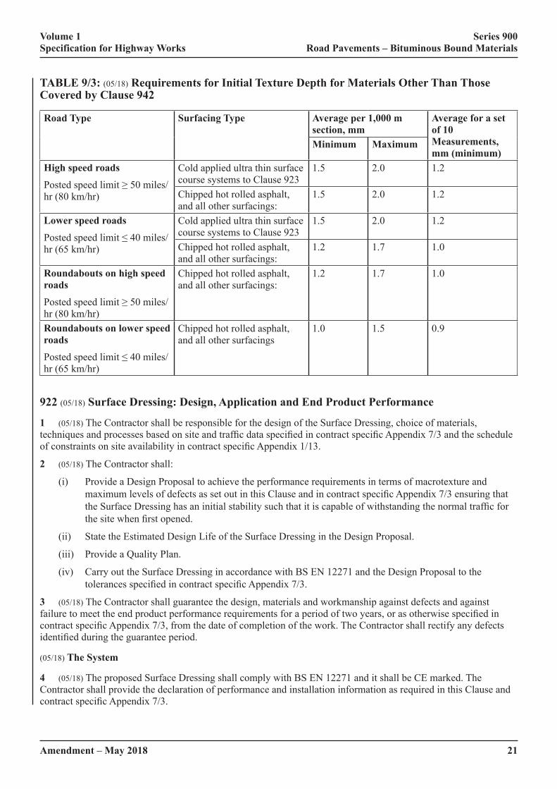
2 (05/18) Texture depth shall be measured by 10 individual measurements taken at approximately 5 m spacing along�a�diagonal�line�across�the�lane�width.�Unless�otherwise�specified�in�contract�specific�Appendix�7/1,�at�least�one set of 10 measurements shall be made for each 250 m section of carriageway lane. The average texture depth for each set of 10 individual measurements and the average texture depth of each 1,000 m section (or complete carriageway lane where this is less than 1,000 m) shall not be less than the appropriate values shown in Table 9/3, unless�otherwise�specified�in�contract�specific�Appendix�7/1.
Volume 1 Series 900 Specification for Highway Works Road Pavements – Bituminous Bound Materials
Amendment – May 2018 21
TABLE 9/3: (05/18) Requirements for Initial Texture Depth for Materials Other Than Those Covered by Clause 942
Road Type Surfacing Type Average per 1,000 m section, mm
Average for a set of 10 Measurements, mm (minimum)
Minimum Maximum
High speed roadsPosted�speed�limit�≥�50�miles/hr (80 km/hr)
Cold applied ultra thin surface course systems to Clause 923
1.5 2.0 1.2
Chipped hot rolled asphalt, and all other surfacings:
1.5 2.0 1.2
Lower speed roadsPosted�speed�limit�≤�40�miles/hr (65 km/hr)
Cold applied ultra thin surface course systems to Clause 923
1.5 2.0 1.2
Chipped hot rolled asphalt, and all other surfacings:
1.2 1.7 1.0
Roundabouts on high speed roadsPosted�speed�limit�≥�50�miles/hr (80 km/hr)
Chipped hot rolled asphalt, and all other surfacings:
1.2 1.7 1.0
Roundabouts on lower speed roadsPosted�speed�limit�≤�40�miles/hr (65 km/hr)
Chipped hot rolled asphalt, and all other surfacings
1.0 1.5 0.9
922 (05/18) Surface Dressing: Design, Application and End Product Performance
1 (05/18) The Contractor shall be responsible for the design of the Surface Dressing, choice of materials, techniques�and�processes�based�on�site�and�traffic�data�specified�in�contract�specific�Appendix�7/3�and�the�schedule�of�constraints�on�site�availability�in�contract�specific�Appendix�1/13.
2 (05/18) The Contractor shall:
(i) Provide a Design Proposal to achieve the performance requirements in terms of macrotexture and maximum�levels�of�defects�as�set�out�in�this�Clause�and�in�contract�specific�Appendix�7/3�ensuring�that�the�Surface�Dressing�has�an�initial�stability�such�that�it�is�capable�of�withstanding�the�normal�traffic�for�the�site�when�first�opened.
(ii) State the Estimated Design Life of the Surface Dressing in the Design Proposal.
(iii) Provide a Quality Plan.
(iv) Carry out the Surface Dressing in accordance with BS EN 12271 and the Design Proposal to the tolerances�specified�in�contract�specific�Appendix�7/3.
3 (05/18) The Contractor shall guarantee the design, materials and workmanship against defects and against failure�to�meet�the�end�product�performance�requirements�for�a�period�of�two�years,�or�as�otherwise�specified�in�contract�specific�Appendix�7/3,�from�the�date�of�completion�of�the�work.�The�Contractor�shall�rectify�any�defects�identified�during�the�guarantee�period.
(05/18) The System
4 (05/18) The proposed Surface Dressing shall comply with BS EN 12271 and it shall be CE marked. The Contractor shall provide the declaration of performance and installation information as required in this Clause and contract�specific�Appendix�7/3.
Volume 1 Series 900 Specification for Highway Works Road Pavements – Bituminous Bound Materials
22Amendment – May 2018
The�declaration�of�performance�shall�demonstrate�that�the�system�meets�the�requirements�of�the�specification�and�provides�performance�categories�for�all�of�the�items�identified�in�this�Clause�and�contract�specific�Appendix�7/3.
(05/18) Materials and Equipment – Binder
5 (05/18) The binder shall be bitumen emulsion complying with BS EN 13808 and be CE marked and comply with�requirements�stated�in�contract�specific�Appendix�7/3.
6 (05/18) The Contractor shall provide, with his Design Proposal, the declaration of performance for the binder which�shall�demonstrate�that�the�binder�shall�meet�the�requirements�of�the�specification�including�the�properties�detailed�in�contract�specific�Appendix�7/3.
Contract�compliance�testing�shall�be�carried�out�as�detailed�in�contract�specific�Appendix�1/5.�The�recovery�of�the�binder shall be carried out in accordance with Clause 955. The test to determine Vialit Pendulum Cohesion shall be�carried�out�in�accordance�with�BS�EN�13588.�The�Contractor�shall�provide�rheological�product�identification�data�for�modified�binders�in�accordance�with�BS�EN�14770.�The�data�provided�shall�be�not�more�than�6�months�old�and obtained on samples of binder representative of binder manufactured and supplied using the same source and processes as the proposed binder. Health and Safety information and a safe handling guide from the manufacturer shall be provided together with details of any weather restrictions placed upon use of the binder.
7 (05/18)�The�binder�application�shall�be�uniform�and�for�motorways,�trunk�roads�and�heavily�trafficked�and�highly�stressed�roads,�shall�be�of�sufficient�width�to�allow�a�full�lane�to�be�dressed�in�a�single�pass.�Before�spraying�begins,�the�Contractor�shall�provide�the�Overseeing�Organisation�with�a�test�certificate�showing�test�results�for�rate of spread and accuracy of spread of binder carried out in accordance with the test methods in BS EN 12272- 1 and issued by, an appropriate organisation, accredited in accordance with sub-Clause 105.4 for those tests, demonstrating that the binder sprayer has been tested, using the binder to be used in the Contract, not more than six weeks before the commencement of the work, and that it complies with the requirements set out in contract specific�Appendix�7/3.
(05/18) Materials and Equipment – Chippings
8 (05/18) The chippings shall be crushed rock, slag, gravel or calcined bauxite complying with the general requirements of BS EN 13043:2002. The aggregate shall have a minimum declared PSV and a maximum AAV as specified�in�contract�specific�Appendix�7/3.
9 (05/18)�Chipping�spreaders�shall�have�controlled�metering�and�be�capable�of�variable�or�fixed�width�application�to match the binder sprayer. Before a spreader is used, the Contractor shall provide the Overseeing Organisation with�a�test�certificate�showing�test�results�for�rate�of�spread�and�accuracy�of�spread�of�chippings�carried�out�in�accordance with the test methods in BS EN 12272-1, and issued by an appropriate organisation, accredited in accordance with sub-Clause 105.4 for those tests, demonstrating that the chipping spreader has been tested, using chippings similar to those to be used in the Contract, not more than six weeks before the commencement of the work,�and�that�it�complies�with�the�requirements�set�out�in�contract�specific�Appendix�7/3.
(05/18) Preparation
10 (05/18) Any necessary remedial works to the road surface and structure shall be completed prior to or as part of the contract and agreed as acceptable by the Overseeing Organisation and the Contractor before Surface Dressing commences.
11 (05/18) Before binder is applied, street furniture shall be masked using self-adhesive masking material. Oil, sand or similar materials shall not be used. Any packed mud or other deposits on the road surface shall be removed, and the road surface shall be swept free of all loose material.
(05/18) Traffic Safety and Management
12 (05/18)�Traffic�Safety�and�Management�shall�be�in�accordance�with�the�requirements�of�Series�100�and�the�site�specific�requirements�specified�in�contract�Appendix�1/17�and�the�constraints�described�in�contract�specific�Appendix 1/13.

Volume 1 Series 900 Specification for Highway Works Road Pavements – Bituminous Bound Materials
Amendment – May 2018 23
(05/18) Application
13 (05/18)�Restrictions�to�be�observed�in�the�event�of�adverse�weather�shall�be�as�specified�in�contract�specific�Appendix�7/3.�Transverse�joints�shall�be�formed�with�spraying�starting�and�finishing�on�a�protective�strip�not�less�than 1 metre wide at each end of the lane length being treated. Transverse joints shall be of binder overlap only and not wider than 100 mm. There shall be no ridges or bare strips. Longitudinal joints shall coincide with lane markings. Longitudinal joints shall be of binder overlap only, while ensuring that the proposed rate of spread is achieved across the joint, for quartering (using a part of the spraybar) the overlap may be extended to a maximum of 300 mm. There shall be no ridges or bare strips.
14 (05/18) The Contractor shall carry out the tests for rates of spread and accuracy of application of binder and chippings�in�accordance�with�the�test�methods�in�BS�EN�12272-1�at�the�frequency�specified�in�contract�specific�Appendix 1/5 and report the results verbally to the Overseeing Organisation within twenty-four hours of carrying out�the�test�and�confirm�in�writing�within�seven�days.�The�Contractor�shall�facilitate�duplicate�testing�by�the�Overseeing Organisation if required.
(05/18) Aftercare
15 (05/18) Masking shall be removed after the Surface Dressing has been applied and before opening the road to unrestricted�traffic.�The�time�period�before�unrestricted�traffic�may�use�the�Surface�Dressing�shall�not�exceed�that�specified�in�contract�specific�Appendix�7/3.�The�Contractor�shall�remove�surplus�chippings�from�the�road�by�suction�sweeping�before�it�is�opened�to�unrestricted�traffic.
16 (05/18) The Contractor shall monitor the Surface Dressing closely for a minimum period of 2 hours, or as specified�in�contract�specific�Appendix�7/3,�after�the�road�is�opened�to�traffic.�The�Contractor�shall�reinstate�traffic�safety and management procedures or institute other such remedial action where necessary, such as dusting, if there are signs of distress, such as turning of the chippings, in order to prevent further damage to the Surface Dressing.
17 (05/18) Further operations to remove subsequently loosened chippings shall be carried out over the next 48 hours. The road, and adjacent side roads, footways and paved areas, shall be kept substantially free of loose chippings for a period of 30 days after completion of the work.
(05/18) As Built Manual
18 (05/18) Not more than 30 days after completion of the work the Contractor shall provide a record of the progress of the work in the form of an As Built Manual incorporating all relevant information, including: all contract compliance test results; variations to the Design Proposal and those necessitated by localised site conditions; a record�of�traffic�control�carried�out;�weather�information;�unforeseen�problems;�a�list�of�complaints,�if�any,�from�the�general public or road users; and any other information that the Overseeing Organisation may reasonably require to be included.
(05/18) Performance Standards During the Guarantee Period
(05/18) Surface Macrotexture
19 (05/18) The Contractor is responsible for maintaining the surface macrotexture requirements set out in contract specific�Appendix�7/3�throughout�the�guarantee�period.
The�definitive�test�is�the�volumetric�patch�technique�measured�in�accordance�with�BS�EN�13036-1�except�that�10�individual�measurements�shall�be�made�on�the�nearside�(inside)�wheel-track�of�the�most�heavily�trafficked�lane. The average macrotexture depth of each lane kilometre, or the complete carriageway lane where this is less than�1,000�metres,�shall�be�as�specified�in�contract�specific�Appendix�7/3.�The�average�of�each�set�of�10�individual�measurements shall be not less than 80% of the minimum permitted.
The�Overseeing�Organisation�will�use�the�TRAffic-speed�Condition�Survey�(TRACS)�or�other�suitable�equipment�to determine the Sensor Measured Texture Depth (SMTD) for trunk roads including motorways and other highly trafficked�or�highly�stressed�roads.�Measurements�of�SMTD�shall�be�made�in�the�nearside�and�offside�wheel-tracks�of all lanes. For other roads where road closure is less critical the volumetric patch technique or other measuring device such as the Mini Texture Meter may be used.
Volume 1 Series 900 Specification for Highway Works Road Pavements – Bituminous Bound Materials
24Amendment – May 2018
The SMTD or results from other devices shall be calibrated for the particular Surface Dressing product design and condition against volumetric patch values to provide the Volumetric Patch Equivalent value. The macrotexture depths will be measured after 11 months and before 13 months and additionally for two year guarantee period contracts�after�22�months�and�before�24�months�unless�otherwise�specified�in�contract�specific�Appendix�7/3.�When�required, the Contractor shall design the Surface Dressing to limit the maximum macrotexture after four weeks trafficking�to�that�specified�in�contract�specific�Appendix�7/3�and�the�macrotexture�depths�will�be�measured,�for�this�purpose,�between�three�weeks�and�five�weeks�after�completion�of�the�Works.
(05/18) Defects
20 (05/18) The extent of chipping loss or other defects will be monitored using a visual method of assessment. The performance standard is that any section of the works shall be deemed as having failed if the areas of defects do not comply�with�the�classes�specified�in�contract�specific�Appendix�7/3.�If�there�is�a�failed�section,�the�Contractor�shall�agree remedial measures with the Overseeing Organisation and undertake the remedial measures.
In the event that the Contractor and Overseeing Organisation are unable to reach agreement on whether a section has failed by qualitative visual assessment described in BS EN 12272-2, the level of defects shall be determined in accordance with the quantitative test methods in BS EN 12272-2. Any section failing to meet the required standard as�specified�in�contract�specific�Appendix�7/3�shall�be�subject�to�remedial�action�by�the�Contractor�after�agreement�of the Overseeing Organisation.
923 (05/18) Cold Applied Ultra Thin Surfacing
(05/18) General
1 (05/18) The Cold Applied Ultra Thin Surfacing shall meet the product performance requirements under the combinations�of�traffic�level�and�site�classification�specified�in�contract�specific�Appendix�7/1�and�it�shall�meet�the�following criteria.
(i) Where the product falls under the scope of a harmonised European standard under the Construction Products Regulation the Cold Applied Ultra Thin Surfacing shall have a declaration of performance and be CE marked in accordance with the relevant British adopted European standard.
(ii) Where the product does not fall under the scope of a harmonised European standard under the Construction Products Regulation it shall either:
(a) have a declaration of performance and be CE marked in accordance with a European Technical Assessment; or
(b)� �be�certified�under�a�product�acceptance�scheme�as�detailed�in�sub-Clauses�104.15�and�104.16�such�as�HAPAS�certification.
The�Contractor�shall�supply�the�certification�or�declaration�of�performance�to�the�Overseeing�Organisation,�it�shall�demonstrate�that�the�Cold�Applied�Ultra�Thin�Surfacing�shall�meet�the�requirements�of�the�specification.
The�installation�of�the�surfacing�shall�be�certified�under�a�product�acceptance�scheme�as�detailed�in�sub-Clauses�104.15�and�104.16�such�as�HAPAS�certification.
2 (05/18) Cold Applied Ultra Thin Surfacing systems that are supplied in accordance with sub-Clause 1 paragraph (ii) (b) shall be produced and installed by organisations that are registered to the National Highways Sector Scheme 13 for The Supply and Application of Surface Treatments to Road Surfaces, as listed in Appendix A.
(05/18) Documentation, Test Certificates and Material Samples
3 (05/18) The Contractor shall supply a Quality Plan and Installation Method Statement to the Overseeing Organisation.
4 (05/18)�Test�certificates�stating�the�properties�of�the�aggregate�to�be�used�shall�be�supplied�to�the�Overseeing�Organisation unless the values are declared in the Declaration of Performance under the CE mark.
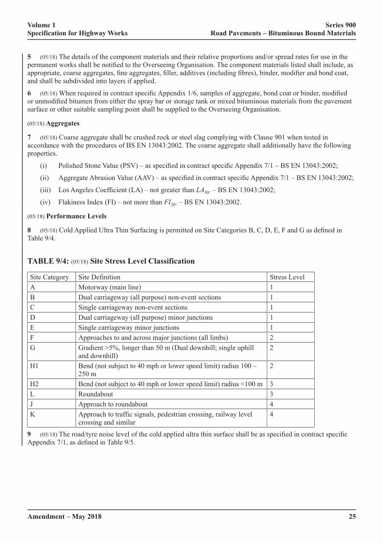
Volume 1 Series 900 Specification for Highway Works Road Pavements – Bituminous Bound Materials
Amendment – May 2018 25
5 (05/18) The details of the component materials and their relative proportions and/or spread rates for use in the permanent�works�shall�be�notified�to�the�Overseeing�Organisation.�The�component�materials�listed�shall�include,�as�appropriate,�coarse�aggregates,�fine�aggregates,�filler,�additives�(including�fibres),�binder,�modifier�and�bond�coat,�and shall be subdivided into layers if applied.
6 (05/18)�When�required�in�contract�specific�Appendix�1/6,�samples�of�aggregate,�bond�coat�or�binder,�modified�or�unmodified�bitumen�from�either�the�spray�bar�or�storage�tank�or�mixed�bituminous�materials�from�the�pavement�surface or other suitable sampling point shall be supplied to the Overseeing Organisation.
(05/18) Aggregates
7 (05/18) Coarse aggregate shall be crushed rock or steel slag complying with Clause 901 when tested in accordance with the procedures of BS EN 13043:2002. The coarse aggregate shall additionally have the following properties.
(i)� Polished�Stone�Value�(PSV)�–�as�specified�in�contract�specific�Appendix�7/1�–�BS�EN�13043:2002;
(ii)� Aggregate�Abrasion�Value�(AAV)�–�as�specified�in�contract�specific�Appendix�7/1�–�BS�EN�13043:2002;
(iii)� Los�Angeles�Coefficient�(LA)�–�not�greater�than�LA30. – BS EN 13043:2002;
(iv) Flakiness Index (FI) – not more than FI20. – BS EN 13043:2002.
(05/18) Performance Levels
8 (05/18)�Cold�Applied�Ultra�Thin�Surfacing�is�permitted�on�Site�Categories�B,�C,�D,�E,�F�and�G�as�defined�in�Table 9/4.
TABLE 9/4: (05/18) Site Stress Level Classification
Site Category Site Definition Stress LevelA Motorway (main line) 1B Dual carriageway (all purpose) non-event sections 1C Single carriageway non-event sections 1D Dual carriageway (all purpose) minor junctions 1E Single carriageway minor junctions 1F Approaches to and across major junctions (all limbs) 2G Gradient >5%, longer than 50 m (Dual downhill; single uphill
and downhill)2
H1 Bend (not subject to 40 mph or lower speed limit) radius 100 – 250 m
2
H2 Bend (not subject to 40 mph or lower speed limit) radius <100 m 3L Roundabout 3J Approach to roundabout 4K Approach to traffic signals, pedestrian crossing, railway level
crossing and similar4
9 (05/18)�The�road/tyre�noise�level�of�the�cold�applied�ultra�thin�surface�shall�be�as�specified�in�contract�specific�Appendix�7/1,�as�defined�in�Table�9/5.

Volume 1 Series 900 Specification for Highway Works Road Pavements – Bituminous Bound Materials
26Amendment – May 2018
TABLE 9/5: (05/18) Road/Tyre Noise Levels
Level Road Surface InfluenceRSI
0 +1.2 dB(A)NR No requirement
(05/18) Layer Thickness
10 (05/18) The minimum and/or maximum compacted thickness of the Cold Applied Ultra Thin Surfacing system shall�be�as�specified�in�contract�specific�Appendix�7/1.�The�installed�layer�thickness�must�not�be�less�than�the�permitted�minimum�thickness�stated�in�the�HAPAS�certificate�or�equivalent�certification�for�a�particular�system.
(05/18) Surface Preparation
11 (05/18)�When�required�in�contract�specific�Appendix�7/1,�a�site�inspection�shall�be�undertaken�prior�to�the�main�works jointly by representatives of the Overseeing Organisation and the Contractor to agree suitable preparation works (e.g. patching).
12 (05/18) Surface preparation shall be in accordance with BS 594987, clause 5.1 and 5.3, and the Installation Method Statement provided in accordance with sub-Clause 4.
(05/18) Transportation
13 (05/18) Transportation of the Cold Applied Ultra Thin Surfacing and/or its components shall be in accordance with the Installation Method Statement provided in accordance with sub-Clause 4.
(05/18) Sweeping and early life monitoring of Cold Applied Ultra Thin Surfacings
14 (05/18) Sweeping of newly laid Cold Applied Ultra Thin Surfacing shall be in accordance with the HAPAS or equivalent�certification�and�the�Installation�Method�Statement.
15 (05/18) Notwithstanding the above, suction sweeping shall be undertaken immediately before the newly laid Cold�Applied�Ultra�Thin�Surfacing�is�opened�to�traffic.
16 (05/18) The installation shall be monitored closely for a minimum period of 2 hours after the road is opened to traffic.�Traffic�safety�and�management�procedures�shall�be�reinstated�or�other�such�remedial�actions�instigated,�if�there are signs of distress in the surfacing, such as turning of the chippings, in order to prevent further damage to the installation.
17 (05/18)�Where�detailed�in�contract�specific�Appendix�1/17�a�mandatory�speed�limit�shall�be�implemented�during�installation and for a period of 5 days after installation.
18 (05/18) Further operations to remove subsequently loosened chippings shall be carried out over the next 48 hours. The road, and adjacent side roads, footways and paved areas shall be kept substantially free of loose chippings for a period of 30 days after completion of the surfacing work.
(05/18) Surface Macrotexture – Untrafficked
19 (05/18) The macrotexture depth of the cold applied ultra thin surfacing after compaction has been completed and before�opening�to�traffic�shall�be�in�accordance�with�Clause�921.
(05/18) Surface Macrotexture – Performance Guarantee
20 (05/18)�For�a�period�of�two�years�from�the�date�of�opening�to�traffic�the�average�macrotexture,�measured�using�the volumetric patch technique described in BS EN 13036-1, will be maintained above an average per 1000m of 1.0�mm,�unless�otherwise�specified�in�contract�specific�Appendix�7/1.

Volume 1 Series 900 Specification for Highway Works Road Pavements – Bituminous Bound Materials
Amendment – May 2018 27
21 (05/18) Where measurement is necessary to demonstrate compliance during the guarantee period, the macrotexture�shall�be�measured�in�accordance�with�BS�EN�13036-1�in�the�most�heavily�trafficked�lane�at�10�m�intervals. The average value of a set of 10 individual measurements taken along the centre of the most heavily worn wheel-track�shall�not�be�less�than�the�appropriate�value�stated�in�contract�specific�Appendix�7/1.
(05/18) Surfacing Integrity – Performance Guarantee
22 (05/18)�Unless�otherwise�stated�in�contract�specific�Appendix�7/1�a�guarantee�shall�be�provided�for�the�integrity�of�the�surfacing�and�the�workmanship�for�a�period�of�five�years�from�the�date�of�opening�to�traffic.
23 (05/18)�The�five-year�guarantee�shall�include�for�defects�such�as�fretting,�ravelling,�stripping�and�loss�of�chippings. Replacement of the surfacing or other remedial measures agreed with the Overseeing Organisation shall be�executed�if�the�surfacing�is�in�a�“Suspect”,�“Poor”�or�“Bad”�condition�as�defined�in�Appendix�A�of�TRL�Report�TRL674 – “Durability of thin surfacing systems, Part 4, Final report after nine years monitoring, TRL report 674”.
924 (05/18) High Friction Surfaces
1 (05/18)�High�friction�surfacing�systems�shall�have�current�HAPAS�certificate�or�equivalent�product�acceptance�scheme�certification�as�described�in�sub-Clauses�104.15�and�104.16.
2 (05/18) High friction surfacing shall be installed in accordance with the requirements of the HAPAS or equivalent�product�acceptance�scheme�certification.
3 (05/18)�The�high�friction�surfacing�system�HAPAS�or�equivalent�product�acceptance�scheme�certification�Type�Classification�required�for�each�location�shall�be�as�specified�in�contract�specific�Appendix�7/1.
(05/18) Aggregate
4 (05/18) Aggregate used in high friction surfacing systems shall have the minimum declared PSV category specified�in�contract�specific�Appendix�7/1�in�accordance�with�BS�EN�13043:2002,�clause�4.2.3.�The�resistance�to�abrasion�of�coarse�aggregate�shall�have�the�maximum�AAV�specified�in�contract�specific�Appendix�7/1�in�accordance with BS EN 13043:2002, clause 4.2.4. The Contractor shall provide, before work commences, the declaration of performance for the aggregate to the Overseeing Organisation. The declaration of performance shall demonstrate�that�the�aggregate�shall�meet�the�requirements�of�the�specification.
(05/18) Installation and Quality Control Procedures
5 (05/18) The installation and quality control procedures shall be in accordance with the HAPAS or equivalent product�acceptance�scheme�certification�for�each�system�and�the�current�method�statement.�The�results�of�all�quality�control checks carried out on site by the Contractor and quality management information compiled in accordance with�the�requirements�of�the�Certificate,�including�results�from�surveillance�visits,�shall�be�made�available�to�the�Overseeing Organisation on request.
(05/18) System Coverage
6 (05/18) For each location where high friction surfacing is applied, the total quantities of each system component used, the measured area of the surface treated and the calculated coverage rate in kg/m2 shall be reported to the Overseeing Organisation within three days of completion at that location. For systems in which aggregate is broadcast�over�a�film�of�binder�applied�to�the�surface,�the�calculated�coverage�rate�shall�be�that�of�the�binder�film�and shall not include the mass of the aggregate.
(05/18) Guarantee
7 (05/18) The Contractor shall guarantee the high friction surfacing materials and workmanship for a period of two�years�from�the�date�of�opening�the�surfacing�to�traffic.�This�guarantee�shall�cover�failure�to�meet�the�minimum�requirements�set�out�in�Table�4�of�the�HAPAS�document�‘Guideline�Document�for�the�Assessment�and�Certification�of High Friction Surfaces for Highways’.
Volume 1 Series 900 Specification for Highway Works Road Pavements – Bituminous Bound Materials
28Amendment – May 2018
925 (05/18) Testing of Bituminous Mixtures
1 (05/18) The contract compliance sampling and testing of bituminous mixtures shall comply with BS EN 12697, except�where�otherwise�specified�in�this�Series.
2 (05/18)�Additional�testing�shall�be�carried�out�as�specified�in�contract�specific�Appendices�7/1,�1/5�and�1/6.
926 (05/18) In Situ Recycling: The Repave Process
1 (05/18) Where milling is required, it shall be carried out in accordance with Clause 709, and as described in contract�specific�Appendix�7/5.
(05/18) Heating and Scarifying
2 (05/18) Surfaces to be treated shall be heated by plant with heating surfaces insulated and fully enclosed. The heated-width�of�surfacing�shall�exceed�the�scarified�width�by�at�least�75�mm�on�each�side,�except�against�the�edge�of the carriageway or kerb face. When new surfacing material is spilt onto the road surface it shall be removed before�the�existing�surface�is�heated�and�scarified.�Areas�of�unscarified�material�shall�not�exceed�50�mm�x�50�mm.
3 (05/18)�The�depth�of�scarification�shall�be�such�that�the�bottom�of�the�scarified�layer�is�parallel�to�and�below�the�finished�road�surface�level�by�the�thickness�of�surface�course�material�specified�in�contract�specific�Appendix�7/5.�A�tolerance�of�±�6�mm�is�permissible.
4 (05/18) Where ironwork and other obstructions occur, these shall be suitably protected or removed and the void covered. Surface dressings and large areas of road markings shall be removed by milling, planing, scarifying or similar.
5 (05/18)�The�heated�surface�shall�be�evenly�scarified�to�comply�with�the�requirements�of�sub-Clause�3�of�this�Clause.�When�ironwork�is�left�in�place�or�raised,�the�adjacent�areas�shall�be�scarified�by�other�means,�with�the�material either left in place or removed, prior to passage of the machine. If ironwork needs to be re-levelled, on completion of work, the new surface course material shall be used to make good the road surface for a maximum width of 200 mm around the ironwork.
6 (05/18) During the reheating process the surface temperature of the road shall not exceed 200°C for more than 5 minutes.
(05/18) New Surfacing
7 (05/18)�New�surface�course�shall�conform�to�Clauses�910,�911,�923,�942�or�943,�as�described�in�contract�specific�Appendix 7/5.
8 (05/18)�The�new�surfacing�material�shall�be�laid�on,�and�compacted�with�the�re-profiled�surfacing,�which�shall�be at a temperature within the range of 70°C to 150°C.
927 & 928 (05/18) Not Used
929 (05/18) Dense Base and Binder Course Asphalt Concrete (Design Mixtures)
1 (05/18) Designed dense base and binder course asphalt concrete (formerly macadams), including HDM and HMB, shall be asphalt concrete conforming to BS EN 13108-1, the example of BSI PD 6691 Annex B for the selected�mixture,�and�requirements�specified�in�contract�specific�Appendix�7/1.�The�mixture�designation�shall�be�one of the following:
(i) AC 32 HDM base 40/60 des.
(ii) AC 32 dense base 40/60 des.
(iii) AC 32 HMB base 30/45 des.
Volume 1 Series 900 Specification for Highway Works Road Pavements – Bituminous Bound Materials
Amendment – May 2018 29
(iv) AC 20 HDM bin 40/60 des.
(v) AC 32 HDM bin 40/60 des.
(vi) AC 20 dense bin 40/60 des.
(vii) AC 32 dense bin 40/60 des.
(viii) AC 20 HMB bin 30/45 des.
(ix) AC 32 HMB bin 30/45 des.
2 (05/18) The volumetric properties of mixtures shall follow the example in BSI PD 6691, clause B.3.2 for designed base mixtures and BSI PD 6691, clause B.3.3 for designed binder course mixtures.
3 (05/18)�When�specified�in�contract�specific�Appendix�7/1,�the�volumetric�properties�of�the�mixture�shall�be�monitored by determining the void content of cores compacted to refusal. Core pairs and samples of loose mix shall be taken every 500 lane metres and tested in accordance with BS 594987, clauses C.2.1, C.2.2, C.3, C.4.1 and C.4.2. If the mean air void content at refusal of any three consecutive pairs of cores falls below 0.5%, the mixture target composition shall be reviewed and the type test revalidated in accordance with BS 594987, Annex C.
(05/18) Deformation Resistance
4 (05/18) The resistance to permanent deformation of the mixture shall be in accordance with the appropriate class selected�from�Table�D.2�of�PD�6691,�as�specified�in�contract�specific�Appendix�7/1.
5 (05/18)�When�specified�in�contract�specific�Appendix�7/1,�the�resistance�to�permanent�deformation�of�material�laid in the permanent works shall be monitored by testing in accordance with clauses D 3.1, 3.2 and 3.3 of BS�594987�Annex�D.�Six�cores�shall�be�taken�from�the�first�kilometre�length�of�material�from�each�mixing�plant�and thereafter one further core from each subsequent lane kilometre. Results shall be assessed on successive rolling means�of�sets�of�six�consecutive�results�and�shall�be�deemed�to�conform�if�the�mean�is�no�greater�than�the�specified�value�and�individual�values�not�more�than�50%�greater�than�the�specified�value.
(05/18) Stiffness
6 (05/18) Stiffness of the mixture shall be assessed in accordance with BS 594987, Annex E.
Mixtures with 40/60 grade binder shall conform to category Smin 1800�as�defined�in�BS�EN�13108-1,�clause�5.4.2.
Mixtures with 30/45 grade binder shall conform to category Smin 2800�as�defined�in�BS�EN�13108-1,�clause�5.4.2.
(05/18) Compaction Control for the Permanent Works
7 (05/18) Compaction shall be controlled and monitored in accordance with the general requirements of BS�594987�9.5.1�and�the�specific�requirements�of�this�Clause.
8 (05/18) Compaction shall be continuously assessed using an indirect density gauge in accordance with BS 594987 9.4.2 with readings taken at 20 m intervals in alternate wheel-tracks. Gauge readings shall also be taken�at�each�core�location�specified�in�sub-Clauses�12�and�14.�Each�gauge�shall�be�individually�calibrated�on�each�mixture from each mixing plant and the calibrations shall be continually checked and updated based on correlations between gauge readings and core densities at the same locations.
9 (05/18) For each location, the in situ void content shall be determined in accordance with BS EN 12697-8 using the bulk density from the gauge reading and a maximum density taken from the mixture type testing data and updated with values from testing in accordance with sub-Clause 12.
10 (05/18) The average in situ void content calculated from any six consecutive indirect gauge readings shall not exceed 7%.
11 (05/18) In the event of a failure to meet the requirements in sub-Clause 10, cores shall be taken at each location and void contents determined as described in sub-Clause 12 and the evaluation of the extent of any non-conformity shall be based on these. If it is necessary to remove and replace any material to restore conformity this shall be in lengths not less than 15 m unless otherwise agreed by the Overseeing Organisation.
Volume 1 Series 900 Specification for Highway Works Road Pavements – Bituminous Bound Materials
30Amendment – May 2018
12 (05/18) For the material from each mixing plant, a pair of cores shall be taken from every 1,000 linear metres laid and the void content shall be determined in accordance with BS 594987, clause 9.5.1.3.
13 (05/18) The average in situ air voids for each core pair shall not exceed 7%.
14 (05/18) For the material from each mixing plant a pair of cores shall be taken every 250 linear metres laid, centred�100�mm�from�the�final�joint�position�at�any�unsupported�edge�and�the�air�void�shall�be�determined�in�accordance with BS 594987, clause 9.5.1.3.
15 (05/18) The average in situ void content for each of these pairs shall not exceed 9%.
16 (05/18) In the event of non-conformity with sub-Clauses 13 or 15 then density readings with indirect gauges and, if necessary, further cores shall be taken to establish the extent. If it is necessary to remove and replace any material to restore conformity, this shall be in lengths not less than 15 m unless otherwise agreed by the Overseeing Organisation.
17 (05/18) Each core extracted shall be examined for evidence of excessive voids below the depth to which the indirect density gauge penetrates. If excessive voids are observed, further cores shall be taken to determine its extent.
18 (05/18)�Two�copies�of�the�final�indirect�density�test�results�obtained�and�their�correlation�with�in�situ�air�void�contents shall be passed to the Overseeing Organisation within 72 hours.
930 (05/18) EME2 Base and Binder Course Asphalt Concrete
1 (05/18) EME2 base and binder course asphalt concrete shall conform to BS EN 13108-1, the example in BSI�PD�6691�Annex�B�for�the�selected�mixture,�the�requirements�of�this�Clause�and�those�specified�in�contract�specific�Appendix�7/1.�The�mixture�designation�shall�be�one�of�the�following:
(i) AC 10 EME2 bin/base 10/20 des.
(ii) AC 10 EME2 bin/base 15/25 des.
(iii) AC 14 EME2 bin/base 10/20 des.
(iv) AC 14 EME2 bin/base 15/25 des.
(v) AC 20 EME2 bin/base 10/20 des.
(vi) AC 20 EME2 bin/base 15/25 des.
2 (05/18) The binder shall be Hard Paving Grade Bitumen in accordance with BS EN 13924 and the requirements specified�in�Tables�9/6,�9/7�and�9/8.
3 (05/18) EME2 mixtures, otherwise conforming to BS EN 13108-1 and the example in BSI PD 6691 Annex B, but�using�alternative�paving�grade�bitumens�or�polymer�modified�paving�grade�bitumens,�shall�not�be�used�without�prior approval by the Overseeing Organisation.
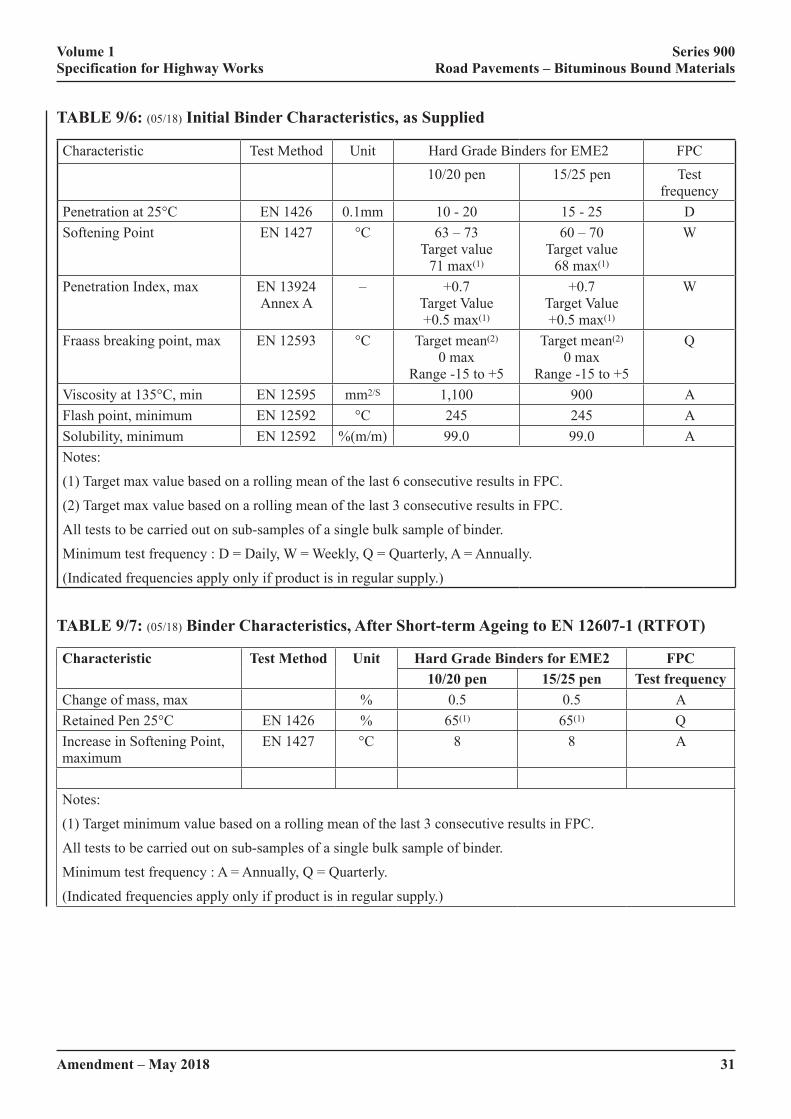
Volume 1 Series 900 Specification for Highway Works Road Pavements – Bituminous Bound Materials
Amendment – May 2018 31
TABLE 9/6: (05/18) Initial Binder Characteristics, as Supplied
Characteristic Test Method Unit Hard Grade Binders for EME2 FPC10/20 pen 15/25 pen Test
frequencyPenetration at 25°C EN 1426 0.1mm 10 - 20 15 - 25 DSoftening Point EN 1427 °C 63 – 73
Target value 71 max(1)
60 – 70 Target value
68 max(1)
W
Penetration Index, max EN 13924 Annex A
– +0.7 Target Value +0.5 max(1)
+0.7 Target Value +0.5 max(1)
W
Fraass breaking point, max EN 12593 °C Target mean(2) 0 max
Range -15 to +5
Target mean(2) 0 max
Range -15 to +5
Q
Viscosity at 135°C, min EN 12595 mm2/S 1,100 900 AFlash point, minimum EN 12592 °C 245 245 ASolubility, minimum EN 12592 %(m/m) 99.0 99.0 ANotes:
(1) Target max value based on a rolling mean of the last 6 consecutive results in FPC.
(2) Target max value based on a rolling mean of the last 3 consecutive results in FPC.
All tests to be carried out on sub-samples of a single bulk sample of binder.
Minimum test frequency : D = Daily, W = Weekly, Q = Quarterly, A = Annually.
(Indicated frequencies apply only if product is in regular supply.)
TABLE 9/7: (05/18) Binder Characteristics, After Short-term Ageing to EN 12607-1 (RTFOT)
Characteristic Test Method Unit Hard Grade Binders for EME2 FPC10/20 pen 15/25 pen Test frequency
Change of mass, max % 0.5 0.5 ARetained Pen 25°C EN 1426 % 65(1) 65(1) QIncrease in Softening Point, maximum
EN 1427 °C 8 8 A
Notes:
(1) Target minimum value based on a rolling mean of the last 3 consecutive results in FPC.
All tests to be carried out on sub-samples of a single bulk sample of binder.
Minimum test frequency : A = Annually, Q = Quarterly.
(Indicated frequencies apply only if product is in regular supply.)
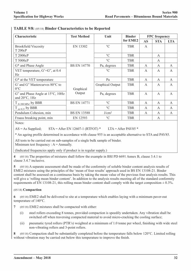
Volume 1 Series 900 Specification for Highway Works Road Pavements – Bituminous Bound Materials
32Amendment – May 2018
TABLE 9/8: (05/18) Binder Characteristics to be Reported
Characteristic Test Method Unit Binder for EME2
FPC frequencyAS STA LTA
Brookfield Viscosity T 200cP
EN 13302 °C TBR A
T 2000cP °C TBR AT 5000cP °C TBR AG* and Phase Angle BS EN 14770
Graphical Output
Pa, degrees TBR A A AVET temperature, G’=G”, at 0.4 Hz
°C TBR A A A
G* at the VET temperature Pa TBR A A AG’ and G” Mastercurves 80°C to 0°C
Graphical Output TBR A A A
G”�and�Phase�Angle�at�15°C,�10Hz�and�20°C,�1Hz
Pa, degrees TBR A A A
T S=300 MPa, by BBR BS EN 14771 °C TBR A A AT m=0.3, by BBR °C TBR A A APendulum Cohesion, min BS EN 13588 J/cm2 TBR A A AFraass breaking point, min EN 12593 °C TBR ANotes:
AS = As Supplied; STA = After EN 12607-1 (RTFOT) * LTA = After PAV85 *
* An ageing profile determined in accordance with clause 955 is an acceptable alternative to STA and PAV85.
All tests to be carried out on sub-samples of a single bulk sample of binder. Minimum test frequency : A = Annually.
(Indicated frequencies apply only if product is in regular supply.)
4 (05/18) The properties of mixtures shall follow the example in BSI PD 6691 Annex B, clause 3.4.1 to clause 3.4.7 inclusive.
5 (05/18) A separate assessment shall be made of the conformity of soluble binder content analysis results of EME2 mixtures using the principles of the ‘mean of four results’ approach used in BS EN 13108-21. Binder content shall be assessed on a continuous basis by taking the mean value of the previous four analysis results. This will give a ‘rolling mean binder content’. In addition to the analysis results meeting all of the standard conformity requirements�of�EN�13108-21,�this�rolling�mean�binder�content�shall�comply�with�the�target�composition�±�0.3%.
(05/18) Compaction
6 (05/18) EME2 shall be delivered to site at a temperature which enables laying with a minimum paver-out temperature of 140°C.
7 (05/18) EME2 mixtures shall be compacted with either:
(i) steel rollers exceeding 8 tonnes, provided compaction is speedily undertaken. Any vibration shall be switched off when traversing compacted material to avoid micro-cracking the cooling surface;
(ii)� pneumatic�tyred�rollers�(PTR’s)�weighted�at�a�minimum�of�1.0�tonne�per�wheel,�finishing�with�wide�steel�non-vibrating rollers and 3-point rollers.
8 (05/18) Compaction shall be substantially completed before the temperature falls below 120°C. Limited rolling without�vibration�may�be�carried�out�below�this�temperature�to�improve�the�finish.
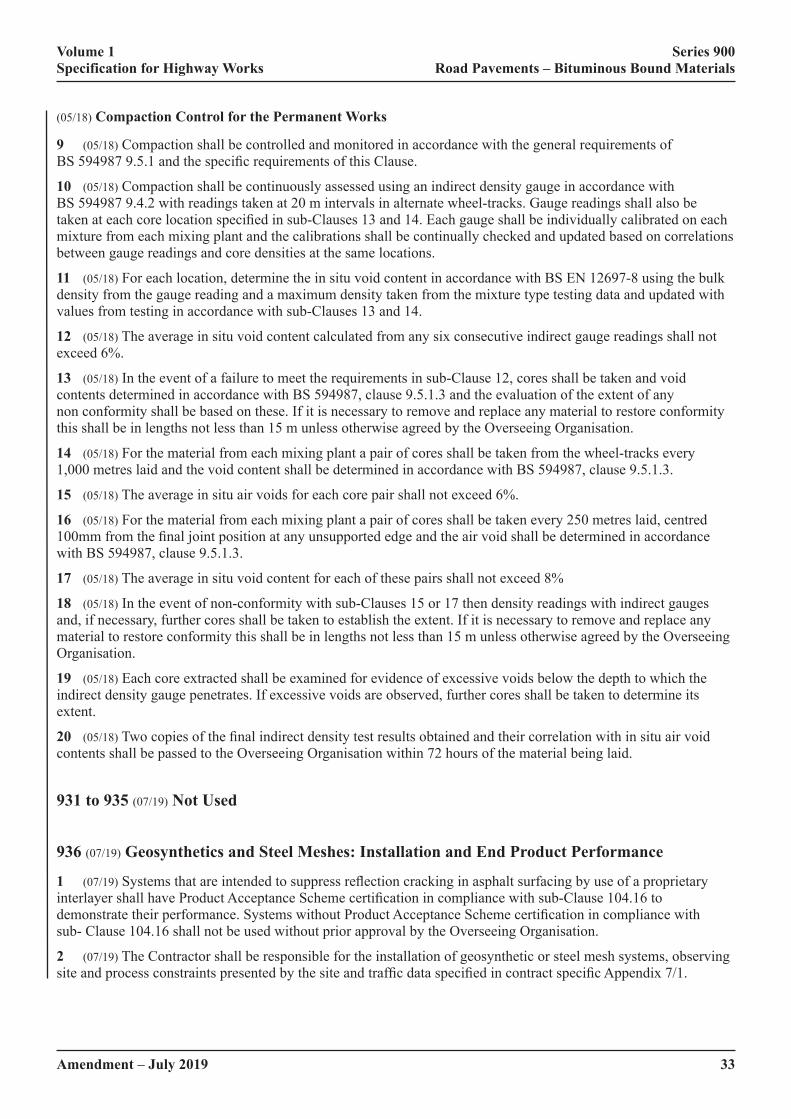
Volume 1 Series 900 Specification for Highway Works Road Pavements – Bituminous Bound Materials
33Amendment – July 2019
(05/18) Compaction Control for the Permanent Works
9 (05/18) Compaction shall be controlled and monitored in accordance with the general requirements of BS�594987�9.5.1�and�the�specific�requirements�of�this�Clause.
10 (05/18) Compaction shall be continuously assessed using an indirect density gauge in accordance with BS 594987 9.4.2 with readings taken at 20 m intervals in alternate wheel-tracks. Gauge readings shall also be taken�at�each�core�location�specified�in�sub-Clauses�13�and�14.�Each�gauge�shall�be�individually�calibrated�on�each�mixture from each mixing plant and the calibrations shall be continually checked and updated based on correlations between gauge readings and core densities at the same locations.
11 (05/18) For each location, determine the in situ void content in accordance with BS EN 12697-8 using the bulk density from the gauge reading and a maximum density taken from the mixture type testing data and updated with values from testing in accordance with sub-Clauses 13 and 14.
12 (05/18) The average in situ void content calculated from any six consecutive indirect gauge readings shall not exceed 6%.
13 (05/18) In the event of a failure to meet the requirements in sub-Clause 12, cores shall be taken and void contents determined in accordance with BS 594987, clause 9.5.1.3 and the evaluation of the extent of any non conformity shall be based on these. If it is necessary to remove and replace any material to restore conformity this shall be in lengths not less than 15 m unless otherwise agreed by the Overseeing Organisation.
14 (05/18) For the material from each mixing plant a pair of cores shall be taken from the wheel-tracks every 1,000 metres laid and the void content shall be determined in accordance with BS 594987, clause 9.5.1.3.
15 (05/18) The average in situ air voids for each core pair shall not exceed 6%.
16 (05/18) For the material from each mixing plant a pair of cores shall be taken every 250 metres laid, centred 100mm�from�the�final�joint�position�at�any�unsupported�edge�and�the�air�void�shall�be�determined�in�accordance�with BS 594987, clause 9.5.1.3.
17 (05/18) The average in situ void content for each of these pairs shall not exceed 8%
18 (05/18) In the event of non-conformity with sub-Clauses 15 or 17 then density readings with indirect gauges and, if necessary, further cores shall be taken to establish the extent. If it is necessary to remove and replace any material to restore conformity this shall be in lengths not less than 15 m unless otherwise agreed by the Overseeing Organisation.
19 (05/18) Each core extracted shall be examined for evidence of excessive voids below the depth to which the indirect density gauge penetrates. If excessive voids are observed, further cores shall be taken to determine its extent.
20 (05/18)�Two�copies�of�the�final�indirect�density�test�results�obtained�and�their�correlation�with�in�situ�air�void�contents shall be passed to the Overseeing Organisation within 72 hours of the material being laid.
931 to 935 (07/19) Not Used
936 (07/19) Geosynthetics and Steel Meshes: Installation and End Product Performance
1 (07/19)�Systems�that�are�intended�to�suppress�reflection�cracking�in�asphalt�surfacing�by�use�of�a�proprietary�interlayer�shall�have�Product�Acceptance�Scheme�certification�in�compliance�with�sub-Clause�104.16�to�demonstrate�their�performance.�Systems�without�Product�Acceptance�Scheme�certification�in�compliance�with�sub- Clause 104.16 shall not be used without prior approval by the Overseeing Organisation.
2 (07/19) The Contractor shall be responsible for the installation of geosynthetic or steel mesh systems, observing site�and�process�constraints�presented�by�the�site�and�traffic�data�specified�in�contract�specific�Appendix�7/1.�
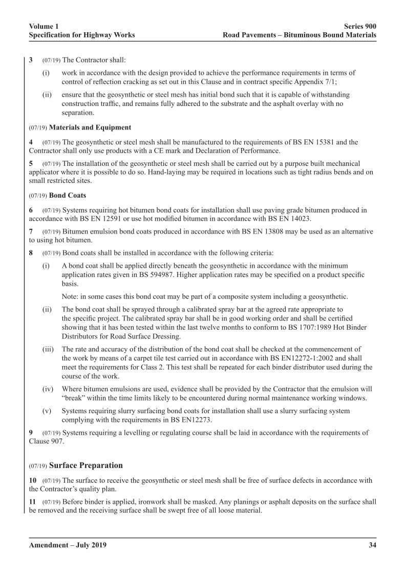
Volume 1 Series 900 Specification for Highway Works Road Pavements – Bituminous Bound Materials
34Amendment – July 2019
3 (07/19) The Contractor shall:
(i) work in accordance with the design provided to achieve the performance requirements in terms of control�of�reflection�cracking�as�set�out�in�this�Clause�and�in�contract�specific�Appendix�7/1;
(ii) ensure that the geosynthetic or steel mesh has initial bond such that it is capable of withstanding construction�traffic,�and�remains�fully�adhered�to�the�substrate�and�the�asphalt�overlay�with�no�separation.
(07/19) Materials and Equipment
4 (07/19) The geosynthetic or steel mesh shall be manufactured to the requirements of BS EN 15381 and the Contractor shall only use products with a CE mark and Declaration of Performance.
5 (07/19) The installation of the geosynthetic or steel mesh shall be carried out by a purpose built mechanical applicator where it is possible to do so. Hand-laying may be required in locations such as tight radius bends and on small restricted sites.
(07/19) Bond Coats
6 (07/19) Systems requiring hot bitumen bond coats for installation shall use paving grade bitumen produced in accordance�with�BS�EN�12591�or�use�hot�modified�bitumen�in�accordance�with�BS�EN�14023.�
7 (07/19) Bitumen emulsion bond coats produced in accordance with BS EN 13808 may be used as an alternative to using hot bitumen.
8 (07/19) Bond coats shall be installed in accordance with the following criteria:
(i) A bond coat shall be applied directly beneath the geosynthetic in accordance with the minimum application�rates�given�in�BS�594987.�Higher�application�rates�may�be�specified�on�a�product�specific�basis.
Note: in some cases this bond coat may be part of a composite system including a geosynthetic.
(ii) The bond coat shall be sprayed through a calibrated spray bar at the agreed rate appropriate to the�specific�project.�The�calibrated�spray�bar�shall�be�in�good�working�order�and�shall�be�certified�showing that it has been tested within the last twelve months to conform to BS 1707:1989 Hot Binder Distributors for Road Surface Dressing.
(iii) The rate and accuracy of the distribution of the bond coat shall be checked at the commencement of the work by means of a carpet tile test carried out in accordance with BS EN12272-1:2002 and shall meet the requirements for Class 2. This test shall be repeated for each binder distributor used during the course of the work.
(iv) Where bitumen emulsions are used, evidence shall be provided by the Contractor that the emulsion will “break” within the time limits likely to be encountered during normal maintenance working windows.
(v) Systems requiring slurry surfacing bond coats for installation shall use a slurry surfacing system complying with the requirements in BS EN12273.
9 (07/19) Systems requiring a levelling or regulating course shall be laid in accordance with the requirements of Clause 907.
(07/19) Surface Preparation
10 (07/19) The surface to receive the geosynthetic or steel mesh shall be free of surface defects in accordance with the Contractor’s quality plan.
11 (07/19) Before binder is applied, ironwork shall be masked. Any planings or asphalt deposits on the surface shall be removed and the receiving surface shall be swept free of all loose material.
Volume 1 Series 900 Specification for Highway Works Road Pavements – Bituminous Bound Materials
35Amendment – July 2019
(07/19) Application
12 (07/19)�Installation�shall�be�carried�out�using�appropriate�mechanical�equipment�that�is�designed�specifically�to�lay the material under tension. Installation shall be planned and carried out such that there is continuity of works and other surfacing operations are not impeded.
13 (07/19) The Contractor’s quality plan shall determine the weather conditions under which the geosynthetic or steel mesh can be installed. Transverse and longitudinal overlaps shall be in accordance with the Contractor’s quality plan. The Contractor shall measure and record the bond condition as stipulated in the quality plan and refer to the RSTA ADEPT Code of Practice for Geosynthetics and Steel Meshes.
14 (07/19)�A�geosynthetic�or�steel�mesh�interlayer�shall�be�placed�sufficiently�deep�within�the�bound�layers�so�that�it is not removed when the surface course is replaced. If a surface course is to be placed directly on a geosynthetic, approval by the Overseeing Organisation (a Departure from Standard) will be needed.
(07/19) Aftercare
15 (07/19) Masking shall be removed after the geosynthetic or steel mesh has been installed and before the surfacing operation commences. The geosynthetic or steel mesh shall be overlaid in the same shift, or as soon as is practically possible.
16 (07/19) The Contractor shall undertake remedial action where necessary, which may include nailing, patching, cutting or dusting if there are signs of distress, such as separation, turning damage, bleeding or pickup of the geosynthetic or steel mesh in order to prevent further damage to the System.
(07/19) As Built Manual
17 (07/19) Not more than 30 days after completion of the work the Contractor shall provide a record of the progress of the work in the form of an ‘as built’ manual incorporating all relevant information, including:
(i) the product name;
(ii) all test results;
(iii) variations to the design proposal and those necessitated by local conditions (which need to be agreed prior to installation);
(iv) a record of installation control carried out;
(v) weather information;
(vi) unforeseen problems encountered;
(vii) a list of complaints, if any, from the general public or road users;
(viii) any other information that the Overseeing Organisation may reasonably require to be included, as previously agreed.
Records are to be sent to Highways England using the [email protected] email address.
(07/19) Defects
18 (07/19)�The�surface�course�shall�not�have�more�than�10%�of�the�reflection�cracking�that�was�present�before�the�installation of the geosynthetic or steel mesh, for a minimum period of 5 years. The amount of cracking shall be expressed as a length per 100m for each 100m length. The length of cracking before treatment shall be taken from the�visual�survey�produced�as�part�of�the�pavement�investigation�used�for�scheme�identification.�

Volume 1 Series 900 Specification for Highway Works Road Pavements – Bituminous Bound Materials
36Amendment – July 2019
19 (07/19) Replacement of the surfacing or other remedial measures agreed with the Overseeing Organisation shall be�carried�out�if�reflection�cracking�appears�within�the�first�5�years.�
20 (07/19) For the period of the guarantee, the geosynthetic or steel mesh shall meet the performance requirements stated�in�this�Clause�and�contract�specific�Appendix�7/1.�
21 (07/19) The guarantee shall exclude defects arising from accidental damage or damage caused by settlement or subsidence on which the surfacing material has been laid.
22 (07/19) �The�reappearance�of�reflection�cracking�shall�be�confirmed�by�comparing�locations�of�cracking�with�visual survey records carried out as part of the investigation prior to maintenance treatment design and coring through the cracks. This will identify whether cracking in the ‘new’ surface appears over existing cracks lower in the�pavement�structure.�Note�that�reflection�cracking�may�be�‘top-down’�or�‘bottom-up’.�
937 (05/18) Stone Mastic Asphalt (SMA) Binder Course and Regulating Course
(05/18) General
1 (05/18) Stone Mastic Asphalt binder course and regulating course shall conform to BS EN13108-5, the example from�BSI�PD�6691�Annex�D�for�the�selected�mixture,�the�requirements�of�this�Clause�and�those�specified�in�contract�specific�Appendix�7/1.�The�mixture�designation�shall�be�one�of�the�following:
(i) SMA 6 bin 40/60.
(ii) SMA 6 bin 70/100.
(iii) SMA 6 bin 100/150.
(iv) SMA 6 bin PMB.
(v) SMA 10 bin 40/60.
(vi) SMA 10 bin 70/100.
(vii) SMA 10 bin 100/150.
(viii) SMA 10 bin PMB.
(ix) SMA 14 bin 40/60.
(x) SMA 14 bin 70/100.
(xi) SMA 14 bin 100/150.
(xii) SMA 14 bin PMB.
(xiii) SMA 20 bin 40/60.
(xiv) SMA 20 bin 70/100.
(xv) SMA 20 bin 100/150.
(xvi) SMA 20 bin PMB.
(05/18) Binder Modification
2 (05/18)�Polymer�modified�bitumens�shall�comply�with�BS�EN�14023.�The�Contractor�shall�provide�the�declaration�of�performance�for�the�polymer�modified�bitumen�to�the�Overseeing�Organisation.�The�declaration�of�performance�shall�demonstrate�that�the�binder�meets�the�requirements�of�the�specification�including�the�requirements�stated�in�contract�specific�Appendix�7/1.
Volume 1 Series 900 Specification for Highway Works Road Pavements – Bituminous Bound Materials
Amendment – May 2018 37
3 (05/18) For premixed binders not covered by BS EN 12591 or BS EN 14023 the Contractor shall provide data sheets�giving�details�of�the�properties�of�the�modified�binders�or�additives�proposed,�including�those�specified�in�contract�specific�Appendix�7/1.�These�shall�include�rheological�data�for�pre-blended�polymer�modified�binders�in�accordance with BS EN 14770 and cohesion in accordance with BS EN 13588.
(05/18) Deformation Resistance
4 (05/18) The resistance to permanent deformation of the mixture shall be in accordance with the appropriate class selected�from�Table�D.7�of�BSI�PD�6691�as�specified�in�contract�specific�Appendix�7/1.
5 (05/18)�When�specified�in�contract�specific�Appendix�7/1�the�resistance�to�permanent�deformation�of�material�laid in the permanent works shall be monitored by testing in accordance with BS 594987, clause G 3.1, 3.2 and 3.3. Six�cores�shall�be�taken�from�the�first�kilometre�length�of�material�from�each�mixing�plant�and�thereafter�one�further�core from each subsequent lane kilometre. Results shall be assessed on successive rolling means of sets of six consecutive�results�and�shall�be�deemed�to�conform�if�the�mean�is�no�greater�than�the�specified�value�and�individual�values�not�more�than�50%�greater�than�the�specified�value.
(05/18) Compaction control for Permanent Works
6 (05/18) Compaction shall be controlled by monitoring density and air void content in accordance with BS 594987, clause 9.5.3 and the requirements of this Clause.
7 (05/18) Density shall be continuously assessed using an indirect density gauge in accordance with BS 594987, clause 9.4.2, with readings taken at 50 m intervals in the centre of the mat. Gauge readings shall also be taken at each�core�location�specified�in�BS�594987,�clause�9.5.3.2.1�and�at�the�location�of�cores�required�by�sub-Clause�11.�Each gauge shall be individually calibrated on each mixture from each mixing plant and the calibrations shall be continually checked and updated based on correlations between gauge readings and core densities at the same locations.
8 (05/18) For each location, the in situ void content shall be determined in accordance with EN 12697-8 using the bulk density from the indirect gauge reading and a maximum density taken from the mixture type testing data and updated with values from testing in accordance with sub-Clause 8.
9 (05/18) The average in situ void content calculated from any six consecutive indirect gauge readings shall not exceed 5%, or for regulating course less than 30 mm in thickness, shall not exceed 7%.
10 (05/18) In the event of a failure to meet the requirements in sub-Clause 10, cores shall be taken at each location and void contents determined. Testing of cores shall be carried out in accordance with BS 594987 section 9.5.3 and assessment of conformity shall be in accordance with BS 594987, clause 9.5.3.6.1
11 (05/18) In the event of non-conformity with the requirements of sub-Clause 11 then density readings with indirect gauges and if necessary, further cores shall be taken to establish the extent of the non-conformity. If it is necessary to remove and replace any material to restore conformity this shall be in lengths not less than 15 m unless otherwise agreed by the Overseeing Organisation.
12 (05/18) If the density readings taken with the indirect density gauge indicate that the air voids content may be less than 2%, one 200 mm diameter core shall be cut at that chainage and the resistance to permanent deformation checked in accordance with sub-Clause 6.
(05/18) Bond Coat
13 (05/18)�Where�the�thickness�of�the�stone�mastic�asphalt�is�less�than�20�mm,�polymer�modified�bond�coats�shall�be used.
938 (05/18) Porous Asphalt
1 (05/18)�Porous�asphalt�shall�conform�to�BS�EN�13108-7,�as�specified�in�contract�specific�Appendix�7/1.
Volume 1 Series 900 Specification for Highway Works Road Pavements – Bituminous Bound Materials
38Amendment – May 2018
939 to 941 (05/18) Not Used
#942 (05/18) Thin Surface Course Systems
(05/18) General
1 (05/18) Thin surface course systems shall be provided and installed in accordance with the requirements stated in�this�Clause�and�those�given�in�contract�specific�Appendix�7/1.
2 (05/18)�Thin�surface�course�systems�specified�under�this�Clause�shall�be�between�20mm�and�50mm�thick.
(05/18) Overall Performance Requirements
3 (05/18) The Contractor shall guarantee the installed thin surface course for a period of 5 years from the date of opening�to�traffic.�For�the�period�of�the�guarantee�the�thin�surface�course�shall�meet�the�performance�requirements�stated�in�this�Clause�and�contract�specific�Appendix�7/1.�The�guarantee�shall�exclude�defects�arising�from�accidental damage or damage caused by settlement, subsidence or failure of the underlying carriageway on which the surfacing material has been laid. Replacement of the surfacing or other remedial measures agreed with the Overseeing�Organisation�shall�be�executed�if�the�surfacing�is�in�a�“Suspect”,�“Poor”�or�“Bad”�condition�as�defined�in Appendix A of TRL Report TRL674 – “Durability of thin surfacing systems, Part 4, Final report after nine years monitoring, TRL report 674”.
4 (05/18) The Contractor shall demonstrate that the ‘as installed’ thin surface course system can meet the requirements�of�the�specification.�This�shall�be�demonstrated�by�the�system�meeting�the�stated�material�requirements and by having undergone a System Installation Performance Trial (SIPT) to cover the aspects of the installation not covered by the material’s declaration of performance. The SIPT shall comply with the requirements of sub-Clauses 23 to 43 of this Clause. An acceptable approach for the SIPT would be to use a scheme in accordance with sub-Clause 104.16. The Contractor shall submit details of the SIPT for the systems to be used in the contract as required in sub-Clause 28 to the Overseeing Organisation for acceptance.
(05/18) Material Requirements
5 (05/18) The thin surface course mixture shall comply with BS EN 13108-1, BS EN 13108-2 or BS EN 13108-5. It shall be CE marked and the Contractor shall submit the declaration of performance for the material to the Overseeing Organisation. The declaration of performance shall demonstrate that the material meets the requirements�of�the�specification.
6 (05/18) The coarse aggregate shall be crushed rock or steel slag complying with Clause 901 and BS EN 13043:2002. The Contractor shall submit the declaration of performance for the aggregate to the Overseeing Organisation. The declaration of performance shall demonstrate that the aggregate meets the requirements of the specification.�The�resistance�to�polishing�and�abrasion,�PSV�and�AAV,�shall�be�as�specified�in�contract�specific�Appendix 7/1.
The�aggregate�resistance�to�fragmentation�and�flakiness�Index�shall�be�as�follows:
(i)� Resistance�to�fragmentation:�Los�Angeles�Coefficient�(LA)�–�not�greater�than�LA30;
(ii) Flakiness Index (FI) – not greater than FI20.
The�maximum�aggregate�size�shall�be�as�given�in�Table�9/9

Volume 1 Series 900 Specification for Highway Works Road Pavements – Bituminous Bound Materials
Amendment – May 2018 39
TABLE 9/9: (05/18) Maximum Aggregate Size
Site Definition Maximum�Aggregate�SizeRoundabouts 10mmBends < 250m radius 10mmJunctions�where�turning�radius�movements�<250m
10mm
All other sites 14mm
7 (05/18)�The�minimum�target�design�binder�contents�shall�be�in�accordance�with�Table�9/10�and�contract�specific�Appendix 7/1.
TABLE 9/10: (05/18) Minimum design binder content
Minimum target design binder content (Bmin)Maximum aggregate size (D)
Mixture types: EN13108, Parts 1 and 2 (AC & BBTM with PMB to BS EN 14023)
Mixture types: EN 13108 Part 5 (SMA – paving grade bitumen to BS EN 12591 and fibresSMA)
14 5.0 6.010 5.2 6.26 5.4 Not used
8 (05/18)�The�resistance�to�permanent�deformation�shall�be�as�specified�in�contract�specific�Appendix�7/1.�The�resistance to permanent deformation of mixtures conforming to BS EN 13108 Parts 1 and 5 shall be in accordance with the appropriate class selected from Table B.4 or D.2 respectively of PD 6691.
9 (05/18)�The�water�sensitivity�shall�be�as�specified�in�contract�specific�Appendix�7/1.�The�water�sensitivity�of�mixtures conforming with BS EN 13108 Parts 1, 2 and 5 shall conform to, at least, category ITSRmin70.
10 (05/18)�Where�required�in�contract�specific�Appendix�7/1�the�design�void�content�shall�be�Vmin1 to Vmax5%
11 (05/18)�Contract�compliance�testing�of�the�mixture�shall�be�carried�out�as�required�in�contract�specific�Appendix�1/5�and�samples�supplied�as�detailed�in�contract�specific�Appendix�1/6.
(05/18) Installation Requirements: General
12 (05/18) The Contractor shall provide an Installation Method Statement to the Overseeing Organisation. It shall include the SIPT method statement as described in sub-Clause 26 of this Clause, all installation instructions relevant�to�the�system�being�used,�details�as�specified�in�this�Clause�and�details�to�meet�the�requirements�of�Clause�903.
13 (05/18)�The�design�thickness�of�the�thin�surface�course�system�shall�be�as�specified�in�the�contract�specific�Appendix 7/1 within the minimum and maximum design thickness permitted in Table 9/11. The installed layer thickness must not be less than the permitted minimum thickness, nor greater than the permitted maximum thickness, stated in the Installation Method Statement.
TABLE 9/11: (05/18) Design Target Layer Thickness.
Nominal Aggregate size, mm
Design target thickness, mmMinimum Maximum
6 20 3010 25 4014 35 50

Volume 1 Series 900 Specification for Highway Works Road Pavements – Bituminous Bound Materials
40Amendment – May 2018
14 (05/18)�Where�required�in�the�Installation�Method�Statement�or�in�contract�specific�Appendix�7/1,�to�achieve�final�pavement�levels�and/or�thicknesses�the�existing�substrate�surface�shall�be�strengthened�or�regulated�in�accordance with Clause 907.
15 (05/18) Where the existing substrate surface is regulated in accordance with Clause 907, evidence that the deformation�resistance�of�the�regulating�material�will�meet�the�specification�shall�be�submitted�by�the�Contractor�to�the Overseeing Organisation. Where the combined thickness of the regulating material and the thin surface course is more than 20 mm, evidence of the deformation resistance of the combined layers shall be provided.
16 (05/18) Surface preparation including the removal of road markings, cleaning and drying, resetting of ironwork and road studs shall be in accordance with BS 594987 and the Installation Method Statement.
17 (05/18) Where required in the Installation Method Statement a bond coat or tack coat shall be applied. It shall be in accordance with the Installation Method Statement. Unless otherwise stated in the Installation Method Statement is shall also comply with Clause 920 and BS 594987. A calibrated mechanised method of application shall be used unless otherwise agreed with the Overseeing Organisation.
18 (05/18) Transportation of the thin surface course material shall be in accordance with the System Installation Method Statement and Clause 903.
(05/18) Installation Requirements: Surface Macrotexture – Untrafficked
19 (05/18) The surface macrotexture depth of the thin surface course system shall be measured in accordance with�BS�EN�13036-1.�Unless�otherwise�stated�in�contract�specific�Appendix�7/1�the�macrotexture�of�the�installed�surfacing shall comply with the relevant section of Table 9/12 or Table 9/13.
TABLE 9/12: (05/18) Requirements for Initial Texture Depth for Trunk Roads including Motorways for Thin Surface Course Systems
Road Type Surfacing TypeAverage per 1,000 m
section, mmAverage for a set of 10 Measurements,
mm (minimum)Minimum Maximum
High speed roads Upper (D)�aggregate�size�of�14mm 1.3 1.8 1.0Upper (D)�aggregate�size�of�10mm 1.1 1.6 0.9Upper (D)�aggregate�size�of�6mm 1.0 1.5 0.9
Lower speed roads Upper (D)�aggregate�size�of�14mm�or�less: 1.0 1.5 0.9
Roundabouts on high speed roads Upper (D)�aggregate�size�of�10mm 1.1 1.6 0.9
Roundabouts on lower speed roads
Upper (D)�aggregate�size�of�10mm 1.0 1.5 0.9Upper (D)�aggregate�size�of�6mm 1.0 1.5 0.9
High�Speed�Roads�are�those�with�a�posted�speed�limit�≥�50�miles/h�(80�km/h) Lower�Speed�Roads�are�those�with�a�posted�speed�limit�≤�40�miles/h�(65�km/h)
Volume 1 Series 900 Specification for Highway Works Road Pavements – Bituminous Bound Materials
Amendment – May 2018 41
TABLE 9/13: (05/18) Requirements for Initial Texture Depth for Roads other than Trunk Roads and Motorways for Thin Surface Course Systems
Road Classification
Posted traffic speed Average per 1,000 m section, mm Average for a set of 10 Measurements,
mm (minimum)Minimum
initial (mm)Maximum Initial
(mm)A ≥�50mph 1.0 1.5 0.9A All other traffic speeds 0.8 1.3 0.7
B,C,U All traffic speeds 0.8 1.3 0.7
(05/18) Installation Requirements: Macrotexture – Trafficked
20 (05/18)�For�a�period�of�two�years�from�the�date�of�opening�to�traffic�the�average�macrotexture,�measured�using�the volumetric patch technique in accordance with BS EN 13036-1, will be maintained above the levels given in contract�specific�Appendix�7/1�and�Table�9/14.�The�measurements�shall�be�in�the�most�heavily�trafficked�lane�at�10 m intervals along the centre of the most heavily worn wheel-track.
TABLE 9/14: (05/18) Retained Surface Macrotexture Requirements
Surfacing Type Average texture depth per 1,000m section, mm*
Systems with an upper (D)�aggregate�size�of�14mm�laid�on�motorway�trunk and high speed A roads
0.9
Systems with an upper (D)�aggregate�size�of�10mm�laid�on�motorway�trunk and high speed A roads
0.8
Systems with an upper (D)�aggregate�size�of�6mm�laid�on�motorway�trunk and high speed A roads
0.7 **
Systems�with�all�aggregate�sizes�laid�on�non-trunk�low�speed�A,�and�all�B, C and U classification roads
0.6
* or the complete carriageway lane where this is less than 1,000 m. **�verification�of�high�speed�friction�performance�required
(05/18) Installation Requirements: Torque Bond
21 (05/18)�The�bond�strength�between�a�thin�surfacing�system�and�its�substrate�shall�be�≥�400�kPa,�measured�in�accordance with Clause 951.
(05/18) Installation Requirements: Noise
22 (05/18) The thin surface course system shall have the road/tyre noise characteristics as required in contract specific�Appendix�7/1.
(05/18) System Installation Performance Trial (SIPT) Requirements
23 (05/18) The thin surface course used in the SIPT shall meet the performance requirements of the thin surface course to be supplied under the contract. This shall be demonstrated by the assessments and testing undertaken for the SIPT.
24 (05/18)�The�installed�thin�surface�course�system�shall�be�assessed,�tested�and�certified�by�a�Certification�Body�using�one�or�more�trial�areas�of�surfacing.�The�Certification�Body�shall�be�accredited�to�BS�EN�45011�by�UKAS�or�equivalent�European�Accreditation�organisation�which�is�party�to�a�multi-lateral�agreement�(MLA)�with�UKAS�or�any equivalent International Accreditation Forum MLA signatory with a scope that includes relevant standard(s) or scheme(s).
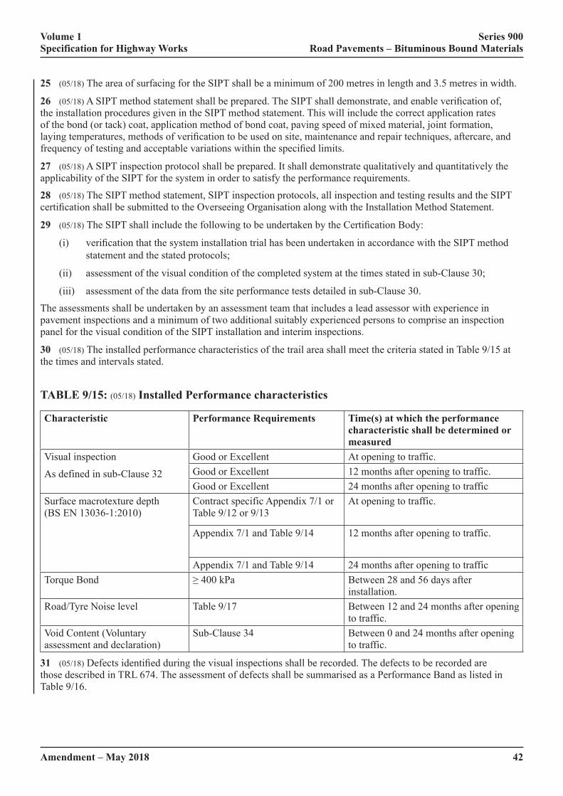
Volume 1 Series 900 Specification for Highway Works Road Pavements – Bituminous Bound Materials
42Amendment – May 2018
25 (05/18) The area of surfacing for the SIPT shall be a minimum of 200 metres in length and 3.5 metres in width.
26 (05/18)�A�SIPT�method�statement�shall�be�prepared.�The�SIPT�shall�demonstrate,�and�enable�verification�of,�the installation procedures given in the SIPT method statement. This will include the correct application rates of the bond (or tack) coat, application method of bond coat, paving speed of mixed material, joint formation, laying�temperatures,�methods�of�verification�to�be�used�on�site,�maintenance�and�repair�techniques,�aftercare,�and�frequency�of�testing�and�acceptable�variations�within�the�specified�limits.
27 (05/18) A SIPT inspection protocol shall be prepared. It shall demonstrate qualitatively and quantitatively the applicability of the SIPT for the system in order to satisfy the performance requirements.
28 (05/18) The SIPT method statement, SIPT inspection protocols, all inspection and testing results and the SIPT certification�shall�be�submitted�to�the�Overseeing�Organisation�along�with�the�Installation�Method�Statement.
29 (05/18)�The�SIPT�shall�include�the�following�to�be�undertaken�by�the�Certification�Body:
(i)� verification�that�the�system�installation�trial�has�been�undertaken�in�accordance�with�the�SIPT�method�statement and the stated protocols;
(ii) assessment of the visual condition of the completed system at the times stated in sub-Clause 30;
(iii) assessment of the data from the site performance tests detailed in sub-Clause 30.
The assessments shall be undertaken by an assessment team that includes a lead assessor with experience in pavement inspections and a minimum of two additional suitably experienced persons to comprise an inspection panel for the visual condition of the SIPT installation and interim inspections.
30 (05/18) The installed performance characteristics of the trail area shall meet the criteria stated in Table 9/15 at the times and intervals stated.
TABLE 9/15: (05/18) Installed Performance characteristics
Characteristic Performance Requirements Time(s) at which the performance characteristic shall be determined or measured
Visual inspection
As defined in sub-Clause 32
Good or Excellent At opening to traffic.Good or Excellent 12 months after opening to traffic.Good or Excellent 24 months after opening to traffic
Surface macrotexture depth (BS EN 13036-1:2010)
Contract specific Appendix 7/1 or Table 9/12 or 9/13
At opening to traffic.
Appendix 7/1 and Table 9/14 12 months after opening to traffic.
Appendix 7/1 and Table 9/14 24 months after opening to trafficTorque Bond ≥�400�kPa Between 28 and 56 days after
installation.Road/Tyre Noise level Table 9/17 Between 12 and 24 months after opening
to traffic.Void Content (Voluntary assessment and declaration)
Sub-Clause 34 Between 0 and 24 months after opening to traffic.
31 (05/18)�Defects�identified�during�the�visual�inspections�shall�be�recorded.�The�defects�to�be�recorded�are�those described in TRL 674. The assessment of defects shall be summarised as a Performance Band as listed in Table 9/16.
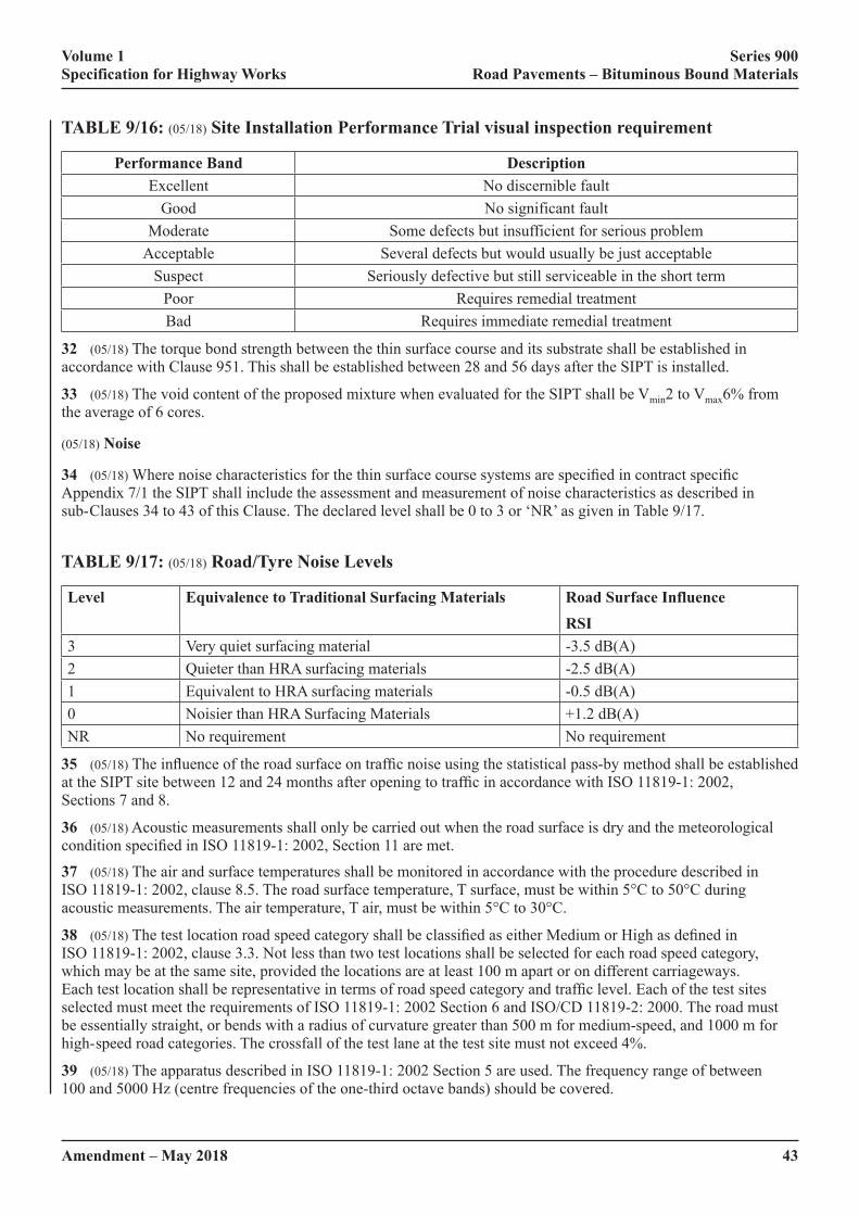
Volume 1 Series 900 Specification for Highway Works Road Pavements – Bituminous Bound Materials
Amendment – May 2018 43
TABLE 9/16: (05/18) Site Installation Performance Trial visual inspection requirement
Performance Band DescriptionExcellent No discernible fault
Good No significant faultModerate Some defects but insufficient for serious problem
Acceptable Several defects but would usually be just acceptableSuspect Seriously defective but still serviceable in the short term
Poor Requires remedial treatmentBad Requires immediate remedial treatment
32 (05/18) The torque bond strength between the thin surface course and its substrate shall be established in accordance with Clause 951. This shall be established between 28 and 56 days after the SIPT is installed.
33 (05/18) The void content of the proposed mixture when evaluated for the SIPT shall be Vmin2 to Vmax6% from the average of 6 cores.
(05/18) Noise
34 (05/18)�Where�noise�characteristics�for�the�thin�surface�course�systems�are�specified�in�contract�specific�Appendix 7/1 the SIPT shall include the assessment and measurement of noise characteristics as described in sub- Clauses 34 to 43 of this Clause. The declared level shall be 0 to 3 or ‘NR’ as given in Table 9/17.
TABLE 9/17: (05/18) Road/Tyre Noise Levels
Level Equivalence to Traditional Surfacing Materials Road Surface InfluenceRSI
3 Very quiet surfacing material -3.5 dB(A)2 Quieter than HRA surfacing materials -2.5 dB(A)1 Equivalent to HRA surfacing materials -0.5 dB(A)0 Noisier than HRA Surfacing Materials +1.2 dB(A)NR No requirement No requirement
35 (05/18)�The�influence�of�the�road�surface�on�traffic�noise�using�the�statistical�pass-by�method�shall�be�established�at�the�SIPT�site�between�12�and�24�months�after�opening�to�traffic�in�accordance�with�ISO�11819-1:�2002,�Sections 7 and 8.
36 (05/18) Acoustic measurements shall only be carried out when the road surface is dry and the meteorological condition�specified�in�ISO�11819-1:�2002,�Section�11�are�met.
37 (05/18) The air and surface temperatures shall be monitored in accordance with the procedure described in ISO 11819-1: 2002, clause 8.5. The road surface temperature, T surface, must be within 5°C to 50°C during acoustic measurements. The air temperature, T air, must be within 5°C to 30°C.
38 (05/18)�The�test�location�road�speed�category�shall�be�classified�as�either�Medium�or�High�as�defined�in�ISO 11819-1: 2002, clause 3.3. Not less than two test locations shall be selected for each road speed category, which may be at the same site, provided the locations are at least 100 m apart or on different carriageways. Each�test�location�shall�be�representative�in�terms�of�road�speed�category�and�traffic�level.�Each�of�the�test�sites�selected must meet the requirements of ISO 11819-1: 2002 Section 6 and ISO/CD 11819-2: 2000. The road must be essentially straight, or bends with a radius of curvature greater than 500 m for medium-speed, and 1000 m for high- speed road categories. The crossfall of the test lane at the test site must not exceed 4%.
39 (05/18) The apparatus described in ISO 11819-1: 2002 Section 5 are used. The frequency range of between 100�and�5000�Hz�(centre�frequencies�of�the�one-third�octave�bands)�should�be�covered.
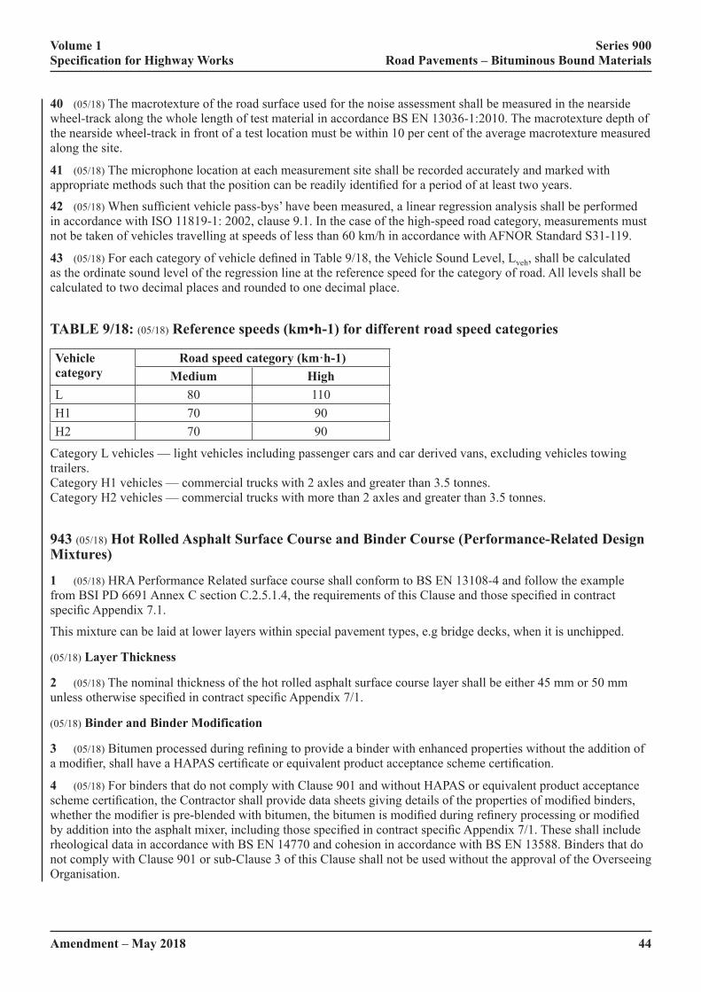
Volume 1 Series 900 Specification for Highway Works Road Pavements – Bituminous Bound Materials
44Amendment – May 2018
40 (05/18) The macrotexture of the road surface used for the noise assessment shall be measured in the nearside wheel-track along the whole length of test material in accordance BS EN 13036-1:2010. The macrotexture depth of the nearside wheel-track in front of a test location must be within 10 per cent of the average macrotexture measured along the site.
41 (05/18) The microphone location at each measurement site shall be recorded accurately and marked with appropriate�methods�such�that�the�position�can�be�readily�identified�for�a�period�of�at�least�two�years.
42 (05/18)�When�sufficient�vehicle�pass-bys’�have�been�measured,�a�linear�regression�analysis�shall�be�performed�in accordance with ISO 11819-1: 2002, clause 9.1. In the case of the high-speed road category, measurements must not be taken of vehicles travelling at speeds of less than 60 km/h in accordance with AFNOR Standard S31-119.
43 (05/18)�For�each�category�of�vehicle�defined�in�Table�9/18,�the�Vehicle�Sound�Level,�Lveh, shall be calculated as the ordinate sound level of the regression line at the reference speed for the category of road. All levels shall be calculated to two decimal places and rounded to one decimal place.
TABLE 9/18: (05/18) Reference speeds (km•h-1) for different road speed categories
Vehicle category
Road speed category (km·h-1) Medium High
L 80 110H1 70 90H2 70 90
Category L vehicles — light vehicles including passenger cars and car derived vans, excluding vehicles towing trailers. Category H1 vehicles — commercial trucks with 2 axles and greater than 3.5 tonnes. Category H2 vehicles — commercial trucks with more than 2 axles and greater than 3.5 tonnes.
943 (05/18) Hot Rolled Asphalt Surface Course and Binder Course (Performance-Related Design Mixtures)
1 (05/18) HRA Performance Related surface course shall conform to BS EN 13108-4 and follow the example from�BSI�PD�6691�Annex�C�section�C.2.5.1.4,�the�requirements�of�this�Clause�and�those�specified�in�contract�specific�Appendix�7.1.
This mixture can be laid at lower layers within special pavement types, e.g bridge decks, when it is unchipped.
(05/18) Layer Thickness
2 (05/18) The nominal thickness of the hot rolled asphalt surface course layer shall be either 45 mm or 50 mm unless�otherwise�specified�in�contract�specific�Appendix�7/1.
(05/18) Binder and Binder Modification
3 (05/18)�Bitumen�processed�during�refining�to�provide�a�binder�with�enhanced�properties�without�the�addition�of�a�modifier,�shall�have�a�HAPAS�certificate�or�equivalent�product�acceptance�scheme�certification.
4 (05/18) For binders that do not comply with Clause 901 and without HAPAS or equivalent product acceptance scheme�certification,�the�Contractor�shall�provide�data�sheets�giving�details�of�the�properties�of�modified�binders,�whether�the�modifier�is�pre-blended�with�bitumen,�the�bitumen�is�modified�during�refinery�processing�or�modified�by�addition�into�the�asphalt�mixer,�including�those�specified�in�contract�specific�Appendix�7/1.�These�shall�include�rheological data in accordance with BS EN 14770 and cohesion in accordance with BS EN 13588. Binders that do not comply with Clause 901 or sub-Clause 3 of this Clause shall not be used without the approval of the Overseeing Organisation.

Volume 1 Series 900 Specification for Highway Works Road Pavements – Bituminous Bound Materials
Amendment – May 2018 45
(05/18) Coarse Aggregate
5 (05/18) Coarse aggregate shall be crushed rock or slag complying with BS EN 13043:2002 and Clause 901. The resistance to polishing of the coarse aggregate for surface course shall comply with category PSV44 in accordance with BS EN 13043:2002, clause 4.2.3.
(05/18) Deformation Resistance
6 (05/18) The resistance to permanent deformation of the mixture shall be in accordance with the appropriate class selected�from�Table�C.3�of�BSI�PD�6691,�as�specified�in�contract�specific�Appendix�7/1.
(05/18) Coated Chippings for Surface Course
7 (05/18)�When�required,�coated�chippings�shall�be�14/20�mm�or�8/14�mm�size�as�specified�in�contract�specific�Appendix 7/1 and comply with Clause 915.
(05/18) Surface Macrotexture for Surface Course
8 (05/18) The surface macrotexture shall comply with Clause 921.
(05/18) Compaction Control Procedures
9 (05/18) Control testing for compaction and resistance to permanent deformation shall be carried out in accordance with BS 594987 section 9.5.2.
10 (05/18)�When�specified�in�the�contract�specific�Appendix�7/1,�the�resistance�to�permanent�deformation�of�material laid in the permanent works shall be monitored by testing in accordance with clause F.3 of BS 594987 Annex�F.�Six�cores�shall�be�taken�from�the�first�kilometre�length�of�material�from�each�mixing�plant�and�thereafter�one further core from each subsequent lane kilometre. Results shall be assessed on successive rolling means of sets of�six�consecutive�results�and�shall�be�deemed�to�conform�if�the�mean�is�no�greater�than�the�specified�value�and�individual�values�not�more�than�50%�greater�than�the�specified�value.
(05/18) Trafficking Newly Laid Surfacing
11 (05/18) The Contractor shall ensure the pavement material has adequately cooled and hardened before the road is�opened�to�traffic.�Unless�otherwise�agreed�by�the�Overseeing�Organisation,�the�road�shall�not�be�opened�to�traffic�if its surface temperature exceeds 25°C unless the maximum temperature within the mat has fallen below 35°C.
944 (05/18) Not Used
945 (05/18) Weather Conditions for Laying of Hot Bituminous Mixtures
1 (05/18) The Contractor shall take account of the weather conditions when planning his working methods. The Contractor’s working methods shall comply with all weather-related requirements of BS 594987 and any additional requirements of this Clause. When laying is to be undertaken during winter (October to April) and/or night�time�(9�p.m.�to�6�a.m.),�the�contractor�shall�work�to�a�Quality�Plan�that�allows�for�the�specific�issues�raised�by�winter and/or night time working.
2 (05/18) Hot bituminous materials laid less than 50 mm thick, other than those supplied to Clause 942, shall be laid within the wind speed and temperature constraints of Figure 9/1.
(05/18) Thin Surface Course Systems
3 (05/18)�The�weather�conditions�for�laying�thin�surface�course�systems�shall�comply�with�those�identified�as�being acceptable in the Installation Method Statement as required in Clause 942.
Volume 1 Series 900 Specification for Highway Works Road Pavements – Bituminous Bound Materials
46Amendment – May 2018
(05/18) Hot Rolled Asphalt With Pre-coated Chippings
4 (05/18) Hot rolled asphalt surface course mixtures incorporating 35% coarse aggregate with pre-coated chippings shall be laid 50 mm thick, within the following constraints of delivery temperature, wind speed and air temperature.
Air temperature (minimum): 0°C
Wind speed (maximum at any air temperature):
40 km/h (at 2 m height)
or
50 km/h (at 10 m height)Minimum delivery temperature of materials: 155°C.
(05/18) Wind Speed
5 (05/18) When measurements are required for assessment, wind speed shall be measured by anemometer positioned�near�the�laying�site�to�accurately�reflect�conditions�at�the�laying�site.�The�anemometer�shall�be�fitted�with�a digital accumulative device.
FIGURE 9/1: (05/18) Wind Speed and Air Temperature Laying Restrictions for Layers Less Than 50 mm Thick
946 (05/18) Local Repairs
(05/18) General
1 (05/18)�Local�repair�is�defined�as�the�reinstatement�of�surface�course,�and�binder�course�and�base�if�necessary,�over a relatively small area.
2 (05/18) Areas of defectiveness greater than 1m2 shall be repaired by inset replacement over a length and width in accordance with sub-Clause 702.10(iv) and sub-Clause 903.21. Areas of defectiveness up to 1m2 in surface area may be repaired using an inset patch. The repair technique used shall be as given in Table 9/19.
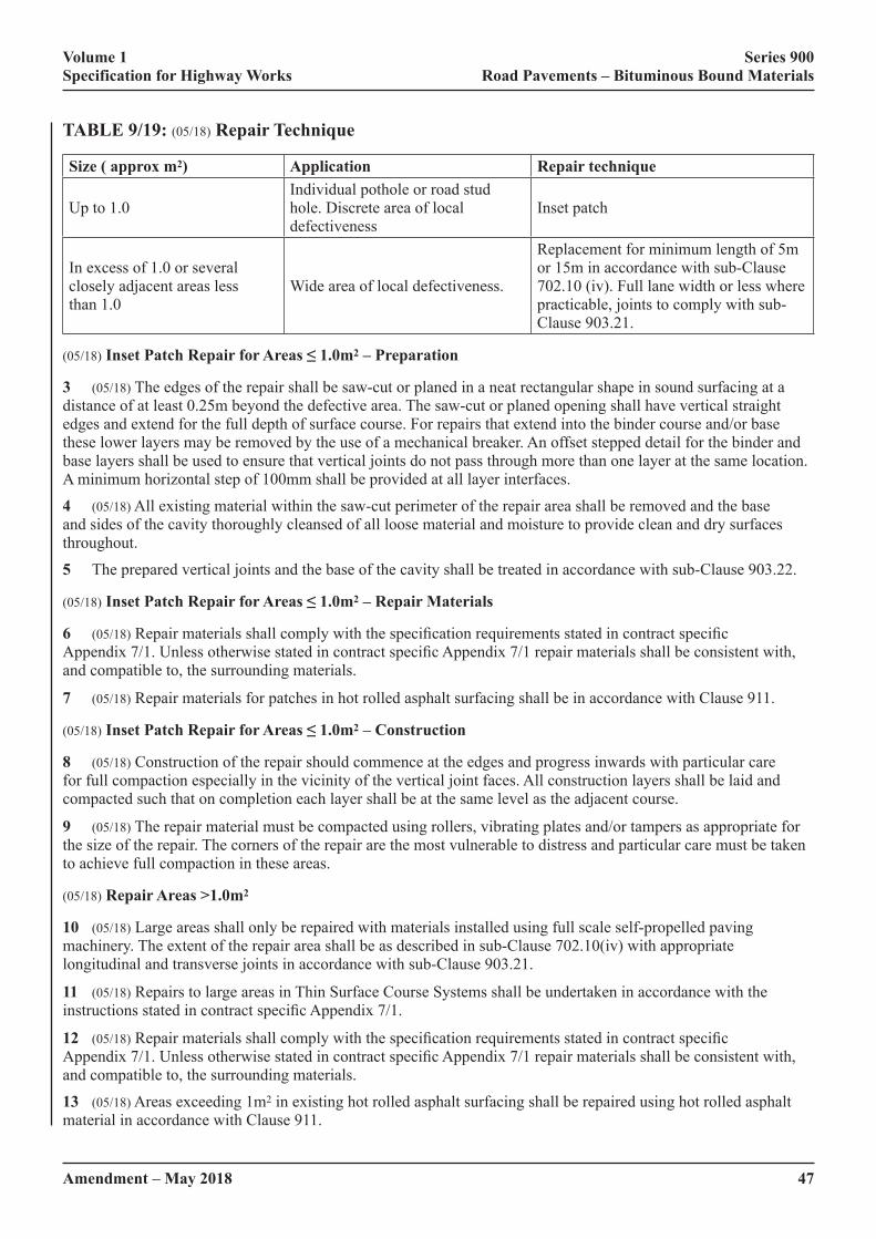
Volume 1 Series 900 Specification for Highway Works Road Pavements – Bituminous Bound Materials
Amendment – May 2018 47
TABLE 9/19: (05/18) Repair Technique
Size ( approx m2) Application Repair technique
Up to 1.0Individual pothole or road stud hole. Discrete area of local defectiveness
Inset patch
In excess of 1.0 or several closely adjacent areas less than 1.0
Wide area of local defectiveness.
Replacement for minimum length of 5m or 15m in accordance with sub-Clause 702.10 (iv). Full lane width or less where practicable, joints to comply with sub-Clause 903.21.
(05/18) Inset Patch Repair for Areas ≤ 1.0m2 – Preparation
3 (05/18) The edges of the repair shall be saw-cut or planed in a neat rectangular shape in sound surfacing at a distance of at least 0.25m beyond the defective area. The saw-cut or planed opening shall have vertical straight edges and extend for the full depth of surface course. For repairs that extend into the binder course and/or base these lower layers may be removed by the use of a mechanical breaker. An offset stepped detail for the binder and base layers shall be used to ensure that vertical joints do not pass through more than one layer at the same location. A�minimum�horizontal�step�of�100mm�shall�be�provided�at�all�layer�interfaces.
4 (05/18) All existing material within the saw-cut perimeter of the repair area shall be removed and the base and sides of the cavity thoroughly cleansed of all loose material and moisture to provide clean and dry surfaces throughout.
5 The prepared vertical joints and the base of the cavity shall be treated in accordance with sub-Clause 903.22.
(05/18) Inset Patch Repair for Areas ≤ 1.0m2 – Repair Materials
6 (05/18)�Repair�materials�shall�comply�with�the�specification�requirements�stated�in�contract�specific�Appendix�7/1.�Unless�otherwise�stated�in�contract�specific�Appendix�7/1�repair�materials�shall�be�consistent�with,�and compatible to, the surrounding materials.
7 (05/18) Repair materials for patches in hot rolled asphalt surfacing shall be in accordance with Clause 911.
(05/18) Inset Patch Repair for Areas ≤ 1.0m2 – Construction
8 (05/18) Construction of the repair should commence at the edges and progress inwards with particular care for full compaction especially in the vicinity of the vertical joint faces. All construction layers shall be laid and compacted such that on completion each layer shall be at the same level as the adjacent course.
9 (05/18) The repair material must be compacted using rollers, vibrating plates and/or tampers as appropriate for the�size�of�the�repair.�The�corners�of�the�repair�are�the�most�vulnerable�to�distress�and�particular�care�must�be�taken�to achieve full compaction in these areas.
(05/18) Repair Areas >1.0m2
10 (05/18) Large areas shall only be repaired with materials installed using full scale self-propelled paving machinery. The extent of the repair area shall be as described in sub-Clause 702.10(iv) with appropriate longitudinal and transverse joints in accordance with sub-Clause 903.21.
11 (05/18) Repairs to large areas in Thin Surface Course Systems shall be undertaken in accordance with the instructions�stated�in�contract�specific�Appendix�7/1.
12 (05/18)�Repair�materials�shall�comply�with�the�specification�requirements�stated�in�contract�specific�Appendix�7/1.�Unless�otherwise�stated�in�contract�specific�Appendix�7/1�repair�materials�shall�be�consistent�with,�and compatible to, the surrounding materials.
13 (05/18) Areas exceeding 1m2 in existing hot rolled asphalt surfacing shall be repaired using hot rolled asphalt material in accordance with Clause 911.
Volume 1 Series 900 Specification for Highway Works Road Pavements – Bituminous Bound Materials
48Amendment – May 2018
14 (05/18) Placing and compaction shall be in accordance with Clause 903 and BS594987 with use of bond coat in accordance with Clause 920.
(05/18) Proprietary Materials and Techniques for Repairs ≤ 1.0m2
15 (05/18) Evidence from laboratory evaluation shall be provided by the Contractor to the Overseeing Organisation to demonstrate that the proprietary repair materials and/or techniques comply with the following performance criteria:
• Stiffness:�≥1�GPa�after�28�days�when�tested�in�accordance�with�BS�EN�12697-26�(ITSM�method�20°C)
• Resistance�to�permanent�deformation:�Classification�No.�1�as�defined�in�Table�D.2�of�BSI�PD�6691
16 (05/18) Data from a representative area of the material and/or technique, for a local repair >2m2�in�size,�must�be�provided�to�demonstrate�that�the�finished�surface�to�be�trafficked�complies�with�the�following:
• The initial surface texture shall be not less than 0.9mm when measured using the volumetric patch method described in BS EN 13036-1
• The minimum wet Skid Resistance value shall not be less than 60 when determined using the portable skid resistance tester (pendulum) in accordance with BS EN 13036-4.
947 (05/18) In Situ Cold Recycled Bitumen Bound Material
(05/18) Scope
1 (05/18) In situ cold recycled bitumen bound material shall be designed and produced to form the foundation or main structural layer of the road pavement. The primary aggregate source shall be obtained by cold pulverisation of all, or part, of the existing road structure. The primary binder (stabilising agent) shall be a foamed bitumen, with cement�or�lime�as�an�adhesion�agent.�The�aggregate�grading�may�be�adjusted�by�the�addition�of�a�filler.�Lime�may�also be used to modify any cohesive sub-grade soil incorporated in the pulverised layer.
2 (05/18) Prior to commencing the pulverisation and stabilisation works, the Contractor shall demonstrate, to the satisfaction of the Overseeing Organisation, using the results of mix design procedures described in sub-Clauses 58 to�65�of�this�Clause,�that�the�existing�pavement�materials�in�the�sections�of�the�works�defined�in�contract�specific�Appendix 7/18 are capable of being recycled by pulverisation to form the primary aggregate component of an in situ�cold�recycled�bitumen�bound�material�which�can�meet�the�specified�end-product�performance�requirements.
(05/18) Component Materials
(05/18) Aggregates and Fillers
3 (05/18)�The�pulverised�pavement�material�and�any�supplementary�aggregate�and/or�filler�shall�normally�be�granular material with not less than 5% and not more than 20% passing the 0.063 mm sieve (Zone A graded material). Approval for use of pulverised granular material containing up to 35% passing the 0.063 mm sieve (Zone�B�graded�material)�shall�require�confirmation�by�the�Overseeing�Organisation,�subject�to�the�results�of�the�mixture design procedures described in sub-Clauses 58 to 65 of this Clause.
4 (05/18) The pulverised granular material shall contain not more than 2% of organic matter as determined in accordance with BS 1377-3 clause 3.
(05/18) Bitumen Binder
5 (05/18) The primary binder shall be foamed bitumen. The base bitumen shall comply with BS EN 12591 and shall be 100/150 penetration grade.
6 (05/18)�Other�than�foaming�agent(s),�bitumen�modifiers�shall�not�be�used�unless�approved�by�the�Overseeing�Organisation for special purposes or conditions.
Volume 1 Series 900 Specification for Highway Works Road Pavements – Bituminous Bound Materials
Amendment – May 2018 49
7 (05/18) The binder shall be transported to the site in tankers capable of maintaining the required temperature and a homogeneous binder consistency and transferred to the stabilising plant in a controlled and uniform manner.
8 (05/18) The foaming of the bitumen shall be carried out within the spraybar system of the recycling machine and immediately mixed with the pulverised aggregate, at which point the foamed bitumen shall have a volume of not less than 10 times the volume of the base penetration grade bitumen.
(05/18) Cement, Filler Aggregate and Lime
9 (05/18)�The�constituents�and�required�quality�standards�of�hydraulic�cement,�filler�aggregate�and�lime�delivered�to�site�shall�be�certified�by�the�supplier,�whose�manufacturing�and�delivery�processes�shall�be�implemented�using�quality�management�systems�in�accordance�with�the�BS�EN�ISO�9001�and�certified�by�an�accredited�body.
10 (05/18)�Hydraulic�cement�as�a�filler�aggregate�or�adhesion�agent�shall�be�cement,�blast�furnace�slag�cement�or�PFA cement, in accordance with sub-Clause 1001.3.
11 (05/18)�PFA,�used�as�a�filler�aggregate,�shall�be�in�accordance�with�BS�EN�450-1.
12 (05/18)�Lime�for�lime�stabilisation�(or�as�a�modifier�for�plastic�fines)�shall,�as�required�in�contract�specific�Appendix 7/18, be either quicklime or hydrated lime, complying with sub-Clause 615.3.
(05/18) Water
13 (05/18) Water for moisture content control of the pulverised granular material, shall normally be obtained from a water company supply and used without testing. Water from an alternative source shall comply with BS EN 1008 and be approved by the Overseeing Organisation.
(05/18) Pulverisation and Stabilisation
14 (05/18) The Contractor shall satisfy the Overseeing Organisation that the plant used for pulverisation is capable�of�uniformly�pulverising�the�existing�road�structure�in�a�single�pass,�to�the�depth�stated�in�contract�specific�Appendix 7/18. The plant used for stabilisation shall be capable of uniformly mixing controlled amounts of water and binder agent(s) into the full depth of pulverised layer. For either operation, the plant shall be equipped with a means�of�controlling�the�depth�of�processing�to�±15�mm�of�the�required�depth.
15 (05/18) The plant used for stabilisation shall be equipped with a spraybar system within the mixing chamber capable of producing and uniformly distributing foamed bitumen binder at a monitored and controlled rate. An accessible�sampling�jet�shall�also�be�fitted�that�produces�foamed�bitumen�having�the�same�characteristics�as�that�produced by the main spraybar. Flow rate meters for measuring the supply rate of hot bitumen and other liquid additives�to�the�mixture�shall�be�capable�of�recording�the�correct�rate�of�flow�during�all�states�of�pipeline�flow�(i.e.�fully�or�partially�charged).�Evidence�confirming�the�capabilities�of�the�plant�and�the�calibration�of�flow�meters,�shall be submitted to and approved by the Overseeing Organisation prior to the stabilisation works commencing.
16 (05/18) The material shall be pulverised and stabilised in a single layer if its compacted thickness is 300 mm or less. If the compacted thickness is greater than 300 mm, the material shall be pulverised and stabilised in the minimum number of layers between 100 mm and 300 mm thick. Where more than one layer is required, the Contractor shall satisfy the Overseeing Organisation that the lower layer has achieved adequate stability in accordance with sub-Clause 31 of this Clause before proceeding with the overlying layer.
(05/18) Pulverisation Process
17 (05/18) Pulverisation of the existing road structure shall be carried out in a systematic pattern, to the required depth,�to�ensure�that�all�parts�of�the�existing�road�designated�in�contract�specific�Appendix�7/18�are�included�in�the�works. An overlap of at least 150 mm shall be made between adjacent passes of the machine. Any material missed along hard edges or around obstructions shall be excavated and placed in the path of subsequent passes of the machine until a uniform fully pulverised aggregate is obtained. The pulverised material shall not be contaminated by material drawn in from the verges.

Volume 1 Series 900 Specification for Highway Works Road Pavements – Bituminous Bound Materials
50Amendment – May 2018
18 (05/18) All longitudinal and transverse joints shall be clean cut and vertical. Where work continues adjacent to previously recycled material, transverse joints shall be reformed a minimum 0.5 m into the previously treated construction. Where a layer of material for stabilisation is placed over a layer previously stabilised, the depth of pulverisation/stabilisation of the upper layer shall be set to cut into the underlying stabilised layer by at least 20 mm.
19 (05/18) Excess pulverised material shall be removed by the grader and/or excavator for use elsewhere on site or�transported�to�stockpile�at�locations�given�in�contract�specific�Appendix�7/18.�The�surface�of�the�layer�shall�be�graded�nominally�to�the�required�profile�and�provisionally�compacted.
20 (05/18) Moisture content of the pulverised aggregate immediately prior to stabilisation shall be measured in accordance with BS EN 1097-5 using the high temperature method. The moisture content shall be uniform throughout�the�layer�within�the�range�±2%�of�the�optimum�moisture�content�for�the�unstabilised�aggregate�including�any�designed�proportion�of�filler,�determined�in�accordance�with�BS�EN�13286-2.
21 (05/18)�If�the�moisture�content�of�the�unstabilised�pulverised�aggregate�fails�to�meet�the�specified�moisture�content range, corrective action shall be taken either by aeration to reduce the moisture content or by controlled addition of water to increase the moisture content.
22 (05/18) Aeration of the affected area shall be achieved by full depth passes of the recycling machine to disturb and loosen the material and assist the evaporation of excess moisture. The material shall be kept in a loose condition until subsequent moisture content tests show that the treated material has reached the required moisture content�range.�The�layer�shall�be�re-graded�nominally�to�the�required�profile�and�provisionally�compacted�in�preparation for stabilisation.
23 (05/18) An increase in moisture content of the affected area shall be achieved by the addition of water through an adjustable spraybar system in conjunction with full depth passes of the recycling machine to achieve a uniform distribution of the water throughout the layer. Increments of water shall be added and mixed in until subsequent moisture content tests show that the material has reached the required moisture content range. The layer shall be re-graded�nominally�to�the�required�profile�and�provisionally�compacted�in�preparation�for�stabilisation.
(05/18) Stabilisation Process
24 (05/18) Stabilisation shall not be carried out during or after periods of rainfall where the duration and intensity are�likely�to�cause�the�stabilised�mixture�to�exceed�the�specified�moisture�content�criteria�and�compromise�the�stability�of�the�layer�under�compaction�(as�defined�in�sub-Clause�31�of�this�Clause).�Stabilisation�of�frozen�materials shall not be permitted.
25 (05/18) Prior to stabilisation, pulverised materials within 100 mm of restricted hard edges such as kerbs and channels, or around obstructions such as gullies, shall be removed and spread uniformly over the remaining full width of the pulverised material.
26 (05/18)�Immediately�prior�to�stabilisation,�any�filler�and/or�adhesion�agent�shall�be�spread�uniformly�over�the�full width of the layer using a mechanical spreader capable of distributing the material(s) in a uniform controlled manner. The rate of spread of these materials shall be calculated to achieve the mixture composition determined in accordance with sub-Clauses 58 to 65 of this Clause and monitored as the spreading operation proceeds in accordance with sub-Clause 35 of this Clause.
27 (05/18) The stabilisation shall be carried out to the required depth in a systematic pattern similar to that used for the pulverisation process, with an overlap of at least 150 mm between adjacent passes of the machine. The bitumen binder shall be introduced as a foamed bitumen and distributed through the spraybar system directly into the rotor and mixing box of the stabiliser. The binder shall be supplied to the spraybar of the recycling machine by pumped pipeline from on-board tanks or from a tanker moving in tandem with the recycling machine. The rate of supply of the bitumen and any foaming agent, calculated to achieve the target binder content determined in accordance with sub-Clauses 58 to 65, shall be controlled and monitored as described in sub-Clause 36 of this Clause.
28 (05/18)�The�layer�of�stabilised�material�shall�be�graded�to�level�and�compacted�within�two�hours�of�the�final�pass�of the stabilising plant, unless a curing or “maturing” period of aeration is required. Any furrow formed by prior excavation�of�edge�materials�shall�be�re-filled�by�grading�the�adjacent�stabilised�material�into�the�space�using�a�minimum amount of re-working.
Volume 1 Series 900 Specification for Highway Works Road Pavements – Bituminous Bound Materials
Amendment – May 2018 51
29 (05/18) The compaction of each layer shall be carried out using compaction plant approved by the Overseeing Organisation, until such time as the in-situ density complies with sub-Clauses 40 and 41 of this Clause and the stabilised layer provides a stable and dense surface. Any open or segregated surface area shall be blinded using dry crushed�rock�fines.
30 (05/18)�The�stability�of�the�layer�under�compaction�shall�be�deemed�adequate�if�the�finished�surface�does�not�shove,�rut�or�exhibit�transverse�cracking�under�the�load�of�subsequent�construction�traffic.
31 (05/18) Where required by the Overseeing Organisation the stability of a layer in any area shall be assessed after�a�curing�period�of�at�least�24�hours�by�channelled�trafficking�using�a�rigid�three-axle�tipper�truck�loaded�to�a�gross mass of 24 tonnes (assumed equivalent to three standard axles). The vertical deformation shall be measured in all wheel-tracks at monitoring points on each of 5 transverse sections set 1 m apart after 5, 15, 30 and 40 passes of�the�truck.�The�mean�vertical�deformations�at�the�above�trafficking�increments�shall�be�plotted�against�the�respective number of truck passes and the mean vertical deformation corresponding to 100 standard axles shall be interpolated. The layer shall be deemed acceptable if the mean vertical deformation corresponding to 100 standard axles is less than 10 mm.
32 (05/18)�On�completion�of�compaction�the�surface�shall�be�sealed�using�a�sprayed�membrane�of�Class�K1–70�bitumen emulsion complying with Clause 920. The bitumen emulsion shall be sprayed at the rate stated in contract specific�Appendix�7/18.�Where�the�surface�is�opened�to�traffic,�the�sealing�membrane�shall�be�blinded�with�fine�aggregate or sand applied at a rate of 5.5 to 7.0 kg/m2.
(05/18) Process Control
33 (05/18) The condition or quality of the pulverised material or stabilised mixture shall be assessed for specification�compliance�on�the�basis�of�each�800�m2 area of the works or part thereof, completed in the same working day.
34 (05/18)�The�moisture�content�specified�in�sub-Clause�20�of�this�Clause�shall�be�monitored�using�test�specimens�extracted from three bulk samples of pulverised aggregate taken from points evenly spaced along a diagonal bisecting the assessment area. The bulk samples shall comprise material taken from the full depth of the pulverised layer. The depth of pulverisation relative to the designed road level shall be measured and recorded at each point.�The�samples�shall�also�be�tested�to�determine�the�particle�(or�“lump”)�size�distribution�in�accordance�with�BS EN 933-1 (or by an amended method to obtain an early assessment of grading, provided correlation with the standard test method can be demonstrated). Where appropriate, the residue of the three samples shall be combined to form one bulk sample and the bitumen content of the pulverised aggregate determined in accordance with BS EN 12697-1. If any adjustment of moisture content is carried out prior to stabilisation, subsequent samples shall be taken and further moisture content tests completed.
35 (05/18)�The�rate�of�spread�of�cement,�filler,�hydrated�lime�or�quicklime�shall�be�measured�by�weighing�the�amount�of�material�retained�on�each�of�five�trays�or�mats�of�known�area�laid�in�the�path�of�the�spreading�machine.�The trays shall be positioned approximately at points equally spaced along a diagonal bisecting the area of coverage. The mean rate of spread and percentage addition of the material shall be determined and recorded for each assessment area.
36 (05/18)�The�rate�of�supply�of�bitumen�binder�and�any�other�fluids�to�the�stabilising�plant�shall�be�set�and�continuously�monitored�using�the�appropriate�flow�rate�meters�on�the�stabilising�plant.�As�a�check�at�the�start�of�each work period, the rate of supply of bitumen shall be determined from before and after dip measurements of the storage/delivery tanks, related to an area of stabilisation of not more than 250 m2. The calculated supply rate of bitumen for each test area shall be recorded.
37 (05/18) As directed by the Overseeing Organisation, where lime has been used to modify a cohesive soil component�of�the�pulverised�aggregate,�the�acceptability�of�the�modified�materials�shall�be�tested�in�accordance�with sub-Clause 615.9.
38 (05/18)�After�stabilisation,�prior�to�final�compaction�of�the�stabilised�mixture,�five�samples�of�the�stabilised�material shall be obtained. Each sample shall be taken from a point equally spaced along a diagonal bisecting the area under consideration. The location of each sampling point shall be recorded. Each sample shall comprise at least 40 kg of material taken from the full depth of the layer. The depth of stabilisation relative to the designed

Volume 1 Series 900 Specification for Highway Works Road Pavements – Bituminous Bound Materials
52Amendment – May 2018
road level shall be measured and recorded at each point. Where appropriate and as directed by the Overseeing Organisation, the depth measurements shall be made using a stringline stretched between points of known level.
39 (05/18)�In�the�field,�each�sample�of�the�stabilised�material�shall�be�mixed�in�a�tray�and�sufficient�representative�material taken to produce a 150 mm cube specimen, made in accordance with the relevant Clauses of Series 800. The refusal density for each cube sample shall be determined to the nearest 10 kg/m3. The remainder of each sample shall be retained in a sealed condition for subsequent testing on site or in the laboratory, as described in sub- Clauses 42, 43 and 46 of this Clause.
40 (05/18)�After�trimming�and�final�compaction�of�the�stabilised�layer,�the�in-situ�bulk�density�shall�be�measured�at�50 m intervals per lane, including points close to the material sampling points, using an indirect density gauge in direct�transmission�mode,�to�a�depth�within�25�mm�of�the�total�layer�thickness.�The�meter�readings�shall�be�verified�periodically in accordance with BS EN 13286-2.
41 (05/18) The in-situ bulk density values obtained shall be compared with the refusal density value obtained from the�cube�specimens�at�the�respective�sampling�points.�The�average�in-situ�bulk�density�of�each�set�of�five�values�shall be at least 95% of the cube refusal density, with no individual in-situ density value less than 93% of the respective refusal density.
42 (05/18)�Either�on�site�or�immediately�on�arrival�at�the�laboratory,�each�of�the�five�samples�shall�be�tested�for�moisture content in accordance with BS 1377-2.
43 (05/18) Either on site or within 24 hours of arrival at the laboratory, one 150 mm diameter by 75 mm to 100 mm high�cylinder�test�specimen�(briquette�specimen)�shall�be�manufactured�from�each�of�the�five�samples,�compacted�in�a�PRD�mould�to�a�target�density�of�the�average�in-situ�bulk�density�measured�in�the�field.�The�final�density�of�each briquette specimen shall be measured and using the respective moisture content values, the dry density values shall be determined.
44 (05/18)�The�curing�history�of�the�five�briquette�specimens�prior�to�testing�shall�be�recorded,�which�shall,�as�soon�as possible after manufacture, include a period of 72 hours at a nominal temperature of 60ºC. Immediately before testing, each briquette specimen shall be conditioned in air for a minimum period of 12 hours at 20ºC and then tested in accordance with BS EN 12697-26 (ITSM method) to determine the Indirect Tensile Stiffness Modulus (ITSM) of the material. After removal from the test apparatus, each briquette shall be immersed in water at 20°C for a minimum period of 24 hours, then re-tested to determine the ITSM of the material in a saturated state.
45 (05/18) The air voids content of each briquette shall be determined in accordance with BS 598-104 except that the maximum density for the partially coated product, used in the air voids content calculation, shall be standardised using the maximum density determined for a fully coated laboratory prepared specimen. A sample of loose pulverised aggregate obtained prior to the addition of foamed bitumen shall be dried to constant mass at�50°C.�Sufficient�hot�penetration�grade�bitumen�shall�then�be�added�in�increments�to�the�dried�aggregate�in�a�mechanical mixer until the mixture is visually fully coated (using of the order 4% of added bitumen). The coated specimen�shall�be�tested�to�determine�maximum�density�as�specified�in�BS�EN�12697-5.
46 (05/18)�The�residue�of�the�five�samples�of�stabilised�material�shall�be�combined�to�form�one�bulk�sample.�From�this bulk sample, four sub-samples shall be obtained. Three sub-samples shall be tested to determine the particle size�distribution�and�one�sub-sample�to�determine�bitumen�content�in�accordance�with�BS�EN�12697-1.�The�added�bitumen content shall be the measured bitumen content of the stabilised mixture, less the bitumen content of the pulverised aggregate prior to stabilisation.
47 (05/18)�The�specification�compliance�criteria�for�the�process�control�tests�shall�be�as�described�in�Table�9/20.
(05/18) End Product Performance of In Situ Cold Recycled Bitumen Bound Material
48 (05/18) The end-product performance of the in situ cold recycled bitumen bound material shall be assessed on the basis of measurements carried out in areas of 800 m2 or part thereof completed each working day which match the�areas�defined�in�sub-Clause�33�of�this�Clause.
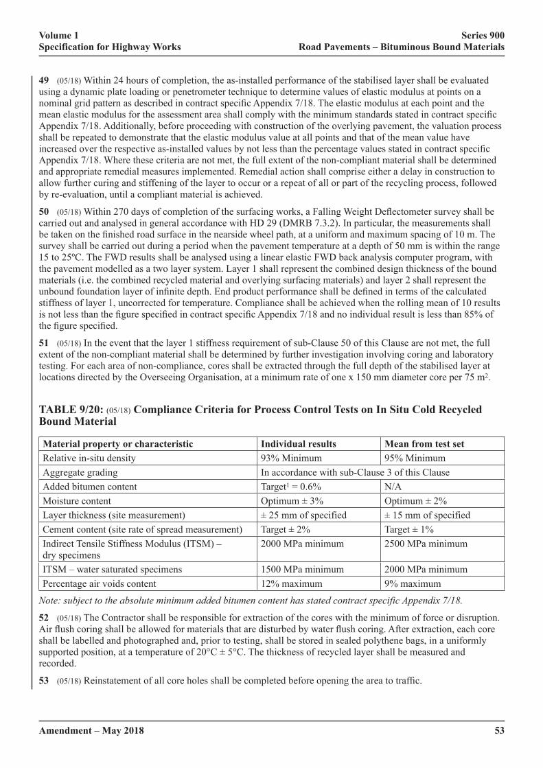
Volume 1 Series 900 Specification for Highway Works Road Pavements – Bituminous Bound Materials
Amendment – May 2018 53
49 (05/18) Within 24 hours of completion, the as-installed performance of the stabilised layer shall be evaluated using a dynamic plate loading or penetrometer technique to determine values of elastic modulus at points on a nominal�grid�pattern�as�described�in�contract�specific�Appendix�7/18.�The�elastic�modulus�at�each�point�and�the�mean�elastic�modulus�for�the�assessment�area�shall�comply�with�the�minimum�standards�stated�in�contract�specific�Appendix 7/18. Additionally, before proceeding with construction of the overlying pavement, the valuation process shall be repeated to demonstrate that the elastic modulus value at all points and that of the mean value have increased�over�the�respective�as-installed�values�by�not�less�than�the�percentage�values�stated�in�contract�specific�Appendix 7/18. Where these criteria are not met, the full extent of the non-compliant material shall be determined and appropriate remedial measures implemented. Remedial action shall comprise either a delay in construction to allow further curing and stiffening of the layer to occur or a repeat of all or part of the recycling process, followed by re-evaluation, until a compliant material is achieved.
50 (05/18)�Within�270�days�of�completion�of�the�surfacing�works,�a�Falling�Weight�Deflectometer�survey�shall�be�carried out and analysed in general accordance with HD 29 (DMRB 7.3.2). In particular, the measurements shall be�taken�on�the�finished�road�surface�in�the�nearside�wheel�path,�at�a�uniform�and�maximum�spacing�of�10�m.�The�survey shall be carried out during a period when the pavement temperature at a depth of 50 mm is within the range 15 to 25ºC. The FWD results shall be analysed using a linear elastic FWD back analysis computer program, with the pavement modelled as a two layer system. Layer 1 shall represent the combined design thickness of the bound materials (i.e. the combined recycled material and overlying surfacing materials) and layer 2 shall represent the unbound�foundation�layer�of�infinite�depth.�End�product�performance�shall�be�defined�in�terms�of�the�calculated�stiffness of layer 1, uncorrected for temperature. Compliance shall be achieved when the rolling mean of 10 results is�not�less�than�the�figure�specified�in�contract�specific�Appendix�7/18�and�no�individual�result�is�less�than�85%�of�the�figure�specified.
51 (05/18) In the event that the layer 1 stiffness requirement of sub-Clause 50 of this Clause are not met, the full extent of the non-compliant material shall be determined by further investigation involving coring and laboratory testing. For each area of non-compliance, cores shall be extracted through the full depth of the stabilised layer at locations directed by the Overseeing Organisation, at a minimum rate of one x 150 mm diameter core per 75 m2.
TABLE 9/20: (05/18) Compliance Criteria for Process Control Tests on In Situ Cold Recycled Bound Material
Material property or characteristic Individual results Mean from test setRelative in-situ density 93% Minimum 95% MinimumAggregate grading In accordance with sub-Clause 3 of this ClauseAdded bitumen content Target1 = 0.6% N/AMoisture content Optimum�±�3% Optimum�±�2%Layer thickness (site measurement) ±�25�mm�of�specified ±�15�mm�of�specifiedCement content (site rate of spread measurement) Target�±�2% Target�±�1%Indirect Tensile Stiffness Modulus (ITSM) – dry specimens
2000 MPa minimum 2500 MPa minimum
ITSM – water saturated specimens 1500 MPa minimum 2000 MPa minimumPercentage air voids content 12% maximum 9% maximum
Note: subject to the absolute minimum added bitumen content has stated contract specific Appendix 7/18.
52 (05/18) The Contractor shall be responsible for extraction of the cores with the minimum of force or disruption. Air�flush�coring�shall�be�allowed�for�materials�that�are�disturbed�by�water�flush�coring.�After�extraction,�each�core�shall be labelled and photographed and, prior to testing, shall be stored in sealed polythene bags, in a uniformly supported�position,�at�a�temperature�of�20°C�±�5°C.�The�thickness�of�recycled�layer�shall�be�measured�and�recorded.
53 (05/18)�Reinstatement�of�all�core�holes�shall�be�completed�before�opening�the�area�to�traffic.

Volume 1 Series 900 Specification for Highway Works Road Pavements – Bituminous Bound Materials
54Amendment – May 2018
54 (05/18)�If,�at�any�of�the�prescribed�core�locations,�it�is�not�possible�to�extract�an�intact�core�of�suitable�size�or�condition for the end-product performance testing, using a maximum of three attempts in an area of 1.5 m radius, the�material�in�the�vicinity�shall�be�deemed�not�to�comply�with�the�end-product�performance�specification.
55 (05/18) In the laboratory, each of the cores extracted successfully shall be trimmed to remove surfacing materials and any underlying material prior to cutting into core test specimens between 75 mm and 100 mm high. Where possible, three test specimens shall be obtained from each core, one from the upper part, one from the centre and the other from the lower part.
56 (05/18) All core test specimens thus obtained shall be tested in accordance with the standards described in Table 9/21.
TABLE 9/21: (05/18) Testing Standards for Core Specimens of In Situ Cold Recycled Bound Material
Test Standard
Bulk density BS EN 12697-6 and sub-Clause 39 of this Clause
Air voids content BS EN 12697-8 and sub-Clause 45 of this Clause
Indirect Tensile Stiffness Modulus BS EN 12697-26
57 (05/18) The results obtained shall be used for assessing the expected performance of the stabilised material in the�Works,�in�relation�to�the�known�performance�of�BS�specified�base�materials.�The�stabilised�material�in�the�trial�area shall be deemed acceptable if the compliance criteria described in Table 9/22 are met.
TABLE 9/22: (05/18) Compliance Criteria for In Situ Cold Recycled Bound Material – Core Specimens from the Works
Material property or characteristic Individual cores Mean from core setCore density relative to refusal density 93% minimum 95% minimumAir voids content 9% maximum 7% maximumLayer thickness (from core measurement) ±�25mm�of�specified ±�15mm�of�specifiedIndirect Tensile Stiffness Modulus – dry 2000 MPa minimum 2500 MPa minimum
(05/18) Mixture Design and Characterisation
58 (05/18) Mixture design and characterisation of in situ cold recycled bitumen bound material for each site, or section�of�site,�including�details�of�filler,�binder,�adhesion�and/or�stabilising�agent(s)�and�their�quantities,�shall�be�submitted to the Overseeing Organisation at least one week prior to commencement of the recycling works. Where the�site�investigation�has�identified�significant�variation�of�existing�pavement�materials�between�different�sections�of the site, a mix design shall be submitted for each section of the site. The proposed plan area and depth of the different sections, covered by each mixture design, shall be approved by the Overseeing Organisation.
59 (05/18) The testing standards used for the mixture design of the recycled bitumen bound mixture shall be those listed in Table 9/23.

Volume 1 Series 900 Specification for Highway Works Road Pavements – Bituminous Bound Materials
Amendment – May 2018 55
TABLE 9/23: (05/18) Testing Standards for the Design and Characterisation of In Situ Cold Recycled Bound Material
Test StandardMoisture content BS 1377-2Bulk density BS EN 12697-6Air voids content BS EN 12697-8 and sub-Clause 45 of this ClauseGrading and Binder Content BS EN 12697-2Indirect Tensile Stiffness Modulus BS EN 12697-26
60 (05/18) The aggregate used in the design and characterisation process shall be obtained from the appropriate section of the works and shall be representative in terms of component material proportions, of the pavement layers to be pulverised. The laboratory manufactured aggregate shall be pulverised or crushed such that it closely replicates�the�nature�and�grading�of�the�pulverised�aggregate�and�that�the�aggregate�particle�size�distribution�shall�comply with sub-Clause 3 of this Clause.
61 (05/18) The laboratory prepared aggregate shall be thoroughly mixed with measured proportions of the bitumen binder and adhesion agent(s) to produce at least three trial mixtures with different added bitumen contents. The penetration reference of the bitumen and the type of the adhesion agent(s) used in the trial mixtures shall be the same�as�those�used�in�the�finished�works.
62 (05/18) The different added bitumen contents of the trial mixtures shall be set at increments of between 0.5% and 1.0% in the range 3.0% to 6.0%, with appropriate allowance made for residual binder in any crushed asphalt component. From each trial mixture, four 150 mm diameter x 75 mm to 100 mm high, cylinder test specimens (briquette specimens) shall be compacted to refusal by vibratory compaction in a cylindrical metal mould, using the compaction mould assembly and vibratory hammer described in BS EN 12697-32. The bulk density of each cylinder shall be determined.
63 (05/18) The briquette specimens shall be cured for a period of 72 hours at a nominal temperature of 60ºC. Following this, the briquette specimens shall be conditioned in air for a minimum period of 12 hours at 20°C and then immediately tested in accordance with BS EN 12697-26 to determine the ITSM. After further conditioning of the briquettes, immersed in water at 20°C for a minimum period of 24 hours, the ITSM tests shall be repeated on each specimen.
64 (05/18) The characteristics of the mixture to be used in the works, including any added water, shall be determined using the optimum ITSM (dry) values. If peak conditions are not clearly displayed then plateau characteristics�shall�be�accepted�and�the�lowest�added�bitumen�content�for�which�all�the�criteria�defined�in�Table�9/24 are met, shall be used in the works subject to a minimum of 4.0% for mixtures containing only pulverised unbound or cement bound aggregate and 3.0% for mixtures containing only pulverised bitumen bound materials.
65 (05/18)�On�the�basis�of�the�foregoing�test�results,�the�contractor�shall�declare�details�of�the�Job�Standard�Mixture(s) for the works, setting out target aggregate grading and type, added water content, adhesion agents and binder content, together with tolerances. The method of compaction shall be described such that the material to be utilised in the works meets the mixture.
TABLE 9/24: (05/18) Acceptable Design and Characteristic Requirements for In Situ Cold Recycled Bound Material
Property or characteristic Individual specimens Mean from test setMoisture content N/A Optimum�±�2%Indirect Tensile Stiffness Modulus (dry) 2000 MPa 2500 MPaIndirect Tensile Stiffness Modulus (wet) 1500 MPa 2000 MPaBitumen content N/A Target�±�0.5%Particle�size�distribution N/A Zone A or Zone BAir voids content 9% maximum 7% maximum
Volume 1 Series 900 Specification for Highway Works Road Pavements – Bituminous Bound Materials
56Amendment – May 2018
948 (05/18) Ex Situ Cold Recycled Bound Material
(05/18) General
1 (05/18)�Ex�situ�cold�recycled�bound�material�(CRBM)�comprises�base�and�binder�courses�produced�in�a�fixed�or mobile mixing plant from graded aggregate processed from arisings from the excavation of roads and similar sources, blended if necessary with other aggregate and bound with cementitious, hydraulic or bituminous binders, separately or in combination. This Clause covers four generic material families: Quick Hydraulic (QH), Slow Hydraulic (SH), Quick Visco-Elastic (QVE) and Slow Visco-Elastic (SVE). The primary binder of these families of materials shall be as follows:
QH: Cement as the main component and excluding bituminous binders.
SH: Hydraulic binders (e.g. PFA/lime and GBS/lime) excluding bituminous and Portland Cement;
QVE: Bituminous binder as the main component but also including Portland Cement.
SVE: Bituminous binder as main component but excluding Portland Cement.
2 (05/18)�Ex�situ�CRBM�shall�be�designed�to�achieve�the�specified�level�of�the�appropriate�end�performance�property
(05/18) Quality Assurance
3 (05/18)�Ex�situ�CRBM�shall�be�produced�in�plants�that�have�a�UKAS�accredited�BS�EN�ISO�9001�Quality�Management�System.�The�BS�EN�ISO�9001�Certificate�scope�shall�include�this�activity.
(05/18) Sourcing of Aggregate
4 (05/18) The quality plan shall contain details of all aggregates to be used in the CRBM. Aggregate may include:
(i) asphalt, concrete or granular material planed or excavated from a road or other paved area;
(ii) primary, secondary or recycled aggregate from other sources;
(iii)� fillers�from�primary�or�secondary�sources�(e.g.�PFA).
5 (05/18)�The�processed�aggregate�including�added�filler�shall�not�contain�deleterious�material�that�adversely�affects the performance of the mixture.
(05/18) Processing of Aggregate
6 (05/18) The quality plan shall describe how, in particular, highway arisings are to be processed, crushed, screened�and�stocked�to�enable�consistent�production�of�the�CRBM�in�line�with�the�Job�Standard�mixture.
(05/18) Binders and Other Constituents
7 (05/18) The bitumen and other constituents shall conform to the following standards:
(i) Bitumen emulsion shall conform to BS EN 13808 and be used in accordance with BS 434-2.
(ii) Cement shall conform to BS EN 197-1.
(iii) Bitumen used for foaming shall conform to BS EN 12591 and shall be grade 160/220 or harder.
(iv) Granulated blast furnace slag (GBS) shall comply with EN 14227-2.
(v) Ground granulated blast furnace slag (GGBS) shall comply with BS EN 14227-2.
(vi) Lime shall comply with BS EN 14227-11.
(vii)� Fly�ash�(PFA)�used�as�either�as�filler�or�pozzolan,�shall�comply�with�BS�EN�14227-4.
(viii)� Un-weathered�0/4mm�Basic�Oxygen�Slag�(BOS)�slag�fines�used�in�SH�material�as�activator/accelerator�to the GBS shall comply with BS 6463 Part 102.
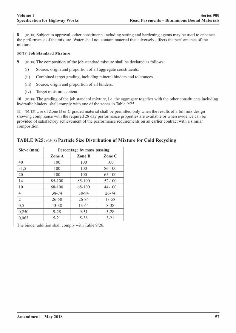
Volume 1 Series 900 Specification for Highway Works Road Pavements – Bituminous Bound Materials
Amendment – May 2018 57
8 (05/18) Subject to approval, other constituents including setting and hardening agents may be used to enhance the performance of the mixture. Water shall not contain material that adversely affects the performance of the mixture.
(05/18) Job Standard Mixture
9 (05/18) The composition of the job standard mixture shall be declared as follows:
(i) Source, origin and proportion of all aggregate constituents.
(ii) Combined target grading, including mineral binders and tolerances.
(iii) Source, origin and proportion of all binders.
(iv) Target moisture content.
10 (05/18) The grading of the job standard mixture, i.e. the aggregate together with the other constituents including hydraulic�binders,�shall�comply�with�one�of�the�zones�in�Table�9/25.
11 (05/18) Use of Zone B or C graded material shall be permitted only when the results of a full mix design showing compliance with the required 28 day performance properties are available or when evidence can be provided of satisfactory achievement of the performance requirements on an earlier contract with a similar composition.
TABLE 9/25: (05/18) Particle Size Distribution of Mixture for Cold Recycling
Sieve (mm) Percentage by mass passingZone A Zone B Zone C
40 100 100 10031,5 100 100 86-10020 100 100 65-10014 85-100 85-100 52-10010 68-100 68-100 44-1004 38-74 38-94 26-742 26-58 26-84 18-580,5 13-38 13-64 8-380,250 9-28 9-51 5-280,063 5-21 5-38 3-21
The binder addition shall comply with Table 9/26.
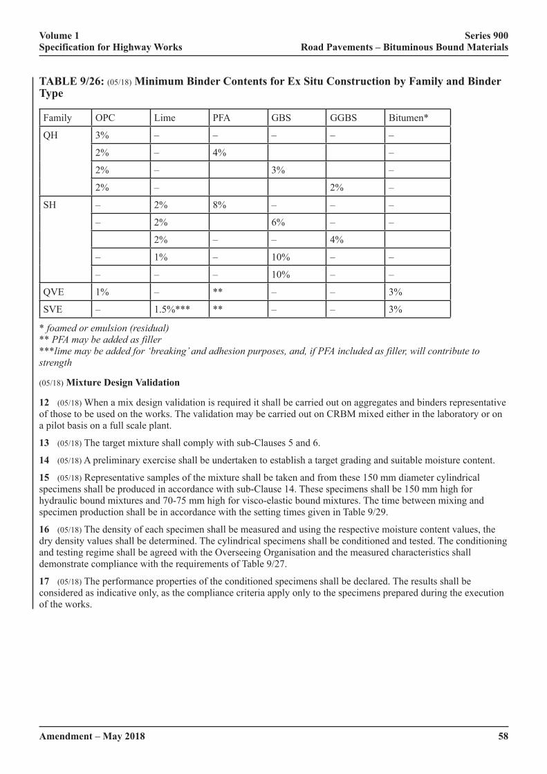
Volume 1 Series 900 Specification for Highway Works Road Pavements – Bituminous Bound Materials
58Amendment – May 2018
TABLE 9/26: (05/18) Minimum Binder Contents for Ex Situ Construction by Family and Binder Type
Family OPC Lime PFA GBS GGBS Bitumen*
QH 3% – – – – –
2% – 4% –
2% – 3% –
2% – 2% –
SH – 2% 8% – – –
– 2% 6% – –
2% – – 4%
– 1% – 10% – –
– – – 10% – –
QVE 1% – ** – – 3%
SVE – 1.5%*** ** – – 3%
* foamed or emulsion (residual) ** PFA may be added as filler ***lime may be added for ‘breaking’ and adhesion purposes, and, if PFA included as filler, will contribute to strength
(05/18) Mixture Design Validation
12 (05/18) When a mix design validation is required it shall be carried out on aggregates and binders representative of those to be used on the works. The validation may be carried out on CRBM mixed either in the laboratory or on a pilot basis on a full scale plant.
13 (05/18) The target mixture shall comply with sub-Clauses 5 and 6.
14 (05/18) A preliminary exercise shall be undertaken to establish a target grading and suitable moisture content.
15 (05/18) Representative samples of the mixture shall be taken and from these 150 mm diameter cylindrical specimens shall be produced in accordance with sub-Clause 14. These specimens shall be 150 mm high for hydraulic bound mixtures and 70-75 mm high for visco-elastic bound mixtures. The time between mixing and specimen production shall be in accordance with the setting times given in Table 9/29.
16 (05/18) The density of each specimen shall be measured and using the respective moisture content values, the dry density values shall be determined. The cylindrical specimens shall be conditioned and tested. The conditioning and testing regime shall be agreed with the Overseeing Organisation and the measured characteristics shall demonstrate compliance with the requirements of Table 9/27.
17 (05/18) The performance properties of the conditioned specimens shall be declared. The results shall be considered as indicative only, as the compliance criteria apply only to the specimens prepared during the execution of the works.

Volume 1 Series 900 Specification for Highway Works Road Pavements – Bituminous Bound Materials
Amendment – May 2018 59
TABLE 9/27: (05/18) Mix Design and End Product Requirements
Property or Characteristic All Materials Mean from Test SetQVE and SVE Materials (360 days*)
Indirect Tensile Stiffness Modulus
Class B1 1900 MPaClass B2 2500 MPaClass B3 3100 MPaClass B4 4700 MPa
QH and SH Materials (360 days*)
*Note: 360 days in situ or cured in accordance with sub clause 15.
(05/18) Trafficking Trial
18 (05/18)�When�specified�in�contract�specific�Appendix�7/1�a�trafficking�trial�shall�be�undertaken�to�demonstrate�that the CRBM is not prone to excessive rutting in its early life.
19 (05/18) A trial area shall be laid using the materials and plant to be used in the main works and on a foundation typical of that in the main works. The trial area shall be left to cure for 24 hours and shall then be subjected to controlled�trafficking.�The�trafficking�shall�be�performed�by�a�heavy�goods�vehicle�with�an�axle�configuration�and�loading typical of that to be encountered in the construction phase. The number of passes shall equate to the total expected�amount�of�traffic�to�be�carried�during�construction,�with�a�default�value�equivalent�to�100�standard�axles.
20 (05/18)�The�measured�rutting�in�the�trafficking�trial�shall�be�less�than�10�mm�or�that�specified�in�contract�specific�Appendix 7/1.
(05/18) Process Control
21 (05/18) Production of the ex situ CRBM shall be subject to process control detailed in the quality plan and meeting the following requirements:
(i)� There�shall�be�a�description�of�the�plant�and�the�production�process,�preferably�including�a�flow�diagram,�detailing�how�material�is�to�be�produced�in�accordance�with�this�specification.
(ii) Calibration schedules for all parts of the plant involved in determining mix consistency shall be provided. These shall be accompanied by calibration records.
(iii) Details of transportation shall be provided. These shall include the location of the mixing plant and the expected average time between mixing and laying. The Contractor shall record the duration between mixing and the completion of compaction at the site during the execution of the works.
(iv) Measures to avoid problems caused by extreme weather. In particular, production shall not proceed if the feedstock�is�frozen�or�excessively�wet.
(05/18) Inspection and Test
22 (05/18) There shall be a schedule of inspection and test frequencies to be made during production of CRBM. This shall comply with the minimum frequencies in Table 9/28.
TABLE 9/28: (05/18) Minimum Frequencies for Inspection and Test
Item Inspection TestAggregate stockpiles Daily Grading and moisture content Before production and weeklyBinders On receipt Supplier dataCombined grading of mixture Continual DailyMoisture content of mixture Continual Daily

Volume 1 Series 900 Specification for Highway Works Road Pavements – Bituminous Bound Materials
60Amendment – May 2018
(05/18) Laying
23 (05/18) A written procedure for the laying of the ex situ CRBM shall be provided.
24 (05/18) The plant used for placing ex situ processed material shall be capable of laying the material without significant�segregation,�evenly�and�to�the�required�thickness�across�at�least�one�lane�width.
25 (05/18) A method for the making of longitudinal and transverse joints, appropriate to the type of CRBM being laid shall be provided.
(05/18) Compaction
26 (05/18)�The�compaction�of�each�layer�shall�be�carried�out�to�a�defined�rolling�pattern,�to�achieve�the�required�in situ density and until the recycled layer provides a stable and dense tight surface. The stability of the layer after compaction�shall�be�deemed�adequate�if�the�finished�surface�does�not�shove,�rut�or�exhibit�transverse�cracking�under�the�load�of�subsequent�traffic.�Open�edges�shall�be�protected�from�traffic.
27 (05/18)�After�trimming�and�final�compaction�of�the�recycled�layer,�the�in�situ�bulk�density�shall�be�measured�using an indirect density gauge in direct transmission mode, to a depth within 25 mm of the total layer thickness. The�meter�readings�shall�be�verified�periodically�in�accordance�with�BS�EN�13286-2.
28 (05/18)�The�in�situ�bulk�density�values�obtained�shall�be�compared�with�the�refusal�density�value�of�the�Job�Standard Mix or of the refusal density of a specimen representative of the day’s production. The average in situ bulk�density�of�each�set�of�five�values�shall�be�at�least�95%�of�the�refusal�density,�with�no�individual�in�situ�density�value being less than 93% of the respective refusal density.
(05/18) Sealing
29 (05/18)�When�specified�in�contract�specific�Appendix�7/1,�the�surface�shall�be�sealed�using�a�sprayed�membrane�of Class C40B4 bitumen emulsion complying with Clause 920. The bitumen emulsion shall be sprayed at a rate 1 to 1.5 l/m2 to achieve a uniform and continuous seal to the surface of the layer. Where the surface is opened to traffic,�the�sealing�membrane�shall�be�blinded�with�fine�aggregate�or�sand�applied�at�a�rate�of�5.5�to�7.0�kg/m2.
(05/18) End Product Testing
30 (05/18) The end product testing of the ex situ CRBM shall be assessed on the basis of representative specimens made�up�in�accordance�with�the�schedule�in�contract�specific�Appendix�7/1.
31 (05/18) Representative samples of the ex situ CRBM shall be taken either at the mixing plant or from site. 150 mm diameter cylindrical test specimens shall be manufactured in sets of six by compacting to refusal in accordance with BS 598 Part 104. The height of the test specimens and the time period after mixing during which compaction must be completed shall be in accordance with Table 9/29.
TABLE 9/29: (05/18) Setting Times of Cold Recycled Families
Family Setting time under normal temperature conditions
Sample dimensions prepared to a target densityDiameter (mm) Height (mm)
QH 2 hours 150 150SH 24 hours* 150 150QVE 2 hours 150 75SVE 24 hours* 150 75
* can be longer depending on material composition
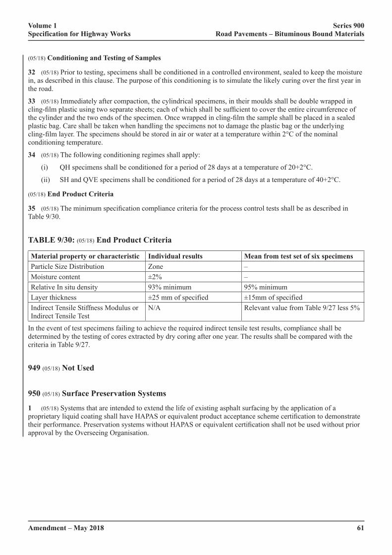
Volume 1 Series 900 Specification for Highway Works Road Pavements – Bituminous Bound Materials
Amendment – May 2018 61
(05/18) Conditioning and Testing of Samples
32 (05/18) Prior to testing, specimens shall be conditioned in a controlled environment, sealed to keep the moisture in,�as�described�in�this�clause.�The�purpose�of�this�conditioning�is�to�simulate�the�likely�curing�over�the�first�year�in�the road.
33 (05/18) Immediately after compaction, the cylindrical specimens, in their moulds shall be double wrapped in cling-film�plastic�using�two�separate�sheets;�each�of�which�shall�be�sufficient�to�cover�the�entire�circumference�of�the�cylinder�and�the�two�ends�of�the�specimen.�Once�wrapped�in�cling-film�the�sample�shall�be�placed�in�a�sealed�plastic bag. Care shall be taken when handling the specimens not to damage the plastic bag or the underlying cling-�film�layer.�The�specimens�should�be�stored�in�air�or�water�at�a�temperature�within�2°C�of�the�nominal�conditioning temperature.
34 (05/18) The following conditioning regimes shall apply:
(i) QH specimens shall be conditioned for a period of 28 days at a temperature of 20+2°C.
(ii) SH and QVE specimens shall be conditioned for a period of 28 days at a temperature of 40+2°C.
(05/18) End Product Criteria
35 (05/18)�The�minimum�specification�compliance�criteria�for�the�process�control�tests�shall�be�as�described�in�Table 9/30.
TABLE 9/30: (05/18) End Product Criteria
Material property or characteristic Individual results Mean from test set of six specimensParticle�Size�Distribution Zone –Moisture content ±2% –Relative In situ density 93% minimum 95% minimumLayer thickness ±25�mm�of�specified ±15mm�of�specifiedIndirect Tensile Stiffness Modulus or Indirect Tensile Test
N/A Relevant value from Table 9/27 less 5%
In the event of test specimens failing to achieve the required indirect tensile test results, compliance shall be determined by the testing of cores extracted by dry coring after one year. The results shall be compared with the criteria in Table 9/27.
949 (05/18) Not Used
950 (05/18) Surface Preservation Systems
1 (05/18) Systems that are intended to extend the life of existing asphalt surfacing by the application of a proprietary�liquid�coating�shall�have�HAPAS�or�equivalent�product�acceptance�scheme�certification�to�demonstrate�their�performance.�Preservation�systems�without�HAPAS�or�equivalent�certification�shall�not�be�used�without�prior�approval by the Overseeing Organisation.
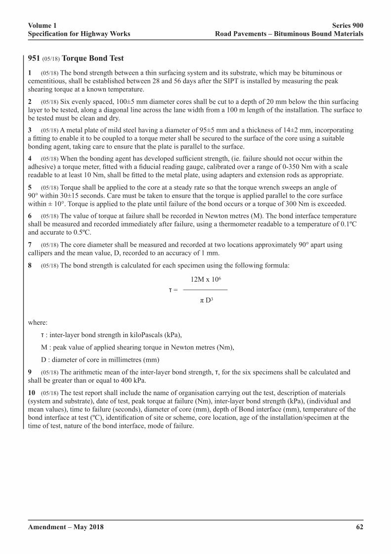
Volume 1 Series 900 Specification for Highway Works Road Pavements – Bituminous Bound Materials
62Amendment – May 2018
951 (05/18) Torque Bond Test
1 (05/18) The bond strength between a thin surfacing system and its substrate, which may be bituminous or cementitious, shall be established between 28 and 56 days after the SIPT is installed by measuring the peak shearing torque at a known temperature.
2 (05/18)�Six�evenly�spaced,�100±5�mm�diameter�cores�shall�be�cut�to�a�depth�of�20�mm�below�the�thin�surfacing�layer to be tested, along a diagonal line across the lane width from a 100 m length of the installation. The surface to be tested must be clean and dry.
3 (05/18)�A�metal�plate�of�mild�steel�having�a�diameter�of�95±5�mm�and�a�thickness�of�14±2�mm,�incorporating�a�fitting�to�enable�it�to�be�coupled�to�a�torque�meter�shall�be�secured�to�the�surface�of�the�core�using�a�suitable�bonding agent, taking care to ensure that the plate is parallel to the surface.
4 (05/18)�When�the�bonding�agent�has�developed�sufficient�strength,�(ie.�failure�should�not�occur�within�the�adhesive)�a�torque�meter,�fitted�with�a�fiducial�reading�gauge,�calibrated�over�a�range�of�0-350�Nm�with�a�scale�readable�to�at�least�10�Nm,�shall�be�fitted�to�the�metal�plate,�using�adapters�and�extension�rods�as�appropriate.
5 (05/18) Torque shall be applied to the core at a steady rate so that the torque wrench sweeps an angle of 90°�within�30±15�seconds.�Care�must�be�taken�to�ensure�that�the�torque�is�applied�parallel�to�the�core�surface�within�±�10°.�Torque�is�applied�to�the�plate�until�failure�of�the�bond�occurs�or�a�torque�of�300�Nm�is�exceeded.
6 (05/18) The value of torque at failure shall be recorded in Newton metres (M). The bond interface temperature shall be measured and recorded immediately after failure, using a thermometer readable to a temperature of 0.1ºC and accurate to 0.5ºC.
7 (05/18) The core diameter shall be measured and recorded at two locations approximately 90° apart using callipers and the mean value, D, recorded to an accuracy of 1 mm.
8 (05/18) The bond strength is calculated for each specimen using the following formula:
12M x 106
τ =
�π�D3
where:
τ : inter-layer bond strength in kiloPascals (kPa),
M : peak value of applied shearing torque in Newton metres (Nm),
D : diameter of core in millimetres (mm)
9 (05/18) The arithmetic mean of the inter-layer bond strength, τ, for the six specimens shall be calculated and shall be greater than or equal to 400 kPa.
10 (05/18) The test report shall include the name of organisation carrying out the test, description of materials (system and substrate), date of test, peak torque at failure (Nm), inter-layer bond strength (kPa), (individual and mean values), time to failure (seconds), diameter of core (mm), depth of Bond interface (mm), temperature of the bond�interface�at�test�(ºC),�identification�of�site�or�scheme,�core�location,�age�of�the�installation/specimen�at�the�time of test, nature of the bond interface, mode of failure.
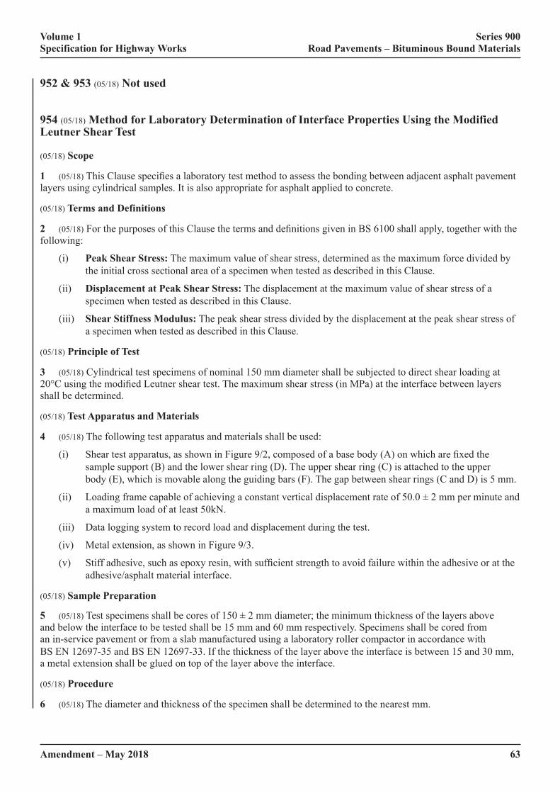
Volume 1 Series 900 Specification for Highway Works Road Pavements – Bituminous Bound Materials
Amendment – May 2018 63
952 & 953 (05/18) Not used
954 (05/18) Method for Laboratory Determination of Interface Properties Using the Modified Leutner Shear Test
(05/18) Scope
1 (05/18)�This�Clause�specifies�a�laboratory�test�method�to�assess�the�bonding�between�adjacent�asphalt�pavement�layers using cylindrical samples. It is also appropriate for asphalt applied to concrete.
(05/18) Terms and Definitions
2 (05/18)�For�the�purposes�of�this�Clause�the�terms�and�definitions�given�in�BS�6100�shall�apply,�together�with�the�following:
(i) Peak Shear Stress: The maximum value of shear stress, determined as the maximum force divided by the initial cross sectional area of a specimen when tested as described in this Clause.
(ii) Displacement at Peak Shear Stress: The displacement at the maximum value of shear stress of a specimen when tested as described in this Clause.
(iii) Shear Stiffness Modulus: The peak shear stress divided by the displacement at the peak shear stress of a specimen when tested as described in this Clause.
(05/18) Principle of Test
3 (05/18) Cylindrical test specimens of nominal 150 mm diameter shall be subjected to direct shear loading at 20°C�using�the�modified�Leutner�shear�test.�The�maximum�shear�stress�(in�MPa)�at�the�interface�between�layers�shall be determined.
(05/18) Test Apparatus and Materials
4 (05/18) The following test apparatus and materials shall be used:
(i)� Shear�test�apparatus,�as�shown�in�Figure�9/2,�composed�of�a�base�body�(A)�on�which�are�fixed�the�sample support (B) and the lower shear ring (D). The upper shear ring (C) is attached to the upper body (E), which is movable along the guiding bars (F). The gap between shear rings (C and D) is 5 mm.
(ii)� Loading�frame�capable�of�achieving�a�constant�vertical�displacement�rate�of�50.0�±�2�mm�per�minute�and�a maximum load of at least 50kN.
(iii) Data logging system to record load and displacement during the test.
(iv) Metal extension, as shown in Figure 9/3.
(v)�� Stiff�adhesive,�such�as�epoxy�resin,�with�sufficient�strength�to�avoid�failure�within�the�adhesive�or�at�the�adhesive/asphalt material interface.
(05/18) Sample Preparation
5 (05/18)�Test�specimens�shall�be�cores�of�150�±�2�mm�diameter;�the�minimum�thickness�of�the�layers�above�and below the interface to be tested shall be 15 mm and 60 mm respectively. Specimens shall be cored from an in-service pavement or from a slab manufactured using a laboratory roller compactor in accordance with BS EN 12697-35 and BS EN 12697-33. If the thickness of the layer above the interface is between 15 and 30 mm, a metal extension shall be glued on top of the layer above the interface.
(05/18) Procedure
6 (05/18) The diameter and thickness of the specimen shall be determined to the nearest mm.
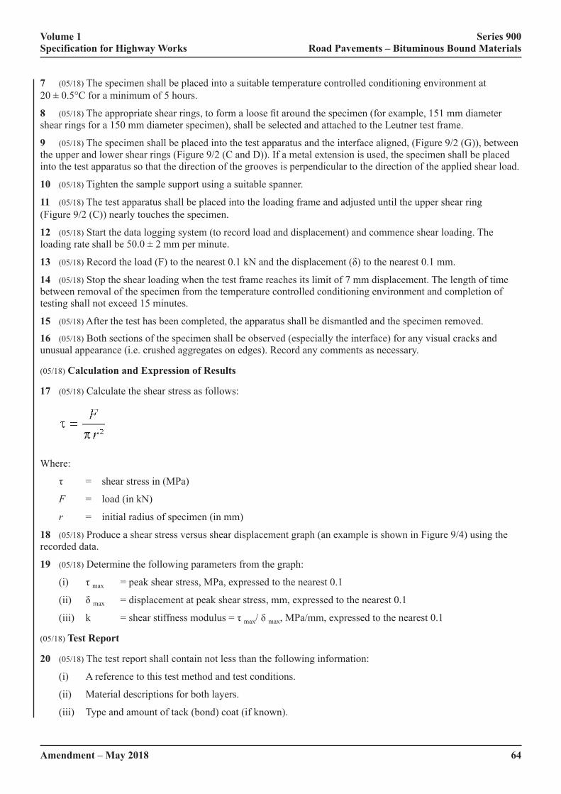
Volume 1 Series 900 Specification for Highway Works Road Pavements – Bituminous Bound Materials
64Amendment – May 2018
7 (05/18) The specimen shall be placed into a suitable temperature controlled conditioning environment at 20 ± 0.5°C for a minimum of 5 hours.
8 (05/18)�The�appropriate�shear�rings,�to�form�a�loose�fit�around�the�specimen�(for�example,�151�mm�diameter�shear rings for a 150 mm diameter specimen), shall be selected and attached to the Leutner test frame.
9 (05/18) The specimen shall be placed into the test apparatus and the interface aligned, (Figure 9/2 (G)), between the upper and lower shear rings (Figure 9/2 (C and D)). If a metal extension is used, the specimen shall be placed into the test apparatus so that the direction of the grooves is perpendicular to the direction of the applied shear load.
10 (05/18) Tighten the sample support using a suitable spanner.
11 (05/18) The test apparatus shall be placed into the loading frame and adjusted until the upper shear ring (Figure 9/2 (C)) nearly touches the specimen.
12 (05/18) Start the data logging system (to record load and displacement) and commence shear loading. The loading�rate�shall�be�50.0�±�2�mm�per�minute.
13 (05/18)�Record�the�load�(F)�to�the�nearest�0.1�kN�and�the�displacement�(δ)�to�the�nearest�0.1�mm.
14 (05/18) Stop the shear loading when the test frame reaches its limit of 7 mm displacement. The length of time between removal of the specimen from the temperature controlled conditioning environment and completion of testing shall not exceed 15 minutes.
15 (05/18) After the test has been completed, the apparatus shall be dismantled and the specimen removed.
16 (05/18) Both sections of the specimen shall be observed (especially the interface) for any visual cracks and unusual appearance (i.e. crushed aggregates on edges). Record any comments as necessary.
(05/18) Calculation and Expression of Results
17 (05/18) Calculate the shear stress as follows:
Where:
τ� =� shear�stress�in�(MPa)
F = load (in kN)
r = initial radius of specimen (in mm)
18 (05/18) Produce a shear stress versus shear displacement graph (an example is shown in Figure 9/4) using the recorded data.
19 (05/18) Determine the following parameters from the graph:
(i)� τ�max = peak shear stress, MPa, expressed to the nearest 0.1
(ii)� δ�max = displacement at peak shear stress, mm, expressed to the nearest 0.1
(iii)� k� =�shear�stiffness�modulus�=�τ�max/�δ�max, MPa/mm, expressed to the nearest 0.1
(05/18) Test Report
20 (05/18) The test report shall contain not less than the following information:
(i) A reference to this test method and test conditions.
(ii) Material descriptions for both layers.
(iii) Type and amount of tack (bond) coat (if known).

Volume 1 Series 900 Specification for Highway Works Road Pavements – Bituminous Bound Materials
Amendment – May 2018 65
(iv) For each specimen tested, report:
– specimen diameter, expressed to the nearest mm
– layer thicknesses, expressed to the nearest mm
– maximum load (F), expressed to the nearest 0.1 kN
–� peak�shear�stress�(τ�max), expressed to the nearest 0.1 MPa
–� displacement�at�peak�shear�stress(δ�max), expressed to the nearest 0.1 mm
– shear stiffness modulus (k), expressed to the nearest 0.1 MPa/mm
– any cracks or other damage.
(v) The test temperature, expressed to the nearest 0.5°C
(vi) The use (or otherwise) of a metal extension.
A – base body B – sample support C – upper shear ring D – lower shear ring E – upper body F – guiding bar G – specimen interface
FIGURE 9/2: (05/18) Schematic Diagram of the Modified Leutner Shear Test apparatus

Volume 1 Series 900 Specification for Highway Works Road Pavements – Bituminous Bound Materials
66Amendment – May 2018
FIGURE 9/3: (05/18) Schematic Drawing of the Metal Extension
FIGURE 9/4: (05/18) Example of Shear Stress vs Displacement Data Plot
Volume 1 Series 900 Specification for Highway Works Road Pavements – Bituminous Bound Materials
Amendment – May 2018 67
955 (05/18) Ageing Profile Test Using a Modified Rolling Thin Film Oven Test (MRTFOT)
(05/18) Scope
1 (05/18)�This�Clause�specifies�the�procedure�for�obtaining�samples�of�‘Aged�Binder’�after�various�stages�of�conditioning.�In�this�way,�a�plot�of�binder�properties�providing�an�‘Ageing�Profile’�may�be�accomplished�in�a�short�time�using�the�Modified�Rolling�Thin�Film�Oven�Test�(MRTFOT)�to�simulate�ageing�in�road�materials�over�many�years in service.
The�MRTFOT�utilises�the�Rolling�Thin�Film�Oven�(ASTM�2872)�specified�in�BS�EN�12607-1.
The method is suitable for generating small quantities of binder for rheological testing
The�‘Ageing�Profile’�is�generated�by�determining�the�rheological�properties�of�complex�shear�(stiffness)�modulus�G*�and�phase�angle�δ�of�samples�taken�from�the�oven�at�intervals�throughout�the�test�period,�typically�one�day.�Other properties such as durability of cohesion may also be assessed.
Three protocols are used depending on the type of binder and its use:
(i)� a�method�to�simulate�ageing�of�polymer�modified�binder�or�paving�grade�bitumen�used�in�the�manufacture of asphalt;
(ii)� a�method�to�remove�the�water�phase�and�volatile�flux�from�polymer�modified�bituminous�emulsions�and�simulate ageing and;
(iii) a method to test the potential for preservatives to reduce the ageing rate of bitumen.
The�‘Ageing�Profile’�in�terms�of�rheological�characteristics�provides�‘Product�Identification’�and�this�is�essential�to�ensure�consistency�and�to�enable�proprietary�binders�to�be�identified.
(05/18) Warning
2 (05/18)�The�use�of�this�test�method�can�involve�hazardous�materials,�operations�and�equipment.�This�Clause�does not purport to address all of the safety problems associated with the use of the test method. It is the responsibility of the user of these test methods to establish appropriate safety and health practices and determine the applicability of regulatory limitations prior to use.
(05/18) Asphalt Binders
3 (05/18)�Binders�used�to�manufacture�hot�mixed�asphalt�(asphalt�binders)�are�first�subjected�to�a�‘Short-term�Ageing Test’ to simulate the effects of manufacture, transport and laying. In this respect, the test described in this Clause has been shown to be equivalent to BS EN 12607-1. The binder is continually stirred by rotating stainless steel�screws�in�sample�cans�to�obtain�a�homogeneous�sample;�the�procedure�also�benefits�from�a�faster�oxidation�rate (rapid ageing), because of the increased exposure to the jetted air stream and, therefore, a shorter test duration.
The binder samples are then aged at a lower temperature and samples removed at intervals and tested to obtain an ‘Ageing�Profile’.�This�is�particularly�useful�for�asphalt,�because�different�air�void�contents�and�binder�contents�in�a�road pavement result in different ageing rates.
The ‘Long-term Aged’ binder sample, where the characteristics are equivalent to those obtained after 65 hours using the Pressure Ageing Vessel PAV85 Test, is obtained after 7 hours; therefore, the test may be carried out in one day. PAV85 is detailed in BS EN 14769.
Binders used for manufacturing ‘Warm Asphalt’ are mixed at much lower temperatures than for hot mixed asphalt and they do not need the same high temperature protocol for ‘Short-term Ageing’; this part of the procedure is therefore amended for these binders. All the ageing is done at the lower temperature.
Volume 1 Series 900 Specification for Highway Works Road Pavements – Bituminous Bound Materials
68Amendment – May 2018
(05/18) Bituminous Emulsion Binders
4 (05/18)�Bitumen�and�polymer�modified�bituminous�emulsions�are�first�subjected�to�a�‘Rapid�Recovery�Test’�which removes any water phase and volatile oils to produce a ‘Recovered Binder’. The ‘Recovered Binder’ has similar properties to that produced from other evaporative tests, but is achieved over a shorter period and the use of nitrogen, replacing air, reduces risks associated with volatile oils in the oven. The ‘Recovered Binder’ in rheological terms is equivalent to that recovered using BS EN 13074-1.
The�‘Ageing�Profile’�is�provided�by�continuing�the�ageing�of�the�‘Recovered�Binder’�in�the�MRTFO�at�a�higher�temperature,�replacing�the�nitrogen�gas�with�air�and�removing�samples�after�specified�periods�for�testing.�A�‘Stabilised Binder’, equivalent in rheological terms to that produced using BS EN 13074-2, may be obtained from the�‘Ageing�Profile’�Plot�for�a�particular�emulsion.�Fluxed�and�vegetal�fluxed�binders�where�volatile�oils�are�thought�to be present may also be tested using this protocol.
(05/18) Preservatives
5 (05/18) 40/60 penetration grade bitumen, used as a control, is subjected to ‘Short-term Ageing’ in the MRTFOT followed by an extended period at a lower temperature to simulate the ageing of the bitumen in a road pavement. This aged bitumen control is then cooled to ambient and treated with the preservative. Most of the volatile oils are then removed by conditioning the samples in the MRTFOT using a nitrogen blanket. The aged bitumen, treated by preservative, is then subjected to further ageing with the MRTFOT. The properties of the aged bitumen, after action of�the�preservative,�are�assessed�by�an�‘Ageing�Profile’�using�rheology�and�compared�with�the�‘Ageing�Profile’�of�the control bitumen.
(05/18) Definitions
6 (05/18)�For�the�purposes�of�the�procedures�specified�in�this�Clause�the�following�definitions�apply:
(i) Laboratory Sample: sample of bituminous binder intended for laboratory tests. It may be a spot sample, a composite sample or a part thereof (a divided sample) as described in BS EN 58.
(ii) Test Sample: sample of bituminous binder produced by treatment or subdivision of a laboratory sample for individual test (BS EN 58).
(iii) Recovered Binder:�material�remaining�after�removal�of�water�or�flux�from�a�polymer�modified�or�unmodified�bituminous�emulsion�or�fluxed�binder�in�the�presence�of�nitrogen,�equivalent�to�the�recovered binder using BS EN 13074-1.
(iv) Aged Binder: material remaining after the Ageing protocol.
(v) Short-term Aged Binder: material obtained during the MRTFOT which is equivalent to that provided by BS EN 12607-1(RTFOT)
(vi) Long-term Aged Binder: material obtained during the MRTFOT which is equivalent to that provided by BS EN 14769
(vii) Ageing Profile: graphical plot of performance-related results from samples tested during the ageing protocol of this method. Performance-related testing is carried out using a Dynamic Shear Rheometer (DSR), providing G* and phase angle data at a determined temperature and frequency.
(05/18) Test Apparatus (common to all protocols)
7 (05/18) The following test apparatus shall be used:
(i) RTFOT apparatus to BS EN 12607-1.
(ii)� Eight�identifiable�sample�cans�with�threaded�screw�top�lids�(or�other�fixing�system)�manufactured�from�aluminium�and�coated�on�all�internal�surfaces�with�polytetrafluoroethylene�(PTFE)�with�internal�dimensions and aperture diameter (L2) as shown below:
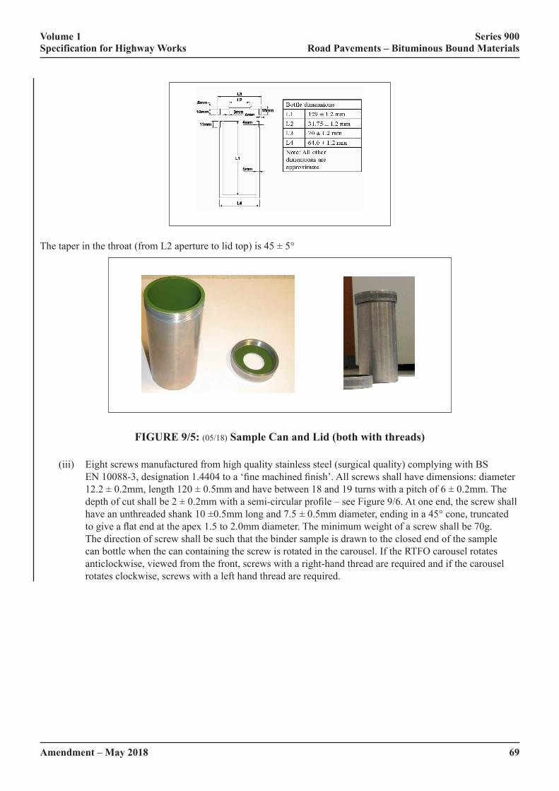
Volume 1 Series 900 Specification for Highway Works Road Pavements – Bituminous Bound Materials
Amendment – May 2018 69
The�taper�in�the�throat�(from�L2�aperture�to�lid�top)�is�45�±�5°
FIGURE 9/5: (05/18) Sample Can and Lid (both with threads)
(iii) Eight screws manufactured from high quality stainless steel (surgical quality) complying with BS EN�10088-3,�designation�1.4404�to�a�‘fine�machined�finish’.�All�screws�shall�have�dimensions:�diameter�12.2�±�0.2mm,�length�120�±�0.5mm�and�have�between�18�and�19�turns�with�a�pitch�of�6�±�0.2mm.�The�depth�of�cut�shall�be�2�±�0.2mm�with�a�semi-circular�profile�–�see�Figure�9/6.�At�one�end,�the�screw�shall�have�an�unthreaded�shank�10�±0.5mm�long�and�7.5�±�0.5mm�diameter,�ending�in�a�45°�cone,�truncated�to�give�a�flat�end�at�the�apex�1.5�to�2.0mm�diameter.�The�minimum�weight�of�a�screw�shall�be�70g.�The direction of screw shall be such that the binder sample is drawn to the closed end of the sample can bottle when the can containing the screw is rotated in the carousel. If the RTFO carousel rotates anticlockwise, viewed from the front, screws with a right-hand thread are required and if the carousel rotates clockwise, screws with a left hand thread are required.

Volume 1 Series 900 Specification for Highway Works Road Pavements – Bituminous Bound Materials
70Amendment – May 2018
Dimension a = 1.5mm to 2mm
FIGURE 9/6 (05/18) Screw with Right-handed Thread (for anti-clockwise rotating carousel)
(iv)� A�spatula�for�removing�the�binder�from�the�sample�cans�(a�flat�blade�with�a�square�end�has�been�found�suitable).
(v) A balance accurate to 0.05g.
(vi)� A�timer�capable�of�timing�100�minutes,�accurate�to�1�second�in�five�minutes�and,�for�the�MRTFOT,�a�timer capable of timing 25 hours to the same accuracy.
(vii) Nitrogen gas supply (for Rapid Recovery Test and preservative test).
(viii) Air supply, clean dry air (for MRTFOT).
(ix) An oven to pre-heat the sample cans and the binder to the required temperature.
(05/18) Principle of the Ageing Profile Test for Polymer Modified and Unmodified Bituminous Binders for Asphalts
8 (05/18)�A�thin�film�of�binder�is�rotated�in�aluminium�sample�cans�with�screw�top�lids,�both�coated�internally�with PTFE (replacing glass bottles), using the Rolling Thin Film Oven Test (RTFOT) apparatus, as described in BS EN 12607-1. Special screws are used to disturb the binder and maintain a homogenous material during ‘Ageing’.�Air�is�jetted�over�the�film�of�binder�for�a�much�longer�period�than�in�the�conventional�test�and�a�lower�temperature used in order to simulate the ‘ageing’ of the binder in the road after application. The screws accelerate the�process,�and�are�necessary�to�maintain�a�homogeneous�sample,�especially�when�testing�polymer�modified�binders, which tend to form a skin and may phase separate in static ageing tests.
The initial conditioning test is to simulate the changes to the properties of the binder caused by the high temperatures during manufacture, transport and laying, termed ‘Short-term Ageing’.
Further ageing is carried out at a reduced temperature and samples removed after set periods and tested, so that an ‘Ageing�Profile’�may�be�plotted.
(05/18) Test Procedure for Determining the Ageing Profile of Hot Mixed Polymer Modified and Unmodified Bituminous Binders for Asphalts
9 (05/18) Obtain a sample in accordance with BS EN 58. Stir the sample thoroughly to ensure it is completely homogenized.�If�sub-samples�are�taken�these�shall�have�a�minimum�volume�of�250ml.�Ensure�that�the�RTFO�is�level�so�that�the�horizontal�axes�of�the�sample�cans�when�in�position�in�the�carousel�are�level.�Pre-heat�the�oven�to�

Volume 1 Series 900 Specification for Highway Works Road Pavements – Bituminous Bound Materials
Amendment – May 2018 71
163�±�1°C,�1h�is�generally�sufficient.�For�binders�used�to�manufacture�warm�mixed�asphalts,�substitute�135°C�for�163°C throughout the test procedure.
Insert a stainless steel screw into each of the sample cans with the tapered end of the screw towards the aperture of the container and record the mass of each assembly to 0.1g. Heat the sample cans and the stainless steel screws to 163�±�1°C�for�90�±�10�min.
Heat�the�sample�to�170�±�3°C.�Thoroughly�stir�the�sample�to�ensure�homogeneity�immediately�prior�to�decanting�into the sample cans.
Pour�19.0�±�0.5g�of�the�sample�into�a�preheated�sample�can�and�record�the�mass�with�lid.�Immediately�after�weighing, roll the sample cans to ensure distribution of the binder on the walls of the can.
Mount the sample can in the carousel of the RTFO. Repeat for the remaining sample cans. Close the door of the RTFO�between�mounting�each�sample�can�in�the�carousel.�The�period�between�weighing�the�first�sample�can�with�binder and mounting of all the sample cans and the start of the rotation of the carousel shall not exceed 20 minutes.
When�the�carousel�is�fully�loaded,�rotate�the�carriage�assembly�at�a�speed�of�15.0�±�0.2min-1.�Start�the�flow�of�air�at�a�set�rate�of�4000�±�200ml/min.�Start�the�timer.�Maintain�the�samples�in�the�oven�and�the�air�flowing�for�45�±�1min�from�the�time�the�test�temperature�reaches�163�±�1°C.
If�the�test�temperature�of�163°C�is�not�reached�within�the�first�15�minutes,�discontinue�the�test.
After�45�±�1min,�sample�cans�(minimum�2)�may�be�removed�for�testing�and�to�determine�mass�loss,�if�required.�This is the Short-term Aged binder, equivalent to RTFOT, BS EN 12607-1.
To�continue�the�Ageing�Profile�test,�maintain�the�temperature�at�163°C�for�a�further�15�minutes,�with�the�carousel�rotating�in�the�air�flow,�then�reduce�the�temperature�of�the�oven�to�135�±�1°C.�Note�the�time�the�RTFO�takes�to�reach 135°C. Once the temperature has been achieved, continue to rotate the samples in the air supply and remove sample cans to obtain samples of aged binder as required for testing after three periods:
2h�±�10min;�termed�Aged2 Binder
4h�±�10min;�termed�Aged4 Binder
6h�±�10min;�termed�Aged6 Binder: this is the Long-term Aged Binder, equivalent to PAV85.
Other periods may be used either for convenience or to allow other degrees of ageing to be investigated.
TABLE 9/31 (05/18) Summary of Sampling Times
Stage Gas RTFO Temperature
Time Sampling Cumulative time
Ageing
Air 163°C 45min RTFOT Equivalent 45minsAir 163°C 15min None 1h 00minAir 135°C 2h Aged2 test samples 3h 00minAir 135°C 4h Aged4 test samples 5h 00minAir 135°C 6h Aged6 test samples (equivalent to PAV85) 7h 00min
For binders used to manufacture ‘Warm Asphalt’, ‘Short Term Ageing’ at 163°C is not required, therefore, replace 163ºC by 135ºC in Table 9/31 and report in addition Aged1 result (ageing at 135°C after a cumulative time of 1h�±�5min).
(05/18) Handling of the Aged Binder
10 (05/18) If the binder is to be tested immediately, remove a sample can from the carousel, extract the screw using a small spatula and set the screw aside for cleaning. Place the sample can(s) in an oven preheated to the softening point�of�the�binder�plus�100°C�(if�known),�or�170°C�if�the�properties�of�the�binder�are�unknown,�for�20�±�5min.

Volume 1 Series 900 Specification for Highway Works Road Pavements – Bituminous Bound Materials
72Amendment – May 2018
Place the containers on their sides in an oven. This allows the binder to drain to one side of the container, which is more easily removed with the spatula.
At�the�end�of�20�±�5min,�remove�the�sample�can�from�the�oven,�unscrew�the�lid�and,�using�the�spatula,�scrape�the�aged binder from the sample can and prepare the test samples in accordance with the relevant test method. Warming the spatula to the same temperature as the binder facilitates removal of the binder.
If the aged binder from more than one sample can is needed to produce a test sample, combine the aged binder from the sample cans and re-heat. Re-heating for testing shall be in accordance with BS EN 12594, ensuring that aged�binder�is�heated�for�no�longer�than�is�absolutely�necessary.�The�binder�shall�be�thoroughly�homogenized�by�stirring after heating and before being used for testing, while taking care not to entrain any air.
If the binder is not to be tested immediately, remove a sample can from the RTFO, extract the screw using a small spatula and set the screw aside for cleaning. Unscrew the lid and, using the spatula, scrape the aged binder from the sample can and place on a silicon sheet. The binder shall be sealed and stored at between 0°C to 5°C. The sample shall be re-heated in accordance with BS EN 12594 and homogenised immediately before testing.
If the aged samples are to be transferred to another laboratory for testing, they shall not be subjected to temperatures greater than ambient after ageing and before testing, and the delay before testing shall not exceed 120 hours.
The thermal history of the sample shall be recorded.
(05/18) Principle of the Ageing Profile Test for Polymer Modified or Unmodified Bituminous Emulsions or Fluxed Binders
11 (05/18)�A�thin�film�of�binder�is�rotated�in�aluminium�sample�cans�with�screw�top�lids,�both�coated�internally�with�PTFE (replacing glass bottles), using the RTFOT apparatus, as described in BS EN 12607-1, to evaporate water from�bituminous�emulsions�and/or�the�light�solvent�or�highly�volatile�fraction�from�fluxed�or�other�binders.�Special�screws are used to disturb the binder and maintain a homogenous material during breaking and/or curing. Nitrogen gas�instead�of�air�is�jetted�over�the�film�of�bituminous�binder�at�a�lower�temperature�in�order�to�minimize�ageing�effects�and�simulate�the�condition�of�the�binder�soon�after�application.�The�first�part�of�the�process�is�carried�out�with the RTFO set at 85°C to prevent frothing of the binder. The temperature is then increased to 135°C to drive off any remaining water and/or solvent to provide the ‘Recovered Binder’, which is equivalent to the recovered binder obtained�from�BS�EN�13074-1.�The�‘Ageing�Profile’�is�provided�by�continuing�the�ageing�of�the�binder�in�the�RTFO�at�135°C,�replacing�the�nitrogen�gas�with�air�and�removing�samples�after�specified�periods�for�testing.
(05/18) Test Procedure for Recovery and Ageing of Bituminous Emulsion and Fluxed Binders
12 (05/18) Obtain a sample in accordance with BS EN 58. Stir the sample thoroughly to ensure it is completely homogenized.�The�temperature�of�the�binder�sample�shall�not�be�less�than�70%�of�the�normal�application�temperature in degrees Celsius and shall be recorded (for example, high binder content surface dressing emulsion may�require�a�minimum�of�60°C,�or�a�polymer�modified�fluxed�binder,�130°C).�The�sample�history�if�known�shall�be recorded; this is important, as some ageing may have occurred. If sub-samples are taken these shall have a minimum�volume�of�250ml.�Ensure�that�the�oven�is�level�so�that�the�horizontal�axes�of�the�sample�cans,�when�in�position�in�the�carriage,�are�level.�Pre-heat�the�oven�to�85�±�1°C,�1h�is�generally�sufficient.
Insert a stainless steel screw into each of the sample cans with the tapered end of the screw towards the aperture of the container and record the mass of each assembly to 0.1g. Heat the sample cans, lids and the stainless steel screws to�85�±�1°C�for�90�±�10min.
Heat�the�sample�to�the�application�temperature�of�the�binder,�or,�if�this�is�not�known,�to�60�±�3°C.�Thoroughly�stir�the sample to ensure homogeneity immediately prior to decanting into the sample cans, taking care to minimise loss of water content and/or any volatile oil. Some cut-back binders and other binders such as primers having low flash�points�are�not�suitable�for�this�test.�If�there�is�any�doubt�concerning�the�volatile�nature�of�the�sample�for�test,�a�suitable�flash�point�test�must�be�carried�out�before�proceeding�with�the�‘Ageing�Profile�test’�or�heating�to�60°C.
Pour�19.0�±�0.5g�of�the�sample�into�a�preheated�sample�can�and�record�the�mass.�Immediately�after�weighing,�roll�the containers to ensure distribution of the binder round the bottle.
Volume 1 Series 900 Specification for Highway Works Road Pavements – Bituminous Bound Materials
Amendment – May 2018 73
Mount the sample can in the carousel of the RTFO. Repeat for the remaining sample cans. Close the door of the RTFO�between�mounting�each�sample�can�in�the�carousel.�The�period�between�weighing�the�first�sample�can�with�binder and mounting of all the sample cans and the start of the rotation of the carousel shall not exceed 20 minutes.
When�the�carousel�is�fully�loaded,�rotate�the�carriage�assembly�at�a�speed�of�15.0�±�0.2min-1.�Start�the�flow�of�nitrogen�at�a�set�rate�of�4000�±�200ml/min.�Start�the�timer.�Maintain�the�samples�in�the�oven�and�the�nitrogen�flowing�for�75�±�1min�from�the�time�the�test�temperature�reaches�85°C.�At�this�stage�there�may�still�be�residual�water in emulsion binders, especially those with high polymer contents.
If�the�test�temperature�of�85°C�is�not�reached�within�the�first�10�minutes,�discontinue�the�test.
Increase�the�temperature�of�the�oven�to�135�±�1°C.�Note�the�time�the�RTFO�takes�to�reach�135°C.�Once�the�temperature�has�been�achieved,�continue�to�rotate�the�carousel�for�a�further�30�±�1min�at�135°C.�At�the�end�of�the 30 minutes, turn off the nitrogen. If required, sample cans may be removed and the samples may be used for testing or determination of mass loss. This is the ‘Recovered Binder’ and is equivalent to that obtained using BS EN 13074-1.
The�Ageing�Profile�can�be�determined�by�maintaining�the�RTFO�at�135°C�and�switching�to�an�air�supply�set�at�4000�±�200ml/min.
Rotate the samples in the air supply and remove sample cans to obtain samples of aged binder as required for testing after three periods:
3h�±�10min;�termed�Aged3 Binder
5h�±�10min;�termed�Aged5 Binder, and
22h�±�10min,�termed�Aged22 BinderOther periods may be used either for convenience or to allow different degrees of ageing to be investigated. Long-term Ageing equivalent to PAV85 has been found to occur at 22 hours. It takes longer to achieve than with asphalt binder, because there is no short-term ageing at 163°C. The PAV85 ageing period is not thought to be relevant for emulsion binders used in most road applications. If samples at 22 hours are not required to simulate PAV85, a combined sample from three sample cans may be useful at 3 and 5 hours, or another aged sample from two cans, say�at�4�hours,�may�be�obtained�for�test�to�enhance�the�‘Ageing�Profile’
TABLE 9/32 (05/18) Summary of Sampling Times
Stage Gas RTFO Temperature
Time Sampling Cumulative time
RecoveryNitrogen 85°C 75±1min none 1h 15minNitrogen Ramp to 135°C 20min approx none 1h 35minNitrogen 135°C 30±1min ‘Recovered binder’ test samples 2h 05min
AgeingAir 135°C 3h Aged3 test samples 5h 05minAir 135°C 5h Aged5 test samples 7h 05minAir 135°C 22h (optional) Aged22 test samples 24h 05min
(05/18) Handling of the Recovered Binder
13 (05/18) If the binder is to be tested immediately, remove a sample can from the carousel, extract the screw using a small spatula and set the screw aside for cleaning. Immediately transfer the sample can (s) to an oven and heat until at the required test temperature. Place the containers on their sides in an oven. This allows the binder to drain to one side of the container, which is more easily removed with the spatula.
Unscrew the lid of the sample can and, using the spatula, scrape the recovered binder from the sample can and place in the test apparatus. Warming the spatula to 135°C facilitates removal of the binder.
Volume 1 Series 900 Specification for Highway Works Road Pavements – Bituminous Bound Materials
74Amendment – May 2018
If the recovered binder from more than one sample can is needed to produce a test sample, combine the recovered binder from the sample cans and re-heat. Re-heating for testing shall be in accordance with BS EN 12594, ensuring that recovered binder is heated for no longer than is absolutely necessary. The recovered binder shall be thoroughly homogenized�by�stirring�after�heating�and�before�being�used�for�testing,�while�taking�care�not�to�entrain�any�air.
If the recovered binder is not to be tested immediately, remove a sample can from the RTFO, extract the screw using a small spatula and set the screw aside for cleaning. Unscrew the lid and, using the spatula, scrape the recovered binder from the sample can and place on a silicon sheet. The binder shall be sealed and stored at between 0°C to 5°C. The sample shall be re-heated in accordance with BS EN 12594 and homogenised immediately before testing.
If the recovered samples are to be transferred to another laboratory for testing, they shall not be subjected to temperatures greater than ambient after recovery and before testing, and the delay before testing shall not exceed 120 hours.
The thermal history of the sample shall be recorded.
(05/18) Handling of the Aged Binder
14 (05/18) If the binder is to be tested immediately, remove a sample can from the carousel, extract the screw using a small spatula and set the screw aside for cleaning. Place the sample can (s) in an oven preheated to the softening point�of�the�binder�plus�100°C�(if�known),�or�170°C�if�the�properties�of�the�binder�are�unknown,�for�20�±�5min.�Place the sample cans on their sides in an oven. This allows the binder to drain to one side of the sample can, which is more easily removed with the spatula.
At�the�end�of�20�±�5min,�remove�the�sample�can�from�the�oven,�unscrew�the�lid�and,�using�the�spatula,�scrape�the�aged binder from the sample can and prepare the test samples in accordance with the relevant test method. Warming the spatula to the same temperature as the binder facilitates removal of the binder.
If the aged binder from more than one sample can is needed to produce a test sample, combine the aged binder from the containers and re-heat. Re-heating for testing shall be in accordance with BS EN 12594, ensuring that aged�binder�is�heated�for�no�longer�than�is�absolutely�necessary.�The�binder�shall�be�thoroughly�homogenized�by�stirring after heating and before being used for testing, while taking care not to entrain any air.
If the binder is not to be tested immediately, remove a sample can from the RTFO, extract the screw using a small spatula, and set the screw aside for cleaning. Unscrew the lid and, using the spatula, scrape the aged binder from the sample can and place on a silicon sheet. The binder shall be sealed and stored at between 0°C to 5°C. The sample shall be re-heated in accordance with BS EN 12594 and homogenised immediately before testing.
If the aged samples are to be transferred to another laboratory for testing, they shall not be subjected to temperatures greater than ambient after ageing and before testing, and the delay before testing shall not exceed 120 hours.
The thermal history of the sample shall be recorded.
(05/18) Principle of Assessing the Action of Preservatives using the MRTFOT
15 (05/18)�A�thin�film�of�40/60�penetration�grade�binder�is�rotated�in�aluminium�sample�cans,�coated�internally�with PTFE (replacing glass bottles), using the Rolling Thin Film Oven Test (RTFOT) apparatus, as described in BS EN 12607-1. Special screws are used to disturb the binder and maintain a homogenous material during conditioning. The bitumen is subjected to ‘Short-term Ageing’ followed by an extended period in the RTFO to simulate the ageing of the bitumen in a road pavement. The properties of the ‘Long-term Aged’ bitumen may be determined at this stage. The aged bitumen control in the remaining samples is then cooled to ambient, treated with the preservative and left for 24 hours. Most of the remaining highly volatile oils are subsequently removed by conditioning the samples in the RTFO using a nitrogen blanket. The aged bitumen, treated by preservative, is then�subjected�to�further�ageing�with�the�Modified�RTFO.�The�properties�of�the�aged�bitumen,�after�action�of�the�preservative,�are�assessed�by�an�‘Ageing�Profile’�test,�using�rheology�values�of�complex�shear�(stiffness)�modulus�G*�and�phase�angle�δ,�in�accordance�with�BS�EN�14770.�Cohesion�durability�may�also�be�determined.

Volume 1 Series 900 Specification for Highway Works Road Pavements – Bituminous Bound Materials
Amendment – May 2018 75
(05/18) Test Procedure for Determining the ‘Ageing Profile’ of Aged Paving Grade Bitumen as a Control Treated with a Preservative
16 (05/18) Obtain a sample of 40/60 paving grade binder in accordance with BS EN 58. Stir the sample thoroughly to�ensure�it�is�completely�homogenized.�If�sub-samples�are�taken�these�shall�have�a�minimum�volume�of�250ml.�Ensure�that�the�RTFO�is�level�so�that�the�horizontal�axes�of�the�sample�cans�when�in�position�in�the�carousel�are�level.�Pre-heat�the�oven�to�163�±�1°C,�1h�is�generally�sufficient.
Insert a weighed stainless steel screw into each of the sample cans with the tapered end of the screw towards the aperture of the can lid; record the mass of each assembly to 0.1g. Heat the sample cans, lids and the stainless steel screws�to�163�±�1°C�for�90�±�10min.
Heat the sample to the maximum storage temperature of the binder. Thoroughly stir the sample to ensure homogeneity immediately prior to decanting into the sample cans.
Pour�19.0�±�0.5g�of�the�sample�into�a�preheated�sample�can�and�record�the�mass.�Immediately�after�weighing,�roll�the sample can on the bench to ensure distribution of the binder round the walls of the can.
Mount the sample can in the carousel of the RTFO. Repeat for the remaining sample cans. Close the door of the RTFO�between�mounting�each�sample�can�in�the�carousel.�The�period�between�weighing�the�first�sample�can�with�binder and mounting of all the sample cans and the start of the rotation of the carousel shall not exceed 20 minutes.
When�the�carousel�is�fully�loaded,�rotate�the�carriage�assembly�at�a�speed�of�15.0�±�0.2min-1.�Start�the�flow�of�air�at�a�set�rate�of�4000�±�200ml/min.�Start�the�timer.�Maintain�the�samples�in�the�oven�and�the�air�flowing�for�45�±�1min�from the time the test temperature reaches 163°C.
If�the�test�temperature�of�163°C�is�not�reached�within�the�first�10minutes,�discontinue�the�test.
After�45±�1min�at�163�±�1°C,�sample�cans�(minimum�2)�shall�be�removed�for�testing�and�to�determine�mass�loss.�This is the ‘Short-term Aged Binder’.
Reduce�the�temperature�of�the�oven�to�135�±�1°C.�Note�the�time�the�RTFO�takes�to�reach�135°C.�Once�this�temperature�has�been�achieved,�continue�to�rotate�the�samples�in�the�air�supply�for�240�±�10min.�At�the�end�of�this�period, remove the sample cans from the RTFO and determine their mass loss.
Remove�the�screws�and�weigh�to�determine�the�mass�of�binder�retained�on�each�identified�screw.
A quantity of binder shall be removed from each sample can, which shall be: 8�±�1g,�less�the�mass�of�binder�retained�on�the�particular�screw�removed.
It may be necessary to warm the sample cans to facilitate the removal of the screws and binder.
After removing the binder, lay the sample cans on their sides and allow them to cool to ambient temperature.
Add�10�±�0.5g�of�preservative�to�each�sample�container�and�swill�the�preservative�around�the�sample�container�for�approximately 15 seconds. Determine the mass of each sample can.
The sample cans with the binder and preservative are stored on their sides, with the pooled binder at the bottom, in�a�ventilated�fume�cupboard�at�ambient�temperature�for�24�hours.�This�process�allows�any�very�low�flashpoint�volatile oil to safely evaporate and consequently reduce the amount of hydrocarbon solvent within the sample can.
Pre-heat�the�oven�to�50�±�1°C,�and�transfer�the�sample�cans�from�the�fume�cupboard�to�the�RTFO�carousel.�Start�the�carousel�and�jet�nitrogen�at�4000�±�200ml/min�over�the�sample�cans�for�120�±�10min.
Identify and weigh eight clean screws and heat the screws to 135°C.
After�2�hours,�the�RTFO�temperature�is�raised�from�50°C�to�135°C�and�air�jetted�at�4000�±�200ml/min�substituted�for the nitrogen supply. Note the time when the oven achieves 135°C.
When the RTFO has reached 135°C, stop the carousel and add a preheated screw to each sample can, with the tapered end of the screw towards the aperture/lid of the sample can (and noting which screw is added to which sample can). Restart the carousel and continue the conditioning of the samples at 135°C in air jetted at 4000�±�200ml/min�for�120�±�10�min.
Volume 1 Series 900 Specification for Highway Works Road Pavements – Bituminous Bound Materials
76Amendment – May 2018
Remove the sample cans from the RTFO to obtain samples of aged binder as required for testing and determine the mass of each sample can.
The control bitumen may be substituted with a binder recovered from a road or from a laboratory aged sample, in which case the ‘Short-term Ageing’ and subsequent ageing protocol are not carried out, because the binder will already have been aged and heated. In this case, the recovered binder sample is heated in accordance with BS�EN�12594�and�11�±�0.5g�added�to�heated�cans�(135°C)�which�are�then�rolled�to�achieve�a�film�around�the�walls.�After�this,�they�are�cooled,�10�±�0.5g�preservative�added�and�the�preservative�treated�samples�subjected�to�the�same�Ageing�Profile�protocol�as�described�above.
(05/18) Handling of the Preservative Treated Aged Bitumen
17 (05/18) If the binder is to be tested immediately, remove a container from the carousel, extract the screw using a small spatula and set the screw aside for cleaning. Place the sample can (s) in an oven preheated to 140°C for 20�±�5min.�Place�the�containers�on�their�sides�in�the�oven.�This�allows�the�binder�to�drain�to�one�side�of�the�container, which is more easily removed with the spatula.
At�the�end�of�20�±�5min,�remove�the�container�from�the�oven,�unscrew�the�lid�and,�using�the�spatula,�scrape�the�aged binder from the container and prepare the test samples in accordance with the relevant test method. Warming the spatula to the same temperature as the binder facilitates removal of the binder.
If the aged binder from more than one container is needed to produce a test sample, combine the aged binder from the containers and re-heat. Re-heating for testing shall be in accordance with BS EN 12594, ensuring that aged binder�is�heated�for�no�longer�than�is�absolutely�necessary.�The�binder�shall�be�thoroughly�homogenized�by�stirring�after heating and before being used for testing, while taking care not to entrain any air.
If the binder is not to be tested immediately, remove a container from the RTFO, extract the screw using a small spatula and set the screw aside for cleaning. Unscrew the lid and, using the spatula, scrape the aged binder from the container and place on a silicone sheet. The binder shall be sealed and stored at between 0°C to 5°C. The sample shall be re-heated in accordance with BS EN 12594 and homogenised immediately before testing.
If the aged samples are to be transferred to another laboratory for testing, they shall not be subjected to temperatures greater than ambient after ageing and before testing, and the delay before testing shall not exceed 120 hours.
The thermal history of the sample shall be recorded.
(05/18) Report
18 (05/18) Sample description (e.g. type, age/condition and source).
The�Ageing�Profile�test�procedure�adopted�for�the�work.
The change in mass of the sample from each stage of the recovery and /or ageing protocol shall be plotted to develop�an�Ageing�Profile�for�mass�change.
Similarly, results of tests (for example G* using BS EN 14770), carried out after each stage of recovery and /or ageing�protocol,�shall�be�plotted�to�develop�an�Ageing�Profile�for�that�property.�These�results�shall�include:
• A�plot�of�G*�(0.4Hz)�over�a�range�of�temperatures�between�0°C�and�60°C
• A�plot�of�phase�angle�(0.4Hz)�over�a�range�of�temperatures�between�0°C�and�60°C
• G*�and�phase�angle�at�0.4Hz�and�25°C
• Temperature�(0.4Hz)�where�the�phase�angle�is�45�degrees�(Viscous�Elastic�Transition�(VET)�temperature)
• G*�(0.4Hz)�at�the�VET�temperature�where�phase�angle�is�45�degrees
For Clause 930 hard grade binder samples and other samples where they are considered to have a softening point above 60°C the temperature range shall be increased to 80°C.
The thermal history of the samples, if they are not tested immediately, shall be reported.
Volume 1 Series 900 Specification for Highway Works Road Pavements – Bituminous Bound Materials
Amendment – May 2018 77
956 & 957 (05/18) Not used
958 (05/18) Modified Binder Storage Stability Test
(05/18) Scope
1 (05/18)�This�test�determines�the�susceptibility�of�a�preblended�modified�binder�to�separation�or�instability�during�prolonged storage at high temperature.
(05/18) Summary of Method
2 (05/18)�A�sample�of�modified�binder�shall�be�contained�in�a�closed�vessel�of�specific�dimensions�and�shall�be�maintained�at�160�±�2°C�for�7�days�±�2�hours.�A�binder�sample�shall�then�be�taken�from�the�top�and�bottom�thirds�of�the�vessel�and�both�samples�shall�be�tested�for�compliance�with�the�binder�specification.
(05/18) Apparatus
3 (05/18) The apparatus shall consist of:
(i)� Cylinder,�made�of�heat�resistant�glass,�190�±�30�mm�long�and�65�±�5�mm�internal�diameter�having�a�removable�lid,�flush�fitting�to�exclude�air�when�the�cylinder�is�filled�with�binder,�and�provided�with�three drain valves, one at the base, the other two spaced equally down the side of the cylinder, to allow the sample to be divided into three equal portions as in sub-Clause 4 (vii) of the procedure.
Alternatively, a thin-wall sheet metal tube or similar vessel such as a 500 ml beverage can, of similar dimensions�to�the�glass�cylinder,�and�having�a�similarly�removable�lid,�fitted�either�with�or�without�drain-valves.
(ii)� Oven,�electrically�heated,�fan�assisted,�and�capable�of�maintaining�a�temperature�of�160�±�2�°C,�having�interior dimensions not less than 330 mm from the top of the heating element to the top of the chamber and not less than 305 mm in width and depth.
(iii) Tube holder, made of metal, that will hold either the glass cylinder or sheet metal can, in a vertical position,�such�that�the�base�of�the�cylinder�or�can�is�not�in�direct�contact�with�the�oven�floor.
(iv) Apparatus for determining the penetration and softening point of bitumen in accordance with BS EN 1426 and BS EN 1427.
(v)� Transfer�dishes�(3),�made�of�metal,�each�of�a�capacity�sufficient�to�hold�at�least�one-third�of�the�test�sample.
(05/18) Test Procedure
4 (05/18) The procedure shall be as follows:
(i)� The�bulk�sample�of�modified�binder�shall�be�obtained�by�sampling�in�accordance�with�BS�EN�58.
(ii)� Place�the�bulk�sample�of�modified�binder�and�the�glass�cylinder�(or�metal�tube�or�equivalent�vessel)�in�the�preheated�oven�at�160�±�2°C�for�a�period�not�exceeding�3.75�±�0.25�hours.
(iii) Remove the bulk sample from the oven and thoroughly mix by stirring to ensure obtaining a representative test sample.
(iv)� Remove�the�glass�cylinder�(or�metal�tube�or�equivalent�vessel)�from�the�oven�and�completely�fill�with�the�modified�binder�test�sample�to�allow�no�air�space�when�the�lid�is�fitted.
(v)� Support�the�filled�cylinder�in�a�vertical�position�in�the�holder�and�transfer�to�the�oven�which�shall�be�controlled�at�a�temperature�of�160�±�2°C�and�allow�to�stand�undisturbed�for�a�period�of�168�±�2�hours.
Volume 1 Series 900 Specification for Highway Works Road Pavements – Bituminous Bound Materials
78Amendment – May 2018
(vi) If a vessel having drain-valves has been used for the test proceed using Method A below, otherwise proceed using Method B.
(vii) Method A
(a) Remove the glass cylinder (or alternative approved vessel) from the oven, keeping the cylinder vertical.
(b) Open the uppermost drain-valve and run off the top third portion of the test sample into a transfer dish for testing.
(c) Open the middle drain-valve and run off the middle third portion of the test sample into a suitable container and discard.
(d) Open the lower drain-valve and run off the bottom third portion of the test sample into a transfer dish for testing.
(viii) Method B
(a) Remove the tube or vessel containing the test sample from the oven and allow it to cool at room temperature�for�2�±�0.25�hours�whilst�maintaining�the�vessel�vertical�in�the�holder.
(b)� �When�the�vessel�of�modified�binder�has�cooled�to�ambient�temperature,�remove�it�from�the�tube holder and make two cuts through the vessel and the sample at positions one-third and two- thirds of the length from, and parallel, to the base.
(c) Retain the top and bottom thirds of the test sample for further testing and discard the middle third.
(ix) Determine the penetrations and softening points of the top and bottom thirds of the test sample, in accordance with BS EN 1426 and BS EN 1427.
(05/18) Reporting
5 (05/18) For both the top and bottom thirds of the test sample the following shall be reported:
(i) The penetration, to BS EN 1426.
(ii) The softening point, to BS EN 1427.
(iii) Whether Method A or Method B was used.
(iv) The location and date of obtaining the bulk sample, and the dates of test.

Volume 1 Series 900 Specification for Highway Works Road Pavements – Bituminous Bound Materials
Amendment – May 2018 79F
NATIONAL ALTERATIONS OF THE OVERSEEING ORGANISATIONS
911TS/WG (05/18) Hot Rolled Asphalt Surface Course (Design Mixtures)
1 (05/18) Hot Rolled Asphalt surface course design mixes shall conform to BS EN 13108-4, the example in BSI PD�6691�Annex�C�and�requirements�specified�in�contract�specific�Appendix�7/1.�The�mixture�designation�shall�be one of the following:
(i) HRA 0/2 F surf xx/yy des
(ii) HRA 30/14 F surf xx/yy des
(iii) HRA 35/14 F surf xx/yy des
(iv) HRA 55/10 F surf xx/yy des
(v) HRA 55/14 F surf xx/yy des
(vi) HRA 0/2 C surf xx/yy des
(vii) HRA 30/14 C surf xx/yy des
(viii) HRA 35/14 C surf xx/yy des
(ix) HRA 55/10 C surf xx/yy des
(x) HRA 55/14 C surf xx/yy des
Unless�otherwise�specified�in�contract�specific�Appendix�7/1,�the�grade�of�bitumen�required�(xx/yy)�shall�be�40/60.
(05/18) Coarse Aggregate
2 (05/18) The resistance to polishing of the coarse aggregate for chipped mixtures shall be category PSV44 as defined�in�BS�EN�13043:2002,�clause�4.2.3.�For�unchipped�mixtures,�the�coarse�aggregate�shall�have�a�minimum�declared�PSV�and�a�maximum�declared�AAV�as�specified�in�contract�specific�Appendix�7/1.
(05/18) Coated Chippings
3 (05/18)�When�required,�coated�chippings�shall�be�either�14/20�mm�or�8/14�mm�size�in�accordance�with�BSI PD 6682-2,�as�specified�in�contract�specific�Appendix�7/1.�Coated�chippings�shall�also�comply�with�Clause 915.
(05/18) Marshall Stability and Flow
4 (05/18)�When�required,�the�Marshall�stability�and�flow�of�the�mixture�at�the�target�binder�content�shall�be�as�specified�in�contract�specific�Appendix�7/1.�Stability�and�flow�values�shall�be�determined�in�accordance�with�the�procedures in BS 594987, Annex H.
942TS (05/18) Stone Mastic Asphalt Surface Course (TS2010)
1 (05/18)�SMA�TS2010�specification�shall�be�as�per�Chapter�2�of�TS2010�Surface�Course�Specification�&�Guidance Issue 03 (October 2015) or subsequent issue, available via the following link:
http://www.transport.gov.scot/system/files/uploaded_content/documents/tsc_basic_pages/Transport/TSIA%2035-15%20%2B%20TS2010%20Ver03%20%28Oct%202015%29.pdf
1
MANUAL OF CONTRACT DOCUMENTS FOR HIGHWAY WORKS VOLUME 2 NOTES FOR GUIDANCE ON THE SPECIFICATION FOR HIGHWAY WORKS
Amendment – May 2018
SERIES NG 900 ROAD PAVEMENTS – BITUMINOUS BOUND MATERIALS
ContentsClause Title Page
NG 900 (05/18) General 2
NG 901 (05/18) Bituminous Pavement Mixtures 2
NG 902 (05/18) Reclaimed Asphalt 3
NG 903 (05/18) Placing and Compaction of Bituminous Mixtures 3
NG 904 (05/18) Hot Rolled Asphalt Base 5
NG 905 (05/18) Hot Rolled Asphalt Binder Course (Recipe Mixtures) 6
NG 906 (05/18) Dense Base and Binder Course Asphalt Concrete (Recipe mixtures) 6
NG 909 (05/18) 6mm Dense Asphalt Concrete Surface Course 6
NG 910 (05/18) Hot Rolled Asphalt Surface Course (Recipe Mixtures) 6
#NG 911 (05/18) Hot Rolled Asphalt Surface Course (Design Mixtures) 6
NG 912 (05/18) Close Graded Asphalt Concrete Surface Course 6
NG 915 (05/18) Coated Chippings for Application to Hot Rolled Asphalt Surfacings 7
NG 916 (05/18) Open Graded Asphalt Concrete Surface Course 7
NG 918 (05/18) Slurry Surfacing Incorporating Microsurfacing 7
NG 919 (05/18) Surface Dressing: Recipe Specification 13
NG 920 (05/18) Bond Coats, Tack Coats and Other Bituminous Sprays 17
NG 921 (05/18) Surface Macrotexture of Bituminous Surface Courses 18
NG 922 (05/18) Surface Dressing: Design, Application and End Product Performance 18
NG 924 (05/18) High Friction Surfaces 26
NG 925 (05/18) Sampling and Testing of Bituminous Mixtures 27
NG 926 (05/18) In Situ Recycling: The Repave Process 28
Clause Title Page
NG 929 (05/18) Dense Base and Binder Course Asphalt Concrete (Design Mixtures) 28
NG 930 (05/18) EME2 Base and Binder Course Asphalt Concrete 31
NG 937 (05/18) Stone Mastic Asphalt (SMA) Binder Course and Regulating Course 31
NG 938 (05/18) Porous Asphalt Surface Course 32
NG 942 (05/18) Thin Surface Course Systems 32
NG 943 (05/18) Hot Rolled Asphalt Surface Course and Binder Course (Performance-Related Design Mix) 37
NG 945 (05/18) Weather Conditions for Laying of Bituminous Materials 39
NG 948 (05/18) Ex Situ Cold Recycled Bound Material 39
NG 954 (05/18) Method of Laboratory Determination of Interface Properties Using the Modified Leutner Shear Test 42
NG 955 (05/18) Ageing Profile Test Using a Modified Rolling Thin Film Oven Test (MRTFOT) 43
NATIONAL ALTERATIONS OF THE OVERSEEING ORGANISATIONS OF SCOTLAND, WALES AND NORTHERN IRELAND
Clause Title Page
NG 911TS (05/18) Rolled Asphalt Surface Course (Design Mixtures) S1F
NG 911WG (05/18) Rolled Asphalt Surface Course (Design Mixtures) W1F
# denotes a Clause or Sample Contract Specific Appendix which has a substitute National Clause or Sample Contract Specific Appendix for one or more of the Overseeing Organisations of Scotland, Wales or Northern Ireland.

2Amendment – May 2018
Volume 2 Series NG 900 Notes for Guidance on the Specification for Highway Works Road Pavements – Bituminous Bound Materials
ROAD PAVEMENTS – BITUMINOUS BOUND MATERIALS
NG 900 (05/18) General
1 (05/18) Advice on the design, construction and maintenance of bituminous roads is given in the Design Manual for Roads and Bridges (DMRB), Volume 7.
NG 901 (05/18) Bituminous Pavement Mixtures
(05/18) General
1 (05/18) Current pavement design methods may give the Contractor a choice of construction materials. The extent of this choice should be stated in contract specific Appendix 7/1 and the alternative materials identified by reference to the Specification Clause numbers. Bituminous mixture specifications are given in the relevant parts of BS EN 13108 with guidance on the requirements to be selected in the UK in BSI PD6691.
2 (05/18) Requirements included in contract specific Appendix 7/1 may include penetration reference of binder and aggregate properties such as polished stone value, aggregate abrasion value, resistance to fragmentation, resistance to freezing and thawing, and water absorption as specified in BS EN 13043.
3 (05/18) Sub-Clause 2 details the Sector Scheme which is mandatory for laying of bituminous mixtures. The requirements for bituminous mixtures to be in accordance with standards harmonised under the Construction Products Regulation and be CE marked means that the manufacturers are obliged to make a declaration of performance for each mixture. The declaration of performance should contain the performance information to confirm that the mixture meets the requirements stated in the specification including those contained in the contract specific Appendices. The Series 900 Clauses and Clause 104 require the declarations to be submitted in order to demonstrate the performance characteristics of the mixtures. The mixture components, bitumen and aggregate, are also required to be CE marked under the regulation and so in some instances the Contractor is also obliged to submit the declarations of performance for components.
(05/18) Aggregates for Bituminous Mixtures
4 (05/18) The use of natural, recovered unbound and artificial aggregates is permitted. In this context, recovered unbound aggregates are natural aggregates recovered from a previous use in an unbound form which satisfy the requirements of Clause 901.
5 (05/18) Guidance on the use of BS EN 13043 can be found in PD 6682-2.
(05/18) Resistance to Fragmentation (Hardness)
6 (05/18) Regional knowledge may indicate that particular aggregates with higher levels of Los Angeles coefficient can be accepted, where these aggregates have given satisfactory service. It is expected that aggregates with a higher coefficient than that specified could be acceptable, provided the cleanness and durability criteria are satisfactory.
(05/18) Resistance to Freezing and Thawing (Durability)
7 (05/18) The soundness value test should initially be used for source acceptance of aggregates, and thereafter only in cases where their durability is suspect. Where local experience indicates that an aggregate with a lower soundness value than that specified may be suitable, details of the aggregate and the appropriate soundness value should be inserted in contract specific Appendix 7/1. The soundness value test is not intended as a mandatory test for known durable aggregates. The water absorption test can be used as a routine check test of such aggregates. When required, details of contract compliance tests should be scheduled in contract specific Appendix 1/5.
Amendment – May 2018 3
Volume 2 Series NG 900 Notes for Guidance on the Specification for Highway Works Road Pavements – Bituminous Bound Materials
8 (05/18) A water absorption value of 2% or less for coarse aggregates is considered to indicate a satisfactory aggregate source. (This value may be exceeded by fine aggregates.) When absorption values of coarse aggregates exceed the recommended WA242, magnesium sulfate soundness tests should be carried out for compliance purposes. BS EN 13043 indicates that the water absorption test is not applicable for blast furnace slag aggregates. Blast furnace slag aggregates with absorption values up to 8% have been shown to have acceptable soundness. Therefore, the durability of blast furnace slag aggregates should be determined by periodic measurement of soundness.
(05/18) Cleanness
9 (05/18) There is no current test procedure for cleanness other than the requirement for aggregates to meet the specified BS EN 13108 requirements for the fraction passing the 0.063 mm sieve. Provided the aggregates meet requirements for particle size distribution, based on the washing and sieving techniques of BS EN 933-1, it is considered the cleanness aspect of the aggregates will be acceptable.
However, the coarse aggregates should be checked to ensure they are not coated with clay or silt after having gone through the drying plant and before being coated with bitumen.
(05/18) Resistance to Polishing and Surface Abrasion
10 (05/18) The Design Manual for Roads and Bridges HD 36 (DMRB 7.5.1) gives guidance on aggregate properties for new bituminous surfacing.
(05/18) Bitumen
11 (05/18) Cutback binders shall not be used.
NG 902 (05/18) Reclaimed Asphalt
1 (05/18) Reclaimed asphalt includes millings, planings, return loads from site and off-cuts from bituminous layer joint preparation. Return loads can include bituminous mixtures rejected from site due to temperature problems or visual defects. Waste bituminous mixtures stockpiled at the plant may also be suitable.
2 (05/18) To ensure homogeneity and consistency of the final product, all reclaimed materials should be granulated or crushed or similarly prepared before mixing with fresh aggregate and bitumen. It may be possible to add some planings and millings directly at the plant without any form of pre-treatment when the proportion added is less than 10%. The grading of reclaimed asphalt will generally need to be more closely controlled than that of freshly won natural aggregate, particularly when the reclaimed asphalt is obtained from more than one source.
3 (05/18) The BS EN 13108 standards include provisions for ensuring that the properties of the combined binder are appropriate for the mixture. Limits for the minimum penetration category are included in BSI PD6691 and these should be adhered to unless there is experience of suitable alternatives. Mix design procedures are not specified, these being left to the expertise of the Contractor who will have to comply with the type testing requirements of BS EN 13108-20.
4 (05/18) Materials containing tar or tar-based binders shall not be recycled using hot processes because of health considerations; some cold processes may be suitable and safe. The environmental impact of recycling materials containing polymer modified binder should be assessed, together with the properties of the mixture, and reported to the Overseeing Organisation. There is no requirement to check the quality of the aggregate in the recycled materials, it being presumed that as these come from existing pavements, or from material that was intended for new works, and that the aggregate quality is adequate for reuse.
NG 903 (05/18) Placing and Compaction of Bituminous Mixtures
(05/18) General
1 (05/18) The purpose of this clause is to define the laying and compaction procedures that will maximise the durability of the finished pavement. It has been drafted to ensure compatibility with the general specifications

4Amendment – May 2018
Volume 2 Series NG 900 Notes for Guidance on the Specification for Highway Works Road Pavements – Bituminous Bound Materials
for the transport, placing and compaction of asphalt mixtures given in BS 594987 and with other appropriate Clauses (929, 930, 942 and 945) and should always be read in conjunction with the above documents as they relate to the particular application.
2 (05/18) Certain key factors are important in maximising the durability of the finished pavement and should be reviewed before work commences. These are as follows.
(i) Mechanical laying wherever practicable.
(ii) Bonding of layers.
(iii) Good compaction, particularly at joints.
(iv) Pre-planning of compaction process.
(v) Sealing of edges and joints to prevent water ingress.
3 (05/18) Clause 903 applies to the surfacing overlaying bridge decks but does not relate to laying waterproofing systems. When laying hot paving materials on bridge deck waterproofing systems, care must be taken to follow the guidance given in IAN 96/07. Appropriate measures should be taken to ensure that the bond system is fully activated by sufficient heat but that the waterproofing system is not damaged by excessive heat.
(05/18) Laying
4 (05/18) Materials should be laid by paver unless there are small or inaccessible areas where hand laying is the only practicable method. Pavers should be used with the minimum of hand raking and making up. The use of automatic levelling devices should be encouraged and, where possible, greater emphasis should be given to evenness rather than levels, provided that pavement thickness and clearances at structures are achieved. This approach is particularly relevant when thick layers of base are being used to minimise the number of horizontal interfaces.
5 (05/18) As far as practicable, the paver should work continuously without stopping. Stops can adversely affect the ride quality of the finished pavement. Therefore, there should be sufficient mixed material on site when paving commences to ensure that lack of supply will not stop operations. However, an excess number of delivery vehicles should also be avoided as it can result in congestion on site and an extended time between mixing and laying for each load.
(05/18) Compaction
6 (05/18) It is important that an effective compaction plan appropriate to the site circumstances is in place and is understood by the paving crew. This is a requirement of sub-Clause 903.5.
7 (05/18) There is no conclusive evidence to show all vibratory rollers provide consistently greater compaction than that achieved with conventional deadweight rollers. It is desirable that compaction should be maximised so site trials of vibratory rollers, proposed as an alternative to conventional deadweight rollers, may be beneficial. The trial should not only determine the required number of passes of the vibratory roller, but also the frequency and amplitude of the vibrating rolls and roller speed. Additional advice is included in TRRL Report LR 1102. Where evidence is provided by the Contractor to indicate a proposed vibratory roller will achieve adequate compaction, the evidence should be representative of the conditions likely to be encountered in the works. Factors which are relevant include types of compacted material and source of aggregate, the thickness and temperature of layers and the condition of the proposed roller compared with that previously used. Site trials are not required to prove vibrating rollers where the final density or air voids is measured as compaction is then a controlled parameter.
8 (05/18) If compaction trials have been carried out, the frequency and amplitude of vibrating rollers and travelling speed of the roller which have been found to be satisfactory should be used. The Contractor can use equations [1] and [2], to select the paving and rolling rates to achieve the minimum number of roller passes required before the surfacing has cooled to the minimum temperature for compaction:
Rolling length (m) = average paving speed (m/min) x T (min) … [1]
Roller passes = (Rolling rate/Paving Rate) x No of Rollers … [2]

5
Volume 2 Series NG 900 Notes for Guidance on the Specification for Highway Works Road Pavements – Bituminous Bound Materials
Amendment – July 2019
where:
Rolling rate (m²/min) = Roller width (m) x Roller speed (m/min)
Paver rate (m²/min) = Paver width (m) x Paver speed (m/min))
T = time required for compaction (usually 10 min for HRA and 8 min for mixtures without pre-coated chippings)
9 (05/18) When reliance is placed on a method specification for the control of compaction of bituminous mixtures, close attention should be paid to the temperature of the material. BS 594987 lays down minimum temperatures at which compaction should be substantially complete. It will, therefore, be necessary to commence rolling at temperatures exceeding the minimum, making due allowance for weather conditions, which may affect the rate of cooling of the laid material. NG 945 for cold weather working gives useful advice. For hot weather, TRL Report 494 ‘The Behaviour of Asphalt in Adverse Hot Weather Conditions’ gives useful advice on the subject. For all practical purposes where material is tested for adequacy of compaction in accordance with Clauses 929, 930 and 937, the requirements should have been achieved above the minimum rolling temperature. Any subsequent rolling at temperatures below the minimum should only be necessary to remove roller marks and regulate the surface.
(05/18) Inter-layer Bond
10 (05/18) Inter-layer bond is essential to prevent ingress of water and resultant deterioration of the pavement. It is also important to ensure that the pavement acts as a homogenous structure. BS 594987 and Clause 920 give explicit and comprehensive requirements that should be followed. It is difficult to overestimate the importance of bond. Generally, it is good practice to lay bases in thicker lifts to minimise the number of layers and, hence, interfaces (giving due consideration to the maximum layer thicknesses given in BS 594987).
(05/18) Joints
11 (05/18) However, a joint in a bituminous layer is constructed, it will always be the weakest part of the pavement. Therefore, it is good practice, wherever possible, to minimise the number of cold joints by, for example, using wide screeds and/or paving in echelon.
12 (05/18) Joints should always be located in low stress areas of the pavement wherever practicable, as indicated in sub-Clause 903.21. However, where an existing road surface is being replaced, it is permitted to locate the longitudinal joints within the surfacing material in the middle of a traffic lane. This position should only be selected if positioning the joint under the lane edge or lane marking would result in significant areas of sound surface course material being unnecessarily replaced. Joints should never be placed in the wheel-track zones.’
13 (05/18) Compaction at joints with unsupported edges will never be as good as in the body of the mat. This is recognised in the air void content requirements in sub-Clauses 903.24, 929.15 and 930.15.
14 (05/18) To guard against ingress of water at joints, Sub-Clause 903.22 requires binder to be applied to the vertical face prior to laying the adjacent mat in order to improve bond and Sub-Clause 903.25 requires overbanding to seal the surface of the joint.
15 (05/18) To ensure that water does not enter the pavement from the side, sub-Clause 903.26 requires sealing the edges of the finished pavement. This is always required for the high side of the elevation. Sealing of the low side is conditional on whether it is necessary to let water out or stop water getting into the pavement. The selection is a design issue and should be specified in Schedule 4 of contract specific Appendix 7/1.
NG 904 (05/18) Hot Rolled Asphalt Base
1 (07/19) The mixture designation should be chosen to suit the thickness of the layer as indicated in BS 594987 Table 1B.
2 (05/18) The binder grade to be used should be stated in contract specific Appendix 7/1. The normal grade is 40/60 although 30/45 may be specified, particularly for very heavy duty use.

6
Volume 2 Series NG 900 Notes for Guidance on the Specification for Highway Works Road Pavements – Bituminous Bound Materials
Amendment – July 2019
NG 905 (05/18) Hot Rolled Asphalt Binder Course (Recipe Mixtures)
1 (07/19) The mixture designation should be chosen to suit the thickness of the layer as indicated in BS 594987 Table 1B.
2 (05/18) The binder grade to be used should be stated in contract specific Appendix 7/1. The normal grade is 40/60 although 30/45 may be specified, particularly for very heavy duty use.
NG 906 (05/18) Dense Base and Binder Course Asphalt Concrete (Recipe Mixtures)
1 (07/19) The mixture designation should be chosen to suit the thickness of the layer as indicated in BS 594987 Table 1A.
NG 909 (05/18) 6mm Dense Asphalt Concrete Surface Course
1 (05/18) The penetration grade of binder should be stated in contract specific Appendix 7/1 as part of the mixture designation and be that which is suitable for the design traffic. Advice on the design of bituminous roads can be found in the Design Manual for Roads and Bridges (DMRB), Volume 7. Further advice is given in BSI PD6691.
NG 910 (05/18) Hot Rolled Asphalt Surface Course (Recipe Mixtures)
1 (05/18) Recipe HRA mixtures should generally only be used in relatively lightly trafficked situations and where there is some knowledge of the performance expected from local mixtures. Where more detailed knowledge exists, design mixtures to Clause 911 can be specified or for the most onerous conditions performance related mixtures to Clause 943.
2 (07/19) The mixture designation should be chosen to suit the thickness of the layer as indicated in BS 594987 Table 1B.
3 (05/18) The binder grade to be used should be stated in contract specific Appendix 7/1. The normal grade is 40/60 although 30/45 may be specified, particularly for very heavy duty use.
#NG 911 (05/18) Hot Rolled Asphalt Surface Course (Design Mixtures)
1 (05/18) The special requirements included in contract specific Appendix 7/1 may include specific mix designations, binder grade and for 30% and 35% stone content mixtures, the required properties of coated chippings in accordance with Clause 915.
2 (05/18) The method for determining the design binder content for surface course is described in BS 594987 Annex H. The target binder content in the mixture will normally be the higher of the design binder content and the minimum binder content indicated in BSI PD6691 Annex C Table C 2A or C 2C as appropriate.
3 (05/18) The Contractor may usually be permitted to use either type C or type F mixtures.
4 (05/18) In the past, Marshall properties, such as stability and flow, were used as indicators of resistance to permanent deformation, but this is no longer included as an option in the BS EN 13108 standards. In very heavily trafficked situations, where resistance to permanent deformation is of high importance, it is recommended that performance related Hot Rolled Asphalt to Clause 943 is used.
NG 912 (05/18) Close Graded Asphalt Concrete Surface Course
1 (07/19) The size of the mixture should be chosen to suit the thickness of the layer as indicated in BS 594987 Table 1A.
7
Volume 2 Series NG 900 Notes for Guidance on the Specification for Highway Works Road Pavements – Bituminous Bound Materials
Amendment – July 2019
NG 915 (05/18) Coated Chippings for Application to Hot Rolled Asphalt Surfacings
1 (05/18) Generally, 14/20mm chippings are required to achieve an initial texture depth of 1.5mm and maintain a suitable texture under traffic. For low speed applications, particularly high stress areas such as roundabouts, lower rates of application and 8/14mm chippings combined with lower requirements for texture depth are appropriate.
2 (05/18) The condition of the binder film at the time of application is critical in achieving good adhesion to the asphalt. The hot sand test in BS EN 12697-37 and the requirement in BS EN 13108-4 and BSI PD6691 C.2.8.4 provide a means for establishing their suitability.
3 (05/18) The binder film can be adversely affected in the following ways:• excessive mixing temperature leading to hardening;
• storage of hot or warm chippings in large stockpiles resulting in ‘coking’ (to prevent this, chippings should be cooled as quickly as possible after mixing and should be stored in stockpiles no more than one metre in height);
• contamination with dirt and dust.
4 (05/18) It is good practice to sheet chipping stockpiles on site in the winter to stop them becoming too cold, particularly in frosty conditions as this can make achieving adhesion more difficult.
NG 916 (05/18) Open Graded Asphalt Concrete Surface Course
1 (07/19) The size of the mixture should be chosen to suit the thickness of the layer as indicated in BS 594987 Table 1A.
NG 918 (05/18) Slurry Surfacing Incorporating Microsurfacing
1 (05/18) Slurry surfacing is covered by BS EN 12273.
2 (05/18) The specification contains elements of performance-related testing of materials for contract compliance, quality control of the process and end product performance. The responsibility for the design of the surfacing belongs to the Contractor and there is performance measurement of the surfacing, measured at the end of the guarantee period. The guarantee period is normally two years for trunk roads including motorways, heavily trafficked or highly stressed roads, and one year for other roads.
3 (05/18) The specification allows considerable freedom to the Contractor in the formulation and application of the Slurry Surfacing. All Design Proposals must be supported by trials, which would normally have been carried out during routine work, but have been fully documented as a Type Approval Installation Trial (TAIT) in accordance with BS EN 12273. The Contractor may choose any number of TAITs to cover the range of products he is prepared to install. A TAIT is suitable for all untrafficked areas such as footways, central reserves, traffic islands etc, cycle ways, tracks and paths and roads carrying less than 250 cv/lane/day with a speed limit of 60 mph or less. For all roads carrying more than 250 cv/lane/day and/or roads with speed limits greater than 60 mph. Clause 942 should be used. These are roads where the Slurry Surfacing would be in direct competition with thin hot-mixed asphalts and should meet the same requirements.
4 (05/18) All coloured materials whether using bituminous emulsion or specially formulated light coloured binders should be specified using the appropriate end performance criteria. Accelerated ageing and weathering tests with colour identification tests have been developed to demonstrate colour retention by HAPAS.
5 (05/18) Low tyre-noise emission Slurry Surfacings may be specified by limiting the maximum macrotexture depth in contract specific Appendix 7/7. Previously for Clause 942 materials the noise emission reduction has been demonstrated for the HAPAS Roads and Bridges Certificate measured by the Statistical Pass-by method BS EN ISO 11819-1 and certified by accrediting organisations, it is categorised by Road Surface Influence (RSI).
6 (05/18) Tenderers are expected to visit all the sites, to assess the parameters required, and in conjunction with those given in the Appendices, to design a suitable Slurry Surfacing.

8Amendment – May 2018
Volume 2 Series NG 900 Notes for Guidance on the Specification for Highway Works Road Pavements – Bituminous Bound Materials
7 (05/18) Basic details of the tendered design for each site should be completed in the Design Proposal and TAIT certificates for similar sites provided.
8 (05/18) If any site is considered by the tenderer to be unsuitable for Slurry Surfacing this should be stated in the Design Proposal. There may be sections where the existing road surface is considered not suitable for treatment or the performance requirements are too onerous to be achieved in practice.
9 (05/18) When preparing the instructions for tendering it is essential that the compiler includes the following information and instructions adapted as necessary to suit the particular conditions of contract and form of contract:
(i) Tenderers’ attention is drawn to the requirement that Tenderers intending to sub-contract Slurry Surfacing must nevertheless provide with their tender all the information required by Clause 918 and contract specific Appendix 7/7.
(ii) In determining the award of the Contract, regard will be had not only to the price tendered but also to the following criteria:
(a) the Contract time period entered in the Form of Tender by the Tenderer;
(b) the requirements of contract specific Appendix 7/7 assessed as follows:
Contract Duration All tenders will be evaluated against the lowest submitted Contract period.
Design Life All tenders will be evaluated considering the Estimated Design Life stated in the TAIT Certificate.
Any tender not complying with the submission of the following information in accordance with the contract will not be considered:
• QA registrations.
• Method Statement.
• Design Proposal.
• Declaration(s) of Performance.
• Traffic Management.
• Contingency Plans.
• Test Results.
• Previous Applications.
10 (05/18) Contractors should recognise the need for best practice as described in the Road Surface Treatments Association (RSTA) Code of Practice for Slurry Surfacing.
11 (05/18) The Estimated Design Life is required in order to assist in the assessment of tenders on a value for money basis; it is often the case that more expensive designs last longer. The end of the Design Life is the time at which the surfacing should no longer be expected to provide the surface properties required at the site in question. (This is a separate consideration from the guarantee period and does not imply a guarantee that the life will always be attained). Further guidance on the Design Life of Surface Treatments including Slurry Surfacings has been published by RSTA and ADEPT.
12 (05/18) The responsibility for the provision of information upon which to base the design should be set out in the contract, but it is expected that the compiler would provide the traffic data, the classification of the site in accordance with HD 36 (DMRB 7.5.1) and the minimum requirements for aggregate properties. The compiler should set out any limitations on the availability of a site in contract specific Appendix 1/13. These limitations could include requirements to avoid the site at rush hours, on market days or for particular events already planned at the time of writing the contract. When the Contractor makes his site visit for the purposes of tendering he should make a visual assessment of the road surface and traffic category and bring any anomalies about the site to the attention of the Overseeing Organisation.
Amendment – May 2018 9
Volume 2 Series NG 900 Notes for Guidance on the Specification for Highway Works Road Pavements – Bituminous Bound Materials
13 (05/18) For the purposes of the contract, monitoring will stop at the end of the guarantee period, or for novel or innovative materials, after one-third of the stated Estimated Design Life, but in order to check the proposed Design Life against the actual achieved life, monitoring should continue for the whole life of the Slurry Surfacing. On heavily trafficked roads this can most conveniently be done by means of the texture output from TRACS (TRAffic-speed Condition Survey) surveys, which are currently carried out on all trunk roads every 2 years and SCRIM surveys, which are carried out annually. For other roads volumetric patch technique or use of the mini texture meter or other device calibrated against glass spheres values as Glass Spheres Patch Equivalent values, may be more convenient.
14 (05/18) The Vialit pendulum test should be carried out using BS EN 13588 on the recovered binder used to manufacture the Slurry Surfacing. The minimum binder cohesion at peak measured using the Vialit Pendulum should be reported. The range of temperature for modified binders for a value of 1.0 J/cm2 provides another parameter for evaluation of the modification.
15 (05/18) Penetration, softening point, Fraass Brittle point, toughness, tenacity, and other viscosity measurements are not in themselves sufficient as product identification tests, although they may be useful as quick or low cost Quality Assurance tests to check consistency from load to load of the binder. The Contractor’s Design Proposal should provide a declaration of performance giving at least the information specified. In order to set a standard the contract compliance test has been standardised using the results from a dynamic shear rheometer of complex shear (stiffness) modulus and phase angle as specified in BS EN 14770. If the supplier considers that other tests would identify his binder more precisely then he may provide the results of these additional tests in addition to the requirements of sub-Clause 918.7 and add them to the Binder Data Sheet in contract specific Appendix 7/7. Other recovery test methods may be used to provide residual binder for subsequent testing and these may be convenient for quality control purposes, however, the definitive test is Clause 955 and results for BS EN 14770 and BS EN 13588 for contract compliance purposes will be based on recovered binder from Clause 955.
16 (05/18) The compiler should specify the minimum PSV required for a particular site together with the maximum AAV. Guidance on the levels to specify is given in HD 36 (DMRB 7.5.1); over specification should be avoided in order to conserve scarce resources. Where coloured Slurry Surfacing is used on the carriageway, even in small areas like ‘village gates’ they should have adequate skidding resistance. As they are usually fairly thin it is not possible to provide deep macrotexture.
17 (05/18) Repairs to the existing road in preparation for Slurry Surfacing (for example, patching), should be carried out well in advance of the works. They should be carried out in such a manner that the hardness and macrotexture of the remedial work is sufficiently similar to the rest of the road to avoid problems of variable appearance and behaviour in the completed Slurry Surfacing for at least the duration of the maintenance period. The existing road variability and surface characteristics have a bearing on the achievable levels of performance that may be specified. If the existing surface is hot rolled asphalt then the patches will ideally be laid with hot rolled asphalt. Thin asphalt surfacings should be repaired with stone mastic asphalt of similar consistency and highly textured variable substrates should be treated with a polymer modified Bond Coat. Patches should not have a horizontal sealing strip applied as this will show through thin Slurry Surfacing reducing macrotexture, similarly binder-rich soft materials used to seal cracks similar to stress absorbing membrane interlayers (SAMIs) should not be used, especially longitudinally in the wheel tracks.
18 (05/18) The minimum and/or maximum thicknesses at which the Slurry Surfacing is to be laid should only be specified where there are specific reasons for so doing. If the Slurry Surfacing is being laid purely to restore surface characteristics such as skid resistance and macrotexture depth, the choice of thickness should not be restricted. One reason for specifying a minimum thickness is to improve the profile. For rut filling this is often accomplished by the application of two layers, sometimes using different materials. This should be described in the Design Proposal.
19 (05/18) Cleanliness of the existing surface is extremely important. The Slurry Surfacing will adhere only to the top layer of the material on which it is placed and if this is mud or dust then the surfacing will fail, lacking bond with the underlying structure. It may be found necessary in some circumstances to use high pressure washing to remove strongly adherent material. The masking of street furniture should be carried out very carefully as any cover must not be rendered immovable. In order to give a clean straight joint at the beginning and end of the work all start and finish points should be masked with a suitable material about 1 m wide for machine laid work and 0.5 m for hand laid work, or an alternative, documented, procedure producing a similar outcome may be used.

10Amendment – May 2018
Volume 2 Series NG 900 Notes for Guidance on the Specification for Highway Works Road Pavements – Bituminous Bound Materials
20 (05/18) General weather limitations should be covered by the Contractor’s Quality Plan. Any site specific weather limitations should be specified under ‘Special restrictions’ in contract specific Appendix 7/7.
21 (05/18) Traffic control immediately after Slurry Surfacing is critical to the production of a good quality surface. The surface should not be trafficked at all until the Slurry Surfacing has set sufficiently to enable it to take the traffic stresses that will be imposed. Too early opening will lead to damage and loss of material, which will require additional remedial work before the Contractor may leave the site. The surface should be monitored closely during early trafficking and if there are signs of distress due to inadequate curing the traffic control regime should be altered to keep the traffic off the Slurry Surfacing until it has gained adequate strength. Strength gain will be particularly slow in conditions of high humidity and/or low temperatures, i.e. those conditions where the rate of evaporation of the water from the Slurry Surfacing is reduced. Traffickability time and mixture cohesion tests are relevant in this context.
22 (05/18) As part of the normal traffic control mechanism for high-speed roads there should be a mandatory temporary speed limit in place for the duration of the work. Therefore, if Slurry Surfacing is being used in this situation (assuming a design is produced and approval given) it should be designed to be opened to traffic travelling at the temporary speed limit on completion of initial sweeping. There should follow a number of days of trafficking at this speed with the traffic management being organised in such a manner that all lanes have at least 48 hours of speed limited trafficking within a minimum of 72 hours of first opening the carriageway to controlled traffic. This period, or such other, longer period, that either the compiler states in contract specific Appendix 7/7 or the Contractor requires for his process should be included within the works programme. The Overseeing Organisation will not normally require a longer period than this but may do so if the traffic on the section of road is unusually light or the work is required to be carried late in the season, i.e. during October. The Contractor will determine the need for a longer period from experience with the particular process that is proposed. All loose aggregate should be removed from any traffickable part of the carriageway or hard shoulder prior to removing the temporary contract speed limit from the works.
23 (05/18) Care should be taken to ensure that the Slurry Surfacing bonds adequately to the underlying surface as with these relatively thin materials it is absolutely essential for there to be a good bond if early failure is to be avoided. Although bond may be checked using a suitable test any unbonded areas are likely to fail within the guarantee period and will be identified during the final visual assessment. Bond coats should normally be used.
24 (05/18) When incorrectly manufactured or laid Slurry Surfacing has poor durability. For Slurry Surfacing placed in a single layer less than about 8 mm thick the assessment of areas of total loss of material at the end of the guarantee period should be a sufficient performance measure.
25 (05/18) It is important to ensure that all access covers are unmasked and if necessary reset as soon as possible after completion of laying so that their owners may find and use them if required. This is particularly important for fire hydrants, as public safety may be dependent on their visibility and accessibility. It is also easier to match the Slurry Surfacing with additional material if needed and make level adjustments while the Slurry Surfacing team is close-by.
26 (05/18) Macrotexture is measured in the nearside (inside) wheel track where the lane width and traffic are sufficient for this to be identified; for low traffic category sites the track carrying the most traffic (wear) is tested, this may be the outside wheel track for narrow lanes where tyre paths in both directions overlap. High-speed sensor measurements should be used for measuring macrotexture depth on high-speed and heavily trafficked roads because of the amount of macrotexture depth measurement to be undertaken. This form of measurement avoids the need for additional lane closures, which use of volumetric patch technique or the mini texture meter would require. Other methods may be used, but the results should be reported as Patch Equivalent values. Lightly trafficked roads should be assessed for cleanliness and cleaned if necessary before measurements are made. This would not normally be necessary on roads carrying heavy or fast traffic. The use of high-speed measurements also enables long term monitoring as part of the routine TRACS surveys. The macrotexture depth for Slurry Surfacing on high-speed heavily trafficked roads (Clause 942 would normally be used to specify slurry surfacing on these roads) at the end of the guarantee period would normally be specified at 1.5 mm measured by the volumetric patch technique. Depending on traffic levels, lower macrotextures at the end of the guarantee period may be specified in contract specific Appendix 7/7 for lower speed roads.
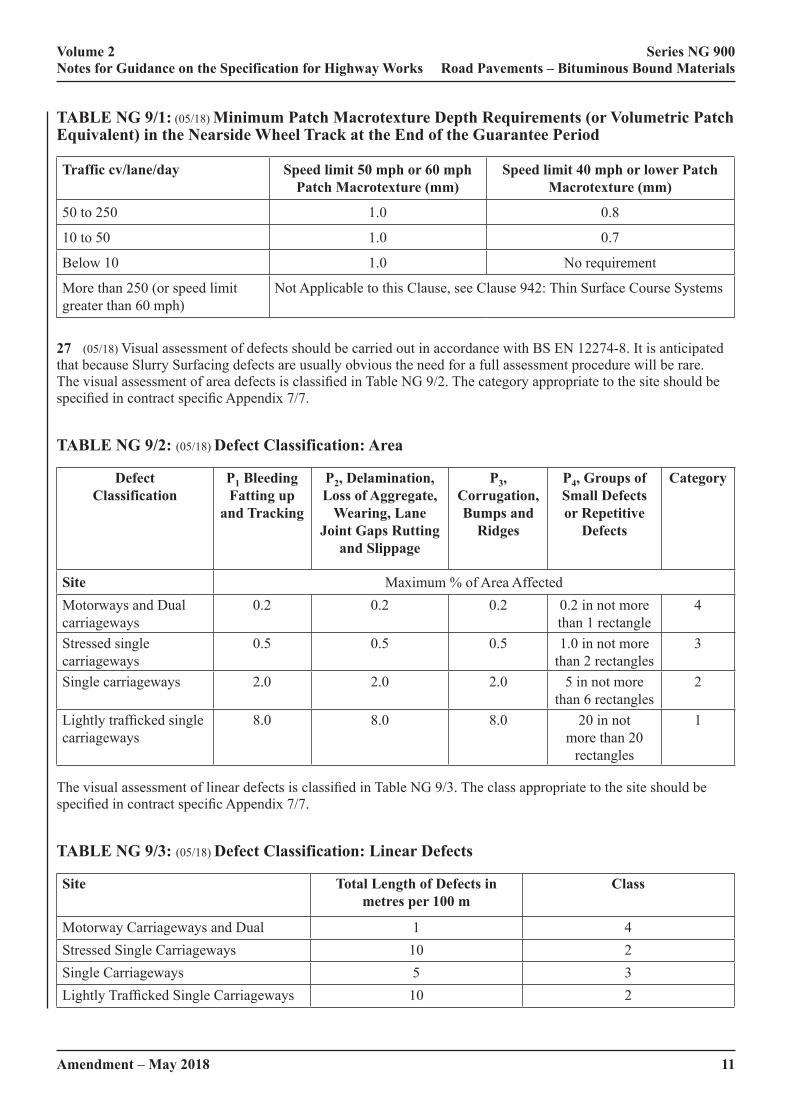
Amendment – May 2018 11
Volume 2 Series NG 900 Notes for Guidance on the Specification for Highway Works Road Pavements – Bituminous Bound Materials
TABLE NG 9/1: (05/18) Minimum Patch Macrotexture Depth Requirements (or Volumetric Patch Equivalent) in the Nearside Wheel Track at the End of the Guarantee Period
Traffic cv/lane/day Speed limit 50 mph or 60 mph Patch Macrotexture (mm)
Speed limit 40 mph or lower Patch Macrotexture (mm)
50 to 250 1.0 0.8
10 to 50 1.0 0.7
Below 10 1.0 No requirement
More than 250 (or speed limit greater than 60 mph)
Not Applicable to this Clause, see Clause 942: Thin Surface Course Systems
27 (05/18) Visual assessment of defects should be carried out in accordance with BS EN 12274-8. It is anticipated that because Slurry Surfacing defects are usually obvious the need for a full assessment procedure will be rare. The visual assessment of area defects is classified in Table NG 9/2. The category appropriate to the site should be specified in contract specific Appendix 7/7.
TABLE NG 9/2: (05/18) Defect Classification: Area
Defect Classification
P1 Bleeding Fatting up
and Tracking
P2, Delamination, Loss of Aggregate,
Wearing, Lane Joint Gaps Rutting
and Slippage
P3, Corrugation, Bumps and
Ridges
P4, Groups of Small Defects or Repetitive
Defects
Category
Site Maximum % of Area AffectedMotorways and Dual carriageways
0.2 0.2 0.2 0.2 in not more than 1 rectangle
4
Stressed single carriageways
0.5 0.5 0.5 1.0 in not more than 2 rectangles
3
Single carriageways 2.0 2.0 2.0 5 in not more than 6 rectangles
2
Lightly trafficked single carriageways
8.0 8.0 8.0 20 in not more than 20
rectangles
1
The visual assessment of linear defects is classified in Table NG 9/3. The class appropriate to the site should be specified in contract specific Appendix 7/7.
TABLE NG 9/3: (05/18) Defect Classification: Linear Defects
Site Total Length of Defects in metres per 100 m
Class
Motorway Carriageways and Dual 1 4Stressed Single Carriageways 10 2Single Carriageways 5 3Lightly Trafficked Single Carriageways 10 2

12Amendment – May 2018
Volume 2 Series NG 900 Notes for Guidance on the Specification for Highway Works Road Pavements – Bituminous Bound Materials
28 (05/18) Where a bond coat is proposed in the Design Proposal it shall comply with Clause 920. If the bond between layers is to be assessed then the torque bond test shall be carried out in accordance with Clause 951.
29 (05/18) Materials failing to set or setting too rapidly are caused by defects in workmanship or laying in inappropriate weather conditions. Work should stop and should not recommence until the any application faults have been rectified and the weather conditions are suitable. If the material has not been manufactured in accordance with the design proposal it may not set either adequately or at all and will need removal and replacement.
30 (05/18) Surface irregularity is measured in two ways as described in Clause 702, but as Slurry Surfacing is laid in a different manner to the method assumed in that Clause, Slurry Surfacing should meet the appropriate class given in Table NG 9/4 for transverse regularity and Table NG 9/7 for longitudinal irregularity. The class limits are given in Table NG 9/5 for the former and in Table NG 9/7 for the latter.
TABLE NG 9/4: (05/18) Transverse Regularity – Requirements
Site ClassDual carriageways and single carriageways with a speed limit greater than 40 mph 3Single carriageways with a 40 mph or lower speed limit, carrying more than 100 cv/l/d or more than 1000 veh/l/d and roads carrying less traffic where the cross fall is less than 2%.
2
All other roads 1Roads where only sealing and improvement to surface characteristics are required (i.e. Regulating is not a requirement)
0
TABLE NG 9/5: (05/18) Transverse Regularity – Class Limits
Class Maximum allowable difference between 3 m straight-edge and the road, mmNew At end of guarantee period
3 3 52 4 71 6 100 No requirement No requirement
TABLE NG 9/6: (05/18) Longitudinal Regularity – Requirements
Site ClassDual carriageways and single carriageways with a speed limit greater than 40 mph 2Single carriageways with a 40 mph or lower speed limit, carrying more than 100 cv/l/d or more than 1000 veh l/d
1
All other roads 0
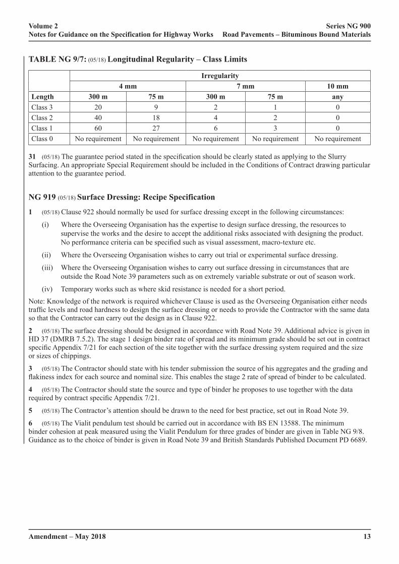
Amendment – May 2018 13
Volume 2 Series NG 900 Notes for Guidance on the Specification for Highway Works Road Pavements – Bituminous Bound Materials
TABLE NG 9/7: (05/18) Longitudinal Regularity – Class Limits
Irregularity4 mm 7 mm 10 mm
Length 300 m 75 m 300 m 75 m anyClass 3 20 9 2 1 0Class 2 40 18 4 2 0Class 1 60 27 6 3 0Class 0 No requirement No requirement No requirement No requirement No requirement
31 (05/18) The guarantee period stated in the specification should be clearly stated as applying to the Slurry Surfacing. An appropriate Special Requirement should be included in the Conditions of Contract drawing particular attention to the guarantee period.
NG 919 (05/18) Surface Dressing: Recipe Specification
1 (05/18) Clause 922 should normally be used for surface dressing except in the following circumstances:
(i) Where the Overseeing Organisation has the expertise to design surface dressing, the resources to supervise the works and the desire to accept the additional risks associated with designing the product. No performance criteria can be specified such as visual assessment, macro-texture etc.
(ii) Where the Overseeing Organisation wishes to carry out trial or experimental surface dressing.
(iii) Where the Overseeing Organisation wishes to carry out surface dressing in circumstances that are outside the Road Note 39 parameters such as on extremely variable substrate or out of season work.
(iv) Temporary works such as where skid resistance is needed for a short period.
Note: Knowledge of the network is required whichever Clause is used as the Overseeing Organisation either needs traffic levels and road hardness to design the surface dressing or needs to provide the Contractor with the same data so that the Contractor can carry out the design as in Clause 922.
2 (05/18) The surface dressing should be designed in accordance with Road Note 39. Additional advice is given in HD 37 (DMRB 7.5.2). The stage 1 design binder rate of spread and its minimum grade should be set out in contract specific Appendix 7/21 for each section of the site together with the surface dressing system required and the size or sizes of chippings.
3 (05/18) The Contractor should state with his tender submission the source of his aggregates and the grading and flakiness index for each source and nominal size. This enables the stage 2 rate of spread of binder to be calculated.
4 (05/18) The Contractor should state the source and type of binder he proposes to use together with the data required by contract specific Appendix 7/21.
5 (05/18) The Contractor’s attention should be drawn to the need for best practice, set out in Road Note 39.
6 (05/18) The Vialit pendulum test should be carried out in accordance with BS EN 13588. The minimum binder cohesion at peak measured using the Vialit Pendulum for three grades of binder are given in Table NG 9/8. Guidance as to the choice of binder is given in Road Note 39 and British Standards Published Document PD 6689.
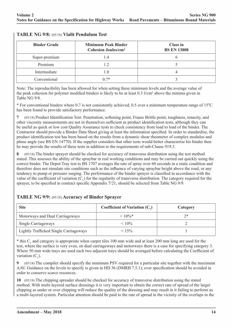
14Amendment – May 2018
Volume 2 Series NG 900 Notes for Guidance on the Specification for Highway Works Road Pavements – Bituminous Bound Materials
TABLE NG 9/8: (05/18) Vialit Pendulum Test
Binder Grade Minimum Peak Binder Cohesion Joules/cm2
Class in BS EN 13808
Super-premium 1.4 6
Premium 1.2 5
Intermediate 1.0 4
Conventional 0.7* 3
Note: The reproducibility has been allowed for when setting these minimum levels and the average value of the peak cohesion for polymer modified binders is likely to be at least 0.3 J/cm2 above the minima given in Table NG 9/8.
* For conventional binders where 0.7 is not consistently achieved, 0.5 over a minimum temperature range of 15oC has been found to provide satisfactory performance.
7 (05/18) Product Identification Test: Penetration, softening point, Fraass Brittle point, toughness, tenacity, and other viscosity measurements are not in themselves sufficient as product identification tests, although they can be useful as quick or low cost Quality Assurance tests to check consistency from load to load of the binder. The Contractor should provide a Binder Data Sheet giving at least the information specified. In order to standardise, the product identification test has been based on the results from a dynamic shear rheometer of complex modulus and phase angle (see BS EN 14770). If the supplier considers that other tests would better characterise his binder then he may provide the results of these tests in addition to the requirements of sub-Clause 919.3.
8 (05/18) The binder sprayer should be checked for accuracy of transverse distribution using the test method stated. This assesses the ability of the spraybar in real working conditions and may be carried out quickly using the correct binder. The Depot Tray test to BS 1707 averages the rate of spray over 60 seconds in a static condition and therefore does not simulate site conditions such as the influence of varying spraybar height above the road, or any tendency to pump or pressure surging. The performance of the binder sprayer is classified in accordance with the value of the coefficient of variation (Cv) for the regularity of transverse distribution. The category required for the sprayer, to be specified in contract specific Appendix 7/21, should be selected from Table NG 9/9.
TABLE NG 9/9: (05/18) Accuracy of Binder Sprayer
Site Coefficient of Variation (Cv) Category
Motorways and Dual Carriageways < 10%* 2*
Single Carriageways < 10% 2
Lightly Trafficked Single Carriageways < 15% 1
* this Cv and category is appropriate when carpet tiles 100 mm wide and at least 200 mm long are used for the test, where the surface is very even, on dual carriageways and motorways there is a case for specifying category 3. Where 50 mm wide trays are used each two adjacent trays should be averaged before calculating the Coefficient of variation (Cv).
9 (05/18) The compiler should specify the minimum PSV required for a particular site together with the maximum AAV. Guidance on the levels to specify is given in HD 36 (DMRB 7.5.1); over specification should be avoided in order to conserve scarce resources.
10 (05/18) The chipping spreader should be checked for accuracy of transverse distribution using the stated method. With multi-layered surface dressings it is very important to obtain the correct rate of spread of the larger chipping as under or over chipping will reduce the quality of the dressing and may result in it failing to perform as a multi-layered system. Particular attention should be paid to the rate of spread in the vicinity of the overlaps in the
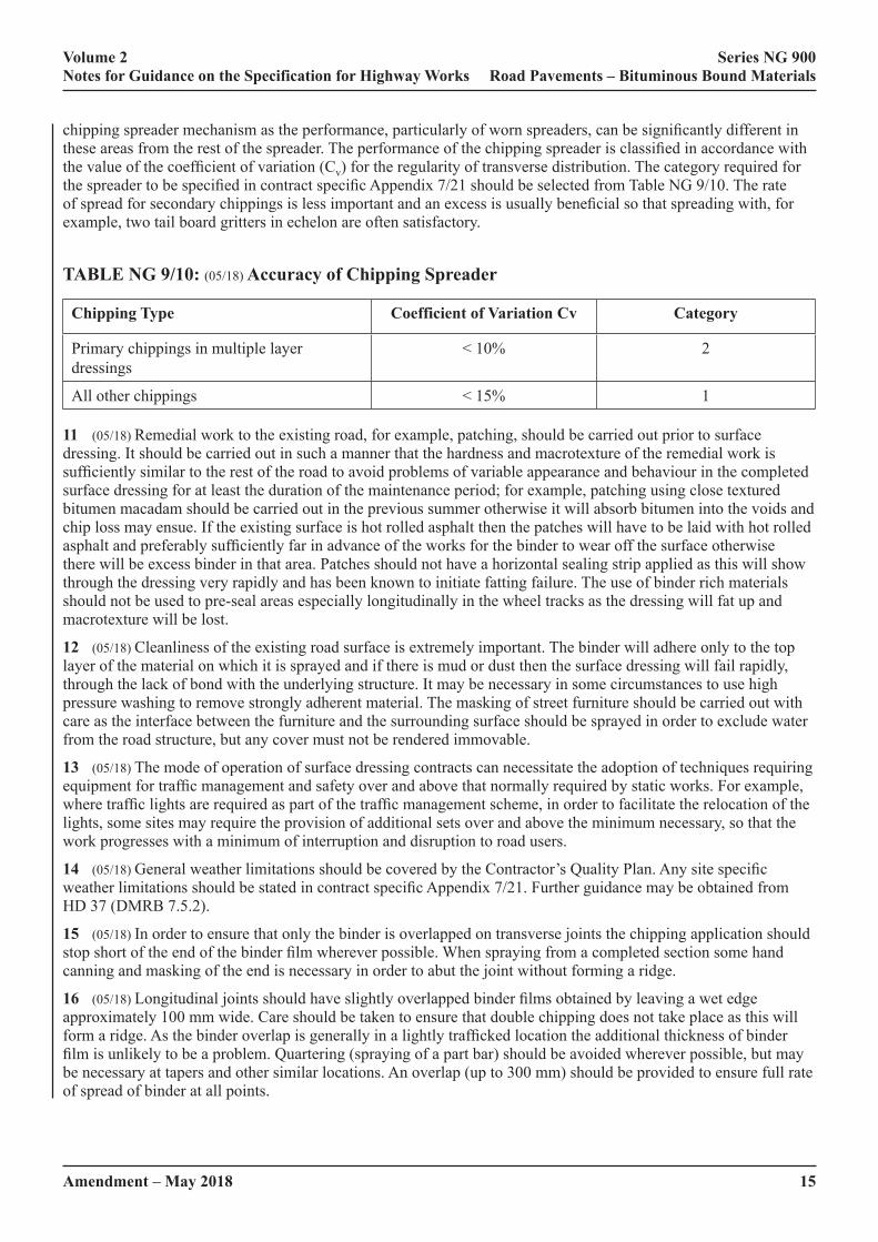
Amendment – May 2018 15
Volume 2 Series NG 900 Notes for Guidance on the Specification for Highway Works Road Pavements – Bituminous Bound Materials
chipping spreader mechanism as the performance, particularly of worn spreaders, can be significantly different in these areas from the rest of the spreader. The performance of the chipping spreader is classified in accordance with the value of the coefficient of variation (Cv) for the regularity of transverse distribution. The category required for the spreader to be specified in contract specific Appendix 7/21 should be selected from Table NG 9/10. The rate of spread for secondary chippings is less important and an excess is usually beneficial so that spreading with, for example, two tail board gritters in echelon are often satisfactory.
TABLE NG 9/10: (05/18) Accuracy of Chipping Spreader
Chipping Type Coefficient of Variation Cv Category
Primary chippings in multiple layer dressings
< 10% 2
All other chippings < 15% 1
11 (05/18) Remedial work to the existing road, for example, patching, should be carried out prior to surface dressing. It should be carried out in such a manner that the hardness and macrotexture of the remedial work is sufficiently similar to the rest of the road to avoid problems of variable appearance and behaviour in the completed surface dressing for at least the duration of the maintenance period; for example, patching using close textured bitumen macadam should be carried out in the previous summer otherwise it will absorb bitumen into the voids and chip loss may ensue. If the existing surface is hot rolled asphalt then the patches will have to be laid with hot rolled asphalt and preferably sufficiently far in advance of the works for the binder to wear off the surface otherwise there will be excess binder in that area. Patches should not have a horizontal sealing strip applied as this will show through the dressing very rapidly and has been known to initiate fatting failure. The use of binder rich materials should not be used to pre-seal areas especially longitudinally in the wheel tracks as the dressing will fat up and macrotexture will be lost.
12 (05/18) Cleanliness of the existing road surface is extremely important. The binder will adhere only to the top layer of the material on which it is sprayed and if there is mud or dust then the surface dressing will fail rapidly, through the lack of bond with the underlying structure. It may be necessary in some circumstances to use high pressure washing to remove strongly adherent material. The masking of street furniture should be carried out with care as the interface between the furniture and the surrounding surface should be sprayed in order to exclude water from the road structure, but any cover must not be rendered immovable.
13 (05/18) The mode of operation of surface dressing contracts can necessitate the adoption of techniques requiring equipment for traffic management and safety over and above that normally required by static works. For example, where traffic lights are required as part of the traffic management scheme, in order to facilitate the relocation of the lights, some sites may require the provision of additional sets over and above the minimum necessary, so that the work progresses with a minimum of interruption and disruption to road users.
14 (05/18) General weather limitations should be covered by the Contractor’s Quality Plan. Any site specific weather limitations should be stated in contract specific Appendix 7/21. Further guidance may be obtained from HD 37 (DMRB 7.5.2).
15 (05/18) In order to ensure that only the binder is overlapped on transverse joints the chipping application should stop short of the end of the binder film wherever possible. When spraying from a completed section some hand canning and masking of the end is necessary in order to abut the joint without forming a ridge.
16 (05/18) Longitudinal joints should have slightly overlapped binder films obtained by leaving a wet edge approximately 100 mm wide. Care should be taken to ensure that double chipping does not take place as this will form a ridge. As the binder overlap is generally in a lightly trafficked location the additional thickness of binder film is unlikely to be a problem. Quartering (spraying of a part bar) should be avoided wherever possible, but may be necessary at tapers and other similar locations. An overlap (up to 300 mm) should be provided to ensure full rate of spread of binder at all points.
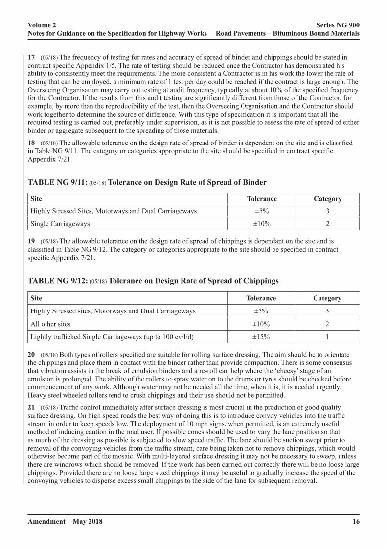
16Amendment – May 2018
Volume 2 Series NG 900 Notes for Guidance on the Specification for Highway Works Road Pavements – Bituminous Bound Materials
17 (05/18) The frequency of testing for rates and accuracy of spread of binder and chippings should be stated in contract specific Appendix 1/5. The rate of testing should be reduced once the Contractor has demonstrated his ability to consistently meet the requirements. The more consistent a Contractor is in his work the lower the rate of testing that can be employed, a minimum rate of 1 test per day could be reached if the contract is large enough. The Overseeing Organisation may carry out testing at audit frequency, typically at about 10% of the specified frequency for the Contractor. If the results from this audit testing are significantly different from those of the Contractor, for example, by more than the reproducibility of the test, then the Overseeing Organisation and the Contractor should work together to determine the source of difference. With this type of specification it is important that all the required testing is carried out, preferably under supervision, as it is not possible to assess the rate of spread of either binder or aggregate subsequent to the spreading of those materials.
18 (05/18) The allowable tolerance on the design rate of spread of binder is dependent on the site and is classified in Table NG 9/11. The category or categories appropriate to the site should be specified in contract specific Appendix 7/21.
TABLE NG 9/11: (05/18) Tolerance on Design Rate of Spread of Binder
Site Tolerance Category
Highly Stressed Sites, Motorways and Dual Carriageways ±5% 3
Single Carriageways ±10% 2
19 (05/18) The allowable tolerance on the design rate of spread of chippings is dependant on the site and is classified in Table NG 9/12. The category or categories appropriate to the site should be specified in contract specific Appendix 7/21.
TABLE NG 9/12: (05/18) Tolerance on Design Rate of Spread of Chippings
Site Tolerance Category
Highly Stressed sites, Motorways and Dual Carriageways ±5% 3
All other sites ±10% 2
Lightly trafficked Single Carriageways (up to 100 cv/l/d) ±15% 1
20 (05/18) Both types of rollers specified are suitable for rolling surface dressing. The aim should be to orientate the chippings and place them in contact with the binder rather than provide compaction. There is some consensus that vibration assists in the break of emulsion binders and a re-roll can help where the ‘cheesy’ stage of an emulsion is prolonged. The ability of the rollers to spray water on to the drums or tyres should be checked before commencement of any work. Although water may not be needed all the time, when it is, it is needed urgently. Heavy steel wheeled rollers tend to crush chippings and their use should not be permitted.
21 (05/18) Traffic control immediately after surface dressing is most crucial in the production of good quality surface dressing. On high speed roads the best way of doing this is to introduce convoy vehicles into the traffic stream in order to keep speeds low. The deployment of 10 mph signs, when permitted, is an extremely useful method of inducing caution in the road user. If possible cones should be used to vary the lane position so that as much of the dressing as possible is subjected to slow speed traffic. The lane should be suction swept prior to removal of the convoying vehicles from the traffic stream, care being taken not to remove chippings, which would otherwise become part of the mosaic. With multi-layered surface dressing it may not be necessary to sweep, unless there are windrows which should be removed. If the work has been carried out correctly there will be no loose large chippings. Provided there are no loose large sized chippings it may be useful to gradually increase the speed of the convoying vehicles to disperse excess small chippings to the side of the lane for subsequent removal.

Amendment – May 2018 17
Volume 2 Series NG 900 Notes for Guidance on the Specification for Highway Works Road Pavements – Bituminous Bound Materials
22 (05/18) It is essential that the dressing is monitored for some time after opening to traffic, particularly in hot weather when using cutback binders, as at high temperatures the binder cohesion is low when using emulsions in humid or cool weather, the binder takes longer to gain cohesion. Both conditions result in lower initial resistance to traffic forces and the mosaic may be destroyed. Should this happen the Contractor should be prepared to re-impose traffic control and have on site a suitable “dust” ready to use. The ideal “dust” is light coloured, absorbent and about 4 mm to 1 mm in size. Oolitic limestone and blastfurnace slag are particularly good although other materials available locally may have to be used.
NG 920 (05/18) Bond Coats, Tack Coats and Other Bituminous Sprays
(05/18) Bond Coats and Tack Coats
1 (05/18) This Clause specifies tack coats and bond coats for asphalt concrete, hot rolled asphalt and stone mastic asphalt binder course and regulating course. Bond coats and tack coats are applied prior to laying of bituminous mixtures in order to promote the development of a homogeneous pavement structure and to prevent ingress of water. The structural design of pavements assumes that the bond between layers is complete. Bond is particularly important in highly stressed areas. The use of tack or bond coat is a universal requirement when placing bituminous material on any new or existing bound substrate, under Clause 903.4. Further information can be found in BS 594987. The use of tack and bond coats under Thin Surface Course Systems is covered by Clause 942.
2 (05/18) BS 594987 gives recommended application rates of tack and bond coats. Clause 903 converts these recommendations into requirements. A bond coat is more appropriate where greater bond strength or better sealing is required. An example is where materials are to be laid less than 30 mm thick, or where a particular site has a binder lean substrate and permeability is considered a problem. Advice on the choice of tack coat or bond coat is provided in BS 594987. Traditionally a tack coat using C40B4 or C60B3 emulsion has been used to add a little extra binder to an existing surface and is often adequate to initiate adhesion between layers. Bond coats generally have a higher binder content containing modifiers and are usually used at a higher rate of spread thus promoting improved adhesion with some waterproofing capability, important to prevent water ingress below porous or permeable materials. Additional information is provided in HD 37 (DMRB 7.5.2).
3 (05/18) Bond coats may sometimes need to be partially covered with aggregate, to prevent them from being picked up when being walked on or driven over, especially during periods of hot weather. A typical rate of application of chippings is approximately 3 to 5 kg/m2. Alternatively, ‘non-tack’ bond coats, which are available from some suppliers, may be used. When these emulsions break, sometimes accelerated using proprietary breaking agents, the residual binder is not as tacky or sticky, only becoming so at the high temperatures associated with the asphalt overlay when they melt at the interface, thereby achieving a bond. These materials are useful for work in urban areas where foot traffic is sometimes unavoidable.
4 (05/18) Rates of spread of binder should follow the recommendations of BS 594987 or the manufacturer’s instructions, as appropriate. Rates of spread may need to be altered for varying macrotexture and porosity of the existing road and an increased rate at the kerb or road edge is beneficial to minimise water ingress where compaction by traffic is least.
5 (05/18) Particular care is required when applying a bituminous surfacing to an existing concrete road as not all emulsions adhere well to concrete. It is likely that one specially formulated for this application will be needed. The adhesion of a bituminous surfacing to newly laid concrete is a special case and evidence of a satisfactory bond should be provided.
6 (05/18) Pendulum Class 4 (previously known as “Intermediate grade”) bond coats or bituminous sprays have a Vialit Pendulum Peak Cohesion minimum value of 1.0 J/cm2 on the recovered binder prepared using Clause 955 when measured using BS EN 13808. Pendulum Class 5 (previously known as “Premium grade”) bond coats or bituminous sprays have a Vialit Pendulum Peak Cohesion minimum value of 1.2 J/cm2. Pendulum Class 4 or 5 bond coats are recommended when overlaying highly variable surfaces or those of high porosity. Pendulum Class 5 bond coats are recommended for sealing under porous asphalt or for improved bond in highly stressed areas.
7 (05/18) The spread rates for tack and bond coats on hydraulically bound substrates may need to be higher than those required for bituminous substrates.
18Amendment – May 2018
Volume 2 Series NG 900 Notes for Guidance on the Specification for Highway Works Road Pavements – Bituminous Bound Materials
Bituminous Sprays
8 (05/18) Bituminous sprays may be used to seal and protect earthworks, drainage media, recycled material and cementitious materials including cement-stabilised soil. The primary purpose is not necessarily to promote bond with an overlay, but to limit the evaporation or ingress of water and in cementitious materials, to facilitate proper curing. Cementitious surfaces are alkaline and in warm summer conditions anionic emulsions may be more suitable than cationic emulsions. Anionic emulsions have an alkaline water phase and can penetrate the surface before breaking. It is important that the coverage of residual binder is uniform. Even small areas that remain unsealed will increase evaporation of water and, in cementitious materials, cause premature drying that will inhibit curing. The surface of the sprayed area should normally be covered with light coloured aggregate to reduce the absorption of heat from the sun’s rays and reduce water loss.
(05/18) General
9 (05/18) To enable the Overseeing Organisation to identify each product the Contractor is to supply the declaration of performance for each product and the other information required in Sheet 2 of contract specific Appendix 7/4.
NG 921 (05/18) Surface Macrotexture of Bituminous Surface Courses
1 (05/18) The depth of surface macrotexture is important in the dispersal of surface water from the tyre road contact area in order to maintain skid resistance in the wet at speed. It is most important on high speed roads and different criteria apply to high speed and low speed roads. For the purposes of Clause 921, a low speed road is defined one with a posted speed limit of 40 miles/hour (65 km/h) or less.
2 (05/18) The long established high speed road requirement of a minimum initial texture depth of 1.5 mm applies only to Hot Rolled Asphalt surface course. This is achieved by the application of coated chippings, as described in Clause 915 and BS 594987.
3 (05/18) A minimum initial texture depth of 1.3 mm has been found to be sufficient for high speed roads surfaced using Thin Surface Course Systems to Clause 942.
4 (05/18) Very high surface texture on high stress areas, particularly roundabouts, compromises toughness and durability and renders the surface prone to fretting, chipping loss and deterioration. Since these are rarely high speed roads by definition, it is good practice to adopt lower texture requirements in such situations and a value of 1.2mm is considered appropriate for the trunk road network.
5 (05/18) On low speed roads, good skid resistance is achieved by maximising the area of contact between tyre and aggregate, rather than by achieving high texture. This often means adopting smaller aggregate sizes. In these circumstances, an initial texture depth of 1.0 mm is considered suitable, including roundabouts on low speed non-trunk roads.
6 (05/18) Requirements for retained texture depth for Thin Surface Course Systems specified to Clause 942 are given in that Clause.
7 (05/18) Clause 921 permits the use of the sand patch method in BS 598-105 (now withdrawn) for routine monitoring of initial surface macrotexture. If the sand patch method is used, the sand should be washed and dried silica sand with a rounded particle shape. The grading of the sand should be 100% (by mass) passing the 0.600 mm test sieve; 90 to 100% (by mass) passing the 0.300 mm test sieve; and not more than 15% (by mass) passing the 0.150 mm test sieve.
NG 922 (05/18) Surface Dressing: Design, Application and End Product Performance
1 (05/18) The specification is not of the conventional recipe/method type. It contains elements of performance-related testing of materials for contract compliance, quality control of the process and end product performance and reference should be made to: BS EN 12271, HD 37 (DMRB 7.5.2), Road Note 39 and British Standards Published Document PD 6689. The principal differences from a recipe specification are that responsibility for the design of the dressing is transferred to the Contractor and that there is performance measurement of the Surface Dressing,
Amendment – May 2018 19
Volume 2 Series NG 900 Notes for Guidance on the Specification for Highway Works Road Pavements – Bituminous Bound Materials
measured at intervals throughout a guarantee period specified in the contract. The guarantee period is normally two years for motorways, trunk roads and heavily trafficked or highly stressed roads, and one year for other roads.
2 (05/18) The specification allows considerable freedom for the Contractor in the design of the Surface Dressing provided it complies with BS EN 12271. BS EN 12271 is a harmonised standard under the Construction Products Regulation and as such the surface dressing is required to be CE marked and the manufacture is obliged to make a declaration of performance. The evaluation of conformity requirements in BS EN 12271 include the Type Approval Installation Trial (TAIT).
3 (05/18) Low noise emission Surface Dressings may be specified by limiting the designs to double or multi-layered dressings and/or the maximum macrotexture depth in contract specific Appendix 7/3.
4 (05/18) Tenderers are expected to visit all the sites, to assess the parameters required, and in conjunction with those given in the appendices, to design a suitable surface dressing.
5 (05/18) Basic details of the tendered design for each site should be completed in the Design Proposal and declaration of performance provided.
6 (05/18) If any site is considered by the tenderer to be unsuitable for surface dressing this should be stated in the Design Proposal. There may be sections where the existing road surface is considered not suitable for treatment or the performance requirements are too onerous to be achieved in practice, see HD 37 (DMRB 7.5.2).
7 (05/18) When preparing the instructions for tendering it is essential that the compiler includes the following information and instructions adapted as necessary to suit the particular conditions of contract and form of contract:
(i) Tenderers’ attention is drawn to the requirement that Tenderers intending to sub-contract surface dressing must nevertheless provide with their tender all the information required by Clause 922 and contract specific Appendix 7/3.
(ii) In determining the award of the Contract, regard will be had not only to the price tendered but also to the following criteria:
(a) the Contract time period entered in the Form of Tender by the Tenderer.
(b) the requirements of contract specific Appendix 7/3 assessed as follows:
Contract Time Period All tenders will be evaluated against the lowest submitted Contract period.
Durability All tenders will be evaluated considering the durability categories stated in the declaration of performance.
QA Certification Any tender submitting QA registrations which are not valid in the context of this scheme will not be considered.
Method Statement All tenders will be evaluated in respect of the submitted method statement and any that do not fully comply with all the constraints contained in the Contract documents will not be considered.
Design Proposal Any tenderer submitting design proposals which do not fully comply with the constraints contained in the Contract Documents will not be considered.
Declaration of Performance Any tenderer failing to submit the declaration of performance for the surface dressing will not be considered.
Traffic Management Any tenderer failing to submit his proposals for traffic control and aftercare as detailed in contract specific Appendices 7/3 and 1/17, or not fully complying with all the constraints contained in the Contract Documents, will not be considered.
Contingency Plans Any tenderer failing to submit his details of contingency plans as detailed in contract specific Appendix 7/3 will not be considered.
Previous Applications Any tenderer failing to submit the details of previous applications, personnel, technical and managerial multiple layer dressing expertise as detailed in contract specific Appendix 7/3 will not be considered.
20Amendment – May 2018
Volume 2 Series NG 900 Notes for Guidance on the Specification for Highway Works Road Pavements – Bituminous Bound Materials
8 (05/18) It is expected that the design would normally be carried out based on Road Note 39 although alternative, documented, design procedures may be used provided they take into account the particular requirements of the site. Contractors should recognise the need for best practice as set out in Road Note 39, BSI PD 6689 and in Road Surface Treatment Association (RSTA) documents. Durability characteristics are required in order to assist in the assessment of tenders on the expected design life of the surface dressing on a value for money basis; it is often the case that more expensive designs last longer. The end of the design life is when the dressing no longer provides the surface properties required at the site in question. Further guidance on the design life of Surface Treatments including Surface Dressing has been published by RSTA and ADEPT.
9 (05/18) The responsibility for the provision of information upon which to base the design should be set out in the contract, but it is expected that the compiler would provide the traffic data, the classification of the site in accordance with HD 36 (DMRB 7.5.1), the minimum requirements for aggregate and binder properties, and records of road surface hardness measurements carried out in accordance with Road Note 39. The compiler should set out any limitations on the availability of a site in contract specific Appendix 1/13. These limitations could include requirements to avoid the site at rush hours, on market days or for particular events already planned at the time of writing the contract. There are problems with hardness measurements in that they need a lane closure and are best carried out when the road temperature is above 15°C, (Road Note 39), therefore it may be necessary for the Overseeing Organisation to carry out measurements during the preceding summer. When the Contractor makes his site visit for the purposes of tendering he should make a visual assessment of the road hardness and traffic category and bring any obvious anomalies about the site to the attention of the Overseeing Organisation.
10 (05/18) For the purposes of the contract, monitoring will stop at the end of the guarantee period, or for novel materials, after one third of the stated estimated design life, but in order to check the proposed design life against the actual achieved life, monitoring should continue for the whole life of the dressing. On heavily trafficked roads this can most conveniently be done by means of the macrotexture output from TRACS surveys, which are currently carried out on all trunk roads every 2 years and SCRIM surveys, which are currently carried out every 3 years. For other roads volumetric patch tests or use of the Mini Texture Meter or other device calibrated against volumetric patch values as Volumetric Patch Equivalent values, may be more convenient.
11 (05/18) The Vialit pendulum test should be carried out using BS EN 13588. The minimum binder cohesion at peak measured using the Vialit Pendulum for four grades of binder are given in Table NG 9/13. Guidance as to the choice of binder is given in HD 37 (DMRB 7.5.2). The range of temperature for premium and intermediate binders for a value of 1.0 J/cm2 for heavily trafficked roads or highly stressed sites, provides another parameter for evaluation of the modification together with peak value (see HD 37 (DMRB 7.5.2).
TABLE NG 9/13: (05/18) Vialit Pendulum Test
Binder Grade Minimum Peak Binder Cohesion J/cm2 Class in BS EN 13808
Super-premium 1.4 6
Premium 1.2 5
Intermediate 1.0 4
Conventional 0.7* 3*
Note: The cohesion test has a significant reproducibility. This has been allowed for when setting these minimum levels and the average value of the peak cohesion for polymer modified binders is likely to be at least 0.3 J/cm2 above the minima given in the Table.
* For conventional binders where 0.7 is not consistently achieved, 0.5 over a minimum temperature range of 15°C has been found to provide satisfactory performance.
12 (05/18) Penetration, softening point, Fraass Brittle point, toughness, tenacity, and other viscosity measurements are not in themselves sufficient as contract compliance tests, although they may be useful as quick or low cost Quality Assurance tests to check consistency from load to load of the binder. The Contractor’s Design Proposal should provide a declaration of performance for the binder giving at least the information specified.

Amendment – May 2018 21
Volume 2 Series NG 900 Notes for Guidance on the Specification for Highway Works Road Pavements – Bituminous Bound Materials
13 (05/18) The binder sprayer should be checked for accuracy of transverse distribution using BS EN 12272-1. This assesses the ability of the spraybar in real working conditions and may be carried out quickly using the correct binder. The Depot Tray test to BS 1707 averages the rate over 60 seconds in a static condition and therefore does not simulate site conditions caused by varying spraybar height, wind effects and pump or pressure surging. The performance of the binder sprayer is classified in accordance with the value of the coefficient of variation (Cv) for the regularity of transverse distribution. The category required for the sprayer, to be specified in contract specific Appendix 7/3, should be selected from Table NG 9/14.
TABLE NG 9/14: (05/18) Accuracy of Binder Sprayer
Site Coefficient of Variation Cv Category
Motorways and Dual Carriageways < 10% 2*
Single Carriageways < 10% 2
Lightly Trafficked Single Carriageways < 15% 1
(05/18) * The Cv and category is appropriate when carpet tiles 100 mm wide and at least 200 mm long are used for the test, where the surface is very even, on dual carriageways and motorways there is a case for specifying category 3. Where 50 mm wide trays are used each two adjacent trays should be averaged before calculating the Coefficient of variation (Cv).
14 (05/18) The compiler should specify the minimum PSV required for a particular site together with the maximum AAV. Guidance on the levels to specify is given in HD 36 (DMRB 7.5.1); over specification should be avoided in order to conserve scarce resources.
15 (05/18) The chipping spreader should be checked for accuracy of transverse distribution using the stated method. With multi-layered surface dressings it is very important to obtain the correct rate of spread of the larger chipping as under or over-chipping will reduce the quality of the dressing and may result in it failing to perform as a multi-layered system. Particular attention should be paid to the rate of spread in the vicinity of the overlaps in the chipping spreader mechanism as the performance, particularly of worn spreaders, can be significantly different in these areas from the rest of the spreader. The performance of the chipping spreader is classified in accordance with the value of the coefficient of variation (Cv) for the regularity of transverse distribution. The category required for the spreader to be specified in contract specific Appendix 7/3 should be selected from Table NG 9/15. The rate of spread for secondary chippings is less important and an excess is usually beneficial so that spreading with two tail-board gritters in echelon is acceptable.
TABLE NG 9/15: (05/18) Accuracy of Chipping Spreader
Chipping Type Coefficient of Variation Cv Category
Primary chippings in multi-layer Surface Dressing < 10% 2
All other chippings < 15% 1
16 (05/18) Repairs to the existing road, in preparation for Surface Dressing, (for example, patching) should be carried out well in advance of the works. They should be carried out in such a manner that the hardness and macrotexture of the remedial work is sufficiently similar to the rest of the road to avoid problems of variable appearance and behaviour in the completed dressing for at least the duration of the maintenance period; for example, patching using close textured bitumen macadam should be carried out in the previous summer otherwise it may absorb bitumen into the voids and chipping loss may ensue. The existing road variability and surface characteristics have a bearing on the achievable levels of performance that may be specified; further information is available in HD 37 (DMRB 7.5.2). If the existing surface is hot rolled asphalt then the patches will have to be laid with hot rolled asphalt and preferably sufficiently far in advance of the works for the binder to wear off the surface

22Amendment – May 2018
Volume 2 Series NG 900 Notes for Guidance on the Specification for Highway Works Road Pavements – Bituminous Bound Materials
otherwise there will be excess binder in that area and fatting may occur. Thin surface course systems should be repaired with stone mastic asphalt of similar consistency and highly textured variable substrata should be sealed with a pad coat. Patches should not have a horizontal sealing strip applied as this will show through the dressing very rapidly and has been known to initiate fatting failure. Binder-rich soft materials to seal cracks similar to stress absorbing membrane interlayers (SAMIs) should not be used especially longitudinally in the wheel tracks, as the Surface Dressing will fat up.
17 (05/18) Cleanliness of the existing road surface is extremely important. The binder will adhere only to the top layer of the material on which it is sprayed and if this is mud or dust then the Surface Dressing will fail rapidly, lacking bond with the underlying structure. It may be found necessary in some circumstances to use high pressure washing to remove strongly adherent material. The masking of street furniture should be carried out very carefully as the interface between the furniture and the surrounding surface should be sprayed in order to exclude water from the road structure, but any cover must not be rendered immovable.
18 (05/18) Traffic safety and management. The mode of operation of Surface Dressing contracts can necessitate the adoption of techniques requiring additional equipment over and above that normally required by static works. For example, where traffic lights are required as part of the traffic management scheme, some sites may require the provision of additional sets of traffic lights over and above the minimum necessary in order to permit work to progress with a minimum of interruption and disruption to road users.
19 (05/18) General weather limitations should be covered by the Contractor’s Quality Plan. Any site specific weather limitations should be specified under ‘Special restrictions’ in contract specific Appendix 7/3. Further guidance may be obtained from HD 37 (DMRB 7.5.2).
20 (05/18) In order to ensure that only the binder is overlapped on transverse joints the chipping application should stop short of the end of the binder film wherever possible. When spraying from a completed section some hand canning and masking of the end is necessary in order to abut the joint without forming a ridge.
21 (05/18) Longitudinal joints should have slightly overlapped binder films obtained by leaving at least a 100 mm wide wet edge. Care should be taken to ensure that double chipping does not take place as this will form a ridge. As the binder overlap is generally in a lightly trafficked location the additional thickness of binder film is unlikely to be a problem. Quartering (spraying of a part bar) should be avoided wherever possible, but may be necessary at tapers and other similar locations, sufficient overlap (up to 300 mm) should be implemented in order to ensure at a minimum the full rate of spread of binder at all points.
22 (05/18) The frequency of testing for rates and accuracy of spread of binder and chippings should be stated in contract specific Appendix 1/5. The rate of testing should be reduced once the Contractor has demonstrated his ability to consistently meet the requirements. The more consistent a contractor is in his work the lower the rate of testing that may be employed; a minimum rate of 1 test per day on motorways and trunk roads might be attained if the contract is large enough. The Overseeing Organisation will carry out testing at audit frequency, typically at about 10% of the specified frequency for the Contractor. If the results from audit testing are significantly different from those of the Contractor, for example, by more than the reproducibility of the tests, then the Overseeing Organisation and the Contractor should work together to determine the source of difference. For roads other than trunk roads or motorways the frequency of testing detailed in the Quality Plan and the Sector Scheme for the Supply and Application of Surface Treatments to Road Surfaces should be used.
23 (05/18) The permitted tolerance on the design rate of spread of binder is dependent on the site and is classified in Table NG 9/16. The category or categories appropriate to the site should be specified in contract specific Appendix 7/3. These categories have been taken from BS EN 12272-1 for surface dressing.
TABLE NG 9/16: (05/18) Tolerance on Design Rate of Spread of Binder
Site Tolerance Category
Highly Stressed Sites, Motorways and Dual Carriageways ± 5% 2
Single Carriageways ± 10% 1

Amendment – May 2018 23
Volume 2 Series NG 900 Notes for Guidance on the Specification for Highway Works Road Pavements – Bituminous Bound Materials
24 (05/18) The permitted tolerance on the design rate of spread of chippings is dependent on the site and is classified in Table NG 9/17. The category appropriate to the site should be specified in contract specific Appendix 7/3. These levels have been taken from BS EN 12272-1 for surface dressing.
TABLE NG 9/17: (05/18) Tolerance on Design Rate of Spread of Chippings
Site Tolerance Category
Highly Stressed Sites, Motorways and Dual Carriageways ±5% 3
All Other Sites ±10% 2
Lightly Trafficked Single Carriageways (up to 100 cv/l/d) ±15% 1
25 (05/18) The aim of rolling should be to orientate the chippings and place them in contact with the binder rather than provide compaction. There is some consensus that vibration using a rubber coated vibratory steel-tyred roller assists in the break of emulsion binders and a re-roll can help where the ‘cheesy’ stage of an emulsion is prolonged. The ability of the rollers to spray water on to the drums or tyres should be checked before commencement of any work. Although water may not be needed all the time, when it is, it is needed urgently. Heavy steel-wheeled rollers (12 tonnes) tend to crush chippings and their use should not be permitted.
26 (05/18) Traffic control immediately after Surface Dressing is most crucial in the production of good quality Surface Dressing. On high speed roads the best way of doing this is to introduce convoy vehicles into the traffic stream in order to keep speeds low. The deployment of 10 mph or 20 mph signs, when permitted, is extremely useful and warn the road user. If possible cones should be used to vary the lane position so that as much of the dressing as possible is subjected to slow speed traffic. The lane should be suction swept prior to removal of the convoying vehicles from the traffic stream, care being taken not to remove chippings that would otherwise become part of the mosaic. With multi-layered surface dressing it may not be necessary to sweep initially unless there are windrows which should be removed. If the work has been carried out correctly there will be no loose large chippings. Provided there are no loose large sized chippings it may be useful to gradually increase the speed of the convoying vehicles to disperse excess small chippings to the side of the lane for subsequent removal.
27 (05/18) On motorways and heavily trafficked dual carriageways it is not normally possible to convoy traffic through the works at a speed of 20 mph which would normally be done on other roads to consolidate the Surface Dressing prior to final sweeping and opening to unrestricted traffic. As part of the normal traffic management for motorway work there is generally a mandatory 50 mph speed restriction in place for the duration of the work. Therefore, instead of the normal slow speed trafficking and convoying as part of the aftercare, the Surface Dressing should be designed to be opened to 50 mph traffic after completion of initial suction sweeping. Suitable designs include double and multi-layered dressings using polymer modified emulsion binders and racked-in dressings using polymer modified cutback binders with lightly coated chippings for the primary layer. There should follow a number of days of trafficking at the restricted speed limit (generally 50 mph) with traffic management being organised in such a manner that all lanes have at least 48 hours of speed limited trafficking. A minimum of 72 hours of restricted speed limit control after opening the whole carriageway to traffic should be included in the works programme. This period may be extended as stated by the Overseeing Organisation in contract specific Appendix 7/3 or as detailed by the Surface Dressing Contractor in his Design Proposal. The period will not normally be extended except when the traffic on the section of motorway is unusually light or the work is to be carried out late season, for example in August. The Surface Dressing Contractor will determine the need for a longer period based on his experience with a particular process that is proposed. All loose chippings should be removed from any traffickable part of the carriageway or hard shoulder prior to removal of the speed restriction.
28 (05/18) It is essential that the dressing is monitored for some time after opening to traffic, particularly in hot weather when using cutback binders as at high temperatures the binder cohesion is low. When using emulsions, humid or cool weather, results in a similar problem as the binder takes longer to gain cohesion. These conditions result in lower initial resistance to traffic forces and the mosaic may be destroyed. The Contractor should be prepared for these eventualities and have on site, ready to use, a suitable ‘dust’, if this is required, and be prepared to re-impose traffic control. The ideal ‘dust’ is light coloured, absorbent and about 4 mm to 1 mm in size. Oolitic

24Amendment – May 2018
Volume 2 Series NG 900 Notes for Guidance on the Specification for Highway Works Road Pavements – Bituminous Bound Materials
limestone and blastfurnace slag are particularly good although other materials available locally may have to be used.
29 (05/18) Macrotexture is measured in the nearside (inside) wheel track where the lane width and traffic are sufficient for this to be identified; for low traffic category sites the track carrying the most traffic (wear) is tested, this may be the outside wheel track for narrow lanes where tyre paths in both directions overlap. High-speed sensor measurements should be used for measuring macrotexture depth on trunk roads and motorways because of the amount of macrotexture depth measurement to be undertaken. This form of measurement avoids the need for additional lane closures, which the use of volumetric patch technique or the Mini Texture Meter would require. Other methods may be used, but the results should be reported as Glass Spheres Patch Equivalent values. Lightly trafficked roads should be assessed for cleanliness and cleaned if necessary before measurements are made. This would not normally be necessary on roads carrying heavy or fast traffic. The use of high speed measurements also enables long term monitoring as part of the routine TRACS surveys. The macrotexture depth for high speed roads at the end of the guarantee period would normally be specified at 1.5 mm measured by the volumetric patch technique. Depending on traffic levels, lower macrotextures at the end of the guarantee period may be specified in contract specific Appendix 7/3 for lower speed roads and for certain Surface Dressing product types as shown in Tables NG 9/18 and NG 9/19. The macrotexture requirements are reduced for double and multiple-layered surface dressings, which are more durable especially when the binder is modified, as the rate of embedment (loss of macrotexture with time) is lower. These dressings have lower initial macrotexture and a greater number of points of contact to tyres and they are used to reduce tyre noise emission in areas where this is important such as urban roads or trunk roads and motorways close to a conurbation. Macrotexture levels specified should be achievable depending on the variability and surface characteristics of the existing road and traffic category; guidance is available in HD 37 (DMRB 7.5.2).
TABLE NG 9/18: (05/18) Minimum Glass Spheres Patch Macrotexture Depth Requirements (or Glass Patch Equivalent) in the Nearside Wheel Track for Single and Racked-in Surface Dressings at the End of the Guarantee Period
Traffic cv/lane/day Speed limit 50 mph or higher Glass Spheres Patch Macrotexture (mm)
Speed limit 40 mph or lower Glass Spheres Patch Macrotexture (mm)
More than 2000 1.5 1.5
250 to 2000 1.5 1.2
50 to 250 1.2 1.0
Less than 50 1.0 0.8
TABLE NG 9/19: (05/18) Minimum Glass Spheres Patch Macrotexture Depth Requirements (or Glass Spheres Patch Equivalent) in the Nearside and Offside Wheel Tracks for Double and Multiple-layered Surface Dressings at the End of the Guarantee Period
Traffic cv/lane/day Any Speed Limit Glass Spheres Patch Macrotexture (mm)
Over 3250 1.2
250 to 3250 1.0
Less than 250 0.8
The decrease in macrotexture between 12 and 24 months is a guide to the life of the dressing, the lower the value the longer the life, unless other failure mechanisms intervene. A maximum reduction in macrotexture of 40% should be specified in contract specific Appendix 7/3. Double and multiple-layered dressings using modified binders normally show reduced loss of macrotexture with time. An increase in macrotexture depth over time indicates that the surface is losing chippings.

Amendment – May 2018 25
Volume 2 Series NG 900 Notes for Guidance on the Specification for Highway Works Road Pavements – Bituminous Bound Materials
30 (05/18) It is anticipated that because Surface Dressing defects are usually obvious the need for a formal assessment procedure using the quantitative method in BS EN 12272-2 will be rare. All defects are measured in 100 m sections. The visual assessment of fatting up, tracking and bleeding P1, expressed as a percentage of area, is categorised in Table NG 9/20. The category appropriate to the site should be specified in contract specific Appendix 7/3 provided that the levels are achievable depending on the traffic category and existing road surface characteristics, see HD 37 (DMRB 7.5.2).
TABLE NG 9/20: (05/18) Defect Category: Fatting Up, Tracking and Bleeding
Site Fatting Up, Tracking and Bleeding: % Area P1
Category
Motorways ≤ 0.5 3
Dual and stressed Single Carriageways ≤ 0.5 3
Single Carriageways ≤ 1.0 2
Lightly Trafficked Single Carriageways ≤ 2.5 1
The visual assessment of scabbing and tearing, (P2), expressed as a percentage of area using BS EN 12272-2, is categorised in Table NG 9/21. The category appropriate to the site should be specified in contract specific Appendix 7/3.
TABLE NG 9/21: (05/18) Defect Category: Scabbing and Tearing
Site % Area Affected P2 Category
Motorways ≤ 0.2 3
Dual and stressed Single Carriageways ≤ 0.5 2
Single Carriageways ≤ 0.5 2
Lightly Trafficked Single Carriageways ≤ 1.0 1
The visual assessment of fretting, (P3), expressed as a percentage chipping loss using BS EN 12272-2, is categorised in Table NG 9/22. The category appropriate to the site should be specified in contract specific Appendix 7/3.
TABLE NG 9/22: (05/18) Defect Category: Fretting
Site % Chipping Loss P3 Category
Motorways ≤ 3.0 3
Dual and stressed Single Carriageways ≤ 3.0 3
Single Carriageways ≤ 6.0 2
Lightly Trafficked Single Carriageways and footways
≤ 10.0 1
The visual assessment of streaking, (P4), expressed as length of streaking using BS EN 12272-2, is categorised in Table NG 9/23. The category appropriate to the site should be specified in contract specific Appendix 7/3.
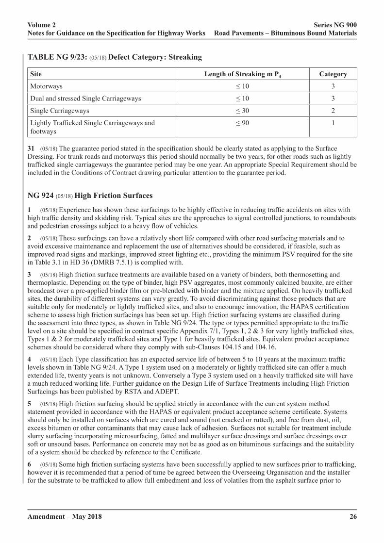
26Amendment – May 2018
Volume 2 Series NG 900 Notes for Guidance on the Specification for Highway Works Road Pavements – Bituminous Bound Materials
TABLE NG 9/23: (05/18) Defect Category: Streaking
Site Length of Streaking m P4 Category
Motorways ≤ 10 3
Dual and stressed Single Carriageways ≤ 10 3
Single Carriageways ≤ 30 2
Lightly Trafficked Single Carriageways and footways
≤ 90 1
31 (05/18) The guarantee period stated in the specification should be clearly stated as applying to the Surface Dressing. For trunk roads and motorways this period should normally be two years, for other roads such as lightly trafficked single carriageways the guarantee period may be one year. An appropriate Special Requirement should be included in the Conditions of Contract drawing particular attention to the guarantee period.
NG 924 (05/18) High Friction Surfaces
1 (05/18) Experience has shown these surfacings to be highly effective in reducing traffic accidents on sites with high traffic density and skidding risk. Typical sites are the approaches to signal controlled junctions, to roundabouts and pedestrian crossings subject to a heavy flow of vehicles.
2 (05/18) These surfacings can have a relatively short life compared with other road surfacing materials and to avoid excessive maintenance and replacement the use of alternatives should be considered, if feasible, such as improved road signs and markings, improved street lighting etc., providing the minimum PSV required for the site in Table 3.1 in HD 36 (DMRB 7.5.1) is complied with.
3 (05/18) High friction surface treatments are available based on a variety of binders, both thermosetting and thermoplastic. Depending on the type of binder, high PSV aggregates, most commonly calcined bauxite, are either broadcast over a pre-applied binder film or pre-blended with binder and the mixture applied. On heavily trafficked sites, the durability of different systems can vary greatly. To avoid discriminating against those products that are suitable only for moderately or lightly trafficked sites, and also to encourage innovation, the HAPAS certification scheme to assess high friction surfacings has been set up. High friction surfacing systems are classified during the assessment into three types, as shown in Table NG 9/24. The type or types permitted appropriate to the traffic level on a site should be specified in contract specific Appendix 7/1, Types 1, 2 & 3 for very lightly trafficked sites, Types 1 & 2 for moderately trafficked sites and Type 1 for heavily trafficked sites. Equivalent product acceptance schemes should be considered where they comply with sub-Clauses 104.15 and 104.16.
4 (05/18) Each Type classification has an expected service life of between 5 to 10 years at the maximum traffic levels shown in Table NG 9/24. A Type 1 system used on a moderately or lightly trafficked site can offer a much extended life, twenty years is not unknown. Conversely a Type 3 system used on a heavily trafficked site will have a much reduced working life. Further guidance on the Design Life of Surface Treatments including High Friction Surfacings has been published by RSTA and ADEPT.
5 (05/18) High friction surfacing should be applied strictly in accordance with the current system method statement provided in accordance with the HAPAS or equivalent product acceptance scheme certificate. Systems should only be installed on surfaces which are cured and sound (not cracked or rutted), and free from dust, oil, excess bitumen or other contaminants that may cause lack of adhesion. Surfaces not suitable for treatment include slurry surfacing incorporating microsurfacing, fatted and multilayer surface dressings and surface dressings over soft or unsound bases. Performance on concrete may not be as good as on bituminous surfacings and the suitability of a system should be checked by reference to the Certificate.
6 (05/18) Some high friction surfacing systems have been successfully applied to new surfaces prior to trafficking, however it is recommended that a period of time be agreed between the Overseeing Organisation and the installer for the substrate to be trafficked to allow full embedment and loss of volatiles from the asphalt surface prior to
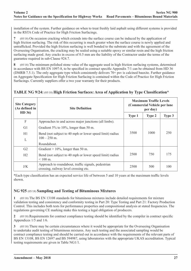
Amendment – May 2018 27
Volume 2 Series NG 900 Notes for Guidance on the Specification for Highway Works Road Pavements – Bituminous Bound Materials
installation of the system. Further guidance on when to treat freshly laid asphalt using different systems is provided in the RSTA Code of Practice for High Friction Surfacings.
7 (05/18) On occasion cracking which extends into the surface course can be induced by the application of high friction surfacing. The risk of this occurring is much greater when the surface course is newly applied and untrafficked. Provided the high friction surfacing is well bonded to the substrate and with the agreement of the Overseeing Organisation, the cracking may be sealed using a suitable epoxy or similar resin and the high friction surfacing made good. Any cracks in excess of 0.5 mm are the liability of the Contractor under the terms of the guarantee required in sub-Clause 924.7.
8 (05/18) The minimum polished stone value of the aggregate used in high friction surfacing systems, determined in accordance with BS EN 1097-8, to be specified in contract specific Appendix 7/1 can be obtained from HD 36 (DMRB 7.5.1). The only aggregate type which consistently delivers 70+ psv is calcined bauxite. Further guidance on Aggregate Specification for High Friction Surfacing is contained within the Code of Practice for High Friction Surfacings. Currently suppliers offer a two year warranty for their products.
TABLE NG 9/24: (05/18) High Friction Surfaces: Area of Application by Type Classification*
Site Category (As defined in
HD 36)Site Definition
Maximum Traffic Levels (Commercial Vehicle per lane
per day)
Type 1 Type 2 Type 3F
G1
H1
L
Approaches to and across major junctions (all limbs).
Gradient 5% to 10%, longer than 50 m.
Bend (not subject to 40 mph or lower speed limit) radius 100 – 250 m.
Roundabout.
3500 1000 250
G2
H2
Gradient > 10%, longer than 50 m.
Bend (not subject to 40 mph or lower speed limit) radius < 100 m.
2500 750 175
J/K Approach to roundabout, traffic signals, pedestrian crossing, railway level crossing etc. 2500 500 100
*Each type classification has an expected service life of between 5 and 10 years at the maximum traffic levels shown.
NG 925 (05/18) Sampling and Testing of Bituminous Mixtures
1 (05/18) The BS EN 13108 standards for bituminous mixtures include detailed requirements for mixture validation testing and consistency and conformity testing in Part 20: Type Testing and Part 21: Factory Production Control. This includes both tests for performance properties and compositional analysis at stated frequencies. The regulations governing CE marking make this testing a legal obligation of producers.
2 (05/18) Requirements for contract compliance testing should be identified by the compiler in contract specific Appendices 1/5 and 1/6.
3 (05/18) There may be certain circumstances where it would be appropriate for the Overseeing Organisation to undertake audit testing of bituminous mixtures. Any such testing and the associated sampling would be contract compliance testing and should be carried out in accordance with the requirements of the relevant parts of BS EN 13108, BS EN 12697 and BS 594987, using laboratories with the appropriate UKAS accreditation. Typical testing requirements are given in Table NG1/1.
28Amendment – May 2018
Volume 2 Series NG 900 Notes for Guidance on the Specification for Highway Works Road Pavements – Bituminous Bound Materials
NG 926 (05/18) In Situ Recycling: The Repave Process
1 (05/18) Guidance to the requirements specified in Clause 926 is contained in HD 31 (DMRB 7.4.1).
2 (05/18) The Repave process is an acceptable alternative to conventional resurfacing and can be used when weather conditions might prevent the use of conventional plant.
3 (05/18) Where the suitability of resurfacing works for the Repave process has been established, it should always be included as an option in tender documents or accepted as an alternative method by suitably equipped contractors following the award of a contract.
NG 929 (05/18) Dense Base and Binder Course Asphalt Concrete (Design Mixtures)
1 (05/18) The requirements in Clause 929 are now based on the European Asphalt Standard BS EN 13108-1 as detailed in BSI PD6691 and BS 594987. This has implications for the verification and validation of mixtures as described below.
2 (05/18) Clause 929 requires that designed dense base and binder course asphalt concrete mixtures meet the example requirements of BSI PD6691 Annex B. It is the responsibility of the asphalt producer to provide verification of these properties for each mixture in the form of a Type Test Report, in accordance with BS EN 13108-20. However, the producer is obliged to supply only the declaration of performance. This verification may have been carried out in accordance with a protocol given in BS 594987 Annex C. The protocol is based on the job mixture approval trial procedure specified previously in earlier editions of the Specification for Highway Works Clause 929, is technically equivalent and provides the same information.
3 (05/18) For most contracts, the information from the declaration of performance and CE Marking, should be sufficient to demonstrate that the mixture complies with the requirements of Clause 929. Under these circumstances, there is no need for an additional job mixture approval trial. On particularly large or critical projects, there may be a benefit in undertaking validation trials as part of the contract. Where required, these should be carried out as contract compliance testing and in accordance with BS 594987 Annex C and the requirement clearly indicated in contract specific Appendix 1/5. It should be noted that this additional testing should only be specified where there is reasonable justification to do so.
4 (05/18) If required, mix volumetrics can be monitored in the permanent works by determining void contents of cores compacted to refusal. This can provide an indication of deformation resistance. It should be noted however, that resistance to permanent deformation assessed by wheeltracking forms part of the Type Test Report. Monitoring void content at refusal will generally only be practicable only on larger contracts. If void content at refusal is to be monitored in the permanent works, this should be clearly indicated in Schedule 5 of Appendix 7/1.
5 (05/18) Verification of wheel tracking properties for each mixture will be recorded in the form of a Type Test Report in accordance with BS EN 13108-20. This verification may have been carried out in accordance with a protocol given in BS 594987 Annex D. Requirements appropriate to traffic and stress condition should be selected from Table NG 9/25.
6 (05/18) On particularly large or critical projects it may be appropriate to monitor resistance to permanent deformation in the permanent works. If required, this should be clearly indicated in Schedule 5 of Appendix 7/1 along with the site classification.
7 (05/18) When specifying resistance to permanent deformation information is given in the note to BSI PD6691 Table B4.
8 (05/18) Sub-clause 6 requires a minimum stiffness category of 1800 MPa for mixtures containing 40/60 grade binder and 2800 MPa for mixtures containing 30/45 grade binder. This is a minimum default value for these mixtures and should not be confused with the design stiffness. Further information on design stiffness can be found in HD 26 (DMRB 7.2.3). There is no protocol covering stiffness determination for dense base and binder asphalt concrete mixtures in BS 594987. Therefore, the following Type Testing protocol should be adopted:
‘Following the general protocol in BS 594987 Annex C, take an additional, three adjacent core pairs as described in C.3.2. Cut test specimens from these cores and determine stiffness in accordance with BS EN 12697-26

Amendment – May 2018 29
Volume 2 Series NG 900 Notes for Guidance on the Specification for Highway Works Road Pavements – Bituminous Bound Materials
(ITSM method 20oC). The mean of the set of six values shall not be less than 1800 MPa for mixtures containing 40/60 grade binder and 2800 MPa for mixtures containing 30/45 grade binder.’
9 (05/18) Indirect density gauges, including nuclear density gauges, are specified for compaction control. It is important that these are calibrated across an appropriate range of densities as required by BS 594987. Such gauges have a penetration depth of approximately 80 mm and where layer thicknesses exceed this it is especially important that cores are visually inspected to ensure that they are uniformly compacted.
10 (05/18) A new requirement for density control close to joints has been introduced. Experience has shown that in-situ void content requirements in the wheeltracks are generally achieved. Therefore, the frequency of testing in this position has been reduced. Compaction at joints is considered to be a primary factor in affecting the durability of asphalt pavements and testing at this location has therefore been introduced. Contractors may need to adopt special measures of joint compaction in order to comply with this requirement.
11 (05/18) Where dense asphalt concrete base and binder course mixtures are to run on directly by normal highway traffic (due to traffic management requirements) it is recommended that they be surface dressed to prevent water ingress and to provide adequate skid resistance.

30Amendment – May 2018
Volume 2 Series NG 900 Notes for Guidance on the Specification for Highway Works Road Pavements – Bituminous Bound Materials
TAB
LE
NG
9/2
5: (0
5/18
) Cla
ssifi
catio
n of
Site
s by
Traf
fic a
nd S
tres
s Con
ditio
n fo
r R
esis
tanc
e to
Per
man
ent D
efor
mat
ion
of
Den
se M
acad
ams t
o C
laus
e 92
9
Site
C
ateg
ory
Site
Def
initi
on
Traf
fic a
t Des
ign
life
(Com
mer
cial
veh
icle
s per
lane
per
day
)
CLA
SS 1
CLA
SS 2
Up
to 2
5025
1 –
500
501
– 10
0010
01 –
150
0>
1500
I & II
AM
otor
way
(mai
n lin
e)
BSI
PD
6691
Tab
le B
4,
Cla
ssifi
catio
n 1
(45°
C)
BD
ual c
arria
gew
ay (a
ll pu
rpos
e) n
on-e
vent
sect
ions
CD
ual c
arria
gew
ay (a
ll pu
rpos
e) m
inor
junc
tions
DSi
ngle
car
riage
way
non
-eve
nt se
ctio
ns
ESi
ngle
car
riage
way
min
or ju
nctio
ns
IA &
II
AA
s I a
nd II
, abo
ve, b
ut w
ith c
ontra
flow
ant
icip
ated
dur
ing
sum
mer
m
onth
s
BSI
PD
6691
Tab
le B
4 C
lass
ifica
tion
2 (6
0°C
)
III
FA
ppro
ache
s to
and
acro
ss m
ajor
junc
tions
(all
limbs
)
G1
Gra
dien
t 3%
to 1
0%, l
onge
r tha
n 50
m
LR
ound
abou
t
IIIA
As I
II, a
bove
, but
with
con
traflo
w a
ntic
ipat
ed d
urin
g su
mm
er m
onth
s or
in a
sout
h-fa
cing
cut
ting
uphi
ll
IVG
2G
radi
ent s
teep
er th
an 1
0%, l
onge
r tha
n 50
m:
IVA
As I
V, a
bove
, but
with
con
traflo
w a
ntic
ipat
ed d
urin
g su
mm
er m
onth
s or
in a
sout
h-fa
cing
cut
ting
uphi
ll
VJ/
KA
ppro
ach
to ro
unda
bout
, tra
ffic
sign
als,
pede
stria
n cr
ossi
ngs,
railw
ay le
vel c
ross
ings
and
sim
ilar
Amendment – May 2018 31
Volume 2 Series NG 900 Notes for Guidance on the Specification for Highway Works Road Pavements – Bituminous Bound Materials
NG 930 (05/18) EME2 Base and Binder Course Asphalt Concrete
1 (05/18) EME2 is a durable, deformation resistant, high performance base and binder course mixture, based on established French technology. The designation EME is from the French name Enrobé à Module Élevé (“High Modulus Coated”), and this acronym is being retained to differentiate these mixtures from the traditional UK High Modulus Base (HMB) materials which have significantly lower binder contents. Further information on the background to the material and the reasons for its introduction are explained in TRL report TRL 636.
2 (05/18) Two BS EN 13924 binder grades are permitted for use in EME2.
3 (05/18) The requirements in Clause 930 are based on BS EN 13108-1 as detailed in BSI PD6691 and BS 594987. This has implications for the verification and validation of mixtures as described below.
4 (05/18) Clause 930 requires that EME 2 base and binder course mixtures meet the detailed requirements of BSI PD6691 Annex B, in terms of constituents, composition, void content, water sensitivity, deformation resistance, stiffness modulus and fatigue properties. It is the responsibility of the asphalt producer to provide verification of these properties for each mixture in the form of a Type Test Report, in accordance with BS EN 13108-20. This verification will have been carried out by laboratory testing of some properties and validation of others by means of a site trial in accordance with a protocol given in BS 594987 Annex E. The protocol is based on the French ‘planche de vérification’ procedure and the job mixture approval trial procedure specified previously in earlier editions of the Specification for Highway Works Clause 929.
5 (05/18) Generally, the information from the declaration of performance and CE Marking, should be sufficient to demonstrate mixture compliance. As EME2 mixtures are still relatively new in the UK, it is considered appropriate to have site validation trials of volumetrics and stiffness carried out on each contract. These should be carried out in accordance with BS 594987 Annex E and the requirement to do so clearly indicated in Schedule 5 of contract specific Appendix 7/1.
6 (05/18) Binder content is a critical feature of EME2 mixtures. Therefore, a separate assessment of soluble binder content is included as a safeguard to ensure that binder contents are targeted close to the intended value and do not fall. In order to conform to this requirement, producers will need to maintain production close to mid point.
7 (05/18) EME2 is a binder rich material and should be more readily compacted to a low void content than traditional DBM, HDM and HMB materials. It is recommended that the trial strips constructed for the Type Test Report are used to evaluate and develop the Contractor’s method statement for compaction required by Clause 903.5.
8 (05/18) A new requirement for density control close to joints has been introduced. Contractors may need to adopt special measures of joint compaction in order to comply.
9 (05/18) EME2 is designed to be laid in thick lifts with small nominal size aggregate. Generally, it is good practice to lay bases in thicker lifts to minimise the number of layers and, hence, interfaces (giving due consideration to the maximum layer thicknesses given in BS 594987).
NG 937 (05/18) Stone Mastic Asphalt (SMA) Binder Course and Regulating Course
1 (05/18) The requirements in Clause 937 are based on BS EN 13108-5 as detailed in BSI PD6691 and BS 594987. This has implications for the verification and validation of mixtures as described below.
2 (05/18) Clause 937 requires the volumetric properties of SMA binder course and regulating mixtures to comply with BSI PD6691 Annex D. It is the responsibility of the asphalt producer to undertake verification of these properties for each mixture in the form of a Type Test Report, in accordance with BS EN 13108-20. This verification will have been carried out in accordance with a protocol given in BS 594987 Annex G. The protocol is based on the job mixture approval trial procedure specified previously in earlier editions of the Specification for Highway Works, is technically equivalent and provides the same information.
3 (05/18) The means to specify resistance to permanent deformation for SMA binder courses, previously given in Clause 952, are now contained within this Clause. Requirements appropriate to traffic and stress condition should be selected from Table NG 9/26. Verification of wheel tracking properties for each mixture will be recorded in the

32Amendment – May 2018
Volume 2 Series NG 900 Notes for Guidance on the Specification for Highway Works Road Pavements – Bituminous Bound Materials
form of a Type Test Report in accordance with BS EN 13108-20. This verification will have been carried out in accordance with a protocol given in BS 594987 Annex G.
4 (05/18) On particularly large or critical projects it may be appropriate to monitor resistance to permanent deformation in the permanent works. If required, this should be clearly indicated in Schedule 5 of contract specific Appendix 7/1 along with the site classification.
5 (05/18) When specifying resistance to permanent deformation information is given in the note to BSI PD6691 Table B4.
NG 938 (05/18) Porous Asphalt Surface Course
1 (05/18) There has been little recent experience with Porous Asphalt in the UK and consequently no detailed requirements are given. Where porous asphalt is to be used, the specific mix details and performance requirements should be agreed with the Overseeing Organisation and established in terms of BS EN 13108-7.
NG 942 (05/18) Thin Surface Course Systems
(05/18) General
1 (05/18) Thin surface course systems are bituminous products with suitable properties to provide a surface course that is laid at a nominal depth between 20mm and 50 mm. This classification refers to hot-mixed asphalts in accordance with the BS EN 13108 family of materials, primarily Parts 1, 2 and 5. Acceptance requirements for the material relate to CE marked products with the required declaration of performance and valid CE marking. These cover only the manufacture of the product and not its installation. Additional in-situ performance requirements are also specified to cover aspects of the installation not covered by the declaration of performance.
2 (05/18) In order to demonstrate that the ‘as installed’ thin surface course system is able to meet the specification requirements a System Installation Performance Trial (SIPT) is required. This requires third party assessment of the installed system when constructed and over a period of two years. The SIPT is part of the evidence to be provided to determine system acceptability and is not to be part of the contact specific works.
3 (05/18) The Contractor is required to guarantee the system for five years. The performance of the system is required to be maintained throughout the five year period. The compiler should ensure that the contract conditions and documentation cover the guarantee requirements.
4 (05/18) CE marking by producers is certificated by Notified Bodies in accordance with the requirements of the relevant standard.
5 (05/18) The UK National Highways Sector Scheme 16 provides interpretation of BS EN ISO 9001 Quality Management Scheme requirements in relation to asphalt laying and registration is required for the laying of asphalt mixes in Clause 901.
6 (05/18) The SIPT is certificated by a Certification Body (CB) which is UKAS accredited for product approval to BS EN 45011. The SIPT will be observed by an inspection panel made up of, at least, a lead auditor and two other competent inspectors. The personnel are required to have appropriate technical knowledge and experience.
7 (05/18) Those supervising the works should ensure that they receive the declaration of performance and the SIPT documentation and check that they identify that the stated performance requirements are met by the chosen materials.
8 (05/18) Completion of the SIPT does not automatically mean that the particular system is suitable for every situation where a thin surface course system is required.
9 (05/18) New materials that have not undergone a SIPT may be considered for use, these would need to be considered using the departures from standard process. Such materials would need to be monitored for at least two years and be in the process of being progressed for a completed SIPT.

Amendment – May 2018 33
Volume 2 Series NG 900 Notes for Guidance on the Specification for Highway Works Road Pavements – Bituminous Bound Materials
Full details of the monitoring arrangements and details of intervention contingency plans must be included in the departures from standards submission. The surface macrotexture performance guarantee period should be extended to three years in these circumstances.
10 (05/18) A distinction should be drawn between limitations set for the properties of thin surface course systems recorded for the SIPT and requirements placed on the work being carried out. The former are based on results from past works and identify what the system achieved for the trial, whilst the latter identify what the system is required to achieve in this case.
(05/18) Design, manufacture, transportation and installation – general
11 (05/18) The compiler should state the site requirements for each section of road and the anticipated commercial traffic flows expected at the site over the guarantee period in contract specific Appendix 7/1. The Contractor should also be required to inspect the Site where the material will be laid.
12 (05/18) The design, manufacture, transportation, placement and compaction of the materials is the Contractor’s responsibility, within the constraints applicable to the chosen system. The decisions regarding weather conditions and their suitability for laying and compaction of the chosen system will lie with the Contractor.
(05/18) Layer Thickness Design
13 (05/18) The compiler should state the design layer thickness and nominal size in contract specific Appendix 7/1.
14 (05/18) The minimum and maximum design thicknesses at which the thin surface course system shall be laid, will be selected from Table 9/11. Possible reasons for specifying a minimum or maximum thickness may be:
• to maintain continuity with the material to be planed out; or,
• to avoid premature cooling in adverse cold weather conditions.
Possible reasons for specifying a maximum thickness may be: • to maintain continuity with the material to be planed out; or
• to retain sufficient headroom under over-bridges; or
• to avoid overloading under-bridges; or
• to minimise the need to raise kerbs, safety barriers and/or ironwork.
15 (05/18) Premature cooling in adverse cold weather could be overcome either by use of a thicker surfacing or by pre-heating of the substrate.
16 (05/18) Retention of thin layers of existing material after planing should be avoided. There is a significant risk of such thin layers failing prematurely.
17 (05/18) The nominal thickness at which to lay the material has to be selected by the Contractor with due allowance for the constructional tolerance. If both a minimum and a maximum thickness are specified, the difference between the maximum and minimum thicknesses should be at least 20% of their average. The System Installation Method Statement should state the absolute installed minimum thickness at any point.
18 (05/18) The range of nominal installation depth at which a thin surface course system can be laid will be specific to the system. If systems are specified to be laid at nominal depths other than those identified, then the desired performance may not be achieved.
(05/18) Design – Mixture Selection
19 (05/18) The compiler should state whether each section of road is only suitable for thin surface course systems with an upper (D) aggregate size of 10mm or less in contract specific Appendix 7/1.
20 (05/18) The minimum polished stone value of the coarse aggregate should be selected from Table 3.1 in HD 36 (DMRB 7.5.1). Separate maximum aggregate abrasion values should be given for thin surface course systems using the appropriate information from Table 3.2 in HD 36 (DMRB 7.5.1).

34Amendment – May 2018
Volume 2 Series NG 900 Notes for Guidance on the Specification for Highway Works Road Pavements – Bituminous Bound Materials
(05/18) Design – Minimum Binder Content
21 (05/18) The minimum target binder contents identified in sub-Clause 942.8 Table 9/10 are deemed to be satisfactory for the range of binder and aggregate combinations typically produced in the UK. However, some combinations may require contents below this to be employed and should be carefully assessed in terms of the declaration of performance under the CE marking in relation to traffic levels, site stress categories and durability. These would need to be considered using the departures from standard process.
(05/18) Bond Coat
22 (05/18) It is essential to have an effective bond between a thin surface course system and the substrate. The purpose of a good bond is to ensure a monolithic structure, and prevent delamination and ingress of water.
23 (05/18) The thinner the surfacing, the greater the importance of an effective bond or tack coat to the performance of the thin surface course surfacing. Emulsion bond or tack coats sprayed as a separate operation ahead of the paver should be allowed to break completely (turn from brown to black) prior to surfacing.
24 (05/18) Polymer modified bond coats provide enhanced performance and should be specified for thin surfacings laid in high stress areas. Polymer modified bond coats can provide enhanced waterproofing to the lower pavement.
25 (05/18) Calibrated mechanised application should be used, however for inaccessible and / or small areas less then 250m2 per shift or for narrow width surfacing i.e. less than 2 metres, it may be pragmatic and acceptable to use hand application.
26 (05/18) Attention should be paid to application rates in the Installation Method Statement.
27 (05/18) Application rates are found in BS594987.
(05/18) Overlaying Concrete
28 (05/18) Thin surface course systems are generally suitable for application to both old and new continuously reinforced concrete (CRCP) surfaces. When laying on concrete it is likely that a polymer modified bond coat will be required. Surfacing directly over jointed concrete is not generally recommended.
(05/18) Road Markings and Studs
29 (05/18) Contraflow and maintenance operations often require the application of temporary retroreflecting road studs. There are many proprietary types of stud available. Trials have indicated that many types of stud leave a sticky deposit of bituminous adhesive which clogs the surface voids and some studs also cause pluck-out of surface aggregate potentially leading to accelerated local deterioration of the pavement surfacing. Therefore, trials may need to be performed, at the outer edge of the hard shoulder, to ensure that the studs proposed for use can be removed from the surface without plucking-out surface aggregate or leaving an excessive deposit.
30 (05/18) Problems have also been reported regarding pre-formed road marking tapes loosing adhesion on negatively macrotextured surfaces in wet weather. Trials should be performed to select the best material.
(05/18) System Installation and Performance Trial (SIPT)
31 (05/18) The Certification Body SIPT inspection protocol should be developed in conjunction with the system provider and installer to enable appropriate assessment of the applicability of the SIPT for the system in order to satisfy the performance requirements. Assessments based on classification of defects to TRL674 have been shown to be acceptable and repeatable.
32 (05/18) Suitably qualified and experienced staff are necessary to ensure a consistent approach to the assessment of systems.
Amendment – May 2018 35
Volume 2 Series NG 900 Notes for Guidance on the Specification for Highway Works Road Pavements – Bituminous Bound Materials
(05/18) Initial Performance Requirements
33 (05/18) Visual condition and untrafficked macrotexture can be specified for the purposes of SIPT and contractual compliance.
34 (05/18) Torque Bond assessment forms part of SIPT. If tested for contract compliance the performance level should meet the stated requirement.
(05/18) Noise
35 (05/18) Noise assessment is an additional optional declaration for a SIPT and should only be specified for sites of specific noise concern.
36 (05/18) Permitted Road/Tyre Noise Levels are given in Table 9/17. Levels 2 and 3 are necessary in noise-sensitive areas. In the interest of sustainability Level 3 should only be specified in very noise sensitive areas.
37 (05/18) Level 0 must not be specified at sites with existing noise barriers or earth bunds, where the latter have been specifically installed as a noise mitigation measure, and must not be used at locations that have been identified as an Important Area, either with or without First Priority Locations, in any of England’s Noise Action Plans published by DEFRA in March 2010.
38 (05/18) Road/Tyre Noise Levels are demonstrated by the optional value stated in the SIPT.
(05/18) Deformation Resistance
39 (05/18) The deformation resistance of thin surface course systems can be set in terms of wheel tracking level stated in the declaration of performance. For trunk roads including motorways, Level 3 is usually required (see also Table NG 9/26).
40 (05/18) If other levels of deformation resistance are required, this shall be specified in contract specific Appendix 7/1, with due consideration of the classifications given in Table NG 9/26.
41 (05/18) Deformation resistance data should be declared under the CE Marking declaration of performance. If cores are taken from a SIPT site for the purposes of checking deformation resistance of the installed material, the following protocol should be used.
42 (05/18) A minimum of six cores should be taken from a 100 m length of the SIPT at nominally even spacing along a diagonal line across the lane width in accordance with BS EN 12697-27: 2001. The cores need to be maintained at a temperature of 15° ± 10°C during transportation to the test laboratory and for up to 96 hours once delivered. If wheel tracking testing has not commenced within 96 hours of coring, the specimens are to be placed in storage and maintained at a temperature 5° ± 2°C until commencement of the testing procedure.
43 (05/18) The cores should be tested in accordance with BS EN 12697-22: 2003.
44 (05/18) The wheel-tracking levels of the thin surface course system are required to be Level 3 unless otherwise specified in contract specific Appendix 7/1. The required level should be stated in contract specific Appendix 7/1.
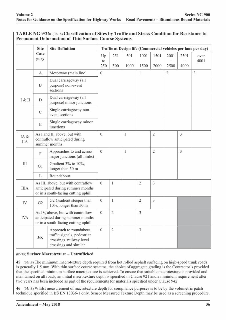
36Amendment – May 2018
Volume 2 Series NG 900 Notes for Guidance on the Specification for Highway Works Road Pavements – Bituminous Bound Materials
TABLE NG 9/26: (05/18) Classification of Sites by Traffic and Stress Condition for Resistance to Permanent Deformation of Thin Surface Course Systems
Site Cate gory
Site Definition Traffic at Design life (Commercial vehicles per lane per day)
Up to
250
251 –
500
501 –
1000
1001 –
1500
1501 –
2000
2001 –
2500
2501 –
4000
over 4001
I & II
A Motorway (main line) 0 1 2 3
BDual carriageway (all purpose) non-event sections
D Dual carriageway (all purpose) minor junctions
C Single carriageway non-event sections
E Single carriageway minor junctions
IA & IIA
As I and II, above, but with contraflow anticipated during summer months
0 1 2 3
III
F Approaches to and across major junctions (all limbs)
0
1 2 3
G1 Gradient 3% to 10%, longer than 50 m
L Roundabout
IIIA As III, above, but with contraflow anticipated during summer months or in a south-facing cutting uphill
0 1 2 3
IV G2 G2 Gradient steeper than 10%, longer than 50 m
0 1 2 3
IVAAs IV, above, but with contraflow anticipated during summer months or in a south-facing cutting uphill
0 2 3
J/K
Approach to roundabout, traffic signals, pedestrian crossings, railway level crossings and similar
0 2 3
(05/18) Surface Macrotexture – Untrafficked
45 (05/18) The minimum macrotexture depth required from hot rolled asphalt surfacing on high-speed trunk roads is generally 1.5 mm. With thin surface course systems, the choice of aggregate grading is the Contractor’s provided that the specified minimum surface macrotexture is achieved. To ensure that suitable macrotexture is provided and maintained on all roads, an initial macrotexture depth is specified in Clause 921 and a minimum requirement after two years has been included as part of the requirements for materials specified under Clause 942.
46 (05/18) Whilst measurement of macrotexture depth for compliance purposes is to be by the volumetric patch technique specified in BS EN 13036-1 only, Sensor Measured Texture Depth may be used as a screening procedure.

37
Volume 2 Series NG 900 Notes for Guidance on the Specification for Highway Works Road Pavements – Bituminous Bound Materials
Amendment – July 2019
47 (05/18) Calibration trials and checks should be undertaken at the start and during the course of work to derive and confirm a relationship between the volumetric patch method and the Measured Texture Depth (SMTD).
48 (05/18) In the event of a dispute, or discrepancy between the two methods, only results obtained using the volumetric patch method will be considered for compliance purposes.
49 (05/18) Calibrations carried out on site are only applicable to that site and that surfacing.
50 (05/18) SMTD is numerically different from macrotexture measured by the volumetric patch technique. Volumetric patch macrotexture depth is a measurement of the average depth of hollows in the surface below general level of peaks. SMTD is the standard deviation of the sample height measurements.
(05/18) Surface Macrotexture – After 2 Years
51 (05/18) The performance levels of macrotexture depth for use on the strategic road network are given in Table 9/14 of Clause 942. Research has shown that hot applied thin surfacings with an upper (D) aggregate size of 10mm or 14mm maintain adequate high speed skid resistance with these levels of texture. For hot applied thin surfacings with an upper (D) aggregate size of 6mm, current techniques for assessing texture depth do not satisfactorily explain the skid resistance characteristics. These materials will require a supplementary assessment from a System Installation Performance Trial (SIPT) to provide evidence verifying adequate high-speed friction performance. Evidence must be provided that a SIPT has been carried out or a SIPT must be included in the proposal for the departure from standard.
NG 943 (05/18) Hot Rolled Asphalt Surface Course and Binder Course (Performance-Related Design Mixtures)
1 (05/18) This Clause is for the specification of hot rolled asphalt mixtures that have been designed to achieve controlled levels of resistance to permanent deformation (rutting) measured by the wheel tracking test. These mixtures are used as both surface course and binder course. They are particularly suitable as a regulating binder course under thin surfacings and as a binder course over bridge deck waterproofing. When used as surface course they must be chipped to provide a skid resistant surface.
2 (05/18) Using hot rolled asphalt surface course to this Clause will ensure a good level of resistance to permanent deformation within the surface course itself. Designers should be aware that significant rutting often occurs in the lower layers of the pavement and use of a performance designed surface course on an inadequate substrate will not protect against this. To provide adequate resistance to deformation, binder course and base designed in accordance with Clauses 929, 930 or 937 should be used, particularly in the top 100 mm of the pavement.
3 (05/18) In almost all cases, the use of a modified binder or binder modifier will be required in order to achieve the more onerous (Class 2) performance level. Since these are generally proprietary products, sub-Clause 5 requires the submission of information to the Overseeing Organisation for approval. If there is evidence of successful use of a modified binder/modifier in similar conditions, the presumption should be of approval.
4 (05/18) Verification of wheel tracking properties for each mixture will be recorded in the form of a Type Test Report in accordance with BS EN 13108-20. This verification will have been carried out in accordance with a protocol given in BS 594987 Annex F. This protocol is based on the job mixture approval trial procedure specified previously in earlier editions of Clause 943, is technically equivalent and provides the same information. Requirements appropriate to traffic and stress condition should be selected from Table NG 9/27 and included in contract specific Appendix 7/1.
5 (05/18) On particularly large or critical projects it may be appropriate to monitor resistance to permanent deformation in the permanent works. If required, this should be clearly indicated in Schedule 5 of contract specific Appendix 7/1 along with the site classification.
6 (07/19) When specifying resistance to permanent deformation, it will be necessary to take into account the transitional problems brought about by the change in the wheel tracking test method from BS 598 Part 110 to BS EN 12697-22, which uses similar equipment but different duration and loading. Further information is given in the note to BSI PD6691 Table C3. Work is in hand to establish criteria for the new method, but in the interim, requirements should be based on the BS 598 test but with data provided to show the values for the same mix tested to the BS EN 12697 method.

38Amendment – May 2018
Volume 2 Series NG 900 Notes for Guidance on the Specification for Highway Works Road Pavements – Bituminous Bound Materials
TAB
LE
NG
9/2
7: (0
5/18
) Cla
ssifi
catio
n of
Site
s by
Traf
fic a
nd S
tres
s Con
ditio
n fo
r R
esis
tanc
e to
Per
man
ent D
efor
mat
ion
of
Perf
orm
ance
Rel
ated
HR
A S
urfa
ce C
ours
e an
d B
inde
r C
ours
e to
Cla
use
943
Site
C
ateg
ory
Site
Def
initi
on
Traf
fic a
t Des
ign
life
(Com
mer
cial
veh
icle
s per
lane
per
day
)
CLA
SS 1
CLA
SS 2
Up
to 2
5025
1 –
500
501
– 10
0010
01 –
150
0>
1500
I & II
AM
otor
way
(mai
n lin
e)
BSI
PD
6691
Tab
le C
.3, C
lass
ifica
tion
1 (4
5°C
)
BD
ual c
arria
gew
ay (a
ll pu
rpos
e) n
on-e
vent
sect
ions
CD
ual c
arria
gew
ay (a
ll pu
rpos
e) m
inor
junc
tions
DSi
ngle
car
riage
way
non
-eve
nt se
ctio
ns
ESi
ngle
car
riage
way
min
or ju
nctio
ns
IA &
II
AA
s I a
nd II
, abo
ve, b
ut w
ith c
ontra
flow
ant
icip
ated
dur
ing
sum
mer
mon
ths
BSI
PD
6691
Tab
le C
.3
Cla
ssifi
catio
n 2
(60°
C)
III
FA
ppro
ache
s to
and
acro
ss m
ajor
junc
tions
(all
limbs
)
G1
Gra
dien
t 3%
to 1
0%, l
onge
r tha
n 50
m
LR
ound
abou
t
IIIA
As I
II, a
bove
, but
with
con
traflo
w a
ntic
ipat
ed d
urin
g su
mm
er
mon
ths o
r in
a so
uth-
faci
ng c
uttin
g up
hill
IVG
2G
radi
ent s
teep
er th
an 1
0%, l
onge
r tha
n 50
m:
IVA
As I
V, a
bove
, but
with
con
traflo
w a
ntic
ipat
ed d
urin
g su
mm
er
mon
ths o
r in
a so
uth-
faci
ng c
uttin
g up
hill
VJ/
KA
ppro
ach
to ro
unda
bout
, tra
ffic
sign
als,
pede
stria
n cr
ossi
ngs,
railw
ay le
vel c
ross
ings
and
sim
ilar
Amendment – May 2018 39
Volume 2 Series NG 900 Notes for Guidance on the Specification for Highway Works Road Pavements – Bituminous Bound Materials
NG 945 (05/18) Weather Conditions for Laying of Bituminous Mixtures
1 (05/18) This Clause considers the laying conditions for bituminous mixtures in four separate categories as follows:
(i) General, applying to all bituminous mixtures.
(ii) Hot bituminous materials laid less than 50 mm thick.
(iii) Thin surface course systems.
(iv) Hot rolled asphalt with pre-coated chippings.
2 (05/18) The layer thickness has a major effect on the time available for compaction before the temperature drops below that at which the compaction is effective. Materials laid 50 mm or more thick, other than hot rolled asphalt with chippings, are likely to be tolerant of all but the most extreme conditions encountered in the UK.
3 (05/18) For materials at nominal thicknesses below 50 mm, air temperatures and, more particularly, wind speeds have a significant effect. For this situation, Sub-Clause 945.2 calls up Figure 9/1 which gives limiting conditions based on a minimum available compaction time of 8 min. Contractors will need to take account of this requirement in their compaction plans drawn up under sub-Clause 903.5.
4 (05/18) The weather conditions for the laying of thin surface course systems should be covered by the relevant installation HAPAS or equivalent product acceptance scheme certificate.
5 (05/18) Experience with hot rolled asphalt with pre-coated chippings led to the conclusion that the most appropriate combination for laying in UK weather conditions was a 35% stone content mixture laid at a nominal 50 mm thickness. Sub-Clause 945.4 gives specific limiting delivery, air temperature and wind speeds for this mixture and thickness only. These requirements for hot rolled asphalt with pre-coated chippings are based on a minimum available compaction time of 10 min from the time the material emerges from the paver. The use of modified binders in the hot rolled asphalt can change the relevant conditions.
6 (05/18) The additional constraints that can apply during winter and/or night-time laying that can affect the suitability of the weather conditions include:
(i) The temperature of bituminous mixtures drops rapidly during winter and night time laying operations. Extra care needs to be taken to ensure bituminous mixtures are adequately protected during transportation, off-loading, laying and rolling.
(ii) Cooling of bituminous layers, factors affecting cooling (wind chill, temperature) and time available for compaction (particularly during short night time lane possessions) needs to be borne in mind whilst planning for laying operations.
(iii) Human factors and health, welfare and safety implications should be given extra consideration for winter and night time working.
7 (05/18) The requirements of Clause 903 still apply, unless specifically amended by this Clause.
NG 948 (05/18) Ex Situ Cold Recycled Bound Material
1 (05/18) Materials to this Clause should be specified in contract specific Appendix 7/1. Either a specific material or materials should be stated or the Contractor permitted to choose a suitable material to meet the design thickness required. For roads designed for more than 20msa only QVE or QH materials should be used.
Examples of the types of materials that satisfy the material classifications QH, SH, QVE and SVE are provided below. It is realised that the combinations listed in Table NG 9/28 for each family are not exhaustive and alternatives to those shown can be considered (as indicated by ‘other’ in the table).
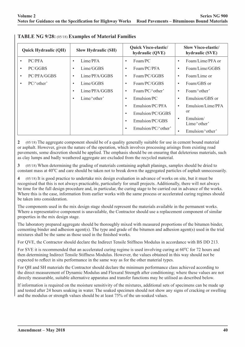
40Amendment – May 2018
Volume 2 Series NG 900 Notes for Guidance on the Specification for Highway Works Road Pavements – Bituminous Bound Materials
TABLE NG 9/28: (05/18) Examples of Material Families
Quick Hydraulic (QH) Slow Hydraulic (SH) Quick Visco-elastic/hydraulic (QVE)
Slow Visco-elastic/hydraulic (SVE)
• PC/PFA
• PC/GGBS
• PC/PFA/GGBS
• PC/‘other’
• Lime/PFA
• Lime/GGBS
• Lime/PFA/GGBS
• Lime/GGBS
• Lime/PFA/GGBS
• Lime/‘other’
• Foam/PC
• Foam/PC/PFA
• Foam/PC/GGBS
• Foam/PC/GGBS
• Foam/PC/‘other’
• Emulsion/PC
• Emulsion/PC/PFA
• Emulsion/PC/GGBS
• Emulsion/PC/GBS
• Emulsion/PC/‘other’
• Foam/Lime/PFA or
• Foam/Lime/GGBS
• Foam/Lime or
• Foam/GBS or
• Foam/‘other’
• Emulsion/GBS or
• Emulsion/Lime/PFA or
• Emulsion/Lime/‘other’
• Emulsion/‘other’
2 (05/18) The aggregate component should be of a quality generally suitable for use in cement bound material or asphalt. However, given the nature of the operation, which involves processing arisings from existing road pavements, some discretion should be applied. The emphasis should be on ensuring that deleterious materials, such as clay lumps and badly weathered aggregate are excluded from the recycled material.
3 (05/18) When determining the grading of materials containing asphalt planings, samples should be dried to constant mass at 40oC and care should be taken not to break down the aggregated particles of asphalt unnecessarily.
4 (05/18) It is good practice to undertake mix design evaluation in advance of works on site, but it must be recognised that this is not always practicable, particularly for small projects. Additionally, there will not always be time for the full design procedure and, in particular, the curing stage to be carried out in advance of the works. Where this is the case, information from earlier works with the same process or accelerated curing regimes should be taken into consideration.
The components used in the mix design stage should represent the materials available in the permanent works. Where a representative component is unavailable, the Contractor should use a replacement component of similar properties in the mix design stage.
The laboratory prepared aggregate should be thoroughly mixed with measured proportions of the bitumen binder, cementing binder and adhesion agent(s). The type and grade of the bitumen and adhesion agent(s) used in the trial mixtures shall be the same as those used in the finished works.
For QVE, the Contractor should declare the Indirect Tensile Stiffness Modulus in accordance with BS DD 213.
For SVE it is recommended that an accelerated curing regime is used involving curing at 60oC for 72 hours and then determining Indirect Tensile Stiffness Modulus. However, the values obtained in this way should not be expected to reflect in situ performance in the same way as for the other material types.
For QH and SH materials the Contractor should declare the minimum performance class achieved according to the direct measurement of Dynamic Modulus and Flexural Strength after conditioning; where these values are not directly measurable, suitable alternative apparatus and transfer functions may be utilised as described below.
If information is required on the moisture sensitivity of the mixtures, additional sets of specimens can be made up and tested after 24 hours soaking in water. The soaked specimen should not show any signs of cracking or swelling and the modulus or strength values should be at least 75% of the un-soaked values.
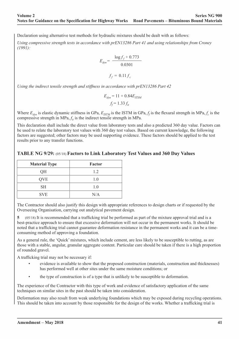
Amendment – May 2018 41
Volume 2 Series NG 900 Notes for Guidance on the Specification for Highway Works Road Pavements – Bituminous Bound Materials
Declaration using alternative test methods for hydraulic mixtures should be dealt with as follows:
Using compressive strength tests in accordance with prEN13286 Part 41 and using relationships from Croney (1991):
Edyn =log f f + 0.773
0.0301
f f = 0.11 f c
Using the indirect tensile strength and stiffness in accordance with prEN13286 Part 42
Edyn = 11 + 0.84EITSM
ff = 1.33 fit
Where Edyn is elastic dynamic stiffness in GPa, EISTM is the ISTM in GPa, ff is the flexural strength in MPa, fc is the compressive strength in MPa, fit is the indirect tensile strength in MPa.
This declaration shall include the direct value from laboratory tests and also a predicted 360 day value. Factors can be used to relate the laboratory test values with 360 day test values. Based on current knowledge, the following factors are suggested; other factors may be used supporting evidence. These factors should be applied to the test results prior to any transfer functions.
TABLE NG 9/29: (05/18) Factors to Link Laboratory Test Values and 360 Day Values
Material Type Factor
QH 1.2
QVE 1.0
SH 1.0
SVE N/A
The Contractor should also justify this design with appropriate references to design charts or if requested by the Overseeing Organisation, carrying out analytical pavement design.
5 (05/18) It is recommended that a trafficking trial be performed as part of the mixture approval trial and is a best-practice approach to ensure that excessive deformation will not occur in the permanent works. It should be noted that a trafficking trial cannot guarantee deformation resistance in the permanent works and it can be a time-consuming method of approving a foundation.
As a general rule, the ‘Quick’ mixtures, which include cement, are less likely to be susceptible to rutting, as are those with a stable, angular, granular aggregate content. Particular care should be taken if there is a high proportion of rounded gravel.
A trafficking trial may not be necessary if:• evidence is available to show that the proposed construction (materials, construction and thicknesses)
has performed well at other sites under the same moisture conditions; or
• the type of construction is of a type that is unlikely to be susceptible to deformation.
The experience of the Contractor with this type of work and evidence of satisfactory application of the same techniques on similar sites in the past should be taken into consideration.
Deformation may also result from weak underlying foundations which may be exposed during recycling operations. This should be taken into account by those responsible for the design of the works. Whether a trafficking trial is

42Amendment – May 2018
Volume 2 Series NG 900 Notes for Guidance on the Specification for Highway Works Road Pavements – Bituminous Bound Materials
performed or not, it is important to ensure that the foundation meets the specified requirements in the permanent works.
If the construction is to be trafficked by special, very heavy vehicles, additional consideration should be given to the proven performance of the material approval trial under trafficking in relation to these vehicles.
6 (05/18) The plant used for ex situ stabilisation should be capable of achieving controlled batching by weight or volume. The plant should have hoppers and tanks appropriate for the component materials to be mixed. The mixing plant shall be located close enough to the site to enable placing of the material within the appropriate setting time.
7 (05/18) It is important to establish a testing regime for end performance properties (stiffness, tensile strength) appropriate to the nature of the works. It is recommended, given the precision of the testing the results are assessed for conformity in sets of six. This does not, however, mean that a full set of six specimens needs to be made up at one time.
For works of a reasonable size, it is recommended that specimens are prepared at an overall frequency of three per 1000 tonnes, with a minimum of three per working day. Conformity should be assessed on a rolling basis.
It may be possible to relax this requirement for small and intermittent jobs.
40kg of material is required for each sample to have sufficient material for the three test samples (PRD, Cylindrical and Moisture Content) to be produced. PRD samples require a minimum of 5kg of material; Cylindrical samples, 4kg; Moisture Content samples, 3kg; as well as three PSD tests from a bulk sample of six individual samples.
8 (05/18) A PRD or other other suitable mould may be used. Where long-term storage of materials is required, the use of an inexpensive mould such as plastic soil pipe is advised.
9 (05/18) The criteria in this sub-Clause represent the minimum permitted end-product compliance criteria; however, they can be supplemented by other laboratory and non-destructive in situ test methods as agreed with the Overseeing Organisation. For VE materials, particularly those containing asphalt planings, analysing for bitumen content is unlikely to be of value. This aspect of process control is better controlled through tank reconciliation. A description of the supplementary test methods and expected outcomes of the testing can be including in the Material Quality Plan declaration. Supplementary testing can be of value to both the Contractor and the Overseeing Organisation and should be viewed as good practice. For example, a non-destructive falling weight test device can in certain circumstances be used to show the in situ performance of the layer and also show that curing is occurring. It is advised that any agreed supplementary testing is used as a tool for ‘acceptance’ (as opposed to ‘rejection’) so that along with practical evidence at other sites these may be used to resolve non-compliance issues should they occur.
NG 954 (05/18) Method for Laboratory Determination of Interface Properties Using the Modified Leutner Shear Test
1 (05/18) The test method is intended to assess the bonding between adjacent asphalt pavement layers using cylindrical samples. It is also appropriate for asphalt applied to concrete.
2 (05/18) The peak shear stress at the interface between asphalt layers measured using the Modified Leutner Shear Test should not be less than 1MPa for an interface within the top 75 mm of the pavement structure and not less than 0.5MPa for interfaces at or below the top 75 mm.
3 (05/18) Clause 954 incorporates by dated or undated reference, provisions from other publications. These normative references are cited at the appropriate places in the text, and the publications are listed in Appendix F. For dated references, subsequent amendments to or revisions of any of these publications apply to this Clause only when incorporated in it by amendment or revision. For undated references the latest edition of the publication referred to applies (including amendments).
4 (05/18) The Leutner shear test was developed in Germany in the late 1970s as a simple means of undertaking a direct shear test on a bond between two pavement layers. The test is performed on 150 mm diameter cores comprising at least two layers (with a bond between them) taken either from a pavement or produced in the laboratory. The principle of the test is to apply a shear displacement rate across the interface under investigation and monitor the resulting shear force. No normal force is applied to the specimen. The standard loading rate is
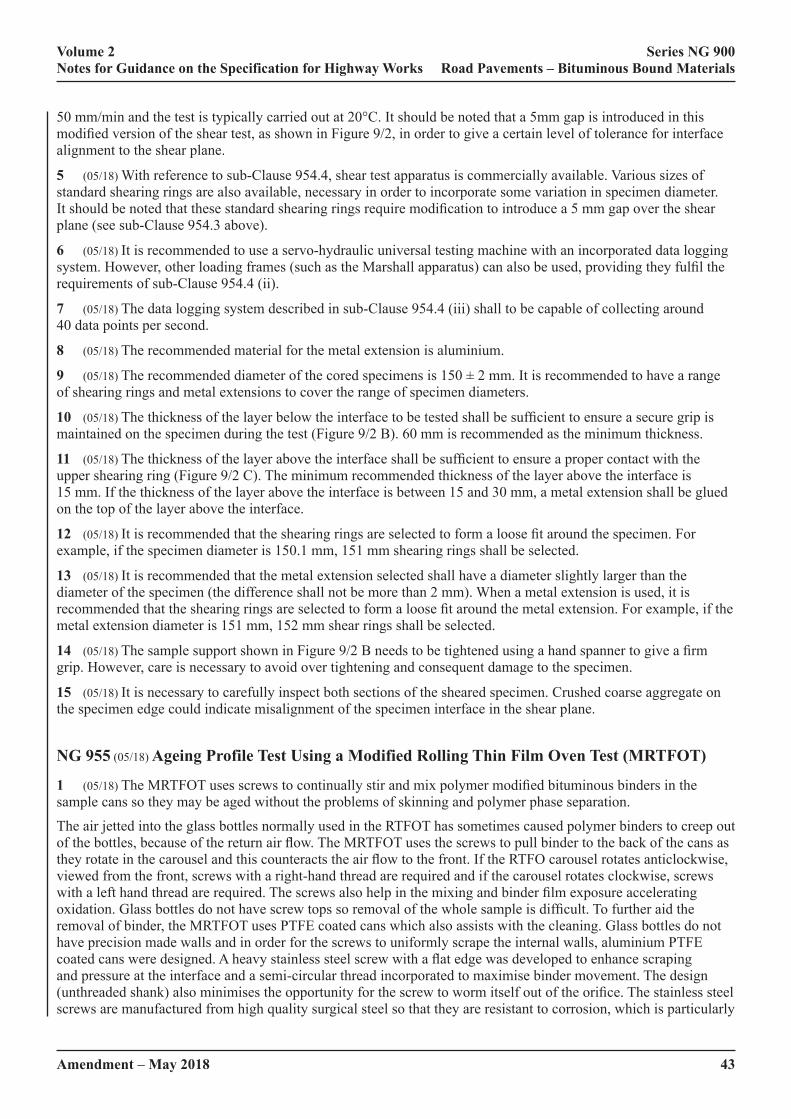
Amendment – May 2018 43
Volume 2 Series NG 900 Notes for Guidance on the Specification for Highway Works Road Pavements – Bituminous Bound Materials
50 mm/min and the test is typically carried out at 20°C. It should be noted that a 5mm gap is introduced in this modified version of the shear test, as shown in Figure 9/2, in order to give a certain level of tolerance for interface alignment to the shear plane.
5 (05/18) With reference to sub-Clause 954.4, shear test apparatus is commercially available. Various sizes of standard shearing rings are also available, necessary in order to incorporate some variation in specimen diameter. It should be noted that these standard shearing rings require modification to introduce a 5 mm gap over the shear plane (see sub-Clause 954.3 above).
6 (05/18) It is recommended to use a servo-hydraulic universal testing machine with an incorporated data logging system. However, other loading frames (such as the Marshall apparatus) can also be used, providing they fulfil the requirements of sub-Clause 954.4 (ii).
7 (05/18) The data logging system described in sub-Clause 954.4 (iii) shall to be capable of collecting around 40 data points per second.
8 (05/18) The recommended material for the metal extension is aluminium.
9 (05/18) The recommended diameter of the cored specimens is 150 ± 2 mm. It is recommended to have a range of shearing rings and metal extensions to cover the range of specimen diameters.
10 (05/18) The thickness of the layer below the interface to be tested shall be sufficient to ensure a secure grip is maintained on the specimen during the test (Figure 9/2 B). 60 mm is recommended as the minimum thickness.
11 (05/18) The thickness of the layer above the interface shall be sufficient to ensure a proper contact with the upper shearing ring (Figure 9/2 C). The minimum recommended thickness of the layer above the interface is 15 mm. If the thickness of the layer above the interface is between 15 and 30 mm, a metal extension shall be glued on the top of the layer above the interface.
12 (05/18) It is recommended that the shearing rings are selected to form a loose fit around the specimen. For example, if the specimen diameter is 150.1 mm, 151 mm shearing rings shall be selected.
13 (05/18) It is recommended that the metal extension selected shall have a diameter slightly larger than the diameter of the specimen (the difference shall not be more than 2 mm). When a metal extension is used, it is recommended that the shearing rings are selected to form a loose fit around the metal extension. For example, if the metal extension diameter is 151 mm, 152 mm shear rings shall be selected.
14 (05/18) The sample support shown in Figure 9/2 B needs to be tightened using a hand spanner to give a firm grip. However, care is necessary to avoid over tightening and consequent damage to the specimen.
15 (05/18) It is necessary to carefully inspect both sections of the sheared specimen. Crushed coarse aggregate on the specimen edge could indicate misalignment of the specimen interface in the shear plane.
NG 955 (05/18) Ageing Profile Test Using a Modified Rolling Thin Film Oven Test (MRTFOT)
1 (05/18) The MRTFOT uses screws to continually stir and mix polymer modified bituminous binders in the sample cans so they may be aged without the problems of skinning and polymer phase separation.
The air jetted into the glass bottles normally used in the RTFOT has sometimes caused polymer binders to creep out of the bottles, because of the return air flow. The MRTFOT uses the screws to pull binder to the back of the cans as they rotate in the carousel and this counteracts the air flow to the front. If the RTFO carousel rotates anticlockwise, viewed from the front, screws with a right-hand thread are required and if the carousel rotates clockwise, screws with a left hand thread are required. The screws also help in the mixing and binder film exposure accelerating oxidation. Glass bottles do not have screw tops so removal of the whole sample is difficult. To further aid the removal of binder, the MRTFOT uses PTFE coated cans which also assists with the cleaning. Glass bottles do not have precision made walls and in order for the screws to uniformly scrape the internal walls, aluminium PTFE coated cans were designed. A heavy stainless steel screw with a flat edge was developed to enhance scraping and pressure at the interface and a semi-circular thread incorporated to maximise binder movement. The design (unthreaded shank) also minimises the opportunity for the screw to worm itself out of the orifice. The stainless steel screws are manufactured from high quality surgical steel so that they are resistant to corrosion, which is particularly
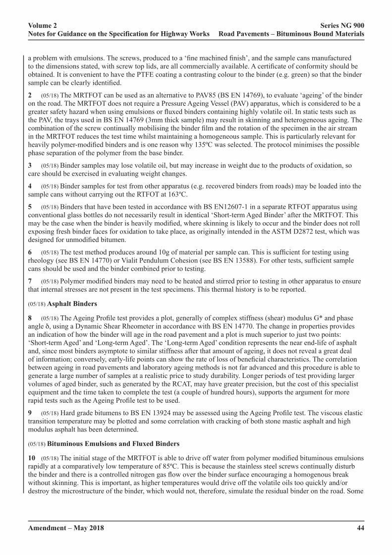
44Amendment – May 2018
Volume 2 Series NG 900 Notes for Guidance on the Specification for Highway Works Road Pavements – Bituminous Bound Materials
a problem with emulsions. The screws, produced to a ‘fine machined finish’, and the sample cans manufactured to the dimensions stated, with screw top lids, are all commercially available. A certificate of conformity should be obtained. It is convenient to have the PTFE coating a contrasting colour to the binder (e.g. green) so that the binder sample can be clearly identified.
2 (05/18) The MRTFOT can be used as an alternative to PAV85 (BS EN 14769), to evaluate ‘ageing’ of the binder on the road. The MRTFOT does not require a Pressure Ageing Vessel (PAV) apparatus, which is considered to be a greater safety hazard when using emulsions or fluxed binders containing highly volatile oil. In static tests such as the PAV, the trays used in BS EN 14769 (3mm thick sample) may result in skinning and heterogeneous ageing. The combination of the screw continually mobilising the binder film and the rotation of the specimen in the air stream in the MRTFOT reduces the test time whilst maintaining a homogeneous sample. This is particularly relevant for heavily polymer-modified binders and is one reason why 135ºC was selected. The protocol minimises the possible phase separation of the polymer from the base binder.
3 (05/18) Binder samples may lose volatile oil, but may increase in weight due to the products of oxidation, so care should be exercised in evaluating weight changes.
4 (05/18) Binder samples for test from other apparatus (e.g. recovered binders from roads) may be loaded into the sample cans without carrying out the RTFOT at 163ºC.
5 (05/18) Binders that have been tested in accordance with BS EN12607-1 in a separate RTFOT apparatus using conventional glass bottles do not necessarily result in identical ‘Short-term Aged Binder’ after the MRTFOT. This may be the case when the binder is heavily modified, where skinning is likely to occur and the binder does not roll exposing fresh binder faces for oxidation to take place, as originally intended in the ASTM D2872 test, which was designed for unmodified bitumen.
6 (05/18) The test method produces around 10g of material per sample can. This is sufficient for testing using rheology (see BS EN 14770) or Vialit Pendulum Cohesion (see BS EN 13588). For other tests, sufficient sample cans should be used and the binder combined prior to testing.
7 (05/18) Polymer modified binders may need to be heated and stirred prior to testing in other apparatus to ensure that internal stresses are not present in the test specimens. This thermal history is to be reported.
(05/18) Asphalt Binders
8 (05/18) The Ageing Profile test provides a plot, generally of complex stiffness (shear) modulus G* and phase angle d, using a Dynamic Shear Rheometer in accordance with BS EN 14770. The change in properties provides an indication of how the binder will age in the road pavement and a plot is much superior to just two points: ‘Short-term Aged’ and ‘Long-term Aged’. The ‘Long-term Aged’ condition represents the near end-life of asphalt and, since most binders asymptote to similar stiffness after that amount of ageing, it does not reveal a great deal of information; conversely, early-life points can show the rate of loss of beneficial characteristics. The correlation between ageing in road pavements and laboratory ageing methods is not far advanced and this procedure is able to generate a large number of samples at a realistic price to study durability. Longer periods of test providing larger volumes of aged binder, such as generated by the RCAT, may have greater precision, but the cost of this specialist equipment and the time taken to complete the test (a couple of hundred hours), supports the argument for more rapid tests such as the Ageing Profile test to be used.
9 (05/18) Hard grade bitumens to BS EN 13924 may be assessed using the Ageing Profile test. The viscous elastic transition temperature may be plotted and some correlation with cracking of both stone mastic asphalt and high modulus asphalt has been determined.
(05/18) Bituminous Emulsions and Fluxed Binders
10 (05/18) The initial stage of the MRTFOT is able to drive off water from polymer modified bituminous emulsions rapidly at a comparatively low temperature of 85ºC. This is because the stainless steel screws continually disturb the binder and there is a controlled nitrogen gas flow over the binder surface encouraging a homogenous break without skinning. This is important, as higher temperatures would drive off the volatile oils too quickly and/or destroy the microstructure of the binder, which would not, therefore, simulate the residual binder on the road. Some
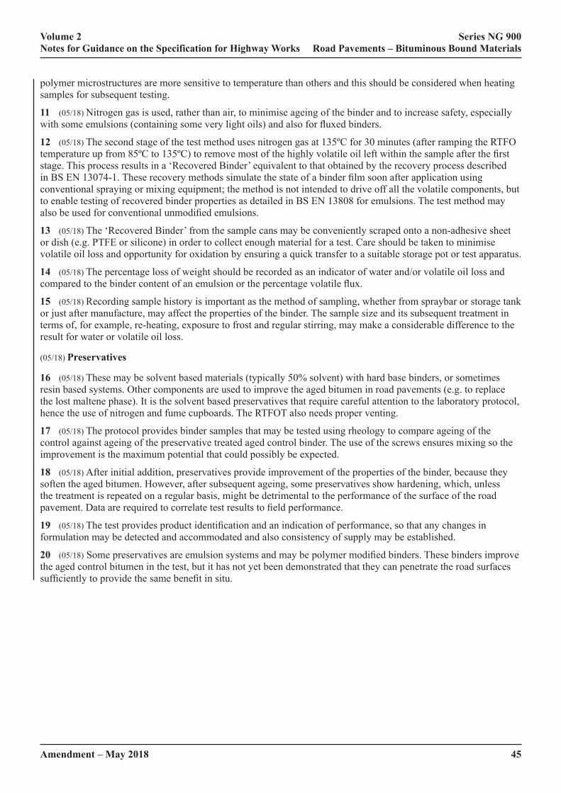
Amendment – May 2018 45
Volume 2 Series NG 900 Notes for Guidance on the Specification for Highway Works Road Pavements – Bituminous Bound Materials
polymer microstructures are more sensitive to temperature than others and this should be considered when heating samples for subsequent testing.
11 (05/18) Nitrogen gas is used, rather than air, to minimise ageing of the binder and to increase safety, especially with some emulsions (containing some very light oils) and also for fluxed binders.
12 (05/18) The second stage of the test method uses nitrogen gas at 135ºC for 30 minutes (after ramping the RTFO temperature up from 85ºC to 135ºC) to remove most of the highly volatile oil left within the sample after the first stage. This process results in a ‘Recovered Binder’ equivalent to that obtained by the recovery process described in BS EN 13074-1. These recovery methods simulate the state of a binder film soon after application using conventional spraying or mixing equipment; the method is not intended to drive off all the volatile components, but to enable testing of recovered binder properties as detailed in BS EN 13808 for emulsions. The test method may also be used for conventional unmodified emulsions.
13 (05/18) The ‘Recovered Binder’ from the sample cans may be conveniently scraped onto a non-adhesive sheet or dish (e.g. PTFE or silicone) in order to collect enough material for a test. Care should be taken to minimise volatile oil loss and opportunity for oxidation by ensuring a quick transfer to a suitable storage pot or test apparatus.
14 (05/18) The percentage loss of weight should be recorded as an indicator of water and/or volatile oil loss and compared to the binder content of an emulsion or the percentage volatile flux.
15 (05/18) Recording sample history is important as the method of sampling, whether from spraybar or storage tank or just after manufacture, may affect the properties of the binder. The sample size and its subsequent treatment in terms of, for example, re-heating, exposure to frost and regular stirring, may make a considerable difference to the result for water or volatile oil loss.
(05/18) Preservatives
16 (05/18) These may be solvent based materials (typically 50% solvent) with hard base binders, or sometimes resin based systems. Other components are used to improve the aged bitumen in road pavements (e.g. to replace the lost maltene phase). It is the solvent based preservatives that require careful attention to the laboratory protocol, hence the use of nitrogen and fume cupboards. The RTFOT also needs proper venting.
17 (05/18) The protocol provides binder samples that may be tested using rheology to compare ageing of the control against ageing of the preservative treated aged control binder. The use of the screws ensures mixing so the improvement is the maximum potential that could possibly be expected.
18 (05/18) After initial addition, preservatives provide improvement of the properties of the binder, because they soften the aged bitumen. However, after subsequent ageing, some preservatives show hardening, which, unless the treatment is repeated on a regular basis, might be detrimental to the performance of the surface of the road pavement. Data are required to correlate test results to field performance.
19 (05/18) The test provides product identification and an indication of performance, so that any changes in formulation may be detected and accommodated and also consistency of supply may be established.
20 (05/18) Some preservatives are emulsion systems and may be polymer modified binders. These binders improve the aged control bitumen in the test, but it has not yet been demonstrated that they can penetrate the road surfaces sufficiently to provide the same benefit in situ.
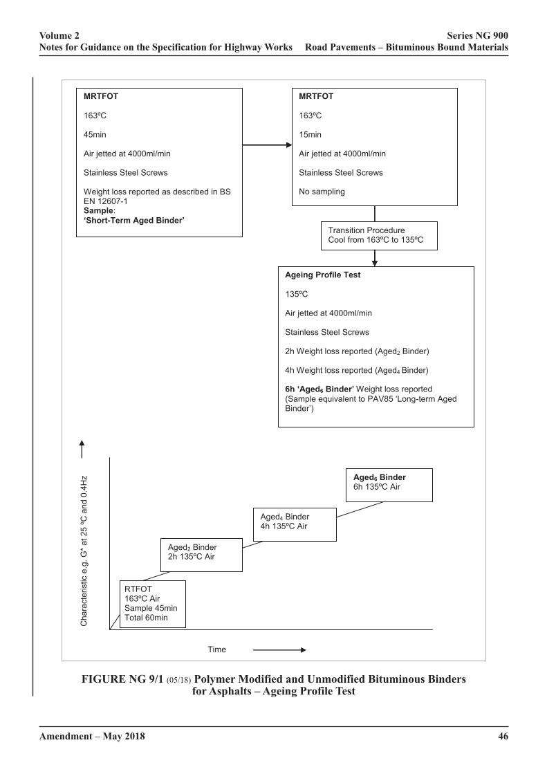
46Amendment – May 2018
Volume 2 Series NG 900 Notes for Guidance on the Specification for Highway Works Road Pavements – Bituminous Bound Materials
MRTFOT 163ºC 45min Air jetted at 4000ml/min Stainless Steel Screws Weight loss reported as described in BS EN 12607-1 Sample: ‘Short-Term Aged Binder’
MRTFOT 163ºC 15min Air jetted at 4000ml/min Stainless Steel Screws No sampling
Transition Procedure Cool from 163ºC to 135ºC
MRTFOT 163ºC 45min Air jetted at 4000ml/min Stainless Steel Screws Weight loss reported as described in BS EN 12607-1 Sample: ‘Short-Term Aged Binder’
MRTFOT 163ºC 15min Air jetted at 4000ml/min Stainless Steel Screws No sampling
Ageing Profile Test 135ºC Air jetted at 4000ml/min Stainless Steel Screws 2h Weight loss reported (Aged2 Binder) 4h Weight loss reported (Aged4 Binder) 6h ‘Aged6 Binder’ Weight loss reported (Sample equivalent to PAV85 ‘Long-term Aged Binder’)
Transition Procedure Cool from 163ºC to 135ºC
MRTFOT 163ºC 45min Air jetted at 4000ml/min Stainless Steel Screws Weight loss reported as described in BS EN 12607-1 Sample: ‘Short-Term Aged Binder’
MRTFOT 163ºC 15min Air jetted at 4000ml/min Stainless Steel Screws No sampling
Cha
ract
eris
tic e
.g. G
* at
25
ºC a
nd 0
.4H
z
Time
Aged6 Binder 6h 135ºC Air
Aged4 Binder 4h 135ºC Air
Aged2 Binder 2h 135ºC Air
RTFOT 163ºC Air Sample 45min Total 60min
FIGURE NG 9/1 (05/18) Polymer Modified and Unmodified Bituminous Binders for Asphalts – Ageing Profile Test
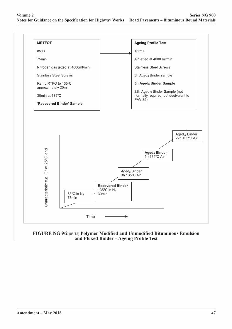
Amendment – May 2018 47
Volume 2 Series NG 900 Notes for Guidance on the Specification for Highway Works Road Pavements – Bituminous Bound Materials
MRTFOT 85ºC 75min Nitrogen gas jetted at 4000ml/min Stainless Steel Screws Ramp RTFO to 135ºC approximately 20min 30min at 135ºC ‘Recovered Binder’ Sample
Ageing Profile Test 135ºC Air jetted at 4000 ml/min Stainless Steel Screws 3h Aged3 Binder sample 5h Aged5 Binder Sample 22h Aged22 Binder Sample (not normally required, but equivalent to PAV 85)
Cha
ract
eris
tic e
.g. G
* at 2
5°C
and
0.
4Hz
Time
Recovered Binder 135ºC in N2 30min
Time
85ºC in N2 75min
Aged5 Binder 5h 135ºC Air
Aged22 Binder 22h 135ºC Air
Aged3 Binder 3h 135ºC Air
Cha
ract
eris
tic e
.g. G
* at 2
5°C
and
0.
4Hz
Recovered Binder 135ºC in N2 30min
Time
FIGURE NG 9/2 (05/18) Polymer Modified and Unmodified Bituminous Emulsion and Fluxed Binder – Ageing Profile Test

48Amendment – May 2018
Volume 2 Series NG 900 Notes for Guidance on the Specification for Highway Works Road Pavements – Bituminous Bound Materials
MRTFOT Control binder - Sample 163°C Air jet at 4000ml/min 45min Stainless steel screws Sample after MRTFOT Weight loss reported
MRTFOT 50°C 2h (no screws) Nitrogen gas jet at 4000ml/min Sample Weight loss reported
Ageing Profile Test 135°C Replace stainless steel screws Air jet at 4000ml/min 2h Sample Weight loss reported Further samples if required e.g. at 4h
Addition of Preservative Remove stainless steel screws Remove some binder and replace with preservative (keeping the residual weight constant), swirl/coat, Cool to ambient on side at 20°C (ambient) for 24 hours in fume cupboard Weight loss reported
MRTFOT 135°C Air jet at 4000ml/min 4h Stainless steel screws Sample of aged control Weight loss reported
Transition Procedure Raise from 50°C to 135°C Nitrogen gas at 4000ml/min Approximately 0.5h
Age
d C
ontr
ol
Bin
der
Age
d C
ontr
ol B
inde
r plu
s Pr
eser
vativ
e
Tran
sitio
n P
roce
dure
C
ool f
rom
163
ºC to
13
5ºC
FIGURE NG 9/3 (05/18) Preservative Test Protocol
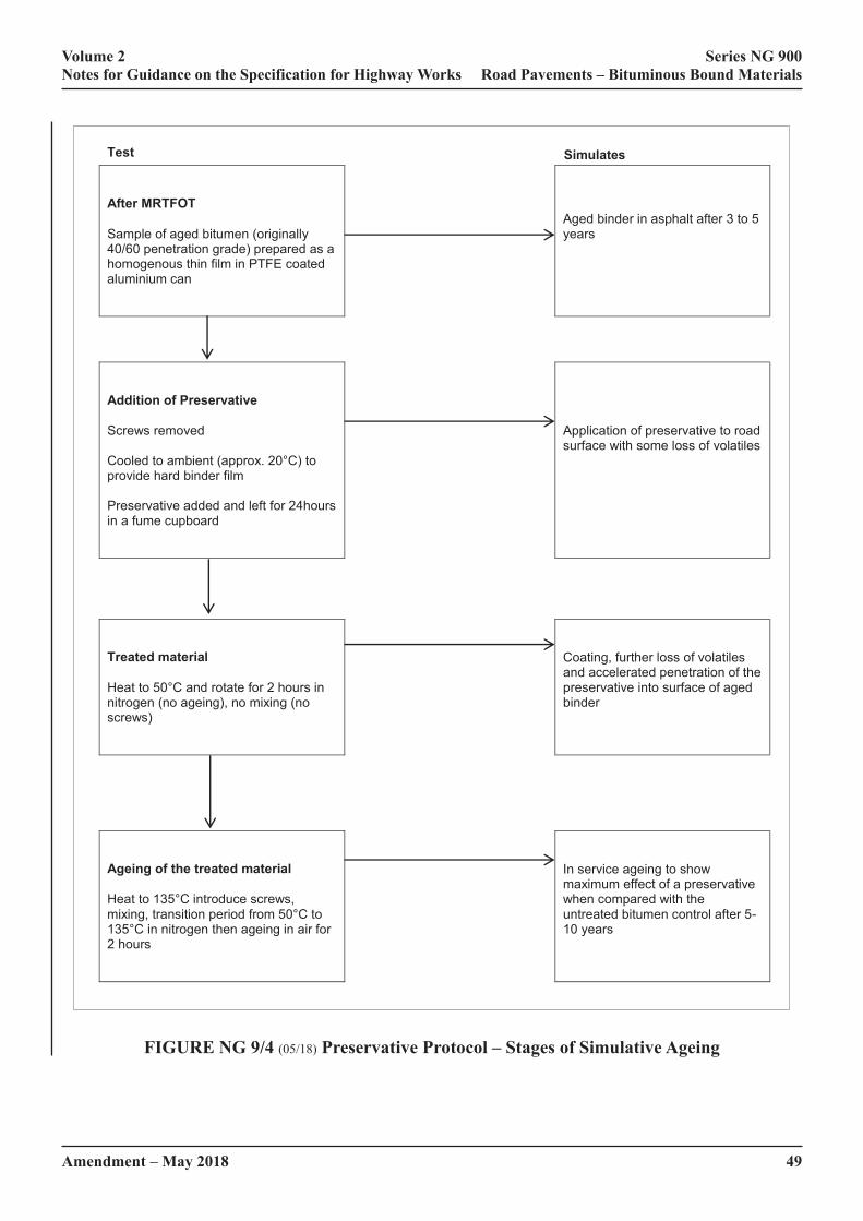
Amendment – May 2018 49
Volume 2 Series NG 900 Notes for Guidance on the Specification for Highway Works Road Pavements – Bituminous Bound Materials
Test Simulates After MRTFOT Sample of aged bitumen (originally 40/60 penetration grade) prepared as a homogenous thin film in PTFE coated aluminium can
Aged binder in asphalt after 3 to 5 years
Addition of Preservative Screws removed Cooled to ambient (approx. 20°C) to provide hard binder film Preservative added and left for 24hours in a fume cupboard
Application of preservative to road surface with some loss of volatiles
Treated material Heat to 50°C and rotate for 2 hours in nitrogen (no ageing), no mixing (no screws)
Coating, further loss of volatiles and accelerated penetration of the preservative into surface of aged binder
Ageing of the treated material Heat to 135°C introduce screws, mixing, transition period from 50°C to 135°C in nitrogen then ageing in air for 2 hours
In service ageing to show maximum effect of a preservative when compared with the untreated bitumen control after 5-10 years
FIGURE NG 9/4 (05/18) Preservative Protocol – Stages of Simulative Ageing

Amendment – May 2018
Volume 2 Series NG 900 Notes for Guidance on the Specification for Highway Works Road Pavements – Bituminous Bound Materials
50F
0
5
10
15
20
25
30
Short Term Aged 40/60 pen Control
Control after laboratory ageing equivalent to 3 to 5 years
Improvement with Preservative applied
Comparison of Preservative treated aged Control after further laboratory ageing equivalent to 5 to 10 years
Visc
ous
Elas
tic T
rans
ition
Tem
pera
ture
°C
40/60 pen Control
Aged 40/60 pen Control treated with Preservative
FIGURE NG 9/5 (05/18) Preservatives –- Improvement in Capacity for Ageing as shown by VET temperature

Amendment – May 2018
Volume 2 Series NG 900 Notes for Guidance on the Specification for Highway Works Road Pavements – Bituminous Bound Materials
S1F
NATIONAL ALTERATIONS OF THE OVERSEEING ORGANISATION OF SCOTLAND
NG 911TS (05/18) Rolled Asphalt Surface Course (Design Mixtures)
1 (05/18) The special requirements included in contract specific Appendix 7/1 may include specific mixture designations, binder grade and for 30/14 and 35/14 mixtures, the required properties of coated chippings in accordance with Clause 915.
2 (05/18) The method of determining the design binder content for surface course mixtures is described in BS 594987, Annex H. The target binder content of the mixture will normally be the higher of the design binder content and the minimum binder content indicated in BSI PD 6691, Annex C, Table C2A or Table C2C as appropriate.
3 (05/18) The Contractor may usually be permitted to use either Type F or Type C mixtures. The use of 70/100 grade bitumen will also usually be permitted, when there is experience of good performance with locally available mixtures.
(05/18) Marshall Stability and Flow
4 (05/18) In the past, Marshall stability and flow have been used as indicators of resistance to permanent deformation. The BS EN 13108 standards no longer require these properties to be specified because resistance to deformation is now measured directly using wheel tracking apparatus. In heavily trafficked situations, where resistance to permanent deformation is of high importance, it is recommended that performance related Hot Rolled Asphalt to Clause 943 is used.
5 (05/18) Marshall stability and flow values at different binder contents are determined as part of the procedure for establishing the design binder content for surface course mixtures. For roads that are not heavily trafficked, stability and flow values at the target binder content may also be used as an additional requirement. The selected values should comply with the requirements of Table NG 9/1TS.
TABLE NG 9/1TS: (05/18) Criteria for the Stability and Flow of Rolled Asphalt Surface Course (Design Mixtures)
Traffic (commercial vehicles per lane per day)
Stability Range, kN Maximum Flow, mm
Less than 1500 3 to 8 5 mm
1500 to 3000 4 to 8 5 mm
NOTE 1. Experience of locally available mixtures may indicate that a maximum stability value of 10.0 kN should be specified. If the stability value is greater than 8 kN, the maximum flow value may be increased to 7 mm.
NOTE 2. Performance related Hot Rolled Asphalt to Clause 943 should be used when the traffic flow is greater than 3000 commercial vehicles per lane per day.
NOTE 3. The stability and flow values are those determined at the target binder content. These values may be different to the values determined at the design binder content.
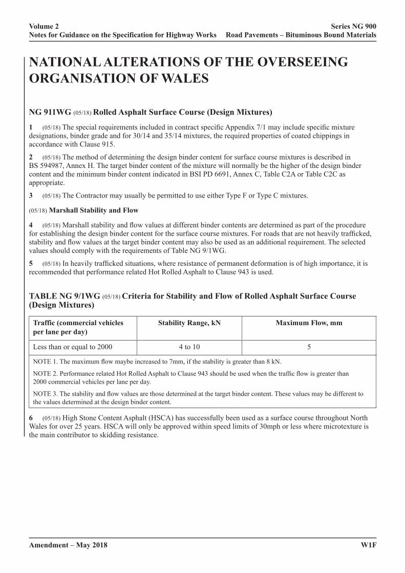
Amendment – May 2018
Volume 2 Series NG 900 Notes for Guidance on the Specification for Highway Works Road Pavements – Bituminous Bound Materials
W1F
NATIONAL ALTERATIONS OF THE OVERSEEING ORGANISATION OF WALES
NG 911WG (05/18) Rolled Asphalt Surface Course (Design Mixtures)
1 (05/18) The special requirements included in contract specific Appendix 7/1 may include specific mixture designations, binder grade and for 30/14 and 35/14 mixtures, the required properties of coated chippings in accordance with Clause 915.
2 (05/18) The method of determining the design binder content for surface course mixtures is described in BS 594987, Annex H. The target binder content of the mixture will normally be the higher of the design binder content and the minimum binder content indicated in BSI PD 6691, Annex C, Table C2A or Table C2C as appropriate.
3 (05/18) The Contractor may usually be permitted to use either Type F or Type C mixtures.
(05/18) Marshall Stability and Flow
4 (05/18) Marshall stability and flow values at different binder contents are determined as part of the procedure for establishing the design binder content for the surface course mixtures. For roads that are not heavily trafficked, stability and flow values at the target binder content may also be used as an additional requirement. The selected values should comply with the requirements of Table NG 9/1WG.
5 (05/18) In heavily trafficked situations, where resistance of permanent deformation is of high importance, it is recommended that performance related Hot Rolled Asphalt to Clause 943 is used.
TABLE NG 9/1WG (05/18) Criteria for Stability and Flow of Rolled Asphalt Surface Course (Design Mixtures)
Traffic (commercial vehicles per lane per day)
Stability Range, kN Maximum Flow, mm
Less than or equal to 2000 4 to 10 5
NOTE 1. The maximum flow maybe increased to 7mm, if the stability is greater than 8 kN.
NOTE 2. Performance related Hot Rolled Asphalt to Clause 943 should be used when the traffic flow is greater than 2000 commercial vehicles per lane per day.
NOTE 3. The stability and flow values are those determined at the target binder content. These values may be different to the values determined at the design binder content.
6 (05/18) High Stone Content Asphalt (HSCA) has successfully been used as a surface course throughout North Wales for over 25 years. HSCA will only be approved within speed limits of 30mph or less where microtexture is the main contributor to skidding resistance.
Related Documents