27. AC circuits (power, resonance, transformers and filters) AC source ⟺

Welcome message from author
This document is posted to help you gain knowledge. Please leave a comment to let me know what you think about it! Share it to your friends and learn new things together.
Transcript
27. AC circuits (power, resonance, transformers and filters)
AC source
⟺
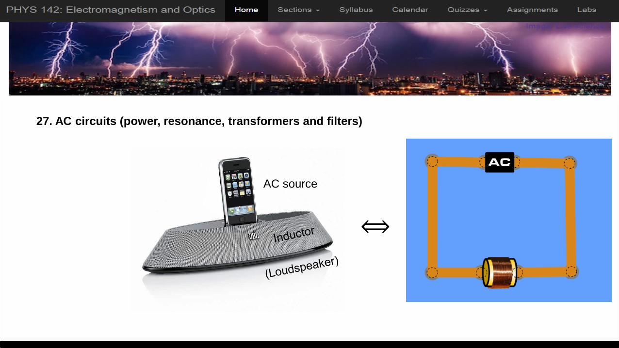
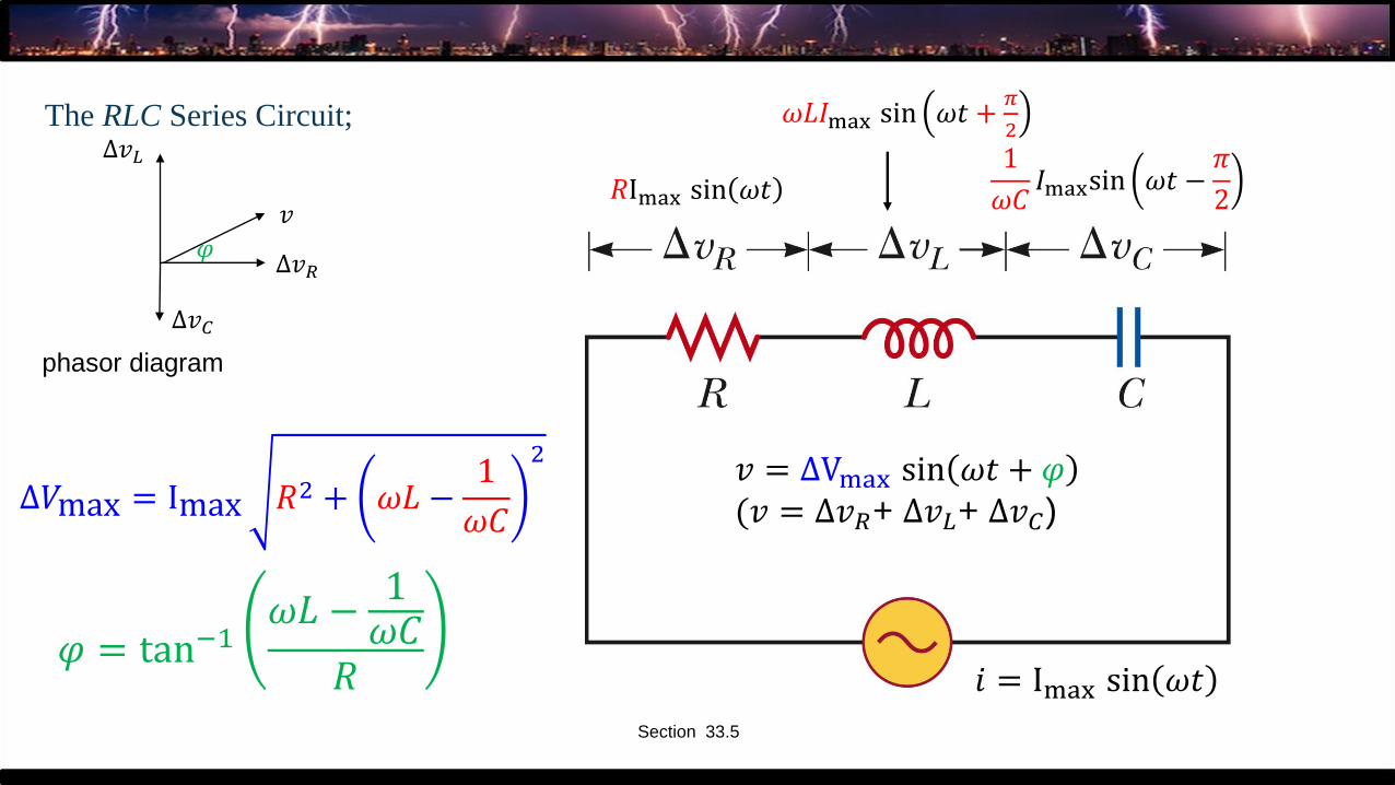
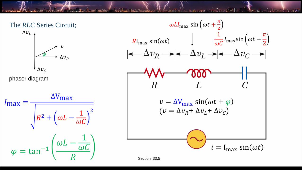
The RLC Series Circuit;
Section 33.5
𝑖 = Imax sin 𝜔𝑡
𝑅Imax sin 𝜔𝑡
𝜔𝐿𝐼max sin 𝜔𝑡 +𝜋
2
1
𝜔𝐶𝐼maxsin 𝜔𝑡 −
𝜋
2
∆𝑣 = ΔVmax sin 𝜔𝑡 + 𝜑(∆𝑣 = ∆𝑣𝑅+ ∆𝑣𝐿+ ∆𝑣𝐶)
𝜑 = tan−1𝜔𝐿 −
1𝜔𝐶
𝑅
Δ𝑉max = Imax 𝑅2 + 𝜔𝐿 −1
𝜔𝐶
2
∆𝑣
∆𝑣𝐶
∆𝑣𝑅
∆𝑣𝐿
phasor diagram
𝜑
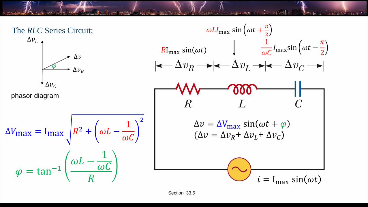
What happens if you interchange R and L (LRC)?
A.We get a different expression for the impedance
B.We get the same expressionfor the impedance
The RLC Series Circuit;
Section 33.5
𝑖 = Imax sin 𝜔𝑡
𝑅Imax sin 𝜔𝑡
𝜔𝐿𝐼max sin 𝜔𝑡 +𝜋
2
1
𝜔𝐶𝐼maxsin 𝜔𝑡 −
𝜋
2
𝑣 = ΔVmax sin 𝜔𝑡 + 𝜑(𝑣 = ∆𝑣𝑅+ ∆𝑣𝐿+ ∆𝑣𝐶)
𝜑 = tan−1𝜔𝐿 −
1𝜔𝐶
𝑅
Δ𝑉max = Imax 𝑅2 + 𝜔𝐿 −1
𝜔𝐶
2
𝑣
∆𝑣𝐶
∆𝑣𝑅
∆𝑣𝐿
phasor diagram
𝜑
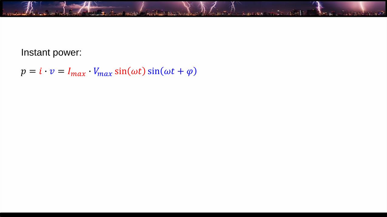
6. Power in an AC circuit:
𝑝 = 𝑖 ∙ 𝑣
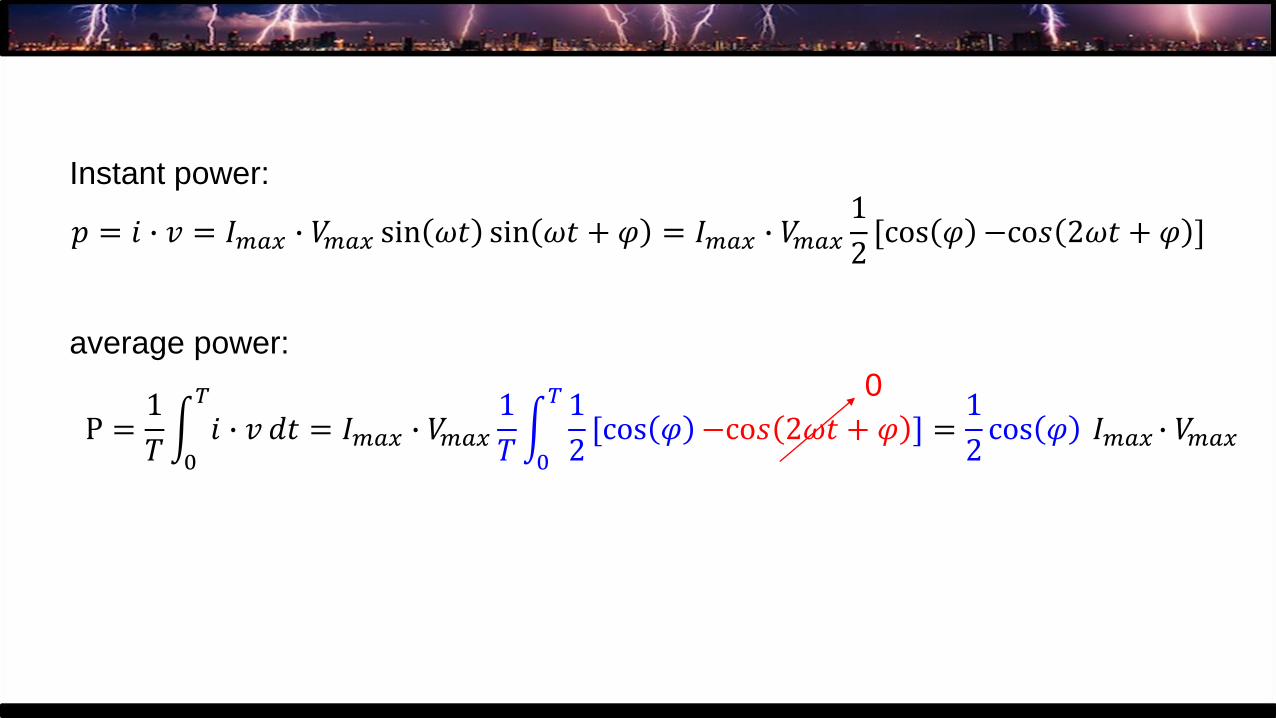
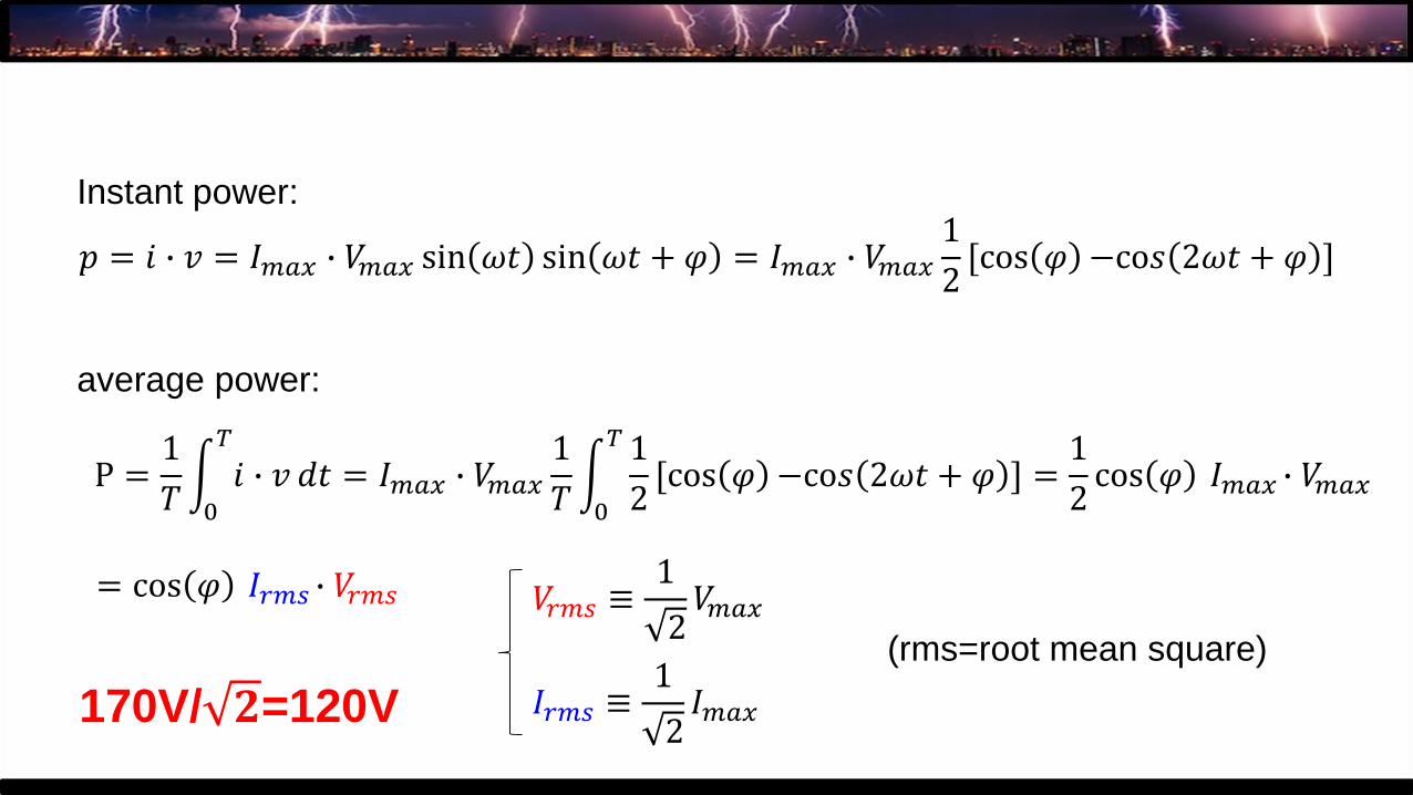
Instant power:
𝑝 = 𝑖 ∙ 𝑣 = 𝐼𝑚𝑎𝑥 sin 𝜔𝑡 ∙ 𝑉𝑚𝑎𝑥 sin 𝜔𝑡 + 𝜑
Instant power:
𝑝 = 𝑖 ∙ 𝑣 = 𝐼𝑚𝑎𝑥 ∙ 𝑉𝑚𝑎𝑥 sin 𝜔𝑡 sin 𝜔𝑡 + 𝜑
Instant power:
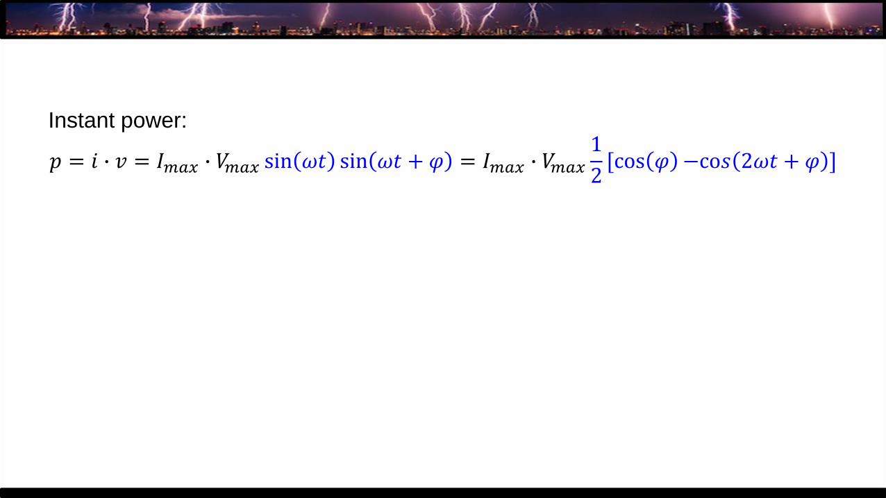
𝑝 = 𝑖 ∙ 𝑣 = 𝐼𝑚𝑎𝑥 ∙ 𝑉𝑚𝑎𝑥 sin 𝜔𝑡 sin 𝜔𝑡 + 𝜑 = 𝐼𝑚𝑎𝑥 ∙ 𝑉𝑚𝑎𝑥
1
2[cos 𝜑 −co𝑠 2𝜔𝑡 + 𝜑 ]
Instant power:
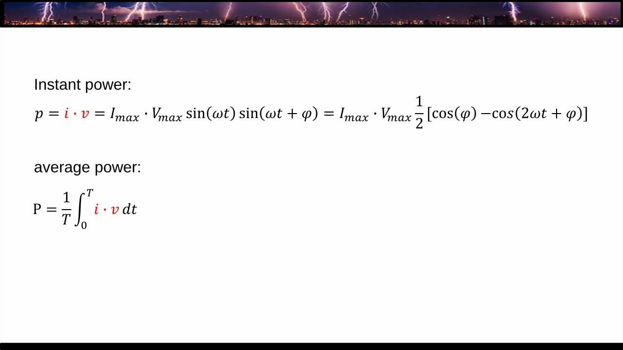
𝑝 = 𝑖 ∙ 𝑣 = 𝐼𝑚𝑎𝑥 ∙ 𝑉𝑚𝑎𝑥 sin 𝜔𝑡 sin 𝜔𝑡 + 𝜑 = 𝐼𝑚𝑎𝑥 ∙ 𝑉𝑚𝑎𝑥
1
2[cos 𝜑 −co𝑠 2𝜔𝑡 + 𝜑 ]
P =1
𝑇න0
𝑇
𝑖 ∙ 𝑣 𝑑𝑡
Instant power:
average power:
𝑝 = 𝑖 ∙ 𝑣 = 𝐼𝑚𝑎𝑥 ∙ 𝑉𝑚𝑎𝑥 sin 𝜔𝑡 sin 𝜔𝑡 + 𝜑 = 𝐼𝑚𝑎𝑥 ∙ 𝑉𝑚𝑎𝑥
1
2[cos 𝜑 −co𝑠 2𝜔𝑡 + 𝜑 ]
P =1
𝑇න0
𝑇
𝑖 ∙ 𝑣 𝑑𝑡 = 𝐼𝑚𝑎𝑥 ∙ 𝑉𝑚𝑎𝑥
1
𝑇න0
𝑇 1
2[cos 𝜑 −co𝑠 2𝜔𝑡 + 𝜑 ]
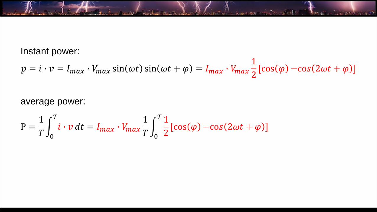
Instant power:
average power:
𝑝 = 𝑖 ∙ 𝑣 = 𝐼𝑚𝑎𝑥 ∙ 𝑉𝑚𝑎𝑥 sin 𝜔𝑡 sin 𝜔𝑡 + 𝜑 = 𝐼𝑚𝑎𝑥 ∙ 𝑉𝑚𝑎𝑥
1
2[cos 𝜑 −co𝑠 2𝜔𝑡 + 𝜑 ]
P =1
𝑇න0
𝑇
𝑖 ∙ 𝑣 𝑑𝑡 = 𝐼𝑚𝑎𝑥 ∙ 𝑉𝑚𝑎𝑥
1
𝑇න0
𝑇 1
2[cos 𝜑 −co𝑠 2𝜔𝑡 + 𝜑 ] =
1
2cos 𝜑 𝐼𝑚𝑎𝑥 ∙ 𝑉𝑚𝑎𝑥
Instant power:
average power:
0
𝑝 = 𝑖 ∙ 𝑣 = 𝐼𝑚𝑎𝑥 ∙ 𝑉𝑚𝑎𝑥 sin 𝜔𝑡 sin 𝜔𝑡 + 𝜑 = 𝐼𝑚𝑎𝑥 ∙ 𝑉𝑚𝑎𝑥
1
2[cos 𝜑 −co𝑠 2𝜔𝑡 + 𝜑 ]
P =1
𝑇න0
𝑇
𝑖 ∙ 𝑣 𝑑𝑡 = 𝐼𝑚𝑎𝑥 ∙ 𝑉𝑚𝑎𝑥
1
𝑇න0
𝑇 1
2[cos 𝜑 −co𝑠 2𝜔𝑡 + 𝜑 ] =
1
2cos 𝜑 𝐼𝑚𝑎𝑥 ∙ 𝑉𝑚𝑎𝑥
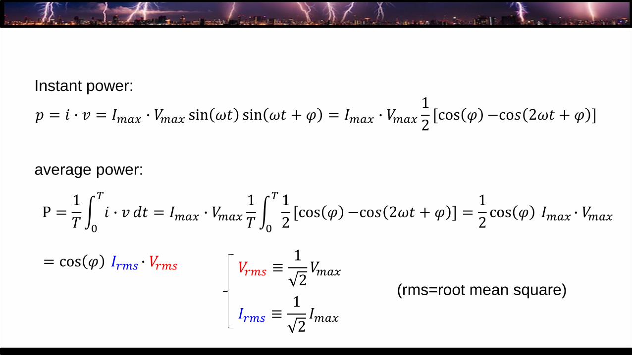
Instant power:
average power:
= cos 𝜑 𝐼𝑟𝑚𝑠 ∙ 𝑉𝑟𝑚𝑠 𝑉𝑟𝑚𝑠 ≡1
2𝑉𝑚𝑎𝑥
𝐼𝑟𝑚𝑠 ≡1
2𝐼𝑚𝑎𝑥
(rms=root mean square)
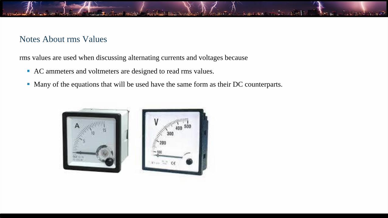
Notes About rms Values
rms values are used when discussing alternating currents and voltages because
▪ AC ammeters and voltmeters are designed to read rms values.
▪ Many of the equations that will be used have the same form as their DC counterparts.
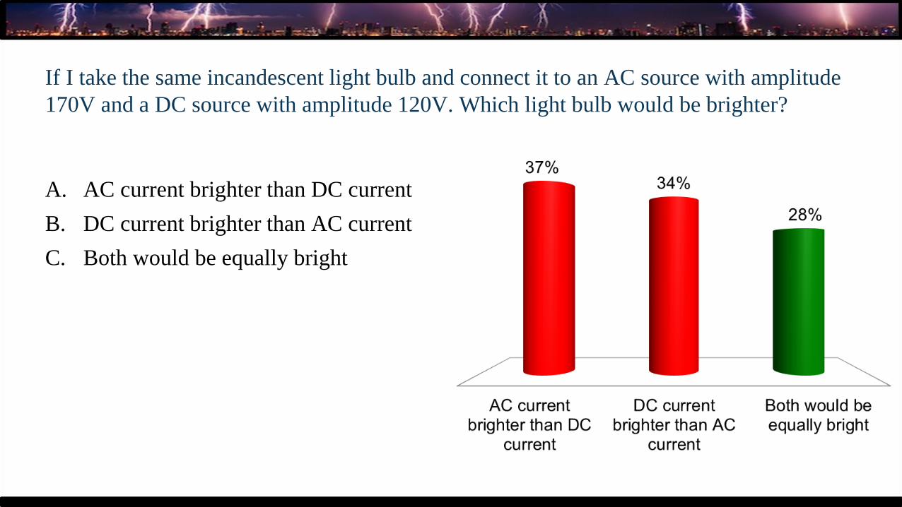
If I take the same incandescent light bulb and connect it to an AC source with amplitude
170V and a DC source with amplitude 120V. Which light bulb would be brighter?
A. AC current brighter than DC current
B. DC current brighter than AC current
C. Both would be equally bright
𝑝 = 𝑖 ∙ 𝑣 = 𝐼𝑚𝑎𝑥 ∙ 𝑉𝑚𝑎𝑥 sin 𝜔𝑡 sin 𝜔𝑡 + 𝜑 = 𝐼𝑚𝑎𝑥 ∙ 𝑉𝑚𝑎𝑥
1
2[cos 𝜑 −co𝑠 2𝜔𝑡 + 𝜑 ]
P =1
𝑇න0
𝑇
𝑖 ∙ 𝑣 𝑑𝑡 = 𝐼𝑚𝑎𝑥 ∙ 𝑉𝑚𝑎𝑥
1
𝑇න0
𝑇 1
2[cos 𝜑 −co𝑠 2𝜔𝑡 + 𝜑 ] =
1
2cos 𝜑 𝐼𝑚𝑎𝑥 ∙ 𝑉𝑚𝑎𝑥
Instant power:
average power:
= cos 𝜑 𝐼𝑟𝑚𝑠 ∙ 𝑉𝑟𝑚𝑠 𝑉𝑟𝑚𝑠 ≡1
2𝑉𝑚𝑎𝑥
𝐼𝑟𝑚𝑠 ≡1
2𝐼𝑚𝑎𝑥
(rms=root mean square)
170V/ 𝟐=120V
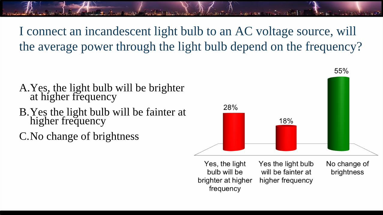
I connect an incandescent light bulb to an AC voltage source, will
the average power through the light bulb depend on the frequency?
A.Yes, the light bulb will be brighter at higher frequency
B.Yes the light bulb will be fainter athigher frequency
C.No change of brightness
Light bulb as a function of frequency demo
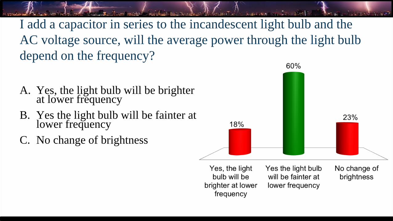
I add a capacitor in series to the incandescent light bulb and the
AC voltage source, will the average power through the light bulb
depend on the frequency?
A. Yes, the light bulb will be brighter at lower frequency
B. Yes the light bulb will be fainter atlower frequency
C. No change of brightness
Light bulb + capacitor as a function of frequency demo

The RLC Series Circuit;
Section 33.5
𝑖 = Imax sin 𝜔𝑡
𝑅Imax sin 𝜔𝑡
𝜔𝐿𝐼max sin 𝜔𝑡 +𝜋
2
1
𝜔𝐶𝐼maxsin 𝜔𝑡 −
𝜋
2
𝑣 = ΔVmax sin 𝜔𝑡 + 𝜑(𝑣 = ∆𝑣𝑅+ ∆𝑣𝐿+ ∆𝑣𝐶)
𝜑 = tan−1𝜔𝐿 −
1𝜔𝐶
𝑅
Δ𝑉max = Imax 𝑅2 + 𝜔𝐿 −1
𝜔𝐶
2
𝑣
∆𝑣𝐶
∆𝑣𝑅
∆𝑣𝐿
phasor diagram
𝜑
The RLC Series Circuit;
Section 33.5
𝑖 = Imax sin 𝜔𝑡
𝑅Imax sin 𝜔𝑡
𝜔𝐿𝐼max sin 𝜔𝑡 +𝜋
2
1
𝜔𝐶𝐼maxsin 𝜔𝑡 −
𝜋
2
𝜑 = tan−1𝜔𝐿 −
1𝜔𝐶
𝑅
𝐼max =∆Vmax
𝑅2 + 𝜔𝐿 −1𝜔𝐶
2
𝑣
∆𝑣𝐶
∆𝑣𝑅
∆𝑣𝐿
phasor diagram
𝜑
𝑣 = ΔVmax sin 𝜔𝑡 + 𝜑(𝑣 = ∆𝑣𝑅+ ∆𝑣𝐿+ ∆𝑣𝐶)
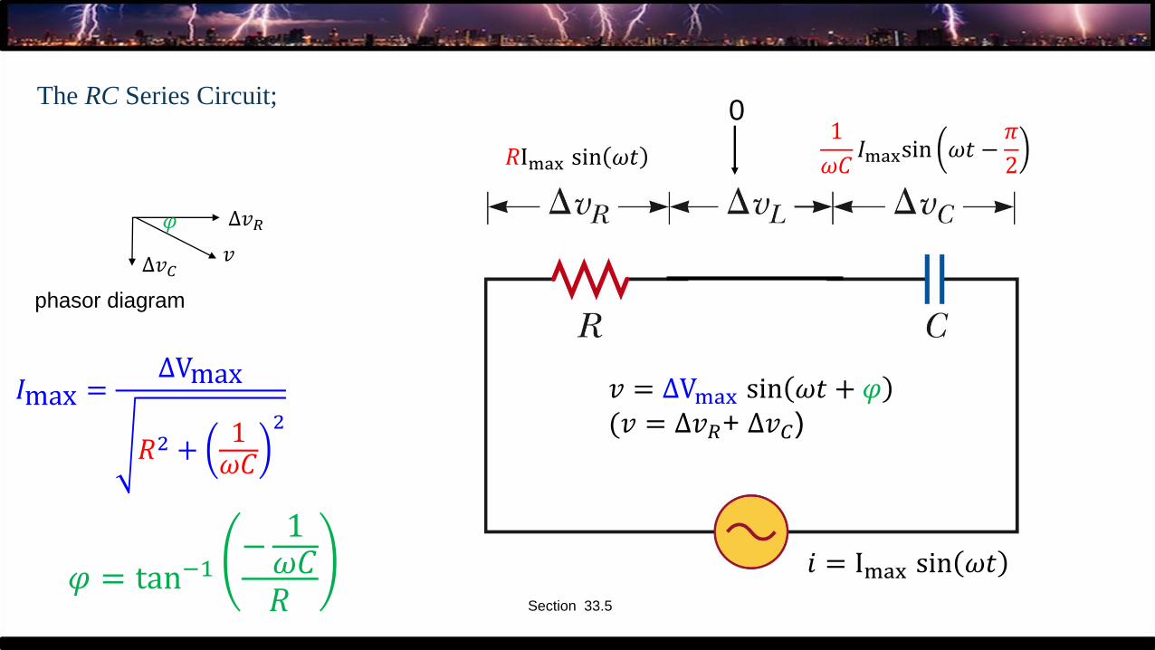
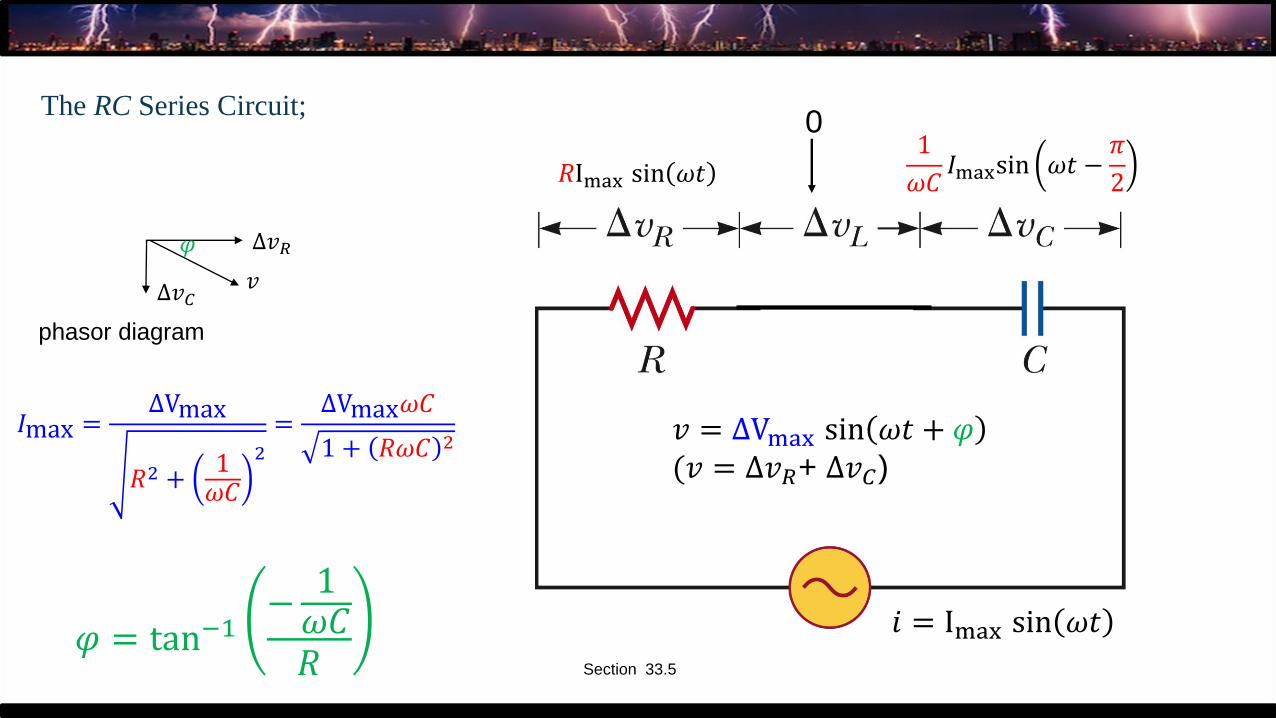
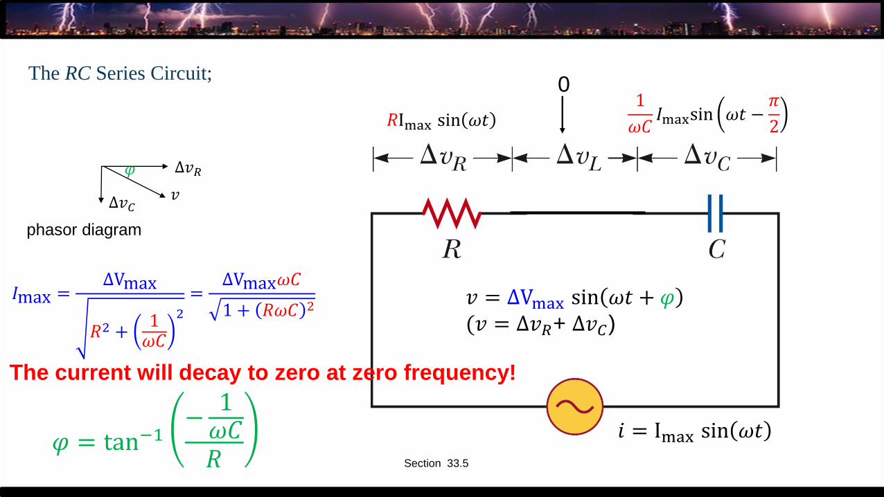
The RC Series Circuit;
Section 33.5
𝑖 = Imax sin 𝜔𝑡
𝑅Imax sin 𝜔𝑡1
𝜔𝐶𝐼maxsin 𝜔𝑡 −
𝜋
2
𝜑 = tan−1−
1𝜔𝐶𝑅
𝐼max =∆Vmax
𝑅2 +1𝜔𝐶
2
𝑣∆𝑣𝐶
∆𝑣𝑅
phasor diagram
𝜑
𝑣 = ΔVmax sin 𝜔𝑡 + 𝜑(𝑣 = ∆𝑣𝑅+ ∆𝑣𝐶)
0
The RC Series Circuit;
Section 33.5
𝑖 = Imax sin 𝜔𝑡
𝑅Imax sin 𝜔𝑡1
𝜔𝐶𝐼maxsin 𝜔𝑡 −
𝜋
2
𝜑 = tan−1−
1𝜔𝐶𝑅
𝐼max =∆Vmax
𝑅2 +1𝜔𝐶
2
=∆Vmax𝜔𝐶
1 + 𝑅𝜔𝐶 2
𝑣∆𝑣𝐶
∆𝑣𝑅
phasor diagram
𝜑
𝑣 = ΔVmax sin 𝜔𝑡 + 𝜑(𝑣 = ∆𝑣𝑅+ ∆𝑣𝐶)
0
The RC Series Circuit;
Section 33.5
𝑖 = Imax sin 𝜔𝑡
𝑅Imax sin 𝜔𝑡1
𝜔𝐶𝐼maxsin 𝜔𝑡 −
𝜋
2
𝜑 = tan−1−
1𝜔𝐶𝑅
𝐼max =∆Vmax
𝑅2 +1𝜔𝐶
2
=∆Vmax𝜔𝐶
1 + 𝑅𝜔𝐶 2
𝑣∆𝑣𝐶
∆𝑣𝑅
phasor diagram
𝜑
𝑣 = ΔVmax sin 𝜔𝑡 + 𝜑(𝑣 = ∆𝑣𝑅+ ∆𝑣𝐶)
0
The current will decay to zero at zero frequency!
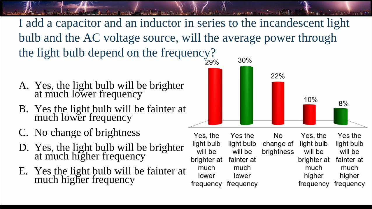
I add a capacitor and an inductor in series to the incandescent light
bulb and the AC voltage source, will the average power through
the light bulb depend on the frequency?
A. Yes, the light bulb will be brighter at much lower frequency
B. Yes the light bulb will be fainter atmuch lower frequency
C. No change of brightness
D. Yes, the light bulb will be brighter at much higher frequency
E. Yes the light bulb will be fainter at much higher frequency
Light bulb + capacitor + loudspeaker (inductor) as a function of frequency demo
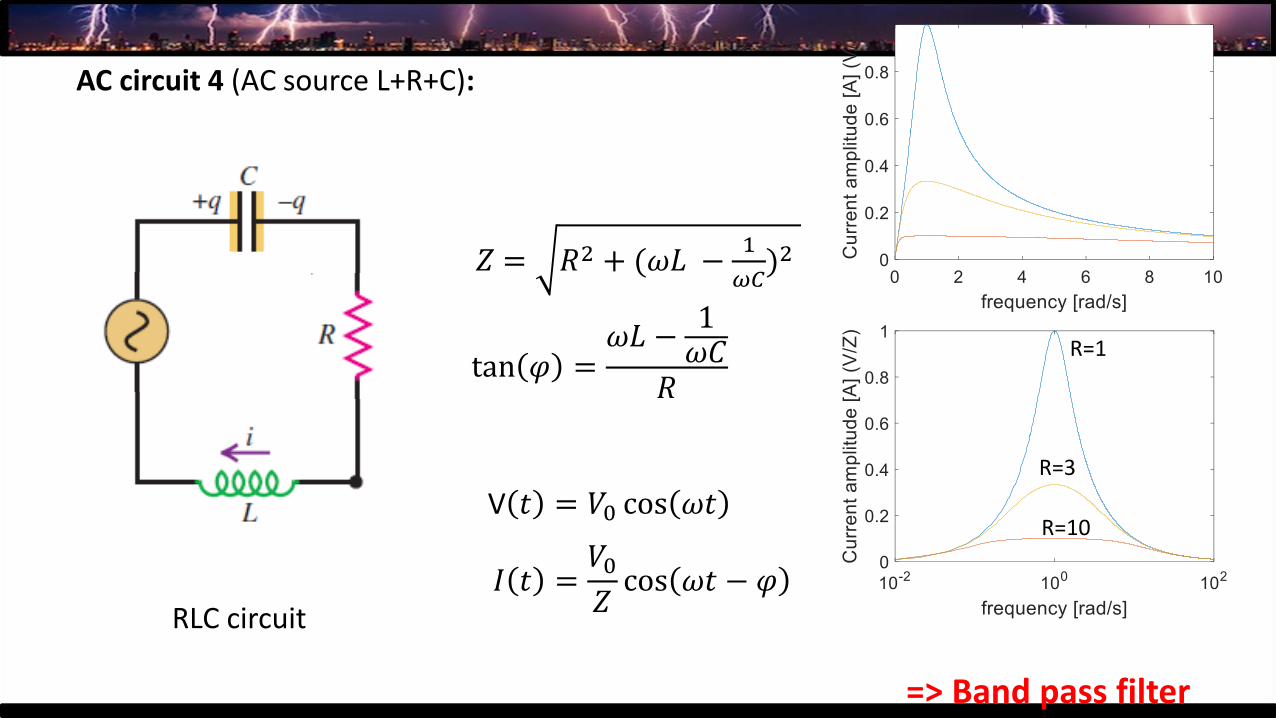
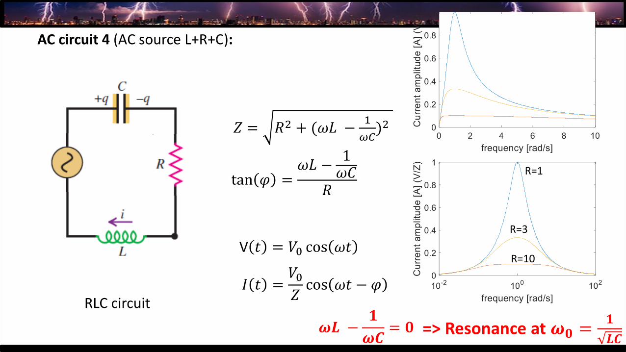
AC circuit 4 (AC source L+R+C):
RLC circuit
𝑍 = 𝑅2 + (𝜔𝐿 −1
𝜔𝐶)2
tan 𝜑 =𝜔𝐿 −
1𝜔𝐶
𝑅
𝐼 𝑡 =𝑉0𝑍cos 𝜔𝑡 − 𝜑
V 𝑡 = 𝑉0 cos 𝜔𝑡
=> Band pass filter
R=10
R=3
R=1
AC circuit 4 (AC source L+R+C):
RLC circuit
𝑍 = 𝑅2 + (𝜔𝐿 −1
𝜔𝐶)2
tan 𝜑 =𝜔𝐿 −
1𝜔𝐶
𝑅
𝐼 𝑡 =𝑉0𝑍cos 𝜔𝑡 − 𝜑
V 𝑡 = 𝑉0 cos 𝜔𝑡
=> Resonance at 𝝎𝟎 =𝟏
𝑳𝑪
R=10
R=3
R=1
𝝎𝑳 −𝟏
𝝎𝑪= 𝟎
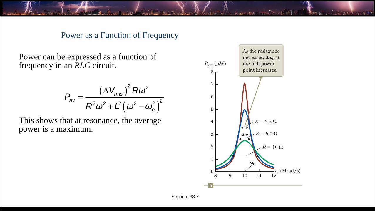
Power as a Function of Frequency
Power can be expressed as a function of frequency in an RLC circuit.
This shows that at resonance, the average power is a maximum.
( )
( )
2 2
22 2 2 2 2
rms
av
o
V RωP
R ω L ω ω
=
+ −
Section 33.7
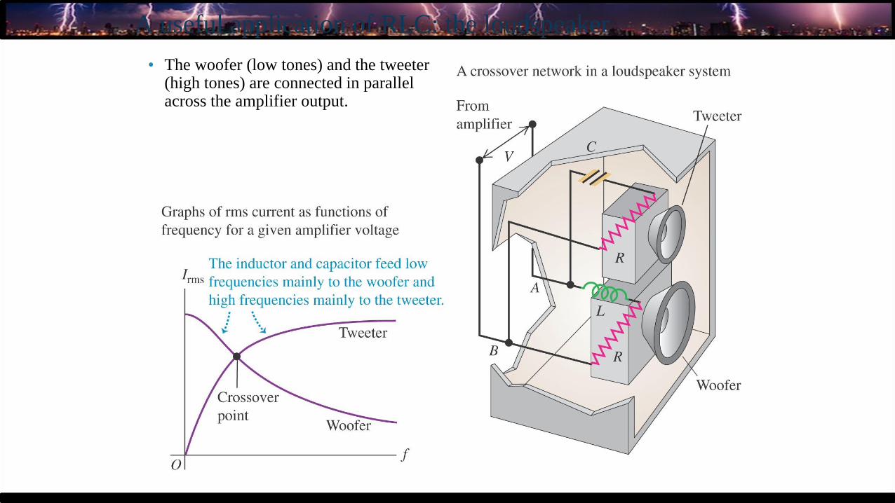
A useful application of RLC: the loudspeaker
• The woofer (low tones) and the tweeter (high tones) are connected in parallel across the amplifier output.
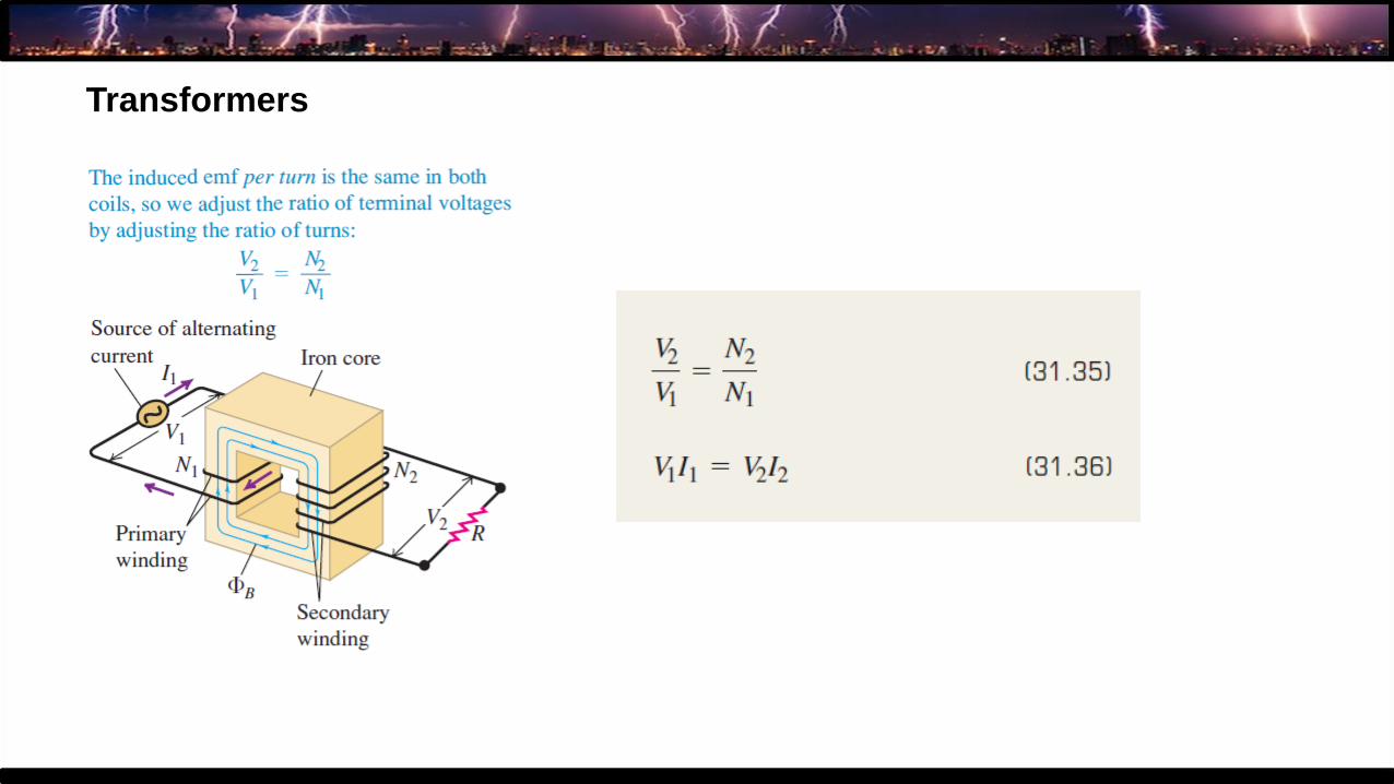
8. Transformer:
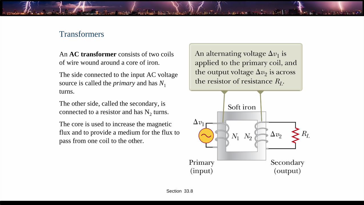
Transformers
An AC transformer consists of two coils
of wire wound around a core of iron.
The side connected to the input AC voltage
source is called the primary and has N1
turns.
The other side, called the secondary, is
connected to a resistor and has N2 turns.
The core is used to increase the magnetic
flux and to provide a medium for the flux to
pass from one coil to the other.
Section 33.8
Transformers
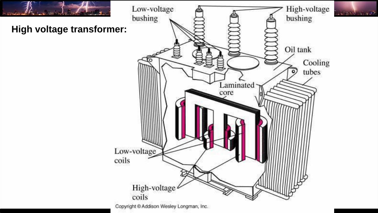
High voltage transformer:

9. Filters:
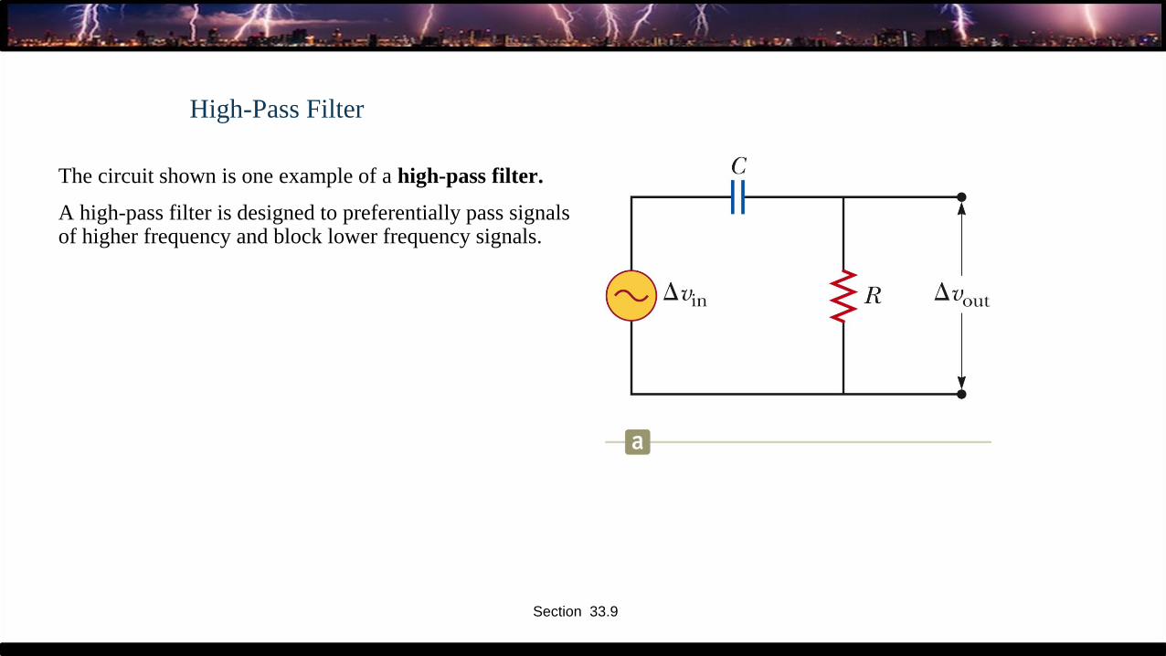
High-Pass Filter
The circuit shown is one example of a high-pass filter.
A high-pass filter is designed to preferentially pass signals of higher frequency and block lower frequency signals.
Section 33.9
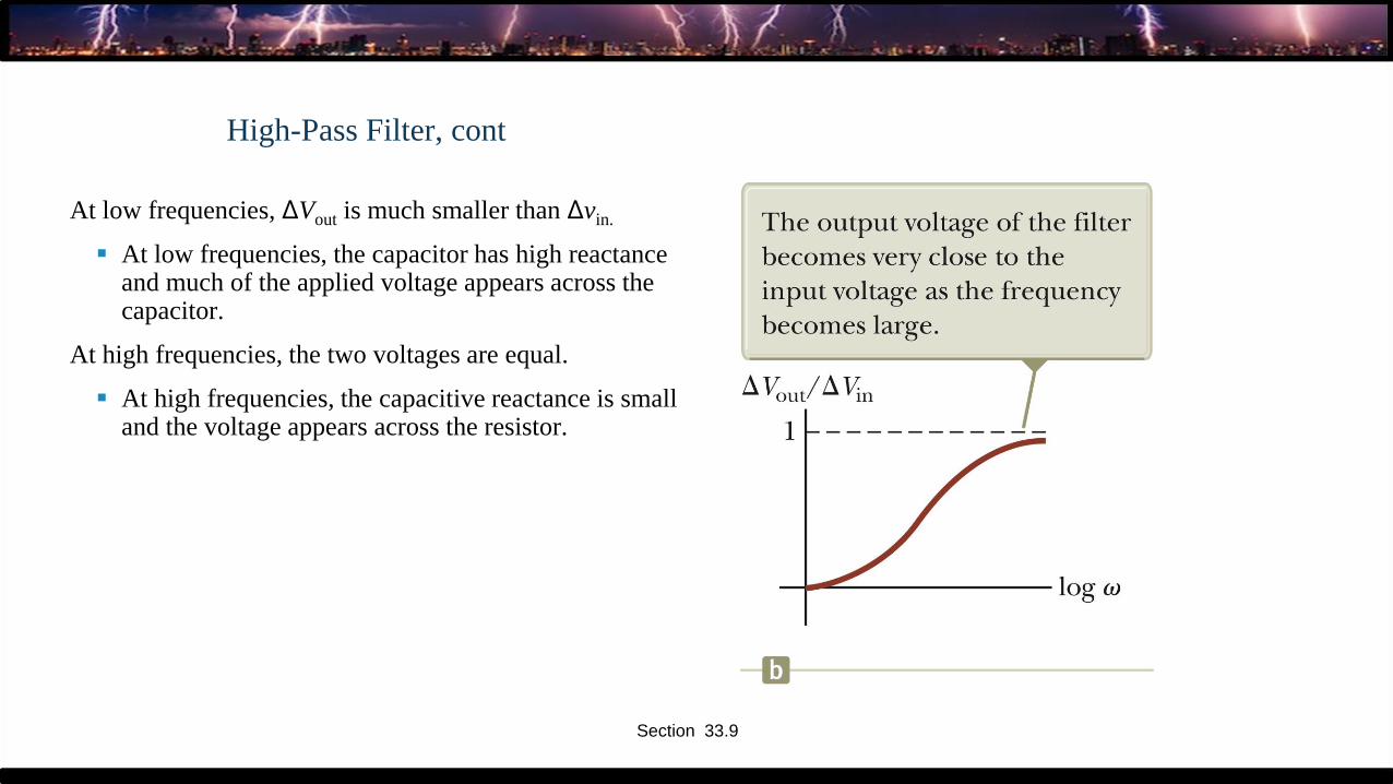
High-Pass Filter, cont
At low frequencies, ΔVout is much smaller than Δvin.
▪ At low frequencies, the capacitor has high reactance and much of the applied voltage appears across the capacitor.
At high frequencies, the two voltages are equal.
▪ At high frequencies, the capacitive reactance is small and the voltage appears across the resistor.
Section 33.9
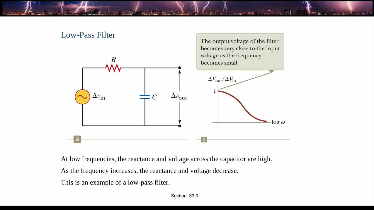
Low-Pass Filter
At low frequencies, the reactance and voltage across the capacitor are high.
As the frequency increases, the reactance and voltage decrease.
This is an example of a low-pass filter.
Section 33.9
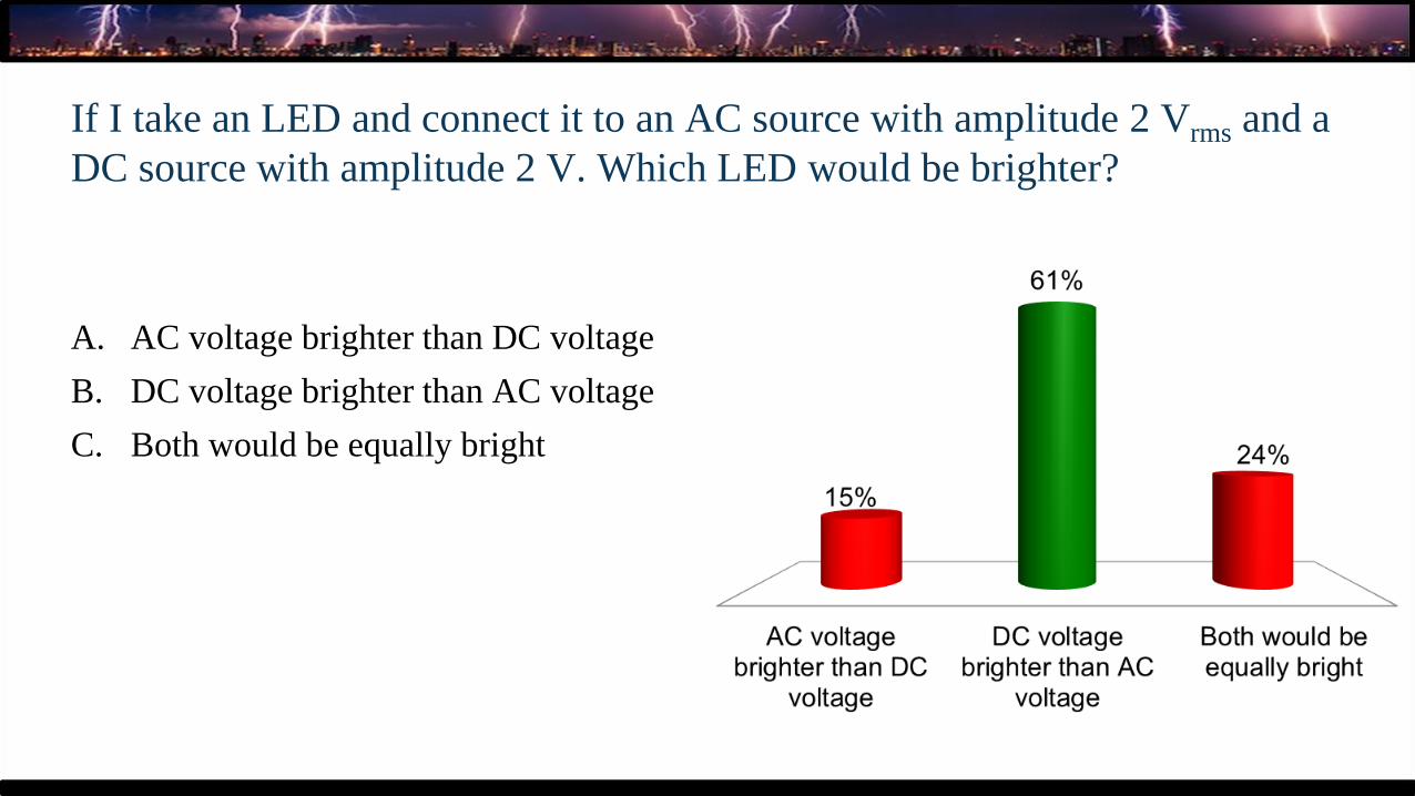
If I take an LED and connect it to an AC source with amplitude 2 Vrms and a
DC source with amplitude 2 V. Which LED would be brighter?
A. AC voltage brighter than DC voltage
B. DC voltage brighter than AC voltage
C. Both would be equally bright

DC vs AC LED brightness
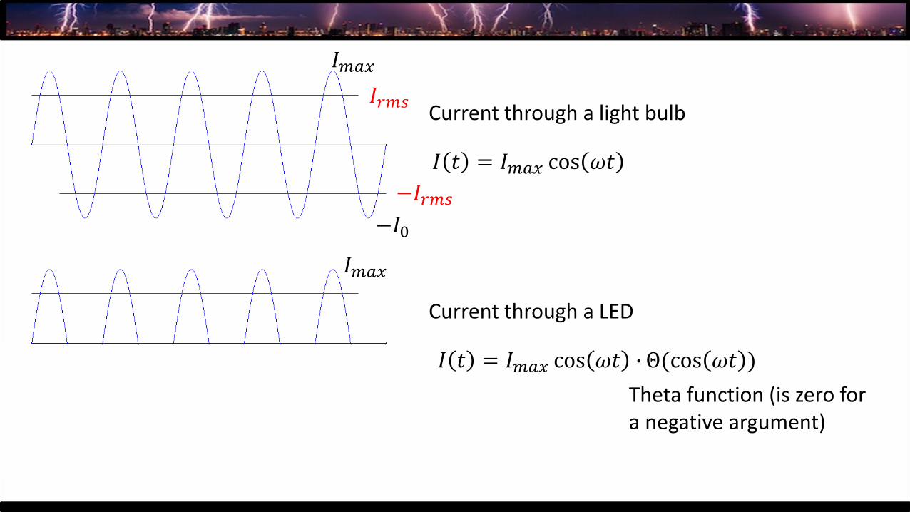
𝐼 𝑡 = 𝐼𝑚𝑎𝑥 cos 𝜔𝑡
Current through a light bulb
𝐼 𝑡 = 𝐼𝑚𝑎𝑥 cos 𝜔𝑡 ∙ Θ(cos 𝜔𝑡 )
Current through a LED
Theta function (is zero for a negative argument)
𝐼𝑚𝑎𝑥
−𝐼𝑟𝑚𝑠
−𝐼0
𝐼𝑟𝑚𝑠
𝐼𝑚𝑎𝑥
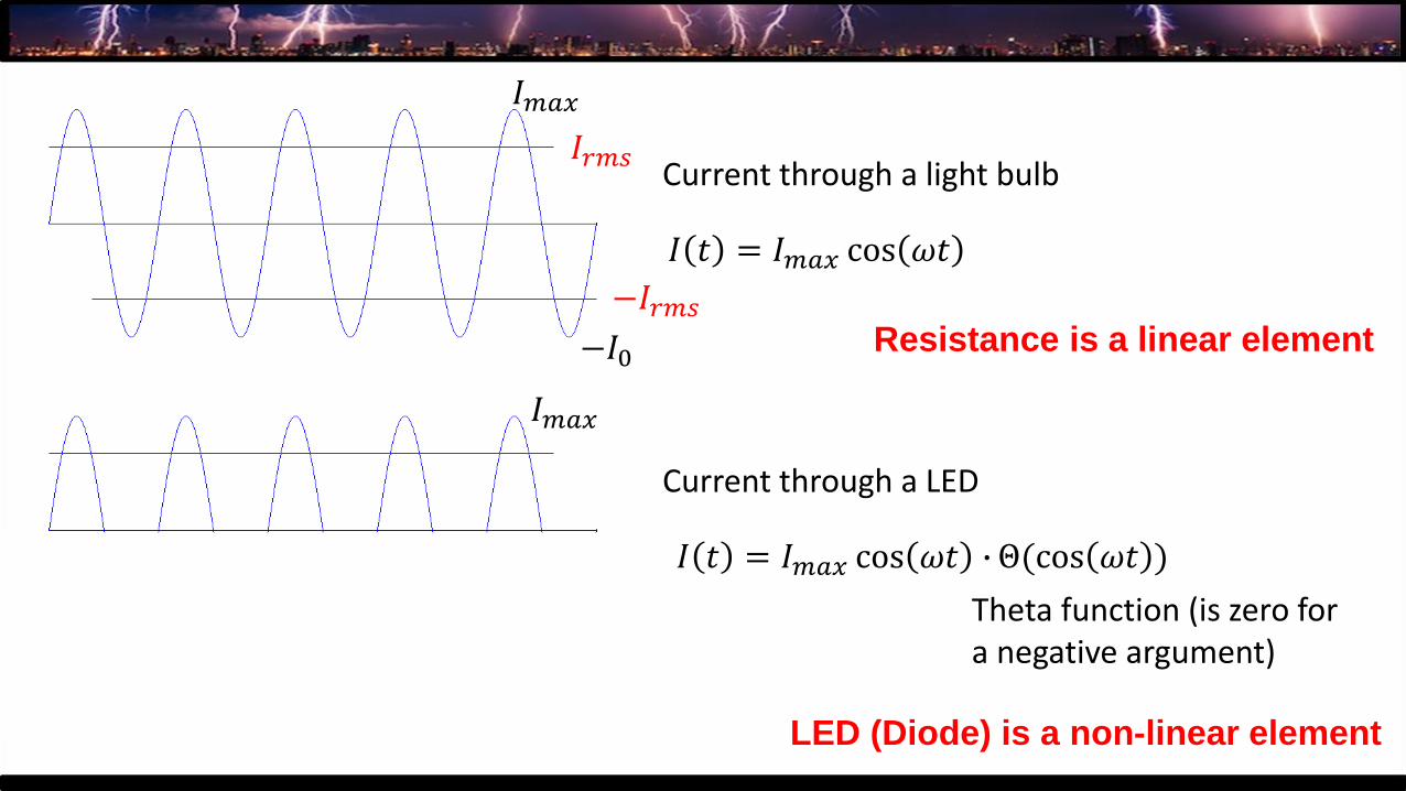
𝐼 𝑡 = 𝐼𝑚𝑎𝑥 cos 𝜔𝑡
Current through a light bulb
𝐼 𝑡 = 𝐼𝑚𝑎𝑥 cos 𝜔𝑡 ∙ Θ(cos 𝜔𝑡 )
Current through a LED
Theta function (is zero for a negative argument)
𝐼𝑚𝑎𝑥
−𝐼𝑟𝑚𝑠
−𝐼0
𝐼𝑟𝑚𝑠
𝐼𝑚𝑎𝑥
Resistance is a linear element
LED (Diode) is a non-linear element
Related Documents

![TRANSFORMERS & AC MOTORS [15EE41T ] · 2018. 12. 30. · TRANSFORMERS & AC MOTORS [15EE41T ] Question Bank – Unit Wise Department of Electrical & Electronics Engineering, Jain Polytechnic](https://static.cupdf.com/doc/110x72/60da4efe558d4521cc7734ee/transformers-ac-motors-15ee41t-2018-12-30-transformers-ac-motors.jpg)