Module 7 Transformer Version 2 EE IIT, Kharagpur

Welcome message from author
This document is posted to help you gain knowledge. Please leave a comment to let me know what you think about it! Share it to your friends and learn new things together.
Transcript

8/7/2019 25.basic
http://slidepdf.com/reader/full/25basic 1/15
Module7
TransformerVersion 2 EE IIT, Kharagpur
8/7/2019 25.basic
http://slidepdf.com/reader/full/25basic 2/15
Lesson
25Testing, Efficiency &
Regulation Version 2 EE IIT, Kharagpur
8/7/2019 25.basic
http://slidepdf.com/reader/full/25basic 3/15
Contents
25 Testing, Efficiency & regulation 4
25.1 Goals of the lesson ………………………………………………………………….. 4
25.2 Determination of equivalent circuit parameters ……………………………………… 4
25.2.1 Qualifying parameters with suffixes LV & HV ……………………………. 5
25.2.2 Open Circuit Test …………………………………………………………... 5
25.2.3 Short circuit test ……………………………………………………………. 6
25.3 Efficiency of transformer …………………………………………………………….. 8
25.3.1 All day efficiency …………………………………………………………... 10
25.4 Regulation ……………………………………………………………………………. 11
25.5 Tick the correct answer ………………………………………………………………. 14
25.6 Solves the Problems …………………………………………………………………. 15
Version 2 EE IIT, Kharagpur

8/7/2019 25.basic
http://slidepdf.com/reader/full/25basic 4/15
25.1 Goals of the lesson
In the previous lesson we have seen how to draw equivalent circuit showing magnetizing
reactance (X m), resistance (Rcl ), representing core loss, equivalent winding resistance (r e) andequivalent leakage reactance (xe). The equivalent circuit will be of little help to us unless we
know the parameter values. In this lesson we first describe two basic simple laboratory testsnamely (i) open circuit test and (ii) short circuit test from which the values of the equivalentcircuit parameters can be computed. Once the equivalent circuit is completely known, we can
predict the performance of the transformer at various loadings. Efficiency and regulation are two
important quantities which are next defined and expressions for them derived and importancehighlighted. A number of objective type questions and problems are given at the end of the
lesson which when solved will make the understanding of the lesson clearer.Key Words: O.C. test, S.C test, efficiency, regulation.
After going through this section students will be able to answer the following questions.
• Which parameters are obtained from O.C test?
• Which parameters are obtained from S.C test?
• What percentage of rated voltage is needed to be applied to carry out O.C test?
• What percentage of rated voltage is needed to be applied to carry out S.C test?
• From which side of a large transformer, would you like to carry out O.C test?
• From which side of a large transformer, would you like to carry out S.C test?
• How to calculate efficiency of the transformer at a given load and power factor?
• Under what condition does the transformer operate at maximum efficiency?
• What is regulation and its importance?
• How to estimate regulation at a given load and power factor?
• What is the difference between efficiency and all day efficiency?
25.2 Determination of equivalent circuit parameters
After developing the equivalent circuit representation, it is natural to ask, how to know
equivalent circuit the parameter values. Theoretically from the detailed design data it is possible
to estimate various parameters shown in the equivalent circuit. In practice, two basic testsnamely the open circuit test and the short circuit test are performed to determine the equivalent
circuit parameters.
25.2.1 Qualifying parameters with suffixes LV & HV
For a given transformer of rating say, 10 kVA, 200 V / 100 V, 50 Hz, one should not be under
the impression that 200 V (HV) side will always be the primary (as because this value appears
Version 2 EE IIT, Kharagpur
8/7/2019 25.basic
http://slidepdf.com/reader/full/25basic 5/15
first in order in the voltage specification) and 100 V (LV) side will always be secondary. Thus,
for a given transformer either of the HV and LV sides may be used as primary or secondary asdecided by the user to suit his/her goals in practice. Usually suffixes 1 and 2 are used for
expressing quantities in terms of primary and secondary respectively – there is nothing wrong in
it so long one keeps track clearly which side is being used as primary. However, there aresituation, such as carrying out O.C & S.C tests (discussed in the next section), where naming
parameters with suffixes HV and LV become imperative to avoid mix up or confusion. Thus, itwill be useful to qualify the parameter values using the suffixes HV and LV (such as r e HV , r e LV etc. instead of r e1, r e2). Therefore, it is recommended to use suffixes as LV, HV instead of 1 and
2 while describing quantities (like voltage V HV , V LV and currents I HV , I LV ) or parameters
(resistances r HV , r LV and reactances xHV , xLV ) in such cases.
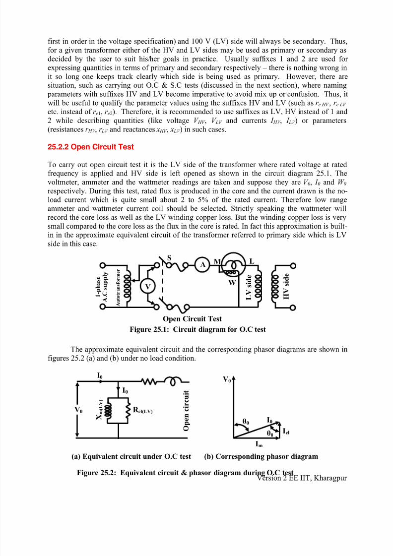
25.2.2 Open Circuit Test
To carry out open circuit test it is the LV side of the transformer where rated voltage at ratedfrequency is applied and HV side is left opened as shown in the circuit diagram 25.1. The
voltmeter, ammeter and the wattmeter readings are taken and suppose they are V 0, I 0 and W 0
respectively. During this test, rated flux is produced in the core and the current drawn is the no-load current which is quite small about 2 to 5% of the rated current. Therefore low range
ammeter and wattmeter current coil should be selected. Strictly speaking the wattmeter will
record the core loss as well as the LV winding copper loss. But the winding copper loss is very
small compared to the core loss as the flux in the core is rated. In fact this approximation is built-in in the approximate equivalent circuit of the transformer referred to primary side which is LV
side in this case.
Open Circuit Test
HV
side
LV
side
Autotransformer
1-phase
A.C supply
V
A
W
M LS
Figure 25.1: Circuit diagram for O.C test
The approximate equivalent circuit and the corresponding phasor diagrams are shown in
figures 25.2 (a) and (b) under no load condition.
Version 2 EE IIT, Kharagpur
V0
(a) Equivalent circuit under O.C test
I0
Xm(LV)
R cl(LV)
I0
Open circuit
V0
I0
Im
Icl
θ0
θ0
(b) Corresponding phasor diagram
Figure 25.2: Equivalent circuit & phasor diagram during O.C test
8/7/2019 25.basic
http://slidepdf.com/reader/full/25basic 6/15
Below we shall show how from the readings of the meters the parallel branch impedancenamely Rcl (LV ) and X m(LV ) can be calculated.
Calculate no load power factor cos θ 0 = 0
0 0
W
V I
Hence θ 0 is known, calculate sin θ 0
Calculate magnetizing current I m = I 0 sin θ 0
Calculate core loss component of current I cl = I 0 cos θ 0
Magnetising branch reactance X m(LV ) = 0
m
V
I
Resistance representing core loss Rcl (LV ) = 0
cl
V
I
We can also calculate X m(HV ) and Rcl (HV ) as follows:
X m(HV ) = ( )2
m LV
X
a
Rcl (HV ) =( )2
cl LV R
a
Where, a = LV
HV
N
N the turns ratio
If we want to draw the equivalent circuit referred to LV side then Rcl (LV ) and X m(LV ) are tobe used. On the other hand if we are interested for the equivalent circuit referred to HV side,
Rcl (HV ) and X m(HV ) are to be used.
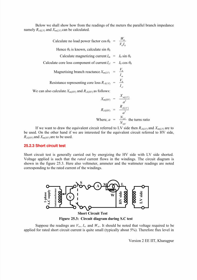
25.2.3 Short circuit test
Short circuit test is generally carried out by energizing the HV side with LV side shorted.
Voltage applied is such that the rated current flows in the windings. The circuit diagram isshown in the figure 25.3. Here also voltmeter, ammeter and the wattmeter readings are noted
corresponding to the rated current of the windings.
Short Circuit Test
HV side
LV side
Autotransformer
1-pha
se
A.C supply
V
A
W
M LS
Figure 25.3: Circuit diagram during S.C test
Suppose the readings are V sc, I sc and W sc. It should be noted that voltage required to be
applied for rated short circuit current is quite small (typically about 5%). Therefore flux level in
Version 2 EE IIT, Kharagpur

8/7/2019 25.basic
http://slidepdf.com/reader/full/25basic 7/15
the core of the transformer will be also very small. Hence core loss is negligibly small compared
to the winding copper losses as rated current now flows in the windings. Magnetizing currenttoo, will be pretty small. In other words, under the condition of the experiment, the parallel
branch impedance comprising of Rcl (HV ) and X m(LV ) can be considered to be absent. The equivalent
circuit and the corresponding phasor diagram during circuit test are shown in figures 25.4 (a) and(b).
Xe(HV)re(HV)
Therefore from the test data series equivalent impedance namely r e(HV ) and xe(HV ) can
easily be computed as follows:
Equivalent resistance ref. to HV side r e(HV ) =2
sc
sc
W
I
Equivalent impedance ref. to HV side z e(HV ) = sc
sc
V
I
Equivalent leakage reactance ref. to HV side xe(HV ) = ( ) ( )
2 2
e HV e HV z - r We can also calculate r e(LV ) and xe(LV ) as follows:
r e(LV ) = a2r e(HV )
xe(LV ) = a2xe(HV )
where, a = LV
HV
N
N the turns ratio
Once again, remember if you are drawing equivalent circuit referred to LV side, use
parameter values with suffixes LV, while for equivalent circuit referred to HV side parameter values with suffixes HV must be used.
25.3 Efficiency of transformer
In a practical transformer we have seen mainly two types of major losses namely core and copper
losses occur. These losses are wasted as heat and temperature of the transformer rises. Thereforeoutput power of the transformer will be always less than the input power drawn by the primary
from the source and efficiency is defined as
VSC
ISC
Short circuit
ISC
(a) Equivalent circuit under S.C test
ISCθSC
(b) Correspondin
Parallel branch
neglected
VSC
g phasor diagram
Figure 25.4: Equivalent circuit & phasor diagram during S.C test
Version 2 EE IIT, Kharagpur

8/7/2019 25.basic
http://slidepdf.com/reader/full/25basic 8/15
η =Output power in KW
Output power in Kw + Losses
= ( )Output power in KW
25.1Output power in Kw + Core loss+ Copper loss
We have seen that from no load to the full load condition the core loss, P core remains
practically constant since the level of flux remains practically same. On the other hand we knowthat the winding currents depend upon the degree of loading and copper loss directly depends
upon the square of the current and not a constant from no load to full load condition. We shall
write a general expression for efficiency for the transformer operating at x per unit loading anddelivering power to a known power factor load. Let,
KVA rating of the transformer be = S
Per unit degree of loading be = x
Transformer is delivering = x S KVA
Power factor of the load be = cos θ
Output power in KW = xS cos θ
Let copper loss at full load (i.e., x = 1) = P cu
Therefore copper loss at x per unit loading = x2 P cu
Constant core loss = P core (25.2)
(25.3)
Therefore efficiency of the transformer for general loading will become:
2
core cu
xS cos θ η=
xS cos θ + P + x P
If the power factor of the load (i.e., cos θ ) is kept constant and degree of loading of the
transformer is varied we get the efficiency Vs degree of loading curve as shown in the figure
25.5. For a given load power factor, transformer can operate at maximum efficiency at someunique value of loading i.e., x. To find out the condition for maximum efficiency, the above
equation for η can be differentiated with respect to x and the result is set to 0. Alternatively, the
right hand side of the above equation can be simplified to, by dividing the numerator and thedenominator by x. the expression for η then becomes:
coreP
cux
S cos θ η=
S cos θ + + x P
For efficiency to be maximum, d dx
(Denominator) is set to zero and we get,
or corecu
P d S cos θ + + x P
dx x
⎛ ⎞⎜ ⎟⎝ ⎠
= 0
Version 2 EE IIT, Kharagpur
8/7/2019 25.basic
http://slidepdf.com/reader/full/25basic 9/15
or 2
corecu
P + P
x− = 0
or x2 P cu = P core
The loading for maximum efficiency, x = core
cu
P
P
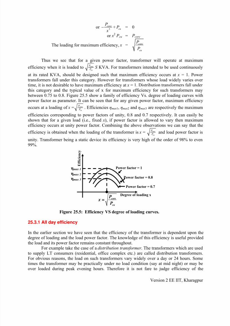
Thus we see that for a given power factor, transformer will operate at maximum
efficiency when it is loaded to core
cu
P
P S KVA. For transformers intended to be used continuously
at its rated KVA, should be designed such that maximum efficiency occurs at x = 1. Power
transformers fall under this category. However for transformers whose load widely varies over time, it is not desirable to have maximum efficiency at x = 1. Distribution transformers fall under
this category and the typical value of x for maximum efficiency for such transformers may
between 0.75 to 0.8. Figure 25.5 show a family of efficiency Vs. degree of loading curves with
power factor as parameter. It can be seen that for any given power factor, maximum efficiency
occurs at a loading of x = core
cu
P
P . Efficiencies ηmax1, ηmax2 and ηmax3 are respectively the maximum
efficiencies corresponding to power factors of unity, 0.8 and 0.7 respectively. It can easily beshown that for a given load (i.e., fixed x), if power factor is allowed to vary then maximum
efficiency occurs at unity power factor. Combining the above observations we can say that the
efficiency is obtained when the loading of the transformer is x = core
cu
P
P and load power factor is
unity. Transformer being a static device its efficiency is very high of the order of 98% to even
99%.
Power factor = 1
Power factor = 0.8
Power factor = 0.7
Degree of loading xcore
cu
Px =
P
Efficiency
ηmax 1
ηmax 2
ηmax 3
Figure 25.5: Efficiency VS degree of loading curves.
25.3.1 All day efficiency
In the earlier section we have seen that the efficiency of the transformer is dependent upon the
degree of loading and the load power factor. The knowledge of this efficiency is useful provided
the load and its power factor remains constant throughout.For example take the case of a distribution transformer . The transformers which are used
to supply LT consumers (residential, office complex etc.) are called distribution transformers.
For obvious reasons, the load on such transformers vary widely over a day or 24 hours. Sometimes the transformer may be practically under no load condition (say at mid night) or may be
over loaded during peak evening hours. Therefore it is not fare to judge efficiency of the
Version 2 EE IIT, Kharagpur

8/7/2019 25.basic
http://slidepdf.com/reader/full/25basic 10/15
transformer calculated at a particular load with a fixed power factor. All day efficiency,
alternatively called energy efficiency is calculated for such transformers to judge how efficientare they. To estimate the efficiency the whole day (24 hours) is broken up into several time
blocks over which the load remains constant. The idea is to calculate total amount of energy
output in KWH and total amount of energy input in KWH over a complete day and then take theratio of these two to get the energy efficiency or all day efficiency of the transformer. Energy or
All day efficiency of a transformer is defined as:
ηall day =Energy output in KWH in 24 hours
Energy input in KWH in 24 hours
=Energy output in KWH in 24 hours
Output in KWH in 24 hours + Energy loss in 24 hours
=Output in KWH in 24 hours
Output in KWH in 24 hours + Loss in core in 24 hours + Loss in the
Winding in 24 hours
= core
Energy output in KWH in 24 hours
Energy output in KWH in 24 hours + 24 + Energy loss (cu) in the
winding in 24 hours
P
With primary energized all the time, constant P core loss will always be present no matter what is
the degree of loading. However copper loss will have different values for different time blocks asit depends upon the degree of loadings. As pointed out earlier, if P cu is the full load copper loss
corresponding to x = 1, copper loss at any arbitrary loading x will be x2 P cu. It is better to make
the following table and then calculate ηall day.
Time blocks KVA
Loading
Degree of
loading x
P.F of load KWH output KWH cu
lossT 1 hours S 1 x1 = S 1/S cos θ 1 S 1 cos θ 1T 1 2
1P cu T 1
T 2 hours S 2 x2 = S 2/S cos θ 2 S 2 cos θ 2T 2 2
2P cu T 2
… … … … … …
T n hours S n xn = S n/S cos θ n S n cos θ nT n 2
n P cu T n
Note that1
n
i
i=
T ∑ = 24
Energy output in 24 hours =
1
n
i i
i=
S cos θ T ∑ i
Total energy loss = 2
1
24n
core i cu i
i=
P + x P T ∑
alldayη = 1
2
1 1
n
i i ii=
n n
i i i i cu i coi= i=
S cos θ T
S cos θ T + x P T + 24 P
∑∑ ∑ re
Version 2 EE IIT, Kharagpur

8/7/2019 25.basic
http://slidepdf.com/reader/full/25basic 11/15
25.4 Regulation
The output voltage in a transformer will not be maintained constant from no load to the full load
condition, for a fixed input voltage in the primary. This is because there will be internal voltage
drop in the series leakage impedance of the transformer the magnitude of which will dependupon the degree of loading as well as on the power factor of the load. The knowledge of
regulation gives us idea about change in the magnitude of the secondary voltage from no load tofull load condition at a given power factor. This can be determined experimentally by directloading of the transformer. To do this, primary is energized with rated voltage and the secondary
terminal voltage is recorded in absence of any load and also in presence of full load. Suppose the
readings of the voltmeters are respectively V 20 and V 2. Therefore change in the magnitudes of thesecondary voltage is V 20 – V 2. This change is expressed as a percentage of the no load secondary
voltage to express regulation. Lower value of regulation will ensure lesser fluctuation of the
voltage across the loads. If the transformer were ideal regulation would have been zero.
( )20 2
20
Percentage Regulation 100V -V
, % R =V
×
For a well designed transformer at full load and 0.8 power factor load percentage
regulation may lie in the range of 2 to 5%. However, it is often not possible to fully load a large
transformer in the laboratory in order to know the value of regulation. Theoretically one canestimate approximately, regulation from the equivalent circuit. For this purpose let us draw the
equivalent circuit of the transformer referred to the secondary side and neglect the effect of no
load current as shown in the figure 25.6. The corresponding phasor diagram referred to thesecondary side is shown in figure 25.7.
Approximate Equivalent Circuit referred to secondary
V20 V2 Z2
re2 xe2 S
S
I2
V20
C
D
F
O A
B
E
I2
θ2
θ2
θ2V2
δ
I2 re2
I2 xe2
Figure 25.6: Equivalent circuit ref. to
secondary.
Figure 25.7: Phasor diagram ref. to
secondary.
It may be noted that when the transformer is under no load condition (i.e., S is opened),
the terminal voltage V 2 is same as V 20. However, this two will be different when the switch is
closed due to drops in I 2 r e2 and I 2 xe2. For a loaded transformer the phasor diagram is drawntaking terminal voltage V 2 on reference. In the usual fashion I 2 is drawn lagging V 2, by the power
factor angle of the load θ 2 and the drops in the equivalent resistance and leakage reactances are
added to get the phasor V 20. Generally, the resistive drop I 2 r e2 is much smaller than the reactive
drop I 2 xe2. It is because of this the angle between OC and OA (δ) is quite small. Therefore as per the definition we can say regulation is
Version 2 EE IIT, Kharagpur

8/7/2019 25.basic
http://slidepdf.com/reader/full/25basic 12/15
( )20 2
20
V -V OC - OAR = =
V OC
An approximate expression for regulation can now be easily derived geometrically from
the phasor diagram shown in figure 25.7.
OC = OD since, δ is small
Therefore, OC – OA = OD – OA
= AD
= AE + ED
= I 2 r e2 cos θ 2 + I 2 xe2 sin θ 2
So per unit regulation, R =OC -OA
OC
= 2 2 2 2 2 2e e
20
I r cos θ +I x sin θ
V
or, R = 2 2 2 22 2
20 20
e eI r I xcos θ + sin θ
V V
It is interesting to note that the above regulation formula was obtained in terms of quantities of secondary side. It is also possible to express regulation in terms of primary
quantities as shown below:
We know, R = 2 2 2 22 2
20 20
e eI r I xcos θ + sin θ
V V
Now multiplying the numerator and denominator of the RHS by a the turns ratio, and further manipulating a bit with a in numerator we get:
R =2 2
2 2 2 22 2
20 20
( ) ( )e eI /a a r I /a a xcos θ + s θ
aV aV in
Now remembering, that 2 22 2 2 1 2( / ) , ,e e e 1e
I a I a r r a x x′= = = and 20 20 1aV V V ′= = ; we get
regulation formula in terms of primary quantity as:
R = 2 1 2 12 2
20 20
e eI r I xcos θ + sin θ V V
′ ′′ ′
Or, R = 2 1 2 12 2
1 1
e eI r I xcos θ + sin θ
V V
′ ′
Neglecting no load current: R ≈ 1 1 1 12 2
1 1
e eI r I x
cos θ + sin θ V V
Version 2 EE IIT, Kharagpur

8/7/2019 25.basic
http://slidepdf.com/reader/full/25basic 13/15
Thus regulation can be calculated using either primary side quantities or secondary side
quantities, since:
R = 2 2 2 2 1 1 1 12 2 2
20 20 1 1
e e e eI r I x I r I xcos θ + sin θ cos θ + sin θ
V V V V = 2
Now the quantity 2 2
20
eI r V , represents what fraction of the secondary no load voltage is
dropped in the equivalent winding resistance of the transformer. Similarly the quantity2 2
20
eI x
V represents what fraction of the secondary no load voltage is dropped in the equivalent
leakage reactance of the transformer. If I 2 is rated curerent, then these quantities are called the
per unit resistance and per unit leakage reactance of the transformer and denoted by ∈ r and ∈ x
respectively. The terms 2
20
rated e 2I r
r V ∈ = and 2
20
rated e 2I x
x V ∈ = are called the per unit resistance and per unit
leakage reactance respectively. Similarly, per unit leakage impedance ∈ z ,can be defined.It can be easily shown that the per unit values can also be calculated in terms of primary
quantities as well and the relations are summarised below.
2 2 1
20 1
rated e rated er
1I r I r V V
∈ = =
2 2 1
20 1
rated e rated ex
1I x I x
V V ∈ = =
2 2 1
20 1
rated e rated ez
1I z I z
V V ∈ = =
where, 2 22 2e e 2ex= +z r and 2 2
1 1e ez r x= + 1e.
It may be noted that the per unit values of resistance and leakage reactance come out tobe same irrespective of the sides from which they are calculated. So regulation can now be
expressed in a simple form in terms of per unit resistance and leakage reactance as follows.
per unit regulation, R = 2 2r xcos θ + sin θ ∈ ∈
and % regulation R = ( )2 2100r xcos θ + sin θ ∈ ∈ ×
For leading power factor load, regulation may be negative indicating that secondary
terminal voltage is more than the no load voltage. A typical plot of regulation versus power
factor for rated current is shown in figure 25.8.
HV LV LV HV HV LV LV HV
Lagging power factor
Leading power factor
% Regulation
6
4
2
-2
-
4-6
10.2 0.4 0.6 0.8 0.8 0.6 0.4 0.2
Fi
gure 25.8: Regulation VS power Figfactor curve.
ure 25.9: LV and HV windings in boththe limbs. Version 2 EE IIT, Kharagpur

8/7/2019 25.basic
http://slidepdf.com/reader/full/25basic 14/15
To keep the regulation to a prescribed limit of low value, good material (such as copper) shouldbe used to reduce resistance and the primary and secondary windings should be distributed in the
limbs in order to reduce leakage flux, hence leakage reactance. The hole LV winding is divided
into two equal parts and placed in the two limbs. Similar is the case with the HV windings asshown in figure 25.9.
25.5 Tick the correct answer
1. While carrying out OC test for a 10 kVA, 110 / 220 V, 50 Hz, single phase transformer
from LV side at rated voltage, the watt meter reading is found to be 100 W. If the sametest is carried out from the HV side at rated voltage, the watt meter reading will be
(A) 100 W (B) 50 W (C) 200 W (D) 25 W
2. A 20 kVA, 220 V / 110 V, 50 Hz single phase transformer has full load copper loss = 200
W and core loss = 112.5 W. At what kVA and load power factor the transformer should
be operated for maximum efficiency?
(A) 20 kVA & 0.8 power factor (B) 15 kVA & unity power factor
(C) 20 kVA & unity power factor (D) 15 kVA & 0.8 power factor.
3. A transformer has negligible resistance and has an equivalent per unit reactance 0.1. Its
voltage regulation on full load at 30° leading load power factor angle is:
(A) +5 % (B) -5 % (C) + 10 % (D) -10 %
4. A transformer operates most efficiently at3
4 th full load. The ratio of its iron loss and full load copper loss is given by:
(A) 16:9 (B) 4:3 (C) 3:4 (D) 9:16
5. Two identical 100 kVA transformer have 150 W iron loss and 150 W of copper loss at
rated output. Transformer-1 supplies a constant load of 80 kW at 0.8 power factor lagging
throughout 24 hours; while transformer-2 supplies 80 kW at unity power factor for 12hours and 120 kW at unity power factor for the remaining 12 hours of the day. The all
day efficiency:
(A) of transformer-1 will be higher. (B) of transformer-2 will be higher.
(B) will be same for both transformers. (D) none of the choices.
6. The current drawn on no load by a single phase transformer is i0 = 3 sin (314t - 60°) A,when a voltage v1 = 300 sin(314t )V is applied across the primary. The values of
magnetizing current and the core loss component current are respectively:
(A) 1.2 A & 1.8 A (B) 2.6 A & 1.5 A (C) 1.8 A & 1.2 A (D) 1.5 A & 2.6 A
Version 2 EE IIT, Kharagpur

8/7/2019 25.basic
http://slidepdf.com/reader/full/25basic 15/15
7. A 4 kVA, 400 / 200 V single phase transformer has 2 % equivalent resistance. The
equivalent resistance referred to the HV side in ohms will be:
(A) 0.2 (B) 0.8 (C) 1.0 (D) 0.25
8. The % resistance and the % leakage reactance of a 5 kVA, 220 V / 440 V, 50 Hz, single
phase transformer are respectively 3 % and 4 %. The voltage to be applied to the HVside, to carry out S.C test at rated current is:
(A) 11 V (B) 15.4 V (C) 22 V (D) 30.8 V
25.6 Solve the Problems
1. A 30KVA, 6000/230V, 50Hz single phase transformer has HV and LV winding
resistances of 10.2Ω and 0.0016Ω respectively. The equivalent leakage reactance as
referred to HV side is 34Ω. Find the voltage to be applied to the HV side in order tocirculate the full load current with LV side short circuited. Also estimate the full load %
regulation of the transformer at 0.8 lagging power factor.
2. A single phase transformer on open circuit condition gave the following test results:
Applied voltage Frequency Power drawn
192 V 40 Hz 39.2 W
288 V 60 Hz 73.2 W
Assuming Steinmetz exponent n = 1.6, find out the hysteresis and eddy current loss
separately if the transformer is supplied with 240 V, 50 Hz.
3. Following are the test results on a 4KVA, 200V/400V, 50Hz single phase transformer.
While no load test is carried out from the LV side, the short circuit test is carried out fromthe HV side.
No load test: 200 V 0.7 A 60 W
Short Circuit Test: 9 V 6 A 21.6 W
Draw the equivalent circuits (i) referred to LV side and then (ii) referred to HV side andinsert all the parameter values.
4. The following data were obtained from testing a 48 kVA, 4800/240V, 50 Hz transformer.
O.C test (from LV side): 240 V 2 A 120 WS.C test (from HV side): 150 V 10 A 600 W
(i) Draw the equivalent circuit referred to the HV side and insert all the parameter
values.
(ii) At what kVA the transformer should be operated for maximum efficiency? Alsocalculate the value of maximum efficiency for 0.8 lagging factor load.
Version 2 EE IIT, Kharagpur
Related Documents


