Humidification Load Calculation Manual Engineering Manual Includes What is Humidity, Affects of Relative Humidity, Calculating Relative Humidity, Requirements to Calculate Humidifier Load, and Load Calculations 2553856-A | 08 SEP 2010 When You Need Humidity!

Welcome message from author
This document is posted to help you gain knowledge. Please leave a comment to let me know what you think about it! Share it to your friends and learn new things together.
Transcript

Humidification Load Calculation Manual Engineering Manual Includes What is Humidity, Affects of Relative Humidity, Calculating Relative Humidity, Requirements to Calculate Humidifier Load, and Load Calculations
2553856-A | 08 SEP 2010
When You Need Humidity!
Thank you for choosing Nortec.
Proprietary Notice This document and the information disclosed herein are proprietary data of WALTER MEIER LTD. Neither this document nor the information contained herein shall be reproduced used, or disclosed to others without the written authorization of WALTER MEIER LTD., except to the extent required for installation or maintenance of recipient’s equipment. All references to the Nortec name should be taken as referring to WALTER MEIER LTD.
Liability Notice Nortec does not accept any liability for installations of humidity equipment installed by unqualified personnel or the use of parts/components/equipment that are not authorized or approved by Nortec.
Copyright Notice Copyright 2009, WALTER MEIER LTD. All rights reserved.

Contents
5 What is Humidity 6 Effects of Relative Humidity 6 Static Electricity
7 Moisture Stability
8 Health and Comfort
10 Calculating Relative Humidity 12 Requirements to Calculate Humidification Load 12 Design Conditions – Selecting an RH Setpoint
16 Outdoor Air Conditions
22 Load Calculations 22 Natural Ventilation
23 Mixed Air System
23 Makeup or Exhaust Air System

5 | Humidification Load Calculation
What is Humidity
If a closed container is partially filled with water, then some of the water molecules in the liquid will leave the surface of the water and become vapor. Once some water molecules are present as vapor they will also re-enter the liquid. After some time at constant temperature equilibrium will be reached where the same number of molecules are leaving and entering the liquid. At
this equilibrium point the relative humidity of the water vapor is 100%.
Figure 1: Water Vapour Equilibrium
The equilibrium point is temperature dependent. At higher temperatures the equilibrium occurs with more water vapor. If the container above was heated to 86ºF (30ºC) the water and water vapor would no longer be in equilibrium. The relative humidity of the vapor right after increasing the temperature would be 57%. This means that immediately after heating there are 57% as many water vapor molecules as would be present in the equilibrium state.
Figure 2: Relative Humidity after Heating
It is the above process that causes dry air in buildings. As cold incoming air is heated, its relative humidity value drops. Therefore moisture must be added to attain an acceptable level of humidity within the building. Load Calculations - on page 22 outlines how to calculate the amount of moisture that must be added to maintain a constant relative humidity.
Relative humidity (RH) is the percentage of water vapour present in the air relative to the amount that would be present in the equilibrium state.
Equilibrium68 ºF (100% RH
Water vapor content0.00108 lb/cu.ft
(0.0173 kg/cu.m)
20ºC)
Water
Water Vapor
=
Equilibrium68ºF (RH = 100%
0.00108 lb/cu.ft(0.0173 kg/cu.m)
20ºC)
Water
WaterVapor
=
Water
WaterVapor
>
Heat to 86ºF
(30ºC )
Not in Equilibrium86ºF (RH = 57%
0.00108 lb/cu.ft(0.0173 kg/cu.m)
30ºC)Equilibrium86ºF (RH=100%
0.00190 lb/cu.ft(0.0303 kg/cu.m)
30ºC)
Given timeand
sufficient water
Water
WaterVapor
=
Humidification Load Calculation | 6
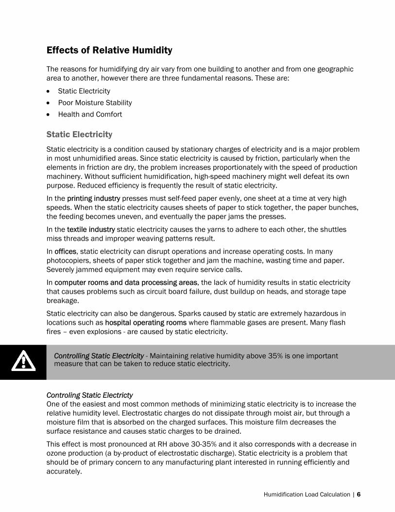
Effects of Relative Humidity
The reasons for humidifying dry air vary from one building to another and from one geographic area to another, however there are three fundamental reasons. These are:
Static Electricity
Poor Moisture Stability
Health and Comfort
Static Electricity
Static electricity is a condition caused by stationary charges of electricity and is a major problem in most unhumidified areas. Since static electricity is caused by friction, particularly when the elements in friction are dry, the problem increases proportionately with the speed of production machinery. Without sufficient humidification, high-speed machinery might well defeat its own purpose. Reduced efficiency is frequently the result of static electricity.
In the printing industry presses must self-feed paper evenly, one sheet at a time at very high speeds. When the static electricity causes sheets of paper to stick together, the paper bunches, the feeding becomes uneven, and eventually the paper jams the presses.
In the textile industry static electricity causes the yarns to adhere to each other, the shuttles miss threads and improper weaving patterns result.
In offices, static electricity can disrupt operations and increase operating costs. In many photocopiers, sheets of paper stick together and jam the machine, wasting time and paper. Severely jammed equipment may even require service calls.
In computer rooms and data processing areas, the lack of humidity results in static electricity that causes problems such as circuit board failure, dust buildup on heads, and storage tape breakage.
Static electricity can also be dangerous. Sparks caused by static are extremely hazardous in locations such as hospital operating rooms where flammable gases are present. Many flash fires – even explosions - are caused by static electricity.
Controling Static Electricty One of the easiest and most common methods of minimizing static electricity is to increase the relative humidity level. Electrostatic charges do not dissipate through moist air, but through a moisture film that is absorbed on the charged surfaces. This moisture film decreases the surface resistance and causes static charges to be drained.
This effect is most pronounced at RH above 30-35% and it also corresponds with a decrease in ozone production (a by-product of electrostatic discharge). Static electricity is a problem that should be of primary concern to any manufacturing plant interested in running efficiently and accurately.
Controlling Static Electricity - Maintaining relative humidity above 35% is one important measure that can be taken to reduce static electricity.

7 | Humidification Load Calculation
Moisture Stability
When air is heated the relative humidity will decrease. When this occurs the rate at which water molecules leave objects containing water or the rate at which water evaporates is increased. All hygroscopic or fibrous materials either lose of gain moisture in direct relation to the relative humidity of the surrounding air
Moisture stability is the ability of a material to maintain a level of moisture content despite fluctuations in the humidity of the environment. Many materials give off, or take on moisture rapidly which can result in serious damage to the material or the process in which it may be involved. The drying out of a material can result in product deterioration, while conversely, a dry material can also suffer damaging side effects of moisture regain. In many cases, product deterioration is directly related to the lack of moisture stability
Table 1 gives the hygroscopic regain of some common hygroscopic materials. Hygroscopic regain is defined as the amount of water a completely dry material will absorb from the air. It is expressed as a percent of the dry weight. (For example the weight of completely dry timber will increase by 9.3% if it is stored at an RH of 50%)
Table 1: Hygroscopic Regain of Some Common Materials
Relative Humidity - %
Industry and/or Material 10 20 30 40 50 60 70 80 90 Baking Crackers 2.1 2.8 3.3 3.9 5 6.5 8.3 10.9 14.9 Flour 2.6 4.1 5.3 6.5 8 9.9 12.4 15.4 19.1 White Bread 0.5 1.7 3.1 4.5 6.2 8.5 11.1 14.5 19 Leather - Sole Oak, Tanned 5 8.5 11.2 13.6 16 18.3 20.6 24 29.2 Printing Paper – Comm. Ledger – 75% Rag1% Ash 3.2 4.2 5 5.6 6.2 6.9 8.1 10.3 13.9 Paper M.F. Newsprint – 24% Ash 2.1 3.2 4 4.7 6.1 7.2 8.7 10.6 Paper White Bond Rag – 1% Ash 2.4 3.7 4.7 5.5 6.5 7.5 8.8 10.8 13.2 Paper Writing – 3% Ash 3 4.2 5.2 6.2 7.2 8.3 9.9 11.9 14.2 Textile Cotton – Absorbent 4.8 9 12.5 15.7 18.5 20.8 22.8 24.3 25.8 Cotton – American-cloth 2.6 3.7 4.4 5.2 5.9 6.8 8.1 10 14.3 Cotton – Sea Isle-roving 2.5 3.7 4.6 5.6 6.6 7.9 9.5 11.5 14.1 Hemp – Manila and Sisal 2.7 4.7 6 7.2 8.5 9.9 11.6 13.6 15.7 Jute – Average Grade 3.1 5.2 6.9 8.5 10.2 12.2 14.4 17.1 20.2 Linen – Dried Spun – Yarn 3.6 5.4 6.5 7.3 8.1 8.9 9.8 11.2 13.8 Rayon – Celulose – Acetate – Fibre 0.8 1.1 1.4 1.9 2.4 3 3.6 4.3 5.3 Rayon – Cupramonium – Average Skein 4 5.7 6.8 7.9 9.2 10.8 12.4 14.2 10 Rayon – Viscose Nitrocel 4 5.7 6.8 7.9 9.2 10.8 12.4 14.2 16 Silk – Raw Chevennes-Skein 3.2 5.5 6.9 8 8.9 10.2 11.9 14.3 18.8 Wool – Australian-Marino-Skein 4.7 7 8.9 10.8 12.8 14.9 17.2 19.9 23.4 Tobacco - Cigarette 5.4 8.6 11 13.3 16 19.5 25 33.5 50 Wood Timber – Average 3 4.4 5.9 7.6 9.3 11.3 14 17.5 22 Glue – Hide 3.4 4.8 5.8 6.6 7.6 9 10.7 11.8 12.5 Miscellaneous Charcoal-Steam Activated 7.1 14.3 22.8 26.2 28.3 29.2 30 31.1 32.7 Gelatin 0.7 1.6 2.8 3.8 4.9 6.1 7.6 9.3 11.4 Silica Gel 5.7 9.8 12.7 15.2 17.2 18.6 20.2 21.5 22.6 Soap 1.9 3.8 5.7 7.6 10 12.9 16.1 19.8 23.8 Starch 2.2 3.8 5.2 6.4 7.4 8.3 9.2 10.6 12.7
NOTE: Moisture content expressed in per cent of dry weight of the substance at various relative humidities – Temperature 75°F (22ºC)

Humidification Load Calculation | 8
Products such as vegetable, cut flowers, fruit and many grocery items cannot be brought back to original quality once they have lost their moisture. By installing an efficient humidification system this costly loss of products can be avoided. Many food processors humidify their plant and storage areas and are able to store fruits and vegetables for months without any loss of product quality or weigh.
For any product that requires a certain percentage of moisture to maintain its quality, loss of that moisture reduces its valve. Some products can be brought back to their original condition by returning the moisture to them. However, among those that cannot reabsorb moisture to regain their lost quality are fruit and vegetable products, paintings and art objects.
Deterioration caused by loss of moisture is also a problem for treasures such as antiques, rare books, and works of art, all of which are susceptible to damage caused by moisture loss. It causes antiques, paintings, paper and book bindings to crack, warp and deteriorate. Fortunately, most libraries and museums are well aware of the need for controlled humidity to protect their collections. They know that proper humidity control is a very inexpensive preventive measure that will avoid costly and often impossible restorations.
A specific moisture content in materials is essential to the quality of products produced by a wide range of manufacturers of hygroscopic or fibrous materials. Wood, paper and textiles are examples of materials particularly affected by changes in content. If these materials have a correct moisture content when they arrive at a plant, and if they are used immediately, they will respond properly to the manufacturing process. But problems can be anticipated if the materials are stored in a dry atmosphere.
Paper provides a good example of the effects of dry air and the lack of moisture stability. When it is stored under dry atmospheric conditions, moisture from the outer layers and edges of the stacks escapes into the air. The moisture loss is much more rapid from the outer edges than from the center of the stacks. The result is not only curled stock, but also uneven moisture content, which creates printing and processing problems.
If moisture stability in the surrounding atmosphere is the answer to a manufacturing operation, then complete humidification of the plant and storage areas is an absolute necessity. Humidification is the best and least expensive way of maintaining moisture stability. If the air surrounding the material is maintained at a proper and constant relative humidity level, so that no moisture is emitted or absorbed by the materials, then the products will remain stable in both moisture content and dimension.
Ideally, humidification equipment should be installed in raw material storage areas, manufacturing facilities, and finished goods’ storage rooms, for full control of the product moisture content.
Health and Comfort
During the heating season, inside air dries to the point where the humidity is substantially lower or comparable to that of the Sahara Desert. The effect on people is to dry out nasal and throat membranes. For employees this means more susceptibility to colds and virus infections. The subsequent increased absenteeism proves costly for any employers. Another aspect of comfort
Hygroscopic Regain – is defined as the amount of water a completely dry material will absorb from the air. . Any hygroscopic product that is purchased and sold by weight must have a carefully controlled environment.

9 | Humidification Load Calculation
is the fact that humidity in the air makes a room feel warmer, so there will be fewer requests to have the thermostat turned up.
Most employers provide air conditioning for employee comfort and productivity during the hot days of summer. Adding humidification for full winter comfort and productivity is just as important as air conditioning in the summer months. In fact, it is one of the most important functions of the complete air conditioning or “total comfort” system.
Figure 3: Optimum Humidity Range for Human Comfort and Health
The advantage of conditioning the interior space of a building to increase productivity and reduce the downtime of machinery has been documented many times. Unfortunately it is usually equipment, such as computers and communications systems, that is placed in separate climate controlled rooms, while the majority of employees have temperature control only.
Temperature control must be combined with humidity control to maintain proper comfort parameters in an office environment. More than 75% of all I.A.Q. problems start with a comfort complaint. If this is not rectified, the employees will continue to complain and become less productive.
Temperature control alone does not take into account the physiological aspects of the employees. As demonstrated in Figure 3, indoor RH variations above and below the 40-60% range have a dramatic effect on the comfort and well being of employees. Humidity conditions above this range are usually controlled easily by the normal dehumidification process of the air-conditioning system. However, as the cold, dry weather of winter approaches or in arid climates, the indoor RH can easily drop well below the recommended 40% parameter. It is not uncommon
0 10 20 30 40 50 60 70 80 90 1Percent Relative Humidity
Decrease in bar width indicates decrease in effectOptimum Zone
Bacteria
Viruses
Fungi
Mites
Respiratory*Infections
Allergic Rhinitisand Asthma
ChemicalInteractions
OzoneProcuction
*Insufficient data above 50% rh
Humidification Load Calculation | 10
to find relative humidities in the 10-15% range in most offices during this period. This low RH creates comfort, productivity, and absenteeism problems costing immeasurable dollars to employers worldwide. Studies conducted by Dr. George Green of the University of Saskatchewan indicates that increasing the indoor RH from 20 to 30% will reduce absenteeism by 15%. This, along with the productivity increase that can be gained from additional comfort result in a real economic benefit from general office humidification.
Calculating Relative Humidity
If initial temperature and relative humidity are known then Table 2 and Table 3 can be used to calculate the relative humidity after heating, cooling, or adding steam. The following two examples use Table 3 and SI units to show the method used for calculating the RH after heating or after adding steam.
Example 1: RH After Heating - What is the RH if air at 5ºC and 80% RH is heated to 30ºC?
1 Obtain moisture content of air at 5ºC and 100% RH from Table 3.
A = 0.00680 kg/cu.m
2 Multiply by starting RH to get the actual moisture content of the air.
B = 0.00680 x 80%/100% = 0.00544 kg/cu.m
3 Obtain moisture air at 30ºC and 100% RH from Table 3.
C = 0.0303 kg/cu.m
4 Divide actual moisture content by moisture content at 100% RH
D = B / C = 0.00544 / 0.0303 x 100%= 18% RH After Heating Example 2: RH after Adding Steam - What is RH if 10 kg of steam is added to 1,000 cu.m of the heated air in example 1?
1 Multiply B (the actual moisture content) by the volume to get mass of water in the air.
E = B x 1000 cu.m = 0.00544 kg/cu.m x 1000 cu.m = 5.44 kg
2 Add the amount of steam being added to the total mass of water.
F = E + 10 kg = 5.44 kg + 10 kg = 15.44 kg
3 Divide by the volume of air to kg/cu.m
G = F / 1000 cu.m = 15.44 kg /1,000 cu.m = 0.0154 kg/cu.m
4 Divide by moisture content at 100 % RH
H = G / C = 0.0154 / 0.0303 x 100% = 51% RH After Adding steam
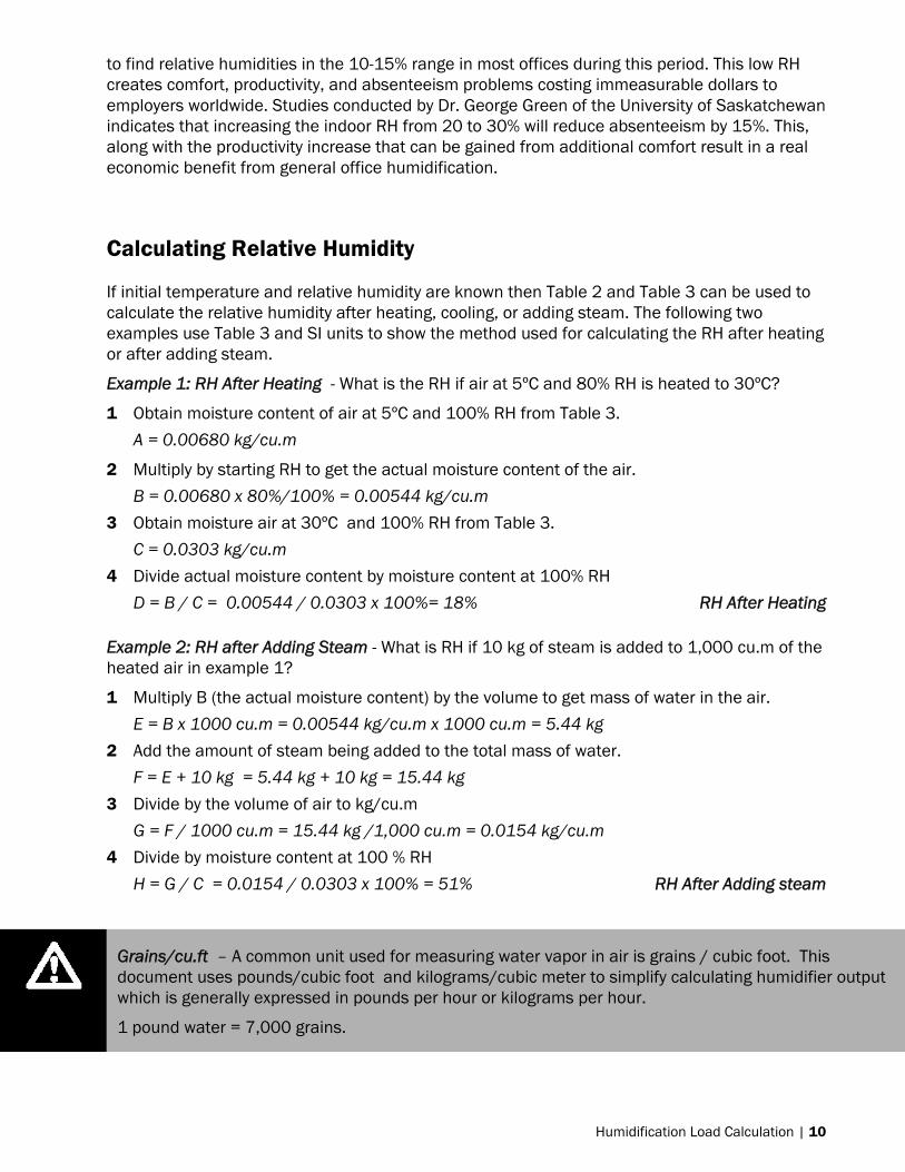
Grains/cu.ft – A common unit used for measuring water vapor in air is grains / cubic foot. This document uses pounds/cubic foot and kilograms/cubic meter to simplify calculating humidifier output which is generally expressed in pounds per hour or kilograms per hour.
1 pound water = 7,000 grains.

11 | Humidification Load Calculation
Table 2: Water Content of Air at 100% RH (IP units)
°F lb/cu.ft °F lb/cu.ft °F lb/cu.ft °F lb/cu.ft °F lb/cu.ft
-20 0.0000343 41 0.000424 61 0.000857 81 0.00163 101 0.00293 -10 0.0000414 42 0.000440 62 0.000886 82 0.00168 102 0.00302 -5 0.0000500 43 0.000457 63 0.000916 83 0.00173 103 0.00310 0 0.0000686 44 0.000474 64 0.000946 84 0.00178 104 0.00319 5 0.0000871 45 0.000491 65 0.000979 85 0.00184 105 0.00328
10 0.000111 46 0.000509 66 0.00101 86 0.00190 106 0.00337 15 0.000141 47 0.000527 67 0.00104 87 0.00195 107 0.00347 20 0.000177 48 0.000547 68 0.00108 88 0.00201 108 0.00356 25 0.000223 49 0.000567 69 0.00111 89 0.00207 109 0.00366 30 0.000279 50 0.000587 70 0.00116 90 0.00213 110 0.00376 31 0.000291 51 0.000609 71 0.00119 91 0.00220 111 0.00387 32 0.000304 52 0.000630 72 0.00123 92 0.00226 112 0.00397 33 0.000316 53 0.000651 73 0.00127 93 0.00233 113 0.00408 34 0.000327 54 0.000674 74 0.00131 94 0.00240 114 0.00419 35 0.000340 55 0.000699 75 0.00135 95 0.00247 115 0.00430 36 0.000353 56 0.000723 76 0.00139 96 0.00254 120 0.00491 37 0.000366 57 0.000747 77 0.00144 97 0.00262 125 0.00559 38 0.000380 58 0.000773 78 0.00149 98 0.00269 130 0.00634 39 0.000394 59 0.000800 79 0.00154 99 0.00277 135 0.00719 40 0.000409 60 0.000829 80 0.00158 100 0.00285 140 0.00812
Table 3: Water Content of Air at 100% RH (SI units)
°C kg/cu.m °C kg/cu.m °C kg/cu.m °C kg/cu.m °C kg/cu.m
-30 0.000578 -10 0.00218 10 0.00943 30 0.0303 50 0.0828
-29 0.000553 -9 0.00238 11 0.0100 31 0.0320 51 0.0867 -28 0.000540 -8 0.00259 12 0.0107 32 0.0337 52 0.0908 -27 0.000540 -7 0.00281 13 0.0114 33 0.0356 53 0.0951 -26 0.000551 -6 0.00305 14 0.0121 34 0.0375 54 0.0995 -25 0.000573 -5 0.00330 15 0.0129 35 0.0395 55 0.104 -24 0.000606 -4 0.00357 16 0.0137 36 0.0416 56 0.109 -23 0.000650 -3 0.00385 17 0.0145 37 0.0438 57 0.114 -22 0.000704 -2 0.00415 18 0.0154 38 0.0461 58 0.119 -21 0.000769 -1 0.00447 19 0.0163 39 0.0485 59 0.124 -20 0.000845 0 0.00481 20 0.0173 40 0.0510 60 0.130 -19 0.000931 1 0.00516 21 0.0183 41 0.0536 61 0.136 -18 0.00103 2 0.00554 22 0.0194 42 0.0563 62 0.142 -17 0.00113 3 0.00594 23 0.0206 43 0.0592 63 0.148 -16 0.00125 4 0.00636 24 0.0218 44 0.0621 64 0.154
-15 0.00138 5 0.00680 25 0.0230 45 0.0652 65 0.161
-14 0.00152 6 0.00727 26 0.0243 46 0.0685 66 0.168 -13 0.00167 7 0.00777 27 0.0257 47 0.0718 67 0.175 -12 0.00183 8 0.00829 28 0.0272 48 0.0753 68 0.182 -11 0.00200 9 0.00884 29 0.0287 49 0.0790 69 0.190

Humidification Load Calculation | 12
Requirements to Calculate Humidification Load
The humidification load calculation assumes that the humidity and temperature in the space being humidified are at the design conditions. Therefore the moisture that must be added is the amount required to bring incoming air to the design condition. Figure 4 shows a schematic of a typical air conditioning system generated by Nortec’s HELP software. The figure also shows the 3 factors that must be known to calculate humidification load.
Design Conditions – Temperature and RH that must be maintained in the humidified space.
Outdoor Air Conditions (Incoming Air) – Temperature and RH of the outdoor air.
Incoming Air Volume - The volume of outdoor air that flows into the space being humidified.
H.E.L.P. Software
The easiest way to calculate the humidification load for any application is to use Nortec’s Humidifier Engineering and Load-sizing Program (H.E.L.P.). The software can be downloaded from www.humidity.com. The software guides you through the different factors and design considerations affecting humidifier selection and provides an easy means for examining the effect of changing conditions.
Figure 4: Help Software System Schematic
Design Conditions – Selecting an RH Setpoint
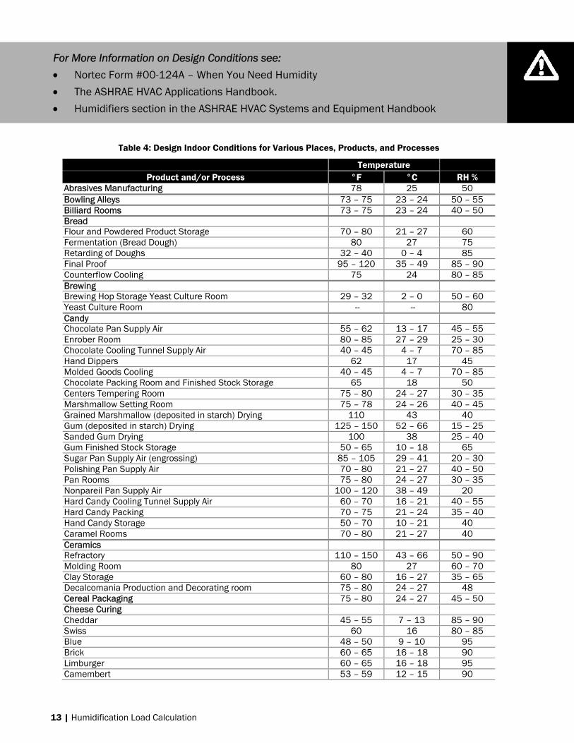
The optimum humidity setpoint depends on the reasons that a space is being humidified. Some of the most common reasons are outlined in Effects of Relative Humidity starting on page 6. The “ASHRAE Handbook – HVAC Applications” recommends specific design relative humidity levels for specific applications. Table 4 provides recommendations for temperature and humidity ranges for various purposes as taken from the ASHRAE Handbook and can be used for the purpose of load calculations.
1
2
3
3
13 | Humidification Load Calculation
Table 4: Design Indoor Conditions for Various Places, Products, and Processes
Temperature Product and/or Process °F °C RH %
Abrasives Manufacturing 78 25 50 Bowling Alleys 73 – 75 23 – 24 50 – 55 Billiard Rooms 73 – 75 23 – 24 40 – 50 Bread Flour and Powdered Product Storage 70 – 80 21 – 27 60 Fermentation (Bread Dough) 80 27 75 Retarding of Doughs 32 – 40 0 – 4 85 Final Proof 95 – 120 35 – 49 85 – 90 Counterflow Cooling 75 24 80 – 85 Brewing Brewing Hop Storage Yeast Culture Room 29 – 32 2 – 0 50 – 60 Yeast Culture Room -- -- 80 Candy Chocolate Pan Supply Air 55 – 62 13 – 17 45 – 55 Enrober Room 80 – 85 27 – 29 25 – 30 Chocolate Cooling Tunnel Supply Air 40 – 45 4 – 7 70 – 85 Hand Dippers 62 17 45 Molded Goods Cooling 40 – 45 4 – 7 70 – 85 Chocolate Packing Room and Finished Stock Storage 65 18 50 Centers Tempering Room 75 – 80 24 – 27 30 – 35 Marshmallow Setting Room 75 – 78 24 – 26 40 – 45 Grained Marshmallow (deposited in starch) Drying 110 43 40 Gum (deposited in starch) Drying 125 – 150 52 – 66 15 – 25 Sanded Gum Drying 100 38 25 – 40 Gum Finished Stock Storage 50 – 65 10 – 18 65 Sugar Pan Supply Air (engrossing) 85 – 105 29 – 41 20 – 30 Polishing Pan Supply Air 70 – 80 21 – 27 40 – 50 Pan Rooms 75 – 80 24 – 27 30 – 35 Nonpareil Pan Supply Air 100 – 120 38 – 49 20 Hard Candy Cooling Tunnel Supply Air 60 – 70 16 – 21 40 – 55 Hard Candy Packing 70 – 75 21 – 24 35 – 40 Hand Candy Storage 50 – 70 10 – 21 40 Caramel Rooms 70 – 80 21 – 27 40 Ceramics Refractory 110 – 150 43 – 66 50 – 90 Molding Room 80 27 60 – 70 Clay Storage 60 – 80 16 – 27 35 – 65 Decalcomania Production and Decorating room 75 – 80 24 – 27 48 Cereal Packaging 75 – 80 24 – 27 45 – 50 Cheese Curing Cheddar 45 – 55 7 – 13 85 – 90 Swiss 60 16 80 – 85 Blue 48 – 50 9 – 10 95 Brick 60 – 65 16 – 18 90 Limburger 60 – 65 16 – 18 95 Camembert 53 – 59 12 – 15 90
For More Information on Design Conditions see:
Nortec Form #00-124A – When You Need Humidity
The ASHRAE HVAC Applications Handbook.
Humidifiers section in the ASHRAE HVAC Systems and Equipment Handbook
Humidification Load Calculation | 14
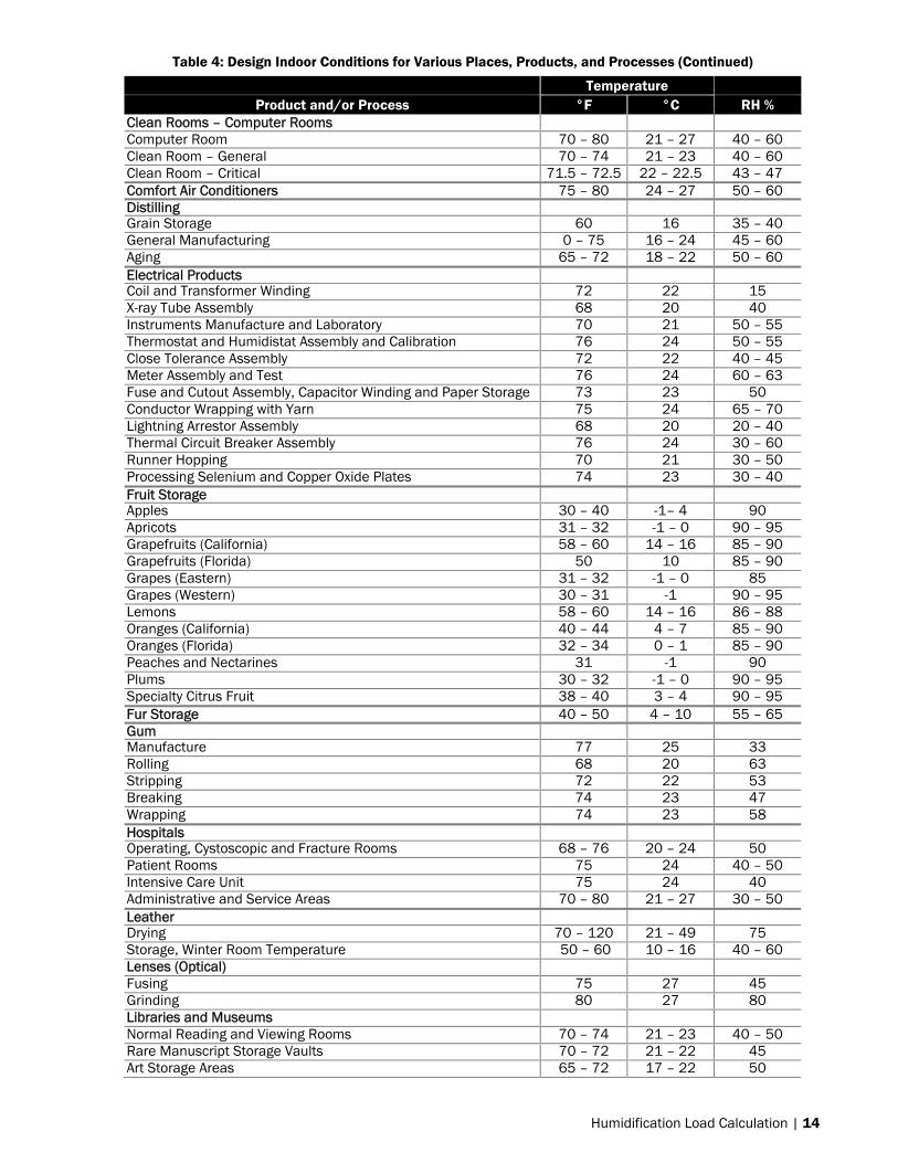
Table 4: Design Indoor Conditions for Various Places, Products, and Processes (Continued)
Temperature Product and/or Process °F °C RH %
Clean Rooms – Computer Rooms Computer Room 70 – 80 21 – 27 40 – 60 Clean Room – General 70 – 74 21 – 23 40 – 60 Clean Room – Critical 71.5 – 72.5 22 – 22.5 43 – 47 Comfort Air Conditioners 75 – 80 24 – 27 50 – 60 Distilling Grain Storage 60 16 35 – 40 General Manufacturing 0 – 75 16 – 24 45 – 60 Aging 65 – 72 18 – 22 50 – 60 Electrical Products Coil and Transformer Winding 72 22 15 X-ray Tube Assembly 68 20 40 Instruments Manufacture and Laboratory 70 21 50 – 55 Thermostat and Humidistat Assembly and Calibration 76 24 50 – 55 Close Tolerance Assembly 72 22 40 – 45 Meter Assembly and Test 76 24 60 – 63 Fuse and Cutout Assembly, Capacitor Winding and Paper Storage 73 23 50 Conductor Wrapping with Yarn 75 24 65 – 70 Lightning Arrestor Assembly 68 20 20 – 40 Thermal Circuit Breaker Assembly 76 24 30 – 60 Runner Hopping 70 21 30 – 50 Processing Selenium and Copper Oxide Plates 74 23 30 – 40 Fruit Storage Apples 30 – 40 -1– 4 90 Apricots 31 – 32 -1 – 0 90 – 95 Grapefruits (California) 58 – 60 14 – 16 85 – 90 Grapefruits (Florida) 50 10 85 – 90 Grapes (Eastern) 31 – 32 -1 – 0 85 Grapes (Western) 30 – 31 -1 90 – 95 Lemons 58 – 60 14 – 16 86 – 88 Oranges (California) 40 – 44 4 – 7 85 – 90 Oranges (Florida) 32 – 34 0 – 1 85 – 90 Peaches and Nectarines 31 -1 90 Plums 30 – 32 -1 – 0 90 – 95 Specialty Citrus Fruit 38 – 40 3 – 4 90 – 95 Fur Storage 40 – 50 4 – 10 55 – 65 Gum Manufacture 77 25 33 Rolling 68 20 63 Stripping 72 22 53 Breaking 74 23 47 Wrapping 74 23 58 Hospitals Operating, Cystoscopic and Fracture Rooms 68 – 76 20 – 24 50 Patient Rooms 75 24 40 – 50 Intensive Care Unit 75 24 40 Administrative and Service Areas 70 – 80 21 – 27 30 – 50 Leather Drying 70 – 120 21 – 49 75 Storage, Winter Room Temperature 50 – 60 10 – 16 40 – 60 Lenses (Optical) Fusing 75 27 45 Grinding 80 27 80 Libraries and Museums Normal Reading and Viewing Rooms 70 – 74 21 – 23 40 – 50 Rare Manuscript Storage Vaults 70 – 72 21 – 22 45 Art Storage Areas 65 – 72 17 – 22 50

15 | Humidification Load Calculation
Table 4: Design Indoor Conditions for Various Places, Products, and Processes (Continued)
Temperature Product and/or Process °F °C RH %
Matches Manufacture 72 – 74 22 – 23 50 Drying 70 – 75 21 – 24 60 Storage 60 – 62 16 – 17 50 Meat and Fish Beef (Fresh) 32 –34 0 – 1 88 – 92 Beef, Fish, Lamb and Pork (Frozen) -10 – 0 -23 – -18 90 – 95 Fish (Fresh) 33 – 35 1 – 3 90 – 95 Lamb and Pork (Fresh) 32 – 34 0 – 1 85 – 90 Mushrooms Sweating-out Period 120 – 140 49 – 60 – Spawn Added 60 – 75 16 – 24 Nearly Sat. Growing Period 48 – 60 9 – 16 80 Storage 32 – 35 0 – 2 80 – 85 Oil Paints: Paint Spraying 60 – 90 16 – 32 80 Pharmaceuticals Manufactured Powder Storage and Packaging Area 75 24 35 Milling Room, Table Compressing and Coating 75 24 35 Effervescent Tablets and Powders 75 24 20 Hypodermic Tablets 75 24 30 Colloids 70 21 30 – 50 Cough Drops 80 27 40 Glandular Products 76 24 5 – 10 Ampoule Manufacturing 75 24 35 – 50 Gelatin Capsules and Storage 76 24 35 Microanalysis 76 24 50 Biological Manufacturing and Liver Extracts 76 24 35 Serums 76 24 50 Animal Rooms 75 – 80 24 – 27 50 Plastics Manufacturing Areas Thermosetting 80 27 35 – 30 Molding Compounds 75 – 80 24 – 27 45 – 65 Plywood Hot Pressing (Resin) 90 32 60 Cold Pressing 90 32 15 – 25 Printing Platemaking 75 – 80 24 – 27 45 Max Lithographic Press Room 76 – 80 24 – 27 43 – 47 Letterpress and Web Offset Press Rooms and Paper Storage 76 – 80 24 – 27 50 Paper Storage (Multicolor Sheet Feed Lithography) 76 – 80 24 – 27 5 – 8 (higher
than press Room) Raw Material Storage Nuts (insect) 45 7 65 – 75 Nuts (rancidity) 34 – 38 1 – 3 65 – 75 Eggs 30 -1 85 – 90 Chocolate (flats) 65 18 50 Butter 20 -7 Dates, Figs, etc. 40 – 45 4 – 7 65 – 75 Corn Syrup 90 – 100 32 – 38 – Liquid Sugar 75 – 80 24 – 27 30 – 40 Rubber Dipped Goods Cementing 80 27 25 – 30 Dipping Surgical Articles 75 – 90 24 – 32 25 – 30 Storage Prior to Manufacture 60 – 75 16 – 24 40 – 50 Laboratory (ASTM Standard) 73.4 23 50 Tea Packaging 65 18 65
Humidification Load Calculation | 16
Table 4: Design Indoor Conditions for Various Places, Products, and Processes (Continued)
Temperature Product and/or Process °F °C RH %
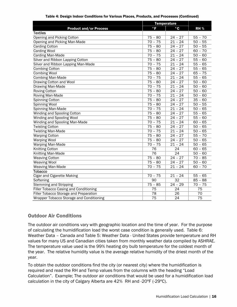
Textiles Opening and Picking Cotton 75 – 80 24 – 27 55 – 70 Opening and Picking Man-Made 70 – 75 21 – 24 50 – 55 Carding Cotton 75 – 80 24 – 27 50 – 55 Carding Wool 75 – 80 24 – 27 60 – 70 Carding Man-Made 70 – 75 21 – 24 50 – 60 Silver and Ribbon Lapping Cotton 75 – 80 24 – 27 55 – 60 Silver and Ribbon Lapping Man-Made 70 – 75 21 – 24 55 – 65 Combing Cotton 75 – 80 24 – 27 55 – 65 Combing Wool 75 – 80 24 – 27 65 – 75 Combing Man-Made 70 – 75 21 – 24 55 – 65 Drawing Cotton and Wool 75 – 80 24 – 27 50 – 60 Drawing Man-Made 70 – 75 21 – 24 50 – 60 Roving Cotton 75 – 80 24 – 27 50 – 60 Roving Man-Made 70 – 75 21 – 24 50 – 60 Spinning Cotton 75 – 80 24 – 27 35 – 60 Spinning Wool 75 – 80 24 – 27 50 – 55 Spinning Man-Made 70 – 75 21 – 24 50 – 65 Winding and Spooling Cotton 75 – 80 24 – 27 55 – 65 Winding and Spooling Wool 75 – 80 24 – 27 55 – 60 Winding and Spooling Man-Made 70 – 75 21 – 24 60 – 65 Twisting Cotton 75 – 80 24 – 27 50 – 65 Twisting Man-Made 70 – 75 21 – 24 50 – 65 Warping Cotton 75 – 80 24 – 27 55 – 70 Warping Wool 75 – 80 24 – 27 50 – 65 Warping Man-Made 70 – 75 21 – 24 50 – 65 Knitting Cotton 76 24 60 – 65 Knitting Man-Made 76 24 50 – 60 Weaving Cotton 75 – 80 24 – 27 70 – 85 Weaving Wool 75 – 80 24 – 27 50 – 60 Weaving Man-Made 70 – 75 21 – 24 60 – 70 Tobacco Cigar and Cigarette Making 70 – 75 21 – 24 55 – 65 Softening 90 32 85 – 88 Stemming and Stripping 75 – 85 24 – 29 70 – 75 Filler Tobacco Casing and Conditioning 75 24 75 Filler Tobacco Storage and Preparation 78 26 70 Wrapper Tobacco Storage and Conditioning 75 24 75
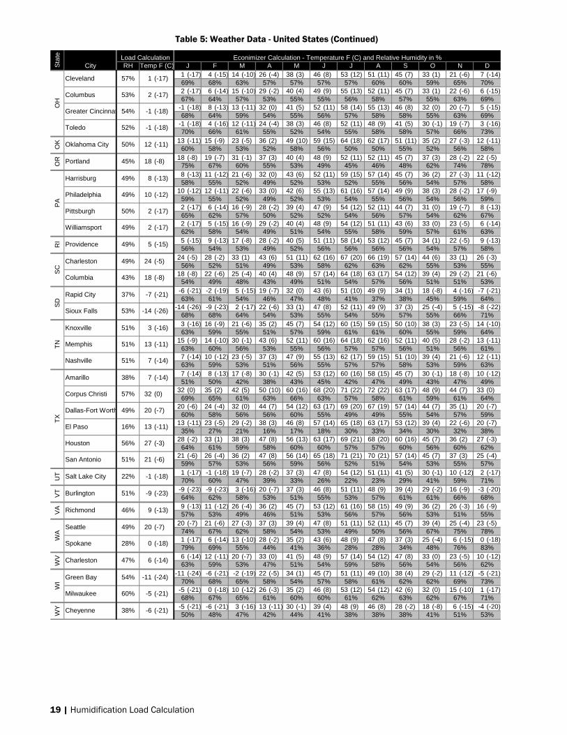
Outdoor Air Conditions
The outdoor air conditions vary with geographic location and the time of year. For the purpose of calculating the humidification load the worst case condition is generally used. Table 6: Weather Data – Canada and Table 5: Weather Data - United States provide temperature and RH values for many US and Canadian cities taken from monthly weather data compiled by ASHRAE. The temperature value used is the 99% heating dry bulb temperature for the coldest month of the year. The relative humidity value is the average relative humidity of the driest month of the year.
To obtain the outdoor conditions find the city (or nearest city) where the humidification is required and read the RH and Temp values from the columns with the heading “Load Calculation”. Example; The outdoor air conditions that would be used for a humidification load calculation in the city of Calgary Alberta are 42% RH and -20ºF (-29ºC).

17 | Humidification Load Calculation
Table 5: Weather Data - United States
Econimizer Calculation - Temperature F (C) and Relative Humidity in %City RH Temp F (C) J F M A M J J A S O N D
15 (-10) 21 (-6) 24 (-4) 40 (4) 48 (9) 56 (13) 62 (17) 62 (17) 52 (11) 41 (5) 25 (-4) 20 (-7)61% 55% 52% 51% 55% 56% 60% 59% 59% 54% 57% 60%
24 (-5) 29 (-2) 38 (3) 47 (8) 56 (13) 62 (17) 69 (20) 68 (20) 57 (14) 46 (8) 38 (3) 28 (-2)61% 56% 55% 52% 54% 55% 60% 61% 59% 53% 57% 61%
-11 (-24) -5 (-21) -1 (-18) 14 (-10) 30 (-1) 42 (6) 47 (8) 42 (6) 32 (0) 14 (-10) -1 (-18) -8 (-22)72% 67% 57% 53% 49% 56% 62% 64% 63% 66% 73% 76%
-38 (-39) -34 (-37) -23 (-31) 0 (-18) 21 (-6) 42 (6) 46 (8) 39 (4) 22 (-6) -2 (-19) -24 (-31) -36 (-38)69% 63% 53% 46% 38% 43% 50% 54% 55% 67% 73% 71%
15 (-10) 16 (-9) 29 (-2) 41 (5) 52 (11) 59 (15) 65 (18) 63 (17) 52 (11) 42 (6) 31 (0) 18 (-8)61% 59% 56% 56% 58% 55% 56% 56% 58% 53% 58% 62%
31 (0) 36 (2) 40 (5) 44 (7) 49 (10) 57 (14) 63 (17) 62 (17) 56 (13) 44 (7) 38 (4) 31 (-1)63% 50% 43% 33% 26% 23% 22% 24% 28% 33% 49% 61%
30 (-1) 34 (1) 37 (3) 42 (5) 47 (8) 54 (12) 60 (15) 58 (15) 50 (10) 41 (5) 36 (2) 30 (-1)67% 55% 47% 34% 26% 23% 22% 25% 28% 35% 53% 68%
37 (3) 43 (6) 44 (7) 48 (9) 52 (11) 56 (13) 58 (14) 60 (15) 57 (14) 52 (11) 45 (7) 42 (6)59% 63% 65% 64% 66% 67% 68% 69% 67% 65% 61% 59%
32 (0) 34 (1) 37 (3) 41 (5) 45 (7) 50 (10) 55 (13) 56 (13) 51 (11) 45 (7) 37 (3) 30 (-1)70% 60% 54% 43% 35% 31% 28% 29% 31% 38% 57% 70%
41 (5) 45 (7) 48 (9) 50 (10) 56 (13) 58 (15) 62 (17) 64 (18) 60 (16) 54 (12) 48 (9) 43 (6)56% 59% 60% 59% 64% 67% 66% 67% 65% 64% 61% 58%
35 (2) 37 (3) 40 (4) 41 (5) 45 (7) 49 (9) 50 (10) 51 (10) 49 (9) 45 (7) 38 (3) 33 (1)66% 65% 63% 59% 59% 58% 59% 61% 59% 59% 63% 67%
-2 (-19) -3 (-19) 9 (-13) 18 (-8) 35 (2) 43 (6) 53 (12) 51 (11) 34 (1) 22 (-6) 11 (-12) -2 (-19)49% 44% 40% 35% 38% 35% 34% 35% 34% 35% 49% 52%
-2 (-19) 5 (-15) 20 (-7) 27 (-3) 39 (4) 48 (9) 56 (13) 55 (13) 43 (6) 32 (0) 16 (-9) 3 (-16)64% 48% 36% 28% 25% 19% 22% 24% 26% 33% 47% 60%
-5 (-21) -4 (-20) 5 (-15) 21 (-6) 37 (3) 48 (9) 55 (13) 52 (11) 41 (5) 23 (-5) 6 (-15) -3 (-19)51% 38% 34% 30% 32% 28% 32% 35% 32% 33% 47% 52%9 (-13) 11 (-12) 19 (-7) 31 (-1) 43 (6) 52 (11) 59 (15) 57 (14) 49 (9) 39 (4) 29 (-2) 14 (-10)60% 58% 56% 54% 60% 61% 61% 62% 62% 59% 61% 61%6 (-14) 11 (-11) 20 (-7) 32 (0) 43 (6) 53 (12) 60 (15) 56 (14) 49 (10) 37 (3) 28 (-3) 12 (-11)60% 57% 52% 50% 53% 53% 54% 57% 56% 54% 56% 60%
13 (-11) 19 (-7) 26 (-3) 37 (3) 47 (9) 59 (15) 65 (18) 62 (16) 53 (12) 42 (5) 31 (-1) 18 (-8)55% 52% 50% 49% 52% 52% 53% 55% 56% 53% 54% 57%
26 (-3) 33 (1) 38 (3) 46 (8) 56 (13) 60 (16) 68 (20) 69 (21) 61 (16) 50 (10) 38 (3) 29 (-2)58% 53% 50% 48% 50% 57% 58% 60% 62% 59% 56% 58%
47 (8) 48 (9) 50 (10) 59 (15) 65 (18) 70 (21) 75 (24) 74 (24) 74 (23) 64 (18) 55 (13) 48 (9)59% 57% 56% 54% 59% 65% 63% 64% 66% 63% 62% 59%
14 (-10) 22 (-6) 28 (-2) 40 (5) 50 (10) 58 (15) 63 (17) 64 (18) 52 (11) 42 (6) 25 (-4) 20 (-7)59% 54% 51% 49% 53% 56% 60% 60% 59% 53% 55% 58%
18 (-8) 24 (-5) 29 (-2) 39 (4) 48 (9) 58 (15) 64 (18) 64 (18) 52 (11) 38 (3) 30 (-1) 22 (-6)54% 49% 48% 45% 49% 51% 54% 57% 55% 49% 50% 53%
23 (-5) 30 (-1) 36 (2) 45 (7) 53 (12) 62 (17) 69 (20) 67 (19) 57 (14) 44 (7) 34 (1) 27 (-3)55% 50% 48% 46% 51% 55% 57% 60% 60% 53% 52% 54%
61 (16) 61 (16) 63 (17) 65 (18) 67 (20) 71 (21) 72 (22) 73 (23) 72 (22) 69 (20) 66 (19) 63 (17)61% 59% 57% 55% 53% 52% 51% 52% 52% 55% 58% 60%4 (-15) 8 (-13) 21 (-6) 30 (-1) 35 (2) 44 (6) 48 (9) 47 (9) 38 (3) 27 (-3) 16 (-9) 1 (-17)70% 60% 45% 36% 34% 30% 22% 23% 29% 39% 60% 71%5 (-15) 10 (-12) 20 (-6) 32 (0) 37 (3) 46 (8) 52 (11) 52 (11) 41 (5) 31 (-1) 18 (-8) 5 (-15)70% 61% 49% 42% 39% 36% 25% 25% 31% 48% 68% 73%
-5 (-21) 2 (-17) 12 (-11) 25 (-4) 38 (3) 49 (9) 53 (12) 53 (12) 43 (6) 32 (0) 18 (-8) -1 (-18)67% 65% 61% 55% 54% 55% 57% 57% 57% 56% 64% 70%
-4 (-20) 2 (-17) 12 (-11) 29 (-1) 40 (4) 52 (11) 58 (15) 54 (12) 43 (6) 33 (1) 17 (-8) 0 (-18)69% 67% 63% 56% 56% 56% 59% 60% 59% 57% 67% 72%
-1 (-18) 1 (-17) 12 (-11) 33 (0) 42 (6) 53 (12) 59 (15) 55 (13) 46 (8) 33 (0) 18 (-8) 2 (-16)68% 68% 64% 56% 54% 54% 58% 60% 56% 54% 65% 72%
-1 (-19) 2 (-17) 11 (-11) 25 (-4) 40 (4) 51 (10) 56 (13) 51 (11) 44 (6) 33 (0) 18 (-8) 4 (-16)71% 69% 64% 57% 54% 54% 56% 58% 58% 58% 68% 74%0 (-18) 2 (-17) 14 (-10) 31 (-1) 42 (5) 51 (11) 57 (14) 54 (12) 44 (7) 32 (0) 18 (-8) 2 (-17)70% 67% 62% 56% 56% 56% 60% 61% 58% 57% 67% 72%
-1 (-18) 3 (-16) 10 (-12) 27 (-3) 38 (4) 49 (9) 56 (13) 53 (11) 43 (6) 33 (1) 15 (-9) 5 (-15)72% 69% 62% 57% 54% 55% 57% 59% 60% 60% 69% 76%
-5 (-20) 0 (-18) 5 (-15) 27 (-3) 43 (6) 52 (11) 59 (15) 54 (12) 42 (6) 30 (-1) 15 (-9) -1 (-18)67% 65% 61% 55% 55% 56% 58% 58% 59% 55% 64% 69%
-7 (-22) -4 (-20) 4 (-16) 20 (-7) 40 (4) 51 (10) 55 (13) 52 (11) 40 (4) 28 (-2) 11 (-12) -4 (-20)68% 67% 63% 52% 54% 57% 59% 61% 58% 54% 64% 71%
AR
CA
Sta
te Load CalculationC
OC
TA
LA
K
Birmingham 51% 15 (-10)
Anchorage 49% -11 (-24)
Mobile 52% 24
Bakersfield 22% 31 (-1)
Fresno 22% 30 (-1)
Los Angeles 59% 37 (3)
Sacramento 28% 30 (-1)
San Diego 56% 41 (5)
Denver 34% -3 (-19)
Grand Junction 19% -2 (-19)
Jacksonville 48% 26 (-3)
Atlanta 49% 14 (-10)
Augusta 45% 18 (-8)
Boise 22% 1 (-17)
Chicago 54% -5 (-21)
Peoria 56% -4 (-20)
Fort Wayne 54% -1 (-19)
Indianapolis 56% 0 (-18)
Des Moines 55% -5 (-20)
(-5)
Little Rock 53% 15 (-10)
Fairbanks 38% -38 (-39)
San Francisco 58% 33 (1)
Pueblo 28% -5 (-21)
Bridgeport 54% 9 (-13)
Wilmington 50% 6 (-14)
Washington 49% 13 (-11)
Miami 54% 47 (8)
Savannah 46% 23 (-5)
Honolulu 51% 61 (16)
Lewiston 25% 5 (-15)
Springfield 54% -1 (-18)
South bend 54% -1 (-18)
Sioux city 52% -7 (-22)
DE
DC
FL
GA
HI
IDIL
INIA

Humidification Load Calculation | 18
Table 5: Weather Data - United States (Continued)
Econimizer Calculation - Temperature F (C) and Relative Humidity in %City RH Temp F (C) J F M A M J J A S O N D
5 (-15) 6 (-15) 10 (-12) 30 (-1) 41 (5) 53 (12) 59 (15) 58 (15) 45 (7) 31 (0) 18 (-8) 2 (-17)58% 56% 50% 46% 51% 48% 44% 47% 48% 46% 53% 58%0 (-18) 1 (-17) 15 (-10) 28 (-2) 42 (5) 55 (13) 57 (14) 55 (13) 44 (7) 33 (1) 19 (-7) 0 (-18)64% 62% 57% 55% 58% 60% 59% 58% 57% 54% 61% 65%4 (-16) 6 (-15) 20 (-7) 36 (2) 45 (7) 54 (12) 61 (16) 58 (14) 48 (9) 36 (2) 20 (-7) 9 (-13)64% 61% 57% 52% 55% 56% 58% 58% 59% 55% 61% 65%
30 (-1) 34 (1) 40 (5) 47 (8) 55 (13) 62 (17) 69 (20) 68 (20) 58 (14) 49 (9) 40 (4) 30 (-1)66% 63% 60% 59% 60% 63% 66% 66% 65% 59% 61% 66%
21 (-6) 27 (-3) 35 (2) 45 (7) 54 (12) 63 (17) 67 (20) 64 (18) 56 (13) 43 (6) 33 (0) 23 (-5)63% 59% 56% 57% 59% 58% 57% 55% 57% 54% 58% 62%
-5 (-21) -11 (-24) 4 (-16) 23 (-5) 35 (2) 45 (7) 51 (11) 47 (8) 38 (3) 29 (-2) 19 (-7) 0 (-18)60% 58% 57% 55% 58% 60% 59% 59% 60% 59% 62% 61%
10 (-12) 13 (-10) 22 (-6) 33 (1) 44 (7) 53 (12) 60 (16) 57 (14) 49 (9) 37 (3) 27 (-3) 16 (-9)57% 54% 51% 49% 52% 52% 53% 55% 55% 54% 55% 58%7 (-14) 12 (-11) 21 (-6) 30 (-1) 44 (7) 54 (12) 60 (15) 58 (14) 49 (10) 39 (4) 29 (-2) 12 (-11)57% 56% 57% 55% 59% 58% 57% 59% 60% 58% 59% 59%
-1 (-18) 3 (-16) 14 (-10) 25 (-4) 38 (3) 48 (9) 53 (12) 51 (10) 43 (6) 31 (-1) 23 (-5) 8 (-14)69% 65% 61% 55% 53% 54% 54% 56% 57% 57% 65% 71%
-1 (-18) 0 (-18) 11 (-12) 21 (-6) 36 (2) 46 (8) 53 (12) 51 (10) 40 (5) 31 (-1) 20 (-7) 3 (-16)72% 68% 64% 57% 53% 55% 56% 58% 61% 62% 70% 75%
-19 (-28) -13 (-25) -5 (-20) 14 (-10) 30 (-1) 40 (4) 47 (8) 45 (7) 35 (2) 24 (-5) 1 (-17) -13 (-25)70% 65% 63% 56% 53% 60% 59% 63% 64% 62% 70% 74%
-14 (-25) -7 (-22) -3 (-19) 21 (-6) 35 (2) 48 (9) 55 (13) 52 (11) 40 (5) 29 (-2) 6 (-14) -7 (-22)67% 65% 61% 52% 52% 54% 54% 57% 59% 58% 66% 70%
19 (-7) 25 (-4) 32 (0) 41 (5) 51 (11) 59 (15) 63 (17) 64 (18) 51 (11) 40 (5) 32 (0) 22 (-6)65% 60% 56% 54% 56% 56% 59% 58% 58% 53% 57% 63%2 (-17) 3 (-16) 13 (-10) 30 (-1) 44 (7) 55 (13) 62 (17) 56 (14) 47 (8) 33 (1) 19 (-7) 1 (-17)64% 64% 59% 56% 59% 59% 58% 59% 59% 55% 62% 65%3 (-16) 10 (-12) 17 (-8) 36 (2) 46 (8) 56 (14) 63 (17) 59 (15) 50 (10) 38 (3) 21 (-6) 7 (-14)66% 63% 59% 54% 55% 55% 56% 56% 58% 55% 63% 68%
-6 (-21) -7 (-22) 5 (-15) 17 (-9) 31 (-1) 44 (7) 52 (11) 48 (9) 36 (2) 17 (-8) 4 (-16) -6 (-21)56% 51% 46% 41% 42% 39% 31% 30% 37% 41% 53% 56%
-11 (-24) -7 (-22) -1 (-18) 15 (-9) 30 (-1) 42 (5) 49 (9) 43 (6) 34 (1) 14 (-10) 2 (-17) -12 (-25)60% 54% 49% 41% 41% 40% 31% 31% 38% 43% 55% 60%
-5 (-21) -2 (-19) 3 (-16) 22 (-5) 34 (1) 44 (6) 52 (11) 48 (9) 34 (1) 24 (-5) 6 (-14) -9 (-23)63% 59% 53% 47% 51% 52% 50% 51% 48% 46% 55% 61%
-4 (-20) 0 (-18) 8 (-13) 24 (-4) 41 (5) 51 (11) 57 (14) 55 (13) 41 (5) 29 (-2) 12 (-11) -2 (-19)65% 63% 57% 52% 54% 55% 58% 59% 59% 55% 62% 67%
23 (-5) 29 (-1) 35 (2) 43 (6) 52 (11) 61 (16) 70 (21) 67 (20) 58 (15) 42 (6) 34 (1) 24 (-4)31% 27% 22% 16% 14% 11% 15% 17% 17% 19% 26% 32%4 (-15) 6 (-14) 16 (-9) 25 (-4) 31 (-1) 38 (3) 44 (7) 39 (4) 33 (0) 22 (-5) 16 (-9) 4 (-16)51% 40% 33% 27% 25% 22% 18% 19% 21% 27% 41% 51%
-11 (-24) -11 (-24) 5 (-15) 22 (-6) 33 (1) 43 (6) 48 (9) 44 (7) 36 (2) 24 (-4) 13 (-11) -2 (-19)58% 55% 52% 47% 47% 52% 51% 53% 55% 53% 59% 61%8 (-14) 8 (-13) 20 (-7) 28 (-2) 39 (4) 50 (10) 55 (13) 54 (12) 46 (8) 34 (1) 25 (-4) 12 (-11)58% 56% 54% 52% 56% 56% 57% 58% 58% 56% 58% 58%
10 (-12) 11 (-12) 22 (-6) 31 (0) 45 (7) 55 (13) 62 (17) 58 (15) 49 (10) 40 (5) 29 (-2) 16 (-9)58% 54% 51% 48% 51% 51% 51% 53% 55% 53% 56% 59%4 (-15) 13 (-11) 22 (-6) 31 (0) 40 (5) 51 (11) 60 (16) 58 (15) 48 (9) 34 (1) 14 (-10) 10 (-12)41% 33% 25% 19% 19% 18% 27% 31% 30% 29% 36% 44%
-7 (-21) -2 (-19) 4 (-16) 25 (-4) 38 (3) 47 (9) 52 (11) 48 (9) 39 (4) 29 (-2) 20 (-7) 0 (-18)63% 58% 53% 49% 52% 56% 55% 58% 59% 57% 62% 65%3 (-16) 1 (-17) 11 (-11) 26 (-3) 39 (4) 48 (9) 54 (12) 51 (11) 45 (7) 33 (1) 23 (-5) 8 (-13)72% 70% 65% 58% 55% 56% 55% 58% 60% 60% 69% 73%
13 (-10) 14 (-10) 23 (-5) 33 (1) 45 (7) 55 (13) 64 (18) 59 (15) 52 (11) 39 (4) 32 (0) 18 (-8)59% 57% 56% 55% 59% 60% 59% 60% 60% 56% 59% 60%2 (-17) 1 (-17) 12 (-11) 26 (-3) 38 (3) 47 (8) 53 (12) 49 (9) 42 (5) 33 (0) 21 (-6) 5 (-15)69% 67% 62% 56% 54% 55% 54% 58% 61% 61% 68% 72%
-4 (-20) -3 (-20) 7 (-14) 24 (-4) 38 (3) 46 (8) 54 (12) 51 (10) 42 (5) 32 (0) 21 (-6) 2 (-17)68% 65% 60% 53% 55% 56% 56% 59% 62% 61% 67% 71%6 (-14) 15 (-10) 21 (-6) 34 (1) 41 (5) 49 (9) 55 (13) 54 (12) 45 (7) 34 (1) 24 (-5) 13 (-11)59% 55% 53% 50% 57% 59% 62% 63% 63% 56% 57% 59%
12 (-11) 20 (-7) 27 (-3) 37 (3) 45 (7) 53 (12) 60 (16) 59 (15) 51 (11) 36 (2) 27 (-3) 20 (-7)55% 52% 49% 45% 54% 56% 58% 60% 58% 53% 52% 55%
-21 (-29) -15 (-26) -5 (-20) 12 (-11) 31 (-1) 43 (6) 48 (9) 45 (7) 29 (-2) 13 (-10) -4 (-20) -18 (-28)68% 68% 62% 51% 48% 52% 47% 46% 50% 51% 65% 71%
Dodge City 44% 2 (-17)
Louisville 52% 4 (-16)
New Orleans 59% 30 (-1)
Portland 55% -11 (-24)
Baltimore 49% 10 (-12)
Detroit 53% -1 (-18)
Duluth 53% -19 (-28)
Kansas City 55% 1 (-17)
Billings 30% -7 (-22)
North Platte 46% -9 (-23)
Las Vegas 11% 23 (-5)
Atlantic City 52% 8 (-14)
Albany 49% -7 (-21)
Buffalo 55% 1 (-17)
New York 55% 13 (-10)
Rochester 54% 1 (-17)
Asheville 50% 6 (-14)
Bismarck 46% -21 (-29)
Topeka 54% 0 (-18)
Shreveport 54% 21 (-6)
Boston 55% 7 (-14)
Grand Rapids 53% -1 (-18)
Minneapolis-St.Pa 52% -14 (-25)
KS
KY
LAS
tate
ME
MD
MA
MI
MN
MS
MO
MT
NE
NV
NH
NJ
NM
NY
NC
ND
Jackson 53% 19 (-7)
St. Louis 54% 3 (-16)
Great Falls 31% -12 (-25)
Omaha 52% -4 (-20)
Reno 18% 4 (-16)
Concord 47% -11 (-24)
Newark 48% 10 (-12)
Albuquerque 18% 4 (-15)
Syracuse 53% -4 (-20)
Raleigh 45% 12 (-11)
Load Calculation
19 | Humidification Load Calculation
Table 5: Weather Data - United States (Continued)
Econimizer Calculation - Temperature F (C) and Relative Humidity in %City RH Temp F (C) J F M A M J J A S O N D
1 (-17) 4 (-15) 14 (-10) 26 (-4) 38 (3) 46 (8) 53 (12) 51 (11) 45 (7) 33 (1) 21 (-6) 7 (-14)69% 68% 63% 57% 57% 57% 57% 60% 60% 59% 65% 70%2 (-17) 6 (-14) 15 (-10) 29 (-2) 40 (4) 49 (9) 55 (13) 52 (11) 45 (7) 33 (1) 22 (-6) 6 (-15)67% 64% 57% 53% 55% 55% 56% 58% 57% 55% 63% 69%
-1 (-18) 8 (-13) 13 (-11) 32 (0) 41 (5) 52 (11) 58 (14) 55 (13) 46 (8) 32 (0) 20 (-7) 5 (-15)68% 64% 59% 54% 55% 56% 57% 58% 58% 55% 63% 69%
-1 (-18) 4 (-16) 12 (-11) 24 (-4) 38 (3) 46 (8) 52 (11) 48 (9) 41 (5) 30 (-1) 19 (-7) 3 (-16)70% 66% 61% 55% 52% 54% 55% 58% 58% 57% 66% 73%
13 (-11) 15 (-9) 23 (-5) 36 (2) 49 (10) 59 (15) 64 (18) 62 (17) 51 (11) 35 (2) 27 (-3) 12 (-11)60% 58% 53% 52% 58% 56% 50% 50% 55% 52% 56% 58%
18 (-8) 19 (-7) 31 (-1) 37 (3) 40 (4) 48 (9) 52 (11) 52 (11) 45 (7) 37 (3) 28 (-2) 22 (-5)75% 67% 60% 55% 53% 49% 45% 46% 48% 62% 74% 78%8 (-13) 11 (-12) 21 (-6) 32 (0) 43 (6) 52 (11) 59 (15) 57 (14) 45 (7) 36 (2) 27 (-3) 11 (-12)58% 55% 52% 49% 52% 53% 52% 55% 56% 54% 57% 58%
10 (-12) 12 (-11) 22 (-6) 33 (0) 42 (6) 55 (13) 61 (16) 57 (14) 49 (9) 38 (3) 28 (-2) 17 (-9)59% 55% 52% 49% 52% 53% 54% 55% 56% 54% 56% 59%2 (-17) 6 (-14) 16 (-9) 28 (-2) 39 (4) 47 (9) 54 (12) 52 (11) 44 (7) 31 (0) 19 (-7) 8 (-13)65% 62% 57% 50% 52% 52% 54% 56% 57% 54% 62% 67%2 (-17) 5 (-15) 16 (-9) 29 (-2) 40 (4) 48 (9) 54 (12) 51 (11) 43 (6) 33 (0) 23 (-5) 6 (-14)62% 58% 54% 49% 51% 54% 55% 58% 59% 57% 61% 63%5 (-15) 9 (-13) 17 (-8) 28 (-2) 40 (5) 51 (11) 58 (14) 53 (12) 45 (7) 34 (1) 22 (-5) 9 (-13)56% 54% 53% 49% 52% 56% 56% 56% 56% 54% 57% 58%
24 (-5) 28 (-2) 33 (1) 43 (6) 51 (11) 62 (16) 67 (20) 66 (19) 57 (14) 44 (6) 33 (1) 26 (-3)56% 52% 51% 49% 53% 58% 62% 63% 62% 55% 53% 55%
18 (-8) 22 (-6) 25 (-4) 40 (4) 48 (9) 57 (14) 64 (18) 63 (17) 54 (12) 39 (4) 29 (-2) 21 (-6)54% 49% 48% 43% 49% 51% 54% 57% 56% 51% 51% 53%
-6 (-21) -2 (-19) 5 (-15) 19 (-7) 32 (0) 43 (6) 51 (10) 49 (9) 34 (1) 18 (-8) 4 (-16) -7 (-21)63% 61% 54% 46% 47% 48% 41% 37% 38% 45% 59% 64%
-14 (-26) -9 (-23) 2 (-17) 22 (-6) 33 (1) 47 (8) 52 (11) 49 (9) 37 (3) 25 (-4) 5 (-15) -8 (-22)68% 68% 64% 54% 53% 55% 54% 55% 57% 55% 66% 71%3 (-16) 16 (-9) 21 (-6) 35 (2) 45 (7) 54 (12) 60 (15) 59 (15) 50 (10) 38 (3) 23 (-5) 14 (-10)63% 59% 55% 51% 57% 59% 61% 61% 60% 55% 59% 64%
15 (-9) 14 (-10) 30 (-1) 43 (6) 52 (11) 60 (16) 64 (18) 62 (16) 52 (11) 40 (5) 28 (-2) 13 (-11)63% 60% 56% 53% 55% 56% 57% 57% 56% 51% 56% 61%7 (-14) 10 (-12) 23 (-5) 37 (3) 47 (9) 55 (13) 62 (17) 59 (15) 51 (10) 39 (4) 21 (-6) 12 (-11)63% 59% 53% 51% 56% 55% 57% 57% 58% 53% 59% 63%7 (-14) 8 (-13) 17 (-8) 30 (-1) 42 (5) 53 (12) 60 (16) 58 (15) 45 (7) 30 (-1) 18 (-8) 10 (-12)51% 50% 42% 38% 43% 45% 42% 47% 49% 43% 47% 49%
32 (0) 35 (2) 42 (5) 50 (10) 60 (16) 68 (20) 71 (22) 72 (22) 63 (17) 48 (9) 44 (7) 33 (0)69% 65% 61% 63% 66% 63% 57% 58% 61% 59% 61% 64%
20 (-6) 24 (-4) 32 (0) 44 (7) 54 (12) 63 (17) 69 (20) 67 (19) 57 (14) 44 (7) 35 (1) 20 (-7)60% 58% 56% 56% 60% 55% 49% 49% 55% 54% 57% 59%
13 (-11) 23 (-5) 29 (-2) 38 (3) 46 (8) 57 (14) 65 (18) 63 (17) 53 (12) 39 (4) 22 (-6) 20 (-7)35% 27% 21% 16% 17% 18% 30% 33% 34% 30% 32% 38%
28 (-2) 33 (1) 38 (3) 47 (8) 56 (13) 63 (17) 69 (21) 68 (20) 60 (16) 45 (7) 36 (2) 27 (-3)64% 61% 59% 58% 60% 60% 57% 57% 60% 56% 60% 62%
21 (-6) 26 (-4) 36 (2) 47 (8) 56 (14) 65 (18) 71 (21) 70 (21) 57 (14) 45 (7) 37 (3) 25 (-4)59% 57% 53% 56% 59% 56% 52% 51% 54% 53% 55% 57%1 (-17) -1 (-18) 19 (-7) 28 (-2) 37 (3) 47 (8) 54 (12) 51 (11) 41 (5) 30 (-1) 10 (-12) 2 (-17)70% 60% 47% 39% 33% 26% 22% 23% 29% 41% 59% 71%
-9 (-23) -9 (-23) 3 (-16) 20 (-7) 37 (3) 46 (8) 51 (11) 48 (9) 39 (4) 29 (-2) 16 (-9) -3 (-20)64% 62% 58% 53% 51% 55% 53% 57% 61% 61% 66% 68%9 (-13) 11 (-12) 26 (-4) 36 (2) 45 (7) 53 (12) 61 (16) 58 (15) 49 (9) 36 (2) 26 (-3) 16 (-9)57% 53% 49% 46% 51% 53% 56% 57% 56% 53% 51% 55%
20 (-7) 21 (-6) 27 (-3) 37 (3) 39 (4) 47 (8) 51 (11) 52 (11) 45 (7) 39 (4) 25 (-4) 23 (-5)74% 67% 62% 58% 54% 53% 49% 50% 56% 67% 75% 78%1 (-17) 6 (-14) 13 (-10) 28 (-2) 35 (2) 43 (6) 48 (9) 47 (8) 37 (3) 25 (-4) 6 (-15) 0 (-18)79% 69% 55% 44% 41% 36% 28% 28% 34% 48% 76% 83%6 (-14) 12 (-11) 20 (-7) 33 (0) 41 (5) 48 (9) 57 (14) 54 (12) 47 (8) 33 (0) 23 (-5) 10 (-12)63% 59% 53% 47% 51% 54% 59% 58% 56% 54% 56% 62%
-11 (-24) -6 (-21) -2 (-19) 22 (-5) 34 (1) 45 (7) 51 (11) 49 (10) 38 (4) 29 (-2) 11 (-12) -5 (-21)70% 68% 65% 58% 54% 57% 58% 61% 62% 62% 69% 73%
-5 (-21) 0 (-18) 10 (-12) 26 (-3) 35 (2) 46 (8) 53 (12) 54 (12) 42 (6) 32 (0) 15 (-10) 1 (-17)68% 67% 65% 61% 60% 60% 61% 62% 63% 62% 67% 71%
-5 (-21) -6 (-21) 3 (-16) 13 (-11) 30 (-1) 39 (4) 48 (9) 46 (8) 28 (-2) 18 (-8) 6 (-15) -4 (-20)50% 48% 47% 42% 44% 41% 38% 38% 38% 41% 51% 53%
Cleveland 57% 1 (-17)
Columbus 53% 2 (-17)
Greater Cincinnat 54% -1 (-18)
Harrisburg 49% 8 (-13)
Philadelphia 49% 10 (-12)
Pittsburgh 50% 2 (-17)
Charleston 49% 24 (-5)
Rapid City 37% -7 (-21)
Knoxville 51% 3 (-16)
Memphis 51% 13 (-11)
Amarillo 38% 7 (-14)
Corpus Christi 57% 32 (0)
Dallas-Fort Worth 49% 20 (-7)
El Paso 16% 13 (-11)
Houston 56% 27 (-3)
Seattle 49% 20 (-7)
OH
OK
OR
PA
RI
SC
SD
TN
TX
UT
VT
VA
WA
WV
WI
WY
Toledo 52% -1 (-18)
Oklahoma City 50% 12 (-11)
Portland 45% 18 (-8)
Williamsport 49% 2 (-17)
Providence 49% 5 (-15)
Columbia 43% 18 (-8)
Sioux Falls 53% -14 (-26)
Nashville 51% 7 (-14)
San Antonio 51% 21 (-6)
Salt Lake City 22% -1 (-18)
Burlington 51% -9 (-23)
Richmond 46% 9 (-13)
Spokane 28% 0 (-18)
(-21)
Charleston 47% 6 (-14)
Green Bay 54% -11 (-24)
Sta
te Load Calculation
Cheyenne 38% -6 (-21)
Milwaukee 60% -5

Humidification Load Calculation | 20
Table 6: Weather Data – Canada
Econimizer Calculation - Temperature F (C) and Relative Humidity in %City RH Temp F (C) M J J A S O N D
-20 (-29) -18 (-28) -7 (-22) 5 (-15) 22 (-6) 38 (3) 42 (6) 40 (4) 25 (-4) 10 (-12) -6 (-21) -17 (-27)59% 57% 55% 43% 42% 44% 44% 43% 45% 43% 56% 60%
-21 (-30) -20 (-29) -6 (-21) 10 (-12) 28 (-2) 42 (6) 45 (7) 44 (7) 29 (-2) 12 (-11) -4 (-20) -23 (-30)69% 66% 61% 44% 40% 46% 51% 52% 52% 49% 65% 70%
-25 (-32) -20 (-29) -14 (-26) 2 (-17) 22 (-5) 36 (2) 42 (6) 39 (4) 26 (-3) 8 (-13) -11 (-24) -22 (-30)68% 67% 63% 47% 43% 48% 51% 51% 51% 47% 64% 69%
-2 (-19) 6 (-15) 14 (-10) 26 (-3) 35 (2) 41 (5) 45 (7) 43 (6) 33 (1) 20 (-6) 6 (-15) -5 (-20)78% 70% 51% 40% 40% 40% 37% 38% 46% 55% 72% 79%
-24 (-31) -16 (-27) -5 (-21) 10 (-12) 29 (-2) 37 (3) 40 (4) 37 (3) 26 (-3) 10 (-12) -10 (-23) -18 (-28)75% 68% 55% 42% 43% 46% 47% 49% 55% 61% 76% 79%
10 (-12) 17 (-8) 19 (-7) 29 (-2) 37 (3) 42 (5) 45 (7) 46 (8) 39 (4) 28 (-2) 16 (-9) 12 (-11)78% 73% 71% 69% 71% 76% 78% 80% 77% 78% 78% 80%
20 (-7) 22 (-6) 27 (-3) 34 (1) 39 (4) 44 (7) 47 (9) 48 (9) 41 (5) 35 (2) 24 (-4) 22 (-6)80% 73% 67% 62% 61% 60% 58% 59% 62% 71% 78% 82%
-30 (-35) -32 (-35) -16 (-27) 2 (-17) 25 (-4) 39 (4) 46 (8) 44 (7) 32 (0) 19 (-7) -8 (-22) -26 (-32)69% 66% 61% 54% 49% 51% 54% 54% 59% 64% 73% 73%
-25 (-32) -25 (-32) -11 (-24) 8 (-13) 28 (-2) 40 (5) 47 (8) 45 (7) 33 (1) 19 (-7) -5 (-20) -17 (-27)75% 75% 72% 54% 45% 50% 52% 50% 53% 56% 72% 77%
-12 (-24) -13 (-25) 1 (-17) 20 (-7) 32 (0) 42 (6) 47 (8) 46 (8) 36 (2) 27 (-3) 14 (-10) -7 (-22)64% 60% 57% 54% 51% 53% 55% 56% 58% 59% 67% 68%
-7 (-22) -7 (-21) 2 (-17) 18 (-8) 32 (0) 40 (4) 47 (8) 45 (7) 37 (3) 27 (-3) 16 (-9) -2 (-19)70% 67% 65% 62% 57% 58% 59% 60% 61% 63% 71% 74%
-7 (-22) -11 (-24) 0 (-18) 18 (-8) 30 (-1) 40 (4) 45 (7) 44 (7) 35 (2) 27 (-3) 17 (-8) -6 (-21)68% 65% 64% 61% 61% 64% 67% 66% 65% 66% 71% 72%
-30 (-34) -31 (-35) -18 (-28) -3 (-19) 12 (-11) 33 (0) 42 (6) 40 (4) 30 (-1) 13 (-11) -5 (-21) -24 (-31)76% 73% 71% 68% 60% 57% 58% 60% 67% 75% 80% 78%0 (-18) -5 (-20) 1 (-17) 17 (-8) 27 (-3) 37 (3) 44 (7) 43 (6) 38 (4) 29 (-1) 20 (-7) 4 (-16)74% 70% 70% 69% 63% 61% 61% 63% 66% 70% 76% 78%6 (-14) 5 (-15) 7 (-14) 19 (-7) 29 (-2) 36 (2) 42 (6) 44 (7) 40 (4) 32 (0) 23 (-5) 12 (-11)80% 78% 77% 76% 73% 70% 69% 71% 72% 76% 80% 81%
-41 (-41) -39 (-39) -27 (-33) -13 (-25) 13 (-10) 37 (3) 45 (7) 42 (6) 28 (-2) 4 (-15) -23 (-31) -35 (-37)67% 65% 59% 57% 48% 45% 48% 54% 62% 76% 78% 71%
2 (-17) 1 (-17) 8 (-13) 25 (-4) 34 (1) 43 (6) 51 (11) 50 (10) 41 (5) 32 (0) 22 (-6) 7 (-14)76% 73% 69% 65% 62% 63% 64% 64% 64% 67% 75% 77%3 (-16) 1 (-17) 6 (-14) 20 (-7) 29 (-2) 37 (3) 47 (8) 48 (9) 40 (4) 33 (0) 23 (-5) 12 (-11)76% 73% 74% 73% 68% 67% 67% 66% 69% 71% 77% 78%
0 (-18) 2 (-17) 10 (-12) 24 (-5) 37 (3) 47 (8) 53 (11) 48 (9) 41 (5) 31 (0) 22 (-5) 4 (-16)74% 72% 68% 58% 57% 57% 57% 60% 63% 67% 73% 77%
-4 (-20) -2 (-19) 7 (-14) 24 (-5) 35 (2) 44 (7) 51 (11) 47 (9) 40 (4) 28 (-2) 17 (-8) 3 (-16)77% 74% 70% 59% 55% 57% 56% 59% 62% 65% 74% 79%
-12 (-24) -11 (-24) 0 (-18) 19 (-7) 35 (2) 45 (7) 52 (11) 49 (9) 39 (4) 30 (-1) 12 (-11) -10 (-23)66% 61% 58% 50% 49% 52% 52% 55% 59% 60% 69% 72%
-18 (-28) -16 (-26) -3 (-19) 13 (-11) 32 (0) 42 (5) 50 (10) 44 (7) 36 (2) 27 (-3) 7 (-14) -11 (-24)71% 67% 62% 54% 48% 51% 51% 56% 60% 64% 74% 75%
-22 (-30) -20 (-29) -9 (-23) 11 (-12) 28 (-2) 38 (3) 44 (7) 42 (6) 31 (0) 22 (-6) 0 (-18) -15 (-26)63% 61% 59% 51% 51% 57% 58% 60% 62% 62% 66% 67%
-4 (-20) -4 (-20) 3 (-16) 19 (-7) 34 (1) 44 (7) 50 (10) 47 (8) 39 (4) 30 (-1) 17 (-8) -1 (-18)75% 72% 68% 57% 54% 55% 53% 56% 60% 63% 73% 77%2 (-17) 6 (-14) 14 (-10) 28 (-2) 39 (4) 49 (10) 54 (12) 53 (12) 44 (7) 35 (2) 21 (-6) 8 (-13)71% 69% 64% 55% 52% 54% 55% 58% 59% 59% 68% 74%
-4 (-20) -2 (-19) 6 (-15) 21 (-6) 31 (0) 41 (5) 50 (10) 48 (9) 41 (5) 32 (0) 20 (-7) 1 (-17)76% 74% 74% 69% 63% 65% 66% 66% 66% 69% 76% 79%
-11 (-24) -8 (-22) -1 (-18) 18 (-8) 26 (-3) 41 (5) 46 (8) 46 (8) 35 (2) 29 (-2) 14 (-10) -4 (-20)73% 72% 70% 67% 60% 62% 64% 66% 68% 69% 74% 76%
-13 (-25) -9 (-23) 1 (-17) 21 (-6) 37 (3) 46 (8) 53 (12) 50 (10) 40 (5) 31 (-1) 15 (-10) -5 (-21)69% 66% 61% 55% 52% 56% 55% 58% 60% 62% 70% 72%
-13 (-25) -13 (-25) -1 (-19) 16 (-9) 31 (0) 43 (6) 48 (9) 46 (8) 36 (2) 27 (-3) 9 (-13) -7 (-22)67% 64% 61% 55% 50% 55% 57% 59% 61% 62% 70% 72%
-23 (-31) -17 (-27) -5 (-21) 8 (-13) 25 (-4) 38 (3) 45 (7) 42 (6) 32 (0) 22 (-6) 2 (-17) -13 (-25)67% 64% 66% 68% 65% 67% 70% 70% 70% 69% 71% 70%
-16 (-27) -17 (-27) -5 (-21) 13 (-10) 31 (0) 40 (4) 45 (7) 42 (5) 32 (0) 22 (-5) 7 (-14) -12 (-25)68% 61% 58% 52% 50% 57% 58% 62% 62% 61% 71% 72%
-31 (-35) -26 (-32) -13 (-25) 6 (-15) 26 (-3) 37 (3) 43 (6) 39 (4) 24 (-5) 9 (-13) -9 (-23) -27 (-33)77% 80% 84% 81% 77% 78% 81% 80% 81% 81% 83% 80%
-31 (-35) -28 (-34) -16 (-27) 7 (-14) 27 (-3) 39 (4) 44 (7) 41 (5) 28 (-2) 10 (-12) -11 (-24) -23 (-31)75% 77% 80% 78% 74% 76% 80% 80% 81% 79% 81% 77%
-34 (-37) -28 (-34) -14 (-26) 3 (-16) 24 (-5) 36 (2) 40 (5) 36 (2) 19 (-7) 3 (-16) -15 (-26) -27 (-33)72% 65% 55% 46% 38% 40% 46% 48% 54% 63% 75% 75%
Load Calculation
Pro
v42% -20 (-29)
AB
Calgary
Red Deer
Prince Rupert
The Pas
Moncton
J F M A
Edmonton 40% -23 (-30)
43% -25 (-32)
Kelowna 37% -5 (-20)
Prince George 42% -24 (-31)
69% 10 (-12)
Victoria 58% 20
Fredericton 51% -13 (-25)
57% -7 (-22)
Churchill Falls 57% -31 (-35)
St John 61% -11
Halifax 62% 1 (-17)
Syndey 66% 1 (-17)
Hamilton 57% 0 (-18)
London 55% -4 (-20)
Ottawa 49% -12 (-24)
Sudbury 48% -18 (-28)
Thunder Bay 51% -22 (-30)
Toronto 53% -4 (-20)
52% -13 (-25)
Mont Joli 60% -11 (-24)
64% -23 (-31)
Quebec 50% -13 (-25)
(-35)
Regina 77% -31 (-35)
(-7)
Winnipeg 45% -25 (-32)
49% -32 (-35)
(-24)
St Johns 69% 5 (-15)
Gander 61% -5 (-20)
Yellowknife 45% -41 (-41)
Windsor 52% 2 (-17)
Charlottetown 63% -4 (-20)
38% -34 (-37)
Sherbrooke 50% -17 (-27)
Saskatoon 74% -31
BC
MB
NB
NL
NT
NS
ON
PE
QC
SK
YT Whitehorse
Sept-Iles
Montreal

21 | Humidification Load Calculation
Incoming Air Volume
For the humidification load calculation it is assumed that the humidity that must be added is the amount required to bring outdoor air to indoor design conditions. Therefore for any type of air conditioning system the volume of incoming air by mechanical means and infiltration must be determined to obtain an accurate humidification load. The incoming volume depends on the construction of the space being humidified and the type of air conditioning system used. The main types of air conditioning systems are;
Natural Ventilation – In this type of system there is no direct mechanical means for providing fresh outdoor air into the space. The amount of makeup air is calculated based on the volume of the humidified space and an estimate of air changes per hour. Table 7 can be used to estimate the air changes for the four types of construction listed.
Table 7: Air Changes for Natural Ventilation.
Type of Construction Air Changes / hour
Tight 0.3
Average 0.6
Poor 1
Loose with lots of in/out traffic 2.5
To calculate incoming air volume for natural ventilation calculate the volume of the space being humidified and multiply by air changes/hour from Table 7.
Mixed air system – In this type of system a fixed percentage of the return air is exhausted and replaced with fresh incoming air. The volume of incoming air is what needs to be humidified. The building is generally pressurized however when calculating the load the space should be examined to determine if there is any infiltration possible due to a loose building envelope, large doors in the building envelope, high level of in/out traffic or any other reason. If infiltration is present it should be estimated and added to the incoming air volume provided by the air conditioning system.
Makeup air system –This type of system consists of an air conditioner providing fresh incoming with no return air. The entire volume of the air conditioning system must be humidified to bring it to the design condition. The building is generally pressurized however as with a Mixed air system the building should be examined to determine if infiltration is present. Any infiltration should be added to the incoming air volume.
Exhaust air system - In this type of system a fixed volume of air is exhausted from the building. The incoming air volume must be at least equal to the volume of exhausted air and is what needs to be humidified. As with the mixed air system and makeup air system the building should be examined to determine if any additional infiltration is present and the volume of infiltration added to the incoming air volume.
Note: For all mechanical air conditioning systems the space being humidified should be examined to determine if there is any infiltration possible due to loose building envelope, large doors in the building envelope, high level of in/out traffic or any other reason. If infiltration is present it should be added to the incoming air volume calculated by mechanical means.

Humidification Load Calculation | 22
Load Calculations Natural Ventilation
Figure 5: Print Shop, Los Angeles California, Natural Ventilation
Example 3: Load Calculation Natural Ventilation - Figure 5 shows a schematic from HELP depicting a print shop in Los Angeles that is poorly sealed with a volume of 60 ft x 100 ft x 10 ft.
1 Get design condition for Printing – Lithographic Press from Table 4 (assume design condition is the middle of the range). Calculate the moisture content using method given in Calculating Relative Humidity on page 10.
Design Condition = 78ºF and 45% RH
A = 0.00149 lb/cu.ft From Table 2
B =A x 45%/100% = 0.00149 x 0.45 = 0.000671lb/cu.ft At 45% RH
2 Get incoming air conditions for Los Angeles from Table 5: Weather Data - United States. Calculate the moisture content at the incoming air conition.
Incoming Air Conditions = 37ºF, 59% RH. From Table 5
C = 0.000366lb/cu.ft From Table 2
D = C x 59%/100% = 0.000366 x 0.59 = 0.000216 lb/cu.ft At 59% RH
3 Subtract the moisture content of incoming air from moisture content at design condition to get moisture which must be added per cu.ft
E = B – D = 0.000671 – 0.000216 = 0.000455 lb/cu.ft
4 Calculate the volume of incoming air for a poorly sealed building.
V = 100 ft x 60 ft x 10 ft = 60,000 cu.ft Volume of the space
Air changes / hr = 1 From Table 7
VIncoming = V x Air Changes = 60,000 x 1 = 60,000 cu.ft/hr
5 Calculate humidification load by multiplying moisture to be added by incoming air volume.
L = E x Vincoming = 0.000455 lb/cu.ft x 60,000 cu.ft/hr= 27 lb/hr Humidification Load
100 ft
60 ft
3
1
2
Print Shop
Natural VentilationPoorly Sealed Building
Los Angeles, CA
Lithographic Press RoomRoom Height 10 ft

23 | Humidification Load Calculation
Mixed Air System
Figure 6: Print Shop, Los Angeles California, Mixed Air System
Example 4: Load Calculation Mixed Air System - Figure 6 shows a schematic from HELP depicting a print shop in Los Angeles with a Mixed Air System. The mixed air system provides 15% makeup air and this building is well sealed.
1 Since design conditions and incoming air conditions are the same as in the previous example the moisture which must be added is the same (Steps 1, 2, and 3).
E = 0.000455 lb/cu.ft Moisture which must be added
2 Calculate the volume of incoming air per hour with 15% makeup air shown in the illustration.. Since this building is well sealed we will assume infiltration will be 0 cfm.
VIncoming = VReturn Air x 15% / 100% = 10,000 cfm x 15% / 100% = 1,500 cfm
VIncoming =1,500 cu.ft/min x 60 min / hr = 90,000 cu.ft/hr
3 Calculate humidification load by multiplying moisture which must be added by incoming air volume.
L = E x Vincoming = 0.000455 lb/cu.ft x 90,000 cu.ft/hr= 41 lb/hr Humidification Load
Makeup or Exhaust Air System
The load calculation for a Makeup Air System, or an Exhaust Air System, are the same as for a mixed air system except that all the air moving through the system must be humidified. For the example above with no return air the load would be calculated as follows.
1 The moisture which must be added is the same.
E = 0.000455 lb/cu.ft
2 The entire volume of 10,000 cfm must be humidified so volume per hour is;
VIncoming =10,000 cu.ft/min x 60 min / hr = 600,000 cu.ft/hr
3 Calculate humidification load by multiplying moisture to be added by incoming air volume.
L = E x Vincoming = 0.000455 lb/cu.ft x 600,000 cu.ft/hr= 273 lb/hr Humidification Load
Print ShopLos Angeles, CA
Lithographic Press RoomMixed Air SystemWell Sealed Building

Humidification Load Calculation | 24
Economizer Cycles
Care should be taken in sizing humidification load when an economizer cycle is incorporated into a building HVAC system. Under normal heating conditions the makeup air volume is usually relatively small to avoid heating large amounts of outside air. However when the economizer cycle is in operation the makeup air volume may be as high as 100% of the supply air volume.
To calculate the humidification load for a system with an economizer cycle the load must be calculated for each month in which the economizer mode may operate. The calculations are performed using a low temperature for each month and the average humidity. The monthly values for the calculation are given in Table 6: Weather Data – Canada and Table 5: Weather Data - United States in the columns under “Economizer Calculation”.
Figure 7: Economizer Cycle with 100% Makeup Air
Example 5: Load Calculation Economizer Cycle - Figure 7 shows the print shop in Los Angeles California for the condition which HELP software has determined will be the maximum economizer cycle humidification load . The supply air temperature for the economizer cycle is 60ºF. The following example shows how to manually calculate the maximum humidification load for a system with an economizer cycle.
1 Create a table listing the months (column A) that the economizer may be active with headings as shown in Table 8. In this case all 12 months are listed.
2 Get the relative humidity (column B) and temperature (column C) for each month from the columns under “Economizer Calculation” in Table 5.
3 Calculate the moisture content of the Outdoor Air (column D and E) for each month using the method outlined in Calculating Relative Humidity on page 10.
4 Calculate the moisture content at the 78ºF 45% RH design conditions (Column F) using the method outlined in Calculating Relative Humidity on page 10.
5 Calculate the moisture that must be added to the outdoor air (Column G) by subtracting moisture content of outdoor air from moisture content at design conditions.
42ºF 59%
42ºF 59%
5000 cfm
5000 cfm
Print ShopLos Angeles, CA
Lithographic Press RoomMixed Air SystemEconomizer Cycle60ºF supply air
Economizer air dampers

25 | Humidification Load Calculation
6 Calculate the percentage outdoor air that economizer cycle will use (column H) to obtain the supply air temperature of 60ºF using the formula;
% Outdoor Air = (Ts – Td) x 100%
(Tod – Td)
Where: Ts = Supply air temperature
Td = Design temperature
Tod = Outdoor air temperature
7 Calculate the Incoming Air Volume that must be humidified each hour (column I) by multiplying the air handler volume in cu.ft/hr x % Outdoor Air.
V = Air Handler Volume cu.ft/min x % Outdoor Air x 60 min/hr
8 Calculate the humidification load (column J) for each month by multiplying the hourly air volume by the moisture that must be added.
Table 8: Economizer Load Calculation, Los Angeles
A B C D E F G H I J
Month Outdoor
RH Outdoor
Temp
Outdoor Air Moisture
content at Outdoor
temp and 100% RH
Outdoor Air Moisture
content at Outdoor RH
Design Moisture Content
Moisture that must be added
Required % Incoming
Air Volume
Required Incoming
Air Volume
Humid-ification
Load
(from Table 10)
(from Table 10)
(from table
6) (B x D)
(from table 6 x
Design RH) (F - E) (Ts-Td) / (Tod-Td)
(H x Volume) (G x I)
% ºF Lb/cu.ft lb/cu.ft lb/cu.ft lb/cu.ft % cu.ft/hr lb/hr Jan 59 37 0.000366 0.000216
0.000671
0.000455 44% 263415 119.9 Feb 63 43 0.000457 0.000288 0.000383 51% 308571 118.2 Mar 65 44 0.000474 0.000308 0.000363 53% 317647 115.3 April 64 48 0.000547 0.000350 0.000321 60% 360000 115.5 May 66 52 0.000630 0.000416 0.000255 69% 415385 106.0 June 67 56 0.000723 0.000484 0.000187 82% 490909 91.6 July 68 58 0.000773 0.000526 0.000145 90% 540000 78.5 Aug 69 60 0.000829 0.000572 0.000099 100% 600000 59.4 Sept 67 57 0.000747 0.000500 0.000171 86% 514286 87.7 Oct 65 52 0.000630 0.000410 0.000262 69% 415385 108.6 Nov 61 45 0.000491 0.000300 0.000371 55% 327273 121.3
Dec 59 42 0.000440 0.000260 0.000411 50% 300000 123.4
Obtain the maximum humidification load with an economizer cycle from column J. In this case it will be 123.4 lb/hr and will occur in December if the economizer draws 50% outdoor air.
Note:
The energy saving function of the economizer cycle may be defeated if the humidification cost exceeds the energy saved by the cycles free cooling.
Maximum humidification load does not occur at the 100% makeup air condition in August because of the high moisture content of the outdoor air in that month.
Warranty | 26
Warranty
Walter Meier Inc. and/or Walter Meier Ltd. (hereinafter collectively referred to as THE COMPANY), warrant for a period of two years after installation or 30 months from manufacturer’s ship date, whichever date is earlier, that THE COMPANY’s manufactured and assembled products, not otherwise expressly warranted (with the exception of the cylinder), are free from defects in material and workmanship. No warranty is made against corrosion, deterioration, or suitability of substituted materials used as a result of compliance with government regulations.
THE COMPANY’s obligations and liabilities under this warranty are limited to furnishing replacement parts to the customer, F.O.B. THE COMPANY’s factory, providing the defective part(s) is returned freight prepaid by the customer. Parts used for repairs are warranted for the balance of the term of the warranty on the original humidifier or 90 days, whichever is longer.
The warranties set forth herein are in lieu of all other warranties expressed or implied by law. No liability whatsoever shall be attached to THE COMPANY until said products have been paid for in full and then said liability shall be limited to the original purchase price for the product. Any further warranty must be in writing, signed by an officer of THE COMPANY.
THE COMPANY’s limited warranty on accessories, not of the companies manufacture, such as controls, humidistats, pumps, etc. is limited to the warranty of the original equipment manufacturer from date of original shipment of humidifier.
THE COMPANY makes no warranty and assumes no liability unless the equipment is installed in strict accordance with a copy of the catalog and installation manual in effect at the date of purchase and by a contractor approved by THE COMPANY to install such equipment.
THE COMPANY makes no warranty and assumes no liability whatsoever for consequential damage or damage resulting directly from misapplication, incorrect sizing or lack of proper maintenance of the equipment.
THE COMPANY makes no warranty and assumes no liability whatsoever for damage resulting from freezing of the humidifier, supply lines, drain lines, or steam distribution systems.
THE COMPANY makes no warranty and assumes no liability whatsoever for equipment that has failed due to ambient conditions when installed in locations having climates below 14°F (-10°C) during January or above 104°F (40°C) during July.
THE COMPANY retains the right to change the design, specification and performance criteria of its products without notice or obligation.

U.S.A. Walter Meier (Climate USA) Inc. 826 Proctor Avenue Ogdensburg, NY 13669 CANADA Walter Meier (Climate Canada) Ltd. 2740 Fenton Road Ottawa, Ontario K1T 3T7 TEL: 1.866.NORTEC1 FAX: 613.822.7964 EMAIL: [email protected] WEBSITE: www.humidity.com www.norteconline.com
Certificate No. 002419
Related Documents