Page 1 Crary Big Top Instruction Sheet Crary Company A Division of TerraMarc Industries 237 12th St. NW • P.O. Box 849 West Fargo, ND 58078-0849 (701)282-5520 • FAX: (701)282-9522 www.crary.com Crary Co. recommends assembling and installing the Big Top Hopper Extension directly on the combine hopper. It is possible to assemble the hopper extension on the ground and raise it to the combine hopper with an overhead hoist. However, fitting problems caused by flexing or bending of the hopper extension parts may occur. If your combine has an existing flip- up grain tank extension, remove it (or fold it in) before installing the Big Top. 2. Secure the base sections to the combine hopper with the four supplied hold down brackets and clips as shown 2. Remove the grain sensor from its bracket. If required, connect the sensor extension cable between the existing sensor connection. 3. Attach the hopper light and grain sensor to the bracket with bolts previously removed. Mount the bracket to the front panel as shown with 1/4 x 1/2" bolts and nuts. Attach the front/rear and side panels first; attach the corners last. 1 Clip nylon lanyards to lynch pins. 2. Align the front panel hinge with the front base connector hinge. Insert a 68.75" hinge pin through a hinge opening as shown. Repeat for rear panel. 3. Align the left panel hinge with the left base side panel hinge. Insert a 64.25" hinge pin through the hinge opening as shown. Repeat for right panel. 4. Attach the corner panels with windows to the right and left front corner base hinges with 26.25" hinge pins. Attach the corner panels with windows to the right and left rear corner base hinges with 26.25" hinge pins. 5. Bolt two (2) nylon lanyard straps per hole with 1/4 x 3/4" bolts. Secure with 1/4" locknuts. Instruction Sheet P/N 25435-00 Big Top No. 25434 Rev. 02/03 1. Remove the hopper light from its bracket. If required, connect the light extension cable between the existing light connection. CAUTION Be careful when working in the combine hopper. The sloped sides and sharp edges are dangerous and could cause serious injury. John Deere 9650STS Series Combines John Deere 9750STS Series Combines (Regular Size) Assembly Instructions Attach the Panels Mount the Base Relocate the Light and Grain Sensor WARNING Shut off the combine and remove key before installing the hopper extension. Make sure the combine is on a level surface. Engage parking brake. Manufactured in the United States of America by Crary Company See inside page for assembly diagram. 1. Slide the four base sections together as shown (See Fig. #1). Bolt the sections together with 3/8 x 4 inch bolts and nuts. The base sections will only fit together one way Installing Exhaust Elbow Mount the 45 degrees exhaust elbow to the end of the combine exhaust. Secure it using the provided muffler clamp. Direct the exhaust away from Big Top. Two sensor/light brackets are included in your owner's kit. If your combine has two grain sensors, you can mount one sensor and bracket to each side panel (side panel bracket holes are predrilled). NOTE When properly mounted, the holes in the side panels should fit easily over the pegs in the corner panels. Secure the panels by inserting lynch pins into the holes in the corner panel pegs. Installing the Guard/ HandRail The guard rail is installed on the STS combines for a safer access to grain tank. Remove/unistall the old guard rail from the combine. Install the provided guardrail using 5/16" x 2" bolts and nuts. The new/provided guardrail is installed in the same location as the old one.

Welcome message from author
This document is posted to help you gain knowledge. Please leave a comment to let me know what you think about it! Share it to your friends and learn new things together.
Transcript

Page 1Crary Big Top Instruction Sheet
Crary CompanyA Division of TerraMarc Industries
237 12th St. NW • P.O. Box 849West Fargo, ND 58078-0849
(701)282-5520 • FAX: (701)282-9522www.crary.com
Crary Co. recommends assemblingand installing the Big Top HopperExtension directly on the combinehopper. It is possible to assemble thehopper extension on the ground andraise it to the combine hopper withan overhead hoist. However, fittingproblems caused by flexing orbending of the hopper extensionparts may occur.
If your combine has an existing flip-up grain tank extension, remove it (orfold it in) before installing the Big Top.
2. Secure the base sections to thecombine hopper with the foursupplied hold down brackets andclips as shown
2. Remove the grain sensor from itsbracket. If required, connect thesensor extension cable betweenthe existing sensor connection.
3. Attach the hopper light and grainsensor to the bracket with boltspreviously removed. Mount thebracket to the front panel asshown with 1/4 x 1/2" bolts andnuts.
Attach the front/rear and sidepanels first; attach the cornerslast.
1 Clip nylon lanyards to lynchpins.
2. Align the front panel hinge withthe front base connector hinge.Insert a 68.75" hinge pin througha hinge opening as shown.Repeat for rear panel.
3. Align the left panel hinge withthe left base side panel hinge.Insert a 64.25" hinge pin throughthe hinge opening as shown.Repeat for right panel.
4. Attach the corner panels withwindows to the right and left frontcorner base hinges with 26.25"hinge pins. Attach the cornerpanels with windows to the rightand left rear corner base hingeswith 26.25" hinge pins.
5. Bolt two (2) nylon lanyard strapsper hole with 1/4 x 3/4" bolts.Secure with 1/4" locknuts.
Instruction Sheet P/N 25435-00Big Top No. 25434
Rev. 02/03
1. Remove the hopper light from itsbracket. If required, connect thelight extension cable betweenthe existing light connection.
CAUTIONBe careful when working in thecombine hopper. The sloped sidesand sharp edges are dangerousand could cause serious injury.
John Deere 9650STS Series CombinesJohn Deere 9750STS Series Combines (Regular Size)
AssemblyInstructions
Attach the Panels
Mount the Base
Relocate the Light andGrain Sensor
WARNINGShut off the combine and removekey before installing the hopperextension. Make sure the combineis on a level surface. Engageparking brake.
Manufactured in the
United States of America
by Crary Company
See inside page for assemblydiagram.
1. Slide the four base sectionstogether as shown (See Fig. #1).Bolt the sections together with3/8 x 4 inch bolts and nuts. Thebase sections will only fittogether one way
Installing ExhaustElbowMount the 45 degrees exhaust elbowto the end of the combine exhaust.Secure it using the provided mufflerclamp. Direct the exhaust away fromBig Top.
Two sensor/light brackets areincluded in your owner's kit. If yourcombine has two grain sensors,you can mount one sensor andbracket to each side panel (sidepanel bracket holes are predrilled).
NOTE
When properly mounted, the holesin the side panels should fit easilyover the pegs in the corner panels.Secure the panels by insertinglynch pins into the holes in thecorner panel pegs.
Installing the Guard/HandRailThe guard rail is installed on the STScombines for a safer access to graintank. Remove/unistall the old guardrail from the combine. Install theprovided guardrail using 5/16" x 2"bolts and nuts. The new/providedguardrail is installed in the samelocation as the old one.

Page 2 Crary Big Top Instruction Sheet
Fig. #1
Assembly diagramJohn Deere 9650STS & 9750STS - Regular Size
Page 3Crary Big Top Instruction Sheet
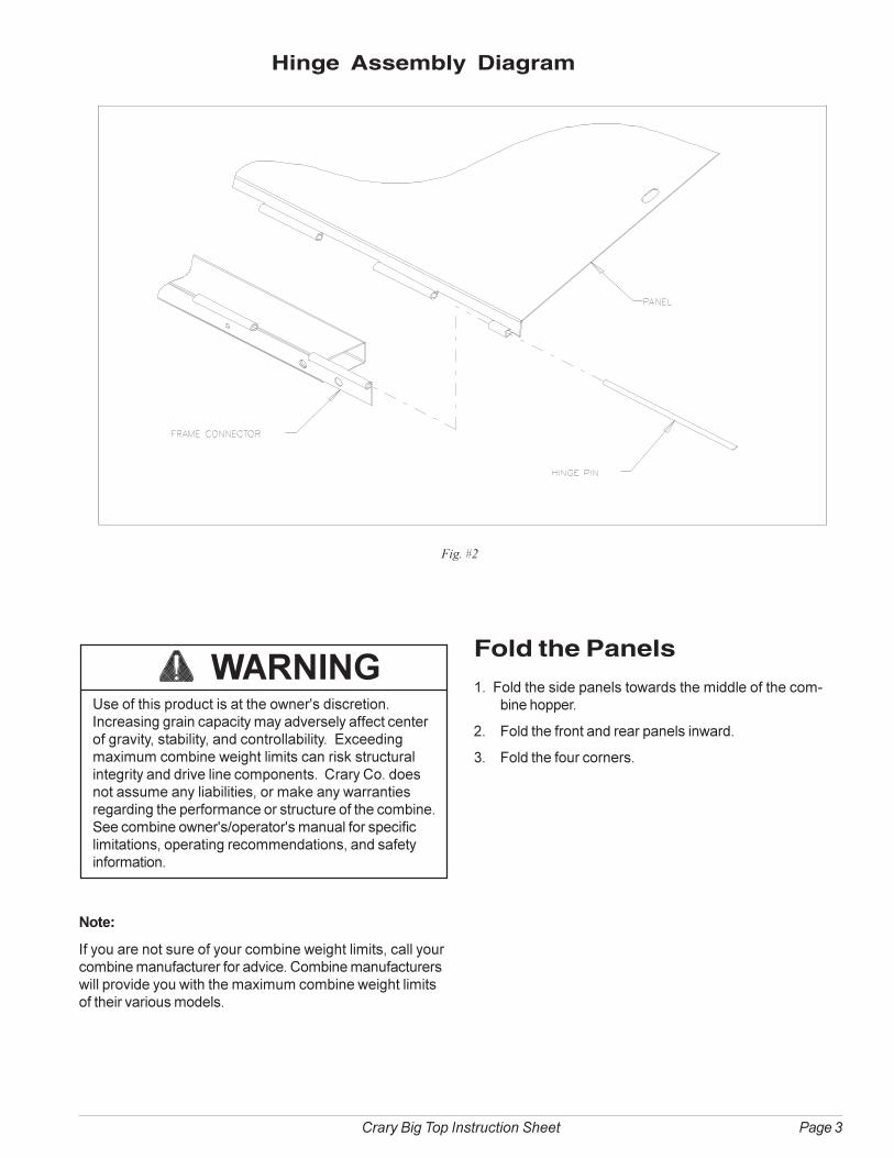
Hinge Assembly Diagram
Fig. #2
Fold the Panels
1. Fold the side panels towards the middle of the com-bine hopper.
2. Fold the front and rear panels inward.
3. Fold the four corners.
Note:
If you are not sure of your combine weight limits, call yourcombine manufacturer for advice. Combine manufacturerswill provide you with the maximum combine weight limitsof their various models.
WARNINGUse of this product is at the owner's discretion.Increasing grain capacity may adversely affect centerof gravity, stability, and controllability. Exceedingmaximum combine weight limits can risk structuralintegrity and drive line components. Crary Co. doesnot assume any liabilities, or make any warrantiesregarding the performance or structure of the combine.See combine owner's/operator's manual for specificlimitations, operating recommendations, and safetyinformation.

Page 4 Crary Big Top Instruction Sheet
Parts List–JD. 9650STS & 9750STS Series
Parts Diagram–John Deere 9650STS & 9750ST Series (Regular Size)
Fig. #3
I T E M P A R T # D E S C R IP T ION QT Y
1 24957 AS S E M B LY , L.H. F R ONT & R .H. R E AR COR NE R 2
2 24958 AS S E M B LY , R .H. F R ONT & L.H. R E AR COR NE R 2
3 25427-15 WE LDM E NT , F R AM E CONNE CT OR 2
4 25361-15 PANE L, B OT T OM F R ONT /R E AR 2
5 25431-00 AS S E M B LY , S IDE PANE L 2
6 25432-00 KIT , B IG T OP OW NE R S (JD S T S S T D.) 1
7 25433-00 KIT , HINGE PIN (JD96/9750 S T S S T D.) 1
8 25448 -00 AS S E M B LY , L.H. F R AM E 1
9 25445-15 W E LDM E NT , L.H. F R AM E (S HOR T ) 1
10 25444 -15 W E LDM E NT , R .H. F R AM E (LONG) 1
11 25446 -15 W E LDM E NT , R .H. F R AM E (S HOR T ) 1
12 13718 -00 E LB OW, 45 DE GR E E E X HAU S T (5" ) 1
13 25687-15 WE LDM E NT , JD S T S HANDR AIL (HALF ) 1
14 25688 -15 WE LDM E NT , JD S T S HANDR AIL (HALF ) 1
15 24953 -15 W E LDM E NT , L.H. F R ONT COR NE R 1
16 23307 W INDOW 1
17 23489 -12 WINDOW F R AM E 1
18 16653 HOPPE R E X T E NS ION W AR NING DE CAL 1
19 15497 R IVE T , 1/4 X 1/2 DOM E HE AD B LIND S S 8
20 24954 -15 W E LDM E NT , R .H. F R ONT COR NE R 1
21 25410 -15 PANE L, B OT T OM S IDE 2
22 16647 B IG T OP DE CAL (B LACK) 2
���� ����� �������� � ���
23 15051 NUT, 3/8" SERRATED FLANGE NC ZP 12
24 15140 BOLT, 5/16 X 2 HCS GR5 ZP 2
25 15272 BOLT, 3/8 X 4 HHCS NC GR5 ZP 12
26 16493 PIN, LYNCH 3/16 16
27 12530 LANYARD, NYLON 16
28 15001 BOLT, 1/4 X 3/4 HCS GR5 ZP 8
29 15087 NUT, 1/4 CENTERLOCK NC ZP 8
30 23764-15 BRACKET, SENSOR/LIGHT 2
31 15344 BOLT, 1/4 X 1/2 SERRATED FLANGE NC ZP 4
32 15053 NUT, 1/4-20 NC SERRATED FLANGE ZP 4
33 16763 SENSOR EXT. HARNESS (NOT SHOWN) 1
34 12478 HARNESS, LIGHT EXT. (NOT SHOWN) 1
35 17320 STRAP, NYLON TIE - 11" (NOT SHOWN) 6
36 15436 BOLT, 5/16 X 1-1/4 HHCS NC GR5 ZP 6
37 15250 WASHER, 5/16 FLAT ZP 10
38 15356 NUT, 5/16 NE NYLOCK ZP 8
39 13719-00 CLAMP, MUFFLER 1
40 25435-00 MANUAL, BIG TOP OWNER’S (NOT SHOWN) 1
41 12644 CARD, AG WARRANTY/REG. (NOT SHOWN) 1
42 23784 PIN, HINGE (26.26") 4
43 25428-00 PIN, HINGE (68.75") 2
44 25429-00 PIN, HINGE (64.25") 2
Related Documents