Page 1 of 2 2.5 MVA 11/0.416kV Transformer Technical Particulars and Guarantees of 2.5 MVA, 11/0.416kV Transformer No. Description Unit Specification Required Proposed 1 GENERAL 1.1 Manufacturer Name SEA, ABB, Siemens, BEST, Schneider, MATELEC or equivalent 1.2 Country of Manufacturing 1.3 Type Oil immersed cable box for both H.V & L.V 1.4 Model To be filled in 1.5 Applicable Standards IEC60076 1.6 Location of service Outdoor 1.7 Type Tests and Short circuit Test Report Certificate Provided Yes 2 RATINGS 2.1 Rated power MVA 2.5 2.2 Rated voltage ratio • Primary kV 11(±2 x 2.5%) • Secondary kV 0.416Y/0.24 2.3 Number of phase 3 2.4 Frequency Hz 50 2.5 Vector group symbol Dyn11 2.6 Cooling method ONAN 2.7 No load losses kw 2.8 Load loss at full load at 75 deg temperature kw 2.9 Maximum temperature rise at rated power • Top oil by thermometer K 45 • Winding by resistance K 50

Welcome message from author
This document is posted to help you gain knowledge. Please leave a comment to let me know what you think about it! Share it to your friends and learn new things together.
Transcript
Page 1 of 2
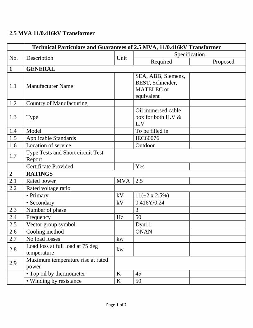
2.5 MVA 11/0.416kV Transformer Technical Particulars and Guarantees of 2.5 MVA, 11/0.416kV Transformer
No. Description Unit Specification Required Proposed
1 GENERAL
1.1 Manufacturer Name
SEA, ABB, Siemens, BEST, Schneider, MATELEC or equivalent
1.2 Country of Manufacturing
1.3 Type Oil immersed cable box for both H.V & L.V
1.4 Model To be filled in 1.5 Applicable Standards IEC60076 1.6 Location of service Outdoor
1.7 Type Tests and Short circuit Test Report
Certificate Provided Yes 2 RATINGS 2.1 Rated power MVA 2.5 2.2 Rated voltage ratio
• Primary kV 11(±2 x 2.5%) • Secondary kV 0.416Y/0.24
2.3 Number of phase 3 2.4 Frequency Hz 50 2.5 Vector group symbol Dyn11 2.6 Cooling method ONAN 2.7 No load losses kw
2.8 Load loss at full load at 75 deg temperature kw
2.9 Maximum temperature rise at rated power
• Top oil by thermometer K 45 • Winding by resistance K 50

Page 2 of 2
Technical Particulars and Guarantees of 2.5 MVA, 11/0.416kV Transformer
No. Description Unit Specification Required Proposed
2.10 Impedance voltage at continuous rated power % ≥ 6
3 Rated insulation level for Primary
• Impulse withstand voltage (1.2/50µS)
kV peak 75
• One minute 50Hz withstand voltage kV rms 28
4 DESIGN DETAILS 4.1 Off-load tap changer
• Tapping range (±2 x 2.5%) • Tapping step 2.50%
4.2 Type of oil (As per IEC requirement) SHELL DIALA B
5 DIMENSION AND WEIGHT
5.1 Dimension of Transformer (L x W x H) mm To be filled in
5.2 Total oil required (Volume) Liter To be filled in
5.3 Total weight of complete transformer including fitting and oil kg To be filled in
Page 1 of 2
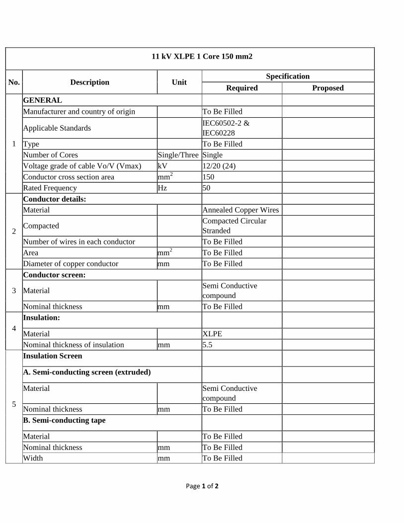
11 kV XLPE 1 Core 150 mm2
No. Description Unit Specification
Required Proposed
1
GENERAL Manufacturer and country of origin To Be Filled
Applicable Standards IEC60502-2 & IEC60228
Type To Be Filled Number of Cores Single/Three Single Voltage grade of cable Vo/V (Vmax) kV 12/20 (24) Conductor cross section area mm2 150 Rated Frequency Hz 50
2
Conductor details: Material Annealed Copper Wires
Compacted Compacted Circular Stranded
Number of wires in each conductor To Be Filled Area mm2 To Be Filled Diameter of copper conductor mm To Be Filled
3
Conductor screen:
Material Semi Conductive compound
Nominal thickness mm To Be Filled
4 Insulation:
Material XLPE Nominal thickness of insulation mm 5.5
5
Insulation Screen
A. Semi-conducting screen (extruded)
Material Semi Conductive compound
Nominal thickness mm To Be Filled B. Semi-conducting tape
Material To Be Filled Nominal thickness mm To Be Filled Width mm To Be Filled
Page 2 of 2
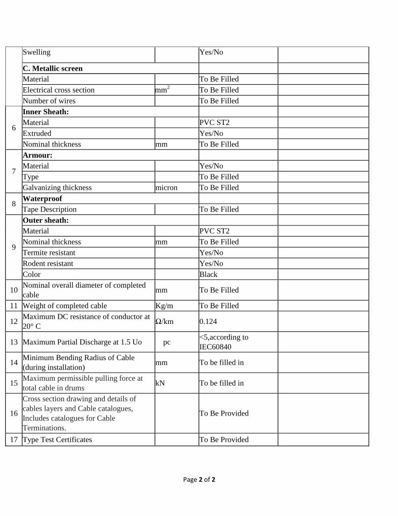
Swelling Yes/No
C. Metallic screen Material To Be Filled Electrical cross section mm2 To Be Filled Number of wires To Be Filled
6
Inner Sheath: Material PVC ST2 Extruded Yes/No Nominal thickness mm To Be Filled
7
Armour: Material Yes/No Type To Be Filled Galvanizing thickness micron To Be Filled
8 Waterproof Tape Description To Be Filled
9
Outer sheath: Material PVC ST2 Nominal thickness mm To Be Filled Termite resistant Yes/No Rodent resistant Yes/No Color Black
10 Nominal overall diameter of completed cable mm To Be Filled
11 Weight of completed cable Kg/m To Be Filled
12 Maximum DC resistance of conductor at 20° C Ω/km 0.124
13 Maximum Partial Discharge at 1.5 Uo pc ˂5,according to IEC60840
14 Minimum Bending Radius of Cable (during installation) mm To be filled in
15 Maximum permissible pulling force at total cable in drums kN To be filled in
16
Cross section drawing and details of cables layers and Cable catalogues, Includes catalogues for Cable Terminations.
To Be Provided
17 Type Test Certificates To Be Provided
Page 1 of 2
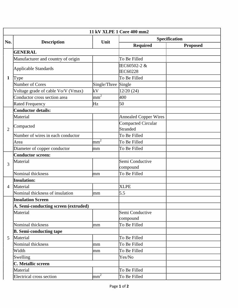
11 kV XLPE 1 Core 400 mm2
No. Description Unit Specification
Required Proposed
1
GENERAL Manufacturer and country of origin To Be Filled
Applicable Standards IEC60502-2 & IEC60228
Type To Be Filled Number of Cores Single/Three Single Voltage grade of cable Vo/V (Vmax) kV 12/20 (24) Conductor cross section area mm2 400 Rated Frequency Hz 50
2
Conductor details: Material Annealed Copper Wires
Compacted Compacted Circular Stranded
Number of wires in each conductor To Be Filled Area mm2 To Be Filled Diameter of copper conductor mm To Be Filled
3
Conductor screen: Material Semi Conductive
compound
Nominal thickness mm To Be Filled
4 Insulation: Material XLPE Nominal thickness of insulation mm 5.5
5
Insulation Screen A. Semi-conducting screen (extruded) Material Semi Conductive
compound
Nominal thickness mm To Be Filled B. Semi-conducting tape Material To Be Filled Nominal thickness mm To Be Filled Width mm To Be Filled Swelling Yes/No C. Metallic screen Material To Be Filled Electrical cross section mm2 To Be Filled
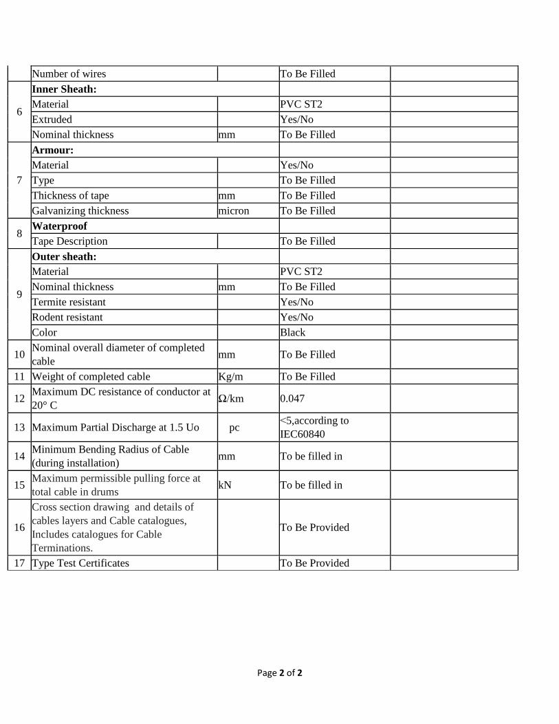
Page 2 of 2
Number of wires To Be Filled
6
Inner Sheath: Material PVC ST2 Extruded Yes/No Nominal thickness mm To Be Filled
7
Armour: Material Yes/No Type To Be Filled Thickness of tape mm To Be Filled Galvanizing thickness micron To Be Filled
8 Waterproof Tape Description To Be Filled
9
Outer sheath: Material PVC ST2 Nominal thickness mm To Be Filled Termite resistant Yes/No Rodent resistant Yes/No Color Black
10 Nominal overall diameter of completed cable mm To Be Filled
11 Weight of completed cable Kg/m To Be Filled
12 Maximum DC resistance of conductor at 20° C Ω/km 0.047
13 Maximum Partial Discharge at 1.5 Uo pc ˂5,according to IEC60840
14 Minimum Bending Radius of Cable (during installation) mm To be filled in
15 Maximum permissible pulling force at total cable in drums kN To be filled in
16
Cross section drawing and details of cables layers and Cable catalogues, Includes catalogues for Cable Terminations.
To Be Provided
17 Type Test Certificates To Be Provided
Equipment’s Should Comply With AIS Technical Specifications Page 1 of 11
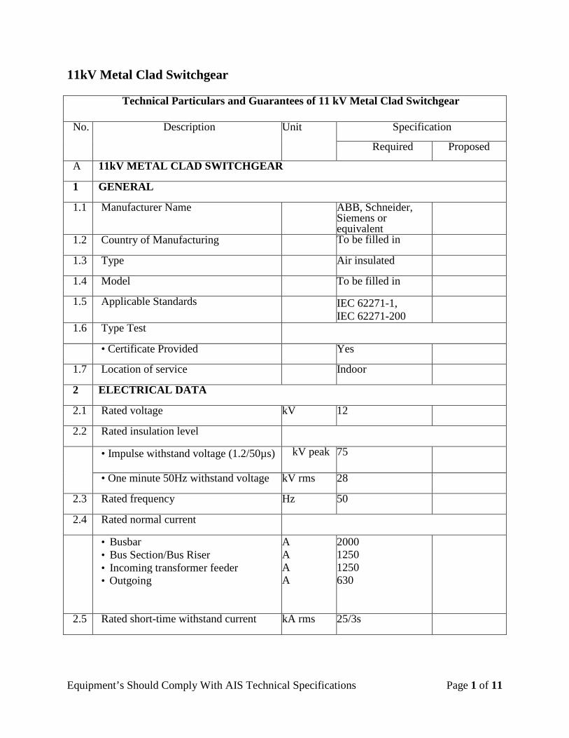
11kV Metal Clad Switchgear
Technical Particulars and Guarantees of 11 kV Metal Clad Switchgear
No. Description Unit Specification
Required Proposed
A 11kV METAL CLAD SWITCHGEAR
1 GENERAL
1.1 Manufacturer Name ABB, Schneider, Siemens or equivalent
1.2 Country of Manufacturing To be filled in
1.3 Type Air insulated
1.4 Model To be filled in
1.5 Applicable Standards IEC 62271-1, IEC 62271-200
1.6 Type Test
• Certificate Provided Yes
1.7 Location of service Indoor
2 ELECTRICAL DATA
2.1 Rated voltage kV 12
2.2 Rated insulation level
• Impulse withstand voltage (1.2/50µs) kV peak 75
• One minute 50Hz withstand voltage kV rms 28
2.3 Rated frequency Hz 50
2.4 Rated normal current
• Busbar • Bus Section/Bus Riser • Incoming transformer feeder • Outgoing
A A A A
2000 1250 1250 630
2.5 Rated short-time withstand current kA rms 25/3s
Equipment’s Should Comply With AIS Technical Specifications Page 2 of 11
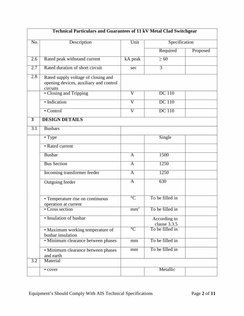
Technical Particulars and Guarantees of 11 kV Metal Clad Switchgear
No. Description Unit Specification
Required Proposed
2.6 Rated peak withstand current kA peak ≥ 60
2.7 Rated duration of short circuit sec 3
2.8 Rated supply voltage of closing and opening devices, auxiliary and control circuits
• Closing and Tripping V DC 110
• Indication V DC 110
• Control V DC 110
3 DESIGN DETAILS
3.1 Busbars
• Type Single
• Rated current
Busbar A 1500
Bus Section A 1250
Incoming transformer feeder A 1250
Outgoing feeder A 630
• Temperature rise on continuous operation at current
°C To be filled in
• Cross section mm2 To be filled in
• Insulation of busbar According to clause 3.3.5
• Maximum working temperature of busbar insulation
°C To be filled in
• Minimum clearance between phases mm To be filled in
• Minimum clearance between phases and earth
mm To be filled in
3.2 Material
• cover Metallic
Equipment’s Should Comply With AIS Technical Specifications Page 3 of 11
Technical Particulars and Guarantees of 11 kV Metal Clad Switchgear
No. Description Unit Specification
Required Proposed
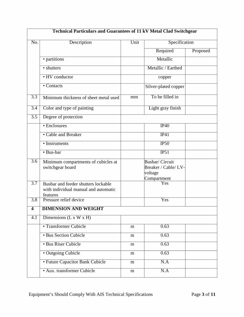
• partitions Metallic
• shutters Metallic / Earthed
• HV conductor copper
• Contacts Silver-plated copper
3.3 Minimum thickness of sheet metal used mm To be filled in
3.4 Color and type of painting Light gray finish
3.5 Degree of protection
• Enclosures IP40
• Cable and Breaker IP41
• Instruments IP50
• Bus-bar IP51
3.6 Minimum compartments of cubicles at switchgear board
Busbar/ Circuit Breaker / Cable/ LV- voltage Compartment
3.7 Busbar and feeder shutters lockable with individual manual and automatic features
Yes
3.8 Pressure relief device Yes
4 DIMENSION AND WEIGHT
4.1 Dimensions (L x W x H)
• Transformer Cubicle m 0.63
• Bus Section Cubicle m 0.63
• Bus Riser Cubicle m 0.63
• Outgoing Cubicle m 0.63
• Future Capacitor Bank Cubicle m N.A
• Aux. transformer Cubicle m N.A
Equipment’s Should Comply With AIS Technical Specifications Page 4 of 11
Technical Particulars and Guarantees of 11 kV Metal Clad Switchgear
No. Description Unit Specification
Required Proposed
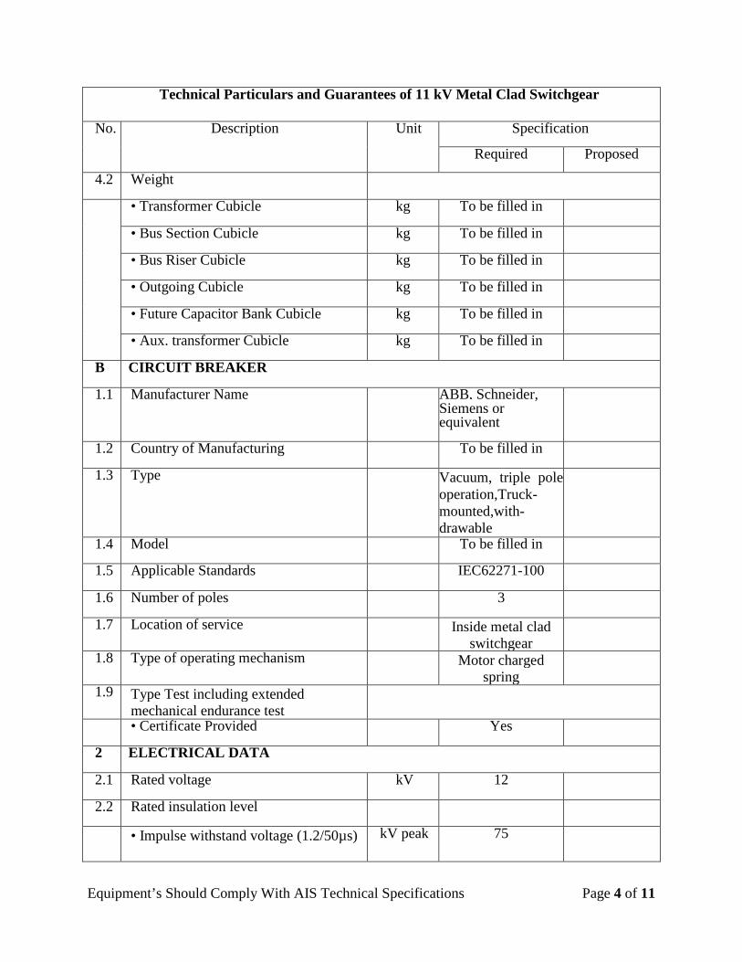
4.2 Weight
• Transformer Cubicle kg To be filled in
• Bus Section Cubicle kg To be filled in
• Bus Riser Cubicle kg To be filled in
• Outgoing Cubicle kg To be filled in
• Future Capacitor Bank Cubicle kg To be filled in
• Aux. transformer Cubicle kg To be filled in
B CIRCUIT BREAKER
1.1 Manufacturer Name ABB, Schneider, Siemens or equivalent
1.2 Country of Manufacturing To be filled in
1.3 Type Vacuum, triple pole operation,Truck-mounted,with-drawable
1.4 Model To be filled in
1.5 Applicable Standards IEC62271-100
1.6 Number of poles 3
1.7 Location of service Inside metal clad switchgear
1.8 Type of operating mechanism Motor charged spring
1.9 Type Test including extended mechanical endurance test
• Certificate Provided Yes
2 ELECTRICAL DATA
2.1 Rated voltage kV 12
2.2 Rated insulation level
• Impulse withstand voltage (1.2/50µs) kV peak 75
Equipment’s Should Comply With AIS Technical Specifications Page 5 of 11
Technical Particulars and Guarantees of 11 kV Metal Clad Switchgear
No. Description Unit Specification
Required Proposed
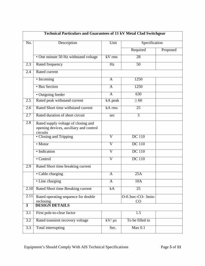
• One minute 50 Hz withstand voltage kV rms 28
2.3 Rated frequency Hz 50
2.4 Rated current
• Incoming A 1250
• Bus Section A 1250
• Outgoing feeder A 630 2.5 Rated peak withstand current kA peak ≥ 60
2.6 Rated Short time withstand current kA rms 25
2.7 Rated duration of short circuit sec 3
2.8 Rated supply voltage of closing and opening devices, auxiliary and control circuits
• Closing and Tripping V DC 110
• Motor V DC 110
• Indication V DC 110
• Control V DC 110
2.9 Rated Short time breaking current
• Cable charging A 25A
• Line charging A 10A
2.10 Rated Short time Breaking current kA 25
2.11 Rated operating sequence for double reclosing
O-0.3sec-CO- 3min-CO
3 DESIGN DETAILS
3.1 First pole-to-clear factor 1.5
3.2 Rated transient recovery voltage kV/ µs To be filled in
3.3 Total interrupting Sec. Max 0.1
Equipment’s Should Comply With AIS Technical Specifications Page 6 of 11
Technical Particulars and Guarantees of 11 kV Metal Clad Switchgear
No. Description Unit Specification
Required Proposed
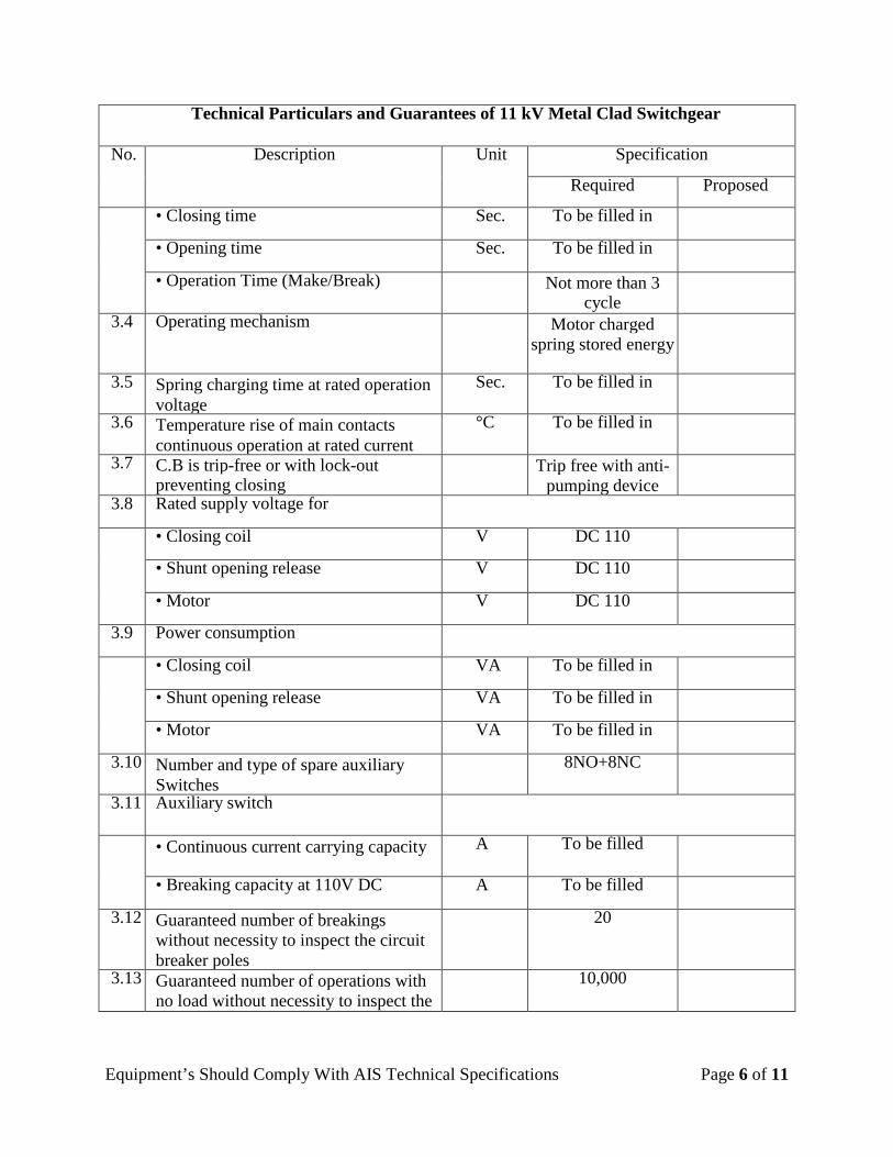
• Closing time Sec. To be filled in
• Opening time Sec. To be filled in
• Operation Time (Make/Break) Not more than 3 cycle
3.4 Operating mechanism Motor charged spring stored energy
3.5 Spring charging time at rated operation voltage
Sec. To be filled in
3.6 Temperature rise of main contacts continuous operation at rated current
°C To be filled in
3.7 C.B is trip-free or with lock-out preventing closing
Trip free with anti-pumping device
3.8 Rated supply voltage for
• Closing coil V DC 110
• Shunt opening release V DC 110
• Motor V DC 110
3.9 Power consumption
• Closing coil VA To be filled in
• Shunt opening release VA To be filled in
• Motor VA To be filled in
3.10 Number and type of spare auxiliary Switches
8NO+8NC
3.11 Auxiliary switch
• Continuous current carrying capacity A To be filled
• Breaking capacity at 110V DC A To be filled
3.12 Guaranteed number of breakings without necessity to inspect the circuit breaker poles
20
3.13 Guaranteed number of operations with no load without necessity to inspect the
10,000
Equipment’s Should Comply With AIS Technical Specifications Page 7 of 11
Technical Particulars and Guarantees of 11 kV Metal Clad Switchgear
No. Description Unit Specification
Required Proposed
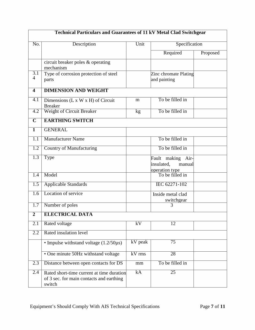
circuit breaker poles & operating mechanism
3.14
Type of corrosion protection of steel parts
Zinc chromate Plating and painting
4 DIMENSION AND WEIGHT
4.1 Dimensions (L x W x H) of Circuit Breaker
m To be filled in
4.2 Weight of Circuit Breaker kg To be filled in
C EARTHING SWITCH
1 GENERAL
1.1 Manufacturer Name To be filled in
1.2 Country of Manufacturing To be filled in
1.3 Type Fault making Air- insulated, manual operation type
1.4 Model To be filled in
1.5 Applicable Standards IEC 62271-102
1.6 Location of service Inside metal clad switchgear
1.7 Number of poles 3
2 ELECTRICAL DATA
2.1 Rated voltage kV 12
2.2 Rated insulation level
• Impulse withstand voltage (1.2/50µs) kV peak 75
• One minute 50Hz withstand voltage kV rms 28
2.3 Distance between open contacts for DS mm To be filled in
2.4 Rated short-time current at time duration of 3 sec. for main contacts and earthing switch
kA 25
Equipment’s Should Comply With AIS Technical Specifications Page 8 of 11
Technical Particulars and Guarantees of 11 kV Metal Clad Switchgear
No. Description Unit Specification
Required Proposed
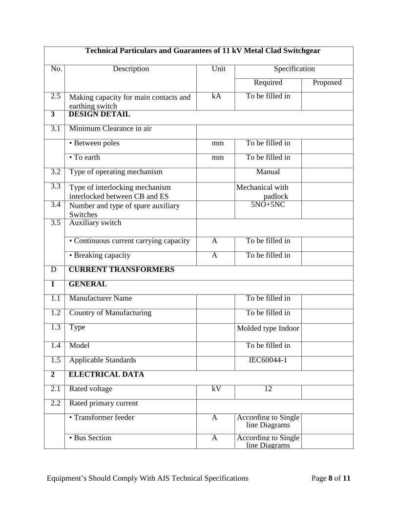
2.5 Making capacity for main contacts and earthing switch
kA To be filled in
3 DESIGN DETAIL
3.1 Minimum Clearance in air
• Between poles mm To be filled in
• To earth mm To be filled in
3.2 Type of operating mechanism Manual
3.3 Type of interlocking mechanism interlocked between CB and ES
Mechanical with padlock
3.4 Number and type of spare auxiliary Switches
5NO+5NC
3.5 Auxiliary switch
• Continuous current carrying capacity A To be filled in
• Breaking capacity A To be filled in
D CURRENT TRANSFORMERS
1 GENERAL
1.1 Manufacturer Name To be filled in
1.2 Country of Manufacturing To be filled in
1.3 Type Molded type Indoor
1.4 Model To be filled in
1.5 Applicable Standards IEC60044-1
2 ELECTRICAL DATA
2.1 Rated voltage kV 12
2.2 Rated primary current
• Transformer feeder A According to Single line Diagrams
• Bus Section A According to Single line Diagrams
Equipment’s Should Comply With AIS Technical Specifications Page 9 of 11
Technical Particulars and Guarantees of 11 kV Metal Clad Switchgear
No. Description Unit Specification
Required Proposed
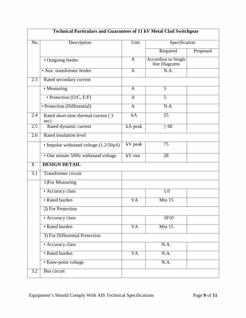
• Outgoing feeder A According to Single line Diagrams
• Aux. transformer feeder A N.A.
2.3 Rated secondary current
• Measuring A 5
• Protection (O/C, E/F) A 5
• Protection (Differential) A N.A
2.4 Rated short-time thermal current ( 3 sec)
kA 25
2.5 Rated dynamic current kA peak ≥ 60
2.6 Rated insulation level
• Impulse withstand voltage (1.2/50µS) kV peak 75
• One minute 50Hz withstand voltage kV rms 28
3 DESIGN DETAIL
3.1 Transformer circuit
1)For Measuring
• Accuracy class 1.0
• Rated burden VA Min 15
2) For Protection
• Accuracy class 5P10
• Rated burden VA Min 15
3) For Differential Protection
• Accuracy class N.A.
• Rated burden VA N.A.
• Knee-point voltage N.A.
3.2 Bus circuit
Equipment’s Should Comply With AIS Technical Specifications Page 10 of 11
Technical Particulars and Guarantees of 11 kV Metal Clad Switchgear
No. Description Unit Specification
Required Proposed
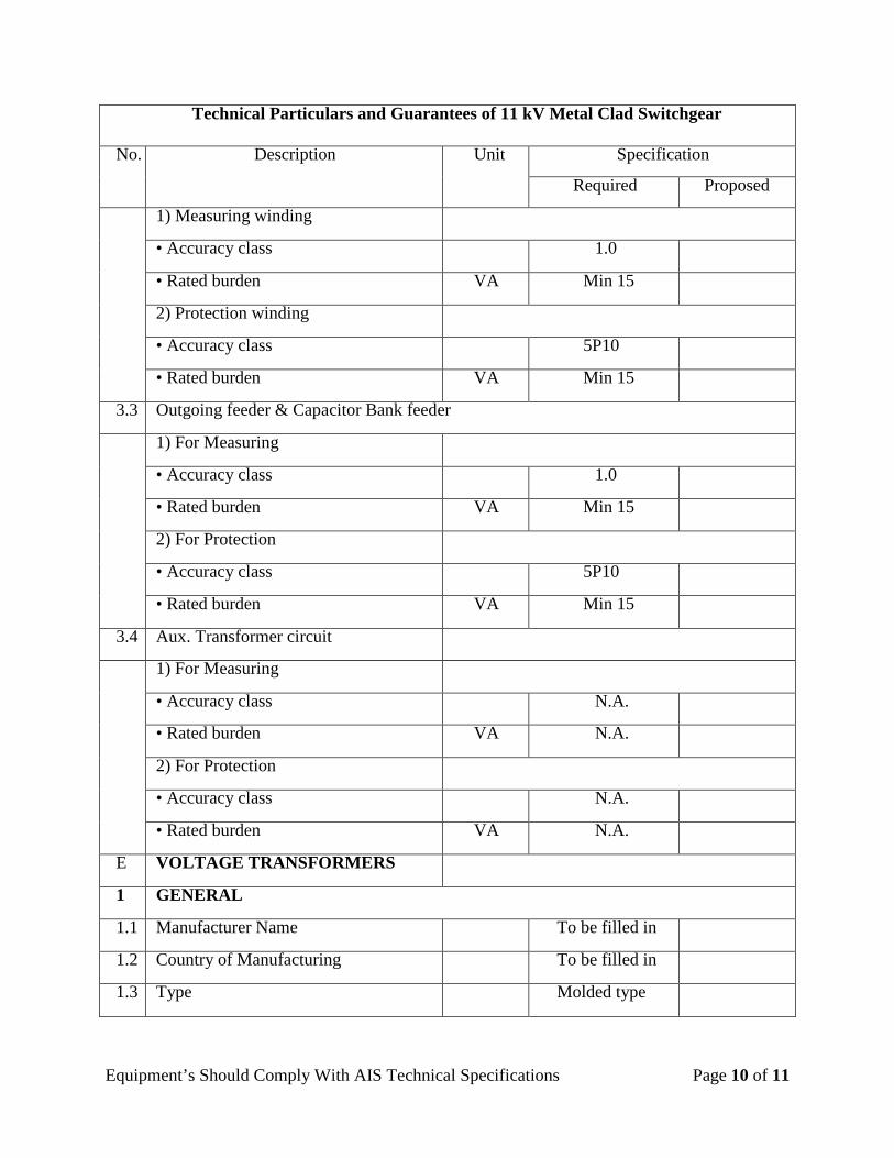
1) Measuring winding
• Accuracy class 1.0
• Rated burden VA Min 15
2) Protection winding
• Accuracy class 5P10
• Rated burden VA Min 15
3.3 Outgoing feeder & Capacitor Bank feeder
1) For Measuring
• Accuracy class 1.0
• Rated burden VA Min 15
2) For Protection
• Accuracy class 5P10
• Rated burden VA Min 15
3.4 Aux. Transformer circuit
1) For Measuring
• Accuracy class N.A.
• Rated burden VA N.A.
2) For Protection
• Accuracy class N.A.
• Rated burden VA N.A.
E VOLTAGE TRANSFORMERS
1 GENERAL
1.1 Manufacturer Name To be filled in
1.2 Country of Manufacturing To be filled in
1.3 Type Molded type
Equipment’s Should Comply With AIS Technical Specifications Page 11 of 11
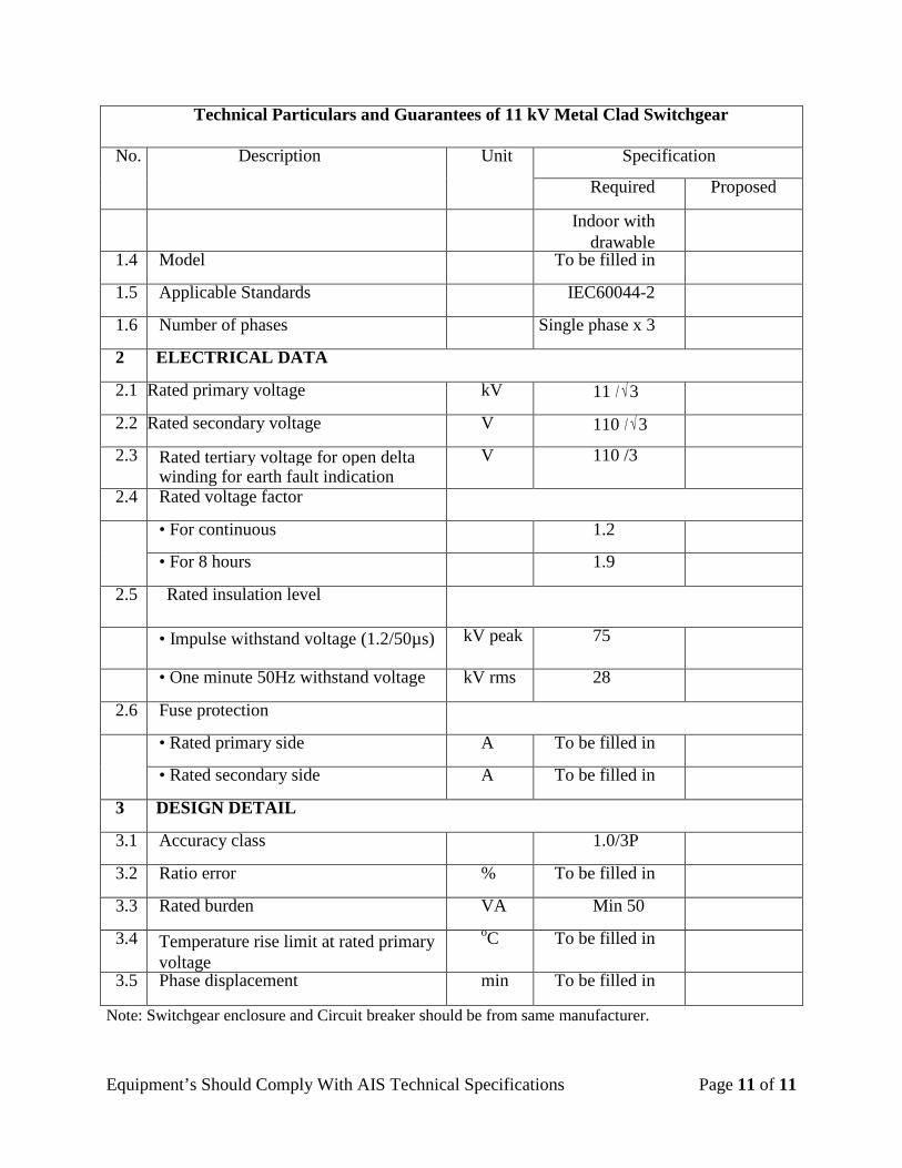
Note: Switchgear enclosure and Circuit breaker should be from same manufacturer.
Technical Particulars and Guarantees of 11 kV Metal Clad Switchgear
No. Description Unit Specification
Required Proposed
Indoor with drawable
1.4 Model To be filled in
1.5 Applicable Standards IEC60044-2
1.6 Number of phases Single phase x 3
2 ELECTRICAL DATA
2.1 Rated primary voltage kV 11 / √3
2.2 Rated secondary voltage V 110 / √3
2.3 Rated tertiary voltage for open delta winding for earth fault indication
V 110 /3
2.4 Rated voltage factor
• For continuous 1.2
• For 8 hours 1.9
2.5 Rated insulation level
• Impulse withstand voltage (1.2/50µs) kV peak 75
• One minute 50Hz withstand voltage kV rms 28
2.6 Fuse protection
• Rated primary side A To be filled in
• Rated secondary side A To be filled in
3 DESIGN DETAIL
3.1 Accuracy class 1.0/3P
3.2 Ratio error % To be filled in
3.3 Rated burden VA Min 50
3.4 Temperature rise limit at rated primary voltage
oC To be filled in
3.5 Phase displacement min To be filled in
Page 1 of 1
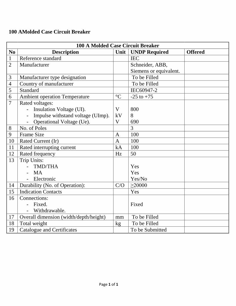
100 AMolded Case Circuit Breaker
100 A Molded Case Circuit Breaker No Description Unit UNDP Required Offered 1 Reference standard IEC 2 Manufacturer Schneider, ABB,
Siemens or equivalent.
3 Manufacturer type designation To be Filled 4 Country of manufacturer To be Filled 5 Standard IEC60947-2 6 Ambient operation Temperature °C -25 to +75 7 Rated voltages:
- Insulation Voltage (UI). - Impulse withstand voltage (UImp). - Operational Voltage (Ue).
V kV V
800 8 690
8 No. of Poles 3 9 Frame Size A 100 10 Rated Current (Ir) A 100 11 Rated interrupting current kA 100 12 Rated frequency Hz 50 13 Trip Units:
- TMD/THA - MA - Electronic
Yes Yes Yes/No
14 Durability (No. of Operation): C/O ≥20000 15 Indication Contacts Yes 16 Connections:
- Fixed. - Withdrawable.
Fixed
17 Overall dimension (width/depth/height) mm To be Filled 18 Total weight kg To be Filled 19 Catalogue and Certificates To be Submitted
Page 1 of 4
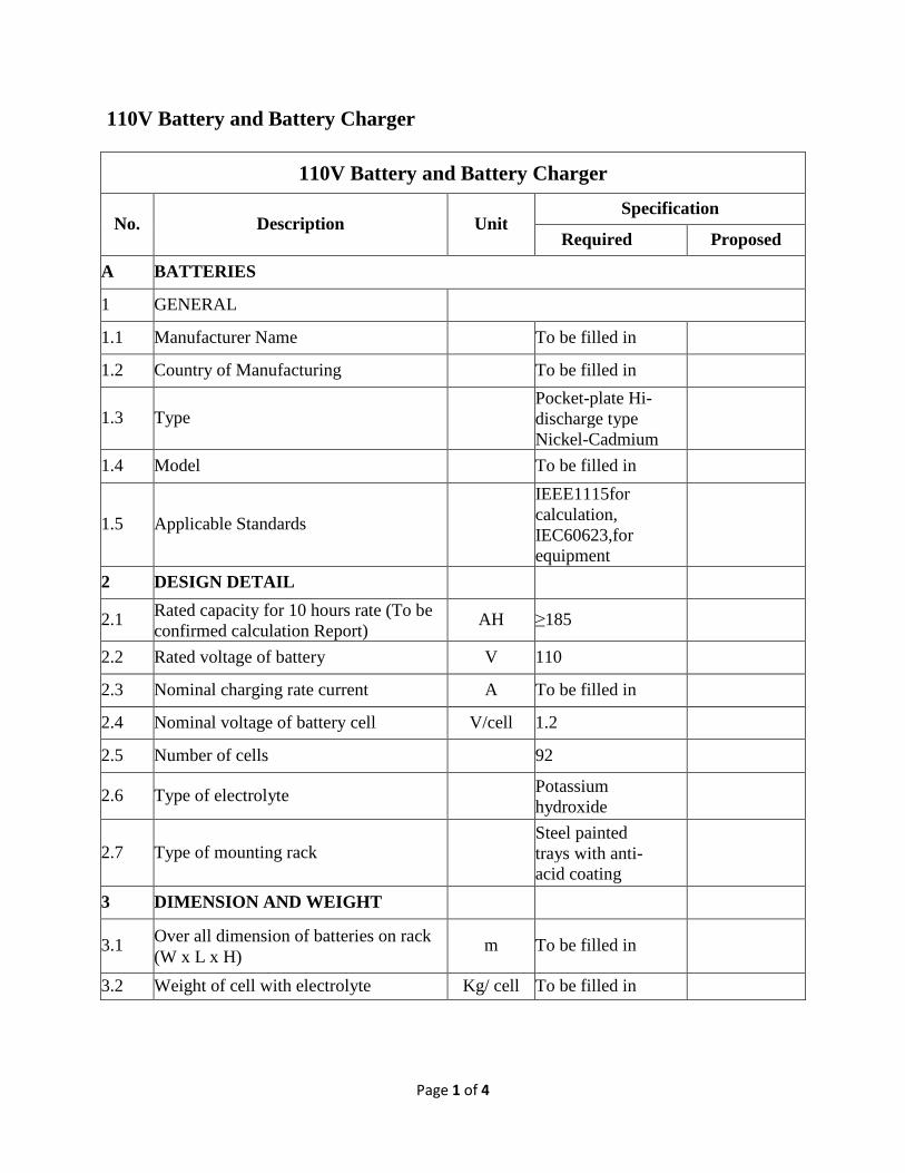
110V Battery and Battery Charger
110V Battery and Battery Charger
No. Description Unit Specification
Required Proposed
A BATTERIES
1 GENERAL
1.1 Manufacturer Name To be filled in
1.2 Country of Manufacturing To be filled in
1.3 Type Pocket-plate Hi- discharge type Nickel-Cadmium
1.4 Model To be filled in
1.5 Applicable Standards IEEE1115for calculation, IEC60623,for equipment
2 DESIGN DETAIL
2.1 Rated capacity for 10 hours rate (To be confirmed calculation Report) AH ≥185
2.2 Rated voltage of battery V 110
2.3 Nominal charging rate current A To be filled in
2.4 Nominal voltage of battery cell V/cell 1.2
2.5 Number of cells 92
2.6 Type of electrolyte Potassium hydroxide
2.7 Type of mounting rack Steel painted trays with anti-acid coating
3 DIMENSION AND WEIGHT
3.1 Over all dimension of batteries on rack (W x L x H)
m To be filled in
3.2 Weight of cell with electrolyte Kg/ cell To be filled in
Page 2 of 4
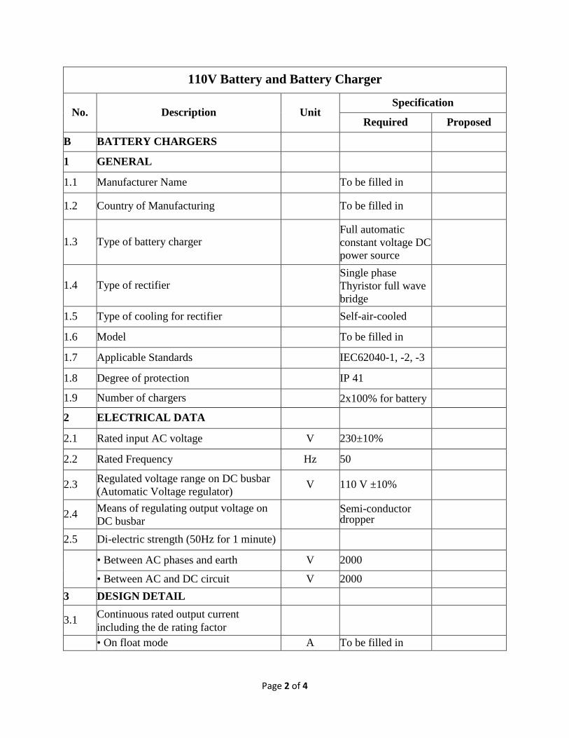
110V Battery and Battery Charger
No. Description Unit Specification
Required Proposed
B BATTERY CHARGERS
1 GENERAL
1.1 Manufacturer Name To be filled in
1.2 Country of Manufacturing To be filled in
1.3 Type of battery charger Full automatic constant voltage DC power source
1.4 Type of rectifier Single phase Thyristor full wave bridge
1.5 Type of cooling for rectifier Self-air-cooled
1.6 Model To be filled in
1.7 Applicable Standards IEC62040-1, -2, -3
1.8 Degree of protection IP 41
1.9 Number of chargers 2x100% for battery
2 ELECTRICAL DATA
2.1 Rated input AC voltage V 230±10%
2.2 Rated Frequency Hz 50
2.3 Regulated voltage range on DC busbar (Automatic Voltage regulator) V 110 V ±10%
2.4 Means of regulating output voltage on DC busbar
Semi-conductor dropper
2.5 Di-electric strength (50Hz for 1 minute)
• Between AC phases and earth V 2000
• Between AC and DC circuit V 2000
3 DESIGN DETAIL
3.1 Continuous rated output current including the de rating factor
• On float mode A To be filled in
Page 3 of 4
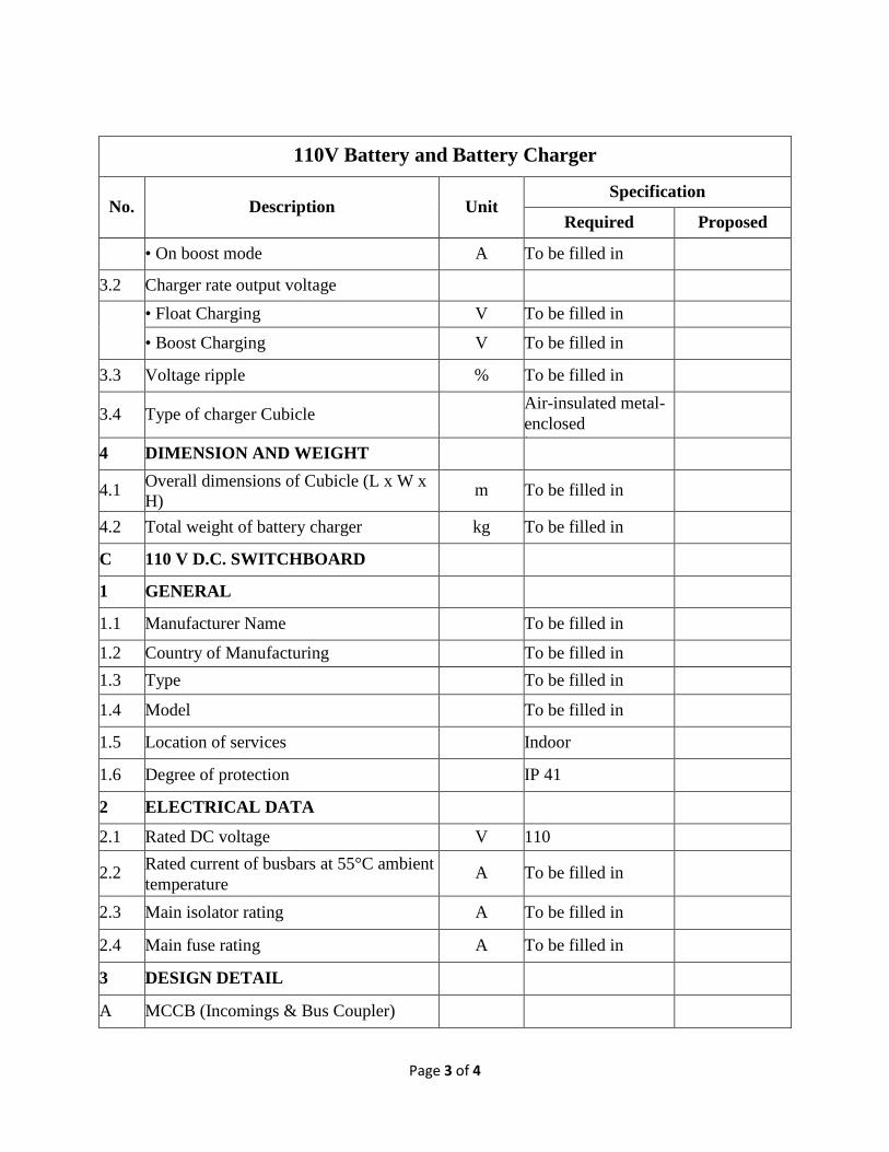
110V Battery and Battery Charger
No. Description Unit Specification
Required Proposed
• On boost mode A To be filled in
3.2 Charger rate output voltage
• Float Charging V To be filled in
• Boost Charging V To be filled in
3.3 Voltage ripple % To be filled in
3.4 Type of charger Cubicle Air-insulated metal-enclosed t
4 DIMENSION AND WEIGHT
4.1 Overall dimensions of Cubicle (L x W x H) m To be filled in
4.2 Total weight of battery charger kg To be filled in
C 110 V D.C. SWITCHBOARD
1 GENERAL
1.1 Manufacturer Name To be filled in
1.2 Country of Manufacturing To be filled in 1.3 Type To be filled in
1.4 Model To be filled in
1.5 Location of services Indoor
1.6 Degree of protection IP 41
2 ELECTRICAL DATA
2.1 Rated DC voltage V 110
2.2 Rated current of busbars at 55°C ambient temperature
A To be filled in
2.3 Main isolator rating A To be filled in
2.4 Main fuse rating A To be filled in
3 DESIGN DETAIL
A MCCB (Incomings & Bus Coupler)
Page 4 of 4
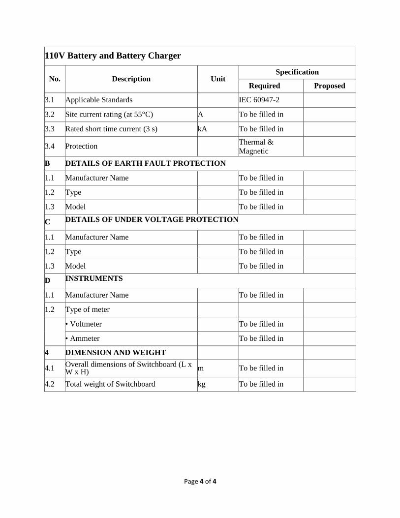
110V Battery and Battery Charger
No. Description Unit Specification
Required Proposed
3.1 Applicable Standards IEC 60947-2
3.2 Site current rating (at 55°C) A To be filled in
3.3 Rated short time current (3 s) kA To be filled in
3.4 Protection Thermal & Magnetic
B DETAILS OF EARTH FAULT PROTECTION
1.1 Manufacturer Name To be filled in
1.2 Type To be filled in
1.3 Model To be filled in
C DETAILS OF UNDER VOLTAGE PROTECTION
1.1 Manufacturer Name To be filled in
1.2 Type To be filled in
1.3 Model To be filled in
D INSTRUMENTS
1.1 Manufacturer Name To be filled in
1.2 Type of meter
• Voltmeter To be filled in
• Ammeter To be filled in
4 DIMENSION AND WEIGHT
4.1 Overall dimensions of Switchboard (L x W x H) m To be filled in
4.2 Total weight of Switchboard kg To be filled in

Page 1 of 1
160 AMolded Case Circuit Breaker
160 A Molded Case Circuit Breaker No Description Unit UNDP Required Offered 1 Reference standard IEC 2 Manufacturer Schneider, ABB,
Siemens or equivalent.
3 Manufacturer type designation To be Filled 4 Country of manufacturer To be Filled 5 Standard IEC60947-2 6 Ambient operation Temperature °C -25 to +75 7 Rated voltages:
- Insulation Voltage (UI). - Impulse withstand voltage (UImp). - Operational Voltage (Ue).
V kV V
800 8 690
8 No. of Poles 3 9 Frame Size A 160 10 Rated Current (Ir) A 100 11 Rated interrupting current kA 100 12 Rated frequency Hz 50 13 Trip Units:
- TMD/THA - MA - Electronic
Yes Yes Yes/No
14 Durability (No. of Operation): C/O ≥20000 15 Indication Contacts Yes 16 Connections:
- Fixed. - Withdrawable.
Fixed
17 Overall dimension (width/depth/height) mm To be Filled 18 Total weight kg To be Filled 19 Catalogue and Certificates To be Submitted

Page 1 of 1
250 AMolded Case Circuit Breaker
250 A Molded Case Circuit Breaker No Description Unit UNDP Required Offered 1 Reference standard IEC 2 Manufacturer Schneider, ABB,
Siemens or equivalent.
3 Manufacturer type designation To be Filled 4 Country of manufacturer To be Filled 5 Standard IEC60947-2 6 Ambient Operation Temperature °C -25 to +75 7 Rated voltages:
- Insulation Voltage (UI). - Impulse withstand voltage (UImp). - Operational Voltage (Ue).
V kV V
800 8 690
8 No. of Poles 3 9 Frame Size A 250 10 Rated Current (Ir) A 250 11 Rated interrupting current kA 100 12 Rated frequency Hz 50 13 Trip Units:
- TMD/THA - MA - Electronic
Yes Yes Yes/No
14 Durability (No. of Operation): C/O ≥20000 15 Indication Contacts Yes 16 Connections:
- Fixed. - Withdrawable.
Fixed
17 Overall dimension (width/depth/height) mm To be Filled 18 Total weight kg To be Filled 19 Catalogue and Certificates To be Submitted
Page 1 of 2
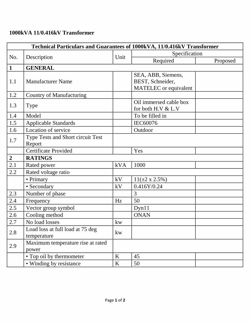
1000kVA 11/0.416kV Transformer Technical Particulars and Guarantees of 1000kVA, 11/0.416kV Transformer
No. Description Unit Specification Required Proposed
1 GENERAL
1.1 Manufacturer Name SEA, ABB, Siemens, BEST, Schneider, MATELEC or equivalent
1.2 Country of Manufacturing
1.3 Type Oil immersed cable box for both H.V & L.V
1.4 Model To be filled in 1.5 Applicable Standards IEC60076 1.6 Location of service Outdoor
1.7 Type Tests and Short circuit Test Report
Certificate Provided Yes 2 RATINGS 2.1 Rated power kVA 1000 2.2 Rated voltage ratio
• Primary kV 11(±2 x 2.5%) • Secondary kV 0.416Y/0.24
2.3 Number of phase 3 2.4 Frequency Hz 50 2.5 Vector group symbol Dyn11 2.6 Cooling method ONAN 2.7 No load losses kw
2.8 Load loss at full load at 75 deg temperature kw
2.9 Maximum temperature rise at rated power
• Top oil by thermometer K 45 • Winding by resistance K 50

Page 2 of 2
Technical Particulars and Guarantees of 1000kVA, 11/0.416kV Transformer
No. Description Unit Specification Required Proposed
• Hot spot of winding K To be filled in
2.10 Impedance voltage at continuous rated power % ≥ 6
3 Rated insulation level for Primary
• Impulse withstand voltage (1.2/50µS)
kV peak 75
• One minute 50Hz withstand voltage kV rms 28
4 DESIGN DETAILS 4.1 Off-load tap changer
• Tapping range (±2 x 2.5%) • Tapping step 2.50%
4.2 Type of oil (As per IEC requirement) SHELL DIALA B
5 DIMENSION AND WEIGHT
5.1 Dimension of Transformer (L x W x H) mm To be filled in
5.2 Total oil required(Volume) Liter To be filled in
5.3 Total weight of complete transformer including fitting and oil kg To be filled in
Page 1 of 1
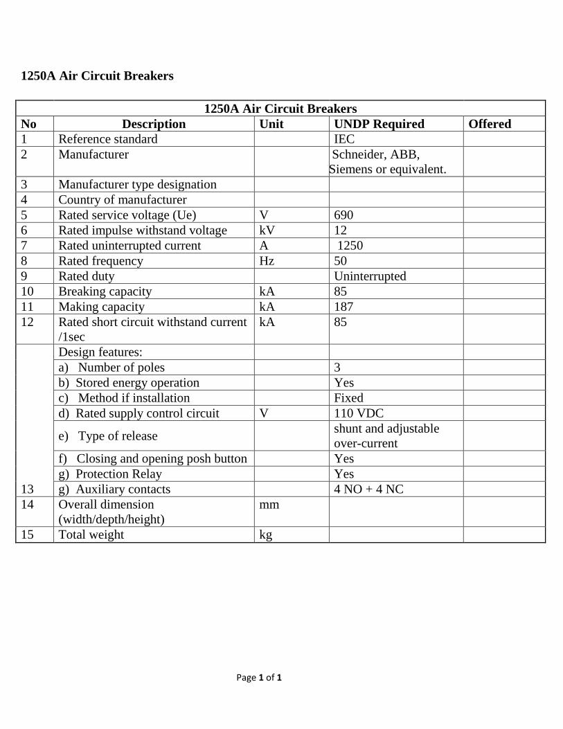
1250A Air Circuit Breakers
1250A Air Circuit Breakers No Description Unit UNDP Required Offered 1 Reference standard IEC 2 Manufacturer Schneider, ABB,
Siemens or equivalent.
3 Manufacturer type designation 4 Country of manufacturer 5 Rated service voltage (Ue) V 690 6 Rated impulse withstand voltage kV 12 7 Rated uninterrupted current A 1250 8 Rated frequency Hz 50 9 Rated duty Uninterrupted 10 Breaking capacity kA 85 11 Making capacity kA 187 12 Rated short circuit withstand current
/1sec kA 85
13
Design features: a) Number of poles 3 b) Stored energy operation Yes c) Method if installation Fixed d) Rated supply control circuit V 110 VDC
e) Type of release shunt and adjustable over-current
f) Closing and opening posh button Yes g) Protection Relay Yes g) Auxiliary contacts 4 NO + 4 NC
14 Overall dimension (width/depth/height)
mm
15 Total weight kg
Page 1 of 1
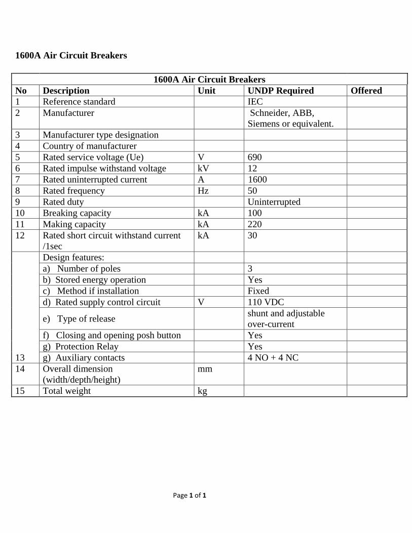
1600A Air Circuit Breakers
1600A Air Circuit Breakers No Description Unit UNDP Required Offered 1 Reference standard IEC 2 Manufacturer Schneider, ABB,
Siemens or equivalent.
3 Manufacturer type designation 4 Country of manufacturer 5 Rated service voltage (Ue) V 690 6 Rated impulse withstand voltage kV 12 7 Rated uninterrupted current A 1600 8 Rated frequency Hz 50 9 Rated duty Uninterrupted 10 Breaking capacity kA 100 11 Making capacity kA 220 12 Rated short circuit withstand current
/1sec kA 30
13
Design features: a) Number of poles 3 b) Stored energy operation Yes c) Method if installation Fixed d) Rated supply control circuit V 110 VDC
e) Type of release shunt and adjustable over-current
f) Closing and opening posh button Yes g) Protection Relay Yes g) Auxiliary contacts 4 NO + 4 NC
14 Overall dimension (width/depth/height)
mm
15 Total weight kg
Page 1 of 1
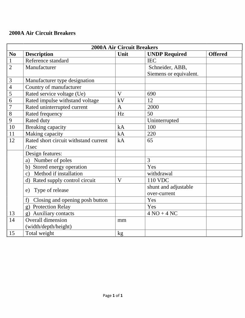
2000A Air Circuit Breakers
2000A Air Circuit Breakers No Description Unit UNDP Required Offered 1 Reference standard IEC 2 Manufacturer Schneider, ABB,
Siemens or equivalent.
3 Manufacturer type designation 4 Country of manufacturer 5 Rated service voltage (Ue) V 690 6 Rated impulse withstand voltage kV 12 7 Rated uninterrupted current A 2000 8 Rated frequency Hz 50 9 Rated duty Uninterrupted 10 Breaking capacity kA 100 11 Making capacity kA 220 12 Rated short circuit withstand current
/1sec kA 65
13
Design features: a) Number of poles 3 b) Stored energy operation Yes c) Method if installation withdrawal d) Rated supply control circuit V 110 VDC
e) Type of release shunt and adjustable over-current
f) Closing and opening posh button Yes g) Protection Relay Yes g) Auxiliary contacts 4 NO + 4 NC
14 Overall dimension (width/depth/height)
mm
15 Total weight kg
Page 1 of 1
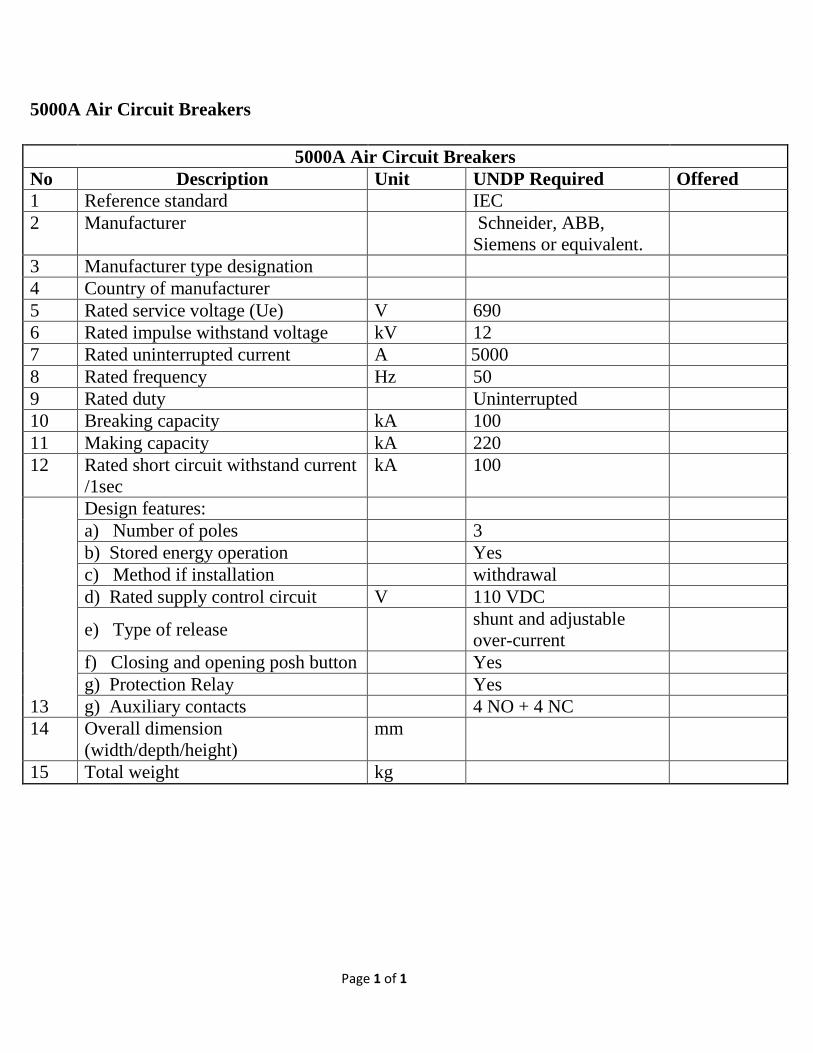
5000A Air Circuit Breakers
5000A Air Circuit Breakers No Description Unit UNDP Required Offered 1 Reference standard IEC 2 Manufacturer Schneider, ABB,
Siemens or equivalent.
3 Manufacturer type designation 4 Country of manufacturer 5 Rated service voltage (Ue) V 690 6 Rated impulse withstand voltage kV 12 7 Rated uninterrupted current A 5000 8 Rated frequency Hz 50 9 Rated duty Uninterrupted 10 Breaking capacity kA 100 11 Making capacity kA 220 12 Rated short circuit withstand current
/1sec kA 100
13
Design features: a) Number of poles 3 b) Stored energy operation Yes c) Method if installation withdrawal d) Rated supply control circuit V 110 VDC
e) Type of release shunt and adjustable over-current
f) Closing and opening posh button Yes g) Protection Relay Yes g) Auxiliary contacts 4 NO + 4 NC
14 Overall dimension (width/depth/height)
mm
15 Total weight kg
Page 1 of 2
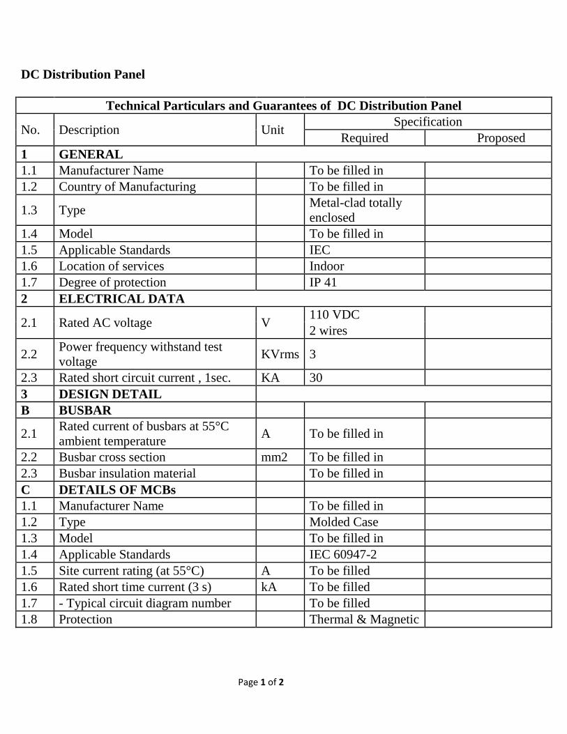
DC Distribution Panel
Technical Particulars and Guarantees of DC Distribution Panel
No. Description Unit Specification Required Proposed
1 GENERAL 1.1 Manufacturer Name To be filled in 1.2 Country of Manufacturing To be filled in
1.3 Type Metal-clad totally enclosed
1.4 Model To be filled in 1.5 Applicable Standards IEC 1.6 Location of services Indoor 1.7 Degree of protection IP 41 2 ELECTRICAL DATA
2.1 Rated AC voltage V 110 VDC 2 wires
2.2 Power frequency withstand test voltage KVrms 3
2.3 Rated short circuit current , 1sec. KA 30 3 DESIGN DETAIL B BUSBAR
2.1 Rated current of busbars at 55°C ambient temperature A To be filled in
2.2 Busbar cross section mm2 To be filled in 2.3 Busbar insulation material To be filled in C DETAILS OF MCBs 1.1 Manufacturer Name To be filled in 1.2 Type Molded Case 1.3 Model To be filled in 1.4 Applicable Standards IEC 60947-2 1.5 Site current rating (at 55°C) A To be filled 1.6 Rated short time current (3 s) kA To be filled 1.7 - Typical circuit diagram number To be filled 1.8 Protection Thermal & Magnetic
Page 2 of 2
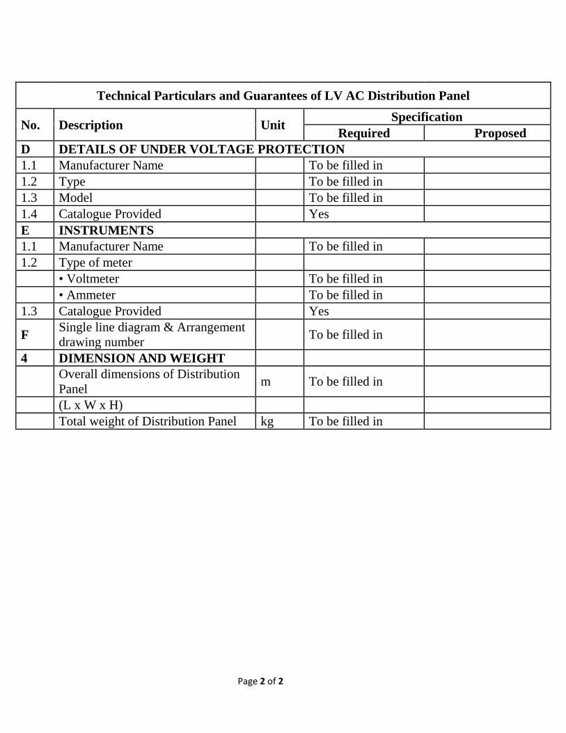
Technical Particulars and Guarantees of LV AC Distribution Panel
No. Description Unit Specification Required Proposed
D DETAILS OF UNDER VOLTAGE PROTECTION 1.1 Manufacturer Name To be filled in 1.2 Type To be filled in 1.3 Model To be filled in 1.4 Catalogue Provided Yes E INSTRUMENTS 1.1 Manufacturer Name To be filled in 1.2 Type of meter • Voltmeter To be filled in • Ammeter To be filled in 1.3 Catalogue Provided Yes
F Single line diagram & Arrangement drawing number To be filled in
4 DIMENSION AND WEIGHT
Overall dimensions of Distribution Panel m To be filled in
(L x W x H) Total weight of Distribution Panel kg To be filled in
Page 1 of 2
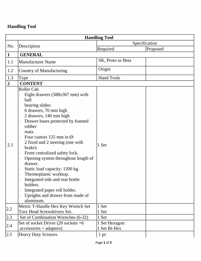
Handling Tool
Handling Tool
No. Description Specification Required Proposed
1 GENERAL 1.1 Manufacturer Name SK, Proto or Beta
1.2 Country of Manufacturing Origin 1.3 Type Hand Tools 2 CONTENT
2.1
Roller Cab - Eight drawers (588x367 mm) with
ball bearing slides: 6 drawers, 70 mm high 2 drawers, 140 mm high
- Drawer bases protected by foamed rubber mats.
- Four castors 125 mm in Ø: 2 fixed and 2 steering (one with brake).
- Front centralized safety lock. - Opening system throughout length of
drawer. - Static load capacity: 1200 kg. - Thermoplastic worktop. - Integrated side and rear bottle
holders. - Integrated paper roll holder. - Uprights and drawer front made of
aluminum.
1 Set
2.2 Metric T-Handle Hex Key Wrench Set Torx Head Screwdrivers Set.
1 Set 1 Set
2.3 Set of Combination Wrenches (6-32) 1 Set
2.4 Set of socket Driver (20 sockets +6 accessories + adapters)
1 Set Hexagon 1 Set Bi-Hex
2.5 Heavy Duty Scissors 1 pc
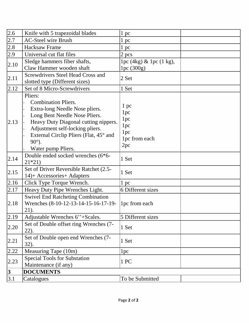
Page 2 of 2
2.6 Knife with 5 trapezoidal blades 1 pc 2.7 AC-Steel wire Brush 1 pc 2.8 Hacksaw Frame 1 pc 2.9 Universal cut flat files 2 pcs
2.10 Sledge hammers fiber shafts, Claw Hammer wooden shaft
1pc (4kg) & 1pc (1 kg), 1pc (300g)
2.11 Screwdrivers Steel Head Cross and slotted type (Different sizes) 2 Set
2.12 Set of 8 Micro-Screwdrivers 1 Set
2.13
Pliers: - Combination Pliers. - Extra-long Needle Nose pliers. - Long Bent Needle Nose Pliers. - Heavy Duty Diagonal cutting nippers. - Adjustment self-locking pliers. - External Circlip Pliers (Flat, 45° and
90°). - Water pump Pliers.
1 pc 1pc 1pc 1pc 1pc 1pc from each 2pc
2.14 Double ended socked wrenches (6*6-21*21) 1 Set
2.15 Set of Driver Reversible Ratchet (2.5-14)+ Accessories+ Adapters 1 Set
2.16 Click Type Torque Wrench. 1 pc 2.17 Heavy Duty Pipe Wrenches Light. 6 Different sizes
2.18 Swivel End Ratcheting Combination Wrenches (8-10-12-13-14-15-16-17-19-21).
1pc from each
2.19 Adjustable Wrenches 6’’+Scales. 5 Different sizes
2.20 Set of Double offset ring Wrenches (7-22). 1 Set
2.21 Set of Double open end Wrenches (7-32). 1 Set
2.22 Measuring Tape (10m) 1pc
2.23 Special Tools for Substation Maintenance (if any) 1 PC
3 DOCUMENTS 3.1 Catalogues To be Submitted
Page 1 of 2
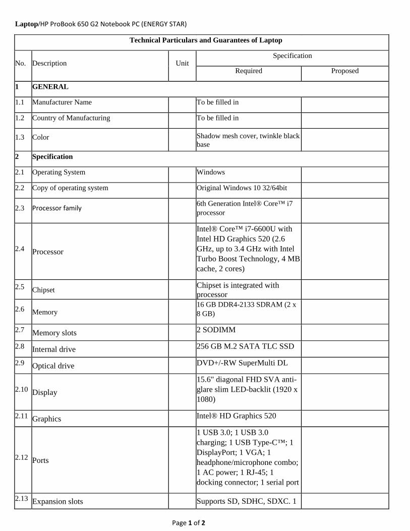
Laptop/HP ProBook 650 G2 Notebook PC (ENERGY STAR)
Technical Particulars and Guarantees of Laptop
No. Description Unit Specification
Required Proposed
1 GENERAL
1.1 Manufacturer Name To be filled in
1.2 Country of Manufacturing To be filled in
1.3 Color Shadow mesh cover, twinkle black base
2 Specification
2.1 Operating System
Windows
2.2 Copy of operating system
Original Windows 10 32/64bit
2.3 Processor family
6th Generation Intel® Core™ i7 processor
2.4 Processor
Intel® Core™ i7-6600U with Intel HD Graphics 520 (2.6 GHz, up to 3.4 GHz with Intel Turbo Boost Technology, 4 MB cache, 2 cores)
2.5 Chipset Chipset is integrated with processor
2.6 Memory 16 GB DDR4-2133 SDRAM (2 x 8 GB)
2.7 Memory slots 2 SODIMM
2.8 Internal drive 256 GB M.2 SATA TLC SSD
2.9 Optical drive DVD+/-RW SuperMulti DL
2.10 Display 15.6" diagonal FHD SVA anti-glare slim LED-backlit (1920 x 1080)
2.11 Graphics Intel® HD Graphics 520
2.12 Ports
1 USB 3.0; 1 USB 3.0 charging; 1 USB Type-C™; 1 DisplayPort; 1 VGA; 1 headphone/microphone combo; 1 AC power; 1 RJ-45; 1 docking connector; 1 serial port
2.13 Expansion slots Supports SD, SDHC, SDXC. 1
Page 2 of 2
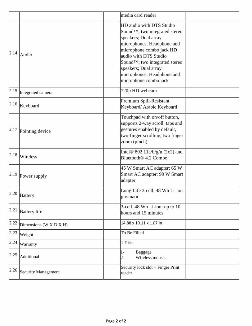
media card reader
2.14 Audio
HD audio with DTS Studio Sound™; two integrated stereo speakers; Dual array microphones; Headphone and microphone combo jack HD audio with DTS Studio Sound™; two integrated stereo speakers; Dual array microphones; Headphone and microphone combo jack
2.15 Integrated camera 720p HD webcam
2.16 Keyboard Premium Spill-Resistant Keyboard/ Arabic Keyboard
2.17 Pointing device
Touchpad with on/off button, supports 2-way scroll, taps and gestures enabled by default, two-finger scrolling, two finger zoom (pinch)
2.18 Wireless Intel® 802.11a/b/g/n (2x2) and Bluetooth® 4.2 Combo
2.19 Power supply 45 W Smart AC adapter; 65 W Smart AC adapter; 90 W Smart adapter
2.20 Battery Long Life 3-cell, 48 Wh Li-ion prismatic
2.21 Battery life 3-cell, 48 Wh Li-ion: up to 10 hours and 15 minutes
2.22 Dimensions (W X D X H) 14.88 x 10.11 x 1.07 in
2.23 Weight To Be Filled
2.24 Warranty 1 Year
2.25 Additional 1- Baggage 2- Wireless mouse.
2.26 Security Management Security lock slot + Finger Print reader
Page 1 of 2
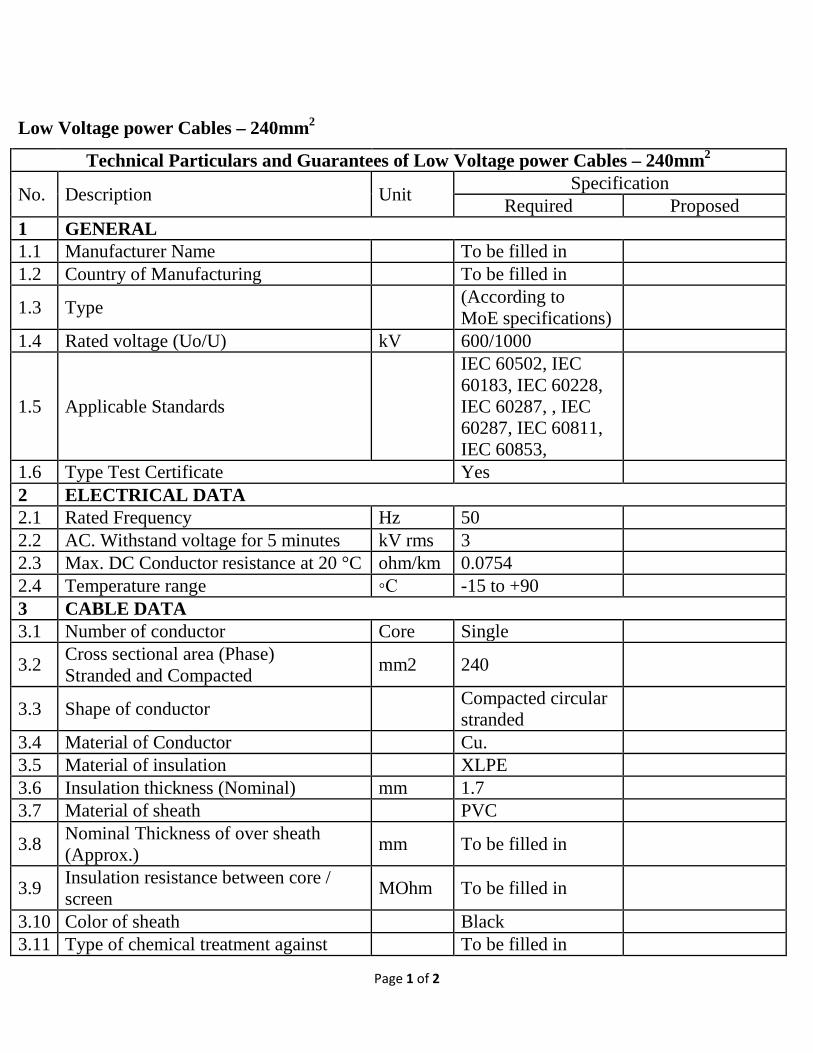
Low Voltage power Cables – 240mm2
Technical Particulars and Guarantees of Low Voltage power Cables – 240mm2
No. Description Unit Specification Required Proposed
1 GENERAL 1.1 Manufacturer Name To be filled in 1.2 Country of Manufacturing To be filled in
1.3 Type (According to MoE specifications)
1.4 Rated voltage (Uo/U) kV 600/1000
1.5 Applicable Standards
IEC 60502, IEC 60183, IEC 60228, IEC 60287, , IEC 60287, IEC 60811, IEC 60853,
1.6 Type Test Certificate Yes 2 ELECTRICAL DATA 2.1 Rated Frequency Hz 50 2.2 AC. Withstand voltage for 5 minutes kV rms 3 2.3 Max. DC Conductor resistance at 20 °C ohm/km 0.0754 2.4 Temperature range C -15 to +90 3 CABLE DATA 3.1 Number of conductor Core Single
3.2 Cross sectional area (Phase) Stranded and Compacted mm2 240
3.3 Shape of conductor Compacted circular stranded
3.4 Material of Conductor Cu. 3.5 Material of insulation XLPE 3.6 Insulation thickness (Nominal) mm 1.7 3.7 Material of sheath PVC
3.8 Nominal Thickness of over sheath (Approx.) mm To be filled in
3.9 Insulation resistance between core / screen MOhm To be filled in
3.10 Color of sheath Black 3.11 Type of chemical treatment against To be filled in
Page 2 of 2
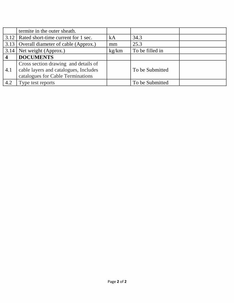
termite in the outer sheath. 3.12 Rated short-time current for 1 sec. kA 34.3 3.13 Overall diameter of cable (Approx.) mm 25.3 3.14 Net weight (Approx.) kg/km To be filled in 4 DOCUMENTS
4.1 Cross section drawing and details of cable layers and catalogues, Includes catalogues for Cable Terminations
To be Submitted
4.2 Type test reports To be Submitted
Equipment’s Should Comply with AIS Technical Specifications. Page 1 of 2
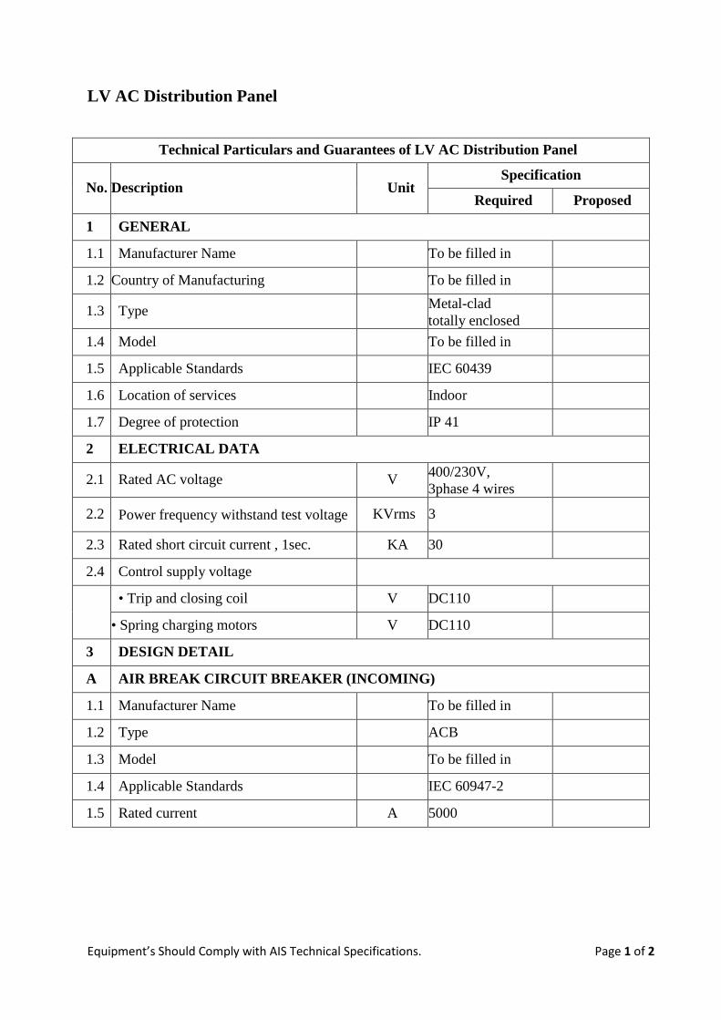
LV AC Distribution Panel
Technical Particulars and Guarantees of LV AC Distribution Panel
No. Description Unit Specification
Required Proposed
1 GENERAL
1.1 Manufacturer Name To be filled in
1.2 Country of Manufacturing To be filled in
1.3 Type Metal-clad totally enclosed
1.4 Model To be filled in
1.5 Applicable Standards IEC 60439
1.6 Location of services Indoor
1.7 Degree of protection IP 41
2 ELECTRICAL DATA
2.1 Rated AC voltage V 400/230V, 3phase 4 wires
2.2 Power frequency withstand test voltage KVrms 3
2.3 Rated short circuit current , 1sec. KA 30
2.4 Control supply voltage
• Trip and closing coil V DC110
• Spring charging motors V DC110
3 DESIGN DETAIL
A AIR BREAK CIRCUIT BREAKER (INCOMING)
1.1 Manufacturer Name To be filled in
1.2 Type ACB
1.3 Model To be filled in
1.4 Applicable Standards IEC 60947-2
1.5 Rated current A 5000
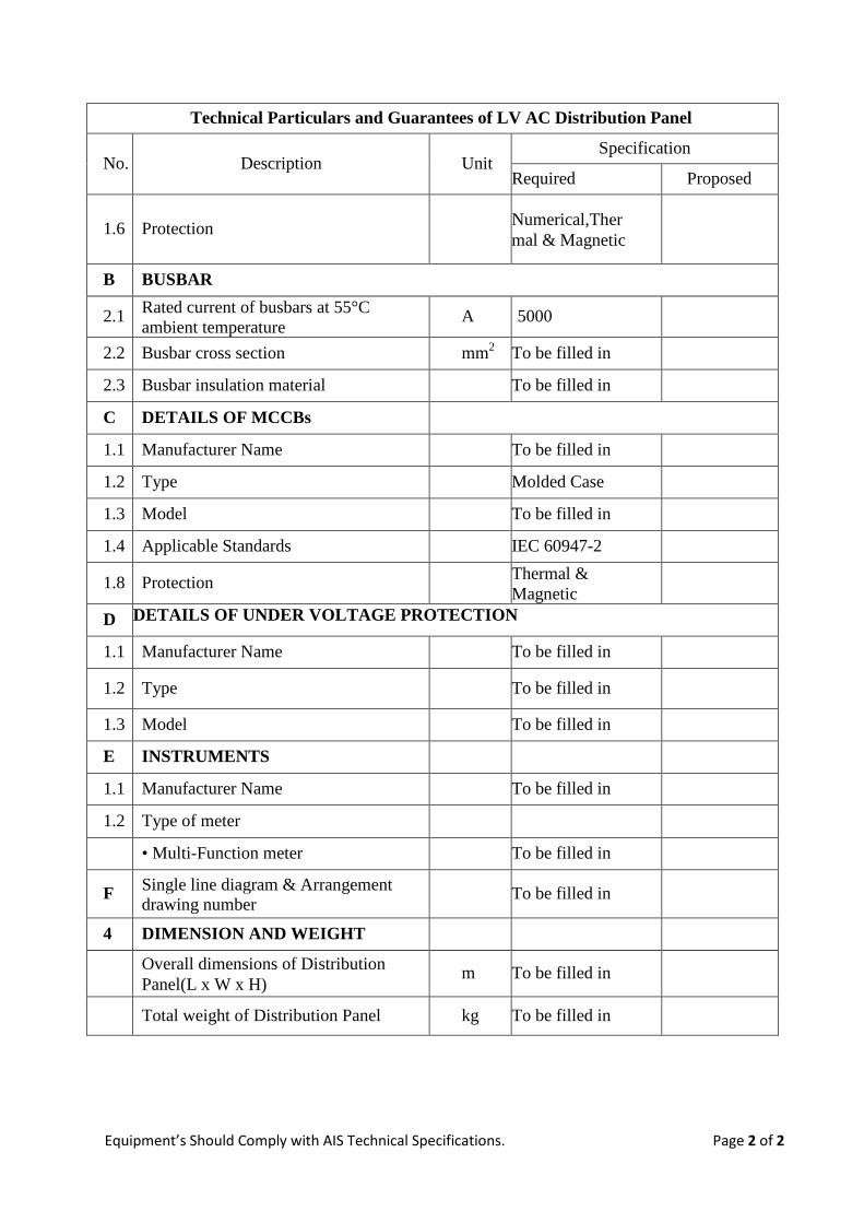
Equipment’s Should Comply with AIS Technical Specifications. Page 2 of 2
Technical Particulars and Guarantees of LV AC Distribution Panel
No. Description Unit Specification
Required Proposed
1.6 Protection Numerical,Thermal & Magnetic
B BUSBAR
2.1 Rated current of busbars at 55°C ambient temperature A 5000
2.2 Busbar cross section mm2 To be filled in
2.3 Busbar insulation material To be filled in
C DETAILS OF MCCBs
1.1 Manufacturer Name To be filled in
1.2 Type Molded Case
1.3 Model To be filled in
1.4 Applicable Standards IEC 60947-2
1.8 Protection Thermal & Magnetic
D DETAILS OF UNDER VOLTAGE PROTECTION
1.1 Manufacturer Name To be filled in
1.2 Type To be filled in
1.3 Model To be filled in
E INSTRUMENTS
1.1 Manufacturer Name To be filled in
1.2 Type of meter
• Multi-Function meter To be filled in
F Single line diagram & Arrangement drawing number
To be filled in
4 DIMENSION AND WEIGHT
Overall dimensions of Distribution Panel(L x W x H)
m To be filled in
Total weight of Distribution Panel kg To be filled in
Related Documents