ZVL517.01 Mod: 24.09.2016 BL 24Vdc Motors Questo prodotto è stato testato e collaudato nei laboratori della casa costruttrice, la quale ne ha verificato la perfetta corrispondenza delle caratteristiche con quelle richieste dalla normativa vigente. This product has been tried and tested in the manufacturer's laboratory who have verified that the product conforms in every aspect to the safety standards in force. Ce produit a été testé et essayé dans les laboratoires du fabriquant. Pour l'installer suivre attentivement les instructions fournies. Dieses Produkt wurde in den Werkstätten der Herstellerfirma auf die perfekte Übereinstimmung ihrer Eigenschaften mit den von den geltenden Normen vorgeschriebenen getestet und geprüft. Este producto ha sido probado y ensayado en los laboratorios del fabricante, que ha comprobado la perfecta correspondencia de sus características con las contempladas por la normativa vigente. Model Date Instruction manual Series BL824 M-S 23-06-2011 ZVL517.01 ACHTUNG! Bevor mit der Installation begonnen wird, sollte die Anleitung aufmerksam gelesen werden! Anlagenart Seite 3 Montagegearbeiten Seiten 4-7 Elektrischer Schaltplan (Anlagenart) Seite 8 Wichtige Hinweise Seite 33 Installationsanleitung Seiten 33-34 Manuelle Entriegelung Seite 34 Elektrischer Anschluss Seiten 34-35 Programmierverfahren Seite 36-38 Neupositionierung Seite 38 Funkbefehl Seite 38 Betriebsmodus Seiten 39 Batteriebetrieb Seite 40 Technische Eigenschaften Seite 52 ITALIANO ENGLISH ESPAÑOL DEUTSCH FRANÇAIS ATTENTION! Before installing this device read the following instructions carefully! Installation example Page 3 Assembly Pages 4-7 Wiring diagram (installation example) Page 8 Important remarks Page 17 Installation instructions Pages 17-18 Manual release mechanism Page 18 Electrical connection Pages 18-19 Programming procedure Page 20-22 Repositioning Page 22 Remote control Page 22 Function modes Pages 23 Battery powered operation Page 24 Technical specifications Page 52 ATTENTION! Avant de commencer la pose, lire attentivement les instructions! Exemple d’installation Page 3 Schéma de montage Pages 4-7 Schéma électrique (exemple d’installation) Page 8 Consignes importants Page 25 Instructions pour l’installation Pages 25-26 Déverrouillage manuel Page 26 Branchement électrique Pages 26-27 Procédé de programmation Page 28-30 Repositionnement Page 30 Commande via radio Page 30 Modes de fonctionnement Pages 31 Fonctionnement à batterie Page 32 Caractéristiques techniques Page 52 ATTENZIONE! Prima di iniziare l'installazione leggere le istruzioni attentamente! Esempio di installazione Pagina 3 Schema di montaggio Pagine 4-7 Schema elettrico (impianto tipo) Pagina 8 Avvertenze importanti Pagina 9 Istruzione per l’installazione Pagine 9-10 Sblocco manuale Pagina 10 Collegamento elettrico Pagine 10-11 Procedura di programmazione Pagina 12-14 Riposizionamento automatico Pagina 14 Comando via radio Pagina 14 Modalità di funzionamento Pagine 15 Funzionamento a batteria Pagina 16 Caratteristiche tecniche Pagina 52 ¡ATENCIÓN! Antes de iniciar la instalación del sistema, leer atentamente las instrucciones. Instalación estándar Página 3 Esquema de montaje Páginas 4-7 Esquema eléctrico (instalación estándar ) Página 8 Advertencias importantes Página 41 Instrucciones para la instalación Páginas 41-42 Desbloqueo manual Página 42 Conexionado eléctrico Páginas 42-43 Procedimiento de programación Página 44-46 Reposicionamiento Página 46 Mando vía radio Página 46 Modalidad de funcionamiento Páginas 47 Funcionamiento a batería Página 48 Datos técnicas Página 52 CARDIN ELETTRONICA spa Via del lavoro, 73 – Z.I. Cimavilla 31013 Codognè (TV) Italy Tel: +39/0438.404011 Fax: +39/0438.401831 email (Italian): [email protected] email (Europe): [email protected] Http: www.cardin.it 24Vdc Motors 200/BL824MCB (V1.00) 200/BL82424S AUTOMAZIONE PER CANCELLI A BATTENTE AUTOMATION FOR HINGED GATES AUTOMATISME POUR PORTAILS BATTANTS DREHTORANTRIEBE AUTOMATIZACIÓN PARA CANCILLAS BATIENTES S 4 4 9 - - - S 4 8 6 - - - S 5 0 8 - - - S 5 0 4 - - - Multi Decoding

Welcome message from author
This document is posted to help you gain knowledge. Please leave a comment to let me know what you think about it! Share it to your friends and learn new things together.
Transcript
ZV
L517
.01
Mod
: 24.
09.2
016
BL24VdcMotors
Questo prodotto è stato testato e collaudato nei laboratori della casa costruttrice, la quale ne ha verificato la perfetta corrispondenza delle caratteristiche con quelle richieste dalla normativa vigente. This product has been tried and tested in the manufacturer's laboratory who have verified that the product conforms in every aspect to the safety standards in force. Ce produit a été testé et essayé dans les laboratoires du fabriquant. Pour l'installer suivre attentivement les instructions fournies. Dieses Produkt wurde in den Werkstätten der Herstellerfirma auf die perfekte Übereinstimmung ihrer Eigenschaften mit den von den geltenden Normen vorgeschriebenen getestet und geprüft. Este producto ha sido probado y ensayado en los laboratorios del fabricante, que ha comprobado la perfecta correspondencia de sus características con las contempladas por la normativa vigente.
Model DateInstruction manual Series
BL824 M-S 23-06-2011ZVL517.01
ACHTUNG! Bevor mit der Installation begonnen wird, sollte die Anleitung aufmerksam gelesen werden!
Anlagenart Seite 3Montagegearbeiten Seiten 4-7Elektrischer Schaltplan (Anlagenart) Seite 8Wichtige Hinweise Seite 33 Installationsanleitung Seiten 33-34Manuelle Entriegelung Seite 34 Elektrischer Anschluss Seiten 34-35Programmierverfahren Seite 36-38Neupositionierung Seite 38Funkbefehl Seite 38Betriebsmodus Seiten 39Batteriebetrieb Seite 40Technische Eigenschaften Seite 52
ITALIANO
ENGLISH ESPAÑOL
DEUTSCH
FRANÇAIS
ATTENTION! Before installing this device read the following instructions carefully!
Installation example Page 3Assembly Pages 4-7Wiring diagram (installation example) Page 8Important remarks Page 17Installation instructions Pages 17-18Manual release mechanism Page 18Electrical connection Pages 18-19Programming procedure Page 20-22Repositioning Page 22Remote control Page 22Function modes Pages 23Battery powered operation Page 24Technical specifications Page 52
ATTENTION! Avant de commencer la pose, lire attentivement les instructions!
Exemple d’installation Page 3Schéma de montage Pages 4-7Schéma électrique (exemple d’installation) Page 8Consignes importants Page 25Instructions pour l’installation Pages 25-26Déverrouillage manuel Page 26Branchement électrique Pages 26-27Procédé de programmation Page 28-30 Repositionnement Page 30Commande via radio Page 30Modes de fonctionnement Pages 31Fonctionnement à batterie Page 32Caractéristiques techniques Page 52
ATTENZIONE! Prima di iniziare l'installazione leggere le istruzioni attentamente!
Esempio di installazione Pagina 3Schema di montaggio Pagine 4-7Schema elettrico (impianto tipo) Pagina 8Avvertenze importanti Pagina 9Istruzione per l’installazione Pagine 9-10Sblocco manuale Pagina 10Collegamento elettrico Pagine 10-11Procedura di programmazione Pagina 12-14 Riposizionamento automatico Pagina 14Comando via radio Pagina 14Modalità di funzionamento Pagine 15Funzionamento a batteria Pagina 16Caratteristiche tecniche Pagina 52
¡ATENCIÓN! Antes de iniciar la instalación del sistema, leer atentamente las instrucciones.
Instalación estándar Página 3Esquema de montaje Páginas 4-7Esquema eléctrico (instalación estándar ) Página 8Advertencias importantes Página 41Instrucciones para la instalación Páginas 41-42Desbloqueo manual Página 42Conexionado eléctrico Páginas 42-43Procedimiento de programación Página 44-46Reposicionamiento Página 46Mando vía radio Página 46Modalidad de funcionamiento Páginas 47Funcionamiento a batería Página 48 Datos técnicas Página 52
CARDIN ELETTRONICA spa Via del lavoro, 73 – Z.I. Cimavilla 31013 Codognè (TV) I ta lyTel: +39/0438.404011Fax: +39/0438.401831email (Italian): [email protected] (Europe): [email protected]: www.cardin.it
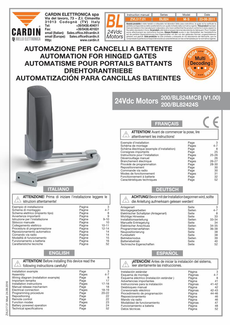
24Vdc Motors 200/BL824MCB (V1.00) 200/BL82424S
AUTOMAZIONE PER CANCELLI A BATTENTEAUTOMATION FOR HINGED GATES
AUTOMATISME POUR PORTAILS BATTANTSDREHTORANTRIEBE
AUTOMATIZACIÓN PARA CANCILLAS BATIENTES
S449 --- S486 --- S508
---
S5
04 ---
MultiDecoding

2
NOTES
3
pro
do
tti Card
in (lamp
. foto
cellule ecc.)
BL824
12.10.11
DI0565
Descrip
tion :
Prod
uct Cod
e :
Date :
Draw
ing numb
er :
P.J.Heath
CA
RD
IN E
LET
TR
ON
ICA
S.p
.A - 31020 S
an Vendem
iano (T
V) Italy - via R
affaello, 36 Tel: 0438/401818 F
ax: 0438/401831
Draft :
All rights reserved
. Unauthorised
copying or use of the inform
ation contained in this d
ocument is p
unishable b
y law
INS
TALLA
ZIO
NE
TIP
O B
L824 (SLIM
)
3
1
4
58
11
1012
7
2
6
9
230V-50Hz
13
1
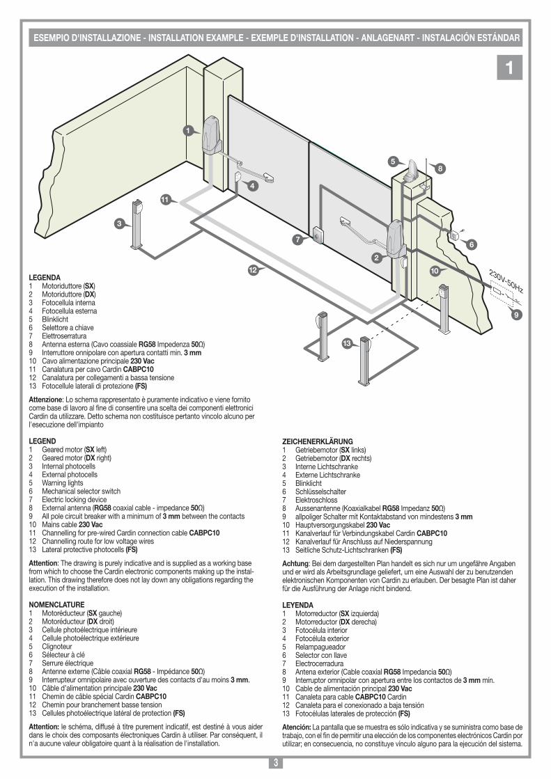
ESEMPIO D'INSTALLAZIONE - INSTALLATION EXAMPLE - EXEMPLE D'INSTALLATION - ANLAGENART - INSTALACIÓN ESTÁNDAR
LEGENDA1 Motoriduttore (SX)2 Motoriduttore (DX)3 Fotocellula interna 4 Fotocellula esterna5 Blinklicht 6 Selettore a chiave7 Elettroserratura 8 Antenna esterna (Cavo coassiale RG58 Impedenza 50Ω)9 Interruttore onnipolare con apertura contatti min. 3 mm10 Cavo alimentazione principale 230 Vac11 Canalatura per cavo Cardin CABPC1012 Canalatura per collegamenti a bassa tensione13 Fotocellule laterali di protezione (FS)
Attenzione: Lo schema rappresentato è puramente indicativo e viene fornito come base di lavoro al fine di consentire una scelta dei componenti elettronici Cardin da utilizzare. Detto schema non costituisce pertanto vincolo alcuno per l'esecuzione dell'impianto
LEGEND1 Geared motor (SX left)2 Geared motor (DX right)3 Internal photocells 4 External photocells5 Warning lights6 Mechanical selector switch7 Electric locking device8 External antenna (RG58 coaxial cable - impedance 50Ω)9 All pole circuit breaker with a minimum of 3 mm between the contacts10 Mains cable 230 Vac11 Channelling for pre-wired Cardin connection cable CABPC1012 Channelling route for low voltage wires13 Lateral protective photocells (FS)
Attention: The drawing is purely indicative and is supplied as a working base from which to choose the Cardin electronic components making up the instal-lation. This drawing therefore does not lay down any obligations regarding the execution of the installation.
NOMENCLATURE1 Motoréducteur (SX gauche)2 Motoréducteur (DX droit)3 Cellule photoélectrique intérieure 4 Cellule photoélectrique extérieure5 Clignoteur 6 Sélecteur à clé7 Serrure électrique8 Antenne externe (Câble coaxial RG58 - Impédance 50Ω)9 Interrupteur omnipolaire avec ouverture des contacts d'au moins 3 mm.10 Câble d’alimentation principale 230 Vac11 Chemin de câble spécial Cardin CABPC1012 Chemin pour branchement basse tension13 Cellules photoélectrique latéral de protection (FS)
Attention: le schéma, diffusé à titre purement indicatif, est destiné à vous aider dans le choix des composants électroniques Cardin à utiliser. Par conséquent, il n'a aucune valeur obligatoire quant à la réalisation de l'installation.
ZEICHENERKLÄRUNG1 Getriebemotor (SX links)2 Getriebemotor (DX rechts)3 Interne Lichtschranke4 Externe Lichtschranke5 Blinklicht6 Schlüsselschalter7 Elektroschloss 8 Aussenantenne (Koaxialkabel RG58 Impedanz 50Ω)9 allpoliger Schalter mit Kontaktabstand von mindestens 3 mm10 Hauptversorgungskabel 230 Vac11 Kanalverlauf für Verbindungskabel Cardin CABPC1012 Kanalverlauf für Anschluss auf Niederspannung13 Seitliche Schutz-Lichtschranken (FS)
Achtung: Bei dem dargestellten Plan handelt es sich nur um ungefähre Angaben und er wird als Arbeitsgrundlage geliefert, um eine Auswahl der zu benutzenden elektronischen Komponenten von Cardin zu erlauben. Der besagte Plan ist daher für die Ausführung der Anlage nicht bindend.
LEYENDA1 Motorreductor (SX izquierda)2 Motorreductor (DX derecha)3 Fotocélula interior 4 Fotocélula exterior5 Relampagueador6 Selector con llave7 Electrocerradura8 Antena exterior (Cable coaxial RG58 Impedancia 50Ω)9 Interruptor omnipolar con apertura entre los contactos de 3 mm mín.10 Cable de alimentación principal 230 Vac11 Canaleta para cable CABPC10 Cardin 12 Canaleta para el conexionado a baja tensión13 Fotocélulas laterales de protección (FS)
Atención: La pantalla que se muestra es sólo indicativa y se suministra como base de trabajo, con el fin de permitir una elección de los componentes electrónicos Cardin por utilizar; en consecuencia, no constituye vínculo alguno para la ejecución del sistema.
4
Dimensioni d'ingombro bracci
BL3924DRM
15-56-2006
DI0466 Description :
Product Code :
Date :
Drawing number :
P.J.Heath
CARDIN ELETTRONICA S.p.A - 31020 San Vendemiano (TV) Italy - via Raffaello, 36 Tel: 0438/401818 Fax: 0438/401831
Draft :
All rights reserved. Unauthorised copying or use of the information contained in this document is punishable by law
BL3924DRM
550
32
31
ISTRUZIONE PER IL MONTAGGIO
12-05-2006
DM0827 Description :
Product Code :
Date :
Drawing number :
P.J.Heath
CARDIN ELETTRONICA S.p.A - 31020 San Vendemiano (TV) Italy - via Raffaello, 36 Tel: 0438/401818 Fax: 0438/401831
Draft :
All rights reserved. Unauthorised copying or use of the information contained in this document is punishable by law
MONTAGGIO BL824BL824
Dett “A”
Dett “B”
Dett. 1206/BL824DRM
112
14
13
67
7
2
10
8
9
10
3
4
5
11
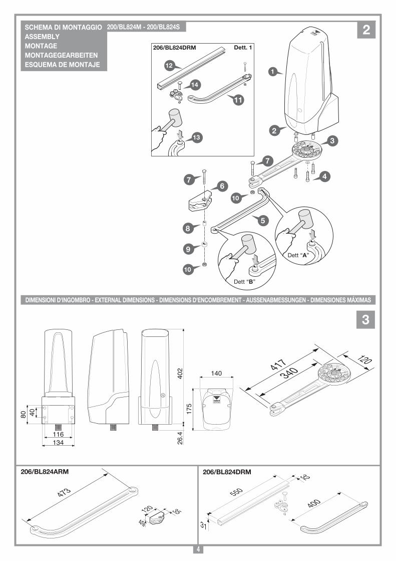
2SCHEMA DI MONTAGGIO ASSEMBLYMONTAGE MONTAGEGEARBEITENESQUEMA DE MONTAJE
200/BL824M - 200/BL824S
3
DIMENSIONI D'INGOMBRO - EXTERNAL DIMENSIONS - DIMENSIONS D'ENCOMBREMENT - AUSSENABMESSUNGEN - DIMENSIONES MÁXIMAS
Dimensioni d'ingombro bracci
BL????
15-05-2006
DI0436 Description :
Product Code :
Date :
Drawing number :
P.J.Heath
CARDIN ELETTRONICA S.p.A - 31020 San Vendemiano (TV) Italy - via Raffaello, 36 Tel: 0438/401818 Fax: 0438/401831
Draft :
All rights reserved. Unauthorised copying or use of the information contained in this document is punishable by law
BRACCIO CURVO NUOVO
473
Dimensioni d'ingombro bracci
BL824
12-10-2011
DI0566 Description :
Product Code :
Date :
Drawing number :
P.J.Heath
CARDIN ELETTRONICA S.p.A - 31020 San Vendemiano (TV) Italy - via Raffaello, 36 Tel: 0438/401818 Fax: 0438/401831
Draft :
All rights reserved. Unauthorised copying or use of the information contained in this document is punishable by law
BRACCIO BL824
340417120
Dimensioni d'ingombro bracci
BLDRM
05-12-2006
DI0465 Description :
Product Code :
Date :
Drawing number :
P.J.Heath
CARDIN ELETTRONICA S.p.A - 31020 San Vendemiano (TV) Italy - via Raffaello, 36 Tel: 0438/401818 Fax: 0438/401831
Draft :
All rights reserved. Unauthorised copying or use of the information contained in this document is punishable by law
BRACCIO DRITTO NUOVO
400
206/BL824ARM 206/BL824DRM
26.4
140
175
402
134
80 40
116
Dimensioni d'ingombro bracci
BL3924
15-56-2006
DI0437 Description :
Product Code :
Date :
Drawing number :
P.J.Heath
CARDIN ELETTRONICA S.p.A - 31020 San Vendemiano (TV) Italy - via Raffaello, 36 Tel: 0438/401818 Fax: 0438/401831
Draft :
All rights reserved. Unauthorised copying or use of the information contained in this document is punishable by law
staffa fissaggio a muro nuovo
49
35120
5
S
prodotti Technocity
BL824
25-05-2012
DI0567 Description :
Product Code :
Date :
Drawing number :
P.J.Heath
CARDIN ELETTRONICA S.p.A - 31020 San Vendemiano (TV) Italy - via Raffaello, 36 Tel: 0438/401818 Fax: 0438/401831
Draft :
All rights reserved. Unauthorised copying or use of the information contained in this document is punishable by law
INSTALLAZIONE BL824ARM
206/BL824ARM
C
A
I
72
B
231
S
ANGOLO DIAPERTURA
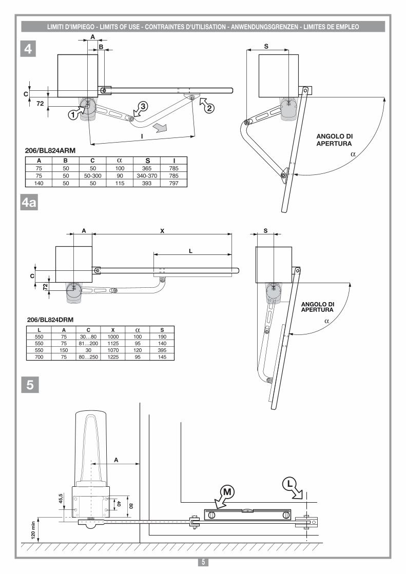
75 50 50 100 365 78575 50 50-300 90 340-370 785
140 50 50 115 393 797
I
LIMITI D’IMPIEGO - LIMITS OF USE - CONTRAINTES D'UTILISATION - ANWENDUNGSGRENZEN - LIMITES DE EMPLEO
4
SC
ALA
:
Pro
do
tti Technocity
BL824
12-10-2011
DI0569
Descrip
tion :
Prod
uct Cod
e :
Date :
Draw
ing numb
er :
P.J.Heath
CA
RD
IN E
LET
TR
ON
ICA
S.p
.A - 31020 S
an Vendem
iano (T
V) Italy - via R
affaello, 36 Tel: 0438/401818 F
ax: 0438/401831
Draft :
All rights reserved
. Unauthorised
copying or use of the inform
ation contained in this d
ocument is p
unishable b
y law
FISS
AG
GIO
BA
SE
MO
TOR
E 824
120
min
A
ML
45,5
80
40
prodotti Cardin
BL824
25-05-2012
206/BL824DRM
S
ANGOLO DIAPERTURA
72
L
XA
C
L A C X S550 75 30…80 1000 100 190550 75 81…200 1125 95 140550 150 30 1070 120 395700 75 80…250 1225 95 145
DI0568 Description :
Product Code :
Date :
Drawing number :
P.J.Heath
CARDIN ELETTRONICA S.p.A - 31020 San Vendemiano (TV) Italy - via Raffaello, 36 Tel: 0438/401818 Fax: 0438/401831
Draft :
All rights reserved. Unauthorised copying or use of the information contained in this document is punishable by law
Installazione BL824DRM
5
4a
6
Description :
Product Code :
Date :
Drawing number :
P.J.Heath
CARDIN ELETTRONICA S.p.A - 31020 San Vendemiano (TV) Italy - via Raffaello, 36 Tel: 0438/401818 Fax: 0438/401831
Draft :
All rights reserved. Unauthorised copying or use of the information contained in this document is punishable by law
ISTRUZIONE PER IL MONTAGGIO
13-10-2011
DM0828
FISSAGGIO BASE MOTOREBL824
V1
4 x M8
V2
D
116
40
4 x M8
E
Dett. 1
G
F
Dett. 2
C
C
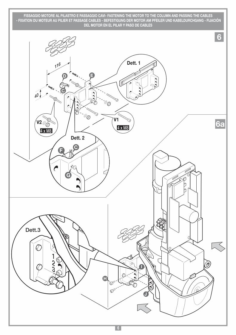
FISSAGGIO MOTORE AL PILASTRO E PASSAGGIO CAVI- FASTENING THE MOTOR TO THE COLUMN AND PASSING THE CABLES - FIXATION DU MOTEUR AU PILIER ET PASSAGE CABLES - BEFESTIGUNG DER MOTOR AM PFEILER UND KABELDURCHGANG - FIJACIÓN
DEL MOTOR EN EL PILAR Y PASO DE CABLES
6
6a
Descrip
tion :
Prod
uct Cod
e :
Date :
Draw
ing numb
er :
P.J.Heath
CA
RD
IN E
LE
TT
RO
NIC
A S
.p.A
- 31020 San Vend
emiano
(TV
) Italy - via Raffaello
, 36 Tel: 0438/401818 Fax: 0438/401831
Draft :
All rights reserved
. Unauthorised
copying or use of the inform
ation contained in this d
ocument is p
unishable b
y law
IST
RU
ZIO
NE
PE
R IL M
ON
TAG
GIO
13-10-2011
DM
0830
FISS
AG
GIO
MO
TO
RE
ALLA
BA
SE
B
L824
I
J
H
123
Dett.3
7
INSERIMENTO FINECORSA MECCANICI E SBLOCCO- INSERTING THE MECHANICAL TRAVEL LIMITS AND RELEASING THE MOTOR - MISE EN PLACE FINS DE COURSE ET DISPOSITIF DE DEVERROUILLAGE MECANIQUES - EINFÜGUNG MECHANISCHE ENDANSCHLÄGE UND
ENTRIEGELUNG -- INSERCIÓN FINALES DE CARRERA MECÁNICOS Y DESBLOQUEO
980/XLSE11C 8
BL202 (serie)
29-07-98
DI0087 Description :
Product Code :
Date :
Drawing number :
P.J.Heath
CARDIN ELETTRONICA S.p.A - 31020 San Vendemiano (TV) Italy - via Raffaello, 36 Tel: 0438/401818 Fax: 0438/401831
Draft :
All rights reserved. Unauthorised copying or use of the information contained in this document is punishable by law
Elettroserratura opzionale
Descrip
tion :
Prod
uct Cod
e :
Date :
Draw
ing numb
er :
P.J.Heath
CA
RD
IN E
LE
TT
RO
NIC
A S
.p.A
- 31020 San Vend
emiano
(TV
) Italy - via Raffaello
, 36 Tel: 0438/401818 Fax: 0438/401831
Draft :
All rights reserved
. Unauthorised
copying or use of the inform
ation contained in this d
ocument is p
unishable b
y law
IST
RU
ZIO
NE
PE
R IL M
ON
TAG
GIO
13-10-2011
DM
0831
INSER
IMEN
TO FIN
ECO
RSE M
ECC
AN
ICH
EB
L824
K
L
Close
Chiudere
Open
Aprire
Dett.1
Lock
blocco
Dett.2
Unlock
sblocco
Dett.3
N
O
P
M
Q
R
7
ELETTROSERRATURA (OPZIONALE) - ELECTRIC LOCKING DEVICE (OPTIONAL) - SERRURE ÉLECTRIQUE (EN OPTION) ELEKTROVERRIEGELUNG (EXTRA) - ELECTROCERRADURA (OPCIONAL)
8
CC2X24
SCHEMA ELETTRICO IMPIANTO TIPO - STANDARD WIRING DIAGRAM - SCHÉMA ÉLECTRIQUE DE L'EXEMPLE D'INSTALLATION ELEKTRISCHER SCHALTPLAN ANLAGENART - ESQUEMA ELÉCTRICO INSTALACIÓN ESTÁNDAR
9
Collegamenti scheda base
CC2X24 (V1.00)
05-09-2015
DI0652 Description :
Product Code :
Date :
Drawing number :
P.J.Heath
CARDIN ELETTRONICA S.p.A - 31020 San Vendemiano (TV) Italy - via Raffaello, 36 Tel: 0438/401818 Fax: 0438/401831
Draft :
All rights reserved. Unauthorised copying or use of the information contained in this document is punishable by law
CENTRALINA 2 MOTORI CC CON ENCODER(con display LCD - BL824M + MULTI-CODIFICA)
SEL
1 3224V 12V 0
C
1 65432
NA
NC NC
CNA
FTC-RX
1 32
24V12V0
FTC-TX
2 1
TB
2 1
LP
1 2
LS
3 4 5 61 2
Bl Gr Gy YwM2 ENCODER 2
RdBk
PC
BL824M-M2
Precablato - Prewired Pre-cable - VorverkabeltPrecableado
2 1
TD
CS1422A DC0550
M1
B1
F2 4 A
TRANSFORMER
L1
29 30 31
F1 4 A
LCD
1
P1 P2 P3
PROG/OK
J5
9 10 11 12 13 14 15 16 17 18 19 20 21 22 23 24 25 26
COLORE COLOUR CODE COLORATION CABLAGGI CODE DES CÂBLAGES Bl Blu Blue Bleu Gr Verde Green Vert Gy Grigio Grey Gris Yw Giallo Yellow Jaune KABELFARBEN COLORACIÓN CABLEADOSBl Blau AzulGr Grün VerdeGy Grau GrisYw Gelb Amarillo
Collegamento motori/encoder a 4 fili Connecting motor/4-wire encoderBranchement moteur/encodeur à 4 filsAnschluss der Motor/Encoder mit 4 DrähtenConexionado motores/encoder de 4 conductores
7 83 4 5 61 2 3 4 5 61 2
YwGyGrBlENCODER 1
YwGyGrBlENCODER 2M1 M2
27 28
TDTA TC
24V
dc
TAL
CM
N
FITB CP
FS
EM
RG
1
EM
RG
2
CM
N
CM
N
CTR
L24
Vd
c
CM
N
LSLPCM
N
LC/CH2ELS
12V
dc
CM
N
F4 10 A
J3
F3 10 ABATTERYCHARGER
J1
R1J6
J2J4
PR
OG
RA
M
L2
00.0
00.0
07
CC
2X
24 V
1.0
0
ANS400
TB
FI
FS
CP
TAT
DT
CTA
L
Enable
Disable
ANQ800-1
LEGENDA
LP LampeggianteLS Lampada spiaFTC-RX Fotocellula ricevitoreFTC-TX Fotocellula trasmettitoreSEL Selettore a chiaveTB Tasto di bloccoTD Tasto dinamicoANS400 Antenna esterna (433 MHz)ANQ800-1 Antenna esterna (868 MHz)
LEGEND
LP Flashing warning lightsLS Indicator lightFTC-RX Photocell receiverFTC-TX Photocell transmitterSEL Selector switchTB Blocking buttonTD Dynamic button (sequential)ANS400 External antenna (433 MHz)ANQ800-1 External antenna (868 MHz)
NOMENCLATURE
LP ClignoteurLS Lampe témoinFTC-RX Cellule photoél. récepteur FTC-TX Cellule photoél. émetteurSEL Sélecteur à cléTB Touche de blocageTD Commande séquentielleANS400 Antenne externe (433 MHz)ANQ800-1 External antenna (868 MHz)
ZEICHENERKLÄRUNG
LP BlinklichtLS Kontroll-Lampe FTC-RX Lichtschrank EmpfängerFTC-TX Lichtschrank SenderSEL SchlüsselwahlschalterTB BlockiertasteTD Taste sequentieller BefehlANS400 Außenantenne (433 MHz)ANQ800-1 Außenantenne (868 MHz)
LEYENDA
LP RelampagueadorLS Luz testigoFTC-RX Fotocélula receptorFTC-TX Fotocélula emisorSEL Selector de llaveTB Tecla de bloqueoTD Tecla di control secuencialANS400 Antena exterior (433 MHz)ANQ800-1 Antena exterior (868 MHz)

9
• Il presente manuale si rivolge a persone abilitate all'installazione di "apparec-chi utilizzatori di energia elettrica" e richiede una buona conoscenza della tecnica, esercitata in forma professionale e della normativa vigente. I materiali usati devono essere certificati e risultare idonei alle condizioni ambientali di installazione.
• Le operazioni di manutenzione devono essere eseguite da personale quali-ficato. Prima di eseguire qualsiasi operazione di pulizia o di manutenzione, disinserire l'apparecchiatura dalla rete di alimentazione elettrica.
• Le apparecchiature qui descritte dovranno essere destinate solo all'uso per il quale sono state espressamente concepite:
"La motorizzazione di cancelli a battente ad una o due ante" lunghezza max. 2 m (2,5 m con braccio articolato ed elettroserratura)
- peso max. 200 kg. • L'applicazione è possibile sia a sx che a dx del passaggio luce. L'utilizzo dei prodotti e la loro destinazione ad usi diversi da quelli previsti e/o
consigliati, non è stata sperimentata dal costruttore, pertanto i lavori eseguiti sono sotto la completa responsabilità dell'installatore.
Attenzione! Installare sempre la battuta di arresto meccanico delle ant.
È responsabilità dell’installatore verificare le seguenti condizioni di sicurezza:1) L’installazione deve essere sufficientemente lontana dalla strada in modo da
non costituire pericolo per la circolazione. 2) L’operatore deve essere installato all’interno della proprietà ed il cancello non
deve aprirsi verso l’area pubblica.3) Il cancello motorizzato è principalmente adibito al passaggio di vetture. Dove
possibile installare per pedoni un ingresso separato.4) I comandi devono essere posti in vista, ad un'altezza compresa tra 1,5 m
e 1,8 m, ma non entro il raggio d’azione del cancello. Inoltre quelli installati all’esterno devono essere protetti da una sicurezza tale da prevenire l’uso non autorizzato.
5) È buona norma segnalare l’automazione con targhe di avvertenza (simili a quella in figura) che devono essere facilmente visibili.
Qualora l’automazione sia adibita al solo passaggio di veicoli dovranno essere poste due targhe di avvertenza di divieto di transito pedonale (una all’interno, una all’esterno).
6) Rendere consapevole l’utente che bambini o animali domestici non devono giocare o sostare nei pressi del cancello. Se necessario indicarlo in targa.
7) Qualora l’anta completamente aperta vada ad avvicinarsi ad una struttura fissa lasciando uno spazio meno di 500 mm, tale spazio deve essere protetto con una costa sensibile antischiacciamento.
8) È buona norma protegere gli accessi laterali del sistema con coppie di fotocellule collegate all'ingresso di stop (FS), vedi l'esempio d'installazione, componente 13 a pagina 2.
9) Per qualsiasi dubbio a riguardo alla sicurezza dell’installazione, non procedere ma rivolgersi al distributore del prodotto.
DESCRIZIONE TECNICA• 200/BL824M motoriduttore Master autobloccante con encoder incorporato
completo di elettronica a bordo.• 200/BL824S motoriduttore Slave autobloccante con encoder incorporato
senza elettronica a bordo.- Motore alimentato con tensione max. 24 Vdc.- Un riduttore epicicloidale a 4 stadi con lubrificazione a grasso fluido perma-
nente. All’interno del riduttore opera un sistema di sblocco (brevetto Cardin) azionabile dall’esterno, che gestisce lo svincolo della parte di riduzione dal movimento manuale del cancello (manovra di emergenza).
- Un apposito telaio in materiale plastico fissato sulla struttura del riduttore sul quale trovano la loro sede il trasformatore toroidale e il programmatore elettronico completo di modulo radio. Caricabatteria e speciali batterie NiMH di emergenza Cardin .
- Staffa supporto motore in fusione di aluminio.
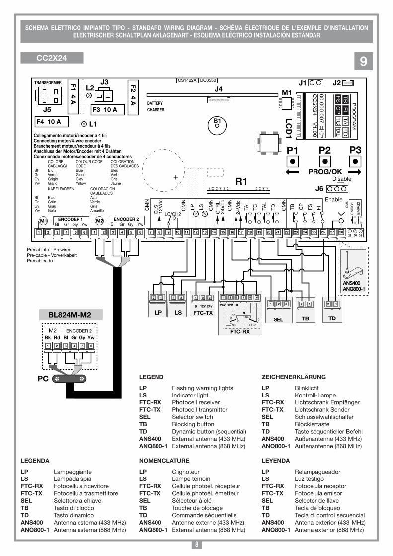
ACCESSORI206/BL824ARM Braccio articolato (curvo) standard in AL pressofuso verniciato.206/BL824DRM Braccio dritto con slitta in AL pressofuso verniciato.980/XLSE11C Elettroserratura 12 Vac/dc
Attenzione! Solo per clienti dell’EU - Marcatura WEEE.Il simbolo indica che il prodotto alla fine della propria vita utile deve essere raccolto separatamente dagli altri rifiuti. L’utente dovrà pertanto conferire l’apparecchiatura agli idonei centri di raccolta differenziata dei rifiuti elettronici ed elettrici, oppure riconsegnarla al rivenditore al momento dell’acquisto di una nuova apparecchiatura di tipo equivalente, in ragione di uno a uno.
L’adeguata raccolta differenziata per l’avvio al riciclaggio, al trattamento e allo smaltimento ambientalmente compatibile contribuisce ad evitare possibili effetti negativi sull’ambiente e sulla salute e favorisce il riciclo dei materiali. Lo smaltimento abusivo del prodotto da parte del detentore comporta l’ap-plicazione delle sanzioni amministrative previste dalla normativa vigente nello Stato Comunitario di appartenenza.
Durante la manovra si deve controllare il movimento del cancello e azionare il dispositivo di arresto immediato (STOP) in caso di pericolo. In caso di emergenza il cancello può essere sbloccato manualmente utilizzando l'apposita chiave di sblocco in dotazione (vedi sblocco manuale pag. 7).Controllare periodicamente lo stato di usura dei perni ed eventualmente ingras-sare le parti in moto usando lubrificanti che mantengano uguali caratteristiche di attrito nel tempo e adatti a funzionare tra -20 e +70°C. Verificare periodicamente il funzionamento delle sicurezze (fotocellule ecc.) Le eventuali riparazioni devono essere eseguite da personale specializzato usando materiali originali e certificati. L'uso dell'automazione non è idoneo all'azio-namento in continuo, bensì deve essere regolato in base ai vari modelli (vedi caratteristiche tecniche pagina 48).
I comandi minimi che possono essere installati sono APERTURA-STOP-CHIU-SURA, tali comandi devono essere posti in un luogo non accessibile a bambini o minori e fuori dal raggio d’azione del cancello.Prima di procedere all'esecuzione dell'impianto verificare che la struttura da automatizzare sia in perfetta efficienza nelle sue parti fisse e mobili e realizzata in conformità alla normativa vigente.A tal fine accertarsi della sufficiente rigidità del telo cancello (se necessario intervenire con rinforzi sulla struttura) e del buon funzionamento dei perni (si consiglia comunque di lubrificare tutte le parti in movimento usando lubrificanti che mantengano uguali caratteristiche di attrito nel tempo e adatti a funzionare tra -20 e +70°C). • Controllare i franchi di sicurezza tra parti fisse e parti mobili: - lasciare uno spazio di 30 mm min. tra il cancello ed il pilastro di supporto
per tutta l’altezza e per tutto l’arco di apertura del cancello; - assicurarsi che lo spazio tra il cancello ed il pavimento non superi mai 30
mm per tutto l’arco di apertura del cancello. • La superficie delle ante non deve presentare aperture tali da permettere il
passaggio della mano o del piede di persone.• Controllare l'esatto posizionamento di perni e cerniere, il loro buon stato di
mantenimento e lubrificazione (importante che la cerniera superiore e quella inferiore siano a piombo tra loro).
• Prevedere il percorso dei cavi secondo le necessità di applicazione dei dispositivi di comando e sicurezza. (ved. impianto tipo fig. 1 pag. 2).
• Controllare che l’operatore sia proporzionato alle dimensioni del cancello e alla frequenza d’uso (intermittenza di lavoro, pag. 48).
PROCEDURA DI MONTAGGIOIl dispositivo può essere fissato sia alla sinistra che alla destra del passaggio luce.• Portare l'anta in posizione di chiuso.• Scegliere la quota "A" in base all'angolo di apertura da ottenere (fig. 4) e definire
in base alle caratteristiche strutturali del cancello a quale altezza andrà fissata la staffa anteriore al cancello.
• Una volta individuate la posizione, passare i cavi di collegamento "C", alimen-tazione e sicurezza attraverso il foro "D" (fig. 6) nella colonna. Fissare la base motore con 4 viti M8 e 4 tasselli in acciaio Ø14 "V1" oppure 4 prigionieri M8 con rondelle e dadi "V2" avendo cura di mettere in bolla la base in pressofu-sione di alluminio "E" (fig. 6).
APERTURA AUTOMATICA
NON AVVICINARSI
NON PERMETTERE A BAMBINI O AD ANIMALI DOMESTICI DI SOSTARE NEL RAGGIO D'AZIONE DEL CANCELLO
ATTENZIONE
AVVERTENZE IMPORTANTI AVVERTENZE IMPORTANTI AVVERTENZE IMPORTANTI
LEGGERE ATTENTAMENTE LE SEGUENTI AVVERTENZE PRIMA DI PROCEDERE ALL’INSTALLAZIONE. PRE-STARE PARTICOLARE ATTENZIONE A TUTTE LE SEGNALAZIONI DISPOSTE NEL TESTO. IL MANCATO RISPETTO DI QUESTE POTREBBE COMPROMETTERE IL BUON FUNZIONAMENTO DEL SISTEMA E CREARE SITUAZIONI DI PERICOLO GRAVE PER L'OPERATORE E GLI UTILIZZATORI DEL SISTEMA STESSO.
CONSIDERAZIONI GENERALI DI SICUREZZA
AVVERTENZE PER L'UTENTE
ISTRUZIONI PER L'INSTALLAZIONE
10
• Attenzione! Per il corretto funzionamento del programmatore è necessario che le batterie incorporate siano in buono stato: in assenza di tensione di rete, se le batterie sono scariche, si verifica la perdita del controllo della posizione dell'anta con conseguente segnalazione di allarme e riposizionamento. Controllare quindi l'efficienza delle batterie ogni sei mesi. (vedi pagina 16 "Verifica delle batterie").
• Dopo aver installato il dispositivo, e prima di dare tensione alla centralina, verificare che il movimento del cancello eseguito in modo manuale (con motore sbloccato) non abbia punti di resistenza particolarmente marcata.
• L’uscita per l’alimentazione dei carichi controllati (morsetto 15) è pensata per ridurre il consumo della batteria in assenza di tensione di rete; collegare pertanto le fotocellule ed i dispositivi di sicurezza.
• Quando arriva un comando radio (o via filo) il programmatore dà tensione all’uscita CTRL 24 Vdc, e se le sicurezze risultano a riposo attiva il motore.
• La connessione all’uscita per i "carichi controllati" permette anche di eseguire l’autotest (abilitabile mediante "TEST FI" e "TEST FS" nel menù "opzioni") per la verifica del corretto funzionamento dei dispositivi di sicurezza.
• La presenza del sensore di corrente non elimina l’obbligo di installare le fotocellule o altri dispositivi di sicurezza previsti dalle normative vigenti.
• Accertarsi, prima di eseguire il collegamento elettrico, che la tensione e la frequenza riportate sulla targhetta caratteristiche corrispondano a quelle dell'impianto di alimentazione.
• Utilizzare per l'alimentazione 230 Vac un cavo 2 x 1.5 mm2 + .• La sostituzione del cavo d'alimentazione deve essere eseguita da
personale qualificato.• Tra la centralina di comando e la rete deve essere interposto un
interruttore onnipolare, con distanza di apertura tra i contatti di almeno 3 mm.
• Non utilizzare cavo con conduttori in alluminio; non stagnare l’estremità dei cavi da inserire in morsettiera; utilizzare cavo con marcatura T min 85°C resistente agli agenti atmosferici.
• I conduttori dovranno essere adeguatamente fissati in prossimità della morsettiera in modo che tale fissaggio serri sia l’isolamento che il conduttore (è sufficiente una fascetta).
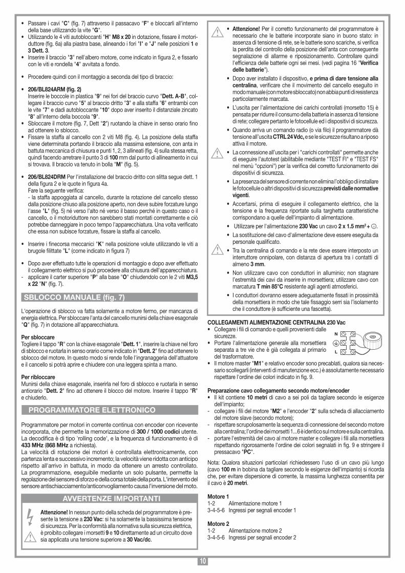
COLLEGAMENTI ALIMENTAZIONE CENTRALINA 230 Vac• Collegare i fili di comando e quelli provenienti dalle
sicurezze.• Portare l'alimentazione generale alla morsettiera
separata a tre vie che è già collegata al primario del trasformatore.
• Il motore master "M1" e relativo encoder sono precablati, qualora sia neces-sario scollegarli (interventi di manutenzione ecc.) è assolutamente necessario rispettare l'ordine dei colori indicato in fig. 9.
Preparazione cavo collegamento secondo motore/encoder• Il kit contiene 10 metri di cavo a sei poli da tagliare secondo le esigenze
dell'impianto;- collegare i fili del motore "M2" e l'encoder "2" sulla scheda di allacciamento
del motore slave (secondo motore);- rispettare scrupolosamente la sequenza di connessione del secondo motore
alla centralina; l’ordine dei morsetti 1...6 è identico sul motore e sulla centralina.- portare l'estremità del cavo al motore master e collegare i fili alla morsettiera
rispettando rigorosamente l'ordine dei colori segnalati in fig. 9 e stringere il pressacavo "PC".
Nota: Qualora situazioni particolari richiedessero l'uso di un cavo più lungo (cavo 100 m in bobina da tagliare secondo le esigenze dell'impianto) si ricorda che, per evitare dispersione di corrente, la massima lunghezza consentita per il cavo è 20 metri.
Motore 11-2 Alimentazione motore 13-4-5-6 Ingressi per segnali encoder 1
Motore 21-2 Alimentazione motore 23-4-5-6 Ingressi per segnali encoder 2
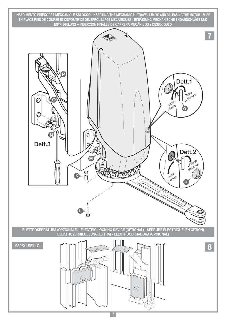
• Passare i cavi "C" (fig. 7) attraverso il passacavo "F" e bloccarli all'interno della base utilizzando la vite "G".
• Utilizzando le 4 viti autobloccanti "H" M8 x 20 in dotazione, fissare il motori-duttore (fig. 6a) alla piastra base, alineando i fori "I" e "J" nelle posizioni 1 e 3 Dett. 3.
• Inserire il braccio "3" nell'albero motore, come indicato in figura 2, e fissarlo con le viti e rondella "4" avvitata a fondo.
• Procedere quindi con il montaggio a seconda del tipo di braccio:
• 206/BL824ARM (fig. 2) Inserire le boccole in plastica "9" nei fori del braccio curvo "Dett. A-B", col-
legare il braccio curvo "5" al braccio dritto "3" e alla staffa "6" entrambi con le vite "7" e dadi autobloccante "10" dopo aver inserito il distanziale zincato "8" all’interno della boccola "9".
• Sbloccare il motore (fig. 7, Dett "2") ruotando la chiave in senso orario fino ad ottenere lo sblocco.
• Fissare la staffa al cancello con 2 viti M8 (fig. 4). La posizione della staffa viene determinata portando il braccio alla massima estensione, con anta in battuta meccanica di chiusura e punti 1, 2, 3 allineati (fig. 4) sulla stessa retta, quindi facendo arretrare il punto 3 di 100 mm dal punto di allineamento in cui si trovava. Il braccio va tenuto in bolla "M" (fig. 5).
• 206/BL824DRM Per l'installazione del braccio dritto con slitta segue dett. 1 della figura 2 e le quote in figura 4a.
Fare la seguente verifica: - la staffa appoggiata al cancello, durante la rotazione del cancello stesso
dalla posizione chiuso alla posizione aperto, non deve subire forzature lungo l'asse "L" (fig. 5) né verso l’alto né verso il basso perché in questo caso o il cancello, o il motoriduttore non sarebbero stati montati correttamente e ciò potrebbe danneggiare in poco tempo l'apparecchiatura. Una volta verificato che essa non subisce forzature, fissare la staffa al cancello.
• Inserire i finecorsa meccanici "K" nella posizione volute utilizzando le viti a brugole filittate "L" (come indicato in figura 7)
• Dopo aver effettuato tutte le operazioni di montaggio e dopo aver effettuato il collegamento elettrico si può procedere alla chiusura dell'apparecchiatura.
- applicare il carter superiore "P" alla base "O" chiudendolo con le 2 viti M3,5 x 22 "N" (fig. 7).
L'operazione di sblocco va fatta solamente a motore fermo, per mancanza di energia elettrica. Per sbloccare l'anta del cancello munirsi della chiave esagonale "Q" (fig. 7) in dotazione all'apparecchiatura.
Per sbloccareTogliere il tappo "R" con la chiave esagonale "Dett. 1", inserire la chiave nel foro di sblocco e ruotarla in senso orario come indicato in "Dett. 2" fino ad ottenere lo sblocco del motore. In questo modo si rende folle l'ingranaggeria dell'attuatore e il cancello si potrà aprire e chiudere con una leggera spinta a mano.
Per ribloccareMunirsi della chiave esagonale, inserirla nel foro di sblocco e ruotarla in senso antiorario "Dett. 2" fino ad ottenere il blocco del motore. Inserire il tappo "R" e chiuderlo.
Programmatore per motori in corrente continua con encoder con ricevente incorporata, che permette la memorizzazione di 300 / 1000 codici utente. La decodifica è di tipo 'rolling code', e la frequenza di funzionamento è di 433 MHz (868 MHz a richiesta).La velocità di rotazione dei motori è controllata elettronicamente, con partenza lenta e successivo incremento; la velocità viene ridotta con anticipo rispetto all'arrivo in battuta, in modo da ottenere un arresto controllato.La programmazione, eseguibile mediante un solo pulsante, permette la regolazione del sensore di sforzo e della corsa totale della porta. L'intervento del sensore antischiacciamento/anticonvogliamento causa l'inversione del moto.
Attenzione! In nessun punto della scheda del programmatore è pre-sente la tensione a 230 Vac: si ha solamente la bassissima tensione di sicurezza. Per la conformità alla normativa sulla sicurezza elettrica, è proibito collegare i morsetti 9 e 10 direttamente ad un circuito dove sia applicata una tensione superiore a 30 Vac/dc.
PROGRAMMATORE ELETTRONICO
SBLOCCO MANUALE (fig. 7)
AVVERTENZE IMPORTANTI
N
L
11
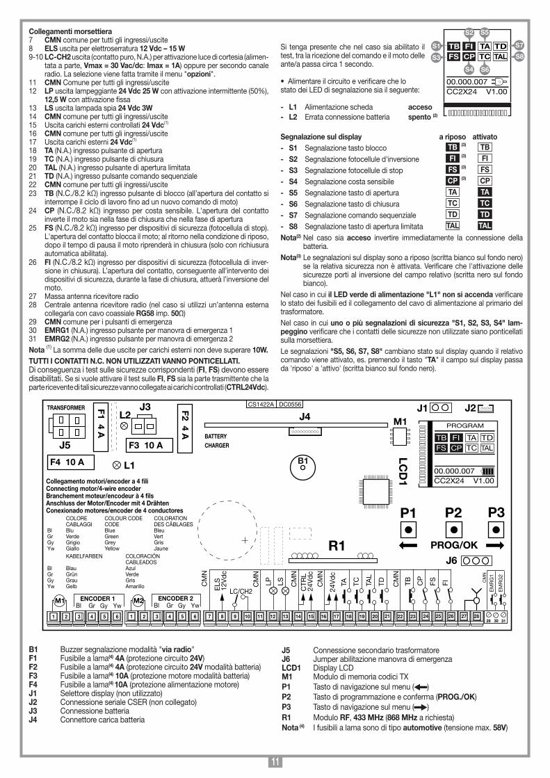
Collegamenti morsettiera7 CMN comune per tutti gli ingressi/uscite8 ELS uscita per elettroserratura 12 Vdc – 15 W9-10 LC-CH2 uscita (contatto puro, N.A.) per attivazione luce di cortesia (alimen-
tata a parte, Vmax = 30 Vac/dc: Imax = 1A) oppure per secondo canale radio. La selezione viene fatta tramite il menu "opzioni".
11 CMN Comune per tutti gli ingressi/uscite12 LP uscita lampeggiante 24 Vdc 25 W con attivazione intermittente (50%),
12,5 W con attivazione fissa13 LS uscita lampada spia 24 Vdc 3W14 CMN comune per tutti gli ingressi/uscite15 Uscita carichi esterni controllati 24 Vdc(1)
16 CMN comune per tutti gli ingressi/uscite17 Uscita carichi esterni 24 Vdc(1)
18 TA (N.A.) ingresso pulsante di apertura19 TC (N.A.) ingresso pulsante di chiusura20 TAL (N.A.) ingresso pulsante di apertura limitata21 TD (N.A.) ingresso pulsante comando sequenziale22 CMN comune per tutti gli ingressi/uscite23 TB (N.C./8.2 kΩ) ingresso pulsante di blocco (all’apertura del contatto si
interrompe il ciclo di lavoro fino ad un nuovo comando di moto)24 CP (N.C./8.2 kΩ) ingresso per costa sensibile. L'apertura del contatto
inverte il moto sia nella fase di chiusura che nella fase di apertura25 FS (N.C./8.2 kΩ) ingresso per dispositivi di sicurezza (fotocellula di stop).
L'apertura del contatto blocca il moto; al ritorno nella condizione di riposo, dopo il tempo di pausa il moto riprenderà in chiusura (solo con richiusura automatica abilitata).
26 FI (N.C./8.2 kΩ) ingresso per dispositivi di sicurezza (fotocellula di inver-sione in chiusura). L’apertura del contatto, conseguente all’intervento dei dispositivi di sicurezza, durante la fase di chiusura, attuerà l’inversione del moto.
27 Massa antenna ricevitore radio28 Centrale antenna ricevitore radio (nel caso si utilizzi un’antenna esterna
collegarla con cavo coassiale RG58 imp. 50Ω)29 CMN comune per i pulsanti di emergenza30 EMRG1 (N.A.) ingresso pulsante per manovra di emergenza 131 EMRG2 (N.A.) ingresso pulsante per manovra di emergenza 2Nota (1) La somma delle due uscite per carichi esterni non deve superare 10W.TUTTI I CONTATTI N.C. NON UTILIZZATI VANNO PONTICELLATI. Di conseguenza i test sulle sicurezze corrispondenti (FI, FS) devono essere disabilitati. Se si vuole attivare il test sulle FI, FS sia la parte trasmittente che la parte ricevente di tali sicurezze vanno collegate ai carichi controllati (CTRL24Vdc).
Si tenga presente che nel caso sia abilitato il test, tra la ricezione del comando e il moto delle ante/a passa circa 1 secondo.
• Alimentare il circuito e verificare che lo stato dei LED di segnalazione sia il seguente:
- L1 Alimentazione scheda acceso- L2 Errata connessione batteria spento (2)
Segnalazione sul display a riposo attivato- S1 Segnalazione tasto blocco TB (3) TB - S2 Segnalazione fotocellule d'inversione FI (3) FI
- S3 Segnalazione fotocellule di stop FS (3) FS
- S4 Segnalazione costa sensibile CP (3) CP - S5 Segnalazione tasto di apertura TA TA
- S6 Segnalazione tasto di chiusura TC TC
- S7 Segnalazione comando sequenziale TD TD
- S8 Segnalazione tasto di apertura limitata TAL TAL
Nota(2) Nel caso sia acceso invertire immediatamente la connessione della batteria.
Nota(3) Le segnalazioni sul display sono a riposo (scritta bianco sul fondo nero) se la relativa sicurezza non è attivata. Verificare che l'attivazione delle sicurezze porti al inversione del campo relativo (scritta nero sul fondo bianco).
Nel caso in cui il LED verde di alimentazione "L1" non si accenda verificare lo stato dei fusibili ed il collegamento del cavo di alimentazione al primario del trasformatore.Nel caso in cui uno o più segnalazioni di sicurezza "S1, S2, S3, S4" lam-peggino verificare che i contatti delle sicurezze non utilizzate siano ponticellati sulla morsettiera. Le segnalazioni "S5, S6, S7, S8" cambiano stato sul display quando il relativo comando viene attivato, es. premendo il tasto "TA" il campo sul display passa da 'riposo' a 'attivo' (scritta bianco sul fondo nero).
B1 Buzzer segnalazione modalità "via radio"F1 Fusibile a lama(4) 4A (protezione circuito 24V) F2 Fusibile a lama(4) 4A (protezione circuito 24V modalità batteria)F3 Fusibile a lama(4) 10A (protezione motore modalità batteria) F4 Fusibile a lama(4) 10A (protezione alimentazione motore) J1 Selettore display (non utilizzato)J2 Connessione seriale CSER (non collegato)J3 Connessione batteriaJ4 Connettore carica batteria
J5 Connessione secondario trasformatoreJ6 Jumper abilitazione manovra di emergenzaLCD1 Display LCDM1 Modulo di memoria codici TXP1 Tasto di navigazione sul menu ( )P2 Tasto di programmazione e conferma (PROG./OK) P3 Tasto di navigazione sul menu ( )R1 Modulo RF, 433 MHz (868 MHz a richiesta)Nota (4) I fusibili a lama sono di tipo automotive (tensione max. 58V)
Collegamenti scheda base
CC2X24
05-09-2015
DC0556 Description :
Product Code :
Date :
Drawing number :
P.J.Heath
CARDIN ELETTRONICA S.p.A - 31020 San Vendemiano (TV) Italy - via Raffaello, 36 Tel: 0438/401818 Fax: 0438/401831
Draft :
All rights reserved. Unauthorised copying or use of the information contained in this document is punishable by law
CC2X24 SCHEDA BASE V1.00(con display LCD + MULTI-DECODIFICA)
CS1422A DC0556
M1
B1
F2 4 A
TRANSFORMER
L1
29 30 31
F1 4 A
LCD
1
P1 P2 P3
PROG/OK
J5
9 10 11 12 13 14 15 16 17 18 19 20 21 22 23 24 25 26
COLORE COLOUR CODE COLORATION CABLAGGI CODE DES CÂBLAGES Bl Blu Blue Bleu Gr Verde Green Vert Gy Grigio Grey Gris Yw Giallo Yellow Jaune KABELFARBEN COLORACIÓN CABLEADOSBl Blau AzulGr Grün VerdeGy Grau GrisYw Gelb Amarillo
Collegamento motori/encoder a 4 fili Connecting motor/4-wire encoderBranchement moteur/encodeur à 4 filsAnschluss der Motor/Encoder mit 4 DrähtenConexionado motores/encoder de 4 conductores
7 83 4 5 61 2 3 4 5 61 2
YwGyGrBlENCODER 1
YwGyGrBlENCODER 2M1 M2
27 28
TDTA TC
24V
dc
TAL
CM
N
FITB CP
FS
EM
RG
1
EM
RG
2
CM
N
CM
N
CTR
L24
Vd
c
CM
N
LSLPCM
N
LC/CH2ELS
12V
dc
CM
N
F4 10 A
J3
F3 10 ABATTERYCHARGER
J1
R1J6
J2J4L2
PROGRAM
TB FIFS CP
TA TDTC TAL
00.000.007CC2X24 V1.00
S5
S6
TB FIFS CP
TA TDTC TAL
00.000.007CC2X24 V1.00
S1
S3
S7
S8
S2
S4
12
“PROG/OK” per ritornare al
menu moto
Premere una freccia per accedere
al menu principale“PROG/OK”
per confermare
“PROG/OK” per ritornare al menu opzioni
OPZIONISICUREZZAMOTODISPLAYCODICI RADIO
PROGRAM
TB FIFS CP
TA TDTC TAL
00.000.007CC2X24 V1.00
OPZIONISICUREZZAMOTODISPLAYCODICI RADIO
Freccia per scorrere
TASTO DINAMICOAPRE-CHIUDE/APRE-STOP-CH
RICH. AUTOMATICAON/OFF
PRELAMPEGGIOON/OFF
OPZIONISICUREZZAMOTODISPLAYCODICI RADIO
Freccia per scorrere
OPZIONISICUREZZAMOTODISPLAYCODICI RADIO
Freccia per scorrere
TASTO DINAMICOAPRE-CHIUDE/APRE-STOP-CH
RICH. AUTOMATICAON/OFF
PRELAMPEGGIOON/OFF
TASTO DINAMICOAPRE-CHIUDE/APRE-STOP-CH
RICH. AUTOMATICAON/OFF
PRELAMPEGGIOON/OFF
PRELAMPEGGIOON/OFF
LAMPEGGIANTEFISSO/
INTERMITTENTELAMPADA SPIA
FISSA/INTERMITTENTE
LAMPEGGIANTEFISSO/
INTERMITTENTELAMPADA SPIA
FISSA/INTERMITTENTE
FOTOCELLULE INV. IN CHIUSURA/
ANCHE IN STOP
LAMPADA SPIAFISSA/
INTERMITTENTEFOTOCELLULE INV.
IN CHIUSURA/ANCHE IN STOP
TEST FION/OFF
FOTOCELLULE INV. IN CHIUSURA/
ANCHE IN STOP
TEST FION/OFFTEST FS ON/OFF
TEST FSON/OFF
SFASAM. APERTURAON/OFF
ELETTROSERRATURAON/OFF
TEST FION/OFFTEST FSON/OFF
SFASAMENTO IN APERTURA
ON/OFF
SFASAM. APERTURAON/OFF
ELETTROSERRATURAON/OFF
MEMORADIOON/OFF
ELETTROSERRATURAON/OFF
MEMORADIOON/OFF
USCITA LC/CH2CANALE RADIO/
LUCE DI CORTESIA
“PROG/OK” per confermare
“PROG/OK” per cambiare
il valore
“PROG/OK” per cambiare
il valore
“PROG/OK” per cambiare
il valore
“PROG/OK” per cambiare
il valore
“PROG/OK” per cambiare
il valore
MEMORADIOON/OFF
USCITA LC/CH2CANALE RADIO/
LUCE DI CORTESIA
USCITA
CONTATTO TBNC/8K2
CONTATTO FINC/8K2
CONTATTO FSNC/8K2
CONTATTO TBNC/8K2
CONTATTO FINC/8K2
CONTATTO FSNC/8K2
“PROG/OK” per confermare
“PROG/OK” per cambiare
il valore
“PROG/OK” per cambiare
il valore
CONTATTO TBNC/8K2
CONTATTO FINC/8K2
CONTATTO FSNC/8K2
“PROG/OK” per cambiare
il valore
CONTATTO FINC/8K2
CONTATTO FSNC/8K2
CONTATTO CPNC/8K2
“PROG/OK” per cambiare
il valore
CONTATTO FSNC/8K2
CONTATTO CPNC/8K2
USCITA
“PROG/OK” per ritornare al
menu sicurezza
SELEZIONE MOTOREBL824
SENSORE CORRENTELIVELLO 1...5
APERTURA LIMITATASETTAGGIO 1...4
SELEZIONE MOTOREBL824
SENSORE CORRENTELIVELLO 1...5
APERTURA LIMITATASETTAGGIO 1...4
“PROG/OK” per confermare
“PROG/OK” per cambiare
il valore
SELEZIONE MOTOREBL824
SENSORE CORRENTELIVELLO 1...5
APERTURA LIMITATASETTAGGIO 1...4
“PROG/OK” per cambiare
il valore
SENSORE CORRENTELIVELLO 1...5
APERTURA LIMITATASETTAGGIO 1...5
DIST. BATT. AP.PASSI 0...9
“PROG/OK” per cambiare
il valore
APERTURA LIMITATASETTAGGIO 1...5DIST. BATT. AP.
PASSI 0...9
SFASAM. APERTURAPASSI 0...9
“PROG/OK” per cambiare
il valore
CONTRASTOda 0....63
RETROILLUMINAZIONE SEMPRE ON/ 60/30 SEC.
USCITA
“PROG/OK” per confermare
CONTRASTOda 0....63
RETROILLUMINAZIONE SEMPRE ON/ 60/30 SEC.
USCITA
“PROG/OK” per cambiare
il valore
CONTRASTOda 0....63
RETROILLUMINAZIONE SEMPRE ON/ 60/30 SEC.
USCITA
“PROG/OK” per ritornare al menu display
Il numero delle manovre dell’ attuatore, il modello della centralina e la versione del rmware rimane sempre visualiz-zato sul display iniziale.
Il simboloindica che la centralina è alimentate dalla rete principale
Il simboloindica che la centralina è alimentate dalla batteria caricata a 100%.
75%
50%
25%
0%
Nota: 1
Nota: 2
Nota: 6
Nota: 7
Nota: 8
Nota: 9
“PROG/OK” per cambiare
il valore
“PROG/OK” per cambiare
il valore
“PROG/OK” per cambiare
il valore
“PROG/OK” per cambiare
il valore
“PROG/OK” per cambiare
il valore
“PROG/OK” per cambiare
il valore
Nota: 3
Nota: 3
Nota: 4
Nota: 5
DIST. BATT. AP.PASSI 1...9
SFASAM. APERTURAPASSI 0...9
SPAZIO FRENATASETTAGGIO 1...3
ITALIANO
FRANÇAIS
ENGLISH
NEDERLANDS
DEUTSCH
ESPAÑOL
PROGRAM
TB FIFS CP
TA TDTC TAL
00.000.007CC2X24 V1.00
premere contemporaneamenteentrambe le frecce per entrare
nel sottomenu lingua
“PROG/OK” per confermare
Selezione della lingua:• Premere i tasti destra e sinistra contemporaneamente per entrare nel sotto menu.• Premere le frecette su o giù per cambiare la lingua: italiano - francese - inglese ecc.• Premere il tasto "PROG/OK" per confermare la lingua.
Premere le frecette per incrementare o ridurre il valore
(max. 63)
* * * * * * * * * * * * * * ** ** REG. CONTRASTO ** SEC. *
* ** * * * * * * * * * * * * * *
26
Lampeggiante sul display. È necessario entrare in modalità di programmazione per programmare il sistema.
Segnala che verrà eseguita la procedura di riposizionamento automatico. In questo caso qualsiasi comando ricevuto (TA, TC, TAL o TD) da inizio immediatamente a questa procedura.
Si verica quando viene attivata una sicurezza (FI, FS, CP) durante la programmazione encoder o riposizionamento automatico. Una volta ristabilito lo stato passivo delle sicurezze l'anta riprende il moto automaticamente. Si verica anche quando viene a mancare la tensione di rete durante la fase di programmazione.
Errore nel test delle sicurezze. Occorre controllare lo stato delle sicurezze, vericando che vadano in allarme (simbolo relativo scritta nero sul fondo bianco) quando un ostacolo si trova in mezzo al loro raggio di azione. Se si riscontra un’anomalia sostituire la sicurezza guasta oppure ponticellare l’ingresso relativo e disabilitare il test relativo alla sicurezza stessa (menu opzioni).
Si verica quando il programmatore dà un comando al motore, ma il motore 1/2 non si mette in moto. È sufciente controllare le connessioni relative al motore 1/2 e lo stato dei fusibili "F3" ed "F4". Dopodiché riprovare a dare un comando di apertura o di chiusura; se il motore non si dovesse rimettere in moto, allora ci potrebbe essere un problema meccanico al motore o un problema sulla centralina.
Errore sul conteggio encoder motore 1/2 . Se si verica nel normale utilizzo del motore signica che c'è un problema sui segnali relativi all’encoder; vericare le connessioni relative ed eseguire il riposizionamento automatico.
Errore di direzione encoder 1/2. La direzione di marcia dell'anta è diversa da quella stabilita dall'encoder (esempio: l’anta va in chiusura mentre il programmatore sta eseguendo la fase di apertura). Controllare la connessione dell'alimentazione motore 1/2.
Errore del sensore di corrente motore 1/2. Con il motore fermo questo simbolo indica che c'è un problema sul sensore di corrente relativo al motore 1/2.
Quando interviene la costa di sicurezza causa l’inversione del moto sia nella fase di chiusura che nella fase di apertura.
Se il sensore interviene durante la fase di chiusura, l'anta inverte immediatamente il moto ed apre totalmente. Se il sensore interviene durante la fase di apertura l'anta inverte immediatamente il moto di qualche centimetro e poi si ferma, in modo da liberare l'ostacolo.
Segnalazioni di allarmeTB FIFS CP
TA TDTC TAL
PROGRAM
TB FIFS CP
TA TDTC TAL
FUORI POS
TB FIFS CP
TA TDTC TAL
ERROR SIC
TB FIFS CP
TA TDTC TAL
STOP PROG
AUTO PROG
TB FIFS CP
TA TDTC TAL
ERROR MOT1/2
TB FIFS CP
TA TDTC TAL
ERROR ENC1/2
TB FIFS CP
TA TDTC TAL
ERR. DIR1/2
TB FIFS CP
TA TDTC TAL
ERR. SENS1/2
Programmazione del tempo di pausa oppure pausa per la richiusura automatica (solo se abilitata)
Programmazione automatica in corso
Fase di apertura
Blocco apertura
Fase di chiusura
Blocco chiusura
Segnalazioni di funzionamento
TB FIFS CP
TA TDTC TAL
PAUSA
TB FIFS CP
TA TDTC TAL
AUTO PROG
TB FIFS CP
TA TDTC TAL
APERTURA
TB FIFS CP
TA TDTC TAL
STOP APERTURA
TB FIFS CP
TA TDTC TAL
CHIUSURA
TB FIFS CP
TA TDTC TAL
STOP CHIUSURA
TB FIFS CP
TA TDTC TAL
INT. COSTA
TB FIFS CP
TA TDTC TAL
INT. SENS
SPAZIO FRENATASETTAGGIO 1...3
VELOC. FRENATASETTAGGIO 1...3
TEMPO DI PAUSA130 SEC.
VELOC. FRENATASETTAGGIO 1...3
TEMPO DI PAUSA180 SEC.
USCITA
“PROG/OK” per confermare
Premere le frecette per incrementare o ridurre il valore (max 240 secondi).Tenendo premuto la frecetta a lungo il valore cambia velocemente.
* * * * * * * * * * * * * * ** ** TEMPO DI PAUSA ** SEC. ** ** * * * * * * * * * * * * * *
180
SFASAM. APERTURAPASSI 0...9
SPAZIO FRENATASETTAGGIO 1...3
VELOC. FRENATASETTAGGIO 1...3
“PROG/OK” per cambiare
il valore
Nota: 10
“PROG/OK” per cambiare
il valore
Nota: 11
“PROG/OK” per cambiare
il valore
Nota: 12
“PROG/OK” per confermare
PREMERE sultrasmettitoreil canale da
memorizzare
PREMERE sultrasmettitore
lo stesso canale per
memorizzare
“PROG/OK” per confermare
Freccia per scorrere
CODIFICA: S4XX
MEMORIZZAZIONE
CANCELLAZIONE
CANCEL. TOTALE
FUNZIONE CANALI
USCITA
“PROG/OK” per confermare
OPZIONISICUREZZAMOTODISPLAYDATARIOCODICI RADIO
MEMORIZZAZIONE[N....]
* * * * * * * * * * * * * * ** ** ATTIVAZIONE 1 ** ** * * * * * * * * * * * * * *
MEMORIZZAZIONE[N....]
* * * * * * * * * * * * * * ** ** ATTIVAZIONE 2 ** ** * * * * * * * * * * * * * *
MEMORIZZAZIONE[N....]
* * * * * * * * * * * * * * ** ** CODICE ** MEMORIZZATO ** * * * * * * * * * * * * * *
“PROG/OK” per confermare
CANCELLAZIONE[N....]
* * * * * * * * * * * * * * ** ** ATTIVAZIONE 1 ** ** * * * * * * * * * * * * * *
PREMERE sultrasmettitoreil canale dacancellare
CANCELLAZIONE[N....]
* * * * * * * * * * * * * * ** ** ATTIVAZIONE 2 ** ** * * * * * * * * * * * * * *
PREMERE sultrasmettitore
lo stesso canale per
cancellare
CANCELLAZIONE[N....]
* * * * * * * * * * * * * * ** ** CODICE ** CANCELLATO ** * * * * * * * * * * * * * *
CODIFICA: S4XX
MEMORIZZAZIONE
CANCELLAZIONE
CANCEL. TOTALE
FUNZIONE CANALI
USCITA
“PROG/OK” per confermare
* * * * * * * * * * * * * * ** CANCELLARE ** LA MEMORIA ? ** * * * * * * * * * * * * * *
PREMERE ok per cancellare la
memoria oppure exit per uscire
CODIFICA: S4XX
MEMORIZZAZIONE
CANCELLAZIONE
CANCEL. TOTALE
FUNZIONE CANALI
USCITA
Freccia per uscire
EXIT
OK
* * * * * * * * * * * * * * **CANCELLAZIONE ** IN CORSO ** * * * * * * * * * * * * * *
CODIFICA: S4XX
MEMORIZZAZIONE
CANCELLAZIONE
CANCEL. TOTALE
FUNZIONE CANALI
USCITA
CANALE Afunzione del canale A
CANALE Bfunzione del canale B
CANALE Cfunzione del canale C
CANALE Dfunzione del canale D
USCITA
CODIFICA: S4XX
MEMORIZZAZIONE
CANCELLAZIONE
CANCEL. TOTALE
FUNZIONE CANALI
USCITA
“PROG/OK” per cambiare
il valore
CODIFICA: S4XX
MEMORIZZAZIONE
CANCELLAZIONE
CANCEL. TOTALE
FUNZIONE CANALI
USCITA
“PROG/OK” per cambiareil valore tra S4XX e S500
“PROG/OK” per ritornare
al menu codici radio
[AB--] [AB--] [AB--]
[AB--] [AB--] [AB--]
Nota: 14
Nota: 13
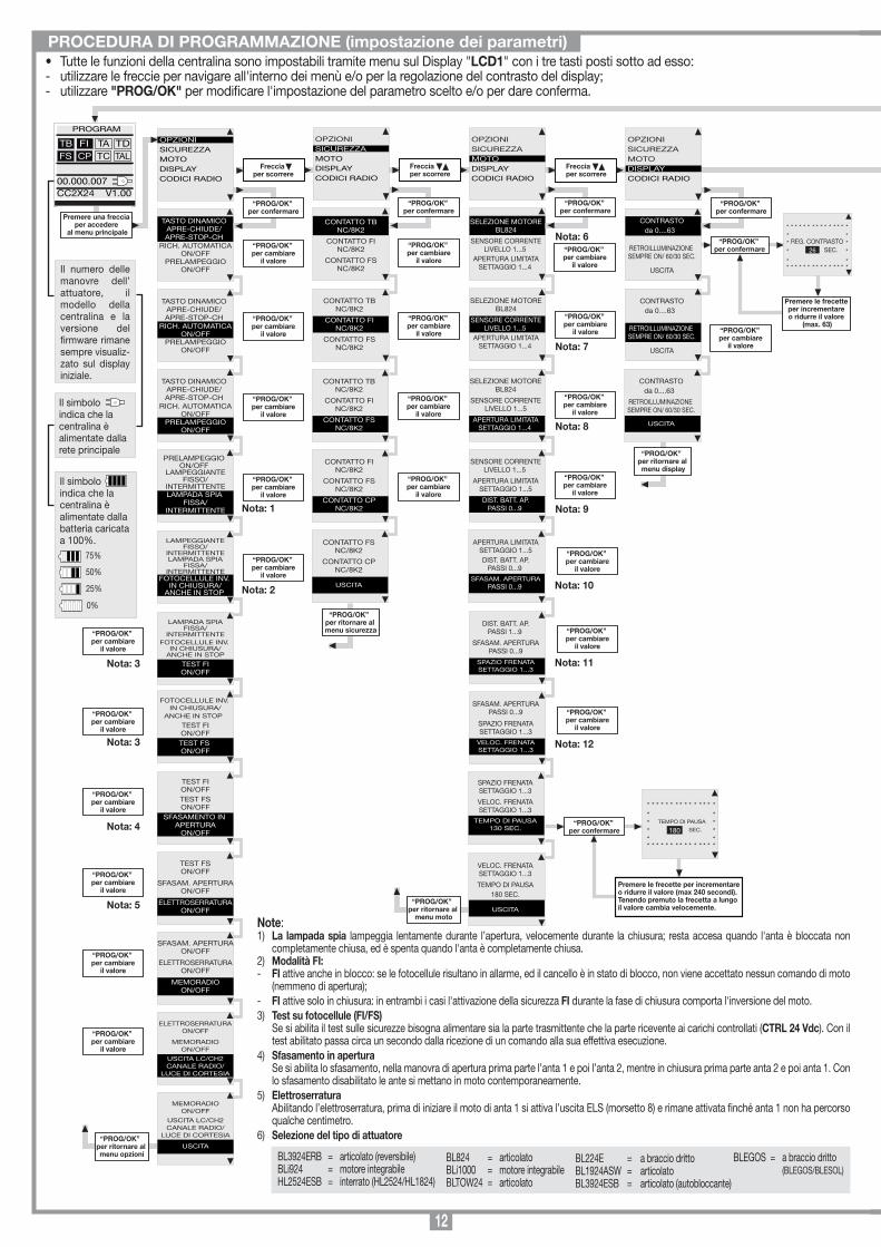
• Tutte le funzioni della centralina sono impostabili tramite menu sul Display "LCD1" con i tre tasti posti sotto ad esso:- utilizzare le freccie per navigare all'interno dei menù e/o per la regolazione del contrasto del display;- utilizzare "PROG/OK" per modificare l'impostazione del parametro scelto e/o per dare conferma.
PROCEDURA DI PROGRAMMAZIONE (impostazione dei parametri)
Note:1) La lampada spia lampeggia lentamente durante l’apertura, velocemente durante la chiusura; resta accesa quando l'anta è bloccata non
completamente chiusa, ed è spenta quando l'anta è completamente chiusa.2) Modalità FI:- FI attive anche in blocco: se le fotocellule risultano in allarme, ed il cancello è in stato di blocco, non viene accettato nessun comando di moto
(nemmeno di apertura);- FI attive solo in chiusura: in entrambi i casi l'attivazione della sicurezza FI durante la fase di chiusura comporta l'inversione del moto.3) Test su fotocellule (FI/FS) Se si abilita il test sulle sicurezze bisogna alimentare sia la parte trasmittente che la parte ricevente ai carichi controllati (CTRL 24 Vdc). Con il
test abilitato passa circa un secondo dalla ricezione di un comando alla sua effettiva esecuzione.4) Sfasamento in apertura Se si abilita lo sfasamento, nella manovra di apertura prima parte l’anta 1 e poi l’anta 2, mentre in chiusura prima parte anta 2 e poi anta 1. Con
lo sfasamento disabilitato le ante si mettano in moto contemporaneamente.5) Elettroserratura Abilitando l’elettroserratura, prima di iniziare il moto di anta 1 si attiva l’uscita ELS (morsetto 8) e rimane attivata finché anta 1 non ha percorso
qualche centimetro.6) Selezione del tipo di attuatore
BL3924ERB = articolato (reversibile)BLi924 = motore integrabile HL2524ESB = interrato (HL2524/HL1824)
BL824 = articolato BLi1000 = motore integrabileBLTOW24 = articolato
BL224E = a braccio drittoBL1924ASW = articolatoBL3924ESB = articolato (autobloccante)
BLEGOS = a braccio dritto (BLEGOS/BLESOL)
13
“PROG/OK” per ritornare al
menu moto
Premere una freccia per accedere
al menu principale“PROG/OK”
per confermare
“PROG/OK” per ritornare al menu opzioni
OPZIONISICUREZZAMOTODISPLAYCODICI RADIO
PROGRAM
TB FIFS CP
TA TDTC TAL
00.000.007CC2X24 V1.00
OPZIONISICUREZZAMOTODISPLAYCODICI RADIO
Freccia per scorrere
TASTO DINAMICOAPRE-CHIUDE/APRE-STOP-CH
RICH. AUTOMATICAON/OFF
PRELAMPEGGIOON/OFF
OPZIONISICUREZZAMOTODISPLAYCODICI RADIO
Freccia per scorrere
OPZIONISICUREZZAMOTODISPLAYCODICI RADIO
Freccia per scorrere
TASTO DINAMICOAPRE-CHIUDE/APRE-STOP-CH
RICH. AUTOMATICAON/OFF
PRELAMPEGGIOON/OFF
TASTO DINAMICOAPRE-CHIUDE/APRE-STOP-CH
RICH. AUTOMATICAON/OFF
PRELAMPEGGIOON/OFF
PRELAMPEGGIOON/OFF
LAMPEGGIANTEFISSO/
INTERMITTENTELAMPADA SPIA
FISSA/INTERMITTENTE
LAMPEGGIANTEFISSO/
INTERMITTENTELAMPADA SPIA
FISSA/INTERMITTENTE
FOTOCELLULE INV. IN CHIUSURA/
ANCHE IN STOP
LAMPADA SPIAFISSA/
INTERMITTENTEFOTOCELLULE INV.
IN CHIUSURA/ANCHE IN STOP
TEST FION/OFF
FOTOCELLULE INV. IN CHIUSURA/
ANCHE IN STOP
TEST FION/OFFTEST FS ON/OFF
TEST FSON/OFF
SFASAM. APERTURAON/OFF
ELETTROSERRATURAON/OFF
TEST FION/OFFTEST FSON/OFF
SFASAMENTO IN APERTURA
ON/OFF
SFASAM. APERTURAON/OFF
ELETTROSERRATURAON/OFF
MEMORADIOON/OFF
ELETTROSERRATURAON/OFF
MEMORADIOON/OFF
USCITA LC/CH2CANALE RADIO/
LUCE DI CORTESIA
“PROG/OK” per confermare
“PROG/OK” per cambiare
il valore
“PROG/OK” per cambiare
il valore
“PROG/OK” per cambiare
il valore
“PROG/OK” per cambiare
il valore
“PROG/OK” per cambiare
il valore
MEMORADIOON/OFF
USCITA LC/CH2CANALE RADIO/
LUCE DI CORTESIA
USCITA
CONTATTO TBNC/8K2
CONTATTO FINC/8K2
CONTATTO FSNC/8K2
CONTATTO TBNC/8K2
CONTATTO FINC/8K2
CONTATTO FSNC/8K2
“PROG/OK” per confermare
“PROG/OK” per cambiare
il valore
“PROG/OK” per cambiare
il valore
CONTATTO TBNC/8K2
CONTATTO FINC/8K2
CONTATTO FSNC/8K2
“PROG/OK” per cambiare
il valore
CONTATTO FINC/8K2
CONTATTO FSNC/8K2
CONTATTO CPNC/8K2
“PROG/OK” per cambiare
il valore
CONTATTO FSNC/8K2
CONTATTO CPNC/8K2
USCITA
“PROG/OK” per ritornare al
menu sicurezza
SELEZIONE MOTOREBL824
SENSORE CORRENTELIVELLO 1...5
APERTURA LIMITATASETTAGGIO 1...4
SELEZIONE MOTOREBL824
SENSORE CORRENTELIVELLO 1...5
APERTURA LIMITATASETTAGGIO 1...4
“PROG/OK” per confermare
“PROG/OK” per cambiare
il valore
SELEZIONE MOTOREBL824
SENSORE CORRENTELIVELLO 1...5
APERTURA LIMITATASETTAGGIO 1...4
“PROG/OK” per cambiare
il valore
SENSORE CORRENTELIVELLO 1...5
APERTURA LIMITATASETTAGGIO 1...5
DIST. BATT. AP.PASSI 0...9
“PROG/OK” per cambiare
il valore
APERTURA LIMITATASETTAGGIO 1...5DIST. BATT. AP.
PASSI 0...9
SFASAM. APERTURAPASSI 0...9
“PROG/OK” per cambiare
il valore
CONTRASTOda 0....63
RETROILLUMINAZIONE SEMPRE ON/ 60/30 SEC.
USCITA
“PROG/OK” per confermare
CONTRASTOda 0....63
RETROILLUMINAZIONE SEMPRE ON/ 60/30 SEC.
USCITA
“PROG/OK” per cambiare
il valore
CONTRASTOda 0....63
RETROILLUMINAZIONE SEMPRE ON/ 60/30 SEC.
USCITA
“PROG/OK” per ritornare al menu display
Il numero delle manovre dell’ attuatore, il modello della centralina e la versione del rmware rimane sempre visualiz-zato sul display iniziale.
Il simboloindica che la centralina è alimentate dalla rete principale
Il simboloindica che la centralina è alimentate dalla batteria caricata a 100%.
75%
50%
25%
0%
Nota: 1
Nota: 2
Nota: 6
Nota: 7
Nota: 8
Nota: 9
“PROG/OK” per cambiare
il valore
“PROG/OK” per cambiare
il valore
“PROG/OK” per cambiare
il valore
“PROG/OK” per cambiare
il valore
“PROG/OK” per cambiare
il valore
“PROG/OK” per cambiare
il valore
Nota: 3
Nota: 3
Nota: 4
Nota: 5
DIST. BATT. AP.PASSI 1...9
SFASAM. APERTURAPASSI 0...9
SPAZIO FRENATASETTAGGIO 1...3
ITALIANO
FRANÇAIS
ENGLISH
NEDERLANDS
DEUTSCH
ESPAÑOL
PROGRAM
TB FIFS CP
TA TDTC TAL
00.000.007CC2X24 V1.00
premere contemporaneamenteentrambe le frecce per entrare
nel sottomenu lingua
“PROG/OK” per confermare
Selezione della lingua:• Premere i tasti destra e sinistra contemporaneamente per entrare nel sotto menu.• Premere le frecette su o giù per cambiare la lingua: italiano - francese - inglese ecc.• Premere il tasto "PROG/OK" per confermare la lingua.
Premere le frecette per incrementare o ridurre il valore
(max. 63)
* * * * * * * * * * * * * * ** ** REG. CONTRASTO ** SEC. *
* ** * * * * * * * * * * * * * *
26
Lampeggiante sul display. È necessario entrare in modalità di programmazione per programmare il sistema.
Segnala che verrà eseguita la procedura di riposizionamento automatico. In questo caso qualsiasi comando ricevuto (TA, TC, TAL o TD) da inizio immediatamente a questa procedura.
Si verica quando viene attivata una sicurezza (FI, FS, CP) durante la programmazione encoder o riposizionamento automatico. Una volta ristabilito lo stato passivo delle sicurezze l'anta riprende il moto automaticamente. Si verica anche quando viene a mancare la tensione di rete durante la fase di programmazione.
Errore nel test delle sicurezze. Occorre controllare lo stato delle sicurezze, vericando che vadano in allarme (simbolo relativo scritta nero sul fondo bianco) quando un ostacolo si trova in mezzo al loro raggio di azione. Se si riscontra un’anomalia sostituire la sicurezza guasta oppure ponticellare l’ingresso relativo e disabilitare il test relativo alla sicurezza stessa (menu opzioni).
Si verica quando il programmatore dà un comando al motore, ma il motore 1/2 non si mette in moto. È sufciente controllare le connessioni relative al motore 1/2 e lo stato dei fusibili "F3" ed "F4". Dopodiché riprovare a dare un comando di apertura o di chiusura; se il motore non si dovesse rimettere in moto, allora ci potrebbe essere un problema meccanico al motore o un problema sulla centralina.
Errore sul conteggio encoder motore 1/2 . Se si verica nel normale utilizzo del motore signica che c'è un problema sui segnali relativi all’encoder; vericare le connessioni relative ed eseguire il riposizionamento automatico.
Errore di direzione encoder 1/2. La direzione di marcia dell'anta è diversa da quella stabilita dall'encoder (esempio: l’anta va in chiusura mentre il programmatore sta eseguendo la fase di apertura). Controllare la connessione dell'alimentazione motore 1/2.
Errore del sensore di corrente motore 1/2. Con il motore fermo questo simbolo indica che c'è un problema sul sensore di corrente relativo al motore 1/2.
Quando interviene la costa di sicurezza causa l’inversione del moto sia nella fase di chiusura che nella fase di apertura.
Se il sensore interviene durante la fase di chiusura, l'anta inverte immediatamente il moto ed apre totalmente. Se il sensore interviene durante la fase di apertura l'anta inverte immediatamente il moto di qualche centimetro e poi si ferma, in modo da liberare l'ostacolo.
Segnalazioni di allarmeTB FIFS CP
TA TDTC TAL
PROGRAM
TB FIFS CP
TA TDTC TAL
FUORI POS
TB FIFS CP
TA TDTC TAL
ERROR SIC
TB FIFS CP
TA TDTC TAL
STOP PROG
AUTO PROG
TB FIFS CP
TA TDTC TAL
ERROR MOT1/2
TB FIFS CP
TA TDTC TAL
ERROR ENC1/2
TB FIFS CP
TA TDTC TAL
ERR. DIR1/2
TB FIFS CP
TA TDTC TAL
ERR. SENS1/2
Programmazione del tempo di pausa oppure pausa per la richiusura automatica (solo se abilitata)
Programmazione automatica in corso
Fase di apertura
Blocco apertura
Fase di chiusura
Blocco chiusura
Segnalazioni di funzionamento
TB FIFS CP
TA TDTC TAL
PAUSA
TB FIFS CP
TA TDTC TAL
AUTO PROG
TB FIFS CP
TA TDTC TAL
APERTURA
TB FIFS CP
TA TDTC TAL
STOP APERTURA
TB FIFS CP
TA TDTC TAL
CHIUSURA
TB FIFS CP
TA TDTC TAL
STOP CHIUSURA
TB FIFS CP
TA TDTC TAL
INT. COSTA
TB FIFS CP
TA TDTC TAL
INT. SENS
SPAZIO FRENATASETTAGGIO 1...3
VELOC. FRENATASETTAGGIO 1...3
TEMPO DI PAUSA130 SEC.
VELOC. FRENATASETTAGGIO 1...3
TEMPO DI PAUSA180 SEC.
USCITA
“PROG/OK” per confermare
Premere le frecette per incrementare o ridurre il valore (max 240 secondi).Tenendo premuto la frecetta a lungo il valore cambia velocemente.
* * * * * * * * * * * * * * ** ** TEMPO DI PAUSA ** SEC. ** ** * * * * * * * * * * * * * *
180
SFASAM. APERTURAPASSI 0...9
SPAZIO FRENATASETTAGGIO 1...3
VELOC. FRENATASETTAGGIO 1...3
“PROG/OK” per cambiare
il valore
Nota: 10
“PROG/OK” per cambiare
il valore
Nota: 11
“PROG/OK” per cambiare
il valore
Nota: 12
“PROG/OK” per confermare
PREMERE sultrasmettitoreil canale da
memorizzare
PREMERE sultrasmettitore
lo stesso canale per
memorizzare
“PROG/OK” per confermare
Freccia per scorrere
CODIFICA: S4XX
MEMORIZZAZIONE
CANCELLAZIONE
CANCEL. TOTALE
FUNZIONE CANALI
USCITA
“PROG/OK” per confermare
OPZIONISICUREZZAMOTODISPLAYDATARIOCODICI RADIO
MEMORIZZAZIONE[N....]
* * * * * * * * * * * * * * ** ** ATTIVAZIONE 1 ** ** * * * * * * * * * * * * * *
MEMORIZZAZIONE[N....]
* * * * * * * * * * * * * * ** ** ATTIVAZIONE 2 ** ** * * * * * * * * * * * * * *
MEMORIZZAZIONE[N....]
* * * * * * * * * * * * * * ** ** CODICE ** MEMORIZZATO ** * * * * * * * * * * * * * *
“PROG/OK” per confermare
CANCELLAZIONE[N....]
* * * * * * * * * * * * * * ** ** ATTIVAZIONE 1 ** ** * * * * * * * * * * * * * *
PREMERE sultrasmettitoreil canale dacancellare
CANCELLAZIONE[N....]
* * * * * * * * * * * * * * ** ** ATTIVAZIONE 2 ** ** * * * * * * * * * * * * * *
PREMERE sultrasmettitore
lo stesso canale per
cancellare
CANCELLAZIONE[N....]
* * * * * * * * * * * * * * ** ** CODICE ** CANCELLATO ** * * * * * * * * * * * * * *
CODIFICA: S4XX
MEMORIZZAZIONE
CANCELLAZIONE
CANCEL. TOTALE
FUNZIONE CANALI
USCITA
“PROG/OK” per confermare
* * * * * * * * * * * * * * ** CANCELLARE ** LA MEMORIA ? ** * * * * * * * * * * * * * *
PREMERE ok per cancellare la
memoria oppure exit per uscire
CODIFICA: S4XX
MEMORIZZAZIONE
CANCELLAZIONE
CANCEL. TOTALE
FUNZIONE CANALI
USCITA
Freccia per uscire
EXIT
OK
* * * * * * * * * * * * * * **CANCELLAZIONE ** IN CORSO ** * * * * * * * * * * * * * *
CODIFICA: S4XX
MEMORIZZAZIONE
CANCELLAZIONE
CANCEL. TOTALE
FUNZIONE CANALI
USCITA
CANALE Afunzione del canale A
CANALE Bfunzione del canale B
CANALE Cfunzione del canale C
CANALE Dfunzione del canale D
USCITA
CODIFICA: S4XX
MEMORIZZAZIONE
CANCELLAZIONE
CANCEL. TOTALE
FUNZIONE CANALI
USCITA
“PROG/OK” per cambiare
il valore
CODIFICA: S4XX
MEMORIZZAZIONE
CANCELLAZIONE
CANCEL. TOTALE
FUNZIONE CANALI
USCITA
“PROG/OK” per cambiareil valore tra S4XX e S500
“PROG/OK” per ritornare
al menu codici radio
[AB--] [AB--] [AB--]
[AB--] [AB--] [AB--]
Nota: 14
Nota: 13
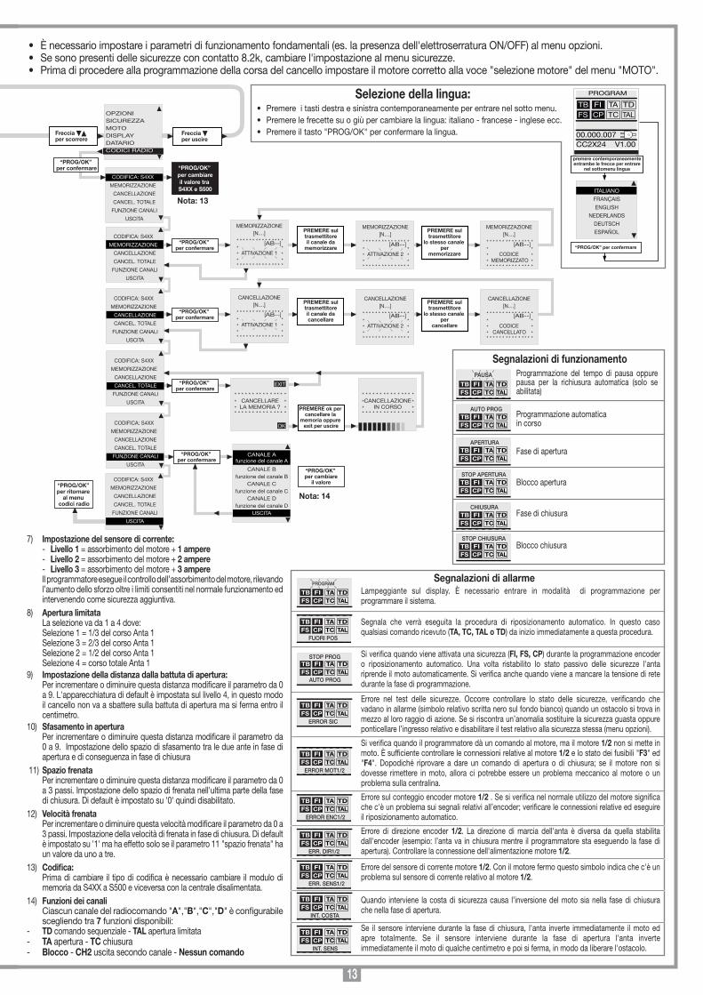
• È necessario impostare i parametri di funzionamento fondamentali (es. la presenza dell'elettroserratura ON/OFF) al menu opzioni.• Se sono presenti delle sicurezze con contatto 8.2k, cambiare l'impostazione al menu sicurezze.• Prima di procedere alla programmazione della corsa del cancello impostare il motore corretto alla voce "selezione motore" del menu "MOTO".
7) Impostazione del sensore di corrente: - Livello 1 = assorbimento del motore + 1 ampere - Livello 2 = assorbimento del motore + 2 ampere - Livello 3 = assorbimento del motore + 3 ampere Il programmatore esegue il controllo dell’assorbimento del motore, rilevando
l’aumento dello sforzo oltre i limiti consentiti nel normale funzionamento ed intervenendo come sicurezza aggiuntiva.
8) Apertura limitata La selezione va da 1 a 4 dove: Selezione 1 = 1/3 del corso Anta 1 Selezione 3 = 2/3 del corso Anta 1 Selezione 2 = 1/2 del corso Anta 1 Selezione 4 = corso totale Anta 19) Impostazione della distanza dalla battuta di apertura: Per incrementare o diminuire questa distanza modificare il parametro da 0
a 9. L'apparecchiatura di default è impostata sul livello 4, in questo modo il cancello non va a sbattere sulla battuta di apertura ma si ferma entro il centimetro.
10) Sfasamento in apertura Per incrementare o diminuire questa distanza modificare il parametro da
0 a 9. Impostazione dello spazio di sfasamento tra le due ante in fase di apertura e di conseguenza in fase di chiusura
11) Spazio frenata Per incrementare o diminuire questa distanza modificare il parametro da 0
a 3 passi. Impostazione dello spazio di frenata nell'ultima parte della fase di chiusura. Di default è impostato su '0' quindi disabilitato.
12) Velocità frenata Per incrementare o diminuire questa velocità modificare il parametro da 0 a
3 passi. Impostazione della velocità di frenata in fase di chiusura. Di default è impostato su '1' ma ha effetto solo se il parametro 11 "spazio frenata" ha un valore da uno a tre.
13) Codifica: Prima di cambiare il tipo di codifica è necessario cambiare il modulo di
memoria da S4XX a S500 e viceversa con la centrale disalimentata.14) Funzioni dei canali Ciascun canale del radiocomando "A","B","C","D" è configurabile
scegliendo tra 7 funzioni disponibili: - TD comando sequenziale - TAL apertura limitata - TA apertura - TC chiusura - Blocco - CH2 uscita secondo canale - Nessun comando
14MEMORIZZAZIONE CODICE TX-RX
RCQ449100
13-04-2001
DM0531 Description :
Product Code :
Date :
Drawing number :
P.J.Heath
CARDIN ELETTRONICA S.p.A - 31020 San Vendemiano (TV) Italy - via Raffaello, 36 Tel: 0438/401818 Fax: 0438/401831
Draft :
All rights reserved. Unauthorised copying or use of the information contained in this document is punishable by law
MR
PROCEDURA DI PROGRAMMAZIONE(corsa del cancello e sensore di corrente)
È possibile azionare a distanza l'automazione tramite radiocomando; ciascun canale è configurabile scegliendo tra 5 funzioni disponibili: apertura - chiusura - apertura limitata - comando sequenziale - blocco.Per configurare le funzioni sui canali "A","B","C","D" si utilizza la voce "FUNZIONE CANALI" dal menu "CODICI RADIO". Il comando sequenziale è configurabile dal menu "OPZIONI" in "apre-stop-chiude-stop" o "apre-chiude".
Modulo di memoria (MM)Estraibile, costituito da una memoria non volatile di tipo EEPROM, contiene i codici dei trasmettitori e permette la memorizzazione di 300 codici S4XX / 1000 codici S500. Nel modulo di memoria i codici vengono mantenuti anche in assenza di alimentazione. Prima di procedere alla prima memorizzazione, ricordarsi di cancellare interamente la memoria. Dovendo sostituire la scheda elettronica per guasto, il modulo di memoria può essere estratto da essa ed inserito nella nuova scheda curandone l’orientamento come indicato in fig. 9.
GESTIONE DEI CODICI DEI TRASMETTITORIMemorizzazione di un canale1. Portarsi alla voce "MEMORIZZAZIONE" del menu "CODICI RADIO" e confermare
tramite il tasto "PROG/OK": sul display LCD lampeggerà la dicitura "Attivazione 1".2. Attivare il trasmettitore sul canale da memorizzare: sul display LCD, lampeggerà la dicitura "Attivazione 2".3. Attivare una seconda volta il trasmettitore (stesso TX, stesso canale*): sul display LCD lampeggerà la dicitura "COD. MEMORIZZATO".Tra le parentesi, sulla prima riga di testo, viene rappresentato il numero di canali presenti in memoria.* Nel caso venga inavvertitamente attivato (al punto 3) un canale diverso da quello della prima attivazione, la procedura verrà automaticamente annullata e sul display LCD lampeggerà dunque la dicitura "Attivazione 1".
Nota: Non è possibile memorizzare un codice che sia già in memoria: in un caso simile durante l’attivazione del radiocomando (al punto 1) sul display LCD lampeg-gerà la scritta "COD. GIA' MEM.".
Cancellazione di un canale:1. Portarsi alla voce "CANCELLAZIONE" del menu "CODICI RADIO" e confermare
tramite il tasto "PROG/OK": sul display LCD lampeggerà la dicitura "Attivazione 1".2. Attivare il trasmettitore sul canale da cancellare: sul display LCD, lampeggerà la dicitura "Attivazione 2".3. Attivare una seconda volta il trasmettitore (stesso TX, stesso canale*): sul display LCD lampeggerà la dicitura "COD. CANCELLATO".Tra le parentesi, sulla prima riga di testo, viene rappresentato il numero di canali presenti in memoria.* Nel caso venga inavvertitamente attivato (al punto 3) un canale diverso da quello della prima attivazione, la procedura verrà automaticamente annullata e sul display LCD lampeggerà dunque la dicitura "Attivazione 1".
Nota: Non è possibile cancellare un codice non presente in memoria: in un caso simile durante l’attivazione del radiocomando (al punto 1) sul display LCD lampeg-gerà la scritta "COD. NON MEMOR.".
Cancellazione completa della memoria utenti:1. Portarsi alla voce "CANCEL. TOTALE" del menu "CODICI RADIO" e confermare
tramite il tasto "PROG/OK": sul display LCD comparirà la richiesta di conferma della procedura "CANC. LA MEMORIA?" (premere una delle due frecce per uscire da tale procedura).
2. Premere il tasto "PROG/OK" per confermare la cancellazione totale: sul display LCD comparirà la scritta "CANCEL. IN CORSO" con una barra di
progressione sottostante che indica lo svolgersi della procedura.3. Terminata la cancellazione totale della memoria il display ritorna alla voce
"CANCEL. TOTALE".
Memorizzazione di ulteriori canali via radio (solo S449 - S486)• La memorizzazione può essere anche attivata via radio (senza aprire la scatola
dove è alloggiata la centralina) se l'impo-stazione "MEMO RADIO" è stata attivata sul menu "OPZIONI".
1. Utilizzando un radiocomando, in cui almeno uno dei tasti di canale "A-B-C-D" sia già stato memorizzato nel ricevitore, attivare il tasto all’interno del radiocomando come indicato nella figura.
Nota: Tutti i ricevitori raggiungibili dall'emissione del radiocomando, e che abbiano almeno un canale del trasmettitore memorizzato, attiveranno contemporaneamente il buzzer di segnalazione "B1" (fig. 9).
• È obbligatoria la presenza delle battute di apertura e chiusura.• Accertarsi che le sicurezze siano a riposo e che la scheda sia alimentata da
rete: in caso contrario non si entra in programmazione. • Non è possibile eseguire la programmazione dei tempi in modalità batteria.• Prima di procedere alla programmazione, impostare i parametri di funziona-
mento alla voce di menu "OPZIONI".
RIPOSIZIONAMENTO
Attenzione! Durante la manovra di riposizionamento il valore del sensore di corrente potrebbe essere alterato (con i valori di coppia massima).Al termine della manovra torna automaticamente al valore selezionato.
Se si dovesse verificare un blocco del programmatore dovuto ad un’anomalia del conteggio encoder ("Errore ENC1-ENC2" sul display), ad un reset del programmatore ("Fuori pos.") o ad un problema con il motore ("Errore Mot1-Mot2") il lampeggiante e la lampada spia lampeggiano contemporaneamente per 2 secondi e poi riman-gono spenti per 10 secondi. Se in questa fase si invia un comando (TA, TC, TAL o TD) al programmatore, il programmatore stesso porta automaticamente il cancello a bassa velocità fino alla battuta di chiusura (per 2 volte come nella procedura di programmazione) in modo da recuperare la posizione.A questo punto il programmatore riprende il normale funzionamento. (Se viene dato un comando "TA" la procedura di recupero viene eseguita in apertura).Durante la fase di riposizionamento non viene accettato nessun comando, mentre le sicurezze agiscono bloccando il moto solamente finché risultano in allarme.Per interrompere la fase di riposizionamento, premere il tasto "PROG" o "TB".
1...4... sec.
Parte il conteggio del tempo di pausa (minimo 2 secondi; massimo 240 secondi), segnalato dal lampeggio della scritta “PAUSA” e dalla progressione del tempo trascorso.
Premere “PROG” per impostare il tempo di pausa al valore desiderato. A questo punto le ante eseguono l’apertura lentamente, in modo da trovare lo stato di completamente aperto.
Quando le ante arrivano alla battuta di apertura, invertono il moto e dopo aver percorso qualche centimetro ritornano in apertura per accertarsi della posizione della battuta. A questa punto l’anta va in chiusura. Quando l’anta arriva in battuta inverte il moto per qualche centimetro per poi ritornare in chiusura, in modo da stabilire la corretta posizione della battuta di chiusura.
Dopo aver effettuato queste manovre la logica di controllo esegue una manovra completa di apertura e chiusura a velocità di regime in modo da tarare il sensore di corrente.
A chiusura completata il programmatore salva i parametri ed esce dalla programmazione.Se l’operazione non è adata a buon ne sarà necessario ripetere la programmazione
Premere il tasto prog/ok per 4 secondi
“PROG/OK” per 4 sec.
CICLO DI AUTOPROGRAMMAZIONE
PROGRAM
TB FIFS CP
TA TDTC TAL
00.000.007CC2X24 V1.00
“PROG/OK”
PAUSA
TB FIFS CP
TA TDTC TAL
00.000.007CC2X24 V1.00
AUTO PROG.
“PROG/OK”
PAUSA
TB FIFS CP
TA TDTC TAL
00.000.007CC2X24 V1.00
AUTO PROG.
APERTURA
TB FIFS CP
TA TDTC TAL
00.000.007CC2X24 V1.00
AUTO PROG.
CHIUSURA
TB FIFS CP
TA TDTC TAL
00.000.007CC2X24 V1.00
AUTO PROG.
PROGRAM
TB FIFS CP
TA TDTC TAL
00.000.007CC2X24 V1.00
[030]
COMANDO VIA RADIO
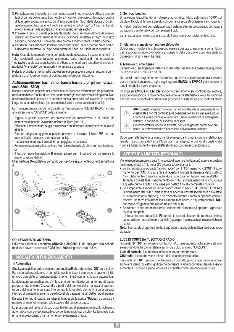
15
2. Per selezionare il ricevitore in cui memorizzare il nuovo codice attivare uno dei tasti di canale dello stesso trasmettitore. I ricevitori che non contengono il codice di tale tasto si disattiveranno, con l'emissione di un "bip" della durata di 5 sec.; quello invece che contiene il codice emetterà un altro "bip" di 1 sec., entrando effettivamente nella modalità di memorizzazione "via radio".
3. Premere il tasto di canale precedentemente scelto sul trasmettitore da memo-rizzare; ad avvenuta memorizzazione il ricevitore emetterà 2 "bip" di mezzo secondo, dopodiché il ricevitore sarà pronto a memorizzare un altro codice.
4. Per uscire dalla modalità lasciare trascorrere 3 sec. senza memorizzare codici. Il ricevitore emetterà un "bip" della durata di 5 sec. ed uscirà dalla modalità.
Nota: Quando la memoria viene completamente occupata, il buzzer emetterà 10 "bip" ravvicinati, uscendo automaticamente dalla modalità di memorizzazione "via radio", la stessa segnalazione si ottiene anche ad ogni tentativo di entrare in modalità "via radio" con memoria interamente occupata.Nota: la procedura memoradio può essere eseguita solo a programmazione com-pletata e al di fuori del menu di configurazione/programmazione.
Abilitazione di nuovi trasmettitori tramite trasmettitori già memorizzati (solo S504 - S508)Questa procedura consiste nell'abilitazione di un nuovo trasmettitore da postazione remota mediante l'ausilio di un altro trasmettitore già memorizzato nell'impianto. Non essendo richiesta la presenza di ricevitori questa procedura può avvenire in qualsiasi luogo lontano dall'impianto (per esempio nel vostro punto vendita di fiducia).
La "memorizzazione rapida" è abilitata se l'impostazione "MEMO RADIO" è stata attivata sul menu "OPZIONI" della centralina.
- Togliere il guscio superiore dei trasmettitori da memorizzare e di quello già memorizzato facendo leva come indicato in figura (dett. a).
- Affiancare il trasmettitore A, già memorizzato sul ricevitore, al trasmettitore nuovo B (dett. b).
- Con un adeguato oggetto appuntito premere e rilasciare il tasto MR sui due trasmettitori (in sequenza o simultaneamente).
- I led arancione dei due trasmettitori lampeggiano lentamente.- Premere e rilasciare sul trasmettitore A un tasto di canale già attivo sul ricevitore (dett.
c).- Il led del nuovo trasmettitore B rimane acceso per 3 secondi per confermare la
memorizzazione (dett. d).Il trasmettitore B è abilitato al comando del ricevitore esattamente come il trasmettitore A.
COLLEGAMENTO ANTENNA Utilizzare l’antenna accordata ANS400 / ANQ800-1, da collegare alla scheda mediante cavetto coassiale RG58 (imp. 50Ω) lunghezza max. 15 m.
1) AutomaticaSi seleziona abilitando la richiusura automatica (Rich. automatica "ON" sul display). Partendo dalla condizione di completamente chiuso, il comando di apertura inizia un ciclo completo di funzionamento, che terminerà con la richiusura automatica. La richiusura automatica entra in funzione con un ritardo pari al tempo di pausa programmato (minimo 2 secondi), a partire dal termine della manovra di apertura oppure dall'istante in cui sono intervenute le fotocellule per l'ultima volta durante il tempo di pausa (l'intervento delle fotocellule causa un reset del tempo di pausa).Durante il tempo di pausa, sul display lampeggia la scritta "Pausa" e compare il numero di secondi rimanenti allo scadere del tempo di pausa.La pressione del tasto di blocco durante il tempo di pausa impedisce la richiusura automatica con conseguente blocco del lampeggio sul display. La lampada spia rimane accesa quando l'anta non è completamente chiusa.
2) Semi-automaticaSi seleziona disabilitando la richiusura automatica (Rich. automatica "OFF" sul display). Il ciclo di lavoro è gestito con comandi separati di apertura e chiusura. Arrivato in posizione di completa apertura il sistema attende un comando di chiusura via radio o tramite tasto per completare il ciclo. La lampada spia rimane accesa quando l'anta non è completamente chiusa.
3) Manovra manuale con motore sbloccatoSbloccando il motore le ante possono essere spostate a mano; una volta ribloc-cati, il programmatore provvederà al ripristino della posizione dopo due tentativi consecutivi di arrivare in battuta.
4) Manovra di emergenzaLa manovra di emergenza di default è disabilitata, per abilitarla posizionare il jumper J6 in posizione "ENABLE" (fig. 9).
Nel caso in cui il programmatore elettronico non dovesse più rispondere ai comandi per un malfunzionamento, agire sugli ingressi EMRG1 o EMRG2 per muovere le ante in modalità uomo presente.
Gli ingressi EMRG1 ed EMRG2 agiscono direttamente sul controllo del motore, escludendo la logica. Il movimento delle ante verrà effettuato a velocità nominale e la direzione del moto dipenderà dalla posizione di installazione del motoriduttore:
Attenzione! Durante la manovra di emergenza tutte le sicurezze risultano disabilitate e non c'è controllo sulla posizione dell'anta: rilasciare dunque i comandi prima dell'arrivo in battuta. Usare la manovra di emergenza soltanto in condizioni di estrema necessità. L’elettroserratura (anche se abilitata) non viene gestita; quindi se è pre-sente un’elettroserratura è necessario attivarla manualmente.
Dopo aver effettuato una manovra di emergenza il programmatore elettronico "perde" la posizione dell'anta ("fuori pos." sul display) e quindi al ripristino del normale funzionamento verrà effettuato il riposizionamento automatico.
Viene eseguita sempre su anta 1; lo spazio di apertura limitata può essere impostato (vedi menu moto) a 1/3, metà, 2/3 o corsa totale di anta 1. • Se è impostata la modalità "apre-chiude" per il "TD" (menu "OPZIONI" ) l'azio-
namento del "TAL" inizia la fase di apertura limitata (solamente dallo stato di "completamente chiuso") e finché dura l'apertura non ha più nessun effetto.
Terminata questa fase, l'azionamento del "TAL" inizia la manovra di chiusura, e a questo punto il "TAL" non viene più gestito fino alla completa chiusura.
• Se è impostata la modalità "apre-blocco-chiude" per il "TD" (menu "OPZIONI") l'azionamento del "TAL" inizia la fase di apertura limitata (solamente dallo stato di "completamente chiuso"), e se azionato durante il moto in apertura causa il blocco; una terza attivazione inizia il moto in chiusura, e a questo punto il "TAL" non viene più gestito fino alla completa chiusura.
• Se durante l'apertura limitata arriva un comando di apertura, l'apertura da parziale diventa completa.
L'intervento della fotocellula FI durante la fase di chiusura da apertura limitata causa la riapertura solamente parziale (riapre per il solo spazio che aveva richiuso l'anta).
Nota: il comando di apertura limitata può essere anche dato utilizzando il comando via radio.
LUCE DI CORTESIA / USCITA CH2 RADIOI morsetti "9","10" fanno capo ai contatti C-NA di un relay; esso potrà essere attivato selezionando la funzione relativa sul display LCD al menu "OPZIONI".Luce di cortesia: il contatto si chiude in modo temporizzato.CH2 radio: il contatto viene pilotato dal secondo canale radio.I morsetti "9","10" forniscono solamente un contatto puro, e non danno una ten-sione all’esterno; questo significa che per usare la luce di cortesia sarà necessario alimentare il circuito a parte, ed usare il contatto come semplice interruttore.
APERTURA LIMITATA (PEDONALE)
MODALITÀ DI FUNZIONAMENTO
MEMORIZZAZIONE CODICE TX-TX
TRQ504
29-10-2013
DM0910 Description :
Product Code :
Date :
Drawing number :
P.J.Heath
CARDIN ELETTRONICA S.p.A - 31020 San Vendemiano (TV) Italy - via Raffaello, 36 Tel: 0438/401818 Fax: 0438/401831
Draft :
All rights reserved. Unauthorised copying or use of the information contained in this document is punishable by law
MR
A
MR
B
1
MEMORIZZAZIONE CODICE TX-TX
TXQ504C4
29-10-2013
DM0911 Description :
Product Code :
Date :
Drawing number :
P.J.Heath
CARDIN ELETTRONICA S.p.A - 31020 San Vendemiano (TV) Italy - via Raffaello, 36 Tel: 0438/401818 Fax: 0438/401831
Draft :
All rights reserved. Unauthorised copying or use of the information contained in this document is punishable by law
A
MEMORIZZAZIONE CODICE TX-TX
TXQ504C4
29-10-2013
DM0912 Description :
Product Code :
Date :
Drawing number :
P.J.Heath
CARDIN ELETTRONICA S.p.A - 31020 San Vendemiano (TV) Italy - via Raffaello, 36 Tel: 0438/401818 Fax: 0438/401831
Draft :
All rights reserved. Unauthorised copying or use of the information contained in this document is punishable by law
B
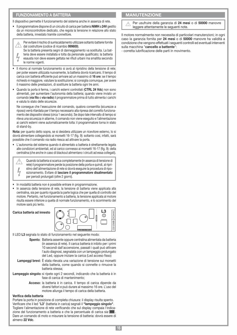
16
MANUTENZIONEIl dispositivo permette il funzionamento del sistema anche in assenza di rete. • Il programmatore dispone di un circuito di carica per batteria NiMH a 24V gestito
da un microcontrollore dedicato, che regola la tensione in relazione allo stato della batteria, innestato tramite connettore.
Per evitare il rischio di surriscaldamento utilizzare soltanto batterie fornite dal costruttore (codice di ricambio 999600).Se la batteria presenta segni di danneggiamento va sostituita. La bat-teria deve essere installata e tolta da personale qualificato; la batteria esausta non deve essere gettata nei rifiuti urbani ma smaltita secondo le norme vigenti.
• Il ritorno al normale funzionamento si avrà al ripristino della tensione di rete; per poter essere utilizzata nuovamente, la batteria dovrà ricaricarsi. Il tempo di carica con batteria efficiente può arrivare ad un massimo di 16 ore: se il tempo richiesto è maggiore, valutare la sostituzione; si consiglia comunque, per avere il massimo delle prestazioni, di sostituire la batteria ogni tre anni.
• Quando la porta è ferma, i carichi esterni controllati (CTRL 24 Vdc) non sono alimentati, per aumentare l’autonomia della batteria; quando viene inviato un comando (via filo o via radio) il programmatore prima di tutto alimenta i carichi e valuta lo stato delle sicurezze.
Ne consegue che l’esecuzione del comando, qualora consentita (sicurezze a riposo) verrà ritardata per il tempo necessario alla ripresa del corretto funziona-mento dei dispositivi stessi (circa 1 secondo). Se dopo tale intervallo di tempo si rileva una sicurezza in allarme, il comando non viene eseguito e l’alimentazione ai carichi esterni viene automaticamente tolta: il programmatore torna in stato di stand-by.
Nota: per quanto detto sopra, se si desidera utilizzare un ricevitore esterno, lo si dovrà alimentare collegandolo ai morsetti 16-17 (fig. 9): soltanto così, infatti, sarà possibile che il comando via radio riesca ad attivare la porta.• L'autonomia del sistema quando è alimentato a batteria è strettamente legata
alle condizioni ambientali, ed al carico connesso ai morsetti 16-17 (fig. 9): della centralina (che anche in caso di blackout alimentano i circuiti ad essa collegati).
Quando la batteria si scarica completamente (in assenza di tensione di rete) il programmatore perde la posizione della porta e quindi, al ripri-stino dell'alimentazione di rete si dovrà eseguire la procedura di ripo-sizionamento. Evitare di lasciare il programmatore disalimentato per periodi prolungati (oltre 2 giorni).
• In modalità batteria non è possibile entrare in programmazione.• In assenza della tensione di rete, la tensione di batteria viene applicata alla
centralina, sia per quanto riguarda la parte logica che per quella di controllo del motore. Pertanto, nel funzionamento a batteria, la tensione applicata al motore risulta essere inferiore a quella di normale funzionamento, e lo scorrimento del motore sarà più lento.
Carica batteria ad innesto
Il LED L3 segnala lo stato di funzionamento nel seguente modo: Spento: Batteria assente oppure centralina alimentata da batteria
(in assenza di rete). Il carica batteria è inibito per i primi 10 secondi dall'accensione, passati i quali può attivare l'auto diagnosi, segnalata con un lampeggio prolungato del Led, oppure iniziare la carica (Led acceso fisso)
Lampeggi brevi: È stata rilevata una variazione di tensione sui morsetti della batteria, come quando si connette o rimuove la batteria stessa;
Lampeggio singolo: si ripete ogni 2 secondi, indicando che la batteria è in fase di carica di mantenimento;
Acceso: la batteria è in carica. Il tempo di carica dipende da diversi fattori e può durare al massimo 16 ore. L’uso del motore allunga il tempo di carica della batteria.
Verifica della batteriaPortare la porta in posizione di completa chiusura: il display risulta spento.Verificare che il led "L3" (batteria in carica) segnali il "lampeggio singolo".Togliere l'alimentazione di rete verificando che sul display compaia l'indica-zione del funzionamento a batteria e che la percentuale di carica sia . Dare un comando di moto e misurare la tensione di batteria: dovrà essere di almeno 22 Vdc.
FUNZIONAMENTO A BATTERIA
CS
1256
BD
C04
50L3
Scheda di innesto
PRG424BC
08-01-2008
DC0435 Description :
Product Code :
Date :
Drawing number :
P.J.Heath
CARDIN ELETTRONICA S.p.A - 31020 San Vendemiano (TV) Italy - via Raffaello, 36 Tel: 0438/401818 Fax: 0438/401831
Draft :
All rights reserved. Unauthorised copying or use of the information contained in this document is punishable by law
Scheda carica batteria
Per usufruire della garanzia di 24 mesi o di 50000 manovre leggere attentamente le seguenti note.
Il motore normalmente non necessita di particolari manutenzioni; in ogni caso la garanzia fornita per 24 mesi o di 50000 manovre ha validità a condizione che vengono effettuati i seguenti controlli ed eventuali interventi sulla macchina "cancello a battente":- corretta lubrificazione delle parti in movimento.
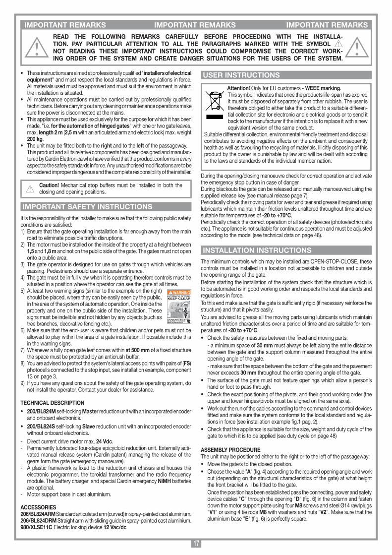
17
IMPORTANT REMARKS IMPORTANT REMARKS IMPORTANT REMARKS
• These instructions are aimed at professionally qualified "installers of electrical equipment" and must respect the local standards and regulations in force. All materials used must be approved and must suit the environment in which the installation is situated.
• All maintenance operations must be carried out by professionally qualified technicians. Before carrying out any cleaning or maintenance operations make sure the power is disconnected at the mains.
• This appliance must be used exclusively for the purpose for which it has been made. "i.e. for the automation of hinged gates" with one or two gate leaves, max. length 2 m (2,5 m with an articulated arm and electric lock) max. weight 200 kg.
• The unit may be fitted both to the right and to the left of the passageway. This product and all its relative components has been designed and manufac-
tured by Cardin Elettronica who have verified that the product conforms in every aspect to the safety standards in force. Any unauthorised modifications are to be considered improper dangerous and the complete responsibility of the installer.
Caution! Mechanical stop buffers must be installed in both the closing and opening positions.
It is the responsibility of the installer to make sure that the following public safety conditions are satisfied:1) Ensure that the gate operating installation is far enough away from the main
road to eliminate possible traffic disruptions. 2) The motor must be installed on the inside of the property at a height between
1,5 and 1,8 m and not on the public side of the gate. The gates must not open onto a public area.
3) The gate operator is designed for use on gates through which vehicles are passing. Pedestrians should use a separate entrance.
4) The gate must be in full view when it is operating therefore controls must be situated in a position where the operator can see the gate at all times.
5) At least two warning signs (similar to the example on the right) should be placed, where they can be easily seen by the public, in the area of the system of automatic operation. One inside the property and one on the public side of the installation. These signs must be indelible and not hidden by any objects (such as tree branches, decorative fencing etc.).
6) Make sure that the end-user is aware that children and/or pets must not be allowed to play within the area of a gate installation. If possible include this in the warning signs.
7) Whenever a fully open gate leaf comes within at 500 mm of a fixed structure the space must be protected by an anticrush buffer.
8) You are advised to protect the system's lateral access points with pairs of (FS) photocells connected to the stop input, see installation example, component 13 on page 3.
9) If you have any questions about the safety of the gate operating system, do not install the operator. Contact your dealer for assistance.
TECHNICAL DESCRIPTION• 200/BL824M self-locking Master reduction unit with an incorporated encoder
and onboard electronics.• 200/BL824S self-locking Slave reduction unit with an incorporated encoder
without onboard electronics.- Direct current drive motor max. 24 Vdc.- Permanently lubricated four-stage epicycloid reduction unit. Externally acti-
vated manual release system (Cardin patent) managing the release of the gears form the gate (emergency manoeuvre).
- A plastic framework is fixed to the reduction unit chassis and houses the electronic programmer, the toroidal transformer and the radio frequency module. The battery charger and special Cardin emergency NiMH batteries are optional.
- Motor support base in cast aluminium.
ACCESSORIES206/BL824ARM Standard articulated arm (curved) in spray-painted cast aluminium.206/BL824DRM Straight arm with sliding guide in spray-painted cast aluminium.980/XLSE11C Electric locking device 12 Vac/dc
Attention! Only for EU customers - WEEE marking.This symbol indicates that once the products life-span has expired it must be disposed of separately from other rubbish. The user is therefore obliged to either take the product to a suitable differen-tial collection site for electronic and electrical goods or to send it back to the manufacturer if the intention is to replace it with a new equivalent version of the same product.
Suitable differential collection, environmental friendly treatment and disposal contributes to avoiding negative effects on the ambient and consequently health as well as favouring the recycling of materials. Illicitly disposing of this product by the owner is punishable by law and will be dealt with according to the laws and standards of the individual member nation.
During the opening/closing manoeuvre check for correct operation and activate the emergency stop button in case of danger.During blackouts the gate can be released and manually manoeuvred using the supplied release key (see manual release page 7).Periodically check the moving parts for wear and tear and grease if required using lubricants which maintain their friction levels unaltered throughout time and are suitable for temperatures of -20 to +70°C.Periodically check the correct operation of all safety devices (photoelectric cells etc.). The appliance is not suitable for continuous operation and must be adjusted according to the model (see technical data on page 48).
The minimum controls which may be installed are OPEN-STOP-CLOSE, these controls must be installed in a location not accessible to children and outside the opening range of the gate.Before starting the installation of the system check that the structure which is to be automated is in good working order and respects the local standards and regulations in force. To this end make sure that the gate is sufficiently rigid (if necessary reinforce the structure) and that it pivots easily.You are advised to grease all the moving parts using lubricants which maintain unaltered friction characteristics over a period of time and are suitable for tem-peratures of -20 to +70°C.• Check the safety measures between the fixed and moving parts: - a minimum space of 30 mm must always be left along the entire distance
between the gate and the support column measured throughout the entire opening angle of the gate.
- make sure that the space between the bottom of the gate and the pavement never exceeds 30 mm throughout the entire opening angle of the gate.
• The surface of the gate must not feature openings which allow a person’s hand or foot to pass through.
• Check the exact positioning of the pivots, and their good working order (the upper and lower hinges/pivots must be aligned on the same axis).
• Work out the run of the cables according to the command and control devices fitted and make sure the system conforms to the local standard and regula-tions in force (see installation example fig.1 pag. 2).
• Check that the appliance is suitable for the size, weight and duty cycle of the gate to which it is to be applied (see duty cycle on page 48)
ASSEMBLY PROCEDUREThe unit may be positioned either to the right or to the left of the passageway:• Move the gate/s to the closed position.• Choose the value "A" (fig. 4) according to the required opening angle and work
out (depending on the structural characteristics of the gate) at what height the front bracket will be fitted to the gate.
Once the position has been established pass the connecting, power and safety device cables "C" through the opening "D" (fig. 6) in the column and fasten down the motor support plate using four M8 screws and steel Ø14 rawlplugs "V1" or using 4 tie rods M8 with washers and nuts "V2". Make sure that the aluminium base "E" (fig. 6) is perfectly square.
READ THE FOLLOWING REMARKS CAREFULLY BEFORE PROCEEDING WITH THE INSTALLA-TION. PAY PARTICULAR ATTENTION TO ALL THE PARAGRAPHS MARKED WITH THE SYMBOL NOT READING THESE IMPORTANT INSTRUCTIONS COULD COMPROMISE THE CORRECT WORK-ING ORDER OF THE SYSTEM AND CREATE DANGER SITUATIONS FOR THE USERS OF THE SYSTEM.
USER INSTRUCTIONS
IMPORTANT SAFETY INSTRUCTIONS
INSTALLATION INSTRUCTIONS
AUTOMATIC OPENING
KEEP CLEAR
CHILDREN OR PETS MUST NOT BE ALLOWED TO PLAY ON OR NEAR THE INSTALLATION
WARNING
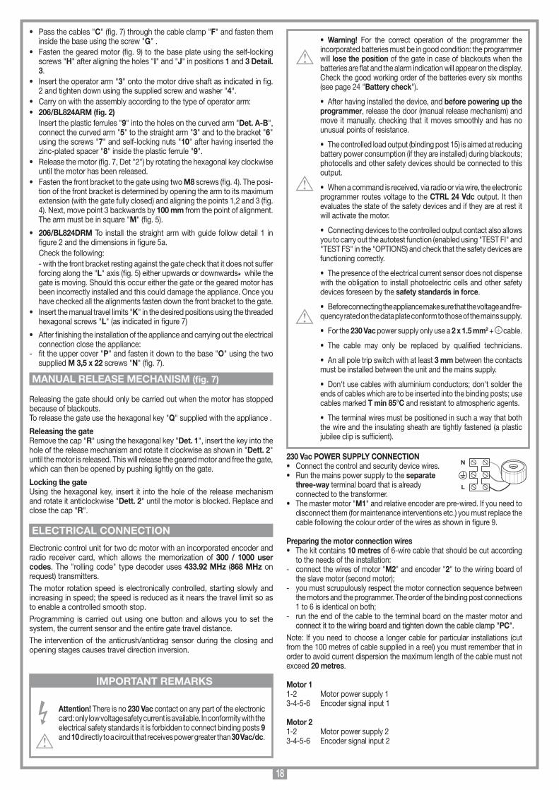
18
• Warning! For the correct operation of the programmer the incorporated batteries must be in good condition: the programmer will lose the position of the gate in case of blackouts when the batteries are flat and the alarm indication will appear on the display. Check the good working order of the batteries every six months (see page 24 "Battery check").
• After having installed the device, and before powering up the programmer, release the door (manual release mechanism) and move it manually, checking that it moves smoothly and has no unusual points of resistance.
• The controlled load output (binding post 15) is aimed at reducing battery power consumption (if they are installed) during blackouts; photocells and other safety devices should be connected to this output.
• When a command is received, via radio or via wire, the electronic programmer routes voltage to the CTRL 24 Vdc output. It then evaluates the state of the safety devices and if they are at rest it will activate the motor.
• Connecting devices to the controlled output contact also allows you to carry out the autotest function (enabled using "TEST FI" and "TEST FS" in the "OPTIONS) and check that the safety devices are functioning correctly.
• The presence of the electrical current sensor does not dispense with the obligation to install photoelectric cells and other safety devices foreseen by the safety standards in force.
• Before connecting the appliance make sure that the voltage and fre-quency rated on the data plate conform to those of the mains supply.
• For the 230 Vac power supply only use a 2 x 1.5 mm2 + cable.
• The cable may only be replaced by qualified technicians.
• An all pole trip switch with at least 3 mm between the contacts must be installed between the unit and the mains supply.
• Don't use cables with aluminium conductors; don't solder the ends of cables which are to be inserted into the binding posts; use cables marked T min 85°C and resistant to atmospheric agents.
• The terminal wires must be positioned in such a way that both the wire and the insulating sheath are tightly fastened (a plastic jubilee clip is sufficient).
230 Vac POWER SUPPLY CONNECTION• Connect the control and security device wires.• Run the mains power supply to the separate three-way terminal board that is already connected to the transformer.• The master motor "M1" and relative encoder are pre-wired. If you need to
disconnect them (for maintenance interventions etc.) you must replace the cable following the colour order of the wires as shown in figure 9.
Preparing the motor connection wires• The kit contains 10 metres of 6-wire cable that should be cut according
to the needs of the installation:- connect the wires of motor "M2" and encoder "2" to the wiring board of
the slave motor (second motor);- you must scrupulously respect the motor connection sequence between
the motors and the programmer. The order of the binding post connections 1 to 6 is identical on both;
- run the end of the cable to the terminal board on the master motor and connect it to the wiring board and tighten down the cable clamp "PC".
Note: If you need to choose a longer cable for particular installations (cut from the 100 metres of cable supplied in a reel) you must remember that in order to avoid current dispersion the maximum length of the cable must not exceed 20 metres.
Motor 11-2 Motor power supply 13-4-5-6 Encoder signal input 1
Motor 21-2 Motor power supply 23-4-5-6 Encoder signal input 2
• Pass the cables "C" (fig. 7) through the cable clamp "F" and fasten them inside the base using the screw "G" .
• Fasten the geared motor (fig. 9) to the base plate using the self-locking screws "H" after aligning the holes "I" and "J" in positions 1 and 3 Detail. 3.
• Insert the operator arm "3" onto the motor drive shaft as indicated in fig. 2 and tighten down using the supplied screw and washer "4".
• Carry on with the assembly according to the type of operator arm:• 206/BL824ARM (fig. 2) Insert the plastic ferrules "9" into the holes on the curved arm "Det. A-B",
connect the curved arm "5" to the straight arm "3" and to the bracket "6" using the screws "7" and self-locking nuts "10" after having inserted the zinc-plated spacer "8" inside the plastic ferrule "9".
• Release the motor (fig. 7, Det "2") by rotating the hexagonal key clockwise until the motor has been released.
• Fasten the front bracket to the gate using two M8 screws (fig. 4). The posi-tion of the front bracket is determined by opening the arm to its maximum extension (with the gate fully closed) and aligning the points 1,2 and 3 (fig. 4). Next, move point 3 backwards by 100 mm from the point of alignment. The arm must be in square "M" (fig. 5).
• 206/BL824DRM To install the straight arm with guide follow detail 1 in figure 2 and the dimensions in figure 5a.
Check the following: - with the front bracket resting against the gate check that it does not suffer
forcing along the "L" axis (fig. 5) either upwards or downwards* while the gate is moving. Should this occur either the gate or the geared motor has been incorrectly installed and this could damage the appliance. Once you have checked all the alignments fasten down the front bracket to the gate.
• Insert the manual travel limits "K" in the desired positions using the threaded hexagonal screws "L" (as indicated in figure 7)
• After finishing the installation of the appliance and carrying out the electrical connection close the appliance:
- fit the upper cover "P" and fasten it down to the base "O" using the two supplied M 3,5 x 22 screws "N" (fig. 7).
Releasing the gate should only be carried out when the motor has stopped because of blackouts.To release the gate use the hexagonal key "Q" supplied with the appliance .
Releasing the gateRemove the cap "R" using the hexagonal key "Det. 1", insert the key into the hole of the release mechanism and rotate it clockwise as shown in "Dett. 2" until the motor is released. This will release the geared motor and free the gate, which can then be opened by pushing lightly on the gate.
Locking the gateUsing the hexagonal key, insert it into the hole of the release mechanism and rotate it anticlockwise "Dett. 2" until the motor is blocked. Replace and close the cap "R".
Electronic control unit for two dc motor with an incorporated encoder and radio receiver card, which allows the memorization of 300 / 1000 user codes. The "rolling code" type decoder uses 433.92 MHz (868 MHz on request) transmitters.The motor rotation speed is electronically controlled, starting slowly and increasing in speed; the speed is reduced as it nears the travel limit so as to enable a controlled smooth stop. Programming is carried out using one button and allows you to set the system, the current sensor and the entire gate travel distance. The intervention of the anticrush/antidrag sensor during the closing and opening stages causes travel direction inversion.
Attention! There is no 230 Vac contact on any part of the electronic card: only low voltage safety current is available. In conformity with the electrical safety standards it is forbidden to connect binding posts 9 and 10 directly to a circuit that receives power greater than 30 Vac/dc.
MANUAL RELEASE MECHANISM (fig. 7)
ELECTRICAL CONNECTION
IMPORTANT REMARKS
N
L
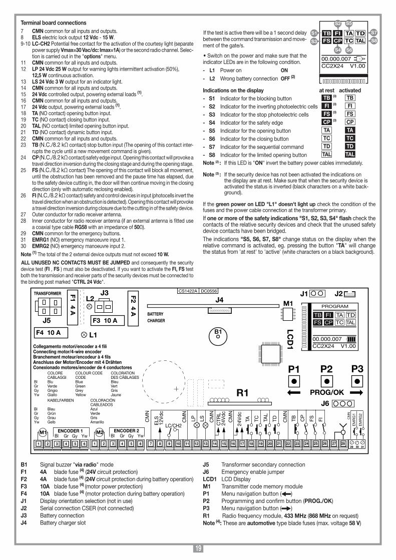
19
Terminal board connections7 CMN common for all inputs and outputs.8 ELS electric lock output 12 Vdc - 15 W.9-10 LC-CH2 Potential free contact for the activation of the courtesy light (separate
power supply Vmax=30 Vac/dc: Imax=1A) or the second radio channel. Selec-tion is carried out in the "options" menu.
11 CMN common for all inputs and outputs.12 LP 24 Vdc 25 W output for warning lights intermittent activation (50%), 12,5 W continuous activation.13 LS 24 Vdc 3 W output for an indicator light.14 CMN common for all inputs and outputs.15 24 Vdc controlled output, powering external loads (1).16 CMN common for all inputs and outputs.17 24 Vdc output, powering external loads (1).18 TA (NO contact) opening button input.19 TC (NO contact) closing button input.20 TAL (NO contact) limited opening button input.21 TD (NO contact) dynamic button input.22 CMN common for all inputs and outputs.23 TB (N.C./8.2 kΩ contact) stop button input (The opening of this contact inter-
rupts the cycle until a new movement command is given).24 CP (N.C./8.2 kΩ contact) safety edge input. Opening this contact will provoke a
travel direction inversion during the closing stage and during the opening stage.25 FS (N.C./8.2 kΩ contact) The opening of this contact will block all movement,
until the obstruction has been removed and the pause time has elapsed, due to the safety device cutting in, the door will then continue moving in the closing direction (only with automatic reclosing enabled).
26 FI (N.C./8.2 kΩ contact) safety and control devices in input (photocells invert the travel direction when an obstruction is detected). Opening this contact will provoke a travel direction inversion during closure due to the cutting in of the safety device.
27 Outer conductor for radio receiver antenna.28 Inner conductor for radio receiver antenna (if an external antenna is fitted use
a coaxial type cable RG58 with an impedance of 50Ω).29 CMN common for the emergency buttons.31 EMRG1 (NO) emergency manoeuvre input 1.30 EMRG2 (NO) emergency manoeuvre input 2.
Note (1) The total of the 2 external device outputs must not exceed 10 W.
ALL UNUSED NC CONTACTS MUST BE JUMPED and consequently the security device test (FI , FS ) must also be deactivated. If you want to activate the FI, FS test both the transmission and receiver parts of the security devices must be connected to the binding post marked "CTRL 24 Vdc".
If the test is active there will be a 1 second delay between the command transmission and move-ment of the gate/s.
• Switch on the power and make sure that the indicator LEDs are in the following condition.
- L1 Power on ON
- L2 Wrong battery connection OFF (2)
Indications on the display at rest activated- S1 Indicator for the blocking button TB (3) TB - S2 Indicator for the inverting photoelectric cells FI (3) FI
- S3 Indicator for the stop photoelectric cells FS (3) FS
- S4 Indicator for the safety edge CP (3) CP - S5 Indicator for the opening button TA TA
- S6 Indicator for the closing button TC TC
- S7 Indicator for the sequential command TD TD
- S8 Indicator for the limited opening button TAL TALNote (2) : If this LED is "ON" invert the battery power cables immediately.
Note (3) : If the security device has not been activated the indications on the display are at rest. Make sure that when the security device is activated the status is inverted (black characters on a white back-ground).
If the green power on LED "L1" doesn't light up check the condition of the fuses and the power cable connection at the transformer primary.If one or more of the safety indications "S1, S2, S3, S4" flash check the contacts of the relative security devices and check that the unused safety device contacts have been bridged. The indications "S5, S6, S7, S8" change status on the display when the relative command is activated, eg. pressing the button "TA" will change the status from 'at rest' to 'active' (white characters on a black background).
B1 Signal buzzer "via radio" modeF1 4A blade fuse (4) (24V circuit protection)F2 4A blade fuse (4) (24V circuit protection during battery operation) F3 10A blade fuse (4) (motor power protection) F4 10A blade fuse (4) (motor protection during battery operation) J1 Display orientation selection (not in use)J2 Serial connection CSER (not connected)J3 Battery connectionJ4 Battery charger slot
J5 Transformer secondary connectionJ6 Emergency enable jumper LCD1 LCD DisplayM1 Transmitter code memory moduleP1 Menu navigation button ( )P2 Programming and confirm button (PROG./OK) P3 Menu navigation button ( )R1 Radio frequency module, 433 MHz (868 MHz on request) Note (4): These are automotive type blade fuses (max. voltage 58 V)
Collegamenti scheda base
CC2X24
05-09-2015
DC0556 Description :
Product Code :
Date :
Drawing number :
P.J.Heath
CARDIN ELETTRONICA S.p.A - 31020 San Vendemiano (TV) Italy - via Raffaello, 36 Tel: 0438/401818 Fax: 0438/401831
Draft :
All rights reserved. Unauthorised copying or use of the information contained in this document is punishable by law
CC2X24 SCHEDA BASE V1.00(con display LCD + MULTI-DECODIFICA)
CS1422A DC0556
M1
B1
F2 4 A
TRANSFORMER
L1
29 30 31
F1 4 A
LCD
1
P1 P2 P3
PROG/OK
J5
9 10 11 12 13 14 15 16 17 18 19 20 21 22 23 24 25 26
COLORE COLOUR CODE COLORATION CABLAGGI CODE DES CÂBLAGES Bl Blu Blue Bleu Gr Verde Green Vert Gy Grigio Grey Gris Yw Giallo Yellow Jaune KABELFARBEN COLORACIÓN CABLEADOSBl Blau AzulGr Grün VerdeGy Grau GrisYw Gelb Amarillo
Collegamento motori/encoder a 4 fili Connecting motor/4-wire encoderBranchement moteur/encodeur à 4 filsAnschluss der Motor/Encoder mit 4 DrähtenConexionado motores/encoder de 4 conductores
7 83 4 5 61 2 3 4 5 61 2
YwGyGrBlENCODER 1
YwGyGrBlENCODER 2M1 M2
27 28
TDTA TC
24V
dc
TAL
CM
N
FITB CP
FS
EM
RG
1
EM
RG
2
CM
N
CM
N
CTR
L24
Vd
c
CM
N
LSLPCM
N
LC/CH2ELS
12V
dc
CM
N
F4 10 A
J3
F3 10 ABATTERYCHARGER
J1
R1J6
J2J4L2
PROGRAM
TB FIFS CP
TA TDTC TAL
00.000.007CC2X24 V1.00
S5
S6
TB FIFS CP
TA TDTC TAL
00.000.007CC2X24 V1.00
S1
S3
S7
S8
S2
S4
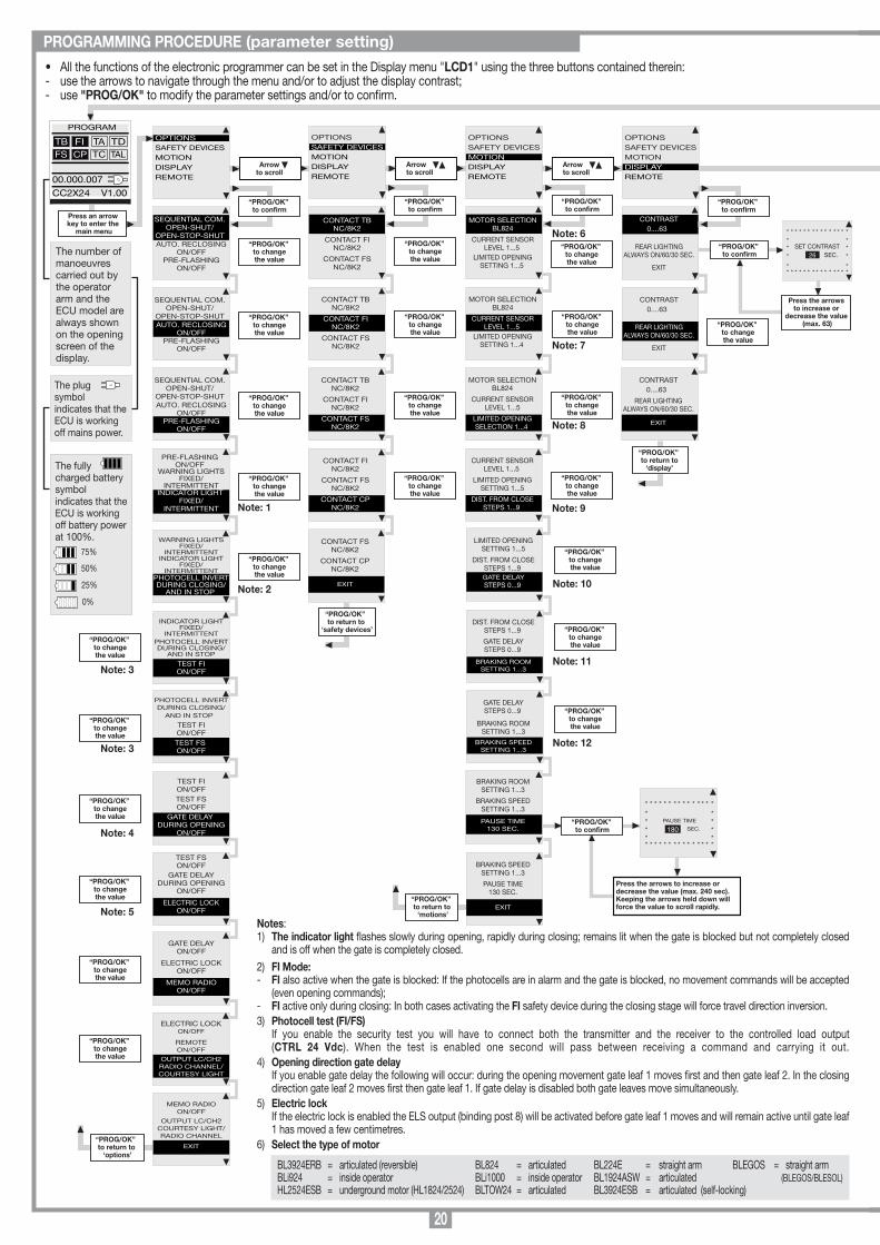
20
“PROG/OK” to return to ‘motions’
“PROG/OK” to confirm
Press the arrows to increase or
decrease the value (max. 63)
* * * * * * * * * * * * * * ** ** SET CONTRAST ** SEC. *
* ** * * * * * * * * * * * * * *
26
“PROG/OK” to return to ‘options’
OPTIONSSAFETY DEVICES MOTIONDISPLAYREMOTE
PROGRAM
TB FIFS CP
TA TDTC TAL
00.000.007
CC2X24 V1.00
OPTIONSSAFETY DEVICESMOTIONDISPLAYREMOTE
Arrowto scroll
SEQUENTIAL COM.OPEN-SHUT/
OPEN-STOP-SHUTAUTO. RECLOSING
ON/OFFPRE-FLASHING
ON/OFF
OPTIONSSAFETY DEVICES MOTIONDISPLAYREMOTE
Arrowto scroll
OPTIONSSAFETY DEVICES MOTIONDISPLAYREMOTE
Arrowto scroll
SEQUENTIAL COM.OPEN-SHUT/
OPEN-STOP-SHUTAUTO. RECLOSING
ON/OFFPRE-FLASHING
ON/OFF
SEQUENTIAL COM.OPEN-SHUT/
OPEN-STOP-SHUTAUTO. RECLOSING
ON/OFFPRE-FLASHING
ON/OFF
PRE-FLASHINGON/OFF
WARNING LIGHTSFIXED/
INTERMITTENTINDICATOR LIGHT
FIXED/INTERMITTENT
WARNING LIGHTSFIXED/
INTERMITTENTINDICATOR LIGHT
FIXED/INTERMITTENT
PHOTOCELL INVERTDURING CLOSING/
AND IN STOP
INDICATOR LIGHTFIXED/
INTERMITTENTPHOTOCELL INVERTDURING CLOSING/
AND IN STOP
TEST FION/OFF
PHOTOCELL INVERTDURING CLOSING/
AND IN STOP
TEST FION/OFFTEST FS ON/OFF
TEST FSON/OFF
GATE DELAYDURING OPENING
ON/OFF
ELECTRIC LOCKON/OFF
TEST FION/OFFTEST FSON/OFF
GATE DELAY DURING OPENING
ON/OFF
GATE DELAYON/OFF
ELECTRIC LOCKON/OFF
MEMO RADIOON/OFF
ELECTRIC LOCKON/OFF
REMOTEON/OFF
OUTPUT LC/CH2RADIO CHANNEL/COURTESY LIGHT
“PROG/OK” to confirm
“PROG/OK” to changethe value
“PROG/OK” to changethe value
“PROG/OK” to changethe value
“PROG/OK” to changethe value
“PROG/OK” to changethe value
“PROG/OK” to changethe value
“PROG/OK” to changethe value
“PROG/OK” to changethe value
“PROG/OK” to changethe value
“PROG/OK” to changethe value
MEMO RADIOON/OFF
OUTPUT LC/CH2COURTESY LIGHT/RADIO CHANNEL
EXIT
“PROG/OK” to changethe value
CONTACT TBNC/8K2
CONTACT FINC/8K2
CONTACT FSNC/8K2
CONTACT TBNC/8K2
CONTACT FINC/8K2
CONTACT FSNC/8K2
“PROG/OK” to confirm
“PROG/OK” to changethe value
“PROG/OK” to changethe value
CONTACT TBNC/8K2
CONTACT FINC/8K2
CONTACT FSNC/8K2
“PROG/OK” to changethe value
CONTACT FINC/8K2
CONTACT FSNC/8K2
CONTACT CPNC/8K2
“PROG/OK” to changethe value
CONTACT FSNC/8K2
CONTACT CPNC/8K2
EXIT
“PROG/OK” to return to
‘safety devices’
MOTOR SELECTIONBL824
CURRENT SENSORLEVEL 1...5
LIMITED OPENINGSETTING 1...5
MOTOR SELECTIONBL824
CURRENT SENSORLEVEL 1...5
LIMITED OPENINGSETTING 1...4
“PROG/OK” to confirm
“PROG/OK” to changethe value
MOTOR SELECTIONBL824
CURRENT SENSORLEVEL 1...5
LIMITED OPENINGSELECTION 1...4
“PROG/OK” to changethe value
CURRENT SENSORLEVEL 1...5
LIMITED OPENINGSETTING 1...5
DIST. FROM CLOSESTEPS 1...9
“PROG/OK” to changethe value
“PROG/OK” to changethe value
CONTRAST0....63
REAR LIGHTINGALWAYS ON/60/30 SEC.
EXIT
“PROG/OK” to confirm
CONTRAST0....63
REAR LIGHTINGALWAYS ON/60/30 SEC.
EXIT
“PROG/OK” to changethe value
CONTRAST0....63
REAR LIGHTINGALWAYS ON/60/30 SEC.
EXIT
“PROG/OK” to return to
‘display’
Note: 1
Note: 2
Note: 3
Note: 3
Note: 6
Note: 7
Note: 8
Note: 9
The number of manoeuvres carried out by the operator arm and the ECU model are always shown on the opening screen of the display.
The plug symbolindicates that the ECU is working off mains power.
The fullycharged battery symbolindicates that the ECU is working off battery power at 100%.
75%
50%
25%
0%
Note: 4
Note: 5
ITALIANO
FRANÇAIS
ENGLISH
NEDERLANDS
DEUTSCH
ESPAÑOL
PROGRAM
TB FIFS CP
TA TDTC TAL
00.000.007CC2X24 V1.00
press both arrows simultaneously to enterthe language submenu
“PROG/OK” to confirm
Flashing on the display. You have to enter the programming mode to program the system.
During normal operation it indicates that the "automatic repositioning" procedure is about to take place. In this case any commands received (TA, TC, TAL or TD) will automatically start this procedure.
This happens when an N.C. contact is activated (FI, FS, CP) during encoder programming or automatic repositioning. Once the passive state of the security devices has been reset the gate will start moving again automatically. It also happens if a blackout occurs during programming.
Safety device test error. Check the condition of the safety devices and make sure that the alarm cuts in when an obstacle interferes with the beam (indication white characters on a black background). In case of anomalies replace the damaged safety device or bridge the contact and deactivate the safety test (option menu).
This occurs when the programmer sends a command to the motor and nothing happens (motor 1/2 doesn't move). Check the Faston connections of motor 1/2 and the condition of the fuses "F3", "F4" and then give another opening or closing command. If the motor still doesn't move you are faced with either a mechanical problem or a problem with the programmer.
Encoder count error motor 1/2 . If this error occurs during normal motor operation it means that there is a problem with one of the encoder signals. Check the relative connections and carry out automatic repositioning.
Encoder direction error motor 1/2 : The gate movement direction is different from the encoder setting (eg. the gate moves in the closing direction while the program is carrying out the opening stage). Check motor 1/2 power supply connections.
Current sensor error motor 1/2 . When the gate is not moving this symbol means there is a problem with the current sensor 1/2 .
Opening this contact will provoke a travel direction inversion during the closing stage and during the opening stage.
If the sensor intervenes during the opening direction the gate inverts the travel direction immediately and proceeds to the fully open position. If the sensor intervenes during the closing direction the gate automatically inverts the travel direction of a few centimetres and then stops to free the obstacle.
Alarm indicationsTB FIFS CP
TA TDTC TAL
PROGRAM
TB FIFS CP
TA TDTC TAL
OUT OF POS
TB FIFS CP
TA TDTC TAL
SAFETY ERROR
TB FIFS CP
TA TDTC TAL
STOP PROG
AUTO PROG
TB FIFS CP
TA TDTC TAL
ERROR MOT1/2
TB FIFS CP
TA TDTC TAL
ERROR ENC1/2
TB FIFS CP
TA TDTC TAL
ERROR DIR1/2
TB FIFS CP
TA TDTC TAL
ERROR SENS1/2
TB FIFS CP
TA TDTC TAL
ACT. SAFETY EDGE
TB FIFS CP
TA TDTC TAL
ACTIVE SENSOR
Press an arrow key to enter the
main menu
LIMITED OPENINGSETTING 1...5
DIST. FROM CLOSESTEPS 1...9 GATE DELAYSTEPS 0...9
DIST. FROM CLOSESTEPS 1...9
GATE DELAYSTEPS 0...9
BRAKING ROOMSETTING 1...3
BRAKING ROOMSETTING 1...3
BRAKING SPEEDSETTING 1...3
PAUSE TIME130 SEC.
BRAKING SPEEDSETTING 1...3
PAUSE TIME130 SEC.
EXIT
“PROG/OK” to confirm
Press the arrows to increase or decrease the value (max. 240 sec).Keeping the arrows held down will force the value to scroll rapidly.
* * * * * * * * * * * * * * ** ** PAUSE TIME ** SEC. ** ** * * * * * * * * * * * * * *
180
GATE DELAYSTEPS 0...9
BRAKING ROOMSETTING 1...3
BRAKING SPEEDSETTING 1...3
“PROG/OK” to changethe value
Note: 10
“PROG/OK” to changethe value
Note: 11
“PROG/OK” to changethe value
Note: 12
Language choice:• Press the right and left buttons simultaneously to enter the language submenu.• Press the right and left buttons to change the language: Italian to English.• Press the "PROG/OK" button to conrm the choice.
Pause time programming or pause for automatic reclosing (if activated)
Automatic programming under way
Opening stage
Block during opening
Closing stage
Block during closing
Operational indications
TB FIFS CP
TA TDTC TAL
PAUSE
TB FIFS CP
TA TDTC TAL
AUTO PROG
TB FIFS CP
TA TDTC TAL
OPENING
TB FIFS CP
TA TDTC TAL
STOP OPENING
TB FIFS CP
TA TDTC TAL
CLOSING
TB FIFS CP
TA TDTC TAL
STOP CLOSING
“PROG/OK” to confirm
PRESS thetransmitter
channelto memorise
PRESS thethe same
transmitterchannel
again
“PROG/OK” to confirm
Arrowto scroll
ENCODING: S4XX
MEMORISE
CANCEL
CLEAR ALL MEMORY
CHANNEL FUNCTION
EXIT
“PROG/OK” to confirm
OPTIONSSAFETY DEVICES MOTIONDISPLAYCALENDARREMOTE
MEMORISE[Nr...]
* * * * * * * * * * * * * * ** ** ACTIVATION 1 ** ** * * * * * * * * * * * * * *
MEMORISE[Nr...]
* * * * * * * * * * * * * * ** ** ACTIVATION 2 ** ** * * * * * * * * * * * * * *
MEMORISE[Nr...]
* * * * * * * * * * * * * * ** ** CODE ** MEMORISED ** * * * * * * * * * * * * * *
“PROG/OK” to confirm
CANCEL[Nr...]
* * * * * * * * * * * * * * ** ** ACTIVATION 1 ** ** * * * * * * * * * * * * * *
PRESS thetransmitter
channelto memorise
CANCEL[Nr...]
* * * * * * * * * * * * * * ** ** ACTIVATION 2 ** ** * * * * * * * * * * * * * *
PRESS thethe same
transmitterchannel
again
CANCEL[Nr...]
* * * * * * * * * * * * * * ** ** CODE ** CANCELLED ** * * * * * * * * * * * * * *
ENCODING: S4XX
MEMORISE
CANCEL
CLEAR ALL MEMORY
CHANNEL FUNCTION
EXIT
“PROG/OK” to confirm
* * * * * * * * * * * * * * ** CANCEL ** ALL MEMORY ? ** * * * * * * * * * * * * * *
PRESS ok to cancel all memory
or press exit
ENCODING: S4XX
MEMORISE
CANCEL
CLEAR ALL MEMORY
CHANNEL FUNCTION
EXIT
Arrowto exit
EXIT
OK
* * * * * * * * * * * * * * ** CANCELLING ** * * * * * * * * * * * * * *
ENCODING: S4XX
MEMORISE
CANCEL
CLEAR ALL MEMORY
CHANNEL FUNCTION
EXIT
CHANNEL Achannel function A
CHANNEL Bchannel function B
CHANNEL Cchannel function C
CHANNEL D
channel function DEXIT
ENCODING: S4XX
MEMORISE
CANCEL
CLEAR ALL MEMORY
CHANNEL FUNCTION
EXIT
“PROG/OK” to changethe value
ENCODING: S4XX
MEMORISE
CANCEL
CLEAR ALL MEMORY
CHANNEL FUNCTION
EXIT
“PROG/OK” to toggle the
value betweenS4XX & S500
“PROG/OK” to return tothe remote
menu
[AB--] [AB--] [AB--]
[AB--] [AB--] [AB--]
Note: 14
Note: 13
• All the functions of the electronic programmer can be set in the Display menu "LCD1" using the three buttons contained therein:- use the arrows to navigate through the menu and/or to adjust the display contrast;- use "PROG/OK" to modify the parameter settings and/or to confirm.
PROGRAMMING PROCEDURE (parameter setting)
Notes:1) The indicator light flashes slowly during opening, rapidly during closing; remains lit when the gate is blocked but not completely closed
and is off when the gate is completely closed.2) FI Mode:- FI also active when the gate is blocked: If the photocells are in alarm and the gate is blocked, no movement commands will be accepted
(even opening commands);- FI active only during closing: In both cases activating the FI safety device during the closing stage will force travel direction inversion.3) Photocell test (FI/FS) If you enable the security test you will have to connect both the transmitter and the receiver to the controlled load output
(CTRL 24 Vdc). When the test is enabled one second will pass between receiving a command and carrying it out.4) Opening direction gate delay If you enable gate delay the following will occur: during the opening movement gate leaf 1 moves first and then gate leaf 2. In the closing
direction gate leaf 2 moves first then gate leaf 1. If gate delay is disabled both gate leaves move simultaneously.5) Electric lock If the electric lock is enabled the ELS output (binding post 8) will be activated before gate leaf 1 moves and will remain active until gate leaf
1 has moved a few centimetres.6) Select the type of motor
BL3924ERB = articulated (reversible)BLi924 = inside operator HL2524ESB = underground motor (HL1824/2524)
BL824 = articulated BLi1000 = inside operator BLTOW24 = articulated
BL224E = straight armBL1924ASW = articulatedBL3924ESB = articulated (self-locking)
BLEGOS = straight arm (BLEGOS/BLESOL)
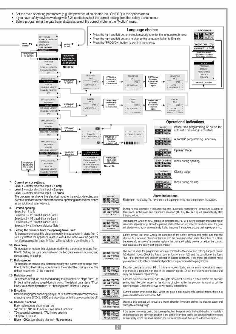
21
“PROG/OK” to return to ‘motions’
“PROG/OK” to confirm
Press the arrows to increase or
decrease the value (max. 63)
* * * * * * * * * * * * * * ** ** SET CONTRAST ** SEC. *
* ** * * * * * * * * * * * * * *
26
“PROG/OK” to return to ‘options’
OPTIONSSAFETY DEVICES MOTIONDISPLAYREMOTE
PROGRAM
TB FIFS CP
TA TDTC TAL
00.000.007
CC2X24 V1.00
OPTIONSSAFETY DEVICESMOTIONDISPLAYREMOTE
Arrowto scroll
SEQUENTIAL COM.OPEN-SHUT/
OPEN-STOP-SHUTAUTO. RECLOSING
ON/OFFPRE-FLASHING
ON/OFF
OPTIONSSAFETY DEVICES MOTIONDISPLAYREMOTE
Arrowto scroll
OPTIONSSAFETY DEVICES MOTIONDISPLAYREMOTE
Arrowto scroll
SEQUENTIAL COM.OPEN-SHUT/
OPEN-STOP-SHUTAUTO. RECLOSING
ON/OFFPRE-FLASHING
ON/OFF
SEQUENTIAL COM.OPEN-SHUT/
OPEN-STOP-SHUTAUTO. RECLOSING
ON/OFFPRE-FLASHING
ON/OFF
PRE-FLASHINGON/OFF
WARNING LIGHTSFIXED/
INTERMITTENTINDICATOR LIGHT
FIXED/INTERMITTENT
WARNING LIGHTSFIXED/
INTERMITTENTINDICATOR LIGHT
FIXED/INTERMITTENT
PHOTOCELL INVERTDURING CLOSING/
AND IN STOP
INDICATOR LIGHTFIXED/
INTERMITTENTPHOTOCELL INVERTDURING CLOSING/
AND IN STOP
TEST FION/OFF
PHOTOCELL INVERTDURING CLOSING/
AND IN STOP
TEST FION/OFFTEST FS ON/OFF
TEST FSON/OFF
GATE DELAYDURING OPENING
ON/OFF
ELECTRIC LOCKON/OFF
TEST FION/OFFTEST FSON/OFF
GATE DELAY DURING OPENING
ON/OFF
GATE DELAYON/OFF
ELECTRIC LOCKON/OFF
MEMO RADIOON/OFF
ELECTRIC LOCKON/OFF
REMOTEON/OFF
OUTPUT LC/CH2RADIO CHANNEL/COURTESY LIGHT
“PROG/OK” to confirm
“PROG/OK” to changethe value
“PROG/OK” to changethe value
“PROG/OK” to changethe value
“PROG/OK” to changethe value
“PROG/OK” to changethe value
“PROG/OK” to changethe value
“PROG/OK” to changethe value
“PROG/OK” to changethe value
“PROG/OK” to changethe value
“PROG/OK” to changethe value
MEMO RADIOON/OFF
OUTPUT LC/CH2COURTESY LIGHT/RADIO CHANNEL
EXIT
“PROG/OK” to changethe value
CONTACT TBNC/8K2
CONTACT FINC/8K2
CONTACT FSNC/8K2
CONTACT TBNC/8K2
CONTACT FINC/8K2
CONTACT FSNC/8K2
“PROG/OK” to confirm
“PROG/OK” to changethe value
“PROG/OK” to changethe value
CONTACT TBNC/8K2
CONTACT FINC/8K2
CONTACT FSNC/8K2
“PROG/OK” to changethe value
CONTACT FINC/8K2
CONTACT FSNC/8K2
CONTACT CPNC/8K2
“PROG/OK” to changethe value
CONTACT FSNC/8K2
CONTACT CPNC/8K2
EXIT
“PROG/OK” to return to
‘safety devices’
MOTOR SELECTIONBL824
CURRENT SENSORLEVEL 1...5
LIMITED OPENINGSETTING 1...5
MOTOR SELECTIONBL824
CURRENT SENSORLEVEL 1...5
LIMITED OPENINGSETTING 1...4
“PROG/OK” to confirm
“PROG/OK” to changethe value
MOTOR SELECTIONBL824
CURRENT SENSORLEVEL 1...5
LIMITED OPENINGSELECTION 1...4
“PROG/OK” to changethe value
CURRENT SENSORLEVEL 1...5
LIMITED OPENINGSETTING 1...5
DIST. FROM CLOSESTEPS 1...9
“PROG/OK” to changethe value
“PROG/OK” to changethe value
CONTRAST0....63
REAR LIGHTINGALWAYS ON/60/30 SEC.
EXIT
“PROG/OK” to confirm
CONTRAST0....63
REAR LIGHTINGALWAYS ON/60/30 SEC.
EXIT
“PROG/OK” to changethe value
CONTRAST0....63
REAR LIGHTINGALWAYS ON/60/30 SEC.
EXIT
“PROG/OK” to return to
‘display’
Note: 1
Note: 2
Note: 3
Note: 3
Note: 6
Note: 7
Note: 8
Note: 9
The number of manoeuvres carried out by the operator arm and the ECU model are always shown on the opening screen of the display.
The plug symbolindicates that the ECU is working off mains power.
The fullycharged battery symbolindicates that the ECU is working off battery power at 100%.
75%
50%
25%
0%
Note: 4
Note: 5
ITALIANO
FRANÇAIS
ENGLISH
NEDERLANDS
DEUTSCH
ESPAÑOL
PROGRAM
TB FIFS CP
TA TDTC TAL
00.000.007CC2X24 V1.00
press both arrows simultaneously to enterthe language submenu
“PROG/OK” to confirm
Flashing on the display. You have to enter the programming mode to program the system.
During normal operation it indicates that the "automatic repositioning" procedure is about to take place. In this case any commands received (TA, TC, TAL or TD) will automatically start this procedure.
This happens when an N.C. contact is activated (FI, FS, CP) during encoder programming or automatic repositioning. Once the passive state of the security devices has been reset the gate will start moving again automatically. It also happens if a blackout occurs during programming.
Safety device test error. Check the condition of the safety devices and make sure that the alarm cuts in when an obstacle interferes with the beam (indication white characters on a black background). In case of anomalies replace the damaged safety device or bridge the contact and deactivate the safety test (option menu).
This occurs when the programmer sends a command to the motor and nothing happens (motor 1/2 doesn't move). Check the Faston connections of motor 1/2 and the condition of the fuses "F3", "F4" and then give another opening or closing command. If the motor still doesn't move you are faced with either a mechanical problem or a problem with the programmer.
Encoder count error motor 1/2 . If this error occurs during normal motor operation it means that there is a problem with one of the encoder signals. Check the relative connections and carry out automatic repositioning.
Encoder direction error motor 1/2 : The gate movement direction is different from the encoder setting (eg. the gate moves in the closing direction while the program is carrying out the opening stage). Check motor 1/2 power supply connections.
Current sensor error motor 1/2 . When the gate is not moving this symbol means there is a problem with the current sensor 1/2 .
Opening this contact will provoke a travel direction inversion during the closing stage and during the opening stage.
If the sensor intervenes during the opening direction the gate inverts the travel direction immediately and proceeds to the fully open position. If the sensor intervenes during the closing direction the gate automatically inverts the travel direction of a few centimetres and then stops to free the obstacle.
Alarm indicationsTB FIFS CP
TA TDTC TAL
PROGRAM
TB FIFS CP
TA TDTC TAL
OUT OF POS
TB FIFS CP
TA TDTC TAL
SAFETY ERROR
TB FIFS CP
TA TDTC TAL
STOP PROG
AUTO PROG
TB FIFS CP
TA TDTC TAL
ERROR MOT1/2
TB FIFS CP
TA TDTC TAL
ERROR ENC1/2
TB FIFS CP
TA TDTC TAL
ERROR DIR1/2
TB FIFS CP
TA TDTC TAL
ERROR SENS1/2
TB FIFS CP
TA TDTC TAL
ACT. SAFETY EDGE
TB FIFS CP
TA TDTC TAL
ACTIVE SENSOR
Press an arrow key to enter the
main menu
LIMITED OPENINGSETTING 1...5
DIST. FROM CLOSESTEPS 1...9 GATE DELAYSTEPS 0...9
DIST. FROM CLOSESTEPS 1...9
GATE DELAYSTEPS 0...9
BRAKING ROOMSETTING 1...3
BRAKING ROOMSETTING 1...3
BRAKING SPEEDSETTING 1...3
PAUSE TIME130 SEC.
BRAKING SPEEDSETTING 1...3
PAUSE TIME130 SEC.
EXIT
“PROG/OK” to confirm
Press the arrows to increase or decrease the value (max. 240 sec).Keeping the arrows held down will force the value to scroll rapidly.
* * * * * * * * * * * * * * ** ** PAUSE TIME ** SEC. ** ** * * * * * * * * * * * * * *
180
GATE DELAYSTEPS 0...9
BRAKING ROOMSETTING 1...3
BRAKING SPEEDSETTING 1...3
“PROG/OK” to changethe value
Note: 10
“PROG/OK” to changethe value
Note: 11
“PROG/OK” to changethe value
Note: 12
Language choice:• Press the right and left buttons simultaneously to enter the language submenu.• Press the right and left buttons to change the language: Italian to English.• Press the "PROG/OK" button to conrm the choice.
Pause time programming or pause for automatic reclosing (if activated)
Automatic programming under way
Opening stage
Block during opening
Closing stage
Block during closing
Operational indications
TB FIFS CP
TA TDTC TAL
PAUSE
TB FIFS CP
TA TDTC TAL
AUTO PROG
TB FIFS CP
TA TDTC TAL
OPENING
TB FIFS CP
TA TDTC TAL
STOP OPENING
TB FIFS CP
TA TDTC TAL
CLOSING
TB FIFS CP
TA TDTC TAL
STOP CLOSING
“PROG/OK” to confirm
PRESS thetransmitter
channelto memorise
PRESS thethe same
transmitterchannel
again
“PROG/OK” to confirm
Arrowto scroll
ENCODING: S4XX
MEMORISE
CANCEL
CLEAR ALL MEMORY
CHANNEL FUNCTION
EXIT
“PROG/OK” to confirm
OPTIONSSAFETY DEVICES MOTIONDISPLAYCALENDARREMOTE
MEMORISE[Nr...]
* * * * * * * * * * * * * * ** ** ACTIVATION 1 ** ** * * * * * * * * * * * * * *
MEMORISE[Nr...]
* * * * * * * * * * * * * * ** ** ACTIVATION 2 ** ** * * * * * * * * * * * * * *
MEMORISE[Nr...]
* * * * * * * * * * * * * * ** ** CODE ** MEMORISED ** * * * * * * * * * * * * * *
“PROG/OK” to confirm
CANCEL[Nr...]
* * * * * * * * * * * * * * ** ** ACTIVATION 1 ** ** * * * * * * * * * * * * * *
PRESS thetransmitter
channelto memorise
CANCEL[Nr...]
* * * * * * * * * * * * * * ** ** ACTIVATION 2 ** ** * * * * * * * * * * * * * *
PRESS thethe same
transmitterchannel
again
CANCEL[Nr...]
* * * * * * * * * * * * * * ** ** CODE ** CANCELLED ** * * * * * * * * * * * * * *
ENCODING: S4XX
MEMORISE
CANCEL
CLEAR ALL MEMORY
CHANNEL FUNCTION
EXIT
“PROG/OK” to confirm
* * * * * * * * * * * * * * ** CANCEL ** ALL MEMORY ? ** * * * * * * * * * * * * * *
PRESS ok to cancel all memory
or press exit
ENCODING: S4XX
MEMORISE
CANCEL
CLEAR ALL MEMORY
CHANNEL FUNCTION
EXIT
Arrowto exit
EXIT
OK
* * * * * * * * * * * * * * ** CANCELLING ** * * * * * * * * * * * * * *
ENCODING: S4XX
MEMORISE
CANCEL
CLEAR ALL MEMORY
CHANNEL FUNCTION
EXIT
CHANNEL Achannel function A
CHANNEL Bchannel function B
CHANNEL Cchannel function C
CHANNEL D
channel function DEXIT
ENCODING: S4XX
MEMORISE
CANCEL
CLEAR ALL MEMORY
CHANNEL FUNCTION
EXIT
“PROG/OK” to changethe value
ENCODING: S4XX
MEMORISE
CANCEL
CLEAR ALL MEMORY
CHANNEL FUNCTION
EXIT
“PROG/OK” to toggle the
value betweenS4XX & S500
“PROG/OK” to return tothe remote
menu
[AB--] [AB--] [AB--]
[AB--] [AB--] [AB--]
Note: 14
Note: 13
• Set the main operating parameters (e.g. the presence of an electric lock ON/OFF) in the options menu.• If you have safety devices working with 8.2k contacts select the correct setting from the safety device menu.• Before programming the gate travel distances select the correct motor in the "Motion" menu.
7) Current sensor settings:- Level 1 = motor electrical input + 1 amp- Level 2 = motor electrical input + 2 amps- Level 3 = motor electrical input + 3 amps The programmer checks the electrical input to the motor, detecting any
eventual increase in effort above the normal operating limits and intervenes as an additional safety device.
8) Limited opening Select from 1 to 4: Selection 1 = 1/3 travel distance Gate 1 Selection 2 = 1/2 travel distance Gate 1 Selection 3 = 2/3 travel distance Gate 1 Selection 4 = entire travel distance Gate 19) Setting the distance from the opening travel limit: To increase or reduce this distance modify the parameter in steps from 0
to 9. By default the appliance is set to level 4 and in this way the gate will not slam against the travel limit but will stop within a centimetre of it.
10) Gate delay To increase or reduce this distance modify the parameter in steps from
0 to 9. Setting the gate delay between the two gate leaves in opening and consequently in closing.
11) Braking room To increase or reduce this distance modify the parameter in steps from
0 to 3. Setting the braking room towards the end of the closing stage. The default paramter is '0', i.e, disabled.
12) Braking speed To increase or reduce this speed modify the parameter in steps from 0 to
9. Setting the braking speed during closing. The default paramter is '1' but it only tales effect if paramter 11 "braking room" is set to 1, 2 or 3.
13) Encoding Before changing the encoding type you must substitute the memory module,
changing from S4XX to S500 and viceversa, with the power switched off. 14) Channel functions Each radio control channel can be "A","B","C","D" set to one of 7 available functions: - TD sequential command - TAL limited opening - TA open - TC close - Block - CH2 second radio channel - No command
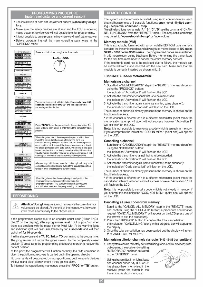
22
MEMORIZZAZIONE CODICE TX-RX
RCQ449100
13-04-2001
DM0531 Description :
Product Code :
Date :
Drawing number :
P.J.Heath
CARDIN ELETTRONICA S.p.A - 31020 San Vendemiano (TV) Italy - via Raffaello, 36 Tel: 0438/401818 Fax: 0438/401831
Draft :
All rights reserved. Unauthorised copying or use of the information contained in this document is punishable by law
MR
PROGRAMMING PROCEDURE(gate travel distance and current sensor)
The system can be remotely activated using radio control devices; each channel has a choice of 5 possible functions: open - shut - limited open-ing - sequential command - stop.To set the functions to channels "A","B","C","D" use the command "CHAN-NEL FUNCTIONS" from the "REMOTE" menu. The sequential command may be set to "open-stop-shut-stop" or "open-close".
Memory module (MM)This is extractable, furnished with a non volatile EEPROM type memory, contains the transmitter codes and allows you to memorise up to 300 codes S4XX / 1000 codes S500 series. The programmed codes are maintained in this module even during blackouts. Before memorising the transmitters for the first time remember to cancel the entire memory content.If the electronic card has to be replaced due to failure, the module can be extracted from it and inserted into the new card. Make sure that the module is correctly inserted as shown in fig. 9.
TRANSMITTER CODE MANAGEMENT
Memorising a channel1. Scroll to the "MEMORISATION" step in the "REMOTE" menu and confirm
using the "PROG/OK" button: the indication "Activation 1" will flash on the LCD.2. Activate the transmitter channel that is to be memorised: the indication "Activation 2" will flash on the LCD.3. Activate the transmitter again (same transmitter, same channel*): the indication "Code memorised" will flash on the LCD.The number of channels already present in the memory is shown on the first line in brackets.* if the channel is different or it is a different transmitter (point three) the memorisation attempt will abort without success however "Activation 1" will still flash on the LCD.Note: It is not possible to memorise a code which is already in memory: if you attempt this the indication "COD. IN MEM." (point one) will appear on the LCD.
Cancelling a channel:1. Scroll to the "CANCELLATION" step in the "REMOTE" menu and confirm
using the "PROG/OK" button: the indication "Activation 1" will flash on the LCD.2. Activate the transmitter channel that is to be cancelled: the indication "Activation 2" will flash on the LCD.3. Activate the transmitter again (same transmitter, same channel*): the indication "Code cancelled" will flash on the LCD.The number of channels already present in the memory is shown on the first line in brackets.* if the channel is different or it is a different transmitter (point three) the cancellation attempt will abort without success however "Activation 1" will still flash on the LCD.
Note: It is not possible to cancel a code which is not already in memory: if you attempt this the indication "COD. NOT MEM." (point one) will appear on the LCD.
Cancelling all user codes from memory:1. Scroll to the "CANCEL ALL MEMORY" step in the "REMOTE" menu
and confirm using the "PROG/OK" button: a procedure confirmation request "CANC ALL MEMORY?" will appear on the LCD (press one of the arrows to exit the procedure).
2. Press the "PROG/OK" button to confirm the total cancellation: the indication "CANCELLING" along with a progress bar will appear on
the display.3. Once the total cancellation has been carried out the display will return
to "CANCEL ALL MEMORY".
Memorising ulterior channels via radio (S449 - S486 transmitters)• The system can be remotely activated using radio control devices; (with-
out opening the receiver) by setting "MEMO RADIO" has been activated in the "OPTIONS" menu.
1. Using a transmitter, in which at least one channel button "A, B, C or D" has already been memorised in the receiver, press the button in the transmitter as shown in figure.
• The installation of both anti-derailment buffers is absolutely obliga-tory.
• Make sure the safety devices are at rest and the ECU is receiving mains power otherwise you will not be able to enter programming.
• It is not possible to enter programming when working off battery power.• Before programming set the main operating parameters in the
"OPTIONS" menu.
REPOSITIONING
Attention! During the repositioning manoeuvre the current sensor value could be altered. At the end of the manoeuvre, however, it will reset automatically to the chosen value.
If the programmer blocks due to an encoder count error ("Error ENC1-ENC2" on the display), after a programmer reset ("Out of pos.") or when there is a problem with the motor ("error Mot1-Mot1") the warning lights and indicator light will flash simultaneously for 2 seconds and will then switch off for 10 seconds. If in this stage you send a (TA, TC, TAL or TD) command to the programmer.The programmer will move the gates slowly to the completely closed position (2 times as in the programming procedure) in order to recover the correct position.At this point the programmer will function normally. If a "TA" command is given the positioning recovery is carried out in the opening direction.No commands will be accepted during repositioning but the security devices will cut in and block all movement if they go into alarm.To interrupt the repositioning manoeuvre press the "PROG" or "TB" button.
REMOTE CONTROL
1...4... sec.
The pause time count will start (min. 2 seconds: max. 240 seconds) indicated by "PAUSE" and the elapsed time appearing on the display
Press “PROG” to set the pause time to the required value. The gates will now open slowly in order to nd the completely open position.
When the gates reach the completely open position they invert the travel direction and after moving for a few centimetres they will open again to conrm the completely open position. At this point the leaves move one at a time in the closing direction (rst gate leaf 2). When one of the gate leaves reaches the completely closed position it inverts the travel direction and after moving for a few centimetres it will close again to conrm the completely closed position.
After carrying out this manouvre the control logic will carry out a complete opening and closing cycle at the standard operating speed in order to calibrate the current sensor.
When the gate reaches the completely closed position the programmer saves the parameters and quits the programming mode. The operation has not succeeded. You will have to repeat the programming procedure.
Press and hold down prog/ok for 4 seconds
“PROG/OK” for 4 sec.
AUTOMATICPROGRAMMING CYCLE
PROGRAM
TB FIFS CP
TA TDTC TAL
00.000.007CC2X24 V1.00
“PROG/OK”
PAUSE
TB FIFS CP
TA TDTC TAL
00.000.007CC2X24 V1.00
AUTO PROG.
“PROG/OK”
TB FIFS CP
TA TDTC TAL
00.000.007CC2X24 V1.00
AUTO PROG.
OPENING
TB FIFS CP
TA TDTC TAL
00.000.007CC2X24 V1.00
AUTO PROG.
CLOSING
TB FIFS CP
TA TDTC TAL
00.000.007CC2X24 V1.00
AUTO PROG.
PROGRAM
TB FIFS CP
TA TDTC TAL
00.000.007CC2X24 V1.00
PAUSA [030]
23
Note: all the receivers within range when the channel button is pressed (and which have at least one of the transmitter channel buttons memorised) will activate their signal buzzer "B1" (fig. 9).
2. Press one of the channel buttons on the same transmitter. The receivers which do not contain that channel code will sound a five-second long "beep" and will then deactivate. The receivers which contain the channel code will sound a one-second long "beep" and will enter the "program-ming via radio" mode.
3. Press the previously chosen channel buttons on the transmitter which you wish to memorise; the receiver will sound 2 "beeps" of half a second each after which the receiver will be ready to receive another code.
4. To leave the programming mode wait for 3 seconds without pressing any buttons. The receiver will sound a five-second long "beep" and will then exit the programming mode.
Note: When the memory is entirely occupied the buzzer will sound 10 rapid "beeps" and will automatically leave the "programming via radio" mode.The same signal is given each time you try to enter "programming via radio" when the memory is full.Note: the memo radio procedure can only be carried out after program-ming has terminated and you have quit the setting/programming menu.t
Memorizing more transmitters by using a previously memorised transmitter (only S504 - S508)This procedure allows you to enable a new transmitter (from a remote po-sition) with the help of a transmitter that has already been memorised in the system. As the presence of the receiver is not required this procedure can be carried out in any remote location (for example in your chosen sales outlet).
Access to the "rapid memorizing" procedure is possible if the "MEMO RA-DIO" function has been activated via the menu "OPTIONS" on the electronic programmer.
- Remove the upper cover from the transmitter to be memorised and from the transmitter that has already been memorised as shown in the drawing below (det. a).
- Place the transmitter A, that has already been memorised in the receiver, beside the new transmitter B (det. b).
- Using a pointed object press and release the MR button on both transmit-ter (in sequence or simultaneously).
- The orange LEDS on the transmitters will flash slowly.- Press and release a channel button on transmitter A that is already pre-
sent in the receiver (det. c).- The led of the new unit B will remain lit for 3 seconds to confirm memoriza-
tion (det. d).Transmitter B will now command the receiver exactly like transmitter A.
CONNECTING THE ANTENNA Connect an ANS400 / ANQ800-1 tuned antenna using a coaxial cable RG58 (impedance 50Ω) with a maximum length of 15 m.
1) AutomaticSelected by enabling automatic reclosing (Automatic reclosing "ON" on the display). When the gate is completely closed the opening command will start a complete cycle which will end with automatic reclosing. Automatic reclosing starts after the programmed pause period has elapsed (minimum 2 seconds) when the opening cycle has been completed or straight away after the intervention of a photoelectric cell (the intervention of a photoelectric cell causes the pause time to be reset).
LIMITED OPENING (PEDESTRIAN ACCESS)
FUNCTION MODESMEMORIZZAZIONE CODICE TX-TX
TRQ504
29-10-2013
DM0910 Description :
Product Code :
Date :
Drawing number :
P.J.Heath
CARDIN ELETTRONICA S.p.A - 31020 San Vendemiano (TV) Italy - via Raffaello, 36 Tel: 0438/401818 Fax: 0438/401831
Draft :
All rights reserved. Unauthorised copying or use of the information contained in this document is punishable by law
MR
A
MR
B
1
MEMORIZZAZIONE CODICE TX-TX
TXQ504C4
29-10-2013
DM0911 Description :
Product Code :
Date :
Drawing number :
P.J.Heath
CARDIN ELETTRONICA S.p.A - 31020 San Vendemiano (TV) Italy - via Raffaello, 36 Tel: 0438/401818 Fax: 0438/401831
Draft :
All rights reserved. Unauthorised copying or use of the information contained in this document is punishable by law
A
MEMORIZZAZIONE CODICE TX-TX
TXQ504C4
29-10-2013
DM0912 Description :
Product Code :
Date :
Drawing number :
P.J.Heath
CARDIN ELETTRONICA S.p.A - 31020 San Vendemiano (TV) Italy - via Raffaello, 36 Tel: 0438/401818 Fax: 0438/401831
Draft :
All rights reserved. Unauthorised copying or use of the information contained in this document is punishable by law
B
During the pause time "Pause" will flash on the display along with the remaining pause time.Pressing the blocking button during this period will stop automatic reclosing and consequently stop the display from flashing. The indicator light remains lit until the closing manoeuvre has terminated.
2) SemiautomaticSelected by deactivating automatic reclosing (Automatic reclosing "OFF" on the display). Work cycle control using separate opening and closing commands. When the door has reached the completely open position the system will wait until it receives a closing command either via an external control button or via radio control, before completing the cycle. The indicator light remains lit until the closing manoeuvre has terminated.
3) Manual manoeuvring with released motorsReleasing the motor the gate can be moved by hand; once the motor has been re-engaged the programmer will recover the position after two con-secutive attempts to arrive at the travel limit.
4) Emergency manoeuvreBy default the emergency manoeuvre is disabled, to enable it move the jumper to the position J6 "ENABLE" (fig. 9).If the electronic programmer no longer responds to commands due to a malfunction you may use the EMRG1 or EMRG2 inputs to move the gate leaf manually (fig. 9). The EMRG1 or EMRG2 inputs directly command the motor without pass-ing through the logic control.Gate movement will be at normal speed and the direction depends on the installed position of the motor:
Attention! During the emergency manoeuvre all safety devices are disabled and there is no gate positioning control: release the commands before you are at the mechanical travel buffer. Only use the emergency manoeuvre in cases of extreme necessity.The electric lock (even if it is enabled) is not active. Therefore if an electric lock is fitted it will have to be activated manually.
After you have carried out an emergency manoeuvre the electronic program-mer will lose the position of the gate ("out of pos" on the display) and therefore when normal operation is restored it will carry out a repositioning manoeuvre.
This always effects gate 1; the limited opening space can be set (see display menu) to 1/3, half, 2/3 or the entire opening distance for gate 1.
• If the "open-close" mode is set for the "TD" button (menu "OPTION") activating the "TAL" button will start the limited opening stage (only from the completely closed position) but while the gate is opening pressing the button again will have no effect. Once the opening position has been reached pressing the "TAL" button will start closing after which pressing "TAL" again will have no effect.
• If the "open-block-close" mode is set for the "TD" button (menu "OPTION") activating the "TAL" button will start the limited opening stage (only from the completely closed position) pressing the button again will block the gate; pressing the button a third time will start the closing cycle. Pressing the "TAL" button again will have no effect.
• If an opening command is received during limited opening; the limited opening command will become a full opening command.
If the FI photocell cuts in during the closing stage you will only have partial movement in the opening direction (It reopens only for the dis-tance it has been closing the gate).
• Note: The limited opening command can also be given by remote control.
COURTESY LIGHT /CH2 RADIO OUTPUTBinding posts “9 ","10 " are linked to a C-NO relay; this can be activated as follows:• Jumper J5 in position 1: the contact is closed by a timer and works as a “courtesy light" • Jumper J5 in position 2:
the contact works as a second radio channel.Binding posts “9 ","10" only give a potential free contact; this means that the courtesy light will have to be powered by an external circuit and the contact used as a simple switch.
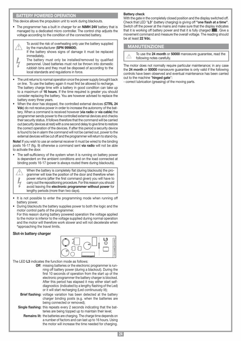
24
MANUTENZIONE
BATTERY POWERED OPERATION
CS
1256
BD
C04
50L3
Scheda di innesto
PRG424BC
08-01-2008
DC0435 Description :
Product Code :
Date :
Drawing number :
P.J.Heath
CARDIN ELETTRONICA S.p.A - 31020 San Vendemiano (TV) Italy - via Raffaello, 36 Tel: 0438/401818 Fax: 0438/401831
Draft :
All rights reserved. Unauthorised copying or use of the information contained in this document is punishable by law
Scheda carica batteria
This device allows the propulsion unit to work during blackouts.
• The programmer has a built in charger for an NiMH 24V battery that is managed by a dedicated micro controller. The control chip adjusts the voltage according to the condition of the connected battery.
To avoid the risk of overheating only use the battery supplied by the manufacturer (SPN 999600).If the battery shows signs of damage it must be replaced immediately.The battery must only be installed/removed by qualified personnel. Used batteries must not be thrown into domestic rubbish bins and they must be disposed of according to the local standards and regulations in force.
• The unit returns to normal operation once the power supply brought back on line. To use the battery again it must first be allowed to recharge.
The battery charge time with a battery in good condition can take up to a maximum of 16 hours. If the time required is greater you should consider replacing the battery. You are however advised to replace the battery every three years.
• When the door has stopped, the controlled external devices (CTRL 24 Vdc) do not receive power in order to increase the autonomy of the bat-tery. When a command is received however (via radio or via cable) the programmer sends power to the controlled external devices and checks their security status. It follows therefore that the command will be carried out (security devices at rest) with a one second delay to give time to restore the correct operation of the devices. If after this period a security device is found to be in alarm the command will not be carried out, power to the external devices will be cut off and the programmer will return to stand-by.
Note! If you wish to use an external receiver it must be wired to the binding posts 16-17 (fig. 9) otherwise a command sent via radio will not be able to activate the door.• The self-sufficiency of the system when it is running on battery power
is dependent on the ambient conditions and on the load connected at binding posts 16-17 (power is always routed there during blackouts).
When the battery is completely flat (during blackouts) the pro-grammer will lose the position of the door and therefore when power returns (after the first command given) you will have to carry out the repositioning procedure. For this reason you should avoid leaving the electronic programmer without power for lengthy periods (more than two days).
• It is not possible to enter the programming mode when running off battery power.
• During blackouts the battery supplies power to both the logic and the motor control parts of the programmer.
For this reason during battery powered operation the voltage applied to the motor is inferior to the voltage supplied during normal operation and the motor will therefore work slower and will not decelerate when ªapproaching the travel limits.
Slot-in battery charger
The LED L3 indicates the function mode as follows: Off: missing batteries or the electronic programmer is run-
ning off battery power (during a blackout). During the first 10 seconds of operation from the start up of the electronic programmer the battery charger is blocked. After this period has elapsed it may either start self-diagnostics (indicated by a lengthy flashing of the Led) or it will start recharging (Led continuously lit);
Brief flashing: voltage variation has been detected at the battery charger binding posts (e.g. when the batteries are being connected or removed);
Single flashing: this repeats every 2 seconds indicating that the bat-teries are being topped up to maintain their level;
Remains lit: the batteries are charging. The charge time depends on a number of factors and can last up to 16 hours. Using the motor will increase the time needed for charging.
Battery checkWith the gate in the completely closed position and the display switched off. Check that LED "L3" (battery charging) is giving off "one flash at a time".Switch off the power at the mains and make sure that the display indicates that it is working off battery power and that it is fully charged . Give a movement command and measure the overall voltage. The reading should be at least 22 Vdc.
To use the 24 month or 50000 manoeuvre guarantee, read the following notes carefully.
The motor does not normally require particular maintenance; in any case the 24 month or 50000 manoeuvre guarantee is only valid if the following controls have been observed and eventual maintenance has been carried out to the machine "hinged gate":- correct lubrication (greasing) of the moving parts.
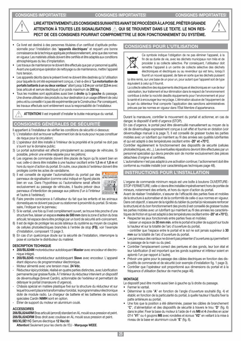
25
• Ce livret est destiné à des personnes titulaires d'un certificat d'aptitude profes-sionnelle pour l'installation des "appareils électriques" et requiert une bonne connaissance de la technique appliquée professionnellement, ainsi que des normes en vigueur. Les matériels utilisés doivent être certifiés et être adaptés aux conditions atmosphériques du lieu d'implantation.
• Les travaux de maintenance ne doivent être effectués que par un personnel qualifié. Avant une quelconque opération de nettoyage ou de maintenance, mettre l'appareil hors tension.
• Les appareils décrits dans le présent livret ne doivent être destinés qu’à l’utilisation pour laquelle ils ont été expressément conçus, c’est-à-dire à "La motorisation de portails battants à un ou deux vantaux" allant jusqu'à 2 m par vantail (2,5 m avec bras articulé et serrure électrique) d'un poids maximum de 200 kg.
• Tous les modèles sont applicables aussi bien à droite qu’à gauche du passage. Une diverse utilisation des produits ou leur destination à un usage différent de celui prévu et/ou conseillé n'a pas été expérimentée par le Constructeur. Par conséquent, les travaux effectués sont entièrement sous la responsabilité de l'installateur.
ATTENTION! Il est impératif d’installer le butée mécanique du vantail.
Il appartient à l’installateur de vérifier les conditions de sécurité ci-dessous:1) L’installation doit se trouver suffisamment loin de la route pour ne pas constituer
de risque pour la circulation;2) L’opérateur doit être installé à l’intérieur de la propriété et le portail ne doit pas
s’ouvrir sur le domaine public;3) Le portail automatisé est affecté principalement au passage de véhicules. Si
possible, prévoir une entrée séparée pour les piétons;4) Les organes de commande doivent être placés de façon qu'ils soient bien en
vue; celle-ci devra être installée à une hauteur oscillant entre 1,5 m et 1,8 m et hors du rayon d’action du portail. En outre, ceux placés à l’extérieur doivent être protégés contre les actes de vandalisme.
5) Il est conseillé de signaler l’automatisation du portail par des panneaux de signalisation (comme celui indiqué en figure) placés bien en vue. Dans l’hypothèse où l’automatisme serait affecté exclusivement au passage de véhicules, il faudra prévoir deux panneaux d’interdiction de passage aux piétons (l’un à l’intérieur et l’autre à l’extérieur);
6) Faire prendre conscience à l’utilisateur du fait que les enfants et les animaux domestiques ne doivent pas jouer ou stationner à proximité du portail. Si néces-saire, l’indiquer sur le panneau;
7) Si le vantail, une fois qu’il est complètement ouvert, se trouve très proche d’une structure fixe, laisser un espace moins de 500 mm dans la zone d’action du bras articulé; tel espace devra être protégé par un bord de sécurité anti-coincement.
8) Il est de règle de protéger les accès latéraux du système au moyen de couples de cellules photoélectriques branchés à l’entrée de stop (FS), voir l’exemple d’installation, composant 13 page 3.
9) En cas d’un quelconque doute sur la sécurité de l’installation, interrompre la pose et contacter le distributeur du matériel.
DESCRIPTION TECHNIQUE • 200/BL824M motoréducteur autobloquant Master avec encodeur et électro-
nique intégré.• 200/BL824S motoréducteur autobloquant Slave avec encodeur. L'appareil
étant dépourvu de programmateur électronique.- Moteur alimenté avec une tension maxi. 24 Vdc.- Réducteur épicycloïdale, réalisé en quatre parties distinctes, avec lubrification
permanente par graisse fluide. À l'intérieur du réducteur intervient un dispositif de déverrouillage (brevet Cardin), actionnable de l'extérieur et permettant de débrayer le portail (manœuvre d'urgence).
- Châssis spécial en matière plastique fixé sur la structure du réducteur et sur lequel trouvent place le transformateur toroïdal, le programmateur électronique doté de module radio. Le chargeur de batterie et les batteries de secours spéciales Cardin NiMH sont en option.
- Étrier de support du moteur en aluminium coulé.
ACCESSOIRES206/BL824ARM Bras articulé (arrondi) standard en AL moulé sous pression et peint.206/BL824DRM Bras droit avec coulisse en AL moulé sous pression et peint.980/XLSE11C Serrure électrique 12 Vac/dc
Attention! Seulement pour les clients de l'EU - Marquage WEEE.
Ce symbole indique l’obligation de ne pas éliminer l’appareil, à la fin de sa durée de vie, avec les déchets municipaux non triés et de procéder à sa collecte sélective. Par conséquent, l’utilisateur doit remettre l’appareil à un centre de collecte sélective des déchets électroniques et électriques ou au revendeur qui est tenu, lorsqu’il fournit un nouvel appareil, de faire en sorte que les déchets puissent
lui être remis, sur une base de un pour un, pour autant que l’appareil soit de type équivalent à celui qu’il fournit.La collecte sélective des équipements électriques et électroniques en vue de leur valorisation, leur traitement et leur élimination dans le respect de l’environnement contribue à éviter la nocivité desdits équipements pour l’environnement et pour la santé et à encourager leur recyclage. L’élimination abusive de l’équipement de la part du détenteur final comporte l’application des sanctions administratives prévues par les normes en vigueur dans l’État Membre d’appartenance.
Durant la manœuvre, contrôler le mouvement du portail et actionner, en cas de danger, le dispositif d'arrêt d'urgence (STOP).En cas d’urgence, le portail peut être déverrouillé manuellement au moyen de la clé de déverrouillage expressément conçue à cet effet et fournie en dotation (voir déverrouillage manuel à la page 7). Il est conseillé de graisser toutes les parties mobiles avec un lubrifiant qui maintient au fil des années ses qualités lubrifiantes et qui est adapté à des températures oscillant entre -20° et +70°C.Contrôler régulièrement le fonctionnement des dispositifs de sécurité (cellules photoélectriques, etc...). Les éventuelles réparations devront être effectuées par un personnel spécialisé qui devra prendre soin de monter exclusivement des pièces détachées d'origine et certifiées. L'automatisme n'est pas adapté à une activation continue; l'actionnement doit être conformé au modèle installé (voir caractéristiques techniques page 48).
L'organe de commande minimum requis est une boîte à boutons OUVERTURE-STOP-FERMETURE; celle-ci devra être installée impérativement hors de portée de mineurs, notamment des enfants, et hors du rayon d'action du portail. Avant de réaliser l'installation, s'assurer de l'efficacité des parties fixes et mobiles de la structure à automatiser et de la conformité de celle-ci aux normes en vigueur.Dans cet objectif, s'assurer de la rigidité du tablier du portail (si nécessaire renforcer la structure) et du bon fonctionnement des pivots (il est conseillé de graisser toutes les parties mobiles avec un lubrifiant qui maintient au fil des années les caractéris-tiques de friction et qui est adapté à des températures oscillant entre -20° et +70°C).• Respecter les jeux fonctionnels entre parties fixes et mobiles: - laisser un espace de 30 mm min. entre le portail et le pilier de support sur toute
la hauteur et sur la totalité de l’arc d’ouverture du portail, - contrôler que l’espace entre le portail et le sol ne soit jamais supérieur à 30
mm sur la totalité de l’arc d’ouverture du portail. • Les panneaux des vantaux ne doivent pas présenter d’ouvertures qui permettent
le passage de la main ou du pied.• Contrôler l’emplacement correct des pentures et des gonds, leur bon état et
leur lubrification (il est important que les gonds supérieur et inférieur soient en aplomb l’un par rapport à l’autre).
• Prévoir une gaine pour le passage des câbles électriques en fonction des dis-positifs de commande et de sécurité (voir exemple d’installation fig. 1 page 3).
• Contrôler que l’opérateur soit proportionné aux dimensions du portail et à la fréquence d’utilisation (facteur de marche page 48).
MONTAGELe dispositif peut être monté aussi bien à gauche qu'à droite du passage.• Fermer le vantail.• Déterminer la cote "A" en fonction de l'angle d'ouverture souhaité (fig. 4) et
établir, en fonction de la particularité du portail, à quelle hauteur il faudra fixer la patte antérieure au portail.
• Une fois que la position a été déterminée, passer les câbles de branchement "C", d'alimentation et des dispositifs de sécurité à travers le trou "D" (fig. 6) dans le pilier. Fixer la base du moteur à l'aide de 4 vis M8 et 4 chevilles en acier Ø14 "V1" ou 4 goujons M8 avec rondelles et écrous "V2" en veillant à la mise à niveau de la base en aluminium coulé "E" (fig. 6).
CONSIGNES GÉNÉRALES DE SÉCURITÉ
CONSIGNES POUR L’UTILISATION
INSTRUCTIONS POUR L’INSTALLATIONFERMETURE AUTOMATISÉE
NE PAS S'APPROCHER
NE PAS PERMETTRE AUX ENFANTS ET AUX ANIMAUX DOMESTIQUES DE STATIONNERDANS LE RAYON D'ACTION DU PORTAIL
ATTENTION
CONSIGNES IMPORTANTES! CONSIGNES IMPORTANTES! CONSIGNES IMPORTANTES!
LIRE ATTENTIVEMENT LES CONSIGNES SUIVANTES AVANT DE PROCÉDER À LA POSE. PRÊTER GRANDE ATTENTION À TOUTES LES SIGNALISATIONS QUI SE TROUVENT DANS LE TEXTE. LE NON RES-PECT DE CES CONSIGNES POURRAIT COMPROMETTRE LE BON FONCTIONNEMENT DU SYSTÈME.
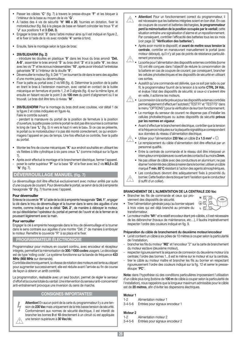
26
• Attention! Pour un fonctionnement correct du programmateur, il est nécessaire que les batteries intégrées soient en bon état. En cas de coupure de courant et batteries déchargées, le programmateur perd la mémorisation de la position occupée par le vantail; cette situation entraîne une signalisation d’alarme et un repositionnement. Par conséquent, contrôler l’efficacité des batteries tous les six mois (voir page 32 "Vérification des batteries").
• Après avoir monté le dispositif, et avant de mettre sous tension la centrale, contrôler en manœuvrant manuellement le portail (avec moteur débrayé), qu’il n’y ait pas de points de résistance particuliè-rement prononcés.
• La sortie pour l’alimentation des dispositifs externes contrôlés (borne 15) ont été conçues dans l’objectif de réduire la consommation de la batterie en cas de coupure de courant; par conséquent, brancher les cellules photoélectriques et les dispositifs de sécurité en utilisant ces sorties.
• Aussitôt qu’une commande est délivrée, que ce soit par radio ou par fil, le programmateur fournit de la tension à la sortie CTRL 24 Vdc, et évalue l’état des dispositifs de sécurité; si ceux-ci s’avèrent être en veille, il actionne les moteurs.
• La connexion à la sortie prévue pour les dispositifs externes contrôlés permet également d’effectuer l’autotest ("TEST FI" et "TEST FS" dans le menu "OPTIONS") pour la vérification de leur bon fonctionnement.
• Le montage du senseur de courant ne dispense pas d’installer les cellules photoélectriques ou autres dispositifs de sécurité prévus par les normes en vigueur.
• Avant d'effectuer le branchement électrique, contrôler que la tension et la fréquence indiquées sur la plaquette signalétique correspondent aux données du réseau d'alimentation électrique.
• Utiliser pour l’alimentation 230 Vac un câble 2 x 1.5 mm2 + .• Le remplacement du câble d’alimentation doit être effectué par un
personnel qualifié.• Entre la centrale de commande et le réseau doit être interposé un
interrupteur omnipolaire avec ouverture des contacts d'au moins 3 mm.• Ne pas utiliser de câble avec des conducteurs en aluminium; ne pas
étamer l'extrémité des câbles à insérer dans le bornier; utiliser un câble marqué T min. 85°C résistant à l'action des agents atmosphériques.
• Les conducteurs devront être adéquatement fixés à proximité du bornier. Cette fixation devra bloquer tant l'isolation que le conducteur (il suffit d'un collier).
BRANCHEMENT DE L'ALIMENTATION DE LA CENTRALE 230 Vac• Brancher les fils de commande et ceux qui pro-
viennent des dispositifs de sécurité.• Tirer l'alimentation générale jusqu'au bornier séparé
à trois voies qui est déjà branché au primaire du transformateur.
• Le moteur maître "M1" et le relatif encodeur étant pré-câblés, s'il est nécessaire de les débrancher (travaux de maintenance, etc…), il faudra impérativement respecter l'ordre des couleurs indiqué en fig. 9.
Préparation du câble de branchement du deuxième moteur/encodeur• Le kit contient un câble à six pôles de 10 mètres à couper selon la particularité
de l’installation,- brancher les fils du moteur "M2" et l'encodeur "2" sur la carte de branchement
du moteur esclave (deuxième moteur),- respecter rigoureusement la séquence de connexion du deuxième moteur à la
centrale; l’ordre des bornes 1...6 est le même sur le moteur et sur la centrale,- tirer le câble au moteur maître et brancher les fils au bornier en respectant
rigoureusement l'ordre des couleurs indiqué sur la fig. 12 et serrer le presse-étoupe "PC".
Nota: dans l'hypothèse où des conditions particulières imposeraient l'utilisation d'un câble plus long (bobine de 100 m de câble à couper selon la particularité de l'installation), nous rappelons que la longueur maximum admissible pour le câble est de 20 mètres, afin d'éviter les dispersions électriques.
Moteur 11-2 Alimentation moteur 13-4-5-6 Entrées pour signaux encodeur 1
Moteur 21-2 Alimentation moteur 23-4-5-6 Entrées pour signaux encodeur 2
• Passer les câbles "C" (fig. 7) à travers le presse-étoupe "F" et les bloquer à l'intérieur de la base au moyen de la vis "G".
• À l'aides des 4 vis de sécurité "H" M8 x 20, fournies en dotation, fixer le motoréducteur (fig. 6a) à la plaque de base en faisant coïncider les trous "I" et "J" aux positions 1 et 3 (Dét. 3).
• Engager le bras droit "3" dans l'arbre moteur ainsi qu'il est indiqué en figure 2, et le fixer à l'aide de la vis avec rondelle "4" serrée à fond.
• Ensuite, faire le montage selon le type de bras:
• 206/BL824ARM (fig. 2) - introduire les douilles en plastique "9" dans les trous du bras arrondi "Dét.
A-B", assembler le bras arrondi "5" au bras droit "3" et à la patte "6", les deux avec les vis "7" et les écrous indesserrables "10", après avoir introduit l'entretoise galvanisée "8" à l'intérieur de la douille "9".
• Déverrouiller le moteur (fig. 9, Dét "1") en tournant la clé dans le sens des aiguilles d'une montre jusqu'au déverrouillage.
• Fixer la patte au portail avec 2 vis M8 (fig. 4). Déterminer la position de la patte en tirant le bras à l'extension maximum, avec vantail en contact de la butée mécanique en fermeture et points 1, 2 et 3 alignés (fig. 4) sur la même ligne, et ensuite en faisant reculer le point 3 de 100 mm du point d'alignement où il se trouvait. Le bras doit être tenu à niveau "M".
• 206/BL824DRM Pour le montage du bras droit avec coulisse, voir détail 1 de la figure 2 et cotes indiquées en figure 4a.
Faire le contrôle suivant: - pendant la manœuvre du portail de la position de fermeture à la position
d'ouverture, la patte posée contre le portail ne doit pas être soumise à contraintes le long de l'axe "L" (fig. 5) ni vers le haut ni vers le bas*. Si ce cas se présente, le portail ou le motoréducteur n'a pas été monté correctement, ce qui endom-magera l'appareil en peu de temps. Une fois effectué ce contrôle, fixer la patte au portail.
• Monter les fins de course mécaniques "K" aux endroit souhaités en utilisant les vis filetées à tête cylindrique à six pans creux "L" (comme indiqué sur la figure 7).
• Après avoir effectué le montage et le branchement électrique, fermer l'appareil.- poser le carter supérieur "P" sur la base "O" et le fixer avec les 2 vis M3,5 x 22
"N" (fig. 7).
Le déverrouillage doit être effectué exclusivement avec moteur arrêté par suite d'une coupure de courant. Pour déverrouiller le portail, se servir de la clé à empreinte hexagonale "Q" (fig. 7) fournie avec l'appareil.
Pour déverrouillerEnlevez le couvercle "R" à l'aide de la clé à empreinte hexagonale "Dét. 1", engager la clé dans le trou de déverrouillage et la tourner dans le sens des aiguilles d'une montre, comme indiqué sur le détail "Dét. 2", de manière à débrayer le moteur, ce qui désolidarise l'opérateur du portail et permet de l'ouvrir et de le fermer en le poussant légèrement avec la main.Pour verrouillerEngager la clé à empreinte hexagonale dans le trou de déverrouillage et la tourner dans le sens contraire aux aiguilles d'une montre "Dét. 2" de manière à embrayer le moteur. Remettre le couvercle "R" à sa place et le fixer.
Programmateur pour moteurs en courant continu, avec encodeur et récepteur intégrés, permettant la mémorisation de 300 / 1000 codes usagers. Le décodage est de type ‘rolling code’. Le système fonctionne sur la bande de fréquence 433 MHz (868 MHz sur demande).Contrôlée électroniquement, la vitesse de rotation des moteurs est lente au départ pour augmenter successivement; elle est réduite avant l’arrivée au fin de course de façon à obtenir un arrêt contrôlé.
La programmation, réalisable avec un seul bouton, permet de régler le senseur d’effort et la course totale du vantail. Une intervention du senseur anti-coincement/anti-entraînement provoque une inversion du sens de marche.
Attention! En aucun point de la carte du programmateur il y a une ten-sion de 230 Vac mais uniquement de la très basse tension de sécurité. Conformément aux normes de sécurité électrique, il est interdit de brancher les bornes 9 et 10 directement à un circuit où est appliquée une tension supérieure à 30 Vac/dc.
DÉVERROUILLAGE MANUEL (fig. 7)
CONSIGNES IMPORTANTES!
PROGRAMMATEUR ÉLECTRONIQUE
N
L
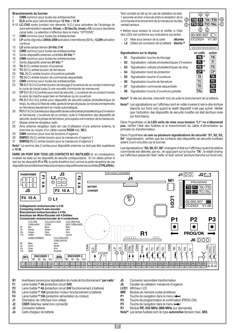
27
B1 Avertisseur sonore pour signalisation du mode de fonctionnement "par radio"F1 Lame fusible (4) 4A (protection circuit 24V)F2 Lame fusible (4) 4A (protection circuit 24V fonctionnement à batterie)F3 Lame fusible (4) 10A (protection moteur fonctionnement à batterie)F4 Lame fusible (4) 10A (protection alimentation du moteur)J1 Orientation de l'afficheur (non utilisé)J2 CSER Selecteur sériel (non connecté)J3 Connexion batterieJ4 Carte chargeur de batterie
J5 Connexion secondaire transformateurJ6 Cavalier de validation manœuvre d’urgenceLCD1 Afficheur LCDMM Module de mémoire codes émetteursP1 Touche de navigation dans le menu ( )P2 Touche de programmation et confirmation (PROG./OK) P3 Touche de navigation dans le menu ( )R1 Module RF, 433 MHz (868 MHz sur demande)Nota(4) Les lames fusibles sont du type automotive (tension maxi. 58V).
Tenir compte du fait qu’en cas de validation du test, 1 seconde environ s’écoule entre la réception de la commande et le lancement de la manœuvre du/des vantail/vantaux.
• Mettre sous tension le circuit et vérifier si l’état des LEDs est conforme aux indications suivantes:- L1 Mise sous tension de la carte allumée- L2 Défaut de connexion de la batterie éteinte (2)
Signalisations sur le display en veille activé- S1 Signalisation touche de blocage TB (3) TB - S2 Signalisation cellules photoélectriques d’inversion FI (3) FI
- S3 Signalisation cellules photoélectriques de stop FS (3) FS
- S4 Signalisation bord de protection CP (3) CP - S5 Signalisation touche d’ouverture TA TA
- S6 Signalisation touche de fermeture TC TC
- S7 Signalisation commande séquentielle TD TD
- S8 Signalisation touche d’ouverture partielle TAL TAL
Nota(2) Si elle est allumée, intervertir tout de suite le branchement de la batterie.
Nota(3) Les signalisations sur l'afficheur sont en vidéo inverse (c'est-à-dire écriture blanche sur fond noir) quand le relatif dispositif n'est pas activé. Vérifier que l'activation des dispositifs de sécurité modifie cet état (écriture noire sur fond blanc).
Dans l’hypothèse où la LED verte de mise sous tension "L1" ne s’allumerait pas, vérifier l’état des fusibles et le branchement du câble d’alimentation au primaire du transformateur.
Dans l'hypothèse où une ou plusieurs signalisations de sécurité "S1, S2, S3, S4" clignoteraient, vérifier que les contacts des dispositifs de sécurité inutilisés soient court-circuités sur le bornier.
Les signalisations "S5, S6, S7, S8" changent d'état sur l'afficheur quand la relative commande est délivrée, par ex.: en appuyant sur la touche "TA", le relatif champ sur l'afficheur passe de l'état 'veille' à l'état 'activé' (écriture blanche sur fond noir).
Branchements du bornier7 CMN commun pour toutes les entrées/sorties8 ELS sortie pour serrure électrique 12 Vdc – 15 W9-10 LC-CH2 sortie (contact non alimenté, N.O.) pour activation de l’éclairage de
zone (alimentation séparée, Vmaxi. = 30 Vac/dc, Imaxi.=1A ) ou pour deuxième canal radio. La sélection s’effectue dans le menu "OPTIONS".
11 CMN commun pour toutes les entrées/sorties12 LP sortie clignoteur 24Vdc 25W activation intermittente (50%), 12,5W activation
continue13 LS sortie lampe témoin 24 Vdc 3 W14 CMN commun pour toutes les entrées/sorties15 Sortie dispositifs externes contrôlés 24 Vdc (1)
16 CMN commun pour toutes les entrées/sorties17 Sortie dispositifs externes 24 Vdc (1)
18 TA (N.O.) entrée bouton d’ouverture 19 TC (N.O.) entrée bouton de fermeture20 TAL (N.O.) entrée bouton d’ouverture partielle21 TD (N.O.) entrée bouton de commande séquentielle22 CMN commun pour toutes les entrées/sorties 23 TB (N.F./8.2 kΩ) entrée bouton de blocage (l’ouverture de ce contact interrompt
le cycle de travail jusqu’à une nouvelle commande de manœuvre)24 CP (N.F./8.2 kΩ) entrée pour bord de sécurité. L'ouverture de ce contact inverse
le sens de marche aussi bien en fermeture qu'en ouverture25 FS (N.F./8.2 kΩ) entrée pour dispositifs de sécurité (cellule photoélectrique de
stop). Au retour à l’état de veille, après le temps de pause, la manœuvre reprendra en fermeture (seulement en mode automatique).
26 FI (N.F./8.2 kΩ) entrée pour dispositifs de sécurité (cellule photoélectrique d’inversion en fermeture). L’ouverture de ce contact, suite à l’intervention des dispositifs de sécurité, durant la phase de fermeture, provoquera une inversion de la manœuvre.
27 Masse antenne récepteur radio28 Âme antenne récepteur radio (en cas d’utilisation d’une antenne externe, la
brancher au moyen d’un câble coaxial RG58 imp. 50Ω)29 CMN commun pour tous les boutons d’urgence30 EMRG1 (N.O.) entrée bouton pour la manœuvre d’urgence 131 EMRG2 (N.O.) entrée bouton pour la manœuvre d’urgence 2Nota(1) La somme des 2 sorties pour dispositifs externes ne doit pas être supérieure à 10 W.FAIRE UN PONT SUR TOUS LES CONTACTS N.F. INUTILISÉS et, en conséquence, invalider les tests sur les dispositifs de sécurité correspondants. Si l’on désire activer le test sur les dispositifs FI et FS, la partie émettrice tout comme la partie réceptrice de ces dispositifs doivent être branchées à la borne pour dispositifs externes contrôlés (CTRL24Vdc).
Collegamenti scheda base
CC2X24
05-09-2015
DC0556 Description :
Product Code :
Date :
Drawing number :
P.J.Heath
CARDIN ELETTRONICA S.p.A - 31020 San Vendemiano (TV) Italy - via Raffaello, 36 Tel: 0438/401818 Fax: 0438/401831
Draft :
All rights reserved. Unauthorised copying or use of the information contained in this document is punishable by law
CC2X24 SCHEDA BASE V1.00(con display LCD + MULTI-DECODIFICA)
CS1422A DC0556
M1
B1
F2 4 A
TRANSFORMER
L1
29 30 31
F1 4 A
LCD
1
P1 P2 P3
PROG/OK
J5
9 10 11 12 13 14 15 16 17 18 19 20 21 22 23 24 25 26
COLORE COLOUR CODE COLORATION CABLAGGI CODE DES CÂBLAGES Bl Blu Blue Bleu Gr Verde Green Vert Gy Grigio Grey Gris Yw Giallo Yellow Jaune KABELFARBEN COLORACIÓN CABLEADOSBl Blau AzulGr Grün VerdeGy Grau GrisYw Gelb Amarillo
Collegamento motori/encoder a 4 fili Connecting motor/4-wire encoderBranchement moteur/encodeur à 4 filsAnschluss der Motor/Encoder mit 4 DrähtenConexionado motores/encoder de 4 conductores
7 83 4 5 61 2 3 4 5 61 2
YwGyGrBlENCODER 1
YwGyGrBlENCODER 2M1 M2
27 28
TDTA TC
24V
dc
TAL
CM
N
FITB CP
FS
EM
RG
1
EM
RG
2
CM
N
CM
N
CTR
L24
Vd
c
CM
N
LSLPCM
N
LC/CH2ELS
12V
dc
CM
N
F4 10 A
J3
F3 10 ABATTERYCHARGER
J1
R1J6
J2J4L2
PROGRAM
TB FIFS CP
TA TDTC TAL
00.000.007CC2X24 V1.00
S5
S6
TB FIFS CP
TA TDTC TAL
00.000.007CC2X24 V1.00
S1
S3
S7
S8
S2
S4
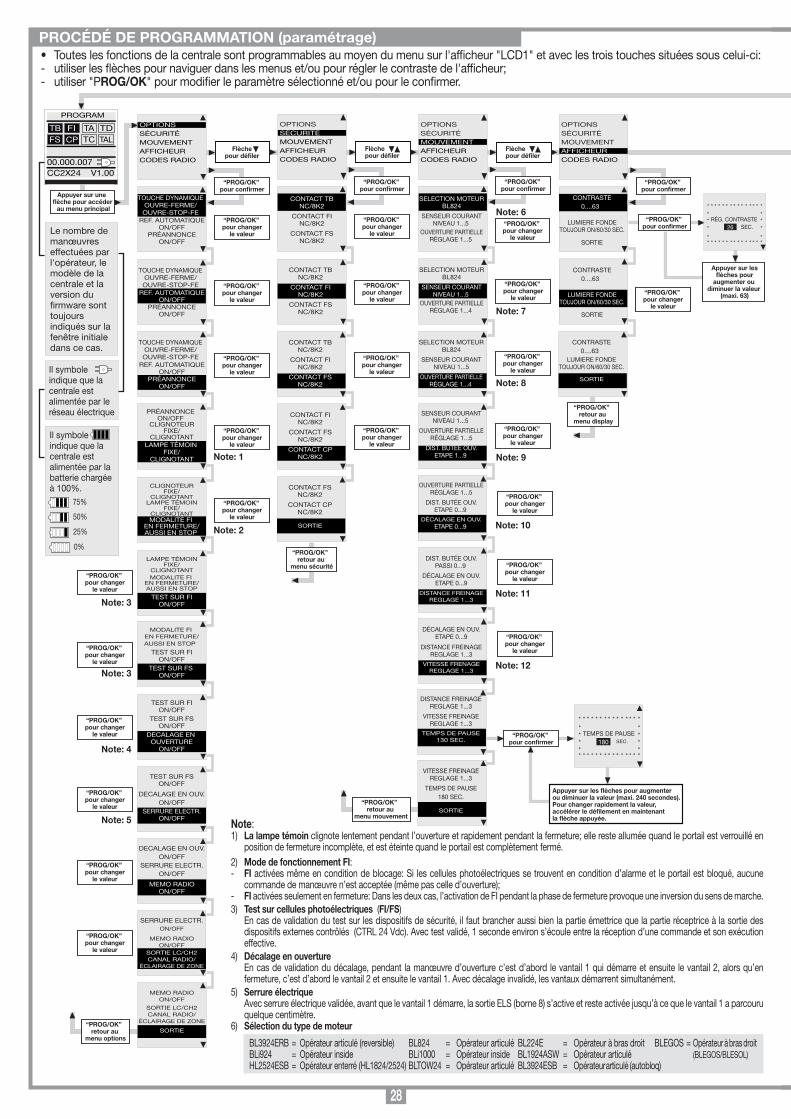
28
• Toutes les fonctions de la centrale sont programmables au moyen du menu sur l'afficheur "LCD1" et avec les trois touches situées sous celui-ci:- utiliser les flèches pour naviguer dans les menus et/ou pour régler le contraste de l'afficheur;- utiliser "PROG/OK" pour modifier le paramètre sélectionné et/ou pour le confirmer.
PROCÉDÉ DE PROGRAMMATION (paramétrage)
“PROG/OK” retour au
menu mouvement
Appuyer sur une flèche pour accéder
au menu principal
“PROG/OK” retour au
menu options
OPTIONSSÉCURITÉMOUVEMENTAFFICHEURCODES RADIO
PROGRAM
TB FIFS CP
TA TDTC TAL
00.000.007CC2X24 V1.00
OPTIONSSÉCURITÉMOUVEMENTAFFICHEURCODES RADIO
Flèchepour défiler
TOUCHE DYNAMIQUEOUVRE-FERME/OUVRE-STOP-FE
REF. AUTOMATIQUEON/OFF
PRÉANNONCEON/OFF
OPTIONSSÉCURITÉMOUVEMENTAFFICHEURCODES RADIO
Flèchepour défiler
OPTIONSSÉCURITÉMOUVEMENTAFFICHEURCODES RADIO
Flèchepour défiler
TOUCHE DYNAMIQUEOUVRE-FERME/OUVRE-STOP-FE
REF. AUTOMATIQUEON/OFF
PRÉANNONCEON/OFF
TOUCHE DYNAMIQUEOUVRE-FERME/OUVRE-STOP-FE
REF. AUTOMATIQUEON/OFF
PRÉANNONCEON/OFF
PRÉANNONCEON/OFF
CLIGNOTEURFIXE/
CLIGNOTANTLAMPE TÉMOIN
FIXE/CLIGNOTANT
CLIGNOTEURFIXE/
CLIGNOTANTLAMPE TÉMOIN
FIXE/CLIGNOTANTMODALITE FI
EN FERMETURE/AUSSI EN STOP
LAMPE TÉMOINFIXE/
CLIGNOTANTMODALITE FI
EN FERMETURE/AUSSI EN STOP
TEST SUR FION/OFF
MODALITE FI EN FERMETURE/AUSSI EN STOP
TEST SUR FION/OFF
TEST SUR FS ON/OFF
TEST SUR FSON/OFF
DECALAGE EN OUV.ON/OFF
SERRURE ELECTR.ON/OFF
TEST SUR FION/OFF
TEST SUR FSON/OFF
DECALAGE EN OUVERTURE
ON/OFF
DECALAGE EN OUV.ON/OFF
SERRURE ELECTR.ON/OFF
MEMO RADIOON/OFF
SERRURE ELECTR.ON/OFF
MEMO RADIOON/OFF
SORTIE LC/CH2CANAL RADIO/
ÉCLAIRAGE DE ZONE
“PROG/OK” pour confirmer
“PROG/OK” pour changer
le valeur
“PROG/OK” pour changer
le valeur
“PROG/OK” pour changer
le valeur
“PROG/OK” pour changer
le valeur
“PROG/OK” pour changer
le valeur
“PROG/OK” pour changer
le valeur
“PROG/OK” pour changer
le valeur
“PROG/OK” pour changer
le valeur
“PROG/OK” pour changer
le valeur
“PROG/OK” pour changer
le valeur
MEMO RADIOON/OFF
SORTIE LC/CH2CANAL RADIO/
ÉCLAIRAGE DE ZONE
SORTIE
“PROG/OK” pour changer
le valeur
CONTACT TBNC/8K2
CONTACT FINC/8K2
CONTACT FSNC/8K2
CONTACT TBNC/8K2
CONTACT FINC/8K2
CONTACT FSNC/8K2
“PROG/OK” pour confirmer
“PROG/OK” pour changer
le valeur
“PROG/OK” pour changer
le valeur
CONTACT TBNC/8K2
CONTACT FINC/8K2
CONTACT FSNC/8K2
“PROG/OK” pour changer
le valeur
CONTACT FINC/8K2
CONTACT FSNC/8K2
CONTACT CPNC/8K2
“PROG/OK” pour changer
le valeur
CONTACT FSNC/8K2
CONTACT CPNC/8K2
SORTIE
“PROG/OK” retour au
menu sécurité
SELECTION MOTEURBL824
SENSEUR COURANTNIVEAU 1...5
OUVERTURE PARTIELLERÉGLAGE 1...5
SELECTION MOTEURBL824
SENSEUR COURANTNIVEAU 1...5
OUVERTURE PARTIELLERÉGLAGE 1...4
“PROG/OK” pour confirmer
“PROG/OK” pour changer
le valeur
SELECTION MOTEURBL824
SENSEUR COURANTNIVEAU 1...5
OUVERTURE PARTIELLERÉGLAGE 1...4
“PROG/OK” pour changer
le valeur
SENSEUR COURANTNIVEAU 1...5
OUVERTURE PARTIELLERÉGLAGE 1...5
DIST. BUTÉE OUV.ETAPE 1...9
“PROG/OK” pour changer
le valeur
“PROG/OK” pour changer
le valeur
CONTRASTE0....63
LUMIERE FONDETOUJOUR ON/60/30 SEC.
SORTIE
“PROG/OK” pour confirmer
CONTRASTE0....63
LUMIERE FONDETOUJOUR ON/60/30 SEC.
SORTIE
“PROG/OK” pour changer
le valeur
CONTRASTE0....63
LUMIERE FONDETOUJOUR ON/60/30 SEC.
SORTIE
“PROG/OK” retour au
menu display
Le nombre de manœuvres effectuées par l'opérateur, le modèle de la centrale et la version du rmware sont toujours indiqués sur la fenêtre initiale dans ce cas.
Il symboleindique que la centrale est alimentée par le réseau électrique
Il symboleindique que la centrale est alimentée par la batterie chargée à 100%.
75%
50%
25%
0%
Note: 1
Note: 2
Note: 3
Note: 3
Note: 6
Note: 7
Note: 8
Note: 9
Note: 4
Note: 5
“PROG/OK” pour confirmer
Appuyer sur les flèches pour augmenter ou
diminuer la valeur (maxi. 63)
* * * * * * * * * * * * * * ** ** RÉG. CONTRASTE ** SEC. *
* ** * * * * * * * * * * * * * *
26
Programmation du temps de pause ou Pause avant la refermeture automatique (seulement si validée)
Programmation automatique en cours
Phase d’ouverture
Blocage d’ouverture
Phase de fermeture
Blocage de fermeture
Signalisations de fonctionnement
TB FIFS CP
TA TDTC TAL
PAUSA
TB FIFS CP
TA TDTC TAL
AUTO PROG
TB FIFS CP
TA TDTC TAL
OUVERTURE
TB FIFS CP
TA TDTC TAL
STOP OUVERTURE
TB FIFS CP
TA TDTC TAL
FERMETURE
TB FIFS CP
TA TDTC TAL
STOP FERMETURE
Signalisations d’alarmeClignotant sur display. Il est nécessaire d’entrer dans le programmation pour programmer le système.
Signale qu’un repositionnement automatique sera effectué. Dans ce cas, une quelconque commande (TA, TC, TAL ou TD) lance immédiatement ce procédé.
Ceci se produit si un dispositif de sécurité (FI, FS, CP) s’active pendant la programmation de l’encodeur ou le repositionnement automatique. Une fois que les dispositifs de sécurité reviennent à l’état passif, la manœuvre reprend automatiquement. Ceci se produit également en cas de coupure de courant pendant la phase de programmation.
Erreur dans le test des dispositifs de sécurité. Il est nécessaire de contrôler l’état des dispositifs de sécurité en vériant qu’ils passent à l’état d’alarme quand un obstacle se trouve dans leur rayon d’action. En cas d’anomalie, remplacer le dispositif de sécurité défectueux ou court-circuiter la relative entrée et invalider le test concernant le dispositif en question (menu options).
Il se produit lorsque le programmateur donne un ordre au moteur 1-2 mais ce dernier ne réagit pas. Il suft de contrôler les connexions inhérentes au moteur 1-2 et l’état des fusibles "F3" et "F4". Après quoi, essayer de nouveau de lancer une manœuvre d’ouverture ou de fermeture. Si le moteur ne se met toujours pas en marche, il est possible qu’il y ait un problème mécanique au niveau du moteur ou un problème de logiciel sur la centrale.
Erreur de comptage de l’encodeur moteur 1-2. Si ceci se produit pendant l’utilisation normale du moteur, il y a un problème sur les signaux inhérents à l’encodeur; vérier les relatives connexions et lancer le repositionnement automatique.
Erreur de direction de l’encodeur moteur 1-2. Le sens de marche du portail est différent de celui établi par l’encodeur (par exemple: le portail va en fermeture alors que le programmateur réalise la phase d’ouverture). Contrôler la connexion de l’alimentation du moteur 1-2.
Erreur du senseur de courant moteur 1-2. Avec moteur arrêté, ce symbole indique qu’il y a un problème sur le senseur de courant moteur 1-2.
L’intervention de bord de sécurité inverse le sens de marche aussi bien en fermeture qu'en ouverture
Si le senseur intervient pendant la phase de fermeture, le vantail inverse immédiatement son sens de marche et s’ouvre complètement. Par contre, si le senseur intervient pendant la phase d’ouverture, le vantail inverse immédiatement son sens de marche sur quelque centimètre et s’arrête an de libérer l’obstacle.
TB FIFS CP
TA TDTC TAL
PROGRAM
TB FIFS CP
TA TDTC TAL
HORS POS.
TB FIFS CP
TA TDTC TAL
ERREUR SÉC.
TB FIFS CP
TA TDTC TAL
STOP PROG
AUTO PROG
TB FIFS CP
TA TDTC TAL
ERREUR MOT1/2
TB FIFS CP
TA TDTC TAL
ERREUR ENC1/2
TB FIFS CP
TA TDTC TAL
ERREUR DIR1/2
TB FIFS CP
TA TDTC TAL
ERREUR SENS1/2
TB FIFS CP
TA TDTC TAL
INT. BORD
TB FIFS CP
TA TDTC TAL
INT. SENSEUR
ITALIANO
FRANÇAIS
ENGLISH
NEDERLANDS
DEUTSCH
ESPAÑOL
PROGRAM
TB FIFS CP
TA TDTC TAL
00.000.007CC2X24 V1.00
appuyer simultanément sur les deux flèches pour accéder au
sous-menu Langue.
“PROG/OK” pour confirmer
Sélection de la langue:• Appuyer simultanément sur les touches de droite et gauche pour accéder au sous-menu.• Appuyer sur la touche de droite ou de gauche pour modier la langue: Italiano - Français • Appuyer sur la touche "PROG/OK" pour conrmer la langue.
OUVERTURE PARTIELLERÉGLAGE 1...5
DIST. BUTÉE OUV.ETAPE 0...9
DÉCALAGE EN OUV.ETAPE 0...9
DIST. BUTÉE OUV.PASSI 0...9
DÉCALAGE EN OUV.ETAPE 0...9
DISTANCE FREINAGEREGLAGE 1...3
DISTANCE FREINAGEREGLAGE 1...3
VITESSE FREINAGEREGLAGE 1...3
TEMPS DE PAUSE130 SEC.
VITESSE FREINAGEREGLAGE 1...3
TEMPS DE PAUSE180 SEC.
SORTIE
“PROG/OK” pour confirmer
Appuyer sur les flèches pour augmenter ou diminuer la valeur (maxi. 240 secondes). Pour changer rapidement la valeur, accélérer le défilement en maintenantla flèche appuyée.
* * * * * * * * * * * * * * ** ** TEMPS DE PAUSE ** SEC. ** ** * * * * * * * * * * * * * *
180
DÉCALAGE EN OUV.ETAPE 0...9
DISTANCE FREINAGEREGLAGE 1...3
VITESSE FRENAGEREGLAGE 1...3
“PROG/OK” pour changer
le valeur
Note: 10
“PROG/OK” pour changer
le valeur
Note: 11
“PROG/OK” pour changer
le valeur
Note: 12
“PROG/OK” pour confirmer
APPUYER surl’émetteurle canal à
mémoriser
APPUYER surl’émetteurle même
canal à mémoriser
“PROG/OK” pour confirmer
Flèchepour dérouler
CODAGE: S4XX
MÉMORISATION
EFFACEMENT
EFFACEMENT TOTAL
FONCTION CANAUX
SORTIE
“PROG/OK” pour confirmer
OPTIONSSÉCURITÉMOUVEMENTAFFICHEURCALENDRIERCODES RADIO
MÉMORISATION[N....]
* * * * * * * * * * * * * * ** ** ACTIVATION 1 ** ** * * * * * * * * * * * * * *
MÉMORISATION[N....]
* * * * * * * * * * * * * * ** ** ACTIVATION 2 ** ** * * * * * * * * * * * * * *
MÉMORISATION[N....]
* * * * * * * * * * * * * * ** ** CODE ** MÉMORISÉ ** * * * * * * * * * * * * * *
“PROG/OK” pour confirmer
EFFACEMENT[N....]
* * * * * * * * * * * * * * ** ** ACTIVATION 1 ** ** * * * * * * * * * * * * * *
APPUYER surl’émetteurle canal à
effacer
EFFACEMENT[N....]
* * * * * * * * * * * * * * ** ** ACTIVATION 2 ** ** * * * * * * * * * * * * * *
APPUYER surl’émetteurle même
canal à effacer
EFFACEMENT[N....]
* * * * * * * * * * * * * * ** ** CODE ** EFFACÉ ** * * * * * * * * * * * * * *
CODAGE: S4XX
MÉMORISATION
EFFACEMENT
EFFACEMENT TOTAL
FONCTION CANAUX
SORTIE
“PROG/OK” pour confirmer
* * * * * * * * * * * * * * ** EFFACEMENT ** TOTAL ? ** * * * * * * * * * * * * * *
APPUYER sur ok pour effacer le mémoir ou sur Exit pour sortir
CODAGE: S4XX
MÉMORISATION
EFFACEMENT
EFFACEMENT TOTAL
FONCTION CANAUX
SORTIE
Flèchepour sortir
EXIT
OK
* * * * * * * * * * * * * * ** EFFACEMENT ** EN COURS ** * * * * * * * * * * * * * *
CODAGE: S4XX
MÉMORISATION
EFFACEMENT
EFFACEMENT TOTAL
FONCTION CANAUX
SORTIE
CANAL Afonction du canal A
CANAL Bfonction du canal B
CANAL Cfonction du canal C
CANAL Dfonction du canal D
SORTIE
CODAGE: S4XX
MÉMORISATION
EFFACEMENT
EFFACEMENT TOTAL
FONCTION CANAUX
SORTIE
“PROG/OK” pour changer
la valeur
CODAGE: S4XX
MÉMORISATION
EFFACEMENT
EFFACEMENT TOTAL
FONCTION CANAUX
SORTIE
“PROG/OK” pour changerla valeur entreS4XX et S500
“PROG/OK” retour au menu
codes radio
[AB--] [AB--] [AB--]
[AB--] [AB--] [AB--]
Note: 14
Note: 13
Note:1) La lampe témoin clignote lentement pendant l’ouverture et rapidement pendant la fermeture; elle reste allumée quand le portail est verrouillé en
position de fermeture incomplète, et est éteinte quand le portail est complètement fermé.2) Mode de fonctionnement FI:- FI activées même en condition de blocage: Si les cellules photoélectriques se trouvent en condition d’alarme et le portail est bloqué, aucune
commande de manœuvre n’est acceptée (même pas celle d’ouverture);- FI activées seulement en fermeture: Dans les deux cas, l’activation de FI pendant la phase de fermeture provoque une inversion du sens de marche.3) Test sur cellules photoélectriques (FI/FS) En cas de validation du test sur les dispositifs de sécurité, il faut brancher aussi bien la partie émettrice que la partie réceptrice à la sortie des
dispositifs externes contrôlés (CTRL 24 Vdc). Avec test validé, 1 seconde environ s’écoule entre la réception d’une commande et son exécution effective.
4) Décalage en ouverture En cas de validation du décalage, pendant la manœuvre d’ouverture c’est d’abord le vantail 1 qui démarre et ensuite le vantail 2, alors qu’en
fermeture, c’est d’abord le vantail 2 et ensuite le vantail 1. Avec décalage invalidé, les vantaux démarrent simultanément.5) Serrure électrique Avec serrure électrique validée, avant que le vantail 1 démarre, la sortie ELS (borne 8) s’active et reste activée jusqu’à ce que le vantail 1 a parcouru
quelque centimètre.6) Sélection du type de moteur
BL3924ERB = Opérateur articulé (reversible)BLi924 = Opérateur inside HL2524ESB = Opérateur enterré (HL1824/2524)
BL824 = Opérateur articulé BLi1000 = Opérateur inside BLTOW24 = Opérateur articulé
BL224E = Opérateur à bras droitBL1924ASW = Opérateur articuléBL3924ESB = Opérateur articulé (autobloq)
BLEGOS = Opérateur à bras droit (BLEGOS/BLESOL)
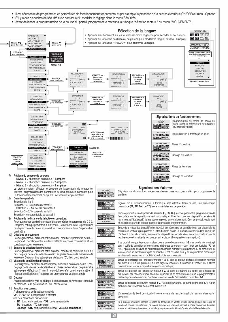
29
• Il est nécessaire de programmer les paramètres de fonctionnement fondamentaux (par exemple la présence de la serrure électrique ON/OFF) au menu Options.• S’il y a des dispositifs de sécurité avec contact 8.2k, modifier le réglage dans le menu Sécurités.• Avant de lancer la programmation de la course du portail, programmer le moteur à la rubrique "sélection moteur " du menu "MOUVEMENT".
“PROG/OK” retour au
menu mouvement
Appuyer sur une flèche pour accéder
au menu principal
“PROG/OK” retour au
menu options
OPTIONSSÉCURITÉMOUVEMENTAFFICHEURCODES RADIO
PROGRAM
TB FIFS CP
TA TDTC TAL
00.000.007CC2X24 V1.00
OPTIONSSÉCURITÉMOUVEMENTAFFICHEURCODES RADIO
Flèchepour défiler
TOUCHE DYNAMIQUEOUVRE-FERME/OUVRE-STOP-FE
REF. AUTOMATIQUEON/OFF
PRÉANNONCEON/OFF
OPTIONSSÉCURITÉMOUVEMENTAFFICHEURCODES RADIO
Flèchepour défiler
OPTIONSSÉCURITÉMOUVEMENTAFFICHEURCODES RADIO
Flèchepour défiler
TOUCHE DYNAMIQUEOUVRE-FERME/OUVRE-STOP-FE
REF. AUTOMATIQUEON/OFF
PRÉANNONCEON/OFF
TOUCHE DYNAMIQUEOUVRE-FERME/OUVRE-STOP-FE
REF. AUTOMATIQUEON/OFF
PRÉANNONCEON/OFF
PRÉANNONCEON/OFF
CLIGNOTEURFIXE/
CLIGNOTANTLAMPE TÉMOIN
FIXE/CLIGNOTANT
CLIGNOTEURFIXE/
CLIGNOTANTLAMPE TÉMOIN
FIXE/CLIGNOTANTMODALITE FI
EN FERMETURE/AUSSI EN STOP
LAMPE TÉMOINFIXE/
CLIGNOTANTMODALITE FI
EN FERMETURE/AUSSI EN STOP
TEST SUR FION/OFF
MODALITE FI EN FERMETURE/AUSSI EN STOP
TEST SUR FION/OFF
TEST SUR FS ON/OFF
TEST SUR FSON/OFF
DECALAGE EN OUV.ON/OFF
SERRURE ELECTR.ON/OFF
TEST SUR FION/OFF
TEST SUR FSON/OFF
DECALAGE EN OUVERTURE
ON/OFF
DECALAGE EN OUV.ON/OFF
SERRURE ELECTR.ON/OFF
MEMO RADIOON/OFF
SERRURE ELECTR.ON/OFF
MEMO RADIOON/OFF
SORTIE LC/CH2CANAL RADIO/
ÉCLAIRAGE DE ZONE
“PROG/OK” pour confirmer
“PROG/OK” pour changer
le valeur
“PROG/OK” pour changer
le valeur
“PROG/OK” pour changer
le valeur
“PROG/OK” pour changer
le valeur
“PROG/OK” pour changer
le valeur
“PROG/OK” pour changer
le valeur
“PROG/OK” pour changer
le valeur
“PROG/OK” pour changer
le valeur
“PROG/OK” pour changer
le valeur
“PROG/OK” pour changer
le valeur
MEMO RADIOON/OFF
SORTIE LC/CH2CANAL RADIO/
ÉCLAIRAGE DE ZONE
SORTIE
“PROG/OK” pour changer
le valeur
CONTACT TBNC/8K2
CONTACT FINC/8K2
CONTACT FSNC/8K2
CONTACT TBNC/8K2
CONTACT FINC/8K2
CONTACT FSNC/8K2
“PROG/OK” pour confirmer
“PROG/OK” pour changer
le valeur
“PROG/OK” pour changer
le valeur
CONTACT TBNC/8K2
CONTACT FINC/8K2
CONTACT FSNC/8K2
“PROG/OK” pour changer
le valeur
CONTACT FINC/8K2
CONTACT FSNC/8K2
CONTACT CPNC/8K2
“PROG/OK” pour changer
le valeur
CONTACT FSNC/8K2
CONTACT CPNC/8K2
SORTIE
“PROG/OK” retour au
menu sécurité
SELECTION MOTEURBL824
SENSEUR COURANTNIVEAU 1...5
OUVERTURE PARTIELLERÉGLAGE 1...5
SELECTION MOTEURBL824
SENSEUR COURANTNIVEAU 1...5
OUVERTURE PARTIELLERÉGLAGE 1...4
“PROG/OK” pour confirmer
“PROG/OK” pour changer
le valeur
SELECTION MOTEURBL824
SENSEUR COURANTNIVEAU 1...5
OUVERTURE PARTIELLERÉGLAGE 1...4
“PROG/OK” pour changer
le valeur
SENSEUR COURANTNIVEAU 1...5
OUVERTURE PARTIELLERÉGLAGE 1...5
DIST. BUTÉE OUV.ETAPE 1...9
“PROG/OK” pour changer
le valeur
“PROG/OK” pour changer
le valeur
CONTRASTE0....63
LUMIERE FONDETOUJOUR ON/60/30 SEC.
SORTIE
“PROG/OK” pour confirmer
CONTRASTE0....63
LUMIERE FONDETOUJOUR ON/60/30 SEC.
SORTIE
“PROG/OK” pour changer
le valeur
CONTRASTE0....63
LUMIERE FONDETOUJOUR ON/60/30 SEC.
SORTIE
“PROG/OK” retour au
menu display
Le nombre de manœuvres effectuées par l'opérateur, le modèle de la centrale et la version du rmware sont toujours indiqués sur la fenêtre initiale dans ce cas.
Il symboleindique que la centrale est alimentée par le réseau électrique
Il symboleindique que la centrale est alimentée par la batterie chargée à 100%.
75%
50%
25%
0%
Note: 1
Note: 2
Note: 3
Note: 3
Note: 6
Note: 7
Note: 8
Note: 9
Note: 4
Note: 5
“PROG/OK” pour confirmer
Appuyer sur les flèches pour augmenter ou
diminuer la valeur (maxi. 63)
* * * * * * * * * * * * * * ** ** RÉG. CONTRASTE ** SEC. *
* ** * * * * * * * * * * * * * *
26
Programmation du temps de pause ou Pause avant la refermeture automatique (seulement si validée)
Programmation automatique en cours
Phase d’ouverture
Blocage d’ouverture
Phase de fermeture
Blocage de fermeture
Signalisations de fonctionnement
TB FIFS CP
TA TDTC TAL
PAUSA
TB FIFS CP
TA TDTC TAL
AUTO PROG
TB FIFS CP
TA TDTC TAL
OUVERTURE
TB FIFS CP
TA TDTC TAL
STOP OUVERTURE
TB FIFS CP
TA TDTC TAL
FERMETURE
TB FIFS CP
TA TDTC TAL
STOP FERMETURE
Signalisations d’alarmeClignotant sur display. Il est nécessaire d’entrer dans le programmation pour programmer le système.
Signale qu’un repositionnement automatique sera effectué. Dans ce cas, une quelconque commande (TA, TC, TAL ou TD) lance immédiatement ce procédé.
Ceci se produit si un dispositif de sécurité (FI, FS, CP) s’active pendant la programmation de l’encodeur ou le repositionnement automatique. Une fois que les dispositifs de sécurité reviennent à l’état passif, la manœuvre reprend automatiquement. Ceci se produit également en cas de coupure de courant pendant la phase de programmation.
Erreur dans le test des dispositifs de sécurité. Il est nécessaire de contrôler l’état des dispositifs de sécurité en vériant qu’ils passent à l’état d’alarme quand un obstacle se trouve dans leur rayon d’action. En cas d’anomalie, remplacer le dispositif de sécurité défectueux ou court-circuiter la relative entrée et invalider le test concernant le dispositif en question (menu options).
Il se produit lorsque le programmateur donne un ordre au moteur 1-2 mais ce dernier ne réagit pas. Il suft de contrôler les connexions inhérentes au moteur 1-2 et l’état des fusibles "F3" et "F4". Après quoi, essayer de nouveau de lancer une manœuvre d’ouverture ou de fermeture. Si le moteur ne se met toujours pas en marche, il est possible qu’il y ait un problème mécanique au niveau du moteur ou un problème de logiciel sur la centrale.
Erreur de comptage de l’encodeur moteur 1-2. Si ceci se produit pendant l’utilisation normale du moteur, il y a un problème sur les signaux inhérents à l’encodeur; vérier les relatives connexions et lancer le repositionnement automatique.
Erreur de direction de l’encodeur moteur 1-2. Le sens de marche du portail est différent de celui établi par l’encodeur (par exemple: le portail va en fermeture alors que le programmateur réalise la phase d’ouverture). Contrôler la connexion de l’alimentation du moteur 1-2.
Erreur du senseur de courant moteur 1-2. Avec moteur arrêté, ce symbole indique qu’il y a un problème sur le senseur de courant moteur 1-2.
L’intervention de bord de sécurité inverse le sens de marche aussi bien en fermeture qu'en ouverture
Si le senseur intervient pendant la phase de fermeture, le vantail inverse immédiatement son sens de marche et s’ouvre complètement. Par contre, si le senseur intervient pendant la phase d’ouverture, le vantail inverse immédiatement son sens de marche sur quelque centimètre et s’arrête an de libérer l’obstacle.
TB FIFS CP
TA TDTC TAL
PROGRAM
TB FIFS CP
TA TDTC TAL
HORS POS.
TB FIFS CP
TA TDTC TAL
ERREUR SÉC.
TB FIFS CP
TA TDTC TAL
STOP PROG
AUTO PROG
TB FIFS CP
TA TDTC TAL
ERREUR MOT1/2
TB FIFS CP
TA TDTC TAL
ERREUR ENC1/2
TB FIFS CP
TA TDTC TAL
ERREUR DIR1/2
TB FIFS CP
TA TDTC TAL
ERREUR SENS1/2
TB FIFS CP
TA TDTC TAL
INT. BORD
TB FIFS CP
TA TDTC TAL
INT. SENSEUR
ITALIANO
FRANÇAIS
ENGLISH
NEDERLANDS
DEUTSCH
ESPAÑOL
PROGRAM
TB FIFS CP
TA TDTC TAL
00.000.007CC2X24 V1.00
appuyer simultanément sur les deux flèches pour accéder au
sous-menu Langue.
“PROG/OK” pour confirmer
Sélection de la langue:• Appuyer simultanément sur les touches de droite et gauche pour accéder au sous-menu.• Appuyer sur la touche de droite ou de gauche pour modier la langue: Italiano - Français • Appuyer sur la touche "PROG/OK" pour conrmer la langue.
OUVERTURE PARTIELLERÉGLAGE 1...5
DIST. BUTÉE OUV.ETAPE 0...9
DÉCALAGE EN OUV.ETAPE 0...9
DIST. BUTÉE OUV.PASSI 0...9
DÉCALAGE EN OUV.ETAPE 0...9
DISTANCE FREINAGEREGLAGE 1...3
DISTANCE FREINAGEREGLAGE 1...3
VITESSE FREINAGEREGLAGE 1...3
TEMPS DE PAUSE130 SEC.
VITESSE FREINAGEREGLAGE 1...3
TEMPS DE PAUSE180 SEC.
SORTIE
“PROG/OK” pour confirmer
Appuyer sur les flèches pour augmenter ou diminuer la valeur (maxi. 240 secondes). Pour changer rapidement la valeur, accélérer le défilement en maintenantla flèche appuyée.
* * * * * * * * * * * * * * ** ** TEMPS DE PAUSE ** SEC. ** ** * * * * * * * * * * * * * *
180
DÉCALAGE EN OUV.ETAPE 0...9
DISTANCE FREINAGEREGLAGE 1...3
VITESSE FRENAGEREGLAGE 1...3
“PROG/OK” pour changer
le valeur
Note: 10
“PROG/OK” pour changer
le valeur
Note: 11
“PROG/OK” pour changer
le valeur
Note: 12
“PROG/OK” pour confirmer
APPUYER surl’émetteurle canal à
mémoriser
APPUYER surl’émetteurle même
canal à mémoriser
“PROG/OK” pour confirmer
Flèchepour dérouler
CODAGE: S4XX
MÉMORISATION
EFFACEMENT
EFFACEMENT TOTAL
FONCTION CANAUX
SORTIE
“PROG/OK” pour confirmer
OPTIONSSÉCURITÉMOUVEMENTAFFICHEURCALENDRIERCODES RADIO
MÉMORISATION[N....]
* * * * * * * * * * * * * * ** ** ACTIVATION 1 ** ** * * * * * * * * * * * * * *
MÉMORISATION[N....]
* * * * * * * * * * * * * * ** ** ACTIVATION 2 ** ** * * * * * * * * * * * * * *
MÉMORISATION[N....]
* * * * * * * * * * * * * * ** ** CODE ** MÉMORISÉ ** * * * * * * * * * * * * * *
“PROG/OK” pour confirmer
EFFACEMENT[N....]
* * * * * * * * * * * * * * ** ** ACTIVATION 1 ** ** * * * * * * * * * * * * * *
APPUYER surl’émetteurle canal à
effacer
EFFACEMENT[N....]
* * * * * * * * * * * * * * ** ** ACTIVATION 2 ** ** * * * * * * * * * * * * * *
APPUYER surl’émetteurle même
canal à effacer
EFFACEMENT[N....]
* * * * * * * * * * * * * * ** ** CODE ** EFFACÉ ** * * * * * * * * * * * * * *
CODAGE: S4XX
MÉMORISATION
EFFACEMENT
EFFACEMENT TOTAL
FONCTION CANAUX
SORTIE
“PROG/OK” pour confirmer
* * * * * * * * * * * * * * ** EFFACEMENT ** TOTAL ? ** * * * * * * * * * * * * * *
APPUYER sur ok pour effacer le mémoir ou sur Exit pour sortir
CODAGE: S4XX
MÉMORISATION
EFFACEMENT
EFFACEMENT TOTAL
FONCTION CANAUX
SORTIE
Flèchepour sortir
EXIT
OK
* * * * * * * * * * * * * * ** EFFACEMENT ** EN COURS ** * * * * * * * * * * * * * *
CODAGE: S4XX
MÉMORISATION
EFFACEMENT
EFFACEMENT TOTAL
FONCTION CANAUX
SORTIE
CANAL Afonction du canal A
CANAL Bfonction du canal B
CANAL Cfonction du canal C
CANAL Dfonction du canal D
SORTIE
CODAGE: S4XX
MÉMORISATION
EFFACEMENT
EFFACEMENT TOTAL
FONCTION CANAUX
SORTIE
“PROG/OK” pour changer
la valeur
CODAGE: S4XX
MÉMORISATION
EFFACEMENT
EFFACEMENT TOTAL
FONCTION CANAUX
SORTIE
“PROG/OK” pour changerla valeur entreS4XX et S500
“PROG/OK” retour au menu
codes radio
[AB--] [AB--] [AB--]
[AB--] [AB--] [AB--]
Note: 14
Note: 13
7) Réglage du senseur de courant: - Niveau 1 = absorption du moteur + 1 ampere - Niveau 2 = absorption du moteur + 2 ampères - Niveau 3 = absorption du moteur + 3 ampères Le programmateur effectue le contrôle de l’absorption du moteur en
relevant l’augmentation des contraintes au-delà des seuils consentis pour un fonctionnement normal, ce qui est une sécurité supplémentaire.
8) Ouverture partielle Sélection de 1 à 4: Sélection 1 = 1/3 course du vantail 1
Sélection 2 = 1/2 course du vantail 1 Sélection 3 = 2/3 course du vantail 1 Sélection 4 = course totale du vantail 19) Réglage de la distance de la butée en ouverture: Pour augmenter ou diminuer cette distance, régler le paramètre de 0 à 9.
L'appareil est réglé par défaut sur niveau 4. De cette manière, le portail n’ira pas taper contre la butée en ouverture mais s’arrêtera dans l’espace d’un centimètre.
10) Décalage en ouverture Pour augmenter ou diminuer cette distance, modifier le paramètre de 0 à 9.
Réglage du décalage entre les deux battants en phase d’ouverture et, en conséquence, en fermeture..
11) Espace de décélération (freinage) Pour augmenter ou diminuer cette distance, modifier le paramètre de 0 à 3
pas. Réglage de l’espace de décélération en phase finale de la manœuvre de fermeture. Ce paramètre est réglé par défaut sur '0' ; il est donc invalidé.
12) Vitesse de décélération (freinage) Pour augmenter ou diminuer cette vitesse, modifier le paramètre de 0 à 3 pas.
Réglage de la vitesse de décélération en phase de fermeture. Ce paramètre est réglé par défaut sur '1' mais il ne produit son effet que si le paramètre 11 "Espace de décélération" est réglé sur une valeur qui va de un à trois.
13) Codage Avant de modifier le type de codage, il est nécessaire de remplacer le module
de mémoire S4XX par le module S500 et vice versa.14) Fonction des canaux À chaque canal de la radiocommande "A","B","C","D" il est possible d'affecter une des 7 fonctions disponibles:
- TD touche dynamique - TAL ouverture partielle - TA ouverture - TC fermeture - Blocage - CH2 sortie deuxième canal - Aucune commande
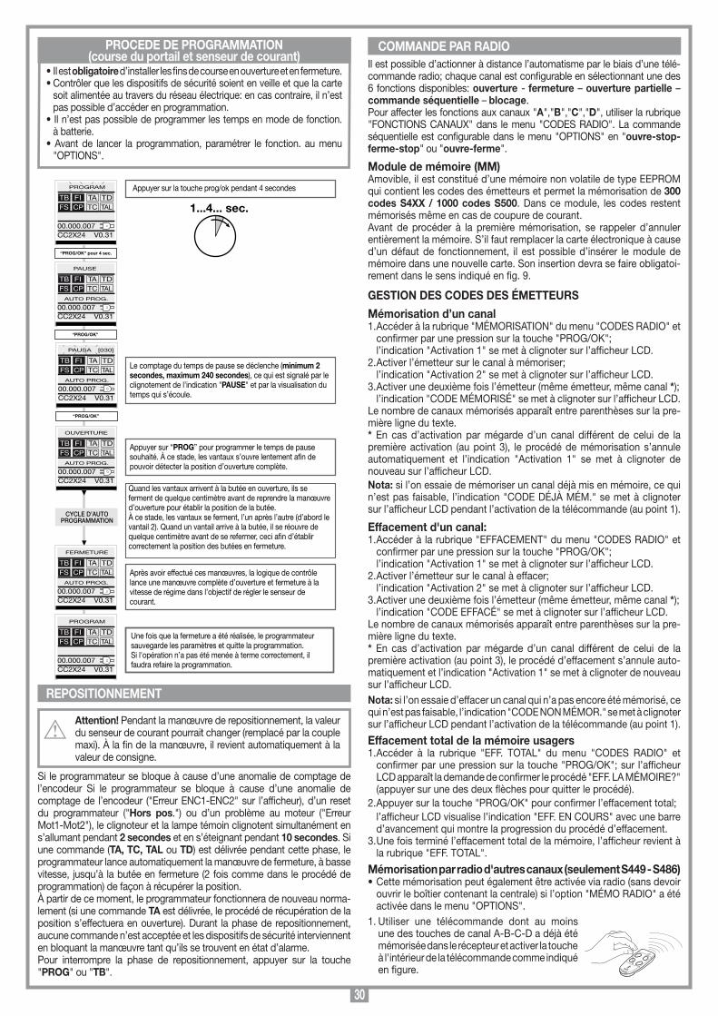
30
MEMORIZZAZIONE CODICE TX-RX
RCQ449100
13-04-2001
DM0531 Description :
Product Code :
Date :
Drawing number :
P.J.Heath
CARDIN ELETTRONICA S.p.A - 31020 San Vendemiano (TV) Italy - via Raffaello, 36 Tel: 0438/401818 Fax: 0438/401831
Draft :
All rights reserved. Unauthorised copying or use of the information contained in this document is punishable by law
MR
PROCÉDÉ DE PROGRAMMATION(course du portail et senseur de courant)
Il est possible d’actionner à distance l’automatisme par le biais d’une télé-commande radio; chaque canal est configurable en sélectionnant une des 6 fonctions disponibles: ouverture - fermeture – ouverture partielle – commande séquentielle – blocage.Pour affecter les fonctions aux canaux "A","B","C","D", utiliser la rubrique "FONCTIONS CANAUX" dans le menu "CODES RADIO". La commande séquentielle est configurable dans le menu "OPTIONS" en "ouvre-stop-ferme-stop" ou "ouvre-ferme".
Module de mémoire (MM)Amovible, il est constitué d’une mémoire non volatile de type EEPROM qui contient les codes des émetteurs et permet la mémorisation de 300 codes S4XX / 1000 codes S500. Dans ce module, les codes restent mémorisés même en cas de coupure de courant.Avant de procéder à la première mémorisation, se rappeler d’annuler entièrement la mémoire. S’il faut remplacer la carte électronique à cause d’un défaut de fonctionnement, il est possible d’insérer le module de mémoire dans une nouvelle carte. Son insertion devra se faire obligatoi-rement dans le sens indiqué en fig. 9.
GESTION DES CODES DES ÉMETTEURS
Mémorisation d’un canal1. Accéder à la rubrique "MÉMORISATION" du menu "CODES RADIO" et
confirmer par une pression sur la touche "PROG/OK"; l’indication "Activation 1" se met à clignoter sur l’afficheur LCD.2. Activer l’émetteur sur le canal à mémoriser; l’indication "Activation 2" se met à clignoter sur l’afficheur LCD.3. Activer une deuxième fois l’émetteur (même émetteur, même canal *); l’indication "CODE MÉMORISÉ" se met à clignoter sur l’afficheur LCD.Le nombre de canaux mémorisés apparaît entre parenthèses sur la pre-mière ligne du texte.* En cas d’activation par mégarde d’un canal différent de celui de la première activation (au point 3), le procédé de mémorisation s’annule automatiquement et l’indication "Activation 1" se met à clignoter de nouveau sur l’afficheur LCD.Nota: si l’on essaie de mémoriser un canal déjà mis en mémoire, ce qui n’est pas faisable, l’indication "CODE DÉJÀ MÉM." se met à clignoter sur l’afficheur LCD pendant l’activation de la télécommande (au point 1).
Effacement d'un canal:1. Accéder à la rubrique "EFFACEMENT" du menu "CODES RADIO" et
confirmer par une pression sur la touche "PROG/OK"; l’indication "Activation 1" se met à clignoter sur l’afficheur LCD.2. Activer l’émetteur sur le canal à effacer; l’indication "Activation 2" se met à clignoter sur l’afficheur LCD.3. Activer une deuxième fois l’émetteur (même émetteur, même canal *); l’indication "CODE EFFACÉ" se met à clignoter sur l’afficheur LCD.Le nombre de canaux mémorisés apparaît entre parenthèses sur la pre-mière ligne du texte.* En cas d’activation par mégarde d’un canal différent de celui de la première activation (au point 3), le procédé d’effacement s’annule auto-matiquement et l’indication "Activation 1" se met à clignoter de nouveau sur l’afficheur LCD.Nota: si l’on essaie d’effacer un canal qui n’a pas encore été mémorisé, ce qui n’est pas faisable, l’indication "CODE NON MÉMOR." se met à clignoter sur l’afficheur LCD pendant l’activation de la télécommande (au point 1).
Effacement total de la mémoire usagers1. Accéder à la rubrique "EFF. TOTAL" du menu "CODES RADIO" et
confirmer par une pression sur la touche "PROG/OK"; sur l’afficheur LCD apparaît la demande de confirmer le procédé "EFF. LA MÉMOIRE?" (appuyer sur une des deux flèches pour quitter le procédé).
2. Appuyer sur la touche "PROG/OK" pour confirmer l’effacement total; l’afficheur LCD visualise l’indication "EFF. EN COURS" avec une barre
d’avancement qui montre la progression du procédé d’effacement.3. Une fois terminé l’effacement total de la mémoire, l’afficheur revient à
la rubrique "EFF. TOTAL".
Mémorisation par radio d'autres canaux (seulement S449 - S486)• Cette mémorisation peut également être activée via radio (sans devoir
ouvrir le boîtier contenant la centrale) si l’option "MÉMO RADIO" a été activée dans le menu "OPTIONS".
1. Utiliser une télécommande dont au moins une des touches de canal A-B-C-D a déjà été mémorisée dans le récepteur et activer la touche à l'intérieur de la télécommande comme indiqué en figure.
• Il est obligatoire d’installer les fins de course en ouverture et en fermeture.• Contrôler que les dispositifs de sécurité soient en veille et que la carte
soit alimentée au travers du réseau électrique: en cas contraire, il n’est pas possible d’accéder en programmation.
• Il n’est pas possible de programmer les temps en mode de fonction. à batterie.
• Avant de lancer la programmation, paramétrer le fonction. au menu "OPTIONS".
REPOSITIONNEMENT
Attention! Pendant la manœuvre de repositionnement, la valeur du senseur de courant pourrait changer (remplacé par la couple maxi). À la fin de la manœuvre, il revient automatiquement à la valeur de consigne.
Si le programmateur se bloque à cause d’une anomalie de comptage de l’encodeur Si le programmateur se bloque à cause d’une anomalie de comptage de l’encodeur ("Erreur ENC1-ENC2" sur l’afficheur), d’un reset du programmateur ("Hors pos.") ou d’un problème au moteur ("Erreur Mot1-Mot2"), le clignoteur et la lampe témoin clignotent simultanément en s’allumant pendant 2 secondes et en s’éteignant pendant 10 secondes. Si une commande (TA, TC, TAL ou TD) est délivrée pendant cette phase, le programmateur lance automatiquement la manœuvre de fermeture, à basse vitesse, jusqu’à la butée en fermeture (2 fois comme dans le procédé de programmation) de façon à récupérer la position. À partir de ce moment, le programmateur fonctionnera de nouveau norma-lement (si une commande TA est délivrée, le procédé de récupération de la position s’effectuera en ouverture). Durant la phase de repositionnement, aucune commande n’est acceptée et les dispositifs de sécurité interviennent en bloquant la manœuvre tant qu’ils se trouvent en état d’alarme.Pour interrompre la phase de repositionnement, appuyer sur la touche "PROG" ou "TB".
COMMANDE PAR RADIO
1...4... sec.
Le comptage du temps de pause se déclenche (minimum 2 secondes, maximum 240 secondes), ce qui est signalé par le clignotement de l’indication "PAUSE" et par la visualisation du temps qui s’écoule.
Appuyer sur “PROG” pour programmer le temps de pause souhaité. À ce stade, les vantaux s’ouvre lentement an de pouvoir détecter la position d’ouverture complète.
Quand les vantaux arrivent à la butée en ouverture, ils se ferment de quelque centimètre avant de reprendre la manœuvre d’ouverture pour établir la position de la butée. À ce stade, les vantaux se ferment, l’un après l’autre (d’abord le vantail 2). Quand un vantail arrive à la butée, il se réouvre de quelque centimètre avant de se refermer, ceci an d’établir correctement la position des butées en fermeture.
Après avoir effectué ces manœuvres, la logique de contrôle lance une manœuvre complète d’ouverture et fermeture à la vitesse de régime dans l’objectif de régler le senseur de courant.
Une fois que la fermeture a été réalisée, le programmateur sauvegarde les paramètres et quitte la programmation. Si l'opération n’a pas été menée à terme correctement, il faudra refaire la programmation.
Appuyer sur la touche prog/ok pendant 4 secondes
“PROG/OK” pour 4 sec.
CYCLE D’AUTOPROGRAMMATION
PROGRAM
TB FIFS CP
TA TDTC TAL
00.000.007CC2X24 V0.31
“PROG/OK”
PAUSE
TB FIFS CP
TA TDTC TAL
00.000.007CC2X24 V0.31
AUTO PROG.
“PROG/OK”
TB FIFS CP
TA TDTC TAL
00.000.007CC2X24 V0.31
AUTO PROG.
OUVERTURE
TB FIFS CP
TA TDTC TAL
00.000.007CC2X24 V0.31
AUTO PROG.
FERMETURE
TB FIFS CP
TA TDTC TAL
00.000.007CC2X24 V0.31
AUTO PROG.
PROGRAM
TB FIFS CP
TA TDTC TAL
00.000.007CC2X24 V0.31
PAUSA [030]
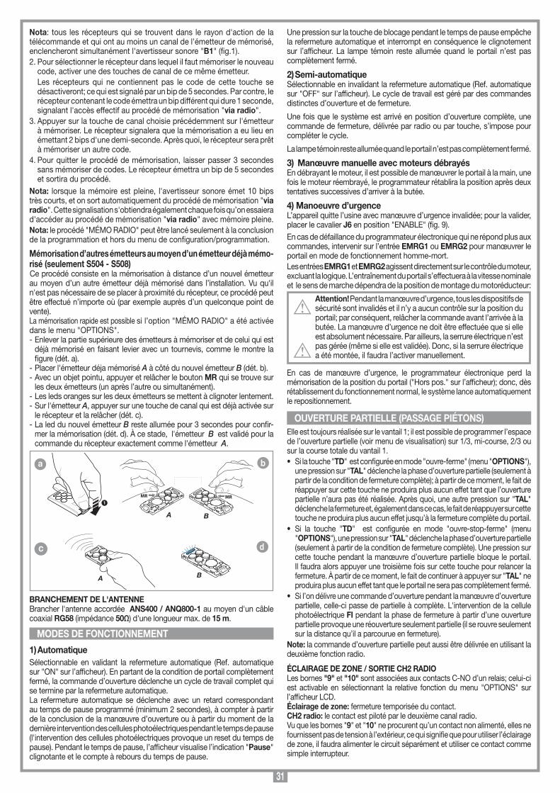
31
Une pression sur la touche de blocage pendant le temps de pause empêche la refermeture automatique et interrompt en conséquence le clignotement sur l’afficheur. La lampe témoin reste allumée quand le portail n’est pas complètement fermé.
2) Semi-automatiqueSélectionnable en invalidant la refermeture automatique (Ref. automatique sur "OFF" sur l’afficheur). Le cycle de travail est géré par des commandes distinctes d’ouverture et de fermeture.
Une fois que le système est arrivé en position d’ouverture complète, une commande de fermeture, délivrée par radio ou par touche, s’impose pour compléter le cycle.
La lampe témoin reste allumée quand le portail n’est pas complètement fermé.
3) Manœuvre manuelle avec moteurs débrayésEn débrayant le moteur, il est possible de manœuvrer le portail à la main, une fois le moteur réembrayé, le programmateur rétablira la position après deux tentatives successives d’arriver à la butée.
4) Manoeuvre d’urgenceL’appareil quitte l’usine avec manœuvre d’urgence invalidée; pour la valider, placer le cavalier J6 en position "ENABLE" (fig. 9). En cas de défaillance du programmateur électronique qui ne répond plus aux commandes, intervenir sur l’entrée EMRG1 ou EMRG2 pour manœuvrer le portail en mode de fonctionnement homme-mort. Les entrées EMRG1 et EMRG2 agissent directement sur le contrôle du moteur, excluant la logique. L’entraînement du portail s’effectuera à la vitesse nominale et le sens de marche dépendra de la position de montage du motoréducteur:
Attention! Pendant la manœuvre d’urgence, tous les dispositifs de sécurité sont invalidés et il n’y a aucun contrôle sur la position du portail; par conséquent, relâcher la commande avant l’arrivée à la butée. La manœuvre d’urgence ne doit être effectuée que si elle est absolument nécessaire. Par ailleurs, la serrure électrique n’est pas gérée (même si elle est validée). Donc, si la serrure électrique a été montée, il faudra l’activer manuellement.
En cas de manœuvre d’urgence, le programmateur électronique perd la mémorisation de la position du portail ("Hors pos." sur l’afficheur); donc, dès rétablissement du fonctionnement normal, le système lance automatiquement le repositionnement.
Elle est toujours réalisée sur le vantail 1; il est possible de programmer l’espace de l’ouverture partielle (voir menu de visualisation) sur 1/3, mi-course, 2/3 ou sur la course totale du vantail 1. • Si la touche "TD" est configurée en mode "ouvre-ferme" (menu "OPTIONS"),
une pression sur "TAL" déclenche la phase d’ouverture partielle (seulement à partir de la condition de fermeture complète); à partir de ce moment, le fait de réappuyer sur cette touche ne produira plus aucun effet tant que l’ouverture partielle n’aura pas été réalisée. Après quoi, une autre pression sur "TAL" déclenche la fermeture et, également dans ce cas, le fait de réappuyer sur cette touche ne produira plus aucun effet jusqu’à la fermeture complète du portail.
• Si la touche "TD" est configurée en mode "ouvre-stop-ferme" (menu "OPTIONS"), une pression sur "TAL" déclenche la phase d’ouverture partielle (seulement à partir de la condition de fermeture complète). Une pression sur cette touche pendant la manœuvre d’ouverture partielle bloque le portail. Il faudra alors appuyer une troisième fois sur cette touche pour relancer la fermeture. À partir de ce moment, le fait de continuer à appuyer sur "TAL" ne produira plus aucun effet tant que le portail ne sera pas complètement fermé.
• Si l’on délivre une commande d’ouverture pendant la manœuvre d’ouverture partielle, celle-ci passe de partielle à complète. L'intervention de la cellule photoélectrique FI pendant la phase de fermeture à partir d’une ouverture partielle provoque une réouverture seulement partielle (il se rouvre seulement sur la distance qu’il a parcourue en fermeture).
Note: la commande d’ouverture partielle peut aussi être délivrée en utilisant la deuxième fonction radio.
ÉCLAIRAGE DE ZONE / SORTIE CH2 RADIOLes bornes "9" et "10" sont associées aux contacts C-NO d’un relais; celui-ci est activable en sélectionnant la relative fonction du menu "OPTIONS" sur l’afficheur LCD.Éclairage de zone: fermeture temporisée du contact.CH2 radio: le contact est piloté par le deuxième canal radio.Vu que les bornes "9" et "10" ne procurent qu’un contact non alimenté, elles ne fournissent pas de tension à l’extérieur, ce qui signifie que pour utiliser l’éclairage de zone, il faudra alimenter le circuit séparément et utiliser ce contact comme simple interrupteur.
OUVERTURE PARTIELLE (PASSAGE PIÉTONS)
MODES DE FONCTIONNEMENT
Nota: tous les récepteurs qui se trouvent dans le rayon d'action de la télécommande et qui ont au moins un canal de l'émetteur de mémorisé, enclencheront simultanément l'avertisseur sonore "B1" (fig.1).2. Pour sélectionner le récepteur dans lequel il faut mémoriser le nouveau
code, activer une des touches de canal de ce même émetteur. Les récepteurs qui ne contiennent pas le code de cette touche se
désactiveront; ce qui est signalé par un bip de 5 secondes. Par contre, le récepteur contenant le code émettra un bip différent qui dure 1 seconde, signalant l'accès effectif au procédé de mémorisation "via radio".
3. Appuyer sur la touche de canal choisie précédemment sur l'émetteur à mémoriser. Le récepteur signalera que la mémorisation a eu lieu en émettant 2 bips d'une demi-seconde. Après quoi, le récepteur sera prêt à mémoriser un autre code.
4. Pour quitter le procédé de mémorisation, laisser passer 3 secondes sans mémoriser de codes. Le récepteur émettra un bip de 5 secondes et sortira du procédé.
Nota: lorsque la mémoire est pleine, l'avertisseur sonore émet 10 bips très courts, et on sort automatiquement du procédé de mémorisation "via radio". Cette signalisation s'obtiendra également chaque fois qu’on essaiera d'accéder au procédé de mémorisation "via radio" avec mémoire pleine. Nota: le procédé "MÉMO RADIO" peut être lancé seulement à la conclusion de la programmation et hors du menu de configuration/programmation.
Mémorisation d’autres émetteurs au moyen d’un émetteur déjà mémo-risé (seulement S504 - S508)Ce procédé consiste en la mémorisation à distance d’un nouvel émetteur au moyen d’un autre émetteur déjà mémorisé dans l’installation. Vu qu'il n'est pas nécessaire de se placer à proximité du récepteur, ce procédé peut être effectué n’importe où (par exemple auprès d’un quelconque point de vente).La mémorisation rapide est possible si l’option "MÉMO RADIO" a été activée dans le menu "OPTIONS".- Enlever la partie supérieure des émetteurs à mémoriser et de celui qui est
déjà mémorisé en faisant levier avec un tournevis, comme le montre la figure (dét. a).
- Placer l'émetteur déja mémorisé A à côté du nouvel émetteur B (dét. b).- Avec un objet pointu, appuyer et relâcher le bouton MR qui se trouve sur
les deux émetteurs (un après l’autre ou simultanément).- Les leds oranges sur les deux émetteurs se mettent à clignoter lentement.- Sur l'émetteur A, appuyer sur une touche de canal qui est déjà activée sur
le récepteur et la relâcher (dét. c).- La led du nouvel émetteur B reste allumée pour 3 secondes pour confir-
mer la mémorisation (dét. d). À ce stade, l'émetteur B est validé pour la commande du récepteur exactement comme l'émetteur A.
Attention: Les instructions pour la gestion des émetteurs de la série S500 sont accessibles par le lien: http://www.cardin.it/Attachment/zvl544-00.pdf
BRANCHEMENT DE L'ANTENNEBrancher l'antenne accordée ANS400 / ANQ800-1 au moyen d'un câble coaxial RG58 (impédance 50Ω) d'une longueur max. de 15 m.
1) AutomatiqueSélectionnable en validant la refermeture automatique (Ref. automatique sur "ON" sur l’afficheur). En partant de la condition de portail complètement fermé, la commande d’ouverture déclenche un cycle de travail complet qui se termine par la refermeture automatique. La refermeture automatique se déclenche avec un retard correspondant au temps de pause programmé (minimum 2 secondes), à compter à partir de la conclusion de la manœuvre d’ouverture ou à partir du moment de la dernière intervention des cellules photoélectriques pendant le temps de pause (l'intervention des cellules photoélectriques provoque un reset du temps de pause). Pendant le temps de pause, l’afficheur visualise l’indication "Pause" clignotante et le compte à rebours du temps de pause.
MEMORIZZAZIONE CODICE TX-TX
TRQ504
29-10-2013
DM0910 Description :
Product Code :
Date :
Drawing number :
P.J.Heath
CARDIN ELETTRONICA S.p.A - 31020 San Vendemiano (TV) Italy - via Raffaello, 36 Tel: 0438/401818 Fax: 0438/401831
Draft :
All rights reserved. Unauthorised copying or use of the information contained in this document is punishable by law
MR
A
MR
B
1
MEMORIZZAZIONE CODICE TX-TX
TXQ504C4
29-10-2013
DM0911 Description :
Product Code :
Date :
Drawing number :
P.J.Heath
CARDIN ELETTRONICA S.p.A - 31020 San Vendemiano (TV) Italy - via Raffaello, 36 Tel: 0438/401818 Fax: 0438/401831
Draft :
All rights reserved. Unauthorised copying or use of the information contained in this document is punishable by law
A
MEMORIZZAZIONE CODICE TX-TX
TXQ504C4
29-10-2013
DM0912 Description :
Product Code :
Date :
Drawing number :
P.J.Heath
CARDIN ELETTRONICA S.p.A - 31020 San Vendemiano (TV) Italy - via Raffaello, 36 Tel: 0438/401818 Fax: 0438/401831
Draft :
All rights reserved. Unauthorised copying or use of the information contained in this document is punishable by law
B
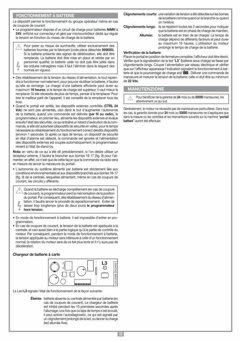
32
MANUTENZIONE
Le dispositif permet le fonctionnement du groupe opérateur même en cas de coupure de courant.• Le programmateur dispose d’un circuit de charge pour batteries NiMH à
24V, enfiché sur connecteur et géré par microcontrôleur dédié qui régule la tension en fonction du niveau de charge de la batterie.
Pour parer au risque de surchauffe, utiliser exclusivement des batteries fournies par la fabricant (code pièce détachée 999600). Si la batterie présente des signes de détérioration, elle doit être remplacée. La batterie doit être mise en place et retirée par un personnel qualifié; la batterie usée ne doit pas être jetée dans les ordures ménagères mais il faut l'éliminer dans le respect des normes en vigueur.
• Dès rétablissement de la tension du réseau d'alimentation, le tout repren-dra à fonctionner normalement; pour pouvoir réutiliser la batterie, il faudra qu'elle se recharge. La charge d’une batterie efficiente peut durer au maximum 16 heures; si le temps de charge est supérieur, il vaut mieux la remplacer. Si elle nécessite de plus de temps, penser à la remplacer. Pour tirer le meilleur parti de l’appareil, il est conseillé de la remplacer tous les trois.
• Quand le portail est arrêté, les dispositifs externes contrôlés (CTRL 24 Vdc) ne sont pas alimentés, ceci dans le but d'augmenter l'autonomie de la batterie; quand une commande est délivrée (par fil ou radio), le programmateur, en premier lieu, alimente les dispositifs externes et évalue ensuite l'état des sécurités, ce qui entraîne un retard d'exécution de la com-mande, si elle est autorisée (dispositifs de sécurité en veille), pour le temps nécessaire au rétablissement du fonctionnement correct desdits dispositifs (environ 1 seconde). Si après ce laps de temps, un dispositif de sécurité en état d'alarme est détecté, la commande est ignorée et l'alimentation des dispositifs externes est coupée automatiquement; le programmateur revient à l'état de stand-by.
Nota: en vertu de ce qui a été dit précédemment, si l'on désire utiliser un récepteur externe, il faudra le brancher aux bornes 16-17 (fig. 9) pour l’ali-menter; en effet, ce n'est que de cette façon que la commande via radio sera en mesure de lancer la manœuvre du portail.• L'autonomie du système alimenté par batterie est strictement liée aux
conditions environnementales et aux dispositifs branchés aux bornes 16-17 (fig. 9) de la centrale, lesquelles alimentent, même en cas de coupure de courant, les circuits y afférents.
Quand la batterie se décharge complètement (en cas de coupure de courant), le programmateur perd la mémorisation de la position du portail. Par conséquent, dès rétablissement du réseau d’alimen-tation, il faudra lancer le procédé de repositionnement. Éviter de laisser trop longtemps (plus de deux jours) le programmateur hors tension.
• En mode de fonctionnement à batterie, il est impossible d’entrer en pro-grammation.
• En cas de coupure de courant, la tension de la batterie est appliquée à la centrale, et ceci aussi bien à la partie logique qu’à la partie de contrôle du moteur. Par conséquent, pendant le mode de fonctionnement à batterie, la tension appliquée au moteur sera inférieure à celle d’un fonctionnement normal; la rotation du moteur sera de ce fait plus lente et il n’y aura pas de décélération.
Chargeur de batterie à carte
Le Led L3 signale l'état de fonctionnement de la façon suivante:
Éteinte: batterie absente ou centrale alimentée par batterie (en cas de coupure de courant). Le chargeur de batterie est inhibé pendant les 10 premières secondes après l'allumage; une fois que ce laps de temps s'est écoulé, il peut activer l'autodiagnostic, ce qui est signalé par un clignotement prolongé de la led, ou lancer la charge (led allumée fixe).
FONCTIONNEMENT À BATTERIE
CS
1256
BD
C04
50L3
Scheda di innesto
PRG424BC
08-01-2008
DC0435 Description :
Product Code :
Date :
Drawing number :
P.J.Heath
CARDIN ELETTRONICA S.p.A - 31020 San Vendemiano (TV) Italy - via Raffaello, 36 Tel: 0438/401818 Fax: 0438/401831
Draft :
All rights reserved. Unauthorised copying or use of the information contained in this document is punishable by law
Scheda carica batteria
Clignotements courts: une variation de tension a été détectée sur les bornes de la batterie comme quand on la branche ou quand on l’enlève;
Clignotements longs: ils se répètent toutes les 2 secondes pour indiquer que la batterie est en phase de charge de maintien,
Allumée: la batterie est en train de se charger. Le temps de charge dépend de différents facteurs et peut durer au maximum 16 heures. L’utilisation du moteur prolonge le temps de charge de la batterie.
Vérification de la batteriePlacer le portail en position de fermeture complète; l’afficheur doit être éteint.Vérifier que la signalisation de la led "L3" (batterie sous charge) se fasse par clignotements longs. Couper l'alimentation par réseau électrique et vérifier que sur l'afficheur apparaisse l'indication signalant le fonctionnement à bat-terie et que le pourcentage de charge soit . Délivrer une commande de manœuvre et mesurer la tension de la batterie; celle-ci doit être au minimum de 22 Vdc.
Pour bénéficier de la garantie de 24 mois ou de 50000 manœuvres, lire attentivement ce qui suit.
Généralement, le moteur ne nécessite pas de maintenances particulières. Dans tous les cas, la garantie donnée pour 24 mois ou 50000 manœuvres ne s’appliquera que dans la mesure où les contrôles et les interventions suivants sur la machine "portail battant" auront été effectués:
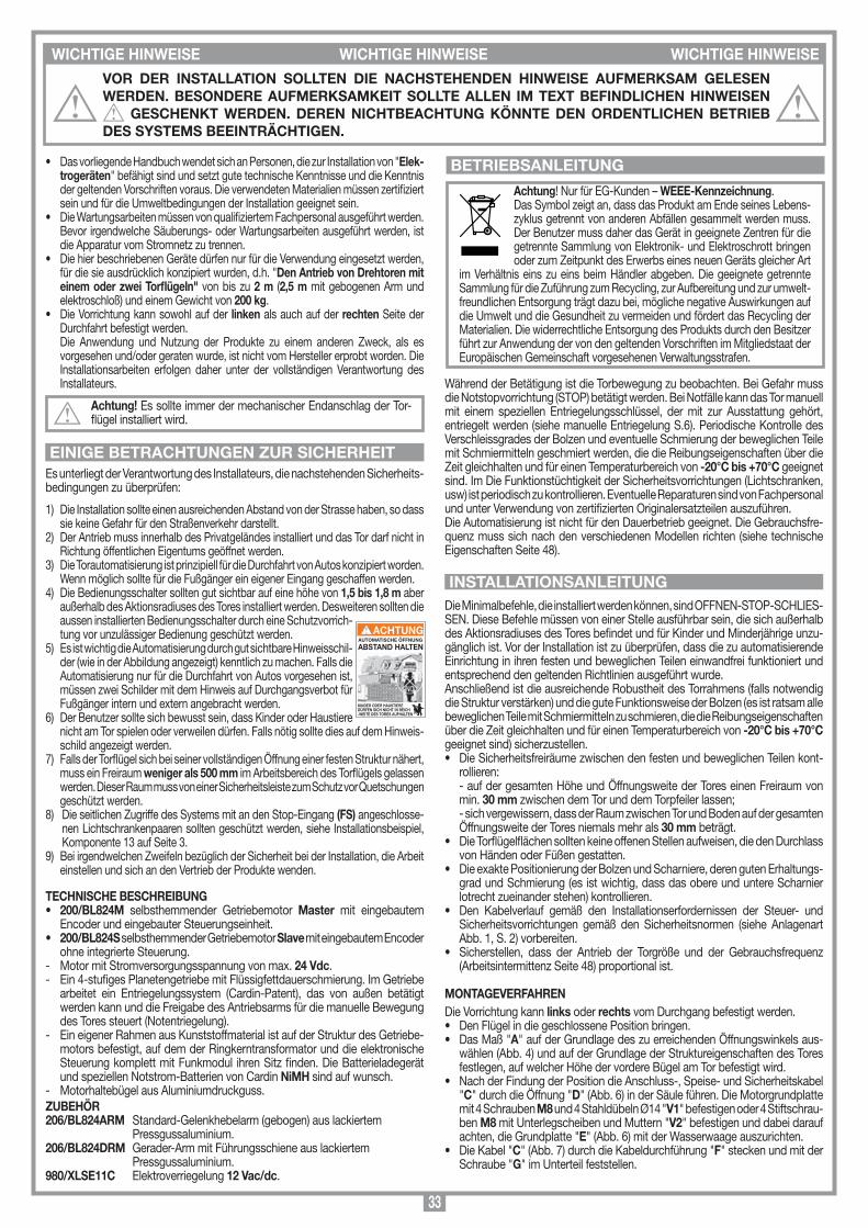
33
• Das vorliegende Handbuch wendet sich an Personen, die zur Installation von "Elek-trogeräten" befähigt sind und setzt gute technische Kenntnisse und die Kenntnis der geltenden Vorschriften voraus. Die verwendeten Materialien müssen zertifiziert sein und für die Umweltbedingungen der Installation geeignet sein.
• Die Wartungsarbeiten müssen von qualifiziertem Fachpersonal ausgeführt werden. Bevor irgendwelche Säuberungs- oder Wartungsarbeiten ausgeführt werden, ist die Apparatur vom Stromnetz zu trennen.
• Die hier beschriebenen Geräte dürfen nur für die Verwendung eingesetzt werden, für die sie ausdrücklich konzipiert wurden, d.h. "Den Antrieb von Drehtoren mit einem oder zwei Torflügeln" von bis zu 2 m (2,5 m mit gebogenen Arm und elektroschloß) und einem Gewicht von 200 kg.
• Die Vorrichtung kann sowohl auf der linken als auch auf der rechten Seite der Durchfahrt befestigt werden.
Die Anwendung und Nutzung der Produkte zu einem anderen Zweck, als es vorgesehen und/oder geraten wurde, ist nicht vom Hersteller erprobt worden. Die Installationsarbeiten erfolgen daher unter der vollständigen Verantwortung des Installateurs.
Achtung! Es sollte immer der mechanischer Endanschlag der Tor-flügel installiert wird.
Es unterliegt der Verantwortung des Installateurs, die nachstehenden Sicherheits-bedingungen zu überprüfen:
1) Die Installation sollte einen ausreichenden Abstand von der Strasse haben, so dass sie keine Gefahr für den Straßenverkehr darstellt.
2) Der Antrieb muss innerhalb des Privatgeländes installiert und das Tor darf nicht in Richtung öffentlichen Eigentums geöffnet werden.
3) Die Torautomatisierung ist prinzipiell für die Durchfahrt von Autos konzipiert worden. Wenn möglich sollte für die Fußgänger ein eigener Eingang geschaffen werden.
4) Die Bedienungsschalter sollten gut sichtbar auf eine höhe von 1,5 bis 1,8 m aber außerhalb des Aktionsradiuses des Tores installiert werden. Desweiteren sollten die aussen installierten Bedienungsschalter durch eine Schutzvorrich-tung vor unzulässiger Bedienung geschützt werden.
5) Es ist wichtig die Automatisierung durch gut sichtbare Hinweisschil-der (wie in der Abbildung angezeigt) kenntlich zu machen. Falls die Automatisierung nur für die Durchfahrt von Autos vorgesehen ist, müssen zwei Schilder mit dem Hinweis auf Durchgangsverbot für Fußgänger intern und extern angebracht werden.
6) Der Benutzer sollte sich bewusst sein, dass Kinder oder Haustiere nicht am Tor spielen oder verweilen dürfen. Falls nötig sollte dies auf dem Hinweis-schild angezeigt werden.
7) Falls der Torflügel sich bei seiner vollständigen Öffnung einer festen Struktur nähert, muss ein Freiraum weniger als 500 mm im Arbeitsbereich des Torflügels gelassen werden. Dieser Raum muss von einer Sicherheitsleiste zum Schutz vor Quetschungen geschützt werden.
8) Die seitlichen Zugriffe des Systems mit an den Stop-Eingang (FS) angeschlosse-nen Lichtschrankenpaaren sollten geschützt werden, siehe Installationsbeispiel, Komponente 13 auf Seite 3.
9) Bei irgendwelchen Zweifeln bezüglich der Sicherheit bei der Installation, die Arbeit einstellen und sich an den Vertrieb der Produkte wenden.
TECHNISCHE BESCHREIBUNG• 200/BL824M selbsthemmender Getriebemotor Master mit eingebautem
Encoder und eingebauter Steuerungseinheit.• 200/BL824S selbsthemmender Getriebemotor Slave mit eingebautem Encoder
ohne integrierte Steuerung.- Motor mit Stromversorgungsspannung von max. 24 Vdc.- Ein 4-stufiges Planetengetriebe mit Flüssigfettdauerschmierung. Im Getriebe
arbeitet ein Entriegelungssystem (Cardin-Patent), das von außen betätigt werden kann und die Freigabe des Antriebsarms für die manuelle Bewegung des Tores steuert (Notentriegelung).
- Ein eigener Rahmen aus Kunststoffmaterial ist auf der Struktur des Getriebe-motors befestigt, auf dem der Ringkerntransformator und die elektronische Steuerung komplett mit Funkmodul ihren Sitz finden. Die Batterieladegerät und speziellen Notstrom-Batterien von Cardin NiMH sind auf wunsch.
- Motorhaltebügel aus Aluminiumdruckguss. ZUBEHÖR206/BL824ARM Standard-Gelenkhebelarm (gebogen) aus lackiertem Pressgussaluminium.206/BL824DRM Gerader-Arm mit Führungsschiene aus lackiertem Pressgussaluminium.980/XLSE11C Elektroverriegelung 12 Vac/dc.
Achtung! Nur für EG-Kunden – WEEE-Kennzeichnung.Das Symbol zeigt an, dass das Produkt am Ende seines Lebens-zyklus getrennt von anderen Abfällen gesammelt werden muss. Der Benutzer muss daher das Gerät in geeignete Zentren für die getrennte Sammlung von Elektronik- und Elektroschrott bringen oder zum Zeitpunkt des Erwerbs eines neuen Geräts gleicher Art
im Verhältnis eins zu eins beim Händler abgeben. Die geeignete getrennte Sammlung für die Zuführung zum Recycling, zur Aufbereitung und zur umwelt-freundlichen Entsorgung trägt dazu bei, mögliche negative Auswirkungen auf die Umwelt und die Gesundheit zu vermeiden und fördert das Recycling der Materialien. Die widerrechtliche Entsorgung des Produkts durch den Besitzer führt zur Anwendung der von den geltenden Vorschriften im Mitgliedstaat der Europäischen Gemeinschaft vorgesehenen Verwaltungsstrafen.
Während der Betätigung ist die Torbewegung zu beobachten. Bei Gefahr muss die Notstopvorrichtung (STOP) betätigt werden. Bei Notfälle kann das Tor manuell mit einem speziellen Entriegelungsschlüssel, der mit zur Ausstattung gehört, entriegelt werden (siehe manuelle Entriegelung S.6). Periodische Kontrolle des Verschleissgrades der Bolzen und eventuelle Schmierung der beweglichen Teile mit Schmiermitteln geschmiert werden, die die Reibungseigenschaften über die Zeit gleichhalten und für einen Temperaturbereich von -20°C bis +70°C geeignet sind. Im Die Funktionstüchtigkeit der Sicherheitsvorrichtungen (Lichtschranken, usw) ist periodisch zu kontrollieren. Eventuelle Reparaturen sind von Fachpersonal und unter Verwendung von zertifizierten Originalersatzteilen auszuführen. Die Automatisierung ist nicht für den Dauerbetrieb geeignet. Die Gebrauchsfre-quenz muss sich nach den verschiedenen Modellen richten (siehe technische Eigenschaften Seite 48).
Die Minimalbefehle, die installiert werden können, sind OFFNEN-STOP-SCHLIES-SEN. Diese Befehle müssen von einer Stelle ausführbar sein, die sich außerhalb des Aktionsradiuses des Tores befindet und für Kinder und Minderjährige unzu-gänglich ist. Vor der Installation ist zu überprüfen, dass die zu automatisierende Einrichtung in ihren festen und beweglichen Teilen einwandfrei funktioniert und entsprechend den geltenden Richtlinien ausgeführt wurde.Anschließend ist die ausreichende Robustheit des Torrahmens (falls notwendig die Struktur verstärken) und die gute Funktionsweise der Bolzen (es ist ratsam alle beweglichen Teile mit Schmiermitteln zu schmieren, die die Reibungseigenschaften über die Zeit gleichhalten und für einen Temperaturbereich von -20°C bis +70°C geeignet sind) sicherzustellen.• Die Sicherheitsfreiräume zwischen den festen und beweglichen Teilen kont-
rollieren: - auf der gesamten Höhe und Öffnungsweite der Tores einen Freiraum von
min. 30 mm zwischen dem Tor und dem Torpfeiler lassen; - sich vergewissern, dass der Raum zwischen Tor und Boden auf der gesamten
Öffnungsweite der Tores niemals mehr als 30 mm beträgt.• Die Torflügelflächen sollten keine offenen Stellen aufweisen, die den Durchlass
von Händen oder Füßen gestatten.• Die exakte Positionierung der Bolzen und Scharniere, deren guten Erhaltungs-
grad und Schmierung (es ist wichtig, dass das obere und untere Scharnier lotrecht zueinander stehen) kontrollieren.
• Den Kabelverlauf gemäß den Installationserfordernissen der Steuer- und Sicherheitsvorrichtungen gemäß den Sicherheitsnormen (siehe Anlagenart Abb. 1, S. 2) vorbereiten.
• Sicherstellen, dass der Antrieb der Torgröße und der Gebrauchsfrequenz (Arbeitsintermittenz Seite 48) proportional ist.
MONTAGEVERFAHRENDie Vorrichtung kann links oder rechts vom Durchgang befestigt werden.• Den Flügel in die geschlossene Position bringen.• Das Maß "A" auf der Grundlage des zu erreichenden Öffnungswinkels aus-
wählen (Abb. 4) und auf der Grundlage der Struktureigenschaften des Tores festlegen, auf welcher Höhe der vordere Bügel am Tor befestigt wird.
• Nach der Findung der Position die Anschluss-, Speise- und Sicherheitskabel "C" durch die Öffnung "D" (Abb. 6) in der Säule führen. Die Motorgrundplatte mit 4 Schrauben M8 und 4 Stahldübeln Ø14 "V1" befestigen oder 4 Stiftschrau-ben M8 mit Unterlegscheiben und Muttern "V2" befestigen und dabei darauf achten, die Grundplatte "E" (Abb. 6) mit der Wasserwaage auszurichten.
• Die Kabel "C" (Abb. 7) durch die Kabeldurchführung "F" stecken und mit der Schraube "G" im Unterteil feststellen.
AUTOMATISCHE ÖFFNUNG
ABSTAND HALTEN
KINDER ODER HAUSTIEREDÜRFEN SICH NICHT IN REICH-WEITE DES TORES AUFHALTEN
ACHTUNG
WICHTIGE HINWEISE WICHTIGE HINWEISE WICHTIGE HINWEISE VOR DER INSTALLATION SOLLTEN DIE NACHSTEHENDEN HINWEISE AUFMERKSAM GELESEN WERDEN. BESONDERE AUFMERKSAMKEIT SOLLTE ALLEN IM TEXT BEFINDLICHEN HINWEISEN
GESCHENKT WERDEN. DEREN NICHTBEACHTUNG KÖNNTE DEN ORDENTLICHEN BETRIEB DES SYSTEMS BEEINTRÄCHTIGEN.
EINIGE BETRACHTUNGEN ZUR SICHERHEIT
BETRIEBSANLEITUNG
INSTALLATIONSANLEITUNG

34
• Achtung! Für den einwandfreien Betrieb der Steuerung müssen die eingebauten Batterien in einem guten Zustand sein. Wenn die Batterien bei einem Netzstromausfall schon entladen sind, erfolgt der Verlust der Torflügelstellungskontrolle mit folglicher Alarm-meldung und automatischer Rückstellung. Die Leistungsfähigkeit der Batterien sollte daher alle sechs Monate überprüft werden (siehe Seite 40 "Überprüfung der Batterien").
• Nachdem die Vorrichtung installiert wurde und bevor die Steue-rung mit Strom versorgt wird, muss überprüft werden, dass der Torflügel bei seiner von Hand (mit entriegeltem Motor) ausgeführten Bewegung auf keine Stellen mit besonderem Widerstand trifft.
• Der Ausgang für die Stromversorgung der kontrollierten Lasten (Anschlussklemme 15) dient zur Verringerung des Batteriestrom-verbrauchs bei Netzstromausfall; die Lichtschranken und die Sicherheitsvorrichtungen sind deshalb daran anzuschließen.
• Wenn ein Befehl über Funk oder mittels Kabelleitung die Steuerung erreicht, gibt diese Strom an den Ausgang CTRL 24 Vdc, bewertet den Zustand der Sicherheitsvorrichtungen und aktiviert, falls diese in Ruhestellung sind, die Motoren.
• Der Anschluss am Ausgang für die "kontrollierten Lasten" gestattet die Ausführung des Selbsttestverfahrens (Freigabe mittels "TEST FI" und "TEST FS) zur Überprüfung der Sicherheitsvorrichtungen auf deren korrekte Betriebsweise.
• Das Vorhandensein des Stromsensors entbindet nicht von der Verpflichtung, die von den geltenden Bestimmungen vorgeschrie-benen Lichtschranken oder andere Sicherheitsvorrichtungen zu installieren.
• Vor der Ausführung des Elektroanschlusses sicherstellen, dass die auf dem Typenschild angegebene Spannung und Frequenz mit denen der elektrischen Stromversorgung übereinstimmen.
- Für die Stromversorgung 230 Vac ein Kabel 2 x 1,5 mm2 + benutzen.
- Der Austausch des Stromversorgungskabels muss von Fachpersonal vorgenommen werden.
• Zwischen der Steuereinheit und dem Stromversorgungsnetz muss ein allpoliger Schalter mit einem Kontaktenabstand von mindestens 3 mm zwischengeschaltet werden.
• Keine Leitungen mit Aluminiumleiter verwenden; in die Klemmleiste einzuführende Kabelenden nicht verzinnen; Kabel mit der Markierung "T min. 85°C - wetterbeständig" verwenden.
• Die Leitungen müssen in der Nähe der Klemmleiste in angemessener Weise so befestigt werden, dass sowohl die Isolierung als auch der Leiter befestigt wird (Kabelband genügt).
ANSCHLÜSSE DER STROMVERSORGUNG DER STEUEREINHEIT 230 Vac• Die Steuerdrähte und die aus den Sicherheitsvorrich-
tungen kommenden Drähte anschließen. • Die allgemeine Stromversorgung auf die 3-Wege-
Klemmenleiste geben, die schon an den Primärkreis des Transformators angeschlossen ist.
• Der Master-Motor "M1" und der entsprechende Encoder sind vorverkabelt. Sollten sie abgenommen werden müssen (Wartungseingriffe usw.), ist es absolut notwendig, die auf Abbildung 12 angegebene Reihenfolge der Farben einzuhalten.
Vorbereitung des Anschlusskabels des zweiten Motors/Encoders• Der Bausatz enthält 10 Meter sechspoliges Kabel, das nach den Erfordernissen
der Anlage zuzuschneiden ist;- die Drähte des Motors "M2" und des Encoders "2" auf der Anschlusskarte
des Slave-Motors (zweiter Motor) anschließen;- streng die Abfolge der Anschlüsse des zweiten Motors an die Steuereinheit
einhalten; die Reihenfolge der Klemmen 1...6 ist identisch auf dem Motor und auf der Steuereinheit;
- das Kabelende an den Master-Motor führen und die Drähte an die Klemmen-leiste anschließen, wobei die Reihenfolge der in Abb. 12 angegebenen Farben streng einzuhalten ist, und die Kabelzwinge "PC" anziehen.
Anmerkung: Sollten besondere Umstände die Benutzung eines längeren Kabels notwendig machen (Kabel 100 m auf Rolle, nach den Anlagenerfordernissen zuzuschneiden), ist darauf zu achten, dass zur Vermeidung von Stromverlusten die maximal erlaubte Kabellänge bei 20 Metern liegt.
Motor 11-2 Stromversorgung Motor 13-4-5-6 Eingänge für Signale Encoder 1
Motor 21-2 Stromversorgung Motor 23-4-5-6 Eingänge für Signale Encoder 2
• Mit den mitgelieferten 4 selbstsichernden Schrauben "H" M8 x 20 den Getrie-bemotor (Abb. 6a) an der Grundplatte befestigen und dafür die Bohrungen "I" und "J" mit den Positionen 1 und 3 (Detail 3) in Übereinstimmung bringen.
• Den Arm "3" in die Motorwelle wie in Abbildung 2 gezeigt einführen und mit der Schraube und Unterlegscheibe "4" befestigen, die ganz anzuziehen ist.
• Dann je nach Armtyp mit der Montage beginnen:
• 206/BL824ARM (Abb. 2)- Die Kunststoffbuchsen "9" in die Öffnungen des gebogenen Arms "Det. A-B"
einführen, den gebogenen Arm "5" mit dem geraden Arm "3" und dem Bügel "6" verbinden (beide mit den Schrauben "7" und den selbstsperrenden Muttern "10"), nachdem das verzinkte Distanzstück "8" in die Buchse "9" eingesetzt wurde.
• Den Motor (Abb. 7, Det. "2") entriegeln, indem der Schlüssel bis zur Entriegelung im Uhrzeigersinn gedreht wird.
• Den Bügel mit 2 Schrauben M8 (Abb. 4) am Tor befestigen. Die Position des Bügels wird bestimmt, indem der Arm so weit wie möglich ausgefahren wird, wobei der Flügel sich am mechanischen Verschlussanschlag befindet und die Punkte 1, 2, 3 auf derselben geraden Linie ausgerichtet sind (Abb. 4). Dann den Punkt 3 um 100 mm von dem Ausrichtungspunkt, in dem er sich befand, zurücksetzen. Der Arm ist mit der Wasserwaage ausgerichtet in Position "M" zu halten (Abb. 5).
• 206/BL824DRM Für die Installation des geraden Arms mit Führung Detail 1 der Abbildung 2 und die Maße in Abbildung 4a befolgen.
Die folgenden Kontrollen durchführen: - Der auf dem Tor aufliegende Bügel darf während der Rotation des Tores aus
der geschlossenen in die offene Position weder entlang der Achse "L" (Abb. 5) noch nach oben oder nach unten* Belastungen ausgesetzt sein, da in diesem Fall entweder das Tor oder der Getriebemotor nicht richtig montiert wäre, und dies könnte innerhalb kurzer Zeit das Gerät beschädigen. Nach der Kontrolle, dass keine Belastungen vorliegen, ist der Bügel am Tor zu befestigen.
• Die mechanischen Endanschläge "K" unter Benutzung der Inbusgewinde-schrauben "L" (wie in Abbildung 7 gezeigt) in die gewünschte Position einsetzen.
• Nach Abschluss aller Montagearbeiten und nach Vornahme des elektrischen Anschlusses kann das Gerät geschlossen werden.
- Das Gehäuseoberteil "P" auf das Unterteil "O" setzen und mit den 2 Schrauben M3,5 x 22 "N" verschließen (Abb. 7).
Die Entriegelung ist nur dann vorzunehmen, wenn der Motor aufgrund fehlender Stromversorgung steht. Für die Entriegelung des Torflügels den mit dem Gerät gelieferten Sechskantschlüssel "Q" (Abb. 7) benutzen.
Für die EntriegelungDen Stöpsel "R" mit dem Sechskantschlüssel "Detail 1" herausnehmen. Den Schlüssel in die Entriegelungsöffnung stecken und im Uhrzeigersinn wie in "Detail 2" gezeigt drehen, bis der Motor entriegelt wird. Auf diese Weise werden die Zahnräder des Antriebs in den Freilauf gesetzt und das Tor kann mit sanftem Druck von Hand geöffnet und geschlossen werden.
Für die WiederverriegelungDen Sechskantschlüssel in die Entriegelungsöffnung stecken und gegen den Uhrzeigersinn drehen "Detail 2", bis die Motorblockierung erfolgt. Den Stöpsel "R" einsetzen und wiederverschließen.
Steuerung für 2 Gleichstrommotoren mit Encoder und eingebautem Empfänger, der die Speicherung von 300 / 1000 Benutzercodes gestattet. Die Dekodifizierung ist vom Typ ‘Rolling Code’ und die Betriebsfrequenz beträgt 433.92 MHz (868 MHz auf Anfrage).Die Drehgeschwindigkeit der Motoren wird elektronisch kontrolliert (langsamer Start und nachfolgende Steigerung); die Geschwindigkeit wird vor der Ankunft am Anschlag verringert, sodass ein kontrollierter Stillstand erfolgt. Die mit nur einer Taste ausführbare Programmierung gestattet die Regelung des Kraftsensors und des gesamten Torflügellaufes. Das Eingreifen des Quetsch-schutz-/Mitreißschutz-Sensors verursacht die Bewegungsumkehrung.
Achtung! An keiner Stelle auf der Leiterplatte der Steuerung befindet sich die Stromspannung von 230 Vac: es ist allein nur die sehr nied-rige Sicherheitsspannung vorhanden. Gemäß der Vorschrift über die elektrische Sicherheit ist es verboten, die Anschlussklemmen 9 und 10 direkt an einen Stromkreis anzuschließen, an den eine Spannung von mehr als 30 Vac/dc angelegt ist.
MANUELLE ENTRIEGELUNG (Abb. 7)
ELEKTRONISCHER STEUERUNG
WICHTIGE HINWEISE
N
L
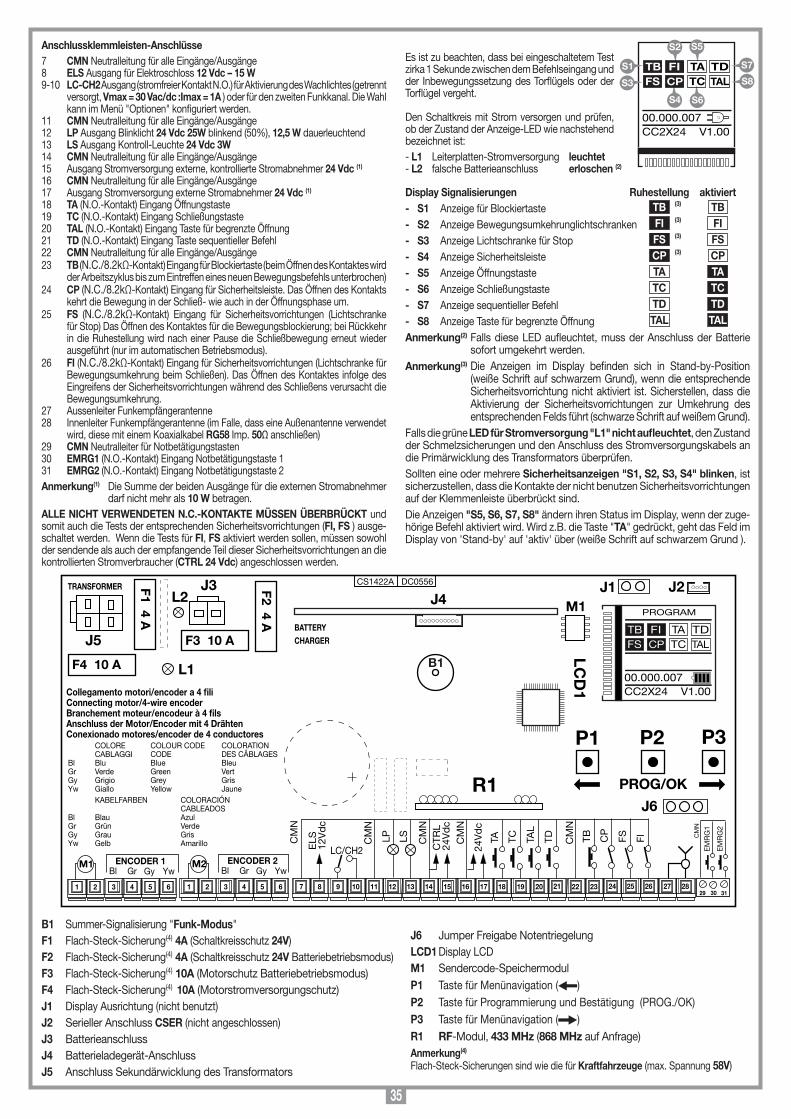
35
Anschlussklemmleisten-Anschlüsse7 CMN Neutralleitung für alle Eingänge/Ausgänge8 ELS Ausgang für Elektroschloss 12 Vdc – 15 W9-10 LC-CH2 Ausgang (stromfreier Kontakt N.O.) für Aktivierung des Wachlichtes (getrennt
versorgt, Vmax = 30 Vac/dc :Imax = 1A ) oder für den zweiten Funkkanal. Die Wahl kann im Menü "Optionen" konfiguriert werden.
11 CMN Neutralleitung für alle Eingänge/Ausgänge12 LP Ausgang Blinklicht 24 Vdc 25W blinkend (50%), 12,5 W dauerleuchtend13 LS Ausgang Kontroll-Leuchte 24 Vdc 3W14 CMN Neutralleitung für alle Eingänge/Ausgänge15 Ausgang Stromversorgung externe, kontrollierte Stromabnehmer 24 Vdc (1)
16 CMN Neutralleitung für alle Eingänge/Ausgänge17 Ausgang Stromversorgung externe Stromabnehmer 24 Vdc (1) 18 TA (N.O.-Kontakt) Eingang Öffnungstaste19 TC (N.O.-Kontakt) Eingang Schließungstaste20 TAL (N.O.-Kontakt) Eingang Taste für begrenzte Öffnung21 TD (N.O.-Kontakt) Eingang Taste sequentieller Befehl22 CMN Neutralleitung für alle Eingänge/Ausgänge23 TB (N.C./8.2kΩ-Kontakt) Eingang für Blockiertaste (beim Öffnen des Kontaktes wird
der Arbeitszyklus bis zum Eintreffen eines neuen Bewegungsbefehls unterbrochen)24 CP (N.C./8.2kΩ-Kontakt) Eingang für Sicherheitsleiste. Das Öffnen des Kontakts
kehrt die Bewegung in der Schließ- wie auch in der Öffnungsphase um.25 FS (N.C./8.2kΩ-Kontakt) Eingang für Sicherheitsvorrichtungen (Lichtschranke
für Stop) Das Öffnen des Kontaktes für die Bewegungsblockierung; bei Rückkehr in die Ruhestellung wird nach einer Pause die Schließbewegung erneut wieder ausgeführt (nur im automatischen Betriebsmodus).
26 FI (N.C./8.2kΩ-Kontakt) Eingang für Sicherheitsvorrichtungen (Lichtschranke für Bewegungsumkehrung beim Schließen). Das Öffnen des Kontaktes infolge des Eingreifens der Sicherheitsvorrichtungen während des Schließens verursacht die Bewegungsumkehrung.
27 Aussenleiter Funkempfängerantenne28 Innenleiter Funkempfängerantenne (im Falle, dass eine Außenantenne verwendet
wird, diese mit einem Koaxialkabel RG58 Imp. 50Ω anschließen)29 CMN Neutralleiter für Notbetätigungstasten30 EMRG1 (N.O.-Kontakt) Eingang Notbetätigungstaste 131 EMRG2 (N.O.-Kontakt) Eingang Notbetätigungstaste 2Anmerkung(1) Die Summe der beiden Ausgänge für die externen Stromabnehmer
darf nicht mehr als 10 W betragen.ALLE NICHT VERWENDETEN N.C.-KONTAKTE MÜSSEN ÜBERBRÜCKT und somit auch die Tests der entsprechenden Sicherheitsvorrichtungen (FI, FS ) ausge-schaltet werden. Wenn die Tests für FI, FS aktiviert werden sollen, müssen sowohl der sendende als auch der empfangende Teil dieser Sicherheitsvorrichtungen an die kontrollierten Stromverbraucher (CTRL 24 Vdc) angeschlossen werden.
Es ist zu beachten, dass bei eingeschaltetem Test zirka 1 Sekunde zwischen dem Befehlseingang und der Inbewegungssetzung des Torflügels oder der Torflügel vergeht.
Den Schaltkreis mit Strom versorgen und prüfen, ob der Zustand der Anzeige-LED wie nachstehend bezeichnet ist:- L1 Leiterplatten-Stromversorgung leuchtet- L2 falsche Batterieanschluss erloschen (2)
Display Signalisierungen Ruhestellung aktiviert- S1 Anzeige für Blockiertaste TB (3) TB - S2 Anzeige Bewegungsumkehrunglichtschranken FI (3) FI
- S3 Anzeige Lichtschranke für Stop FS (3) FS
- S4 Anzeige Sicherheitsleiste CP (3) CP - S5 Anzeige Öffnungstaste TA TA
- S6 Anzeige Schließungstaste TC TC
- S7 Anzeige sequentieller Befehl TD TD
- S8 Anzeige Taste für begrenzte Öffnung TAL TAL
Anmerkung(2) Falls diese LED aufleuchtet, muss der Anschluss der Batterie sofort umgekehrt werden.
Anmerkung(3) Die Anzeigen im Display befinden sich in Stand-by-Position (weiße Schrift auf schwarzem Grund), wenn die entsprechende Sicherheitsvorrichtung nicht aktiviert ist. Sicherstellen, dass die Aktivierung der Sicherheitsvorrichtungen zur Umkehrung des entsprechenden Felds führt (schwarze Schrift auf weißem Grund).
Falls die grüne LED für Stromversorgung "L1" nicht aufleuchtet, den Zustand der Schmelzsicherungen und den Anschluss des Stromversorgungskabels an die Primärwicklung des Transformators überprüfen.Sollten eine oder mehrere Sicherheitsanzeigen "S1, S2, S3, S4" blinken, ist sicherzustellen, dass die Kontakte der nicht benutzen Sicherheitsvorrichtungen auf der Klemmenleiste überbrückt sind.Die Anzeigen "S5, S6, S7, S8" ändern ihren Status im Display, wenn der zuge-hörige Befehl aktiviert wird. Wird z.B. die Taste "TA" gedrückt, geht das Feld im Display von 'Stand-by' auf 'aktiv' über (weiße Schrift auf schwarzem Grund ).
Collegamenti scheda base
CC2X24
05-09-2015
DC0556 Description :
Product Code :
Date :
Drawing number :
P.J.Heath
CARDIN ELETTRONICA S.p.A - 31020 San Vendemiano (TV) Italy - via Raffaello, 36 Tel: 0438/401818 Fax: 0438/401831
Draft :
All rights reserved. Unauthorised copying or use of the information contained in this document is punishable by law
CC2X24 SCHEDA BASE V1.00(con display LCD + MULTI-DECODIFICA)
CS1422A DC0556
M1
B1
F2 4 A
TRANSFORMER
L1
29 30 31
F1 4 A
LCD
1
P1 P2 P3
PROG/OK
J5
9 10 11 12 13 14 15 16 17 18 19 20 21 22 23 24 25 26
COLORE COLOUR CODE COLORATION CABLAGGI CODE DES CÂBLAGES Bl Blu Blue Bleu Gr Verde Green Vert Gy Grigio Grey Gris Yw Giallo Yellow Jaune KABELFARBEN COLORACIÓN CABLEADOSBl Blau AzulGr Grün VerdeGy Grau GrisYw Gelb Amarillo
Collegamento motori/encoder a 4 fili Connecting motor/4-wire encoderBranchement moteur/encodeur à 4 filsAnschluss der Motor/Encoder mit 4 DrähtenConexionado motores/encoder de 4 conductores
7 83 4 5 61 2 3 4 5 61 2
YwGyGrBlENCODER 1
YwGyGrBlENCODER 2M1 M2
27 28
TDTA TC
24V
dc
TAL
CM
N
FITB CP
FS
EM
RG
1
EM
RG
2
CM
N
CM
N
CTR
L24
Vd
c
CM
N
LSLPCM
N
LC/CH2ELS
12V
dc
CM
N
F4 10 A
J3
F3 10 ABATTERYCHARGER
J1
R1J6
J2J4L2
PROGRAM
TB FIFS CP
TA TDTC TAL
00.000.007CC2X24 V1.00
B1 Summer-Signalisierung "Funk-Modus"F1 Flach-Steck-Sicherung(4) 4A (Schaltkreisschutz 24V) F2 Flach-Steck-Sicherung(4) 4A (Schaltkreisschutz 24V Batteriebetriebsmodus)F3 Flach-Steck-Sicherung(4) 10A (Motorschutz Batteriebetriebsmodus) F4 Flach-Steck-Sicherung(4) 10A (Motorstromversorgungschutz) J1 Display Ausrichtung (nicht benutzt)J2 Serieller Anschluss CSER (nicht angeschlossen)J3 BatterieanschlussJ4 Batterieladegerät-AnschlussJ5 Anschluss Sekundärwicklung des Transformators
J6 Jumper Freigabe NotentriegelungLCD1 Display LCDM1 Sendercode-SpeichermodulP1 Taste für Menünavigation ( )P2 Taste für Programmierung und Bestätigung (PROG./OK) P3 Taste für Menünavigation ( )R1 RF-Modul, 433 MHz (868 MHz auf Anfrage)Anmerkung(4) Flach-Steck-Sicherungen sind wie die für Kraftfahrzeuge (max. Spannung 58V)
S5
S6
TB FIFS CP
TA TDTC TAL
00.000.007CC2X24 V1.00
S1
S3
S7
S8
S2
S4
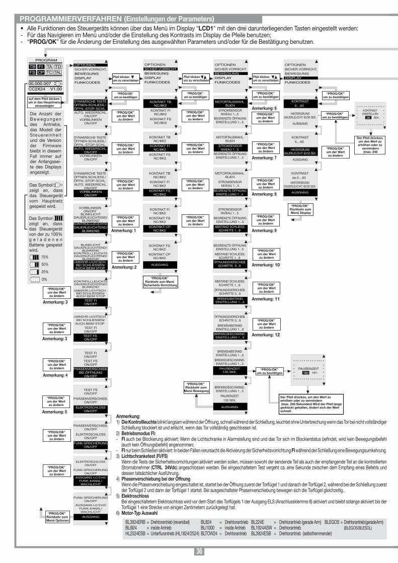
36
• Alle Funktionen des Steuergeräts können über das Menü im Display "LCD1" mit den drei darunterliegenden Tasten eingestellt werden:- Für das Navigieren im Menü und/oder die Einstellung des Kontrasts im Display die Pfeile benutzen;- “PROG/OK” für die Änderung der Einstellung des ausgewählten Parameters und/oder für die Bestätigung benutzen.
PROGRAMMIERVERFAHREN (Einstellungen der Parameters)
Anmerkung:1) Die Kontrollleuchte blinkt langsam während der Öffnung, schnell während der Schließung, leuchtet ohne Unterbrechung wenn das Tor bei nicht vollständiger
Schließung blockiert ist und erlischt, wenn das Tor vollständig geschlossen ist.2) Betriebsmodus FI:- FI auch bei Blockierung aktiviert: Wenn die Lichtschranke in Alarmstellung sind und das Tor sich im Blockierstatus befindet, wird kein Bewegungsbefehl
(auch kein Öffnungsbefehl) angenommen;- FI nur beim Schließen aktiviert: In beiden Fällen verursacht die Aktivierung der Sicherheitsvorrichtung FI während der Schließung eine Bewegungsumkehrung.3) Lichtschranketest (FI/FS) Wenn die Tests der Sicherheitsvorrichtungen aktiviert werden sollen, müssen sowohl der sendende Teil als auch der empfangende Teil an die kontrollierten
Stromabnehmer (CTRL 24Vdc) angeschlossen werden. Bei eingeschaltetem Test vergeht ca. eine Sekunde zwischen dem Empfang eines Befehls und dessen tatsächlicher Ausführung.
4) Phasenverschiebung bei der Öffnung Wenn die Phasenverschiebung eingeschaltet ist, startet bei der Öffnung zuerst der Torflügel 1 und danach der Torflügel 2, während bei der Schließung zuerst
der Torflügel 2 und dann der Torflügel 1 startet. Bei ausgeschalteter Phasenverschiebung bewegen sich die Torflügel gleichzeitig..5) Elektroschloss Bei eingeschaltetem Elektroschloss wird vor dem Start des Torflügels 1 der Ausgang ELS (Anschlussklemme 8) aktiviert und bleibt solange aktiviert bis der
Torflügel 1 eine Strecke von einigen Zentimetern zurückgelegt hat.6) Motor-Typ Auswahl“PROG/OK”
Rückkehr zum Menü Optionen
OPTIONENSICHER.VORRICHT.BEWEGUNGDISPLAYFUNKCODES
PROGRAM
TB FIFS CP
TA TDTC TAL
00.000.007CC2X24 V1.00
OPTIONENSICHER.VORRICHT.BEWEGUNGDISPLAYFUNKCODES
Pfeil klicken um zu verschieben
DYNAMISCHE TASTEÖFFNEN-SCHLIESS./ÖFFN.-STOP-SCHL.AUTO. WIEDERSCHL.
ON/OFFVORBLINKEN
ON/OFF
OPTIONENSICHER.VORRICHT.BEWEGUNGDISPLAYFUNKCODES
Pfeil klicken um zu verschieben
OPTIONENSICHER.VORRICHT.BEWEGUNGDISPLAYFUNKCODES
DYNAMISCHE TASTEÖFFNEN-SCHLIESS./ÖFFN.-STOP-SCHL.AUTO. WIEDERSCHL.
ON/OFFVORBLINKEN
ON/OFF
DYNAMISCHE TASTEÖFFNEN-SCHLIESS./ÖFFN.-STOP-SCHL.AUTO. WIEDERSCHL.
ON/OFFVORBLINKEN
ON/OFF
VORBLINKENON/OFF
BLINKLICHTDAUERLEUCHTEND/
BLINKENDKONTROLLLEUCHTE DAUERLEUCHTEND/
BLINKEND
BLINKLICHTDAUERLEUCHTEND/
BLINKENDKONTROLLLEUCHTEDAUERLEUCHTEND/
BLINKENDUMKEHR-LICHTSCH.
BEI SCHLIESSEN/AUCH BEIM STOP
KONTROLLLEUCHTEDAUERLEUCHTEND/
BLINKENDUMKEHR-LICHTSCH.
BEI SCHLIESSEN/AUCH BEIM STOP
TEST FION/OFF
UMKEHR-LICHTSCH. BEI SCHLIESSEN/
AUCH BEIM STOP
TEST FION/OFFTEST FS ON/OFF
TEST FSON/OFF
PHASENVERSCHIEB.ON/OFF
ELEKTROSCHLOSSON/OFF
TEST FION/OFFTEST FSON/OFF
PHASENVERSCHIEB.BEI ÖFFNUNG
ON/OFF
PHASENVERSCHIEB.ON/OFF
ELEKTROSCHLOSSON/OFF
FUNK-SPEICHERUNGON/OFF
ELEKTROSCHLOSSON/OFF
FUNK-SPEICHERUNGON/OFF
AUSGANG LC/CH2FUNK-KANAL/WACHLICHT
“PROG/OK” um zu bestätigen
“PROG/OK” um der Wertzu ändern
“PROG/OK” um der Wertzu ändern
“PROG/OK” um der Wertzu ändern
“PROG/OK” um der Wertzu ändern
“PROG/OK” um der Wertzu ändern
“PROG/OK” um der Wertzu ändern
“PROG/OK” um der Wertzu ändern
“PROG/OK” um der Wertzu ändern
“PROG/OK” um der Wertzu ändern
“PROG/OK” um der Wertzu ändern
FUNK-SPEICHERUNGON/OFF
AUSGANG LC/CH2FUNK-KANAL/WACHLICHT
AUSGANG
“PROG/OK” um der Wertzu ändern
KONTAKT TBNC/8K2
KONTAKT FINC/8K2
KONTAKT FSNC/8K2
KONTAKT TBNC/8K2
KONTAKT FINC/8K2
KONTAKT FSNC/8K2
“PROG/OK” um zu bestätigen
“PROG/OK” um der Wertzu ändern
“PROG/OK” um der Wertzu ändern
KONTAKT TBNC/8K2
KONTAKT FINC/8K2
KONTAKT FSNC/8K2
“PROG/OK” um der Wertzu ändern
KONTAKT FINC/8K2
KONTAKT FSNC/8K2
KONTAKT CPNC/8K2
“PROG/OK” um der Wertzu ändern
KONTAKT FSNC/8K2
KONTAKT CPNC/8K2
AUSGANG
“PROG/OK” Rückkehr zum Menü
Sicherheits-Vorrichtung
MOTORTAUSWAHL BL824
STROMSENSORNIVEAU 1...5
BEGRENZTE ÖFFNUNGEINSTELLUNG 1...5
MOTORTAUSWAHL BL824
STROMSENSORNIVEAU 1...5
BEGRENZTE ÖFFNUNGEINSTELLUNG 1...4
“PROG/OK” um zu bestätigen
“PROG/OK” um der Wertzu ändern
MOTORTAUSWAHL BL824
STROMSENSORNIVEAU 1...5
BEGRENZTE ÖFFNUNGEINSTELLUNG 1...4
“PROG/OK” um der Wertzu ändern
STROMSENSORNIVEAU 1...5
BEGRENZTE ÖFFNUNGEINSTELLUNG 1...5
ABSTAND SCHLIESS.SCHRITTE 1...9
“PROG/OK” um der Wertzu ändern
“PROG/OK” um der Wertzu ändern
KONTRAST0....63
HINTERGRUNDDAUERLEUCHT/ 60/30 SEK.
AUSGANG
“PROG/OK” um zu bestätigen
KONTRAST0....63
HINTERGRUNDDAUERLEUCHT/ 60/30 SEK.
AUSGANG
“PROG/OK” um der Wertzu ändern
KONTRASTda 0....63
HINTERGRUNDDAUERLEUCHT/ 60/30 SEK.
AUSGANG
“PROG/OK” Rückkehr zum Menü Display
Die Anzahl der B e w e g u n g e n des Antriebs, das Modell der Steuere inhe i t und die Version der Firmware bleibt in diesem Fall immer auf der Anfangssei-te des Displays angezeigt.
Das Symbolzeigt an, dass das Steuergerät vom Hauptnetz gespeist wird.
Das Symbolzeigt an, dass das Steuergerät von der zu 100% g e l a d e n e n Batterie gespeist wird.
75%
50%
25%
0%
Anmerkung: 1
“PROG/OK” Rückkehr zum
Menü Bewegung
Pfeil klicken um zu verschieben
Anmerkung: 2
Anmerkung: 3
Anmerkung: 3
Anmerkung: 4
Anmerkung: 5
Anmerkung: 6
Anmerkung: 7
Anmerkung: 8
Anmerkung: 9
ITALIANO
FRANÇAIS
ENGLISH
NEDERLANDS
DEUTSCH
ESPAÑOL
PROGRAM
TB FIFS CP
TA TDTC TAL
00.000.007CC2X24 V1.00
Beide Pfeile gleichzeitigdrücken um in das
Untermenü zu gelangen
“PROG/OK” um zu bestätigen
“PROG/OK” um zu bestätigen
Der Pfeil drücken, um den Wert zu erhöhen oder zu
vermindern (max. 240
* * * * * * * * * * * * * * ** KONTRAST ** EINSTELLEN ** SEK. *
* ** * * * * * * * * * * * * * *
26
auf dem Pfeil klicken um in das Hauptmenu
einzusteigen
Blinkend auf dem Display. Zur Programmierung des Systems sich in den Programmiermodus begeben.
Bei Normalbetrieb wird stattdessen angezeigt, dass die automatische Rückstellung ausgeführt wird. In diesem Fall gibt jeder eintreffende Befehl (TA, TC, TAL oder TD) zur sofortigen Ausführung dieses Vorganges Anlass.
Dieser Zustand tritt ein, wenn ein Ausschaltgliedkontakt (FI, FS, CP) während der Encoderprogrammierung oder automatische Rückstellung aktiviert wird. Nachdem der passive Zustand der Sicherheitsvorrichtungen wiederhergestellt ist, nimmt der Torügel seine Bewegung automatisch wieder auf. Dies geschieht auch, wenn die Netzstromversorgung während der Programmierung ausfällt.Der Zustand der Sicherheitsvorrichtungen muss kontrolliert werden, wobei zu überprüfen ist, ob diese in den Alarmzustand treten (diesbezügliche LED erloschen), wenn ein Hindernis sich in deren Aktionsradius bendet. Wenn eine Anomalie gefunden wird, ist die fehlerhafte Sicherheitsvorrichtung auszuwechseln oder der entsprechende Eingang zu überbrücken und der Test dieser Sicherheitsvorrichtung abzuschalten (Menu Optionen).Dieses Problem tritt auf, wenn die Steuerung dem Motor 1-2 einen Befehl erteilt, dieser aber nicht anläuft. Es brauchen nur die Stromanschlüsse des Motors 1-2 und die Schmelzsicherungen "F3" und "F4" überprüft werden. Danach noch mal einen Öffnungs- oder Schließungsbefehl geben. Wenn der Motor auch jetzt nicht anläuft, könnte das Problem bei der Mechanik des Motors oder bei der Steuereinheit liegen.
Fehler bei Encoder Motor 1-2. Wenn dies bei der normalen Verwendung des Motors 1 auftritt, bedeutet dies, dass ein Problem mit der Encoder-Signalen besteht. Die Anschlüsse überprüfen und die automatische Rückstellung ausführen.
Die Laufrichtung des Torügels 1-2 ist anders als wie vom Encoder festgelegt. (z.B.: Das Drehtor schließt während die Steuerung die Öffnung ausführt). Den Anschluss der Motoren-Stromversorgung überprüfen.
Fehlermeldung des Stromsensors Motor 1-2. Bei stillstehendem Motor zeigt dieses Symbol an, dass ein Problem mit dem Motor stromsensor 1-2 besteht.
Das Öffnen des Kontakts kehrt die Bewegung in der Schließ- wie auch in der Öffnungsphase um
Wenn der Fühler in der Öffnungsphase anspricht, kehrt der Torügel sofort die Bewegung um und öffnet sich vollständig. Wenn der Fühler während der Öffnungsphase anspricht, kehrt der Torügel sofort die Bewegung für einige Zentimeter um und stoppt dann, um das Hindernis freizugeben.
Alarmsignalisierungen
TB FIFS CP
TA TDTC TAL
PROGRAM
TB FIFS CP
TA TDTC TAL
FALSCH POS.
TB FIFS CP
TA TDTC TAL
SICHER. FEHLE
TB FIFS CP
TA TDTC TAL
STOP PROG
AUTO PROG
TB FIFS CP
TA TDTC TAL
FEHLE MOT1/2
TB FIFS CP
TA TDTC TAL
FEHLE ENC1/2
TB FIFS CP
TA TDTC TAL
FEHLE DIR1/2
TB FIFS CP
TA TDTC TAL
FEHLE FÜHLE 1/2
Programmierung der Pausenzeit oder Pause für die automatische Wieder-Schliessung (nur wenn befähigt)
Automatische programmierung im Gange
Öffnungsphase
Stop während der Öffnungsphase
Schliessungsphase
Stop während der Schliessungsphase
Betriebssignalisierungen
TB FIFS CP
TA TDTC TAL
PAUSE
TB FIFS CP
TA TDTC TAL
AUTO PROG
TB FIFS CP
TA TDTC TAL
ÖFFNUNG
TB FIFS CP
TA TDTC TAL
STOP ÖFFNUNG
TB FIFS CP
TA TDTC TAL
SCHLIESSUNG
TB FIFS CP
TA TDTC TAL
STOP SCHLIESSUNG
TB FIFS CP
TA TDTC TAL
AKTIVIERTE LEISTE
TB FIFS CP
TA TDTC TAL
AKTIVIERTE FÜHLER
Auswahl der Sprache:• Für den Zugriff auf das Untermenü die Tasten rechts und links gleichzeitig drücken.• Die Taste rechts oder links drücken, um die Sprache zu wechseln: Italienisch - Deutsch.• Zur Bestätigung der Sprache die Taste "PROG/OK" drücken.
BEGRENZTE ÖFFNUNGEINSTELLUNG 1...5
ABSTAND SCHLIESS.SCHRITTE 1...9
ÖFFNUNGSVERSCHIEB.SCHRITTE 0...9
ABSTAND SCHLIESS.SCHRITTE 1...9
ÖFFNUNGSVERSCHIEB.SCHRITTE 0...9
BREMSABSTANDEINSTELLUNG 1...3
BREMSABSTANDEINSTELLUNG 1...3
BREMSGESCHWIND.EINSTELLUNG 1...3
PAUSENZEIT130 SEK.
BREMSGESCHWIND.EINSTELLUNG 1...3
PAUSENZEIT130 SEK.
AUSGANG
“PROG/OK” um zu bestätigen
Der Pfeil drücken, um den Wert zu erhöhen oder zu vermindern (max. 240 Sekunden) Wird der Pfeil lange gedrückt gehalten, ändert sich der Wert schnell.
* * * * * * * * * * * * * * ** ** PAUSENZEIT ** SEK. ** ** * * * * * * * * * * * * * *
180
ÖFFNUNGSVERSCHIEB.SCHRITTE 0...9
BREMSABSTANDEINSTELLUNG 1...3
BREMSGESCHWIND.EINSTELLUNG 1...3
“PROG/OK” um der Wertzu ändern
Anmerkung: 10
“PROG/OK” um der Wertzu ändern
Anmerkung: 11
“PROG/OK” um der Wertzu ändern
Anmerkung: 12
“PROG/OK” um zu bestätigen
Die zu speichernde
Kanaltaste auf dem Sender
drücken.
Die zu speichernde
Kanaltaste auf dem Sender
drücken.
“PROG/OK” um zu bestätigen
Pfeil für den Durchlauf
KODIERUNG: S4XX
SPEICHERUNG
LÖSCHUNG
TOTALLÖSCHUNG
KANAL-FUNKTIONEN
AUSGANG
“PROG/OK” um zu bestätigen
OPTIONENSICHER.VORRICHT.BEWEGUNGDISPLAYKALENDERFUNKCODES
SPEICHERUNG[Nr....]
* * * * * * * * * * * * * * ** ** AKTIVIERUNG 1 ** ** * * * * * * * * * * * * * *
SPEICHERUNG[Nr....]
* * * * * * * * * * * * * * ** ** AKTIVIERUNG 2 ** ** * * * * * * * * * * * * * *
SPEICHERUNG[Nr....]
* * * * * * * * * * * * * * ** ** CODE ** GESPEICHERT ** * * * * * * * * * * * * * *
“PROG/OK” um zu bestätigen
LÖSCHUNG[Nr....]
* * * * * * * * * * * * * * ** ** AKTIVIERUNG 1 ** ** * * * * * * * * * * * * * *
Die zu löschende
Kanaltaste auf dem Sender
drücken.
LÖSCHUNG[Nr....]
* * * * * * * * * * * * * * ** ** AKTIVIERUNG 2 ** ** * * * * * * * * * * * * * *
Die zu löschende
Kanaltaste auf dem Sender
drücken.
LÖSCHUNG[Nr....]
* * * * * * * * * * * * * * ** ** CODE ** GELÖSCHT ** * * * * * * * * * * * * * *
KODIERUNG: S4XX
SPEICHERUNG
LÖSCHUNG
TOTALLÖSCHUNG
KANAL-FUNKTIONEN
AUSGANG
“PROG/OK” um zu bestätigen
* * * * * * * * * * * * * * ** SPEICHER ** LÖSCHEN ? ** * * * * * * * * * * * * * *
OK drücken, um den Speicher
zu löschen oder Exit klicken
KODIERUNG: S4XX
SPEICHERUNG
LÖSCHUNG
TOTALLÖSCHUNG
KANAL-FUNKTIONEN
AUSGANG
Pfeil um zur Startseitezurückzukehren
EXIT
OK
* * * * * * * * * * * * * * ** LÖSCHUNG ** LÄUFT ** * * * * * * * * * * * * * *
KODIERUNG: S4XX
SPEICHERUNG
LÖSCHUNG
TOTALLÖSCHUNG
KANAL-FUNKTIONEN
AUSGANG
KANAL AKanal-Funktion A
KANAL BKanal-Funktion B
KANAL CKanal-Funktion C
KANAL DKanal-Funktion D
AUSGANG
KODIERUNG: S4XX
SPEICHERUNG
LÖSCHUNG
TOTALLÖSCHUNG
KANAL-FUNKTIONEN
AUSGANG
“PROG/OK” um den Wert
zu ändern
KODIERUNG: S4XX
SPEICHERUNG
LÖSCHUNG
TOTALLÖSCHUNG
KANAL-FUNKTIONEN
AUSGANG
“PROG/OK” um den Wert
zwischen S4XX und S500
zu ändern
“PROG/OK” Rückkehr zum Menü Funkcodes
[AB--] [AB--] [AB--]
[AB--] [AB--] [AB--]
Anmerkung: 14
Anmerkung: 13
BL3924ERB = Drehtorantrieb (reversibel)BLi924 = inside Antrieb HL2524ESB = Unterflurantrieb (HL1824/2524)
BL824 = Drehtorantrieb BLi1000 = inside AntriebBLTOW24 = Drehtorantrieb
BL224E = Drehtorantrieb (gerade Arm)BL1924ASW = DrehtorantriebBL3924ESB = Drehtorantrieb (selbsthemmender)
BLEGOS = Drehtorantrieb (gerade Arm) (BLEGOS/BLESOL)
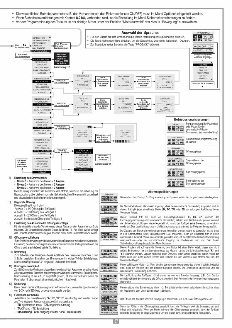
37
“PROG/OK” Rückkehr zum
Menü Optionen
OPTIONENSICHER.VORRICHT.BEWEGUNGDISPLAYFUNKCODES
PROGRAM
TB FIFS CP
TA TDTC TAL
00.000.007CC2X24 V1.00
OPTIONENSICHER.VORRICHT.BEWEGUNGDISPLAYFUNKCODES
Pfeil klicken um zu verschieben
DYNAMISCHE TASTEÖFFNEN-SCHLIESS./ÖFFN.-STOP-SCHL.AUTO. WIEDERSCHL.
ON/OFFVORBLINKEN
ON/OFF
OPTIONENSICHER.VORRICHT.BEWEGUNGDISPLAYFUNKCODES
Pfeil klicken um zu verschieben
OPTIONENSICHER.VORRICHT.BEWEGUNGDISPLAYFUNKCODES
DYNAMISCHE TASTEÖFFNEN-SCHLIESS./ÖFFN.-STOP-SCHL.AUTO. WIEDERSCHL.
ON/OFFVORBLINKEN
ON/OFF
DYNAMISCHE TASTEÖFFNEN-SCHLIESS./ÖFFN.-STOP-SCHL.AUTO. WIEDERSCHL.
ON/OFFVORBLINKEN
ON/OFF
VORBLINKENON/OFF
BLINKLICHTDAUERLEUCHTEND/
BLINKENDKONTROLLLEUCHTE DAUERLEUCHTEND/
BLINKEND
BLINKLICHTDAUERLEUCHTEND/
BLINKENDKONTROLLLEUCHTEDAUERLEUCHTEND/
BLINKENDUMKEHR-LICHTSCH.
BEI SCHLIESSEN/AUCH BEIM STOP
KONTROLLLEUCHTEDAUERLEUCHTEND/
BLINKENDUMKEHR-LICHTSCH.
BEI SCHLIESSEN/AUCH BEIM STOP
TEST FION/OFF
UMKEHR-LICHTSCH. BEI SCHLIESSEN/
AUCH BEIM STOP
TEST FION/OFFTEST FS ON/OFF
TEST FSON/OFF
PHASENVERSCHIEB.ON/OFF
ELEKTROSCHLOSSON/OFF
TEST FION/OFFTEST FSON/OFF
PHASENVERSCHIEB.BEI ÖFFNUNG
ON/OFF
PHASENVERSCHIEB.ON/OFF
ELEKTROSCHLOSSON/OFF
FUNK-SPEICHERUNGON/OFF
ELEKTROSCHLOSSON/OFF
FUNK-SPEICHERUNGON/OFF
AUSGANG LC/CH2FUNK-KANAL/WACHLICHT
“PROG/OK” um zu bestätigen
“PROG/OK” um der Wertzu ändern
“PROG/OK” um der Wertzu ändern
“PROG/OK” um der Wertzu ändern
“PROG/OK” um der Wertzu ändern
“PROG/OK” um der Wertzu ändern
“PROG/OK” um der Wertzu ändern
“PROG/OK” um der Wertzu ändern
“PROG/OK” um der Wertzu ändern
“PROG/OK” um der Wertzu ändern
“PROG/OK” um der Wertzu ändern
FUNK-SPEICHERUNGON/OFF
AUSGANG LC/CH2FUNK-KANAL/WACHLICHT
AUSGANG
“PROG/OK” um der Wertzu ändern
KONTAKT TBNC/8K2
KONTAKT FINC/8K2
KONTAKT FSNC/8K2
KONTAKT TBNC/8K2
KONTAKT FINC/8K2
KONTAKT FSNC/8K2
“PROG/OK” um zu bestätigen
“PROG/OK” um der Wertzu ändern
“PROG/OK” um der Wertzu ändern
KONTAKT TBNC/8K2
KONTAKT FINC/8K2
KONTAKT FSNC/8K2
“PROG/OK” um der Wertzu ändern
KONTAKT FINC/8K2
KONTAKT FSNC/8K2
KONTAKT CPNC/8K2
“PROG/OK” um der Wertzu ändern
KONTAKT FSNC/8K2
KONTAKT CPNC/8K2
AUSGANG
“PROG/OK” Rückkehr zum Menü
Sicherheits-Vorrichtung
MOTORTAUSWAHL BL824
STROMSENSORNIVEAU 1...5
BEGRENZTE ÖFFNUNGEINSTELLUNG 1...5
MOTORTAUSWAHL BL824
STROMSENSORNIVEAU 1...5
BEGRENZTE ÖFFNUNGEINSTELLUNG 1...4
“PROG/OK” um zu bestätigen
“PROG/OK” um der Wertzu ändern
MOTORTAUSWAHL BL824
STROMSENSORNIVEAU 1...5
BEGRENZTE ÖFFNUNGEINSTELLUNG 1...4
“PROG/OK” um der Wertzu ändern
STROMSENSORNIVEAU 1...5
BEGRENZTE ÖFFNUNGEINSTELLUNG 1...5
ABSTAND SCHLIESS.SCHRITTE 1...9
“PROG/OK” um der Wertzu ändern
“PROG/OK” um der Wertzu ändern
KONTRAST0....63
HINTERGRUNDDAUERLEUCHT/ 60/30 SEK.
AUSGANG
“PROG/OK” um zu bestätigen
KONTRAST0....63
HINTERGRUNDDAUERLEUCHT/ 60/30 SEK.
AUSGANG
“PROG/OK” um der Wertzu ändern
KONTRASTda 0....63
HINTERGRUNDDAUERLEUCHT/ 60/30 SEK.
AUSGANG
“PROG/OK” Rückkehr zum Menü Display
Die Anzahl der B e w e g u n g e n des Antriebs, das Modell der Steuere inhe i t und die Version der Firmware bleibt in diesem Fall immer auf der Anfangssei-te des Displays angezeigt.
Das Symbolzeigt an, dass das Steuergerät vom Hauptnetz gespeist wird.
Das Symbolzeigt an, dass das Steuergerät von der zu 100% g e l a d e n e n Batterie gespeist wird.
75%
50%
25%
0%
Anmerkung: 1
“PROG/OK” Rückkehr zum
Menü Bewegung
Pfeil klicken um zu verschieben
Anmerkung: 2
Anmerkung: 3
Anmerkung: 3
Anmerkung: 4
Anmerkung: 5
Anmerkung: 6
Anmerkung: 7
Anmerkung: 8
Anmerkung: 9
ITALIANO
FRANÇAIS
ENGLISH
NEDERLANDS
DEUTSCH
ESPAÑOL
PROGRAM
TB FIFS CP
TA TDTC TAL
00.000.007CC2X24 V1.00
Beide Pfeile gleichzeitigdrücken um in das
Untermenü zu gelangen
“PROG/OK” um zu bestätigen
“PROG/OK” um zu bestätigen
Der Pfeil drücken, um den Wert zu erhöhen oder zu
vermindern (max. 240
* * * * * * * * * * * * * * ** KONTRAST ** EINSTELLEN ** SEK. *
* ** * * * * * * * * * * * * * *
26
auf dem Pfeil klicken um in das Hauptmenu
einzusteigen
Blinkend auf dem Display. Zur Programmierung des Systems sich in den Programmiermodus begeben.
Bei Normalbetrieb wird stattdessen angezeigt, dass die automatische Rückstellung ausgeführt wird. In diesem Fall gibt jeder eintreffende Befehl (TA, TC, TAL oder TD) zur sofortigen Ausführung dieses Vorganges Anlass.
Dieser Zustand tritt ein, wenn ein Ausschaltgliedkontakt (FI, FS, CP) während der Encoderprogrammierung oder automatische Rückstellung aktiviert wird. Nachdem der passive Zustand der Sicherheitsvorrichtungen wiederhergestellt ist, nimmt der Torügel seine Bewegung automatisch wieder auf. Dies geschieht auch, wenn die Netzstromversorgung während der Programmierung ausfällt.Der Zustand der Sicherheitsvorrichtungen muss kontrolliert werden, wobei zu überprüfen ist, ob diese in den Alarmzustand treten (diesbezügliche LED erloschen), wenn ein Hindernis sich in deren Aktionsradius bendet. Wenn eine Anomalie gefunden wird, ist die fehlerhafte Sicherheitsvorrichtung auszuwechseln oder der entsprechende Eingang zu überbrücken und der Test dieser Sicherheitsvorrichtung abzuschalten (Menu Optionen).Dieses Problem tritt auf, wenn die Steuerung dem Motor 1-2 einen Befehl erteilt, dieser aber nicht anläuft. Es brauchen nur die Stromanschlüsse des Motors 1-2 und die Schmelzsicherungen "F3" und "F4" überprüft werden. Danach noch mal einen Öffnungs- oder Schließungsbefehl geben. Wenn der Motor auch jetzt nicht anläuft, könnte das Problem bei der Mechanik des Motors oder bei der Steuereinheit liegen.
Fehler bei Encoder Motor 1-2. Wenn dies bei der normalen Verwendung des Motors 1 auftritt, bedeutet dies, dass ein Problem mit der Encoder-Signalen besteht. Die Anschlüsse überprüfen und die automatische Rückstellung ausführen.
Die Laufrichtung des Torügels 1-2 ist anders als wie vom Encoder festgelegt. (z.B.: Das Drehtor schließt während die Steuerung die Öffnung ausführt). Den Anschluss der Motoren-Stromversorgung überprüfen.
Fehlermeldung des Stromsensors Motor 1-2. Bei stillstehendem Motor zeigt dieses Symbol an, dass ein Problem mit dem Motor stromsensor 1-2 besteht.
Das Öffnen des Kontakts kehrt die Bewegung in der Schließ- wie auch in der Öffnungsphase um
Wenn der Fühler in der Öffnungsphase anspricht, kehrt der Torügel sofort die Bewegung um und öffnet sich vollständig. Wenn der Fühler während der Öffnungsphase anspricht, kehrt der Torügel sofort die Bewegung für einige Zentimeter um und stoppt dann, um das Hindernis freizugeben.
Alarmsignalisierungen
TB FIFS CP
TA TDTC TAL
PROGRAM
TB FIFS CP
TA TDTC TAL
FALSCH POS.
TB FIFS CP
TA TDTC TAL
SICHER. FEHLE
TB FIFS CP
TA TDTC TAL
STOP PROG
AUTO PROG
TB FIFS CP
TA TDTC TAL
FEHLE MOT1/2
TB FIFS CP
TA TDTC TAL
FEHLE ENC1/2
TB FIFS CP
TA TDTC TAL
FEHLE DIR1/2
TB FIFS CP
TA TDTC TAL
FEHLE FÜHLE 1/2
Programmierung der Pausenzeit oder Pause für die automatische Wieder-Schliessung (nur wenn befähigt)
Automatische programmierung im Gange
Öffnungsphase
Stop während der Öffnungsphase
Schliessungsphase
Stop während der Schliessungsphase
Betriebssignalisierungen
TB FIFS CP
TA TDTC TAL
PAUSE
TB FIFS CP
TA TDTC TAL
AUTO PROG
TB FIFS CP
TA TDTC TAL
ÖFFNUNG
TB FIFS CP
TA TDTC TAL
STOP ÖFFNUNG
TB FIFS CP
TA TDTC TAL
SCHLIESSUNG
TB FIFS CP
TA TDTC TAL
STOP SCHLIESSUNG
TB FIFS CP
TA TDTC TAL
AKTIVIERTE LEISTE
TB FIFS CP
TA TDTC TAL
AKTIVIERTE FÜHLER
Auswahl der Sprache:• Für den Zugriff auf das Untermenü die Tasten rechts und links gleichzeitig drücken.• Die Taste rechts oder links drücken, um die Sprache zu wechseln: Italienisch - Deutsch.• Zur Bestätigung der Sprache die Taste "PROG/OK" drücken.
BEGRENZTE ÖFFNUNGEINSTELLUNG 1...5
ABSTAND SCHLIESS.SCHRITTE 1...9
ÖFFNUNGSVERSCHIEB.SCHRITTE 0...9
ABSTAND SCHLIESS.SCHRITTE 1...9
ÖFFNUNGSVERSCHIEB.SCHRITTE 0...9
BREMSABSTANDEINSTELLUNG 1...3
BREMSABSTANDEINSTELLUNG 1...3
BREMSGESCHWIND.EINSTELLUNG 1...3
PAUSENZEIT130 SEK.
BREMSGESCHWIND.EINSTELLUNG 1...3
PAUSENZEIT130 SEK.
AUSGANG
“PROG/OK” um zu bestätigen
Der Pfeil drücken, um den Wert zu erhöhen oder zu vermindern (max. 240 Sekunden) Wird der Pfeil lange gedrückt gehalten, ändert sich der Wert schnell.
* * * * * * * * * * * * * * ** ** PAUSENZEIT ** SEK. ** ** * * * * * * * * * * * * * *
180
ÖFFNUNGSVERSCHIEB.SCHRITTE 0...9
BREMSABSTANDEINSTELLUNG 1...3
BREMSGESCHWIND.EINSTELLUNG 1...3
“PROG/OK” um der Wertzu ändern
Anmerkung: 10
“PROG/OK” um der Wertzu ändern
Anmerkung: 11
“PROG/OK” um der Wertzu ändern
Anmerkung: 12
“PROG/OK” um zu bestätigen
Die zu speichernde
Kanaltaste auf dem Sender
drücken.
Die zu speichernde
Kanaltaste auf dem Sender
drücken.
“PROG/OK” um zu bestätigen
Pfeil für den Durchlauf
KODIERUNG: S4XX
SPEICHERUNG
LÖSCHUNG
TOTALLÖSCHUNG
KANAL-FUNKTIONEN
AUSGANG
“PROG/OK” um zu bestätigen
OPTIONENSICHER.VORRICHT.BEWEGUNGDISPLAYKALENDERFUNKCODES
SPEICHERUNG[Nr....]
* * * * * * * * * * * * * * ** ** AKTIVIERUNG 1 ** ** * * * * * * * * * * * * * *
SPEICHERUNG[Nr....]
* * * * * * * * * * * * * * ** ** AKTIVIERUNG 2 ** ** * * * * * * * * * * * * * *
SPEICHERUNG[Nr....]
* * * * * * * * * * * * * * ** ** CODE ** GESPEICHERT ** * * * * * * * * * * * * * *
“PROG/OK” um zu bestätigen
LÖSCHUNG[Nr....]
* * * * * * * * * * * * * * ** ** AKTIVIERUNG 1 ** ** * * * * * * * * * * * * * *
Die zu löschende
Kanaltaste auf dem Sender
drücken.
LÖSCHUNG[Nr....]
* * * * * * * * * * * * * * ** ** AKTIVIERUNG 2 ** ** * * * * * * * * * * * * * *
Die zu löschende
Kanaltaste auf dem Sender
drücken.
LÖSCHUNG[Nr....]
* * * * * * * * * * * * * * ** ** CODE ** GELÖSCHT ** * * * * * * * * * * * * * *
KODIERUNG: S4XX
SPEICHERUNG
LÖSCHUNG
TOTALLÖSCHUNG
KANAL-FUNKTIONEN
AUSGANG
“PROG/OK” um zu bestätigen
* * * * * * * * * * * * * * ** SPEICHER ** LÖSCHEN ? ** * * * * * * * * * * * * * *
OK drücken, um den Speicher
zu löschen oder Exit klicken
KODIERUNG: S4XX
SPEICHERUNG
LÖSCHUNG
TOTALLÖSCHUNG
KANAL-FUNKTIONEN
AUSGANG
Pfeil um zur Startseitezurückzukehren
EXIT
OK
* * * * * * * * * * * * * * ** LÖSCHUNG ** LÄUFT ** * * * * * * * * * * * * * *
KODIERUNG: S4XX
SPEICHERUNG
LÖSCHUNG
TOTALLÖSCHUNG
KANAL-FUNKTIONEN
AUSGANG
KANAL AKanal-Funktion A
KANAL BKanal-Funktion B
KANAL CKanal-Funktion C
KANAL DKanal-Funktion D
AUSGANG
KODIERUNG: S4XX
SPEICHERUNG
LÖSCHUNG
TOTALLÖSCHUNG
KANAL-FUNKTIONEN
AUSGANG
“PROG/OK” um den Wert
zu ändern
KODIERUNG: S4XX
SPEICHERUNG
LÖSCHUNG
TOTALLÖSCHUNG
KANAL-FUNKTIONEN
AUSGANG
“PROG/OK” um den Wert
zwischen S4XX und S500
zu ändern
“PROG/OK” Rückkehr zum Menü Funkcodes
[AB--] [AB--] [AB--]
[AB--] [AB--] [AB--]
Anmerkung: 14
Anmerkung: 13
• Die wesentlichen Betriebsparameter (z.B. das Vorhandensein des Elektroschlosses ON/OFF) muss im Menü Optionen eingestellt werden.• Wenn Sicherheitsvorrichtungen mit Kontakt 8.2 kΩ, vorhanden sind, ist die Einstellung im Menü Sicherheitsvorrichtungen zu ändern.• Vor der Programmierung des Torlaufs ist der richtige Motor unter der Position "Motorauswahl" des Menüs "Bewegung" auszuwählen.
7) Einstellung des Stromsensors: - Niveau 1 = Aufnahme des Motors + 1 Ampere - Niveau 2 = Aufnahme des Motors + 2 Ampere - Niveau 3 = Aufnahme des Motors + 3 Ampere Die Steuerung kontrolliert die Aufnahme des Motors, wobei sie die Erhöhung der
Beanspruchung über die beim normalen Betrieb erlaubten Grenzwerte hinaus erfasst und als zusätzliche Sicherheitsvorrichtung eingreift.
8) Begrenzte Öffnung Die Auswahl geht von 1 bis 4: Auswahl 2 = 1/2 Öffnung des Torflügels 1 Auswahl 1 = 1/3 Öffnung des Torflügels 1 Auswahl 3 = 2/3 Öffnung des Torflügels 1 Auswahl 4 = die totale Öffnung des Torflügels 19) Einstellung des Abstands des Offnungsanschlags: Für die Vergrößerung oder Verkleinerung dieses Abstands den Parameter von 0 bis
9 ändern. Die Defaulteinstellung des Geräts ist Niveau 4. Auf diese Weise schlägt das Tor nicht am Schließanschlag an, sondern bleibt einen Zentimeter davor stehen.
10) Öffnungsverschiebung Zum Erhöhen oder Verringern dieses Abstands den Parameter zwischen 0-9 verstellen.
Einstellung des Verschiebungsraumes zwischen den beiden Torflügeln während der Öffnung und anschließend bei der Schließung.
11) Bremsweg Zum Erhöhen oder Verringern dieses Abstands den Parameter zwischen 0 und
3 Stufen verstellen. Einstellen des Bremsweges im letzten Teil der Schließphase. Standardmäßig ist es auf „0“ eingestellt und somit deaktiviert.
12) Bremsgeschwindigkeit Zum Erhöhen oder Verringern dieser Geschwindigkeit den Parameter zwischen 0 und
3 Stufen verstellen. Einstellen der Bremsgeschwindigkeit während der Schließphase. Standardmäßig ist sie auf „1“ eingestellt gesetzt, ist aber nur wirksam, wenn der Parameter 11 „Bremsweg“ einen Wert zwischen 1-3 aufweist.
13) Kodierung: Bevor die Art der Verschlüsselung verändert werden kann, muss das Speichermodul
von S4XX nach S500 und umgekehrt getauscht werden. 14) Funktionen der Kanäle Jeder Kanal der Funksteuerung "A","B","C","D" kann konfiguriert werden, wobei
aus 7 verfügbaren Funktionen ausgewählt werden kann: - TD dynamische Taste - TAL begrenzte Öffnung - TA Öffnung - TC Schließung - Blockierung - CH2 Ausgang zweiter Kanal - Kein Befehl
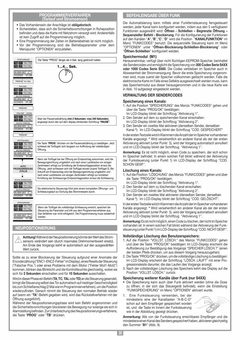
38
MEMORIZZAZIONE CODICE TX-RX
RCQ449100
13-04-2001
DM0531 Description :
Product Code :
Date :
Drawing number :
P.J.Heath
CARDIN ELETTRONICA S.p.A - 31020 San Vendemiano (TV) Italy - via Raffaello, 36 Tel: 0438/401818 Fax: 0438/401831
Draft :
All rights reserved. Unauthorised copying or use of the information contained in this document is punishable by law
MR
PROGRAMMIERVERFAHREN (Torlauf und Stromsensor)
Die Automatisierung kann mittels einer Funkfernsteuerung ferngesteuert werden; jeder Kanal kann konfiguriert werden, indem aus den 5 verfügbaren Funktionen ausgewählt wird: Öffnen - Schließen – Begrenzte Öffnung – Sequenzieller Befehl - Blockierung. Für die Konfigurierung der Funktionen auf den Kanälen "A","B","C","D" wird die Position "KANALFUNKTION" im Menü "FUNKCODES" benutzt. Die sequenzielle Steuerung kann im Menü "OPTIONEN" unter "Öffnen-Blockierung-Schließen-Blockierung" oder "Öffnen-Schließen" konfiguriert werden.
Speichermodul (M1)Herausnehmbar, verfügt über nicht flüchtigen EEPROM-Speicher, beinhaltet die Sendercodes und ermöglicht die Speicherung von 300 Codes Serie S4XX oder 1000 Codes Serie S500. Die Codes verbleiben im Speicher auch in Abwesenheit der Stromversorgung. Bevor die erste Speicherung vorgenom-men wird, muss zuerst der Speicher vollkommen gelöscht werden. Falls die elektronische Karte im Falle eines Defekts ausgewechselt werden muss, kann das Speichermodul aus dieser herausgenommen und in die neue Karte wie in Abb. 10 aufgezeigt eingesteckt werden.
VERWALTUNG DER SENDERCODES
Speicherung eines Kanals:1. Auf die Position "SPEICHERUNG" des Menüs "FUNKCODES" gehen und
über die Taste "PROG/OK“ bestätigen: Im LCD-Display blinkt der Schriftzug "Aktivierung 1". 2. Den Sender auf dem zu speichernden Kanal einschalten: Im LCD-Display blinkt der Schriftzug "Aktivierung 2". 3. Den Sender ein zweites Mal aktivieren (denselben Sender, denselben
Kanal *): Im LCD-Display blinkt der Schriftzug "COD. GESPEICHERT"In der ersten Textzeile wird in Klammern die Anzahl der im Speicher vorhandenen Kanäle angezeigt. * Wird versehentlich ein anderer Kanal als der der ersten Aktivierung aktiviert (unter Punkt 3), wird der Vorgang automatisch annulliert und im LCD-Display blinkt der Schriftzug "Aktivierung 1".Anmerkung: Es ist nicht möglich, einen Code zu speichern, der sich schon im Speicher befindet: In einem solchen Fall blinkt während der Aktivierung der Funksteuerung (unter Punkt 1) im LCD-Display der Schriftzug "COD. SCHON GESP.".
Löschung eines Kanals:1. Auf die Position "LÖSCHUNG" des Menüs "FUNKCODES" gehen und über
die Taste "PROG/OK“ bestätigen: Im LCD-Display blinkt der Schriftzug "Aktivierung 1". 2. Den Sender auf dem zu löschenden Kanal einschalten: Im LCD-Display blinkt der Schriftzug "Aktivierung 2". 3. Den Sender ein zweites Mal aktivieren (denselben Sender, denselben
Kanal *): Im LCD-Display blinkt der Schriftzug "COD. GELÖSCHT".In der ersten Textzeile wird in Klammern die Anzahl der im Speicher vorhandenen Kanäle angezeigt. * Wird versehentlich ein anderer Kanal als der der ersten Aktivierung aktiviert (unter Punkt 3), wird der Vorgang automatisch annulliert und im LCD-Display blinkt der Schriftzug "Aktivierung 1".Anmerkung: Es ist nicht möglich, einen Code zu löschen, der nicht im Speicher vorhanden ist: In einem solchen Fall blinkt während der Aktivierung der Funk-steuerung (unter Punkt 1) im LCD-Display der Schriftzug "COD. NICHT GESP.".
Vollständige Löschung des Benutzerspeichers:1. Auf die Position "VOLLST. LÖSCH." des Menüs "FUNKCODES" gehen
und über die Taste "PROG/OK" bestätigen: Im LCD-Display erscheint die Aufforderung zur Bestätigung des Vorgangs "SPEICHER LÖSCH.?" (einen der beiden Pfeile drücken, um aus diesem Vorgang herauszugehen).
2. Die Taste "PROG/OK" drücken, um die vollständige Löschung zu bestätigen: Im LCD-Display erscheint der Schriftzug "LÖSCH. LÄUFT" mit einer Pro-
gressionsleiste darunter, die das Laufen des Vorgangs anzeigt.3. Nach der vollständigen Löschung des Speichers kehrt das Display auf die
Position "VOLLST. LÖSCH." zurück.
Speicherung weiterer Kanäle über Funk (nur S4XX) • Die Speicherung kann auch über Funk aktiviert werden (ohne die Dose
zu öffnen, in der sich das Steuergerät befindet), wenn die Einstellung "FUNKSPEICHERUNG" im Menü "OPTIONEN" aktiviert wurde.
1. Eine Funksteuerung verwenden, bei der mindestens eine der Kanaltasten "A-B-C-D" schon auf dem Empfänger gespeichert worden ist, und die Taste im Innern der Funksteuerung wie in der Abbildung gezeigt drücken.
Anmerkung: Alle von der Funksteuerung erreichbaren Empfänger und die mindestens einen Kanal des Senders gespeichert haben, aktivieren gleichzeitig den Summer "B1" (Abb. 9).
• Das Vorhandensein der Anschläge ist obligatorisch. • Sicherstellen, dass sich die Sicherheitsvorrichtungen in Ruheposition
befinden und dass die Karte mit Netzstrom versorgt wird: Anderenfalls ist kein Zugriff auf die Programmierung möglich.
• Eine Programmierung der Zeiten im Batteriebetrieb ist nicht möglich. • Vor der Programmierung sind die Betriebsparameter unter dem
Menüpunkt "OPTIONEN" einzustellen.
NEUPOSITIONIERUNG
Achtung! Während der Neupositionierung könnte der Wert des Strom-sensors verändert sein (durch maxmales Drehmomentswert ersetz). Am Ende des Vorgangs kehrt er automatisch auf den ausgewählten Wert zurück.
Sollte es zu einer Blockierung der Steuerung aufgrund einer Anomalie der Encoderzählung ("ENC1-ENC2-Fehler" im Display), eines Resets der Steuerung ("Falscher Pos.") oder eines Problems mit dem Motor ("Fehler Mot1-Mot2") kommen, blinken das Blinklicht und die Kontrollleuchte gleichzeitig, wobei sie sich für 2 Sekunden einschalten und für 10 Sekunden ausschalten. Wird in dieser Phase ein Befehl (TA, TC, TAL oder TD) an die Steuerung gesendet, bringt die Steuerung selbst das Tor automatisch auf niedriger Geschwindigkeit bis zum Schließanschlag (2 Mal wie im Programmierverfahren), um die Position wiederzufinden. Danach nimmt die Steuerung den normalen Betrieb wieder auf (wenn ein "TA"-Befehl gegeben wird, wird das Rückstellverfahren mit der Öffnung ausgeführt). Während der Neupositionierungsphase wird kein Befehl angenommen und die Sicherheitsvorrichtungen blockieren die Bewegung nur solange sie sich in Alarmstellung befinden. Zur Unterbrechung des Neupositionierungsverfahrens, die Taste "PROG" oder "TB" drücken.
BEFEHLEINGABE ÜBER FUNK
1...4... Sek.
Start der Pausenzeitzählung (min 2 Sekunden; max 240 Sekunden), angezeigt durch den auf dem display blinkenden Schriftzug “PAUSE”.
Die Taste “PROG” drücken um die Pausenzeitzählung zu bestätigen. Jetzt schliesst dei Torügeln sich langsam zur Aufndung der vollständigen Öffnung.
Wenn die Torügel bei der Öffnung am Endanschlag ankommen, wird die Bewegungsrichtung umgekehrt und nach einer Laufstrecke von einigen Zentimetern erfolgt zur Ermittlung der Endanschlagsposition erneut die Öffnung. Jetzt schliessen sich die Torügel einzeln (zuerst Torügel 2). Bei Ankunft am Endanschlag wird die Bewegungsrichtung umgekehrt und nach einer Laufstrecke von einigen Zentimetern erfolgt zur korrekten Ermittlung der Schliessungs-Endanschlagposition erneut die Schliessung.
Die elektronische Steuerungs führt jetzt einem kompletten Öffnungs- und Schliessungslauf zur Eichung des Strommessers durch.
Wenn der Torügel die vollständige Schliessung erreicht, speichert die Steuerung die Parameter und tritt aus dem Programmierverfahren aus.Das Verfahren war nicht erfolgreich. Die Programmierung muss wiederholt werden
Die Taste “PROG” länger als 4 Sek. lang gedrückt halten
“PROG/OK” für 4 Sek.
AUTO PROGRAMMIERUNG
ZYKLUS
PROGRAM
TB FIFS CP
TA TDTC TAL
00.000.007CC2X24 V1.00
“PROG/OK”
PAUSE
TB FIFS CP
TA TDTC TAL
00.000.007CC2X24 V1.00
AUTO PROG.
“PROG/OK”
TB FIFS CP
TA TDTC TAL
00.000.007CC2X24 V1.00
AUTO PROG.
ÖFFNUNG
TB FIFS CP
TA TDTC TAL
00.000.007CC2X24 V1.00
AUTO PROG.
SCHLIESSUNG
TB FIFS CP
TA TDTC TAL
00.000.007CC2X24 V1.00
AUTO PROG.
PROGRAM
TB FIFS CP
TA TDTC TAL
00.000.007CC2X24 V1.00
PAUSE [030]
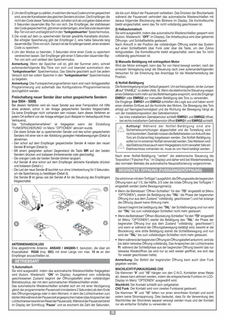
39
2. Um den Empfänger zu wählen, in welchem die neue Codenummer gespeichert wird, eine der Kanaltasten des gleichen Senders drücken. Die Empfänger, die nicht den Code dieser Taste besitzen, schalten sich ab und geben dabei einen 5 Sekunden dauernden Bip-Ton von sich. Der Empfänger, der stattdessen den Code gespeichert hat, gibt einen andersartigen, eine Sekunde dauernden Bip-Ton von sich und begibt sich in den "funkgesteuerten" Speichermodus.
3. Die vorab auf dem zu speichernden Sender gewählte Kanaltaste drücken. Bei erfolgter Speicherung gibt der Empfänger 2, eine halbe Sekunde lang dauernde Bip-Töne von sich. Danach ist der Empfänger bereit, einen anderen Code zu speichern.
4. Um den Modus zu beenden, 3 Sekunden ohne einen Code zu speichern verstreichen lassen. Der Empfänger gibt einen 5 Sekunden dauernden Bip-Ton von sich und verlässt den Speichermodus.
Anmerkung: Wenn der Speicher voll ist, gibt der Summer zehn, schnell aufeinanderfolgende Bip-Töne von sich und beendet automatisch den "funkgesteuerten" Speichermodus. Das Gleiche geschieht auch bei jedem Versuch sich bei vollem Speicher in den "funkgesteuerten" Speichermodus zu begeben.Anmerkung: Das Funkspeicherungsverfahren kann erst nach fertiggestellter Programmierung und außerhalb des Konfigurations-/Programmiermenüs durchgeführt werden.
Freischaltung neuer Sender über schon gespeicherte Sendern(nur S504 - S508)Bei diesem Verfahren wird ein neuer Sender aus einer Fernposition mit Hilfe eines anderen, schon in der Anlage gespeicherten Senders freigeschaltet. Da keine Empfänger nicht vorhanden sein müssen, kann dieses Verfahren an jedem Ort entfernt von der Anlage erfolgen (zum Beispiel im Verkaufspunkt Ihres Vertrauens). Das "Schnellspeicherverfahren" ist freigegeben wenn die Einstellung "FUNKSPEICHERUNG" im Menü "OPTIONEN" aktiviert wurde.- Die obere Schale der zu speichernden Sender und des schon gespeicherten
Senders mit einer wie in der Abbildung gezeigten Hebelbewegungen (Detail a) abnehmen.
- Den schon auf dem Empfänger gespeicherten Sender A neben den neuen Sender B bringen (Detail b).
- Mit einem geeigneten spitzen Gegenstand die Taste MR auf den beiden Sendern drücken und loslassen (hintereinander oder gleichzeitig).
- Die orangen Leds der beiden Sender blinken langsam.- Auf Sender A eine schon auf dem Empfänger aktivierte Kanaltaste drücken
und loslassen (Detail c.)- Die Led der neue Sender B leuchtet nun ohne Unterbrechung für 3 Sekunden,
um die Speicherung zu bestätigen (Detail d). Der Sender B ist genau wie der Sender A für die Steuerung des Empfängers
freigeschaltet.
ANTENNENANSCHLUSS Eine abgestimmte Antenne ANS400 / ANQ800-1, benutzen, die über ein Koaxialkabel RG58 (imp. 50Ω) mit einer Länge von max. 15 m an den Empfänger anzuschließen ist.
1) AutomatischSie wird ausgewählt, indem das automatische Wiederschließen freigegeben wird (Autom. Wiederschl. "ON" im Display). Ausgehend vom vollständig geschlossenen Zustand beginnt der Öffnungsbefehl einen vollständigen Betriebszyklus, der mit dem automatischen Wiederschließen endet. Das automatische Wiederschließen schaltet sich ein mit einer Verzögerung gleich der programmierten Pausenzeit (mindestens 2 Sekunden) ab dem Ende des Öffnungsvorgangs oder in dem Moment, in dem die Lichtschranken zum letzten Mal während der Pausenzeit angesprochen haben (das Ansprechen der Lichtschranken bewirkt ein Reset der Pausenzeit). Während der Pausenzeit blinkt im Display der Schriftzug "Pause" und es erscheint die Zahl der Sekunden,
BEGRENZTE ÖFFNUNG (FUSSGÄNGERÖFFNUNG)
BETRIEBSARTMEMORIZZAZIONE CODICE TX-TX
TRQ504
29-10-2013
DM0910 Description :
Product Code :
Date :
Drawing number :
P.J.Heath
CARDIN ELETTRONICA S.p.A - 31020 San Vendemiano (TV) Italy - via Raffaello, 36 Tel: 0438/401818 Fax: 0438/401831
Draft :
All rights reserved. Unauthorised copying or use of the information contained in this document is punishable by law
MR
A
MR
B
1
MEMORIZZAZIONE CODICE TX-TX
TXQ504C4
29-10-2013
DM0911 Description :
Product Code :
Date :
Drawing number :
P.J.Heath
CARDIN ELETTRONICA S.p.A - 31020 San Vendemiano (TV) Italy - via Raffaello, 36 Tel: 0438/401818 Fax: 0438/401831
Draft :
All rights reserved. Unauthorised copying or use of the information contained in this document is punishable by law
A
MEMORIZZAZIONE CODICE TX-TX
TXQ504C4
29-10-2013
DM0912 Description :
Product Code :
Date :
Drawing number :
P.J.Heath
CARDIN ELETTRONICA S.p.A - 31020 San Vendemiano (TV) Italy - via Raffaello, 36 Tel: 0438/401818 Fax: 0438/401831
Draft :
All rights reserved. Unauthorised copying or use of the information contained in this document is punishable by law
B
die bis zum Ablauf der Pausenzeit verbleiben. Das Drücken der Blockiertaste während der Pausenzeit verhindert das automatische Wiederschließen mit daraus folgernder Blockierung des Blinkens im Display. Die Kontrollleuchte bleibt eingeschaltet, wenn das Tor nicht vollständig geschlossen ist. 2) HalbautomatischSie wird ausgewählt, indem das automatische Wiederschließen gesperrt wird (Autom. Wiederschl. "OFF" im Display). Der Arbeitszyklus wird über getrennte Öffnungs- und Schließbefehle gesteuert. Nach Ankunft in der Position der vollständigen Öffnung wartet das System auf einen Schließbefehl über Funk oder über die Taste, um den Zyklus fertigzustellen. Die Kontrollleuchte bleibt eingeschaltet, wenn das Tor nicht vollständig geschlossen ist.
3) Manuelle Betätigung mit entriegeltem MotorWird der Motor entriegelt, kann das Tor von Hand bewegt werden; nach der erneuten Verriegelung sorgt die Steuerung nach zwei aufeinanderfolgenden Versuchen für die Erreichung des Anschlags für die Wiederherstellung der Position.
4) Notfall-BetätigungDie Notentriegelung ist per Default gesperrt. Um sie freizugeben, ist der Jumper J6 auf "ENABLE" zu stellen (Abb. 9). Wenn die elektronische Steuerung wegen eines Defektes nicht mehr auf die Befehlseingabe anspricht, sind die Eingänge EMRG1 oder EMRG2 zur manuellen Betätigung des Tors zu verwenden. Die Eingänge EMRG1 und EMRG2 schließen die Logik aus und haben somit einen direkten Einfluss auf die Kontrolle des Motors. Die Bewegung des Tors erfolgt auf Nenngeschwindigkeit und die Richtung der Bewegung hängt ab von der Installationsposition des Getriebemotors:- bei links installiertem Getriebemotor schließt EMRG1 und EMRG2 öffnet;- bei rechts installiertem Getriebemotor öffnet EMRG1 und EMRG2 schließt.
Achtung! Während der Notfal l-Betät igung sind al le Sicherheitsvorrichtungen abgeschaltet und die Torstellung wird nicht kontrolliert. Deshalb müssen die Befehlstasten vor Ankunft des Tors am Endanschlag losgelassen werden. Die Notfall-Betätigung sollte nur im extremen Notfall verwendet werden. Des Weiteren wird das Elektroschloss (auch wenn freigegeben) nicht verwaltet; falls ein Elektroschloss vorhanden ist, muss es von Hand betätigt werden.
Nach einer Notfall-Betätigung "verliert" die elektronische Steuerung die Torposition ("Falscher Pos." im Display) und daher wird bei Wiederherstellung des normalen Betriebs die automatische Neupositionierung vorgenommen.
Sie wird immer mit dem Torflügel 1 ausgeführt; die Öffnungsweite der begrenzten Öffnung kann auf 1/3, die Hälfte, 2/3 oder die totale Öffnung des Torflügels 1 eingestellt werden (siehe Bewegungsmenü).• Wenn die Betriebsart "Öffnen-Schließen" für den "TD" eingestellt ist (Menu
"OPTIONEN"), startet die Betätigung des "TAL" die Phase der begrenzten Öffnung (nur aus dem Zustand "vollständig geschlossen") und hat solange die Öffnung dauert keine Wirkung mehr.
Danach beginnt bei betätigung des "TAL" der Schließvorgang und nun wird der "TAL" bis zum vollständigen Schließen nicht mehr gesteuert.
• Wenn die Betriebsart "Öffnen-Blockierung-Schließen" für den "TD" eingestellt ist (Menu "OPTIONEN") startet die Betätigung des "TAL" die Phase der begrenzten Öffnung (nur aus dem Zustand "vollständig geschlossen") und wenn er während der Öffnungsbewegung betätigt wird, bewirkt er die Blockierung; eine dritte Betätigung startet die Schließbewegung und nun wird der "TAL" bis zum vollständigen Schließen nicht mehr gesteuert.
• Wenn während der begrenzten Öffnung ein Öffnungsbefehl ankommt, wird die bis dahin teilweise Öffnung vollständig. Das Ansprechen der Lichtschranke FI während der Schließphase aus der begrenzten Öffnung bewirkt das nur teilweise Wiederöffnen (es wird nur so weit wieder geöffnet, wie sich das Tor wieder geschlossen hatte).
Anmerkung: Der Befehl der begrenzten Öffnung kann auch über Funk gegeben werden.
WACHLICHT/FUNKAUSGANG CH2Die Klemmen “9” und ”10” hängen von den C-N.O. Kontakten eines Relais ab; dieses kann aktiviert werden, indem die entsprechende Funktion im LCD-Display im Menü "OPTIONEN" ausgewählt wird.Wachlicht: Der Kontakt schließt sich zeitgetaktet.CH2 Funk: Der Kontakt wird vom zweiten Funkkanal gesteuert.Die Klemmen “9” und ”10” liefern nur einen stromfreien Kontakt und somit extern keine Stromspannung. Dies bedeutet, dass für die Verwendung des Wachlichtes der Stromkreis separat versorgt werden muss und der Kontakt nur als einfacher Schalter zu verwenden ist.
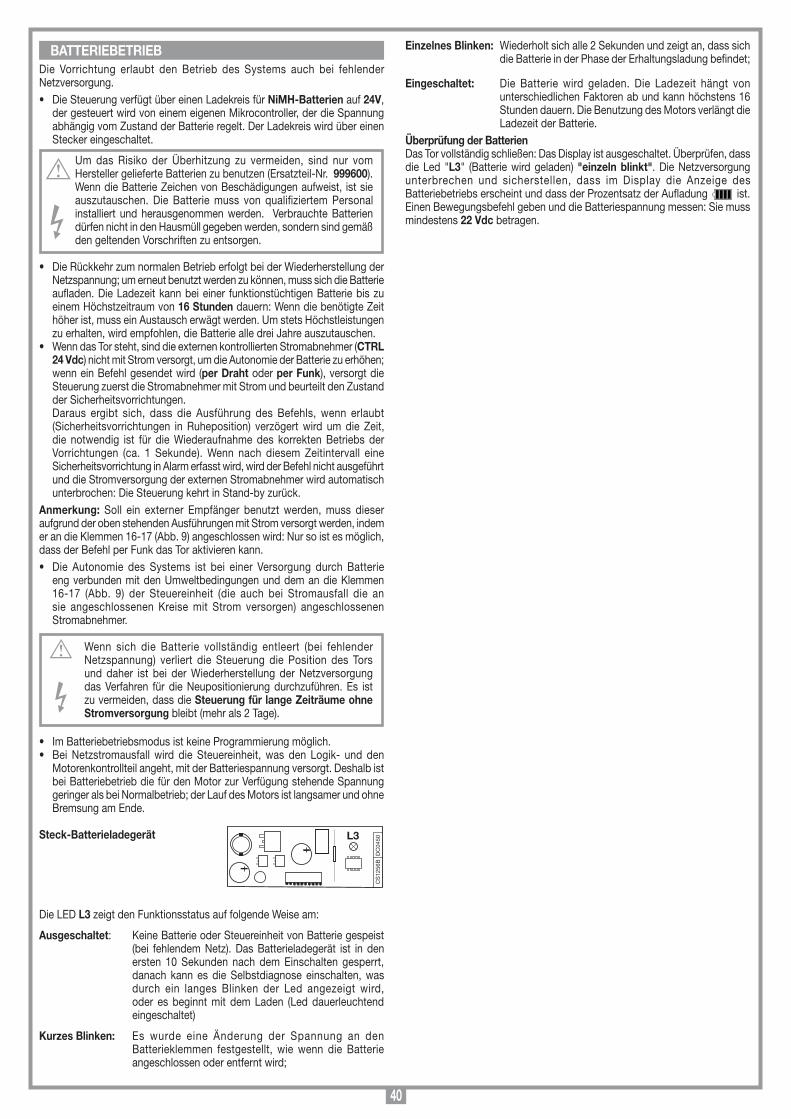
40
Die Vorrichtung erlaubt den Betrieb des Systems auch bei fehlender Netzversorgung. • Die Steuerung verfügt über einen Ladekreis für NiMH-Batterien auf 24V,
der gesteuert wird von einem eigenen Mikrocontroller, der die Spannung abhängig vom Zustand der Batterie regelt. Der Ladekreis wird über einen Stecker eingeschaltet.
Um das Risiko der Überhitzung zu vermeiden, sind nur vom Hersteller gelieferte Batterien zu benutzen (Ersatzteil-Nr. 999600). Wenn die Batterie Zeichen von Beschädigungen aufweist, ist sie auszutauschen. Die Batterie muss von qualifiziertem Personal installiert und herausgenommen werden. Verbrauchte Batterien dürfen nicht in den Hausmüll gegeben werden, sondern sind gemäß den geltenden Vorschriften zu entsorgen.
• Die Rückkehr zum normalen Betrieb erfolgt bei der Wiederherstellung der Netzspannung; um erneut benutzt werden zu können, muss sich die Batterie aufladen. Die Ladezeit kann bei einer funktionstüchtigen Batterie bis zu einem Höchstzeitraum von 16 Stunden dauern: Wenn die benötigte Zeit höher ist, muss ein Austausch erwägt werden. Um stets Höchstleistungen zu erhalten, wird empfohlen, die Batterie alle drei Jahre auszutauschen.
• Wenn das Tor steht, sind die externen kontrollierten Stromabnehmer (CTRL 24 Vdc) nicht mit Strom versorgt, um die Autonomie der Batterie zu erhöhen; wenn ein Befehl gesendet wird (per Draht oder per Funk), versorgt die Steuerung zuerst die Stromabnehmer mit Strom und beurteilt den Zustand der Sicherheitsvorrichtungen.
Daraus ergibt sich, dass die Ausführung des Befehls, wenn erlaubt (Sicherheitsvorrichtungen in Ruheposition) verzögert wird um die Zeit, die notwendig ist für die Wiederaufnahme des korrekten Betriebs der Vorrichtungen (ca. 1 Sekunde). Wenn nach diesem Zeitintervall eine Sicherheitsvorrichtung in Alarm erfasst wird, wird der Befehl nicht ausgeführt und die Stromversorgung der externen Stromabnehmer wird automatisch unterbrochen: Die Steuerung kehrt in Stand-by zurück.
Anmerkung: Soll ein externer Empfänger benutzt werden, muss dieser aufgrund der oben stehenden Ausführungen mit Strom versorgt werden, indem er an die Klemmen 16-17 (Abb. 9) angeschlossen wird: Nur so ist es möglich, dass der Befehl per Funk das Tor aktivieren kann.• Die Autonomie des Systems ist bei einer Versorgung durch Batterie
eng verbunden mit den Umweltbedingungen und dem an die Klemmen 16-17 (Abb. 9) der Steuereinheit (die auch bei Stromausfall die an sie angeschlossenen Kreise mit Strom versorgen) angeschlossenen Stromabnehmer.
Wenn sich die Batterie vollständig entleert (bei fehlender Netzspannung) verliert die Steuerung die Position des Tors und daher ist bei der Wiederherstellung der Netzversorgung das Verfahren für die Neupositionierung durchzuführen. Es ist zu vermeiden, dass die Steuerung für lange Zeiträume ohne Stromversorgung bleibt (mehr als 2 Tage).
• Im Batteriebetriebsmodus ist keine Programmierung möglich. • Bei Netzstromausfall wird die Steuereinheit, was den Logik- und den
Motorenkontrollteil angeht, mit der Batteriespannung versorgt. Deshalb ist bei Batteriebetrieb die für den Motor zur Verfügung stehende Spannung geringer als bei Normalbetrieb; der Lauf des Motors ist langsamer und ohne Bremsung am Ende.
Steck-Batterieladegerät
Die LED L3 zeigt den Funktionsstatus auf folgende Weise am:
Ausgeschaltet: Keine Batterie oder Steuereinheit von Batterie gespeist (bei fehlendem Netz). Das Batterieladegerät ist in den ersten 10 Sekunden nach dem Einschalten gesperrt, danach kann es die Selbstdiagnose einschalten, was durch ein langes Blinken der Led angezeigt wird, oder es beginnt mit dem Laden (Led dauerleuchtend eingeschaltet)
Kurzes Blinken: Es wurde eine Änderung der Spannung an den Batterieklemmen festgestellt, wie wenn die Batterie angeschlossen oder entfernt wird;
BATTERIEBETRIEB
CS
1256
BD
C04
50L3
Scheda di innesto
PRG424BC
08-01-2008
DC0435 Description :
Product Code :
Date :
Drawing number :
P.J.Heath
CARDIN ELETTRONICA S.p.A - 31020 San Vendemiano (TV) Italy - via Raffaello, 36 Tel: 0438/401818 Fax: 0438/401831
Draft :
All rights reserved. Unauthorised copying or use of the information contained in this document is punishable by law
Scheda carica batteria
Einzelnes Blinken: Wiederholt sich alle 2 Sekunden und zeigt an, dass sich die Batterie in der Phase der Erhaltungsladung befindet;
Eingeschaltet: Die Batterie wird geladen. Die Ladezeit hängt von unterschiedlichen Faktoren ab und kann höchstens 16 Stunden dauern. Die Benutzung des Motors verlängt die Ladezeit der Batterie.
Überprüfung der BatterienDas Tor vollständig schließen: Das Display ist ausgeschaltet. Überprüfen, dass die Led "L3" (Batterie wird geladen) "einzeln blinkt". Die Netzversorgung unterbrechen und sicherstellen, dass im Display die Anzeige des Batteriebetriebs erscheint und dass der Prozentsatz der Aufladung ist. Einen Bewegungsbefehl geben und die Batteriespannung messen: Sie muss mindestens 22 Vdc betragen.
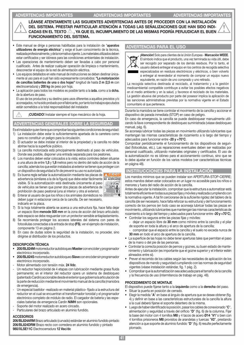
41
• Este manual se dirige a personas habilitadas para la instalación de "aparatos utilizadores de energía eléctrica" y exige el buen conocimiento de la técnica, realizada profesionalmente, y de la normativa vigente. Los materiales utilizados deben estar certificados y ser idóneos para las condiciones ambientales de instalación.
• Las operaciones de mantenimiento deben ser llevadas a cabo por personal cualificado. Antes de realizar cualquier operación de limpieza o mantenimiento, desconectar el equipo de la red de alimentación eléctrica.
• Los equipos detallados en este manual de instrucciones se deben destinar única-mente al uso para el cual han sido expresamente concebidos: "La motorización de cancillas batientes de una o dos hojas" longitud de hasta 2 m (2,5 m con electrocerradura) y 200 kg de peso por hoja.
• La aplicación para todos los modelos es posible tanto a la izda. como a la dcha. de la abertura de paso.
El uso de los productos y su destino para usos diferentes a aquéllos previstos y/o aconsejados, no ha sido probado por el fabricante, por tanto los trabajos ejecutados están sometidos a la total responsabilidad del instalador.
¡CUIDADO! Instalar siempre el tope mecánico de la hoja.
Es el instalador quien tiene que comprobar las siguientes condiciones de seguridad:1) La instalación debe estar lo suficientemente apartada de la carretera como
para no constituir un peligro para la circulación.2) El actuador se debe instalar al interior de la propiedad y la cancilla no debe
abrirse hacia la superficie público.3) La cancilla motorizada está principalmente destinado al paso de vehículos.
Donde sea posible, disponer una entrada separada para los peatones.4) Los mandos deben estar colocados a la vista; estos controles deben situarse
a una altura de entre 1,5 y 1,8 metros pero no dentro del radio de acción de la cancilla; además los que están instalados al exterior se tienen que proteger con un dispositivo de seguridad a fin de prevenir su uso no autorizado.
5) Es buena regla señalar la automatización mediante las placas de advertencia (similares a la de la figura) que debe estar fácilmente visible. Si la automatización está destinada únicamente al paso de vehículos se tienen que poner dos placas de advertencia de prohibición de paso peatonal (una al interior y otra al exterior).
6) Enterar al usuario de que los niños o los animales domésticos no deben jugar ni estacionar cerca de la cancilla. De ser necesario, indicarlo en la placa.
7) Si la hoja totalmente abierta se acerca a una estructura fija, hace falta dejar un espacio libre menode 500 mm en la zona de acción del brazo articulado; este espacio se debe resguardar con un protector sensible antiaplastamiento.
8) Se recomienda proteger los accesos laterales del sistema con pares de fotocélulas conectadas a la entrada de stop (FS), ver el ejemplo de instalación, componente 13 en página 2.
9) En caso de dudas sobre la seguridad de la instalación, no proceder, sino dirigirse al distribuidor de los productos.
DESCRIPCIÓN TÉCNICA• 200/BL824M motorreductor autobloqueo Master con encóder y programador
electrónico incorporado.• 200/BL824S motorreductor autobloqueo Slave con encóder sin programador
electrónico incorporado.- Motor alimentado con tensión máx. 24 Vdc.- Un reductor hepicicloidal de 4 etapas con lubricación mediante grasa fluida
permanente; en el interior del reductor opera un sistema de desbloqueo (patentado Cardin) accionable desde el exterior que gobierna la articulación de la parte de reducción mediante el movimiento manual de la cancilla (maniobra de emergencia).
- Un especial bastidor -realizado en material plástico- fijado a la estructura del reductor en el cual se encuentran el transformador toroidal y el programador electrónico completo de módulo de radio. El cargador de batería y las espe-ciales baterías de emergencia Cardin NiMH son opcionales.
- Soporte del motor realizado en acero cincado.- Particulares del brazo articulado en aluminio fundido.
ACCESORIOS206/BL824ARM Brazo articulado (curvado) estándar en aluminio fundido pintado206/BL824DRM Brazo recto con corredera en aluminio fundido y pintado980/XLSE11C Electrocerradura 12 Vac/dc
ADVERTENCIAS GENERALES SOBRE LA SEGURIDAD
¡Atención! Solo para clientes de la Unión Europea - Marcación WEEE.El símbolo indica que el producto, una vez terminada su vida útil, debe ser recogido por separado de los demás residuos. Por lo tanto, el usuario deberá entregar el equipo en los centros de recogida selectiva especializados en residuos electrónicos y eléctricos, o bien volverlo a entregar al revendedor al momento de comprar un equipo nuevo equivalente, en razón de uno comprado y uno retirado.
La recogida selectiva destinada al reciclado, al tratamiento y a la gestión medioambiental compatible contribuye a evitar los posibles efectos negativos en el medio ambiente y en la salud, y favorece el reciclado de los materiales. La gestión abusiva del producto por parte del posesor implica la aplicación de las sanciones administrativas previstas por la normativa vigente en el Estado comunitario al que pertenece.
Durante la maniobra se tiene controlar el movimiento de la cancilla y accionar el dispositivo de parada inmediata (STOP) en caso de peligro. En caso de emergencia, la cancilla se puede desbloquear manualmente utili-zando la llave correspondiente de desbloqueo suministrada (véase desbloqueo manual, pág. 6).Se aconseja lubricar todas las piezas en movimiento utilizando lubricantes que mantengan las mismas características de rozamiento a lo largo del tiempo y adecuados para funcionar entre -20 y +70°C.Comprobar periódicamente el funcionamiento de los dispositivos de seguri-dad (fotocélulas, etc.). Las reparaciones eventuales deben ser realizadas por personal cualificado, utilizando materiales originales y certificados. El uso de la automatización no es idóneo para el accionamiento continuo, sino que se lo debe ajustar en función de los varios modelos (ver características técnicas en página 48).
Los mandos mínimos que se pueden instalar son APERTURA-STOP-CIERRE; estos mandos deben estar colocados en un lugar no accesible para los niños o menores y fuera del radio de acción de la cancilla.Antes de ejecutar la instalación, comprobar que la estructura a automatizar está totalmente eficiente en todas sus piezas fijas y móviles y realizada cumpliendo con la normativa vigente. A tal fin cerciorarse de la suficiente rigidez del tablero de la cancilla (de ser necesario, hace falta reforzar su estructura) y del funcionamiento correcto de los pernos (en todo caso se aconseja lubricar todas las piezas en movimiento, utilizando lubricantes que mantengan las mismas características de rozamiento a lo largo del tiempo y adecuados para funcionar entre -20 y +70°C).• Controlar los seguros entre las piezas fijas y móviles: - dejar un espacio libre de 30 mm como mínimo entre la cancilla y el pilar
de soporte en toda la altura y el arco de apertura de la cancilla; - comprobar que el espacio entre la cancilla y el suelo no exceda nunca de
30 mm en todo el arco de apertura de la cancilla.• La superficie de las hojas no debe tener aperturas tales que permitan el paso
de la mano o del pie de las personas.• Controlar la correcta posición de pernos y goznes, su buen estado de mante-
nimiento y lubricación (es importante que el gozne superior y el inferior estén alineados entre sí).
• Prever el recorrido de los cables según las necesidades de aplicación de los dispositivos de mando y seguridad cumpliendo con las normas de seguridad vigentes (véase instalación estándar, fig. 1 pág. 2).
• Comprobar que la automatización sea adecuada para el tamaño de la cancilla y la frecuencia de uso (intermitencia de trabajo en pág. 48).
PROCEDIMIENTO DE MONTAJEEl dispositivo puede fijarse tanto a la izquierda como a la derecha del paso. • Situar la puerta en posición de cerrado.• Elegir la medida "A" en base al ángulo de apertura que se desee obtener (fig.
4) y definir en base a las características estructurales de la cancilla la altura a la cual deberá fijarse el soporte delantero de la misma.
• Luego de haber identificado la posición, pasar los cables de conexionado "C", alimentación y seguridad a través del orificio "D" (fig. 6) de la columna. Fijar la base del motor con 4 tornillos M8 y 4 tacos de acero Ø14 "V1"o bien con 4 tornillos prisioneros M8 provistos de arandelas y tuercas "V2", prestando atención a que soporte de aluminio fundido "D" (fig. 6) resulte perfectamente plomado.
ADVERTENCIAS PARA EL USO
INSTRUCCIONES PARA LA INSTALACIÓNAPERTURA AUTOMATICA
NO ACERCARSE
NO DEJAR QUE LOS NIÑOS O ANIMALES DOMESTICOS ESTACIONEN EN EL RADIO DE ACCION DE LA CANCELA
¡CUIDADO!
ADVERTENCIAS IMPORTANTES ADVERTENCIAS IMPORTANTES ADVERTENCIAS IMPORTANTESLÉANSE ATENTAMENTE LAS SIGUIENTES ADVERTENCIAS ANTES DE PROCEDER CON LA INSTALACIÓN DEL SISTEMA. PRESTAR PARTICULAR ATENCIÓN A TODAS LAS SEÑALIZACIONES QUE HAN SIDO INDI-CADAS EN EL TEXTO , YA QUE EL INCUMPLIMIENTO DE LAS MISMAS PODRÍA PERJUDICAR EL BUEN FUNCIONAMIENTO DEL SISTEMA.
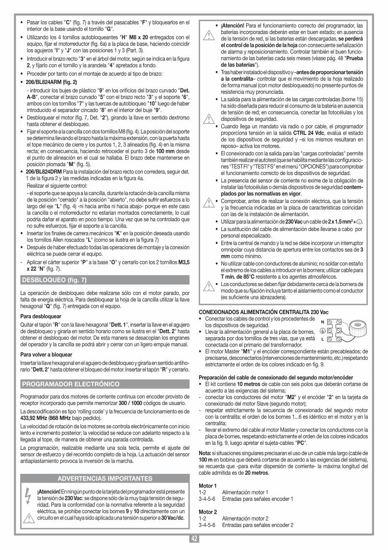
42
• Pasar los cables "C" (fig. 7) a través del pasacables "F" y bloquearlos en el interior de la base usando el tornillo "G".
• Utilizando los 4 tornillos autobloqueantes "H" M8 x 20 entregados con el equipo, fijar el motorreductor (fig. 6a) a la placa de base, haciendo coincidir los agujeros "I" y "J" con las posiciones 1 y 3 (Part. 3).
• Introducir el brazo recto "3" en el árbol del motor, según se indica en la figura 2, y fijarlo con el tornillo y la arandela "4" apretados a fondo.
• Proceder por tanto con el montaje de acuerdo al tipo de brazo: • 206/BL824ARM (fig. 2) - introducir los bujes de plástico "9" en los orificios del brazo curvado "Det.
A-B", conectar el brazo curvado "5" con el brazo recto "3" y el soporte "6", ambos con los tornillos "7" y las tuercas de autobloqueo "10" luego de haber introducido el separador cincado "8" en el interior del buje "9".
• Desbloquear el motor (fig. 7, Det. "2"), girando la llave en sentido dextrorso hasta obtener el desbloqueo.
• Fijar el soporte a la cancilla con dos tornillos M8 (fig. 4). La posición del soporte se determina llevando el brazo hasta la máxima extensión, con la puerta hasta el tope mecánico de cierre y los puntos 1, 2, 3 alineados (fig. 4) en la misma recta; en consecuencia, haciendo retroceder el punto 3 de 100 mm desde el punto de alineación en el cual se hallaba. El brazo debe mantenerse en posición plomada "M" (fig. 5).
• 206/BL824DRM Para la instalación del brazo recto con corredera, seguir det. 1 de la figura 2 y las medidas indicadas en la figura 4a.
Realizar el siguiente control: - el soporte que se apoya a la cancilla, durante la rotación de la cancilla misma
de la posición "cerrado" a la posición "abierto", no debe sufrir esfuerzos a lo largo del eje "L" (fig. 4) -ni hacia arriba ni hacia abajo- porque en este caso la cancilla o el motorreductor no estarían montados correctamente, lo cual podría dañar el aparato en poco tiempo. Una vez que se ha controlado que no sufre esfuerzos, fijar el soporte a la cancilla.
• Insertar los finales de carrera mecánicos "K" en la posición deseada usando los tornillos Allen roscados "L" (como se ilustra en la figura 7)
• Después de haber efectuado todas las operaciones de montaje y la conexión eléctrica se puede cerrar el equipo.
- Aplicar el cárter superior "P" a la base "O" y cerrarlo con los 2 tornillos M3,5 x 22 "N" (fig. 7).
La operación de desbloqueo debe realizarse sólo con el motor parado, por falta de energía eléctrica. Para desbloquear la hoja de la cancilla utilizar la llave hexagonal "Q" (fig. 7) entregada con el equipo.
Para desbloquearQuitar el tapón "R" con la llave hexagonal "Dett. 1", insertar la llave en el agujero de desbloqueo y girarla en sentido horario como se ilustra en el "Dett. 2" hasta obtener el desbloqueo del motor. De esta manera se desacoplan los engranes del operador y la cancilla se podrá abrir y cerrar con un ligero empuje manual.
Para volver a bloquearInsertar la llave hexagonal en el agujero de desbloqueo y girarla en sentido antiho-rario "Dett. 2" hasta obtener el bloqueo del motor. Insertar el tapón "R" y cerrarlo.
Programador para dos motores de corriente continua con encoder provisto de receptor incorporado que permite memorizar 300 / 1000 códigos de usuario. La descodificación es tipo ‘rolling code’ y la frecuencia de funcionamiento es de 433,92 MHz (868 MHz bajo pedido).La velocidad de rotación de los motores se controla electrónicamente con inicio lento e incremento posterior; la velocidad se reduce con adelanto respecto a la llegada al tope, de manera de obtener una parada controlada.La programación, realizable mediante una sola tecla, permite el ajuste del sensor de esfuerzo y del recorrido completo de la hoja. La actuación del sensor antiaplastamiento provoca la inversión de la marcha.
¡Atención! En ningún punto de la tarjeta del programador está presente la tensión de 230 Vac: se dispone sólo de la muy baja tensión de segu-ridad. Para la conformidad con la normativa referente a la seguridad eléctrica, se prohibe conectar los bornes 9 y 10 directamente con un circuito en el cual haya sido aplicada una tensión superior a 30 Vac/dc.
• ¡Atención! Para el funcionamiento correcto del programador, las baterías incorporadas deberán estar en buen estado; en ausencia de la tensión de red, si las baterías están descargadas, se perderá el control de la posición de la hoja con consecuente señalización de alarma y reposicionamiento. Controlar también el buen funcio-namiento de las baterías cada seis meses (véase pág. 48 "Prueba de las baterías").
• Tras haber instalado el dispositivo y –antes de proporcionar tensión a la centralita– controlar que el movimiento de la hoja realizado de forma manual (con motor desbloqueado) no presente puntos de resistencia muy pronunciada.
• La salida para la alimentación de las cargas controladas (borne 15) ha sido diseñada para reducir el consumo de la batería en ausencia de tensión de red; en consecuencia, conectar las fotocélulas y los dispositivos de seguridad.
• Cuando llega un mandato vía radio o por cable, el programador proporciona tensión en la salida CTRL 24 Vdc, evalúa el estado de los dispositivos de seguridad y –si los mismos resultaran en reposo– activa los motores.
• El conexionado con la salida para las "cargas controladas" permite también realizar el autotest (que se habilita mediante las configuracio-nes "TEST FI" y "TEST FS" en el menú "OPCIONES") para comprobar el funcionamiento correcto de los dispositivos de seguridad.
• La presencia del sensor de corriente no exime de la obligación de instalar las fotocélulas o demás dispositivos de seguridad contem-plados por las normativas en vigor.
• Comprobar, antes de realizar la conexión eléctrica, que la tensión y la frecuencia indicadas en la placa de características coincidan con las de la instalación de alimentación.
• Utilizar para la alimentación de 230 Vac un cable de 2 x 1.5 mm2 + .• La sustitución del cable de alimentación debe llevarse a cabo por
personal especializado.• Entre la central de mando y la red se debe incorporar un interruptor
omnipolar cuya distancia de apertura entre los contactos sea de 3 mm como mínimo.
• No utilizar cable con conductores de aluminio; no soldar con estaño el extremo de los cables a introducir en la bornera; utilizar cable para T mín. de 85°C resistente a los agentes atmosféricos.
• Los conductores se deben fijar debidamente cerca de la bornera de modo que su fijación incluya tanto el aislamiento como el conductor (es suficiente una abrazadera).
CONEXIONADOS ALIMENTACIÓN CENTRALITA 230 Vac• Conectar los cables de control y los procedentes de
los dispositivos de seguridad.• Llevar la alimentación general a la placa de bornes,
separada por dos tornillos de tres vías, que ya está conectada con el primario del transformador.
• El motor Master "M1" y el encóder correspondiente están precableados; de precisarse, desconectarlos (intervenciones de mantenimiento, etc.) respetando estrictamente el orden de los colores indicado en fig. 9.
Preparación del cable de conexionado del segundo motor/encóder• El kit contiene 10 metros de cable con seis polos que deberán cortarse de
acuerdo a las exigencias del sistema;- conectar los conductores del motor "M2" y el encóder "2" en la tarjeta de
conexionado del motor Slave (segundo motor);- respetar estrictamente la secuencia de conexionado del segundo motor
con la centralita; el orden de los bornes 1...6 es idéntico en el motor y en la centralita;
- llevar el extremo del cable al motor Master y conectar los conductores con la placa de bornes, respetando estrictamente el orden de los colores indicados en la fig. 9, luego apretar el sujeta-cables "PC".
Nota: si situaciones singulares precisaran el uso de un cable más largo (cable de 100 m en bobina que deberá cortarse de acuerdo a las exigencias del sistema), se recuerda que -para evitar dispersión de corriente- la máxima longitud del cable admitida es de 20 metros.
Motor 11-2 Alimentación motor 13-4-5-6 Entradas para señales encoder 1
Motor 21-2 Alimentación motor 23-4-5-6 Entradas para señales encoder 2
DESBLOQUEO (fig. 7)
PROGRAMADOR ELECTRÓNICO
ADVERTENCIAS IMPORTANTES
N
L
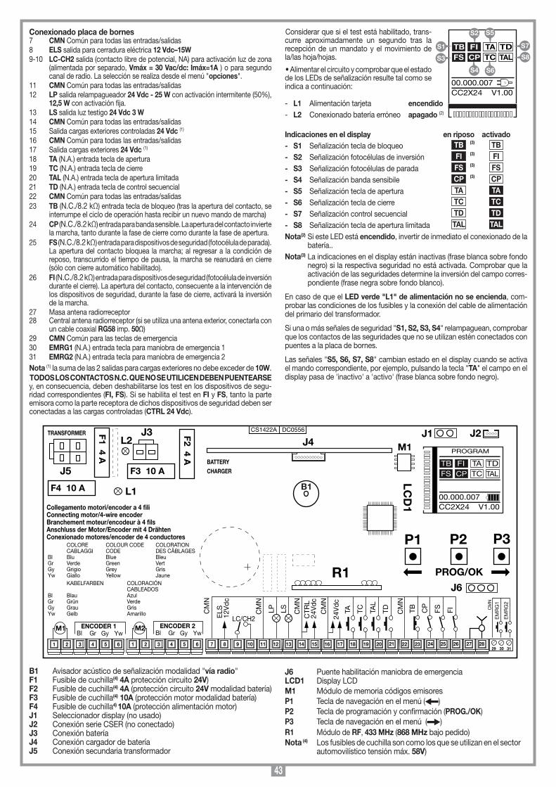
43
Conexionado placa de bornes7 CMN Común para todas las entradas/salidas8 ELS salida para cerradura eléctrica 12 Vdc–15W9-10 LC-CH2 salida (contacto libre de potencial, NA) para activación luz de zona
(alimentada por separado, Vmáx = 30 Vac/dc: Imáx=1A ) o para segundo canal de radio. La selección se realiza desde el menú "opciones".
11 CMN Común para todas las entradas/salidas12 LP salida relampagueador 24 Vdc - 25 W con activación intermitente (50%),
12,5 W con activación fija.13 LS salida luz testigo 24 Vdc 3 W14 CMN Común para todas las entradas/salidas15 Salida cargas exteriores controladas 24 Vdc (1)
16 CMN Común para todas las entradas/salidas17 Salida cargas exteriores 24 Vdc (1)
18 TA (N.A.) entrada tecla de apertura19 TC (N.A.) entrada tecla de cierre20 TAL (N.A.) entrada tecla de apertura limitada21 TD (N.A.) entrada tecla de control secuencial22 CMN Común para todas las entradas/salidas23 TB (N.C./8.2 kΩ) entrada tecla de bloqueo (tras la apertura del contacto, se
interrumpe el ciclo de operación hasta recibir un nuevo mando de marcha)24 CP (N.C./8.2 kΩ) entrada para banda sensible. La apertura del contacto invierte
la marcha, tanto durante la fase de cierre como durante la fase de apertura.25 FS (N.C./8.2 kΩ) entrada para dispositivos de seguridad (fotocélula de parada).
La apertura del contacto bloquea la marcha; al regresar a la condición de reposo, transcurrido el tiempo de pausa, la marcha se reanudará en cierre (sólo con cierre automático habilitado).
26 FI (N.C./8.2 kΩ) entrada para dispositivos de seguridad (fotocélula de inversión durante el cierre). La apertura del contacto, consecuente a la intervención de los dispositivos de seguridad, durante la fase de cierre, activará la inversión de la marcha.
27 Masa antena radiorreceptor28 Central antena radiorreceptor (si se utiliza una antena exterior, conectarla con
un cable coaxial RG58 imp. 50Ω)29 CMN Común para las teclas de emergencia30 EMRG1 (N.A.) entrada tecla para maniobra de emergencia 131 EMRG2 (N.A.) entrada tecla para maniobra de emergencia 2Nota (1) la suma de las 2 salidas para cargas exteriores no debe exceder de 10W.TODOS LOS CONTACTOS N.C. QUE NO SE UTILICEN DEBEN PUENTEARSE y, en consecuencia, deben deshabilitarse los test en los dispositivos de segu-ridad correspondientes (FI, FS). Si se habilita el test en FI y FS, tanto la parte emisora como la parte receptora de dichos dispositivos de seguridad deben ser conectadas a las cargas controladas (CTRL 24 Vdc).
Considerar que si el test está habilitado, trans-curre aproximadamente un segundo tras la recepción de un mandato y el movimiento de la/las hoja/hojas.
• Alimentar el circuito y comprobar que el estado de los LEDs de señalización resulte tal como se indica a continuación:
- L1 Alimentación tarjeta encendido- L2 Conexionado batería erróneo apagado (2)
Indicaciones en el display en riposo activado- S1 Señalización tecla de bloqueo TB (3) TB - S2 Señalización fotocélulas de inversión FI (3) FI
- S3 Señalización fotocélulas de parada FS (3) FS
- S4 Señalización banda sensibile CP (3) CP - S5 Señalización tecla de apertura TA TA
- S6 Señalización tecla de cierre TC TC
- S7 Señalización control secuencial TD TD
- S8 Señalización tecla de apertura limitada TAL TAL
Nota(2) Si este LED está encendido, invertir de inmediato el conexionado de la batería..
Nota(3) La indicaciones en el display están inactivas (frase blanca sobre fondo negro) si la respectiva seguridad no está activada. Comprobar que la activación de las seguridades determine la inversión del campo corres-pondiente (frase negra sobre fondo blanco).
En caso de que el LED verde "L1" de alimentación no se encienda, com-probar las condiciones de los fusibles y la conexión del cable de alimentación del primario del transformador.
Si una o más señales de seguridad "S1, S2, S3, S4" relampaguean, comprobar que los contactos de las seguridades que no se utilizan estén conectados con puentes a la placa de bornes.
Las señales "S5, S6, S7, S8" cambian estado en el display cuando se activa el mando correspondiente, por ejemplo, pulsando la tecla "TA" el campo en el display pasa de 'inactivo' a 'activo' (frase blanca sobre fondo negro).
Collegamenti scheda base
CC2X24
05-09-2015
DC0556 Description :
Product Code :
Date :
Drawing number :
P.J.Heath
CARDIN ELETTRONICA S.p.A - 31020 San Vendemiano (TV) Italy - via Raffaello, 36 Tel: 0438/401818 Fax: 0438/401831
Draft :
All rights reserved. Unauthorised copying or use of the information contained in this document is punishable by law
CC2X24 SCHEDA BASE V1.00(con display LCD + MULTI-DECODIFICA)
CS1422A DC0556
M1
B1
F2 4 A
TRANSFORMER
L1
29 30 31
F1 4 A
LCD
1
P1 P2 P3
PROG/OK
J5
9 10 11 12 13 14 15 16 17 18 19 20 21 22 23 24 25 26
COLORE COLOUR CODE COLORATION CABLAGGI CODE DES CÂBLAGES Bl Blu Blue Bleu Gr Verde Green Vert Gy Grigio Grey Gris Yw Giallo Yellow Jaune KABELFARBEN COLORACIÓN CABLEADOSBl Blau AzulGr Grün VerdeGy Grau GrisYw Gelb Amarillo
Collegamento motori/encoder a 4 fili Connecting motor/4-wire encoderBranchement moteur/encodeur à 4 filsAnschluss der Motor/Encoder mit 4 DrähtenConexionado motores/encoder de 4 conductores
7 83 4 5 61 2 3 4 5 61 2
YwGyGrBlENCODER 1
YwGyGrBlENCODER 2M1 M2
27 28
TDTA TC
24V
dc
TAL
CM
N
FITB CP
FS
EM
RG
1
EM
RG
2
CM
N
CM
N
CTR
L24
Vd
c
CM
N
LSLPCM
N
LC/CH2ELS
12V
dc
CM
N
F4 10 A
J3
F3 10 ABATTERYCHARGER
J1
R1J6
J2J4L2
PROGRAM
TB FIFS CP
TA TDTC TAL
00.000.007CC2X24 V1.00
B1 Avisador acústico de señalización modalidad "vía radio"F1 Fusible de cuchilla(4) 4A protección circuito 24V) F2 Fusible de cuchilla(4) 4A (protección circuito 24V modalidad batería)F3 Fusible de cuchilla(4) 10A (protección motor modalidad batería) F4 Fusible de cuchilla4) 10A (protección alimentación motor) J1 Seleccionador display (no usado)J2 Conexión serie CSER (no conectado)J3 Conexión bateríaJ4 Conexión cargador de bateríaJ5 Conexión secundaria transformador
J6 Puente habilitación maniobra de emergenciaLCD1 Display LCDM1 Módulo de memoria códigos emisoresP1 Tecla de navegación en el menú ( )P2 Tecla de programación y confirmación (PROG./OK) P3 Tecla de navegación en el menú ( )R1 Módulo de RF, 433 MHz (868 MHz bajo pedido)Nota (4) Los fusibles de cuchilla son como los que se utilizan en el sector automovilístico tensión máx. 58V)
S5
S6
TB FIFS CP
TA TDTC TAL
00.000.007CC2X24 V1.00
S1
S3
S7
S8
S2
S4
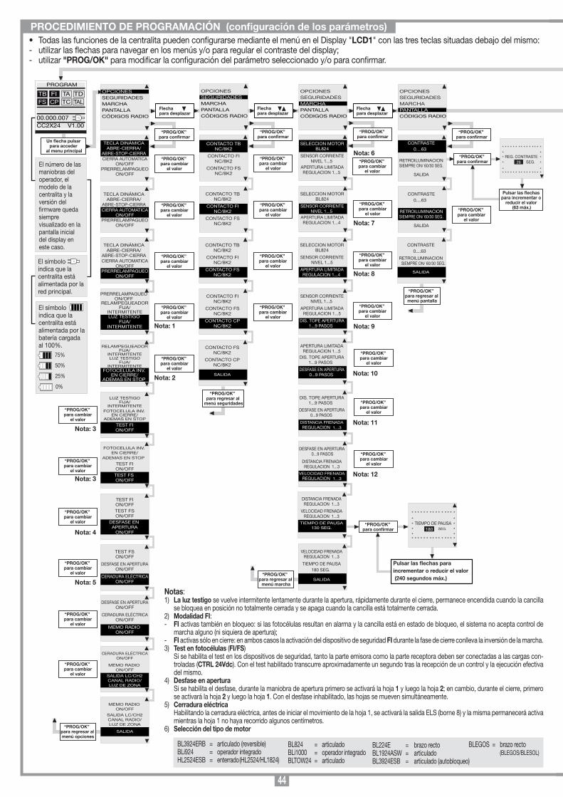
44
Un flecha pulsar para acceder
al menu principal“PROG/OK”
para confirmar
Pulsar las flechas para incrementar o
reducir el valor (63 máx.)
* * * * * * * * * * * * * * ** ** REG. CONTRASTE ** SEG. *
* ** * * * * * * * * * * * * * *
26
“PROG/OK” para regresar al menú opciones
OPCIONESSEGURIDADESMARCHAPANTALLACÓDIGOS RADIO
PROGRAM
TB FIFS CP
TA TDTC TAL
00.000.007CC2X24 V1.00
OPCIONESSEGURIDADESMARCHAPANTALLACÓDIGOS RADIO
Flechapara desplazar
TECLA DINÁMICAABRE-CIERRA/
ABRE-STOP-CIERRACIERRA AUTOMATICA
ON/OFFPRERRELAMPAGUEO
ON/OFF
OPCIONESSEGURIDADESMARCHAPANTALLACÓDIGOS RADIO
Flechapara desplazar
OPCIONESSEGURIDADESMARCHAPANTALLACÓDIGOS RADIO
Flechapara desplazar
TECLA DINÁMICAABRE-CIERRA/
ABRE-STOP-CIERRACIERRA AUTOMATICA
ON/OFFPRERRELAMPAGUEO
ON/OFF
TECLA DINÁMICAABRE-CIERRA/
ABRE-STOP-CIERRACIERRA AUTOMATICA
ON/OFFPRERRELAMPAGUEO
ON/OFF
PRERRELAMPAGUEOON/OFF
RELAMPEGUEADORFIJA/
INTERMITENTELUZ TESTIGO
FIJA/INTERMITENTE
RELAMPEGUEADORFIJA/
INTERMITENTELUZ TESTIGO
FIJA/INTERMITENTE
FOTOCELULA INV. EN CIERRE/
ADEMAS EN STOP
LUZ TESTIGOFIJA/
INTERMITENTEFOTOCELULA INV.
EN CIERRE/ADEMAS EN STOP
TEST FION/OFF
FOTOCELULA INV. EN CIERRE/
ADEMAS EN STOP
TEST FION/OFFTEST FS ON/OFF
TEST FSON/OFF
DESFASE EN APERTURAON/OFF
CERADURA ELÉCTRICAON/OFF
TEST FION/OFFTEST FSON/OFF
DESFASE EN APERTURA
ON/OFF
DESFASE EN APERTURAON/OFF
CERADURA ELÉCTRICAON/OFF
MEMO RADIO ON/OFF
CERADURA ELÉCTRICAON/OFF
MEMO RADIO ON/OFF
SALIDA LC/CH2CANAL RADIO/LUZ DE ZONA
“PROG/OK” para confirmar
“PROG/OK” para cambiar
el valor
“PROG/OK” para cambiar
el valor
“PROG/OK” para cambiar
el valor
“PROG/OK” para cambiar
el valor
“PROG/OK” para cambiar
el valor
“PROG/OK” para cambiar
el valor
“PROG/OK” para cambiar
el valor
“PROG/OK” para cambiar
el valor
“PROG/OK” para cambiar
el valor
“PROG/OK” para cambiar
el valor
MEMO RADIO ON/OFF
SALIDA LC/CH2CANAL RADIO/LUZ DE ZONA
SALIDA
“PROG/OK” para cambiar
el valor
CONTACTO TBNC/8K2
CONTACTO FINC/8K2
CONTACTO FSNC/8K2
CONTACTO TBNC/8K2
CONTACTO FINC/8K2
CONTACTO FSNC/8K2
“PROG/OK” para confirmar
“PROG/OK” para cambiar
el valor
“PROG/OK” para cambiar
el valor
CONTACTO TBNC/8K2
CONTACTO FINC/8K2
CONTACTO FSNC/8K2
“PROG/OK” para cambiar
el valor
CONTACTO FINC/8K2
CONTACTO FSNC/8K2
CONTACTO CPNC/8K2
“PROG/OK” para cambiar
el valor
CONTACTO FSNC/8K2
CONTACTO CPNC/8K2
SALIDA
“PROG/OK” para regresar al
menú seguridades
SELECCION MOTORBL824
SENSOR CORRIENTENIVEL 1...5
APERTURA LIMITADAREGULACION 1...5
SELECCION MOTORBL824
SENSOR CORRIENTENIVEL 1...5
APERTURA LIMITADAREGULACION 1...4
“PROG/OK” para confirmar
“PROG/OK” para cambiar
el valor
SELECCION MOTORBL824
SENSOR CORRIENTENIVEL 1...5
APERTURA LIMITADAREGULACION 1...4
“PROG/OK” para cambiar
el valor
SENSOR CORRIENTENIVEL 1...5
APERTURA LIMITADAREGULACION 1...5
DIS. TOPE APERTURA1...9 PASOS
“PROG/OK” para cambiar
el valor
“PROG/OK” para cambiar
el valor
CONTRASTE0....63
RETROILUMINACIONSIEMPRE ON/ 60/30 SEG.
SALIDA
“PROG/OK” para confirmar
CONTRASTE0....63
RETROILUMINACIONSIEMPRE ON/ 60/30 SEG.
SALIDA
“PROG/OK” para cambiar
el valor
CONTRASTE0....63
RETROILUMINACION SIEMPRE ON/ 60/30 SEG.
SALIDA
“PROG/OK” para regresar al menú pantalla
El número de las maniobras del operador, el modelo de la centralita y la versión del rmware queda siempre visualizado en la pantalla inicial del display en este caso.
El símboloindica que la centralita está alimentada por la red principal.
El símboloindica que la centralita está alimentada por la batería cargada al 100%.
75%
50%
25%
0%
Nota: 1
Nota: 2
Nota: 3
Nota: 3
Nota: 6
Nota: 7
Nota: 8
Nota: 9
Nota: 4
Nota: 5
ITALIANO
FRANÇAIS
ENGLISH
NEDERLANDS
DEUTSCH
ESPAÑOL
PROGRAM
TB FIFS CP
TA TDTC TAL
00.000.007CC2X24 V1.00
para entrar en el submenú idioma pulsar simultáneamente
ambas flechas
“PROG/OK” per confirmar
Intermitencia en el display. Se debe entrar en la modalidad de programación para programar el sistema.
Señaliza que se cumplirá el procedimiento de reposicionamiento automático. En este caso, cualquier control recibido (TA, TC, TAL o TD) activa de inmediato este procedimiento.
Se verica cuando se activa un contacto N.C. (FI, FS, CP) durante la programación del codicador. Tras haber restablecido el estado pasivo de los dispositivos de seguridad, automáticamente la cancilla se activa de nuevo. Se presenta también en caso de fallo de la tensión de red durante la fase de programación.
Error de seguridad. Controlar que los dispositivos de seguridad sitúen en condición de alarma (LED correspondiente apagado) cuando un obstáculo se encuentra en el medio del radio de acción de los mismos. Si se detectara una anomalía, cambiar el dispositivo de seguridad en avería o puentear la respectiva entrada e inhabilitar el test correspondiente al dispositivo de seguridad mismo (menu opciones).
Se presenta cuando el programador proporciona un mando al motor 1-2, pero el motor no se pone en marcha. Es suciente controlar los conexionados correspondientes al motor y el estado de los fusibles "F3" y "F4"; a continuación, proporcionar otro mando de apertura o de cierre. Si el motor 1-2 no se pone en marcha, entonces la causa podría ser un problema mecánico del motor o un problema de la centralita.
Error en la cuenta del encoder motor 1-2. Este error se visualiza cuando se proporciona un control con el motor 1-2 desbloqueado. Si se verica durante la utilización corriente del motor, signica que existe un problema en las señales correspondientes al encoder; comprobar los conexionados correspondientes y realizar el reposicionamiento automático.
Error en la dirección del encoder motor 1-2. La direzione di marcia dell'anta è diversa da quella stabilita dall'encoder (esempio: l’anta va in chiusura mentre il programmatore sta eseguendo la fase di apertura). Controllare la connessione dell'alimentazione motore.
Error del sensor de corriente motore 1-2. Con el motor parado, este símbolo indica que existe un problema en el sensor de corriente motor 1-2.
La apertura del contacto invierte la marcha, tanto durante la fase de cierre como durante la fase de apertura.
Si el sensor interviene durante la fase de cierre, la hoja invierte inmediatamente el movimiento y se abre completamente. Si el sensor interviene durante la fase de apertura, la hoja invierte inmediatamente el movimiento de algunos centímetros y luego se detiene para liberar el obstáculo.
Señalizaciones de alarmaTB FIFS CP
TA TDTC TAL
PROGRAM
TB FIFS CP
TA TDTC TAL
FUERA POS
TB FIFS CP
TA TDTC TAL
ERROR SEG.
TB FIFS CP
TA TDTC TAL
STOP PROG
AUTO PROG
TB FIFS CP
TA TDTC TAL
ERROR MOT1/2
TB FIFS CP
TA TDTC TAL
ERROR ENC1/2
TB FIFS CP
TA TDTC TAL
ERROR DIR1/2
TB FIFS CP
TA TDTC TAL
ERROR SENS1/2
Programación del tiempo de pausa o pausa para el cierre automático (sólo si ha sido habilitada)
Programación automática en curso
Fase de apertura
Bloqueo durante la apertura
Fase de cierre
Bloqueo durante la cierre
Señalizaciones de funcionamiento
TB FIFS CP
TA TDTC TAL
PAUSA
TB FIFS CP
TA TDTC TAL
AUTO PROG
TB FIFS CP
TA TDTC TAL
APERTURA
TB FIFS CP
TA TDTC TAL
STOP APERTURA
TB FIFS CP
TA TDTC TAL
CIERRE
TB FIFS CP
TA TDTC TAL
STOP CIERRE
TB FIFS CP
TA TDTC TAL
REBORD ATTIVADO
TB FIFS CP
TA TDTC TAL
SENSOR ATTIVADO
Selección del idioma:• Pulsar las teclas derecha e izquierda simultáneamente para entrar en el submenú.• Pulsar la tecla derecha o izquierda para cambiar el idioma: italiano - español.• Pulsar la tecla "PROG/OK" para conrmar el idioma:
“PROG/OK” para regresar al menú marcha
APERTURA LIMITADAREGULACION 1...5
DIS. TOPE APERTURA1...9 PASOS
DESFASE EN APERTURA 0...9 PASOS
DIS. TOPE APERTURA1...9 PASOS
DESFASE EN APERTURA 0...9 PASOS
DISTANCIA FRENADAREGULACION 1...3
DISTANCIA FRENADAREGULACION 1...3
VELOCIDAD FRENADAREGULACION 1...3
TIEMPO DE PAUSA130 SEG.
VELOCIDAD FRENADAREGULACION 1...3
TIEMPO DE PAUSA 180 SEG.
SALIDA
“PROG/OK” para confirmar
Pulsar las flechas para incrementar o reducir el valor (240 segundos máx.)
* * * * * * * * * * * * * * ** ** TIEMPO DE PAUSA ** SEG. ** ** * * * * * * * * * * * * * *
180
DESFASE EN APERTURA 0...9 PASOS
DISTANCIA FRENADAREGULACION 1...3
VELOCIDAD FRENADAREGULACION 1...3
“PROG/OK” para cambiar
el valor
Nota: 10
“PROG/OK” para cambiar
el valor
Nota: 11
“PROG/OK” para cambiar
el valor
Nota: 12
“PROG/OK” para confirmar
PULSAR el canal por
memorizar en el emisor
PULSAR el mismo canal
por memorizar en el emisor
“PROG/OK” para confirmar
Flechapara desplazar
CODIFICACIÓN: S4XX MEMORIZACIÓN
CANCELACIÓN
CANCEL. TOTAL
FUNCIÓN CANALES
SALIDA
“PROG/OK” para confirmar
OPCIONESSEGURIDADESMARCHAPANTALLACALENDARIOCÓDIGOS RADIO
MEMORIZACIÓN[n....]
* * * * * * * * * * * * * * ** ** ACTIVACIÓN 1 ** ** * * * * * * * * * * * * * *
MEMORIZACIÓN[n....]
* * * * * * * * * * * * * * ** ** ACTIVACIÓN 2 ** ** * * * * * * * * * * * * * *
MEMORIZACIÓN[n....]
* * * * * * * * * * * * * * ** ** CÓDIGO ** MEMORIZADO ** * * * * * * * * * * * * * *
“PROG/OK” para confirmar
CANCELACIÓN[n....]
* * * * * * * * * * * * * * ** ** ACTIVACIÓN 1 ** ** * * * * * * * * * * * * * *
PULSAR el canal por
cancelar en el emisor
CANCELACIÓN[n....]
* * * * * * * * * * * * * * ** ** ACTIVACIÓN 2 ** ** * * * * * * * * * * * * * *
PULSAR el canal por
cancelar en el emisor
CANCELACIÓN[n....]
* * * * * * * * * * * * * * ** ** CÓDIGO ** CANCELADO ** * * * * * * * * * * * * * *
CODIFICACIÓN: S4XX
MEMORIZACIÓN
CANCELACIÓN
CANCEL. TOTAL
FUNCIÓN CANALES
SALIDA
“PROG/OK” para confirmar
* * * * * * * * * * * * * * ** CANCELAR ** LA MEMORIA ? ** * * * * * * * * * * * * * *
PULSAR ok paracancelar la memoria o
exit para salir
CODIFICACIÓN: S4XX
MEMORIZACIÓN
CANCELACIÓN
CANCEL. TOTAL
FUNCIÓN CANALES
SALIDA
Flechapara salir
EXIT
OK
* * * * * * * * * * * * * * ** CANCELACIÓN ** EN CURSO ** * * * * * * * * * * * * * *
CODIFICACIÓN: S4XX
MEMORIZACIÓN
CANCELACIÓN
CANCEL. TOTAL
FUNCIÓN CANALES
SALIDA
CANAL Afunción canal A
CANAL Bfunción canal B
CANAL Cfunción canal C
CANAL Dfunción canal D
SALIDA
CODIFICACIÓN: S4XX
MEMORIZACIÓN
CANCELACIÓN
CANCEL. TOTAL
FUNCIÓN CANALES
SALIDA
“PROG/OK” para cambiar
el valor
CODIFICACIÓN: S4XX
MEMORIZACIÓN
CANCELACIÓN
CANCEL. TOTAL
FUNCIÓN CANALES
SALIDA
“PROG/OK” para cambiar
el valor S4XX a S500
“PROG/OK” para regresar
al menúcódigos radio
[AB--] [AB--] [AB--]
[AB--] [AB--] [AB--]
Nota: 14
Nota: 13
• Todas las funciones de la centralita pueden configurarse mediante el menú en el Display "LCD1" con las tres teclas situadas debajo del mismo:- utilizar las flechas para navegar en los menús y/o para regular el contraste del display;- utilizar "PROG/OK" para modificar la configuración del parámetro seleccionado y/o para confirmar.
PROCEDIMIENTO DE PROGRAMACIÓN (configuración de los parámetros)
Notas:1) La luz testigo se vuelve intermitente lentamente durante la apertura, rápidamente durante el cierre, permanece encendida cuando la cancilla
se bloquea en posición no totalmente cerrada y se apaga cuando la cancilla está totalmente cerrada.2) Modalidad FI:- FI activas también en bloqueo: si las fotocélulas resultan en alarma y la cancilla está en estado de bloqueo, el sistema no acepta control de
marcha alguno (ni siquiera de apertura);- FI activas sólo en cierre: en ambos casos la activación del dispositivo de seguridad FI durante la fase de cierre conlleva la inversión de la marcha.3) Test en fotocélulas (FI/FS) Si se habilita el test en los dispositivos de seguridad, tanto la parte emisora como la parte receptora deben ser conectadas a las cargas con-
troladas (CTRL 24Vdc). Con el test habilitado transcurre aproximadamente un segundo tras la recepción de un control y la ejecución efectiva del mismo.
4) Desfase en apertura Si se habilita el desfase, durante la maniobra de apertura primero se activará la hoja 1 y luego la hoja 2; en cambio, durante el cierre, primero
se activará la hoja 2 y luego la hoja 1. Con el desfase inhabilitado, las hojas se mueven simultáneamente.5) Cerradura eléctrica Habilitando la cerradura eléctrica, antes de iniciar el movimiento de la hoja 1, se activará la salida ELS (borne 8) y la misma permanecerá activa
mientras la hoja 1 no haya recorrido algunos centímetros.6) Selección del tipo de motor
BL3924ERB = articulado (reversible)BLi924 = operador integrado HL2524ESB = enterrado (HL2524/HL1824)
BL824 = articulado BLi1000 = operador integradoBLTOW24 = articulado
BL224E = brazo rectoBL1924ASW = articuladoBL3924ESB = articulado (autobloqueo)
BLEGOS = brazo recto (BLEGOS/BLESOL)
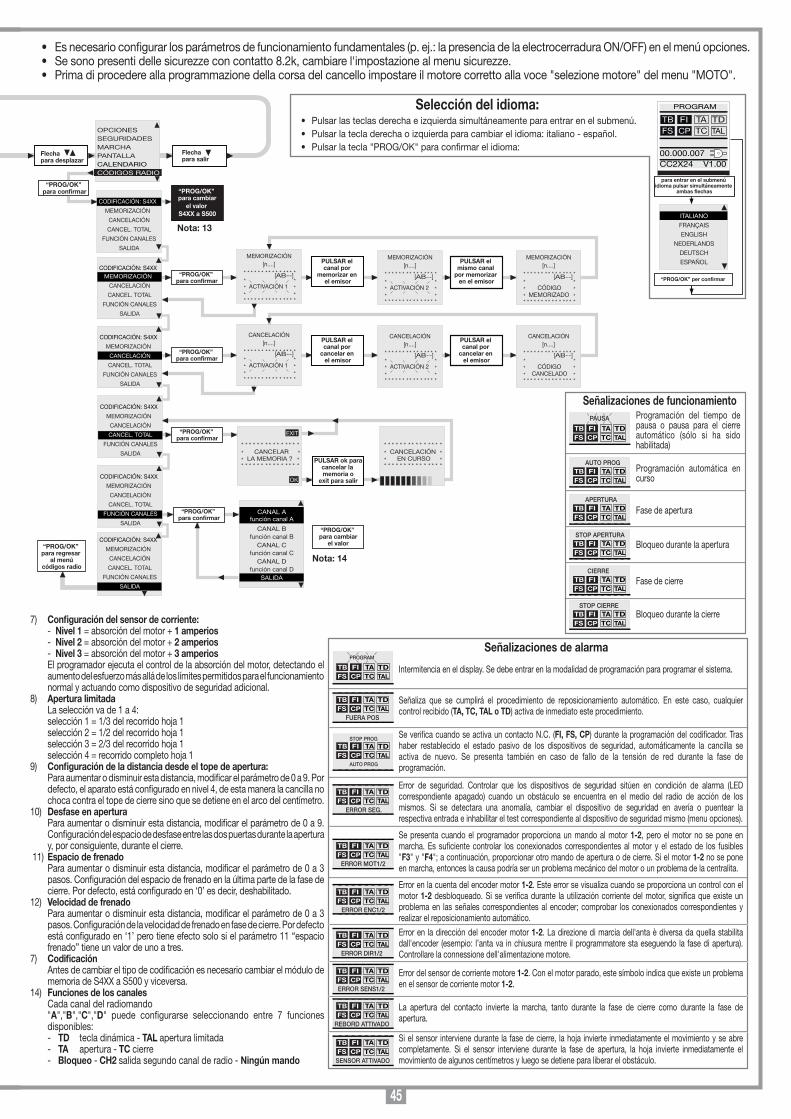
45
Un flecha pulsar para acceder
al menu principal“PROG/OK”
para confirmar
Pulsar las flechas para incrementar o
reducir el valor (63 máx.)
* * * * * * * * * * * * * * ** ** REG. CONTRASTE ** SEG. *
* ** * * * * * * * * * * * * * *
26
“PROG/OK” para regresar al menú opciones
OPCIONESSEGURIDADESMARCHAPANTALLACÓDIGOS RADIO
PROGRAM
TB FIFS CP
TA TDTC TAL
00.000.007CC2X24 V1.00
OPCIONESSEGURIDADESMARCHAPANTALLACÓDIGOS RADIO
Flechapara desplazar
TECLA DINÁMICAABRE-CIERRA/
ABRE-STOP-CIERRACIERRA AUTOMATICA
ON/OFFPRERRELAMPAGUEO
ON/OFF
OPCIONESSEGURIDADESMARCHAPANTALLACÓDIGOS RADIO
Flechapara desplazar
OPCIONESSEGURIDADESMARCHAPANTALLACÓDIGOS RADIO
Flechapara desplazar
TECLA DINÁMICAABRE-CIERRA/
ABRE-STOP-CIERRACIERRA AUTOMATICA
ON/OFFPRERRELAMPAGUEO
ON/OFF
TECLA DINÁMICAABRE-CIERRA/
ABRE-STOP-CIERRACIERRA AUTOMATICA
ON/OFFPRERRELAMPAGUEO
ON/OFF
PRERRELAMPAGUEOON/OFF
RELAMPEGUEADORFIJA/
INTERMITENTELUZ TESTIGO
FIJA/INTERMITENTE
RELAMPEGUEADORFIJA/
INTERMITENTELUZ TESTIGO
FIJA/INTERMITENTE
FOTOCELULA INV. EN CIERRE/
ADEMAS EN STOP
LUZ TESTIGOFIJA/
INTERMITENTEFOTOCELULA INV.
EN CIERRE/ADEMAS EN STOP
TEST FION/OFF
FOTOCELULA INV. EN CIERRE/
ADEMAS EN STOP
TEST FION/OFFTEST FS ON/OFF
TEST FSON/OFF
DESFASE EN APERTURAON/OFF
CERADURA ELÉCTRICAON/OFF
TEST FION/OFFTEST FSON/OFF
DESFASE EN APERTURA
ON/OFF
DESFASE EN APERTURAON/OFF
CERADURA ELÉCTRICAON/OFF
MEMO RADIO ON/OFF
CERADURA ELÉCTRICAON/OFF
MEMO RADIO ON/OFF
SALIDA LC/CH2CANAL RADIO/LUZ DE ZONA
“PROG/OK” para confirmar
“PROG/OK” para cambiar
el valor
“PROG/OK” para cambiar
el valor
“PROG/OK” para cambiar
el valor
“PROG/OK” para cambiar
el valor
“PROG/OK” para cambiar
el valor
“PROG/OK” para cambiar
el valor
“PROG/OK” para cambiar
el valor
“PROG/OK” para cambiar
el valor
“PROG/OK” para cambiar
el valor
“PROG/OK” para cambiar
el valor
MEMO RADIO ON/OFF
SALIDA LC/CH2CANAL RADIO/LUZ DE ZONA
SALIDA
“PROG/OK” para cambiar
el valor
CONTACTO TBNC/8K2
CONTACTO FINC/8K2
CONTACTO FSNC/8K2
CONTACTO TBNC/8K2
CONTACTO FINC/8K2
CONTACTO FSNC/8K2
“PROG/OK” para confirmar
“PROG/OK” para cambiar
el valor
“PROG/OK” para cambiar
el valor
CONTACTO TBNC/8K2
CONTACTO FINC/8K2
CONTACTO FSNC/8K2
“PROG/OK” para cambiar
el valor
CONTACTO FINC/8K2
CONTACTO FSNC/8K2
CONTACTO CPNC/8K2
“PROG/OK” para cambiar
el valor
CONTACTO FSNC/8K2
CONTACTO CPNC/8K2
SALIDA
“PROG/OK” para regresar al
menú seguridades
SELECCION MOTORBL824
SENSOR CORRIENTENIVEL 1...5
APERTURA LIMITADAREGULACION 1...5
SELECCION MOTORBL824
SENSOR CORRIENTENIVEL 1...5
APERTURA LIMITADAREGULACION 1...4
“PROG/OK” para confirmar
“PROG/OK” para cambiar
el valor
SELECCION MOTORBL824
SENSOR CORRIENTENIVEL 1...5
APERTURA LIMITADAREGULACION 1...4
“PROG/OK” para cambiar
el valor
SENSOR CORRIENTENIVEL 1...5
APERTURA LIMITADAREGULACION 1...5
DIS. TOPE APERTURA1...9 PASOS
“PROG/OK” para cambiar
el valor
“PROG/OK” para cambiar
el valor
CONTRASTE0....63
RETROILUMINACIONSIEMPRE ON/ 60/30 SEG.
SALIDA
“PROG/OK” para confirmar
CONTRASTE0....63
RETROILUMINACIONSIEMPRE ON/ 60/30 SEG.
SALIDA
“PROG/OK” para cambiar
el valor
CONTRASTE0....63
RETROILUMINACION SIEMPRE ON/ 60/30 SEG.
SALIDA
“PROG/OK” para regresar al menú pantalla
El número de las maniobras del operador, el modelo de la centralita y la versión del rmware queda siempre visualizado en la pantalla inicial del display en este caso.
El símboloindica que la centralita está alimentada por la red principal.
El símboloindica que la centralita está alimentada por la batería cargada al 100%.
75%
50%
25%
0%
Nota: 1
Nota: 2
Nota: 3
Nota: 3
Nota: 6
Nota: 7
Nota: 8
Nota: 9
Nota: 4
Nota: 5
ITALIANO
FRANÇAIS
ENGLISH
NEDERLANDS
DEUTSCH
ESPAÑOL
PROGRAM
TB FIFS CP
TA TDTC TAL
00.000.007CC2X24 V1.00
para entrar en el submenú idioma pulsar simultáneamente
ambas flechas
“PROG/OK” per confirmar
Intermitencia en el display. Se debe entrar en la modalidad de programación para programar el sistema.
Señaliza que se cumplirá el procedimiento de reposicionamiento automático. En este caso, cualquier control recibido (TA, TC, TAL o TD) activa de inmediato este procedimiento.
Se verica cuando se activa un contacto N.C. (FI, FS, CP) durante la programación del codicador. Tras haber restablecido el estado pasivo de los dispositivos de seguridad, automáticamente la cancilla se activa de nuevo. Se presenta también en caso de fallo de la tensión de red durante la fase de programación.
Error de seguridad. Controlar que los dispositivos de seguridad sitúen en condición de alarma (LED correspondiente apagado) cuando un obstáculo se encuentra en el medio del radio de acción de los mismos. Si se detectara una anomalía, cambiar el dispositivo de seguridad en avería o puentear la respectiva entrada e inhabilitar el test correspondiente al dispositivo de seguridad mismo (menu opciones).
Se presenta cuando el programador proporciona un mando al motor 1-2, pero el motor no se pone en marcha. Es suciente controlar los conexionados correspondientes al motor y el estado de los fusibles "F3" y "F4"; a continuación, proporcionar otro mando de apertura o de cierre. Si el motor 1-2 no se pone en marcha, entonces la causa podría ser un problema mecánico del motor o un problema de la centralita.
Error en la cuenta del encoder motor 1-2. Este error se visualiza cuando se proporciona un control con el motor 1-2 desbloqueado. Si se verica durante la utilización corriente del motor, signica que existe un problema en las señales correspondientes al encoder; comprobar los conexionados correspondientes y realizar el reposicionamiento automático.
Error en la dirección del encoder motor 1-2. La direzione di marcia dell'anta è diversa da quella stabilita dall'encoder (esempio: l’anta va in chiusura mentre il programmatore sta eseguendo la fase di apertura). Controllare la connessione dell'alimentazione motore.
Error del sensor de corriente motore 1-2. Con el motor parado, este símbolo indica que existe un problema en el sensor de corriente motor 1-2.
La apertura del contacto invierte la marcha, tanto durante la fase de cierre como durante la fase de apertura.
Si el sensor interviene durante la fase de cierre, la hoja invierte inmediatamente el movimiento y se abre completamente. Si el sensor interviene durante la fase de apertura, la hoja invierte inmediatamente el movimiento de algunos centímetros y luego se detiene para liberar el obstáculo.
Señalizaciones de alarmaTB FIFS CP
TA TDTC TAL
PROGRAM
TB FIFS CP
TA TDTC TAL
FUERA POS
TB FIFS CP
TA TDTC TAL
ERROR SEG.
TB FIFS CP
TA TDTC TAL
STOP PROG
AUTO PROG
TB FIFS CP
TA TDTC TAL
ERROR MOT1/2
TB FIFS CP
TA TDTC TAL
ERROR ENC1/2
TB FIFS CP
TA TDTC TAL
ERROR DIR1/2
TB FIFS CP
TA TDTC TAL
ERROR SENS1/2
Programación del tiempo de pausa o pausa para el cierre automático (sólo si ha sido habilitada)
Programación automática en curso
Fase de apertura
Bloqueo durante la apertura
Fase de cierre
Bloqueo durante la cierre
Señalizaciones de funcionamiento
TB FIFS CP
TA TDTC TAL
PAUSA
TB FIFS CP
TA TDTC TAL
AUTO PROG
TB FIFS CP
TA TDTC TAL
APERTURA
TB FIFS CP
TA TDTC TAL
STOP APERTURA
TB FIFS CP
TA TDTC TAL
CIERRE
TB FIFS CP
TA TDTC TAL
STOP CIERRE
TB FIFS CP
TA TDTC TAL
REBORD ATTIVADO
TB FIFS CP
TA TDTC TAL
SENSOR ATTIVADO
Selección del idioma:• Pulsar las teclas derecha e izquierda simultáneamente para entrar en el submenú.• Pulsar la tecla derecha o izquierda para cambiar el idioma: italiano - español.• Pulsar la tecla "PROG/OK" para conrmar el idioma:
“PROG/OK” para regresar al menú marcha
APERTURA LIMITADAREGULACION 1...5
DIS. TOPE APERTURA1...9 PASOS
DESFASE EN APERTURA 0...9 PASOS
DIS. TOPE APERTURA1...9 PASOS
DESFASE EN APERTURA 0...9 PASOS
DISTANCIA FRENADAREGULACION 1...3
DISTANCIA FRENADAREGULACION 1...3
VELOCIDAD FRENADAREGULACION 1...3
TIEMPO DE PAUSA130 SEG.
VELOCIDAD FRENADAREGULACION 1...3
TIEMPO DE PAUSA 180 SEG.
SALIDA
“PROG/OK” para confirmar
Pulsar las flechas para incrementar o reducir el valor (240 segundos máx.)
* * * * * * * * * * * * * * ** ** TIEMPO DE PAUSA ** SEG. ** ** * * * * * * * * * * * * * *
180
DESFASE EN APERTURA 0...9 PASOS
DISTANCIA FRENADAREGULACION 1...3
VELOCIDAD FRENADAREGULACION 1...3
“PROG/OK” para cambiar
el valor
Nota: 10
“PROG/OK” para cambiar
el valor
Nota: 11
“PROG/OK” para cambiar
el valor
Nota: 12
“PROG/OK” para confirmar
PULSAR el canal por
memorizar en el emisor
PULSAR el mismo canal
por memorizar en el emisor
“PROG/OK” para confirmar
Flechapara desplazar
CODIFICACIÓN: S4XX MEMORIZACIÓN
CANCELACIÓN
CANCEL. TOTAL
FUNCIÓN CANALES
SALIDA
“PROG/OK” para confirmar
OPCIONESSEGURIDADESMARCHAPANTALLACALENDARIOCÓDIGOS RADIO
MEMORIZACIÓN[n....]
* * * * * * * * * * * * * * ** ** ACTIVACIÓN 1 ** ** * * * * * * * * * * * * * *
MEMORIZACIÓN[n....]
* * * * * * * * * * * * * * ** ** ACTIVACIÓN 2 ** ** * * * * * * * * * * * * * *
MEMORIZACIÓN[n....]
* * * * * * * * * * * * * * ** ** CÓDIGO ** MEMORIZADO ** * * * * * * * * * * * * * *
“PROG/OK” para confirmar
CANCELACIÓN[n....]
* * * * * * * * * * * * * * ** ** ACTIVACIÓN 1 ** ** * * * * * * * * * * * * * *
PULSAR el canal por
cancelar en el emisor
CANCELACIÓN[n....]
* * * * * * * * * * * * * * ** ** ACTIVACIÓN 2 ** ** * * * * * * * * * * * * * *
PULSAR el canal por
cancelar en el emisor
CANCELACIÓN[n....]
* * * * * * * * * * * * * * ** ** CÓDIGO ** CANCELADO ** * * * * * * * * * * * * * *
CODIFICACIÓN: S4XX
MEMORIZACIÓN
CANCELACIÓN
CANCEL. TOTAL
FUNCIÓN CANALES
SALIDA
“PROG/OK” para confirmar
* * * * * * * * * * * * * * ** CANCELAR ** LA MEMORIA ? ** * * * * * * * * * * * * * *
PULSAR ok paracancelar la memoria o
exit para salir
CODIFICACIÓN: S4XX
MEMORIZACIÓN
CANCELACIÓN
CANCEL. TOTAL
FUNCIÓN CANALES
SALIDA
Flechapara salir
EXIT
OK
* * * * * * * * * * * * * * ** CANCELACIÓN ** EN CURSO ** * * * * * * * * * * * * * *
CODIFICACIÓN: S4XX
MEMORIZACIÓN
CANCELACIÓN
CANCEL. TOTAL
FUNCIÓN CANALES
SALIDA
CANAL Afunción canal A
CANAL Bfunción canal B
CANAL Cfunción canal C
CANAL Dfunción canal D
SALIDA
CODIFICACIÓN: S4XX
MEMORIZACIÓN
CANCELACIÓN
CANCEL. TOTAL
FUNCIÓN CANALES
SALIDA
“PROG/OK” para cambiar
el valor
CODIFICACIÓN: S4XX
MEMORIZACIÓN
CANCELACIÓN
CANCEL. TOTAL
FUNCIÓN CANALES
SALIDA
“PROG/OK” para cambiar
el valor S4XX a S500
“PROG/OK” para regresar
al menúcódigos radio
[AB--] [AB--] [AB--]
[AB--] [AB--] [AB--]
Nota: 14
Nota: 13
• Es necesario configurar los parámetros de funcionamiento fundamentales (p. ej.: la presencia de la electrocerradura ON/OFF) en el menú opciones.• Se sono presenti delle sicurezze con contatto 8.2k, cambiare l'impostazione al menu sicurezze.• Prima di procedere alla programmazione della corsa del cancello impostare il motore corretto alla voce "selezione motore" del menu "MOTO".
7) Configuración del sensor de corriente: - Nivel 1 = absorción del motor + 1 amperios - Nivel 2 = absorción del motor + 2 amperios - Nivel 3 = absorción del motor + 3 amperios El programador ejecuta el control de la absorción del motor, detectando el
aumento del esfuerzo más allá de los límites permitidos para el funcionamiento normal y actuando como dispositivo de seguridad adicional.
8) Apertura limitada La selección va de 1 a 4: selección 1 = 1/3 del recorrido hoja 1 selección 2 = 1/2 del recorrido hoja 1 selección 3 = 2/3 del recorrido hoja 1 selección 4 = recorrido completo hoja 19) Configuración de la distancia desde el tope de apertura: Para aumentar o disminuir esta distancia, modificar el parámetro de 0 a 9. Por
defecto, el aparato está configurado en nivel 4, de esta manera la cancilla no choca contra el tope de cierre sino que se detiene en el arco del centímetro.
10) Desfase en apertura Para aumentar o disminuir esta distancia, modificar el parámetro de 0 a 9.
Configuración del espacio de desfase entre las dos puertas durante la apertura y, por consiguiente, durante el cierre.
11) Espacio de frenado Para aumentar o disminuir esta distancia, modificar el parámetro de 0 a 3
pasos. Configuración del espacio de frenado en la última parte de la fase de cierre. Por defecto, está configurado en ‘0’ es decir, deshabilitado.
12) Velocidad de frenado Para aumentar o disminuir esta distancia, modificar el parámetro de 0 a 3
pasos. Configuración de la velocidad de frenado en fase de cierre. Por defecto está configurado en ‘1’ pero tiene efecto solo si el parámetro 11 “espacio frenado” tiene un valor de uno a tres.
7) Codificación Antes de cambiar el tipo de codificación es necesario cambiar el módulo de
memoria de S4XX a S500 y viceversa.14) Funciones de los canales Cada canal del radiomando "A","B","C","D" puede configurarse seleccionando entre 7 funciones
disponibles: - TD tecla dinámica - TAL apertura limitada - TA apertura - TC cierre - Bloqueo - CH2 salida segundo canal de radio - Ningún mando
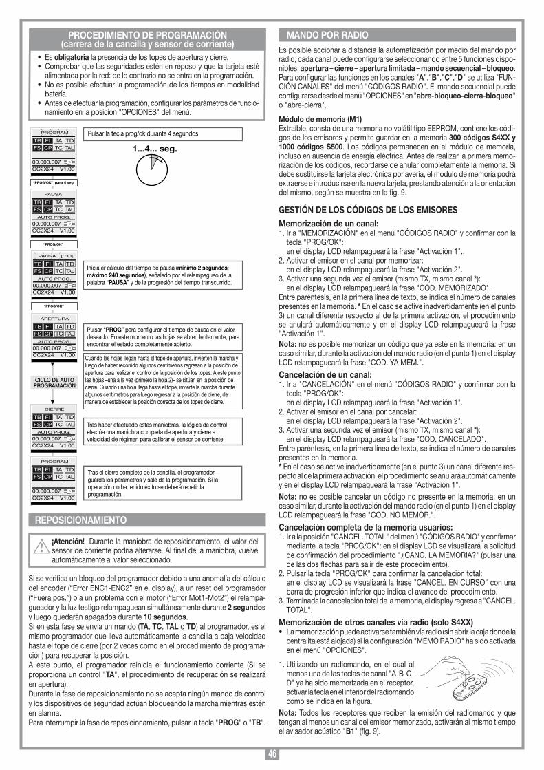
46
MEMORIZZAZIONE CODICE TX-RX
RCQ449100
13-04-2001
DM0531 Description :
Product Code :
Date :
Drawing number :
P.J.Heath
CARDIN ELETTRONICA S.p.A - 31020 San Vendemiano (TV) Italy - via Raffaello, 36 Tel: 0438/401818 Fax: 0438/401831
Draft :
All rights reserved. Unauthorised copying or use of the information contained in this document is punishable by law
MR
PROCEDIMIENTO DE PROGRAMACIÓN(carrera de la cancilla y sensor de corriente)
Es posible accionar a distancia la automatización por medio del mando por radio; cada canal puede configurarse seleccionando entre 5 funciones dispo-nibles: apertura – cierre – apertura limitada – mando secuencial – bloqueo.Para configurar las funciones en los canales "A","B","C","D" se utiliza "FUN-CIÓN CANALES" del menú "CÓDIGOS RADIO". El mando secuencial puede configurarse desde el menú "OPCIONES" en "abre-bloqueo-cierra-bloqueo" o "abre-cierra".
Módulo de memoria (M1)Extraíble, consta de una memoria no volátil tipo EEPROM, contiene los códi-gos de los emisores y permite guardar en la memoria 300 códigos S4XX y 1000 códigos S500. Los códigos permanecen en el módulo de memoria, incluso en ausencia de energía eléctrica. Antes de realizar la primera memo-rización de los códigos, recordarse de anular completamente la memoria. Si debe sustituirse la tarjeta electrónica por avería, el módulo de memoria podrá extraerse e introducirse en la nueva tarjeta, prestando atención a la orientación del mismo, según se muestra en la fig. 9.
GESTIÓN DE LOS CÓDIGOS DE LOS EMISORESMemorización de un canal:1. Ir a "MEMORIZACIÓN" en el menú "CÓDIGOS RADIO" y confirmar con la
tecla "PROG/OK": en el display LCD relampagueará la frase "Activación 1"..2. Activar el emisor en el canal por memorizar: en el display LCD relampagueará la frase "Activación 2".3. Activar una segunda vez el emisor (mismo TX, mismo canal *): en el display LCD relampagueará la frase "COD. MEMORIZADO".Entre paréntesis, en la primera línea de texto, se indica el número de canales presentes en la memoria. * En el caso se active inadvertidamente (en el punto 3) un canal diferente respecto al de la primera activación, el procedimiento se anulará automáticamente y en el display LCD relampagueará la frase "Activación 1".Nota: no es posible memorizar un código que ya esté en la memoria: en un caso similar, durante la activación del mando radio (en el punto 1) en el display LCD relampagueará la frase "COD. YA MEM.".
Cancelación de un canal:1. Ir a "CANCELACIÓN" en el menú "CÓDIGOS RADIO" y confirmar con la
tecla "PROG/OK": en el display LCD relampagueará la frase "Activación 1".2. Activar el emisor en el canal por cancelar: en el display LCD relampagueará la frase "Activación 2".3. Activar una segunda vez el emisor (mismo TX, mismo canal *): en el display LCD relampagueará la frase "COD. CANCELADO".Entre paréntesis, en la primera línea de texto, se indica el número de canales presentes en la memoria.* En el caso se active inadvertidamente (en el punto 3) un canal diferente res-pecto al de la primera activación, el procedimiento se anulará automáticamente y en el display LCD relampagueará la frase "Activación 1".Nota: no es posible cancelar un código no presente en la memoria: en un caso similar, durante la activación del mando radio (en el punto 1) en el display LCD relampagueará la frase "COD. NO MEMOR.".
Cancelación completa de la memoria usuarios:1. Ir a la posición "CANCEL. TOTAL" del menú "CÓDIGOS RADIO" y confirmar
mediante la tecla "PROG/OK": en el display LCD se visualizará la solicitud de confirmación del procedimiento "¿CANC. LA MEMORIA?" (pulsar una de las dos flechas para salir de este procedimiento).
2. Pulsar la tecla "PROG/OK" para confirmar la cancelación total: en el display LCD se visualizará la frase "CANCEL. EN CURSO" con una
barra de progresión inferior que indica el avance del procedimiento.3. Terminada la cancelación total de la memoria, el display regresa a "CANCEL.
TOTAL".
Memorización de otros canales vía radio (solo S4XX) • La memorización puede activarse también vía radio (sin abrir la caja donde la
centralita está alojada) si la configuración "MEMO RADIO" ha sido activada en el menú "OPCIONES".
1. Utilizando un radiomando, en el cual al menos una de las teclas de canal "A-B-C-D" ya ha sido memorizada en el receptor, activar la tecla en el interior del radiomando como se indica en la figura.
Nota: Todos los receptores que reciben la emisión del radiomando y que tengan al menos un canal del emisor memorizado, activarán al mismo tiempo el avisador acústico "B1" (fig. 9).
• Es obligatoria la presencia de los topes de apertura y cierre.• Comprobar que las seguridades estén en reposo y que la tarjeta esté
alimentada por la red: de lo contrario no se entra en la programación. • No es posible efectuar la programación de los tiempos en modalidad
batería.• Antes de efectuar la programación, configurar los parámetros de funcio-
namiento en la posición "OPCIONES" del menú.
REPOSICIONAMIENTO
¡Atención! Durante la maniobra de reposicionamiento, el valor del sensor de corriente podría alterarse. Al final de la maniobra, vuelve automáticamente al valor seleccionado.
Si se verifica un bloqueo del programador debido a una anomalía del cálculo del encoder (“Error ENC1-ENC2” en el display), a un reset del programador (“Fuera pos.”) o a un problema con el motor (“Error Mot1-Mot2”) el relampa-gueador y la luz testigo relampaguean simultáneamente durante 2 segundos y luego quedarán apagados durante 10 segundos. Si en esta fase se envía un mando (TA, TC, TAL o TD) al programador, es el mismo programador que lleva automáticamente la cancilla a baja velocidad hasta el tope de cierre (por 2 veces como en el procedimiento de programa-ción) para recuperar la posición.A este punto, el programador reinicia el funcionamiento corriente (Si se proporciona un control "TA", el procedimiento de recuperación se realizará en apertura). Durante la fase de reposicionamiento no se acepta ningún mando de control y los dispositivos de seguridad actúan bloqueando la marcha mientras estén en alarma.Para interrumpir la fase de reposicionamiento, pulsar la tecla "PROG" o "TB".
MANDO POR RADIO
1...4... seg.
Inicia er cálculo del tiempo de pausa (mínimo 2 segundos; máximo 240 segundos), señalado por el relampagueo de la palabra “PAUSA” y de la progresión del tiempo transcurrido.
Pulsar “PROG” para congurar el tiempo de pausa en el valor deseado. En este momento las hojas se abren lentamente, para encontrar el estado completamente abierto.
Cuando las hojas llegan hasta el tope de apertura, invierten la marcha y luego de haber recorrido algunos centímetros regresan a la posición de apertura para realizar el control de la posición de los topes. A este punto, las hojas –una a la vez (primero la hoja 2)– se sitúan en la posición de cierre. Cuando una hoja llega hasta el tope, invierte la marcha durante algunos centímetros para luego regresar a la posición de cierre, de manera de establecer la posición correcta de los topes de cierre.
Tras haber efectuado estas maniobras, la lógica de control efectúa una maniobra completa de apertura y cierre a velocidad de régimen para calibrar el sensor de corriente.
Tras el cierre completo de la cancilla, el programador guarda los parámetros y sale de la programación. Si la operación no ha tenido éxito se deberá repetir la programación.
Pulsar la tecla prog/ok durante 4 segundos
“PROG/OK” para 4 seg.
CICLO DE AUTOPROGRAMACIÓN
PROGRAM
TB FIFS CP
TA TDTC TAL
00.000.007CC2X24 V1.00
“PROG/OK”
PAUSA
TB FIFS CP
TA TDTC TAL
00.000.007CC2X24 V1.00
AUTO PROG.
“PROG/OK”
TB FIFS CP
TA TDTC TAL
00.000.007CC2X24 V1.00
AUTO PROG.
APERTURA
TB FIFS CP
TA TDTC TAL
00.000.007CC2X24 V1.00
AUTO PROG.
CIERRE
TB FIFS CP
TA TDTC TAL
00.000.007CC2X24 V1.00
AUTO PROG.
PROGRAM
TB FIFS CP
TA TDTC TAL
00.000.007CC2X24 V1.00
PAUSA [030]
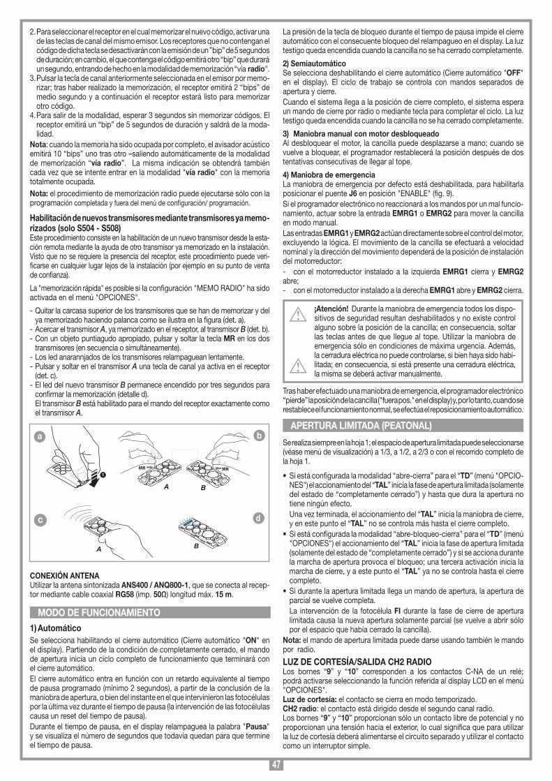
47
La presión de la tecla de bloqueo durante el tiempo de pausa impide el cierre automático con el consecuente bloqueo del relampagueo en el display. La luz testigo queda encendida cuando la cancilla no se ha cerrado completamente.
2) SemiautomáticoSe selecciona deshabilitando el cierre automático (Cierre automático "OFF" en el display). El ciclo de trabajo se controla con mandos separados de apertura y cierre. Cuando el sistema llega a la posición de cierre completo, el sistema espera un mando de cierre por radio o mediante tecla para completar el ciclo. La luz testigo queda encendida cuando la cancilla no se ha cerrado completamente.
3) Maniobra manual con motor desbloqueadoAl desbloquear el motor, la cancilla puede desplazarse a mano; cuando se vuelve a bloquear, el programador restablecerá la posición después de dos tentativas consecutivas de llegar al tope.
4) Maniobra de emergenciaLa maniobra de emergencia por defecto está deshabilitada, para habilitarla posicionar el puente J6 en posición "ENABLE" (fig. 9). Si el programador electrónico no reaccionará a los mandos por un mal funcio-namiento, actuar sobre la entrada EMRG1 o EMRG2 para mover la cancilla en modo manual. Las entradas EMRG1 y EMRG2 actúan directamente sobre el control del motor, excluyendo la lógica. El movimiento de la cancilla se efectuará a velocidad nominal y la dirección del movimiento dependerá de la posición de instalación del motorreductor:- con el motorreductor instalado a la izquierda EMRG1 cierra y EMRG2 abre;- con el motorreductor instalado a la derecha EMRG1 abre y EMRG2 cierra.
¡Atención! Durante la maniobra de emergencia todos los dispo-sitivos de seguridad resultan deshabilitados y no existe control alguno sobre la posición de la cancilla; en consecuencia, soltar las teclas antes de que llegue al tope. Utilizar la maniobra de emergencia sólo en condiciones de máxima urgencia. Además, la cerradura eléctrica no puede controlarse, si bien haya sido habi-litada; en consecuencia, si está presente una cerradura eléctrica, la misma se deberá activar manualmente.
Tras haber efectuado una maniobra de emergencia, el programador electrónico “pierde” la posición de la cancilla ("fuera pos." en el display) y, por lo tanto, cuando se restablece el funcionamiento normal, se efectúa el reposicionamiento automático.
Se realiza siempre en la hoja 1; el espacio de apertura limitada puede seleccionarse (véase menú de visualización) a 1/3, a 1/2, a 2/3 o con el recorrido completo de la hoja 1.
• Si está configurada la modalidad “abre-cierra” para el “TD” (menú "OPCIO-NES") el accionamiento del “TAL” inicia la fase de apertura limitada (solamente del estado de “completamente cerrado”) y hasta que dura la apertura no tiene ningún efecto.
Una vez terminada, el accionamiento del “TAL” inicia la maniobra de cierre, y en este punto el “TAL” no se controla más hasta el cierre completo.
• Si está configurada la modalidad “abre-bloqueo-cierra” para el “TD” (menú "OPCIONES") el accionamiento del “TAL” inicia la fase de apertura limitada (solamente del estado de “completamente cerrado”) y si se acciona durante la marcha de apertura provoca el bloqueo; una tercera activación inicia la marcha de cierre, y a este punto el “TAL” ya no se controla hasta el cierre completo.
• Si durante la apertura limitada llega un mando de apertura, la apertura de parcial se vuelve completa.
La intervención de la fotocélula FI durante la fase de cierre de apertura limitada causa la nueva apertura solamente parcial (se vuelve a abrir sólo por el espacio que había cerrado la cancilla).
Nota: el mando de apertura limitada puede darse usando también le mando por radio.
LUZ DE CORTESÍA/SALIDA CH2 RADIOLos bornes “9” y “10” corresponden a los contactos C-NA de un relé; podrá activarse seleccionando la función referida al display LCD en el menú "OPCIONES".Luz de cortesía: el contacto se cierra en modo temporizado.CH2 radio: el contacto está dirigido desde el segundo canal radio.Los bornes “9” y “10” proporcionan sólo un contacto libre de potencial y no proporcionan una tensión hacia el exterior, lo cual significa que para utilizar la luz de cortesía deberá alimentarse el circuito separado y utilizar el contacto como un interruptor simple.
APERTURA LIMITADA (PEATONAL)
MODO DE FUNCIONAMIENTO
2. Para seleccionar el receptor en el cual memorizar el nuevo código, activar una de las teclas de canal del mismo emisor. Los receptores que no contengan el código de dicha tecla se desactivarán con la emisión de un ”bip” de 5 segundos de duración; en cambio, el que contenga el código emitirá otro “bip” que durará un segundo, entrando de hecho en la modalidad de memorización “vía radio".
3. Pulsar la tecla de canal anteriormente seleccionada en el emisor por memo-rizar; tras haber realizado la memorización, el receptor emitirá 2 “bips” de medio segundo y a continuación el receptor estará listo para memorizar otro código.
4. Para salir de la modalidad, esperar 3 segundos sin memorizar códigos. El receptor emitirá un “bip” de 5 segundos de duración y saldrá de la moda-lidad.
Nota: cuando la memoria ha sido ocupada por completo, el avisador acústico emitirá 10 “bips” uno tras otro –saliendo automáticamente de la modalidad de memorización “vía radio”. La misma indicación se obtendrá también cada vez que se intente entrar en la modalidad "vía radio" con la memoria totalmente ocupada. Nota: el procedimiento de memorización radio puede ejecutarse sólo con la programación completada y fuera del menú de configuración/ programación.
Habilitación de nuevos transmisores mediante transmisores ya memo-rizados (solo S504 - S508)Este procedimiento consiste en la habilitación de un nuevo transmisor desde la esta-ción remota mediante la ayuda de otro transmisor ya memorizado en la instalación. Visto que no se requiere la presencia del receptor, este procedimiento puede veri-ficarse en cualquier lugar lejos de la instalación (por ejemplo en su punto de venta de confianza).
La "memorización rápida" es posible si la configuración "MEMO RADIO" ha sido activada en el menú "OPCIONES".
- Quitar la carcasa superior de los transmisores que se han de memorizar y del ya memorizado haciendo palanca como se ilustra en la figura (det. a).
- Acercar el transmisor A, ya memorizado en el receptor, al transmisor B (det. b).- Con un objeto puntiagudo apropiado, pulsar y soltar la tecla MR en los dos
transmisores (en secuencia o simultáneamente).- Los led anarannjados de los transmisores relampaguean lentamente.- Pulsar y soltar en el transmisor A una tecla de canal ya activa en el receptor
(det. c).- El led del nuevo transmisor B permanece encendido por tres segundos para
confirmar la memorización (detalle d). El transmisor B está habilitado para el mando del receptor exactamente como
el transmisor A.
Atención: Las in
CONEXIÓN ANTENA Utilizar la antena sintonizada ANS400 / ANQ800-1, que se conecta al recep-tor mediante cable coaxial RG58 (imp. 50Ω) longitud máx. 15 m.
1) AutomáticoSe selecciona habilitando el cierre automático (Cierre automático "ON" en el display). Partiendo de la condición de completamente cerrado, el mando de apertura inicia un ciclo completo de funcionamiento que terminará con el cierre automático. El cierre automático entra en función con un retardo equivalente al tiempo de pausa programado (mínimo 2 segundos), a partir de la conclusión de la maniobra de apertura, o bien del instante en el que intervinieron las fotocélulas por la última vez durante el tiempo de pausa (la intervención de las fotocélulas causa un reset del tiempo de pausa). Durante el tiempo de pausa, en el display relampaguea la palabra "Pausa" y se visualiza el número de segundos que todavía quedan para que termine el tiempo de pausa.
MEMORIZZAZIONE CODICE TX-TX
TRQ504
29-10-2013
DM0910 Description :
Product Code :
Date :
Drawing number :
P.J.Heath
CARDIN ELETTRONICA S.p.A - 31020 San Vendemiano (TV) Italy - via Raffaello, 36 Tel: 0438/401818 Fax: 0438/401831
Draft :
All rights reserved. Unauthorised copying or use of the information contained in this document is punishable by law
MR
A
MR
B
1
MEMORIZZAZIONE CODICE TX-TX
TXQ504C4
29-10-2013
DM0911 Description :
Product Code :
Date :
Drawing number :
P.J.Heath
CARDIN ELETTRONICA S.p.A - 31020 San Vendemiano (TV) Italy - via Raffaello, 36 Tel: 0438/401818 Fax: 0438/401831
Draft :
All rights reserved. Unauthorised copying or use of the information contained in this document is punishable by law
A
MEMORIZZAZIONE CODICE TX-TX
TXQ504C4
29-10-2013
DM0912 Description :
Product Code :
Date :
Drawing number :
P.J.Heath
CARDIN ELETTRONICA S.p.A - 31020 San Vendemiano (TV) Italy - via Raffaello, 36 Tel: 0438/401818 Fax: 0438/401831
Draft :
All rights reserved. Unauthorised copying or use of the information contained in this document is punishable by law
B
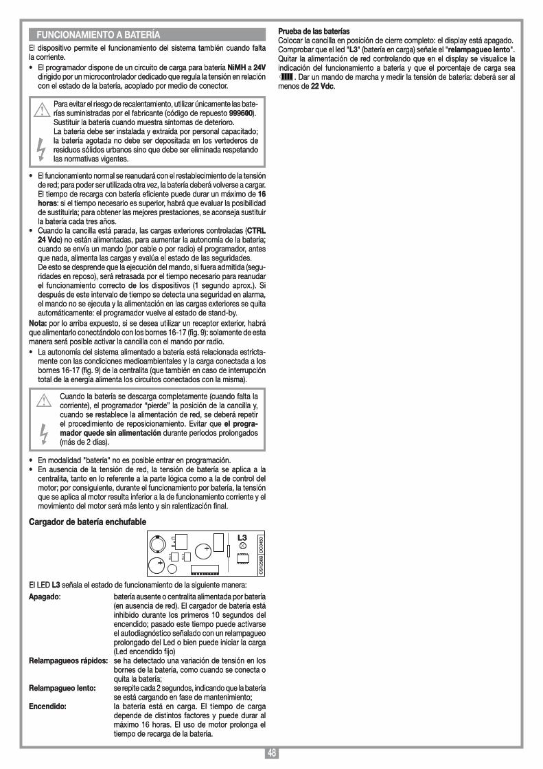
48
El dispositivo permite el funcionamiento del sistema también cuando falta la corriente. • El programador dispone de un circuito de carga para batería NiMH a 24V
dirigido por un microcontrolador dedicado que regula la tensión en relación con el estado de la batería, acoplado por medio de conector.
Para evitar el riesgo de recalentamiento, utilizar únicamente las bate-rías suministradas por el fabricante (código de repuesto 999600).Sustituir la batería cuando muestra síntomas de deterioro.La batería debe ser instalada y extraída por personal capacitado; la batería agotada no debe ser depositada en los vertederos de residuos sólidos urbanos sino que debe ser eliminada respetando las normativas vigentes.
• El funcionamiento normal se reanudará con el restablecimiento de la tensión de red; para poder ser utilizada otra vez, la batería deberá volverse a cargar. El tiempo de recarga con batería eficiente puede durar un máximo de 16 horas: si el tiempo necesario es superior, habrá que evaluar la posibilidad de sustituirla; para obtener las mejores prestaciones, se aconseja sustituir la batería cada tres años.
• Cuando la cancilla está parada, las cargas exteriores controladas (CTRL 24 Vdc) no están alimentadas, para aumentar la autonomía de la batería; cuando se envía un mando (por cable o por radio) el programador, antes que nada, alimenta las cargas y evalúa el estado de las seguridades.
De esto se desprende que la ejecución del mando, si fuera admitida (segu-ridades en reposo), será retrasada por el tiempo necesario para reanudar el funcionamiento correcto de los dispositivos (1 segundo aprox.). Si después de este intervalo de tiempo se detecta una seguridad en alarma, el mando no se ejecuta y la alimentación en las cargas exteriores se quita automáticamente: el programador vuelve al estado de stand-by.
Nota: por lo arriba expuesto, si se desea utilizar un receptor exterior, habrá que alimentarlo conectándolo con los bornes 16-17 (fig. 9): solamente de esta manera será posible activar la cancilla con el mando por radio.• La autonomía del sistema alimentado a batería está relacionada estricta-
mente con las condiciones medioambientales y la carga conectada a los bornes 16-17 (fig. 9) de la centralita (que también en caso de interrupción total de la energía alimenta los circuitos conectados con la misma).
Cuando la batería se descarga completamente (cuando falta la corriente), el programador “pierde” la posición de la cancilla y, cuando se restablece la alimentación de red, se deberá repetir el procedimiento de reposicionamiento. Evitar que el progra-mador quede sin alimentación durante períodos prolongados (más de 2 días).
• En modalidad "batería" no es posible entrar en programación.• En ausencia de la tensión de red, la tensión de batería se aplica a la
centralita, tanto en lo referente a la parte lógica como a la de control del motor; por consiguiente, durante el funcionamiento por batería, la tensión que se aplica al motor resulta inferior a la de funcionamiento corriente y el movimiento del motor será más lento y sin ralentización final.
Cargador de batería enchufable
El LED L3 señala el estado de funcionamiento de la siguiente manera:Apagado: batería ausente o centralita alimentada por batería
(en ausencia de red). El cargador de batería está inhibido durante los primeros 10 segundos del encendido; pasado este tiempo puede activarse el autodiagnóstico señalado con un relampagueo prolongado del Led o bien puede iniciar la carga (Led encendido fijo)
Relampagueos rápidos: se ha detectado una variación de tensión en los bornes de la batería, como cuando se conecta o quita la batería;
Relampagueo lento: se repite cada 2 segundos, indicando que la batería se está cargando en fase de mantenimiento;
Encendido: la batería está en carga. El tiempo de carga depende de distintos factores y puede durar al máximo 16 horas. El uso de motor prolonga el tiempo de recarga de la batería.
FUNCIONAMIENTO A BATERÍA
CS
1256
BD
C04
50L3
Scheda di innesto
PRG424BC
08-01-2008
DC0435 Description :
Product Code :
Date :
Drawing number :
P.J.Heath
CARDIN ELETTRONICA S.p.A - 31020 San Vendemiano (TV) Italy - via Raffaello, 36 Tel: 0438/401818 Fax: 0438/401831
Draft :
All rights reserved. Unauthorised copying or use of the information contained in this document is punishable by law
Scheda carica batteria
Prueba de las bateríasColocar la cancilla en posición de cierre completo: el display está apagado.Comprobar que el led "L3" (batería en carga) señale el "relampagueo lento".Quitar la alimentación de red controlando que en el display se visualice la indicación del funcionamiento a batería y que el porcentaje de carga sea
. Dar un mando de marcha y medir la tensión de batería: deberá ser al menos de 22 Vdc.
El dispositivo permite el funcionamiento del sistema también cuando falta la corriente. • El programador dispone de un circuito de carga para batería NiMH a 24V
dirigido por un microcontrolador dedicado que regula la tensión en relación con el estado de la batería, acoplado por medio de conector.
Para evitar el riesgo de recalentamiento, utilizar únicamente las bate-rías suministradas por el fabricante (código de repuesto 999540).Sustituir la batería cuando muestra síntomas de deterioro.La batería debe ser instalada y extraída por personal capacitado; la batería agotada no debe ser depositada en los vertederos de residuos sólidos urbanos sino que debe ser eliminada respetando las normativas vigentes.
• El funcionamiento normal se reanudará con el restablecimiento de la tensión de red; para poder ser utilizada otra vez, la batería deberá volverse a cargar. El tiempo de recarga con batería eficiente puede durar un máximo de 16 horas: si el tiempo necesario es superior, habrá que evaluar la posibilidad de sustituirla; para obtener las mejores prestaciones, se aconseja sustituir la batería cada tres años.
• Cuando la cancilla está parada, las cargas exteriores controladas (CTRL 24 Vdc) no están alimentadas, para aumentar la autonomía de la batería; cuando se envía un mando (por cable o por radio) el programador, antes que nada, alimenta las cargas y evalúa el estado de las seguridades.
De esto se desprende que la ejecución del mando, si fuera admitida (segu-ridades en reposo), será retrasada por el tiempo necesario para reanudar el funcionamiento correcto de los dispositivos (1 segundo aprox.). Si después de este intervalo de tiempo se detecta una seguridad en alarma, el mando no se ejecuta y la alimentación en las cargas exteriores se quita automáticamente: el programador vuelve al estado de stand-by.
Nota: por lo arriba expuesto, si se desea utilizar un receptor exterior, habrá que alimentarlo conectándolo con los bornes 16-17 (fig. 9): solamente de esta manera será posible activar la cancilla con el mando por radio.• La autonomía del sistema alimentado a batería está relacionada estricta-
mente con las condiciones medioambientales y la carga conectada a los bornes 16-17 (fig. 9) de la centralita (que también en caso de interrupción total de la energía alimenta los circuitos conectados con la misma).
Cuando la batería se descarga completamente (cuando falta la corriente), el programador “pierde” la posición de la cancilla y, cuando se restablece la alimentación de red, se deberá repetir el procedimiento de reposicionamiento. Evitar que el progra-mador quede sin alimentación durante períodos prolongados (más de 2 días).
• En modalidad "batería" no es posible entrar en programación.• En ausencia de la tensión de red, la tensión de batería se aplica a la
centralita, tanto en lo referente a la parte lógica como a la de control del motor; por consiguiente, durante el funcionamiento por batería, la tensión que se aplica al motor resulta inferior a la de funcionamiento corriente y el movimiento del motor será más lento y sin ralentización final.
Cargador de batería enchufable
El LED L3 señala el estado de funcionamiento de la siguiente manera:Apagado: batería ausente o centralita alimentada por batería
(en ausencia de red). El cargador de batería está inhibido durante los primeros 10 segundos del encendido; pasado este tiempo puede activarse el autodiagnóstico señalado con un relampagueo prolongado del Led o bien puede iniciar la carga (Led encendido fijo)
Relampagueos rápidos: se ha detectado una variación de tensión en los bornes de la batería, como cuando se conecta o quita la batería;
Relampagueo lento: se repite cada 2 segundos, indicando que la batería se está cargando en fase de mantenimiento;
Encendido: la batería está en carga. El tiempo de carga depende de distintos factores y puede durar al máximo 16 horas. El uso de motor prolonga el tiempo de recarga de la batería.
FUNCIONAMIENTO A BATERÍA
CS
1256
BD
C04
50L3
Scheda di innesto
PRG424BC
08-01-2008
DC0435 Description :
Product Code :
Date :
Drawing number :
P.J.Heath
CARDIN ELETTRONICA S.p.A - 31020 San Vendemiano (TV) Italy - via Raffaello, 36 Tel: 0438/401818 Fax: 0438/401831
Draft :
All rights reserved. Unauthorised copying or use of the information contained in this document is punishable by law
Scheda carica batteria
Prueba de las bateríasColocar la cancilla en posición de cierre completo: el display está apagado.Comprobar que el led "L3" (batería en carga) señale el "relampagueo lento".Quitar la alimentación de red controlando que en el display se visualice la indicación del funcionamiento a batería y que el porcentaje de carga sea
. Dar un mando de marcha y medir la tensión de batería: deberá ser al menos de 22 Vdc.
49
The CE conformity declaration for Cardin products is available in original language from the site www.cardin.it under the section "Standards and Certification".
Les déclarations de conformité CE des produits Cardin sont disponibles dans la langue originale sur le site www.cardin.it dans la section "normes et certificats".
Die CE-Konformitätserklärungen für die Cardin-Produkte stehen in der Originalsprache auf der Homepage www.cardin.it im Bereich "Normen und Zertifizierung" zur Verfügung.
Las declaraciones de conformidad CE de los productos Cardin se encuentran disponibles en el idioma original en el sitio www.cardin.it en la sección "normas y certificaciones".
BL 24 Vdc 11-01-2015DCE076
x x x x x x x x x x x x x x x x x x x x x x x x x x x x x x x x x x x x x x x x x x x x x x x x x x x x x x x x x x
x x x x x x x x x x x x x x x x x x x x x x x x x x x x x x x x x x x x x x x x x x x x x x x x x x x x x x x x x x
x x x x x x x x x x x x x x x x x x x x x x x x x x x x x x x x x x x x x x x x x x x x x x x x x x x x x x x x x x
x x x x x x x x x x x x x x x x x x x x x x x x x x x x x x x x x x x x x x x x x x x x x x x x x x x x x x x x x x
x x x x x x x x x x x x x x x x x x x x x x x x x x x x x x x x x x x x x x x x x x x x x x x x x x x x x x x x x x
x x x x x x x x x x x x x x x x x x x x x x x x x x x x x x x x x x x x x x x x x x x x x x x x x x x x x x x x x x
x x x x x x x x x x x x x x x x x x x x x x x x x x x x x x x x x x x x x x x x x x x x x x x x x x x x x x x x x x
x x x x x x x x x x x x x x x x x x x x x x x x x x x x x x x x x x x x x x x x x x x x x x x x x x x x x x x x x x
x x x x x x x x x x x x x x x x x x x x x x x x x x x x x x x x x x x x x x x x x x x x x x x x x x x x x x x x x x
x x x x x x x x x x x x x x x x x x x x x x x x x x x x x x x x x x x x x x x x x x x x x x x x x x x x x x x x x x
x x x x x x x x x x x x x x x x x x x x x x x x x x x x x x x x x x x x x x x x x x x x x x x x x x x x x x x x x x
CARDIN ELETTRONICA spa Via del lavoro, 73 – Z.I. Cimavilla 31013 Codognè (TV) ItalyTel.: (+39) 04 38 40 40 11 Fax: (+39) 04 38 40 18 31e-mail (Italy): [email protected] (Europe): [email protected]: www.cardin.it
Il costruttore: CARDIN ELETTRONICA S.p.A. DICHIARA CHE L'APPARECCHIATURA DESTINATA AD ESSERE INSERITA IN MACCHINE E NON FUNZIONANTE IN MODO INDIPENDENTE:
Nome dell'apparato Motoriduttore serie BL824 Tipo di apparato Automazione a 24 Vdc per cancelli a battente con centralina e modulo RF a bordo (su motore master)Modello BL824MCB - BL824S (motore master + slave)Marchio Cardin Elettronica - TelcomaAnno di prima fabbricazione 2011
MODELLO DATACODICE SERIE
Dichiarazione di Incorporazione(Direttiva Macchine 2006/42/EC, All. IIB)
DICHIARA CHE L'APPARECCHIATURA È IDEATA PER ESSERE INCORPORATA IN UNA MACCHINA O PER ESSERE ASSEMBLATA CON ALTRI MACCHINARI PER COSTITUIRE UNA MACCHINA CONSIDERATA DALLA DIRETTIVA 2006/42/CE E SUCCESSIVI EMENDAMENTI.INOLTRE DICHIARA CHE NON È CONSENTITO METTERE IN SERVIZIO L' APPARECCHIATURA FINO A CHE LA MACCHINA NELLA QUALE SARÀ INCORPORATA E DELLA QUALE DIVENTERÀ COMPONENTE NON SIA STATA IDENTIFICATA E DICHIARATA LA CONFORMITÀ ALLE DI-SPOSIZIONI DELLA DIRETTIVA 2006/42/CEE E SUCCESSIVI EMENDAMENTI.
Cardin Elettronica si impegna a trasmettere, in risposta a una richiesta adeguatamente motivata delle autorità nazionali, informazioni pertinenti sulla quasi-macchina in oggetto.
Codognè il 06/04/2016 Persona autorizzata a costituire la documentazione tecnica
Ing. A. Fiorotto (Responsabile tecnico R&D Laboratory)
Rappresentante legale dell'azienda
Dott. Cristiano Cardin (Amministratore delegato)
e sono state applicate le seguenti norme e/o specifiche tecniche:- EN 55014-1 : 2006 + A1 + A2- EN 55014-2 : 1997 + A1 :2001 + A2 :2008- EN 61000-3-2 : 2006 + A1 + A2- EN 61000-3-3 : 2013- EN 301489-1 : V1.9.2- EN 301489-3 : V1.6.1- EN 60335-1 : 2011- EN 60335-2 : 2003 + A11 2009- EN 62233 : 2008
è conforme alle disposizioni delle seguenti direttive comunitarie:- Direttiva 2014/30/EU (Compatibilità Elettromagnetica)- Direttiva 2014/35/EU (Bassa Tensione)- Direttiva 2014/53/EU (R&TTE)
La dichiarazione di conformità CE per i prodotti Cardin è disponibile in lingua originale nel sito www.cardin.it nella sezione "norme e certificazione" attraverso il link: The CE conformity declaration for Cardin products is available in original language from the site www.cardin.it under the section "Standards and Certification" via the link: Les déclarations de conformité CE des produits Cardin sont disponibles dans la langue originale sur le site www.cardin.it dans la section "normes et certificats" par le lien: Die CE-Konformitätserklärungen für die Cardin-Produkte stehen in der Originalsprache auf der Homepage www.cardin.it im Bereich "Normen und Zertifizierung" zur Verfügung unter dem Link: Las declaraciones de conformidad CE de los productos Cardin se encuentran disponibles en el idioma original en el sitio www.cardin.it en la secci—n "normas y certificaciones” en el enlace:
http://www.cardin.it/Attachment/dce076.pdf

50
NOTES

51
NOTES
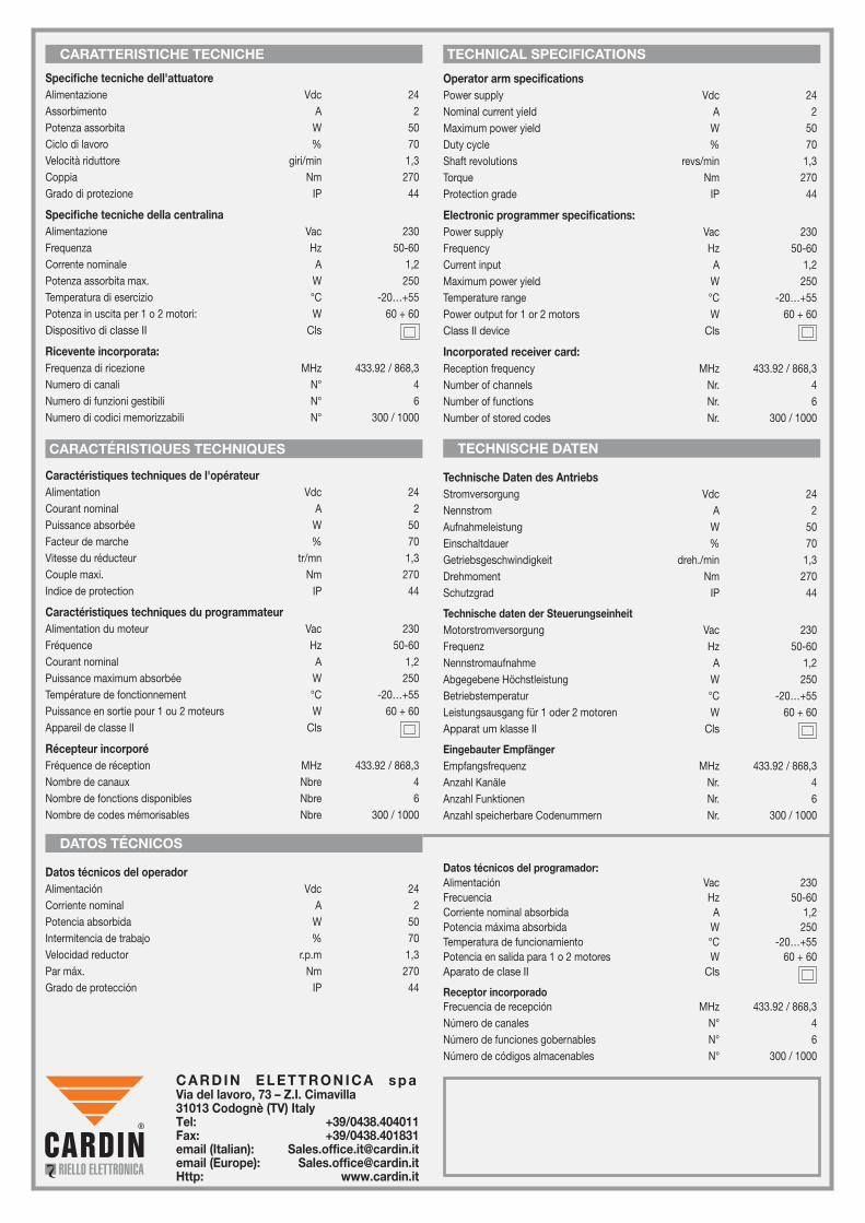
CARATTERISTICHE TECNICHE
Specifiche tecniche dell'attuatoreAlimentazione Vdc 24Assorbimento A 2Potenza assorbita W 50Ciclo di lavoro % 70Velocità riduttore giri/min 1,3Coppia Nm 270Grado di protezione IP 44
Specifiche tecniche della centralinaAlimentazione Vac 230Frequenza Hz 50-60Corrente nominale A 1,2Potenza assorbita max. W 250Temperatura di esercizio °C -20…+55Potenza in uscita per 1 o 2 motori: W 60 + 60 Dispositivo di classe II Cls
Ricevente incorporata:Frequenza di ricezione MHz 433.92 / 868,3Numero di canali N° 4Numero di funzioni gestibili N° 6Numero di codici memorizzabili N° 300 / 1000
CARACTÉRISTIQUES TECHNIQUES
DATOS TÉCNICOS
TECHNISCHE DATEN
Datos técnicos del operadorAlimentación Vdc 24 Corriente nominal A 2Potencia absorbida W 50Intermitencia de trabajo % 70Velocidad reductor r.p.m 1,3Par máx. Nm 270Grado de protección IP 44
Datos técnicos del programador:Alimentación Vac 230Frecuencia Hz 50-60 Corriente nominal absorbida A 1,2Potencia máxima absorbida W 250Temperatura de funcionamiento °C -20…+55Potencia en salida para 1 o 2 motores W 60 + 60Aparato de clase II Cls
Receptor incorporadoFrecuencia de recepción MHz 433.92 / 868,3Número de canales N° 4Número de funciones gobernables N° 6Número de códigos almacenables N° 300 / 1000
Operator arm specificationsPower supply Vdc 24Nominal current yield A 2Maximum power yield W 50Duty cycle % 70Shaft revolutions revs/min 1,3Torque Nm 270Protection grade IP 44
Electronic programmer specifications:Power supply Vac 230Frequency Hz 50-60Current input A 1,2Maximum power yield W 250Temperature range °C -20…+55Power output for 1 or 2 motors W 60 + 60Class II device Cls
Incorporated receiver card:Reception frequency MHz 433.92 / 868,3Number of channels Nr. 4Number of functions Nr. 6Number of stored codes Nr. 300 / 1000
Caractéristiques techniques de l'opérateurAlimentation Vdc 24 Courant nominal A 2Puissance absorbée W 50Facteur de marche % 70Vitesse du réducteur tr/mn 1,3Couple maxi. Nm 270Indice de protection IP 44
Caractéristiques techniques du programmateurAlimentation du moteur Vac 230Fréquence Hz 50-60 Courant nominal A 1,2Puissance maximum absorbée W 250Température de fonctionnement °C -20…+55Puissance en sortie pour 1 ou 2 moteurs W 60 + 60 Appareil de classe II Cls
Récepteur incorporéFréquence de réception MHz 433.92 / 868,3Nombre de canaux Nbre 4Nombre de fonctions disponibles Nbre 6Nombre de codes mémorisables Nbre 300 / 1000
Technische Daten des AntriebsStromversorgung Vdc 24 Nennstrom A 2Aufnahmeleistung W 50Einschaltdauer % 70Getriebsgeschwindigkeit dreh./min 1,3Drehmoment Nm 270Schutzgrad IP 44
Technische daten der SteuerungseinheitMotorstromversorgung Vac 230Frequenz Hz 50-60 Nennstromaufnahme A 1,2Abgegebene Höchstleistung W 250Betriebstemperatur °C -20…+55Leistungsausgang für 1 oder 2 motoren W 60 + 60Apparat um klasse II Cls
Eingebauter EmpfängerEmpfangsfrequenz MHz 433.92 / 868,3Anzahl Kanäle Nr. 4Anzahl Funktionen Nr. 6Anzahl speicherbare Codenummern Nr. 300 / 1000
TECHNICAL SPECIFICATIONS
C A R D I N E L E T T R O N I C A s p a Via del lavoro, 73 – Z.I. Cimavilla 31013 Codognè (TV) ItalyTel: +39/0438.404011Fax: +39/0438.401831email (Italian): [email protected] (Europe): [email protected]: www.cardin.it
Related Documents