24-Port Layer 3 Switch Management Guide

Welcome message from author
This document is posted to help you gain knowledge. Please leave a comment to let me know what you think about it! Share it to your friends and learn new things together.
Transcript
24-Port Layer 3 Switch
Management Guide

Management Guide Guide
24-Port Layer 3 SwitchLayer 3 Workgroup Switch with 24 10/100BASE-TX (RJ-45) Ports, and 2 Slots for Gigabit Uplink Modules

ES3626G-ZZF1.1.0.0 E032003-R02150200027900A
Contents
Chapter 1: Introduction 1-1Key Features 1-1Description of Software Features 1-2System Defaults 1-6
Chapter 2: Initial Configuration 2-1Connecting to the Switch 2-1
Configuration Options 2-1Required Connections 2-2Remote Connections 2-3
Basic Configuration 2-3Console Connection 2-3Setting Passwords 2-4Setting an IP Address 2-4
Manual Configuration 2-4Dynamic Configuration 2-5
Enabling SNMP Management Access 2-6Community Strings 2-6Trap Receivers 2-7
Saving Configuration Settings 2-8Managing System Files 2-8
Chapter 3: Configuring the Switch 3-1Using the Web Interface 3-1Navigating the Web Browser Interface 3-2
Home Page 3-2Configuration Options 3-2Panel Display 3-3Main Menu 3-3
Basic Configuration 3-8Displaying System Information 3-8Displaying Switch Hardware/Software Versions 3-9Displaying Bridge Extension Capabilities 3-10Setting the Switch’s IP Address 3-12
Manual Configuration 3-13Using DHCP/BOOTP 3-13
Managing Firmware 3-15Downloading System Software from a Server 3-15
Saving or Restoring Configuration Settings 3-16Downloading Configuration Settings from a Server 3-17
Setting the System Clock 3-18Configuring SNTP 3-18Setting the Time Zone 3-19
v
Contents
Resetting the System 3-20User Authentication 3-20
Configuring the Logon Password 3-20Configuring RADIUS Logon Authentication 3-21Configuring 802.1x Port Authentication 3-23
Displaying 802.1x Global Settings 3-24Configuring 802.1x Global Settings 3-26Configuring Port Authorization Mode 3-27Displaying 802.1x Statistics 3-28
Access Control Lists 3-30Configuring Access Control Lists 3-30Binding a Port to an Access Control List 3-36
Simple Network Management Protocol 3-36Setting Community Access Strings 3-37Specifying Trap Managers and Trap Types 3-38
Dynamic Host Configuration Protocol 3-38Configuring DHCP Relay Service 3-39Configuring the DHCP Server 3-40
Enabling the Server, Setting Excluded Addresses 3-40Configuring Address Pools 3-41Displaying Address Bindings 3-46
Port Configuration 3-47Displaying Connection Status 3-47Configuring Interface Connections 3-49Setting Broadcast Storm Thresholds 3-50Configuring Port Mirroring 3-52Showing Port Statistics 3-53Configuring Rate Limits 3-57
Trunk Configuration 3-58Dynamically Configuring a Trunk 3-59Statically Configuring a Trunk 3-60
Address Table Settings 3-62Setting Static Addresses 3-62Displaying the Address Table 3-63Changing the Aging Time 3-64
Spanning Tree Algorithm Configuration 3-64Displaying Global Settings 3-65Configuring Global Settings 3-67Displaying Interface Settings 3-70Configuring Interface Settings 3-72
VLAN Configuration 3-74Overview 3-74
Assigning Ports to VLANs 3-75Forwarding Tagged/Untagged Frames 3-76
Enabling or Disabling GVRP (Global Setting) 3-77
vi
Contents
Displaying Basic VLAN Information 3-77Displaying Current VLANs 3-78Creating VLANs 3-80Adding Static Members to VLANs (VLAN Index) 3-81Adding Static Members to VLANs (Port Index) 3-83Configuring VLAN Behavior for Interfaces 3-83Configuring Private VLANs 3-86
Enabling Private VLANs 3-86Configuring Uplink and Downlink Ports 3-86
Class of Service Configuration 3-87Setting the Default Priority for Interfaces 3-87Mapping CoS Values to Egress Queues 3-88Setting the Service Weight for Traffic Classes 3-90Mapping Layer 3/4 Priorities to CoS Values 3-91Selecting IP Precedence/DSCP Priority 3-91Mapping IP Precedence 3-92Mapping DSCP Priority 3-94Mapping IP Port Priority 3-96Copying IP Settings to Another Interface 3-97
Multicast Filtering 3-98IGMP Protocol 3-99Layer 2 IGMP (Snooping and Query) 3-99
Configuring IGMP Snooping Parameters 3-100Displaying Interfaces Attached to a Multicast Router 3-101Specifying Static Interfaces for a Multicast Router 3-102Displaying Port Members of Multicast Services 3-104Assigning Ports to Multicast Services 3-105
Layer 3 IGMP (Query used with Multicast Routing) 3-106Configuring IGMP Interface Parameters 3-106Displaying Multicast Group Information 3-109
IP Routing 3-110Overview 3-110
Initial Configuration 3-110IP Switching 3-111
Routing Path Management 3-112Routing Protocols 3-112
Basic IP Interface Configuration 3-114Configuring IP Routing Interfaces 3-115Address Resolution Protocol 3-116
Proxy ARP 3-117Basic ARP Configuration 3-117Configuring Static ARP Addresses 3-118Displaying Dynamically Learned ARP Entries 3-119Displaying Local ARP Entries 3-121Displaying ARP Statistics 3-122
vii
Contents
Displaying Statistics for IP Protocols 3-123IP Statistics 3-123ICMP Statistics 3-124UDP Statistics 3-126TCP Statistics 3-127
Configuring Static Routes 3-128Displaying the Routing Table 3-129Configuring the Routing Information Protocol 3-130
Configuring General Protocol Settings 3-131Specifying Network Interfaces for RIP 3-133Configuring Network Interfaces for RIP 3-134Displaying RIP Information and Statistics 3-137
Multicast Routing 3-139Configuring Global Settings for Multicast Routing 3-140Displaying the Multicast Routing Table 3-140Configuring DVMRP 3-142
Configuring Global DVMRP Settings 3-142Configuring DVMRP Interface Settings 3-144Displaying Neighbor Information 3-146Displaying the Routing Table 3-147
Configuring PIM-DM 3-148Configuring Global PIM-DM Settings 3-148Configuring PIM-DM Interface Settings 3-149Displaying Interface Information 3-151Displaying Neighbor Information 3-152
Chapter 4: Command Line Interface 4-1Using the Command Line Interface 4-1
Accessing the CLI 4-1Console Connection 4-1Telnet Connection 4-2
Entering Commands 4-3Keywords and Arguments 4-3Minimum Abbreviation 4-3Command Completion 4-3Getting Help on Commands 4-3
Showing Commands 4-4Partial Keyword Lookup 4-4Negating the Effect of Commands 4-5Using Command History 4-5Understanding Command Modes 4-5Exec Commands 4-5Configuration Commands 4-6Command Line Processing 4-7
Command Groups 4-8
viii
Contents
Line Commands 4-9line 4-9login 4-10password 4-11exec-timeout 4-12password-thresh 4-12silent-time 4-13databits 4-14parity 4-14speed 4-15stopbits 4-16show line 4-16
General Commands 4-17enable 4-17disable 4-18configure 4-18show history 4-19reload 4-19end 4-20exit 4-21quit 4-21
System Management Commands 4-22Device Designation Commands 4-22
prompt 4-22hostname 4-23
User Access Commands 4-23username 4-23enable password 4-24
Web Server Commands 4-25ip http port 4-25ip http server 4-26
Event Logging Commands 4-26logging on 4-26logging history 4-27clear logging 4-28show logging 4-28
Time Commands 4-29sntp client 4-29sntp server 4-30sntp poll 4-31sntp broadcast client 4-32show sntp 4-32clock timezone 4-33
System Status Commands 4-34show startup-config 4-34
ix
Contents
show running-config 4-36show system 4-38show users 4-38show version 4-39
Flash/File Commands 4-40copy 4-40delete 4-42dir 4-42whichboot 4-43boot system 4-44
Authentication Commands 4-44Authentication Sequence 4-45
authentication login 4-45RADIUS Client 4-46
radius-server host 4-46radius-server port 4-46radius-server key 4-47radius-server retransmit 4-47radius-server timeout 4-48show radius-server 4-48
802.1x Port Authentication 4-49authentication dot1x default 4-49dot1x default 4-50dot1x max-req 4-50dot1x port-control 4-51dot1x re-authenticate 4-51dot1x re-authentication 4-52dot1x timeout quiet-period 4-52dot1x timeout re-authperiod 4-53dot1x timeout tx-period 4-53show dot1x 4-54
Access Control List Commands 4-56IP ACLs 4-56
access-list ip 4-57permit, deny (Standard ACL) 4-58permit, deny (Extended ACL) 4-59ip access-group 4-61show ip access-group 4-61show ip access-list 4-62
MAC ACLs 4-62access-list mac 4-63permit, deny (MAC ACL) 4-64mac access-group 4-65show mac access-group 4-65show mac access-list 4-66
x
Contents
ACL Information 4-67show access-list 4-67show access-group 4-67
SNMP Commands 4-68snmp-server community 4-68snmp-server contact 4-69snmp-server location 4-69snmp-server host 4-70snmp-server enable traps 4-71show snmp 4-72
DHCP Commands 4-73DHCP Client 4-73
ip dhcp client-identifier 4-73ip dhcp restart client 4-74
DHCP Relay 4-75ip dhcp restart relay 4-75ip dhcp relay server 4-76
DHCP Server 4-77service dhcp 4-77ip dhcp excluded-address 4-78ip dhcp pool 4-78network 4-79default-router 4-80domain-name 4-80dns-server 4-81next-server 4-81bootfile 4-82netbios-name-server 4-82netbios-node-type 4-83lease 4-84host 4-84client-identifier 4-85hardware-address 4-86clear ip dhcp binding 4-87show ip dhcp binding 4-87
Interface Commands 4-89interface 4-89description 4-90speed-duplex 4-90negotiation 4-91capabilities 4-92flowcontrol 4-93shutdown 4-94switchport broadcast packet-rate 4-95clear counters 4-95
xi
Contents
show interfaces status 4-96show interfaces counters 4-97show interfaces switchport 4-98
Mirror Port Commands 4-100port monitor 4-100show port monitor 4-101
Rate Limit Commands 4-102rate-limit 4-102
Link Aggregation Commands 4-103channel-group 4-104lacp 4-104
Address Table Commands 4-106mac-address-table static 4-106clear mac-address-table dynamic 4-107show mac-address-table 4-108mac-address-table aging-time 4-109show mac-address-table aging-time 4-109
Spanning Tree Commands 4-110spanning-tree 4-110spanning-tree mode 4-111spanning-tree forward-time 4-112spanning-tree hello-time 4-112spanning-tree max-age 4-113spanning-tree priority 4-114spanning-tree pathcost method 4-114spanning-tree transmission-limit 4-115spanning-tree cost 4-116spanning-tree port-priority 4-116spanning-tree edge-port 4-117spanning-tree portfast 4-118spanning-tree link-type 4-119spanning-tree protocol-migration 4-120show spanning-tree 4-120
VLAN Commands 4-122Editing VLAN Groups 4-122
vlan database 4-122vlan 4-123
Configuring VLAN Interfaces 4-124interface vlan 4-124switchport mode 4-125switchport acceptable-frame-types 4-125switchport ingress-filtering 4-126switchport native vlan 4-127switchport allowed vlan 4-128switchport forbidden vlan 4-129
xii
Contents
Displaying VLAN Information 4-130show vlan 4-130
Configuring Private VLANs 4-131pvlan 4-131show pvlan 4-132
GVRP and Bridge Extension Commands 4-132bridge-ext gvrp 4-132show bridge-ext 4-133switchport gvrp 4-134show gvrp configuration 4-134garp timer 4-135show garp timer 4-136
Priority Commands 4-136Priority Commands (Layer 2) 4-137
switchport priority default 4-137queue bandwidth 4-138queue cos-map 4-139show queue bandwidth 4-140show queue cos-map 4-140
Priority Commands (Layer 3 and 4) 4-141map ip port (Global Configuration) 4-141map ip port (Interface Configuration) 4-142map ip precedence (Global Configuration) 4-142map ip precedence (Interface Configuration) 4-143map ip dscp (Global Configuration) 4-144map ip dscp (Interface Configuration) 4-145show map ip port 4-146show map ip precedence 4-146show map ip dscp 4-147
Multicast Filtering Commands 4-148IGMP Snooping Commands 4-149
ip igmp snooping 4-149ip igmp snooping vlan static 4-149ip igmp snooping version 4-150show ip igmp snooping 4-151show mac-address-table multicast 4-151
IGMP Query Commands (Layer 2) 4-152ip igmp snooping querier 4-152ip igmp snooping query-count 4-153ip igmp snooping query-interval 4-153ip igmp snooping query-max-response-time 4-154ip igmp snooping router-port-expire-time 4-155
IGMP Commands (Layer 3) 4-156ip igmp 4-156ip igmp robustval 4-157
xiii

Contents
ip igmp query-interval 4-158ip igmp max-resp-interval 4-158ip igmp last-memb-query-interval 4-159ip igmp version 4-160show ip igmp interface 4-160clear ip igmp group 4-161show ip igmp groups 4-162
IP Interface Commands 4-163Basic IP Configuration 4-163
ip address 4-163ip default-gateway 4-165show ip interface 4-165show ip redirects 4-166ping 4-166
Address Resolution Protocol (ARP) 4-168arp 4-168arp-timeout 4-169clear arp-cache 4-169show arp 4-170ip proxy-arp 4-170
IP Routing Commands 4-171Global Routing Configuration 4-171
ip routing 4-171ip route 4-172clear ip route 4-173show ip route 4-173show ip traffic 4-174
Routing Information Protocol (RIP) 4-175router rip 4-175timers basic 4-176network 4-177neighbor 4-177version 4-178ip rip receive version 4-179ip rip send version 4-180ip split-horizon 4-181ip rip authentication key 4-181ip rip authentication mode 4-182show rip globals 4-183show ip rip 4-183
Multicast Routing Commands 4-184Static Multicast Routing Commands 4-185
ip igmp snooping vlan mrouter 4-185show ip igmp snooping mrouter 4-186
General Multicast Routing Commands 4-186
xiv
Contents
ip multicast-routing 4-186show ip mroute 4-187
DVMRP Multicast Routing Commands 4-189router dvmrp 4-189probe-interval 4-190nbr-timeout 4-191report-interval 4-191flash-update-interval 4-192prune-lifetime 4-192default-gateway 4-193ip dvmrp 4-193ip dvmrp metric 4-194clear ip dvmrp route 4-195show router dvmrp 4-195show ip dvmrp route 4-196show ip dvmrp neighbor 4-196show ip dvmrp interface 4-197
PIM-DM Multicast Routing Commands 4-198router pim 4-198ip pim dense-mode 4-199ip pim hello-interval 4-200ip pim hello-holdtime 4-200ip pim trigger-hello-interval 4-201ip pim join-prune-holdtime 4-201ip pim graft-retry-interval 4-202ip pim max-graft-retries 4-203show router pim 4-203show ip pim interface 4-203show ip pim neighbor 4-204
Appendix A: Software Specifications A-1Software Features A-1Management Features A-2Standards A-2Management Information Bases A-3
Appendix B: Upgrading Firmware via the Serial Port B-1Appendix C: Troubleshooting C-1
Glossary
Index
xv

Contents
xvi
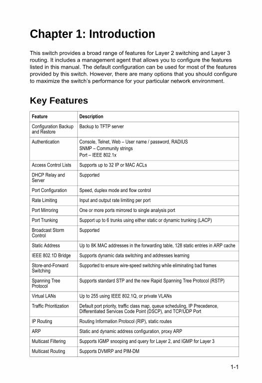
Chapter 1: IntroductionThis switch provides a broad range of features for Layer 2 switching and Layer 3 routing. It includes a management agent that allows you to configure the features listed in this manual. The default configuration can be used for most of the features provided by this switch. However, there are many options that you should configure to maximize the switch’s performance for your particular network environment.
Key Features
Feature Description
Configuration Backup and Restore
Backup to TFTP server
Authentication Console, Telnet, Web – User name / password, RADIUSSNMP – Community stringsPort – IEEE 802.1x
Access Control Lists Supports up to 32 IP or MAC ACLs
DHCP Relay and Server
Supported
Port Configuration Speed, duplex mode and flow control
Rate Limiting Input and output rate limiting per port
Port Mirroring One or more ports mirrored to single analysis port
Port Trunking Support up to 6 trunks using either static or dynamic trunking (LACP)
Broadcast Storm Control
Supported
Static Address Up to 8K MAC addresses in the forwarding table, 128 static entries in ARP cache
IEEE 802.1D Bridge Supports dynamic data switching and addresses learning
Store-and-Forward Switching
Supported to ensure wire-speed switching while eliminating bad frames
Spanning Tree Protocol
Supports standard STP and the new Rapid Spanning Tree Protocol (RSTP)
Virtual LANs Up to 255 using IEEE 802.1Q, or private VLANs
Traffic Prioritization Default port priority, traffic class map, queue scheduling, IP Precedence, Differentiated Services Code Point (DSCP), and TCP/UDP Port
IP Routing Routing Information Protocol (RIP), static routes
ARP Static and dynamic address configuration, proxy ARP
Multicast Filtering Supports IGMP snooping and query for Layer 2, and IGMP for Layer 3
Multicast Routing Supports DVMRP and PIM-DM
1-1
Introduction
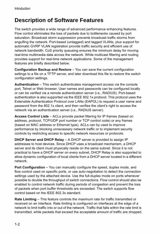
Description of Software FeaturesThe switch provides a wide range of advanced performance enhancing features. Flow control eliminates the loss of packets due to bottlenecks caused by port saturation. Broadcast storm suppression prevents broadcast traffic storms from engulfing the network. Port-based (untagged) and tagged VLANs, plus support for automatic GVRP VLAN registration provide traffic security and efficient use of network bandwidth. CoS priority queueing ensures the minimum delay for moving real-time multimedia data across the network. While multicast filtering and routing provides support for real-time network applications. Some of the management features are briefly described below.
Configuration Backup and Restore – You can save the current configuration settings to a file on a TFTP server, and later download this file to restore the switch configuration settings.
Authentication – This switch authenticates management access via the console port, Telnet or Web browser. User names and passwords can be configured locally or can be verified via a remote authentication server (i.e., RADIUS). Port-based authentication is also supported via the IEEE 802.1x protocol. This protocol uses the Extensible Authentication Protocol over LANs (EAPOL) to request a user name and password from the 802.1x client, and then verifies the client’s right to access the network via an authentication server (i.e., RADIUS server).
Access Control Lists – ACLs provide packet filtering for IP frames (based on address, protocol, TCP/UDP port number or TCP control code) or any frames (based on MAC address or Ethernet type). ACLs can by used to improve performance by blocking unnecessary network traffic or to implement security controls by restricting access to specific network resources or protocols.
DHCP Server and DHCP Relay – A DHCP server is provided to assign IP addresses to host devices. Since DHCP uses a broadcast mechanism, a DHCP server and its client must physically reside on the same subnet. Since it is not practical to have a DHCP server on every subnet, DHCP Relay is also supported to allow dynamic configuration of local clients from a DHCP server located in a different network.
Port Configuration – You can manually configure the speed, duplex mode, and flow control used on specific ports, or use auto-negotiation to detect the connection settings used by the attached device. Use the full-duplex mode on ports whenever possible to double the throughput of switch connections. Flow control should also be enabled to control network traffic during periods of congestion and prevent the loss of packets when port buffer thresholds are exceeded. The switch supports flow control based on the IEEE 802.3x standard.
Rate Limiting – This feature controls the maximum rate for traffic transmitted or received on an interface. Rate limiting is configured on interfaces at the edge of a network to limit traffic into or out of the network. Traffic that falls within the rate limit is transmitted, while packets that exceed the acceptable amount of traffic are dropped.
1-2
Description of Software Features
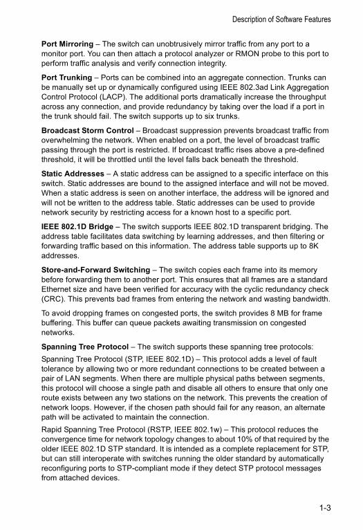
Port Mirroring – The switch can unobtrusively mirror traffic from any port to a monitor port. You can then attach a protocol analyzer or RMON probe to this port to perform traffic analysis and verify connection integrity.
Port Trunking – Ports can be combined into an aggregate connection. Trunks can be manually set up or dynamically configured using IEEE 802.3ad Link Aggregation Control Protocol (LACP). The additional ports dramatically increase the throughput across any connection, and provide redundancy by taking over the load if a port in the trunk should fail. The switch supports up to six trunks.
Broadcast Storm Control – Broadcast suppression prevents broadcast traffic from overwhelming the network. When enabled on a port, the level of broadcast traffic passing through the port is restricted. If broadcast traffic rises above a pre-defined threshold, it will be throttled until the level falls back beneath the threshold.
Static Addresses – A static address can be assigned to a specific interface on this switch. Static addresses are bound to the assigned interface and will not be moved. When a static address is seen on another interface, the address will be ignored and will not be written to the address table. Static addresses can be used to provide network security by restricting access for a known host to a specific port.
IEEE 802.1D Bridge – The switch supports IEEE 802.1D transparent bridging. The address table facilitates data switching by learning addresses, and then filtering or forwarding traffic based on this information. The address table supports up to 8K addresses.
Store-and-Forward Switching – The switch copies each frame into its memory before forwarding them to another port. This ensures that all frames are a standard Ethernet size and have been verified for accuracy with the cyclic redundancy check (CRC). This prevents bad frames from entering the network and wasting bandwidth.
To avoid dropping frames on congested ports, the switch provides 8 MB for frame buffering. This buffer can queue packets awaiting transmission on congested networks.
Spanning Tree Protocol – The switch supports these spanning tree protocols:Spanning Tree Protocol (STP, IEEE 802.1D) – This protocol adds a level of fault tolerance by allowing two or more redundant connections to be created between a pair of LAN segments. When there are multiple physical paths between segments, this protocol will choose a single path and disable all others to ensure that only one route exists between any two stations on the network. This prevents the creation of network loops. However, if the chosen path should fail for any reason, an alternate path will be activated to maintain the connection.Rapid Spanning Tree Protocol (RSTP, IEEE 802.1w) – This protocol reduces the convergence time for network topology changes to about 10% of that required by the older IEEE 802.1D STP standard. It is intended as a complete replacement for STP, but can still interoperate with switches running the older standard by automatically reconfiguring ports to STP-compliant mode if they detect STP protocol messages from attached devices.
1-3
Introduction
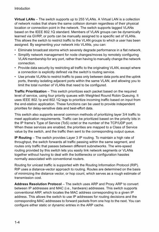
Virtual LANs – The switch supports up to 255 VLANs. A Virtual LAN is a collection of network nodes that share the same collision domain regardless of their physical location or connection point in the network. The switch supports tagged VLANs based on the IEEE 802.1Q standard. Members of VLAN groups can be dynamically learned via GVRP, or ports can be manually assigned to a specific set of VLANs. This allows the switch to restrict traffic to the VLAN groups to which a user has been assigned. By segmenting your network into VLANs, you can:• Eliminate broadcast storms which severely degrade performance in a flat network.• Simplify network management for node changes/moves by remotely configuring
VLAN membership for any port, rather than having to manually change the network connection.
• Provide data security by restricting all traffic to the originating VLAN, except where a connection is explicitly defined via the switch’s routing service.
• Use private VLANs to restrict traffic to pass only between data ports and the uplink ports, thereby isolating adjacent ports within the same VLAN, and allowing you to limit the total number of VLANs that need to be configured.
Traffic Prioritization – This switch prioritizes each packet based on the required level of service, using four priority queues with Weighted Round Robin Queuing. It uses IEEE 802.1p and 802.1Q tags to prioritize incoming traffic based on input from the end-station application. These functions can be used to provide independent priorities for delay-sensitive data and best-effort data.
This switch also supports several common methods of prioritizing layer 3/4 traffic to meet application requirements. Traffic can be prioritized based on the priority bits in the IP frame’s Type of Service (ToS) octet or the number of the TCP/UDP port. When these services are enabled, the priorities are mapped to a Class of Service value by the switch, and the traffic then sent to the corresponding output queue.
IP Routing – The switch provides Layer 3 IP routing. To maintain a high rate of throughput, the switch forwards all traffic passing within the same segment, and routes only traffic that passes between different subnetworks. The wire-speed routing provided by this switch lets you easily link network segments or VLANs together without having to deal with the bottlenecks or configuration hassles normally associated with conventional routers.
Routing for unicast traffic is supported with the Routing Information Protocol (RIP). RIP uses a distance-vector approach to routing. Routes are determined on the basis of minimizing the distance vector, or hop count, which serves as a rough estimate of transmission cost.
Address Resolution Protocol – The switch uses ARP and Proxy ARP to convert between IP addresses and MAC (i.e., hardware) addresses. This switch supports conventional ARP, which locates the MAC address corresponding to a given IP address. This allows the switch to use IP addresses for routing decisions and the corresponding MAC addresses to forward packets from one hop to the next. You can configure either static or dynamic entries in the ARP cache.
1-4
Description of Software Features
Proxy ARP allows hosts that do not support routing to determine the MAC address of a device on another network or subnet. When a host sends an ARP request for a remote network, the switch checks to see if it has the best route. If it does, it sends its own MAC address to the host. The host then sends traffic for the remote destination via the switch, which uses its own routing table to reach the destination on the other network.
Multicast Filtering – Specific multicast traffic can be assigned to its own VLAN to ensure that it does not interfere with normal network traffic and to guarantee real-time delivery by setting the required priority level for the designated VLAN. The switch uses IGMP Snooping at Layer 2 and IGMP at Layer 3 to manage multicast group registration.
Multicast Routing – Routing for multicast packets is supported by the Distance Vector Multicast Routing Protocol (DVMRP) and Protocol-Independent Multicasting - Dense Mode (PIM-DM). These protocols work in conjunction with IGMP to filter and route multicast traffic. DVMRP is a more comprehensive implementation that maintains its own routing table, but is gradually being replacing by most network managers with PIM, Dense Mode and Sparse Mode. PIM is a very simple protocol that uses the routing table of the unicast routing protocol enabled on an interface. Dense Mode is designed for areas where the probability of multicast clients is relatively high, and the overhead of frequent flooding is justified. While Sparse mode is designed for network areas, such as the Wide Area Network, where the probability of multicast clients is low. This switch currently supports DVMRP and PIM-DM.
1-5
Introduction
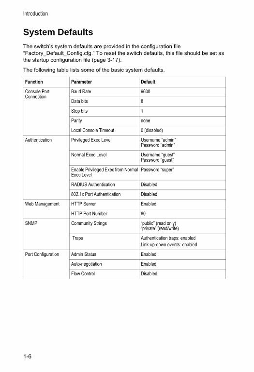
System DefaultsThe switch’s system defaults are provided in the configuration file “Factory_Default_Config.cfg.” To reset the switch defaults, this file should be set as the startup configuration file (page 3-17).
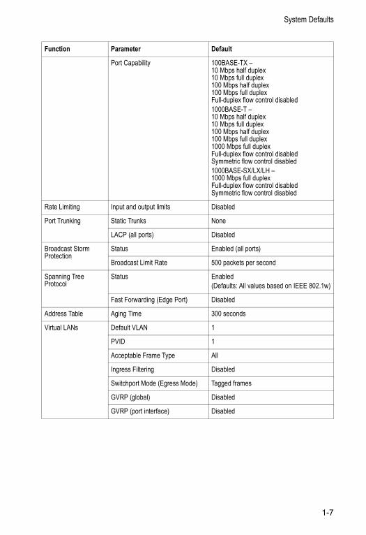
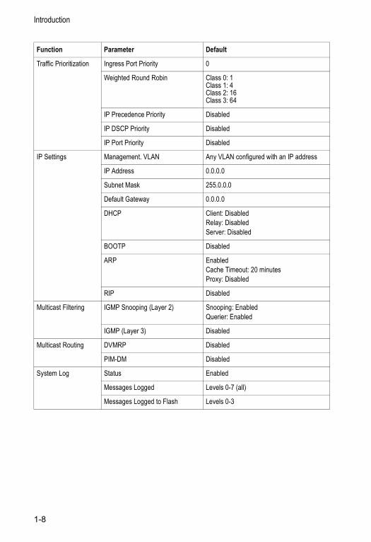
The following table lists some of the basic system defaults.
Function Parameter Default
Console Port Connection
Baud Rate 9600
Data bits 8
Stop bits 1
Parity none
Local Console Timeout 0 (disabled)
Authentication Privileged Exec Level Username “admin”Password “admin”
Normal Exec Level Username “guest”Password “guest”
Enable Privileged Exec from Normal Exec Level
Password “super”
RADIUS Authentication Disabled
802.1x Port Authentication Disabled
Web Management HTTP Server Enabled
HTTP Port Number 80
SNMP Community Strings “public” (read only) “private” (read/write)
Traps Authentication traps: enabledLink-up-down events: enabled
Port Configuration Admin Status Enabled
Auto-negotiation Enabled
Flow Control Disabled
1-6
System Defaults
Port Capability 100BASE-TX –10 Mbps half duplex10 Mbps full duplex100 Mbps half duplex100 Mbps full duplexFull-duplex flow control disabled1000BASE-T –10 Mbps half duplex10 Mbps full duplex100 Mbps half duplex100 Mbps full duplex1000 Mbps full duplexFull-duplex flow control disabledSymmetric flow control disabled1000BASE-SX/LX/LH –1000 Mbps full duplexFull-duplex flow control disabledSymmetric flow control disabled
Rate Limiting Input and output limits Disabled
Port Trunking Static Trunks None
LACP (all ports) Disabled
Broadcast Storm Protection
Status Enabled (all ports)
Broadcast Limit Rate 500 packets per second
Spanning Tree Protocol
Status Enabled(Defaults: All values based on IEEE 802.1w)
Fast Forwarding (Edge Port) Disabled
Address Table Aging Time 300 seconds
Virtual LANs Default VLAN 1
PVID 1
Acceptable Frame Type All
Ingress Filtering Disabled
Switchport Mode (Egress Mode) Tagged frames
GVRP (global) Disabled
GVRP (port interface) Disabled
Function Parameter Default
1-7
Introduction
Traffic Prioritization Ingress Port Priority 0
Weighted Round Robin Class 0: 1Class 1: 4Class 2: 16Class 3: 64
IP Precedence Priority Disabled
IP DSCP Priority Disabled
IP Port Priority Disabled
IP Settings Management. VLAN Any VLAN configured with an IP address
IP Address 0.0.0.0
Subnet Mask 255.0.0.0
Default Gateway 0.0.0.0
DHCP Client: DisabledRelay: DisabledServer: Disabled
BOOTP Disabled
ARP EnabledCache Timeout: 20 minutesProxy: Disabled
RIP Disabled
Multicast Filtering IGMP Snooping (Layer 2) Snooping: EnabledQuerier: Enabled
IGMP (Layer 3) Disabled
Multicast Routing DVMRP Disabled
PIM-DM Disabled
System Log Status Enabled
Messages Logged Levels 0-7 (all)
Messages Logged to Flash Levels 0-3
Function Parameter Default
1-8
Chapter 2: Initial Configuration
Connecting to the Switch
Configuration OptionsThe switch includes a built-in network management agent. The agent offers a variety of management options, including SNMP, RMON and a Web-based interface. A PC may also be connected directly to the switch for configuration and monitoring via a command line interface (CLI).
Note: The IP address for this switch is unassigned by default. To change this address, see “Setting an IP Address” on page 2-4.
The switch’s HTTP Web agent allows you to configure switch parameters, monitor port connections, and display statistics using a standard Web browser such as Netscape Navigator version 6.2 and higher or Microsoft IE version 5.0 and higher. The switch’s Web management interface can be accessed from any computer attached to the network.
The CLI program can be accessed by a direct connection to the RS-232 serial console port on the switch, or remotely by a Telnet connection over the network.
The switch’s management agent also supports SNMP (Simple Network Management Protocol). This SNMP agent permits the switch to be managed from any system in the network using network management software such as HP OpenView.
The switch’s Web interface, CLI configuration program, and SNMP agent allow you to perform the following management functions:
• Set user names and passwords for up to 16 users• Set an IP interface for a management VLAN• Configure SNMP parameters • Enable/disable any port • Set the speed/duplex mode for any port • Configure the bandwidth of any port by limiting input or output rates• Configure up to 255 IEEE 802.1Q VLANs • Enable GVRP automatic VLAN registration• Configure IP routing• Configure IGMP multicast filtering• Upload and download system firmware via TFTP• Upload and download switch configuration files via TFTP• Configure Spanning Tree parameters• Configure Class of Service (CoS) priority queuing• Configure up to six static or LACP trunks• Enable port mirroring
2-1
Initial Configuration
• Set broadcast storm control on any port• Display system information and statistics
Required ConnectionsThe switch provides an RS-232 serial port that enables a connection to a PC or terminal for monitoring and configuring the switch. A null-modem console cable is provided with the switch.
Attach a VT100-compatible terminal, or a PC running a terminal emulation program to the switch. You can use the console cable provided with this package, or use a null-modem cable that complies with the wiring assignments shown in the Installation Guide.
To connect a terminal to the console port, complete the following steps:
1. Connect the console cable to the serial port on a terminal, or a PC running terminal emulation software, and tighten the captive retaining screws on the DB-9 connector.
2. Connect the other end of the cable to the RS-232 serial port on the switch.
3. Make sure the terminal emulation software is set as follows:• Select the appropriate serial port (COM port 1 or COM port 2). • Set the data rate to 9600 baud. • Set the data format to 8 data bits, 1 stop bit, and no parity. • Set flow control to none. • Set the emulation mode to VT100. • When using HyperTerminal, select Terminal keys, not Windows keys.
Notes: 1. When using HyperTerminal with Microsoft® Windows® 2000, make sure that you have Windows 2000 Service Pack 2 or later installed. Windows 2000 Service Pack 2 fixes the problem of arrow keys not functioning in HyperTerminal’s VT100 emulation. See www.microsoft.com for information on Windows 2000 service packs.
2. Refer to “Line Commands” on page 4-9 for a complete description of console configuration options.
3. Once you have set up the terminal correctly, the console login screen will be displayed.
For a description of how to use the CLI, see “Using the Command Line Interface” on page 4-1. For a list of all the CLI commands and detailed information on using the CLI, refer to “Command Groups” on page 4-8.
2-2
Basic Configuration
Remote ConnectionsPrior to accessing the switch’s onboard agent via a network connection, you must first configure it with a valid IP address, subnet mask, and default gateway using a console connection, DHCP or BOOTP protocol.
The IP address for this switch is unassigned by default. To manually configure this address or enable dynamic address assignment via DHCP or BOOTP, see “Setting an IP Address” on page 2-4.
Notes: 1. This switch supports four concurrent Telnet sessions.
2. Each VLAN group can be assigned its own IP interface address (page 2-4). You can manage the switch via any of these addresses.
After configuring the switch’s IP parameters, you can access the onboard configuration program from anywhere within the attached network. The onboard configuration program can be accessed using Telnet from any computer attached to the network. The switch can also be managed by any computer using a Web browser (Internet Explorer 5.0 or above, or Netscape Navigator 6.2 or above), or from a network computer using SNMP network management software.
Note: The onboard program only provides access to basic configuration functions. To access the full range of SNMP management functions, you must use SNMP-based network management software.
Basic Configuration
Console ConnectionThe CLI program provides two different command levels — normal access level (Normal Exec) and privileged access level (Privileged Exec). The commands available at the Normal Exec level are a limited subset of those available at the Privileged Exec level and allow you to only display information and use basic utilities. To fully configure switch parameters, you must access the CLI at the Privileged Exec level.
Access to both CLI levels are controlled by user names and passwords. The switch has a default user name and password for each level. To log into the CLI at the Privileged Exec level using the default user name and password, perform these steps:
1. To initiate your console connection, press <Enter>. The “User Access Verification” procedure starts.
2. At the Username prompt, enter “admin.”3. At the Password prompt, also enter “admin.” (The password characters are not
displayed on the console screen.)4. The session is opened and the CLI displays the “Console#” prompt indicating
you have access at the Privileged Exec level.
2-3
Initial Configuration
Setting PasswordsNote: If this is your first time to log into the CLI program, you should define new
passwords for both default user names using the “username” command, record them and put them in a safe place.
Passwords can consist of up to 8 alphanumeric characters and are case sensitive. To prevent unauthorized access to the switch, set the passwords as follows:
1. Open the console interface with the default user name and password “admin” to access the Privileged Exec level.
2. Type “configure” and press <Enter>.
3. Type “username guest password 0 password,” for the Normal Exec level, where password is your new password. Press <Enter>.
4. Type “username admin password 0 password,” for the Privileged Exec level, where password is your new password. Press <Enter>.
Setting an IP AddressYou must establish IP address information for the switch to obtain management access through the network. This can be done in either of the following ways:
Manual — You have to input the information, including IP address and subnet mask. If your management station is not in the same IP subnet as the switch, you will also need to specify the default gateway router.
Dynamic — The switch sends IP configuration requests to BOOTP or DHCP address allocation servers on the network.
Manual ConfigurationYou can manually assign an IP address to the switch. You may also need to specify a default gateway that resides between this device and management stations that exist on another network segment (if routing is not enabled on this switch). Valid IP addresses consist of four decimal numbers, 0 to 255, separated by periods. Anything outside this format will not be accepted by the CLI program.
Note: The IP address for this switch is unassigned by default.
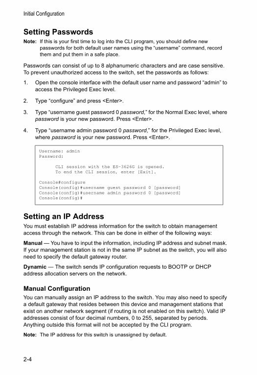
Username: adminPassword:
CLI session with the ES-3626G is opened. To end the CLI session, enter [Exit].
Console#configureConsole(config)#username guest password 0 [password]Console(config)#username admin password 0 [password]Console(config)#
2-4
Basic Configuration
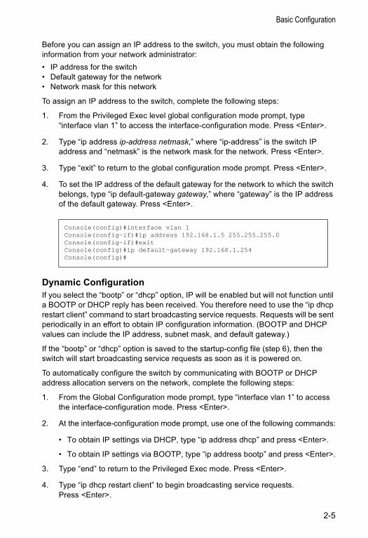
Before you can assign an IP address to the switch, you must obtain the following information from your network administrator:• IP address for the switch • Default gateway for the network • Network mask for this network
To assign an IP address to the switch, complete the following steps:
1. From the Privileged Exec level global configuration mode prompt, type “interface vlan 1” to access the interface-configuration mode. Press <Enter>.
2. Type “ip address ip-address netmask,” where “ip-address” is the switch IP address and “netmask” is the network mask for the network. Press <Enter>.
3. Type “exit” to return to the global configuration mode prompt. Press <Enter>.
4. To set the IP address of the default gateway for the network to which the switch belongs, type “ip default-gateway gateway,” where “gateway” is the IP address of the default gateway. Press <Enter>.
Dynamic ConfigurationIf you select the “bootp” or “dhcp” option, IP will be enabled but will not function until a BOOTP or DHCP reply has been received. You therefore need to use the “ip dhcp restart client” command to start broadcasting service requests. Requests will be sent periodically in an effort to obtain IP configuration information. (BOOTP and DHCP values can include the IP address, subnet mask, and default gateway.)
If the “bootp” or “dhcp” option is saved to the startup-config file (step 6), then the switch will start broadcasting service requests as soon as it is powered on.
To automatically configure the switch by communicating with BOOTP or DHCP address allocation servers on the network, complete the following steps:
1. From the Global Configuration mode prompt, type “interface vlan 1” to access the interface-configuration mode. Press <Enter>.
2. At the interface-configuration mode prompt, use one of the following commands:
• To obtain IP settings via DHCP, type “ip address dhcp” and press <Enter>.
• To obtain IP settings via BOOTP, type “ip address bootp” and press <Enter>.
3. Type “end” to return to the Privileged Exec mode. Press <Enter>.
4. Type “ip dhcp restart client” to begin broadcasting service requests. Press <Enter>.
Console(config)#interface vlan 1Console(config-if)#ip address 192.168.1.5 255.255.255.0Console(config-if)#exitConsole(config)#ip default-gateway 192.168.1.254Console(config)#
2-5
Initial Configuration
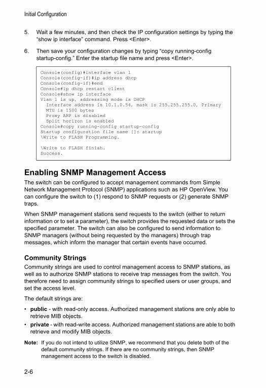
5. Wait a few minutes, and then check the IP configuration settings by typing the “show ip interface” command. Press <Enter>.
6. Then save your configuration changes by typing “copy running-config startup-config.” Enter the startup file name and press <Enter>.
Enabling SNMP Management Access The switch can be configured to accept management commands from Simple Network Management Protocol (SNMP) applications such as HP OpenView. You can configure the switch to (1) respond to SNMP requests or (2) generate SNMP traps.
When SNMP management stations send requests to the switch (either to return information or to set a parameter), the switch provides the requested data or sets the specified parameter. The switch can also be configured to send information to SNMP managers (without being requested by the managers) through trap messages, which inform the manager that certain events have occurred.
Community StringsCommunity strings are used to control management access to SNMP stations, as well as to authorize SNMP stations to receive trap messages from the switch. You therefore need to assign community strings to specified users or user groups, and set the access level.
The default strings are:
• public - with read-only access. Authorized management stations are only able to retrieve MIB objects.
• private - with read-write access. Authorized management stations are able to both retrieve and modify MIB objects.
Note: If you do not intend to utilize SNMP, we recommend that you delete both of the default community strings. If there are no community strings, then SNMP management access to the switch is disabled.
Console(config)#interface vlan 1Console(config-if)#ip address dhcpConsole(config-if)#endConsole#ip dhcp restart clientConsole#show ip interfaceVlan 1 is up, addressing mode is DHCP Interface address is 10.1.0.54, mask is 255.255.255.0, Primary MTU is 1500 bytes Proxy ARP is disabled Split horizon is enabledConsole#copy running-config startup-configStartup configuration file name []: startup\Write to FLASH Programming.
\Write to FLASH finish.Success.
2-6
Basic Configuration
To prevent unauthorized access to the switch via SNMP, it is recommended that you change the default community strings.
To configure a community string, complete the following steps:
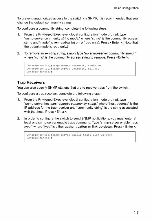
1. From the Privileged Exec level global configuration mode prompt, type “snmp-server community string mode,” where “string” is the community access string and “mode” is rw (read/write) or ro (read only). Press <Enter>. (Note that the default mode is read only.)
2. To remove an existing string, simply type “no snmp-server community string,” where “string” is the community access string to remove. Press <Enter>.
Trap ReceiversYou can also specify SNMP stations that are to receive traps from the switch.
To configure a trap receiver, complete the following steps:
1. From the Privileged Exec level global configuration mode prompt, type “snmp-server host host-address community-string,” where “host-address” is the IP address for the trap receiver and “community-string” is the string associated with that host. Press <Enter>.
2. In order to configure the switch to send SNMP notifications, you must enter at least one snmp-server enable traps command. Type “snmp-server enable traps type,” where “type” is either authentication or link-up-down. Press <Enter>.
Console(config)#snmp-server community admin rwConsole(config)#snmp-server community privateConsole(config)#
Console(config)#snmp-server enable traps link-up-downConsole(config)#
2-7

Initial Configuration
Saving Configuration SettingsConfiguration commands only modify the running configuration file and are not saved when the switch is rebooted. To save all your configuration changes in nonvolatile storage, you must copy the running configuration file to the start-up configuration file using the “copy” command.
To save the current configuration settings, enter the following command:
1. From the Privileged Exec mode prompt, type “copy running-config startup-config” and press <Enter>.
2. Enter the name of the start-up file. Press <Enter>.
Managing System FilesThe switch’s flash memory supports three types of system files that can be managed by the CLI program, Web interface, or SNMP. The switch’s file system allows files to be uploaded and downloaded, copied, deleted, and set as a start-up file.
The three types of files are:
• Configuration — This file stores system configuration information and is created when configuration settings are saved. Saved configuration files can be selected as a system start-up file or can be uploaded via TFTP to a server for backup. A file named “Factory_Default_Config.cfg” contains all the system default settings and cannot be deleted from the system. See “Saving or Restoring Configuration Settings” on page 3-16 for more information.
• Operation Code — System software that is executed after boot-up, also known as run-time code. This code runs the switch operations and provides the CLI and Web management interfaces. See “Managing Firmware” on page 3-15 for more information.
• Diagnostic Code — Software that is run during system boot-up, also known as POST (Power On Self-Test). This code also provides a facility to upload firmware files to the system directly through the console port. See “Upgrading Firmware via the Serial Port” on page B-1.
Console#copy running-config startup-configStartup configuration file name []: startup\Write to FLASH Programming.
\Write to FLASH finish.Success.
Console#
2-8

Managing System Files
Due to the size limit of the flash memory, the switch supports only two operation code files. However, you can have as many diagnostic code files and configuration files as available flash memory space allows.
In the system flash memory, one file of each type must be set as the start-up file. During a system boot, the diagnostic and operation code files set as the start-up file are run, and then the start-up configuration file is loaded.
Note that configuration files should be downloaded using a file name that reflects the contents or usage of the file settings. If you download directly to the running-config, the system will reboot, and the settings will have to be copied from the running-config to a permanent file.
2-9

Initial Configuration
2-10
Chapter 3: Configuring the Switch
Using the Web InterfaceThis switch provides an embedded HTTP Web agent. Using a Web browser you can configure the switch and view statistics to monitor network activity. The Web agent can be accessed by any computer on the network using a standard Web browser (Internet Explorer 5.0 or above, or Netscape Navigator 6.2 or above).
Note: You can also use the Command Line Interface (CLI) to manage the switch over a serial connection to the console port or via Telnet. For more information on using the CLI, refer to Chapter 4: “Command Line Interface.”
Prior to accessing the switch from a Web browser, be sure you have first performed the following tasks:
1. Configure the switch with a valid IP address, subnet mask, and default gateway using an out-of-band serial connection, BOOTP or DHCP protocol. (See “Setting the Switch’s IP Address” on page 3-12.)
2. Set user names and passwords using an out-of-band serial connection. Access to the Web agent is controlled by the same user names and passwords as the onboard configuration program. (See “Configuring the Logon Password” on page 3-20.)
3. After you enter a user name and password, you will have access to the system configuration program.
Notes: 1. You are allowed three attempts to enter the correct password; on the third failed attempt the current connection is terminated.
2. If you log into the Web interface as guest (Normal Exec level), you can view the configuration settings or change the guest password. If you log in as “admin” (Privileged Exec level), you can change the settings on any page.
3. If the path between your management station and this switch does not pass through any device that uses the Spanning Tree Algorithm, then you can set the switch port attached to your management station to fast forwarding (i.e., enable Admin Edge Port) to improve the switch’s response time to management commands issued through the Web interface. See “Configuring Interface Settings” on page 3-72.
3-1
Configuring the Switch
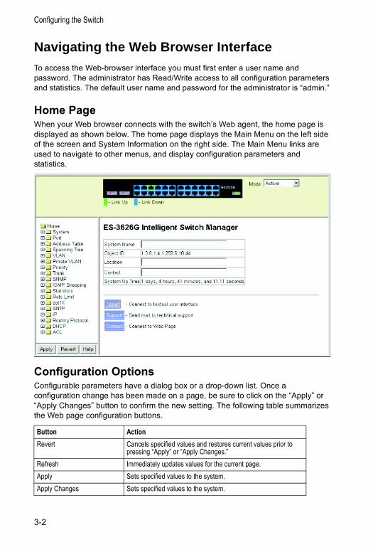
Navigating the Web Browser InterfaceTo access the Web-browser interface you must first enter a user name and password. The administrator has Read/Write access to all configuration parameters and statistics. The default user name and password for the administrator is “admin.”
Home PageWhen your Web browser connects with the switch’s Web agent, the home page is displayed as shown below. The home page displays the Main Menu on the left side of the screen and System Information on the right side. The Main Menu links are used to navigate to other menus, and display configuration parameters and statistics.
Configuration OptionsConfigurable parameters have a dialog box or a drop-down list. Once a configuration change has been made on a page, be sure to click on the “Apply” or “Apply Changes” button to confirm the new setting. The following table summarizes the Web page configuration buttons.
Button ActionRevert Cancels specified values and restores current values prior to
pressing “Apply” or “Apply Changes.”Refresh Immediately updates values for the current page.Apply Sets specified values to the system. Apply Changes Sets specified values to the system.
3-2
Navigating the Web Browser Interface
Notes: 1. To ensure proper screen refresh, be sure that Internet Explorer 5.x is configured as follows: Under the menu “Tools / Internet Options / General / Temporary Internet Files / Settings,” the setting for item “Check for newer versions of stored pages” should be “Every visit to the page.”
2. When using Internet Explorer 5.0, you may have to manually refresh the screen after making configuration changes by pressing the browser’s refresh button.
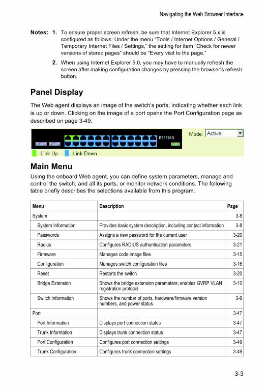
Panel DisplayThe Web agent displays an image of the switch’s ports, indicating whether each link is up or down. Clicking on the image of a port opens the Port Configuration page as described on page 3-49.
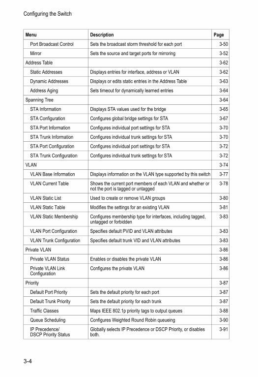
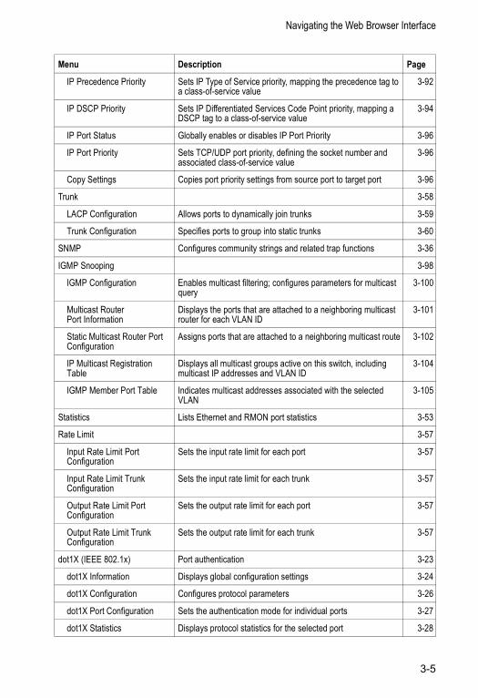
Main Menu Using the onboard Web agent, you can define system parameters, manage and control the switch, and all its ports, or monitor network conditions. The following table briefly describes the selections available from this program.
Menu Description Page
System 3-8
System Information Provides basic system description, including contact information 3-8
Passwords Assigns a new password for the current user 3-20
Radius Configures RADIUS authentication parameters 3-21
Firmware Manages code image files 3-15
Configuration Manages switch configuration files 3-16
Reset Restarts the switch 3-20
Bridge Extension Shows the bridge extension parameters; enables GVRP VLAN registration protocol
3-10
Switch Information Shows the number of ports, hardware/firmware version numbers, and power status
3-9
Port 3-47
Port Information Displays port connection status 3-47
Trunk Information Displays trunk connection status 3-47
Port Configuration Configures port connection settings 3-49
Trunk Configuration Configures trunk connection settings 3-49
3-3
Configuring the Switch
Port Broadcast Control Sets the broadcast storm threshold for each port 3-50
Mirror Sets the source and target ports for mirroring 3-52
Address Table 3-62
Static Addresses Displays entries for interface, address or VLAN 3-62
Dynamic Addresses Displays or edits static entries in the Address Table 3-63
Address Aging Sets timeout for dynamically learned entries 3-64
Spanning Tree 3-64
STA Information Displays STA values used for the bridge 3-65
STA Configuration Configures global bridge settings for STA 3-67
STA Port Information Configures individual port settings for STA 3-70
STA Trunk Information Configures individual trunk settings for STA 3-70
STA Port Configuration Configures individual port settings for STA 3-72
STA Trunk Configuration Configures individual trunk settings for STA 3-72
VLAN 3-74
VLAN Base Information Displays information on the VLAN type supported by this switch 3-77
VLAN Current Table Shows the current port members of each VLAN and whether or not the port is tagged or untagged
3-78
VLAN Static List Used to create or remove VLAN groups 3-80
VLAN Static Table Modifies the settings for an existing VLAN 3-81
VLAN Static Membership Configures membership type for interfaces, including tagged, untagged or forbidden
3-83
VLAN Port Configuration Specifies default PVID and VLAN attributes 3-83
VLAN Trunk Configuration Specifies default trunk VID and VLAN attributes 3-83
Private VLAN 3-86
Private VLAN Status Enables or disables the private VLAN 3-86
Private VLAN Link Configuration
Configures the private VLAN 3-86
Priority 3-87
Default Port Priority Sets the default priority for each port 3-87
Default Trunk Priority Sets the default priority for each trunk 3-87
Traffic Classes Maps IEEE 802.1p priority tags to output queues 3-88
Queue Scheduling Configures Weighted Round Robin queueing 3-90
IP Precedence/DSCP Priority Status
Globally selects IP Precedence or DSCP Priority, or disables both.
3-91
Menu Description Page
3-4
Navigating the Web Browser Interface
IP Precedence Priority Sets IP Type of Service priority, mapping the precedence tag to a class-of-service value
3-92
IP DSCP Priority Sets IP Differentiated Services Code Point priority, mapping a DSCP tag to a class-of-service value
3-94
IP Port Status Globally enables or disables IP Port Priority 3-96
IP Port Priority Sets TCP/UDP port priority, defining the socket number and associated class-of-service value
3-96
Copy Settings Copies port priority settings from source port to target port 3-96
Trunk 3-58
LACP Configuration Allows ports to dynamically join trunks 3-59
Trunk Configuration Specifies ports to group into static trunks 3-60
SNMP Configures community strings and related trap functions 3-36
IGMP Snooping 3-98
IGMP Configuration Enables multicast filtering; configures parameters for multicast query
3-100
Multicast Router Port Information
Displays the ports that are attached to a neighboring multicast router for each VLAN ID
3-101
Static Multicast Router Port Configuration
Assigns ports that are attached to a neighboring multicast route 3-102
IP Multicast Registration Table
Displays all multicast groups active on this switch, including multicast IP addresses and VLAN ID
3-104
IGMP Member Port Table Indicates multicast addresses associated with the selected VLAN
3-105
Statistics Lists Ethernet and RMON port statistics 3-53
Rate Limit 3-57
Input Rate Limit Port Configuration
Sets the input rate limit for each port 3-57
Input Rate Limit Trunk Configuration
Sets the input rate limit for each trunk 3-57
Output Rate Limit Port Configuration
Sets the output rate limit for each port 3-57
Output Rate Limit Trunk Configuration
Sets the output rate limit for each trunk 3-57
dot1X (IEEE 802.1x) Port authentication 3-23
dot1X Information Displays global configuration settings 3-24
dot1X Configuration Configures protocol parameters 3-26
dot1X Port Configuration Sets the authentication mode for individual ports 3-27
dot1X Statistics Displays protocol statistics for the selected port 3-28
Menu Description Page
3-5
Configuring the Switch
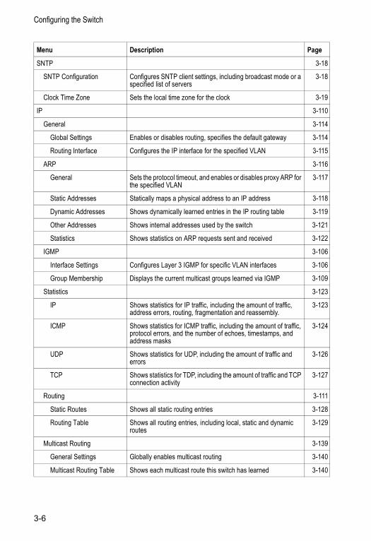
SNTP 3-18
SNTP Configuration Configures SNTP client settings, including broadcast mode or a specified list of servers
3-18
Clock Time Zone Sets the local time zone for the clock 3-19
IP 3-110
General 3-114
Global Settings Enables or disables routing, specifies the default gateway 3-114
Routing Interface Configures the IP interface for the specified VLAN 3-115
ARP 3-116
General Sets the protocol timeout, and enables or disables proxy ARP for the specified VLAN
3-117
Static Addresses Statically maps a physical address to an IP address 3-118
Dynamic Addresses Shows dynamically learned entries in the IP routing table 3-119
Other Addresses Shows internal addresses used by the switch 3-121
Statistics Shows statistics on ARP requests sent and received 3-122
IGMP 3-106
Interface Settings Configures Layer 3 IGMP for specific VLAN interfaces 3-106
Group Membership Displays the current multicast groups learned via IGMP 3-109
Statistics 3-123
IP Shows statistics for IP traffic, including the amount of traffic, address errors, routing, fragmentation and reassembly.
3-123
ICMP Shows statistics for ICMP traffic, including the amount of traffic, protocol errors, and the number of echoes, timestamps, and address masks
3-124
UDP Shows statistics for UDP, including the amount of traffic and errors
3-126
TCP Shows statistics for TDP, including the amount of traffic and TCP connection activity
3-127
Routing 3-111
Static Routes Shows all static routing entries 3-128
Routing Table Shows all routing entries, including local, static and dynamic routes
3-129
Multicast Routing 3-139
General Settings Globally enables multicast routing 3-140
Multicast Routing Table Shows each multicast route this switch has learned 3-140
Menu Description Page
3-6
Navigating the Web Browser Interface
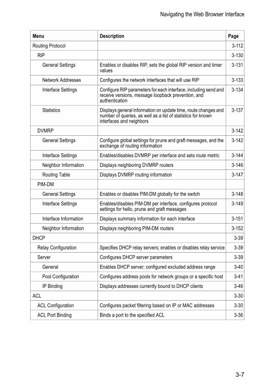
Routing Protocol 3-112
RIP 3-130
General Settings Enables or disables RIP, sets the global RIP version and timer values
3-131
Network Addresses Configures the network interfaces that will use RIP 3-133
Interface Settings Configure RIP parameters for each interface, including send and receive versions, message loopback prevention, and authentication
3-134
Statistics Displays general information on update time, route changes and number of queries, as well as a list of statistics for known interfaces and neighbors
3-137
DVMRP 3-142
General Settings Configure global settings for prune and graft messages, and the exchange of routing information
3-142
Interface Settings Enables/disables DVMRP per interface and sets route metric 3-144
Neighbor Information Displays neighboring DVMRP routers 3-146
Routing Table Displays DVMRP routing information 3-147
PIM-DM
General Settings Enables or disables PIM-DM globally for the switch 3-148
Interface Settings Enables/disables PIM-DM per interface, configures protocol settings for hello, prune and graft messages
3-149
Interface Information Displays summary information for each interface 3-151
Neighbor Information Displays neighboring PIM-DM routers 3-152
DHCP 3-39
Relay Configuration Specifies DHCP relay servers; enables or disables relay service 3-39
Server Configures DHCP server parameters 3-39
General Enables DHCP server; configured excluded address range 3-40
Pool Configuration Configures address pools for network groups or a specific host 3-41
IP Binding Displays addresses currently bound to DHCP clients 3-46
ACL 3-30
ACL Configuration Configures packet filtering based on IP or MAC addresses 3-30
ACL Port Binding Binds a port to the specified ACL 3-36
Menu Description Page
3-7
Configuring the Switch
Basic Configuration
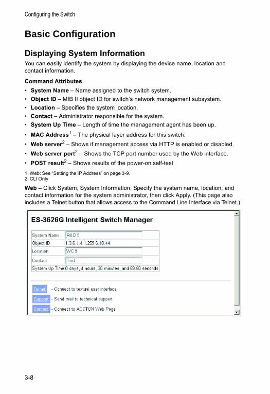
Displaying System InformationYou can easily identify the system by displaying the device name, location and contact information.
Command Attributes• System Name – Name assigned to the switch system.• Object ID – MIB II object ID for switch’s network management subsystem.• Location – Specifies the system location.• Contact – Administrator responsible for the system.• System Up Time – Length of time the management agent has been up.
• MAC Address1 – The physical layer address for this switch. • Web server2 – Shows if management access via HTTP is enabled or disabled.• Web server port2 – Shows the TCP port number used by the Web interface.• POST result2 – Shows results of the power-on self-test
1: Web: See “Setting the IP Address” on page 3-9.2: CLI Only
Web – Click System, System Information. Specify the system name, location, and contact information for the system administrator, then click Apply. (This page also includes a Telnet button that allows access to the Command Line Interface via Telnet.)
3-8
Basic Configuration
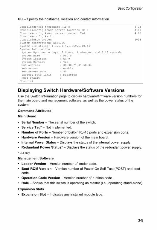
CLI – Specify the hostname, location and contact information.
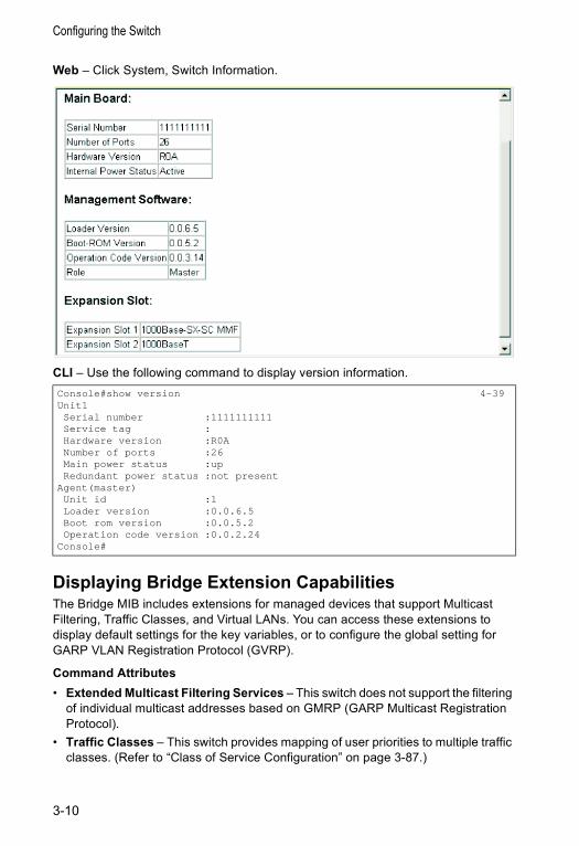
Displaying Switch Hardware/Software Versions Use the Switch Information page to display hardware/firmware version numbers for the main board and management software, as well as the power status of the system.
Command AttributesMain Board
• Serial Number – The serial number of the switch.• Service Tag* – Not implemented.• Number of Ports – Number of built-in RJ-45 ports and expansion ports.• Hardware Version – Hardware version of the main board.• Internal Power Status – Displays the status of the internal power supply.• Redundant Power Status* – Displays the status of the redundant power supply.* CLI only.
Management Software• Loader Version – Version number of loader code.• Boot-ROM Version – Version number of Power-On Self-Test (POST) and boot
code.• Operation Code Version – Version number of runtime code.• Role – Shows that this switch is operating as Master (i.e., operating stand-alone).
Expansion Slots• Expansion Slot – Indicates any installed module type.
Console(config)#hostname R&D 5 4-23Console(config)#snmp-server location WC 9 4-69Console(config)#snmp-server contact Ted 4-69Console(config)#exitConsole#show system 4-38System description: ES3626GSystem OID string: 1.3.6.1.4.1.259.6.10.44System informationSystem Up time: 0 days, 2 hours, 4 minutes, and 7.13 secondsSystem Name : R&D 5System Location : WC 9System Contact : TedMAC address : 00-30-f1-47-58-3aWeb server : enableWeb server port : 80Ingress rate limit : DisabledPOST result :
Console#
3-9
Configuring the Switch
Web – Click System, Switch Information.
CLI – Use the following command to display version information.
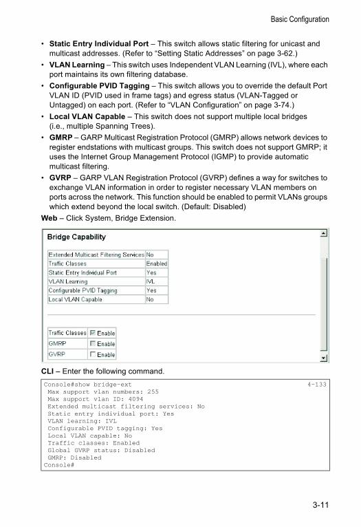
Displaying Bridge Extension CapabilitiesThe Bridge MIB includes extensions for managed devices that support Multicast Filtering, Traffic Classes, and Virtual LANs. You can access these extensions to display default settings for the key variables, or to configure the global setting for GARP VLAN Registration Protocol (GVRP).
Command Attributes• Extended Multicast Filtering Services – This switch does not support the filtering
of individual multicast addresses based on GMRP (GARP Multicast Registration Protocol).
• Traffic Classes – This switch provides mapping of user priorities to multiple traffic classes. (Refer to “Class of Service Configuration” on page 3-87.)
Console#show version 4-39Unit1Serial number :1111111111Service tag :Hardware version :R0ANumber of ports :26Main power status :upRedundant power status :not present
Agent(master)Unit id :1Loader version :0.0.6.5Boot rom version :0.0.5.2Operation code version :0.0.2.24
Console#
3-10
Basic Configuration
• Static Entry Individual Port – This switch allows static filtering for unicast and multicast addresses. (Refer to “Setting Static Addresses” on page 3-62.)
• VLAN Learning – This switch uses Independent VLAN Learning (IVL), where each port maintains its own filtering database.
• Configurable PVID Tagging – This switch allows you to override the default Port VLAN ID (PVID used in frame tags) and egress status (VLAN-Tagged or Untagged) on each port. (Refer to “VLAN Configuration” on page 3-74.)
• Local VLAN Capable – This switch does not support multiple local bridges (i.e., multiple Spanning Trees).
• GMRP – GARP Multicast Registration Protocol (GMRP) allows network devices to register endstations with multicast groups. This switch does not support GMRP; it uses the Internet Group Management Protocol (IGMP) to provide automatic multicast filtering.
• GVRP – GARP VLAN Registration Protocol (GVRP) defines a way for switches to exchange VLAN information in order to register necessary VLAN members on ports across the network. This function should be enabled to permit VLANs groups which extend beyond the local switch. (Default: Disabled)
Web – Click System, Bridge Extension.
CLI – Enter the following command. Console#show bridge-ext 4-133Max support vlan numbers: 255Max support vlan ID: 4094Extended multicast filtering services: NoStatic entry individual port: YesVLAN learning: IVLConfigurable PVID tagging: YesLocal VLAN capable: NoTraffic classes: EnabledGlobal GVRP status: DisabledGMRP: Disabled
Console#
3-11
Configuring the Switch
Setting the Switch’s IP Address This section describes how to configure an initial IP interface for management access over the network. The IP address for this switch is unassigned by default. To manually configure an address, you need to change the switch’s default settings (IP address 0.0.0.0 and netmask 255.0.0.0) to values that are compatible with your network. You may also need to a establish a default gateway between the switch and management stations that exist on another network segment (if routing is not enabled on this switch).
You can manually configure a specific IP address, or direct the device to obtain an address from a BOOTP or DHCP server. Valid IP addresses consist of four decimal numbers, 0 to 255, separated by periods. Anything outside this format will not be accepted by the CLI program.
Command Usage• The section describes how to configure a single local interface for initial access to
the switch. To configure multiple IP interfaces on this switch, you must set up an IP interface for each VLAN (page 3-115).
• To enable routing between the different interfaces on this switch, you must enable IP routing (page 3-114).
• To enable routing between the interfaces defined on this switch and external network interfaces, you must configure static routes (page 3-128) or use dynamic routing (i.e., Routing Information Protocol - RIP, page 3-130).
• The precedence for configuring IP interfaces is the IP / General / Routing Interface menu (page 3-115), static routes (page 3-128), and then RIP (page 3-130).
Command Attributes• VLAN – ID of the configured VLAN (1-4094, no leading zeroes). By default, all
ports on the switch are members of VLAN 1. However, the management station can be attached to a port belonging to any VLAN, as long as that VLAN has been assigned an IP address.
• IP Address Mode – Specifies whether IP functionality is enabled via manual configuration (Static), Dynamic Host Configuration Protocol (DHCP), or Boot Protocol (BOOTP). If DHCP/BOOTP is enabled, IP will not function until a reply has been received from the server. Requests will be broadcast periodically by the switch for an IP address. (DHCP/BOOTP values can include the IP address, subnet mask, and default gateway.)
• IP Address – Address of the VLAN interface that is allowed management access. Valid IP addresses consist of four numbers, 0 to 255, separated by periods. (Default: 0.0.0.0)
• Subnet Mask – This mask identifies the host address bits used for routing to specific subnets. (Default: 255.0.0.0)
• Default Gateway – IP address of the gateway router between this device and management stations that exist on other network segments. (Default: 0.0.0.0)
3-12
Basic Configuration
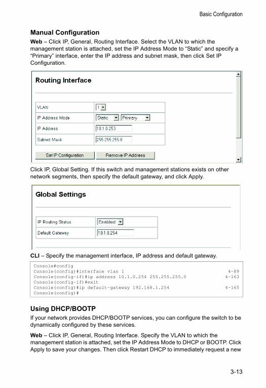
Manual ConfigurationWeb – Click IP, General, Routing Interface. Select the VLAN to which the management station is attached, set the IP Address Mode to “Static” and specify a “Primary” interface, enter the IP address and subnet mask, then click Set IP Configuration.
Click IP, Global Setting. If this switch and management stations exists on other network segments, then specify the default gateway, and click Apply.
CLI – Specify the management interface, IP address and default gateway.
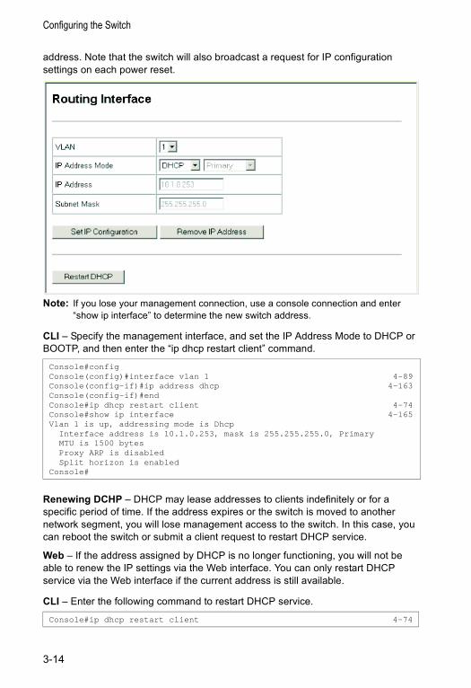
Using DHCP/BOOTP If your network provides DHCP/BOOTP services, you can configure the switch to be dynamically configured by these services.
Web – Click IP, General, Routing Interface. Specify the VLAN to which the management station is attached, set the IP Address Mode to DHCP or BOOTP. Click Apply to save your changes. Then click Restart DHCP to immediately request a new
Console#configConsole(config)#interface vlan 1 4-89Console(config-if)#ip address 10.1.0.254 255.255.255.0 4-163Console(config-if)#exitConsole(config)#ip default-gateway 192.168.1.254 4-165Console(config)#
3-13
Configuring the Switch
address. Note that the switch will also broadcast a request for IP configuration settings on each power reset.
Note: If you lose your management connection, use a console connection and enter “show ip interface” to determine the new switch address.
CLI – Specify the management interface, and set the IP Address Mode to DHCP or BOOTP, and then enter the “ip dhcp restart client” command.
Renewing DCHP – DHCP may lease addresses to clients indefinitely or for a specific period of time. If the address expires or the switch is moved to another network segment, you will lose management access to the switch. In this case, you can reboot the switch or submit a client request to restart DHCP service.
Web – If the address assigned by DHCP is no longer functioning, you will not be able to renew the IP settings via the Web interface. You can only restart DHCP service via the Web interface if the current address is still available.
CLI – Enter the following command to restart DHCP service.
Console#configConsole(config)#interface vlan 1 4-89Console(config-if)#ip address dhcp 4-163Console(config-if)#endConsole#ip dhcp restart client 4-74Console#show ip interface 4-165Vlan 1 is up, addressing mode is Dhcp
Interface address is 10.1.0.253, mask is 255.255.255.0, PrimaryMTU is 1500 bytesProxy ARP is disabledSplit horizon is enabled
Console#
Console#ip dhcp restart client 4-74
3-14
Basic Configuration
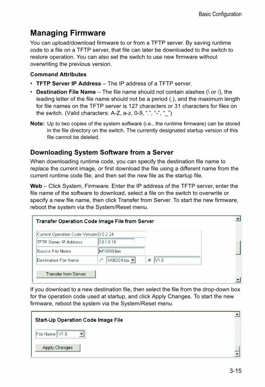
Managing FirmwareYou can upload/download firmware to or from a TFTP server. By saving runtime code to a file on a TFTP server, that file can later be downloaded to the switch to restore operation. You can also set the switch to use new firmware without overwriting the previous version.
Command Attributes• TFTP Server IP Address – The IP address of a TFTP server.• Destination File Name – The file name should not contain slashes (\ or /), the
leading letter of the file name should not be a period (.), and the maximum length for file names on the TFTP server is 127 characters or 31 characters for files on the switch. (Valid characters: A-Z, a-z, 0-9, “.”, “-”, “_”)
Note: Up to two copies of the system software (i.e., the runtime firmware) can be stored in the file directory on the switch. The currently designated startup version of this file cannot be deleted.
Downloading System Software from a ServerWhen downloading runtime code, you can specify the destination file name to replace the current image, or first download the file using a different name from the current runtime code file, and then set the new file as the startup file.
Web – Click System, Firmware. Enter the IP address of the TFTP server, enter the file name of the software to download, select a file on the switch to overwrite or specify a new file name, then click Transfer from Server. To start the new firmware, reboot the system via the System/Reset menu.
If you download to a new destination file, then select the file from the drop-down box for the operation code used at startup, and click Apply Changes. To start the new firmware, reboot the system via the System/Reset menu.
3-15
Configuring the Switch
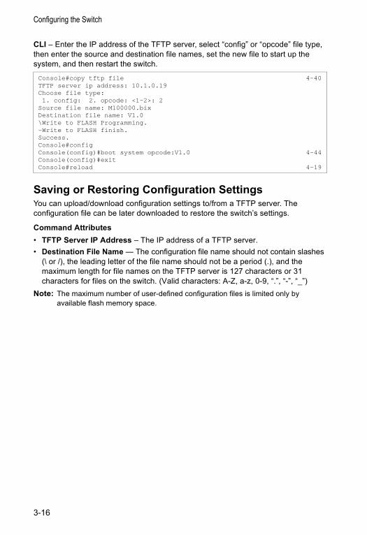
CLI – Enter the IP address of the TFTP server, select “config” or “opcode” file type, then enter the source and destination file names, set the new file to start up the system, and then restart the switch.
Saving or Restoring Configuration SettingsYou can upload/download configuration settings to/from a TFTP server. The configuration file can be later downloaded to restore the switch’s settings.
Command Attributes• TFTP Server IP Address – The IP address of a TFTP server.• Destination File Name — The configuration file name should not contain slashes
(\ or /), the leading letter of the file name should not be a period (.), and the maximum length for file names on the TFTP server is 127 characters or 31 characters for files on the switch. (Valid characters: A-Z, a-z, 0-9, “.”, “-”, “_”)
Note: The maximum number of user-defined configuration files is limited only by available flash memory space.
Console#copy tftp file 4-40TFTP server ip address: 10.1.0.19Choose file type:1. config: 2. opcode: <1-2>: 2
Source file name: M100000.bixDestination file name: V1.0\Write to FLASH Programming.-Write to FLASH finish.Success.Console#configConsole(config)#boot system opcode:V1.0 4-44Console(config)#exitConsole#reload 4-19
3-16
Basic Configuration
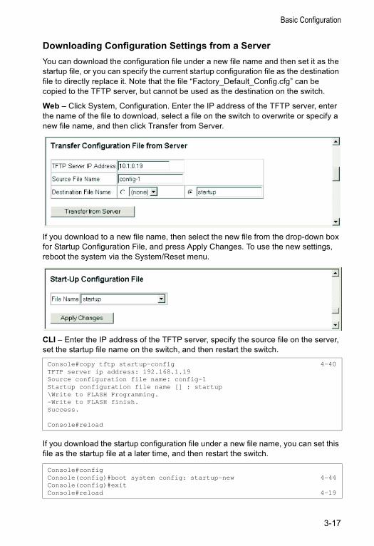
Downloading Configuration Settings from a ServerYou can download the configuration file under a new file name and then set it as the startup file, or you can specify the current startup configuration file as the destination file to directly replace it. Note that the file “Factory_Default_Config.cfg” can be copied to the TFTP server, but cannot be used as the destination on the switch.
Web – Click System, Configuration. Enter the IP address of the TFTP server, enter the name of the file to download, select a file on the switch to overwrite or specify a new file name, and then click Transfer from Server.
If you download to a new file name, then select the new file from the drop-down box for Startup Configuration File, and press Apply Changes. To use the new settings, reboot the system via the System/Reset menu.
CLI – Enter the IP address of the TFTP server, specify the source file on the server, set the startup file name on the switch, and then restart the switch.
If you download the startup configuration file under a new file name, you can set this file as the startup file at a later time, and then restart the switch.
Console#copy tftp startup-config 4-40TFTP server ip address: 192.168.1.19Source configuration file name: config-1Startup configuration file name [] : startup\Write to FLASH Programming.-Write to FLASH finish.Success.
Console#reload
Console#configConsole(config)#boot system config: startup-new 4-44Console(config)#exitConsole#reload 4-19
3-17
Configuring the Switch
Setting the System ClockSimple Network Time Protocol (SNTP) allows the switch to set its internal clock based on periodic updates from a time server (SNTP or NTP). Maintaining an accurate time on the switch enables the system log to record meaningful dates and times for event entries. Without SNTP, the switch will only record the time from the factory default set at the last bootup.
This switch acts as an SNTP client in two modes: Unicast – The switch periodically sends a request for a time update to a configured time server. You can configure up to three time server IP addresses. The switch will attempt to poll each server in the configured sequence.
Broadcast – The switch sets its clock from an time server in the same subnet that broadcasts time updates. If there is more than one SNTP server, the switch accepts the first broadcast it detects and ignores broadcasts from other servers.
Configuring SNTPYou can configure the switch to send time synchronization requests to specific time servers (i.e., client mode), update its clock based on broadcasts from time servers, or use both methods. When both methods are enabled, the switch will update its clock using information broadcast from time servers, but will query the specified server(s) if a broadcast is not received with the polling interval.
Command Attributes• Current Time – Displays the current time.• SNTP Client – Configures the switch to operate as an SNTP unicast client. This
mode requires at least one time server to be specified in the SNTP Server field.• SNTP Broadcast client – Configures the switch to operate as an SNTP broadcast
client. This mode requires no other configuration settings; the switch will obtain time updates from time server broadcasts (using the multicast address 224.0.1.1).
• SNTP Poll Interval – Sets the interval between sending requests for a time update from a time server when set to SNTP Client mode. (Range: 16-16284 seconds; Default: 16 seconds)
• SNTP Server – In unicast mode, sets the IP address for up to three time servers. The switch attempts to update the time from the first server, if this fails it attempts an update from the next server in the sequence.
3-18
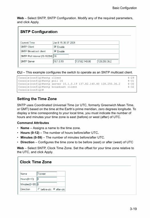
Basic Configuration
Web – Select SNTP, SNTP Configuration. Modify any of the required parameters, and click Apply.
CLI – This example configures the switch to operate as an SNTP multicast client.
Setting the Time ZoneSNTP uses Coordinated Universal Time (or UTC, formerly Greenwich Mean Time, or GMT) based on the time at the Earth’s prime meridian, zero degrees longitude. To display a time corresponding to your local time, you must indicate the number of hours and minutes your time zone is east (before) or west (after) of UTC.
Command Attributes• Name – Assigns a name to the time zone.• Hours (0-12) – The number of hours before/after UTC.• Minutes (0-59) – The number of minutes before/after UTC.• Direction – Configures the time zone to be before (east) or after (west) of UTC
Web – Select SNTP, Clock Time Zone. Set the offset for your time zone relative to the UTC, and click Apply.
Console(config)#sntp client 4-29Console(config)#sntp poll 16 4-31Console(config)#sntp server 10.1.0.19 137.82.140.80 128.250.36.2 4-30Console(config)#sntp broadcast client 4-32Console(config)#
3-19
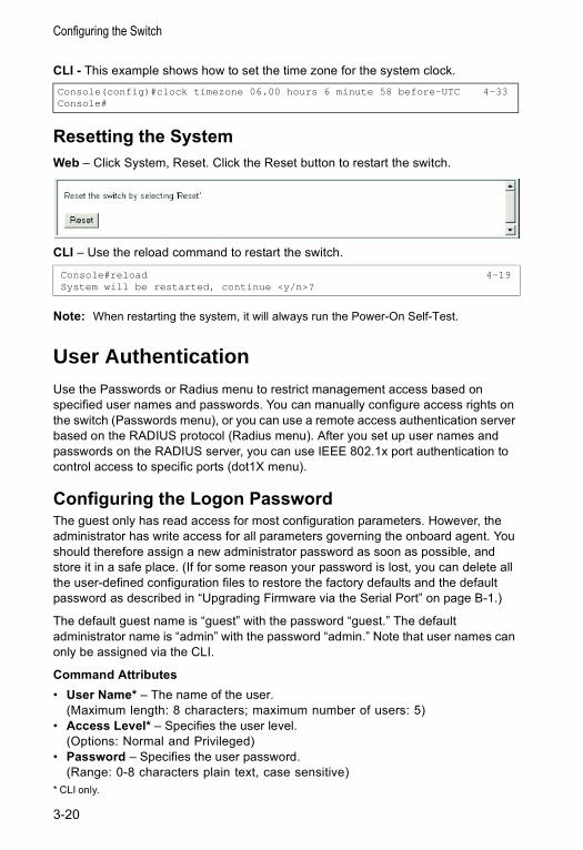
Configuring the Switch
CLI - This example shows how to set the time zone for the system clock.
Resetting the SystemWeb – Click System, Reset. Click the Reset button to restart the switch.
CLI – Use the reload command to restart the switch.
Note: When restarting the system, it will always run the Power-On Self-Test.
User AuthenticationUse the Passwords or Radius menu to restrict management access based on specified user names and passwords. You can manually configure access rights on the switch (Passwords menu), or you can use a remote access authentication server based on the RADIUS protocol (Radius menu). After you set up user names and passwords on the RADIUS server, you can use IEEE 802.1x port authentication to control access to specific ports (dot1X menu).
Configuring the Logon PasswordThe guest only has read access for most configuration parameters. However, the administrator has write access for all parameters governing the onboard agent. You should therefore assign a new administrator password as soon as possible, and store it in a safe place. (If for some reason your password is lost, you can delete all the user-defined configuration files to restore the factory defaults and the default password as described in “Upgrading Firmware via the Serial Port” on page B-1.)
The default guest name is “guest” with the password “guest.” The default administrator name is “admin” with the password “admin.” Note that user names can only be assigned via the CLI.
Command Attributes• User Name* – The name of the user.
(Maximum length: 8 characters; maximum number of users: 5)• Access Level* – Specifies the user level.
(Options: Normal and Privileged)• Password – Specifies the user password.
(Range: 0-8 characters plain text, case sensitive)* CLI only.
Console(config)#clock timezone 06.00 hours 6 minute 58 before-UTC 4-33Console#
Console#reload 4-19System will be restarted, continue <y/n>?
3-20
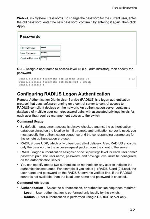
User Authentication
Web – Click System, Passwords. To change the password for the current user, enter the old password, enter the new password, confirm it by entering it again, then click Apply.
CLI – Assign a user name to access-level 15 (i.e., administrator), then specify the password.
Configuring RADIUS Logon AuthenticationRemote Authentication Dial-in User Service (RADIUS) is a logon authentication protocol that uses software running on a central server to control access to RADIUS-compliant devices on the network. An authentication server contains a database of multiple user name/password pairs with associated privilege levels for each user that requires management access to the switch.
Command Usage• By default, management access is always checked against the authentication
database stored on the local switch. If a remote authentication server is used, you must specify the authentication sequence and the corresponding parameters for the remote authentication protocol.
• RADIUS uses UDP, which only offers best effort delivery. Also, RADIUS encrypts only the password in the access-request packet from the client to the server.
• RADIUS logon authentication assigns a specific privilege level for each user name/password pair. The user name, password, and privilege level must be configured on the authentication server.
• You can specify one to two authentication methods for any user to indicate the authentication sequence. For example, if you select (1) RADIUS and (2) Local, the user name and password on the RADIUS server is verified first. If the RADIUS server is not available, then the local user name and password is checked.
Command Attributes• Authentication – Select the authentication, or authentication sequence required:
- Local – User authentication is performed only locally by the switch.- Radius – User authentication is performed using a RADIUS server only.
Console(config)#username bob access-level 15 4-23Console(config)#username bob password 0 smithConsole(config)#
3-21
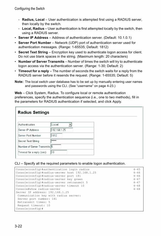
Configuring the Switch
- Radius, Local – User authentication is attempted first using a RADIUS server, then locally by the switch.
- Local, Radius – User authentication is first attempted locally by the switch, then using a RADIUS server.
• Server IP Address – Address of authentication server. (Default: 10.1.0.1)• Server Port Number – Network (UDP) port of authentication server used for
authentication messages. (Range: 1-65535; Default: 1812)• Secret Text String – Encryption key used to authenticate logon access for client.
Do not use blank spaces in the string. (Maximum length: 20 characters)• Number of Server Transmits – Number of times the switch will try to authenticate
logon access via the authentication server. (Range: 1-30; Default: 2)• Timeout for a reply – The number of seconds the switch waits for a reply from the
RADIUS server before it resends the request. (Range: 1-65535; Default: 5)
Note: The local switch user database has to be set up by manually entering user names and passwords using the CLI. (See “username” on page 4-23.)
Web – Click System, Radius. To configure local or remote authentication preferences, specify the authentication sequence (i.e., one to two methods), fill in the parameters for RADIUS authentication if selected, and click Apply.
CLI – Specify all the required parameters to enable logon authentication.Console(config)#authentication login radius 4-45Console(config)#radius-server host 192.168.1.25 4-46Console(config)#radius-server port 181 4-46Console(config)#radius-server key green 4-47Console(config)#radius-server retransmit 5 4-47Console(config)#radius-server timeout 10 4-48Console#show radius-server 4-48Server IP address: 192.168.1.25Communication key with radius server:Server port number: 181Retransmit times: 5Request timeout: 10
Console(config)#
3-22
User Authentication
Configuring 802.1x Port Authentication Network switches can provide open and easy access to network resources by simply attaching a client PC. Although this automatic configuration and access is a desirable feature, it also allows unauthorized personnel to easily intrude and possibly gain access to sensitive network data.
The IEEE 802.1x (dot1x) standard defines a port-based access control procedure that prevents unauthorized access to a network by requiring users to first enter a user ID and password for authentication. Access to all switch ports in a network can be centrally controlled from a server, which means that authorized users can use a single user ID and password for authentication from any point within the network.
This switch uses the Extensible Authentication Protocol over LAN (EAPOL) with MD5 authentication to exchange authentication protocol messages with the client, and a remote login authentication server (i.e., RADIUS) to verify user identity and access rights. When a client (i.e., Supplicant) connects to a switch port, the switch (i.e., Authenticator) responds with an identity request. The client provides its identity to the switch, which it forwards to the authentication server. The authentication server verifies the client identity and sends this information back to the switch. The switch then issues an MD5 access challenge to the client, and the client returns an MD5 response to the switch based on its user ID and password. If authentication is successful, the switch allows the client to access the network. Otherwise, network access is denied and the port remains blocked.
The operation of dot1x on the switch requires the following:• The switch must have an IP address assigned.• RADIUS authentication must be enabled on the switch and the IP address of the
RADIUS server specified.• Each switch port that will be used must be set to dot1x “Auto” mode.• Each client that needs to be authenticated must have dot1x client software
installed and properly configured.
3-23
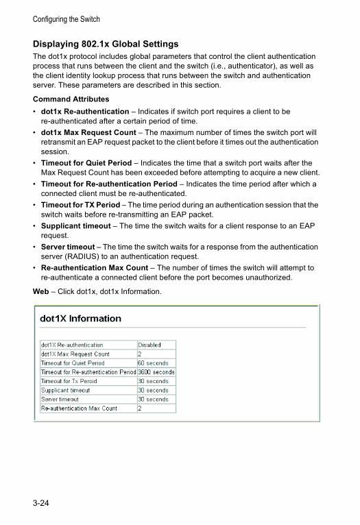
Configuring the Switch
Displaying 802.1x Global SettingsThe dot1x protocol includes global parameters that control the client authentication process that runs between the client and the switch (i.e., authenticator), as well as the client identity lookup process that runs between the switch and authentication server. These parameters are described in this section.
Command Attributes • dot1x Re-authentication – Indicates if switch port requires a client to be
re-authenticated after a certain period of time. • dot1x Max Request Count – The maximum number of times the switch port will
retransmit an EAP request packet to the client before it times out the authentication session.
• Timeout for Quiet Period – Indicates the time that a switch port waits after the Max Request Count has been exceeded before attempting to acquire a new client.
• Timeout for Re-authentication Period – Indicates the time period after which a connected client must be re-authenticated.
• Timeout for TX Period – The time period during an authentication session that the switch waits before re-transmitting an EAP packet.
• Supplicant timeout – The time the switch waits for a client response to an EAP request.
• Server timeout – The time the switch waits for a response from the authentication server (RADIUS) to an authentication request.
• Re-authentication Max Count – The number of times the switch will attempt to re-authenticate a connected client before the port becomes unauthorized.
Web – Click dot1x, dot1x Information.
3-24

User Authentication
CLI – This example shows the default protocol settings for dot1x. For a description of the additional entries displayed in the CLI, See “show dot1x” on page 4-54.
Console#show dot1x 4-54Global 802.1X Parametersreauth-enabled: yesreauth-period: 300quiet-period: 350tx-period: 300supp-timeout: 30server-timeout: 30reauth-max: 2max-req: 2
802.1X Port SummaryPort Name Status Mode Authorized
1 disabled ForceAuthorized n/a2 disabled ForceAuthorized n/a
... 25 disabled ForceAuthorized yes26 enabled Auto yes
802.1X Port Details
802.1X is disabled on port 1...
802.1X is enabled on port 26Max request 2Quiet period 350Reauth period 300Tx period 300Status UnauthorizedPort-control AutoSupplicant 00-00-00-00-00-00
Authenticator State MachineState ConnectingReauth Count 3Backend State MachineState IdleRequest Count 0Identifier(Server) 0
Reauthentication State MachineState InitializeConsole#
3-25
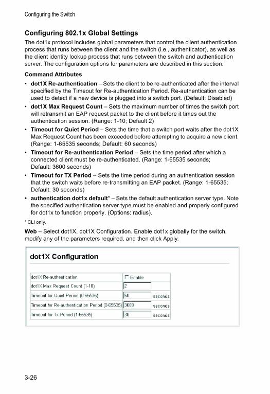
Configuring the Switch
Configuring 802.1x Global SettingsThe dot1x protocol includes global parameters that control the client authentication process that runs between the client and the switch (i.e., authenticator), as well as the client identity lookup process that runs between the switch and authentication server. The configuration options for parameters are described in this section.
Command Attributes• dot1X Re-authentication – Sets the client to be re-authenticated after the interval
specified by the Timeout for Re-authentication Period. Re-authentication can be used to detect if a new device is plugged into a switch port. (Default: Disabled)
• dot1X Max Request Count – Sets the maximum number of times the switch port will retransmit an EAP request packet to the client before it times out the authentication session. (Range: 1-10; Default 2)
• Timeout for Quiet Period – Sets the time that a switch port waits after the dot1X Max Request Count has been exceeded before attempting to acquire a new client. (Range: 1-65535 seconds; Default: 60 seconds)
• Timeout for Re-authentication Period – Sets the time period after which a connected client must be re-authenticated. (Range: 1-65535 seconds; Default: 3600 seconds)
• Timeout for TX Period – Sets the time period during an authentication session that the switch waits before re-transmitting an EAP packet. (Range: 1-65535; Default: 30 seconds)
• authentication dot1x default* – Sets the default authentication server type. Note the specified authentication server type must be enabled and properly configured for dot1x to function properly. (Options: radius).
* CLI only.
Web – Select dot1X, dot1X Configuration. Enable dot1x globally for the switch, modify any of the parameters required, and then click Apply.
3-26

User Authentication
CLI – This example enables re-authentication and sets all of the global parameters for dot1x.
Configuring Port Authorization ModeWhen dot1x is enabled, you need to specify the dot1x authentication mode configured for each port.
Command Attributes• Status – Indicates if authentication is enabled or disabled on the port.• Mode – Sets the authentication mode to one of the following options:
- Auto – Requires a dot1x-aware client to be authorized by the authentication server. Clients that are not dot1x-aware will be denied access.
- Force-Authorized – Forces the port to grant access to all clients, either dot1x-aware or otherwise.
- Force-Unauthorized – Forces the port to deny access to all clients, either dot1x-aware or otherwise.
• Authorized – - Yes – Connected client is authorized.- No – Connected client is not authorized.- Blank – Displays nothing when dot1x is disabled on a port.
• Supplicant – Indicates the MAC address of a connected client.• Trunk – Indicates if the port is configured as a trunk port.
Web – Click dot1X, dot1X Port configuration. Select the authentication mode from the drop-down box and click Apply.
Console(config)#dot1x re-authentication 4-52Console(config)#dot1x max-req 5 4-50Console(config)#dot1x timeout quiet-period 40 4-52Console(config)#dot1x timeout re-auth 5 4-53Console(config)#dot1x timeout tx-period 40 4-53Console(config)#authentication dot1x default radius 4-50Console(config)#
3-27
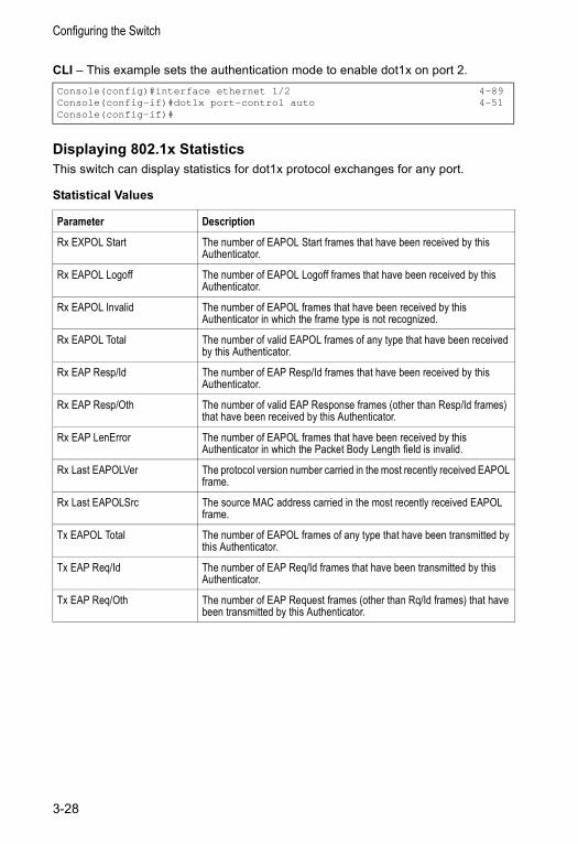
Configuring the Switch
CLI – This example sets the authentication mode to enable dot1x on port 2.
Displaying 802.1x StatisticsThis switch can display statistics for dot1x protocol exchanges for any port.
Statistical Values
Console(config)#interface ethernet 1/2 4-89Console(config-if)#dot1x port-control auto 4-51Console(config-if)#
Parameter Description
Rx EXPOL Start The number of EAPOL Start frames that have been received by this Authenticator.
Rx EAPOL Logoff The number of EAPOL Logoff frames that have been received by this Authenticator.
Rx EAPOL Invalid The number of EAPOL frames that have been received by this Authenticator in which the frame type is not recognized.
Rx EAPOL Total The number of valid EAPOL frames of any type that have been received by this Authenticator.
Rx EAP Resp/Id The number of EAP Resp/Id frames that have been received by this Authenticator.
Rx EAP Resp/Oth The number of valid EAP Response frames (other than Resp/Id frames) that have been received by this Authenticator.
Rx EAP LenError The number of EAPOL frames that have been received by this Authenticator in which the Packet Body Length field is invalid.
Rx Last EAPOLVer The protocol version number carried in the most recently received EAPOL frame.
Rx Last EAPOLSrc The source MAC address carried in the most recently received EAPOL frame.
Tx EAPOL Total The number of EAPOL frames of any type that have been transmitted by this Authenticator.
Tx EAP Req/Id The number of EAP Req/Id frames that have been transmitted by this Authenticator.
Tx EAP Req/Oth The number of EAP Request frames (other than Rq/Id frames) that have been transmitted by this Authenticator.
3-28
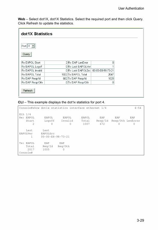
User Authentication
Web – Select dot1X, dot1X Statistics. Select the required port and then click Query. Click Refresh to update the statistics.
CLI – This example displays the dot1x statistics for port 4.Console#show dot1x statistics interface ethernet 1/4 4-54
Eth 1/4Rx: EXPOL EAPOL EAPOL EAPOL EAP EAP EAP
Start Logoff Invalid Total Resp/Id Resp/Oth LenError2 0 0 1007 672 0 0
Last LastEAPOLVer EAPOLSrc
1 00-00-E8-98-73-21
Tx: EAPOL EAP EAPTotal Req/Id Req/Oth2017 1005 0
Console#
3-29
Configuring the Switch
Access Control ListsAccess Control Lists (ACL) provide packet filtering for IP frames (based on address, protocol, TCP/UDP port number or TCP control code) or any frames (based on MAC address or Ethernet type). To filter incoming packets, first create an access list, add the require rules, and then bind the list to a specific port.
Configuring Access Control ListsAn ACL is a sequential list of permit or deny conditions that apply to IP addresses, MAC addresses, or other more specific criteria. This switch tests incoming packets against the conditions in an ACL one by one. If a list contains all permit rules, a packet will be accepted as soon as it passes any of the rules. If a list contains all deny rules, a packet will be rejected as soon as it fails any one of the rules. In other words, if no rules match for a permit list, the packet is dropped; and if no rules match for a deny list, the packet is accepted.
Note: An ACL can contain up to 32 rules.
Command Attributes
ACL Configuration – Setting the Name and Type• Name – Name of the ACL. (Maximum length: 16 characters)• Type – There are three filtering modes:
- Standard: IP ACL mode that filters packets based on the source IP address. - Extended: IP ACL mode that filters packets based on source or destination IP
address, as well as protocol type and TCP/UDP port number. If the “TCP” protocol type is specified, then you can also filter packets based on the TCP control code.
- MAC: MAC ACL mode that filters packets based on the source or destination MAC address and the Ethernet frame type (RFC 1060).
ACL Configuration – Configuring a Standard IP ACL• Action – An ACL can contain all permit rules or all deny rules.
(Default: Permit rules)• IP – Specifies the source IP address. Use “Any” to include all possible addresses,
“Host” to specify a specific host address in the Address field, or “IP” to specify a range of addresses with the Address and SubMask fields. (Options: Any, Host, IP; Default: Any)
• Address – Source IP address.• SubMask – A subnet mask containing four integers from 0 to 255, each separated
by a period. The mask uses 1 bits to indicate “match” and 0 bits to indicate “ignore.” The mask is bitwise ANDed with the specified source IP address, and compared with the address for each IP packet entering the port(s) to which this ACL has been assigned.
3-30
Access Control Lists
ACL Configuration – Configuring an Extended IP ACL• Action – An ACL can contain all permit rules or all deny rules.
(Default: Permit rules)• Src/Dst IP – Specifies the source or destination IP address. Use “Any” to include
all possible addresses, “Host” to specify a specific host address in the Address field, or “IP” to specify a range of addresses with the Address and SubMask fields. (Options: Any, Host, IP; Default: Any)
• Src/Dst Address – Source or destination IP address.• Src/Dst SubMask – Subnet mask for source or destination address. (See
SubMask in the preceding section.)• Protocol – Specifies the protocol type to match as TCP, UDP or Others, where
others indicates a specific protocol number (0-255). (Options: TCP, UDP, Others; Default: TCP)
• Src/Dst Port – TCP or UDP source/destination port number. (Range: 0-65535)• Control Code – Decimal number (representing a bit string) that specifies flag bits
in byte 14 of the TCP header. (Range: 0-63)• Control Bitmask – Decimal number representing the code bits to match.
The control bitmask is a decimal number (for an equivalent binary bit mask) that is applied to the control code. Enter a decimal number, where the equivalent binary bit “1” means to match a bit and “0” means to ignore a bit. The following bits may be specified:- 1 (fin) – Finish- 2 (syn) – Synchronize- 4 (rst) – Reset- 8 (psh) – Push- 16 (ack) – Acknowledgement- 32 (urg) – Urgent pointer
For example, use the code value and mask below to catch packets with the following flags set: - SYN flag valid, use “control-code 2 2”- Both SYN and ACK valid, use “control-code 18 18”- SYN valid and ACK invalid, use “control-code 2 18”
ACL Configuration – Configuring a MAC ACL• Action – An ACL can contain all permit rules or all deny rules.
(Default: Permit rules)• Source/Destination MAC – Source or destination MAC address.• Source/Destination Mask – Binary mask for source or destination MAC address.• Ethernet Type – This option can only be used to filter Ethernet II formatted
packets. (A detailed listing of Ethernet protocol types can be found in RFC 1060.) A few of the more common types include 0800 (IP), 0806 (ARP), 8137 (IPX).
3-31
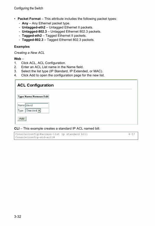
Configuring the Switch
• Packet Format – This attribute includes the following packet types:- Any – Any Ethernet packet type.- Untagged-eth2 – Untagged Ethernet II packets.- Untagged-802.3 – Untagged Ethernet 802.3 packets.- Tagged-eth2 – Tagged Ethernet II packets.- Tagged-802.3 – Tagged Ethernet 802.3 packets.
Examples
Creating a New ACL
Web – 1. Click ACL, ACL Configuration.2. Enter an ACL List name in the Name field.3. Select the list type (IP Standard, IP Extended, or MAC).4. Click Add to open the configuration page for the new list.
CLI – This example creates a standard IP ACL named bill.Console(config)#access-list ip standard bill 4-57Console(config-std-acl)#
3-32
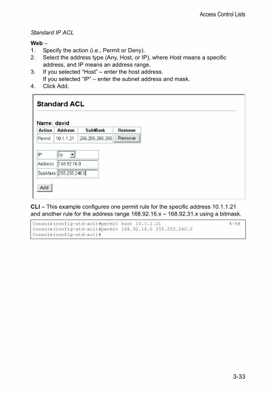
Access Control Lists
Standard IP ACL
Web – 1. Specify the action (i.e., Permit or Deny).2. Select the address type (Any, Host, or IP), where Host means a specific
address, and IP means an address range.3. If you selected “Host” – enter the host address.
If you selected “IP” – enter the subnet address and mask.4. Click Add.
CLI – This example configures one permit rule for the specific address 10.1.1.21 and another rule for the address range 168.92.16.x – 168.92.31.x using a bitmask.Console(config-std-acl)#permit host 10.1.1.21 4-58Console(config-std-acl)#permit 168.92.16.0 255.255.240.0Console(config-std-acl)#
3-33
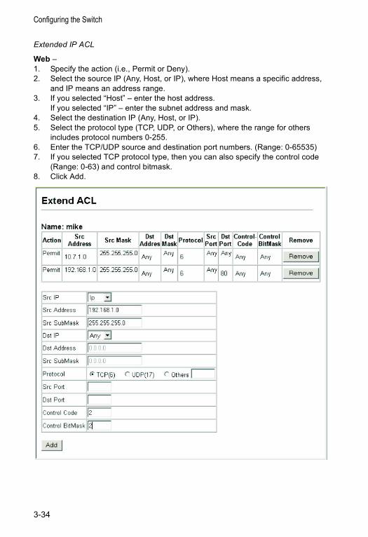
Configuring the Switch
Extended IP ACL
Web – 1. Specify the action (i.e., Permit or Deny).2. Select the source IP (Any, Host, or IP), where Host means a specific address,
and IP means an address range.3. If you selected “Host” – enter the host address.
If you selected “IP” – enter the subnet address and mask.4. Select the destination IP (Any, Host, or IP).5. Select the protocol type (TCP, UDP, or Others), where the range for others
includes protocol numbers 0-255.6. Enter the TCP/UDP source and destination port numbers. (Range: 0-65535)7. If you selected TCP protocol type, then you can also specify the control code
(Range: 0-63) and control bitmask.8. Click Add.
3-34
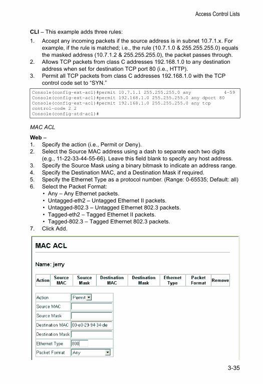
Access Control Lists
CLI – This example adds three rules:1. Accept any incoming packets if the source address is in subnet 10.7.1.x. For
example, if the rule is matched; i.e., the rule (10.7.1.0 & 255.255.255.0) equals the masked address (10.7.1.2 & 255.255.255.0), the packet passes through.
2. Allows TCP packets from class C addresses 192.168.1.0 to any destination address when set for destination TCP port 80 (i.e., HTTP).
3. Permit all TCP packets from class C addresses 192.168.1.0 with the TCP control code set to “SYN.”
MAC ACL
Web – 1. Specify the action (i.e., Permit or Deny).2. Select the Source MAC address using a dash to separate each two digits
(e.g., 11-22-33-44-55-66). Leave this field blank to specify any host address.3. Specify the Source Mask using a binary bitmask to indicate an address range.4. Specify the Destination MAC, and a Destination Mask if required.5. Specify the Ethernet Type as a protocol number. (Range: 0-65535; Default: all)6. Select the Packet Format:
• Any – Any Ethernet packets.• Untagged-eth2 – Untagged Ethernet II packets.• Untagged-802.3 – Untagged Ethernet 802.3 packets.• Tagged-eth2 – Tagged Ethernet II packets.• Tagged-802.3 – Tagged Ethernet 802.3 packets.
7. Click Add.
Console(config-ext-acl)#permit 10.7.1.1 255.255.255.0 any 4-59Console(config-ext-acl)#permit 192.168.1.0 255.255.255.0 any dport 80Console(config-ext-acl)#permit 192.168.1.0 255.255.255.0 any tcpcontrol-code 2 2Console(config-std-acl)#
3-35
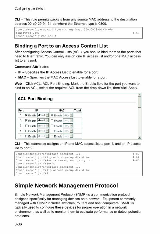
Configuring the Switch
CLI – This rule permits packets from any source MAC address to the destination address 00-e0-29-94-34-de where the Ethernet type is 0800.
Binding a Port to an Access Control ListAfter configuring Access Control Lists (ACL), you should bind them to the ports that need to filter traffic. You can only assign one IP access list and/or one MAC access list to any port.
Command Attributes• IP – Specifies the IP Access List to enable for a port.• MAC – Specifies the MAC Access List to enable for a port.
Web – Click ACL, ACL Port Binding. Mark the Enable field for the port you want to bind to an ACL, select the required ACL from the drop-down list, then click Apply.
CLI – This examples assigns an IP and MAC access list to port 1, and an IP access list to port 2.
Simple Network Management Protocol Simple Network Management Protocol (SNMP) is a communication protocol designed specifically for managing devices on a network. Equipment commonly managed with SNMP includes switches, routers and host computers. SNMP is typically used to configure these devices for proper operation in a network environment, as well as to monitor them to evaluate performance or detect potential problems.
Console(config-mac-acl)#permit any host 00-e0-29-94-34-deethertype 0800 4-64Console(config-mac-acl)#
Console(config)#interface ethernet 1/1 4-89Console(config-if)#ip access-group david in 4-61Console(config-if)#mac access-group jerry in 4-65Console(config-if)#exitConsole(config)#interface ethernet 1/2Console(config-if)#ip access-group david inConsole(config-if)#
3-36
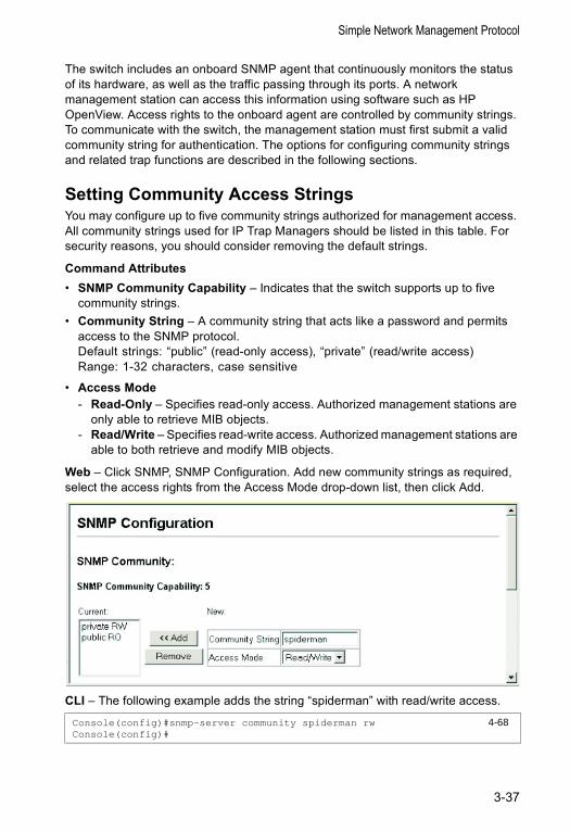
Simple Network Management Protocol
The switch includes an onboard SNMP agent that continuously monitors the status of its hardware, as well as the traffic passing through its ports. A network management station can access this information using software such as HP OpenView. Access rights to the onboard agent are controlled by community strings. To communicate with the switch, the management station must first submit a valid community string for authentication. The options for configuring community strings and related trap functions are described in the following sections.
Setting Community Access Strings You may configure up to five community strings authorized for management access. All community strings used for IP Trap Managers should be listed in this table. For security reasons, you should consider removing the default strings.
Command Attributes• SNMP Community Capability – Indicates that the switch supports up to five
community strings.• Community String – A community string that acts like a password and permits
access to the SNMP protocol. Default strings: “public” (read-only access), “private” (read/write access)Range: 1-32 characters, case sensitive
• Access Mode - Read-Only – Specifies read-only access. Authorized management stations are
only able to retrieve MIB objects. - Read/Write – Specifies read-write access. Authorized management stations are
able to both retrieve and modify MIB objects.
Web – Click SNMP, SNMP Configuration. Add new community strings as required, select the access rights from the Access Mode drop-down list, then click Add.
CLI – The following example adds the string “spiderman” with read/write access.
Console(config)#snmp-server community spiderman rw 4-68Console(config)#
3-37
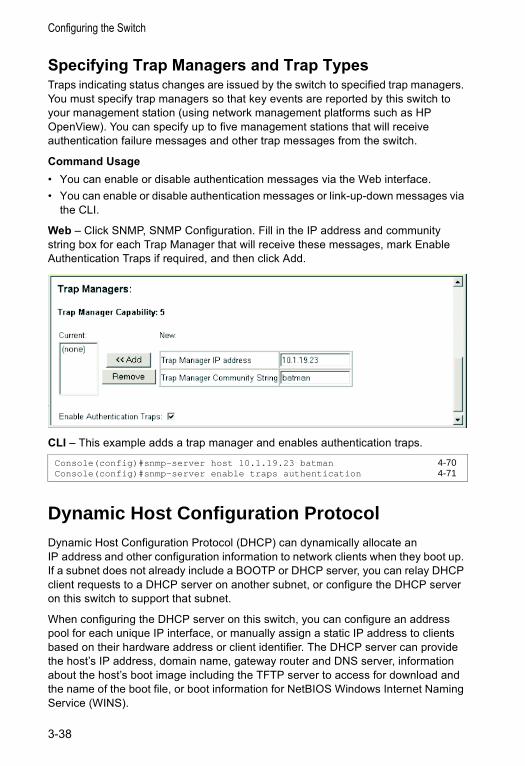
Configuring the Switch
Specifying Trap Managers and Trap TypesTraps indicating status changes are issued by the switch to specified trap managers. You must specify trap managers so that key events are reported by this switch to your management station (using network management platforms such as HP OpenView). You can specify up to five management stations that will receive authentication failure messages and other trap messages from the switch.
Command Usage• You can enable or disable authentication messages via the Web interface.• You can enable or disable authentication messages or link-up-down messages via
the CLI.
Web – Click SNMP, SNMP Configuration. Fill in the IP address and community string box for each Trap Manager that will receive these messages, mark Enable Authentication Traps if required, and then click Add.
CLI – This example adds a trap manager and enables authentication traps.
Dynamic Host Configuration ProtocolDynamic Host Configuration Protocol (DHCP) can dynamically allocate an IP address and other configuration information to network clients when they boot up. If a subnet does not already include a BOOTP or DHCP server, you can relay DHCP client requests to a DHCP server on another subnet, or configure the DHCP server on this switch to support that subnet.
When configuring the DHCP server on this switch, you can configure an address pool for each unique IP interface, or manually assign a static IP address to clients based on their hardware address or client identifier. The DHCP server can provide the host’s IP address, domain name, gateway router and DNS server, information about the host’s boot image including the TFTP server to access for download and the name of the boot file, or boot information for NetBIOS Windows Internet Naming Service (WINS).
Console(config)#snmp-server host 10.1.19.23 batman 4-70Console(config)#snmp-server enable traps authentication 4-71
3-38
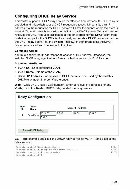
Dynamic Host Configuration Protocol
Configuring DHCP Relay ServiceThis switch supports DHCP relay service for attached host devices. If DHCP relay is enabled, and this switch sees a DHCP request broadcast, it inserts its own IP address into the request so the DHCP server will know the subnet where the client is located. Then, the switch forwards the packet to the DHCP server. When the server receives the DHCP request, it allocates a free IP address for the DHCP client from its defined scope for the DHCP client’s subnet, and sends a DHCP response back to the DHCP relay agent (i.e., this switch). This switch then broadcasts the DHCP response received from the server to the client.
Command Usage You must specify the IP address for at least one DHCP server. Otherwise, the switch’s DHCP relay agent will not forward client requests to a DHCP server.
Command Attributes• VLAN ID – ID of configured VLAN.• VLAN Name – Name of the VLAN.• Server IP Address – Addresses of DHCP servers to be used by the switch’s
DHCP relay agent in order of preference.
Web – Click DHCP, Relay Configuration. Enter up to five IP addresses for any VLAN, then click Restart DHCP Relay to start the relay service.
CLI – This example specifies one DHCP relay server for VLAN 1, and enables the relay service.Console(config)#interface vlan 1 4-89Console(config-if)#dhcp relay server 10.1.0.99 4-76Console(config-if)#ip dhcp relay 4-75Console(config-if)#
3-39
Configuring the Switch
Configuring the DHCP ServerThis switch includes a Dynamic Host Configuration Protocol (DHCP) server that can assign temporary IP addresses to any attached host requesting service. It can also provide other network settings such as the domain name, default gateway, Domain Name Servers (DNS), Windows Internet Naming Service (WINS) name servers, or information on the bootup file for the host device to download. Addresses can be assigned to clients from a common address pool configured for a specific IP interface on this switch, or fixed addresses can be assigned to hosts based on the client identifier code or MAC address.
Command Usage • First configure any excluded addresses, including the address for this switch.• Then configure address pools for the network interfaces. You can configure up to
8 network address pools. You can also manually bind an address to a specific client if required. However, any fixed addresses must fall within the range of an existing network address pool. You can configure up to 32 fixed host addresses (i.e., entering one address per pool).
Enabling the Server, Setting Excluded AddressesEnable the DHCP Server and specify the IP addresses that it should not be assigned to clients.
Command Attributes• DHCP Server – Enables or disables the DHCP server on this switch.
(Default: Disabled)• Excluded Addresses – Specifies IP addresses that the DHCP server should not
assign to DHCP clients. You can specify a single address or an address range.
Note: Be sure you exclude the address for this switch and other key network devices.
3-40
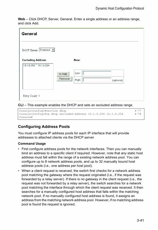
Dynamic Host Configuration Protocol
Web – Click DHCP, Server, General. Enter a single address or an address range, and click Add.
CLI – This example enables the DHCP and sets an excluded address range.
Configuring Address PoolsYou must configure IP address pools for each IP interface that will provide addresses to attached clients via the DHCP server.
Command Usage• First configure address pools for the network interfaces. Then you can manually
bind an address to a specific client if required. However, note that any static host address must fall within the range of a existing network address pool. You can configure up to 8 network address pools, and up to 32 manually bound host address pools (i.e., one address per host pool).
• When a client request is received, the switch first checks for a network address pool matching the gateway where the request originated (i.e., if the request was forwarded by a relay server). If there is no gateway in the client request (i.e., the request was not forwarded by a relay server), the switch searches for a network pool matching the interface through which the client request was received. It then searches for a manually configured host address that falls within the matching network pool. If no manually configured host address is found, it assigns an address from the matching network address pool. However, if no matching address pool is found the request is ignored.
Console(config)#service dhcp 4-77Console(config)#ip dhcp excluded-address 10.1.0.250 10.1.0.254 4-78Console#
3-41
Configuring the Switch
• When searching for a manual binding, the switch compares the client identifier and then the hardware address for DHCP clients. Since BOOTP clients cannot transmit a client identifier, you must configure a hardware address for this host type. If no manual binding has been specified for a host entry with a hardware address or client identifier, the switch will assign an address from the first matching network pool.
• If the subnet mask is not specified for network or host address pools, the class A, B, or C natural mask is used (see page 3-133). The DHCP server assumes that all host addresses are available. You can exclude subsets of the address space by using the IP Excluded Address field on the DHCP Server General configuration page.
Command Attributes
Creating a New Address Pool • Pool Name – A string or integer. (Range: 1-8 characters)
Setting the Network Parameters• IP – The IP address of the DHCP address pool.• Subnet Mask – The bit combination that identifies the network (or subnet) and the
host portion of the DHCP address pool.
Setting the Host Parameters• IP – The IP address of the DHCP address pool.• Subnet Mask – Specifies the network mask of the client.• Hardware Address – Specifies the MAC address and protocol used on the client.
(Options: Ethernet, IEEE802, FDDI; Default: Ethernet)• Client-Identifier – A unique designation for the client device, either a text string
(1-15 characters) or hexadecimal value.
Setting the Optional Parameters• Default Router – The IP address of the primary and alternate gateway router.
The IP address of the router should be on the same subnet as the client.• DNS Server – The IP address of the primary and alternate DNS server. DNS
servers must be configured for a DHCP client to map host names to IP addresses.• Netbios Server – IP address of the primary and alternate NetBIOS Windows
Internet Naming Service (WINS) name server used for Microsoft DHCP clients. • Netbios Type – NetBIOS node type for Microsoft DHCP clients.
(Options: Broadcast, Hybrid, Mixed, Peer to Peer; Default: Hybrid)• Domain Name – The domain name of the client. (Range: 1-32 characters)• Bootfile – The default boot image for a DHCP client. This file should placed on the
Trivial File Transfer Protocol (TFTP) server specified as the Next Server.• Next Server – The IP address of the next server in the boot process, which is
typically a Trivial File Transfer Protocol (TFTP) server.• Lease Time – The duration that an IP address is assigned to a DHCP client.
(Options: fixed period, Infinite; Default: 1 day)
3-42
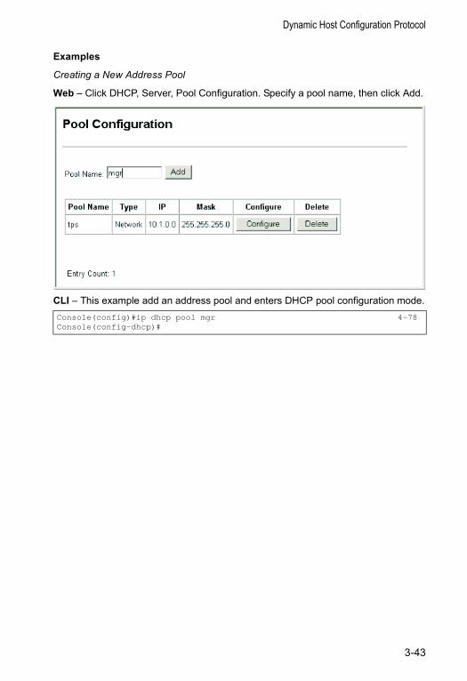
Dynamic Host Configuration Protocol
Examples
Creating a New Address Pool
Web – Click DHCP, Server, Pool Configuration. Specify a pool name, then click Add.
CLI – This example add an address pool and enters DHCP pool configuration mode.Console(config)#ip dhcp pool mgr 4-78Console(config-dhcp)#
3-43
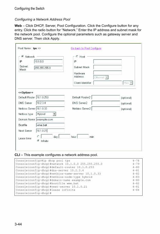
Configuring the Switch
Configuring a Network Address Pool
Web – Click DHCP, Server, Pool Configuration. Click the Configure button for any entry. Click the radio button for “Network.” Enter the IP address and subnet mask for the network pool. Configure the optional parameters such as gateway server and DNS server. Then click Apply.
CLI – This example configures a network address pool.Console(config)#ip dhcp pool tps 4-78Console(config-dhcp)#network 10.1.0.0 255.255.255.0 4-79Console(config-dhcp)#default-router 10.1.0.253 4-80Console(config-dhcp)#dns-server 10.2.3.4 4-81Console(config-dhcp)#netbios-name-server 10.1.0.33 4-82Console(config-dhcp)#netbios-node-type hybrid 4-83Console(config-dhcp)#domain-name example.com 4-80Console(config-dhcp)#bootfile wme.bat 4-82Console(config-dhcp)#next-server 10.1.0.21 4-81Console(config-dhcp)#lease infinite 4-84Console(config-dhcp)#
3-44
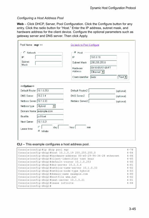
Dynamic Host Configuration Protocol
Configuring a Host Address Pool
Web – Click DHCP, Server, Pool Configuration. Click the Configure button for any entry. Click the radio button for “Host.” Enter the IP address, subnet mask, and hardware address for the client device. Configure the optional parameters such as gateway server and DNS server. Then click Apply.
CLI – This example configures a host address pool.Console(config)#ip dhcp pool mgr 4-78Console(config-dhcp)#host 10.1.0.19 255.255.255.0 4-84Console(config-dhcp)#hardware-address 00-e0-29-94-34-28 ethernet 4-86Console(config-dhcp)#client-identifier text bear 4-85Console(config-dhcp)#default-router 10.1.0.253 4-80Console(config-dhcp)#dns-server 10.2.3.4 4-81Console(config-dhcp)#netbios-name-server 10.1.0.33 4-82Console(config-dhcp)#netbios-node-type hybrid 4-83Console(config-dhcp)#domain-name example.com 4-80Console(config-dhcp)#bootfile wme.bat 4-82Console(config-dhcp)#next-server 10.1.0.21 4-81Console(config-dhcp)#lease infinite 4-84Console(config-dhcp)#
3-45
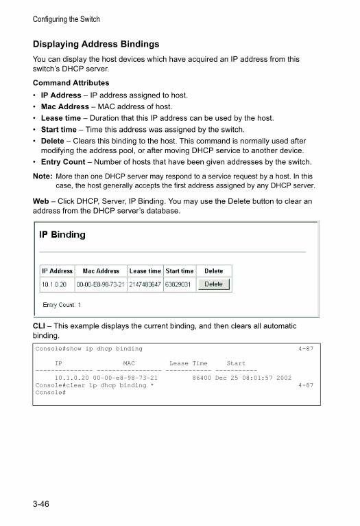
Configuring the Switch
Displaying Address BindingsYou can display the host devices which have acquired an IP address from this switch’s DHCP server.
Command Attributes• IP Address – IP address assigned to host.• Mac Address – MAC address of host.• Lease time – Duration that this IP address can be used by the host.• Start time – Time this address was assigned by the switch.• Delete – Clears this binding to the host. This command is normally used after
modifying the address pool, or after moving DHCP service to another device.• Entry Count – Number of hosts that have been given addresses by the switch.
Note: More than one DHCP server may respond to a service request by a host. In this case, the host generally accepts the first address assigned by any DHCP server.
Web – Click DHCP, Server, IP Binding. You may use the Delete button to clear an address from the DHCP server’s database.
CLI – This example displays the current binding, and then clears all automatic binding.Console#show ip dhcp binding 4-87
IP MAC Lease Time Start--------------- ----------------- ------------ -----------
10.1.0.20 00-00-e8-98-73-21 86400 Dec 25 08:01:57 2002Console#clear ip dhcp binding * 4-87Console#
3-46
Port Configuration
Port Configuration
Displaying Connection StatusYou can use the Port Information or Trunk Information pages to display the current connection status, including link state, speed/duplex mode, flow control, and auto-negotiation.
Command Attributes• Name – Interface label.• Type – Indicates the port type (100BASE-TX, 1000BASE-T, 1000BASE-SX,
1000BASE-LX or 100BASE-FX). • Admin Status – Shows if the interface is enabled or disabled.
Web: Displays Enabled or Disabled.CLI: Displays Port Admin (up or down).
• Link Status – Indicates if the link is Up or Down. (CLI only)• Oper Status – Indicates if the link is Up or Down. (Web only)• Port Operation Status – Provides detailed information on port state.
This item only displays if the link is up. (CLI only)• Speed/Duplex Status – Shows the current speed and duplex mode.• Flow Control Status – Indicates the type of flow control currently in use.
Web: IEEE 802.3x, Back-Pressure or None.CLI: Enabled or Disabled. Flow Type shows IEEE 802.3x, Back-Pressure or None.
• Autonegotiation – Shows if auto-negotiation is enabled or disabled.• MAC Address – The physical layer address for this port. (CLI only)
To access this item on the Web, see “Setting the Switch’s IP Address” on page 3-12.
• Trunk Member – Shows if port is a trunk member. (Port Information only)• Creation – Shows if a trunk is manually configured or dynamically set via LACP.
(Trunk Information only)• Port Capabilities – Specifies the capabilities to be advertised for a port during
auto-negotiation. (To access this item on the Web, see “Configuring Interface Connections” on page 3-48.) The following capabilities are supported. • 10half - Supports 10 Mbps half-duplex operation • 10full - Supports 10 Mbps full-duplex operation • 100half - Supports 100 Mbps half-duplex operation • 100full - Supports 100 Mbps full-duplex operation • 1000full - Supports 1000 Mbps full-duplex operation • Sym - Transmits and receives pause frames for flow control• FC - Supports flow control
3-47
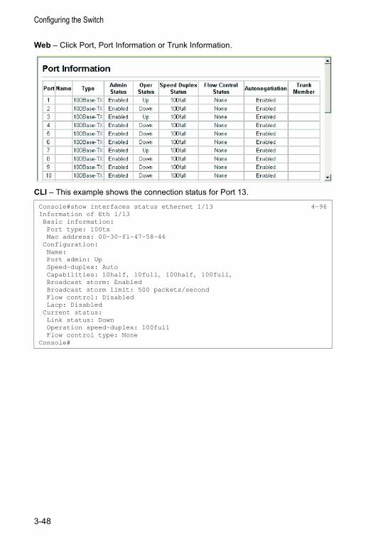
Configuring the Switch
Web – Click Port, Port Information or Trunk Information.
CLI – This example shows the connection status for Port 13.
Console#show interfaces status ethernet 1/13 4-96Information of Eth 1/13Basic information:Port type: 100txMac address: 00-30-f1-47-58-46
Configuration:Name:Port admin: UpSpeed-duplex: AutoCapabilities: 10half, 10full, 100half, 100full,Broadcast storm: EnabledBroadcast storm limit: 500 packets/secondFlow control: DisabledLacp: Disabled
Current status:Link status: DownOperation speed-duplex: 100fullFlow control type: None
Console#
3-48
Port Configuration
Configuring Interface ConnectionsYou can use the Port Configuration or Trunk Configuration page to enable/disable an interface, set auto-negotiation and the interface capabilities to advertise, or manually fix the speed, duplex mode, and flow control.
Command Attributes• Name – Allows you to label an interface. (Range: 1-64 characters)• Admin – Allows you to manually disable an interface. You can disable an interface
due to abnormal behavior (e.g., excessive collisions), and then reenable it after the problem has been resolved. You may also disable an interface for security reasons.
• Speed/Duplex – Allows you to manually set the port speed and duplex mode.• Flow Control – Allows automatic or manual selection of flow control.• Autonegotiation (Port Capabilities) – Allows auto-negotiation to be enabled/
disabled. When auto-negotiation is enabled, you need to specify the capabilities to be advertised. When auto-negotiation is disabled, you can force the settings for speed, mode, and flow control.The following capabilities are supported. - 10half - Supports 10 Mbps half-duplex operation- 10full - Supports 10 Mbps full-duplex operation - 100half - Supports 100 Mbps half-duplex operation - 100full - Supports 100 Mbps full-duplex operation - 1000full - Supports 1000 Mbps full-duplex operation - Sym (Gigabit only) - Check this item to transmit and receive pause frames, or
clear it to auto-negotiate the sender and receiver for asymmetric pause frames. (The current switch chip only supports symmetric pause frames.)
- FC - Supports flow control Flow control can eliminate frame loss by “blocking” traffic from end stations or segments connected directly to the switch when its buffers fill. When enabled, back pressure is used for half-duplex operation and IEEE 802.3x for full-duplex operation. (Avoid using flow control on a port connected to a hub unless it is actually required to solve a problem. Otherwise back pressure jamming signals may degrade overall performance for the segment attached to the hub.)
(Default: Autonegotiation enabled; Advertised capabilities for 100BASE-TX – 10half, 10full, 100half, 100full; 1000BASE-T – 10half, 10full, 100half, 100full, 1000full; 1000BASE-SX/LX/LH – 1000full)
• Trunk – Indicates if a port is a member of a trunk. To create trunks and select port members, see “Trunk Configuration” on page 3-58.
Note: Auto-negotiation must be disabled before you can configure or force the interface to use the Speed/Duplex Mode or Flow Control options.
3-49
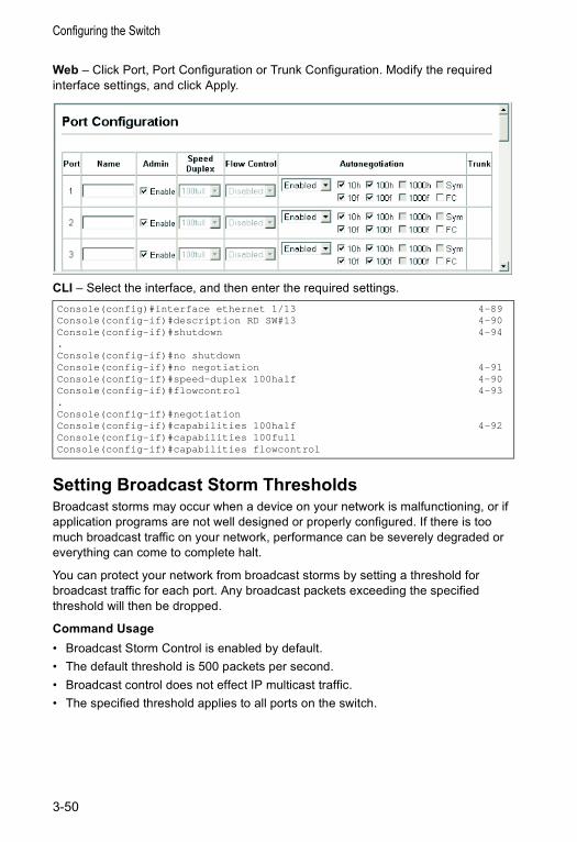
Configuring the Switch
Web – Click Port, Port Configuration or Trunk Configuration. Modify the required interface settings, and click Apply.
CLI – Select the interface, and then enter the required settings.
Setting Broadcast Storm ThresholdsBroadcast storms may occur when a device on your network is malfunctioning, or if application programs are not well designed or properly configured. If there is too much broadcast traffic on your network, performance can be severely degraded or everything can come to complete halt.
You can protect your network from broadcast storms by setting a threshold for broadcast traffic for each port. Any broadcast packets exceeding the specified threshold will then be dropped.
Command Usage• Broadcast Storm Control is enabled by default.• The default threshold is 500 packets per second.• Broadcast control does not effect IP multicast traffic.• The specified threshold applies to all ports on the switch.
Console(config)#interface ethernet 1/13 4-89Console(config-if)#description RD SW#13 4-90Console(config-if)#shutdown 4-94.Console(config-if)#no shutdownConsole(config-if)#no negotiation 4-91Console(config-if)#speed-duplex 100half 4-90Console(config-if)#flowcontrol 4-93.Console(config-if)#negotiationConsole(config-if)#capabilities 100half 4-92Console(config-if)#capabilities 100fullConsole(config-if)#capabilities flowcontrol
3-50
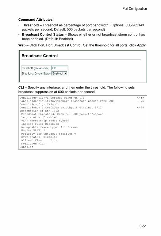
Port Configuration
Command Attributes• Threshold – Threshold as percentage of port bandwidth. (Options: 500-262143
packets per second; Default: 500 packets per second) • Broadcast Control Status – Shows whether or not broadcast storm control has
been enabled. (Default: Enabled)
Web – Click Port, Port Broadcast Control. Set the threshold for all ports, click Apply.
CLI – Specify any interface, and then enter the threshold. The following sets broadcast suppression at 600 packets per second.Console(config)#interface ethernet 1/1 4-89Console(config-if)#switchport broadcast packet-rate 600 4-95Console(config-if)#endConsole#show interfaces switchport ethernet 1/12 4-98Information of Eth 1/12Broadcast threshold: Enabled, 600 packets/secondLacp status: DisabledVLAN membership mode: HybridIngress rule: DisabledAcceptable frame type: All framesNative VLAN: 1Priority for untagged traffic: 0Gvrp status: DisabledAllowed Vlan: 1(u),Forbidden Vlan:
Console#
3-51
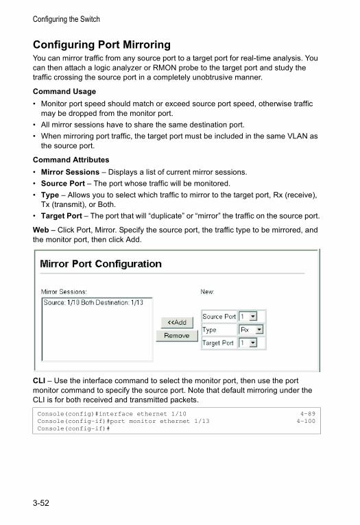
Configuring the Switch
Configuring Port MirroringYou can mirror traffic from any source port to a target port for real-time analysis. You can then attach a logic analyzer or RMON probe to the target port and study the traffic crossing the source port in a completely unobtrusive manner.
Command Usage• Monitor port speed should match or exceed source port speed, otherwise traffic
may be dropped from the monitor port.• All mirror sessions have to share the same destination port. • When mirroring port traffic, the target port must be included in the same VLAN as
the source port.
Command Attributes• Mirror Sessions – Displays a list of current mirror sessions.• Source Port – The port whose traffic will be monitored.• Type – Allows you to select which traffic to mirror to the target port, Rx (receive),
Tx (transmit), or Both.• Target Port – The port that will “duplicate” or “mirror” the traffic on the source port.
Web – Click Port, Mirror. Specify the source port, the traffic type to be mirrored, and the monitor port, then click Add.
CLI – Use the interface command to select the monitor port, then use the port monitor command to specify the source port. Note that default mirroring under the CLI is for both received and transmitted packets.
Console(config)#interface ethernet 1/10 4-89Console(config-if)#port monitor ethernet 1/13 4-100Console(config-if)#
3-52
Port Configuration
Showing Port StatisticsYou can display standard statistics on network traffic from the Interfaces Group and Ethernet-like MIBs, as well as a detailed breakdown of traffic based on the RMON MIB. Interfaces and Ethernet-like statistics display errors on the traffic passing through each port. This information can be used to identify potential problems with the switch (such as a faulty port or unusually heavy loading). RMON statistics provide access to a broad range of statistics, including a total count of different frame types and sizes passing through each port. All values displayed have been accumulated since the last system reboot, and are shown as counts per second. Statistics are refreshed every 60 seconds by default.
Note: RMON groups 2, 3 and 9 can only be accessed using SNMP management software such as HP OpenView.
Statistical Values
Parameter Description
Interface Statistics
Received Octets The total number of octets received on the interface, including framing characters.
Received Unicast Packets The number of subnetwork-unicast packets delivered to a higher-layer protocol.
Received Multicast Packets The number of packets, delivered by this sub-layer to a higher (sub-)layer, which were addressed to a multicast address at this sub-layer.
Received Broadcast Packets The number of packets, delivered by this sub-layer to a higher (sub-)layer, which were addressed to a broadcast address at this sub-layer.
Received Discarded Packets The number of inbound packets which were chosen to be discarded even though no errors had been detected to prevent their being deliverable to a higher-layer protocol. One possible reason for discarding such a packet could be to free up buffer space.
Received Unknown Packets The number of packets received via the interface which were discarded because of an unknown or unsupported protocol.
Received Errors The number of inbound packets that contained errors preventing them from being deliverable to a higher-layer protocol.
Transmit Octets The total number of octets transmitted out of the interface, including framing characters.
Transmit Unicast Packets The total number of packets that higher-level protocols requested be transmitted to a subnetwork-unicast address, including those that were discarded or not sent.
Transmit Multicast Packets The total number of packets that higher-level protocols requested be transmitted, and which were addressed to a multicast address at this sub-layer, including those that were discarded or not sent.
Transmit Broadcast Packets The total number of packets that higher-level protocols requested be transmitted, and which were addressed to a broadcast address at this sub-layer, including those that were discarded or not sent.
3-53
Configuring the Switch
Transmit Discarded Packets The number of outbound packets which were chosen to be discarded even though no errors had been detected to prevent their being transmitted. One possible reason for discarding such a packet could be to free up buffer space.
Transmit Errors The number of outbound packets that could not be transmitted because of errors.
Etherlike Statistics
Alignment Errors The number of alignment errors (missynchronized data packets).
Late Collisions The number of times that a collision is detected later than 512 bit-times into the transmission of a packet.
FCS Errors A count of frames received on a particular interface that are an integral number of octets in length but do not pass the FCS check. This count does not include frames received with frame-too-long or frame-too-short error.
Excessive Collisions A count of frames for which transmission on a particular interface fails due to excessive collisions. This counter does not increment when the interface is operating in full-duplex mode.
Single Collision Frames The number of successfully transmitted frames for which transmission is inhibited by exactly one collision.
Internal MAC Transmit Errors A count of frames for which transmission on a particular interface fails due to an internal MAC sublayer transmit error.
Multiple Collision Frames A count of successfully transmitted frames for which transmission is inhibited by more than one collision.
Carrier Sense Errors The number of times that the carrier sense condition was lost or never asserted when attempting to transmit a frame.
SQE Test Errors A count of times that the SQE TEST ERROR message is generated by the PLS sublayer for a particular interface.
Frames Too Long A count of frames received on a particular interface that exceed the maximum permitted frame size.
Deferred Transmissions A count of frames for which the first transmission attempt on a particular interface is delayed because the medium was busy.
Internal MAC Receive Errors A count of frames for which reception on a particular interface fails due to an internal MAC sublayer receive error.
RMON Statistics
Drop Events The total number of events in which packets were dropped due to lack of resources.
Jabbers The total number of frames received that were longer than 1518 octets (excluding framing bits, but including FCS octets), and had either an FCS or alignment error.
Received Bytes Total number of bytes of data received on the network. This statistic can be used as a reasonable indication of Ethernet utilization.
Collisions The best estimate of the total number of collisions on this Ethernet segment.
Received Frames The total number of frames (bad, broadcast and multicast) received.
Parameter Description
3-54
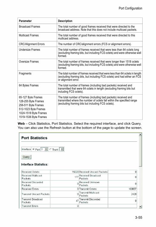
Port Configuration
Web – Click Statistics, Port Statistics. Select the required interface, and click Query. You can also use the Refresh button at the bottom of the page to update the screen.
Broadcast Frames The total number of good frames received that were directed to the broadcast address. Note that this does not include multicast packets.
Multicast Frames The total number of good frames received that were directed to this multicast address.
CRC/Alignment Errors The number of CRC/alignment errors (FCS or alignment errors).
Undersize Frames The total number of frames received that were less than 64 octets long (excluding framing bits, but including FCS octets) and were otherwise well formed.
Oversize Frames The total number of frames received that were longer than 1518 octets (excluding framing bits, but including FCS octets) and were otherwise well formed.
Fragments The total number of frames received that were less than 64 octets in length (excluding framing bits, but including FCS octets) and had either an FCS or alignment error.
64 Bytes Frames The total number of frames (including bad packets) received and transmitted that were 64 octets in length (excluding framing bits but including FCS octets).
65-127 Byte Frames128-255 Byte Frames256-511 Byte Frames512-1023 Byte Frames1024-1518 Byte Frames1519-1536 Byte Frames
The total number of frames (including bad packets) received and transmitted where the number of octets fall within the specified range (excluding framing bits but including FCS octets).
Parameter Description
3-55
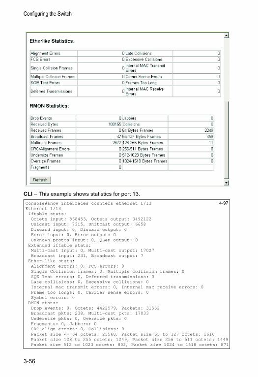
Configuring the Switch
CLI – This example shows statistics for port 13.Console#show interfaces counters ethernet 1/13 4-97Ethernet 1/13Iftable stats:Octets input: 868453, Octets output: 3492122Unicast input: 7315, Unitcast output: 6658Discard input: 0, Discard output: 0Error input: 0, Error output: 0Unknown protos input: 0, QLen output: 0
Extended iftable stats:Multi-cast input: 0, Multi-cast output: 17027Broadcast input: 231, Broadcast output: 7
Ether-like stats:Alignment errors: 0, FCS errors: 0Single Collision frames: 0, Multiple collision frames: 0SQE Test errors: 0, Deferred transmissions: 0Late collisions: 0, Excessive collisions: 0Internal mac transmit errors: 0, Internal mac receive errors: 0Frame too longs: 0, Carrier sense errors: 0Symbol errors: 0
RMON stats:Drop events: 0, Octets: 4422579, Packets: 31552Broadcast pkts: 238, Multi-cast pkts: 17033Undersize pkts: 0, Oversize pkts: 0Fragments: 0, Jabbers: 0CRC align errors: 0, Collisions: 0Packet size <= 64 octets: 25568, Packet size 65 to 127 octets: 1616Packet size 128 to 255 octets: 1249, Packet size 256 to 511 octets: 1449Packet size 512 to 1023 octets: 802, Packet size 1024 to 1518 octets: 871
3-56
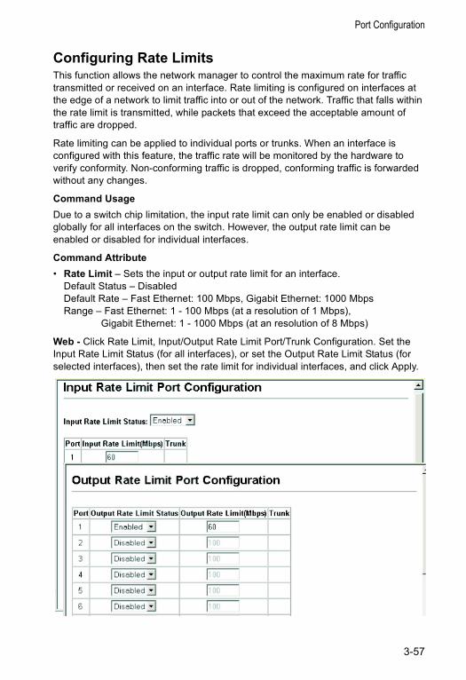
Port Configuration
Configuring Rate LimitsThis function allows the network manager to control the maximum rate for traffic transmitted or received on an interface. Rate limiting is configured on interfaces at the edge of a network to limit traffic into or out of the network. Traffic that falls within the rate limit is transmitted, while packets that exceed the acceptable amount of traffic are dropped.
Rate limiting can be applied to individual ports or trunks. When an interface is configured with this feature, the traffic rate will be monitored by the hardware to verify conformity. Non-conforming traffic is dropped, conforming traffic is forwarded without any changes.
Command UsageDue to a switch chip limitation, the input rate limit can only be enabled or disabled globally for all interfaces on the switch. However, the output rate limit can be enabled or disabled for individual interfaces.
Command Attribute• Rate Limit – Sets the input or output rate limit for an interface.
Default Status – DisabledDefault Rate – Fast Ethernet: 100 Mbps, Gigabit Ethernet: 1000 MbpsRange – Fast Ethernet: 1 - 100 Mbps (at a resolution of 1 Mbps),
Gigabit Ethernet: 1 - 1000 Mbps (at an resolution of 8 Mbps)
Web - Click Rate Limit, Input/Output Rate Limit Port/Trunk Configuration. Set the Input Rate Limit Status (for all interfaces), or set the Output Rate Limit Status (for selected interfaces), then set the rate limit for individual interfaces, and click Apply.
3-57
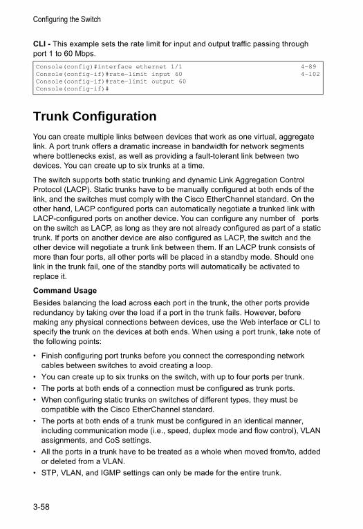
Configuring the Switch
CLI - This example sets the rate limit for input and output traffic passing through port 1 to 60 Mbps.
Trunk ConfigurationYou can create multiple links between devices that work as one virtual, aggregate link. A port trunk offers a dramatic increase in bandwidth for network segments where bottlenecks exist, as well as providing a fault-tolerant link between two devices. You can create up to six trunks at a time.
The switch supports both static trunking and dynamic Link Aggregation Control Protocol (LACP). Static trunks have to be manually configured at both ends of the link, and the switches must comply with the Cisco EtherChannel standard. On the other hand, LACP configured ports can automatically negotiate a trunked link with LACP-configured ports on another device. You can configure any number of ports on the switch as LACP, as long as they are not already configured as part of a static trunk. If ports on another device are also configured as LACP, the switch and the other device will negotiate a trunk link between them. If an LACP trunk consists of more than four ports, all other ports will be placed in a standby mode. Should one link in the trunk fail, one of the standby ports will automatically be activated to replace it.
Command UsageBesides balancing the load across each port in the trunk, the other ports provide redundancy by taking over the load if a port in the trunk fails. However, before making any physical connections between devices, use the Web interface or CLI to specify the trunk on the devices at both ends. When using a port trunk, take note of the following points:
• Finish configuring port trunks before you connect the corresponding network cables between switches to avoid creating a loop.
• You can create up to six trunks on the switch, with up to four ports per trunk.• The ports at both ends of a connection must be configured as trunk ports.• When configuring static trunks on switches of different types, they must be
compatible with the Cisco EtherChannel standard.• The ports at both ends of a trunk must be configured in an identical manner,
including communication mode (i.e., speed, duplex mode and flow control), VLAN assignments, and CoS settings.
• All the ports in a trunk have to be treated as a whole when moved from/to, added or deleted from a VLAN.
• STP, VLAN, and IGMP settings can only be made for the entire trunk.
Console(config)#interface ethernet 1/1 4-89Console(config-if)#rate-limit input 60 4-102Console(config-if)#rate-limit output 60Console(config-if)#
3-58
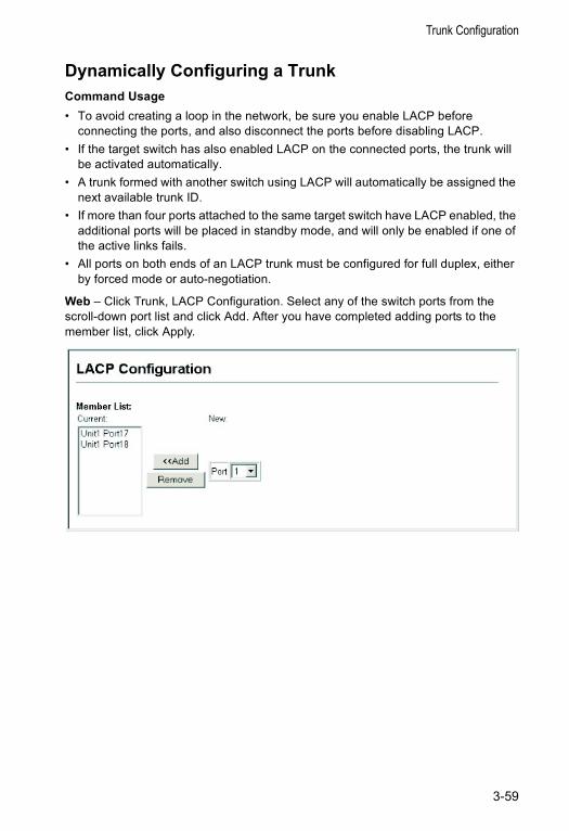
Trunk Configuration
Dynamically Configuring a TrunkCommand Usage• To avoid creating a loop in the network, be sure you enable LACP before
connecting the ports, and also disconnect the ports before disabling LACP. • If the target switch has also enabled LACP on the connected ports, the trunk will
be activated automatically. • A trunk formed with another switch using LACP will automatically be assigned the
next available trunk ID. • If more than four ports attached to the same target switch have LACP enabled, the
additional ports will be placed in standby mode, and will only be enabled if one of the active links fails.
• All ports on both ends of an LACP trunk must be configured for full duplex, either by forced mode or auto-negotiation.
Web – Click Trunk, LACP Configuration. Select any of the switch ports from the scroll-down port list and click Add. After you have completed adding ports to the member list, click Apply.
3-59
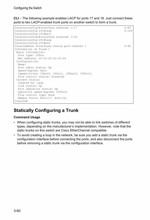
Configuring the Switch
CLI – The following example enables LACP for ports 17 and 18. Just connect these ports to two LACP-enabled trunk ports on another switch to form a trunk.
Statically Configuring a TrunkCommand Usage• When configuring static trunks, you may not be able to link switches of different
types, depending on the manufacturer’s implementation. However, note that the static trunks on this switch are Cisco EtherChannel compatible.
• To avoid creating a loop in the network, be sure you add a static trunk via the configuration interface before connecting the ports, and also disconnect the ports before removing a static trunk via the configuration interface.
Console(config)#interface ethernet 1/17 4-89Console(config-if)#lacp 4-104Console(config-if)#exitConsole(config)#interface ethernet 1/18Console(config-if)#lacpConsole(config-if)#endConsole#show interfaces status port-channel 1 4-96Information of Trunk 1Basic information:Port type: 100txMac address: 22-22-22-22-22-2d
Configuration:Name:Port admin status: UpSpeed-duplex: AutoCapabilities: 10half, 10full, 100half, 100full,Flow control status: Disabled
Current status:Created by: LacpLink status: UpPort operation status: UpOperation speed-duplex: 100fullFlow control type: NoneMember Ports: Eth1/17, Eth1/18,
Console#
3-60
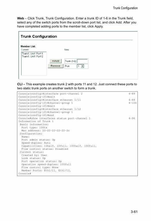
Trunk Configuration
Web – Click Trunk, Trunk Configuration. Enter a trunk ID of 1-6 in the Trunk field, select any of the switch ports from the scroll-down port list, and click Add. After you have completed adding ports to the member list, click Apply.
CLI – This example creates trunk 2 with ports 11 and 12. Just connect these ports to two static trunk ports on another switch to form a trunk.Console(config)#interface port-channel 2 4-89Console(config-if)#exitConsole(config)#interface ethernet 1/11 4-89Console(config-if)#channel-group 1 4-104Console(config-if)#exitConsole(config)#interface ethernet 1/12Console(config-if)#channel-group 1Console(config-if)#endConsole#show interfaces status port-channel 1 4-96Information of Trunk 1Basic information:Port type: 100txMac address: 22-22-22-22-22-2c
Configuration:Name:Port admin status: UpSpeed-duplex: AutoCapabilities: 10half, 10full, 100half, 100full,Flow control status: Disabled
Current status:Created by: UserLink status: UpPort operation status: UpOperation speed-duplex: 100fullFlow control type: NoneMember Ports: Eth1/11, Eth1/12,
Console#
3-61
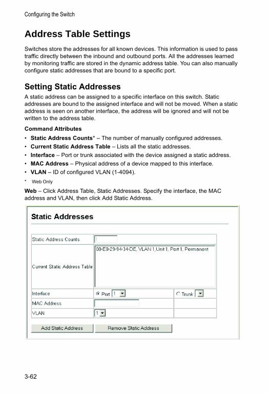
Configuring the Switch
Address Table SettingsSwitches store the addresses for all known devices. This information is used to pass traffic directly between the inbound and outbound ports. All the addresses learned by monitoring traffic are stored in the dynamic address table. You can also manually configure static addresses that are bound to a specific port.
Setting Static AddressesA static address can be assigned to a specific interface on this switch. Static addresses are bound to the assigned interface and will not be moved. When a static address is seen on another interface, the address will be ignored and will not be written to the address table.
Command Attributes• Static Address Counts* – The number of manually configured addresses.• Current Static Address Table – Lists all the static addresses.• Interface – Port or trunk associated with the device assigned a static address.• MAC Address – Physical address of a device mapped to this interface.• VLAN – ID of configured VLAN (1-4094).* Web Only
Web – Click Address Table, Static Addresses. Specify the interface, the MAC address and VLAN, then click Add Static Address.
3-62
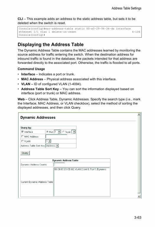
Address Table Settings
CLI – This example adds an address to the static address table, but sets it to be deleted when the switch is reset.
Displaying the Address TableThe Dynamic Address Table contains the MAC addresses learned by monitoring the source address for traffic entering the switch. When the destination address for inbound traffic is found in the database, the packets intended for that address are forwarded directly to the associated port. Otherwise, the traffic is flooded to all ports.
Command Usage• Interface – Indicates a port or trunk.• MAC Address – Physical address associated with this interface.• VLAN – ID of configured VLAN (1-4094).• Address Table Sort Key – You can sort the information displayed based on
interface (port or trunk) or MAC address.
Web – Click Address Table, Dynamic Addresses. Specify the search type (i.e., mark the Interface, MAC Address, or VLAN checkbox), select the method of sorting the displayed addresses, and then click Query.
Console(config)#mac-address-table static 00-e0-29-94-34-de interfaceethernet 1/1 vlan 1 delete-on-reset 4-106Console(config)#
3-63

Configuring the Switch
CLI – This example also displays the address table entries for port 1.
Changing the Aging TimeYou can set the aging time for entries in the dynamic address table.
Command Attributes• Aging Time – The time after which a learned entry is discarded.
(Range: 10-1000000 seconds; Default: 300 seconds)
Web – Click Address Table, Address Aging. Specify the new aging time, click Apply.
CLI – This example sets the aging time to 400 seconds.
Spanning Tree Algorithm Configuration The Spanning Tree Algorithm (STA) can be used to detect and disable network loops, and to provide backup links between switches, bridges or routers. This allows the switch to interact with other bridging devices (that is, an STA-compliant switch, bridge or router) in your network to ensure that only one route exists between any two stations on the network, and provide backup links which automatically take over when a primary link goes down.
The spanning tree algorithms supported by this switch include these versions:• STP – Spanning Tree Protocol (IEEE 802.1D)• RSTP – Rapid Spanning Tree Protocol (IEEE 802.1w)
STA uses a distributed algorithm to select a bridging device (STA-compliant switch, bridge or router) that serves as the root of the spanning tree network. It selects a root port on each bridging device (except for the root device) which incurs the lowest path cost when forwarding a packet from that device to the root device. Then it selects a designated bridging device from each LAN which incurs the lowest path cost when forwarding a packet from that LAN to the root device. All ports connected to designated bridging devices are assigned as designated ports. After determining the lowest cost spanning tree, it enables all root ports and designated ports, and
Console#show mac-address-table interface ethernet 1/1 4-108Interface Mac Address Vlan Type--------- ----------------- ---- -----------------Eth 1/ 1 00-E0-29-94-34-DE 1 PermanentEth 1/ 1 00-20-9C-23-CD-60 2 Learned
Console#
Console(config)#mac-address-table aging-time 400 4-109Console(config)#
3-64
Spanning Tree Algorithm Configuration
disables all other ports. Network packets are therefore only forwarded between root ports and designated ports, eliminating any possible network loops.
Once a stable network topology has been established, all bridges listen for Hello BPDUs (Bridge Protocol Data Units) transmitted from the Root Bridge. If a bridge does not get a Hello BPDU after a predefined interval (Maximum Age), the bridge assumes that the link to the Root Bridge is down. This bridge will then initiate negotiations with other bridges to reconfigure the network to reestablish a valid network topology.
RSTP is designed as a general replacement for the slower, legacy STP. RSTP achieves must faster reconfiguration (i.e., around one tenth of the time required by STP) by reducing the number of state changes before active ports start learning, predefining an alternate route that can be used when a node or port fails, and retaining the forwarding database for ports insensitive to changes in the tree structure when reconfiguration occurs.
Displaying Global SettingsYou can display a summary of the current bridge STA information that applies to the entire switch using the STA Information screen.
Field Attributes• Spanning Tree State – Shows if the switch is enabled to participate in an
STA-compliant network.• Bridge ID – A unique identifier for this bridge, consisting of the bridge priority and
MAC address (where the address is taken from the switch system).• Max Age – The maximum time (in seconds) a device can wait without receiving a
configuration message before attempting to reconfigure. All device ports (except for designated ports) should receive configuration messages at regular intervals. Any port that ages out STA information (provided in the last configuration message) becomes the designated port for the attached LAN. If it is a root port, a new root port is selected from among the device ports attached to the network. (References to “ports” in this section mean “interfaces,” which includes both ports and trunks.)
• Hello Time – Interval (in seconds) at which the root device transmits a configuration message.
• Forward Delay – The maximum time (in seconds) the root device will wait before changing states (i.e., discarding to learning to forwarding). This delay is required because every device must receive information about topology changes before it starts to forward frames. In addition, each port needs time to listen for conflicting information that would make it return to a discarding state; otherwise, temporary data loops might result.
• Designated Root – The priority and MAC address of the device in the Spanning Tree that this switch has accepted as the root device.• Root Port – The number of the port on this switch that is closest to the root. This
switch communicates with the root device through this port. If there is no root
3-65
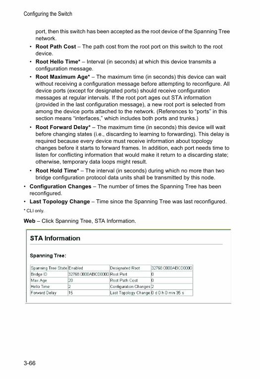
Configuring the Switch
port, then this switch has been accepted as the root device of the Spanning Tree network.
• Root Path Cost – The path cost from the root port on this switch to the root device.
• Root Hello Time* – Interval (in seconds) at which this device transmits a configuration message.
• Root Maximum Age* – The maximum time (in seconds) this device can wait without receiving a configuration message before attempting to reconfigure. All device ports (except for designated ports) should receive configuration messages at regular intervals. If the root port ages out STA information (provided in the last configuration message), a new root port is selected from among the device ports attached to the network. (References to “ports” in this section means “interfaces,” which includes both ports and trunks.)
• Root Forward Delay* – The maximum time (in seconds) this device will wait before changing states (i.e., discarding to learning to forwarding). This delay is required because every device must receive information about topology changes before it starts to forward frames. In addition, each port needs time to listen for conflicting information that would make it return to a discarding state; otherwise, temporary data loops might result.
• Root Hold Time* – The interval (in seconds) during which no more than two bridge configuration protocol data units shall be transmitted by this node.
• Configuration Changes – The number of times the Spanning Tree has been reconfigured.
• Last Topology Change – Time since the Spanning Tree was last reconfigured.* CLI only.
Web – Click Spanning Tree, STA Information.
3-66
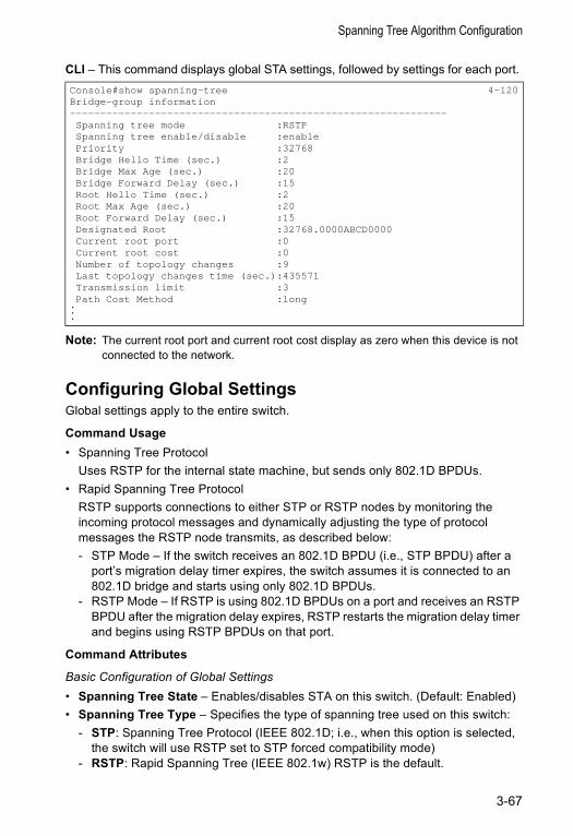
Spanning Tree Algorithm Configuration
CLI – This command displays global STA settings, followed by settings for each port.
Note: The current root port and current root cost display as zero when this device is not connected to the network.
Configuring Global SettingsGlobal settings apply to the entire switch.
Command Usage• Spanning Tree Protocol
Uses RSTP for the internal state machine, but sends only 802.1D BPDUs.• Rapid Spanning Tree Protocol
RSTP supports connections to either STP or RSTP nodes by monitoring the incoming protocol messages and dynamically adjusting the type of protocol messages the RSTP node transmits, as described below:- STP Mode – If the switch receives an 802.1D BPDU (i.e., STP BPDU) after a
port’s migration delay timer expires, the switch assumes it is connected to an 802.1D bridge and starts using only 802.1D BPDUs.
- RSTP Mode – If RSTP is using 802.1D BPDUs on a port and receives an RSTP BPDU after the migration delay expires, RSTP restarts the migration delay timer and begins using RSTP BPDUs on that port.
Command Attributes
Basic Configuration of Global Settings• Spanning Tree State – Enables/disables STA on this switch. (Default: Enabled)• Spanning Tree Type – Specifies the type of spanning tree used on this switch:
- STP: Spanning Tree Protocol (IEEE 802.1D; i.e., when this option is selected, the switch will use RSTP set to STP forced compatibility mode)
- RSTP: Rapid Spanning Tree (IEEE 802.1w) RSTP is the default.
Console#show spanning-tree 4-120Bridge-group information--------------------------------------------------------------Spanning tree mode :RSTPSpanning tree enable/disable :enablePriority :32768Bridge Hello Time (sec.) :2Bridge Max Age (sec.) :20Bridge Forward Delay (sec.) :15Root Hello Time (sec.) :2Root Max Age (sec.) :20Root Forward Delay (sec.) :15Designated Root :32768.0000ABCD0000Current root port :0Current root cost :0Number of topology changes :9Last topology changes time (sec.):435571Transmission limit :3Path Cost Method :long
.
.
.
3-67
Configuring the Switch
• Priority – Bridge priority is used in selecting the root device, root port, and designated port. The device with the highest priority becomes the STA root device. However, if all devices have the same priority, the device with the lowest MAC address will then become the root device. (Note that lower numeric values indicate higher priority.)• Default: 32768• Range: 0-61440, in steps of 4096• Options: 0, 4096, 8192, 12288, 16384, 20480, 24576, 28672, 32768, 36864,
40960, 45056, 49152, 53248, 57344, 61440
Root Device Configuration• Hello Time – Interval (in seconds) at which the root device transmits a
configuration message. • Default: 2• Minimum: 1• Maximum: The lower of 10 or [(Max. Message Age / 2) -1]
• Maximum Age – The maximum time (in seconds) a device can wait without receiving a configuration message before attempting to reconfigure. All device ports (except for designated ports) should receive configuration messages at regular intervals. Any port that ages out STA information (provided in the last configuration message) becomes the designated port for the attached LAN. If it is a root port, a new root port is selected from among the device ports attached to the network. (References to “ports” in this section mean “interfaces,” which includes both ports and trunks.)• Default: 20• Minimum: The higher of 6 or [2 x (Hello Time + 1)].• Maximum: The lower of 40 or [2 x (Forward Delay - 1)]
• Forward Delay – The maximum time (in seconds) this device will wait before changing states (i.e., discarding to learning to forwarding). This delay is required because every device must receive information about topology changes before it starts to forward frames. In addition, each port needs time to listen for conflicting information that would make it return to a discarding state; otherwise, temporary data loops might result.• Default: 15• Minimum: The higher of 4 or [(Max. Message Age / 2) + 1]• Maximum: 30
Advanced Configuration Settings for RSTP • Path Cost Method – The path cost is used to determine the best path between
devices. The path cost method is used to determine the range of values that can be assigned to each interface. • Long: Specifies 32-bit based values that range from 1-200,000,000.• Short: Specifies 16-bit based values that range from 1-65535. (This is• the default.)
3-68
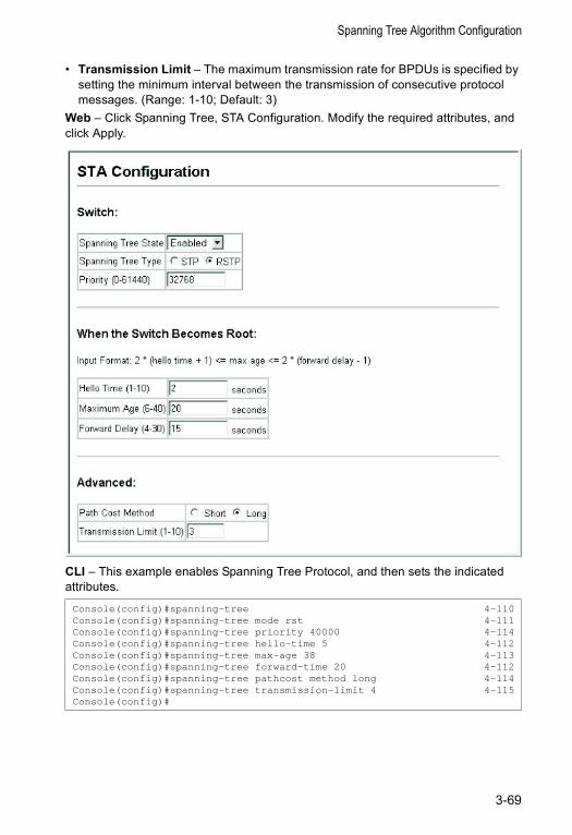
Spanning Tree Algorithm Configuration
• Transmission Limit – The maximum transmission rate for BPDUs is specified by setting the minimum interval between the transmission of consecutive protocol messages. (Range: 1-10; Default: 3)
Web – Click Spanning Tree, STA Configuration. Modify the required attributes, and click Apply.
CLI – This example enables Spanning Tree Protocol, and then sets the indicated attributes.
Console(config)#spanning-tree 4-110Console(config)#spanning-tree mode rst 4-111Console(config)#spanning-tree priority 40000 4-114Console(config)#spanning-tree hello-time 5 4-112Console(config)#spanning-tree max-age 38 4-113Console(config)#spanning-tree forward-time 20 4-112Console(config)#spanning-tree pathcost method long 4-114Console(config)#spanning-tree transmission-limit 4 4-115Console(config)#
3-69
Configuring the Switch
Displaying Interface SettingsThe STA Port Information and STA Trunk Information pages display the current status of ports and trunks in the Spanning Tree.
Command Attributes
The following attributes are read-only and cannot be changed:• STA Status – Displays current state of this port within the Spanning Tree:
• Discarding - Port receives STA configuration messages, but does not forward packets.
• Learning - Port has transmitted configuration messages for an interval set by the Forward Delay parameter without receiving contradictory information. Port address table is cleared, and the port begins learning addresses.
• Forwarding - Port forwards packets, and continues learning addresses.
The rules defining port status are:- A port on a network segment with no other STA compliant bridging device is
always forwarding.- If two ports of a switch are connected to the same segment and there is no other
STA device attached to this segment, the port with the smaller ID forwards packets and the other is discarding.
- All ports are discarding when the switch is booted, then some of them change state to learning, and then to forwarding.
• Forward Transitions – The number of times this port has transitioned from the Learning state to the Forwarding state.
• Designated Cost – The cost for a packet to travel from this port to the root in the current Spanning Tree configuration. The slower the media, the higher the cost.
• Designated Bridge – The bridge priority and MAC address of the device through which this port must communicate to reach the root of the Spanning Tree.
• Designated Port – The port priority and number of the port on the designated bridging device through which this switch must communicate with the root of the Spanning Tree.
• Oper Link Type – The operational point-to-point status of the LAN segment attached to this interface. This parameter is determined by manual configuration or by auto-detection, as described for Admin Link Type in STA Port Configuration on page 3-72.
• Oper Edge Port – This parameter is initialized to the setting for Admin Edge Port in STA Port Configuration on page 3-72 (i.e., true or false), but will be set to false if a BPDU is received, indicating that another bridge is attached to this port.
• Port Role – Roles are assigned according to whether the port is part of the active topology connecting the bridge to the root bridge (i.e., root port), connecting a LAN through the bridge to the root bridge (i.e., designated port); or is an alternate or backup port that may provide connectivity if other bridges, bridge ports, or LANs fail or are removed. The role is set to disabled (i.e., disabled port) if a port has no role within the spanning tree.
3-70
Spanning Tree Algorithm Configuration
• Trunk Member – Indicates if a port is a member of a trunk. (STA Port Information only)
These additional parameters are only displayed for the CLI:• Admin status – Shows if STA has been enabled on this interface.• Path Cost – This parameter is used by the STA to determine the best path
between devices. Therefore, lower values should be assigned to ports attached to faster media, and higher values assigned to ports with slower media. (Path cost takes precedence over port priority.)
• Priority – Defines the priority used for this port in the Spanning Tree Algorithm. If the path cost for all ports on a switch is the same, the port with the highest priority (i.e., lowest value) will be configured as an active link in the Spanning Tree. This makes a port with higher priority less likely to be blocked if the Spanning Tree Algorithm is detecting network loops. Where more than one port is assigned the highest priority, the port with the lowest numeric identifier will be enabled.
• Designated root – The priority and MAC address of the device in the Spanning Tree that this switch has accepted as the root device.
• Fast forwarding – This field provides the same information as Admin Edge port, and is only included for backward compatibility with earlier products.
• Admin Link Type – The link type attached to this interface.• Point-to-Point – A connection to exactly one other bridge.• Shared – A connection to two or more bridges.• Auto – The switch automatically determines if the interface is attached to a
point-to-point link or to shared media.• Admin Edge Port – You can enable this option if an interface is attached to a LAN
segment that is at the end of a bridged LAN or to an end node. Since end nodes cannot cause forwarding loops, they can pass directly through to the spanning tree forwarding state. Specifying Edge Ports provides quicker convergence for devices such as workstations or servers, retains the current forwarding database to reduce the amount of frame flooding required to rebuild address tables during reconfiguration events, does not cause the spanning tree to reconfigure when the interface changes state, and also overcomes other STA-related timeout problems. However, remember that Edge Port should only be enabled for ports connected to an end-node device.
3-71
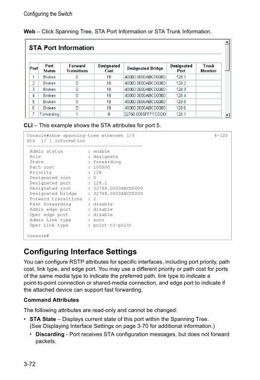
Configuring the Switch
Web – Click Spanning Tree, STA Port Information or STA Trunk Information.
CLI – This example shows the STA attributes for port 5.
Configuring Interface SettingsYou can configure RSTP attributes for specific interfaces, including port priority, path cost, link type, and edge port. You may use a different priority or path cost for ports of the same media type to indicate the preferred path, link type to indicate a point-to-point connection or shared-media connection, and edge port to indicate if the attached device can support fast forwarding.
Command Attributes
The following attributes are read-only and cannot be changed:• STA State – Displays current state of this port within the Spanning Tree.
(See Displaying Interface Settings on page 3-70 for additional information.)• Discarding - Port receives STA configuration messages, but does not forward
packets.
Console#show spanning-tree ethernet 1/5 4-120Eth 1/ 1 information------------------------------------------Admin status : enableRole : designateState : forwardingPath cost : 100000Priority : 128Designated cost : 0Designated port : 128.1Designated root : 32768.0000ABCD0000Designated bridge : 32768.0000ABCD0000Forward transitions : 2Fast forwarding : disableAdmin edge port : disableOper edge port : disableAdmin Link type : autoOper Link type : point-to-point
Console#
3-72
Spanning Tree Algorithm Configuration
• Learning - Port has transmitted configuration messages for an interval set by the Forward Delay parameter without receiving contradictory information. Port address table is cleared, and the port begins learning addresses.
• Forwarding - Port forwards packets, and continues learning addresses.• Trunk – Indicates if a port is a member of a trunk.
(STA Port Configuration only)
The following interface attributes can be configured:• Priority – Defines the priority used for this port in the Spanning Tree Protocol. If
the path cost for all ports on a switch are the same, the port with the highest priority (i.e., lowest value) will be configured as an active link in the Spanning Tree. This makes a port with higher priority less likely to be blocked if the Spanning Tree Protocol is detecting network loops. Where more than one port is assigned the highest priority, the port with lowest numeric identifier will be enabled.• Default: 128• Range: 0-240, in steps of 16
• Path Cost – This parameter is used by the STP to determine the best path between devices. Therefore, lower values should be assigned to ports attached to faster media, and higher values assigned to ports with slower media. (Path cost takes precedence over port priority.) Note that when the Path Cost Method is set to short (page 3-63), the maximum path cost is 65,535.• Range –
- Ethernet: 200,000-20,000,000- Fast Ethernet: 20,000-2,000,000- Gigabit Ethernet: 2,000-200,000
• Default –- Ethernet – Half duplex: 2,000,000; full duplex: 1,000,000; trunk: 500,000- Fast Ethernet – Half duplex: 200,000; full duplex: 100,000; trunk: 50,000- Gigabit Ethernet – Full duplex: 10,000; trunk: 5,000
• Admin Link Type – The link type attached to this interface.• Point-to-Point – A connection to exactly one other bridge.• Shared – A connection to two or more bridges.• Auto – The switch automatically determines if the interface is attached to a
point-to-point link or to shared media. (This is the default setting.)• Admin Edge Port (Fast Forwarding) – You can enable this option if an interface is
attached to a LAN segment that is at the end of a bridged LAN or to an end node. Since end nodes cannot cause forwarding loops, they can pass directly through to the spanning tree forwarding state. Specifying Edge Ports provides quicker convergence for devices such as workstations or servers, retains the current forwarding database to reduce the amount of frame flooding required to rebuild address tables during reconfiguration events, does not cause the spanning tree to initiate reconfiguration when the interface changes state, and also overcomes other STA-related timeout problems. However, remember that Edge Port should only be enabled for ports connected to an end-node device. (Default: Disabled)
3-73

Configuring the Switch
• Migration – If at any time the switch detects STP BPDUs, including Configuration or Topology Change Notification BPDUs, it will automatically set the selected interface to forced STP-compatible mode. However, you can also use the Protocol Migration button to manually re-check the appropriate BPDU format (RSTP or STP-compatible) to send on the selected interfaces. (Default: Disabled)
Web – Click Spanning Tree, STA Port Configuration or STA Trunk Configuration. Modify the required attributes, then click Apply.
CLI – This example sets STA attributes for port 7.
VLAN Configuration
OverviewIn large networks, routers are used to isolate broadcast traffic for each subnet into separate domains. This switch provides a similar service at Layer 2 by using VLANs to organize any group of network nodes into separate broadcast domains. VLANs confine broadcast traffic to the originating group, and can eliminate broadcast storms in large networks. This also provides a more secure and cleaner network environment.
An IEEE 802.1Q VLAN is a group of ports that can be located anywhere in the network, but communicate as though they belong to the same physical segment.
Console(config)#interface ethernet 1/7 4-89Console(config-if)#spanning-tree port-priority 0 4-116Console(config-if)#spanning-tree cost 50 4-116Console(config-if)#spanning-tree link-type auto 4-119Console(config-if)#no spanning-tree edge-port 4-117Console(config-if)#spanning-tree protocol-migration 4-120Console(config-if)#
3-74
VLAN Configuration
VLANs help to simplify network management by allowing you to move devices to a new VLAN without having to change any physical connections. VLANs can be easily organized to reflect departmental groups (such as Marketing or R&D), usage groups (such as e-mail), or multicast groups (used for multimedia applications such as videoconferencing).
VLANs provide greater network efficiency by reducing broadcast traffic, and allow you to make network changes without having to update IP addresses or IP subnets. VLANs inherently provide a high level of network security since traffic must pass through a configured Layer 3 link to reach a different VLAN.
This switch supports the following VLAN features:
• Up to 255 VLANs based on the IEEE 802.1Q standard• Distributed VLAN learning across multiple switches using explicit or implicit tagging
and GVRP protocol• Port overlapping, allowing a port to participate in multiple VLANs• End stations can belong to multiple VLANs• Passing traffic between VLAN-aware and VLAN-unaware devices • Priority tagging
Assigning Ports to VLANsBefore enabling VLANs for the switch, you must first assign each port to the VLAN group(s) in which it will participate. By default all ports are assigned to VLAN 1 as untagged ports. Add a port as a tagged port if you want it to carry traffic for one or more VLANs, and any intermediate network devices or the host at the other end of the connection supports VLANs. Then assign ports on the other VLAN-aware network devices along the path that will carry this traffic to the same VLAN(s), either manually or dynamically using GVRP. However, if you want a port on this switch to participate in one or more VLANs, but none of the intermediate network devices nor the host at the other end of the connection supports VLANs, then you should add this port to the VLAN as an untagged port.
Note: VLAN-tagged frames can pass through VLAN-aware or VLAN-unaware network interconnection devices, but the VLAN tags should be stripped off before passing it on to any end-node host that does not support VLAN tagging.
VLAN Classification – When the switch receives a frame, it classifies the frame in one of two ways. If the frame is untagged, the switch assigns the frame to an associated VLAN (based on the default VLAN ID of the receiving port). But if the frame is tagged, the switch uses the tagged VLAN ID to identify the port broadcast domain of the frame.
Port Overlapping – Port overlapping can be used to allow access to commonly shared network resources among different VLAN groups, such as file servers or printers. Note that if you implement VLANs which do not overlap, but still need to communicate, you can connect them by enabled routing on this switch.
3-75
Configuring the Switch
Untagged VLANs – Untagged (or static) VLANs are typically used to reduce broadcast traffic and to increase security. A group of network users assigned to a VLAN form a broadcast domain that is separate from other VLANs configured on the switch. Packets are forwarded only between ports that are designated for the same VLAN. Untagged VLANs can be used to manually isolate user groups or subnets. However, you should use IEEE 802.3 tagged VLANs with GVRP whenever possible to fully automate VLAN registration.
Automatic VLAN Registration – GVRP (GARP VLAN Registration Protocol) defines a system whereby the switch can automatically learn the VLANs to which each end station should be assigned. If an end station (or its network adapter) supports the IEEE 802.1Q VLAN protocol, it can be configured to broadcast a message to your network indicating the VLAN groups it wants to join. When this switch receives these messages, it will automatically place the receiving port in the specified VLANs, and then forward the message to all other ports. When the message arrives at another switch that supports GVRP, it will also place the receiving port in the specified VLANs, and pass the message on to all other ports. VLAN requirements are propagated in this way throughout the network. This allows GVRP-compliant devices to be automatically configured for VLAN groups based solely on endstation requests.
To implement GVRP in a network, first add the host devices to the required VLANs (using the operating system or other application software), so that these VLANs can be propagated onto the network. For both the edge switches attached directly to these hosts, and core switches in the network, enable GVRP on the links between these devices. You should also determine security boundaries in the network and disable GVRP on ports to prevent advertisements being propagated, or forbid ports from joining restricted VLANs.
Note: If you have host devices that do not support GVRP, you should configure static or untagged VLANs for the switch ports connected to these devices (as described in “Adding Static Members to VLANs (VLAN Index)” on page 3-81). But you can still enable GVRP on these edge switches, as well as on the core switches in the network.
Forwarding Tagged/Untagged FramesIf you want to create a small port-based VLAN for devices attached directly to a single switch, you can assign ports to the same untagged VLAN. However, to participate in a VLAN group that crosses several switches, you should create a VLAN for that group and enable tagging on all ports.
Ports can be assigned to multiple tagged or untagged VLANs. Each port on the switch is therefore capable of passing tagged or untagged frames. When forwarding a frame from this switch along a path that contains any VLAN-aware devices, the switch should include VLAN tags. When forwarding a frame from this switch along a path that does not contain any VLAN-aware devices (including the destination host), the switch must first strip off the VLAN tag before forwarding the frame. When the switch receives a tagged frame, it will pass this frame onto the VLAN(s) indicated by the frame tag. However, when this switch receives an untagged frame from a
3-76
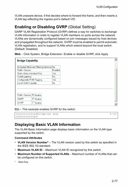
VLAN Configuration
VLAN-unaware device, it first decides where to forward the frame, and then inserts a VLAN tag reflecting the ingress port’s default VID.
Enabling or Disabling GVRP (Global Setting) GARP VLAN Registration Protocol (GVRP) defines a way for switches to exchange VLAN information in order to register VLAN members on ports across the network. VLANs are dynamically configured based on join messages issued by host devices and propagated throughout the network. GVRP must be enabled to permit automatic VLAN registration, and to support VLANs which extend beyond the local switch. (Default: Disabled)
Web – Click System, Bridge Extension. Enable or disable GVRP, click Apply
CLI – This example enables GVRP for the switch.
Displaying Basic VLAN InformationThe VLAN Basic Information page displays basic information on the VLAN type supported by the switch.
Command Attributes• VLAN Version Number* – The VLAN version used by this switch as specified in
the IEEE 802.1Q standard.• Maximum VLAN ID – Maximum VLAN ID recognized by this switch.• Maximum Number of Supported VLANs – Maximum number of VLANs that can
be configured on this switch. * Web Only
Console(config)#bridge-ext gvrp 4-132Console(config)#
3-77
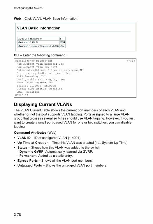
Configuring the Switch
Web – Click VLAN, VLAN Base Information.
CLI – Enter the following command.
Displaying Current VLANsThe VLAN Current Table shows the current port members of each VLAN and whether or not the port supports VLAN tagging. Ports assigned to a large VLAN group that crosses several switches should use VLAN tagging. However, if you just want to create a small port-based VLAN for one or two switches, you can disable tagging.
Command Attributes (Web)• VLAN ID – ID of configured VLAN (1-4094).• Up Time at Creation – Time this VLAN was created (i.e., System Up Time).• Status – Shows how this VLAN was added to the switch.
- Dynamic GVRP: Automatically learned via GVRP.- Permanent: Added as a static entry.
• Egress Ports – Shows all the VLAN port members.• Untagged Ports – Shows the untagged VLAN port members.
Console#show bridge-ext 4-133Max support vlan numbers: 255Max support vlan ID: 4094Extended multicast filtering services: NoStatic entry individual port: YesVLAN learning: IVLConfigurable PVID tagging: YesLocal VLAN capable: NoTraffic classes: EnabledGlobal GVRP status: DisabledGMRP: Disabled
Console#
3-78
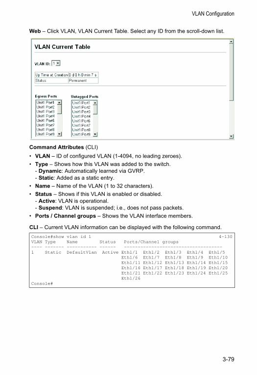
VLAN Configuration
Web – Click VLAN, VLAN Current Table. Select any ID from the scroll-down list.
Command Attributes (CLI)• VLAN – ID of configured VLAN (1-4094, no leading zeroes).• Type – Shows how this VLAN was added to the switch.
- Dynamic: Automatically learned via GVRP.- Static: Added as a static entry.
• Name – Name of the VLAN (1 to 32 characters).• Status – Shows if this VLAN is enabled or disabled.
- Active: VLAN is operational.- Suspend: VLAN is suspended; i.e., does not pass packets.
• Ports / Channel groups – Shows the VLAN interface members.
CLI – Current VLAN information can be displayed with the following command.Console#show vlan id 1 4-130VLAN Type Name Status Ports/Channel groups---- ------- ----------- ------ ------------------------------------1 Static DefaultVlan Active Eth1/1 Eth1/2 Eth1/3 Eth1/4 Eth1/5
Eth1/6 Eth1/7 Eth1/8 Eth1/9 Eth1/10Eth1/11 Eth1/12 Eth1/13 Eth1/14 Eth1/15Eth1/16 Eth1/17 Eth1/18 Eth1/19 Eth1/20Eth1/21 Eth1/22 Eth1/23 Eth1/24 Eth1/25Eth1/26
Console#
3-79
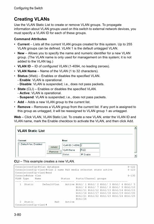
Configuring the Switch
Creating VLANsUse the VLAN Static List to create or remove VLAN groups. To propagate information about VLAN groups used on this switch to external network devices, you must specify a VLAN ID for each of these groups.
Command Attributes• Current – Lists all the current VLAN groups created for this system. Up to 255
VLAN groups can be defined. VLAN 1 is the default untagged VLAN. • New – Allows you to specify the name and numeric identifier for a new VLAN
group. (The VLAN name is only used for management on this system; it is not added to the VLAN tag.)
• VLAN ID – ID of configured VLAN (1-4094, no leading zeroes).• VLAN Name – Name of the VLAN (1 to 32 characters).• Status (Web) – Enables or disables the specified VLAN.
- Enable: VLAN is operational.- Disable: VLAN is suspended; i.e., does not pass packets.
• State (CLI) – Enables or disables the specified VLAN. - Active: VLAN is operational.- Suspend: VLAN is suspended; i.e., does not pass packets.
• Add – Adds a new VLAN group to the current list.• Remove – Removes a VLAN group from the current list. If any port is assigned to
this group as untagged, it will be reassigned to VLAN group 1 as untagged.
Web – Click VLAN, VLAN Static List. To create a new VLAN, enter the VLAN ID and VLAN name, mark the Enable checkbox to activate the VLAN, and then click Add.
CLI – This example creates a new VLAN.Console(config)#vlan database 4-122Console(config-vlan)#vlan 2 name R&D media ethernet state active 4-123Console(config-vlan)#endConsole#show vlan 4-130VLAN Type Name Status Ports/Channel groups---- ------- ---------------- --------- ----------------------------------
1 Static DefaultVlan Active Eth1/ 1 Eth1/ 2 Eth1/ 3 Eth1/ 4 Eth1/ 5Eth1/ 6 Eth1/ 7 Eth1/ 8 Eth1/ 9 Eth1/10Eth1/11 Eth1/12 Eth1/13 Eth1/14 Eth1/15Eth1/16 Eth1/17 Eth1/18 Eth1/19 Eth1/20Eth1/21 Eth1/22 Eth1/23 Eth1/24 Eth1/25Eth1/26
2 Static R&D ActiveConsole(config-vlan)#
3-80
VLAN Configuration
Adding Static Members to VLANs (VLAN Index)Use the VLAN Static Table to configure port members for the selected VLAN index. Assign ports as tagged if they are connected to 802.1Q VLAN compliant devices, or untagged they are not connected to any VLAN-aware devices. Or configure a port as forbidden to prevent the switch from automatically adding it to a VLAN via the GVRP protocol.
Notes: 1. You can also use the VLAN Static Membership by Port page to configure VLAN groups based on the port index (page 3-83). However, note that this configuration page can only add ports to a VLAN as tagged members.
2. VLAN 1 is the default untagged VLAN containing all ports on the switch, and can only be modified by first reassigning the default port VLAN ID as described under “Configuring VLAN Behavior for Interfaces” on page 3-83.
Command Attributes• VLAN – ID of configured VLAN (1-4094, no leading zeroes).• Name – Name of the VLAN (1 to 32 characters).• Status – Enables or disables the specified VLAN.
- Enable: VLAN is operational.- Disable: VLAN is suspended; i.e., does not pass packets.
• Port – Port identifier.• Trunk – Trunk identifier.• Membership Type – Select VLAN membership for each interface by marking the
appropriate radio button for a port or trunk: - Tagged: Interface is a member of the VLAN. All packets transmitted by the port
will be tagged, that is, carry a tag and therefore carry VLAN or CoS information.- Untagged: Interface is a member of the VLAN. All packets transmitted by the
port will be untagged, that is, not carry a tag and therefore not carry VLAN or CoS information. Note that an interface must be assigned to at least one group as an untagged port.
- Forbidden: Interface is forbidden from automatically joining the VLAN via GVRP. For more information, see “Automatic VLAN Registration” on page 3-76.
- None: Interface is not a member of the VLAN. Packets associated with this VLAN will not be transmitted by the interface.
• Trunk Member – Indicates if a port is a member of a trunk. To add a trunk to the selected VLAN, use the last table on the VLAN Static Table page.
3-81
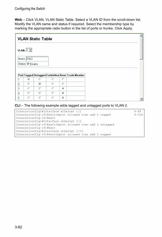
Configuring the Switch
Web – Click VLAN, VLAN Static Table. Select a VLAN ID from the scroll-down list. Modify the VLAN name and status if required. Select the membership type by marking the appropriate radio button in the list of ports or trunks. Click Apply.
CLI – The following example adds tagged and untagged ports to VLAN 2.Console(config)#interface ethernet 1/1 4-89Console(config-if)#switchport allowed vlan add 2 tagged 4-128Console(config-if)#exitConsole(config)#interface ethernet 1/2Console(config-if)#switchport allowed vlan add 2 untaggedConsole(config-if)#exitConsole(config)#interface ethernet 1/13Console(config-if)#switchport allowed vlan add 2 tagged
3-82
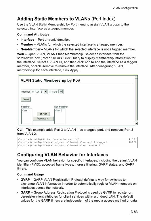
VLAN Configuration
Adding Static Members to VLANs (Port Index)Use the VLAN Static Membership by Port menu to assign VLAN groups to the selected interface as a tagged member.
Command Attributes• Interface – Port or trunk identifier.• Member – VLANs for which the selected interface is a tagged member.• Non-Member – VLANs for which the selected interface is not a tagged member.Web – Open VLAN, VLAN Static Membership. Select an interface from the scroll-down box (Port or Trunk). Click Query to display membership information for the interface. Select a VLAN ID, and then click Add to add the interface as a tagged member, or click Remove to remove the interface. After configuring VLAN membership for each interface, click Apply.
CLI – This example adds Port 3 to VLAN 1 as a tagged port, and removes Port 3 from VLAN 2.
Configuring VLAN Behavior for InterfacesYou can configure VLAN behavior for specific interfaces, including the default VLAN identifier (PVID), accepted frame types, ingress filtering, GVRP status, and GARP timers.
Command Usage• GVRP – GARP VLAN Registration Protocol defines a way for switches to
exchange VLAN information in order to automatically register VLAN members on interfaces across the network.
• GARP – Group Address Registration Protocol is used by GVRP to register or deregister client attributes for client services within a bridged LAN. The default values for the GARP timers are independent of the media access method or data
Console(config)#interface ethernet 1/3 4-89Console(config-if)#switchport allowed vlan add 1 tagged 4-128Console(config-if)#switchport allowed vlan remove 2
3-83
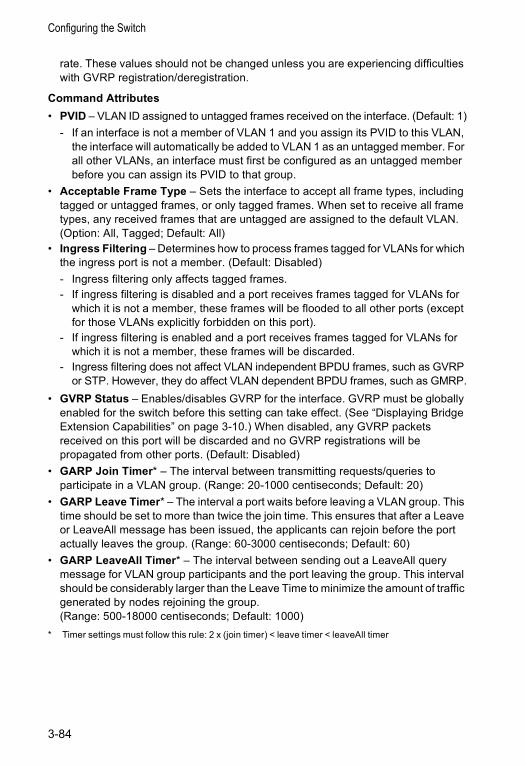
Configuring the Switch
rate. These values should not be changed unless you are experiencing difficulties with GVRP registration/deregistration.
Command Attributes• PVID – VLAN ID assigned to untagged frames received on the interface. (Default: 1)
- If an interface is not a member of VLAN 1 and you assign its PVID to this VLAN, the interface will automatically be added to VLAN 1 as an untagged member. For all other VLANs, an interface must first be configured as an untagged member before you can assign its PVID to that group.
• Acceptable Frame Type – Sets the interface to accept all frame types, including tagged or untagged frames, or only tagged frames. When set to receive all frame types, any received frames that are untagged are assigned to the default VLAN. (Option: All, Tagged; Default: All)
• Ingress Filtering – Determines how to process frames tagged for VLANs for which the ingress port is not a member. (Default: Disabled)- Ingress filtering only affects tagged frames. - If ingress filtering is disabled and a port receives frames tagged for VLANs for
which it is not a member, these frames will be flooded to all other ports (except for those VLANs explicitly forbidden on this port).
- If ingress filtering is enabled and a port receives frames tagged for VLANs for which it is not a member, these frames will be discarded.
- Ingress filtering does not affect VLAN independent BPDU frames, such as GVRP or STP. However, they do affect VLAN dependent BPDU frames, such as GMRP.
• GVRP Status – Enables/disables GVRP for the interface. GVRP must be globally enabled for the switch before this setting can take effect. (See “Displaying Bridge Extension Capabilities” on page 3-10.) When disabled, any GVRP packets received on this port will be discarded and no GVRP registrations will be propagated from other ports. (Default: Disabled)
• GARP Join Timer* – The interval between transmitting requests/queries to participate in a VLAN group. (Range: 20-1000 centiseconds; Default: 20)
• GARP Leave Timer* – The interval a port waits before leaving a VLAN group. This time should be set to more than twice the join time. This ensures that after a Leave or LeaveAll message has been issued, the applicants can rejoin before the port actually leaves the group. (Range: 60-3000 centiseconds; Default: 60)
• GARP LeaveAll Timer* – The interval between sending out a LeaveAll query message for VLAN group participants and the port leaving the group. This interval should be considerably larger than the Leave Time to minimize the amount of traffic generated by nodes rejoining the group. (Range: 500-18000 centiseconds; Default: 1000)
* Timer settings must follow this rule: 2 x (join timer) < leave timer < leaveAll timer
3-84
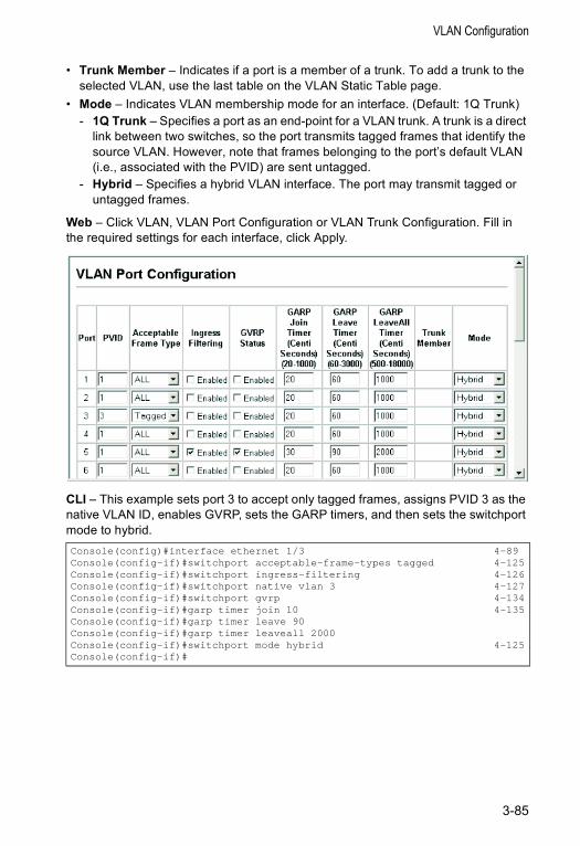
VLAN Configuration
• Trunk Member – Indicates if a port is a member of a trunk. To add a trunk to the selected VLAN, use the last table on the VLAN Static Table page.
• Mode – Indicates VLAN membership mode for an interface. (Default: 1Q Trunk)- 1Q Trunk – Specifies a port as an end-point for a VLAN trunk. A trunk is a direct
link between two switches, so the port transmits tagged frames that identify the source VLAN. However, note that frames belonging to the port’s default VLAN (i.e., associated with the PVID) are sent untagged.
- Hybrid – Specifies a hybrid VLAN interface. The port may transmit tagged or untagged frames.
Web – Click VLAN, VLAN Port Configuration or VLAN Trunk Configuration. Fill in the required settings for each interface, click Apply.
CLI – This example sets port 3 to accept only tagged frames, assigns PVID 3 as the native VLAN ID, enables GVRP, sets the GARP timers, and then sets the switchport mode to hybrid.Console(config)#interface ethernet 1/3 4-89Console(config-if)#switchport acceptable-frame-types tagged 4-125Console(config-if)#switchport ingress-filtering 4-126Console(config-if)#switchport native vlan 3 4-127Console(config-if)#switchport gvrp 4-134Console(config-if)#garp timer join 10 4-135Console(config-if)#garp timer leave 90Console(config-if)#garp timer leaveall 2000Console(config-if)#switchport mode hybrid 4-125Console(config-if)#
3-85
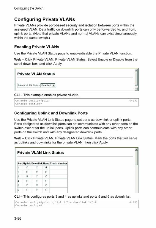
Configuring the Switch
Configuring Private VLANsPrivate VLANs provide port-based security and isolation between ports within the assigned VLAN. Data traffic on downlink ports can only be forwarded to, and from, uplink ports. (Note that private VLANs and normal VLANs can exist simultaneously within the same switch.)
Enabling Private VLANsUse the Private VLAN Status page to enable/disable the Private VLAN function.
Web – Click Private VLAN, Private VLAN Status. Select Enable or Disable from the scroll-down box, and click Apply.
CLI – This example enables private VLANs.
Configuring Uplink and Downlink PortsUse the Private VLAN Link Status page to set ports as downlink or uplink ports. Ports designated as downlink ports can not communicate with any other ports on the switch except for the uplink ports. Uplink ports can communicate with any other ports on the switch and with any designated downlink ports.
Web – Click Private VLAN, Private VLAN Link Status. Mark the ports that will serve as uplinks and downlinks for the private VLAN, then click Apply.
CLI – This configures ports 3 and 4 as uplinks and ports 5 and 6 as downlinks.
Console(config)#pvlan 4-131Console(config)#
Console(config)#pvlan uplink 1/3-4 downlink 1/5-6 4-131Console(config)#
3-86
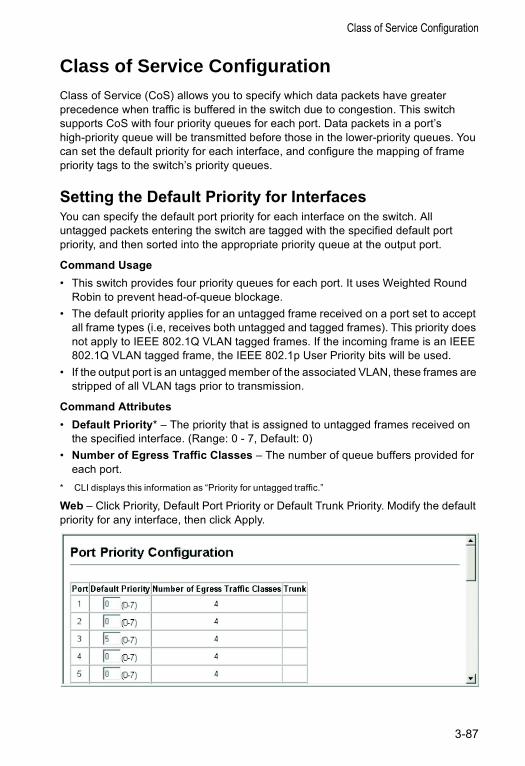
Class of Service Configuration
Class of Service ConfigurationClass of Service (CoS) allows you to specify which data packets have greater precedence when traffic is buffered in the switch due to congestion. This switch supports CoS with four priority queues for each port. Data packets in a port’s high-priority queue will be transmitted before those in the lower-priority queues. You can set the default priority for each interface, and configure the mapping of frame priority tags to the switch’s priority queues.
Setting the Default Priority for InterfacesYou can specify the default port priority for each interface on the switch. All untagged packets entering the switch are tagged with the specified default port priority, and then sorted into the appropriate priority queue at the output port.
Command Usage• This switch provides four priority queues for each port. It uses Weighted Round
Robin to prevent head-of-queue blockage.• The default priority applies for an untagged frame received on a port set to accept
all frame types (i.e, receives both untagged and tagged frames). This priority does not apply to IEEE 802.1Q VLAN tagged frames. If the incoming frame is an IEEE 802.1Q VLAN tagged frame, the IEEE 802.1p User Priority bits will be used.
• If the output port is an untagged member of the associated VLAN, these frames are stripped of all VLAN tags prior to transmission.
Command Attributes• Default Priority* – The priority that is assigned to untagged frames received on
the specified interface. (Range: 0 - 7, Default: 0)• Number of Egress Traffic Classes – The number of queue buffers provided for
each port.* CLI displays this information as “Priority for untagged traffic.”
Web – Click Priority, Default Port Priority or Default Trunk Priority. Modify the default priority for any interface, then click Apply.
3-87
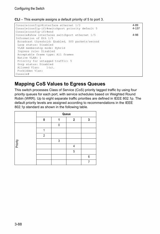
Configuring the Switch
CLI – This example assigns a default priority of 5 to port 3.
Mapping CoS Values to Egress QueuesThis switch processes Class of Service (CoS) priority tagged traffic by using four priority queues for each port, with service schedules based on Weighted Round Robin (WRR). Up to eight separate traffic priorities are defined in IEEE 802.1p. The default priority levels are assigned according to recommendations in the IEEE 802.1p standard as shown in the following table.
Console(config)#interface ethernet 1/3 4-89Console(config-if)#switchport priority default 5 4-137Console(config-if)#endConsole#show interfaces switchport ethernet 1/5 4-98Information of Eth 1/5Broadcast threshold: Enabled, 500 packets/secondLacp status: DisabledVLAN membership mode: HybridIngress rule: DisabledAcceptable frame type: All framesNative VLAN: 1Priority for untagged traffic: 5Gvrp status: DisabledAllowed Vlan: 1(u),Forbidden Vlan:
Console#
Queue
0 1 2 3
Prior
ity
012
345
67
3-88
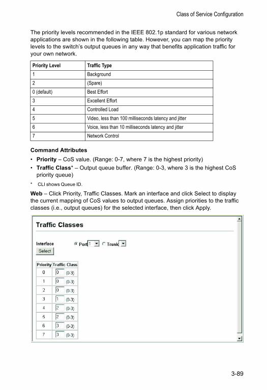
Class of Service Configuration
The priority levels recommended in the IEEE 802.1p standard for various network applications are shown in the following table. However, you can map the priority levels to the switch’s output queues in any way that benefits application traffic for your own network.
Command Attributes• Priority – CoS value. (Range: 0-7, where 7 is the highest priority)• Traffic Class* – Output queue buffer. (Range: 0-3, where 3 is the highest CoS
priority queue)* CLI shows Queue ID.
Web – Click Priority, Traffic Classes. Mark an interface and click Select to display the current mapping of CoS values to output queues. Assign priorities to the traffic classes (i.e., output queues) for the selected interface, then click Apply.
Priority Level Traffic Type1 Background2 (Spare)0 (default) Best Effort3 Excellent Effort4 Controlled Load5 Video, less than 100 milliseconds latency and jitter6 Voice, less than 10 milliseconds latency and jitter7 Network Control
3-89
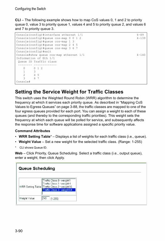
Configuring the Switch
CLI – The following example shows how to map CoS values 0, 1 and 2 to priority queue 0, value 3 to priority queue 1, values 4 and 5 to priority queue 2, and values 6 and 7 to priority queue 3.
Setting the Service Weight for Traffic ClassesThis switch uses the Weighted Round Robin (WRR) algorithm to determine the frequency at which it services each priority queue. As described in “Mapping CoS Values to Egress Queues” on page 3-88, the traffic classes are mapped to one of the four egress queues provided for each port. You can assign a weight to each of these queues (and thereby to the corresponding traffic priorities). This weight sets the frequency at which each queue will be polled for service, and subsequently affects the response time for software applications assigned a specific priority value.
Command Attributes• WRR Setting Table* – Displays a list of weights for each traffic class (i.e., queue).• Weight Value – Set a new weight for the selected traffic class. (Range: 1-255)* CLI shows Queue ID.
Web – Click Priority, Queue Scheduling. Select a traffic class (i.e., output queue), enter a weight, then click Apply.
Console(config)#interface ethernet 1/1 4-89Console(config)#queue cos-map 0 0 1 2 4-139Console(config)#queue cos-map 1 3Console(config)#queue cos-map 2 4 5Console(config)#queue cos-map 3 6 7Console(config)#exitConsole#show queue cos-map ethernet 1/1 4-140Information of Eth 1/1Queue ID Traffic class-------- -------------
0 0 1 21 32 4 53 6 7
Console#
3-90
Class of Service Configuration
CLI – The following example shows how to assign WRR weights of 16, 64, 128 and 240 to the CoS priority queues 0, 1, 2 and 3.
Mapping Layer 3/4 Priorities to CoS ValuesThis switch supports several common methods of prioritizing layer 3/4 traffic to meet application requirements. Traffic priorities can be specified in the IP header of a frame, using the priority bits in the Type of Service (ToS) octet or the number of the TCP port. If priority bits are used, the ToS octet may contain three bits for IP Precedence or six bits for Differentiated Services Code Point (DSCP) service. When these services are enabled, the priorities are mapped to a Class of Service value by the switch, and the traffic then sent to the corresponding output queue.
Because different priority information may be contained in the traffic, this switch maps priority values to the output queues in the following manner:
• The precedence for priority mapping is IP Port Priority, IP Precedence or DSCP Priority, and then Default Port Priority.
• IP Precedence and DSCP Priority cannot both be enabled. Enabling one of these priority types will automatically disable the other.
Selecting IP Precedence/DSCP PriorityThe switch allows you to choose between using IP Precedence or DSCP priority. Select one of the methods or disable this feature.
Command Attributes• Disabled – Disables both priority services. (This is the default setting.)• IP Precedence – Maps layer 3/4 priorities using IP Precedence.• IP DSCP – Maps layer 3/4 priorities using Differentiated Services Code Point
Mapping.
Console(config)#queue bandwidth 16 64 128 240 4-138Console(config)#exitConsole#show queue bandwidth 4-140Queue ID Weight-------- ------
0 161 642 1283 240
Console#
3-91
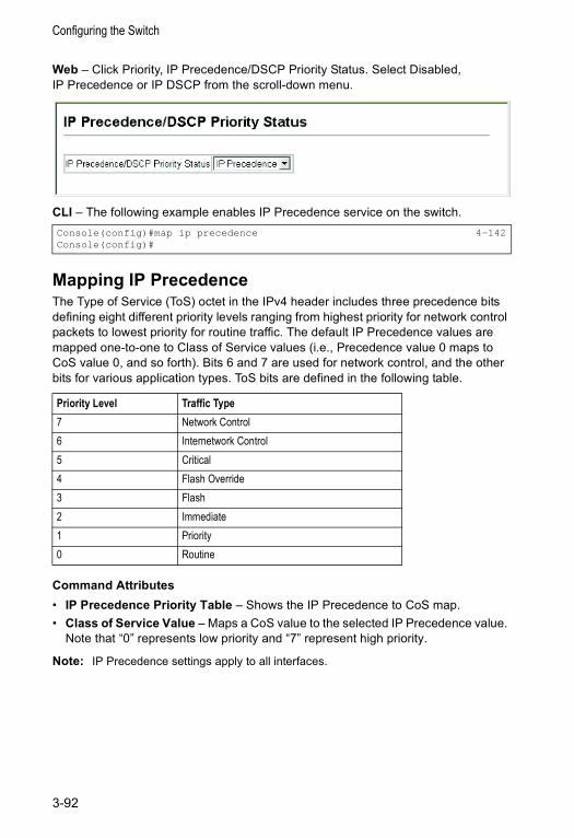
Configuring the Switch
Web – Click Priority, IP Precedence/DSCP Priority Status. Select Disabled, IP Precedence or IP DSCP from the scroll-down menu.
CLI – The following example enables IP Precedence service on the switch.
Mapping IP PrecedenceThe Type of Service (ToS) octet in the IPv4 header includes three precedence bits defining eight different priority levels ranging from highest priority for network control packets to lowest priority for routine traffic. The default IP Precedence values are mapped one-to-one to Class of Service values (i.e., Precedence value 0 maps to CoS value 0, and so forth). Bits 6 and 7 are used for network control, and the other bits for various application types. ToS bits are defined in the following table.
Command Attributes• IP Precedence Priority Table – Shows the IP Precedence to CoS map.• Class of Service Value – Maps a CoS value to the selected IP Precedence value.
Note that “0” represents low priority and “7” represent high priority.
Note: IP Precedence settings apply to all interfaces.
Console(config)#map ip precedence 4-142Console(config)#
Priority Level Traffic Type7 Network Control6 Internetwork Control5 Critical4 Flash Override3 Flash2 Immediate1 Priority0 Routine
3-92
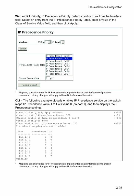
Class of Service Configuration
Web – Click Priority, IP Precedence Priority. Select a port or trunk from the Interface field. Select an entry from the IP Precedence Priority Table, enter a value in the Class of Service Value field, and then click Apply.
* Mapping specific values for IP Precedence is implemented as an interface configuration command, but any changes will apply to the all interfaces on the switch.
CLI – The following example globally enables IP Precedence service on the switch, maps IP Precedence value 1 to CoS value 0 (on port 1), and then displays the IP Precedence settings.
* Mapping specific values for IP Precedence is implemented as an interface configuration command, but any changes will apply to the all interfaces on the switch.
Console(config)#map ip precedence 4-142Console(config)#interface ethernet 1/1 4-89Console(config-if)#map ip precedence 1 cos 0 4-143Console(config-if)#endConsole#show map ip precedence ethernet 1/5 4-146Precedence mapping status: disabled
Port Precedence COS--------- ---------- ---Eth 1/ 1 0 0Eth 1/ 1 1 0Eth 1/ 1 2 2Eth 1/ 1 3 3Eth 1/ 1 4 4Eth 1/ 1 5 5Eth 1/ 1 6 6Eth 1/ 1 7 7
Console#
3-93
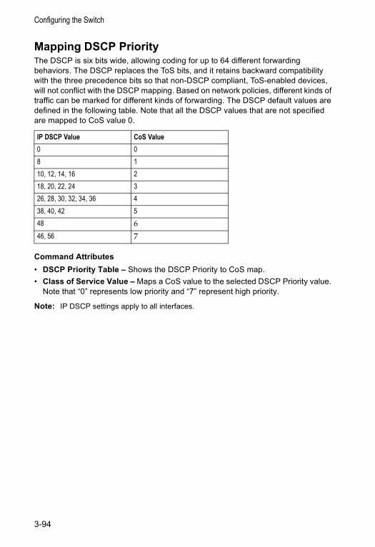
Configuring the Switch
Mapping DSCP PriorityThe DSCP is six bits wide, allowing coding for up to 64 different forwarding behaviors. The DSCP replaces the ToS bits, and it retains backward compatibility with the three precedence bits so that non-DSCP compliant, ToS-enabled devices, will not conflict with the DSCP mapping. Based on network policies, different kinds of traffic can be marked for different kinds of forwarding. The DSCP default values are defined in the following table. Note that all the DSCP values that are not specified are mapped to CoS value 0.
Command Attributes• DSCP Priority Table – Shows the DSCP Priority to CoS map.• Class of Service Value – Maps a CoS value to the selected DSCP Priority value.
Note that “0” represents low priority and “7” represent high priority.
Note: IP DSCP settings apply to all interfaces.
IP DSCP Value CoS Value0 08 110, 12, 14, 16 218, 20, 22, 24 326, 28, 30, 32, 34, 36 438, 40, 42 548 6
46, 56 7
3-94
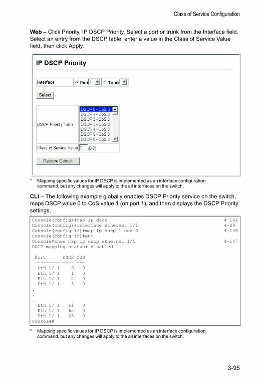
Class of Service Configuration
Web – Click Priority, IP DSCP Priority. Select a port or trunk from the Interface field. Select an entry from the DSCP table, enter a value in the Class of Service Value field, then click Apply.
* Mapping specific values for IP DSCP is implemented as an interface configuration command, but any changes will apply to the all interfaces on the switch.
CLI – The following example globally enables DSCP Priority service on the switch, maps DSCP value 0 to CoS value 1 (on port 1), and then displays the DSCP Priority settings.
* Mapping specific values for IP DSCP is implemented as an interface configuration command, but any changes will apply to the all interfaces on the switch.
Console(config)#map ip dscp 4-144Console(config)#interface ethernet 1/1 4-89Console(config-if)#map ip dscp 1 cos 0 4-145Console(config-if)#endConsole#show map ip dscp ethernet 1/5 4-147DSCP mapping status: disabled
Port DSCP COS--------- ---- ---Eth 1/ 1 0 0Eth 1/ 1 1 0Eth 1/ 1 2 0Eth 1/ 1 3 0
.
.
.Eth 1/ 1 61 0Eth 1/ 1 62 0Eth 1/ 1 63 0
Console#
3-95
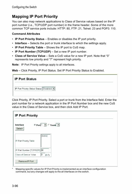
Configuring the Switch
Mapping IP Port PriorityYou can also map network applications to Class of Service values based on the IP port number (i.e., TCP/UDP port number) in the frame header. Some of the more common TCP service ports include: HTTP: 80, FTP: 21, Telnet: 23 and POP3: 110.
Command Attributes
• IP Port Priority Status – Enables or disables the IP port priority.• Interface – Selects the port or trunk interface to which the settings apply.• IP Port Priority Table – Shows the IP port to CoS map.• IP Port Number (TCP/UDP) – Set a new IP port number.• Class of Service Value – Sets a CoS value for a new IP port. Note that “0”
represents low priority and “7” represent high priority.
Note: IP Port Priority settings apply to all interfaces.
Web – Click Priority, IP Port Status. Set IP Port Priority Status to Enabled.
Click Priority, IP Port Priority. Select a port or trunk from the Interface field. Enter the port number for a network application in the IP Port Number box and the new CoS value in the Class of Service box, and then click Add IP Port.
* Mapping specific values for IP Port Priority is implemented as an interface configuration command, but any changes will apply to the all interfaces on the switch.
3-96
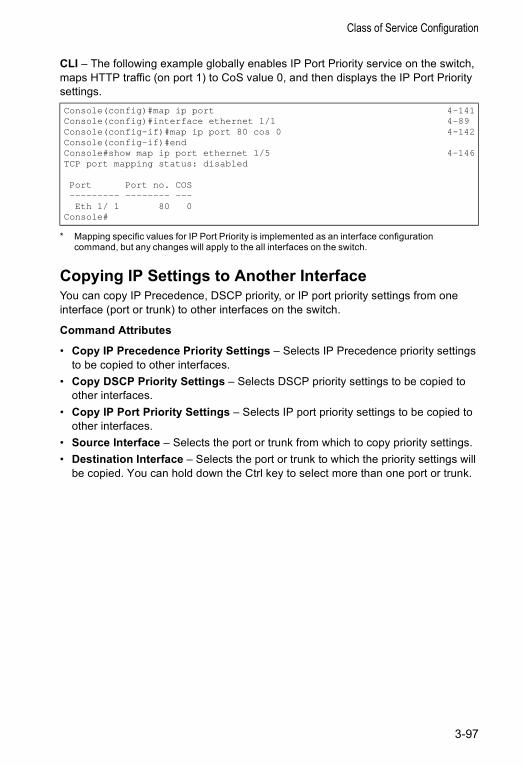
Class of Service Configuration
CLI – The following example globally enables IP Port Priority service on the switch, maps HTTP traffic (on port 1) to CoS value 0, and then displays the IP Port Priority settings.
* Mapping specific values for IP Port Priority is implemented as an interface configuration command, but any changes will apply to the all interfaces on the switch.
Copying IP Settings to Another InterfaceYou can copy IP Precedence, DSCP priority, or IP port priority settings from one interface (port or trunk) to other interfaces on the switch.
Command Attributes
• Copy IP Precedence Priority Settings – Selects IP Precedence priority settings to be copied to other interfaces.
• Copy DSCP Priority Settings – Selects DSCP priority settings to be copied to other interfaces.
• Copy IP Port Priority Settings – Selects IP port priority settings to be copied to other interfaces.
• Source Interface – Selects the port or trunk from which to copy priority settings.• Destination Interface – Selects the port or trunk to which the priority settings will
be copied. You can hold down the Ctrl key to select more than one port or trunk.
Console(config)#map ip port 4-141Console(config)#interface ethernet 1/1 4-89Console(config-if)#map ip port 80 cos 0 4-142Console(config-if)#endConsole#show map ip port ethernet 1/5 4-146TCP port mapping status: disabled
Port Port no. COS--------- -------- ---Eth 1/ 1 80 0
Console#
3-97
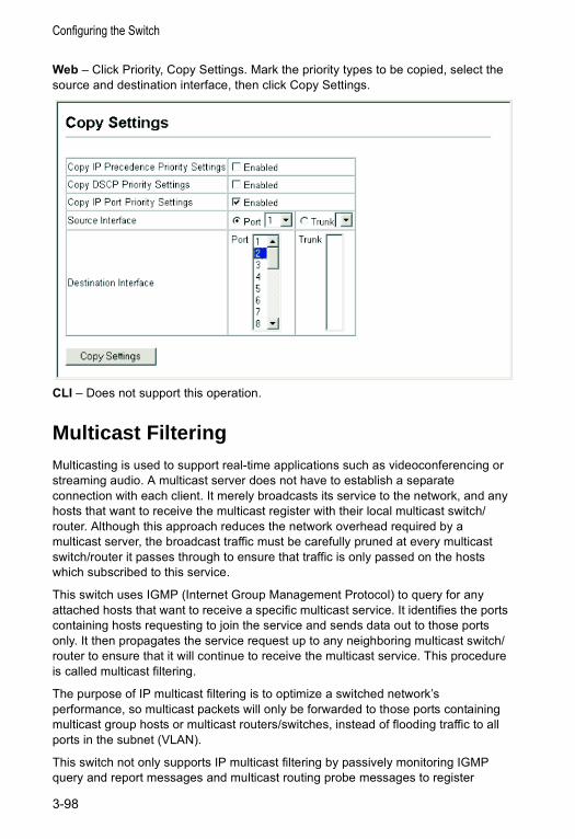
Configuring the Switch
Web – Click Priority, Copy Settings. Mark the priority types to be copied, select the source and destination interface, then click Copy Settings.
CLI – Does not support this operation.
Multicast Filtering Multicasting is used to support real-time applications such as videoconferencing or streaming audio. A multicast server does not have to establish a separate connection with each client. It merely broadcasts its service to the network, and any hosts that want to receive the multicast register with their local multicast switch/router. Although this approach reduces the network overhead required by a multicast server, the broadcast traffic must be carefully pruned at every multicast switch/router it passes through to ensure that traffic is only passed on the hosts which subscribed to this service.
This switch uses IGMP (Internet Group Management Protocol) to query for any attached hosts that want to receive a specific multicast service. It identifies the ports containing hosts requesting to join the service and sends data out to those ports only. It then propagates the service request up to any neighboring multicast switch/router to ensure that it will continue to receive the multicast service. This procedure is called multicast filtering.
The purpose of IP multicast filtering is to optimize a switched network’s performance, so multicast packets will only be forwarded to those ports containing multicast group hosts or multicast routers/switches, instead of flooding traffic to all ports in the subnet (VLAN).
This switch not only supports IP multicast filtering by passively monitoring IGMP query and report messages and multicast routing probe messages to register
3-98
Multicast Filtering
end-stations as multicast group members, but also supports the DVMRP and PIM-DM multicast routing protocols required to forward multicast traffic to other subnets (page 3-142 and 3-148).
IGMP ProtocolThe Internet Group Management Protocol (IGMP) runs between hosts and their immediately adjacent multicast router/switch. IGMP is a multicast host registration protocol that allows any host to inform its local router that it wants to receive transmissions addressed to a specific multicast group.
A router, or multicast-enabled switch, can periodically ask their hosts if they want to receive multicast traffic. If there is more than one router/switch on the LAN performing IP multicasting, one of these devices is elected “querier” and assumes the role of querying the LAN for group members. It then propagates the service requests on to any adjacent multicast switch/router to ensure that it will continue to receive the multicast service.
Based on the group membership information learned from IGMP, a router/switch can determine which (if any) multicast traffic needs to be forwarded to each of its ports. At Layer 3, multicast routers use this information, along with a multicast routing protocol such as DVMRP or PIM, to support IP multicasting across the Internet.
Note that IGMP neither alters nor routes IP multicast packets. A multicast routing protocol must be used to deliver IP multicast packets across different subnetworks. Therefore, when DVMRP or PIM routing is enabled for a subnet on this switch, you also need to enable IGMP.
Layer 2 IGMP (Snooping and Query)IGMP Snooping and Query – If multicast routing is not supported on other switches in your network, you can use IGMP Snooping and IGMP Query (page 3-100) to monitor IGMP service requests passing between multicast clients and servers, and dynamically configure the switch ports which need to forward multicast traffic.
Static IGMP Router Interface – If IGMP snooping cannot locate the IGMP querier, you can manually designate a known IGMP querier (i.e., a multicast router/switch) connected over the network to an interface on your switch (page 3-102). This interface will then join all the current multicast groups supported by the attached router to ensure that multicast traffic is passed to all appropriate interfaces within the switch.
Static IGMP Host Interface – For multicast applications that you need to control more carefully, you can manually assign a multicast service to specific interfaces on the switch (page 3-105).
IGMP Query (Layer 2 or 3) – IGMP Query can only be enabled globally at Layer 2, but can be enabled for individual VLAN interfaces at Layer 3 (page 3-106). However, note that Layer 2 query is disabled if Layer 3 query is enabled.
3-99
Configuring the Switch
Configuring IGMP Snooping ParametersYou can configure the switch to forward multicast traffic intelligently. Based on the IGMP query and report messages, the switch forwards traffic only to the ports that request multicast traffic. This prevents the switch from broadcasting the traffic to all ports and possibly disrupting network performance.
Command Usage• IGMP Snooping – This switch can passively snoop on IGMP Query and Report
packets transferred between IP multicast routers/switches and IP multicast host groups to identify the IP multicast group members. It simply monitors the IGMP packets passing through it, picks out the group registration information, and configures the multicast filters accordingly.
• IGMP Querier – A router, or multicast-enabled switch, can periodically ask their hosts if they want to receive multicast traffic. If there is more than one router/switch on the LAN performing IP multicasting, one of these devices is elected “querier” and assumes the role of querying the LAN for group members. It then propagates the service requests on to any upstream multicast switch/router to ensure that it will continue to receive the multicast service.
Note: Multicast routers use this information, along with a multicast routing protocol such as DVMRP or PIM, to support IP multicasting across the Internet.
Command Attributes• IGMP Status — When enabled, the switch will monitor network traffic to determine
which hosts want to receive multicast traffic. This is also referred to as IGMP Snooping. (Default: Enabled)
• Act as IGMP Querier — When enabled, the switch can serve as the Querier, which is responsible for asking hosts if they want to receive multicast traffic. (Default: Disabled)
• IGMP Query Count — Sets the maximum number of queries issued for which there has been no response before the switch takes action to drop a client from the multicast group. (Range: 2-10, Default: 2)
• IGMP Query Interval — Sets the frequency at which the switch sends IGMP host-query messages. (Range: 60-125 seconds, Default: 125)
• IGMP Report Delay — Sets the time between receiving an IGMP Report for an IP multicast address on a port before the switch sends an IGMP Query out of that port and removes the entry from its list. (Range: 5-30 seconds, Default: 10)
• Query Timeout — The time the switch waits after the previous querier stops before it considers the router port (i.e., the interface which had been receiving query packets) to have expired. (Range: 300-500 seconds, Default: 300)
• IGMP Version — Sets the protocol version for compatibility with other devices on the network. (Default: 2, Range: 1 - 2)
Notes: 1. All systems on the subnet must support the same version.
2. Some attributes are only enabled for IGMPv2, including IGMP Report Delay and IGMP Query Timeout.
3-100
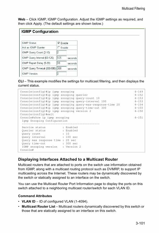
Multicast Filtering
Web – Click IGMP, IGMP Configuration. Adjust the IGMP settings as required, and then click Apply. (The default settings are shown below.)
CLI – This example modifies the settings for multicast filtering, and then displays the current status.
Displaying Interfaces Attached to a Multicast RouterMulticast routers that are attached to ports on the switch use information obtained from IGMP, along with a multicast routing protocol such as DVMRP, to support IP multicasting across the Internet. These routers may be dynamically discovered by the switch or statically assigned to an interface on the switch.
You can use the Multicast Router Port Information page to display the ports on this switch attached to a neighboring multicast router/switch for each VLAN ID.
Command Attributes• VLAN ID – ID of configured VLAN (1-4094).• Multicast Router List – Multicast routers dynamically discovered by this switch or
those that are statically assigned to an interface on this switch.
Console(config)#ip igmp snooping 4-149Console(config)#ip igmp snooping querier 4-152Console(config)#ip igmp snooping query-count 10 4-153Console(config)#ip igmp snooping query-interval 100 4-153Console(config)#ip igmp snooping query-max-response-time 20 4-154Console(config)#ip igmp snooping query-time-out 300 4-155Console(config)#ip igmp snooping version 2 4-150Console(config)#exitConsole#show ip igmp snooping 4-151Igmp Snooping Configuration----------------------------------------------Service status : EnabledQuerier status : EnabledQuery count : 10Query interval : 100 secQuery max response time : 20 secQuery time-out : 300 secIGMP snooping version : Version 2
Console#
3-101

Configuring the Switch
Web – Click IGMP, Multicast Router Port Information. Select the required VLAN ID from the scroll-down list to display the associated multicast routers.
CLI – This example shows that Port 11 has been statically configured as a port attached to a multicast router.
Specifying Static Interfaces for a Multicast RouterDepending on your network connections, IGMP snooping may not always be able to locate the IGMP querier. Therefore, if the IGMP querier is a known multicast router/ switch connected over the network to an interface (port or trunk) on your switch, you can manually configure the interface (and a specified VLAN) to join all the current multicast groups supported by the attached router. This can ensure that multicast traffic is passed to all the appropriate interfaces within the switch.
Command Attributes• Interface – Activates the Port or Trunk scroll down list.• VLAN ID – Selects the VLAN to propagate all multicast traffic coming from the
attached multicast router.• Port or Trunk – Specifies the interface attached to a multicast router.
Console#show ip igmp snooping mrouter vlan 1 4-186VLAN M'cast Router Port Type---- ------------------ -------
1 Eth 1/11 Static
3-102
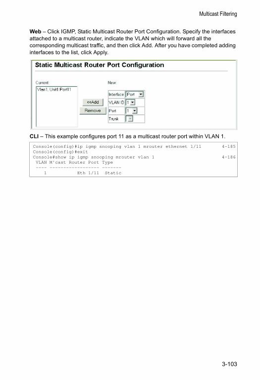
Multicast Filtering
Web – Click IGMP, Static Multicast Router Port Configuration. Specify the interfaces attached to a multicast router, indicate the VLAN which will forward all the corresponding multicast traffic, and then click Add. After you have completed adding interfaces to the list, click Apply.
CLI – This example configures port 11 as a multicast router port within VLAN 1.
Console(config)#ip igmp snooping vlan 1 mrouter ethernet 1/11 4-185Console(config)#exitConsole#show ip igmp snooping mrouter vlan 1 4-186VLAN M'cast Router Port Type---- ------------------ -------
1 Eth 1/11 Static
3-103
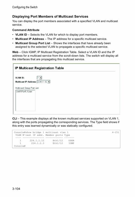
Configuring the Switch
Displaying Port Members of Multicast Services You can display the port members associated with a specified VLAN and multicast service.
Command Attribute• VLAN ID – Selects the VLAN for which to display port members.• Multicast IP Address – The IP address for a specific multicast service.• Multicast Group Port List – Shows the interfaces that have already been
assigned to the selected VLAN to propagate a specific multicast service.
Web – Click IGMP, IP Multicast Registration Table. Select a VLAN ID and the IP address for a multicast service from the scroll-down lists. The switch will display all the interfaces that are propagating this multicast service.
CLI – This example displays all the known multicast services supported on VLAN 1, along with the ports propagating the corresponding services. The Type field shows if this entry was learned dynamically or was statically configured.
Console#show bridge 1 multicast vlan 1 4-151VLAN M'cast IP addr. Member ports Type---- --------------- ------------ -------
1 224.1.1.12 Eth1/12 USER1 224.1.2.3 Eth1/12 IGMP
Console#
3-104
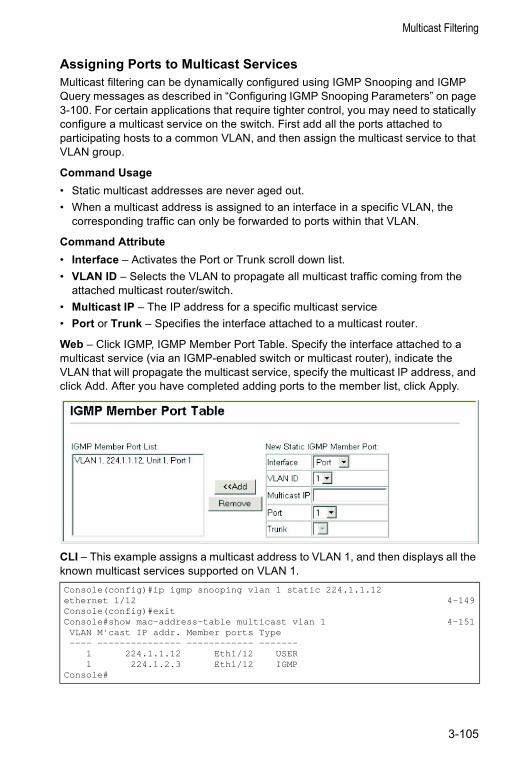
Multicast Filtering
Assigning Ports to Multicast Services Multicast filtering can be dynamically configured using IGMP Snooping and IGMP Query messages as described in “Configuring IGMP Snooping Parameters” on page 3-100. For certain applications that require tighter control, you may need to statically configure a multicast service on the switch. First add all the ports attached to participating hosts to a common VLAN, and then assign the multicast service to that VLAN group.
Command Usage• Static multicast addresses are never aged out.• When a multicast address is assigned to an interface in a specific VLAN, the
corresponding traffic can only be forwarded to ports within that VLAN.
Command Attribute• Interface – Activates the Port or Trunk scroll down list.• VLAN ID – Selects the VLAN to propagate all multicast traffic coming from the
attached multicast router/switch.• Multicast IP – The IP address for a specific multicast service• Port or Trunk – Specifies the interface attached to a multicast router.
Web – Click IGMP, IGMP Member Port Table. Specify the interface attached to a multicast service (via an IGMP-enabled switch or multicast router), indicate the VLAN that will propagate the multicast service, specify the multicast IP address, and click Add. After you have completed adding ports to the member list, click Apply.
CLI – This example assigns a multicast address to VLAN 1, and then displays all the known multicast services supported on VLAN 1.Console(config)#ip igmp snooping vlan 1 static 224.1.1.12ethernet 1/12 4-149Console(config)#exitConsole#show mac-address-table multicast vlan 1 4-151VLAN M'cast IP addr. Member ports Type---- --------------- ------------ -------
1 224.1.1.12 Eth1/12 USER1 224.1.2.3 Eth1/12 IGMP
Console#
3-105
Configuring the Switch
Layer 3 IGMP (Query used with Multicast Routing)IGMP Snooping – IGMP Snooping is a Layer 2 function (page 3-100) that can be used to provide multicast filtering when no other switches in the network support multicast routing. (Note that IGMP Snooping can only be globally enabled.)
IGMP Query – Multicast query is used to poll each known multicast group for active members, and dynamically configure the switch ports which need to forward multicast traffic. Although the implementation differs slightly, IGMP Query is used in conjunction with both Layer 2 IGMP Snooping and multicast routing. Note that when using IGMP Snooping, multicast query is automatically enabled. (See “Configuring IGMP Snooping Parameters” on page 3-100.)
Layer 3 IGMP – This protocol includes a form of multicast query specifically designed to work with multicast routing. A router periodically asks its hosts if they want to receive multicast traffic. It then propagates service requests on to any upstream multicast router to ensure that it will continue to receive the multicast service. Layer 3 IGMP can be enabled for individual VLAN interfaces (page 3-106), (Note that Layer 2 snooping and query is disabled if Layer 3 IGMP is enabled.)
Configuring IGMP Interface ParametersThis switch uses IGMP (Internet Group Management Protocol) to query for any attached hosts that want to receive a specific multicast service. The hosts may respond with several types of IP multicast messages. Hosts respond to queries with report messages that indicate which groups they want to join or the groups to which they already belong. If a router does not receive a report message within a specified period of time, it will prune that interface from the multicast tree. A host can also submit a join message at any time without waiting for a query from the router. Host can also signal when they no longer want to receive traffic for a specific group by sending a leave-group message.
These IGMP messages are used by the router to identify ports containing multicast hosts and to restrict the downstream flow of multicast data to only these ports. If more than one router on the LAN is performing IP multicasting, one of these is elected as the “querier” and assumes the role of querying for group members. It then propagates the service request up to any neighboring multicast router to ensure that it will continue to receive the multicast service. The following parameters are used to control Layer 3 IGMP and query functions.
Command Attributes• VLAN (Interface) – VLAN interface bound to a primary IP address.
(Range: 1-4094)• IGMP Protocol Status (Admin Status) – Enables IGMP on a VLAN interface.
(Default: Disabled)
3-106
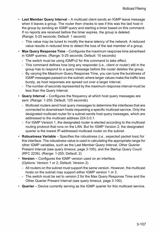
Multicast Filtering
• Last Member Query Interval – A multicast client sends an IGMP leave message when it leaves a group. The router then checks to see if this was the last host in the group by sending an IGMP query and starting a timer based on this command. If no reports are received before the timer expires, the group is deleted. (Range: 0-25 seconds; Default: 1 second)- This value may be tuned to modify the leave latency of the network. A reduced
value results in reduced time to detect the loss of the last member of a group. • Max Query Response Time – Configures the maximum response time advertised
in IGMP queries. (Range: 0-25 seconds; Default: 10 seconds)- The switch must be using IGMPv2 for this command to take effect. - This command defines how long any responder (i.e., client or router) still in the
group has to respond to a query message before the router deletes the group.- By varying the Maximum Query Response Time, you can tune the burstiness of
IGMP messages passed on the subnet; where larger values make the traffic less bursty, as host responses are spread out over a larger interval.
- The number of seconds represented by the maximum response interval must be less than the Query Interval.
• Query Interval – Configures the frequency at which host query messages are sent. (Range: 1-255; Default: 125 seconds)- Multicast routers send host query messages to determine the interfaces that are
connected to downstream hosts requesting a specific multicast service. Only the designated multicast router for a subnet sends host query messages, which are addressed to the multicast address 224.0.0.1.
- For IGMP Version 1, the designated router is elected according to the multicast routing protocol that runs on the LAN. But for IGMP Version 2, the designated querier is the lowest IP-addressed multicast router on the subnet.
• Robustness Variable – Specifies the robustness (i.e., expected packet loss) for this interface. The robustness value is used in calculating the appropriate range for other IGMP variables, such as the Last Member Query Interval, Other Querier Present Interval (see query timeout, page 3-100), and the Startup Query Count (RFC 2236). (Range: 1-255; Default: 2)
• Version – Configures the IGMP version used on an interface. (Options: Version 1 or 2; Default: Version 2)- All routers on the subnet must support the same version. However, the multicast
hosts on the subnet may support either IGMP version 1 or 2.- The switch must be set to version 2 for the Max Query Response Time and the
Other Querier Present Interval (see query timeout, page 3-100).• Querier – Device currently serving as the IGMP querier for this multicast service.
3-107
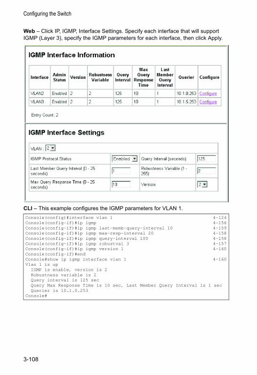
Configuring the Switch
Web – Click IP, IGMP, Interface Settings. Specify each interface that will support IGMP (Layer 3), specify the IGMP parameters for each interface, then click Apply.
CLI – This example configures the IGMP parameters for VLAN 1.Console(config)#interface vlan 1 4-124Console(config-if)#ip igmp 4-156Console(config-if)#ip igmp last-memb-query-interval 10 4-159Console(config-if)#ip igmp max-resp-interval 20 4-158Console(config-if)#ip igmp query-interval 100 4-158Console(config-if)#ip igmp robustval 3 4-157Console(config-if)#ip igmp version 1 4-160Console(config-if)#endConsole#show ip igmp interface vlan 1 4-160Vlan 1 is up
IGMP is enable, version is 2Robustness variable is 2Query interval is 125 secQuery Max Response Time is 10 sec, Last Member Query Interval is 1 secQuerier is 10.1.0.253
Console#
3-108
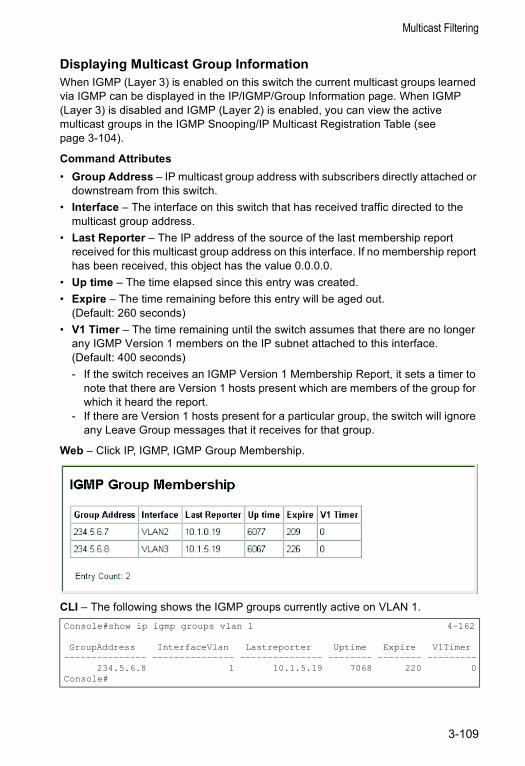
Multicast Filtering
Displaying Multicast Group InformationWhen IGMP (Layer 3) is enabled on this switch the current multicast groups learned via IGMP can be displayed in the IP/IGMP/Group Information page. When IGMP (Layer 3) is disabled and IGMP (Layer 2) is enabled, you can view the active multicast groups in the IGMP Snooping/IP Multicast Registration Table (see page 3-104).
Command Attributes• Group Address – IP multicast group address with subscribers directly attached or
downstream from this switch.• Interface – The interface on this switch that has received traffic directed to the
multicast group address.• Last Reporter – The IP address of the source of the last membership report
received for this multicast group address on this interface. If no membership report has been received, this object has the value 0.0.0.0.
• Up time – The time elapsed since this entry was created.• Expire – The time remaining before this entry will be aged out.
(Default: 260 seconds)• V1 Timer – The time remaining until the switch assumes that there are no longer
any IGMP Version 1 members on the IP subnet attached to this interface. (Default: 400 seconds)- If the switch receives an IGMP Version 1 Membership Report, it sets a timer to
note that there are Version 1 hosts present which are members of the group for which it heard the report.
- If there are Version 1 hosts present for a particular group, the switch will ignore any Leave Group messages that it receives for that group.
Web – Click IP, IGMP, IGMP Group Membership.
CLI – The following shows the IGMP groups currently active on VLAN 1.Console#show ip igmp groups vlan 1 4-162
GroupAddress InterfaceVlan Lastreporter Uptime Expire V1Timer--------------- --------------- --------------- -------- -------- ---------
234.5.6.8 1 10.1.5.19 7068 220 0Console#
3-109
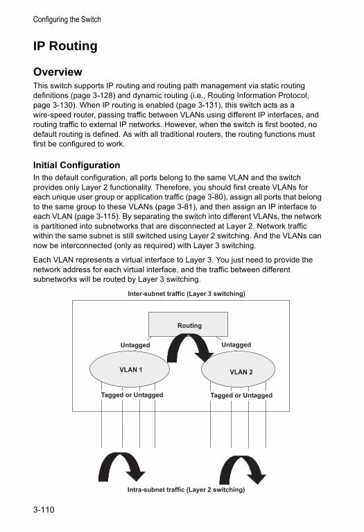
Configuring the Switch
IP Routing
OverviewThis switch supports IP routing and routing path management via static routing definitions (page 3-128) and dynamic routing (i.e., Routing Information Protocol, page 3-130). When IP routing is enabled (page 3-131), this switch acts as a wire-speed router, passing traffic between VLANs using different IP interfaces, and routing traffic to external IP networks. However, when the switch is first booted, no default routing is defined. As with all traditional routers, the routing functions must first be configured to work.
Initial ConfigurationIn the default configuration, all ports belong to the same VLAN and the switch provides only Layer 2 functionality. Therefore, you should first create VLANs for each unique user group or application traffic (page 3-80), assign all ports that belong to the same group to these VLANs (page 3-81), and then assign an IP interface to each VLAN (page 3-115). By separating the switch into different VLANs, the network is partitioned into subnetworks that are disconnected at Layer 2. Network traffic within the same subnet is still switched using Layer 2 switching. And the VLANs can now be interconnected (only as required) with Layer 3 switching.
Each VLAN represents a virtual interface to Layer 3. You just need to provide the network address for each virtual interface, and the traffic between different subnetworks will be routed by Layer 3 switching.
VLAN 1 VLAN 2
Inter-subnet traffic (Layer 3 switching)
Routing
UntaggedUntaggedUntaggedUntagged
Tagged or UntaggedTagged or Untagged Tagged or UntaggedTagged or Untagged
Intra-subnet traffic (Layer 2 switching)
3-110
IP Routing
IP SwitchingIP Switching (or packet forwarding) encompasses tasks required to forward packets for both Layer 2 and Layer 3, as well as traditional routing. These functions include:
• Layer 2 forwarding (switching) based on the Layer 2 destination MAC address• Layer 3 forwarding (routing):
- Based on the Layer 3 destination address- Replacing destination/source MAC addresses for each hop- Incrementing the hop count- Decrementing the time-to-live- Verifying and recalculating the Layer 3 checksum
If the destination node is on the same subnetwork as the source network, then the packet can be transmitted directly without the help of a router. However, if the MAC address is not yet known to the switch, an Address Resolution Protocol (ARP) packet with the destination IP address is broadcast to get the destination MAC address from the destination node. The IP packet can then be sent directly with the destination MAC address.
If the destination belongs to a different subnet on this switch, the packet can be routed directly to the destination node. However, if the packet belongs to a subnet not included on this switch, then the packet should be sent to a router (with the MAC address of the router itself used as the destination MAC address, and the destination IP address of the destination node). The router will then forward the packet to the destination node via the correct path. The router can also use the ARP protocol to find out the MAC address of the destination node of the next router as necessary.
Note: In order to perform IP switching, the switch should be recognized by other network nodes as an IP router, either by setting it as the default gateway or by redirection from another router via the ICMP process.
When the switch receives an IP packet addressed to its own MAC address, the packet follows the Layer 3 routing process. The destination IP address is checked against the Layer 3 address table. If the address is not already there, the switch broadcasts an ARP packet to all the ports on the destination VLAN to find out the destination MAC address. After the MAC address is discovered, the packet is reformatted and sent out to the destination. The reformat process includes decreasing the Time-To-Live (TTL) field of the IP header, recalculating the IP header checksum, and replacing the destination MAC address with either the MAC address of the destination node or that of the next hop router.
When another packet destined to the same node arrives, the destination MAC can be retrieved directly from the Layer 3 address table; the packet is then reformatted and sent out the destination port. IP switching can be done at wire-speed when the destination address entry is already in the Layer 3 address table.
If the switch determines that a frame must be routed, the route is calculated only during setup. Once the route has been determined, all packets in the current flow
3-111
Configuring the Switch
are simply switched or forwarded across the chosen path. This takes advantage of the high throughput and low latency of switching by enabling the traffic to bypass the routing engine once the path calculation has been performed.
Routing Path ManagementRouting Path Management involves the determination and updating of all the routing information required for packet forwarding, including:
• Handling routing protocols• Updating the routing table• Updating the Layer 3 switching database
Routing ProtocolsThe switch supports both static and dynamic routing.• Static routing requires routing information to be stored in the switch either manually
or when a connection is set up by an application outside the switch.• Dynamic routing uses a routing protocol to exchange routing information, calculate
routing tables, and respond to changes in the status or loading of the network.
Dynamic routing involves the determination and updating of all the routing information required for packet forwarding, as listed on page 3-112.• Handling routing protocols• Updating the routing table• Updating the Layer 3 switching database
The switch supports RIP and RIP-2 dynamic routing protocols.
RIP and RIP-2 Dynamic Routing ProtocolsThe RIP protocol is the most widely used routing protocol. The RIP protocol uses a distance-vector-based approach to routing. Routes are determined on the basis of minimizing the distance vector, or hop count, which serves as a rough estimate of transmission cost. Each router broadcasts its advertisement every 30 seconds, together with any updates to its routing table. This allows all routers on the network to learn consistent tables of next hop links which lead to relevant subnets.
Just as Layer 2 switches use the Spanning Tree Algorithm to prevent loops, routers also use methods for preventing loops that would cause endless retransmission of data traffic. RIP utilizes the following three methods to prevent loops from occurring:• Split horizon – Never propagate routes back to an interface port from which they
have been acquired.• Poison reverse – Propagate routes back to an interface port from which they have
been acquired, but set the distance-vector metrics to infinity. (This provides faster convergence.)
• Triggered updates – Whenever a route gets changed, broadcast an update message after waiting for a short random delay, but without waiting for the periodic cycle.
3-112
IP Routing
RIP-2 is a compatible upgrade to RIP. RIP-2 adds useful capabilities for plain text authentication, multiple independent RIP domains, variable length subnet masks, and multicast transmissions for route advertising (RFC 1723).There are several serious problems with RIP that you should consider. First of all, RIP (version 1) has no knowledge of subnets, both RIP versions can take a long time to converge on a new route after the failure of a link or router during which time routing loops may occur, and its small hop count limitation of 15 restricts its use to smaller networks. Moreover, RIP (version 1) wastes valuable network bandwidth by propagating routing information via broadcasts; it also considers too few network variables to make the best routing decision.
Non-IP Protocol RoutingThe switch supports IP routing only. Non-IP protocols such as IPX and Appletalk cannot be routed by this switch, and will be confined within their local VLAN group unless bridged by an external router.
To coexist with a network built on multilayer switches, the subnetworks for non-IP protocols must follow the same logical boundary as that of the IP subnetworks. A separate multi-protocol router can then be used to link the subnetworks by connecting to one port from each available VLAN on the network.
3-113
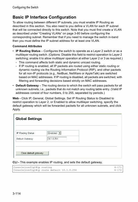
Configuring the Switch
Basic IP Interface ConfigurationTo allow routing between different IP subnets, you must enable IP Routing as described in this section. You also need to you define a VLAN for each IP subnet that will be connected directly to this switch. Note that you must first create a VLAN as described under “Creating VLANs” on page 3-80 before configuring the corresponding subnet. Remember that if you need to manage the switch in-band then you must define the IP subnet address for at least one VLAN.
Command Attributes• IP Routing Status – Configures the switch to operate as a Layer 2 switch or as a
multilayer routing switch. (Options: Disable this field to restrict operation to Layer 2 switching; enable it to allow multilayer operation at either Layer 2 or 3 as required.)- This command affects both static and dynamic unicast routing.- If IP routing is enabled, all IP packets are routed using either static routing or
dynamic routing via the Routing Information Protocol (RIP), and other packets for all non-IP protocols (e.g., NetBuei, NetWare or AppleTalk) are switched based on MAC addresses. If IP routing is disabled, all packets are switched, with filtering and forwarding decisions based strictly on MAC addresses.
• Default Gateway – The routing device to which the switch will pass packets for all unknown subnets; i.e., packets that do not match any routing table entry. (Valid IP addresses consist of four numbers, 0 to 255, separated by periods.)
Web - Click IP, General, Global Settings. Set IP Routing Status to Disabled to restrict operation to Layer 2, or Enabled to allow multilayer switching, specify the default gateway which will be forwarded packets for all unknown subnets, and click Apply.
CLI - This example enables IP routing, and sets the default gateway.Console(config)#ip routing 4-171Console(config)#ip route default 10.1.0.254 4-172
3-114
IP Routing
Configuring IP Routing InterfacesYou can specify the IP subnets connected to this switch by manually assigning an IP address to each VLAN, or by using the RIP dynamic routing protocol to identify routes that lead to other interfaces by exchanging protocol messages with other routers on the network.
Command Usage• If this switch is directly connected to end node devices (or connected to end nodes
via shared media) that will be assigned to a specific subnet, then you must create a router interface for each VLAN that will support routing. The router interface consists of an IP address and subnet mask. This interface address defines both the network number to which the router interface is attached and the switch’s host number on that network. In other words, a router interface address defines the network and subnetwork numbers of the segment that is connected to that interface, and allows you to send IP packets to or from the router.
• Before you configure any network interfaces on this switch, you should first create a VLAN for each unique user group, or for each network application and its associated users. Then assign the ports associated with each of these VLANs.
Command Attributes• VLAN ID – ID of configured VLAN (1-4094, no leading zeroes).• IP Address Mode – Specifies whether the IP address for this interface is statically
assigned, or obtained from a network address server. (Options: Static, DHCP - Dynamic Host Configuration Protocol, BOOTP - Boot Protocol; Default: Static) - If Static address type is selected, then you must also specify whether the IP
address is the primary IP address on the VLAN or a secondary IP address. An interface can have only one primary IP address, but can have multiple secondary IP addresses. In other words, you will need to specify secondary addresses if more than one IP subnet that can accessed via this interface.
- If DHCP/BOOTP is enabled, IP will not function until a reply has been received from the address server. Requests will be broadcast periodically by the switch for an IP address. (DHCP/BOOTP values include the IP address and subnet mask.)
• IP Address – Address of the VLAN interface. Valid IP addresses consist of four numbers, 0 to 255, separated by periods.
• Subnet Mask – This mask identifies the host address bits used for routing to specific subnets.
3-115
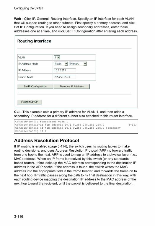
Configuring the Switch
Web - Click IP, General, Routing Interface. Specify an IP interface for each VLAN that will support routing to other subnets. First specify a primary address, and click Set IP Configuration. If you need to assign secondary addresses, enter these addresses one at a time, and click Set IP Configuration after entering each address.
CLI - This example sets a primary IP address for VLAN 1, and then adds a secondary IP address for a different subnet also attached to this router interface.
Address Resolution Protocol If IP routing is enabled (page 3-114), the switch uses its routing tables to make routing decisions, and uses Address Resolution Protocol (ARP) to forward traffic from one hop to the next. ARP is used to map an IP address to a physical layer (i.e., MAC) address. When an IP frame is received by this switch (or any standards- based router), it first looks up the MAC address corresponding to the destination IP address in the ARP cache. If the address is found, the switch writes the MAC address into the appropriate field in the frame header, and forwards the frame on to the next hop. IP traffic passes along the path to its final destination in this way, with each routing device mapping the destination IP address to the MAC address of the next hop toward the recipient, until the packet is delivered to the final destination.
Console(config)#interface vlan 1Console(config-if)#ip address 10.1.0.253 255.255.255.0 4-163Console(config-if)#ip address 10.1.9.253 255.255.255.0 secondaryConsole(config-if)#
3-116
IP Routing
If there is no entry for an IP address in the ARP cache, the switch will broadcast an ARP request packet to all devices on the network. The ARP request contains the following fields similar to that shown in this example:
When devices receive this request, they discard it if their address does not match the destination IP address in the message. However, if it does match, they write their own hardware address into the destination MAC address field and send the message back to the source hardware address. When the source device receives a reply, it writes the destination IP address and corresponding MAC address into its cache, and forwards the IP traffic on to the next hop. As long as this entry has not timed out, the switch will be able forward traffic directly to the next hop for this destination without having to broadcast another ARP request.
Proxy ARPWhen a node in the attached subnetwork does not have routing or a default gateway configured, Proxy ARP can be used to forward ARP requests to a remote subnetwork. When the switch receives an ARP request for a remote network and Proxy ARP is enabled, it determines if it has the best route to the remote network, and then answers the ARP request by sending its own MAC address to the requesting node. That node then sends traffic to the switch, which in turn uses its own routing table to forward the traffic to the remote destination.
Basic ARP ConfigurationYou can use the ARP General configuration menu to specify the timeout for ARP cache entries, or to enable Proxy ARP for specific VLAN interfaces.
Command Usage• The aging time determines how long dynamic entries remain the cache. If the
timeout is too short, the switch may tie up resources by repeating ARP requests for addresses recently flushed from the table.
• End stations that require Proxy ARP must view the entire network as a single network. These nodes must therefore use a smaller subnet mask than that used by the switch or other relevant network devices.
• Extensive use of Proxy ARP can degrade switch performance because it may lead to increased ARP traffic and increased search time for larger ARP address tables.
Command Attributes• Timeout – Sets the aging time for dynamic entries in the ARP cache.
(Range: 300 - 86400 seconds; Default: 1200 seconds or 20 minutes)• Proxy ARP – Enables or disables Proxy ARP for specified VLAN interfaces.
destination IP address 10.1.0.19
destination MAC address ?
source IP address 10.1.0.253
source MAC address 00-00-ab-cd-00-00
3-117
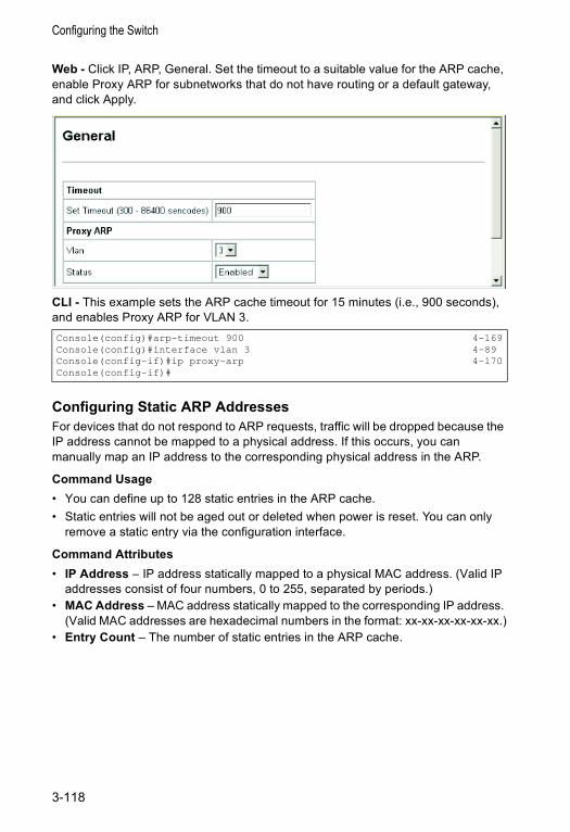
Configuring the Switch
Web - Click IP, ARP, General. Set the timeout to a suitable value for the ARP cache, enable Proxy ARP for subnetworks that do not have routing or a default gateway, and click Apply.
CLI - This example sets the ARP cache timeout for 15 minutes (i.e., 900 seconds), and enables Proxy ARP for VLAN 3.
Configuring Static ARP AddressesFor devices that do not respond to ARP requests, traffic will be dropped because the IP address cannot be mapped to a physical address. If this occurs, you can manually map an IP address to the corresponding physical address in the ARP.
Command Usage• You can define up to 128 static entries in the ARP cache.• Static entries will not be aged out or deleted when power is reset. You can only
remove a static entry via the configuration interface.
Command Attributes• IP Address – IP address statically mapped to a physical MAC address. (Valid IP
addresses consist of four numbers, 0 to 255, separated by periods.)• MAC Address – MAC address statically mapped to the corresponding IP address.
(Valid MAC addresses are hexadecimal numbers in the format: xx-xx-xx-xx-xx-xx.)• Entry Count – The number of static entries in the ARP cache.
Console(config)#arp-timeout 900 4-169Console(config)#interface vlan 3 4-89Console(config-if)#ip proxy-arp 4-170Console(config-if)#
3-118
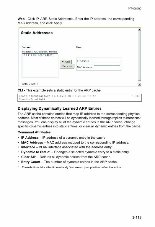
IP Routing
Web - Click IP, ARP, Static Addresses. Enter the IP address, the corresponding MAC address, and click Apply.
CLI - This example sets a static entry for the ARP cache.
Displaying Dynamically Learned ARP EntriesThe ARP cache contains entries that map IP address to the corresponding physical address. Most of these entries will be dynamically learned through replies to broadcast messages. You can display all of the dynamic entries in the ARP cache, change specific dynamic entries into static entries, or clear all dynamic entries from the cache.
Command Attributes• IP Address – IP address of a dynamic entry in the cache. • MAC Address – MAC address mapped to the corresponding IP address.• Interface – VLAN interface associated with the address entry.• Dynamic to Static* – Changes a selected dynamic entry to a static entry.• Clear All* – Deletes all dynamic entries from the ARP cache.• Entry Count – The number of dynamic entries in the ARP cache.* These buttons take effect immediately. You are not prompted to confirm the action.
Console(config)#arp 10.1.0.11 00-11-22-33-44-55 4-168Console(config)#
3-119
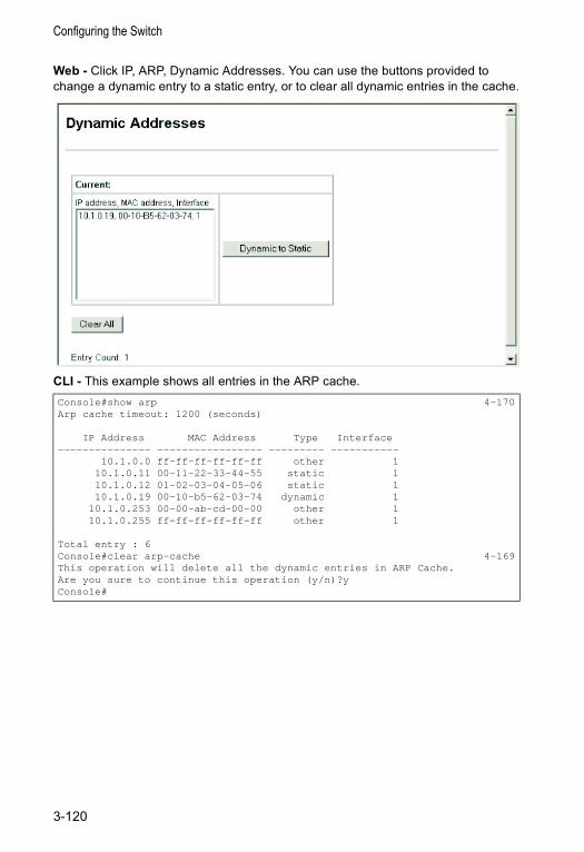
Configuring the Switch
Web - Click IP, ARP, Dynamic Addresses. You can use the buttons provided to change a dynamic entry to a static entry, or to clear all dynamic entries in the cache.
CLI - This example shows all entries in the ARP cache.Console#show arp 4-170Arp cache timeout: 1200 (seconds)
IP Address MAC Address Type Interface--------------- ----------------- --------- -----------
10.1.0.0 ff-ff-ff-ff-ff-ff other 110.1.0.11 00-11-22-33-44-55 static 110.1.0.12 01-02-03-04-05-06 static 110.1.0.19 00-10-b5-62-03-74 dynamic 1
10.1.0.253 00-00-ab-cd-00-00 other 110.1.0.255 ff-ff-ff-ff-ff-ff other 1
Total entry : 6Console#clear arp-cache 4-169This operation will delete all the dynamic entries in ARP Cache.Are you sure to continue this operation (y/n)?yConsole#
3-120
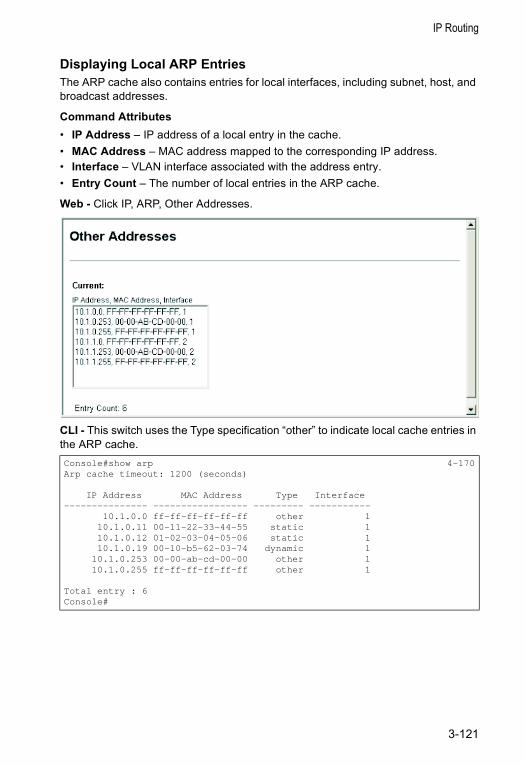
IP Routing
Displaying Local ARP EntriesThe ARP cache also contains entries for local interfaces, including subnet, host, and broadcast addresses.
Command Attributes• IP Address – IP address of a local entry in the cache. • MAC Address – MAC address mapped to the corresponding IP address.• Interface – VLAN interface associated with the address entry.• Entry Count – The number of local entries in the ARP cache.
Web - Click IP, ARP, Other Addresses.
CLI - This switch uses the Type specification “other” to indicate local cache entries in the ARP cache.Console#show arp 4-170Arp cache timeout: 1200 (seconds)
IP Address MAC Address Type Interface--------------- ----------------- --------- -----------
10.1.0.0 ff-ff-ff-ff-ff-ff other 110.1.0.11 00-11-22-33-44-55 static 110.1.0.12 01-02-03-04-05-06 static 110.1.0.19 00-10-b5-62-03-74 dynamic 1
10.1.0.253 00-00-ab-cd-00-00 other 110.1.0.255 ff-ff-ff-ff-ff-ff other 1
Total entry : 6Console#
3-121
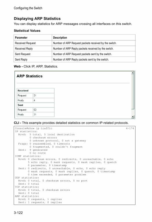
Configuring the Switch
Displaying ARP StatisticsYou can display statistics for ARP messages crossing all interfaces on this switch.
Statistical Values
Web - Click IP, ARP, Statistics.
CLI - This example provides detailed statistics on common IP-related protocols.
Parameter Description
Received Request Number of ARP Request packets received by the switch.
Received Reply Number of ARP Reply packets received by the switch.
Sent Request Number of ARP Request packets sent by the switch.
Sent Reply Number of ARP Reply packets sent by the switch.
Console#show ip traffic 4-174IP statistics:
Rcvd: 5 total, 5 local destination0 checksum errors0 unknown protocol, 0 not a gateway
Frags: 0 reassembled, 0 timeouts0 fragmented, 0 couldn't fragment
Sent: 9 generated0 no route
ICMP statistics:Rcvd: 0 checksum errors, 0 redirects, 0 unreachable, 0 echo
5 echo reply, 0 mask requests, 0 mask replies, 0 quench0 parameter, 0 timestamp
Sent: 0 redirects, 0 unreachable, 0 echo, 0 echo reply0 mask requests, 0 mask replies, 0 quench, 0 timestamp0 time exceeded, 0 parameter problem
UDP statistics:Rcvd: 0 total, 0 checksum errors, 0 no portSent: 0 total
TCP statistics:Rcvd: 0 total, 0 checksum errorsSent: 0 total
ARP statistics:Rcvd: 0 requests, 1 repliesSent: 1 requests, 0 replies
3-122
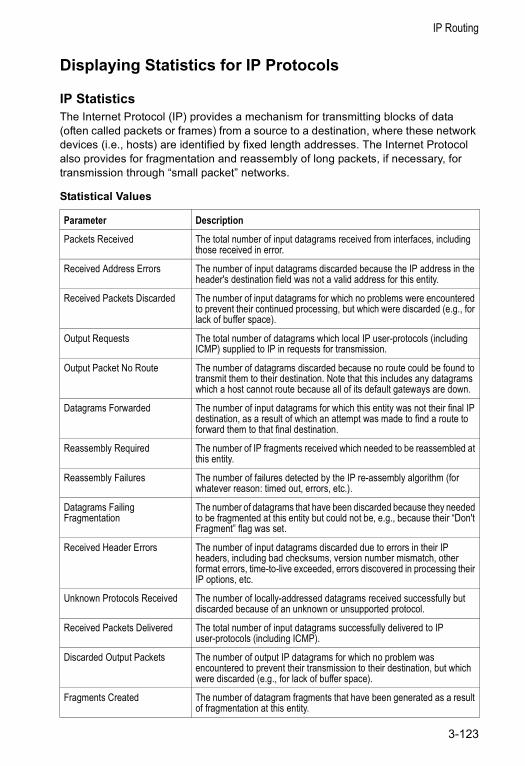
IP Routing
Displaying Statistics for IP Protocols
IP StatisticsThe Internet Protocol (IP) provides a mechanism for transmitting blocks of data (often called packets or frames) from a source to a destination, where these network devices (i.e., hosts) are identified by fixed length addresses. The Internet Protocol also provides for fragmentation and reassembly of long packets, if necessary, for transmission through “small packet” networks.
Statistical Values
Parameter Description
Packets Received The total number of input datagrams received from interfaces, including those received in error.
Received Address Errors The number of input datagrams discarded because the IP address in the header's destination field was not a valid address for this entity.
Received Packets Discarded The number of input datagrams for which no problems were encountered to prevent their continued processing, but which were discarded (e.g., for lack of buffer space).
Output Requests The total number of datagrams which local IP user-protocols (including ICMP) supplied to IP in requests for transmission.
Output Packet No Route The number of datagrams discarded because no route could be found to transmit them to their destination. Note that this includes any datagrams which a host cannot route because all of its default gateways are down.
Datagrams Forwarded The number of input datagrams for which this entity was not their final IP destination, as a result of which an attempt was made to find a route to forward them to that final destination.
Reassembly Required The number of IP fragments received which needed to be reassembled at this entity.
Reassembly Failures The number of failures detected by the IP re-assembly algorithm (for whatever reason: timed out, errors, etc.).
Datagrams Failing Fragmentation
The number of datagrams that have been discarded because they needed to be fragmented at this entity but could not be, e.g., because their “Don't Fragment” flag was set.
Received Header Errors The number of input datagrams discarded due to errors in their IP headers, including bad checksums, version number mismatch, other format errors, time-to-live exceeded, errors discovered in processing their IP options, etc.
Unknown Protocols Received The number of locally-addressed datagrams received successfully but discarded because of an unknown or unsupported protocol.
Received Packets Delivered The total number of input datagrams successfully delivered to IP user-protocols (including ICMP).
Discarded Output Packets The number of output IP datagrams for which no problem was encountered to prevent their transmission to their destination, but which were discarded (e.g., for lack of buffer space).
Fragments Created The number of datagram fragments that have been generated as a result of fragmentation at this entity.
3-123
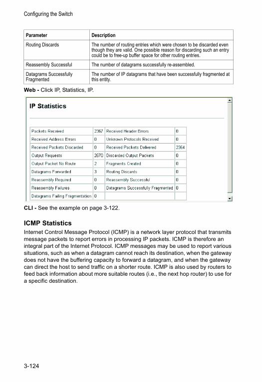
Configuring the Switch
Web - Click IP, Statistics, IP.
CLI - See the example on page 3-122.
ICMP StatisticsInternet Control Message Protocol (ICMP) is a network layer protocol that transmits message packets to report errors in processing IP packets. ICMP is therefore an integral part of the Internet Protocol. ICMP messages may be used to report various situations, such as when a datagram cannot reach its destination, when the gateway does not have the buffering capacity to forward a datagram, and when the gateway can direct the host to send traffic on a shorter route. ICMP is also used by routers to feed back information about more suitable routes (i.e., the next hop router) to use for a specific destination.
Routing Discards The number of routing entries which were chosen to be discarded even though they are valid. One possible reason for discarding such an entry could be to free-up buffer space for other routing entries.
Reassembly Successful The number of datagrams successfully re-assembled.
Datagrams Successfully Fragmented
The number of IP datagrams that have been successfully fragmented at this entity.
Parameter Description
3-124
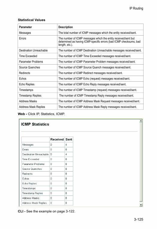
IP Routing
Statistical Values
Web - Click IP, Statistics, ICMP.
CLI - See the example on page 3-122.
Parameter Description
Messages The total number of ICMP messages which the entity received/sent.
Errors The number of ICMP messages which the entity received/sent but determined as having ICMP-specific errors (bad ICMP checksums, bad length, etc.).
Destination Unreachable The number of ICMP Destination Unreachable messages received/sent.
Time Exceeded The number of ICMP Time Exceeded messages received/sent.
Parameter Problems The number of ICMP Parameter Problem messages received/sent.
Source Quenches The number of ICMP Source Quench messages received/sent.
Redirects The number of ICMP Redirect messages received/sent.
Echos The number of ICMP Echo (request) messages received/sent.
Echo Replies The number of ICMP Echo Reply messages received/sent.
Timestamps The number of ICMP Timestamp (request) messages received/sent.
Timestamp Replies The number of ICMP Timestamp Reply messages received/sent.
Address Masks The number of ICMP Address Mask Request messages received/sent.
Address Mask Replies The number of ICMP Address Mask Reply messages received/sent.
3-125
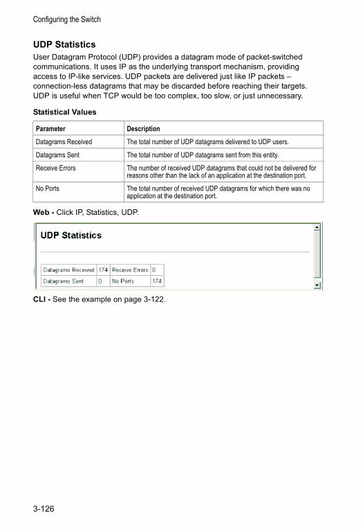
Configuring the Switch
UDP StatisticsUser Datagram Protocol (UDP) provides a datagram mode of packet-switched communications. It uses IP as the underlying transport mechanism, providing access to IP-like services. UDP packets are delivered just like IP packets – connection-less datagrams that may be discarded before reaching their targets. UDP is useful when TCP would be too complex, too slow, or just unnecessary.
Statistical Values
Web - Click IP, Statistics, UDP.
CLI - See the example on page 3-122.
Parameter Description
Datagrams Received The total number of UDP datagrams delivered to UDP users.
Datagrams Sent The total number of UDP datagrams sent from this entity.
Receive Errors The number of received UDP datagrams that could not be delivered for reasons other than the lack of an application at the destination port.
No Ports The total number of received UDP datagrams for which there was no application at the destination port.
3-126
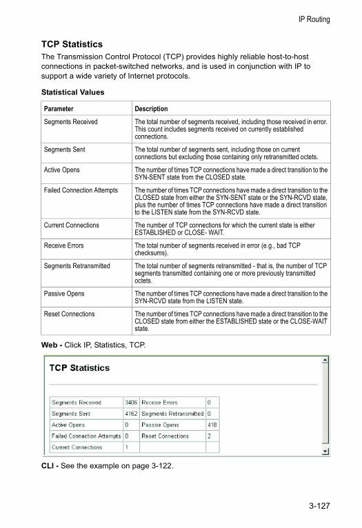
IP Routing
TCP StatisticsThe Transmission Control Protocol (TCP) provides highly reliable host-to-host connections in packet-switched networks, and is used in conjunction with IP to support a wide variety of Internet protocols.
Statistical Values
Web - Click IP, Statistics, TCP.
CLI - See the example on page 3-122.
Parameter Description
Segments Received The total number of segments received, including those received in error. This count includes segments received on currently established connections.
Segments Sent The total number of segments sent, including those on current connections but excluding those containing only retransmitted octets.
Active Opens The number of times TCP connections have made a direct transition to the SYN-SENT state from the CLOSED state.
Failed Connection Attempts The number of times TCP connections have made a direct transition to the CLOSED state from either the SYN-SENT state or the SYN-RCVD state, plus the number of times TCP connections have made a direct transition to the LISTEN state from the SYN-RCVD state.
Current Connections The number of TCP connections for which the current state is either ESTABLISHED or CLOSE- WAIT.
Receive Errors The total number of segments received in error (e.g., bad TCP checksums).
Segments Retransmitted The total number of segments retransmitted - that is, the number of TCP segments transmitted containing one or more previously transmitted octets.
Passive Opens The number of times TCP connections have made a direct transition to the SYN-RCVD state from the LISTEN state.
Reset Connections The number of times TCP connections have made a direct transition to the CLOSED state from either the ESTABLISHED state or the CLOSE-WAIT state.
3-127
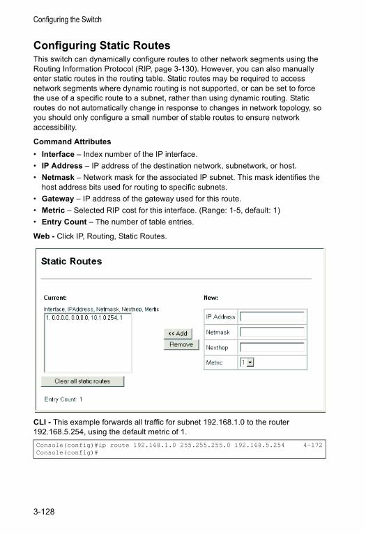
Configuring the Switch
Configuring Static RoutesThis switch can dynamically configure routes to other network segments using the Routing Information Protocol (RIP, page 3-130). However, you can also manually enter static routes in the routing table. Static routes may be required to access network segments where dynamic routing is not supported, or can be set to force the use of a specific route to a subnet, rather than using dynamic routing. Static routes do not automatically change in response to changes in network topology, so you should only configure a small number of stable routes to ensure network accessibility.
Command Attributes• Interface – Index number of the IP interface.• IP Address – IP address of the destination network, subnetwork, or host.• Netmask – Network mask for the associated IP subnet. This mask identifies the
host address bits used for routing to specific subnets.• Gateway – IP address of the gateway used for this route.• Metric – Selected RIP cost for this interface. (Range: 1-5, default: 1)• Entry Count – The number of table entries.
Web - Click IP, Routing, Static Routes.
CLI - This example forwards all traffic for subnet 192.168.1.0 to the router 192.168.5.254, using the default metric of 1.Console(config)#ip route 192.168.1.0 255.255.255.0 192.168.5.254 4-172Console(config)#
3-128
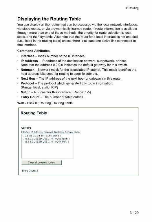
IP Routing
Displaying the Routing TableYou can display all the routes that can be accessed via the local network interfaces, via static routes, or via a dynamically learned route. If route information is available through more than one of these methods, the priority for route selection is local, static, and then dynamic. Also note that the route for a local interface is not enabled (i.e., listed in the routing table) unless there is at least one active link connected to that interface.
Command Attributes• Interface – Index number of the IP interface.• IP Address – IP address of the destination network, subnetwork, or host.
Note that the address 0.0.0.0 indicates the default gateway for this switch.• Netmask – Network mask for the associated IP subnet. This mask identifies the
host address bits used for routing to specific subnets.• Next Hop – The IP address of the next hop (or gateway) in this route.• Protocol – The protocol which generated this route information.
(Range: local, static, RIP)• Metric – RIP cost for this interface. (Range: 1-5)• Entry Count – The number of table entries.
Web - Click IP, Routing, Routing Table.
3-129
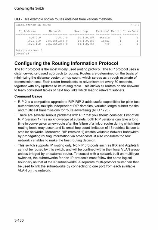
Configuring the Switch
CLI - This example shows routes obtained from various methods.
Configuring the Routing Information ProtocolThe RIP protocol is the most widely used routing protocol. The RIP protocol uses a distance-vector-based approach to routing. Routes are determined on the basis of minimizing the distance vector, or hop count, which serves as a rough estimate of transmission cost. Each router broadcasts its advertisement every 30 seconds, together with any updates to its routing table. This allows all routers on the network to learn consistent tables of next hop links which lead to relevant subnets.
Command Usage• RIP-2 is a compatible upgrade to RIP. RIP-2 adds useful capabilities for plain text
authentication, multiple independent RIP domains, variable length subnet masks, and multicast transmissions for route advertising (RFC 1723).
• There are several serious problems with RIP that you should consider. First of all, RIP (version 1) has no knowledge of subnets, both RIP versions can take a long time to converge on a new route after the failure of a link or router during which time routing loops may occur, and its small hop count limitation of 15 restricts its use to smaller networks. Moreover, RIP (version 1) wastes valuable network bandwidth by propagating routing information via broadcasts; it also considers too few network variables to make the best routing decision.
• This switch supports IP routing only. Non-IP protocols such as IPX and Appletalk cannot be routed by this switch, and will be confined within their local VLAN group unless bridged by an external router. To coexist with a network built on multilayer switches, the subnetworks for non-IP protocols must follow the same logical boundary as that of the IP subnetworks. A separate multi-protocol router can then be used to link the subnetworks by connecting to one port from each available VLAN on the network.
Console#show ip route 4-173
Ip Address Netmask Next Hop Protocol Metric Interface--------------- --------------- --------------- -------- ------ ---------
0.0.0.0 0.0.0.0 10.1.0.254 static 1 110.1.0.0 255.255.255.0 10.1.0.253 local 1 110.1.1.0 255.255.255.0 10.1.0.254 RIP 2 1
Total entries: 3Console#
3-130
IP Routing
Configuring General Protocol SettingsRIP is used to specify how routers exchange routing information. When RIP is enabled on this switch, it sends RIP messages to all devices in the network every 30 seconds (by default), and updates its own routing table when RIP messages are received from other routers. To communicate properly with other routers using RIP, you need to specify the RIP version used globally by the switch, as well as the RIP send and receive versions used on specific interfaces (page 3-134).
Command Usage• When you specify a Global RIP Version, any VLAN interface not previously set to
a specific Receive or Send Version (page 3-134) is set to the following values: - RIP Version 1 configures previously unset interfaces to send RIPv1 compatible
protocol messages and receive either RIPv1 or RIPv2 protocol messages.- RIP Version 2 configures previously unset interfaces to use RIPv2 for both
sending and receiving protocol messages.• The update timer is the fundamental timer used to control all basic RIP processes.
- Setting the update timer to a short interval can cause the switch to spend an excessive amount of time processing updates. On the other hand, setting it to an excessively long time will make the routing protocol less sensitive to changes in the network configuration.
- The timers must be set to the same values for all routers in the network.
Command AttributesGlobal Settings• RIP Routing Process – Enables RIP routing for all IP interfaces on the switch.
(Default: Disabled)• Global RIP Version – Specifies a RIP version used globally by the switch.
(Default: RIP Version 1)
Timer Settings• Update – Sets the rate at which updates are sent. This value will also set the
timeout timer to 6 times the update time, and the garbage-collection timer to 4 times the update time. (Range: 15-60 seconds; Default: 30 seconds)
• Timeout – Sets the time after which there have been no update messages that a route is declared dead. The route is marked inaccessible (i.e., the metric set to infinite) and advertised as unreachable. However, packets are still forwarded on this route. (Default: 180 seconds)
• Garbage Collection – After the timeout interval expires, the switch waits for an interval specified by the garbage-collection timer before removing this entry from the routing table. This timer allows neighbors to become aware of an invalid route prior to purging. (Default: 120 seconds)
3-131
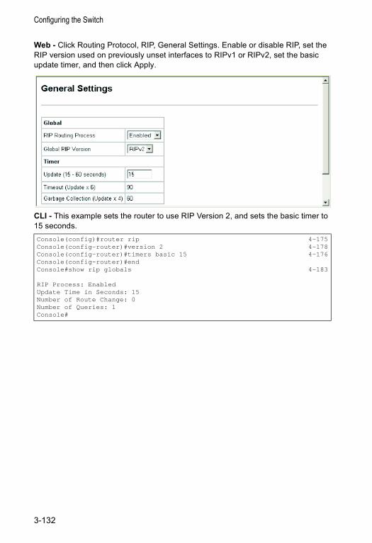
Configuring the Switch
Web - Click Routing Protocol, RIP, General Settings. Enable or disable RIP, set the RIP version used on previously unset interfaces to RIPv1 or RIPv2, set the basic update timer, and then click Apply.
CLI - This example sets the router to use RIP Version 2, and sets the basic timer to 15 seconds.Console(config)#router rip 4-175Console(config-router)#version 2 4-178Console(config-router)#timers basic 15 4-176Console(config-router)#endConsole#show rip globals 4-183
RIP Process: EnabledUpdate Time in Seconds: 15Number of Route Change: 0Number of Queries: 1Console#
3-132
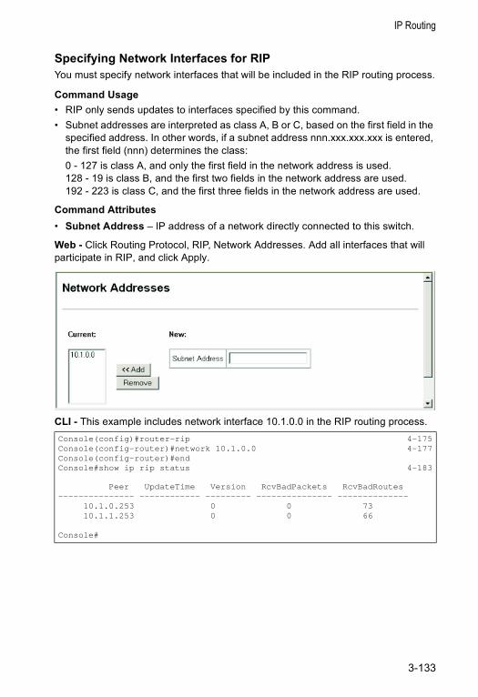
IP Routing
Specifying Network Interfaces for RIPYou must specify network interfaces that will be included in the RIP routing process.
Command Usage • RIP only sends updates to interfaces specified by this command.• Subnet addresses are interpreted as class A, B or C, based on the first field in the
specified address. In other words, if a subnet address nnn.xxx.xxx.xxx is entered, the first field (nnn) determines the class:0 - 127 is class A, and only the first field in the network address is used.128 - 19 is class B, and the first two fields in the network address are used.192 - 223 is class C, and the first three fields in the network address are used.
Command Attributes• Subnet Address – IP address of a network directly connected to this switch.
Web - Click Routing Protocol, RIP, Network Addresses. Add all interfaces that will participate in RIP, and click Apply.
CLI - This example includes network interface 10.1.0.0 in the RIP routing process.Console(config)#router-rip 4-175Console(config-router)#network 10.1.0.0 4-177Console(config-router)#endConsole#show ip rip status 4-183
Peer UpdateTime Version RcvBadPackets RcvBadRoutes--------------- ------------ --------- --------------- --------------
10.1.0.253 0 0 7310.1.1.253 0 0 66
Console#
3-133
Configuring the Switch
Configuring Network Interfaces for RIPFor each interface that participates in the RIP routing process, you must specify the protocol message type accepted (i.e., RIP version) and the message type sent (i.e., RIP version or compatibility mode), the method for preventing loopback of protocol messages, and whether or not authentication is used (i.e., authentication only applies if RIPv2 messages are being sent or received).
Command UsageSpecifying Receive and Send Protocol Types• Setting the RIP Receive Version or Send Version for an interface overrides the
global setting specified by the RIP / General Settings, Global RIP Version field. • You can specify the Receive Version based on these options:
- Use “RIPv1” or “RIPv2” if all routers in the local network are based on RIPv1 or RIPv2, respectively.
- Use “RIPv1 or RIPv2” if some routers in the local network are using RIPv2, but there are still some older routers using RIPv1.
- Use “Do Not Receive” if you do not want to add any dynamic entries to the routing table for an interface. (For example, you may only want to allow static routes for a specific interface.)
• You can specify the Send Version based on these options:- Use “RIPv1” or “RIPv2” if all routers in the local network are based on RIPv1 or
RIPv2, respectively.- Use “RIPv1 Compatible” to propagate route information by broadcasting to other
routers on the network using the RIPv2 advertisement list, instead of multicasting as normally required by RIPv2. (Using this mode allows RIPv1 routers to receive these protocol messages, but still allows RIPv2 routers to receive the additional information provided by RIPv2, including subnet mask, next hop and authentication information.)
- Use “Do Not Send” to passively monitor route information advertised by other routers attached to the network.
Loopback PreventionJust as Layer 2 switches use the Spanning Tree Algorithm to prevent loops, routers also use methods for preventing loops that would cause endless retransmission of data traffic. When protocol packets are caught in a loop, links will be congested, and protocol packets may be lost. However, the network will slowly converge to the new state. RIP utilizes the following three methods that can provide faster convergence when the network topology changes and prevent most loops from occurring:• Split Horizon – Never propagate routes back to an interface port from which they
have been acquired.• Poison Reverse – Propagate routes back to an interface port from which they have
been acquired, but set the distance-vector metrics to infinity. (This provides faster convergence.)
• Triggered Updates – Whenever a route gets changed, broadcast an update message after waiting for a short random delay, but without waiting for the periodic cycle.
3-134
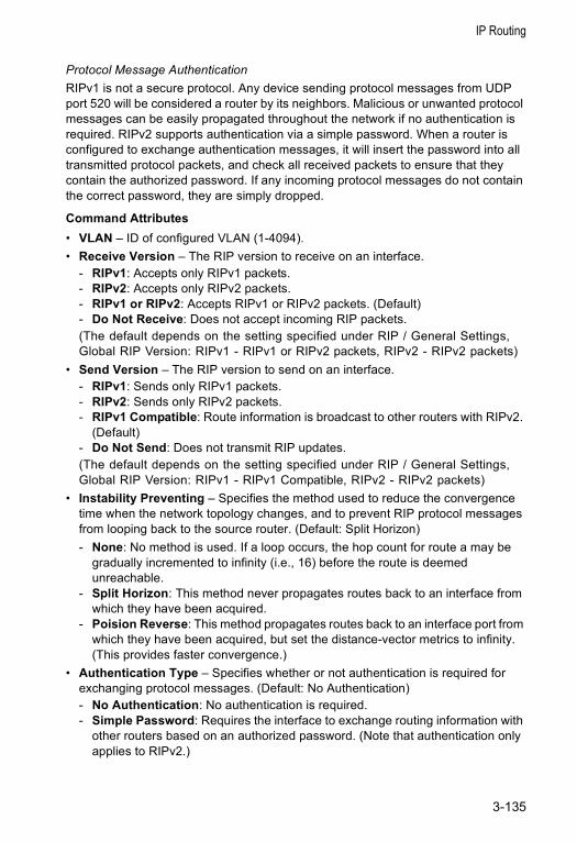
IP Routing
Protocol Message AuthenticationRIPv1 is not a secure protocol. Any device sending protocol messages from UDP port 520 will be considered a router by its neighbors. Malicious or unwanted protocol messages can be easily propagated throughout the network if no authentication is required. RIPv2 supports authentication via a simple password. When a router is configured to exchange authentication messages, it will insert the password into all transmitted protocol packets, and check all received packets to ensure that they contain the authorized password. If any incoming protocol messages do not contain the correct password, they are simply dropped.
Command Attributes• VLAN – ID of configured VLAN (1-4094).• Receive Version – The RIP version to receive on an interface.
- RIPv1: Accepts only RIPv1 packets.- RIPv2: Accepts only RIPv2 packets.- RIPv1 or RIPv2: Accepts RIPv1 or RIPv2 packets. (Default)- Do Not Receive: Does not accept incoming RIP packets.(The default depends on the setting specified under RIP / General Settings, Global RIP Version: RIPv1 - RIPv1 or RIPv2 packets, RIPv2 - RIPv2 packets)
• Send Version – The RIP version to send on an interface.- RIPv1: Sends only RIPv1 packets.- RIPv2: Sends only RIPv2 packets.- RIPv1 Compatible: Route information is broadcast to other routers with RIPv2.
(Default)- Do Not Send: Does not transmit RIP updates.(The default depends on the setting specified under RIP / General Settings, Global RIP Version: RIPv1 - RIPv1 Compatible, RIPv2 - RIPv2 packets)
• Instability Preventing – Specifies the method used to reduce the convergence time when the network topology changes, and to prevent RIP protocol messages from looping back to the source router. (Default: Split Horizon)- None: No method is used. If a loop occurs, the hop count for route a may be
gradually incremented to infinity (i.e., 16) before the route is deemed unreachable.
- Split Horizon: This method never propagates routes back to an interface from which they have been acquired.
- Poision Reverse: This method propagates routes back to an interface port from which they have been acquired, but set the distance-vector metrics to infinity. (This provides faster convergence.)
• Authentication Type – Specifies whether or not authentication is required for exchanging protocol messages. (Default: No Authentication)- No Authentication: No authentication is required.- Simple Password: Requires the interface to exchange routing information with
other routers based on an authorized password. (Note that authentication only applies to RIPv2.)
3-135
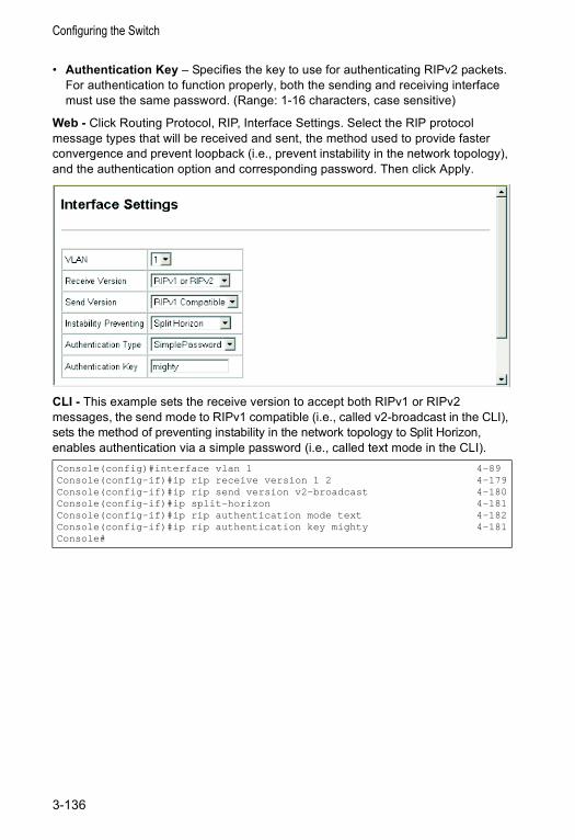
Configuring the Switch
• Authentication Key – Specifies the key to use for authenticating RIPv2 packets. For authentication to function properly, both the sending and receiving interface must use the same password. (Range: 1-16 characters, case sensitive)
Web - Click Routing Protocol, RIP, Interface Settings. Select the RIP protocol message types that will be received and sent, the method used to provide faster convergence and prevent loopback (i.e., prevent instability in the network topology), and the authentication option and corresponding password. Then click Apply.
CLI - This example sets the receive version to accept both RIPv1 or RIPv2 messages, the send mode to RIPv1 compatible (i.e., called v2-broadcast in the CLI), sets the method of preventing instability in the network topology to Split Horizon, enables authentication via a simple password (i.e., called text mode in the CLI).Console(config)#interface vlan 1 4-89Console(config-if)#ip rip receive version 1 2 4-179Console(config-if)#ip rip send version v2-broadcast 4-180Console(config-if)#ip split-horizon 4-181Console(config-if)#ip rip authentication mode text 4-182Console(config-if)#ip rip authentication key mighty 4-181Console#
3-136
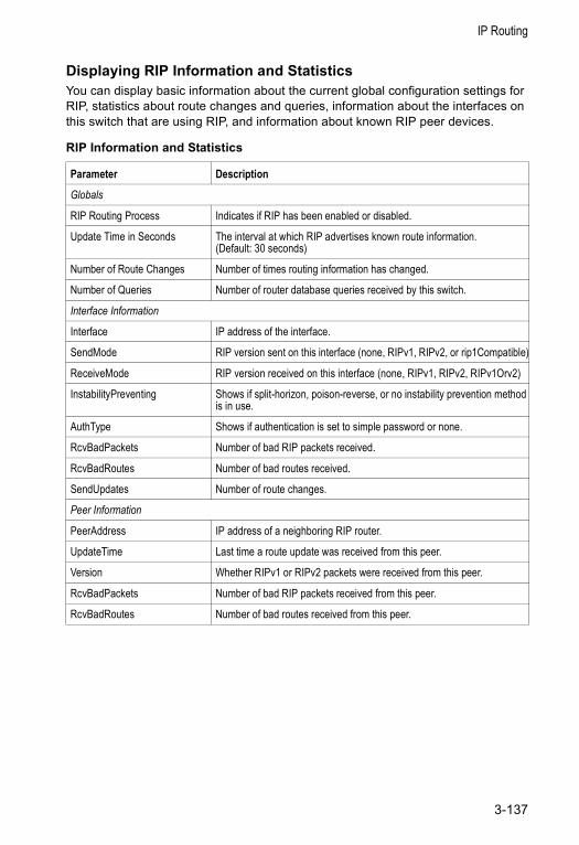
IP Routing
Displaying RIP Information and StatisticsYou can display basic information about the current global configuration settings for RIP, statistics about route changes and queries, information about the interfaces on this switch that are using RIP, and information about known RIP peer devices.
RIP Information and Statistics
Parameter Description
Globals
RIP Routing Process Indicates if RIP has been enabled or disabled.
Update Time in Seconds The interval at which RIP advertises known route information. (Default: 30 seconds)
Number of Route Changes Number of times routing information has changed.
Number of Queries Number of router database queries received by this switch.
Interface Information
Interface IP address of the interface.
SendMode RIP version sent on this interface (none, RIPv1, RIPv2, or rip1Compatible)
ReceiveMode RIP version received on this interface (none, RIPv1, RIPv2, RIPv1Orv2)
InstabilityPreventing Shows if split-horizon, poison-reverse, or no instability prevention method is in use.
AuthType Shows if authentication is set to simple password or none.
RcvBadPackets Number of bad RIP packets received.
RcvBadRoutes Number of bad routes received.
SendUpdates Number of route changes.
Peer Information
PeerAddress IP address of a neighboring RIP router.
UpdateTime Last time a route update was received from this peer.
Version Whether RIPv1 or RIPv2 packets were received from this peer.
RcvBadPackets Number of bad RIP packets received from this peer.
RcvBadRoutes Number of bad routes received from this peer.
3-137
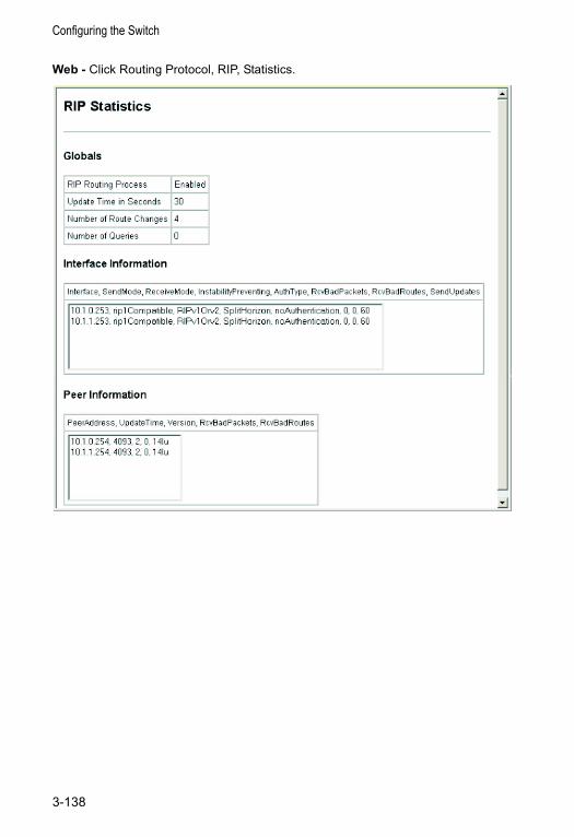
Configuring the Switch
Web - Click Routing Protocol, RIP, Statistics.
3-138
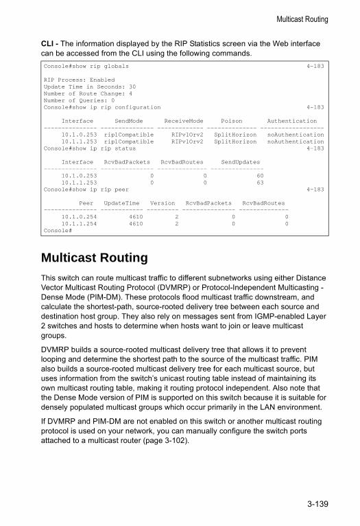
Multicast Routing
CLI - The information displayed by the RIP Statistics screen via the Web interface can be accessed from the CLI using the following commands.
Multicast RoutingThis switch can route multicast traffic to different subnetworks using either Distance Vector Multicast Routing Protocol (DVMRP) or Protocol-Independent Multicasting - Dense Mode (PIM-DM). These protocols flood multicast traffic downstream, and calculate the shortest-path, source-rooted delivery tree between each source and destination host group. They also rely on messages sent from IGMP-enabled Layer 2 switches and hosts to determine when hosts want to join or leave multicast groups.
DVMRP builds a source-rooted multicast delivery tree that allows it to prevent looping and determine the shortest path to the source of the multicast traffic. PIM also builds a source-rooted multicast delivery tree for each multicast source, but uses information from the switch’s unicast routing table instead of maintaining its own multicast routing table, making it routing protocol independent. Also note that the Dense Mode version of PIM is supported on this switch because it is suitable for densely populated multicast groups which occur primarily in the LAN environment.
If DVMRP and PIM-DM are not enabled on this switch or another multicast routing protocol is used on your network, you can manually configure the switch ports attached to a multicast router (page 3-102).
Console#show rip globals 4-183
RIP Process: EnabledUpdate Time in Seconds: 30Number of Route Change: 4Number of Queries: 0Console#show ip rip configuration 4-183
Interface SendMode ReceiveMode Poison Authentication--------------- --------------- ------------- -------------- ------------------
10.1.0.253 rip1Compatible RIPv1Orv2 SplitHorizon noAuthentication10.1.1.253 rip1Compatible RIPv1Orv2 SplitHorizon noAuthentication
Console#show ip rip status 4-183
Interface RcvBadPackets RcvBadRoutes SendUpdates--------------- --------------- -------------- ---------------
10.1.0.253 0 0 6010.1.1.253 0 0 63
Console#show ip rip peer 4-183
Peer UpdateTime Version RcvBadPackets RcvBadRoutes--------------- ------------ --------- --------------- --------------
10.1.0.254 4610 2 0 010.1.1.254 4610 2 0 0
Console#
3-139

Configuring the Switch
Configuring Global Settings for Multicast RoutingTo use multicast routing on this switch, you must first globally enable multicast routing as described in this section, globally enable DVRMP (page 3-142) or PIM (page 3-148), and specify the interfaces that will participate (page 3-144 or 3-149). Note that you can only enable one multicast routing protocol on any given interface.
Web – Click IP, Multicast Routing, General Setting. Set Multicast Forwarding Status to Enabled, and click Apply.
CLI – This example enables multicast routing globally for the switch.
Displaying the Multicast Routing TableYou can display information on each multicast route this switch has learned via DVMRP or PIM. The switch learns multicast routes from neighboring routers, and also advertises these routes to its neighbors. The switch stores entries for all paths learned by itself or from other routers, without considering actual group membership or prune messages. The routing table therefore does not indicate that the switch has processed multicast traffic from any particular source listed in the table. It uses these routes to forward multicast traffic only if group members appear on directly-attached subnetworks or on subnetworks attached to downstream routers.
Field Attributes• Group Address – IP group address for a multicast service.• Source Address – Subnetwork containing the IP multicast source.• Netmask – Network mask for the IP multicast source.• Interface – Interface leading to the upstream neighbor.• Owner – The associated multicast protocol (i.e., DVMRP or PIM).• Flags – The flags associated with each interface indicate prune (P) if the
downstream interface has been recently terminated or forwarding (F) if the interface is still active.
• Detail – This button displays detailed information for the selected entry.• Upstream Router* – The multicast router immediately upstream for this group.• Downstream* – Interface(s) on which multicast subscribers have been recorded. * These items are displayed in the IP Multicast Routing Entry (Detail) table.
Console(config)#ip multicast-routing 4-186Console(config)#
3-140
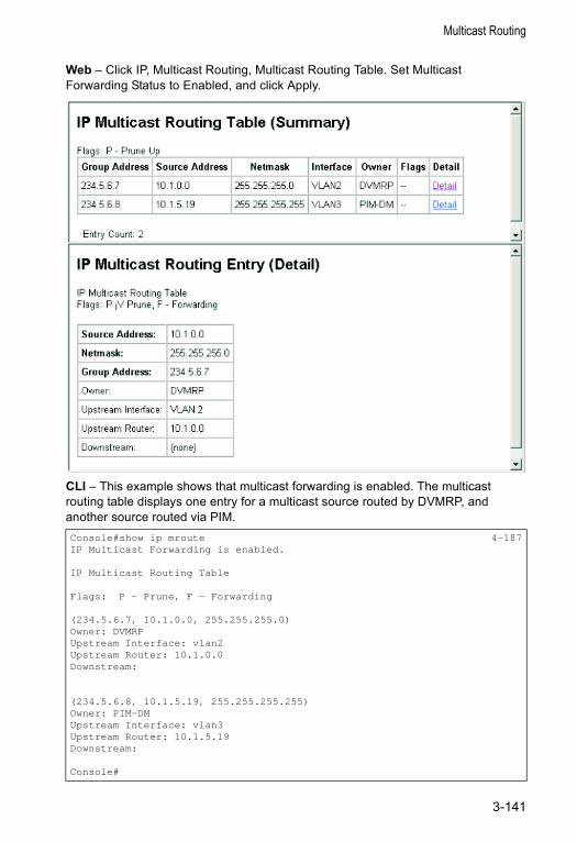
Multicast Routing
Web – Click IP, Multicast Routing, Multicast Routing Table. Set Multicast Forwarding Status to Enabled, and click Apply.
CLI – This example shows that multicast forwarding is enabled. The multicast routing table displays one entry for a multicast source routed by DVMRP, and another source routed via PIM.Console#show ip mroute 4-187IP Multicast Forwarding is enabled.
IP Multicast Routing Table
Flags: P - Prune, F - Forwarding
(234.5.6.7, 10.1.0.0, 255.255.255.0)Owner: DVMRPUpstream Interface: vlan2Upstream Router: 10.1.0.0Downstream:
(234.5.6.8, 10.1.5.19, 255.255.255.255)Owner: PIM-DMUpstream Interface: vlan3Upstream Router: 10.1.5.19Downstream:
Console#
3-141
Configuring the Switch
Configuring DVMRPThe Distance-Vector Multicast Routing Protocol (DVMRP) behaves somewhat similarly to RIP. A router supporting DVMRP periodically floods its attached networks to pass information about supported multicast services along to new routers and hosts. Routers that receive a DVMRP packet send a copy out to all paths (except the path back to the origin). These routers then send a prune message back to the source to stop a data stream if the router is attached to a LAN which does not want to receive traffic from a particular multicast group. However, if a host attached to this routing switch issues an IGMP message indicating that it wants to subscribe to the concerned multicast service, this switch will use DVMRP to build up a source-rooted multicast delivery tree that allows it to prevent looping and determine the shortest path to the source of this multicast traffic.
When this switch receives the multicast message, it checks its unicast routing table to locate the port that provides the shortest path back to the source. If that path passes through the same port on which the multicast message was received, then this switch records path information for the concerned multicast group in its routing table and forwards the multicast message on to adjacent routers, except for the port through which the message arrived. This process eliminates potential loops from the tree and ensures that the shortest path (in terms of hop count) is always used.
Configuring Global DVMRP SettingsDVMRP is used to route multicast traffic to nodes which have requested a specific multicast service via IGMP. This switch uses Reverse Path Forwarding (RPF) to build a shortest-path delivery tree that begins at the source and spreads out to reach group members through the network. RPF uses three different techniques to dynamically reconfigure the multicast spanning tree: broadcasting, pruning, and grafting.
Command Usage
Broadcasting periodically floods the network with traffic from any active multicast server. If IGMP snooping is disabled, multicast traffic is flooded to all ports on the switch. However, if IGMP snooping is enabled, then the first packet for any source group pair is flooded to all DVMRP downstream neighbors. If a packet is received through an interface that the switch determines to be the shortest path back to the source (based on interface metrics), then the switch forwards the packet on all interfaces except for the incoming interface.
The switch will transmit a prune message back out the receiving interface (i.e., the parent interface) to its upstream neighboring router if there are no group members on its child interfaces. A prune message tells the upstream router to stop forwarding packets for a particular source-group pair for the prune lifetime.
If the switch that previously sent a prune message now discovers a new group member on one of its connections, it sends a graft message to the upstream router. When an upstream router receives this message, it cancels the prune message. If
3-142
Multicast Routing
necessary, graft messages are propagated back toward the source until reaching the nearest live branch in the multicast tree.
The global settings that control the prune and graft messages (i.e., prune lifetime) should be configured to the same values on all switches throughout the network to allow DVMRP to function properly. However, if you encounter problems in maintaining a multicast flow, then you may need to modify the protocol variables which control the exchange of topology information between DVMRP routers; such as the probe interval, neighbor timeout or report interval.
Command Attributes• DVMRP Protocol – Enables/disables DVMRP globally. (Default: Disabled)• Probe Interval – Sets the interval for sending neighbor probe messages to the
multicast group address for all DVMRP routers. Probe messages are sent to neighboring DVMRP routers from which this device has received probes, and is used to verify whether or not these neighbors are still active members of the multicast tree. (Range: 1-65535 seconds; Default: 10 seconds)
• Neighbor Timeout Interval – Sets the interval to wait for messages from a DVMRP neighbor before declaring it dead. This command is used for timing out routes, and for setting the children and leaf flags. (Range: 1-65535 seconds; Default: 35 seconds)
• Report Interval – Specifies how often to propagate the complete set of routing tables to other neighbor DVMRP routers. (Range: 1-65535 seconds; Default: 60 seconds)
• Flash Update Interval – Specifies how often to send trigger updates, which reflect changes in the network topology.
• Prune Lifetime – Specifies how long a prune state will remain in effect for a multicast tree. (Range: 1-65535; Default: 7200 seconds)
• Default Gateway* – Specifies the default DVMRP gateway for IP multicast traffic. (Default: none)- The specified interface advertises itself as a default route to neighboring
DVMRP routers. It advertises the default route out through its other interfaces. Neighboring routers on the other interfaces return Poison Reverse messages for the default route back to the switch. When the switch receives these messages, it records all the downstream routers for the default route.
- When multicast traffic with an unknown source address (i.e., not found in the route table) is received on the default upstream route interface, the switch forwards this traffic out through the other interfaces (with known downstream routers). However, when multicast traffic with an unknown source address is received on another interface, the switch drops it because only the default upstream interface can forward multicast traffic from an unknown source.
* CLI only.
3-143
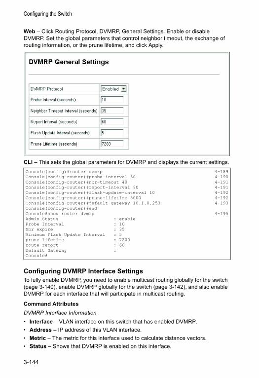
Configuring the Switch
Web – Click Routing Protocol, DVMRP, General Settings. Enable or disable DVMRP. Set the global parameters that control neighbor timeout, the exchange of routing information, or the prune lifetime, and click Apply.
CLI – This sets the global parameters for DVMRP and displays the current settings.
Configuring DVMRP Interface SettingsTo fully enable DVMRP, you need to enable multicast routing globally for the switch (page 3-140), enable DVMRP globally for the switch (page 3-142), and also enable DVMRP for each interface that will participate in multicast routing.
Command AttributesDVMRP Interface Information• Interface – VLAN interface on this switch that has enabled DVMRP.• Address – IP address of this VLAN interface.• Metric – The metric for this interface used to calculate distance vectors.• Status – Shows that DVMRP is enabled on this interface.
Console(config)#router dvmrp 4-189Console(config-router)#probe-interval 30 4-190Console(config-router)#nbr-timeout 40 4-191Console(config-router)#report-interval 90 4-191Console(config-router)#flash-update-interval 10 4-192Console(config-router)#prune-lifetime 5000 4-192Console(config-router)#default-gateway 10.1.0.253 4-193Console(config-router)#endConsole#show router dvmrp 4-195Admin Status : enableProbe Interval : 10Nbr expire : 35Minimum Flash Update Interval : 5prune lifetime : 7200route report : 60Default Gateway :Console#
3-144

Multicast Routing
DVMRP Interface Settings• VLAN – Selects a VLAN interface on this switch. • Metric – Sets the metric for this interface used to calculate distance vectors.• Status – Enables or disables DVMRP.
- If DVMRP is enabled on any interface, Layer 3 IGMP should also be enabled on the switch (page 3-106).
- If DVMRP is disabled, the interface cannot propagate IP multicast routing information. However, as long as IGMP snooping is enabled, the interface will still forward multicast traffic to downstream group members within the VLAN. But if IGMP snooping is disabled, then the interface will flood incoming multicast traffic to all ports in the attached VLAN.
Web – Click Routing Protocol, DVMRP, Interface Settings. Select a VLAN from the drop-down box under DVMRP Interface Settings, modify the Metric if required, set the Status to Enabled or Disabled, and click Apply.
CLI – This example enables DVMRP and sets the metric for VLAN 1.Console(config)#interface vlan 1 4-89Console(config-if)#ip dvmrp 4-193Console(config-if)#ip dvmrp metric 2 4-194Console(config-if)#endConsole#show ip dvmrp interface 4-197Vlan 1 is up
DVMRP is enabledMetric is 2
Console#
3-145
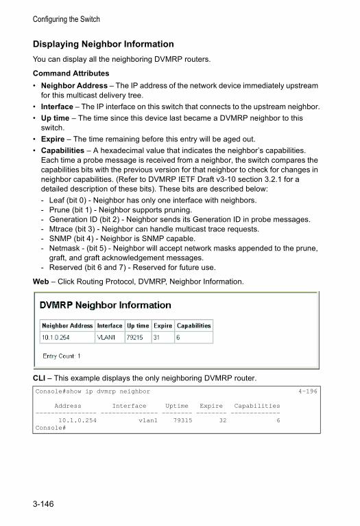
Configuring the Switch
Displaying Neighbor InformationYou can display all the neighboring DVMRP routers.
Command Attributes• Neighbor Address – The IP address of the network device immediately upstream
for this multicast delivery tree.• Interface – The IP interface on this switch that connects to the upstream neighbor.• Up time – The time since this device last became a DVMRP neighbor to this
switch.• Expire – The time remaining before this entry will be aged out.• Capabilities – A hexadecimal value that indicates the neighbor’s capabilities.
Each time a probe message is received from a neighbor, the switch compares the capabilities bits with the previous version for that neighbor to check for changes in neighbor capabilities. (Refer to DVMRP IETF Draft v3-10 section 3.2.1 for a detailed description of these bits). These bits are described below:- Leaf (bit 0) - Neighbor has only one interface with neighbors. - Prune (bit 1) - Neighbor supports pruning. - Generation ID (bit 2) - Neighbor sends its Generation ID in probe messages. - Mtrace (bit 3) - Neighbor can handle multicast trace requests.- SNMP (bit 4) - Neighbor is SNMP capable.- Netmask - (bit 5) - Neighbor will accept network masks appended to the prune,
graft, and graft acknowledgement messages.- Reserved (bit 6 and 7) - Reserved for future use.
Web – Click Routing Protocol, DVMRP, Neighbor Information.
CLI – This example displays the only neighboring DVMRP router.Console#show ip dvmrp neighbor 4-196
Address Interface Uptime Expire Capabilities---------------- --------------- -------- -------- -------------
10.1.0.254 vlan1 79315 32 6Console#
3-146
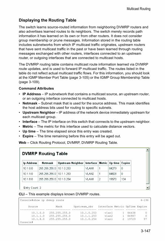
Multicast Routing
Displaying the Routing TableThe switch learns source-routed information from neighboring DVMRP routers and also advertises learned routes to its neighbors. The switch merely records path information it has learned on its own or from other routers. It does not consider group membership or prune messages. Information stored in the routing table includes subnetworks from which IP multicast traffic originates, upstream routers that have sent multicast traffic in the past or have been learned through routing messages exchanged with other routers, interfaces connected to an upstream router, or outgoing interfaces that are connected to multicast hosts.
The DVMRP routing table contains multicast route information learned via DVMRP route updates, and is used to forward IP multicast traffic. The routes listed in the table do not reflect actual multicast traffic flows. For this information, you should look at the IGMP Member Port Table (page 3-105) or the IGMP Group Membership Table (page 3-109).
Command Attributes• IP Address – IP subnetwork that contains a multicast source, an upstream router,
or an outgoing interface connected to multicast hosts. • Netmask – Subnet mask that is used for the source address. This mask identifies
the host address bits used for routing to specific subnets.• Upstream Neighbor – IP address of the network device immediately upstream for
each multicast group.• Interface – The IP interface on this switch that connects to the upstream neighbor.• Metric – The metric for this interface used to calculate distance vectors.• Up time – The time elapsed since this entry was created.• Expire – The time remaining before this entry will be aged out.
Web – Click Routing Protocol, DVMRP, DVMRP Routing Table.
CLI – This example displays known DVMRP routes.Console#show ip dvmrp route 4-196
Source Mask Upstream_nbr Interface Metric UpTime Expire--------------- --------------- --------------- --------- ------ ------ ------
10.1.0.0 255.255.255.0 10.1.0.253 vlan1 1 84438 010.1.1.0 255.255.255.0 10.1.1.253 vlan2 1 84987 010.1.8.0 255.255.255.0 10.1.0.254 vlan1 2 19729 97
Console#
3-147
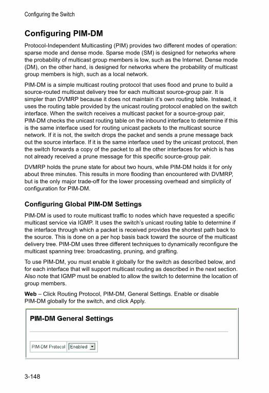
Configuring the Switch
Configuring PIM-DMProtocol-Independent Multicasting (PIM) provides two different modes of operation: sparse mode and dense mode. Sparse mode (SM) is designed for networks where the probability of multicast group members is low, such as the Internet. Dense mode (DM), on the other hand, is designed for networks where the probability of multicast group members is high, such as a local network.
PIM-DM is a simple multicast routing protocol that uses flood and prune to build a source-routed multicast delivery tree for each multicast source-group pair. It is simpler than DVMRP because it does not maintain it’s own routing table. Instead, it uses the routing table provided by the unicast routing protocol enabled on the switch interface. When the switch receives a multicast packet for a source-group pair, PIM-DM checks the unicast routing table on the inbound interface to determine if this is the same interface used for routing unicast packets to the multicast source network. If it is not, the switch drops the packet and sends a prune message back out the source interface. If it is the same interface used by the unicast protocol, then the switch forwards a copy of the packet to all the other interfaces for which is has not already received a prune message for this specific source-group pair.
DVMRP holds the prune state for about two hours, while PIM-DM holds it for only about three minutes. This results in more flooding than encountered with DVMRP, but is the only major trade-off for the lower processing overhead and simplicity of configuration for PIM-DM.
Configuring Global PIM-DM SettingsPIM-DM is used to route multicast traffic to nodes which have requested a specific multicast service via IGMP. It uses the switch’s unicast routing table to determine if the interface through which a packet is received provides the shortest path back to the source. This is done on a per hop basis back toward the source of the multicast delivery tree. PIM-DM uses three different techniques to dynamically reconfigure the multicast spanning tree: broadcasting, pruning, and grafting.
To use PIM-DM, you must enable it globally for the switch as described below, and for each interface that will support multicast routing as described in the next section. Also note that IGMP must be enabled to allow the switch to determine the location of group members.
Web – Click Routing Protocol, PIM-DM, General Settings. Enable or disable PIM-DM globally for the switch, and click Apply.
3-148
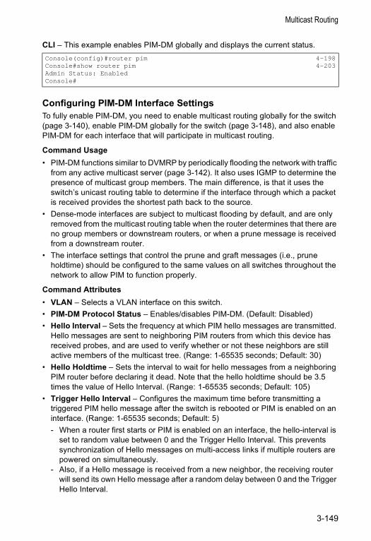
Multicast Routing
CLI – This example enables PIM-DM globally and displays the current status.
Configuring PIM-DM Interface SettingsTo fully enable PIM-DM, you need to enable multicast routing globally for the switch (page 3-140), enable PIM-DM globally for the switch (page 3-148), and also enable PIM-DM for each interface that will participate in multicast routing.
Command Usage• PIM-DM functions similar to DVMRP by periodically flooding the network with traffic
from any active multicast server (page 3-142). It also uses IGMP to determine the presence of multicast group members. The main difference, is that it uses the switch’s unicast routing table to determine if the interface through which a packet is received provides the shortest path back to the source.
• Dense-mode interfaces are subject to multicast flooding by default, and are only removed from the multicast routing table when the router determines that there are no group members or downstream routers, or when a prune message is received from a downstream router.
• The interface settings that control the prune and graft messages (i.e., prune holdtime) should be configured to the same values on all switches throughout the network to allow PIM to function properly.
Command Attributes• VLAN – Selects a VLAN interface on this switch.• PIM-DM Protocol Status – Enables/disables PIM-DM. (Default: Disabled)• Hello Interval – Sets the frequency at which PIM hello messages are transmitted.
Hello messages are sent to neighboring PIM routers from which this device has received probes, and are used to verify whether or not these neighbors are still active members of the multicast tree. (Range: 1-65535 seconds; Default: 30)
• Hello Holdtime – Sets the interval to wait for hello messages from a neighboring PIM router before declaring it dead. Note that the hello holdtime should be 3.5 times the value of Hello Interval. (Range: 1-65535 seconds; Default: 105)
• Trigger Hello Interval – Configures the maximum time before transmitting a triggered PIM hello message after the switch is rebooted or PIM is enabled on an interface. (Range: 1-65535 seconds; Default: 5)- When a router first starts or PIM is enabled on an interface, the hello-interval is
set to random value between 0 and the Trigger Hello Interval. This prevents synchronization of Hello messages on multi-access links if multiple routers are powered on simultaneously.
- Also, if a Hello message is received from a new neighbor, the receiving router will send its own Hello message after a random delay between 0 and the Trigger Hello Interval.
Console(config)#router pim 4-198Console#show router pim 4-203Admin Status: EnabledConsole#
3-149
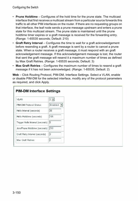
Configuring the Switch
• Prune Holdtime – Configures of the hold time for the prune state. The multicast interface that first receives a multicast stream from a particular source forwards this traffic to all other PIM interfaces on the router. If there are no requesting groups on that interface, the leaf node sends a prune message upstream and enters a prune state for this multicast stream. The prune state is maintained until the prune holdtime timer expires or a graft message is received for the forwarding entry. (Range: 1-65535 seconds; Default: 210)
• Graft Retry Interval – Configures the time to wait for a graft acknowledgement before resending a graft. A graft message is sent by a router to cancel a prune state. When a router receives a graft message, it must respond with an graft acknowledgement message. If this acknowledgement message is lost, the router that sent the graft message will resend it a maximum number of times as defined by Max Graft Retries. (Range: 1-65535 seconds; Default: 3)
• Max Graft Retries – Configures the maximum number of times to resend a graft message if it has not been acknowledged. (Range: 1-65535; Default: 2)
Web – Click Routing Protocol, PIM-DM, Interface Settings. Select a VLAN, enable or disable PIM-DM for the selected interface, modify any of the protocol parameters as required, and click Apply.
3-150
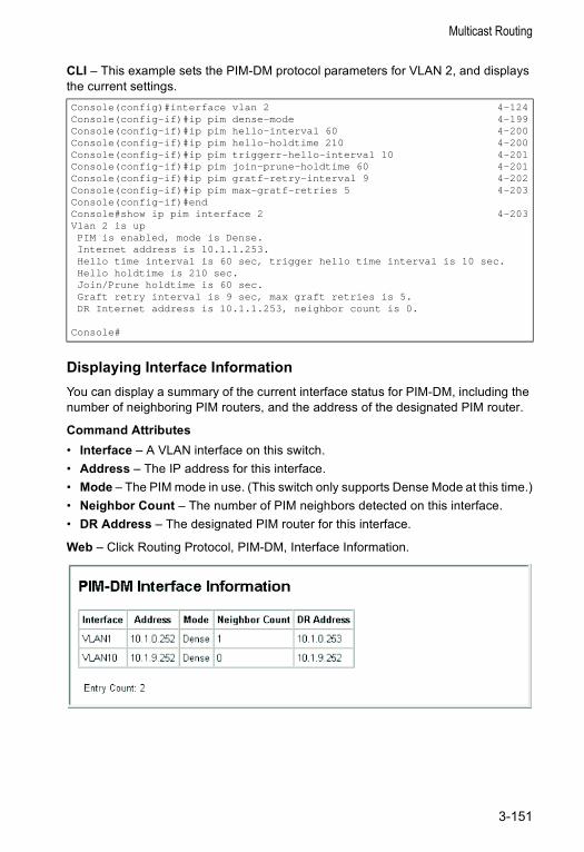
Multicast Routing
CLI – This example sets the PIM-DM protocol parameters for VLAN 2, and displays the current settings.
Displaying Interface InformationYou can display a summary of the current interface status for PIM-DM, including the number of neighboring PIM routers, and the address of the designated PIM router.
Command Attributes• Interface – A VLAN interface on this switch.• Address – The IP address for this interface.• Mode – The PIM mode in use. (This switch only supports Dense Mode at this time.)• Neighbor Count – The number of PIM neighbors detected on this interface.• DR Address – The designated PIM router for this interface.
Web – Click Routing Protocol, PIM-DM, Interface Information.
Console(config)#interface vlan 2 4-124Console(config-if)#ip pim dense-mode 4-199Console(config-if)#ip pim hello-interval 60 4-200Console(config-if)#ip pim hello-holdtime 210 4-200Console(config-if)#ip pim triggerr-hello-interval 10 4-201Console(config-if)#ip pim join-prune-holdtime 60 4-201Console(config-if)#ip pim gratf-retry-interval 9 4-202Console(config-if)#ip pim max-gratf-retries 5 4-203Console(config-if)#endConsole#show ip pim interface 2 4-203Vlan 2 is upPIM is enabled, mode is Dense.Internet address is 10.1.1.253.Hello time interval is 60 sec, trigger hello time interval is 10 sec.Hello holdtime is 210 sec.Join/Prune holdtime is 60 sec.Graft retry interval is 9 sec, max graft retries is 5.DR Internet address is 10.1.1.253, neighbor count is 0.
Console#
3-151
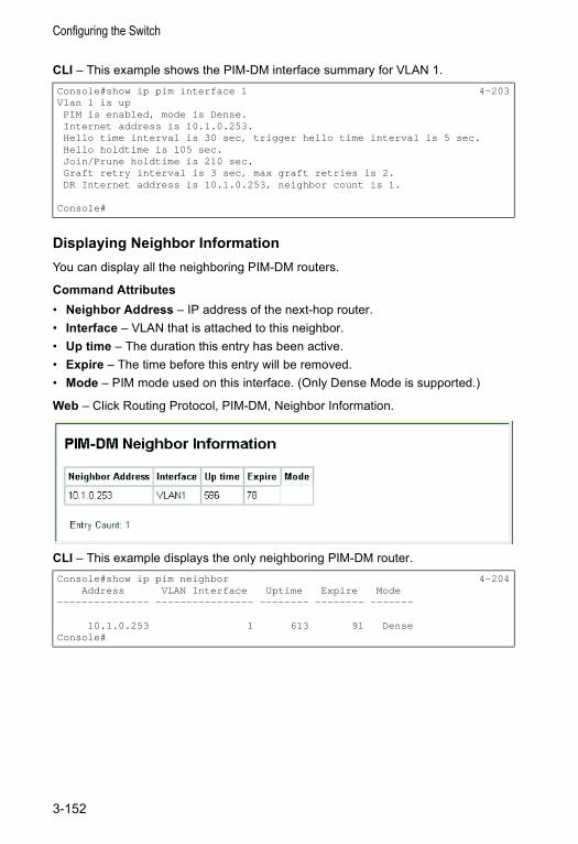
Configuring the Switch
CLI – This example shows the PIM-DM interface summary for VLAN 1.
Displaying Neighbor InformationYou can display all the neighboring PIM-DM routers.
Command Attributes• Neighbor Address – IP address of the next-hop router.• Interface – VLAN that is attached to this neighbor.• Up time – The duration this entry has been active.• Expire – The time before this entry will be removed.• Mode – PIM mode used on this interface. (Only Dense Mode is supported.)
Web – Click Routing Protocol, PIM-DM, Neighbor Information.
CLI – This example displays the only neighboring PIM-DM router.
Console#show ip pim interface 1 4-203Vlan 1 is upPIM is enabled, mode is Dense.Internet address is 10.1.0.253.Hello time interval is 30 sec, trigger hello time interval is 5 sec.Hello holdtime is 105 sec.Join/Prune holdtime is 210 sec.Graft retry interval is 3 sec, max graft retries is 2.DR Internet address is 10.1.0.253, neighbor count is 1.
Console#
Console#show ip pim neighbor 4-204Address VLAN Interface Uptime Expire Mode
--------------- ---------------- -------- -------- -------
10.1.0.253 1 613 91 DenseConsole#
3-152
Chapter 4: Command Line InterfaceThis chapter describes how to use the Command Line Interface (CLI).
Using the Command Line Interface
Accessing the CLIWhen accessing the management interface for the switch over a direct connection to the server’s console port, or via a Telnet connection, the switch can be managed by entering command keywords and parameters at the prompt. Using the switch's command-line interface (CLI) is very similar to entering commands on a UNIX system.
Console ConnectionTo access the switch through the console port, perform these steps:
1. At the console prompt, enter the user name and password. (The default user names are “admin” and “guest” with corresponding passwords of “admin” and “guest.”) When the administrator user name and password is entered, the CLI displays the “Console#” prompt and enters privileged access mode (i.e., Privileged Exec). But when the guest user name and password is entered, the CLI displays the “Console>” prompt and enters normal access mode (i.e., Normal Exec).
2. Enter the necessary commands to complete your desired tasks.
3. When finished, exit the session with the “quit” or “exit” command.
After connecting to the system through the console port, the login screen displays:
User Access Verification
Username: adminPassword:
CLI session with the ES3626G Intelligent Switch is opened.To end the CLI session, enter [Exit].
Console#
4-1
Command Line Interface
Telnet ConnectionTelnet operates over the IP transport protocol. In this environment, your management station and any network device you want to manage over the network must have a valid IP address. Valid IP addresses consist of four numbers, 0 to 255, separated by periods. Each address consists of a network portion and host portion. For example, the IP address assigned to this switch, 10.1.0.1, consists of a network portion (10.1.0) and a host portion (1).
Note: The IP address for this switch is unassigned by default.
To access the switch through a Telnet session, you must first set the IP address for the switch, and set the default gateway if you are managing the switch from a different IP subnet. For example,
If your corporate network is connected to another network outside your office or to the Internet, you need to apply for a registered IP address. However, if you are attached to an isolated network, then you can use any IP address that matches the network segment to which you are attached.
After you configure the switch with an IP address, you can open a Telnet session by performing these steps:
1. From the remote host, enter the Telnet command and the IP address of the device you want to access.
2. At the prompt, enter the user name and system password. The CLI will display the “Vty-0#” prompt for the administrator to show that you are using privileged access mode (i.e., Privileged Exec), or “Vty-0>” for the guest to show that you are using normal access mode (i.e., Normal Exec).
3. Enter the necessary commands to complete your desired tasks.
4. When finished, exit the session with the “quit” or “exit” command.
After entering the Telnet command, the login screen displays:
Note: You can open up to four sessions to the device via Telnet.
Console(config)#interface vlan 1Console(config-if)#ip address 10.1.0.254 255.255.255.0Console(config-if)#exitConsole(config)#ip default-gateway 10.1.0.254
Username: adminPassword:
CLI session with the ES3626G Intelligent Switch is opened.To end the CLI session, enter [Exit].
Vty-0#
4-2
Entering Commands
Entering CommandsThis section describes how to enter CLI commands.
Keywords and ArgumentsA CLI command is a series of keywords and arguments. Keywords identify a command, and arguments specify configuration parameters. For example, in the command “show interfaces status ethernet 1/5,” show interfaces and status are keywords, ethernet is an argument that specifies the interface type, and 1/5 specifies the unit/port.
You can enter commands as follows:
• To enter a simple command, enter the command keyword. • To enter multiple commands, enter each command in the required order. For
example, to enable Privileged Exec command mode, and display the startup configuration, enter:Console>enableConsole#show startup-config
• To enter commands that require parameters, enter the required parameters after the command keyword. For example, to set a password for the administrator, enter:Console(config)#username admin password 0 smith
Minimum AbbreviationThe CLI will accept a minimum number of characters that uniquely identify a command. For example, the command “configure” can be entered as con. If an entry is ambiguous, the system will prompt for further input.
Command CompletionIf you terminate input with a Tab key, the CLI will print the remaining characters of a partial keyword up to the point of ambiguity. In the “logging history” example, typing log followed by a tab will result in printing the command up to “logging.”
Getting Help on CommandsYou can display a brief description of the help system by entering the help command. You can also display command syntax by using the “?” character to list keywords or parameters.
4-3
Command Line Interface
Showing CommandsIf you enter a “?” at the command prompt, the system will display the first level of keywords for the current command class (Normal Exec or Privileged Exec) or configuration class (Global, ACL, DHCP, Interface, Line, Router or VLAN Database). You can also display a list of valid keywords for a specific command. For example, the command “show ?” displays a list of possible show commands:
The command “show interfaces ?” will display the following information:
Partial Keyword LookupIf you terminate a partial keyword with a question mark, alternatives that match the initial letters are provided. (Remember not to leave a space between the command and question mark.) For example “s?” shows all the keywords starting with “s.”
Console#show ? access-group Access groups access-list Access lists arp Information of arp cache bridge-ext Bridge extend information garp Garp property gvrp Show GVRP information of interface history Information of history interfaces Information of interfaces ip IP information line TTY line information logging Show the contents of logging buffers mac MAC access lists mac-address-table Set configuration of the address table map Map priority port Characteristics of the port pvlan Information of private VLAN queue Information of priority queue radius-server RADIUS server information rip Rip router Router running-config The system configuration of running snmp SNMP statistics sntp Sntp spanning-tree Specify spanning-tree startup-config The system configuration of starting up system Information of system users Display information about terminal lines version System hardware and software status vlan Switch VLAN Virtual InterfaceConsole#show
Console>show interfaces ?counters Information of interfaces countersstatus Information of interfaces statusswitchport Information of interfaces switchport
Console#show s?snmp startup-config system
4-4
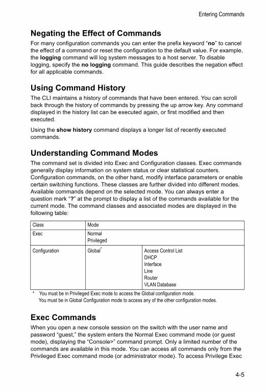
Entering Commands
Negating the Effect of CommandsFor many configuration commands you can enter the prefix keyword “no” to cancel the effect of a command or reset the configuration to the default value. For example, the logging command will log system messages to a host server. To disable logging, specify the no logging command. This guide describes the negation effect for all applicable commands.
Using Command HistoryThe CLI maintains a history of commands that have been entered. You can scroll back through the history of commands by pressing the up arrow key. Any command displayed in the history list can be executed again, or first modified and then executed.
Using the show history command displays a longer list of recently executed commands.
Understanding Command ModesThe command set is divided into Exec and Configuration classes. Exec commands generally display information on system status or clear statistical counters. Configuration commands, on the other hand, modify interface parameters or enable certain switching functions. These classes are further divided into different modes. Available commands depend on the selected mode. You can always enter a question mark “?” at the prompt to display a list of the commands available for the current mode. The command classes and associated modes are displayed in the following table:
Exec CommandsWhen you open a new console session on the switch with the user name and password “guest,” the system enters the Normal Exec command mode (or guest mode), displaying the “Console>” command prompt. Only a limited number of the commands are available in this mode. You can access all commands only from the Privileged Exec command mode (or administrator mode). To access Privilege Exec
Class ModeExec Normal
Privileged
Configuration Global* Access Control ListDHCPInterfaceLineRouterVLAN Database
* You must be in Privileged Exec mode to access the Global configuration mode. You must be in Global Configuration mode to access any of the other configuration modes.
4-5
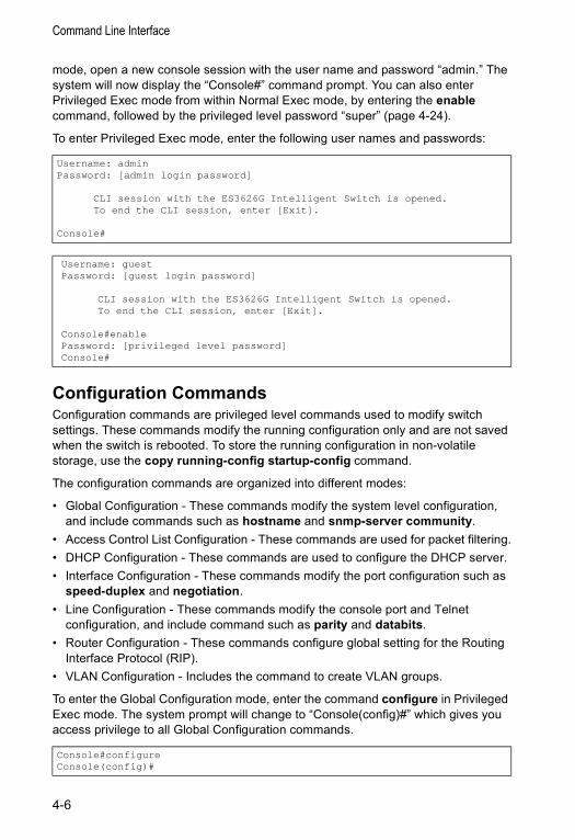
Command Line Interface
mode, open a new console session with the user name and password “admin.” The system will now display the “Console#” command prompt. You can also enter Privileged Exec mode from within Normal Exec mode, by entering the enable command, followed by the privileged level password “super” (page 4-24).
To enter Privileged Exec mode, enter the following user names and passwords:
Configuration CommandsConfiguration commands are privileged level commands used to modify switch settings. These commands modify the running configuration only and are not saved when the switch is rebooted. To store the running configuration in non-volatile storage, use the copy running-config startup-config command.
The configuration commands are organized into different modes:
• Global Configuration - These commands modify the system level configuration, and include commands such as hostname and snmp-server community.
• Access Control List Configuration - These commands are used for packet filtering.• DHCP Configuration - These commands are used to configure the DHCP server.• Interface Configuration - These commands modify the port configuration such as
speed-duplex and negotiation. • Line Configuration - These commands modify the console port and Telnet
configuration, and include command such as parity and databits.• Router Configuration - These commands configure global setting for the Routing
Interface Protocol (RIP).• VLAN Configuration - Includes the command to create VLAN groups.
To enter the Global Configuration mode, enter the command configure in Privileged Exec mode. The system prompt will change to “Console(config)#” which gives you access privilege to all Global Configuration commands.
Username: adminPassword: [admin login password]
CLI session with the ES3626G Intelligent Switch is opened.To end the CLI session, enter [Exit].
Console#
Username: guestPassword: [guest login password]
CLI session with the ES3626G Intelligent Switch is opened.To end the CLI session, enter [Exit].
Console#enablePassword: [privileged level password]Console#
Console#configureConsole(config)#
4-6
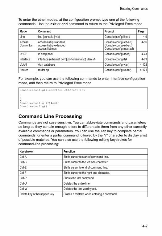
Entering Commands
To enter the other modes, at the configuration prompt type one of the following commands. Use the exit or end command to return to the Privileged Exec mode.
For example, you can use the following commands to enter interface configuration mode, and then return to Privileged Exec mode
Command Line ProcessingCommands are not case sensitive. You can abbreviate commands and parameters as long as they contain enough letters to differentiate them from any other currently available commands or parameters. You can use the Tab key to complete partial commands, or enter a partial command followed by the “?” character to display a list of possible matches. You can also use the following editing keystrokes for command-line processing:
Mode Command Prompt PageLine line {console | vty} Console(config-line)# 4-9Access Control List
access-list ip standardaccess-list ip extendedaccess-list mac
Console(config-std-acl)Console(config-ext-acl)Console(config-mac-acl)
4-56
DHCP ip dhcp pool Console(config-dhcp) 4-73Interface interface {ethernet port | port-channel id| vlan id} Console(config-if)# 4-89VLAN vlan database Console(config-vlan) 4-122Router router rip Console(config-router) 4-171
Console(config)#interface ethernet 1/5...Console(config-if)#exitConsole(config)#
Keystroke FunctionCtrl-A Shifts cursor to start of command line. Ctrl-B Shifts cursor to the left one character.Ctrl-E Shifts cursor to end of command line. Ctrl-F Shifts cursor to the right one character.Ctrl-P Shows the last command.Ctrl-U Deletes the entire line. Ctrl-W Deletes the last word typed. Delete key or backspace key Erases a mistake when entering a command.
4-7
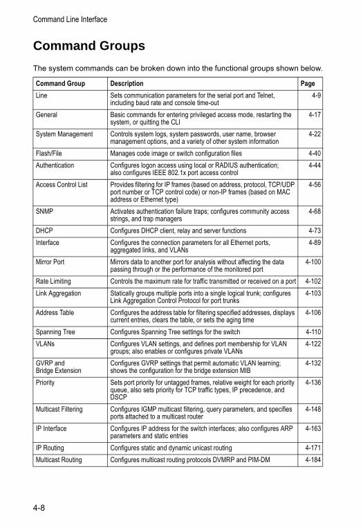
Command Line Interface
Command Groups
The system commands can be broken down into the functional groups shown below.
Command Group Description PageLine Sets communication parameters for the serial port and Telnet,
including baud rate and console time-out4-9
General Basic commands for entering privileged access mode, restarting the system, or quitting the CLI
4-17
System Management Controls system logs, system passwords, user name, browser management options, and a variety of other system information
4-22
Flash/File Manages code image or switch configuration files 4-40Authentication Configures logon access using local or RADIUS authentication;
also configures IEEE 802.1x port access control4-44
Access Control List Provides filtering for IP frames (based on address, protocol, TCP/UDP port number or TCP control code) or non-IP frames (based on MAC address or Ethernet type)
4-56
SNMP Activates authentication failure traps; configures community access strings, and trap managers
4-68
DHCP Configures DHCP client, relay and server functions 4-73Interface Configures the connection parameters for all Ethernet ports,
aggregated links, and VLANs4-89
Mirror Port Mirrors data to another port for analysis without affecting the data passing through or the performance of the monitored port
4-100
Rate Limiting Controls the maximum rate for traffic transmitted or received on a port 4-102Link Aggregation Statically groups multiple ports into a single logical trunk; configures
Link Aggregation Control Protocol for port trunks4-103
Address Table Configures the address table for filtering specified addresses, displays current entries, clears the table, or sets the aging time
4-106
Spanning Tree Configures Spanning Tree settings for the switch 4-110VLANs Configures VLAN settings, and defines port membership for VLAN
groups; also enables or configures private VLANs4-122
GVRP and Bridge Extension
Configures GVRP settings that permit automatic VLAN learning; shows the configuration for the bridge extension MIB
4-132
Priority Sets port priority for untagged frames, relative weight for each priority queue, also sets priority for TCP traffic types, IP precedence, and DSCP
4-136
Multicast Filtering Configures IGMP multicast filtering, query parameters, and specifies ports attached to a multicast router
4-148
IP Interface Configures IP address for the switch interfaces; also configures ARP parameters and static entries
4-163
IP Routing Configures static and dynamic unicast routing 4-171Multicast Routing Configures multicast routing protocols DVMRP and PIM-DM 4-184
4-8
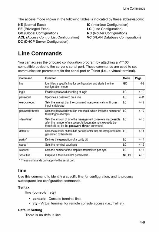
Line Commands
The access mode shown in the following tables is indicated by these abbreviations: NE (Normal Exec) IC (Interface Configuration) PE (Privileged Exec) LC (Line Configuration)GC (Global Configuration) RC (Router Configuration)ACL (Access Control List Configuration) VC (VLAN Database Configuration)DC (DHCP Server Configuration)
Line CommandsYou can access the onboard configuration program by attaching a VT100 compatible device to the server’s serial port. These commands are used to set communication parameters for the serial port or Telnet (i.e., a virtual terminal).
lineUse this command to identify a specific line for configuration, and to process subsequent line configuration commands.
Syntax line {console | vty}
• console - Console terminal line. • vty - Virtual terminal for remote console access (i.e., Telnet).
Default Setting There is no default line.
Command Function Mode Pageline Identifies a specific line for configuration and starts the line
configuration modeGC 4-9
login Enables password checking at login LC 4-10password Specifies a password on a line LC 4-11exec-timeout Sets the interval that the command interpreter waits until user
input is detectedLC 4-12
password-thresh Sets the password intrusion threshold, which limits the number of failed logon attempts
LC 4-12
silent-time* Sets the amount of time the management console is inaccessible after the number of unsuccessful logon attempts exceeds the threshold set by the password-thresh command
LC 4-13
databits* Sets the number of data bits per character that are interpreted and generated by hardware
LC 4-14
parity* Defines the generation of a parity bit LC 4-14speed* Sets the terminal baud rate LC 4-15stopbits* Sets the number of the stop bits transmitted per byte LC 4-16show line Displays a terminal line's parameters NE, PE 4-16* These commands only apply to the serial port.
4-9
Command Line Interface
Command Mode Global Configuration
Command Usage Telnet is considered a virtual terminal connection and will be shown as “Vty” in screen displays such as show users. However, the serial communication parameters (e.g., databits) do not affect Telnet connections.
Example To enter console line mode, enter the following command:
Related Commandsshow line (4-16)show users (4-38)
loginUse this command to enable password checking at login. Use the no form to disable password checking and allow connections without a password.
Syntax login [local] no login
local - Selects local password checking. Authentication is based on the user name specified with the username command.
Default Setting login local
Command Mode Line Configuration
Command Usage • There are three authentication modes provided by the switch itself at login:
- login selects authentication by a single global password as specified by the password line configuration command. When using this method, the management interface starts in Normal Exec (NE) mode.
- login local selects authentication via the user name and password specified by the username command (i.e., default setting). When using this method, the management interface starts in Normal Exec (NE) or Privileged Exec (PE) mode, depending on the user’s privilege level (0 or 15 respectively).
- no login selects no authentication. When using this method, the management interface starts in Normal Exec (NE) mode.
Console(config)#line consoleConsole(config-line)#
4-10
Line Commands
• This command controls login authentication via the switch itself. To configure user names and passwords for remote authentication servers, you must use the RADIUS software installed on those servers.
Example
Related Commandsusername (4-23)password (4-11)
passwordUse this command to specify the password for a line. Use the no form to remove the password.
Syntax password {0 | 7} passwordno password
• {0 | 7} - 0 means plain password, 7 means encrypted password• password - Character string that specifies the line password.
(Maximum length: 8 characters plain text, 32 encrypted, case sensitive)
Default Setting No password is specified.
Command Mode Line Configuration
Command Usage • When a connection is started on a line with password protection, the system
prompts for the password. If you enter the correct password, the system shows a prompt. You can use the password-thresh command to set the number of times a user can enter an incorrect password before the system terminates the line connection and returns the terminal to the idle state.
• The encrypted password is required for compatibility with legacy password settings (i.e., plain text or encrypted) when reading the configuration file during system bootup or when downloading the configuration file from a TFTP server. There is no need for you to manually configure encrypted passwords.
Example
Console(config-line)#login localConsole(config-line)#
Console(config-line)#password 0 secretConsole(config-line)#
4-11
Command Line Interface
Related Commandslogin (4-10)password-thresh (4-12)
exec-timeoutUse this command to set the interval that the system waits until user input is detected. Use the no form to restore the default.
Syntax exec-timeout [seconds]no exec-timeout
seconds - Integer that specifies the number of seconds. (Range: 0 - 65535 seconds; 0: no timeout)
Default Setting CLI: No timeoutTelnet: 10 minutes
Command Mode Line Configuration
Command Usage • If user input is detected within the timeout interval, the session is kept open;
otherwise the session is terminated.• This command applies to both the local console and Telnet connections.• The timeout for Telnet cannot be disabled.
Example To set the timeout to two minutes, enter this command:
password-threshUse this command to set the password intrusion threshold which limits the number of failed logon attempts. Use the no form to remove the threshold value.
Syntax password-thresh thresholdno password-thresh
threshold - The number of allowed password attempts. (Range: 1-120; 0: no threshold)
Default Setting The default value is three attempts.
Console(config-line)#exec-timeout 120Console(config-line)#
4-12
Line Commands
Command Mode Line Configuration
Command Usage • When the logon attempt threshold is reached, the system interface becomes
silent for a specified amount of time before allowing the next logon attempt. (Use the silent-time command to set this interval.) When this threshold is reached for Telnet, the Telnet logon interface shuts down.
• This command applies to both the local console and Telnet connections.
Example To set the password threshold to five attempts, enter this command:
Related Commandssilent-time (4-13)
silent-timeUse this command to set the amount of time the management console is inaccessible after the number of unsuccessful logon attempts exceeds the threshold set by the password-thresh command. Use the no form to remove the silent time value.
Syntax silent-time secondsno silent-time
seconds - The number of seconds to disable console response. (Range: 0-65535; 0: no silent-time)
Default Setting The default value is no silent-time.
Command Mode Line Configuration
Example To set the silent time to 60 seconds, enter this command:
Related Commands password-thresh (4-12)
Console(config-line)#password-thresh 5Console(config-line)#
Console(config-line)#silent-time 60Console(config-line)#
4-13
Command Line Interface
databitsUse this command to set the number of data bits per character that are interpreted and generated by the console port. Use the no form to restore the default value.
Syntax databits {7 | 8}no databits
• 7 - Seven data bits per character. • 8 - Eight data bits per character.
Default Setting 8 data bits per character
Command Mode Line Configuration
Command Usage The databits command can be used to mask the high bit on input from devices that generate 7 data bits with parity. If parity is being generated, specify 7 data bits per character. If no parity is required, specify 8 data bits per character.
Example To specify 7 data bits, enter this command:
Related Commands parity (4-14)
parityUse this command to define generation of a parity bit. Use the no form to restore the default setting.
Syntax parity {none | even | odd}no parity
• none - No parity • even - Even parity • odd - Odd parity
Default Setting No parity
Command Mode Line Configuration
Console(config-line)#databits 7Console(config-line)#
4-14
Line Commands
Command Usage Communication protocols provided by devices such as terminals and modems often require a specific parity bit setting.
Example To specify no parity, enter this command:
speedUse this command to set the terminal line’s baud rate. This command sets both the transmit (to terminal) and receive (from terminal) speeds. Use the no form to restore the default setting.
Syntax speed bpsno speed
bps - Baud rate in bits per second. (Options: 9600, 19200, 38400, 57600, 115200 bps)
Default Setting 9600 bps
Command Mode Line Configuration
Command Usage Set the speed to match the baud rate of the device connected to the serial port. Some baud rates available on devices connected to the port might not be supported. The system indicates if the speed you selected is not supported.
Example To specify 57600 bps, enter this command:
Console(config-line)#parity noneConsole(config-line)#
Console(config-line)#speed 57600Console(config-line)#
4-15
Command Line Interface
stopbitsUse this command to set the number of the stop bits transmitted per byte. Use the no form to restore the default setting.
Syntax stopbits {1 | 2}
• 1 - One stop bit • 2 - Two stop bits
Default Setting 1 stop bit
Command Mode Line Configuration
Example To specify 2 stop bits, enter this command:
show lineUse this command to display the terminal line’s parameters.
Syntax show line [console | vty]
• console - Console terminal line.• vty - Virtual terminal for remote console access.
Default Setting Shows all lines
Command Mode Normal Exec, Privileged Exec
Example To show all lines, enter this command:
Console(config-line)#stopbits 2Console(config-line)#
Console#show lineConsole configuration:Password threshold: 3 timesInteractive timeout: DisabledSilent time: DisabledBaudrate: 9600Databits: 8Parity: noneStopbits: 1
Vty configuration:Password threshold: 3 timesInteractive timeout: 65535
4-16
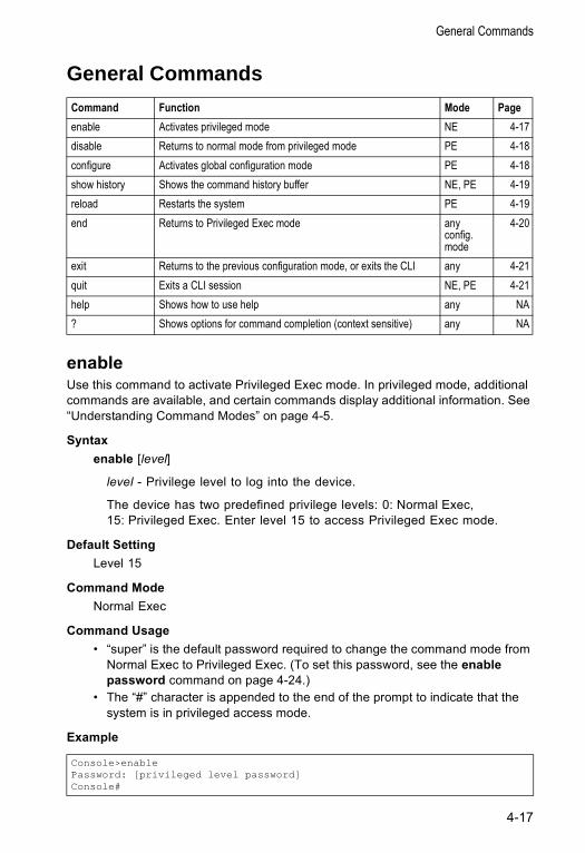
General Commands
General Commands
enableUse this command to activate Privileged Exec mode. In privileged mode, additional commands are available, and certain commands display additional information. See “Understanding Command Modes” on page 4-5.
Syntax enable [level]
level - Privilege level to log into the device.
The device has two predefined privilege levels: 0: Normal Exec, 15: Privileged Exec. Enter level 15 to access Privileged Exec mode.
Default SettingLevel 15
Command ModeNormal Exec
Command Usage • “super” is the default password required to change the command mode from
Normal Exec to Privileged Exec. (To set this password, see the enable password command on page 4-24.)
• The “#” character is appended to the end of the prompt to indicate that the system is in privileged access mode.
Example
Command Function Mode Pageenable Activates privileged mode NE 4-17disable Returns to normal mode from privileged mode PE 4-18configure Activates global configuration mode PE 4-18show history Shows the command history buffer NE, PE 4-19reload Restarts the system PE 4-19end Returns to Privileged Exec mode any
config. mode
4-20
exit Returns to the previous configuration mode, or exits the CLI any 4-21quit Exits a CLI session NE, PE 4-21help Shows how to use help any NA? Shows options for command completion (context sensitive) any NA
Console>enablePassword: [privileged level password]Console#
4-17
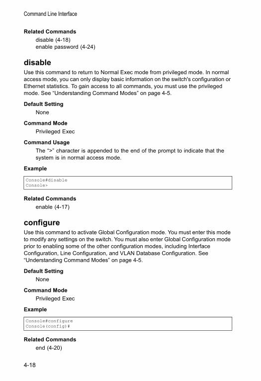
Command Line Interface
Related Commands disable (4-18)enable password (4-24)
disableUse this command to return to Normal Exec mode from privileged mode. In normal access mode, you can only display basic information on the switch's configuration or Ethernet statistics. To gain access to all commands, you must use the privileged mode. See “Understanding Command Modes” on page 4-5.
Default Setting None
Command Mode Privileged Exec
Command Usage The “>” character is appended to the end of the prompt to indicate that the system is in normal access mode.
Example
Related Commands enable (4-17)
configureUse this command to activate Global Configuration mode. You must enter this mode to modify any settings on the switch. You must also enter Global Configuration mode prior to enabling some of the other configuration modes, including Interface Configuration, Line Configuration, and VLAN Database Configuration. See “Understanding Command Modes” on page 4-5.
Default Setting None
Command Mode Privileged Exec
Example
Related Commands end (4-20)
Console#disableConsole>
Console#configureConsole(config)#
4-18
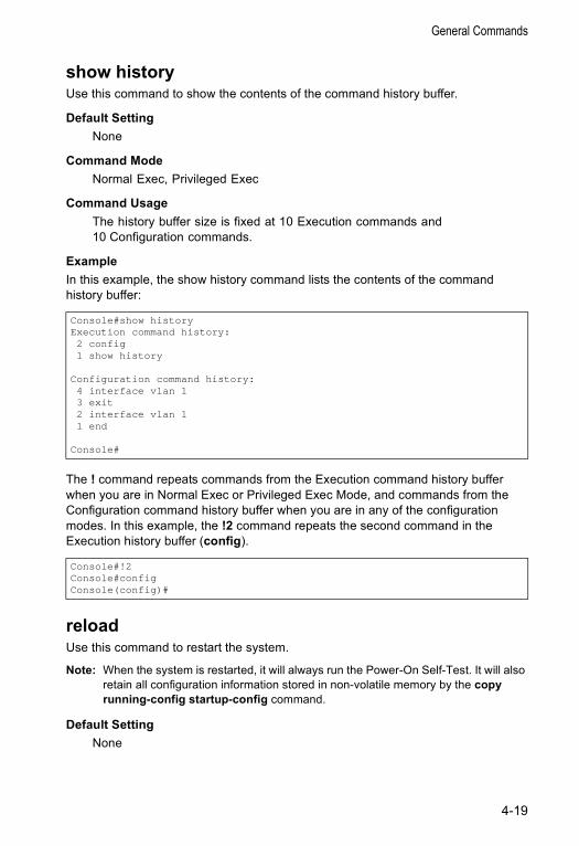
General Commands
show historyUse this command to show the contents of the command history buffer.
Default Setting None
Command Mode Normal Exec, Privileged Exec
Command Usage The history buffer size is fixed at 10 Execution commands and 10 Configuration commands.
Example In this example, the show history command lists the contents of the command history buffer:
The ! command repeats commands from the Execution command history buffer when you are in Normal Exec or Privileged Exec Mode, and commands from the Configuration command history buffer when you are in any of the configuration modes. In this example, the !2 command repeats the second command in the Execution history buffer (config).
reloadUse this command to restart the system.
Note: When the system is restarted, it will always run the Power-On Self-Test. It will also retain all configuration information stored in non-volatile memory by the copy running-config startup-config command.
Default Setting None
Console#show historyExecution command history:2 config1 show history
Configuration command history:4 interface vlan 13 exit2 interface vlan 11 end
Console#
Console#!2Console#configConsole(config)#
4-19
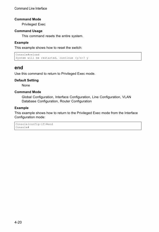
Command Line Interface
Command Mode Privileged Exec
Command Usage This command resets the entire system.
Example This example shows how to reset the switch:
endUse this command to return to Privileged Exec mode.
Default Setting None
Command Mode Global Configuration, Interface Configuration, Line Configuration, VLAN Database Configuration, Router Configuration
Example This example shows how to return to the Privileged Exec mode from the Interface Configuration mode:
Console#reloadSystem will be restarted, continue <y/n>? y
Console(config-if)#endConsole#
4-20
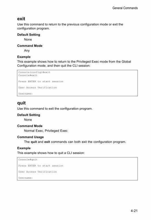
General Commands
exitUse this command to return to the previous configuration mode or exit the configuration program.
Default Setting None
Command Mode Any
Example This example shows how to return to the Privileged Exec mode from the Global Configuration mode, and then quit the CLI session:
quitUse this command to exit the configuration program.
Default Setting None
Command Mode Normal Exec, Privileged Exec
Command Usage The quit and exit commands can both exit the configuration program.
Example This example shows how to quit a CLI session:
Console(config)#exitConsole#exit
Press ENTER to start session
User Access Verification
Username:
Console#quit
Press ENTER to start session
User Access Verification
Username:
4-21
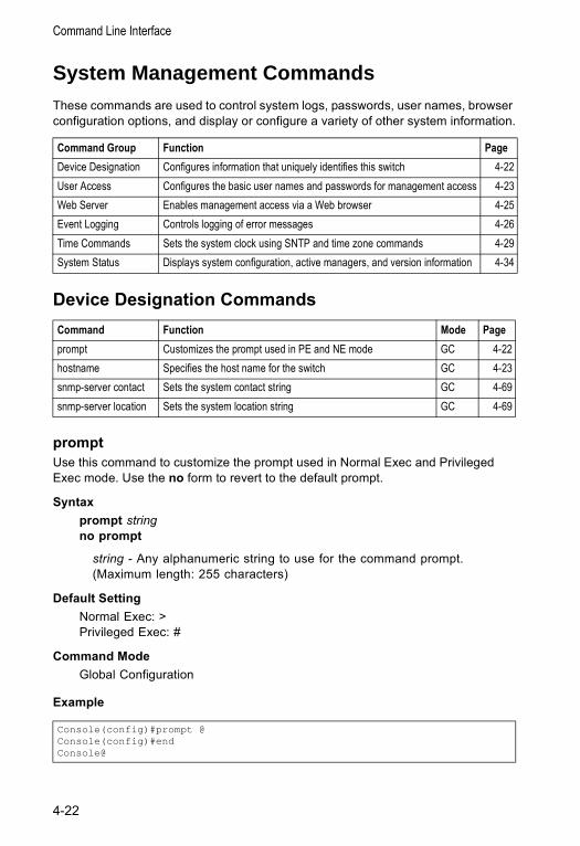
Command Line Interface
System Management CommandsThese commands are used to control system logs, passwords, user names, browser configuration options, and display or configure a variety of other system information.
Device Designation Commands
promptUse this command to customize the prompt used in Normal Exec and Privileged Exec mode. Use the no form to revert to the default prompt.
Syntax prompt stringno prompt
string - Any alphanumeric string to use for the command prompt. (Maximum length: 255 characters)
Default Setting Normal Exec: >Privileged Exec: #
Command Mode Global Configuration
Example
Command Group Function PageDevice Designation Configures information that uniquely identifies this switch 4-22User Access Configures the basic user names and passwords for management access 4-23Web Server Enables management access via a Web browser 4-25Event Logging Controls logging of error messages 4-26Time Commands Sets the system clock using SNTP and time zone commands 4-29System Status Displays system configuration, active managers, and version information 4-34
Command Function Mode Pageprompt Customizes the prompt used in PE and NE mode GC 4-22hostname Specifies the host name for the switch GC 4-23snmp-server contact Sets the system contact string GC 4-69snmp-server location Sets the system location string GC 4-69
Console(config)#prompt @Console(config)#endConsole@
4-22

System Management Commands
hostnameUse this command to specify or modify the host name for this device. Use the no form to restore the default host name.
Syntax hostname nameno hostname
name - The name of this host. (Maximum length: 255 characters)
Default Setting None
Command Mode Global Configuration
Example
User Access CommandsThe basic commands required for management access are listed in this section. This switch also includes other options for password checking via the console or a Telnet connection (page 4-9), user authentication via a remote authentication server (page 4-44), and host access authentication for specific ports (page 4-49).
usernameUse this command to add named users, require authentication at login, specify or change a user's password (or specify that no password is required), or specify or change a user's access level. Use the no form to remove a user name.
Syntax username name {access-level level | nopassword |
password {0 | 7} password}no username name
• name - The name of the user. (Maximum length: 8 characters, case sensitive. Maximum users: 16)
• access-level level - Specifies the user level.The device has two predefined privilege levels: 0: Normal Exec, 15: Privileged Exec.
• nopassword - No password is required for this user to log in.
Console(config)#hostname ES3626GConsole(config)#
Command Function Mode Pageusername Establishes a user name-based authentication system at login GC 4-23enable password Sets a password to control access to the Privileged Exec level GC 4-24
4-23
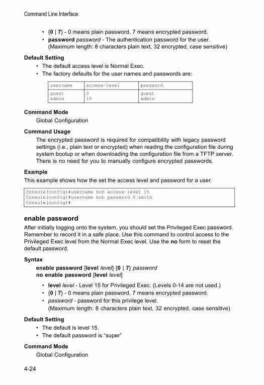
Command Line Interface
• {0 | 7} - 0 means plain password, 7 means encrypted password. • password password - The authentication password for the user.
(Maximum length: 8 characters plain text, 32 encrypted, case sensitive)
Default Setting • The default access level is Normal Exec. • The factory defaults for the user names and passwords are:
Command Mode Global Configuration
Command Usage The encrypted password is required for compatibility with legacy password settings (i.e., plain text or encrypted) when reading the configuration file during system bootup or when downloading the configuration file from a TFTP server. There is no need for you to manually configure encrypted passwords.
Example This example shows how the set the access level and password for a user.
enable passwordAfter initially logging onto the system, you should set the Privileged Exec password. Remember to record it in a safe place. Use this command to control access to the Privileged Exec level from the Normal Exec level. Use the no form to reset the default password.
Syntax enable password [level level] {0 | 7} passwordno enable password [level level]
• level level - Level 15 for Privileged Exec. (Levels 0-14 are not used.)• {0 | 7} - 0 means plain password, 7 means encrypted password. • password - password for this privilege level.
(Maximum length: 8 characters plain text, 32 encrypted, case sensitive)
Default Setting • The default is level 15. • The default password is “super”
Command Mode Global Configuration
username access-level password
guestadmin
015
guestadmin
Console(config)#username bob access-level 15Console(config)#username bob password 0 smithConsole(config)#
4-24
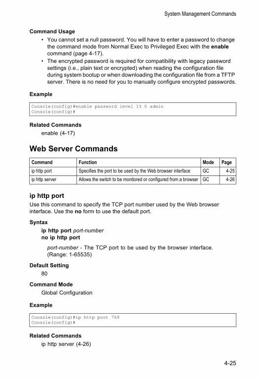
System Management Commands
Command Usage • You cannot set a null password. You will have to enter a password to change
the command mode from Normal Exec to Privileged Exec with the enable command (page 4-17).
• The encrypted password is required for compatibility with legacy password settings (i.e., plain text or encrypted) when reading the configuration file during system bootup or when downloading the configuration file from a TFTP server. There is no need for you to manually configure encrypted passwords.
Example
Related Commandsenable (4-17)
Web Server Commands
ip http portUse this command to specify the TCP port number used by the Web browser interface. Use the no form to use the default port.
Syntax ip http port port-numberno ip http port
port-number - The TCP port to be used by the browser interface. (Range: 1-65535)
Default Setting 80
Command Mode Global Configuration
Example
Related Commandsip http server (4-26)
Console(config)#enable password level 15 0 adminConsole(config)#
Command Function Mode Pageip http port Specifies the port to be used by the Web browser interface GC 4-25ip http server Allows the switch to be monitored or configured from a browser GC 4-26
Console(config)#ip http port 769Console(config)#
4-25
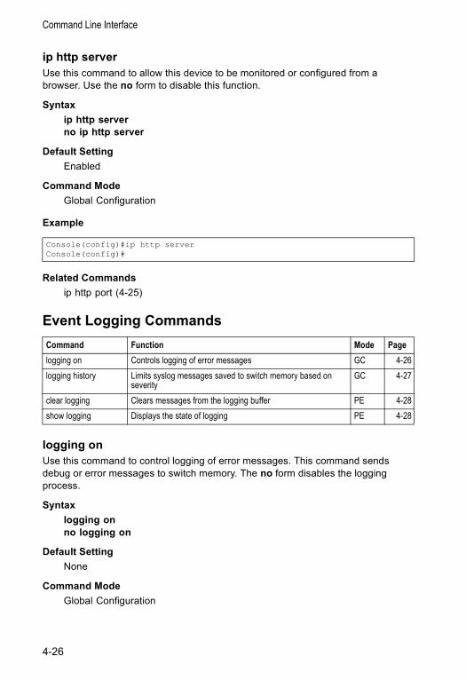
Command Line Interface
ip http serverUse this command to allow this device to be monitored or configured from a browser. Use the no form to disable this function.
Syntax ip http serverno ip http server
Default Setting Enabled
Command Mode Global Configuration
Example
Related Commandsip http port (4-25)
Event Logging Commands
logging onUse this command to control logging of error messages. This command sends debug or error messages to switch memory. The no form disables the logging process.
Syntax logging onno logging on
Default Setting None
Command Mode Global Configuration
Console(config)#ip http serverConsole(config)#
Command Function Mode Pagelogging on Controls logging of error messages GC 4-26logging history Limits syslog messages saved to switch memory based on
severity GC 4-27
clear logging Clears messages from the logging buffer PE 4-28show logging Displays the state of logging PE 4-28
4-26

System Management Commands
Command Usage The logging process controls error messages saved to switch memory. You can use the logging history command to control the type of error messages that are stored.
Example
Related Commandslogging history (4-27)clear logging (4-28)
logging historyUse this command to limit syslog messages saved to switch memory based on severity. The no form returns the logging of syslog messages to the default level.
Syntax logging history {flash | ram} levelno logging history {flash | ram}
• flash - Event history stored in flash memory (i.e., permanent memory). • ram - Event history stored in temporary RAM (i.e., memory flushed on
power reset). • level - One of the level arguments listed below. Messages sent include the
selected level down to level 0.
Default Setting Flash: errors (level 3 - 0)RAM: warnings (level 7 - 0)
Command Mode Global Configuration
Console(config)#logging onConsole(config)#
Level Argument Level Descriptiondebugging 7 Debugging messagesinformational 6 Informational messages onlynotifications 5 Normal but significant condition, such as cold start warnings 4 Warning conditions (e.g., return false, unexpected return)errors 3 Error conditions (e.g., invalid input, default used)critical 2 Critical conditions (e.g., memory allocation, or free
memory error - resource exhausted)alerts 1 Immediate action neededemergencies 0 System unusable* There are only Level 2, 5 and 6 error messages for the current firmware release.
4-27
Command Line Interface
Command Usage The message level specified for flash memory must be a higher priority (i.e., numerically lower) than that specified for RAM.
Example
clear loggingUse this command to clear messages from the log buffer.
Syntax clear logging [flash | ram]
• flash - Event history stored in flash memory (i.e., permanent memory). • ram - Event history stored in temporary RAM (i.e., memory flushed on
power reset).
Default Setting Flash and RAM
Command Mode Privileged Exec
Example
Related Commandsshow logging (4-28)
show loggingUse this command to display the logging configuration, along with any system and event messages stored in memory.
Syntax show logging {flash | ram}
• flash - Event history stored in flash memory (i.e., permanent memory). • ram - Event history stored in temporary RAM (i.e., memory flushed on
power reset).
Default Setting None
Command Mode Privileged Exec
Console(config)#logging history ram 0Console(config)#
Console#clear loggingConsole#
4-28
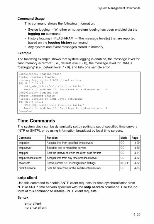
System Management Commands
Command Usage This command shows the following information:
• Syslog logging – Whether or not system logging has been enabled via the logging on command.
• History logging in FLASH/RAM – The message level(s) that are reported based on the logging history command.
• Any system and event messages stored in memory.
Example
The following example shows that system logging is enabled, the message level for flash memory is “errors” (i.e., default level 3 - 0), the message level for RAM is “debugging” (i.e., default level 7 - 0), and lists one sample error
Time CommandsThe system clock can be dynamically set by polling a set of specified time servers (NTP or SNTP), or by using information broadcast by local time servers.
sntp clientUse this command to enable SNTP client requests for time synchronization from NTP or SNTP time servers specified with the sntp servers command. Use the no form of this command to disable SNTP client requests.
Syntax
sntp clientno sntp client
Console#show logging flashSyslog logging: EnableHistory logging in FLASH: level errors[0] 0:0:5 1/1/1
"PRI_MGR_InitDefault function fails."level: 3, module: 13, function: 0, and event no.: 0
Console#show logging ramSyslog logging: EnableHistory logging in RAM: level debugging[0] 0:0:5 1/1/1
"PRI_MGR_InitDefault function fails."level: 3, module: 13, function: 0, and event no.: 0
Console#
Command Function Mode Pagesntp client Accepts time from specified time servers GC 4-29sntp server Specifies one or more time servers GC 4-30sntp poll Sets the interval at which the client polls for time GC 4-31sntp broadcast client Accepts time from any time broadcast server GC 4-32show sntp Shows current SNTP configuration settings NE, PE 4-32clock timezone Sets the time zone for the switch’s internal clock GC 4-33
4-29
Command Line Interface
Default Setting
Disabled
Command Mode
Global Configuration
Command Usage • The time acquired from time servers is used to record accurate dates and
times for log events. Without SNTP, the switch only records the time starting from the factory default set at the last bootup (i.e., 00:00:00, Jan. 1, 2001).
• This command enables client time requests to time servers specified via the sntp servers command. It issues time synchronization requests based on the interval set via the sntp poll command.
• The SNTP time query method is set to client mode when the first sntp client command is issued. However, if the sntp broadcast client command is issued, then the no sntp broadcast client command must be used to return the switch to SNTP client mode.
Example
Related Commandssntp server (4-30)sntp poll (4-31)sntp broadcast client (4-32)show sntp (4-32)
sntp serverUse this command to set the IP address of the servers to which SNTP time requests are issued. Use the this command with no arguments to clear all time servers from the current list.
Syntax
sntp server [ip1 [ip2 [ip3]]]
ip - IP address of an time server (NTP or SNTP). (Range: 1 - 3 addresses)
Default Setting
None
Console(config)#sntp server 10.1.0.19Console(config)#sntp poll 60Console(config)#sntp clientConsole(config)#endConsole#show sntpCurrent time: Dec 23 02:52:44 2002Poll interval: 60Current mode: unicastConsole#
4-30
System Management Commands
Command Mode
Global Configuration
Command Usage This command specifies time servers from which the switch will poll for time updates when set to SNTP client mode. The client will poll the time servers in the order specified until a response is received. It issues time synchronization requests based on the interval set via the sntp poll command.
Example
Related Commandssntp client (4-29)sntp poll (4-31)show sntp (4-32)
sntp pollUse this command to set the interval between sending time requests when the switch is set to SNTP client mode. Use the no form to restore to the default.
Syntax
sntp poll secondsno sntp poll
seconds - Interval between time requests. (Range: 16-16384 seconds)
Default Setting
16 seconds
Command Mode
Global Configuration
Command Usage This command is only applicable when the switch is set to SNTP client mode.
Example
Related Commandssntp client (4-29)
Console(config)#sntp server 10.1.0.19Console#
Console(config)#sntp poll 60Console#
4-31
Command Line Interface
sntp broadcast clientUse this command to synchronize the switch’s clock based on time broadcast from time servers (using the multicast address 224.0.1.1). Use the no form to disable SNTP broadcast client mode.
Syntax
sntp broadcast clientno sntp broadcast client
Default Setting
Disabled
Command Mode
Global Configuration
Example
show sntpUse this command to display the current time and configuration settings for the SNTP client, and whether or not the local time has been properly updated.
Command Mode
Normal Exec, Privileged Exec
Command Usage This command displays the current time, the poll interval used for sending time synchronization requests (when the switch is set to SNTP client mode), and the current SNTP mode (i.e., client or broadcast).
Example
Console(config)#sntp broadcast clientConsole#
Console#show sntpCurrent time: Dec 23 05:13:28 2002Poll interval: 16Current mode: unicastConsole#
4-32
System Management Commands
clock timezoneUse this command to set the time zone for the switch’s internal clock.
Syntax
clock timezone name hour hours minute minutes {before-utc | after-utc}
• name - Name of timezone, usually an acronym. (Range: 1-29 characters)• hours - Number of hours before/after UTC. (Range: 1-12 hours)• minutes - Number of minutes before/after UTC. (Range: 0-59 minutes)• before-utc - Sets the local time zone before (east) of UTC.• after-utc - Sets the local time zone after (west) of UTC.
Default Setting
None
Command Mode
Global Configuration
Command Usage
This command sets the local time zone relative to the Coordinated Universal Time (UTC, formerly Greenwich Mean Time or GMT), based on the earth’s prime meridian, zero degrees longitude. To display a time corresponding to your local time, you must indicate the number of hours and minutes your time zone is east (before) or west (after) of UTC.
Example
Related Commandsshow sntp (4-32)
Console(config)#clock timezone Japan hours 8 minute 0 after-UTCConsole(config)#
4-33
Command Line Interface
System Status Commands
show startup-configUse this command to display the configuration file stored in non-volatile memory that is used to start up the system.
Default Setting None
Command Mode Privileged Exec
Command Usage • Use this command in conjunction with the show running-config command to
compare the information in running memory to the information stored in non-volatile memory.
• This command displays settings for key command modes. Each mode group is separated by “!” symbols, and includes the configuration mode command, and corresponding commands. This command displays the following information:
- SNMP community strings- Users (names and access levels)- VLAN database (VLAN ID, name and state)- VLAN configuration settings for each interface- IP address configured for VLANs- Routing protocol configuration settings- Spanning tree settings- Any configured settings for the console port and Telnet
Command Function Mode Pageshow startup-config Displays the contents of the configuration file (stored in flash
memory) that is used to start up the systemPE 4-34
show running-config Displays the configuration data currently in use PE 4-36show system Displays system information NE, PE 4-38show users Shows all active console and Telnet sessions, including user
name, idle time, and IP address of Telnet clientsNE, PE 4-38
show version Displays version information for the system NE, PE 4-39
4-34
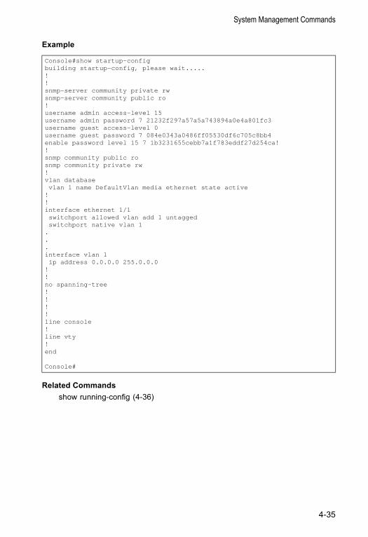
System Management Commands
Example
Related Commandsshow running-config (4-36)
Console#show startup-configbuilding startup-config, please wait.....!!snmp-server community private rwsnmp-server community public ro!username admin access-level 15username admin password 7 21232f297a57a5a743894a0e4a801fc3username guest access-level 0username guest password 7 084e0343a0486ff05530df6c705c8bb4enable password level 15 7 1b3231655cebb7a1f783eddf27d254ca!!snmp community public rosnmp community private rw!vlan databasevlan 1 name DefaultVlan media ethernet state active
!!interface ethernet 1/1switchport allowed vlan add 1 untaggedswitchport native vlan 1
.
.
.interface vlan 1ip address 0.0.0.0 255.0.0.0
!!no spanning-tree!!!!line console!line vty!end
Console#
4-35
Command Line Interface
show running-configUse this command to display the configuration information currently in use.
Default Setting None
Command Mode Privileged Exec
Command Usage • Use this command in conjunction with the show startup-config command to
compare the information in running memory to the information stored in non-volatile memory.
• This command displays settings for key command modes. Each mode group is separated by “!” symbols, and includes the configuration mode command, and corresponding commands. This command displays the following information:
- SNMP community strings- Users (names, access levels, and encrypted passwords)- VLAN database (VLAN ID, name and state)- VLAN configuration settings for each interface- IP address configured for VLANs- Routing protocol configuration settings- Spanning tree settings- Any configured settings for the console port and Telnet
4-36
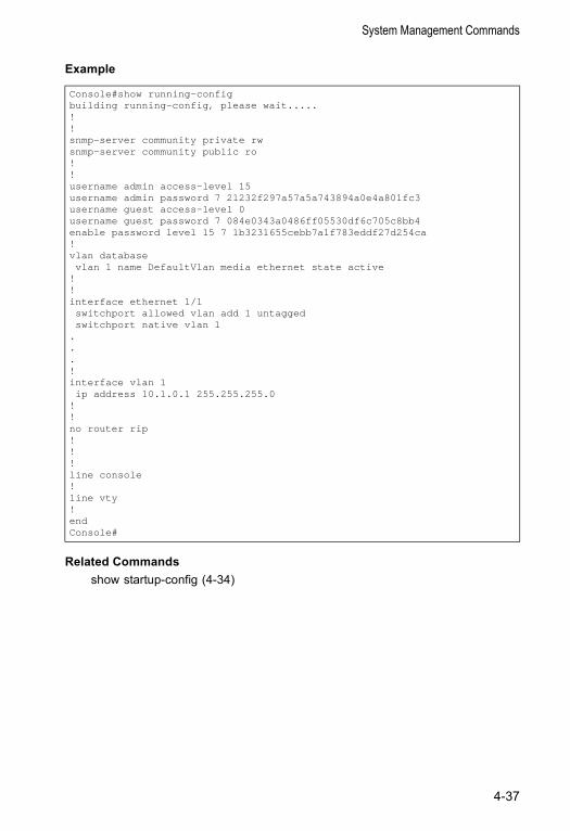
System Management Commands
Example
Related Commandsshow startup-config (4-34)
Console#show running-configbuilding running-config, please wait.....!!snmp-server community private rwsnmp-server community public ro!!username admin access-level 15username admin password 7 21232f297a57a5a743894a0e4a801fc3username guest access-level 0username guest password 7 084e0343a0486ff05530df6c705c8bb4enable password level 15 7 1b3231655cebb7a1f783eddf27d254ca!vlan databasevlan 1 name DefaultVlan media ethernet state active
!!interface ethernet 1/1switchport allowed vlan add 1 untaggedswitchport native vlan 1
.
.
.!interface vlan 1ip address 10.1.0.1 255.255.255.0
!!no router rip!!!line console!line vty!endConsole#
4-37
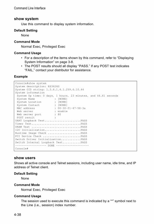
Command Line Interface
show systemUse this command to display system information.
Default Setting None
Command Mode Normal Exec, Privileged Exec
Command Usage • For a description of the items shown by this command, refer to “Displaying
System Information” on page 3-8. • The POST results should all display “PASS.” If any POST test indicates
“FAIL,” contact your distributor for assistance.
Example
show usersShows all active console and Telnet sessions, including user name, idle time, and IP address of Telnet client.
Default Setting None
Command Mode Normal Exec, Privileged Exec
Command Usage The session used to execute this command is indicated by a “*” symbol next to the Line (i.e., session) index number.
Console#show systemSystem description: ES3626GSystem OID string: 1.3.6.1.4.1.259.6.10.44System informationSystem Up time: 0 days, 1 hours, 23 minutes, and 44.61 secondsSystem Name : [NONE]System Location : [NONE]System Contact : [NONE]MAC address : 00-30-f1-47-58-3aWeb server : enableWeb server port : 80POST result :
UART Loopback Test......................PASSTimer Test..............................PASSDRAM Test ..............................PASSI2C Initialization......................PASSRuntime Image Check ....................PASSPCI Device Check .......................PASSSwitch Driver Initialization............PASSSwitch Internal Loopback Test...........PASS------------------- DONE --------------------Console#
4-38
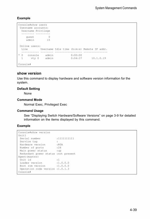
System Management Commands
Example
show versionUse this command to display hardware and software version information for the system.
Default Setting None
Command Mode Normal Exec, Privileged Exec
Command Usage See “Displaying Switch Hardware/Software Versions” on page 3-9 for detailed information on the items displayed by this command.
Example
Console#show usersUsername accounts:Username Privilege-------- ---------
guest 0admin 15
Online users:Line Username Idle time (h:m:s) Remote IP addr.----------- -------- ----------------- ---------------
* 0 console admin 0:00:001 vty 0 admin 0:04:37 10.1.0.19
Console#
Console#show versionUnit1Serial number :1111111111Service tag :Hardware version :R0ANumber of ports :26Main power status :upRedundant power status :not present
Agent(master)Unit id :1Loader version :1.0.0.0Boot rom version :1.0.0.0Operation code version :1.0.1.3
Console#
4-39
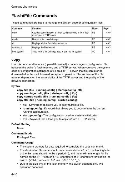
Command Line Interface
Flash/File CommandsThese commands are used to manage the system code or configuration files.
copy Use this command to move (upload/download) a code image or configuration file between the switch’s flash memory and a TFTP server. When you save the system code or configuration settings to a file on a TFTP server, that file can later be downloaded to the switch to restore system operation. The success of the file transfer depends on the accessibility of the TFTP server and the quality of the network connection.
Syntax copy file {file | running-config | startup-config | tftp}copy running-config {file | startup-config | tftp}copy startup-config {file | running-config | tftp}copy tftp {file | running-config | startup-config}
• file - Keyword that allows you to copy to/from a file. • running-config - Keyword that allows you to copy to/from the current
running configuration. • startup-config - The configuration used for system initialization. • tftp - Keyword that allows you to copy to/from a TFTP server.
Default Setting None
Command Mode Privileged Exec
Command Usage • The system prompts for data required to complete the copy command. • The destination file name should not contain slashes (\ or /), the leading letter
of the file name should not be a period (.), and the maximum length for file names on the TFTP server is 127 characters or 31 characters for files on the switch. (Valid characters: A-Z, a-z, 0-9, “.”, “-”, “_”)
• Due to the size limit of the flash memory, the switch supports only two operation code files.
Command Function Mode Pagecopy Copies a code image or a switch configuration to or from flash
memory or a TFTP serverPE 4-40
delete Deletes a file or code image PE 4-42dir Displays a list of files in flash memory PE 4-42whichboot Displays the files booted PE 4-43boot system Specifies the file or image used to start up the system GC 4-44
4-40
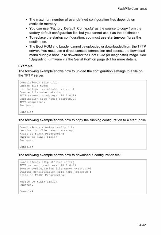
Flash/File Commands
• The maximum number of user-defined configuration files depends on available memory.
• You can use “Factory_Default_Config.cfg” as the source to copy from the factory default configuration file, but you cannot use it as the destination.
• To replace the startup configuration, you must use startup-config as the destination.
• The Boot ROM and Loader cannot be uploaded or downloaded from the TFTP server. You must use a direct console connection and access the download menu during a boot up to download the Boot ROM (or diagnostic) image. See “Upgrading Firmware via the Serial Port” on page B-1 for more details.
Example The following example shows how to upload the configuration settings to a file on the TFTP server:
The following example shows how to copy the running configuration to a startup file.
The following example shows how to download a configuration file:
Console#copy file tftpChoose file type:1. config: 2. opcode: <1-2>: 1
Source file name: startupTFTP server ip address: 10.1.0.99Destination file name: startup.01TFTP completed.Success.
Console#
Console#copy running-config filedestination file name : startupWrite to FLASH Programming.\Write to FLASH finish.Success.
Console#
Console#copy tftp startup-configTFTP server ip address: 10.1.0.99Source configuration file name: startup.01Startup configuration file name [startup]:Write to FLASH Programming.
\Write to FLASH finish.Success.
Console#
4-41
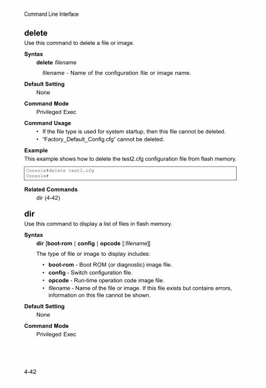
Command Line Interface
deleteUse this command to delete a file or image.
Syntax delete filename
filename - Name of the configuration file or image name.
Default Setting None
Command Mode Privileged Exec
Command Usage • If the file type is used for system startup, then this file cannot be deleted. • “Factory_Default_Config.cfg” cannot be deleted.
Example This example shows how to delete the test2.cfg configuration file from flash memory.
Related Commandsdir (4-42)
dirUse this command to display a list of files in flash memory.
Syntax dir [boot-rom | config | opcode [:filename]]
The type of file or image to display includes:
• boot-rom - Boot ROM (or diagnostic) image file.• config - Switch configuration file.• opcode - Run-time operation code image file. • filename - Name of the file or image. If this file exists but contains errors,
information on this file cannot be shown.
Default Setting None
Command Mode Privileged Exec
Console#delete test2.cfgConsole#
4-42
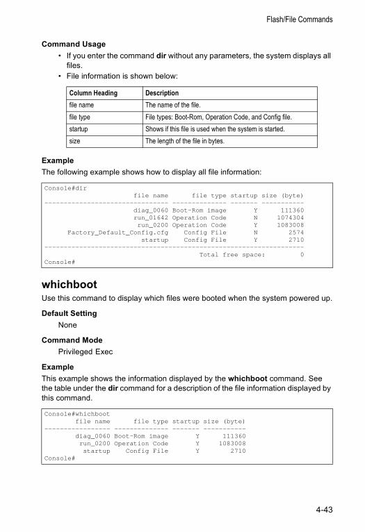
Flash/File Commands
Command Usage • If you enter the command dir without any parameters, the system displays all
files. • File information is shown below:
Example The following example shows how to display all file information:
whichbootUse this command to display which files were booted when the system powered up.
Default Setting None
Command Mode Privileged Exec
ExampleThis example shows the information displayed by the whichboot command. See the table under the dir command for a description of the file information displayed by this command.
Column Heading Descriptionfile name The name of the file.file type File types: Boot-Rom, Operation Code, and Config file.startup Shows if this file is used when the system is started.size The length of the file in bytes.
Console#dirfile name file type startup size (byte)
-------------------------------- -------------- ------- -----------diag_0060 Boot-Rom image Y 111360run_01642 Operation Code N 1074304run_0200 Operation Code Y 1083008
Factory_Default_Config.cfg Config File N 2574startup Config File Y 2710
-------------------------------------------------------------------Total free space: 0
Console#
Console#whichbootfile name file type startup size (byte)
----------------- -------------- ------- -----------diag_0060 Boot-Rom image Y 111360run_0200 Operation Code Y 1083008startup Config File Y 2710
Console#
4-43
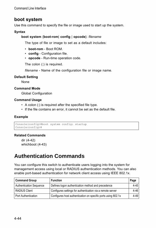
Command Line Interface
boot systemUse this command to specify the file or image used to start up the system.
Syntax boot system {boot-rom| config | opcode}: filename
The type of file or image to set as a default includes:
• boot-rom - Boot ROM.• config - Configuration file.• opcode - Run-time operation code.
The colon (:) is required.
filename - Name of the configuration file or image name.
Default Setting None
Command Mode Global Configuration
Command Usage • A colon (:) is required after the specified file type. • If the file contains an error, it cannot be set as the default file.
Example
Related Commandsdir (4-42)whichboot (4-43)
Authentication Commands You can configure this switch to authenticate users logging into the system for management access using local or RADIUS authentication methods. You can also enable port-based authentication for network client access using IEEE 802.1x.
Console(config)#boot system config: startupConsole(config)#
Command Group Function PageAuthentication Sequence Defines logon authentication method and precedence 4-45RADIUS Client Configures settings for authentication via a remote server 4-46Port Authentication Configures host authentication on specific ports using 802.1x 4-49
4-44
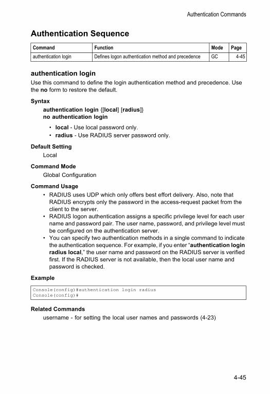
Authentication Commands
Authentication Sequence
authentication loginUse this command to define the login authentication method and precedence. Use the no form to restore the default.
Syntax authentication login {[local] [radius]}no authentication login
• local - Use local password only. • radius - Use RADIUS server password only.
Default Setting Local
Command Mode Global Configuration
Command Usage • RADIUS uses UDP which only offers best effort delivery. Also, note that
RADIUS encrypts only the password in the access-request packet from the client to the server.
• RADIUS logon authentication assigns a specific privilege level for each user name and password pair. The user name, password, and privilege level must be configured on the authentication server.
• You can specify two authentication methods in a single command to indicate the authentication sequence. For example, if you enter “authentication login radius local,” the user name and password on the RADIUS server is verified first. If the RADIUS server is not available, then the local user name and password is checked.
Example
Related Commandsusername - for setting the local user names and passwords (4-23)
Command Function Mode Pageauthentication login Defines logon authentication method and precedence GC 4-45
Console(config)#authentication login radiusConsole(config)#
4-45
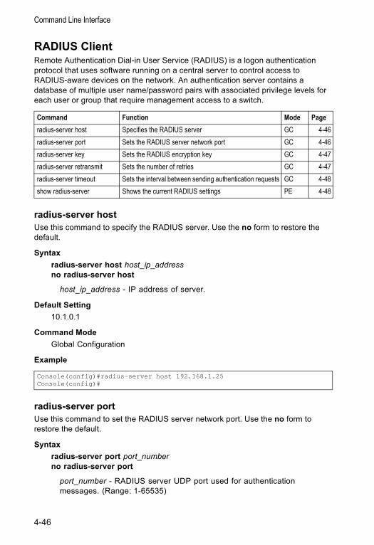
Command Line Interface
RADIUS ClientRemote Authentication Dial-in User Service (RADIUS) is a logon authentication protocol that uses software running on a central server to control access to RADIUS-aware devices on the network. An authentication server contains a database of multiple user name/password pairs with associated privilege levels for each user or group that require management access to a switch.
radius-server hostUse this command to specify the RADIUS server. Use the no form to restore the default.
Syntax radius-server host host_ip_addressno radius-server host
host_ip_address - IP address of server.
Default Setting 10.1.0.1
Command Mode Global Configuration
Example
radius-server portUse this command to set the RADIUS server network port. Use the no form to restore the default.
Syntax radius-server port port_numberno radius-server port
port_number - RADIUS server UDP port used for authentication messages. (Range: 1-65535)
Command Function Mode Pageradius-server host Specifies the RADIUS server GC 4-46radius-server port Sets the RADIUS server network port GC 4-46radius-server key Sets the RADIUS encryption key GC 4-47radius-server retransmit Sets the number of retries GC 4-47radius-server timeout Sets the interval between sending authentication requests GC 4-48show radius-server Shows the current RADIUS settings PE 4-48
Console(config)#radius-server host 192.168.1.25Console(config)#
4-46
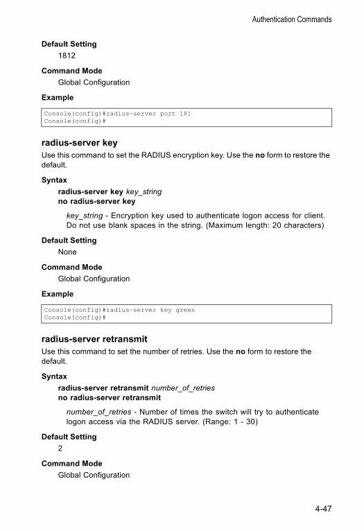
Authentication Commands
Default Setting 1812
Command Mode Global Configuration
Example
radius-server keyUse this command to set the RADIUS encryption key. Use the no form to restore the default.
Syntax radius-server key key_stringno radius-server key
key_string - Encryption key used to authenticate logon access for client. Do not use blank spaces in the string. (Maximum length: 20 characters)
Default Setting None
Command Mode Global Configuration
Example
radius-server retransmitUse this command to set the number of retries. Use the no form to restore the default.
Syntax radius-server retransmit number_of_retriesno radius-server retransmit
number_of_retries - Number of times the switch will try to authenticate logon access via the RADIUS server. (Range: 1 - 30)
Default Setting 2
Command Mode Global Configuration
Console(config)#radius-server port 181Console(config)#
Console(config)#radius-server key greenConsole(config)#
4-47
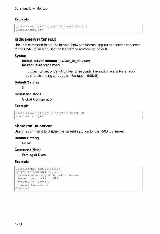
Command Line Interface
Example
radius-server timeoutUse this command to set the interval between transmitting authentication requests to the RADIUS server. Use the no form to restore the default.
Syntax radius-server timeout number_of_secondsno radius-server timeout
number_of_seconds - Number of seconds the switch waits for a reply before resending a request. (Range: 1-65535)
Default Setting 5
Command Mode Global Configuration
Example
show radius-serverUse this command to display the current settings for the RADIUS server.
Default Setting None
Command Mode Privileged Exec
Example
Console(config)#radius-server retransmit 5Console(config)#
Console(config)#radius-server timeout 10Console(config)#
Console#show radius-serverServer IP address: 10.1.0.1Communication key with radius server:Server port number: 1812Retransmit times: 2Request timeout: 5
Console#
4-48
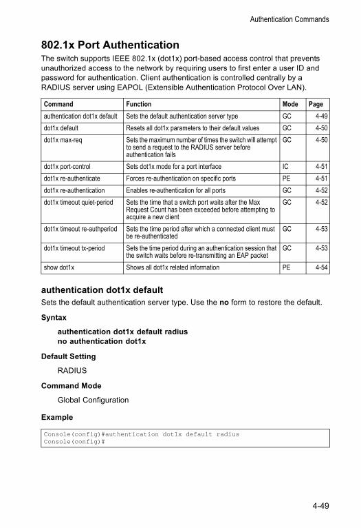
Authentication Commands
802.1x Port AuthenticationThe switch supports IEEE 802.1x (dot1x) port-based access control that prevents unauthorized access to the network by requiring users to first enter a user ID and password for authentication. Client authentication is controlled centrally by a RADIUS server using EAPOL (Extensible Authentication Protocol Over LAN).
authentication dot1x defaultSets the default authentication server type. Use the no form to restore the default.
Syntax
authentication dot1x default radiusno authentication dot1x
Default Setting
RADIUS
Command Mode
Global Configuration
Example
Command Function Mode Pageauthentication dot1x default Sets the default authentication server type GC 4-49dot1x default Resets all dot1x parameters to their default values GC 4-50dot1x max-req Sets the maximum number of times the switch will attempt
to send a request to the RADIUS server before authentication fails
GC 4-50
dot1x port-control Sets dot1x mode for a port interface IC 4-51dot1x re-authenticate Forces re-authentication on specific ports PE 4-51dot1x re-authentication Enables re-authentication for all ports GC 4-52dot1x timeout quiet-period Sets the time that a switch port waits after the Max
Request Count has been exceeded before attempting to acquire a new client
GC 4-52
dot1x timeout re-authperiod Sets the time period after which a connected client must be re-authenticated
GC 4-53
dot1x timeout tx-period Sets the time period during an authentication session that the switch waits before re-transmitting an EAP packet
GC 4-53
show dot1x Shows all dot1x related information PE 4-54
Console(config)#authentication dot1x default radiusConsole(config)#
4-49
Command Line Interface
dot1x defaultSets all configurable dot1x global and port settings to their default values.
Syntax
dot1x default
Command Mode
Global Configuration
Example
dot1x max-reqSets the maximum number of times the switch port will retransmit an EAP request packet to the client before it times out the authentication session. Use the no form to restore the default.
Syntax
dot1x max-req countno dot1x max-req
count – The maximum number of requests (Range: 1-10)
Default
2
Command Mode
Global Configuration
Example
Console(config)#dot1x defaultConsole(config)#
Console(config)#dot1x max-req 2Console(config)#
4-50
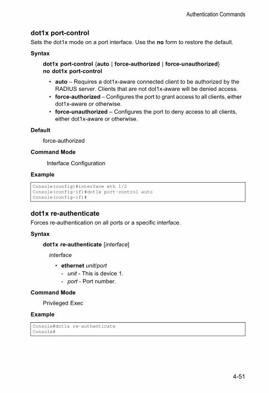
Authentication Commands
dot1x port-controlSets the dot1x mode on a port interface. Use the no form to restore the default.
Syntax
dot1x port-control {auto | force-authorized | force-unauthorized}no dot1x port-control
• auto – Requires a dot1x-aware connected client to be authorized by the RADIUS server. Clients that are not dot1x-aware will be denied access.
• force-authorized – Configures the port to grant access to all clients, either dot1x-aware or otherwise.
• force-unauthorized – Configures the port to deny access to all clients, either dot1x-aware or otherwise.
Default
force-authorized
Command Mode
Interface Configuration
Example
dot1x re-authenticateForces re-authentication on all ports or a specific interface.
Syntax
dot1x re-authenticate [interface]
interface
• ethernet unit/port- unit - This is device 1. - port - Port number.
Command Mode
Privileged Exec
Example
Console(config)#interface eth 1/2Console(config-if)#dot1x port-control autoConsole(config-if)#
Console#dot1x re-authenticateConsole#
4-51
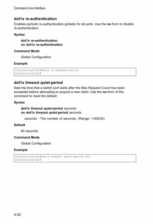
Command Line Interface
dot1x re-authenticationEnables periodic re-authentication globally for all ports. Use the no form to disable re-authentication.
Syntax
dot1x re-authenticationno dot1x re-authentication
Command Mode
Global Configuration
Example
dot1x timeout quiet-periodSets the time that a switch port waits after the Max Request Count has been exceeded before attempting to acquire a new client. Use the no form of this command to reset the default.
Syntax
dot1x timeout quiet-period secondsno dot1x timeout quiet-period seconds
seconds - The number of seconds. (Range: 1-65535)
Default
60 seconds
Command Mode
Global Configuration
Example
Console(config)#dot1x re-authenticationConsole(config)#
Console(config)#dot1x timeout quiet-period 350Console(config)#
4-52
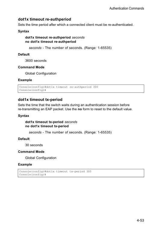
Authentication Commands
dot1x timeout re-authperiodSets the time period after which a connected client must be re-authenticated.
Syntax
dot1x timeout re-authperiod secondsno dot1x timeout re-authperiod
seconds - The number of seconds. (Range: 1-65535)
Default
3600 seconds
Command Mode
Global Configuration
Example
dot1x timeout tx-periodSets the time that the switch waits during an authentication session before re-transmitting an EAP packet. Use the no form to reset to the default value.
Syntax
dot1x timeout tx-period secondsno dot1x timeout tx-period
seconds - The number of seconds. (Range: 1-65535)
Default
30 seconds
Command Mode
Global Configuration
Example
Console(config)#dot1x timeout re-authperiod 300Console(config)#
Console(config)#dot1x timeout tx-period 300Console(config)#
4-53
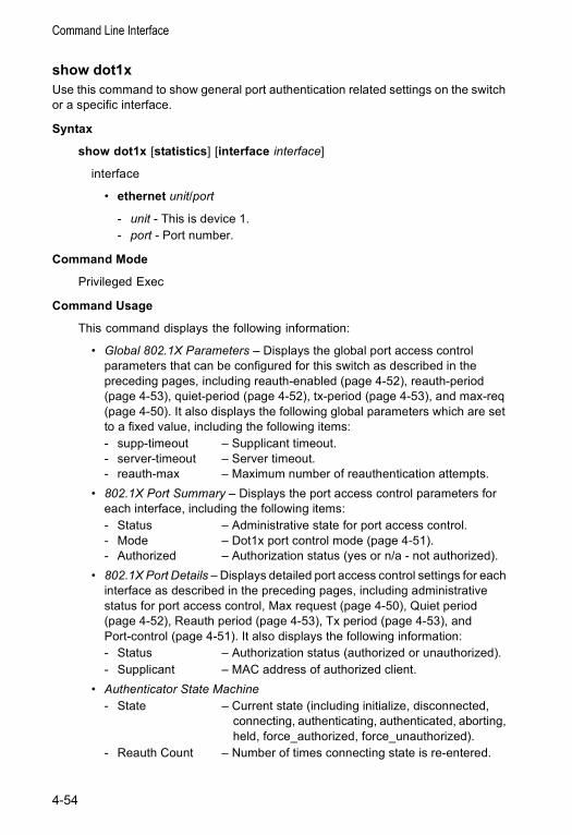
Command Line Interface
show dot1xUse this command to show general port authentication related settings on the switch or a specific interface.
Syntax
show dot1x [statistics] [interface interface]
interface
• ethernet unit/port
- unit - This is device 1. - port - Port number.
Command Mode
Privileged Exec
Command Usage
This command displays the following information:
• Global 802.1X Parameters – Displays the global port access control parameters that can be configured for this switch as described in the preceding pages, including reauth-enabled (page 4-52), reauth-period (page 4-53), quiet-period (page 4-52), tx-period (page 4-53), and max-req (page 4-50). It also displays the following global parameters which are set to a fixed value, including the following items:- supp-timeout – Supplicant timeout.- server-timeout – Server timeout.- reauth-max – Maximum number of reauthentication attempts.
• 802.1X Port Summary – Displays the port access control parameters for each interface, including the following items:- Status – Administrative state for port access control.- Mode – Dot1x port control mode (page 4-51).- Authorized – Authorization status (yes or n/a - not authorized).
• 802.1X Port Details – Displays detailed port access control settings for each interface as described in the preceding pages, including administrative status for port access control, Max request (page 4-50), Quiet period (page 4-52), Reauth period (page 4-53), Tx period (page 4-53), and Port-control (page 4-51). It also displays the following information:- Status – Authorization status (authorized or unauthorized).- Supplicant – MAC address of authorized client.
• Authenticator State Machine - State – Current state (including initialize, disconnected,
connecting, authenticating, authenticated, aborting, held, force_authorized, force_unauthorized).
- Reauth Count – Number of times connecting state is re-entered.
4-54
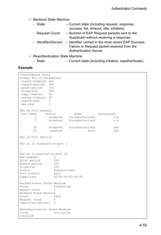
Authentication Commands
• Backend State Machine - State – Current state (including request, response,
success, fail, timeout, idle, initialize).- Request Count – Number of EAP Request packets sent to the
Supplicant without receiving a response.- Identifier(Server) – Identifier carried in the most recent EAP Success,
Failure or Request packet received from the Authentication Server.
• Reauthentication State Machine - State – Current state (including initialize, reauthenticate).
Example
Console#show dot1xGlobal 802.1X Parametersreauth-enabled: yesreauth-period: 300quiet-period: 350tx-period: 300supp-timeout: 30server-timeout: 30reauth-max: 2max-req: 2
802.1X Port SummaryPort Name Status Mode Authorized
1 disabled ForceAuthorized n/a2 disabled ForceAuthorized n/a
... 25 disabled ForceAuthorized yes26 enabled Auto yes
802.1X Port Details
802.1X is disabled on port 1...
802.1X is enabled on port 26Max request 2Quiet period 350Reauth period 300Tx period 300Status UnauthorizedPort-control AutoSupplicant 00-00-00-00-00-00
Authenticator State MachineState ConnectingReauth Count 3Backend State MachineState IdleRequest Count 0Identifier(Server) 0
Reauthentication State MachineState InitializeConsole#
4-55
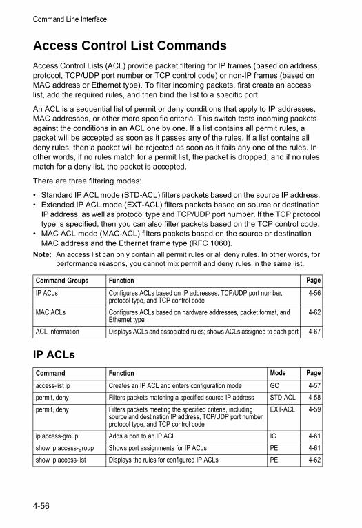
Command Line Interface
Access Control List CommandsAccess Control Lists (ACL) provide packet filtering for IP frames (based on address, protocol, TCP/UDP port number or TCP control code) or non-IP frames (based on MAC address or Ethernet type). To filter incoming packets, first create an access list, add the required rules, and then bind the list to a specific port.
An ACL is a sequential list of permit or deny conditions that apply to IP addresses, MAC addresses, or other more specific criteria. This switch tests incoming packets against the conditions in an ACL one by one. If a list contains all permit rules, a packet will be accepted as soon as it passes any of the rules. If a list contains all deny rules, then a packet will be rejected as soon as it fails any one of the rules. In other words, if no rules match for a permit list, the packet is dropped; and if no rules match for a deny list, the packet is accepted.
There are three filtering modes:
• Standard IP ACL mode (STD-ACL) filters packets based on the source IP address. • Extended IP ACL mode (EXT-ACL) filters packets based on source or destination
IP address, as well as protocol type and TCP/UDP port number. If the TCP protocol type is specified, then you can also filter packets based on the TCP control code.
• MAC ACL mode (MAC-ACL) filters packets based on the source or destination MAC address and the Ethernet frame type (RFC 1060).
Note: An access list can only contain all permit rules or all deny rules. In other words, for performance reasons, you cannot mix permit and deny rules in the same list.
IP ACLs
Command Groups Function Page
IP ACLs Configures ACLs based on IP addresses, TCP/UDP port number, protocol type, and TCP control code
4-56
MAC ACLs Configures ACLs based on hardware addresses, packet format, and Ethernet type
4-62
ACL Information Displays ACLs and associated rules; shows ACLs assigned to each port 4-67
Command Function Mode Page
access-list ip Creates an IP ACL and enters configuration mode GC 4-57permit, deny Filters packets matching a specified source IP address STD-ACL 4-58permit, deny Filters packets meeting the specified criteria, including
source and destination IP address, TCP/UDP port number, protocol type, and TCP control code
EXT-ACL 4-59
ip access-group Adds a port to an IP ACL IC 4-61show ip access-group Shows port assignments for IP ACLs PE 4-61show ip access-list Displays the rules for configured IP ACLs PE 4-62
4-56
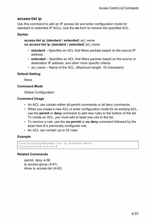
Access Control List Commands
access-list ip Use this command to add an IP access list and enter configuration mode for standard or extended IP ACLs. Use the no form to remove the specified ACL.
Syntax
access-list ip {standard | extended} acl_nameno access-list ip {standard | extended} acl_name
• standard – Specifies an ACL that filters packets based on the source IP address.
• extended – Specifies an ACL that filters packets based on the source or destination IP address, and other more specific criteria.
• acl_name – Name of the ACL. (Maximum length: 16 characters)
Default Setting
None
Command Mode
Global Configuration
Command Usage
• An ACL can contain either all permit commands or all deny commands.• When you create a new ACL or enter configuration mode for an existing ACL,
use the permit or deny command to add new rules to the bottom of the list. To create an ACL, you must add at least one rule to the list.
• To remove a rule, use the no permit or no deny command followed by the exact text of a previously configured rule.
• An ACL can contain up to 32 rules.
Example
Related Commands
permit, deny 4-58ip access-group (4-61)show ip access-list (4-62)
Console(config)#access-list ip standard davidConsole(config-std-acl)#
4-57
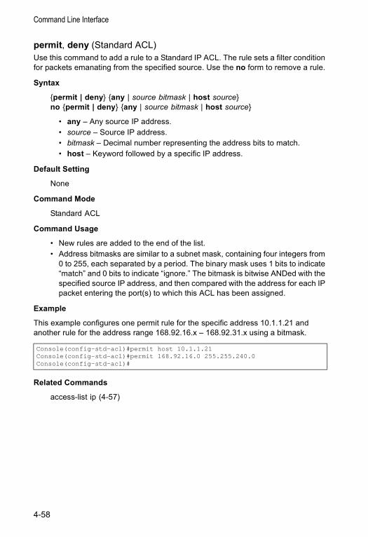
Command Line Interface
permit, deny (Standard ACL) Use this command to add a rule to a Standard IP ACL. The rule sets a filter condition for packets emanating from the specified source. Use the no form to remove a rule.
Syntax
{permit | deny} {any | source bitmask | host source}no {permit | deny} {any | source bitmask | host source}
• any – Any source IP address.• source – Source IP address.• bitmask – Decimal number representing the address bits to match.• host – Keyword followed by a specific IP address.
Default Setting
None
Command Mode
Standard ACL
Command Usage
• New rules are added to the end of the list.• Address bitmasks are similar to a subnet mask, containing four integers from
0 to 255, each separated by a period. The binary mask uses 1 bits to indicate “match” and 0 bits to indicate “ignore.” The bitmask is bitwise ANDed with the specified source IP address, and then compared with the address for each IP packet entering the port(s) to which this ACL has been assigned.
Example
This example configures one permit rule for the specific address 10.1.1.21 and another rule for the address range 168.92.16.x – 168.92.31.x using a bitmask.
Related Commands
access-list ip (4-57)
Console(config-std-acl)#permit host 10.1.1.21Console(config-std-acl)#permit 168.92.16.0 255.255.240.0Console(config-std-acl)#
4-58
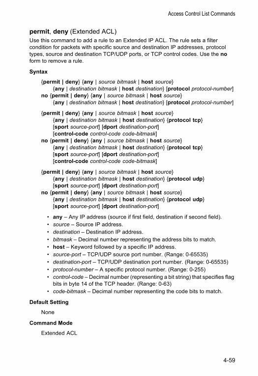
Access Control List Commands
permit, deny (Extended ACL) Use this command to add a rule to an Extended IP ACL. The rule sets a filter condition for packets with specific source and destination IP addresses, protocol types, source and destination TCP/UDP ports, or TCP control codes. Use the no form to remove a rule.
Syntax
{permit | deny} {any | source bitmask | host source} {any | destination bitmask | host destination} [protocol protocol-number]
no {permit | deny} {any | source bitmask | host source} {any | destination bitmask | host destination} [protocol protocol-number]
{permit | deny} {any | source bitmask | host source} {any | destination bitmask | host destination} {protocol tcp} [sport source-port] [dport destination-port] [control-code control-code code-bitmask]
no {permit | deny} {any | source bitmask | host source} {any | destination bitmask | host destination} {protocol tcp} [sport source-port] [dport destination-port] [control-code control-code code-bitmask]
{permit | deny} {any | source bitmask | host source} {any | destination bitmask | host destination} {protocol udp} [sport source-port] [dport destination-port]
no {permit | deny} {any | source bitmask | host source} {any | destination bitmask | host destination} {protocol udp} [sport source-port] [dport destination-port]
• any – Any IP address (source if first field, destination if second field).• source – Source IP address.• destination – Destination IP address.• bitmask – Decimal number representing the address bits to match.• host – Keyword followed by a specific IP address.• source-port – TCP/UDP source port number. (Range: 0-65535)• destination-port – TCP/UDP destination port number. (Range: 0-65535)• protocol-number – A specific protocol number. (Range: 0-255)• control-code – Decimal number (representing a bit string) that specifies flag
bits in byte 14 of the TCP header. (Range: 0-63)• code-bitmask – Decimal number representing the code bits to match.
Default Setting
None
Command Mode
Extended ACL
4-59
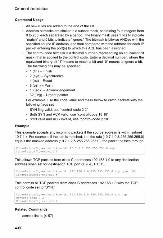
Command Line Interface
Command Usage
• All new rules are added to the end of the list.• Address bitmasks are similar to a subnet mask, containing four integers from
0 to 255, each separated by a period. The binary mask uses 1 bits to indicate “match” and 0 bits to indicate “ignore.” The bitmask is bitwise ANDed with the specified source IP address, and then compared with the address for each IP packet entering the port(s) to which this ACL has been assigned.
• The control-code bitmask is a decimal number (representing an equivalent bit mask) that is applied to the control code. Enter a decimal number, where the equivalent binary bit “1” means to match a bit and “0” means to ignore a bit. The following bits may be specified:- 1 (fin) – Finish- 2 (syn) – Synchronize- 4 (rst) – Reset- 8 (psh) – Push- 16 (ack) – Acknowledgement- 32 (urg) – Urgent pointerFor example, use the code value and mask below to catch packets with the following flags set: - SYN flag valid, use “control-code 2 2”- Both SYN and ACK valid, use “control-code 18 18”- SYN valid and ACK invalid, use “control-code 2 18”
Example
This example accepts any incoming packets if the source address is within subnet 10.7.1.x. For example, if the rule is matched; i.e., the rule (10.7.1.0 & 255.255.255.0) equals the masked address (10.7.1.2 & 255.255.255.0), the packet passes through.
This allows TCP packets from class C addresses 192.168.1.0 to any destination address when set for destination TCP port 80 (i.e., HTTP).
This permits all TCP packets from class C addresses 192.168.1.0 with the TCP control code set to “SYN.”
Related Commands
access-list ip (4-57)
Console(config-ext-acl)#permit 10.7.1.1 255.255.255.0 anyConsole(config-ext-acl)#
Console(config-ext-acl)#permit 192.168.1.0 255.255.255.0 any dport 80Console(config-ext-acl)#
Console(config-ext-acl)#permit 192.168.1.0 255.255.255.0 any tcpcontrol-code 2 2Console(config-ext-acl)#
4-60
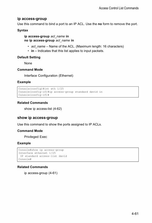
Access Control List Commands
ip access-group Use this command to bind a port to an IP ACL. Use the no form to remove the port.
Syntax
ip access-group acl_name inno ip access-group acl_name in
• acl_name – Name of the ACL. (Maximum length: 16 characters)• in – Indicates that this list applies to input packets.
Default Setting
None
Command Mode
Interface Configuration (Ethernet)
Example
Related Commands
show ip access-list (4-62)
show ip access-groupUse this command to show the ports assigned to IP ACLs.
Command Mode
Privileged Exec
Example
Related Commands
ip access-group (4-61)
Console(config)#int eth 1/25Console(config-if)#ip access-group standard david inConsole(config-if)#
Console#show ip access-groupInterface ethernet 1/25IP standard access-list david
Console#
4-61
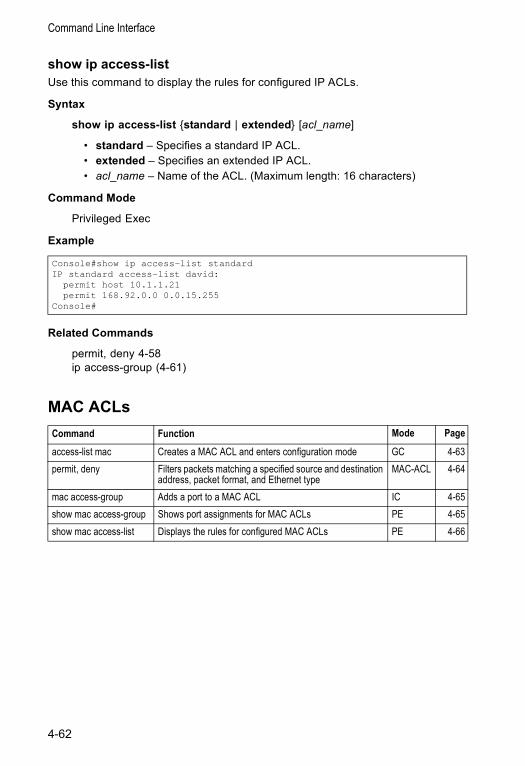
Command Line Interface
show ip access-list Use this command to display the rules for configured IP ACLs.
Syntax
show ip access-list {standard | extended} [acl_name]
• standard – Specifies a standard IP ACL.• extended – Specifies an extended IP ACL.• acl_name – Name of the ACL. (Maximum length: 16 characters)
Command Mode
Privileged Exec
Example
Related Commands
permit, deny 4-58ip access-group (4-61)
MAC ACLs
Console#show ip access-list standardIP standard access-list david:
permit host 10.1.1.21permit 168.92.0.0 0.0.15.255
Console#
Command Function Mode Page
access-list mac Creates a MAC ACL and enters configuration mode GC 4-63permit, deny Filters packets matching a specified source and destination
address, packet format, and Ethernet typeMAC-ACL 4-64
mac access-group Adds a port to a MAC ACL IC 4-65show mac access-group Shows port assignments for MAC ACLs PE 4-65show mac access-list Displays the rules for configured MAC ACLs PE 4-66
4-62
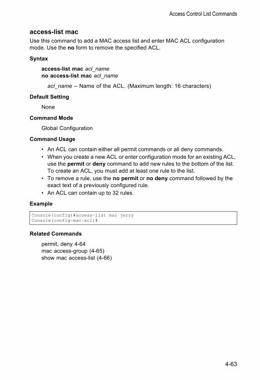
Access Control List Commands
access-list mac Use this command to add a MAC access list and enter MAC ACL configuration mode. Use the no form to remove the specified ACL.
Syntax
access-list mac acl_nameno access-list mac acl_name
acl_name – Name of the ACL. (Maximum length: 16 characters)
Default Setting
None
Command Mode
Global Configuration
Command Usage
• An ACL can contain either all permit commands or all deny commands.• When you create a new ACL or enter configuration mode for an existing ACL,
use the permit or deny command to add new rules to the bottom of the list. To create an ACL, you must add at least one rule to the list.
• To remove a rule, use the no permit or no deny command followed by the exact text of a previously configured rule.
• An ACL can contain up to 32 rules.
Example
Related Commands
permit, deny 4-64mac access-group (4-65)show mac access-list (4-66)
Console(config)#access-list mac jerryConsole(config-mac-acl)#
4-63
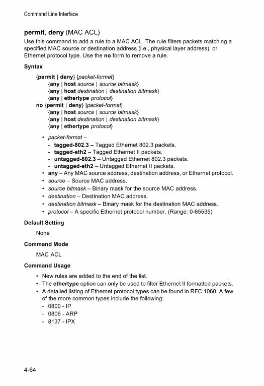
Command Line Interface
permit, deny (MAC ACL)Use this command to add a rule to a MAC ACL. The rule filters packets matching a specified MAC source or destination address (i.e., physical layer address), or Ethernet protocol type. Use the no form to remove a rule.
Syntax
{permit | deny} [packet-format] {any | host source | source bitmask} {any | host destination | destination bitmask}{any | ethertype protocol}
no {permit | deny} [packet-format] {any | host source | source bitmask} {any | host destination | destination bitmask}{any | ethertype protocol}
• packet-format – - tagged-802.3 – Tagged Ethernet 802.3 packets.- tagged-eth2 – Tagged Ethernet II packets.- untagged-802.3 – Untagged Ethernet 802.3 packets.- untagged-eth2 – Untagged Ethernet II packets.
• any – Any MAC source address, destination address, or Ethernet protocol. • source – Source MAC address.• source bitmask – Binary mask for the source MAC address.• destination – Destination MAC address.• destination bitmask – Binary mask for the destination MAC address.• protocol – A specific Ethernet protocol number. (Range: 0-65535)
Default Setting
None
Command Mode
MAC ACL
Command Usage
• New rules are added to the end of the list.• The ethertype option can only be used to filter Ethernet II formatted packets. • A detailed listing of Ethernet protocol types can be found in RFC 1060. A few
of the more common types include the following:- 0800 - IP- 0806 - ARP- 8137 - IPX
4-64
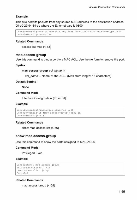
Access Control List Commands
Example
This rule permits packets from any source MAC address to the destination address 00-e0-29-94-34-de where the Ethernet type is 0800.
Related Commands
access-list mac (4-63)
mac access-groupUse this command to bind a port to a MAC ACL. Use the no form to remove the port.
Syntax
mac access-group acl_name in
acl_name – Name of the ACL. (Maximum length: 16 characters)
Default Setting
None
Command Mode
Interface Configuration (Ethernet)
Example
Related Commands
show mac access-list (4-66)
show mac access-groupUse this command to show the ports assigned to MAC ACLs.
Command Mode
Privileged Exec
Example
Related Commands
mac access-group (4-65)
Console(config-mac-acl)#permit any host 00-e0-29-94-34-de ethertype 0800Console(config-mac-acl)#
Console(config)#interface ethernet 1/25Console(config-if)#mac access-group jerry inConsole(config-if)#
Console#show mac access-groupInterface ethernet 1/25MAC access-list jerry
Console#
4-65
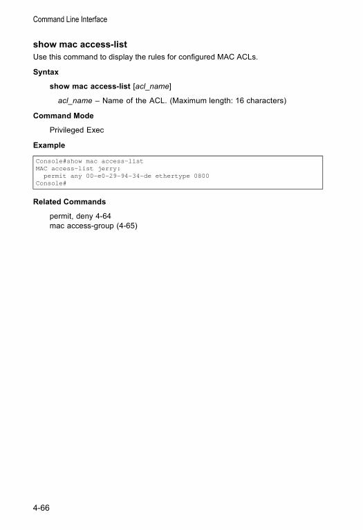
Command Line Interface
show mac access-list Use this command to display the rules for configured MAC ACLs.
Syntax
show mac access-list [acl_name]
acl_name – Name of the ACL. (Maximum length: 16 characters)
Command Mode
Privileged Exec
Example
Related Commands
permit, deny 4-64mac access-group (4-65)
Console#show mac access-listMAC access-list jerry:
permit any 00-e0-29-94-34-de ethertype 0800Console#
4-66
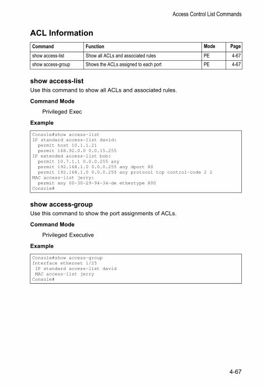
Access Control List Commands
ACL Information
show access-listUse this command to show all ACLs and associated rules.
Command Mode
Privileged Exec
Example
show access-groupUse this command to show the port assignments of ACLs.
Command Mode
Privileged Executive
Example
Command Function Mode Page
show access-list Show all ACLs and associated rules PE 4-67show access-group Shows the ACLs assigned to each port PE 4-67
Console#show access-listIP standard access-list david:
permit host 10.1.1.21permit 168.92.0.0 0.0.15.255
IP extended access-list bob:permit 10.7.1.1 0.0.0.255 anypermit 192.168.1.0 0.0.0.255 any dport 80permit 192.168.1.0 0.0.0.255 any protocol tcp control-code 2 2
MAC access-list jerry:permit any 00-30-29-94-34-de ethertype 800
Console#
Console#show access-groupInterface ethernet 1/25IP standard access-list davidMAC access-list jerry
Console#
4-67
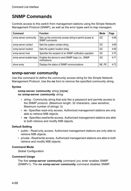
Command Line Interface
SNMP CommandsControls access to this switch from management stations using the Simple Network Management Protocol (SNMP), as well as the error types sent to trap managers.
snmp-server communityUse this command to define the community access string for the Simple Network Management Protocol. Use the no form to remove the specified community string.
Syntax snmp-server community string [ro|rw]no snmp-server community string
• string - Community string that acts like a password and permits access to the SNMP protocol. (Maximum length: 32 characters, case sensitive; Maximum number of strings: 5)
• ro - Specifies read-only access. Authorized management stations are only able to retrieve MIB objects.
• rw - Specifies read/write access. Authorized management stations are able to both retrieve and modify MIB objects.
Default Setting • public - Read-only access. Authorized management stations are only able to
retrieve MIB objects.• private - Read/write access. Authorized management stations are able to both
retrieve and modify MIB objects.
Command Mode Global Configuration
Command Usage The first snmp-server community command you enter enables SNMP (SNMPv1). The no snmp-server community command disables SNMP.
Command Function Mode Pagesnmp-server community Sets up the community access string to permit access to
SNMP commands GC 4-68
snmp-server contact Sets the system contact string GC 4-69snmp-server location Sets the system location string GC 4-69snmp-server host Specifies the recipient of an SNMP notification operation GC 4-70snmp-server enable traps Enables the device to send SNMP traps (i.e., SNMP
notifications) GC 4-71
show snmp Displays the status of SNMP communications NE, PE 4-72
4-68
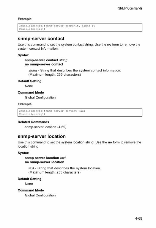
SNMP Commands
Example
snmp-server contactUse this command to set the system contact string. Use the no form to remove the system contact information.
Syntax snmp-server contact stringno snmp-server contact
string - String that describes the system contact information. (Maximum length: 255 characters)
Default Setting None
Command Mode Global Configuration
Example
Related Commandssnmp-server location (4-69)
snmp-server locationUse this command to set the system location string. Use the no form to remove the location string.
Syntax snmp-server location textno snmp-server location
text - String that describes the system location. (Maximum length: 255 characters)
Default Setting None
Command Mode Global Configuration
Console(config)#snmp-server community alpha rwConsole(config)#
Console(config)#snmp-server contact PaulConsole(config)#
4-69

Command Line Interface
Example
Related Commandssnmp-server contact (4-69)
snmp-server host Use this command to specify the recipient of a Simple Network Management Protocol notification operation. Use the no form to remove the specified host.
Syntax snmp-server host host-addr community-stringno snmp-server host host-addr
• host-addr - Internet address of the host (the targeted recipient). (Maximum host addresses: 5 trap destination IP address entries)
• community-string - Password-like community string sent with the notification operation. Although you can set this string using the snmp-server host command by itself, we recommend that you define this string using the snmp-server community command prior to using the snmp-server host command. (Maximum length: 32 characters)
Default Setting None
Command Mode Global Configuration
Command Usage • If you do not enter an snmp-server host command, no notifications are sent.
In order to configure the switch to send SNMP notifications, you must enter at least one snmp-server host command. In order to enable multiple hosts, you must issue a separate snmp-server host command for each host.
• The snmp-server host command is used in conjunction with the snmp-server enable traps command. Use the snmp-server enable traps command to specify which SNMP notifications are sent globally. For a host to receive notifications, at least one snmp-server enable traps command and the snmp-server host command for that host must be enabled.
• However, some notification types cannot be controlled with the snmp-server enable traps command. For example, some notification types are always enabled.
Example
Console(config)#snmp-server location WC-19Console(config)#
Console(config)#snmp-server host 10.1.19.23 batmanConsole(config)#
4-70
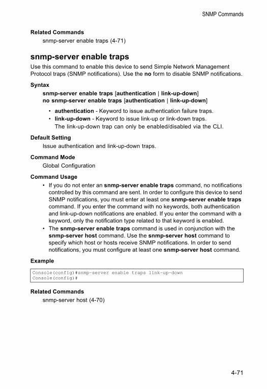
SNMP Commands
Related Commandssnmp-server enable traps (4-71)
snmp-server enable trapsUse this command to enable this device to send Simple Network Management Protocol traps (SNMP notifications). Use the no form to disable SNMP notifications.
Syntax snmp-server enable traps [authentication | link-up-down]no snmp-server enable traps [authentication | link-up-down]
• authentication - Keyword to issue authentication failure traps. • link-up-down - Keyword to issue link-up or link-down traps.
The link-up-down trap can only be enabled/disabled via the CLI.
Default Setting Issue authentication and link-up-down traps.
Command Mode Global Configuration
Command Usage • If you do not enter an snmp-server enable traps command, no notifications
controlled by this command are sent. In order to configure this device to send SNMP notifications, you must enter at least one snmp-server enable traps command. If you enter the command with no keywords, both authentication and link-up-down notifications are enabled. If you enter the command with a keyword, only the notification type related to that keyword is enabled.
• The snmp-server enable traps command is used in conjunction with the snmp-server host command. Use the snmp-server host command to specify which host or hosts receive SNMP notifications. In order to send notifications, you must configure at least one snmp-server host command.
Example
Related Commandssnmp-server host (4-70)
Console(config)#snmp-server enable traps link-up-downConsole(config)#
4-71
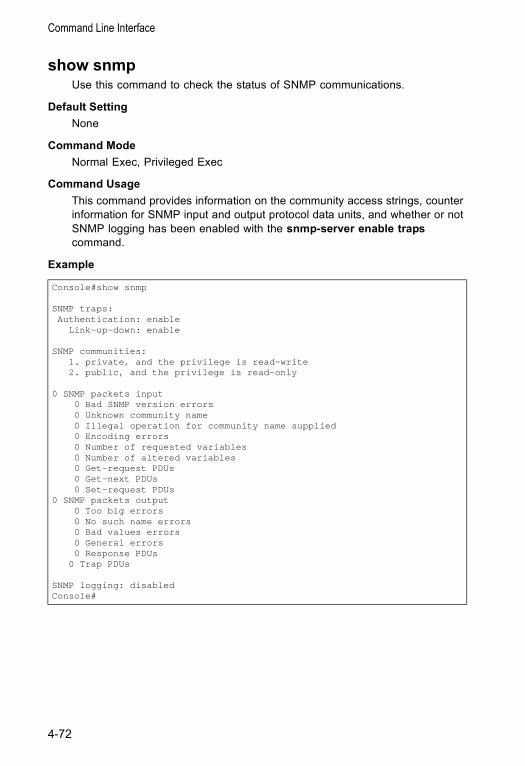
Command Line Interface
show snmpUse this command to check the status of SNMP communications.
Default Setting None
Command Mode Normal Exec, Privileged Exec
Command Usage This command provides information on the community access strings, counter information for SNMP input and output protocol data units, and whether or not SNMP logging has been enabled with the snmp-server enable traps command.
Example
Console#show snmp
SNMP traps:Authentication: enable
Link-up-down: enable
SNMP communities:1. private, and the privilege is read-write2. public, and the privilege is read-only
0 SNMP packets input0 Bad SNMP version errors0 Unknown community name0 Illegal operation for community name supplied0 Encoding errors0 Number of requested variables0 Number of altered variables0 Get-request PDUs0 Get-next PDUs0 Set-request PDUs
0 SNMP packets output0 Too big errors0 No such name errors0 Bad values errors0 General errors0 Response PDUs
0 Trap PDUs
SNMP logging: disabledConsole#
4-72
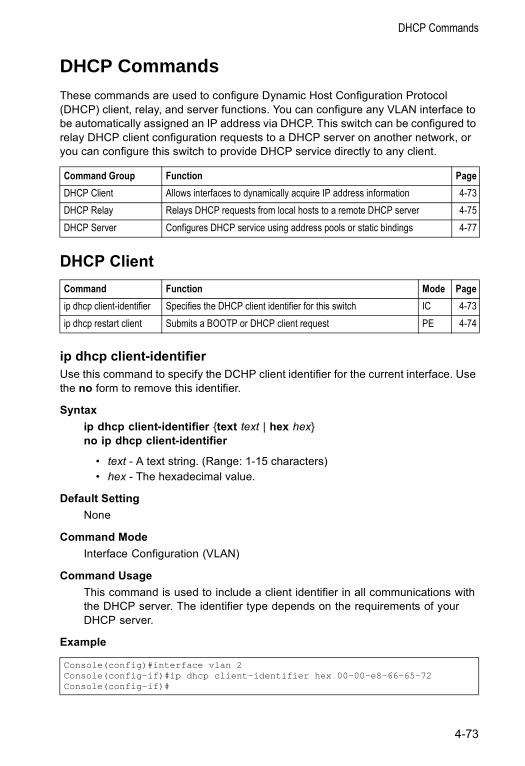
DHCP Commands
DHCP CommandsThese commands are used to configure Dynamic Host Configuration Protocol (DHCP) client, relay, and server functions. You can configure any VLAN interface to be automatically assigned an IP address via DHCP. This switch can be configured to relay DHCP client configuration requests to a DHCP server on another network, or you can configure this switch to provide DHCP service directly to any client.
DHCP Client
ip dhcp client-identifierUse this command to specify the DCHP client identifier for the current interface. Use the no form to remove this identifier.
Syntax ip dhcp client-identifier {text text | hex hex}no ip dhcp client-identifier
• text - A text string. (Range: 1-15 characters) • hex - The hexadecimal value.
Default Setting None
Command Mode Interface Configuration (VLAN)
Command Usage This command is used to include a client identifier in all communications with the DHCP server. The identifier type depends on the requirements of your DHCP server.
Example
Command Group Function PageDHCP Client Allows interfaces to dynamically acquire IP address information 4-73DHCP Relay Relays DHCP requests from local hosts to a remote DHCP server 4-75DHCP Server Configures DHCP service using address pools or static bindings 4-77
Command Function Mode Pageip dhcp client-identifier Specifies the DHCP client identifier for this switch IC 4-73ip dhcp restart client Submits a BOOTP or DHCP client request PE 4-74
Console(config)#interface vlan 2Console(config-if)#ip dhcp client-identifier hex 00-00-e8-66-65-72Console(config-if)#
4-73
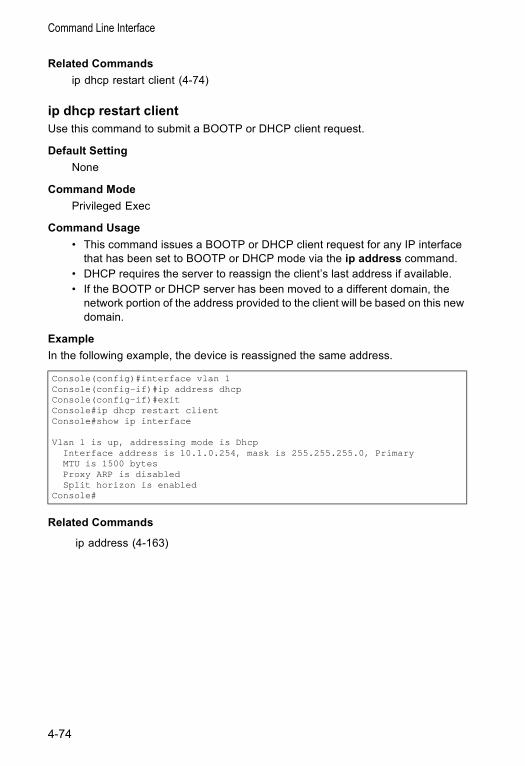
Command Line Interface
Related Commandsip dhcp restart client (4-74)
ip dhcp restart clientUse this command to submit a BOOTP or DHCP client request.
Default Setting None
Command Mode Privileged Exec
Command Usage • This command issues a BOOTP or DHCP client request for any IP interface
that has been set to BOOTP or DHCP mode via the ip address command.• DHCP requires the server to reassign the client’s last address if available. • If the BOOTP or DHCP server has been moved to a different domain, the
network portion of the address provided to the client will be based on this new domain.
Example In the following example, the device is reassigned the same address.
Related Commands
ip address (4-163)
Console(config)#interface vlan 1Console(config-if)#ip address dhcpConsole(config-if)#exitConsole#ip dhcp restart clientConsole#show ip interface
Vlan 1 is up, addressing mode is DhcpInterface address is 10.1.0.254, mask is 255.255.255.0, PrimaryMTU is 1500 bytesProxy ARP is disabledSplit horizon is enabled
Console#
4-74
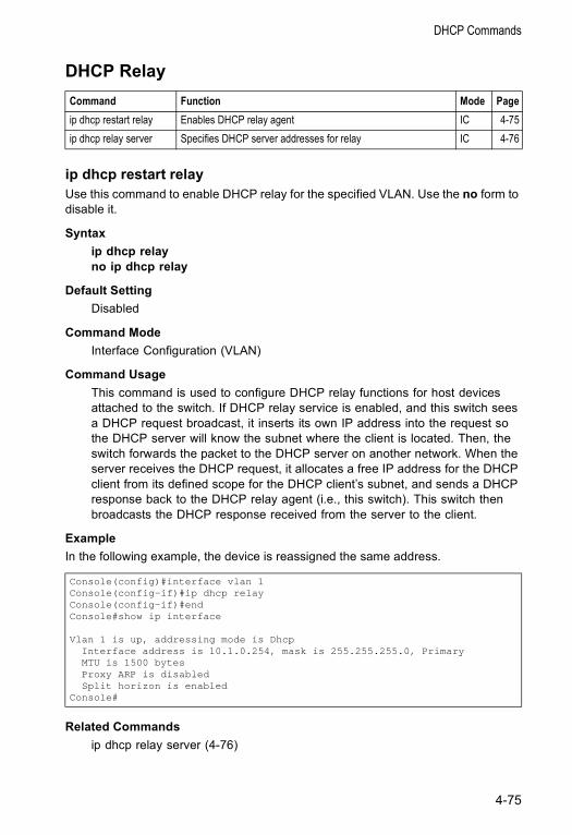
DHCP Commands
DHCP Relay
ip dhcp restart relayUse this command to enable DHCP relay for the specified VLAN. Use the no form to disable it.
Syntax ip dhcp relayno ip dhcp relay
Default Setting Disabled
Command Mode Interface Configuration (VLAN)
Command Usage This command is used to configure DHCP relay functions for host devices attached to the switch. If DHCP relay service is enabled, and this switch sees a DHCP request broadcast, it inserts its own IP address into the request so the DHCP server will know the subnet where the client is located. Then, the switch forwards the packet to the DHCP server on another network. When the server receives the DHCP request, it allocates a free IP address for the DHCP client from its defined scope for the DHCP client’s subnet, and sends a DHCP response back to the DHCP relay agent (i.e., this switch). This switch then broadcasts the DHCP response received from the server to the client.
Example In the following example, the device is reassigned the same address.
Related Commandsip dhcp relay server (4-76)
Command Function Mode Pageip dhcp restart relay Enables DHCP relay agent IC 4-75ip dhcp relay server Specifies DHCP server addresses for relay IC 4-76
Console(config)#interface vlan 1Console(config-if)#ip dhcp relayConsole(config-if)#endConsole#show ip interface
Vlan 1 is up, addressing mode is DhcpInterface address is 10.1.0.254, mask is 255.255.255.0, PrimaryMTU is 1500 bytesProxy ARP is disabledSplit horizon is enabled
Console#
4-75
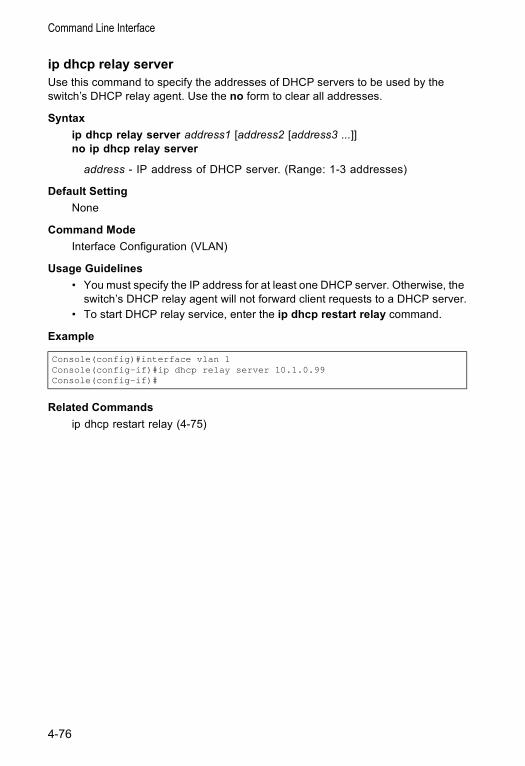
Command Line Interface
ip dhcp relay serverUse this command to specify the addresses of DHCP servers to be used by the switch’s DHCP relay agent. Use the no form to clear all addresses.
Syntaxip dhcp relay server address1 [address2 [address3 ...]]no ip dhcp relay server
address - IP address of DHCP server. (Range: 1-3 addresses)
Default Setting None
Command ModeInterface Configuration (VLAN)
Usage Guidelines • You must specify the IP address for at least one DHCP server. Otherwise, the
switch’s DHCP relay agent will not forward client requests to a DHCP server.• To start DHCP relay service, enter the ip dhcp restart relay command.
Example
Related Commandsip dhcp restart relay (4-75)
Console(config)#interface vlan 1Console(config-if)#ip dhcp relay server 10.1.0.99Console(config-if)#
4-76
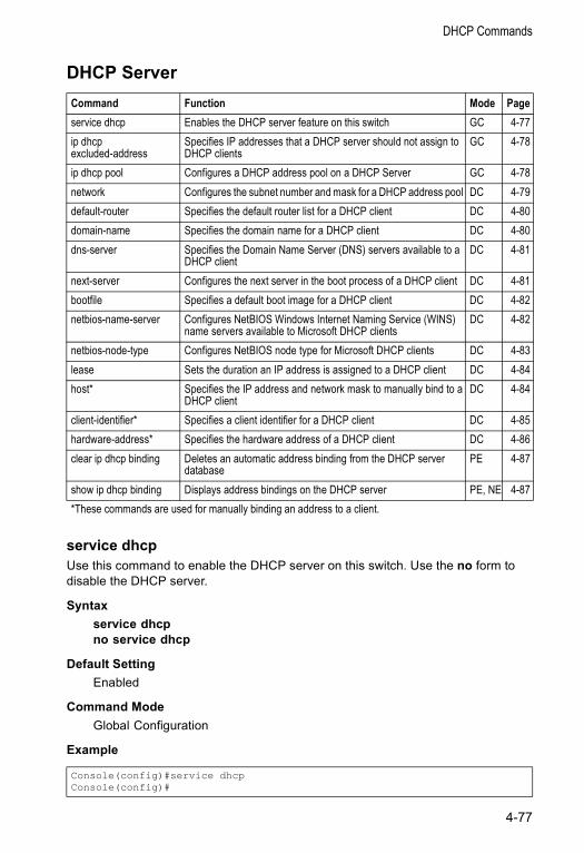
DHCP Commands
DHCP Server
service dhcpUse this command to enable the DHCP server on this switch. Use the no form to disable the DHCP server.
Syntaxservice dhcpno service dhcp
Default Setting Enabled
Command ModeGlobal Configuration
Example
Command Function Mode Pageservice dhcp Enables the DHCP server feature on this switch GC 4-77ip dhcp excluded-address
Specifies IP addresses that a DHCP server should not assign to DHCP clients
GC 4-78
ip dhcp pool Configures a DHCP address pool on a DHCP Server GC 4-78network Configures the subnet number and mask for a DHCP address pool DC 4-79default-router Specifies the default router list for a DHCP client DC 4-80domain-name Specifies the domain name for a DHCP client DC 4-80dns-server Specifies the Domain Name Server (DNS) servers available to a
DHCP clientDC 4-81
next-server Configures the next server in the boot process of a DHCP client DC 4-81bootfile Specifies a default boot image for a DHCP client DC 4-82netbios-name-server Configures NetBIOS Windows Internet Naming Service (WINS)
name servers available to Microsoft DHCP clientsDC 4-82
netbios-node-type Configures NetBIOS node type for Microsoft DHCP clients DC 4-83lease Sets the duration an IP address is assigned to a DHCP client DC 4-84host* Specifies the IP address and network mask to manually bind to a
DHCP clientDC 4-84
client-identifier* Specifies a client identifier for a DHCP client DC 4-85hardware-address* Specifies the hardware address of a DHCP client DC 4-86clear ip dhcp binding Deletes an automatic address binding from the DHCP server
databasePE 4-87
show ip dhcp binding Displays address bindings on the DHCP server PE, NE 4-87*These commands are used for manually binding an address to a client.
Console(config)#service dhcpConsole(config)#
4-77
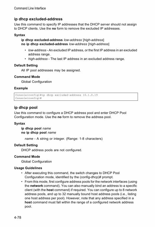
Command Line Interface
ip dhcp excluded-addressUse this command to specify IP addresses that the DHCP server should not assign to DHCP clients. Use the no form to remove the excluded IP addresses.
Syntaxip dhcp excluded-address low-address [high-address]no ip dhcp excluded-address low-address [high-address]
• low-address - An excluded IP address, or the first IP address in an excluded address range.
• high-address - The last IP address in an excluded address range.
Default Setting All IP pool addresses may be assigned.
Command ModeGlobal Configuration
Example
ip dhcp poolUse this command to configure a DHCP address pool and enter DHCP Pool Configuration mode. Use the no form to remove the address pool.
Syntaxip dhcp pool nameno ip dhcp pool name
name - A string or integer. (Range: 1-8 characters)
Default Setting DHCP address pools are not configured.
Command ModeGlobal Configuration
Usage Guidelines • After executing this command, the switch changes to DHCP Pool
Configuration mode, identified by the (config-dhcp)# prompt.• From this mode, first configure address pools for the network interfaces (using
the network command). You can also manually bind an address to a specific client (with the host command) if required. You can configure up to 8 network address pools, and up to 32 manually bound host address pools (i.e., listing one host address per pool). However, note that any address specified in a host command must fall within the range of a configured network address pool.
Console(config)#ip dhcp excluded-address 10.1.0.19Console(config)#
4-78

DHCP Commands
Example
Related Commandsnetwork (4-79)host (4-84)
networkUse this command to configure the subnet number and mask for a DHCP address pool. Use the no form to remove the subnet number and mask.
Syntaxnetwork network-number [mask]no network
• network-number - The IP address of the DHCP address pool.• mask - The bit combination that identifies the network (or subnet) and the
host portion of the DHCP address pool.
Command ModeDHCP Pool Configuration
Usage Guidelines • When a client request is received, the switch first checks for a network
address pool matching the gateway where the request originated (i.e., if the request was forwarded by a relay server). If there is no gateway in the client request (i.e., the request was not forwarded by a relay server), the switch searches for a network pool matching the interface through which the client request was received. It then searches for a manually configured host address that falls within the matching network pool. If no manually configured host address is found, it assigns an address from the matching network address pool. However, if no matching address pool is found the request is ignored.
• This command is valid for DHCP network address pools only. If the mask is not specified, the class A, B, or C natural mask is used (see page 3-133). The DHCP server assumes that all host addresses are available. You can exclude subsets of the address space by using the ip dhcp excluded-address command.
Example
Console(config)#ip dhcp pool R&DConsole(config-dhcp)#
Console(config-dhcp)#network 10.1.0.0 255.255.255.0Console(config-dhcp)#
4-79
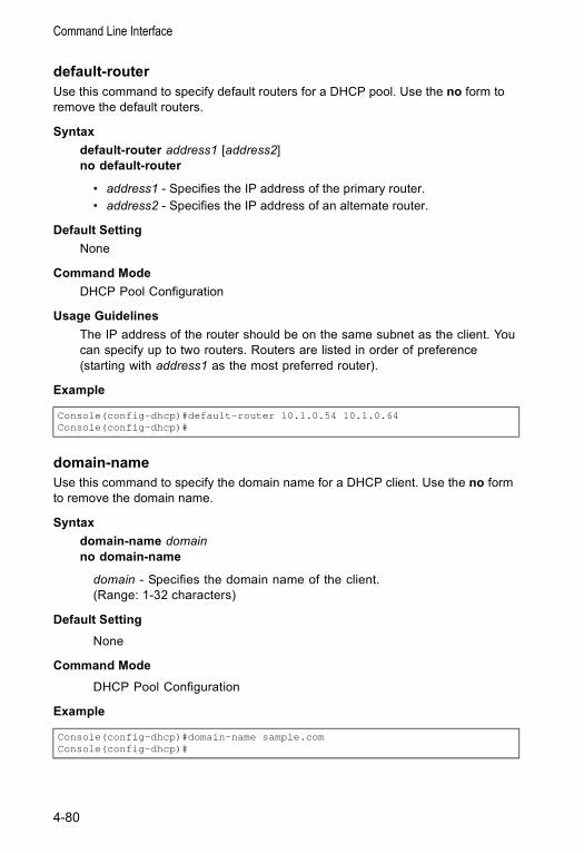
Command Line Interface
default-routerUse this command to specify default routers for a DHCP pool. Use the no form to remove the default routers.
Syntax default-router address1 [address2]no default-router
• address1 - Specifies the IP address of the primary router. • address2 - Specifies the IP address of an alternate router.
Default Setting None
Command ModeDHCP Pool Configuration
Usage Guidelines The IP address of the router should be on the same subnet as the client. You can specify up to two routers. Routers are listed in order of preference (starting with address1 as the most preferred router).
Example
domain-nameUse this command to specify the domain name for a DHCP client. Use the no form to remove the domain name.
Syntax domain-name domainno domain-name
domain - Specifies the domain name of the client. (Range: 1-32 characters)
Default Setting None
Command ModeDHCP Pool Configuration
Example
Console(config-dhcp)#default-router 10.1.0.54 10.1.0.64Console(config-dhcp)#
Console(config-dhcp)#domain-name sample.comConsole(config-dhcp)#
4-80
DHCP Commands
dns-serverUse this command to specify the Domain Name System (DNS) IP servers available to a DHCP client. Use the no form to remove the DNS server list.
Syntaxdns-server address1 [address2]no dns-server
• address1 - Specifies the IP address of the primary DNS server.• address2 - Specifies the IP address of the alternate DNS server.
Default Setting None
Command ModeDHCP Pool Configuration
Usage Guidelines • If DNS IP servers are not configured for a DHCP client, the client cannot
correlate host names to IP addresses.• Servers are listed in order of preference (starting with address1 as the most
preferred server).
Example
next-serverUse this command to configure the next server in the boot process of a DHCP client. Use the no form to remove the boot server list.
Syntaxnext-server addressno next-server address
address - Specifies the IP address of the next server in the boot process, which is typically a Trivial File Transfer Protocol (TFTP) server.
Default SettingNone
Command ModeDHCP Pool Configuration
Example
Console(config-dhcp)#dns-server 10.1.1.253 192.168.3.19Console(config-dhcp)#
Console(config-dhcp)#next-server 10.1.0.21Console(config-dhcp)#
4-81
Command Line Interface
Related Commandsbootfile (4-82)
bootfileUse this command to specify the name of the default boot image for a DHCP client. This file should placed on the Trivial File Transfer Protocol (TFTP) server specified with the next-server command. Use the no form to delete the boot image name.
Syntax bootfile filenameno bootfile
filename - Name of the file that is used as a default boot image.
Default Setting None
Command ModeDHCP Pool Configuration
Example
Related Commandsnext-server (4-81)
netbios-name-serverUse this command to configure NetBIOS Windows Internet Naming Service (WINS) name servers that are available to Microsoft DHCP clients. Use the no form to remove the NetBIOS name server list.
Syntaxnetbios-name-server address1 [address2]no netbios-name-server
• address1 - Specifies IP address of primary NetBIOS WINS name server.• address2 - Specifies IP address of alternate NetBIOS WINS name server.
Default SettingNone
Command ModeDHCP Pool Configuration
Usage Guidelines Servers are listed in order of preference (starting with address1 as the most preferred server).
Console(config-dhcp)#bootfile wme.batConsole(config-dhcp)#
4-82
DHCP Commands
Example
Related Commandsnetbios-node-type (4-83)
netbios-node-typeUse this command to configure the NetBIOS node type for Microsoft DHCP clients. Use the no form to remove the NetBIOS node type.
Syntax netbios-node-type typeno netbios-node-type
type - Specifies the NetBIOS node type:• broadcast• hybrid (recommended)• mixed• peer-to-peer
Default SettingNone
Command ModeDHCP Pool Configuration
Example
Related Commandsnetbios-name-server (4-82)
Console(config-dhcp)#netbios-name-server 10.1.0.33 10.1.0.34Console(config-dhcp)#
Console(config-dhcp)#netbios-node-type hybridConsole(config-dhcp)#
4-83
Command Line Interface
leaseUse this command to configure the duration that an IP address is assigned to a DHCP client. Use the no form to restore the default value.
Syntaxlease {days [hours][minutes] | infinite}no lease
• days - Specifies the duration of the lease in numbers of days. (Range: 0-364)
• hours - Specifies the number of hours in the lease. A days value must be supplied before you can configure hours. (Range: 0-23)
• minutes - Specifies the number of minutes in the lease. A days and hours value must be supplied before you can configure minutes. (Range: 0-59)
• infinite - Specifies that the lease time is unlimited. This option is normally used for addresses manually bound to a BOOTP client via the host command.
Default SettingOne day
Command Modes DHCP Pool Configuration
Example The following example leases an address to clients using this pool for 7 days.
hostUse this command to specify the IP address and network mask to manually bind to a DHCP client. Use the no form to remove the IP address for the client.
Syntaxhost address [mask]no host
• address - Specifies the IP address of a client.• mask - Specifies the network mask of the client.
Default Setting None
Command ModeDHCP Pool Configuration
Console(config-dhcp)#lease 7Console(config-dhcp)#
4-84
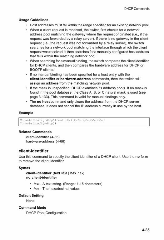
DHCP Commands
Usage Guidelines • Host addresses must fall within the range specified for an existing network pool.• When a client request is received, the switch first checks for a network
address pool matching the gateway where the request originated (i.e., if the request was forwarded by a relay server). If there is no gateway in the client request (i.e., the request was not forwarded by a relay server), the switch searches for a network pool matching the interface through which the client request was received. It then searches for a manually configured host address that falls within the matching network pool.
• When searching for a manual binding, the switch compares the client identifier for DHCP clients, and then compares the hardware address for DHCP or BOOTP clients.
• If no manual binding has been specified for a host entry with the client-identifier or hardware-address commands, then the switch will assign an address from the matching network pool.
• If the mask is unspecified, DHCP examines its address pools. If no mask is found in the pool database, the Class A, B, or C natural mask is used (see page 3-133). This command is valid for manual bindings only.
• The no host command only clears the address from the DHCP server database. It does not cancel the IP address currently in use by the host.
Example
Related Commandsclient-identifier (4-85)hardware-address (4-86)
client-identifierUse this command to specify the client identifier of a DHCP client. Use the no form to remove the client identifier.
Syntaxclient-identifier {text text | hex hex}no client-identifier
• text - A text string. (Range: 1-15 characters) • hex - The hexadecimal value.
Default Setting None
Command Mode DHCP Pool Configuration
Console(config-dhcp)#host 10.1.0.21 255.255.255.0Console(config-dhcp)#
4-85
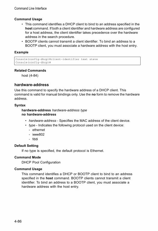
Command Line Interface
Command Usage • This command identifies a DHCP client to bind to an address specified in the
host command. If both a client identifier and hardware address are configured for a host address, the client identifier takes precedence over the hardware address in the search procedure.
• BOOTP clients cannot transmit a client identifier. To bind an address to a BOOTP client, you must associate a hardware address with the host entry.
Example
Related Commandshost (4-84)
hardware-addressUse this command to specify the hardware address of a DHCP client. This command is valid for manual bindings only. Use the no form to remove the hardware address.
Syntaxhardware-address hardware-address typeno hardware-address
• hardware-address - Specifies the MAC address of the client device.• type - Indicates the following protocol used on the client device:
- ethernet- ieee802- fddi
Default Setting If no type is specified, the default protocol is Ethernet.
Command ModeDHCP Pool Configuration
Command Usage This command identifies a DHCP or BOOTP client to bind to an address specified in the host command. BOOTP clients cannot transmit a client identifier. To bind an address to a BOOTP client, you must associate a hardware address with the host entry.
Console(config-dhcp)#client-identifier text steveConsole(config-dhcp)#
4-86
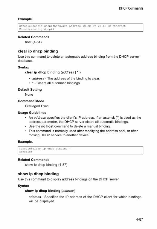
DHCP Commands
Example.
Related Commandshost (4-84)
clear ip dhcp bindingUse this command to delete an automatic address binding from the DHCP server database.
Syntax clear ip dhcp binding {address | * }
• address - The address of the binding to clear.• * - Clears all automatic bindings.
Default Setting None
Command ModePrivileged Exec
Usage Guidelines • An address specifies the client’s IP address. If an asterisk (*) is used as the
address parameter, the DHCP server clears all automatic bindings.• Use the no host command to delete a manual binding.• This command is normally used after modifying the address pool, or after
moving DHCP service to another device.
Example.
Related Commandsshow ip dhcp binding (4-87)
show ip dhcp bindingUse this command to display address bindings on the DHCP server.
Syntaxshow ip dhcp binding [address]
address - Specifies the IP address of the DHCP client for which bindings will be displayed.
Console(config-dhcp)#hardware-address 00-e0-29-94-34-28 ethernetConsole(config-dhcp)#
Console#clear ip dhcp binding *Console#
4-87

Command Line Interface
Default Setting None
Command ModeNormal Exec, Privileged Exec
Example.
Console#show ip dhcp binding
IP MAC Lease Time Start--------------- ----------------- ------------ -----------
192.1.3.21 00-00-e8-98-73-21 86400 Dec 25 08:01:57 2002Console#
4-88
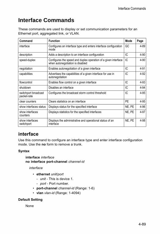
Interface Commands
Interface CommandsThese commands are used to display or set communication parameters for an Ethernet port, aggregated link, or VLAN.
interfaceUse this command to configure an interface type and enter interface configuration mode. Use the no form to remove a trunk.
Syntax
interface interfaceno interface port-channel channel-id
interface
• ethernet unit/port- unit - This is device 1. - port - Port number.
• port-channel channel-id (Range: 1-6) • vlan vlan-id (Range: 1-4094)
Default Setting
None
Command Function Mode Pageinterface Configures an interface type and enters interface configuration
mode GC 4-89
description Adds a description to an interface configuration IC 4-90speed-duplex Configures the speed and duplex operation of a given interface
when autonegotiation is disabledIC 4-90
negotiation Enables autonegotiation of a given interface IC 4-91capabilities Advertises the capabilities of a given interface for use in
autonegotiation IC 4-92
flowcontrol Enables flow control on a given interface IC 4-93shutdown Disables an interface IC 4-94switchport broadcast packet-rate
Configures the broadcast storm control threshold IC 4-95
clear counters Clears statistics on an interface PE 4-95show interfaces status Displays status for the specified interface NE, PE 4-96show interfaces counters
Displays statistics for the specified interfaces NE, PE 4-97
show interfaces switchport
Displays the administrative and operational status of an interface
NE, PE 4-98
4-89
Command Line Reference
Command Mode
Global Configuration
Example
To specify port 25, enter the following command:
descriptionUse this command to add a description to an interface. Use the no form to remove the description.
Syntax
description stringno description
string - Comment or a description to help you remember what is attached to this interface. (Range: 1-64 characters)
Default Setting
None
Command Mode
Interface Configuration (Ethernet, Port Channel)
Example
The following example adds a description to port 25.
speed-duplexUse this command to configure the speed and duplex mode of a given interface when autonegotiation is disabled. Use the no form to restore the default.
Syntax
speed-duplex {1000full | 100full | 100half | 10full | 10half}no speed-duplex
• 1000full - Forces 1000 Mbps full-duplex operation • 100full - Forces 100 Mbps full-duplex operation • 100half - Forces 100 Mbps half-duplex operation • 10full - Forces 10 Mbps full-duplex operation • 10half - Forces 10 Mbps half-duplex operation
Console(config)#interface ethernet 1/25Console(config-if)#
Console(config)#interface ethernet 1/25Console(config-if)#description RD-SW#3Console(config-if)#
4-90
Interface Commands
Default Setting
• Auto-negotiation is enabled by default. • When auto-negotiation is disabled, the default speed-duplex setting is 100half
for 100BASE-TX ports and 1000full for Gigabit Ethernet ports.
Command Mode
Interface Configuration (Ethernet, Port Channel)
Command Usage
• To force operation to the speed and duplex mode specified in a speed-duplex command, use the no negotiation command to disable auto-negotiation on the selected interface.
• When using the negotiation command to enable auto-negotiation, the optimal settings will be determined by the capabilities command. To set the speed/duplex mode under auto-negotiation, the required mode must be specified in the capabilities list for an interface.
Example
The following example configures port 5 to 100 Mbps, half-duplex operation.
Related Commands
negotiation (4-91)capabilities (4-92)
negotiationUse this command to enable autonegotiation for a given interface. Use the no form to disable autonegotiation.
Syntax
negotiationno negotiation
Default Setting
Enabled
Command Mode
Interface Configuration (Ethernet, Port Channel)
Command Usage
• When auto-negotiation is enabled the switch will negotiate the best settings for a link based on the capabilities command. When auto-negotiation is
Console(config)#interface ethernet 1/5Console(config-if)#speed-duplex 100halfConsole(config-if)#no negotiationConsole(config-if)#
4-91
Command Line Reference
disabled, you must manually specify the link attributes with the speed-duplex and flowcontrol commands.
• If autonegotiation is disabled, auto-MDI/MDI-X pin signal configuration will also be disabled for the RJ-45 ports.
Example
The following example configures port 11 to use autonegotiation.
Related Commands
capabilities (4-92)speed-duplex (4-90)
capabilitiesUse this command to advertise the port capabilities of a given interface during autonegotiation. Use the no form with parameters to remove an advertised capability, or the no form without parameters to restore the default values.
Syntax
capabilities {1000full | 100full | 100half | 10full | 10half | flowcontrol | symmetric}
no capabilities [1000full | 100full | 100half | 10full | 10half | flowcontrol | symmetric]
• 1000full - Supports 1000 Mbps full-duplex operation • 100full - Supports 100 Mbps full-duplex operation • 100half - Supports 100 Mbps half-duplex operation • 10full - Supports 10 Mbps full-duplex operation • 10half - Supports 10 Mbps half-duplex operation • flowcontrol - Supports flow control • symmetric (Gigabit only) - When specified, the port transmits and receives
pause frames; when not specified, the port will auto-negotiate to determine the sender and receiver for asymmetric pause frames. (The current switch ASIC only supports symmetric pause frames.)
Default Setting
• 100BASE-TX: 10half, 10full, 100half, 100full• 1000BASE-T: 10half, 10full, 100half, 100full, 1000full• 1000BASE-SX/LX/LH: 1000full
Command Mode
Interface Configuration (Ethernet, Port Channel)
Console(config)#interface ethernet 1/11Console(config-if)#negotiationConsole(config-if)#
4-92
Interface Commands
Command Usage
When auto-negotiation is enabled with the negotiation command, the switch will negotiate the best settings for a link based on the capabilites command. When auto-negotiation is disabled, you must manually specify the link attributes with the speed-duplex and flowcontrol commands.
Example
The following example configures Ethernet port 5 capabilities to 100half, 100full and flow control.
Related Commands
negotiation (4-91)speed-duplex (4-90)flowcontrol (4-93)
flowcontrolUse this command to enable flow control. Use the no form to disable flow control.
Syntax
flowcontrolno flowcontrol
Default Setting
Flow control enabled
Command Mode
Interface Configuration (Ethernet, Port Channel)
Command Usage
• Flow control can eliminate frame loss by “blocking” traffic from end stations or segments connected directly to the switch when its buffers fill. When enabled, back pressure is used for half-duplex operation and IEEE 802.3x for full-duplex operation.
• To force flow control on or off (with the flowcontrol or no flowcontrol command), use the no negotiation command to disable auto-negotiation on the selected interface.
• When using the negotiation command to enable auto-negotiation, the optimal settings will be determined by the capabilities command. To enable flow control under auto-negotiation, “flowcontrol” must be included in the capabilities list for any port
Console(config)#interface ethernet 1/5Console(config-if)#capabilities 100halfConsole(config-if)#capabilities 100fullConsole(config-if)#capabilities flowcontrolConsole(config-if)#
4-93
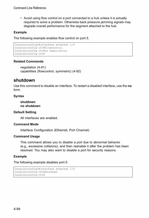
Command Line Reference
• Avoid using flow control on a port connected to a hub unless it is actually required to solve a problem. Otherwise back pressure jamming signals may degrade overall performance for the segment attached to the hub.
Example
The following example enables flow control on port 5.
Related Commands
negotiation (4-91)capabilities (flowcontrol, symmetric) (4-92)
shutdown Use this command to disable an interface. To restart a disabled interface, use the no form.
Syntax
shutdownno shutdown
Default Setting
All interfaces are enabled.
Command Mode
Interface Configuration (Ethernet, Port Channel)
Command Usage
This command allows you to disable a port due to abnormal behavior (e.g., excessive collisions), and then reenable it after the problem has been resolved. You may also want to disable a port for security reasons.
Example
The following example disables port 5.
Console(config)#interface ethernet 1/5Console(config-if)#flowcontrolConsole(config-if)#no negotiationConsole(config-if)#
Console(config)#interface ethernet 1/5Console(config-if)#shutdownConsole(config-if)#
4-94
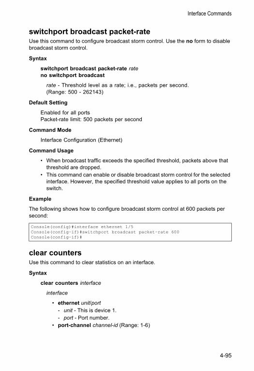
Interface Commands
switchport broadcast packet-rateUse this command to configure broadcast storm control. Use the no form to disable broadcast storm control.
Syntax
switchport broadcast packet-rate rateno switchport broadcast
rate - Threshold level as a rate; i.e., packets per second. (Range: 500 - 262143)
Default Setting
Enabled for all portsPacket-rate limit: 500 packets per second
Command Mode
Interface Configuration (Ethernet)
Command Usage
• When broadcast traffic exceeds the specified threshold, packets above that threshold are dropped.
• This command can enable or disable broadcast storm control for the selected interface. However, the specified threshold value applies to all ports on the switch.
Example
The following shows how to configure broadcast storm control at 600 packets per second:
clear countersUse this command to clear statistics on an interface.
Syntax
clear counters interface
interface
• ethernet unit/port- unit - This is device 1. - port - Port number.
• port-channel channel-id (Range: 1-6)
Console(config)#interface ethernet 1/5Console(config-if)#switchport broadcast packet-rate 600Console(config-if)#
4-95
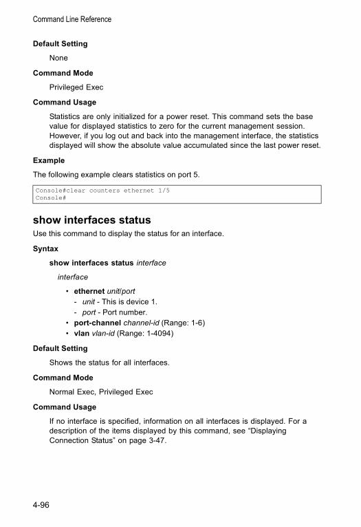
Command Line Reference
Default Setting
None
Command Mode
Privileged Exec
Command Usage
Statistics are only initialized for a power reset. This command sets the base value for displayed statistics to zero for the current management session. However, if you log out and back into the management interface, the statistics displayed will show the absolute value accumulated since the last power reset.
Example
The following example clears statistics on port 5.
show interfaces statusUse this command to display the status for an interface.
Syntax
show interfaces status interface
interface
• ethernet unit/port- unit - This is device 1. - port - Port number.
• port-channel channel-id (Range: 1-6) • vlan vlan-id (Range: 1-4094)
Default Setting
Shows the status for all interfaces.
Command Mode
Normal Exec, Privileged Exec
Command Usage
If no interface is specified, information on all interfaces is displayed. For a description of the items displayed by this command, see “Displaying Connection Status” on page 3-47.
Console#clear counters ethernet 1/5Console#
4-96
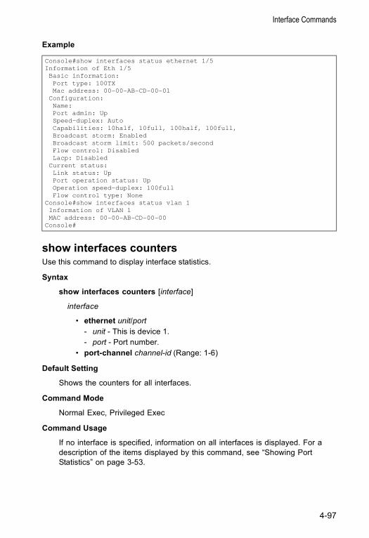
Interface Commands
Example
show interfaces countersUse this command to display interface statistics.
Syntax
show interfaces counters [interface]
interface
• ethernet unit/port- unit - This is device 1. - port - Port number.
• port-channel channel-id (Range: 1-6)
Default Setting
Shows the counters for all interfaces.
Command Mode
Normal Exec, Privileged Exec
Command Usage
If no interface is specified, information on all interfaces is displayed. For a description of the items displayed by this command, see “Showing Port Statistics” on page 3-53.
Console#show interfaces status ethernet 1/5Information of Eth 1/5Basic information:Port type: 100TXMac address: 00-00-AB-CD-00-01
Configuration:Name:Port admin: UpSpeed-duplex: AutoCapabilities: 10half, 10full, 100half, 100full,Broadcast storm: EnabledBroadcast storm limit: 500 packets/secondFlow control: DisabledLacp: Disabled
Current status:Link status: UpPort operation status: UpOperation speed-duplex: 100fullFlow control type: None
Console#show interfaces status vlan 1Information of VLAN 1MAC address: 00-00-AB-CD-00-00
Console#
4-97
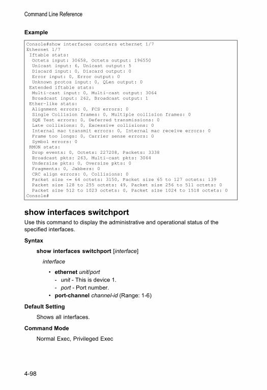
Command Line Reference
Example
show interfaces switchportUse this command to display the administrative and operational status of the specified interfaces.
Syntax
show interfaces switchport [interface]
interface
• ethernet unit/port- unit - This is device 1. - port - Port number.
• port-channel channel-id (Range: 1-6)
Default Setting
Shows all interfaces.
Command Mode
Normal Exec, Privileged Exec
Console#show interfaces counters ethernet 1/7Ethernet 1/7Iftable stats:Octets input: 30658, Octets output: 196550Unicast input: 6, Unicast output: 5Discard input: 0, Discard output: 0Error input: 0, Error output: 0Unknown protos input: 0, QLen output: 0
Extended iftable stats:Multi-cast input: 0, Multi-cast output: 3064Broadcast input: 262, Broadcast output: 1
Ether-like stats:Alignment errors: 0, FCS errors: 0Single Collision frames: 0, Multiple collision frames: 0SQE Test errors: 0, Deferred transmissions: 0Late collisions: 0, Excessive collisions: 0Internal mac transmit errors: 0, Internal mac receive errors: 0Frame too longs: 0, Carrier sense errors: 0Symbol errors: 0
RMON stats:Drop events: 0, Octets: 227208, Packets: 3338Broadcast pkts: 263, Multi-cast pkts: 3064Undersize pkts: 0, Oversize pkts: 0Fragments: 0, Jabbers: 0CRC align errors: 0, Collisions: 0Packet size <= 64 octets: 3150, Packet size 65 to 127 octets: 139Packet size 128 to 255 octets: 49, Packet size 256 to 511 octets: 0Packet size 512 to 1023 octets: 0, Packet size 1024 to 1518 octets: 0
Console#
4-98
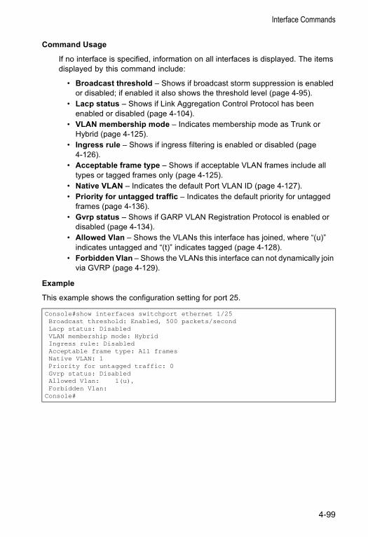
Interface Commands
Command Usage
If no interface is specified, information on all interfaces is displayed. The items displayed by this command include:
• Broadcast threshold – Shows if broadcast storm suppression is enabled or disabled; if enabled it also shows the threshold level (page 4-95).
• Lacp status – Shows if Link Aggregation Control Protocol has been enabled or disabled (page 4-104).
• VLAN membership mode – Indicates membership mode as Trunk or Hybrid (page 4-125).
• Ingress rule – Shows if ingress filtering is enabled or disabled (page 4-126).
• Acceptable frame type – Shows if acceptable VLAN frames include all types or tagged frames only (page 4-125).
• Native VLAN – Indicates the default Port VLAN ID (page 4-127).• Priority for untagged traffic – Indicates the default priority for untagged
frames (page 4-136).• Gvrp status – Shows if GARP VLAN Registration Protocol is enabled or
disabled (page 4-134).• Allowed Vlan – Shows the VLANs this interface has joined, where “(u)”
indicates untagged and “(t)” indicates tagged (page 4-128).• Forbidden Vlan – Shows the VLANs this interface can not dynamically join
via GVRP (page 4-129).
Example
This example shows the configuration setting for port 25.
Console#show interfaces switchport ethernet 1/25Broadcast threshold: Enabled, 500 packets/secondLacp status: DisabledVLAN membership mode: HybridIngress rule: DisabledAcceptable frame type: All framesNative VLAN: 1Priority for untagged traffic: 0Gvrp status: DisabledAllowed Vlan: 1(u),Forbidden Vlan:
Console#
4-99
Command Line Reference
Mirror Port Commands
This section describes how to mirror traffic from a source port to a target port.
port monitorUse this command to configure a mirror session. Use the no form to clear a mirror session.
Syntax
port monitor interface [rx | tx | both]no port monitor interface
• interface - ethernet unit/port (source port) - unit - Switch (unit 1). - port - Port number.
• rx - Mirror received packets. • tx - Mirror transmitted packets. • both - Mirror both received and transmitted packets.
Default Setting
No mirror session is defined. When enabled, the default mirroring is for both received and transmitted packets.
Command Mode
Interface Configuration (Ethernet, destination port)
Command Usage
• You can mirror traffic from any source port to a destination port for real-time analysis. You can then attach a logic analyzer or RMON probe to the destination port and study the traffic crossing the source port in a completely unobtrusive manner.
• The destination port is set by specifying an Ethernet interface. • The mirror port and monitor port speeds should match, otherwise traffic may
be dropped from the monitor port.• You can create multiple mirror sessions, but all sessions must share the same
destination port. However, you should avoid sending too much traffic to the destination port from multiple source ports.
Command Function Mode Pageport monitor Configures a mirror session IC 4-100show port monitor Shows the configuration for a mirror port PE 4-101
4-100
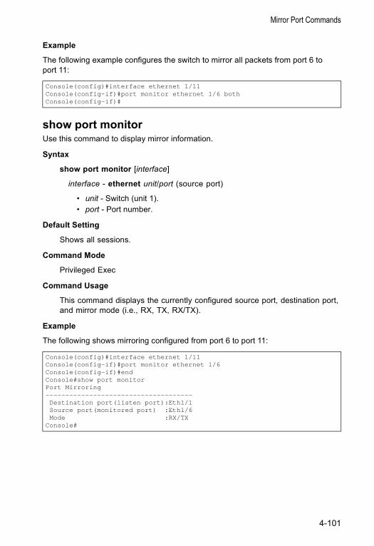
Mirror Port Commands
Example
The following example configures the switch to mirror all packets from port 6 to port 11:
show port monitorUse this command to display mirror information.
Syntax
show port monitor [interface]
interface - ethernet unit/port (source port)
• unit - Switch (unit 1). • port - Port number.
Default Setting
Shows all sessions.
Command Mode
Privileged Exec
Command Usage
This command displays the currently configured source port, destination port, and mirror mode (i.e., RX, TX, RX/TX).
Example
The following shows mirroring configured from port 6 to port 11:
Console(config)#interface ethernet 1/11Console(config-if)#port monitor ethernet 1/6 bothConsole(config-if)#
Console(config)#interface ethernet 1/11Console(config-if)#port monitor ethernet 1/6Console(config-if)#endConsole#show port monitorPort Mirroring-------------------------------------Destination port(listen port):Eth1/1Source port(monitored port) :Eth1/6Mode :RX/TX
Console#
4-101
Command Line Reference
Rate Limit CommandsThis function allows the network manager to control the maximum rate for traffic transmitted or received on an interface. Rate limiting is configured on interfaces at the edge of a network to limit traffic into or out of the network. Traffic that falls within the rate limit is transmitted, while packets that exceed the acceptable amount of traffic are dropped.
Rate limiting can be applied to individual ports or trunks. When an interface is configured with this feature, the traffic rate will be monitored by the hardware to verify conformity. Non-conforming traffic is dropped, conforming traffic is forwarded without any changes.
rate-limitUse this command to define the rate limit for a specific interface. Use this command without specifying a rate to restore the default rate. Use the no form to restore the default status of disabled.
Syntax
rate-limit {input | output} [rate]no rate-limit {input | output}
• input – Input rate• output – Output rate• rate – Maximum value in Mbps.
Default Setting Fast Ethernet interface – 100 MbpsGigabit Ethernet interface – 1000 Mbps
Command Mode Interface Configuration (Ethernet, Port Channel)
Command Usage• The range is:
- Fast Ethernet interface – 1 to 100 Mbps- Gigabit Ethernet interface – 8 to 1000 Mbps
• Resolution – The increment of change:- Fast Ethernet interface – 1 Mbps- Gigabit Ethernet interface – 8 Mbps
• Due to a switch chip limitation, the input rate limit can only be enabled or disabled for all interfaces. In other words, the rate limit input and no rate limit
Command Function Mode Pagerate-limit Configures the maximum input or output rate for a port IC 4-102
4-102
Link Aggregation Commands
input commands apply globally to the entire switch. However, specific rates apply to the specified interface.
• The output rate limit can be enabled or disabled for specific interfaces.
Example
Link Aggregation CommandsPorts can be statically grouped into an aggregate link (i.e., trunk) to increase the bandwidth of a network connection or to ensure fault recovery. Or you can use the Link Aggregation Control Protocol (LACP) to automatically negotiate a trunk link between this switch and another network device. For static trunks, the switches have to comply with the Cisco EtherChannel standard. For dynamic trunks, the switches have to comply with LACP. This switch supports up to six trunks. For example, a trunk consisting of two 1000 Mbps ports can support an aggregate bandwidth of 4 Gbps when operating at full duplex.
Guidelines for Creating Trunks
• Finish configuring port trunks before you connect the corresponding network cables between switches to avoid creating a loop.
• A trunk can have up to four 10/100 Mbps ports or up to two 1000 Mbps ports.• The ports at both ends of a connection must be configured as trunk ports.• All ports in a trunk must consist of the same media type (i.e., twisted-pair or
fiber).• All ports in a trunk must be configured in an identical manner, including
communication mode (i.e., speed, duplex mode and flow control), VLAN assignments, and CoS settings.
• All the ports in a trunk have to be treated as a whole when moved from/to, added or deleted from a VLAN via the specified port-channel.
Console(config)#interface ethernet 1/1Console(config-if)#rate-limit input 10Console(config-if)#
Command Function Mode PageManual Configuration Commandsinterface port-channel Configures a trunk and enters interface configuration mode
for the trunk GC 4-89
channel-group Adds a port to a trunk IC 4-104Dynamic Configuration Command lacp Configures LACP for the current interface IC 4-104Trunk Status Display Commandshow interfaces status port-channel
Shows trunk information NE, PE 4-96
4-103
Command Line Reference
• STP, VLAN, and IGMP settings can only be made for the entire trunk via the specified port-channel.
channel-group Use this command to add a port to a trunk. Use the no form to remove a port from a trunk.
Syntax
channel-group channel-idno channel-group
channel-id - Trunk index (Range: 1-6)
Default Setting
The current port will be added to this trunk.
Command Mode
Interface Configuration (Ethernet)
Command Usage
• When configuring static trunks, the switches must comply with the Cisco EtherChannel standard.
• Use no channel-group to remove a port group from a trunk.• Use no interfaces port-channel to remove a trunk from the switch.
Example
The following example creates trunk 1 and then adds port 11:
lacpUse this command to enable 802.3ad Link Aggregation Control Protocol (LACP) for the current interface. Use the no form to disable it.
Syntax
lacpno lacp
Default Setting
Disabled
Command Mode
Interface Configuration (Ethernet)
Console(config)#interface port-channel 1Console(config-if)#exitConsole(config)#interface ethernet 1/11Console(config-if)#channel-group 1Console(config-if)#
4-104
Link Aggregation Commands
Command Usage
• The ports on both ends of an LACP trunk must be configured for full duplex, either by forced mode or auto-negotiation.
• A trunk formed with another switch using LACP will automatically be assigned the next available port-channel ID.
• If the target switch has also enabled LACP on the connected ports, the trunk will be activated automatically.
• If more than four ports attached to the same target switch have LACP enabled, the additional ports will be placed in standby mode, and will only be enabled if one of the active links fails.
Example
The following shows LACP enabled on ports 11-13. Because LACP has also been enabled on the ports at the other end of the links, the show interfaces status port-channel 1 command shows that Trunk1 has been established.
Console(config)#interface ethernet 1/11Console(config-if)#lacpConsole(config-if)#exitConsole(config)#interface ethernet 1/12Console(config-if)#lacpConsole(config-if)#exitConsole(config)#interface ethernet 1/13Console(config-if)#lacpConsole(config-if)#exitConsole(config)#exitConsole#show interfaces status port-channel 1Information of Trunk 1Basic information:Port type: 100txMac address: 00-00-e8-00-00-0b
Configuration:Name:Port admin status: UpSpeed-duplex: AutoCapabilities: 10half, 10full, 100half, 100full,Flow control status: Disabled
Current status:Created by: lacpLink status: UpOperation speed-duplex: 100fullFlow control type: NoneMember Ports: Eth1/11, Eth1/12, Eth1/13,
Console#
4-105
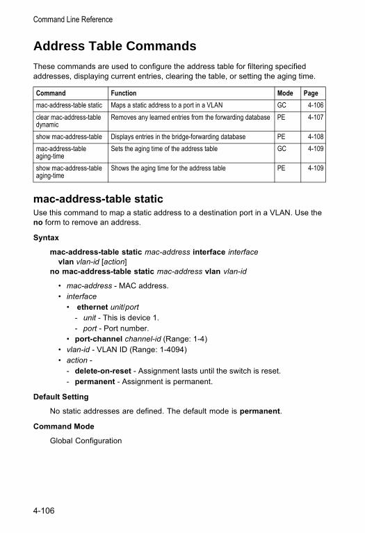
Command Line Reference
Address Table CommandsThese commands are used to configure the address table for filtering specified addresses, displaying current entries, clearing the table, or setting the aging time.
mac-address-table staticUse this command to map a static address to a destination port in a VLAN. Use the no form to remove an address.
Syntax
mac-address-table static mac-address interface interface vlan vlan-id [action]
no mac-address-table static mac-address vlan vlan-id
• mac-address - MAC address. • interface
• ethernet unit/port- unit - This is device 1. - port - Port number.
• port-channel channel-id (Range: 1-4) • vlan-id - VLAN ID (Range: 1-4094) • action -
- delete-on-reset - Assignment lasts until the switch is reset. - permanent - Assignment is permanent.
Default Setting
No static addresses are defined. The default mode is permanent.
Command Mode
Global Configuration
Command Function Mode Pagemac-address-table static Maps a static address to a port in a VLAN GC 4-106clear mac-address-table dynamic
Removes any learned entries from the forwarding database PE 4-107
show mac-address-table Displays entries in the bridge-forwarding database PE 4-108mac-address-table aging-time
Sets the aging time of the address table GC 4-109
show mac-address-table aging-time
Shows the aging time for the address table PE 4-109
4-106
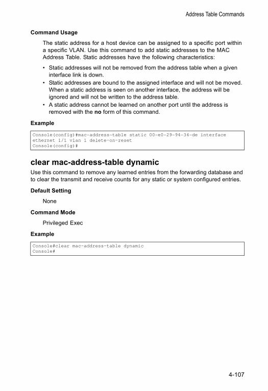
Address Table Commands
Command Usage
The static address for a host device can be assigned to a specific port within a specific VLAN. Use this command to add static addresses to the MAC Address Table. Static addresses have the following characteristics:
• Static addresses will not be removed from the address table when a given interface link is down.
• Static addresses are bound to the assigned interface and will not be moved. When a static address is seen on another interface, the address will be ignored and will not be written to the address table.
• A static address cannot be learned on another port until the address is removed with the no form of this command.
Example
clear mac-address-table dynamicUse this command to remove any learned entries from the forwarding database and to clear the transmit and receive counts for any static or system configured entries.
Default Setting
None
Command Mode
Privileged Exec
Example
Console(config)#mac-address-table static 00-e0-29-94-34-de interfaceethernet 1/1 vlan 1 delete-on-resetConsole(config)#
Console#clear mac-address-table dynamicConsole#
4-107
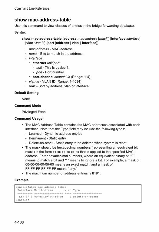
Command Line Reference
show mac-address-tableUse this command to view classes of entries in the bridge-forwarding database.
Syntax
show mac-address-table [address mac-address [mask]] [interface interface] [vlan vlan-id] [sort {address | vlan | interface}]
• mac-address - MAC address.• mask - Bits to match in the address. • interface
• ethernet unit/port- unit - This is device 1. - port - Port number.
• port-channel channel-id (Range: 1-4) • vlan-id - VLAN ID (Range: 1-4094) • sort - Sort by address, vlan or interface.
Default Setting
None
Command Mode
Privileged Exec
Command Usage
• The MAC Address Table contains the MAC addresses associated with each interface. Note that the Type field may include the following types:- Learned - Dynamic address entries- Permanent - Static entry- Delete-on-reset - Static entry to be deleted when system is reset
• The mask should be hexadecimal numbers (representing an equivalent bit mask) in the form xx-xx-xx-xx-xx-xx that is applied to the specified MAC address. Enter hexadecimal numbers, where an equivalent binary bit “0” means to match a bit and “1” means to ignore a bit. For example, a mask of 00-00-00-00-00-00 means an exact match, and a mask of FF-FF-FF-FF-FF-FF means “any.”
• The maximum number of address entries is 8191.
Example
Console#show mac-address-tableInterface Mac Address Vlan Type--------- ----------------- ---- -----------------Eth 1/ 1 00-e0-29-94-34-de 1 Delete-on-reset
Console#
4-108
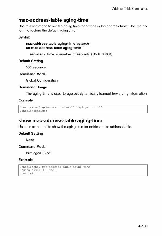
Address Table Commands
mac-address-table aging-timeUse this command to set the aging time for entries in the address table. Use the no form to restore the default aging time.
Syntax
mac-address-table aging-time secondsno mac-address-table aging-time
seconds - Time is number of seconds (10-1000000).
Default Setting
300 seconds
Command Mode
Global Configuration
Command Usage
The aging time is used to age out dynamically learned forwarding information.
Example
show mac-address-table aging-timeUse this command to show the aging time for entries in the address table.
Default Setting
None
Command Mode
Privileged Exec
Example
Console(config)#mac-address-table aging-time 100Console(config)#
Console#show mac-address-table aging-timeAging time: 300 sec.
Console#
4-109
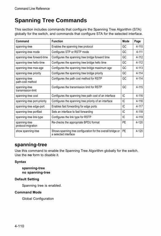
Command Line Reference
Spanning Tree CommandsThis section includes commands that configure the Spanning Tree Algorithm (STA) globally for the switch, and commands that configure STA for the selected interface.
spanning-treeUse this command to enable the Spanning Tree Algorithm globally for the switch. Use the no form to disable it.
Syntax
spanning-treeno spanning-tree
Default Setting
Spanning tree is enabled.
Command Mode
Global Configuration
Command Function Mode Pagespanning-tree Enables the spanning tree protocol GC 4-110spanning-tree mode Configures STP or RSTP mode GC 4-111spanning-tree forward-time Configures the spanning tree bridge forward time GC 4-112spanning-tree hello-time Configures the spanning tree bridge hello time GC 4-112spanning-tree max-age Configures the spanning tree bridge maximum age GC 4-113spanning-tree priority Configures the spanning tree bridge priority GC 4-114spanning-tree path-cost method
Configures the path cost method for RSTP GC 4-114
spanning-tree transmission-limit
Configures the transmission limit for RSTP GC 4-115
spanning-tree cost Configures the spanning tree path cost of an interface IC 4-116spanning-tree port-priority Configures the spanning tree priority of an interface IC 4-116spanning-tree edge-port Enables fast forwarding for edge ports IC 4-117spanning-tree portfast Sets an interface to fast forwarding IC 4-118spanning-tree link-type Configures the link type for RSTP IC 4-119spanning-tree protocol-migration
Re-checks the appropriate BPDU format PE 4-120
show spanning-tree Shows spanning tree configuration for the overall bridge or a selected interface
PE 4-120
4-110
Spanning Tree Commands
Command Usage
The Spanning Tree Algorithm (STA) can be used to detect and disable network loops, and to provide backup links between switches, bridges or routers. This allows the switch to interact with other bridging devices (that is, an STA-compliant switch, bridge or router) in your network to ensure that only one route exists between any two stations on the network, and provide backup links which automatically take over when a primary link goes down.
Example
This example shows how to enable the Spanning Tree Algorithm for the switch:
spanning-tree modeUse this command to select the spanning tree mode for this switch. Use the no form to restore the default.
Syntax
spanning-tree mode {stp | rstp}no spanning-tree mode
• stp - Spanning Tree Protocol (IEEE 802.1D)• rstp - Rapid Spanning Tree Protocol (IEEE 802.1w)
Default Setting
rstp
Command Mode
Global Configuration
Command Usage
• Spanning Tree Protocol
Uses RSTP for the internal state machine, but sends only 802.1D BPDUs.
• Rapid Spanning Tree Protocol
RSTP supports connections to either STP or RSTP nodes by monitoring the incoming protocol messages and dynamically adjusting the type of protocol messages the RSTP node transmits, as described below:
- STP Mode – If the switch receives an 802.1D BPDU after a port’s migration delay timer expires, the switch assumes it is connected to an 802.1D bridge and starts using only 802.1D BPDUs.
- RSTP Mode – If RSTP is using 802.1D BPDUs on a port and receives an RSTP BPDU after the migration delay expires, RSTP restarts the migration delay timer and begins using RSTP BPDUs on that port.
Console(config)#spanning-treeConsole(config)#
4-111
Command Line Reference
Example
The following example configures the switch to use Rapid Spanning Tree:
spanning-tree forward-timeUse this command to configure the spanning tree bridge forward time globally for this switch. Use the no form to restore the default.
Syntax
spanning-tree forward-time secondsno spanning-tree forward-time
seconds - Time in seconds. (Range: 4 - 30 seconds)The minimum value is the higher of 4 or [(max-age / 2) + 1].
Default Setting
15 seconds
Command Mode
Global Configuration
Command Usage
This command sets the maximum time (in seconds) the root device will wait before changing states (i.e., discarding to learning to forwarding). This delay is required because every device must receive information about topology changes before it starts to forward frames. In addition, each port needs time to listen for conflicting information that would make it return to the discarding state; otherwise, temporary data loops might result.
Example
spanning-tree hello-timeUse this command to configure the spanning tree bridge hello time globally for this switch. Use the no form to restore the default.
Syntax
spanning-tree hello-time timeno spanning-tree hello-time
time - Time in seconds. (Range: 1-10 seconds). The maximum value is the lower of 10 or [(max-age / 2) -1].
Console(config)#spanning-tree mode rstpConsole(config)#
Console(config)#spanning-tree forward-time 20Console(config)#
4-112
Spanning Tree Commands
Default Setting
2 seconds
Command Mode
Global Configuration
Command Usage
This command sets the time interval (in seconds) at which the root device transmits a configuration message.
Example
spanning-tree max-ageUse this command to configure the spanning tree bridge maximum age globally for this switch. Use the no form to restore the default.
Syntax
spanning-tree max-age secondsno spanning-tree max-age
seconds - Time in seconds. (Range: 6-40 seconds)The minimum value is the higher of 6 or [2 x (hello-time + 1)].The maximum value is the lower of 40 or [2 x (forward-time - 1)].
Default Setting
20 seconds
Command Mode
Global Configuration
Command Usage
This command sets the maximum time (in seconds) a device can wait without receiving a configuration message before attempting to reconfigure. All device ports (except for designated ports) should receive configuration messages at regular intervals. Any port that ages out STA information (provided in the last configuration message) becomes the designated port for the attached LAN. If it is a root port, a new root port is selected from among the device ports attached to the network.
Example
Console(config)#spanning-tree hello-time 5Console(config)#
Console(config)#spanning-tree max-age 40Console(config)#
4-113
Command Line Reference
spanning-tree priorityUse this command to configure the spanning tree priority globally for this switch. Use the no form to restore the default.
Syntax
spanning-tree priority priority no spanning-tree priority
priority - Priority of the bridge. (Range: 0 - 65535) (Range – 0-61440, in steps of 4096; Options: 0, 4096, 8192, 12288, 16384, 20480, 24576, 28672, 32768, 36864, 40960, 45056, 49152, 53248, 57344, 61440)
Default Setting
32768
Command Mode
Global Configuration
Command Usage
Bridge priority is used in selecting the root device, root port, and designated port. The device with the highest priority becomes the STA root device. However, if all devices have the same priority, the device with the lowest MAC address will then become the root device.
Example
spanning-tree pathcost methodUse this command to configure the path cost method used for Rapid Spanning Tree. Use the no form to restore the default.
Syntax
spanning-tree pathcost method {long | short} no spanning-tree pathcost method
• long - Specifies 32-bit based values that range from 1-200,000,000. • short - Specifies 16-bit based values that range from 1-65535.
Default Setting
short method
Command Mode
Global Configuration
Console(config)#spanning-tree priority 40000Console(config)#
4-114
Spanning Tree Commands
Command Usage
The path cost method is used to determine the best path between devices. Therefore, lower values should be assigned to ports attached to faster media, and higher values assigned to ports with slower media. Note that path cost (page 4-116) takes precedence over port priority (page 4-116).
Example
spanning-tree transmission-limitUse this command to configure the minimum interval between the transmission of consecutive RSTP BPDUs. Use the no form to restore the default.
Syntax
spanning-tree transmission-limit countno spanning-tree transmission-limit
count - The transmission limit in seconds. (Range: 1-10)
Default Setting
3
Command Mode
Global Configuration
Command Usage
This command limits the maximum transmission rate for BPDUs.
Example
Console(config)#spanning-tree pathcost method longConsole(config)#
Console(config)#spanning-tree transmission-limit 4Console(config)#
4-115
Command Line Reference
spanning-tree costUse this command to configure the spanning tree path cost for the specified interface. Use the no form to restore the default.
Syntax
spanning-tree cost costno spanning-tree cost
cost - The path cost for the port. (Range: 1-200,000,000))The recommended range is:
• Ethernet: 200,000-20,000,000• Fast Ethernet: 20,000-2,000,000• Gigabit Ethernet: 2,000-200,000
Default Setting
• Ethernet – half duplex: 2,000,000; full duplex: 1,000,000; trunk: 500,000• Fast Ethernet – half duplex: 200,000; full duplex: 100,000; trunk: 50,000• Gigabit Ethernet – full duplex: 10,000; trunk: 5,000
Command Mode
Interface Configuration (Ethernet, Port Channel)
Command Usage
• This command is used by the Spanning Tree Algorithm to determine the best path between devices. Therefore, lower values should be assigned to ports attached to faster media, and higher values assigned to ports with slower media.
• Path cost takes precedence over port priority.• When the spanning-tree pathcost method is set to short, the maximum value
for path cost is 65,535.
Example
spanning-tree port-priorityUse this command to configure the priority for the specified interface. Use the no form to restore the default.
Syntax
spanning-tree port-priority priorityno spanning-tree port-priority
priority - The priority for a port. (Range: 0-240, in steps of 16)
Console(config)#interface ethernet 1/5Console(config-if)#spanning-tree cost 50Console(config-if)#
4-116
Spanning Tree Commands
Default Setting
128
Command Mode
Interface Configuration (Ethernet, Port Channel)
Command Usage
• This command defines the priority for the use of a port in the Spanning Tree Algorithm. If the path cost for all ports on a switch are the same, the port with the highest priority (that is, lowest value) will be configured as an active link in the spanning tree.
• Where more than one port is assigned the highest priority, the port with lowest numeric identifier will be enabled.
Example
Related Commands
spanning-tree cost (4-116)
spanning-tree edge-portUse this command to specify an interface as an edge port. Use the no form to restore the default.
Syntax
spanning-tree edge-portno spanning-tree edge-port
Default Setting
Disabled
Command Mode
Interface Configuration (Ethernet, Port Channel)
Command Usage
• You can enable this option if an interface is attached to a LAN segment that is at the end of a bridged LAN or to an end node. Since end nodes cannot cause forwarding loops, they can pass directly through to the spanning tree forwarding state. Specifying Edge Ports provides quicker convergence for devices such as workstations or servers, retains the current forwarding database to reduce the amount of frame flooding required to rebuild address tables during reconfiguration events, does not cause the spanning tree to initiate reconfiguration when the interface changes state, and also overcomes
Console(config)#interface ethernet 1/5Console(config-if)#spanning-tree port-priority 0Console(config-if)#
4-117
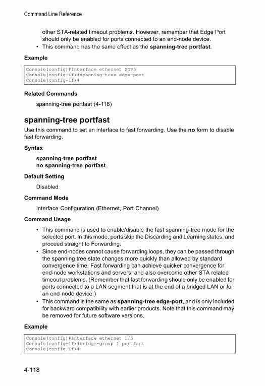
Command Line Reference
other STA-related timeout problems. However, remember that Edge Port should only be enabled for ports connected to an end-node device.
• This command has the same effect as the spanning-tree portfast.
Example
Related Commands
spanning-tree portfast (4-118)
spanning-tree portfastUse this command to set an interface to fast forwarding. Use the no form to disable fast forwarding.
Syntax
spanning-tree portfastno spanning-tree portfast
Default Setting
Disabled
Command Mode
Interface Configuration (Ethernet, Port Channel)
Command Usage
• This command is used to enable/disable the fast spanning-tree mode for the selected port. In this mode, ports skip the Discarding and Learning states, and proceed straight to Forwarding.
• Since end-nodes cannot cause forwarding loops, they can be passed through the spanning tree state changes more quickly than allowed by standard convergence time. Fast forwarding can achieve quicker convergence for end-node workstations and servers, and also overcome other STA related timeout problems. (Remember that fast forwarding should only be enabled for ports connected to a LAN segment that is at the end of a bridged LAN or for an end-node device.)
• This command is the same as spanning-tree edge-port, and is only included for backward compatibility with earlier products. Note that this command may be removed for future software versions.
Example
Console(config)#interface ethernet SNP5Console(config-if)#spanning-tree edge-portConsole(config-if)#
Console(config)#interface ethernet 1/5Console(config-if)#bridge-group 1 portfastConsole(config-if)#
4-118
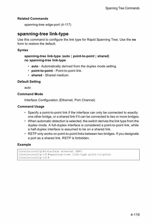
Spanning Tree Commands
Related Commands
spanning-tree edge-port (4-117)
spanning-tree link-typeUse this command to configure the link type for Rapid Spanning Tree. Use the no form to restore the default.
Syntax
spanning-tree link-type {auto | point-to-point | shared}no spanning-tree link-type
• auto - Automatically derived from the duplex mode setting. • point-to-point - Point-to-point link.• shared - Shared medium.
Default Setting
auto
Command Mode
Interface Configuration (Ethernet, Port Channel)
Command Usage
• Specify a point-to-point link if the interface can only be connected to exactly one other bridge, or a shared link if it can be connected to two or more bridges.
• When automatic detection is selected, the switch derives the link type from the duplex mode. A full-duplex interface is considered a point-to-point link, while a half-duplex interface is assumed to be on a shared link.
• RSTP only works on point-to-point links between two bridges. If you designate a port as a shared link, RSTP is forbidden.
Example
Console(config)#interface ethernet SNP5Console(config-if)#spanning-tree link-type point-to-pointConsole(config-if)#
4-119
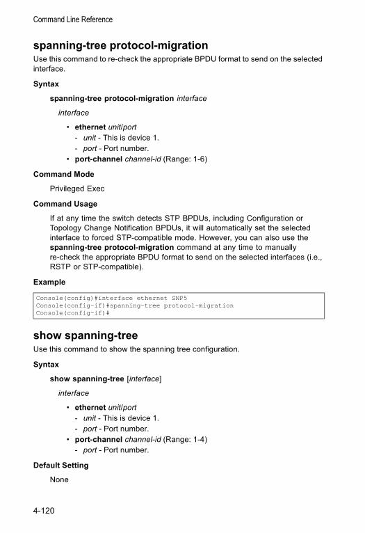
Command Line Reference
spanning-tree protocol-migrationUse this command to re-check the appropriate BPDU format to send on the selected interface.
Syntax
spanning-tree protocol-migration interface
interface
• ethernet unit/port- unit - This is device 1. - port - Port number.
• port-channel channel-id (Range: 1-6)
Command Mode
Privileged Exec
Command Usage
If at any time the switch detects STP BPDUs, including Configuration or Topology Change Notification BPDUs, it will automatically set the selected interface to forced STP-compatible mode. However, you can also use the spanning-tree protocol-migration command at any time to manually re-check the appropriate BPDU format to send on the selected interfaces (i.e., RSTP or STP-compatible).
Example
show spanning-treeUse this command to show the spanning tree configuration.
Syntax
show spanning-tree [interface]
interface
• ethernet unit/port- unit - This is device 1. - port - Port number.
• port-channel channel-id (Range: 1-4) - port - Port number.
Default Setting
None
Console(config)#interface ethernet SNP5Console(config-if)#spanning-tree protocol-migrationConsole(config-if)#
4-120
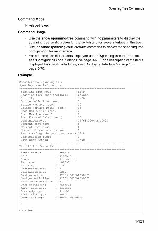
Spanning Tree Commands
Command Mode
Privileged Exec
Command Usage
• Use the show spanning-tree command with no parameters to display the spanning tree configuration for the switch and for every interface in the tree.
• Use the show spanning-tree interface command to display the spanning tree configuration for an interface.
• For a description of the items displayed under “Spanning-tree information,” see “Configuring Global Settings” on page 3-67. For a description of the items displayed for specific interfaces, see “Displaying Interface Settings” on page 3-70.
Example
Console#show spanning-treeSpanning-tree information---------------------------------------------------------------Spanning tree mode :RSTPSpanning tree enable/disable :enablePriority :32768Bridge Hello Time (sec.) :2Bridge Max Age (sec.) :20Bridge Forward Delay (sec.) :15Root Hello Time (sec.) :2Root Max Age (sec.) :20Root Forward Delay (sec.) :15Designated Root :32768.0000ABCD0000Current root port :0Current root cost :0Number of topology changes :2Last topology changes time (sec.):1718Transmission limit :3Path Cost Method :long
---------------------------------------------------------------Eth 1/ 1 information---------------------------------------------------------------Admin status : enableRole : disableState : discardingPath cost : 100000Priority : 128Designated cost : 0Designated port : 128.1Designated root : 32768.0000ABCD0000Designated bridge : 32768.0000ABCD0000Forward transitions : 0Fast forwarding : disableAdmin edge port : disableOper edge port : disableAdmin Link type : autoOper Link type : point-to-point
.
.
.Console#
4-121

Command Line Reference
VLAN CommandsA VLAN is a group of ports that can be located anywhere in the network, but communicate as though they belong to the same physical segment. This section describes commands used to create VLAN groups, add port members, specify how VLAN tagging is used, and enable automatic VLAN registration for the selected interface.
Editing VLAN Groups
vlan databaseUse this command to enter VLAN database mode. All commands in this mode will take effect immediately.
Default Setting
None
Command Mode
Global Configuration
Command Usage
• Use the VLAN database command mode to add, change, and delete VLANs. After finishing configuration changes, you can display the VLAN settings by entering the show vlan command.
• Use the interface vlan command mode to define the port membership mode and add or remove ports from a VLAN. The results of these commands are written to the running-configuration file, and you can display this file by entering the show running-config command.
Command Groups Function PageEditing VLAN Groups Sets up VLAN groups, including name, VID and state 4-122Configuring VLAN Interfaces
Configures VLAN interfaces parameters, including ingress and egress tagging mode, ingress filtering, PVID, and GVRP
4-124
Displaying VLAN Information
Displays VLAN groups, status, port members, and MAC address 4-130
Configuring Private VLANs Configures private VLANs, including uplink and downlink ports 4-131
Command Function Mode Pagevlan database Enters VLAN database mode to add, change, and delete
VLANs GC 4-122
vlan Configures a VLAN, including VID, name and state VC 4-123
4-122
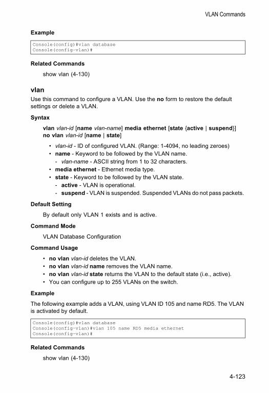
VLAN Commands
Example
Related Commands
show vlan (4-130)
vlanUse this command to configure a VLAN. Use the no form to restore the default settings or delete a VLAN.
Syntax
vlan vlan-id [name vlan-name] media ethernet [state {active | suspend}]no vlan vlan-id [name | state]
• vlan-id - ID of configured VLAN. (Range: 1-4094, no leading zeroes) • name - Keyword to be followed by the VLAN name.
- vlan-name - ASCII string from 1 to 32 characters. • media ethernet - Ethernet media type. • state - Keyword to be followed by the VLAN state.
- active - VLAN is operational. - suspend - VLAN is suspended. Suspended VLANs do not pass packets.
Default Setting
By default only VLAN 1 exists and is active.
Command Mode
VLAN Database Configuration
Command Usage
• no vlan vlan-id deletes the VLAN. • no vlan vlan-id name removes the VLAN name. • no vlan vlan-id state returns the VLAN to the default state (i.e., active). • You can configure up to 255 VLANs on the switch.
Example
The following example adds a VLAN, using VLAN ID 105 and name RD5. The VLAN is activated by default.
Related Commands
show vlan (4-130)
Console(config)#vlan databaseConsole(config-vlan)#
Console(config)#vlan databaseConsole(config-vlan)#vlan 105 name RD5 media ethernetConsole(config-vlan)#
4-123
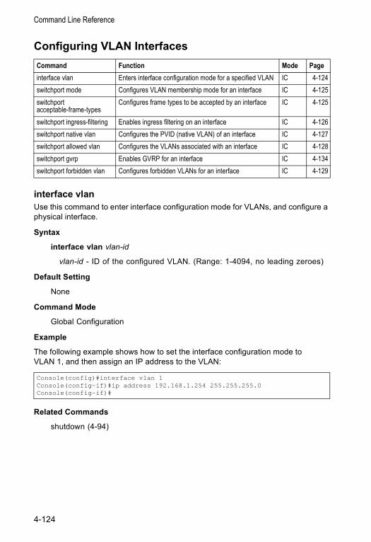
Command Line Reference
Configuring VLAN Interfaces
interface vlanUse this command to enter interface configuration mode for VLANs, and configure a physical interface.
Syntax
interface vlan vlan-id
vlan-id - ID of the configured VLAN. (Range: 1-4094, no leading zeroes)
Default Setting
None
Command Mode
Global Configuration
Example
The following example shows how to set the interface configuration mode to VLAN 1, and then assign an IP address to the VLAN:
Related Commands
shutdown (4-94)
Command Function Mode Pageinterface vlan Enters interface configuration mode for a specified VLAN IC 4-124switchport mode Configures VLAN membership mode for an interface IC 4-125switchport acceptable-frame-types
Configures frame types to be accepted by an interface IC 4-125
switchport ingress-filtering Enables ingress filtering on an interface IC 4-126switchport native vlan Configures the PVID (native VLAN) of an interface IC 4-127switchport allowed vlan Configures the VLANs associated with an interface IC 4-128switchport gvrp Enables GVRP for an interface IC 4-134switchport forbidden vlan Configures forbidden VLANs for an interface IC 4-129
Console(config)#interface vlan 1Console(config-if)#ip address 192.168.1.254 255.255.255.0Console(config-if)#
4-124
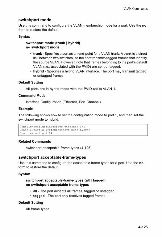
VLAN Commands
switchport modeUse this command to configure the VLAN membership mode for a port. Use the no form to restore the default.
Syntax
switchport mode {trunk | hybrid}no switchport mode
• trunk - Specifies a port as an end-point for a VLAN trunk. A trunk is a direct link between two switches, so the port transmits tagged frames that identify the source VLAN. However, note that frames belonging to the port’s default VLAN (i.e., associated with the PVID) are sent untagged.
• hybrid - Specifies a hybrid VLAN interface. The port may transmit tagged or untagged frames.
Default Setting
All ports are in hybrid mode with the PVID set to VLAN 1.
Command Mode
Interface Configuration (Ethernet, Port Channel)
Example
The following shows how to set the configuration mode to port 1, and then set the switchport mode to hybrid:
Related Commands
switchport acceptable-frame-types (4-125)
switchport acceptable-frame-types Use this command to configure the acceptable frame types for a port. Use the no form to restore the default.
Syntax
switchport acceptable-frame-types {all | tagged}no switchport acceptable-frame-types
• all - The port accepts all frames, tagged or untagged. • tagged - The port only receives tagged frames.
Default Setting
All frame types
Console(config)#interface ethernet 1/1Console(config-if)#switchport mode hybridConsole(config-if)#
4-125
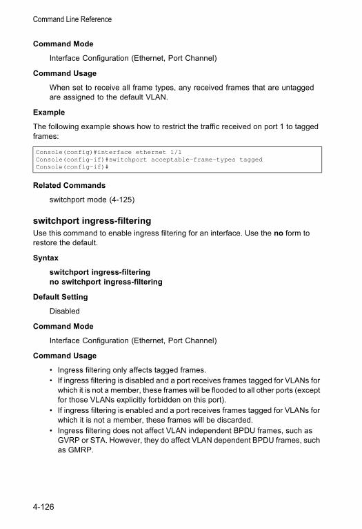
Command Line Reference
Command Mode
Interface Configuration (Ethernet, Port Channel)
Command Usage
When set to receive all frame types, any received frames that are untagged are assigned to the default VLAN.
Example
The following example shows how to restrict the traffic received on port 1 to tagged frames:
Related Commands
switchport mode (4-125)
switchport ingress-filtering Use this command to enable ingress filtering for an interface. Use the no form to restore the default.
Syntax
switchport ingress-filteringno switchport ingress-filtering
Default Setting
Disabled
Command Mode
Interface Configuration (Ethernet, Port Channel)
Command Usage
• Ingress filtering only affects tagged frames.• If ingress filtering is disabled and a port receives frames tagged for VLANs for
which it is not a member, these frames will be flooded to all other ports (except for those VLANs explicitly forbidden on this port).
• If ingress filtering is enabled and a port receives frames tagged for VLANs for which it is not a member, these frames will be discarded.
• Ingress filtering does not affect VLAN independent BPDU frames, such as GVRP or STA. However, they do affect VLAN dependent BPDU frames, such as GMRP.
Console(config)#interface ethernet 1/1Console(config-if)#switchport acceptable-frame-types taggedConsole(config-if)#
4-126
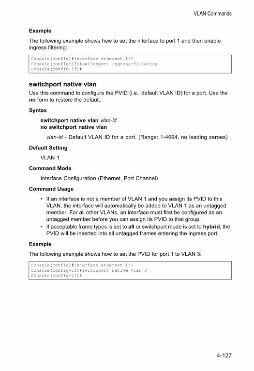
VLAN Commands
Example
The following example shows how to set the interface to port 1 and then enable ingress filtering:
switchport native vlanUse this command to configure the PVID (i.e., default VLAN ID) for a port. Use the no form to restore the default.
Syntax
switchport native vlan vlan-idno switchport native vlan
vlan-id - Default VLAN ID for a port. (Range: 1-4094, no leading zeroes)
Default Setting
VLAN 1
Command Mode
Interface Configuration (Ethernet, Port Channel)
Command Usage
• If an interface is not a member of VLAN 1 and you assign its PVID to this VLAN, the interface will automatically be added to VLAN 1 as an untagged member. For all other VLANs, an interface must first be configured as an untagged member before you can assign its PVID to that group.
• If acceptable frame types is set to all or switchport mode is set to hybrid, the PVID will be inserted into all untagged frames entering the ingress port.
Example
The following example shows how to set the PVID for port 1 to VLAN 3:
Console(config)#interface ethernet 1/1Console(config-if)#switchport ingress-filteringConsole(config-if)#
Console(config)#interface ethernet 1/1Console(config-if)#switchport native vlan 3Console(config-if)#
4-127
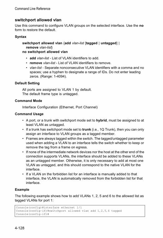
Command Line Reference
switchport allowed vlanUse this command to configure VLAN groups on the selected interface. Use the no form to restore the default.
Syntax
switchport allowed vlan {add vlan-list [tagged | untagged] | remove vlan-list}
no switchport allowed vlan
• add vlan-list - List of VLAN identifiers to add.• remove vlan-list - List of VLAN identifiers to remove. • vlan-list - Separate nonconsecutive VLAN identifiers with a comma and no
spaces; use a hyphen to designate a range of IDs. Do not enter leading zeros. (Range: 1-4094).
Default Setting
All ports are assigned to VLAN 1 by default.The default frame type is untagged.
Command Mode
Interface Configuration (Ethernet, Port Channel)
Command Usage
• A port, or a trunk with switchport mode set to hybrid, must be assigned to at least VLAN as untagged.
• If a trunk has switchport mode set to trunk (i.e., 1Q Trunk), then you can only assign an interface to VLAN groups as a tagged member.
• Frames are always tagged within the switch. The tagged/untagged parameter used when adding a VLAN to an interface tells the switch whether to keep or remove the tag from a frame on egress.
• If none of the intermediate network devices nor the host at the other end of the connection supports VLANs, the interface should be added to these VLANs as an untagged member. Otherwise, it is only necessary to add at most one VLAN as untagged, and this should correspond to the native VLAN for the interface.
• If a VLAN on the forbidden list for an interface is manually added to that interface, the VLAN is automatically removed from the forbidden list for that interface.
Example
The following example shows how to add VLANs 1, 2, 5 and 6 to the allowed list as tagged VLANs for port 1:
Console(config)#interface ethernet 1/1Console(config-if)#switchport allowed vlan add 1,2,5,6 taggedConsole(config-if)#
4-128
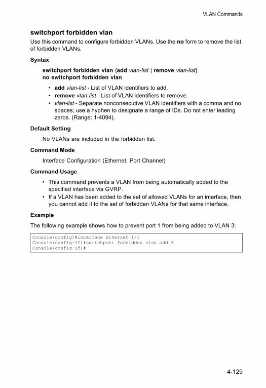
VLAN Commands
switchport forbidden vlanUse this command to configure forbidden VLANs. Use the no form to remove the list of forbidden VLANs.
Syntax
switchport forbidden vlan {add vlan-list | remove vlan-list}no switchport forbidden vlan
• add vlan-list - List of VLAN identifiers to add.• remove vlan-list - List of VLAN identifiers to remove.• vlan-list - Separate nonconsecutive VLAN identifiers with a comma and no
spaces; use a hyphen to designate a range of IDs. Do not enter leading zeros. (Range: 1-4094).
Default Setting
No VLANs are included in the forbidden list.
Command Mode
Interface Configuration (Ethernet, Port Channel)
Command Usage
• This command prevents a VLAN from being automatically added to the specified interface via GVRP.
• If a VLAN has been added to the set of allowed VLANs for an interface, then you cannot add it to the set of forbidden VLANs for that same interface.
Example
The following example shows how to prevent port 1 from being added to VLAN 3:
Console(config)#interface ethernet 1/1Console(config-if)#switchport forbidden vlan add 3Console(config-if)#
4-129
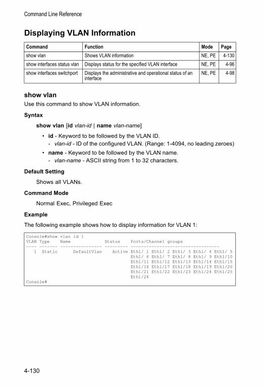
Command Line Reference
Displaying VLAN Information
show vlanUse this command to show VLAN information.
Syntax
show vlan [id vlan-id | name vlan-name]
• id - Keyword to be followed by the VLAN ID. - vlan-id - ID of the configured VLAN. (Range: 1-4094, no leading zeroes)
• name - Keyword to be followed by the VLAN name. - vlan-name - ASCII string from 1 to 32 characters.
Default Setting
Shows all VLANs.
Command Mode
Normal Exec, Privileged Exec
Example
The following example shows how to display information for VLAN 1:
Command Function Mode Pageshow vlan Shows VLAN information NE, PE 4-130show interfaces status vlan Displays status for the specified VLAN interface NE, PE 4-96show interfaces switchport Displays the administrative and operational status of an
interfaceNE, PE 4-98
Console#show vlan id 1VLAN Type Name Status Ports/Channel groups---- ------- ---------------- --------- ----------------------------------
1 Static DefaultVlan Active Eth1/ 1 Eth1/ 2 Eth1/ 3 Eth1/ 4 Eth1/ 5Eth1/ 6 Eth1/ 7 Eth1/ 8 Eth1/ 9 Eth1/10Eth1/11 Eth1/12 Eth1/13 Eth1/14 Eth1/15Eth1/16 Eth1/17 Eth1/18 Eth1/19 Eth1/20Eth1/21 Eth1/22 Eth1/23 Eth1/24 Eth1/25Eth1/26
Console#
4-130
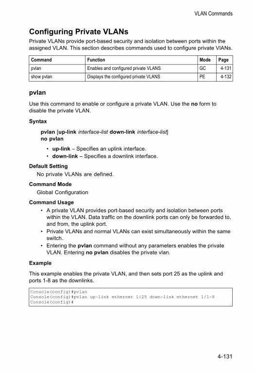
VLAN Commands
Configuring Private VLANsPrivate VLANs provide port-based security and isolation between ports within the assigned VLAN. This section describes commands used to configure private VlANs.
pvlan Use this command to enable or configure a private VLAN. Use the no form to disable the private VLAN.
Syntax
pvlan [up-link interface-list down-link interface-list]no pvlan
• up-link – Specifies an uplink interface.• down-link – Specifies a downlink interface.
Default Setting No private VLANs are defined.
Command Mode Global Configuration
Command Usage• A private VLAN provides port-based security and isolation between ports
within the VLAN. Data traffic on the downlink ports can only be forwarded to, and from, the uplink port.
• Private VLANs and normal VLANs can exist simultaneously within the same switch.
• Entering the pvlan command without any parameters enables the private VLAN. Entering no pvlan disables the private vlan.
Example
This example enables the private VLAN, and then sets port 25 as the uplink and ports 1-8 as the downlinks.
Command Function Mode Pagepvlan Enables and configured private VLANS GC 4-131show pvlan Displays the configured private VLANS PE 4-132
Console(config)#pvlanConsole(config)#pvlan up-link ethernet 1/25 down-link ethernet 1/1-8Console(config)#
4-131
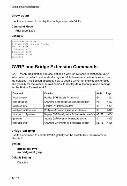
Command Line Reference
show pvlanUse this command to display the configured private VLAN.
Command Mode Privileged Exec
Example
GVRP and Bridge Extension CommandsGARP VLAN Registration Protocol defines a way for switches to exchange VLAN information in order to automatically register VLAN members on interfaces across the network. This section describes how to enable GVRP for individual interfaces and globally for the switch, as well as how to display default configuration settings for the Bridge Extension MIB.
bridge-ext gvrpUse this command to enable GVRP globally for the switch. Use the no form to disable it.
Syntax
bridge-ext gvrpno bridge-ext gvrp
Default Setting
Disabled
Console#show pvlanPrivate VLAN status: EnabledUp-link port:Ethernet 1/25
Down-link port:Ethernet 1/1-8
Console#
Command Function Mode Pagebridge-ext gvrp Enables GVRP globally for the switch GC 4-132show bridge-ext Shows the global bridge extension configuration PE 4-133switchport gvrp Enables GVRP for an interface IC 4-134switchport forbidden vlan Configures forbidden VLANs for an interface IC 4-129show gvrp configuration Displays GVRP configuration for the selected interface NE, PE 4-134garp timer Sets the GARP timer for the selected function IC 4-135show garp timer Shows the GARP timer for the selected function NE, PE 4-136
4-132
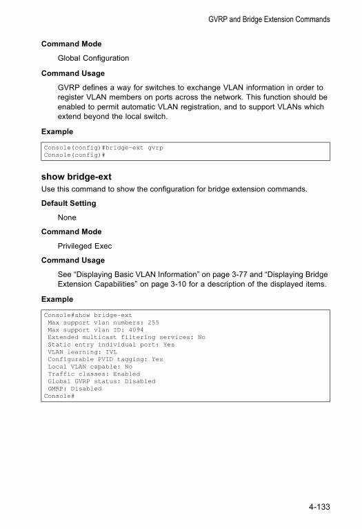
GVRP and Bridge Extension Commands
Command Mode
Global Configuration
Command Usage
GVRP defines a way for switches to exchange VLAN information in order to register VLAN members on ports across the network. This function should be enabled to permit automatic VLAN registration, and to support VLANs which extend beyond the local switch.
Example
show bridge-extUse this command to show the configuration for bridge extension commands.
Default Setting
None
Command Mode
Privileged Exec
Command Usage
See “Displaying Basic VLAN Information” on page 3-77 and “Displaying Bridge Extension Capabilities” on page 3-10 for a description of the displayed items.
Example
Console(config)#bridge-ext gvrpConsole(config)#
Console#show bridge-extMax support vlan numbers: 255Max support vlan ID: 4094Extended multicast filtering services: NoStatic entry individual port: YesVLAN learning: IVLConfigurable PVID tagging: YesLocal VLAN capable: NoTraffic classes: EnabledGlobal GVRP status: DisabledGMRP: Disabled
Console#
4-133
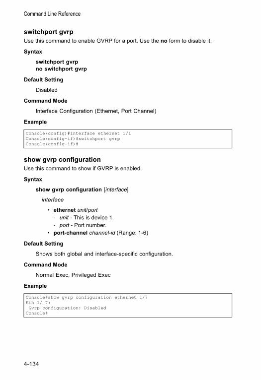
Command Line Reference
switchport gvrpUse this command to enable GVRP for a port. Use the no form to disable it.
Syntax
switchport gvrpno switchport gvrp
Default Setting
Disabled
Command Mode
Interface Configuration (Ethernet, Port Channel)
Example
show gvrp configurationUse this command to show if GVRP is enabled.
Syntax
show gvrp configuration [interface]
interface
• ethernet unit/port - unit - This is device 1. - port - Port number.
• port-channel channel-id (Range: 1-6)
Default Setting
Shows both global and interface-specific configuration.
Command Mode
Normal Exec, Privileged Exec
Example
Console(config)#interface ethernet 1/1Console(config-if)#switchport gvrpConsole(config-if)#
Console#show gvrp configuration ethernet 1/7Eth 1/ 7:Gvrp configuration: Disabled
Console#
4-134
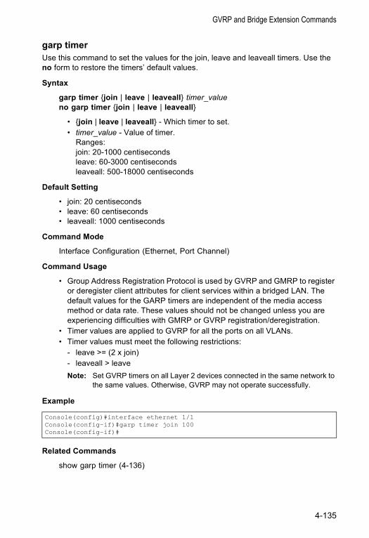
GVRP and Bridge Extension Commands
garp timerUse this command to set the values for the join, leave and leaveall timers. Use the no form to restore the timers’ default values.
Syntax
garp timer {join | leave | leaveall} timer_valueno garp timer {join | leave | leaveall}
• {join | leave | leaveall} - Which timer to set. • timer_value - Value of timer.
Ranges:join: 20-1000 centiseconds leave: 60-3000 centiseconds leaveall: 500-18000 centiseconds
Default Setting
• join: 20 centiseconds• leave: 60 centiseconds• leaveall: 1000 centiseconds
Command Mode
Interface Configuration (Ethernet, Port Channel)
Command Usage
• Group Address Registration Protocol is used by GVRP and GMRP to register or deregister client attributes for client services within a bridged LAN. The default values for the GARP timers are independent of the media access method or data rate. These values should not be changed unless you are experiencing difficulties with GMRP or GVRP registration/deregistration.
• Timer values are applied to GVRP for all the ports on all VLANs. • Timer values must meet the following restrictions:
- leave >= (2 x join) - leaveall > leave Note: Set GVRP timers on all Layer 2 devices connected in the same network to
the same values. Otherwise, GVRP may not operate successfully.
Example
Related Commands
show garp timer (4-136)
Console(config)#interface ethernet 1/1Console(config-if)#garp timer join 100Console(config-if)#
4-135
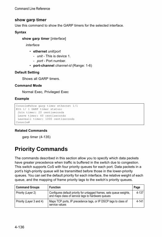
Command Line Reference
show garp timerUse this command to show the GARP timers for the selected interface.
Syntax
show garp timer [interface]
interface
• ethernet unit/port - unit - This is device 1. - port - Port number.
• port-channel channel-id (Range: 1-6)
Default Setting
Shows all GARP timers.
Command Mode
Normal Exec, Privileged Exec
Example
Related Commands
garp timer (4-135)
Priority CommandsThe commands described in this section allow you to specify which data packets have greater precedence when traffic is buffered in the switch due to congestion. This switch supports CoS with four priority queues for each port. Data packets in a port’s high-priority queue will be transmitted before those in the lower-priority queues. You can set the default priority for each interface, the relative weight of each queue, and the mapping of frame priority tags to the switch’s priority queues.
Console#show garp timer ethernet 1/1Eth 1/ 1 GARP timer status:Join timer: 20 centisecondsLeave timer: 60 centisecondsLeaveall timer: 1000 centiseconds
Console#
Command Groups Function PagePriority (Layer 2) Configures default priority for untagged frames, sets queue weights,
and maps class of service tags to hardware queues4-137
Priority (Layer 3 and 4) Maps TCP ports, IP precedence tags, or IP DSCP tags to class of service values
4-141
4-136
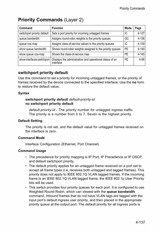
Priority Commands
Priority Commands (Layer 2)
switchport priority defaultUse this command to set a priority for incoming untagged frames, or the priority of frames received by the device connected to the specified interface. Use the no form to restore the default value.
Syntax
switchport priority default default-priority-idno switchport priority default
default-priority-id - The priority number for untagged ingress traffic. The priority is a number from 0 to 7. Seven is the highest priority.
Default Setting
The priority is not set, and the default value for untagged frames received on the interface is zero.
Command Mode
Interface Configuration (Ethernet, Port Channel)
Command Usage
• The precedence for priority mapping is IP Port, IP Precedence or IP DSCP, and default switchport priority.
• The default priority applies for an untagged frame received on a port set to accept all frame types (i.e, receives both untagged and tagged frames). This priority does not apply to IEEE 802.1Q VLAN tagged frames. If the incoming frame is an IEEE 802.1Q VLAN tagged frame, the IEEE 802.1p User Priority bits will be used.
• This switch provides four priority queues for each port. It is configured to use Weighted Round Robin, which can viewed with the queue bandwidth command. Inbound frames that do not have VLAN tags are tagged with the input port’s default ingress user priority, and then placed in the appropriate priority queue at the output port. The default priority for all ingress ports is
Command Function Mode Pageswitchport priority default Sets a port priority for incoming untagged frames IC 4-137queue bandwidth Assigns round-robin weights to the priority queues GC 4-138queue cos map Assigns class-of-service values to the priority queues IC 4-139show queue bandwidth Shows round-robin weights assigned to the priority queues PE 4-140show queue cos-map Shows the class-of-service map PE 4-140show interfaces switchport Displays the administrative and operational status of an
interfacePE 4-98
4-137
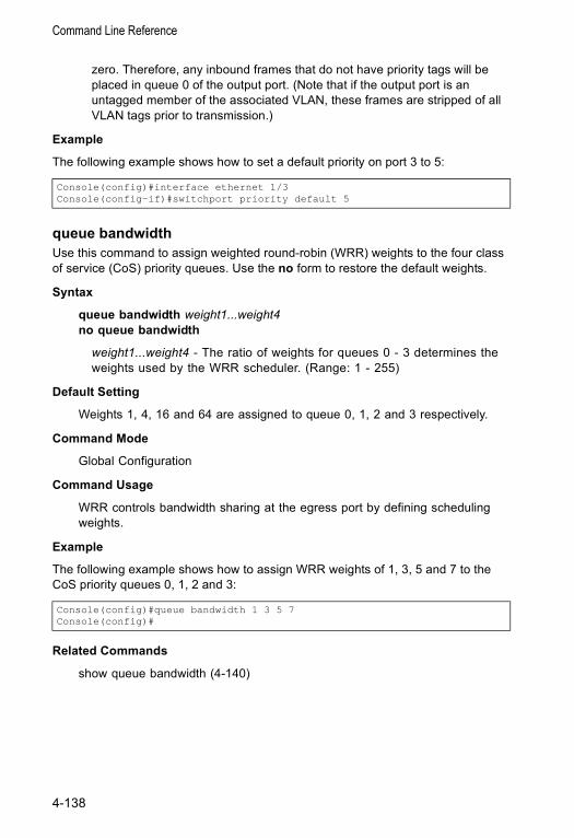
Command Line Reference
zero. Therefore, any inbound frames that do not have priority tags will be placed in queue 0 of the output port. (Note that if the output port is an untagged member of the associated VLAN, these frames are stripped of all VLAN tags prior to transmission.)
Example
The following example shows how to set a default priority on port 3 to 5:
queue bandwidth Use this command to assign weighted round-robin (WRR) weights to the four class of service (CoS) priority queues. Use the no form to restore the default weights.
Syntax
queue bandwidth weight1...weight4no queue bandwidth
weight1...weight4 - The ratio of weights for queues 0 - 3 determines the weights used by the WRR scheduler. (Range: 1 - 255)
Default Setting
Weights 1, 4, 16 and 64 are assigned to queue 0, 1, 2 and 3 respectively.
Command Mode
Global Configuration
Command Usage
WRR controls bandwidth sharing at the egress port by defining scheduling weights.
Example
The following example shows how to assign WRR weights of 1, 3, 5 and 7 to the CoS priority queues 0, 1, 2 and 3:
Related Commands
show queue bandwidth (4-140)
Console(config)#interface ethernet 1/3Console(config-if)#switchport priority default 5
Console(config)#queue bandwidth 1 3 5 7Console(config)#
4-138
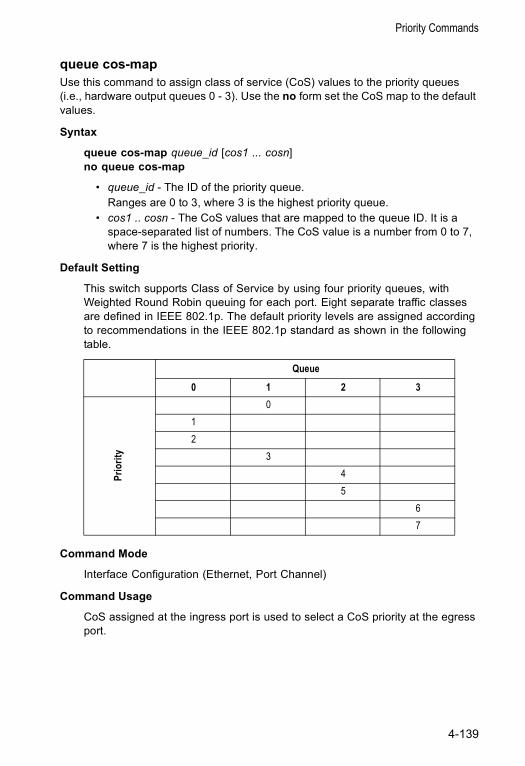
Priority Commands
queue cos-mapUse this command to assign class of service (CoS) values to the priority queues (i.e., hardware output queues 0 - 3). Use the no form set the CoS map to the default values.
Syntax
queue cos-map queue_id [cos1 ... cosn]no queue cos-map
• queue_id - The ID of the priority queue.Ranges are 0 to 3, where 3 is the highest priority queue.
• cos1 .. cosn - The CoS values that are mapped to the queue ID. It is a space-separated list of numbers. The CoS value is a number from 0 to 7, where 7 is the highest priority.
Default Setting
This switch supports Class of Service by using four priority queues, with Weighted Round Robin queuing for each port. Eight separate traffic classes are defined in IEEE 802.1p. The default priority levels are assigned according to recommendations in the IEEE 802.1p standard as shown in the following table.
Command Mode
Interface Configuration (Ethernet, Port Channel)
Command Usage
CoS assigned at the ingress port is used to select a CoS priority at the egress port.
Queue
0 1 2 3
Prio
rity
012
345
67
4-139
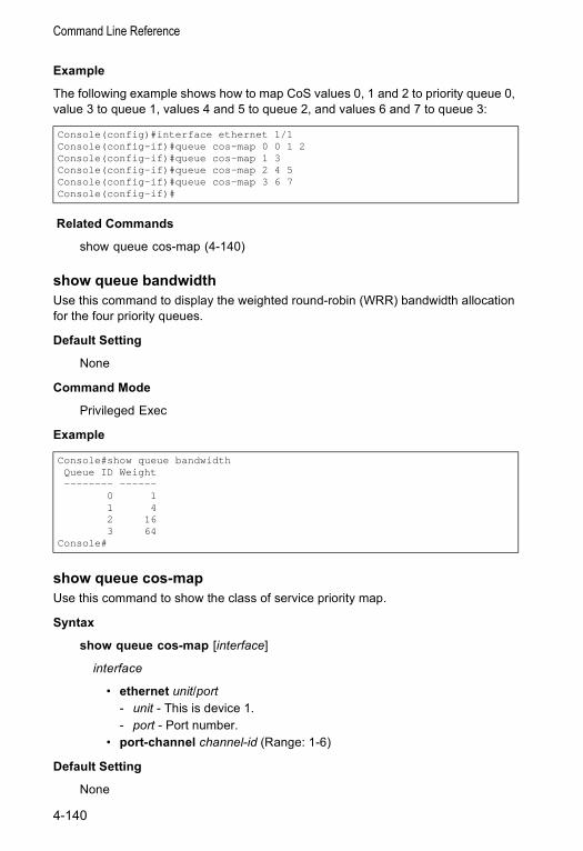
Command Line Reference
Example
The following example shows how to map CoS values 0, 1 and 2 to priority queue 0, value 3 to queue 1, values 4 and 5 to queue 2, and values 6 and 7 to queue 3:
Related Commands
show queue cos-map (4-140)
show queue bandwidthUse this command to display the weighted round-robin (WRR) bandwidth allocation for the four priority queues.
Default Setting
None
Command Mode
Privileged Exec
Example
show queue cos-mapUse this command to show the class of service priority map.
Syntax
show queue cos-map [interface]
interface
• ethernet unit/port - unit - This is device 1. - port - Port number.
• port-channel channel-id (Range: 1-6)
Default Setting
None
Console(config)#interface ethernet 1/1Console(config-if)#queue cos-map 0 0 1 2Console(config-if)#queue cos-map 1 3Console(config-if)#queue cos-map 2 4 5Console(config-if)#queue cos-map 3 6 7Console(config-if)#
Console#show queue bandwidthQueue ID Weight-------- ------
0 11 42 163 64
Console#
4-140
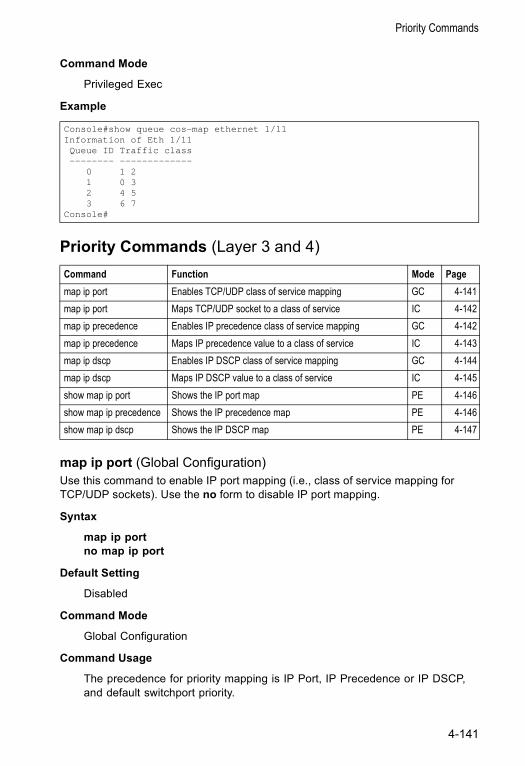
Priority Commands
Command Mode
Privileged Exec
Example
Priority Commands (Layer 3 and 4)
map ip port (Global Configuration)Use this command to enable IP port mapping (i.e., class of service mapping for TCP/UDP sockets). Use the no form to disable IP port mapping.
Syntax
map ip port no map ip port
Default Setting
Disabled
Command Mode
Global Configuration
Command Usage
The precedence for priority mapping is IP Port, IP Precedence or IP DSCP, and default switchport priority.
Console#show queue cos-map ethernet 1/11Information of Eth 1/11Queue ID Traffic class-------- -------------
0 1 21 0 32 4 53 6 7
Console#
Command Function Mode Pagemap ip port Enables TCP/UDP class of service mapping GC 4-141map ip port Maps TCP/UDP socket to a class of service IC 4-142map ip precedence Enables IP precedence class of service mapping GC 4-142map ip precedence Maps IP precedence value to a class of service IC 4-143map ip dscp Enables IP DSCP class of service mapping GC 4-144map ip dscp Maps IP DSCP value to a class of service IC 4-145show map ip port Shows the IP port map PE 4-146show map ip precedence Shows the IP precedence map PE 4-146show map ip dscp Shows the IP DSCP map PE 4-147
4-141
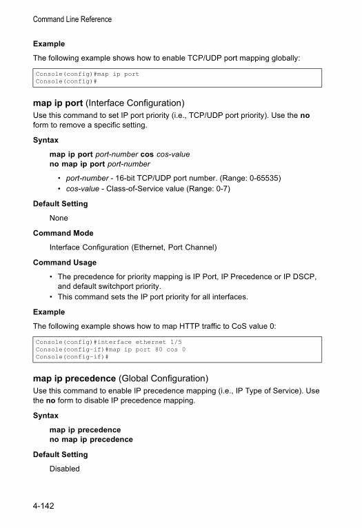
Command Line Reference
Example
The following example shows how to enable TCP/UDP port mapping globally:
map ip port (Interface Configuration)Use this command to set IP port priority (i.e., TCP/UDP port priority). Use the no form to remove a specific setting.
Syntax
map ip port port-number cos cos-valueno map ip port port-number
• port-number - 16-bit TCP/UDP port number. (Range: 0-65535) • cos-value - Class-of-Service value (Range: 0-7)
Default Setting
None
Command Mode
Interface Configuration (Ethernet, Port Channel)
Command Usage
• The precedence for priority mapping is IP Port, IP Precedence or IP DSCP, and default switchport priority.
• This command sets the IP port priority for all interfaces.
Example
The following example shows how to map HTTP traffic to CoS value 0:
map ip precedence (Global Configuration)Use this command to enable IP precedence mapping (i.e., IP Type of Service). Use the no form to disable IP precedence mapping.
Syntax
map ip precedence no map ip precedence
Default Setting
Disabled
Console(config)#map ip portConsole(config)#
Console(config)#interface ethernet 1/5Console(config-if)#map ip port 80 cos 0Console(config-if)#
4-142
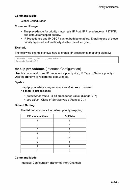
Priority Commands
Command Mode
Global Configuration
Command Usage
• The precedence for priority mapping is IP Port, IP Precedence or IP DSCP, and default switchport priority.
• IP Precedence and IP DSCP cannot both be enabled. Enabling one of these priority types will automatically disable the other type.
Example
The following example shows how to enable IP precedence mapping globally:
map ip precedence (Interface Configuration)Use this command to set IP precedence priority (i.e., IP Type of Service priority). Use the no form to restore the default table.
Syntax
map ip precedence ip-precedence-value cos cos-valueno map ip precedence
• precedence-value - 3-bit precedence value. (Range: 0-7) • cos-value - Class-of-Service value (Range: 0-7)
Default Setting
The list below shows the default priority mapping.
Command Mode
Interface Configuration (Ethernet, Port Channel)
Console(config)#map ip precedenceConsole(config)#
IP Precedence Value CoS Value0 01 12 23 34 45 56 67 7
4-143
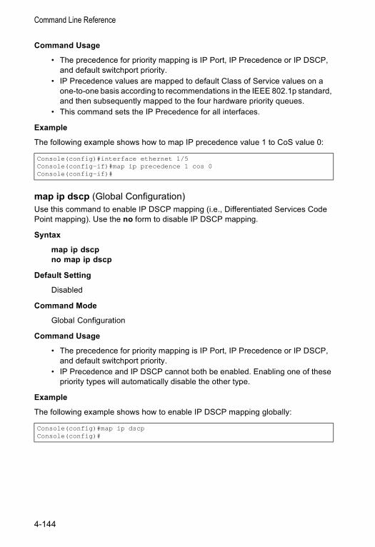
Command Line Reference
Command Usage
• The precedence for priority mapping is IP Port, IP Precedence or IP DSCP, and default switchport priority.
• IP Precedence values are mapped to default Class of Service values on a one-to-one basis according to recommendations in the IEEE 802.1p standard, and then subsequently mapped to the four hardware priority queues.
• This command sets the IP Precedence for all interfaces.
Example
The following example shows how to map IP precedence value 1 to CoS value 0:
map ip dscp (Global Configuration)Use this command to enable IP DSCP mapping (i.e., Differentiated Services Code Point mapping). Use the no form to disable IP DSCP mapping.
Syntax
map ip dscpno map ip dscp
Default Setting
Disabled
Command Mode
Global Configuration
Command Usage
• The precedence for priority mapping is IP Port, IP Precedence or IP DSCP, and default switchport priority.
• IP Precedence and IP DSCP cannot both be enabled. Enabling one of these priority types will automatically disable the other type.
Example
The following example shows how to enable IP DSCP mapping globally:
Console(config)#interface ethernet 1/5Console(config-if)#map ip precedence 1 cos 0Console(config-if)#
Console(config)#map ip dscpConsole(config)#
4-144
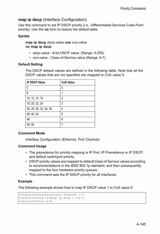
Priority Commands
map ip dscp (Interface Configuration)Use this command to set IP DSCP priority (i.e., Differentiated Services Code Point priority). Use the no form to restore the default table.
Syntax
map ip dscp dscp-value cos cos-valueno map ip dscp
• dscp-value - 8-bit DSCP value. (Range: 0-255) • cos-value - Class-of-Service value (Range: 0-7)
Default Setting
The DSCP default values are defined in the following table. Note that all the DSCP values that are not specified are mapped to CoS value 0.
Command Mode
Interface Configuration (Ethernet, Port Channel)
Command Usage
• The precedence for priority mapping is IP Port, IP Precedence or IP DSCP, and default switchport priority.
• DSCP priority values are mapped to default Class of Service values according to recommendations in the IEEE 802.1p standard, and then subsequently mapped to the four hardware priority queues.
• This command sets the IP DSCP priority for all interfaces.
Example
The following example shows how to map IP DSCP value 1 to CoS value 0:
IP DSCP Value CoS Value0 08 110, 12, 14, 16 218, 20, 22, 24 326, 28, 30, 32, 34, 36 438, 40, 42 548 646, 56 7
Console(config)#interface ethernet 1/5Console(config-if)#map ip dscp 1 cos 0Console(config-if)#
4-145
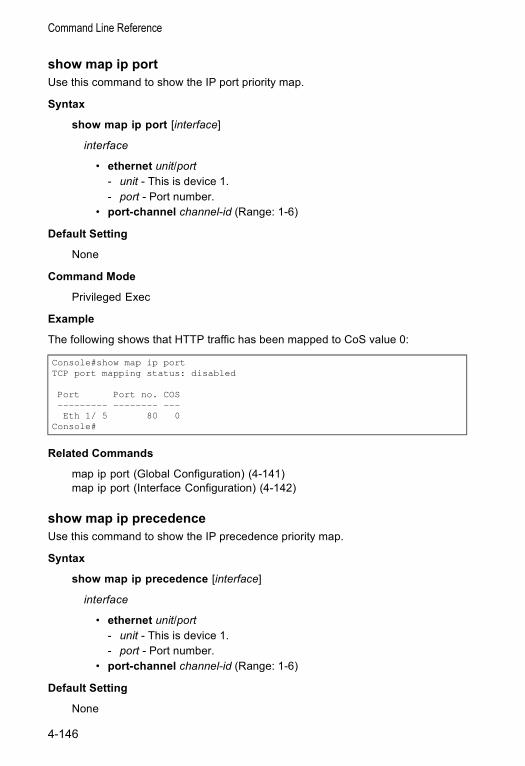
Command Line Reference
show map ip portUse this command to show the IP port priority map.
Syntax
show map ip port [interface]
interface
• ethernet unit/port - unit - This is device 1. - port - Port number.
• port-channel channel-id (Range: 1-6)
Default Setting
None
Command Mode
Privileged Exec
Example
The following shows that HTTP traffic has been mapped to CoS value 0:
Related Commands
map ip port (Global Configuration) (4-141)map ip port (Interface Configuration) (4-142)
show map ip precedenceUse this command to show the IP precedence priority map.
Syntax
show map ip precedence [interface]
interface
• ethernet unit/port - unit - This is device 1. - port - Port number.
• port-channel channel-id (Range: 1-6)
Default Setting
None
Console#show map ip portTCP port mapping status: disabled
Port Port no. COS--------- -------- ---Eth 1/ 5 80 0
Console#
4-146
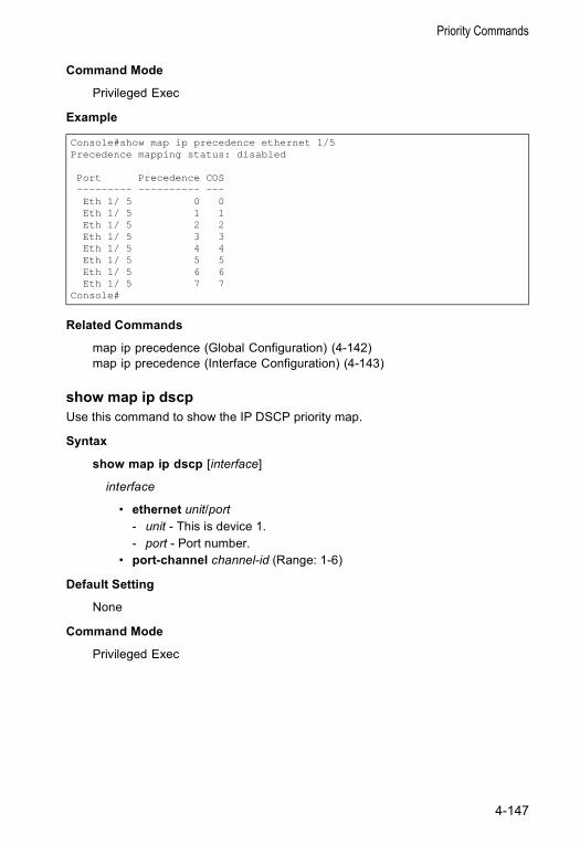
Priority Commands
Command Mode
Privileged Exec
Example
Related Commands
map ip precedence (Global Configuration) (4-142)map ip precedence (Interface Configuration) (4-143)
show map ip dscpUse this command to show the IP DSCP priority map.
Syntax
show map ip dscp [interface]
interface
• ethernet unit/port - unit - This is device 1. - port - Port number.
• port-channel channel-id (Range: 1-6)
Default Setting
None
Command Mode
Privileged Exec
Console#show map ip precedence ethernet 1/5Precedence mapping status: disabled
Port Precedence COS--------- ---------- ---Eth 1/ 5 0 0Eth 1/ 5 1 1Eth 1/ 5 2 2Eth 1/ 5 3 3Eth 1/ 5 4 4Eth 1/ 5 5 5Eth 1/ 5 6 6Eth 1/ 5 7 7
Console#
4-147
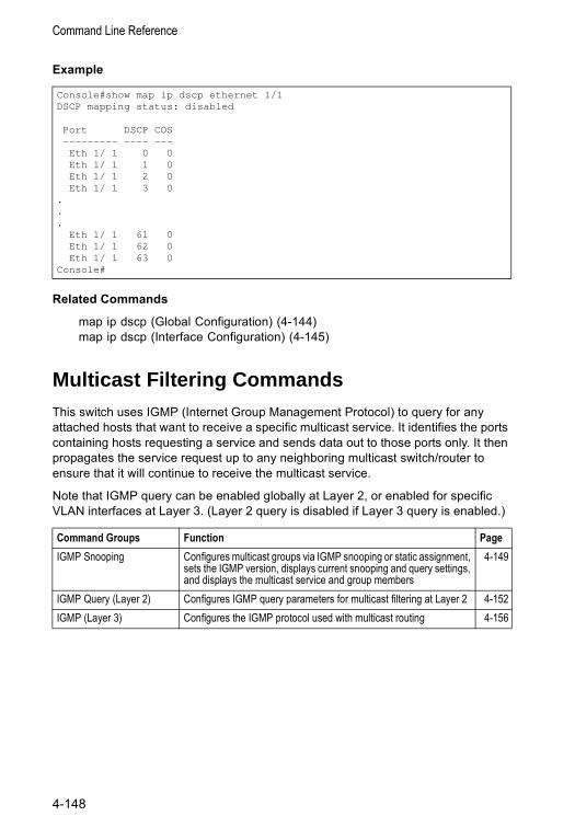
Command Line Reference
Example
Related Commands
map ip dscp (Global Configuration) (4-144)map ip dscp (Interface Configuration) (4-145)
Multicast Filtering CommandsThis switch uses IGMP (Internet Group Management Protocol) to query for any attached hosts that want to receive a specific multicast service. It identifies the ports containing hosts requesting a service and sends data out to those ports only. It then propagates the service request up to any neighboring multicast switch/router to ensure that it will continue to receive the multicast service.
Note that IGMP query can be enabled globally at Layer 2, or enabled for specific VLAN interfaces at Layer 3. (Layer 2 query is disabled if Layer 3 query is enabled.)
Console#show map ip dscp ethernet 1/1DSCP mapping status: disabled
Port DSCP COS--------- ---- ---Eth 1/ 1 0 0Eth 1/ 1 1 0Eth 1/ 1 2 0Eth 1/ 1 3 0
.
.
.Eth 1/ 1 61 0Eth 1/ 1 62 0Eth 1/ 1 63 0
Console#
Command Groups Function PageIGMP Snooping Configures multicast groups via IGMP snooping or static assignment,
sets the IGMP version, displays current snooping and query settings, and displays the multicast service and group members
4-149
IGMP Query (Layer 2) Configures IGMP query parameters for multicast filtering at Layer 2 4-152IGMP (Layer 3) Configures the IGMP protocol used with multicast routing 4-156
4-148
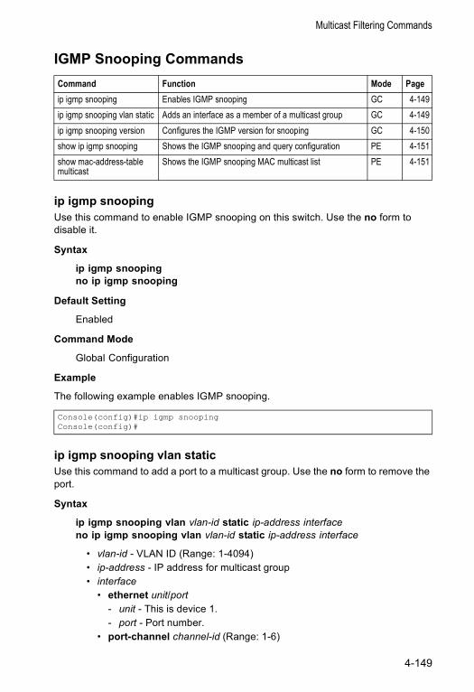
Multicast Filtering Commands
IGMP Snooping Commands
ip igmp snoopingUse this command to enable IGMP snooping on this switch. Use the no form to disable it.
Syntax
ip igmp snoopingno ip igmp snooping
Default Setting
Enabled
Command Mode
Global Configuration
Example
The following example enables IGMP snooping.
ip igmp snooping vlan staticUse this command to add a port to a multicast group. Use the no form to remove the port.
Syntax
ip igmp snooping vlan vlan-id static ip-address interfaceno ip igmp snooping vlan vlan-id static ip-address interface
• vlan-id - VLAN ID (Range: 1-4094) • ip-address - IP address for multicast group • interface
• ethernet unit/port - unit - This is device 1. - port - Port number.
• port-channel channel-id (Range: 1-6)
Command Function Mode Pageip igmp snooping Enables IGMP snooping GC 4-149ip igmp snooping vlan static Adds an interface as a member of a multicast group GC 4-149ip igmp snooping version Configures the IGMP version for snooping GC 4-150show ip igmp snooping Shows the IGMP snooping and query configuration PE 4-151show mac-address-table multicast
Shows the IGMP snooping MAC multicast list PE 4-151
Console(config)#ip igmp snoopingConsole(config)#
4-149
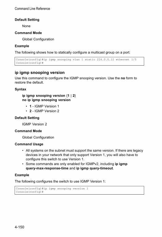
Command Line Reference
Default Setting
None
Command Mode
Global Configuration
Example
The following shows how to statically configure a multicast group on a port:
ip igmp snooping versionUse this command to configure the IGMP snooping version. Use the no form to restore the default.
Syntax
ip igmp snooping version {1 | 2}no ip igmp snooping version
• 1 - IGMP Version 1 • 2 - IGMP Version 2
Default Setting
IGMP Version 2
Command Mode
Global Configuration
Command Usage
• All systems on the subnet must support the same version. If there are legacy devices in your network that only support Version 1, you will also have to configure this switch to use Version 1.
• Some commands are only enabled for IGMPv2, including ip igmp query-max-response-time and ip igmp query-timeout.
Example
The following configures the switch to use IGMP Version 1:
Console(config)#ip igmp snooping vlan 1 static 224.0.0.12 ethernet 1/5Console(config)#
Console(config)#ip igmp snooping version 1Console(config)#
4-150
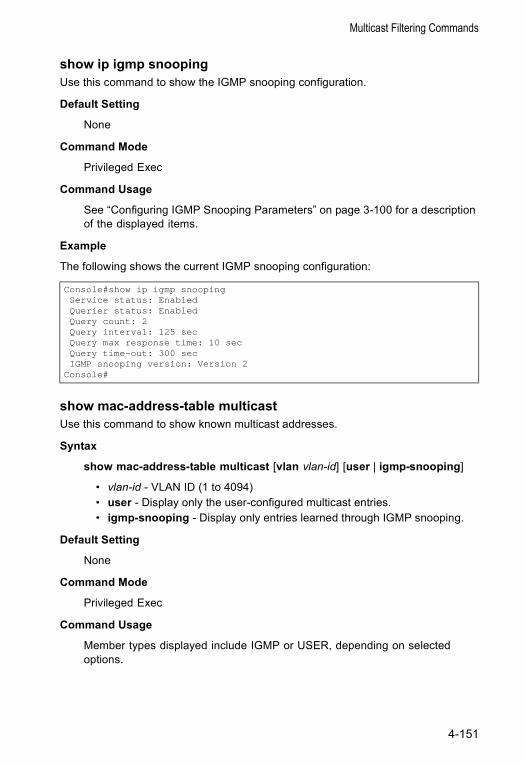
Multicast Filtering Commands
show ip igmp snoopingUse this command to show the IGMP snooping configuration.
Default Setting
None
Command Mode
Privileged Exec
Command Usage
See “Configuring IGMP Snooping Parameters” on page 3-100 for a description of the displayed items.
Example
The following shows the current IGMP snooping configuration:
show mac-address-table multicastUse this command to show known multicast addresses.
Syntax
show mac-address-table multicast [vlan vlan-id] [user | igmp-snooping]
• vlan-id - VLAN ID (1 to 4094) • user - Display only the user-configured multicast entries. • igmp-snooping - Display only entries learned through IGMP snooping.
Default Setting
None
Command Mode
Privileged Exec
Command Usage
Member types displayed include IGMP or USER, depending on selected options.
Console#show ip igmp snoopingService status: EnabledQuerier status: EnabledQuery count: 2Query interval: 125 secQuery max response time: 10 secQuery time-out: 300 secIGMP snooping version: Version 2
Console#
4-151
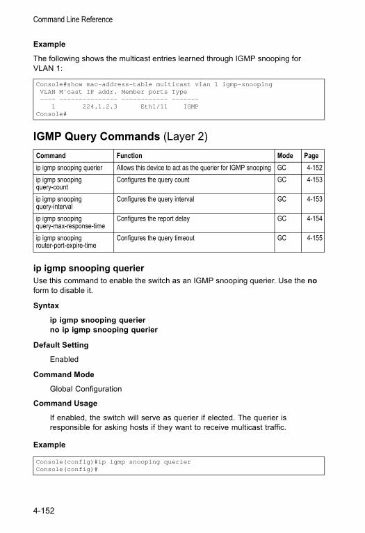
Command Line Reference
Example
The following shows the multicast entries learned through IGMP snooping for VLAN 1:
IGMP Query Commands (Layer 2)
ip igmp snooping querierUse this command to enable the switch as an IGMP snooping querier. Use the no form to disable it.
Syntax
ip igmp snooping querierno ip igmp snooping querier
Default Setting
Enabled
Command Mode
Global Configuration
Command Usage
If enabled, the switch will serve as querier if elected. The querier is responsible for asking hosts if they want to receive multicast traffic.
Example
Console#show mac-address-table multicast vlan 1 igmp-snoopingVLAN M'cast IP addr. Member ports Type---- --------------- ------------ -------
1 224.1.2.3 Eth1/11 IGMPConsole#
Command Function Mode Pageip igmp snooping querier Allows this device to act as the querier for IGMP snooping GC 4-152ip igmp snooping query-count
Configures the query count GC 4-153
ip igmp snooping query-interval
Configures the query interval GC 4-153
ip igmp snooping query-max-response-time
Configures the report delay GC 4-154
ip igmp snooping router-port-expire-time
Configures the query timeout GC 4-155
Console(config)#ip igmp snooping querierConsole(config)#
4-152
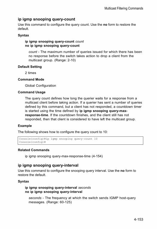
Multicast Filtering Commands
ip igmp snooping query-countUse this command to configure the query count. Use the no form to restore the default.
Syntax
ip igmp snooping query-count countno ip igmp snooping query-count
count - The maximum number of queries issued for which there has been no response before the switch takes action to drop a client from the multicast group. (Range: 2-10)
Default Setting
2 times
Command Mode
Global Configuration
Command Usage
The query count defines how long the querier waits for a response from a multicast client before taking action. If a querier has sent a number of queries defined by this command, but a client has not responded, a countdown timer is started using the time defined by ip igmp snooping query-max- response-time. If the countdown finishes, and the client still has not responded, then that client is considered to have left the multicast group.
Example
The following shows how to configure the query count to 10:
Related Commands
ip igmp snooping query-max-response-time (4-154)
ip igmp snooping query-intervalUse this command to configure the snooping query interval. Use the no form to restore the default.
Syntax
ip igmp snooping query-interval secondsno ip igmp snooping query-interval
seconds - The frequency at which the switch sends IGMP host-query messages. (Range: 60-125)
Console(config)#ip igmp snooping query-count 10Console(config)#
4-153
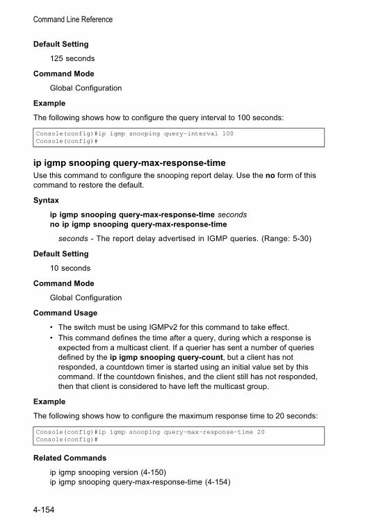
Command Line Reference
Default Setting
125 seconds
Command Mode
Global Configuration
Example
The following shows how to configure the query interval to 100 seconds:
ip igmp snooping query-max-response-timeUse this command to configure the snooping report delay. Use the no form of this command to restore the default.
Syntax
ip igmp snooping query-max-response-time secondsno ip igmp snooping query-max-response-time
seconds - The report delay advertised in IGMP queries. (Range: 5-30)
Default Setting
10 seconds
Command Mode
Global Configuration
Command Usage
• The switch must be using IGMPv2 for this command to take effect. • This command defines the time after a query, during which a response is
expected from a multicast client. If a querier has sent a number of queries defined by the ip igmp snooping query-count, but a client has not responded, a countdown timer is started using an initial value set by this command. If the countdown finishes, and the client still has not responded, then that client is considered to have left the multicast group.
Example
The following shows how to configure the maximum response time to 20 seconds:
Related Commands
ip igmp snooping version (4-150)ip igmp snooping query-max-response-time (4-154)
Console(config)#ip igmp snooping query-interval 100Console(config)#
Console(config)#ip igmp snooping query-max-response-time 20Console(config)#
4-154
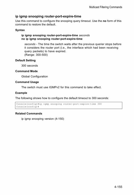
Multicast Filtering Commands
ip igmp snooping router-port-expire-timeUse this command to configure the snooping query timeout. Use the no form of this command to restore the default.
Syntax
ip igmp snooping router-port-expire-time secondsno ip igmp snooping router-port-expire-time
seconds - The time the switch waits after the previous querier stops before it considers the router port (i.e., the interface which had been receiving query packets) to have expired. (Range: 300-500)
Default Setting
300 seconds
Command Mode
Global Configuration
Command Usage
The switch must use IGMPv2 for this command to take effect.
Example
The following shows how to configure the default timeout to 300 seconds:
Related Commands
ip igmp snooping version (4-150)
Console(config)#ip igmp snooping router-port-expire-time 300Console(config)#
4-155

Command Line Reference
IGMP Commands (Layer 3)
ip igmpUse this command to enable IGMP on a VLAN interface. Use the no form of this command to disable IGMP on the specified interface.
Syntax
ip igmpno ip igmp
Default Setting
Disabled
Command Mode
Interface Configuration (VLAN)
Command Usage
IGMP query can be enabled globally at Layer 2 via the ip igmp snooping command, or enabled for specific VLAN interfaces at Layer 3 via the ip igmp command. (Layer 2 query is disabled if Layer 3 query is enabled.)
Command Function Mode Pageip igmp Enables IGMP for the specified interface IC 4-156ip igmp robustval Configures the expected packet loss IC 4-157ip igmp query-interval Configures frequency for sending host query messages IC 4-158ip igmp max-resp-interval Configures the maximum host response time IC 4-158ip igmp last-memb-query-interval
Configures frequency for sending group-specific host query messages
IC 4-159
ip igmp version Configures IGMP version used on this interface IC 4-160show ip igmp interface Displays the IGMP configuration for specified interfaces NE, PE 4-160clear ip igmp group Deletes entries from the IGMP cache PE 4-161show ip igmp groups Displays detailed information for IGMP groups NE, PE 4-162
4-156
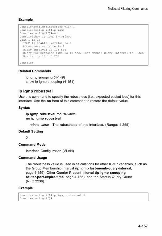
Multicast Filtering Commands
Example
Related Commands
ip igmp snooping (4-149)show ip igmp snooping (4-151)
ip igmp robustval Use this command to specify the robustness (i.e., expected packet loss) for this interface. Use the no form of this command to restore the default value.
Syntax
ip igmp robustval robust-valueno ip igmp robustval
robust-value - The robustness of this interface. (Range: 1-255)
Default Setting
2
Command Mode
Interface Configuration (VLAN)
Command Usage
The robustness value is used in calculations for other IGMP variables, such as the Group Membership Interval (ip igmp last-memb-query-interval, page 4-159), Other Querier Present Interval (ip igmp snooping router-port-expire-time, page 4-155), and the Startup Query Count (RFC 2236).
Example
Console(config)#interface vlan 1Console(config-if)#ip igmpConsole(config-if)#endConsole#show ip igmp interfaceVlan 1 is up
IGMP is enable, version is 2Robustness variable is 2Query interval is 125 secQuery Max Response Time is 10 sec, Last Member Query Interval is 1 secQuerier is 10.1.0.253
Console#
Console(config-if)#ip igmp robustval 3Console(config-if)#
4-157
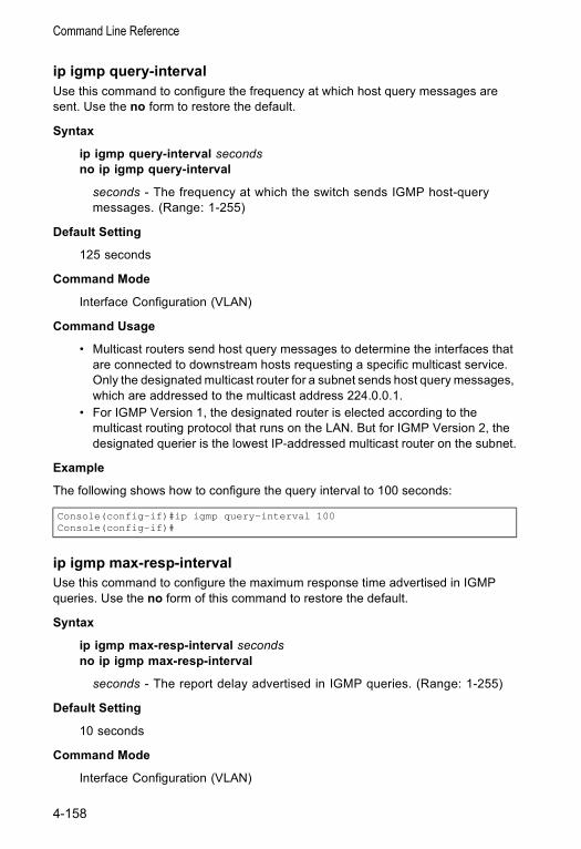
Command Line Reference
ip igmp query-intervalUse this command to configure the frequency at which host query messages are sent. Use the no form to restore the default.
Syntax
ip igmp query-interval secondsno ip igmp query-interval
seconds - The frequency at which the switch sends IGMP host-query messages. (Range: 1-255)
Default Setting
125 seconds
Command Mode
Interface Configuration (VLAN)
Command Usage
• Multicast routers send host query messages to determine the interfaces that are connected to downstream hosts requesting a specific multicast service. Only the designated multicast router for a subnet sends host query messages, which are addressed to the multicast address 224.0.0.1.
• For IGMP Version 1, the designated router is elected according to the multicast routing protocol that runs on the LAN. But for IGMP Version 2, the designated querier is the lowest IP-addressed multicast router on the subnet.
Example
The following shows how to configure the query interval to 100 seconds:
ip igmp max-resp-intervalUse this command to configure the maximum response time advertised in IGMP queries. Use the no form of this command to restore the default.
Syntax
ip igmp max-resp-interval secondsno ip igmp max-resp-interval
seconds - The report delay advertised in IGMP queries. (Range: 1-255)
Default Setting
10 seconds
Command Mode
Interface Configuration (VLAN)
Console(config-if)#ip igmp query-interval 100Console(config-if)#
4-158
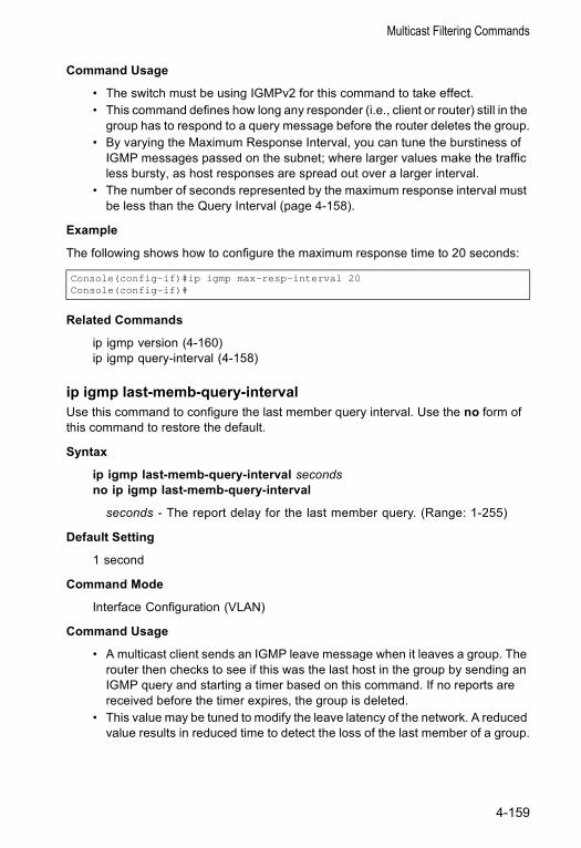
Multicast Filtering Commands
Command Usage
• The switch must be using IGMPv2 for this command to take effect. • This command defines how long any responder (i.e., client or router) still in the
group has to respond to a query message before the router deletes the group.• By varying the Maximum Response Interval, you can tune the burstiness of
IGMP messages passed on the subnet; where larger values make the traffic less bursty, as host responses are spread out over a larger interval.
• The number of seconds represented by the maximum response interval must be less than the Query Interval (page 4-158).
Example
The following shows how to configure the maximum response time to 20 seconds:
Related Commands
ip igmp version (4-160)ip igmp query-interval (4-158)
ip igmp last-memb-query-intervalUse this command to configure the last member query interval. Use the no form of this command to restore the default.
Syntax
ip igmp last-memb-query-interval secondsno ip igmp last-memb-query-interval
seconds - The report delay for the last member query. (Range: 1-255)
Default Setting
1 second
Command Mode
Interface Configuration (VLAN)
Command Usage
• A multicast client sends an IGMP leave message when it leaves a group. The router then checks to see if this was the last host in the group by sending an IGMP query and starting a timer based on this command. If no reports are received before the timer expires, the group is deleted.
• This value may be tuned to modify the leave latency of the network. A reduced value results in reduced time to detect the loss of the last member of a group.
Console(config-if)#ip igmp max-resp-interval 20Console(config-if)#
4-159
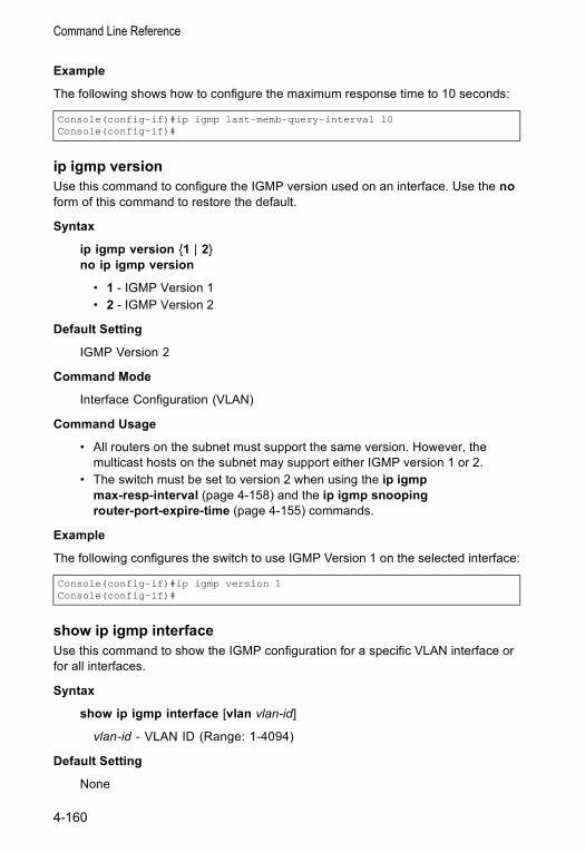
Command Line Reference
Example
The following shows how to configure the maximum response time to 10 seconds:
ip igmp versionUse this command to configure the IGMP version used on an interface. Use the no form of this command to restore the default.
Syntax
ip igmp version {1 | 2}no ip igmp version
• 1 - IGMP Version 1 • 2 - IGMP Version 2
Default Setting
IGMP Version 2
Command Mode
Interface Configuration (VLAN)
Command Usage
• All routers on the subnet must support the same version. However, the multicast hosts on the subnet may support either IGMP version 1 or 2.
• The switch must be set to version 2 when using the ip igmp max-resp-interval (page 4-158) and the ip igmp snooping router-port-expire-time (page 4-155) commands.
Example
The following configures the switch to use IGMP Version 1 on the selected interface:
show ip igmp interfaceUse this command to show the IGMP configuration for a specific VLAN interface or for all interfaces.
Syntax
show ip igmp interface [vlan vlan-id]
vlan-id - VLAN ID (Range: 1-4094)
Default Setting
None
Console(config-if)#ip igmp last-memb-query-interval 10Console(config-if)#
Console(config-if)#ip igmp version 1Console(config-if)#
4-160
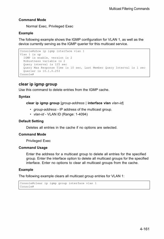
Multicast Filtering Commands
Command Mode
Normal Exec, Privileged Exec
Example
The following example shows the IGMP configuration for VLAN 1, as well as the device currently serving as the IGMP querier for this multicast service.
clear ip igmp groupUse this command to delete entries from the IGMP cache.
Syntax
clear ip igmp group [group-address | interface vlan vlan-id]
• group-address - IP address of the multicast group.• vlan-id - VLAN ID (Range: 1-4094)
Default Setting
Deletes all entries in the cache if no options are selected.
Command Mode
Privileged Exec
Command Usage
Enter the address for a multicast group to delete all entries for the specified group. Enter the interface option to delete all multicast groups for the specified interface. Enter no options to clear all multicast groups from the cache.
Example
The following example clears all multicast group entries for VLAN 1:
Console#show ip igmp interface vlan 1Vlan 1 is up
IGMP is enable, version is 2Robustness variable is 2Query interval is 125 secQuery Max Response Time is 10 sec, Last Member Query Interval is 1 secQuerier is 10.1.0.253
Console#
Console#clear ip igmp group interface vlan 1Console#
4-161
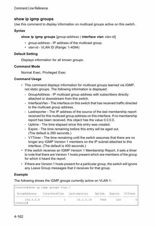
Command Line Reference
show ip igmp groupsUse this command to display information on multicast groups active on this switch.
Syntax
show ip igmp groups [group-address | interface vlan vlan-id]
• group-address - IP address of the multicast group.• vlan-id - VLAN ID (Range: 1-4094)
Default Setting
Displays information for all known groups.
Command Mode
Normal Exec, Privileged Exec
Command Usage
• This command displays information for multicast groups learned via IGMP, not static groups. The following information is displayed:- GroupAddress - IP multicast group address with subscribers directly
attached or downstream from this switch.- InterfaceVlan - The interface on this switch that has received traffic directed
to the multicast group address.- Lastreporter - The IP address of the source of the last membership report
received for this multicast group address on this interface. If no membership report has been received, this object has the value 0.0.0.0.
- Uptime - The time elapsed since this entry was created.- Expire - The time remaining before this entry will be aged out.
(The default is 260 seconds.)- V1Timer - The time remaining until the switch assumes that there are no
longer any IGMP Version 1 members on the IP subnet attached to this interface. (The default is 400 seconds.)
• If the switch receives an IGMP Version 1 Membership Report, it sets a timer to note that there are Version 1 hosts present which are members of the group for which it heard the report.
• If there are Version 1 hosts present for a particular group, the switch will ignore any Leave Group messages that it receives for that group.
Example
The following shows the IGMP groups currently active on VLAN 1:
Console#show ip igmp groups vlan 1
GroupAddress InterfaceVlan Lastreporter Uptime Expire V1Timer--------------- --------------- --------------- -------- -------- ---------
234.5.6.8 1 10.1.5.19 7068 220 0Console#
4-162
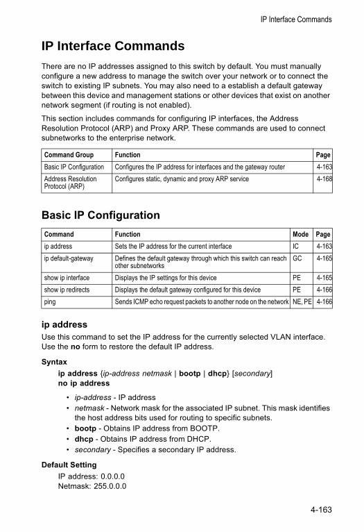
IP Interface Commands
IP Interface CommandsThere are no IP addresses assigned to this switch by default. You must manually configure a new address to manage the switch over your network or to connect the switch to existing IP subnets. You may also need to a establish a default gateway between this device and management stations or other devices that exist on another network segment (if routing is not enabled).
This section includes commands for configuring IP interfaces, the Address Resolution Protocol (ARP) and Proxy ARP. These commands are used to connect subnetworks to the enterprise network.
Basic IP Configuration
ip addressUse this command to set the IP address for the currently selected VLAN interface. Use the no form to restore the default IP address.
Syntax ip address {ip-address netmask | bootp | dhcp} [secondary]no ip address
• ip-address - IP address • netmask - Network mask for the associated IP subnet. This mask identifies
the host address bits used for routing to specific subnets. • bootp - Obtains IP address from BOOTP. • dhcp - Obtains IP address from DHCP. • secondary - Specifies a secondary IP address.
Default Setting IP address: 0.0.0.0Netmask: 255.0.0.0
Command Group Function PageBasic IP Configuration Configures the IP address for interfaces and the gateway router 4-163Address Resolution Protocol (ARP)
Configures static, dynamic and proxy ARP service 4-168
Command Function Mode Pageip address Sets the IP address for the current interface IC 4-163ip default-gateway Defines the default gateway through which this switch can reach
other subnetworksGC 4-165
show ip interface Displays the IP settings for this device PE 4-165show ip redirects Displays the default gateway configured for this device PE 4-166ping Sends ICMP echo request packets to another node on the network NE, PE 4-166
4-163
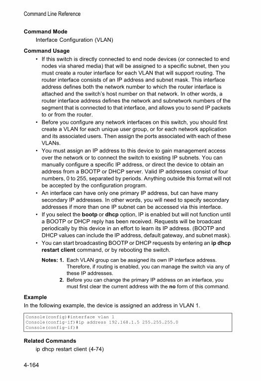
Command Line Reference
Command Mode Interface Configuration (VLAN)
Command Usage • If this switch is directly connected to end node devices (or connected to end
nodes via shared media) that will be assigned to a specific subnet, then you must create a router interface for each VLAN that will support routing. The router interface consists of an IP address and subnet mask. This interface address defines both the network number to which the router interface is attached and the switch’s host number on that network. In other words, a router interface address defines the network and subnetwork numbers of the segment that is connected to that interface, and allows you to send IP packets to or from the router.
• Before you configure any network interfaces on this switch, you should first create a VLAN for each unique user group, or for each network application and its associated users. Then assign the ports associated with each of these VLANs.
• You must assign an IP address to this device to gain management access over the network or to connect the switch to existing IP subnets. You can manually configure a specific IP address, or direct the device to obtain an address from a BOOTP or DHCP server. Valid IP addresses consist of four numbers, 0 to 255, separated by periods. Anything outside this format will not be accepted by the configuration program.
• An interface can have only one primary IP address, but can have many secondary IP addresses. In other words, you will need to specify secondary addresses if more than one IP subnet can be accessed via this interface.
• If you select the bootp or dhcp option, IP is enabled but will not function until a BOOTP or DHCP reply has been received. Requests will be broadcast periodically by this device in an effort to learn its IP address. (BOOTP and DHCP values can include the IP address, default gateway, and subnet mask).
• You can start broadcasting BOOTP or DHCP requests by entering an ip dhcp restart client command, or by rebooting the switch.
Notes: 1. Each VLAN group can be assigned its own IP interface address. Therefore, if routing is enabled, you can manage the switch via any of these IP addresses.
2. Before you can change the primary IP address on an interface, you must first clear the current address with the no form of this command.
ExampleIn the following example, the device is assigned an address in VLAN 1.
Related Commandsip dhcp restart client (4-74)
Console(config)#interface vlan 1Console(config-if)#ip address 192.168.1.5 255.255.255.0Console(config-if)#
4-164
IP Interface Commands
ip default-gatewayUse this command to a establish a static route between this switch and devices that exist on another network segment. Use the no form to remove the static route.
Syntax ip default-gateway gatewayno ip default-gateway
gateway - IP address of the default gateway
Default Setting No static route is established.
Command Mode Global Configuration
Command Usage • The gateway specified in this command is only valid if routing is disabled with
the no ip routing command. If IP routing is disabled, you must define a gateway if the target device is located in a different subnet.
• If routing is enabled, you must define the gateway with the ip route command.
Example The following example defines a default gateway for this device:
Related Commands show ip redirects (4-166)ip routing (4-171)ip route (4-172)
show ip interfaceUse this command to display the settings of an IP interface.
Default Setting All interfaces
Command Mode Privileged Exec
Console(config)#ip default-gateway 10.1.1.254Console(config)#
4-165
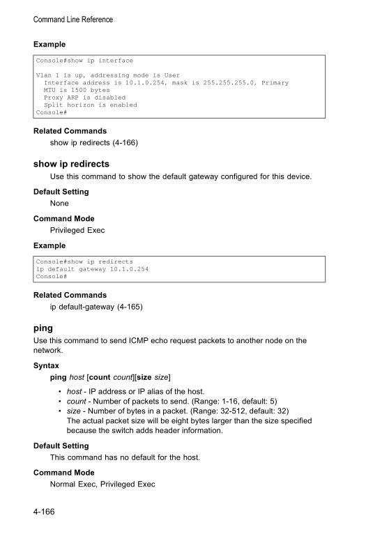
Command Line Reference
Example
Related Commands show ip redirects (4-166)
show ip redirectsUse this command to show the default gateway configured for this device.
Default Setting None
Command Mode Privileged Exec
Example
Related Commands ip default-gateway (4-165)
pingUse this command to send ICMP echo request packets to another node on the network.
Syntax ping host [count count][size size]
• host - IP address or IP alias of the host. • count - Number of packets to send. (Range: 1-16, default: 5) • size - Number of bytes in a packet. (Range: 32-512, default: 32)
The actual packet size will be eight bytes larger than the size specified because the switch adds header information.
Default Setting This command has no default for the host.
Command Mode Normal Exec, Privileged Exec
Console#show ip interface
Vlan 1 is up, addressing mode is UserInterface address is 10.1.0.254, mask is 255.255.255.0, PrimaryMTU is 1500 bytesProxy ARP is disabledSplit horizon is enabled
Console#
Console#show ip redirectsip default gateway 10.1.0.254Console#
4-166
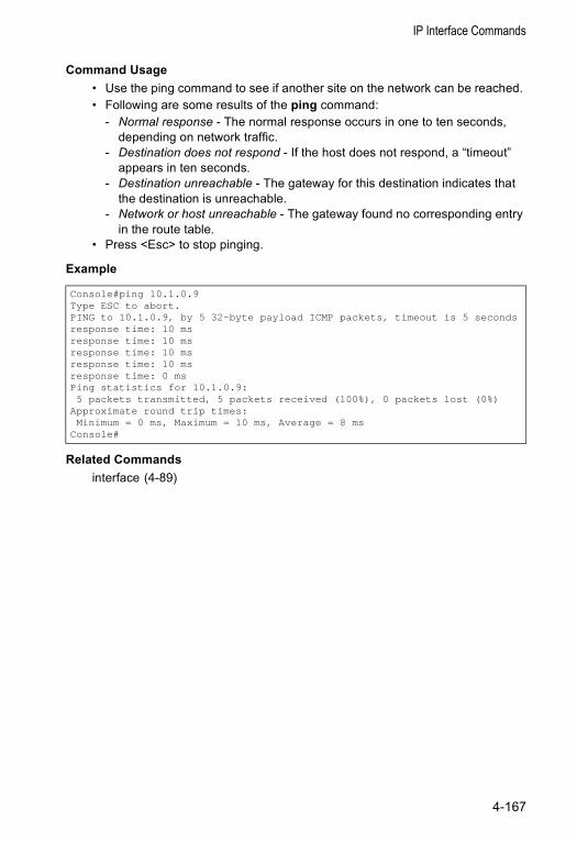
IP Interface Commands
Command Usage • Use the ping command to see if another site on the network can be reached. • Following are some results of the ping command:
- Normal response - The normal response occurs in one to ten seconds, depending on network traffic.
- Destination does not respond - If the host does not respond, a “timeout” appears in ten seconds.
- Destination unreachable - The gateway for this destination indicates that the destination is unreachable.
- Network or host unreachable - The gateway found no corresponding entry in the route table.
• Press <Esc> to stop pinging.
Example
Related Commands interface (4-89)
Console#ping 10.1.0.9Type ESC to abort.PING to 10.1.0.9, by 5 32-byte payload ICMP packets, timeout is 5 secondsresponse time: 10 msresponse time: 10 msresponse time: 10 msresponse time: 10 msresponse time: 0 msPing statistics for 10.1.0.9:5 packets transmitted, 5 packets received (100%), 0 packets lost (0%)
Approximate round trip times:Minimum = 0 ms, Maximum = 10 ms, Average = 8 ms
Console#
4-167
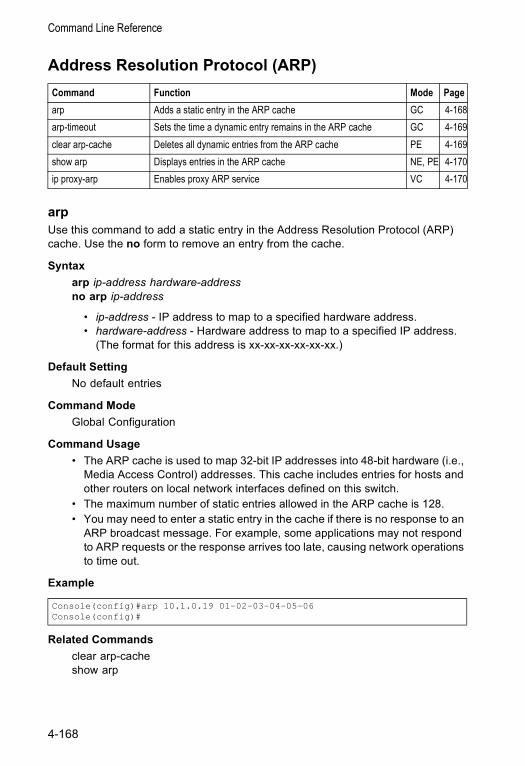
Command Line Reference
Address Resolution Protocol (ARP)
arpUse this command to add a static entry in the Address Resolution Protocol (ARP) cache. Use the no form to remove an entry from the cache.
Syntax arp ip-address hardware-addressno arp ip-address
• ip-address - IP address to map to a specified hardware address. • hardware-address - Hardware address to map to a specified IP address.
(The format for this address is xx-xx-xx-xx-xx-xx.)
Default Setting No default entries
Command Mode Global Configuration
Command Usage • The ARP cache is used to map 32-bit IP addresses into 48-bit hardware (i.e.,
Media Access Control) addresses. This cache includes entries for hosts and other routers on local network interfaces defined on this switch.
• The maximum number of static entries allowed in the ARP cache is 128.• You may need to enter a static entry in the cache if there is no response to an
ARP broadcast message. For example, some applications may not respond to ARP requests or the response arrives too late, causing network operations to time out.
Example
Related Commands clear arp-cacheshow arp
Command Function Mode Pagearp Adds a static entry in the ARP cache GC 4-168arp-timeout Sets the time a dynamic entry remains in the ARP cache GC 4-169clear arp-cache Deletes all dynamic entries from the ARP cache PE 4-169show arp Displays entries in the ARP cache NE, PE 4-170ip proxy-arp Enables proxy ARP service VC 4-170
Console(config)#arp 10.1.0.19 01-02-03-04-05-06Console(config)#
4-168
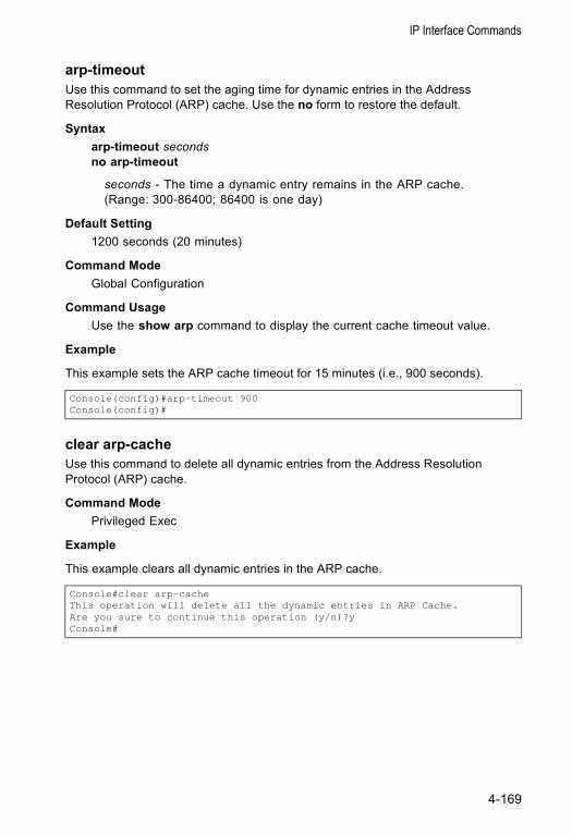
IP Interface Commands
arp-timeoutUse this command to set the aging time for dynamic entries in the Address Resolution Protocol (ARP) cache. Use the no form to restore the default.
Syntax arp-timeout secondsno arp-timeout
seconds - The time a dynamic entry remains in the ARP cache. (Range: 300-86400; 86400 is one day)
Default Setting 1200 seconds (20 minutes)
Command Mode Global Configuration
Command Usage Use the show arp command to display the current cache timeout value.
Example
This example sets the ARP cache timeout for 15 minutes (i.e., 900 seconds).
clear arp-cacheUse this command to delete all dynamic entries from the Address Resolution Protocol (ARP) cache.
Command Mode Privileged Exec
Example
This example clears all dynamic entries in the ARP cache.
Console(config)#arp-timeout 900Console(config)#
Console#clear arp-cacheThis operation will delete all the dynamic entries in ARP Cache.Are you sure to continue this operation (y/n)?yConsole#
4-169
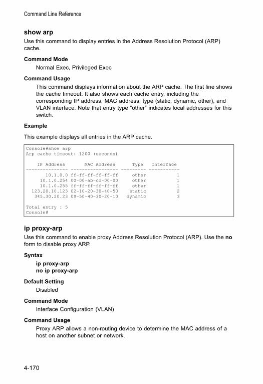
Command Line Reference
show arpUse this command to display entries in the Address Resolution Protocol (ARP) cache.
Command Mode Normal Exec, Privileged Exec
Command Usage This command displays information about the ARP cache. The first line shows the cache timeout. It also shows each cache entry, including the corresponding IP address, MAC address, type (static, dynamic, other), and VLAN interface. Note that entry type “other” indicates local addresses for this switch.
Example
This example displays all entries in the ARP cache.
ip proxy-arpUse this command to enable proxy Address Resolution Protocol (ARP). Use the no form to disable proxy ARP.
Syntax ip proxy-arpno ip proxy-arp
Default Setting Disabled
Command Mode Interface Configuration (VLAN)
Command Usage Proxy ARP allows a non-routing device to determine the MAC address of a host on another subnet or network.
Console#show arpArp cache timeout: 1200 (seconds)
IP Address MAC Address Type Interface--------------- ----------------- --------- -----------
10.1.0.0 ff-ff-ff-ff-ff-ff other 110.1.0.254 00-00-ab-cd-00-00 other 110.1.0.255 ff-ff-ff-ff-ff-ff other 1
123.20.10.123 02-10-20-30-40-50 static 2345.30.20.23 09-50-40-30-20-10 dynamic 3
Total entry : 5Console#
4-170
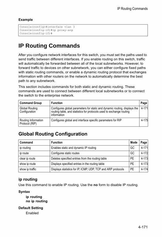
IP Routing Commands
Example
IP Routing CommandsAfter you configure network interfaces for this switch, you must set the paths used to send traffic between different interfaces. If you enable routing on this switch, traffic will automatically be forwarded between all of the local subnetworks. However, to forward traffic to devices on other subnetwork, you can either configure fixed paths with static routing commands, or enable a dynamic routing protocol that exchanges information with other routers on the network to automatically determine the best path to any subnetwork.
This section includes commands for both static and dynamic routing. These commands are used to connect between different local subnetworks or to connect the switch to the enterprise network.
Global Routing Configuration
ip routingUse this command to enable IP routing. Use the no form to disable IP routing.
Syntax ip routingno ip routing
Default Setting Enabled
Console(config)#interface vlan 3Console(config-if)#ip proxy-arpConsole(config-if)#
Command Group Function PageGlobal Routing Configuration
Configures global parameters for static and dynamic routing, displays the routing table, and statistics for protocols used to exchange routing information
4-171
Routing Information Protocol (RIP)
Configures global and interface specific parameters for RIP 4-175
Command Function Mode Pageip routing Enables static and dynamic IP routing GC 4-171ip route Configures static routes GC 4-172clear ip route Deletes specified entries from the routing table PE 4-173show ip route Displays specified entries in the routing table PE 4-173show ip traffic Displays statistics for IP, ICMP, UDP, TCP and ARP protocols PE 4-174
4-171
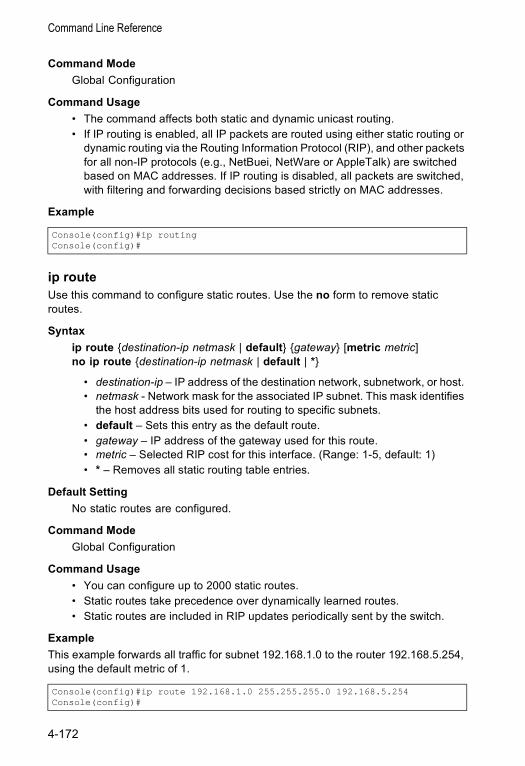
Command Line Reference
Command Mode Global Configuration
Command Usage • The command affects both static and dynamic unicast routing.• If IP routing is enabled, all IP packets are routed using either static routing or
dynamic routing via the Routing Information Protocol (RIP), and other packets for all non-IP protocols (e.g., NetBuei, NetWare or AppleTalk) are switched based on MAC addresses. If IP routing is disabled, all packets are switched, with filtering and forwarding decisions based strictly on MAC addresses.
Example
ip routeUse this command to configure static routes. Use the no form to remove static routes.
Syntax ip route {destination-ip netmask | default} {gateway} [metric metric]no ip route {destination-ip netmask | default | *}
• destination-ip – IP address of the destination network, subnetwork, or host. • netmask - Network mask for the associated IP subnet. This mask identifies
the host address bits used for routing to specific subnets. • default – Sets this entry as the default route.• gateway – IP address of the gateway used for this route. • metric – Selected RIP cost for this interface. (Range: 1-5, default: 1)• * – Removes all static routing table entries.
Default Setting No static routes are configured.
Command Mode Global Configuration
Command Usage • You can configure up to 2000 static routes.• Static routes take precedence over dynamically learned routes.• Static routes are included in RIP updates periodically sent by the switch.
ExampleThis example forwards all traffic for subnet 192.168.1.0 to the router 192.168.5.254, using the default metric of 1.
Console(config)#ip routingConsole(config)#
Console(config)#ip route 192.168.1.0 255.255.255.0 192.168.5.254Console(config)#
4-172
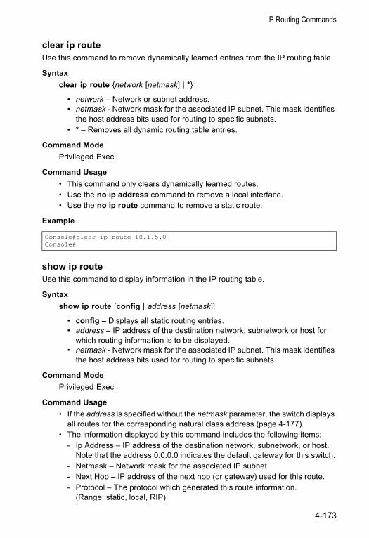
IP Routing Commands
clear ip routeUse this command to remove dynamically learned entries from the IP routing table.
Syntax clear ip route {network [netmask] | *}
• network – Network or subnet address. • netmask - Network mask for the associated IP subnet. This mask identifies
the host address bits used for routing to specific subnets. • * – Removes all dynamic routing table entries.
Command Mode Privileged Exec
Command Usage • This command only clears dynamically learned routes.• Use the no ip address command to remove a local interface.• Use the no ip route command to remove a static route.
Example
show ip routeUse this command to display information in the IP routing table.
Syntax show ip route [config | address [netmask]]
• config – Displays all static routing entries.• address – IP address of the destination network, subnetwork or host for
which routing information is to be displayed. • netmask - Network mask for the associated IP subnet. This mask identifies
the host address bits used for routing to specific subnets.
Command Mode Privileged Exec
Command Usage • If the address is specified without the netmask parameter, the switch displays
all routes for the corresponding natural class address (page 4-177).• The information displayed by this command includes the following items:
- Ip Address – IP address of the destination network, subnetwork, or host. Note that the address 0.0.0.0 indicates the default gateway for this switch.
- Netmask – Network mask for the associated IP subnet.- Next Hop – IP address of the next hop (or gateway) used for this route.- Protocol – The protocol which generated this route information.
(Range: static, local, RIP)
Console#clear ip route 10.1.5.0Console#
4-173
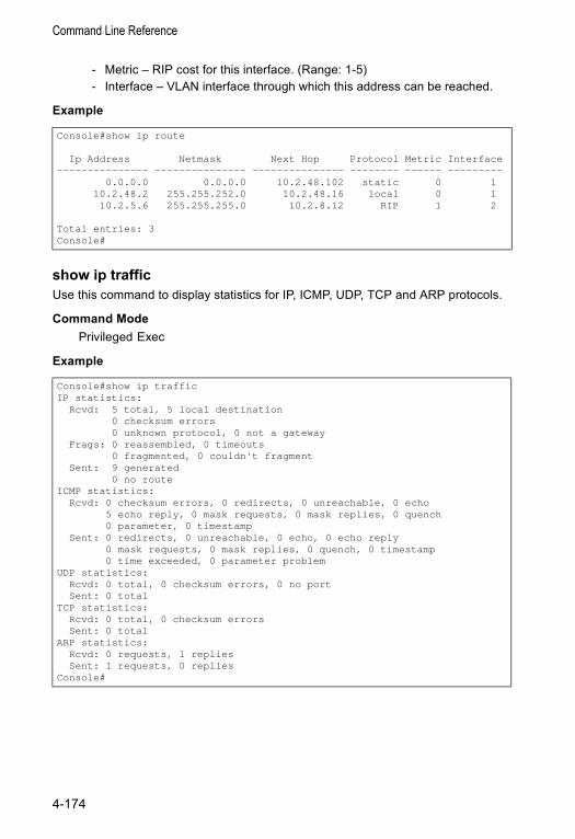
Command Line Reference
- Metric – RIP cost for this interface. (Range: 1-5)- Interface – VLAN interface through which this address can be reached.
Example
show ip trafficUse this command to display statistics for IP, ICMP, UDP, TCP and ARP protocols.
Command Mode Privileged Exec
Example
Console#show ip route
Ip Address Netmask Next Hop Protocol Metric Interface--------------- --------------- --------------- -------- ------ ---------
0.0.0.0 0.0.0.0 10.2.48.102 static 0 110.2.48.2 255.255.252.0 10.2.48.16 local 0 110.2.5.6 255.255.255.0 10.2.8.12 RIP 1 2
Total entries: 3Console#
Console#show ip trafficIP statistics:
Rcvd: 5 total, 5 local destination0 checksum errors0 unknown protocol, 0 not a gateway
Frags: 0 reassembled, 0 timeouts0 fragmented, 0 couldn't fragment
Sent: 9 generated0 no route
ICMP statistics:Rcvd: 0 checksum errors, 0 redirects, 0 unreachable, 0 echo
5 echo reply, 0 mask requests, 0 mask replies, 0 quench0 parameter, 0 timestamp
Sent: 0 redirects, 0 unreachable, 0 echo, 0 echo reply0 mask requests, 0 mask replies, 0 quench, 0 timestamp0 time exceeded, 0 parameter problem
UDP statistics:Rcvd: 0 total, 0 checksum errors, 0 no portSent: 0 total
TCP statistics:Rcvd: 0 total, 0 checksum errorsSent: 0 total
ARP statistics:Rcvd: 0 requests, 1 repliesSent: 1 requests, 0 replies
Console#
4-174
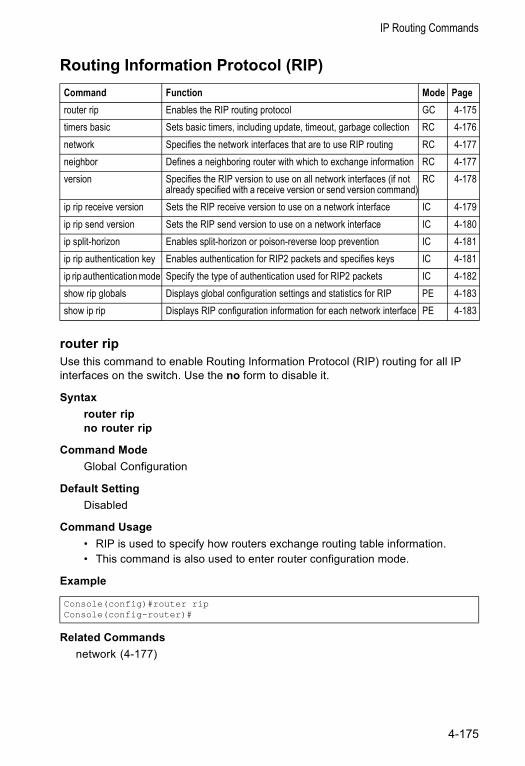
IP Routing Commands
Routing Information Protocol (RIP)
router ripUse this command to enable Routing Information Protocol (RIP) routing for all IP interfaces on the switch. Use the no form to disable it.
Syntax router ripno router rip
Command Mode Global Configuration
Default Setting Disabled
Command Usage • RIP is used to specify how routers exchange routing table information.• This command is also used to enter router configuration mode.
Example
Related Commandsnetwork (4-177)
Command Function Mode Pagerouter rip Enables the RIP routing protocol GC 4-175timers basic Sets basic timers, including update, timeout, garbage collection RC 4-176network Specifies the network interfaces that are to use RIP routing RC 4-177neighbor Defines a neighboring router with which to exchange information RC 4-177version Specifies the RIP version to use on all network interfaces (if not
already specified with a receive version or send version command)RC 4-178
ip rip receive version Sets the RIP receive version to use on a network interface IC 4-179ip rip send version Sets the RIP send version to use on a network interface IC 4-180ip split-horizon Enables split-horizon or poison-reverse loop prevention IC 4-181ip rip authentication key Enables authentication for RIP2 packets and specifies keys IC 4-181ip rip authentication mode Specify the type of authentication used for RIP2 packets IC 4-182show rip globals Displays global configuration settings and statistics for RIP PE 4-183show ip rip Displays RIP configuration information for each network interface PE 4-183
Console(config)#router ripConsole(config-router)#
4-175
Command Line Reference
timers basicUse this command to configure the RIP update timer, timeout timer, and garbage- collection timer. Use the no form to restore the defaults.
Syntax timers basic update-secondsno timers basic
update-seconds – Sets the update timer to the specified value, sets the timeout time value to 6 times the update time, and sets the garbage- collection timer to 4 times the update time. (Range for update timer: 15-60 seconds)
Command Mode Router Configuration
Default Setting Update: 30 secondsTimeout: 180 secondsGarbage collection: 120 seconds
Command Usage • The update timer sets the rate at which updates are sent. This is the
fundamental timer used to control all basic RIP processes.• The timeout timer is time after which there have been no update messages
that a route is declared dead. The route is marked inaccessible (i.e., the metric set to infinite) and advertised as unreachable. However, packets are still forwarded on this route.
• After the timeout interval expires, the switch waits for an interval specified by the garbage-collection timer before removing this entry from the routing table. This timer allows neighbors to become aware of an invalid route prior to purging it.
• Setting the update timer to a short interval can cause the switch to spend an excessive amount of time processing updates.
• These timers must be set to the same values for all routers in the network.
ExampleThis example sets the update timer to 40 seconds. The timeout timer is subsequently set to 240 seconds, and the garbage-collection timer to 160 seconds.
Console(config-router)#timers basic 15Console(config-router)#
4-176
IP Routing Commands
networkUse this command to specify the network interfaces that will be included in the RIP routing process. Use the no form to remove an entry.
Syntax network subnet-addressno network subnet-address
subnet-address – IP address of a network directly connected to this switch.
Command Mode Router Configuration
Default Setting No networks are specified.
Command Usage • RIP only sends updates to interfaces specified by this command.• Subnet addresses are interpreted as class A, B or C, based on the first field
in the specified address. In other words, if a subnet address nnn.xxx.xxx.xxx is entered, the first field (nnn) determines the class:0 - 127 is class A, and only the first field in the network address is used.128 - 19 is class B, and the first two fields in the network address are used.192 - 223 is class C, and the first three fields in the network address are used.
ExampleThis example includes network interface 10.1.0.0 in the RIP routing process.
Related Commandsrouter rip (4-175)
neighborUse this command to define a neighboring router with which this switch will exchange routing information. Use the no form to remove an entry.
Syntax neighbor ip-addressno neighbor ip-address
ip-address - IP address to map to a specified hardware address.
Command Mode Router Configuration
Default Setting No neighbors are defined.
Console(config-router)#network 10.1.0.0Console(config-router)#
4-177
Command Line Reference
Command Usage This command can be used to configure a static neighbor with which this switch will exchange information, rather than relying on broadcast messages generated by the RIP protocol.
Example
versionUse this command to specify a RIP version used globally by the switch. Use the no form to restore the default value.
Syntax version {1 | 2}no version
• 1 - RIP Version 1• 2 - RIP Version 2
Command Mode Router Configuration
Default Setting RIP Version 1
Command Usage • When this command is used to specify a global RIP version, any VLAN
interface not previously set by the ip rip receive version or ip rip send version command will be set to the following values: - RIP Version 1 configures the unset interfaces to send RIPv1 compatible
protocol messages and receive either RIPv1 or RIPv2 protocol messages.- RIP Version 2 configures the unset interfaces to use RIPv2 for both sending
and receiving protocol messages.• When the no form of this command is used to restore the default value, any
VLAN interface not previously set by the ip rip receive version or ip rip send version command will be set to the default send or receive version.
ExampleThis example sets the global version for RIP to send and receive version 2 packets.
Related Commandsip rip receive version (4-179)ip rip send version (4-180)
Console(config-router)#neighbor 10.2.0.254Console(config-router)#
Console(config-router)#version 2Console(config-router)#
4-178
IP Routing Commands
ip rip receive versionUse this command to specify a RIP version to receive on an interface. Use the no form to restore the default value.
Syntax ip rip receive version {none | 1 | 2 | 1 2}no ip rip receive version
• none - Does not accept incoming RIP packets.• 1 - Accepts only RIPv1 packets.• 2 - Accepts only RIPv2 packets.• 1 2 - Accepts RIPv1 or RIPv2 packets
Command Mode Interface Configuration (VLAN)
Default Setting The default depends on the setting specified with the version command:Global RIPv1 - RIPv1 or RIPv2 packetsGlobal RIPv2 - RIPv2 packets
Command Usage • Use this command to override the global setting specified by the RIP version
command.• You can specify the receive version based on these options:
- Use “none” if you do not want to add any dynamic entries to the routing table for an interface. (For example, you may only want to allow static routes for a specific interface.)
- Use “1” or “2” if all routers in the local network are based on RIPv1 or RIPv2, respectively.
- Use “1 2” if some routers in the local network are using RIPv2, but there are still some older routers using RIPv1.
ExampleThis example sets the interface version for VLAN 1 to receive RIPv1 packets.
Related Commandsversion (4-178)
Console(config)#interface vlan 1Console(config-if)#ip rip receive version 1Console(config-if)#
4-179
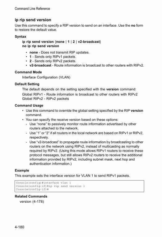
Command Line Reference
ip rip send versionUse this command to specify a RIP version to send on an interface. Use the no form to restore the default value.
Syntax ip rip send version {none | 1 | 2 | v2-broadcast}no ip rip send version
• none - Does not transmit RIP updates.• 1 - Sends only RIPv1 packets.• 2 - Sends only RIPv2 packets.• v2-broadcast - Route information is broadcast to other routers with RIPv2.
Command Mode Interface Configuration (VLAN)
Default Setting The default depends on the setting specified with the version command:Global RIPv1 - Route information is broadcast to other routers with RIPv2Global RIPv2 - RIPv2 packets
Command Usage • Use this command to override the global setting specified by the RIP version
command.• You can specify the receive version based on these options:
- Use “none” to passively monitor route information advertised by other routers attached to the network.
- Use “1” or “2” if all routers in the local network are based on RIPv1 or RIPv2, respectively.
- Use “v2-broadcast” to propagate route information by broadcasting to other routers on the network using RIPv2, instead of multicasting as normally required by RIPv2. (Using this mode allows RIPv1 routers to receive these protocol messages, but still allows RIPv2 routers to receive the additional information provided by RIPv2, including subnet mask, next hop and authentication information.)
ExampleThis example sets the interface version for VLAN 1 to send RIPv1 packets.
Related Commandsversion (4-178)
Console(config)#interface vlan 1Console(config-if)#ip rip send version 1Console(config-if)#
4-180
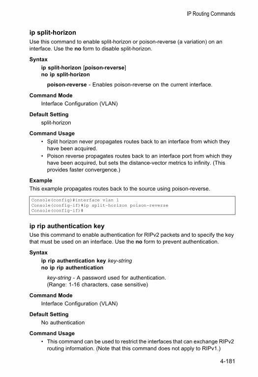
IP Routing Commands
ip split-horizonUse this command to enable split-horizon or poison-reverse (a variation) on an interface. Use the no form to disable split-horizon.
Syntax ip split-horizon [poison-reverse]no ip split-horizon
poison-reverse - Enables poison-reverse on the current interface.
Command Mode Interface Configuration (VLAN)
Default Setting split-horizon
Command Usage • Split horizon never propagates routes back to an interface from which they
have been acquired.• Poison reverse propagates routes back to an interface port from which they
have been acquired, but sets the distance-vector metrics to infinity. (This provides faster convergence.)
ExampleThis example propagates routes back to the source using poison-reverse.
ip rip authentication keyUse this command to enable authentication for RIPv2 packets and to specify the key that must be used on an interface. Use the no form to prevent authentication.
Syntax ip rip authentication key key-stringno ip rip authentication
key-string - A password used for authentication. (Range: 1-16 characters, case sensitive)
Command Mode Interface Configuration (VLAN)
Default Setting No authentication
Command Usage • This command can be used to restrict the interfaces that can exchange RIPv2
routing information. (Note that this command does not apply to RIPv1.)
Console(config)#interface vlan 1Console(config-if)#ip split-horizon poison-reverseConsole(config-if)#
4-181
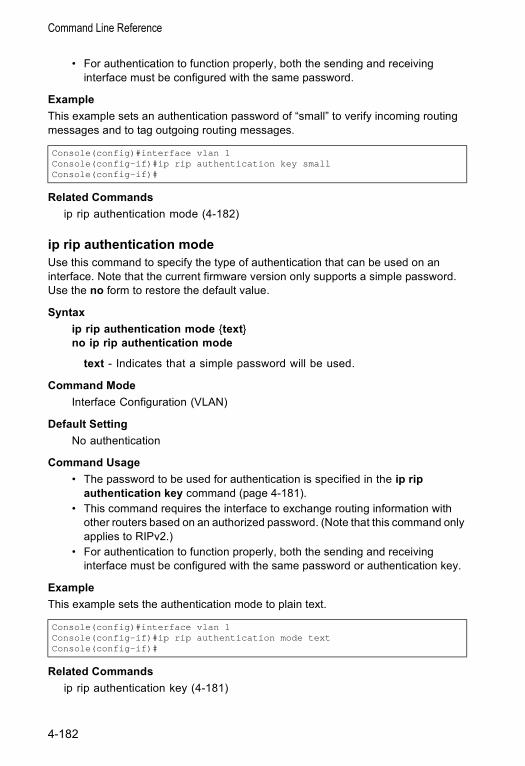
Command Line Reference
• For authentication to function properly, both the sending and receiving interface must be configured with the same password.
ExampleThis example sets an authentication password of “small” to verify incoming routing messages and to tag outgoing routing messages.
Related Commandsip rip authentication mode (4-182)
ip rip authentication modeUse this command to specify the type of authentication that can be used on an interface. Note that the current firmware version only supports a simple password. Use the no form to restore the default value.
Syntax ip rip authentication mode {text}no ip rip authentication mode
text - Indicates that a simple password will be used.
Command Mode Interface Configuration (VLAN)
Default Setting No authentication
Command Usage • The password to be used for authentication is specified in the ip rip
authentication key command (page 4-181).• This command requires the interface to exchange routing information with
other routers based on an authorized password. (Note that this command only applies to RIPv2.)
• For authentication to function properly, both the sending and receiving interface must be configured with the same password or authentication key.
ExampleThis example sets the authentication mode to plain text.
Related Commandsip rip authentication key (4-181)
Console(config)#interface vlan 1Console(config-if)#ip rip authentication key smallConsole(config-if)#
Console(config)#interface vlan 1Console(config-if)#ip rip authentication mode textConsole(config-if)#
4-182
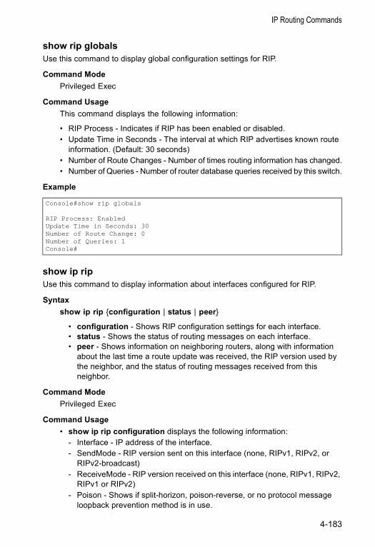
IP Routing Commands
show rip globalsUse this command to display global configuration settings for RIP.
Command Mode Privileged Exec
Command Usage This command displays the following information:
• RIP Process - Indicates if RIP has been enabled or disabled.• Update Time in Seconds - The interval at which RIP advertises known route
information. (Default: 30 seconds)• Number of Route Changes - Number of times routing information has changed.• Number of Queries - Number of router database queries received by this switch.
Example
show ip ripUse this command to display information about interfaces configured for RIP.
Syntax show ip rip {configuration | status | peer}
• configuration - Shows RIP configuration settings for each interface.• status - Shows the status of routing messages on each interface.• peer - Shows information on neighboring routers, along with information
about the last time a route update was received, the RIP version used by the neighbor, and the status of routing messages received from this neighbor.
Command Mode Privileged Exec
Command Usage • show ip rip configuration displays the following information:
- Interface - IP address of the interface.- SendMode - RIP version sent on this interface (none, RIPv1, RIPv2, or
RIPv2-broadcast)- ReceiveMode - RIP version received on this interface (none, RIPv1, RIPv2,
RIPv1 or RIPv2)- Poison - Shows if split-horizon, poison-reverse, or no protocol message
loopback prevention method is in use.
Console#show rip globals
RIP Process: EnabledUpdate Time in Seconds: 30Number of Route Change: 0Number of Queries: 1Console#
4-183
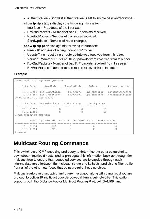
Command Line Reference
- Authentication - Shows if authentication is set to simple password or none.• show ip rip status displays the following information:
- Interface - IP address of the interface.- RcvBadPackets - Number of bad RIP packets received.- RcvBadRoutes - Number of bad routes received.- SendUpdates - Number of route changes.
• show ip rip peer displays the following information:- Peer - IP address of a neighboring RIP router.- UpdateTime - Last time a route update was received from this peer.- Version - Whether RIPv1 or RIPv2 packets were received from this peer.- RcvBadPackets - Number of bad RIP packets received from this peer.- RcvBadRoutes - Number of bad routes received from this peer.
Example
Multicast Routing CommandsThis switch uses IGMP snooping and query to determine the ports connected to downstream multicast hosts, and to propagate this information back up through the multicast tree to ensure that requested services are forwarded through each intermediate node between the multicast server and its hosts, and also to filter traffic from all of the other interfaces that do not require these services.
Multicast routers use snooping and query messages, along with a multicast routing protocol to deliver IP multicast packets across different subnetworks. This switch supports both the Distance-Vector Multicast Routing Protocol (DVMRP) and
Console#show ip rip configuration
Interface SendMode ReceiveMode Poison Authentication--------------- --------------- ------------- -------------- ------------------
10.1.0.253 rip1Compatible RIPv1Orv2 SplitHorizon noAuthentication10.1.1.253 rip1Compatible RIPv1Orv2 SplitHorizon noAuthentication
Console#show ip rip status
Interface RcvBadPackets RcvBadRoutes SendUpdates--------------- --------------- -------------- ---------------
10.1.0.253 0 0 1310.1.1.253 0 0 13
Console#show ip rip peer
Peer UpdateTime Version RcvBadPackets RcvBadRoutes--------------- ------------ --------- --------------- --------------
10.1.0.254 1625 2 0 010.1.1.254 1625 2 0 0
Console#
4-184
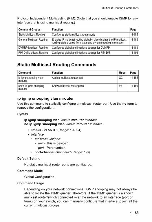
Multicast Routing Commands
Protocol Independent Multicasting (PIM). (Note that you should enable IGMP for any interface that is using multicast routing.)
Static Multicast Routing Commands
ip igmp snooping vlan mrouterUse this command to statically configure a multicast router port. Use the no form to remove the configuration.
Syntax
ip igmp snooping vlan vlan-id mrouter interfaceno ip igmp snooping vlan vlan-id mrouter interface
• vlan-id - VLAN ID (Range: 1-4094) • interface
• ethernet unit/port - unit - This is device 1. - port - Port number.
• port-channel channel-id (Range: 1-6)
Default Setting
No static multicast router ports are configured.
Command Mode
Global Configuration
Command Usage
Depending on your network connections, IGMP snooping may not always be able to locate the IGMP querier. Therefore, if the IGMP querier is a known multicast router/switch connected over the network to an interface (port or trunk) on your switch, you can manually configure that interface to join all the current multicast groups.
Command Groups Function PageStatic Multicast Routing Configures static multicast router ports 4-185General Multicast Routing Enables IP multicast routing globally; also displays the IP multicast
routing table created from static and dynamic routing information4-186
DVMRP Multicast Routing Configures global and interface settings for DVMRP 4-189PIM-DM Multicast Routing Configures global and interface settings for PIM-DM 4-198
Command Function Mode Pageip igmp snooping vlan mrouter
Adds a multicast router port GC 4-185
show ip igmp snooping mrouter
Shows multicast router ports PE 4-186
4-185
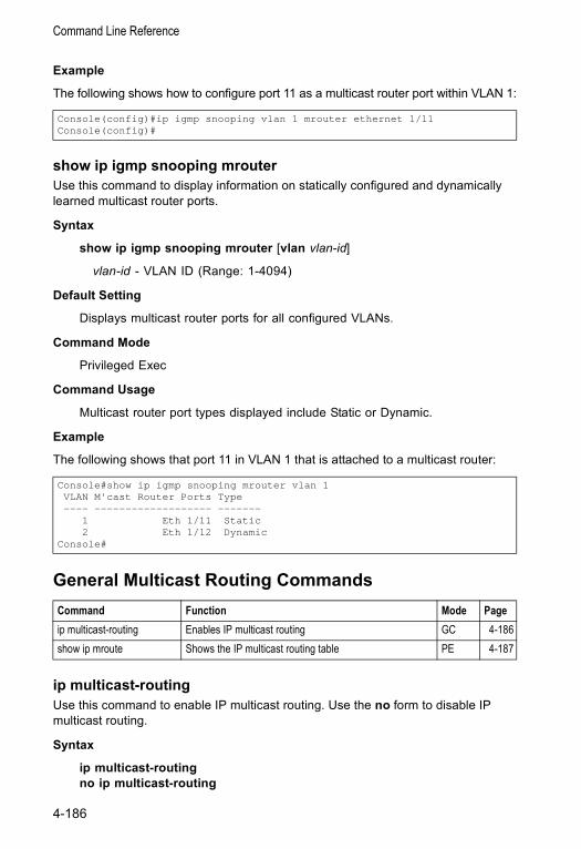
Command Line Reference
Example
The following shows how to configure port 11 as a multicast router port within VLAN 1:
show ip igmp snooping mrouter Use this command to display information on statically configured and dynamically learned multicast router ports.
Syntax
show ip igmp snooping mrouter [vlan vlan-id]
vlan-id - VLAN ID (Range: 1-4094)
Default Setting
Displays multicast router ports for all configured VLANs.
Command Mode
Privileged Exec
Command Usage
Multicast router port types displayed include Static or Dynamic.
Example
The following shows that port 11 in VLAN 1 that is attached to a multicast router:
General Multicast Routing Commands
ip multicast-routingUse this command to enable IP multicast routing. Use the no form to disable IP multicast routing.
Syntax
ip multicast-routingno ip multicast-routing
Console(config)#ip igmp snooping vlan 1 mrouter ethernet 1/11Console(config)#
Console#show ip igmp snooping mrouter vlan 1VLAN M'cast Router Ports Type---- ------------------- -------
1 Eth 1/11 Static2 Eth 1/12 Dynamic
Console#
Command Function Mode Pageip multicast-routing Enables IP multicast routing GC 4-186show ip mroute Shows the IP multicast routing table PE 4-187
4-186
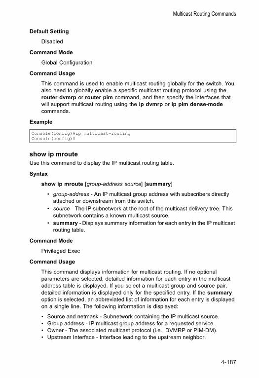
Multicast Routing Commands
Default Setting
Disabled
Command Mode
Global Configuration
Command Usage
This command is used to enable multicast routing globally for the switch. You also need to globally enable a specific multicast routing protocol using the router dvmrp or router pim command, and then specify the interfaces that will support multicast routing using the ip dvmrp or ip pim dense-mode commands.
Example
show ip mrouteUse this command to display the IP multicast routing table.
Syntax
show ip mroute [group-address source] [summary]
• group-address - An IP multicast group address with subscribers directly attached or downstream from this switch.
• source - The IP subnetwork at the root of the multicast delivery tree. This subnetwork contains a known multicast source.
• summary - Displays summary information for each entry in the IP multicast routing table.
Command Mode
Privileged Exec
Command Usage
This command displays information for multicast routing. If no optional parameters are selected, detailed information for each entry in the multicast address table is displayed. If you select a multicast group and source pair, detailed information is displayed only for the specified entry. If the summary option is selected, an abbreviated list of information for each entry is displayed on a single line. The following information is displayed:
• Source and netmask - Subnetwork containing the IP multicast source.• Group address - IP multicast group address for a requested service.• Owner - The associated multicast protocol (i.e., DVMRP or PIM-DM).• Upstream Interface - Interface leading to the upstream neighbor.
Console(config)#ip multicast-routingConsole(config)#
4-187
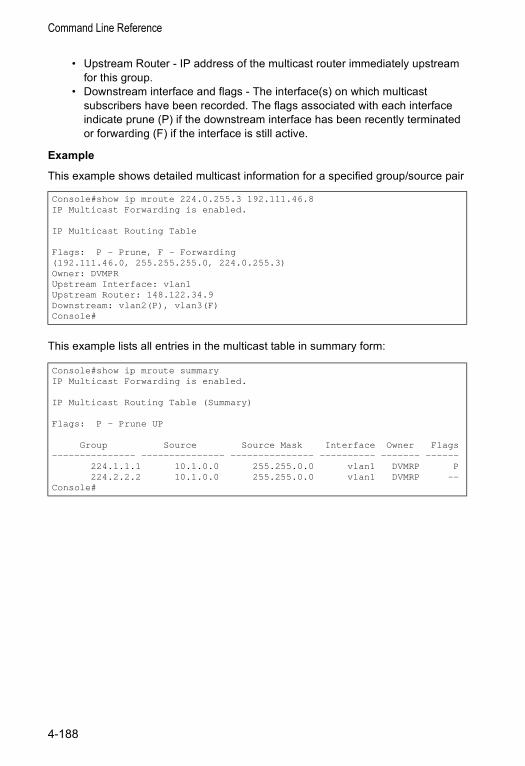
Command Line Reference
• Upstream Router - IP address of the multicast router immediately upstream for this group.
• Downstream interface and flags - The interface(s) on which multicast subscribers have been recorded. The flags associated with each interface indicate prune (P) if the downstream interface has been recently terminated or forwarding (F) if the interface is still active.
Example
This example shows detailed multicast information for a specified group/source pair
This example lists all entries in the multicast table in summary form:
Console#show ip mroute 224.0.255.3 192.111.46.8IP Multicast Forwarding is enabled.
IP Multicast Routing Table
Flags: P - Prune, F - Forwarding(192.111.46.0, 255.255.255.0, 224.0.255.3)Owner: DVMPRUpstream Interface: vlan1Upstream Router: 148.122.34.9Downstream: vlan2(P), vlan3(F)Console#
Console#show ip mroute summaryIP Multicast Forwarding is enabled.
IP Multicast Routing Table (Summary)
Flags: P - Prune UP
Group Source Source Mask Interface Owner Flags--------------- --------------- --------------- ---------- ------- ------
224.1.1.1 10.1.0.0 255.255.0.0 vlan1 DVMRP P224.2.2.2 10.1.0.0 255.255.0.0 vlan1 DVMRP --
Console#
4-188
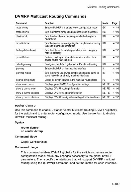
Multicast Routing Commands
DVMRP Multicast Routing Commands
router dvmrpUse this command to enable Distance-Vector Multicast Routing (DVMRP) globally for the switch and to enter router configuration mode. Use the no form to disable DVMRP multicast routing.
Syntax
router dvmrpno router dvmrp
Command Mode
Global Configuration
Command Usage
This command enables DVMRP globally for the switch and enters router configuration mode. Make any changes necessary to the global DVMRP parameters. Then specify the interfaces that will support DVMRP multicast routing using the ip dvmrp command, and set the metric for each interface.
Command Function Mode Pagerouter dvmrp Enables DVMRP and enters router configuration mode GC 4-189probe-interval Sets the interval for sending neighbor probe messages RC 4-190nbr-timeout Sets the delay before declaring an attached neighbor
router downRC 4-191
report-interval Sets the interval for propagating the complete set of routing tables to other neighbor routers
RC 4-191
flash-update-interval Sets the interval for sending updates about changes to network topology
RC 4-192
prune-lifetime Defines how long a prune state remains in effect for a source-routed multicast tree
RC 4-192
default-gateway Configures the default gateway for IP multicast routing RC 4-193ip dvmrp Enables DVMRP on the specified interface IC 4-193ip dvmrp metric Sets the metric used when establishing reverse paths to
some networks on directly attached interfacesIC 4-194
clear ip dvmrp route Clears all dynamic routes in the multicast routing table PE 4-195show router dvmrp Displays global DVMRP configuration settings NE, PE 4-195show ip dvmrp route Displays DVMRP routing information NE, PE 4-196show ip dvmrp neighbor Displays DVMRP neighbor information NE, PE 4-196show ip dvmrp interface Displays DVMRP configuration settings for the interfaces NE, PE 4-197
4-189
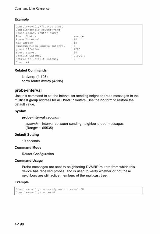
Command Line Reference
Example
Related Commands
ip dvmrp (4-193)show router dvmrp (4-195)
probe-intervalUse this command to set the interval for sending neighbor probe messages to the multicast group address for all DVMRP routers. Use the no form to restore the default value.
Syntax
probe-interval seconds
seconds - Interval between sending neighbor probe messages. (Range: 1-65535)
Default Setting
10 seconds
Command Mode
Router Configuration
Command Usage
Probe messages are sent to neighboring DVMRP routers from which this device has received probes, and is used to verify whether or not these neighbors are still active members of the multicast tree.
Example
Console(config)#router dvmrpConsole(config-router)#endConsole#show router dvmrpAdmin Status : enableProbe Interval : 10Nbr expire : 35Minimum Flash Update Interval : 5prune lifetime : 7200route report : 60Default Gateway : 0.0.0.0Metric of Default Gateway : 0Console#
Console(config-router)#probe-interval 30Console(config-router)#
4-190
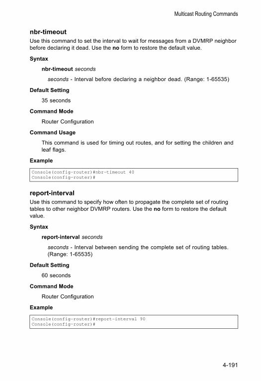
Multicast Routing Commands
nbr-timeoutUse this command to set the interval to wait for messages from a DVMRP neighbor before declaring it dead. Use the no form to restore the default value.
Syntax
nbr-timeout seconds
seconds - Interval before declaring a neighbor dead. (Range: 1-65535)
Default Setting
35 seconds
Command Mode
Router Configuration
Command Usage
This command is used for timing out routes, and for setting the children and leaf flags.
Example
report-intervalUse this command to specify how often to propagate the complete set of routing tables to other neighbor DVMRP routers. Use the no form to restore the default value.
Syntax
report-interval seconds
seconds - Interval between sending the complete set of routing tables. (Range: 1-65535)
Default Setting
60 seconds
Command Mode
Router Configuration
Example
Console(config-router)#nbr-timeout 40Console(config-router)#
Console(config-router)#report-interval 90Console(config-router)#
4-191
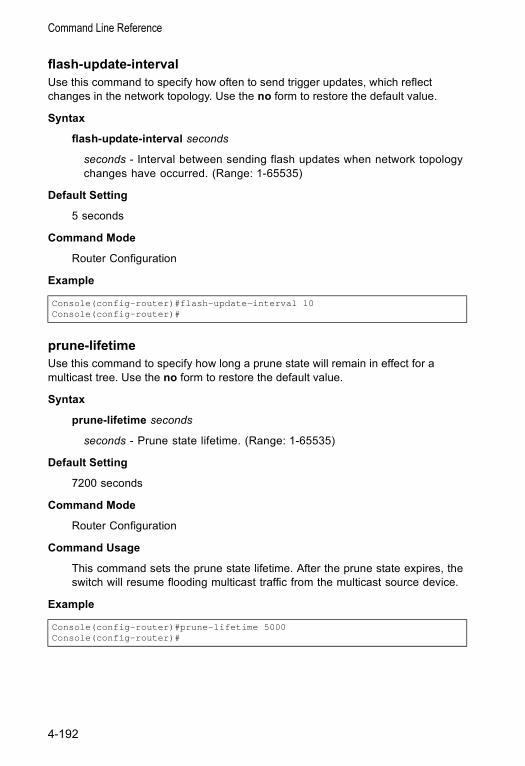
Command Line Reference
flash-update-intervalUse this command to specify how often to send trigger updates, which reflect changes in the network topology. Use the no form to restore the default value.
Syntax
flash-update-interval seconds
seconds - Interval between sending flash updates when network topology changes have occurred. (Range: 1-65535)
Default Setting
5 seconds
Command Mode
Router Configuration
Example
prune-lifetimeUse this command to specify how long a prune state will remain in effect for a multicast tree. Use the no form to restore the default value.
Syntax
prune-lifetime seconds
seconds - Prune state lifetime. (Range: 1-65535)
Default Setting
7200 seconds
Command Mode
Router Configuration
Command Usage
This command sets the prune state lifetime. After the prune state expires, the switch will resume flooding multicast traffic from the multicast source device.
Example
Console(config-router)#flash-update-interval 10Console(config-router)#
Console(config-router)#prune-lifetime 5000Console(config-router)#
4-192
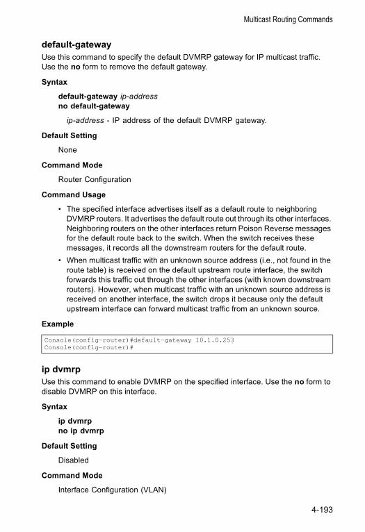
Multicast Routing Commands
default-gatewayUse this command to specify the default DVMRP gateway for IP multicast traffic. Use the no form to remove the default gateway.
Syntax
default-gateway ip-addressno default-gateway
ip-address - IP address of the default DVMRP gateway.
Default Setting
None
Command Mode
Router Configuration
Command Usage
• The specified interface advertises itself as a default route to neighboring DVMRP routers. It advertises the default route out through its other interfaces. Neighboring routers on the other interfaces return Poison Reverse messages for the default route back to the switch. When the switch receives these messages, it records all the downstream routers for the default route.
• When multicast traffic with an unknown source address (i.e., not found in the route table) is received on the default upstream route interface, the switch forwards this traffic out through the other interfaces (with known downstream routers). However, when multicast traffic with an unknown source address is received on another interface, the switch drops it because only the default upstream interface can forward multicast traffic from an unknown source.
Example
ip dvmrpUse this command to enable DVMRP on the specified interface. Use the no form to disable DVMRP on this interface.
Syntax
ip dvmrpno ip dvmrp
Default Setting
Disabled
Command Mode
Interface Configuration (VLAN)
Console(config-router)#default-gateway 10.1.0.253Console(config-router)#
4-193
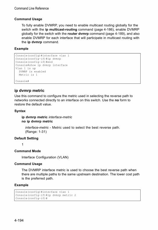
Command Line Reference
Command Usage
To fully enable DVMRP, you need to enable multicast routing globally for the switch with the ip multicast-routing command (page 4-186), enable DVMRP globally for the switch with the router dvmrp command (page 4-189), and also enable DVMRP for each interface that will participate in multicast routing with the ip dvmrp command.
Example
ip dvmrp metricUse this command to configure the metric used in selecting the reverse path to networks connected directly to an interface on this switch. Use the no form to restore the default value.
Syntax
ip dvmrp metric interface-metricno ip dvmrp metric
interface-metric - Metric used to select the best reverse path. (Range: 1-31)
Default Setting
1
Command Mode
Interface Configuration (VLAN)
Command Usage
The DVMRP interface metric is used to choose the best reverse path when there are multiple paths to the same upstream destination. The lower cost path is the preferred path.
Example
Console(config)#interface vlan 1Console(config-if)#ip dvmrpConsole(config-if)#endConsole#show ip dvmrp interfaceVlan 1 is up
DVMRP is enabledMetric is 1
Console#
Console(config)#interface vlan 1Console(config-if)#ip dvmrp metric 2Console(config-if)#
4-194
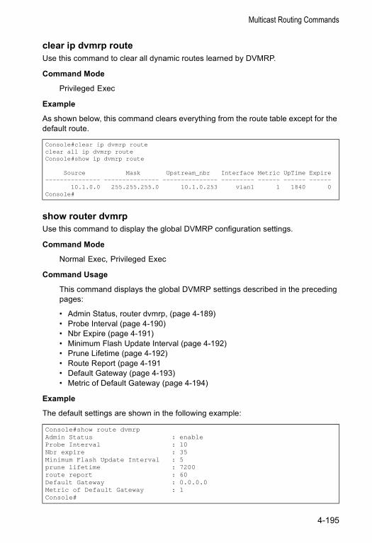
Multicast Routing Commands
clear ip dvmrp routeUse this command to clear all dynamic routes learned by DVMRP.
Command Mode
Privileged Exec
Example
As shown below, this command clears everything from the route table except for the default route.
show router dvmrpUse this command to display the global DVMRP configuration settings.
Command Mode
Normal Exec, Privileged Exec
Command Usage
This command displays the global DVMRP settings described in the preceding pages:
• Admin Status, router dvmrp, (page 4-189)• Probe Interval (page 4-190)• Nbr Expire (page 4-191)• Minimum Flash Update Interval (page 4-192)• Prune Lifetime (page 4-192)• Route Report (page 4-191• Default Gateway (page 4-193)• Metric of Default Gateway (page 4-194)
Example
The default settings are shown in the following example:
Console#clear ip dvmrp routeclear all ip dvmrp routeConsole#show ip dvmrp route
Source Mask Upstream_nbr Interface Metric UpTime Expire--------------- --------------- --------------- --------- ------ ------ ------
10.1.0.0 255.255.255.0 10.1.0.253 vlan1 1 1840 0Console#
Console#show route dvmrpAdmin Status : enableProbe Interval : 10Nbr expire : 35Minimum Flash Update Interval : 5prune lifetime : 7200route report : 60Default Gateway : 0.0.0.0Metric of Default Gateway : 1Console#
4-195
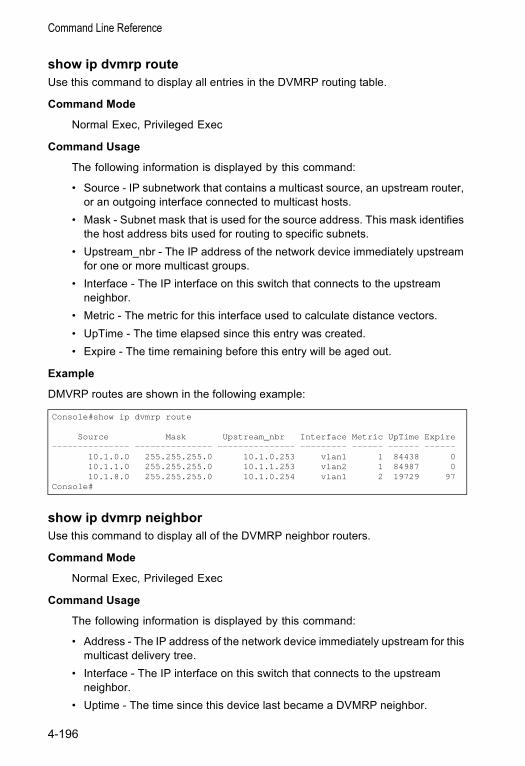
Command Line Reference
show ip dvmrp routeUse this command to display all entries in the DVMRP routing table.
Command Mode
Normal Exec, Privileged Exec
Command Usage
The following information is displayed by this command:
• Source - IP subnetwork that contains a multicast source, an upstream router, or an outgoing interface connected to multicast hosts.
• Mask - Subnet mask that is used for the source address. This mask identifies the host address bits used for routing to specific subnets.
• Upstream_nbr - The IP address of the network device immediately upstream for one or more multicast groups.
• Interface - The IP interface on this switch that connects to the upstream neighbor.
• Metric - The metric for this interface used to calculate distance vectors.• UpTime - The time elapsed since this entry was created.• Expire - The time remaining before this entry will be aged out.
Example
DMVRP routes are shown in the following example:
show ip dvmrp neighborUse this command to display all of the DVMRP neighbor routers.
Command Mode
Normal Exec, Privileged Exec
Command Usage
The following information is displayed by this command:
• Address - The IP address of the network device immediately upstream for this multicast delivery tree.
• Interface - The IP interface on this switch that connects to the upstream neighbor.
• Uptime - The time since this device last became a DVMRP neighbor.
Console#show ip dvmrp route
Source Mask Upstream_nbr Interface Metric UpTime Expire--------------- --------------- --------------- --------- ------ ------ ------
10.1.0.0 255.255.255.0 10.1.0.253 vlan1 1 84438 010.1.1.0 255.255.255.0 10.1.1.253 vlan2 1 84987 010.1.8.0 255.255.255.0 10.1.0.254 vlan1 2 19729 97
Console#
4-196
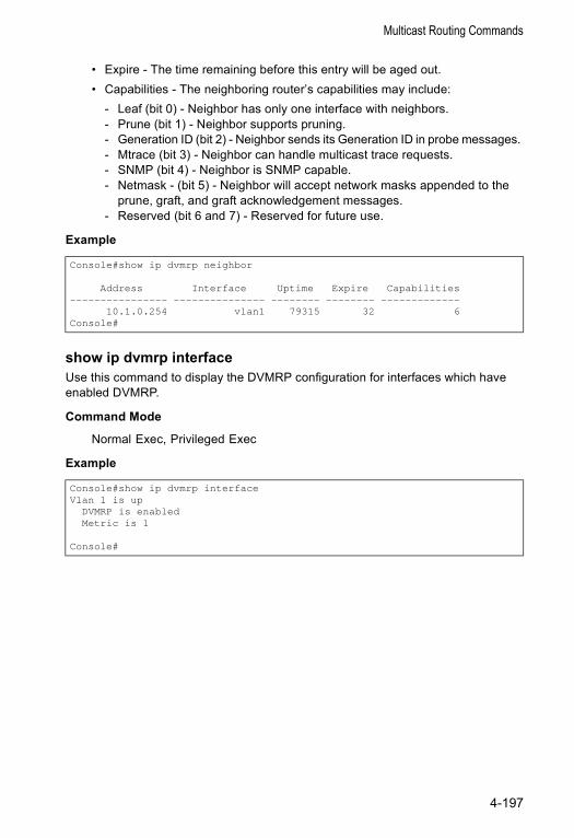
Multicast Routing Commands
• Expire - The time remaining before this entry will be aged out.• Capabilities - The neighboring router’s capabilities may include:
- Leaf (bit 0) - Neighbor has only one interface with neighbors. - Prune (bit 1) - Neighbor supports pruning. - Generation ID (bit 2) - Neighbor sends its Generation ID in probe messages. - Mtrace (bit 3) - Neighbor can handle multicast trace requests.- SNMP (bit 4) - Neighbor is SNMP capable.- Netmask - (bit 5) - Neighbor will accept network masks appended to the
prune, graft, and graft acknowledgement messages.- Reserved (bit 6 and 7) - Reserved for future use.
Example
show ip dvmrp interfaceUse this command to display the DVMRP configuration for interfaces which have enabled DVMRP.
Command Mode
Normal Exec, Privileged Exec
Example
Console#show ip dvmrp neighbor
Address Interface Uptime Expire Capabilities---------------- --------------- -------- -------- -------------
10.1.0.254 vlan1 79315 32 6Console#
Console#show ip dvmrp interfaceVlan 1 is up
DVMRP is enabledMetric is 1
Console#
4-197
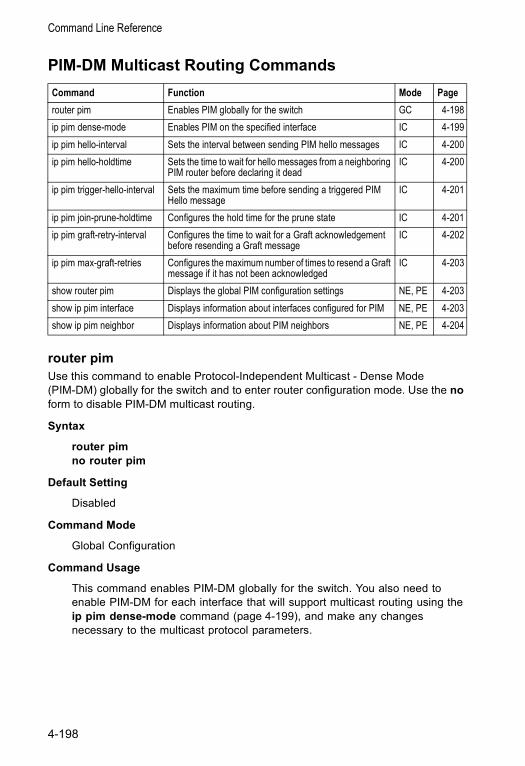
Command Line Reference
PIM-DM Multicast Routing Commands
router pimUse this command to enable Protocol-Independent Multicast - Dense Mode (PIM-DM) globally for the switch and to enter router configuration mode. Use the no form to disable PIM-DM multicast routing.
Syntax
router pimno router pim
Default Setting
Disabled
Command Mode
Global Configuration
Command Usage
This command enables PIM-DM globally for the switch. You also need to enable PIM-DM for each interface that will support multicast routing using the ip pim dense-mode command (page 4-199), and make any changes necessary to the multicast protocol parameters.
Command Function Mode Pagerouter pim Enables PIM globally for the switch GC 4-198ip pim dense-mode Enables PIM on the specified interface IC 4-199ip pim hello-interval Sets the interval between sending PIM hello messages IC 4-200ip pim hello-holdtime Sets the time to wait for hello messages from a neighboring
PIM router before declaring it deadIC 4-200
ip pim trigger-hello-interval Sets the maximum time before sending a triggered PIM Hello message
IC 4-201
ip pim join-prune-holdtime Configures the hold time for the prune state IC 4-201ip pim graft-retry-interval Configures the time to wait for a Graft acknowledgement
before resending a Graft messageIC 4-202
ip pim max-graft-retries Configures the maximum number of times to resend a Graft message if it has not been acknowledged
IC 4-203
show router pim Displays the global PIM configuration settings NE, PE 4-203show ip pim interface Displays information about interfaces configured for PIM NE, PE 4-203show ip pim neighbor Displays information about PIM neighbors NE, PE 4-204
4-198
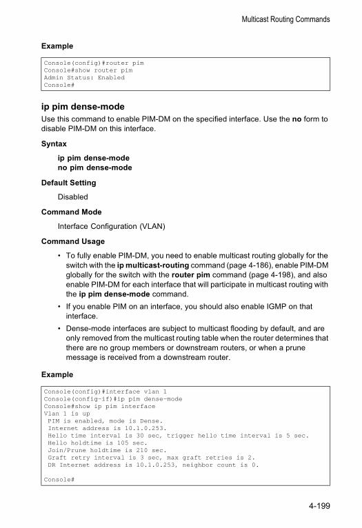
Multicast Routing Commands
Example
ip pim dense-modeUse this command to enable PIM-DM on the specified interface. Use the no form to disable PIM-DM on this interface.
Syntax
ip pim dense-modeno pim dense-mode
Default Setting
Disabled
Command Mode
Interface Configuration (VLAN)
Command Usage
• To fully enable PIM-DM, you need to enable multicast routing globally for the switch with the ip multicast-routing command (page 4-186), enable PIM-DM globally for the switch with the router pim command (page 4-198), and also enable PIM-DM for each interface that will participate in multicast routing with the ip pim dense-mode command.
• If you enable PIM on an interface, you should also enable IGMP on that interface.
• Dense-mode interfaces are subject to multicast flooding by default, and are only removed from the multicast routing table when the router determines that there are no group members or downstream routers, or when a prune message is received from a downstream router.
Example
Console(config)#router pimConsole#show router pimAdmin Status: EnabledConsole#
Console(config)#interface vlan 1Console(config-if)#ip pim dense-modeConsole#show ip pim interfaceVlan 1 is upPIM is enabled, mode is Dense.Internet address is 10.1.0.253.Hello time interval is 30 sec, trigger hello time interval is 5 sec.Hello holdtime is 105 sec.Join/Prune holdtime is 210 sec.Graft retry interval is 3 sec, max graft retries is 2.DR Internet address is 10.1.0.253, neighbor count is 0.
Console#
4-199
Command Line Reference
ip pim hello-intervalUse this command to configure the frequency at which PIM hello messages are transmitted. Use the no form to restore the default value.
Syntax
ip pim hello-interval secondsno pim hello-interval
seconds - Interval between sending PIM hello messages. (Range: 1-65535)
Default Setting
30 seconds
Command Mode
Interface Configuration (VLAN)
Command Usage
Hello messages are sent to neighboring PIM routers from which this device has received probes, and are used to verify whether or not these neighbors are still active members of the multicast tree.
Example
ip pim hello-holdtimeUse this command to configure the interval to wait for hello messages from a neighboring PIM router before declaring it dead. Use the no form to restore the default value.
Syntax
ip pim hello-holdtime secondsno ip pim hello-interval
seconds - The hold time for PIM hello messages. (Range: 1-65535)
Default Setting
105 seconds
Command Mode
Interface Configuration (VLAN)
Command Usage
The ip pim hello-holdtime should be 3.5 times the value of ip pim hello-interval (page 4-200).
Console(config-if)#ip pim hello-interval 60Console(config-if)#
4-200
Multicast Routing Commands
Example
ip pim trigger-hello-intervalUse this command to configure the maximum time before transmitting a triggered PIM Hello message after the switch is rebooted or PIM is enabled on an interface. Use the no form to restore the default value.
Syntax
ip pim triggerr-hello-interval secondsno ip pim triggerr-hello-interval
seconds - The maximum time before sending a triggered PIM Hello message. (Range: 0-65535)
Default Setting
5 seconds
Command Mode
Interface Configuration (VLAN)
Command Usage
• When a router first starts or PIM is enabled on an interface, the hello-interval is set to random value between 0 and the trigger-hello-interval. This prevents synchronization of Hello messages on multi-access links if multiple routers are powered on simultaneously.
• Also, if a Hello message is received from a new neighbor, the receiving router will send its own Hello message after a random delay between 0 and the trigger-hello-interval.
Example
ip pim join-prune-holdtimeUse this command to configure of the hold time for the prune state. Use the no form to restore the default value.
Syntax
ip pim join-prune-holdtime secondsno ip pim join-prune-holdtime
seconds - The hold time for the prune state. (Range: 0-65535)
Console(config-if)#ip pim hello-holdtime 210Console(config-if)#
Console(config-if)#ip pim triggerr-hello-interval 10Console(config-if)#
4-201
Command Line Reference
Default Setting
210 seconds
Command Mode
Interface Configuration (VLAN)
Command Usage
The multicast interface that first receives a multicast stream from a particular source forwards this traffic to all other PIM interfaces on the router. If there are no requesting groups on that interface, the leaf node sends a prune message upstream and enters a prune state for this multicast stream. The prune state is maintained until the join-prune-holdtime timer expires or a graft message is received for the forwarding entry.
Example
ip pim graft-retry-intervalUse this command to configure the time to wait for a Graft acknowledgement before resending a Graft. Use the no form to restore the default value.
Syntax
ip pim graft-retry-interval secondsno ip pim graft-retry-interval
seconds - The time before resending a Graft. (Range: 0-65535)
Default Setting
3 seconds
Command Mode
Interface Configuration (VLAN)
Command Usage
A graft message is sent by a router to cancel a prune state. When a router receives a graft message, it must respond with an graft acknowledgement message. If this acknowledgement message is lost, the router that sent the graft message will resend it a number of times (as defined by the ip pim max-graft-retries command).
Example
Console(config-if)#ip pim join-prune-holdtime 60Console(config-if)#
Console(config-if)#ip pim graft-retry-interval 9Console(config-if)#
4-202
Multicast Routing Commands
ip pim max-graft-retriesUse this command to configure the maximum number of times to resend a Graft message if it has not been acknowledged. Use the no form to restore the default value.
Syntax
ip pim max-graft-retries retriesno ip pim graft-retry-interval
retries - The maximum number of times to resend a Graft. (Range: 0-65535)
Default Setting
2
Command Mode
Interface Configuration (VLAN)
Example
show router pimUse this command to display the global PIM configuration settings.
Command Mode
Normal Exec, Privileged Exec
Example
show ip pim interfaceUse this command to display information about interfaces configured for PIM.
Syntax
show ip pim interface vlan-id
vlan-id - VLAN ID (Range: 1-4094)
Command Mode
Normal Exec, Privileged Exec
Console(config-if)#ip pim max-graft-retries 5Console(config-if)#
Console#show router pimAdmin Status: EnabledConsole#
4-203
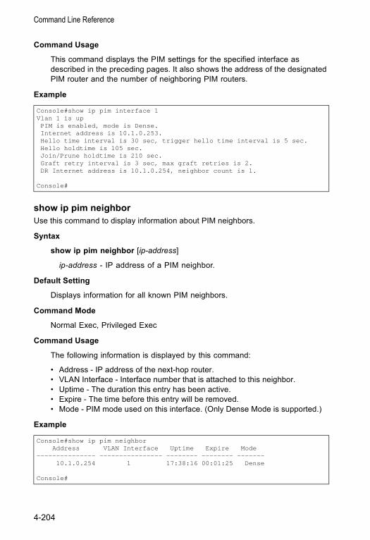
Command Line Reference
Command Usage
This command displays the PIM settings for the specified interface as described in the preceding pages. It also shows the address of the designated PIM router and the number of neighboring PIM routers.
Example
show ip pim neighborUse this command to display information about PIM neighbors.
Syntax
show ip pim neighbor [ip-address]
ip-address - IP address of a PIM neighbor.
Default Setting
Displays information for all known PIM neighbors.
Command Mode
Normal Exec, Privileged Exec
Command Usage
The following information is displayed by this command:
• Address - IP address of the next-hop router.• VLAN Interface - Interface number that is attached to this neighbor.• Uptime - The duration this entry has been active.• Expire - The time before this entry will be removed.• Mode - PIM mode used on this interface. (Only Dense Mode is supported.)
Example
Console#show ip pim interface 1Vlan 1 is upPIM is enabled, mode is Dense.Internet address is 10.1.0.253.Hello time interval is 30 sec, trigger hello time interval is 5 sec.Hello holdtime is 105 sec.Join/Prune holdtime is 210 sec.Graft retry interval is 3 sec, max graft retries is 2.DR Internet address is 10.1.0.254, neighbor count is 1.
Console#
Console#show ip pim neighborAddress VLAN Interface Uptime Expire Mode
--------------- ---------------- -------- -------- -------10.1.0.254 1 17:38:16 00:01:25 Dense
Console#
4-204

Appendix A: Software Specifications
Software FeaturesAuthentication
Local, RADIUS, Port (802.1x)Access Control Lists
IP, MAC (up to 32 lists)DHCP
Client, Relay, ServerPort Configuration
100BASE-TX: 10/100 Mbps, half/full duplex1000BASE-T: 10/100/1000 Mbps, half/full duplex1000BASE-SX/LX: 1000 Mbps, full duplex
Flow ControlFull Duplex: IEEE 802.3xHalf Duplex: Back pressure
Broadcast Storm Control Traffic throttled above a critical threshold
Port MirroringMultiple source ports, one destination port
Rate LimitsInput limit (globally enabled)Output limit (enabled per interface)Range (configured per port)
Fast Ethernet: 1 - 100 MbpsGigabit Ethernet: 1 - 1000 Mbps
Port TrunkingStatic trunks (Cisco EtherChannel compliant)Dynamic trunks (Link Aggregation Control Protocol)
Spanning Tree ProtocolSpanning Tree Protocol (STP, IEEE 802.1D) Rapid Spanning Tree Protocol (RSTP, IEEE 802.1w)
VLAN SupportUp to 255 groups; port-based or with 802.1Q VLAN tagging,GVRP for automatic VLAN learning, private VLANs
Class of ServiceSupports four levels of priority and Weighted Round Robin Queueing(which can be configured by VLAN tag or port),Layer 3/4 priority mapping: IP Port, IP Precedence, IP DSCP
A-1
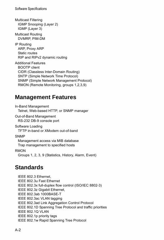
Software Specifications
Multicast Filtering IGMP Snooping (Layer 2)IGMP (Layer 3)
Multicast Routing DVMRP, PIM-DM
IP Routing ARP, Proxy ARPStatic routesRIP and RIPv2 dynamic routing
Additional FeaturesBOOTP clientCIDR (Classless Inter-Domain Routing)SNTP (Simple Network Time Protocol)SNMP (Simple Network Management Protocol)RMON (Remote Monitoring, groups 1,2,3,9)
Management FeaturesIn-Band Management
Telnet, Web-based HTTP, or SNMP managerOut-of-Band Management
RS-232 DB-9 console portSoftware Loading
TFTP in-band or XModem out-of-bandSNMP
Management access via MIB databaseTrap management to specified hosts
RMONGroups 1, 2, 3, 9 (Statistics, History, Alarm, Event)
StandardsIEEE 802.3 Ethernet, IEEE 802.3u Fast EthernetIEEE 802.3x full-duplex flow control (ISO/IEC 8802-3)IEEE 802.3z Gigabit Ethernet, IEEE 802.3ab 1000BASE-TIEEE 802.3ac VLAN taggingIEEE 802.3ad Link Aggregation Control ProtocolIEEE 802.1D Spanning Tree Protocol and traffic prioritiesIEEE 802.1Q VLANIEEE 802.1p priority tagsIEEE 802.1w Rapid Spanning Tree Protocol
A-2
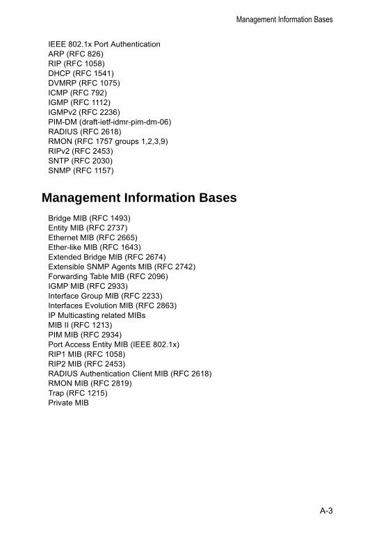
Management Information Bases
IEEE 802.1x Port AuthenticationARP (RFC 826)RIP (RFC 1058)DHCP (RFC 1541)DVMRP (RFC 1075)ICMP (RFC 792)IGMP (RFC 1112)IGMPv2 (RFC 2236)PIM-DM (draft-ietf-idmr-pim-dm-06)RADIUS (RFC 2618)RMON (RFC 1757 groups 1,2,3,9)RIPv2 (RFC 2453)SNTP (RFC 2030)SNMP (RFC 1157)
Management Information BasesBridge MIB (RFC 1493)Entity MIB (RFC 2737)Ethernet MIB (RFC 2665)Ether-like MIB (RFC 1643)Extended Bridge MIB (RFC 2674)Extensible SNMP Agents MIB (RFC 2742)Forwarding Table MIB (RFC 2096)IGMP MIB (RFC 2933)Interface Group MIB (RFC 2233)Interfaces Evolution MIB (RFC 2863)IP Multicasting related MIBs MIB II (RFC 1213)PIM MIB (RFC 2934)Port Access Entity MIB (IEEE 802.1x)RIP1 MIB (RFC 1058)RIP2 MIB (RFC 2453)RADIUS Authentication Client MIB (RFC 2618)RMON MIB (RFC 2819)Trap (RFC 1215)Private MIB
A-3

Software Specifications
A-4
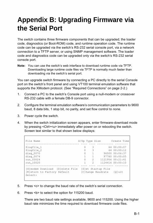
Appendix B: Upgrading Firmware via the Serial PortThe switch contains three firmware components that can be upgraded; the loader code, diagnostics (or Boot-ROM) code, and runtime operation code. The runtime code can be upgraded via the switch’s RS-232 serial console port, via a network connection to a TFTP server, or using SNMP management software. The loader code and diagnostics code can be upgraded only via the switch’s RS-232 serial console port.
Note: You can use the switch’s web interface to download runtime code via TFTP. Downloading large runtime code files via TFTP is normally much faster than downloading via the switch’s serial port.
You can upgrade switch firmware by connecting a PC directly to the serial Console port on the switch’s front panel and using VT100 terminal emulation software that supports the XModem protocol. (See “Required Connections” on page 2-2.)
1. Connect a PC to the switch’s Console port using a null-modem or crossover RS-232 cable with a female DB-9 connector.
2. Configure the terminal emulation software’s communication parameters to 9600 baud, 8 data bits, 1 stop bit, no parity, and set flow control to none.
3. Power cycle the switch.
4. When the switch initialization screen appears, enter firmware-download mode by pressing <Ctrl><u> immediately after power on or rebooting the switch. Screen text similar to that shown below displays:
5. Press <c> to change the baud rate of the switch’s serial connection.
6. Press <b> to select the option for 115200 baud.
There are two baud rate settings available, 9600 and 115200. Using the higher baud rate minimizes the time required to download firmware code files.
File Name S/Up Type Size Create Time--------------------------------- ---- ---- ---------- --------$logfile_1 0 3 64 00:00:07$logfile_2 0 3 64 00:00:12diag_0070 0 1 96500 00:06:37diag_0074 1 1 97780 00:00:05run_03024 0 2 1121956 00:21:41run_10020 1 2 1124416 00:00:10--------------------------------- ---- ---- ---------- --------[X]modem Download [D]elete File [S]et Startup File[R]eturn to Factory Default [C]hange Baudrate [Q]uitSelect>
B-1
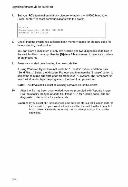
Upgrading Firmware via the Serial Port
7. Set your PC’s terminal emulation software to match the 115200 baud rate. Press <Enter> to reset communications with the switch.
8. Check that the switch has sufficient flash memory space for the new code file before starting the download.
You can store a maximum of only two runtime and two diagnostic code files in the switch’s flash memory. Use the [D]elete File command to remove a runtime or diagnostic file.
9. Press <x> to start downloading the new code file.
If using Windows HyperTerminal, click the “Transfer” button, and then click “Send File....” Select the XModem Protocol and then use the “Browse” button to select the required firmware code file from your PC system. The “Xmodem file send” window displays the progress of the download procedure.
Note: The download file must be a binary software file for this switch.
10. After the file has been downloaded, you are prompted with “Update Image File:” to specify the type of code file. Press <R> for runtime code, <D> for diagnostic code, or <L> for loader code.
Caution: If you select <L> for loader code, be sure the file is a valid loader code file for the switch. If you download an invalid file, the switch will not be able to boot. Unless absolutely necessary, do not attempt to download loader code files.
Select>Change baudrate [A]9600 [B]115200Baudrate set to 115200
B-2
11. Specify a name for the downloaded code file. File names are case-sensitive, should be from 1 to 31 characters, not contain slashes (\ or /), and the leading letter of the file name should not be a period (.). (Valid characters: A-Z, a-z, 0-9, “.”, “-”, “_”)
For example, the following screen text shows the download procedure for a runtime code file:
12. To set the new downloaded file as the startup file, use the [S]et Startup File menu option.
13. When you have finished downloading code files, use the [C]hange Baudrate menu option to change the baud rate of the switch’s serial connection back to 9600 baud.
14. Set your PC’s terminal emulation software baud rate back to 9600 baud. Press <Enter> to reset communications with the switch.
15. Press <q> to quit the firmware-download mode and boot the switch.
Select>xXmodem Receiving Start ::Image downloaded to buffer.
[R]untime[D]iagnostic[L]oader (Warning: you sure what you are doing?)
Update Image File:rRuntime Image Filename : run_1013Updating file system.File system updated.[Press any key to continue]
B-3

Upgrading Firmware via the Serial Port
B-4
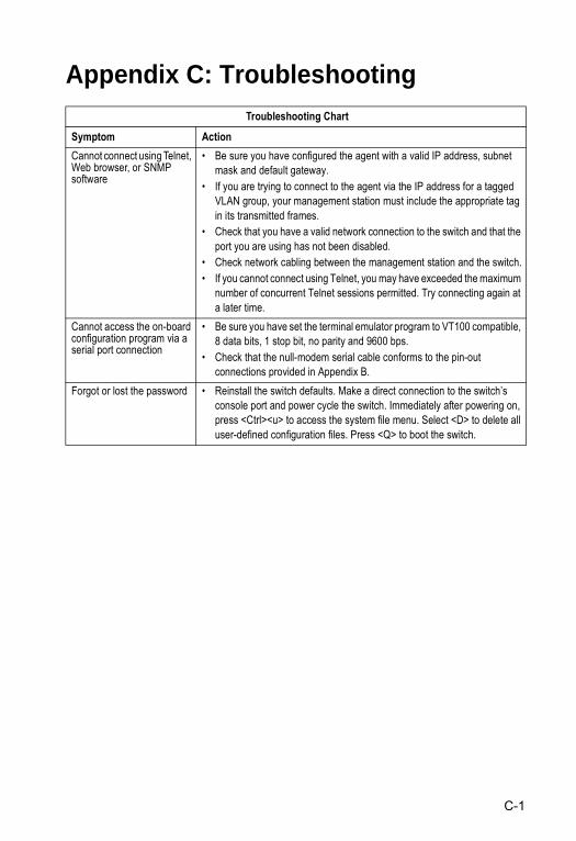
Appendix C: Troubleshooting Troubleshooting Chart
Symptom ActionCannot connect using Telnet, Web browser, or SNMP software
• Be sure you have configured the agent with a valid IP address, subnet mask and default gateway.
• If you are trying to connect to the agent via the IP address for a tagged VLAN group, your management station must include the appropriate tag in its transmitted frames.
• Check that you have a valid network connection to the switch and that the port you are using has not been disabled.
• Check network cabling between the management station and the switch.• If you cannot connect using Telnet, you may have exceeded the maximum
number of concurrent Telnet sessions permitted. Try connecting again at a later time.
Cannot access the on-board configuration program via a serial port connection
• Be sure you have set the terminal emulator program to VT100 compatible, 8 data bits, 1 stop bit, no parity and 9600 bps.
• Check that the null-modem serial cable conforms to the pin-out connections provided in Appendix B.
Forgot or lost the password • Reinstall the switch defaults. Make a direct connection to the switch’s console port and power cycle the switch. Immediately after powering on, press <Ctrl><u> to access the system file menu. Select <D> to delete all user-defined configuration files. Press <Q> to boot the switch.
C-1

Troubleshooting
C-2
Glossary-1
Glossary
Access Control List (ACL)ACLs can limit network traffic and restrict access to certain users or devices by checking each packet for certain IP or MAC (i.e., Layer 2) information.
Address Resolution Protocol (ARP)ARP converts between IP addresses and MAC (i.e., hardware) addresses. ARP is used to locate the MAC address corresponding to a given IP address. This allows the switch to use IP addresses for routing decisions and the corresponding MAC addresses to forward packets from one hop to the next.
Boot Protocol (BOOTP)BOOTP is used to provide bootup information for network devices, including IP address information, the address of the TFTP server that contains the devices system files, and the name of the boot file.
Class of Service (CoS)CoS is supported by prioritizing packets based on the required level of service, and then placing them in the appropriate output queue. Data is transmitted from the queues using weighted round-robin service to enforce priority service and prevent blockage of lower-level queues. Priority may be set according to the port default, the packet’s priority bit (in the VLAN tag), TCP/UDP port number, IP Precedence bit, or DSCP priority bit.
Differentiated Services Code Point Service (DSCP)DSCP uses a six-bit tag to provide for up to 64 different forwarding behaviors. Based on network policies, different kinds of traffic can be marked for different kinds of forwarding. The DSCP bits are mapped to the Class of Service categories, and then into the output queues.
Distance Vector Multicast Routing Protocol (DVMRP)A distance-vector-style routing protocol used for routing multicast datagrams through the Internet. DVMRP combines many of the features of RIP with Reverse Path Forwarding (RPF).
Dynamic Host Control Protocol (DHCP)Provides a framework for passing configuration information to hosts on a TCP/IP network. DHCP is based on the Bootstrap Protocol (BOOTP), adding the capability of automatic allocation of reusable network addresses and additional configuration options.
Glossary
Glossary-2
Extensible Authentication Protocol over LAN (EAPOL) EAPOL is a client authentication protocol used by this switch to verify the network access rights for any device that is plugged into the switch. A user name and password is requested by the switch, and then passed to an authentication server (e.g., RADIUS) for verification. EAPOL is implemented as part of the IEEE 802.1x Port Authentication standard.
GARP VLAN Registration Protocol (GVRP)Defines a way for switches to exchange VLAN information in order to register necessary VLAN members on ports along the Spanning Tree so that VLANs defined in each switch can work automatically over a Spanning Tree network.
Generic Attribute Registration Protocol (GARP)GARP is a protocol that can be used by endstations and switches to register and propagate multicast group membership information in a switched environment so that multicast data frames are propagated only to those parts of a switched LAN containing registered endstations. Formerly called Group Address Registration Protocol.
Generic Multicast Registration Protocol (GMRP)GMRP allows network devices to register end stations with multicast groups. GMRP requires that any participating network devices or end stations comply with the IEEE 802.1p standard.
Group Attribute Registration Protocol (GARP)See Generic Attribute Registration Protocol.
IEEE 802.1DSpecifies a general method for the operation of MAC bridges, including the Spanning Tree Protocol.
IEEE 802.1QVLAN Tagging—Defines Ethernet frame tags which carry VLAN information. It allows switches to assign endstations to different virtual LANs, and defines a standard way for VLANs to communicate across switched networks.
IEEE 802.1pAn IEEE standard for providing quality of service (QoS) in Ethernet networks. The standard uses packet tags that define up to eight traffic classes and allows switches to transmit packets based on the tagged priority value.
IEEE 802.1xPort Authentication controls access to the switch ports by requiring users to first enter a user ID and password for authentication.
Glossary
Glossary-3
IEEE 802.3acDefines frame extensions for VLAN tagging.
IEEE 802.3xDefines Ethernet frame start/stop requests and timers used for flow control on full-duplex links.
IGMP SnoopingListening to IGMP Query and IGMP Report packets transferred between IP Multicast Routers and IP Multicast host groups to identify IP Multicast group members.
Internet Control Message Protocol (ICMP)A network layer protocol that reports errors in processing IP packets. ICMP is also used by routers to feed back information about better routing choices.
Internet Group Management Protocol (IGMP)A protocol through which hosts can register with their local router for multicast services. If there is more than one multicast router on a given subnetwork, one of the routers is made the “querier” and assumes responsibility for keeping track of group membership.
In-Band ManagementManagement of the network from a station attached directly to the network.
IP Multicast FilteringA process whereby this switch can pass multicast traffic along to participating hosts.
IP PrecedenceThe Type of Service (ToS) octet in the IPv4 header includes three precedence bits defining eight different priority levels ranging from highest priority for network control packets to lowest priority for routine traffic. The eight values are mapped one-to-one to the Class of Service categories by default, but may be configured differently to suit the requirements for specific network applications.
Layer 2Data Link layer in the ISO 7-Layer Data Communications Protocol. This is related directly to the hardware interface for network devices and passes on traffic based on MAC addresses.
Layer 3Network layer in the ISO 7-Layer Data Communications Protocol. This layer handles the routing functions for data moving from one open system to another.
Glossary
Glossary-4
Link AggregationSee Port Trunk.
Link Aggregation Control Protocol (LACP)Allows ports to automatically negotiate a trunked link with LACP-configured ports on another device.
Management Information Base (MIB)An acronym for Management Information Base. It is a set of database objects that contains information about a specific device.
Multicast SwitchingA process whereby the switch filters incoming multicast frames for services for which no attached host has registered, or forwards them to all ports contained within the designated multicast VLAN group.
Network Time Protocol (NTP)NTP provides the mechanisms to synchronize time across the network. The time servers operate in a hierarchical-master-slave configuration in order to synchronize local clocks within the subnet and to national time standards via wire or radio.
Out-of-Band ManagementManagement of the network from a station not attached to the network.
Port AuthenticationSee IEEE 802.1x.
Port MirroringA method whereby data on a target port is mirrored to a monitor port for troubleshooting with a logic analyzer or RMON probe. This allows data on the target port to be studied unobstructively.
Port TrunkDefines a network link aggregation and trunking method which specifies how to create a single high-speed logical link that combines several lower-speed physical links.
Private VLANsPrivate VLANs provide port-based security and isolation between ports within the assigned VLAN. Data traffic on downlink ports can only be forwarded to, and from, uplink ports.
Glossary
Glossary-5
Protocol-Independent Multicasting (PIM)This multicast routing protocol floods multicast traffic downstream, and calculates the shortest-path back to the multicast source network via reverse path forwarding. PIM uses the router’s IP routing table rather than maintaining a separate multicast routing table as with DVMRP. PIM - Sparse Mode is designed for networks where the probability of a multicast client is low, such as on a Wide Area Network. PIM - Dense Mode is designed for networks where the probability of a multicast client is high and frequent flooding of multicast traffic can be justified.
Remote Authentication Dial-in User Service (RADIUS)
RADIUS is a logon authentication protocol that uses software running on a central server to control access to RADIUS-compliant devices on the network.
Remote Monitoring (RMON)RMON provides comprehensive network monitoring capabilities. It eliminates the polling required in standard SNMP, and can set alarms on a variety of traffic conditions, including specific error types.
Rapid Spanning Tree Protocol (RSTP)RSTP reduces the convergence time for network topology changes to about 10% of that required by the older IEEE 802.1D STP standard.
Routing Information Protocol (RIP)The RIP protocol seeks to find the shortest route to another device by minimizing the distance-vector, or hop count, which serves as a rough estimate of transmission cost. RIP-2 is a compatible upgrade to RIP. It adds useful capabilities for subnet routing, authentication, and multicast transmissions.
Simple Network Management Protocol (SNMP)The application protocol in the Internet suite of protocols which offers network management services.
Simple Network Time Protocol (SNTP)
SNTP allows a device to set its internal clock based on periodic updates from a Network Time Protocol (NTP) server. Updates can be requested from a specific NTP server, or can be received via broadcasts sent by NTP servers.
Spanning Tree Protocol (STP)A technology that checks your network for any loops. A loop can often occur in complicated or backup linked network systems. Spanning Tree detects and directs data along the shortest available path, maximizing the performance and efficiency of the network.
Glossary
Glossary-6
TelnetDefines a remote communication facility for interfacing to a terminal device over TCP/IP.
Transmission Control Protocol/Internet Protocol (TCP/IP)Protocol suite that includes TCP as the primary transport protocol, and IP as the network layer protocol.
Trivial File Transfer Protocol (TFTP)A TCP/IP protocol commonly used for software downloads.
User Datagram Protocol (UDP)
UDP provides a datagram mode for packet-switched communications. It uses IP as the underlying transport mechanism to provide access to IP-like services. UDP packets are delivered just like IP packets – connection-less datagrams that may be discarded before reaching their targets. UDP is useful when TCP would be too complex, too slow, or just unnecessary.
Virtual LAN (VLAN)A Virtual LAN is a collection of network nodes that share the same collision domain regardless of their physical location or connection point in the network. A VLAN serves as a logical workgroup with no physical barriers, and allows users to share information and resources as though located on the same LAN.
XModemA protocol used to transfer files between devices. Data is grouped in 128-byte blocks and error-corrected.
Index
Numerics802.1x, port authentication 3-23, 4-49Aacceptable frame type 3-84, 4-125Access Control List See ACLACL
Extended IP 3-30, 4-56, 4-59MAC 3-30, 4-56, 4-62, 4-63–4-66Standard IP 3-30, 4-56, 4-58
Address Resolution Protocol See ARPaddress table 3-62, 4-106
aging time 3-64, 4-109ARP
configuration 3-117, 4-168description 3-116proxy 3-117, 4-170statistics 3-122, 4-174
BBOOTP 3-13, 4-163BPDU 3-65broadcast storm, threshold 3-50, 4-95
CClass of Service See CoSCLI, showing commands 4-4command line interface See CLIcommunity string 2-6, 3-37, 4-68configuration settings, saving or
restoring 2-8, 3-16, 4-40console port, required connections 2-2CoS
configuring 3-87, 4-136copying settings 3-97DSCP 3-94, 4-144IP port priority 3-96, 4-141IP precedence 3-92, 4-142layer 3/4 priorities 3-91, 4-141queue mapping 3-88, 4-139traffic class weights 3-90, 4-138
Ddefault gateway, configuration 3-114,
4-165
default priority, ingress port 3-87, 4-137
default settings, system 1-6DHCP 3-13, 4-163
address pool 3-41, 4-78client 3-12, 4-73dynamic configuration 2-5relay service 3-39, 4-75server 3-40, 4-77
Differentiated Code Point Service See DSCP
downloading software 3-15, 4-40, B-1DSCP
enabling 3-91, 4-144mapping priorities 3-94, 4-145
DVMRPconfiguring 3-142, 4-189global settings 3-142, 4-189–4-193interface settings 3-144,
4-193–4-194neighbor routers 3-146, 4-196routing table 3-147, 4-196
dynamic addresses, displaying 3-63, 4-108
Dynamic Host Configuration Protocol See DHCP
Eedge port, STA 3-71, 3-73, 4-117event logging 4-26
Ffirmware
displaying version 3-9, 4-39upgrading 3-15, 4-40, B-1
GGARP VLAN Registration Protocol See
GVRPgateway, default 3-114, 4-165GVRP
global setting 3-77, 4-132interface configuration 3-84, 4-134
Hhardware version, displaying 3-9, 4-39
Index-1
Index
IIEEE 802.1D 3-64, 4-111IEEE 802.1w 3-64, 4-111IEEE 802.1x 3-23, 4-49IGMP
description of protocol 3-99groups, displaying 3-104, 4-162Layer 2 3-99, 4-149Layer 3 3-106, 4-156query 3-99, 4-152, 4-156query, Layer 2 3-100, 4-152query, Layer 3 3-106, 4-156services, displaying 3-109, 4-162snooping 3-99, 4-149snooping, configuring 3-100, 4-149
ingress filtering 3-84, 4-126IP address
BOOTP/DHCP 3-13, 4-74, 4-163setting 2-4, 3-12, 4-163
IP port priorityenabling 3-96, 4-141mapping priorities 3-96, 4-142
IP precedenceenabling 3-91, 4-142mapping priorities 3-92, 4-143
IP routing 3-110, 4-171configuring interfaces 3-115, 4-163enabling or disabling 3-114, 4-171status 3-114, 4-171unicast protocols 3-112
IP, statistics 3-123, 4-174
Llink type, STA 3-71, 3-73, 4-119log-in, Web interface 3-2logon authentication 3-20, 4-44
RADIUS client 3-21, 4-46RADIUS server 3-21, 4-46
logon authentication, sequence 3-21, 4-45
Mmain menu 3-3Management Information Bases
(MIBs) A-3mirror port, configuring 3-52, 4-100multicast filtering 3-98, 4-148
multicast groups 3-104, 3-109, 4-151displaying 3-109, 4-151static 3-104, 4-149
multicast routing 3-139, 4-184description 3-139DVMRP 3-142, 4-189enabling 3-140, 4-186general commands 4-186global settings 3-140, 4-186PIM-DM 3-148, 4-198routing table 3-140, 4-187
multicast servicesconfiguring 3-105, 4-149displaying 3-104, 4-151
multicast, static router port 3-102, 4-185
Ppassword, line 4-11passwords 2-4
administrator setting 3-20, 4-23path cost 3-71
method 3-68, 4-114STA 3-71, 4-114
PIM-DM 3-148, 4-198configuring 3-148, 4-198global configuration 3-148, 4-198interface settings 3-149,
4-199–4-203neighbor routers 3-152, 4-204
port authentication 3-23, 4-49port priority
configuring 3-87, 4-136default ingress 3-87, 4-137STA 3-71, 4-116
port, statistics 3-53, 4-97ports
autonegotiation 3-49, 4-91broadcast storm threshold 3-50,
4-95capabilities 3-49, 4-92duplex mode 3-49, 4-90flow control 3-49, 4-93speed 3-49, 4-90
ports, configuring 3-47, 4-89ports, mirroring 3-52, 4-100
Index-2
Index
priority, default port ingress 3-87, 4-137
problems, troubleshooting C-1protocol migration 3-74, 4-120proxy ARP 3-117, 4-170
Qqueue weights 3-90, 4-138
RRADIUS, logon authentication 3-21,
4-46rate limits, setting 3-57, 4-102restarting the system 3-20, 4-19RIP
configuring 3-130, 4-175–4-183description 3-112global settings 3-131, 4-175–4-176interface protocol settings 3-134,
4-177–4-182specifying interfaces 3-133, 4-177statistics 3-137, 4-184
routing table, displaying 3-129, 4-173RSTP 3-64, 4-111
global configuration 3-65, 4-111
Sserial port
configuring 4-9XModem downloads B-1
Simple Network Management Protocol See SNMP
SNMP 3-36community string 3-37, 4-68enabling traps 3-38, 4-71trap manager 3-38, 4-70
softwaredisplaying version 3-9, 4-39downloading 3-15, 4-40, B-1
Spanning Tree Protocol See STAspecifications, software A-1STA 3-64, 4-110
edge port 3-71, 3-73, 4-117
global settings, configuring 3-67, 4-110–4-115
global settings, displaying 3-65, 4-120
interface settings 3-70, 4-116–4-120, 4-121
link type 3-71, 3-73, 4-119path cost 3-71, 4-116path cost method 3-68, 4-114port priority 3-71, 4-116protocol migration 3-74, 4-120transmission limit 3-69, 4-115
standards, IEEE A-2startup files
creating 3-17, 4-40displaying 3-15, 4-34setting 3-15, 4-44
static addresses, setting 3-62, 4-106static routes, configuring 3-128, 4-172statistics
ARP 3-122, 4-174ICMP 3-124, 4-174IP 3-123, 4-174port 3-53, 4-97RIP 3-137, 4-184TCP 3-127, 4-174UDP 3-126, 4-174
STP 3-67, 4-111STP Also see STAsystem clock, setting 3-18, 4-29system software, downloading from
server 3-15, 4-40
Ttime, setting 3-18, 4-29traffic class weights 3-90, 4-138trap manager 2-7, 3-38, 4-70troubleshooting C-1trunk
configuration 3-58, 4-103LACP 3-59, 4-104static 3-60, 4-104
Uupgrading software 3-15, 4-40, B-1user password 3-20, 4-23, 4-24
Index-3

Index
VVLANs 3-74–3-86, 4-122–4-132
adding static members 3-81, 3-83, 4-128
creating 3-80, 4-123description 3-74displaying basic information 3-77,
4-133displaying port members 3-78,
4-130egress mode 3-85, 4-125
interface configuration 3-83, 4-125–4-129
private 3-86, 4-131
WWeb interface
access requirements 3-1configuration buttons 3-2home page 3-2menu list 3-3panel display 3-3
XXModem downloads B-1
Index-4


ES3626G-ZZE032003-R02150200027900A
Related Documents