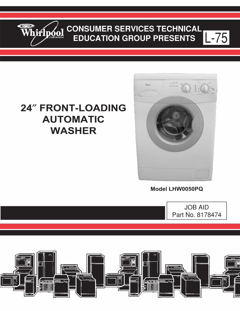
CONSUMER SERVICES TECHNICAL EDUCATION GROUP PRESENTS L-75 JOB AID Part No. 8178474 24″ FRONT-LOADING AUTOMATIC WASHER Model LHW0050PQ

Welcome message from author
This document is posted to help you gain knowledge. Please leave a comment to let me know what you think about it! Share it to your friends and learn new things together.
Transcript
CONSUMER SERVICES TECHNICALEDUCATION GROUP PRESENTS L-75
JOB AIDPart No. 8178474
24″ FRONT-LOADING
AUTOMATIC
WASHER
Model LHW0050PQ
- ii -
WHIRLPOOL CORPORATION assumes no responsibility for any repairs madeon our products by anyone other than Authorized Service Technicians.
FORWARDThis Whirlpool Job Aid “24″ Front-Loading Automatic Washer” (Part No. 8178474), provides thetechnician with information on the installation, operation, and service of the 24″ Front-LoadingAutomatic Washer. It is to be used as a training Job Aid and Service Manual. For specificinformation on the model being serviced, refer to the “Use and Care Guide,” or “Tech Sheet”provided with the washer.
The Wiring Diagram used in this Job Aid is typical and should be used for training purposes only.Always use the Wiring Diagram supplied with the product when servicing the unit.
GOALS AND OBJECTIVESThe goal of this Job Aid is to provide detailed information that will enable the service technician toproperly diagnose malfunctions and repair the 24″ Front-Loading Automatic Washer.
The objectives of this Job Aid are to:
• Understand and follow proper safety precautions.
• Successfully troubleshoot and diagnose malfunctions.
• Successfully perform necessary repairs.
• Successfully return the washer to its proper operational status.
Copyright © 2004, Whirlpool Corporation, Benton Harbor, MI 49022
- iii -
TABLE OF CONTENTSPage
GENERAL ............................................................................................................................... 1-1Safety First ......................................................................................................................... 1-1Model & Serial Number Label Location ............................................................................. 1-2Specifications..................................................................................................................... 1-3Whirlpool Washer Warranty ............................................................................................... 1-4
INSTALLATION INFORMATION ........................................................................................... 2-1Installation Requirements .................................................................................................. 2-1Installation Instructions ...................................................................................................... 2-4
PRODUCT OPERATION ........................................................................................................ 3-1Theory Of Operation .......................................................................................................... 3-1Washer Use ....................................................................................................................... 3-3Washer Care...................................................................................................................... 3-8
COMPONENT ACCESS ......................................................................................................... 4-1Component Locations ........................................................................................................ 4-1Removing The Control Panel Components ....................................................................... 4-2Removing A Dispenser Motor And The Dispenser Assembly ........................................... 4-5Removing The Control Board & Pressure Switch .............................................................. 4-7Removing A Water Inlet Valve ........................................................................................... 4-8Removing The Power Supply Cord & Interference Filter ................................................... 4-9Removing The Door Switch ............................................................................................. 4-10Removing The Door Seal ................................................................................................ 4-11Removing The Drain Pump ............................................................................................. 4-13Removing The Motor Control Unit ................................................................................... 4-14Removing The Heating Element & Temperature Sensor ................................................ 4-15Removing The Wash Motor ............................................................................................. 4-16Removing The Thermostat .............................................................................................. 4-17Removing The Filter Housing .......................................................................................... 4-18Removing The Basket From The Tub.............................................................................. 4-19
COMPONENT TESTING ........................................................................................................ 5-1Power On/Off Switch ......................................................................................................... 5-1Dispenser Motors ............................................................................................................... 5-2Pressure Switch ................................................................................................................. 5-2Water Inlet Valves.............................................................................................................. 5-3Door Switch ....................................................................................................................... 5-3Drain Pump ........................................................................................................................ 5-4Heating Element ................................................................................................................ 5-4Temperature Sensor .......................................................................................................... 5-5Wash Motor ....................................................................................................................... 5-5Thermostat ......................................................................................................................... 5-6
DIAGNOSTICS & TROUBLESHOOTING .............................................................................. 6-1Diagnostics ........................................................................................................................ 6-1Troubleshooting Guide ...................................................................................................... 6-4Pinouts ............................................................................................................................... 6-7
WIRING DIAGRAM ................................................................................................................. 7-1

- iv -
— NOTES —
1-1
GENERALSAFETY FIRST
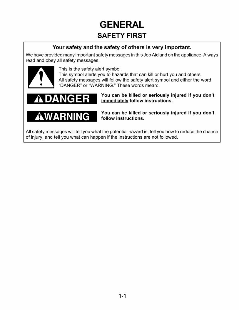
Your safety and the safety of others is very important.
We have provided many important safety messages in this Job Aid and on the appliance. Alwaysread and obey all safety messages.
This is the safety alert symbol.This symbol alerts you to hazards that can kill or hurt you and others.All safety messages will follow the safety alert symbol and either the word“DANGER” or “WARNING.” These words mean:
DANGER
WARNINGAll safety messages will tell you what the potential hazard is, tell you how to reduce the chanceof injury, and tell you what can happen if the instructions are not followed.
You can be killed or seriously injured if you don’timmediately follow instructions.
You can be killed or seriously injured if you don’tfollow instructions.
1-2
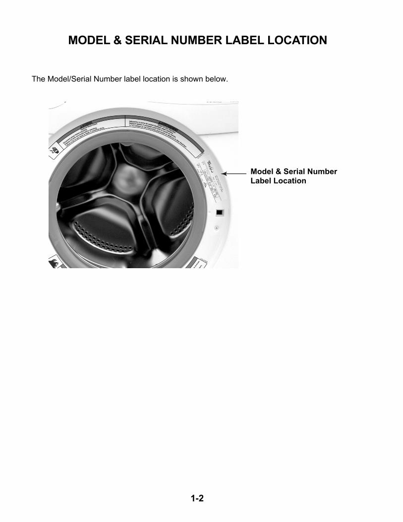
MODEL & SERIAL NUMBER LABEL LOCATION
The Model/Serial Number label location is shown below.
Model & Serial NumberLabel Location
1-3
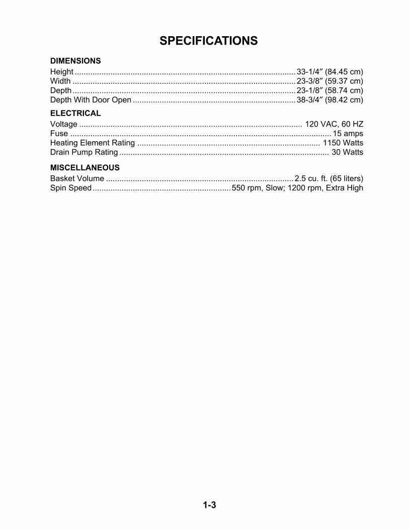
SPECIFICATIONS
DIMENSIONS
Height ................................................................................................... 33-1/4″ (84.45 cm)Width .................................................................................................... 23-3/8″ (59.37 cm)Depth.................................................................................................... 23-1/8″ (58.74 cm)Depth With Door Open ......................................................................... 38-3/4″ (98.42 cm)
ELECTRICAL
Voltage .................................................................................................... 120 VAC, 60 HZFuse ..................................................................................................................... 15 ampsHeating Element Rating .................................................................................. 1150 WattsDrain Pump Rating .............................................................................................. 30 Watts
MISCELLANEOUS
Basket Volume .................................................................................... 2.5 cu. ft. (65 liters)Spin Speed..............................................................550 rpm, Slow; 1200 rpm, Extra High
1-4
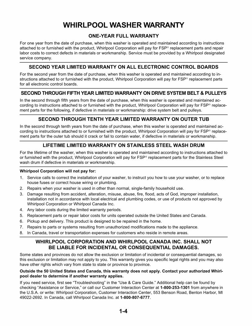
WHIRLPOOL WASHER WARRANTY
ONE-YEAR FULL WARRANTY
For one year from the date of purchase, when this washer is operated and maintained according to instructions
attached to or furnished with the product, Whirlpool Corporation will pay for FSP replacement parts and repair
labor costs to correct defects in materials or workmanship. Service must be provided by a Whirlpool designated
service company.
SECOND YEAR LIMITED WARRANTY ON ALL ELECTRONIC CONTROL BOARDS
For the second year from the date of purchase, when this washer is operated and maintained according to in-
structions attached to or furnished with the product, Whirlpool Corporation will pay for FSP replacement parts
for all electronic control boards.
SECOND THROUGH FIFTH YEAR LIMITED WARRANTY ON DRIVE SYSTEM BELT & PULLEYS
In the second through fifth years from the date of purchase, when this washer is operated and maintained ac-
cording to instructions attached to or furnished with the product, Whirlpool Corporation will pay for FSP replace-
ment parts for the following, if defective in materials or workmanship: drive system belt and pulleys.
SECOND THROUGH TENTH YEAR LIMITED WARRANTY ON OUTER TUB
In the second through tenth years from the date of purchase, when this washer is operated and maintained ac-
cording to instructions attached to or furnished with the product, Whirlpool Corporation will pay for FSP replace-
ment parts for the outer tub should it crack or fail to contain water, if defective in materials or workmanship.
LIFETIME LIMITED WARRANTY ON STAINLESS STEEL WASH DRUM
For the lifetime of the washer, when this washer is operated and maintained according to instructions attached to
or furnished with the product, Whirlpool Corporation will pay for FSP replacement parts for the Stainless Steel
wash drum if defective in materials or workmanship.
Whirlpool Corporation will not pay for:
1. Service calls to correct the installation of your washer, to instruct you how to use your washer, or to replace
house fuses or correct house wiring or plumbing.
2. Repairs when your washer is used in other than normal, single-family household use.
3. Damage resulting from accident, alteration, misuse, abuse, fire, flood, acts of God, improper installation,
installation not in accordance with local electrical and plumbing codes, or use of products not approved by
Whirlpool Corporation or Whirlpool Canada Inc.
4. Any labor costs during the limited warranty periods.
5. Replacement parts or repair labor costs for units operated outside the United States and Canada.
6. Pickup and delivery. This product is designed to be repaired in the home.
7. Repairs to parts or systems resulting from unauthorized modifications made to the appliance.
8. In Canada, travel or transportation expenses for customers who reside in remote areas.
WHIRLPOOL CORPORATION AND WHIRLPOOL CANADA INC. SHALL NOTBE LIABLE FOR INCIDENTAL OR CONSEQUENTIAL DAMAGES.
Some states and provinces do not allow the exclusion or limitation of incidental or consequential damages, so
this exclusion or limitation may not apply to you. This warranty gives you specific legal rights and you may also
have other rights which vary from state to state or province to province.
Outside the 50 United States and Canada, this warranty does not apply. Contact your authorized Whirl-
pool dealer to determine if another warranty applies.
If you need service, first see “Troubleshooting” in the “Use & Care Guide.” Additional help can be found by
checking “Assistance or Service,” or call our Customer Interaction Center at 1-800-253-1301 from anywhere in
the U.S.A. or write: Whirlpool Corporation, Customer Interaction Center, 553 Benson Road, Benton Harbor, Ml
49022-2692. In Canada, call Whirlpool Canada Inc. at 1-800-807-6777.
2-1
INSTALLATION INFORMATIONINSTALLATION REQUIREMENTS
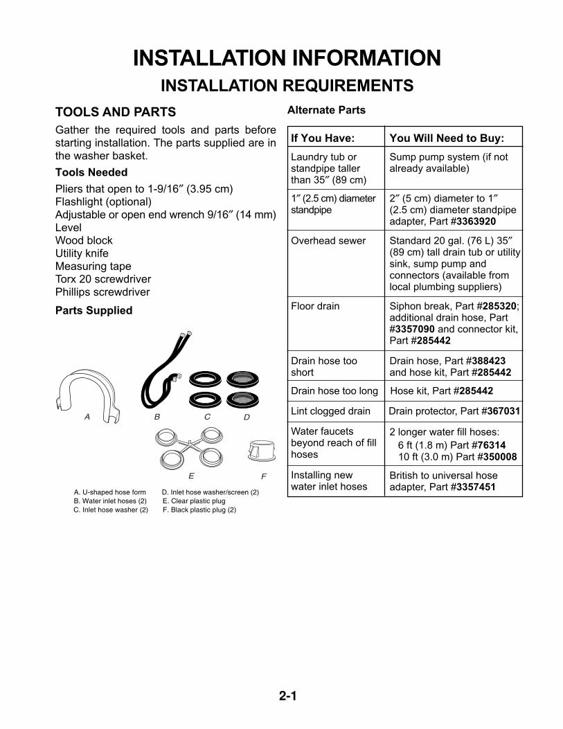
TOOLS AND PARTS
Gather the required tools and parts beforestarting installation. The parts supplied are inthe washer basket.
Tools Needed
Pliers that open to 1-9/16″ (3.95 cm)Flashlight (optional)Adjustable or open end wrench 9/16″ (14 mm)LevelWood blockUtility knifeMeasuring tapeTorx 20 screwdriverPhillips screwdriver
Parts Supplied
Alternate Parts
If You Have: You Will Need to Buy:
Laundry tub orstandpipe tallerthan 35″ (89 cm)
Sump pump system (if notalready available)
1″ (2.5 cm) diameterstandpipe
2″ (5 cm) diameter to 1″(2.5 cm) diameter standpipeadapter, Part #3363920
Overhead sewer Standard 20 gal. (76 L) 35″(89 cm) tall drain tub or utilitysink, sump pump andconnectors (available fromlocal plumbing suppliers)
Floor drain Siphon break, Part #285320;additional drain hose, Part#3357090 and connector kit,Part #285442
Drain hose tooshort
Drain hose, Part #388423and hose kit, Part #285442
Drain hose too long Hose kit, Part #285442
Lint clogged drain Drain protector, Part #367031
Water faucetsbeyond reach of fillhoses
2 longer water fill hoses:
6 ft (1.8 m) Part #76314 10 ft (3.0 m) Part #350008
Installing newwater inlet hoses
British to universal hoseadapter, Part #3357451
A. U-shaped hose formB. Water inlet hoses (2)C. Inlet hose washer (2)
D. Inlet hose washer/screen (2)E. Clear plastic plugF. Black plastic plug (2)
A B C D
E F
2-2
(59.37 cm)23-1/8"23-3/8"
(58.74 cm)
Front View Side View Closet Door With Vents
LOCATION REQUIREMENTS
Selecting the proper location for your washerimproves performance and minimizes noiseand possible washer “walk.”
The washer can be installed in a basement,laundry room, closet, or recessed area (see“Drain System”).
IMPORTANT: Do not install or store the washerwhere it will be exposed to the weather.
Proper installation is your responsibility.
You Will Need
• A water heater set to deliver 120°F (49°C)water to the washer.
• A grounded electrical outlet located within5 ft (1.5 m) of where the power cord isattached to the back of the washer (see“Electrical Requirements”).
• Hot and cold water faucets located within3-1/2 ft (1.1 m) of the hot and cold water fillvalves, and water pressure of 5-100 psi(34.5-690 kPa).
• A level floor with a maximum slope of 3/4″(1.9 cm) under entire washer. Installing thewasher on carpeting is not recommended.
• A sturdy floor to support the washer weight(washer, water and load) of 260 lbs (118 kg).
• Do not store or operate your washer intemperatures at or below 38°F (3.33°C).Some water can remain in the washer andcan cause damage in low temperatures.
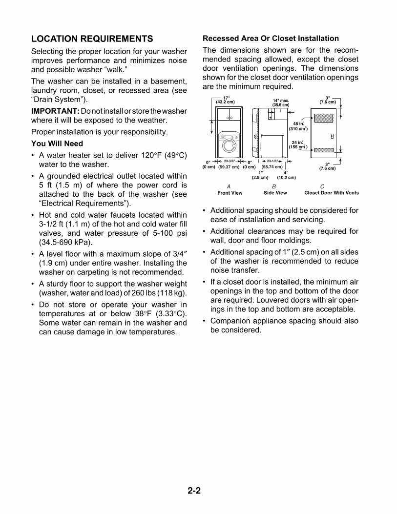
Recessed Area Or Closet Installation
The dimensions shown are for the recom-mended spacing allowed, except the closetdoor ventilation openings. The dimensionsshown for the closet door ventilation openingsare the minimum required.
• Additional spacing should be considered forease of installation and servicing.
• Additional clearances may be required forwall, door and floor moldings.
• Additional spacing of 1″ (2.5 cm) on all sidesof the washer is recommended to reducenoise transfer.
• If a closet door is installed, the minimum airopenings in the top and bottom of the doorare required. Louvered doors with air open-ings in the top and bottom are acceptable.
• Companion appliance spacing should alsobe considered.
2-3
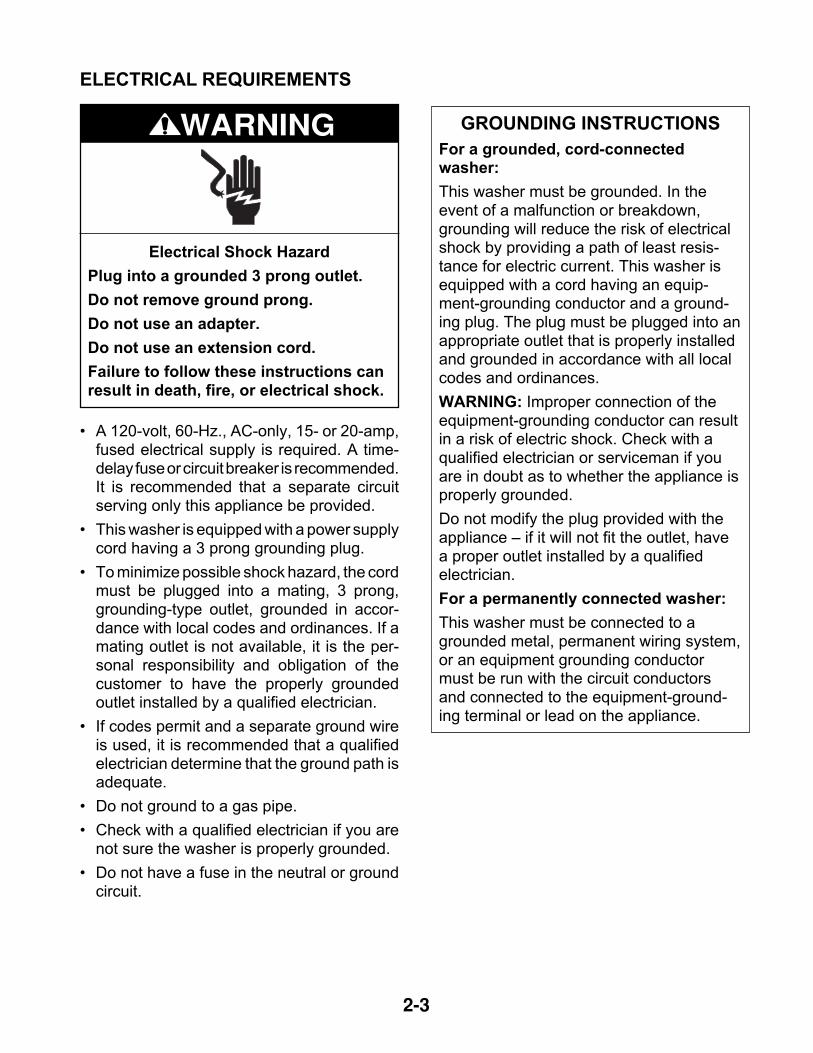
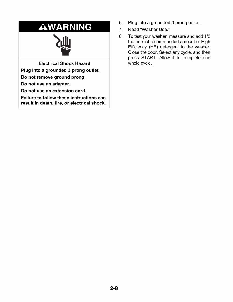
Electrical Shock Hazard
Plug into a grounded 3 prong outlet.
Do not remove ground prong.
Do not use an adapter.
Do not use an extension cord.
Failure to follow these instructions canresult in death, fire, or electrical shock.
WARNING
• A 120-volt, 60-Hz., AC-only, 15- or 20-amp,fused electrical supply is required. A time-delay fuse or circuit breaker is recommended.It is recommended that a separate circuitserving only this appliance be provided.
• This washer is equipped with a power supplycord having a 3 prong grounding plug.
• To minimize possible shock hazard, the cordmust be plugged into a mating, 3 prong,grounding-type outlet, grounded in accor-dance with local codes and ordinances. If amating outlet is not available, it is the per-sonal responsibility and obligation of thecustomer to have the properly groundedoutlet installed by a qualified electrician.
• If codes permit and a separate ground wireis used, it is recommended that a qualifiedelectrician determine that the ground path isadequate.
• Do not ground to a gas pipe.
• Check with a qualified electrician if you arenot sure the washer is properly grounded.
• Do not have a fuse in the neutral or groundcircuit.
GROUNDING INSTRUCTIONS
For a grounded, cord-connectedwasher:
This washer must be grounded. In theevent of a malfunction or breakdown,grounding will reduce the risk of electricalshock by providing a path of least resis-tance for electric current. This washer isequipped with a cord having an equip-ment-grounding conductor and a ground-ing plug. The plug must be plugged into anappropriate outlet that is properly installedand grounded in accordance with all localcodes and ordinances.
WARNING: Improper connection of theequipment-grounding conductor can resultin a risk of electric shock. Check with aqualified electrician or serviceman if youare in doubt as to whether the appliance isproperly grounded.
Do not modify the plug provided with theappliance – if it will not fit the outlet, havea proper outlet installed by a qualifiedelectrician.
For a permanently connected washer:
This washer must be connected to agrounded metal, permanent wiring system,or an equipment grounding conductormust be run with the circuit conductorsand connected to the equipment-ground-ing terminal or lead on the appliance.
ELECTRICAL REQUIREMENTS
2-4
INSTALLATION INSTRUCTIONS
WARNING
• To prevent floor damage, set the washeronto cardboard before moving across floor.
• Move the washer to within approximately 3 ft(90 cm) of the final location.
REMOVE TRANSPORT SYSTEM
To install the machine, follow the steps below:
1. Move the machine to its installation posi-tion and remove the outer wrapping andthe polystyrene base.
2. For transport reasons, the drum is lockedin position. Loosen the four locking boltsand remove them along with the plasticspacers.
Excessive Weight Hazard
Use two or more people to move andinstall washer.
Failure to do so can result in back orother injury.
NOTE: If the plastic spacers cannot be re-moved from the machine, open the side panelby loosening the screws indicated as “E”above. Remove the spacers and replace thepanel.
NOTE: If the washer is to be transported at alater date, call your local service center.
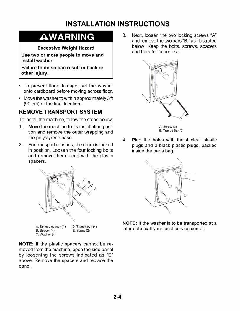
3. Next, loosen the two locking screws “A”and remove the two bars “B,” as illustratedbelow. Keep the bolts, screws, spacersand bars for future use.
4. Plug the holes with the 4 clear plasticplugs and 2 black plastic plugs, packedinside the parts bag.
A. Splined spacer (4)B. Spacer (4)C. Washer (4)
D. Transit bolt (4)E. Screw (2)
AB
CD
E
A. Screw (2)B. Transit Bar (2)
A
B
2-5
DRAIN SYSTEM
The washer can be installed using the standpipedrain system (floor or wall), the laundry tubdrain system, or the floor drain system. Selectthe drain hose installation method you need(see “Tools and Parts”).
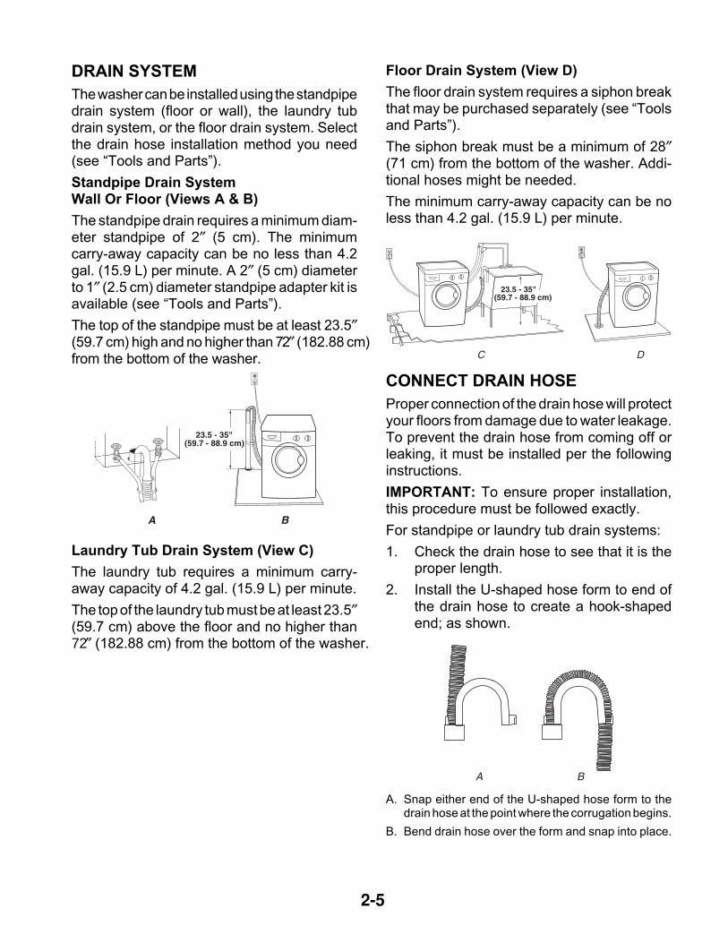
Standpipe Drain SystemWall Or Floor (Views A & B)
The standpipe drain requires a minimum diam-eter standpipe of 2″ (5 cm). The minimumcarry-away capacity can be no less than 4.2gal. (15.9 L) per minute. A 2″ (5 cm) diameterto 1″ (2.5 cm) diameter standpipe adapter kit isavailable (see “Tools and Parts”).
The top of the standpipe must be at least 23.5″(59.7 cm) high and no higher than 72″ (182.88 cm)from the bottom of the washer.
Laundry Tub Drain System (View C)
The laundry tub requires a minimum carry-away capacity of 4.2 gal. (15.9 L) per minute.
The top of the laundry tub must be at least 23.5″(59.7 cm) above the floor and no higher than72″ (182.88 cm) from the bottom of the washer.
CONNECT DRAIN HOSE
Proper connection of the drain hose will protectyour floors from damage due to water leakage.To prevent the drain hose from coming off orleaking, it must be installed per the followinginstructions.
IMPORTANT: To ensure proper installation,this procedure must be followed exactly.
For standpipe or laundry tub drain systems:
1. Check the drain hose to see that it is theproper length.
2. Install the U-shaped hose form to end ofthe drain hose to create a hook-shapedend; as shown.
A B
23.5 - 35"(59.7 - 88.9 cm)
A B
Floor Drain System (View D)
The floor drain system requires a siphon breakthat may be purchased separately (see “Toolsand Parts”).
The siphon break must be a minimum of 28″(71 cm) from the bottom of the washer. Addi-tional hoses might be needed.
The minimum carry-away capacity can be noless than 4.2 gal. (15.9 L) per minute.
A. Snap either end of the U-shaped hose form to thedrain hose at the point where the corrugation begins.
B. Bend drain hose over the form and snap into place.
2-6
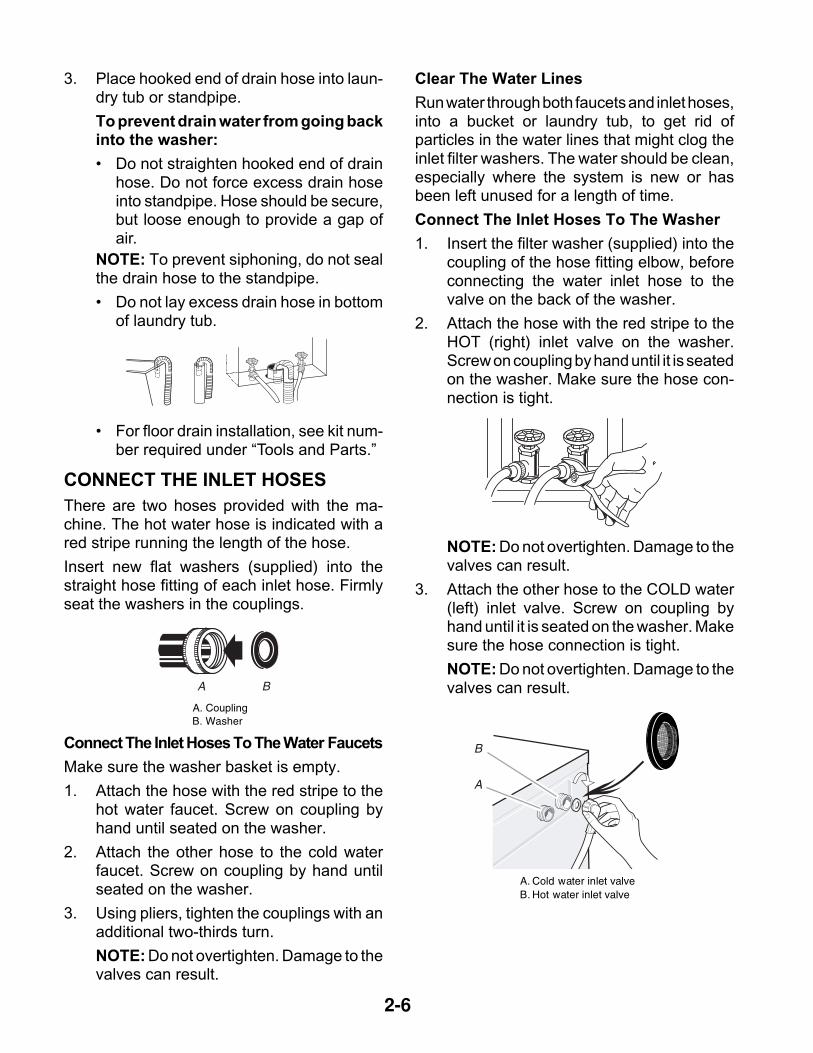
3. Place hooked end of drain hose into laun-dry tub or standpipe.
To prevent drain water from going backinto the washer:
• Do not straighten hooked end of drainhose. Do not force excess drain hoseinto standpipe. Hose should be secure,but loose enough to provide a gap ofair.
NOTE: To prevent siphoning, do not sealthe drain hose to the standpipe.
• Do not lay excess drain hose in bottomof laundry tub.
• For floor drain installation, see kit num-ber required under “Tools and Parts.”
CONNECT THE INLET HOSES
There are two hoses provided with the ma-chine. The hot water hose is indicated with ared stripe running the length of the hose.
Insert new flat washers (supplied) into thestraight hose fitting of each inlet hose. Firmlyseat the washers in the couplings.
Connect The Inlet Hoses To The Water Faucets
Make sure the washer basket is empty.
1. Attach the hose with the red stripe to thehot water faucet. Screw on coupling byhand until seated on the washer.
2. Attach the other hose to the cold waterfaucet. Screw on coupling by hand untilseated on the washer.
3. Using pliers, tighten the couplings with anadditional two-thirds turn.
NOTE: Do not overtighten. Damage to thevalves can result.
Clear The Water Lines
Run water through both faucets and inlet hoses,into a bucket or laundry tub, to get rid ofparticles in the water lines that might clog theinlet filter washers. The water should be clean,especially where the system is new or hasbeen left unused for a length of time.
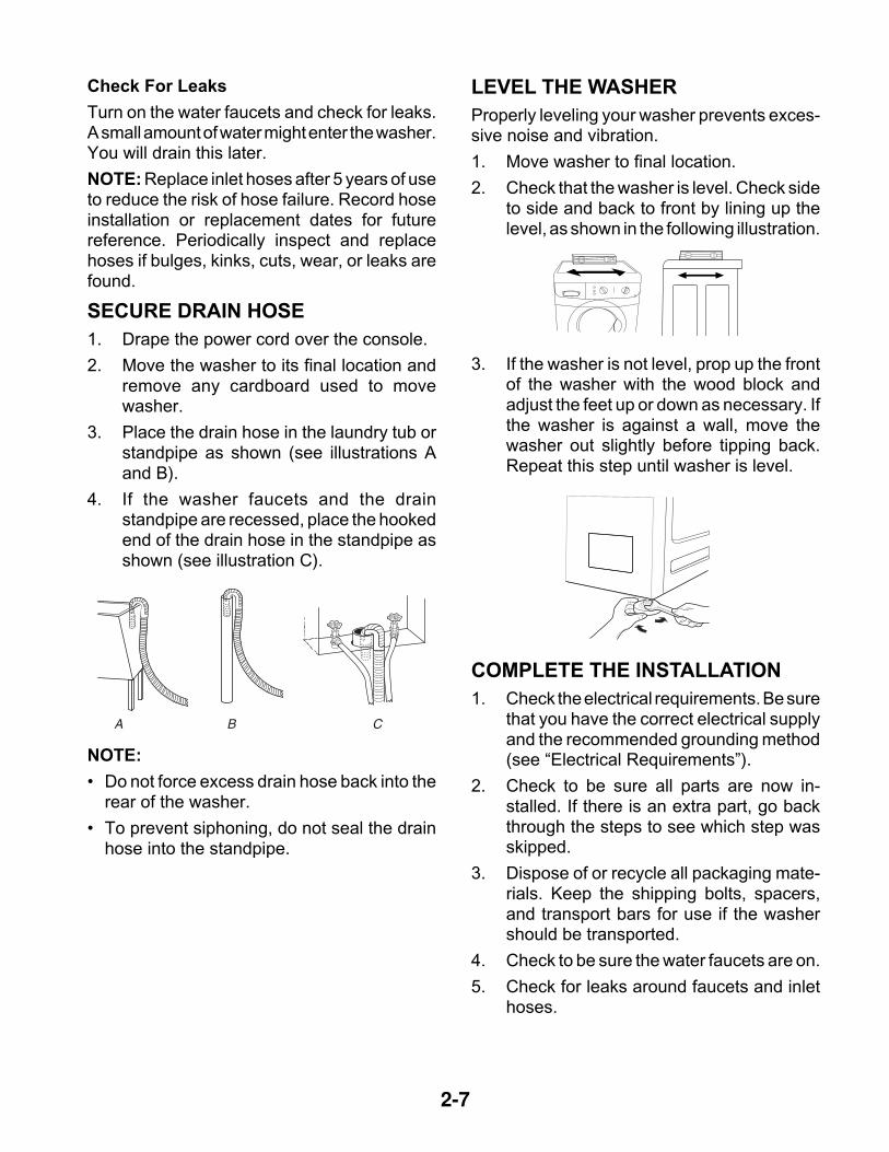
Connect The Inlet Hoses To The Washer
1. Insert the filter washer (supplied) into thecoupling of the hose fitting elbow, beforeconnecting the water inlet hose to thevalve on the back of the washer.
2. Attach the hose with the red stripe to theHOT (right) inlet valve on the washer.Screw on coupling by hand until it is seatedon the washer. Make sure the hose con-nection is tight.
NOTE: Do not overtighten. Damage to thevalves can result.
3. Attach the other hose to the COLD water(left) inlet valve. Screw on coupling byhand until it is seated on the washer. Makesure the hose connection is tight.
NOTE: Do not overtighten. Damage to thevalves can result.
A. CouplingB. Washer
A B
A. Cold water inlet valveB. Hot water inlet valve
A
B
2-7
Check For Leaks
Turn on the water faucets and check for leaks.A small amount of water might enter the washer.You will drain this later.
NOTE: Replace inlet hoses after 5 years of useto reduce the risk of hose failure. Record hoseinstallation or replacement dates for futurereference. Periodically inspect and replacehoses if bulges, kinks, cuts, wear, or leaks arefound.
SECURE DRAIN HOSE
1. Drape the power cord over the console.
2. Move the washer to its final location andremove any cardboard used to movewasher.
3. Place the drain hose in the laundry tub orstandpipe as shown (see illustrations Aand B).
4. If the washer faucets and the drainstandpipe are recessed, place the hookedend of the drain hose in the standpipe asshown (see illustration C).
NOTE:
• Do not force excess drain hose back into therear of the washer.
• To prevent siphoning, do not seal the drainhose into the standpipe.
3. If the washer is not level, prop up the frontof the washer with the wood block andadjust the feet up or down as necessary. Ifthe washer is against a wall, move thewasher out slightly before tipping back.Repeat this step until washer is level.
COMPLETE THE INSTALLATION
1. Check the electrical requirements. Be surethat you have the correct electrical supplyand the recommended grounding method(see “Electrical Requirements”).
2. Check to be sure all parts are now in-stalled. If there is an extra part, go backthrough the steps to see which step wasskipped.
3. Dispose of or recycle all packaging mate-rials. Keep the shipping bolts, spacers,and transport bars for use if the washershould be transported.
4. Check to be sure the water faucets are on.
5. Check for leaks around faucets and inlethoses.
A B C
LEVEL THE WASHER
Properly leveling your washer prevents exces-sive noise and vibration.
1. Move washer to final location.
2. Check that the washer is level. Check sideto side and back to front by lining up thelevel, as shown in the following illustration.
2-8
6. Plug into a grounded 3 prong outlet.
7. Read “Washer Use.”
8. To test your washer, measure and add 1/2the normal recommended amount of HighEfficiency (HE) detergent to the washer.Close the door. Select any cycle, and thenpress START. Allow it to complete onewhole cycle.Electrical Shock Hazard
Plug into a grounded 3 prong outlet.
Do not remove ground prong.
Do not use an adapter.
Do not use an extension cord.
Failure to follow these instructions canresult in death, fire, or electrical shock.
WARNING
3-1
PRODUCT OPERATIONTHEORY OF OPERATION
PRESSURE SWITCH
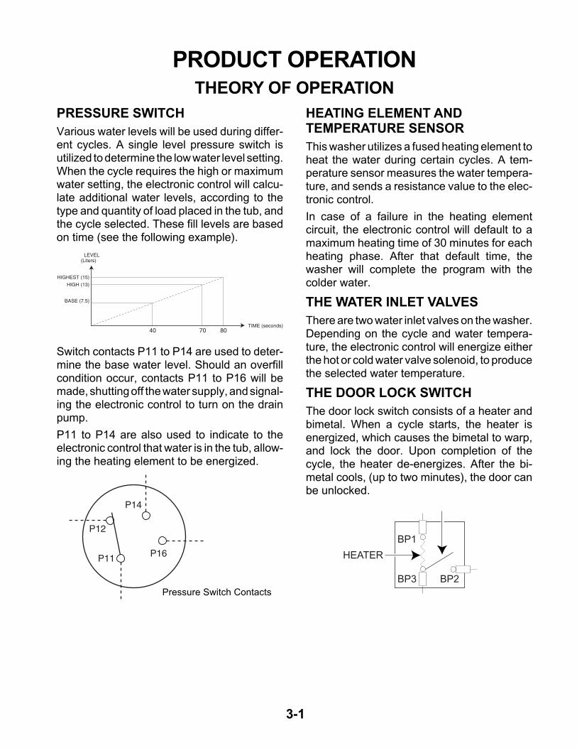
Various water levels will be used during differ-ent cycles. A single level pressure switch isutilized to determine the low water level setting.When the cycle requires the high or maximumwater setting, the electronic control will calcu-late additional water levels, according to thetype and quantity of load placed in the tub, andthe cycle selected. These fill levels are basedon time (see the following example).
Switch contacts P11 to P14 are used to deter-mine the base water level. Should an overfillcondition occur, contacts P11 to P16 will bemade, shutting off the water supply, and signal-ing the electronic control to turn on the drainpump.
P11 to P14 are also used to indicate to theelectronic control that water is in the tub, allow-ing the heating element to be energized.
P12
P11
P14
P16
Pressure Switch Contacts
TIME (seconds)
LEVEL(Liters)
BASE (7.5)
HIGH (13)
HIGHEST (15)
40 70 80
HEATING ELEMENT ANDTEMPERATURE SENSOR
This washer utilizes a fused heating element toheat the water during certain cycles. A tem-perature sensor measures the water tempera-ture, and sends a resistance value to the elec-tronic control.
In case of a failure in the heating elementcircuit, the electronic control will default to amaximum heating time of 30 minutes for eachheating phase. After that default time, thewasher will complete the program with thecolder water.
THE WATER INLET VALVES
There are two water inlet valves on the washer.Depending on the cycle and water tempera-ture, the electronic control will energize eitherthe hot or cold water valve solenoid, to producethe selected water temperature.
THE DOOR LOCK SWITCH
The door lock switch consists of a heater andbimetal. When a cycle starts, the heater isenergized, which causes the bimetal to warp,and lock the door. Upon completion of thecycle, the heater de-energizes. After the bi-metal cools, (up to two minutes), the door canbe unlocked.
BP1
HEATER
BP3 BP2
wallagl
wallagl
wallagl
3-2
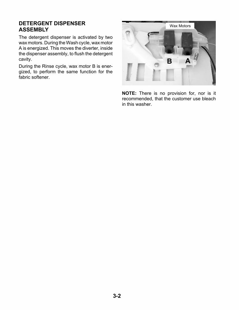
DETERGENT DISPENSERASSEMBLY
The detergent dispenser is activated by twowax motors. During the Wash cycle, wax motorA is energized. This moves the diverter, insidethe dispenser assembly, to flush the detergentcavity.
During the Rinse cycle, wax motor B is ener-gized, to perform the same function for thefabric softener.
AB
Wax Motors
NOTE: There is no provision for, nor is itrecommended, that the customer use bleachin this washer.
3-3
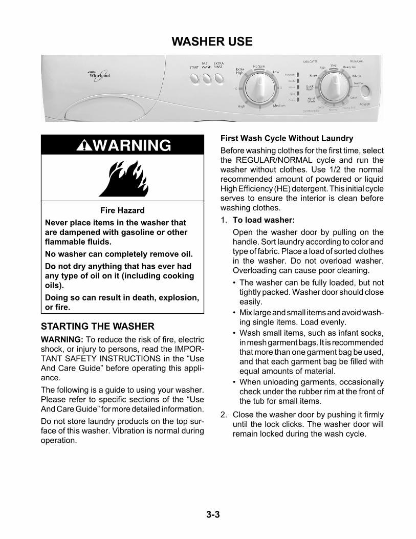
WASHER USE
STARTING THE WASHER
WARNING: To reduce the risk of fire, electricshock, or injury to persons, read the IMPOR-TANT SAFETY INSTRUCTIONS in the “UseAnd Care Guide” before operating this appli-ance.
The following is a guide to using your washer.Please refer to specific sections of the “UseAnd Care Guide” for more detailed information.
Do not store laundry products on the top sur-face of this washer. Vibration is normal duringoperation.
Fire Hazard
Never place items in the washer thatare dampened with gasoline or otherflammable fluids.
No washer can completely remove oil.
Do not dry anything that has ever hadany type of oil on it (including cookingoils).
Doing so can result in death, explosion,or fire.
WARNINGFirst Wash Cycle Without Laundry
Before washing clothes for the first time, selectthe REGULAR/NORMAL cycle and run thewasher without clothes. Use 1/2 the normalrecommended amount of powdered or liquidHigh Efficiency (HE) detergent. This initial cycleserves to ensure the interior is clean beforewashing clothes.
1. To load washer:
Open the washer door by pulling on thehandle. Sort laundry according to color andtype of fabric. Place a load of sorted clothesin the washer. Do not overload washer.Overloading can cause poor cleaning.
• The washer can be fully loaded, but nottightly packed. Washer door should closeeasily.
• Mix large and small items and avoid wash-ing single items. Load evenly.
• Wash small items, such as infant socks,in mesh garment bags. It is recommendedthat more than one garment bag be used,and that each garment bag be filled withequal amounts of material.
• When unloading garments, occasionallycheck under the rubber rim at the front ofthe tub for small items.
2. Close the washer door by pushing it firmlyuntil the lock clicks. The washer door willremain locked during the wash cycle.
3-4
3. Open the dispenser drawer and add laun-dry products to the detergent or fabric soft-ener compartments. Close drawer slowly toavoid spills (see “Using the Dispenser”).
IMPORTANT: To avoid damage to cloth-ing, do not use liquid bleach or powderedcolor-safe bleach in this washer. If youneed extra whitening, use a HE powderdetergent with bleach additive.
NOTE:
• For best performance, use High Efficiencydetergents. The package for this type ofdetergent will be marked “HE” or “HighEfficiency.” The wash action along withless water could create too much sudsingwith a regular detergent.
• Use only HE detergent made for front-loading washers and follow label instruc-tions. The amount of detergent variesamong the different brands, but for mostdetergents, you need only one or twotablespoons. Too much detergent couldleave a residue on your clothes and pos-sibly damage the appliance.
• Do not add detergent to the Pre Washcompartment unless you have selectedthe Pre Wash option. If you have deter-gent in both the Pre Wash and MainWash compartments, and have not se-lected a Pre Wash option, the washercould oversuds and spill onto the floor.
• If you select the Pre Wash option, usepowdered HE detergent in the Main Washcompartment. If you use liquid detergentin the Main Wash compartment, it willdispense immediately.
• Excessive use of fabric softener can dam-age garments.
• Close the detergent drawer securely.
IMPORTANT: To avoid water spillage, donot open the detergent drawer while themachine is operating.
4. Turn on the washer by selecting POWER.
5. Select one of the cycles by turning the cycleselector. The preset settings provide therecommended fabric care for the selectedcycle.
6. Select the desired options. Not all optionsare available with all cycles.
7. To begin the wash cycle Select START.When the wash cycle is complete, the DONEstatus light glows, the door unlocks, and thewash load can be removed from the washer.To power down the washer manually afterthe wash cycle is complete, press POWERonce.
USING THE DISPENSER
The washer has a dispenser drawer with threeseparate compartments for your laundry prod-ucts. Two are for detergent, and one is for liquidfabric softener. Laundry products are dilutedand dispensed automatically at the proper timeduring the wash cycle, making it unnecessaryfor you to return to the washer during the cycleto add them.
It is normal for small amounts of water toremain in the dispensers when the wash cycleis complete.
Do not add laundry additives directly into thewash tub. Always use the proper dispenserswhen adding laundry products.
Choosing The Right Detergent
For best washing performance, use a HighEfficiency (HE), or low-sudsing, detergent.
3-5
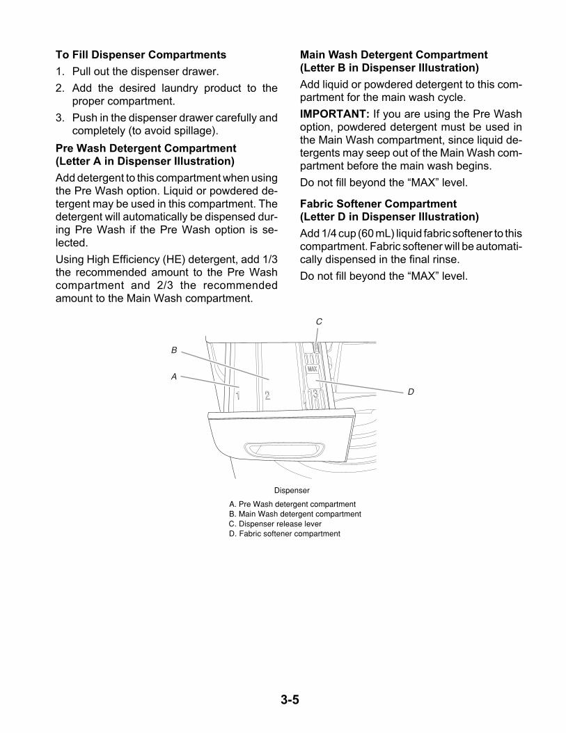
To Fill Dispenser Compartments
1. Pull out the dispenser drawer.
2. Add the desired laundry product to theproper compartment.
3. Push in the dispenser drawer carefully andcompletely (to avoid spillage).
Dispenser
A. Pre Wash detergent compartmentB. Main Wash detergent compartmentC. Dispenser release leverD. Fabric softener compartment
Pre Wash Detergent Compartment(Letter A in Dispenser Illustration)
Add detergent to this compartment when usingthe Pre Wash option. Liquid or powdered de-tergent may be used in this compartment. Thedetergent will automatically be dispensed dur-ing Pre Wash if the Pre Wash option is se-lected.
Using High Efficiency (HE) detergent, add 1/3the recommended amount to the Pre Washcompartment and 2/3 the recommendedamount to the Main Wash compartment.
Main Wash Detergent Compartment(Letter B in Dispenser Illustration)
Add liquid or powdered detergent to this com-partment for the main wash cycle.
IMPORTANT: If you are using the Pre Washoption, powdered detergent must be used inthe Main Wash compartment, since liquid de-tergents may seep out of the Main Wash com-partment before the main wash begins.
Do not fill beyond the “MAX” level.
Fabric Softener Compartment(Letter D in Dispenser Illustration)
Add 1/4 cup (60 mL) liquid fabric softener to thiscompartment. Fabric softener will be automati-cally dispensed in the final rinse.
Do not fill beyond the “MAX” level.
3-6
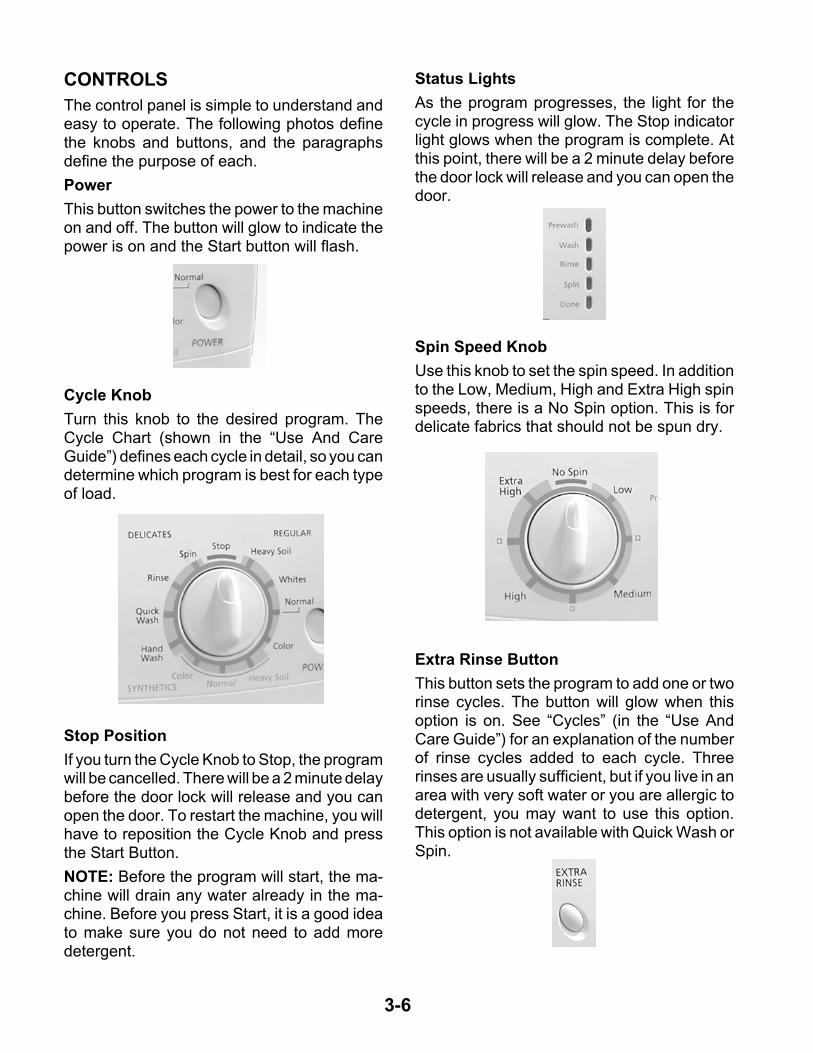
CONTROLS
The control panel is simple to understand andeasy to operate. The following photos definethe knobs and buttons, and the paragraphsdefine the purpose of each.
Power
This button switches the power to the machineon and off. The button will glow to indicate thepower is on and the Start button will flash.
Status Lights
As the program progresses, the light for thecycle in progress will glow. The Stop indicatorlight glows when the program is complete. Atthis point, there will be a 2 minute delay beforethe door lock will release and you can open thedoor.
Cycle Knob
Turn this knob to the desired program. TheCycle Chart (shown in the “Use And CareGuide”) defines each cycle in detail, so you candetermine which program is best for each typeof load.
Stop Position
If you turn the Cycle Knob to Stop, the programwill be cancelled. There will be a 2 minute delaybefore the door lock will release and you canopen the door. To restart the machine, you willhave to reposition the Cycle Knob and pressthe Start Button.
NOTE: Before the program will start, the ma-chine will drain any water already in the ma-chine. Before you press Start, it is a good ideato make sure you do not need to add moredetergent.
Spin Speed Knob
Use this knob to set the spin speed. In additionto the Low, Medium, High and Extra High spinspeeds, there is a No Spin option. This is fordelicate fabrics that should not be spun dry.
Extra Rinse Button
This button sets the program to add one or tworinse cycles. The button will glow when thisoption is on. See “Cycles” (in the “Use AndCare Guide”) for an explanation of the numberof rinse cycles added to each cycle. Threerinses are usually sufficient, but if you live in anarea with very soft water or you are allergic todetergent, you may want to use this option.This option is not available with Quick Wash orSpin.
3-7
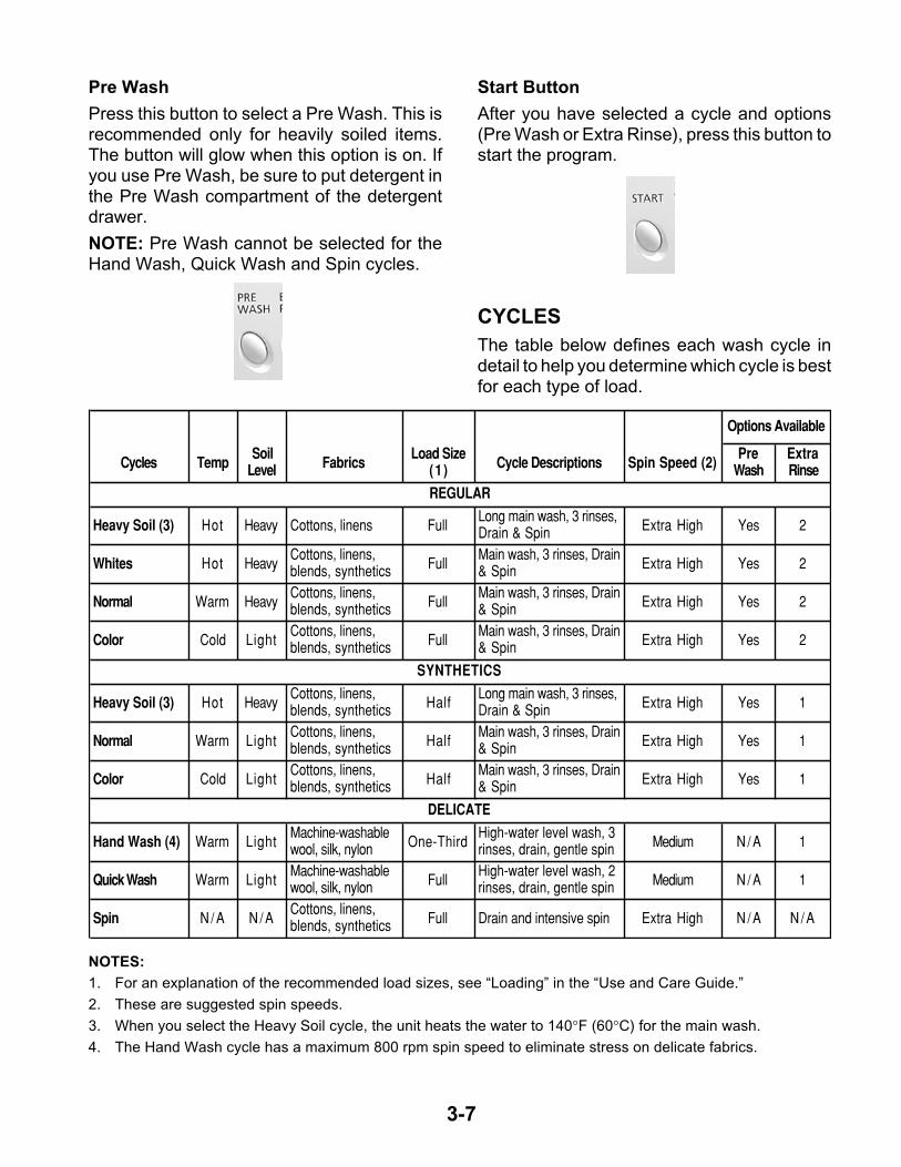
Pre Wash
Press this button to select a Pre Wash. This isrecommended only for heavily soiled items.The button will glow when this option is on. Ifyou use Pre Wash, be sure to put detergent inthe Pre Wash compartment of the detergentdrawer.
NOTE: Pre Wash cannot be selected for theHand Wash, Quick Wash and Spin cycles.
Start Button
After you have selected a cycle and options(Pre Wash or Extra Rinse), press this button tostart the program.
CYCLES
The table below defines each wash cycle indetail to help you determine which cycle is bestfor each type of load.
NOTES:
1. For an explanation of the recommended load sizes, see “Loading” in the “Use and Care Guide.”
2. These are suggested spin speeds.
3. When you select the Heavy Soil cycle, the unit heats the water to 140°F (60°C) for the main wash.
4. The Hand Wash cycle has a maximum 800 rpm spin speed to eliminate stress on delicate fabrics.
Cycles TempSoil
Level FabricsLoad Size
(1 ) Cycle Descriptions Spin Speed (2)Pre
WashExtra Rinse
Heavy Soil (3) Hot Heavy Cottons, linens FullLong main wash, 3 rinses, Drain & Spin Extra High Yes 2
Whites Hot HeavyCottons, linens, blends, synthetics Full
Main wash, 3 rinses, Drain & Spin Extra High Yes 2
Normal Warm HeavyCottons, linens, blends, synthetics Full
Main wash, 3 rinses, Drain & Spin Extra High Yes 2
Color Cold LightCottons, linens, blends, synthetics Full
Main wash, 3 rinses, Drain & Spin Extra High Yes 2
Heavy Soil (3) Hot HeavyCottons, linens, blends, synthetics Half
Long main wash, 3 rinses, Drain & Spin Extra High Yes 1
Normal Warm LightCottons, linens, blends, synthetics Half
Main wash, 3 rinses, Drain & Spin Extra High Yes 1
Color Cold LightCottons, linens, blends, synthetics Half
Main wash, 3 rinses, Drain & Spin Extra High Yes 1
Hand Wash (4) Warm LightMachine-washable wool, silk, nylon One-Third
High-water level wash, 3 rinses, drain, gentle spin Medium N / A 1
Quick Wash Warm LightMachine-washable wool, silk, nylon Full
High-water level wash, 2 rinses, drain, gentle spin Medium N / A 1
Spin N / A N / ACottons, linens, blends, synthetics Full Drain and intensive spin Extra High N / A N / A
DELICATE
Options Available
REGULAR
SYNTHETICS
3-8
CLEANING THE WASHER
WARNING: Before performing the operationsdescribed below, make sure that the power isoff and the unit is unplugged.
Cleaning The Exterior
Use a soft damp cloth or sponge to wipe up anyspills. Occasionally wipe the outside of thewasher to keep it looking new. Use mild soapand water. Do not use abrasive products.
Cleaning The Interior
Use a soft damp cloth or sponge to occasion-ally wipe the inner door to remove any deter-gent residue. Use mild soap and water. Do notuse abrasive products.
Cleaning The Door Seal
Use a soft damp cloth or sponge when neces-sary. Check the fold of the seal periodically forany foreign objects.
Cleaning The Dispenser Drawer
The dispenser drawer is removable for easycleaning.
1. Unlock the dispenser drawer by pressingon the plastic part of the softener compart-ment marked “PUSH.” See “Using the Dis-penser.”
2. Remove the drawer.
3. Do not clean the door with cleaning sol-vents or abrasive cleansers. You coulddamage the finish.
4. Replace the inserts and return the dis-penser to the drawer.
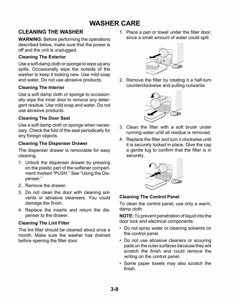
Cleaning The Lint Filter
The lint filter should be cleaned about once amonth. Make sure the washer has drainedbefore opening the filter door.
WASHER CARE1. Place a pan or towel under the filter door,
since a small amount of water could spill.
Cleaning The Control Panel
To clean the control panel, use only a warm,damp cloth.
NOTE: To prevent penetration of liquid into thedoor lock and electrical components:
• Do not spray water or cleaning solvents onthe control panel.
• Do not use abrasive cleaners or scouringpads on the outer surfaces because they willscratch the finish and could remove thewriting on the control panel.
• Some paper towels may also scratch thefinish.
3. Clean the filter with a soft brush underrunning water until all residue is removed.
4. Replace the filter and turn it clockwise untilit is securely locked in place. Give the capa gentle tug to confirm that the filter is insecurely.
2. Remove the filter by rotating it a half-turncounterclockwise and pulling outwards.
4-1
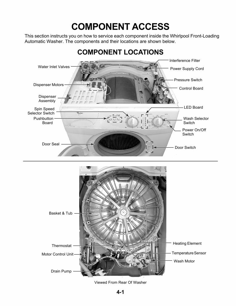
COMPONENT LOCATIONS
This section instructs you on how to service each component inside the Whirlpool Front-LoadingAutomatic Washer. The components and their locations are shown below.
COMPONENT ACCESS
Motor Control Unit
Wash Motor
Drain Pump
Thermostat
Viewed From Rear Of Washer
Pressure Switch
Water Inlet Valves
Dispenser Motors
Basket & Tub
Spin SpeedSelector Switch
Pushbutton Board
Wash SelectorSwitch
LED Board
Power On/OffSwitch
Door Switch
DispenserAssembly
Control Board
Interference Filter
Power Supply Cord
Door Seal
Temperature Sensor
Heating Element
4-2
REMOVING THE CONTROL PANEL COMPONENTS
Electrical Shock Hazard
Disconnect power before servicing.
Replace all parts and panels beforeoperating.
Failure to do so can result in death orelectrical shock.
WARNING
1. Unplug washer or disconnect power.
2. Turn off the water supply to the washer.
3. Pull the washer away from the wall so youcan access the rear of the unit.
4. Remove the two screws from the back ofthe top cover.
5. Lift the rear of the top cover, unhook it fromthe front, and remove the cover.
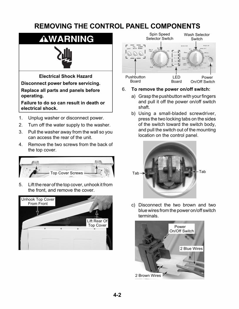
6. To remove the power on/off switch:
a) Grasp the pushbutton with your fingersand pull it off the power on/off switchshaft.
b) Using a small-bladed screwdriver,press the two locking tabs on the sidesof the switch toward the switch body,and pull the switch out of the mountinglocation on the control panel.
Top Cover Screws
Unhook Top CoverFrom Front
Lift Rear OfTop Cover
PushbuttonBoard
LEDBoard
Power On/Off Switch
Spin SpeedSelector Switch
Wash SelectorSwitch
c) Disconnect the two brown and twoblue wires from the power on/off switchterminals.
Tab Tab
2 Brown Wires
2 Blue Wires
Power On/Off Switch
4-3
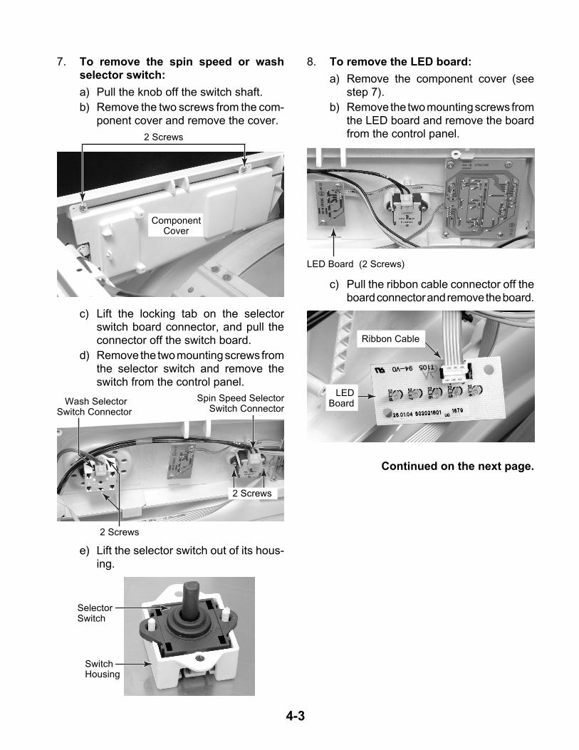
7. To remove the spin speed or washselector switch:
a) Pull the knob off the switch shaft.
b) Remove the two screws from the com-ponent cover and remove the cover.
8. To remove the LED board:
a) Remove the component cover (seestep 7).
b) Remove the two mounting screws fromthe LED board and remove the boardfrom the control panel.
c) Lift the locking tab on the selectorswitch board connector, and pull theconnector off the switch board.
d) Remove the two mounting screws fromthe selector switch and remove theswitch from the control panel.
ComponentCover
2 Screws
Wash SelectorSwitch Connector
Spin Speed SelectorSwitch Connector
2 Screws
2 Screws
e) Lift the selector switch out of its hous-ing.
SwitchHousing
SelectorSwitch
c) Pull the ribbon cable connector off theboard connector and remove the board.
LED Board (2 Screws)
LEDBoard
Ribbon Cable
Continued on the next page.
4-4
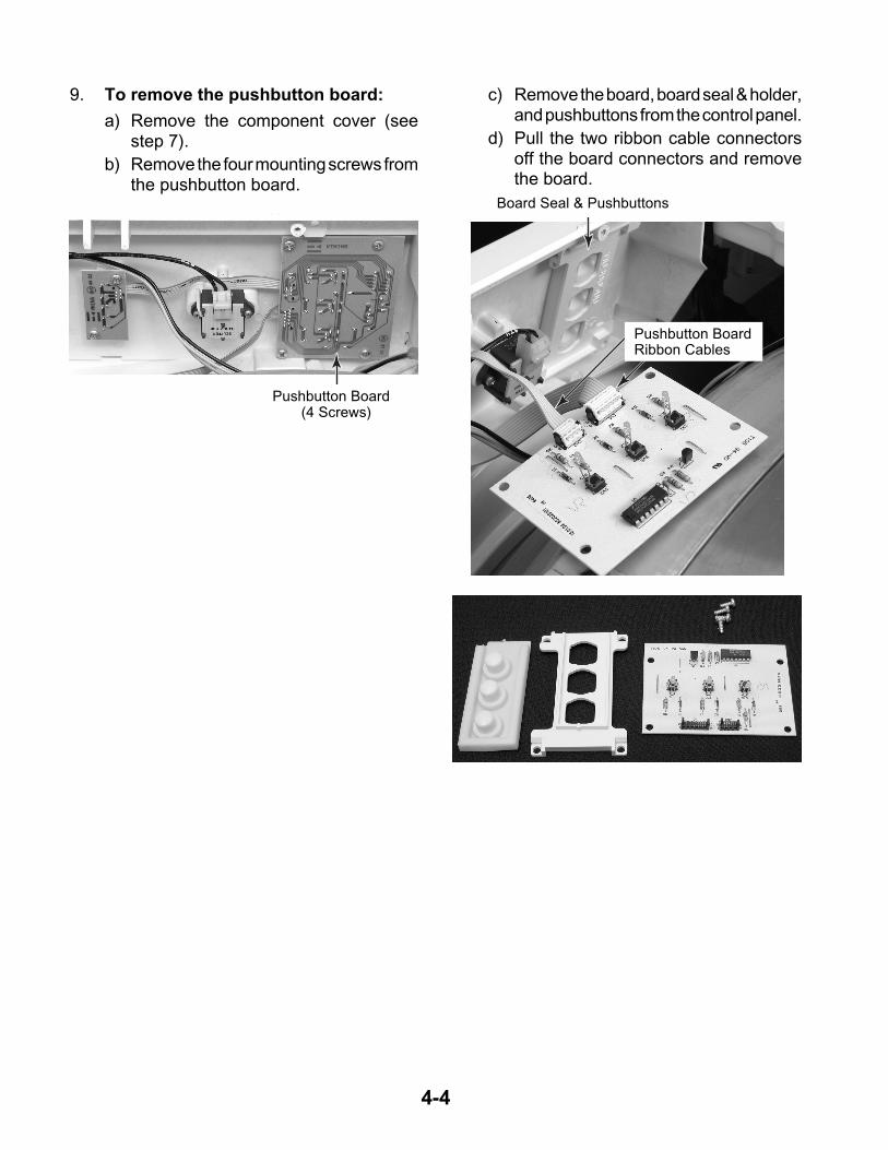
9. To remove the pushbutton board:
a) Remove the component cover (seestep 7).
b) Remove the four mounting screws fromthe pushbutton board.
c) Remove the board, board seal & holder,and pushbuttons from the control panel.
d) Pull the two ribbon cable connectorsoff the board connectors and removethe board.
Pushbutton Board (4 Screws)
Board Seal & Pushbuttons
Pushbutton BoardRibbon Cables
4-5
REMOVING A DISPENSER MOTOR AND THE DISPENSER ASSEMBLY
1. Unplug washer or disconnect power.
2. Turn off the water supply to the washer.
3. Remove the top cover from the washer(see page 4-2 for the procedure).
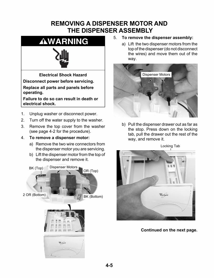
4. To remove a dispenser motor:
a) Remove the two wire connectors fromthe dispenser motor you are servicing.
b) Lift the dispenser motor from the top ofthe dispenser and remove it.
Electrical Shock Hazard
Disconnect power before servicing.
Replace all parts and panels beforeoperating.
Failure to do so can result in death orelectrical shock.
WARNING5. To remove the dispenser assembly:
a) Lift the two dispenser motors from thetop of the dispenser (do not disconnectthe wires) and move them out of theway.
Dispenser MotorsBK (Top)
2 OR (Bottom)
OR (Top)
BK (Bottom)
b) Pull the dispenser drawer out as far asthe stop. Press down on the lockingtab, pull the drawer out the rest of theway, and remove it.
Dispenser Motors
Continued on the next page.
Locking Tab
Dispenser Drawer
4-6
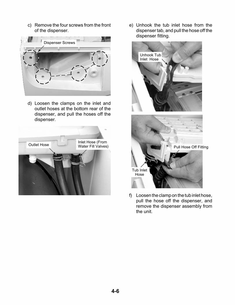
c) Remove the four screws from the frontof the dispenser.
d) Loosen the clamps on the inlet andoutlet hoses at the bottom rear of thedispenser, and pull the hoses off thedispenser.
e) Unhook the tub inlet hose from thedispenser tab, and pull the hose off thedispenser fitting.
Dispenser Screws
Inlet Hose (FromWater Fill Valves)Outlet Hose
f) Loosen the clamp on the tub inlet hose,pull the hose off the dispenser, andremove the dispenser assembly fromthe unit.
Unhook TubInlet Hose
Pull Hose Off Fitting
Tub InletHose
4-7
REMOVING THE CONTROL BOARD & PRESSURE SWITCH
1. Unplug washer or disconnect power.
2. Turn off the water supply to the washer.
3. Remove the top cover from the washer(see page 4-2 for the procedure).
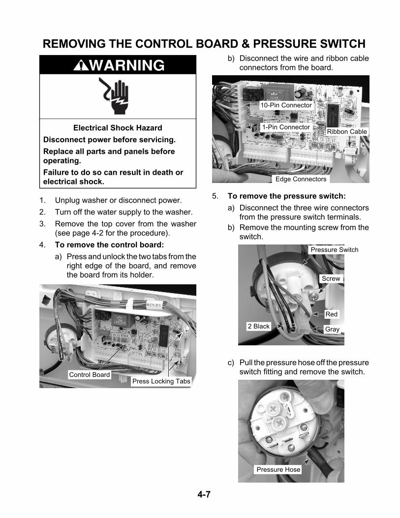
4. To remove the control board:
a) Press and unlock the two tabs from theright edge of the board, and removethe board from its holder.
Electrical Shock Hazard
Disconnect power before servicing.
Replace all parts and panels beforeoperating.
Failure to do so can result in death orelectrical shock.
WARNINGb) Disconnect the wire and ribbon cable
connectors from the board.
5. To remove the pressure switch:
a) Disconnect the three wire connectorsfrom the pressure switch terminals.
b) Remove the mounting screw from theswitch.
c) Pull the pressure hose off the pressureswitch fitting and remove the switch.
Press Locking TabsControl Board
10-Pin Connector
1-Pin Connector
Edge Connectors
Ribbon Cable
Pressure Switch
Screw
Red
Gray2 Black
Pressure Hose
4-8
1. Unplug washer or disconnect power.
2. Turn off the water supply to the washer.
3. Remove the top cover from the washer(see page 4-2 for the procedure).
Electrical Shock Hazard
Disconnect power before servicing.
Replace all parts and panels beforeoperating.
Failure to do so can result in death orelectrical shock.
WARNING
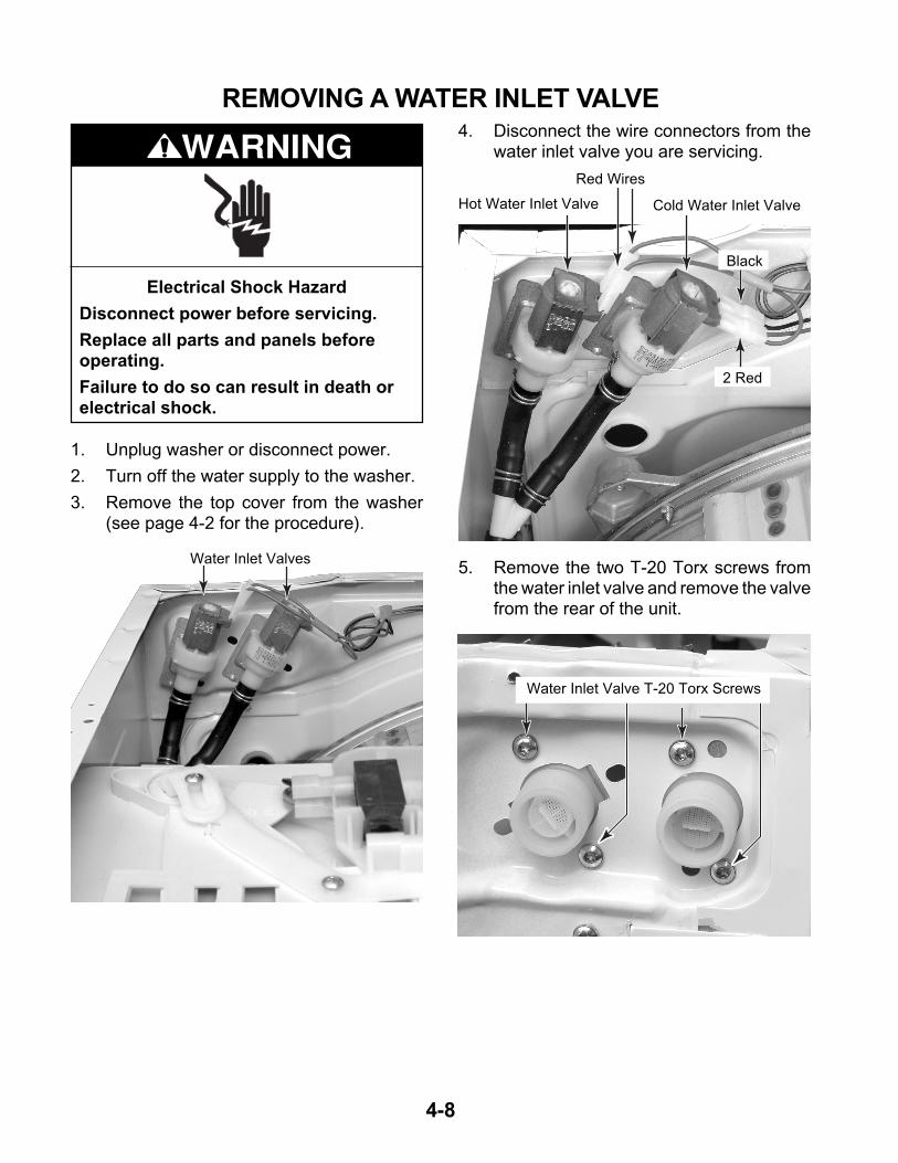
REMOVING A WATER INLET VALVE4. Disconnect the wire connectors from the
water inlet valve you are servicing.
5. Remove the two T-20 Torx screws fromthe water inlet valve and remove the valvefrom the rear of the unit.
Water Inlet Valves
Hot Water Inlet Valve
Red Wires
Cold Water Inlet Valve
2 Red
Black
Water Inlet Valve T-20 Torx Screws
4-9
1. Unplug washer or disconnect power.
2. Turn off the water supply to the washer.
3. Remove the top cover from the washer(see page 4-2 for the procedure).
Electrical Shock Hazard
Disconnect power before servicing.
Replace all parts and panels beforeoperating.
Failure to do so can result in death orelectrical shock.
WARNING
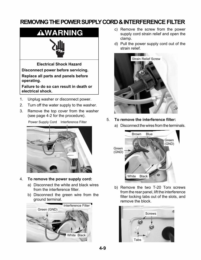
REMOVING THE POWER SUPPLY CORD & INTERFERENCE FILTERc) Remove the screw from the power
supply cord strain relief and open theclamp.
d) Pull the power supply cord out of thestrain relief.
5. To remove the interference filter:
a) Disconnect the wires from the terminals.
b) Remove the two T-20 Torx screwsfrom the rear panel, lift the interferencefilter locking tabs out of the slots, andremove the block.
Power Supply Cord Interference Filter
4. To remove the power supply cord:
a) Disconnect the white and black wiresfrom the interference filter.
b) Disconnect the green wire from theground terminal.
White Black
Green (GND)
Interference Filter
Strain Relief Screw
Brown Blue
Green(GND)
White Black
Green(GND)
Tabs
Screws
4-10
1. Unplug washer or disconnect power.
2. Turn off the water supply to the washer.
3. Remove the top cover from the washer(see page 4-2 for the procedure).
4. Open the washer door.
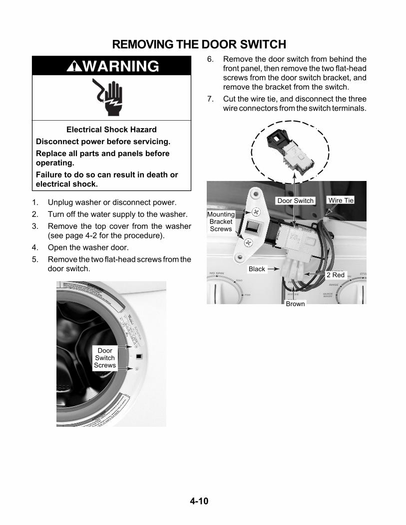
5. Remove the two flat-head screws from thedoor switch.
Electrical Shock Hazard
Disconnect power before servicing.
Replace all parts and panels beforeoperating.
Failure to do so can result in death orelectrical shock.
WARNING
REMOVING THE DOOR SWITCH6. Remove the door switch from behind the
front panel, then remove the two flat-headscrews from the door switch bracket, andremove the bracket from the switch.
7. Cut the wire tie, and disconnect the threewire connectors from the switch terminals.
DoorSwitchScrews
MountingBracketScrews
Wire Tie
2 Red
Brown
Door Switch
Black
4-11
1. Unplug washer or disconnect power.
2. Turn off the water supply to the washer.
3. Remove the top cover from the washer(see page 4-2 for the procedure).
4. Open the washer door.
5. Using a small-bladed screwdriver, pry thefront spring clamp band out of the groovein the door seal and remove the band.
Electrical Shock Hazard
Disconnect power before servicing.
Replace all parts and panels beforeoperating.
Failure to do so can result in death orelectrical shock.
WARNING
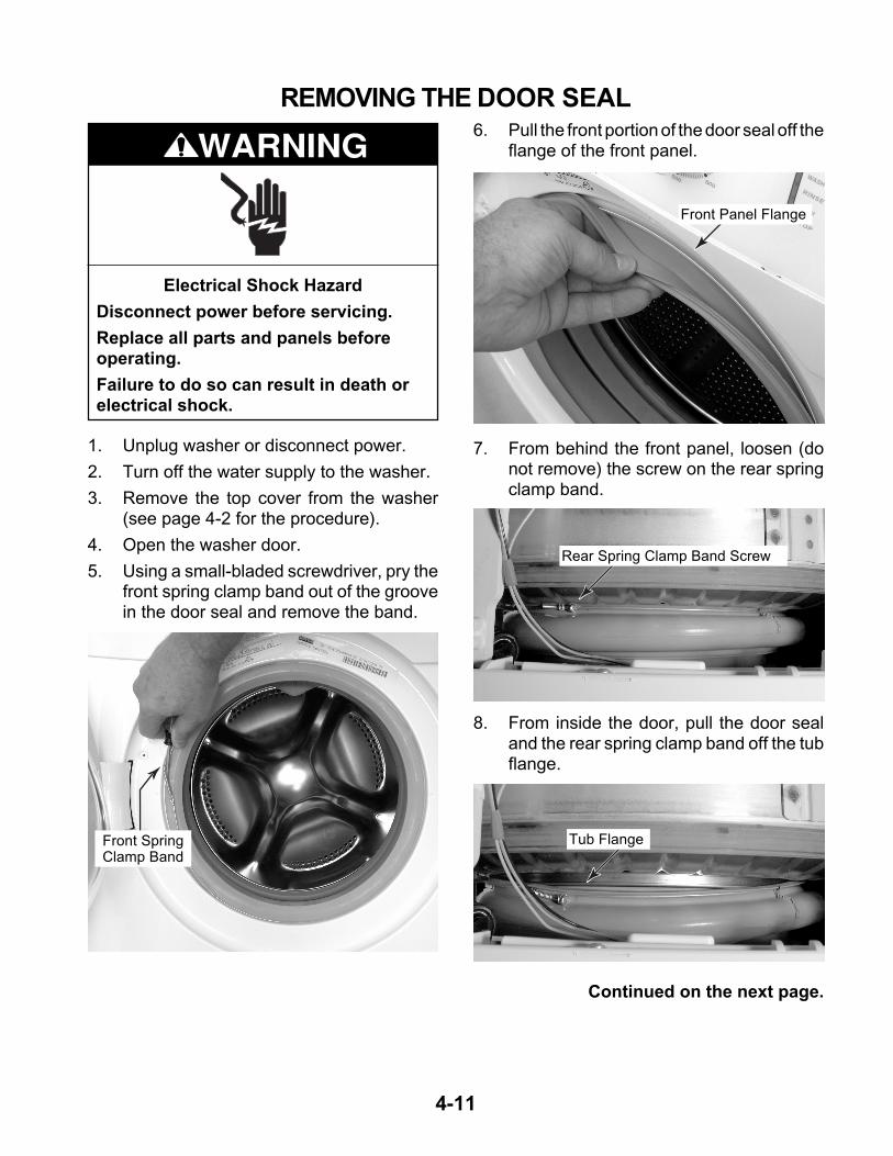
REMOVING THE DOOR SEAL6. Pull the front portion of the door seal off the
flange of the front panel.
7. From behind the front panel, loosen (donot remove) the screw on the rear springclamp band.
Front SpringClamp Band
Front Panel Flange
8. From inside the door, pull the door sealand the rear spring clamp band off the tubflange.
Rear Spring Clamp Band Screw
Tub Flange
Continued on the next page.
4-12
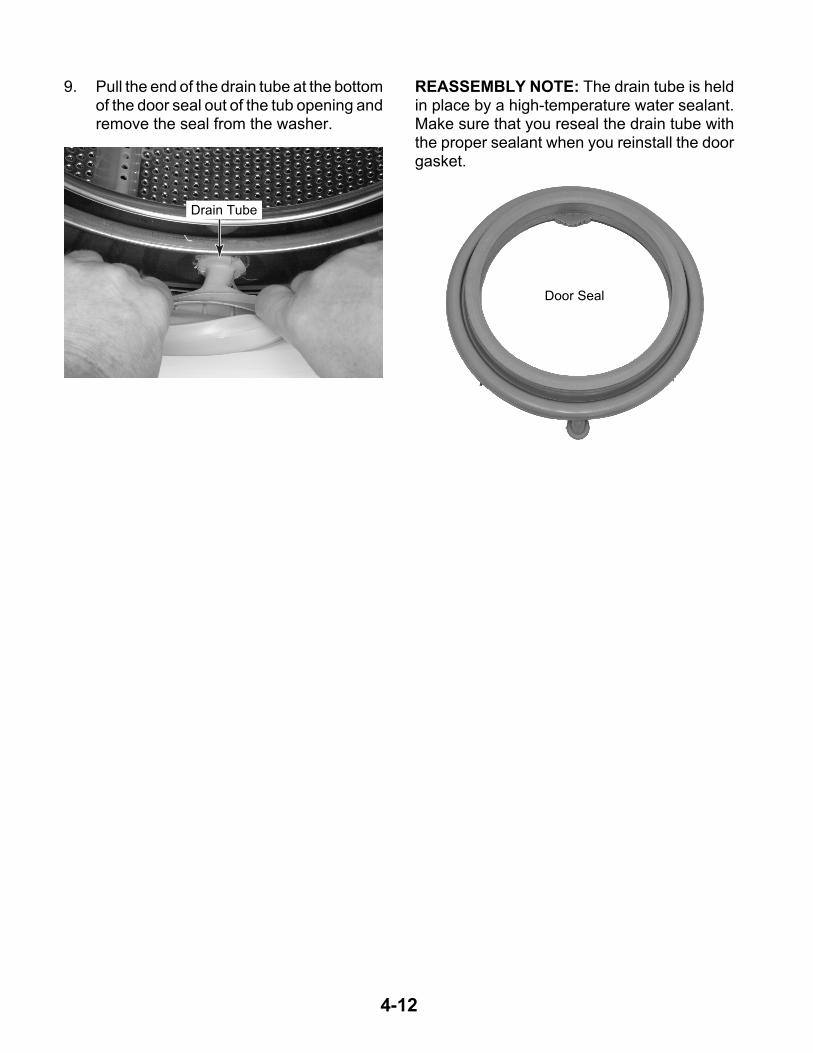
9. Pull the end of the drain tube at the bottomof the door seal out of the tub opening andremove the seal from the washer.
Drain Tube
Door Seal
REASSEMBLY NOTE: The drain tube is heldin place by a high-temperature water sealant.Make sure that you reseal the drain tube withthe proper sealant when you reinstall the doorgasket.
4-13
1. Unplug washer or disconnect power.
2. Turn off the water supply to the washer.
3. Remove the top cover from the washer(see page 4-2 for the procedure).
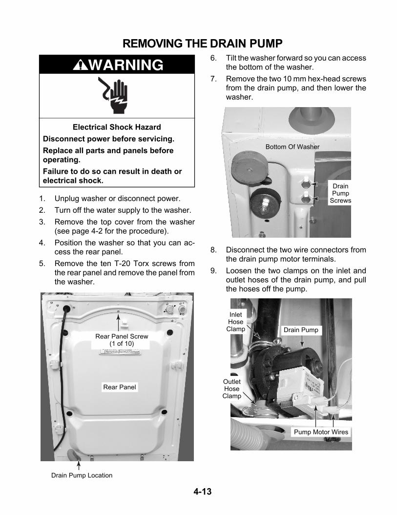
4. Position the washer so that you can ac-cess the rear panel.
5. Remove the ten T-20 Torx screws fromthe rear panel and remove the panel fromthe washer.
Electrical Shock Hazard
Disconnect power before servicing.
Replace all parts and panels beforeoperating.
Failure to do so can result in death orelectrical shock.
WARNING
REMOVING THE DRAIN PUMP6. Tilt the washer forward so you can access
the bottom of the washer.
7. Remove the two 10 mm hex-head screwsfrom the drain pump, and then lower thewasher.
8. Disconnect the two wire connectors fromthe drain pump motor terminals.
9. Loosen the two clamps on the inlet andoutlet hoses of the drain pump, and pullthe hoses off the pump.
Rear Panel Screw(1 of 10)
Rear Panel
DrainPump
Screws
Bottom Of Washer
Drain Pump Location
OutletHoseClamp
InletHoseClamp Drain Pump
Pump Motor Wires
4-14
1. Unplug washer or disconnect power.
2. Turn off the water supply to the washer.
3. Remove the top cover from the washer(see page 4-2 for the procedure).
4. Remove the rear panel (see page 4-13).
Electrical Shock Hazard
Disconnect power before servicing.
Replace all parts and panels beforeoperating.
Failure to do so can result in death orelectrical shock.
WARNING
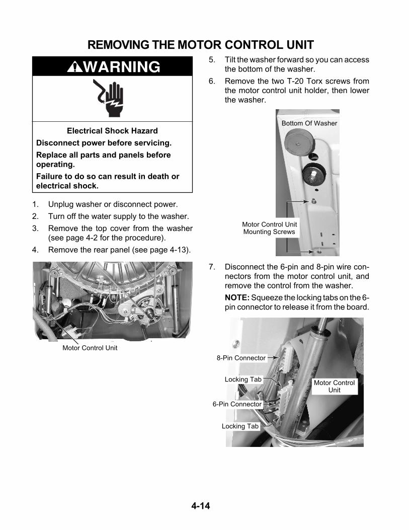
REMOVING THE MOTOR CONTROL UNIT5. Tilt the washer forward so you can access
the bottom of the washer.
6. Remove the two T-20 Torx screws fromthe motor control unit holder, then lowerthe washer.
Motor Control Unit
7. Disconnect the 6-pin and 8-pin wire con-nectors from the motor control unit, andremove the control from the washer.
NOTE: Squeeze the locking tabs on the 6-pin connector to release it from the board.
Motor Control UnitMounting Screws
Bottom Of Washer
Motor ControlUnit
8-Pin Connector
6-Pin Connector
Locking Tab
Locking Tab
4-15
1. Unplug washer or disconnect power.
2. Turn off the water supply to the washer.
3. Remove the top cover from the washer(see page 4-2 for the procedure).
4. Remove the rear panel (see page 4-13).
Electrical Shock Hazard
Disconnect power before servicing.
Replace all parts and panels beforeoperating.
Failure to do so can result in death orelectrical shock.
WARNING
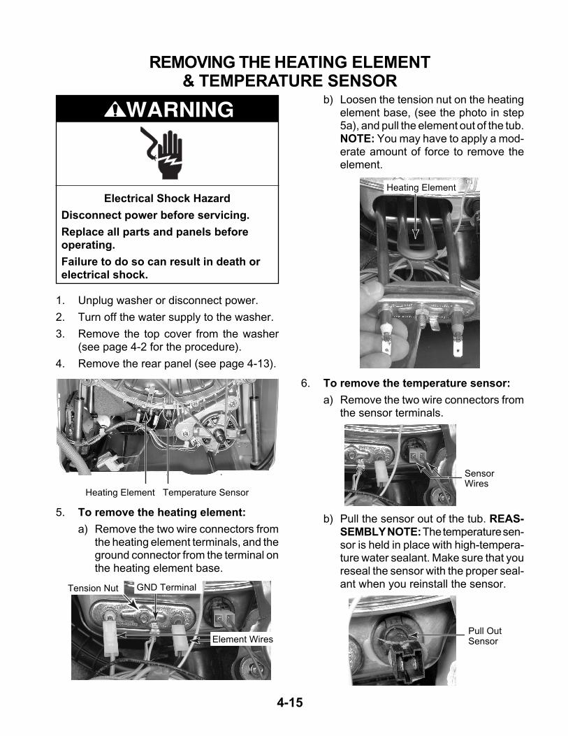
REMOVING THE HEATING ELEMENT& TEMPERATURE SENSOR
Heating Element Temperature Sensor
b) Loosen the tension nut on the heatingelement base, (see the photo in step5a), and pull the element out of the tub.NOTE: You may have to apply a mod-erate amount of force to remove theelement.
5. To remove the heating element:
a) Remove the two wire connectors fromthe heating element terminals, and theground connector from the terminal onthe heating element base.
GND Terminal
Element Wires
Tension Nut
6. To remove the temperature sensor:
a) Remove the two wire connectors fromthe sensor terminals.
Heating Element
b) Pull the sensor out of the tub. REAS-SEMBLY NOTE: The temperature sen-sor is held in place with high-tempera-ture water sealant. Make sure that youreseal the sensor with the proper seal-ant when you reinstall the sensor.
SensorWires
Pull OutSensor
4-16
1. Unplug washer or disconnect power.
2. Turn off the water supply to the washer.
3. Remove the top cover from the washer(see page 4-2 for the procedure).
4. Remove the rear panel (see page 4-13).
Electrical Shock Hazard
Disconnect power before servicing.
Replace all parts and panels beforeoperating.
Failure to do so can result in death orelectrical shock.
WARNING
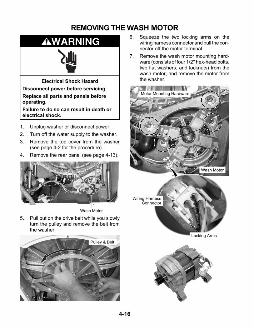
REMOVING THE WASH MOTOR
Wash Motor
5. Pull out on the drive belt while you slowlyturn the pulley and remove the belt fromthe washer.
6. Squeeze the two locking arms on thewiring harness connector and pull the con-nector off the motor terminal.
7. Remove the wash motor mounting hard-ware (consists of four 1/2″ hex-head bolts,two flat washers, and locknuts) from thewash motor, and remove the motor fromthe washer.
Pulley & Belt
Locking Arms
Wiring Harness Connector
Wash Motor
Motor Mounting Hardware
4-17
1. Unplug washer or disconnect power.
2. Turn off the water supply to the washer.
3. Remove the top cover from the washer(see page 4-2 for the procedure).
4. Remove the rear panel (see page 4-13).
Electrical Shock Hazard
Disconnect power before servicing.
Replace all parts and panels beforeoperating.
Failure to do so can result in death orelectrical shock.
WARNING
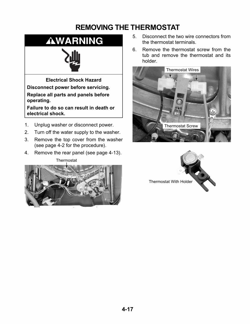
REMOVING THE THERMOSTAT
Thermostat
5. Disconnect the two wire connectors fromthe thermostat terminals.
6. Remove the thermostat screw from thetub and remove the thermostat and itsholder.
Thermostat Wires
Thermostat Screw
Thermostat With Holder
4-18
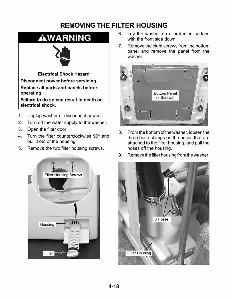
1. Unplug washer or disconnect power.
2. Turn off the water supply to the washer.
3. Open the filter door.
4. Turn the filter counterclockwise 90° andpull it out of the housing.
5. Remove the two filter housing screws.
Electrical Shock Hazard
Disconnect power before servicing.
Replace all parts and panels beforeoperating.
Failure to do so can result in death orelectrical shock.
WARNING
REMOVING THE FILTER HOUSING
8. From the bottom of the washer, loosen thethree hose clamps on the hoses that areattached to the filter housing, and pull thehoses off the housing.
9. Remove the filter housing from the washer.
6. Lay the washer on a protected surfacewith the front side down.
7. Remove the eight screws from the bottompanel and remove the panel from thewasher.
Filter
Housing
Bottom Panel(8 Screws)
Filter Housing Screws
3 Hoses
Filter Housing
4-19
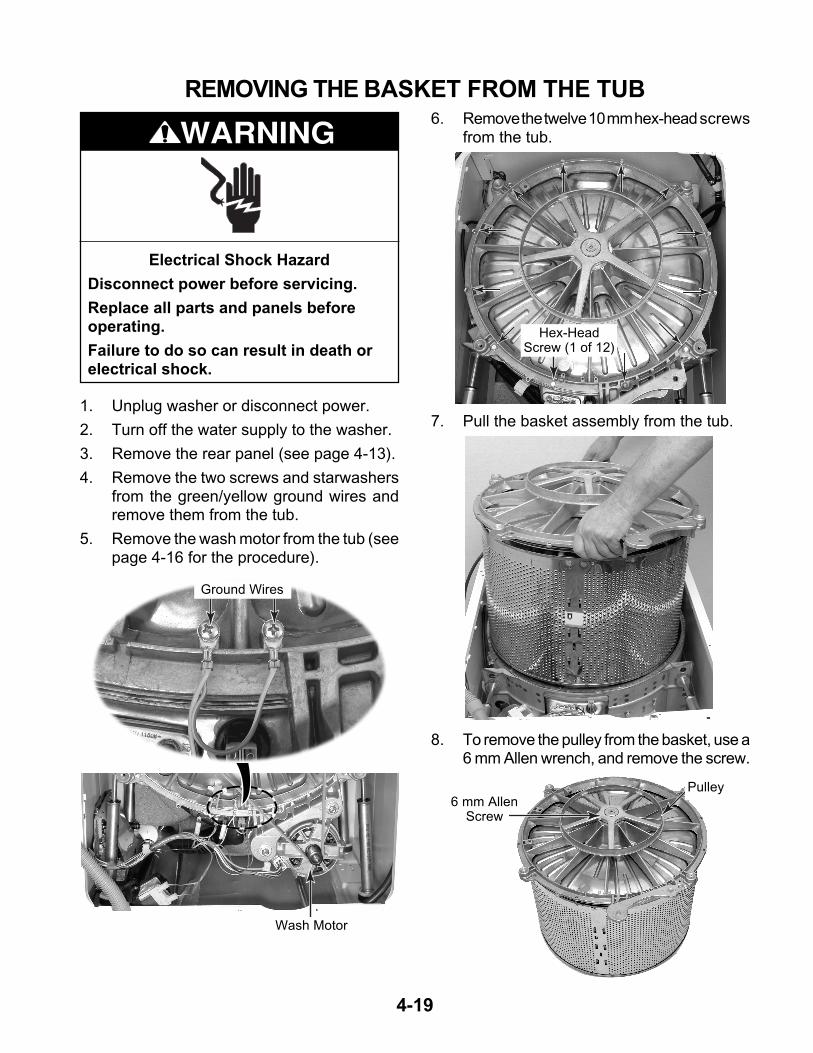
1. Unplug washer or disconnect power.
2. Turn off the water supply to the washer.
3. Remove the rear panel (see page 4-13).
4. Remove the two screws and starwashersfrom the green/yellow ground wires andremove them from the tub.
5. Remove the wash motor from the tub (seepage 4-16 for the procedure).
Electrical Shock Hazard
Disconnect power before servicing.
Replace all parts and panels beforeoperating.
Failure to do so can result in death orelectrical shock.
WARNING
REMOVING THE BASKET FROM THE TUB
Ground Wires
6. Remove the twelve 10 mm hex-head screwsfrom the tub.
8. To remove the pulley from the basket, use a6 mm Allen wrench, and remove the screw.
Wash Motor
Hex-HeadScrew (1 of 12)
7. Pull the basket assembly from the tub.
6 mm Allen Screw
Pulley

4-20
— NOTES —
5-1
COMPONENT TESTINGBefore testing any of the components, performthe following checks:
• Control failure can be the result of corrosionon connectors. Therefore, disconnecting andreconnecting wires will be necessary through-out test procedures.
• All tests/checks should be made with a VOMor DVM having a sensitivity of 20,000 ohms-per-volt DC, or greater.
• Check all connections before replacing com-ponents, looking for broken or loose wires,failed terminals, or wires not pressed intoconnectors far enough.
• Resistance checks must be made with powercord unplugged from outlet, and with wiringharness or connectors disconnected.
• Unless stated otherwise, make all resis-tance checks by disconnecting the compo-nent connector at the electronic control.
WARNINGElectrical Shock Hazard
Disconnect power before servicing.
Replace all parts and panels before operating.
Failure to do so can result in death or electrical shock.
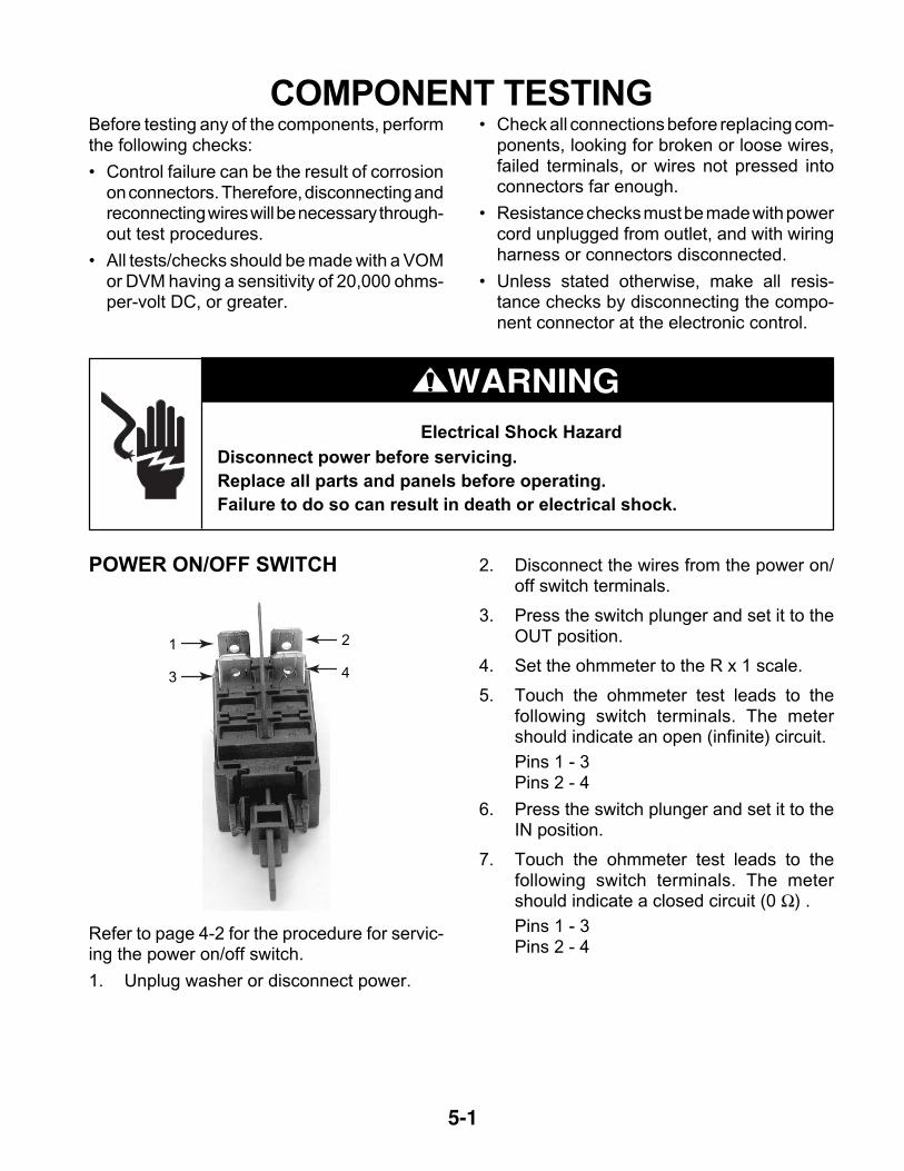
POWER ON/OFF SWITCH
Refer to page 4-2 for the procedure for servic-ing the power on/off switch.
1. Unplug washer or disconnect power.
1
3
2
4
2. Disconnect the wires from the power on/off switch terminals.
3. Press the switch plunger and set it to theOUT position.
4. Set the ohmmeter to the R x 1 scale.
5. Touch the ohmmeter test leads to thefollowing switch terminals. The metershould indicate an open (infinite) circuit.
Pins 1 - 3Pins 2 - 4
6. Press the switch plunger and set it to theIN position.
7. Touch the ohmmeter test leads to thefollowing switch terminals. The metershould indicate a closed circuit (0 Ω) .
Pins 1 - 3Pins 2 - 4
5-2
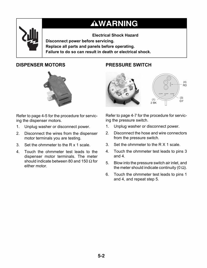
Refer to page 4-5 for the procedure for servic-ing the dispenser motors.
1. Unplug washer or disconnect power.
2. Disconnect the wires from the dispensermotor terminals you are testing.
3. Set the ohmmeter to the R x 1 scale.
4. Touch the ohmmeter test leads to thedispenser motor terminals. The metershould indicate between 80 and 150 Ω foreither motor.
WARNINGElectrical Shock Hazard
Disconnect power before servicing.
Replace all parts and panels before operating.
Failure to do so can result in death or electrical shock.
DISPENSER MOTORS PRESSURE SWITCH
Refer to page 4-7 for the procedure for servic-ing the pressure switch.
1. Unplug washer or disconnect power.
2. Disconnect the hose and wire connectorsfrom the pressure switch.
3. Set the ohmmeter to the R X 1 scale.
4. Touch the ohmmeter test leads to pins 3and 4.
5. Blow into the pressure switch air inlet, andthe meter should indicate continuity (0 Ω).
6. Touch the ohmmeter test leads to pins 1and 4, and repeat step 5.
(4)RD
(3)GY(1)
2 BK
5-3
WARNINGElectrical Shock Hazard
Disconnect power before servicing.
Replace all parts and panels before operating.
Failure to do so can result in death or electrical shock.
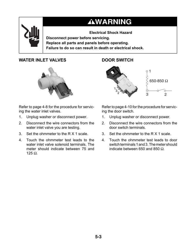
WATER INLET VALVES
Refer to page 4-8 for the procedure for servic-ing the water inlet valves.
1. Unplug washer or disconnect power.
2. Disconnect the wire connectors from thewater inlet valve you are testing.
3. Set the ohmmeter to the R X 1 scale.
4. Touch the ohmmeter test leads to thewater inlet valve solenoid terminals. Themeter should indicate between 75 and125 Ω.
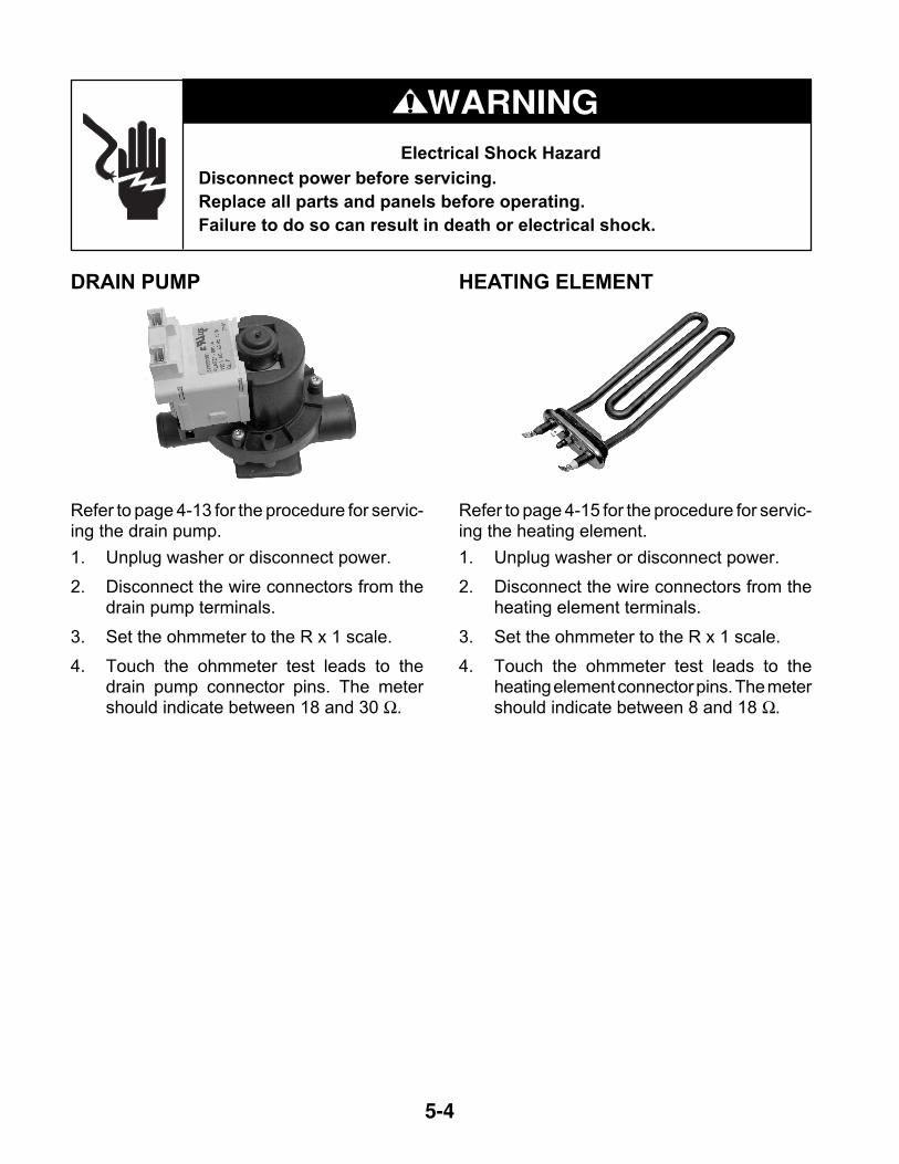
DOOR SWITCH
Refer to page 4-10 for the procedure for servic-ing the door switch.
1. Unplug washer or disconnect power.
2. Disconnect the wire connectors from thedoor switch terminals.
3. Set the ohmmeter to the R X 1 scale.
4. Touch the ohmmeter test leads to doorswitch terminals 1 and 3. The meter shouldindicate between 650 and 850 Ω.
13
2
1
3 2
650-850 Ω
5-4
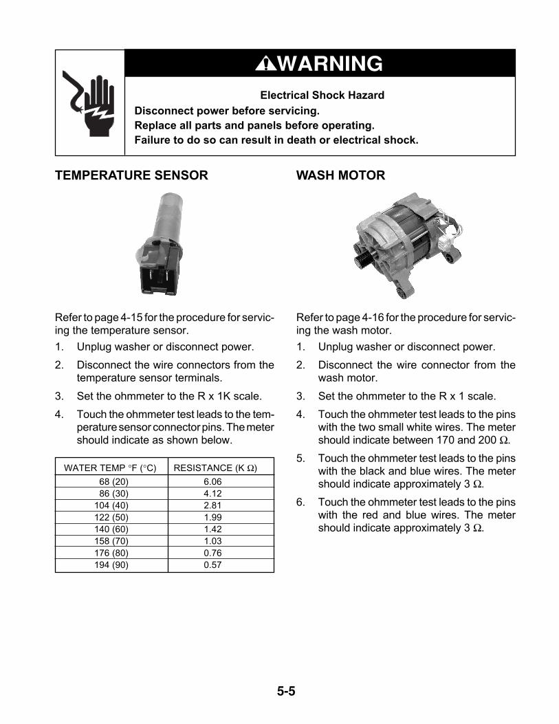
DRAIN PUMP
Refer to page 4-13 for the procedure for servic-ing the drain pump.
1. Unplug washer or disconnect power.
2. Disconnect the wire connectors from thedrain pump terminals.
3. Set the ohmmeter to the R x 1 scale.
4. Touch the ohmmeter test leads to thedrain pump connector pins. The metershould indicate between 18 and 30 Ω.
WARNINGElectrical Shock Hazard
Disconnect power before servicing.
Replace all parts and panels before operating.
Failure to do so can result in death or electrical shock.
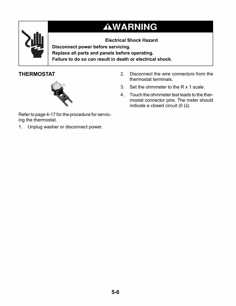
HEATING ELEMENT
Refer to page 4-15 for the procedure for servic-ing the heating element.
1. Unplug washer or disconnect power.
2. Disconnect the wire connectors from theheating element terminals.
3. Set the ohmmeter to the R x 1 scale.
4. Touch the ohmmeter test leads to theheating element connector pins. The metershould indicate between 8 and 18 Ω.
5-5
WARNINGElectrical Shock Hazard
Disconnect power before servicing.
Replace all parts and panels before operating.
Failure to do so can result in death or electrical shock.
TEMPERATURE SENSOR
Refer to page 4-15 for the procedure for servic-ing the temperature sensor.
1. Unplug washer or disconnect power.
2. Disconnect the wire connectors from thetemperature sensor terminals.
3. Set the ohmmeter to the R x 1K scale.
4. Touch the ohmmeter test leads to the tem-perature sensor connector pins. The metershould indicate as shown below.
WASH MOTOR
Refer to page 4-16 for the procedure for servic-ing the wash motor.
1. Unplug washer or disconnect power.
2. Disconnect the wire connector from thewash motor.
3. Set the ohmmeter to the R x 1 scale.
4. Touch the ohmmeter test leads to the pinswith the two small white wires. The metershould indicate between 170 and 200 Ω.
5. Touch the ohmmeter test leads to the pinswith the black and blue wires. The metershould indicate approximately 3 Ω.
6. Touch the ohmmeter test leads to the pinswith the red and blue wires. The metershould indicate approximately 3 Ω.
WATER TEMP °F (°C) RESISTANCE (K Ω)
68 (20) 6.06
86 (30) 4.12
104 (40) 2.81
122 (50) 1.99
140 (60) 1.42
158 (70) 1.03
176 (80) 0.76
194 (90) 0.57
5-6
WARNINGElectrical Shock Hazard
Disconnect power before servicing.
Replace all parts and panels before operating.
Failure to do so can result in death or electrical shock.
THERMOSTAT 2. Disconnect the wire connectors from thethermostat terminals.
3. Set the ohmmeter to the R x 1 scale.
4. Touch the ohmmeter test leads to the ther-mostat connector pins. The meter shouldindicate a closed circuit (0 Ω).
Refer to page 4-17 for the procedure for servic-ing the thermostat.
1. Unplug washer or disconnect power.
6-1
DIAGNOSTICS & TROUBLESHOOTINGDIAGNOSTICS
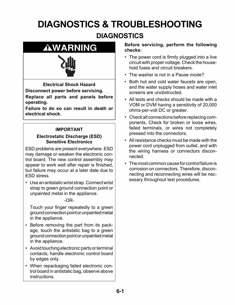
IMPORTANT
Electrostatic Discharge (ESD)Sensitive Electronics
ESD problems are present everywhere. ESDmay damage or weaken the electronic con-trol board. The new control assembly mayappear to work well after repair is finished,but failure may occur at a later date due toESD stress.
• Use an antistatic wrist strap. Connect wriststrap to green ground connection point orunpainted metal in the appliance.
-OR-
Touch your finger repeatedly to a greenground connection point or unpainted metalin the appliance.
• Before removing the part from its pack-age, touch the antistatic bag to a greenground connection point or unpainted metalin the appliance.
• Avoid touching electronic parts or terminalcontacts; handle electronic control boardby edges only.
• When repackaging failed electronic con-trol board in antistatic bag, observe aboveinstructions.
Before servicing, perform the followingchecks:
• The power cord is firmly plugged into a livecircuit with proper voltage. Check the house-hold fuses and circuit breakers.
• The washer is not in a Pause mode?
• Both hot and cold water faucets are open,and the water supply hoses and water inletscreens are unobstructed.
• All tests and checks should be made with aVOM or DVM having a sensitivity of 20,000ohms-per-volt DC or greater.
• Check all connections before replacing com-ponents. Check for broken or loose wires,failed terminals, or wires not completelypressed into the connectors.
• All resistance checks must be made with thepower cord unplugged from outlet, and withthe wiring harness or connectors discon-nected.
• The most common cause for control failure iscorrosion on connectors. Therefore, discon-necting and reconnecting wires will be nec-essary throughout test procedures.
Electrical Shock Hazard
Disconnect power before servicing.
Replace all parts and panels beforeoperating.
Failure to do so can result in death orelectrical shock.
WARNING
6-2
TESTING OF CIRCUIT BOARDS
No Spin
Low Prewash
Wash
Rinse
Spin
DoneMediumHigh
ExtraHigh
Stop
POWER
START
PRE
WASH
EXTRA
RINSE
REGULARDELICATES
Heavy Soil
Whites
Normal
Normal
Color
Color Heavy Soil
HandWash
QuickWash
Rinse
Spin
Spin Speed
Selector
Program
Selector5 LEDs
Luminous
Buttons
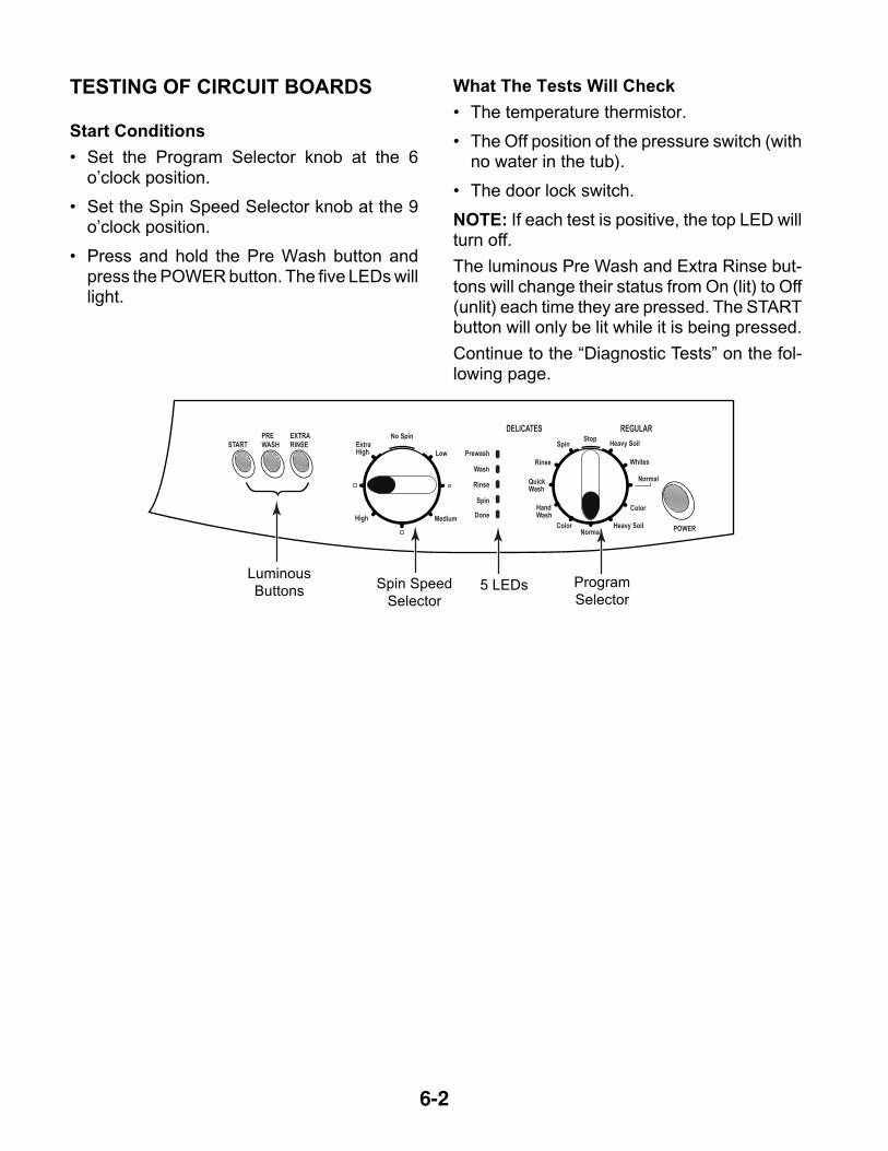
Start Conditions
• Set the Program Selector knob at the 6o’clock position.
• Set the Spin Speed Selector knob at the 9o’clock position.
• Press and hold the Pre Wash button andpress the POWER button. The five LEDs willlight.
What The Tests Will Check
• The temperature thermistor.
• The Off position of the pressure switch (withno water in the tub).
• The door lock switch.
NOTE: If each test is positive, the top LED willturn off.
The luminous Pre Wash and Extra Rinse but-tons will change their status from On (lit) to Off(unlit) each time they are pressed. The STARTbutton will only be lit while it is being pressed.
Continue to the “Diagnostic Tests” on the fol-lowing page.
6-3
Prewash
6 O’Clock Position
Wash
Rinse
Spin
Done
1
Prewash
Wash
Rinse
Spin
Done
2
1
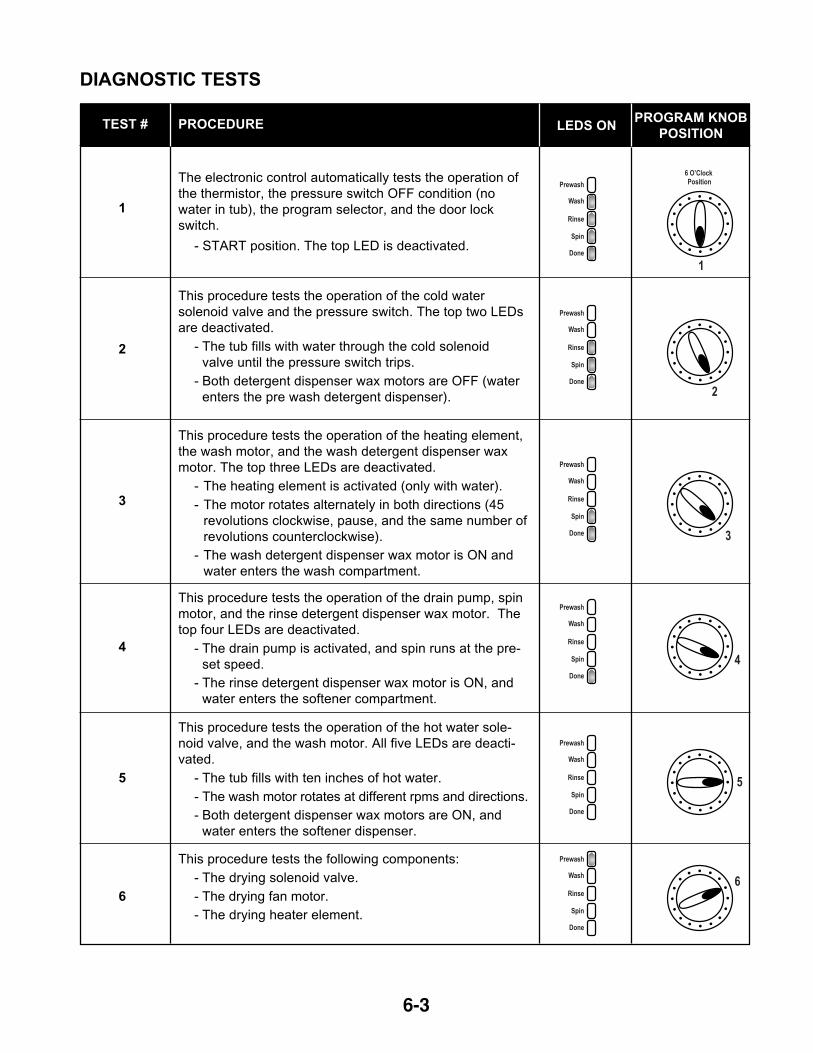
PROCEDUREPROGRAM KNOB
POSITION
The electronic control automatically tests the operation of
the thermistor, the pressure switch OFF condition (no
water in tub), the program selector, and the door lock
switch.
- START position. The top LED is deactivated.
2
3
4
5
6
This procedure tests the operation of the cold water
solenoid valve and the pressure switch. The top two LEDs
are deactivated.
- The tub fills with water through the cold solenoid
valve until the pressure switch trips.
- Both detergent dispenser wax motors are OFF (water
enters the pre wash detergent dispenser).
This procedure tests the operation of the heating element,
the wash motor, and the wash detergent dispenser wax
motor. The top three LEDs are deactivated.
- The heating element is activated (only with water).
- The motor rotates alternately in both directions (45
revolutions clockwise, pause, and the same number of
revolutions counterclockwise).
- The wash detergent dispenser wax motor is ON and
water enters the wash compartment.
This procedure tests the operation of the drain pump, spin
motor, and the rinse detergent dispenser wax motor. The
top four LEDs are deactivated.
- The drain pump is activated, and spin runs at the pre-
set speed.
- The rinse detergent dispenser wax motor is ON, and
water enters the softener compartment.
This procedure tests the operation of the hot water sole-
noid valve, and the wash motor. All five LEDs are deacti-
vated.
- The tub fills with ten inches of hot water.
- The wash motor rotates at different rpms and directions.
- Both detergent dispenser wax motors are ON, and
water enters the softener dispenser.
This procedure tests the following components:
- The drying solenoid valve.
- The drying fan motor.
- The drying heater element.
Prewash
Wash
Rinse
Spin
Done 3
Prewash
Wash
Rinse
Spin
Done
4
Prewash
Wash
Rinse
Spin
Done
5
Prewash
Wash
Rinse
Spin
Done
6
TEST # LEDS ON
DIAGNOSTIC TESTS
6-4
TROUBLESHOOTING GUIDE
Prewash
6 O’Clock Position
Wash
Rinse
Spin
Done
1
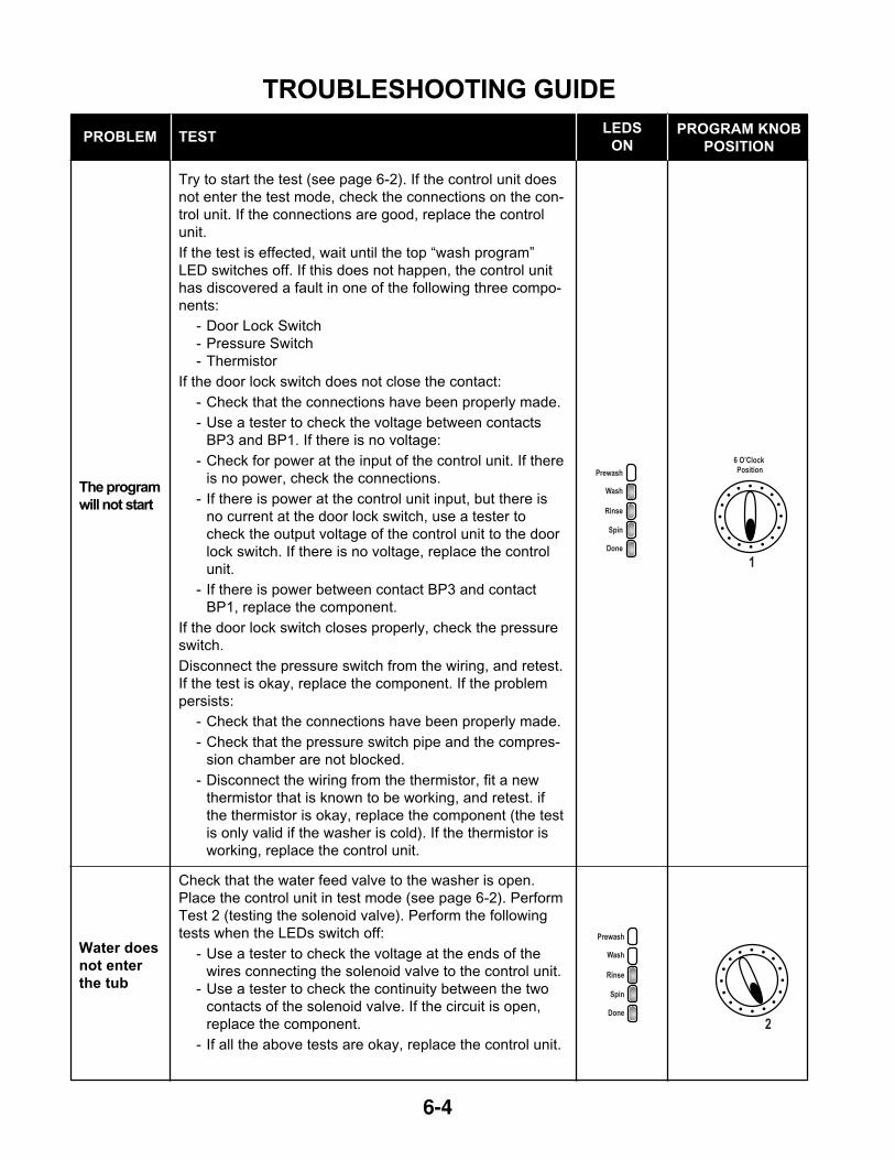
TESTPROGRAM KNOB
POSITIONPROBLEM
The program
will not start
Try to start the test (see page 6-2). If the control unit does
not enter the test mode, check the connections on the con-
trol unit. If the connections are good, replace the control
unit.
If the test is effected, wait until the top “wash program”
LED switches off. If this does not happen, the control unit
has discovered a fault in one of the following three compo-
nents:
- Door Lock Switch
- Pressure Switch
- Thermistor
If the door lock switch does not close the contact:
- Check that the connections have been properly made.
- Use a tester to check the voltage between contacts
BP3 and BP1. If there is no voltage:
- Check for power at the input of the control unit. If there
is no power, check the connections.
- If there is power at the control unit input, but there is
no current at the door lock switch, use a tester to
check the output voltage of the control unit to the door
lock switch. If there is no voltage, replace the control
unit.
- If there is power between contact BP3 and contact
BP1, replace the component.
If the door lock switch closes properly, check the pressure
switch.
Disconnect the pressure switch from the wiring, and retest.
If the test is okay, replace the component. If the problem
persists:
- Check that the connections have been properly made.
- Check that the pressure switch pipe and the compres-
sion chamber are not blocked.
- Disconnect the wiring from the thermistor, fit a new
thermistor that is known to be working, and retest. if
the thermistor is okay, replace the component (the test
is only valid if the washer is cold). If the thermistor is
working, replace the control unit.
LEDS
ON
Prewash
Wash
Rinse
Spin
Done
2
Water does
not enter
the tub
Check that the water feed valve to the washer is open.
Place the control unit in test mode (see page 6-2). Perform
Test 2 (testing the solenoid valve). Perform the following
tests when the LEDs switch off:
- Use a tester to check the voltage at the ends of the
wires connecting the solenoid valve to the control unit.
- Use a tester to check the continuity between the two
contacts of the solenoid valve. If the circuit is open,
replace the component.
- If all the above tests are okay, replace the control unit.
6-5
Prewash
Wash
Rinse
Spin
Done 3
TESTPROGRAM KNOB
POSITIONPROBLEM
LEDS
ON
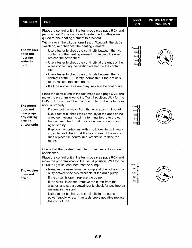
The washer
does not
heat the
water in
the tub
Place the control unit in the test mode (see page 6-2), and
perform Test 2 to allow water to enter the tub (this is re-
quired for the heating element to function).
With water in the tub, perform Test 3. Wait until the LEDs
switch on, and then test the heating element:
- Use a tester to check the continuity between the two
contacts of the heating element, if the circuit is open,
replace the component.
- Use a tester to check the continuity at the ends of the
wires connecting the heating element to the control
unit.
- Use a tester to check the continuity between the two
contacts of the 90° safety thermostat. If the circuit is
open, replace the component.
- If all the above tests are okay, replace the control unit.
The motor
does not
turn prop-
erly during
a wash
and/or spin
Place the control unit in the test mode (see page 6-2), and
move the program knob to the Test 4 position. Wait for the
LEDs to light up, and then test the motor. If the motor does
not run properly:
- Disconnect the motor from the wiring terminal board.
- Use a tester to check the continuity at the ends of the
wires connecting the wiring terminal board to the con-
trol unit and check that the connectors are not dam-
aged or dirty.
- Replace the control unit with one known to be in work-
ing order and check that the motor runs. If the motor
runs replace the control unit, otherwise replace the
motor.
The washer
does not
drain
Check that the washer/drier filter or the user's drains are
not blocked.
Place the control unit in the test mode (see page 6-2), and
move the program knob to the Test 4 position. Wait for the
LEDs to light up, and then test the pump:
- Remove the wires from the pump and check the conti-
nuity between the two terminals of the drain pump.
- If the circuit is open, replace the pump.
- If the circuit is closed, remove the pump from the
washer, and use a screwdriver to check for any foreign
material in the scroll.
- Use a tester to check the continuity in the pump
power supply wires. If the tests prove negative replace
the control unit.
Prewash
Wash
Rinse
Spin
Done
4
Prewash
Wash
Rinse
Spin
Done
4
6-6
TESTPROBLEM
Waterflows intothe tubcontinu-ously
- Check that the solenoid valve is working by carrying outthe appropriate test for that particular component.
- Check that the pressure switch is working by carryingout the appropriate test for that particular component.
- Check that there are no leaks from the tub unit.
- Remove the pressure switch pipe from the drain cou-pling and check that there are no holes in the pipe.
- If all the above tests result negative, replace the con-trol unit.
Safety
After eight failed attempts to start the motor (either in wash
or spin mode), the control unit passes to the end of the
cycle, and the End indicator light flashes (motor rotor
blocked or tachometric open).
If the control unit does not detect the pressure switch
empty condition after twenty minutes of pump running time,
it passes to the next step (pump blocked).
If, after fifty minutes of heating element operation the set
temperature has not been reached, the control unit ad-
vances, and continues the cycle as normal.
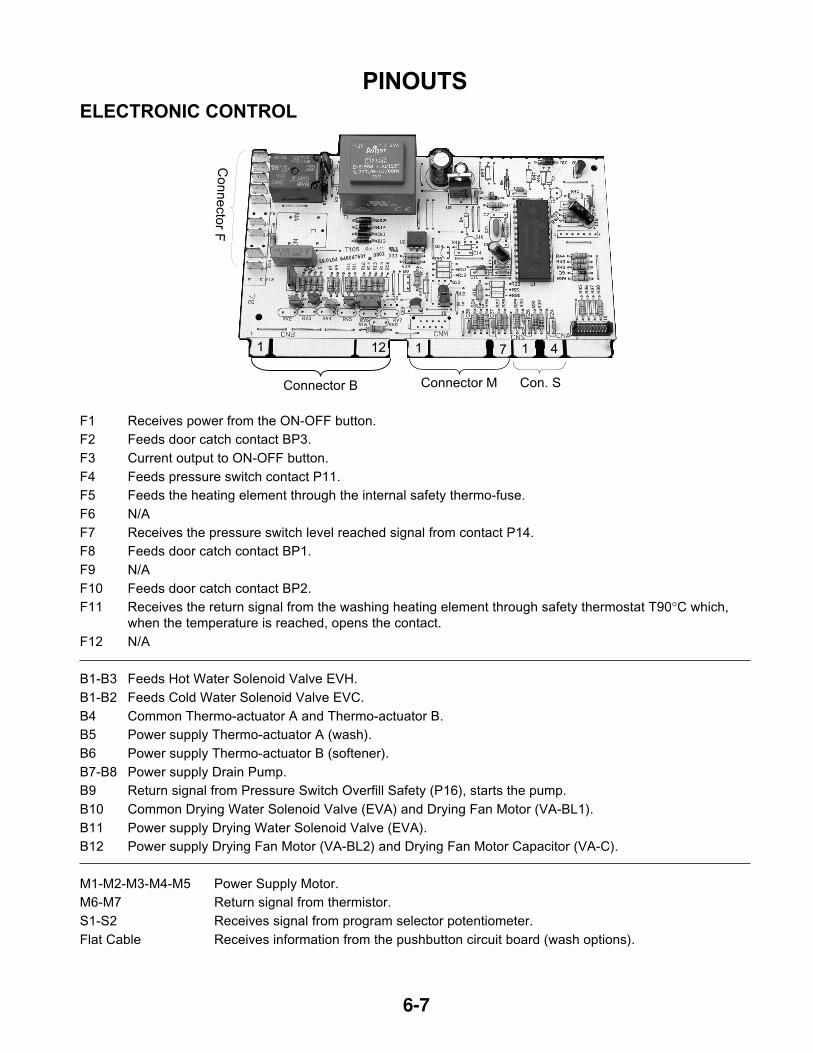
6-7
PINOUTS
ELECTRONIC CONTROL
F1 Receives power from the ON-OFF button.
F2 Feeds door catch contact BP3.
F3 Current output to ON-OFF button.
F4 Feeds pressure switch contact P11.
F5 Feeds the heating element through the internal safety thermo-fuse.
F6 N/A
F7 Receives the pressure switch level reached signal from contact P14.
F8 Feeds door catch contact BP1.
F9 N/A
F10 Feeds door catch contact BP2.
F11 Receives the return signal from the washing heating element through safety thermostat T90°C which,
when the temperature is reached, opens the contact.
F12 N/A
B1-B3 Feeds Hot Water Solenoid Valve EVH.
B1-B2 Feeds Cold Water Solenoid Valve EVC.
B4 Common Thermo-actuator A and Thermo-actuator B.
B5 Power supply Thermo-actuator A (wash).
B6 Power supply Thermo-actuator B (softener).
B7-B8 Power supply Drain Pump.
B9 Return signal from Pressure Switch Overfill Safety (P16), starts the pump.
B10 Common Drying Water Solenoid Valve (EVA) and Drying Fan Motor (VA-BL1).
B11 Power supply Drying Water Solenoid Valve (EVA).
B12 Power supply Drying Fan Motor (VA-BL2) and Drying Fan Motor Capacitor (VA-C).
M1-M2-M3-M4-M5 Power Supply Motor.
M6-M7 Return signal from thermistor.
S1-S2 Receives signal from program selector potentiometer.
Flat Cable Receives information from the pushbutton circuit board (wash options).
Connector B Connector M Con. S
Co
nn
ecto
r F
1 12 1 7 1 4
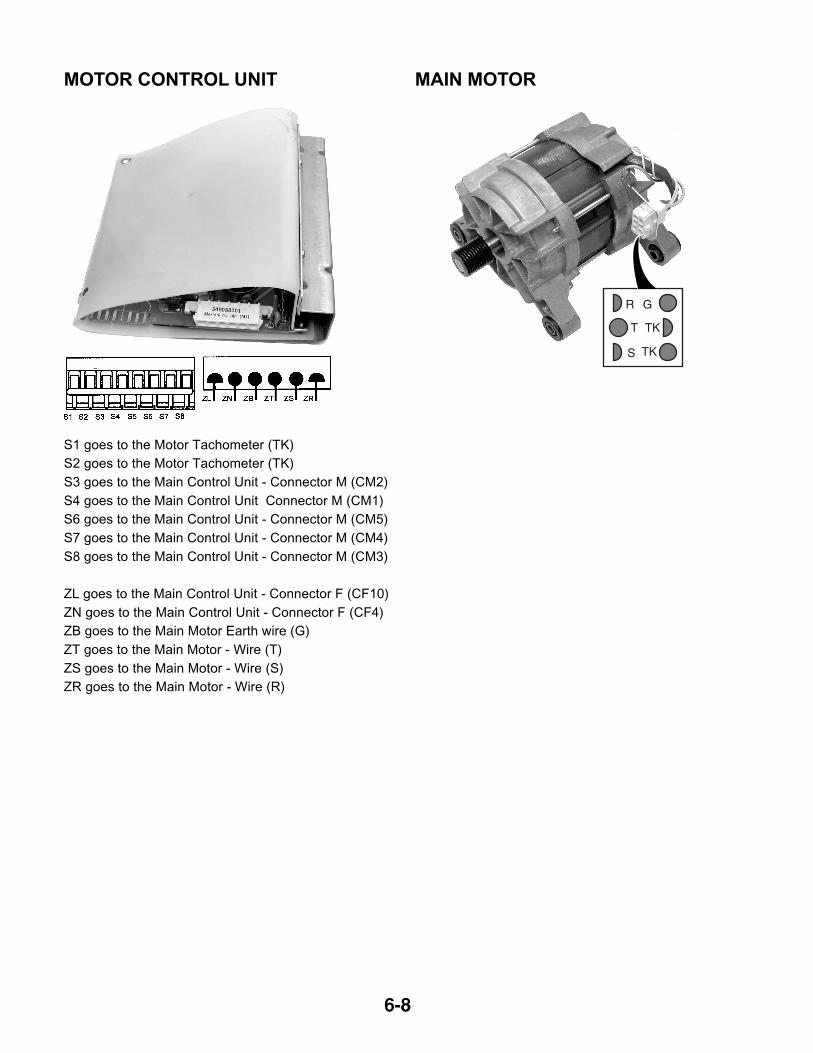
6-8
S1 goes to the Motor Tachometer (TK)
S2 goes to the Motor Tachometer (TK)
S3 goes to the Main Control Unit - Connector M (CM2)
S4 goes to the Main Control Unit Connector M (CM1)
S6 goes to the Main Control Unit - Connector M (CM5)
S7 goes to the Main Control Unit - Connector M (CM4)
S8 goes to the Main Control Unit - Connector M (CM3)
ZL goes to the Main Control Unit - Connector F (CF10)
ZN goes to the Main Control Unit - Connector F (CF4)
ZB goes to the Main Motor Earth wire (G)
ZT goes to the Main Motor - Wire (T)
ZS goes to the Main Motor - Wire (S)
ZR goes to the Main Motor - Wire (R)
MOTOR CONTROL UNIT
R G
T
S
TK
TK
MAIN MOTOR
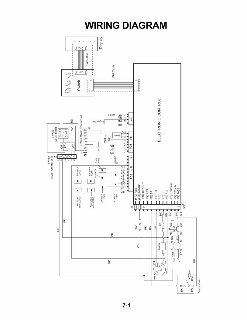
7-1
WIRING DIAGRAM
BP
1
BP
3B
P2
Sw
itch
ELE
CT
RO
NIC
CO
NT
RO
L
Dis
pla
y
Fla
t C
ab
le
Fla
t C
ab
le
12
34
12
34
56
7
Program Sel.
Spin Sel.
Therm.
S
6-W
ire
Mo
tor
Co
ntr
ol U
nit
RD
RD
RD
RD
RD
RD
RD
RD
GY
RD
RDORBU
BK
BK
BK
BKBK
WH OR
GYGY
RD
GY
RD
BR
BR
BR
BR
BU
BU
BK
GY
BK
WH
OR
BK
BK
BK
BK
BK
WH
6-W
ire
MA
IN M
oto
r
8-W
ire
Mo
tor
Co
ntr
ol U
nit
Z
S1
S8
RG
TT
K
ST
K
ZL
ZN ZB
ZT
ZS
ZR
PC
B c
nB
CN1
CN2
PC
B c
nM
cnS
cnF
12
10 1
112
(F12)
RE
S.
(F9)
RE
S.
(F11
) T-9
0 R
F
(F10)
BP
2-O
UT
(F8)
BP
1
(F7)
P14
(F6)
-
(F5)
RF
(F4)
P11
(F3)
NE
UT
RA
L
(F2)
BP
3 -
IN
(F1)
FA
SE
PR
EH
P14
P16
fafa
AS
2A
S3
AS
5A
S6
fafa
P11
N L
Hot W
ate
rV
alv
e (
CO
M)
Hot W
ate
rV
alv
e
Act
uato
r A
(CO
M)
Act
uato
r A
Act
uato
r B
Act
uato
r B
(CO
M)
Cold
Wate
rV
alv
e (
CO
M)
Cold
Wate
rV
alv
e
Door
Lock
Sw
itch
He
ate
r
T9
0 RF
Dra
in
Pum
p

7-2
— NOTES —

7-3
— NOTES —

7-4
— NOTES —
PRODUCT SPECIFICATIONS
AND
WARRANTY INFORMATION SOURCES
IN THE UNITED STATES:
FOR PRODUCT SPECIFICATIONS AND WARRANTY INFORMATION CALL:
FOR TECHNICAL ASSISTANCE WHILE AT THE CUSTOMER’S HOME CALL:
THE TECHNICAL ASSISTANCE LINE: 1-800-253-2870
HAVE YOUR STORE NUMBER READY TO IDENTIFY YOU AS AN
AUTHORIZED SERVICER
FOR LITERATURE ORDERS:
PHONE: 1-800-851-4605
FOR TECHNICAL INFORMATION AND SERVICE POINTERS:
www.servicematters.com
IN CANADA:
FOR PRODUCT SPECIFICATIONS AND WARRANTY INFORMATION CALL:
1-800-461-5681
FOR TECHNICAL ASSISTANCE WHILE AT THE CUSTOMER’S HOME CALL:
THE TECHNICAL ASSISTANCE LINE: 1-800-488-4791
HAVE YOUR STORE NUMBER READY TO IDENTIFY YOU AS AN
AUTHORIZED SERVICER
FOR WHIRLPOOL PRODUCTS: 1-800-253-1301
FOR KITCHENAID PRODUCTS: 1-800-422-1230
FOR ROPER PRODUCTS: 1-800-447-6737

CORPORATION
Related Documents


