1 24

Welcome message from author
This document is posted to help you gain knowledge. Please leave a comment to let me know what you think about it! Share it to your friends and learn new things together.
Transcript
1
24

2Prof. M D Atrey, Department of Mechanical Engineering, IIT Bombay
• In the earlier lecture, we have seen the working of rectification column with the help of animation.
• Ponchon & Savarit, McCabe & Thiele and Numerical techniques are used to calculate the theoretical number of plates.
• McCabe & Thiele method is less general and is widely used for binary mixtures.
• The major assumption is that the saturated vapor and saturated liquid enthalpies are independent of the mole fraction.
Earlier Lecture
Earlier Lecture
3Prof. M D Atrey, Department of Mechanical Engineering, IIT Bombay
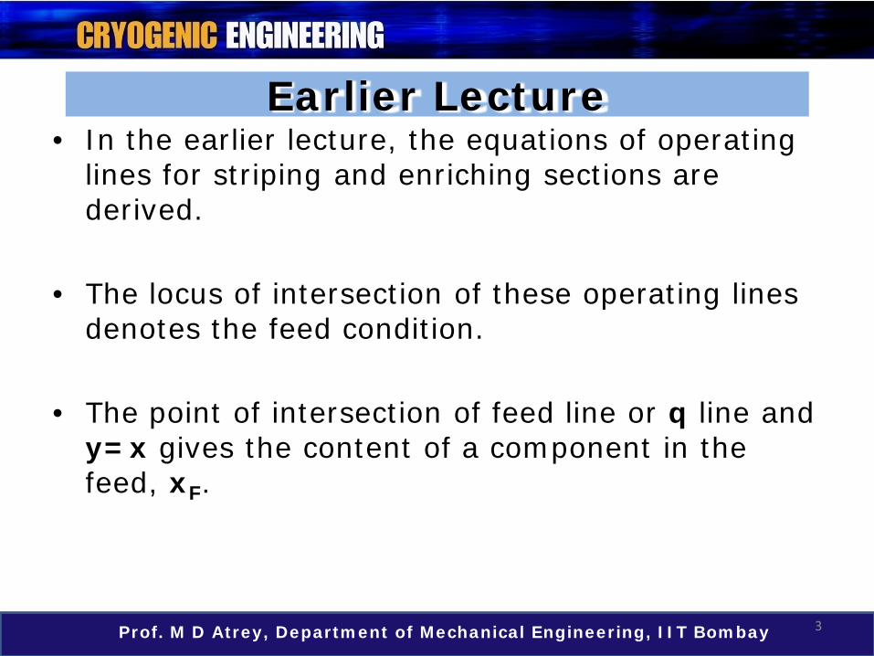
• In the earlier lecture, the equations of operating lines for striping and enriching sections are derived.
• The locus of intersection of these operating lines denotes the feed condition.
• The point of intersection of feed line or q line and y=x gives the content of a component in the feed, xF.
Outline of the Lecture
4Prof. M D Atrey, Department of Mechanical Engineering, IIT Bombay
Topic : Gas Separation (contd)
• Graphical solution for column design using McCabe – Thiele method
• Tutorial
5Prof. M D Atrey, Department of Mechanical Engineering, IIT Bombay
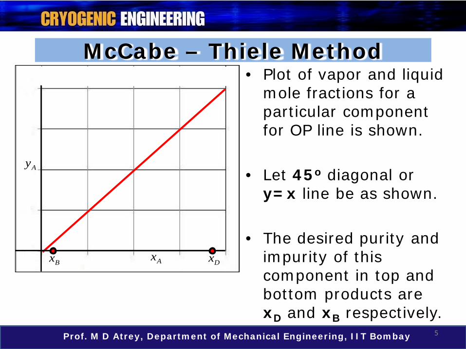
McCabe – Thiele Method• Plot of vapor and liquid
mole fractions for a particular component for OP line is shown.
• Let 45o diagonal or y=x line be as shown.
• The desired purity and impurity of this component in top and bottom products are xD and xB respectively.
Ax
Ay
DxBx

6Prof. M D Atrey, Department of Mechanical Engineering, IIT Bombay
McCabe – Thiele Method
Ax
Ay
Dx
D
n
x DV
• The equation of operating line for stripping section is
• The equation for operating line in enriching section is
OP line for Enriching Section
11
mm m B
m m
L By x xV V
++
= −
BxB
m
x BV
OP line for Stripping Section
11
nn n D
n n
L Dy x xV V
++
= +
7Prof. M D Atrey, Department of Mechanical Engineering, IIT Bombay
McCabe – Thiele Method
Ax
Ay
D
n
x DV
BxB
m
x BV
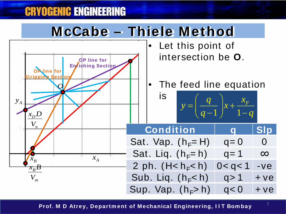
• Let this point of intersection be O.
• The feed line equation is
1 1Fxqy x
q q
= + − −
Condition q Slp
Sat. Liq. (hF=h) q=1 ∞2 ph. (H<hF<h) 0<q<1 -ve
Sat. Vap. (hF=H) q=0 0
Sup. Vap. (hF>h) q<0 +veSub. Liq. (hF<h) q>1 +ve
O
OP line for Enriching Section
OP line for Stripping Section

8Prof. M D Atrey, Department of Mechanical Engineering, IIT Bombay
McCabe – Thiele Method
Ax
Ay
D
n
x DV
BxB
m
x BV
• The point of intersection of feed line or q line and y=x, gives the content of the component A in feed, xF.
• This intersection point is used to draw the feed line as shown in the figure.Fx
Dx
O
OP line for Enriching Section
OP line for Stripping Section
9Prof. M D Atrey, Department of Mechanical Engineering, IIT Bombay
McCabe – Thiele Method
Ay
D
n
x DV
BxB
m
x BV
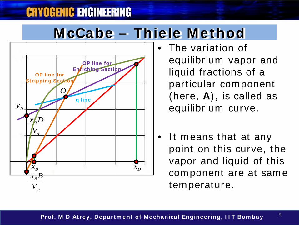
• The variation of equilibrium vapor and liquid fractions of a particular component (here, A), is called as equilibrium curve.
• It means that at any point on this curve, the vapor and liquid of this component are at same temperature.
Dx
Oq line
OP line for Enriching Section
OP line for Stripping Section

10Prof. M D Atrey, Department of Mechanical Engineering, IIT Bombay
McCabe – Thiele Method
Ay
D
n
x DV
Bx
• On each plate, vapor and liquid are in thermal equilibrium. Therefore, the plate condition lies on the equilibrium line.
• That is, equilibrium curve gives the relation between liquid composition (xn) and vapor composition (yn)on the same plate.
Dx
q lineO
B
m
x BV
OP line for Enriching Section
OP line for Stripping Section
11Prof. M D Atrey, Department of Mechanical Engineering, IIT Bombay
McCabe – Thiele Method
Ay
D
n
x DV
BxB
m
x BV
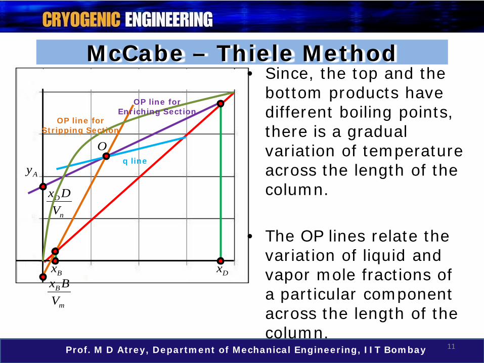
• Since, the top and the bottom products have different boiling points, there is a gradual variation of temperature across the length of the column.
• The OP lines relate the variation of liquid and vapor mole fractions of a particular component across the length of the column.
Dx
q lineO
OP line for Enriching Section
OP line for Stripping Section

12Prof. M D Atrey, Department of Mechanical Engineering, IIT Bombay
McCabe – Thiele Method
Ay
D
n
x DV
BxB
m
x BV
Dx
q lineO
n
D
• Reviewing the OP line equation, say for the top section, it is clear that this equation relates xn+1 and yn, for this component, A.
11
nn n D
n n
L Dy x xV V
++
= +
1nL +
nLnV
OP line for Enriching Section
OP line for Stripping Section

13Prof. M D Atrey, Department of Mechanical Engineering, IIT Bombay
McCabe – Thiele Method
Ay
D
n
x DV
Bx
• All these curves and lines are vital in calculating the number of plates using McCabe – Thiele method.
• In view of this, the slopes of operating and q lines, equilibrium curve and purity requirement form the basis to determine the number of plates.
Dx
Oq line
OP line for Enriching Section
OP line for Stripping Section
14Prof. M D Atrey, Department of Mechanical Engineering, IIT Bombay
McCabe – Thiele Method
Ay
Bx Dx
q lineO
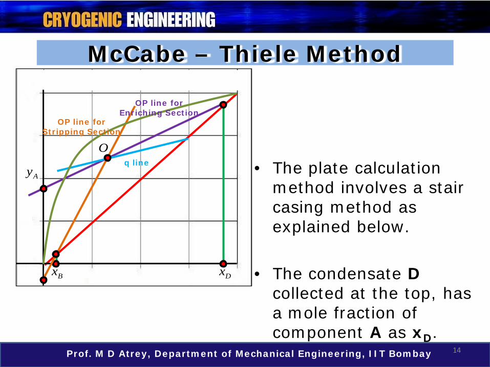
• The plate calculation method involves a stair casing method as explained below.
• The condensate D collected at the top, has a mole fraction of component A as xD.
OP line for Enriching Section
OP line for Stripping Section
15Prof. M D Atrey, Department of Mechanical Engineering, IIT Bombay
McCabe – Thiele Method
Ay
Bx Dx
q lineO
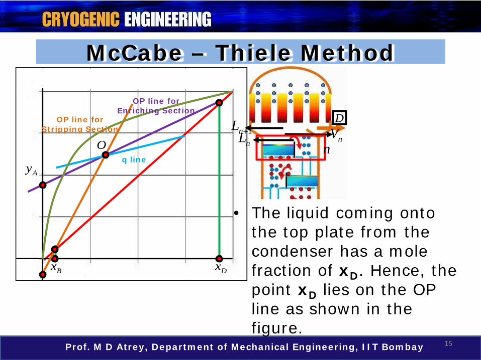
• The liquid coming onto the top plate from the condenser has a mole fraction of xD. Hence, the point xD lies on the OP line as shown in the figure.
D
nVn
1nL +nL
OP line for Enriching Section
OP line for Stripping Section
16Prof. M D Atrey, Department of Mechanical Engineering, IIT Bombay
McCabe – Thiele Method
Ay
Bx Dx
q lineO
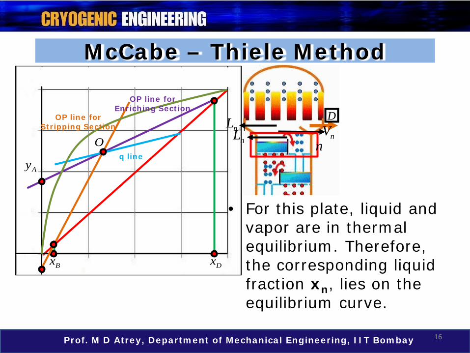
• For this plate, liquid and vapor are in thermal equilibrium. Therefore, the corresponding liquid fraction xn, lies on the equilibrium curve.
OP line for Enriching Section
OP line for Stripping Section
D
nVn
1nL +nL

17Prof. M D Atrey, Department of Mechanical Engineering, IIT Bombay
McCabe – Thiele Method
Ay
Bx Dx
q lineO
• This equilibrium point is found by extending a horizontal line from xD to the equilibrium curve. Let this point be denoted by P.
POP line for Enriching Section
OP line for Stripping Section
D
nVn
1nL +nL
18Prof. M D Atrey, Department of Mechanical Engineering, IIT Bombay
McCabe – Thiele Method
Ay
Bx Dx
q lineO
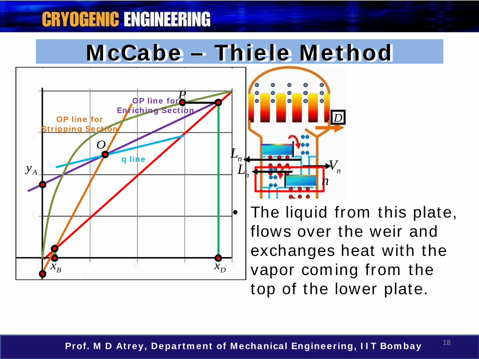
• The liquid from this plate, flows over the weir and exchanges heat with the vapor coming from the top of the lower plate.
POP line for Enriching Section
OP line for Stripping Section
nVnnL
1nL +
D
19Prof. M D Atrey, Department of Mechanical Engineering, IIT Bombay
McCabe – Thiele Method
Ay
Bx Dx
q lineO
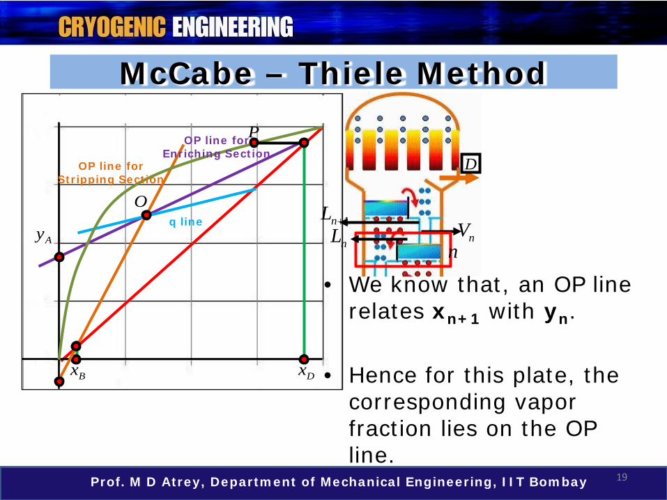
• We know that, an OP line relates xn+1 with yn.
• Hence for this plate, the corresponding vapor fraction lies on the OP line.
POP line for Enriching Section
OP line for Stripping Section
nVnnL
1nL +
D

20Prof. M D Atrey, Department of Mechanical Engineering, IIT Bombay
McCabe – Thiele Method
Ay
Bx Dx
q lineO
• The vapor composition, yn, for this plate is found by extending a vertical line from P onto the OP line. Let this point be denoted by Q.
PP
Q
OP line for Enriching Section
OP line for Stripping Section
nVnnL
1nL +
D

21Prof. M D Atrey, Department of Mechanical Engineering, IIT Bombay
McCabe – Thiele Method
Ay
Bx Dx
q lineO
• The stair casing should be continued till the stairs cross the point O (the intersection of OP lines) as shown in the figure.
PP
QR
OP line for Enriching Section
OP line for Stripping Section
nVnnL
1nL +
D

22Prof. M D Atrey, Department of Mechanical Engineering, IIT Bombay
McCabe – Thiele Method
Ay
Bx
• It is clear that• Every horizontal line
gives the condition of liquid – vapor on the same plate which are in thermal equilibrium.
• Every vertical line gives the vapor condition for the plate below the earlier plate.
Dx
q lineO
P
QRS
OP line for Enriching Section
OP line for Stripping Section

23Prof. M D Atrey, Department of Mechanical Engineering, IIT Bombay
McCabe – Thiele Method
Ay
Bx
• It means that, every vertical line indicates the need for the plate in the enriching section, till the stair casing crosses the point O.
• The same exercise could be done for the lower section, with xDas the desired impurity of the component A in the bottom product.
Dx
q lineO
P
QRS
OP line for Enriching Section
OP line for Stripping Section
24Prof. M D Atrey, Department of Mechanical Engineering, IIT Bombay
McCabe – Thiele Method
Ay
Bx
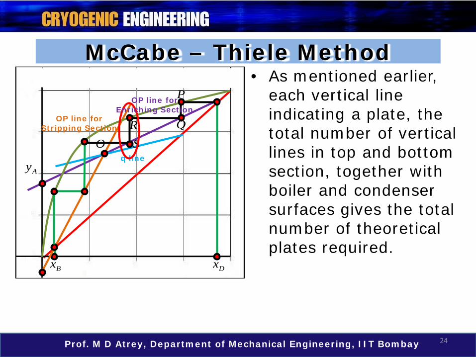
• As mentioned earlier, each vertical line indicating a plate, the total number of vertical lines in top and bottom section, together with boiler and condenser surfaces gives the total number of theoretical plates required.
Dx
q lineO
P
QRS
OP line for Enriching Section
OP line for Stripping Section

25Prof. M D Atrey, Department of Mechanical Engineering, IIT Bombay
McCabe – Thiele Method
Ay
Bx
• From the adjacent hypothetical figure, the total number of vertical lines are 4.
• Hence, the total number of theoretical plates can be tabulated as shown below.
Dx
q lineO
P
QRS
OP line for Enriching Section
OP line for Stripping Section
McCabe – Thiele Method
Top 3 + 1 (Cond)Bottom 3 + 1 (Boiler)
26Prof. M D Atrey, Department of Mechanical Engineering, IIT Bombay
McCabe – Thiele Method
Ay
Bx
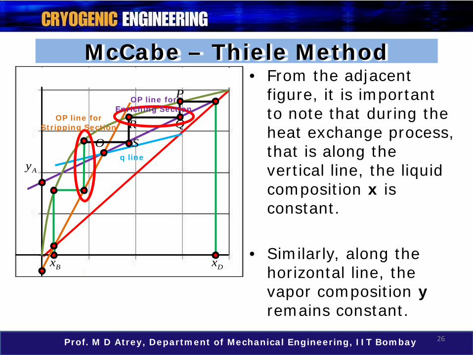
• From the adjacent figure, it is important to note that during the heat exchange process, that is along the vertical line, the liquid composition x is constant.
• Similarly, along the horizontal line, the vapor composition yremains constant.
Dx
q lineO
P
QRS
OP line for Enriching Section
OP line for Stripping Section

27Prof. M D Atrey, Department of Mechanical Engineering, IIT Bombay
McCabe – Thiele Method
Ay
Bx
• Also, note that in moving from top to bottom, the McCabe –Thiele diagram starts with an horizontal line and ends with a vertical line.
• This is because the liquid flows downwards and is represented by a vertical line.
Dx
q lineO
P
QRS
OP line for Enriching Section
OP line for Stripping Section
28Prof. M D Atrey, Department of Mechanical Engineering, IIT Bombay
McCabe – Thiele Method
m
n
B
D
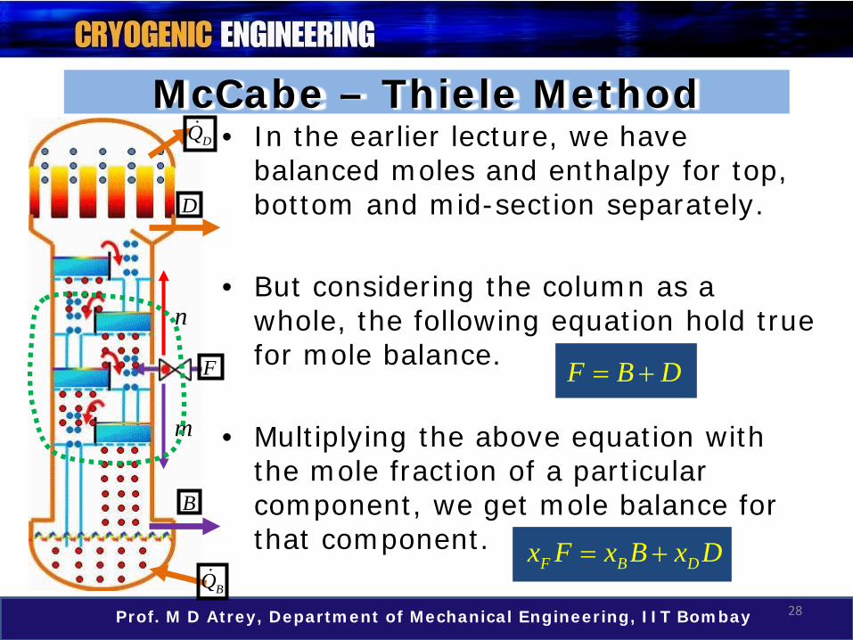
• In the earlier lecture, we have balanced moles and enthalpy for top, bottom and mid-section separately.
• But considering the column as a whole, the following equation hold true for mole balance.
• Multiplying the above equation with the mole fraction of a particular component, we get mole balance for that component.
F B D= +
BQ
DQ
F
F B Dx F x B x D= +
29Prof. M D Atrey, Department of Mechanical Engineering, IIT Bombay
McCabe – Thiele Method
m
n
B
D
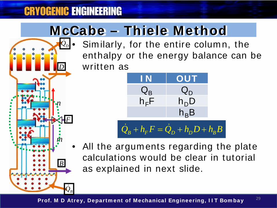
• Similarly, for the entire column, the enthalpy or the energy balance can be written as
• All the arguments regarding the plate calculations would be clear in tutorial as explained in next slide.
B F D D BQ h F Q h D h B+ = + +
BQ
DQ
F
IN OUTQB QDhFF hDD
hBB

Tutorial
30Prof. M D Atrey, Department of Mechanical Engineering, IIT Bombay
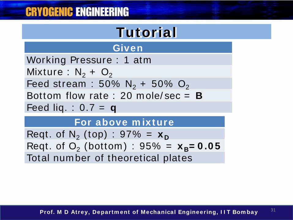
• Consider a rectification column for N2 and O2separation operating at 1 atm. Determine the number of theoretical plates required to yield 97% N2 at top and 95% O2 at bottom. Feed stream is 50% N2 and 50% O2. Molar fraction of liquid in feed stream is 0.7 mole liquid/mole mixture. The desired flow rate at the bottom product is 20 mole/sec and the heat removed in the condenser at top of the column is 500 kW.
31Prof. M D Atrey, Department of Mechanical Engineering, IIT Bombay
GivenWorking Pressure : 1 atmMixture : N2 + O2Feed stream : 50% N2 + 50% O2Bottom flow rate : 20 mole/sec = BFeed liq. : 0.7 = q
For above mixtureReqt. of N2 (top) : 97% = xDReqt. of O2 (bottom) : 95% = xB=0.05Total number of theoretical plates
Tutorial
32Prof. M D Atrey, Department of Mechanical Engineering, IIT Bombay
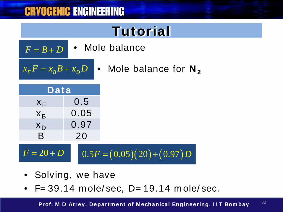
• Mole balance
DataxF 0.5xB 0.05xD 0.97B 20
F B D= +
Tutorial
• Mole balance for N2F B Dx F x B x D= +
20F D= + ( )( ) ( )0.5 0.05 20 0.97F D= +
• Solving, we have• F=39.14 mole/sec, D=19.14 mole/sec.

33Prof. M D Atrey, Department of Mechanical Engineering, IIT Bombay
B D D B FQ Q h D h B h F= + + −
Tutorial• Enthalpy balance
Mole fraction N2
Enth
alpy
, h
–kJ
/mol 90
8885
7880
8182
8384
N2 – O2 at 1 atm
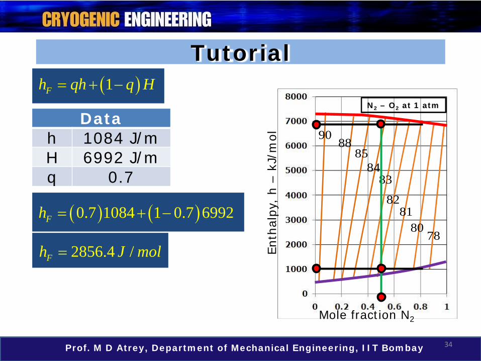
• Fraction of stream in feed
FH hqH h−
=−
• Rearranging, we have
( )1Fh qh q H= + −
• For 50% N2 + 50% O2
• h=1084 J/mol, H=6992 J/mol
34Prof. M D Atrey, Department of Mechanical Engineering, IIT Bombay
Tutorial
Mole fraction N2
Enth
alpy
, h
–kJ
/mol 90
8885
7880
8182
8384
N2 – O2 at 1 atm
( )1Fh qh q H= + −
Datah 1084 J/mH 6992 J/mq 0.7
( ) ( )0.7 1084 1 0.7 6992Fh = + −
2856.4 /Fh J mol=

35Prof. M D Atrey, Department of Mechanical Engineering, IIT Bombay
Tutorial
Mole fraction N2
Enth
alpy
, h
–kJ
/mol 90
8885
7880
8182
8384
N2 – O2 at 1 atmDataQD 500 kWhD 1084 J/mhB 1084 J/mhF 2856.4 J/m
B D D B FQ Q h D h B h F= + + −
( ) ( )( )( )( ) ( )( )
3500 10 1084 19.14
1084 20 2856.4 39.14BQ = +
+ −
430.6BQ kW=
DataF 39.14B 20D 19.14

36Prof. M D Atrey, Department of Mechanical Engineering, IIT Bombay
Tutorial
DataQD 500kWHn 6992 J/m
hn+1 1084 J/mhD 1084 J/mD 19.14 mol/s
• Operating line for Enriching Section
1
1
n n
n DD n
H hDV Q h h
D
+
+
−=
+ −
6992 1084500000 1084 108419.14
n
DV
−=
+ −0.226
n
DV
=
1 1n
n n
L DV V
+ = − 1 1 0.226n
n
LV
+ = − 1 0.773n
n
LV
+ =

37Prof. M D Atrey, Department of Mechanical Engineering, IIT Bombay
Tutorial• Operating line for Enriching Section
11
nn n D
n n
L Dy x xV V
++
= +
0.226n
DV
= 1 0.773n
n
LV
+ =
( ) ( )( )10.773 0.226 0.97n ny x += + DataxD 0.97
10.773 0.22n ny x += +
38Prof. M D Atrey, Department of Mechanical Engineering, IIT Bombay
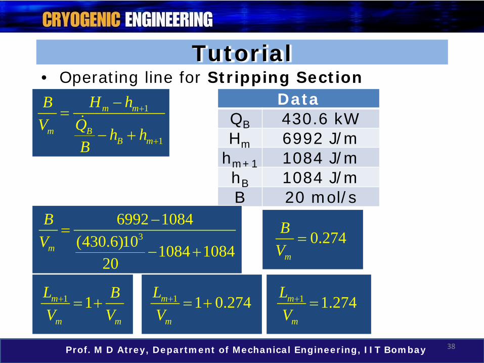
Tutorial
DataQB 430.6 kWHm 6992 J/m
hm+1 1084 J/mhB 1084 J/mB 20 mol/s
• Operating line for Stripping Section
1
1
m m
m BB m
H hBV Q h h
B
+
+
−=
− +
36992 1084
(430.6)10 1084 108420
m
BV
−=
− +0.274
m
BV
=
1 1m
m m
L BV V
+ = + 1 1 0.274m
m
LV
+ = + 1 1.274m
m
LV
+ =
39Prof. M D Atrey, Department of Mechanical Engineering, IIT Bombay
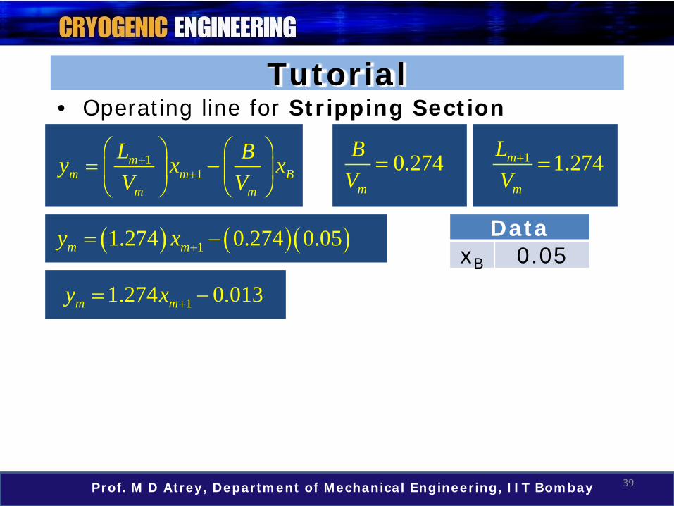
Tutorial• Operating line for Stripping Section
11
mm m B
m m
L By x xV V
++
= −
0.274m
BV
= 1 1.274m
m
LV
+ =
( ) ( )( )11.274 0.274 0.05m my x += − DataxB 0.05
11.274 0.013m my x += −
40Prof. M D Atrey, Department of Mechanical Engineering, IIT Bombay
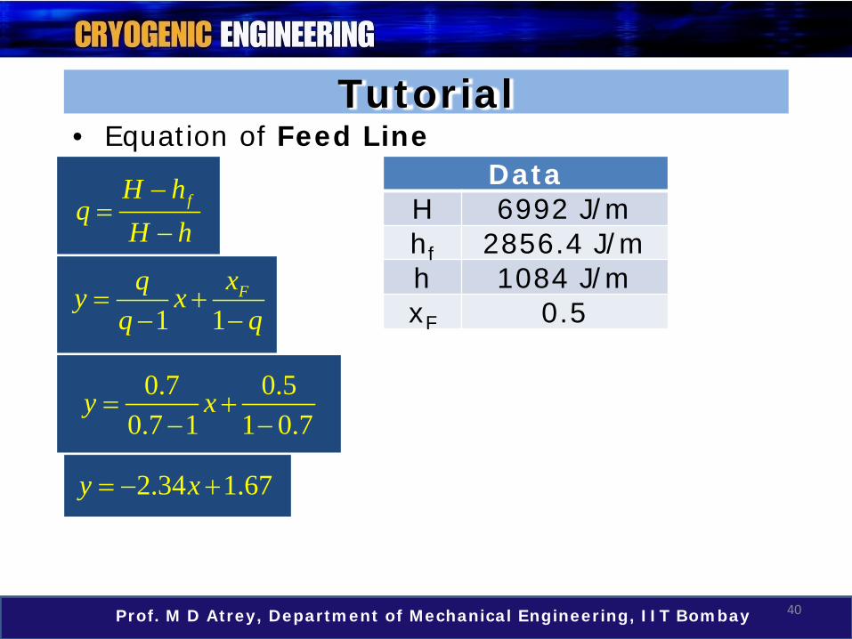
Tutorial
DataH 6992 J/mhf 2856.4 J/mh 1084 J/mxF 0.5
• Equation of Feed Line
fH hq
H h−
=−
1 1Fxqy x
q q= +
− −
0.7 0.50.7 1 1 0.7
y x= +− −
2.34 1.67y x= − +

41Prof. M D Atrey, Department of Mechanical Engineering, IIT Bombay
Tutorial• Summarizing, we have the following.
• OP line for enriching section :
• OP line for stripping section :
• q line :
• The stair casing procedure is shown on an excel sheet to have a better understanding of the method.
2.34 1.67y x= − +
11.274 0.013m my x += −
10.773 0.22n ny x += +

42Prof. M D Atrey, Department of Mechanical Engineering, IIT Bombay
Tutorial
McCabe – Thiele MethodEnriching Section 3 + 1 (Condenser)Stripping Section 6 + 1 (Boiler)
• From the excel sheet, it is clear that the total number of vertical lines are 9.
• Therefore, the total number of theoretical plates for this column can be tabulated as shown below.

Summary
43Prof. M D Atrey, Department of Mechanical Engineering, IIT Bombay
• Equilibrium curve gives the relation between liquid composition (xn) and vapor composition (yn) on the same plate.
• The OP lines relate the variation of liquid (xn+1) and vapor (yn) mole fractions of a particular component across the length of the column.
• The plate calculation is a stair casing method which involves locating equilibrium conditions on equilibrium line and OP line.
Summary
44Prof. M D Atrey, Department of Mechanical Engineering, IIT Bombay
• In a McCabe – Thiele diagram• Each horizontal line gives the condition of
liquid – vapor on the same plate which are in thermal equilibrium.
• Each vertical line gives the vapor condition for the plate with respect to liquid that leaves the earlier plate on the top.
• The total number of vertical lines in top and bottom section, together with boiler and condenser surfaces is the total number of theoretical plates required.
45Prof. M D Atrey, Department of Mechanical Engineering, IIT Bombay
Thank You!
Related Documents


![4성분계 다중반응증류 공정의 - CHERIC방법은 Ponchon-Savarit[7,8], McCabe-Thiele[9] 기법과 같이 이를 시각화 하는 것이다. 반응증류에서도 마찬가지로](https://static.cupdf.com/doc/110x72/5eb52345a1aa3a0da10c5c87/4ee-eee-e-ee-ponchon-savarit78-mccabe-thiele9.jpg)