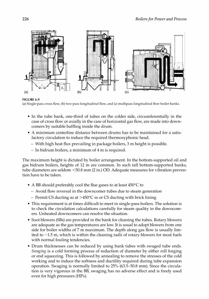
226 Boilers for Power and Process In the tube bank, one-third of tubes on the colder side, circumferentially in the case of cross flow or axially in the case of horizontal gas flow, are made into down- comers by suitable baffling inside the drum. A minimum centerline distance between drums has to be maintained for a satis- factory circulation to induce the required thermosyphonic head. – With high heat flux prevailing in package boilers, 3 m height is possible. – In bidrum boilers, a minimum of 4 m is required. The maximum height is dictated by boiler arrangement. In the bottom-supported oil and gas bidrum boilers, heights of 12 m are common. In such tall bottom-supported banks, tube diameters are seldom <50.8 mm (2 in.) OD. Adequate measures for vibration preven- tion have to be taken. A BB should preferably cool the flue gases to at least 450°C to – Avoid flow reversal in the downcomer tubes due to steam generation – Permit CS ducting as at >450°C ss or CS ducting with brick lining This requirement is at times difficult to meet in single-pass boilers. The solution is to check the circulation calculations carefully for steam quality in the downcom- ers. Unheated downcomers can resolve the situation. Soot blowers (SBs) are provided in the bank for cleaning the tubes. Rotary blowers are adequate as the gas temperatures are low. It is usual to adopt blowers from one side for boiler widths of 7 m maximum. The depth along gas flow is usually lim- ited to ∼ 1.5 m, which is within the cleaning radii of rotary blowers for most fuels with normal fouling tendencies. Drum thicknesses can be reduced by using bank tubes with swaged tube ends. Swaging is a cold forming process of reduction of diameter by either roll forging or end squeezing. This is followed by annealing to remove the stresses of the cold working and to induce the softness and ductility required during tube expansion operation. Swaging is normally limited to 25% (63.5–50.8 mm). Since the circula- tion is very vigorous in the BB, swaging has no adverse effect and is freely used even for high pressures (HPs). • • • • • • FIGURE 6.9 (a) Single-pass cross flow, (b) two-pass longitudinal flow, and (c) multipass longitudinal flow boiler banks.

Welcome message from author
This document is posted to help you gain knowledge. Please leave a comment to let me know what you think about it! Share it to your friends and learn new things together.
Transcript
226 Boilers for Power and Process
In the tube bank, one-third of tubes on the colder side, circumferentially in the case of cross fl ow or axially in the case of horizontal gas fl ow, are made into down-comers by suitable baffl ing inside the drum.A minimum centerline distance between drums has to be maintained for a satis-factory circulation to induce the required thermosyphonic head.– With high heat fl ux prevailing in package boilers, 3 m height is possible.– In bidrum boilers, a minimum of 4 m is required.
The maximum height is dictated by boiler arrangement. In the bottom-supported oil and gas bidrum boilers, heights of 12 m are common. In such tall bottom-supported banks, tube diameters are seldom <50.8 mm (2 in.) OD. Adequate measures for vibration preven-tion have to be taken.
A BB should preferably cool the fl ue gases to at least 450°C to– Avoid fl ow reversal in the downcomer tubes due to steam generation– Permit CS ducting as at >450°C ss or CS ducting with brick liningThis requirement is at times diffi cult to meet in single-pass boilers. The solution is to check the circulation calculations carefully for steam quality in the downcom-ers. Unheated downcomers can resolve the situation.Soot blowers (SBs) are provided in the bank for cleaning the tubes. Rotary blowers are adequate as the gas temperatures are low. It is usual to adopt blowers from one side for boiler widths of 7 m maximum. The depth along gas fl ow is usually lim-ited to ∼1.5 m, which is within the cleaning radii of rotary blowers for most fuels with normal fouling tendencies.Drum thicknesses can be reduced by using bank tubes with swaged tube ends. Swaging is a cold forming process of reduction of diameter by either roll forging or end squeezing. This is followed by annealing to remove the stresses of the cold working and to induce the softness and ductility required during tube expansion operation. Swaging is normally limited to 25% (63.5–50.8 mm). Since the circula-tion is very vigorous in the BB, swaging has no adverse effect and is freely used even for high pressures (HPs).
•
•
•
•
•
•
FIGURE 6.9(a) Single-pass cross fl ow, (b) two-pass longitudinal fl ow, and (c) multipass longitudinal fl ow boiler banks.
CRC_75365_Ch006.indd 226CRC_75365_Ch006.indd 226 2/27/2009 4:11:26 PM2/27/2009 4:11:26 PM
Heating Surfaces 227
6.3 Superheater and Reheater (SH and RH)
The effi ciency of the steam cycle is improved by higher steam pressure and tempera-ture as well as reheating. Both superheating and reheating of steam have to be as high as possible. At a steam pressure of 120 bar and higher, the cycle effi ciency improves by ∼1% for every 20°C rise in superheat. Therefore, high superheats are desired for each band of pressure consistent with the metallurgy of the turbine.
In smaller power ranges, 485, 510, and 530°C (905, 950, and 985°F) are the popular SOTs.For utility applications, 540°C (1005°F) is the most common.The 565°C (1050°F) is becoming prevalent in large heat recovery steam generators (HRSGs), and in subcritical boilers for RH.In ultra-SC (USC) applications, 620°C (1150°F) is used.
Beyond 540°C, the metallurgical issues assume a great importance. The most compli-cated parts of the boiler are the SH and RH because:
They are located in the hottest gases (either inside or immediately after furnace).The coolant is not saturated water but steam, whose cooling effectiveness as mea-sured by the fi lm conductance is far inferior to that of water, making SH and RH attain the highest metal temperatures.At those temperatures, their sizing has to be very exact because the margin of error for overheating is limited.The disposition of surface should take into account the effects of gas-side slagging, fouling, erosion, and corrosion.Unbalance of steam fl ow and variation of gas fl ow across the boiler width have to be factored in, on top of upset conditions in gas temperatures, to arrive at the tube metal temperatures for material selection. Steam fl ow unbalance (elaborated in Section 6.3.7) is the variation of fl ow across the SH elements compared to the average fl ow. Upset conditions are the FEGT excursions due to furnace slagging or overloading.Appropriate steam temperature controls (STCs) have to be incorporated individu-ally for SH and RH.
6.3.1 Superheater (SH)
In a subcritical boiler, the SH is between the main-steam header and the steam drum and consists of
Saturated tubes that transport steam from the drum to the SH inlet header (when the SH tubes are not directly connected to the drum)Superheater banks with their respective inlet and outlet headersAttemperator station for STCMain-steam header with all fi ttings and terminating with the main-steam stop valve (MSSV)
Steam from the steam drum fl ows toward the main-steam header, and there should be no valve between the two to ensure fl ow in SH tubes under all conditions to prevent over-heating and failure.
•
••
•
••
•
•
•
•
•
•••
CRC_75365_Ch006.indd 227CRC_75365_Ch006.indd 227 2/27/2009 4:11:26 PM2/27/2009 4:11:26 PM
228 Boilers for Power and Process
6.3.2 Reheater (RH)
Reheating of steam involves withdrawal of partly expanded steam (at the end of the high-pressure cylinder of the turbine), taking it back to the boiler in cold reheat pipes, heating to the same or higher temperature as the superheated steam, and returning to the turbine in hot reheat pipes. In terms of hardware, an RH system comprises
Cold reheat pipe from turbine to boilerSafety valves on the cold reheat pipeEmergency spray-water attemperator system on a cold reheat pipe or interconnect-ing pipeReheater bank complete with inlet and outlet headersHot reheat pipe from boiler to turbine
Considering the required changes to the boiler and the turbine, the reheating involves a lot of expense and, from practical considerations, it is considered viable only above 100 MWe. In HRSGs, likewise, RH is employed in bigger combined cycle (CC) plants employ-ing advanced class machines with high exhaust-gas temperatures >600°C and larger frame sizes with large gas fl ows. Typically, RH starts in HRSGs behind the gas turbine (GT) of frame size 9FA or equivalent with steam turbine output of >120 MWe.
A temperature of 540°C is the most popular. As the pressures in RH are lower (about one-third to one-fourth of SH), for the same stress levels in tubes, it is possible to have higher RH OTs of ∼20 to 30°C over SOT.
In steam power plants, the RH fl ow is (∼2%) less than the SH fl ow, as there are minor leakages in the HP cylinder of the turbine. In the case of gas-based power plants, however, the reverse applies. The intermediate-pressure (IP) steam is produced at the same pressure as the RH and is added to the RH fl ow.
6.3.3 Superheater and Reheater Design Principles
Superheater and reheater are the tube banks that attain the highest temperatures in a boiler and consequently require the greatest care in the design, fabrication, and O&M to ensure that the permissible metal temperatures are never exceeded. The fi nal sec-tions of both SH and RH must be placed in the highest gas temperatures, which calls for adopting the most appropriate high-temperature alloy for the tubing from consider-ations of
Metal temperaturesFouling due to ash compoundsCorrosion due to salts in ash
The three most important aspects of the design of both SH and RH are:
1. Uniform distribution of steam and gas across all the sections to minimize unbal-ance of fl ows.
2. Optimally high steam velocity in all the tubes to keep the metal temperatures as low as possible.
3. Minimum steam pressure losses.
•••
••
•••
CRC_75365_Ch006.indd 228CRC_75365_Ch006.indd 228 2/27/2009 4:11:26 PM2/27/2009 4:11:26 PM
Heating Surfaces 229
a. Superheater pressure drop is normally limited to ∼8% of outlet pressure to reduce the pumping load.
b. Reheater pressure drop is usually <2 bar from cycle effi ciency considerations. This is a tough requirement, particularly where specifi c volumes of RH steam are three to four times higher than those of SH steam. A reheater bank is usu-ally located just after the fi nal SH bank in the hot gases to make it as compact as possible and contain it in a single bank between a single set of headers.
6.3.4 Superheater and Reheater Classification
Superheater and reheater can be classifi ed from design and arrangement considerations as shown in Table 6.2.
6.3.4.1 Parallel Flow and Counterflow
These fl ows are based on the overall direction of steam fl ow with respect to gas fl ow. Indi-vidual tubes, however, are always at cross fl ow.
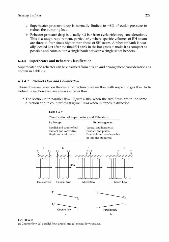
The section is in parallel fl ow (Figure 6.10b) when the two fl ows are in the same direction and in counterfl ow (Figure 6.10a) when in opposite direction.
•
TABLE 6.2
Classifi cation of Superheaters and Reheaters
By Design By Arrangement
Parallel and counterfl ow Vertical and horizontalRadiant and convective Pendant and platenSingle and multipass Drainable and nondrainable
In-line and staggered
a
Counterflow
Counterflow
a b
b
Gas
Parallel flow
c
Mixed flow
d
Mixed flow
T1
t2
T2
t1
T1
T2
t2t1 Parallel flow
FIGURE 6.10(a) Counterfl ow, (b) parallel fl ow, and (c) and (d) mixed-fl ow surfaces.
CRC_75365_Ch006.indd 229CRC_75365_Ch006.indd 229 2/27/2009 4:11:26 PM2/27/2009 4:11:26 PM
230 Boilers for Power and Process
In parallel fl ow, the highest gas temperature is in contact with the lowest steam temperature, which makes LMTD a little lower and the HS a little higher. The reverse applies to counterfl ow. Naturally the counterfl ow arrangement yields the lowest surface.Because the highest gas and steam temperatures in counterfl ow coincide, the metal temperatures are at their highest.
Mixed-fl ow arrangement (Figure 6.10d) is the optimum solution that yields a good com-promise—counterfl ow at a lower temperature and parallel fl ow at a higher temperature. Sometimes this pattern is reversed as shown in Figure 6.10c.
A. Counterflow LMTD T t T t
T t T t1 2 2 1
1 2 2 1
( ) ( ) ( ) ( )loge
( ) ( ) ( )B. Parallel flow LMTD
T t T t
T t T1 1 2 2
1 1 2
loge t2( )
(6.4)
6.3.4.2 Radiant and Convective Superheater and Reheater
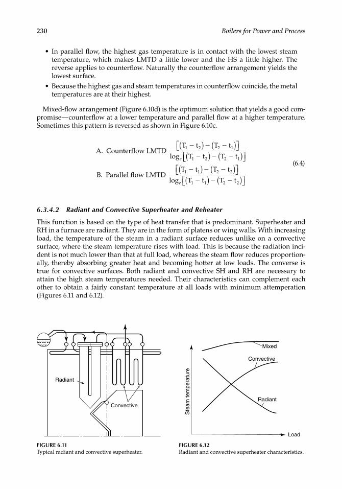
This function is based on the type of heat transfer that is predominant. Superheater and RH in a furnace are radiant. They are in the form of platens or wing walls. With increasing load, the temperature of the steam in a radiant surface reduces unlike on a convective surface, where the steam temperature rises with load. This is because the radiation inci-dent is not much lower than that at full load, whereas the steam fl ow reduces proportion-ally, thereby absorbing greater heat and becoming hotter at low loads. The converse is true for convective surfaces. Both radiant and convective SH and RH are necessary to attain the high steam temperatures needed. Their characteristics can complement each other to obtain a fairly constant temperature at all loads with minimum attemperation (Figures 6.11 and 6.12).
•
•
Radiant
Convective
FIGURE 6.11Typical radiant and convective superheater.
Ste
am te
mpe
ratu
re
Mixed
Convective
Radiant
Load
FIGURE 6.12Radiant and convective superheater characteristics.
CRC_75365_Ch006.indd 230CRC_75365_Ch006.indd 230 2/27/2009 4:11:27 PM2/27/2009 4:11:27 PM
Heating Surfaces 231
6.3.4.3 Single-Pass and Multipass Arrangements
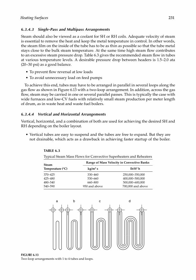
Steam should also be viewed as a coolant for SH or RH coils. Adequate velocity of steam is essential to remove the heat and keep the metal temperature in control. In other words, the steam fi lm on the inside of the tube has to be as thin as possible so that the tube metal stays close to the bulk steam temperature. At the same time high steam fl ow contributes to an excessive steam pressure drop. Table 6.3 gives the recommended steam fl ow in tubes at various temperature levels. A desirable pressure drop between headers is 1.5–2.0 ata (20–30 psi) as a good balance.
To prevent fl ow reversal at low loadsTo avoid unnecessary load on feed pumps
To achieve this end, tubes may have to be arranged in parallel in several loops along the gas fl ow as shown in Figure 6.13 with a two-loop arrangement. In addition, across the gas fl ow, steam may be carried in one or several parallel passes. This is typically the case with wide furnaces and low-CV fuels with relatively small steam production per meter length of drum, as in waste heat and waste fuel boilers.
6.3.4.4 Vertical and Horizontal Arrangements
Vertical, horizontal, and a combination of both are used for achieving the desired SH and RH depending on the boiler layout.
Vertical tubes are easy to suspend and the tubes are free to expand. But they are not drainable, which acts as a drawback in achieving faster startup of the boiler.
••
•
TABLE 6.3
Typical Steam Mass Flows for Convective Superheaters and Reheaters
Steam Temperature (°C)
Range of Mass Velocity in Convective Banks
kg/m2 s lb/ft2 h
370–425 330–460 250,000–350,000425–480 530–660 400,000–500,000480–540 660–800 500,000–600,000540–590 950 and above 700,000 and above
FIGURE 6.13Two-loop arrangements with 1 to 4 tubes and loops.
a b c d
CRC_75365_Ch006.indd 231CRC_75365_Ch006.indd 231 2/27/2009 4:11:27 PM2/27/2009 4:11:27 PM
232 Boilers for Power and Process
On rapid heating, water condensed from the previous shutdown turns to steam abruptly and forms a vapor lock in certain vertical tubes, preventing fl ow of steam in either direction. This causes tube overheating and failure. A controlled heating is therefore needed.Horizontal tubes are fully drainable and hence facilitate a faster startup and supe-rior boiler load response but require a more elaborate and expensive supporting arrangement to permit proper tube expansion.
6.3.4.5 Pendant and Platen Surfaces
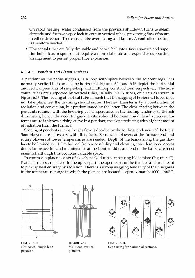
A pendant as the name suggests, is a loop with space between the adjacent legs. It is normally vertical but can also be horizontal. Figures 6.14 and 6.15 depict the horizontal and vertical pendants of single-loop and multiloop constructions, respectively. The hori-zontal tubes are supported by vertical tubes, usually ECON tubes, on cleats as shown in Figure 6.16. The spacing of vertical tubes is such that the sagging of horizontal tubes does not take place, lest the draining should suffer. The heat transfer is by a combination of radiation and convection, but predominated by the latter. The clear spacing between the pendants reduces with the lowering gas temperatures as the fouling tendency of the ash diminishes; hence, the need for gas velocities should be maintained. Load versus steam temperature is always a rising curve in a pendant, the slope reducing with higher amount of radiation from the furnace.
Spacing of pendants across the gas fl ow is decided by the fouling tendencies of the fuels. Soot blowers are necessary with dirty fuels. Retractable blowers at the furnace end and rotary blowers at lower temperatures are needed. Depth of the banks along the gas fl ow has to be limited to ∼1.7 m for coal from accessibility and cleaning considerations. Access doors for inspection and maintenance at the front, middle, and end of the banks are most essential, although this occupies valuable space.
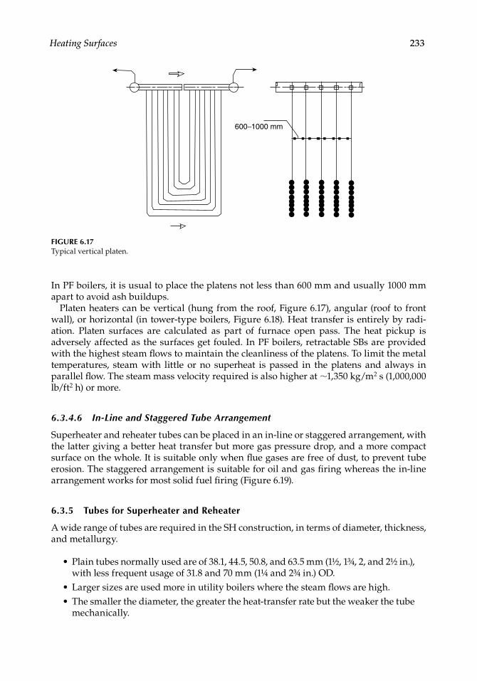
In contrast, a platen is a set of closely packed tubes appearing like a plate (Figure 6.17). Platen surfaces are placed in the upper part, the open pass, of the furnace and are meant to pick up heat entirely by radiation. There is a strong slagging tendency of the fl ue gases in the temperature range in which the platens are located— approximately 1000–1200°C.
•
FIGURE 6.14Horizontal single-loop pendant.
FIGURE 6.15Multiloop vertical pendant.
FIGURE 6.16Supporting for horizontal sections.
CRC_75365_Ch006.indd 232CRC_75365_Ch006.indd 232 2/27/2009 4:11:27 PM2/27/2009 4:11:27 PM
Heating Surfaces 233
In PF boilers, it is usual to place the platens not less than 600 mm and usually 1000 mm apart to avoid ash buildups.
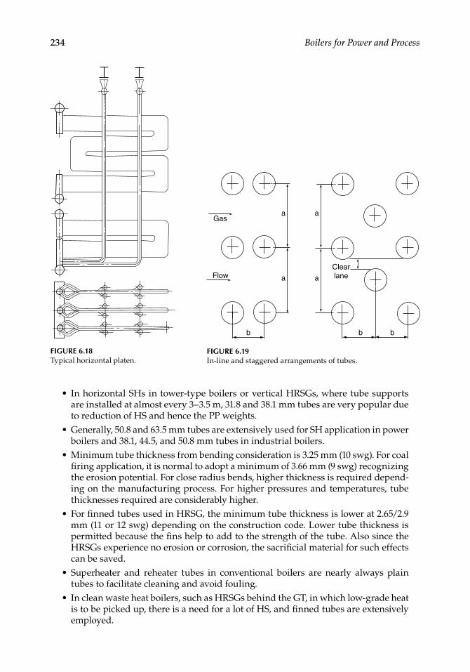
Platen heaters can be vertical (hung from the roof, Figure 6.17), angular (roof to front wall), or horizontal (in tower-type boilers, Figure 6.18). Heat transfer is entirely by radi-ation. Platen surfaces are calculated as part of furnace open pass. The heat pickup is adversely affected as the surfaces get fouled. In PF boilers, retractable SBs are provided with the highest steam fl ows to maintain the cleanliness of the platens. To limit the metal temperatures, steam with little or no superheat is passed in the platens and always in parallel fl ow. The steam mass velocity required is also higher at ∼1,350 kg/m2 s (1,000,000 lb/ft2 h) or more.
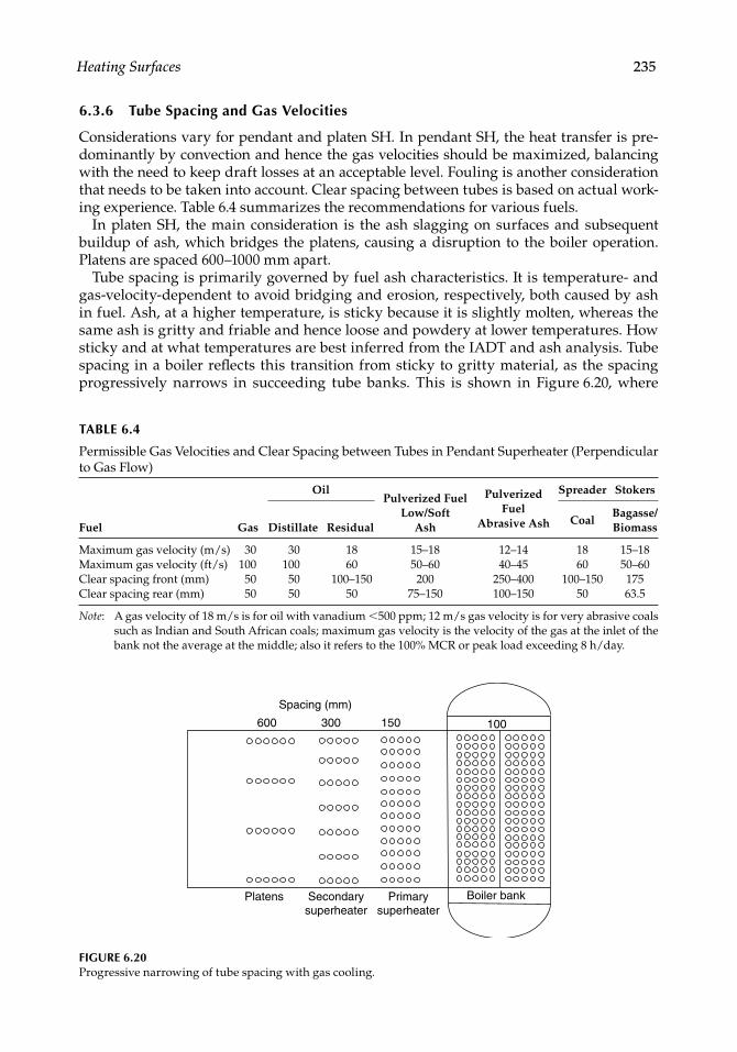
6.3.4.6 In-Line and Staggered Tube Arrangement
Superheater and reheater tubes can be placed in an in-line or staggered arrangement, with the latter giving a better heat transfer but more gas pressure drop, and a more compact surface on the whole. It is suitable only when fl ue gases are free of dust, to prevent tube erosion. The staggered arrangement is suitable for oil and gas fi ring whereas the in-line arrangement works for most solid fuel fi ring (Figure 6.19).
6.3.5 Tubes for Superheater and Reheater
A wide range of tubes are required in the SH construction, in terms of diameter, thickness, and metallurgy.
Plain tubes normally used are of 38.1, 44.5, 50.8, and 63.5 mm (1½, 1¾, 2, and 2½ in.), with less frequent usage of 31.8 and 70 mm (1¼ and 2¾ in.) OD.Larger sizes are used more in utility boilers where the steam fl ows are high.The smaller the diameter, the greater the heat-transfer rate but the weaker the tube mechanically.
•
••
600−1000 mm
FIGURE 6.17Typical vertical platen.
CRC_75365_Ch006.indd 233CRC_75365_Ch006.indd 233 2/27/2009 4:11:27 PM2/27/2009 4:11:27 PM
234 Boilers for Power and Process
In horizontal SHs in tower-type boilers or vertical HRSGs, where tube supports are installed at almost every 3–3.5 m, 31.8 and 38.1 mm tubes are very popular due to reduction of HS and hence the PP weights.Generally, 50.8 and 63.5 mm tubes are extensively used for SH application in power boilers and 38.1, 44.5, and 50.8 mm tubes in industrial boilers.Minimum tube thickness from bending consideration is 3.25 mm (10 swg). For coal fi ring application, it is normal to adopt a minimum of 3.66 mm (9 swg) recognizing the erosion potential. For close radius bends, higher thickness is required depend-ing on the manufacturing process. For higher pressures and temperatures, tube thicknesses required are considerably higher.For fi nned tubes used in HRSG, the minimum tube thickness is lower at 2.65/2.9 mm (11 or 12 swg) depending on the construction code. Lower tube thickness is permitted because the fi ns help to add to the strength of the tube. Also since the HRSGs experience no erosion or corrosion, the sacrifi cial material for such effects can be saved.Superheater and reheater tubes in conventional boilers are nearly always plain tubes to facilitate cleaning and avoid fouling.In clean waste heat boilers, such as HRSGs behind the GT, in which low-grade heat is to be picked up, there is a need for a lot of HS, and fi nned tubes are extensively employed.
•
•
•
•
•
•
a
a
a
a
b b b
FlowClearlane
Gas
FIGURE 6.19In-line and staggered arrangements of tubes.
FIGURE 6.18Typical horizontal platen.
CRC_75365_Ch006.indd 234CRC_75365_Ch006.indd 234 2/27/2009 4:11:28 PM2/27/2009 4:11:28 PM
Heating Surfaces 235
6.3.6 Tube Spacing and Gas Velocities
Considerations vary for pendant and platen SH. In pendant SH, the heat transfer is pre-dominantly by convection and hence the gas velocities should be maximized, balancing with the need to keep draft losses at an acceptable level. Fouling is another consideration that needs to be taken into account. Clear spacing between tubes is based on actual work-ing experience. Table 6.4 summarizes the recommendations for various fuels.
In platen SH, the main consideration is the ash slagging on surfaces and subsequent buildup of ash, which bridges the platens, causing a disruption to the boiler operation. Platens are spaced 600–1000 mm apart.
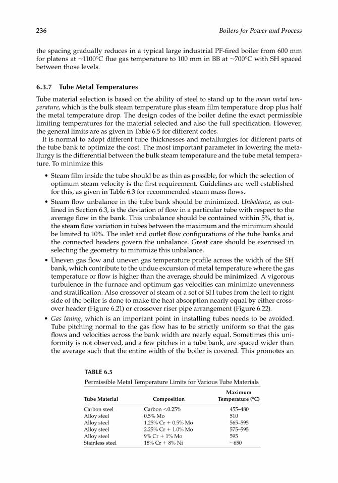
Tube spacing is primarily governed by fuel ash characteristics. It is temperature- and gas-velocity-dependent to avoid bridging and erosion, respectively, both caused by ash in fuel. Ash, at a higher temperature, is sticky because it is slightly molten, whereas the same ash is gritty and friable and hence loose and powdery at lower temperatures. How sticky and at what temperatures are best inferred from the IADT and ash analysis. Tube spacing in a boiler refl ects this transition from sticky to gritty material, as the spacing progressively narrows in succeeding tube banks. This is shown in Figure 6.20, where
TABLE 6.4
Permissible Gas Velocities and Clear Spacing between Tubes in Pendant Superheater (Perpendi cular to Gas Flow)
Fuel Gas
OilPulverized Fuel
Low/Soft Ash
Pulverized Fuel
Abrasive Ash
Spreader Stokers
Distillate ResidualCoal
Bagasse/Biomass
Maximum gas velocity (m/s) 30 30 18 15–18 12–14 18 15–18Maximum gas velocity (ft/s) 100 100 60 50–60 40–45 60 50–60Clear spacing front (mm) 50 50 100–150 200 250–400 100–150 175Clear spacing rear (mm) 50 50 50 75–150 100–150 50 63.5
Note: A gas velocity of 18 m/s is for oil with vanadium <500 ppm; 12 m/s gas velocity is for very abrasive coals such as Indian and South African coals; maximum gas velocity is the velocity of the gas at the inlet of the bank not the average at the middle; also it refers to the 100% MCR or peak load exceeding 8 h/day.
Spacing (mm)
600 300 150
Platens Secondarysuperheater
Primarysuperheater
Boiler bank
100
FIGURE 6.20Progressive narrowing of tube spacing with gas cooling.
CRC_75365_Ch006.indd 235CRC_75365_Ch006.indd 235 2/27/2009 4:11:28 PM2/27/2009 4:11:28 PM
236 Boilers for Power and Process
the spacing gradually reduces in a typical large industrial PF-fi red boiler from 600 mm for platens at ∼1100°C fl ue gas temperature to 100 mm in BB at ∼700°C with SH spaced between those levels.
6.3.7 Tube Metal Temperatures
Tube material selection is based on the ability of steel to stand up to the mean metal tem-perature, which is the bulk steam temperature plus steam fi lm temperature drop plus half the metal temperature drop. The design codes of the boiler defi ne the exact permissible limiting temperatures for the material selected and also the full specifi cation. However, the general limits are as given in Table 6.5 for different codes.
It is normal to adopt different tube thicknesses and metallurgies for different parts of the tube bank to optimize the cost. The most important parameter in lowering the meta-llurgy is the differential between the bulk steam temperature and the tube metal tempera-ture. To minimize this
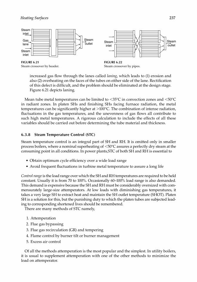
Steam fi lm inside the tube should be as thin as possible, for which the selection of optimum steam velocity is the fi rst requirement. Guidelines are well established for this, as given in Table 6.3 for recommended steam mass fl ows.Steam fl ow unbalance in the tube bank should be minimized. Unbalance, as out-lined in Section 6.3, is the deviation of fl ow in a particular tube with respect to the average fl ow in the bank. This unbalance should be contained within 5%, that is, the steam fl ow variation in tubes between the maximum and the minimum should be limited to 10%. The inlet and outlet fl ow confi gurations of the tube banks and the connected headers govern the unbalance. Great care should be exercised in selecting the geometry to minimize this unbalance.Uneven gas fl ow and uneven gas temperature profi le across the width of the SH bank, which contribute to the undue excursion of metal temperature where the gas temperature or fl ow is higher than the average, should be minimized. A vigorous turbulence in the furnace and optimum gas velocities can minimize unevenness and stratifi cation. Also crossover of steam of a set of SH tubes from the left to right side of the boiler is done to make the heat absorption nearly equal by either cross-over header (Figure 6.21) or crossover riser pipe arrangement (Figure 6.22).Gas laning, which is an important point in installing tubes needs to be avoided. Tube pitching normal to the gas fl ow has to be strictly uniform so that the gas fl ows and velocities across the bank width are nearly equal. Sometimes this uni-formity is not observed, and a few pitches in a tube bank, are spaced wider than the average such that the entire width of the boiler is covered. This promotes an
•
•
•
•
TABLE 6.5
Permissible Metal Temperature Limits for Various Tube Materials
Tube Material CompositionMaximum
Temperature (°C)
Carbon steel Carbon <0.25% 455–480Alloy steel 0.5% Mo 510Alloy steel 1.25% Cr + 0.5% Mo 565–595Alloy steel 2.25% Cr + 1.0% Mo 575–595Alloy steel 9% Cr + 1% Mo 595Stainless steel 18% Cr + 8% Ni ∼650
CRC_75365_Ch006.indd 236CRC_75365_Ch006.indd 236 2/27/2009 4:11:28 PM2/27/2009 4:11:28 PM
Heating Surfaces 237
increased gas fl ow through the lanes called laning, which leads to (1) erosion and also (2) overheating on the faces of the tubes on either side of the lane. Rectifi cation of this defect is diffi cult, and the problem should be eliminated at the design stage. Figure 6.21 depicts laning.
Mean tube metal temperatures can be limited to <35°C in convection zones and <50°C in radiant zones. In platen SHs and fi nishing SHs facing furnace radiation, the metal temperatures can be signifi cantly higher at >100°C. The combination of intense radiation, fl uctuations in the gas temperatures, and the unevenness of gas fl ows all contribute to such high metal temperatures. A rigorous calculation to include the effects of all these variables should be carried out before determining the tube material and thickness.
6.3.8 Steam Temperature Control (STC)
Steam temperature control is an integral part of SH and RH. It is omitted only in smaller process boilers, where a nominal superheating of <50°C assures a perfectly dry steam at the consuming point in all conditions. In power plants,STC of both SH and RH is essential to
Obtain optimum cycle effi ciency over a wide load rangeAvoid frequent fl uctuations in turbine metal temperature to assure a long life
Control range is the load range over which the SH and RH temperatures are required to be held constant. Usually it is from 70 to 100%. Occasionally 60–100% load range is also demanded. This demand is expensive because the SH and RH must be considerably oversized with com-mensurately large-size attemperators. At low loads with diminishing gas temperatures, it takes a very large SH to extract heat and maintain the SH outlet temperature (SHOT). Platen SH is a solution for this, but the punishing duty to which the platen tubes are subjected lead-ing to corresponding shortened lives should be remembered.
There are many methods of STC namely,
1. Attemperation 2. Flue gas bypassing 3. Flue gas recirculation (GR) and tempering 4. Flame control by burner tilt or burner management 5. Excess air control
Of all the methods attemperation is the most popular and the simplest. In utility boilers, it is usual to supplement attemperation with one of the other methods to minimize the load on attemperator.
••
Steaminlet
Steamoutlet
FIGURE 6.22Steam crossover by pipes.
Steaminlet
Gaslane
Steaminlet
Steamoutlet
FIGURE 6.21Steam crossover by header.
CRC_75365_Ch006.indd 237CRC_75365_Ch006.indd 237 2/27/2009 4:11:28 PM2/27/2009 4:11:28 PM
238 Boilers for Power and Process
6.3.8.1 Attemperator
Attemperation is the desuperheating of main or reheat steam to control the fi nal tem-peratures to the set limits. In a spray attemperator, the principle is a direct contact heat exchange where the feed water (FW) bypasses the ECON and evaporator circuits and joins the superheated steam directly. In a drum attemperator, an indirect heat exchange occurs when the extra heat of steam is dissipated to the drum water.
Besides the temperature control, an attemperator can also control the tube metal tem-peratures of SH and RH.
Reheater attemperation. Attemperation in RH is only for an emergency condition and not for regular temperature control operation because it reduces the overall cycle effi ciency. The spray water added in the attemperator expands only in the IP and the low-pressure (LP) portions of the turbines bypassing the HP section altogether. Spray quantity of 1% steam fl ow reduces the heat rate by ∼0.2%. The temperature control of the RH is to be performed by fl ue gas bypassing or recirculation or by burner tilting.
The attemperator is located at the inlet on the cold reheat line so that the metal tempera-tures can also be controlled.
Superheater attemperation. Location of the attemperator is important for SH layout.
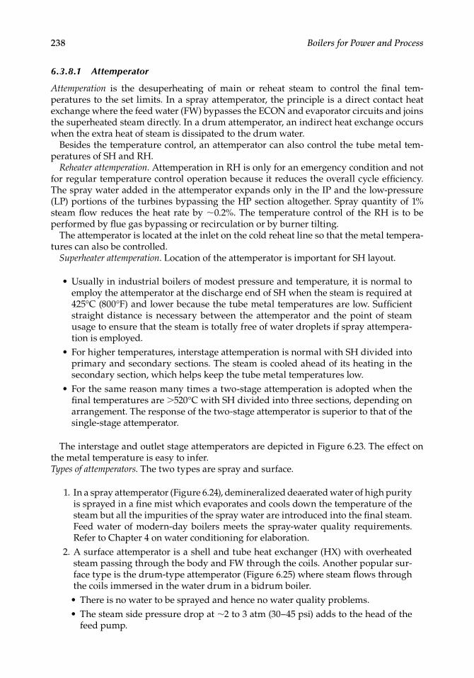
Usually in industrial boilers of modest pressure and temperature, it is normal to employ the attemperator at the discharge end of SH when the steam is required at 425°C (800°F) and lower because the tube metal temperatures are low. Suffi cient straight distance is necessary between the attemperator and the point of steam usage to ensure that the steam is totally free of water droplets if spray attempera-tion is employed.For higher temperatures, interstage attemperation is normal with SH divided into primary and secondary sections. The steam is cooled ahead of its heating in the secondary section, which helps keep the tube metal temperatures low.For the same reason many times a two-stage attemperation is adopted when the fi nal temperatures are >520°C with SH divided into three sections, depending on arrangement. The response of the two-stage attemperator is superior to that of the single-stage attemperator.
The interstage and outlet stage attemperators are depicted in Figure 6.23. The effect on the metal temperature is easy to infer.Types of attemperators. The two types are spray and surface.
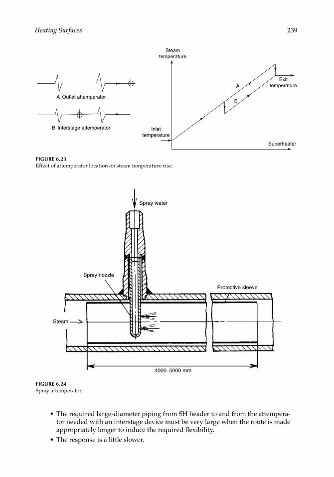
1. In a spray attemperator (Figure 6.24), demineralized deaerated water of high purity is sprayed in a fi ne mist which evaporates and cools down the temperature of the steam but all the impurities of the spray water are introduced into the fi nal steam. Feed water of modern-day boilers meets the spray-water quality requirements. Refer to Chapter 4 on water conditioning for elaboration.
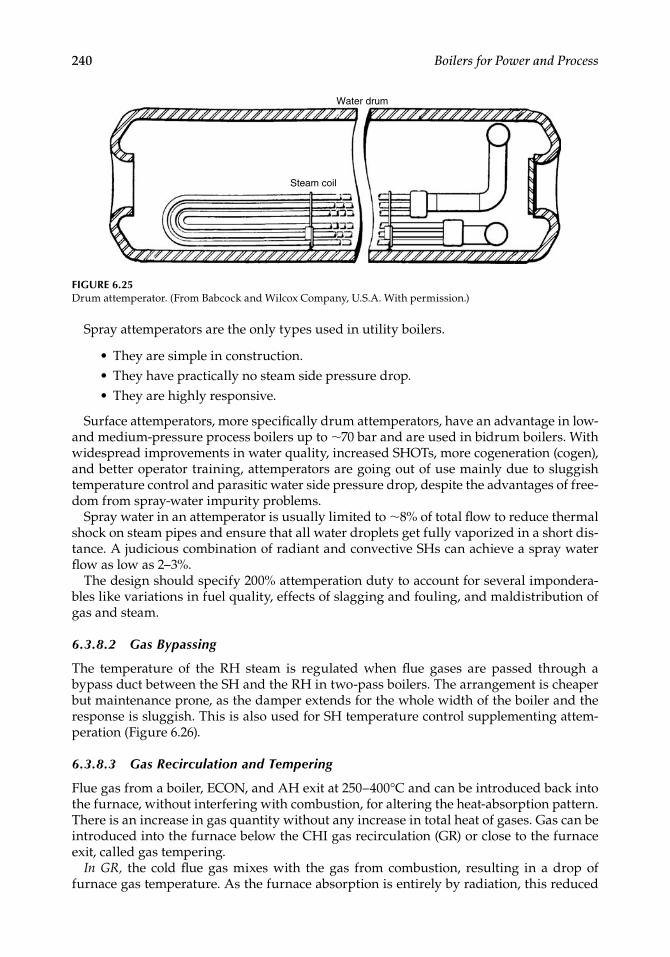
2. A surface attemperator is a shell and tube heat exchanger (HX) with overheated steam passing through the body and FW through the coils. Another popular sur-face type is the drum-type attemperator (Figure 6.25) where steam fl ows through the coils immersed in the water drum in a bidrum boiler.
• There is no water to be sprayed and hence no water quality problems.• The steam side pressure drop at ∼2 to 3 atm (30–45 psi) adds to the head of the
feed pump.
•
•
•
CRC_75365_Ch006.indd 238CRC_75365_Ch006.indd 238 2/27/2009 4:11:28 PM2/27/2009 4:11:28 PM
Heating Surfaces 239
• The required large-diameter piping from SH header to and from the attempera-tor needed with an interstage device must be very large when the route is made appropriately longer to induce the required fl exibility.
• The response is a little slower.
A Outlet attemperator
B Interstage attemperator
Steamtemperature
Inlettemperature
Exittemperature
Superheater
A
B
FIGURE 6.23Effect of attemperator location on steam temperature rise.
Spray water
Spray nozzle
Steam
4000−5000 mm
Protective sleeve
FIGURE 6.24Spray attemperator.
CRC_75365_Ch006.indd 239CRC_75365_Ch006.indd 239 2/27/2009 4:11:29 PM2/27/2009 4:11:29 PM
240 Boilers for Power and Process
Spray attemperators are the only types used in utility boilers.
• They are simple in construction.• They have practically no steam side pressure drop.• They are highly responsive.
Surface attemperators, more specifi cally drum attemperators, have an advantage in low- and medium-pressure process boilers up to ∼70 bar and are used in bidrum boilers. With widespread improvements in water quality, increased SHOTs, more cogeneration (cogen), and better operator training, attemperators are going out of use mainly due to sluggish temperature control and parasitic water side pressure drop, despite the advantages of free-dom from spray-water impurity problems.
Spray water in an attemperator is usually limited to ∼8% of total fl ow to reduce thermal shock on steam pipes and ensure that all water droplets get fully vaporized in a short dis-tance. A judicious combination of radiant and convective SHs can achieve a spray water fl ow as low as 2–3%.
The design should specify 200% attemperation duty to account for several impondera-bles like variations in fuel quality, effects of slagging and fouling, and maldistribution of gas and steam.
6.3.8.2 Gas Bypassing
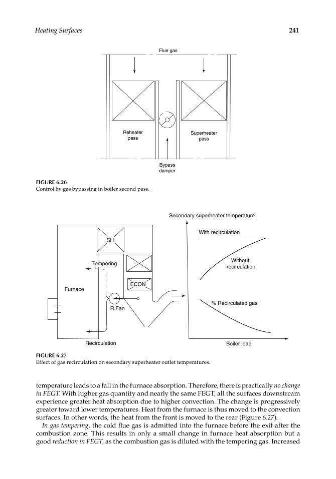
The temperature of the RH steam is regulated when fl ue gases are passed through a bypass duct between the SH and the RH in two-pass boilers. The arrangement is cheaper but maintenance prone, as the damper extends for the whole width of the boiler and the response is sluggish. This is also used for SH temperature control supplementing attem-peration (Figure 6.26).
6.3.8.3 Gas Recirculation and Tempering
Flue gas from a boiler, ECON, and AH exit at 250–400°C and can be introduced back into the furnace, without interfering with combustion, for altering the heat-absorption pattern. There is an increase in gas quantity without any increase in total heat of gases. Gas can be introduced into the furnace below the CHI gas recirculation (GR) or close to the furnace exit, called gas tempering.
In GR, the cold fl ue gas mixes with the gas from combustion, resulting in a drop of furnace gas temperature. As the furnace absorption is entirely by radiation, this reduced
Water drum
Steam coil
FIGURE 6.25Drum attemperator. (From Babcock and Wilcox Company, U.S.A. With permission.)
CRC_75365_Ch006.indd 240CRC_75365_Ch006.indd 240 2/27/2009 4:11:29 PM2/27/2009 4:11:29 PM
Heating Surfaces 241
temperature leads to a fall in the furnace absorption. Therefore, there is practically no change in FEGT. With higher gas quantity and nearly the same FEGT, all the surfaces downstream experience greater heat absorption due to higher convection. The change is progressively greater toward lower temperatures. Heat from the furnace is thus moved to the convection surfaces. In other words, the heat from the front is moved to the rear (Figure 6.27).
In gas tempering, the cold fl ue gas is admitted into the furnace before the exit after the combustion zone. This results in only a small change in furnace heat absorption but a good reduction in FEGT, as the combustion gas is diluted with the tempering gas. Increased
Flue gas
Reheaterpass
Superheaterpass
Bypassdamper
FIGURE 6.26Control by gas bypassing in boiler second pass.
Recirculation
Furnace
R.Fan
Tempering
SH
Secondary superheater temperature
With recirculation
% Recirculated gas
Boiler load
Without recirculation
ECON
FIGURE 6.27Effect of gas recirculation on secondary superheater outlet temperatures.
CRC_75365_Ch006.indd 241CRC_75365_Ch006.indd 241 2/27/2009 4:11:29 PM2/27/2009 4:11:29 PM
242 Boilers for Power and Process
gas fl ow and reduced gas temperatures contribute to a reduction in heat absorption in the secondary SH, nearly no change in the RH and some increase in the primary SH, and a good increase in the ECON. Heat is redistributed in the SH downward without much change to the furnace.
The greater the amount of recirculated gases, the greater the redistribution of heat. About 5% is considered as minimum for preventing backfl ow. Gas recirculation is greater at low loads as the SH and RH temperatures are lower. As the furnace absorption is lowered, GR is also used for controlling the furnace temperatures to regulate metal temperatures and slagging.
Furnace and RH heat absorption remains almost the same regardless of the amount of gas tempering. Its use is more in reducing the secondary SH temperature and fouling in the SH area.
Fans for recycling of gas experience a heavy use in terms of temperature, dust, and the pressure drop. This is an important consideration in evaluating the gas recycling option.
6.3.8.4 Flame Control
Burner tilt and burner management are the two arrangements available to control the CHI for corner-fi red and wall-fi red boilers, respectively. In corner-fi red boilers, the burner tilt changes the position of the fl ame ball upward or downward, thereby altering the furnace absorption and FEGT. In wall-fi red boilers, a similar effect can be achieved by cutting in and out the lowest and the highest tier of burners.
With tilting of burners, it is not possible to precisely control both SH and RH simultane-ously because of the differing characteristics. It is normal, therefore, to control the RH with a burner tilt and the SH with an attemperator.
6.3.8.5 Excess Air Control
Slight increases in the excess air give a little more superheat and reheat. The combustion temperature and consequently the furnace heat absorption are both lowered, resulting in slightly higher FEGT and gas weights, which affect the steam temperatures of SH and RH positively. At the same time this method contributes to an effi ciency loss due to higher stack loss. For short periods and low loads, this method can be adopted but not on a regu-lar basis at higher loads.
6.4 Back-End Equipment
Economizer and airheater are called the back-end equipment. They are the last of the heat traps and positioned behind the evaporator surfaces in bidrum boilers and behind SH/RH surface in radiant boilers. The ECON is so-called because it economizes the fuel usage by extracting the low-grade heat. Flue gases leave the evaporator in bidrum boilers and the SH in single-drum boilers at a maximum temperature of ∼500 and 600°C, respectively and are cooled to an optimal level at the back end.
The design of the back end requires great care and skill, as the boiler effi ciency increases by ∼1% point for every 22°C (40°F) of drop in exit temperature. In an effort to recover the low-grade heat, excessive surfacing may increase the costs. Balancing is most important.
•
CRC_75365_Ch006.indd 242CRC_75365_Ch006.indd 242 2/27/2009 4:11:29 PM2/27/2009 4:11:29 PM
Heating Surfaces 243
The optimum level for cooling the gases is dependent on the fuel and its cost and can vary from as low as 75°C (∼165°F) in HRSGs fi ring natural gas to ∼160°C (320°F) or even higher for high-sulfur fuels. For most common fuels, such as coal and oil with low sulfur, the gas exit temperature is ∼140°C (285°F) at full load; the limit is imposed by the corrosion of the downstream fl ues and dust-collecting equipment at part load operation.Although ECON and AH are both for recovery of heat at the fi nal levels, there is an important difference in the way the heat is returned to the system. In ECON, the heat from the fl ue gas is transferred directly to ECON water, whereas in AH, the transfer is indirect. Heat is transferred to the cold combustion air that enters into the furnace as hot air, raising the furnace temperature and then giving away the heat to the furnace and the SH. Thus FEGT is always higher with a unit equipped with AH, and slagging and fouling aspects have to be checked. Combustion speed is also enhanced. Even though both are back-end heat traps, the AH and ECON must be evaluated on a case-to-case basis.
6.4.1 Airheater or Economizer?
The back end may consist of only ECON or a combination of ECON and AH, depending on the fuel and process. The inclusion of AH is compulsory where the combustion process demands hot air, such as in PF, biofuels, and BL. In power plant boilers, where the FW tem-peratures are high, the ECON alone cannot cool the gases. In HRSGs, however, the AHs are conspicuous by their absence. In these days of low gas exit temperatures, AH alone as back-end equipment is a rarity because the hot air temperature so obtained would not be acceptable to most fi ring equipment and fl ues. If the fl ue gases are not cooled adequately, the hot exhaust gases would be too hot for fans, dust collectors, and stack.
Besides reducing the gas temperature, the ECON performs another important task of narrowing the difference between feed and drum temperatures, thereby reducing the thermal shock to drum and water walls.
This requires understanding of process side of water and air.
In most process plants, condensate returns at 40–90°C to the deaerator from where, after deaeration and chemical addition, the FW enters the boiler at 105°C. In such cases no AH is required if hot air is not needed for combustion.If hot air is needed, an AH of appropriate size is provided behind the ECON, so that together they provide hot air and cold fl ue gas as required for the system.In power plants, regenerative heating delivers the FW at temperatures of 160–270°C, necessitating both AH and ECON.In combined cycle pressure parts (CCPPs), the condensate at ∼40°C returns to the HRSG from the condenser because there are no heaters in the cycle. A condensate preheater is the last heat trap in the HRSG located behind the ECON. The exit gas temperature can be as low as 75°C, depending on the sulfur in the fuel.
6.4.2 Airheater versus Economizer
As the AH and ECON extract low-grade heat, they experience low thermal heads to drive the heat and hence are very large HXs. The ECON has nearly three to four times greater heat-transfer coeffi cient than the AH, which is a gas–air HX. Economizer heat transfer is governed by gas-side coeffi cient only, whereas the AH coeffi cient is governed by both gas
•
•
•
•
•
•
CRC_75365_Ch006.indd 243CRC_75365_Ch006.indd 243 2/27/2009 4:11:30 PM2/27/2009 4:11:30 PM
244 Boilers for Power and Process
and air sides, nearly in equal measure. This is the reason for the large difference in heat-transfer rates of the two systems. Airheater surface is, therefore, three to four times that of an equivalent ECON.
An economizer is a PP and hence expensive but more compact. On the contrary, since an AH is three to four times as large and more voluminous, it is often more expensive to build, although it is a nonpressure part (NPP). In an AH, the ducting adds to the cost sig-nifi cantly and its routing affects the layout tremendously.
6.4.3 Airheater and Economizer Arrangements
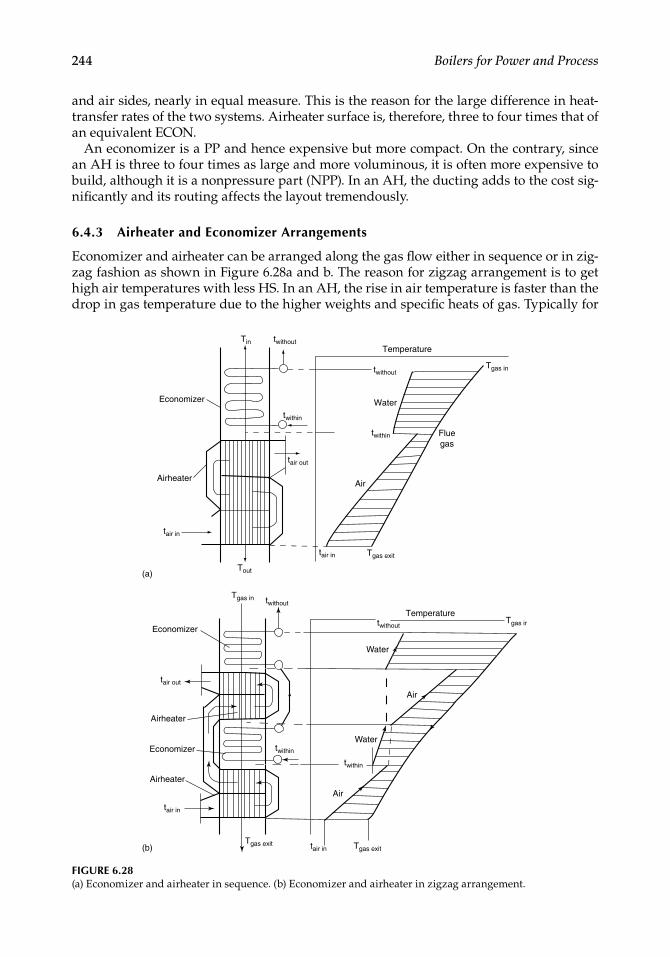
Economizer and airheater can be arranged along the gas fl ow either in sequence or in zig-zag fashion as shown in Figure 6.28a and b. The reason for zigzag arrangement is to get high air temperatures with less HS. In an AH, the rise in air temperature is faster than the drop in gas temperature due to the higher weights and specifi c heats of gas. Typically for
Economizer
Airheater
(a)
(b)
Water
Tin twithout
twithin
twithin
tair out
Tout
tair in
tair in
Tgas in
Tgas exit
twithout
Temperature
Fluegas
Air
TemperatureTgas in
Tgas in
Tgas exit Tgas exit
tair out
tair in
tair in
twithout
twithin
twithin
twithout
Water
Water
Economizer
Economizer
Airheater
Airheater
Air
Air
FIGURE 6.28(a) Economizer and airheater in sequence. (b) Economizer and airheater in zigzag arrangement.
CRC_75365_Ch006.indd 244CRC_75365_Ch006.indd 244 2/27/2009 4:11:30 PM2/27/2009 4:11:30 PM
Heating Surfaces 245
low- moisture fuels such as coal and oil, the air temperature increases by ∼1.2°C for every 1°C drop in gas temperature, whereas for high-moisture fuels such as bagasse, it is as high as 1.6°C.
6.5 Economizer
Economizer surfaces transfer heat from fl ue gases to pressurized andsubcooled FW on its way to the drum. Heat transfer in an ECON is nearly entirely by convection, and hence the gas velocities are maximized consistent with pressure drop and tube spacing limitations. Coal ash in fl ue gas at temperatures <600°C is no longer sticky and hence fouling of tubes is not as much an issue as in SH. The ash is loose and does not form strongly adhering deposits and hence is easily removed by soot blowing. However, if there is a mixed fi ring of oil and coal, the ash can stick over the oil deposits that form on the tubes. The major concern is to reduce the surface and volume to optimize the space and cost.
Usually smaller tubes with 38.1, 44.5, and 50.8 mm (1½, 1¾, and 2 in.) ODs are cho-sen to increase the heat-transfer rate. 31.8 mm (1¼ in.) tubes are used in SC boilers and vertical HRSGs.Large-diameter tubes like 63.5 and 76.2 mm are adopted in vertical ECONs based on strength considerations.Close bending of tubes with radius of 1D or lower is also used most frequently.Care is taken to avoid a back pitch (along the gas fl ow) of 1.07–1.25 times the OD, via development of boundary layer, to avoid excessive draft loss and reduced heat transfer. Heat transfer can reduce by as much as 30% with this spacing.Optimum mass velocity for bare tube ECON lies between 5.4 and 6.8 kg/m2 s (4000–5000 lb/ft2 h).
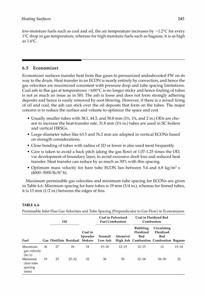
Maximum permissible gas velocities and minimum tube spacing for ECONs are given in Table 6.6. Minimum spacing for bare tubes is 19 mm (3/4 in.), whereas for fi nned tubes, it is 13 mm (1/2 in.) between the edges of fi ns.
•
•
••
•
TABLE 6.6
Permissible Inlet Flue Gas Velocities and Tube Spacing (Perpendicular to Gas Flow) in Economizers
Fuel Gas
Oil
Coal in Spreader Stokers
Coal in Pulverized Fuel Combustion
Coal in Fluidized Bed Combustion
BagasseDistillate ResidualNormal/Low Ash
Abrasive/High Ash
Bubbling Fluidized
Bed Combustion
Circulating Fluidized
Bed Combustion
Maximum gas velocity (m/s)
36 27 18 18 15–18 12–15 12–15 12 15–18
Minimum clear tube spacing (mm)
19 25 25–32 32 38 50 32–38 38–50 32
CRC_75365_Ch006.indd 245CRC_75365_Ch006.indd 245 2/27/2009 4:11:30 PM2/27/2009 4:11:30 PM
246 Boilers for Power and Process
Water in ECONs should always fl ow upward to allow the steam bubbles to ascend smoothly. In the downward fl ow, steam bubbles can cause fl ow stagnation and disrupt the operation. In cases when downward fl ow is compulsory due to layout, adequate pressure drop is created by inserting ferrules for fl ow equalization.
Tube selection should not exceed 6 m/s (20 ft/s) of water velocity to avoid excessive pressure drop and also the erosion of tubes. A minimum water velocity should be main-tained at ∼2 m/s (6 ft/s) for fl ow equalization. Likewise, the axial velocity in ECON head-ers should be <6 m/s (20 ft/s).
Economizer banks must be restricted to 1.8 m (6 ft) for effective soot blowing. A clear access of 600 mm (2 ft) is necessary for proper access and weld repair.
6.5.1 Classification
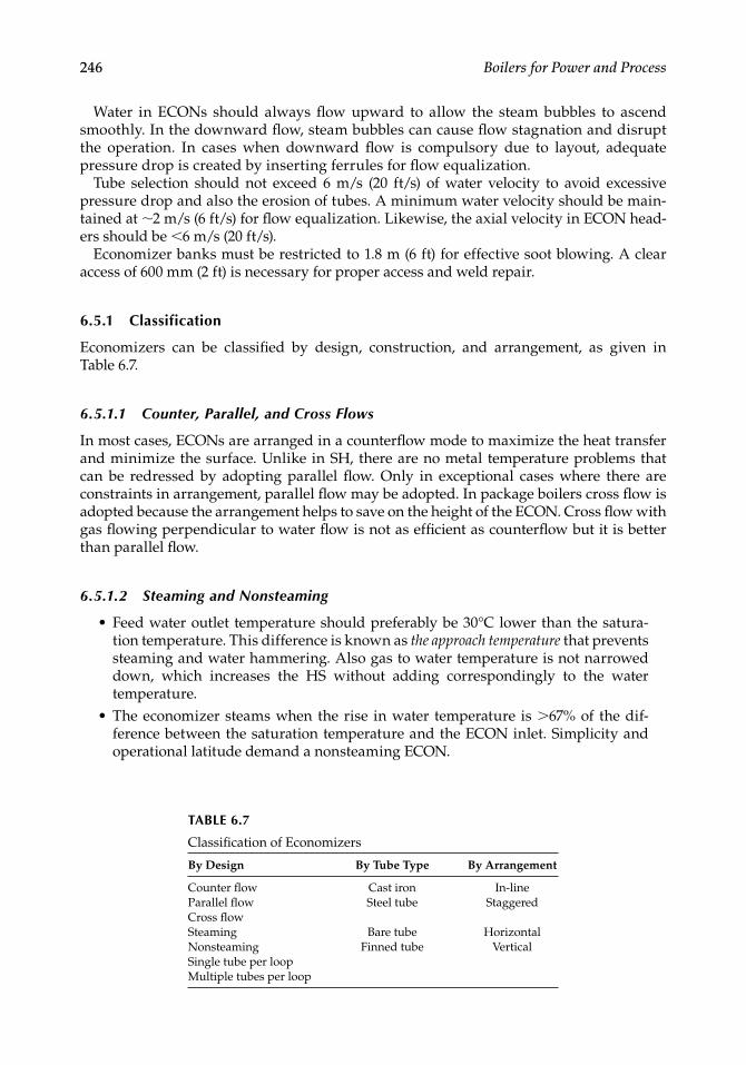
Economizers can be classifi ed by design, construction, and arrangement, as given in Table 6.7.
6.5.1.1 Counter, Parallel, and Cross Flows
In most cases, ECONs are arranged in a counterfl ow mode to maximize the heat transfer and minimize the surface. Unlike in SH, there are no metal temperature problems that can be redressed by adopting parallel fl ow. Only in exceptional cases where there are constraints in arrangement, parallel fl ow may be adopted. In package boilers cross fl ow is adopted because the arrangement helps to save on the height of the ECON. Cross fl ow with gas fl owing perpendicular to water fl ow is not as effi cient as counterfl ow but it is better than parallel fl ow.
6.5.1.2 Steaming and Nonsteaming
Feed water outlet temperature should preferably be 30°C lower than the satura-tion temperature. This difference is known as the approach temperature that prevents steaming and water hammering. Also gas to water temperature is not narrowed down, which increases the HS without adding correspondingly to the water temperature.The economizer steams when the rise in water temperature is >67% of the dif-ference between the saturation temperature and the ECON inlet. Simplicity and operational latitude demand a nonsteaming ECON.
•
•
TABLE 6.7
Classifi cation of Economizers
By Design By Tube Type By Arrangement
Counter fl owParallel fl owCross fl ow
Cast iron Steel tube
In-line Staggered
Steaming Nonsteaming
Bare tube Finned tube
Horizontal Vertical
Single tube per loopMultiple tubes per loop
CRC_75365_Ch006.indd 246CRC_75365_Ch006.indd 246 2/27/2009 4:11:30 PM2/27/2009 4:11:30 PM
Heating Surfaces 247
At times, this condition may in fact be benefi cial to increase the ECON surface and generate some steam in it. Then the ECON outlet header should be located below the drum level. Care should be taken to avoid any loops or downward slopes in both ECON tubing and water piping from ECON to drum so that all the steam generated is constantly directed upward to the drum. Depending on the steam generation, it may be necessary to provide additional dedicated cyclones for sepa-ration. Usually 8% of steam generation is considered a safe limit, although there are cases of 20% steam generated on ECONs. The water treatment has to be very stringent.
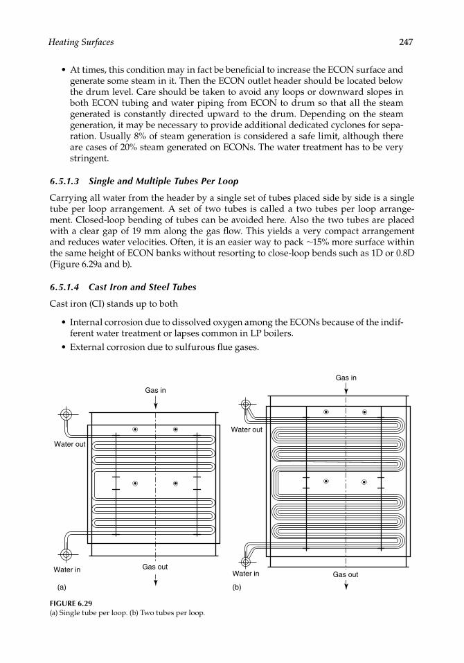
6.5.1.3 Single and Multiple Tubes Per Loop
Carrying all water from the header by a single set of tubes placed side by side is a single tube per loop arrangement. A set of two tubes is called a two tubes per loop arrange-ment. Closed-loop bending of tubes can be avoided here. Also the two tubes are placed with a clear gap of 19 mm along the gas fl ow. This yields a very compact arrangement and reduces water velocities. Often, it is an easier way to pack ∼15% more surface within the same height of ECON banks without resorting to close-loop bends such as 1D or 0.8D (Figure 6.29a and b).
6.5.1.4 Cast Iron and Steel Tubes
Cast iron (CI) stands up to both
Internal corrosion due to dissolved oxygen among the ECONs because of the indif-ferent water treatment or lapses common in LP boilers.External corrosion due to sulfurous fl ue gases.
•
•
•
Water out
Water in
(a) (b)
Gas in
Gas outGas out
Gas in
Water out
Water in
FIGURE 6.29(a) Single tube per loop. (b) Two tubes per loop.
CRC_75365_Ch006.indd 247CRC_75365_Ch006.indd 247 2/27/2009 4:11:30 PM2/27/2009 4:11:30 PM
248 Boilers for Power and Process
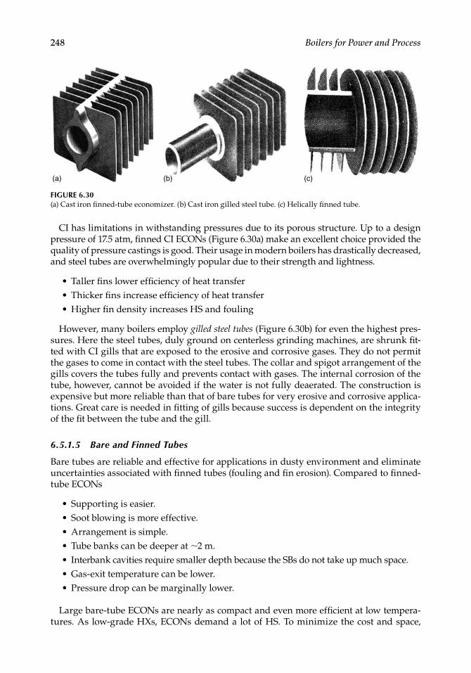
CI has limitations in withstanding pressures due to its porous structure. Up to a design pressure of 17.5 atm, fi nned CI ECONs (Figure 6.30a) make an excellent choice provided the quality of pressure castings is good. Their usage in modern boilers has drastically decreased, and steel tubes are overwhelmingly popular due to their strength and lightness.
Taller fi ns lower effi ciency of heat transferThicker fi ns increase effi ciency of heat transferHigher fi n density increases HS and fouling
However, many boilers employ gilled steel tubes (Figure 6.30b) for even the highest pres-sures. Here the steel tubes, duly ground on centerless grinding machines, are shrunk fi t-ted with CI gills that are exposed to the erosive and corrosive gases. They do not permit the gases to come in contact with the steel tubes. The collar and spigot arrangement of the gills covers the tubes fully and prevents contact with gases. The internal corrosion of the tube, however, cannot be avoided if the water is not fully deaerated. The construction is expensive but more reliable than that of bare tubes for very erosive and corrosive applica-tions. Great care is needed in fi tting of gills because success is dependent on the integrity of the fi t between the tube and the gill.
6.5.1.5 Bare and Finned Tubes
Bare tubes are reliable and effective for applications in dusty environment and eliminate uncertainties associated with fi nned tubes (fouling and fi n erosion). Compared to fi nned-tube ECONs
Supporting is easier.Soot blowing is more effective.Arrangement is simple.Tube banks can be deeper at ∼2 m.Interbank cavities require smaller depth because the SBs do not take up much space.Gas-exit temperature can be lower.Pressure drop can be marginally lower.
Large bare-tube ECONs are nearly as compact and even more effi cient at low tempera-tures. As low-grade HXs, ECONs demand a lot of HS. To minimize the cost and space,
•••
•••••••
(a) (b) (c)
FIGURE 6.30(a) Cast iron fi nned-tube economizer. (b) Cast iron gilled steel tube. (c) Helically fi nned tube.
CRC_75365_Ch006.indd 248CRC_75365_Ch006.indd 248 2/27/2009 4:11:31 PM2/27/2009 4:11:31 PM
Heating Surfaces 249
various types of extended-surface ECONs have been tried with varying degrees of success with different fuels. By and large for fouling fuels, plain tubes seem to offer the most sat-isfactory solution. With clean gases the fi nned-tube ECONs fi nd favor.
6.5.1.5.1 Finned-Tube Economizers
Extended-surface/fi nned-tube ECONs are compact and generally economical. Heat- transfer coeffi cient on the water side (>5600 W/m2 °C or ∼5000 kcal/m2 °C or ∼1000 Btu/ft2 h °F) is much higher than that on the gas side (∼5.6 W/m2 °C or ∼50 kcal/m2 °C or ∼10 Btu/ft2 h °F),making a good case for employing fi n tubes, provided the fouling of tubes (leads to the blocked fi ns) and the resultant drop in performance are eliminated. The HS that can be packed with fi n tubes is enormous. For example, a 50.8 mm OD tube with 150 fi ns/m of 19 mm helical fi ns provides ∼10 times the HS of the bare tube.
There are several types of extended surfaces suitable for ECONs.
1. Helical fi ns. High-frequency continuous helically fi nned tubes (Figure 6.30c) are the most popular. For ECON application, the tubes and the fi ns are of low CS execution. Tubes are usually 31.8, 38.1, 44.5, and 50.8 mm OD. Staggered or trian-gular pitching is suitable only for clean gases such as natural gas. Fin spacing and thickness increase as the gases get dustier. Table 6.8 summarizes the application range. A conservative approach is to adopt fi n spacing a step lower than specifi ed in the table. It is important that the tubes are kept free of fouling by restricting the bank depths to 1.5 m and employing rake-type SBs (see Figure 8.63).
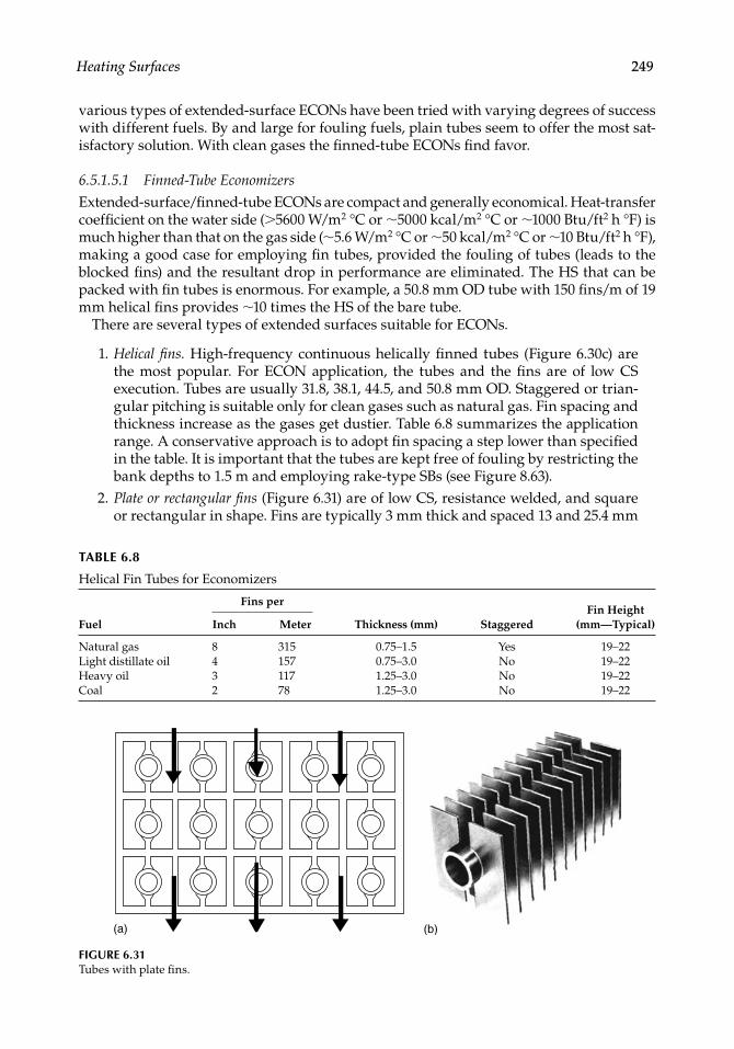
2. Plate or rectangular fi ns (Figure 6.31) are of low CS, resistance welded, and square or rectangular in shape. Fins are typically 3 mm thick and spaced 13 and 25.4 mm
TABLE 6.8
Helical Fin Tubes for Economizers
Fuel
Fins per
Thickness (mm) StaggeredFin Height
(mm—Typical)Inch Meter
Natural gas 8 315 0.75–1.5 Yes 19–22Light distillate oil 4 157 0.75–3.0 No 19–22Heavy oil 3 117 1.25–3.0 No 19–22Coal 2 78 1.25–3.0 No 19–22
(a) (b)
FIGURE 6.31Tubes with plate fi ns.
CRC_75365_Ch006.indd 249CRC_75365_Ch006.indd 249 2/27/2009 4:11:31 PM2/27/2009 4:11:31 PM
250 Boilers for Power and Process
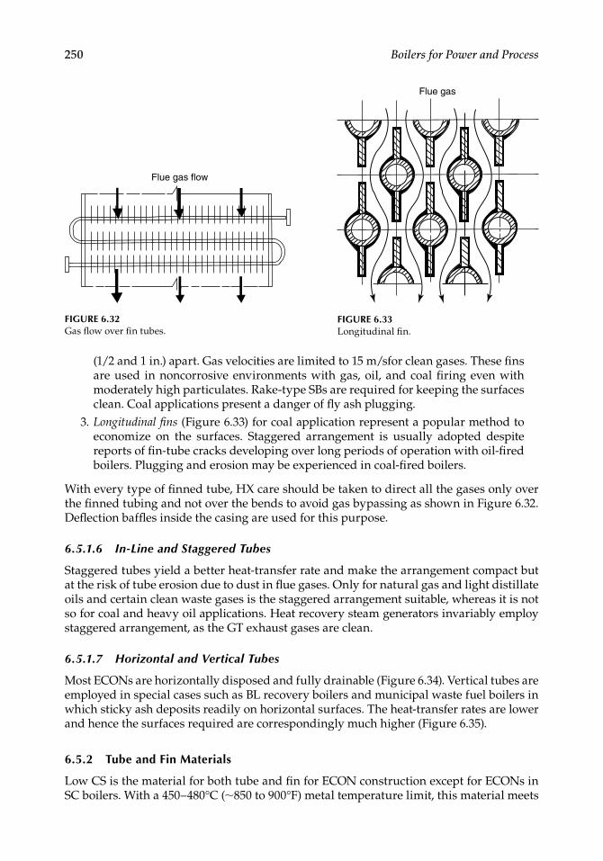
(1/2 and 1 in.) apart. Gas velocities are limited to 15 m/sfor clean gases. These fi ns are used in noncorrosive environments with gas, oil, and coal fi ring even with moderately high particulates. Rake-type SBs are required for keeping the surfaces clean. Coal applications present a danger of fl y ash plugging.
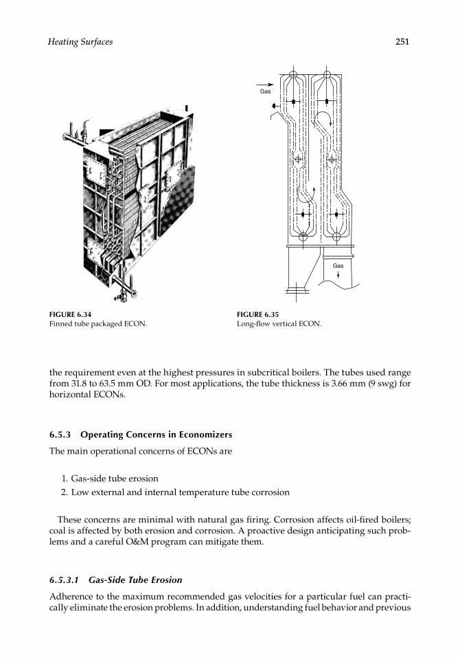
3. Longitudinal fi ns (Figure 6.33) for coal application represent a popular method to economize on the surfaces. Staggered arrangement is usually adopted despite reports of fi n-tube cracks developing over long periods of operation with oil-fi red boilers. Plugging and erosion may be experienced in coal-fi red boilers.
With every type of fi nned tube, HX care should be taken to direct all the gases only over the fi nned tubing and not over the bends to avoid gas bypassing as shown in Figure 6.32. Defl ection baffl es inside the casing are used for this purpose.
6.5.1.6 In-Line and Staggered Tubes
Staggered tubes yield a better heat-transfer rate and make the arrangement compact but at the risk of tube erosion due to dust in fl ue gases. Only for natural gas and light distillate oils and certain clean waste gases is the staggered arrangement suitable, whereas it is not so for coal and heavy oil applications. Heat recovery steam generators invariably employ staggered arrangement, as the GT exhaust gases are clean.
6.5.1.7 Horizontal and Vertical Tubes
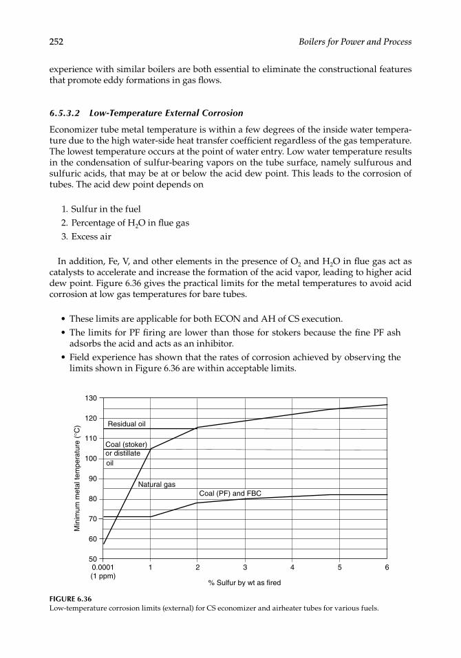
Most ECONs are horizontally disposed and fully drainable (Figure 6.34). Vertical tubes are employed in special cases such as BL recovery boilers and municipal waste fuel boilers in which sticky ash deposits readily on horizontal surfaces. The heat-transfer rates are lower and hence the surfaces required are correspondingly much higher (Figure 6.35).
6.5.2 Tube and Fin Materials
Low CS is the material for both tube and fi n for ECON construction except for ECONs in SC boilers. With a 450–480°C (∼850 to 900°F) metal temperature limit, this material meets
Flue gas flow
FIGURE 6.32Gas fl ow over fi n tubes.
Flue gas
FIGURE 6.33Longitudinal fi n.
CRC_75365_Ch006.indd 250CRC_75365_Ch006.indd 250 2/27/2009 4:11:32 PM2/27/2009 4:11:32 PM
Heating Surfaces 251
the requirement even at the highest pressures in subcritical boilers. The tubes used range from 31.8 to 63.5 mm OD. For most applications, the tube thickness is 3.66 mm (9 swg) for horizontal ECONs.
6.5.3 Operating Concerns in Economizers
The main operational concerns of ECONs are
1. Gas-side tube erosion 2. Low external and internal temperature tube corrosion
These concerns are minimal with natural gas fi ring. Corrosion affects oil-fi red boilers; coal is affected by both erosion and corrosion. A proactive design anticipating such prob-lems and a careful O&M program can mitigate them.
6.5.3.1 Gas-Side Tube Erosion
Adherence to the maximum recommended gas velocities for a particular fuel can practi-cally eliminate the erosion problems. In addition, understanding fuel behavior and previous
FIGURE 6.34Finned tube packaged ECON.
Gas
Gas
FIGURE 6.35Long-fl ow vertical ECON.
CRC_75365_Ch006.indd 251CRC_75365_Ch006.indd 251 2/27/2009 4:11:32 PM2/27/2009 4:11:32 PM
252 Boilers for Power and Process
experience with similar boilers are both essential to eliminate the constructional features that promote eddy formations in gas fl ows.
6.5.3.2 Low-Temperature External Corrosion
Economizer tube metal temperature is within a few degrees of the inside water tempera-ture due to the high water-side heat transfer coeffi cient regardless of the gas temperature. The lowest temperature occurs at the point of water entry. Low water temperature results in the condensation of sulfur-bearing vapors on the tube surface, namely sulfurous and sulfuric acids, that may be at or below the acid dew point. This leads to the corrosion of tubes. The acid dew point depends on
1. Sulfur in the fuel 2. Percentage of H2O in fl ue gas 3. Excess air
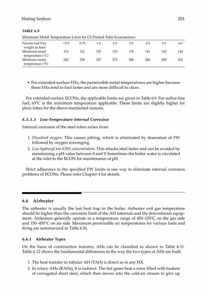
In addition, Fe, V, and other elements in the presence of O2 and H2O in fl ue gas act as catalysts to accelerate and increase the formation of the acid vapor, leading to higher acid dew point. Figure 6.36 gives the practical limits for the metal temperatures to avoid acid corrosion at low gas temperatures for bare tubes.
These limits are applicable for both ECON and AH of CS execution.The limits for PF fi ring are lower than those for stokers because the fi ne PF ash adsorbs the acid and acts as an inhibitor.Field experience has shown that the rates of corrosion achieved by observing the limits shown in Figure 6.36 are within acceptable limits.
••
•
FIGURE 6.36Low-temperature corrosion limits (external) for CS economizer and airheater tubes for various fuels.
130
120
110
100
90
80
70
60
501 2 3
% Sulfur by wt as fired
Min
imum
met
al te
mpe
ratu
re (
°C)
4 5 60.0001(1 ppm)
Residual oil
Coal (stoker)or distillateoil
Natural gasCoal (PF) and FBC
CRC_75365_Ch006.indd 252CRC_75365_Ch006.indd 252 2/27/2009 4:11:32 PM2/27/2009 4:11:32 PM
Heating Surfaces 253
For extended-surface HXs, the permissible metal temperatures are higher because these HXs tend to foul faster and are more diffi cult to clean.
For extended-surface ECONs, the applicable limits are given in Table 6.9. For sulfur-free fuel, 65°C is the minimum temperature applicable. These limits are slightly higher for plain tubes for the above-mentioned reasons.
6.5.3.3 Low-Temperature Internal Corrosion
Internal corrosion of the steel tubes arises from:
1. Dissolved oxygen. This causes pitting, which is eliminated by deaeration of FW followed by oxygen scavenging.
2. Low hydroxyl ion (OH) concentration. This attacks steel faster and can be avoided by maintaining a pH value between 8 and 9. Sometimes the boiler water is circulated at the inlet to the ECON for maintenance of pH.
Strict adherence to the specifi ed FW limits is one way to eliminate internal corrosion problems of ECONs. Please refer Chapter 4 for details.
6.6 Airheater
The airheater is usually the last heat trap in the boiler. Airheater exit gas temperature should be higher than the corrosion limit of the AH internals and the downstream equip-ment. Airheaters generally operate in a temperature range of 450–120°C on the gas side and 150–450°C on air side. Maximum permissible air temperatures for various fuels and fi ring are summarized in Table 6.10.
6.6.1 Airheater Types
On the basis of construction features, AHs can be classifi ed as shown in Table 6.11. Table 6.12 shows the fundamental differences in the way the two types of AHs are built.
1. The heat transfer in tubular AH (TAH) is direct as in any HX. 2. In rotary AHs (RAHs), it is indirect. The hot gases heat a rotor fi lled with baskets
of corrugated sheet steel, which then moves into the cold-air stream to give up
•
TABLE 6.9
Minimum Metal Temperature Limit for CS Finned-Tube Economizers
Percent fuel S by weight as fi red
<0.5 0.75 1.0 2.0 3.0 4.0 5.0 6.0
Minimum metal temperature (°C)
115 121 125 135 139 141 142 144
Minimum metal temperature (°F)
240 250 257 275 280 286 289 292
CRC_75365_Ch006.indd 253CRC_75365_Ch006.indd 253 2/27/2009 4:11:33 PM2/27/2009 4:11:33 PM
254 Boilers for Power and Process
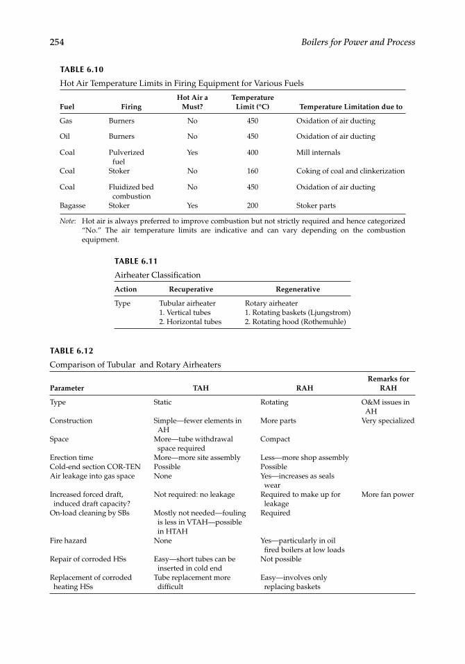
TABLE 6.10
Hot Air Temperature Limits in Firing Equipment for Various Fuels
Fuel FiringHot Air a
Must?Temperature
Limit (°C) Temperature Limitation due to
Gas Burners No 450 Oxidation of air ducting
Oil Burners No 450 Oxidation of air ducting
Coal Pulverized fuel
Yes 400 Mill internals
Coal Stoker No 160 Coking of coal and clinkerization
Coal Fluidized bed combustion
No 450 Oxidation of air ducting
Bagasse Stoker Yes 200 Stoker parts
Note: Hot air is always preferred to improve combustion but not strictly required and hence categorized “No.” The air temperature limits are indicative and can vary depending on the combustion equipment.
TABLE 6.11
Airheater Classifi cation
Action Recuperative Regenerative
Type Tubular airheater Rotary airheater1. Vertical tubes 1. Rotating baskets (Ljungstrom)2. Horizontal tubes 2. Rotating hood (Rothemuhle)
TABLE 6.12
Comparison of Tubular and Rotary Airheaters
Parameter TAH RAHRemarks for
RAH
Type Static Rotating O&M issues in AH
Construction Simple—fewer elements in AH
More parts Very specialized
Space More—tube withdrawal space required
Compact
Erection time More—more site assembly Less—more shop assemblyCold-end section COR-TEN Possible PossibleAir leakage into gas space None Yes—increases as seals
wearIncreased forced draft, induced draft capacity?
Not required: no leakage Required to make up for leakage
More fan power
On-load cleaning by SBs Mostly not needed—fouling is less in VTAH—possible in HTAH
Required
Fire hazard None Yes—particularly in oil fi red boilers at low loads
Repair of corroded HSs Easy—short tubes can be inserted in cold end
Not possible
Replacement of corroded heating HSs
Tube replacement more diffi cult
Easy—involves only replacing baskets
CRC_75365_Ch006.indd 254CRC_75365_Ch006.indd 254 2/27/2009 4:11:33 PM2/27/2009 4:11:33 PM
Heating Surfaces 255
heat in a moving rotor design. The heat exchange is, thus, through the medium of steel baskets subjected to hot and cold air streams alternately on a continuous basis. In the rotating hood design, the rotor remains stationary and the hoods for gas and air rotate to achieve the same results.
6.6.2 TAH versus RAH
Both types of AHs are popular. The TAH is simple to fabricate and does not increase the existing auxiliary power or erosion problems (in case of coal-fi red boilers), because there are no leakages from air to gas side such as in the case of an RAH and no maintenance issues because the assembly is static.
The RAH needs regular adjustment to the seals and is also maintenance prone but the real advantage lies in its compactness and simplifi ed duct layout. With several shop-fabricated subassemblies, the site erection takes much less time. Also, with enameled baskets, lower gas-exit temperatures can affect boiler effi ciency favorably.
Where space is not a constraint, erection costs are low presents and boilers are ∼400 tph or lower, TAH an economical proposition. When there is space constraint, RAH is the answer; it is a also preferred solution for utility boilers. A brief comparison is given in Table 6.12.
In the case of FBC boilers where there are high discharge pressures for forced draft (FD) and primary air (PA) fans, TAH is preferred to RAH because air leakage and hence maintenance of seals can be high, since air to gas differential pressure can be ∼2000 mm wg (∼80 in.).
6.6.3 Tubular Airheater
See (Figure 6.39).
6.6.3.1 Heat Transfer
Heat transfer in a single bank in both vertical (VAH) and horizontal (HAH) systems is always in a perfect cross fl ow. Only when several banks are arranged does the AH become parallel or counter or mixed fl ow. The coeffi cient is adjusted depend-ing on whether the set of banks are parallel or counterfl ow.With smaller tubes transporting air, the HAH enjoys a slightly better heat-transfer coeffi cient, making it more compact.Metal temperature is also a little higher in HAHs than in VAHs. But air pressure drop is marginally higher. Mostly the choice between the HAHs and VAHs is gov-erned by the layout considerations of fans and ducting.For optimum design, AHs are designed with pressure drops not exceeding 65 and 40 mm wg for each bank for air and gas, respectively, for both VAHs and HAHs.The permissible mass velocities and typical heat-transfer coeffi cients are given in Table 6.13.
•
•
•
•
•
CRC_75365_Ch006.indd 255CRC_75365_Ch006.indd 255 2/27/2009 4:11:33 PM2/27/2009 4:11:33 PM
256 Boilers for Power and Process
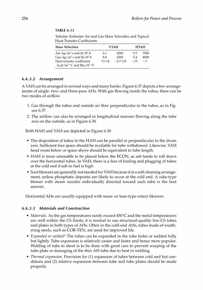
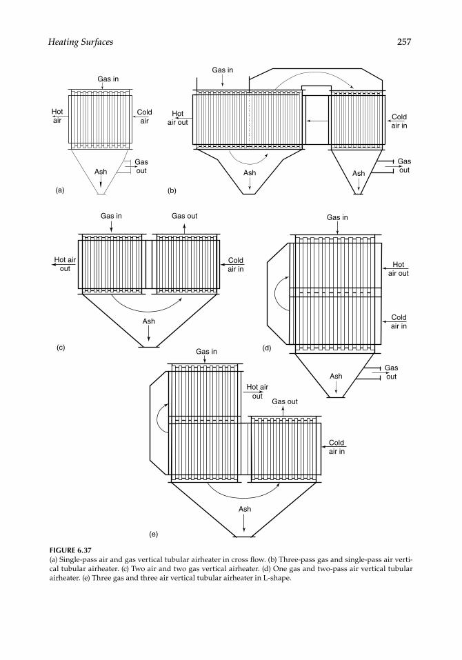
6.6.3.2 Arrangement
A VAH can be arranged in several ways and many banks. Figure 6.37 depicts a few arrange-ments of single- two- and three-pass AHs. With gas fl owing inside the tubes, there can be two modes of airfl ow.
1. Gas through the tubes and outside air fl ow per pendicular to the tubes, as in Fig-ure 6.37.
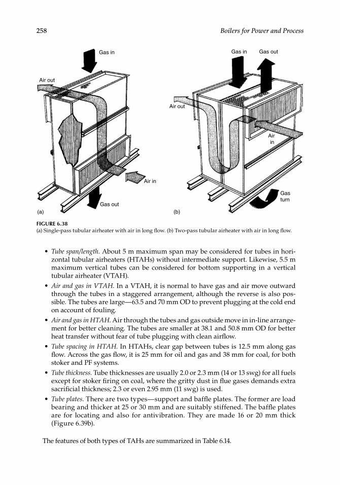
2. The airfl ow can also be arranged in longitudinal manner fl owing along the tube axis on the outside, as in Figure 6.38.
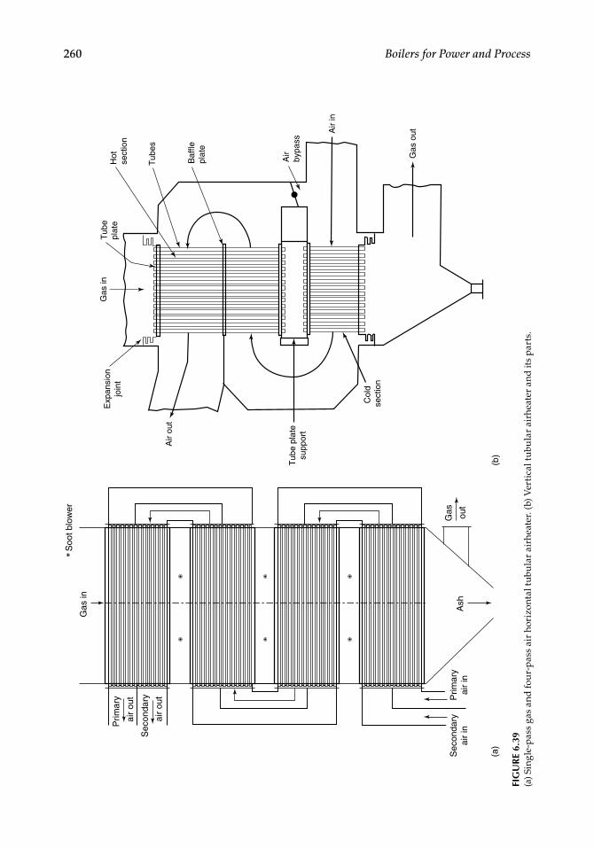
Both HAH and VAH are depicted in Figure 6.39.
The disposition of tubes in the HAH can be parallel or perpendicular to the drum axis. Suffi cient free space should be available for tube withdrawal. Likewise, VAH head room below or space above should be equivalent to tube length.HAH is more amenable to be placed below the ECON, as ash tends to roll down over the horizontal tubes. In VAH, there is a fear of fouling and plugging of tubes at the cold end if ash in fuel is high.Soot blowers are generally not needed for VAH because it is a self-cleaning arrange-ment, unless phosphatic deposits are likely to occur at the cold end. A rake-type blower with steam nozzles individually directed toward each tube is the best answer.
Horizontal AHs are usually equipped with mass- or lane-type rotary blowers.
6.6.3.3 Materials and Construction
Materials. As the gas temperatures rarely exceed 450°C and the metal temperatures are well within the CS limits, it is normal to use structural-quality low-CS tubes and plates in both types of AHs. Often in the cold-end AHs, tubes made of weath-ering steels, such as COR-TEN, are used for improved life.Expanded or welded? The tubes can be expanded in the tube holes or welded fully but lightly. Tube expansion is relatively easier and faster and hence more popular. Welding of tube to sheet is to be done with great care to prevent warping of the tube plate or damaging of the thin AH tube due to heat in welding.Thermal expansion. Provision for (1) expansion of tubes between cold and hot con-ditions and (2) relative expansion between tube and tube plates should be made properly.
•
•
•
•
•
•
TABLE 6.13
Tubular Airheater Air and Gas Mass Velocities and Typical Heat-Transfer Coeffi cients
Mass Velocities VTAH HTAH
Air: kg/m2 s and lb/ft2 h 6.1 4500 9.5 7000Gas: kg/m2 s and lb/ft2 h 8.8 6500 5.4 4000Heat-transfer coeffi cient: kcal/m2 °C and Btu/ft2 °F
13–14 ∼2.7–2.8 ∼15 ∼3
CRC_75365_Ch006.indd 256CRC_75365_Ch006.indd 256 2/27/2009 4:11:33 PM2/27/2009 4:11:33 PM
Heating Surfaces 257
Gas in
Coldair
Hotair
(a) (b)
(c) (d)
(e)
GasoutAsh
Hotair out
GasoutAsh Ash
Gas in
Coldair in
Hot airout
Gas in Gas out
Coldair in
Ash
GasoutAsh
Gas in
Hotair out
Coldair in
Ash
Coldair in
Hot airout
Gas out
Gas in
FIGURE 6.37(a) Single-pass air and gas vertical tubular airheater in cross fl ow. (b) Three-pass gas and single-pass air verti-cal tubular airheater. (c) Two air and two gas vertical airheater. (d) One gas and two-pass air vertical tubular airheater. (e) Three gas and three air vertical tubular airheater in L-shape.
CRC_75365_Ch006.indd 257CRC_75365_Ch006.indd 257 2/27/2009 4:11:33 PM2/27/2009 4:11:33 PM
258 Boilers for Power and Process
Tube span/length. About 5 m maximum span may be considered for tubes in hori-zontal tubular airheaters (HTAHs) without intermediate support. Likewise, 5.5 m maximum vertical tubes can be considered for bottom supporting in a vertical tubular airheater (VTAH).Air and gas in VTAH. In a VTAH, it is normal to have gas and air move outward through the tubes in a staggered arrangement, although the reverse is also pos-sible. The tubes are large—63.5 and 70 mm OD to prevent plugging at the cold end on account of fouling.Air and gas in HTAH. Air through the tubes and gas outside move in in-line arrange-ment for better cleaning. The tubes are smaller at 38.1 and 50.8 mm OD for better heat transfer without fear of tube plugging with clean airfl ow.Tube spacing in HTAH. In HTAHs, clear gap between tubes is 12.5 mm along gas fl ow. Across the gas fl ow, it is 25 mm for oil and gas and 38 mm for coal, for both stoker and PF systems.Tube thickness. Tube thicknesses are usually 2.0 or 2.3 mm (14 or 13 swg) for all fuels except for stoker fi ring on coal, where the gritty dust in fl ue gases demands extra sacrifi cial thickness; 2.3 or even 2.95 mm (11 swg) is used.Tube plates. There are two types—support and baffl e plates. The former are load bearing and thicker at 25 or 30 mm and are suitably stiffened. The baffl e plates are for locating and also for antivibration. They are made 16 or 20 mm thick (Figure 6.39b).
The features of both types of TAHs are summarized in Table 6.14.
•
•
•
•
•
•
Gas in
Gas out(a)
Air out
Air in
Gas in
Air out
Gasturn
Air in
Gas out
(b)
FIGURE 6.38(a) Single-pass tubular airheater with air in long fl ow. (b) Two-pass tubular airheater with air in long fl ow.
CRC_75365_Ch006.indd 258CRC_75365_Ch006.indd 258 2/27/2009 4:11:33 PM2/27/2009 4:11:33 PM
Heating Surfaces 259
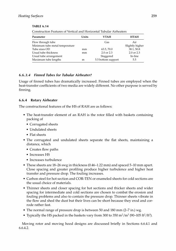
6.6.3.4 Finned Tubes for Tubular Airheater?
Usage of fi nned tubes has dramatically increased. Finned tubes are employed when the heat-transfer coeffi cients of two media are widely different. No other purpose is served by fi nning.
6.6.4 Rotary Airheater
The constructional features of the HS of RAH are as follows:
The heat-transfer element of an RAH is the rotor fi lled with baskets containing packing of• Corrugated sheets• Undulated sheets• Flat sheetsThe corrugated and undulated sheets separate the fl at sheets, maintaining a distance, which• Creates fl ow paths• Increases HS• Increases turbulenceThese sheets are 18–26 swg in thickness (0.46–1.22 mm) and spaced 5–10 mm apart. Close spacing and greater profi ling produce higher turbulence and higher heat transfer and pressure drop. The fouling increases.Carbon steel for hot section and COR-TEN or enameled sheets for cold sections are the usual choice of materials.Thinner sheets and closer spacing for hot sections and thicker sheets and wider spacing for intermediate and cold sections are chosen to combat the erosion and fouling problems and also to contain the pressure drop. Thinner sheets vibrate in the fl ow and shed the dust but their lives can be short because they erod and cor-rode rather fast.The normal range of pressure drop is between 50 and 180 mm (2–7 in.) wg.Typically the HS packed in the baskets vary from 300 to 350 m2/m3 (90–105 ft2/ft3).
Moving rotor and moving hood designs are discussed briefl y in Sections 6.6.4.1 and 6.6.4.2.
•
•
•
•
•
••
TABLE 6.14
Construction Features of Vertical and Horizontal Tubular Airheaters
Parameter Units VTAH HTAH
Flow through tube Gas AirMinimum tube metal temperature Slightly higherTube sizes OD mm 63.5, 70.0 38.1, 50.8Usual tube thickness mm 2.0 or 2.3 2.0 or 2.3Usual tube arrangement Staggered In-lineMaximum tube lengths m 5.5 bottom support 5.5
CRC_75365_Ch006.indd 259CRC_75365_Ch006.indd 259 2/27/2009 4:11:34 PM2/27/2009 4:11:34 PM
260 Boilers for Power and Process
Ash
Gas
in
Gas ou
t
Prim
ary
air
out
Soo
t blo
wer
Sec
onda
ry
air
out Prim
ary
air
inS
econ
dary
air
in
(a)
(b)
Exp
ansi
onjo
int
Air
in
Air
bypa
ss
Baf
flepl
ate
Hot
sect
ion
Gas
out
Tub
e pl
ate
supp
ort
Col
d se
ctio
n
Tub
es
Gas
inT
ube
plat
e
Air
out
FIG
UR
E 6.
39(a
) Sin
gle-
pass
gas
and
fou
r-pa
ss a
ir h
oriz
onta
l tu
bula
r ai
rhea
ter.
(b) V
erti
cal t
ubu
lar
airh
eate
r an
d it
s pa
rts.
CRC_75365_Ch006.indd 260CRC_75365_Ch006.indd 260 2/27/2009 4:11:34 PM2/27/2009 4:11:34 PM
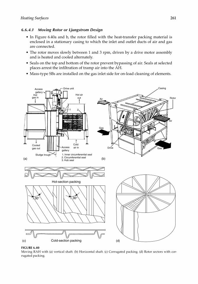
Heating Surfaces 261
6.6.4.1 Moving Rotor or Ljungstrom Design
In Figure 6.40a and b, the rotor fi lled with the heat-transfer packing material is enclosed in a stationary casing to which the inlet and outlet ducts of air and gas are connected.The rotor moves slowly between 1 and 3 rpm, driven by a drive motor assembly and is heated and cooled alternately.Seals on the top and bottom of the rotor prevent bypassing of air. Seals at selected places arrest the infi ltration of tramp air into the AH.Mass-type SBs are installed on the gas inlet side for on-load cleaning of elements.
•
•
•
•
Drive unit
Hot airout
Accessgallery
Cold air in
Sludge trough
Cooledgas out
Hotgas in
Access gallery
3. Hub seal2. Circumferential seal1. Inner circumferential seal
3 1 2
Rotor
Casing
Drive
Rotor
Air
Gas
Gas
(a) (b)
(c) (d)
Air
Hot-section packing
Cold-section packing
30° 30°
FIGURE 6.40Moving RAH with (a) vertical shaft. (b) Horizontal shaft. (c) Corrugated packing. (d) Rotor sectors with cor-rugated packing.
CRC_75365_Ch006.indd 261CRC_75365_Ch006.indd 261 2/27/2009 4:11:34 PM2/27/2009 4:11:34 PM
262 Boilers for Power and Process
As part of start-up and shutdown interlocks, the AH should be soot blown before and after service to keep it free from unburnt fuel.Both horizontal and vertical designs are used, with the latter more common in utility boilers. The horizontal design is popular with the package and fi eld-erected boilers, fi ring oil and gas, as it fi ts very well where the gas exit and air entry are both at a low level.Figure 6.40a and b shows the typical bisector AH popular with oil and gas fi ring. The rotor is divided into two parts for the passage of air and gas. In a PF application, a trisector AH is required, as the pressure of PA is higher and temperature can also be higher. The rotor is then split into three parts. Even quadra sector AHs are used occasionally.Very large AHs can be built to this design. Rotors as large as 20 m diameter and weighing 800 t are in operation.
6.6.4.2 Rotating Hood or Rothemuhle Design
The stator, packed with corrugated material, remains stationary whereas the air hood rotates slowly picking up heat from the stator (Figure 6.41). All the variations available with moving rotor design are also offered in the moving hood designs. In both designs, air and gas bypass ducts with dampers are integrated with the AH. Safe operating tem-peratures of RAHs are nearly the same as those of TAHs.
6.6.5 Operational Concerns
The operating problems of AHs can be summarized as
1. Low-temperature corrosion 2. Fouling 3. Erosion 4. Fire
6.6.5.1 Low-Temperature Corrosion in Airheater
Airheaters are always provided with bypasses on both air and gas sides based on the pro-cess and layout. Air bypass is provided by allowing only a part of the air to pass through the AH to decrease cooling of fl ue gas. This is for raising the gas-exit temperature and along with it the cold-end metal temperature, which is usually a start-up precaution. A similar arrangement on the gas side is also possible. The bypass dampers are fully shut off during normal operation. Care should be taken to provide a minimum possible opening and a tight shutoff damper. The great tendency for leakage represents a permanent loss of effi ciency.
Cold-end corrosion is a serious issue over which a constant vigil is necessary. The coldest point in the AH is where the cold air and exit gas come into contact. We assume that the metal temperature is the arithmetic mean of the two. With a wide difference in the ambient temperatures, there is always a danger of the cold-end slipping into the corrosion range with boilers designed for the lowest stack losses and causing serious
•
•
•
•
CRC_75365_Ch006.indd 262CRC_75365_Ch006.indd 262 2/27/2009 4:11:35 PM2/27/2009 4:11:35 PM
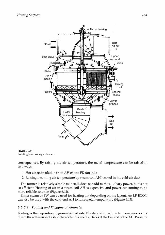
Heating Surfaces 263
consequences. By raising the air temperature, the metal temperature can be raised in two ways.
1. Hot-air recirculation from AH exit to FD fan inlet 2. Raising incoming air temperature by steam coil AH located in the cold-air duct
The former is relatively simple to install, does not add to the auxiliary power, but is not so effi cient. Heating of air in a steam coil AH is expensive and power-consuming but a more reliable solution (Figure 6.42).
Either steam or FW can be used for heating air, depending on the layout. An LP ECON can also be used with the cold-end AH to raise metal temperature (Figure 6.43).
6.6.5.2 Fouling and Plugging of Airheater
Fouling is the deposition of gas-entrained ash. The deposition at low temperatures occurs due to the adherence of ash to the acid-moistened surfaces at the low end of the AH. Pressure
Thrust bearing
Air out
Pinion
Driving unit
Sealingshoes
Lowerair hood
Gasout
Upperair hood
Air in
Rollers
Stator
Soot blower
Airhood
Collarair seals
Guidebearing
Gas in
13
FIGURE 6.41Rotating hood rotary airheater.
CRC_75365_Ch006.indd 263CRC_75365_Ch006.indd 263 2/27/2009 4:11:35 PM2/27/2009 4:11:35 PM
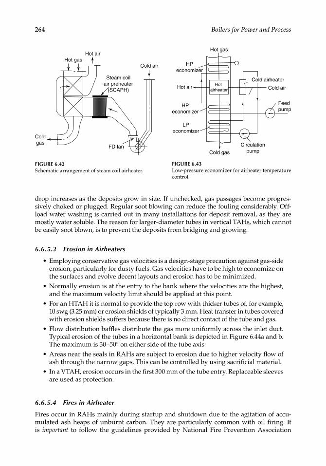
264 Boilers for Power and Process
drop increases as the deposits grow in size. If unchecked, gas passages become progres-sively choked or plugged. Regular soot blowing can reduce the fouling considerably. Off-load water washing is carried out in many installations for deposit removal, as they are mostly water soluble. The reason for larger-diameter tubes in vertical TAHs, which cannot be easily soot blown, is to prevent the deposits from bridging and growing.
6.6.5.3 Erosion in Airheaters
Employing conservative gas velocities is a design-stage precaution against gas-side erosion, particularly for dusty fuels. Gas velocities have to be high to economize on the surfaces and evolve decent layouts and erosion has to be minimized.Normally erosion is at the entry to the bank where the velocities are the highest, and the maximum velocity limit should be applied at this point.For an HTAH it is normal to provide the top row with thicker tubes of, for example, 10 swg (3.25 mm) or erosion shields of typically 3 mm. Heat transfer in tubes covered with erosion shields suffers because there is no direct contact of the tube and gas.Flow distribution baffl es distribute the gas more uniformly across the inlet duct. Typical erosion of the tubes in a horizontal bank is depicted in Figure 6.44a and b. The maximum is 30–50° on either side of the tube axis.Areas near the seals in RAHs are subject to erosion due to higher velocity fl ow of ash through the narrow gaps. This can be controlled by using sacrifi cial material.In a VTAH, erosion occurs in the fi rst 300 mm of the tube entry. Replaceable sleeves are used as protection.
6.6.5.4 Fires in Airheater
Fires occur in RAHs mainly during startup and shutdown due to the agitation of accu-mulated ash heaps of unburnt carbon. They are particularly common with oil fi ring. It is important to follow the guidelines provided by National Fire Prevention Association
•
•
•
•
•
•
Hot airHot gas
Steam coilair preheater
(SCAPH)
Cold air
FD fan
Coldgas
FIGURE 6.42Schematic arrangement of steam coil airheater.
Hot gas
Hot air
HPeconomizer
HPeconomizer
LPeconomizer
Cold gas
Circulationpump
Feed pump
Cold airheater
Cold air Hot
airheater
FIGURE 6.43Low-pressure economizer for airheater temperature control.
CRC_75365_Ch006.indd 264CRC_75365_Ch006.indd 264 2/27/2009 4:11:35 PM2/27/2009 4:11:35 PM
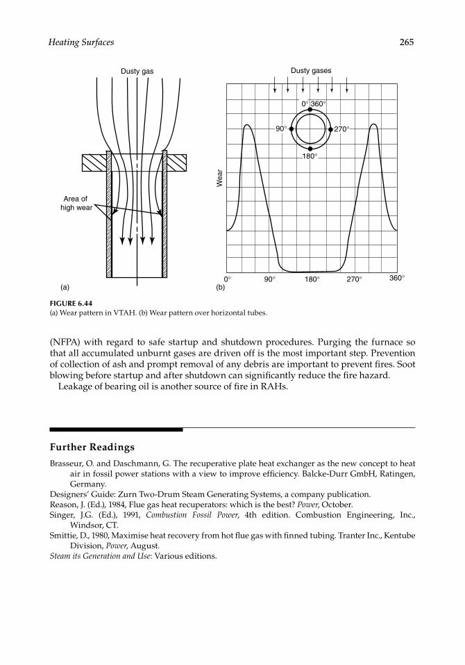
Heating Surfaces 265
(NFPA) with regard to safe startup and shutdown procedures. Purging the furnace so that all accumulated unburnt gases are driven off is the most important step. Prevention of collection of ash and prompt removal of any debris are important to prevent fi res. Soot blowing before startup and after shutdown can signifi cantly reduce the fi re hazard.
Leakage of bearing oil is another source of fi re in RAHs.
Further Readings
Brasseur, O. and Daschmann, G. The recuperative plate heat exchanger as the new concept to heat air in fossil power stations with a view to improve effi ciency. Balcke-Durr GmbH, Ratingen, Germany.
Designers’ Guide: Zurn Two-Drum Steam Generating Systems, a company publication.Reason, J. (Ed.), 1984, Flue gas heat recuperators: which is the best? Power, October.Singer, J.G. (Ed.), 1991, Combustion Fossil Power, 4th edition. Combustion Engineering, Inc.,
Windsor, CT.Smittie, D., 1980, Maximise heat recovery from hot fl ue gas with fi nned tubing. Tranter Inc., Kentube
Division, Power, August.Steam its Generation and Use: Various editions.
Area of high wear
Dusty gas Dusty gases
0° 360°
270°
180°
90°
90° 180° 270° 360°0°(b)(a)
Wea
r
FIGURE 6.44(a) Wear pattern in VTAH. (b) Wear pattern over horizontal tubes.
CRC_75365_Ch006.indd 265CRC_75365_Ch006.indd 265 2/27/2009 4:11:36 PM2/27/2009 4:11:36 PM

CRC_75365_Ch006.indd 266CRC_75365_Ch006.indd 266 2/27/2009 4:11:36 PM2/27/2009 4:11:36 PM
267
7Fabricated Parts
7.1 Introduction
Fabricated parts of the boiler can be divided broadly into the following categories:
1. Unheated pressure parts (PPs) (coded parts kept mostly outside the gas pass) 2. Draft plant items (mainly sheet metal work) 3. Structures (mainly rolled and fabricated steel work)
These parts do not participate in heat transfer, other than in the gas-swept portions of the drums in the bidrum bank. Nor are they fi nished auxiliary items that contribute to the performance of the boiler. The fabricated items are mostly static and perform the following background functions:
• Support the boiler, its various components, and machinery• Transport the fl uids, gas, and air (in fl ues and ducts), and water or steam (integral
piping)
7.2 Unheated Pressure Parts
Unheated PPs are pressure-containing pipes and drums outside the gas passes:
1. Steam drums 2. Risers and downcomers (unheated) 3. Integral piping
Steam drums and risers and downcomers are parts of the boiler circulation system and connected to the evaporator surfaces. Integral piping comprises drain, soot blower (SB), blowdown, and all interconnecting piping for superheater (SH) and reheater (RH) to com-plete the circuits. Other than the drums, all the unheated PPs are made of pipe work. There is no heat transfer and no close bending requirement as in tube banks. Also, the range of sizes is higher, from 25 mm nominal bore (NB) to 457 mm OD. The tubulars are pipes as opposed to tubes used inside the boiler for tube banks, coil work, and panels.
The terms tube and pipe are often used interchangeably in general engineering but not in boiler practice. The differences are brought out in Table 5.4.
CRC_75365_Ch007.indd 267CRC_75365_Ch007.indd 267 2/27/2009 4:59:09 PM2/27/2009 4:59:09 PM
268 Boilers for Power and Process
7.2.1 Steam and Water Drums
Steam drum. In natural circulation boilers, the steam drum occupies a position of impor-tance because of:
• It is the heaviest PP and often the heaviest component.• The layout and erection of the boiler revolve around it.• It takes the maximum time for manufacturing and needs the costliest machinery.• Moving it demands a high level of logistics.• It needs the heaviest crane or lifting tackle during both fabrication and erection.
Thermodynamically, however, a steam drum is merely a surge tank in the circulation system to which the following parts are connected:
• Economizer (ECON) outlet and SH inlet pipes on one side• Downcomers and risers on the other side
Under steady operating conditions when the fl ows are balanced, the steam drum pro-duces a steady water level. Drum water level is one of the most important parameters, of a boiler control system. The other important function of the steam drum is to house the drum internals (see Section 7.2.1.3), which perform the following functions:
1. Saturated water from evaporator circuits, which contain varying amounts of steam, is separated by the steam seperators. Water-free steam to the SH and steam-free water to the downcomers are required of steam seperators and purifi ers.
2. Chemical dosing to maintain the chemistry of the circulating water. 3. Continuous blowdown (CBD) of drum water to keep the carryover under specifi ed
limits.
Water drums are present only in the bidrum boilers and play a less important role.
• A water drum acts like a large header connecting the riser and downcomer tubes of the bank.
• It feeds the downcomers to the various evaporator sections.• It is where the sludge is withdrawn for disposal in many boilers.
7.2.1.1 Sizing of Steam and Water Drum
Steam-drum sizing. The size of the steam drum should be adequate to meet the following requirements:
1. Housing of all internals with adequate space for their dismantling and installation. 2. Providing enough water holding to meet sudden surges of steam demand without
much decrease in SH outlet pressure (SOP) by quickly evaporating steam from saturated water. The other evaporator surfaces also help in this effort with total water-holding capacity of the boiler coming into play. In the case of bidrum boil-ers, the water in the bank tubes and bottom drum, and in case of single-drum
CRC_75365_Ch007.indd 268CRC_75365_Ch007.indd 268 2/27/2009 4:59:10 PM2/27/2009 4:59:10 PM
Fabricated Parts 269
boilers, the water in the large-bore downcomers add to the water in the steam drum, thus providing the total water-holding.
3. Suffi cient swell volume is important for vertical waste heat recovery boilers (WHRBs) or heat recovery steam generators (HRSGs) with evaporator tubes in coil construction. As all the tubes are joined to form a coil (and not left as individual tubes as in a bidrum arrangement) during the startup or a large load change, there is a sudden rush of all the accumulated steam and water in all the legs, causing a massive increase of the drum water. If the drum diameter is too small, the water will overfl ow into the SH tubes. The amount of swell depends on the boiler con-struction and the process variations. The start-up conditions of a gas turbine (GT) are very severe on HRSGs, as the GTs attain full-load conditions in minutes. In vertical WHRBs and HRSGs, where gas fl ow is vertical and evaporators in hori-zontal coils, the steam drums are larger and governed by the swell conditions.
Drum diameters for the same function reduce with increasing pressure, as the specifi c volume of steam progressively reduces at higher pressure. Steam drums, normally speci-fi ed by ID, range from ∼1000 to 2200 mm (∼40 to 87 in.) in conventional boilers and even 2800 mm (110 in.) in HRSGs. The smallest steam drums are usually in package boilers starting at 914 mm (36 in.). Popular sizes are 1067 mm (42 in.), 1220 mm (48 in.), 1370 mm (54 in.), 1524 mm (60 in.), and occasionally 1676 mm (66 in.) for low-pressure boilers. Larger sizes of 1676 mm (66 in.) and 1830 mm (72 in.) and above are mostly found in utilities or WHRBs/HRSGs. Steam drum thicknesses vary from as low as 25 mm to as high as 250 mm (∼1 to 10 in.).
Water-drum sizing. Water drums were known as mud drums because of a large amount of sludge or obsolete designs. The water drum is always smaller than the steam drum as there are no important internals and, more importantly, the number of tubes to be expanded is usually limited to the bank tubes, usually
• 10 or 11 in oil/gas package boilers• 16–20 in two-pass boiler banks (BBs)• 18–22 in single-pass BBs
In package boilers, which are shop-assembled, the bottom drums are sometimes made from rolled seamless pipes of 610 mm (24 in.) OD using special ultracompact expanding tools. The minimum diameter is 760 mm id (30 in.). The other popular size is 914 mm (36 in.) and occasionally 1067 mm (42 in.). Table 7.1 gives the popular sizes of the steam and the water drums for all types of boilers.
• These sizes are indicative, and the manufacturers use different sizes.• The drums are made as per the availability of the dies for making the dish ends.• Drums larger than 2210 mm (87 in.) can also be made mainly for large HRSGs.• Usually from 1370, 1830, and 2210 mm id (54, 72, and 87 in.), steam drums have the
capability to accommodate two, three, and four sets of cyclones (Figure 7.1).
Expanded and stubbed drums. In all the bidrums the bank tubes are expanded in the boiler drums, and these drums are called expanded drums. The tube holes are generally ∼1 to 2 mm larger than the tube OD. After considering the tolerance of the tube OD, a small clearance (between the tube and the hole) has to be added to arrive at the hole ID.
CRC_75365_Ch007.indd 269CRC_75365_Ch007.indd 269 2/27/2009 4:59:11 PM2/27/2009 4:59:11 PM
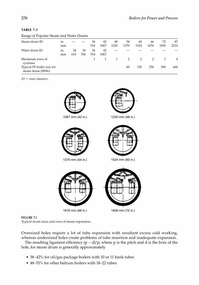
270 Boilers for Power and Process
Oversized holes require a lot of tube expansion with resultant excess cold working, whereas undersized holes create problems of tube insertion and inadequate expansion.
The resulting ligament effi ciency (p − d)/p, where p is the pitch and d is the bore of the hole, for steam drum is generally approximately
• 38–42% for oil/gas package boilers with 10 or 11 bank tubes• 48–51% for other bidrum boilers with 18–22 tubes
TABLE 7.1
Range of Popular Steam and Water Drums
Steam drum ID in. — — 36 42 48 54 60 66 72 87mm 914 1067 1220 1370 1524 1676 1830 2210
Water drum ID in. 24 30 36 42 — — — — — —mm 610 760 914 1067
Maximum rows of cyclones
1 1 1 2 2 2 3 4
Typical PF boiler size for steam drum (MWe)
60 150 250 500 660
ID = inner diameter.
1220 mm (48 in.)1067 mm (42 in.)
1370 mm (54 in.) 1524 mm (60 in.)
1830 mm (72 in.)1676 mm (66 in.)
FIGURE 7.1Typical drum sizes and rows of steam separators.
CRC_75365_Ch007.indd 270CRC_75365_Ch007.indd 270 2/27/2009 4:59:11 PM2/27/2009 4:59:11 PM
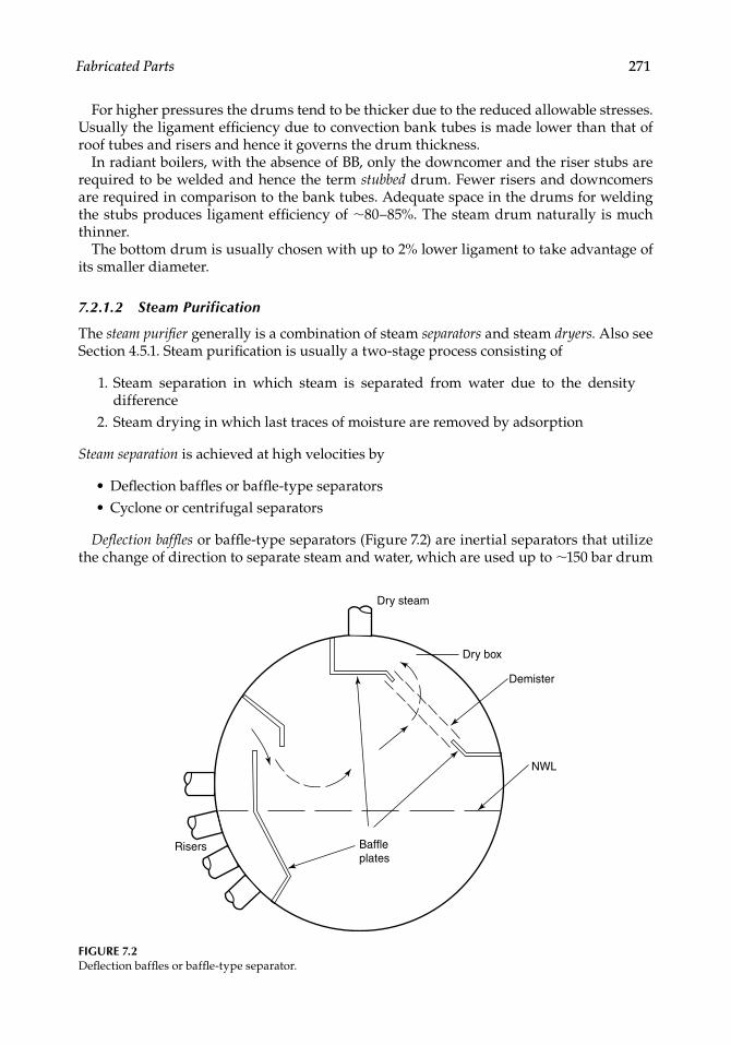
Fabricated Parts 271
For higher pressures the drums tend to be thicker due to the reduced allowable stresses. Usually the ligament effi ciency due to convection bank tubes is made lower than that of roof tubes and risers and hence it governs the drum thickness.
In radiant boilers, with the absence of BB, only the downcomer and the riser stubs are required to be welded and hence the term stubbed drum. Fewer risers and downcomers are required in comparison to the bank tubes. Adequate space in the drums for welding the stubs produces ligament effi ciency of ∼80–85%. The steam drum naturally is much thinner.
The bottom drum is usually chosen with up to 2% lower ligament to take advantage of its smaller diameter.
7.2.1.2 Steam Purification
The steam purifi er generally is a combination of steam separators and steam dryers. Also see Section 4.5.1. Steam purifi cation is usually a two-stage process consisting of
1. Steam separation in which steam is separated from water due to the density difference
2. Steam drying in which last traces of moisture are removed by adsorption
Steam separation is achieved at high velocities by
• Defl ection baffl es or baffl e-type separators• Cyclone or centrifugal separators
Defl ection baffl es or baffl e-type separators (Figure 7.2) are inertial separators that utilize the change of direction to separate steam and water, which are used up to ∼150 bar drum
NWL
Demister
Dry steam
Dry box
Baffleplates
Risers
FIGURE 7.2Defl ection baffl es or baffl e-type separator.
CRC_75365_Ch007.indd 271CRC_75365_Ch007.indd 271 2/27/2009 4:59:11 PM2/27/2009 4:59:11 PM
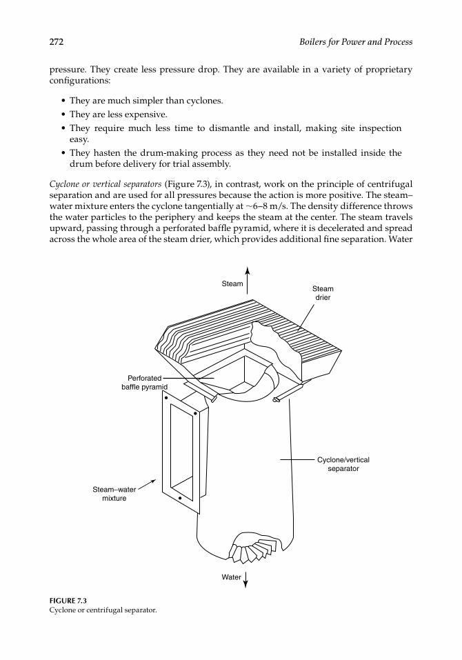
272 Boilers for Power and Process
pressure. They create less pressure drop. They are available in a variety of proprietary confi gurations:
• They are much simpler than cyclones.• They are less expensive.• They require much less time to dismantle and install, making site inspection
easy.• They hasten the drum-making process as they need not be installed inside the
drum before delivery for trial assembly.
Cyclone or vertical separators (Figure 7.3), in contrast, work on the principle of centrifugal separation and are used for all pressures because the action is more positive. The steam–water mixture enters the cyclone tangentially at ∼6–8 m/s. The density difference throws the water particles to the periphery and keeps the steam at the center. The steam travels upward, passing through a perforated baffl e pyramid, where it is decelerated and spread across the whole area of the steam drier, which provides additional fi ne separation. Water
FIGURE 7.3Cyclone or centrifugal separator.
Steam
Water
Steam−watermixture
Perforatedbaffle pyramid
Cyclone/verticalseparator
Steamdrier
CRC_75365_Ch007.indd 272CRC_75365_Ch007.indd 272 2/27/2009 4:59:11 PM2/27/2009 4:59:11 PM

Fabricated Parts 273
travels downward in a vigorous swirl. The action is so dynamic that the drum water is kept out of the cyclones, although they are immersed up to half of their height. The cyclones
• Provide a more positive steam separation• Consume more pressure drop• Are used for all drum pressures up to 210 bar• Are more expensive and take more installation time
The two types of cyclone/centrifugal separators are vertical and horizontal (Figures 7.4 and 7.5). Both are proprietary designs developed by different fi rms. The horizontal cyclone arrangement takes slightly less space for the same duty. But in terms of performance, there does not seem to be much difference. Figures 7.4 and 7.5 represent stubbed and expanded drums, respectively.
Steam drying. Drying devices produce dry steam. There are two methods, and both reduce steam–water velocity so that the water gets attached either to the plates or to the wires of the driers. The two types are:
1. Corrugated plate assemblies (also called as chevrons) 2. Demisters
In corrugated or sinusoidal plates, as the steam containing traces of water passes through the pack of corrugated plates, water adheres to steel by its natural affi nity by adsorption. The formed water fi lm slides down into the water space by the inclination of plates. It is normal to make the plates with stainless steel (ss) material as ss alone provides a highly polished surface that helps the water to roll off easily. Besides, ss is corrosion-resistant.
Saturated steam outlet
Steamdrier
Saturatedsteam
Cycloneseparator
Water
Demineralization
Water/steaminlet
Downcomer
Feed water inlet
Thermalsleeve
FIGURE 7.4Drum internals with two sets of vertical cyclones in a stubbed drum.
CRC_75365_Ch007.indd 273CRC_75365_Ch007.indd 273 2/27/2009 4:59:12 PM2/27/2009 4:59:12 PM
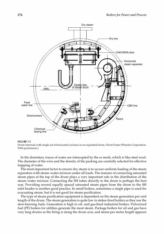
274 Boilers for Power and Process
In the demisters, traces of water are intercepted by the ss mesh, which is like steel wool. The diameter of the wire and the density of the packing are carefully selected for effective trapping of water.
The most important factor to ensure dry steam is to secure uniform loading of the steam separators with steam–water mixture under all loads. The manner of connecting saturated steam pipes at the top of the drum plays a very important role in the distribution of the steam–water mixture. Connecting the SH tubes directly to the drum is perhaps the best way. Providing several equally spaced saturated steam pipes from the drum to the SH inlet header is another good practice. In small boilers, sometimes a single pipe is used for evacuating steam, but it is not good for steam purifi cation.
The type of steam purifi cation equipment is dependent on the steam generation per unit length of the drum. The steam generation is quite low in stoker-fi red boilers as they use the slow-burning fuels. Generation is high in oil- and gas-fi red industrial boilers. Pulverized fuel (PF) boilers for utilities generate the most steam. Package boilers for oil and gas have very long drums as the fi ring is along the drum axis, and steam per meter length appears
FIGURE 7.5Drum internals with single set of horizontal cyclones in an expanded drum. (From Foster Wheeler Corporation. With permission.)
Center lineof steam drumNWL
Chemical dosing line
Feedwater line
Downcomers
Dry steam
Dry box
CHEVRON drier
Horizontalsteam separator
CBD line
Risers
CRC_75365_Ch007.indd 274CRC_75365_Ch007.indd 274 2/27/2009 4:59:12 PM2/27/2009 4:59:12 PM
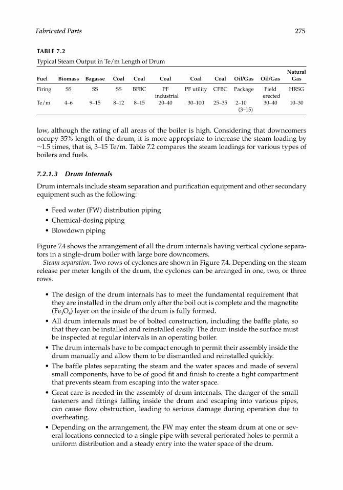
Fabricated Parts 275
low, although the rating of all areas of the boiler is high. Considering that downcomers occupy 35% length of the drum, it is more appropriate to increase the steam loading by ∼1.5 times, that is, 3–15 Te/m. Table 7.2 compares the steam loadings for various types of boilers and fuels.
7.2.1.3 Drum Internals
Drum internals include steam separation and purifi cation equipment and other secondary equipment such as the following:
• Feed water (FW) distribution piping• Chemical-dosing piping• Blowdown piping
Figure 7.4 shows the arrangement of all the drum internals having vertical cyclone separa-tors in a single-drum boiler with large bore downcomers.
Steam separation. Two rows of cyclones are shown in Figure 7.4. Depending on the steam release per meter length of the drum, the cyclones can be arranged in one, two, or three rows.
• The design of the drum internals has to meet the fundamental requirement that they are installed in the drum only after the boil out is complete and the magnetite (Fe3O4) layer on the inside of the drum is fully formed.
• All drum internals must be of bolted construction, including the baffl e plate, so that they can be installed and reinstalled easily. The drum inside the surface must be inspected at regular intervals in an operating boiler.
• The drum internals have to be compact enough to permit their assembly inside the drum manually and allow them to be dismantled and reinstalled quickly.
• The baffl e plates separating the steam and the water spaces and made of several small components, have to be of good fi t and fi nish to create a tight compartment that prevents steam from escaping into the water space.
• Great care is needed in the assembly of drum internals. The danger of the small fasteners and fi ttings falling inside the drum and escaping into various pipes, can cause fl ow obstruction, leading to serious damage during operation due to overheating.
• Depending on the arrangement, the FW may enter the steam drum at one or sev-eral locations connected to a single pipe with several perforated holes to permit a uniform distribution and a steady entry into the water space of the drum.
TABLE 7.2
Typical Steam Output in Te/m Length of Drum
Fuel Biomass Bagasse Coal Coal Coal Coal Coal Oil/Gas Oil/GasNatural
Gas
Firing SS SS SS BFBC PF industrial
PF utility CFBC Package Field erected
HRSG
Te/m 4–6 9–15 8–12 8–15 20–40 30–100 25–35 2–10 (3–15)
30–40 10–30
CRC_75365_Ch007.indd 275CRC_75365_Ch007.indd 275 2/27/2009 4:59:12 PM2/27/2009 4:59:12 PM
276 Boilers for Power and Process
• Blowdown water, to limit and maintain the concentration of solids in the drum water, is collected at the bottoms of the cyclones by means of perforated pipes.
• The small chemical-dosing pipes run the entire length of the steam drum to dis-tribute the chemicals.
• All drum internals are nonpressure parts (NPPs) because the same drum pressure acts inside and outside.
• All nozzles carrying cold liquids should have thermal sleeves to prevent thermal shock to the drum (Figure 7.4).
7.2.1.4 Boiler Dynamics and Drum
The steam drum is located outside the fl ue-gas path in single-drum boilers and inside the gas path in the bidrum boilers. The metal temperature can be considered the same as the saturation temperature of water in unheated drums, whereas it is a few degrees (<10ºC) higher in heated drums. The drum thickness is governed by the following elements:
• Ligament effi ciency• Inside diameter• Design pressure• Material of construction
Drum thickness is the governing factor in limiting the startup and shutdown rates of a boiler, particularly as the drums attain thicknesses ∼100 mm and more.
In thicker drums, the difference between the inside and the outside temperatures of the drum shell on an accelerated loading or shutdown can create differential stresses, leading to over-stressing and failure. This can be avoided by adopting lower ramp-up rates for the boiler loading.
• For drums with expanded tubes, the criterion is the loosening of tubes during accelerated cooling, because the thin tubes contract faster than the drum shell.
• Typically the heating is limited to 1ºC/min of the saturation temperature for expanded drums, to prevent the reverse of the above condition.
• For fully welded drums, based on the stress analysis, limit the temperature dif-ferentials for a certain pressure– Across the drum plate– Between the top and the bottom of the drum
These limits are different for heating and cooling. Naturally for higher rates of starting and cooling, boilers with no expanded tubes, stubbed drums, are better.
7.2.2 Downcomers, Supplies, and Risers
Supplies and risers are pipes that feed and evacuate water walls and other evaporator sur-faces, respectively.
• Downcomers are the supply pipes that start from the drum to feed the water walls and convection banks.
CRC_75365_Ch007.indd 276CRC_75365_Ch007.indd 276 2/27/2009 4:59:13 PM2/27/2009 4:59:13 PM
Fabricated Parts 277
• Because saturated water fl ows through these downcomer pipes, they are at the same temperature with no relative expansions among themselves or the EVAP banks they are connected to.
• They made of CS unless at high pressures; low-alloy steel such as SA 213 T1 (0.5% Mo) or T11 (or 1.25% Cr and 0.5% Mo) is used for thickness reduction.
The large-bore downcomers take water from drums for further feeding.
• They usually vary from 193 mm (7 3/4 in.) to 457 mm (18 in.) OD.• They fi t the layouts of tall boilers very well but not the oil- and gas-fi red package
boilers.• Large-bore downcomers are almost indispensable for radiant boilers where they
are used for bringing the saturated water to lower headers.• In tall bidrums they are connected from the bottom drum.• Many times these pipes are not directly welded to the drum but hung sepa-
rately and connected with small pipes for better layout considerations. Also, they avoid heavy welding on the thick-walled drums, which is better for the life of the drum.
• When large-bore downcomers are directly attached to the drums, antivortex baf-fl es have to be installed at the entry so that the vortex effect is broken, and the steam bubbles are not sucked into the downcomer circuits. This can weaken the circulation by reducing the saturated head. These baffl es are only a pair of fl ats inserted into the entry of the downcomer at right angles, which break the vorti-ces. Supply pipes start from the drum in small boilers and from the downcomers in large boilers.
• Circulation calculations can prove the adequacy of the number and the size of the supplies provided.
• New supply pipe arrangements should be checked for circulation adequacy.• At low and medium pressures, supply pipe areas are generally 1/4 to 1/6 times the
area of the evaporator circuit they serve, depending on the pressure.• At higher pressures, as the circulation ratio is lower, the area required for supplies
is greater.
Riser pipes connect the top headers of the water walls to the drum in the area below the separating baffl e for evacuating the steam and water mixture.
• The specifi c volume of the steam–water mixture is greater than the saturated water. It is essential that the area of risers be larger than the area of supplies for any circuit.
• For low and medium pressures, area for risers is generally 1/3 to 1/2 times the area of water wall and even higher for the division walls.
• The area here is also higher for higher pressures.• For all sizes of boilers, arranging riser pipes, clearing the suspension hangers
from the roof, and leading them to the drum at some uniform spacing, are time- consuming and diffi cult processes.
CRC_75365_Ch007.indd 277CRC_75365_Ch007.indd 277 2/27/2009 4:59:13 PM2/27/2009 4:59:13 PM
278 Boilers for Power and Process
• Riser pipes connecting the farthest header to the drum are generally susceptible to sagging and mild vibration when they are longer than 6 m. Often they are sup-ported at some midpoint.
As the boiler sizes and pressures increase, the ratio of risers, downcomers, and supplies in the total PPs also increases disproportionately.
7.2.3 Integral Piping
Integral piping is located on the boiler island, that is, between the feed-check valve and the main steam stop valve (MSSV). The term covers all pressure piping comprising
• Soot blower• Blowdown—continuous and intermittent• Drain and vent—sampling• Terminal piping—feed inlet, main steam outlet, and RH inlet and outlet pipings
Most integral piping, except for terminal piping and SB main piping measures <76 mm NB and many times it is site-fabricated and erected.
7.2.3.1 Soot Blower Piping
This piping forms the bulk of the integral piping. Starting usually from the SH intermedi-ate header or the drum, the piping is routed up to the individual SB.
• A main isolating valve, a pressure-reducing valve, and a safety valve are located on the main SB line before it branches to an individual SB.
• The main line terminates at some convenient lower level with a draining arrange-ment complete with a steam-trap assembly.
• Each branch terminates at its respective isolating valve upstream of the blower.• Appropriate slopes for the main and the branch lines provide proper draining
of the whole piping, which is essential to ensure that no water particles are deposited in the soot-blowing steam. Impingement of water particles at high velocity can rupture the tubes inside the boiler as the dust laden steam jets are very erosive.
• Piping to retractable SBs is often stress-analyzed for fl exibility.• Soot blower main piping is usually of CS. If connected to SH headers, it can be of
low-alloy steel of the same mix as the headers to which it is connected.
More details are given in Chapter 8.
7.2.3.2 Blowdown Piping
As explained in Chapter 4, boiler water is dosed with chemicals and conditioned so that it does not
• Attack the wet parts and cause corrosion• Leave behind scaly deposits, which cause tube overheating and corrosion.• Contribute to carryover
CRC_75365_Ch007.indd 278CRC_75365_Ch007.indd 278 2/27/2009 4:59:13 PM2/27/2009 4:59:13 PM
Fabricated Parts 279
As the steam is evaporated, a concentration of reacted chemicals and solids is leftbehind by the steam, which has to be removed for maintaining the specifi ed limits. While operating the boiler, this is done by blowing down. There are two types of blowdowns as given in Table 7.3.
• Blowdown piping extends from drums or downcomers to the blowdown tanks.• Intermittent blowdown is dirty as it contains sludge from the boiler, and the IBD
tanks are vented to atmosphere with no fl ash steam recovery.• Continuous blowdown is clean and continuous and hence amenable to fl ash steam
recovery on large units or with common CBD tank for multiple boilers.
7.2.3.3 Drain and Vent Piping
7.2.3.3.1 Drains
Boiler drains are located at the bottoms of the saturated circuits and SH and RH circuits. The drains have several purposes.
• Draining of the boiler water from the water walls and downcomers for inspection and emptying.
• Lowering the water level in the boiler from the downcomers or the bottom drum in an emergency during operation.
• Draining of steam from the SH headers during start-up to induce fl ow through the SH coils for keeping the tubes cool and to help raise the steam temperature faster.
The following constructional aspects are worth noting.
• All the lower headers have drain connections. The upper headers do not need them as they are drained into the lower headers by connecting tubes.
• Headers longer than about 4 m are provided with drains on either end.• Water-wall drains are all connected to a ring main, which is then connected to the
IBD tank.• During normal operation of the boiler, the water walls are not to be drained.
Draining would disrupt the circulation and cause serious damage to the tubes.
TABLE 7.3
Types of Blowdown
Type Main Purpose Location
CBD Silica control at high pressuresAlkalinity control at low and medium pressures
Steam drum—below steam separators
IBD Sludge removal Water drum or downcomers, whichever is lower
CRC_75365_Ch007.indd 279CRC_75365_Ch007.indd 279 2/27/2009 4:59:13 PM2/27/2009 4:59:13 PM
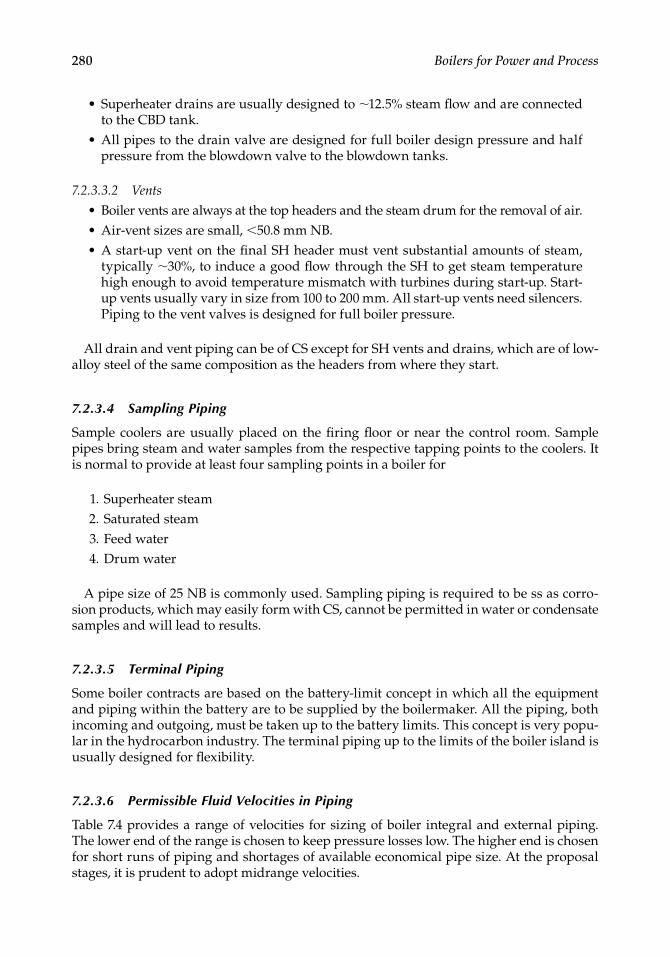
280 Boilers for Power and Process
• Superheater drains are usually designed to ∼12.5% steam fl ow and are connected to the CBD tank.
• All pipes to the drain valve are designed for full boiler design pressure and half pressure from the blowdown valve to the blowdown tanks.
7.2.3.3.2 Vents
• Boiler vents are always at the top headers and the steam drum for the removal of air.• Air-vent sizes are small, <50.8 mm NB.• A start-up vent on the fi nal SH header must vent substantial amounts of steam,
typically ∼30%, to induce a good fl ow through the SH to get steam temperature high enough to avoid temperature mismatch with turbines during start-up. Start-up vents usually vary in size from 100 to 200 mm. All start-up vents need silencers. Piping to the vent valves is designed for full boiler pressure.
All drain and vent piping can be of CS except for SH vents and drains, which are of low-alloy steel of the same composition as the headers from where they start.
7.2.3.4 Sampling Piping
Sample coolers are usually placed on the fi ring fl oor or near the control room. Sample pipes bring steam and water samples from the respective tapping points to the coolers. It is normal to provide at least four sampling points in a boiler for
1. Superheater steam 2. Saturated steam 3. Feed water 4. Drum water
A pipe size of 25 NB is commonly used. Sampling piping is required to be ss as corro-sion products, which may easily form with CS, cannot be permitted in water or condensate samples and will lead to results.
7.2.3.5 Terminal Piping
Some boiler contracts are based on the battery-limit concept in which all the equipment and piping within the battery are to be supplied by the boilermaker. All the piping, both incoming and outgoing, must be taken up to the battery limits. This concept is very popu-lar in the hydrocarbon industry. The terminal piping up to the limits of the boiler island is usually designed for fl exibility.
7.2.3.6 Permissible Fluid Velocities in Piping
Table 7.4 provides a range of velocities for sizing of boiler integral and external piping.The lower end of the range is chosen to keep pressure losses low. The higher end is chosen for short runs of piping and shortages of available economical pipe size. At the proposal stages, it is prudent to adopt midrange velocities.
CRC_75365_Ch007.indd 280CRC_75365_Ch007.indd 280 2/27/2009 4:59:13 PM2/27/2009 4:59:13 PM
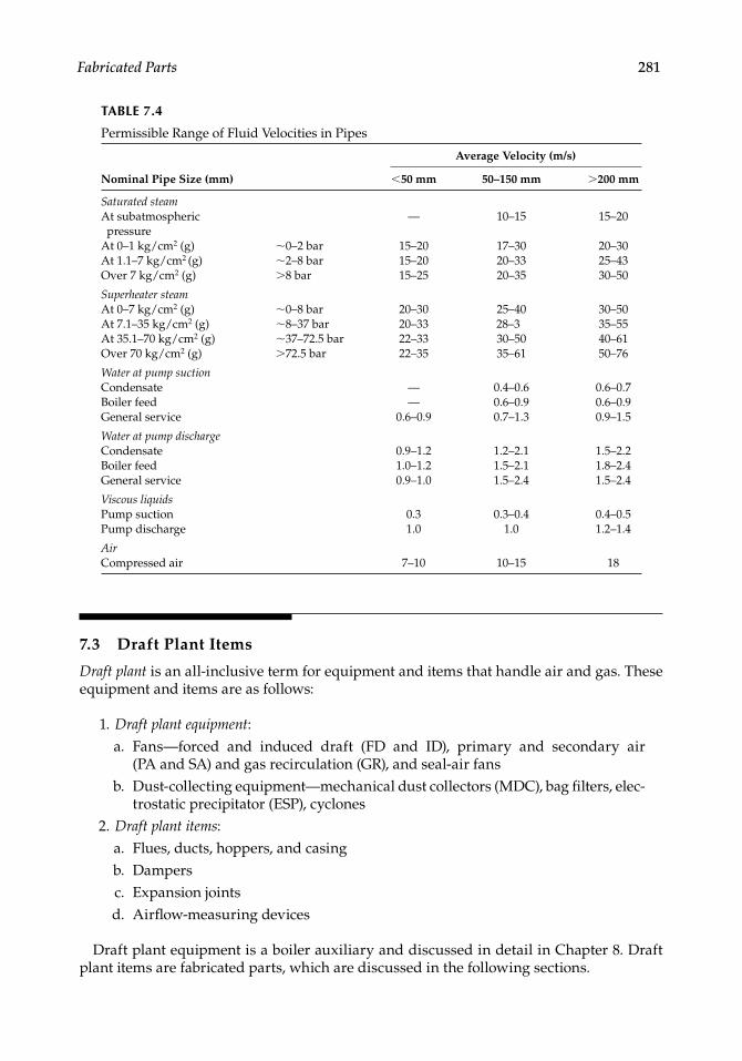
Fabricated Parts 281
7.3 Draft Plant Items
Draft plant is an all-inclusive term for equipment and items that handle air and gas. These equipment and items are as follows:
1. Draft plant equipment: a. Fans—forced and induced draft (FD and ID), primary and secondary air
(PA and SA) and gas recirculation (GR), and seal-air fans b. Dust-collecting equipment—mechanical dust collectors (MDC), bag fi lters, elec-
trostatic precipitator (ESP), cyclones 2. Draft plant items: a. Flues, ducts, hoppers, and casing b. Dampers c. Expansion joints d. Airfl ow-measuring devices
Draft plant equipment is a boiler auxiliary and discussed in detail in Chapter 8. Draft plant items are fabricated parts, which are discussed in the following sections.
TABLE 7.4
Permissible Range of Fluid Velocities in Pipes
Nominal Pipe Size (mm)
Average Velocity (m/s)
<50 mm 50–150 mm >200 mm
Saturated steamAt subatmospheric pressure
— 10–15 15–20
At 0–1 kg/cm2 (g) ∼0–2 bar 15–20 17–30 20–30At 1.1–7 kg/cm2 (g) ∼2–8 bar 15–20 20–33 25–43Over 7 kg/cm2 (g) >8 bar 15–25 20–35 30–50
Superheater steamAt 0–7 kg/cm2 (g) ∼0–8 bar 20–30 25–40 30–50At 7.1–35 kg/cm2 (g) ∼8–37 bar 20–33 28–3 35–55At 35.1–70 kg/cm2 (g) ∼37–72.5 bar 22–33 30–50 40–61Over 70 kg/cm2 (g) >72.5 bar 22–35 35–61 50–76
Water at pump suctionCondensate — 0.4–0.6 0.6–0.7Boiler feed — 0.6–0.9 0.6–0.9General service 0.6–0.9 0.7–1.3 0.9–1.5
Water at pump dischargeCondensate 0.9–1.2 1.2–2.1 1.5–2.2Boiler feed 1.0–1.2 1.5–2.1 1.8–2.4General service 0.9–1.0 1.5–2.4 1.5–2.4
Viscous liquidsPump suction 0.3 0.3–0.4 0.4–0.5Pump discharge 1.0 1.0 1.2–1.4
AirCompressed air 7–10 10–15 18
CRC_75365_Ch007.indd 281CRC_75365_Ch007.indd 281 2/27/2009 4:59:13 PM2/27/2009 4:59:13 PM
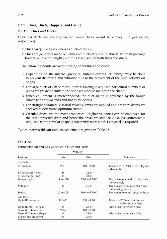
282 Boilers for Power and Process
7.3.1 Flues, Ducts, Hoppers, and Casing
7.3.1.1 Flues and Ducts
Flues and ducts are rectangular or round ducts meant to convey fl ue gas or air, respectively.
• Flues carry fl ue gases whereas ducts carry air.• Flues are generally made of 6 mm and ducts of 5 mm thickness. In small-package
boilers, with short lengths, 4 mm is also used for both fl ues and ducts.
The following points are worth noting about fl ues and ducts:
1. Depending on the internal pressure, suitable external stiffening must be doneto prevent distortion and vibration due to the movement of the high-velocity air or gas.
2. For large ducts of 2 m or more, internal bracing is required. Structural members or pipes are welded fi rmly to the opposite sides to maintain the shape.
3. When equipment is interconnected, the duct sizing is governed by the fl ange dimensions at two ends and not by velocities.
4. For straight distances, classical velocity limits are applied and pressure drops are checked to determine optimum sizing.
5. Circular ducts are the most economical. Higher velocities can be employed for the same pressure drop and hence the areas are smaller. Also, less stiffening is required as the circular shape is inherently more rigid. Less steel is required.
Typical permissible air and gas velocities are given in Table 7.5.
TABLE 7.5
Permissible Air and Gas Velocities in Flues and Ducts
Location
Velocity
Remarksm/s ft/m
Air ductsFD suction 9–11 1800–2200 Even 14 m/s (2800 ft/m) if layout
demandsFD discharge — cold 11 2200FD discharge — hot 15 3000Tempering air 14 and 18 2800 and 3600 For rectangular and circular ducts,
respectivelyMill inlet 18 3600 High velocity because of airfl ow-
measuring deviceSeal air 20 and 25 3600 and 5000 For rectangular and circular ducts
Gas ductsUp to ID fan — coal 12.5–15 2500–3000 Reason: <12.5 ash buildup and
>15 erosion in fl uesUp to ID fan — oil/gas 14 2800 Also other nonerosive fuelsBeyond ID fan — coal 9–14 1800–2800Beyond ID fan — oil/gas 14 2800 Also other nonerosive fuelsBypass and crossover 14 2800
CRC_75365_Ch007.indd 282CRC_75365_Ch007.indd 282 2/27/2009 4:59:13 PM2/27/2009 4:59:13 PM
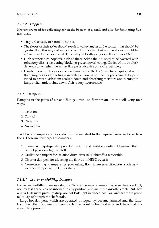
Fabricated Parts 283
7.3.1.2 Hoppers
Hoppers are used for collecting ash at the bottom of a bank and also for facilitating fl ue-gas turns.
• They are usually of 6 mm thickness.• The slopes of their sides should result in valley angles at the corners that should be
greater than the angle of repose of ash. In coal-fi red boilers, the slopes should be 70° or more to the horizontal. This will yield valley angles at the corners >63º.
• High-temperature hoppers, such as those below the BB, need to be covered with refractory tiles or insulating blocks to prevent overheating. Choice of tile or block depends on whether the ash in fl ue gas is abrasive or not, respectively.
• Low-temperature hoppers, such as those below the ESP, have to be equipped with fl uidizing nozzles for aiding a smooth ash fl ow. Also, heating pads have to be pro-vided to prevent ash from cooling down and absorbing moisture and turning to lumps when unit is shut down. Ash is very hygroscopic.
7.3.2 Dampers
Dampers in the paths of air and fl ue gas work on fl ow streams in the following four ways:
1. Isolation 2. Control 3. Diversion 4. Nonreturn
All boiler dampers are fabricated from sheet steel to the required sizes and specifi ca-tions. There are four types of dampers.
1. Louver or fl ap-type dampers for control and isolation duties. However, theycannot provide a tight shutoff.
2. Guillotine dampers for isolation duty. Even 100% shutoff is achievable. 3. Diverter dampers for diverting the fl ow as in HRSG bypass. 4. Nonreturn fl ap dampers for preventing fl ow in reverse direction, such as a
weather damper in the HRSG stack.
7.3.2.1 Louver or Multiflap Dampers
Louver or multifl ap dampers (Figure 7.6) are the most common because they are light, occupy less space, can be inserted in any position, and are mechanically simple. But they offer a little more pressure drop, are not leak tight in closed position, and are more prone to leakages through the shaft seals.
Large hot dampers, which are operated infrequently, become jammed and the func-tioning is often indifferent unless the damper construction is sturdy, and the actuator is adequately powered.
CRC_75365_Ch007.indd 283CRC_75365_Ch007.indd 283 2/27/2009 4:59:13 PM2/27/2009 4:59:13 PM
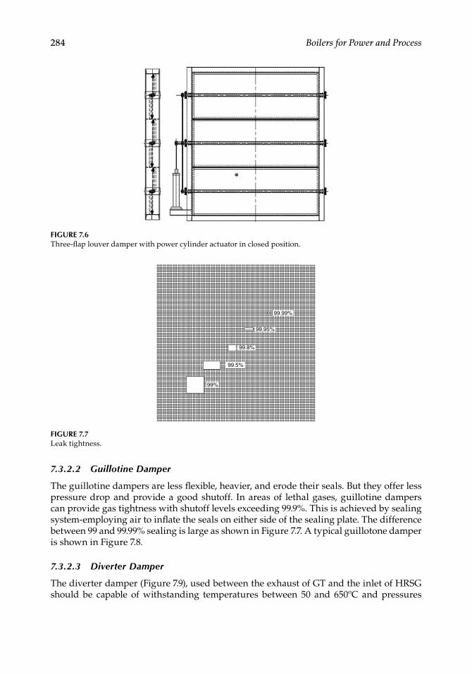
284 Boilers for Power and Process
7.3.2.2 Guillotine Damper
The guillotine dampers are less fl exible, heavier, and erode their seals. But they offer less pressure drop and provide a good shutoff. In areas of lethal gases, guillotine dampers can provide gas tightness with shutoff levels exceeding 99.9%. This is achieved by sealing system-employing air to infl ate the seals on either side of the sealing plate. The difference between 99 and 99.99% sealing is large as shown in Figure 7.7. A typical guillotone damper is shown in Figure 7.8.
7.3.2.3 Diverter Damper
The diverter damper (Figure 7.9), used between the exhaust of GT and the inlet of HRSG should be capable of withstanding temperatures between 50 and 650ºC and pressures
FIGURE 7.6Three-fl ap louver damper with power cylinder actuator in closed position.
FIGURE 7.7Leak tightness.
99.99%
99.95%
99.8%
99.5%
99%
CRC_75365_Ch007.indd 284CRC_75365_Ch007.indd 284 2/27/2009 4:59:14 PM2/27/2009 4:59:14 PM
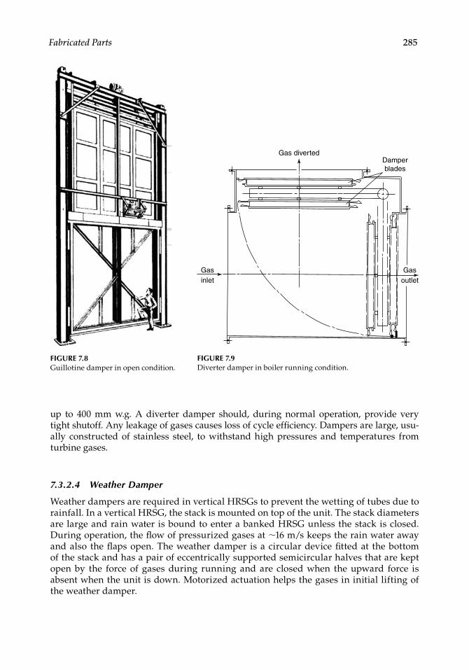
Fabricated Parts 285
up to 400 mm w.g. A diverter damper should, during normal operation, provide verytight shutoff. Any leakage of gases causes loss of cycle effi ciency. Dampers are large, usu-ally constructed of stainless steel, to withstand high pressures and temperatures from turbine gases.
7.3.2.4 Weather Damper
Weather dampers are required in vertical HRSGs to prevent the wetting of tubes due to rainfall. In a vertical HRSG, the stack is mounted on top of the unit. The stack diameters are large and rain water is bound to enter a banked HRSG unless the stack is closed. During operation, the fl ow of pressurized gases at ∼16 m/s keeps the rain water away and also the fl aps open. The weather damper is a circular device fi tted at the bottom of the stack and has a pair of eccentrically supported semicircular halves that are kept open by the force of gases during running and are closed when the upward force is absent when the unit is down. Motorized actuation helps the gases in initial lifting of the weather damper.
FIGURE 7.8Guillotine damper in open condition.
Gas divertedDamperblades
Gasoutlet
Gasinlet
FIGURE 7.9Diverter damper in boiler running condition.
CRC_75365_Ch007.indd 285CRC_75365_Ch007.indd 285 2/27/2009 4:59:14 PM2/27/2009 4:59:14 PM
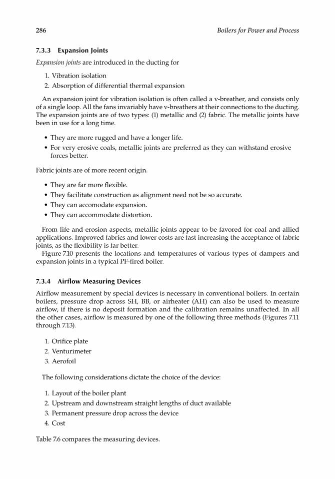
286 Boilers for Power and Process
7.3.3 Expansion Joints
Expansion joints are introduced in the ducting for
1. Vibration isolation 2. Absorption of differential thermal expansion
An expansion joint for vibration isolation is often called a v-breather, and consists only of a single loop. All the fans invariably have v-breathers at their connections to the ducting. The expansion joints are of two types: (1) metallic and (2) fabric. The metallic joints have been in use for a long time.
• They are more rugged and have a longer life.• For very erosive coals, metallic joints are preferred as they can withstand erosive
forces better.
Fabric joints are of more recent origin.
• They are far more fl exible. • They facilitate construction as alignment need not be so accurate.• They can accomodate expansion.• They can accommodate distortion.
From life and erosion aspects, metallic joints appear to be favored for coal and allied applications. Improved fabrics and lower costs are fast increasing the acceptance of fabric joints, as the fl exibility is far better.
Figure 7.10 presents the locations and temperatures of various types of dampers and expansion joints in a typical PF-fi red boiler.
7.3.4 Airflow Measuring Devices
Airfl ow measurement by special devices is necessary in conventional boilers. In certain boilers, pressure drop across SH, BB, or airheater (AH) can also be used to measure airfl ow, if there is no deposit formation and the calibration remains unaffected. In all the other cases, airfl ow is measured by one of the following three methods (Figures 7.11 through 7.13).
1. Orifi ce plate 2. Venturimeter 3. Aerofoil
The following considerations dictate the choice of the device:
1. Layout of the boiler plant 2. Upstream and downstream straight lengths of duct available 3. Permanent pressure drop across the device 4. Cost
Table 7.6 compares the measuring devices.
CRC_75365_Ch007.indd 286CRC_75365_Ch007.indd 286 2/27/2009 4:59:15 PM2/27/2009 4:59:15 PM
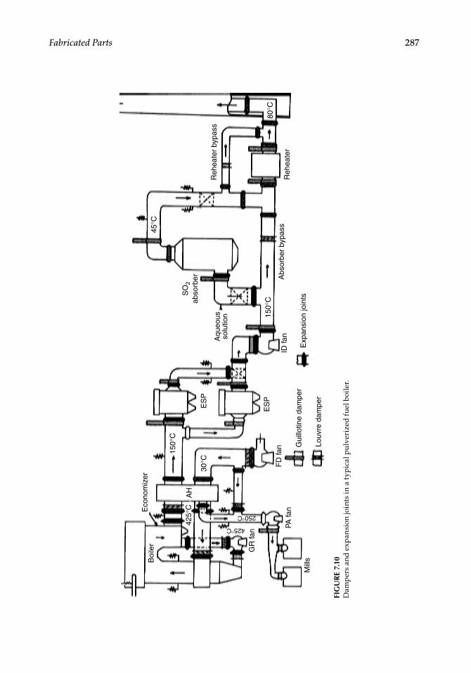
Fabricated Parts 287
ES
P
150°
C
30°C
AH
425°
C
Boi
ler
GR
fan
250°C
425°C PA fa
n
Mill
sG
uillo
tine
dam
per
Louv
re d
ampe
r
ID fa
n
Exp
ansi
on jo
ints
150°
C
Abs
orbe
r by
pass
Reh
eate
r
Reh
eate
r by
pass
80°C
45°C
SO
2ab
sorb
er
Aqu
eous
solu
tion
Eco
nom
izer
FD
fan
ES
P
FIG
UR
E 7.
10D
amp
ers
and
exp
ansi
on jo
ints
in a
typ
ical
pu
lver
ized
fue
l boi
ler.
CRC_75365_Ch007.indd 287CRC_75365_Ch007.indd 287 2/27/2009 4:59:15 PM2/27/2009 4:59:15 PM
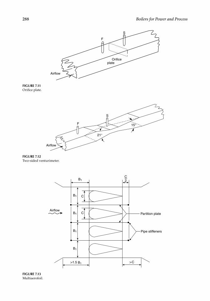
288 Boilers for Power and Process
F
Orificeplate
Airflow
S
FIGURE 7.11Orifi ce plate.
Airflow
21°
15°
S
F
FIGURE 7.12Two-sided venturimeter.
FIGURE 7.13Multiaerofoil.
Airflow
B1
B1
B1
B1
B1
C
C
>1.5 B1
C2
>C
Partition plate
Pipe stiffeners
CRC_75365_Ch007.indd 288CRC_75365_Ch007.indd 288 2/27/2009 4:59:15 PM2/27/2009 4:59:15 PM
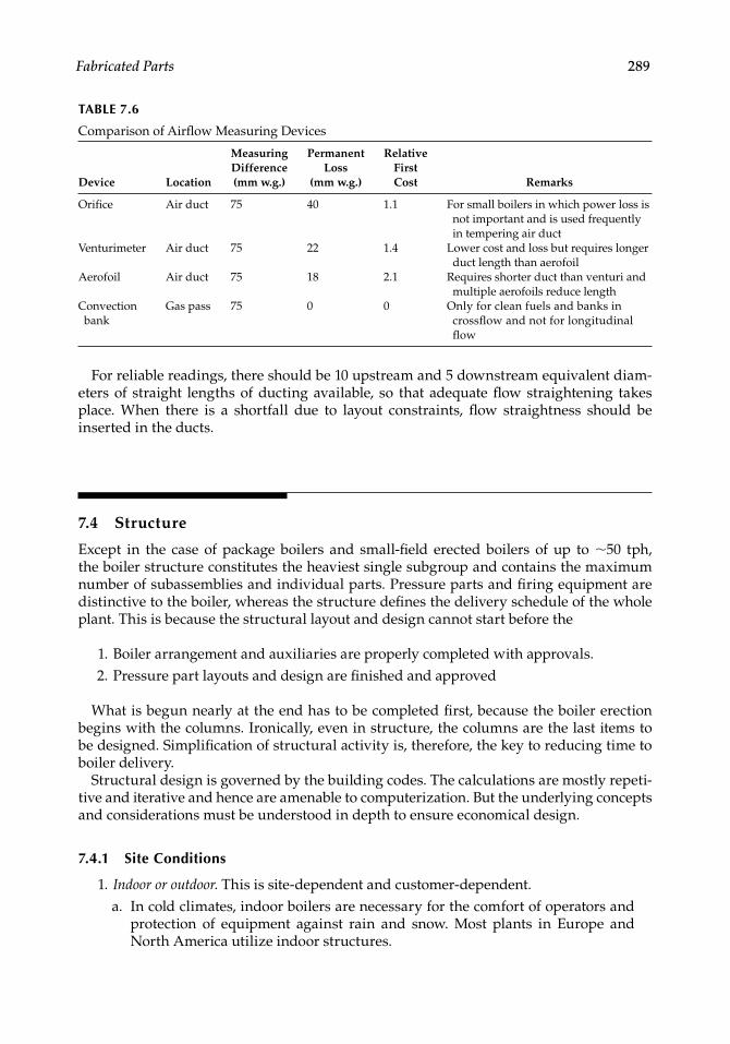
Fabricated Parts 289
TABLE 7.6
Comparison of Airfl ow Measuring Devices
Device Location
Measuring Difference (mm w.g.)
Permanent Loss
(mm w.g.)
Relative First Cost Remarks
Orifi ce Air duct 75 40 1.1 For small boilers in which power loss is not important and is used frequently in tempering air duct
Venturimeter Air duct 75 22 1.4 Lower cost and loss but requires longer duct length than aerofoil
Aerofoil Air duct 75 18 2.1 Requires shorter duct than venturi and multiple aerofoils reduce length
Convection bank
Gas pass 75 0 0 Only for clean fuels and banks in crossfl ow and not for longitudinal fl ow
For reliable readings, there should be 10 upstream and 5 downstream equivalent diam-eters of straight lengths of ducting available, so that adequate fl ow straightening takes place. When there is a shortfall due to layout constraints, fl ow straightness should be inserted in the ducts.
7.4 Structure
Except in the case of package boilers and small-fi eld erected boilers of up to ∼50 tph, the boiler structure constitutes the heaviest single subgroup and contains the maximum number of subassemblies and individual parts. Pressure parts and fi ring equipment are distinctive to the boiler, whereas the structure defi nes the delivery schedule of the whole plant. This is because the structural layout and design cannot start before the
1. Boiler arrangement and auxiliaries are properly completed with approvals. 2. Pressure part layouts and design are fi nished and approved
What is begun nearly at the end has to be completed fi rst, because the boiler erection begins with the columns. Ironically, even in structure, the columns are the last items to be designed. Simplifi cation of structural activity is, therefore, the key to reducing time to boiler delivery.
Structural design is governed by the building codes. The calculations are mostly repeti-tive and iterative and hence are amenable to computerization. But the underlying concepts and considerations must be understood in depth to ensure economical design.
7.4.1 Site Conditions
1. Indoor or outdoor. This is site-dependent and customer-dependent. a. In cold climates, indoor boilers are necessary for the comfort of operators and
protection of equipment against rain and snow. Most plants in Europe and North America utilize indoor structures.
CRC_75365_Ch007.indd 289CRC_75365_Ch007.indd 289 2/27/2009 4:59:16 PM2/27/2009 4:59:16 PM
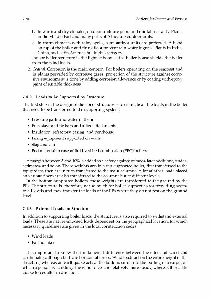
290 Boilers for Power and Process
b. In warm and dry climates, outdoor units are popular if rainfall is scanty. Plants in the Middle East and many parts of Africa are outdoor units.
c. In warm climates with rainy spells, semioutdoor units are preferred. A hood on top of the boiler and fi ring fl oor prevent rain water ingress. Plants in India, China, and Latin America fall in this category.
Indoor boiler structure is the lightest because the boiler house shields the boiler from the wind loads.
2. Coastal. Corrosion is the main concern. For boilers operating on the seacoast and in plants pervaded by corrosive gases, protection of the structure against corro-sive environment is done by adding corrosion allowance or by coating with epoxy paint of suitable thickness.
7.4.2 Loads to be Supported by Structure
The fi rst step in the design of the boiler structure is to estimate all the loads in the boiler that need to be transferred to the supporting system:
• Pressure parts and water in them• Buckstays and tie bars and allied attachments• Insulation, refractory, casing, and penthouse• Firing equipment supported on walls• Slag and ash• Bed material in case of fl uidized bed combustion (FBC) boilers
A margin between 5 and 10% is added as a safety against outages, later additions, under-estimates, and so on. These weights are, in a top-supported boiler, fi rst transferred to the top girders, then are in turn transferred to the main columns. A lot of other loads placed on various fl oors are also transferred to the columns but at different levels.
In the bottom-supported boilers, these weights are transferred to the ground by the PPs. The structure is, therefore, not so much for boiler support as for providing access to all levels and may transfer the loads of the PPs where they do not rest on the ground level.
7.4.3 External Loads on Structure
In addition to supporting boiler loads, the structure is also required to withstand external loads. These are nature-imposed loads dependent on the geographical location, for which necessary guidelines are given in the local construction codes.
• Wind loads• Earthquakes
It is important to know the fundamental difference between the effects of wind and earthquake, although both are horizontal forces. Wind loads act on the entire height of the structure, whereas an earthquake acts at the bottom, similar to the pulling of a carpet on which a person is standing. The wind forces are relatively more steady, whereas the earth-quake forces alter in direction.
CRC_75365_Ch007.indd 290CRC_75365_Ch007.indd 290 2/27/2009 4:59:16 PM2/27/2009 4:59:16 PM
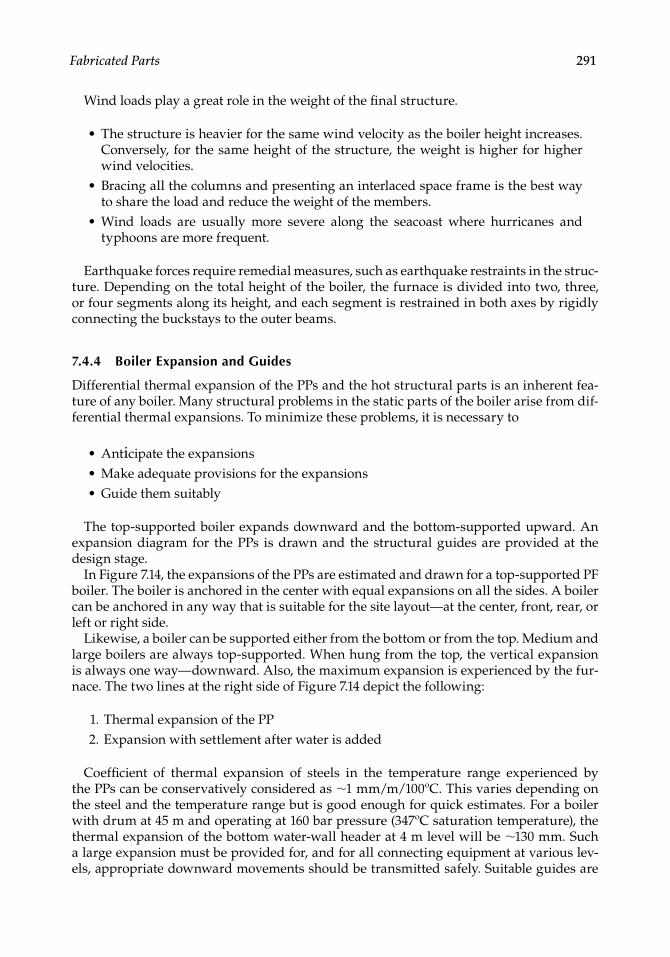
Fabricated Parts 291
Wind loads play a great role in the weight of the fi nal structure.
• The structure is heavier for the same wind velocity as the boiler height increases. Conversely, for the same height of the structure, the weight is higher for higher wind velocities.
• Bracing all the columns and presenting an interlaced space frame is the best way to share the load and reduce the weight of the members.
• Wind loads are usually more severe along the seacoast where hurricanes and typhoons are more frequent.
Earthquake forces require remedial measures, such as earthquake restraints in the struc-ture. Depending on the total height of the boiler, the furnace is divided into two, three, or four segments along its height, and each segment is restrained in both axes by rigidly connecting the buckstays to the outer beams.
7.4.4 Boiler Expansion and Guides
Differential thermal expansion of the PPs and the hot structural parts is an inherent fea-ture of any boiler. Many structural problems in the static parts of the boiler arise from dif-ferential thermal expansions. To minimize these problems, it is necessary to
• Anticipate the expansions• Make adequate provisions for the expansions• Guide them suitably
The top-supported boiler expands downward and the bottom-supported upward. An expansion diagram for the PPs is drawn and the structural guides are provided at the design stage.
In Figure 7.14, the expansions of the PPs are estimated and drawn for a top-supported PF boiler. The boiler is anchored in the center with equal expansions on all the sides. A boiler can be anchored in any way that is suitable for the site layout—at the center, front, rear, or left or right side.
Likewise, a boiler can be supported either from the bottom or from the top. Medium and large boilers are always top-supported. When hung from the top, the vertical expansion is always one way—downward. Also, the maximum expansion is experienced by the fur-nace. The two lines at the right side of Figure 7.14 depict the following:
1. Thermal expansion of the PP 2. Expansion with settlement after water is added
Coeffi cient of thermal expansion of steels in the temperature range experienced by the PPs can be conservatively considered as ∼1 mm/m/100ºC. This varies depending on the steel and the temperature range but is good enough for quick estimates. For a boiler with drum at 45 m and operating at 160 bar pressure (347ºC saturation temperature), the thermal expansion of the bottom water-wall header at 4 m level will be ∼130 mm. Such a large expansion must be provided for, and for all connecting equipment at various lev-els, appropriate downward movements should be transmitted safely. Suitable guides are
CRC_75365_Ch007.indd 291CRC_75365_Ch007.indd 291 2/27/2009 4:59:16 PM2/27/2009 4:59:16 PM
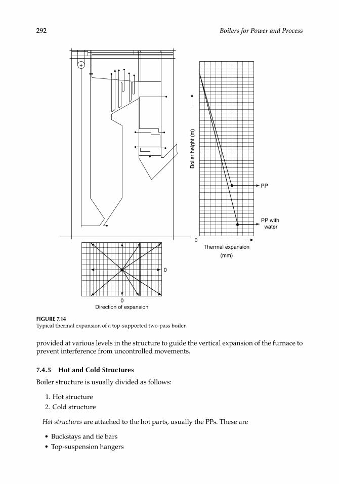
292 Boilers for Power and Process
provided at various levels in the structure to guide the vertical expansion of the furnace to prevent interference from uncontrolled movements.
7.4.5 Hot and Cold Structures
Boiler structure is usually divided as follows:
1. Hot structure 2. Cold structure
Hot structures are attached to the hot parts, usually the PPs. These are
• Buckstays and tie bars• Top-suspension hangers
Boi
ler
heig
ht (
m)
Thermal expansion
(mm)
Direction of expansion
0
0
0
+
PP
PP with water
FIGURE 7.14Typical thermal expansion of a top-supported two-pass boiler.
CRC_75365_Ch007.indd 292CRC_75365_Ch007.indd 292 2/27/2009 4:59:16 PM2/27/2009 4:59:16 PM

Fabricated Parts 293
Cold structure supports the boiler and includes:
• Top-suspension girders• Columns with base plates• Main beams and bracings• Galleries, ladders, and platforms• Guides and restraints
7.4.5.1 Hot Structure
Buckstays and tie bars. Buckstays were explained in Chapter 6 (see Figure 6.5). Buckstays experience the following loading:
1. Longitudinal loading due to internal pressure and externally applied loads 2. Normal loading due to internal pressure 3. Bending moments caused by the eccentricity of the brackets supporting the PPs 4. Temporary loading due to (1) internal explosions, (2) wind forces, and (3) seismic
conditions
The buckstays have to restrain the tubes from bending and keep the furnace enclosure in position. The buckstay spacing should contain the tube defl ection, and the tube vibration should not coincide with the natural frequency of three cycles per second.
Buckstay defl ection is normally limited to
• L/360 for stoker and similar industrial boilers• L/480 for PF and large boilers
Tie bars are really the hot parts, which are attached to the furnace tubes or the membrane panel. Buckstay clips or welding clips attach the tie bars to the buckstays. Buckstays should be kept as cool as possible. Care should be taken to avoid closing them with insulation.
Top-suspension hangers/sling rods. The whole weight of the boiler is transferred to the top girders by means of suspension hangers or sling rods. Top girders have several pairs of supporting beams from where the sling rods are suspended. The other ends of the rods are attached to the top headers or the roof tubes. Cup-spring assemblies are used with varying numbers of springs to prevent sagging of the headers in the middle.
Figures 7.15 and 7.16 depict the suspension rods in small and large boilers. In the smaller boilers, the system is simple and the rods are rigidly held between the girders and the PPs. In larger boilers, the rods are much longer, and they have to overcome the differ-ential expansion problems created by the penthouse by having a more elaborate seal-ing. The penthouse is the enclosure for risers above the furnace roof. Figure 7.16 shows the way the rod behaves from cold to running condition during start-up in a penthouse with hot casing, that is, casing insulated from outside. The rods have to be analyzed for these various conditions together with the expansion restrictions imposed by their seal-ing arrangements.
Suspension rods mostly are made of CS and are designed to a temperature of 400ºC except for those connected to the PPs (SH and RH) at a higher temperature, in which case the metallurgy of the two is matched. If gas leakage is expected into the penthouse, the rods are made of alloy steel with a design temperature of 450ºC.
CRC_75365_Ch007.indd 293CRC_75365_Ch007.indd 293 2/27/2009 4:59:16 PM2/27/2009 4:59:16 PM
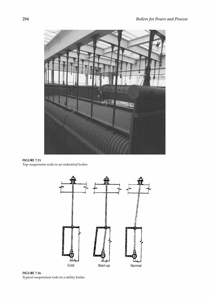
294 Boilers for Power and Process
FIGURE 7.15Top-suspension rods in an industrial boiler.
FIGURE 7.16Typical suspension rods in a utility boiler.
Cold Start-up Normal
CRC_75365_Ch007.indd 294CRC_75365_Ch007.indd 294 2/27/2009 4:59:16 PM2/27/2009 4:59:16 PM

Fabricated Parts 295
Drum slings (Figure 7.17) are different in construction from sling rods. Only two sus-pension assemblies are used at either end of the steam drum. The two designs of drum slings are:
1. Bar/solid slings 2. Fabricated-plate slings a. For weights up to ∼200 t, it is possible to use solid slings made of high-tensile
bar material. These are solid rods of 50–150 mm diameter, depending on the weight to be supported. As single rods for meeting such lengths are not usually available, they are made by joining two or three pieces to obtain the required length by welding, which is followed by stress-relieving and radiography.
b. For larger drum weights, laminated plate slings fabricated from plate steel are used. Typical weight taken by a pair of plate-type slings is as high as 1100 t in a 660 MW boiler. Plate slings fi t the drum profi le more closely than rod slings.
Intermediate cradles. To reduce the number of penetrations and correspondingly the sealing arrangements in the penthouse, it is usual to adopt intermediate cradles. They are particularly suitable for roof tubes. A set of tubes is slung from an intermediate cradle, which, in turn, is suspended from the top girders (Figure 7.18).
7.4.5.2 Cold Structure
Top-suspension girders are at the highest elevation of the boiler, resting on the top plate of the main columns. The entire weight of the boiler is transferred to them. They are the deepest girders in the boiler and, therefore, have to be necessarily fabricated, except in case of small boilers. The suspension rods are hung from the cross girders, which are welded to the main girders. The main and the cross girders together form a grid at the top, col-lectively known as the top suspension grid.
The top girders, as they merely rest on the bearing plates on the top of the columns, are treated as simply supported beams. Typically, the limiting defl ection is very small at L/700 so that the connected parts experience minimum sag.
Loadpads
Laminated plate slingSolid sling
FIGURE 7.17Drum slings.
CRC_75365_Ch007.indd 295CRC_75365_Ch007.indd 295 2/27/2009 4:59:17 PM2/27/2009 4:59:17 PM
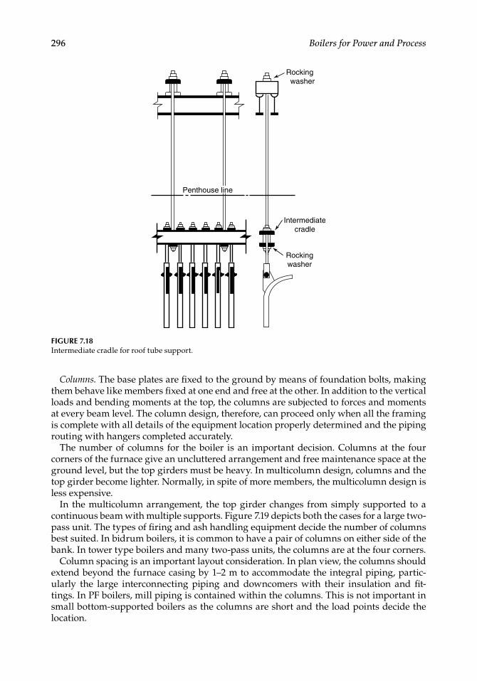
296 Boilers for Power and Process
Columns. The base plates are fi xed to the ground by means of foundation bolts, making them behave like members fi xed at one end and free at the other. In addition to the vertical loads and bending moments at the top, the columns are subjected to forces and moments at every beam level. The column design, therefore, can proceed only when all the framing is complete with all details of the equipment location properly determined and the piping routing with hangers completed accurately.
The number of columns for the boiler is an important decision. Columns at the four corners of the furnace give an uncluttered arrangement and free maintenance space at the ground level, but the top girders must be heavy. In multicolumn design, columns and the top girder become lighter. Normally, in spite of more members, the multicolumn design is less expensive.
In the multicolumn arrangement, the top girder changes from simply supported to a continuous beam with multiple supports. Figure 7.19 depicts both the cases for a large two-pass unit. The types of fi ring and ash handling equipment decide the number of columns best suited. In bidrum boilers, it is common to have a pair of columns on either side of the bank. In tower type boilers and many two-pass units, the columns are at the four corners.
Column spacing is an important layout consideration. In plan view, the columns should extend beyond the furnace casing by 1–2 m to accommodate the integral piping, partic-ularly the large interconnecting piping and downcomers with their insulation and fi t-tings. In PF boilers, mill piping is contained within the columns. This is not important in small bottom-supported boilers as the columns are short and the load points decide the location.
FIGURE 7.18Intermediate cradle for roof tube support.
Rocking washer
Intermediatecradle
Rockingwasher
Penthouse line
CRC_75365_Ch007.indd 296CRC_75365_Ch007.indd 296 2/27/2009 4:59:17 PM2/27/2009 4:59:17 PM
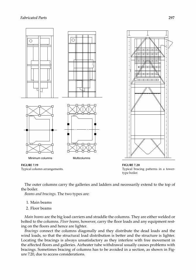
Fabricated Parts 297
The outer columns carry the galleries and ladders and necessarily extend to the top of the boiler.
Beams and bracings. The two types are:
1. Main beams 2. Floor beams
Main beams are the big load carriers and straddle the columns. They are either welded or bolted to the columns. Floor beams, however, carry the fl oor loads and any equipment rest-ing on the fl oors and hence are lighter.
Bracings connect the columns diagonally and they distribute the dead loads and the wind loads, so that the structural load distribution is better and the structure is lighter. Locating the bracings is always unsatisfactory as they interfere with free movement in the affected fl oors and galleries. Airheater tube withdrawal usually causes problems with bracings. Sometimes bracing of columns has to be avoided in a section, as shown in Fig-ure 7.20, due to access considerations.
Minimum columns Multicolumns
FIGURE 7.19Typical column arrangements.
FIGURE 7.20Typical bracing patterns in a tower- type boiler.
CRC_75365_Ch007.indd 297CRC_75365_Ch007.indd 297 2/27/2009 4:59:18 PM2/27/2009 4:59:18 PM
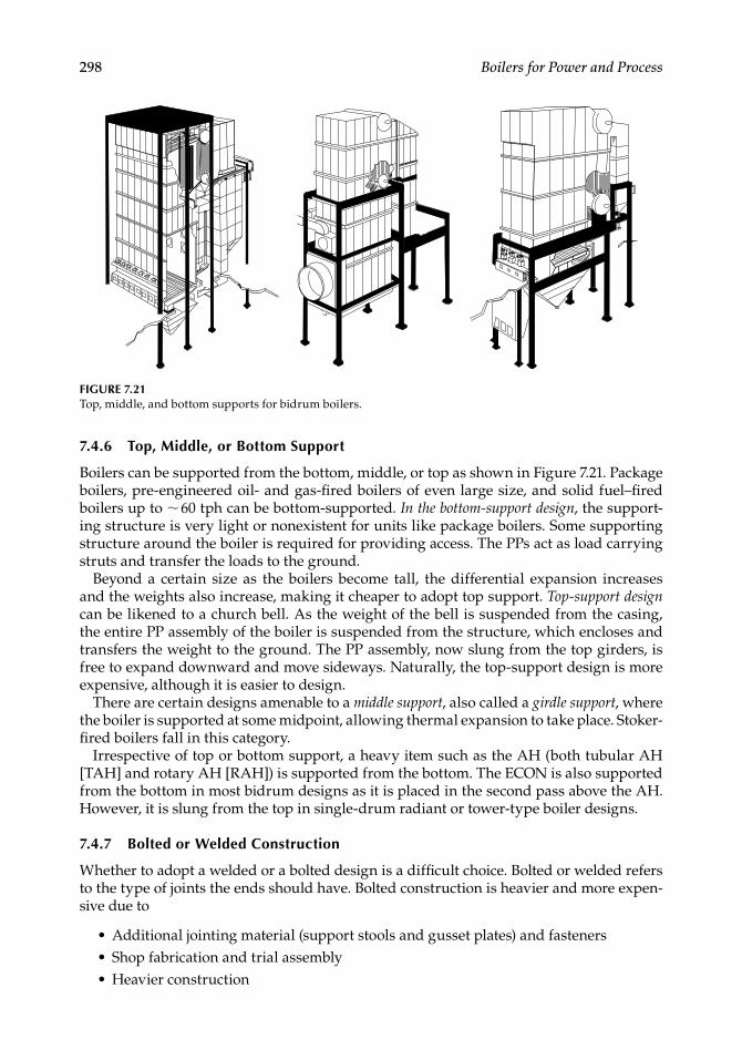
298 Boilers for Power and Process
7.4.6 Top, Middle, or Bottom Support
Boilers can be supported from the bottom, middle, or top as shown in Figure 7.21. Package boilers, pre-engineered oil- and gas-fi red boilers of even large size, and solid fuel–fi red boilers up to ∼ 60 tph can be bottom-supported. In the bottom-support design, the support-ing structure is very light or nonexistent for units like package boilers. Some supporting structure around the boiler is required for providing access. The PPs act as load carrying struts and transfer the loads to the ground.
Beyond a certain size as the boilers become tall, the differential expansion increases and the weights also increase, making it cheaper to adopt top support. Top-support design can be likened to a church bell. As the weight of the bell is suspended from the casing, the entire PP assembly of the boiler is suspended from the structure, which encloses and transfers the weight to the ground. The PP assembly, now slung from the top girders, is free to expand downward and move sideways. Naturally, the top-support design is more expensive, although it is easier to design.
There are certain designs amenable to a middle support, also called a girdle support, where the boiler is supported at some midpoint, allowing thermal expansion to take place. Stoker-fi red boilers fall in this category.
Irrespective of top or bottom support, a heavy item such as the AH (both tubular AH [TAH] and rotary AH [RAH]) is supported from the bottom. The ECON is also supported from the bottom in most bidrum designs as it is placed in the second pass above the AH. However, it is slung from the top in single-drum radiant or tower-type boiler designs.
7.4.7 Bolted or Welded Construction
Whether to adopt a welded or a bolted design is a diffi cult choice. Bolted or welded refers to the type of joints the ends should have. Bolted construction is heavier and more expen-sive due to
• Additional jointing material (support stools and gusset plates) and fasteners• Shop fabrication and trial assembly• Heavier construction
FIGURE 7.21Top, middle, and bottom supports for bidrum boilers.
CRC_75365_Ch007.indd 298CRC_75365_Ch007.indd 298 2/27/2009 4:59:18 PM2/27/2009 4:59:18 PM
Fabricated Parts 299
Bolted construction renders erection very easy and fast. If the erection costs are high, the overall cost works out nearly the same as the welded design with the added advantage of faster and error-free erection. Welded construction is more popular, although it requires more erection time, welding, and manpower, because:
• There are no additional jointing materials.• It is lighter because it is part of an integrated structural framework.• It is easy to correct at site.
The practice followed by the boilermaker or the preference of the customer usually decides this issue of welded versus bolted structure.
7.4.8 Rolled Beams or Built-Up Sections
The top suspension girders must be fabricated as they exceed the limit of rolled sections. Likewise, the main columns and certain heavy beams of medium and large boilers are also required to be fabricated. With greater availability of H and WF sections, it is now possible to adopt rolled sections and reduce the fabrication, at least for the main columns and the beams of utility boilers. But the specifi c cost of the extra-deep sections is higher and the delivery time longer. Deep sections for main columns and certain beams are fab-ricated using thick plates at nearly the same cost.
Further Readings
Killicaslan, M. and Babcock, D., 1991, Summary of symposium about the design of natural circulation boilers for power plants, Power, March.
O’Keefe, W., 1981, Reliable dampers: vital for today’s power plant, A Power Special Report, October.O’Keefe, W., 1992, Benefi t from user experience with non-metallic duct joints, Power, August.Tracey, P.L., Constructional Features of Large Natural Circulation and Once Through Boilers, Babcock and
Wilcox (Operations) Ltd.
CRC_75365_Ch007.indd 299CRC_75365_Ch007.indd 299 2/27/2009 4:59:18 PM2/27/2009 4:59:18 PM

CRC_75365_Ch007.indd 300CRC_75365_Ch007.indd 300 2/27/2009 4:59:19 PM2/27/2009 4:59:19 PM
301
8Boiler Auxiliaries
8.1 Introduction
The auxiliaries breathe life into an otherwise static boiler made of pressure parts (PPs) and nonpressure parts (NPPs). The auxiliaries, generating and regulating the fl ows, are present in the following two circuits:
1. Air and gas circuit that comprises a. Fans b. Dust-collecting equipment c. Dampers 2. Steam and water circuit that comprises a. Feed pumps and circulation pumps b. Valves, mountings, and fi ttings c. Soot blowers (SBs)
Soot blowers are aid not involved in the movement and control of fl uids but in removing the soot or dust deposited on the heating surfaces (HSs) of the boiler. They are unique to the boilers.
Only a brief description of the important boiler auxiliaries is given in this chapter, covering the salient features such as the process and constructional aspects. Feed pumps are not discussed here because they normally are in the scope of turbine island. However, they are briefl y described in Chapters 1 and 2, in Sections 1.8.5 and 2.5.8, respectively.
8.2 Fans
8.2.1 Fans in Boiler Plant
Fans are perhaps the most important of all the auxiliaries because they affect the boiler
PerformanceAuxiliary power consumptionDynamics
•••
CRC_75365_Ch008.indd 301CRC_75365_Ch008.indd 301 1/30/2009 1:44:24 PM1/30/2009 1:44:24 PM
302 Boilers for Power and Process
Almost all boilers are provided with fans for air and fl ue gas movement, except for certain waste heat recovery boilers (WHRBs) and heat recovery steam generators (HRSGs), which receive pressurized gas from the process plants or gas turbines (GTs).
Balanced draft boilers employ a pair of fans, one for forcing the airfl ow through the fi ring equipment and the other for inducing the gas fl ow up to the stack, thus balancing the forced draft (FD) and the induced draft (ID) to achieve balanced draft. This pair is a single set of fans in smaller boilers and double set of fans in larger boilers.Pressurized fi red boilers have only a single FD fan arrangement to push the air all the way to the chimney. In larger boilers, a double set of fans is employed.There are other fans, such as the secondary air (SA) fans, mill fans, and so on, depending on the boiler process.Fans provide air for combustion and removal of fl ue gases in line with the load requirement.Fans maintain the boiler draft. Auxiliary power consumption of a boiler is substantially contributed by the fans, necessitating effi cient fans for new boilers and ways to optimize fan power in running boilers.Boiler dynamics are largely governed by the fans, as their inertia is high due to their large and heavy impellers.
The fan assemblies and drives constitute the largest and the most critical part of the boiler auxiliaries.
8.2.2 Salient Aspects of Fans
A fan can be defi ned as a volumetric device, that moves air or gas from one place to another, overcoming the resistance to fl ow.Fans overcome static forces. Total pressure, however, includes velocity head, which is due to kinetic energy. Figure 8.1 describes pressures.As a volumetric device, a fan gives output in cubic meters and generates head in millimeters water gauge and not in kilograms and millibars. The weight and pres-sure are the derived fi gures, depending on the density or specifi c volume. There-fore, fl uid density, which, in turn, is affected by temperature and altitude, has an overwhelming effect on the fan performance.The behavior of any fan is captured by its characteristics, which are a set of graphs drawn against a common x-axis of fan volumetric output Q. Head (H), effi ciency, and shaft power are the three variables plotted against Q. The characteristics of various types of fans are given in Sections 8.2.4 and 8.2.5.
Fans, blowers, and compressors all move air and gas, but the pressure ranges differ. Fans work from a few millimeters to ∼2000 mm wg (∼1 psig) but handle more volume.
•
•
•
•
••
•
•
•
•
•
CRC_75365_Ch008.indd 302CRC_75365_Ch008.indd 302 1/30/2009 1:44:25 PM1/30/2009 1:44:25 PM
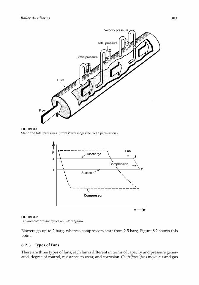
Boiler Auxiliaries 303
Blowers go up to 2 barg, whereas compressors start from 2.5 barg. Figure 8.2 shows this point.
8.2.3 Types of Fans
There are three types of fans; each fan is different in terms of capacity and pressure gener-ated, degree of control, resistance to wear, and corrosion. Centrifugal fans move air and gas
Velocity pressure
Total pressure
Static pressure
Duct
Flow
FIGURE 8.1Static and total pressures. (From Power magazine. With permission.)
Discharge
Suction
Compression
Compressor
V
FanP
4
1
3
2
FIGURE 8.2Fan and compressor cycles on P–V diagram.
CRC_75365_Ch008.indd 303CRC_75365_Ch008.indd 303 1/30/2009 1:44:26 PM1/30/2009 1:44:26 PM
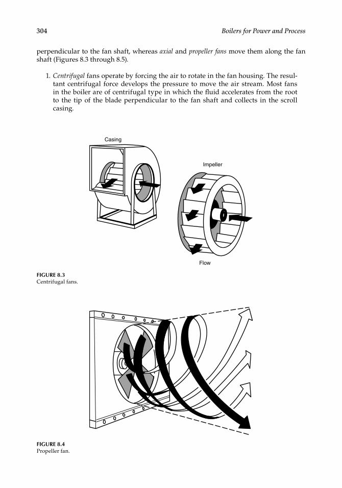
304 Boilers for Power and Process
perpendicular to the fan shaft, whereas axial and propeller fans move them along the fan shaft (Figures 8.3 through 8.5).
1. Centrifugal fans operate by forcing the air to rotate in the fan housing. The resul-tant centrifugal force develops the pressure to move the air stream. Most fans in the boiler are of centrifugal type in which the fl uid accelerates from the root to the tip of the blade perpendicular to the fan shaft and collects in the scroll casing.
Casing
Impeller
Flow
FIGURE 8.3Centrifugal fans.
FIGURE 8.4Propeller fan.
CRC_75365_Ch008.indd 304CRC_75365_Ch008.indd 304 1/30/2009 1:44:26 PM1/30/2009 1:44:26 PM
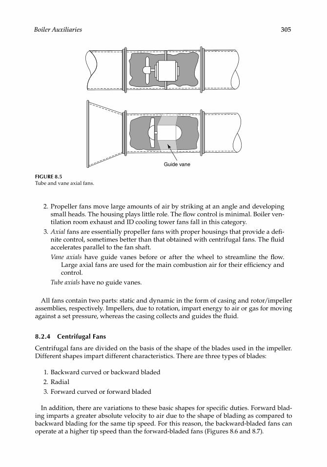
Boiler Auxiliaries 305
2. Propeller fans move large amounts of air by striking at an angle and developing small heads. The housing plays little role. The fl ow control is minimal. Boiler ven-tilation room exhaust and ID cooling tower fans fall in this category.
3. Axial fans are essentially propeller fans with proper housings that provide a defi -nite control, sometimes better than that obtained with centrifugal fans. The fl uid accelerates parallel to the fan shaft.Vane axials have guide vanes before or after the wheel to streamline the fl ow.
Large axial fans are used for the main combustion air for their effi ciency and control.
Tube axials have no guide vanes.
All fans contain two parts: static and dynamic in the form of casing and rotor/impeller assemblies, respectively. Impellers, due to rotation, impart energy to air or gas for moving against a set pressure, whereas the casing collects and guides the fl uid.
8.2.4 Centrifugal Fans
Centrifugal fans are divided on the basis of the shape of the blades used in the impeller. Different shapes impart different characteristics. There are three types of blades:
1. Backward curved or backward bladed 2. Radial 3. Forward curved or forward bladed
In addition, there are variations to these basic shapes for specifi c duties. Forward blad-ing imparts a greater absolute velocity to air due to the shape of blading as compared to backward blading for the same tip speed. For this reason, the backward-bladed fans can operate at a higher tip speed than the forward-bladed fans (Figures 8.6 and 8.7).
Guide vane
FIGURE 8.5Tube and vane axial fans.
CRC_75365_Ch008.indd 305CRC_75365_Ch008.indd 305 1/30/2009 1:44:27 PM1/30/2009 1:44:27 PM
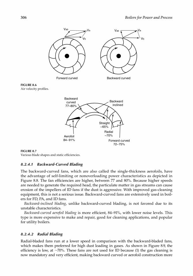
306 Boilers for Power and Process
8.2.4.1 Backward-Curved Blading
The backward-curved fans, which are also called the single-thickness aerofoils, have the advantage of self-limiting or nonoverloading power characteristics as depicted inFigure 8.8. The fan effi ciencies are higher, between 77 and 80%. Because higher speeds are needed to generate the required head, the particulate matter in gas streams can cause erosion of the impellers of ID fans if the dust is aggressive. With improved gas-cleaning equipment, this is not a serious issue. Backward-curved fans are extensively used in boil-ers for FD, PA, and ID fans.
Backward-inclined blading, unlike backward-curved blading, is not favored due to its unstable characteristics.
Backward-curved aerofoil blading is more effi cient, 84–91%, with lower noise levels. This type is more expensive to make and repair, good for cleaning applications, and popular for utility boilers.
8.2.4.2 Radial Blading
Radial-bladed fans run at a lower speed in comparison with the backward-bladed fans, which makes them preferred for high dust loading in gases. As shown in Figure 8.9, the effi ciency is low, at ∼70%. These fans are not used for ID because (1) the gas cleaning is now mandatory and very effi cient, making backward curved or aerofoil construction more
FIGURE 8.6Air velocity profi les.
Forward curved Backward curved
VbVb
VabVab VaVa
Backward curved
77–80%
Aerofoil 84–91%
Backward inclined
Straight ~65%
Radial ~70%
Forward curved72–75%
FIGURE 8.7Various blade shapes and static effi ciencies.
CRC_75365_Ch008.indd 306CRC_75365_Ch008.indd 306 1/30/2009 1:44:27 PM1/30/2009 1:44:27 PM
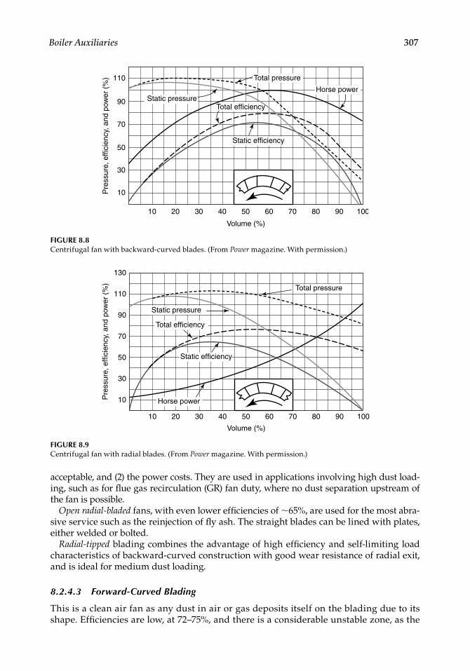
Boiler Auxiliaries 307
acceptable, and (2) the power costs. They are used in applications involving high dust load-ing, such as for fl ue gas recirculation (GR) fan duty, where no dust separation upstream of the fan is possible.
Open radial-bladed fans, with even lower effi ciencies of ∼65%, are used for the most abra-sive service such as the reinjection of fl y ash. The straight blades can be lined with plates, either welded or bolted.
Radial-tipped blading combines the advantage of high effi ciency and self-limiting load characteristics of backward-curved construction with good wear resistance of radial exit, and is ideal for medium dust loading.
8.2.4.3 Forward-Curved Blading
This is a clean air fan as any dust in air or gas deposits itself on the blading due to its shape. Effi ciencies are low, at 72–75%, and there is a considerable unstable zone, as the
10
10
30
50
70
90
110 Total pressure
Horse powerStatic pressure
Static efficiency
Total efficiency
20 30 40 50 60
Volume (%)
Pre
ssur
e, e
ffici
ency
, and
pow
er (
%)
70 80 90 100
FIGURE 8.8Centrifugal fan with backward-curved blades. (From Power magazine. With permission.)
10
10
30
50
70
90
110
130
Total pressure
Horse power
Static pressure
Static efficiency
Total efficiency
20 30 40 50 60
Volume (%)
Pre
ssur
e, e
ffici
ency
, and
pow
er (
%)
70 80 90 100
FIGURE 8.9Centrifugal fan with radial blades. (From Power magazine. With permission.)
CRC_75365_Ch008.indd 307CRC_75365_Ch008.indd 307 1/30/2009 1:44:27 PM1/30/2009 1:44:27 PM
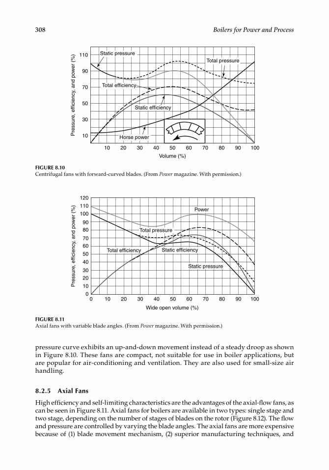
308 Boilers for Power and Process
pressure curve exhibits an up-and-down movement instead of a steady droop as shown in Figure 8.10. These fans are compact, not suitable for use in boiler applications, but are popular for air-conditioning and ventilation. They are also used for small-size air handling.
8.2.5 Axial Fans
High effi ciency and self-limiting characteristics are the advantages of the axial-fl ow fans, as can be seen in Figure 8.11. Axial fans for boilers are available in two types: single stage and two stage, depending on the number of stages of blades on the rotor (Figure 8.12). The fl ow and pressure are controlled by varying the blade angles. The axial fans are more expensive because of (1) blade movement mechanism, (2) superior manufacturing techniques, and
10
10
30
50
70
90
110Total pressure
Horse power
Static efficiency
Total efficiency
20 30 40 50 60
Volume (%)
Pre
ssur
e, e
ffici
ency
, and
pow
er (
%)
70 80 90 100
Static pressure
FIGURE 8.10Centrifugal fans with forward-curved blades. (From Power magazine. With permission.)
FIGURE 8.11Axial fans with variable blade angles. (From Power magazine. With permission.)
100
10
20
0
30
40
50
60
70
8090
100
110
120
Power
Total efficiency
Static pressure
Static efficiency
Total pressure
20 30 40 50 60
Wide open volume (%)
Pre
ssur
e, e
ffici
ency
, and
pow
er (
%)
70 80 90 100
CRC_75365_Ch008.indd 308CRC_75365_Ch008.indd 308 1/30/2009 1:44:28 PM1/30/2009 1:44:28 PM
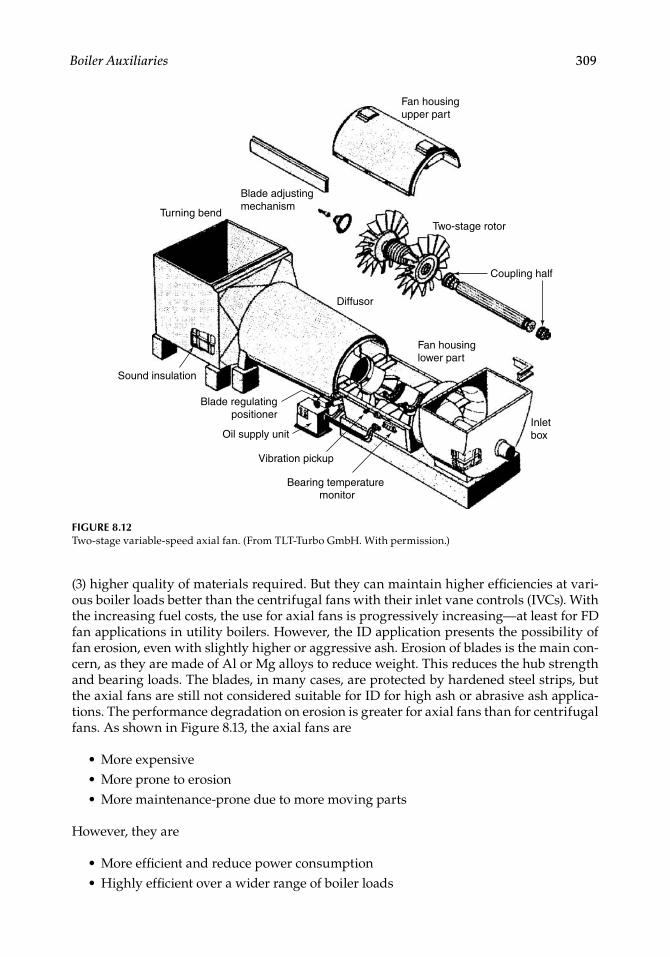
Boiler Auxiliaries 309
(3) higher quality of materials required. But they can maintain higher effi ciencies at vari-ous boiler loads better than the centrifugal fans with their inlet vane controls (IVCs). With the increasing fuel costs, the use for axial fans is progressively increasing—at least for FD fan applications in utility boilers. However, the ID application presents the possibility of fan erosion, even with slightly higher or aggressive ash. Erosion of blades is the main con-cern, as they are made of Al or Mg alloys to reduce weight. This reduces the hub strength and bearing loads. The blades, in many cases, are protected by hardened steel strips, but the axial fans are still not considered suitable for ID for high ash or abrasive ash applica-tions. The performance degradation on erosion is greater for axial fans than for centrifugal fans. As shown in Figure 8.13, the axial fans are
More expensiveMore prone to erosionMore maintenance-prone due to more moving parts
However, they are
More effi cient and reduce power consumptionHighly effi cient over a wider range of boiler loads
•••
••
Fan housinglower part
Fan housingupper part
Two-stage rotor
Blade adjustingmechanism
Turning bend
Sound insulation
Blade regulatingpositioner
Oil supply unit
Coupling half
Vibration pickup
Bearing temperature monitor
Inletbox
Diffusor
FIGURE 8.12Two-stage variable-speed axial fan. (From TLT-Turbo GmbH. With permission.)
CRC_75365_Ch008.indd 309CRC_75365_Ch008.indd 309 1/30/2009 1:44:28 PM1/30/2009 1:44:28 PM
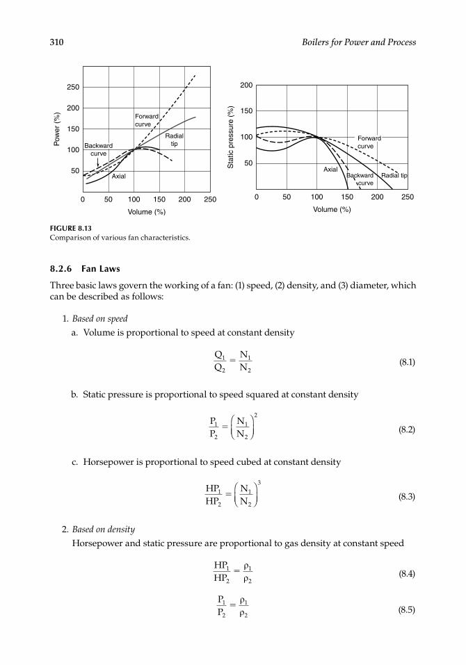
310 Boilers for Power and Process
8.2.6 Fan Laws
Three basic laws govern the working of a fan: (1) speed, (2) density, and (3) diameter, which can be described as follows:
1. Based on speed
a. Volume is proportional to speed at constant density
NN
1
2
1
2
(8.1)
b. Static pressure is proportional to speed squared at constant density
PP
NN
1
2
1
2
2
(8.2)
c. Horsepower is proportional to speed cubed at constant density
HPHP
NN
1
2
1
2
3
(8.3)
2. Based on density
Horsepower and static pressure are proportional to gas density at constant speed
HPHP
1
2
1
2
(8.4)
PP
1
2
1
2
(8.5)
FIGURE 8.13Comparison of various fan characteristics.
0
50
100
250
200
150
Pow
er (
%)
50 100
Axial
Forward curve
Radial tip
AxialBackward
curveRadial tip
150
Volume (%)
200 250 0
50
100
150
200
50 100 150
Volume (%)
Sta
tic p
ress
ure
(%)
200 250
Backward curve
Forward curve
CRC_75365_Ch008.indd 310CRC_75365_Ch008.indd 310 1/30/2009 1:44:28 PM1/30/2009 1:44:28 PM
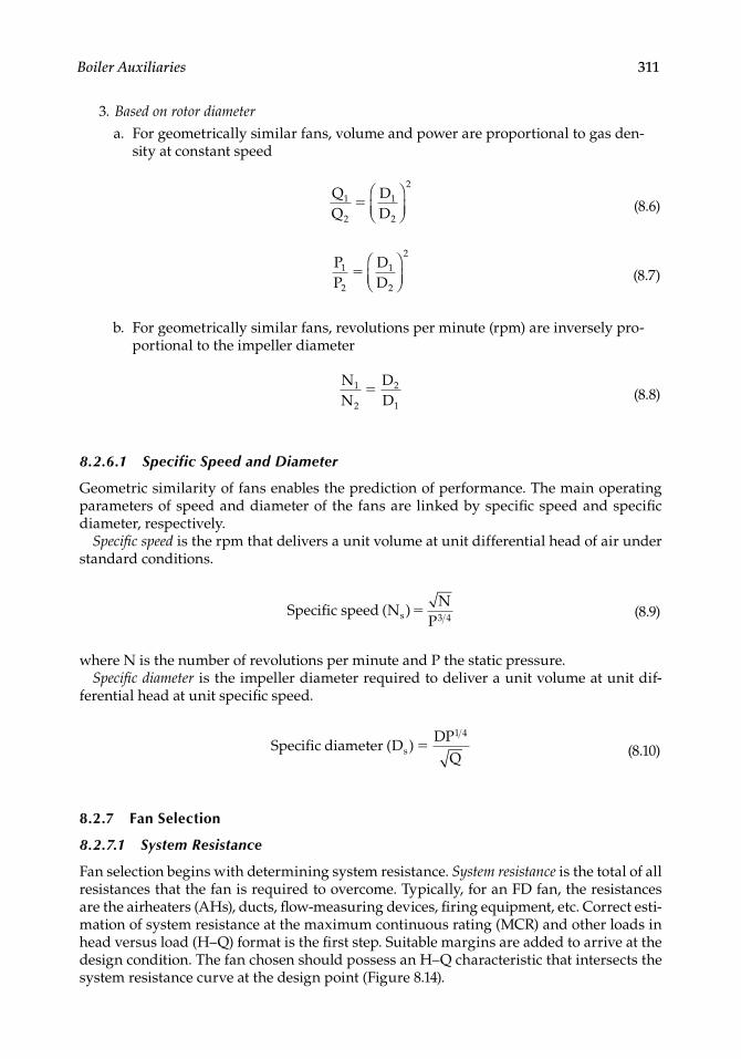
Boiler Auxiliaries 311
3. Based on rotor diameter
a. For geometrically similar fans, volume and power are proportional to gas den-sity at constant speed
DD
1
2
1
2
2
(8.6)
PP
DD
1
2
1
2
2
(8.7)
b. For geometrically similar fans, revolutions per minute (rpm) are inversely pro-portional to the impeller diameter
NN
DD
1
2
2
1
(8.8)
8.2.6.1 Specific Speed and Diameter
Geometric similarity of fans enables the prediction of performance. The main operating parameters of speed and diameter of the fans are linked by specifi c speed and specifi c diameter, respectively.
Specifi c speed is the rpm that delivers a unit volume at unit differential head of air under standard conditions.
Specific speed ( )N
NPs
3 4 (8.9)
where N is the number of revolutions per minute and P the static pressure.Specifi c diameter is the impeller diameter required to deliver a unit volume at unit dif-
ferential head at unit specifi c speed.
Specific diameter ( )D
DPQ
s 1 4
(8.10)
8.2.7 Fan Selection
8.2.7.1 System Resistance
Fan selection begins with determining system resistance. System resistance is the total of all resistances that the fan is required to overcome. Typically, for an FD fan, the resistances are the airheaters (AHs), ducts, fl ow-measuring devices, fi ring equipment, etc. Correct esti-mation of system resistance at the maximum continuous rating (MCR) and other loads in head versus load (H–Q) format is the fi rst step. Suitable margins are added to arrive at the design condition. The fan chosen should possess an H–Q characteristic that intersects the system resistance curve at the design point (Figure 8.14).
CRC_75365_Ch008.indd 311CRC_75365_Ch008.indd 311 1/30/2009 1:44:29 PM1/30/2009 1:44:29 PM

312 Boilers for Power and Process
It is necessary to have a substantially drooping characteristic for the fan to ensure only a single fl ow for a certain head in the fan-operating range. If a hump or fl atness in the curve results more than one fl ow for a certain head, the fan tends to shift the operating point, causing hunting, that is, continuous load change and unstable operation. Also, the fan selected should give optimum effi ciency at the MCR and normal continuous rating (NCR) conditions. The best effi ciency condition should lie in the region where the fan operates for a maximum period and not necessarily at the design point.
8.2.7.2 Fan Speed
Direct drive for fans is preferred, as it is the most compact arrangement with the least trans-mission losses. AC induction motors are the most common drives. Although a fan runs at one of the nominal synchronous speeds, the best effi ciencies may not coincide with these speeds.
Centrifugal fans operate at nominal speeds of 3000, 1500, 1000, and 750 rpm, with most at 1500 and 1000 rpm. In the past, 600 rpm has also been used for very dusty applications. (Actual speeds are ∼3% lower due to slip in motor.)
The fan speed of 3000 rpm is only for clean air application requiring high heads, as in the case of SA, because of high noise level and excessive wear on bearings.
Likewise, 750 rpm is not preferred due to the large impeller diameter and heavy weight, producing high inertia, calling for star–delta starters to reduce the starting time. Also the dynamics are poor and lead to sluggish response. The entire arrangement is expensive due to the fan and motor assembly, special starters, heavy cables, and large foundation. Such low rpm is chosen only when excessive wear is expected from dusty gases. The fan selec-tion is radial in most cases with the attendant poor fan effi ciency calling for high-kilowatt motors. Wear liners on both impeller blades and casing, if chosen, worsen the dynamics. Induced draft fans required such construction in boilers with high-ash coal fi ring with
Fan pressure
Fan power
System resistance
40 60 80
Design flow (Q) (%)
Sta
tic p
ress
ure
(H)
and
pow
er (
P)
(%)
100 120200
20
40
80
60
100
120
FIGURE 8.14System resistance versus fan curves. (From Power magazine. With permission.)
CRC_75365_Ch008.indd 312CRC_75365_Ch008.indd 312 1/30/2009 1:44:29 PM1/30/2009 1:44:29 PM
Boiler Auxiliaries 313
only mechanical dust collectors (MDCs) upstream. With stricter pollution norms and the use of electrostatic precipitators (ESPs), 750 rpm speed is rare. For GR fans, with no dust separation possibility, 750 rpm may still be necessary in many cases, depending on the location of gas suction and the severity of erosion of ash.
Clean air application almost never demands a speed below 1000 rpm. In fact, 1500 rpm is better, as the fan and the motor are both smaller and the arrangement is cheaper. For ID and GR fans, 1000 rpm is the most common speed for solid fuel fi ring.
For small fans of up to ∼150 kW, belt drives are popular, as they enable the fans to run at the most effi ciency despite slightly higher transmission losses. With the motor parallel to the fan, the arrangement can also suit a tight layout.
8.2.7.3 Fan Margins
Margins on volume, head, and operating temperatures are added to the estimated MCR or peak system resistance points to arrive at the design conditions. The fan margins are essential for the following reasons:
The pressure and draft losses calculated are the best approximations and need safety margins. The fuel analysis, air and gas weight calculations, and the assump-tions in calculating the losses are accurate only within certain practical limits.There are bound to be differences in the geometry used for calculation and the boiler constructed due to inaccuracies in manufacturing and erection.The fouling of surfaces is unpredictable, particularly with fuels such as coal, and cannot be captured accurately.Any boiler that needs overfi ring to catch up with rapid load ramps needs more power from the fans and the fi ring equipment. This requires spare power.Every fan has negative tolerances on head and volume due to manufacture. They must be compensated for if all the parameters are to be met in practice.
Excessive margins. Although it is imperative to provide correct margins, excessive provi-sioning is wasteful and injurious. Motors are provided with additional margins to
Account for the positive power tolerance of the fan and the negative power toler-ance of the motor and possible errors in the estimated fi gures of powerProvide for a possible drop in system voltage and frequency
Considering that boilers normally operate at ∼80% of the MCR load most of the time, the loading of fan motors, even with normal margins, works out to ∼50 to 60% of the rated motor loading, which results in motor operation at a signifi cantly lower effi ciency. The initial costs of fan, motor, and electrical equipment are all higher too. With more generous margins, the situation worsens. Excessive auxiliary power consumption alone is a good enough reason to avoid unnecessarily large margins.
Margin range. Fan margin fi gures are continuously refi ned. There is a general consensus for the main fans, namely the FD and ID fans, that the margins for solid fuel–fi red boiler should be around
20% for volume44% for the variable head20°C for the operating temperature
•
•
•
•
•
•
•
•••
CRC_75365_Ch008.indd 313CRC_75365_Ch008.indd 313 1/30/2009 1:44:29 PM1/30/2009 1:44:29 PM
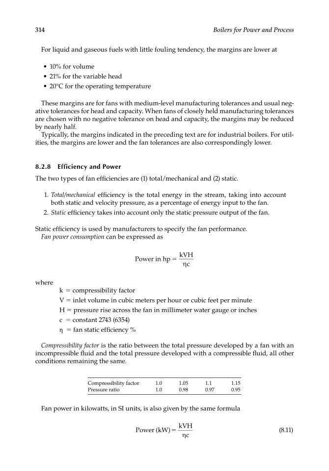
314 Boilers for Power and Process
For liquid and gaseous fuels with little fouling tendency, the margins are lower at
10% for volume21% for the variable head20°C for the operating temperature
These margins are for fans with medium-level manufacturing tolerances and usual neg-ative tolerances for head and capacity. When fans of closely held manufacturing tolerances are chosen with no negative tolerance on head and capacity, the margins may be reduced by nearly half.
Typically, the margins indicated in the preceding text are for industrial boilers. For util-ities, the margins are lower and the fan tolerances are also correspondingly lower.
8.2.8 Efficiency and Power
The two types of fan effi ciencies are (1) total/mechanical and (2) static.
1. Total/mechanical effi ciency is the total energy in the stream, taking into account both static and velocity pressure, as a percentage of energy input to the fan.
2. Static effi ciency takes into account only the static pressure output of the fan.
Static effi ciency is used by manufacturers to specify the fan performance.Fan power consumption can be expressed as
Power in hp
c
kVH
wherek = compressibility factorV = inlet volume in cubic meters per hour or cubic feet per minuteH = pressure rise across the fan in millimeter water gauge or inchesc = constant 2743 (6354)η = fan static effi ciency %
Compressibility factor is the ratio between the total pressure developed by a fan with an incompressible fl uid and the total pressure developed with a compressible fl uid, all other conditions remaining the same.
Compressibility factor 1.0 1.05 1.1 1.15Pressure ratio 1.0 0.98 0.97 0.95
Fan power in kilowatts, in SI units, is also given by the same formula
Power kW)
c(
kVH
(8.11)
•••
CRC_75365_Ch008.indd 314CRC_75365_Ch008.indd 314 1/30/2009 1:44:29 PM1/30/2009 1:44:29 PM
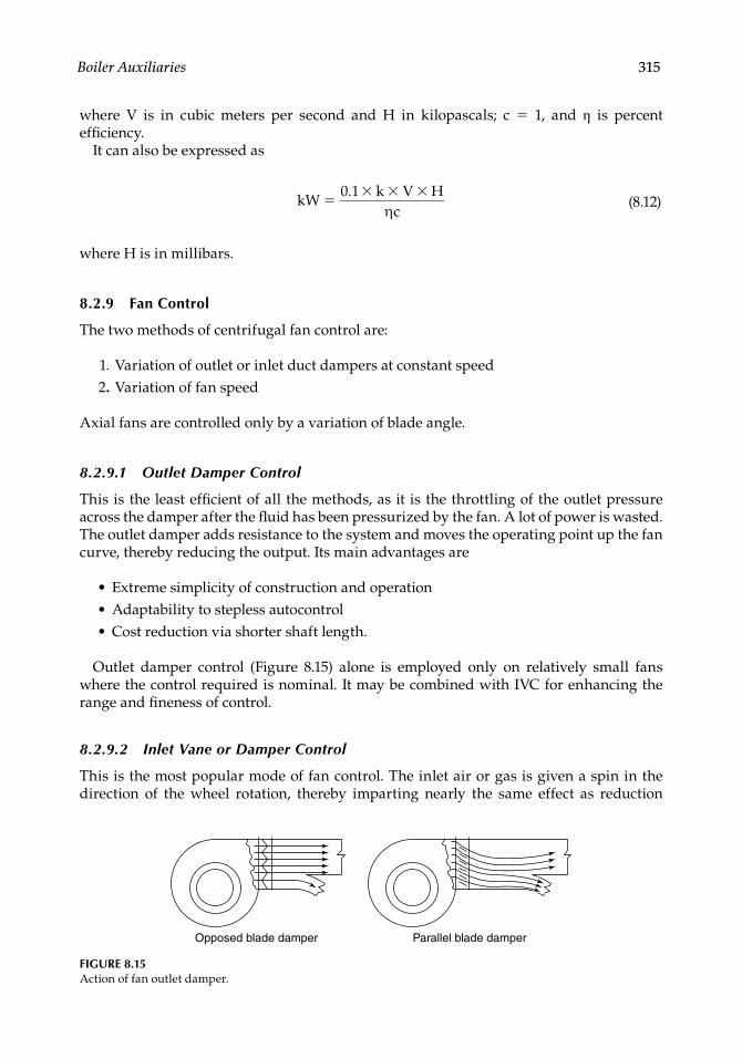
Boiler Auxiliaries 315
where V is in cubic meters per second and H in kilopascals; c = 1, and η is percent effi ciency.
It can also be expressed as
kW
c
0 1. k V H
(8.12)
where H is in millibars.
8.2.9 Fan Control
The two methods of centrifugal fan control are:
1. Variation of outlet or inlet duct dampers at constant speed 2. Variation of fan speed
Axial fans are controlled only by a variation of blade angle.
8.2.9.1 Outlet Damper Control
This is the least effi cient of all the methods, as it is the throttling of the outlet pressure across the damper after the fl uid has been pressurized by the fan. A lot of power is wasted. The outlet damper adds resistance to the system and moves the operating point up the fan curve, thereby reducing the output. Its main advantages are
Extreme simplicity of construction and operationAdaptability to stepless autocontrolCost reduction via shorter shaft length.
Outlet damper control (Figure 8.15) alone is employed only on relatively small fans where the control required is nominal. It may be combined with IVC for enhancing the range and fi neness of control.
8.2.9.2 Inlet Vane or Damper Control
This is the most popular mode of fan control. The inlet air or gas is given a spin in the direction of the wheel rotation, thereby imparting nearly the same effect as reduction
•••
Opposed blade damper Parallel blade damper
FIGURE 8.15Action of fan outlet damper.
CRC_75365_Ch008.indd 315CRC_75365_Ch008.indd 315 1/30/2009 1:44:30 PM1/30/2009 1:44:30 PM
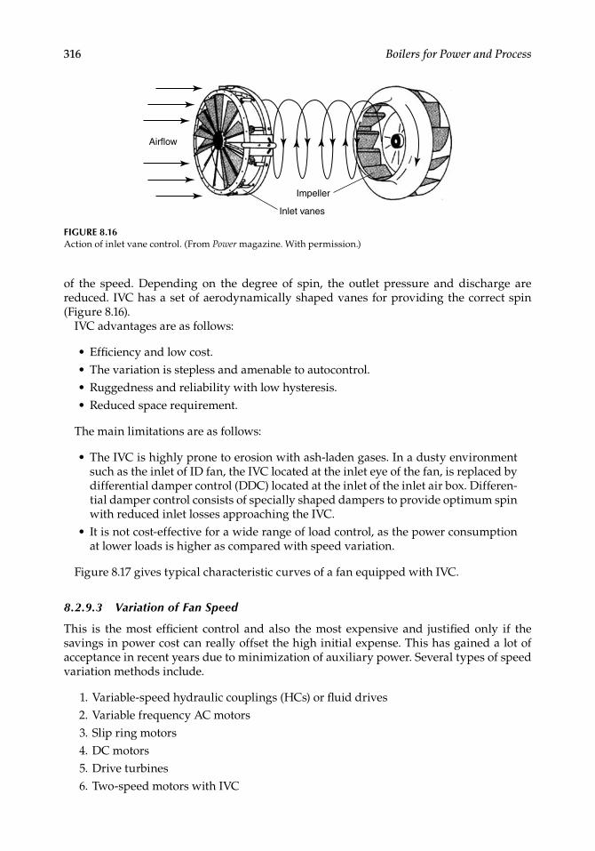
316 Boilers for Power and Process
of the speed. Depending on the degree of spin, the outlet pressure and discharge are reduced. IVC has a set of aerodynamically shaped vanes for providing the correct spin (Figure 8.16).
IVC advantages are as follows:
Effi ciency and low cost.The variation is stepless and amenable to autocontrol.Ruggedness and reliability with low hysteresis.Reduced space requirement.
The main limitations are as follows:
The IVC is highly prone to erosion with ash-laden gases. In a dusty environment such as the inlet of ID fan, the IVC located at the inlet eye of the fan, is replaced by differential damper control (DDC) located at the inlet of the inlet air box. Differen-tial damper control consists of specially shaped dampers to provide optimum spin with reduced inlet losses approaching the IVC.It is not cost-effective for a wide range of load control, as the power consumption at lower loads is higher as compared with speed variation.
Figure 8.17 gives typical characteristic curves of a fan equipped with IVC.
8.2.9.3 Variation of Fan Speed
This is the most effi cient control and also the most expensive and justifi ed only if the savings in power cost can really offset the high initial expense. This has gained a lot of acceptance in recent years due to minimization of auxiliary power. Several types of speed variation methods include.
1. Variable-speed hydraulic couplings (HCs) or fl uid drives 2. Variable frequency AC motors 3. Slip ring motors 4. DC motors 5. Drive turbines 6. Two-speed motors with IVC
••••
•
•
FIGURE 8.16Action of inlet vane control. (From Power magazine. With permission.)
Airflow
Impeller
Inlet vanes
CRC_75365_Ch008.indd 316CRC_75365_Ch008.indd 316 1/30/2009 1:44:30 PM1/30/2009 1:44:30 PM
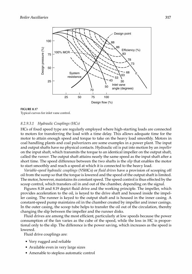
Boiler Auxiliaries 317
8.2.9.3.1 Hydraulic Couplings (HCs)
HCs of fi xed speed type are regularly employed where high-starting loads are connected to motors for transferring the load with a time delay. This allows adequate time for the motor to attain enough speed and torque to take on the heavy load smoothly. Motors in coal handling plants and coal pulverizers are some examples in a power plant. The input and output shafts have no physical contacts. Hydraulic oil is put into motion by an impeller on the input shaft, which transmits the torque to an identical impeller on the output shaft, called the runner. The output shaft attains nearly the same speed as the input shaft after a short time. The speed difference between the two shafts is the slip that enables the motor to start smoothly and reach a speed at which it is connected to the heavy load.
Variable-speed hydraulic couplings (VSHCs) or fl uid drives have a provision of scooping off oil from the sump so that the torque is lowered and the speed of the output shaft is limited. The motor, however, maintains its constant speed. The speed control is thus effected by the scoop control, which transfers oil in and out of the chamber, depending on the signal.
Figures 8.18 and 8.19 depict fl uid drive and the working principle. The impeller, which provides acceleration to the oil, is keyed to the drive shaft and housed inside the impel-ler casing. The runner is keyed to the output shaft and is housed in the inner casing. A constant-speed pump maintains oil in the chamber created by impeller and inner casings. In the outer casing, the scoop tube helps to transfer the oil out of the circulation, thereby changing the slip between the impeller and the runner disks.
Fluid drives are among the most effi cient, particularly at low speeds because the power consumption of the fan varies as the cube of the speed, while the loss in HC is propor-tional only to the slip. The difference is the power saving, which increases as the speed is lowered.
Fluid drive couplings are:
Very rugged and reliableAvailable even in very large sizesAmenable to stepless automatic control
•••
100% MCR
System resistance
Design point
88
86
83
7873
06863
5343 30
50Inlet vane angle (degrees) 70
Efficiency (%)
25 50 75
Design flow (%)
Des
ign
pres
sure
(%
)
100
25
75
50
100
FIGURE 8.17Typical curves for inlet vane control.
CRC_75365_Ch008.indd 317CRC_75365_Ch008.indd 317 1/30/2009 1:44:30 PM1/30/2009 1:44:30 PM

318 Boilers for Power and Process
8.2.9.3.2 Variable Frequency AC Motors
These motors employ a frequency control panel by which the output frequency (f ) is varied, which, in turn, regulates the speed of the motor as given by the formula
N
fp
120
where p is the number of poles in the motor.The variable frequency drives (VFDs) have become very popular as their range has
increased and their cost decreased. With practically no maintenance, the VFDs are good choices.
Impeller
Inputshaft
Outputshaft
Oilpump
RunnerImpeller casing
Inner casing
Outer casing
FIGURE 8.18Power transmission in hydraulic coupling.
FIGURE 8.19Load variation by scoop control.
Reservoir
Impeller
Runner
Pump
Input shaft
To cooler From cooler
Inner casing
Outer casing
Movable scoop tube
Output shaft
CRC_75365_Ch008.indd 318CRC_75365_Ch008.indd 318 1/30/2009 1:44:31 PM1/30/2009 1:44:31 PM
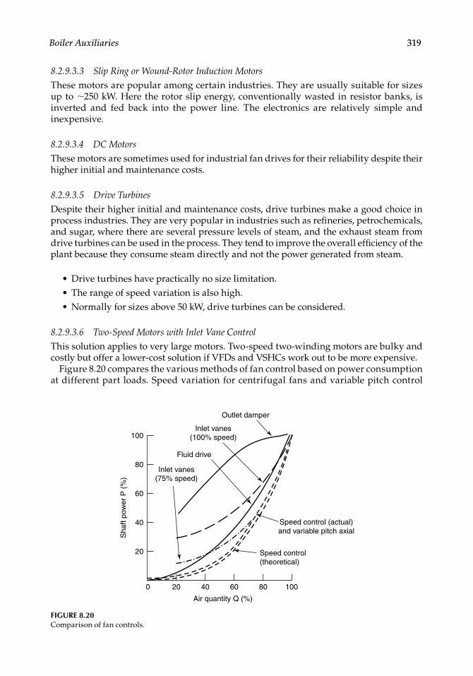
Boiler Auxiliaries 319
8.2.9.3.3 Slip Ring or Wound-Rotor Induction Motors
These motors are popular among certain industries. They are usually suitable for sizes up to ∼250 kW. Here the rotor slip energy, conventionally wasted in resistor banks, is inverted and fed back into the power line. The electronics are relatively simple and inexpensive.
8.2.9.3.4 DC Motors
These motors are sometimes used for industrial fan drives for their reliability despite their higher initial and maintenance costs.
8.2.9.3.5 Drive Turbines
Despite their higher initial and maintenance costs, drive turbines make a good choice in process industries. They are very popular in industries such as refi neries, petrochemicals, and sugar, where there are several pressure levels of steam, and the exhaust steam from drive turbines can be used in the process. They tend to improve the overall effi ciency of the plant because they consume steam directly and not the power generated from steam.
Drive turbines have practically no size limitation.The range of speed variation is also high.Normally for sizes above 50 kW, drive turbines can be considered.
8.2.9.3.6 Two-Speed Motors with Inlet Vane Control
This solution applies to very large motors. Two-speed two- winding motors are bulky and costly but offer a lower-cost solution if VFDs and VSHCs work out to be more expensive.
Figure 8.20 compares the various methods of fan control based on power consumption at different part loads. Speed variation for centrifugal fans and variable pitch control
•••
Outlet damper
40 60 80
Air quantity Q (%)
Sha
ft po
wer
P (
%)
100200
20
40
80
60
100
Fluid drive
Inlet vanes (100% speed)
Inlet vanes (75% speed)
Speed control (actual) and variable pitch axial
Speed control (theoretical)
FIGURE 8.20Comparison of fan controls.
CRC_75365_Ch008.indd 319CRC_75365_Ch008.indd 319 1/30/2009 1:44:31 PM1/30/2009 1:44:31 PM
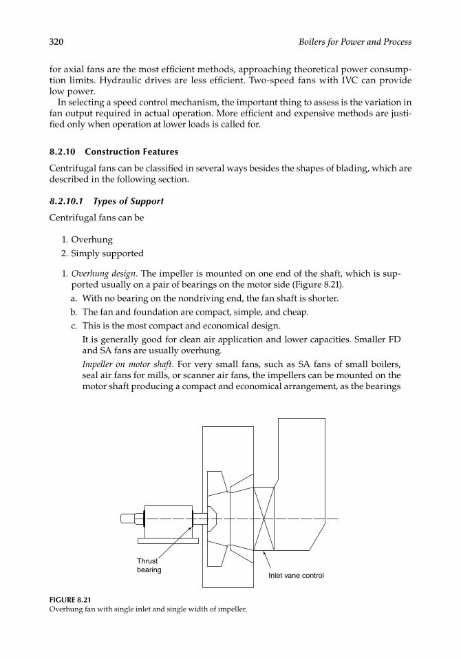
320 Boilers for Power and Process
for axial fans are the most effi cient methods, approaching theoretical power consump-tion limits. Hydraulic drives are less effi cient. Two-speed fans with IVC can provide low power.
In selecting a speed control mechanism, the important thing to assess is the variation in fan output required in actual operation. More effi cient and expensive methods are justi-fi ed only when operation at lower loads is called for.
8.2.10 Construction Features
Centrifugal fans can be classifi ed in several ways besides the shapes of blading, which are described in the following section.
8.2.10.1 Types of Support
Centrifugal fans can be
1. Overhung 2. Simply supported
1. Overhung design. The impeller is mounted on one end of the shaft, which is sup-ported usually on a pair of bearings on the motor side (Figure 8.21).
a. With no bearing on the nondriving end, the fan shaft is shorter. b. The fan and foundation are compact, simple, and cheap. c. This is the most compact and economical design. It is generally good for clean air application and lower capacities. Smaller FD
and SA fans are usually overhung. Impeller on motor shaft. For very small fans, such as SA fans of small boilers,
seal air fans for mills, or scanner air fans, the impellers can be mounted on the motor shaft producing a compact and economical arrangement, as the bearings
Thrustbearing
Inlet vane control
FIGURE 8.21Overhung fan with single inlet and single width of impeller.
CRC_75365_Ch008.indd 320CRC_75365_Ch008.indd 320 1/30/2009 1:44:31 PM1/30/2009 1:44:31 PM
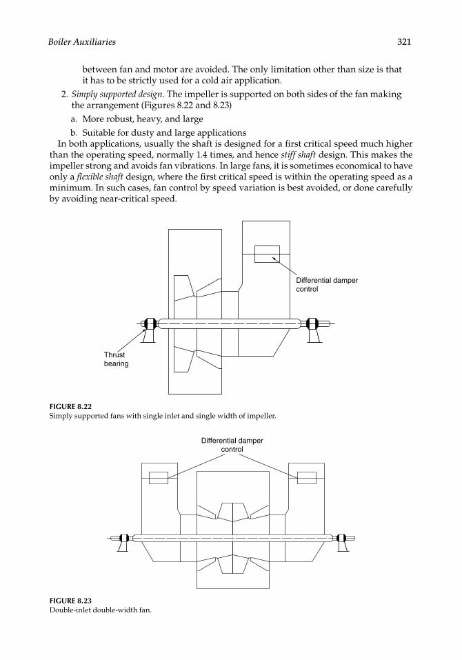
Boiler Auxiliaries 321
between fan and motor are avoided. The only limitation other than size is that it has to be strictly used for a cold air application.
2. Simply supported design. The impeller is supported on both sides of the fan making the arrangement (Figures 8.22 and 8.23)
a. More robust, heavy, and large b. Suitable for dusty and large applications
In both applications, usually the shaft is designed for a fi rst critical speed much higher than the operating speed, normally 1.4 times, and hence stiff shaft design. This makes the impeller strong and avoids fan vibrations. In large fans, it is sometimes economical to have only a fl exible shaft design, where the fi rst critical speed is within the operating speed as a minimum. In such cases, fan control by speed variation is best avoided, or done carefully by avoiding near-critical speed.
FIGURE 8.22Simply supported fans with single inlet and single width of impeller.
Differential damper control
Thrustbearing
Differential damper control
FIGURE 8.23Double-inlet double-width fan.
CRC_75365_Ch008.indd 321CRC_75365_Ch008.indd 321 1/30/2009 1:44:31 PM1/30/2009 1:44:31 PM
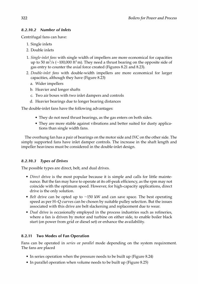
322 Boilers for Power and Process
8.2.10.2 Number of Inlets
Centrifugal fans can have:
1. Single inlets 2. Double inlets
1. Single-inlet fans with single width of impellers are more economical for capacities up to 50 m3/s (∼100,000 ft3 m). They need a thrust bearing on the opposite side of gas entry to counter the axial force created (Figures 8.21 and 8.23).
2. Double-inlet fans with double-width impellers are more economical for larger capacities, although they have (Figure 8.23)
a. Wider impellers b. Heavier and longer shafts c. Two air boxes with two inlet dampers and controls d. Heavier bearings due to longer bearing distances
The double-inlet fans have the following advantages:
They do not need thrust bearings, as the gas enters on both sides.They are more stable against vibrations and better suited for dusty applica-tions than single width fans.
The overhung fan has a pair of bearings on the motor side and IVC on the other side. The simply supported fans have inlet damper controls. The increase in the shaft length and impeller heaviness must be considered in the double-inlet design.
8.2.10.3 Types of Drives
The possible types are direct, belt, and dual drives.
Direct drive is the most popular because it is simple and calls for little mainte-nance. But the fan may have to operate at its off-peak effi ciency, as the rpm may not coincide with the optimum speed. However, for high-capacity applications, direct drive is the only solution.Belt drive can be opted up to ∼150 kW and can save space. The best operating speed as per H–Q curves can be chosen by suitable pulley selection. But the issues associated with this drive are belt slackening and replacement due to wear.Dual drive is occasionally employed in the process industries such as refi neries, where a fan is driven by motor and turbine on either side, to enable boiler black start (on power from grid or diesel set) or enhance the availability.
8.2.11 Two Modes of Fan Operation
Fans can be operated in series or parallel mode depending on the system requirement.The fans are placed
In series operation when the pressure needs to be built up (Figure 8.24)In parallel operation when volume needs to be built up (Figure 8.25)
••
•
•
•
••
CRC_75365_Ch008.indd 322CRC_75365_Ch008.indd 322 1/30/2009 1:44:32 PM1/30/2009 1:44:32 PM
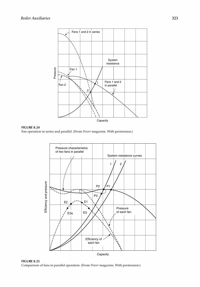
Boiler Auxiliaries 323
Fans 1 and 2 in series
Fan 1
Fan 21
2
System resistance
Fans 1 and 2 in parallel
Pre
ssur
e
Capacity
FIGURE 8.24Fan operation in series and parallel. (From Power magazine. With permission.)
FIGURE 8.25Comparison of fans in parallel operation. (From Power magazine. With permission.)
Pressure characteristics of two fans in parallel
System resistance curves
1 2
P2
P3
E3
E2 E1
E3a
P1
Pressure of each fan
Efficiency of each fan
Capacity
Effi
cien
cy a
nd p
ress
ure
CRC_75365_Ch008.indd 323CRC_75365_Ch008.indd 323 1/30/2009 1:44:32 PM1/30/2009 1:44:32 PM
324 Boilers for Power and Process
A primary air (PA) fan drawing suction from the AH, which is downstream of the FD fan in pulverized fuel (PF) boiler, is an example of series operation. FD and ID fan opera-tions are other examples. A pair of FD fans or ID fans or a number of PA fans operating simultaneously are examples of parallel operation.
Dissimilar fans can be in series operation, even an axial fan and a centrifugal fan, but for parallel operation, the fans have to be very similar with continuously drooping char-acteristics with no humps to prevent unstable operation, leading to dangerous hunting. Hunting occurs when there is a hump in the fan and it keeps shifting its operation from high to low volumes.
8.2.12 Single Set and Two Sets of Fans
It is normal to have a single set of fans for smaller boilers and two sets of fans for the larger ones. Single set of fans has the advantage of
Simplicity of arrangementReduced duct workLess instrumentation and controlBetter effi ciencyLower auxiliary power due to larger size
Single sets permit lower installation and running costs. Two sets of fans, however, provide redundancy while sacrifi cing the above-mentioned benefi ts. Induced draft fan erosion was the main reason behind the adoption of two sets of fans, even for midsize boilers. With very reliable ESPs, fabric fi lters (FFs), and superior fans, the single-fan concept is gaining greater acceptance.
8.2.13 Fan Erosion and Protection
Fan erosion is experienced mainly in coal-fi red boilers. Coal ash impinging at high veloci-ties is the main reason for this erosion. Induced draft and GR are the usual fans in a power plant, which are susceptible to erosion. With the adoption of ESPs and bag fi lters, ID fans have largely overcome this problem. GR fans, however, continue to experience high dust loads and hence are made of radial blading to resist erosion. The PA fans in suction mills are also prone to erosion. Depending on the gas fl ow and fan construction, the areas of wear can be predicted and identifi ed.
Overlaying weld material on selected areas of impellerProviding replaceable liners
These are the two methods of protecting the centrifugal fans against erosion of ash besides lower speeds, but they increase the impeller weight. Increase in fan weight leads to poorer boiler dynamics and longer start-up times. On the whole, there is no fully satisfactory solu-tion for the problem of fan wear.
1. Deposition of weld material of a hard composition, such as chromium carbide, on the blades and the inside channel, which come in contact with moving gas, is a very common remedy. A careful judgment is needed regarding the exact loca-tion and amount of deposition, as the inertia of the impeller increases with any
•••••
•
•
CRC_75365_Ch008.indd 324CRC_75365_Ch008.indd 324 1/30/2009 1:44:32 PM1/30/2009 1:44:32 PM
Boiler Auxiliaries 325
weight addition. Flame or plasma spray metallizing is not very popular because it can peel off if not applied properly. More importantly, the alloying left behind interferes with any later weldments. Metallizing is capable of withstanding nearly perpendicular impingement but not tangential abrasive forces.
2. Replaceable liners can be provided for blades or casing or both, depending on the protection needed. They are soft sacrifi cial plates, either bolted or welded. Bolted blades also need bead welding to prevent entry of dust particles under the plate. Ceramic or tungsten carbide tiles are attractive due to their extreme hardness, low thickness, and light weight. But the problem of securing the fan blades is not fully solved.
For variable pitch axial fans, protection is needed on the upstream edges of the blades, which is provided by stainless steel (ss) or chrome strips attached by ss screws. Complete blade sets must be replaced after detecting erosion, and this can be usually done in a single shift by the maintenance staff. The erosion protection for axial fans is thus easier, but the capability to withstand erosion is inherently lower in axial fans.
8.2.14 Boiler Fans
A boiler plant, depending on the fi ring system and size, contains several fans of various sizes and types:
Forced draft fan is the main air fan whose prime job is to deliver the combustion air to the fi ring equipment in a balanced draft boiler. In a pressurized boiler, the FD fan has to further push the gases formed in the combustion chamber up to the chimney exit.
A forced draft fan takes clean cold air from the atmosphere, unless steam AHs are in the circuit, in which case the inlet air is slightly hotter.In cold countries, it is normal for warm air to be drawn from the top of the boiler house. The tall suction duct can also be used for airfl ow measurement.Forced draft fan heads vary from as low as ∼50 mm wg in stoker-fi red boilers to as high as ∼2000 mm wg and higher in circulating fl uidized bed combustion (CFBC) boilers.In the case of PF boilers, FD fans supply only SA as the PA fans supply the PA.Backward-curved or aerofoil type of centrifugal fans mostly with IVCs, are usu-ally adopted here. In utility boilers, FD is the most ideal application for axial fans with variable pitch.
Induced draft fans, employed only in balanced draft boilers, suck the combustion gases from the furnace and discharge them at the stack exit. They maintain a nom-inal suction of 5–25 mm wg in the furnace to avoid fl ames leaping out, and ensure operator safety and prevent the insulation and casing from burning out.
Induced draft fans are hot gas fans with temperatures usually ∼150°C and rarely exceeding 200°C.Suction pressures vary from ∼200 to 400 mm wg. Higher pressures are required when dust separation devices such as bag fi lters or wet scrubbers (WS) are employed.When dust collection from fl ue gases was not mandatory, radial or backward-curved radial-tipped blading was used in centrifugal fans. With reliable gas
•
•
•
•
••
•
•
•
•
CRC_75365_Ch008.indd 325CRC_75365_Ch008.indd 325 1/30/2009 1:44:32 PM1/30/2009 1:44:32 PM
326 Boilers for Power and Process
cleaning equipment in use, fans with aerofoil, backward-curved or backward-curved radial-tipped blading are used, depending on the effi ciency of the dust col-lectors and the erosive nature of the fl y ash. Aerofoil blading is also common now.Variable pitch axial fans are also used where the fl y ash is not erosive and the upstream dust collection is good.Corrosion of fans is an issue only for liquor or refuse-fi red boilers.
Secondary air fans or over-fi re air (OFA) fans are used for providing 10–30% combus-tion air to the furnace at high pressure to (1) provide turbulence and (2) prevent stratifi cation of gas streams so that the combustion is complete. More volatile mat-ter (VM) in fuel increases the OFA requirement, as more combustion takes place in the furnace. In the case of staged combustion for NOx abatement, these fans provide much higher amounts of air, even as high as 50%.
Pressures vary from 250 to 1000 mm wg.Aerofoil or backward-bladed construction is suitable.Both cold and hot air are used. Hot air can be as high as 350°C, demanding spe-cial care for bearing cooling.
Gas tempering (GT) and GR fans are high-temperature fans and, in case of solid fuel fi ring, they are also high-dust fans. The gas temperature is dependent on the loca-tion of suction—whether the economizer (ECON) or the AH exit.
Only centrifugal fans with radial or radial-tipped blading are suitable for this application, depending on the dust loading and its erosivity.These fans have the most severe duty in the power plant, as they are subjected to high-dust loads and high temperatures with wide fl uctuations.Care should be taken to select a fan with integral hub and shaft, as shrink fi tting may not be adequate.
Primary air fans in PF boilers draw hot air from the discharge of AH and push the hot PA through the mills and carry the pulverized coal to the burners. A cold PA fan takes ambient air and passes it through the AH additionally. Air quantities are relatively small, and the heads are high, requiring a narrow wheel with large diameter. As the hot air is usually dusty with rotary AHs, the hot PA fans use radial blading. The cold PA fans, on the other hand, deal with clean air and can be made with aerofoil blading.Exhauster fans downstream of the coal mills in suction-type PF fi ring are always made of straight radial blading to withstand erosion of coal dust.
8.3 Dust-Collecting Equipment
Dust collection in a boiler plant is mainly for the control of the particulate emissions, and the separated dust is disposed of by a suitable ash-handling system. In some cases, part (stoker, BFBC) or all (CFBC) of the dust is required to be returned to the system to enhance the combustion effi ciency. In CFBC boilers, the main process is dependent on the returned dust, which acts as a coolant in the bed. Cyclones in CFBCs are actually used as process equipment. The cyclone evaporator and the Venturi scrubber in BL-fi red boilers help to concentrate the liquor in addition to trapping the dust.
•
••
•••
•
•
•
•
•
•
CRC_75365_Ch008.indd 326CRC_75365_Ch008.indd 326 1/30/2009 1:44:33 PM1/30/2009 1:44:33 PM
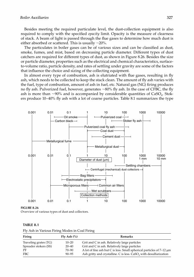
Boiler Auxiliaries 327
Besides meeting the required particulate level, the dust-collection equipment is also required to comply with the specifi ed opacity limit. Opacity is the measure of clearness of stack. A beam of light is passed through the fl ue gases to determine how much dust is either absorbed or scattered. This is usually ∼20%.
The particulates in boiler gases can be of various sizes and can be classifi ed as dust, smoke, fumes, and mist, based on decreasing particle diameter. Different types of dust catchers are required for different types of dust, as shown in Figure 8.26. Besides the size or particle diameter, properties such as the electrical and chemical characteristics, surface-to-volume ratio, particle density, and rates of settling under gravity are some of the factors that infl uence the choice and sizing of the collecting equipment.
In almost every type of combustion, ash is elutriated with fl ue gases, resulting in fl y ash, which needs to be collected to keep the stack clean. The amount of fl y ash varies with the fuel, type of combustion, amount of ash in fuel, etc. Natural gas (NG) fi ring produces no fl y ash. Pulverized fuel, however, generates ∼80% fl y ash. In the case of CFBC, the fl y ash is more than ∼90% and is accompanied by considerable quantities of CaSO4. Stok-ers produce 10–40% fl y ash with a lot of coarse particles. Table 8.1 summarizes the type
0.001 0.01 0.1 1 10 100 1000 10000
0.001 0.01 0.1Diameter of dust (µm)
1 10 100 1000 100001 mm 10 mm
0.001 0.01 0.1 1 10 100 1000 10000
Metallurgical fume
Oil smokeCarbon black
Pulverized coal fly ashCoal dust
Pulverized coal
Electrostatic precipitators
Microporous filters Common air filters
Wet scrubbers
Bag filters
Settling chambersCentrifugal (mechanical) dust collectors
Metallurgical dust
Cement dust
Stoker fly ash
Collection methods
FIGURE 8.26Overview of various types of dust and collectors.
TABLE 8.1
Fly Ash in Various Firing Modes in Coal Firing
Firing Fly Ash (%) Remarks
Traveling grates (TG) 10–20 Grit and C in ash. Relatively large particlesSpreader stokers (SS) 20–40 Grit and C in ash. Relatively large particlesPF 70–90 A lot of fi ne ash but C is less. Small spherical particles of 7–12 µmFBC 90–95 Ash gritty and crystalline. C is less. CaSO4 with desulfurization
CRC_75365_Ch008.indd 327CRC_75365_Ch008.indd 327 1/30/2009 1:44:33 PM1/30/2009 1:44:33 PM
328 Boilers for Power and Process
of ash generated in each type of fi ring. The dust-collecting equipment in a boiler can be classifi ed as
MDCsESP or electrofi ltersBag or FFsWet or liquid scrubbers
Particles larger than 100 µm (0.1 mm) settle quickly and may need no more than settling chambers. In any case, boiler ash is always fi ner than 100 µm.
Gas and dust are worked on differently. In MDCs, the gas is given a change of direc-tion by centrifugal action. Naturally, this takes a lot of energy as compared with the ESPs where only the dust is treated. The gases are not treated in ESPs. In bag fi lters, however, the gas is worked on, as the dusty gases are fi ltered through the cloth separator. Naturally, energy expended is considerable. In wet scrubbers, the gas is sprayed with water to cap-ture the dust.
8.4 Mechanical Dust Collectors (MDCs)
Depending on the collection process, MDCs can be classifi ed as
Inertial separatorsCentrifugal separators
Inertial separators rely on a change of direction of gas fl ow or interception of dust or both, to effect a separation of dust particles from gas. They are simple in construction with low pressure drop and moderate collection effi ciencies. They are essentially good for collecting grit from fl ue gases for refi ring. U-beams in CFBCs and defl ection baffl es in hoppers are typical examples of inertial separators.
Centrifugal or cyclone separators provide a downward high-speed swirl to the gases, causing the dust particles to be thrown to the periphery by the centrifugal action, and slide down along the edge. The inward inclination of the collector tube at the discharge end helps the gases to form a smaller swirl inside and exit at the top duly dedusted. This is explained in Figure 8.27. Depending on the gas volume and the dust loading, the cyclones can be classifi ed as
Small-diameter multicyclones, also called multiclones (Figures 8.28 and 8.29)Large-diameter cyclones arranged in single or multiple units (Figure 8.27)
8.4.1 Multiclones
Multiclones employ small-diameter (250–500 mm mostly) long tubes, which help to pro-vide higher centrifugal forces and longer separation time, both of which increase the collection effi ciency, which can be as high as 95% for particles larger than 5 µm under
••••
••
••
CRC_75365_Ch008.indd 328CRC_75365_Ch008.indd 328 1/30/2009 1:44:33 PM1/30/2009 1:44:33 PM
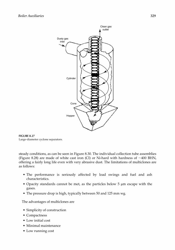
Boiler Auxiliaries 329
steady conditions, as can be seen in Figure 8.30. The individual collection tube assemblies (Figure 8.28) are made of white cast iron (CI) or Ni-hard with hardness of ∼400 BHN, offering a fairly long life even with very abrasive dust. The limitations of multiclones are as follows:
The performance is seriously affected by load swings and fuel and ash characteristics.Opacity standards cannot be met, as the particles below 5 µm escape with the gases.The pressure drop is high, typically between 50 and 125 mm wg.
The advantages of multiclones are
Simplicity of constructionCompactnessLow initial costMinimal maintenanceLow running cost
•
•
•
•••••
Clean gas outlet
Dusty gas inlet
Cylinder
Cone
Hopper
FIGURE 8.27Large-diameter cyclone separators.
CRC_75365_Ch008.indd 329CRC_75365_Ch008.indd 329 1/30/2009 1:44:33 PM1/30/2009 1:44:33 PM
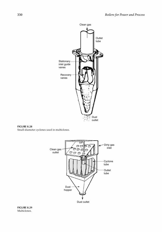
330 Boilers for Power and Process
Dirty gas inlet
Cyclone tube
Outlet tube
Dust outlet
Dust hopper
Clean gas outlet
FIGURE 8.29Multiclones.
Outlet tube
Clean gas
Dust outlet
Recovery vanes
Stationary inlet guide vanes
FIGURE 8.28Small-diameter cyclones used in multiclones.
CRC_75365_Ch008.indd 330CRC_75365_Ch008.indd 330 1/30/2009 1:44:34 PM1/30/2009 1:44:34 PM

Boiler Auxiliaries 331
The main disadvantages are
1. Poor collection effi ciencies for particles below 5 µm size (Figure 8.30), which do not meet the present-day opacity and particulate pollution norms.
2. With high inlet dust loading, the small inlets of the cyclones get choked, making the multiclones unsuitable.
A typical volume versus pressure drop relationship is shown in Figure 8.31.The multiclones are now practically obsolete because of the present-day pollution norms
for particulate emission. They are now occasionally used as precollectors before the ESPs or bag fi lters to trap the grits in the dust for refi ring purposes.
In the 1960s and 1970s, they were used as precollectors to the ESPs with a view to reduc-ing the dust load on ESPs to improve the collection and reduce the size. These expectations were belied because the ESP sizing depended more on the collection of fi nes and not so much on the grit.
8.4.2 Large-Diameter Cyclones
These cyclones, ranging from <1 m to more than 10 m in diameter, are employed for higher dust loads and gas volumes. Also, they can be adapted for higher temperatures of ∼900°C and high erosion by lining the inside walls. The interest in cyclones is now sustained by their use in the CFBC boilers.
50
20
40
60
80
100
10 15 20
Particle size (µm)
Fractional efficiencyMicrons efficiency
Specific gravity 2.0
Flow/cell 0.47 m3/s at 15°C 760 mm wg
Dust concentration 4.5 g/m3
0−5
5−10
10−20
>20
40.7
96.2
99.2
99.5
Col
lect
ion
effic
ienc
y (%
)
25
FIGURE 8.30Typical collection effi ciency of multiclone.
CRC_75365_Ch008.indd 331CRC_75365_Ch008.indd 331 1/30/2009 1:44:34 PM1/30/2009 1:44:34 PM
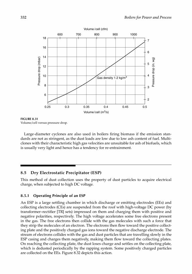
332 Boilers for Power and Process
Large-diameter cyclones are also used in boilers fi ring biomass if the emission stan-dards are not as stringent, as the dust loads are low due to low ash content of fuel. Multi-clones with their characteristic high gas velocities are unsuitable for ash of biofuels, which is usually very light and hence has a tendency for re-entrainment.
8.5 Dry Electrostatic Precipitator (ESP)
This method of dust collection uses the property of dust particles to acquire electrical charge, when subjected to high DC voltage.
8.5.1 Operating Principle of an ESP
An ESP is a large settling chamber in which discharge or emitting electrodes (EEs) and collecting electrodes (CEs) are suspended from the roof with high-voltage DC power (by transformer–rectifi er [TR] sets) impressed on them and charging them with positive and negative polarities, respectively. The high voltage accelerates some free electrons present in the gas. The free electrons then collide with the gas molecules with such a force that they strip the molecules of an electron. The electrons then fl ow toward the positive collect-ing plate and the positively charged gas ions toward the negative discharge electrode. The stream of electrons collides with the gas and dust particles that are travelling slowly in the ESP casing and charges them negatively, making them fl ow toward the collecting plates. On reaching the collecting plate, the dust loses charge and settles on the collecting plate, which is dedusted periodically by the rapping system. Some positively charged particles are collected on the EEs. Figure 8.32 depicts this action.
FIGURE 8.31Volume/cell versus pressure drop.
0.25 0.3 0.35 0.4 0.45
6
8
10
12
14
16
18
Volume/cell (m3/s)
Pre
ssur
e dr
op (
mba
r)
0.5
7
600 700
Volume / cell (cfm)
800 900 1000
6
5
4
3 Pre
ssur
e dr
op (
in. w
g)
2
Gas density 1.2 kg/m3
CRC_75365_Ch008.indd 332CRC_75365_Ch008.indd 332 1/30/2009 1:44:34 PM1/30/2009 1:44:34 PM
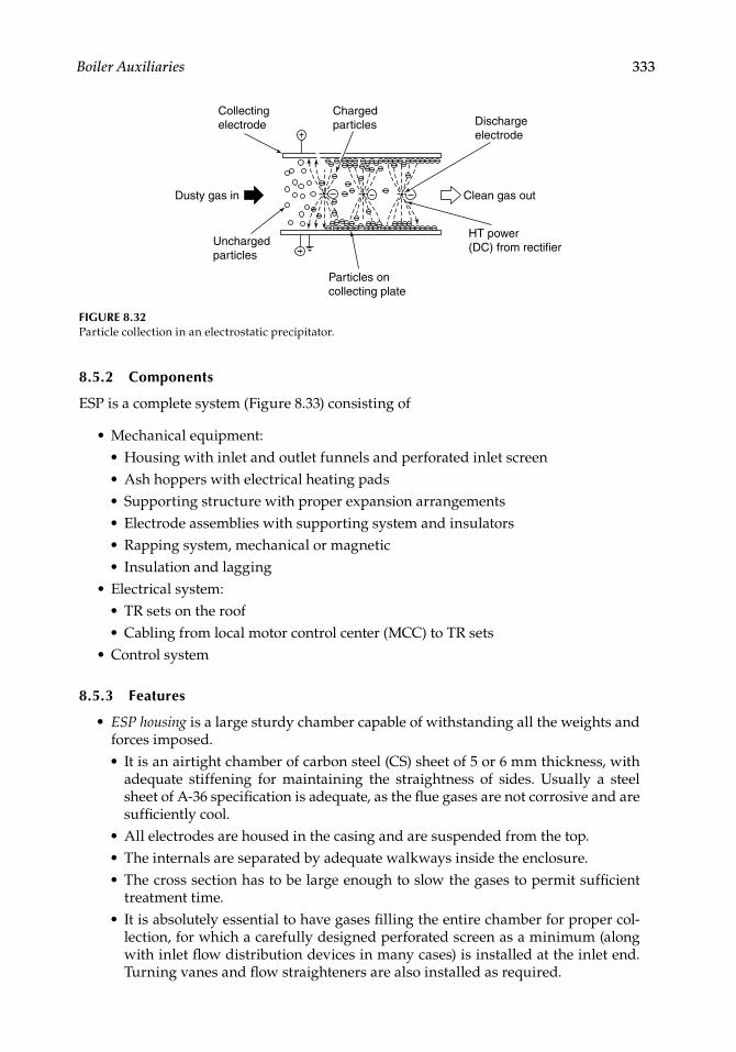
Boiler Auxiliaries 333
8.5.2 Components
ESP is a complete system (Figure 8.33) consisting of
Mechanical equipment:Housing with inlet and outlet funnels and perforated inlet screenAsh hoppers with electrical heating padsSupporting structure with proper expansion arrangementsElectrode assemblies with supporting system and insulatorsRapping system, mechanical or magneticInsulation and lagging
Electrical system:TR sets on the roofCabling from local motor control center (MCC) to TR sets
Control system
8.5.3 Features
ESP housing is a large sturdy chamber capable of withstanding all the weights and forces imposed.
It is an airtight chamber of carbon steel (CS) sheet of 5 or 6 mm thickness, with adequate stiffening for maintaining the straightness of sides. Usually a steel sheet of A-36 specifi cation is adequate, as the fl ue gases are not corrosive and are suffi ciently cool.All electrodes are housed in the casing and are suspended from the top.The internals are separated by adequate walkways inside the enclosure.The cross section has to be large enough to slow the gases to permit suffi cient treatment time.It is absolutely essential to have gases fi lling the entire chamber for proper col-lection, for which a carefully designed perforated screen as a minimum (along with inlet fl ow distribution devices in many cases) is installed at the inlet end. Turning vanes and fl ow straighteners are also installed as required.
•••••••
•••
•
•
•
•••
•
Collectingelectrode
Chargedparticles Discharge
electrode
Clean gas outDusty gas in
HT power(DC) from rectifier
Particles oncollecting plate
Unchargedparticles
FIGURE 8.32Particle collection in an electrostatic precipitator.
CRC_75365_Ch008.indd 333CRC_75365_Ch008.indd 333 1/30/2009 1:44:34 PM1/30/2009 1:44:34 PM
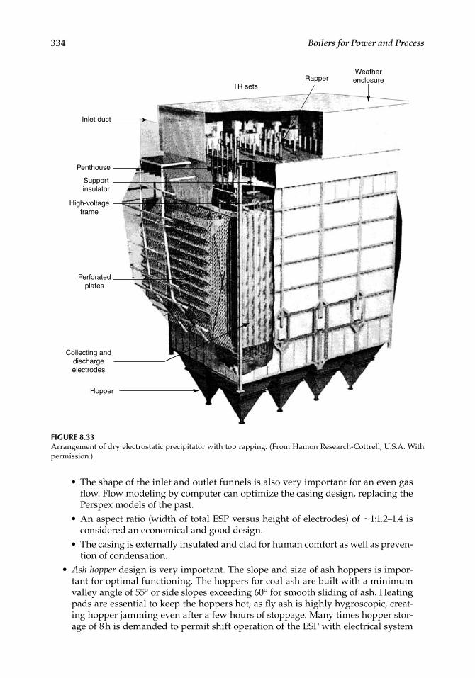
334 Boilers for Power and Process
The shape of the inlet and outlet funnels is also very important for an even gas fl ow. Flow modeling by computer can optimize the casing design, replacing the Perspex models of the past.An aspect ratio (width of total ESP versus height of electrodes) of ∼1:1.2–1.4 is considered an economical and good design.The casing is externally insulated and clad for human comfort as well as preven-tion of condensation.
Ash hopper design is very important. The slope and size of ash hoppers is impor-tant for optimal functioning. The hoppers for coal ash are built with a minimum valley angle of 55° or side slopes exceeding 60° for smooth sliding of ash. Heating pads are essential to keep the hoppers hot, as fl y ash is highly hygroscopic, creat-ing hopper jamming even after a few hours of stoppage. Many times hopper stor-age of 8 h is demanded to permit shift operation of the ESP with electrical system
•
•
•
•
FIGURE 8.33Arrangement of dry electrostatic precipitator with top rapping. (From Hamon Research-Cottrell, U.S.A. With permission.)
Inlet duct
TR setsRapper
Weather enclosure
Penthouse
Support insulator
High-voltageframe
Perforated plates
Collecting and discharge electrodes
Hopper
CRC_75365_Ch008.indd 334CRC_75365_Ch008.indd 334 1/30/2009 1:44:35 PM1/30/2009 1:44:35 PM
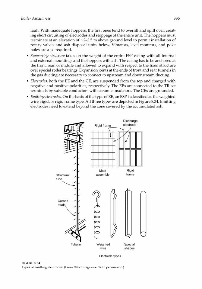
Boiler Auxiliaries 335
fault. With inadequate hoppers, the fi rst ones tend to overfi ll and spill over, creat-ing short circuiting of electrodes and stoppage of the entire unit. The hoppers must terminate at an elevation of ∼2–2.5 m above ground level to permit installation of rotary valves and ash disposal units below. Vibrators, level monitors, and poke holes are also required.Supporting structure takes on the weight of the entire ESP casing with all internal and external mountings and the hoppers with ash. The casing has to be anchored at the front, rear, or middle and allowed to expand with respect to the fi xed structure over special roller bearings. Expansion joints at the ends of front and rear funnels in the gas ducting are necessary to connect to upstream and downstream ducting.Electrodes, both the EE and the CE, are suspended from the top and charged with negative and positive polarities, respectively. The EEs are connected to the TR set terminals by suitable conductors with ceramic insulators. The CEs are grounded.Emitting electrodes. On the basis of the type of EE, an ESP is classifi ed as the weighted wire, rigid, or rigid frame type. All three types are depicted in Figure 8.34. Emitting electrodes need to extend beyond the zone covered by the accumulated ash.
•
•
•
MastassemblyStructural
tube
Coronastuds
Tubular Weightedwire
Electrode types
Specialshapes
Rigid frame
Rigidframe
Dischargeelectrode
FIGURE 8.34Types of emitting electrodes. (From Power magazine. With permission.)
CRC_75365_Ch008.indd 335CRC_75365_Ch008.indd 335 1/30/2009 1:44:37 PM1/30/2009 1:44:37 PM
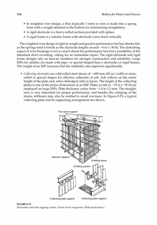
336 Boilers for Power and Process
In weighted wire design, a thin (typically 3 mm) ss wire is made into a spring form with a weight attached at the bottom for maintaining straightness.A rigid electrode is a heavy-rolled section provided with spikes.A rigid frame is a tubular frame with electrode wires fi xed vertically.
The weighted wire design is light in weight and good in performance but has shorter life, as the springs tend to break as the electrode lengths exceed ∼9 m (∼30 ft). The disturbing aspect of wire breakage is not so much about the performance loss but a possibility of the attendant short circuiting, calling for an immediate repair. The rigid electrode and rigid frame designs rely on heavier members for stronger construction and reliability. Large ESPs for utilities are made with pipe- or special-shaped heavy electrodes or rigid frames. The weight of an ESP increases but the reliability also improves signifi cantly.
Collecting electrodes are cold-rolled steel sheets of ∼600 mm (24 in.) width or more, rolled to special shapes for effective collection of ash. Ash collects on the entire height of the plate and, when dislodged, falls in layers. The height of the collecting plates is one of the prime dimensions of an ESP. Plates as tall as ∼15 m (∼50 ft) are employed on large ESPs. Plate thickness varies from ∼1.0 to 1.5 mm. The straight-ness is very important for proper performance, and besides the crimping of the sheets, stiffeners may also be welded to avoid waviness. In Figure 8.35, a typical collecting plate and its supporting arrangement are shown.
•
••
•
Four-point support
Hammer rappers
Collecting plate support
Emitting system
Emitting frame
Collecting plate rappers
FIGURE 8.35Electrodes and side rapping system. (From Power magazine. With permission.)
CRC_75365_Ch008.indd 336CRC_75365_Ch008.indd 336 1/30/2009 1:44:37 PM1/30/2009 1:44:37 PM
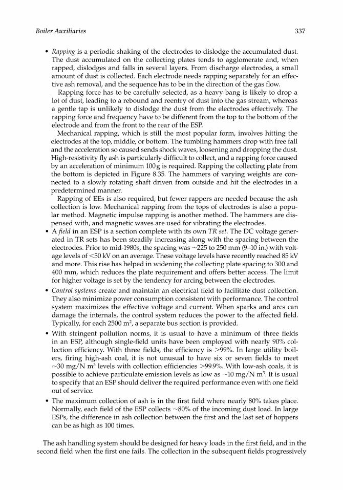
Boiler Auxiliaries 337
Rapping is a periodic shaking of the electrodes to dislodge the accumulated dust. The dust accumulated on the collecting plates tends to agglomerate and, when rapped, dislodges and falls in several layers. From discharge electrodes, a small amount of dust is collected. Each electrode needs rapping separately for an effec-tive ash removal, and the sequence has to be in the direction of the gas fl ow.
Rapping force has to be carefully selected, as a heavy bang is likely to drop a lot of dust, leading to a rebound and reentry of dust into the gas stream, whereas a gentle tap is unlikely to dislodge the dust from the electrodes effectively. The rapping force and frequency have to be different from the top to the bottom of the electrode and from the front to the rear of the ESP.
Mechanical rapping, which is still the most popular form, involves hitting the electrodes at the top, middle, or bottom. The tumbling hammers drop with free fall and the acceleration so caused sends shock waves, loosening and dropping the dust. High-resistivity fl y ash is particularly diffi cult to collect, and a rapping force caused by an acceleration of minimum 100 g is required. Rapping the collecting plate from the bottom is depicted in Figure 8.35. The hammers of varying weights are con-nected to a slowly rotating shaft driven from outside and hit the electrodes in a predetermined manner.
Rapping of EEs is also required, but fewer rappers are needed because the ash collection is low. Mechanical rapping from the tops of electrodes is also a popu-lar method. Magnetic impulse rapping is another method. The hammers are dis-pensed with, and magnetic waves are used for vibrating the electrodes.A fi eld in an ESP is a section complete with its own TR set. The DC voltage gener-ated in TR sets has been steadily increasing along with the spacing between the electrodes. Prior to mid-1980s, the spacing was ∼225 to 250 mm (9–10 in.) with volt-age levels of <50 kV on an average. These voltage levels have recently reached 85 kV and more. This rise has helped in widening the collecting plate spacing to 300 and 400 mm, which reduces the plate requirement and offers better access. The limit for higher voltage is set by the tendency for arcing between the electrodes.Control systems create and maintain an electrical fi eld to facilitate dust collection. They also minimize power consumption consistent with performance. The control system maximizes the effective voltage and current. When sparks and arcs can damage the internals, the control system reduces the power to the affected fi eld. Typically, for each 2500 m2, a separate bus section is provided.With stringent pollution norms, it is usual to have a minimum of three fi elds in an ESP, although single-fi eld units have been employed with nearly 90% col-lection effi ciency. With three fi elds, the effi ciency is >99%. In large utility boil-ers, fi ring high-ash coal, it is not unusual to have six or seven fi elds to meet ∼30 mg/N m3 levels with collection effi ciencies >99.9%. With low-ash coals, it is possible to achieve particulate emission levels as low as ∼10 mg/N m3. It is usual to specify that an ESP should deliver the required performance even with one fi eld out of service.The maximum collection of ash is in the fi rst fi eld where nearly 80% takes place. Normally, each fi eld of the ESP collects ∼80% of the incoming dust load. In large ESPs, the difference in ash collection between the fi rst and the last set of hoppers can be as high as 100 times.
The ash handling system should be designed for heavy loads in the fi rst fi eld, and in the second fi eld when the fi rst one fails. The collection in the subsequent fi elds progressively
•
•
•
•
•
CRC_75365_Ch008.indd 337CRC_75365_Ch008.indd 337 1/30/2009 1:44:38 PM1/30/2009 1:44:38 PM
338 Boilers for Power and Process
reduces, but the particles are fi ner. The ash handling plant should be designed such great variations in mind.
8.5.4 Advantages
An ESP is the most popular particulate collection system in all sizes of boilers based on its enormous advantages:
Collection effi ciencies >99.9% can be achieved effortlessly by increasing the fi elds. The exit dust load can be as low as ∼30 mg/N m3 with high-ash coals and even 10 mg/N m3 for low-ash coals.Electrostatic precipitators can be effective in collecting not only the coarse particles but also the fi ne particles and fumes. They can collect a wide range of dust, from submicron levels of 0.05 µm to large particles of 10 µm or more.The pressure drop is surprisingly low, between 20 and 30 mm wg, not much higher than that for a settling chamber because the internals are wide apart and the gas velocity is low. More importantly, the dust is worked upon and not the fl ue gases, unlike in the cyclones or bag fi lters.The power consumption is very low for the same reason.Because of the low gas velocities, the erosion of the internals is not an issue. EPS is ideally suited for coals with high amounts of abrasive ash.ESP is an extremely reliable and rugged system, which requires practically no maintenance.
8.5.5 Limitations
An ESP is expensive, particularly in lower sizes on a specifi c cost basis because of the numerous components.It occupies a lot of fl oor space.Emission limits are exceeded during upset conditions such as soot blowing. If the emission limits are to be observed under all conditions, the ESP becomes too large.For very low emission limits such as 30 mg/N m3 from high-ash coal-fi red boilers, bag fi lters become attractive, if the ash is not too abrasive.The collection effi ciency of particles of 2 µm and below is poor.
8.5.6 Performance Parameters
The classical Deutsche–Anderson equation describes the behavior of an ESP reasonably well, although it is defi cient in predicting the performance.
Collection effi ciency of an ESP can be defi ned as
E
(inlet dust outlet dust)inlet dust
or 1outlet dustinlet duust
(8.13)
An ESP is a percentage collector. Outlet dust loading increases in proportion to the inlet dust loading, and if the outlet concentration is to be maintained at high dust loads, the ESP
•
•
•
••
•
•
••
•
•
CRC_75365_Ch008.indd 338CRC_75365_Ch008.indd 338 1/30/2009 1:44:38 PM1/30/2009 1:44:38 PM

Boiler Auxiliaries 339
size has to be increased. This is an important point of difference compared with the FFs in which the outlet loading remains indifferent to the inlet load.
Collection efficiency E e Aw V(%) / 1 (8.14)
whereA = the area of CEs in square metersV = actual gas volume in cubic meters per secondw = migration or drift velocity in meters per seconde = natural logarithm 2.718
Collection effi ciency is a function of
1. A/V, the specifi c collection area (SCA) in square meters per cubic meter per second of fl ue gas. More collection area improves collection effi ciency for the same gas volume.
2. w, the migration velocity, is governed by ash resistivity. Higher migration velocity means better collection effi ciency. Lower ash resistivity promotes higher migra-tion velocity.
Uniform gas fl ow distribution is of paramount importance in achieving the predicted collection.
Collecting area ( )A
Vw
Em e2 1 1 [ ]/( )
Collecting area is directly proportional to the gas volume and inversely to the migra-tion velocity. It is the total area of the collecting plates measured on both sides. SCA is the way by which the ESP sizing is understood and compared for various fuels and resistivities.
SCA comparison for ESPs can be done only after they are rationalized for the electrode spacing. It is usual to convert the SCA for 300 mm electrode spacing, an informal indus-try standard. Since there are a number of variables in the sizing of ESP and most of them are diffi cult to measure accurately, the ESP sizing is largely empirical and is based on the previous data.
Migration or drift velocity is the theoretical average velocity of the charged par-ticles as they move toward the CEs. Higher migration velocity means lower collection surface and smaller ESP. This is dependent on how easily the dust particles acquire charge when subjected to a high voltage, that is, how low is the ash resistivity (measured in ohm centimeters). As the ash resistivity increases, the migration velocity reduces, as shown in Figure 8.36. Fuel and ash characteristics, operating temperature, voltage levels, and gas fl ow distribution affect migration velocity.Ash resistivity values typically vary from 108 to 1014 Ω cm, with 5 × 10⁹–5 × 10¹⁰ Ω cm as the ideal range for ESPs. Ash resistivity of >5 × 10¹¹ Ω cm poses diffi culty in collection, whereas resistivity of <109 Ω cm leads to ash re-entrainment issues. Such low resistivity in ash is rare, but, on the higher side, 2 × 10¹² Ω cm is pos-sible, with low-sulfur coals and a rather large ESP. Peak ash resistivity occurs at
•
•
CRC_75365_Ch008.indd 339CRC_75365_Ch008.indd 339 1/30/2009 1:44:38 PM1/30/2009 1:44:38 PM
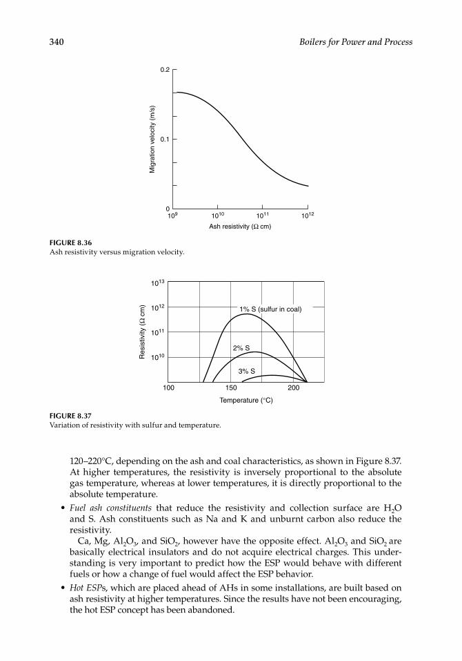
340 Boilers for Power and Process
120–220°C, depending on the ash and coal characteristics, as shown in Figure 8.37. At higher temperatures, the resistivity is inversely proportional to the absolute gas temperature, whereas at lower temperatures, it is directly proportional to the absolute temperature.Fuel ash constituents that reduce the resistivity and collection surface are H2O and S. Ash constituents such as Na and K and unburnt carbon also reduce the resistivity.
Ca, Mg, Al2O3, and SiO2, however have the opposite effect. Al2O3 and SiO2 are basically electrical insulators and do not acquire electrical charges. This under-standing is very important to predict how the ESP would behave with different fuels or how a change of fuel would affect the ESP behavior.Hot ESPs, which are placed ahead of AHs in some installations, are built based on ash resistivity at higher temperatures. Since the results have not been encouraging, the hot ESP concept has been abandoned.
•
•
Ash resistivity (Ω cm)
Mig
ratio
n ve
loci
ty (
m/s
)
1012101110101090
0.1
0.2
FIGURE 8.36Ash resistivity versus migration velocity.
FIGURE 8.37Variation of resistivity with sulfur and temperature.
100 150 200
1013
1012
1011
1010
Temperature (°C)
Res
istiv
ity (
Ω c
m)
1% S (sulfur in coal)
2% S
3% S
CRC_75365_Ch008.indd 340CRC_75365_Ch008.indd 340 1/30/2009 1:44:38 PM1/30/2009 1:44:38 PM
Boiler Auxiliaries 341
Gas velocity ranges from 1 to 2 m/s and is required to be in the lower end for both high and low ash resistivities. High-resistivity ash requires more time for collection, whereas low-resistivity ash has tendencies to re-entrain. Approximately 1.3 m/s gas velocity is optimum for coal fi ring. Greater gas velocity reduces the ESP cross sec-tion with a possibility of undersizing. At the same time, a very low velocity could result in meandering of gases with a possibility of ionization, leading to sparkover and performance degradation.Treatment time is the time when gases reside inside the ESP from the fi rst to the last electrode. For high-resistivity ash, it varies from 15 to 25 s, whereas for medium-resistivity ash, it varies from 7 to 10 s.Fly ash conditioning is sometimes required for collecting dust. SO3 is the most popu-lar agent, which is introduced at the inlet in trace amounts. This helps to reduce the ash resistivity and improve collection. NH3
is, at times, introduced because it helps agglomerate particles, which prevents re-entrainment. As much as 20–30% reduction in ESP size is possible by gas conditioning.
The most extensive use of ESPs is in coal-fi red boilers of all sizes. Collection effi ciencies exceeding 99.9% are common to give outlet emissions of <30 mg/N m3 at 6% O2.
Electrostatic precipitators are also employed in boilers fi ring bagasse, wood, bark, oil, and municipal refuse. The resistivity of ash in all cases is less than coal mainly because the moisture content in fuel helps to lower it. SCA in these ESPs is considerably lower, leading to smaller unit sizes.
8.6 Fabric Filters (FFs)
A fabric fi lter (FF), cloth fi lter, or bag fi lter is essentially an airtight chamber with a number of cloth bags arranged inside along the gas path, forcing the incoming dusty gases to pass through them to deliver clean gases. The dust stays behind, sticking to the cloth, which is periodically dusted off by backwashing with high-pressure air or recirculating cleaned gases. Fabric fi lters employ woven or felted fabrics through which the gas has to pass. Fab-ric fi lters are not percentage fi lters like ESPs but absolute fi lters with no change in outlet concentration irrespective of inlet dust load. The real fi ltering medium is not the cloth bag but the dust cake formed on it. While dedusting the bags, a layer of dust cake is inten-tionally left behind to continue the sieving act. Bags are cylindrically stitched cloth pieces closed from one side and adequately stiffened with suitable light metal frames to withstand mechanical and cleaning forces.
Based on the type of cleaning, the FFs are classifi ed into three types, as represented in Figure 8.38.
1. Reverse gas fi lters (RGFs) 2. Shaker fi lters (SFs) 3. Pulse jet fi lters (PJFs)
In RGF and SF, where the bags are open at the bottom and closed at the top, the dusty gases enter from the bottom and the dust is collected on the inside of the bags. Mechanical shaking used for removal of dust imposes severe stresses on the bags. Bag materials currently available cannot withstand such violent stresses for a large number of cycles. SFs have short lives and are not popular. RGFs are, by far, the most popular design, as
•
•
•
CRC_75365_Ch008.indd 341CRC_75365_Ch008.indd 341 1/30/2009 1:44:39 PM1/30/2009 1:44:39 PM
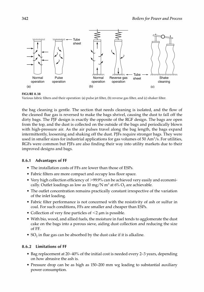
342 Boilers for Power and Process
the bag cleaning is gentle. The section that needs cleaning is isolated, and the fl ow of the cleaned fl ue gas is reversed to make the bags shrivel, causing the dust to fall off the dirty bags. The PJF design is exactly the opposite of the RGF design. The bags are open from the top, and the dust is collected on the outside of the bags and periodically blown with high-pressure air. As the air pulses travel along the bag length, the bags expand intermittently, loosening and shaking off the dust. PJFs require stronger bags. They were used in smaller sizes for industrial applications for gas volumes of 50 Am3/s. For utilities, RGFs were common but PJFs are also fi nding their way into utility markets due to their improved designs and bags.
8.6.1 Advantages of FF
The installation costs of FFs are lower than those of ESPs.Fabric fi lters are more compact and occupy less fl oor space.Very high collection effi ciency of >99.9% can be achieved very easily and economi-cally. Outlet loadings as low as 10 mg/N m3 at 6% O2 are achievable.The outlet concentration remains practically constant irrespective of the variation of the inlet loading.Fabric fi lter performance is not concerned with the resistivity of ash or sulfur in coal. For such conditions, FFs are smaller and cheaper than ESPs.Collection of very fi ne particles of <2 µm is possible.With bio, wood, and allied fuels, the moisture in fuel tends to agglomerate the dust cake on the bags into a porous sieve, aiding dust collection and reducing the size of FF.SO2 in fl ue gas can be absorbed by the dust cake if it is alkaline.
8.6.2 Limitations of FF
Bag replacement at 20–40% of the initial cost is needed every 2–3 years, depending on how abrasive the ash is.Pressure drop can be as high as 150–200 mm wg leading to substantial auxiliary power consumption.
•••
•
•
••
•
•
•
Normal operation
Pulse operation
Normal operation
Reverse gas operation
Shake cleaning
(c)
Tube sheet
(a) (b)
Tube sheet
FIGURE 8.38Various fabric fi lters and their operation: (a) pulse jet fi lter, (b) reverse gas fi lter, and (c) shaker fi lter.
CRC_75365_Ch008.indd 342CRC_75365_Ch008.indd 342 1/30/2009 1:44:39 PM1/30/2009 1:44:39 PM
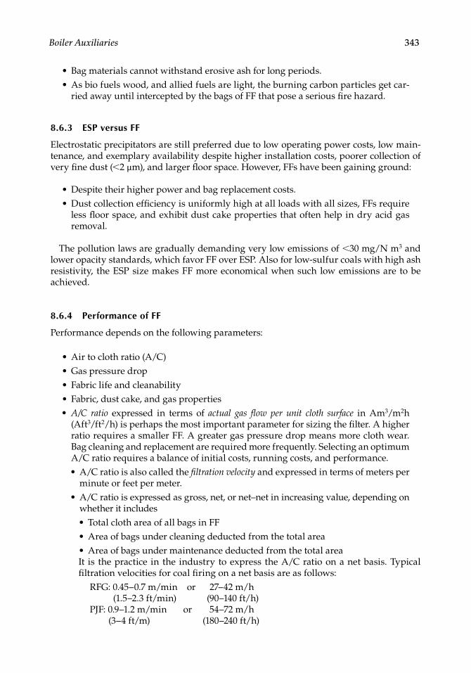
Boiler Auxiliaries 343
Bag materials cannot withstand erosive ash for long periods.As bio fuels wood, and allied fuels are light, the burning carbon particles get car-ried away until intercepted by the bags of FF that pose a serious fi re hazard.
8.6.3 ESP versus FF
Electrostatic precipitators are still preferred due to low operating power costs, low main-tenance, and exemplary availability despite higher installation costs, poorer collection of very fi ne dust (<2 µm), and larger fl oor space. However, FFs have been gaining ground:
Despite their higher power and bag replacement costs.Dust collection effi ciency is uniformly high at all loads with all sizes, FFs require less fl oor space, and exhibit dust cake properties that often help in dry acid gas removal.
The pollution laws are gradually demanding very low emissions of <30 mg/N m3 and lower opacity standards, which favor FF over ESP. Also for low-sulfur coals with high ash resistivity, the ESP size makes FF more economical when such low emissions are to be achieved.
8.6.4 Performance of FF
Performance depends on the following parameters:
Air to cloth ratio (A/C)Gas pressure dropFabric life and cleanabilityFabric, dust cake, and gas propertiesA/C ratio expressed in terms of actual gas fl ow per unit cloth surface in Am3/m2h (Aft3/ft2/h) is perhaps the most important parameter for sizing the fi lter. A higher ratio requires a smaller FF. A greater gas pressure drop means more cloth wear. Bag cleaning and replacement are required more frequently. Selecting an optimum A/C ratio requires a balance of initial costs, running costs, and performance.
A/C ratio is also called the fi ltration velocity and expressed in terms of meters per minute or feet per meter.A/C ratio is expressed as gross, net, or net–net in increasing value, depending on whether it includes
Total cloth area of all bags in FFArea of bags under cleaning deducted from the total areaArea of bags under maintenance deducted from the total area
It is the practice in the industry to express the A/C ratio on a net basis. Typical fi ltration velocities for coal fi ring on a net basis are as follows:
RFG: 0.45–0.7 m/min or 27–42 m/h (1.5–2.3 ft/min) (90–140 ft/h)PJF: 0.9–1.2 m/min or 54–72 m/h
(3–4 ft/m) (180–240 ft/h)
••
••
•••••
•
•
•••
CRC_75365_Ch008.indd 343CRC_75365_Ch008.indd 343 1/30/2009 1:44:40 PM1/30/2009 1:44:40 PM
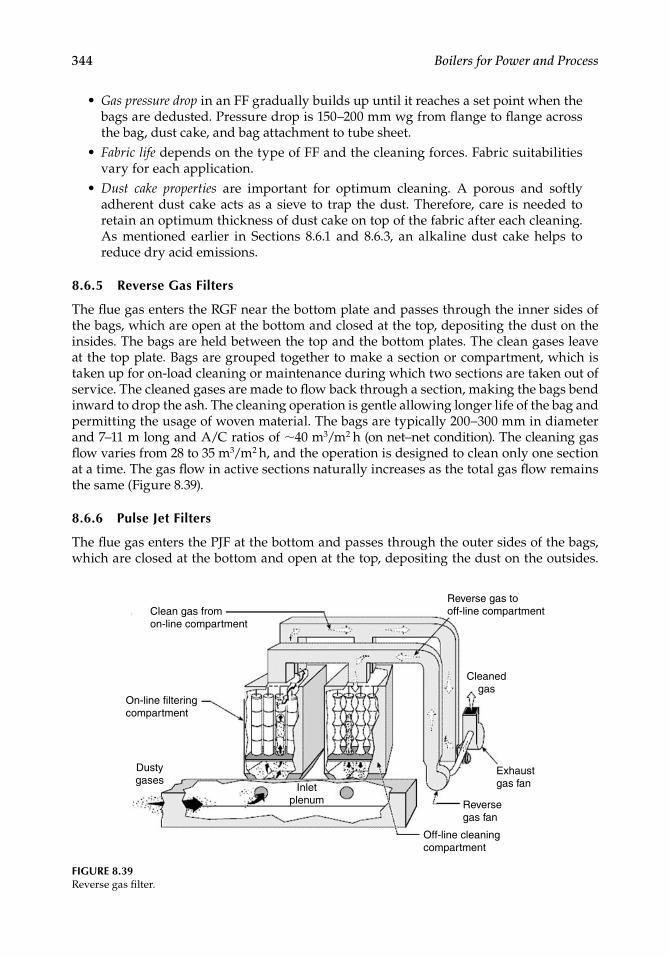
344 Boilers for Power and Process
Gas pressure drop in an FF gradually builds up until it reaches a set point when the bags are dedusted. Pressure drop is 150–200 mm wg from fl ange to fl ange across the bag, dust cake, and bag attachment to tube sheet.Fabric life depends on the type of FF and the cleaning forces. Fabric suitabilities vary for each application.Dust cake properties are important for optimum cleaning. A porous and softly adherent dust cake acts as a sieve to trap the dust. Therefore, care is needed to retain an optimum thickness of dust cake on top of the fabric after each cleaning. As mentioned earlier in Sections 8.6.1 and 8.6.3, an alkaline dust cake helps to reduce dry acid emissions.
8.6.5 Reverse Gas Filters
The fl ue gas enters the RGF near the bottom plate and passes through the inner sides of the bags, which are open at the bottom and closed at the top, depositing the dust on the insides. The bags are held between the top and the bottom plates. The clean gases leave at the top plate. Bags are grouped together to make a section or compartment, which is taken up for on-load cleaning or maintenance during which two sections are taken out of service. The cleaned gases are made to fl ow back through a section, making the bags bend inward to drop the ash. The cleaning operation is gentle allowing longer life of the bag and permitting the usage of woven material. The bags are typically 200–300 mm in diameter and 7–11 m long and A/C ratios of ∼40 m3/m2 h (on net–net condition). The cleaning gas fl ow varies from 28 to 35 m3/m2 h, and the operation is designed to clean only one section at a time. The gas fl ow in active sections naturally increases as the total gas fl ow remains the same (Figure 8.39).
8.6.6 Pulse Jet Filters
The fl ue gas enters the PJF at the bottom and passes through the outer sides of the bags, which are closed at the bottom and open at the top, depositing the dust on the outsides.
•
•
•
Reverse gas to off-line compartmentClean gas from
on-line compartment
On-line filteringcompartment
Dusty gases
Inletplenum
Off-line cleaningcompartment
Reversegas fan
Exhaustgas fan
Cleanedgas
FIGURE 8.39Reverse gas fi lter.
CRC_75365_Ch008.indd 344CRC_75365_Ch008.indd 344 1/30/2009 1:44:40 PM1/30/2009 1:44:40 PM
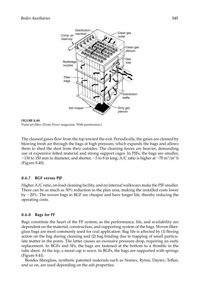
Boiler Auxiliaries 345
The cleaned gases fl ow from the top toward the exit. Periodically, the gases are cleaned by blowing fresh air through the bags at high pressure, which expands the bags and allows them to shed the dust from their outsides. The cleaning forces are heavier, demanding use of expensive felted material and strong support cages. In PJFs, the bags are smaller, ∼130 to 150 mm in diameter, and shorter, ∼5 to 8 m long; A/C ratio is higher at ∼70 m3/m2 h (Figure 8.40).
8.6.7 RGF versus PJF
Higher A/C ratio, on-load cleaning facility, and no internal walkways make the PJF smaller. There can be as much as 50% reduction in the plan area, making the installed costs lower by ∼20%. The woven bags in RGF are cheaper and have longer life, thereby reducing the operating costs.
8.6.8 Bags for FF
Bags constitute the heart of the FF system, as the performance, life, and availability are dependent on the material, construction, and supporting system of the bags. Woven fi ber-glass bags are most commonly used for coal application. Bag life is affected by (1) fl exing action on the bag during cleaning and (2) bag binding due to trapping of small particu-late matter in the pores. The latter causes an excessive pressure drop, requiring an early replacement. In RGFs and SFs, the bags are fastened at the bottom to a thimble in the tube sheet. At the top, a metal cap is sewn. In RGFs, the bags are supported with springs (Figure 8.41).
Besides fi berglass, synthetic patented materials such as Nomex, Ryton, Daytex, Tefl on, and so on, are used depending on the ash properties.
FIGURE 8.40Pulse jet fi lter. (From Power magazine. With permission.)
Distributionmanifold
Distributionbaffle
Dirty gasplenum
Ash hopper
Filterbags
Multistagenozzles
Comp. airreservoir
Clean gasoutlet
Clean gasplenum
Gasinlet
CRC_75365_Ch008.indd 345CRC_75365_Ch008.indd 345 1/30/2009 1:44:41 PM1/30/2009 1:44:41 PM
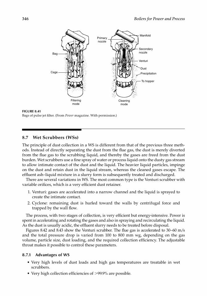
346 Boilers for Power and Process
8.7 Wet Scrubbers (WSs)
The principle of dust collection in a WS is different from that of the previous three meth-ods. Instead of directly separating the dust from the fl ue gas, the dust is merely diverted from the fl ue gas to the scrubbing liquid, and thereby the gases are freed from the dust burden. Wet scrubbers use a fi ne spray of water or process liquid onto the dusty gas stream to allow intimate contact of the dust and the liquid. The heavier liquid particles, impinge on the dust and retain dust in the liquid stream, whereas the cleaned gases escape. The effl uent ash–liquid mixture in a slurry form is subsequently treated and discharged.
There are several variations in WS. The most common type is the Venturi scrubber with variable orifi ces, which is a very effi cient dust retainer.
1. Venturi: gases are accelerated into a narrow channel and the liquid is sprayed to create the intimate contact.
2. Cyclone: remaining dust is hurled toward the walls by centrifugal force and trapped by the wall fl ow.
The process, with two stages of collection, is very effi cient but energy-intensive. Power is spent in accelerating and rotating the gases and also in spraying and recirculating the liquid. As the dust is usually acidic, the effl uent slurry needs to be treated before disposal.
Figures 8.42 and 8.43 show the Venturi scrubber. The fl ue gas is accelerated to 30–60 m/s and the total pressure drop is varied from 100 to 800 mm wg, depending on the gas volume, particle size, dust loading, and the required collection effi ciency. The adjustable throat makes it possible to control these parameters.
8.7.1 Advantages of WS
Very high levels of dust loads and high gas temperatures are treatable in wet scrubbers.Very high collection effi ciencies of >99.9% are possible.
•
•
FIGURE 8.41Bags of pulse jet fi lter. (From Power magazine. With permission.)
Bag
Cage
Filtering mode
Cleaning mode
Primary nozzle
Manifold
Secondary nozzle
Venturi
Dust
To hopper
Precipitation
CRC_75365_Ch008.indd 346CRC_75365_Ch008.indd 346 1/30/2009 1:44:41 PM1/30/2009 1:44:41 PM
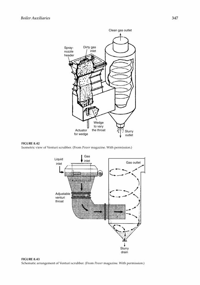
Boiler Auxiliaries 347
Spray- nozzle header
Dirty gas inlet
Clean gas outlet
Actuator for wedge
Wedge to vary
the throat Slurry outlet
FIGURE 8.42Isometric view of Venturi scrubber. (From Power magazine. With permission.)
FIGURE 8.43Schematic arrangement of Venturi scrubber. (From Power magazine. With permission.)
Liquidinlet
Adjustable venturi throat
Gasinlet Gas outlet
Slurry drain
CRC_75365_Ch008.indd 347CRC_75365_Ch008.indd 347 1/30/2009 1:44:42 PM1/30/2009 1:44:42 PM
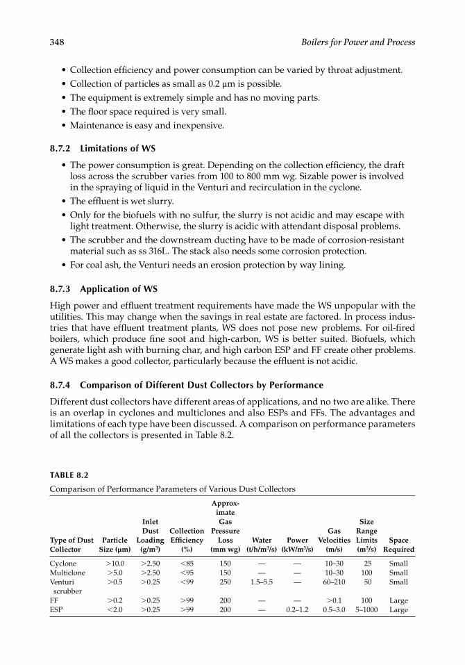
348 Boilers for Power and Process
TABLE 8.2
Comparison of Performance Parameters of Various Dust Collectors
Type of Dust Collector
Particle Size (µm)
Inlet Dust
Loading (g/m3)
Collection Effi ciency
(%)
Approx-imateGas
Pressure Loss
(mm wg)Water
(t/h/m3/s)Power
(kW/m3/s)
Gas Velocities
(m/s)
Size Range Limits (m3/s)
Space Required
Cyclone >10.0 >2.50 <85 150 — — 10–30 25 SmallMulticlone >5.0 >2.50 <95 150 — — 10–30 100 SmallVenturi scrubber
>0.5 >0.25 <99 250 1.5–5.5 — 60–210 50 Small
FF >0.2 >0.25 >99 200 — — >0.1 100 LargeESP <2.0 >0.25 >99 200 — 0.2–1.2 0.5–3.0 5–1000 Large
Collection effi ciency and power consumption can be varied by throat adjustment.Collection of particles as small as 0.2 µm is possible.The equipment is extremely simple and has no moving parts.The fl oor space required is very small.Maintenance is easy and inexpensive.
8.7.2 Limitations of WS
The power consumption is great. Depending on the collection effi ciency, the draft loss across the scrubber varies from 100 to 800 mm wg. Sizable power is involved in the spraying of liquid in the Venturi and recirculation in the cyclone.The effl uent is wet slurry.Only for the biofuels with no sulfur, the slurry is not acidic and may escape with light treatment. Otherwise, the slurry is acidic with attendant disposal problems.The scrubber and the downstream ducting have to be made of corrosion- resistant material such as ss 316L. The stack also needs some corrosion protection.For coal ash, the Venturi needs an erosion protection by way lining.
8.7.3 Application of WS
High power and effl uent treatment requirements have made the WS unpopular with the utilities. This may change when the savings in real estate are factored. In process indus-tries that have effl uent treatment plants, WS does not pose new problems. For oil-fi red boilers, which produce fi ne soot and high-carbon, WS is better suited. Biofuels, which generate light ash with burning char, and high carbon ESP and FF create other problems. A WS makes a good collector, particularly because the effl uent is not acidic.
8.7.4 Comparison of Different Dust Collectors by Performance
Different dust collectors have different areas of applications, and no two are alike. There is an overlap in cyclones and multiclones and also ESPs and FFs. The advantages and limitations of each type have been discussed. A comparison on performance parameters of all the collectors is presented in Table 8.2.
•••••
•
••
•
•
CRC_75365_Ch008.indd 348CRC_75365_Ch008.indd 348 1/30/2009 1:44:42 PM1/30/2009 1:44:42 PM
Boiler Auxiliaries 349
8.8 Valves and Mountings
Valves, mountings, and fi ttings are the auxiliaries in the steam and water circuit. The mountings and fi ttings are the mandatory safety devices specifi ed by codes for permitting a boiler to steam. These are
Main steam stop valve (MSSV)Nonreturn valve (NRV) on steam lineSafety valves (SV)Blow-down valvesHigh–low water-level alarms on steam drumWater-level indicators (WLI) on steam drum Pressure gauges on steam drum and SH
Valves on a boiler are mainly for start–stop service of steam and water. Control valves (CVs) are only for regulating the main FW and attemperator spray water. There is no direct regulation of steam in any boiler for output control, which is carried out only by regulating the FW. However, CVs are at times employed in steam circuits in applications such as drum attemperators where three-way CVs are used for dividing steam into the attemperator and bypass lines. Butterfl y CVs are employed for larger sizes. Boiler valves are pressure valves and are governed by various ANSI or equivalent codes as listed below:
ANSI B16.5 for steel pipe fl anges and fl anged fi ttingsANSI B16.11 for steel socket welding fi ttingsANSI B16.25 for butt-welding ends (for pipes, valves, fl anges, and fi ttings)ANSI B16.34 for steel valves (fl anged and butt-welding ends)
There are valves in oil and gas circuits for control and isolation functions, which are different in construction. Along with burner front piping, these oil and gas valve trains, mounted on suitable racks, are usually supplied by burner manufacturers. Ball, plug, and butterfl y valves dominate oil and gas lines unlike the GGC valves (explained in the fol-lowing text) in steam lines. Boiler steam and water valves can be classifi ed into three types by construction.
1. Isolating valves form the bulk of boiler valves and are known as GGCs: a. Globe valves b. Gate valves c. Check valves
dictated by the process-fl ow conditions. 2. Control valves are governed by both process and control considerations. 3. Safety and blowdown valves are specifi c to a boiler.
Forged steel valves. Valves of 50 NB size and below are of forged steel construction, and size is amenable to drop forging. Even larger valves are available in forged construction but are more expensive than cast steel valves. Forged steel valves, being denser in struc-ture, have thinner sections and hence are lower in weight. Their higher cost, particularly in larger sizes, is many times justifi ed, as the compact size and lower weight allow fl exibility and shorter routing.
•••••••
CRC_75365_Ch008.indd 349CRC_75365_Ch008.indd 349 1/30/2009 1:44:42 PM1/30/2009 1:44:42 PM
350 Boilers for Power and Process
Butt-welded socket-welded, and fl anged ends. Small forged steel valves of 50 NB and below are made with ends suitable for socket welding. For larger sizes, the valves are made with either fl anged or welded ends, with the latter type most common. The leakage aspect is totally taken care of with butt-welded valves. They are also lighter, thus helping in fl exibil-ity. Flanged valves are preferred in some applications, particularly at low pressures.
Major valves have long delivery times and constitute nearly 80% by value:
MSSV and NRVFeed stop and check valvesStart-up vent and its isolating valvesSVs on drum, superheater (SH), and reheater (RH)Continuous blow-down (CBD) and intermittent blow-down (IBD) valvesMain, low-load, and start-up feed CVs and their bypass and isolation valvesAttemperator control and isolating valvesCirculating pump’s isolating valves in water circuit on either side of the pump
In a variable-pressure boiler, the MSSV is not present but is merged with the main tur-bine inlet stop valve and located at the turbine end.
In HRSGs that have high pressure (HP), intermediate pressure (IP), and LP, the valves are repeated for each circuit. A large HRSG with 3P and RH is a veritable maze of valves of numerous types, sizes, and ratings.
Constructional features and prominent characteristics of the major boiler valves are briefl y described in the following sections.
8.8.1 Main Steam Stop Valve and Nonreturn Valve
A boiler MSSV is a heavy-duty isolating gate valve matching the NB of main steam line or a size smaller, with minimum pressure drop. It can be a wedge gate, parallel slide, or Venturi type (Figure 8.44).
Wedge gates are preferred for low and medium pressures but not for large sizes to limit the forces on the disk. The tapered faces of the disk provide a positive sealing.Parallel slides have two disks forcing themselves on the two faces by means of a set of springs to provide sealing. But the real sealing force is exerted by the upstream steam pressure on the disk. The thin disks are more fl exible and can withstand more temperature and pressure than gates but are costlier and demand more maintenance.In Venturi construction, the valve body has taper at inlet and outlet so that the actual sealing disk has smaller diameter than the parallel slide valves. Venturi is preferred for very large sizes, although more expensive to make and maintain, mainly to reduce
Pressure losses in valveMaintenance caused by larger mating surfaces of disks and seats
Usually, MSSVs are motorized and butt welded, but in smaller low-pressure process boilers, they can be hand operated and fl anged. It is normal to have an integral body
••••••••
•
•
•
••
CRC_75365_Ch008.indd 350CRC_75365_Ch008.indd 350 1/30/2009 1:44:42 PM1/30/2009 1:44:42 PM
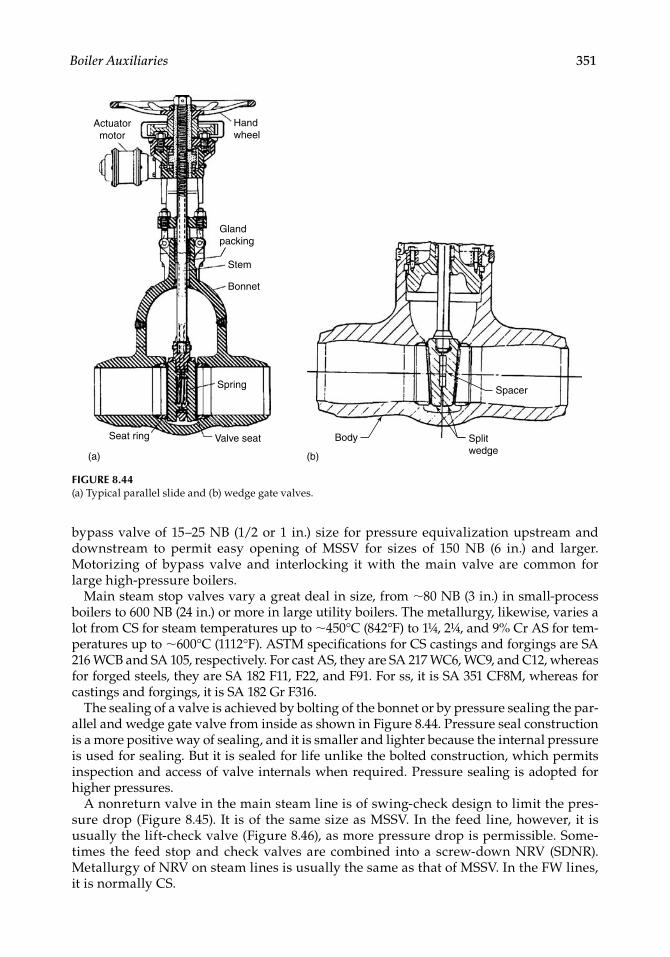
Boiler Auxiliaries 351
bypass valve of 15–25 NB (1/2 or 1 in.) size for pressure equivalization upstream and downstream to permit easy opening of MSSV for sizes of 150 NB (6 in.) and larger. Motorizing of bypass valve and interlocking it with the main valve are common for large high-pressure boilers.
Main steam stop valves vary a great deal in size, from ∼80 NB (3 in.) in small-process boilers to 600 NB (24 in.) or more in large utility boilers. The metallurgy, likewise, varies a lot from CS for steam temperatures up to ∼450°C (842°F) to 1¼, 2¼, and 9% Cr AS for tem-peratures up to ∼600°C (1112°F). ASTM specifi cations for CS castings and forgings are SA 216 WCB and SA 105, respectively. For cast AS, they are SA 217 WC6, WC9, and C12, whereas for forged steels, they are SA 182 F11, F22, and F91. For ss, it is SA 351 CF8M, whereas for castings and forgings, it is SA 182 Gr F316.
The sealing of a valve is achieved by bolting of the bonnet or by pressure sealing the par-allel and wedge gate valve from inside as shown in Figure 8.44. Pressure seal construction is a more positive way of sealing, and it is smaller and lighter because the internal pressure is used for sealing. But it is sealed for life unlike the bolted construction, which permits inspection and access of valve internals when required. Pressure sealing is adopted for higher pressures.
A nonreturn valve in the main steam line is of swing-check design to limit the pres-sure drop (Fig ure 8.45). It is of the same size as MSSV. In the feed line, however, it is usually the lift-check valve (Figure 8.46), as more pressure drop is permissible. Some-times the feed stop and check valves are combined into a screw-down NRV (SDNR). Metallurgy of NRV on steam lines is usually the same as that of MSSV. In the FW lines, it is normally CS.
Actuator motor
Hand wheel
Gland packing
Stem
Bonnet
Spring
Valve seatSeat ring Body Split wedge
Spacer
(a) (b)
FIGURE 8.44(a) Typical parallel slide and (b) wedge gate valves.
CRC_75365_Ch008.indd 351CRC_75365_Ch008.indd 351 1/30/2009 1:44:43 PM1/30/2009 1:44:43 PM
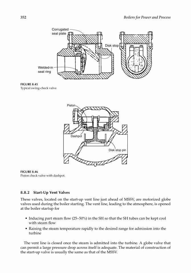
352 Boilers for Power and Process
8.8.2 Start-Up Vent Valves
These valves, located on the start-up vent line just ahead of MSSV, are motorized globe valves used during the boiler starting. The vent line, leading to the atmosphere, is opened at the boiler startup for
Inducing part steam fl ow (25–50%) in the SH so that the SH tubes can be kept cool with steam fl owRaising the steam temperature rapidly to the desired range for admission into the turbine
The vent line is closed once the steam is admitted into the turbine. A globe valve that can permit a large pressure drop across itself is adequate. The material of construction of the start-up valve is usually the same as that of the MSSV.
•
•
Corrugated seal plate
Disk stop
Welded-in seat ring
FIGURE 8.45Typical swing-check valve.
Piston
Dashpot
Disk stop pin
FIGURE 8.46Piston check valve with dashpot.
CRC_75365_Ch008.indd 352CRC_75365_Ch008.indd 352 1/30/2009 1:44:43 PM1/30/2009 1:44:43 PM
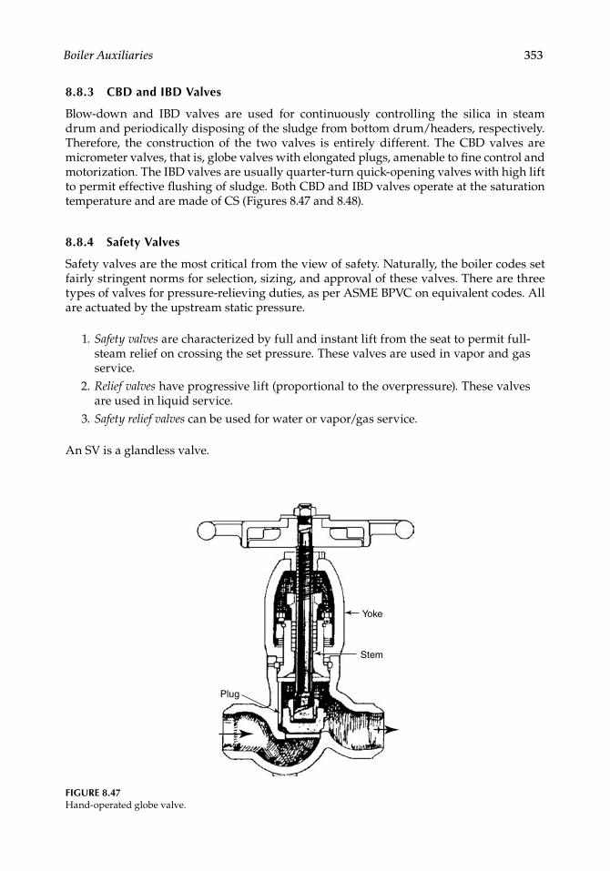
Boiler Auxiliaries 353
8.8.3 CBD and IBD Valves
Blow-down and IBD valves are used for continuously controlling the silica in steam drum and periodically disposing of the sludge from bottom drum/headers, respectively. Therefore, the construction of the two valves is entirely different. The CBD valves are micrometer valves, that is, globe valves with elongated plugs, amenable to fi ne control and motori zation. The IBD valves are usually quarter-turn quick-opening valves with high lift to permit effective fl ushing of sludge. Both CBD and IBD valves operate at the saturation temperature and are made of CS (Figures 8.47 and 8.48).
8.8.4 Safety Valves
Safety valves are the most critical from the view of safety. Naturally, the boiler codes set fairly stringent norms for selection, sizing, and approval of these valves. There are three types of valves for pressure-relieving duties, as per ASME BPVC on equivalent codes. All are actuated by the upstream static pressure.
1. Safety valves are characterized by full and instant lift from the seat to permit full-steam relief on crossing the set pressure. These valves are used in vapor and gas service.
2. Relief valves have progressive lift (proportional to the overpressure). These valves are used in liquid service.
3. Safety relief valves can be used for water or vapor/gas service.
An SV is a glandless valve.
FIGURE 8.47Hand-operated globe valve.
Plug
Stem
Yoke
CRC_75365_Ch008.indd 353CRC_75365_Ch008.indd 353 1/30/2009 1:44:43 PM1/30/2009 1:44:43 PM
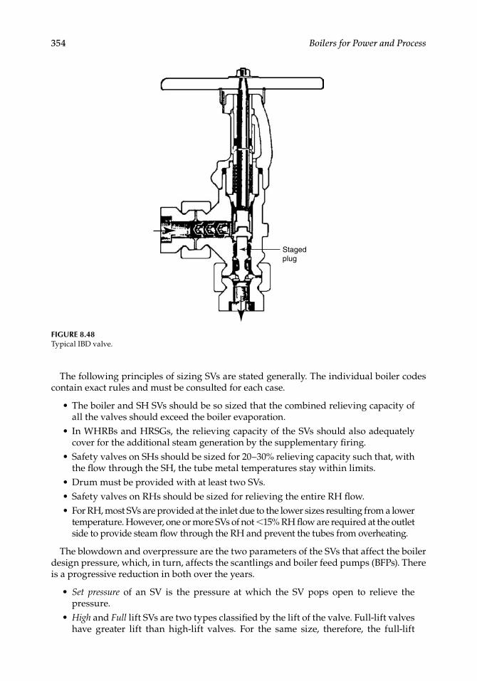
354 Boilers for Power and Process
The following principles of sizing SVs are stated generally. The individual boiler codes contain exact rules and must be consulted for each case.
The boiler and SH SVs should be so sized that the combined relieving capacity of all the valves should exceed the boiler evaporation.In WHRBs and HRSGs, the relieving capacity of the SVs should also adequately cover for the additional steam generation by the supplementary fi ring.Safety valves on SHs should be sized for 20–30% relieving capacity such that, with the fl ow through the SH, the tube metal temperatures stay within limits.Drum must be provided with at least two SVs.Safety valves on RHs should be sized for relieving the entire RH fl ow.For RH, most SVs are provided at the inlet due to the lower sizes resulting from a lower temperature. However, one or more SVs of not <15% RH fl ow are required at the outlet side to provide steam fl ow through the RH and prevent the tubes from overheating.
The blowdown and overpressure are the two parameters of the SVs that affect the boiler design pressure, which, in turn, affects the scantlings and boiler feed pumps (BFPs). There is a progressive reduction in both over the years.
Set pressure of an SV is the pressure at which the SV pops open to relieve the pressure. High and Full lift SVs are two types classifi ed by the lift of the valve. Full-lift valves have greater lift than high-lift valves. For the same size, therefore, the full-lift
•
•
•
•••
•
•
Staged plug
FIGURE 8.48Typical IBD valve.
CRC_75365_Ch008.indd 354CRC_75365_Ch008.indd 354 1/30/2009 1:44:44 PM1/30/2009 1:44:44 PM
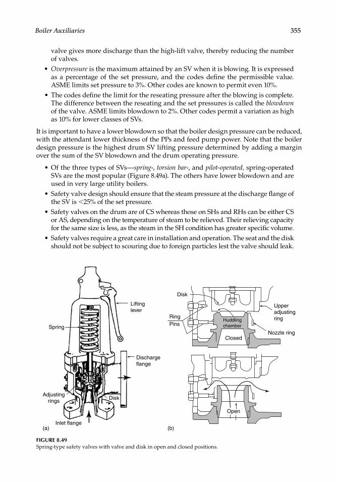
Boiler Auxiliaries 355
valve gives more discharge than the high-lift valve, thereby reducing the number of valves.Overpressure is the maximum attained by an SV when it is blowing. It is expressed as a percentage of the set pressure, and the codes defi ne the permissible value. ASME limits set pressure to 3%. Other codes are known to permit even 10%.The codes defi ne the limit for the reseating pressure after the blowing is complete. The difference between the reseating and the set pressures is called the blowdown of the valve. ASME limits blowdown to 2%. Other codes permit a variation as high as 10% for lower classes of SVs.
It is important to have a lower blowdown so that the boiler design pressure can be reduced, with the attendant lower thickness of the PPs and feed pump power. Note that the boiler design pressure is the highest drum SV lifting pressure determined by adding a margin over the sum of the SV blowdown and the drum operating pressure.
Of the three types of SVs—spring-, torsion bar-, and pilot-operated, spring-operated SVs are the most popular (Figure 8.49a). The others have lower blowdown and are used in very large utility boilers.Safety valve design should ensure that the steam pressure at the discharge fl ange of the SV is <25% of the set pressure.Safety valves on the drum are of CS whereas those on SHs and RHs can be either CS or AS, depending on the temperature of steam to be relieved. Their relieving capacity for the same size is less, as the steam in the SH condition has greater specifi c volume.Safety valves require a great care in installation and operation. The seat and the disk should not be subject to scouring due to foreign particles lest the valve should leak.
•
•
•
•
•
•
FIGURE 8.49Spring-type safety valves with valve and disk in open and closed positions.
Lifting lever
Discharge flange
Spring
Adjusting rings
Inlet flange
Disk
Disk
Upper adjusting ring
Nozzle ringClosed
Open
RingPins
(a) (b)
Huddling chamber
CRC_75365_Ch008.indd 355CRC_75365_Ch008.indd 355 1/30/2009 1:44:44 PM1/30/2009 1:44:44 PM
356 Boilers for Power and Process
Hydrostatic plugs are to be placed at the inlet during any hydraulic test to prevent damage to valve internals due to the ingress of water. Frequent lifting of SV surely leads to leakages calling for boiler stoppage for seat lapping and reassembly. There are no glands in an SV, and all the internals are made from stainless steel with mirror fi nish to provide high-quality alignment and ensure accurate and per-fect pop action while lifting and reseating. The SV blowing (and reseating pres-sures) and blowdown are set by the manufacturer in the presence of an inspector, and the rings are locked in position, requiring no further adjustment at site. Some valve designs have a provision for adjusting the blowdown at site by means of upper and lower adjusting rings, as shown in Figure 8.49b. Chatter of an SV is a repeated lifting and reseating of the valve caused mainly by faults in installation or a long inlet pipe or faulty discharge pipe system. The SV chatter inevitably leads to valve leakage, needing a lapping of the seating surfaces to restore the tightness.Spacing of SVs must be correct to prevent the discharge forces from interfering with each other.Likewise, the discharge piping must be installed properly to lead the discharge steam safely to a suitable location, which is many times to the boiler roof. The discharge pipes or SV escape pipes are rigidly tied to any nearby boiler column, whereas the SVs located on drum or piping have their own thermal expansions. Suitable expansion chambers between the SV discharge elbow and the escape pip-ing are essential to eliminate stresses due to differential expansion between the fi xed escape piping and the moving SV. The expansion chamber should be pro-vided with a suitable drain (Figure 8.50).Safety valve inlet nozzle length should be as short as possible to minimize the pres-sure loss, which can lead to chatter. SVs are usually directly mounted on drums or pipes. Pressure drop to the inlet has to be <50% of the SV blowdown. There is an upward force created as steam takes a turn inside the valve, which imposes stress on the drum and piping. To avoid the extra stress on PPs, the SVs can be located at some distance and rigidly supported on structural members. The inlet piping must be carefully sited and the set pressure of SV has account for pressure loss in the inlet pipe for a proper operation of the valves.
Electromatic SV. Considering the inevitability of SV seat leakage after a few lifts, it is a nor-mal practice to install an additional electrically actuated SV on SH header, which operates fi rst and prevents the main SVs from operating. This valve is provided with an isolating knife gate valve, which permits on-line maintenance. The discharge from this valve is not added to the relieving capacity of the other valves and is not covered by the boiler codes.
8.8.5 Drain and Vent Valves
These valves form nearly 80% of the total. Sizes of 40, 50, 63.5, and, at times, 80 NB (1½, 2, 2½, and 3 in.) are used. Various designs and practical aspects of the drain and vent valves are briefl y discussed below. At different locations, they have different roles to play.
Carbon steel predominates except for draining and venting of the SH and RH where the drain and vent valves can be of CS or AS.Usually, the valves are made of the same material as the header to which they are attached.
•
•
•
•
•
•
•
CRC_75365_Ch008.indd 356CRC_75365_Ch008.indd 356 1/30/2009 1:44:44 PM1/30/2009 1:44:44 PM
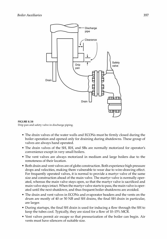
Boiler Auxiliaries 357
The drain valves of the water walls and ECONs must be fi rmly closed during the boiler operation and opened only for draining during shutdowns. These group of valves are always hand operated.The drain valves of the SH, RH, and SBs are normally motorized for operator’s convenience except in very small boilers.The vent valves are always motorized in medium and large boilers due to the remoteness of their location.Both drain and vent valves are of globe construction. Both experience high pressure drops and velocities, making them vulnerable to wear due to wire-drawing effect. For frequently operated valves, it is normal to provide a martyr valve of the same size and construction ahead of the main valve. The martyr valve is normally oper-ated, whereas the main valve stays open, so that the martyr valve is sacrifi ced and main valve stays intact. When the martyr valve starts to pass, the main valve is oper-ated until the next shutdown, and thus frequent boiler shutdowns are avoided.The drain and vent valves in ECONs and evaporator headers and the vents on the drum are mostly of 40 or 50 NB and SH drains, the fi nal SH drain in particular, are larger.During startups, the fi nal SH drain is used for inducing a fl ow through the SH to keep the tubes cool. Typically, they are sized for a fl ow of 10–15% MCR.Vent valves permit air escape so that pressurization of the boiler can begin. Air vents must have silencers of suitable size.
•
•
•
•
•
•
•
Dischargepipe
Clearance
Safetyvalve
Drain
Drain
Drippan
FIGURE 8.50Drip pan and safety valve in discharge piping.
CRC_75365_Ch008.indd 357CRC_75365_Ch008.indd 357 1/30/2009 1:44:45 PM1/30/2009 1:44:45 PM
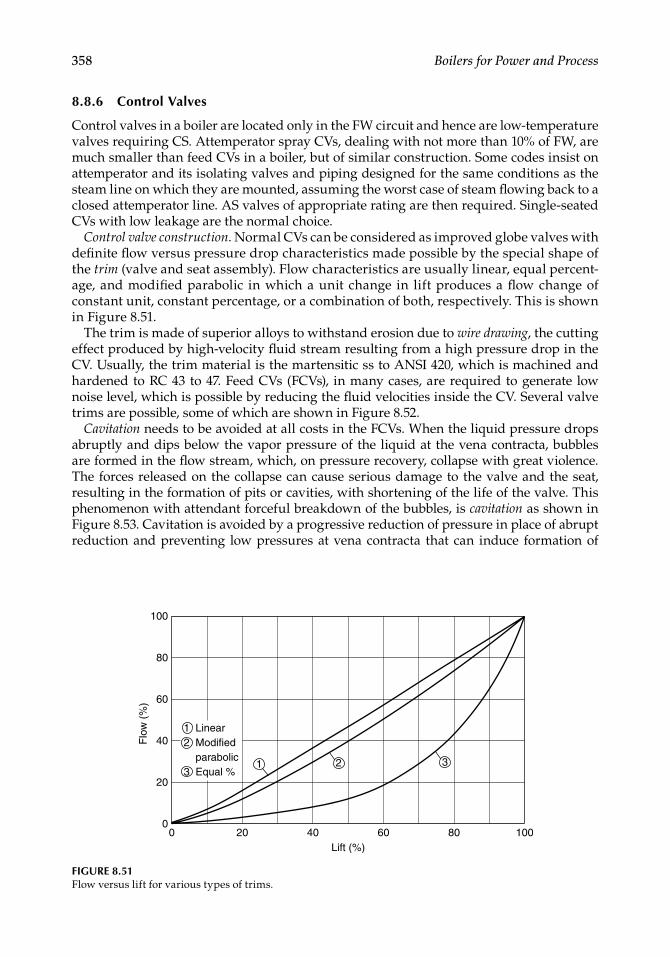
358 Boilers for Power and Process
8.8.6 Control Valves
Control valves in a boiler are located only in the FW circuit and hence are low-temperature valves requiring CS. Attemperator spray CVs, dealing with not more than 10% of FW, are much smaller than feed CVs in a boiler, but of similar construction. Some codes insist on attemperator and its isolating valves and piping designed for the same conditions as the steam line on which they are mounted, assuming the worst case of steam fl owing back to a closed attemperator line. AS valves of appropriate rating are then required. Single-seated CVs with low leakage are the normal choice.
Control valve construction. Normal CVs can be considered as improved globe valves with defi nite fl ow versus pressure drop characteristics made possible by the special shape of the trim (valve and seat assembly). Flow characteristics are usually linear, equal percent-age, and modifi ed parabolic in which a unit change in lift produces a fl ow change of constant unit, constant percentage, or a combination of both, respectively. This is shown in Figure 8.51.
The trim is made of superior alloys to withstand erosion due to wire drawing, the cutting effect produced by high-velocity fl uid stream resulting from a high pressure drop in the CV. Usually, the trim material is the martensitic ss to ANSI 420, which is machined and hardened to RC 43 to 47. Feed CVs (FCVs), in many cases, are required to generate low noise level, which is possible by reducing the fl uid velocities inside the CV. Several valve trims are possible, some of which are shown in Figure 8.52.
Cavitation needs to be avoided at all costs in the FCVs. When the liquid pressure drops abruptly and dips below the vapor pressure of the liquid at the vena contracta, bubbles are formed in the fl ow stream, which, on pressure recovery, collapse with great violence. The forces released on the collapse can cause serious damage to the valve and the seat, resulting in the formation of pits or cavities, with shortening of the life of the valve. This phenomenon with attendant forceful breakdown of the bubbles, is cavitation as shown in Figure 8.53. Cavitation is avoided by a progressive reduction of pressure in place of abrupt reduction and preventing low pressures at vena contracta that can induce formation of
0 20 40 60 80
20
0
40
60
80
100
100
Flo
w (
%)
Lift (%)
1 Linear 2 Modified parabolic 3 Equal %
321
FIGURE 8.51Flow versus lift for various types of trims.
CRC_75365_Ch008.indd 358CRC_75365_Ch008.indd 358 1/30/2009 1:44:45 PM1/30/2009 1:44:45 PM
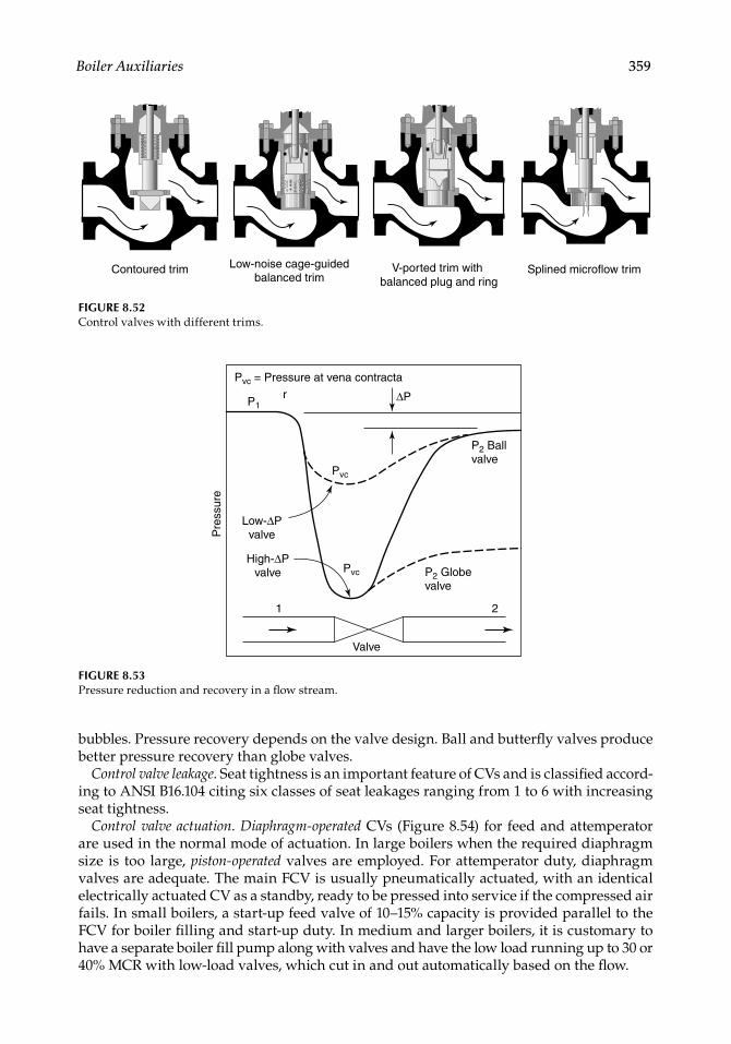
Boiler Auxiliaries 359
bubbles. Pressure recovery depends on the valve design. Ball and butterfl y valves produce better pressure recovery than globe valves.
Control valve leakage. Seat tightness is an important feature of CVs and is classifi ed accord-ing to ANSI B16.104 citing six classes of seat leakages ranging from 1 to 6 with increasing seat tightness.
Control valve actuation. Diaphragm-operated CVs (Figure 8.54) for feed and attemperator are used in the normal mode of actuation. In large boilers when the required diaphragm size is too large, piston-operated valves are employed. For attemperator duty, diaphragm valves are adequate. The main FCV is usually pneumatically actuated, with an identical electrically actuated CV as a standby, ready to be pressed into service if the compressed air fails. In small boilers, a start-up feed valve of 10–15% capacity is provided parallel to the FCV for boiler fi lling and start-up duty. In medium and larger boilers, it is customary to have a separate boiler fi ll pump along with valves and have the low load running up to 30 or 40% MCR with low-load valves, which cut in and out automatically based on the fl ow.
Contoured trim Low-noise cage-guided balanced trim
V-ported trim with balanced plug and ring
Splined microflow trim
FIGURE 8.52Control valves with different trims.
Pvc = Pressure at vena contracta
Pvc
Pvc
P2 Ball valve
P2 Globe valve
21
P1∆P
Low-∆P valve
High-∆Pvalve
Pre
ssur
e
r
Valve
FIGURE 8.53Pressure reduction and recovery in a fl ow stream.
CRC_75365_Ch008.indd 359CRC_75365_Ch008.indd 359 1/30/2009 1:44:45 PM1/30/2009 1:44:45 PM
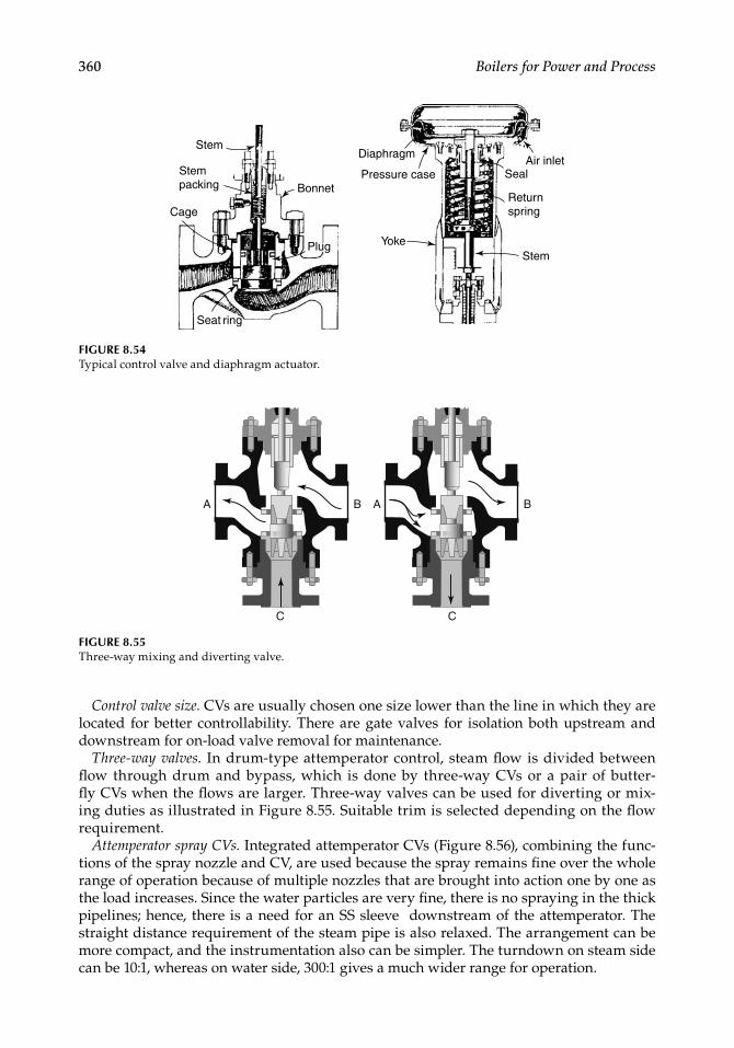
360 Boilers for Power and Process
Control valve size. CVs are usually chosen one size lower than the line in which they are located for better controllability. There are gate valves for isolation both upstream and downstream for on-load valve removal for maintenance.
Three-way valves. In drum-type attemperator control, steam fl ow is divided between fl ow through drum and bypass, which is done by three-way CVs or a pair of butter-fl y CVs when the fl ows are larger. Three-way valves can be used for diverting or mix-ing duties as illustrated in Figure 8.55. Suitable trim is selected depending on the fl ow requirement.
Attemperator spray CVs. Integrated attemperator CVs (Figure 8.56), combining the func-tions of the spray nozzle and CV, are used because the spray remains fi ne over the whole range of operation because of multiple nozzles that are brought into action one by one as the load increases. Since the water particles are very fi ne, there is no spraying in the thick pipelines; hence, there is a need for an SS sleeve downstream of the attemperator. The straight distance requirement of the steam pipe is also relaxed. The arrangement can be more compact, and the instrumentation also can be simpler. The turndown on steam side can be 10:1, whereas on water side, 300:1 gives a much wider range for operation.
Stem
Stem packing
Cage
Bonnet
Plug
Seat ring
YokeStem
Return spring
SealAir inlet
Diaphragm
Pressure case
FIGURE 8.54Typical control valve and diaphragm actuator.
A B
C
A B
C
FIGURE 8.55Three-way mixing and diverting valve.
CRC_75365_Ch008.indd 360CRC_75365_Ch008.indd 360 1/30/2009 1:44:45 PM1/30/2009 1:44:45 PM
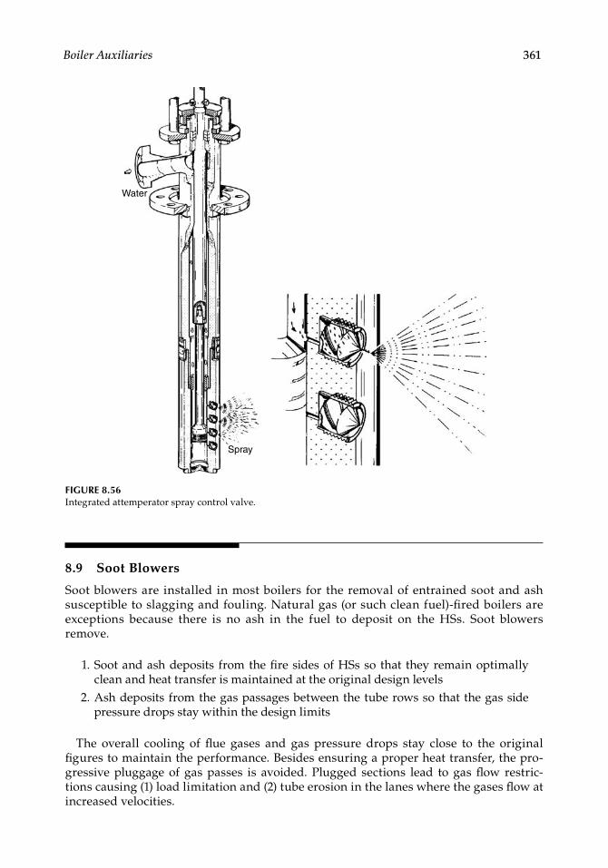
Boiler Auxiliaries 361
8.9 Soot Blowers
Soot blowers are installed in most boilers for the removal of entrained soot and ash susceptible to slagging and fouling. Natural gas (or such clean fuel)-fi red boilers are exceptions because there is no ash in the fuel to deposit on the HSs. Soot blowers remove.
1. Soot and ash deposits from the fi re sides of HSs so that they remain optimally clean and heat transfer is maintained at the original design levels
2. Ash deposits from the gas passages between the tube rows so that the gas side pressure drops stay within the design limits
The overall cooling of fl ue gases and gas pressure drops stay close to the original fi gures to maintain the performance. Besides ensuring a proper heat transfer, the pro-gressive pluggage of gas passes is avoided. Plugged sections lead to gas fl ow restric-tions causing (1) load limitation and (2) tube erosion in the lanes where the gases fl ow at increased velocities.
Water
Spray
FIGURE 8.56Integrated attemperator spray control valve.
CRC_75365_Ch008.indd 361CRC_75365_Ch008.indd 361 1/30/2009 1:44:46 PM1/30/2009 1:44:46 PM
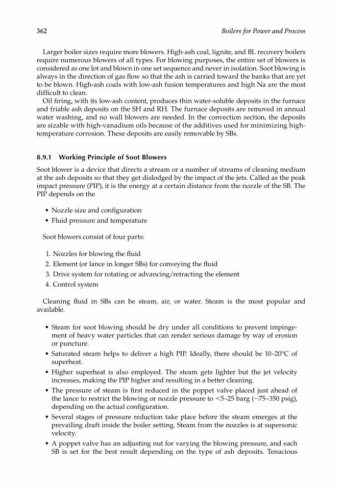
362 Boilers for Power and Process
Larger boiler sizes require more blowers. High-ash coal, lignite, and BL recovery boilers require numerous blowers of all types. For blowing purposes, the entire set of blowers is considered as one lot and blown in one set sequence and never in isolation. Soot blowing is always in the direction of gas fl ow so that the ash is carried toward the banks that are yet to be blown. High-ash coals with low-ash fusion temperatures and high Na are the most diffi cult to clean.
Oil fi ring, with its low-ash content, produces thin water-soluble deposits in the furnace and friable ash deposits on the SH and RH. The furnace deposits are removed in annual water washing, and no wall blowers are needed. In the convection section, the deposits are sizable with high-vanadium oils because of the additives used for minimizing high-temperature corrosion. These deposits are easily removable by SBs.
8.9.1 Working Principle of Soot Blowers
Soot blower is a device that directs a stream or a number of streams of cleaning medium at the ash deposits so that they get dislodged by the impact of the jets. Called as the peak impact pressure (PIP), it is the energy at a certain distance from the nozzle of the SB. The PIP depends on the
Nozzle size and confi gurationFluid pressure and temperature
Soot blowers consist of four parts:
1. Nozzles for blowing the fl uid 2. Element (or lance in longer SBs) for conveying the fl uid 3. Drive system for rotating or advancing/retracting the element 4. Control system
Cleaning fl uid in SBs can be steam, air, or water. Steam is the most popular and available.
Steam for soot blowing should be dry under all conditions to prevent impinge-ment of heavy water particles that can render serious damage by way of erosion or puncture.Saturated steam helps to deliver a high PIP. Ideally, there should be 10–20°C of superheat.Higher superheat is also employed. The steam gets lighter but the jet velocity increases, making the PIP higher and resulting in a better cleaning.The pressure of steam is fi rst reduced in the poppet valve placed just ahead of the lance to restrict the blowing or nozzle pressure to <5–25 barg (∼75–350 psig), depending on the actual confi guration.Several stages of pressure reduction take place before the steam emerges at the prevailing draft inside the boiler setting. Steam from the nozzles is at supersonic velocity.A poppet valve has an adjusting nut for varying the blowing pressure, and each SB is set for the best result depending on the type of ash deposits. Tenacious
••
•
•
•
•
•
•
CRC_75365_Ch008.indd 362CRC_75365_Ch008.indd 362 1/30/2009 1:44:46 PM1/30/2009 1:44:46 PM
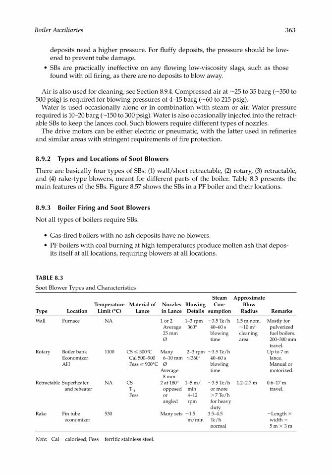
Boiler Auxiliaries 363
deposits need a higher pressure. For fl uffy deposits, the pressure should be low-ered to prevent tube damage.SBs are practically ineffective on any fl owing low-viscosity slags, such as those found with oil fi ring, as there are no deposits to blow away.
Air is also used for cleaning; see Section 8.9.4. Compressed air at ∼25 to 35 barg (∼350 to 500 psig) is required for blowing pressures of 4–15 barg (∼60 to 215 psig).
Water is used occasionally alone or in combination with steam or air. Water pressure required is 10–20 barg (∼150 to 300 psig). Water is also occasionally injected into the retract-able SBs to keep the lances cool. Such blowers require different types of nozzles.
The drive motors can be either electric or pneumatic, with the latter used in refi neries and similar areas with stringent requirements of fi re protection.
8.9.2 Types and Locations of Soot Blowers
There are basically four types of SBs: (1) wall/short retractable, (2) rotary, (3) retractable, and (4) rake-type blowers, meant for different parts of the boiler. Table 8.3 presents the main features of the SBs. Figure 8.57 shows the SBs in a PF boiler and their locations.
8.9.3 Boiler Firing and Soot Blowers
Not all types of boilers require SBs.
Gas-fi red boilers with no ash deposits have no blowers.PF boilers with coal burning at high temperatures produce molten ash that depos-its itself at all locations, requiring blowers at all locations.
•
••
TABLE 8.3
Soot Blower Types and Characteristics
Type LocationTemperature
Limit (°C)Material of
LanceNozzles in Lance
Blowing Details
Steam Con-
sumption
Approximate Blow
Radius Remarks
Wall Furnace NA 1 or 2Average 25 mm Ø
1–3 rpm360°
∼3.5 Te/h40–60 sblowing time
1.5 m nom.∼10 m2 cleaning area.
Mostly for pulverized fuel boilers. 200–300 mm travel.
Rotary Boiler bankEconomizerAH
1100 CS ≤ 500°C Cal 500–900 Fess ≥ 900°C
Many 6–10 mm Ø
Average 8 mm
2–3 rpm ≤360°
∼3.5 Te/h 40–60 s blowing time
Up to 7 m lance. Manual or motorized.
Retractable Superheater and reheater
NA CS T11
Fess
2 at 180°
opposed or angled
1–5 m/min 4–12 rpm
∼3.5 Te/h or more > 7 Te/h for heavy duty
1.2–2.7 m 0.6–17 m travel.
Rake Fin tube economizer
530 Many sets ∼1.5 m/min
3.5–4.5 Te/h normal
∼Length × width = 5 m × 3 m
Note: Cal = calorised, Fess = ferritic stainless steel.
CRC_75365_Ch008.indd 363CRC_75365_Ch008.indd 363 1/30/2009 1:44:46 PM1/30/2009 1:44:46 PM
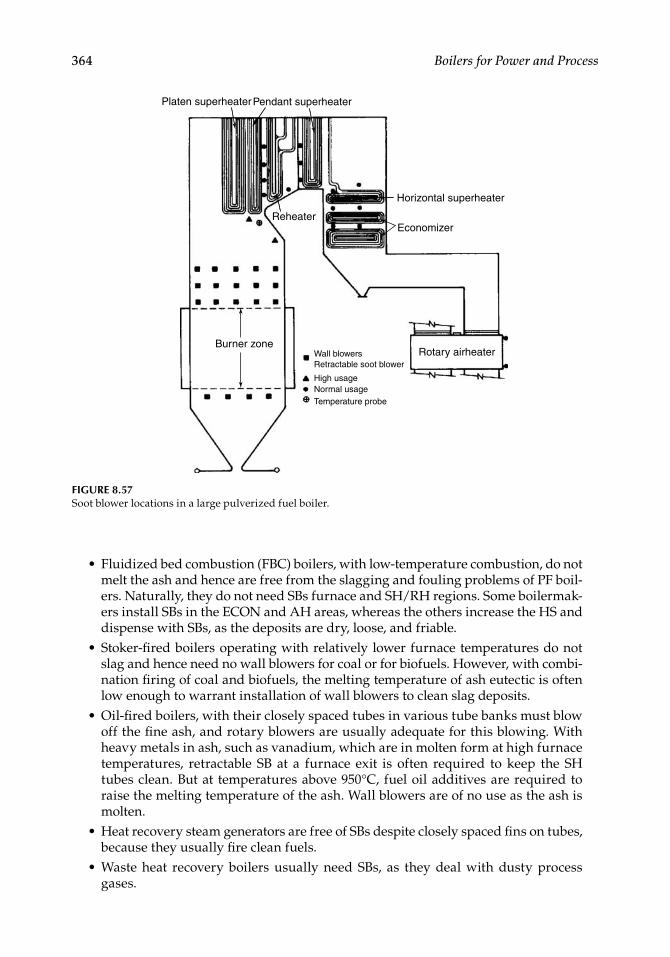
364 Boilers for Power and Process
Fluidized bed combustion (FBC) boilers, with low-temperature combustion, do not melt the ash and hence are free from the slagging and fouling problems of PF boil-ers. Naturally, they do not need SBs furnace and SH/RH regions. Some boilermak-ers install SBs in the ECON and AH areas, whereas the others increase the HS and dispense with SBs, as the deposits are dry, loose, and friable.Stoker-fi red boilers operating with relatively lower furnace temperatures do not slag and hence need no wall blowers for coal or for biofuels. However, with combi-nation fi ring of coal and biofuels, the melting temperature of ash eutectic is often low enough to warrant installation of wall blowers to clean slag deposits.Oil-fi red boilers, with their closely spaced tubes in various tube banks must blow off the fi ne ash, and rotary blowers are usually adequate for this blowing. With heavy metals in ash, such as vanadium, which are in molten form at high furnace temperatures, retractable SB at a furnace exit is often required to keep the SH tubes clean. But at temperatures above 950°C, fuel oil additives are required to raise the melting temperature of the ash. Wall blowers are of no use as the ash is molten.Heat recovery steam generators are free of SBs despite closely spaced fi ns on tubes, because they usually fi re clean fuels.Waste heat recovery boilers usually need SBs, as they deal with dusty process gases.
•
•
•
•
•
Platen superheaterPendant superheater
Reheater
Burner zoneWall blowers Retractable soot blower
High usageNormal usageTemperature probe
Rotary airheater
Horizontal superheater
Economizer
FIGURE 8.57Soot blower locations in a large pulverized fuel boiler.
CRC_75365_Ch008.indd 364CRC_75365_Ch008.indd 364 1/30/2009 1:44:46 PM1/30/2009 1:44:46 PM
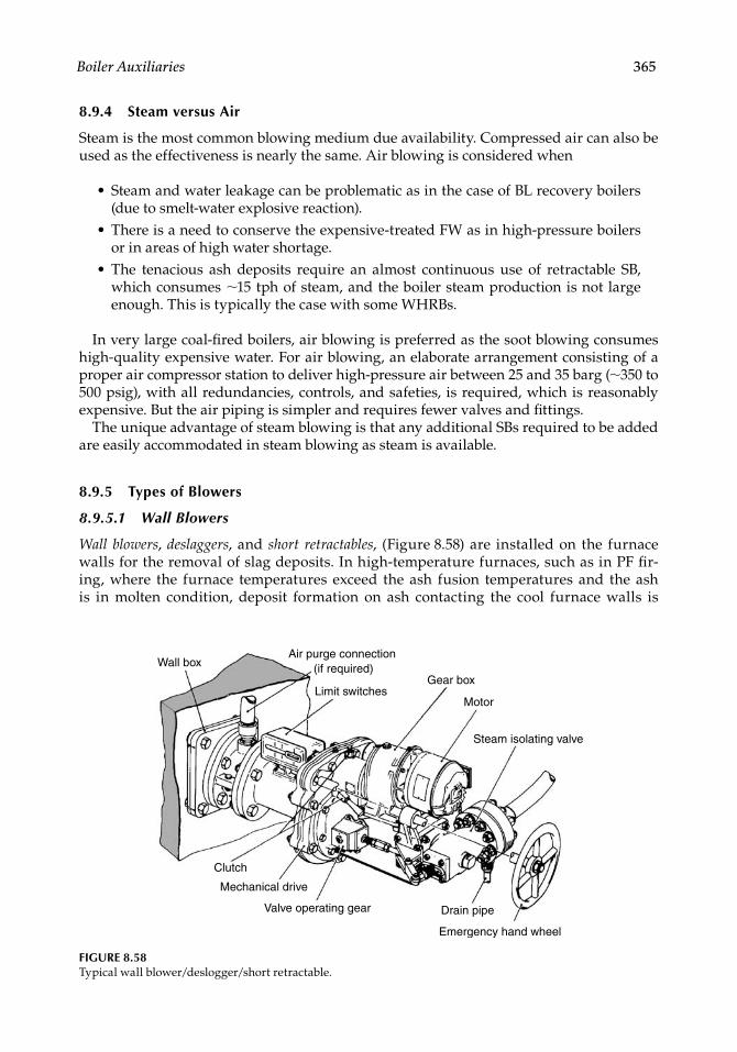
Boiler Auxiliaries 365
8.9.4 Steam versus Air
Steam is the most common blowing medium due availability. Compressed air can also be used as the effectiveness is nearly the same. Air blowing is considered when
Steam and water leakage can be problematic as in the case of BL recovery boilers (due to smelt-water explosive reaction).There is a need to conserve the expensive-treated FW as in high-pressure boilers or in areas of high water shortage.The tenacious ash deposits require an almost continuous use of retractable SB, which consumes ∼15 tph of steam, and the boiler steam production is not large enough. This is typically the case with some WHRBs.
In very large coal-fi red boilers, air blowing is preferred as the soot blowing consumes high-quality expensive water. For air blowing, an elaborate arrangement consisting of a proper air compressor station to deliver high-pressure air between 25 and 35 barg (∼350 to 500 psig), with all redundancies, controls, and safeties, is required, which is reasonably expensive. But the air piping is simpler and requires fewer valves and fi ttings.
The unique advantage of steam blowing is that any additional SBs required to be added are easily accommodated in steam blowing as steam is available.
8.9.5 Types of Blowers
8.9.5.1 Wall Blowers
Wall blowers, deslaggers, and short retractables, (Figure 8.58) are installed on the furnace walls for the removal of slag deposits. In high-temperature furnaces, such as in PF fi r-ing, where the furnace temperatures exceed the ash fusion temperatures and the ash is in molten condition, deposit formation on ash contacting the cool furnace walls is
•
•
•
FIGURE 8.58Typical wall blower/deslogger/short retractable.
Wall boxAir purge connection
(if required)
Limit switches Motor
Steam isolating valve
Clutch
Mechanical drive
Valve operating gear Drain pipe
Emergency hand wheel
Gear box
CRC_75365_Ch008.indd 365CRC_75365_Ch008.indd 365 1/30/2009 1:44:47 PM1/30/2009 1:44:47 PM
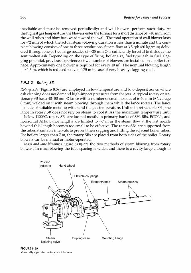
366 Boilers for Power and Process
inevitable and must be removed periodically; and wall blowers perform such duty. At the highest gas temperature, the blowers enter the furnace for a short distance of ∼40 mm from the wall tubes and blow backward toward the wall. The total operation of wall blower lasts for <2 min of which the actual steam-blowing duration is less than a minute and the com-plete blowing consists of one to three revolutions. Steam fl ow at 3.5 tph (60 kg/min) deliv-ered through one or two large nozzles of ∼25 mm Ø is suffi ciently forceful to dislodge the semimolten ash. Depending on the type of fi ring, boiler size, fuel type, ash in fuel, slag-ging potential, previous experience, etc., a number of blowers are installed on a boiler fur-nace. Approximately one blower is required for every 10 m2. The nominal blowing length is ∼1.5 m, which is reduced to even 0.75 m in case of very heavily slagging coals.
8.9.5.2 Rotary SB
Rotary SBs (Figure 8.59) are employed in low-temperature and low-deposit zones where ash cleaning does not demand high-impact pressures from the jets. A typical rotary or sta-tionary SB has a 40–80 mm Ø lance with a number of small nozzles of 6–10 mm Ø (average 8 mm) welded on it with steam blowing through them while the lance rotates. The lance is made of suitable metal to withstand the gas temperature. Unlike in retractable SBs, the lance in rotary SB does not rely on steam to cool it. As the maximum temperature limit is below 1100°C, rotary SBs are located mostly in primary banks of SH, BBs, ECONs, and horizontal AHs. Lance lengths are limited to ∼7 m as the steam fl ow at the last nozzle beyond this length becomes too small to be effective. The rotary SBs are supported from the tubes at suitable intervals to prevent their sagging and hitting the adjacent boiler tubes. For boilers larger than 7 m, the rotary SBs are placed from both sides of the boiler. Rotary blowers can be manual or motor-operated.
Mass and lane blowing (Figure 8.60) are the two methods of steam blowing from rotary blowers. In mass blowing the tube spacing is wider, and there is a cavity large enough to
Position indicator
Flexible couplings
Steam isolating valve
Steam nozzlesElement/lance
Hand wheel
Coupling case Mounting flange
FIGURE 8.59Manually operated rotary soot blower.
CRC_75365_Ch008.indd 366CRC_75365_Ch008.indd 366 1/30/2009 1:44:47 PM1/30/2009 1:44:47 PM
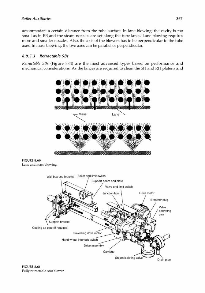
Boiler Auxiliaries 367
accommodate a certain distance from the tube surface. In lane blowing, the cavity is too small as in BB and the steam nozzles are set along the tube lanes. Lane blowing requires more and smaller nozzles. Also, the axis of the blowers has to be perpendicular to the tube axes. In mass blowing, the two axes can be parallel or perpendicular.
8.9.5.3 Retractable SBs
Retractable SBs (Figure 8.61) are the most advanced types based on performance and mechanical considerations. As the lances are required to clean the SH and RH platens and
Mass Lane
FIGURE 8.60Lane and mass blowing.
FIGURE 8.61Fully retractable soot blower.
Wall box end bracket Boiler end limit switch
Support beam and plate
Valve end limit switch
Junction box Drive motor
Breather plug
Valve operating gear
Drain pipeSteam isolating valve
Carriage
Drive assembly
Hand wheel interlock switch
Traversing drive motor
Cooling air pipe (if required)
Support bracket
CRC_75365_Ch008.indd 367CRC_75365_Ch008.indd 367 1/30/2009 1:44:47 PM1/30/2009 1:44:47 PM
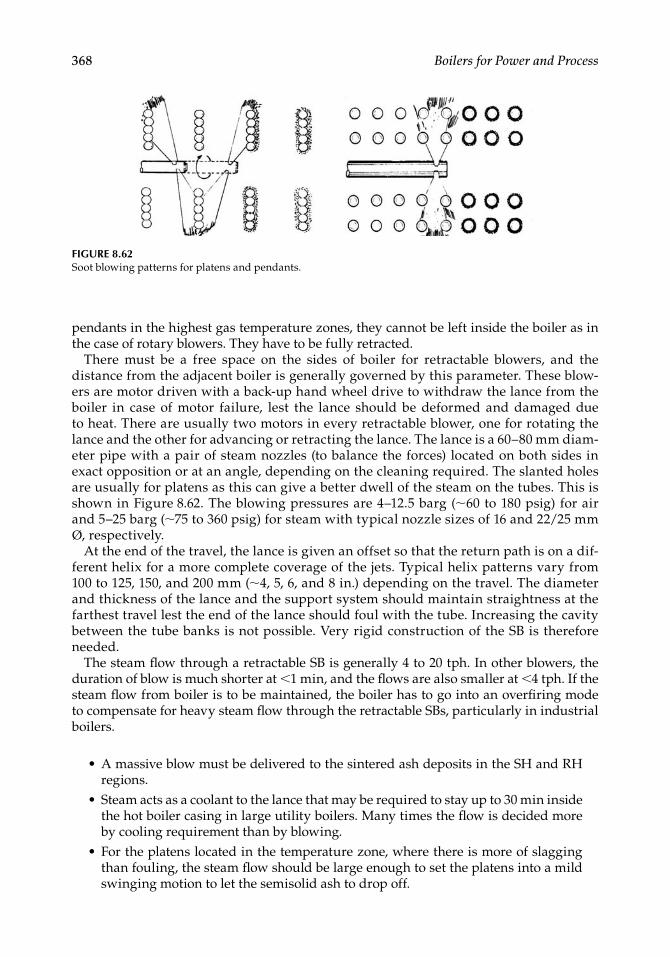
368 Boilers for Power and Process
pendants in the highest gas temperature zones, they cannot be left inside the boiler as in the case of rotary blowers. They have to be fully retracted.
There must be a free space on the sides of boiler for retractable blowers, and the distance from the adjacent boiler is generally governed by this parameter. These blow-ers are motor driven with a back-up hand wheel drive to withdraw the lance from the boiler in case of motor failure, lest the lance should be deformed and damaged due to heat. There are usually two motors in every retractable blower, one for rotating the lance and the other for advancing or retracting the lance. The lance is a 60–80 mm diam-eter pipe with a pair of steam nozzles (to balance the forces) located on both sides in exact opposition or at an angle, depending on the cleaning required. The slanted holes are usually for platens as this can give a better dwell of the steam on the tubes. This is shown in Figure 8.62. The blowing pressures are 4–12.5 barg (∼60 to 180 psig) for air and 5–25 barg (∼75 to 360 psig) for steam with typical nozzle sizes of 16 and 22/25 mm Ø, respectively.
At the end of the travel, the lance is given an offset so that the return path is on a dif-ferent helix for a more complete coverage of the jets. Typical helix patterns vary from 100 to 125, 150, and 200 mm (∼4, 5, 6, and 8 in.) depending on the travel. The diameter and thickness of the lance and the support system should maintain straightness at the farthest travel lest the end of the lance should foul with the tube. Increasing the cavity between the tube banks is not possible. Very rigid construction of the SB is therefore needed.
The steam fl ow through a retractable SB is generally 4 to 20 tph. In other blowers, the duration of blow is much shorter at <1 min, and the fl ows are also smaller at <4 tph. If the steam fl ow from boiler is to be maintained, the boiler has to go into an overfi ring mode to compensate for heavy steam fl ow through the retractable SBs, particularly in industrial boilers.
A massive blow must be delivered to the sintered ash deposits in the SH and RH regions.Steam acts as a coolant to the lance that may be required to stay up to 30 min inside the hot boiler casing in large utility boilers. Many times the fl ow is decided more by cooling requirement than by blowing.For the platens located in the temperature zone, where there is more of slagging than fouling, the steam fl ow should be large enough to set the platens into a mild swinging motion to let the semisolid ash to drop off.
•
•
•
FIGURE 8.62Soot blowing patterns for platens and pendants.
CRC_75365_Ch008.indd 368CRC_75365_Ch008.indd 368 1/30/2009 1:44:48 PM1/30/2009 1:44:48 PM
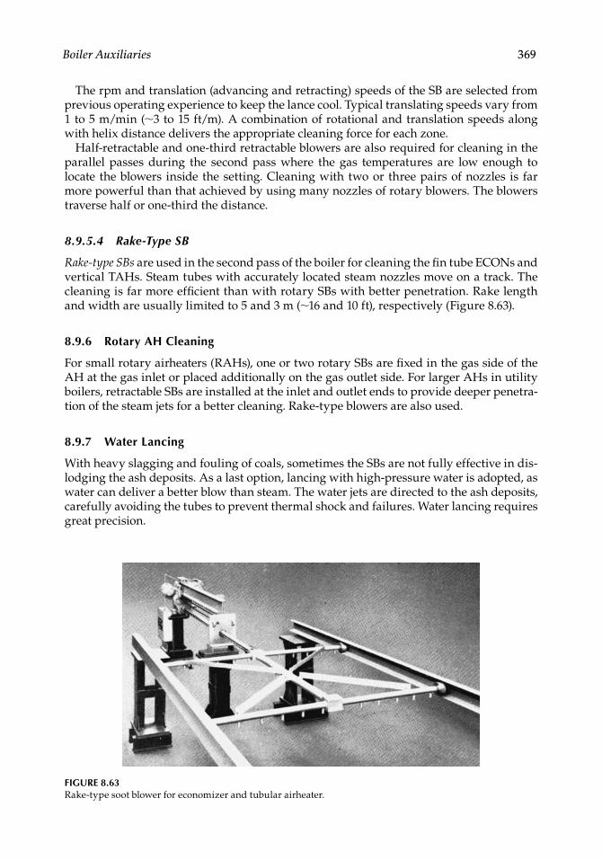
Boiler Auxiliaries 369
The rpm and translation (advancing and retracting) speeds of the SB are selected from previous operating experience to keep the lance cool. Typical translating speeds vary from 1 to 5 m/min (∼3 to 15 ft/m). A combination of rotational and translation speeds along with helix distance delivers the appropriate cleaning force for each zone.
Half-retractable and one-third retractable blowers are also required for cleaning in the parallel passes during the second pass where the gas temperatures are low enough to locate the blowers inside the setting. Cleaning with two or three pairs of nozzles is far more powerful than that achieved by using many nozzles of rotary blowers. The blowers traverse half or one-third the distance.
8.9.5.4 Rake-Type SB
Rake-type SBs are used in the second pass of the boiler for cleaning the fi n tube ECONs and vertical TAHs. Steam tubes with accurately located steam nozzles move on a track. The cleaning is far more effi cient than with rotary SBs with better penetration. Rake length and width are usually limited to 5 and 3 m (∼16 and 10 ft), respectively (Figure 8.63).
8.9.6 Rotary AH Cleaning
For small rotary airheaters (RAHs), one or two rotary SBs are fi xed in the gas side of the AH at the gas inlet or placed additionally on the gas outlet side. For larger AHs in utility boilers, retractable SBs are installed at the inlet and outlet ends to provide deeper penetra-tion of the steam jets for a better cleaning. Rake-type blowers are also used.
8.9.7 Water Lancing
With heavy slagging and fouling of coals, sometimes the SBs are not fully effective in dis-lodging the ash deposits. As a last option, lancing with high-pressure water is adopted, as water can deliver a better blow than steam. The water jets are directed to the ash deposits, carefully avoiding the tubes to prevent thermal shock and failures. Water lancing requires great precision.
FIGURE 8.63Rake-type soot blower for economizer and tubular airheater.
CRC_75365_Ch008.indd 369CRC_75365_Ch008.indd 369 1/30/2009 1:44:48 PM1/30/2009 1:44:48 PM
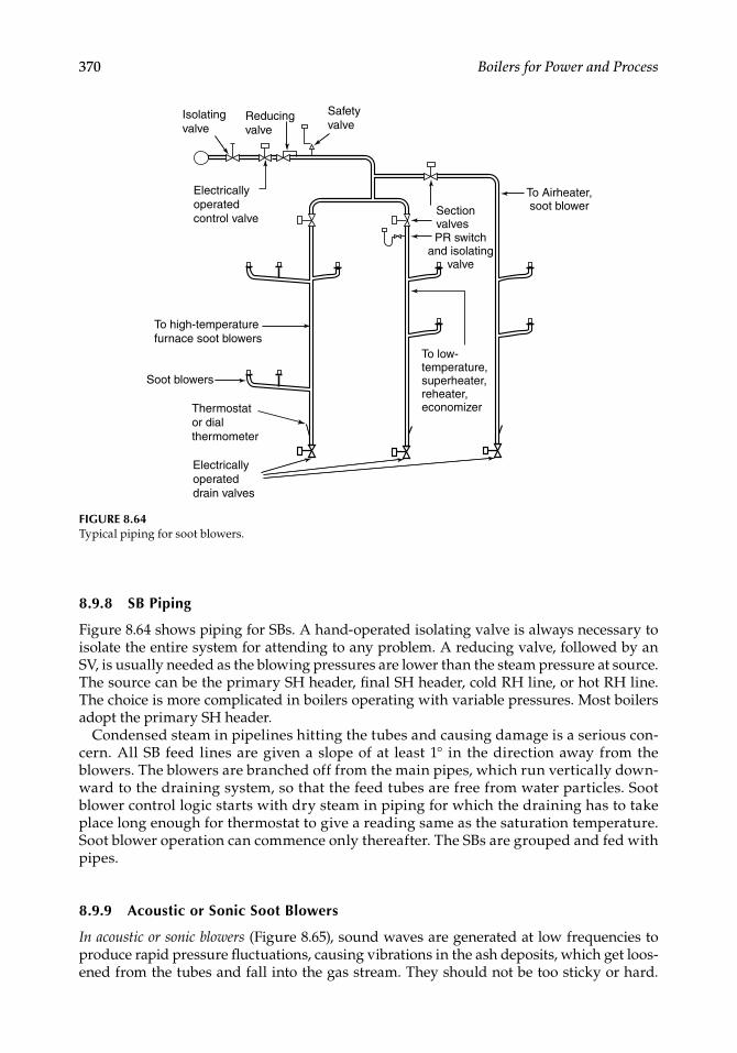
370 Boilers for Power and Process
8.9.8 SB Piping
Figure 8.64 shows piping for SBs. A hand-operated isolating valve is always necessary to isolate the entire system for attending to any problem. A reducing valve, followed by an SV, is usually needed as the blowing pressures are lower than the steam pressure at source. The source can be the primary SH header, fi nal SH header, cold RH line, or hot RH line. The choice is more complicated in boilers operating with variable pressures. Most boilers adopt the primary SH header.
Condensed steam in pipelines hitting the tubes and causing damage is a serious con-cern. All SB feed lines are given a slope of at least 1° in the direction away from the blowers. The blowers are branched off from the main pipes, which run vertically down-ward to the draining system, so that the feed tubes are free from water particles. Soot blower control logic starts with dry steam in piping for which the draining has to take place long enough for thermostat to give a reading same as the saturation temperature. Soot blower operation can commence only thereafter. The SBs are grouped and fed with pipes.
8.9.9 Acoustic or Sonic Soot Blowers
In acoustic or sonic blowers (Figure 8.65), sound waves are generated at low frequencies to produce rapid pressure fl uctuations, causing vibrations in the ash deposits, which get loos-ened from the tubes and fall into the gas stream. They should not be too sticky or hard.
Isolatingvalve
Reducingvalve
Electricallyoperated control valve
Electricallyoperateddrain valves
Thermostator dialthermometer
To high-temperaturefurnace soot blowers
Safetyvalve
Sectionvalves
To Airheater,soot blower
PR switchand isolating
valve
To low-temperature, superheater,reheater, economizer
Soot blowers
FIGURE 8.64Typical piping for soot blowers.
CRC_75365_Ch008.indd 370CRC_75365_Ch008.indd 370 1/30/2009 1:44:49 PM1/30/2009 1:44:49 PM
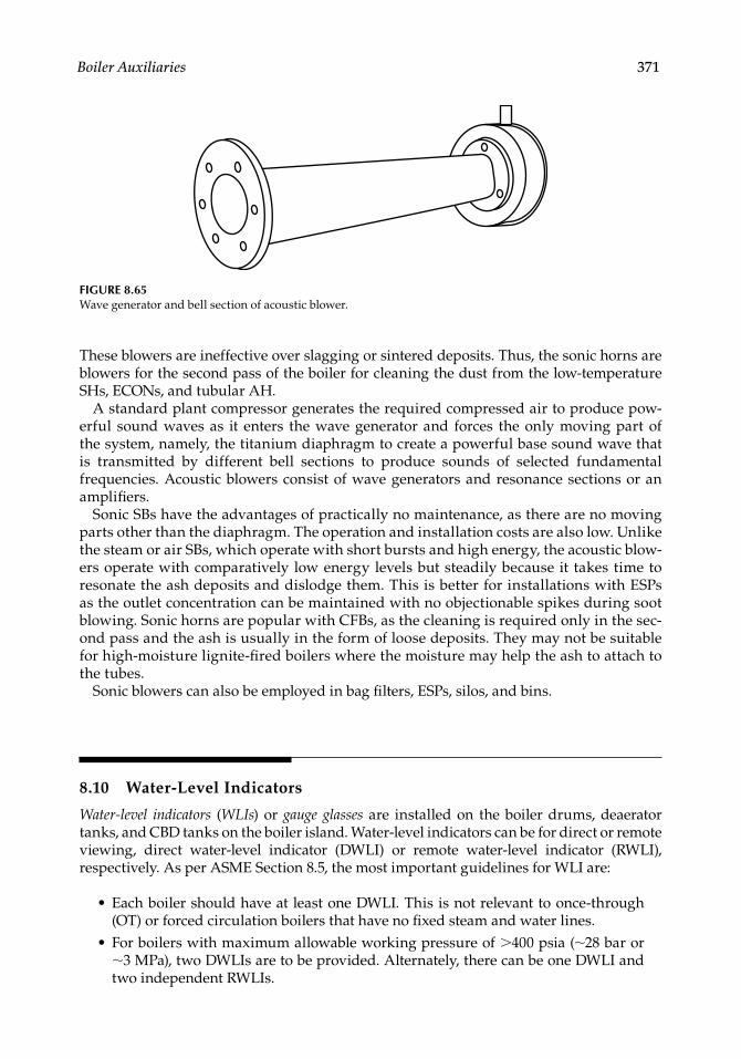
Boiler Auxiliaries 371
These blowers are ineffective over slagging or sintered deposits. Thus, the sonic horns are blowers for the second pass of the boiler for cleaning the dust from the low-temperature SHs, ECONs, and tubular AH.
A standard plant compressor generates the required compressed air to produce pow-erful sound waves as it enters the wave generator and forces the only moving part of the system, namely, the titanium diaphragm to create a powerful base sound wave that is transmitted by different bell sections to produce sounds of selected fundamental frequencies. Acoustic blowers consist of wave generators and resonance sections or an amplifi ers.
Sonic SBs have the advantages of practically no maintenance, as there are no moving parts other than the diaphragm. The operation and installation costs are also low. Unlike the steam or air SBs, which operate with short bursts and high energy, the acoustic blow-ers operate with comparatively low energy levels but steadily because it takes time to resonate the ash deposits and dislodge them. This is better for installations with ESPs as the outlet concentration can be maintained with no objectionable spikes during soot blowing. Sonic horns are popular with CFBs, as the cleaning is required only in the sec-ond pass and the ash is usually in the form of loose deposits. They may not be suitable for high-moisture lignite-fi red boilers where the moisture may help the ash to attach to the tubes.
Sonic blowers can also be employed in bag fi lters, ESPs, silos, and bins.
8.10 Water-Level Indicators
Water-level indicators (WLIs) or gauge glasses are installed on the boiler drums, deaerator tanks, and CBD tanks on the boiler island. Water-level indicators can be for direct or remote viewing, direct water-level indicator (DWLI) or remote water-level indicator (RWLI), respectively. As per ASME Section 8.5, the most important guidelines for WLI are:
Each boiler should have at least one DWLI. This is not relevant to once-through (OT) or forced circulation boilers that have no fi xed steam and water lines.For boilers with maximum allowable working pressure of >400 psia (∼28 bar or ∼3 MPa), two DWLIs are to be provided. Alternately, there can be one DWLI and two independent RWLIs.
•
•
FIGURE 8.65Wave generator and bell section of acoustic blower.
CRC_75365_Ch008.indd 371CRC_75365_Ch008.indd 371 1/30/2009 1:44:50 PM1/30/2009 1:44:50 PM

372 Boilers for Power and Process
When two independent RWLIs are installed and are operating reliably, one DWLI may be shut off but kept in a serviceable condition.The lowest visible water level in a DWLI and an RWLI should be at least 50 mm above the lowest permissible water level. (This is usually upper end of the last downcomer tube.)
Boiler codes differ slightly in specifying WLIs, although the underlying principles are the same. Respective codes must be studied carefully before adopting the WLIs in any application.
Achieving drum water level indication is not particularly easy. With relatively small diameter drums used in modern high-capacity boilers, more accuracy is needed. The high pressures and temperatures in the drums, coupled with fl uctuations, make the drum water level measurement much more diffi cult than in other containers such as tanks and silos. Direct and remote WLIs are the two broad classifi cations of gauge glasses.
Several types of WLIs are available.
8.10.1 Direct Water-Level Indicators
Direct water-level indicators are available in several designs. In small boilers with steam drum levels of up to 20 m from the operating fl oor, the drum water can be seen adequately with suitably illuminated refl ex or bicolor WLIs. For a better viewing from a wider area, the level can be seen by providing a suitable enclosure and a pair of refl ect-ing mirrors, called the telescopic arrangement. For bigger boilers with steam drums located at 50 m and above the operating fl oor, the DWLIs are too remote even for refl ect-ing in mirrors.
Direct WLIs suffer from displaying a lower level than the actual level due to the den-sity difference of water between the drum and the (thin) cooled water column of the DWLI. Typically, at 180 bar drum pressure, the level at the top of 200 mm water column displayed in the gauge can be lower than the actual by as much as 120 mm, depending on the ambient condition. Despite this disadvantage, the comfort it induces cannot be replicated by watching the level of an RWLI; hence, it remains as a reliable backup for RWLI.
8.10.1.1 Tubular Gauge Glasses
These glasses are the oldest and the simplest of the DWLIs employed for nontoxic and nonhazardous media and low pressures up to 15 barg (∼220 psig). The gauge glasses are supported at their ends and are subject to bending which limits their use to low pressures. Also, the affi nity of alkaline drum water to glass increases with the tem-perature (and consequently the steam pressure) and does not permit the use of plain glass beyond the low pressure. The breakage of gauge glass can be dangerous to the operators as the splinters can fl y around. With clear water, the meniscus is visible only by the vibration of the column. A glass protector is usually used to improve the safety and visibility. Closed on three sides, the protector is a metal sheet with a thin black strip at the center, which gets magnifi ed by the lens effect of water to improve the dis-play. Figure 8.66 shows the tubular gauge glasses with and without the protector sheet. The plain gauge glasses are rarely used as they do not satisfy the safety and display requirements.
•
•
CRC_75365_Ch008.indd 372CRC_75365_Ch008.indd 372 1/30/2009 1:44:50 PM1/30/2009 1:44:50 PM
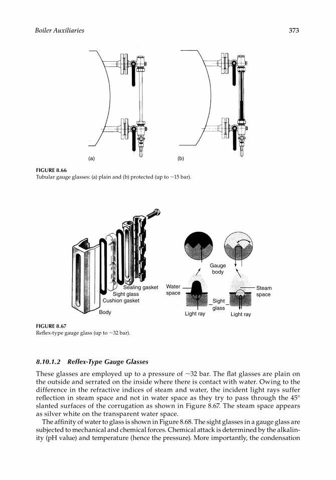
Boiler Auxiliaries 373
8.10.1.2 Reflex-Type Gauge Glasses
These glasses are employed up to a pressure of ∼32 bar. The fl at glasses are plain on the outside and serrated on the inside where there is contact with water. Owing to the difference in the refractive indices of steam and water, the incident light rays suffer refl ection in steam space and not in water space as they try to pass through the 45° slanted surfaces of the corrugation as shown in Figure 8.67. The steam space appears as silver white on the transparent water space.
The affi nity of water to glass is shown in Figure 8.68. The sight glasses in a gauge glass are subjected to mechanical and chemical forces. Chemical attack is determined by the alkalin-ity (pH value) and temperature (hence the pressure). More importantly, the condensation
(a) (b)
FIGURE 8.66Tubular gauge glasses: (a) plain and (b) protected (up to ∼15 bar).
Sealing gasketSight glass
Cushion gasket
Body
Water space
Gauge body
Light ray
Sightglass
Light ray
Steam space
FIGURE 8.67Refl ex-type gauge glass (up to ∼32 bar).
CRC_75365_Ch008.indd 373CRC_75365_Ch008.indd 373 1/30/2009 1:44:50 PM1/30/2009 1:44:50 PM
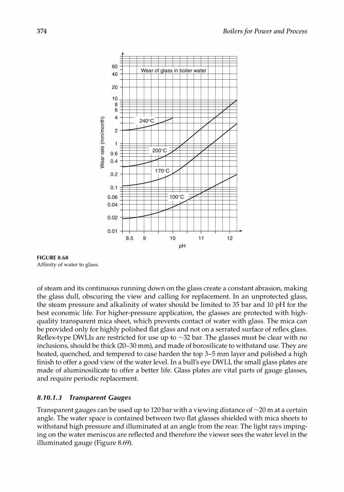
374 Boilers for Power and Process
FIGURE 8.68Affi nity of water to glass.
8.5 9 10 11 12
pH
0.01
0.02
0.040.06
0.1
0.2
0.4
0.6
1
Wea
r ra
te (
mm
/mon
th)
2
4240°C
200°C
170°C
100°C
6
10
20
40
60
8
Wear of glass in boiler water
of steam and its continuous running down on the glass create a constant abrasion, making the glass dull, obscuring the view and calling for replacement. In an unprotected glass, the steam pressure and alkalinity of water should be limited to 35 bar and 10 pH for the best economic life. For higher-pressure application, the glasses are protected with high-quality transparent mica sheet, which prevents contact of water with glass. The mica can be provided only for highly polished fl at glass and not on a serrated surface of refl ex glass. Refl ex-type DWLIs are restricted for use up to ∼32 bar. The glasses must be clear with no inclusions, should be thick (20–30 mm), and made of borosilicate to withstand use. They are heated, quenched, and tempered to case harden the top 3–5 mm layer and polished a high fi nish to offer a good view of the water level. In a bull’s eye DWLI, the small glass plates are made of aluminosilicate to offer a better life. Glass plates are vital parts of gauge glasses, and require periodic replacement.
8.10.1.3 Transparent Gauges
Transparent gauges can be used up to 120 bar with a viewing distance of ∼20 m at a certain angle. The water space is contained between two fl at glasses shielded with mica sheets to withstand high pressure and illuminated at an angle from the rear. The light rays imping-ing on the water meniscus are refl ected and therefore the viewer sees the water level in the illuminated gauge (Figure 8.69).
CRC_75365_Ch008.indd 374CRC_75365_Ch008.indd 374 1/30/2009 1:44:51 PM1/30/2009 1:44:51 PM
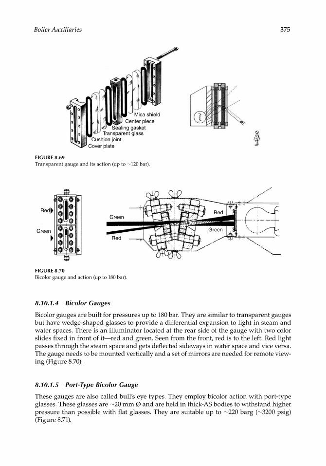
Boiler Auxiliaries 375
8.10.1.4 Bicolor Gauges
Bicolor gauges are built for pressures up to 180 bar. They are similar to transparent gauges but have wedge-shaped glasses to provide a differential expansion to light in steam and water spaces. There is an illuminator located at the rear side of the gauge with two color slides fi xed in front of it—red and green. Seen from the front, red is to the left. Red light passes through the steam space and gets defl ected sideways in water space and vice versa. The gauge needs to be mounted vertically and a set of mirrors are needed for remote view-ing (Figure 8.70).
8.10.1.5 Port-Type Bicolor Gauge
These gauges are also called bull’s eye types. They employ bicolor action with port-type glasses. These glasses are ∼20 mm Ø and are held in thick-AS bodies to withstand higher pressure than possible with fl at glasses. They are suitable up to ∼220 barg (∼3200 psig) (Figure 8.71).
FIGURE 8.69Transparent gauge and its action (up to ∼120 bar).
Mica shieldCenter piece
Sealing gasketTransparent glass
Cushion jointCover plate
Red
Green
Green
Red
Green
Red
FIGURE 8.70Bicolor gauge and action (up to 180 bar).
CRC_75365_Ch008.indd 375CRC_75365_Ch008.indd 375 1/30/2009 1:44:51 PM1/30/2009 1:44:51 PM
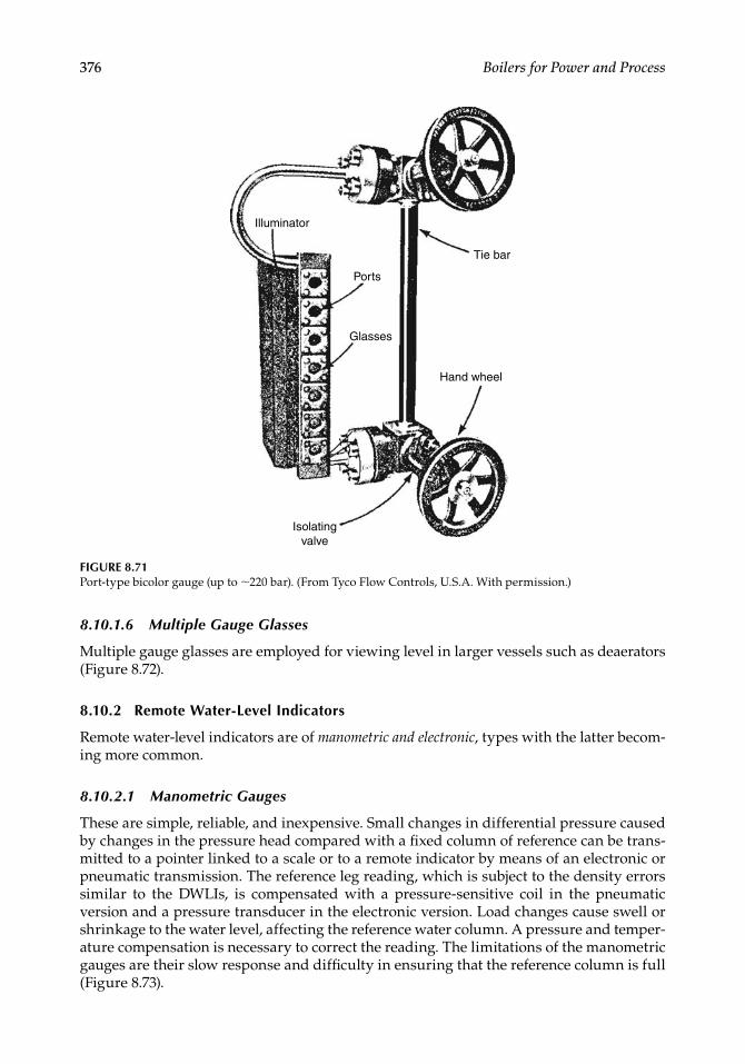
376 Boilers for Power and Process
8.10.1.6 Multiple Gauge Glasses
Multiple gauge glasses are employed for viewing level in larger vessels such as deaerators(Figure 8.72).
8.10.2 Remote Water-Level Indicators
Remote water-level indicators are of manometric and electronic, types with the latter becom-ing more common.
8.10.2.1 Manometric Gauges
These are simple, reliable, and inexpensive. Small changes in differential pressure caused by changes in the pressure head compared with a fi xed column of reference can be trans-mitted to a pointer linked to a scale or to a remote indicator by means of an electronic or pneumatic transmission. The reference leg reading, which is subject to the density errors similar to the DWLIs, is compensated with a pressure-sensitive coil in the pneumatic version and a pressure transducer in the electronic version. Load changes cause swell or shrinkage to the water level, affecting the reference water column. A pressure and temper-ature compensation is necessary to correct the reading. The limitations of the manometric gauges are their slow response and diffi culty in ensuring that the reference column is full (Figure 8.73).
Tie bar
Illuminator
Ports
Glasses
Hand wheel
Isolatingvalve
FIGURE 8.71Port-type bicolor gauge (up to ∼220 bar). (From Tyco Flow Controls, U.S.A. With permission.)
CRC_75365_Ch008.indd 376CRC_75365_Ch008.indd 376 1/30/2009 1:44:52 PM1/30/2009 1:44:52 PM
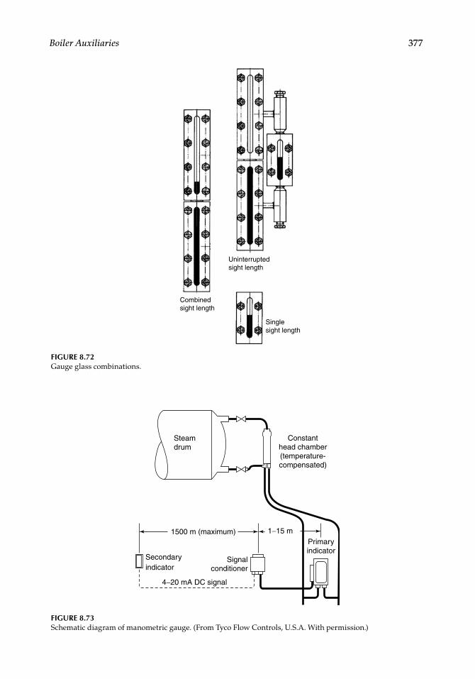
Boiler Auxiliaries 377
Combined sight length
Uninterrupted sight length
Single sight length
FIGURE 8.72Gauge glass combinations.
Steam drum
1500 m (maximum)
Secondaryindicator
Signal conditioner
4−20 mA DC signal
1−15 mPrimary indicator
Constant head chamber (temperature- compensated)
FIGURE 8.73Schematic diagram of manometric gauge. (From Tyco Flow Controls, U.S.A. With permission.)
CRC_75365_Ch008.indd 377CRC_75365_Ch008.indd 377 1/30/2009 1:44:53 PM1/30/2009 1:44:53 PM
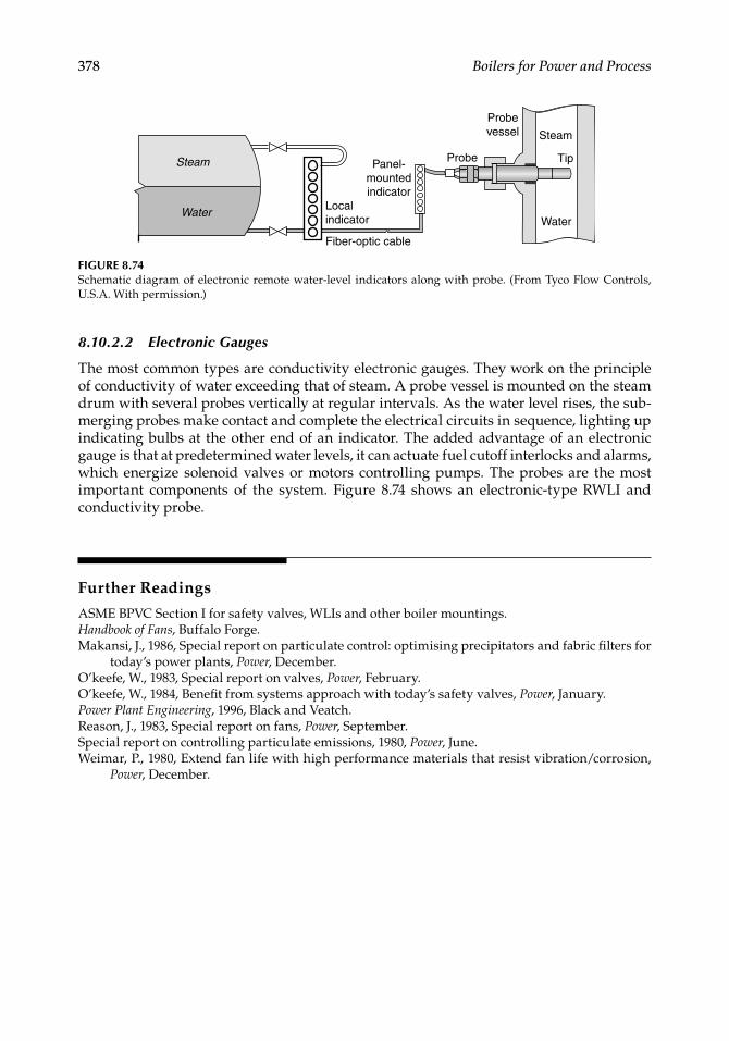
378 Boilers for Power and Process
Tip
Steam
Water
Panel-mountedindicator
Localindicator
Fiber-optic cable
Probevessel
ProbeSteam
Water
FIGURE 8.74Schematic diagram of electronic remote water-level indicators along with probe. (From Tyco Flow Controls, U.S.A. With permission.)
8.10.2.2 Electronic Gauges
The most common types are conductivity electronic gauges. They work on the principle of conductivity of water exceeding that of steam. A probe vessel is mounted on the steam drum with several probes vertically at regular intervals. As the water level rises, the sub-merging probes make contact and complete the electrical circuits in sequence, lighting up indicating bulbs at the other end of an indicator. The added advantage of an electronic gauge is that at predetermined water levels, it can actuate fuel cutoff interlocks and alarms, which energize solenoid valves or motors controlling pumps. The probes are the most important components of the system. Figure 8.74 shows an electronic-type RWLI and conductivity probe.
Further Readings
ASME BPVC Section I for safety valves, WLIs and other boiler mountings.Handbook of Fans, Buffalo Forge.Makansi, J., 1986, Special report on particulate control: optimising precipitators and fabric fi lters for
today’s power plants, Power, December.O’keefe, W., 1983, Special report on valves, Power, February.O’keefe, W., 1984, Benefi t from systems approach with today’s safety valves, Power, January.Power Plant Engineering, 1996, Black and Veatch.Reason, J., 1983, Special report on fans, Power, September.Special report on controlling particulate emissions, 1980, Power, June.Weimar, P., 1980, Extend fan life with high performance materials that resist vibration/corrosion,
Power, December.
CRC_75365_Ch008.indd 378CRC_75365_Ch008.indd 378 1/30/2009 1:44:54 PM1/30/2009 1:44:54 PM
Section III
Boilers and Firing
CRC_75365_S003.indd 379CRC_75365_S003.indd 379 1/30/2009 1:48:23 PM1/30/2009 1:48:23 PM

CRC_75365_S003.indd 380CRC_75365_S003.indd 380 1/30/2009 1:48:23 PM1/30/2009 1:48:23 PM
381
9Industrial and Utility Boilers
9.1 Water Tube Boilers for Industry and Power
Water tube boilers are made
From ∼5 tph to ∼4500 tph capacityAt steam pressures ranging from ∼3.5 to 320 barAt steam temperatures ranging from saturation to ∼620°C
The lower end of the range up to ∼400 tph is employed for its process steam, captive power, and cogeneration (cogen) needs. Beyond 400 tph, where reheating of steam becomes viable, boilers are mainly used for utility application. This dividing line is thin and tentative, and exceptions are found on both sides of this arbitrary demarcation. With cogen on the rise and very large plants gaining popularity, what a utility boiler was in the past has become an industrial unit today and this progression is only going to continue.
9.1.1 Characteristic Features of Industrial Boilers
Variety of confi gurations are required to meet a wide range of steaming conditions and fuels.Fuels burnt include waste and manufactured fuels found in an array of industries and biofuels.These boilers are for meeting process steam requirements, captive power, or both (cogen). In cold countries, steam for district heating is another application.Steaming conditions are more modest, usually, with maximum continuous rat-ing (MCR) <400 tph, superheater outlet pressure (SOP) <150 bar, and superheater outlet temperature (SOT) <565°C, with no reheat.Often multifuel fl exibility is required to use the available fuels; optimize the cheapest fuel; use the fuel of the season, in case of biofuels; or increase the reli-ability of the fuel-supply chain.When used for generating captive power or in cogen mode, they are expected to integrate with the dynamics of the main plant seamlessly.The process leads and the boiler are required to follow. The boiler process control and the dynamics are aligned to match this requirement.Availability of the boiler plant is vital for the process industry, even at the cost of fractionally better effi ciency. Multiple boilers of smaller size are many times preferred to large-sized single units for the sake of availability, even if this arrange-ment is more expensive.
•••
•
•
•
•
•
•
•
•
CRC_75365_Ch009.indd 381CRC_75365_Ch009.indd 381 1/30/2009 1:49:57 PM1/30/2009 1:49:57 PM
382 Boilers for Power and Process
Besides a steady degeneration of quality of prime fuels available to industry at com-petitive prices, there is an increase in waste fuels from industry, as process indus-tries are becoming larger, more complex, and more varied. With greater attention that biomass fi ring is receiving, the range of biofuels turned over to boilers for cofi ring is also increasing.
9.1.2 Characteristic Features of Utility Boilers
They are optimized for best performance and highest reliability.Their fuel fl exibility is rarely the prime consideration.They are made to the largest sizes that the grid can bear and to the highest steam-ing conditions that give the best effi ciencies, so that the power generation is most reliable and least expensive.Their steaming conditions can be as high as MCR ∼4500 tph, SOP up to ∼320 bar, and SOT ∼620°C.Plant dynamics are governed by the grid fl uctuations.Utility boilers come in relatively fewer confi gurations compared to the industrial boilers.
Large utility boilers based on oil and gas were built in the 1960s. Since then two unfavor-able developments have taken place:
The oil crisis of the early 1970s has made oil too expensive for power generation.The increased reliability of gas turbines (GTs) with exceptionally rapid growth in unit sizes has fi rmly driven out oil- and gas-based steam cycles in favor of com-bined cycle power plants (CCPPs).
Utility boilers for power today are based on coal when gas-based power is not viable.
•••
•
••
••
TABLE 9.1
Industrial versus Utility Boilers
Parameter Industrial Boilers Utility Boilers
Purpose Process steam, captive power, cogen, heating Grid powerSteaming conditions
Generally <400 tph, no reheat, <150 bar/565°C Generally up to 4500 tph with reheat, up to 320 bar/620°C
Fuels All types—prime, waste, manufactured, and biofuels
Prime fuels—occasionally waste gas, petcoke, etc.
Multifuel fl exibility
Yes Very rarely
Firing All types—burner, stoker, pile burn, BFBC, CFBC, PF boilers
PF, cyclone, and CFBC boilers
Type Bidrum and single drum, bottom and top supported, package, and fi eld-erected boilers
Single drum and no drum for once-through (OT) boilers. Top supported. Only fi eld-erected boilers
Circulation Mostly natural, sometimes forced Natural, assisted, supercritical, subcritical OT
Dynamics To suit process or captive or cogen power To suit grid
CRC_75365_Ch009.indd 382CRC_75365_Ch009.indd 382 1/30/2009 1:49:58 PM1/30/2009 1:49:58 PM
Industrial and Utility Boilers 383
Heat recovery steam generators (HRSGs) fall between industrial and utility boilers. They generate steam for driving turbines like any utility boiler, with the main difference in that they do not burn any fuel but use the hot exhaust gases from the GTs. In the largest sizes they have main and reheat steam temperatures of the same range as utility boilers and they even work on sliding pressure mode. Yet their pressures are no more than ∼170 bar, and in size they are like large industrial boilers. They are like waste heat boilers receiving exhaust gases from GTs, and hence are considered slave units of a process. Large boilermakers, therefore, treat HRSG more as an advanced class industrial boiler for utility application. In fact, the HRSG is the only waste heat boiler of the utility market. Table 9.1 compares the industrial and utility boilers.
9.2 Industrial Boilers
9.2.1 Boiler Classification by Firing
9.2.1.1 Oil- or Gas-Fired Boilers
Oil- and gas-fi red boilers are burner-fi red and are amenable to extensive standardization because of a fair degree of uniformity of the fuel characteristics. The quick and relatively clean burning nature of the fuels makes them compact and suitable for full or part shop assembly, as in package or fi eld-erected boilers, respectively.
9.2.1.1.1 Package Boilers
Package boilers are available for capacities up to 250 tph, with horizontal gas fl ow, bottom support, short drum centers, and extremely high heat release and absorption rates. These features allow such boilers to be compact and easily transportable on trailers or barges. Because of the horizontal gas fl ow, the package boiler design is more amenable to fi ring clean fuels such as gas and number 2 oil. One to four burners are always mounted on the front wall of the furnace. The furnace is arranged parallel to the drums and convection bank. Package boilers are shop assembled and sent to site where they are unloaded on a leveled, cemented fl oor requiring minimum foundation work. In developing countries, where transportation is expensive and labor costs for erection are low, the package boilers are often fi eld erected with shop-made modules.
9.2.1.1.2 Field-Erected Boilers
Bidrum bottom-supported boilers for power and process steam are extensively standard-ized for capacities up to 450 tph. The fl ue gas fl ows up and down, permitting dusty and fouling oils and gases to be fi red in these boilers. The burners are mounted on the front wall of the furnace arranged normal to the axis of the drums and convection bank, unlike in the package boilers where the furnace is set parallel to the drums. The modular designs of these boilers permit economical manufacturing and quick erection.
Single-drum design for oil and gas is the preferred confi guration of many customers. Low water holding, less weight, and drainable SH in these boilers enable quick starts and shutdowns as required in two-shift operations. These boilers can be bottom supported for capacities up to 100–150 tph and top supported for larger sizes. There is a great fl exibility in arranging the burners in these designs. They can be roof, fl oor, and sidewall or front wall mounted, depending on the desired SH characteristics.
All these boilers are more extensively dealt with in Chapter 10.
CRC_75365_Ch009.indd 383CRC_75365_Ch009.indd 383 1/30/2009 1:49:58 PM1/30/2009 1:49:58 PM
384 Boilers for Power and Process
9.2.1.2 Stoker-Fired Boilers
Stokers, which were workhorses, have been severely affected by the rise of bubbling fl uid-ized bed combustion (BFBC) boilers and the tightening of pollution norms on both SOx and NOx. They can be classifi ed as
Dumping grate stokersChain grate stokersSpreader stokers (SS)Pulsating/reciprocating grates (PGs/RGs)
Bidrum boilers are the industry standards for pressures up to ∼90 bar and the single-drum boilers for higher pressures of up to 150 bar. Bottom support is possible and econom-ical up to ∼40 to 60 tph. Stoker-fi red boilers are more elaborately discussed in Chapter 11.
9.2.1.2.1 Dumping Grates
Dumping grates are used to burn fuels like bagasse and occasionally low-ash coal where steam pressure fl uctuations and loss of green fuel during the stoker dumping periods are acceptable. The combination of suspension (with ∼40 to 60% of heat release in furnace) and grate fi ring makes the dumping grates release much higher heat than gravity-fed chain grates. Dumping grates are very simple and inexpensive. No return strands make them very light, cheap, easy to maintain, and compact. Dumping effects get smoothened out as the number of grates increase in a boiler. Reasonably high heat-release rates, of ∼70 to 80% of traveling grates, are achieved with bagasse and similar uniformly sized biofuels. Dumping grates are unsuitable for fi ring coal of medium-to-high ash or fuels with some clinkering tendencies, as there is no automatic discharge from the grates. Bagasse-fi red boilers as large as 150 tph have been built with multiple dumping grates.
9.2.1.2.2 Chain Grate Stokers
Chain grate stokers have gravity feeding and burn fuel in a quiescent state. The fuel burns substantially on the grate, with only the volatiles burning in suspension. Burning rates are low and burning is slow. The grate and the furnace are large. As there is no agitation of the fuel bed to expose more surfaces, the ash in the fuel has to be low (<15%). This type of fi ring is yielding to SS and BFBC boilers.
9.2.1.2.3 Spreader Stokers
Spreader stokers (SSs) are the most versatile and feature
The highest heat-release ratesContinuous ash dischargeVery good load response due to suspension fi ringFully automatic combustion controlExceptional fuel fl exibilityVery good multifuel fi ring capability
However, they suffer from certain limitations, such as they cannot
Burn high-ash coals (>35% ash) effi ciently because unburnt losses are highEffectively burn lignites of high moisture (∼55% and above)
••••
••••••
••
CRC_75365_Ch009.indd 384CRC_75365_Ch009.indd 384 1/30/2009 1:49:58 PM1/30/2009 1:49:58 PM
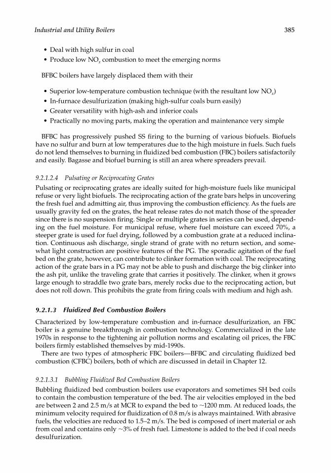
Industrial and Utility Boilers 385
Deal with high sulfur in coalProduce low NOx combustion to meet the emerging norms
BFBC boilers have largely displaced them with their
Superior low-temperature combustion technique (with the resultant low NOx)In-furnace desulfurization (making high-sulfur coals burn easily)Greater versatility with high-ash and inferior coalsPractically no moving parts, making the operation and maintenance very simple
BFBC has progressively pushed SS fi ring to the burning of various biofuels. Biofuels have no sulfur and burn at low temperatures due to the high moisture in fuels. Such fuels do not lend themselves to burning in fl uidized bed combustion (FBC) boilers satisfactorily and easily. Bagasse and biofuel burning is still an area where spreaders prevail.
9.2.1.2.4 Pulsating or Reciprocating Grates
Pulsating or reciprocating grates are ideally suited for high-moisture fuels like municipal refuse or very light biofuels. The reciprocating action of the grate bars helps in uncovering the fresh fuel and admitting air, thus improving the combustion effi ciency. As the fuels are usually gravity fed on the grates, the heat release rates do not match those of the spreader since there is no suspension fi ring. Single or multiple grates in series can be used, depend-ing on the fuel moisture. For municipal refuse, where fuel moisture can exceed 70%, a steeper grate is used for fuel drying, followed by a combustion grate at a reduced inclina-tion. Continuous ash discharge, single strand of grate with no return section, and some-what light construction are positive features of the PG. The sporadic agitation of the fuel bed on the grate, however, can contribute to clinker formation with coal. The reciprocating action of the grate bars in a PG may not be able to push and discharge the big clinker into the ash pit, unlike the traveling grate that carries it positively. The clinker, when it grows large enough to straddle two grate bars, merely rocks due to the reciprocating action, but does not roll down. This prohibits the grate from fi ring coals with medium and high ash.
9.2.1.3 Fluidized Bed Combustion Boilers
Characterized by low-temperature combustion and in-furnace desulfurization, an FBC boiler is a genuine breakthrough in combustion technology. Commercialized in the late 1970s in response to the tightening air pollution norms and escalating oil prices, the FBC boilers fi rmly established themselves by mid-1990s.
There are two types of atmospheric FBC boilers—BFBC and circulating fl uidized bed combustion (CFBC) boilers, both of which are discussed in detail in Chapter 12.
9.2.1.3.1 Bubbling Fluidized Bed Combustion Boilers
Bubbling fl uidized bed combustion boilers use evaporators and sometimes SH bed coils to contain the combustion temperature of the bed. The air velocities employed in the bed are between 2 and 2.5 m/s at MCR to expand the bed to ∼1200 mm. At reduced loads, the minimum velocity required for fl uidization of 0.8 m/s is always maintained. With abrasive fuels, the velocities are reduced to 1.5–2 m/s. The bed is composed of inert material or ash from coal and contains only ∼3% of fresh fuel. Limestone is added to the bed if coal needs desulfurization.
••
••••
CRC_75365_Ch009.indd 385CRC_75365_Ch009.indd 385 1/30/2009 1:49:58 PM1/30/2009 1:49:58 PM
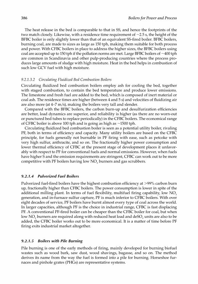
386 Boilers for Power and Process
The heat release in the bed is comparable to that in SS, and hence the footprints of the two match closely. Likewise, with a residence time requirement of ∼2.5 s, the height of the BFBC boiler is only slightly lower than that of an equivalent SS-fi red boiler. BFBC boilers, burning coal, are made to sizes as large as 150 tph, making them suitable for both process and power. With CFBC boilers in place to address the higher sizes, the BFBC boilers using coal are accepted up to 150 tph if the pollution norms are met. Large BFBC boilers of ∼400 tph are common in Scandinavia and other pulp-producing countries where the process pro-duces large amounts of sludge with high moisture. Heat in the bed helps in combustion of such low GCV fuel with high moisture.
9.2.1.3.2 Circulating Fluidized Bed Combustion Boilers
Circulating fl uidized bed combustion boilers employ ash for cooling the bed, together with staged combustion, to contain the bed temperature and produce lower emissions. The limestone and fresh fuel are added to the bed, which is composed of inert material or coal ash. The residence times are higher (between 4 and 5 s) and velocities of fl uidizing air are also more (at 4–7 m/s), making the boilers very tall and slender.
Compared with the BFBC boilers, the carbon burn-up and desulfurization effi ciencies are better, load dynamics are superior, and reliability is higher (as there are no worn-out or punctured bed tubes to replace periodically) in the CFBC boilers. The economical range of CFBC boiler is above 100 tph and is going as high as ∼1500 tph.
Circulating fl uidized bed combustion boiler is seen as a potential utility boiler, rivaling PF, both in terms of effi ciency and capacity. Many utility boilers are based on the CFBC principle, for fuels generally not burnable in PF fi ring with ease, such as petcoke with very high sulfur, anthracite, and so on. The fractionally higher power consumption and lower thermal effi ciency of CFBC at the present stage of development places it unfavor-ably with respect to PF for conventional fuels and normal emissions. However, when fuels have higher S and the emission requirements are stringent, CFBC can work out to be more competitive with PF boilers having low NOx burners and gas scrubbers.
9.2.1.4 Pulverized Fuel Boilers
Pulverized fuel-fi red boilers have the highest combustion effi ciency at >99% carbon burn up, fractionally higher than CFBC boilers. The power consumption is lower in spite of the additional milling plant. In terms of fuel fl exibility, multifuel fi ring capability, low NOx generation, and in-furnace sulfur capture, PF is much inferior to CFBC boilers. With over eight decades of service, PF boilers have burnt almost every type of coal across the world. In larger capacities, although PF is the choice in industrial range, CFBC is fast displacing PF. A conventional PF-fi red boiler can be cheaper than the CFBC boiler for coal, but when low NOx burners are required along with reduced heat load and deSOx units are also to be added, the CFBC boiler works out to be more economical. It is a matter of time before PF fi ring exits industrial market altogether.
9.2.1.5 Boilers with Pile Burning
Pile burning is one of the early methods of fi ring, mainly developed for burning biofuel wastes such as wood bark, saw dust, wood shavings, bagasse, and so on. The method derives its name from the way the fuel is formed into a pile for burning. Horseshoe fur-naces and pinhole grates (PHGs) are representative systems.
CRC_75365_Ch009.indd 386CRC_75365_Ch009.indd 386 1/30/2009 1:49:58 PM1/30/2009 1:49:58 PM
Industrial and Utility Boilers 387
9.2.1.5.1 Horseshoe Furnace (Thick Pile Burning)
Fuel is gravity fed and dropped on the fl oor of the furnace in a conical pile. Hot air is admit-ted at three to four levels through air tuyeres formed in the brick walls surrounding the pile at temperatures ranging from 150 to 300°C. No air should enter through the fl oor, as it would escape from the edges of the pile and not participate in combustion. Combustion takes place on the sides of the pile. Brick walls arranged in a semicircular manner around the pile and the arches at the top of the pile have a very important role of radiating the heat of combus-tion. The furnace above the arches provides space for combustion of volatile matter (VM).
A bagasse-fi red boiler would be fi tted with two, three, or four refractory cells to generate ∼20, 30, or 40 T of steam, respectively. Each cell usually burns ∼5 T of bagasse and during cleaning the remaining cells in service would generate ∼20% extra. Heat release rates as high as ∼0.4 kg/m2 s (∼300 lb/ft2 h ) of fl oor area for bagasse can be realized in these furnaces with cold air. Another 20% increase is possible with hot air. This combustion rate is approximately two to three times the combustion rate on grates with intensely high heat generation.
Pile burning used to be popular in rural environment or remote areas with limited operating skills and cheap fuel because
Burning is simple and demands simple operating skills.Burning is vigorous but quiescent with no carryover to cause erosion of pressure parts (PPs).Fuel sizing is not a concern. Sizes up to 100 mm long can be tolerated.Fuel with moisture as high as 60% can be effectively burnt.5:1 turndown is possible.Due to the large refractory and fuel inventory, temporary fuel interruptions do not affect the boiler.
Pile burning is almost obsolete because
Combustion is ineffi cient and cheap fuels are unavailable.Load control is gross and is only possible by the variation of air. Fuel variation is not particularly effective as there is a lot of green fuel in the pile and plenty of heat in the massive refractory.Clinker formation is a recurring problem due to the uncontrolled nature of combus-tion and the high rates. The presence of hot refractory only worsens the problem.Refractory maintenance and repair are serious issues requiring periodical shutdown of the boilers.Ash removal is manual and there is loss of generation and reduced effi ciency dur-ing deashing.
Figure 9.1 depicts a typical twin horseshoe furnace used for pile burning of bagasse. Figure 9.2 shows a furnace with water cooling. Pile burning combustors in the form of horseshoes are arranged below the conventional boilers.
9.2.1.5.2 Pinhole Grate (Thin Pile Burning)
The name is derived from the fi ne pinholes that grate castings are provided with for air distribution (Figure 9.3). Pinhole grates (Figure 9.4) are stationary grates bolted tightly to the grate castings to the furnace fl oor tubes. Fuel is spread on the top by pneumatic spreaders in a thin pile similar to SS, and air is admitted from bottom through the fi ne
••
••••
••
•
•
•
CRC_75365_Ch009.indd 387CRC_75365_Ch009.indd 387 1/30/2009 1:49:59 PM1/30/2009 1:49:59 PM
388 Boilers for Power and Process
FIGURE 9.1Horseshoe furnace with two cells. (From Babcock and Wilcox Company, U.S.A. With permission.)
Arch
Air
Fuel
Inlet
FIGURE 9.2Horseshoe with water-cooled furnace.
Water-cooledfurnace
Arches
Horseshoe furnace
Superheater
Burners
Fuel in
CRC_75365_Ch009.indd 388CRC_75365_Ch009.indd 388 1/30/2009 1:49:59 PM1/30/2009 1:49:59 PM
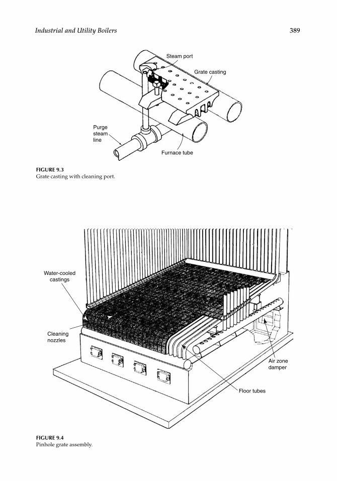
Industrial and Utility Boilers 389
FIGURE 9.3Grate casting with cleaning port.
Purgesteamline
Furnace tube
Grate casting
Steam port
FIGURE 9.4Pinhole grate assembly.
Water-cooled castings
Cleaningnozzles
Floor tubes
Air zonedamper
CRC_75365_Ch009.indd 389CRC_75365_Ch009.indd 389 1/30/2009 1:50:00 PM1/30/2009 1:50:00 PM
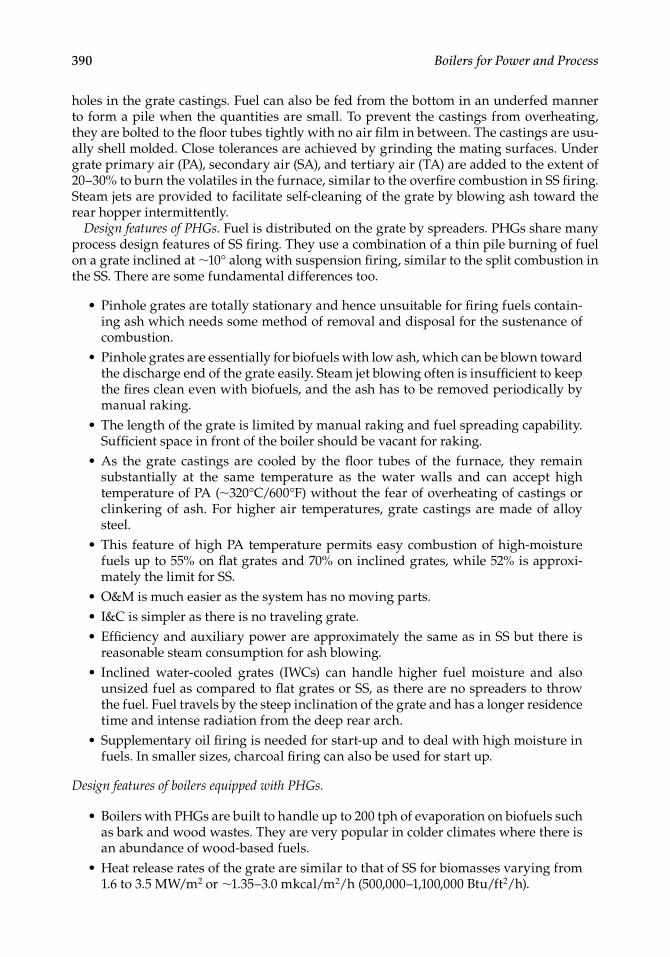
390 Boilers for Power and Process
holes in the grate castings. Fuel can also be fed from the bottom in an underfed manner to form a pile when the quantities are small. To prevent the castings from overheating, they are bolted to the fl oor tubes tightly with no air fi lm in between. The castings are usu-ally shell molded. Close tolerances are achieved by grinding the mating surfaces. Under grate primary air (PA), secondary air (SA), and tertiary air (TA) are added to the extent of 20–30% to burn the volatiles in the furnace, similar to the overfi re combustion in SS fi ring. Steam jets are provided to facilitate self-cleaning of the grate by blowing ash toward the rear hopper intermittently.
Design features of PHGs. Fuel is distributed on the grate by spreaders. PHGs share many process design features of SS fi ring. They use a combination of a thin pile burning of fuel on a grate inclined at ∼10° along with suspension fi ring, similar to the split combustion in the SS. There are some fundamental differences too.
Pinhole grates are totally stationary and hence unsuitable for fi ring fuels contain-ing ash which needs some method of removal and disposal for the sustenance of combustion.Pinhole grates are essentially for biofuels with low ash, which can be blown toward the discharge end of the grate easily. Steam jet blowing often is insuffi cient to keep the fi res clean even with biofuels, and the ash has to be removed periodically by manual raking.The length of the grate is limited by manual raking and fuel spreading capability. Suffi cient space in front of the boiler should be vacant for raking.As the grate castings are cooled by the fl oor tubes of the furnace, they remain substantially at the same temperature as the water walls and can accept high temperature of PA (∼320°C/600°F) without the fear of overheating of castings or clinkering of ash. For higher air temperatures, grate castings are made of alloy steel.This feature of high PA temperature permits easy combustion of high-moisture fuels up to 55% on fl at grates and 70% on inclined grates, while 52% is approxi-mately the limit for SS.O&M is much easier as the system has no moving parts.I&C is simpler as there is no traveling grate.Effi ciency and auxiliary power are approximately the same as in SS but there is reasonable steam consumption for ash blowing.Inclined water-cooled grates (IWCs) can handle higher fuel moisture and also unsized fuel as compared to fl at grates or SS, as there are no spreaders to throw the fuel. Fuel travels by the steep inclination of the grate and has a longer residence time and intense radiation from the deep rear arch.Supplementary oil fi ring is needed for start-up and to deal with high moisture in fuels. In smaller sizes, charcoal fi ring can also be used for start up.
Design features of boilers equipped with PHGs.
Boilers with PHGs are built to handle up to 200 tph of evaporation on biofuels such as bark and wood wastes. They are very popular in colder climates where there is an abundance of wood-based fuels.Heat release rates of the grate are similar to that of SS for biomasses varying from 1.6 to 3.5 MW/m2 or ∼1.35–3.0 mkcal/m2/h (500,000–1,100,000 Btu/ft2/h).
•
•
•
•
•
•••
•
•
•
•
CRC_75365_Ch009.indd 390CRC_75365_Ch009.indd 390 1/30/2009 1:50:01 PM1/30/2009 1:50:01 PM
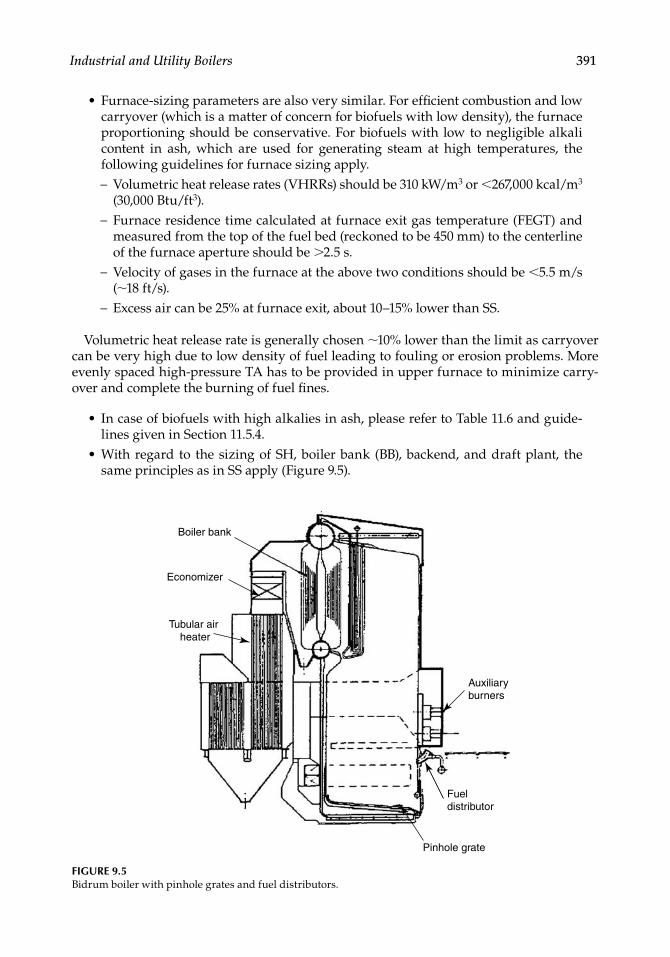
Industrial and Utility Boilers 391
Furnace-sizing parameters are also very similar. For effi cient combustion and low carryover (which is a matter of concern for biofuels with low density), the furnace proportioning should be conservative. For biofuels with low to negligible alkali content in ash, which are used for generating steam at high temperatures, the following guidelines for furnace sizing apply.
Volumetric heat release rates (VHRRs) should be 310 kW/m3 or <267,000 kcal/m3
(30,000 Btu/ft3).Furnace residence time calculated at furnace exit gas temperature (FEGT) and measured from the top of the fuel bed (reckoned to be 450 mm) to the centerline of the furnace aperture should be >2.5 s.Velocity of gases in the furnace at the above two conditions should be <5.5 m/s (∼18 ft/s).Excess air can be 25% at furnace exit, about 10–15% lower than SS.
Volumetric heat release rate is generally chosen ∼10% lower than the limit as carryover can be very high due to low density of fuel leading to fouling or erosion problems. More evenly spaced high-pressure TA has to be provided in upper furnace to minimize carry-over and complete the burning of fuel fi nes.
In case of biofuels with high alkalies in ash, please refer to Table 11.6 and guide-lines given in Section 11.5.4.With regard to the sizing of SH, boiler bank (BB), backend, and draft plant, the same principles as in SS apply (Figure 9.5).
•
−
−
−
−
•
•
FIGURE 9.5Bidrum boiler with pinhole grates and fuel distributors.
Economizer
Tubular air heater
Auxiliaryburners
Fueldistributor
Pinhole grate
Boiler bank
CRC_75365_Ch009.indd 391CRC_75365_Ch009.indd 391 1/30/2009 1:50:01 PM1/30/2009 1:50:01 PM
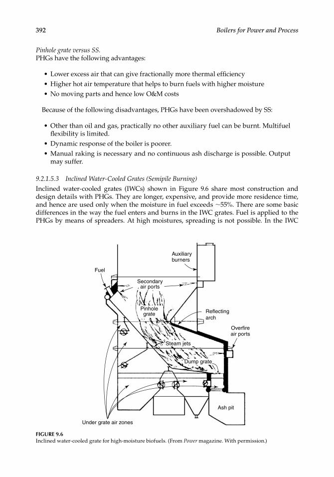
392 Boilers for Power and Process
Pinhole grate versus SS. PHGs have the following advantages:
Lower excess air that can give fractionally more thermal effi ciencyHigher hot air temperature that helps to burn fuels with higher moistureNo moving parts and hence low O&M costs
Because of the following disadvantages, PHGs have been overshadowed by SS:
Other than oil and gas, practically no other auxiliary fuel can be burnt. Multifuel fl exibility is limited.Dynamic response of the boiler is poorer.Manual raking is necessary and no continuous ash discharge is possible. Output may suffer.
9.2.1.5.3 Inclined Water-Cooled Grates (Semipile Burning)
Inclined water-cooled grates (IWCs) shown in Figure 9.6 share most construction and design details with PHGs. They are longer, expensive, and provide more residence time, and hence are used only when the moisture in fuel exceeds ∼55%. There are some basic differences in the way the fuel enters and burns in the IWC grates. Fuel is applied to the PHGs by means of spreaders. At high moistures, spreading is not possible. In the IWC
•••
•
••
Fuel
Secondaryair ports
Pinholegrate
Auxiliaryburners
Reflectingarch
Overfireair ports
Under grate air zones
Steam jets
Dump grate
Ash pit
FIGURE 9.6Inclined water-cooled grate for high-moisture biofuels. (From Power magazine. With permission.)
CRC_75365_Ch009.indd 392CRC_75365_Ch009.indd 392 1/30/2009 1:50:01 PM1/30/2009 1:50:01 PM
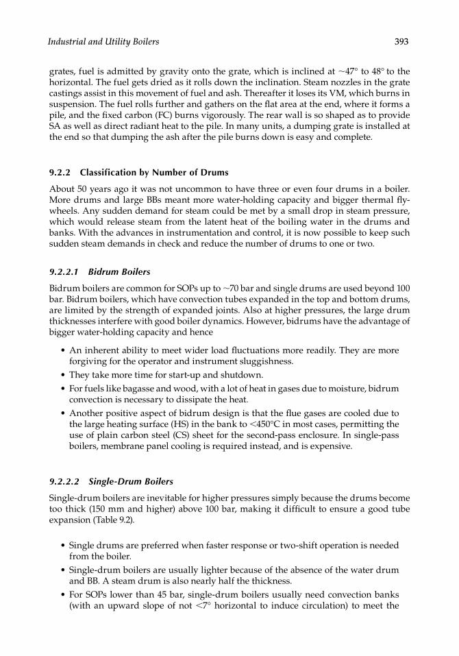
Industrial and Utility Boilers 393
grates, fuel is admitted by gravity onto the grate, which is inclined at ∼47° to 48° to the horizontal. The fuel gets dried as it rolls down the inclination. Steam nozzles in the grate castings assist in this movement of fuel and ash. Thereafter it loses its VM, which burns in suspension. The fuel rolls further and gathers on the fl at area at the end, where it forms a pile, and the fi xed carbon (FC) burns vigorously. The rear wall is so shaped as to provide SA as well as direct radiant heat to the pile. In many units, a dumping grate is installed at the end so that dumping the ash after the pile burns down is easy and complete.
9.2.2 Classification by Number of Drums
About 50 years ago it was not uncommon to have three or even four drums in a boiler. More drums and large BBs meant more water-holding capacity and bigger thermal fl y-wheels. Any sudden demand for steam could be met by a small drop in steam pressure, which would release steam from the latent heat of the boiling water in the drums and banks. With the advances in instrumentation and control, it is now possible to keep such sudden steam demands in check and reduce the number of drums to one or two.
9.2.2.1 Bidrum Boilers
Bidrum boilers are common for SOPs up to ∼70 bar and single drums are used beyond 100 bar. Bidrum boilers, which have convection tubes expanded in the top and bottom drums, are limited by the strength of expanded joints. Also at higher pressures, the large drum thicknesses interfere with good boiler dynamics. However, bidrums have the advantage of bigger water-holding capacity and hence
An inherent ability to meet wider load fl uctuations more readily. They are more forgiving for the operator and instrument sluggishness.They take more time for start-up and shutdown.For fuels like bagasse and wood, with a lot of heat in gases due to moisture, bidrum convection is necessary to dissipate the heat.Another positive aspect of bidrum design is that the fl ue gases are cooled due to the large heating surface (HS) in the bank to <450°C in most cases, permitting the use of plain carbon steel (CS) sheet for the second-pass enclosure. In single-pass boilers, membrane panel cooling is required instead, and is expensive.
9.2.2.2 Single-Drum Boilers
Single-drum boilers are inevitable for higher pressures simply because the drums become too thick (150 mm and higher) above 100 bar, making it diffi cult to ensure a good tube expansion (Table 9.2).
Single drums are preferred when faster response or two-shift operation is needed from the boiler.Single-drum boilers are usually lighter because of the absence of the water drum and BB. A steam drum is also nearly half the thickness.For SOPs lower than 45 bar, single-drum boilers usually need convection banks (with an upward slope of not <7° horizontal to induce circulation) to meet the
•
••
•
•
•
•
CRC_75365_Ch009.indd 393CRC_75365_Ch009.indd 393 1/30/2009 1:50:02 PM1/30/2009 1:50:02 PM
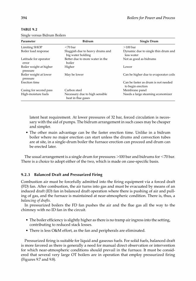
394 Boilers for Power and Process
TABLE 9.2
Single versus Bidrum Boilers
Parameter Bidrum Single Drum
Limiting SHOP <70 bar >100 barBoiler load response Sluggish due to heavy drums and
big water holdingDynamic due to single thin drum and less water
Latitude for operator error
Better due to more water in the boiler
Not as good as bidrums
Boiler weight at higher pressure
Higher Lower
Boiler weight at lower pressure
May be lower Can be higher due to evaporator coils
Erection time Can be faster as drum is not needed to begin erection
Casing for second pass Carbon steel Membrane panelHigh-moisture fuels Necessary due to high sensible
heat in fl ue gasesNeeds a large steaming economizer
latent heat requirement. At lower pressures of 32 bar, forced circulation is neces-sary with the aid of pumps. The bidrum arrangement in such cases may be cheaper and simpler.The other main advantage can be the faster erection time. Unlike in a bidrum boiler where no major erection can start unless the drums and convection tubes are at site, in a single-drum boiler the furnace erection can proceed and drum can be erected later.
The usual arrangement is a single drum for pressures >100 bar and bidrums for <70 bar. There is a choice to adopt either of the two, which is made on case-specifi c basis.
9.2.3 Balanced Draft and Pressurized Firing
Combustion air must be forcefully admitted into the fi ring equipment via a forced draft (FD) fan. After combustion, the air turns into gas and must be evacuated by means of an induced draft (ID) fan in balanced draft operation where there is pushing of air and pull-ing of gas, and the furnace is maintained at near-atmospheric condition. There is, thus, a balancing of drafts.
In pressurized boilers the FD fan pushes the air and the fl ue gas all the way to the chimney with no ID fan in the circuit.
The boiler effi ciency is slightly higher as there is no tramp air ingress into the setting, contributing to reduced stack losses.There is less O&M effort, as the fan and peripherals are eliminated.
Pressurized fi ring is suitable for liquid and gaseous fuels. For solid fuels, balanced draft is more favored as there is generally a need for manual direct observation or intervention for which near-atmospheric conditions should prevail in the furnace. It must be consid-ered that several very large OT boilers are in operation that employ pressurized fi ring (Figures 9.7 and 9.8).
•
•
•
CRC_75365_Ch009.indd 394CRC_75365_Ch009.indd 394 1/30/2009 1:50:02 PM1/30/2009 1:50:02 PM
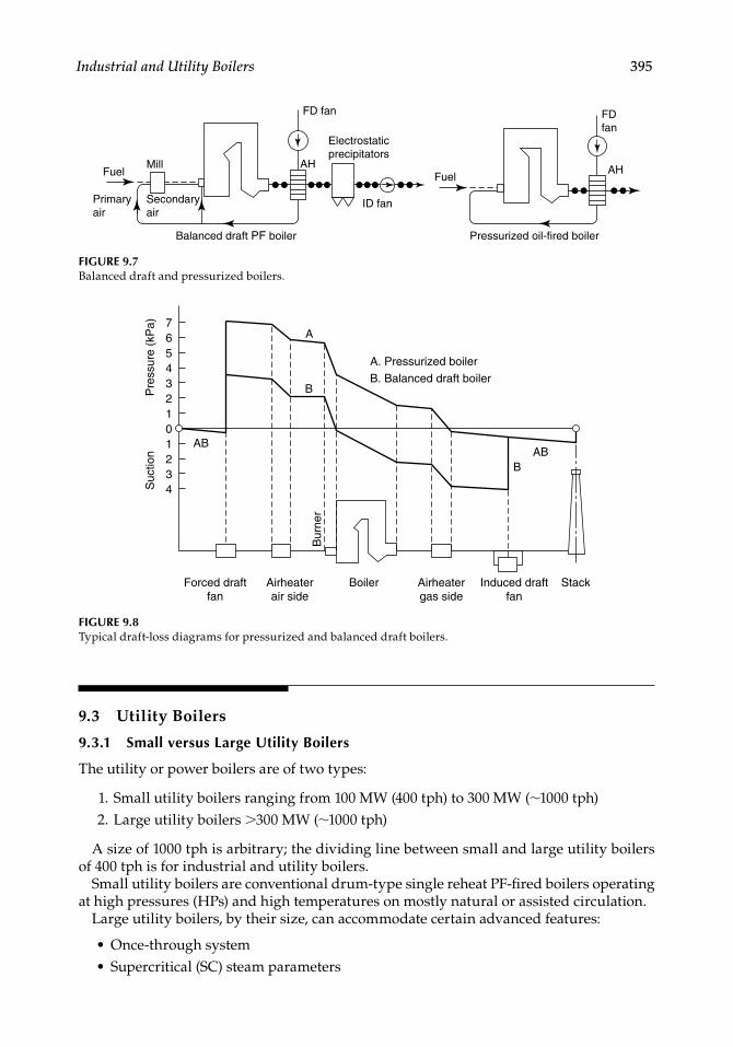
Industrial and Utility Boilers 395
9.3 Utility Boilers
9.3.1 Small versus Large Utility Boilers
The utility or power boilers are of two types:
1. Small utility boilers ranging from 100 MW (400 tph) to 300 MW (∼1000 tph) 2. Large utility boilers >300 MW (∼1000 tph)
A size of 1000 tph is arbitrary; the dividing line between small and large utility boilers of 400 tph is for industrial and utility boilers.
Small utility boilers are conventional drum-type single reheat PF-fi red boilers operating at high pressures (HPs) and high temperatures on mostly natural or assisted circulation.
Large utility boilers, by their size, can accommodate certain advanced features:
Once-through systemSupercritical (SC) steam parameters
••
Balanced draft PF boiler
Primaryair
Secondaryair
AH
Electrostaticprecipitators
FD fan FD fan
ID fan
MillFuel
Pressurized oil-fired boiler
AHFuel
FIGURE 9.7Balanced draft and pressurized boilers.
FIGURE 9.8Typical draft-loss diagrams for pressurized and balanced draft boilers.
Forced draftfan
Boiler
A. Pressurized boiler
B. Balanced draft boiler
Bur
ner
StackAirheaterair side
Airheatergas side
Induced draftfan
Suc
tion
Pre
ssur
e (k
Pa)
ABAB
A
B
B
7654321
1234
0
CRC_75365_Ch009.indd 395CRC_75365_Ch009.indd 395 1/30/2009 1:50:02 PM1/30/2009 1:50:02 PM
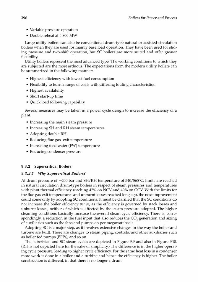
396 Boilers for Power and Process
Variable pressure operationDouble reheat at >800 MW
Large utility boilers can also be conventional drum-type natural or assisted- circulation boilers when they are used for mainly base load operation. They have been used for slid-ing pressure and two-shift operation, but SC boilers are more suited and offer greater fl exibility.
Utility boilers represent the most advanced type. The working conditions to which they are subjected are the most arduous. The expectations from the modern utility boilers can be summarized in the following manner:
Highest effi ciency with lowest fuel consumptionFlexibility to burn a range of coals with differing fouling characteristicsHighest availabilityShort start-up timeQuick load following capability
Several measures may be taken in a power cycle design to increase the effi ciency of a plant.
Increasing the main steam pressureIncreasing SH and RH steam temperaturesAdopting double RHReducing fl ue gas–exit temperatureIncreasing feed water (FW) temperatureReducing condenser pressure
9.3.2 Supercritical Boilers
9.3.2.1 Why Supercritical Boilers?
At drum pressure of ∼200 bar and SH/RH temperature of 540/565°C, limits are reached in natural circulation drum-type boilers in respect of steam pressures and temperatures with plant thermal effi ciency reaching 42% on NCV and 40% on GCV. With the limits for the fl ue gas exit temperatures and unburnt losses reached long ago, the next improvement could come only by adopting SC conditions. It must be clarifi ed that the SC conditions do not increase the boiler effi ciency per se, as the effi ciency is governed by stack losses and unburnt losses, neither of which is affected by the steam pressure adopted. The higher steaming conditions basically increase the overall steam cycle effi ciency. There is, corre-spondingly, a reduction in the fuel input that also reduces the CO2 generation and sizing of auxiliaries such as the fans and pumps on per megawatt basis.
Adopting SC is a major step, as it involves extensive changes in the way the boiler and turbine are built. There are changes to steam piping, controls, and other auxiliaries such as boiler fed pumps (BFPs), and so on.
The subcritical and SC steam cycles are depicted in Figure 9.9 and also in Figure 9.10. (RH is not depicted here for the sake of simplicity.) The difference is in the higher operat-ing cycle pressure, leading to higher cycle effi ciency. For the same heat loss in a condenser more work is done in a boiler and a turbine and hence the effi ciency is higher. The boiler construction is different, in that there is no longer a drum.
••
•••••
••••••
CRC_75365_Ch009.indd 396CRC_75365_Ch009.indd 396 1/30/2009 1:50:03 PM1/30/2009 1:50:03 PM
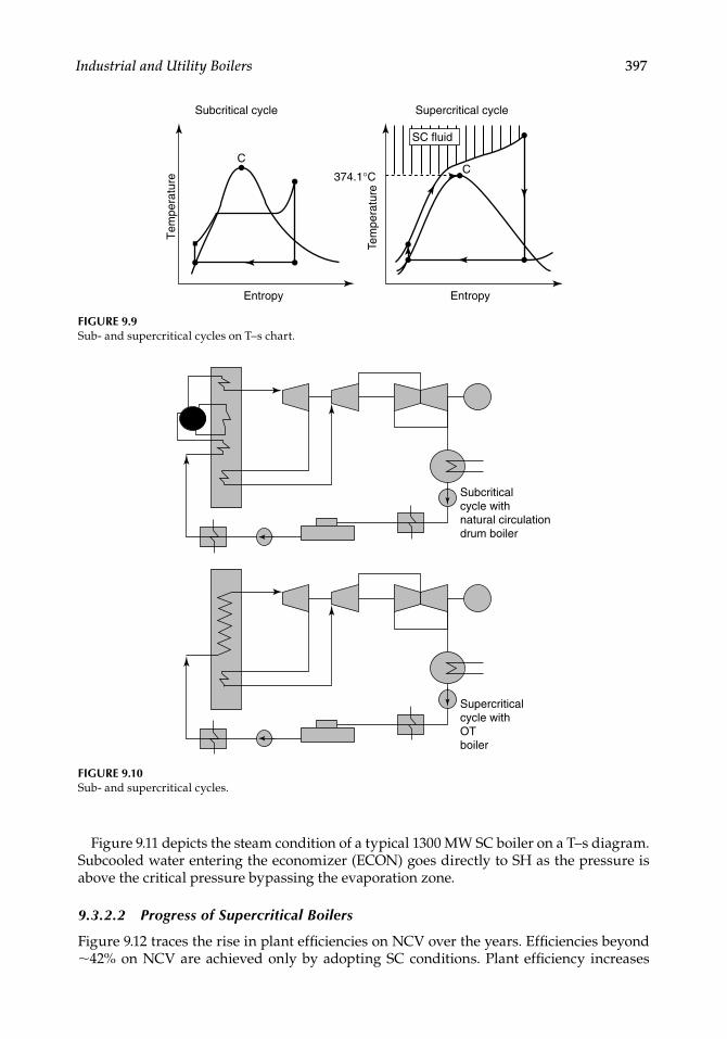
Industrial and Utility Boilers 397
Figure 9.11 depicts the steam condition of a typical 1300 MW SC boiler on a T–s diagram. Subcooled water entering the economizer (ECON) goes directly to SH as the pressure is above the critical pressure bypassing the evaporation zone.
9.3.2.2 Progress of Supercritical Boilers
Figure 9.12 traces the rise in plant effi ciencies on NCV over the years. Effi ciencies beyond ∼42% on NCV are achieved only by adopting SC conditions. Plant effi ciency increases
Subcritical cycle
374.1°C
Entropy
CT
empe
ratu
re
Supercritical cycle
Entropy
C
Tem
pera
ture
SC fluid
FIGURE 9.9Sub- and supercritical cycles on T–s chart.
Supercriticalcycle withOTboiler
Subcriticalcycle withnatural circulationdrum boiler
FIGURE 9.10Sub- and supercritical cycles.
CRC_75365_Ch009.indd 397CRC_75365_Ch009.indd 397 1/30/2009 1:50:03 PM1/30/2009 1:50:03 PM
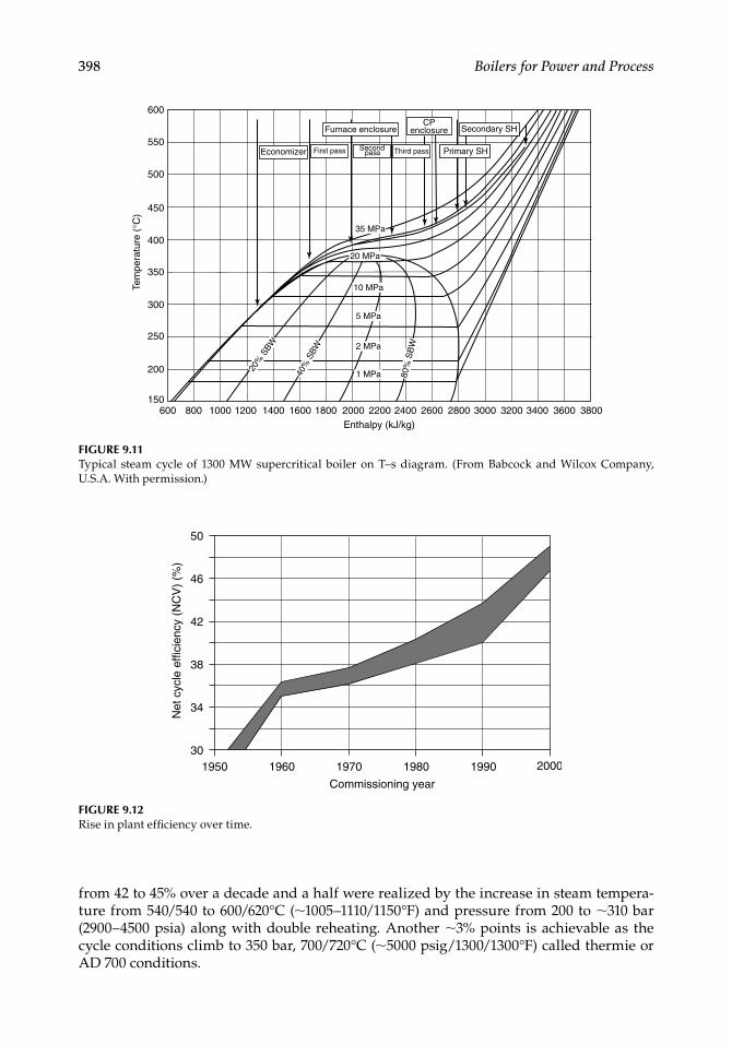
398 Boilers for Power and Process
from 42 to 45% over a decade and a half were realized by the increase in steam tempera-ture from 540/540 to 600/620°C (∼1005–1110/1150°F) and pressure from 200 to ∼310 bar (2900–4500 psia) along with double reheating. Another ∼3% points is achievable as the cycle conditions climb to 350 bar, 700/720°C (∼5000 psig/1300/1300°F) called thermie or AD 700 conditions.
600150
200
250
300
350
400
Tem
pera
ture
(°C
)
450
500
550
600
800 1000 1200 1400 1600 1800 2000 2200 2400Enthalpy (kJ/kg)
2600 2800 3000 3200 3400 3600 3800
Economizer First pass Second Third pass
CPenclosure
Primary SH
20 MPa
35 MPa
10 MPa
5 MPa
2 MPa
1 MPa
20%
SBW
40%
SBW
80%
SB
W
Secondary SHFurnace enclosure
pass
FIGURE 9.11Typical steam cycle of 1300 MW supercritical boiler on T–s diagram. (From Babcock and Wilcox Company, U.S.A. With permission.)
50
46
42
38
34
30200019901980197019601950
Commissioning year
Net
cyc
le e
ffici
ency
(N
CV
) (%
)
FIGURE 9.12Rise in plant effi ciency over time.
CRC_75365_Ch009.indd 398CRC_75365_Ch009.indd 398 1/30/2009 1:50:03 PM1/30/2009 1:50:03 PM
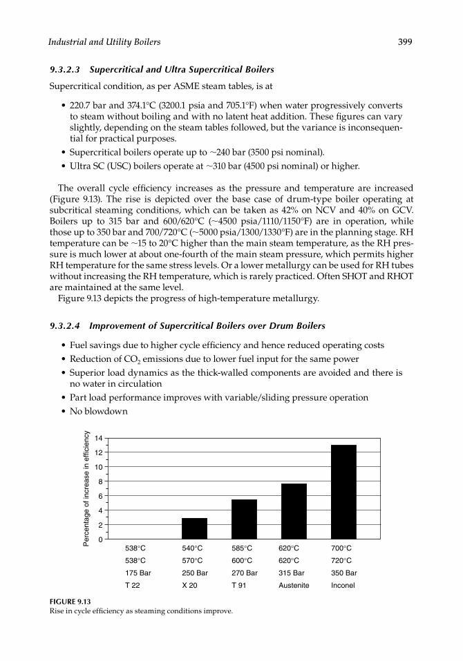
Industrial and Utility Boilers 399
9.3.2.3 Supercritical and Ultra Supercritical Boilers
Supercritical condition, as per ASME steam tables, is at
220.7 bar and 374.1°C (3200.1 psia and 705.1°F) when water progressively converts to steam without boiling and with no latent heat addition. These fi gures can vary slightly, depending on the steam tables followed, but the variance is inconsequen-tial for practical purposes. Supercritical boilers operate up to ∼240 bar (3500 psi nominal).Ultra SC (USC) boilers operate at ∼310 bar (4500 psi nominal) or higher.
The overall cycle effi ciency increases as the pressure and temperature are increased (Figure 9.13). The rise is depicted over the base case of drum-type boiler operating at subcritical steaming conditions, which can be taken as 42% on NCV and 40% on GCV. Boilers up to 315 bar and 600/620°C (∼4500 psia/1110/1150°F) are in operation, while those up to 350 bar and 700/720°C (∼5000 psia/1300/1330°F) are in the planning stage. RH temperature can be ∼15 to 20°C higher than the main steam temperature, as the RH pres-sure is much lower at about one-fourth of the main steam pressure, which permits higher RH temperature for the same stress levels. Or a lower metallurgy can be used for RH tubes without increasing the RH temperature, which is rarely practiced. Often SHOT and RHOT are maintained at the same level.
Figure 9.13 depicts the progress of high-temperature metallurgy.
9.3.2.4 Improvement of Supercritical Boilers over Drum Boilers
Fuel savings due to higher cycle effi ciency and hence reduced operating costsReduction of CO2 emissions due to lower fuel input for the same powerSuperior load dynamics as the thick-walled components are avoided and there is no water in circulationPart load performance improves with variable/sliding pressure operationNo blowdown
•
••
•••
••
14
12
8
4
0620°C
620°C
315 Bar
Austenite
700°C
720°C
350 Bar
Inconel
585°C
600°C
270 Bar
T 91
540°C
570°C
250 Bar
X 20
538°C
538°C
175 Bar
T 22
Per
cent
age
of in
crea
se in
effi
cien
cy
2
6
10
FIGURE 9.13Rise in cycle effi ciency as steaming conditions improve.
CRC_75365_Ch009.indd 399CRC_75365_Ch009.indd 399 1/30/2009 1:50:04 PM1/30/2009 1:50:04 PM
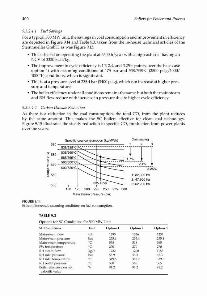
400 Boilers for Power and Process
9.3.2.4.1 Fuel Savings
For a typical 500 MW unit, the savings in coal consumption and improvement in effi ciency are depicted in Figure 9.14 and Table 9.3, taken from the in-house technical articles of the Steinmueller GmbH, as was Figure 9.13.
This is based on operating the plant at 6500 h/year with a high-ash coal having an NCV of 3330 kcal/kg.The improvement in cycle effi ciency is 1.7, 2.4, and 3.25% points, over the base case (option 1) with steaming conditions of 175 bar and 538/538°C (2500 psig/1000/1000°F) conditions, which is signifi cant.This is at a pressure level of 235.4 bar (3400 psig), which can increase at higher pres-sure and temperature.The boiler effi ciency under all conditions remains the same, but both the main steam and RH fl ow reduce with increase in pressure due to higher cycle effi ciency.
9.3.2.4.2 Carbon Dioxide Reduction
As there is a reduction in the coal consumption, the total CO2 from the plant reduces by the same amount. This makes the SC boilers effective for clean coal technology. Figure 9.15 illustrates the steady reduction in specifi c CO2 production from power plants over the years.
•
•
•
•
590
580
538/538°C
538/565°C
565/565°C 580/600°C
600/620°C 570
560
550150 175 200 225 250
Main steam pressure (bar)
Specific coal consumption (kg/MWh) Coal saving
1
1.7%
2.4%3.25%
1: 32,300 t/a2: 47,900 t/a3: 62,200 t/a
2 3
275 300
235.4 bar
Tem
pera
ture
(°C
)
FIGURE 9.14Effect of increased steaming conditions on fuel consumption.
TABLE 9.3
Options for SC Conditions for 500 MW Unit
SC Conditions Unit Option 1 Option 2 Option 3
Main-steam fl ow tph 1395 1356 1332Main-steam pressure bar 235.4 235.4 235.4Main-steam temperature °C 538 538 565FW temperature °C 270 270 270RH steam fl ow kg/s 1232 1200 1183RH inlet pressure bar 55.9 55.3 55.3RH inlet temperature °C 319.6 318.2 339.5RH outlet pressure °C 538 565 565Boiler effi ciency on net calorifi c value
% 91.2 91.2 91.2
CRC_75365_Ch009.indd 400CRC_75365_Ch009.indd 400 1/30/2009 1:50:04 PM1/30/2009 1:50:04 PM
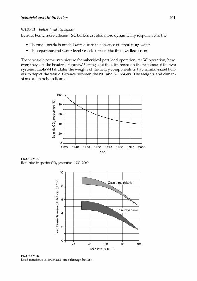
Industrial and Utility Boilers 401
9.3.2.4.3 Better Load Dynamics
Besides being more effi cient, SC boilers are also more dynamically responsive as the
Thermal inertia is much lower due to the absence of circulating water.The separator and water level vessels replace the thick-walled drum.
These vessels come into picture for subcritical part load operation. At SC operation, how-ever, they act like headers. Figure 9.16 brings out the differences in the response of the two systems. Table 9.4 tabulates the weights of the heavy components in two similar-sized boil-ers to depict the vast difference between the NC and SC boilers. The weights and dimen-sions are merely indicative.
••
FIGURE 9.15Reduction in specifi c CO2 generation, 1930–2000.
2000
100
80
60
40
20
01990198019701960195019401930
Year
Spe
cific
CO
2 pr
oduc
tion
(%)
10
8
6
4
2
020 40 60
Load rate (% MCR)
Load
tran
sien
ts r
efer
red
to fu
ll lo
ad (
%/m
in)
80 100
Drum-type boiler
Once-through boiler
FIGURE 9.16Load transients in drum and once-through boilers.
CRC_75365_Ch009.indd 401CRC_75365_Ch009.indd 401 1/30/2009 1:50:04 PM1/30/2009 1:50:04 PM
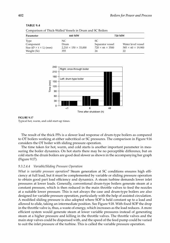
402 Boilers for Power and Process
The result of the thick PPs is a slower load response of drum-type boilers as compared to OT boilers working at either subcritical or SC pressures. The comparison in Figure 9.16 considers the OT boiler with sliding pressure operation.
The time taken for hot, warm, and cold starts is another important parameter in mea-suring the boiler dynamics. On hot starts there may be no perceptible difference, but on cold starts the drum boilers are good deal slower as shown in the accompanying bar graph (Figure 9.17).
9.3.2.4.4 Variable/Sliding Pressure Operation
What is variable pressure operation? Steam generation at SC conditions ensures high effi -ciency at full load, but it must be complemented by variable or sliding pressure operation to obtain good part load effi ciency and dynamics. A steam turbine demands lower inlet pressures at lower loads. Generally, conventional drum-type boilers generate steam at a constant pressure, which is then reduced in the main throttle valves to feed the nozzles at a suitable lower pressure. This is not always the case and drum-type boilers are also designed for variable pressure operation, particularly with the help of assisted circulation. A modifi ed sliding pressure is also adopted where SOP is held constant up to a load and allowed to elide, taking an intermediate position. See Figure 9.18. With fi xed SOP the drop in the throttle valve is, thus, a waste of energy, which increases as the load reduces. A more effi cient system would generate steam at lower variable pressures instead of generating steam at a higher pressure and killing in the throttle valves. The throttle valves and the main stop valves could be dispensed with, and the speed of the feed pump could be varied to suit the inlet pressure of the turbine. This is called the variable pressure operation.
TABLE 9.4
Comparison of Thick-Walled Vessels in Drum and SC Boilers
Parameter 660 MW 720 MW
Type NC SCComponent Drum Separator vessel Water level vesselSize (Ø × t × L) (mm) 2,210 × 150 × 33,000 720 × 66 × 3500 585 × 60 × 19,900Weight (Te) 355 24 22
Right: once-through boiler
Tim
e (m
in)
240
210
180
150
120
90
60
30
0<1 8
Time after shutdown (h)48
Left: drum-type boiler
FIGURE 9.17Typical hot, warm, and cold start-up times.
CRC_75365_Ch009.indd 402CRC_75365_Ch009.indd 402 1/30/2009 1:50:05 PM1/30/2009 1:50:05 PM
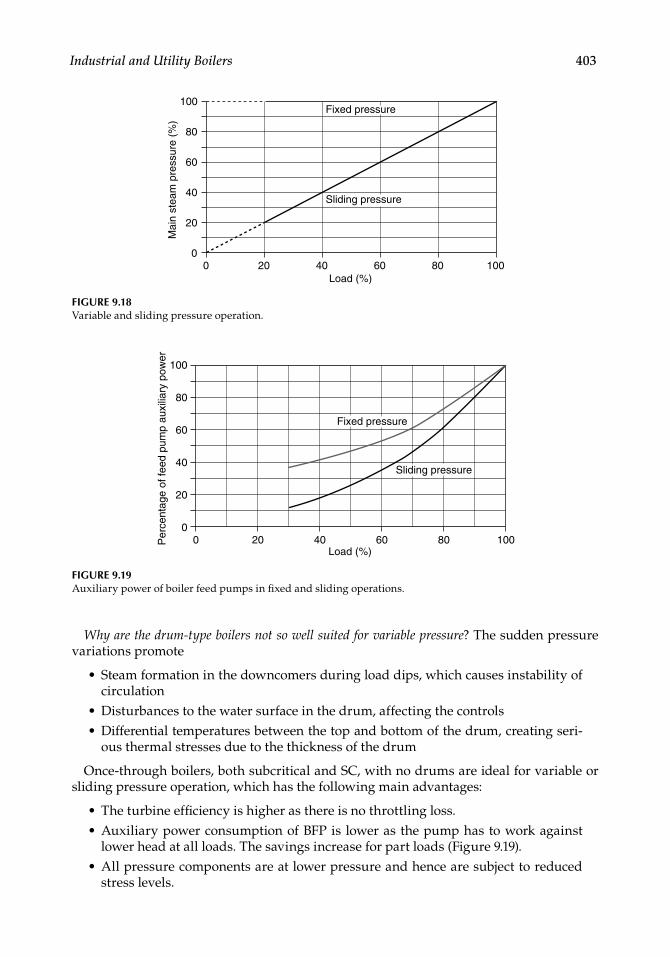
Industrial and Utility Boilers 403
Why are the drum-type boilers not so well suited for variable pressure? The sudden pressure variations promote
Steam formation in the downcomers during load dips, which causes instability of circulationDisturbances to the water surface in the drum, affecting the controlsDifferential temperatures between the top and bottom of the drum, creating seri-ous thermal stresses due to the thickness of the drum
Once-through boilers, both subcritical and SC, with no drums are ideal for variable or sliding pressure operation, which has the following main advantages:
The turbine effi ciency is higher as there is no throttling loss.Auxiliary power consumption of BFP is lower as the pump has to work against lower head at all loads. The savings increase for part loads (Figure 9.19).All pressure components are at lower pressure and hence are subject to reduced stress levels.
•
••
••
•
100
Fixed pressure
Sliding pressure
80
60
Per
cent
age
of fe
ed p
ump
auxi
liary
pow
er
40
20
00 20 40 60
Load (%)80 100
FIGURE 9.19Auxiliary power of boiler feed pumps in fi xed and sliding operations.
100Fixed pressure
Sliding pressure
80
60M
ain
stea
m p
ress
ure
(%)
40
20
00 20 40 60
Load (%)80 100
FIGURE 9.18Variable and sliding pressure operation.
CRC_75365_Ch009.indd 403CRC_75365_Ch009.indd 403 1/30/2009 1:50:05 PM1/30/2009 1:50:05 PM
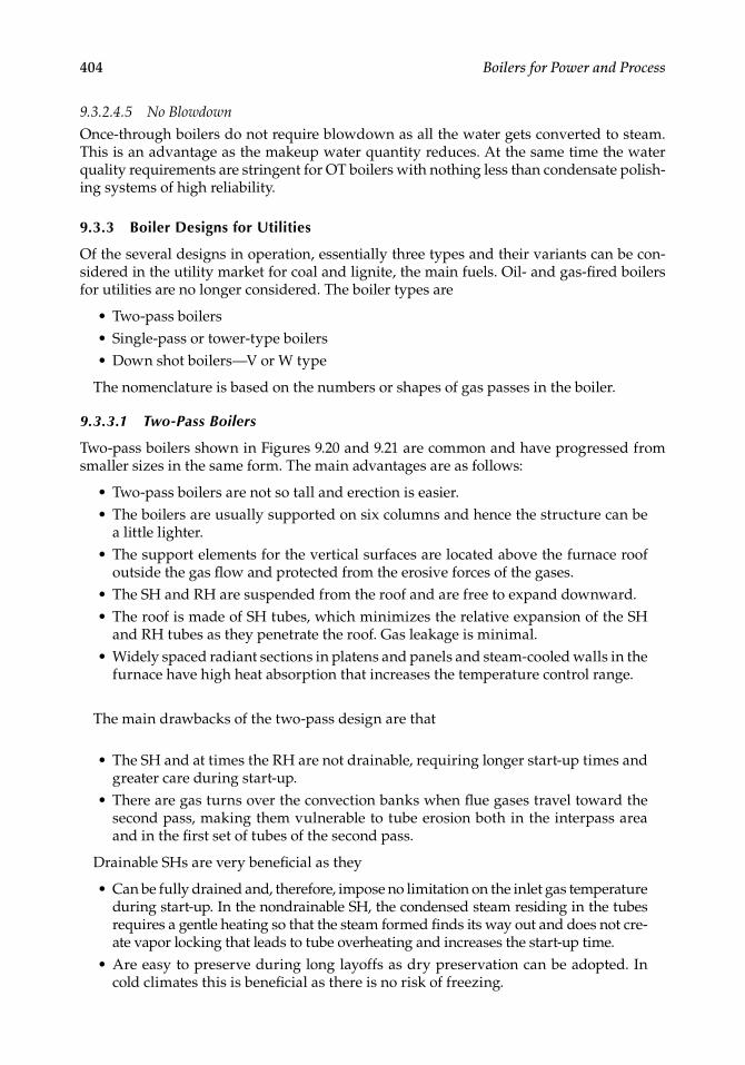
404 Boilers for Power and Process
9.3.2.4.5 No Blowdown
Once-through boilers do not require blowdown as all the water gets converted to steam. This is an advantage as the makeup water quantity reduces. At the same time the water quality requirements are stringent for OT boilers with nothing less than condensate polish-ing systems of high reliability.
9.3.3 Boiler Designs for Utilities
Of the several designs in operation, essentially three types and their variants can be con-sidered in the utility market for coal and lignite, the main fuels. Oil- and gas-fi red boilers for utilities are no longer considered. The boiler types are
Two-pass boilersSingle-pass or tower-type boilersDown shot boilers—V or W type
The nomenclature is based on the numbers or shapes of gas passes in the boiler.
9.3.3.1 Two-Pass Boilers
Two-pass boilers shown in Figures 9.20 and 9.21 are common and have progressed from smaller sizes in the same form. The main advantages are as follows:
Two-pass boilers are not so tall and erection is easier.The boilers are usually supported on six columns and hence the structure can be a little lighter.The support elements for the vertical surfaces are located above the furnace roof outside the gas fl ow and protected from the erosive forces of the gases.The SH and RH are suspended from the roof and are free to expand downward.The roof is made of SH tubes, which minimizes the relative expansion of the SH and RH tubes as they penetrate the roof. Gas leakage is minimal.Widely spaced radiant sections in platens and panels and steam-cooled walls in the furnace have high heat absorption that increases the temperature control range.
The main drawbacks of the two-pass design are that
The SH and at times the RH are not drainable, requiring longer start-up times and greater care during start-up.There are gas turns over the convection banks when fl ue gases travel toward the second pass, making them vulnerable to tube erosion both in the interpass area and in the fi rst set of tubes of the second pass.
Drainable SHs are very benefi cial as they
Can be fully drained and, therefore, impose no limitation on the inlet gas temperature during start-up. In the nondrainable SH, the condensed steam residing in the tubes requires a gentle heating so that the steam formed fi nds its way out and does not cre-ate vapor locking that leads to tube overheating and increases the start-up time.Are easy to preserve during long layoffs as dry preservation can be adopted. In cold climates this is benefi cial as there is no risk of freezing.
•••
••
•
••
•
•
•
•
•
CRC_75365_Ch009.indd 404CRC_75365_Ch009.indd 404 1/30/2009 1:50:05 PM1/30/2009 1:50:05 PM
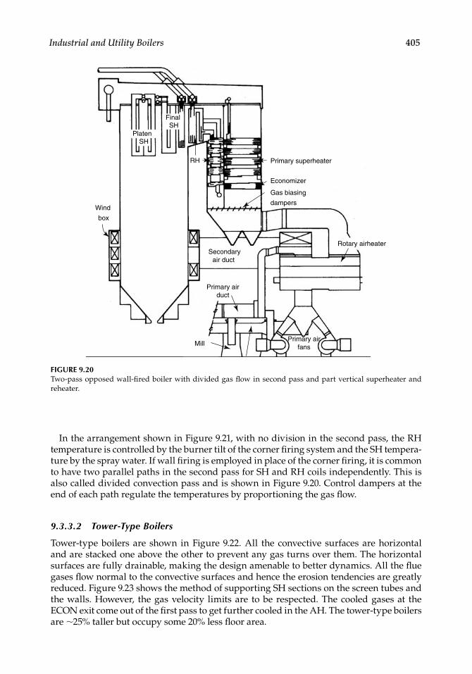
Industrial and Utility Boilers 405
In the arrangement shown in Figure 9.21, with no division in the second pass, the RH temperature is controlled by the burner tilt of the corner fi ring system and the SH tempera-ture by the spray water. If wall fi ring is employed in place of the corner fi ring, it is common to have two parallel paths in the second pass for SH and RH coils independently. This is also called divided convection pass and is shown in Figure 9.20. Control dampers at the end of each path regulate the temperatures by proportioning the gas fl ow.
9.3.3.2 Tower-Type Boilers
Tower-type boilers are shown in Figure 9.22. All the convective surfaces are horizontal and are stacked one above the other to prevent any gas turns over them. The horizontal surfaces are fully drainable, making the design amenable to better dynamics. All the fl ue gases fl ow normal to the convective surfaces and hence the erosion tendencies are greatly reduced. Figure 9.23 shows the method of supporting SH sections on the screen tubes and the walls. However, the gas velocity limits are to be respected. The cooled gases at the ECON exit come out of the fi rst pass to get further cooled in the AH. The tower-type boilers are ∼25% taller but occupy some 20% less fl oor area.
PlatenSH
FinalSH
RH Primary superheater
Economizer
Gas biasing
dampersWind
box
Secondaryair duct
Primary air duct
Mill
Rotary airheater
Primary airfans
FIGURE 9.20Two-pass opposed wall-fi red boiler with divided gas fl ow in second pass and part vertical superheater and reheater.
CRC_75365_Ch009.indd 405CRC_75365_Ch009.indd 405 1/30/2009 1:50:06 PM1/30/2009 1:50:06 PM
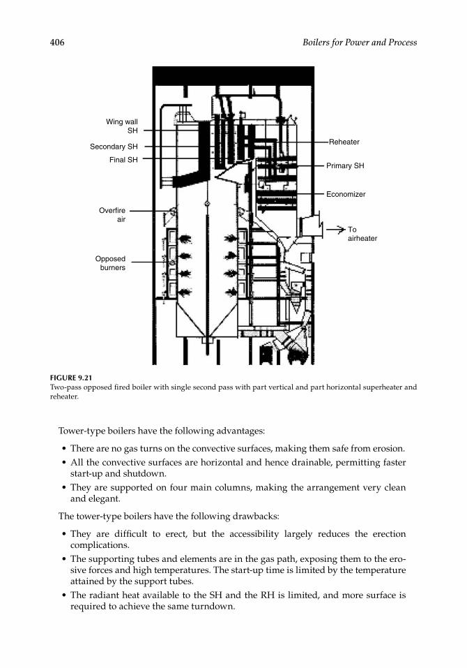
406 Boilers for Power and Process
Tower-type boilers have the following advantages:
There are no gas turns on the convective surfaces, making them safe from erosion.All the convective surfaces are horizontal and hence drainable, permitting faster start-up and shutdown.They are supported on four main columns, making the arrangement very clean and elegant.
The tower-type boilers have the following drawbacks:
They are diffi cult to erect, but the accessibility largely reduces the erection complications.The supporting tubes and elements are in the gas path, exposing them to the ero-sive forces and high temperatures. The start-up time is limited by the temperature attained by the support tubes.The radiant heat available to the SH and the RH is limited, and more surface is required to achieve the same turndown.
••
•
•
•
•
FIGURE 9.21Two-pass opposed fi red boiler with single second pass with part vertical and part horizontal superheater and reheater.
Reheater
Primary SH
Economizer
Opposedburners
Overfireair
Final SH
Secondary SH
Wing wallSH
Toairheater
CRC_75365_Ch009.indd 406CRC_75365_Ch009.indd 406 1/30/2009 1:50:06 PM1/30/2009 1:50:06 PM
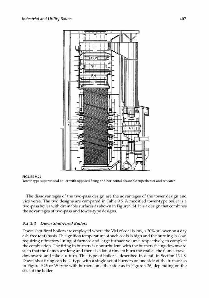
Industrial and Utility Boilers 407
The disadvantages of the two-pass design are the advantages of the tower design and vice versa. The two designs are compared in Table 9.5. A modifi ed tower-type boiler is a two-pass boiler with drainable surfaces as shown in Figure 9.24. It is a design that combines the advantages of two-pass and tower-type designs.
9.3.3.3 Down Shot-Fired Boilers
Down shot-fi red boilers are employed where the VM of coal is low, <20% or lower on a dry ash-free (daf) basis. The ignition temperature of such coals is high and the burning is slow, requiring refractory lining of furnace and large furnace volume, respectively, to complete the combustion. The fi ring in burners is nonturbulent, with the burners facing downward such that the fl ames are long and there is a lot of time to burn the coal as the fl ames travel downward and take a u-turn. This type of boiler is described in detail in Section 13.4.8. Down-shot fi ring can be U-type with a single set of burners on one side of the furnace as in Figure 9.25 or W-type with burners on either side as in Figure 9.26, depending on the size of the boiler.
ECON
SH
RH
SH
AH
FD
FIGURE 9.22Tower-type supercritical boiler with opposed fi ring and horizontal drainable superheater and reheater.
CRC_75365_Ch009.indd 407CRC_75365_Ch009.indd 407 1/30/2009 1:50:07 PM1/30/2009 1:50:07 PM
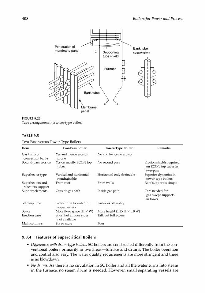
408 Boilers for Power and Process
TABLE 9.5
Two-Pass versus Tower-Type Boilers
Item Two-Pass Boiler Tower-Type Boiler Remarks
Gas turns on convection banks
Yes and hence erosion prone
No and hence no erosion
Second-pass erosion Yes on mostly ECON top tubes
No second pass Erosion shields required on ECON top tubes in two-pass
Superheater type Vertical and horizontal nondrainable
Horizontal only drainable Superior dynamics in tower-type boilers
Superheaters and reheaters support
From roof From walls Roof support is simple
Support elements Outside gas path Inside gas path Care needed for gas-swept supports in tower
Start-up time Slower due to water in superheaters
Faster as SH is dry
Space More fl oor space (H × W) More height (1.25 H × 0.8 W)Erection ease Short but all four sides
not availableTall, but full access
Main columns Six or more Four
Penetration ofmembrane panel
Bank tubesuspension
Furnace
Supportingtube shield
Bank tubes
Membranepanel
FIGURE 9.23Tube arrangement in a tower-type boiler.
9.3.4 Features of Supercritical Boilers
Differences with drum-type boilers. SC boilers are constructed differently from the con-ventional boilers primarily in two areas—furnace and drums. The boiler operation and control also vary. The water quality requirements are more stringent and there is no blowdown.No drums. As there is no circulation in SC boiler and all the water turns into steam in the furnace, no steam drum is needed. However, small separating vessels are
•
•
CRC_75365_Ch009.indd 408CRC_75365_Ch009.indd 408 1/30/2009 1:50:07 PM1/30/2009 1:50:07 PM
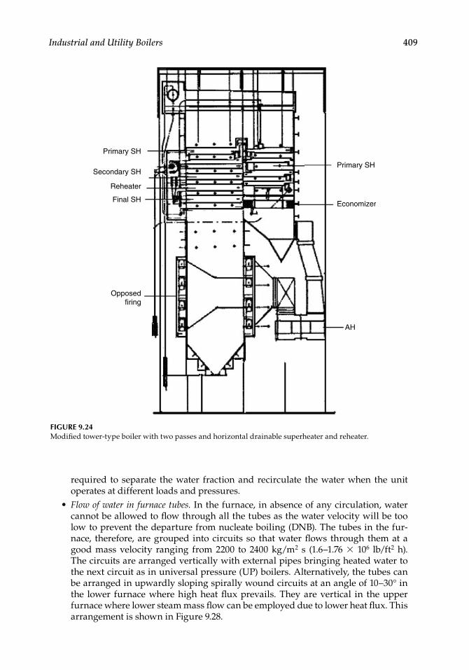
Industrial and Utility Boilers 409
required to separate the water fraction and recirculate the water when the unit operates at different loads and pressures.Flow of water in furnace tubes. In the furnace, in absence of any circulation, water cannot be allowed to fl ow through all the tubes as the water velocity will be too low to prevent the departure from nucleate boiling (DNB). The tubes in the fur-nace, therefore, are grouped into circuits so that water fl ows through them at a good mass velocity ranging from 2200 to 2400 kg/m2 s (1.6–1.76 × 10⁶ lb/ft2 h). The circuits are arranged vertically with external pipes bringing heated water to the next circuit as in universal pressure (UP) boilers. Alternatively, the tubes can be arranged in upwardly sloping spirally wound circuits at an angle of 10–30° in the lower furnace where high heat fl ux prevails. They are vertical in the upper furnace where lower steam mass fl ow can be employed due to lower heat fl ux. This arrangement is shown in Figure 9.28.
•
FIGURE 9.24Modifi ed tower-type boiler with two passes and horizontal drainable superheater and reheater.
Primary SH
Secondary SH
Reheater
Final SH
Opposedfiring
Primary SH
Economizer
AH
CRC_75365_Ch009.indd 409CRC_75365_Ch009.indd 409 1/30/2009 1:50:07 PM1/30/2009 1:50:07 PM
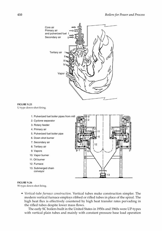
410 Boilers for Power and Process
Core airPrimary airand pulverized fuelSecondary air
Tertiary air
Vapor
lV
III
II
I
II
I
FIGURE 9.25U-type down-shot fi ring.
Vertical-tube furnace construction. Vertical tubes make construction simpler. The modern vertical furnace employs ribbed or rifl ed tubes in place of the spiral. The high heat fl ux is effectively countered by high heat transfer rates pervading in the rifl ed tubes despite lower mass fl ows.
The early SC boilers built in the United States in 1950s and 1960s were UP-types with vertical plain tubes and mainly with constant pressure base load operation
•
1. Pulverized fuel boiler pipes from mill
2. Cyclone separator
3. Rotary feeder
4. Primary air
5. Pulverized fuel boiler pipe
6. Down shot burner
7. Secondary air
8. Tertiary air
9. Vapors
10. Vapor burner
11. Oil burner
12. Furnace
13. Submerged chain conveyor
29
10
12
13
6
11
1
4
53
8 7
9
FIGURE 9.26W-type down-shot fi ring.
CRC_75365_Ch009.indd 410CRC_75365_Ch009.indd 410 1/30/2009 1:50:08 PM1/30/2009 1:50:08 PM
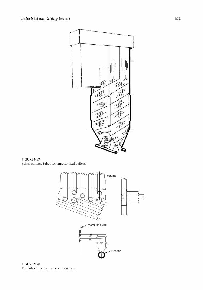
Industrial and Utility Boilers 411
FIGURE 9.27Spiral furnace tubes for supercritical boilers.
FIGURE 9.28Transition from spiral to vertical tube.
Forging
Membrane wall
Header
CRC_75365_Ch009.indd 411CRC_75365_Ch009.indd 411 1/30/2009 1:50:08 PM1/30/2009 1:50:08 PM
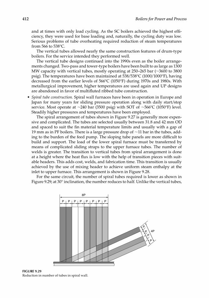
412 Boilers for Power and Process
and at times with only load cycling. As the SC boilers achieved the highest effi -ciency, they were used for base loading and, naturally, the cycling duty was low. Serious problems of tube overheating required reduction of steam temperatures from 566 to 538°C.
The vertical tubes allowed nearly the same construction features of drum-type boilers. For the service intended they performed well.
The vertical tube designs continued into the 1990s even as the boiler arrange-ments changed. Two-pass and tower-type boilers have been built to as large as 1300 MW capacity with vertical tubes, mostly operating at 250–265 bar (∼3600 to 3800 psig). The temperatures have been maintained at 538/538°C (1000/1000°F), having decreased from the earlier levels of 566°C (1050°F) during 1970s and 1980s. With metallurgical improvement, higher temperatures are used again and UP designs are abandoned in favor of multifl uted ribbed tube construction.Spiral tube construction. Spiral wall furnaces have been in operation in Europe and Japan for many years for sliding pressure operation along with daily start/stop service. Most operate at ∼240 bar (3500 psig) with SOT of ∼566°C (1050°F) level. Steadily higher pressures and temperatures have been employed.
The spiral arrangement of tubes shown in Figure 9.27 is generally more expen-sive and complicated. The tubes are selected usually between 31.8 and 42 mm OD and spaced to suit the fi n material temperature limits and usually with a gap of 19 mm as in PF boilers. There is a large pressure drop of ∼11 bar in the tubes, add-ing to the burden of the feed pump. The sloping tube panels are more diffi cult to build and support. The load of the lower spiral furnace must be transferred by means of complicated sliding straps to the upper furnace tubes. The number of welds is greater. The transition to vertical tubes from spiral arrangement is done at a height where the heat fl ux is low with the help of transition pieces with suit-able headers. This adds cost, welds, and fabrication time. This transition is usually achieved by the use of mixing header to achieve uniform steam enthalpy at the inlet to upper furnace. This arrangement is shown in Figure 9.28.
For the same circuit, the number of spiral tubes required is lower as shown in Figure 9.29; at 30° inclination, the number reduces to half. Unlike the vertical tubes,
•
8P
P P P P P P P P
P
4PP
P
P
FIGURE 9.29Reduction in number of tubes in spiral wall.
CRC_75365_Ch009.indd 412CRC_75365_Ch009.indd 412 1/30/2009 1:50:09 PM1/30/2009 1:50:09 PM
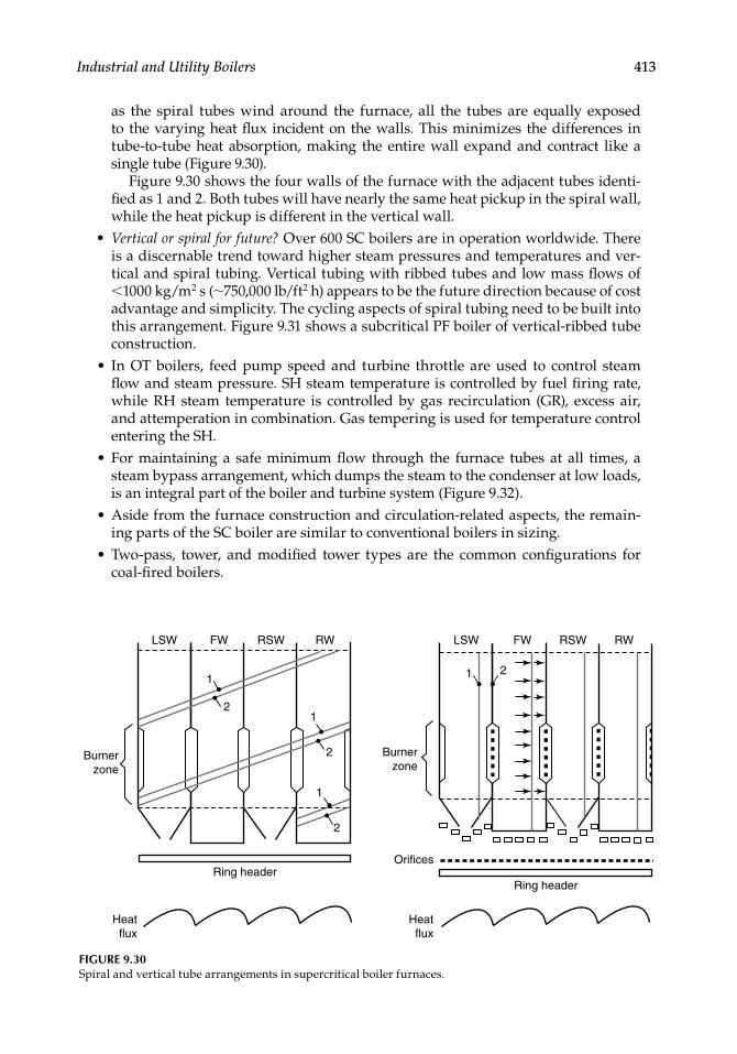
Industrial and Utility Boilers 413
LSW
Burnerzone
Burnerzone
Orifices
Ring headerRing header
Heatflux
Heatflux
FW
1
1
2
2
2
RSW RW LSW FW RSW RW
1
1
2
FIGURE 9.30Spiral and vertical tube arrangements in supercritical boiler furnaces.
as the spiral tubes wind around the furnace, all the tubes are equally exposed to the varying heat fl ux incident on the walls. This minimizes the differences in tube-to-tube heat absorption, making the entire wall expand and contract like a single tube (Figure 9.30).
Figure 9.30 shows the four walls of the furnace with the adjacent tubes identi-fi ed as 1 and 2. Both tubes will have nearly the same heat pickup in the spiral wall, while the heat pickup is different in the vertical wall.Vertical or spiral for future? Over 600 SC boilers are in operation worldwide. There is a discernable trend toward higher steam pressures and temperatures and ver-tical and spiral tubing. Vertical tubing with ribbed tubes and low mass fl ows of <1000 kg/m2 s (∼750,000 lb/ft2 h) appears to be the future direction because of cost advantage and simplicity. The cycling aspects of spiral tubing need to be built into this arrangement. Figure 9.31 shows a subcritical PF boiler of vertical-ribbed tube construction.In OT boilers, feed pump speed and turbine throttle are used to control steam fl ow and steam pressure. SH steam temperature is controlled by fuel fi ring rate, while RH steam temperature is controlled by gas recirculation (GR), excess air, and attemperation in combination. Gas tempering is used for temperature control entering the SH.For maintaining a safe minimum fl ow through the furnace tubes at all times, a steam bypass arrangement, which dumps the steam to the condenser at low loads, is an integral part of the boiler and turbine system (Figure 9.32).Aside from the furnace construction and circulation-related aspects, the remain-ing parts of the SC boiler are similar to conventional boilers in sizing.Two-pass, tower, and modifi ed tower types are the common confi gurations for coal-fi red boilers.
•
•
•
•
•
CRC_75365_Ch009.indd 413CRC_75365_Ch009.indd 413 1/30/2009 1:50:09 PM1/30/2009 1:50:09 PM
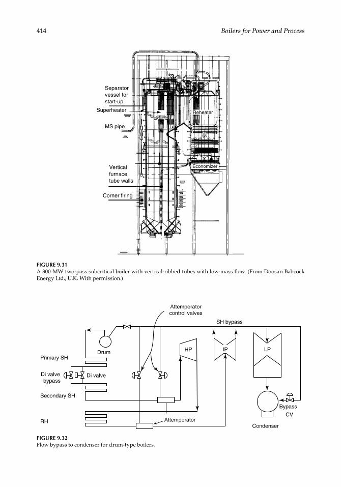
414 Boilers for Power and Process
Superheater
Verticalfurnacetube walls
Separatorvessel forstart-up
MS pipe
Corner firing
Economizer
Reheater
FIGURE 9.31A 300-MW two-pass subcritical boiler with vertical-ribbed tubes with low-mass fl ow. (From Doosan Babcock Energy Ltd., U.K. With permission.)
FIGURE 9.32Flow bypass to condenser for drum-type boilers.
Primary SHDrum
Attemperatorcontrol valves
SH bypass
Di valve
Attemperator
Bypass
CV
Condenser
Di valve bypass
Secondary SH
RH
LPIPHP
CRC_75365_Ch009.indd 414CRC_75365_Ch009.indd 414 1/30/2009 1:50:10 PM1/30/2009 1:50:10 PM
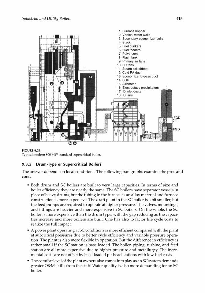
Industrial and Utility Boilers 415
1. Furnace hopper 2. Vertical water walls 3. Secondary economizer coils 4. Stack 5. Fuel bunkers 6. Fuel feeders 7. Pulverizers 8. Flash tank 9. Primary air fans10. FD fans11. Steam coil airheat12. Cold PA duct13. Economizer bypass duct14. SCR15. Airheater16. Electrostatic precipitators17. ID inlet ducts18. ID fans
5
2 3 13
14
1
8
6
7
12
10 9
11
16
17
18
4
ID fan
FGD
FGD15
FIGURE 9.33Typical modern 800 MW standard supercritical boiler.
9.3.5 Drum-Type or Supercritical Boiler?
The answer depends on local conditions. The following paragraphs examine the pros and cons:
Both drum and SC boilers are built to very large capacities. In terms of size and boiler effi ciency they are nearly the same. The SC boilers have separator vessels in place of heavy drums, but the tubing in the furnace is an alloy material and furnace construction is more expensive. The draft plant in the SC boiler is a bit smaller, but the feed pumps are required to operate at higher pressure. The valves, mountings, and fi ttings are heavier and more expensive in SC boilers. On the whole, the SC boiler is more expensive than the drum type, with the gap reducing as the capaci-ties increase and more boilers are built. One has also to factor life cycle costs to realize the full impact.A power plant operating at SC conditions is more effi cient compared with the plant at subcritical pressures due to better cycle effi ciency and variable pressure opera-tion. The plant is also more fl exible in operation. But the difference in effi ciency is rather small if the SC station is base loaded. The boiler, piping, turbine, and feed station are all more expensive due to higher pressure and metallurgy. The incre-mental costs are not offset by base-loaded pit-head stations with low fuel costs.The comfort level of the plant owners also comes into play as an SC system demands greater O&M skills from the staff. Water quality is also more demanding for an SC boiler.
•
•
•
CRC_75365_Ch009.indd 415CRC_75365_Ch009.indd 415 1/30/2009 1:50:10 PM1/30/2009 1:50:10 PM

416 Boilers for Power and Process
It is generally accepted that SC plants are viable beyond ∼300 MW, which means that the grid should also be large enough.
9.3.6 Standard Plant Configurations for Supercritical Boilers
To optimize the costs of SC plants, large power plant makers from Japan, South Korea, and recently China advocate standard plants in the sizes of 600, 800, and 1000 MW capacities. One such plant for 800 MW is shown in Figure 9.33.
Further Readings
Benson boilers for maximum cost effectiveness in power plants. Siemens Power Generation Group.Black and Veatch, 1996, Power Plant Engineering, Chapman & Hall, New York.Brundle, B. and Babcock, M., 2002, World fi rsts for Yaomeng with vertical-tube low-mass-fl ow,
Benson Unit, Modern Power Systems, July.Cosmann, R., Schwendig, F., and William, J., Steam Generators of the Single Pass Type, Steinmueller,
Germany.Franke, J. and Kral, R., 2003, Supercritical boiler technology for future market conditions, Parsons
Conference.Franke, J. et al., Steam generators for the next generation power plants—aspects of design and
performance, Siemens Power Generation Group.Goidich, S.J. and Bose, A.C., 2005, Design Aspects of Ultra Supercritical CFB Boilers, International
Pittsburgh Coal Conference, Pittsburgh, PA, Sept 12–15.Koreans set a standard for SC systems, Modern Power Systems, May 2002.Luby, P., 2003, Supercritical systems, Modern Power Systems, August.Lundqvist, L. et al., 2003, A Major Step Forward—The Supercritical CFB Boiler, Foster Wheeler Energia
Corporation, Powergen International.Mcdonald, D.K., 2001, Vertical tube, variable pressure furnace for supercritical steam boilers, B&W
Company and S.S.Kim, US DOE, Powergen International.Power from wood, a special report, Power, Feb 1980.Richardson, M. et al., Supercritical technology matures, Babcock Hitachi.Schwendig, F., 1996, Comparison between natural circulation and once-through steam generators,
L&C Steinmueller, Germany, January.Smith, J.W., 1998, Supercritical (once-through) boiler technology, B&W USA, May.Vishwanathan, R., Armor, A.F., and Booras, G., 2004, A critical look at SC power plants. EPRI, Power,
April.Vitalis, B.P., 2006, Constant and sliding pressure options for new supercritical plants, Riley Power
Inc, Power, Jan–Feb.
•
CRC_75365_Ch009.indd 416CRC_75365_Ch009.indd 416 1/30/2009 1:50:11 PM1/30/2009 1:50:11 PM
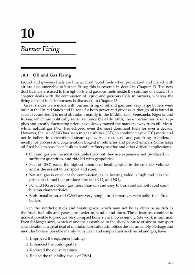
417
10Burner Firing
10.1 Oil and Gas Firing
Liquid and gaseous fuels are burner fi red. Solid fuels when pulverized and mixed with air are also amenable to burner fi ring; this is covered in detail in Chapter 13. The new duct burners are used to fi re light oils and gaseous fuels inside the confi nes of a duct. This chapter deals with the combustion of liquid and gaseous fuels in burners, whereas the fi ring of solid fuels in burners is discussed in Chapter 13.
Great strides were made with burner fi ring of oil and gas, and very large boilers were built in the United States and Europe for both power and process. Although oil is found in several countries, it is most abundant mainly in the Middle East, Venezuela, Nigeria, and Russia, which are politically sensitive. Since the early 1970s, the uncertainties of oil sup-plies and greatly fl uctuating prices have slowly moved the markets away from oil. Mean-while, natural gas (NG) has eclipsed even the most dominant fuels for over a decade. However, the use of NG has been in gas turbines (GTs) in combined cycle (CC) mode and not in boilers in conventional steam cycles. As a result, oil and gas fi ring in boilers is mostly for process and cogeneration (cogen) in refi neries and petrochemicals. Some large oil-fi red boilers have been built to handle refi nery residue and other diffi cult applications.
• Oil and gas are the most desirable fuels but they are expensive, not produced in suffi cient quantities, and riddled with geopolitics.Fuel oil (FO) packs the highest amount of heating value in the smallest volumeand is the easiest to transport and store.Natural gas is excellent for combustion, as its heating value is high and it is the prime fossil fuel that produces the least CO2 and NOx.FO and NG are clean (gas more than oil) and easy to burn and exhibit rapid com-bustion characteristics.
• Both installation and O&M are very simple in comparison with solid fuel–fi red boilers.
Even the synthetic fuels and waste gases, which may not be as clean or as rich asthe fossil-fuel oils and gases, are easier to handle and burn. These features combine to make it possible to produce very compact boilers via shop assembly. Site work is minimal. Even for larger sizes, which cannot be assembled in the shop, because of size or transport considerations, a great deal of modular fabrication simplifi es the site assembly. Package and modular boilers, possible mainly with clean and simple fuels such as oil and gas, have
1. Improved the equipment ratings 2. Enhanced the build quality 3. Reduced the delivery times 4. Raised the reliability levels of O&M
•
•
•
CRC_75365_Ch010.indd 417CRC_75365_Ch010.indd 417 1/30/2009 1:52:46 PM1/30/2009 1:52:46 PM
418 Boilers for Power and Process
Although FO- and NG-fi red boilers have shown growth, oil and gas fi ring is extensively employed in almost every type of boiler.
• Most solid fuels cannot start combustion on their own and need start-up support. Stoker PF, bubbling fl uidized bed combustion (BFBC) boilers, and circulating fl u-idized bed combustion (CFBC) boilers require oil or gas for ignition.All solid fuels have defi nite load turndown, and below the minimum load, the fi ring becomes unstable. Oil and gas fi ring is employed when such low loads are encountered.Pulverized fuel boilers have small turndowns of 1:2 or 1:3 at best. Also, with wet coals in monsoons at ∼50% load, they experience fl ame instability and oil or gas fi ring has to be pressed into service.With manufactured or waste fuels of limited availability, evaporation shortages and peak loads can only be met by oil and gas fi ring.With seasonal agrofuels, oil and gas are used during off-season unless some other agrofuel is available. Coal fi ring is not as economical.
• Supplementary fi ring is quite common to incorporate in gas-based cogen plants to get some additional evaporation or to generate full steam when the GT is down.
Burner fi ring also has good potential in fi ring a variety of waste liquid and gaseous fuels and forms the backbone of the waste heat boilers.
10.2 Burners and Combustion
10.2.1 Burner Size
Burner. A burner brings together the fuels and air in right proportions and admits them into the furnace chamber to accomplish combustion in an effi cient and safe manner. It mixes and burns the fuel but does not control it. The proportion and regulation are per-formed externally for fuel and air by control valves and dampers, respectively.
Burners consist of four subassemblies:
1. Atomizer for oil and spuds/pipes for gas—for proper fuel admission 2. Air register for dividing and supplying the air with a proper swirl to provide
adequate turbulence 3. Igniter for lighting the fuel 4. Flame monitor for checking the health of the fl ame
The shape and size of the furnace helps to develop the fl ame properly and achieve the completeness of combustion. Burner sizes have grown dramatically. Approximately 2 tph of oil fi ring per burner was considered maximum in 1960, which grew to ∼8 tph by the 1970s. There has been no signifi cant increase in burner capacities, but the efforts focused on environmental compliance.
Burner size is always designated by the diameter of its throat—the slightly narrowed channel in the air register through which all air is directed toward the combustion area of
•
•
•
•
CRC_75365_Ch010.indd 418CRC_75365_Ch010.indd 418 1/30/2009 1:52:47 PM1/30/2009 1:52:47 PM
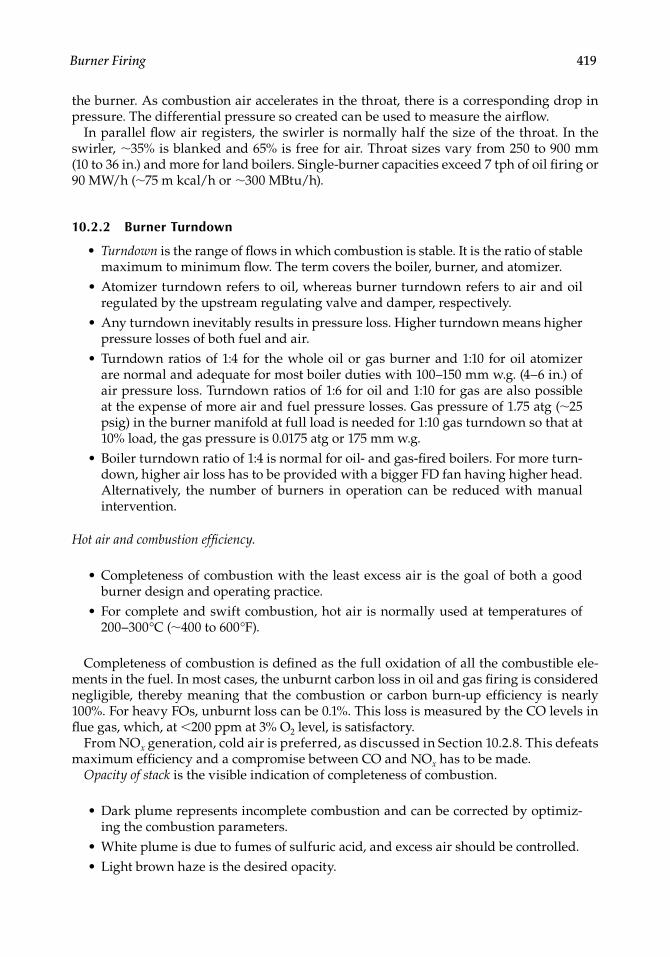
Burner Firing 419
the burner. As combustion air accelerates in the throat, there is a corresponding drop in pressure. The differential pressure so created can be used to measure the airfl ow.
In parallel fl ow air registers, the swirler is normally half the size of the throat. In the swirler, ∼35% is blanked and 65% is free for air. Throat sizes vary from 250 to 900 mm(10 to 36 in.) and more for land boilers. Single-burner capacities exceed 7 tph of oil fi ring or 90 MW/h (∼75 m kcal/h or ∼300 MBtu/h).
10.2.2 Burner Turndown
• Turndown is the range of fl ows in which combustion is stable. It is the ratio of stable maximum to minimum fl ow. The term covers the boiler, burner, and atomizer.Atomizer turndown refers to oil, whereas burner turndown refers to air and oil regulated by the upstream regulating valve and damper, respectively.Any turndown inevitably results in pressure loss. Higher turndown means higher pressure losses of both fuel and air.Turndown ratios of 1:4 for the whole oil or gas burner and 1:10 for oil atomizer are normal and adequate for most boiler duties with 100–150 mm w.g. (4–6 in.) of air pressure loss. Turndown ratios of 1:6 for oil and 1:10 for gas are also possibleat the expense of more air and fuel pressure losses. Gas pressure of 1.75 atg (∼25 psig) in the burner manifold at full load is needed for 1:10 gas turndown so that at 10% load, the gas pressure is 0.0175 atg or 175 mm w.g.
• Boiler turndown ratio of 1:4 is normal for oil- and gas-fi red boilers. For more turn-down, higher air loss has to be provided with a bigger FD fan having higher head. Alternatively, the number of burners in operation can be reduced with manual intervention.
Hot air and combustion effi ciency.
• Completeness of combustion with the least excess air is the goal of both a good burner design and operating practice.
• For complete and swift combustion, hot air is normally used at temperatures of 200–300°C (∼400 to 600°F).
Completeness of combustion is defi ned as the full oxidation of all the combustible ele-ments in the fuel. In most cases, the unburnt carbon loss in oil and gas fi ring is considered negligible, thereby meaning that the combustion or carbon burn-up effi ciency is nearly 100%. For heavy FOs, unburnt loss can be 0.1%. This loss is measured by the CO levels in fl ue gas, which, at <200 ppm at 3% O2 level, is satisfactory.
From NOx generation, cold air is preferred, as discussed in Section 10.2.8. This defeats maximum effi ciency and a compromise between CO and NOx has to be made.
Opacity of stack is the visible indication of completeness of combustion.
• Dark plume represents incomplete combustion and can be corrected by optimiz-ing the combustion parameters.White plume is due to fumes of sulfuric acid, and excess air should be controlled.
• Light brown haze is the desired opacity.
•
•
•
•
CRC_75365_Ch010.indd 419CRC_75365_Ch010.indd 419 1/30/2009 1:52:47 PM1/30/2009 1:52:47 PM
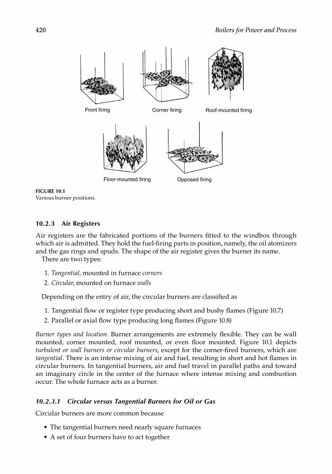
420 Boilers for Power and Process
10.2.3 Air Registers
Air registers are the fabricated portions of the burners fi tted to the windbox through which air is admitted. They hold the fuel-fi ring parts in position, namely, the oil atomizers and the gas rings and spuds. The shape of the air register gives the burner its name.
There are two types:
1. Tangential, mounted in furnace corners
2. Circular, mounted on furnace walls
Depending on the entry of air, the circular burners are classifi ed as
1. Tangential fl ow or register type producing short and bushy fl ames (Figure 10.7) 2. Parallel or axial fl ow type producing long fl ames (Figure 10.8)
Burner types and location. Burner arrangements are extremely fl exible. They can be wall mounted, corner mounted, roof mounted, or even fl oor mounted. Figure 10.1 depicts turbulent or wall burners or circular burners, except for the corner-fi red burners, which are tangential. There is an intense mixing of air and fuel, resulting in short and hot fl ames in circular burners. In tangential burners, air and fuel travel in parallel paths and toward an imaginary circle in the center of the furnace where intense mixing and combustion occur. The whole furnace acts as a burner.
10.2.3.1 Circular versus Tangential Burners for Oil or Gas
Circular burners are more common because
• The tangential burners need nearly square furnaces• A set of four burners have to act together
Front firing Corner firing Roof-mounted firing
Opposed firingFloor-mounted firing
FIGURE 10.1Various burner positions.
CRC_75365_Ch010.indd 420CRC_75365_Ch010.indd 420 1/30/2009 1:52:47 PM1/30/2009 1:52:47 PM
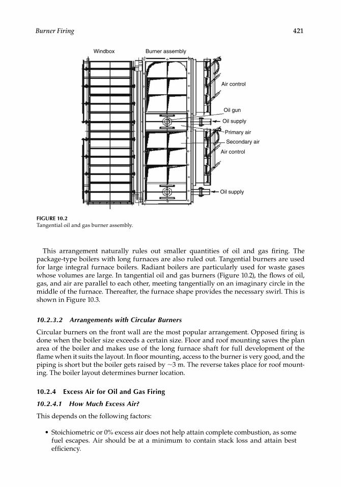
Burner Firing 421
This arrangement naturally rules out smaller quantities of oil and gas fi ring. The package-type boilers with long furnaces are also ruled out. Tangential burners are used for large integral furnace boilers. Radiant boilers are particularly used for waste gases whose volumes are large. In tangential oil and gas burners (Figure 10.2), the fl ows of oil, gas, and air are parallel to each other, meeting tangentially on an imaginary circle in the middle of the furnace. Thereafter, the furnace shape provides the necessary swirl. This is shown in Figure 10.3.
10.2.3.2 Arrangements with Circular Burners
Circular burners on the front wall are the most popular arrangement. Opposed fi ring is done when the boiler size exceeds a certain size. Floor and roof mounting saves the plan area of the boiler and makes use of the long furnace shaft for full development of the fl ame when it suits the layout. In fl oor mounting, access to the burner is very good, and the piping is short but the boiler gets raised by ∼3 m. The reverse takes place for roof mount-ing. The boiler layout determines burner location.
10.2.4 Excess Air for Oil and Gas Firing
10.2.4.1 How Much Excess Air?
This depends on the following factors:
• Stoichiometric or 0% excess air does not help attain complete combustion, as some fuel escapes. Air should be at a minimum to contain stack loss and attain best effi ciency.
Windbox Burner assembly
Air control
Oil gun
Oil supply
Primary air
Secondary air
Air control
Oil supply
FIGURE 10.2Tangential oil and gas burner assembly.
CRC_75365_Ch010.indd 421CRC_75365_Ch010.indd 421 1/30/2009 1:52:48 PM1/30/2009 1:52:48 PM
Related Documents