22.1 Chapter 22 Network Layer: Delivery, Forwarding, and Routing Copyright © The McGraw-Hill Companies, Inc. Permission required for reproduction or display.

22.1 Chapter 22 Network Layer: Delivery, Forwarding, and Routing Copyright © The McGraw-Hill Companies, Inc. Permission required for reproduction or display.
Dec 27, 2015
Welcome message from author
This document is posted to help you gain knowledge. Please leave a comment to let me know what you think about it! Share it to your friends and learn new things together.
Transcript

22.1
Chapter 22
Network Layer:Delivery, Forwarding,
and Routing
Copyright © The McGraw-Hill Companies, Inc. Permission required for reproduction or display.
22.2
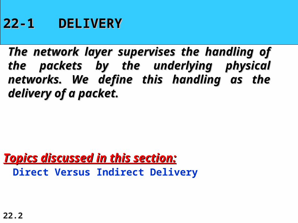
22-1 DELIVERY22-1 DELIVERY
The network layer supervises the handling of the The network layer supervises the handling of the packets by the underlying physical networks. We packets by the underlying physical networks. We define this handling as the delivery of a packet.define this handling as the delivery of a packet.
Direct Versus Indirect DeliveryTopics discussed in this section:Topics discussed in this section:

22.3
Figure 22.1 Direct and indirect delivery

22.4
22-2 FORWARDING22-2 FORWARDING
Forwarding means to place the packet in its route to Forwarding means to place the packet in its route to its destination. Forwarding requires a host or a router its destination. Forwarding requires a host or a router to have a routing table. When a host has a packet to to have a routing table. When a host has a packet to send or when a router has received a packet to be send or when a router has received a packet to be forwarded, it looks at this table to find the route to the forwarded, it looks at this table to find the route to the final destination. final destination.
Forwarding TechniquesForwarding ProcessRouting Table
Topics discussed in this section:Topics discussed in this section:

22.5
Figure 22.2 Route method versus next-hop method

22.6
Figure 22.3 Host-specific versus network-specific method
22.7
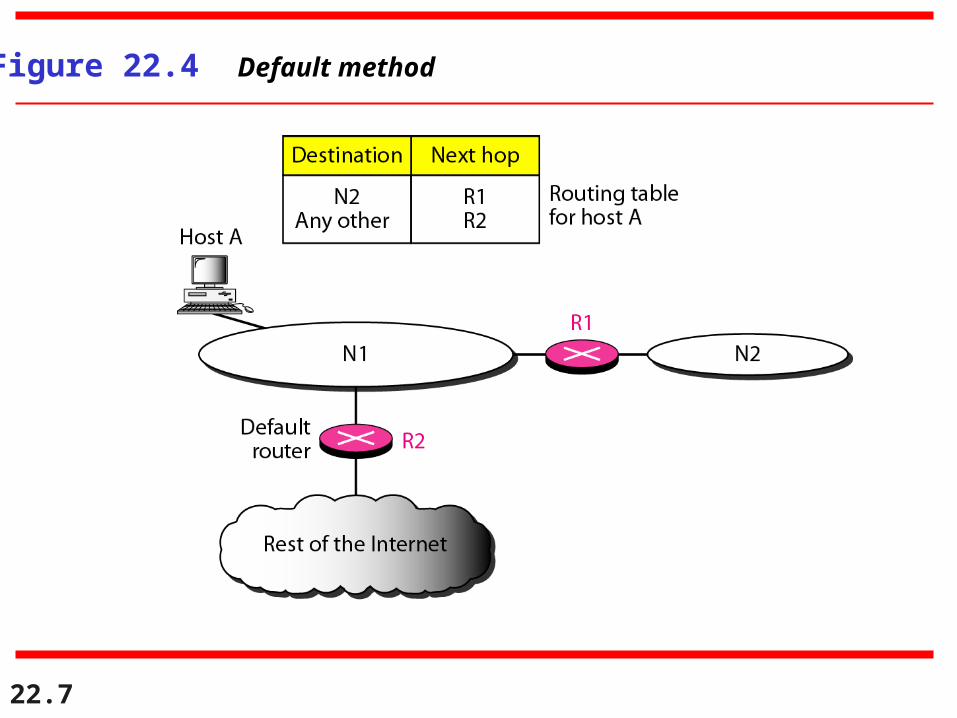
Figure 22.4 Default method

22.8
In classless addressing, we need at least four columns in a routing table.
Note

22.9
Make a routing table for router R1, using the configuration in Figure 22.6.
Example 22.1
SolutionTable 22.1 shows the corresponding table.

22.10
Figure 22.6 Configuration for Example 22.1

22.11
Table 22.1 Routing table for router R1 in Figure 22.6

22.12
Show the forwarding process if a packet arrives at R1 in Figure 22.6 with the destination address 180.70.65.140.
Example 22.2
SolutionThe router performs the following steps:1. The first mask (/26) is applied to the destination address. The result is 180.70.65.128, which does not match the corresponding network address.2. The second mask (/25) is applied to the destination address. The result is 180.70.65.128, which matches the corresponding network address. The next-hop address and the interface number m0 are passed to ARP for further processing.

22.13
Show the forwarding process if a packet arrives at R1 in Figure 22.6 with the destination address 201.4.22.35.
Example 22.3
SolutionThe router performs the following steps:1. The first mask (/26) is applied to the destination
address. The result is 201.4.22.0, which does notmatch the corresponding network address.
2. The second mask (/25) is applied to the destination address. The result is 201.4.22.0, which does not match the corresponding network address (row 2).

22.14
Example 22.3 (continued)
3. The third mask (/24) is applied to the destination address. The result is 201.4.22.0, which matches the corresponding network address. The destination address of the packet and the interface number m3 are passed to ARP.

22.15
Show the forwarding process if a packet arrives at R1 in Figure 22.6 with the destination address 18.24.32.78.
Example 22.4
SolutionThis time all masks are applied, one by one, to the destination address, but no matching network address is found. When it reaches the end of the table, the module gives the next-hop address 180.70.65.200 and interface number m2 to ARP. This is probably an outgoing package that needs to be sent, via the default router, to someplace else in the Internet.

22.16
Figure 22.7 Address aggregation
22.17
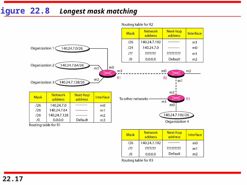
Figure 22.8 Longest mask matching

22.18
As an example of hierarchical routing, let us consider Figure 22.9. A regional ISP is granted 16,384 addresses starting from 120.14.64.0. The regional ISP has decided to divide this block into four subblocks, each with 4096 addresses. Three of these subblocks are assigned to threelocal ISPs; the second subblock is reserved for future use. Note that the mask for each block is /20 because the original block with mask /18 is divided into 4 blocks.
Example 22.5
The first local ISP has divided its assigned subblock into 8 smaller blocks and assigned each to a small ISP. Each small ISP provides services to 128 households, each using four addresses.

22.19
The second local ISP has divided its block into 4 blocks and has assigned the addresses to four large organizations.
Example 22.5 (continued)
There is a sense of hierarchy in this configuration. All routers in the Internet send a packet with destination address 120.14.64.0 to 120.14.127.255 to the regional ISP.
The third local ISP has divided its block into 16 blocks and assigned each block to a small organization. Each small organization has 256 addresses, and the mask is /24.

22.20
Figure 22.9 Hierarchical routing with ISPs

22.21
Figure 22.10 Common fields in a routing table

22.22
One utility that can be used to find the contents of a routing table for a host or router is netstat in UNIX or LINUX. The next slide shows the list of the contents of a default server. We have used two options, r and n. The option r indicates that we are interested in the routing table, and the option n indicates that we are looking for numeric addresses. Note that this is a routing table for a host, not a router. Although we discussed the routing table for a router throughout the chapter, a host also needs a routing table.
Example 22.6

22.23
Example 22.6 (continued)
The destination column here defines the network address. The term gateway used by UNIX is synonymous with router. This column actually defines the address of the next hop. The value 0.0.0.0 shows that the delivery is direct. The last entry has a flag of G, which means that the destination can be reached through a router (default router). The Iface defines the interface.

22.24
Example 22.6 (continued)
More information about the IP address and physical address of the server can be found by using the ifconfig command on the given interface (eth0).

22.25
Figure 22.11 Configuration of the server for Example 22.6

22.26
22-3 UNICAST ROUTING PROTOCOLS22-3 UNICAST ROUTING PROTOCOLS
A routing table can be either static or dynamic. A A routing table can be either static or dynamic. A static table is one with manual entries. A dynamic static table is one with manual entries. A dynamic table is one that is updated automatically when there is table is one that is updated automatically when there is a change somewhere in the Internet. A routing a change somewhere in the Internet. A routing protocol is a combination of rules and procedures that protocol is a combination of rules and procedures that lets routers in the Internet inform each other of lets routers in the Internet inform each other of changes. changes.
OptimizationIntra- and Interdomain RoutingDistance Vector Routing and RIPLink State Routing and OSPFPath Vector Routing and BGP
Topics discussed in this section:Topics discussed in this section:

22.27
Figure 22.12 Autonomous systems

22.28
Figure 22.13 Popular routing protocols
22.29
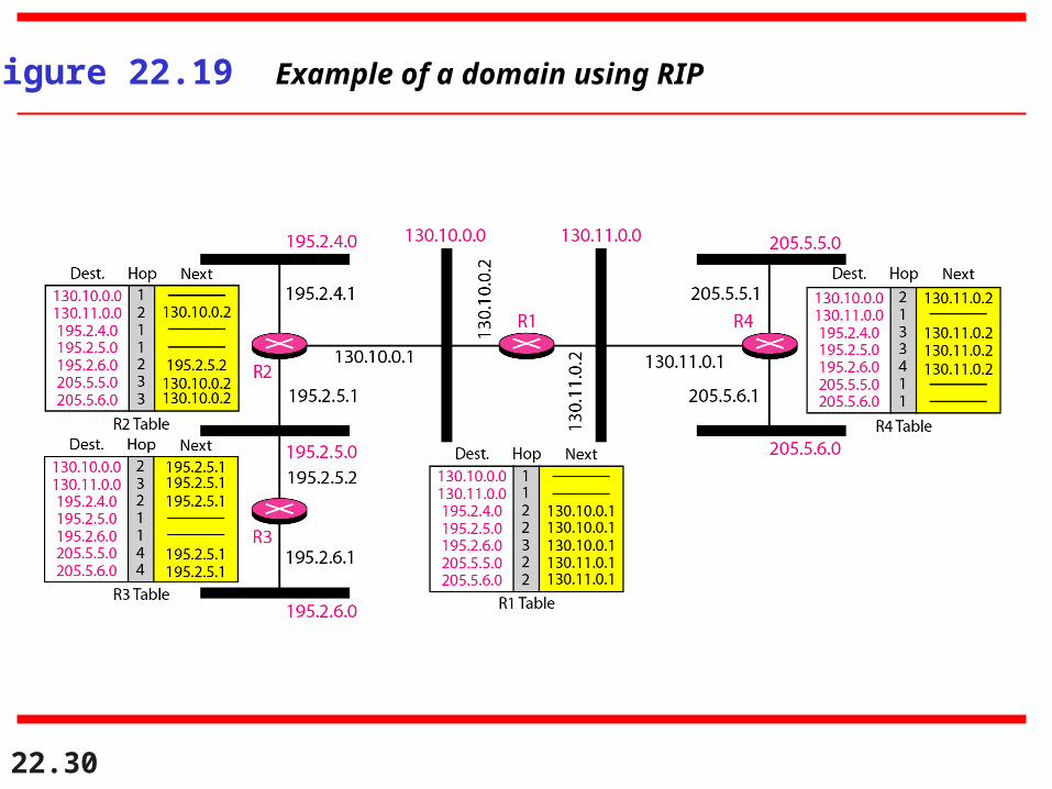
In distance vector routing, each node shares its routing table with its
immediate neighbors periodically and when there is a change.
Note
22.30
Figure 22.19 Example of a domain using RIP

22.31
Figure 22.25 Types of links

22.32
Figure 22.26 Point-to-point link

22.33
Figure 22.27 Transient link

22.34
Figure 22.28 Stub link

22.35
Figure 22.29 Example of an AS and its graphical representation in OSPF

22.36
22-4 MULTICAST ROUTING PROTOCOLS22-4 MULTICAST ROUTING PROTOCOLS
In this section, we discuss multicasting and multicast In this section, we discuss multicasting and multicast routing protocols. routing protocols.
Unicast, Multicast, and BroadcastApplicationsMulticast RoutingRouting Protocols
Topics discussed in this section:Topics discussed in this section:
22.37
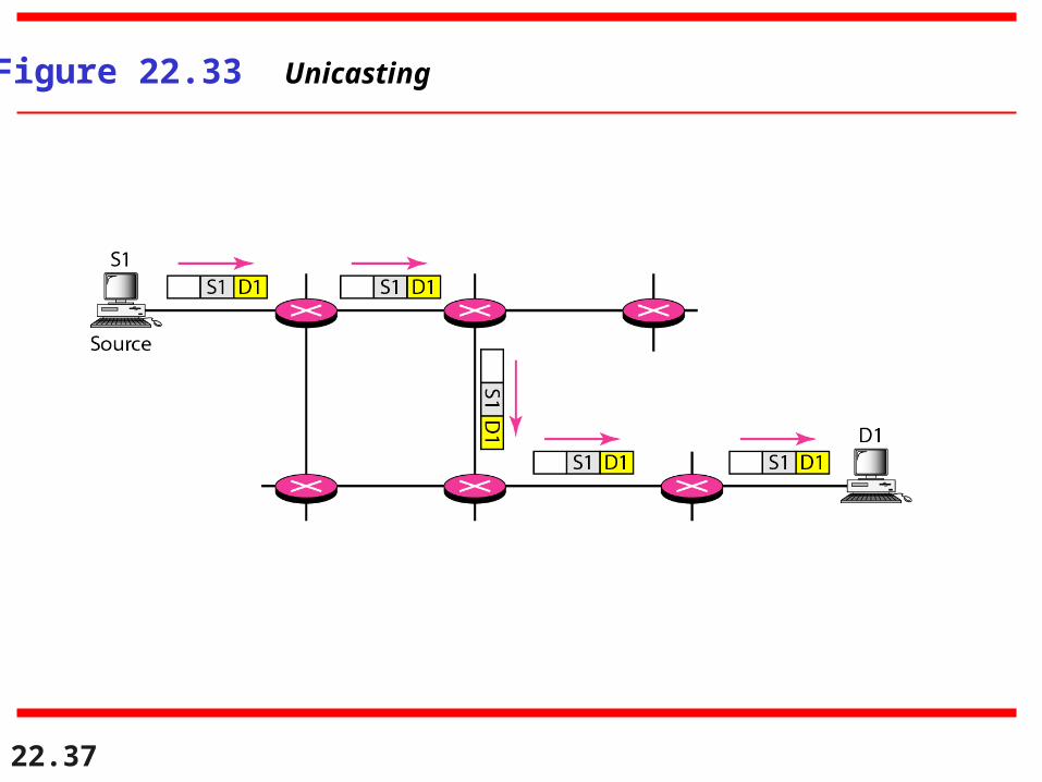
Figure 22.33 Unicasting
22.38
In unicasting, the router forwards the received packet throughonly one of its interfaces.
Note

22.39
Figure 22.34 Multicasting

22.40
In multicasting, the router may forward the received packet
through several of its interfaces.
Note

22.41
Figure 22.35 Multicasting versus multiple unicasting
22.42
Emulation of multicasting through multiple unicasting is not efficient
and may create long delays, particularly with a large group.
Note

22.43
In unicast routing, each router in the domain has a table that definesa shortest path tree to possible
destinations.
Note

22.44
Figure 22.36 Shortest path tree in unicast routing

22.45
In multicast routing, each involved router needs to construct
a shortest path tree for each group.
Note
22.46
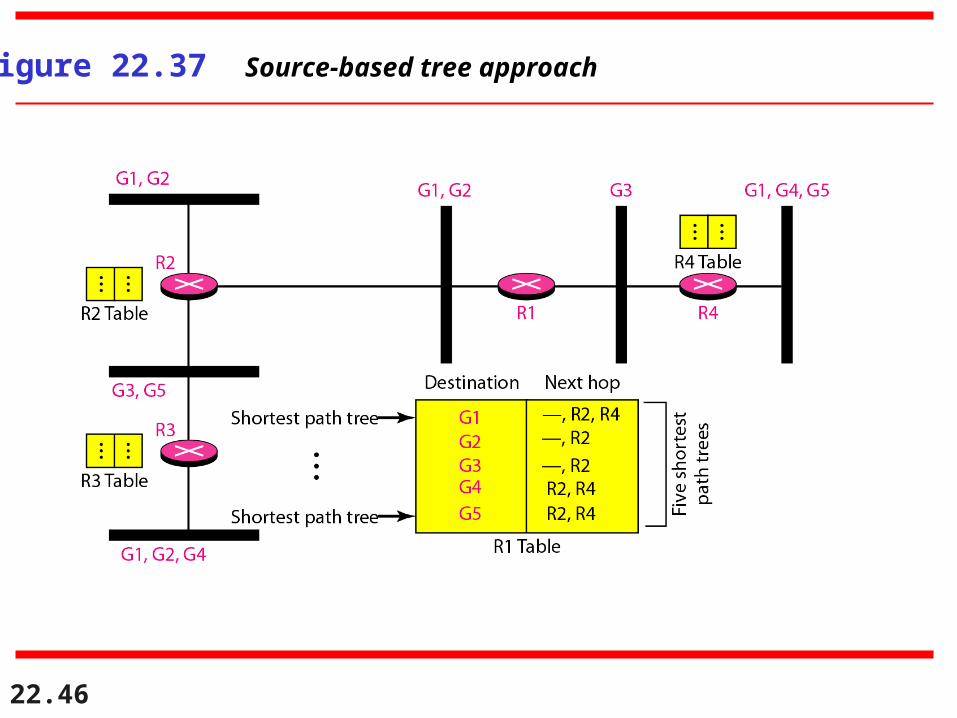
Figure 22.37 Source-based tree approach

22.47
In the source-based tree approach, each router needs to have one shortest path
tree for each group.
Note

22.48
Figure 22.38 Group-shared tree approach

22.49
In the group-shared tree approach, only the core router, which has a shortest
path tree for each group, is involved in multicasting.
Note

22.50
Figure 22.39 Taxonomy of common multicast protocols

22.51
Multicast link state routing uses the source-based tree approach.
Note

22.52
Flooding broadcasts packets, but creates loops in the systems.
Note

22.53
RPF eliminates the loop in the flooding process.
Note

22.54
Figure 22.40 Reverse path forwarding (RPF)

22.55
Figure 22.41 Problem with RPF
22.56
RPB creates a shortest path broadcast tree from the source to each destination.
It guarantees that each destination receives one and only one copy
of the packet.
Note

22.57
Figure 22.43 RPF, RPB, and RPM

22.58
RPM adds pruning and grafting to RPB to create a multicast shortest
path tree that supports dynamic membership changes.
Note

22.59
Figure 22.44 Group-shared tree with rendezvous router

22.60
Figure 22.45 Sending a multicast packet to the rendezvous router

22.61
In CBT, the source sends the multicast packet (encapsulated in a unicast
packet) to the core router. The core router decapsulates the packet and
forwards it to all interested interfaces.
Note

22.62
PIM-DM is used in a dense multicast environment, such as a LAN.
Note

22.63
PIM-DM uses RPF and pruning and grafting strategies to handle
multicasting.However, it is independent of the
underlying unicast protocol.
Note
22.64
PIM-SM is used in a sparse multicast environment such as a WAN.
Note

22.65
Figure 22.46 Logical tunneling
22.66
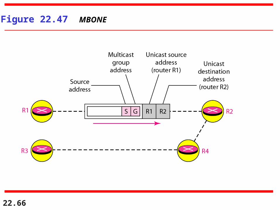
Figure 22.47 MBONE
Related Documents