CONTENTS INTRODUCTION ...............................1 GENERAL INFORMATION ........................1 PROGRAM HISTORY ...........................1 WHY WE RACE .............................2 FIVE PILLARS GUIDE GM RACING’S INTEGRATED STRATEGTY . . .2 LEGAL INFORMATION ..........................2 OREDERING PARTS IN THIS BOOK ..................3 BASE ENGINE OVERVIEW ........................3 L61 PARTS LIST ...............................5 LSJ PARTS LIST ..............................15 ENGINE ASSEMBLY STOCK TO 250 HP .............25 ADJUSTABLE CAM GEARS .......................25 NITROUS OXIDE SYSTEMS ......................26 SUPERCHARGER ............................26 ECOTEC SUPERCHARGER INSTALLATION ...............26 POWERTRAIN CONTROL MODULE RECALIBRATION .........38 SUPERCHARGER PARTS LIST .....................39 ENGINE ASSEMBLY 250 HP TO 400 HP ............41 CONNECTING RODS ..........................41 PISTONS ................................42 INTAKE MANIFOLD ..........................42 HEAD GASKET AND HEAD BOLTS ..................42 VALVE SPRINGS AND RETAINERS ...................42 NITROUS OXIDE SYSTEMS ......................43 TURBOCHARGERS ...........................43 HIGH PERFORMANCE PISTON AND ROD R&R PROCEDURE (COBALT) ..............................43 STOCK to 400 HP PARTS LIST ...................61 ENGINE ASSEMBLY 400 HP TO 600 HP ............63 ENGINE BLOCK ............................64 ENGINE BLOCK MAIN GIRDLE ....................64 OIL PAN ................................65 CRANKSHAFT ..............................65 CRANKSHAFT MAIN BEARINGS ....................66 CONNECTING RODS ..........................66 CONNECTING ROD BEARINGS ....................66 PISTONS ................................66 PISTON PINS ..............................67 PISTON RINGS .............................67 PISTON PIN LOCKS ..........................67 CYLINDER HEAD ............................67 CYLINDER HEAD COVER .......................68 VALVE SPRINGS AND RETAINERS ...................69 CAMSHAFTS ..............................69 LASH ADJUSTERS ...........................69 INTAKE MANIFOLD ..........................69 WATER PUMP .............................70 OIL PUMP (WET SUMP) .......................70 400 HP TO 600 HP PARTS LIST ..................71 ENGINE ASSEMBLY 600 HP TO 1000 HP ...........73 ENGINE BLOCK ............................74 ENGINE BLOCK MAIN GIRDLE ....................75 OIL PAN ................................75 CRANKSHAFT ..............................76 GM SPORT COMPACT Performance Build Book i

Welcome message from author
This document is posted to help you gain knowledge. Please leave a comment to let me know what you think about it! Share it to your friends and learn new things together.
Transcript
CONTENTSINTRODUCTION . . . . . . . . . . . . . . . . . . . . . . . . . . . . . . .1
GENERAL INFORMATION . . . . . . . . . . . . . . . . . . . . . . . .1
PROGRAM HISTORY . . . . . . . . . . . . . . . . . . . . . . . . . . .1
WHY WE RACE . . . . . . . . . . . . . . . . . . . . . . . . . . . . .2
FIVE PILLARS GUIDE GM RACING’S INTEGRATED STRATEGTY . . .2
LEGAL INFORMATION . . . . . . . . . . . . . . . . . . . . . . . . . .2
OREDERING PARTS IN THIS BOOK . . . . . . . . . . . . . . . . . .3
BASE ENGINE OVERVIEW . . . . . . . . . . . . . . . . . . . . . . . .3
L61 PARTS LIST. . . . . . . . . . . . . . . . . . . . . . . . . . . . . . .5
LSJ PARTS LIST . . . . . . . . . . . . . . . . . . . . . . . . . . . . . .15
ENGINE ASSEMBLY STOCK TO 250 HP . . . . . . . . . . . . .25
ADJUSTABLE CAM GEARS . . . . . . . . . . . . . . . . . . . . . . .25
NITROUS OXIDE SYSTEMS . . . . . . . . . . . . . . . . . . . . . .26
SUPERCHARGER . . . . . . . . . . . . . . . . . . . . . . . . . . . .26
ECOTEC SUPERCHARGER INSTALLATION . . . . . . . . . . . . . . .26
POWERTRAIN CONTROL MODULE RECALIBRATION . . . . . . . . .38
SUPERCHARGER PARTS LIST. . . . . . . . . . . . . . . . . . . . .39
ENGINE ASSEMBLY 250 HP TO 400 HP . . . . . . . . . . . .41
CONNECTING RODS . . . . . . . . . . . . . . . . . . . . . . . . . .41
PISTONS . . . . . . . . . . . . . . . . . . . . . . . . . . . . . . . .42
INTAKE MANIFOLD . . . . . . . . . . . . . . . . . . . . . . . . . .42
HEAD GASKET AND HEAD BOLTS . . . . . . . . . . . . . . . . . .42
VALVE SPRINGS AND RETAINERS . . . . . . . . . . . . . . . . . . .42
NITROUS OXIDE SYSTEMS . . . . . . . . . . . . . . . . . . . . . .43
TURBOCHARGERS . . . . . . . . . . . . . . . . . . . . . . . . . . .43
HIGH PERFORMANCE PISTON AND ROD R&R PROCEDURE(COBALT) . . . . . . . . . . . . . . . . . . . . . . . . . . . . . .43
STOCK to 400 HP PARTS LIST . . . . . . . . . . . . . . . . . . .61
ENGINE ASSEMBLY 400 HP TO 600 HP . . . . . . . . . . . .63
ENGINE BLOCK . . . . . . . . . . . . . . . . . . . . . . . . . . . .64
ENGINE BLOCK MAIN GIRDLE . . . . . . . . . . . . . . . . . . . .64
OIL PAN . . . . . . . . . . . . . . . . . . . . . . . . . . . . . . . .65
CRANKSHAFT . . . . . . . . . . . . . . . . . . . . . . . . . . . . . .65
CRANKSHAFT MAIN BEARINGS . . . . . . . . . . . . . . . . . . . .66
CONNECTING RODS . . . . . . . . . . . . . . . . . . . . . . . . . .66
CONNECTING ROD BEARINGS . . . . . . . . . . . . . . . . . . . .66
PISTONS . . . . . . . . . . . . . . . . . . . . . . . . . . . . . . . .66
PISTON PINS . . . . . . . . . . . . . . . . . . . . . . . . . . . . . .67
PISTON RINGS . . . . . . . . . . . . . . . . . . . . . . . . . . . . .67
PISTON PIN LOCKS . . . . . . . . . . . . . . . . . . . . . . . . . .67
CYLINDER HEAD . . . . . . . . . . . . . . . . . . . . . . . . . . . .67
CYLINDER HEAD COVER . . . . . . . . . . . . . . . . . . . . . . .68
VALVE SPRINGS AND RETAINERS . . . . . . . . . . . . . . . . . . .69
CAMSHAFTS . . . . . . . . . . . . . . . . . . . . . . . . . . . . . .69
LASH ADJUSTERS . . . . . . . . . . . . . . . . . . . . . . . . . . .69
INTAKE MANIFOLD . . . . . . . . . . . . . . . . . . . . . . . . . .69
WATER PUMP . . . . . . . . . . . . . . . . . . . . . . . . . . . . .70
OIL PUMP (WET SUMP) . . . . . . . . . . . . . . . . . . . . . . .70
400 HP TO 600 HP PARTS LIST . . . . . . . . . . . . . . . . . .71
ENGINE ASSEMBLY 600 HP TO 1000 HP . . . . . . . . . . .73
ENGINE BLOCK . . . . . . . . . . . . . . . . . . . . . . . . . . . .74
ENGINE BLOCK MAIN GIRDLE . . . . . . . . . . . . . . . . . . . .75
OIL PAN . . . . . . . . . . . . . . . . . . . . . . . . . . . . . . . .75
CRANKSHAFT . . . . . . . . . . . . . . . . . . . . . . . . . . . . . .76
� GM SPORT COMPACT Performance Build Book i
CRANKSHAFT MAIN BEARINGS . . . . . . . . . . . . . . . . . . . .77
CONNECTING RODS . . . . . . . . . . . . . . . . . . . . . . . . . .77
CONNECTING ROD BEARINGS . . . . . . . . . . . . . . . . . . . .77
PISTONS . . . . . . . . . . . . . . . . . . . . . . . . . . . . . . . .78
PISTON PINS . . . . . . . . . . . . . . . . . . . . . . . . . . . . . .78
PISTON RINGS . . . . . . . . . . . . . . . . . . . . . . . . . . . . .78
PISTON PIN LOCKS . . . . . . . . . . . . . . . . . . . . . . . . . .79
CYLINDER HEAD . . . . . . . . . . . . . . . . . . . . . . . . . . . .79
HEAD GASKET . . . . . . . . . . . . . . . . . . . . . . . . . . . . .81
ROCKERS AND LIFTERS . . . . . . . . . . . . . . . . . . . . . . . .81
CYLINDER HEAD COVER . . . . . . . . . . . . . . . . . . . . . . .81
CAMSHAFTS . . . . . . . . . . . . . . . . . . . . . . . . . . . . . .81
INTAKE MANIFOLD . . . . . . . . . . . . . . . . . . . . . . . . . .82
WATER PUMP . . . . . . . . . . . . . . . . . . . . . . . . . . . . .82
600 HP TO 1000 HP PARTS LIST . . . . . . . . . . . . . . . . .83
ENGINE ASSEMBLY 1000 HP TO 1400 HP . . . . . . . . . .85
ENGINE BLOCK . . . . . . . . . . . . . . . . . . . . . . . . . . . .86
OIL PAN . . . . . . . . . . . . . . . . . . . . . . . . . . . . . . . .86
FLYWHEEL BOLTS . . . . . . . . . . . . . . . . . . . . . . . . . . .87
PISTON RINGS . . . . . . . . . . . . . . . . . . . . . . . . . . . . .87
PISTON PIN LOCKS . . . . . . . . . . . . . . . . . . . . . . . . . .87
CYLINDER HEAD . . . . . . . . . . . . . . . . . . . . . . . . . . . .87
SPRINGS AND RETAINERS . . . . . . . . . . . . . . . . . . . . . .88
VALVES AND LOCKS . . . . . . . . . . . . . . . . . . . . . . . . . .88
ROCKERS AND LIFTERS . . . . . . . . . . . . . . . . . . . . . . . .89
MECHANICAL TIMING CHAIN TENSIONER . . . . . . . . . . . . . .89
CYLINDER HEAD COVER . . . . . . . . . . . . . . . . . . . . . . .89
CAMSHAFTS . . . . . . . . . . . . . . . . . . . . . . . . . . . . . .90
INTAKE MANIFOLD . . . . . . . . . . . . . . . . . . . . . . . . . .90
WATER PUMP . . . . . . . . . . . . . . . . . . . . . . . . . . . . .91
OIL PUMP (WET SUMP) . . . . . . . . . . . . . . . . . . . . . . .91
1000 HP TO 1400 HP PARTS LIST . . . . . . . . . . . . . . . .93
CONTROL SYSTEMS . . . . . . . . . . . . . . . . . . . . . . . . . . .95
FUEL SYSTEMS . . . . . . . . . . . . . . . . . . . . . . . . . . . . .95
ENGINE MANAGEMENT . . . . . . . . . . . . . . . . . . . . . . . .96
IGNITION SYSTEMS . . . . . . . . . . . . . . . . . . . . . . . . . .96
COIL ON PLUG IGNITION . . . . . . . . . . . . . . . . . . . . . . .97
CAMSHAFT POSITION SENSOR . . . . . . . . . . . . . . . . . . . .97
DIS SYSTEM . . . . . . . . . . . . . . . . . . . . . . . . . . . . . .97
TURBOCHARGER . . . . . . . . . . . . . . . . . . . . . . . . . . . .97
BOOST CONTROLLER . . . . . . . . . . . . . . . . . . . . . . . . .98
WASTE GATES . . . . . . . . . . . . . . . . . . . . . . . . . . . . .98
INTERCOOLER . . . . . . . . . . . . . . . . . . . . . . . . . . . . .99
TORQUE SPECIFICATIONS . . . . . . . . . . . . . . . . . . . . . .101
4T65 RACING TRANSMISSION COMPONENTS . . . . . . .103
TRANSBRAKE . . . . . . . . . . . . . . . . . . . . . . . . . . . . .104
TRANSMISSION CASE . . . . . . . . . . . . . . . . . . . . . . . .105
STATOR SUPPORT . . . . . . . . . . . . . . . . . . . . . . . . . .106
TORQUE CONVERTER . . . . . . . . . . . . . . . . . . . . . . . . .106
INPUT SHAFT . . . . . . . . . . . . . . . . . . . . . . . . . . . . .107
OIL PUMP SHAFT . . . . . . . . . . . . . . . . . . . . . . . . . .107
DRIVE CHAINS . . . . . . . . . . . . . . . . . . . . . . . . . . . .107
SECOND GEAR CLUTCH . . . . . . . . . . . . . . . . . . . . . . .108
THIRD GEAR CLUTCH . . . . . . . . . . . . . . . . . . . . . . . .108
SINGLE WRAP BAND . . . . . . . . . . . . . . . . . . . . . . . .109
OIL DAM . . . . . . . . . . . . . . . . . . . . . . . . . . . . . . .109
PLANETARY SET . . . . . . . . . . . . . . . . . . . . . . . . . . .109
SPRAGS . . . . . . . . . . . . . . . . . . . . . . . . . . . . . . . .110
SUN GEAR AND SHAFT . . . . . . . . . . . . . . . . . . . . . . .110
PARK PAWL GEAR . . . . . . . . . . . . . . . . . . . . . . . . . .110
ii � GM SPORT COMPACT Performance Build Book
TORSEN� DIFFERENTIAL . . . . . . . . . . . . . . . . . . . . . . .110
RACE OUTPUT FLANGES . . . . . . . . . . . . . . . . . . . . . . .111
ACCUMULATOR AND FORWARD SERVO . . . . . . . . . . . . . .111
MODIFIED FLUID PICK-UP . . . . . . . . . . . . . . . . . . . . .111
RACE TRANSMISSION PAN 22° . . . . . . . . . . . . . . . . . . .112
MODIFIED TUBE AND INDICATOR . . . . . . . . . . . . . . . . .112
SEPARATOR PLATE . . . . . . . . . . . . . . . . . . . . . . . . . .112
VALVE BODY . . . . . . . . . . . . . . . . . . . . . . . . . . . . .112
PRESSURE REGULATOR . . . . . . . . . . . . . . . . . . . . . . .113
CASE COVER . . . . . . . . . . . . . . . . . . . . . . . . . . . . .113
SHIFT CONTROLS . . . . . . . . . . . . . . . . . . . . . . . . . . .114
4T65E SHIFT ALGORITHM . . . . . . . . . . . . . . . . . . . . . .115
SHIFT CONTROLLERS . . . . . . . . . . . . . . . . . . . . . . . . .115
TRANSMISSION FLUID INFORMATION . . . . . . . . . . . . . . .115
4T65E PERFORMANCETRANSMISSION PARTS LIST . . . .117
COBALT PHASE5 . . . . . . . . . . . . . . . . . . . . . . . . . . . . .119
INTRODUCTION . . . . . . . . . . . . . . . . . . . . . . . . . . . .119
POWERTRAIN . . . . . . . . . . . . . . . . . . . . . . . . . . . . .120
ENGINE INSTALLATION . . . . . . . . . . . . . . . . . . . . . . . .120
COOLING SYSTEM . . . . . . . . . . . . . . . . . . . . . . . . . .122
FUEL SYSTEM . . . . . . . . . . . . . . . . . . . . . . . . . . . . .123
FUEL PUMP . . . . . . . . . . . . . . . . . . . . . . . . . . . . . .123
FUEL TANK . . . . . . . . . . . . . . . . . . . . . . . . . . . . . .124
ELECTRICAL SYSTEM . . . . . . . . . . . . . . . . . . . . . . . . .124
SWITCHES . . . . . . . . . . . . . . . . . . . . . . . . . . . . . . .125
EXHAUST SYSTEM . . . . . . . . . . . . . . . . . . . . . . . . . .125
CHASSIS SAFTEY MODIFICATIONS . . . . . . . . . . . . . . . . .126
ROLL BAR KIT . . . . . . . . . . . . . . . . . . . . . . . . . . . .126
SEAT BELT HARNESS . . . . . . . . . . . . . . . . . . . . . . . . .127
SEATING . . . . . . . . . . . . . . . . . . . . . . . . . . . . . . . .128
THROTTLE PEDAL ASSEMBLY . . . . . . . . . . . . . . . . . . . .129
STEERING WHEEL . . . . . . . . . . . . . . . . . . . . . . . . . .129
GAUGE PANEL . . . . . . . . . . . . . . . . . . . . . . . . . . . .130
SHIFTER . . . . . . . . . . . . . . . . . . . . . . . . . . . . . . . .130
FRONT SUSPENSION . . . . . . . . . . . . . . . . . . . . . . . . .131
HALF SHAFTS . . . . . . . . . . . . . . . . . . . . . . . . . . . . .132
OUTPUT FLANGES . . . . . . . . . . . . . . . . . . . . . . . . . .132
STEERING SYSTEM . . . . . . . . . . . . . . . . . . . . . . . . . .132
REAR SUSPENSION . . . . . . . . . . . . . . . . . . . . . . . . . .133
BRAKES . . . . . . . . . . . . . . . . . . . . . . . . . . . . . . . .134
HOOD . . . . . . . . . . . . . . . . . . . . . . . . . . . . . . . . .135
PHASE5 PARTS LIST . . . . . . . . . . . . . . . . . . . . . . . . . .137
COBALT GRAND AM CUP(ST CLASS) RACING SERIES . .139
POWERTRAIN . . . . . . . . . . . . . . . . . . . . . . . . . . . . .141
SUPERCHARGER PULLEY . . . . . . . . . . . . . . . . . . . . . . .141
AFTERCOOLER . . . . . . . . . . . . . . . . . . . . . . . . . . . .142
CORSA EXHAUST . . . . . . . . . . . . . . . . . . . . . . . . . . .142
4.45 FINAL DRIVE LSD TRANSMISSION . . . . . . . . . . . . . .143
B&M ALUMINUM SHIFTER . . . . . . . . . . . . . . . . . . . . .143
HALF SHAFTS . . . . . . . . . . . . . . . . . . . . . . . . . . . . .143
CHASSIS . . . . . . . . . . . . . . . . . . . . . . . . . . . . . . . .144
FRONT SUSPENSION . . . . . . . . . . . . . . . . . . . . . . . . .144
REAR SUSPENSION . . . . . . . . . . . . . . . . . . . . . . . . . .146
BRAKES . . . . . . . . . . . . . . . . . . . . . . . . . . . . . . . .146
CARBON FIBER BRAKE DUCTS . . . . . . . . . . . . . . . . . . .147
STEERING . . . . . . . . . . . . . . . . . . . . . . . . . . . . . . .147
BODY . . . . . . . . . . . . . . . . . . . . . . . . . . . . . . . . .148
CARBON FIBER PANELS . . . . . . . . . . . . . . . . . . . . . . .148
� GM SPORT COMPACT Performance Build Book iii

COBALT ACCESSORIES. . . . . . . . . . . . . . . . . . . . . . . . .149
COBALT RACING BODY COMPONENTS . . . . . . . . . . . . .151
SUPPLIERS . . . . . . . . . . . . . . . . . . . . . . . . . . . . . . . . .153
iv � GM SPORT COMPACT Performance Build Book
INTRODUCTIONGENERAL INFORMATION
This handbook describes parts and procedures used toprepare ECOTEC Race Engines used by GM Racing inprofessional sport compact drag racing, as well as engine,transmission, and chassis modifications designed for,sportsman-level drag racers and road racers.
This handbook is intended to be used by experienced andknowledgeable race engine and chassis builders. It doesnot cover basic engine blueprinting and assemblyprocedures, since it is assumed that the reader is alreadyfamiliar with machining, measuring, and inspecting thecomponents. Some of the procedures described requirespecialized tools and skills. If you do not have theappropriate training and equipment to perform thesemodifications safely, this work should be performed by otherprofessionals.
There are of course, many other possible combinations ofcomponents and additional modifications that may produceequal or superior results. However, by using thecombination of parts and procedures described in thishandbook, an experienced engine builder can build acompetitive and reliable ECOTEC Race Engine.
It is not the intent of these specifications to replace thecomprehensive and detailed service practices explained in
the GM service manuals. GM service manuals are availablefrom:
Helm IncorporatedPO Box 07130Detroit, MI 48207
Observe all safety precautions and warnings in the servicemanuals. Wear eye protection and appropriate protectiveclothing. When working under or around the vehicle supportit securely with jack stands. Use only the proper tools.Exercise extreme caution when working with flammable,corrosive, and hazardous liquids and materials.
PROGRAM HISTORY
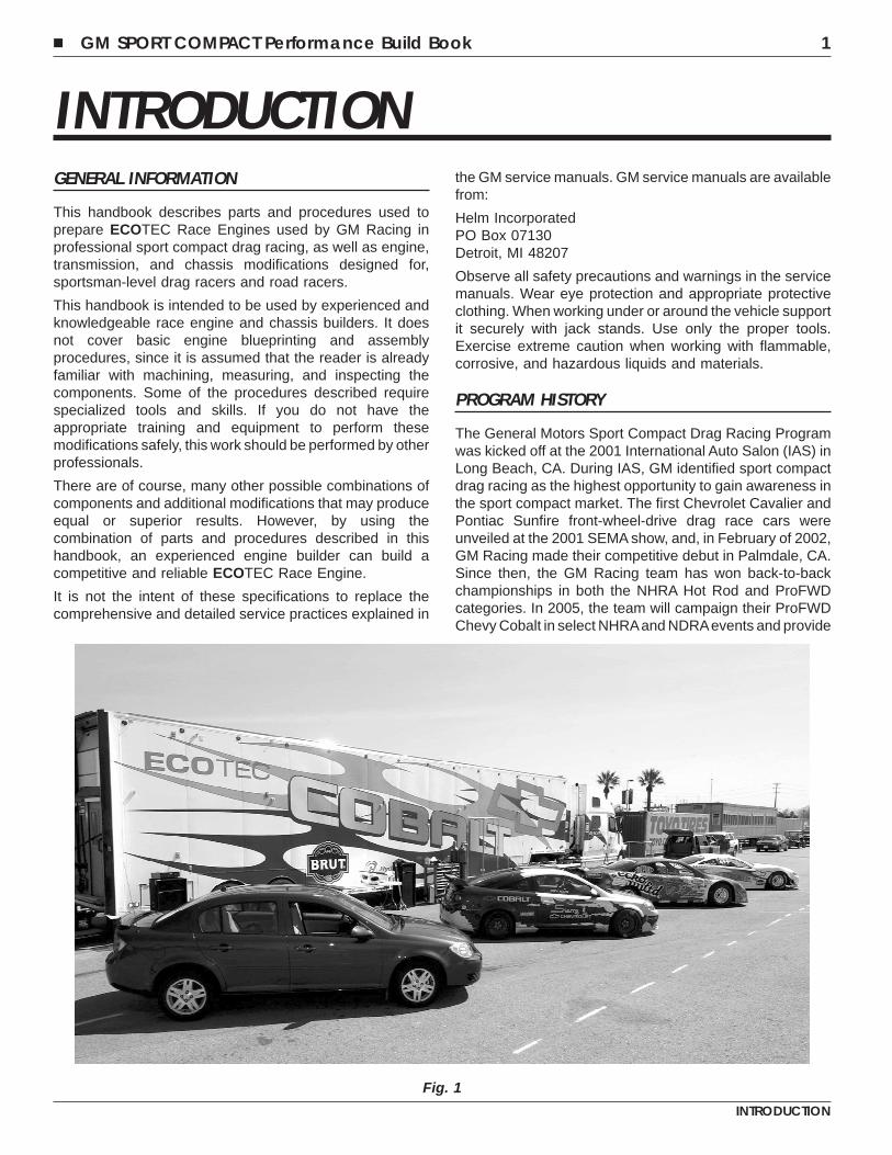
The General Motors Sport Compact Drag Racing Programwas kicked off at the 2001 International Auto Salon (IAS) inLong Beach, CA. During IAS, GM identified sport compactdrag racing as the highest opportunity to gain awareness inthe sport compact market. The first Chevrolet Cavalier andPontiac Sunfire front-wheel-drive drag race cars wereunveiled at the 2001 SEMA show, and, in February of 2002,GM Racing made their competitive debut in Palmdale, CA.Since then, the GM Racing team has won back-to-backchampionships in both the NHRA Hot Rod and ProFWDcategories. In 2005, the team will campaign their ProFWDChevy Cobalt in select NHRAand NDRAevents and provide
Fig. 1
� GM SPORT COMPACT Performance Build Book 1
INTRODUCTION
support to independent teams running their ownECOTEC-powered Chevy Cobalt drag cars.
WHY WE RACE
At GM, we race because it’s where we came from andbecause it fuels our love for competition.
Racing has been part of the GM culture since auto pioneerslike Louis Chevrolet relied on speed records and racingvictories to launch his fledgling car company. GM hasremained in racing for two basic reasons - to win on the trackand win in the marketplace.
Racing is a compelling demonstration of the depth of GM’stechnical resources, the capabilities of its people and theperformance, reliability, quality and safety of its products.The race track is the toughest of proving grounds to forgeengineering, marketing and business skills into tangibleresults. Few, if any, environments can match racing’s abilityto build awareness and consideration of a manufacturer’sproducts to new customers, while simultaneously solidifyingthe loyalty of current customers.
FIVE PILLARS GUIDE GM RACING’S INTEGRATEDSTRATEGTY
It provides a dynamic training ground for GM engineers.In racing, decisions must be made at a rapid rate. You mustbe ready at all times, on time, and solve problems quicklyand effectively. Racing’s demands are the perfect venue inwhich to exercise the mind and expand abilities, improveteamwork and communication - and do it all without makingexcuses.
This leads to technology transfer. Racing is well known tohave introduced improvements in the auto productionindustry in areas such as suspensions, brakes, engines,aerodynamics and safety - but there’s also a transfer intechnology through people who work in racing, then takethose improved skills and knowledge to the productionprocess. Likewise, the advanced technology and peopleinvolved in the mass production of vehicles has enhancedthe development of race cars.
Human nature dictates that people want to compete - andwin. There is a strong competitive spirit within GM, andsuccess in racing produces a vibrant esprit de corps. GM isnot a sponsor of racing - we are an active, engagedparticipant who produces the cars and the components, andprovides the technology essential to the sport.
If racing did not already exist, auto manufacturers wouldinvent it as the perfect marketing platform. Racing is asport that’s all about the product and the people, followedwith cult-like passionate fans who buy cars and trucks at ahigher and more loyal rate than the average consumer.
Grass roots racers and enthusiasts demand the best, andhave made GM Performance Parts the leader in over thecounter components and engine assemblies. GM’s
approach, as a participant in racing, is to take responsibilityto support the sport. Someone else might even build a motorthat beats the factory team. But it’s this democratization ofracing that sets GM apart, and is the cornerstone of GM’stotal business approach.
LEGAL INFORMATION
This publication is intended to provide technical informationon the GM ECOTEC engines, Hydra-Matic transmission,and Chevy Cobalt used in sport compact drag racing at theprofessional and sportsman level.
This handbook pertains exclusively to engines and vehicleswhich are used off the public highways. Federal law restrictsthe removal or modification of any part of a federallyrequired emission control system on motor vehicles.Further, many states have enacted laws which prohibittampering with or modifying any required emission or noisecontrol system. Vehicles which are not operated on publichighways are generally exempt from most regulations, butthe reader is strongly urged to check all applicable local andstate laws.
Many of the parts described or listed in this handbook aremerchandised for off-highway application only, and aretagged with the following “Special Parts Notice”:
SPECIAL PARTS NOTICEThis part has been specifically designed for Off-Highwayapplication only. Since the installation of this part mayeither impair your vehicle’s emission controlperformance or be uncertified under current MotorVehicle Safety Standards, it should not be installed in avehicle used on any street or highway. Additionally, anysuch application could adversely affect the warrantycoverage of such an on-street or highway vehicle.
The information contained in this handbook is subject tochange. General Motors also reserves the right to makechanges at any time, without notice, in equipment,manufacturers, specifications, and materials, or todiscontinue items.
The information in this publication is presented without anywarranty. All the risk for its use is entirely assumed by theuser. Specific component design, mechanical procedures,and the qualifications of individual readers are beyond thecontrol of the publisher, and therefore the publisherdisclaims all liability incurred in connection with the use ofinformation contained in this publication.
Chevrolet, Cobalt, ECOTEC, Hydra-Matic, General Motors,and GM are registered trademarks of the General MotorsCorporation.
2 � GM SPORT COMPACT Performance Build Book
INTRODUCTION
OREDERING PARTS IN THIS BOOK
Parts described in this book are from several sources. Manyparts are available from aftermarket suppliers. The contactinformation for these suppliers is listed in a separate sectionof the book. Note that some parts may be available fromadditional sources.
There are three types of General Motors parts listed in thisbook. First are parts used in regular production vehicle.These are regular service and replacement parts, donatedas ’GM’ parts in this book. These parts are available throughany GM dealer. See www.gmgoodwrench.com for moreinformation and to locate a dealer near you.
The second type of GM parts shown are GM PerformanceParts. These parts are available only through authorizedGM Performance Parts dealers. Not all GM dealers areauthorized to sell GM Performance Parts. For moreinformation or to locate an authorized dealer, visitwww.gmgoodwrench.com and click on GM PerformanceParts. Please note that not all parts are listed on the GmPerformance Parts website. Your authorized dealer has amore complete list. If your dealer is an authorized GMPerformance Parts dealer and still cannot locate a GMPerformance Part listed in this book, please e-mail GMRacing at [email protected].
The third type of parts listed in this book are availableexclusively from GM Racing. These are typicallylow-volume parts for racing applications. All GM RacingParts are for off-highway use only and are tagged with the�Special Parts Notice� shown previously in this book. GMRacing Parts are available only by [email protected]. Racing personnel will respondto you with additional ordering information and partavailability. Please allow up to twelve weeks for delivery.
All part numbers are subject to change. Please contact theappropriate source for the most recent information.
BASE ENGINE OVERVIEW
The engine is the heart of a competition car. It must becapable of delivering full power reliably run-after-run on raceday, at engine and vehicle speeds far in excess of thoseencountered in normal driving. Every part of a competitionengine must be as nearly perfect as possible – the slightestfailure can put you out of the running or even out of the race.
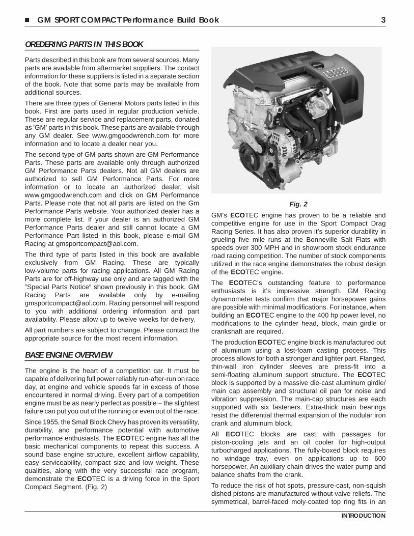
Since 1955, the Small Block Chevy has proven its versatility,durability, and performance potential with automotiveperformance enthusiasts. The ECOTEC engine has all thebasic mechanical components to repeat this success. Asound base engine structure, excellent airflow capability,easy serviceability, compact size and low weight. Thesequalities, along with the very successful race program,demonstrate the ECOTEC is a driving force in the SportCompact Segment. (Fig. 2)
GM’s ECOTEC engine has proven to be a reliable andcompetitive engine for use in the Sport Compact DragRacing Series. It has also proven it’s superior durability ingrueling five mile runs at the Bonneville Salt Flats withspeeds over 300 MPH and in showroom stock enduranceroad racing competition. The number of stock componentsutilized in the race engine demonstrates the robust designof the ECOTEC engine.
The ECOTEC’s outstanding feature to performanceenthusiasts is it’s impressive strength. GM Racingdynamometer tests confirm that major horsepower gainsare possible with minimal modifications. For instance, whenbuilding an ECOTEC engine to the 400 hp power level, nomodifications to the cylinder head, block, main girdle orcrankshaft are required.
The production ECOTEC engine block is manufactured outof aluminum using a lost-foam casting process. Thisprocess allows for both a stronger and lighter part. Flanged,thin-wall iron cylinder sleeves are press-fit into asemi-floating aluminum support structure. The ECOTECblock is supported by a massive die-cast aluminum girdle/main cap assembly and structural oil pan for noise andvibration suppression. The main-cap structures are eachsupported with six fasteners. Extra-thick main bearingsresist the differential thermal expansion of the nodular ironcrank and aluminum block.
All ECOTEC blocks are cast with passages forpiston-cooling jets and an oil cooler for high-outputturbocharged applications. The fully-boxed block requiresno windage tray, even on applications up to 600horsepower. An auxiliary chain drives the water pump andbalance shafts from the crank.
To reduce the risk of hot spots, pressure-cast, non-squishdished pistons are manufactured without valve reliefs. Thesymmetrical, barrel-faced moly-coated top ring fits in an
Fig. 2
� GM SPORT COMPACT Performance Build Book 3
INTRODUCTION
anodized ring-groove below a super-thin 3 mm top ring land,creating a low crevice volume for reduced emissions. Thepistons deliver power through full-floating piston pins andpowder-metal or forged steel connecting rods.
The ECOTEC twin-cam cylinder head uses low-frictionhydraulic roller finger-followers, which have been provenreliable and effective up to 11,000 rpm. Head fastenerplacement permits cylinder head removal and installationwithout removing the camshafts. The camshafts are drivendirectly off the crank by a chain. The design includesprovisions for future upgrading to variable cam phasing. Thefinger-follower design permits a light-weight narrow profileand reduced valve angles(the intake valve is 18 degreesfrom vertical and the exhaust valve 16 degrees).
The design of the intake manifold eliminates the need forvariable-length intake runners and consideration has beenmade for conversion to gasoline direct-injection.
The ECOTEC engine management system uses a port-EFIdesign with cassette waste-spark ignition. An integralcompression-sense ignition module eliminates the need fora cam position sensor.
The current 2.2L version of the ECOTEC is available in thefollowing vehicles:
• Chevy – Cobalt, Malibu and Cavalier
• Pontiac – Grand Am and Sunfire
• Saturn – L-Series, Ion and Vue
• Opel/Vauxhal – Vectra, Zafira and Speedster.
The next several sections of this publication focus onperformance modifications for the 2.2L ECOTEC engineinstalled in a 2005 Chevy Cobalt. The modifications showncould be performed on a number of GM vehicles.
See your local GM dealer for more information on orderinga vehicle equipped with the ECOTEC engine.
4 � GM SPORT COMPACT Performance Build Book
INTRODUCTION
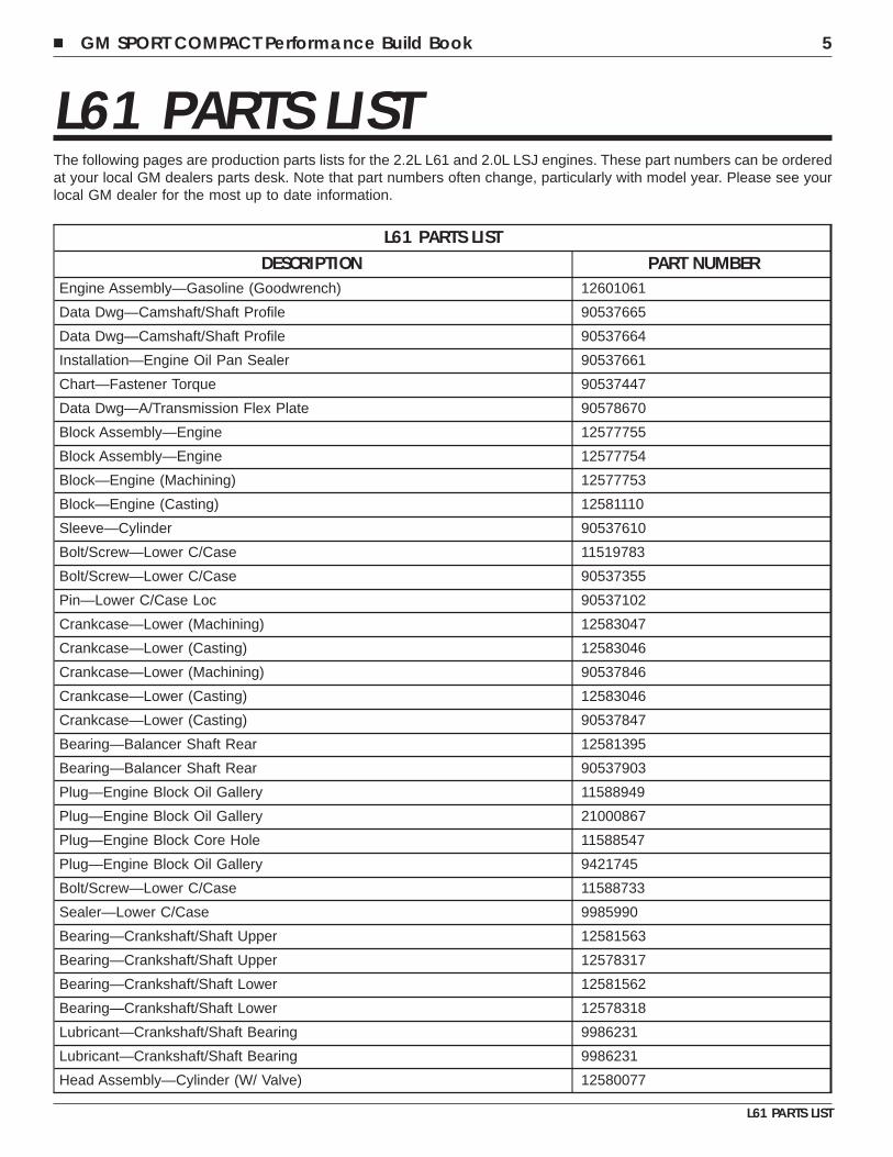
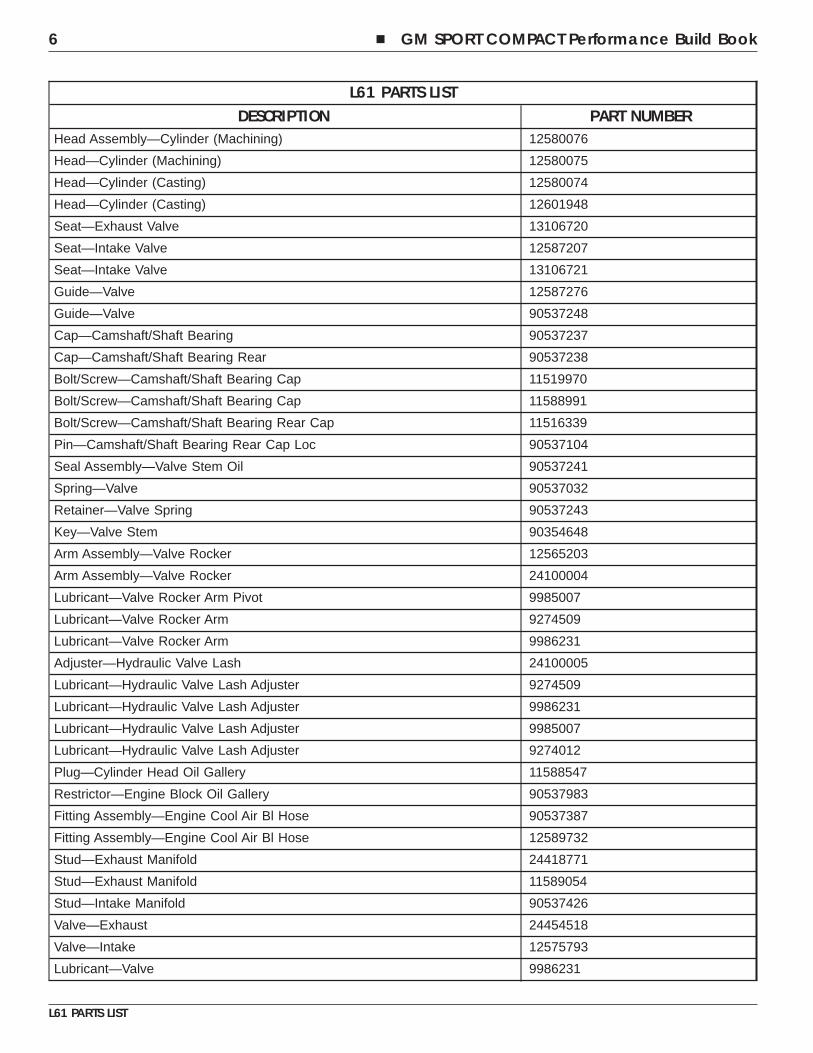
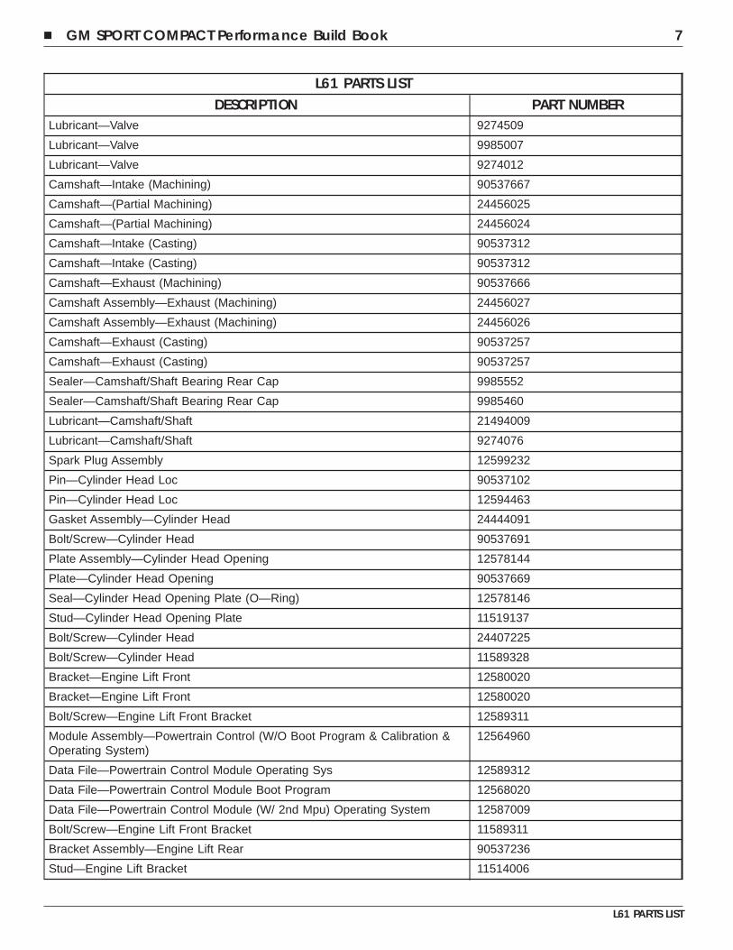
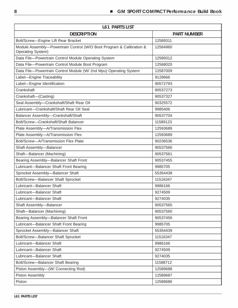
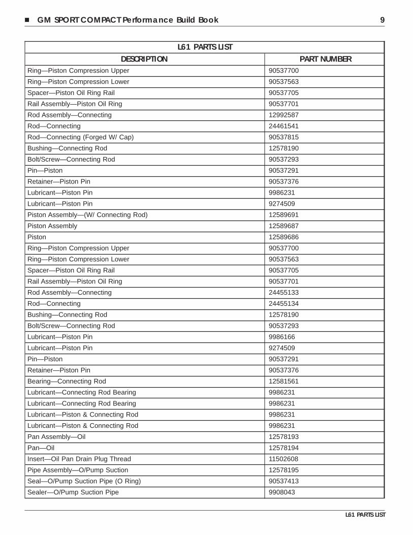
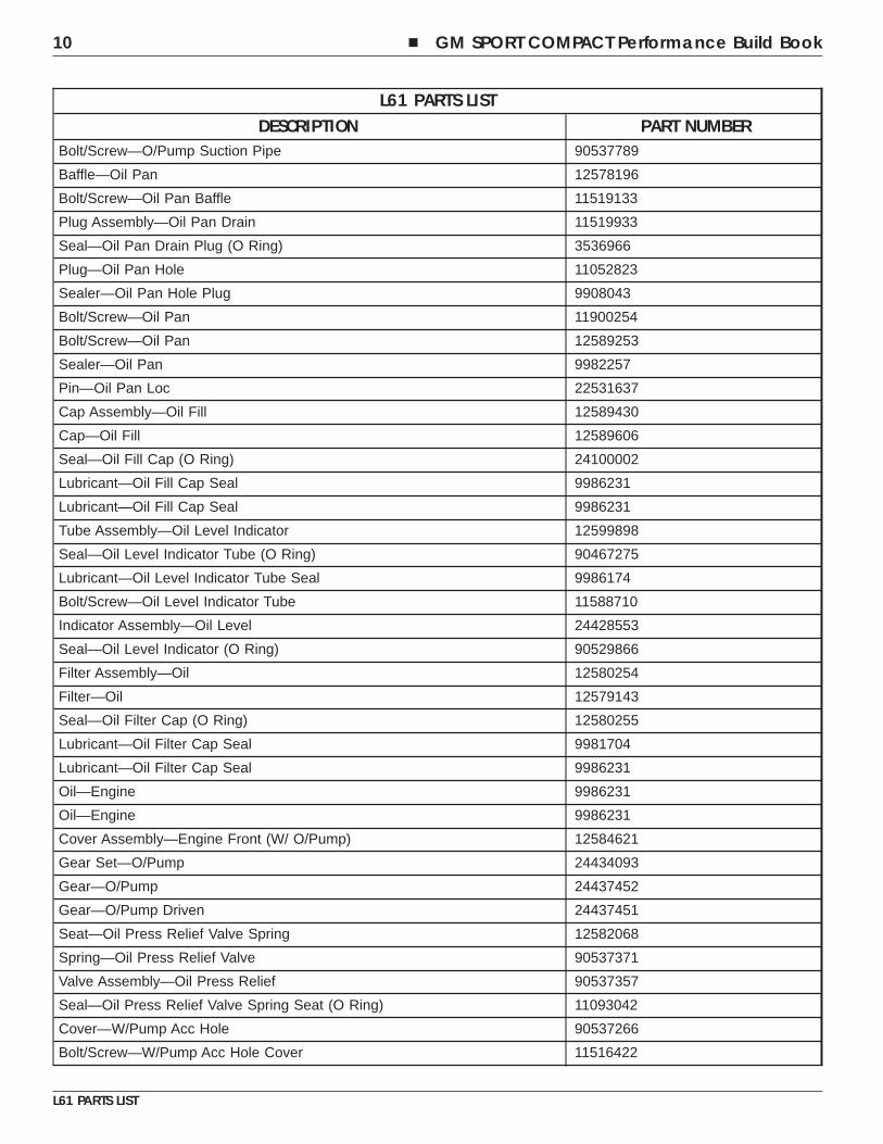
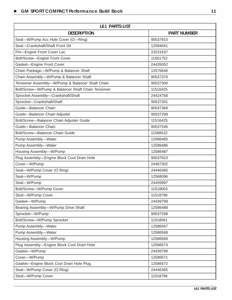
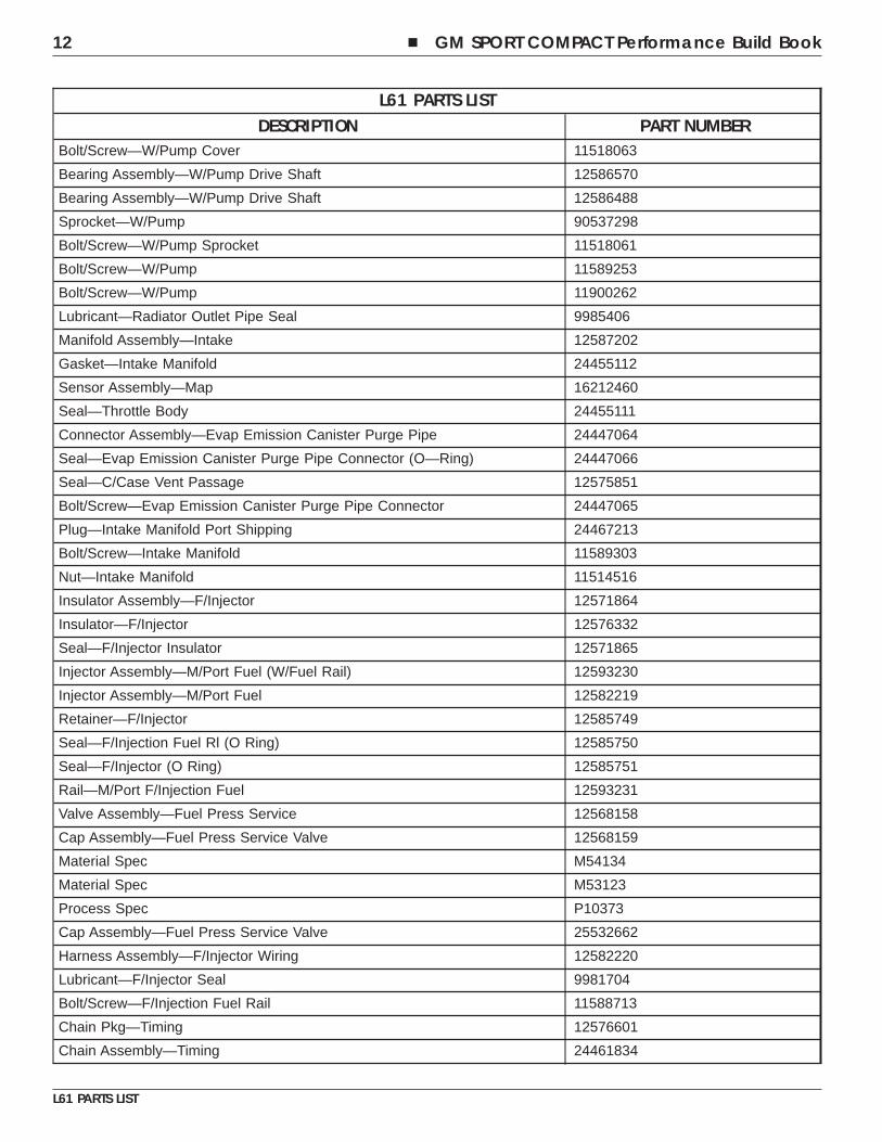
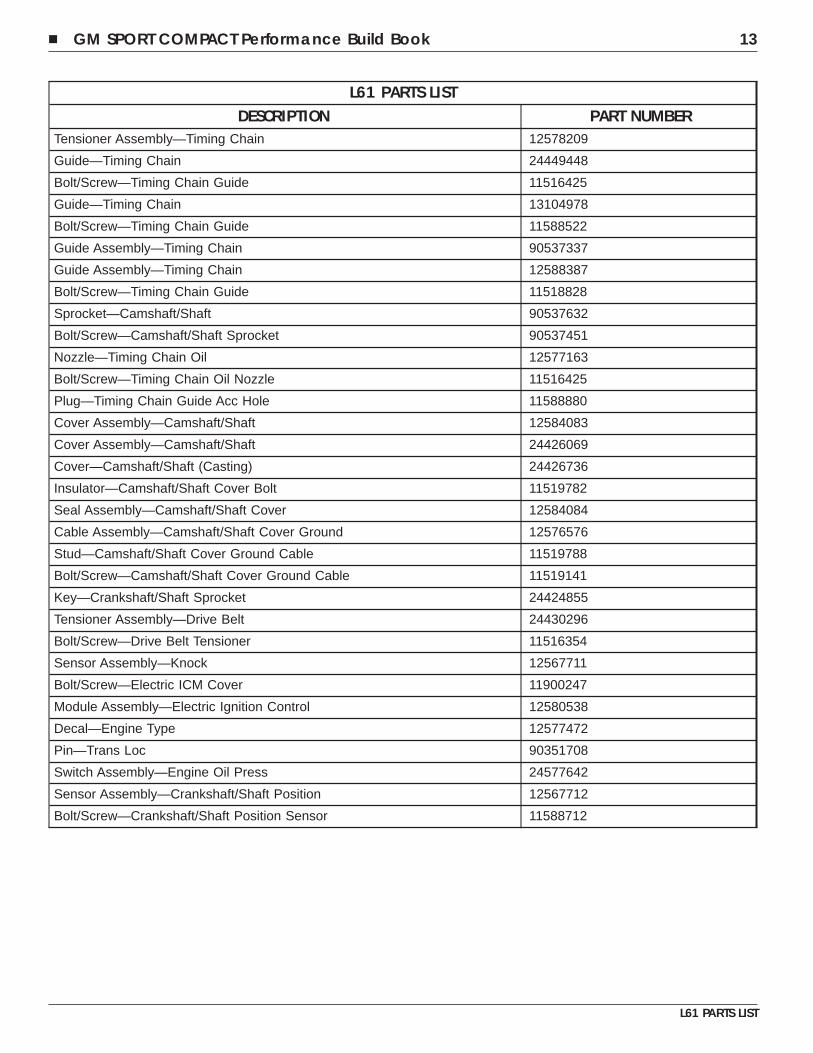
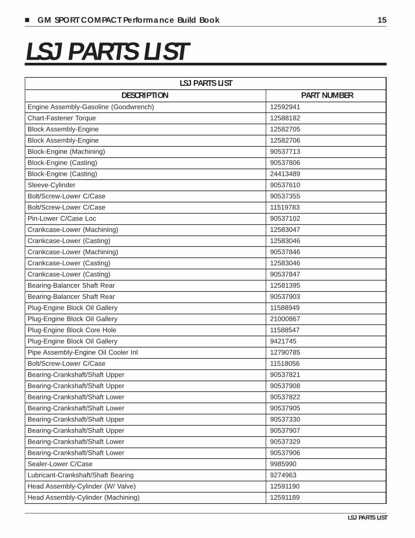
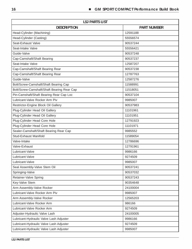
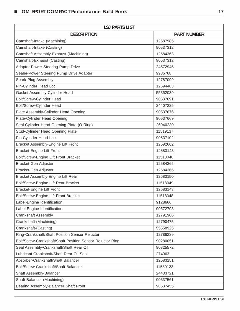
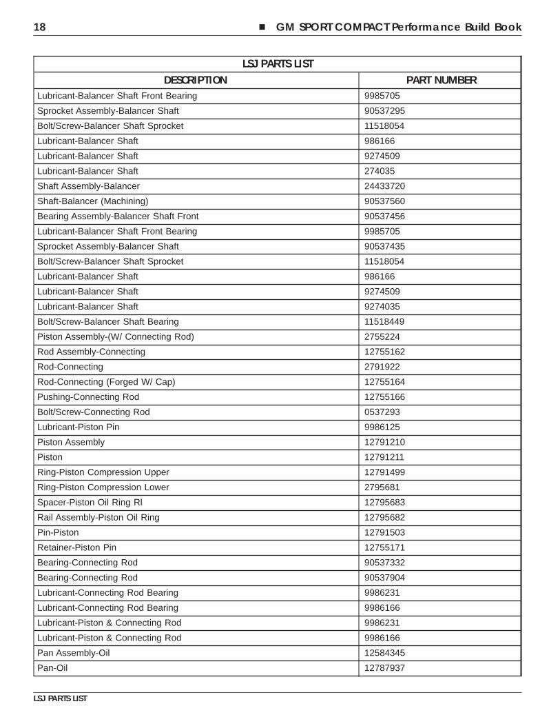
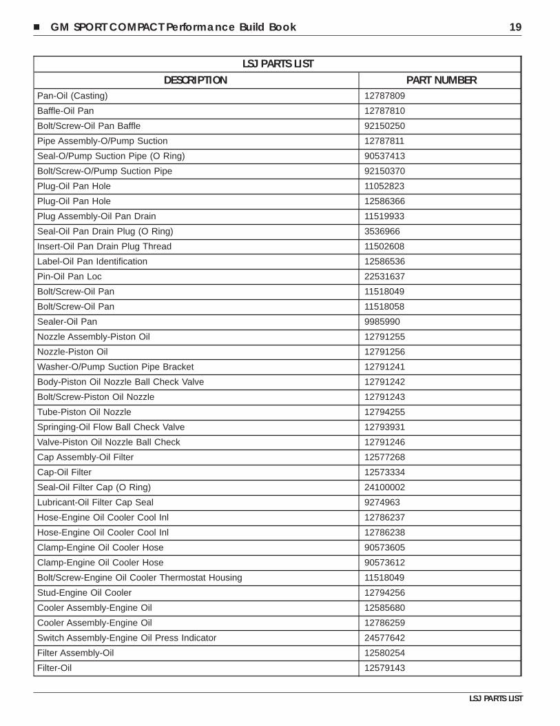
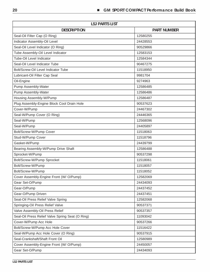
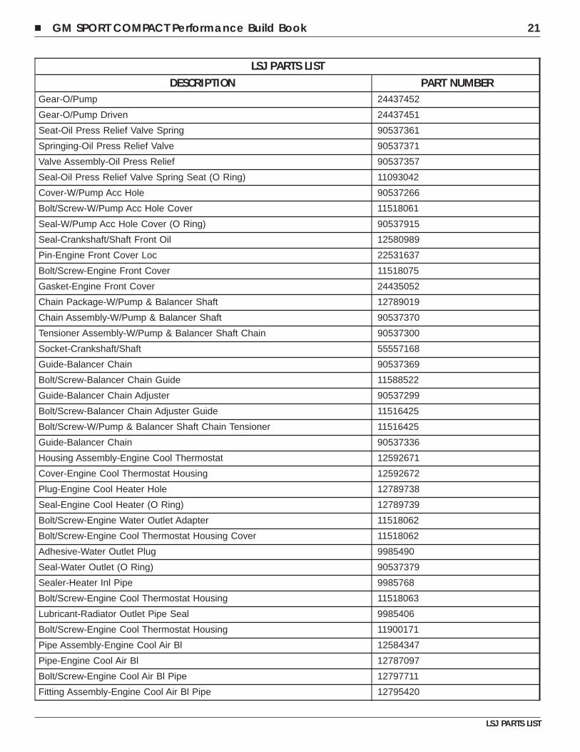
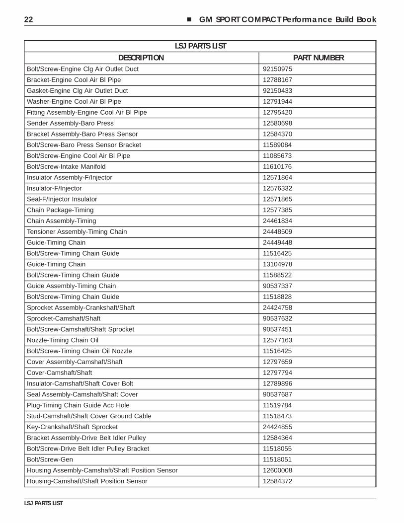
L61 PARTS LISTThe following pages are production parts lists for the 2.2L L61 and 2.0L LSJ engines. These part numbers can be orderedat your local GM dealers parts desk. Note that part numbers often change, particularly with model year. Please see yourlocal GM dealer for the most up to date information.
L61 PARTS LISTDESCRIPTION PART NUMBER
Engine Assembly—Gasoline (Goodwrench) 12601061
Data Dwg—Camshaft/Shaft Profile 90537665
Data Dwg—Camshaft/Shaft Profile 90537664
Installation—Engine Oil Pan Sealer 90537661
Chart—Fastener Torque 90537447
Data Dwg—A/Transmission Flex Plate 90578670
Block Assembly—Engine 12577755
Block Assembly—Engine 12577754
Block—Engine (Machining) 12577753
Block—Engine (Casting) 12581110
Sleeve—Cylinder 90537610
Bolt/Screw—Lower C/Case 11519783
Bolt/Screw—Lower C/Case 90537355
Pin—Lower C/Case Loc 90537102
Crankcase—Lower (Machining) 12583047
Crankcase—Lower (Casting) 12583046
Crankcase—Lower (Machining) 90537846
Crankcase—Lower (Casting) 12583046
Crankcase—Lower (Casting) 90537847
Bearing—Balancer Shaft Rear 12581395
Bearing—Balancer Shaft Rear 90537903
Plug—Engine Block Oil Gallery 11588949
Plug—Engine Block Oil Gallery 21000867
Plug—Engine Block Core Hole 11588547
Plug—Engine Block Oil Gallery 9421745
Bolt/Screw—Lower C/Case 11588733
Sealer—Lower C/Case 9985990
Bearing—Crankshaft/Shaft Upper 12581563
Bearing—Crankshaft/Shaft Upper 12578317
Bearing—Crankshaft/Shaft Lower 12581562
Bearing—Crankshaft/Shaft Lower 12578318
Lubricant—Crankshaft/Shaft Bearing 9986231
Lubricant—Crankshaft/Shaft Bearing 9986231
Head Assembly—Cylinder (W/ Valve) 12580077
� GM SPORT COMPACT Performance Build Book 5
L61 PARTS LIST
L61 PARTS LISTDESCRIPTION PART NUMBER
Head Assembly—Cylinder (Machining) 12580076
Head—Cylinder (Machining) 12580075
Head—Cylinder (Casting) 12580074
Head—Cylinder (Casting) 12601948
Seat—Exhaust Valve 13106720
Seat—Intake Valve 12587207
Seat—Intake Valve 13106721
Guide—Valve 12587276
Guide—Valve 90537248
Cap—Camshaft/Shaft Bearing 90537237
Cap—Camshaft/Shaft Bearing Rear 90537238
Bolt/Screw—Camshaft/Shaft Bearing Cap 11519970
Bolt/Screw—Camshaft/Shaft Bearing Cap 11588991
Bolt/Screw—Camshaft/Shaft Bearing Rear Cap 11516339
Pin—Camshaft/Shaft Bearing Rear Cap Loc 90537104
Seal Assembly—Valve Stem Oil 90537241
Spring—Valve 90537032
Retainer—Valve Spring 90537243
Key—Valve Stem 90354648
Arm Assembly—Valve Rocker 12565203
Arm Assembly—Valve Rocker 24100004
Lubricant—Valve Rocker Arm Pivot 9985007
Lubricant—Valve Rocker Arm 9274509
Lubricant—Valve Rocker Arm 9986231
Adjuster—Hydraulic Valve Lash 24100005
Lubricant—Hydraulic Valve Lash Adjuster 9274509
Lubricant—Hydraulic Valve Lash Adjuster 9986231
Lubricant—Hydraulic Valve Lash Adjuster 9985007
Lubricant—Hydraulic Valve Lash Adjuster 9274012
Plug—Cylinder Head Oil Gallery 11588547
Restrictor—Engine Block Oil Gallery 90537983
Fitting Assembly—Engine Cool Air Bl Hose 90537387
Fitting Assembly—Engine Cool Air Bl Hose 12589732
Stud—Exhaust Manifold 24418771
Stud—Exhaust Manifold 11589054
Stud—Intake Manifold 90537426
Valve—Exhaust 24454518
Valve—Intake 12575793
Lubricant—Valve 9986231
6 � GM SPORT COMPACT Performance Build Book
L61 PARTS LIST
L61 PARTS LISTDESCRIPTION PART NUMBER
Lubricant—Valve 9274509
Lubricant—Valve 9985007
Lubricant—Valve 9274012
Camshaft—Intake (Machining) 90537667
Camshaft—(Partial Machining) 24456025
Camshaft—(Partial Machining) 24456024
Camshaft—Intake (Casting) 90537312
Camshaft—Intake (Casting) 90537312
Camshaft—Exhaust (Machining) 90537666
Camshaft Assembly—Exhaust (Machining) 24456027
Camshaft Assembly—Exhaust (Machining) 24456026
Camshaft—Exhaust (Casting) 90537257
Camshaft—Exhaust (Casting) 90537257
Sealer—Camshaft/Shaft Bearing Rear Cap 9985552
Sealer—Camshaft/Shaft Bearing Rear Cap 9985460
Lubricant—Camshaft/Shaft 21494009
Lubricant—Camshaft/Shaft 9274076
Spark Plug Assembly 12599232
Pin—Cylinder Head Loc 90537102
Pin—Cylinder Head Loc 12594463
Gasket Assembly—Cylinder Head 24444091
Bolt/Screw—Cylinder Head 90537691
Plate Assembly—Cylinder Head Opening 12578144
Plate—Cylinder Head Opening 90537669
Seal—Cylinder Head Opening Plate (O—Ring) 12578146
Stud—Cylinder Head Opening Plate 11519137
Bolt/Screw—Cylinder Head 24407225
Bolt/Screw—Cylinder Head 11589328
Bracket—Engine Lift Front 12580020
Bracket—Engine Lift Front 12580020
Bolt/Screw—Engine Lift Front Bracket 12589311
Module Assembly—Powertrain Control (W/O Boot Program & Calibration &Operating System)
12564960
Data File—Powertrain Control Module Operating Sys 12589312
Data File—Powertrain Control Module Boot Program 12568020
Data File—Powertrain Control Module (W/ 2nd Mpu) Operating System 12587009
Bolt/Screw—Engine Lift Front Bracket 11589311
Bracket Assembly—Engine Lift Rear 90537236
Stud—Engine Lift Bracket 11514006
� GM SPORT COMPACT Performance Build Book 7
L61 PARTS LIST
L61 PARTS LISTDESCRIPTION PART NUMBER
Bolt/Screw—Engine Lift Rear Bracket 12589311
Module Assembly—Powertrain Control (W/O Boot Program & Calibration &Operating System)
12564960
Data File—Powertrain Control Module Operating System 12589312
Data File—Powertrain Control Module Boot Program 12568020
Data File—Powertrain Control Module (W/ 2nd Mpu) Operating System 12587009
Label—Engine Traceability 9128666
Label—Engine Identification 90572793
Crankshaft 90537273
Crankshaft—(Casting) 90537327
Seal Assembly—Crankshaft/Shaft Rear Oil 90325572
Lubricant—Crankshaft/Shaft Rear Oil Seal 9985406
Balancer Assembly—Crankshaft/Shaft 90537704
Bolt/Screw—Crankshaft/Shaft Balancer 11589123
Plate Assembly—A/Transmission Flex 12593689
Plate Assembly—A/Transmission Flex 12593689
Bolt/Screw—A/Transmission Flex Plate 90236536
Shaft Assembly—Balancer 90537566
Shaft—Balancer (Machining) 90537561
Bearing Assembly—Balancer Shaft Front 90537455
Lubricant—Balancer Shaft Front Bearing 9985705
Sprocket Assembly—Balancer Shaft 55354438
Bolt/Screw—Balancer Shaft Sprocket 11516347
Lubricant—Balancer Shaft 9986166
Lubricant—Balancer Shaft 9274509
Lubricant—Balancer Shaft 9274035
Shaft Assembly—Balancer 90537565
Shaft—Balancer (Machining) 90537560
Bearing Assembly—Balancer Shaft Front 90537456
Lubricant—Balancer Shaft Front Bearing 9985705
Sprocket Assembly—Balancer Shaft 55354439
Bolt/Screw—Balancer Shaft Sprocket 11516347
Lubricant—Balancer Shaft 9986166
Lubricant—Balancer Shaft 9274509
Lubricant—Balancer Shaft 9274035
Bolt/Screw—Balancer Shaft Bearing 11588712
Piston Assembly—(W/ Connecting Rod) 12589688
Piston Assembly 12589687
Piston 12589686
8 � GM SPORT COMPACT Performance Build Book
L61 PARTS LIST
L61 PARTS LISTDESCRIPTION PART NUMBER
Ring—Piston Compression Upper 90537700
Ring—Piston Compression Lower 90537563
Spacer—Piston Oil Ring Rail 90537705
Rail Assembly—Piston Oil Ring 90537701
Rod Assembly—Connecting 12992587
Rod—Connecting 24461541
Rod—Connecting (Forged W/ Cap) 90537815
Bushing—Connecting Rod 12578190
Bolt/Screw—Connecting Rod 90537293
Pin—Piston 90537291
Retainer—Piston Pin 90537376
Lubricant—Piston Pin 9986231
Lubricant—Piston Pin 9274509
Piston Assembly—(W/ Connecting Rod) 12589691
Piston Assembly 12589687
Piston 12589686
Ring—Piston Compression Upper 90537700
Ring—Piston Compression Lower 90537563
Spacer—Piston Oil Ring Rail 90537705
Rail Assembly—Piston Oil Ring 90537701
Rod Assembly—Connecting 24455133
Rod—Connecting 24455134
Bushing—Connecting Rod 12578190
Bolt/Screw—Connecting Rod 90537293
Lubricant—Piston Pin 9986166
Lubricant—Piston Pin 9274509
Pin—Piston 90537291
Retainer—Piston Pin 90537376
Bearing—Connecting Rod 12581561
Lubricant—Connecting Rod Bearing 9986231
Lubricant—Connecting Rod Bearing 9986231
Lubricant—Piston & Connecting Rod 9986231
Lubricant—Piston & Connecting Rod 9986231
Pan Assembly—Oil 12578193
Pan—Oil 12578194
Insert—Oil Pan Drain Plug Thread 11502608
Pipe Assembly—O/Pump Suction 12578195
Seal—O/Pump Suction Pipe (O Ring) 90537413
Sealer—O/Pump Suction Pipe 9908043
� GM SPORT COMPACT Performance Build Book 9
L61 PARTS LIST
L61 PARTS LISTDESCRIPTION PART NUMBER
Bolt/Screw—O/Pump Suction Pipe 90537789
Baffle—Oil Pan 12578196
Bolt/Screw—Oil Pan Baffle 11519133
Plug Assembly—Oil Pan Drain 11519933
Seal—Oil Pan Drain Plug (O Ring) 3536966
Plug—Oil Pan Hole 11052823
Sealer—Oil Pan Hole Plug 9908043
Bolt/Screw—Oil Pan 11900254
Bolt/Screw—Oil Pan 12589253
Sealer—Oil Pan 9982257
Pin—Oil Pan Loc 22531637
Cap Assembly—Oil Fill 12589430
Cap—Oil Fill 12589606
Seal—Oil Fill Cap (O Ring) 24100002
Lubricant—Oil Fill Cap Seal 9986231
Lubricant—Oil Fill Cap Seal 9986231
Tube Assembly—Oil Level Indicator 12599898
Seal—Oil Level Indicator Tube (O Ring) 90467275
Lubricant—Oil Level Indicator Tube Seal 9986174
Bolt/Screw—Oil Level Indicator Tube 11588710
Indicator Assembly—Oil Level 24428553
Seal—Oil Level Indicator (O Ring) 90529866
Filter Assembly—Oil 12580254
Filter—Oil 12579143
Seal—Oil Filter Cap (O Ring) 12580255
Lubricant—Oil Filter Cap Seal 9981704
Lubricant—Oil Filter Cap Seal 9986231
Oil—Engine 9986231
Oil—Engine 9986231
Cover Assembly—Engine Front (W/ O/Pump) 12584621
Gear Set—O/Pump 24434093
Gear—O/Pump 24437452
Gear—O/Pump Driven 24437451
Seat—Oil Press Relief Valve Spring 12582068
Spring—Oil Press Relief Valve 90537371
Valve Assembly—Oil Press Relief 90537357
Seal—Oil Press Relief Valve Spring Seat (O Ring) 11093042
Cover—W/Pump Acc Hole 90537266
Bolt/Screw—W/Pump Acc Hole Cover 11516422
10 � GM SPORT COMPACT Performance Build Book
L61 PARTS LIST
L61 PARTS LISTDESCRIPTION PART NUMBER
Seal—W/Pump Acc Hole Cover (O—Ring) 90537915
Seal—Crankshaft/Shaft Front Oil 12584041
Pin—Engine Front Cover Loc 22531637
Bolt/Screw—Engine Front Cover 11561752
Gasket—Engine Front Cover 24435052
Chain Package—W/Pump & Balancer Shaft 12576646
Chain Assembly—W/Pump & Balancer Shaft 90537370
Tensioner Assembly—W/Pump & Balancer Shaft Chain 90537300
Bolt/Screw—W/Pump & Balancer Shaft Chain Tensioner 11516425
Sprocket Assembly—Crankshaft/Shaft 24424758
Sprocket—Crankshaft/Shaft 90537301
Guide—Balancer Chain 90537369
Guide—Balancer Chain Adjuster 90537299
Bolt/Screw—Balancer Chain Adjuster Guide 11516425
Guide—Balancer Chain 90537336
Bolt/Screw—Balancer Chain Guide 11588522
Pump Assembly—Water 12586485
Pump Assembly—Water 12586486
Housing Assembly—W/Pump 12586487
Plug Assembly—Engine Block Cool Drain Hole 90537623
Cover—W/Pump 24467302
Seal—W/Pump Cover (O Ring) 24446365
Seal—W/Pump 12568096
Seal—W/Pump 24405897
Bolt/Screw—W/Pump Cover 11518063
Stud—W/Pump Cover 11518796
Gasket—W/Pump 24439799
Bearing Assembly—W/Pump Drive Shaft 12586488
Sprocket—W/Pump 90537298
Bolt/Screw—W/Pump Sprocket 11518061
Pump Assembly—Water 12586567
Pump Assembly—Water 12586568
Housing Assembly—W/Pump 12586569
Plug Assembly—Engine Block Cool Drain Hole 12586573
Gasket—W/Pump 24439799
Cover—W/Pump 12586571
Gasket—Engine Block Cool Drain Hole Plug 12586572
Seal—W/Pump Cover (O Ring) 24446365
Stud—W/Pump Cover 11518796
� GM SPORT COMPACT Performance Build Book 11
L61 PARTS LIST
L61 PARTS LISTDESCRIPTION PART NUMBER
Bolt/Screw—W/Pump Cover 11518063
Bearing Assembly—W/Pump Drive Shaft 12586570
Bearing Assembly—W/Pump Drive Shaft 12586488
Sprocket—W/Pump 90537298
Bolt/Screw—W/Pump Sprocket 11518061
Bolt/Screw—W/Pump 11589253
Bolt/Screw—W/Pump 11900262
Lubricant—Radiator Outlet Pipe Seal 9985406
Manifold Assembly—Intake 12587202
Gasket—Intake Manifold 24455112
Sensor Assembly—Map 16212460
Seal—Throttle Body 24455111
Connector Assembly—Evap Emission Canister Purge Pipe 24447064
Seal—Evap Emission Canister Purge Pipe Connector (O—Ring) 24447066
Seal—C/Case Vent Passage 12575851
Bolt/Screw—Evap Emission Canister Purge Pipe Connector 24447065
Plug—Intake Manifold Port Shipping 24467213
Bolt/Screw—Intake Manifold 11589303
Nut—Intake Manifold 11514516
Insulator Assembly—F/Injector 12571864
Insulator—F/Injector 12576332
Seal—F/Injector Insulator 12571865
Injector Assembly—M/Port Fuel (W/Fuel Rail) 12593230
Injector Assembly—M/Port Fuel 12582219
Retainer—F/Injector 12585749
Seal—F/Injection Fuel Rl (O Ring) 12585750
Seal—F/Injector (O Ring) 12585751
Rail—M/Port F/Injection Fuel 12593231
Valve Assembly—Fuel Press Service 12568158
Cap Assembly—Fuel Press Service Valve 12568159
Material Spec M54134
Material Spec M53123
Process Spec P10373
Cap Assembly—Fuel Press Service Valve 25532662
Harness Assembly—F/Injector Wiring 12582220
Lubricant—F/Injector Seal 9981704
Bolt/Screw—F/Injection Fuel Rail 11588713
Chain Pkg—Timing 12576601
Chain Assembly—Timing 24461834
12 � GM SPORT COMPACT Performance Build Book
L61 PARTS LIST
L61 PARTS LISTDESCRIPTION PART NUMBER
Tensioner Assembly—Timing Chain 12578209
Guide—Timing Chain 24449448
Bolt/Screw—Timing Chain Guide 11516425
Guide—Timing Chain 13104978
Bolt/Screw—Timing Chain Guide 11588522
Guide Assembly—Timing Chain 90537337
Guide Assembly—Timing Chain 12588387
Bolt/Screw—Timing Chain Guide 11518828
Sprocket—Camshaft/Shaft 90537632
Bolt/Screw—Camshaft/Shaft Sprocket 90537451
Nozzle—Timing Chain Oil 12577163
Bolt/Screw—Timing Chain Oil Nozzle 11516425
Plug—Timing Chain Guide Acc Hole 11588880
Cover Assembly—Camshaft/Shaft 12584083
Cover Assembly—Camshaft/Shaft 24426069
Cover—Camshaft/Shaft (Casting) 24426736
Insulator—Camshaft/Shaft Cover Bolt 11519782
Seal Assembly—Camshaft/Shaft Cover 12584084
Cable Assembly—Camshaft/Shaft Cover Ground 12576576
Stud—Camshaft/Shaft Cover Ground Cable 11519788
Bolt/Screw—Camshaft/Shaft Cover Ground Cable 11519141
Key—Crankshaft/Shaft Sprocket 24424855
Tensioner Assembly—Drive Belt 24430296
Bolt/Screw—Drive Belt Tensioner 11516354
Sensor Assembly—Knock 12567711
Bolt/Screw—Electric ICM Cover 11900247
Module Assembly—Electric Ignition Control 12580538
Decal—Engine Type 12577472
Pin—Trans Loc 90351708
Switch Assembly—Engine Oil Press 24577642
Sensor Assembly—Crankshaft/Shaft Position 12567712
Bolt/Screw—Crankshaft/Shaft Position Sensor 11588712
� GM SPORT COMPACT Performance Build Book 13
L61 PARTS LIST

NOTES
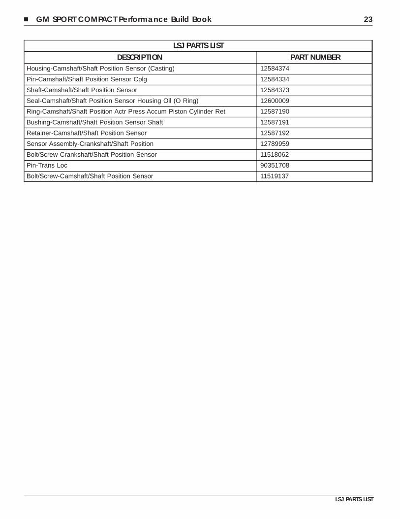
LSJ PARTS LISTLSJ PARTS LIST
DESCRIPTION PART NUMBEREngine Assembly-Gasoline (Goodwrench) 12592941
Chart-Fastener Torque 12588182
Block Assembly-Engine 12582705
Block Assembly-Engine 12582706
Block-Engine (Machining) 90537713
Block-Engine (Casting) 90537806
Block-Engine (Casting) 24413489
Sleeve-Cylinder 90537610
Bolt/Screw-Lower C/Case 90537355
Bolt/Screw-Lower C/Case 11519783
Pin-Lower C/Case Loc 90537102
Crankcase-Lower (Machining) 12583047
Crankcase-Lower (Casting) 12583046
Crankcase-Lower (Machining) 90537846
Crankcase-Lower (Casting) 12583046
Crankcase-Lower (Casting) 90537847
Bearing-Balancer Shaft Rear 12581395
Bearing-Balancer Shaft Rear 90537903
Plug-Engine Block Oil Gallery 11588949
Plug-Engine Block Oil Gallery 21000867
Plug-Engine Block Core Hole 11588547
Plug-Engine Block Oil Gallery 9421745
Pipe Assembly-Engine Oil Cooler Inl 12790785
Bolt/Screw-Lower C/Case 11518056
Bearing-Crankshaft/Shaft Upper 90537821
Bearing-Crankshaft/Shaft Upper 90537908
Bearing-Crankshaft/Shaft Lower 90537822
Bearing-Crankshaft/Shaft Lower 90537905
Bearing-Crankshaft/Shaft Upper 90537330
Bearing-Crankshaft/Shaft Upper 90537907
Bearing-Crankshaft/Shaft Lower 90537329
Bearing-Crankshaft/Shaft Lower 90537906
Sealer-Lower C/Case 9985990
Lubricant-Crankshaft/Shaft Bearing 9274963
Head Assembly-Cylinder (W/ Valve) 12591190
Head Assembly-Cylinder (Machining) 12591189
� GM SPORT COMPACT Performance Build Book 15
LSJ PARTS LIST
LSJ PARTS LISTDESCRIPTION PART NUMBER
Head-Cylinder (Machining) 12591188
Head-Cylinder (Casting) 55556574
Seat-Exhaust Valve 90537244
Seat-Intake Valve 55556421
Guide-Valve 90537248
Cap-Camshaft/Shaft Bearing 90537237
Seat-Intake Valve 12587207
Cap-Camshaft/Shaft Bearing Rear 90537238
Cap-Camshaft/Shaft Bearing Rear 12787763
Guide-Valve 12587276
Bolt/Screw-Camshaft/Shaft Bearing Cap 11588991
Bolt/Screw-Camshaft/Shaft Bearing Rear Cap 11518051
Pin-Camshaft/Shaft Bearing Rear Cap Loc 90537104
Lubricant-Valve Rocker Arm Piv 9985007
Restrictor-Engine Block Oil Gallery 90537983
Plug-Cylinder Head Oil Gallery 11101961
Plug-Cylinder Head Oil Gallery 11101951
Plug-Cylinder Head Core Hole 12791923
Plug-Cylinder Head Core Hole 11101971
Sealer-Camshaft/Shaft Bearing Rear Cap 9985552
Stud-Exhaust Manifold 11589054
Valve-Intake 12786696
Valve-Exhaust 12791961
Lubricant-Valve 9986166
Lubricant-Valve 9274509
Lubricant-Valve 9985007
Seal Assembly-Valve Stem Oil 90537241
Springing-Valve 90537032
Retainer-Valve Spring 90537243
Key-Valve Stem 90354648
Arm Assembly-Valve Rocker 24100004
Lubricant-Valve Rocker Arm Piv 9985007
Arm Assembly-Valve Rocker 12565203
Lubricant-Valve Rocker Arm 986166
Lubricant-Valve Rocker Arm 9274509
Adjuster-Hydraulic Valve Lash 24100005
Lubricant-Hydraulic Valve Lash Adjuster 9986166
Lubricant-Hydraulic Valve Lash Adjuster 9274509
Lubricant-Hydraulic Valve Lash Adjuster 9985007
16 � GM SPORT COMPACT Performance Build Book
LSJ PARTS LIST
LSJ PARTS LISTDESCRIPTION PART NUMBER
Camshaft-Intake (Machining) 12587985
Camshaft-Intake (Casting) 90537312
Camshaft Assembly-Exhaust (Machining) 12584363
Camshaft-Exhaust (Casting) 90537312
Adapter-Power Steering Pump Drive 24572945
Sealer-Power Steering Pump Drive Adapter 9985768
Spark Plug Assembly 12787099
Pin-Cylinder Head Loc 12594463
Gasket Assembly-Cylinder Head 55352039
Bolt/Screw-Cylinder Head 90537691
Bolt/Screw-Cylinder Head 24407225
Plate Assembly-Cylinder Head Opening 90537676
Plate-Cylinder Head Opening 90537669
Seal-Cylinder Head Opening Plate (O Ring) 26040230
Stud-Cylinder Head Opening Plate 11519137
Pin-Cylinder Head Loc 90537102
Bracket Assembly-Engine Lift Front 12592662
Bracket-Engine Lift Front 12583143
Bolt/Screw-Engine Lift Front Bracket 11518048
Bracket-Gen Adjuster 12584365
Bracket-Gen Adjuster 12584366
Bracket Assembly-Engine Lift Rear 12583150
Bolt/Screw-Engine Lift Rear Bracket 11518049
Bracket-Engine Lift Front 12583143
Bolt/Screw-Engine Lift Front Bracket 11518048
Label-Engine Identification 9128666
Label-Engine Identification 90572793
Crankshaft Assembly 12791966
Crankshaft-(Machining) 12790475
Crankshaft-(Casting) 55558925
Ring-Crankshaft/Shaft Position Sensor Reluctor 12786239
Bolt/Screw-Crankshaft/Shaft Position Sensor Reluctor Ring 90280051
Seal Assembly-Crankshaft/Shaft Rear Oil 90325572
Lubricant-Crankshaft/Shaft Rear Oil Seal 274963
Absorber-Crankshaft/Shaft Balancer 12583151
Bolt/Screw-Crankshaft/Shaft Balancer 11589123
Shaft Assembly-Balancer 24433721
Shaft-Balancer (Machining) 90537561
Bearing Assembly-Balancer Shaft Front 90537455
� GM SPORT COMPACT Performance Build Book 17
LSJ PARTS LIST
LSJ PARTS LISTDESCRIPTION PART NUMBER
Lubricant-Balancer Shaft Front Bearing 9985705
Sprocket Assembly-Balancer Shaft 90537295
Bolt/Screw-Balancer Shaft Sprocket 11518054
Lubricant-Balancer Shaft 986166
Lubricant-Balancer Shaft 9274509
Lubricant-Balancer Shaft 274035
Shaft Assembly-Balancer 24433720
Shaft-Balancer (Machining) 90537560
Bearing Assembly-Balancer Shaft Front 90537456
Lubricant-Balancer Shaft Front Bearing 9985705
Sprocket Assembly-Balancer Shaft 90537435
Bolt/Screw-Balancer Shaft Sprocket 11518054
Lubricant-Balancer Shaft 986166
Lubricant-Balancer Shaft 9274509
Lubricant-Balancer Shaft 9274035
Bolt/Screw-Balancer Shaft Bearing 11518449
Piston Assembly-(W/ Connecting Rod) 2755224
Rod Assembly-Connecting 12755162
Rod-Connecting 2791922
Rod-Connecting (Forged W/ Cap) 12755164
Pushing-Connecting Rod 12755166
Bolt/Screw-Connecting Rod 0537293
Lubricant-Piston Pin 9986125
Piston Assembly 12791210
Piston 12791211
Ring-Piston Compression Upper 12791499
Ring-Piston Compression Lower 2795681
Spacer-Piston Oil Ring Rl 12795683
Rail Assembly-Piston Oil Ring 12795682
Pin-Piston 12791503
Retainer-Piston Pin 12755171
Bearing-Connecting Rod 90537332
Bearing-Connecting Rod 90537904
Lubricant-Connecting Rod Bearing 9986231
Lubricant-Connecting Rod Bearing 9986166
Lubricant-Piston & Connecting Rod 9986231
Lubricant-Piston & Connecting Rod 9986166
Pan Assembly-Oil 12584345
Pan-Oil 12787937
18 � GM SPORT COMPACT Performance Build Book
LSJ PARTS LIST
LSJ PARTS LISTDESCRIPTION PART NUMBER
Pan-Oil (Casting) 12787809
Baffle-Oil Pan 12787810
Bolt/Screw-Oil Pan Baffle 92150250
Pipe Assembly-O/Pump Suction 12787811
Seal-O/Pump Suction Pipe (O Ring) 90537413
Bolt/Screw-O/Pump Suction Pipe 92150370
Plug-Oil Pan Hole 11052823
Plug-Oil Pan Hole 12586366
Plug Assembly-Oil Pan Drain 11519933
Seal-Oil Pan Drain Plug (O Ring) 3536966
Insert-Oil Pan Drain Plug Thread 11502608
Label-Oil Pan Identification 12586536
Pin-Oil Pan Loc 22531637
Bolt/Screw-Oil Pan 11518049
Bolt/Screw-Oil Pan 11518058
Sealer-Oil Pan 9985990
Nozzle Assembly-Piston Oil 12791255
Nozzle-Piston Oil 12791256
Washer-O/Pump Suction Pipe Bracket 12791241
Body-Piston Oil Nozzle Ball Check Valve 12791242
Bolt/Screw-Piston Oil Nozzle 12791243
Tube-Piston Oil Nozzle 12794255
Springing-Oil Flow Ball Check Valve 12793931
Valve-Piston Oil Nozzle Ball Check 12791246
Cap Assembly-Oil Filter 12577268
Cap-Oil Filter 12573334
Seal-Oil Filter Cap (O Ring) 24100002
Lubricant-Oil Filter Cap Seal 9274963
Hose-Engine Oil Cooler Cool Inl 12786237
Hose-Engine Oil Cooler Cool Inl 12786238
Clamp-Engine Oil Cooler Hose 90573605
Clamp-Engine Oil Cooler Hose 90573612
Bolt/Screw-Engine Oil Cooler Thermostat Housing 11518049
Stud-Engine Oil Cooler 12794256
Cooler Assembly-Engine Oil 12585680
Cooler Assembly-Engine Oil 12786259
Switch Assembly-Engine Oil Press Indicator 24577642
Filter Assembly-Oil 12580254
Filter-Oil 12579143
� GM SPORT COMPACT Performance Build Book 19
LSJ PARTS LIST
LSJ PARTS LISTDESCRIPTION PART NUMBER
Seal-Oil Filter Cap (O Ring) 12580255
Indicator Assembly-Oil Level 24428553
Seal-Oil Level Indicator (O Ring) 90529866
Tube Assembly-Oil Level Indicator 12583153
Tube-Oil Level Indicator 12584344
Seal-Oil Level Indicator Tube 90467275
Bolt/Screw-Oil Level Indicator Tube 11518950
Lubricant-Oil Filter Cap Seal 9981704
Oil-Engine 9274963
Pump Assembly-Water 12586485
Pump Assembly-Water 12586486
Housing Assembly-W/Pump 12586487
Plug Assembly-Engine Block Cool Drain Hole 90537623
Cover-W/Pump 24467302
Seal-W/Pump Cover (O Ring) 24446365
Seal-W/Pump 12568096
Seal-W/Pump 24405897
Bolt/Screw-W/Pump Cover 11518063
Stud-W/Pump Cover 11518796
Gasket-W/Pump 24439799
Bearing Assembly-W/Pump Drive Shaft 12586488
Sprocket-W/Pump 90537298
Bolt/Screw-W/Pump Sprocket 11518061
Bolt/Screw-W/Pump 11518057
Bolt/Screw-W/Pump 11518052
Cover Assembly-Engine Front (W/ O/Pump) 12582069
Gear Set-O/Pump 24434093
Gear-O/Pump 24437452
Gear-O/Pump Driven 24437451
Seat-Oil Press Relief Valve Spring 12582068
Springing-Oil Press Relief Valve 90537371
Valve Assembly-Oil Press Relief 90537357
Seal-Oil Press Relief Valve Spring Seat (O Ring) 11093042
Cover-W/Pump Acc Hole 90537266
Bolt/Screw-W/Pump Acc Hole Cover 11516422
Seal-W/Pump Acc Hole Cover (O Ring) 90537915
Seal-Crankshaft/Shaft Front Oil 12580989
Cover Assembly-Engine Front (W/ O/Pump) 24450057
Gear Set-O/Pump 24434093
20 � GM SPORT COMPACT Performance Build Book
LSJ PARTS LIST
LSJ PARTS LISTDESCRIPTION PART NUMBER
Gear-O/Pump 24437452
Gear-O/Pump Driven 24437451
Seat-Oil Press Relief Valve Spring 90537361
Springing-Oil Press Relief Valve 90537371
Valve Assembly-Oil Press Relief 90537357
Seal-Oil Press Relief Valve Spring Seat (O Ring) 11093042
Cover-W/Pump Acc Hole 90537266
Bolt/Screw-W/Pump Acc Hole Cover 11518061
Seal-W/Pump Acc Hole Cover (O Ring) 90537915
Seal-Crankshaft/Shaft Front Oil 12580989
Pin-Engine Front Cover Loc 22531637
Bolt/Screw-Engine Front Cover 11518075
Gasket-Engine Front Cover 24435052
Chain Package-W/Pump & Balancer Shaft 12789019
Chain Assembly-W/Pump & Balancer Shaft 90537370
Tensioner Assembly-W/Pump & Balancer Shaft Chain 90537300
Socket-Crankshaft/Shaft 55557168
Guide-Balancer Chain 90537369
Bolt/Screw-Balancer Chain Guide 11588522
Guide-Balancer Chain Adjuster 90537299
Bolt/Screw-Balancer Chain Adjuster Guide 11516425
Bolt/Screw-W/Pump & Balancer Shaft Chain Tensioner 11516425
Guide-Balancer Chain 90537336
Housing Assembly-Engine Cool Thermostat 12592671
Cover-Engine Cool Thermostat Housing 12592672
Plug-Engine Cool Heater Hole 12789738
Seal-Engine Cool Heater (O Ring) 12789739
Bolt/Screw-Engine Water Outlet Adapter 11518062
Bolt/Screw-Engine Cool Thermostat Housing Cover 11518062
Adhesive-Water Outlet Plug 9985490
Seal-Water Outlet (O Ring) 90537379
Sealer-Heater Inl Pipe 9985768
Bolt/Screw-Engine Cool Thermostat Housing 11518063
Lubricant-Radiator Outlet Pipe Seal 9985406
Bolt/Screw-Engine Cool Thermostat Housing 11900171
Pipe Assembly-Engine Cool Air Bl 12584347
Pipe-Engine Cool Air Bl 12787097
Bolt/Screw-Engine Cool Air Bl Pipe 12797711
Fitting Assembly-Engine Cool Air Bl Pipe 12795420
� GM SPORT COMPACT Performance Build Book 21
LSJ PARTS LIST
LSJ PARTS LISTDESCRIPTION PART NUMBER
Bolt/Screw-Engine Clg Air Outlet Duct 92150975
Bracket-Engine Cool Air Bl Pipe 12788167
Gasket-Engine Clg Air Outlet Duct 92150433
Washer-Engine Cool Air Bl Pipe 12791944
Fitting Assembly-Engine Cool Air Bl Pipe 12795420
Sender Assembly-Baro Press 12580698
Bracket Assembly-Baro Press Sensor 12584370
Bolt/Screw-Baro Press Sensor Bracket 11589084
Bolt/Screw-Engine Cool Air Bl Pipe 11085673
Bolt/Screw-Intake Manifold 11610176
Insulator Assembly-F/Injector 12571864
Insulator-F/Injector 12576332
Seal-F/Injector Insulator 12571865
Chain Package-Timing 12577385
Chain Assembly-Timing 24461834
Tensioner Assembly-Timing Chain 24448509
Guide-Timing Chain 24449448
Bolt/Screw-Timing Chain Guide 11516425
Guide-Timing Chain 13104978
Bolt/Screw-Timing Chain Guide 11588522
Guide Assembly-Timing Chain 90537337
Bolt/Screw-Timing Chain Guide 11518828
Sprocket Assembly-Crankshaft/Shaft 24424758
Sprocket-Camshaft/Shaft 90537632
Bolt/Screw-Camshaft/Shaft Sprocket 90537451
Nozzle-Timing Chain Oil 12577163
Bolt/Screw-Timing Chain Oil Nozzle 11516425
Cover Assembly-Camshaft/Shaft 12797659
Cover-Camshaft/Shaft 12797794
Insulator-Camshaft/Shaft Cover Bolt 12789896
Seal Assembly-Camshaft/Shaft Cover 90537687
Plug-Timing Chain Guide Acc Hole 11519784
Stud-Camshaft/Shaft Cover Ground Cable 11518473
Key-Crankshaft/Shaft Sprocket 24424855
Bracket Assembly-Drive Belt Idler Pulley 12584364
Bolt/Screw-Drive Belt Idler Pulley Bracket 11518055
Bolt/Screw-Gen 11518051
Housing Assembly-Camshaft/Shaft Position Sensor 12600008
Housing-Camshaft/Shaft Position Sensor 12584372
22 � GM SPORT COMPACT Performance Build Book
LSJ PARTS LIST
LSJ PARTS LISTDESCRIPTION PART NUMBER
Housing-Camshaft/Shaft Position Sensor (Casting) 12584374
Pin-Camshaft/Shaft Position Sensor Cplg 12584334
Shaft-Camshaft/Shaft Position Sensor 12584373
Seal-Camshaft/Shaft Position Sensor Housing Oil (O Ring) 12600009
Ring-Camshaft/Shaft Position Actr Press Accum Piston Cylinder Ret 12587190
Bushing-Camshaft/Shaft Position Sensor Shaft 12587191
Retainer-Camshaft/Shaft Position Sensor 12587192
Sensor Assembly-Crankshaft/Shaft Position 12789959
Bolt/Screw-Crankshaft/Shaft Position Sensor 11518062
Pin-Trans Loc 90351708
Bolt/Screw-Camshaft/Shaft Position Sensor 11519137
� GM SPORT COMPACT Performance Build Book 23
LSJ PARTS LIST

NOTES
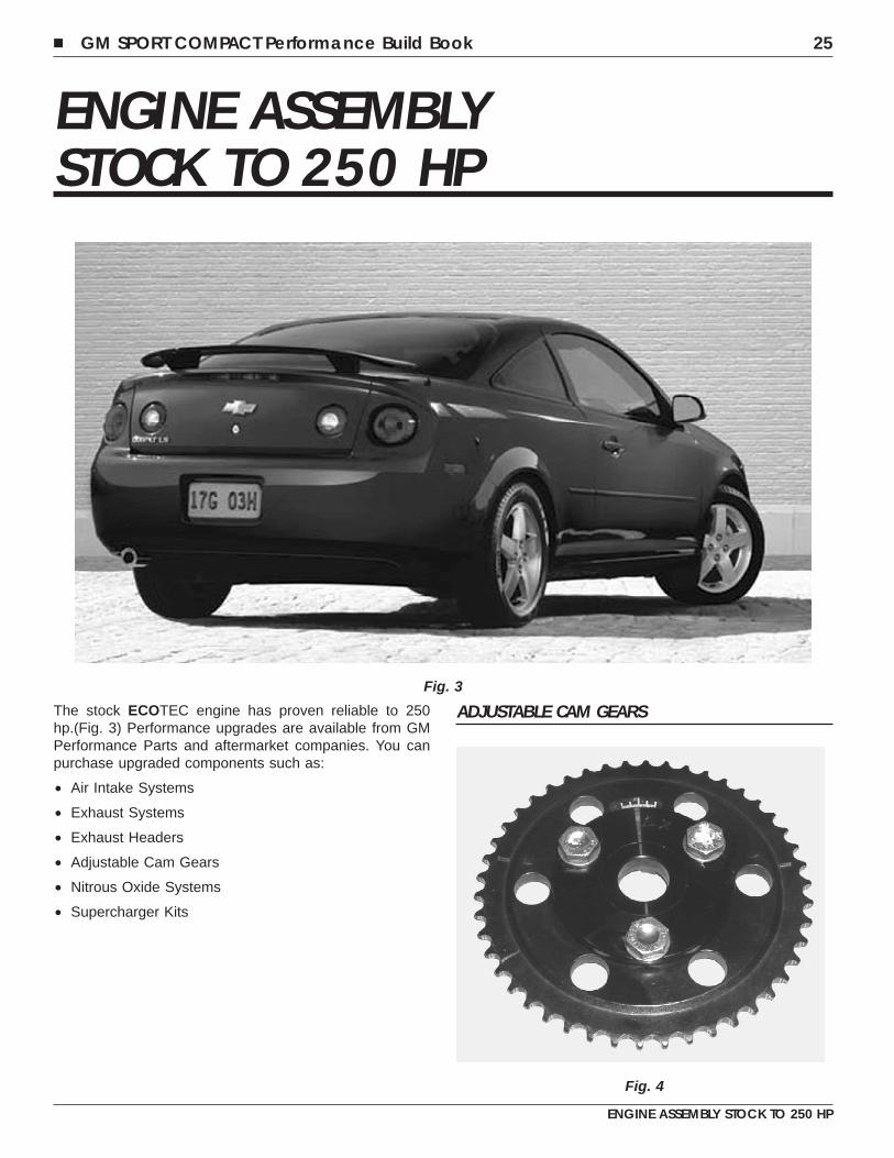
ENGINE ASSEMBLYSTOCK TO 250 HP
The stock ECOTEC engine has proven reliable to 250hp.(Fig. 3) Performance upgrades are available from GMPerformance Parts and aftermarket companies. You canpurchase upgraded components such as:
• Air Intake Systems
• Exhaust Systems
• Exhaust Headers
• Adjustable Cam Gears
• Nitrous Oxide Systems
• Supercharger Kits
ADJUSTABLE CAM GEARSFig. 3
Fig. 4
� GM SPORT COMPACT Performance Build Book 25
ENGINE ASSEMBLY STOCK TO 250 HP
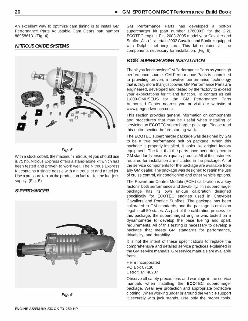
An excellent way to optimize cam timing is to install GMPerformance Parts Adjustable Cam Gears part number88958613. (Fig. 4)
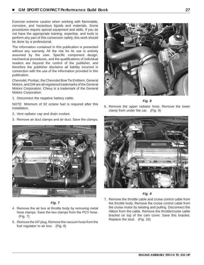
NITROUS OXIDE SYSTEMS
With a stock cobalt, the maximum nitrous jet you should useis 75 hp. Nitrous Express offers a stand-alone kit which hasbeen tested and proven to work well. The Nitrous ExpressKit contains a single nozzle with a nitrous jet and a fuel jet.Use a pressure tap on the production fuel rail for the fuel jet’ssupply. (Fig. 5)
SUPERCHARGER
GM Performance Parts has developed a bolt-onsupercharger kit (part number 1780003) for the 2.2LECOTEC engine. Fits 2003-2005 model year Cavalier andSunfire.Also fits certain 2002 Cavalier and Sunfire equippedwith Delphi fuel inejectors. This kit contains all thecomponents necessary for installation. (Fig. 6)
ECOTEC SUPERCHARGER INSTALLATION
Thank you for choosing GM Performance Parts as your highperformance source. GM Performance Parts is committedto providing proven, innovative performance technologythat is truly more than just power. GM Performance Parts areengineered, developed and tested by the factory to exceedyour expectations for fit and function. To contact us call1-800-GMUSEUS for the GM Performance PartsAuthorized Center nearest you or visit our website atwww.gmgoodwrench.com.
This section provides general information on componentsand procedures that may be useful when installing orservicing an ECOTEC supercharger package. Please readthis entire section before starting work.
The ECOTEC supercharger package was designed by GMto be a true performance bolt on package. When thispackage is properly installed, it looks like original factoryequipment. The fact that the parts have been designed toGM standards ensures a quality product. All of the fastenersrequired for installation are included in the package. All ofthe service components for the package are available fromany GM dealer. The package was designed to retain the useof cruise control, air conditioning and other vehicle options.
The Powertrain Control Module (PCM) calibration is a keyfactor in both performance and drivability. This superchargerpackage has its own unique calibration designedspecifically for ECOTEC engines used in ChevroletCavaliers and Pontiac Sunfires. The package has beencalibrated to GM standards, and the package is emissionlegal in all 50 states. As part of the calibration process forthis package, the supercharged engine was tested on adynamometer to develop the base fueling and sparkrequirements. All of this testing is necessary to develop apackage that meets GM standards for performance,drivability, and durability.
It is not the intent of these specifications to replace thecomprehensive and detailed service practices explained inthe GM service manuals. GM service manuals are availablefrom:
Helm IncorporatedPO Box 07130Detroit, MI 48207
Observe all safety precautions and warnings in the servicemanuals when installing the ECOTEC superchargerpackage. Wear eye protection and appropriate protectiveclothing. When working under or around the vehicle supportit securely with jack stands. Use only the proper tools.
Fig. 5
Fig. 6
26 � GM SPORT COMPACT Performance Build Book
ENGINE ASSEMBLY STOCK TO 250 HP
Exercise extreme caution when working with flammable,corrosive, and hazardous liquids and materials. Someprocedures require special equipment and skills. If you donot have the appropriate training, expertise, and tools toperform any part of this conversion safely, this work shouldbe done by a professional.
The information contained in this publication is presentedwithout any warranty. All the risk for its use is entirelyassumed by the user. Specific component design,mechanical procedures, and the qualifications of individualreaders are beyond the control of the publisher, andtherefore the publisher disclaims all liability incurred inconnection with the use of the information provided in thispublication.
Chevrolet, Pontiac, the Chevrolet Bow Tie Emblem, GeneralMotors, and GM are all registered trademarks of the GeneralMotors Corporation. Chevy is a trademark of the GeneralMotors Corporation.
1. Disconnect the negative battery cable.
NOTE: Minimum of 92 octane fuel is required after thisinstallation.
2. Vent radiator cap and drain coolant.
3. Remove air duct clamps and air duct. Save the clamps.
4. Remove the air box at throttle body by removing metalhose clamps. Save the two clamps from the PCV hose.
(Fig. 7)
5. Remove the IAT plug. Remove the vacuum hose from thefuel regulator to air box. (Fig. 8)
6. Remove the upper radiator hose. Remove the lowerclamp from under the car. (Fig. 9)
7. Remove the throttle cable and cruise control cable fromthe throttle body. Remove the cruise control cable fromthe cruise motor by twisting and pulling. Disconnect theribbon from the cable. Remove the throttle/cruise cablebracket on top of the cam cover. Save this bracket.Replace the stud. (Fig. 10)
Fig. 7
Fig. 8
Fig. 9
� GM SPORT COMPACT Performance Build Book 27
ENGINE ASSEMBLY STOCK TO 250 HP
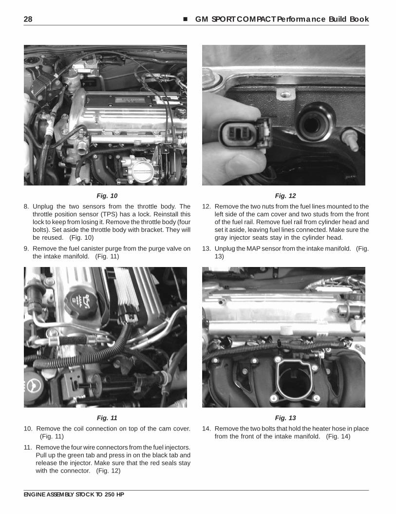
8. Unplug the two sensors from the throttle body. Thethrottle position sensor (TPS) has a lock. Reinstall thislock to keep from losing it. Remove the throttle body (fourbolts). Set aside the throttle body with bracket. They willbe reused. (Fig. 10)
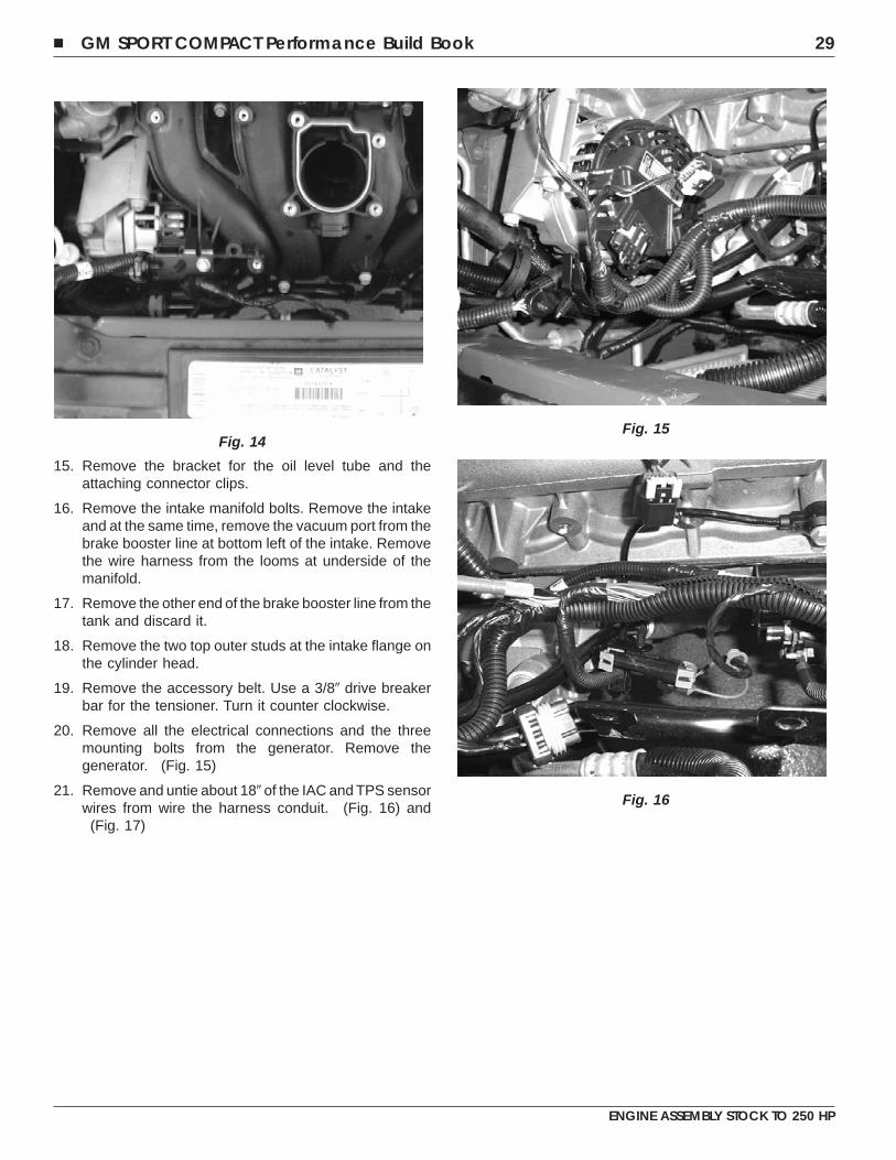
9. Remove the fuel canister purge from the purge valve onthe intake manifold. (Fig. 11)
10. Remove the coil connection on top of the cam cover.(Fig. 11)
11. Remove the four wire connectors from the fuel injectors.Pull up the green tab and press in on the black tab andrelease the injector. Make sure that the red seals staywith the connector. (Fig. 12)
12. Remove the two nuts from the fuel lines mounted to theleft side of the cam cover and two studs from the frontof the fuel rail. Remove fuel rail from cylinder head andset it aside, leaving fuel lines connected. Make sure thegray injector seats stay in the cylinder head.
13. Unplug the MAP sensor from the intake manifold. (Fig.13)
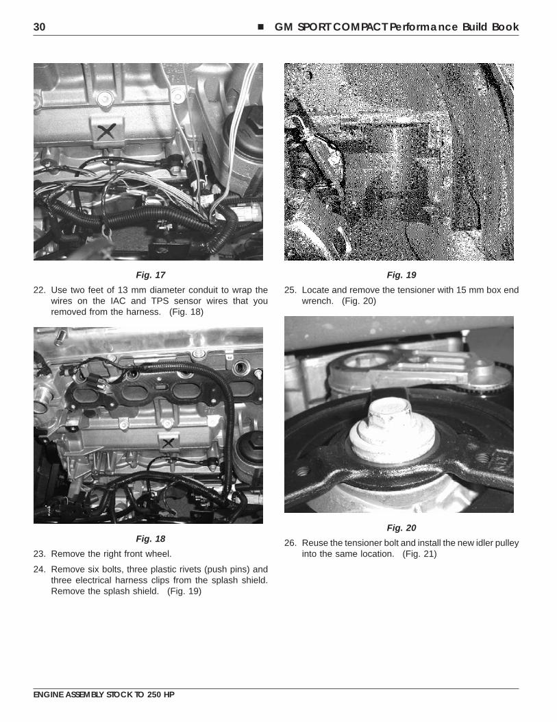
14. Remove the two bolts that hold the heater hose in placefrom the front of the intake manifold. (Fig. 14)
Fig. 10
Fig. 11
Fig. 12
Fig. 13
28 � GM SPORT COMPACT Performance Build Book
ENGINE ASSEMBLY STOCK TO 250 HP
15. Remove the bracket for the oil level tube and theattaching connector clips.
16. Remove the intake manifold bolts. Remove the intakeand at the same time, remove the vacuum port from thebrake booster line at bottom left of the intake. Removethe wire harness from the looms at underside of themanifold.
17. Remove the other end of the brake booster line from thetank and discard it.
18. Remove the two top outer studs at the intake flange onthe cylinder head.
19. Remove the accessory belt. Use a 3/8� drive breakerbar for the tensioner. Turn it counter clockwise.
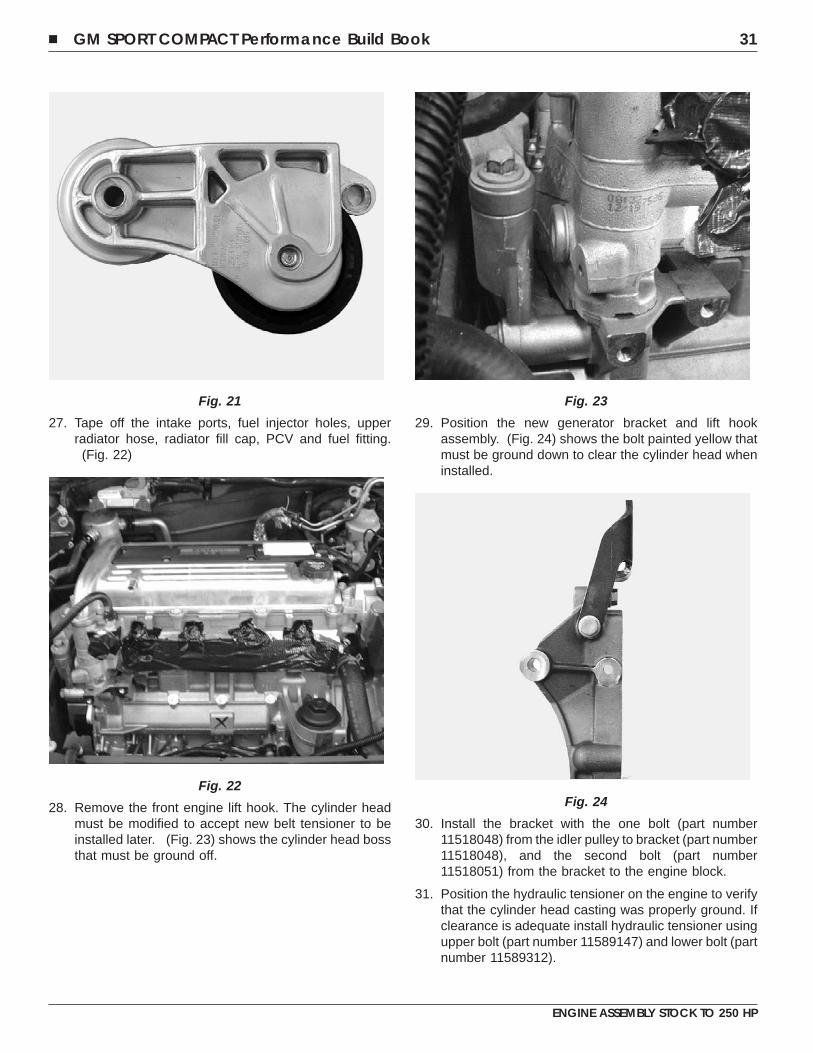
20. Remove all the electrical connections and the threemounting bolts from the generator. Remove thegenerator. (Fig. 15)
21. Remove and untie about 18� of the IAC and TPS sensorwires from wire the harness conduit. (Fig. 16) and
(Fig. 17)
Fig. 14Fig. 15
Fig. 16
� GM SPORT COMPACT Performance Build Book 29
ENGINE ASSEMBLY STOCK TO 250 HP
22. Use two feet of 13 mm diameter conduit to wrap thewires on the IAC and TPS sensor wires that youremoved from the harness. (Fig. 18)
23. Remove the right front wheel.
24. Remove six bolts, three plastic rivets (push pins) andthree electrical harness clips from the splash shield.Remove the splash shield. (Fig. 19)
25. Locate and remove the tensioner with 15 mm box endwrench. (Fig. 20)
26. Reuse the tensioner bolt and install the new idler pulleyinto the same location. (Fig. 21)
Fig. 17
Fig. 18
Fig. 19
Fig. 20
30 � GM SPORT COMPACT Performance Build Book
ENGINE ASSEMBLY STOCK TO 250 HP
27. Tape off the intake ports, fuel injector holes, upperradiator hose, radiator fill cap, PCV and fuel fitting.
(Fig. 22)
28. Remove the front engine lift hook. The cylinder headmust be modified to accept new belt tensioner to beinstalled later. (Fig. 23) shows the cylinder head bossthat must be ground off.
29. Position the new generator bracket and lift hookassembly. (Fig. 24) shows the bolt painted yellow thatmust be ground down to clear the cylinder head wheninstalled.
30. Install the bracket with the one bolt (part number11518048) from the idler pulley to bracket (part number11518048), and the second bolt (part number11518051) from the bracket to the engine block.
31. Position the hydraulic tensioner on the engine to verifythat the cylinder head casting was properly ground. Ifclearance is adequate install hydraulic tensioner usingupper bolt (part number 11589147) and lower bolt (partnumber 11589312).
Fig. 21
Fig. 22
Fig. 23
Fig. 24
� GM SPORT COMPACT Performance Build Book 31
ENGINE ASSEMBLY STOCK TO 250 HP
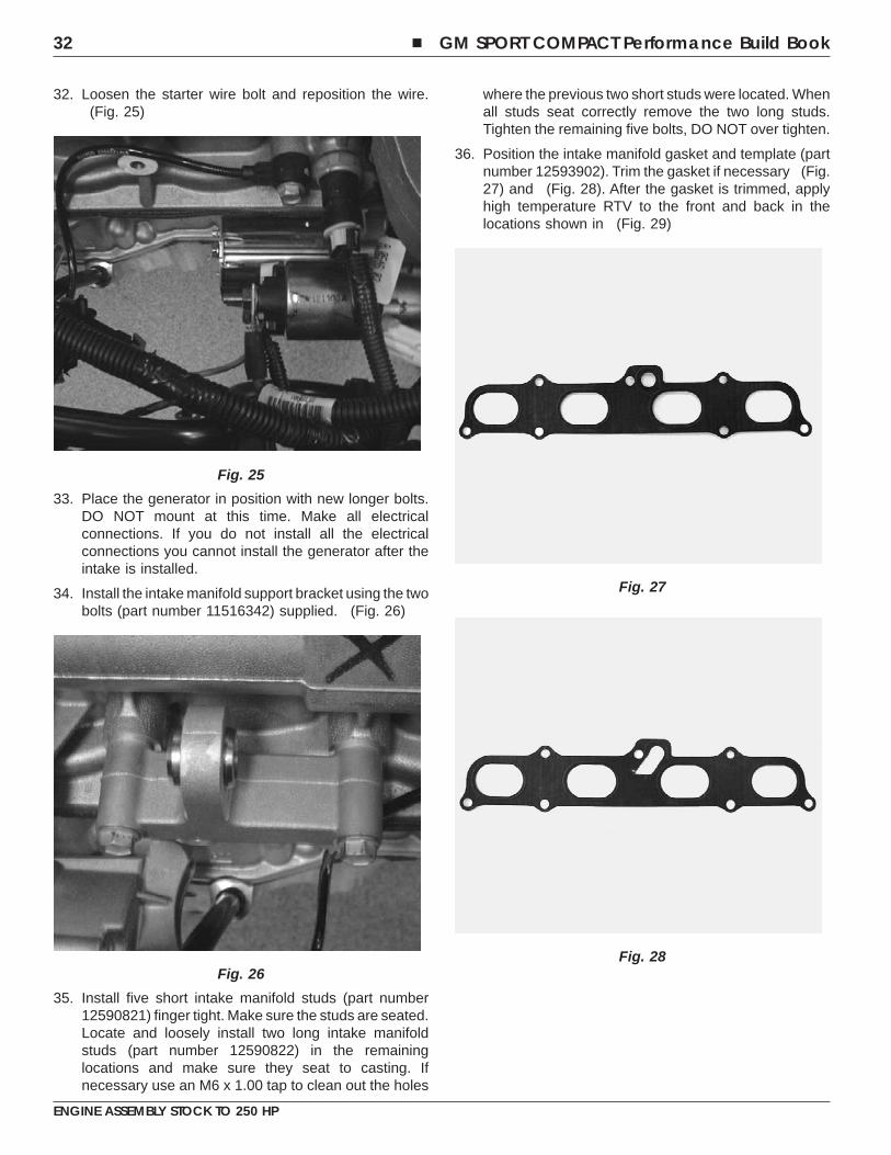
32. Loosen the starter wire bolt and reposition the wire.(Fig. 25)
33. Place the generator in position with new longer bolts.DO NOT mount at this time. Make all electricalconnections. If you do not install all the electricalconnections you cannot install the generator after theintake is installed.
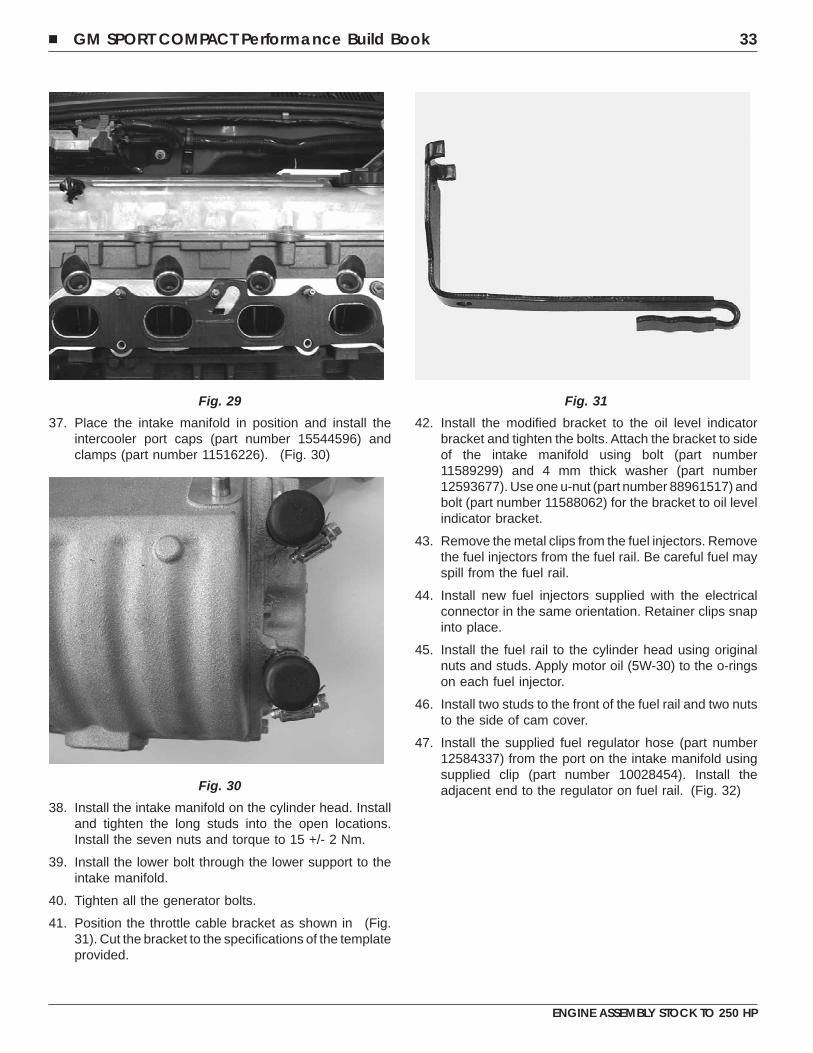
34. Install the intake manifold support bracket using the twobolts (part number 11516342) supplied. (Fig. 26)
35. Install five short intake manifold studs (part number12590821) finger tight. Make sure the studs are seated.Locate and loosely install two long intake manifoldstuds (part number 12590822) in the remaininglocations and make sure they seat to casting. Ifnecessary use an M6 x 1.00 tap to clean out the holes
where the previous two short studs were located. Whenall studs seat correctly remove the two long studs.Tighten the remaining five bolts, DO NOT over tighten.
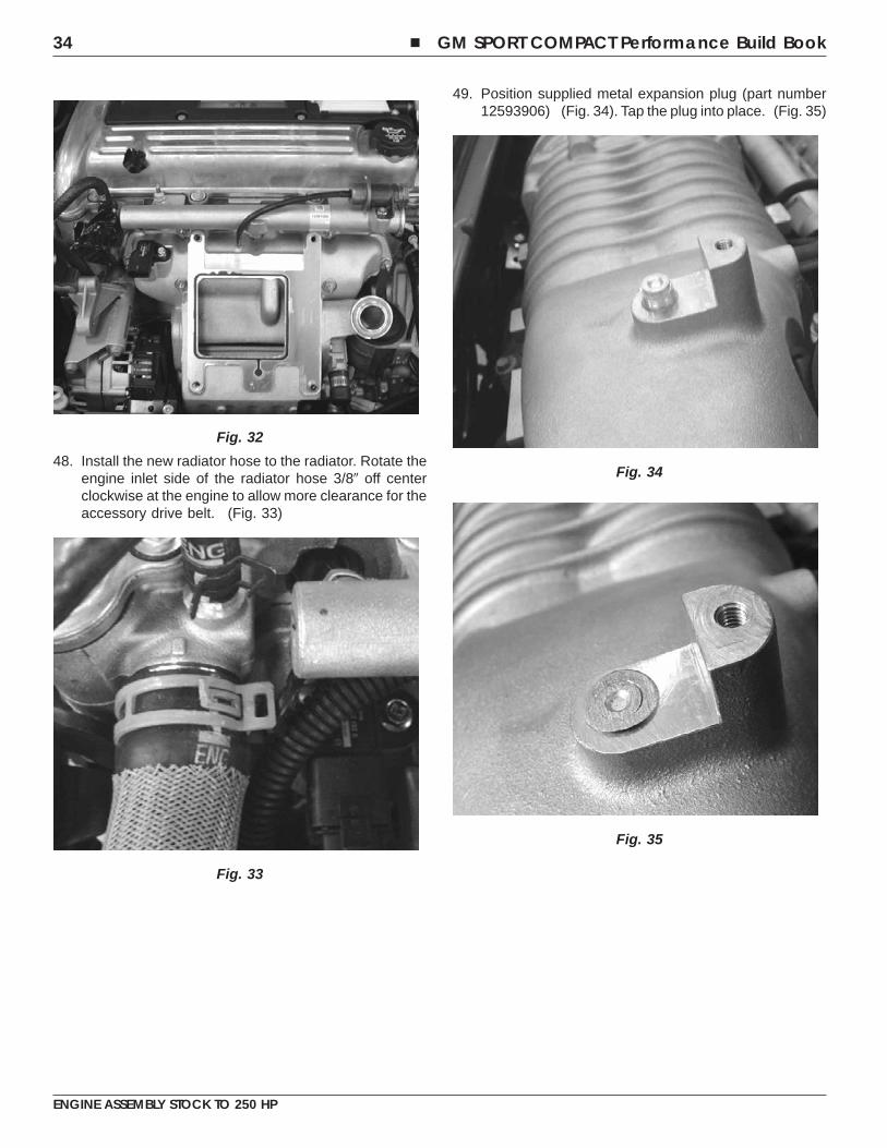
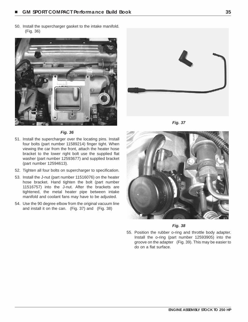
36. Position the intake manifold gasket and template (partnumber 12593902). Trim the gasket if necessary (Fig.27) and (Fig. 28). After the gasket is trimmed, applyhigh temperature RTV to the front and back in thelocations shown in (Fig. 29)
Fig. 25
Fig. 26
Fig. 27
Fig. 28
32 � GM SPORT COMPACT Performance Build Book
ENGINE ASSEMBLY STOCK TO 250 HP
37. Place the intake manifold in position and install theintercooler port caps (part number 15544596) andclamps (part number 11516226). (Fig. 30)
38. Install the intake manifold on the cylinder head. Installand tighten the long studs into the open locations.Install the seven nuts and torque to 15 +/- 2 Nm.
39. Install the lower bolt through the lower support to theintake manifold.
40. Tighten all the generator bolts.
41. Position the throttle cable bracket as shown in (Fig.31). Cut the bracket to the specifications of the templateprovided.
42. Install the modified bracket to the oil level indicatorbracket and tighten the bolts. Attach the bracket to sideof the intake manifold using bolt (part number11589299) and 4 mm thick washer (part number12593677). Use one u-nut (part number 88961517) andbolt (part number 11588062) for the bracket to oil levelindicator bracket.
43. Remove the metal clips from the fuel injectors. Removethe fuel injectors from the fuel rail. Be careful fuel mayspill from the fuel rail.
44. Install new fuel injectors supplied with the electricalconnector in the same orientation. Retainer clips snapinto place.
45. Install the fuel rail to the cylinder head using originalnuts and studs. Apply motor oil (5W-30) to the o-ringson each fuel injector.
46. Install two studs to the front of the fuel rail and two nutsto the side of cam cover.
47. Install the supplied fuel regulator hose (part number12584337) from the port on the intake manifold usingsupplied clip (part number 10028454). Install theadjacent end to the regulator on fuel rail. (Fig. 32)
Fig. 29
Fig. 30
Fig. 31
� GM SPORT COMPACT Performance Build Book 33
ENGINE ASSEMBLY STOCK TO 250 HP
48. Install the new radiator hose to the radiator. Rotate theengine inlet side of the radiator hose 3/8� off centerclockwise at the engine to allow more clearance for theaccessory drive belt. (Fig. 33)
49. Position supplied metal expansion plug (part number12593906) (Fig. 34). Tap the plug into place. (Fig. 35)
Fig. 32
Fig. 33
Fig. 34
Fig. 35
34 � GM SPORT COMPACT Performance Build Book
ENGINE ASSEMBLY STOCK TO 250 HP
50. Install the supercharger gasket to the intake manifold.(Fig. 36)
51. Install the supercharger over the locating pins. Installfour bolts (part number 11589214) finger tight. Whenviewing the car from the front, attach the heater hosebracket to the lower right bolt use the supplied flatwasher (part number 12593677) and supplied bracket(part number 12594613).
52. Tighten all four bolts on supercharger to specification.
53. Install the J-nut (part number 11516076) on the heaterhose bracket. Hand tighten the bolt (part number11516757) into the J-nut. After the brackets aretightened, the metal heater pipe between intakemanifold and coolant fans may have to be adjusted.
54. Use the 90 degree elbow from the original vacuum lineand install it on the can. (Fig. 37) and (Fig. 38)
55. Position the rubber o-ring and throttle body adapter.Install the o-ring (part number 12593905) into thegroove on the adapter (Fig. 39). This may be easier todo on a flat surface.
Fig. 36
Fig. 37
Fig. 38
� GM SPORT COMPACT Performance Build Book 35
ENGINE ASSEMBLY STOCK TO 250 HP
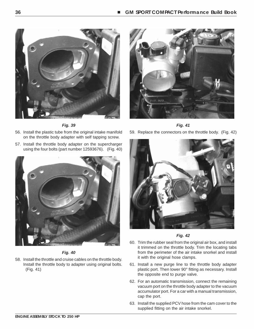
56. Install the plastic tube from the original intake manifoldon the throttle body adapter with self tapping screw.
57. Install the throttle body adapter on the superchargerusing the four bolts (part number 12593676). (Fig. 40)
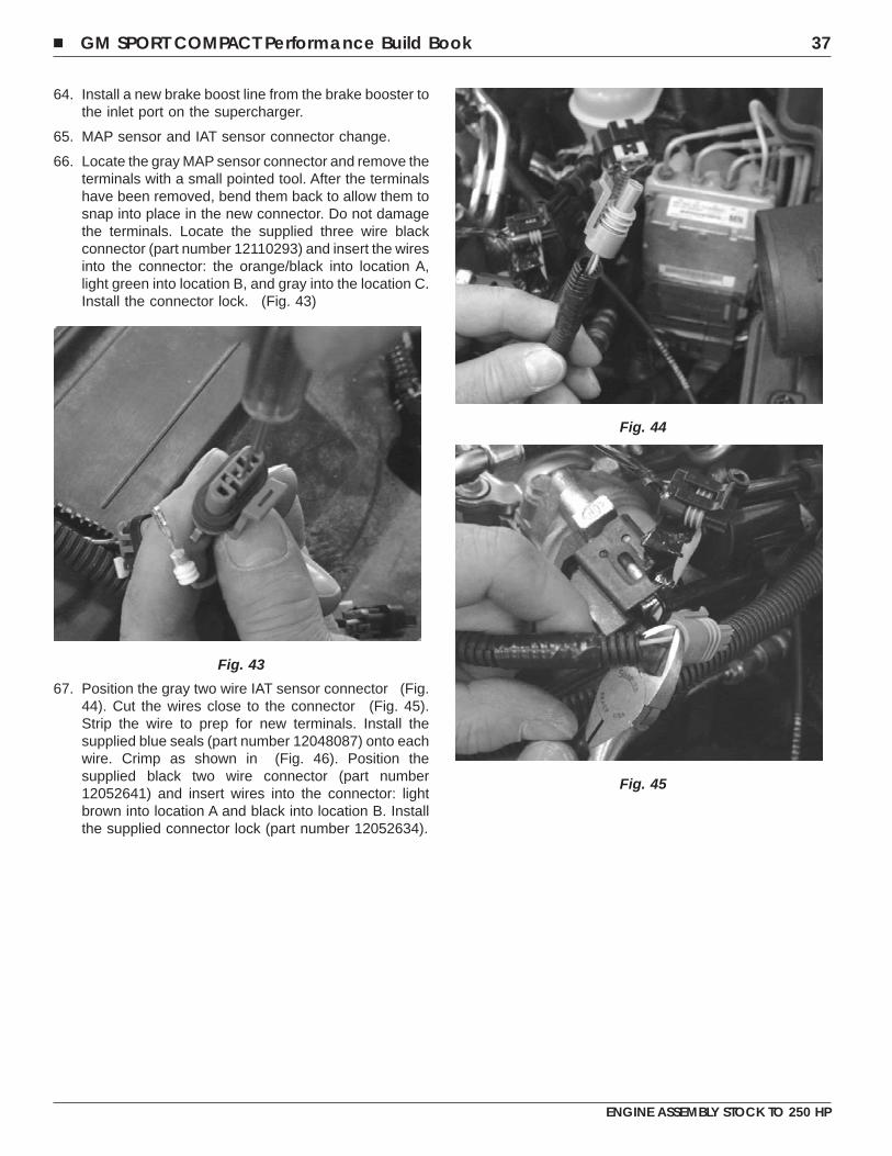
58. Install the throttle and cruise cables on the throttle body.Install the throttle body to adapter using original bolts.
(Fig. 41)
59. Replace the connectors on the throttle body. (Fig. 42)
60. Trim the rubber seal from the original air box, and installit trimmed on the throttle body. Trim the locating tabsfrom the perimeter of the air intake snorkel and installit with the original hose clamps.
61. Install a new purge line to the throttle body adapterplastic port. Then lower 90° fitting as necessary. Installthe opposite end to purge valve.
62. For an automatic transmission, connect the remainingvacuum port on the throttle body adapter to the vacuumaccumulator port. For a car with a manual transmission,cap the port.
63. Install the supplied PCV hose from the cam cover to thesupplied fitting on the air intake snorkel.
Fig. 39
Fig. 40
Fig. 41
Fig. 42
36 � GM SPORT COMPACT Performance Build Book
ENGINE ASSEMBLY STOCK TO 250 HP
64. Install a new brake boost line from the brake booster tothe inlet port on the supercharger.
65. MAP sensor and IAT sensor connector change.
66. Locate the gray MAP sensor connector and remove theterminals with a small pointed tool. After the terminalshave been removed, bend them back to allow them tosnap into place in the new connector. Do not damagethe terminals. Locate the supplied three wire blackconnector (part number 12110293) and insert the wiresinto the connector: the orange/black into location A,light green into location B, and gray into the location C.Install the connector lock. (Fig. 43)
67. Position the gray two wire IAT sensor connector (Fig.44). Cut the wires close to the connector (Fig. 45).Strip the wire to prep for new terminals. Install thesupplied blue seals (part number 12048087) onto eachwire. Crimp as shown in (Fig. 46). Position thesupplied black two wire connector (part number12052641) and insert wires into the connector: lightbrown into location A and black into location B. Installthe supplied connector lock (part number 12052634).
Fig. 43
Fig. 44
Fig. 45
� GM SPORT COMPACT Performance Build Book 37
ENGINE ASSEMBLY STOCK TO 250 HP

68. Locate wire harness (part number 12590818) andconnect it to the four wire connector at the intakemanifold next to the engines upper radiator hose. Plugin the two wire connector to the modified IAT sensorconnector. Leave the three wire MAP sensor connectorunplugged until the GM dealer has updated the PCMwith the new calibration. After the new calibration iscomplete, install the three wire MAP sensor connection.
POWERTRAIN CONTROL MODULE RECALIBRATION
Important: The Product Information Label (part number12593900) must be presented to dealer in order to receivethe new calibration.
For the engine controls to function properly, the on-boardPowertrain Control Module (PCM) must be calibrated afterthe GM Performance Parts ECOTEC Supercharger Kit (partnumber 17800003) has been installed. Note: failure torecalibrate the PCM will result in voiding both theproduct and vehicle warranty. Warning: Driving thevehicle prior to receiving the new calibration is neitherrecommended nor approved by GM Performance Partsand will result in voiding both the product and vehiclewarranty.
GM Performance Parts recommends on-board recalibrationbe performed by an Authorized GM Dealership. Thisprocess may require a full day for service and must bescheduled in advance with an Authorized GM Dealership.During the recalibration process, the Authorized GMDealership activates the supercharger kit warranty andvalidates the installation. The limited GM Performance Partssupercharger warranty will only be honored if theAuthorizedGM Dealership verifies proper installation and a properlymaintained and fully operational GM Powertrain. In order forthe dealership to access the new calibration, contact theTechline Customer Support Center (TCSC) at1-800-828-6860. The dealer will be able to access the newcalibration, GM part number 12590819 for AutomaticTransmission / 12590820 for Manual Transmission, throughthe system.
Warning: Failure to install the supercharger kit properlyand completely, failure to recalibrate the PCM or failingto maintain the full powertrain will void both the productand vehicle warranty. Warranty does not coverinstallation or installation related issues involvingsupercharger kit installed outside an Authorized GMDealership.
69. Install the accessory drive belt.
70. Cut off one inch of coolant reservoir tank hose. Zip tieall hoses away from accessory drive belt. Make surethere is enough clearance when the engine is running.Check periodically to make sure that hoses are notrubbing against other components.
71. Affix “Premium Fuel Only” label to fuel door.
Fig. 46
38 � GM SPORT COMPACT Performance Build Book
ENGINE ASSEMBLY STOCK TO 250 HP
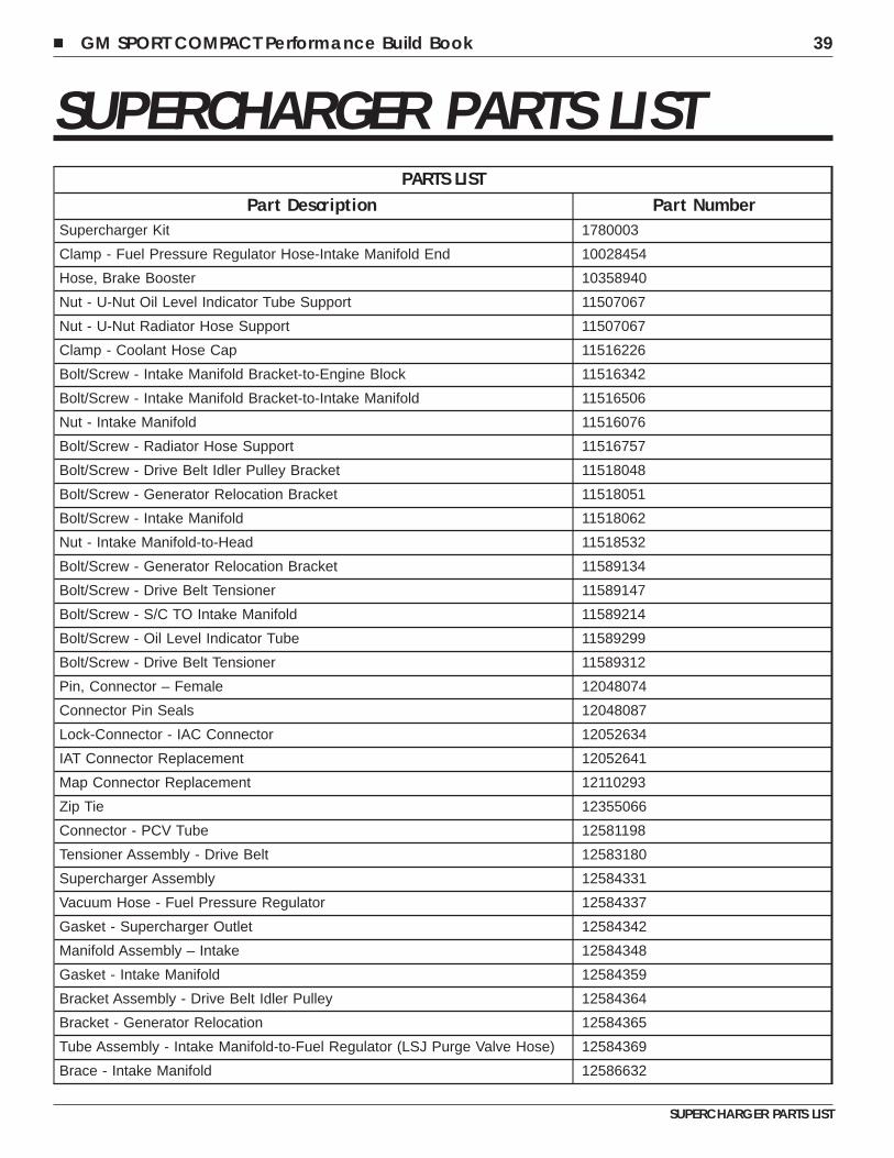
SUPERCHARGER PARTS LISTPARTS LIST
Part Description Part NumberSupercharger Kit 1780003
Clamp - Fuel Pressure Regulator Hose-Intake Manifold End 10028454
Hose, Brake Booster 10358940
Nut - U-Nut Oil Level Indicator Tube Support 11507067
Nut - U-Nut Radiator Hose Support 11507067
Clamp - Coolant Hose Cap 11516226
Bolt/Screw - Intake Manifold Bracket-to-Engine Block 11516342
Bolt/Screw - Intake Manifold Bracket-to-Intake Manifold 11516506
Nut - Intake Manifold 11516076
Bolt/Screw - Radiator Hose Support 11516757
Bolt/Screw - Drive Belt Idler Pulley Bracket 11518048
Bolt/Screw - Generator Relocation Bracket 11518051
Bolt/Screw - Intake Manifold 11518062
Nut - Intake Manifold-to-Head 11518532
Bolt/Screw - Generator Relocation Bracket 11589134
Bolt/Screw - Drive Belt Tensioner 11589147
Bolt/Screw - S/C TO Intake Manifold 11589214
Bolt/Screw - Oil Level Indicator Tube 11589299
Bolt/Screw - Drive Belt Tensioner 11589312
Pin, Connector – Female 12048074
Connector Pin Seals 12048087
Lock-Connector - IAC Connector 12052634
IAT Connector Replacement 12052641
Map Connector Replacement 12110293
Zip Tie 12355066
Connector - PCV Tube 12581198
Tensioner Assembly - Drive Belt 12583180
Supercharger Assembly 12584331
Vacuum Hose - Fuel Pressure Regulator 12584337
Gasket - Supercharger Outlet 12584342
Manifold Assembly – Intake 12584348
Gasket - Intake Manifold 12584359
Bracket Assembly - Drive Belt Idler Pulley 12584364
Bracket - Generator Relocation 12584365
Tube Assembly - Intake Manifold-to-Fuel Regulator (LSJ Purge Valve Hose) 12584369
Brace - Intake Manifold 12586632
� GM SPORT COMPACT Performance Build Book 39
SUPERCHARGER PARTS LIST
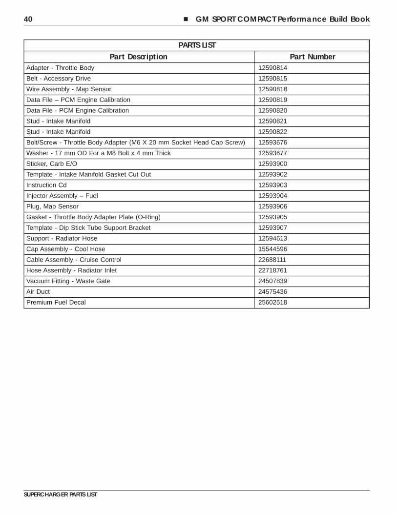
PARTS LISTPart Description Part Number
Adapter - Throttle Body 12590814
Belt - Accessory Drive 12590815
Wire Assembly - Map Sensor 12590818
Data File – PCM Engine Calibration 12590819
Data File - PCM Engine Calibration 12590820
Stud - Intake Manifold 12590821
Stud - Intake Manifold 12590822
Bolt/Screw - Throttle Body Adapter (M6 X 20 mm Socket Head Cap Screw) 12593676
Washer - 17 mm OD For a M8 Bolt x 4 mm Thick 12593677
Sticker, Carb E/O 12593900
Template - Intake Manifold Gasket Cut Out 12593902
Instruction Cd 12593903
Injector Assembly – Fuel 12593904
Plug, Map Sensor 12593906
Gasket - Throttle Body Adapter Plate (O-Ring) 12593905
Template - Dip Stick Tube Support Bracket 12593907
Support - Radiator Hose 12594613
Cap Assembly - Cool Hose 15544596
Cable Assembly - Cruise Control 22688111
Hose Assembly - Radiator Inlet 22718761
Vacuum Fitting - Waste Gate 24507839
Air Duct 24575436
Premium Fuel Decal 25602518
40 � GM SPORT COMPACT Performance Build Book
SUPERCHARGER PARTS LIST
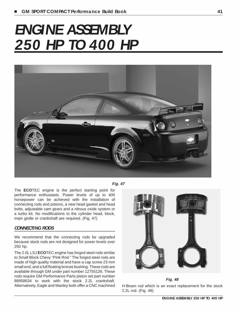
ENGINE ASSEMBLY250 HP TO 400 HP
The ECOTEC engine is the perfect starting point forperformance enthusiasts. Power levels of up to 400horsepower can be achieved with the installation ofconnecting rods and pistons, a new head gasket and headbolts, adjustable cam gears and a nitrous oxide system ora turbo kit. No modifications to the cylinder head, block,main girdle or crankshaft are required. (Fig. 47)
CONNECTING RODS
We recommend that the connecting rods be upgradedbecause stock rods are not designed for power levels over250 hp.
The 2.0L LSJ ECOTEC engine has forged steel rods similarto Small Block Chevy “Pink Rod.” The forged steel rods aremade of high quality material and have a cap screw 23 mmsmall end, and a full floating bronze bushing. These rods areavailable through GM under part number 12755126. Theserods require GM Performance Parts piston set part number88958634 to work with the stock 2.2L crankshaft.Alternatively, Eagle and Manley both offer a CNC machined H-Beam rod which is an exact replacement for the stock
2.2L rod. (Fig. 48)
Fig. 47
Fig. 48
� GM SPORT COMPACT Performance Build Book 41
ENGINE ASSEMBLY 250 HP TO 400 HP
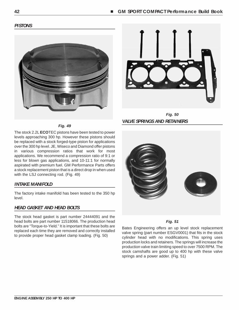
PISTONS
The stock 2.2L ECOTEC pistons have been tested to powerlevels approaching 300 hp. However these pistons shouldbe replaced with a stock forged-type piston for applicationsover the 300 hp level. JE, Wiseco and Diamond offer pistonsin various compression ratios that work for mostapplications. We recommend a compression ratio of 9:1 orless for blown gas applications, and 10-11:1 for normallyaspirated with premium fuel. GM Performance Parts offersa stock replacement piston that is a direct drop in when usedwith the LSJ connecting rod. (Fig. 49)
INTAKE MANIFOLD
The factory intake manifold has been tested to the 350 hplevel.
HEAD GASKET AND HEAD BOLTS
The stock head gasket is part number 24444091 and thehead bolts are part number 11518066. The production headbolts are “Torque-to-Yield.” It is important that these bolts arereplaced each time they are removed and correctly installedto provide proper head gasket clamp loading. (Fig. 50)
VALVE SPRINGS AND RETAINERS
Bates Engineering offers an up level stock replacementvalve spring (part number ESGV0001) that fits in the stockcylinder head with no modifications. This spring usesproduction locks and retainers. The springs will increase theproduction valve train limiting speed to over 7500 RPM. Thestock camshafts are good up to 400 hp with these valvesprings and a power adder. (Fig. 51)
Fig. 49
Fig. 50
Fig. 51
42 � GM SPORT COMPACT Performance Build Book
ENGINE ASSEMBLY 250 HP TO 400 HP
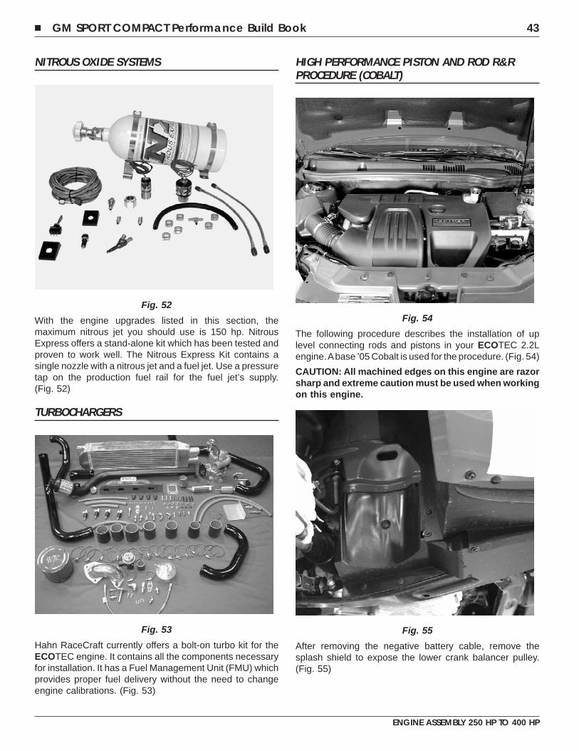
NITROUS OXIDE SYSTEMS
With the engine upgrades listed in this section, themaximum nitrous jet you should use is 150 hp. NitrousExpress offers a stand-alone kit which has been tested andproven to work well. The Nitrous Express Kit contains asingle nozzle with a nitrous jet and a fuel jet. Use a pressuretap on the production fuel rail for the fuel jet’s supply.(Fig. 52)
TURBOCHARGERS
Hahn RaceCraft currently offers a bolt-on turbo kit for theECOTEC engine. It contains all the components necessaryfor installation. It has a Fuel Management Unit (FMU) whichprovides proper fuel delivery without the need to changeengine calibrations. (Fig. 53)
HIGH PERFORMANCE PISTON AND ROD R&RPROCEDURE (COBALT)
The following procedure describes the installation of uplevel connecting rods and pistons in your ECOTEC 2.2Lengine.Abase ’05 Cobalt is used for the procedure. (Fig. 54)
CAUTION: All machined edges on this engine are razorsharp and extreme caution must be used when workingon this engine.
After removing the negative battery cable, remove thesplash shield to expose the lower crank balancer pulley.(Fig. 55)
Fig. 52
Fig. 53
Fig. 54
Fig. 55
� GM SPORT COMPACT Performance Build Book 43
ENGINE ASSEMBLY 250 HP TO 400 HP
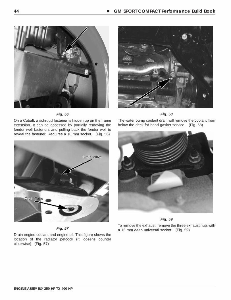
On a Cobalt, a schroud fastener is hidden up on the frameextension. It can be accessed by partially removing thefender well fasteners and pulling back the fender well toreveal the fastener. Requires a 10 mm socket. (Fig. 56)
Drain engine coolant and engine oil. This figure shows thelocation of the radiator petcock (It loosens counterclockwise) (Fig. 57)
The water pump coolant drain will remove the coolant frombelow the deck for head gasket service. (Fig. 58)
To remove the exhaust, remove the three exhaust nuts witha 15 mm deep universal socket. (Fig. 59)
Fig. 56
Fig. 57
Fig. 58
Fig. 59
44 � GM SPORT COMPACT Performance Build Book
ENGINE ASSEMBLY 250 HP TO 400 HP
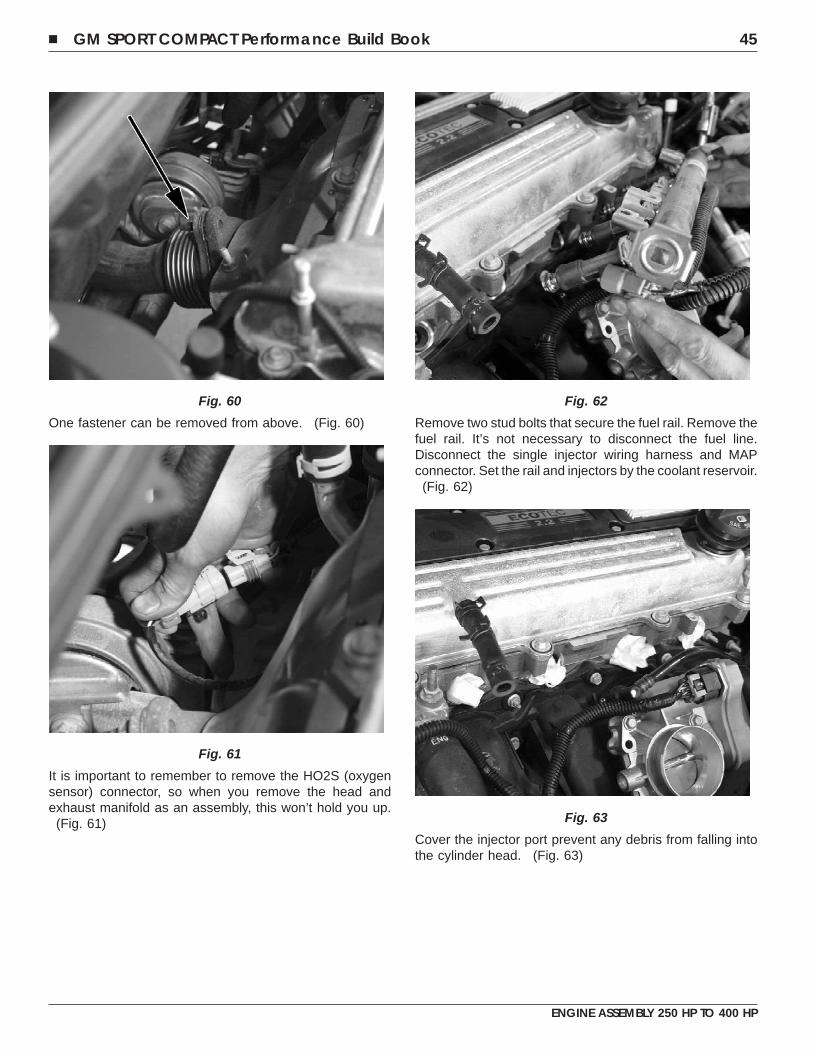
One fastener can be removed from above. (Fig. 60)
It is important to remember to remove the HO2S (oxygensensor) connector, so when you remove the head andexhaust manifold as an assembly, this won’t hold you up.
(Fig. 61)
Remove two stud bolts that secure the fuel rail. Remove thefuel rail. It’s not necessary to disconnect the fuel line.Disconnect the single injector wiring harness and MAPconnector. Set the rail and injectors by the coolant reservoir.
(Fig. 62)
Cover the injector port prevent any debris from falling intothe cylinder head. (Fig. 63)
Fig. 60
Fig. 61
Fig. 62
Fig. 63
� GM SPORT COMPACT Performance Build Book 45
ENGINE ASSEMBLY 250 HP TO 400 HP
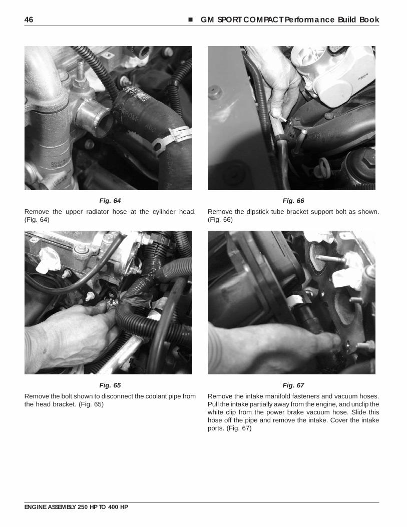
Remove the upper radiator hose at the cylinder head.(Fig. 64)
Remove the bolt shown to disconnect the coolant pipe fromthe head bracket. (Fig. 65)
Remove the dipstick tube bracket support bolt as shown.(Fig. 66)
Remove the intake manifold fasteners and vacuum hoses.Pull the intake partially away from the engine, and unclip thewhite clip from the power brake vacuum hose. Slide thishose off the pipe and remove the intake. Cover the intakeports. (Fig. 67)
Fig. 64
Fig. 65
Fig. 66
Fig. 67
46 � GM SPORT COMPACT Performance Build Book
ENGINE ASSEMBLY 250 HP TO 400 HP
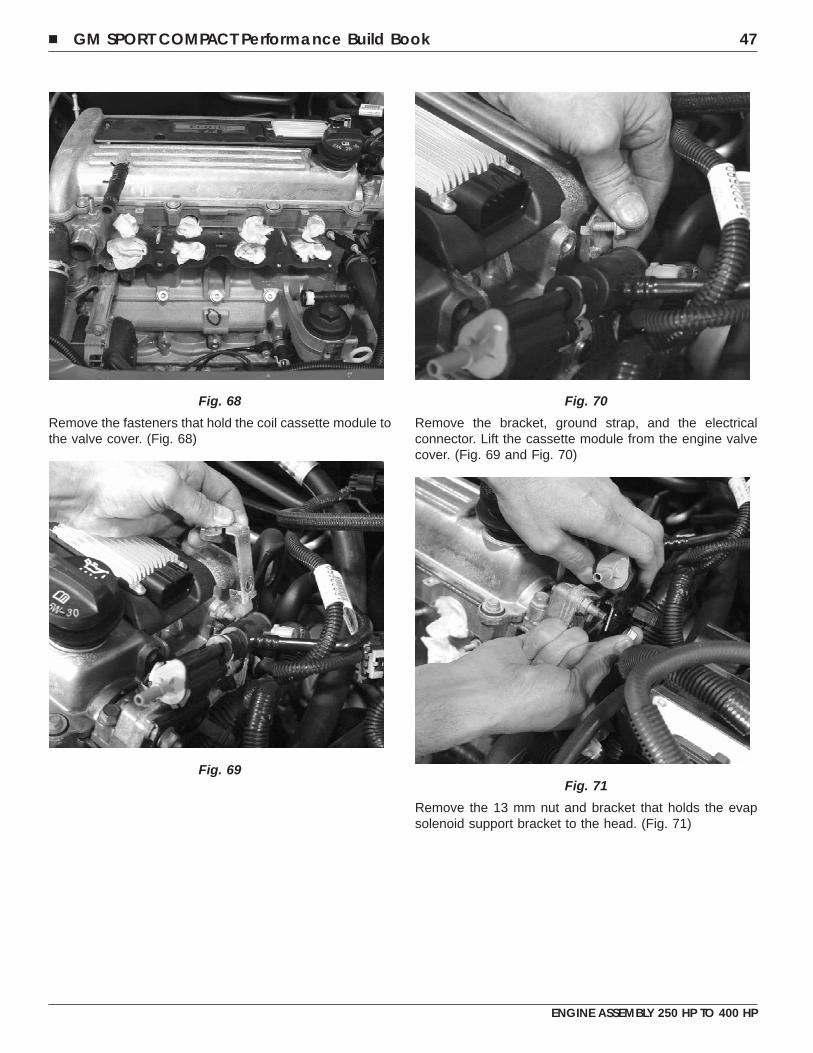
Remove the fasteners that hold the coil cassette module tothe valve cover. (Fig. 68)
Remove the bracket, ground strap, and the electricalconnector. Lift the cassette module from the engine valvecover. (Fig. 69 and Fig. 70)
Remove the 13 mm nut and bracket that holds the evapsolenoid support bracket to the head. (Fig. 71)
Fig. 68
Fig. 69
Fig. 70
Fig. 71
� GM SPORT COMPACT Performance Build Book 47
ENGINE ASSEMBLY 250 HP TO 400 HP
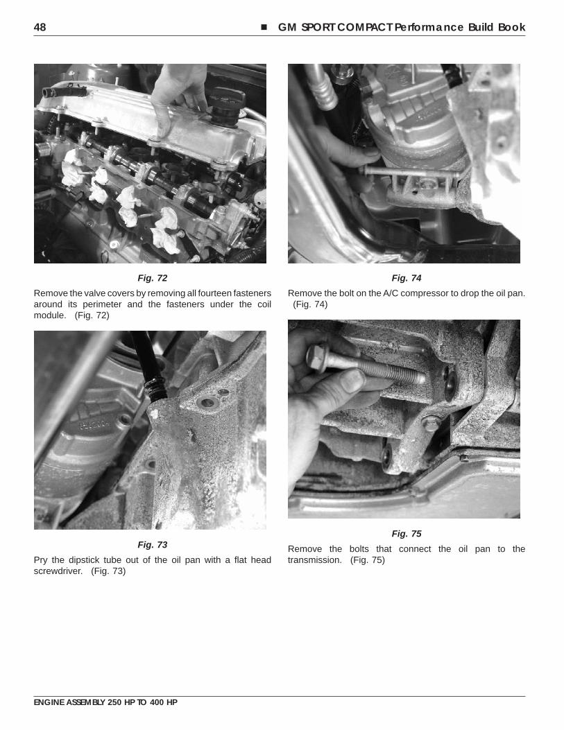
Remove the valve covers by removing all fourteen fastenersaround its perimeter and the fasteners under the coilmodule. (Fig. 72)
Pry the dipstick tube out of the oil pan with a flat headscrewdriver. (Fig. 73)
Remove the bolt on the A/C compressor to drop the oil pan.(Fig. 74)
Remove the bolts that connect the oil pan to thetransmission. (Fig. 75)
Fig. 72
Fig. 73
Fig. 74
Fig. 75
48 � GM SPORT COMPACT Performance Build Book
ENGINE ASSEMBLY 250 HP TO 400 HP
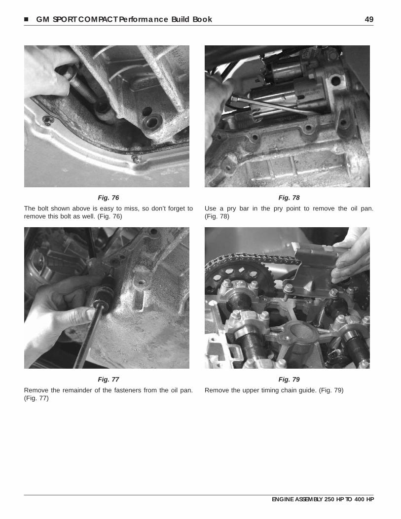
The bolt shown above is easy to miss, so don’t forget toremove this bolt as well. (Fig. 76)
Remove the remainder of the fasteners from the oil pan.(Fig. 77)
Use a pry bar in the pry point to remove the oil pan.(Fig. 78)
Remove the upper timing chain guide. (Fig. 79)
Fig. 76
Fig. 77
Fig. 78
Fig. 79
� GM SPORT COMPACT Performance Build Book 49
ENGINE ASSEMBLY 250 HP TO 400 HP
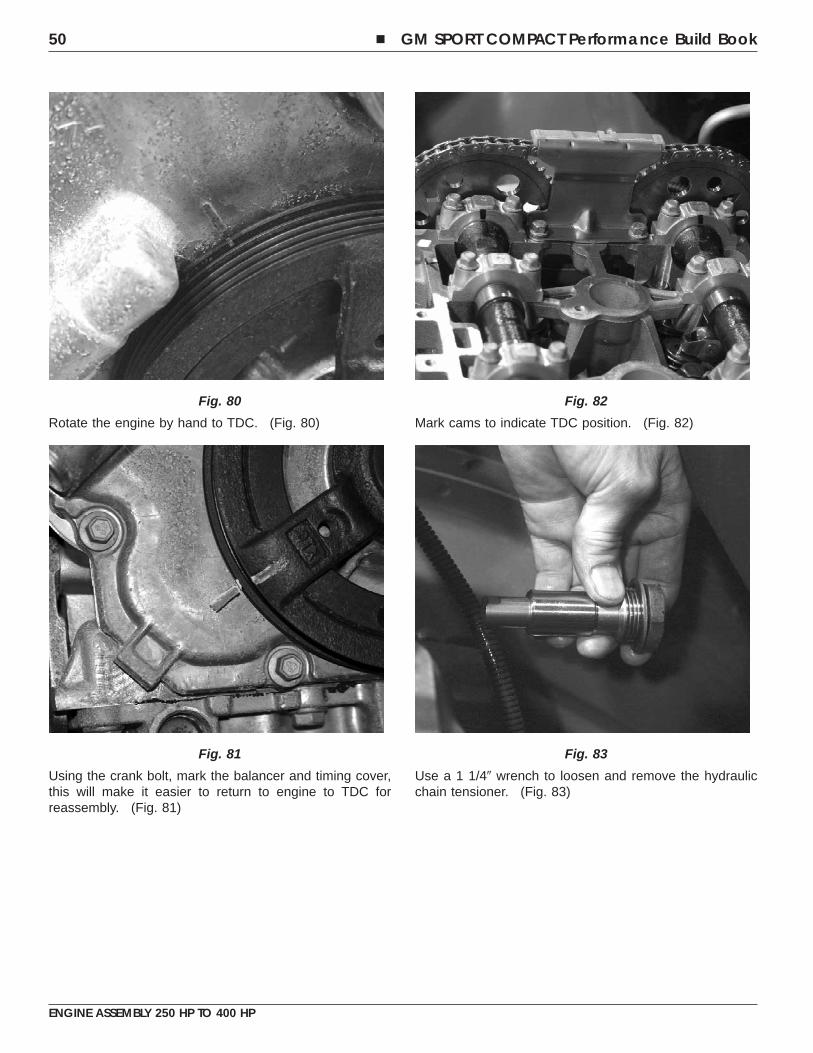
Rotate the engine by hand to TDC. (Fig. 80)
Using the crank bolt, mark the balancer and timing cover,this will make it easier to return to engine to TDC forreassembly. (Fig. 81)
Mark cams to indicate TDC position. (Fig. 82)
Use a 1 1/4� wrench to loosen and remove the hydraulicchain tensioner. (Fig. 83)
Fig. 80
Fig. 81
Fig. 82
Fig. 83
50 � GM SPORT COMPACT Performance Build Book
ENGINE ASSEMBLY 250 HP TO 400 HP
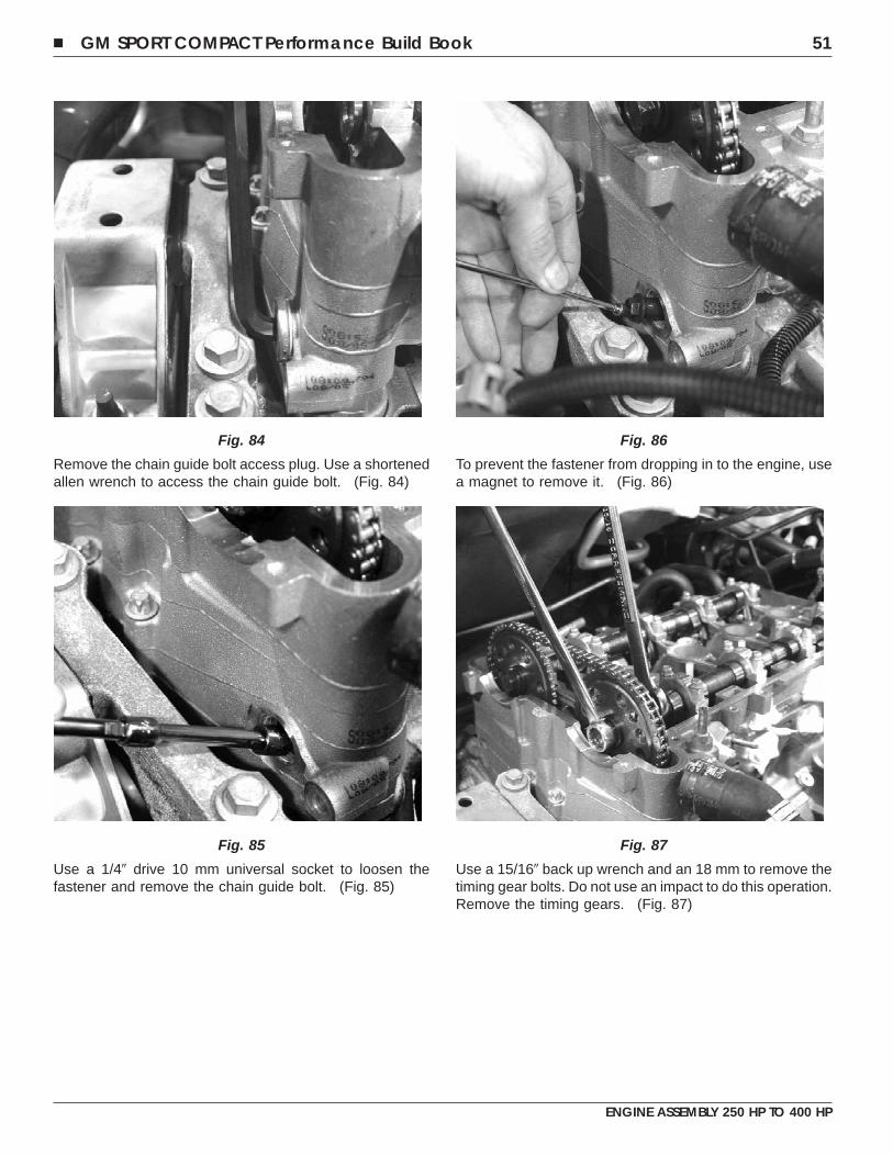
Remove the chain guide bolt access plug. Use a shortenedallen wrench to access the chain guide bolt. (Fig. 84)
Use a 1/4� drive 10 mm universal socket to loosen thefastener and remove the chain guide bolt. (Fig. 85)
To prevent the fastener from dropping in to the engine, usea magnet to remove it. (Fig. 86)
Use a 15/16� back up wrench and an 18 mm to remove thetiming gear bolts. Do not use an impact to do this operation.Remove the timing gears. (Fig. 87)
Fig. 84
Fig. 85
Fig. 86
Fig. 87
� GM SPORT COMPACT Performance Build Book 51
ENGINE ASSEMBLY 250 HP TO 400 HP
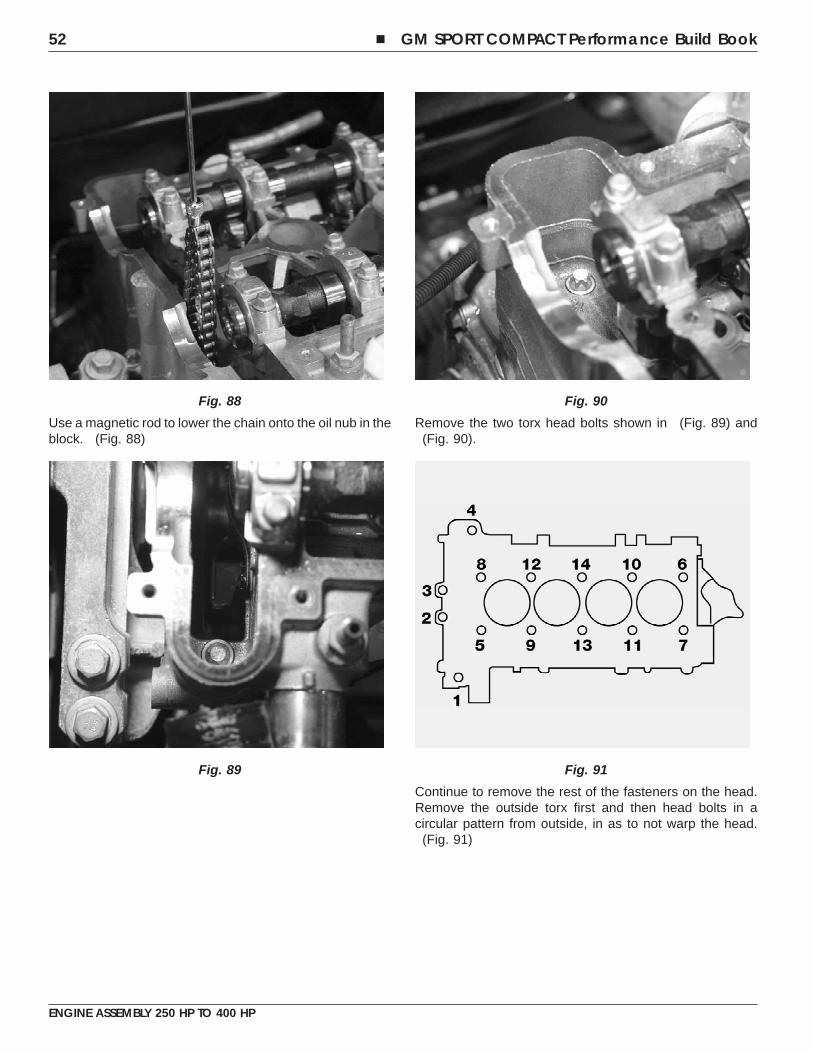
Use a magnetic rod to lower the chain onto the oil nub in theblock. (Fig. 88)
Remove the two torx head bolts shown in (Fig. 89) and(Fig. 90).
Continue to remove the rest of the fasteners on the head.Remove the outside torx first and then head bolts in acircular pattern from outside, in as to not warp the head.
(Fig. 91)
Fig. 88
Fig. 89
Fig. 90
Fig. 91
52 � GM SPORT COMPACT Performance Build Book
ENGINE ASSEMBLY 250 HP TO 400 HP
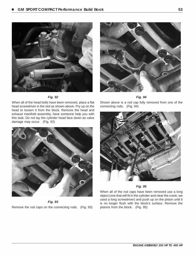
When all of the head bolts have been removed, place a flathead screwdriver in the slot as shown above. Pry up on thehead to loosen it from the block. Remove the head andexhaust manifold assembly, have someone help you withthis task. Do not lay the cylinder head face down as valvedamage may occur. (Fig. 92)
Remove the rod caps on the connecting rods. (Fig. 93)
Shown above is a rod cap fully removed from one of theconnecting rods. (Fig. 94)
When all of the rod caps have been removed use a longobject (one that will fit in the cylinder and clear the crank, weused a long screwdriver) and push up on the piston until itis no longer flush with the block’s surface. Remove thepistons from the block. (Fig. 95)
Fig. 92
Fig. 93
Fig. 94
Fig. 95
� GM SPORT COMPACT Performance Build Book 53
ENGINE ASSEMBLY 250 HP TO 400 HP
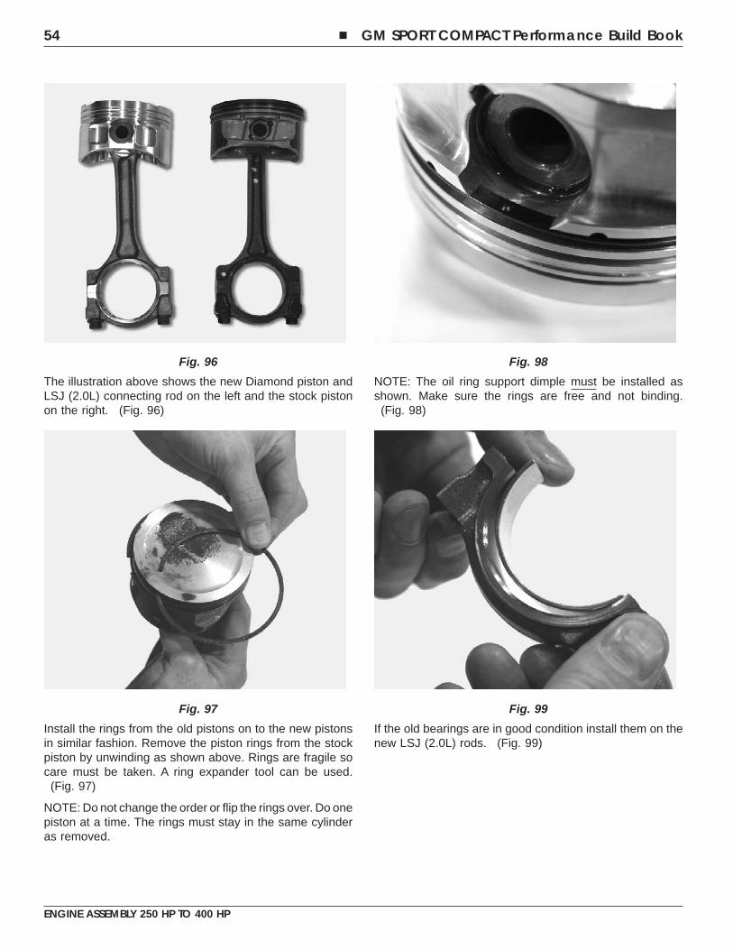
The illustration above shows the new Diamond piston andLSJ (2.0L) connecting rod on the left and the stock pistonon the right. (Fig. 96)
Install the rings from the old pistons on to the new pistonsin similar fashion. Remove the piston rings from the stockpiston by unwinding as shown above. Rings are fragile socare must be taken. A ring expander tool can be used.
(Fig. 97)
NOTE: Do not change the order or flip the rings over. Do onepiston at a time. The rings must stay in the same cylinderas removed.
NOTE: The oil ring support dimple must be installed asshown. Make sure the rings are free and not binding.
(Fig. 98)
If the old bearings are in good condition install them on thenew LSJ (2.0L) rods. (Fig. 99)
Fig. 96
Fig. 97
Fig. 98
Fig. 99
54 � GM SPORT COMPACT Performance Build Book
ENGINE ASSEMBLY 250 HP TO 400 HP
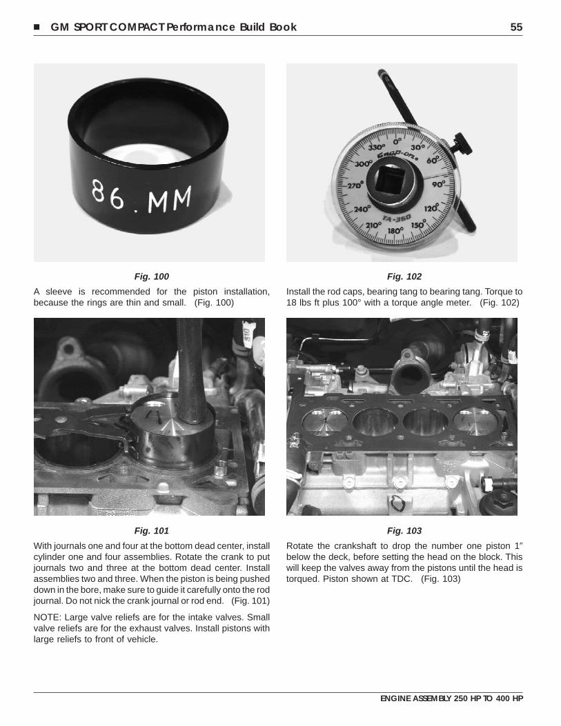
A sleeve is recommended for the piston installation,because the rings are thin and small. (Fig. 100)
With journals one and four at the bottom dead center, installcylinder one and four assemblies. Rotate the crank to putjournals two and three at the bottom dead center. Installassemblies two and three. When the piston is being pusheddown in the bore, make sure to guide it carefully onto the rodjournal. Do not nick the crank journal or rod end. (Fig. 101)
NOTE: Large valve reliefs are for the intake valves. Smallvalve reliefs are for the exhaust valves. Install pistons withlarge reliefs to front of vehicle.
Install the rod caps, bearing tang to bearing tang. Torque to18 lbs ft plus 100° with a torque angle meter. (Fig. 102)
Rotate the crankshaft to drop the number one piston 1�below the deck, before setting the head on the block. Thiswill keep the valves away from the pistons until the head istorqued. Piston shown at TDC. (Fig. 103)
Fig. 100
Fig. 101
Fig. 102
Fig. 103
� GM SPORT COMPACT Performance Build Book 55
ENGINE ASSEMBLY 250 HP TO 400 HP
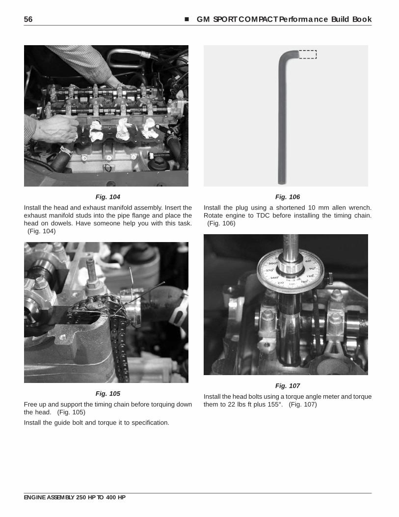
Install the head and exhaust manifold assembly. Insert theexhaust manifold studs into the pipe flange and place thehead on dowels. Have someone help you with this task.
(Fig. 104)
Free up and support the timing chain before torquing downthe head. (Fig. 105)
Install the guide bolt and torque it to specification.
Install the plug using a shortened 10 mm allen wrench.Rotate engine to TDC before installing the timing chain.
(Fig. 106)
Install the head bolts using a torque angle meter and torquethem to 22 lbs ft plus 155°. (Fig. 107)
Fig. 104
Fig. 105
Fig. 106
Fig. 107
56 � GM SPORT COMPACT Performance Build Book
ENGINE ASSEMBLY 250 HP TO 400 HP
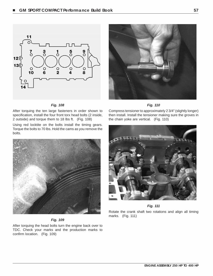
After torquing the ten large fasteners in order shown tospecification, install the four front torx head bolts (2 inside,2 outside) and torque them to 18 lbs ft. (Fig. 108)
Using red locktite on the bolts install the timing gears.Torque the bolts to 70 lbs. Hold the cams as you remove thebolts.
After torquing the head bolts turn the engine back over toTDC. Check your marks and the production marks toconfirm location. (Fig. 109)
Compress tensioner to approximately 2 3/4� (slightly longer)then install. Install the tensioner making sure the groves inthe chain yoke are vertical. (Fig. 110)
Rotate the crank shaft two rotations and align all timingmarks. (Fig. 111)
Fig. 108
Fig. 109
Fig. 110
Fig. 111
� GM SPORT COMPACT Performance Build Book 57
ENGINE ASSEMBLY 250 HP TO 400 HP
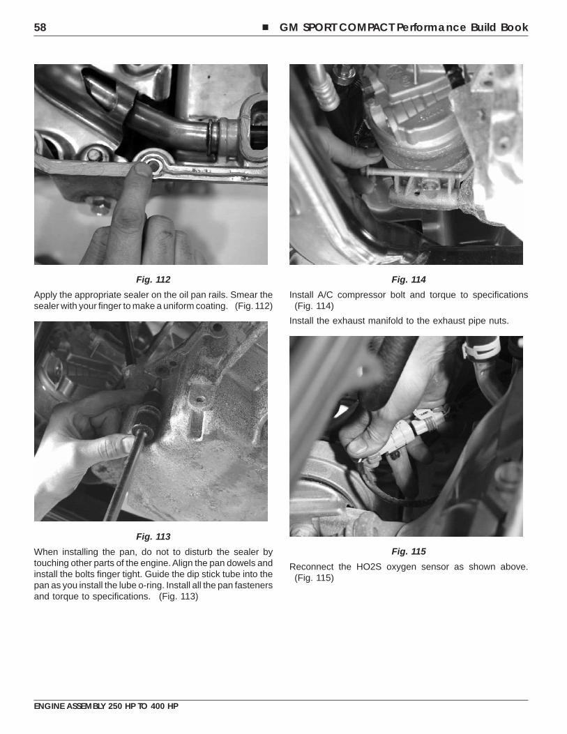
Apply the appropriate sealer on the oil pan rails. Smear thesealer with your finger to make a uniform coating. (Fig. 112)
When installing the pan, do not to disturb the sealer bytouching other parts of the engine. Align the pan dowels andinstall the bolts finger tight. Guide the dip stick tube into thepan as you install the lube o-ring. Install all the pan fastenersand torque to specifications. (Fig. 113)
Install A/C compressor bolt and torque to specifications(Fig. 114)
Install the exhaust manifold to the exhaust pipe nuts.
Reconnect the HO2S oxygen sensor as shown above.(Fig. 115)
Fig. 112
Fig. 113
Fig. 114
Fig. 115
58 � GM SPORT COMPACT Performance Build Book
ENGINE ASSEMBLY 250 HP TO 400 HP
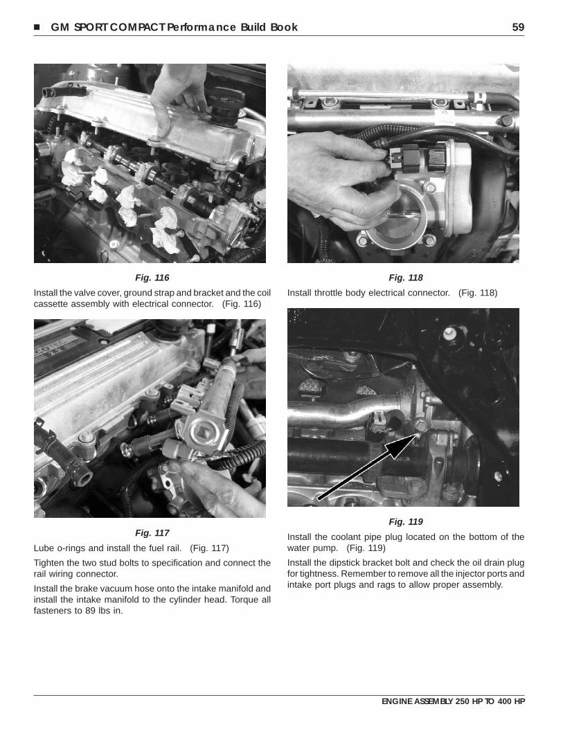
Install the valve cover, ground strap and bracket and the coilcassette assembly with electrical connector. (Fig. 116)
Lube o-rings and install the fuel rail. (Fig. 117)
Tighten the two stud bolts to specification and connect therail wiring connector.
Install the brake vacuum hose onto the intake manifold andinstall the intake manifold to the cylinder head. Torque allfasteners to 89 lbs in.
Install throttle body electrical connector. (Fig. 118)
Install the coolant pipe plug located on the bottom of thewater pump. (Fig. 119)
Install the dipstick bracket bolt and check the oil drain plugfor tightness. Remember to remove all the injector ports andintake port plugs and rags to allow proper assembly.
Fig. 116
Fig. 117
Fig. 118
Fig. 119
� GM SPORT COMPACT Performance Build Book 59
ENGINE ASSEMBLY 250 HP TO 400 HP
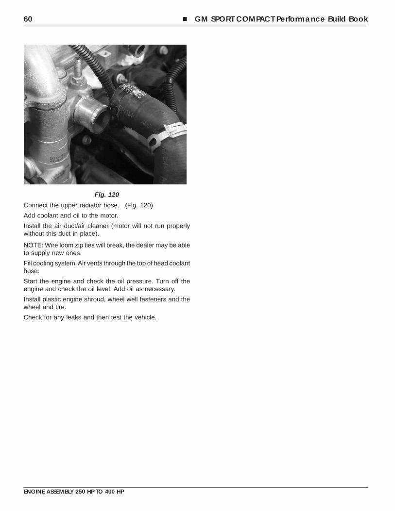
Connect the upper radiator hose. (Fig. 120)
Add coolant and oil to the motor.
Install the air duct/air cleaner (motor will not run properlywithout this duct in place).
NOTE: Wire loom zip ties will break, the dealer may be ableto supply new ones.
Fill cooling system.Air vents through the top of head coolanthose.
Start the engine and check the oil pressure. Turn off theengine and check the oil level. Add oil as necessary.
Install plastic engine shroud, wheel well fasteners and thewheel and tire.
Check for any leaks and then test the vehicle.
Fig. 120
60 � GM SPORT COMPACT Performance Build Book
ENGINE ASSEMBLY 250 HP TO 400 HP
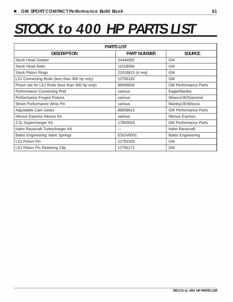
STOCK to 400 HP PARTS LISTPARTS LIST
DESCRIPTION PART NUMBER SOURCEStock Head Gasket 24444091 GM
Stock Head Bolts 11518066 GM
Stock Piston Rings 21018813 (4 req) GM
LSJ Connecting Rods (less than 300 hp only) 12755162 GM
Piston set for LSJ Rods (less than 300 hp only) 88958634 GM Performance Parts
Performance Connecting Rod various Eagle/Manley
Performance Forged Pistons various Wiseco/JE/Diamond
Street Performance Wrist Pin various Manley/JE/Wiseco
Adjustable Cam Gears 88958613 GM Performance Parts
Nitrous Express Nitrous Kit various Nitrous Express
2.2L Supercharger Kit 17800003 GM Performance Parts
Hahn Racecraft Turbocharger Kit — Hahn Racecraft
Bates Engineering Valve Springs ESGV0001 Bates Engineering
LSJ Piston Pin 12791503 GM
LSJ Piston Pin Retaining Clip 12755171 GM
� GM SPORT COMPACT Performance Build Book 61
STOCK to 400 HP PARTS LIST

NOTES
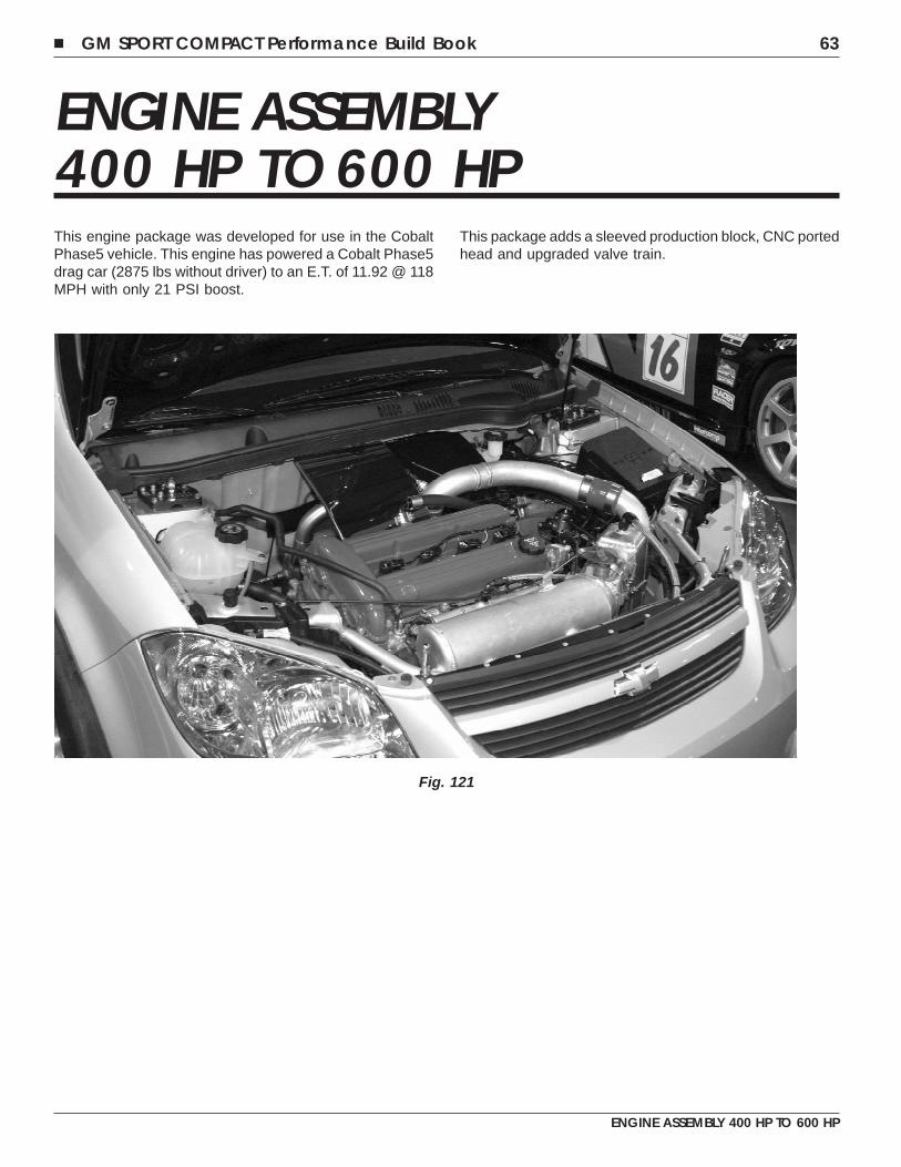
ENGINE ASSEMBLY400 HP TO 600 HPThis engine package was developed for use in the CobaltPhase5 vehicle. This engine has powered a Cobalt Phase5drag car (2875 lbs without driver) to an E.T. of 11.92 @ 118MPH with only 21 PSI boost.
This package adds a sleeved production block, CNC portedhead and upgraded valve train.
Fig. 121
� GM SPORT COMPACT Performance Build Book 63
ENGINE ASSEMBLY 400 HP TO 600 HP
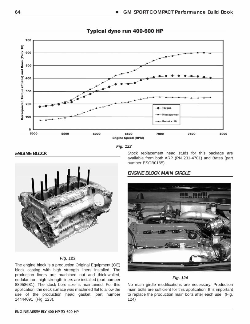
ENGINE BLOCK
The engine block is a production Original Equipment (OE)block casting with high strength liners installed. Theproduction liners are machined out and thick-walled,nodular iron, high-strength liners are installed (part number88958681). The stock bore size is maintained. For thisapplication, the deck surface was machined flat to allow theuse of the production head gasket, part number24444091 (Fig. 123).
Stock replacement head studs for this package areavailable from both ARP (PN 231-4701) and Bates (partnumber ESGB0165).
ENGINE BLOCK MAIN GIRDLE
No main girdle modifications are necessary. Productionmain bolts are sufficient for this application. It is importantto replace the production main bolts after each use. (Fig.124)
Fig. 122
Fig. 123
Fig. 124
64 � GM SPORT COMPACT Performance Build Book
ENGINE ASSEMBLY 400 HP TO 600 HP
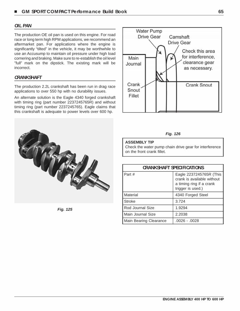
OIL PAN
The production OE oil pan is used on this engine. For roadrace or long term high RPM applications, we recommend anaftermarket pan. For applications where the engine issignificantly “tilted” in the vehicle, it may be worthwhile touse an Accusump to maintain oil pressure under high loadcornering and braking. Make sure to re-establish the oil level�full� mark on the dipstick. The existing mark will beincorrect.
CRANKSHAFT
The production 2.2L crankshaft has been run in drag raceapplications to over 550 hp with no durability issues.
An alternate solution is the Eagle 4340 forged crankshaftwith timing ring (part number 2237245765R) and withouttiming ring (part number 2237245765). Eagle claims thatthis crankshaft is adequate to power levels over 600 hp.
ASSEMBLY TIPCheck the water pump chain drive gear for interferenceon the front crank fillet.
CRANKSHAFT SPECIFICATIONSPart # Eagle 2237245765R (This
crank is available withouta timing ring if a cranktrigger is used.)
Material 4340 Forged Steel
Stroke 3.724
Rod Journal Size 1.9294
Main Journal Size 2.2038
Main Bearing Clearance .0026 - .0028
Fig. 125
Fig. 126
� GM SPORT COMPACT Performance Build Book 65
ENGINE ASSEMBLY 400 HP TO 600 HP
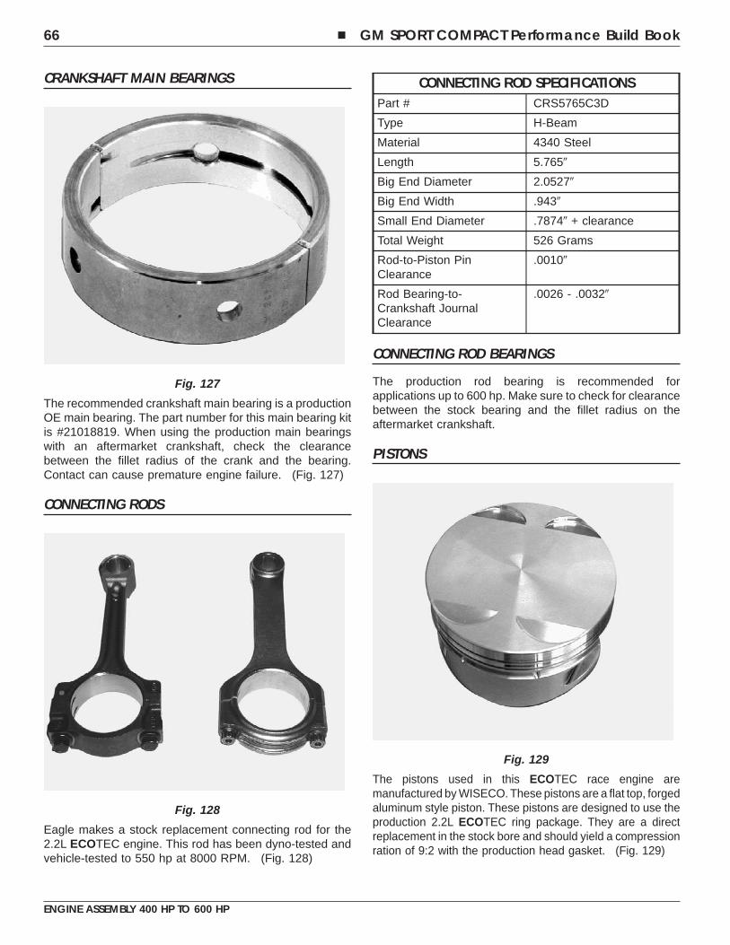
CRANKSHAFT MAIN BEARINGS
The recommended crankshaft main bearing is a productionOE main bearing. The part number for this main bearing kitis #21018819. When using the production main bearingswith an aftermarket crankshaft, check the clearancebetween the fillet radius of the crank and the bearing.Contact can cause premature engine failure. (Fig. 127)
CONNECTING RODS
Eagle makes a stock replacement connecting rod for the2.2L ECOTEC engine. This rod has been dyno-tested andvehicle-tested to 550 hp at 8000 RPM. (Fig. 128)
CONNECTING ROD SPECIFICATIONSPart # CRS5765C3D
Type H-Beam
Material 4340 Steel
Length 5.765�
Big End Diameter 2.0527�
Big End Width .943�
Small End Diameter .7874� + clearance
Total Weight 526 Grams
Rod-to-Piston PinClearance
.0010�
Rod Bearing-to-Crankshaft JournalClearance
.0026 - .0032�
CONNECTING ROD BEARINGS
The production rod bearing is recommended forapplications up to 600 hp. Make sure to check for clearancebetween the stock bearing and the fillet radius on theaftermarket crankshaft.
PISTONS
The pistons used in this ECOTEC race engine aremanufactured by WISECO. These pistons are a flat top, forgedaluminum style piston. These pistons are designed to use theproduction 2.2L ECOTEC ring package. They are a directreplacement in the stock bore and should yield a compressionration of 9:2 with the production head gasket. (Fig. 129)
Fig. 127
Fig. 128
Fig. 129
66 � GM SPORT COMPACT Performance Build Book
ENGINE ASSEMBLY 400 HP TO 600 HP
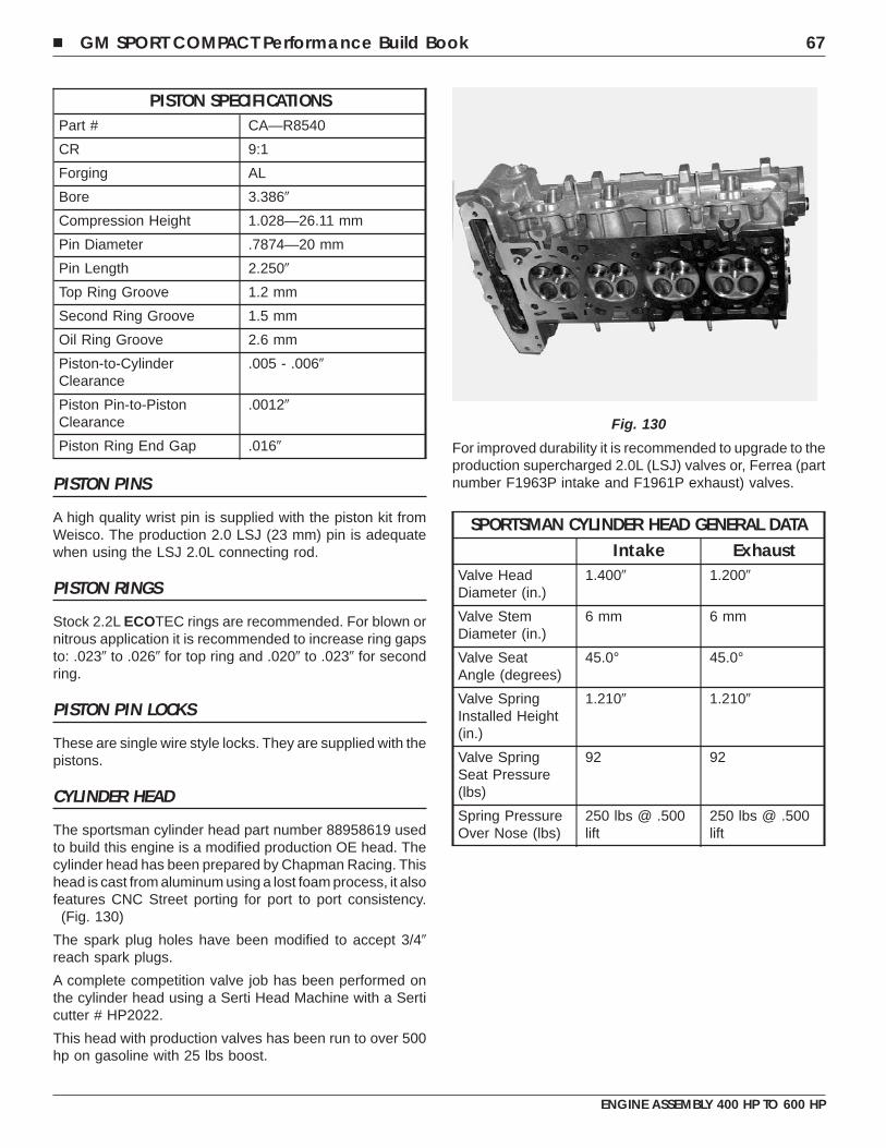
PISTON SPECIFICATIONSPart # CA—R8540
CR 9:1
Forging AL
Bore 3.386�
Compression Height 1.028—26.11 mm
Pin Diameter .7874—20 mm
Pin Length 2.250�
Top Ring Groove 1.2 mm
Second Ring Groove 1.5 mm
Oil Ring Groove 2.6 mm
Piston-to-CylinderClearance
.005 - .006�
Piston Pin-to-PistonClearance
.0012�
Piston Ring End Gap .016�
PISTON PINS
A high quality wrist pin is supplied with the piston kit fromWeisco. The production 2.0 LSJ (23 mm) pin is adequatewhen using the LSJ 2.0L connecting rod.
PISTON RINGS
Stock 2.2L ECOTEC rings are recommended. For blown ornitrous application it is recommended to increase ring gapsto: .023� to .026� for top ring and .020� to .023� for secondring.
PISTON PIN LOCKS
These are single wire style locks. They are supplied with thepistons.
CYLINDER HEAD
The sportsman cylinder head part number 88958619 usedto build this engine is a modified production OE head. Thecylinder head has been prepared by Chapman Racing. Thishead is cast from aluminum using a lost foam process, it alsofeatures CNC Street porting for port to port consistency.
(Fig. 130)
The spark plug holes have been modified to accept 3/4�reach spark plugs.
A complete competition valve job has been performed onthe cylinder head using a Serti Head Machine with a Serticutter # HP2022.
This head with production valves has been run to over 500hp on gasoline with 25 lbs boost.
For improved durability it is recommended to upgrade to theproduction supercharged 2.0L (LSJ) valves or, Ferrea (partnumber F1963P intake and F1961P exhaust) valves.
SPORTSMAN CYLINDER HEAD GENERAL DATAIntake Exhaust
Valve HeadDiameter (in.)
1.400� 1.200�
Valve StemDiameter (in.)
6 mm 6 mm
Valve SeatAngle (degrees)
45.0° 45.0°
Valve SpringInstalled Height(in.)
1.210� 1.210�
Valve SpringSeat Pressure(lbs)
92 92
Spring PressureOver Nose (lbs)
250 lbs @ .500lift
250 lbs @ .500lift
Fig. 130
� GM SPORT COMPACT Performance Build Book 67
ENGINE ASSEMBLY 400 HP TO 600 HP
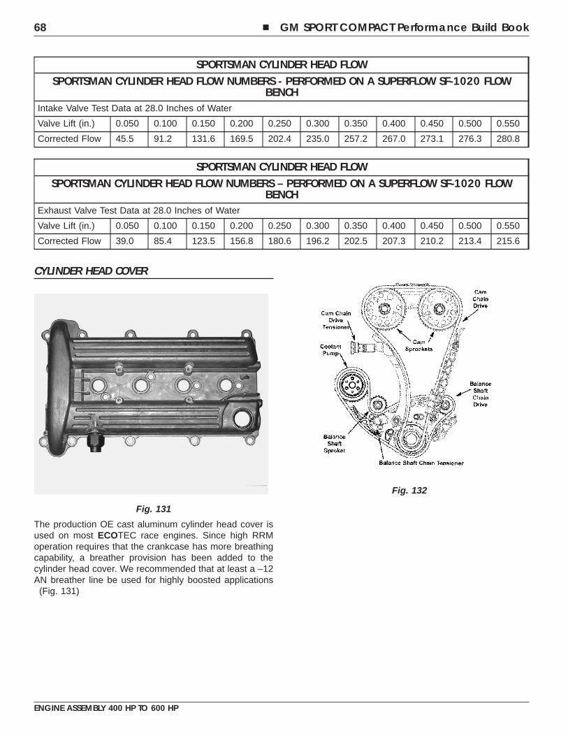
SPORTSMAN CYLINDER HEAD FLOWSPORTSMAN CYLINDER HEAD FLOW NUMBERS - PERFORMED ON A SUPERFLOW SF-1020 FLOW
BENCHIntake Valve Test Data at 28.0 Inches of Water
Valve Lift (in.) 0.050 0.100 0.150 0.200 0.250 0.300 0.350 0.400 0.450 0.500 0.550
Corrected Flow 45.5 91.2 131.6 169.5 202.4 235.0 257.2 267.0 273.1 276.3 280.8
SPORTSMAN CYLINDER HEAD FLOWSPORTSMAN CYLINDER HEAD FLOW NUMBERS – PERFORMED ON A SUPERFLOW SF-1020 FLOW
BENCHExhaust Valve Test Data at 28.0 Inches of Water
Valve Lift (in.) 0.050 0.100 0.150 0.200 0.250 0.300 0.350 0.400 0.450 0.500 0.550
Corrected Flow 39.0 85.4 123.5 156.8 180.6 196.2 202.5 207.3 210.2 213.4 215.6
CYLINDER HEAD COVER
The production OE cast aluminum cylinder head cover isused on most ECOTEC race engines. Since high RRMoperation requires that the crankcase has more breathingcapability, a breather provision has been added to thecylinder head cover. We recommended that at least a –12AN breather line be used for highly boosted applications
(Fig. 131)
Fig. 131
Fig. 132
68 � GM SPORT COMPACT Performance Build Book
ENGINE ASSEMBLY 400 HP TO 600 HP
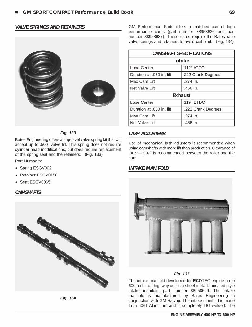
VALVE SPRINGS AND RETAINERS
Bates Engineering offers an up-level valve spring kit that willaccept up to .500� valve lift. This spring does not requirecylinder head modifications, but does require replacementof the spring seat and the retainers. (Fig. 133)
Part Numbers:
• Spring ESGV002
• Retainer ESGV0150
• Seat ESGV0065
CAMSHAFTS
GM Performance Parts offers a matched pair of highperformance cams (part number 88958636 and partnumber 88958637). These cams require the Bates racevalve springs and retainers to avoid coil bind. (Fig. 134)
CAMSHAFT SPECIFICATIONSIntake
Lobe Center 112° ATDC
Duration at .050 in. lift 222 Crank Degrees
Max Cam Lift .274 In.
Net Valve Lift .466 In.
ExhaustLobe Center 119° BTDC
Duration at .050 in. lift .222 Crank Degrees
Max Cam Lift .274 In.
Net Valve Lift .466 In.
LASH ADJUSTERS
Use of mechanical lash adjusters is recommended whenusing camshafts with more lift than production. Clearance of.005�—.007� is recommended between the roller and thecam.
INTAKE MANIFOLD
The intake manifold developed for ECOTEC engine up to600 hp for off-highway use is a sheet metal fabricated styleintake manifold, part number 88958629. The intakemanifold is manufactured by Bates Engineering inconjunction with GM Racing. The intake manifold is madefrom 6061 Aluminum and is completely TIG welded. The
Fig. 133
Fig. 134
Fig. 135
� GM SPORT COMPACT Performance Build Book 69
ENGINE ASSEMBLY 400 HP TO 600 HP
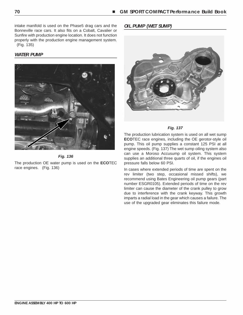
intake manifold is used on the Phase5 drag cars and theBonneville race cars. It also fits on a Cobalt, Cavalier orSunfire with production engine location. It does not functionproperly with the production engine management system.
(Fig. 135)
WATER PUMP
The production OE water pump is used on the ECOTECrace engines. (Fig. 136)
OIL PUMP (WET SUMP)
The production lubrication system is used on all wet sumpECOTEC race engines, including the OE gerotor-style oilpump. This oil pump supplies a constant 125 PSI at allengine speeds. (Fig. 137) The wet sump oiling system alsocan use a Moroso Accusump oil system. This systemsupplies an additional three quarts of oil, if the engines oilpressure falls below 60 PSI.
In cases where extended periods of time are spent on therev limiter (two step, occasional missed shifts), werecommend using Bates Engineering oil pump gears (partnumber ESGR0105). Extended periods of time on the revlimiter can cause the diameter of the crank pulley to growdue to interference with the crank keyway. This growthimparts a radial load in the gear which causes a failure. Theuse of the upgraded gear eliminates this failure mode.
Fig. 136
Fig. 137
70 � GM SPORT COMPACT Performance Build Book
ENGINE ASSEMBLY 400 HP TO 600 HP
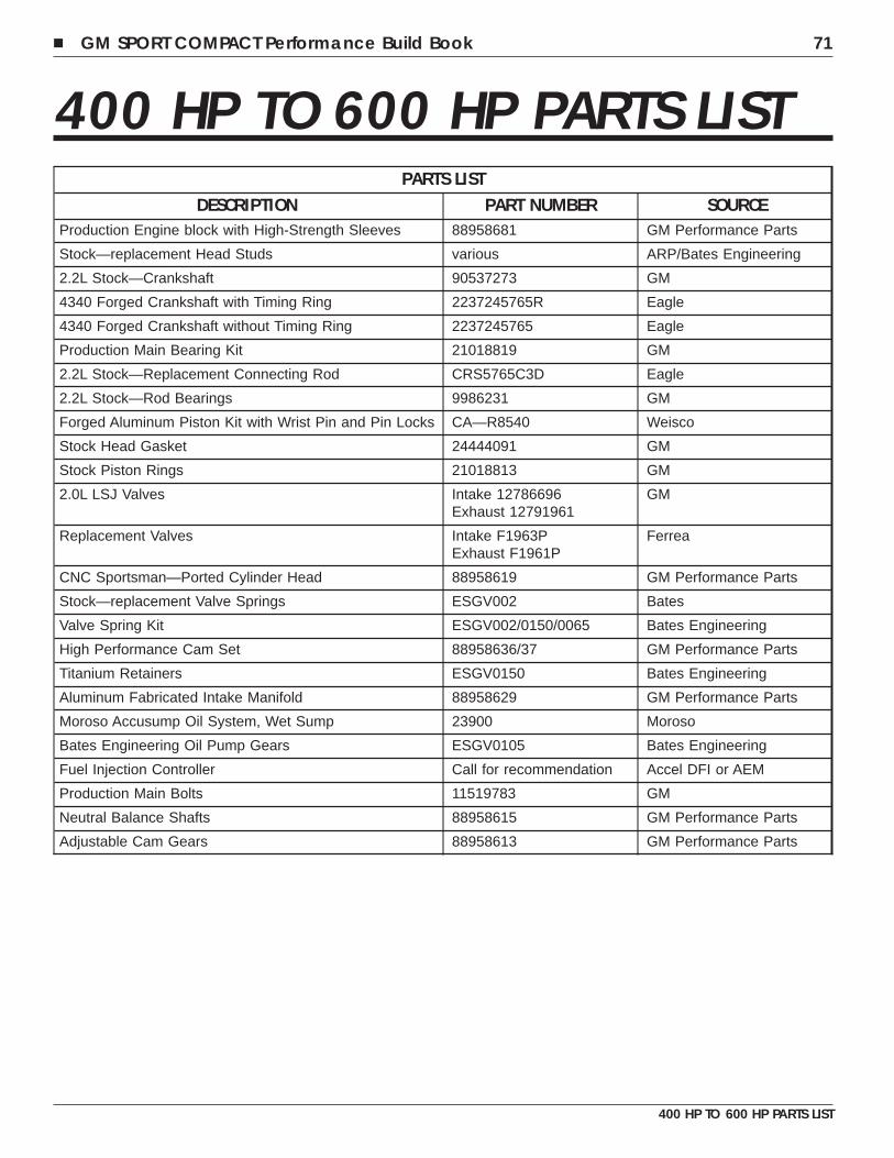
400 HP TO 600 HP PARTS LISTPARTS LIST
DESCRIPTION PART NUMBER SOURCEProduction Engine block with High-Strength Sleeves 88958681 GM Performance Parts
Stock—replacement Head Studs various ARP/Bates Engineering
2.2L Stock—Crankshaft 90537273 GM
4340 Forged Crankshaft with Timing Ring 2237245765R Eagle
4340 Forged Crankshaft without Timing Ring 2237245765 Eagle
Production Main Bearing Kit 21018819 GM
2.2L Stock—Replacement Connecting Rod CRS5765C3D Eagle
2.2L Stock—Rod Bearings 9986231 GM
Forged Aluminum Piston Kit with Wrist Pin and Pin Locks CA—R8540 Weisco
Stock Head Gasket 24444091 GM
Stock Piston Rings 21018813 GM
2.0L LSJ Valves Intake 12786696Exhaust 12791961
GM
Replacement Valves Intake F1963PExhaust F1961P
Ferrea
CNC Sportsman—Ported Cylinder Head 88958619 GM Performance Parts
Stock—replacement Valve Springs ESGV002 Bates
Valve Spring Kit ESGV002/0150/0065 Bates Engineering
High Performance Cam Set 88958636/37 GM Performance Parts
Titanium Retainers ESGV0150 Bates Engineering
Aluminum Fabricated Intake Manifold 88958629 GM Performance Parts
Moroso Accusump Oil System, Wet Sump 23900 Moroso
Bates Engineering Oil Pump Gears ESGV0105 Bates Engineering
Fuel Injection Controller Call for recommendation Accel DFI or AEM
Production Main Bolts 11519783 GM
Neutral Balance Shafts 88958615 GM Performance Parts
Adjustable Cam Gears 88958613 GM Performance Parts
� GM SPORT COMPACT Performance Build Book 71
400 HP TO 600 HP PARTS LIST

NOTES
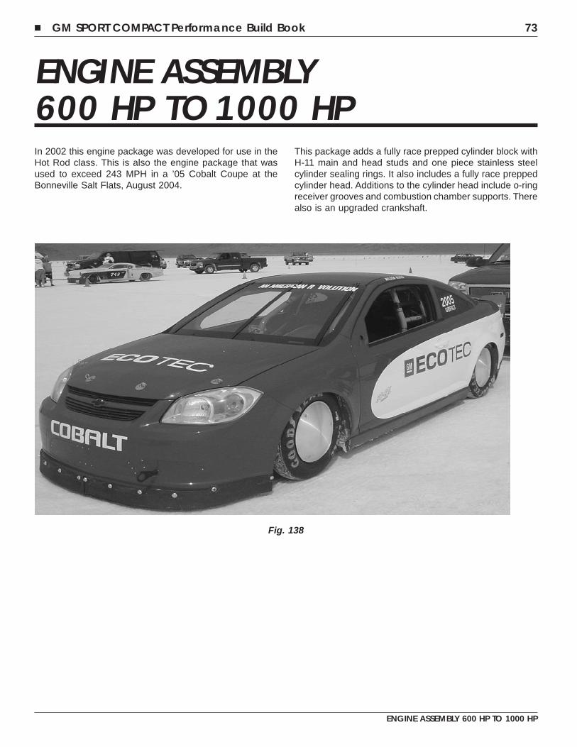
ENGINE ASSEMBLY600 HP TO 1000 HPIn 2002 this engine package was developed for use in theHot Rod class. This is also the engine package that wasused to exceed 243 MPH in a ’05 Cobalt Coupe at theBonneville Salt Flats, August 2004.
This package adds a fully race prepped cylinder block withH-11 main and head studs and one piece stainless steelcylinder sealing rings. It also includes a fully race preppedcylinder head. Additions to the cylinder head include o-ringreceiver grooves and combustion chamber supports. Therealso is an upgraded crankshaft.
Fig. 138
� GM SPORT COMPACT Performance Build Book 73
ENGINE ASSEMBLY 600 HP TO 1000 HP
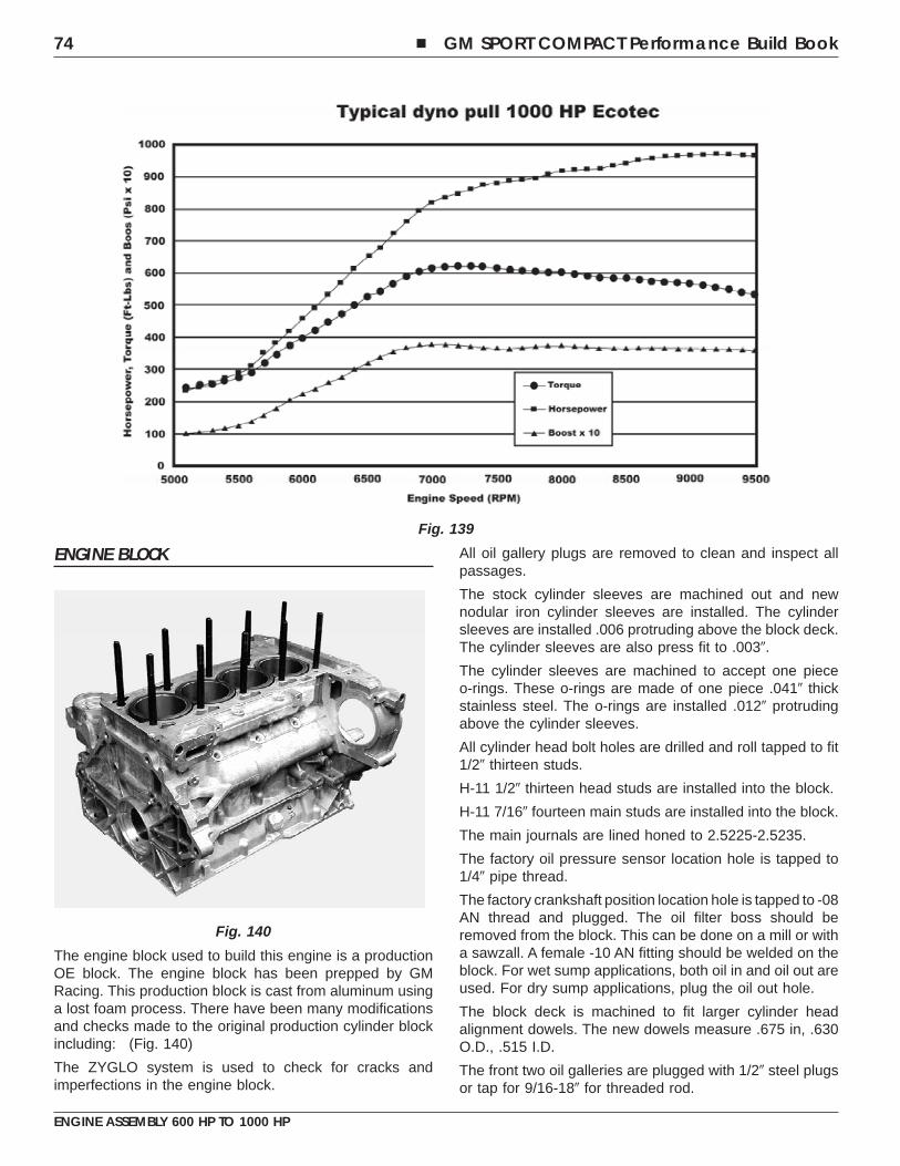
ENGINE BLOCK
The engine block used to build this engine is a productionOE block. The engine block has been prepped by GMRacing. This production block is cast from aluminum usinga lost foam process. There have been many modificationsand checks made to the original production cylinder blockincluding: (Fig. 140)
The ZYGLO system is used to check for cracks andimperfections in the engine block.
All oil gallery plugs are removed to clean and inspect allpassages.
The stock cylinder sleeves are machined out and newnodular iron cylinder sleeves are installed. The cylindersleeves are installed .006 protruding above the block deck.The cylinder sleeves are also press fit to .003�.
The cylinder sleeves are machined to accept one pieceo-rings. These o-rings are made of one piece .041� thickstainless steel. The o-rings are installed .012� protrudingabove the cylinder sleeves.
All cylinder head bolt holes are drilled and roll tapped to fit1/2� thirteen studs.
H-11 1/2� thirteen head studs are installed into the block.
H-11 7/16� fourteen main studs are installed into the block.
The main journals are lined honed to 2.5225-2.5235.
The factory oil pressure sensor location hole is tapped to1/4� pipe thread.
The factory crankshaft position location hole is tapped to -08AN thread and plugged. The oil filter boss should beremoved from the block. This can be done on a mill or witha sawzall. A female -10 AN fitting should be welded on theblock. For wet sump applications, both oil in and oil out areused. For dry sump applications, plug the oil out hole.
The block deck is machined to fit larger cylinder headalignment dowels. The new dowels measure .675 in, .630O.D., .515 I.D.
The front two oil galleries are plugged with 1/2� steel plugsor tap for 9/16-18� for threaded rod.
Fig. 139
Fig. 140
74 � GM SPORT COMPACT Performance Build Book
ENGINE ASSEMBLY 600 HP TO 1000 HP
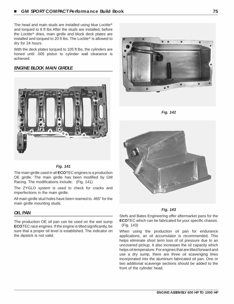
The head and main studs are installed using blue Loctite�and torqued to 8 ft lbs After the studs are installed, beforethe Loctite� dries, main girdle and block deck plates areinstalled and torqued to 20 ft lbs. The Loctite� is allowed todry for 24 hours.
With the deck plates torqued to 105 ft lbs, the cylinders arehoned until .005 piston to cylinder wall clearance isachieved.
ENGINE BLOCK MAIN GIRDLE
The main girdle used in all ECOTEC engines is a productionOE girdle. The main girdle has been modified by GMRacing. The modifications include: (Fig. 141)
The ZYGLO system is used to check for cracks andimperfections in the main girdle.
All main girdle stud holes have been reamed to .465� for themain girdle mounting studs.
OIL PAN
The production OE oil pan can be used on the wet sumpECOTEC race engines. If the engine is tilted significantly, besure that a proper oil level is established. The indicator onthe dipstick is not valid.
Stefs and Bates Engineering offer aftermarket pans for theECOTEC which can be fabricated for your specific chassis.
(Fig. 143)
When using the production oil pan for enduranceapplications, an oil accumulator is recommended. Thishelps eliminate short term loss of oil pressure due to anuncovered pickup. It also increases the oil capacity whichhelps oil temperature. For engines that are tilted forward anduse a dry sump, there are three oil scavenging linesincorporated into the aluminum fabricated oil pan. One ortwo additional scavenge sections should be added to thefront of the cylinder head.
Fig. 141
Fig. 142
Fig. 143
� GM SPORT COMPACT Performance Build Book 75
ENGINE ASSEMBLY 600 HP TO 1000 HP
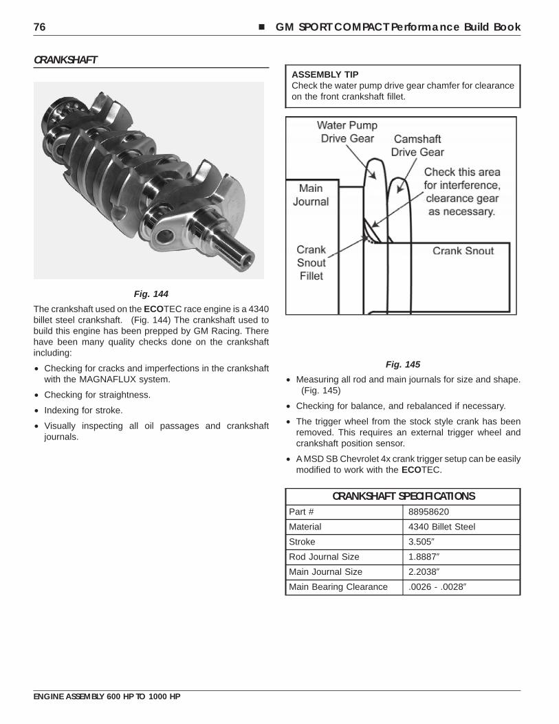
CRANKSHAFT
The crankshaft used on the ECOTEC race engine is a 4340billet steel crankshaft. (Fig. 144) The crankshaft used tobuild this engine has been prepped by GM Racing. Therehave been many quality checks done on the crankshaftincluding:
• Checking for cracks and imperfections in the crankshaftwith the MAGNAFLUX system.
• Checking for straightness.
• Indexing for stroke.
• Visually inspecting all oil passages and crankshaftjournals.
ASSEMBLY TIPCheck the water pump drive gear chamfer for clearanceon the front crankshaft fillet.
• Measuring all rod and main journals for size and shape.(Fig. 145)
• Checking for balance, and rebalanced if necessary.
• The trigger wheel from the stock style crank has beenremoved. This requires an external trigger wheel andcrankshaft position sensor.
• A MSD SB Chevrolet 4x crank trigger setup can be easilymodified to work with the ECOTEC.
CRANKSHAFT SPECIFICATIONSPart # 88958620
Material 4340 Billet Steel
Stroke 3.505�
Rod Journal Size 1.8887�
Main Journal Size 2.2038�
Main Bearing Clearance .0026 - .0028�
Fig. 144
Fig. 145
76 � GM SPORT COMPACT Performance Build Book
ENGINE ASSEMBLY 600 HP TO 1000 HP
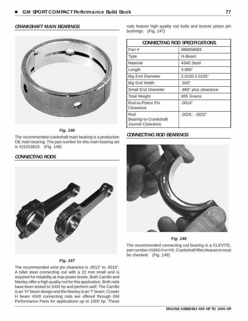
CRANKSHAFT MAIN BEARINGS
The recommended crankshaft main bearing is a productionOE main bearing. The part number for this main bearing setis #21018819. (Fig. 146)
CONNECTING RODS
The recommended wrist pin clearance is .0012� to .0015�.A billet steel connecting rod with a 22 mm small end isrequired for reliability at max power levels. Both Carrillo andManley offer a high quality rod for this application. Both rodshave been tested to 1000 hp and perform well. The Carrillois an “H” beam design and the Manley is an “I” beam. CrowerH beam 4340 connecting rods are offered through GMPerformance Parts for applications up to 1000 hp. These
rods feature high quality rod bolts and bronze piston pinbushings. (Fig. 147)
CONNECTING ROD SPECIFICATIONSPart # 888958683
Type H-Beam
Material 4340 Steel
Length 5.888�
Big End Diameter 2.0150-2.0155�
Big End Width .943�
Small End Diameter .866� plus clearance
Total Weight 655 Grams
Rod-to-Piston PinClearance
.0014�
RodBearing-to-CrankshaftJournal Clearance
.0026 - .0032�
CONNECTING ROD BEARINGS
The recommended connecting rod bearing is a CLEVITE,part number #1663 H or HX. Crankshaft fillet clearance mustbe checked. (Fig. 148)
Fig. 146
Fig. 147
Fig. 148
� GM SPORT COMPACT Performance Build Book 77
ENGINE ASSEMBLY 600 HP TO 1000 HP
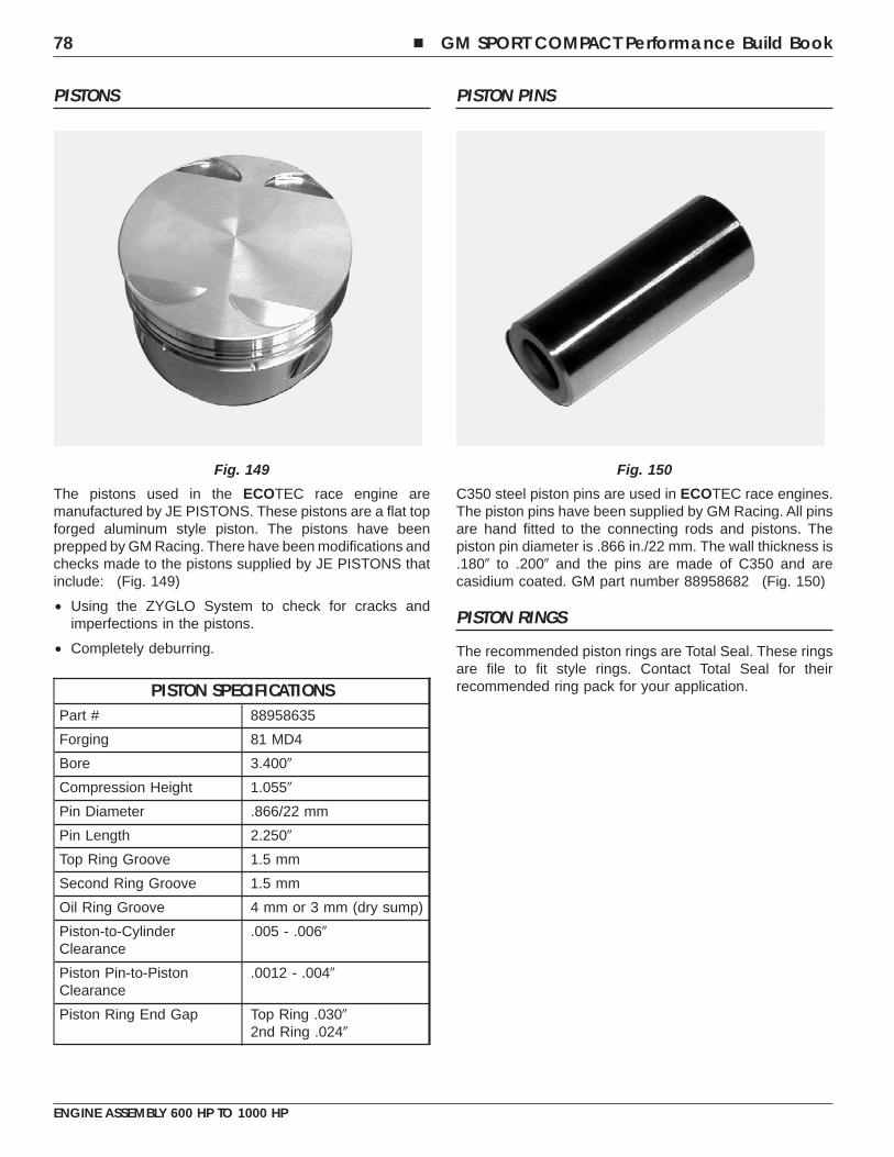
PISTONS
The pistons used in the ECOTEC race engine aremanufactured by JE PISTONS. These pistons are a flat topforged aluminum style piston. The pistons have beenprepped by GM Racing. There have been modifications andchecks made to the pistons supplied by JE PISTONS thatinclude: (Fig. 149)
• Using the ZYGLO System to check for cracks andimperfections in the pistons.
• Completely deburring.
PISTON SPECIFICATIONSPart # 88958635
Forging 81 MD4
Bore 3.400�
Compression Height 1.055�
Pin Diameter .866/22 mm
Pin Length 2.250�
Top Ring Groove 1.5 mm
Second Ring Groove 1.5 mm
Oil Ring Groove 4 mm or 3 mm (dry sump)
Piston-to-CylinderClearance
.005 - .006�
Piston Pin-to-PistonClearance
.0012 - .004�
Piston Ring End Gap Top Ring .030�2nd Ring .024�
PISTON PINS
C350 steel piston pins are used in ECOTEC race engines.The piston pins have been supplied by GM Racing. All pinsare hand fitted to the connecting rods and pistons. Thepiston pin diameter is .866 in./22 mm. The wall thickness is.180� to .200� and the pins are made of C350 and arecasidium coated. GM part number 88958682 (Fig. 150)
PISTON RINGS
The recommended piston rings are Total Seal. These ringsare file to fit style rings. Contact Total Seal for theirrecommended ring pack for your application.
Fig. 149 Fig. 150
78 � GM SPORT COMPACT Performance Build Book
ENGINE ASSEMBLY 600 HP TO 1000 HP
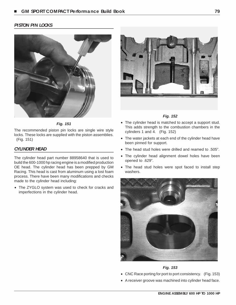
PISTON PIN LOCKS
The recommended piston pin locks are single wire stylelocks. These locks are supplied with the piston assemblies.
(Fig. 151)
CYLINDER HEAD
The cylinder head part number 88958640 that is used tobuild the 600-1000 hp racing engine is a modified productionOE head. The cylinder head has been prepped by GMRacing. This head is cast from aluminum using a lost foamprocess. There have been many modifications and checksmade to the cylinder head including:
• The ZYGLO system was used to check for cracks andimperfections in the cylinder head.
• The cylinder head is matched to accept a support stud.This adds strength to the combustion chambers in thecylinders 1 and 4. (Fig. 152)
• The water jackets at each end of the cylinder head havebeen pinned for support.
• The head stud holes were drilled and reamed to .505�.
• The cylinder head alignment dowel holes have beenopened to .629�.
• The head stud holes were spot faced to install stepwashers.
• CNC Race porting for port to port consistency. (Fig. 153)
• A receiver groove was machined into cylinder head face.
Fig. 151
Fig. 152
Fig. 153
� GM SPORT COMPACT Performance Build Book 79
ENGINE ASSEMBLY 600 HP TO 1000 HP
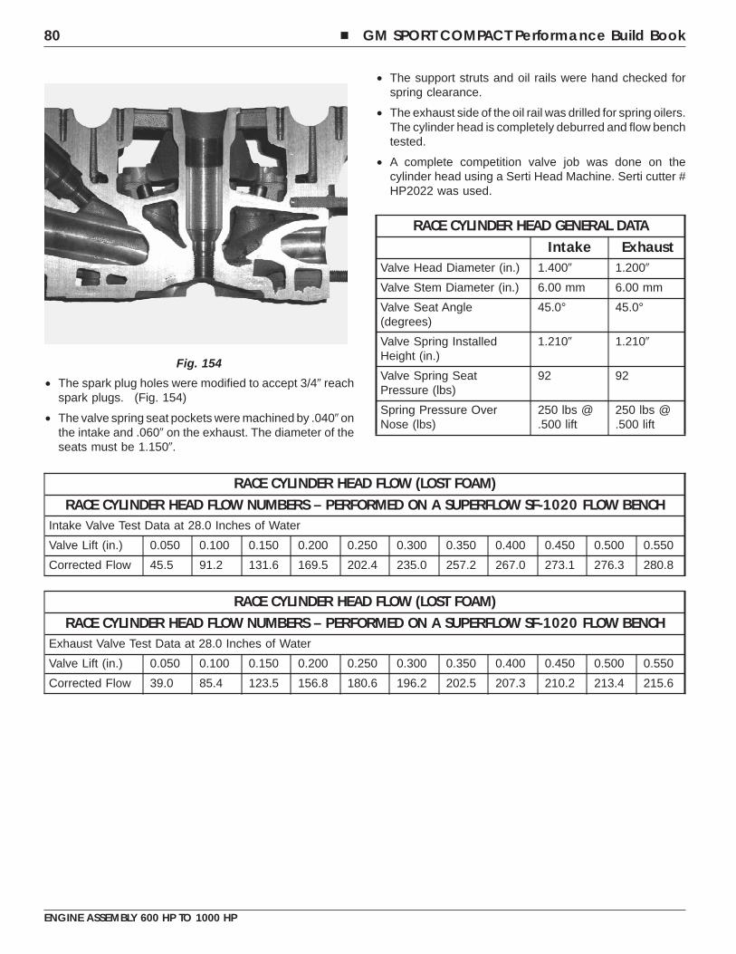
• The spark plug holes were modified to accept 3/4� reachspark plugs. (Fig. 154)
• The valve spring seat pockets were machined by .040� onthe intake and .060� on the exhaust. The diameter of theseats must be 1.150�.
• The support struts and oil rails were hand checked forspring clearance.
• The exhaust side of the oil rail was drilled for spring oilers.The cylinder head is completely deburred and flow benchtested.
• A complete competition valve job was done on thecylinder head using a Serti Head Machine. Serti cutter #HP2022 was used.
RACE CYLINDER HEAD GENERAL DATAIntake Exhaust
Valve Head Diameter (in.) 1.400� 1.200�
Valve Stem Diameter (in.) 6.00 mm 6.00 mm
Valve Seat Angle(degrees)
45.0° 45.0°
Valve Spring InstalledHeight (in.)
1.210� 1.210�
Valve Spring SeatPressure (lbs)
92 92
Spring Pressure OverNose (lbs)
250 lbs @.500 lift
250 lbs @.500 lift
RACE CYLINDER HEAD FLOW (LOST FOAM)RACE CYLINDER HEAD FLOW NUMBERS – PERFORMED ON A SUPERFLOW SF-1020 FLOW BENCH
Intake Valve Test Data at 28.0 Inches of Water
Valve Lift (in.) 0.050 0.100 0.150 0.200 0.250 0.300 0.350 0.400 0.450 0.500 0.550
Corrected Flow 45.5 91.2 131.6 169.5 202.4 235.0 257.2 267.0 273.1 276.3 280.8
RACE CYLINDER HEAD FLOW (LOST FOAM)RACE CYLINDER HEAD FLOW NUMBERS – PERFORMED ON A SUPERFLOW SF-1020 FLOW BENCH
Exhaust Valve Test Data at 28.0 Inches of Water
Valve Lift (in.) 0.050 0.100 0.150 0.200 0.250 0.300 0.350 0.400 0.450 0.500 0.550
Corrected Flow 39.0 85.4 123.5 156.8 180.6 196.2 202.5 207.3 210.2 213.4 215.6
Fig. 154
80 � GM SPORT COMPACT Performance Build Book
ENGINE ASSEMBLY 600 HP TO 1000 HP
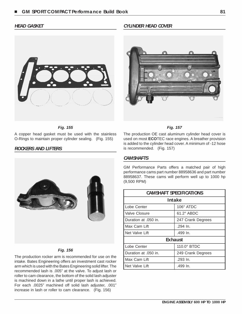
HEAD GASKET
A copper head gasket must be used with the stainlessO-Rings to maintain proper cylinder sealing. (Fig. 155)
ROCKERS AND LIFTERS
The production rocker arm is recommended for use on theintake. Bates Engineering offers an investment cast rockerarm which is used with the Bates Engineering solid lifter. Therecommended lash is .005� at the valve. To adjust lash orroller to cam clearance, the bottom of the solid lash adjusteris machined down in a lathe until proper lash is achieved.For each .0025� machined off solid lash adjuster, .001�increase in lash or roller to cam clearance. (Fig. 156)
CYLINDER HEAD COVER
The production OE cast aluminum cylinder head cover isused on most ECOTEC race engines. A breather provisionis added to the cylinder head cover. A minimum of -12 hoseis recommended. (Fig. 157)
CAMSHAFTS
GM Performance Parts offers a matched pair of highperformance cams part number 88958636 and part number88958637. These cams will perform well up to 1000 hp(9,500 RPM)
CAMSHAFT SPECIFICATIONSIntake
Lobe Center 106° ATDC
Valve Closure 61.2° ABDC
Duration at .050 in. 247 Crank Degrees
Max Cam Lift .294 In.
Net Valve Lift .499 In.
ExhaustLobe Center 110.0° BTDC
Duration at .050 in. 249 Crank Degrees
Max Cam Lift .293 In.
Net Valve Lift .499 In.
Fig. 155
Fig. 156
Fig. 157
� GM SPORT COMPACT Performance Build Book 81
ENGINE ASSEMBLY 600 HP TO 1000 HP
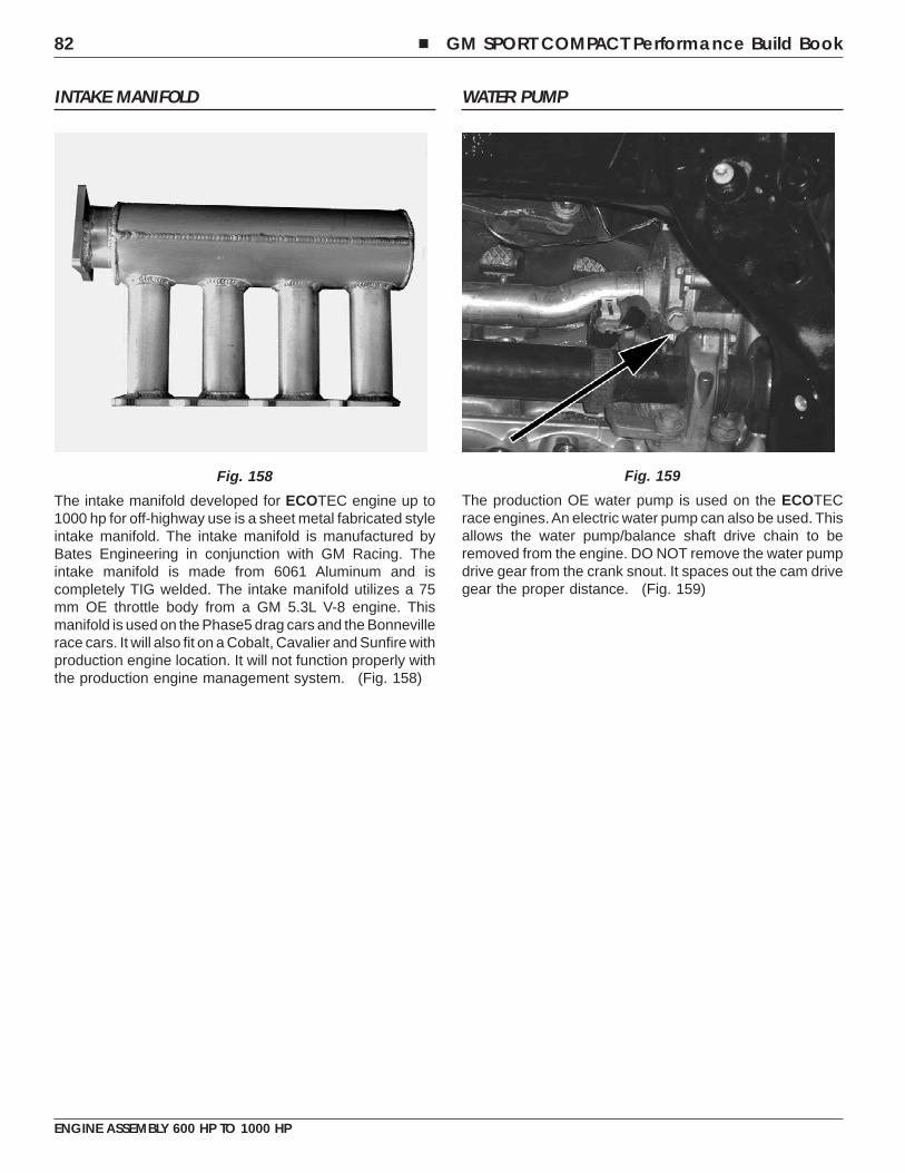
INTAKE MANIFOLD
The intake manifold developed for ECOTEC engine up to1000 hp for off-highway use is a sheet metal fabricated styleintake manifold. The intake manifold is manufactured byBates Engineering in conjunction with GM Racing. Theintake manifold is made from 6061 Aluminum and iscompletely TIG welded. The intake manifold utilizes a 75mm OE throttle body from a GM 5.3L V-8 engine. Thismanifold is used on the Phase5 drag cars and the Bonnevillerace cars. It will also fit on a Cobalt, Cavalier and Sunfire withproduction engine location. It will not function properly withthe production engine management system. (Fig. 158)
WATER PUMP
The production OE water pump is used on the ECOTECrace engines.An electric water pump can also be used. Thisallows the water pump/balance shaft drive chain to beremoved from the engine. DO NOT remove the water pumpdrive gear from the crank snout. It spaces out the cam drivegear the proper distance. (Fig. 159)
Fig. 158 Fig. 159
82 � GM SPORT COMPACT Performance Build Book
ENGINE ASSEMBLY 600 HP TO 1000 HP
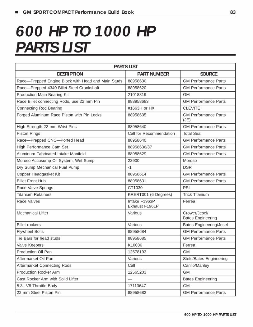
600 HP TO 1000 HPPARTS LIST
PARTS LISTDESRIPTION PART NUMBER SOURCE
Race—Prepped Engine Block with Head and Main Studs 88958630 GM Performance Parts
Race—Prepped 4340 Billet Steel Crankshaft 88958620 GM Performance Parts
Production Main Bearing Kit 21018819 GM
Race Billet connecting Rods, use 22 mm Pin 888958683 GM Performance Parts
Connecting Rod Bearing #1663H or HX CLEVITE
Forged Aluminum Race Piston with Pin Locks 88958635 GM Performance Parts(JE)
High Strength 22 mm Wrist Pins 88958640 GM Performance Parts
Piston Rings Call for Recommendation Total Seal
Race—Prepped CNC—Ported Head 88958640 GM Performance Parts
High Performance Cam Set 88958636/37 GM Performance Parts
Aluminum Fabricated Intake Manifold 88958629 GM Performance Parts
Moroso Accusump Oil System, Wet Sump 23900 Moroso
Dry Sump Mechanical Fuel Pump -1 DSR
Copper Headgasket Kit 88958614 GM Performance Parts
Billet Front Hub 88958631 GM Performance Parts
Race Valve Springs CT1030 PSI
Titanium Retainers KRERT001 (6 Degrees) Trick Titanium
Race Valves Intake F1963PExhaust F1961P
Ferrea
Mechanical Lifter Various Crower/Jesel/Bates Engineering
Billet rockers Various Bates Engineering/Jesel
Flywheel Bolts 88958684 GM Performance Parts
Tie Bars for head studs 88958685 GM Performance Parts
Valve Keepers K10036 Ferrea
Production Oil Pan 12578193 GM
Aftermarket Oil Pan Various Stefs/Bates Engineering
Aftermarket Connecting Rods Call Carillo/Manley
Production Rocker Arm 12565203 GM
Cast Rocker Arm with Solid Lifter — Bates Engineering
5.3L V8 Throttle Body 17113647 GM
22 mm Steel Piston Pin 88958682 GM Performance Parts
� GM SPORT COMPACT Performance Build Book 83
600 HP TO 1000 HP PARTS LIST

NOTES
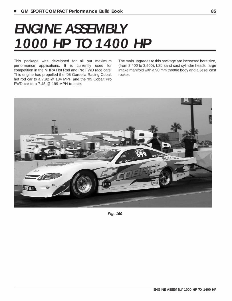
ENGINE ASSEMBLY1000 HP TO 1400 HPThis package was developed for all out maximumperformance applications. It is currently used forcompetition in the NHRA Hot Rod and Pro FWD race cars.This engine has propelled the ’05 Gardella Racing Cobalthot rod car to a 7.92 @ 184 MPH and the ’05 Cobalt ProFWD car to a 7.45 @ 199 MPH to date.
The main upgrades to this package are increased bore size,(from 3.400 to 3.500), LSJ sand cast cylinder heads, largeintake manifold with a 90 mm throttle body and a Jesel castrocker.
Fig. 160
� GM SPORT COMPACT Performance Build Book 85
ENGINE ASSEMBLY 1000 HP TO 1400 HP
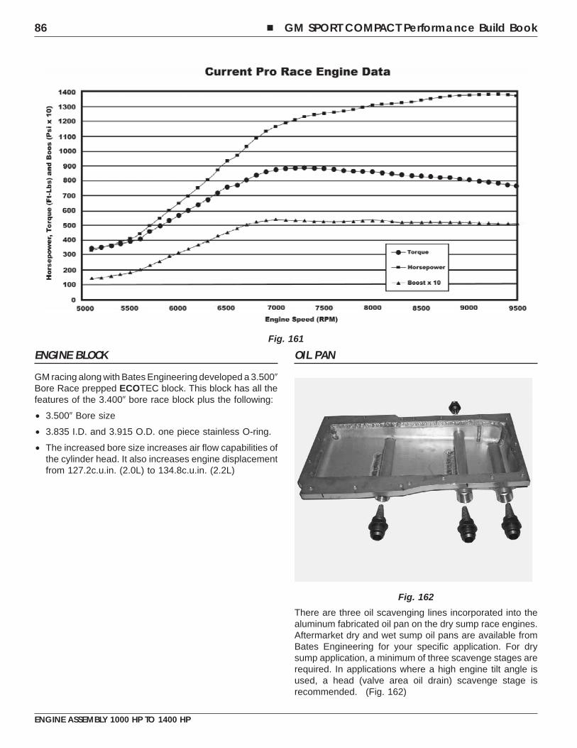
ENGINE BLOCK
GM racing along with Bates Engineering developed a 3.500�Bore Race prepped ECOTEC block. This block has all thefeatures of the 3.400� bore race block plus the following:
• 3.500� Bore size
• 3.835 I.D. and 3.915 O.D. one piece stainless O-ring.
• The increased bore size increases air flow capabilities ofthe cylinder head. It also increases engine displacementfrom 127.2c.u.in. (2.0L) to 134.8c.u.in. (2.2L)
OIL PAN
There are three oil scavenging lines incorporated into thealuminum fabricated oil pan on the dry sump race engines.Aftermarket dry and wet sump oil pans are available fromBates Engineering for your specific application. For drysump application, a minimum of three scavenge stages arerequired. In applications where a high engine tilt angle isused, a head (valve area oil drain) scavenge stage isrecommended. (Fig. 162)
Fig. 161
Fig. 162
86 � GM SPORT COMPACT Performance Build Book
ENGINE ASSEMBLY 1000 HP TO 1400 HP
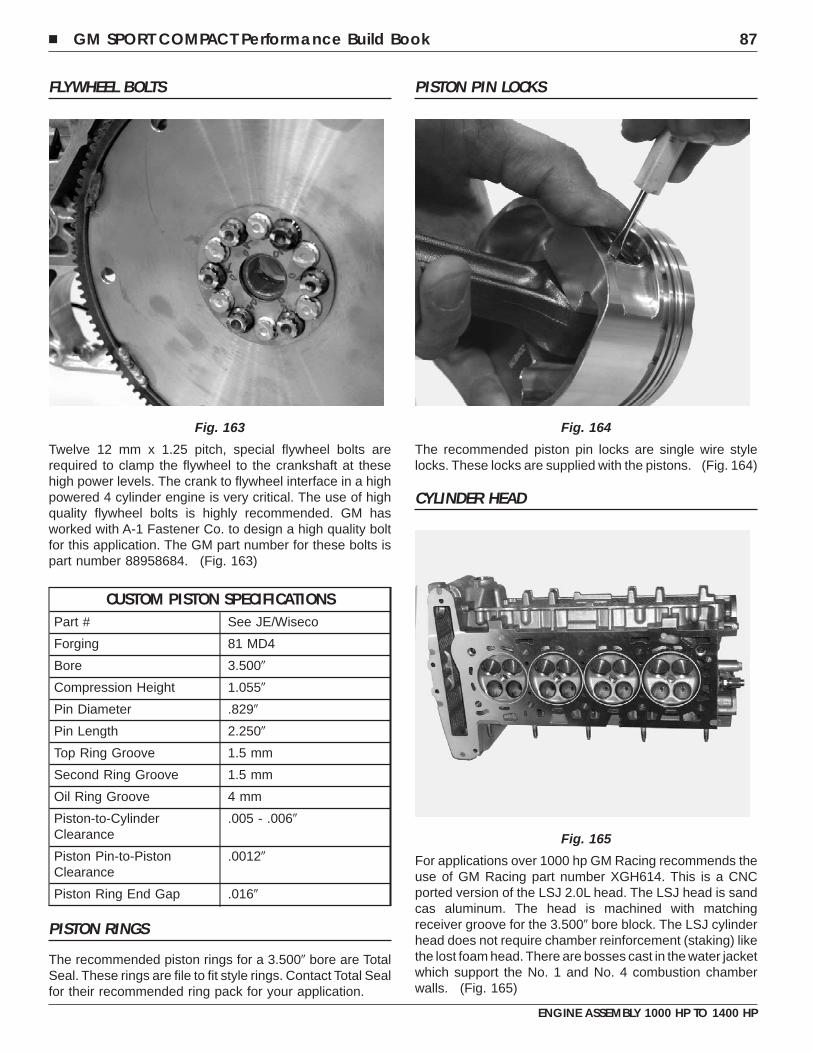
FLYWHEEL BOLTS
Twelve 12 mm x 1.25 pitch, special flywheel bolts arerequired to clamp the flywheel to the crankshaft at thesehigh power levels. The crank to flywheel interface in a highpowered 4 cylinder engine is very critical. The use of highquality flywheel bolts is highly recommended. GM hasworked with A-1 Fastener Co. to design a high quality boltfor this application. The GM part number for these bolts ispart number 88958684. (Fig. 163)
CUSTOM PISTON SPECIFICATIONSPart # See JE/Wiseco
Forging 81 MD4
Bore 3.500�
Compression Height 1.055�
Pin Diameter .829�
Pin Length 2.250�
Top Ring Groove 1.5 mm
Second Ring Groove 1.5 mm
Oil Ring Groove 4 mm
Piston-to-CylinderClearance
.005 - .006�
Piston Pin-to-PistonClearance
.0012�
Piston Ring End Gap .016�
PISTON RINGS
The recommended piston rings for a 3.500� bore are TotalSeal. These rings are file to fit style rings. Contact Total Sealfor their recommended ring pack for your application.
PISTON PIN LOCKS
The recommended piston pin locks are single wire stylelocks. These locks are supplied with the pistons. (Fig. 164)
CYLINDER HEAD
For applications over 1000 hp GM Racing recommends theuse of GM Racing part number XGH614. This is a CNCported version of the LSJ 2.0L head. The LSJ head is sandcas aluminum. The head is machined with matchingreceiver groove for the 3.500� bore block. The LSJ cylinderhead does not require chamber reinforcement (staking) likethe lost foam head. There are bosses cast in the water jacketwhich support the No. 1 and No. 4 combustion chamberwalls. (Fig. 165)
Fig. 163 Fig. 164
Fig. 165
� GM SPORT COMPACT Performance Build Book 87
ENGINE ASSEMBLY 1000 HP TO 1400 HP
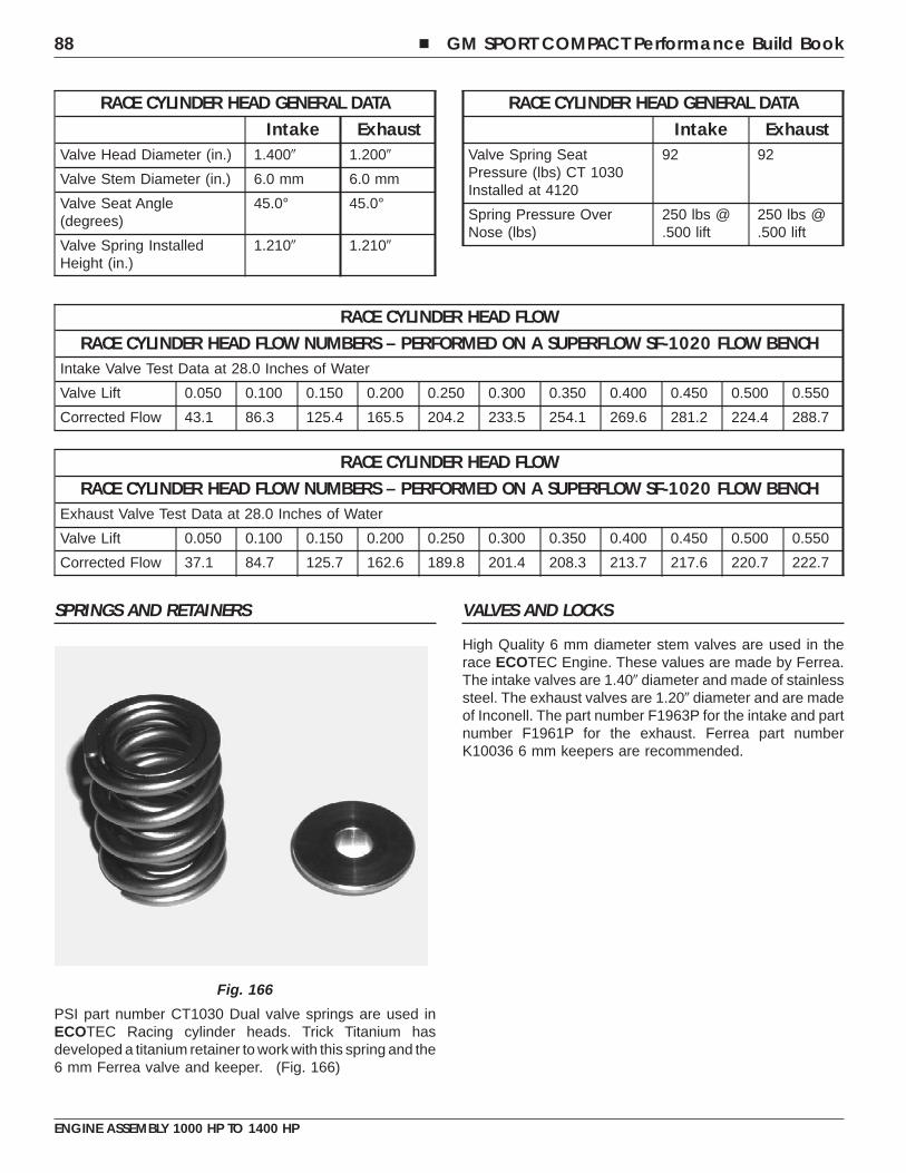
RACE CYLINDER HEAD GENERAL DATAIntake Exhaust
Valve Head Diameter (in.) 1.400� 1.200�
Valve Stem Diameter (in.) 6.0 mm 6.0 mm
Valve Seat Angle(degrees)
45.0° 45.0°
Valve Spring InstalledHeight (in.)
1.210� 1.210�
RACE CYLINDER HEAD GENERAL DATAIntake Exhaust
Valve Spring SeatPressure (lbs) CT 1030Installed at 4120
92 92
Spring Pressure OverNose (lbs)
250 lbs @.500 lift
250 lbs @.500 lift
RACE CYLINDER HEAD FLOWRACE CYLINDER HEAD FLOW NUMBERS – PERFORMED ON A SUPERFLOW SF-1020 FLOW BENCH
Intake Valve Test Data at 28.0 Inches of Water
Valve Lift 0.050 0.100 0.150 0.200 0.250 0.300 0.350 0.400 0.450 0.500 0.550
Corrected Flow 43.1 86.3 125.4 165.5 204.2 233.5 254.1 269.6 281.2 224.4 288.7
RACE CYLINDER HEAD FLOWRACE CYLINDER HEAD FLOW NUMBERS – PERFORMED ON A SUPERFLOW SF-1020 FLOW BENCH
Exhaust Valve Test Data at 28.0 Inches of Water
Valve Lift 0.050 0.100 0.150 0.200 0.250 0.300 0.350 0.400 0.450 0.500 0.550
Corrected Flow 37.1 84.7 125.7 162.6 189.8 201.4 208.3 213.7 217.6 220.7 222.7
SPRINGS AND RETAINERS
PSI part number CT1030 Dual valve springs are used inECOTEC Racing cylinder heads. Trick Titanium hasdeveloped a titanium retainer to work with this spring and the6 mm Ferrea valve and keeper. (Fig. 166)
VALVES AND LOCKS
High Quality 6 mm diameter stem valves are used in therace ECOTEC Engine. These values are made by Ferrea.The intake valves are 1.40� diameter and made of stainlesssteel. The exhaust valves are 1.20� diameter and are madeof Inconell. The part number F1963P for the intake and partnumber F1961P for the exhaust. Ferrea part numberK10036 6 mm keepers are recommended.
Fig. 166
88 � GM SPORT COMPACT Performance Build Book
ENGINE ASSEMBLY 1000 HP TO 1400 HP
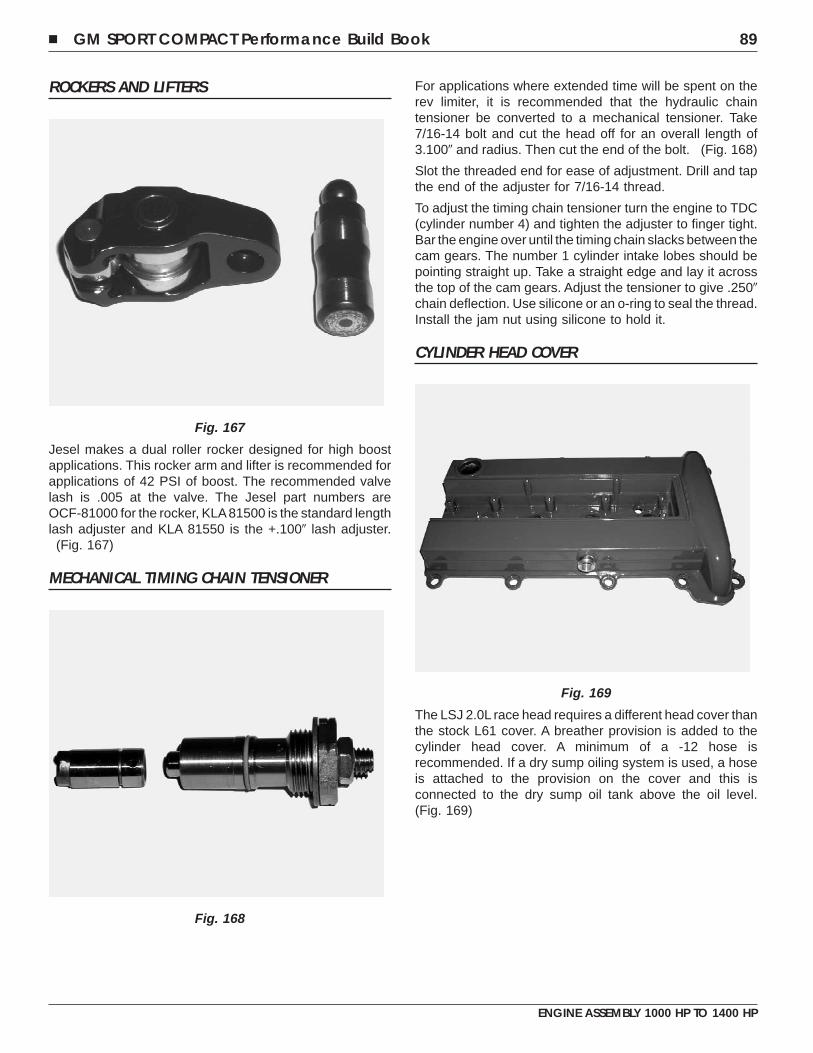
ROCKERS AND LIFTERS
Jesel makes a dual roller rocker designed for high boostapplications. This rocker arm and lifter is recommended forapplications of 42 PSI of boost. The recommended valvelash is .005 at the valve. The Jesel part numbers areOCF-81000 for the rocker, KLA81500 is the standard lengthlash adjuster and KLA 81550 is the +.100� lash adjuster.(Fig. 167)
MECHANICAL TIMING CHAIN TENSIONER
For applications where extended time will be spent on therev limiter, it is recommended that the hydraulic chaintensioner be converted to a mechanical tensioner. Take7/16-14 bolt and cut the head off for an overall length of3.100� and radius. Then cut the end of the bolt. (Fig. 168)
Slot the threaded end for ease of adjustment. Drill and tapthe end of the adjuster for 7/16-14 thread.
To adjust the timing chain tensioner turn the engine to TDC(cylinder number 4) and tighten the adjuster to finger tight.Bar the engine over until the timing chain slacks between thecam gears. The number 1 cylinder intake lobes should bepointing straight up. Take a straight edge and lay it acrossthe top of the cam gears. Adjust the tensioner to give .250�chain deflection. Use silicone or an o-ring to seal the thread.Install the jam nut using silicone to hold it.
CYLINDER HEAD COVER
The LSJ 2.0L race head requires a different head cover thanthe stock L61 cover. A breather provision is added to thecylinder head cover. A minimum of a -12 hose isrecommended. If a dry sump oiling system is used, a hoseis attached to the provision on the cover and this isconnected to the dry sump oil tank above the oil level.(Fig. 169)
Fig. 167
Fig. 168
Fig. 169
� GM SPORT COMPACT Performance Build Book 89
ENGINE ASSEMBLY 1000 HP TO 1400 HP
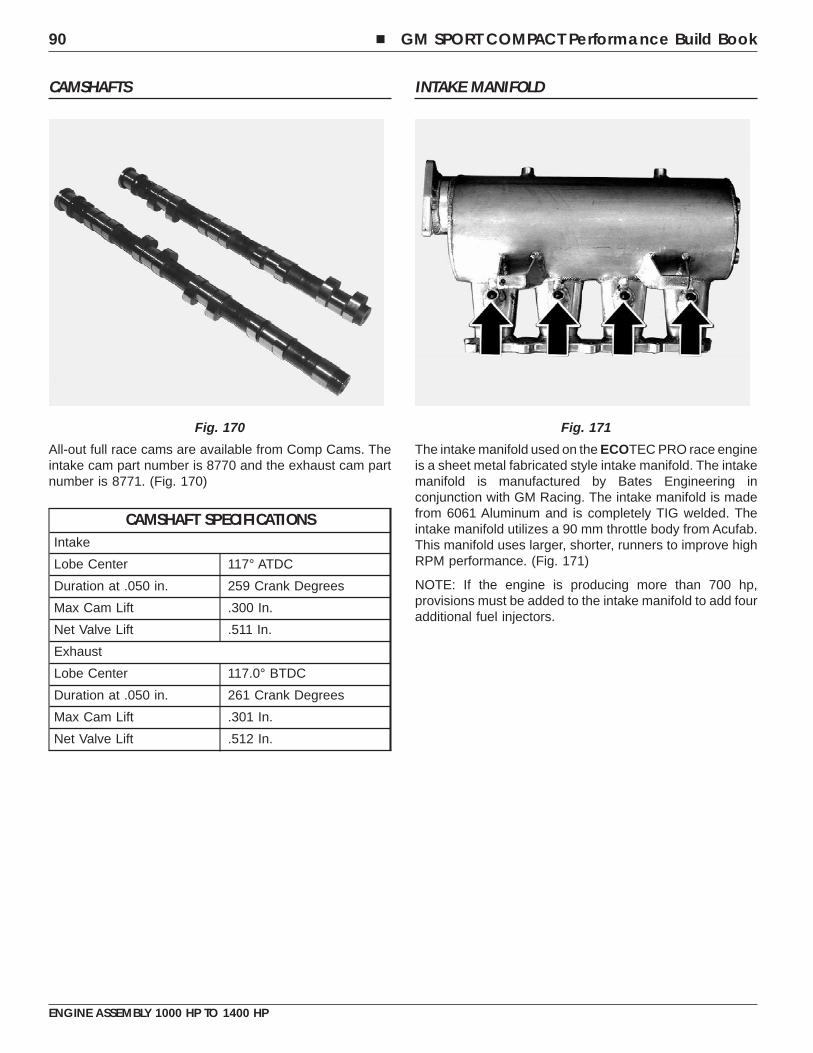
CAMSHAFTS
All-out full race cams are available from Comp Cams. Theintake cam part number is 8770 and the exhaust cam partnumber is 8771. (Fig. 170)
CAMSHAFT SPECIFICATIONSIntake
Lobe Center 117° ATDC
Duration at .050 in. 259 Crank Degrees
Max Cam Lift .300 In.
Net Valve Lift .511 In.
Exhaust
Lobe Center 117.0° BTDC
Duration at .050 in. 261 Crank Degrees
Max Cam Lift .301 In.
Net Valve Lift .512 In.
INTAKE MANIFOLD
The intake manifold used on the ECOTEC PRO race engineis a sheet metal fabricated style intake manifold. The intakemanifold is manufactured by Bates Engineering inconjunction with GM Racing. The intake manifold is madefrom 6061 Aluminum and is completely TIG welded. Theintake manifold utilizes a 90 mm throttle body from Acufab.This manifold uses larger, shorter, runners to improve highRPM performance. (Fig. 171)
NOTE: If the engine is producing more than 700 hp,provisions must be added to the intake manifold to add fouradditional fuel injectors.
Fig. 170 Fig. 171
90 � GM SPORT COMPACT Performance Build Book
ENGINE ASSEMBLY 1000 HP TO 1400 HP
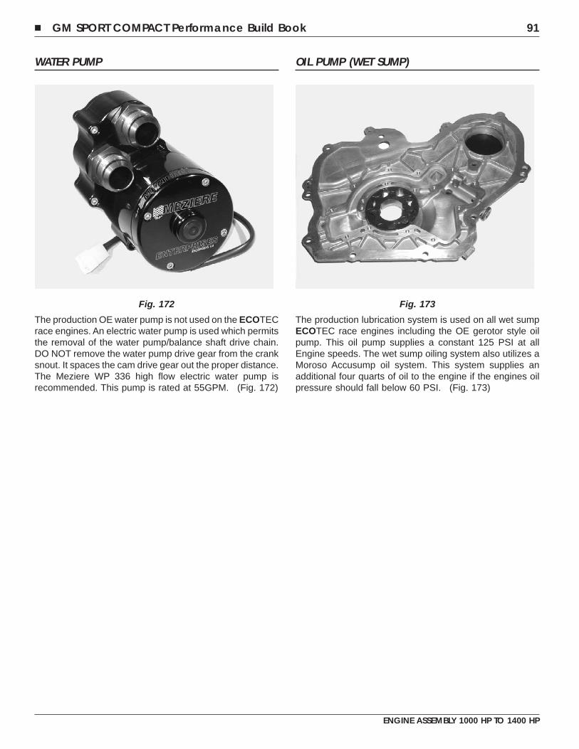
WATER PUMP
The production OE water pump is not used on the ECOTECrace engines. An electric water pump is used which permitsthe removal of the water pump/balance shaft drive chain.DO NOT remove the water pump drive gear from the cranksnout. It spaces the cam drive gear out the proper distance.The Meziere WP 336 high flow electric water pump isrecommended. This pump is rated at 55GPM. (Fig. 172)
OIL PUMP (WET SUMP)
The production lubrication system is used on all wet sumpECOTEC race engines including the OE gerotor style oilpump. This oil pump supplies a constant 125 PSI at allEngine speeds. The wet sump oiling system also utilizes aMoroso Accusump oil system. This system supplies anadditional four quarts of oil to the engine if the engines oilpressure should fall below 60 PSI. (Fig. 173)
Fig. 172 Fig. 173
� GM SPORT COMPACT Performance Build Book 91
ENGINE ASSEMBLY 1000 HP TO 1400 HP

NOTES
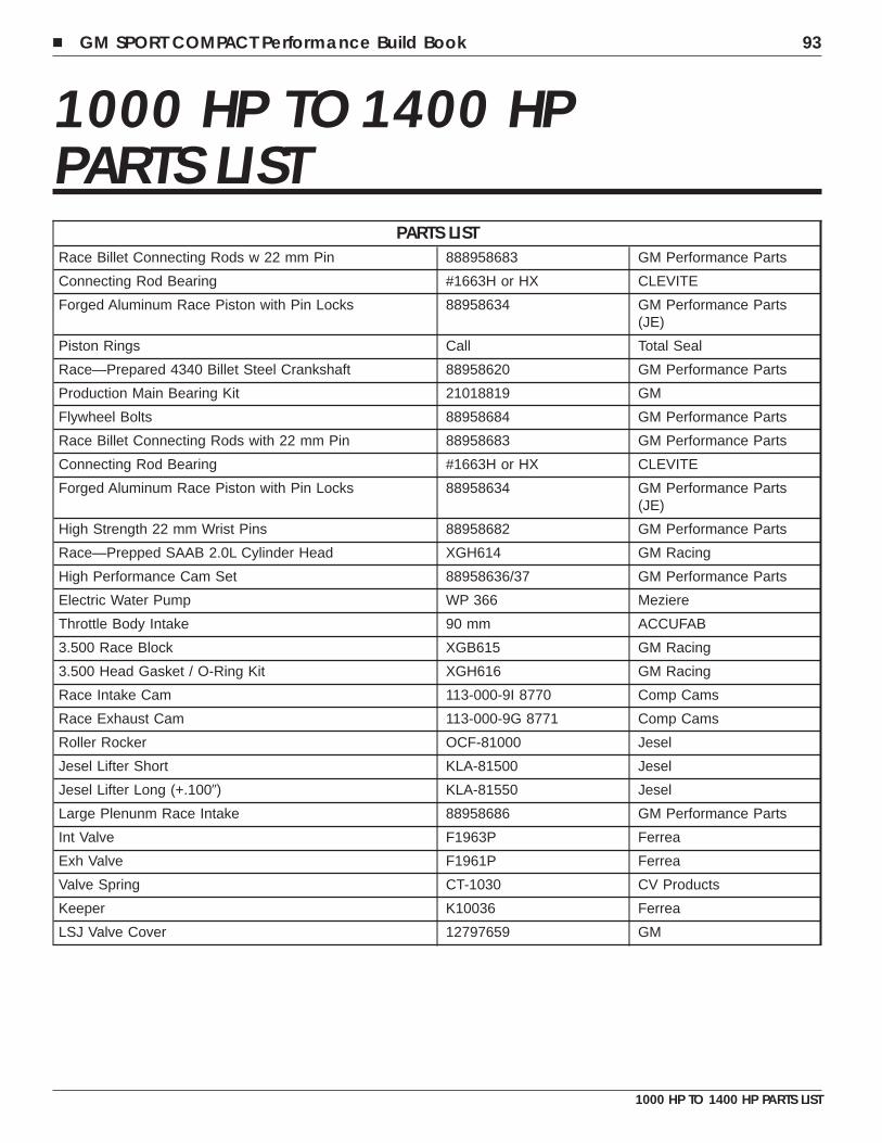
1000 HP TO 1400 HPPARTS LIST
PARTS LISTRace Billet Connecting Rods w 22 mm Pin 888958683 GM Performance Parts
Connecting Rod Bearing #1663H or HX CLEVITE
Forged Aluminum Race Piston with Pin Locks 88958634 GM Performance Parts(JE)
Piston Rings Call Total Seal
Race—Prepared 4340 Billet Steel Crankshaft 88958620 GM Performance Parts
Production Main Bearing Kit 21018819 GM
Flywheel Bolts 88958684 GM Performance Parts
Race Billet Connecting Rods with 22 mm Pin 88958683 GM Performance Parts
Connecting Rod Bearing #1663H or HX CLEVITE
Forged Aluminum Race Piston with Pin Locks 88958634 GM Performance Parts(JE)
High Strength 22 mm Wrist Pins 88958682 GM Performance Parts
Race—Prepped SAAB 2.0L Cylinder Head XGH614 GM Racing
High Performance Cam Set 88958636/37 GM Performance Parts
Electric Water Pump WP 366 Meziere
Throttle Body Intake 90 mm ACCUFAB
3.500 Race Block XGB615 GM Racing
3.500 Head Gasket / O-Ring Kit XGH616 GM Racing
Race Intake Cam 113-000-9I 8770 Comp Cams
Race Exhaust Cam 113-000-9G 8771 Comp Cams
Roller Rocker OCF-81000 Jesel
Jesel Lifter Short KLA-81500 Jesel
Jesel Lifter Long (+.100�) KLA-81550 Jesel
Large Plenunm Race Intake 88958686 GM Performance Parts
Int Valve F1963P Ferrea
Exh Valve F1961P Ferrea
Valve Spring CT-1030 CV Products
Keeper K10036 Ferrea
LSJ Valve Cover 12797659 GM
� GM SPORT COMPACT Performance Build Book 93
1000 HP TO 1400 HP PARTS LIST

NOTES
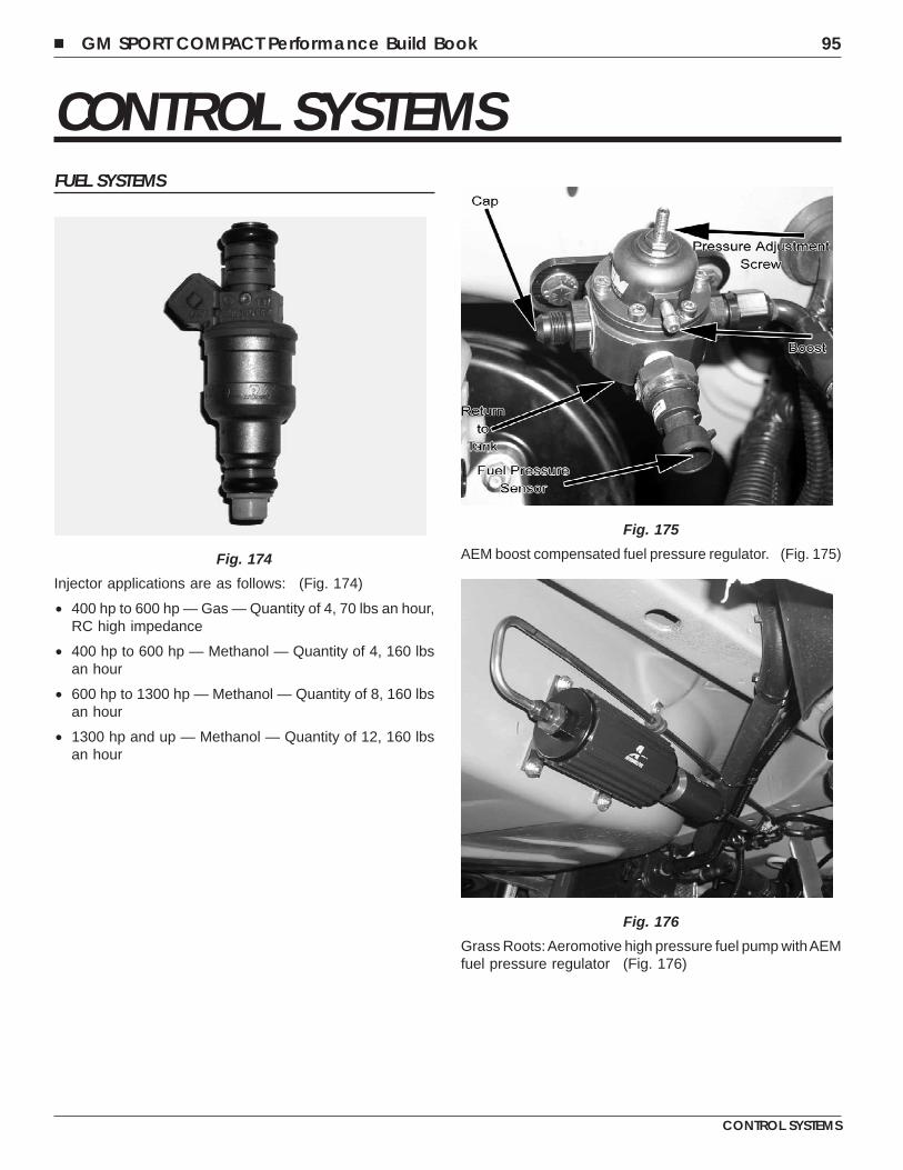
CONTROL SYSTEMSFUEL SYSTEMS
Injector applications are as follows: (Fig. 174)
• 400 hp to 600 hp — Gas — Quantity of 4, 70 lbs an hour,RC high impedance
• 400 hp to 600 hp — Methanol — Quantity of 4, 160 lbsan hour
• 600 hp to 1300 hp — Methanol — Quantity of 8, 160 lbsan hour
• 1300 hp and up — Methanol — Quantity of 12, 160 lbsan hour
AEM boost compensated fuel pressure regulator. (Fig. 175)
Grass Roots:Aeromotive high pressure fuel pump withAEMfuel pressure regulator (Fig. 176)
Fig. 174
Fig. 175
Fig. 176
� GM SPORT COMPACT Performance Build Book 95
CONTROL SYSTEMS
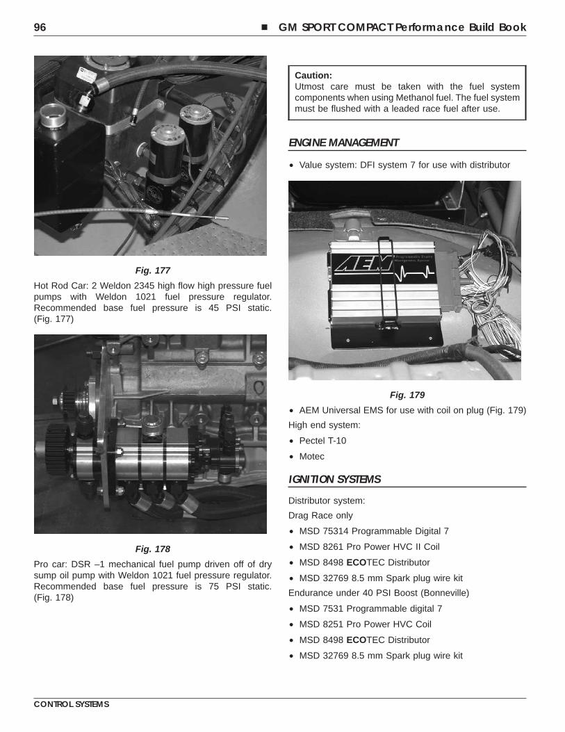
Hot Rod Car: 2 Weldon 2345 high flow high pressure fuelpumps with Weldon 1021 fuel pressure regulator.Recommended base fuel pressure is 45 PSI static.(Fig. 177)
Pro car: DSR –1 mechanical fuel pump driven off of drysump oil pump with Weldon 1021 fuel pressure regulator.Recommended base fuel pressure is 75 PSI static.(Fig. 178)
Caution:Utmost care must be taken with the fuel systemcomponents when using Methanol fuel. The fuel systemmust be flushed with a leaded race fuel after use.
ENGINE MANAGEMENT
• Value system: DFI system 7 for use with distributor
• AEM Universal EMS for use with coil on plug (Fig. 179)
High end system:
• Pectel T-10
• Motec
IGNITION SYSTEMS
Distributor system:
Drag Race only
• MSD 75314 Programmable Digital 7
• MSD 8261 Pro Power HVC II Coil
• MSD 8498 ECOTEC Distributor
• MSD 32769 8.5 mm Spark plug wire kit
Endurance under 40 PSI Boost (Bonneville)
• MSD 7531 Programmable digital 7
• MSD 8251 Pro Power HVC Coil
• MSD 8498 ECOTEC Distributor
• MSD 32769 8.5 mm Spark plug wire kit
Fig. 177
Fig. 178
Fig. 179
96 � GM SPORT COMPACT Performance Build Book
CONTROL SYSTEMS
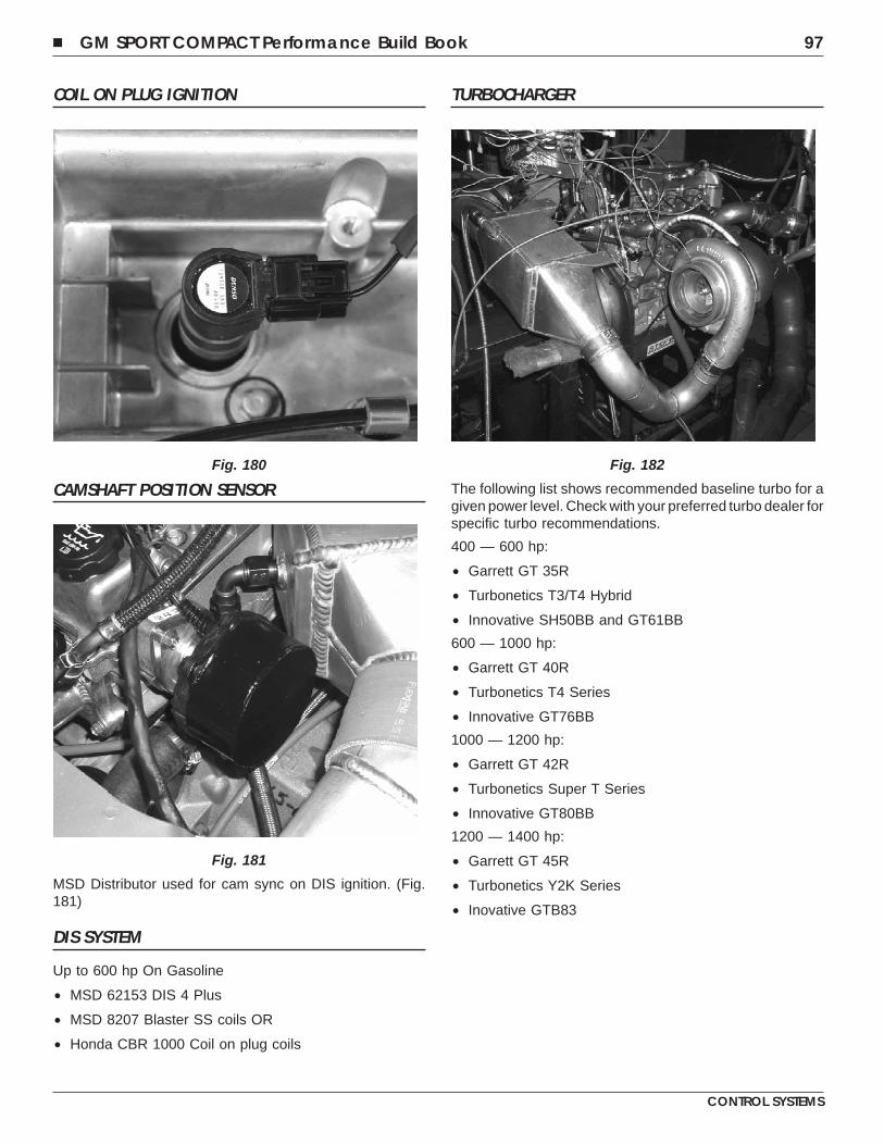
COIL ON PLUG IGNITION
CAMSHAFT POSITION SENSOR
MSD Distributor used for cam sync on DIS ignition. (Fig.181)
DIS SYSTEM
Up to 600 hp On Gasoline
• MSD 62153 DIS 4 Plus
• MSD 8207 Blaster SS coils OR
• Honda CBR 1000 Coil on plug coils
TURBOCHARGER
The following list shows recommended baseline turbo for agiven power level. Check with your preferred turbo dealer forspecific turbo recommendations.
400 — 600 hp:
• Garrett GT 35R
• Turbonetics T3/T4 Hybrid
• Innovative SH50BB and GT61BB
600 — 1000 hp:
• Garrett GT 40R
• Turbonetics T4 Series
• Innovative GT76BB
1000 — 1200 hp:
• Garrett GT 42R
• Turbonetics Super T Series
• Innovative GT80BB
1200 — 1400 hp:
• Garrett GT 45R
• Turbonetics Y2K Series
• Inovative GTB83
Fig. 180
Fig. 181
Fig. 182
� GM SPORT COMPACT Performance Build Book 97
CONTROL SYSTEMS
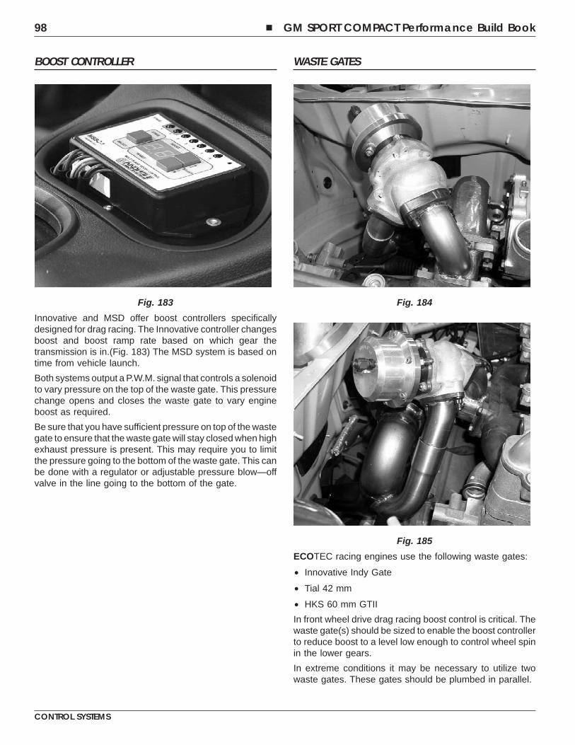
BOOST CONTROLLER
Innovative and MSD offer boost controllers specificallydesigned for drag racing. The Innovative controller changesboost and boost ramp rate based on which gear thetransmission is in.(Fig. 183) The MSD system is based ontime from vehicle launch.
Both systems output a P.W.M. signal that controls a solenoidto vary pressure on the top of the waste gate. This pressurechange opens and closes the waste gate to vary engineboost as required.
Be sure that you have sufficient pressure on top of the wastegate to ensure that the waste gate will stay closed when highexhaust pressure is present. This may require you to limitthe pressure going to the bottom of the waste gate. This canbe done with a regulator or adjustable pressure blow—offvalve in the line going to the bottom of the gate.
WASTE GATES
ECOTEC racing engines use the following waste gates:
• Innovative Indy Gate
• Tial 42 mm
• HKS 60 mm GTII
In front wheel drive drag racing boost control is critical. Thewaste gate(s) should be sized to enable the boost controllerto reduce boost to a level low enough to control wheel spinin the lower gears.
In extreme conditions it may be necessary to utilize twowaste gates. These gates should be plumbed in parallel.
Fig. 183 Fig. 184
Fig. 185
98 � GM SPORT COMPACT Performance Build Book
CONTROL SYSTEMS
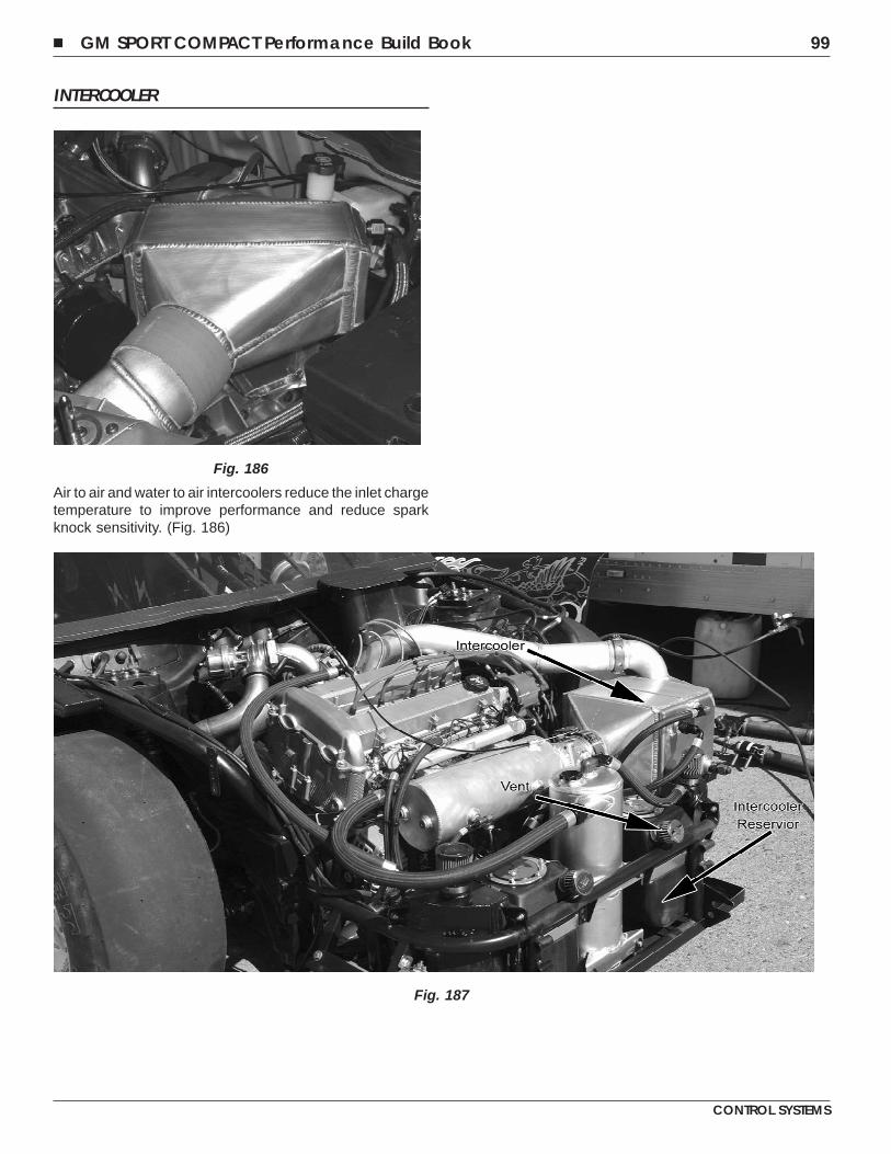
INTERCOOLER
Air to air and water to air intercoolers reduce the inlet chargetemperature to improve performance and reduce sparkknock sensitivity. (Fig. 186)
Fig. 186
Fig. 187
� GM SPORT COMPACT Performance Build Book 99
CONTROL SYSTEMS
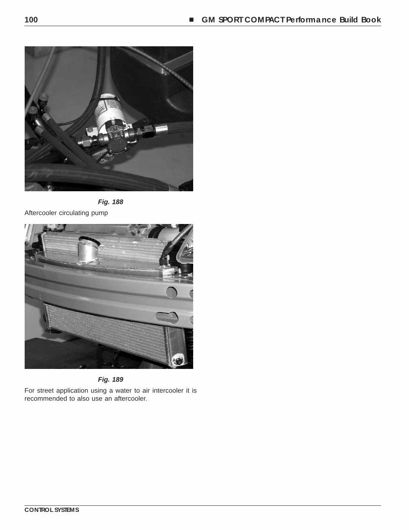
Aftercooler circulating pump
For street application using a water to air intercooler it isrecommended to also use an aftercooler.
Fig. 188
Fig. 189
100 � GM SPORT COMPACT Performance Build Book
CONTROL SYSTEMS
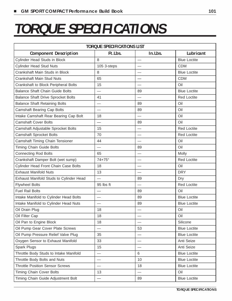
TORQUE SPECIFICATIONSTORQUE SPECIFICATIONS LIST
Component Description Ft.Lbs. In.Lbs. LubricantCylinder Head Studs in Block 8 — Blue Loctite
Cylinder Head Stud Nuts 105 3-steps — CDM
Crankshaft Main Studs in Block 8 — Blue Loctite
Crankshaft Main Stud Nuts 65 — CDM
Crankshaft to Block Peripheral Bolts 15 — Oil
Balance Shaft Chain Guide Bolts — 89 Blue Loctite
Balance Shaft Drive Sprocket Bolts 41 — Red Loctite
Balance Shaft Retaining Bolts — 89 Oil
Camshaft Bearing Cap Bolts — 89 Oil
Intake Camshaft Rear Bearing Cap Bolt 18 — Oil
Camshaft Cover Bolts — 89 Oil
Camshaft Adjustable Sprocket Bolts 15 — Red Loctite
Camshaft Sprocket Bolts 70 — Red Loctite
Camshaft Timing Chain Tensioner 44 — Oil
Timing Chain Guide Bolts — 89 Oil
Connecting Rod Bolts 65 — Molly
Crankshaft Damper Bolt (wet sump) 74+75° — Red Loctite
Cylinder Head Front Chain Case Bolts 18 — Oil
Exhaust Manifold Nuts 13 — DRY
Exhaust Manifold Studs to Cylinder Head — 89 Dry
Flywheel Bolts 95 lbs ft — Red Loctite
Fuel Rail Bolts — 89 Oil
Intake Manifold to Cylinder Head Bolts — 89 Blue Loctite
Intake Manifold to Cylinder Head Nuts — 89 Blue Loctite
Oil Drain Plug 18 — Oil
Oil Filter Cap 18 — Oil
Oil Pan to Engine Block 18 — Silicone
Oil Pump Gear Cover Plate Screws — 53 Blue Loctite
Oil Pump Pressure Relief Valve Plug 35 — Blue Loctite
Oxygen Sensor to Exhaust Manifold 33 — Anti Seize
Spark Plugs 15 — Anti Seize
Throttle Body Studs to Intake Manifold — 6 Blue Loctite
Throttle Body Bolts and Nuts — 10 Blue Loctite
Throttle Position Sensor Screws — 18 Blue Loctite
Timing Chain Cover Bolts 13 — Oil
Timing Chain Guide Adjustment Bolt — 89 Blue Loctite
� GM SPORT COMPACT Performance Build Book 101
TORQUE SPECIFICATIONS
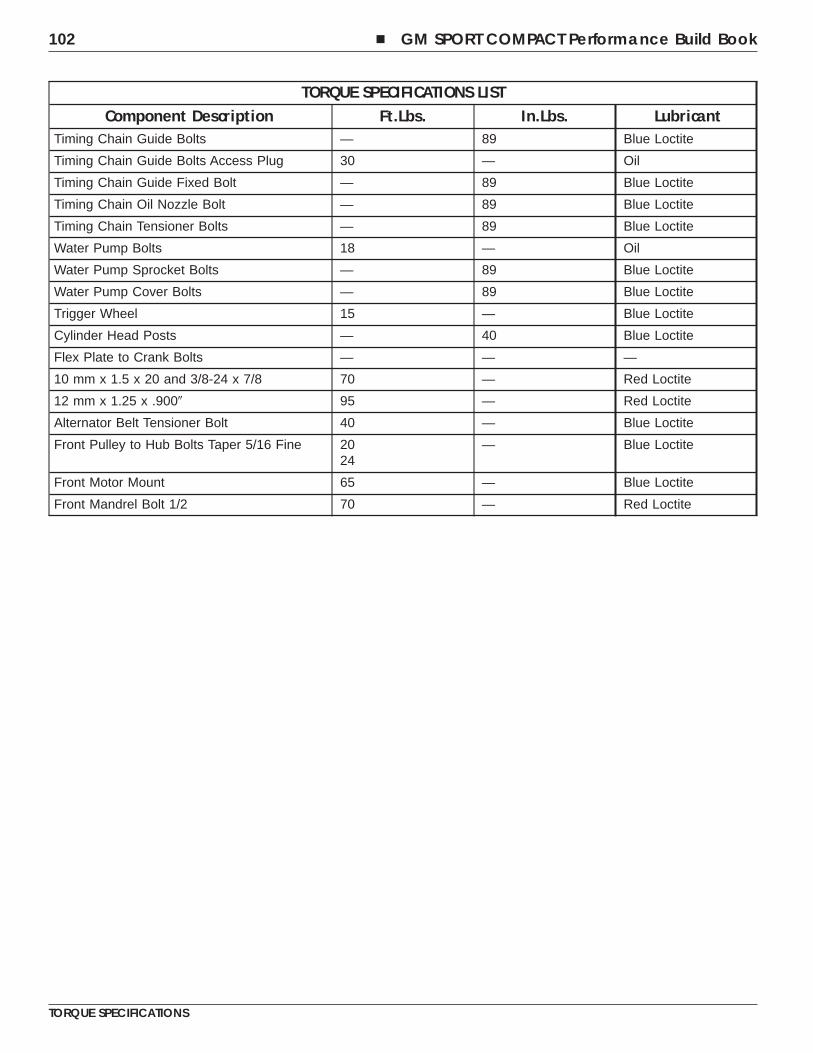
TORQUE SPECIFICATIONS LISTComponent Description Ft.Lbs. In.Lbs. Lubricant
Timing Chain Guide Bolts — 89 Blue Loctite
Timing Chain Guide Bolts Access Plug 30 — Oil
Timing Chain Guide Fixed Bolt — 89 Blue Loctite
Timing Chain Oil Nozzle Bolt — 89 Blue Loctite
Timing Chain Tensioner Bolts — 89 Blue Loctite
Water Pump Bolts 18 — Oil
Water Pump Sprocket Bolts — 89 Blue Loctite
Water Pump Cover Bolts — 89 Blue Loctite
Trigger Wheel 15 — Blue Loctite
Cylinder Head Posts — 40 Blue Loctite
Flex Plate to Crank Bolts — — —
10 mm x 1.5 x 20 and 3/8-24 x 7/8 70 — Red Loctite
12 mm x 1.25 x .900� 95 — Red Loctite
Alternator Belt Tensioner Bolt 40 — Blue Loctite
Front Pulley to Hub Bolts Taper 5/16 Fine 2024
— Blue Loctite
Front Motor Mount 65 — Blue Loctite
Front Mandrel Bolt 1/2 70 — Red Loctite
102 � GM SPORT COMPACT Performance Build Book
TORQUE SPECIFICATIONS
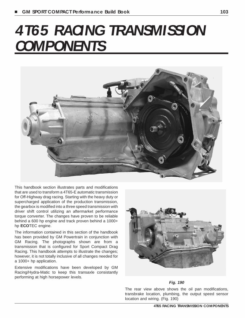
4T65 RACING TRANSMISSIONCOMPONENTS
This handbook section illustrates parts and modificationsthat are used to transform a 4T65-E automatic transmissionfor Off-Highway drag racing. Starting with the heavy duty orsupercharged application of the production transmission,the gearbox is modified into a three speed transmission withdriver shift control utilizing an aftermarket performancetorque converter. The changes have proven to be reliablebehind a 600 hp engine and track proven behind a 1000+hp ECOTEC engine.
The information contained in this section of the handbookhas been provided by GM Powertrain in conjunction withGM Racing. The photographs shown are from atransmission that is configured for Sport Compact DragRacing. This handbook attempts to illustrate the changes;however, it is not totally inclusive of all changes needed fora 1000+ hp application.
Extensive modifications have been developed by GMRacing/Hydra-Matic to keep this transaxle consistantlyperforming at high horsepower levels.
The rear view above shows the oil pan modifications,transbrake location, plumbing, the output speed sensorlocation and wiring. (Fig. 190)
Fig. 190
� GM SPORT COMPACT Performance Build Book 103
4T65 RACING TRANSMISSION COMPONENTS
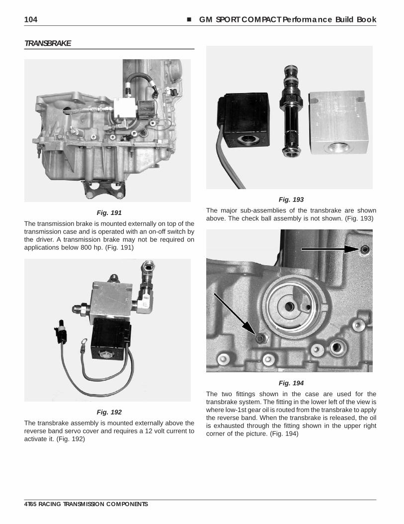
TRANSBRAKE
The transmission brake is mounted externally on top of thetransmission case and is operated with an on-off switch bythe driver. A transmission brake may not be required onapplications below 800 hp. (Fig. 191)
The transbrake assembly is mounted externally above thereverse band servo cover and requires a 12 volt current toactivate it. (Fig. 192)
The major sub-assemblies of the transbrake are shownabove. The check ball assembly is not shown. (Fig. 193)
The two fittings shown in the case are used for thetransbrake system. The fitting in the lower left of the view iswhere low-1st gear oil is routed from the transbrake to applythe reverse band. When the transbrake is released, the oilis exhausted through the fitting shown in the upper rightcorner of the picture. (Fig. 194)
Fig. 191
Fig. 192
Fig. 193
Fig. 194
104 � GM SPORT COMPACT Performance Build Book
4T65 RACING TRANSMISSION COMPONENTS
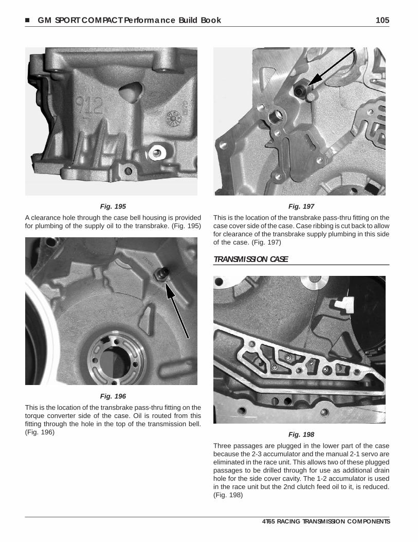
A clearance hole through the case bell housing is providedfor plumbing of the supply oil to the transbrake. (Fig. 195)
This is the location of the transbrake pass-thru fitting on thetorque converter side of the case. Oil is routed from thisfitting through the hole in the top of the transmission bell.(Fig. 196)
This is the location of the transbrake pass-thru fitting on thecase cover side of the case. Case ribbing is cut back to allowfor clearance of the transbrake supply plumbing in this sideof the case. (Fig. 197)
TRANSMISSION CASE
Three passages are plugged in the lower part of the casebecause the 2-3 accumulator and the manual 2-1 servo areeliminated in the race unit. This allows two of these pluggedpassages to be drilled through for use as additional drainhole for the side cover cavity. The 1-2 accumulator is usedin the race unit but the 2nd clutch feed oil to it, is reduced.(Fig. 198)
Fig. 195
Fig. 196
Fig. 197
Fig. 198
� GM SPORT COMPACT Performance Build Book 105
4T65 RACING TRANSMISSION COMPONENTS
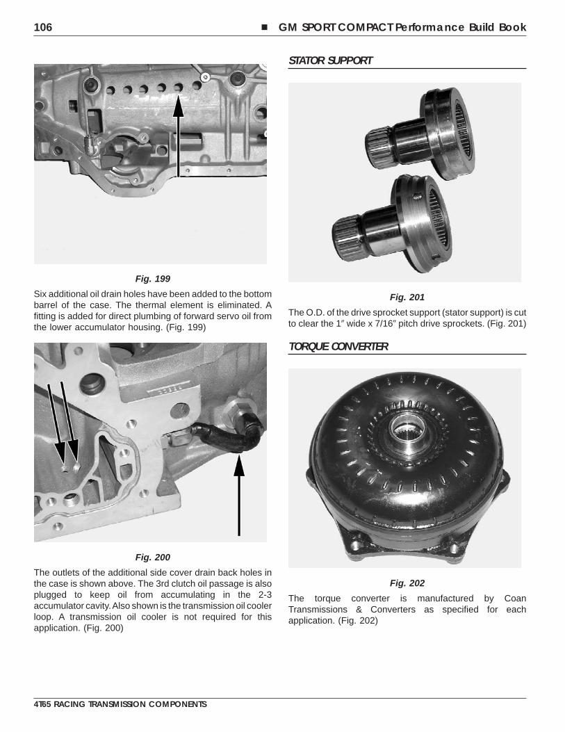
Six additional oil drain holes have been added to the bottombarrel of the case. The thermal element is eliminated. Afitting is added for direct plumbing of forward servo oil fromthe lower accumulator housing. (Fig. 199)
The outlets of the additional side cover drain back holes inthe case is shown above. The 3rd clutch oil passage is alsoplugged to keep oil from accumulating in the 2-3accumulator cavity.Also shown is the transmission oil coolerloop. A transmission oil cooler is not required for thisapplication. (Fig. 200)
STATOR SUPPORT
The O.D. of the drive sprocket support (stator support) is cutto clear the 1� wide x 7/16� pitch drive sprockets. (Fig. 201)
TORQUE CONVERTER
The torque converter is manufactured by CoanTransmissions & Converters as specified for eachapplication. (Fig. 202)
Fig. 199
Fig. 200
Fig. 201
Fig. 202
106 � GM SPORT COMPACT Performance Build Book
4T65 RACING TRANSMISSION COMPONENTS
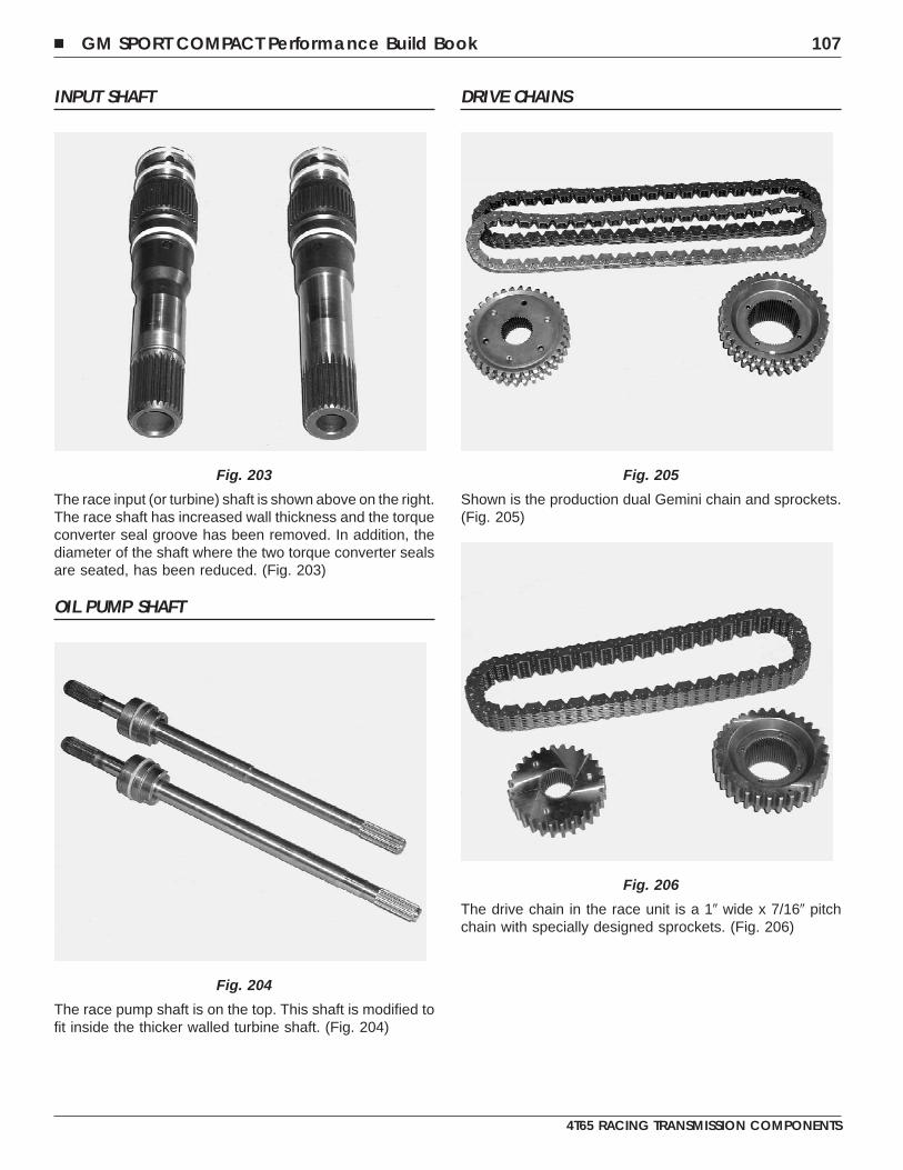
INPUT SHAFT
The race input (or turbine) shaft is shown above on the right.The race shaft has increased wall thickness and the torqueconverter seal groove has been removed. In addition, thediameter of the shaft where the two torque converter sealsare seated, has been reduced. (Fig. 203)
OIL PUMP SHAFT
The race pump shaft is on the top. This shaft is modified tofit inside the thicker walled turbine shaft. (Fig. 204)
DRIVE CHAINS
Shown is the production dual Gemini chain and sprockets.(Fig. 205)
The drive chain in the race unit is a 1� wide x 7/16� pitchchain with specially designed sprockets. (Fig. 206)
Fig. 203
Fig. 204
Fig. 205
Fig. 206
� GM SPORT COMPACT Performance Build Book 107
4T65 RACING TRANSMISSION COMPONENTS
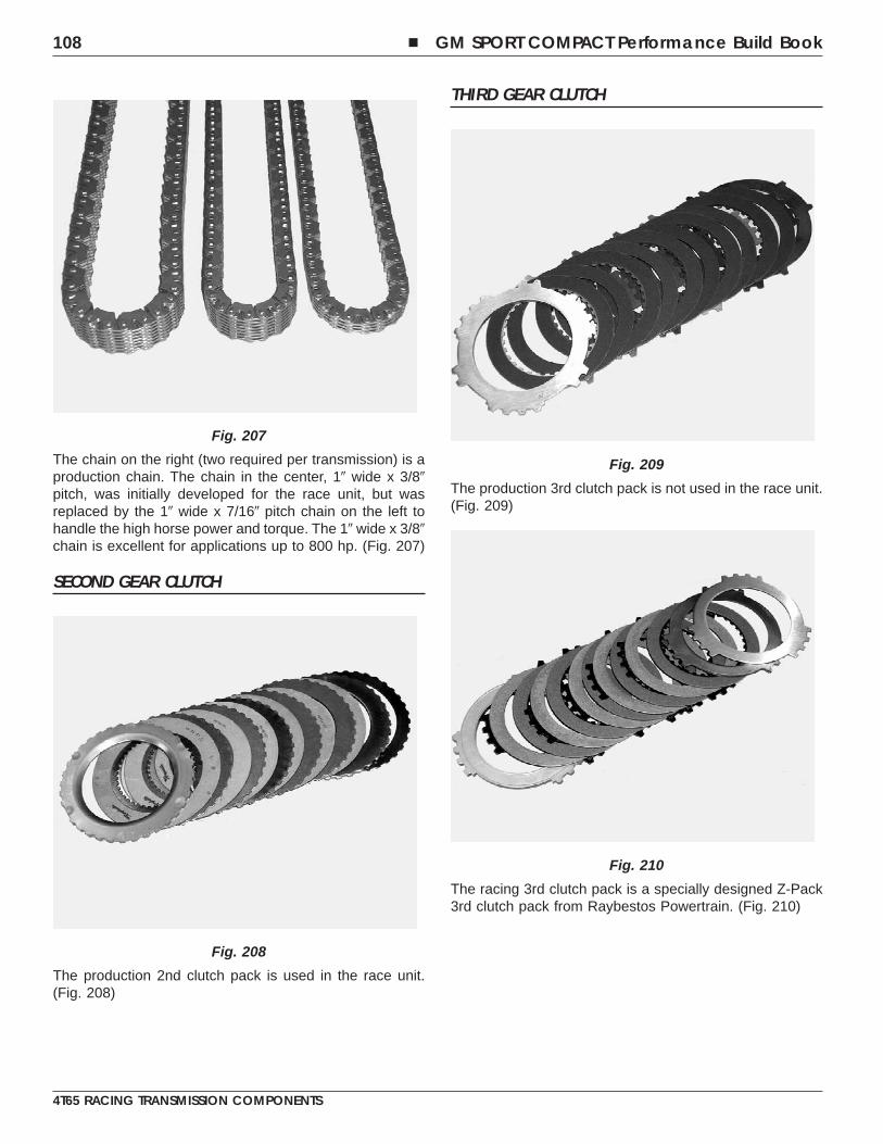
The chain on the right (two required per transmission) is aproduction chain. The chain in the center, 1� wide x 3/8�pitch, was initially developed for the race unit, but wasreplaced by the 1� wide x 7/16� pitch chain on the left tohandle the high horse power and torque. The 1� wide x 3/8�chain is excellent for applications up to 800 hp. (Fig. 207)
SECOND GEAR CLUTCH
The production 2nd clutch pack is used in the race unit.(Fig. 208)
THIRD GEAR CLUTCH
The production 3rd clutch pack is not used in the race unit.(Fig. 209)
The racing 3rd clutch pack is a specially designed Z-Pack3rd clutch pack from Raybestos Powertrain. (Fig. 210)
Fig. 207
Fig. 208
Fig. 209
Fig. 210
108 � GM SPORT COMPACT Performance Build Book
4T65 RACING TRANSMISSION COMPONENTS
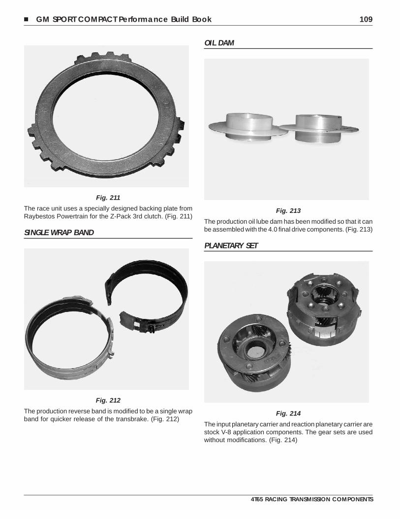
The race unit uses a specially designed backing plate fromRaybestos Powertrain for the Z-Pack 3rd clutch. (Fig. 211)
SINGLE WRAP BAND
The production reverse band is modified to be a single wrapband for quicker release of the transbrake. (Fig. 212)
OIL DAM
The production oil lube dam has been modified so that it canbe assembled with the 4.0 final drive components. (Fig. 213)
PLANETARY SET
The input planetary carrier and reaction planetary carrier arestock V-8 application components. The gear sets are usedwithout modifications. (Fig. 214)
Fig. 211
Fig. 212
Fig. 213
Fig. 214
� GM SPORT COMPACT Performance Build Book 109
4T65 RACING TRANSMISSION COMPONENTS
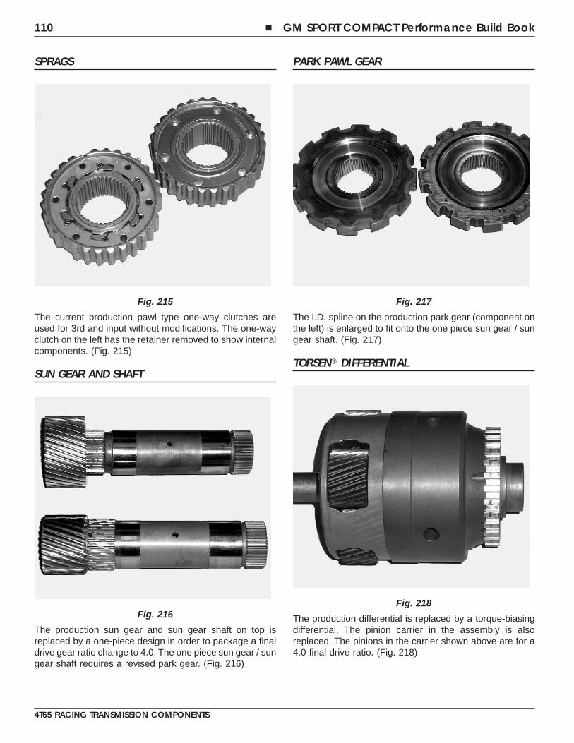
SPRAGS
The current production pawl type one-way clutches areused for 3rd and input without modifications. The one-wayclutch on the left has the retainer removed to show internalcomponents. (Fig. 215)
SUN GEAR AND SHAFT
The production sun gear and sun gear shaft on top isreplaced by a one-piece design in order to package a finaldrive gear ratio change to 4.0. The one piece sun gear / sungear shaft requires a revised park gear. (Fig. 216)
PARK PAWL GEAR
The I.D. spline on the production park gear (component onthe left) is enlarged to fit onto the one piece sun gear / sungear shaft. (Fig. 217)
TORSEN� DIFFERENTIAL
The production differential is replaced by a torque-biasingdifferential. The pinion carrier in the assembly is alsoreplaced. The pinions in the carrier shown above are for a4.0 final drive ratio. (Fig. 218)
Fig. 215
Fig. 216
Fig. 217
Fig. 218
110 � GM SPORT COMPACT Performance Build Book
4T65 RACING TRANSMISSION COMPONENTS
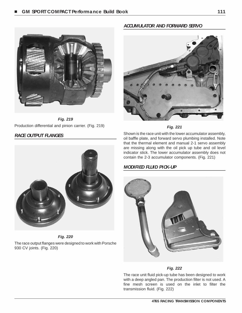
Production differential and pinion carrier. (Fig. 219)
RACE OUTPUT FLANGES
The race output flanges were designed to work with Porsche930 CV joints. (Fig. 220)
ACCUMULATOR AND FORWARD SERVO
Shown is the race unit with the lower accumulator assembly,oil baffle plate, and forward servo plumbing installed. Notethat the thermal element and manual 2-1 servo assemblyare missing along with the oil pick up tube and oil levelindicator stick. The lower accumulator assembly does notcontain the 2-3 accumulator components. (Fig. 221)
MODIFIED FLUID PICK-UP
The race unit fluid pick-up tube has been designed to workwith a deep angled pan. The production filter is not used. Afine mesh screen is used on the inlet to filter thetransmission fluid. (Fig. 222)
Fig. 219
Fig. 220
Fig. 221
Fig. 222
� GM SPORT COMPACT Performance Build Book 111
4T65 RACING TRANSMISSION COMPONENTS
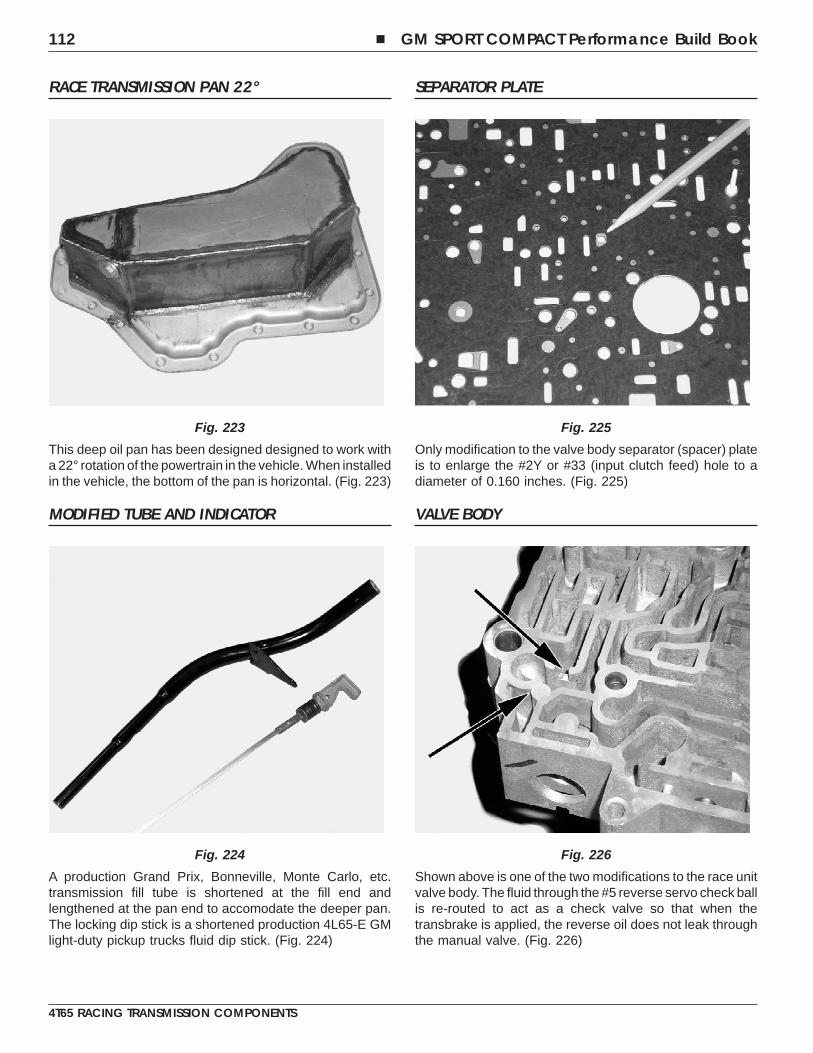
RACE TRANSMISSION PAN 22°
This deep oil pan has been designed designed to work witha 22° rotation of the powertrain in the vehicle. When installedin the vehicle, the bottom of the pan is horizontal. (Fig. 223)
MODIFIED TUBE AND INDICATOR
A production Grand Prix, Bonneville, Monte Carlo, etc.transmission fill tube is shortened at the fill end andlengthened at the pan end to accomodate the deeper pan.The locking dip stick is a shortened production 4L65-E GMlight-duty pickup trucks fluid dip stick. (Fig. 224)
SEPARATOR PLATE
Only modification to the valve body separator (spacer) plateis to enlarge the #2Y or #33 (input clutch feed) hole to adiameter of 0.160 inches. (Fig. 225)
VALVE BODY
Shown above is one of the two modifications to the race unitvalve body. The fluid through the #5 reverse servo check ballis re-routed to act as a check valve so that when thetransbrake is applied, the reverse oil does not leak throughthe manual valve. (Fig. 226)
Fig. 223
Fig. 224
Fig. 225
Fig. 226
112 � GM SPORT COMPACT Performance Build Book
4T65 RACING TRANSMISSION COMPONENTS
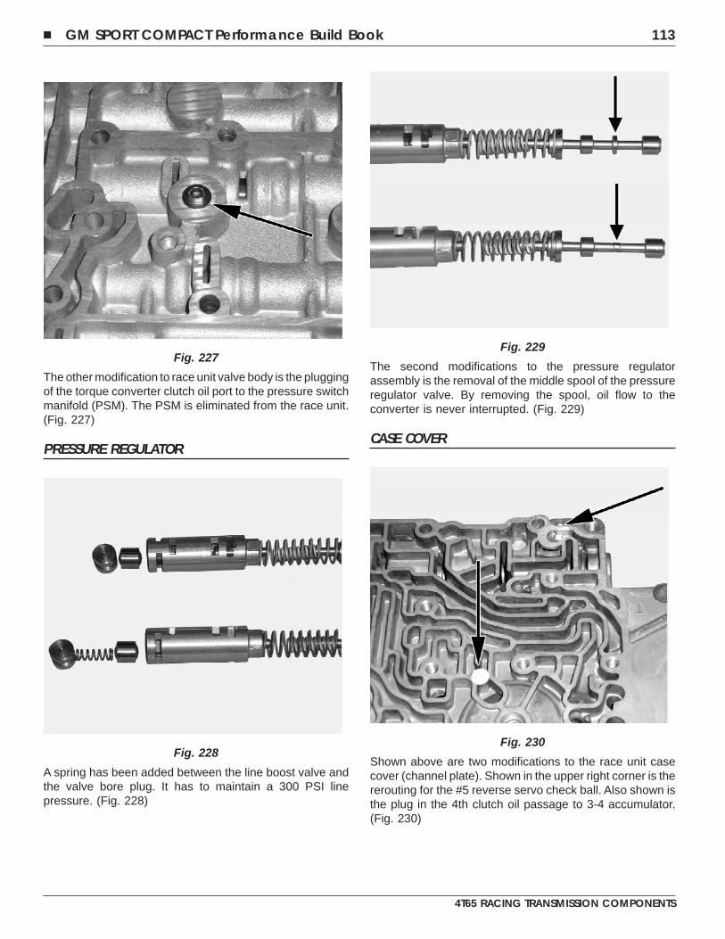
The other modification to race unit valve body is the pluggingof the torque converter clutch oil port to the pressure switchmanifold (PSM). The PSM is eliminated from the race unit.(Fig. 227)
PRESSURE REGULATOR
A spring has been added between the line boost valve andthe valve bore plug. It has to maintain a 300 PSI linepressure. (Fig. 228)
The second modifications to the pressure regulatorassembly is the removal of the middle spool of the pressureregulator valve. By removing the spool, oil flow to theconverter is never interrupted. (Fig. 229)
CASE COVER
Shown above are two modifications to the race unit casecover (channel plate). Shown in the upper right corner is thererouting for the #5 reverse servo check ball. Also shown isthe plug in the 4th clutch oil passage to 3-4 accumulator.(Fig. 230)
Fig. 227
Fig. 228
Fig. 229
Fig. 230
� GM SPORT COMPACT Performance Build Book 113
4T65 RACING TRANSMISSION COMPONENTS
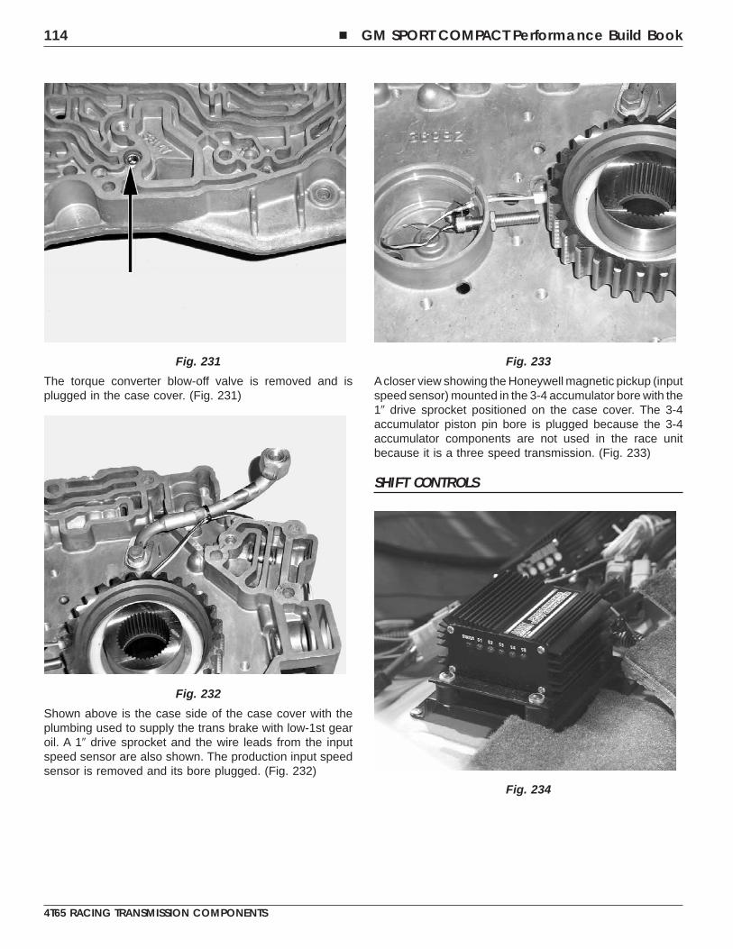
The torque converter blow-off valve is removed and isplugged in the case cover. (Fig. 231)
Shown above is the case side of the case cover with theplumbing used to supply the trans brake with low-1st gearoil. A 1� drive sprocket and the wire leads from the inputspeed sensor are also shown. The production input speedsensor is removed and its bore plugged. (Fig. 232)
Acloser view showing the Honeywell magnetic pickup (inputspeed sensor) mounted in the 3-4 accumulator bore with the1� drive sprocket positioned on the case cover. The 3-4accumulator piston pin bore is plugged because the 3-4accumulator components are not used in the race unitbecause it is a three speed transmission. (Fig. 233)
SHIFT CONTROLS
Fig. 231
Fig. 232
Fig. 233
Fig. 234
114 � GM SPORT COMPACT Performance Build Book
4T65 RACING TRANSMISSION COMPONENTS
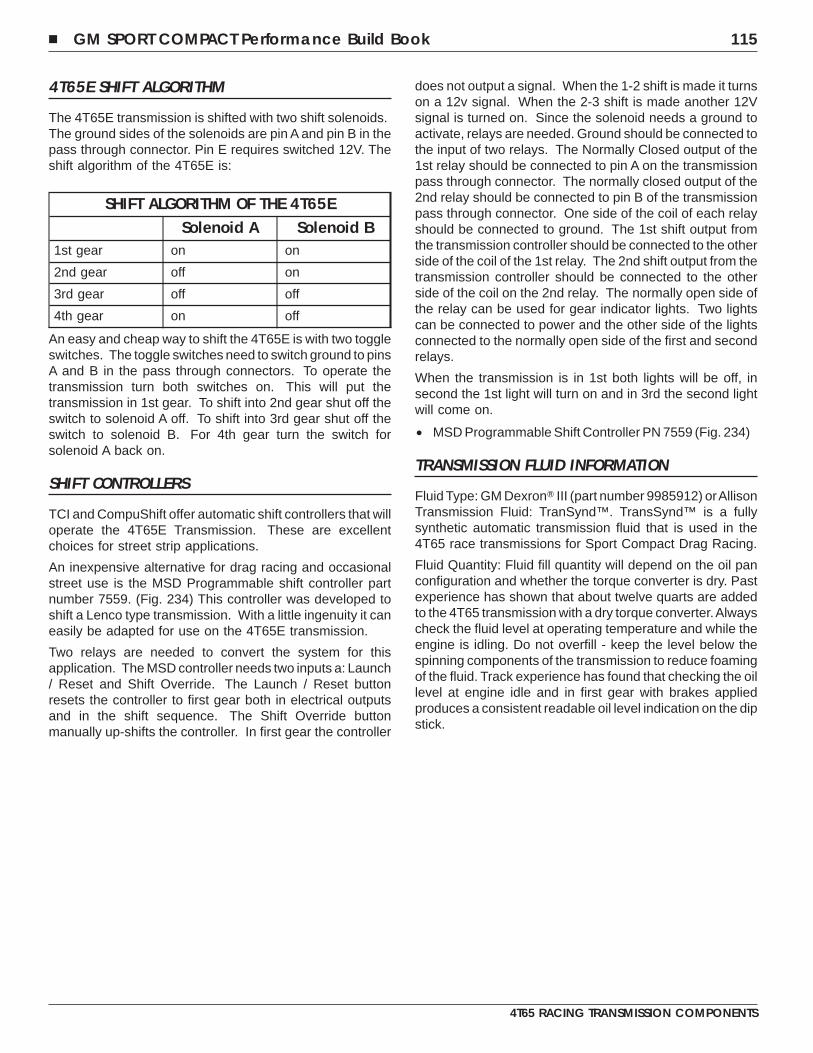
4T65E SHIFT ALGORITHM
The 4T65E transmission is shifted with two shift solenoids.The ground sides of the solenoids are pin A and pin B in thepass through connector. Pin E requires switched 12V. Theshift algorithm of the 4T65E is:
SHIFT ALGORITHM OF THE 4T65ESolenoid A Solenoid B
1st gear on on
2nd gear off on
3rd gear off off
4th gear on off
An easy and cheap way to shift the 4T65E is with two toggleswitches. The toggle switches need to switch ground to pinsA and B in the pass through connectors. To operate thetransmission turn both switches on. This will put thetransmission in 1st gear. To shift into 2nd gear shut off theswitch to solenoid A off. To shift into 3rd gear shut off theswitch to solenoid B. For 4th gear turn the switch forsolenoid A back on.
SHIFT CONTROLLERS
TCI and CompuShift offer automatic shift controllers that willoperate the 4T65E Transmission. These are excellentchoices for street strip applications.
An inexpensive alternative for drag racing and occasionalstreet use is the MSD Programmable shift controller partnumber 7559. (Fig. 234) This controller was developed toshift a Lenco type transmission. With a little ingenuity it caneasily be adapted for use on the 4T65E transmission.
Two relays are needed to convert the system for thisapplication. The MSD controller needs two inputs a: Launch/ Reset and Shift Override. The Launch / Reset buttonresets the controller to first gear both in electrical outputsand in the shift sequence. The Shift Override buttonmanually up-shifts the controller. In first gear the controller
does not output a signal. When the 1-2 shift is made it turnson a 12v signal. When the 2-3 shift is made another 12Vsignal is turned on. Since the solenoid needs a ground toactivate, relays are needed. Ground should be connected tothe input of two relays. The Normally Closed output of the1st relay should be connected to pin A on the transmissionpass through connector. The normally closed output of the2nd relay should be connected to pin B of the transmissionpass through connector. One side of the coil of each relayshould be connected to ground. The 1st shift output fromthe transmission controller should be connected to the otherside of the coil of the 1st relay. The 2nd shift output from thetransmission controller should be connected to the otherside of the coil on the 2nd relay. The normally open side ofthe relay can be used for gear indicator lights. Two lightscan be connected to power and the other side of the lightsconnected to the normally open side of the first and secondrelays.
When the transmission is in 1st both lights will be off, insecond the 1st light will turn on and in 3rd the second lightwill come on.
• MSD Programmable Shift Controller PN 7559 (Fig. 234)
TRANSMISSION FLUID INFORMATION
Fluid Type: GM Dexron� III (part number 9985912) orAllisonTransmission Fluid: TranSynd™. TransSynd™ is a fullysynthetic automatic transmission fluid that is used in the4T65 race transmissions for Sport Compact Drag Racing.
Fluid Quantity: Fluid fill quantity will depend on the oil panconfiguration and whether the torque converter is dry. Pastexperience has shown that about twelve quarts are addedto the 4T65 transmission with a dry torque converter.Alwayscheck the fluid level at operating temperature and while theengine is idling. Do not overfill - keep the level below thespinning components of the transmission to reduce foamingof the fluid. Track experience has found that checking the oillevel at engine idle and in first gear with brakes appliedproduces a consistent readable oil level indication on the dipstick.
� GM SPORT COMPACT Performance Build Book 115
4T65 RACING TRANSMISSION COMPONENTS

NOTES
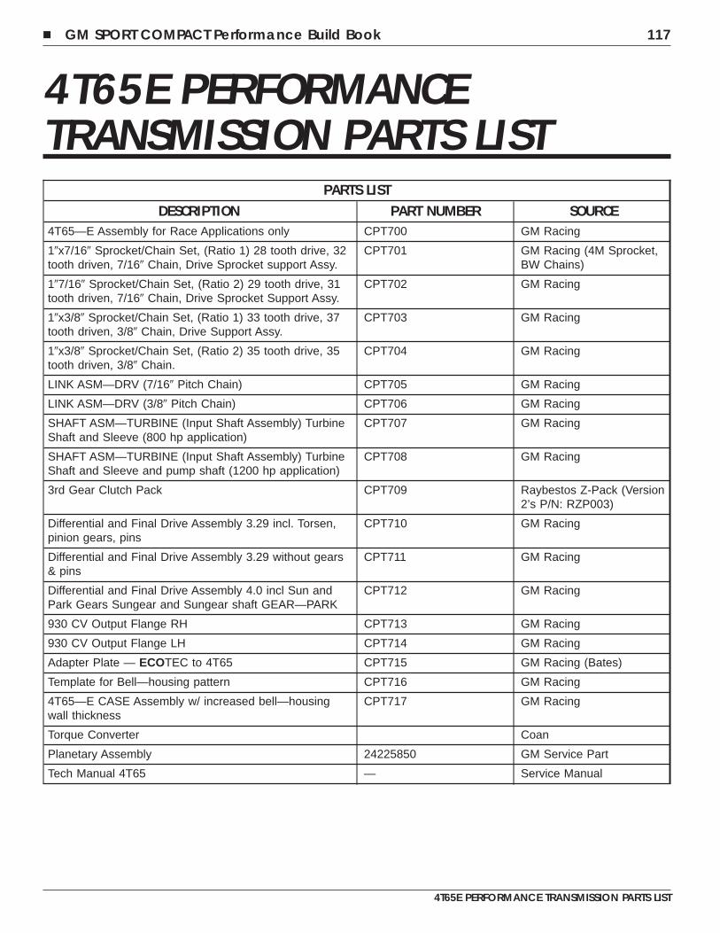
4T65E PERFORMANCETRANSMISSION PARTS LIST
PARTS LISTDESCRIPTION PART NUMBER SOURCE
4T65—E Assembly for Race Applications only CPT700 GM Racing
1�x7/16� Sprocket/Chain Set, (Ratio 1) 28 tooth drive, 32tooth driven, 7/16� Chain, Drive Sprocket support Assy.
CPT701 GM Racing (4M Sprocket,BW Chains)
1�7/16� Sprocket/Chain Set, (Ratio 2) 29 tooth drive, 31tooth driven, 7/16� Chain, Drive Sprocket Support Assy.
CPT702 GM Racing
1�x3/8� Sprocket/Chain Set, (Ratio 1) 33 tooth drive, 37tooth driven, 3/8� Chain, Drive Support Assy.
CPT703 GM Racing
1�x3/8� Sprocket/Chain Set, (Ratio 2) 35 tooth drive, 35tooth driven, 3/8� Chain.
CPT704 GM Racing
LINK ASM—DRV (7/16� Pitch Chain) CPT705 GM Racing
LINK ASM—DRV (3/8� Pitch Chain) CPT706 GM Racing
SHAFT ASM—TURBINE (Input Shaft Assembly) TurbineShaft and Sleeve (800 hp application)
CPT707 GM Racing
SHAFT ASM—TURBINE (Input Shaft Assembly) TurbineShaft and Sleeve and pump shaft (1200 hp application)
CPT708 GM Racing
3rd Gear Clutch Pack CPT709 Raybestos Z-Pack (Version2’s P/N: RZP003)
Differential and Final Drive Assembly 3.29 incl. Torsen,pinion gears, pins
CPT710 GM Racing
Differential and Final Drive Assembly 3.29 without gears& pins
CPT711 GM Racing
Differential and Final Drive Assembly 4.0 incl Sun andPark Gears Sungear and Sungear shaft GEAR—PARK
CPT712 GM Racing
930 CV Output Flange RH CPT713 GM Racing
930 CV Output Flange LH CPT714 GM Racing
Adapter Plate — ECOTEC to 4T65 CPT715 GM Racing (Bates)
Template for Bell—housing pattern CPT716 GM Racing
4T65—E CASE Assembly w/ increased bell—housingwall thickness
CPT717 GM Racing
Torque Converter Coan
Planetary Assembly 24225850 GM Service Part
Tech Manual 4T65 — Service Manual
� GM SPORT COMPACT Performance Build Book 117
4T65E PERFORMANCE TRANSMISSION PARTS LIST

NOTES
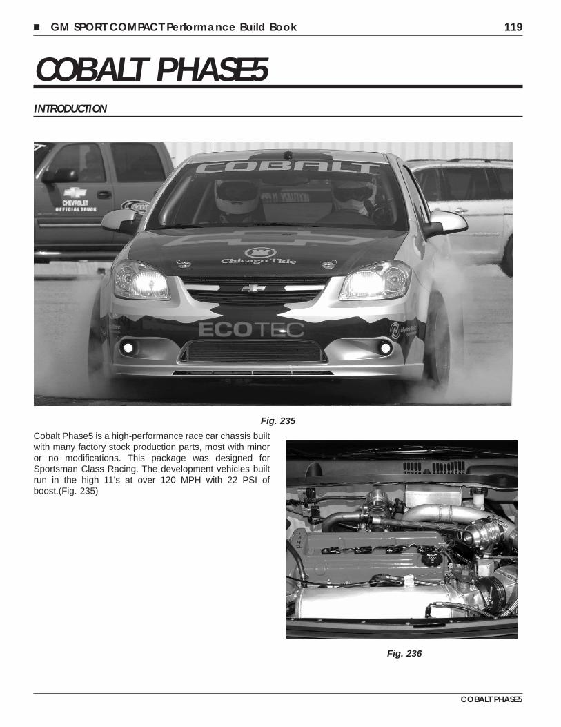
COBALT PHASE5INTRODUCTION
Cobalt Phase5 is a high-performance race car chassis builtwith many factory stock production parts, most with minoror no modifications. This package was designed forSportsman Class Racing. The development vehicles builtrun in the high 11’s at over 120 MPH with 22 PSI ofboost.(Fig. 235)
Fig. 235
Fig. 236
� GM SPORT COMPACT Performance Build Book 119
COBALT PHASE5
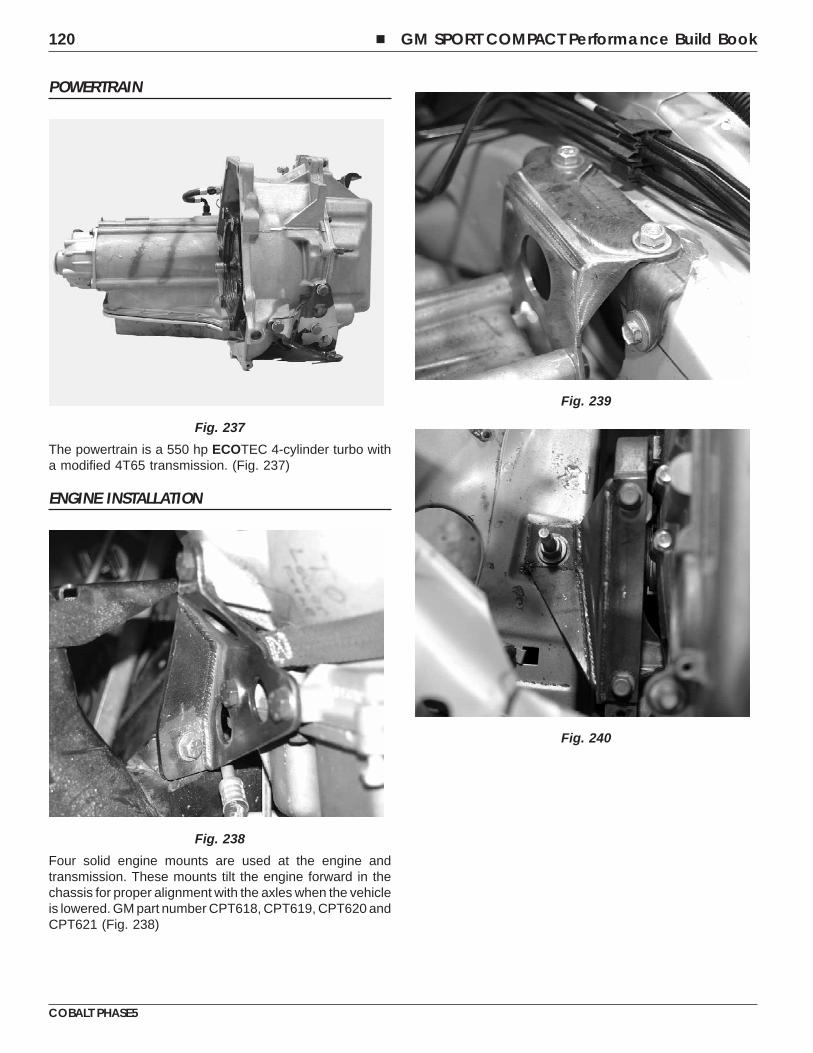
POWERTRAIN
The powertrain is a 550 hp ECOTEC 4-cylinder turbo witha modified 4T65 transmission. (Fig. 237)
ENGINE INSTALLATION
Four solid engine mounts are used at the engine andtransmission. These mounts tilt the engine forward in thechassis for proper alignment with the axles when the vehicleis lowered. GM part number CPT618, CPT619, CPT620 andCPT621 (Fig. 238)
Fig. 237
Fig. 238
Fig. 239
Fig. 240
120 � GM SPORT COMPACT Performance Build Book
COBALT PHASE5
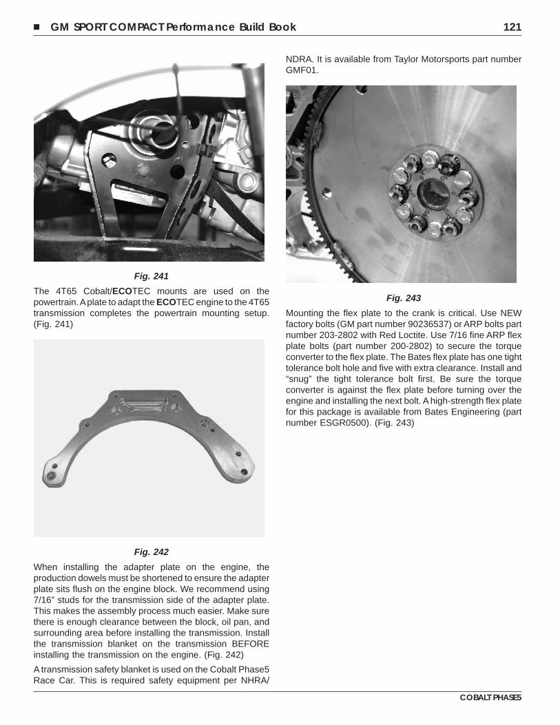
The 4T65 Cobalt/ECOTEC mounts are used on thepowertrain.Aplate to adapt the ECOTEC engine to the 4T65transmission completes the powertrain mounting setup.(Fig. 241)
When installing the adapter plate on the engine, theproduction dowels must be shortened to ensure the adapterplate sits flush on the engine block. We recommend using7/16� studs for the transmission side of the adapter plate.This makes the assembly process much easier. Make surethere is enough clearance between the block, oil pan, andsurrounding area before installing the transmission. Installthe transmission blanket on the transmission BEFOREinstalling the transmission on the engine. (Fig. 242)
A transmission safety blanket is used on the Cobalt Phase5Race Car. This is required safety equipment per NHRA/
NDRA. It is available from Taylor Motorsports part numberGMF01.
Mounting the flex plate to the crank is critical. Use NEWfactory bolts (GM part number 90236537) or ARP bolts partnumber 203-2802 with Red Loctite. Use 7/16 fine ARP flexplate bolts (part number 200-2802) to secure the torqueconverter to the flex plate. The Bates flex plate has one tighttolerance bolt hole and five with extra clearance. Install and“snug” the tight tolerance bolt first. Be sure the torqueconverter is against the flex plate before turning over theengine and installing the next bolt. A high-strength flex platefor this package is available from Bates Engineering (partnumber ESGR0500). (Fig. 243)
Fig. 241
Fig. 242
Fig. 243
� GM SPORT COMPACT Performance Build Book 121
COBALT PHASE5
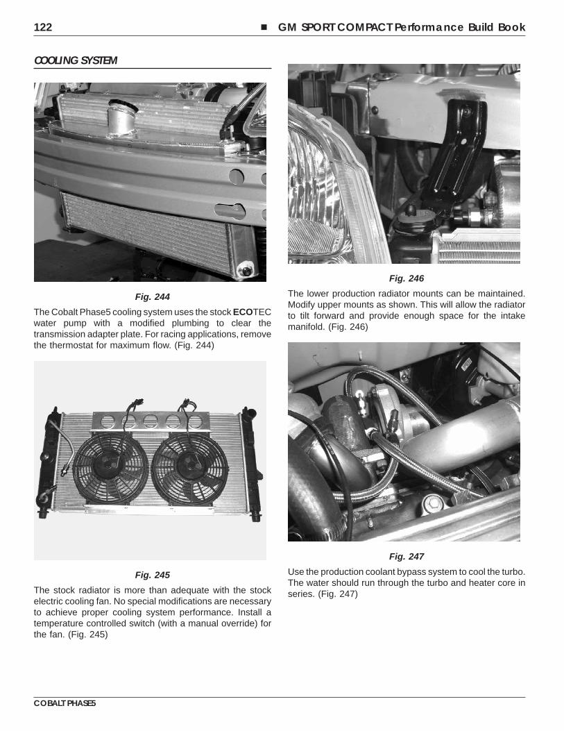
COOLING SYSTEM
The Cobalt Phase5 cooling system uses the stock ECOTECwater pump with a modified plumbing to clear thetransmission adapter plate. For racing applications, removethe thermostat for maximum flow. (Fig. 244)
The stock radiator is more than adequate with the stockelectric cooling fan. No special modifications are necessaryto achieve proper cooling system performance. Install atemperature controlled switch (with a manual override) forthe fan. (Fig. 245)
The lower production radiator mounts can be maintained.Modify upper mounts as shown. This will allow the radiatorto tilt forward and provide enough space for the intakemanifold. (Fig. 246)
Use the production coolant bypass system to cool the turbo.The water should run through the turbo and heater core inseries. (Fig. 247)
Fig. 244
Fig. 245
Fig. 246
Fig. 247
122 � GM SPORT COMPACT Performance Build Book
COBALT PHASE5
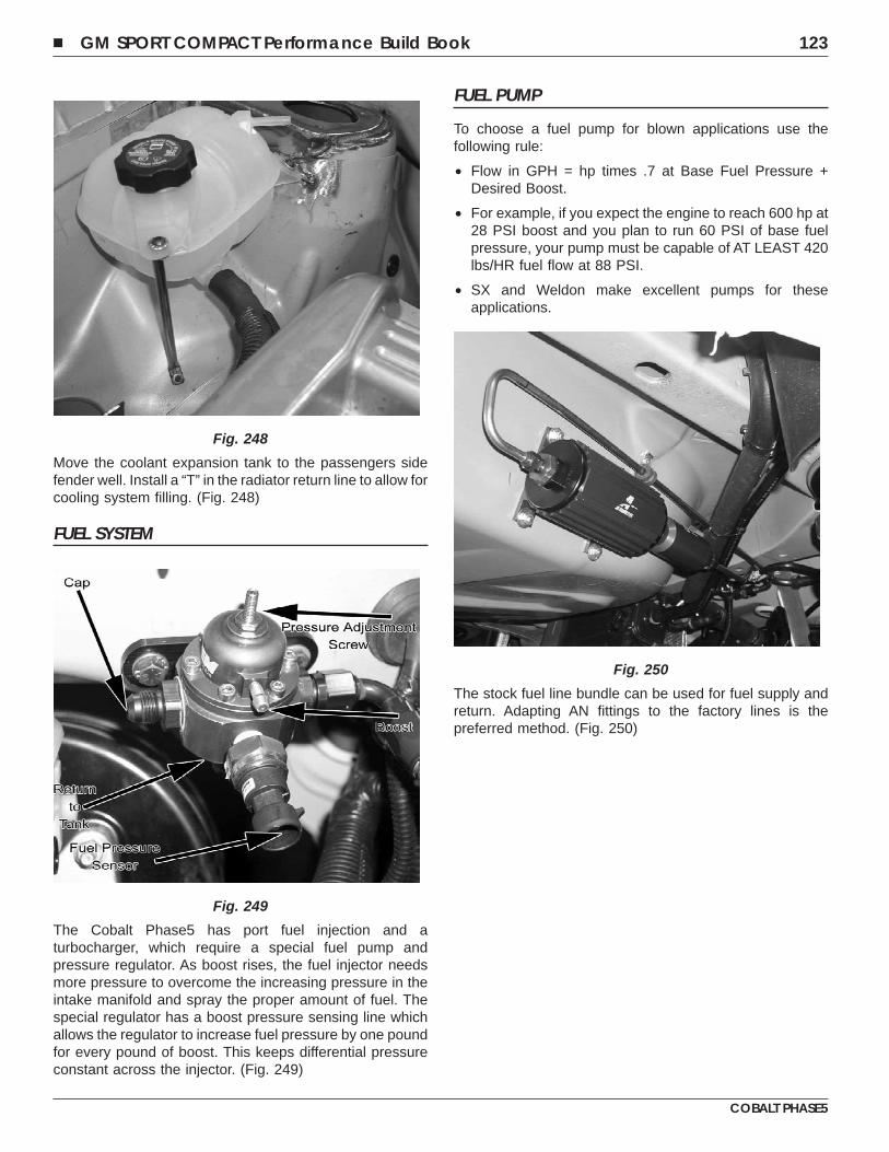
Move the coolant expansion tank to the passengers sidefender well. Install a “T” in the radiator return line to allow forcooling system filling. (Fig. 248)
FUEL SYSTEM
The Cobalt Phase5 has port fuel injection and aturbocharger, which require a special fuel pump andpressure regulator. As boost rises, the fuel injector needsmore pressure to overcome the increasing pressure in theintake manifold and spray the proper amount of fuel. Thespecial regulator has a boost pressure sensing line whichallows the regulator to increase fuel pressure by one poundfor every pound of boost. This keeps differential pressureconstant across the injector. (Fig. 249)
FUEL PUMP
To choose a fuel pump for blown applications use thefollowing rule:
• Flow in GPH = hp times .7 at Base Fuel Pressure +Desired Boost.
• For example, if you expect the engine to reach 600 hp at28 PSI boost and you plan to run 60 PSI of base fuelpressure, your pump must be capable of AT LEAST 420lbs/HR fuel flow at 88 PSI.
• SX and Weldon make excellent pumps for theseapplications.
The stock fuel line bundle can be used for fuel supply andreturn. Adapting AN fittings to the factory lines is thepreferred method. (Fig. 250)
Fig. 248
Fig. 249
Fig. 250
� GM SPORT COMPACT Performance Build Book 123
COBALT PHASE5
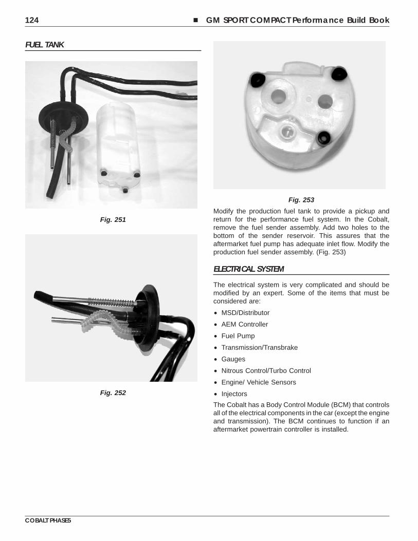
FUEL TANK
Modify the production fuel tank to provide a pickup andreturn for the performance fuel system. In the Cobalt,remove the fuel sender assembly. Add two holes to thebottom of the sender reservoir. This assures that theaftermarket fuel pump has adequate inlet flow. Modify theproduction fuel sender assembly. (Fig. 253)
ELECTRICAL SYSTEM
The electrical system is very complicated and should bemodified by an expert. Some of the items that must beconsidered are:
• MSD/Distributor
• AEM Controller
• Fuel Pump
• Transmission/Transbrake
• Gauges
• Nitrous Control/Turbo Control
• Engine/ Vehicle Sensors
• Injectors
The Cobalt has a Body Control Module (BCM) that controlsall of the electrical components in the car (except the engineand transmission). The BCM continues to function if anaftermarket powertrain controller is installed.
Fig. 251
Fig. 252
Fig. 253
124 � GM SPORT COMPACT Performance Build Book
COBALT PHASE5
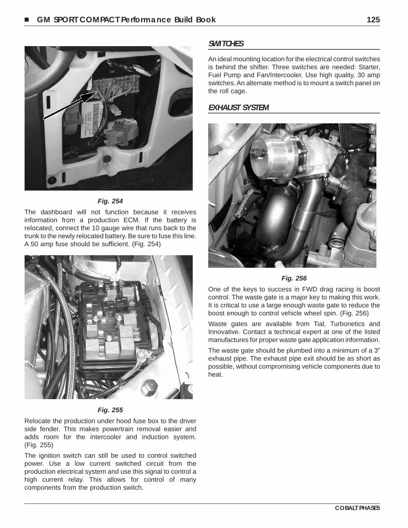
The dashboard will not function because it receivesinformation from a production ECM. If the battery isrelocated, connect the 10 gauge wire that runs back to thetrunk to the newly relocated battery. Be sure to fuse this line.A 50 amp fuse should be sufficient. (Fig. 254)
Relocate the production under hood fuse box to the driverside fender. This makes powertrain removal easier andadds room for the intercooler and induction system.(Fig. 255)
The ignition switch can still be used to control switchedpower. Use a low current switched circuit from theproduction electrical system and use this signal to control ahigh current relay. This allows for control of manycomponents from the production switch.
SWITCHES
An ideal mounting location for the electrical control switchesis behind the shifter. Three switches are needed: Starter,Fuel Pump and Fan/Intercooler. Use high quality, 30 ampswitches. An alternate method is to mount a switch panel onthe roll cage.
EXHAUST SYSTEM
One of the keys to success in FWD drag racing is boostcontrol. The waste gate is a major key to making this work.It is critical to use a large enough waste gate to reduce theboost enough to control vehicle wheel spin. (Fig. 256)
Waste gates are available from Tial, Turbonetics andInnovative. Contact a technical expert at one of the listedmanufactures for proper waste gate application information.
The waste gate should be plumbed into a minimum of a 3�exhaust pipe. The exhaust pipe exit should be as short aspossible, without compromising vehicle components due toheat.
Fig. 254
Fig. 255
Fig. 256
� GM SPORT COMPACT Performance Build Book 125
COBALT PHASE5
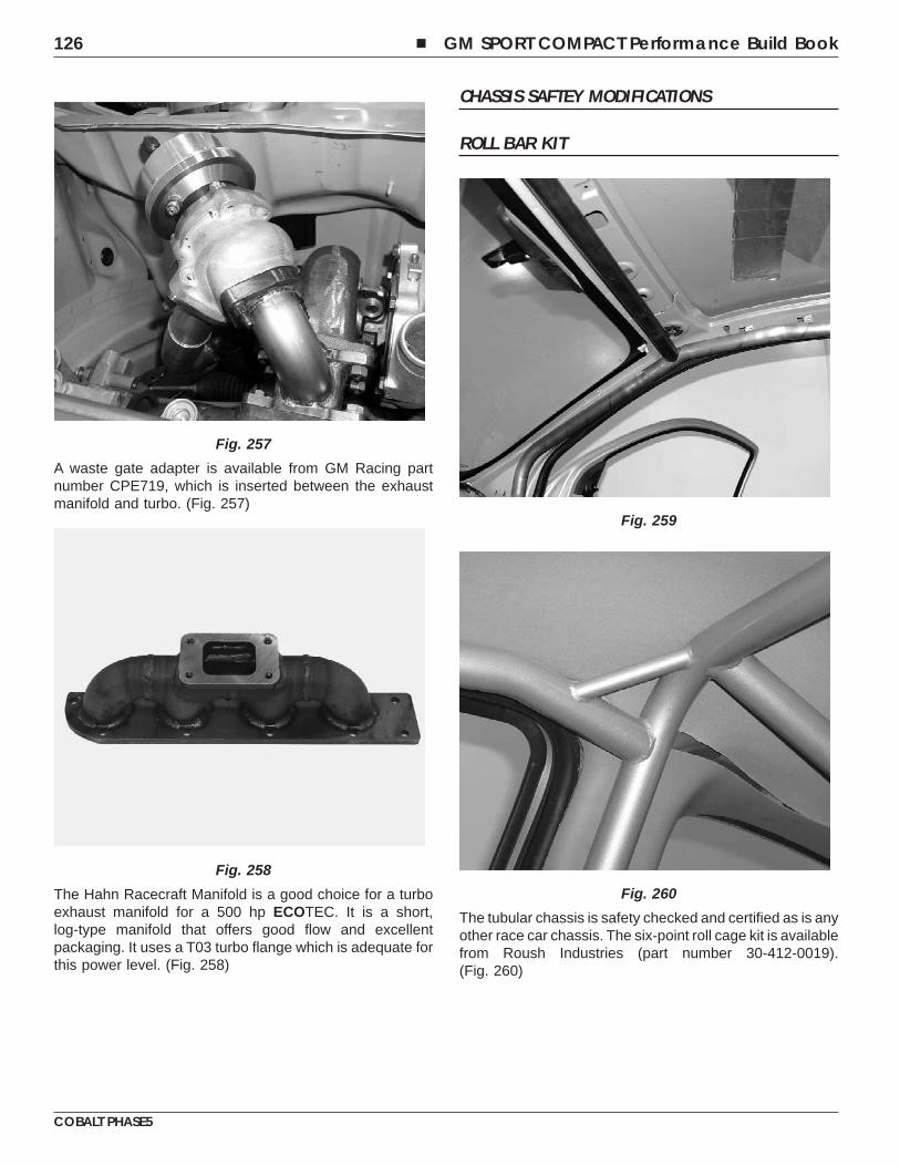
A waste gate adapter is available from GM Racing partnumber CPE719, which is inserted between the exhaustmanifold and turbo. (Fig. 257)
The Hahn Racecraft Manifold is a good choice for a turboexhaust manifold for a 500 hp ECOTEC. It is a short,log-type manifold that offers good flow and excellentpackaging. It uses a T03 turbo flange which is adequate forthis power level. (Fig. 258)
CHASSIS SAFTEY MODIFICATIONS
ROLL BAR KIT
The tubular chassis is safety checked and certified as is anyother race car chassis. The six-point roll cage kit is availablefrom Roush Industries (part number 30-412-0019).(Fig. 260)
Fig. 257
Fig. 258
Fig. 259
Fig. 260
126 � GM SPORT COMPACT Performance Build Book
COBALT PHASE5
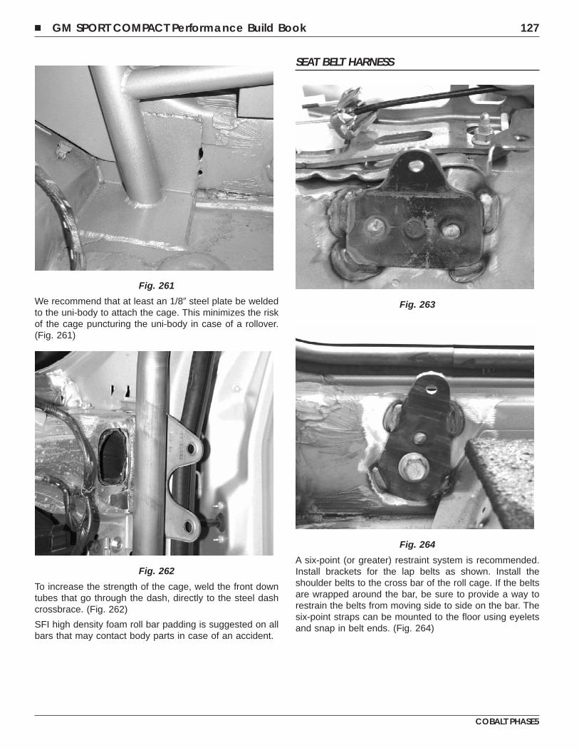
We recommend that at least an 1/8� steel plate be weldedto the uni-body to attach the cage. This minimizes the riskof the cage puncturing the uni-body in case of a rollover.(Fig. 261)
To increase the strength of the cage, weld the front downtubes that go through the dash, directly to the steel dashcrossbrace. (Fig. 262)
SFI high density foam roll bar padding is suggested on allbars that may contact body parts in case of an accident.
SEAT BELT HARNESS
A six-point (or greater) restraint system is recommended.Install brackets for the lap belts as shown. Install theshoulder belts to the cross bar of the roll cage. If the beltsare wrapped around the bar, be sure to provide a way torestrain the belts from moving side to side on the bar. Thesix-point straps can be mounted to the floor using eyeletsand snap in belt ends. (Fig. 264)
Fig. 261
Fig. 262
Fig. 263
Fig. 264
� GM SPORT COMPACT Performance Build Book 127
COBALT PHASE5
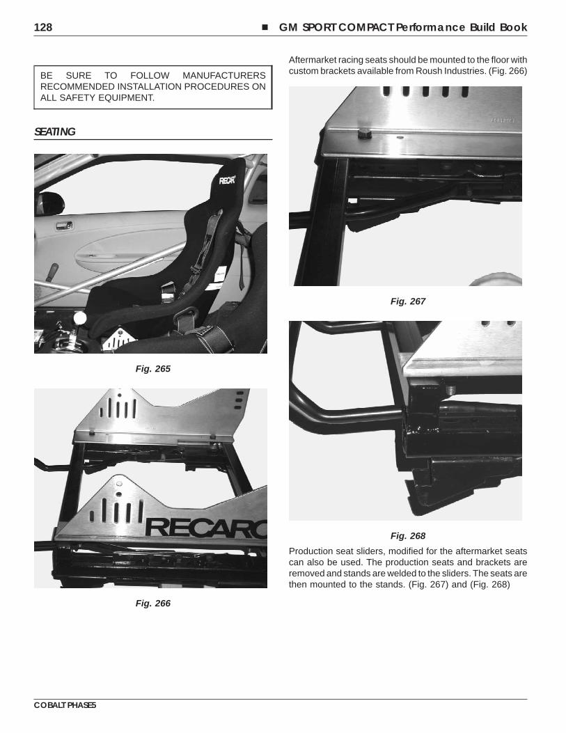
BE SURE TO FOLLOW MANUFACTURERSRECOMMENDED INSTALLATION PROCEDURES ONALL SAFETY EQUIPMENT.
SEATING
Aftermarket racing seats should be mounted to the floor withcustom brackets available from Roush Industries. (Fig. 266)
Production seat sliders, modified for the aftermarket seatscan also be used. The production seats and brackets areremoved and stands are welded to the sliders. The seats arethen mounted to the stands. (Fig. 267) and (Fig. 268)
Fig. 265
Fig. 266
Fig. 267
Fig. 268
128 � GM SPORT COMPACT Performance Build Book
COBALT PHASE5
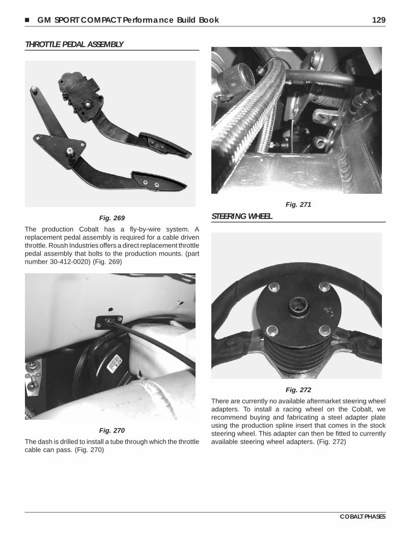
THROTTLE PEDAL ASSEMBLY
The production Cobalt has a fly-by-wire system. Areplacement pedal assembly is required for a cable driventhrottle. Roush Industries offers a direct replacement throttlepedal assembly that bolts to the production mounts. (partnumber 30-412-0020) (Fig. 269)
The dash is drilled to install a tube through which the throttlecable can pass. (Fig. 270)
STEERING WHEEL
There are currently no available aftermarket steering wheeladapters. To install a racing wheel on the Cobalt, werecommend buying and fabricating a steel adapter plateusing the production spline insert that comes in the stocksteering wheel. This adapter can then be fitted to currentlyavailable steering wheel adapters. (Fig. 272)
Fig. 269
Fig. 270
Fig. 271
Fig. 272
� GM SPORT COMPACT Performance Build Book 129
COBALT PHASE5
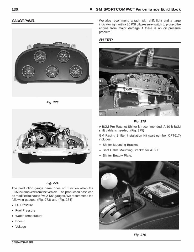
GAUGE PANEL
The production gauge panel does not function when theECM is removed from the vehicle. The production dash canbe modified to house five 2 1/6� gauges. We recommend thefollowing gauges: (Fig. 273) and (Fig. 274)
• Oil Pressure
• Fuel Pressure
• Water Temperature
• Boost
• Voltage
We also recommend a tach with shift light and a largeindicator light with a 30 PSI oil pressure switch to protect theengine from major damage if there is an oil pressureproblem.
SHIFTER
A B&M Pro Ratchet Shifter is recommended. A 10 ft B&Mshift cable is needed. (Fig. 275)
GM Racing Shifter Installation Kit (part number CPT617)includes:
• Shifter Mounting Bracket
• Shift Cable Mounting Bracket for 4T65E
• Shifter Beauty Plate.
Fig. 273
Fig. 274
Fig. 275
Fig. 276
130 � GM SPORT COMPACT Performance Build Book
COBALT PHASE5
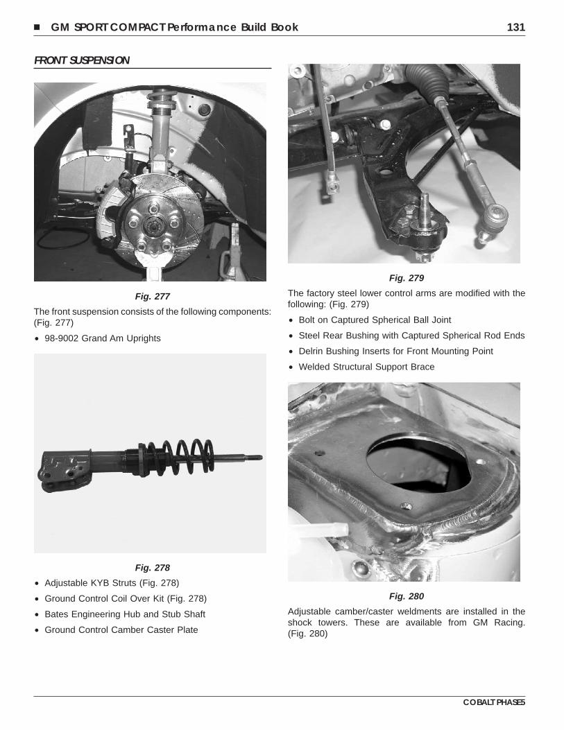
FRONT SUSPENSION
The front suspension consists of the following components:(Fig. 277)
• 98-9002 Grand Am Uprights
• Adjustable KYB Struts (Fig. 278)
• Ground Control Coil Over Kit (Fig. 278)
• Bates Engineering Hub and Stub Shaft
• Ground Control Camber Caster Plate
The factory steel lower control arms are modified with thefollowing: (Fig. 279)
• Bolt on Captured Spherical Ball Joint
• Steel Rear Bushing with Captured Spherical Rod Ends
• Delrin Bushing Inserts for Front Mounting Point
• Welded Structural Support Brace
Adjustable camber/caster weldments are installed in theshock towers. These are available from GM Racing.(Fig. 280)
Fig. 277
Fig. 278
Fig. 279
Fig. 280
� GM SPORT COMPACT Performance Build Book 131
COBALT PHASE5
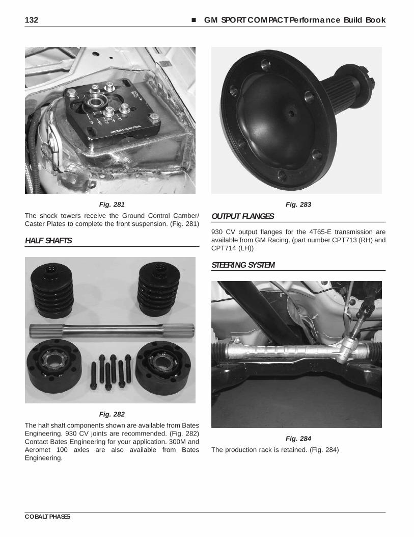
The shock towers receive the Ground Control Camber/Caster Plates to complete the front suspension. (Fig. 281)
HALF SHAFTS
The half shaft components shown are available from BatesEngineering. 930 CV joints are recommended. (Fig. 282)Contact Bates Engineering for your application. 300M andAeromet 100 axles are also available from BatesEngineering.
OUTPUT FLANGES
930 CV output flanges for the 4T65-E transmission areavailable from GM Racing. (part number CPT713 (RH) andCPT714 (LH))
STEERING SYSTEM
The production rack is retained. (Fig. 284)
Fig. 281
Fig. 282
Fig. 283
Fig. 284
132 � GM SPORT COMPACT Performance Build Book
COBALT PHASE5
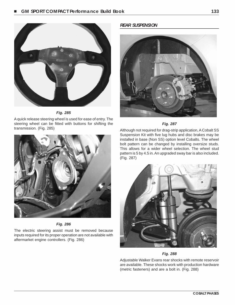
A quick release steering wheel is used for ease of entry. Thesteering wheel can be fitted with buttons for shifting thetransmission. (Fig. 285)
The electric steering assist must be removed becauseinputs required for its proper operation are not available withaftermarket engine controllers. (Fig. 286)
REAR SUSPENSION
Although not required for drag-strip application, A Cobalt SSSuspension Kit with five lug hubs and disc brakes may beinstalled in base (Non SS) option level Cobalts. The wheelbolt pattern can be changed by installing oversize studs.This allows for a wider wheel selection. The wheel studpattern is 5 by 4.5 in.An upgraded sway bar is also included.(Fig. 287)
Adjustable Walker Evans rear shocks with remote reservoirare available. These shocks work with production hardware(metric fasteners) and are a bolt in. (Fig. 288)
Fig. 285
Fig. 286
Fig. 287
Fig. 288
� GM SPORT COMPACT Performance Build Book 133
COBALT PHASE5
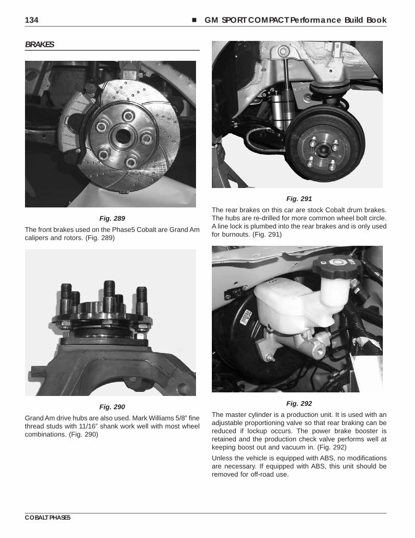
BRAKES
The front brakes used on the Phase5 Cobalt are Grand Amcalipers and rotors. (Fig. 289)
Grand Am drive hubs are also used. Mark Williams 5/8� finethread studs with 11/16� shank work well with most wheelcombinations. (Fig. 290)
The rear brakes on this car are stock Cobalt drum brakes.The hubs are re-drilled for more common wheel bolt circle.A line lock is plumbed into the rear brakes and is only usedfor burnouts. (Fig. 291)
The master cylinder is a production unit. It is used with anadjustable proportioning valve so that rear braking can bereduced if lockup occurs. The power brake booster isretained and the production check valve performs well atkeeping boost out and vacuum in. (Fig. 292)
Unless the vehicle is equipped with ABS, no modificationsare necessary. If equipped with ABS, this unit should beremoved for off-road use.
Fig. 289
Fig. 290
Fig. 291
Fig. 292
134 � GM SPORT COMPACT Performance Build Book
COBALT PHASE5
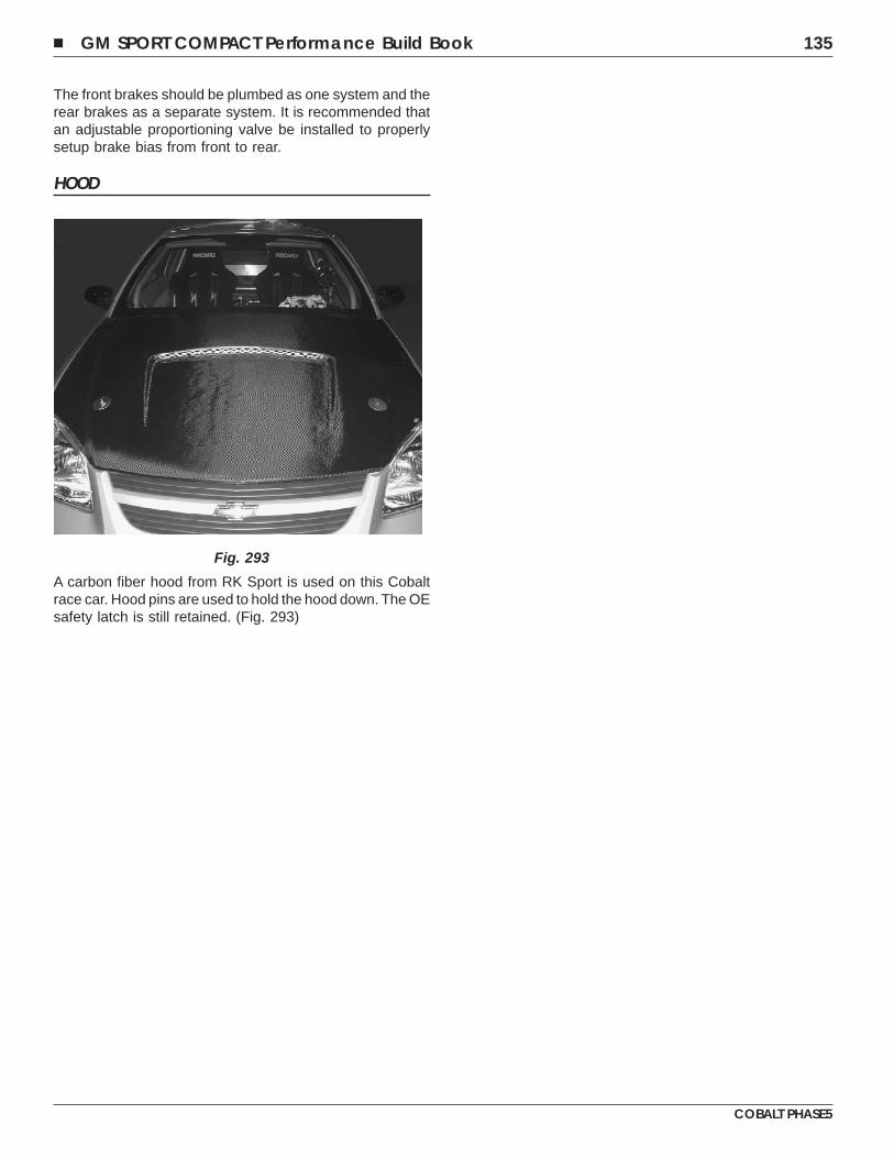
The front brakes should be plumbed as one system and therear brakes as a separate system. It is recommended thatan adjustable proportioning valve be installed to properlysetup brake bias from front to rear.
HOOD
A carbon fiber hood from RK Sport is used on this Cobaltrace car. Hood pins are used to hold the hood down. The OEsafety latch is still retained. (Fig. 293)
Fig. 293
� GM SPORT COMPACT Performance Build Book 135
COBALT PHASE5

NOTES
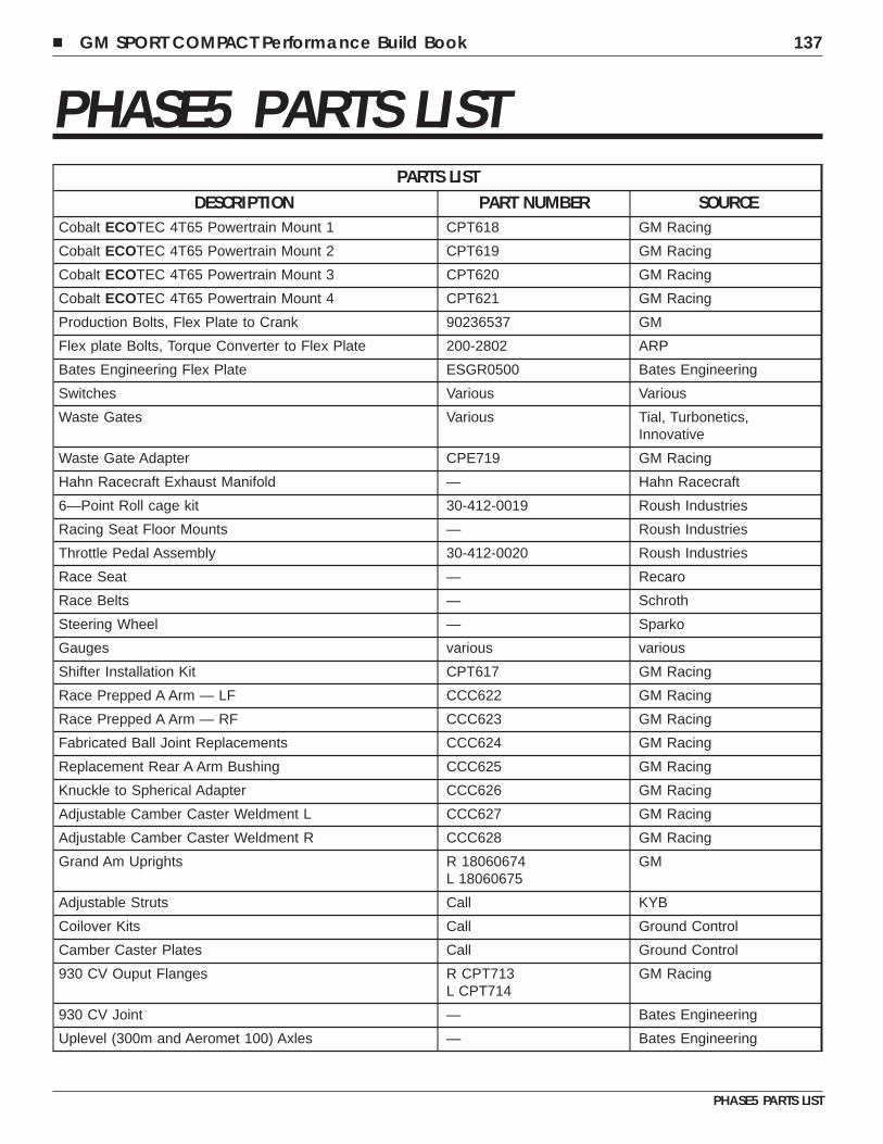
PHASE5 PARTS LISTPARTS LIST
DESCRIPTION PART NUMBER SOURCECobalt ECOTEC 4T65 Powertrain Mount 1 CPT618 GM Racing
Cobalt ECOTEC 4T65 Powertrain Mount 2 CPT619 GM Racing
Cobalt ECOTEC 4T65 Powertrain Mount 3 CPT620 GM Racing
Cobalt ECOTEC 4T65 Powertrain Mount 4 CPT621 GM Racing
Production Bolts, Flex Plate to Crank 90236537 GM
Flex plate Bolts, Torque Converter to Flex Plate 200-2802 ARP
Bates Engineering Flex Plate ESGR0500 Bates Engineering
Switches Various Various
Waste Gates Various Tial, Turbonetics,Innovative
Waste Gate Adapter CPE719 GM Racing
Hahn Racecraft Exhaust Manifold — Hahn Racecraft
6—Point Roll cage kit 30-412-0019 Roush Industries
Racing Seat Floor Mounts — Roush Industries
Throttle Pedal Assembly 30-412-0020 Roush Industries
Race Seat — Recaro
Race Belts — Schroth
Steering Wheel — Sparko
Gauges various various
Shifter Installation Kit CPT617 GM Racing
Race Prepped A Arm — LF CCC622 GM Racing
Race Prepped A Arm — RF CCC623 GM Racing
Fabricated Ball Joint Replacements CCC624 GM Racing
Replacement Rear A Arm Bushing CCC625 GM Racing
Knuckle to Spherical Adapter CCC626 GM Racing
Adjustable Camber Caster Weldment L CCC627 GM Racing
Adjustable Camber Caster Weldment R CCC628 GM Racing
Grand Am Uprights R 18060674L 18060675
GM
Adjustable Struts Call KYB
Coilover Kits Call Ground Control
Camber Caster Plates Call Ground Control
930 CV Ouput Flanges R CPT713L CPT714
GM Racing
930 CV Joint — Bates Engineering
Uplevel (300m and Aeromet 100) Axles — Bates Engineering
� GM SPORT COMPACT Performance Build Book 137
PHASE5 PARTS LIST
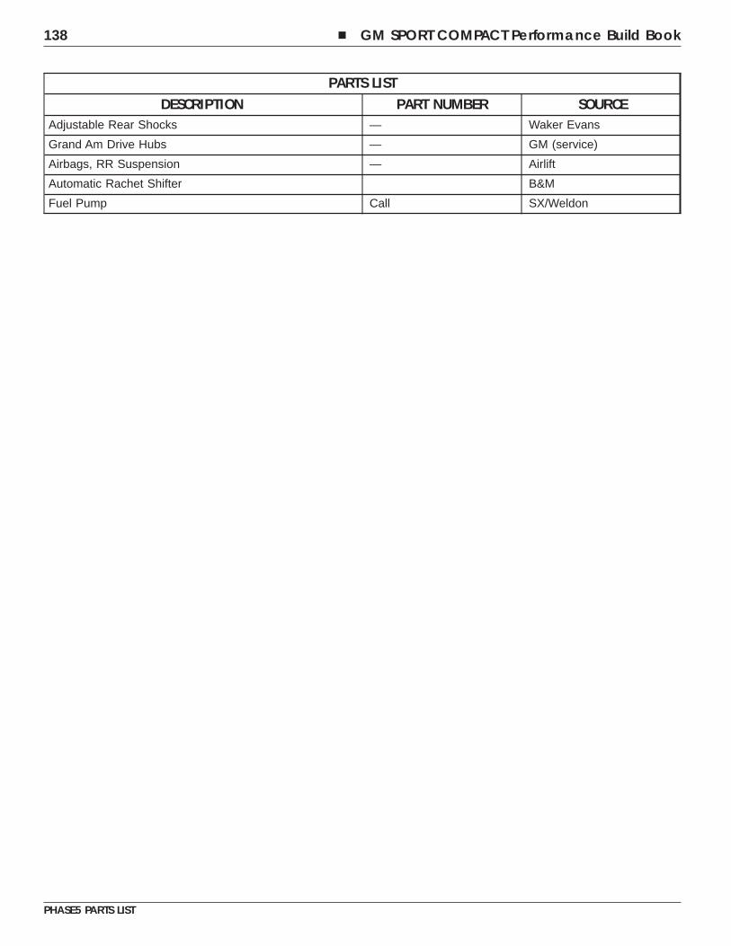
PARTS LISTDESCRIPTION PART NUMBER SOURCE
Adjustable Rear Shocks — Waker Evans
Grand Am Drive Hubs — GM (service)
Airbags, RR Suspension — Airlift
Automatic Rachet Shifter B&M
Fuel Pump Call SX/Weldon
138 � GM SPORT COMPACT Performance Build Book
PHASE5 PARTS LIST
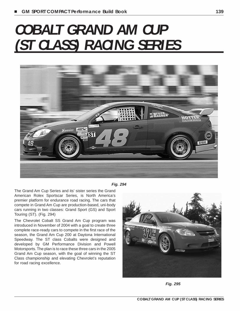
COBALT GRAND AM CUP(ST CLASS) RACING SERIES
The Grand Am Cup Series and its’ sister series the GrandAmerican Rolex Sportscar Series, is North America’spremier platform for endurance road racing. The cars thatcompete in Grand Am Cup are production-based, uni-bodycars running in two classes: Grand Sport (GS) and SportTouring (ST). (Fig. 294)
The Chevrolet Cobalt SS Grand Am Cup program wasintroduced in November of 2004 with a goal to create threecomplete race-ready cars to compete in the first race of theseason, the Grand Am Cup 200 at Daytona InternationalSpeedway. The ST class Cobalts were designed anddeveloped by GM Performance Division and PowellMotorsports. The plan is to race these three cars in the 2005Grand Am Cup season, with the goal of winning the STClass championship and elevating Chevrolet’s reputationfor road racing excellence.
Fig. 294
Fig. 295
� GM SPORT COMPACT Performance Build Book 139
COBALT GRAND AM CUP (ST CLASS) RACING SERIES
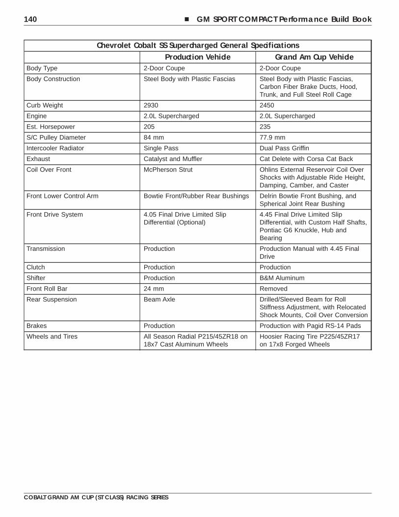
Chevrolet Cobalt SS Supercharged General SpecificationsProduction Vehicle Grand Am Cup Vehicle
Body Type 2-Door Coupe 2-Door Coupe
Body Construction Steel Body with Plastic Fascias Steel Body with Plastic Fascias,Carbon Fiber Brake Ducts, Hood,Trunk, and Full Steel Roll Cage
Curb Weight 2930 2450
Engine 2.0L Supercharged 2.0L Supercharged
Est. Horsepower 205 235
S/C Pulley Diameter 84 mm 77.9 mm
Intercooler Radiator Single Pass Dual Pass Griffin
Exhaust Catalyst and Muffler Cat Delete with Corsa Cat Back
Coil Over Front McPherson Strut Ohlins External Reservoir Coil OverShocks with Adjustable Ride Height,Damping, Camber, and Caster
Front Lower Control Arm Bowtie Front/Rubber Rear Bushings Delrin Bowtie Front Bushing, andSpherical Joint Rear Bushing
Front Drive System 4.05 Final Drive Limited SlipDifferential (Optional)
4.45 Final Drive Limited SlipDifferential, with Custom Half Shafts,Pontiac G6 Knuckle, Hub andBearing
Transmission Production Production Manual with 4.45 FinalDrive
Clutch Production Production
Shifter Production B&M Aluminum
Front Roll Bar 24 mm Removed
Rear Suspension Beam Axle Drilled/Sleeved Beam for RollStiffness Adjustment, with RelocatedShock Mounts, Coil Over Conversion
Brakes Production Production with Pagid RS-14 Pads
Wheels and Tires All Season Radial P215/45ZR18 on18x7 Cast Aluminum Wheels
Hoosier Racing Tire P225/45ZR17on 17x8 Forged Wheels
140 � GM SPORT COMPACT Performance Build Book
COBALT GRAND AM CUP (ST CLASS) RACING SERIES
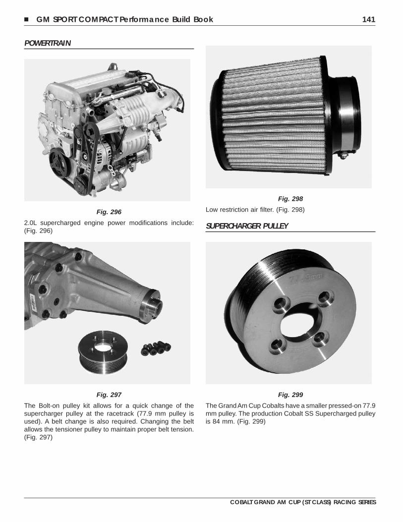
POWERTRAIN
2.0L supercharged engine power modifications include:(Fig. 296)
The Bolt-on pulley kit allows for a quick change of thesupercharger pulley at the racetrack (77.9 mm pulley isused). A belt change is also required. Changing the beltallows the tensioner pulley to maintain proper belt tension.(Fig. 297)
Low restriction air filter. (Fig. 298)
SUPERCHARGER PULLEY
The GrandAm Cup Cobalts have a smaller pressed-on 77.9mm pulley. The production Cobalt SS Supercharged pulleyis 84 mm. (Fig. 299)
Fig. 296
Fig. 297
Fig. 298
Fig. 299
� GM SPORT COMPACT Performance Build Book 141
COBALT GRAND AM CUP (ST CLASS) RACING SERIES
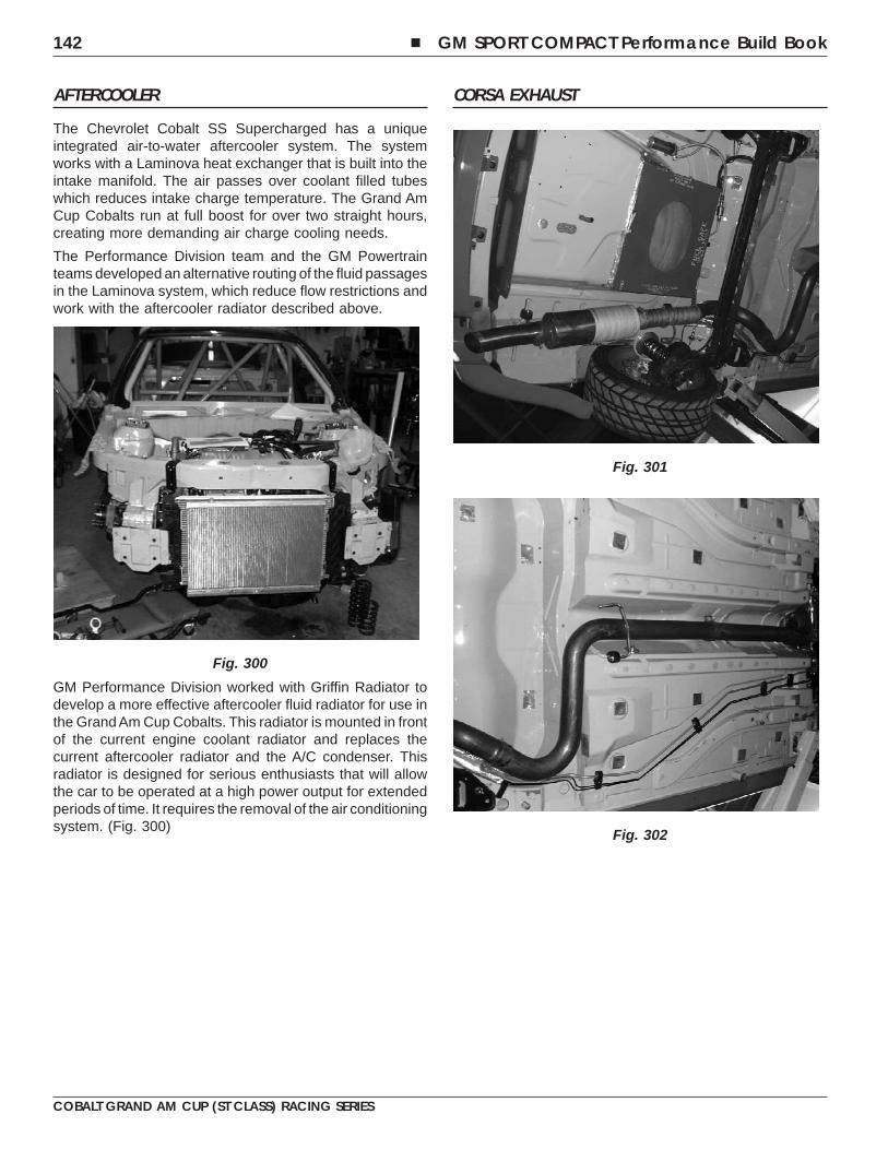
AFTERCOOLER
The Chevrolet Cobalt SS Supercharged has a uniqueintegrated air-to-water aftercooler system. The systemworks with a Laminova heat exchanger that is built into theintake manifold. The air passes over coolant filled tubeswhich reduces intake charge temperature. The Grand AmCup Cobalts run at full boost for over two straight hours,creating more demanding air charge cooling needs.
The Performance Division team and the GM Powertrainteams developed an alternative routing of the fluid passagesin the Laminova system, which reduce flow restrictions andwork with the aftercooler radiator described above.
GM Performance Division worked with Griffin Radiator todevelop a more effective aftercooler fluid radiator for use inthe Grand Am Cup Cobalts. This radiator is mounted in frontof the current engine coolant radiator and replaces thecurrent aftercooler radiator and the A/C condenser. Thisradiator is designed for serious enthusiasts that will allowthe car to be operated at a high power output for extendedperiods of time. It requires the removal of the air conditioningsystem. (Fig. 300)
CORSA EXHAUST
Fig. 300
Fig. 301
Fig. 302
142 � GM SPORT COMPACT Performance Build Book
COBALT GRAND AM CUP (ST CLASS) RACING SERIES
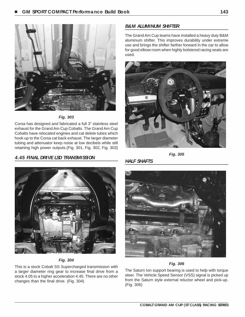
Corsa has designed and fabricated a full 3� stainless steelexhaust for the Grand Am Cup Cobalts. The Grand Am CupCobalts have relocated engines and cat delete tubes whichhook up to the Corsa cat back exhaust. The larger diametertubing and attenuator keep noise at low decibels while stillretaining high power outputs.(Fig. 301, Fig. 302, Fig. 303)
4.45 FINAL DRIVE LSD TRANSMISSION
This is a stock Cobalt SS Supercharged transmission witha larger diameter ring gear to increase final drive from astock 4.05 to a higher acceleration 4.45. There are no otherchanges than the final drive. (Fig. 304)
B&M ALUMINUM SHIFTER
The Grand Am Cup teams have installed a heavy duty B&Maluminum shifter. This improves durability under extremeuse and brings the shifter farther forward in the car to allowfor good elbow room when highly bolstered racing seats areused.
HALF SHAFTS
The Saturn Ion support bearing is used to help with torquesteer. The Vehicle Speed Sensor (VSS) signal is picked upfrom the Saturn style external reluctor wheel and pick-up.(Fig. 306)
Fig. 303
Fig. 304
Fig. 305
Fig. 306
� GM SPORT COMPACT Performance Build Book 143
COBALT GRAND AM CUP (ST CLASS) RACING SERIES
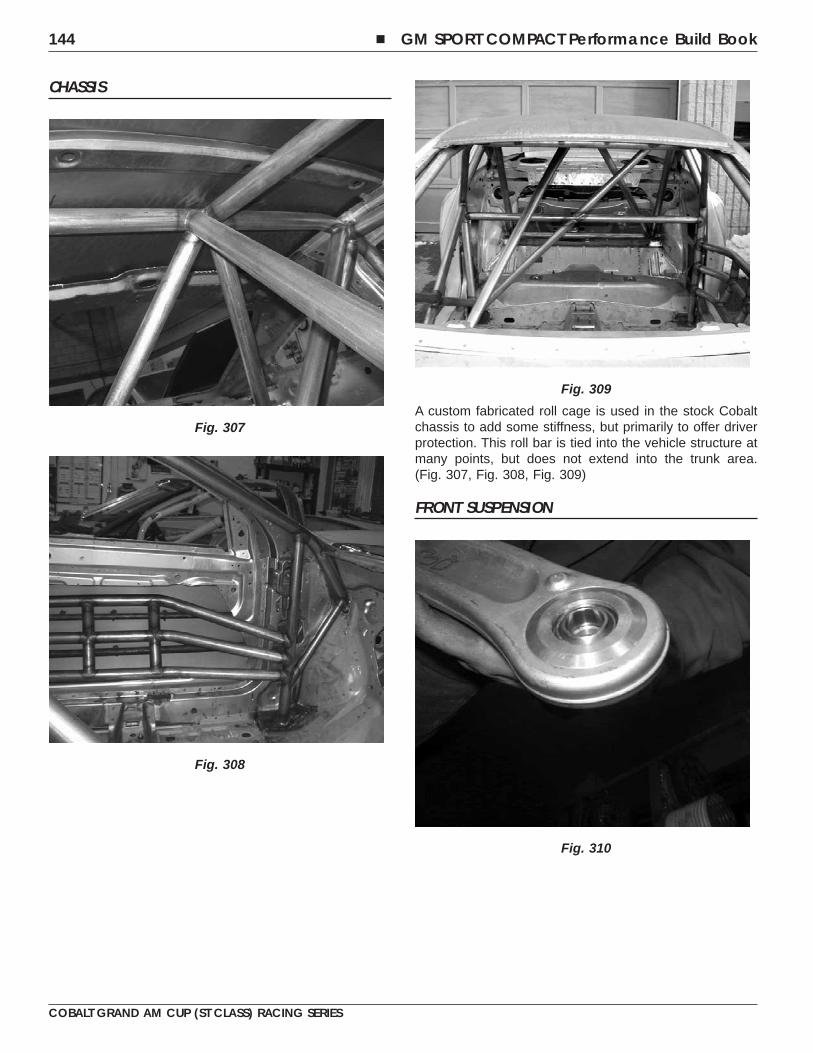
CHASSIS
A custom fabricated roll cage is used in the stock Cobaltchassis to add some stiffness, but primarily to offer driverprotection. This roll bar is tied into the vehicle structure atmany points, but does not extend into the trunk area.(Fig. 307, Fig. 308, Fig. 309)
FRONT SUSPENSION
Fig. 307
Fig. 308
Fig. 309
Fig. 310
144 � GM SPORT COMPACT Performance Build Book
COBALT GRAND AM CUP (ST CLASS) RACING SERIES
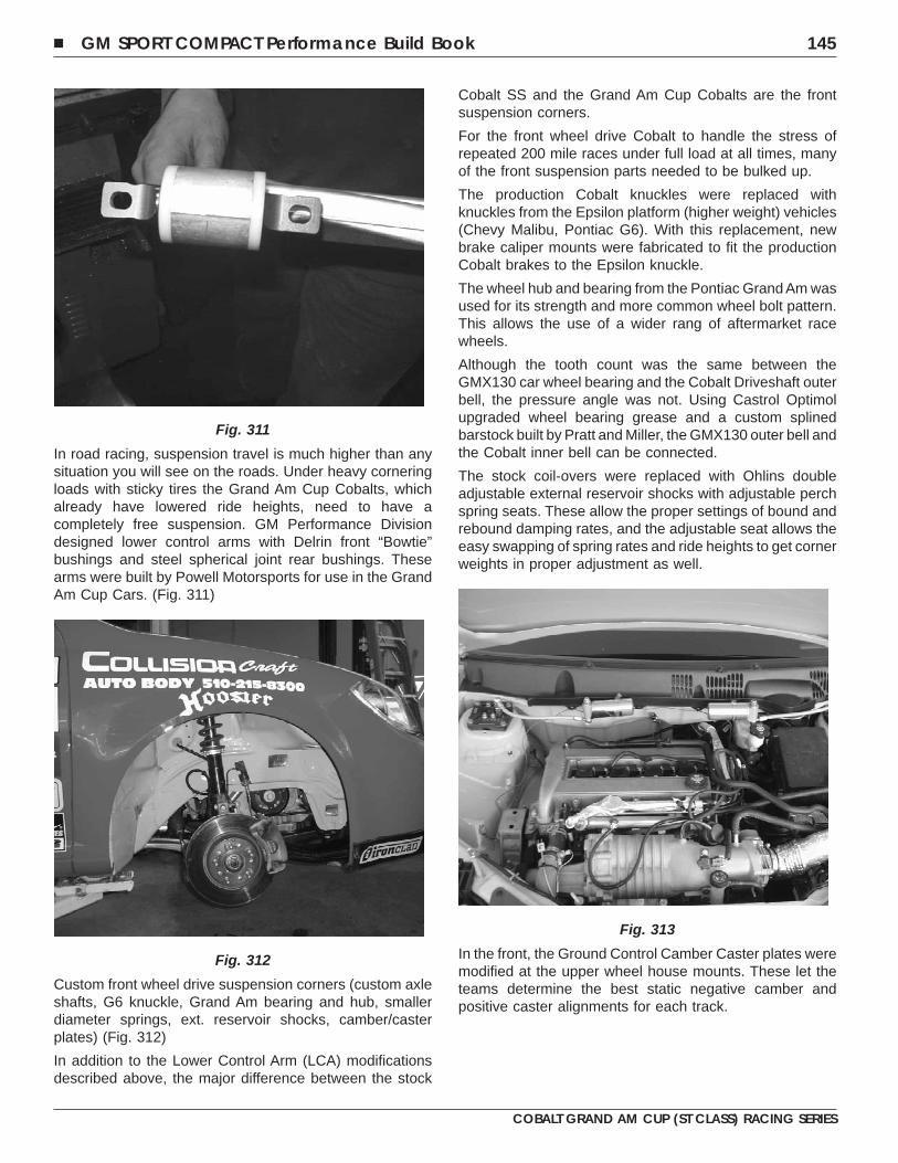
In road racing, suspension travel is much higher than anysituation you will see on the roads. Under heavy corneringloads with sticky tires the Grand Am Cup Cobalts, whichalready have lowered ride heights, need to have acompletely free suspension. GM Performance Divisiondesigned lower control arms with Delrin front “Bowtie”bushings and steel spherical joint rear bushings. Thesearms were built by Powell Motorsports for use in the GrandAm Cup Cars. (Fig. 311)
Custom front wheel drive suspension corners (custom axleshafts, G6 knuckle, Grand Am bearing and hub, smallerdiameter springs, ext. reservoir shocks, camber/casterplates) (Fig. 312)
In addition to the Lower Control Arm (LCA) modificationsdescribed above, the major difference between the stock
Cobalt SS and the Grand Am Cup Cobalts are the frontsuspension corners.
For the front wheel drive Cobalt to handle the stress ofrepeated 200 mile races under full load at all times, manyof the front suspension parts needed to be bulked up.
The production Cobalt knuckles were replaced withknuckles from the Epsilon platform (higher weight) vehicles(Chevy Malibu, Pontiac G6). With this replacement, newbrake caliper mounts were fabricated to fit the productionCobalt brakes to the Epsilon knuckle.
The wheel hub and bearing from the Pontiac Grand Am wasused for its strength and more common wheel bolt pattern.This allows the use of a wider rang of aftermarket racewheels.
Although the tooth count was the same between theGMX130 car wheel bearing and the Cobalt Driveshaft outerbell, the pressure angle was not. Using Castrol Optimolupgraded wheel bearing grease and a custom splinedbarstock built by Pratt and Miller, the GMX130 outer bell andthe Cobalt inner bell can be connected.
The stock coil-overs were replaced with Ohlins doubleadjustable external reservoir shocks with adjustable perchspring seats. These allow the proper settings of bound andrebound damping rates, and the adjustable seat allows theeasy swapping of spring rates and ride heights to get cornerweights in proper adjustment as well.
In the front, the Ground Control Camber Caster plates weremodified at the upper wheel house mounts. These let theteams determine the best static negative camber andpositive caster alignments for each track.
Fig. 311
Fig. 312
Fig. 313
� GM SPORT COMPACT Performance Build Book 145
COBALT GRAND AM CUP (ST CLASS) RACING SERIES
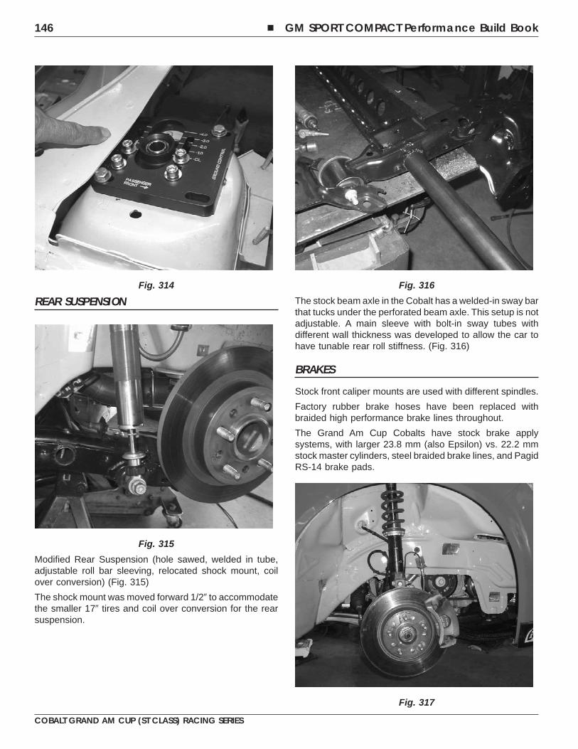
REAR SUSPENSION
Modified Rear Suspension (hole sawed, welded in tube,adjustable roll bar sleeving, relocated shock mount, coilover conversion) (Fig. 315)
The shock mount was moved forward 1/2� to accommodatethe smaller 17� tires and coil over conversion for the rearsuspension.
The stock beam axle in the Cobalt has a welded-in sway barthat tucks under the perforated beam axle. This setup is notadjustable. A main sleeve with bolt-in sway tubes withdifferent wall thickness was developed to allow the car tohave tunable rear roll stiffness. (Fig. 316)
BRAKES
Stock front caliper mounts are used with different spindles.
Factory rubber brake hoses have been replaced withbraided high performance brake lines throughout.
The Grand Am Cup Cobalts have stock brake applysystems, with larger 23.8 mm (also Epsilon) vs. 22.2 mmstock master cylinders, steel braided brake lines, and PagidRS-14 brake pads.
Fig. 314
Fig. 315
Fig. 316
Fig. 317
146 � GM SPORT COMPACT Performance Build Book
COBALT GRAND AM CUP (ST CLASS) RACING SERIES
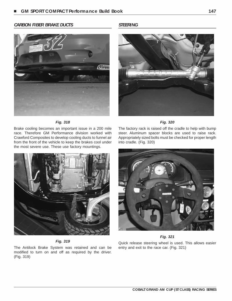
CARBON FIBER BRAKE DUCTS
Brake cooling becomes an important issue in a 200 milerace. Therefore GM Performance division worked withCrawford Composites to develop cooling ducts to funnel airfrom the front of the vehicle to keep the brakes cool underthe most severe use. These use factory mountings.
The Antilock Brake System was retained and can bemodified to turn on and off as required by the driver.(Fig. 319)
STEERING
The factory rack is raised off the cradle to help with bumpsteer. Aluminum spacer blocks are used to raise rack.Appropriately sized bolts must be checked for proper lengthinto cradle. (Fig. 320)
Quick release steering wheel is used. This allows easierentry and exit to the race car. (Fig. 321)
Fig. 318
Fig. 319
Fig. 320
Fig. 321
� GM SPORT COMPACT Performance Build Book 147
COBALT GRAND AM CUP (ST CLASS) RACING SERIES
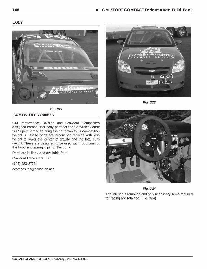
BODY
CARBON FIBER PANELS
GM Performance Division and Crawford Compositesdesigned carbon fiber body parts for the Chevrolet CobaltSS Supercharged to bring the car down to its competitionweight. All these parts are production replicas with lessweight to lower the center of gravity and the total curbweight. These are designed to be used with hood pins forthe hood and spring clips for the trunk.
Parts are built by and available from:
Crawford Race Cars LLC
(704) 483-8726
The interior is removed and only necessary items requiredfor racing are retained. (Fig. 324)
Fig. 322
Fig. 323
Fig. 324
148 � GM SPORT COMPACT Performance Build Book
COBALT GRAND AM CUP (ST CLASS) RACING SERIES
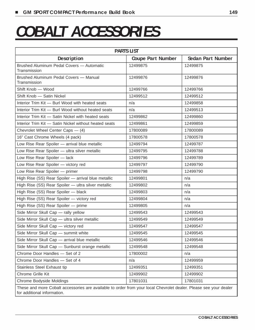
COBALT ACCESSORIESPARTS LIST
Description Coupe Part Number Sedan Part NumberBrushed Aluminum Pedal Covers — AutomaticTransmission
12499875 12499875
Brushed Aluminum Pedal Covers — ManualTransmission
12499876 12499876
Shift Knob — Wood 12499766 12499766
Shift Knob — Satin Nickel 12499512 12499512
Interior Trim Kit — Burl Wood with heated seats n/a 12499858
Interior Trim Kit — Burl Wood without heated seats n/a 12499513
Interior Trim Kit — Satin Nickel with heated seats 12499862 12499860
Interior Trim Kit — Satin Nickel without heated seats 12499861 12499859
Chevrolet Wheel Center Caps — (4) 17800089 17800089
16� Cast Chrome Wheels (4 pack) 17800578 17800578
Low Rise Rear Spoiler — arrival blue metallic 12499794 12499787
Low Rise Rear Spoiler — ultra silver metallic 12499795 12499788
Low Rise Rear Spoiler — lack 12499796 12499789
Low Rise Rear Spoiler — victory red 12499797 12499790
Low Rise Rear Spoiler — primer 12499798 12499790
High Rise (SS) Rear Spoiler — arrival blue metallic 12499801 n/a
High Rise (SS) Rear Spoiler — ultra silver metallic 12499802 n/a
High Rise (SS) Rear Spoiler — black 12499803 n/a
High Rise (SS) Rear Spoiler — victory red 12499804 n/a
High Rise (SS) Rear Spoiler — prime 12499805 n/a
Side Mirror Skull Cap — rally yellow 12499543 12499543
Side Mirror Skull Cap — ultra silver metallic 12499549 12499549
Side Mirror Skull Cap — victory red 12499547 12499547
Side Mirror Skull Cap — summit white 12499545 12499545
Side Mirror Skull Cap — arrival blue metallic 12499546 12499546
Side Mirror Skull Cap — Sunburst orange metallic 12499548 12499548
Chrome Door Handles — Set of 2 17800002 n/a
Chrome Door Handles — Set of 4 n/a 12499959
Stainless Steel Exhaust tip 12499351 12499351
Chrome Grille Kit 12499902 12499902
Chrome Bodyside Moldings 17801031 17801031
These and more Cobalt accessories are available to order from your local Chevrolet dealer. Please see your dealerfor additional information.
� GM SPORT COMPACT Performance Build Book 149
COBALT ACCESSORIES

NOTES
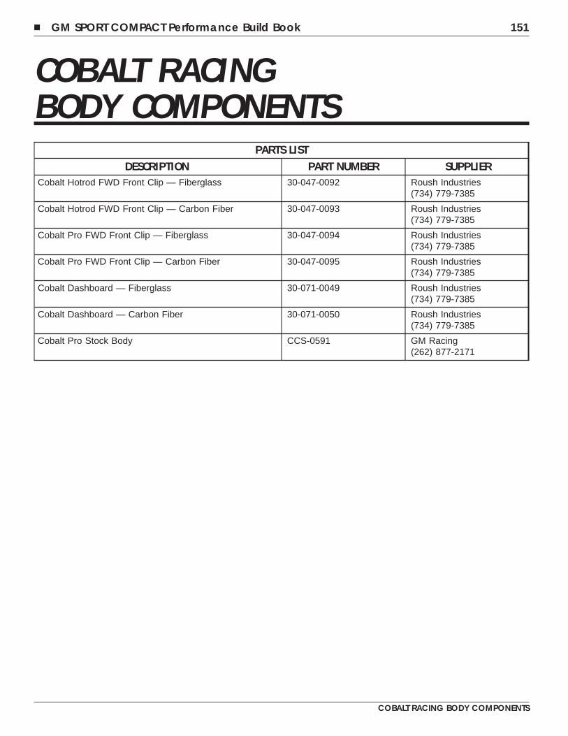
COBALT RACINGBODY COMPONENTS
PARTS LISTDESCRIPTION PART NUMBER SUPPLIER
Cobalt Hotrod FWD Front Clip — Fiberglass 30-047-0092 Roush Industries(734) 779-7385
Cobalt Hotrod FWD Front Clip — Carbon Fiber 30-047-0093 Roush Industries(734) 779-7385
Cobalt Pro FWD Front Clip — Fiberglass 30-047-0094 Roush Industries(734) 779-7385
Cobalt Pro FWD Front Clip — Carbon Fiber 30-047-0095 Roush Industries(734) 779-7385
Cobalt Dashboard — Fiberglass 30-071-0049 Roush Industries(734) 779-7385
Cobalt Dashboard — Carbon Fiber 30-071-0050 Roush Industries(734) 779-7385
Cobalt Pro Stock Body CCS-0591 GM Racing(262) 877-2171
� GM SPORT COMPACT Performance Build Book 151
COBALT RACING BODY COMPONENTS

NOTES
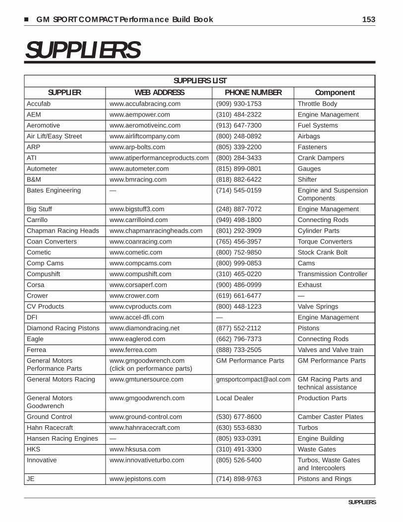
SUPPLIERSSUPPLIERS LIST
SUPPLIER WEB ADDRESS PHONE NUMBER ComponentAccufab www.accufabracing.com (909) 930-1753 Throttle Body
AEM www.aempower.com (310) 484-2322 Engine Management
Aeromotive www.aeromotiveinc.com (913) 647-7300 Fuel Systems
Air Lift/Easy Street www.airliftcompany.com (800) 248-0892 Airbags
ARP www.arp-bolts.com (805) 339-2200 Fasteners
ATI www.atiperformanceproducts.com (800) 284-3433 Crank Dampers
Autometer www.autometer.com (815) 899-0801 Gauges
B&M www.bmracing.com (818) 882-6422 Shifter
Bates Engineering — (714) 545-0159 Engine and SuspensionComponents
Big Stuff www.bigstuff3.com (248) 887-7072 Engine Management
Carrillo www.carrilloind.com (949) 498-1800 Connecting Rods
Chapman Racing Heads www.chapmanracingheads.com (801) 292-3909 Cylinder Parts
Coan Converters www.coanracing.com (765) 456-3957 Torque Converters
Cometic www.cometic.com (800) 752-9850 Stock Crank Bolt
Comp Cams www.compcams.com (800) 999-0853 Cams
Compushift www.compushift.com (310) 465-0220 Transmission Controller
Corsa www.corsaperf.com (900) 486-0999 Exhaust
Crower www.crower.com (619) 661-6477 —
CV Products www.cvproducts.com (800) 448-1223 Valve Springs
DFI www.accel-dfi.com — Engine Management
Diamond Racing Pistons www.diamondracing.net (877) 552-2112 Pistons
Eagle www.eaglerod.com (662) 796-7373 Connecting Rods
Ferrea www.ferrea.com (888) 733-2505 Valves and Valve train
General MotorsPerformance Parts
www.gmgoodwrench.com(click on performance parts)
GM Performance Parts GM Performance Parts
General Motors Racing www.gmtunersource.com [email protected] GM Racing Parts andtechnical assistance
General MotorsGoodwrench
www.gmgoodwrench.com Local Dealer Production Parts
Ground Control www.ground-control.com (530) 677-8600 Camber Caster Plates
Hahn Racecraft www.hahnracecraft.com (630) 553-6830 Turbos
Hansen Racing Engines — (805) 933-0391 Engine Building
HKS www.hksusa.com (310) 491-3300 Waste Gates
Innovative www.innovativeturbo.com (805) 526-5400 Turbos, Waste Gatesand Intercoolers
JE www.jepistons.com (714) 898-9763 Pistons and Rings
� GM SPORT COMPACT Performance Build Book 153
SUPPLIERS
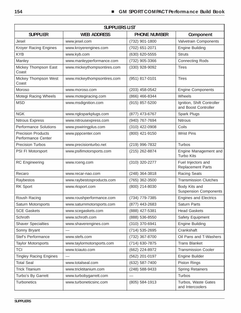
SUPPLIERS LISTSUPPLIER WEB ADDRESS PHONE NUMBER Component
Jesel www.jesel.com (732) 901-1800 Valvetrain Components
Kroyer Racing Engines www.kroyerengines.com (702) 651-2071 Engine Building
KYB www.kyb.com (630) 620-5555 Struts
Manley www.manleyperformance.com (732) 905-3366 Connecting Rods
Mickey Thompson EastCoast
www.mickeythompsontires.com (330) 928-9092 Tires
Mickey Thompson WestCoast
www.mickeythompsontires.com (951) 817-0101 Tires
Moroso www.moroso.com (203) 458-0542 Engine Components
Motegi Racing Wheels www.motegiracing.com (866) 466-8344 Wheels
MSD www.msdignition.com (915) 857-5200 Ignition, Shift Controllerand Boost Controller
NGK www.ngksparkplugs.com (877) 473-6767 Spark Plugs
Nitrous Express www.nitrousexpress.com (940) 767-7694 Nitrous
Performance Solutions www.pswiringplus.com (310) 422-0908 Coils
Precision ProductsPerformance Center
www.pppcenter.com (800) 421-9150 Wrist Pins
Precision Turbos www.precisionturbo.net (219) 996-7832 Turbos
PSI FI Motorsport www.psifimotorsports.com (215) 262-8874 Engine Management andTurbo Kits
RC Engineering www.rceng.com (310) 320-2277 Fuel Injectors andReplacement Parts
Recaro www.recar-nao.com (248) 364-3818 Racing Seats
Raybestos www.raybestosproducts.com (765) 362-3500 Transmission Clutches
RK Sport www.rksport.com (800) 214-8030 Body Kits andSuspension Components
Roush Racing www.roushperformance.com (734) 779-7385 Engines and Electrics
Saturn Motorsports www.saturnmotorsports.com (877) 443-2683 Saturn Parts
SCE Gaskets www.scegaskets.com (888) 427-5381 Head Gaskets
Schroth www.schroth.com (888) 536-8550 Safety Equipment
Shaver Specialties www.shaverengines.com (310) 370-6941 Engine Building
Sonny Bryant — (714) 535-2695 Crankshaft
Stef’s Performance www.stefs.com (732) 367-8700 Oil Pans and T-Washers
Taylor Motorsports www.taylormotorsports.com (714) 630-7875 Trans Blanket
TCI www.tciauto.com (662) 224-8972 Transmission Cooler
Tingley Racing Engines — (562) 201-0197 Engine Builder
Total Seal www.totalseal.com (632) 587-7400 Piston Rings
Trick Titanium www.tricktitanium.com (248) 588-9433 Spring Retainers
Turbo’s By Garrett www.turbobygarrett.com — Turbos
Turbonetics www.turboneticsinc.com (805) 584-1913 Turbos, Waste Gatesand Intercoolers
154 � GM SPORT COMPACT Performance Build Book
SUPPLIERS
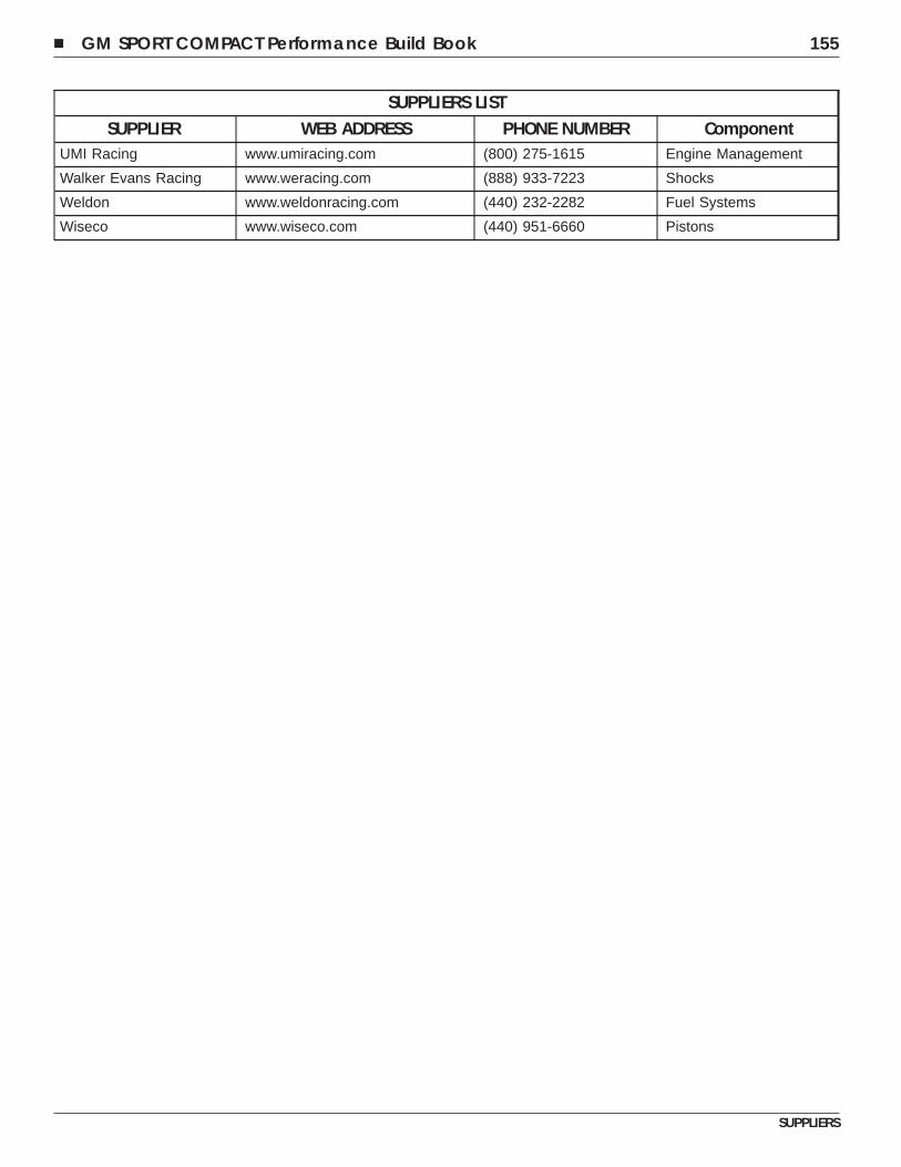
SUPPLIERS LISTSUPPLIER WEB ADDRESS PHONE NUMBER Component
UMI Racing www.umiracing.com (800) 275-1615 Engine Management
Walker Evans Racing www.weracing.com (888) 933-7223 Shocks
Weldon www.weldonracing.com (440) 232-2282 Fuel Systems
Wiseco www.wiseco.com (440) 951-6660 Pistons
� GM SPORT COMPACT Performance Build Book 155
SUPPLIERS

NOTES
Related Documents