2.13 Water Supply Pressure Pump Station www.gvwater.vic.gov.au DESIGN GUIDELINE 1800 454 500 | [email protected]

Welcome message from author
This document is posted to help you gain knowledge. Please leave a comment to let me know what you think about it! Share it to your friends and learn new things together.
Transcript
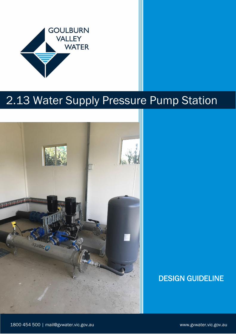
2.13 Water Supply Pressure Pump Station
www.gvwater.vic.gov.au
DESIGN GUIDELINE
1800 454 500 | [email protected]
2.13 Design Guideline - Water Supply Pressure Pump Station
Last Approved: 4 October 2018 Page 2 of 15 Reference Number: QDOC/989
---- Uncontrolled document when printed ----
Title 2.13 Design Guideline - Water Supply Pressure Pump Station
System Asset Management
Reference Number QDOC/989
Approved By Steven Nash
Next review date 4 October 2021
Note: With each edit to this document, the following must be completed. Also if a
document is being reviewed and there are no changes, it should be noted that the review
was undertaken and the next review date updated.
Details of Review/Changes
Date Description Modified By Approved By
4/10/2018 Workshop Original Draft Troy Riordan Steven Nash
4/04/2019 Updated electrical standards Adam Glasson Grant Barry
2.13 Design Guideline - Water Supply Pressure Pump Station
Last Approved: 4 October 2018 Page 3 of 15 Reference Number: QDOC/989
---- Uncontrolled document when printed ----
TABLE OF CONTENTS
Table of Contents ...................................................................................................................... 3
Description ................................................................................................................................. 4
Objective: ................................................................................................................................... 4
Risk: ............................................................................................................................................ 4
Reference Documents: ............................................................................................................. 4
Schematic Plan .......................................................................................................................... 6
Small Installation ................................................................................................................... 6
Large Installation ................................................................................................................... 7
Component Description: ........................................................................................................... 8
1. Pump Station Site ....................................................................................................... 8
2. Electricity Supply ......................................................................................................... 8
3. Switchboard ................................................................................................................ 9
4. Perimeter Fence ......................................................................................................... 9
5. Signage ........................................................................................................................ 9
6. Pumps .......................................................................................................................... 9
7. Noise Attenuation .................................................................................................... 10
8. Pump Controls ......................................................................................................... 10
9. Valves ....................................................................................................................... 10
10. Pipework ................................................................................................................... 11
Suction ............................................................................................................................ 11
Discharge ........................................................................................................................ 11
11. Electromagnetic Flow Meter ................................................................................... 11
12. Aesthetics ................................................................................................................. 13
13. Standard Drawings and Site Photos ...................................................................... 13
Site Photos .............................................................................................................................. 13
Appendices ............................................................................................................................. 15
2.13 Design Guideline - Water Supply Pressure Pump Station
Last Approved: 4 October 2018 Page 4 of 15 Reference Number: QDOC/989
---- Uncontrolled document when printed ----
DESCRIPTION
The water supply pressure pump station is a component of the reticulation system and
improves the pressure in a network, upon demand. The operation of the pump will be
governed by a reticulation pressure signal.
OBJECTIVE:
The objective of the water supply pressure pump station is to maintain an acceptable
minimum pressure level.
RISK:
This Guideline may identify some risks and provides guidance in mitigating these risks.
However a further site specific assessment and/or HAZOP are required to address other
risks.
All materials in contact with potable water must comply with AS/NZS 4020 and utilise
WSAA National Codes and standards where applicable.
Isolation points for all energy sources including electrical, pneumatic and hydraulic must
be considered. Installed isolation points are to be listed in the Operations Manuals for all
asset types.
REFERENCE DOCUMENTS:
• AS/NZS 4020: Testing of products for use in contact with drinking water
• AS/NZS 3000: Electrical Installations
• WSAA – MRWA – Water Supply Code of Australia
• GVW Supplement to the WSAA – MRWA – Water Supply Code of Australia
• GVW Preferred Equipment List
• GVW Safe Water Infrastructure Water Quality Procedure
• GVW Land Development Framework
• GVW General Electrical Specification
• 1.2 Design Guideline: Confined Spaces – Access Security and Signage
• 1.4 Design Guideline: Building Aesthetics
• 1.5 Design Guideline: Security Fencing
• 1.10 Design Guideline: Electromagnetic Flow Meter Installation
• 1.12 Design Guideline: Security Signage
• 1.14 Design Guideline: Backup Generator
• GVW Pressure Pump Station Specific Electrical Requirements
2.13 Design Guideline - Water Supply Pressure Pump Station
Last Approved: 4 October 2018 Page 5 of 15 Reference Number: QDOC/989
---- Uncontrolled document when printed ----
• GVW Booster Pump Station Specific Electrical Requirements
• GVW-PID-101– Legend P&ID
• GVW-PID-102– Small Pressure Booster P&ID
• GVW-PID-103 – Large Pressure Booster P&ID
2.13 Design Guideline - Water Supply Pressure Pump Station
Last Approved: 4 October 2018 Page 6 of 15 Reference Number: QDOC/989
---- Uncontrolled document when printed ----
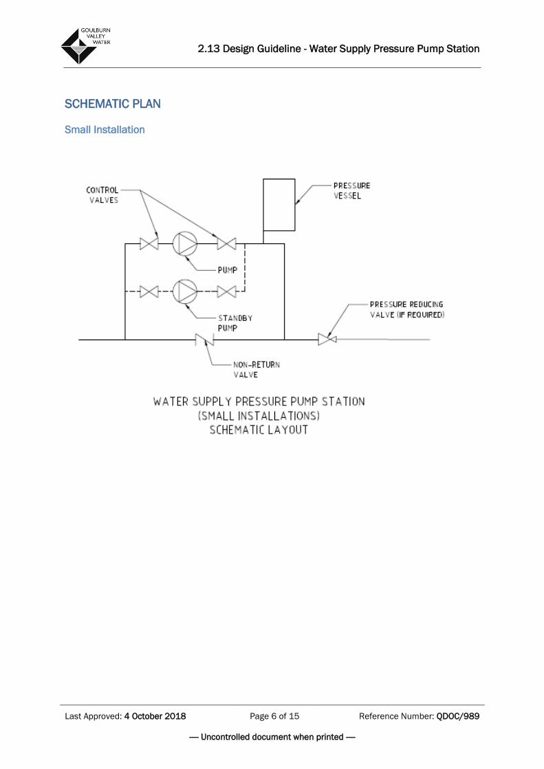
SCHEMATIC PLAN
Small Installation
2.13 Design Guideline - Water Supply Pressure Pump Station
Last Approved: 4 October 2018 Page 7 of 15 Reference Number: QDOC/989
---- Uncontrolled document when printed ----
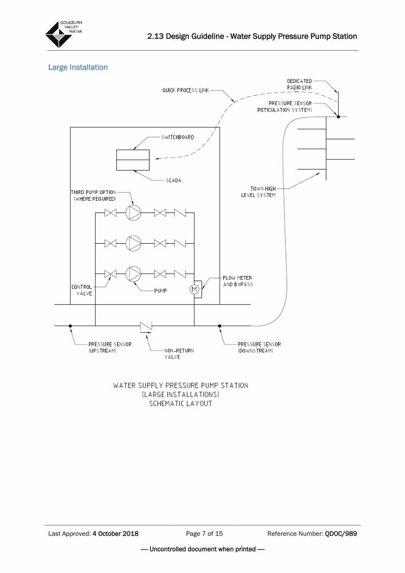
Large Installation
2.13 Design Guideline - Water Supply Pressure Pump Station
Last Approved: 4 October 2018 Page 8 of 15 Reference Number: QDOC/989
---- Uncontrolled document when printed ----
COMPONENT DESCRIPTION:
1. Pump Station Site
The pump station site is to be located within a reserve in favour of the Goulburn
Valley Region Water Corporation.
The pump station site area/reserve is to be determined by the below requirements
as a minimum.
The pump site is to be selected where a sufficient water supply is provided at peak
periods for the pump to operate (water pressure and flow). Advice is to be sought
from Goulburn Valley Water’s Planning and Project Development Section.
The site is not to be encumbered by existing or proposed overhead power lines
and is to provide satisfactory coverage for monitoring and control via SCADA.
The site must be accessible by vehicles by means of an all-weather road. The
minimum width of the access is 3 metre wide and sufficient space is to be
provided for a light truck vehicle to turn and for at least 1 parking space.
The surrounding area of the pump station site is to be covered with a minimum of
100mm compacted crushed rock or similar approved material to provide an all-
weather access to the site.
The layout of the pump station must ensure that the available space for
maintenance purposes is maximised. A minimum of 1 metre clearance between
all assets and the reserve title boundary must be achieved.
Roofing to cover pumps and switchboard to be installed and designed to a
minimum of 2.7m high to allow for crane access.
Considerations are to be made for backup power supply.
2. Electricity Supply
The capacity of the electricity supply system needs to be investigated to ensure
that there is an electricity supply capable of meeting pump station loading within
electricity supply regulations for both Amperage and Voltage.
Considerations are to be made for backup power supply. This can include the
option of a permanent generator, or connection of a portable generator (see 1.14
Design Guideline: Backup Generator).
If a development project, then the connection to the grid is to be arranged by the
consultant including the meeting of associated costs as part of the project. These
include:
• Costs to connect to grid
2.13 Design Guideline - Water Supply Pressure Pump Station
Last Approved: 4 October 2018 Page 9 of 15 Reference Number: QDOC/989
---- Uncontrolled document when printed ----
• Expected running costs of pump annually and life time
• Pump wiring requirements,
• All weather control box
• Generators (refer 1.14: Backup Generator Design Guideline)
o All pump stations shall have a generator supplied for the total installation
whether it be a fixed generator or portable generator.
o All pump station installations shall have an inlet installed for future use of a
portable generator, when required.
3. Switchboard
The electrical cabinet and switchboard is to be in accordance with the GVW
General Electrical Specification. This is available, along with the following
information, upon request via the appointed GVW Project Manager;
• GVW Booster Pump Station Specific Electrical/Requirements
• GVW preferred Equipment List
Control cabinet shall not be located between access and pumps, so maintenance
and repairs can be easily accessed and carried out.
All electrical work is to be as per AS/NZ 3000 and the GVW General Electrical
Specification.
Door clearance to comply with AS/NZS 3000.
4. Perimeter Fence
The perimeter Fence shall comply with 1.5 Design Guideline: Security Fencing.
5. Signage
Security signage shall comply with Design Guideline: 1.12 Security Signage.
General signage, or in reference to access/confined space shall comply with
Design Guideline: 1.2 Confined Spaces – Access Security and Signage.
6. Pumps
All water supply pressure pump stations that supply pressurised potable water to
the reticulation system are to equipped with a minimum of two separate pumps, in
a duty/standby arrangement and are to be rated to operate in an open weather
environment.
Considerations to be made on pump quantities, dependant on number of houses
on the network.
For pump selections, refer to the GVW Preferred Equipment List.
2.13 Design Guideline - Water Supply Pressure Pump Station
Last Approved: 4 October 2018 Page 10 of 15 Reference Number: QDOC/989
---- Uncontrolled document when printed ----
For detailed specifications of pump requirements e.g. pressure requirements,
please refer to appointed GVW Project Manager.
The selection of the pump and the design will be determined by adequate
pressure requirements. The preference is dedicated inlet and outlet water mains.
Pumps should be located adjacent to the access/parking area, so that there is
unrestricted access to pumps to allow lifting as required using a small GVW crane
truck.
Pumps and pipework are to be secured to a suitable concrete slab, which drains
surface water adequately.
When a Water Supply Pressure Pump Station will supply over 100 houses, a
pressure transmitter and telemetry cabinet shall be installed at the end of the
reticulation line.
Between 10-100 houses, is to be decided at the design stage as variables on
distance and height will determine the appropriate action and confirmed with the
appointed GVW project manager.
For <10 houses, a pressure transmitter on the outlet of the pump shall suffice.
7. Noise Attenuation
The noise generated from the start, stop and running of the pumps is to be
considered and must be designed to meet the noise level limits set by the
Environmental Protection Authority (EPA).
8. Pump Controls
The pumps are to operate on a duty call and duty stop set point from the
reticulation pressure. There is to be a telemetry (radio) link between pumps station
and pressure transmitter on a large installation (>100 houses) if required, or if it’s
greater than 100m, alternatively a local transmitter will be used on a small
installation
Cable is not to be used when the distance between the pumps and the tanks is
greater than 100m.
The pumps should have an automatic changeover between the duty and standby.
9. Valves
The isolation valves on the suction and discharge are to be either Gate DI
resilient/metal seated or Butterfly CI. These isolation valves are to be termination
style, i.e. lugged, or double flanged to allow removal of pump or NRV
Discharge valves to be located 3-5 Diameters away from the pump discharge.
2.13 Design Guideline - Water Supply Pressure Pump Station
Last Approved: 4 October 2018 Page 11 of 15 Reference Number: QDOC/989
---- Uncontrolled document when printed ----
Suction valves to be located 2-3 Diameters away from suction of the pump.
Stainless steel valves are accepted.
10. Pipework
All pipework in the vicinity of the pumps is to be above ground and comprise
flanged or welded stainless steel or flanged DICL pipework.
Inlet and outlet pipes to be cast into a minimum of 100mm thick reinforced
concrete slab.
All below ground pipe work within the pump station site must be DICL material.
Suction
- Keep length of suction pipe to a minimum.
- Minimum 5 Diameters of straight pipe before pump suction (no valves in
this area).
- No elbows or bends close to the inlet of the pump (10 diameters)
- Eliminate potential for air entrapment in pump suction (use eccentric
reducers and not concentric reducers. Do not install eccentric reducers
upside down.).
- Ensure piping arrangement does not cause strain on pump casing.
- Suction piping should be at least one size larger than then suction size of
the pump.
Discharge
- Minimum 5 Diameters of straight pipe after pump discharge (no valves in
this area).
- A transient analysis should be done to understand whether Anti-slam non-
return valves are required. If this is to be the case, these should be used
instead of the valves specified below.
- Cast iron swing check non-return valves should be used where extended
shafts are required and low response to reverse flow is acceptable.
- Dual plate non-return valve should be used for applications where rapid
response to reverse flow conditions is required and extended shafts are not
required.
11. Electromagnetic Flow Meter
An electromagnetic flow meter is to be installed on the discharge pipework from
the pumps and located above ground.
Installation must comply with the 1.10 Design Guideline: Electromagnetic Flow
Meter Installation
2.13 Design Guideline - Water Supply Pressure Pump Station
Last Approved: 4 October 2018 Page 12 of 15 Reference Number: QDOC/989
---- Uncontrolled document when printed ----
The discharge flow rate is to be displayed on the electrical cabinet and also linked
to SCADA, so that it can be viewed remotely.
2.13 Design Guideline - Water Supply Pressure Pump Station
Last Approved: 4 October 2018 Page 13 of 15 Reference Number: QDOC/989
---- Uncontrolled document when printed ----
12. Aesthetics
Refer to 1.4 Design Guideline: Building Aesthetics
13. Standard Drawings and Site Photos
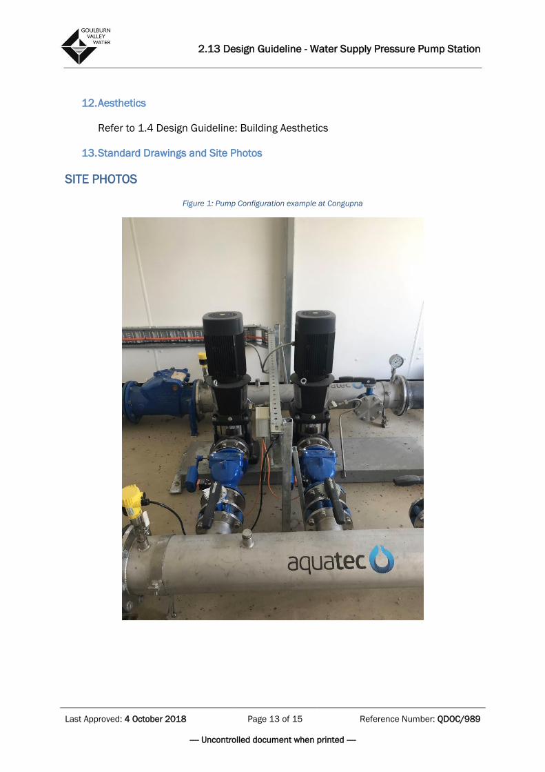
SITE PHOTOS
Figure 1: Pump Configuration example at Congupna
2.13 Design Guideline - Water Supply Pressure Pump Station
Last Approved: 4 October 2018 Page 14 of 15 Reference Number: QDOC/989
---- Uncontrolled document when printed ----
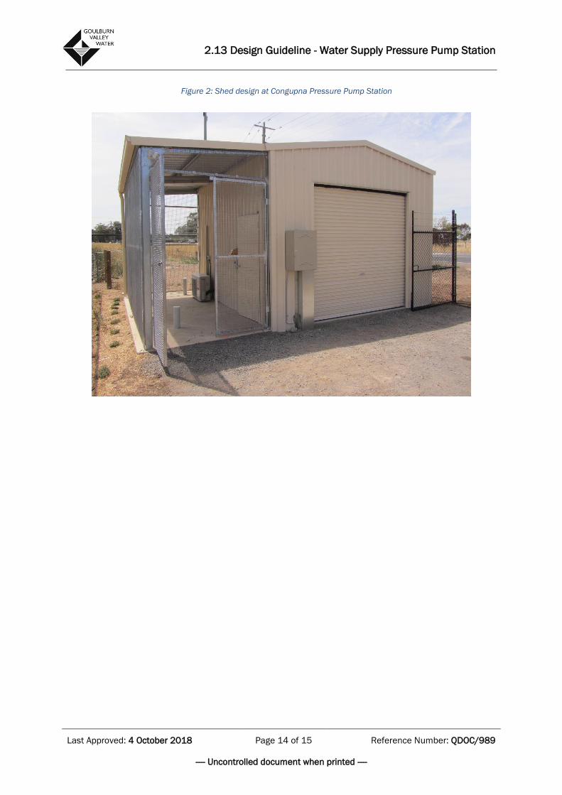
Figure 2: Shed design at Congupna Pressure Pump Station
2.13 Design Guideline - Water Supply Pressure Pump Station
Last Approved: 4 October 2018 Page 15 of 15 Reference Number: QDOC/989
---- Uncontrolled document when printed ----
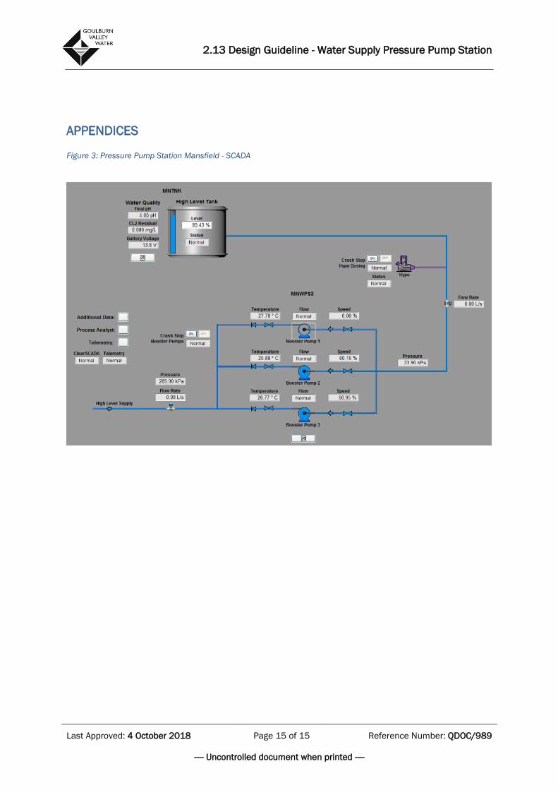
APPENDICES Figure 3: Pressure Pump Station Mansfield - SCADA
Related Documents