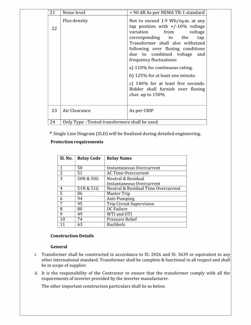
21 Noise level Flux density 22 < 90 dB As per NEMA TR-1 standard Not to exceed 1.9 Wb/sq.m. at any tap position with +/-10% voltage variation from voltage corresponding to the tap. Transformer shall also withstand following over fluxing conditions due to combined voltage and frequency fluctuations: a) 110% for continuous rating. b) 125% for at least one minute. c) 140% for at least five seconds. Bidder shall furnish over fluxing char. up to 150% 23 Air Clearance As per CBIP 24 Only Type –Tested transformers shall be used. * Single Line Diagram (SLD) will be finalized during detailed engineering. Protection requirements Sl. No. Relay Code Relay Name 1 50 Instantaneous Overcurrent 2 51 AC Time Overcurrent 3 50N & 50G Neutral & Residual Instantaneous Overcurrent 4 51N & 51G Neutral & Residual Time Overcurrent 5 86 Master Trip 6 94 Anti-Pumping 7 95 Trip Circuit Supervision 8 80 DC Failure 9 49 WTI and OTI 10 74 Pressure Relief 11 63 Buchholz Construction Details General i. Transformer shall be constructed in accordance to IS: 2026 and IS: 3639 or equivalent to any other international standard. Transformer shall be complete & functional in all respect and shall be in scope of supplier. ii. It is the responsibility of the Contractor to ensure that the transformer comply with all the requirements of inverter provided by the inverter manufacturer. The other important construction particulars shall be as below.

Welcome message from author
This document is posted to help you gain knowledge. Please leave a comment to let me know what you think about it! Share it to your friends and learn new things together.
Transcript
21 Noise level
Flux density
22
< 90 dB As per NEMA TR-1 standard
Not to exceed 1.9 Wb/sq.m. at any
tap position with +/-10% voltage
variation from voltage
corresponding to the tap.
Transformer shall also withstand
following over fluxing conditions
due to combined voltage and
frequency fluctuations:
a) 110% for continuous rating.
b) 125% for at least one minute.
c) 140% for at least five seconds.
Bidder shall furnish over fluxing
char. up to 150%
23 Air Clearance As per CBIP
24 Only Type –Tested transformers shall be used.
* Single Line Diagram (SLD) will be finalized during detailed engineering.
Protection requirements
Sl. No. Relay Code Relay Name
1 50 Instantaneous Overcurrent 2 51 AC Time Overcurrent
3 50N & 50G Neutral & Residual Instantaneous Overcurrent
4 51N & 51G Neutral & Residual Time Overcurrent 5 86 Master Trip 6 94 Anti-Pumping 7 95 Trip Circuit Supervision 8 80 DC Failure 9 49 WTI and OTI 10 74 Pressure Relief 11 63 Buchholz
Construction Details
General
i. Transformer shall be constructed in accordance to IS: 2026 and IS: 3639 or equivalent to any
other international standard. Transformer shall be complete & functional in all respect and shall
be in scope of supplier.
ii. It is the responsibility of the Contractor to ensure that the transformer comply with all the
requirements of inverter provided by the inverter manufacturer.
The other important construction particulars shall be as below.
iii. The Transformer tank and cover shall be fabricated from high grade low carbon plate steel of
tested quality. The tank and the cover shall be of welded construction and there should be
provision for lifting by crane.
iv. A double float type Buchholz relay conforming to IS: 3637 shall be provided.
v. Suitable Inspection hole(s) with welded flange(s) and bolted cover(s) shall be provided on the
tank cover. The inspection hole(s) shall be of sufficient size to afford easy access to the lower
ends of the bushings, terminals etc.
vi. All bolted connections to the tank shall be fitted with suitable oil-tight gaskets which shall give
satisfactory service under the operating conditions for complete life of the transformer if not
opened for maintenance at site
vii. The transformer conservator shall be provided with Atmoseal (Bladder) type single
compartment with conventional single compartment conservator. The top of the conservator
shall be connected to the atmosphere through indicating type cobalt free silica gel breather (in
transparent enclosure). Silica gel shall be isolated from atmosphere by an oil seal.
viii. Transformer shall have adequate capacity Conservator tank to accommodate oil preservation
system and volumetric expansion of total transformer oil.
ix. The radiators shall be detachable type, mounted on the tank with shut off valve at each point of
connection to the tank, lifts, along with drain plug/valve at the bottom and air release plug at
the top.
x. M. Box shall be of sheet steel, dust and vermin proof provided with proper lighting and
thermostatically controlled space heaters. The degree of protection shall be IP 55. Marshalling
Box of all transformers shall be preferably Tank Mounted. One dummy terminal block in
between each trip wire terminal shall be provided. At least 20% spare terminals shall be
provided on each panel. The gasket used shall be of neoprene rubber. Also, Marshalling Box,
shall be at least 450 mm above ground level. Wiring scheme (TB details) shall be engraved in a
stainless steel plate with viewable font size and the same shall be fixed inside the Marshalling
Box door.
xi. Winding, core and other supporting arrangement etc. should be same as that of successful type
tested (Short Circuit, impulse and temperature rise test) transformer.
xii. Transformer shall be designed for at least 5% total harmonic distortion (THD) to withstand
distortion generated by the inverter as well as possible outside harmonics from the network.
xiii. The transformer shall be suitable for continuous operation with a frequency variation of ±2.5%
from nominal frequency of 50 Hz without exceeding the specified temperature rise.
xiv. Inverter Transformer shall have shield winding between LV & HV windings. Each LV winding
must be capable of handling non-sinusoidal voltage with voltage gradient as specified by the
inverter manufacturer. Also, shield winding shall be taken out from tank through shield bushing
and the same shall be brought down to the bottom of the tank using copper flat and support
insulator for independent grounding.
xv. Vector group of inverter transformer shall be as per the inverter manufacturer requirement.
Short circuit test of transformer should be conducted on the same configuration.
xvi. Neutral bushing of Inverter transformer shall be brought outside the tank for the testing
purpose. It shall be covered with MS sheet and a sticker “For testing purpose only. Do not earth”.
xvii. Transformer shall have winding temperature sensors and Winding Temperature Indicator
(WTI) with requisite set of remote signalling contacts for alarm and trip operations.
xviii. All external surface of the transformer shall be painted with two coats of epoxy-based paint of
colour shade as decided by the REIL / Customer. Internal surface of cable boxes and
marshaling box shall be painted with epoxy enamel white paint. The minimum dry film
thickness (DFT) shall be 100 microns.
xix. LV and HV cable box shall be provided with disconnecting chamber to facilitate the movement of
transformer without disturbing cable box and termination.
xx. Bi-directional wheel/skids cover lifting eyes, transformer-lifting lugs, jacking pads, towing holes,
core and winding lifting lugs, inspection cover, rating plate, valve schedule plate, accessories and
terminal marking plates, two nos. of earthing terminals shall be provided.
Windings
i. The bidder shall ensure that windings of all transformers are made in dust proof &
conditioned atmosphere.
ii. The conductors shall be of electrolytic grade copper free from scales & burrs.
iii. All windings of the transformers shall have uniform insulation.
iv. Tapping shall be so arranged as to preserve the magnetic balance of the transformer at all
voltage ratio.
Core
i. The core shall be constructed from non-ageing, cold rolled, super grain oriented silicon steel
laminations equivalent to M4 grade steels or better.
ii. Core isolation level shall be 2 kV (rms.) for 1 minute in air.
iii. Adequate lifting lugs will be provided to enable the core & windings to be lifted.
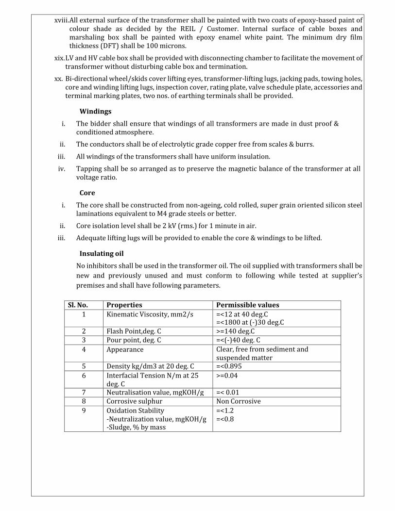
Insulating oil
No inhibitors shall be used in the transformer oil. The oil supplied with transformers shall be
new and previously unused and must conform to following while tested at supplier's
premises and shall have following parameters.
Sl. No. Properties Permissible values
1 Kinematic Viscosity, mm2/s =<12 at 40 deg.C =<1800 at (-)30 deg.C
2 Flash Point,deg. C >=140 deg.C
3 Pour point, deg. C =<(-)40 deg. C
4 Appearance Clear, free from sediment and
suspended matter
5 Density kg/dm3 at 20 deg. C =<0.895
6 Interfacial Tension N/m at 25
deg. C
>=0.04
7 Neutralisation value, mgKOH/g =< 0.01
8 Corrosive sulphur Non Corrosive
9 Oxidation Stability
-Neutralization value, mgKOH/g -Sludge, % by mass
=<1.2
=<0.8
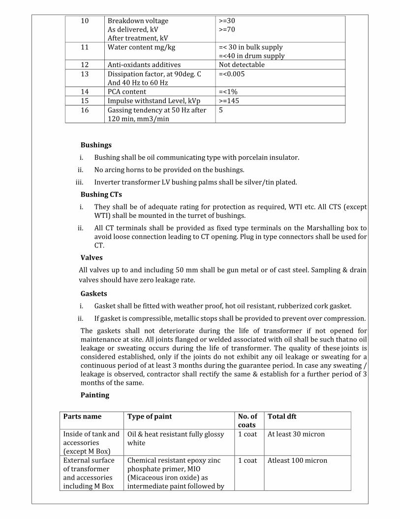
10 Breakdown voltage
As delivered, kV
After treatment, kV
11 Water content mg/kg
12 Anti-oxidants additives
13 Dissipation factor, at 90deg. C
And 40 Hz to 60 Hz
14 PCA content
15 Impulse withstand Level, kVp
16 Gassing tendency at 50 Hz after
120 min, mm3/min
>=30
>=70
=< 30 in bulk supply
=<40 in drum supply
Not detectable
=<0.005
=<1%
>=145
5
Bushings
i. Bushing shall be oil communicating type with porcelain insulator.
ii. No arcing horns to be provided on the bushings.
iii. Inverter transformer LV bushing palms shall be silver/tin plated.
Bushing CTs
i. They shall be of adequate rating for protection as required, WTI etc. All CTS (except
WTI) shall be mounted in the turret of bushings.
ii. All CT terminals shall be provided as fixed type terminals on the Marshalling box to
avoid loose connection leading to CT opening. Plug in type connectors shall be used for
CT.
Valves
All valves up to and including 50 mm shall be gun metal or of cast steel. Sampling & drain
valves should have zero leakage rate.
Gaskets
i. Gasket shall be fitted with weather proof, hot oil resistant, rubberized cork gasket.
ii. If gasket is compressible, metallic stops shall be provided to prevent over compression.
The gaskets shall not deteriorate during the life of transformer if not opened for
maintenance at site. All joints flanged or welded associated with oil shall be such that no oil
leakage or sweating occurs during the life of transformer. The quality of these joints is
considered established, only if the joints do not exhibit any oil leakage or sweating for a
continuous period of at least 3 months during the guarantee period. In case any sweating /
leakage is observed, contractor shall rectify the same & establish for a further period of 3
months of the same.
Painting
Parts name Type of paint No. of
coats
Total dft
Inside of tank and
accessories
(except M Box)
Oil & heat resistant fully glossy
white
1 coat At least 30 micron
External surface
of transformer
and accessories
including M Box
Chemical resistant epoxy zinc
phosphate primer, MIO
(Micaceous iron oxide) as
intermediate paint followed by
1 coat Atleast 100 micron
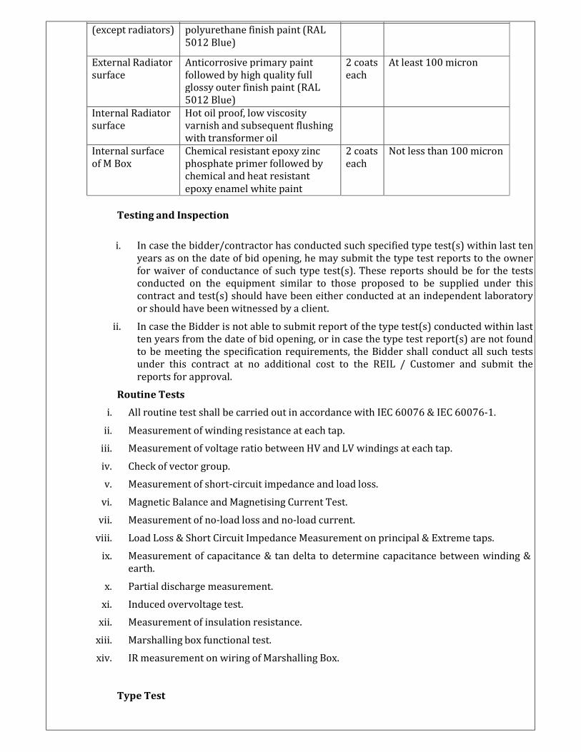
(except radiators) polyurethane finish paint (RAL
5012 Blue)
External Radiator Anticorrosive primary paint 2 coats At least 100 micron
surface followed by high quality full each
glossy outer finish paint (RAL
5012 Blue)
Internal Radiator Hot oil proof, low viscosity
surface varnish and subsequent flushing
with transformer oil
Internal surface Chemical resistant epoxy zinc 2 coats Not less than 100 micron
of M Box phosphate primer followed by each
chemical and heat resistant
epoxy enamel white paint
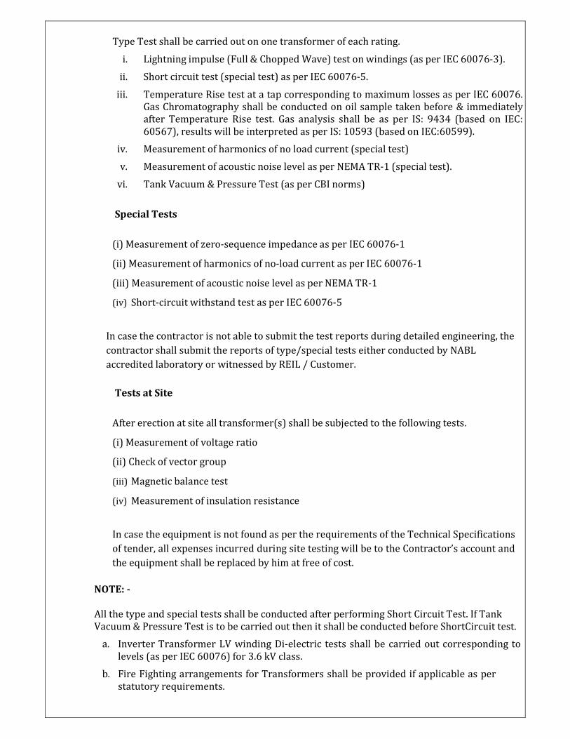
Testing and Inspection
i. In case the bidder/contractor has conducted such specified type test(s) within last ten
years as on the date of bid opening, he may submit the type test reports to the owner
for waiver of conductance of such type test(s). These reports should be for the tests
conducted on the equipment similar to those proposed to be supplied under this
contract and test(s) should have been either conducted at an independent laboratory
or should have been witnessed by a client.
ii. In case the Bidder is not able to submit report of the type test(s) conducted within last
ten years from the date of bid opening, or in case the type test report(s) are not found
to be meeting the specification requirements, the Bidder shall conduct all such tests
under this contract at no additional cost to the REIL / Customer and submit the
reports for approval.
Routine Tests
i. All routine test shall be carried out in accordance with IEC 60076 & IEC 60076-1.
ii. Measurement of winding resistance at each tap.
iii. Measurement of voltage ratio between HV and LV windings at each tap.
iv. Check of vector group.
v. Measurement of short-circuit impedance and load loss.
vi. Magnetic Balance and Magnetising Current Test.
vii. Measurement of no-load loss and no-load current.
viii. Load Loss & Short Circuit Impedance Measurement on principal & Extreme taps.
ix. Measurement of capacitance & tan delta to determine capacitance between winding &
earth.
x. Partial discharge measurement.
xi. Induced overvoltage test.
xii. Measurement of insulation resistance.
xiii. Marshalling box functional test.
xiv. IR measurement on wiring of Marshalling Box.
Type Test
Type Test shall be carried out on one transformer of each rating.
i. Lightning impulse (Full & Chopped Wave) test on windings (as per IEC 60076-3).
ii. Short circuit test (special test) as per IEC 60076-5.
iii. Temperature Rise test at a tap corresponding to maximum losses as per IEC 60076.
Gas Chromatography shall be conducted on oil sample taken before & immediately
after Temperature Rise test. Gas analysis shall be as per IS: 9434 (based on IEC:
60567), results will be interpreted as per IS: 10593 (based on IEC:60599).
iv. Measurement of harmonics of no load current (special test)
v. Measurement of acoustic noise level as per NEMA TR-1 (special test).
vi. Tank Vacuum & Pressure Test (as per CBI norms)
Special Tests
(i) Measurement of zero-sequence impedance as per IEC 60076-1
(ii) Measurement of harmonics of no-load current as per IEC 60076-1
(iii) Measurement of acoustic noise level as per NEMA TR-1
(iv) Short-circuit withstand test as per IEC 60076-5
In case the contractor is not able to submit the test reports during detailed engineering, the
contractor shall submit the reports of type/special tests either conducted by NABL
accredited laboratory or witnessed by REIL / Customer.
Tests at Site
After erection at site all transformer(s) shall be subjected to the following tests.
(i) Measurement of voltage ratio
(ii) Check of vector group
(iii) Magnetic balance test
(iv) Measurement of insulation resistance
In case the equipment is not found as per the requirements of the Technical Specifications
of tender, all expenses incurred during site testing will be to the Contractor’s account and
the equipment shall be replaced by him at free of cost.
NOTE: -
All the type and special tests shall be conducted after performing Short Circuit Test. If Tank
Vacuum & Pressure Test is to be carried out then it shall be conducted before ShortCircuit test.
a. Inverter Transformer LV winding Di-electric tests shall be carried out corresponding to
levels (as per IEC 60076) for 3.6 kV class.
b. Fire Fighting arrangements for Transformers shall be provided if applicable as per
statutory requirements.
c. Firewall as applicable (as per IS 3034) shall be provided of minimum 230 mm thickness of
RCC wall subject to PMCs/Owners approval.
d. Transformer efficiency shall be as per Central Electricity Authority (Technical Standards
for Construction of Electrical Plants and Electrical Lines) regulation, 2010.
e. Danger plate indicating, “entry prohibited under energized condition” of the transformer
shall be provided as per statutory requirements.
f. Rating plate
i. Name of manufacturer
ii. Serial number
iii. Year of manufacture
iv. Number of phases
v. KVA or MVA rating
vi. Frequency
vii. Voltage ratings.
viii. Tap voltages.
ix. Connection diagram.
x. Cooling class
xi. Phasor or vector diagram
xii. % impedance between primary and secondary
xiii. Approximate mass or weight of the transformer
xiv. Type of insulating liquid.
xv. Conductor material of each winding.
xvi. Oil volume (of each transformer Container/Compartment)
xvii. Valve schedule Plate
xviii. The name-plate shall contain the information of all the valves, their locations,
quantities and schematics for the valve.
xix. OCTC plate
xx. Type
xxi. Serial number
xxii. Year of manufacture
xxiii. Phase
xxiv. Frequency
xxv. Steps (Number)
xxvi. Steps voltages.
xxvii. Control voltage.
xxviii. Weight with and without oil
Marshalling Box
i. Name of manufacturer
ii. Serial number
iii. Year of manufacture
iv. Purchase order No.
v. Engraved drawing of control circuit, CT/ PT circuit and TB.
Oil filling instruction plate of conservator
Step wise process for filling the oil in conservator
The accessories listed above are indicative only. Accessories which are not mentioned above
but required for satisfactory operation of the transformers are deemed to be included in the
contract without extra charges.
Warranty
The transformer shall be warranted for minimum of 5 (five) years against all material/
manufacturing defects and workmanship.
Approval
The Detailed Design Report Submitted by the contractor to REIL / Customer must
contain but not limited to the following details of the transformers:
• Detailed specification including Fittings and Accessories
• Outline dimension/GA drawings of transformers.
• Bushing Assembly drawings (for both HV&LV).
• Marshalling Box GA & Connection Drawings.
• Transport drawings, showing main dimensions and weight of each package.
• Instruction plate for oil filling procedure for Air cell conservator
• Foundation details
• Tap-changing equipment
• Rating & Property plate diagrams
• Necessary test certificates and type test reports.
• GTP shall be provided by the contractor as per Proforma provided by REIL / Customer during approval.
A joint inspection will be done by REIL / Customer and authorized representatives of
the contractor at the manufacturer’s workshop. Testing and inspection of the
transformers will be carried out as per relevant Indian Standard. Arrangements for the
aforesaid testing and inspection at manufacturer’s end are to be provided by the
contractor.
Prior to the delivery of the product, the contractor shall submit but not limited to the
following documents:
Guarantees
Instructions for installation and operation manual
Safety precautions
Test reports for routine tests and acceptance tests etc.
Detailed schematics of all power instrumentation and control equipmentand
Sub systems along with their interconnection diagrams. Schematics shall
indicate wiring diagrams, their numbers and quantities, type and ratings of
all components and sub systems etc.
The contractor can deliver the product to the site only after receiving such approval
against their request in writing from REIL / Customer.
5. 33 KV HT Switchgear
Switchgear Panel
i. The switchgear boards shall have a single front, single tier, fully compartmentalized, metal
enclosed construction complying with clause No. 3.102 of IEC 62271-200, comprising of
a row of freestanding floor mounted panels.
ii. The circuit breakers and bus VTs shall be mounted on withdrawable trucks which shall
roll out horizontally from service position to isolated position. For complete withdrawal
from the panel, the truck shall rollout on the floor or shall roll out on telescopic rails. In
case, circuit breaker is to be rolled out on telescopic rails, bidder to provide suitable
trolley for withdrawal and insertion of the truck from and into the panel at each location
i.e. switchgear room. Testing of breaker shall be possible in isolated position by keeping
the control plug connected.
iii. The trucks shall have distinct SERVICE and ISOLATED positions. It shall be possible to
close the breaker compartment door in isolated position to retain the specified degree of
protection of switchgear panel. Circuit Breaker rack-in and rack-out from service to test,
test to isolated position or vice-versa shall be possible only in the compartment door
closed condition.
iv. Separate earthing trucks shall be provided for earthing of busbars and incoming/outgoing
feeders. The trucks shall have voltage transformer to indicate presence of voltage prior to
earthing. An audible alarm shall also be provided in case of voltage on the earthing
terminal. Integral earth switches may also be considered instead of earthing trucks. The
earthing truck/switch shall have short circuit withstand capability equal to that of the
associated switchgear panel.
v. The switchgear assembly shall be dust, moisture, rodent and vermin proof.
vi. The control/ relay compartments shall have degree of protection not less than IP 5X in
accordance with IS/IEC 60947. However, remaining compartments can have a degree of
protection of IP 4X. If louvers are provided, shall have very fine brass or GI mesh screen.
Tight fitting gourmet/ gaskets are to be provided at all openings in relay compartment.
vii. Numerical relays shall be fully flush mounted on the switchgear panels at a suitable
height.
viii. The switchgear shall be specially design to withstand internal explosion etc. so that it
should not endanger the operating personal while operating the breaker. In addition,
pressure relief device shall be provided in each high voltage compartment of a panel for
vent out the gases that may be generated in case of fault without spreading to other
compartment. The pressure relief device shall not however reduce the degree of
protection of panels under normal working condition.
ix. Enclosure shall be constructed with rolled steel sections. The doors and covers shall be
constructed from cold rolled steel sheets of 2.00mm or higher thickness. Gland plates shall
be 2.5mm thick hot or cold rolled steel section and for non-magnetic material it shall be
3.0mm.
x. Total height of the switchgear panels shall not exceed 2600 mm. The height of switches,
push buttons and other hand operated devices shall not exceed 1800mm and shall not be
less than 700mm. Switchgear shall be cooled by natural air flow.
xi. Suitable base frame made out of steel channels shall be supplied along with necessary
anchor bolts and other hardware, for mounting of switchgear panels. These should be
dispatched in advance so that they may be installed and levelled when the flooring is being
done.
xii. Pressure relief device shall be provided in each high voltage compartment of a panel to
safely vent the gases in the event of internal arc. Seal-off bushing arrangement shall be
provided between the breaker compartment and bus bar/cable compartments to prevent
transfer of arc from one compartment to other.
xiii. Automatic safety shutters shall be provided to cover up the fixed high voltage contacts on
bus bar and cable sides when the truck is moved to TEST position.
xiv. Degree of protection of the switchgear panel shall not be less than IP 55 as per IEC 60529.
Mechanical /Electrical interlocks shall be provided to prevent mal-operation and in
particular to ensure the following.
xv. Mechanical /Electrical interlocks shall be provided to prevent mal-operation and in
particular to ensure the following.
a) The breaker shall be operated only if it is in SERVICE or TEST position.
b) Movement of the breaker truck between SERVICE and TEST positions shall be possible
only if the breaker isOFF.
c) It shall be possible to open the door only when the breaker is in TEST position.
xvi. Failure of a control supply / de-energisation / restart of relay shall not initiate any circuit
breaker operation.
xvii. Each switchgear panel shall be provided with thermostatically controlled space heaters,
separately for breaker, cable and bus bar compartments, to prevent condensation within
the compartment. The space heater shall be connected to 240 V, 50 Hz, single-phase AC
supply through suitable switch and fuse.
xviii. 240 V, 15 A, SPN industrial socket-outlet with ON/OFF switch shall be provided in each
panel. Each panel shall be provided with LED lamp rated for 240 V, 50 Hz, single-phase
AC supply for interior illumination controlled by door switch.
xix. Gapless, metal-oxide surge arrestors shall be provided between line and earth in cable
compartment of the switchgear panel.
xx. Suitable lifting hooks shall be provided for each panel.
xxi. All external surface shall be painted with two coats of epoxy based paint of colour shade
RAL 7032. Internal surface shall be painted with epoxy enamel white paint. The minimum
dry film thickness (DFT) shall be 100 micron.
Circuit Breakers
i. The circuit breakers shall be of Vacuum type.
ii. They shall comprise of three separate, identical single pole interrupting units, operated
through a common shaft by a sturdy operating mechanism. An arrangement of two
breakers in parallel to meet specified current rating shall not be acceptable.
iii. Circuit breaker shall be restrike free, stored energy operated, anti-pumping and trip free
type. Motor wound closing spring charging shall be provided for each breaker, even if it
has built-in mechanical anti-pumping features. During closing, main poles shall not
rebound and mechanism shall not require adjustment. Suitable dampers shall be provided
to withstand the impact at the end of opening stroke.
iv. The operating mechanism shall be such that failure of any auxiliary spring shall not
prevent tripping and shall not lead to closing or tripping of circuit breaker. Failure of any
auxiliary spring shall also not cause damage to the circuit breaker or endanger the
operator.
v. Mechanical indicators shall be provided on the breaker trucks to indicate OPEN/ CLOSED
conditions of the circuit breaker and charged/ discharge conditions of the closing spring.
An operation counter of breaker shall be visible without opening the breaker
compartment door.
vi. The closing coil and spring charging motor shall operate satisfactorily at all values of
control supply voltage 220VDC.
vii. The time taken for charging of closing spring shall not exceed 30 seconds. The spring
charging shall take place automatically preferably after closing operation. Breaker
operation shall be independent of the spring charging motor which shall only charge the
closing spring. Opening spring shall get charged automatically during closing operation.
As long as power supply is available to the charging motor a continuous sequence of
closing and operations shall be possible. One open-close-open operation of the circuit
breaker shall be possible after failure of supply to the motor.
viii. The Bidder may note that total break time of the breaker shall not be exceeded under any
duty conditions specified such as with the combined variation of the trip coil voltage,
pneumatic pressure etc. While furnishing the proof of the total break time of complete
circuit breaker, the Bidder may specifically bring out the effect of non-simultaneity
between same pole and poles and show how it is covered in the guaranteed total break
time.
ix. Bidder shall indicate the noise level of breaker at distance of 50 to 150 m from base of the
breaker.
x. The circuit breaker will normally be controlled from remote control panels through
closing and shunt trip coils. The local control console of relay flush mounted on the
switchgear would normally use only for testing of circuit breaker in isolated position and
for tripping it in an emergency. The closing and opening of the breaker shall also be
possible from laptop through front serial port of the relay to facilitate commissioning
activities.
xi. 6NO and 6NC auxiliary contacts per pole shall be provided as spare contacts.
xii. Each panel shall have two separate limit switches, one for the service position and other
for isolated position. Each of these limit switches shall have at least four (4) contacts
which shall close in the respective positions.
Numerical Relays and Networking
i. All circuit breaker feeders shall be provided with communicable numerical relays (IED,
i.e. Intelligent Electronic Device) complying with IEC-61850, having protection, control,
measurement and monitoring features. These relays shall be networked and suitably
interfaced with the Solar SCADA system for dynamic SLD display, status monitoring,
measurements, event / alarm displays, reports, etc. The relays shall be flush mounted on
panel front with connections from the inside. These numerical relays shall be of types as
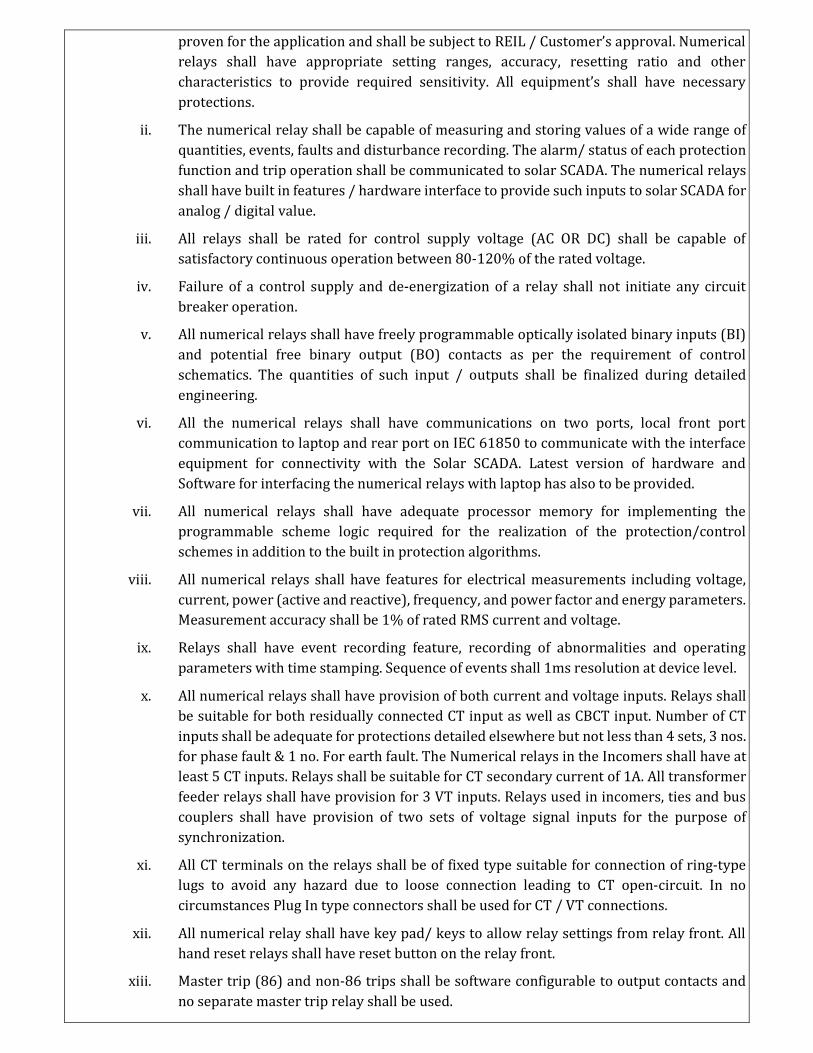
proven for the application and shall be subject to REIL / Customer’s approval. Numerical
relays shall have appropriate setting ranges, accuracy, resetting ratio and other
characteristics to provide required sensitivity. All equipment’s shall have necessary
protections.
ii. The numerical relay shall be capable of measuring and storing values of a wide range of
quantities, events, faults and disturbance recording. The alarm/ status of each protection
function and trip operation shall be communicated to solar SCADA. The numerical relays
shall have built in features / hardware interface to provide such inputs to solar SCADA for
analog / digital value.
iii. All relays shall be rated for control supply voltage (AC OR DC) shall be capable of
satisfactory continuous operation between 80-120% of the rated voltage.
iv. Failure of a control supply and de-energization of a relay shall not initiate any circuit
breaker operation.
v. All numerical relays shall have freely programmable optically isolated binary inputs (BI)
and potential free binary output (BO) contacts as per the requirement of control
schematics. The quantities of such input / outputs shall be finalized during detailed
engineering.
vi. All the numerical relays shall have communications on two ports, local front port
communication to laptop and rear port on IEC 61850 to communicate with the interface
equipment for connectivity with the Solar SCADA. Latest version of hardware and
Software for interfacing the numerical relays with laptop has also to be provided.
vii. All numerical relays shall have adequate processor memory for implementing the
programmable scheme logic required for the realization of the protection/control
schemes in addition to the built in protection algorithms.
viii. All numerical relays shall have features for electrical measurements including voltage,
current, power (active and reactive), frequency, and power factor and energy parameters.
Measurement accuracy shall be 1% of rated RMS current and voltage.
ix. Relays shall have event recording feature, recording of abnormalities and operating
parameters with time stamping. Sequence of events shall 1ms resolution at device level.
x. All numerical relays shall have provision of both current and voltage inputs. Relays shall
be suitable for both residually connected CT input as well as CBCT input. Number of CT
inputs shall be adequate for protections detailed elsewhere but not less than 4 sets, 3 nos.
for phase fault & 1 no. For earth fault. The Numerical relays in the Incomers shall have at
least 5 CT inputs. Relays shall be suitable for CT secondary current of 1A. All transformer
feeder relays shall have provision for 3 VT inputs. Relays used in incomers, ties and bus
couplers shall have provision of two sets of voltage signal inputs for the purpose of
synchronization.
xi. All CT terminals on the relays shall be of fixed type suitable for connection of ring-type
lugs to avoid any hazard due to loose connection leading to CT open-circuit. In no
circumstances Plug In type connectors shall be used for CT / VT connections.
xii. All numerical relay shall have key pad/ keys to allow relay settings from relay front. All
hand reset relays shall have reset button on the relay front.
xiii. Master trip (86) and non-86 trips shall be software configurable to output contacts and
no separate master trip relay shall be used.
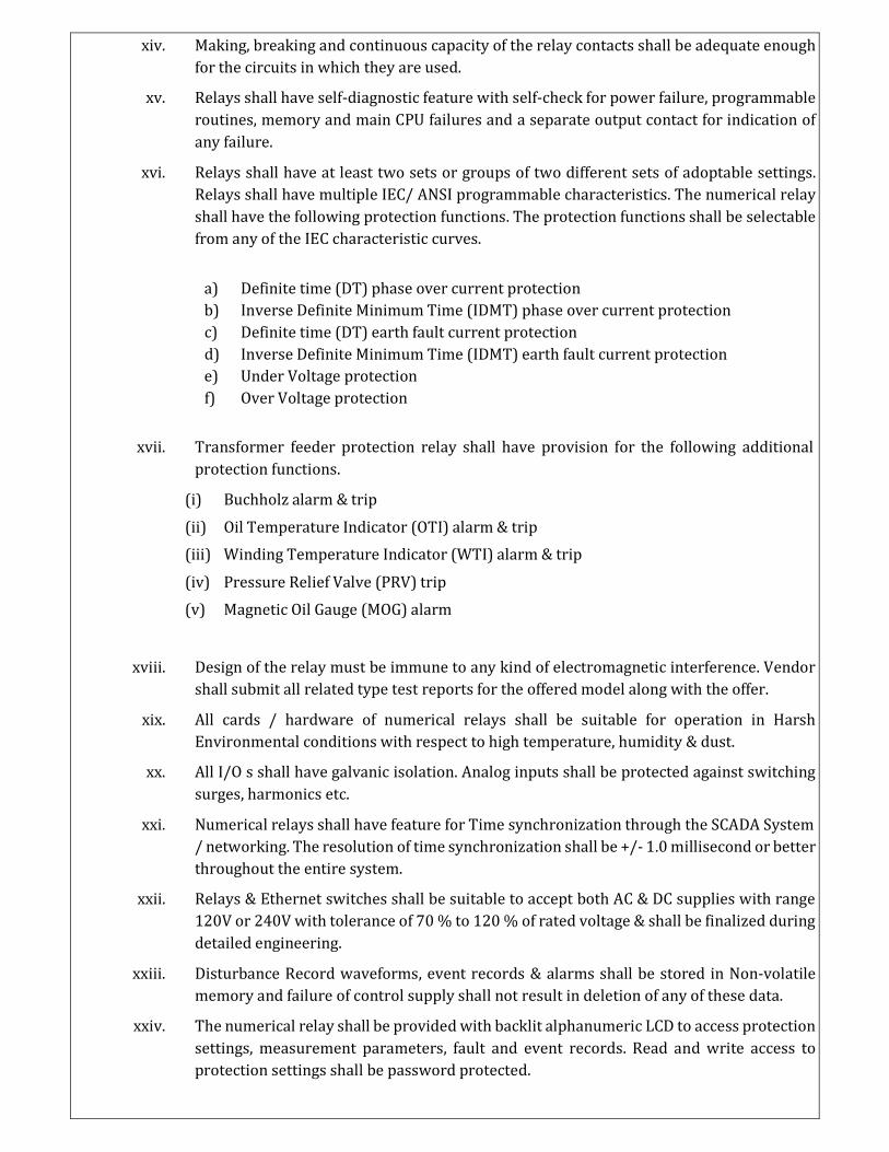
xiv. Making, breaking and continuous capacity of the relay contacts shall be adequate enough
for the circuits in which they are used.
xv. Relays shall have self-diagnostic feature with self-check for power failure, programmable
routines, memory and main CPU failures and a separate output contact for indication of
any failure.
xvi. Relays shall have at least two sets or groups of two different sets of adoptable settings.
Relays shall have multiple IEC/ ANSI programmable characteristics. The numerical relay
shall have the following protection functions. The protection functions shall be selectable
from any of the IEC characteristic curves.
a) Definite time (DT) phase over current protection
b) Inverse Definite Minimum Time (IDMT) phase over current protection
c) Definite time (DT) earth fault current protection
d) Inverse Definite Minimum Time (IDMT) earth fault current protection
e) Under Voltage protection
f) Over Voltage protection
xvii. Transformer feeder protection relay shall have provision for the following additional
protection functions.
(i) Buchholz alarm & trip
(ii) Oil Temperature Indicator (OTI) alarm & trip
(iii) Winding Temperature Indicator (WTI) alarm & trip
(iv) Pressure Relief Valve (PRV) trip
(v) Magnetic Oil Gauge (MOG) alarm
xviii. Design of the relay must be immune to any kind of electromagnetic interference. Vendor
shall submit all related type test reports for the offered model along with the offer.
xix. All cards / hardware of numerical relays shall be suitable for operation in Harsh
Environmental conditions with respect to high temperature, humidity & dust.
xx. All I/O s shall have galvanic isolation. Analog inputs shall be protected against switching
surges, harmonics etc.
xxi. Numerical relays shall have feature for Time synchronization through the SCADA System
/ networking. The resolution of time synchronization shall be +/- 1.0 millisecond or better
throughout the entire system.
xxii. Relays & Ethernet switches shall be suitable to accept both AC & DC supplies with range
120V or 240V with tolerance of 70 % to 120 % of rated voltage & shall be finalized during
detailed engineering.
xxiii. Disturbance Record waveforms, event records & alarms shall be stored in Non-volatile
memory and failure of control supply shall not result in deletion of any of these data.
xxiv. The numerical relay shall be provided with backlit alphanumeric LCD to access protection
settings, measurement parameters, fault and event records. Read and write access to
protection settings shall be password protected.
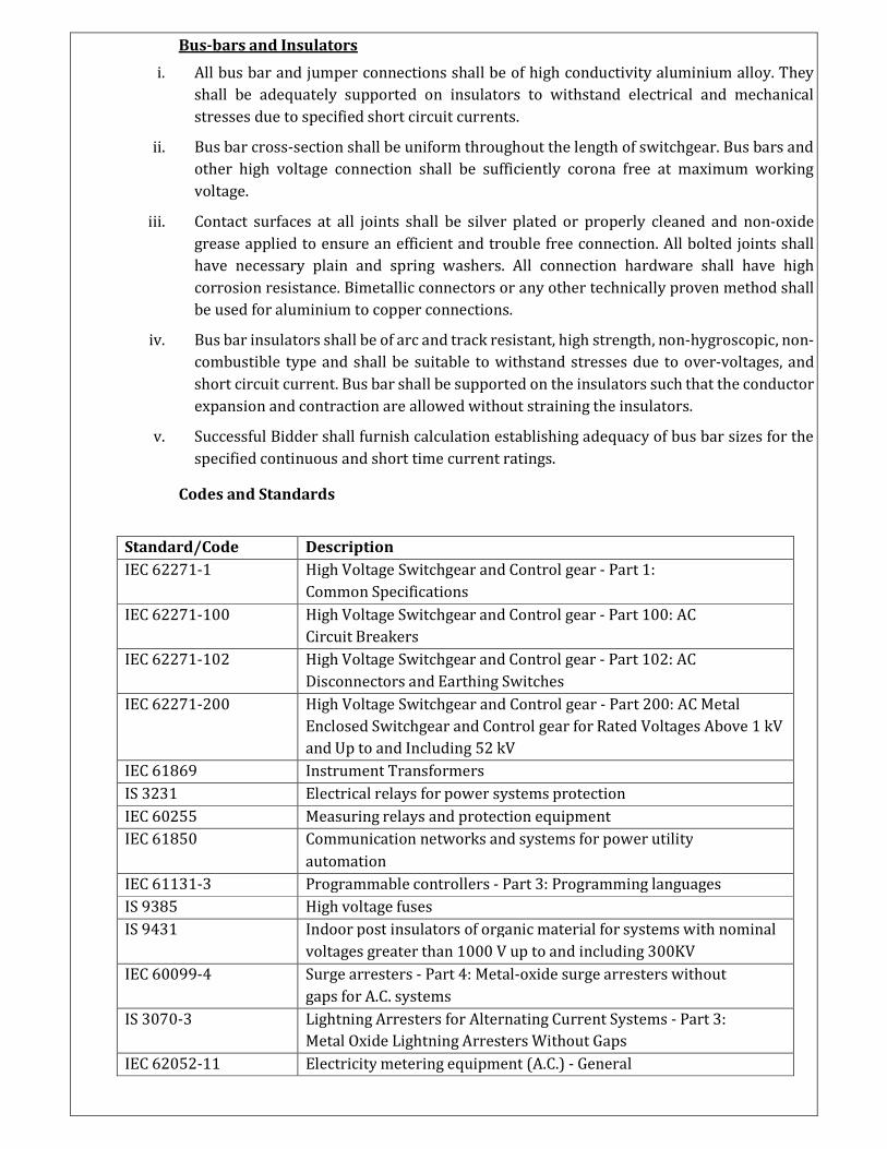
Bus-bars and Insulators
i. All bus bar and jumper connections shall be of high conductivity aluminium alloy. They
shall be adequately supported on insulators to withstand electrical and mechanical
stresses due to specified short circuit currents.
ii. Bus bar cross-section shall be uniform throughout the length of switchgear. Bus bars and
other high voltage connection shall be sufficiently corona free at maximum working
voltage.
iii. Contact surfaces at all joints shall be silver plated or properly cleaned and non-oxide
grease applied to ensure an efficient and trouble free connection. All bolted joints shall
have necessary plain and spring washers. All connection hardware shall have high
corrosion resistance. Bimetallic connectors or any other technically proven method shall
be used for aluminium to copper connections.
iv. Bus bar insulators shall be of arc and track resistant, high strength, non-hygroscopic, non-
combustible type and shall be suitable to withstand stresses due to over-voltages, and
short circuit current. Bus bar shall be supported on the insulators such that the conductor
expansion and contraction are allowed without straining the insulators.
v. Successful Bidder shall furnish calculation establishing adequacy of bus bar sizes for the
specified continuous and short time current ratings.
Codes and Standards
Standard/Code Description
IEC 62271-1 High Voltage Switchgear and Control gear - Part 1:
Common Specifications
IEC 62271-100 High Voltage Switchgear and Control gear - Part 100: AC
Circuit Breakers
IEC 62271-102 High Voltage Switchgear and Control gear - Part 102: AC
Disconnectors and Earthing Switches
IEC 62271-200 High Voltage Switchgear and Control gear - Part 200: AC Metal
Enclosed Switchgear and Control gear for Rated Voltages Above 1 kV
and Up to and Including 52 kV
IEC 61869 Instrument Transformers
IS 3231 Electrical relays for power systems protection
IEC 60255 Measuring relays and protection equipment
IEC 61850 Communication networks and systems for power utility
automation
IEC 61131-3 Programmable controllers - Part 3: Programming languages
IS 9385 High voltage fuses
IS 9431 Indoor post insulators of organic material for systems with nominal
voltages greater than 1000 V up to and including 300KV
IEC 60099-4 Surge arresters - Part 4: Metal-oxide surge arresters without
gaps for A.C. systems
IS 3070-3 Lightning Arresters for Alternating Current Systems - Part 3:
Metal Oxide Lightning Arresters Without Gaps
IEC 62052-11 Electricity metering equipment (A.C.) - General
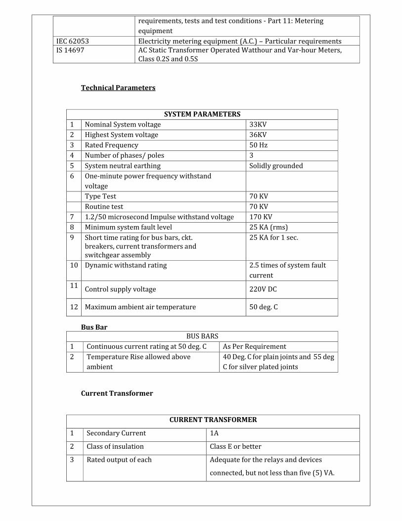
IEC 62053
IS 14697
requirements, tests and test conditions - Part 11: Metering
equipment
Electricity metering equipment (A.C.) – Particular requirements
AC Static Transformer Operated Watthour and Var-hour Meters,
Class 0.2S and 0.5S
Technical Parameters
SYSTEM PARAMETERS
1 Nominal System voltage 33KV
2 Highest System voltage 36KV
3 Rated Frequency 50 Hz
4 Number of phases/ poles 3
5 System neutral earthing Solidly grounded
6 One-minute power frequency withstand
voltage
Type Test 70 KV
Routine test 70 KV
7 1.2/50 microsecond Impulse withstand voltage 170 KV
8 Minimum system fault level 25 KA (rms)
9 Short time rating for bus bars, ckt.
breakers, current transformers and
switchgear assembly
25 KA for 1 sec.
10 Dynamic withstand rating 2.5 times of system fault
current
11 Control supply voltage 220V DC
12 Maximum ambient air temperature 50 deg. C
Bus Bar
BUS BARS
1 Continuous current rating at 50 deg. C As Per Requirement
2 Temperature Rise allowed above
ambient
40 Deg. C for plain joints and 55 deg
C for silver plated joints
Current Transformer
CURRENT TRANSFORMER
1 Secondary Current 1A
2 Class of insulation Class E or better
3 Rated output of each Adequate for the relays and devices
connected, but not less than five (5) VA.
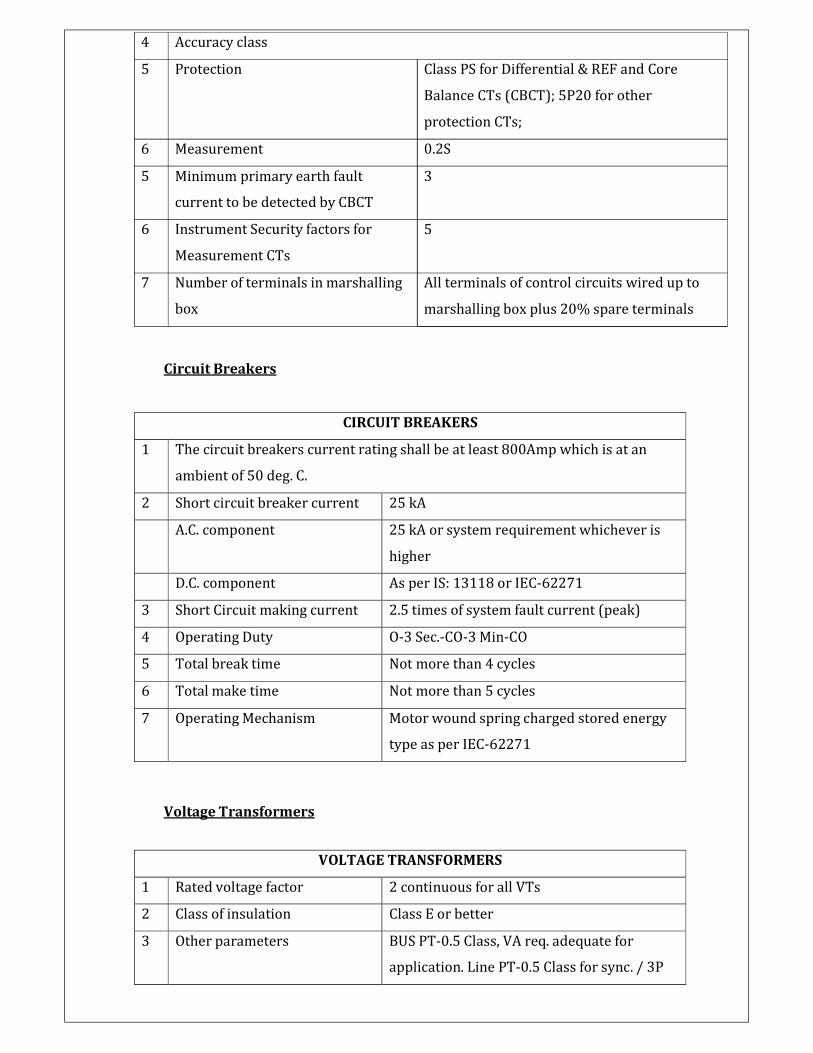
4 Accuracy class
5 Protection Class PS for Differential & REF and Core
Balance CTs (CBCT); 5P20 for other
protection CTs;
6 Measurement 0.2S
5 Minimum primary earth fault
current to be detected by CBCT
6 Instrument Security factors for
Measurement CTs
7 Number of terminals in marshalling
box
3
5
All terminals of control circuits wired up to
marshalling box plus 20% spare terminals
Circuit Breakers
CIRCUIT BREAKERS
1 The circuit breakers current rating shall be at least 800Amp which is at an
ambient of 50 deg. C.
2 Short circuit breaker current 25 kA
A.C. component 25 kA or system requirement whichever is
higher
D.C. component As per IS: 13118 or IEC-62271
3 Short Circuit making current 2.5 times of system fault current (peak)
4 Operating Duty O-3 Sec.-CO-3 Min-CO
5 Total break time Not more than 4 cycles
6 Total make time Not more than 5 cycles
7 Operating Mechanism Motor wound spring charged stored energy
type as per IEC-62271
Voltage Transformers
VOLTAGE TRANSFORMERS
1 Rated voltage factor 2 continuous for all VTs
2 Class of insulation Class E or better
3 Other parameters BUS PT-0.5 Class, VA req. adequate for
application. Line PT-0.5 Class for sync. / 3P
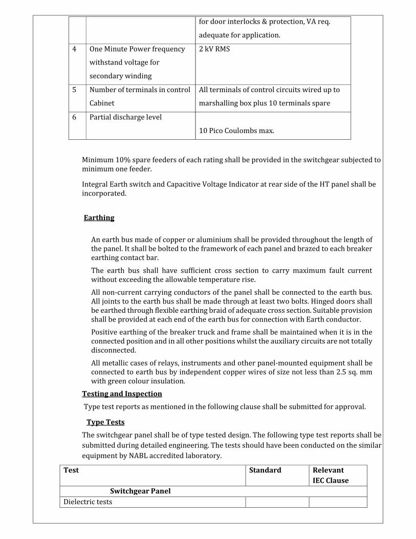
4 One Minute Power frequency
withstand voltage for
secondary winding
5 Number of terminals in control
Cabinet
6 Partial discharge level
for door interlocks & protection, VA req.
adequate for application.
2 kV RMS
All terminals of control circuits wired up to
marshalling box plus 10 terminals spare
10 Pico Coulombs max.
Minimum 10% spare feeders of each rating shall be provided in the switchgear subjected to
minimum one feeder.
Integral Earth switch and Capacitive Voltage Indicator at rear side of the HT panel shall be
incorporated.
Earthing
An earth bus made of copper or aluminium shall be provided throughout the length of
the panel. It shall be bolted to the framework of each panel and brazed to each breaker
earthing contact bar.
The earth bus shall have sufficient cross section to carry maximum fault current
without exceeding the allowable temperature rise.
All non-current carrying conductors of the panel shall be connected to the earth bus.
All joints to the earth bus shall be made through at least two bolts. Hinged doors shall
be earthed through flexible earthing braid of adequate cross section. Suitable provision
shall be provided at each end of the earth bus for connection with Earth conductor.
Positive earthing of the breaker truck and frame shall be maintained when it is in the
connected position and in all other positions whilst the auxiliary circuits are not totally
disconnected.
All metallic cases of relays, instruments and other panel-mounted equipment shall be
connected to earth bus by independent copper wires of size not less than 2.5 sq. mm
with green colour insulation.
Testing and Inspection
Type test reports as mentioned in the following clause shall be submitted for approval.
Type Tests
The switchgear panel shall be of type tested design. The following type test reports shall be
submitted during detailed engineering. The tests should have been conducted on the similar
equipment by NABL accredited laboratory.
Test Standard Relevant
IEC Clause
Switchgear Panel
Dielectric tests
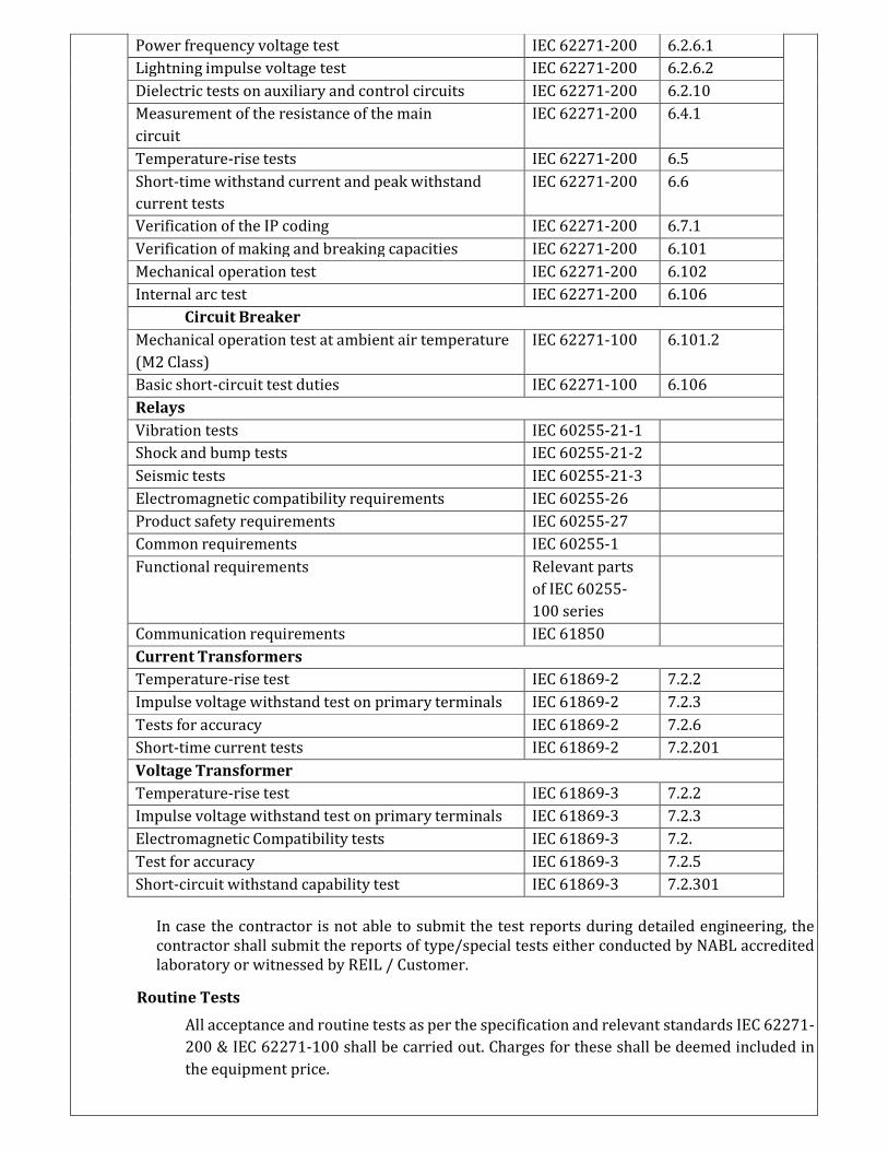
Power frequency voltage test IEC 62271-200 6.2.6.1
Lightning impulse voltage test IEC 62271-200 6.2.6.2
Dielectric tests on auxiliary and control circuits IEC 62271-200 6.2.10
Measurement of the resistance of the main
circuit
IEC 62271-200 6.4.1
Temperature-rise tests IEC 62271-200 6.5
Short-time withstand current and peak withstand
current tests
IEC 62271-200 6.6
Verification of the IP coding IEC 62271-200 6.7.1
Verification of making and breaking capacities IEC 62271-200 6.101
Mechanical operation test IEC 62271-200 6.102
Internal arc test IEC 62271-200 6.106
Circuit Breaker
Mechanical operation test at ambient air temperature
(M2 Class)
IEC 62271-100 6.101.2
Basic short-circuit test duties IEC 62271-100 6.106
Relays
Vibration tests IEC 60255-21-1
Shock and bump tests IEC 60255-21-2
Seismic tests IEC 60255-21-3
Electromagnetic compatibility requirements IEC 60255-26
Product safety requirements IEC 60255-27
Common requirements IEC 60255-1
Functional requirements Relevant parts
of IEC 60255-
100 series
Communication requirements IEC 61850
Current Transformers
Temperature-rise test IEC 61869-2 7.2.2
Impulse voltage withstand test on primary terminals IEC 61869-2 7.2.3
Tests for accuracy IEC 61869-2 7.2.6
Short-time current tests IEC 61869-2 7.2.201
Voltage Transformer
Temperature-rise test IEC 61869-3 7.2.2
Impulse voltage withstand test on primary terminals IEC 61869-3 7.2.3
Electromagnetic Compatibility tests IEC 61869-3 7.2.
Test for accuracy IEC 61869-3 7.2.5
Short-circuit withstand capability test IEC 61869-3 7.2.301
In case the contractor is not able to submit the test reports during detailed engineering, the
contractor shall submit the reports of type/special tests either conducted by NABL accredited
laboratory or witnessed by REIL / Customer.
Routine Tests
All acceptance and routine tests as per the specification and relevant standards IEC 62271-
200 & IEC 62271-100 shall be carried out. Charges for these shall be deemed included in
the equipment price.
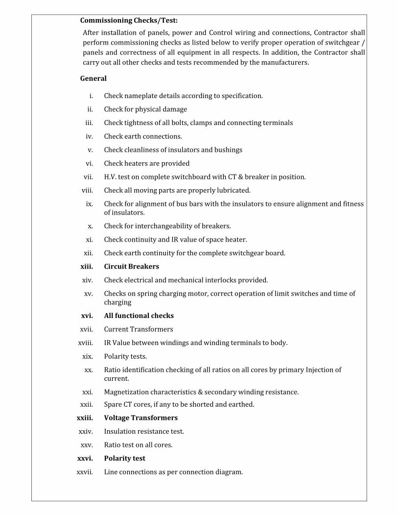
Commissioning Checks/Test:
After installation of panels, power and Control wiring and connections, Contractor shall
perform commissioning checks as listed below to verify proper operation of switchgear /
panels and correctness of all equipment in all respects. In addition, the Contractor shall
carry out all other checks and tests recommended by the manufacturers.
General
i. Check nameplate details according to specification.
ii. Check for physical damage
iii. Check tightness of all bolts, clamps and connecting terminals
iv. Check earth connections.
v. Check cleanliness of insulators and bushings
vi. Check heaters are provided
vii. H.V. test on complete switchboard with CT & breaker in position.
viii. Check all moving parts are properly lubricated.
ix. Check for alignment of bus bars with the insulators to ensure alignment and fitness
of insulators.
x. Check for interchangeability of breakers.
xi. Check continuity and IR value of space heater.
xii. Check earth continuity for the complete switchgear board.
xiii. Circuit Breakers
xiv. Check electrical and mechanical interlocks provided.
xv. Checks on spring charging motor, correct operation of limit switches and time of
charging
xvi. All functional checks
xvii. Current Transformers
xviii. IR Value between windings and winding terminals to body.
xix. Polarity tests.
xx. Ratio identification checking of all ratios on all cores by primary Injection of
current.
xxi. Magnetization characteristics & secondary winding resistance.
xxii. Spare CT cores, if any to be shorted and earthed.
xxiii. Voltage Transformers
xxiv. Insulation resistance test.
xxv. Ratio test on all cores.
xxvi. Polarity test
xxvii. Line connections as per connection diagram.
xxviii. Cubicle Wiring
xxix. Check all switch developments.
xxx. It should be made sure that the wiring is as per relevant drawings.
xxxi. All interconnections between panels shall similarly be checked.
xxxii. All the wires shall be checked for IR value to earth.
xxxiii. Functional checking of all control circuit e.g. closing, tripping interlock, supervision
and alarm circuit including proper functioning of component / equipment.
xxxiv. Check terminations and connections.
xxxv. Wire ducting.
Measuring Instruments
All the measuring instruments shall be digital, flush mounting type with communication
Facility.
All feeders shall be provided with digital Multi-Function Meter (MFM). ABT/Tri Vector
Meter (TVM) shall be provided for the solar incomer feeder at 33KV.The, accuracy class
of MFM shall be 0.5 and that of ABT/TVM shall be 0.2S.
Measuring instruments shall have provision to display the following parameters.
(i) Line and phase voltages
(ii) Line and phase currents
(iii) Active power, Reactive power, Apparent power
(iv) Frequency
(v) Power factor
(vi) Total Harmonic Distortion (THD)
Warranty
The HT panel unit shall be warranted for minimum of 5 (five) years against all material/
manufacturing defects and workmanship.
Approval
Documents/Drawings
i. Guaranteed Technical Particular (GTP) Datasheet.
ii. General Arrangement (GA) Drawing and Foundation details
iii. Schematic diagram
iv. Bus bar sizing calculation
v. Bill of Materials
vi. Quality Assurance Plan (QAP)
6. Compact Sub-Station (CSS)
Standards and Codes
Compact Sub-Station (CSS) shall comply with the latest edition of the following standard
including amendments.
Standard/Code Description
IEC 62271-202 High-voltage/ low-voltage prefabricated substation
Design Criteria
Compact Sub-Station shall consist of 800KVA, PCU output voltage/33 KV, ONAN inverter
duty transformer, and 33KV SF6 insulated/VCB breaker panel.LT switchgear of suitable
voltage in compliance with inverter maximum output voltage with all accessories,
interconnections, fittings and auxiliary equipment. The Contractor may propose to keep
PCU also inside the CSS. The complete unit shall be installed on a substation plinth (base)
as Outdoor substation.
The pre-fabricated compact substation shall be designed for
(a) Compactness
(b) Fast installation
(c) Maintenance free operation
(d) Safety for operator & public.
For continuous operation at specified ratings, temperature rise of the all the components
of CSS shall be limited to permissible values stipulated in the relevant standard and / or
this specification.
Service Conditions
The Package substation shall be suitable for continuous operation under the basic service
conditions indicated below.
i) Ambient Temperature 50°C
ii) Relative Humidity Up to 95%
iii) Altitude Up to 1000 m
Construction
The CSS shall have separate compartments for transformer, RMU and LT switchgear with
suitable safety barriers. Each compartment shall be provided with doors and pad locking
arrangement. All doors shall have proper interlocks for safety of the operator.
High Voltage terminals of the transformer shall be connected to switchgear using
Aluminium cable/flexible bus-bar.
The CSS Enclosure shall be made of sheet steel tropicalized to local weather conditions.
Degree of protection of the enclosure shall be NEMA 4X or IP 66 for HT & LT switchgear
compartment and NEMA 3 (or IP 54) for transformer compartment.
The Enclosure shall be painted with the colour approved by the REIL / Customer. The
paint shall be carefully selected to withstand tropical heat, rain and salt mist. The paint
shall not scale off or crinkle or be removed by abrasion due to normal handling.
All enclosures/metal frames of CSS, transformer, RMU and LT switchgear shall be
properly earthed. The continuity of the earth system shall be ensured taking into account
the thermal and mechanical stress caused by the current it may have to carry.
Adequate ventilation arrangement shall be provided for natural ventilation of the CSS.
Internal lighting with door operated switch shall be provided for each compartment
separately.
The CSS shall contain all safety accessories like voltage detection rod, fire extinguishers,
gloves etc.
Danger Boards, Safety notices, manufacturer’s operating instructions etc shall be durable
and clearly legible.
The CSS shall be completely assembled at factory. No site assembly is allowed.
Warranty
The Compact Sub-station shall be warranted for minimum of 5 (five) years against all
material/ manufacturing defects and workmanship.
Test Certificates/Reports
Type test reports as mentioned in the following clause shall be submitted for approval.
Type Tests
The CSS shall be of type tested design. Type test reports as per IEC 62271-202 shall be
submitted during detailed engineering. The tests should have been conducted on the similar
equipment by NABL accredited laboratory.
In case the contractor is not able to submit the test reports during detailed engineering, the
contractor shall submit the reports of type/special tests either conducted by NABL
accredited laboratory or witnessed by REIL / Customer.
Routine Tests
Routine tests and acceptance tests shall be as per the Quality Assurance Plan (QAP) approved
by the REIL / Customer.
7. AC CABLES
Standards and Codes
All AC Cables shall conform to the following standards and codes.
IS 7098 Cross linked polyethylene insulated PVC sheathed cables, Part
1: For working voltage up to and including 1100 V
IS 7098 Cross linked Polyethylene Insulated Thermoplastics Sheathed
Cables Part 2:for Working Voltages from 3.3 kV up to and
Including 33 kV
The minimum size of cable based on 33 kV voltage level power application shall be
3CX150Sqmm.
All AC cables shall be flame retardant, low smoke (FRLS) type designed to withstand all
mechanical, electrical and thermal stresses develop under steady state and transient
Related Documents