1 High Performance Building Science Workshop on 7/31/09 © copyrighted 2009 High Performance High Performance Building Science Building Science Workshop: Workshop: Village of Civano Village of Civano Presented by Presented by C. Alan Nichols, P.E., CEM, GBE, LEED AP C. Alan Nichols, P.E., CEM, GBE, LEED AP Jason Laros, LEED AP Jason Laros, LEED AP Justin Cupp Justin Cupp Design Tools for the 21st Century CIVANO, located in Tucson, Arizona, was originally conceived as the "Solar Village" as an outgrowth of builder and consumer interest in solar designs with a natural, and appropriate extension of desert living. Led by the Metropolitan Energy Commission, a number of local builders and environmentalists obtained a commitment from the Arizona Energy Office to fund the planning and design of the prototype community. As research progressed, the planners soon began to contemplate comprehensive extensions of their original idea including energy and water conservation, solid waste reduction, and lower air pollution. "Solar Village" soon became a much larger concept, and the Community of CIVANO began to take shape. It was to be more sustainable, and it was to incorporate many of the compact, life- enhancing and socially integrated aspects of American's small towns.

21 Design Work Shop 7.30.2009
Aug 20, 2015
Welcome message from author
This document is posted to help you gain knowledge. Please leave a comment to let me know what you think about it! Share it to your friends and learn new things together.
Transcript

1
High Performance Building Science Workshop on 7/31/09© copyrighted 2009
High Performance High Performance Building Science Building Science
Workshop:Workshop:Village of CivanoVillage of Civano
Presented byC. Alan Nichols, P.E., CEM, GBE, LEED AP
Jason Laros, LEED APJustin Cupp
Presented byPresented byC. Alan Nichols, P.E., CEM, GBE, LEED APC. Alan Nichols, P.E., CEM, GBE, LEED AP
Jason Laros, LEED APJason Laros, LEED APJustin CuppJustin Cupp
Design Tools for the 21st Century
CIVANO, located in Tucson, Arizona, was originally conceived as the "Solar Village" as an outgrowth of builder and consumer interest in solar designs with a natural, and appropriate extension of desert living. Led by the Metropolitan Energy Commission, a number of local builders and environmentalists obtained a commitment from the Arizona Energy Office to fund the planning and design of the prototype community. As research progressed, the planners soon began to contemplate comprehensive extensions of their original idea including energy and water conservation, solid waste reduction, and lower air pollution. "Solar Village" soon became a much larger concept, and the Community of CIVANO began to take shape. It was to be more sustainable, and it was to incorporate many of the compact, life-enhancing and socially integrated aspects of American's small towns.

2
High Performance Building Science Workshop on 7/31/09© copyrighted 2009
SESSION ONESESSION ONE
WATER CONSERVATIONWATER CONSERVATION
By:By:Justin CuppJustin Cupp
OwnerOwnerHome Improvement & Maintenance, Inc.Home Improvement & Maintenance, Inc.

3
High Performance Building Science Workshop on 7/31/09© copyrighted 2009
Conservation Of WaterConservation Of WaterLow Water Use Landscape Low Water Use Landscape RequiredRequiredDrastically Reduce Potable Drastically Reduce Potable Water Used for IrrigationWater Used for Irrigation
Reclaimed WaterReclaimed Water•• Optional at home, Optional at home,
required in common required in common areasareas
Rain Water CisternsRain Water Cisterns•• Common retrofit in Common retrofit in
Phase IPhase IGrey Water SystemsGrey Water Systems
•• Few have attempted Few have attempted grey water systemsgrey water systems
On Site RetentionOn Site Retention•• Used in Phase II at Used in Phase II at
the home level and the home level and common areascommon areas
Civano neighborhoods have performed well in the area of water conservation.
Desert landscaping, reclaimed water in neighborhood I, and several rainwater collection systems are used to achieve this success.

4
High Performance Building Science Workshop on 7/31/09© copyrighted 2009
Landscape And Irrigation Landscape And Irrigation RequirementsRequirements
5.0 LANDSCAPE AND IRRIGATION REQUIREMENTS5.1 LANDSCAPE REQUIREMENTS
5.1.1 Soil pretreatment. Due to construction site compaction, the soils in planting areas must be pretreated to ensure adequate infiltration of harvested water. Soil Pretreatment techniques, locations and schematics should be provided in the Implementation Plan. 5.1.2 Plant selection and placement. Plants selected for use within descreet WHIAs shall have compatible water needs. Plants shall be positioned to account for the level of expected inundation. They may be placed on the bottoms or sides of recessed areas or the tops of adjacent soil where their roots can grow toward adjacent moist soil. Other placement considerations shall include sun exposure, maintenance requirements, shape, form and aesthetics5.1.3 Mulch placement. Mulch shall be positioned away from the base of plant trunks to avoid excessive moisture there.
5.2 IRRIGATION REQUIREMENTS 5.2.1 Irrigation systems shall be fitted with irrigation controllers and shall be capable of monitoring and responding to plant water needs through the use of soil moisture gauges, tensiometers, weather stations and/or evapotranspiration data. The irrigation technology chosen should be capable of preventing the irrigation system from running if sufficient soil moisture is present to support the vegetation. All systems shall include rain shut off devices. Instruments shall be correctly placed to ensure plants are kept healthy using a combination of harvested and non-harvested water and to ensure the stated water-saving goal of the Ordinance is met. 5.2.2 Irrigation timers shall not be used for primary irrigation system control except in the following situations: 3-year plant establishment period, and facilities with container systems that are inter- plumbed with other water supplies to provide direct irrigation of landscape plants.5.2.3 Irrigation plans must include calculations for estimated water use based on assumptions about plant water demand and canopy size used in the Site Water Budget. 5.2.4 Drip irrigation systems shall meet and maintain a minimum 80% emission uniformity.

5
High Performance Building Science Workshop on 7/31/09© copyrighted 2009
Creating a Water Budget to Live Creating a Water Budget to Live ByBy
Plant water needsPlant water needsWater Storage Water Storage SummarySummaryLandscape Landscape Collection AreaCollection AreaPavement Pavement Collection AreaCollection AreaWater Supply Water Supply Estimate (Rooftop Estimate (Rooftop ““footprintfootprint””))
4.2 WATER HARVESTING IMPLEMENTATION PLANThe Water Harvesting Implementation Plan (Implementation Plan) shall consist of a separate sheet with a plan view layout of the site. The format and design of the Implementation Plan shall be consistent with the base plan, be it a Plat (DS
2-03), Site Plan (DS 2-04), Development Plan (DS 2-05), or their successor documents, as applicable. The Implementation Plan shall include all details necessary and appropriate to convey the technical concept of the water harvesting system design and to facilitate proper installation and maintenance of the water harvesting system in compliance with the Ordinance and this standard.
Submittal of the Implementation Plan for water harvesting shall be made concurrently with the Development Plan and Landscape Plan. Revision of the Implementation Plan may be required in conjunction with preparation of the Grading Plan in order to coordinate the construction details and specifications.
4.2.1 The following general information shall be provided on the Implementation Plan: A. The case number shall be located in the lower right corner of the plan.B. The means by which monthly rainfall data will be obtained and recordedC. The means by which monthly irrigation data will be obtained and recordedD. Soil pretreatment techniques, locations and schematicsE. Maintenance notesF. Monitoring and Annual Reporting Requirements4.2.2 Tabulated Data
The Implementation Plan shall include a table detailing information for each identified Water Harvesting Infiltration Area (WHIA) at the site, and for the site as a whole, as described below. A. General information: 1. WHIA identifier
2. Spatial size (square feet) of WHIA3. Average depth (feet) of WHIA4. Capacity (gallons) of WHIA5. Type and general location where sensors that control the irrigation system will be placed
B. Plant canopy information 1. Plant canopy area (square feet) that is served by each WHIA, consisting of the sum of understory, midstory and overstory plant canopies at 60 percent of the mature plant size
2. Plant water demand category3. Total annual plant water demand (gallons)
C. Information about passive and/or active water harvesting systems serving the Water Harvesting Infiltration Area:1. For the Subwatershed passively serving each WHIA: a. Subwatershed identifierb. Spatial size (square feet) of the subwatershedc. Material the subwatershed is made ofd. Percent of plant water demand provided by this subwatershed to the WHIA2. For the containment system actively serving each WHIA:a. Tank Identifierb. Tank capacity (gallons)c. Tank location d. Percent of plant water demand provided by this tank to the WHIA
D. Any additional information needed to document how 50% of irrigation demand will be met using harvested water.E. Data tabulated for the entire site:
1. Percent of annual landscape water demand met using harvested water2. Water harvesting capacity that will offset standard retention/detention basin size.
F. Additional plan information may be requested or required by the Development Services Department (DSD) Director to evaluate rainwater-harvesting proposals.
4.2.3Mapped Data The Implementation Plan shall graphically show the following, drawing on tabulated data:A. For the area receiving infiltrated water, the WHIA:
1.Indicate the boundary of each WHIA and show its identifier 2. Use arrows to show water flow directions within WHIA, including flow direction at inlets and outlets3. Show location where sensors that control the irrigation system will be placed
B. Plant Canopy information: Indicate the boundary of the plant canopy area to be served by each WHIA C. Information about Passive and/or Active Water Harvesting Systems serving each WHIA:
1. Passively supplied water: a. Indicate the Subwatershed Area and show its identifierb. Use arrows to indicate the flow path water will take from source to WHIAc. Indicate spot elevations for the bottoms of water harvesting structures, at spillways, and to define other grades as needed
d. Indicate the location of all surface or subsurface infiltration structures, pipelines, spillways, French drains, scuppers, curb cuts and other infrastructure elements needed to convey, store or overflow passively supplied water, or to control erosion
2. Actively supplied watera. Show tank and show its identifierb. Label tank as delivering water by gravity flow or pumpc. Use arrows to indicate flow path water will take from source to WHIAd. Show additional piping, pump and other infrastructure needed to store, overflow, and convey water to WHIA
4.2.4 Additional InformationAdditional notes shall be provided on the Implementation Plan to ensure current and subsequent site owners and operators are informed of the inspection and maintenance required in Section 6 of this development standard.

6
High Performance Building Science Workshop on 7/31/09© copyrighted 2009
Soil PretreatmentSoil PretreatmentDue to Due to construction site construction site compaction, the compaction, the soils in planting soils in planting areas must be areas must be pretreated to pretreated to ensure adequate ensure adequate infiltration of infiltration of harvested water. harvested water.

7
High Performance Building Science Workshop on 7/31/09© copyrighted 2009
Plant Selection And PlacementPlant Selection And Placement
Plants selected for Plants selected for use within discreet use within discreet WHIAWHIA’’ss shall have shall have compatible water compatible water needs. Plants shall needs. Plants shall be positioned to be positioned to account for the level account for the level of expected of expected inundation.inundation.
Water Harvesting Infiltration Areas. Pervious areas of a site where harvested water collects and soaks into the subsurface to support landscape plants. Water Harvesting Infiltration Areas include exposed soil shaped to hold and infiltrate water, permeable soil subgrades overlain with impervious pavement that receive water via perforated pipes or other conveyance techniques, structured soil overlain with permeable paving, and other strategies that collect water and allow it to soak into the subsurface to support landscape plants.

8
High Performance Building Science Workshop on 7/31/09© copyrighted 2009
Irrigation SystemsIrrigation SystemsIrrigation systems shall be Irrigation systems shall be fitted with irrigation fitted with irrigation controllers and shall be controllers and shall be capable of monitoring and capable of monitoring and responding to plant water responding to plant water needs through the use of needs through the use of soil moisture gauges, soil moisture gauges, tensiometerstensiometers, weather , weather stations and/or stations and/or evapotranspirationevapotranspiration data.data.Drip irrigation systems shall Drip irrigation systems shall meet and maintain a meet and maintain a minimum 80% emission minimum 80% emission uniformityuniformity

9
High Performance Building Science Workshop on 7/31/09© copyrighted 2009
Large Scale Fully IntegratedLarge Scale Fully IntegratedInto Commercial Irrigation Into Commercial Irrigation
SystemSystem
CORPORATE INCOME TAX CREDIT1. The credit is for costs incurred of installing a water conservation system plumbing stub out that collects all graywater sources that end at a plumbing stub out that is separate and distinct from the regular plumbing system. These costs are for installing or including such a system in one or more houses or dwelling units located in Arizona and constructed by the taxpayer,2. This credit is effective for taxable years from and after December 31, 2006. It ends before January 1, 2012. Therefore, the credit is available for tax years 2007, 2008, 2009, 2010 and 2011.3. To qualify for the credit, the stub out must:a. Comply with rules adopted by the Arizona Department of Environmental Quality and that relate to the direct reuse of reclaimed water.b. Meet applicable local building codes.4. The credit cannot exceed $200 for each separate house or dwelling unit.5. If the credit exceeds the tax due on the taxpayer’s tax return, it can be carried forward for five years.6. Co-owner of a business, including corporate partners in a partnership, may each claim only the pro rata share of the credit, based on ownership interest.7. The corporation must make application to the Arizona Department of Revenue (ADOR) on the appropriate ADOR form and must obtain a Credit Certification indicating that the taxpayer is entitled to take this credit and the amount of credit to which the taxpayer is entitled. Application can only be made after actual purchase and installation of the system. . Copies of documentation for installation of the plumbing stub outs, with date of installation and addresses shown, must be attached to the application.8. If the taxpayer’s installation of the stub outs is contingent upon receiving the credit, the taxpayer can contact Rosemary Soto at (602) 716-6595 to see how much room under the credit limitation is available. Although a guarantee of credit availability cannot be provided, a fairly educated guess of credit availability can be made.9. The Credit Certification should be attached to the taxpayer’s corporate income tax return at the time of filing as proof of eligibility.10. The maximum amount of corporate income tax credits the ADOR can certify in a calendar year is $500,000.11. Credits shall be granted on a first come, first served basis.12. If an application is received that, if authorized, would require the ADOR to exceed $500,000, ADOR shall grant that applicant only the remaining credit amount that would not exceed the $500,000 limit.13. ADOR may verify that a water conservation system has been installed by the taxpayer.If you have questions regarding this credit, contact Rosemary Soto at (602) 716-6595. Mail completed applications to:Rosemary Soto, Economic SpecialistOffice of Economic Research and AnalysisArizona Department of RevenueP.O. Box 25248Phoenix, AZ 85002

10
High Performance Building Science Workshop on 7/31/09© copyrighted 2009
Civano Water UseCivano Water Use
Civano I uses more water than Civano II, but less potable water due to the active use of reclaimed water in many of the residences.
Reclaimed water is not being sent to Phase II residences because it is not practical given the costs. However, small, desert landscaped yards in Phase II are probably the driving force behind the overall water savings realized there.

11
High Performance Building Science Workshop on 7/31/09© copyrighted 2009
Civano Phase I vs. Phase IICivano Phase I vs. Phase IICivano I vs Civano II Water Use
0
2
4
6
8
10
12
Apr-06
May-06
Jun-06
Jul-06
Aug-06
Sep-06
Oct-06
Nov-06
Dec-06
Jan-07
Feb-07
Mar-07
ccf p
er M
o
Civano II Total W ater Use Civano I Total

12
High Performance Building Science Workshop on 7/31/09© copyrighted 2009
Civano I & II vs. CityCivano I & II vs. CityCivano I, Civano II, City
02468
10121416
Apr-06
May-06
Jun-06
Jul-06
Aug-06
Sep-06
Oct-06
Nov-06
Dec-06
Jan-07
Feb-07
Mar-07
ccf p
er M
o
City Potable Water Use Civano I Potable Civano II TotalCivano I Reclaimed Civano I Total
Civano I uses more water than Civano II, but less potable water due to the active use of reclaimed water in many of the residences.
Reclaimed water is not being sent to Phase II residences because it is not practical given the costs. However, small, desert landscaped yards in Phase II are probably the driving force behind the overall water savings realized there.

13
High Performance Building Science Workshop on 7/31/09© copyrighted 2009
Total Water SavingsTotal Water Savings
42%42%34%34%Reduction Over City Average Use, TotalReduction Over City Average Use, TotalBaselineBaseline
42%42%58%58%Reduction Over City Average Use, PotableReduction Over City Average Use, Potable
131.1131.175.675.686.286.2TotalTotal
000031.431.412 Month Reclaimed Use (12 Month Reclaimed Use (ccfccf))
131.1131.175.675.654.854.812 Month Potable Use (12 Month Potable Use (ccfccf))
CityCityCivano IICivano IICivano ICivano I20062006--20072007
Here are the percentages. Again, notice Civano I uses less potable water than Civano II, but more water overall.

14
High Performance Building Science Workshop on 7/31/09© copyrighted 2009
COMMERCIAL RAINWATER COMMERCIAL RAINWATER HARVESTING and HARVESTING and
RESIDENTIAL GREY WATER RESIDENTIAL GREY WATER STUBOUTS STUBOUTS ––
TUCSONTUCSON’’S DEVELOPMENTS DEVELOPMENT
STANDARDSTANDARD
Tucson’s Water Challenge
. INTRODUCTIONHarvesting rainwater is a useful strategy for providing supplemental irrigation water to
commercial landscapes, making more efficient use of the desert’s most limited resource: water. The City of Tucson Mayor and Council adopted the Commercial Rainwater Harvesting Ordinance October 14, 2008 to increase the use of harvested rainwater at commercial sites in Tucson and to decrease use of potable and reclaimed water supplies. The ordinance takes effect June 1, 2010.PURPOSE
This Development Standard has been prepared to facilitate effective use of available rainwater resources for landscape irrigation in commercial development as a means of reducing dependency on potable and reclaimed water sources. It clarifies requirements for compliance with Ordinance No. 10597, the Commercial Rainwater Harvesting Ordinance (Ordinance), including the key requirement of meeting 50% of landscape water demand using harvested water. This standard provides:
Design considerations and technical requirements for passive and active water harvesting systems;
Requirements and guidelines for the preparation and implementation of Rainwater Harvesting Plans;
Requirements for landscape and irrigation at water harvesting sitesRecommended maintenance stepsElements required for compliance with the OrdinanceEnforcement provisionsResources to assist applicants in the selection, design and operation of water harvesting
strategies

15
High Performance Building Science Workshop on 7/31/09© copyrighted 2009
Commercial Rainwater Commercial Rainwater Harvesting OrdinanceHarvesting Ordinance
By June of 2010 By June of 2010 all commercial sitesall commercial sites
will be requiredwill be requiredto supplement 50% of to supplement 50% of
landscape water landscape water demanddemand
by collecting rainwaterby collecting rainwateron site.on site.

16
High Performance Building Science Workshop on 7/31/09© copyrighted 2009
City Adopts New Development City Adopts New Development Standard Standard
INTRODUCTION. By minimizing amenity irrigation demands, rainwater harvesting reduces demand on the desert's most limited resource: water.
PURPOSE. The Development Standard has been prepared to facilitate effective use of available rainwater resources for landscape irrigation in commercial development as a means of reducing dependency on potable and reclaimed water sources. It shall clarify requirements for compliance with Ordinance No. 10597, the Commercial Rainwater Harvesting Ordinance.
1.1 INTRODUCTIONHarvesting rainwater is a useful strategy for providing supplemental irrigation water to commercial landscapes, making
more efficient use of the desert’s most limited resource: water. The City of Tucson Mayor and Council adopted the Commercial Rainwater Harvesting Ordinance October 14, 2008 to increase the use of harvested rainwater at commercial sites in Tucson and to decrease use of potable and reclaimed water supplies. The ordinance takes effect June 1, 2010.
1.2 This Development Standard has been prepared to facilitate effective use of available rainwater resources for landscape irrigation in commercial development as a means of reducing dependency on potable and reclaimed water sources. It clarifies requirements for compliance with Ordinance No. 10597, the Commercial Rainwater Harvesting Ordinance (Ordinance), including the key requirement of meeting 50% of landscape water demand using harvested water. This standard provides:
A. Design considerations and technical requirements for passive and active water harvesting systems;B. Requirements and guidelines for the preparation and implementation of Rainwater Harvesting Plans;C. Requirements for landscape and irrigation at water harvesting sitesD. Recommended maintenance stepsE. Elements required for compliance with the OrdinanceF. Enforcement provisionsG. Resources to assist applicants in the selection, design and operation of water harvesting strategies APPLICABILITY
This standard applies to all commercial development plans submitted after June 1, 2010.

17
High Performance Building Science Workshop on 7/31/09© copyrighted 2009
Smart HarvestingSmart Harvesting
Harvesting Harvesting rainwater depends rainwater depends on needon need
DEFINITIONS Other than as provided below, definitions used in this Standard are found in the Development Standards Glossary or Sec. 6.2.0 of the Land Use Code (LUC).Active Water Harvesting. The collection of stormwater runoff into containment systems for storage and later diversion to beneficial uses.Catchment Areas. Areas of a site where water is harvested, including where rain falls directly on plant canopies and pervious Water Harvesting Infiltration Areas, and where rain falls on impervious rooftops, sidewalks, parking lots, driveways and other surfaces from which stormwaterrunoff is directed toward Water Harvesting Infiltration Areas.Catchment Ratio. The ratio of the water harvesting catchment area to the canopy area of the plants that use water harvested from that catchment area. Commercial development. Any new non-residential development that is intended to be used primarily for commercial activities and is subject to applicable City Codes.Containment systems. Above-ground tanks, below-ground tanks, other types of above- and below-ground water-holding containers, and associated pipes and transmission equipment that enable beneficial use of the harvested water. Evapotranspiration (ET). The transfer of water from land surface to the atmosphere through the combination of evaporation and plant transpiration.Impervious Subwatersheds. Discrete nonporous subareas of a site--including rooftops, sidewalks, parking lots, driveways and other impervious areas--that capture stormwater runoff and deliver it through gravity flow to discrete containment systems or Water Harvesting Infiltration Areas. Passive Water Harvesting. The collection of stormwater runoff directly into Water Harvesting Infiltration Areas without the temporary storage of water in a containment system.Plant Canopy Area. The square feet of ground covered by plants and trees as viewed from above for a given area, consisting of the sum of understory, midstory and overstory plant canopies at 60 percent of their mature plant size. Rainwater. Liquid precipitation falling from the sky before it lands on a surface. Stormwater. Rainwater that has landed on a surface becomes stormwater.Water harvesting. The process of intercepting stormwater and putting it to beneficial use.Water Harvesting Infiltration Areas. Pervious areas of a site where harvested water collects and soaks into the subsurface to support landscape plants. Water Harvesting Infiltration Areas include exposed soil shaped to hold and infiltrate water, permeable soil subgrades overlain with impervious pavement that receive water via perforated pipes or other conveyance techniques, structured soil overlain with permeable paving, and other strategies that collect water and allow it to soak into the subsurface to support landscape plants.
Smart harvesting includes an ability to have a balance of high demand and low demand plants to create the appearance of a lush landscape, but drought tolerant. Canopy landscaping is key to reduce the heat island effect and overall water demand.

18
High Performance Building Science Workshop on 7/31/09© copyrighted 2009
Rainwater Harvesting Rainwater Harvesting Techniques Techniques
3.0 DESIGN CONSIDERATIONS AND TECHNICAL REQUIREMENTS Two primary strategies for harvesting water are commonly used in the southwest US to support
landscape water needs. Passive water harvesting is accomplished by infiltrating rainfall and stormwater runoff directly in Water Harvesting Infiltration Areas. Active water harvesting stores harvested water in containment systems located above or below ground so the stored water is available for later beneficial use. The commercial facility may determine the strategy or strategies most appropriate for their site.
19
High Performance Building Science Workshop on 7/31/09© copyrighted 2009
Two Primary StrategiesTwo Primary Strategies
Passive Rainwater Passive Rainwater HarvestingHarvestingActive Rainwater Active Rainwater HarvestingHarvesting
20
High Performance Building Science Workshop on 7/31/09© copyrighted 2009
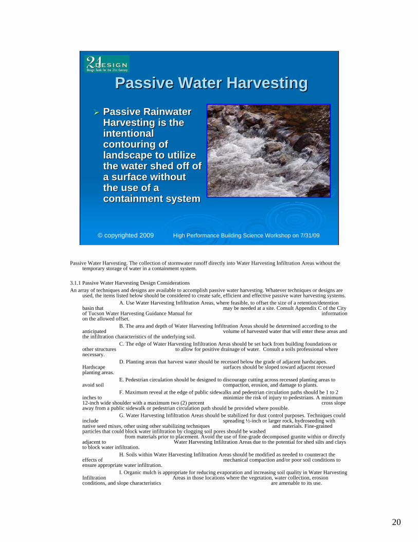
Passive Water HarvestingPassive Water HarvestingPassive Rainwater Passive Rainwater Harvesting is the Harvesting is the intentional intentional contouring of contouring of landscape to utilize landscape to utilize the water shed off of the water shed off of a surface without a surface without the use of a the use of a containment systemcontainment system
Passive Water Harvesting. The collection of stormwater runoff directly into Water Harvesting Infiltration Areas without the temporary storage of water in a containment system.
3.1.1 Passive Water Harvesting Design ConsiderationsAn array of techniques and designs are available to accomplish passive water harvesting. Whatever techniques or designs are
used, the items listed below should be considered to create safe, efficient and effective passive water harvesting systems.A. Use Water Harvesting Infiltration Areas, where feasible, to offset the size of a retention/detention
basin that may be needed at a site. Consult Appendix C of the City of Tucson Water Harvesting Guidance Manual for information on the allowed offset.
B. The area and depth of Water Harvesting Infiltration Areas should be determined according to the anticipated volume of harvested water that will enter these areas and the infiltration characteristics of the underlying soil.
C. The edge of Water Harvesting Infiltration Areas should be set back from building foundations or other structures to allow for positive drainage of water. Consult a soils professional where necessary.
D. Planting areas that harvest water should be recessed below the grade of adjacent hardscapes. Hardscape surfaces should be sloped toward adjacent recessed planting areas.
E. Pedestrian circulation should be designed to discourage cutting across recessed planting areas to avoid soil compaction, erosion, and damage to plants.
F. Maximum reveal at the edge of public sidewalks and pedestrian circulation paths should be 1 to 2 inches to minimize the risk of injury to pedestrians. A minimum 12-inch wide shoulder with a maximum two (2) percent cross slope away from a public sidewalk or pedestrian circulation path should be provided where possible.
G. Water Harvesting Infiltration Areas should be stabilized for dust control purposes. Techniques could include spreading ½-inch or larger rock, hydroseeding with native seed mixes, other using other stabilizing techniques and materials. Fine-grained particles that could block water infiltration by clogging soil pores should be washed
from materials prior to placement. Avoid the use of fine-grade decomposed granite within or directly adjacent to Water Harvesting Infiltration Areas due to the potential for shed silts and clays to block water infiltration.
H. Soils within Water Harvesting Infiltration Areas should be modified as needed to counteract the effects of mechanical compaction and/or poor soil conditions to ensure appropriate water infiltration.
I. Organic mulch is appropriate for reducing evaporation and increasing soil quality in Water Harvesting Infiltration Areas in those locations where the vegetation, water collection, erosion conditions, and slope characteristics are amenable to its use.

21
High Performance Building Science Workshop on 7/31/09© copyrighted 2009
Curb Cuts and GabionsCurb Cuts and Gabions
3.1.2 Passive Water Harvesting Technical RequirementsThe following technical requirements apply to all passive water harvesting systems.
A. Water Harvesting Infiltration Areas shall be designed so thatwater infiltrates into soil within twenty (24) hours.
B. Water Harvesting Infiltration Areas shall be designed to minimize ponding in areas that may create a nuisance for pedestrians. Ponding is not allowed on or over public sidewalks or pedestrian circulation paths.
C. Materials for erosion protection shall be specified, where necessary due to erosion potential. The ground
surface treatment of spillways and other areas that convey water flows shall be able to withstand scouring.
D. Plants with similar water demands shall be placed in the sameareas within Water Harvesting Infiltration Areas.

22
High Performance Building Science Workshop on 7/31/09© copyrighted 2009
Berms and SwalesBerms and Swales
1. Passively supplied water: a. Indicate the Subwatershed Area and show its identifierb. Use arrows to indicate the flow path water will take from
source to WHIAc. Indicate spot elevations for the bottoms of water
harvesting structures, at spillways, and to define other grades as needed
d. Indicate the location of all surface or subsurface infiltration structures, pipelines, spillways, French drains, scuppers, curb cuts and other infrastructure elements needed to convey, store or overflow passively supplied water, or to control erosion

23
High Performance Building Science Workshop on 7/31/09© copyrighted 2009
Active Water HarvestingActive Water HarvestingActive water Active water harvesting is the use of harvesting is the use of containment systems containment systems located above or below located above or below ground, such that the ground, such that the stored water is stored water is available for later, available for later, beneficial, use.beneficial, use.
3.2.1 Active Water Harvesting Design ConsiderationsAn array of techniques and designs are available to accomplish active water harvesting. Whatever
techniques or designs are used, the items listed below should be considered to create safe, efficient and effective active water harvesting systems.
A. Tanks may be constructed of metal, plastic, masonry, reinforced concrete, fiberglass, or other suitable DSD-approved material designed to store water.
B. Above-ground tank construction material or coating should be opaque toprevent sunlight from inducing algae growth. Any portion of a subsurface tank that is exposed to sunlight should be opaque to prevent sunlight from inducing algae growth.
C. A “first flush device” is intended to prevent the dust, grit, leaves and other materials that may accumulate on a roof from being washed into a water harvesting tank. This is accomplished by deflecting the first flush of
stormwater runoff from entering the tank inlet line. The installation of first flush devices is strongly
recommended but not required.D. The dimensions of tanks may be determined by the applicant based on site-
specific design needs. E. Inlet piping may convey water overhead from a roof to a tank, or in a U-shaped
configuration that conveys water to a lower entry point on the tank. The U-shaped configuration should be designed to hold standing water, and
must be pressure rated and sealed to prevent leaks.F. Designs that involve water falling freely through the air before entering a tank
may be allowed provided the design minimizes the entry of light and mosquitoes into the tank.

24
High Performance Building Science Workshop on 7/31/09© copyrighted 2009
Design SchematicsDesign Schematics
3.2.2 Active Water Harvesting Technical RequirementsThe following technical requirements apply to all active water harvesting systems.
A. Materials must be installed per manufacturer’s specifications.B. Consult the International Building Code for applicable regulations.C. Containment system plumbing is per the International Plumbing code.D. Tanks and covers shall be constructed of materials appropriate for use for storing water.E. Above-ground tank construction material must be able to endure UV exposure without loss of structural integrity, or must be UV protected with an appropriate coating. Any portion of a subsurface tank that is exposed to sunlight must be able to endure UV exposure without loss of structural integrity, or must be UV protected with an appropriate coating.F. Tanks shall have a base or foundation that meets manufacturer’s specifications. If no specifications are provided by the manufacturer, the base shall be designed by an engineer.G. Sub-surface storage tanks shall be constructed of materials designed for holding water underground. Below-ground tanks must be designed and installed under the guidance of a civil or structural engineer and/or tanks must be installed per manufacturer’s specifications regarding bedding, setting the tank, strapping or other anchoring device, load bearing characteristics and backfill requirements.H. There must be a structured overflow device installed with the tank to automatically allow excess infill water to exit the tank safely.I. Outlets for overflow pipes shall be positioned so as not to compromise the foundations of buildings or otherstructures.J. If debris screening is used for inlets to tanks, screening must be configured in such a way that an unmaintainedscreen cannot block inlet pipes to a tank. Obstructed screens can prevent water harvesting and back water up on the roof creating unsafe weight load conditions on the roof. K. An overflow mechanism, separate from that provided inside the tank, shall be provided to ensure that watercannot back up on a roof. Roof overflow drains shall not be connected to tanks. L. Tanks must have an inspection port of sufficient size to conduct any necessary visual inspection, maintenance, cleaning, repair or other tasks as described in the manufacturer’s specifications.M. If a manhole is provided with the intent of allowing human access into a tank, it must meet any applicable size and safety requirements.N. Containment systems shall be designed, maintained and operated to prevent mosquito harboring and/or breeding.O. Locations of containment systems shall be in accordance with applicable codes.P. A reverse-pressure backflow-preventer assembly is required when connecting irrigation from an active water harvesting system to a potable water irrigation system to protect the public water system and/or building water system. Q. Systems that include an outlet to allow authorized people to tap water from the active water harvesting system directly shall include a keyed hose bib and be posted with a yellow placard with black text stating the water is non-potable, as required by Section 601.2.2 of the Uniform Plumbing Code. 2. Actively supplied watera. Show tank and show its identifierb. Label tank as delivering water by gravity flow or pumpc. Use arrows to indicate flow path water will take from source to WHIAd. Show additional piping, pump and other infrastructure needed to store, overflow, and convey water to WHIA

25
High Performance Building Science Workshop on 7/31/09© copyrighted 2009
Foundation PrepFoundation Prep
F. Tanks shall have a base or foundation that meets manufacturer’s specifications. If no specifications are provided by the manufacturer, the base shall be designed by an engineer.
Galvanized culverts were not designed to hold water, only to let water pass through. It just so happens that they conveniently do hold water and at a cost effective price. Therefore, there are no specifications from the manufacturer and an engineer will have to be involved.
Installer’s tip: Once pipe and rebar are put in place concrete should be poured to stabilize assemblies while setting the culverts in place. There are two options for pouring. First, a whole slab can be poured followed by a second slab which the culverts would be sitting in. Or the second option would be to spot concrete each assembly, enough to be stable when setting the culverts upright. The second option allows for a more thorough pour, whereas the first option may not allow the two slabs to perfectly adhere to one another.

26
High Performance Building Science Workshop on 7/31/09© copyrighted 2009
Set In PlaceSet In Place
Before setting culvert in concrete, steps must be taken to ensure system will not fail upon an initial rainstorm event:
• If a culvert is cut with a torch, it destroys the galvanization of the steel. Therefore it is important to coat the unprotected part with any product (tar, epoxy or polymer paints, etc.) that adheres to metal and is durable in a wet environment.
• The seam in the culvert will also have to be “painted.”The manufacturer does not rate galvanized culverts for the collection of rainwater therefore the seam on a culvert cannot be guaranteed to be perfectly sealed. Use the same product used to coat the unprotected steel to seal the seam.
Now for lifting the culverts into place.Manpower!...or a crane, whichever you choose, the culvert
just needs to get on the foundation before the concrete dries.
27
High Performance Building Science Workshop on 7/31/09© copyrighted 2009
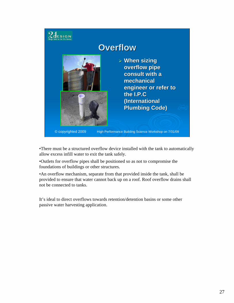
OverflowOverflowWhen sizing When sizing overflow pipe overflow pipe consult with a consult with a mechanical mechanical engineer or refer to engineer or refer to the I.P.C the I.P.C (International (International Plumbing Code)Plumbing Code)
•There must be a structured overflow device installed with the tank to automatically allow excess infill water to exit the tank safely.•Outlets for overflow pipes shall be positioned so as not to compromise the foundations of buildings or other structures.•An overflow mechanism, separate from that provided inside the tank, shall be provided to ensure that water cannot back up on a roof. Roof overflow drains shall not be connected to tanks.
It’s ideal to direct overflows towards retention/detention basins or some other passive water harvesting application.

28
High Performance Building Science Workshop on 7/31/09© copyrighted 2009
LidLidCovers on storage Covers on storage tanks are necessary tanks are necessary to prevent animals to prevent animals and debris from and debris from entering and entering and potentially causing potentially causing cloggingcloggingPrevents algae Prevents algae growth inside tankgrowth inside tankDiscourages Discourages mosquito harboring & mosquito harboring & breedingbreeding
Tanks and covers shall be constructed of materials appropriate for use for storing water.Tanks must have an inspection port of sufficient size to conduct any necessary visual inspection, maintenance, cleaning, repair and other tasks as described in the manufacturer’s specifications.If a manhole is provided with the intent of allowing human access into a tank, it must meet any applicable size and safety requirements.Containment systems shall be designed, maintained and operated to prevent mosquito harboring and/or breeding.

29
High Performance Building Science Workshop on 7/31/09© copyrighted 2009
Connections, Wire Cage, and Connections, Wire Cage, and VineVine
P. A reverse-pressure backflow-preventer assembly is required when connecting irrigation from an active water harvesting system to a potable water irrigation system to protect the public water system and/or building water system.
Q. Systems that include an outlet to allow authorized people to tap water from the active water harvesting system directly shall include a keyed hose bib and be posted with a yellow placard with black text stating the water is non-potable, as required by Section 601.2.2 of the Uniform Plumbing Code.
Mechanical ball valves are now available at any Lowe’s or Home Depot. They cost $10. Unlike traditional irrigation valves they open under no water pressure. However, like traditional irrigation, it allows the user to program it for a regular watering schedule.

30
High Performance Building Science Workshop on 7/31/09© copyrighted 2009
Parking Structure For Parking Structure For Rio NuevoRio Nuevo

31
High Performance Building Science Workshop on 7/31/09© copyrighted 2009
Distribution Of Distribution Of Rainwater To SiteRainwater To Site

32
High Performance Building Science Workshop on 7/31/09© copyrighted 2009
L.U.C. Code for Containment L.U.C. Code for Containment TanksTanks
MEMORANDUMDATE: February 19, 2009 TO: DSD Staff FROM: Craig L. Gross, Zoning AdministratorSUBJECT: Water Harvesting CisternsThe following is a clarification of existing Land Use Code regulations regarding the heights and setbacks of water harvesting cisterns.Cisterns are storage tanks for rainfall collected from a roof or other catchment area. A water harvesting cistern is considered an accessory structure. Land Use Code Sections 3.2.5 and 3.2.6 detail the requirements for accessory structures. The following standards are to be used for reviewing cisterns for zoning purposes:1. A cistern no more than five (5) feet in height and no more than ten (10) square feet in area (approximately 3.5 feet in diameter), may be placed anywhere within a property boundary with zero (0) setbacks from property lines (LUC 3.2.5.2.F).2. A cistern over five (5) feet but no more than six (6) feet in height and no more than ten(10) square feet in area (approximately 3.5 feet in diameter), may be placed anywhere inthe defined side or rear yard (excluding street perimeter yards) with zero (0) setbacksfrom property lines (LUC 3.2.5.2.C) if screened by a wall or fence of equivalent height.3. A cistern over six (6) feet in height or more than ten (10) square feet in area(approximately 3.5 feet in diameter), may be placed anywhere in the defined side or rearyard subject to compliance with the perimeter yard width requirements applicable to thezone. The perimeter yard width requirements may be reduced with the written consent ofthe adjoining, or when separated by an alley, the adjacent property owner, or bycompleting the Design Development Option (DDO) process (LUC 3.2.5.2.C).4. A cistern that is part of and integrated into the design of the principal building may beconsidered part of the principal building as determined by the Zoning Administrator on acase by case basis.5. Maximum height of a cistern in a residential zone is twelve (12) feet (LUC 3.2.5.3.B).Maximum height of a cistern in a commercial zone is equal to the height limitation of theprincipal building (LUC 3.2.5.4.B). All height measurements are from established designgrade at the base of the cistern and includes any foundations or bases required to supportthe cistern.6. Other applicable building codes and fire codes may apply.
33
High Performance Building Science Workshop on 7/31/09© copyrighted 2009
Goals for TucsonGoals for TucsonThe facility may determine The facility may determine the strategy or strategies the strategy or strategies most appropriate for their most appropriate for their site. site. Preparation of the Water Preparation of the Water Budget and Rainwater Budget and Rainwater Harvesting Implementation Harvesting Implementation Plan, by the applicant, Plan, by the applicant, showing appropriate showing appropriate strategy(s), and illustrate strategy(s), and illustrate how the use of the selected how the use of the selected strategy(s) will accomplish strategy(s) will accomplish the 50% off set requirement the 50% off set requirement pursuant to the Ordinance.pursuant to the Ordinance.
4.0 RAINWATER HARVESTING PLANA Rainwater Harvesting Plan shall be submitted with all applications for commercial developments
at which landscaping is required. The Rainwater Harvesting Plan shall consist of two elements: a Site Water Budget and a Water Harvesting Implementation Plan. Preparation of the Rainwater Harvesting Plan elements requires coordination between project managers, site engineers and landscape architects from the inception of the project. The two elements of the Rainwater Harvesting Plan shall illustrate how water harvesting will meet 50 percent of landscape water demand, as required by the Ordinance. Resources describing various water-harvesting strategies are listed in Appendix A to assist—but not limit—applicants as they design water harvesting for their site.
4.1 SITE WATER BUDGET The Site Water Budget shall detail landscape water demand and the harvested water supply needed
to meet 50 percent of this demand. The Site Water Budget and the Water Harvesting Implementation Plan shall be consistent with one another.
A water budget format is shown in Appendix B, along with the background data and assumptions used to develop it. This water budget format will be available to applicants as an Excel spreadsheet. Applicants may use this water budget format to enter site specific data and develop their Site Water Budget. Alternatively, applicants may develop their own Site Water Budget format. Whichever format is used, the submitted Site Water Budget shall incorporate and provide the following:
4.1.1 Water DemandApplicants shall use plant water demand categories and data provided in Appendix B unless an
alternative assumption is provided and satisfactorily justified.4.1.2 Water supply
Applicants shall use the effective monthly rainfall assumptions shown in Appendix B unless an alternative assumption is provided and satisfactorily justified.
4.1.3 OutputOutput of the Site Water Budget shall include calculations showing how 50 percent of landscape
water demand will be met using harvested rainwater, and shall include assumptions and supporting calculations as necessary to document these outputs.

34
High Performance Building Science Workshop on 7/31/09© copyrighted 2009
Corporate And IndividualCorporate And IndividualIncome Tax Credit For Water Income Tax Credit For Water
Conservation SystemsConservation SystemsThis credit is for costs associated with This credit is for costs associated with installing a water conservation system in installing a water conservation system in the taxpayerthe taxpayer’’s residence located in s residence located in Arizona. Arizona. The Tax Credit is 25% or up to $1000, the The Tax Credit is 25% or up to $1000, the lesser of the two.lesser of the two.The tax credit incentive is set to expire in The tax credit incentive is set to expire in 20112011If the credit exceeds the tax due on the If the credit exceeds the tax due on the taxpayertaxpayer’’s tax return, it can be carried s tax return, it can be carried forward for five years.forward for five years.
INDIVIDUAL INCOME TAX CREDITThis credit is for costs associated with installing a water conservation system in the taxpayer’s residence located in Arizona.A water conservation system is a system or series of components or mechanisms that are designed to provide for the collection of rainwater or residential graywater. A water conservation system includes a system that is capable of storing rainwater or residential graywater for future use and reusing the collected water for the same residential property.1. To qualify for the credit, a residential graywater conservation system and its installation must comply with rules that are adopted by the Arizona Department of Environmental Quality (ADEQ) and that relate to the recovery and disposal of graywater. For detailed information please contact ADEQ:• www.azdeq.gov/environ/water/permits/reclaimed.html• Phone number: (602) 771-2300Toll free: (800) 234-56772. This credit is effective for taxable years from and after December 31, 2006. It ends before January 1, 2012. Therefore, the credit is available for tax years 2007, 2008, 2009, 2010 and 2011.3. The credit is equal to the lesser of 25% of the cost of the system or $1,000.4. Only one credit in one tax year is allowed per residence.5. Tax credits claimed over multiple tax year years by a taxpayer for the same residence cannot exceed $1, 000.6. If the credit exceeds the tax due on the taxpayer’s tax return, it can be carried forward for five years.7. The individual must make application to the Arizona Department of Revenue (ADOR) on the appropriate ADOR form and must obtain a Credit Certification indicating that the taxpayer is entitled to take this credit and the amount of credit to which the taxpayer is entitled. Application can only be made after actual purchase and installation of the system. Copies of the receipt for purchase and installation of the system, with date of installation shown, must be attached to the application.9. If the taxpayer’s purchase and installation of the system is contingent upon receiving the credit, the taxpayer can contact Rosemary Soto at (602) 716-6595 to see how much room under the credit limitation is available. Although a guarantee of credit availability cannot be provided, a fairly educated guess of credit availability can be made.10. The Credit Certification must be attached to the taxpayer’s individual income tax return at the time of filing as proof of eligibility.11. The maximum amount of individual income tax credits the ADOR can certify in a calendar year is $250,000.12. Credits shall be granted on a first come, first served basis.13. If an application is received that, if authorized, would require the ADOR to exceed $250,000, ADOR shall grant that applicant only the remaining credit amount that would not exceed the $250,000 limit.14. ADOR may verify that a water conservation system has been installed in the taxpayer’s residence. If you have questions regarding this credit, contact Rosemary Soto at (602) 716-6595. Mail completed applications to:Rosemary Soto, Economic SpecialistOffice of Economic Research and AnalysisArizona Department of RevenueP.O. Box 25248Phoenix, AZ 85002
35
High Performance Building Science Workshop on 7/31/09© copyrighted 2009
How Much Water Does A Rain How Much Water Does A Rain Water Tank System Save Water Tank System Save
Anyway?Anyway?Using 1.5 sqft per tank gallon Using 1.5 sqft per tank gallon
and 9 inches a year:and 9 inches a year:
1 1 -- 4x10 => 8,500 gallons/yr4x10 => 8,500 gallons/yr
1 1 –– 6x12 => 22,800 gallons/yr6x12 => 22,800 gallons/yr
11 11 –– 6x8 => 167,400 gallons/yr6x8 => 167,400 gallons/yr
Assuming all harvested Assuming all harvested rainwater can be used rainwater can be used between eventsbetween events

36
High Performance Building Science Workshop on 7/31/09© copyrighted 2009
How Much ?????How Much ?????Would You Believe:Would You Believe:
A 4 foot A 4 foot diamdiam. by 10 foot tall . by 10 foot tall stores 940 gallons and costs stores 940 gallons and costs about $2,100, or $2.25 a about $2,100, or $2.25 a gallon installed.gallon installed.A 6 foot A 6 foot diamdiam. by 12 foot tall . by 12 foot tall is 2,500 gallons and costs is 2,500 gallons and costs about $3,400, or $1.36 a about $3,400, or $1.36 a gallon installed.gallon installed.Eleven 6 foot Eleven 6 foot diamdiam. by 8 foot . by 8 foot tall tanks is about 18,000 tall tanks is about 18,000 gallons at roughly $1.20 a gallons at roughly $1.20 a gallon.gallon.

37
High Performance Building Science Workshop on 7/31/09© copyrighted 2009
The Future Of The Future Of Rainwater CollectionRainwater Collection
Drinking water on Drinking water on tap (Off Grid Solar)tap (Off Grid Solar)Water supply to Water supply to plumbing fixtures plumbing fixtures in structures such in structures such as toilets as toilets Supplementing Supplementing groundwater groundwater supply onsitesupply onsite

38
High Performance Building Science Workshop on 7/31/09© copyrighted 2009
Residential Gray WaterResidential Gray WaterCodeCode
By 2010 all new By 2010 all new residential residential construction must construction must provide gray water provide gray water stub outs.stub outs.Actual use of the Actual use of the system is not system is not required.required.
39
High Performance Building Science Workshop on 7/31/09© copyrighted 2009
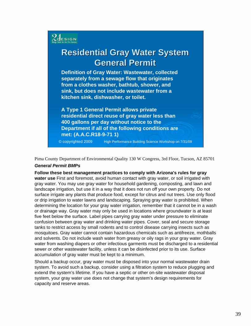
Residential Gray Water System Residential Gray Water System General PermitGeneral Permit
Definition of Gray Water: Wastewater, collected separately from a sewage flow that originates from a clothes washer, bathtub, shower, and sink, but does not include wastewater from a kitchen sink, dishwasher, or toilet.
A Type 1 General Permit allows private residential direct reuse of gray water less than 400 gallons per day without notice to the Department if all of the following conditions are met: (A.A.C.R18-9-71 1)
Pima County Department of Environmental Quality 130 W Congress, 3rd Floor, Tucson, AZ 85701General Permit BMPsFollow these best management practices to comply with Arizona's rules for gray water use First and foremost, avoid human contact with gray water, or soil irrigated with gray water. You may use gray water for household gardening, composting, and lawn and landscape irrigation, but use it in a way that it does not run off your own property. Do not surface irrigate any plants that produce food, except for citrus and nut trees. Use only flood or drip irrigation to water lawns and landscaping. Spraying gray water is prohibited. When determining the location for your gray water irrigation, remember that it cannot be in a wash or drainage way. Gray water may only be used in locations where groundwater is at least five feet below the surface. Label pipes carrying gray water under pressure to eliminate confusion between gray water and drinking water pipes. Cover, seal and secure storage tanks to restrict access by small rodents and to control disease carrying insects such as mosquitoes. Gray water cannot contain hazardous chemicals such as antifreeze, mothballs and solvents. Do not include wash water from greasy or oily rags in your gray water. Gray water from washing diapers or other infectious garments must be discharged to a residential sewer or other wastewater facility, unless it can be disinfected prior to its use. Surface accumulation of gray water must be kept to a minimum.Should a backup occur, gray water must be disposed into your normal wastewater drain system. To avoid such a backup, consider using a filtration system to reduce plugging and extend the system’s lifetime. If you have a septic or other on-site wastewater disposal system, your gray water use does not change that system’s design requirements for capacity and reserve areas.

40
High Performance Building Science Workshop on 7/31/09© copyrighted 2009
Typical Gray Water SystemTypical Gray Water Systemby the UPC Appendix Gby the UPC Appendix G
www.watercasa.org

41
High Performance Building Science Workshop on 7/31/09© copyrighted 2009
Modified Piping 2 Story HomeModified Piping 2 Story Home

42
High Performance Building Science Workshop on 7/31/09© copyrighted 2009
Subsurface Irrigation Subsurface Irrigation Preferred But Not requiredPreferred But Not required

43
High Performance Building Science Workshop on 7/31/09© copyrighted 2009
Surface Irrigation Surface Irrigation Is Allowed If Standing Water Is Is Allowed If Standing Water Is
AvoidedAvoided“First and foremost, avoid human contact with graywater, or soil irrigated with gray water.”

44
High Performance Building Science Workshop on 7/31/09© copyrighted 2009
Design ConsiderationsDesign ConsiderationsGray water will clog Gray water will clog the soil and prevent the soil and prevent percolationpercolationSoil and Soil and infrastructure infrastructure components must components must be adequate to be adequate to withstand a high withstand a high amount of solidsamount of solids

45
High Performance Building Science Workshop on 7/31/09© copyrighted 2009
RecapRecap
Apply all of the aforementioned techniques Apply all of the aforementioned techniques in your landscape and you also will see in your landscape and you also will see the savings!the savings!

46
High Performance Building Science Workshop on 7/31/09© copyrighted 2009
Rodney GlassmanCity of Tucson Ward [email protected]
C. Alan Nichols, P.E., CEM, GBE, LEED APAl Nichols Engineering [email protected]
Justin CuppHome Improvement and Maintenance, [email protected]
Contact Information:
Related Documents