MECHANICAL ENGINEERING IPE 331 PRODUCTION PROCESS TEACHER: DR. NIKHIL RANJAN DHAR, PROFESSOR REFERENCE BOOKS A TEXTBOOK OF PRODUCTION TECHNOLOGY BY P.C. SHARMA MANUFACTURING ENGINEERING AND TECHNOLOGY BY KALPAKJIAN AND SCHMID FUNDAMENTALS OF MODERN MANUFACTURING BY M.P. GROVEER MATERIALS AND PROCESSING IN MANUFACTURING BY DEMGARMO PREPARED BY, S. EHTESHAM AL HANIF (HRIDOY) STUDENT ID: 0510035 LEVEL: 3, TERM: 2 ME, BUET

20738599-Ipe331-Casting
Sep 04, 2014
Welcome message from author
This document is posted to help you gain knowledge. Please leave a comment to let me know what you think about it! Share it to your friends and learn new things together.
Transcript
MECHANICAL ENGINEERING
IPE 331
PRODUCTION PROCESS
TEACHER:
DR. NIKHIL RANJAN DHAR, PROFESSOR
REFERENCE BOOKS
A TEXTBOOK OF PRODUCTION TECHNOLOGY BY P.C. SHARMA
MANUFACTURING ENGINEERING AND TECHNOLOGY BY KALPAKJIAN AND SCHMID
FUNDAMENTALS OF MODERN MANUFACTURING BY M.P. GROVEER
MATERIALS AND PROCESSING IN MANUFACTURING BY DEMGARMO
PREPARED BY,
S. EHTESHAM AL HANIF (HRIDOY)
STUDENT ID: 0510035
LEVEL: 3, TERM: 2
ME, BUET
IPE: 331 Production Process [Pick the date]
S. Ehtesham Al Hanif [BUET-ME-0510035] Page 2
Casting pattern and molding:
Casting:
Casting is probably one of the most ancient processes of manufacturing metallic components. Also, with few exceptions, it is the first step in the manufacture of metallic components. The process involves the following basic steps:
1. Melting the metal. 2. Pouring it into a previously made mould or cavity which conforms to the shape of
the desired component. 3. Allowing the molten metal to cool and solidify in the mould. 4. Removing the solidified component from the mould, cleaning it and subjecting it to
further treatment, if necessary.
Applications:
(a) automobile engine blocks, cylinder blocks of automobile (b) airplane engines, pistons’ and piston rings, (c) Machine tool beds and frames, mill rolls, (d) Water supply and sewer pipes, sanitary fittings and agricultural parts etc.
Course outline:
Casting:
1. Introduction 2. Sand casting procedures 3. Pattern making 4. Material types and construction of patterns 5. Pattern allowances 6. Molding process 7. Molding materials 8. Tools and equipment 9. Testing of sand 10. Molding machines and core making 11. Castings processes 12. Casting defects etc
IPE: 331 Production Process [Pick the date]
S. Ehtesham Al Hanif [BUET-ME-0510035] Page 3
Pattern:
An approximate duplicate of the final casting used to form the mold cavity.
A pattern is an element used for making cavities in the mould, into which molten metal is poured to produce a casting. It is not an exact replica of the casting desired.
There are certain essential differences. It is slightly larger than the desired casting, due to the various allowances (shrinkage allowance, machining allowance etc.).
Pattern material:
1. Wood:
1. Light in weight
Advantages:
2. Comparatively inexpensive 3. Good workability 4. Lends itself to gluing and joining 5. Holds well varnishes and paints 6. Can be repaired easily
1. Inherently non uniform in structure
Disadvantages:
2. Posses poor wear and abrasion resistance 3. Can not withstand rough handling 4. Absorbs and gives off moisture, so that it varies in volume, wraps and thus
changes its mechanical properties
2. Metals:
1. More durable and accurate in size than wooden patterns
Advantages:
2. Have a smooth surface 3. Do not deform in storage 4. Are resistant to wear, abrasion, corrosion and swelling 5. Can withstand rough handling
1. Expensive as compared to wood
Disadvantages:
2. Not easily repaired 3. Heavier than wooden patterns
IPE: 331 Production Process [Pick the date]
S. Ehtesham Al Hanif [BUET-ME-0510035] Page 4
4. Ferrous patterns can get rusted
The common metals used for pattern making are:
1. Cast iron 2. Brass 3. Aluminum 4. White metal
3. Plaster gypsum cement 4. Plastic compound
1. Facilitates the production process.
Advantages:
2. Makes it more economical in cost and labor. 3. Plastic patterns are highly resistant to corrosion, lighter and stronger than
wood patterns. 4. Molding sand sticks less to plastics than to wood. 5. No moisture absorption. 6. Smooth surface of patterns. 7. Strong and dimensionally stable.
5. Wax
Pattern allowances:
The difference in the dimensions of the casting and the pattern is due to the various allowances considered while designing a pattern for a casting. These allowances are discussed below:
1. Shrinkage allowance:
Since metal shrinks on solidification and contracts further on cooling to room temperature, linear dimensions of patterns are increased in respect of those of the finished casting to be obtained. This is called the "shrinkage allowance". It depends on:
a) Dimensions of casting
b) Design and intricacy of casting
c) Resistance of mol to shrinkage
d) Molding materials used
e) Method of molding used
f) Pouring temp of the molten metal
IPE: 331 Production Process [Pick the date]
S. Ehtesham Al Hanif [BUET-ME-0510035] Page 5
2. Draft or taper allowance:
Pattern draft is the taper placed on the pattern surfaces that are parallel to the direction in which the pattern is withdrawn from the mould (that is perpendicular to the parting plane), to allow removal of the pattern without damaging the mould cavity. It depends on:
a) the method of molding b) the sand mixture used c) the design (shape and length of the vertical side of the pattern) d) economic restrictions imposed on the casting e) intricacy of the pattern
3. Distortion allowance:
This allowance is considered only for castings of irregular shape which are distorted in the process of cooling because of metal shrinkage.
4. Finishing or machining allowance:
Machining allowance or finish allowance indicates how much larger the rough casting should be over the finished casting to allow sufficient material to insure that machining will "clean up" the surfaces.
This machining allowance is added to all surfaces that are to be machined. Machining allowance is larger for hand molding as compared to machine molding. It depends on:
a) Machining operation b) Characteristics of metal c) Methods of castings d) Size, shapes and volumes of castings e) Degree of finish required in castings f) configuration of the casting
5. Shaking or rapping allowance:
To take the pattern out of the mould cavity it is slightly rapped to detach it from the mould cavity. Due to this, the cavity in the mould increases slightly.
IPE: 331 Production Process [Pick the date]
S. Ehtesham Al Hanif [BUET-ME-0510035] Page 6
Types of pattern:
The following factors affect the choice of a pattern.
(i) Number of Castings to be produced. (ii) Size and complexity of the shape and size of casting (iii) Type of molding and castings method to be used. (iv) Machining operation (v) Characteristics of castings
Different types of patterns:
The common types of patterns are:
1) Single piece pattern
2) Split piece pattern
3) Loose piece pattern
4) Gated pattern
5) Match pattern
6) Sweep pattern
7) Cope and drag pattern
8) Skeleton pattern
9) Shell pattern
10) Follow board pattern
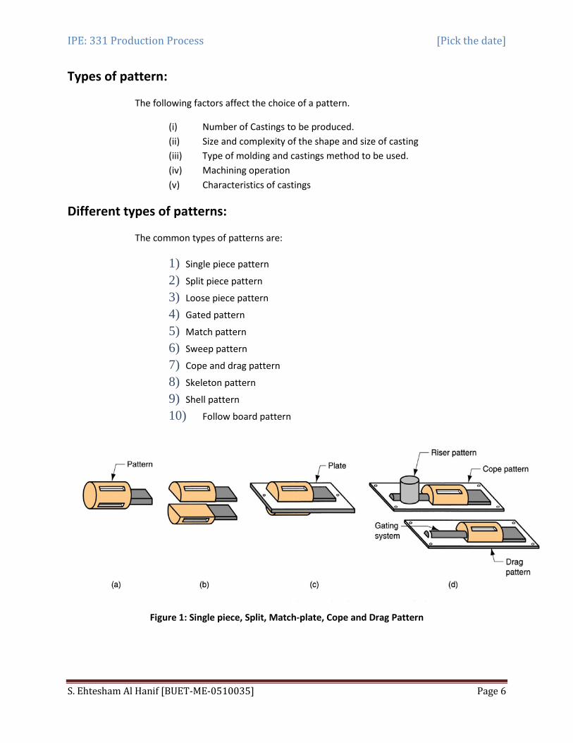
Figure 1: Single piece, Split, Match-plate, Cope and Drag Pattern
IPE: 331 Production Process [Pick the date]
S. Ehtesham Al Hanif [BUET-ME-0510035] Page 7
Single piece pattern:
This is the simplest type of pattern, exactly like the desired casting. For making a mould, the pattern is accommodated either in cope or drag.
Used for producing a few large castings, for example, stuffing box of steam engine.
Split pattern:
These patterns are split along the parting plane (which may be flat or irregular surface) to facilitate the extraction of the pattern out of the mould before the pouring operation.
For a more complex casting, the pattern may be split in more than two parts.
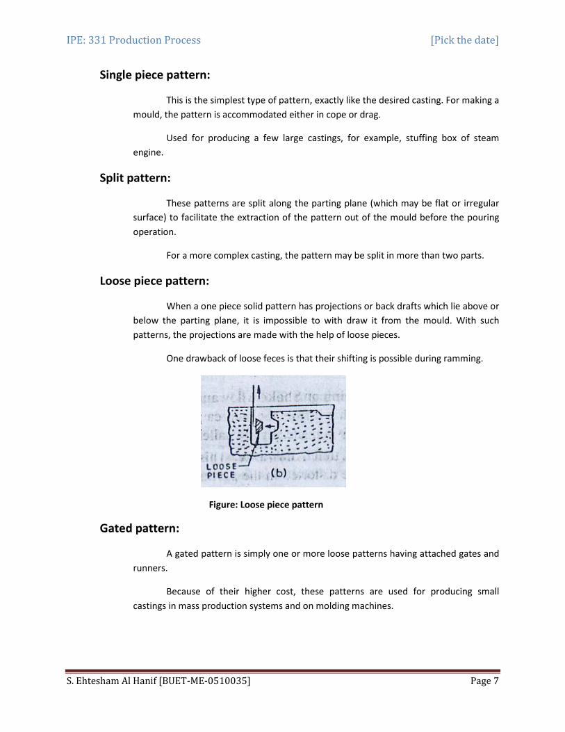
Loose piece pattern:
When a one piece solid pattern has projections or back drafts which lie above or below the parting plane, it is impossible to with draw it from the mould. With such patterns, the projections are made with the help of loose pieces.
One drawback of loose feces is that their shifting is possible during ramming.
Figure: Loose piece pattern
Gated pattern:
A gated pattern is simply one or more loose patterns having attached gates and runners.
Because of their higher cost, these patterns are used for producing small castings in mass production systems and on molding machines.

IPE: 331 Production Process [Pick the date]
S. Ehtesham Al Hanif [BUET-ME-0510035] Page 8
Figure: Gated pattern
Match plate pattern:
A match plate pattern is a split pattern having the cope and drags portions mounted on opposite sides of a plate (usually metallic), called the "match plate" that conforms to the contour of the parting surface.
The gates and runners are also mounted on the match plate, so that very little hand work is required. This results in higher productivity. This type of pattern is used for a large number of castings.
Piston rings of I.C. engines are produced by this process.
Sweep pattern:
A sweep is a section or board (wooden) of proper contour that is rotated about one edge to shape mould cavities having shapes of rotational symmetry.
This type of pattern is used when a casting of large size is to be produced in a short time. Large kettles of C.I. are made by sweep patterns.
Figure: Sweep pattern
Cope and drag pattern:
A cope and drag pattern is a split pattern having the cope and drag portions each mounted on separate match plates. These patterns are used when in the
IPE: 331 Production Process [Pick the date]
S. Ehtesham Al Hanif [BUET-ME-0510035] Page 9
production of large castings; the complete moulds are too heavy and unwieldy to be handled by a single worker.
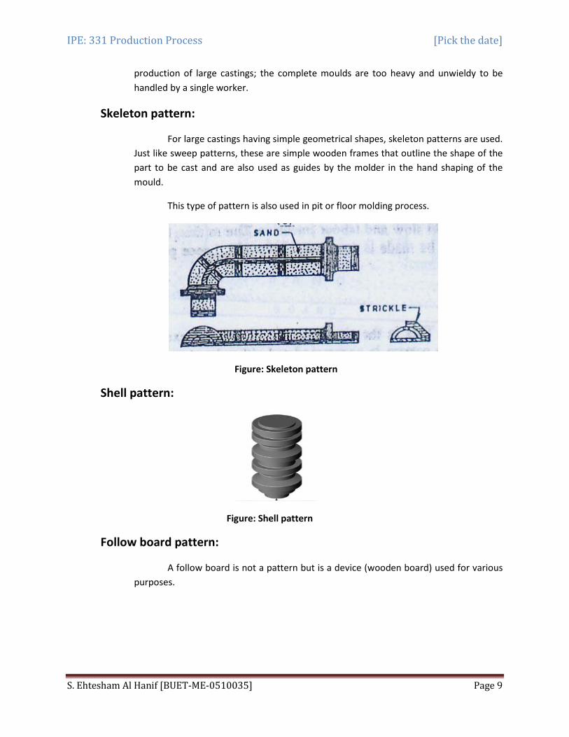
Skeleton pattern:
For large castings having simple geometrical shapes, skeleton patterns are used. Just like sweep patterns, these are simple wooden frames that outline the shape of the part to be cast and are also used as guides by the molder in the hand shaping of the mould.
This type of pattern is also used in pit or floor molding process.
Figure: Skeleton pattern
Shell pattern:
Figure: Shell pattern
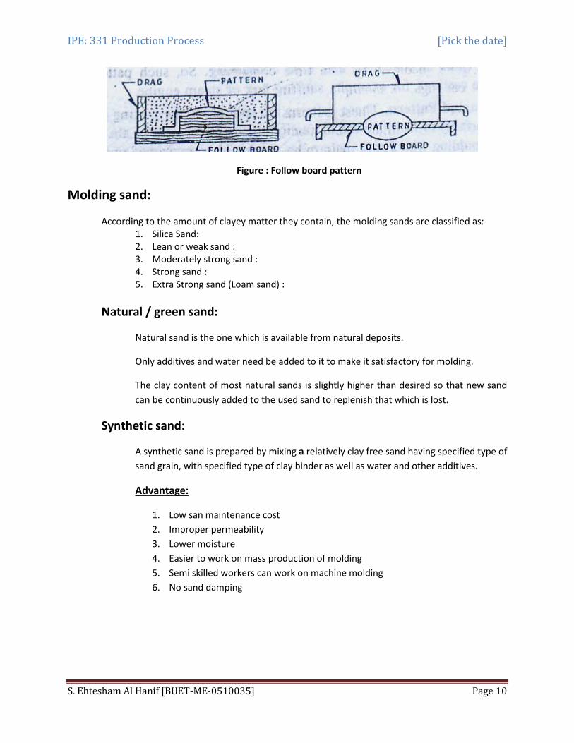
Follow board pattern:
A follow board is not a pattern but is a device (wooden board) used for various purposes.
IPE: 331 Production Process [Pick the date]
S. Ehtesham Al Hanif [BUET-ME-0510035] Page 10
Figure : Follow board pattern
Molding sand:
According to the amount of clayey matter they contain, the molding sands are classified as: 1. Silica Sand: 2. Lean or weak sand : 3. Moderately strong sand : 4. Strong sand : 5. Extra Strong sand (Loam sand) :
Natural / green sand:
Natural sand is the one which is available from natural deposits.
Only additives and water need be added to it to make it satisfactory for molding.
The clay content of most natural sands is slightly higher than desired so that new sand can be continuously added to the used sand to replenish that which is lost.
Synthetic sand:
A synthetic sand is prepared by mixing a relatively clay free sand having specified type of sand grain, with specified type of clay binder as well as water and other additives.
1. Low san maintenance cost
Advantage:
2. Improper permeability 3. Lower moisture 4. Easier to work on mass production of molding 5. Semi skilled workers can work on machine molding 6. No sand damping

IPE: 331 Production Process [Pick the date]
S. Ehtesham Al Hanif [BUET-ME-0510035] Page 11
Properties of molding sand:
The success of the casting process depends to a large extent on the making of a satisfactory mould. For this, the molding properties of the sand have to be controlled.
These properties include:
(i) Porosity or Permeability (ii) Strength or cohesiveness, (iii) Refractoriness, (iv) Plasticity, (v) Collapsibility and (vi) Adhesiveness (vii) Co-efficient of expansion etc.
Refractoriness:
It is the ability of the molding sand mixture to withstand the heat of melt without showing any signs of softening or fusion.
This property is greatly influenced by the purity of the sand particles and their size.
It increases with the grain size of sand and its content and with the diminished amount of impurities and silt.
Permeability:
Permeability or porosity of the molding sand is the measure of its ability to permit air to flow through it.
Molten metal always contains a certain amount of dissolved gases which try to leave it when the metal solidifies. If all these gases and vapors are not able to escape completely through the walls of the mould, they may penetrate the liquid metal where, after solidification, they form gas holes and pores. To avoid these defects, the molding sand should have good gas permeability.
Again, higher the silt contents of sand, the lower its gas permeability. If the mould is rammed too hand, its permeability will decrease and vice versa.
Cohesiveness:
It is defined as the property of holding together of sand grains. Molding sand should have ample strength so that the mould does not collapse or get partially destroyed during conveying, turning over or closing.
IPE: 331 Production Process [Pick the date]
S. Ehtesham Al Hanif [BUET-ME-0510035] Page 12
This property also enables the pattern to be removed without breaking the mould and to stand, the flow of molten metal when it rushes inside the mould.
The strength of the molding sand grows with density, clay content of the mix and decreased size of sand grains. So, it is clear that as the strength of the molding sand increases, its porosity decreases;
Adhesiveness:
This is the property of sand mixture to adhere to another body (here, the molding flasks). The molding sand should cling to the sides of the molding boxes so that it does not fall out when the flasks are lifted and turned over.
This property depends on the type and amount of binder used in the sand mix.
Plasticity or flow-ability:
It is the measure of the molding sand to flow around and over a pattern during ramming and to uniformly fill the flask. This property may be enhanced by adding clay and water to the silica sand.
Types of molding sand:
Green sand:
Natural sand with moisture
Dry sand:
Not suitable for large castings
Facing sand:
This sand is used directly next to the surface of the pattern and comes into contact with the molten metal when the mould is poured.
As a result, it is subjected to the severest conditions and must possess, therefore, high strength and refractoriness. This sand also provides a smoother casting surface and should be of fine texture. It is made of silica sand and clay, and some additives without the addition of used sand.
Facing sand is "always used to make dry sand moulds while system sand is frequently used for green sand molding.
IPE: 331 Production Process [Pick the date]
S. Ehtesham Al Hanif [BUET-ME-0510035] Page 13
Parting sand:
This sand is used to prevent adhering of two halves of mould surfaces in each molding box when they are separated. Thus, to ensure good parting, the mould surface (at contact of cope and Drag) should be treated with parting sand or some other parting material.
It is also sprinkled or applied on the pattern surface (before the molding sand is put over it) to avoid its sticking and permit its easy withdrawal from the mould. The parting sand is fine dry sand.
Backing or floor or black sand:
This is the sand which is used to back up the facing sand and to fill the whole volume of the flask. Old, repeatedly used molding sand is mainly employed for this purpose.
Core sand:
The core sand mainly consists of silica sand and an organic binder, with very little, if any, clay content. The presence of clay in core sand reduces its permeability and collapsibility. The core sand may contain small percentages of other constituents also, to enhance its properties.
Loam sand:
50 % of clay and dried hard and using for large castings
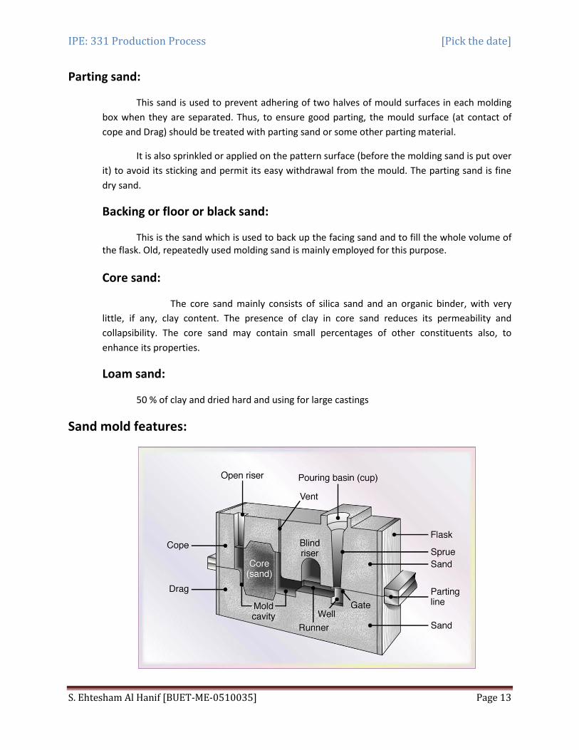
Sand mold features:
IPE: 331 Production Process [Pick the date]
S. Ehtesham Al Hanif [BUET-ME-0510035] Page 14
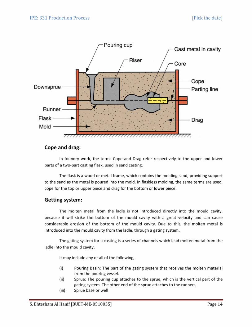
Cope and drag:
In foundry work, the terms Cope and Drag refer respectively to the upper and lower parts of a two-part casting flask, used in sand casting.
The flask is a wood or metal frame, which contains the molding sand, providing support to the sand as the metal is poured into the mold. In flaskless molding, the same terms are used, cope for the top or upper piece and drag for the bottom or lower piece.
Getting system:
The molten metal from the ladle is not introduced directly into the mould cavity, because it will strike the bottom of the mould cavity with a great velocity and can cause considerable erosion of the bottom of the mould cavity. Due to this, the molten metal is introduced into the mould cavity from the ladle, through a gating system.
The gating system for a casting is a series of channels which lead molten metal from the ladle into the mould cavity.
It may include any or all of the following,
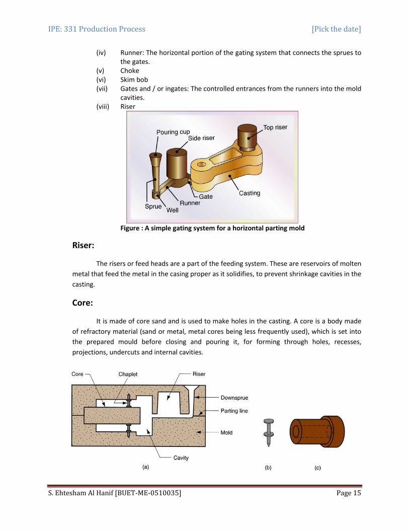
(i) Pouring Basin: The part of the gating system that receives the molten material from the pouring vessel.
(ii) Sprue: The pouring cup attaches to the sprue, which is the vertical part of the gating system. The other end of the sprue attaches to the runners.
(iii) Sprue base or well
IPE: 331 Production Process [Pick the date]
S. Ehtesham Al Hanif [BUET-ME-0510035] Page 15
(iv) Runner: The horizontal portion of the gating system that connects the sprues to the gates.
(v) Choke (vi) Skim bob (vii) Gates and / or ingates: The controlled entrances from the runners into the mold
cavities. (viii) Riser
Figure : A simple gating system for a horizontal parting mold
Riser:
The risers or feed heads are a part of the feeding system. These are reservoirs of molten metal that feed the metal in the casing proper as it solidifies, to prevent shrinkage cavities in the casting.
Core:
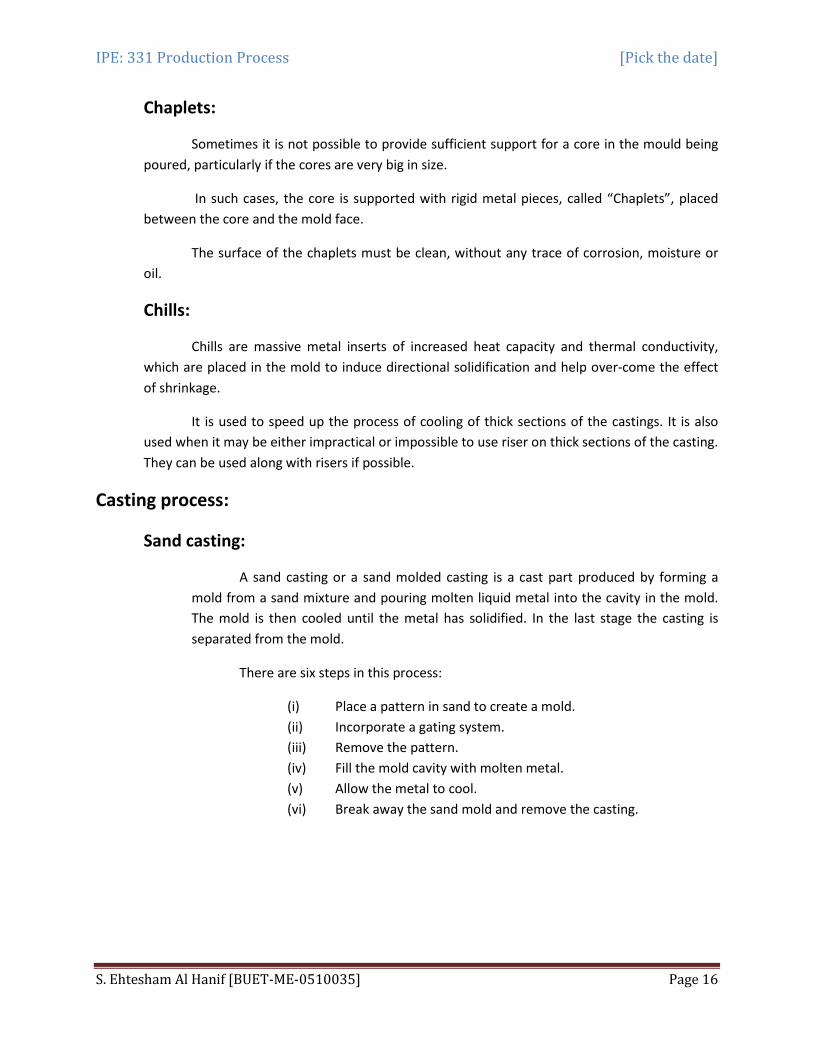
It is made of core sand and is used to make holes in the casting. A core is a body made of refractory material (sand or metal, metal cores being less frequently used), which is set into the prepared mould before closing and pouring it, for forming through holes, recesses, projections, undercuts and internal cavities.
IPE: 331 Production Process [Pick the date]
S. Ehtesham Al Hanif [BUET-ME-0510035] Page 16
Chaplets:
Sometimes it is not possible to provide sufficient support for a core in the mould being poured, particularly if the cores are very big in size.
In such cases, the core is supported with rigid metal pieces, called “Chaplets”, placed between the core and the mold face.
The surface of the chaplets must be clean, without any trace of corrosion, moisture or oil.
Chills:
Chills are massive metal inserts of increased heat capacity and thermal conductivity, which are placed in the mold to induce directional solidification and help over-come the effect of shrinkage.
It is used to speed up the process of cooling of thick sections of the castings. It is also used when it may be either impractical or impossible to use riser on thick sections of the casting. They can be used along with risers if possible.
Casting process:
Sand casting:
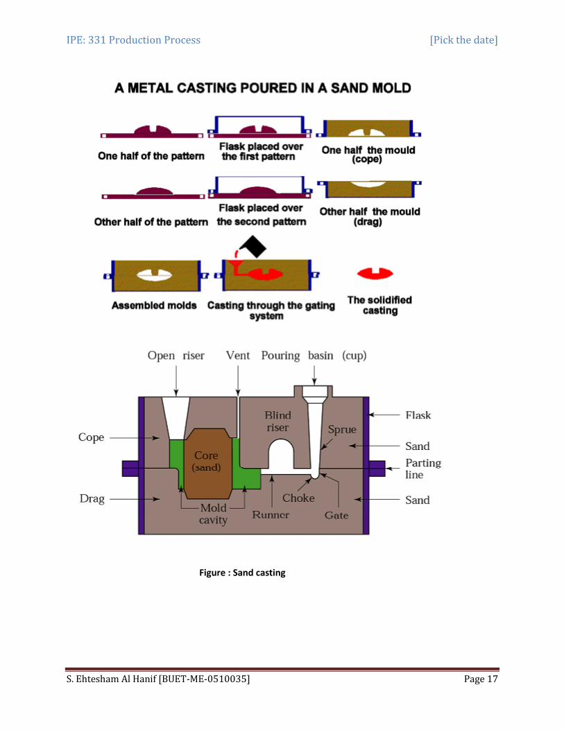
A sand casting or a sand molded casting is a cast part produced by forming a mold from a sand mixture and pouring molten liquid metal into the cavity in the mold. The mold is then cooled until the metal has solidified. In the last stage the casting is separated from the mold.
There are six steps in this process:
(i) Place a pattern in sand to create a mold. (ii) Incorporate a gating system. (iii) Remove the pattern. (iv) Fill the mold cavity with molten metal. (v) Allow the metal to cool. (vi) Break away the sand mold and remove the casting.
IPE: 331 Production Process [Pick the date]
S. Ehtesham Al Hanif [BUET-ME-0510035] Page 17
Figure : Sand casting
IPE: 331 Production Process [Pick the date]
S. Ehtesham Al Hanif [BUET-ME-0510035] Page 18
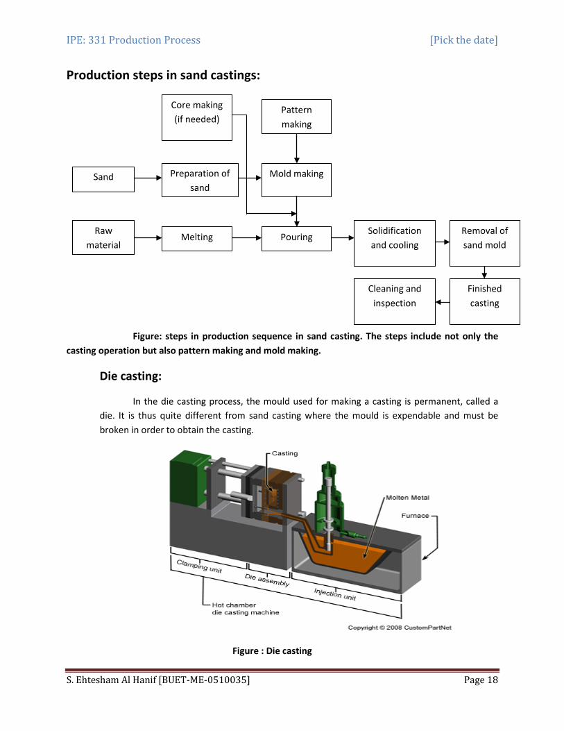
Production steps in sand castings:
Figure: steps in production sequence in sand casting. The steps include not only the casting operation but also pattern making and mold making.
Die casting:
In the die casting process, the mould used for making a casting is permanent, called a die. It is thus quite different from sand casting where the mould is expendable and must be broken in order to obtain the casting.
Figure : Die casting
Core making (if needed)
Preparation of sand
Melting
Pattern making
Mold making
Pouring Solidification and cooling
Removal of sand mold
Cleaning and inspection
Finished casting
Sand
Raw material
IPE: 331 Production Process [Pick the date]
S. Ehtesham Al Hanif [BUET-ME-0510035] Page 19
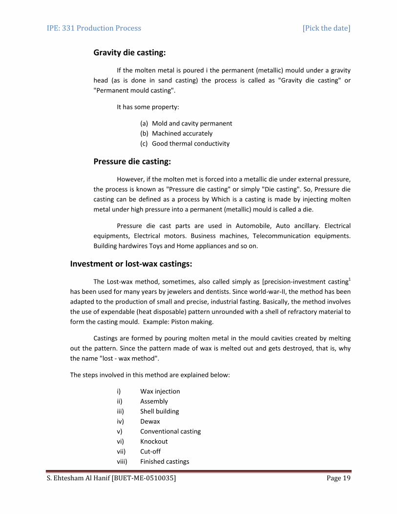
Gravity die casting:
If the molten metal is poured i the permanent (metallic) mould under a gravity head (as is done in sand casting) the process is called as "Gravity die casting" or "Permanent mould casting".
It has some property:
(a) Mold and cavity permanent (b) Machined accurately (c) Good thermal conductivity
Pressure die casting:
However, if the molten met is forced into a metallic die under external pressure, the process is known as "Pressure die casting" or simply "Die casting". So, Pressure die casting can be defined as a process by Which is a casting is made by injecting molten metal under high pressure into a permanent (metallic) mould is called a die.
Pressure die cast parts are used in Automobile, Auto ancillary. Electrical equipments, Electrical motors. Business machines, Telecommunication equipments. Building hardwires Toys and Home appliances and so on.
Investment or lost-wax castings:
The Lost-wax method, sometimes, also called simply as [precision-investment casting1
Castings are formed by pouring molten metal in the mould cavities created by melting out the pattern. Since the pattern made of wax is melted out and gets destroyed, that is, why the name "lost - wax method".
has been used for many years by jewelers and dentists. Since world-war-II, the method has been adapted to the production of small and precise, industrial fasting. Basically, the method involves the use of expendable (heat disposable) pattern unrounded with a shell of refractory material to form the casting mould. Example: Piston making.
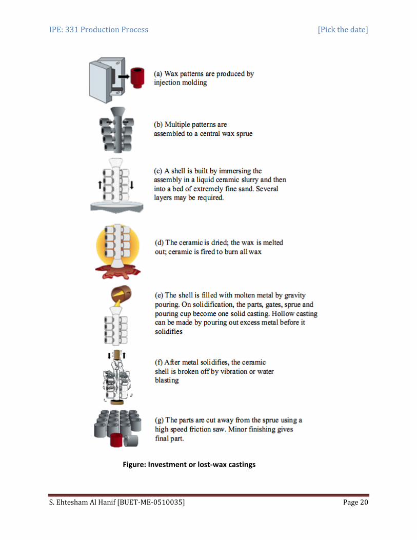
The steps involved in this method are explained below:
i) Wax injection ii) Assembly iii) Shell building iv) Dewax v) Conventional casting vi) Knockout vii) Cut-off viii) Finished castings
IPE: 331 Production Process [Pick the date]
S. Ehtesham Al Hanif [BUET-ME-0510035] Page 20
Figure: Investment or lost-wax castings
IPE: 331 Production Process [Pick the date]
S. Ehtesham Al Hanif [BUET-ME-0510035] Page 21
i) Intricate details can be cast.
Advantages:
ii) Undercuts and other shapes, which would not allow the withdrawal of a normal pattern, are easily obtained.
iii) The surface is very smooth and there is no parting line. iv) High accuracy can be obtained so that much of complicated and costly
machining can be eliminated. v) Unmachinable alloys can be cast. vi) More than one casting can be made at a time. vii) It can be reused. viii) Preferred for casting weight less
i) It is involved and thus expensive
Limitations:
ii) It has limitations in use of and location of holes iii) The parts are limited in size to a few kg
i) Parts for aerospace industry
Application:
ii) Parts for computers iii) Parts for food and beverage iv) Costume jewellery
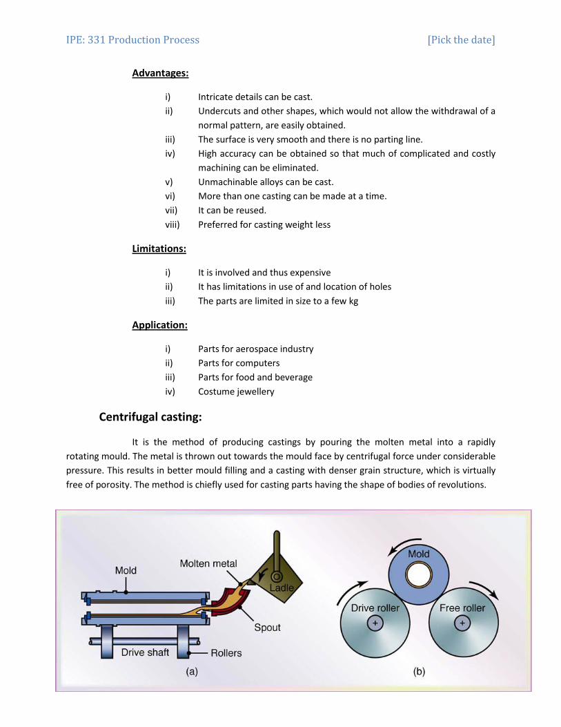
Centrifugal casting:
It is the method of producing castings by pouring the molten metal into a rapidly rotating mould. The metal is thrown out towards the mould face by centrifugal force under considerable pressure. This results in better mould filling and a casting with denser grain structure, which is virtually free of porosity. The method is chiefly used for casting parts having the shape of bodies of revolutions.

IPE: 331 Production Process [Pick the date]
S. Ehtesham Al Hanif [BUET-ME-0510035] Page 22
i) Castings acquire high density, high mechanical strength and fine grained structure
Advantages:
ii) Inclusions and impurities are lighter iii) Gates and risers are not needed iv) High output v) Formation of hollow interiors without cores
i) An inaccurate diameter of the inner surface of the casting.
Disadvantages:
ii) Not all alloys can be cast in this way.
Application:
Comparison of casting process:
pipe, bushings, gears, flywheel etc.
Castings process name advantages Disadvantages Sand castings ⊗ Any metal can be cast
⊗ No limit size and shape ⊗ Less equipment cost ⊗ Economic for low
volume production
⊗ Coarse final ⊗ Dimensional accuracy is
not good ⊗ Finishing required ⊗ Less production rate
Individual casting ⊗ Any metal can be cast ⊗ Good surface finish and
dimensional accuracy ⊗ Fairly high production
rate ⊗ Less finishing cost ⊗ Interlaced shape can be
cast
⊗ High labor cost ⊗ Expensive patterns and
mold ⊗ Limitation on part size
Die castings ⊗ Excellent surface finish ⊗ Excellent dimensional
accuracy ⊗ High production rate ⊗ Complex shape can be
cast ⊗ Little or no finish cost
⊗ Limitation on part size ⊗ High cost of die ⊗ Generally limited to
casting of non ferrous metal
Lost-wax casting ⊗ High production rate ⊗ Good dimensional
accuracy ⊗ Good surface finishing
⊗ Expensive setup ⊗ Good for production of
cylindrical parts only
Centrifugal casting ⊗ No limit size and shape but mainly spherical
⊗ Surface finishing smooth
⊗ Not all alloys can be cast in this way
⊗ An inaccurate diameter
IPE: 331 Production Process [Pick the date]
S. Ehtesham Al Hanif [BUET-ME-0510035] Page 23
of the inner surface of the casting
Castings defects:
A properly designed casting, a properly prepared mould and correctly malted metal should result in a defect free casting. However, if proper control is not exercised in the foundry-sometimes it is too expensive - a variety of defects may result in a casting.
These defects may be the result of:
(a) improper pattern design, (b) improper mould and core construction, (c) improper melting practice, (d) improper pouring practice and (e) Because of molding and core making materials. (f) Improper gating system (g) Improper metal composition (h) Inadequate melting temp and rate of pouring
It creates a deficiency or imperfection.
Exceeding quality limits imposed by design and service casting defects are mainly 3 categories. These are:
(1) Major or most severe defects (2) Intermediate defects (3) Minor defects
Surface defects:
Due to design and quality of sand molds and general cause is poor ramming.
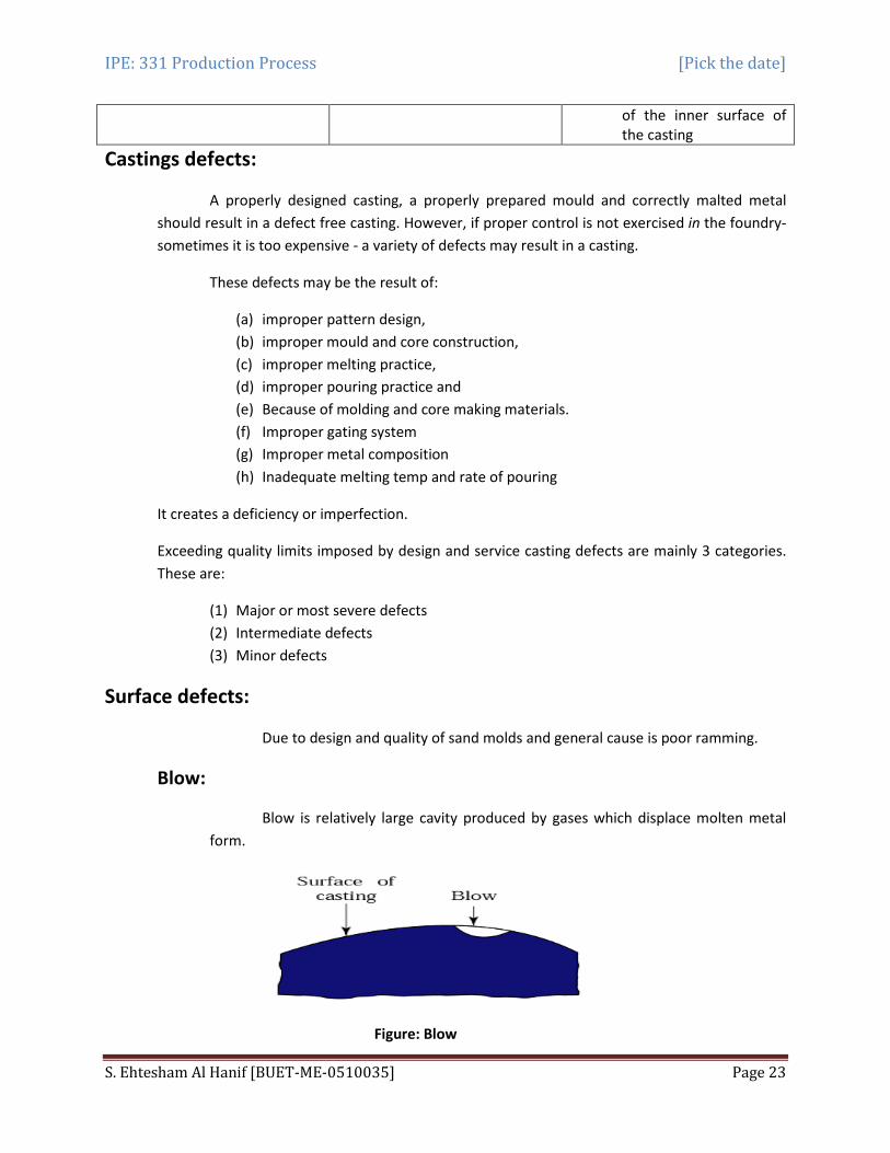
Blow:
Blow is relatively large cavity produced by gases which displace molten metal form.
Figure: Blow
IPE: 331 Production Process [Pick the date]
S. Ehtesham Al Hanif [BUET-ME-0510035] Page 24
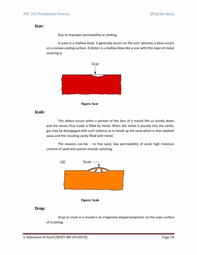
Scar:
Due to improper permeability or venting.
A scare is a shallow blow. It generally occurs on flat surf; whereas a blow occurs on a convex casting surface. A blister is a shallow blow like a scar with thin layer of metal covering it,
Figure: Scar
Scab:
This defect occurs when a portion of the face of a mould lifts or breaks down and the recess thus made is filled by metal. When the metal is poured into the cavity, gas may be disengaged with such violence as to break up the sand which is then washed away and the resulting cavity filled with metal.
The reasons can be: - to fine sand, low permeability of sand, high moisture content of sand and uneven moulds ramming.
Figure: Scab
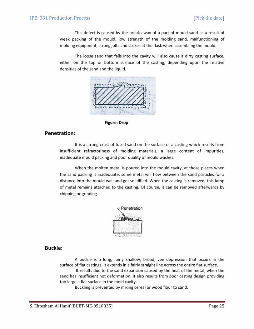
Drop:
Drop or crush in a mould is an irregularly shaped projection on the cope surface of a casting.
IPE: 331 Production Process [Pick the date]
S. Ehtesham Al Hanif [BUET-ME-0510035] Page 25
This defect is caused by the break-away of a part of mould sand as a result of weak packing of the mould, low strength of the molding sand, malfunctioning of molding equipment, strong jolts and strikes at the flask when assembling the mould.
The loose sand that falls into the cavity will also cause a dirty casting surface, either on the top or bottom surface of the casting, depending upon the relative densities of the sand and the liquid.
Figure: Drop
Penetration:
It is a strong crust of fused sand on the surface of a casting which results from insufficient refractoriness of molding materials, a large content of impurities, inadequate mould packing and poor quality of mould washes.
When the molten metal is poured into the mould cavity, at those places when the sand packing is inadequate, some metal will flow between the sand particles for a distance into the mould wall and get solidified. When the casting is removed, this lump of metal remains attached to the casting. Of course, it can be removed afterwards by chipping or grinding.
Buckle:
A buckle is a long, fairly shallow, broad, vee depression that occurs in the surface of flat castings. It extends in a fairly straight line across the entire flat surface.
It results due to the sand expansion caused by the heat of the metal, when the sand has insufficient hot deformation. It also results from poor casting design providing too large a flat surface in the mold cavity.
Buckling is prevented by mixing cereal or wood flour to sand.

IPE: 331 Production Process [Pick the date]
S. Ehtesham Al Hanif [BUET-ME-0510035] Page 26
Figure: Buckle
Internal defects:
Blow holes:
Blow holes, gas holes or gas cavities are well rounded cavities having a clean and smooth surface. They appear either on the casting surface or in the body of a casting.
These defects occur when an excessive evolved gas is not able to flow through the mould. So, it collects into a bubble at the high points of a mould cavity ad prevents the liquid metal from filling that space.
This will result in open blows. Closed, cavities or gas holes are formed when the evolved gases or the dissolved gases in the molten metal are not able to leave the m ass of the molten metal as it solidifies and get trapped within the casting.
These defects are caused by :
i) excessive moisture content (in the case of green sand moulds) or organic content of the sand, moisture on chills, chaplets or metal inserts,
ii) inadequate gas permeability of the molding sand (due to fine grain size of sand, high clay content, hard ramming),
iii) poor venting of mould, insufficient drying of mould and cores, cores not properly vented, high gas content of the molten metal,
iv) low pouring temperature and incorrect feeding of the casting etc.
Pin holes:
Pin holes are small gas holes either at the surface or just below the surface. When these are present, they occur in large numbers and are fairly uniformly dispersed over the surface.
This defect occurs due to gas dissolved in the alloy and the alloy not properly
degassed.
IPE: 331 Production Process [Pick the date]
S. Ehtesham Al Hanif [BUET-ME-0510035] Page 27
Figure: Pin holes
Visible defects:
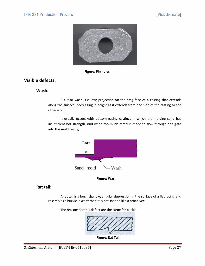
Wash:
A cut or wash is a low; projection on the drag face of a casting that extends along the surface, decreasing in height as it extends from one side of the casting to the other end.
It usually occurs with bottom gating castings in which the
molding sand has insufficient hot strength, and when too much metal is made to flow through one gate into the mold cavity,
Figure: Wash
Rat tail:
A rat tail is a long, shallow, angular depression in the surface of a flat rating and resembles a buckle, except that, it is not shaped like a broad vee.
The reasons for this defect are the same for buckle.
Figure: Rat Tail
IPE: 331 Production Process [Pick the date]
S. Ehtesham Al Hanif [BUET-ME-0510035] Page 28
Hot tear:
Hot tears are hot cracks which appear in the form of irregular crevices with a dark oxidized fracture surface. They arise when the solidifying met does not have sufficient strength to resist tensile forces produced during solidification.
They are chiefly from an excessively high temperature of casting metal, increased metal contraction incorrect design of the gating system and casting on the whole (causing portions of the casting to be restrained from shrinking freely during cooling which in turn causes excessive high intern resistance stresses), poor deformability of the cores, and non-uniform cooling which gives rise t internal stresses. This defect can be avoided by improving the design of the casting and by having a mould of low hot strength and large hot deformation.
Figure: Hot Tear
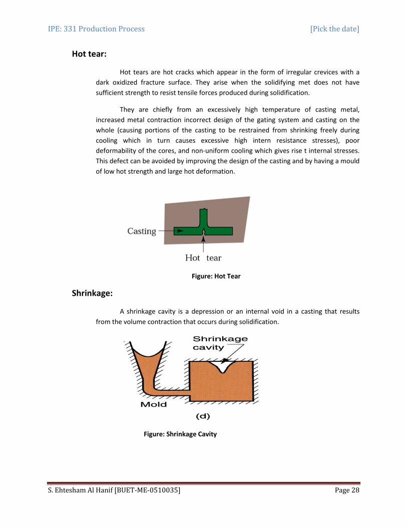
Shrinkage:
A shrinkage cavity is a depression or an internal void in a casting that results from the volume contraction that occurs during solidification.
Figure: Shrinkage Cavity
IPE: 331 Production Process [Pick the date]
S. Ehtesham Al Hanif [BUET-ME-0510035] Page 29
Swell:
A swell is a slight, smooth bulge usually found on vertical faces of castings, resulting from liquid metal pressure. It may be due to low strength of mould because of too high a water content or when the mould is not rammed sufficiently.
Figure: Swell
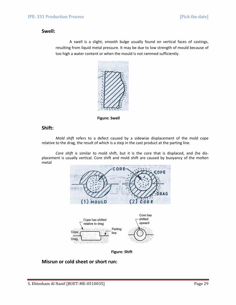
Shift:
Mold shift refers to a defect caused by a sidewise displacement of the mold cope relative to the drag, the result of which is a step in the cast product at the parting line. Core shift is similar to mold shift, but it is the core that is displaced, and (he dis-placement is usually vertical. Core shift and mold shift are caused by buoyancy of the molten metal
Figure: Shift
Misrun or cold sheet or short run:

IPE: 331 Production Process [Pick the date]
S. Ehtesham Al Hanif [BUET-ME-0510035] Page 30
This defect is incomplete cavity filling. The reasons can be: - inadequate metal supply, too- low mould or melt temperature, improperly designed gates, .or length to thickness ratio of the casting is too large. When molten metal is flowing from one side in a thin section, it may loose sufficient heat resulting in loss of its fluidity, such that the leading edge of the stream may freeze before it reaches the end of the cavity.
Figure: Misrun
Related Documents