Schweitzer Engineering Laboratories, Inc. SEL-2030 Data Sheet SEL-2030 Communications Processor Integrate New and Existing Substations Create integrated systems that utilize substation hardened equipment to collect data from station IEDs, process and concentrate collected data, provide data to multiple master devices (RTUs, PLCs, HMIs, etc.), and provide a connection point to IEDs for engineering and maintenance. Use the SEL-2030 to provide simultaneous data collection, control, engineering access, and time synchronization over a single cable or fiber-optic pair (using SEL-2810 transceivers). Major Features and Benefits ➤ Supports Synchrophasors. Collect synchrophasor data from select SEL-300 and SEL-400 series relays. Map phasor data values to traditional SCADA protocols, such as DNP3 or Modbus ® , for inte- gration into Energy Management Systems and State Estimation. ➤ Superior Alternative to RTU. Use Modbus or DNP3 to communicate to off-site SCADA masters. Use protocol converters for other protocols. ➤ Increase Reliability. Tested and designed to the same environmental specifications as SEL relays. Pro- tects you from frequent operating system crashes and upgrades of PC-based systems. ➤ Simplifies Station Networks. Use a single star network rather than multiple multidrop networks to col- lect data, provide control, distribute time synchronization, and provide engineering access to IEDs. ➤ Single-Point Engineering Access. Gain engineering access to station IEDs through a single serial port, modem, or high-speed network (using the SEL-2701) connection. ➤ Supports Multiple Masters. Provide an optimized and scaled data set to each master increasing commu- nication performance and efficiency and reducing burden on master devices. ➤ Time-Stamped Data. Collect relay SER data using SEL Fast SER messages. ➤ Station Automation. Combine and react to station and system conditions using logic processing and data manipulation.

2030_DS_20070629
Mar 07, 2016
Major Features and Benefits ➤ Station Automation. Combine and react to station and system conditions using logic processing and data manipulation. SEL-2030 Data Sheet Schweitzer Engineering Laboratories, Inc.
Welcome message from author
This document is posted to help you gain knowledge. Please leave a comment to let me know what you think about it! Share it to your friends and learn new things together.
Transcript
Schweitzer Engineering Laboratories, Inc. SEL-2030 Data Sheet
SEL-2030 Communications Processor
Integrate New and Existing Substations
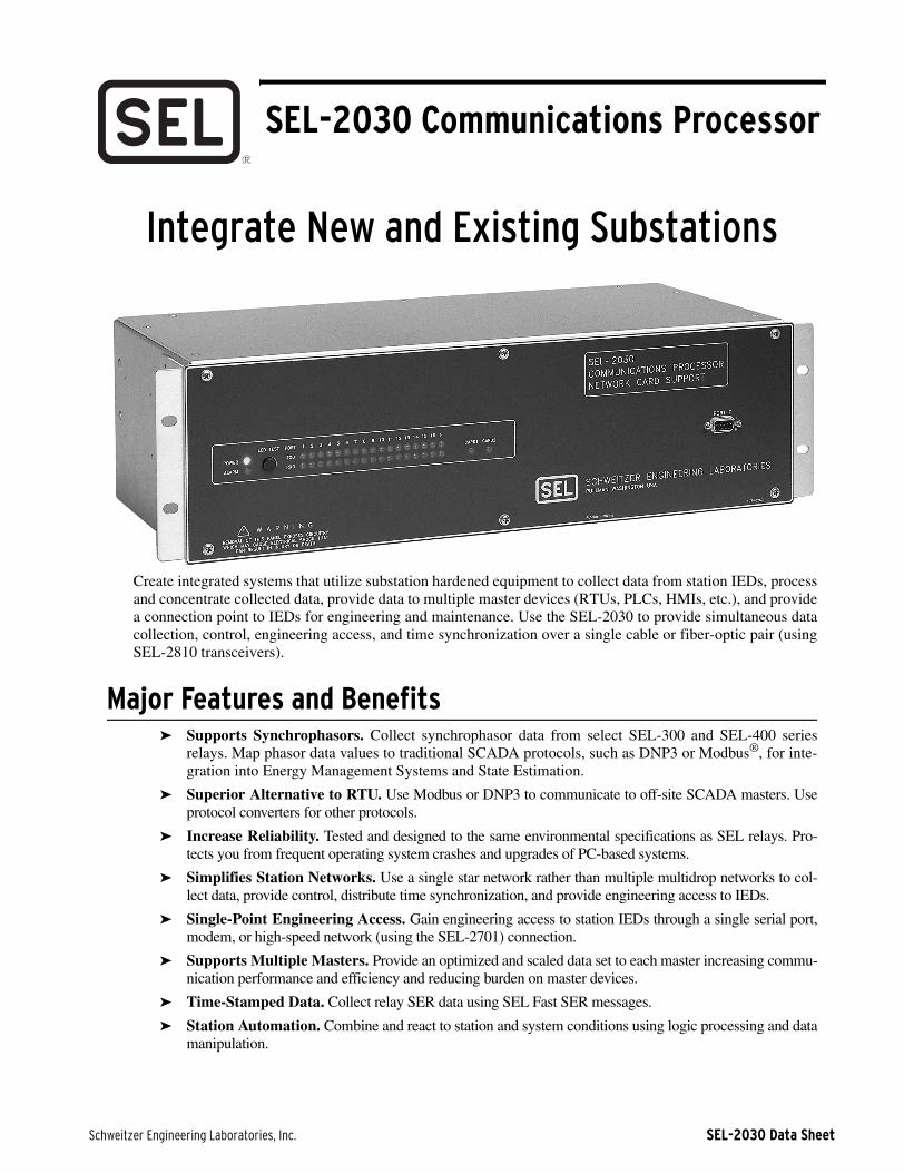
Create integrated systems that utilize substation hardened equipment to collect data from station IEDs, processand concentrate collected data, provide data to multiple master devices (RTUs, PLCs, HMIs, etc.), and providea connection point to IEDs for engineering and maintenance. Use the SEL-2030 to provide simultaneous datacollection, control, engineering access, and time synchronization over a single cable or fiber-optic pair (usingSEL-2810 transceivers).
Major Features and Benefits➤ Supports Synchrophasors. Collect synchrophasor data from select SEL-300 and SEL-400 series
relays. Map phasor data values to traditional SCADA protocols, such as DNP3 or Modbus®, for inte-gration into Energy Management Systems and State Estimation.
➤ Superior Alternative to RTU. Use Modbus or DNP3 to communicate to off-site SCADA masters. Useprotocol converters for other protocols.
➤ Increase Reliability. Tested and designed to the same environmental specifications as SEL relays. Pro-tects you from frequent operating system crashes and upgrades of PC-based systems.
➤ Simplifies Station Networks. Use a single star network rather than multiple multidrop networks to col-lect data, provide control, distribute time synchronization, and provide engineering access to IEDs.
➤ Single-Point Engineering Access. Gain engineering access to station IEDs through a single serial port,modem, or high-speed network (using the SEL-2701) connection.
➤ Supports Multiple Masters. Provide an optimized and scaled data set to each master increasing commu-nication performance and efficiency and reducing burden on master devices.
➤ Time-Stamped Data. Collect relay SER data using SEL Fast SER messages.
➤ Station Automation. Combine and react to station and system conditions using logic processing and datamanipulation.

SEL-2030 Data Sheet Schweitzer Engineering Laboratories, Inc.
2
➤ Provides Ethernet UCA2 Connectivity. Use the SEL-2701 Ethernet Processor Card to provide a UCA2interface for serial devices.
➤ Provides Ethernet DNP3 Connectivity. Use the SEL-2701 Ethernet Processor Card to provide a DNP3interface for serial devices.
➤ Autoconfiguration. SEL IEDs self-describe available data, data messages, and control to automate data-base creation and simplify message settings.
➤ Time Synchronization. Distributes incoming IRIG-B or sends IRIG-B based on internal clock. UseSEL-2810 transceivers to time synchronize IEDs using fiber-optic connections.
Functional Overview
Figure 1 Functional Model
Figure 1 shows a functional model of the SEL-2030including the Input Handlers, Message Generators, DataArea, SELOGIC® Control Equations Processor, Time Pro-cessor, optional I/O, and optional nonvolatile archivememory.
Input Handler/Message GeneratorThere is an Input Handler and Message Generator for eachserial port. When you communicate with the SEL-2030using the command set, the Input Handler separates thecommands into their basic components. The Input Handlersends data to the Data Area and directs the Message Gen-erator to make a response based on the SEL-2030 settingsthat you have defined.
When you use the SEL-2030 as a port switch, the InputHandler places collected data in the Data Area, and theMessage Generator reads and outputs these data to a des-ignated port. The Input Handler also stops communicationwhen it recognizes the default termination condition or atermination condition you have defined in settings.
Messages are predefined responses that may include data,responses to special-purpose user-defined commands, andautomatic messages that you have defined in settings andthat are triggered by SELOGIC control equations. You canuse relay automatic messages to initiate data collection bysetting the SEL-2030 to collect and store data when anunsolicited message is received. For example, receiving asummary event report could trigger the SEL-2030 to sendthe EVENT command back to the relay. The relay wouldrespond with the long event report, and the SEL-2030could then save it. You can store the data in volatile RAMor in the optional nonvolatile archive memory.
When enabled, based on SEL-2030 settings, the InputHandler receives binary sequential events recorder (SER)messages from SEL relays and places them in temporarydata storage. These messages are then forwarded by theMessage Generator along with SER messages generatedby the change-of-state (COS) of the SEL-2030 local I/O.
* IRIG-B input NOT required to have IRIG-B output
Communications ProcessorSEL-2030
High-SpeedNetwork
NetworkHigh-Speed
CardComm
Optional
CardComm
Optional
External Modem
Phone Line
GeneratorsMessage
HandlersInput
ProcessorEquationControlSELOGIC
16 IRIG-B Outputs*
IRIG-B Input*
16 Optoisolated Inputs
4 Output Contacts
17 EIA-232 Ports
I/O
Optional
ProcessorTime
AreaData
MemoryArchiveOptional

Schweitzer Engineering Laboratories, Inc. SEL-2030 Data Sheet
3
Data Area With Automatic DatabaseThe Data Area is divided into regions of volatile (RAM)and nonvolatile memory. The SEL-2030 stores settings innonvolatile memory. The SEL-2030 is unique in its abilityto receive, parse, store, and distribute data. The SEL-2030automatically parses data from SEL relays, and has severalparsing options for data from other devices. Additionalnonvolatile archive memory is an option you can use forlong-term data storage.
SELOGIC Control Equations ProcessorThe SELOGIC Control Equations Processor executes Bool-ean equations that you write to trigger transmission ofmessages. The Boolean values in the equations can belogic bits from the Data Area or comparisons against thepresent time. You can program the SEL-2030 to recognizeuser-defined commands and to set a bit in the Data Areawhen it receives one of these commands. The SELOGIC
Control Equations Processor can then use this bit to ini-tiate another operation, such as collecting data or transmit-ting a message. The SELOGIC Control EquationsProcessor also controls the optional I/O.
Time ProcessorThe Time Processor keeps the date and time, reads IRIG-Btime input (if it is present), and broadcasts demodulatedIRIG-B time code to all rear-panel serial ports. It also
time-tags data stored in the Data Area and supplies time-of-day and day-of-the-week input to the SELOGIC ControlEquations Processor.
Optional Input/OutputIf the optional I/O is installed, the inputs and outputs oper-ate with the Data Area and the SELOGIC Control Equa-tions Processor. Optoisolated inputs feed directly into theData Area as logic bits, which you can viewusing SEL-2030 commands. You can program SELOGIC
control equations to use the logic bits. The SELOGIC Con-trol Equations Processor controls the output contacts onthe I/O board. These outputs can be programmed to oper-ate based on Data Area bits or time comparisons. Thispowerful capability lets you build adaptive relay schemes,automate responses to alarms, and directly control powerapparatus.
Optional Communication CardsThe optional communication cards allow the SEL-2030 tobe connected to high-speed networks. See additional prod-uct model number SEL-2700 series data sheets fordescriptions of the specific high-speed networks available.
ApplicationsCollect and Format DataFrom Relays for SCADA Systems
You can use strings that you define to instruct theSEL-2030 to collect and format relay data for SCADAsystems. Simple settings enable you to individually con-figure SEL-2030 ports to define their data retrieval andstorage attributes. Instruct the SEL-2030 to automaticallyinterrogate connected devices for data. The SEL-2030 canalso provide a uniform data interface to the SCADAdevices, so that the SCADA software does not have to spe-cifically accommodate each IED type.
Access Data Through Multiple PathsDifferent departments in a utility may be interested in dif-ferent data and different data rates. For example, a systemoperator may be interested in metering and contact dataevery 5 or 10 seconds and fault location shortly after afault. A protection engineer is usually interested in settingrelays and analyzing a full event report after a fault occurs.You can accommodate these needs by connecting one porton the SEL-2030 to a SCADA RTU for the operator and atelephone modem to another port for the protection engi-neer.
Program SEL-2030 Database FunctionsUse the SEL-2030 settings and SELOGIC control equationsto build a database of load profiles and event reports and tostore them in nonvolatile memory. Define commands sodifferent devices can retrieve appropriately formatted data.
Perform ProgrammableLogic Controller (PLC) Functions
Use Boolean and arithmetic operators to create logicalschemes to produce and forward information or performcontrol to eliminate auxiliary devices.
Synchronize Relay Clocks in SubstationThe SEL-2030 receives an IRIG-B time-code input from asingle IRIG-B receiver or local clock and distributes it tothe devices connected to any of the 16 serial ports. TheSEL-2030 supports modulated or demodulated time-codeinput.
If there is no external signal, the SEL-2030 generates anIRIG-B signal using an internal clock so you can synchro-nize device clocks without an IRIG-B receiver or localclock.
Create Station-Wide SERMonitor local input contacts to timestamp state changes ofdiscrete contacts, and create and queue an SER messagefor each occurrence. The SEL-2030 can then forwardthese SER messages, and route SER messages receivedfrom relays, to a host.
Use Events to Switch Relay Setting GroupsProgram the SEL-2030 to use the time of day, day of theweek, or a specific event, such as a relay alarm output, toswitch relay setting groups.
SEL-2030 Data Sheet Schweitzer Engineering Laboratories, Inc.
4
Monitor Relay Alarm ContactsWith the optional I/O installed, you can program theSEL-2030 to monitor relay alarm contacts. Instruct theSEL-2030 to send predetermined messages or initiate anaction you designate, like closing an output contact basedon these inputs.
Log Messages on a Local PrinterYou can set the SEL-2030 to print selected messages,including control actions, diagnostic status messages,short event reports, and demand meter data.
Drive a LocalHuman-Machine Interface With Relay Data
Connect a computer to the SEL-2030 through the com-puter serial port. Using your own human-machine inter-face (HMI) software, you can build screens and specifythe HMI data definition. You can create commands thatinstruct the SEL-2030 to send selected data to the standardserial port interface for the HMI package.
Integration FeaturesThe SEL-2030 Communications Processor provides manyspecial features needed in today's substations to communi-cate with a variety of microprocessor-based devices,including digital fault recorders, sequential event record-ers, digital meters, and digital relays. The SEL-2030 canfunction as a simple, but intelligent, port switch. Or it canprovide sophisticated communication and data handlingcapability required for advanced substation integrationprojects. Data are collected, processed, and stored in theSEL-2030 database, permitting quick distribution ofselected data to an RTU (remote terminal unit) or anotherdevice. Figure 2 on page 5 shows an example block dia-gram configuration of the SEL-2030 with SEL relays andperipheral devices connected.
Enhanced/Intelligent Port SwitchingUnlike conventional port switches, the SEL-2030 can sup-port communications on all active ports simultaneously atspeeds up to 19200 or 38400 bps depending on port con-figuration. This means that you can communicate locallythrough the SEL-2030 with one connected IED (intelligentelectronic device) at the same time that someone else iscommunicating remotely through the same SEL-2030 toanother connected IED. Other intelligent features, like theSEL-2030 auto-configuration function, make setup andoperation much easier than with simple port switches. Inadvanced applications, where the SEL-2030 is used to col-lect, store, and distribute information, the simultaneouscommunication function provides an uninterrupted flow ofinformation from all active IEDs to an RTU or station inte-gration computer. At the same time you can communicatethrough the SEL-2030, either locally or remotely, with oneof the connected relays or IEDs.
Data Collection, Processing, Storage, Distribution
You can collect, store, process, and distribute target, meter,event, status, sequential events records, synchrophasors,and other information–virtually all information availablefrom an SEL relay and a variety of information availablefrom other IEDs–with the SEL-2030, using a simple, butpowerful, set of communication commands. Likewise, theSEL-2030 reduces the processing burden for these exter-nal devices by separating selected data from IEDs so thatonly the essential information is delivered and in the formand format required.
Substation Integration and Network Interface
Communication and information handling features makethe SEL-2030 ideal for small substation integrationprojects, eliminating the need for separate substation net-work architecture. On larger integration projects, theSEL-2030 reduces or eliminates the need for costly net-work interface devices, otherwise required for each IED.Inclusion of Modbus and DNP support eases integrationwith systems that support Modbus or DNP. The ability toadd protocol cards allows the use of high-speed networksand allows your protocol choice to change in the futurewith minimal hardware impact.
Time SynchronizationThe SEL-2030 can synchronize the time clocks in attacheddevices, such as relays, that accept a demodulated IRIG-Btime signal. The demodulated IRIG-B signal is regener-ated in the SEL-2030 from an external modulated ordemodulated source, such as a GOES or GPS satelliteclock receiver. If no IRIG-B source is available, thedemodulated IRIG-B time signal is generated internally bythe SEL-2030. A setting allows you to select the externalIRIG-B signal, or network command to set the SEL-2030clock.
Optional Expanded Long-Term Information Storage
Long-term information storage, for such functions asalarms, event reports, and load profiles, can be accommo-dated using optional nonvolatile archive memory.
Optional Input/OutputOptional I/O, consisting of four programmable outputcontacts and 16 optoisolated inputs, is available for moni-toring, control, and SER. You can use SELOGIC controlequations, written in the SEL-2030 settings, to performbasic control functions such as consolidating alarms andswitching adaptive relay setting groups. Jumper configureeach output contact as form A or form B through solderedjumper connections.
Compact DesignThe SEL-2030 is available with two mounting styles; oneis for mounting in panels, and one is for racks. You canreverse the mounting ears on the rack-mount case for pro-

Schweitzer Engineering Laboratories, Inc. SEL-2030 Data Sheet
5
jection mounting. Figure 5 on page 10 shows theSEL-2030 front and rear panels, both with and without theoptional I/O board. Refer to Figure 6 on page 11 fordimensions and drill plans.
Optional Communication CardsThe SEL-2030 has two card slots that each acceptSEL-2700 series cards. Each card has 64 incoming controlpoints, set by the card, and 64 outgoing control points thatare set by the SEL-2030.
The SEL-2030 also supports virtual terminal connectionsthrough the optional communications card slots. Forexample, with an SEL-2701 Ethernet Processor installed,Ethernet users can establish Telnet sessions through thecard, issue a PORT command, and communicate with anIED connected to the SEL-2030.
Figure 2 SEL-2030 Example Configuration Diagram
Printer
RTU
Substation LAN
IRIG–BTime
Receiver
SEL–587 SEL–351
3
SEL–351A
4
SEL–351A
5
SEL–351A
SEL–351A
6
SEL–321
SEL–311C
2
1
SEL–321
SEL–311C
SEL–2030Communications
Processor
Local User Interface
TelephoneLine
SCADA
EMS
SEL-2030 Data Sheet Schweitzer Engineering Laboratories, Inc.
6
Guideform SpecificationThe communications processor shall operate a star com-munications network and provide a combination of func-tions including Boolean logic processing, automatictransmission of outgoing messages and parsing ofresponses, data scaling, data aggregation, simultaneouscollection of data from up to 16 slave devices (both SELand non-SEL), and simultaneous data access for multiplemaster devices. The communications processor shall pro-vide Modbus RTU Slave and DNP3 Level 2 Slave proto-cols and provide two card slots for the installation ofadditional protocol cards. Specific operational and func-tional requirements are as follows:
➤ Power Supply. The communications processorshall be capable of operating on a wide range ofpower supply voltages and shall be available withone of three power supply types: 85–350 Vdc or85–264 Vac, 38–200 Vdc or 85–140 Vac, or 20–60Vdc.
➤ Temperature. The communications processor shallbe capable of continuous operation over a tempera-ture range of –40° to +85° C in order to allowmounting in an outdoor control cubicle or in case ofthe failure of enclosure heating or cooling. Thecommunications processor shall be type tested toIEC 60068-2-1: 1990 (Test Ad 16 hr @ –40°C),IEC 60068-2-2: 1974 (Test Bd 16 hr @ +85°), andIEC 60068-2-30: 1980 (Test Db 12 + 12-hour cycle@ 55°C, 6 cycles).
➤ Environmental Testing. The communications pro-cessor shall be tested to the same standards as pro-tective relays including IEC 60255-21-1,IEC 60255-21-2, IEC 60255-21-3, IEC 60255-22-1, IEC 60255-22-2, EN 61000-4-2, IEC 60255-22-3, IEC 60255-22-4, EN 61000-4-4, and IEEEC37.90.1 (See Specifications on page 13 fordetails).
➤ Input/Output. There shall be an optionalinput/output module with 16 optoisolated inputsand 4 outputs. There shall be three types of inputsavailable rated for operation at a nominal 48 Vdc,125 Vdc, or 250 Vdc. The inputs shall draw nomore than 4 mA when nominal control voltage isapplied. The outputs shall be contact type with a30 A make and 6 A carry with MOV protection.
➤ Alarm Output. There shall be an Alarm contactoutput programmed to signal internal errors andmalfunctions. The alarm contact shall be program-mable so that the alarm conditions that activate theoutput can include additional conditions with thecommunications processor, collected data, and theresults of logical and mathematical calculations.The Alarm contact shall be configurable to operateas a Form A or Form B contact.
➤ EIA-232 Ports. The communications processorshall have one front panel and 16 rear panel portsusing standard DB-9 connectors and MOV protec-tion. Two pins on each port shall be available as ademodulated IRIG-B time synchronization signal.One rear port shall be capable of receiving ademodulated IRIG-B signal. Six rear ports shall
have a selectable +5 Vdc output on Pin 1. Each rearport shall be capable of operation at 300–9200 bps.
➤ Password Security. The communications proces-sor shall have a multilevel password system requir-ing that you pass through lower levels to reachhigher levels. The passwords shall be user config-urable and allow up to 12 characters including case-sensitive letters, digits, and special charactersincluding !@#$%^&*()-_=+;:,<.>/?'”\|. There shallbe a jumper to allow emergency password disable.This password scheme meets or exceeds all of therequirements of the DOE Password Guide (DOE G205.3-1).
➤ Protocol Card Slots. There shall be two slots thatallow installation of field-installable protocol cards.The communications processor shall automaticallyrecognize and communicate with the protocolcards.
➤ Database. Each port shall have a separate databasethat allows data collection and labeling. Manipula-tion of data within the databases shall be availablevia label reference or memory address reference.There shall be a programmable User region thatallows the data transfer, data scaling and offset,arithmetic operations, Boolean combinations, anddata concentration.
➤ Configuration. Configuration of messages anddata processing functions shall be through simplemessage commands and data movement equationsthat do not require specific knowledge or tools forprogramming in C or other programming lan-guages. Configuration of messages for data collec-tion with SEL devices shall include automaticparsing and labeling of data.
➤ Outgoing Messages. The communications proces-sor shall be capable of sending outgoing messagestriggered based on collected data, calculated data,time of day, and periodic time functions. Outgoingmessages can contain any binary or ASCII charac-ter, internal database registers, and automatic CRCchecksum calculation.
➤ Incoming Messages. In response to an outgoingmessage, the communications processor shall becapable of ignoring the response or parsing asASCII integer, ASCII floating point, characterstring, integer string, integer string withXON/XOFF, and flexible parsing. Flexible parsingshall be capable of handling messages that containnumbers that may be replaced with non-numerictext temporarily through a system of decode equa-tions.
➤ Auto-configuration. The communications proces-sor shall be capable of automatically communicat-ing with SEL devices to determine communicationparameters and features of the connected device.
➤ Interleaved Conversations. The communicationsprocessor shall be capable of simultaneous ASCII,binary, and IRIG-B communications with con-nected SEL relays over a single communicationscable or with the addition of transceivers over a sin-gle fiber-optic pair. The collection of status and

Schweitzer Engineering Laboratories, Inc. SEL-2030 Data Sheet
7
measurement data and control operations from mas-ter devices connected to the SEL-2030 shall not beinterrupted by ASCII engineering conversationswith the relay over the same cable.
➤ Synchrophasors. The communications processorshall be capable of receiving synchronized phasormeasurement data via the SEL Fast Messages forsynchrophasors with supported message rates of 1per minute to 1 per second. Received synchropha-sor data shall be available for use in logic process-ing and redistribution through outgoing protocolssuch as DNP3 or Modbus.
➤ DNP3. The communications processor shall becapable of operating as a DNP3 Level 2 Slave. Thecommunications processor shall allow configura-tion of any incoming data or data calculated withinthe communications processor to be availablethrough the DNP interface. All control pointswithin the communications processor shall be avail-able as DNP control points using latch on/latch off,pulse on/pulse off, or trip/close control functions.
➤ Modbus. The communications processor shall becapable of operating as a Modbus slave simulta-neously on as many as three ports. The Modbusslave implementation shall allow direct access toany register within the communications processor.The Modbus implementation shall allow control ofany control point within the communications pro-cessor.
➤ Boolean Equation Processing. The communica-tions processor shall process Boolean equationstatements for the purposes of triggering outgoingmessages and control actions and combining col-lected data for retrieval by master devices.
➤ Configuration Storage. The communications pro-cessor shall store all settings and configuration innonvolatile memory allowing recovery after pro-longed loss of power including failure of the inter-nal battery.
➤ Nonvolatile Storage. There shall be an option for2MB of flash memory used as nonvolatile storageof incoming and calculated data within the commu-nications processor. Data stored in the nonvolatilememory shall be available for retrieval after sus-tained power outage including failure of the internalbattery.

SEL-2030 Data Sheet Schweitzer Engineering Laboratories, Inc.
8
Front-Panel Features
Figure 3 Front-Panel Features
Shal
low
30
0-s
erie
s Ca
se
mou
nts
in c
omm
unic
atio
ns
rack
or
pane
l cut
out.
LED
s in
dica
te t
rans
mit
ted
and
rece
ived
act
ivit
y on
each
por
t fo
r ea
sy c
heck
out.
Rug
ged
encl
osur
e
wit
hsta
nds
EMI,
RFI
,
shoc
k, a
nd v
ibra
tion
.
+ 85
˚C
– 40
˚C
Wid
e op
erat
ing
tem
pera
ture
ran
ge.
Fron
t se
rvic
e po
rt
for
quic
k, c
onve
nien
t,
syst
em s
etup
,
chec
kout
, and
loca
l
acce
ss.
Clo
ck b
atte
ry la
sts
10 y
ears
.
No
othe
r m
aint
enan
ce r
equi
red.
Hig
h-co
ntra
st w
hite
-on-
blue
lett
erin
g is
hig
hly
legi
ble
even
in d
ark
cubi
cles
.
Rev
ersi
ble
flan
ges
for
flus
h or
proj
ecti
on m
ount
ing.

Schweitzer Engineering Laboratories, Inc. SEL-2030 Data Sheet
9
Rear-Panel Features
Figure 4 Rear-Panel Features
All
term
inal
s ar
e cl
earl
ynu
mbe
red
and
lett
ered
for
prec
ise
wir
ing
and
test
ing.
Prog
ram
mab
le I/
O in
tegr
ates
cont
rol,
prot
ecti
on, a
ndco
mm
unic
atio
n.
Hig
h-co
ntra
st w
hite
-on-
blue
lett
erin
g is
hig
hly
legi
ble
even
in d
ark
cubi
cles
.
Port
s ha
ndle
SEL
rel
ays
and
virt
ually
all
othe
r IE
Ds,
as
wel
l as
com
pute
rs, p
rint
ers,
R
TUs
and
mod
ems.
Scre
w t
erm
inal
s ac
cept
ri
ng lu
gs w
ith
wir
es u
p to
AW
G #
10.
All
rear
por
ts p
rovi
deco
mm
unic
atio
ns a
ndti
me
code
.
Inte
rnal
clo
ck g
ener
ates
tim
e co
de, a
nd s
yncs
to
mod
ulat
ed o
r de
mod
ulat
edti
me-
code
inpu
t.
Ala
rm c
onta
cts
sign
al s
elf-
test
stat
us.
Supp
orts
tw
o pl
ug-i
npr
otoc
ol c
ards
.Co
nsum
es o
nly
12 w
atts
.W
ide-
rang
epo
wer
sup
ply.
All
DB
-9 c
onne
ctor
pin
assi
gnm
ents
are
cl
earl
y id
enti
fied
.

SEL-2030 Data Sheet Schweitzer Engineering Laboratories, Inc.
10
Mechanical Diagrams
Figure 5 SEL-2030 Front and Rear Panels
Front-Panel Rack Mount
Front-Panel Panel Mount
Rear Panel, With I/O Board
Rear Panel, Without I/O Board

Schweitzer Engineering Laboratories, Inc. SEL-2030 Data Sheet
11
Mounting Diagrams
Figure 6 Dimensions and Panel-Mount Cutout

SEL-2030 Data Sheet Schweitzer Engineering Laboratories, Inc.
12
Wiring Diagram
Figure 7 Typical DC Wiring Diagram
Annunciator
IN1
SEL-2030(partial)
A09
A10
IN16
A40
A39
-Z02
+Z01
3
1
A02
A01
A08
A07
OUT1 OUT4
ALARM
PSGND
Z03
With Optional I/O BoardExternal Contact Inputs
External Relay Inputs or Auxiliary Coils
Schweitzer Engineering Laboratories, Inc. SEL-2030 Data Sheet
13
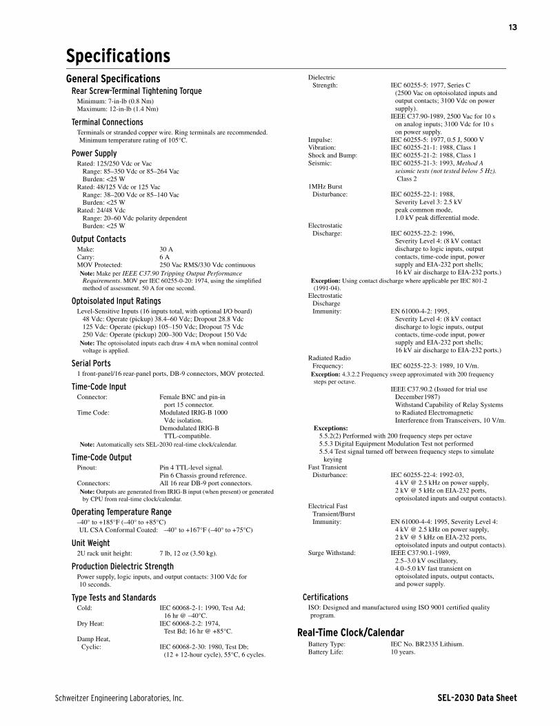
SpecificationsGeneral Specifications
Rear Screw-Terminal Tightening TorqueMinimum: 7-in-lb (0.8 Nm)Maximum: 12-in-lb (1.4 Nm)
Terminal ConnectionsTerminals or stranded copper wire. Ring terminals are recommended. Minimum temperature rating of 105°C.
Power SupplyRated: 125/250 Vdc or Vac
Range: 85–350 Vdc or 85–264 VacBurden: <25 W
Rated: 48/125 Vdc or 125 VacRange: 38–200 Vdc or 85–140 VacBurden: <25 W
Rated: 24/48 VdcRange: 20–60 Vdc polarity dependentBurden: <25 W
Output ContactsMake: 30 ACarry: 6 AMOV Protected: 250 Vac RMS/330 Vdc continuousNote: Make per IEEE C37.90 Tripping Output Performance Requirements. MOV per IEC 60255-0-20: 1974, using the simplified method of assessment. 50 A for one second.
Optoisolated Input RatingsLevel-Sensitive Inputs (16 inputs total, with optional I/O board)
48 Vdc: Operate (pickup) 38.4–60 Vdc; Dropout 28.8 Vdc125 Vdc: Operate (pickup) 105–150 Vdc; Dropout 75 Vdc250 Vdc: Operate (pickup) 200–300 Vdc; Dropout 150 Vdc
Note: The optoisolated inputs each draw 4 mA when nominal control voltage is applied.
Serial Ports1 front-panel/16 rear-panel ports, DB-9 connectors, MOV protected.
Time-Code InputConnector: Female BNC and pin-in
port 15 connector.Time Code: Modulated IRIG-B 1000
Vdc isolation. Demodulated IRIG-B
TTL-compatible.Note: Automatically sets SEL-2030 real-time clock/calendar.
Time-Code OutputPinout: Pin 4 TTL-level signal.
Pin 6 Chassis ground reference.Connectors: All 16 rear DB-9 port connectors.Note: Outputs are generated from IRIG-B input (when present) or generated by CPU from real-time clock/calendar.
Operating Temperature Range–40° to +185°F (–40° to +85°C)UL CSA Conformal Coated: –40° to +167°F (–40° to +75°C)
Unit Weight2U rack unit height: 7 lb, 12 oz (3.50 kg).
Production Dielectric StrengthPower supply, logic inputs, and output contacts: 3100 Vdc for 10 seconds.
Type Tests and StandardsCold: IEC 60068-2-1: 1990, Test Ad;
16 hr @ –40°C.Dry Heat: IEC 60068-2-2: 1974,
Test Bd; 16 hr @ +85°C.Damp Heat,
Cyclic: IEC 60068-2-30: 1980, Test Db;(12 + 12-hour cycle), 55°C, 6 cycles.
Dielectric Strength: IEC 60255-5: 1977, Series C
(2500 Vac on optoisolated inputs andoutput contacts; 3100 Vdc on power supply).
IEEE C37.90-1989, 2500 Vac for 10 son analog inputs; 3100 Vdc for 10 son power supply.
Impulse: IEC 60255-5: 1977, 0.5 J, 5000 VVibration: IEC 60255-21-1: 1988, Class 1Shock and Bump: IEC 60255-21-2: 1988, Class 1Seismic: IEC 60255-21-3: 1993, Method A
seismic tests (not tested below 5 Hz). Class 2
1MHz BurstDisturbance: IEC 60255-22-1: 1988,
Severity Level 3: 2.5 kVpeak common mode,1.0 kV peak differential mode.
Electrostatic Discharge: IEC 60255-22-2: 1996,
Severity Level 4: (8 kV contactdischarge to logic inputs, outputcontacts, time-code input, powersupply and EIA-232 port shells;16 kV air discharge to EIA-232 ports.)
Exception: Using contact discharge where applicable per IEC 801-2(1991-04).
Electrostatic Discharge Immunity: EN 61000-4-2: 1995,
Severity Level 4: (8 kV contactdischarge to logic inputs, outputcontacts, time-code input, powersupply and EIA-232 port shells;16 kV air discharge to EIA-232 ports.)
Radiated RadioFrequency: IEC 60255-22-3: 1989, 10 V/m.
Exception: 4.3.2.2 Frequency sweep approximated with 200 frequency steps per octave.
IEEE C37.90.2 (Issued for trial useDecember1987) Withstand Capability of Relay Systemsto Radiated ElectromagneticInterference from Transceivers, 10 V/m.
Exceptions:5.5.2(2) Performed with 200 frequency steps per octave5.5.3 Digital Equipment Modulation Test not performed5.5.4 Test signal turned off between frequency steps to simulate
keyingFast Transient
Disturbance: IEC 60255-22-4: 1992-03,4 kV @ 2.5 kHz on power supply,2 kV @ 5 kHz on EIA-232 ports,optoisolated inputs and output contacts).
Electrical Fast Transient/Burst Immunity: EN 61000-4-4: 1995, Severity Level 4:
4 kV @ 2.5 kHz on power supply,2 kV @ 5 kHz on EIA-232 ports,optoisolated inputs and output contacts).
Surge Withstand: IEEE C37.90.1-1989,2.5–3.0 kV oscillatory,4.0–5.0 kV fast transient onoptoisolated inputs, output contacts,and power supply.
CertificationsISO: Designed and manufactured using ISO 9001 certified quality program.
Real-Time Clock/CalendarBattery Type: IEC No. BR2335 Lithium.Battery Life: 10 years.

SEL-2030 Data Sheet Schweitzer Engineering Laboratories, Inc.
14
Clock Accuracy: ±20 min/yr @ 25°C(without power applied).
±1 min/yr @ 25°C (withpower applied).
±1 ms with IRIG-B time-code input.
Serial Data Speeds300, 600, 1200, 2400, 4800, 9600, 19200, 38400 bps.
Optional MemoryBase Memory: 256 kB shared RAM, 64 kB EEPROM.Expanded RAM: 1 MB of shared RAM, 64 kB EEPROM.Expanded RAM,
Archive (Flash): 1 MB of shared RAM, 64 kB EEPROM, 2 MB Flash.
Plug-In Card Slots2 card slots; SEL standard shared memory data interface, and virtual terminal support.

Schweitzer Engineering Laboratories, Inc. SEL-2030 Data Sheet
15
Notes

16
© 2002–2007 by Schweitzer Engineering Laboratories, Inc. All rights reserved.
All brand or product names appearing in this document are the trademark or registered trade-mark of their respective holders. No SEL trademarks may be used without written permission.SEL products appearing in this document may be covered by US and Foreign patents.
Schweitzer Engineering Laboratories, Inc. reserves all rights and benefits afforded under fed-eral and international copyright and patent laws in its products, including without limitationsoftware, firmware, and documentation.
The information in this document is provided for informational use only and is subject tochange without notice. Schweitzer Engineering Laboratories, Inc. has approved only theEnglish language document.
This product is covered by the standard SEL 10-year warranty. For warranty details, visitwww.selinc.com or contact your customer service representative. *PDS2030-01*
SCHWEITZER ENGINEERING LABORATORIES2350 NE Hopkins Court • Pullman, WA 99163-5603 - USA
Phone: +1.509.332.1890 • Fax: +1.509.332.7990
Internet: www.selinc.com • E-mail: [email protected]
SEL-2030 Data Sheet Date Code 20070629
Notes