Energy Fuels Resources (USA) Inc. 225 Union Blvd. Suite 600 Lakewood, CO, US, 80228 303 974 2140 www.energyfuels.com April 12, 2021 Via Electronic Mail and Express Delivery Ms. Valerie Thorsen Air Permits Unit Manager Air Quality Division 1110 W. Washington St. Phoenix, AZ 85007 Re: Class II Permit Renewal Application for the Pinyon Plain Mine, Permit No. 62877 (as Amended by No. 86356) Dear Ms. Thorsen: Energy Fuels Resources (USA) Inc. (“EFRI”) operates the Pinyon Plain Mine (the “Mine”) located 6.5 miles southeast of Tusayan, Arizona. The Mine’s Class II Air Quality Permit #62877 (as amended by Amendment #86356) (the “Permit”) is scheduled to expire on October 13, 2021. EFRI is submitting the attached permit application to renew the Permit in accordance with A.A.C. R18-2-304.C.2. Operation of the Mine will remain consistent with the current permit. Please refer to the original Permit application submitted in April 2010, and the minor revision submitted in October 2012 for detailed project description, applicable requirements, facility flow diagram, and dispersion modeling analyses. Potential to Emit emissions have changed slightly from the values included in Permit #62878 and have been updated in the mine’s emission inventory. Additionally, an electronic emissions calculations file has been included with the electronic version submitted via e-mail. Please contact me at 303-389-4132 or [email protected] if you have any questions or need additional information. Sincerely, ENERGY FUELS RESOURCES (USA) INC. Scott A. Bakken Vice President, Regulatory Affairs Enc. ADEQ Class II Renewal Application cc: D. Frydenlund, Kathy Weinel, D. Kolkman (EFRI), E. Farstad (CTEH)

Welcome message from author
This document is posted to help you gain knowledge. Please leave a comment to let me know what you think about it! Share it to your friends and learn new things together.
Transcript
Energy Fuels Resources (USA) Inc.
225 Union Blvd. Suite 600
Lakewood, CO, US, 80228
303 974 2140
www.energyfuels.com
April 12, 2021
Via Electronic Mail and Express Delivery
Ms. Valerie Thorsen Air Permits Unit Manager
Air Quality Division 1110 W. Washington St.
Phoenix, AZ 85007
Re: Class II Permit Renewal Application for the Pinyon Plain Mine, Permit No.
62877 (as Amended by No. 86356)
Dear Ms. Thorsen:
Energy Fuels Resources (USA) Inc. (“EFRI”) operates the Pinyon Plain Mine (the “Mine”) located 6.5 miles southeast of Tusayan, Arizona. The Mine’s Class II Air Quality Permit #62877 (as amended by Amendment #86356) (the “Permit”) is scheduled to expire on October 13,
2021. EFRI is submitting the attached permit application to renew the Permit in accordance
with A.A.C. R18-2-304.C.2. Operation of the Mine will remain consistent with the current permit. Please refer to the original Permit application submitted in April 2010, and the minor revision submitted in October 2012 for detailed project description, applicable requirements, facility flow diagram, and dispersion modeling analyses. Potential to Emit emissions have changed slightly from the values included in Permit #62878 and have been updated in the mine’s emission inventory. Additionally, an electronic emissions calculations file has been included with the electronic version submitted via e-mail.
Please contact me at 303-389-4132 or [email protected] if you have any
questions or need additional information.
Sincerely,
ENERGY FUELS RESOURCES (USA) INC.
Scott A. Bakken
Vice President, Regulatory Affairs Enc. ADEQ Class II Renewal Application cc: D. Frydenlund, Kathy Weinel, D. Kolkman (EFRI), E. Farstad (CTEH)

ATTACHMENT A
CLASS II PERMIT RENEWAL APPLICATION FOR THE PINYON PLAIN MINE

Energy Fuels Resources (USA) Inc.
CLASS II PERMIT RENEWAL APPLICATION FOR
THE PINYON PLAIN MINE
Submitted to:
Arizona Department of Environmental Quality Air Quality Division
1110 West Washington Street Phoenix, Arizona 85007
Submitted by:
Energy Fuels Resources (USA) Inc. 225 Union Blvd., Suite 600
Lakewood, CO 80228
Prepared by:
CTEH, LLC 1114 Washington Ave., Suite 201
Golden, CO 80401
April 12, 2021
i
Table of Contents Section Page Number
1.0 INTRODUCTION ............................................................................................................................. 1
2.0 FACILITY DESCRIPTION .................................................................................................................. 1
3.0 SUMMARY OF FACILITY CHANGES ................................................................................................ 2
4.0 INSIGNIFICANT ACTIVITIES ............................................................................................................ 4
5.0 SUMMARY OF FACILITY EMISSIONS .............................................................................................. 4
6.0 COMPLIANCE SCHEDULE ............................................................................................................... 4
7.0 DRAFT PERMIT LANGUAGE ........................................................................................................... 4
8.0 REFERENCES ................................................................................................................................ 10
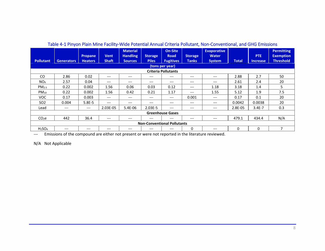
List of Tables Table 4-1 Pinyon Plain Mine Facility-Wide Potential Annual Criteria Pollutant, Non-Conventional, and
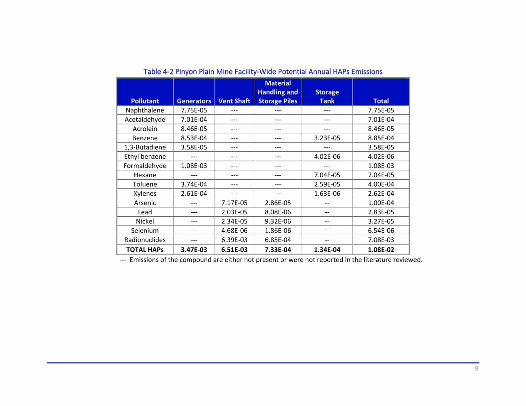
GHG Emissions ...................................................................................................................................... 8 Table 4-2 Pinyon Plain Mine Facility-Wide Potential Annual HAPs Emissions.............................................. 9
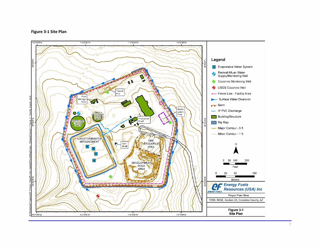
List of Figures Figure 3-1 Site Plan ....................................................................................................................................... 7
List of Appendices Appendix A ............................................................................... Permit Application Form and Equipment List
Appendix B ................................................................................................................... Emission Calculations
Appendix C ............................................................................ Equipment Specifications and Documentation
1
1.0 INTRODUCTION
Energy Fuels Resources (USA) Inc. (EFRI) is submitting this permit application to renew Class II Air Quality Permit #62877 (as amended by 86356) for the Pinyon Plain Mine (formerly called the Canyon Mine) located 6.5 miles southeast of Tusayan, Arizona. Operation of the mine will remain consistent with the current permit. Several minor adjustments to the mine’s equipment and operations are incorporated into this renewal, as detailed in the application materials. None of the changes exceed the Permitting Exemption Thresholds given in Arizona Administrative Code (A.A.C.) R18-2-101.101, nor do all the changes cumulatively exceed the Permitting Exemption Thresholds.
Potential to Emit (PTE) emissions have changed slightly from the values included in Permit #62878 and have been updated in the mine’s emission inventory. Please refer to the original Class II permit application submitted in April 2010 for detailed project description, applicable requirements, facility flow diagram, and dispersion modeling analyses. The electronic emission calculations file is also attached with this application package.
Appendices to this document complete the necessary information required as part of the permit renewal application and include:
Appendix A Permit Application Forms and Equipment List
Appendix B Emission Calculations
2.0 FACILITY DESCRIPTION
The Pinyon Plain Mine is located at Universal Transverse Mercator (UTM) coordinates 401,057 meters east and 3,971,533 meters north (North American Datum [NAD] 83, Zone 12). The location of the site in Coconino County is within an area that is currently classified as an attainment or unclassifiable area for air quality. The maximum annual production rate is 109,500 tons per year (tpy) of uranium ore. Access to the ore deposit is by a conventional vertical shaft located immediately northeast of the deposit.
Raises or incline workings within the mine connect the various levels within, or very near, the deposit. Sublevel workings are driven to extract ore from the deposit at various elevations from these levels. The broken ore is dropped down raises, designed for this use, collecting in drawpoints on the lowest level. The ore is then hauled to the shaft, where it is transferred to skips in the shaft and hoisted to the surface. Barren development rock generated during mining is removed and stockpiled on the surface in the Development Rock Area (DRA) (see Figure 3-1). Ore is stockpiled on the Ore Stockpile Area (OSA) until it is shipped to the off-site processing mill. If the ore cannot be shipped immediately to the mill, it is stored in the OSA. The OSA encompasses approximately 0.7 acres and can accommodate up to 13,100 tons of stockpiled ore.
2
Rock from the mining operations with less than 0.03 percent uranium is stored on the surface in the DRA and in mined-out areas of the underground workings. The DRA encompasses 1.54 acres. An existing topsoil pile is present on the site. It has been seeded and produces only minor dust emissions from wind erosion.
Power for the Pinyon Plain Mine is supplied via overhead electric lines. A diesel generator is used as a source of backup power in the event of power failure. The primary road into the site is the north-south National Forest Road 305A that connects with National Forest Road 305 four miles south of the site. This east-west road connects to State Highway 64 approximately 2 miles west of the 305/305A junction. On-site traffic within the Permit Area Boundary (PAB) occurs during mining operations to access the OSA, the DRA, storage tanks, and maintenance facilities. Surface equipment that routinely travels on on-site roads includes:
• Front-End Loaders
• Highway Ore Haul Trucks
• Water Truck
• Fuel Truck
• Pick-up Trucks
Fuel and other products may be stored on-site in above ground storage tanks (ASTs), drums, and smaller containers. The fueling station is located in the northwestern portion of the site and contains one 6,000-gallon diesel tank. Emissions from the diesel storage tank are included in the emission inventory (Table B -10). Note that the diesel storage tank was inadvertently referred to as a 4,000-gallon diesel tank in previous permit application materials. The storage tank is an insignificant activity per A.A.C. R18-2-101.68 and is therefore not listed in the permit. The tank size has been updated in the emission inventory included with this application.
One ventilation shaft is located on the site. This shaft is required under safety protocols for mine operations. Emissions of criteria pollutants are expected to be very low. Watering required under safety regulations (Mine Safety and Health Administration [MSHA] regulations at Title 30 Code of Federal Regulations [CFR] Part 57) also reduce potential emissions from mining (MSHA 2007).
3.0 SUMMARY OF FACILITY CHANGES
Since the Pinyon Plain Mine’s 2016 permit renewal, a minor revision (#65899) was issued in 2017 to add a new evaporative water spray system (EWS) and an administrative amendment (#86356) was issued in 2020 to change the name of the mine from the “Canyon Mine” to the “Pinyon Plain Mine.” After the 2017 minor revision, EFRI replaced the EWS Landshark evaporator fans with more efficient APEX 2.0 evaporator
3
fans. Both the Landshark fans and the APEX 2.0 fans are manufactured by Resource West Inc. (RWI). The change to more efficient fans resulted in a decrease in potential particulate emissions from the EWS. 10-micron particulate matter (PM10) decreased from 1.98 tons per year (tpy) to 1.55 tpy and 2.5-micron particulate matter (PM2.5) decreased from 1.55 tpy to 1.18 tpy.
Additionally, EFRI is planning several minor adjustments to the mine operation. These changes are described below:
1. The Ore Stockpile Area (OSA) will be moved to a location approximately 300 feet to the east of its current location to allow better access to haul trucks. The OSA will not have an increased area and therefore potential particulate emissions will not increase. The proposed OSA location is shown in Figure 3-1.
2. A small, portable 56-kilowatt (kW) diesel generator will be added to the mine site and will be used for well sampling activities and will be available for emergency power generation in the event of an emergency. This generator is a categorically exempt source based on R18-2-101.24.a. Its PTE emissions have been added to the facility emission inventory (Table B-5). Specifications for the generator are provided in Appendix C.
3. Several small propane space heaters totaling 60,000 British Thermal Units (Btu’s) will be added to the mine site to provide heat during the winter months. The estimated usage is expected to be about 20,000 Btu/hr during winter months but the PTE emissions have been calculated based on maximum hourly and annual usage. These propane space heaters are also categorically exempt activities per R18-2-101.24.a because the combined power with the portable generator is less than 145 hp. Specifications for the space heaters are given in Appendix C.
4. A 350-gallon propane tank will be added to the site to provide propane for the space heaters described above. The propane tank is an insignificant activity per R18-2-101.68.a.iii. Maximum annual throughput for the propane tank will be approximately 5,750 gallons/year.
5. A 150-gallon diesel tote will be added to the mine site for use in fueling mining equipment. The diesel tote is an insignificant activity per R18-2-101.68.a.i. Emission estimates for the diesel tote have been added to the facility emission inventory (Table B-10).
6. A sulfuric acid storage tank will also be added to the mine site. Sulfuric acid will be used as part of a water treatment program. The storage tank (tote) will have a 275-gallon capacity and will be connected to a 75-gallon dosing tank. Any venting from the storage tank/dosing system will be routed into a drum with water and limestone for acid neutralization. Sulfuric acid mist is considered a non-conventional air pollutant by the Arizona Department of Environmental Quality (ADEQ). It is not a hazardous air pollutant. The permitting exemption threshold for sulfuric acid mist is 7 tons per year (tpy) of air emissions and applies to both major and minor sources (A.A.C. R18-2-101.131.B). Potential emissions have been estimated for this storage system and are
4
included in the emission inventory (Table B-17). Based on calculations, the potential sulfuric acid mist emissions will be negligible.
The cumulative emission increases from the six adjustments listed above are below all ADEQ Permitting Exemption Thresholds as detailed in Section 5.0. Therefore, minor New Source Review is not applicable.
4.0 INSIGNIFICANT ACTIVITIES
The proposed new equipment and/or activities are described above. The diesel generator and the propane heaters are categorically exempt activities. The 350-gallon propane tank and the 150-gallon diesel tote are insignificant activities.
5.0 SUMMARY OF FACILITY EMISSIONS
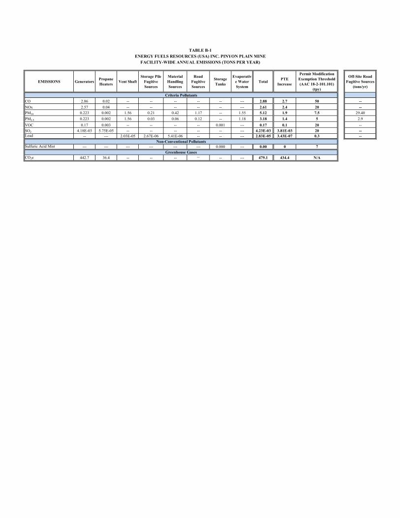
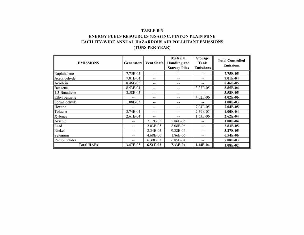
Sources of air emissions associated with the Pinyon Plain Mine include mine vent shaft emissions, diesel generators, propane heaters, small storage tanks, ore and development rock storage and handling, an evaporative water system, and other fugitive emissions. A summary of facility-wide PTE emissions for criteria air pollutants and greenhouse gases (GHGs) is given in Table 4-1. A summary of facility-wide PTE emissions for hazardous air pollutants (HAPs) is given in Table 4-2. PTE emissions increases shown in Tables 4-1 and 4-2 are well below the associated permitting exemption thresholds.
6.0 COMPLIANCE SCHEDULE
All existing sources are in compliance with applicable requirements. Therefore, a compliance schedule is not needed as part of this permit renewal application.
7.0 DRAFT PERMIT LANGUAGE
Should specific permit language be required for the portable 56-kW diesel generator, suggested draft permit language is provided below:
A. Engine Limitations
1. Fuel Limits
The Permittee shall only burn diesel fuel in the internal combustion engine identified in this section.
[A.A.C. R18-2-306.A.2]
5
2. Fuel Requirements
a. The Permittee shall use diesel fuel that meets the requirements of non-road diesel fuel in 40 CFR 80.510(b) and listed below:
1. Sulfur content: 15 ppm maximum; and
2. A minimum cetane index of 40 or a maximum aromatic content of 35 volume percent.
[40 CFR 63.6604(b)]
3. Emission Limitations and Standards
The Permittee shall comply with the emission standards listed in 40 CFR 1039.102.
4. Compliance Requirements
The Permittee shall install and configure the engine according to the manufacturer's specifications.
5. Monitoring and Recordkeeping
The Permittee shall maintain a copy of engine certifications or other documentation demonstrating that each engine complies with the applicable standards in this Permit, and shall make the documentation available to ADEQ upon request.
6. Permit Shield
Compliance with the conditions of this Part shall be deemed compliance with 40 CFR 1039.
[A.A.C. R18-2-325]
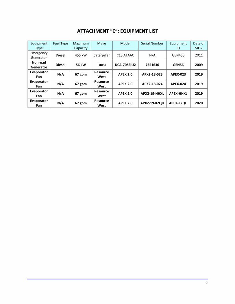
In addition, the following changes to the current permit language in Attachment C of Class II Permit No. 62877 (As amended by 86356) are provided for consideration in the minor permit renewal. Changes are indicated by bold text.
6
ATTACHMENT “C”: EQUIPMENT LIST
Equipment Type
Fuel Type Maximum Capacity
Make Model Serial Number Equipment ID
Date of MFG.
Emergency Generator Diesel 455 kW Caterpillar C15 ATAAC N/A GEN455 2011
Nonroad Generator Diesel 56 kW Isuzu DCA-70SSIU2 7351630 GEN56 2009
Evaporator Fan N/A 67 gpm Resource
West APEX 2.0 APX2-18-023 APEX-023 2019
Evaporator Fan N/A 67 gpm Resource
West APEX 2.0 APX2-18-024 APEX-024 2019
Evaporator Fan N/A 67 gpm Resource
West APEX 2.0 APX2-19-HHXL APEX-HHXL 2019
Evaporator Fan N/A 67 gpm Resource
West APEX 2.0 APX2-19-KZQH APEX-KZQH 2020
7
Figure 3-1 Site Plan
8
Table 4-1 Pinyon Plain Mine Facility-Wide Potential Annual Criteria Pollutant, Non-Conventional, and GHG Emissions
Pollutant
Generators
Propane Heaters
Vent Shaft
Material Handling Sources
Storage Piles
On-Site Road
Fugitives Storage Tanks
Evaporative Water System
Total PTE
Increase
Permitting Exemption Threshold
(tons per year) Criteria Pollutants
CO 2.86 0.02 --- --- --- --- --- --- 2.88 2.7 50 NOX 2.57 0.04 --- --- --- --- --- --- 2.61 2.4 20
PM2.5 0.22 0.002 1.56 0.06 0.03 0.12 --- 1.18 3.18 1.4 5 PM10 0.22 0.002 1.56 0.42 0.21 1.17 --- 1.55 5.12 1.9 7.5 VOC 0.17 0.003 --- --- --- --- 0.001 --- 0.17 0.1 20 SO2 0.004 5.8E-5 --- --- --- --- --- --- 0.0042 0.0038 20 Lead --- --- 2.03E-05 5.4E-06 2.03E-5 --- --- --- 2.8E-05 3.4E-7 0.3
Greenhouse Gases CO2e 442 36.4 --- --- --- --- --- --- 479.1 434.4 N/A
Non-Conventional Pollutants H2SO4 --- --- --- --- --- --- 0 --- 0 0 7
--- Emissions of the compound are either not present or were not reported in the literature reviewed.
N/A Not Applicable
9
Table 4-2 Pinyon Plain Mine Facility-Wide Potential Annual HAPs Emissions
Pollutant
Generators
Vent Shaft
Material Handling and Storage Piles
Storage
Tank
Total Naphthalene 7.75E-05 --- --- --- 7.75E-05 Acetaldehyde 7.01E-04 --- --- --- 7.01E-04
Acrolein 8.46E-05 --- --- --- 8.46E-05 Benzene 8.53E-04 --- --- 3.23E-05 8.85E-04
1,3-Butadiene 3.58E-05 --- --- --- 3.58E-05 Ethyl benzene --- --- --- 4.02E-06 4.02E-06 Formaldehyde 1.08E-03 --- --- --- 1.08E-03
Hexane --- --- --- 7.04E-05 7.04E-05 Toluene 3.74E-04 --- --- 2.59E-05 4.00E-04 Xylenes 2.61E-04 --- --- 1.63E-06 2.62E-04 Arsenic --- 7.17E-05 2.86E-05 -- 1.00E-04
Lead --- 2.03E-05 8.08E-06 -- 2.83E-05 Nickel --- 2.34E-05 9.32E-06 -- 3.27E-05
Selenium --- 4.68E-06 1.86E-06 -- 6.54E-06 Radionuclides --- 6.39E-03 6.85E-04 -- 7.08E-03 TOTAL HAPs 3.47E-03 6.51E-03 7.33E-04 1.34E-04 1.08E-02
--- Emissions of the compound are either not present or were not reported in the literature reviewed.

10
8.0 REFERENCES
Mine Safety and Health Administration (MSHA) Department of Labor. 2007. 30CFR Part 57 – Safety and Health Standards – Underground Metal and Nonmetal Mines. https://www.msha.gov/volume-iv-metal-and-nonmetal-mines-table-contents.
APPENDIX A
Permit Application Form and Equipment List
Class II Permit Application Page 9 of 35 February 23, 2018 Definitions for all terms that are bolded and italicized can be found starting on page 20
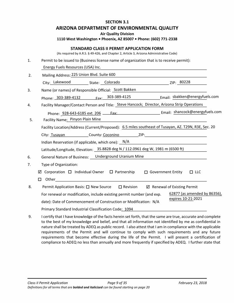
SECTION 3.1
ARIZONA DEPARTMENT OF ENVIRONMENTAL QUALITY Air Quality Division
1110 West Washington • Phoenix, AZ 85007 • Phone: (602) 771-2338
STANDARD CLASS II PERMIT APPLICATION FORM (As required by A.R.S. § 49-426, and Chapter 2, Article 3, Arizona Administrative Code)
1. Permit to be issued to (Business license name of organization that is to receive permit):
State: ZIP:
3. Name (or names) of Responsible Official:
Email:
4. Facility Manager/Contact Person and Title:
Email:
ZIP:
Latitude/Longitude, Elevation:
6. General Nature of Business:
7. Type of Organization:
Corporation Individual Owner Partnership Government Entity LLC
Other
8. Permit Application Basis: New Source Revision Renewal of Existing Permit
For renewal or modification, include existing permit number (and exp.
date): Date of Commencement of Construction or Modification: N/A
Primary Standard Industrial Classification Code: 1094
9. I certify that I have knowledge of the facts herein set forth, that the same are true, accurate and completeto the best of my knowledge and belief, and that all information not identified by me as confidential innature shall be treated by ADEQ as public record. I also attest that I am in compliance with the applicablerequirements of the Permit and will continue to comply with such requirements and any futurerequirements that become effective during the life of the Permit. I will present a certification ofcompliance to ADEQ no less than annually and more frequently if specified by ADEQ. I further state that
Energy Fuels Resources (USA) Inc.
225 Union Blvd. Suite 6002. Mailing Address:
City: Lakewood Colorado 80228
Scott Bakken
Phone: 303-389-4132 Fax: 303-389-4125 [email protected]
Steve Hancock; Director, Arizona Strip Operations
Fax: [email protected]: 928-643-6185 ext. 206 5. Facility Name: Pinyon Plain Mine
6.5 miles southeast of Tusayan, AZ. T29N, R3E, Sec. 20Facility Location/Address (Current/Proposed):
City: Tusayan County: Coconino
Indian Reservation (if applicable, which one): N/A
35.8828 deg N / 112.0961 deg W, 1981 m (6500 ft)
Underground Uranium Mine
62877 (as amended by 86356), expires 10-21-2021
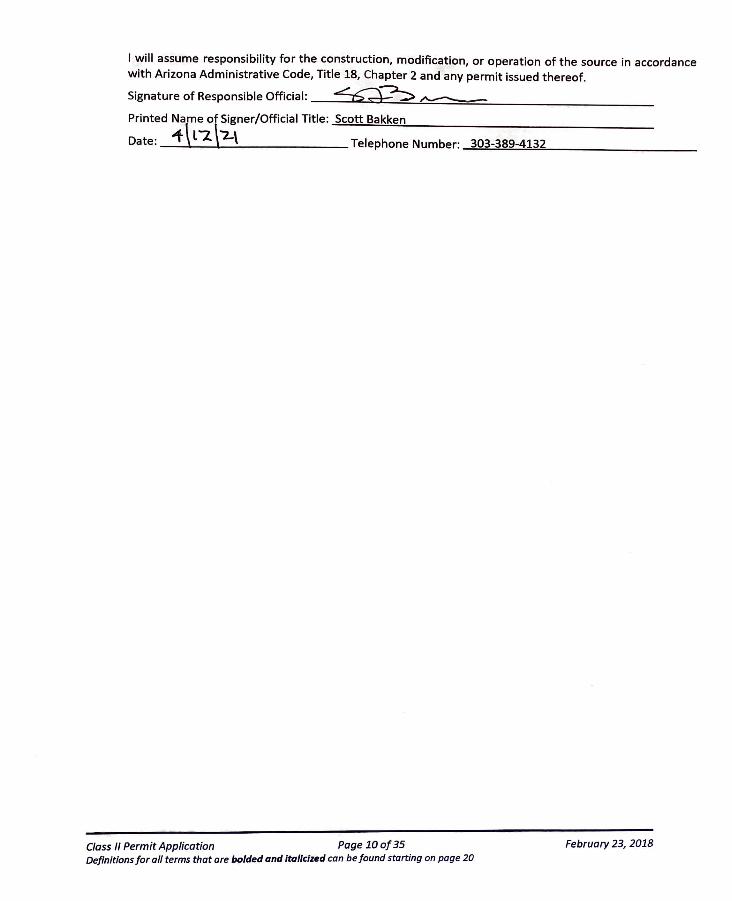
I will assume responsibility for the construction, modification, or operation of the source in accordance with Arizona Administrative Code, Title 18, Chapter 2 and any permit issued thereof.
Signature of Responsible Official:
Printed Name of Signer/Official Title: ..;:S:.ac::.::o:.:tt.:...::;B.::.a.:.:.kk:.::e""n..:..... ________________ _
Date: -f \ l "2. \2 \ Telephone Number: .....::.3.:::.03:::...-..:::::3.,._89::...-.;;,4.._l::.:32=-----------
Class II Permit Application Page 10 of 35 February 23, 2018 Definitions for all terms that are balded and Italicized can be found starting on page 20
Class II Permit Application Page 18 of 35 February 23, 2018 Definitions for all terms that are bolded and italicized can be found starting on page 20
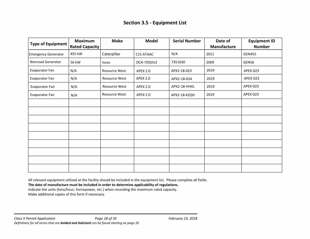
Section 3.5 - Equipment List
Type of EquipmentMaximum
Rated Capacity Make Model Serial Number Date of
ManufactureEquipment ID
Number
All relevant equipment utilized at the facility should be included in the equipment list. Please complete all fields. The date of manufacture must be included in order to determine applicability of regulations.Indicate the units (tons/hour, horsepower, etc.) when recording the maximum rated capacity. Make additional copies of this form if necessary.
Emergency Generator 455 kW Caterpillar C15 ATAAC N/A 2011 GEN455
Nonroad Generator 56 kW Isuzu DCA-70SSIU2 7351630 GEN562009
Evaporator Fan N/A
Resource West APEX 2.0
APX2-18-023 2019
APEX-023
Evaporator Fan
Evaporator Fan
Evaporator Fan N/A
N/A
N/A
Resource West
Resource West
Resource West
APEX 2.0
APEX 2.0
APEX 2.0
APX2-18-024
APX2-18-HHXL
APX2-18-KZQH
2019
2019
2019
APEX-023
APEX-023
APEX-023
Class II Permit Application Page 19 of 35 February 23, 2018 Definitions for all terms that are bolded and italicized can be found starting on page 20
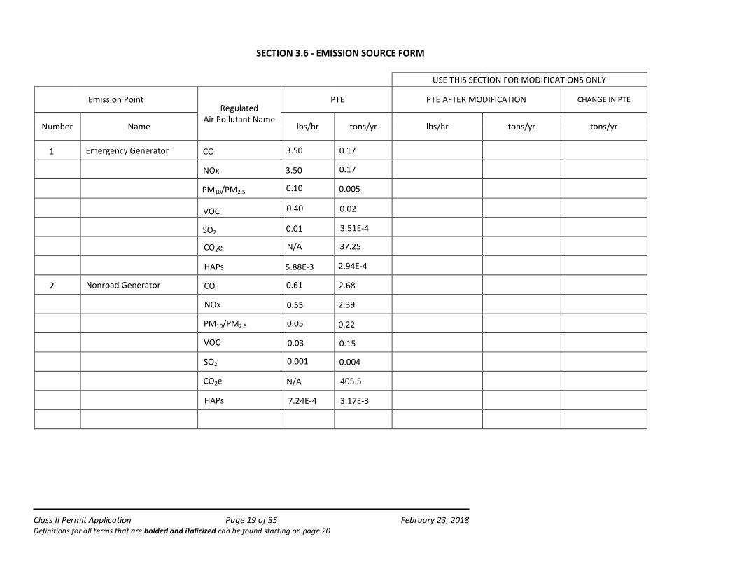
SECTION 3.6 - EMISSION SOURCE FORM
USE THIS SECTION FOR MODIFICATIONS ONLY
Emission Point Regulated
Air Pollutant Name
PTE PTE AFTER MODIFICATION CHANGE IN PTE
Number Name lbs/hr tons/yr lbs/hr tons/yr tons/yr
1
2
Emergency Generator CO
NOx
PM10/PM2.5
VOC
SO2
3.50 0.17
3.50 0.17
0.10 0.005
0.40 0.02
0.01 3.51E-4
HAPs 5.88E-3 2.94E-4
Nonroad Generator CO
NOx
0.61 2.68
0.55 2.39
PM10/PM2.5 0.05 0.22
SO2 0.001 0.004
CO2e N/A 37.25
VOC 0.150.03
HAPs
CO2e
3.17E-3
405.5N/A
7.24E-4
Class II Permit Application Page 19 of 35 February 23, 2018 Definitions for all terms that are bolded and italicized can be found starting on page 20
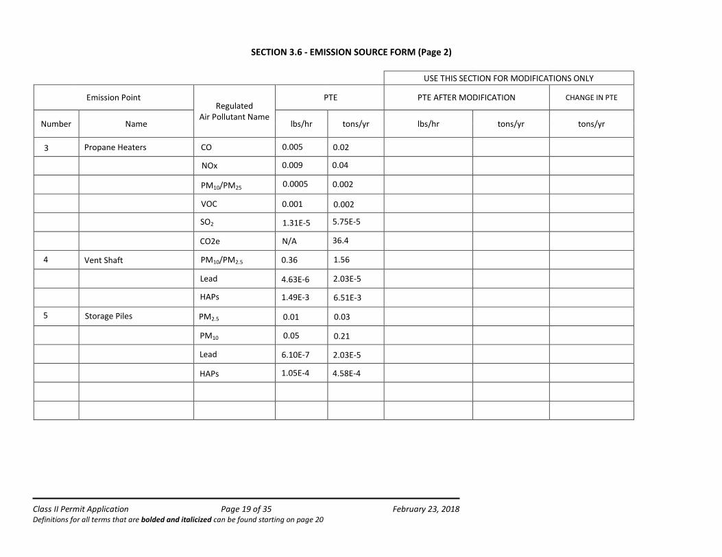
SECTION 3.6 - EMISS ION SOURCE FORM (Page 2)
USE THIS SECTION FOR MODIFICATIONS ONLY
Emission Point Regulated
Air Pollutant Name
PTE PTE AFTER MODIFICATION CHANGE IN PTE
Number Name lbs/hr tons/yr lbs/hr tons/yr tons/yr
Vent Shaft
PM10
5 Storage Piles PM2.5
Lead
0.01 0.03
0.05 0.21
1.05E-4 4.58E-4
3
5.75E-5
0.36
0.0020.0005
0.040.009
PM10/PM25
NOx
SO2
CO2e
PM10/PM2.5
HAPs
0.002
6.10E-7
1.56
36.4N/A
1.49E-3
4
HAPs
Lead 2.03E-5
6.51E-3
2.03E-54.63E-6
VOC 0.001
1.31E-5
CO 0.005 0.02Propane Heaters
Class II Permit Application Page 19 of 35 February 23, 2018 Definitions for all terms that are bolded and italicized can be found starting on page 20
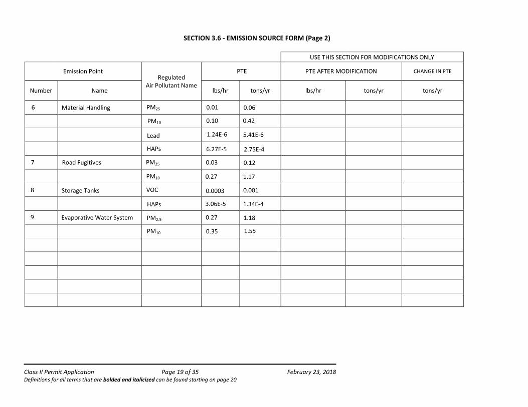
SECTION 3.6 - EMISS ION SOURCE FORM (Page 2)
USE THIS SECTION FOR MODIFICATIONS ONLY
Emission Point Regulated
Air Pollutant Name
PTE PTE AFTER MODIFICATION CHANGE IN PTE
Number Name lbs/hr tons/yr lbs/hr tons/yr tons/yr
7
Storage Tanks
PM10
PM2.5
0.35
0.27
1.55
1.189 Evaporative Water System
VOC
Road Fugitives
6
0.27
5.41E-61.24E-6
0.420.10
PM25
PM10
HAPs
PM10
PM25
HAPs
2.75E-4
1.17
0.120.03
3.06E-5
8
1.34E-4
0.0010.0003
Lead
6.27E-5
0.01 0.06Material Handling
Class II Permit Application Page 35 of 35 February 23, 2018 Definitions for all terms that are bolded and italicized can be found starting on page 20
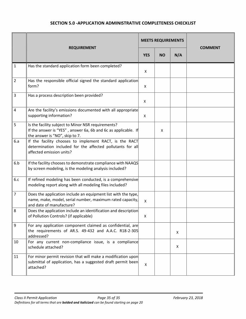
SECTION 5.0 -APPLICATION ADMINISTRATIVE COMPLETENESS CHECKLIST
REQUIREMENT
MEETS REQUIREMENTS
COMMENT
YES NO N/A
1 Has the standard application form been completed?
2 Has the responsible official signed the standard application form?
3 Has a process description been provided?
4 Are the facility’s emissions documented with all appropriate supporting information?
5 Is the facility subject to Minor NSR requirements? If the answer is “YES” , answer 6a, 6b and 6c as applicable. If the answer is “NO”, skip to 7.
6.a If the facility chooses to implement RACT, is the RACT determination included for the affected pollutants for all affected emission units?
6.b If the facility chooses to demonstrate compliance with NAAQS by screen modeling, is the modeling analysis included?
6.c If refined modeling has been conducted, is a comprehensive modeling report along with all modeling files included?
7 Does the application include an equipment list with the type, name, make, model, serial number, maximum rated capacity, and date of manufacture?
8 Does the application include an identification and description of Pollution Controls? (if applicable)
9 For any application component claimed as confidential, are the requirements of AR.S. 49-432 and A.A.C. R18-2-305 addressed?
10 For any current non-compliance issue, is a compliance schedule attached?
11 For minor permit revision that will make a modification upon submittal of application, has a suggested draft permit been attached?
X
X
X
X
X
X
X
X
X
X
APPENDIX B
Emission Calculations
EMISSIONS GeneratorsPropane Heaters
Vent ShaftStorage Pile
Fugitive Sources
Material Handling Sources
Road Fugitive Sources
Storage Tanks
Evaporative Water System
TotalPTE
Increase
Permit Modification Exemption Threshold(AAC 18-2-101.101)
(tpy)
Off-Site Road Fugitive Sources
(tons/yr)
CO 2.86 0.02 -- -- -- -- -- --- 2.88 2.7 50 --
NOx 2.57 0.04 -- -- -- -- -- --- 2.61 2.4 20 --
PM10 0.223 0.002 1.56 0.21 0.42 1.17 -- 1.55 5.12 1.9 7.5 29.40
PM2.5 0.223 0.002 1.56 0.03 0.06 0.12 -- 1.18 3.18 1.4 5 2.9
VOC 0.17 0.003 -- -- -- -- 0.001 --- 0.17 0.1 20 --
SO2 4.18E-03 5.75E-05 -- -- -- -- -- --- 4.23E-03 3.81E-03 20 --Lead -- --- 2.03E-05 2.67E-06 5.41E-06 -- -- --- 2.83E-05 3.43E-07 0.3 --
Sulfuric Acid Mist --- --- --- --- --- --- 0.000 --- 0.00 0 7
CO2e 442.7 36.4 -- -- -- -- -- --- 479.1 434.4 N/AGreenhouse Gases
TABLE B-1ENERGY FUELS RESOURCES (USA) INC. PINYON PLAIN MINE
FACILITY-WIDE ANNUAL EMISSIONS (TONS PER YEAR)
Non-Conventional Pollutants
Criteria Pollutants
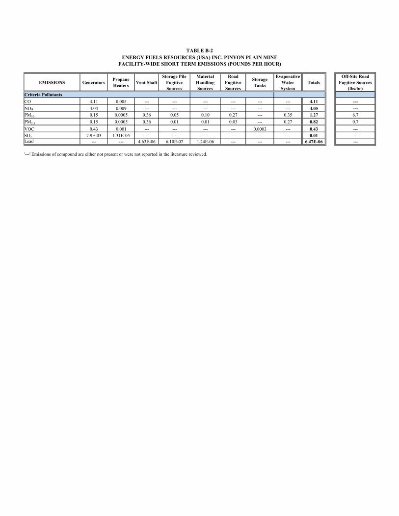
EMISSIONS GeneratorsPropane Heaters
Vent ShaftStorage Pile
Fugitive Sources
Material Handling Sources
Road Fugitive Sources
Storage Tanks
Evaporative Water System
TotalsOff-Site Road
Fugitive Sources (lbs/hr)
Criteria Pollutants
CO 4.11 0.005 --- --- --- --- --- --- 4.11 ---
NOx 4.04 0.009 --- --- --- --- --- --- 4.05 ---PM10 0.15 0.0005 0.36 0.05 0.10 0.27 --- 0.35 1.27 6.7
PM2.5 0.15 0.0005 0.36 0.01 0.01 0.03 --- 0.27 0.82 0.7
VOC 0.43 0.001 --- --- --- --- 0.0003 --- 0.43 ---SO2 7.9E-03 1.31E-05 --- --- --- --- --- --- 0.01 ---Lead --- --- 4.63E-06 6.10E-07 1.24E-06 --- --- --- 6.47E-06 ---
'---' Emissions of compound are either not present or were not reported in the literature reviewed.
TABLE B-2ENERGY FUELS RESOURCES (USA) INC. PINYON PLAIN MINE
FACILITY-WIDE SHORT TERM EMISSIONS (POUNDS PER HOUR)
EMISSIONS Generators Vent ShaftMaterial
Handling and Storage Piles
Storage Tank
Emissions
Total Controlled Emissions
Naphthalene 7.75E-05 -- -- -- 7.75E-05Acetaldehyde 7.01E-04 -- -- -- 7.01E-04Acrolein 8.46E-05 -- -- -- 8.46E-05Benzene 8.53E-04 -- -- 3.23E-05 8.85E-041,3-Butadiene 3.58E-05 -- -- -- 3.58E-05Ethyl benzene -- -- -- 4.02E-06 4.02E-06Formaldehyde 1.08E-03 -- -- -- 1.08E-03Hexane -- -- -- 7.04E-05 7.04E-05Toluene 3.74E-04 -- -- 2.59E-05 4.00E-04Xylenes 2.61E-04 -- -- 1.63E-06 2.62E-04Arsenic -- 7.17E-05 2.86E-05 -- 1.00E-04Lead -- 2.03E-05 8.08E-06 -- 2.83E-05Nickel -- 2.34E-05 9.32E-06 -- 3.27E-05Selenium -- 4.68E-06 1.86E-06 -- 6.54E-06Radionuclides -- 6.39E-03 6.85E-04 -- 7.08E-03
Total HAPs 3.47E-03 6.51E-03 7.33E-04 1.34E-04 1.08E-02
TABLE B-3ENERGY FUELS RESOURCES (USA) INC. PINYON PLAIN MINE
FACILITY-WIDE ANNUAL HAZARDOUS AIR POLLUTANT EMISSIONS(TONS PER YEAR)
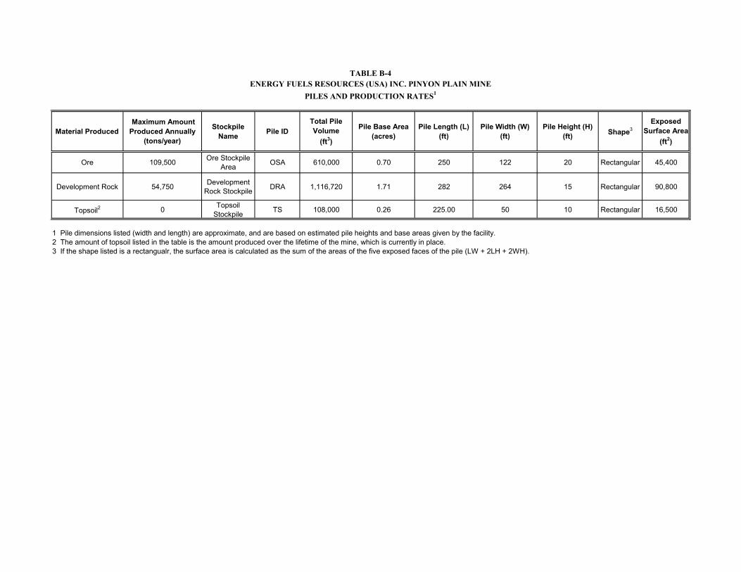
Material Produced Maximum Amount Produced Annually
(tons/year)
Stockpile Name Pile ID
Total Pile Volume
(ft3)
Pile Base Area (acres)
Pile Length (L) (ft)
Pile Width (W)(ft)
Pile Height (H)(ft) Shape3
Exposed Surface Area
(ft2)
Ore 109,500 Ore Stockpile Area OSA 610,000 0.70 250 122 20 Rectangular 45,400
Development Rock 54,750 Development Rock Stockpile DRA 1,116,720 1.71 282 264 15 Rectangular 90,800
Topsoil2 0 Topsoil Stockpile TS 108,000 0.26 225.00 50 10 Rectangular 16,500
1 Pile dimensions listed (width and length) are approximate, and are based on estimated pile heights and base areas given by the facility.2 The amount of topsoil listed in the table is the amount produced over the lifetime of the mine, which is currently in place.3 If the shape listed is a rectangualr, the surface area is calculated as the sum of the areas of the five exposed faces of the pile (LW + 2LH + 2WH).
ENERGY FUELS RESOURCES (USA) INC. PINYON PLAIN MINE
PILES AND PRODUCTION RATES1
TABLE B-4
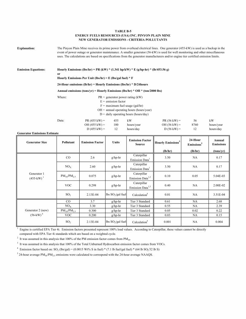
Explanation:
Emission Equations: Hourly Emissions (lbs/hr) = PR (kW) * (1.341 hp/kW) * E (g/hp-hr) * (lb/453.56 g)orHourly Emissions Per Unit (lbs/hr) = E (lbs/gal fuel) * F
24-Hour emissions (lb/hr) = Hourly Emissions (lbs/hr) * D/24hours
Annual emissions (tons/yr) = Hourly Emissions (lbs/hr) * OH * (ton/2000 lbs)
Where: PR = generator power rating (kW)E = emission factorF = maximum fuel usage (gal/hr)
OH = annual operating hours (hours/year)D = daily operating hours (hours/day)
Data: PR (455 kW) = 455 kW PR (56 kW) = 56 kWOH (455 kW) = 100 hours/year OH (56 kW) = 8760 hours/year
D (455 kW) = 12 hours/day D (56 kW) = 12 hours/dayGenerator Emissions Estimate
Generator Size Pollutant Emission Factor UnitsEmission Factor
Source Hourly Emissions5 24-Hour
Emissions5Annual
Emissions
(lb/hr) (lb/hr) (tons/yr)
CO 2.6 g/hp-hrCaterpillar
Emission Data1 3.50 NA 0.17
NOX 2.60 g/hp-hrCaterpillar
Emission Data1 3.50 NA 0.17
PM10/PM2.5 0.075 g/hp-hrCaterpillar
Emission Data1,2 0.10 0.05 5.04E-03
VOC 0.298 g/hp-hrCaterpillar
Emission Data1,3 0.40 NA 2.00E-02
SO2 2.13E-04 lbs SO2/gal fuel Calculation4 0.01 NA 3.51E-04
CO 3.7 g/hp-hr Tier 3 Standard 0.61 NA 2.68NOX 3.30 g/hp-hr Tier 3 Standard 0.55 NA 2.39
PM10/PM2.5 0.300 g/hp-hr Tier 3 Standard 0.05 0.02 0.22
VOC 0.200 g/hp-hr Tier 3 Standard 0.03 NA 0.15
SO2 2.13E-04 lbs SO2/gal fuel Calculation4 0.001 NA 0.004
1 Engine is certified EPA Tier 4i. Emission factors presented represent 100% load values. According to Caterpillar, these values cannot be directly compared with EPA Tier 4i standards which are based on a weighted cycle.2 It was assumed in this analysis that 100% of the PM emission factor comes from PM10.3 It was assumed in this analysis that 100% of the Total Unburned Hydrocarbon emission factor comes from VOCs.4 Emission factor based on: SO2 (lbs/gal) = (0.0015 Wt% S in fuel) * (7.1 lb fuel/gal fuel) * (64 lb SO2/32 lb S)5 24-hour average PM10/PM2.5 emissions were calculated to correspond with the 24-hour average NAAQS.
TABLE B-5ENERGY FUELS RESOURCES (USA) INC. PINYON PLAIN MINE
NEW GENERATOR EMISSIONS - CRITERIA POLLUTANTS
Generator 1
(455-kW) 1
Generator 2 (new)
(56-kW) 6
The Pinyon Plain Mine receives its prime power from overhead electrical lines. One generator (455-kW) is used as a backup in the event of power outage or generator maintenance. A smaller generator (56-kW) is used for well monitoring and other miscellaneous uses. The calculations are based on specifications from the generator manufacturers and/or engine tier certified emission limits.
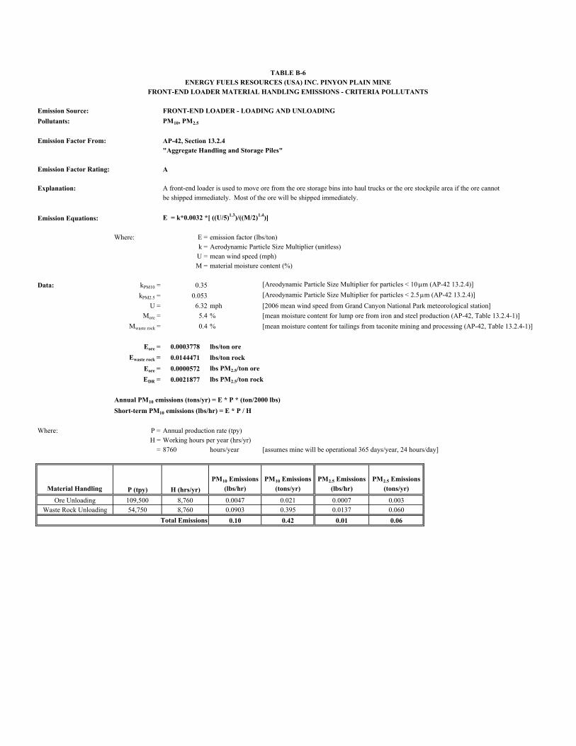
Emission Source: FRONT-END LOADER - LOADING AND UNLOADING
Pollutants: PM10, PM2.5
Emission Factor From: AP-42, Section 13.2.4"Aggregate Handling and Storage Piles"
Emission Factor Rating: A
Explanation: A front-end loader is used to move ore from the ore storage bins into haul trucks or the ore stockpile area if the ore cannot be shipped immediately. Most of the ore will be shipped immediately.
Emission Equations: E = k*0.0032 *[ ((U/5)1.3)/((M/2)1.4)]
Where: E = emission factor (lbs/ton)k = Aerodynamic Particle Size Multiplier (unitless)U = mean wind speed (mph)M = material moisture content (%)
Data: kPM10 = 0.35 [Areodynamic Particle Size Multiplier for particles < 10 m (AP-42 13.2.4)]
kPM2.5 = 0.053 [Areodynamic Particle Size Multiplier for particles < 2.5 m (AP-42 13.2.4)]
U = 6.32 mph [2006 mean wind speed from Grand Canyon National Park meteorological station]
More = 5.4 % [mean moisture content for lump ore from iron and steel production (AP-42, Table 13.2.4-1)]
Mwaste rock = 0.4 % [mean moisture content for tailings from taconite mining and processing (AP-42, Table 13.2.4-1)]
0.0003778 lbs/ton ore
Ewaste rock = 0.0144471 lbs/ton rock
0.0000572 lbs PM2.5/ton ore
EDR = 0.0021877 lbs PM2.5/ton rock
Annual PM10 emissions (tons/yr) = E * P * (ton/2000 lbs)
Short-term PM10 emissions (lbs/hr) = E * P / H
Where: P = Annual production rate (tpy)H = Working hours per year (hrs/yr)
= 8760 hours/year [assumes mine will be operational 365 days/year, 24 hours/day]
Material Handling P (tpy) H (hrs/yr)
PM10 Emissions
(lbs/hr)
PM10 Emissions
(tons/yr)
PM2.5 Emissions
(lbs/hr)
PM2.5 Emissions
(tons/yr)
Ore Unloading 109,500 8,760 0.0047 0.021 0.0007 0.003Waste Rock Unloading 54,750 8,760 0.0903 0.395 0.0137 0.060
0.10 0.42 0.01 0.06Total Emissions
Eore =
Eore =
TABLE B-6ENERGY FUELS RESOURCES (USA) INC. PINYON PLAIN MINE
FRONT-END LOADER MATERIAL HANDLING EMISSIONS - CRITERIA POLLUTANTS
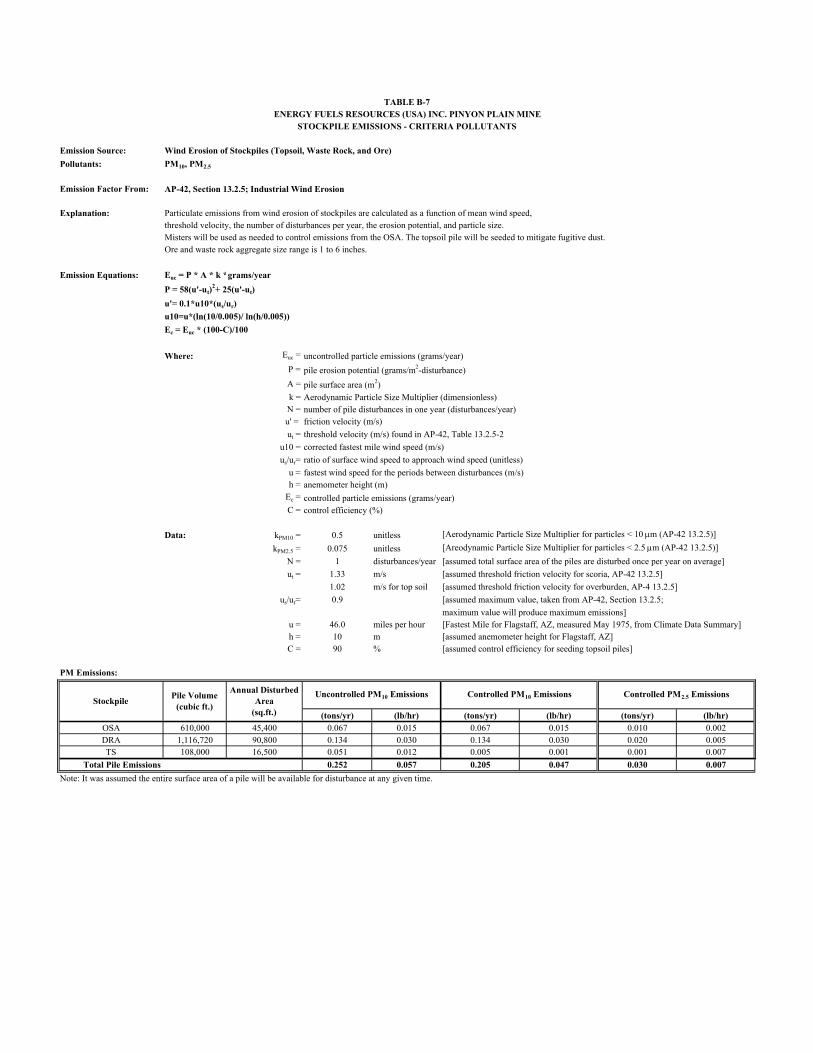
Emission Source: Wind Erosion of Stockpiles (Topsoil, Waste Rock, and Ore)
Pollutants: PM10, PM2.5
Emission Factor From: AP-42, Section 13.2.5; Industrial Wind Erosion
Explanation: Particulate emissions from wind erosion of stockpiles are calculated as a function of mean wind speed,threshold velocity, the number of disturbances per year, the erosion potential, and particle size.Misters will be used as needed to control emissions from the OSA. The topsoil pile will be seeded to mitigate fugitive dust.Ore and waste rock aggregate size range is 1 to 6 inches.
Emission Equations: Euc = P * A * k *grams/year
P = 58(u'-ut)2+ 25(u'-ut)
u'= 0.1*u10*(us/ur)
u10=u*(ln(10/0.005)/ ln(h/0.005))
Ec = Euc * (100-C)/100
Where: Euc = uncontrolled particle emissions (grams/year)
P = pile erosion potential (grams/m2-disturbance)
A = pile surface area (m2)k = Aerodynamic Particle Size Multiplier (dimensionless)N = number of pile disturbances in one year (disturbances/year)u' = friction velocity (m/s)
ut = threshold velocity (m/s) found in AP-42, Table 13.2.5-2
u10 = corrected fastest mile wind speed (m/s)
us/ur= ratio of surface wind speed to approach wind speed (unitless)
u = fastest wind speed for the periods between disturbances (m/s)h = anemometer height (m)
Ec = controlled particle emissions (grams/year)C = control efficiency (%)
Data: kPM10 = 0.5 unitless [Aerodynamic Particle Size Multiplier for particles < 10 m (AP-42 13.2.5)]
kPM2.5 = 0.075 unitless [Areodynamic Particle Size Multiplier for particles < 2.5 m (AP-42 13.2.5)]
N = 1 disturbances/year [assumed total surface area of the piles are disturbed once per year on average]
ut = 1.33 m/s [assumed threshold friction velocity for scoria, AP-42 13.2.5]
1.02 m/s for top soil [assumed threshold friction velocity for overburden, AP-4 13.2.5]
us/ur= 0.9 [assumed maximum value, taken from AP-42, Section 13.2.5;
maximum value will produce maximum emissions]u = 46.0 miles per hour [Fastest Mile for Flagstaff, AZ, measured May 1975, from Climate Data Summary]h = 10 m [assumed anemometer height for Flagstaff, AZ]C = 90 % [assumed control efficiency for seeding topsoil piles]
PM Emissions:
(tons/yr) (lb/hr) (tons/yr) (lb/hr) (tons/yr) (lb/hr)OSA 610,000 45,400 0.067 0.015 0.067 0.015 0.010 0.002DRA 1,116,720 90,800 0.134 0.030 0.134 0.030 0.020 0.005TS 108,000 16,500 0.051 0.012 0.005 0.001 0.001 0.007
Total Pile Emissions 0.252 0.057 0.205 0.047 0.030 0.007
Note: It was assumed the entire surface area of a pile will be available for disturbance at any given time.
TABLE B-7ENERGY FUELS RESOURCES (USA) INC. PINYON PLAIN MINE
STOCKPILE EMISSIONS - CRITERIA POLLUTANTS
StockpileAnnual Disturbed
Area(sq.ft.)
Uncontrolled PM10 EmissionsPile Volume(cubic ft.)
Controlled PM10 Emissions Controlled PM2.5 Emissions
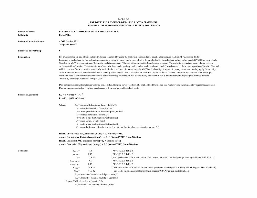
Emission Source: FUGITIVE DUST EMISSIONS FROM VEHICLE TRAFFIC
Pollutants: PM10, PM2.5
Emission Factor Reference: AP-42, Section 13.2.2"Unpaved Roads"
Emission Factor Rating: B
Explanation: PM emissions for on- and off-site vehicle traffic are calculated by using the predictive emission factor equation for unpaved roads in AP-42, Section 13.2.2. Emissions are calculated by first calculating an emission factor for each vehicle type, which is then multiplied by the calculated vehicle miles traveled (VMT) for each vehicle.To calculate VMT, an examination of the on-site roads is necessary. All roads within the facility boundary are unpaved. The main site access is an unpaved road entering on the east side of the site. The vast majority of truck (i.e. haul trucks, pick-up trucks, tanker trucks, and water trucks) travel occurs on the southern portion of the site. Nonroad vehicles, such as front-end loaders, travel only on site in the portal area. In most cases, the VMT is calculated by taking the frequency of use and multiplying by the quantityof the amount of material hauled divided by the capacity of the vehicle. The product is then multiplied by the haul road distance times two, to accommodate round-trips. When the VMT is not dependant on the amount of material being hauled (such as a pickup truck), the annual VMT is determined by multiplying the distance traveled per trip by an average number of trips per year.
Dust suppression methods including watering as needed and limiting travel speeds will be applied to all traveled on-site roadways and the immediately adjacent access road. Dust suppression methods of limiting travel speeds will be applied to off-site haul roads.
Emission Equations: Euc = k * (s/12)a * (W/3)b
Ec = Euc * [(100 - C) / 100]
Where: Euc = uncontrolled emission factor (lbs/VMT)Ec = controlled emission factor (lbs/VMT)k = Aerodynamic Particle Size Multiplier (unitless)s = surface material silt content (%)a = particle size multiplier constant (unitless)
W = mean vehicle weight (tons)b = particle size multiplier constant (unitless)C = control efficiency of surfactant used to mitigate fugitive dust emissions from roads (%)
Hourly Uncontrolled PM10 emissions (lbs/hr) = Euc * (hourly VMT)
Annual Uncontrolled PM10 emissions (tons/yr) = Euc * (Annual VMT) * (ton/2000 lbs)
Hourly Controlled PM10 emissions (lbs/hr) = Ec * (hourly VMT)
Annual Controlled PM10 emissions (tons/yr) = Ec * (Annual VMT) * (ton/2000 lbs)
Constants: kPM10 = 1.5 [AP-42 13.2.2, Table 2]
kPM2.5 = 0.15 [AP-42 13.2.2, Table 2]
s = 5.8 % [average silt content for a haul road (to/from pit) at a taconite ore mining and processing facility (AP-42, 13.2.2)]
aPM10,PM2.5 = 0.9 [AP-42 13.2.2, Table 2]
bPM10,PM2.5 = 0.45 [AP-42 13.2.2, Table 2]
COSR = 74.8 % [Onsite roads: emission control for low travel speeds and watering (44% + 55%); WRAP Fugitive Dust Handbook]
CHR = 44.0 % [Haul roads: emission control for low travel speeds; WRAP Fugitive Dust Handbook]
Lhr = Amount of material hauled per hour (tph)
Lyr = Amount of material hauled per year (tpy)
Annual VMT = Lyr / Truck Capacity * Drt
Drt = Round-Trip Hauling Distance (miles)
TABLE B-8ENERGY FUELS RESOURCES (USA) INC. PINYON PLAIN MINE
FUGITIVE UNPAVED ROAD EMISSIONS - CRITERIA POLLUTANTS
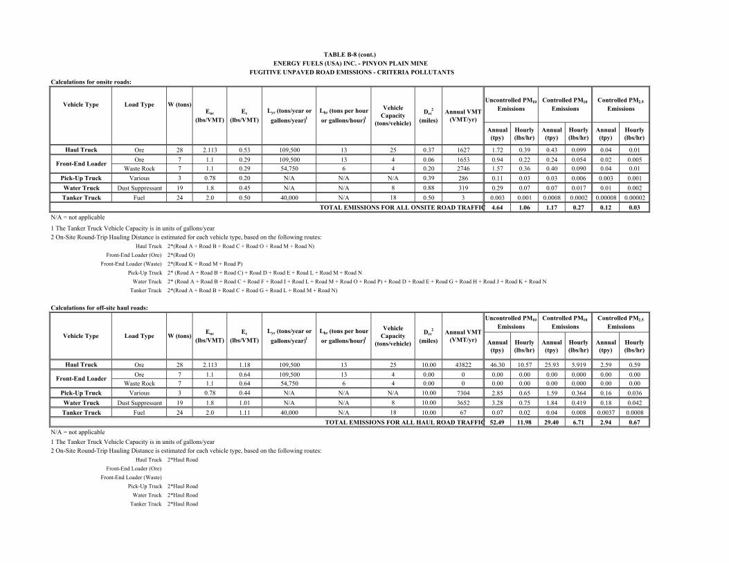
Calculations for onsite roads:
Vehicle Type Load Type W (tons)
Annual (tpy)
Hourly (lbs/hr)
Annual (tpy)
Hourly (lbs/hr)
Annual (tpy)
Hourly (lbs/hr)
Haul Truck Ore 28 2.113 0.53 109,500 13 25 0.37 1627 1.72 0.39 0.43 0.099 0.04 0.01
Ore 7 1.1 0.29 109,500 13 4 0.06 1653 0.94 0.22 0.24 0.054 0.02 0.005Waste Rock 7 1.1 0.29 54,750 6 4 0.20 2746 1.57 0.36 0.40 0.090 0.04 0.01
Pick-Up Truck Various 3 0.78 0.20 N/A N/A N/A 0.39 286 0.11 0.03 0.03 0.006 0.003 0.001
Water Truck Dust Suppressant 19 1.8 0.45 N/A N/A 8 0.88 319 0.29 0.07 0.07 0.017 0.01 0.002
Tanker Truck Fuel 24 2.0 0.50 40,000 N/A 18 0.50 3 0.003 0.001 0.0008 0.0002 0.00008 0.00002
TOTAL EMISSIONS FOR ALL ONSITE ROAD TRAFFIC 4.64 1.06 1.17 0.27 0.12 0.03
N/A = not applicable
1 The Tanker Truck Vehicle Capacity is in units of gallons/year2 On-Site Round-Trip Hauling Distance is estimated for each vehicle type, based on the following routes:
Haul Truck 2*(Road A + Road B + Road C + Road O + Road M + Road N)
Front-End Loader (Ore) 2*(Road O)
Front-End Loader (Waste) 2*(Road K + Road M + Road P)
Pick-Up Truck 2* (Road A + Road B + Road C) + Road D + Road E + Road L + Road M + Road N
Water Truck 2* (Road A + Road B + Road C + Road F + Road I + Road L + Road M + Road O + Road P) + Road D + Road E + Road G + Road H + Road J + Road K + Road N
Tanker Truck 2*(Road A + Road B + Road C + Road G + Road L + Road M + Road N)
Calculations for off-site haul roads:
Annual (tpy)
Hourly (lbs/hr)
Annual (tpy)
Hourly (lbs/hr)
Annual (tpy)
Hourly (lbs/hr)
Haul Truck Ore 28 2.113 1.18 109,500 13 25 10.00 43822 46.30 10.57 25.93 5.919 2.59 0.59
Ore 7 1.1 0.64 109,500 13 4 0.00 0 0.00 0.00 0.00 0.000 0.00 0.00Waste Rock 7 1.1 0.64 54,750 6 4 0.00 0 0.00 0.00 0.00 0.000 0.00 0.00
Pick-Up Truck Various 3 0.78 0.44 N/A N/A N/A 10.00 7304 2.85 0.65 1.59 0.364 0.16 0.036
Water Truck Dust Suppressant 19 1.8 1.01 N/A N/A 8 10.00 3652 3.28 0.75 1.84 0.419 0.18 0.042
Tanker Truck Fuel 24 2.0 1.11 40,000 N/A 18 10.00 67 0.07 0.02 0.04 0.008 0.0037 0.0008
TOTAL EMISSIONS FOR ALL HAUL ROAD TRAFFIC 52.49 11.98 29.40 6.71 2.94 0.67
N/A = not applicable
1 The Tanker Truck Vehicle Capacity is in units of gallons/year2 On-Site Round-Trip Hauling Distance is estimated for each vehicle type, based on the following routes:
Haul Truck 2*Haul Road
Front-End Loader (Ore)
Front-End Loader (Waste)
Pick-Up Truck 2*Haul Road
Water Truck 2*Haul Road
Tanker Truck 2*Haul Road
Front-End Loader
Drt2
(miles)Annual VMT
(VMT/yr)
Uncontrolled PM10
EmissionsControlled PM10
EmissionsControlled PM2.5
Emissions
Vehicle Type Load Type W (tons)
Front-End Loader
Uncontrolled PM10
EmissionsVehicle Capacity
(tons/vehicle)
Lyr (tons/year or
gallons/year)1Lhr (tons per hour
or gallons/hour)1
Controlled PM10
EmissionsControlled PM2.5
EmissionsDrt2
(miles)Annual VMT
(VMT/yr)
TABLE B-8 (cont.)ENERGY FUELS (USA) INC. - PINYON PLAIN MINE
FUGITIVE UNPAVED ROAD EMISSIONS - CRITERIA POLLUTANTS
Euc
(lbs/VMT)Ec
(lbs/VMT)
Lyr (tons/year or
gallons/year)1Lhr (tons per hour
or gallons/hour)1
Vehicle Capacity
(tons/vehicle)
Euc
(lbs/VMT)Ec
(lbs/VMT)
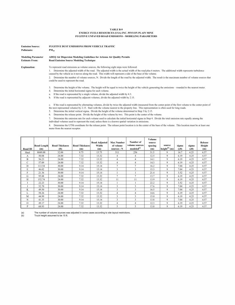
Emission Source: FUGITIVE DUST EMISSIONS FROM VEHICLE TRAFFIC
Pollutants: PM10
Modeling Parameter ADEQ Air Dispersion Modeling Guidelines for Arizona Air Quality PermitsEstimate From: Road Emission Source Modeling Technique
Explanation: To represent road emissions as volume sources, the following eight steps were followed:
4. Determine the initial horizontal sigma for each volume.a. If the road is represented by a single volume, divide the adjusted width by 4.3.b. If the road is represented by adjacent volumes, divide the adjusted width by 2.15.
5. Determine the initial vertical sigma. Divide the height of the volume determined in Step 3 by 2.15.6. Determine the release point. Divide the height of the volume by two. This point is the center of the volume.
Road IDRoad Length
(m)Road Thickness
(ft)Road Thickness
(m)
Road Adjusted Width
(m)
Max Number of volume
sources - N
Number of volume sources
modeled(a)
Volume source spacing
(m)
source
height(b) (m) sigma (y0)
sigma (z0)
Release Height
(m)
Haul 8049.00 32.00 9.75 15.75 511 256 31.5 9 14.7 4.25 4.57
A 50.08 24.00 7.32 13.32 4 4 12.5 9 6.19 4.25 4.57B 56.23 24.00 7.32 13.32 4 4 14.1 9 6.19 4.25 4.57C 57.09 24.00 7.32 13.32 4 4 14.3 9 6.19 4.25 4.57D 113.54 30.00 9.14 15.14 7 7 16.2 9 7.04 4.25 4.57E 46.02 30.00 9.14 15.14 3 3 15.3 9 7.04 4.25 4.57F 21.36 30.00 9.14 15.14 1 1 21.4 9 3.52 4.25 4.57G 95.88 24.00 7.32 13.32 7 7 13.7 9 6.19 4.25 4.57H 152.74 24.00 7.32 13.32 11 11 13.9 9 6.19 4.25 4.57I 22.23 30.00 9.14 15.14 1 1 22.2 9 3.52 4.25 4.57J 52.70 30.00 9.14 15.14 3 3 17.6 9 7.04 4.25 4.57K 49.50 30.00 9.14 15.14 3 3 16.5 9 7.04 4.25 4.57L 58.26 24.00 7.32 13.32 4 4 14.6 9 6.19 4.25 4.57M 44.99 24.00 7.32 13.32 3 3 15.0 9 6.19 4.25 4.57N 41.35 30.00 9.14 15.14 3 3 13.8 9 7.04 4.25 4.57O 49.17 24.00 7.32 13.32 4 4 12.3 9 6.19 4.25 4.57P 68.93 24.00 7.32 13.32 5 5 13.8 9 6.19 4.25 4.57
(a) The number of volume sources was adjusted in some cases according to site layout restrictions.(b) Truck height assumed to be 15 ft.
ENERGY FUELS RESOURCES (USA) INC. PINYON PLAIN MINETABLE B-9
1. Determine the adjusted width of the road. The adjusted width is the actual width of the road plus 6 meters. The additional width represents turbulence caused by the vehicle as it moves along the road. This width will represent a side of the base of the volume.
8. Determine the UTM coordinate for the release point. The release point location is in the center of the base of the volume. This location must be at least one meter from the nearest receptor.
2. Determine the number of volume sources, N. Divide the length of the road by the adjusted width. The result is the maximum number of volume sources that could be used to represent the road.
3. Determine the height of the volume. The height will be equal to twice the height of the vehicle generating the emissions – rounded to the nearest meter.
c. If the road is represented by alternating volumes, divide by twice the adjusted width (measured from the center point of the first volume to the center point of the next represented volume) by 2.15. Start with the volume nearest to the property line. This representation is often used for long roads.
7. Determine the emission rate for each volume used to calculate the initial horizontal sigma in Step 4. Divide the total emission rate equally among the individual volumes used to represent the road, unless there is a known spatial variation in emissions.
FUGITIVE UNPAVED ROAD EMISSIONS - MODELING PARAMETERS
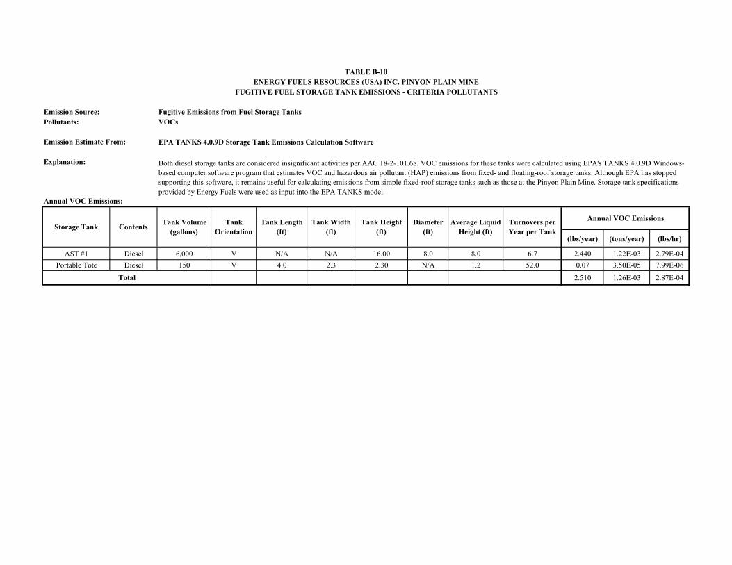
Emission Source: Fugitive Emissions from Fuel Storage TanksPollutants: VOCs
Emission Estimate From: EPA TANKS 4.0.9D Storage Tank Emissions Calculation Software
Explanation:
Annual VOC Emissions:
(lbs/year) (tons/year) (lbs/hr)
AST #1 Diesel 6,000 V N/A N/A 16.00 8.0 8.0 6.7 2.440 1.22E-03 2.79E-04
Portable Tote Diesel 150 V 4.0 2.3 2.30 N/A 1.2 52.0 0.07 3.50E-05 7.99E-06
2.510 1.26E-03 2.87E-04Total
ContentsTank Volume
(gallons)Tank
Orientation
TABLE B-10ENERGY FUELS RESOURCES (USA) INC. PINYON PLAIN MINE
Annual VOC EmissionsTank Length (ft)
Diameter(ft)
Turnovers per Year per Tank
Average Liquid Height (ft)
Storage TankTank Height
(ft)
FUGITIVE FUEL STORAGE TANK EMISSIONS - CRITERIA POLLUTANTS
Tank Width (ft)
Both diesel storage tanks are considered insignificant activities per AAC 18-2-101.68. VOC emissions for these tanks were calculated using EPA's TANKS 4.0.9D Windows-based computer software program that estimates VOC and hazardous air pollutant (HAP) emissions from fixed- and floating-roof storage tanks. Although EPA has stopped supporting this software, it remains useful for calculating emissions from simple fixed-roof storage tanks such as those at the Pinyon Plain Mine. Storage tank specifications provided by Energy Fuels were used as input into the EPA TANKS model.
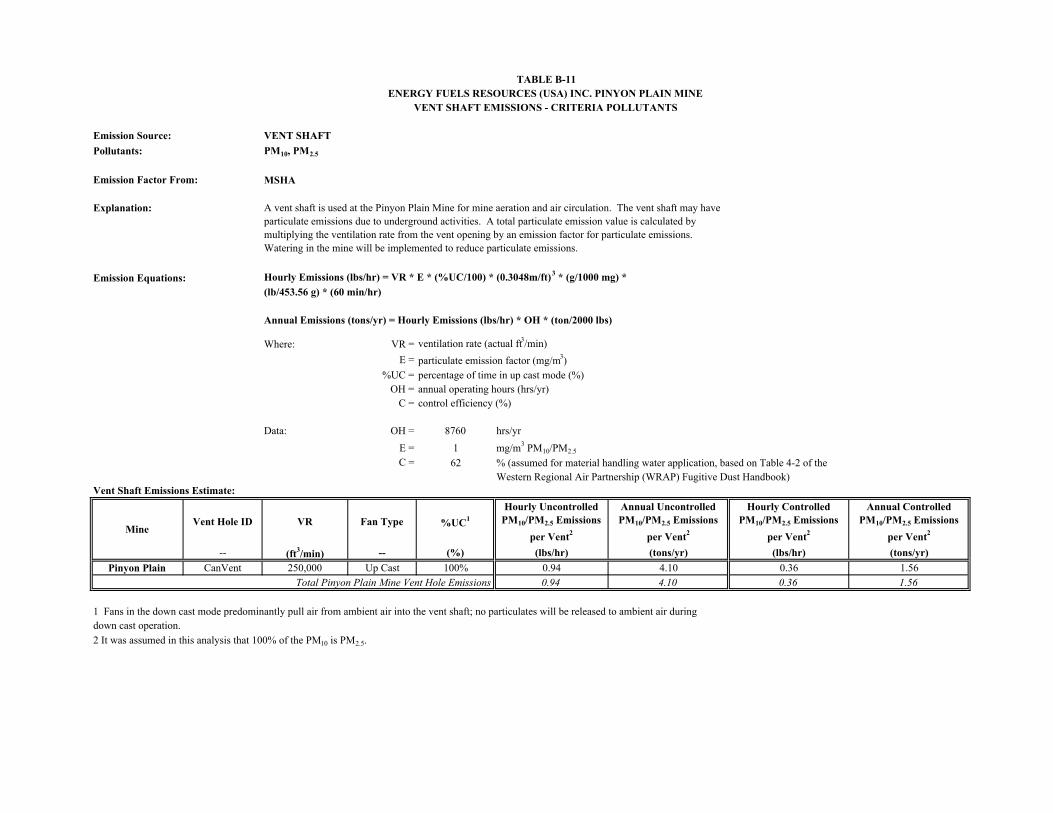
Emission Source: VENT SHAFT
Pollutants: PM10, PM2.5
Emission Factor From: MSHA
Explanation:
Emission Equations: Hourly Emissions (lbs/hr) = VR * E * (%UC/100) * (0.3048m/ft)3 * (g/1000 mg) *
(lb/453.56 g) * (60 min/hr)
Annual Emissions (tons/yr) = Hourly Emissions (lbs/hr) * OH * (ton/2000 lbs)
Where: VR = ventilation rate (actual ft3/min)
E = particulate emission factor (mg/m3)%UC = percentage of time in up cast mode (%)
OH = annual operating hours (hrs/yr)C = control efficiency (%)
Data: OH = 8760 hrs/yr
E = 1 mg/m3 PM10/PM2.5
C = 62 % (assumed for material handling water application, based on Table 4-2 of the Western Regional Air Partnership (WRAP) Fugitive Dust Handbook)
Vent Shaft Emissions Estimate:
Vent Hole ID VR Fan Type %UC1
Hourly Uncontrolled PM10/PM2.5 Emissions
per Vent2
Annual Uncontrolled PM10/PM2.5 Emissions
per Vent2
Hourly Controlled PM10/PM2.5 Emissions
per Vent2
Annual Controlled PM10/PM2.5 Emissions
per Vent2
-- (ft3/min) -- (%) (lbs/hr) (tons/yr) (lbs/hr) (tons/yr)
Pinyon Plain CanVent 250,000 Up Cast 100% 0.94 4.10 0.36 1.56
Total Pinyon Plain Mine Vent Hole Emissions 0.94 4.10 0.36 1.56
1 Fans in the down cast mode predominantly pull air from ambient air into the vent shaft; no particulates will be released to ambient air during down cast operation.
2 It was assumed in this analysis that 100% of the PM10 is PM2.5.
TABLE B-11ENERGY FUELS RESOURCES (USA) INC. PINYON PLAIN MINE
VENT SHAFT EMISSIONS - CRITERIA POLLUTANTS
Mine
A vent shaft is used at the Pinyon Plain Mine for mine aeration and air circulation. The vent shaft may have particulate emissions due to underground activities. A total particulate emission value is calculated by multiplying the ventilation rate from the vent opening by an emission factor for particulate emissions. Watering in the mine will be implemented to reduce particulate emissions.
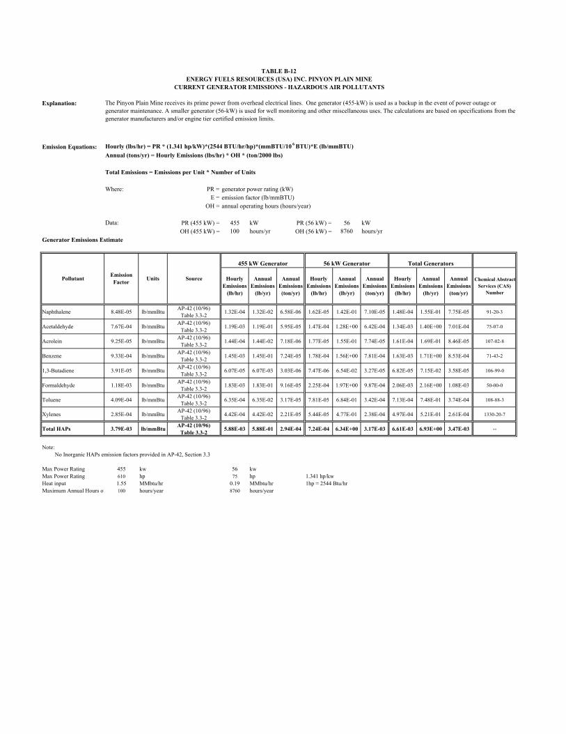
Explanation:
Emission Equations: Hourly (lbs/hr) = PR * (1.341 hp/kW)*(2544 BTU/hr/hp)*(mmBTU/10 6 BTU)*E (lb/mmBTU)
Annual (tons/yr) = Hourly Emissions (lbs/hr) * OH * (ton/2000 lbs)
Total Emissions = Emissions per Unit * Number of Units
Where: PR = generator power rating (kW)E = emission factor (lb/mmBTU)
OH = annual operating hours (hours/year)
Data: PR (455 kW) = 455 kW PR (56 kW) = 56 kWOH (455 kW) = 100 hours/yr OH (56 kW) = 8760 hours/yr
Generator Emissions Estimate
Naphthalene 8.48E-05 lb/mmBtuAP-42 (10/96)
Table 3.3-21.32E-04 1.32E-02 6.58E-06 1.62E-05 1.42E-01 7.10E-05 1.48E-04 1.55E-01 7.75E-05 91-20-3
Acetaldehyde 7.67E-04 lb/mmBtuAP-42 (10/96)
Table 3.3-21.19E-03 1.19E-01 5.95E-05 1.47E-04 1.28E+00 6.42E-04 1.34E-03 1.40E+00 7.01E-04 75-07-0
Acrolein 9.25E-05 lb/mmBtuAP-42 (10/96)
Table 3.3-21.44E-04 1.44E-02 7.18E-06 1.77E-05 1.55E-01 7.74E-05 1.61E-04 1.69E-01 8.46E-05 107-02-8
Benzene 9.33E-04 lb/mmBtuAP-42 (10/96)
Table 3.3-21.45E-03 1.45E-01 7.24E-05 1.78E-04 1.56E+00 7.81E-04 1.63E-03 1.71E+00 8.53E-04 71-43-2
1,3-Butadiene 3.91E-05 lb/mmBtuAP-42 (10/96)
Table 3.3-26.07E-05 6.07E-03 3.03E-06 7.47E-06 6.54E-02 3.27E-05 6.82E-05 7.15E-02 3.58E-05 106-99-0
Formaldehyde 1.18E-03 lb/mmBtuAP-42 (10/96)
Table 3.3-21.83E-03 1.83E-01 9.16E-05 2.25E-04 1.97E+00 9.87E-04 2.06E-03 2.16E+00 1.08E-03 50-00-0
Toluene 4.09E-04 lb/mmBtuAP-42 (10/96)
Table 3.3-26.35E-04 6.35E-02 3.17E-05 7.81E-05 6.84E-01 3.42E-04 7.13E-04 7.48E-01 3.74E-04 108-88-3
Xylenes 2.85E-04 lb/mmBtuAP-42 (10/96)
Table 3.3-24.42E-04 4.42E-02 2.21E-05 5.44E-05 4.77E-01 2.38E-04 4.97E-04 5.21E-01 2.61E-04 1330-20-7
Total HAPs 3.79E-03 lb/mmBtuAP-42 (10/96)
Table 3.3-25.88E-03 5.88E-01 2.94E-04 7.24E-04 6.34E+00 3.17E-03 6.61E-03 6.93E+00 3.47E-03 --
Note: No Inorganic HAPs emission factors provided in AP-42, Section 3.3
Max Power Rating 455 kw 56 kwMax Power Rating 610 hp 75 hp 1.341 hp/kwHeat input 1.55 MMbtu/hr 0.19 MMbtu/hr 1hp = 2544 Btu/hrMaximum Annual Hours of 100 hours/year 8760 hours/year
455 kW Generator 56 kW Generator Total Generators
Hourly Emissions
(lb/hr)
Annual Emissions
(lb/yr)
Annual Emissions (ton/yr)
TABLE B-12ENERGY FUELS RESOURCES (USA) INC. PINYON PLAIN MINE
CURRENT GENERATOR EMISSIONS - HAZARDOUS AIR POLLUTANTS
Chemical Abstract Services (CAS)
Number
Hourly Emissions
(lb/hr)
Annual Emissions
(lb/yr)
Annual Emissions (ton/yr)
The Pinyon Plain Mine receives its prime power from overhead electrical lines. One generator (455-kW) is used as a backup in the event of power outage or generator maintenance. A smaller generator (56-kW) is used for well monitoring and other miscellaneous uses. The calculations are based on specifications from the generator manufacturers and/or engine tier certified emission limits.
PollutantEmission
FactorUnits Source Hourly
Emissions (lb/hr)
Annual Emissions
(lb/yr)
Annual Emissions (ton/yr)
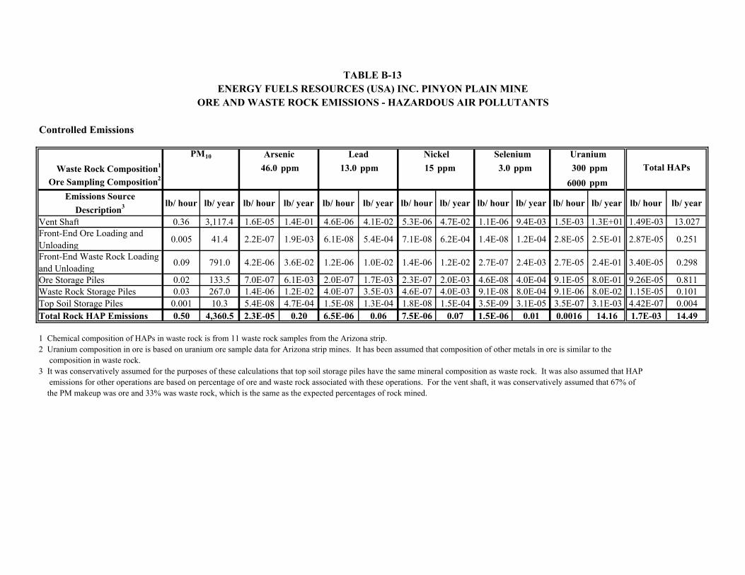
Controlled Emissions
Waste Rock Composition1 46.0 ppm 13.0 ppm 15 ppm 3.0 ppm 300 ppm
Ore Sampling Composition26000 ppm
Emissions Source
Description3 lb/ hour lb/ year lb/ hour lb/ year lb/ hour lb/ year lb/ hour lb/ year lb/ hour lb/ year lb/ hour lb/ year lb/ hour lb/ year
Vent Shaft 0.36 3,117.4 1.6E-05 1.4E-01 4.6E-06 4.1E-02 5.3E-06 4.7E-02 1.1E-06 9.4E-03 1.5E-03 1.3E+01 1.49E-03 13.027Front-End Ore Loading and Unloading
0.005 41.4 2.2E-07 1.9E-03 6.1E-08 5.4E-04 7.1E-08 6.2E-04 1.4E-08 1.2E-04 2.8E-05 2.5E-01 2.87E-05 0.251
Front-End Waste Rock Loading and Unloading
0.09 791.0 4.2E-06 3.6E-02 1.2E-06 1.0E-02 1.4E-06 1.2E-02 2.7E-07 2.4E-03 2.7E-05 2.4E-01 3.40E-05 0.298
Ore Storage Piles 0.02 133.5 7.0E-07 6.1E-03 2.0E-07 1.7E-03 2.3E-07 2.0E-03 4.6E-08 4.0E-04 9.1E-05 8.0E-01 9.26E-05 0.811Waste Rock Storage Piles 0.03 267.0 1.4E-06 1.2E-02 4.0E-07 3.5E-03 4.6E-07 4.0E-03 9.1E-08 8.0E-04 9.1E-06 8.0E-02 1.15E-05 0.101Top Soil Storage Piles 0.001 10.3 5.4E-08 4.7E-04 1.5E-08 1.3E-04 1.8E-08 1.5E-04 3.5E-09 3.1E-05 3.5E-07 3.1E-03 4.42E-07 0.004Total Rock HAP Emissions 0.50 4,360.5 2.3E-05 0.20 6.5E-06 0.06 7.5E-06 0.07 1.5E-06 0.01 0.0016 14.16 1.7E-03 14.49
1 Chemical composition of HAPs in waste rock is from 11 waste rock samples from the Arizona strip. 2 Uranium composition in ore is based on uranium ore sample data for Arizona strip mines. It has been assumed that composition of other metals in ore is similar to the composition in waste rock.3 It was conservatively assumed for the purposes of these calculations that top soil storage piles have the same mineral composition as waste rock. It was also assumed that HAP emissions for other operations are based on percentage of ore and waste rock associated with these operations. For the vent shaft, it was conservatively assumed that 67% of the PM makeup was ore and 33% was waste rock, which is the same as the expected percentages of rock mined.
Total HAPs
TABLE B-13ENERGY FUELS RESOURCES (USA) INC. PINYON PLAIN MINE
ORE AND WASTE ROCK EMISSIONS - HAZARDOUS AIR POLLUTANTS
Nickel Selenium UraniumLeadPM10 Arsenic
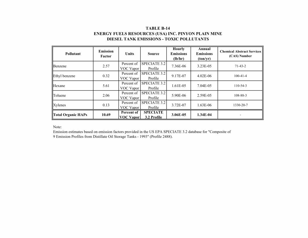
Benzene 2.57Percent of
VOC VaporSPECIATE 3.2
Profile7.36E-06 3.23E-05 71-43-2
Ethyl benzene 0.32Percent of
VOC VaporSPECIATE 3.2
Profile9.17E-07 4.02E-06 100-41-4
Hexane 5.61Percent of
VOC VaporSPECIATE 3.2
Profile1.61E-05 7.04E-05 110-54-3
Toluene 2.06Percent of
VOC VaporSPECIATE 3.2
Profile5.90E-06 2.59E-05 108-88-3
Xylenes 0.13Percent of
VOC VaporSPECIATE 3.2
Profile3.72E-07 1.63E-06 1330-20-7
Total Organic HAPs 10.69Percent of
VOC VaporSPECIATE 3.2 Profile
3.06E-05 1.34E-04 -
Note:Emission estimates based on emission factors provided in the US EPA SPECIATE 3.2 database for "Composite of 9 Emission Profiles from Distillate Oil Storage Tanks - 1993" (Profile 2488).
TABLE B-14
DIESEL TANK EMISSIONS - TOXIC POLLUTANTS
PollutantChemical Abstract Services
(CAS) NumberEmission
FactorUnits Source
Hourly Emissions
(lb/hr)
Annual Emissions (ton/yr)
ENERGY FUELS RESOURCES (USA) INC. PINYON PLAIN MINE
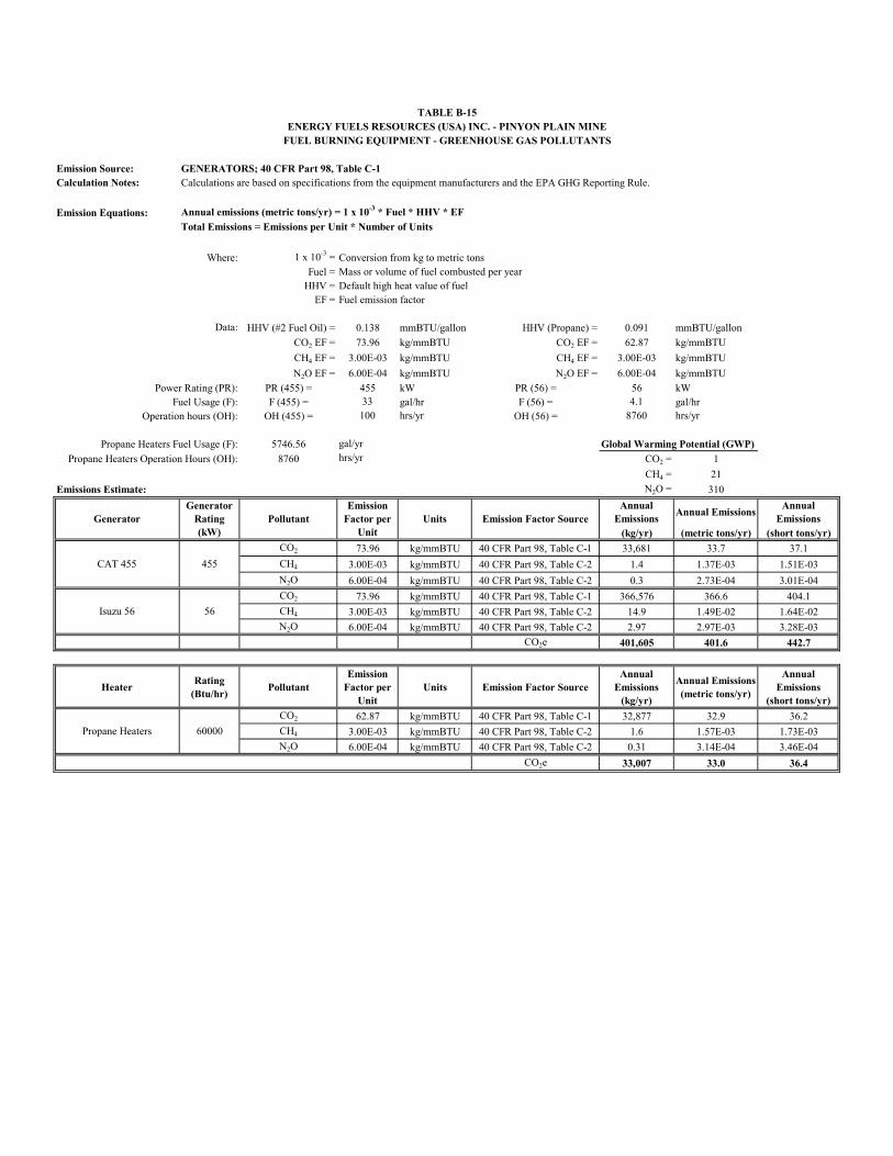
Emission Source: GENERATORS; 40 CFR Part 98, Table C-1Calculation Notes: Calculations are based on specifications from the equipment manufacturers and the EPA GHG Reporting Rule.
Emission Equations: Annual emissions (metric tons/yr) = 1 x 10⁻³ * Fuel * HHV * EF
Total Emissions = Emissions per Unit * Number of Units
Where: 1 x 10-3 = Conversion from kg to metric tonsFuel = Mass or volume of fuel combusted per year
HHV = Default high heat value of fuelEF = Fuel emission factor
Data: HHV (#2 Fuel Oil) = 0.138 mmBTU/gallon HHV (Propane) = 0.091 mmBTU/gallon
CO2 EF = 73.96 kg/mmBTU CO2 EF = 62.87 kg/mmBTU
CH4 EF = 3.00E-03 kg/mmBTU CH4 EF = 3.00E-03 kg/mmBTU
N2O EF = 6.00E-04 kg/mmBTU N2O EF = 6.00E-04 kg/mmBTU
Power Rating (PR): PR (455) = 455 kW PR (56) = 56 kWFuel Usage (F): F (455) = 33 gal/hr F (56) = 4.1 gal/hr
Operation hours (OH): OH (455) = 100 hrs/yr OH (56) = 8760 hrs/yr
Propane Heaters Fuel Usage (F): 5746.56 gal/yr Global Warming Potential (GWP)
Propane Heaters Operation Hours (OH): 8760 hrs/yr CO2 = 1
CH4 = 21
Emissions Estimate: N2O = 310
Annual Emissions
Annual EmissionsAnnual
Emissions(kg/yr) (metric tons/yr) (short tons/yr)
CO2 73.96 kg/mmBTU 40 CFR Part 98, Table C-1 33,681 33.7 37.1
CH4 3.00E-03 kg/mmBTU 40 CFR Part 98, Table C-2 1.4 1.37E-03 1.51E-03
N2O 6.00E-04 kg/mmBTU 40 CFR Part 98, Table C-2 0.3 2.73E-04 3.01E-04
CO2 73.96 kg/mmBTU 40 CFR Part 98, Table C-1 366,576 366.6 404.1
CH4 3.00E-03 kg/mmBTU 40 CFR Part 98, Table C-2 14.9 1.49E-02 1.64E-02
N2O 6.00E-04 kg/mmBTU 40 CFR Part 98, Table C-2 2.97 2.97E-03 3.28E-03
CO2e 401,605 401.6 442.7
HeaterRating
(Btu/hr)Pollutant
Emission Factor per
UnitUnits Emission Factor Source
Annual Emissions
(kg/yr)
Annual Emissions(metric tons/yr)
Annual Emissions
(short tons/yr)
CO2 62.87 kg/mmBTU 40 CFR Part 98, Table C-1 32,877 32.9 36.2
CH4 3.00E-03 kg/mmBTU 40 CFR Part 98, Table C-2 1.6 1.57E-03 1.73E-03
N2O 6.00E-04 kg/mmBTU 40 CFR Part 98, Table C-2 0.31 3.14E-04 3.46E-04
CO2e 33,007 33.0 36.4
Propane Heaters 60000
TABLE B-15ENERGY FUELS RESOURCES (USA) INC. - PINYON PLAIN MINE
FUEL BURNING EQUIPMENT - GREENHOUSE GAS POLLUTANTS
CAT 455 455
Isuzu 56 56
GeneratorGenerator
Rating(kW)
PollutantEmission
Factor per Unit
Units Emission Factor Source
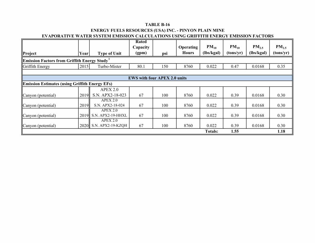
Project Year Type of Unit
Rated Capacity
(gpm) psi
OperatingHours
PM10
(lbs/kgal)PM10
(tons/yr)PM2.5
(lbs/kgal)PM2.5
(tons/yr)
Griffith Energy 2015 Turbo-Mister 80.1 150 8760 0.022 0.47 0.0168 0.35
Canyon (potential) 2019APEX 2.0
S.N. APX2-18-023 67 100 8760 0.022 0.39 0.0168 0.30
Canyon (potential) 2019APEX 2.0
S.N. APX2-18-024 67 100 8760 0.022 0.39 0.0168 0.30
Canyon (potential) 2019APEX 2.0
S.N. APX2-19-HHXL 67 100 8760 0.022 0.39 0.0168 0.30
Canyon (potential) 2020APEX 2.0
S.N. APX2-19-KZQH 67 100 8760 0.022 0.39 0.0168 0.30Totals: 1.55 1.18
Emission Estimates (using Griffith Energy EFs)
ENERGY FUELS RESOURCES (USA) INC. - PINYON PLAIN MINETABLE B-16
EVAPORATIVE WATER SYSTEM EMISSION CALCULATIONS USING GRIFFITH ENERGY EMISSION FACTORS
Emission Factors from Griffith Energy Study1
EWS with four APEX 2.0 units
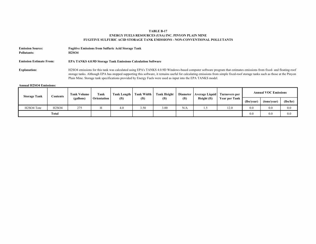
Emission Source: Fugitive Emissions from Sulfuric Acid Storage TankPollutants: H2SO4
Emission Estimate From: EPA TANKS 4.0.9D Storage Tank Emissions Calculation Software
Explanation:
Annual H2SO4 Emissions:
(lbs/year) (tons/year) (lbs/hr)
H2SO4 Tote H2SO4 275 H 4.0 3.50 3.00 N/A 1.5 12.0 0.0 0.0 0.0
0.0 0.0 0.0Total
TABLE B-17ENERGY FUELS RESOURCES (USA) INC. PINYON PLAIN MINE
FUGITIVE SULFURIC ACID STORAGE TANK EMISSIONS - NON-CONVENTIONAL POLLUTANTS
H2SO4 emissions for this tank was calculated using EPA's TANKS 4.0.9D Windows-based computer software program that estimates emissions from fixed- and floating-roof storage tanks. Although EPA has stopped supporting this software, it remains useful for calculating emissions from simple fixed-roof storage tanks such as those at the Pinyon Plain Mine. Storage tank specifications provided by Energy Fuels were used as input into the EPA TANKS model.
Storage Tank ContentsTank Volume
(gallons)Tank
OrientationTank Length
(ft)Tank Width
(ft)Tank Height
(ft)Diameter
(ft)Average Liquid
Height (ft)Turnovers per Year per Tank
Annual VOC Emissions
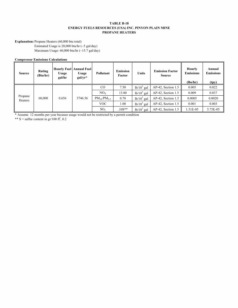
Explanation: Propane Heaters (60,000 btu total)Estimated Usage is 20,000 btu/hr (~5 gal/day)Maximum Usage: 60,000 btu/hr (~15.7 gal/day)
Compressor Emissions Calculations
Hourly Emissions
Annual Emissions
(lbs/hr) (tpy)
CO 7.50 lb/103 gal AP-42, Section 1.5 0.005 0.022
NOX 13.00 lb/103 gal AP-42, Section 1.5 0.009 0.037
PM10/PM2.5 0.70 lb/103 gal AP-42, Section 1.5 0.0005 0.0020
VOC 1.00 lb/103 gal AP-42, Section 1.5 0.001 0.003
SO2 .10S** lb/103 gal AP-42, Section 1.5 1.31E-05 5.75E-05
* Assume 12 months per year because usage would not be restricted by a permit condition** S = sulfur content in gr/100 ft3, 0.2
Propane Heaters
60,000 0.656 5746.56
TABLE B-18ENERGY FUELS RESOURCES (USA) INC. PINYON PLAIN MINE
PROPANE HEATERS
SourceRating
(Btu/hr)
Hourly Fuel Usagegal/hr
Annual Fuel Usagegal/yr*
PollutantEmission
FactorUnits
Emission Factor Source
APPENDIX C
Equipment Specifications and Documentation
THIS MANUAL MUST ACCOMPANY THE EQUIPMENT AT ALL TIMES.
To fi nd the latest revision of this publication, visit our website at:
www.mqpower.com
Revision #0 (05/29/09)
OPERATION AND PARTS MANUAL
WHISPERWATT™ SERIES
MODEL DCA70SSIU260HZ GENERATOR
(ISUZU BJ-4JJ1X DIESEL ENGINE)
PARTS LIST NO. M2870300604
PAGE 2 — DCA70SSIU2 60 HZ GENERATOR • OPERATION AND PARTS MANUAL — REV. #0 (05/29/09)
PROPOSITION 65 WARNING
Diesel engine exhaust and some of
DCA70SSIU2 60 HZ GENERATOR • OPERATION AND PARTS MANUAL — REV. #0 (05/29/09) — PAGE 3
If you believe that your vehicle has a defect that could cause a crash or could cause injury or death, you should immediately inform the National Highway Traffi c Safety Administration (NHTSA) in addition to notifying Multiquip at 1-800-421-1244.
If NHTSA receives similar complaints, it may open an investigation, and if it fi nds that a safety defect exists in a group of vehicles, it may order a recall and remedy campaign. However, NHTSA cannot become involved in individual problems between you, your dealer, or Multiquip.
To contact NHTSA, you may either call the Vehicle Safety Hotline toll-free at 1-888-327-4236 (TTY: 1-800-424-9153), go to http://www.nhtsa.dot.gov; or write to:
AdministratorNHTSA1200 New Jersey Avenue S.E.Washington, DC 20590
You can also obtain information about motor vehicle safety from http://www.safecar.gov.
REPORTING SAFETY DEFECTS
PAGE 4 — DCA70SSIU2 60 HZ GENERATOR • OPERATION AND PARTS MANUAL — REV. #0 (05/29/09)
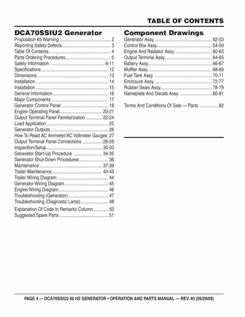
TABLE OF CONTENTS
DCA70SSIU2 GeneratorProposition 65 Warning ........................................... 2Reporting Safety Defects ......................................... 3Table Of Contents .................................................... 4Parts Ordering Procedures ...................................... 5Safety Information .............................................. 6-11Specifi cations ........................................................ 12Dimensions ............................................................ 13Installation ............................................................. 14Installation ............................................................. 15General Information ............................................... 16Major Components ................................................ 17Generator Control Panel ........................................ 18Engine Operating Panel.................................... 20-21Output Terminal Panel Familiarization .............. 22-24Load Application .................................................... 25Generator Outputs ................................................. 26How To Read AC Ammeter/AC Voltmeter Gauges 27Output Terminal Panel Connections ................. 28-29Inspection/Setup ............................................... 30-33Generator Start-Up Procedure ........................ 34-35Generator Shut-Down Procedures ........................ 36Maintenance ..................................................... 37-39Trailer Maintenance .......................................... 40-43Trailer Wiring Diagram ........................................... 44Generator Wiring Diagram ..................................... 45Engine Wiring Diagram .......................................... 46Troubleshooting (Generator) .................................. 47Troubleshooting (Diagnostic Lamp) ....................... 48
Explanation Of Code In Remarks Column............. 50Suggested Spare Parts ......................................... 51
Component DrawingsGenerator Assy. ................................................ 52-53Control Box Assy. .............................................. 54-59Engine And Radiator Assy. ............................... 60-63Output Terminal Assy. ....................................... 64-65Battery Assy. ..................................................... 66-67Muffl er Assy. ..................................................... 68-69Fuel Tank Assy. ................................................ 70-71Enclosure Assy. ................................................ 72-77Rubber Seals Assy. ........................................... 78-79Nameplate And Decals Assy. ........................... 80-81
Terms And Conditions Of Sale — Parts ................ 82
DCA70SSIU2 60 HZ GENERATOR • OPERATION AND PARTS MANUAL — REV. #0 (05/29/09) — PAGE 5
PARTS ORDERING PROCEDURES
ww
w.m
qpow
er.
com
Ordering parts has never been easier! Choose from three easy options:
WE ACCEPT ALL MAJOR CREDIT CARDS!
When ordering parts, please supply: Dealer Account Number Dealer Name and Address Shipping Address (if different than billing address) Return Fax Number Applicable Model Number Quantity, Part Number and Description of Each Part
Specify Preferred Method of Shipment:UPS/Fed Ex DHL
Priority One Truck Ground
Next Day Second/Third Day
If you have an MQ Account, to obtain a Username and Password, E-mail us at: [email protected].
To obtain an MQ Account, contact your District Sales Manager for more information.
Order via Internet (Dealers Only):Order parts on-line using Multiquip’s SmartEquip website! View Parts Diagrams Order Parts Print Specification Information
Note: Discounts Are Subject To Change
Goto www.multiquip.com and click on Order Parts to log in and save!
Use the internet and qualify for a 5% Discount on Standard orders for all orders which include complete part numbers.*
Order via Fax (Dealers Only):All customers are welcome to order parts via Fax.Domestic (US) Customers dial: 1-800-6-PARTS-7 (800-672-7877)
Fax your order in and qualify for a 2% Discount on Standard orders for all orders which include complete part numbers.*
Order via Phone: Domestic (US) Dealers Call: 1-800-427-1244
Best Deal!
International Customers should contact their local Multiquip Representatives for Parts Ordering information.
Non-Dealer Customers: Contact your local Multiquip Dealer for parts or call 800-427-1244 for help in locating a dealer near you.
Note: Discounts Are Subject To Change
Effective: January 1st, 2006
NOTICE
All orders are treated as Standard Orders and will ship the same day if received prior to 3PM PST.
PAGE 6 — DCA70SSIU2 60 HZ GENERATOR • OPERATION AND PARTS MANUAL — REV. #0 (05/29/09)
SAFETY INFORMATION
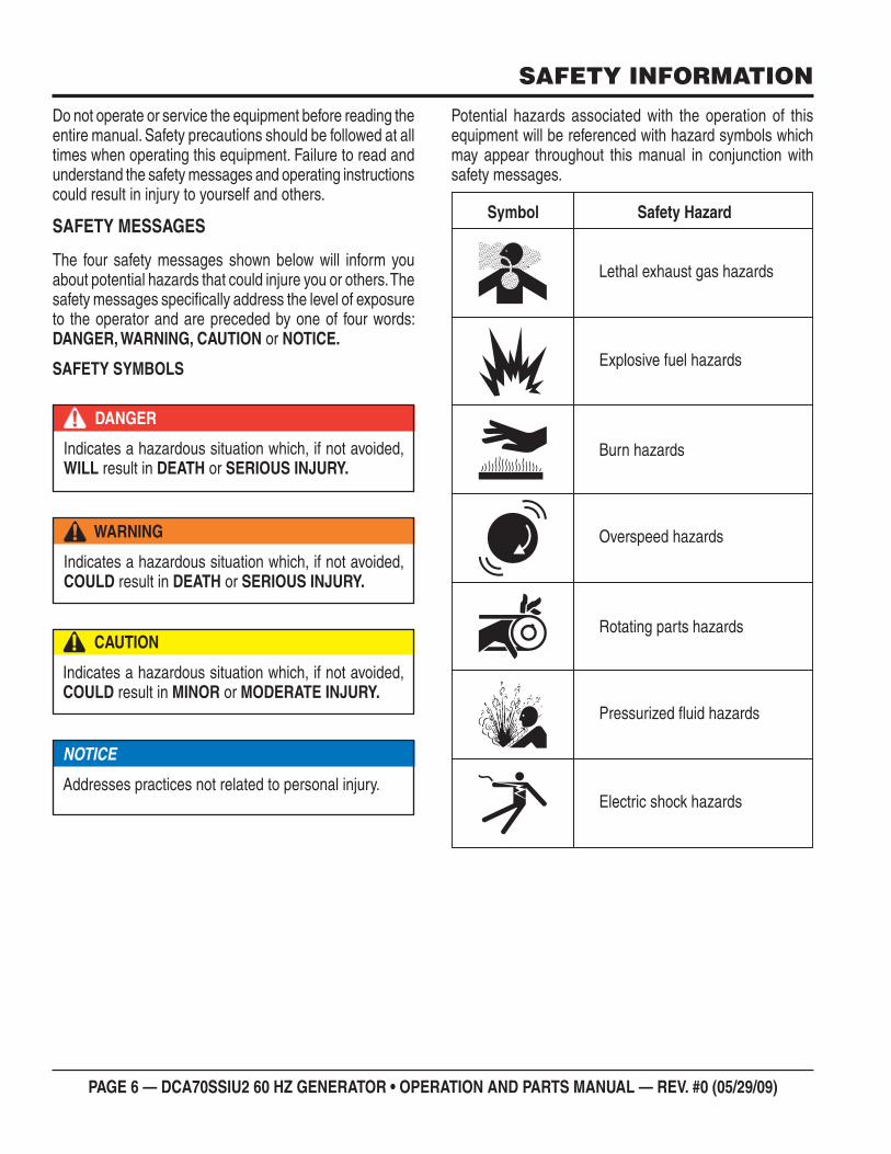
Do not operate or service the equipment before reading the entire manual. Safety precautions should be followed at all times when operating this equipment. Failure to read and understand the safety messages and operating instructions could result in injury to yourself and others.
SAFETY MESSAGES
The four safety messages shown below will inform you about potential hazards that could injure you or others. The safety messages specifi cally address the level of exposure to the operator and are preceded by one of four words: DANGER, WARNING, CAUTION or NOTICE.
SAFETY SYMBOLS
DANGER
Indicates a hazardous situation which, if not avoided, WILL result in DEATH or SERIOUS INJURY.
WARNING
Indicates a hazardous situation which, if not avoided, COULD result in DEATH or SERIOUS INJURY.
CAUTION
Indicates a hazardous situation which, if not avoided, COULD result in MINOR or MODERATE INJURY.
NOTICE
Addresses practices not related to personal injury.
Potential hazards associated with the operation of thisequipment will be referenced with hazard symbols whichmay appear throughout this manual in conjunction withsafety messages.
DCA70SSIU2 60 HZ GENERATOR • OPERATION AND PARTS MANUAL — REV. #0 (05/29/09) — PAGE 7
SAFETY INFORMATION
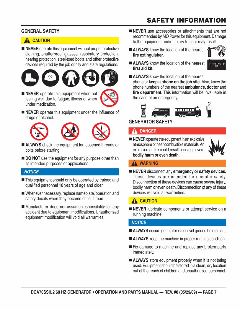
GENERAL SAFETY
CAUTION
NEVER operate this equipment without proper protective clothing, shatterproof glasses, respiratory protection, hearing protection, steel-toed boots and other protective devices required by the job or city and state regulations.
NEVER operate this equipment when not feeling well due to fatigue, illness or when under medication.
NEVER operate this equipment under the infl uence of drugs or alcohol.
ALWAYS check the equipment for loosened threads or bolts before starting.
DO NOT use the equipment for any purpose other than its intended purposes or applications.
NOTICE
This equipment should only be operated by trained and qualifi ed personnel 18 years of age and older.
Whenever necessary, replace nameplate, operation and safety decals when they become diffi cult read.
Manufacturer does not assume responsibility for any accident due to equipment modifi cations. Unauthorized equipment modifi cation will void all warranties.
NEVER use accessories or attachments that are notrecommended by MQ Power for this equipment. Damageto the equipment and/or injury to user may result.
ALWAYS know the location of the nearest fi re extinguisher.
ALWAYS know the location of the nearest fi rst aid kit.
ALWAYS know the location of the nearest phone or keep a phone on the job site. Also, know the phone numbers of the nearest ambulance, doctor and fi re department. This information will be invaluable inthe case of an emergency.
GENERATOR SAFETY
DANGER
NEVER operate the equipment in an explosive atmosphere or near combustible materials. An explosion or fi re could result causing severe bodily harm or even death.
WARNING
NEVER disconnect any emergency or safety devices. These devices are intended for operator safety.Disconnection of these devices can cause severe injury,bodily harm or even death. Disconnection of any of thesedevices will void all warranties.
CAUTION
NEVER lubricate components or attempt service on a running machine.
NOTICE
ALWAYS ensure generator is on level ground before use.
ALWAYS keep the machine in proper running condition.
Fix damage to machine and replace any broken parts immediately.
ALWAYS store equipment properly when it is not being used. Equipment should be stored in a clean, dry location out of the reach of children and unauthorized personnel
PAGE 8 — DCA70SSIU2 60 HZ GENERATOR • OPERATION AND PARTS MANUAL — REV. #0 (05/29/09)
SAFETY INFORMATION
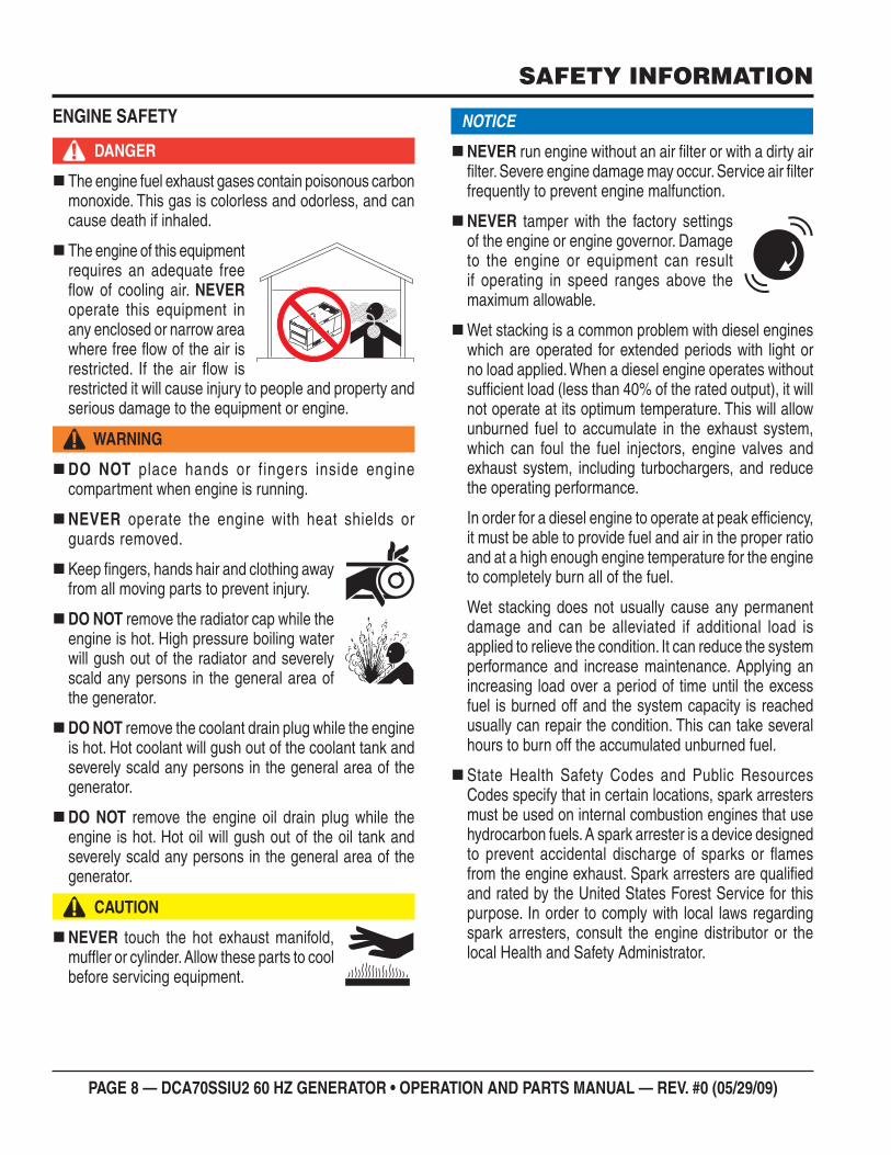
ENGINE SAFETY
DANGER
The engine fuel exhaust gases contain poisonous carbon monoxide. This gas is colorless and odorless, and can cause death if inhaled.
The engine of this equipment requires an adequate free fl ow of cooling air. NEVER operate this equipment in any enclosed or narrow area where free fl ow of the air is restricted. If the air fl ow is restricted it will cause injury to people and property and serious damage to the equipment or engine.
WARNING
DO NOT place hands or fingers inside engine compartment when engine is running.
NEVER operate the engine with heat shields or guards removed.
Keep fi ngers, hands hair and clothing away from all moving parts to prevent injury.
DO NOT remove the radiator cap while the engine is hot. High pressure boiling water will gush out of the radiator and severely scald any persons in the general area of the generator.
DO NOT remove the coolant drain plug while the engine is hot. Hot coolant will gush out of the coolant tank and severely scald any persons in the general area of the generator.
DO NOT remove the engine oil drain plug while the engine is hot. Hot oil will gush out of the oil tank and severely scald any persons in the general area of the generator.
CAUTION
NEVER touch the hot exhaust manifold, muffl er or cylinder. Allow these parts to cool before servicing equipment.
NOTICE
NEVER run engine without an air fi lter or with a dirty airfi lter. Severe engine damage may occur. Service air fi lter frequently to prevent engine malfunction.
NEVER tamper with the factory settings of the engine or engine governor. Damage to the engine or equipment can result if operating in speed ranges above the maximum allowable.
Wet stacking is a common problem with diesel engines which are operated for extended periods with light or no load applied. When a diesel engine operates without suffi cient load (less than 40% of the rated output), it will not operate at its optimum temperature. This will allow unburned fuel to accumulate in the exhaust system, which can foul the fuel injectors, engine valves and exhaust system, including turbochargers, and reduce the operating performance.
In order for a diesel engine to operate at peak effi ciency,it must be able to provide fuel and air in the proper ratio and at a high enough engine temperature for the engine to completely burn all of the fuel.
Wet stacking does not usually cause any permanentdamage and can be alleviated if additional load is applied to relieve the condition. It can reduce the system performance and increase maintenance. Applying an increasing load over a period of time until the excess fuel is burned off and the system capacity is reached usually can repair the condition. This can take several hours to burn off the accumulated unburned fuel.
State Health Safety Codes and Public Resources Codes specify that in certain locations, spark arresters must be used on internal combustion engines that use hydrocarbon fuels. A spark arrester is a device designed to prevent accidental discharge of sparks or fl ames from the engine exhaust. Spark arresters are qualifi ed and rated by the United States Forest Service for this purpose. In order to comply with local laws regarding spark arresters, consult the engine distributor or the local Health and Safety Administrator.
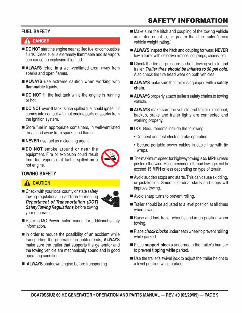
DCA70SSIU2 60 HZ GENERATOR • OPERATION AND PARTS MANUAL — REV. #0 (05/29/09) — PAGE 9
SAFETY INFORMATION
FUEL SAFETY
DANGER
DO NOT start the engine near spilled fuel or combustible fl uids. Diesel fuel is extremely fl ammable and its vapors can cause an explosion if ignited.
ALWAYS refuel in a well-ventilated area, away from sparks and open fl ames.
ALWAYS use extreme caution when working with fl ammable liquids.
DO NOT fi ll the fuel tank while the engine is running or hot.
DO NOT overfi ll tank, since spilled fuel could ignite if it comes into contact with hot engine parts or sparks from the ignition system.
Store fuel in appropriate containers, in well-ventilated areas and away from sparks and fl ames.
NEVER use fuel as a cleaning agent.
DO NOT smoke around or near the equipment. Fire or explosion could result from fuel vapors or if fuel is spilled on a hot engine.
TOWING SAFETY
CAUTION
Check with your local county or state safety towing regulations, in addition to meeting Department of Transportation (DOT) Safety Towing Regulations, before towing your generator.
Refer to MQ Power trailer manual for additional safety information.
In order to reduce the possibility of an accident while transporting the generator on public roads, ALWAYS make sure the trailer that supports the generator and the towing vehicle are mechanically sound and in good operating condition.
ALWAYS shutdown engine before transporting
Make sure the hitch and coupling of the towing vehicle are rated equal to, or greater than the trailer “gross vehicle weight rating.”
ALWAYS inspect the hitch and coupling for wear. NEVER tow a trailer with defective hitches, couplings, chains, etc.
Check the tire air pressure on both towing vehicle and trailer. Trailer tires should be infl ated to 50 psi cold. Also check the tire tread wear on both vehicles.
ALWAYS make sure the trailer is equipped with a safety chain.
ALWAYS properly attach trailer’s safety chains to towing vehicle.
ALWAYS make sure the vehicle and trailer directional, backup, brake and trailer lights are connected and working properly.
DOT Requirements include the following:
• Connect and test electric brake operation.
• Secure portable power cables in cable tray with tiewraps.
The maximum speed for highway towing is 55 MPH unless posted otherwise. Recommended off-road towing is not toexceed 15 MPH or less depending on type of terrain.
Avoid sudden stops and starts. This can cause skidding, or jack-knifi ng. Smooth, gradual starts and stops will improve towing.
Avoid sharp turns to prevent rolling.
Trailer should be adjusted to a level position at all times when towing.
Raise and lock trailer wheel stand in up position when towing.
Place chock blocks underneath wheel to prevent rolling while parked.
Place support blocks underneath the trailer’s bumperto prevent tipping while parked.
Use the trailer’s swivel jack to adjust the trailer height to a level position while parked.
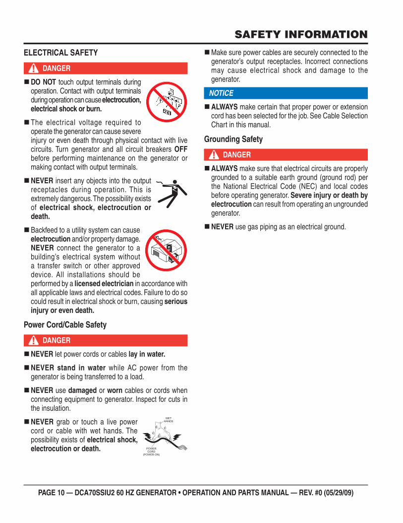
PAGE 10 — DCA70SSIU2 60 HZ GENERATOR • OPERATION AND PARTS MANUAL — REV. #0 (05/29/09)
SAFETY INFORMATION
ELECTRICAL SAFETY
DANGER
DO NOT touch output terminals during operation. Contact with output terminals during operation can cause electrocution, electrical shock or burn.
The electrical voltage required to operate the generator can cause severe injury or even death through physical contact with live circuits. Turn generator and all circuit breakers OFF before performing maintenance on the generator or making contact with output terminals.
NEVER insert any objects into the output receptacles during operation. This is extremely dangerous. The possibility exists of electrical shock, electrocution or death.
Backfeed to a utility system can cause electrocution and/or property damage. NEVER connect the generator to a building’s electrical system without a transfer switch or other approved device. All installations should be performed by a licensed electrician in accordance with all applicable laws and electrical codes. Failure to do so could result in electrical shock or burn, causing serious injury or even death.
Power Cord/Cable Safety
DANGER
NEVER let power cords or cables lay in water.
NEVER stand in water while AC power from the generator is being transferred to a load.
NEVER use damaged or worn cables or cords when connecting equipment to generator. Inspect for cuts in the insulation.
NEVER grab or touch a live power cord or cable with wet hands. The possibility exists of electrical shock, electrocution or death.
Make sure power cables are securely connected to the generator’s output receptacles. Incorrect connections may cause electrical shock and damage to the generator.
NOTICE
ALWAYS make certain that proper power or extensioncord has been selected for the job. See Cable Selection Chart in this manual.
Grounding Safety
DANGER
ALWAYS make sure that electrical circuits are properly grounded to a suitable earth ground (ground rod) per the National Electrical Code (NEC) and local codes before operating generator. Severe injury or death by electrocution can result from operating an ungrounded generator.
NEVER use gas piping as an electrical ground.
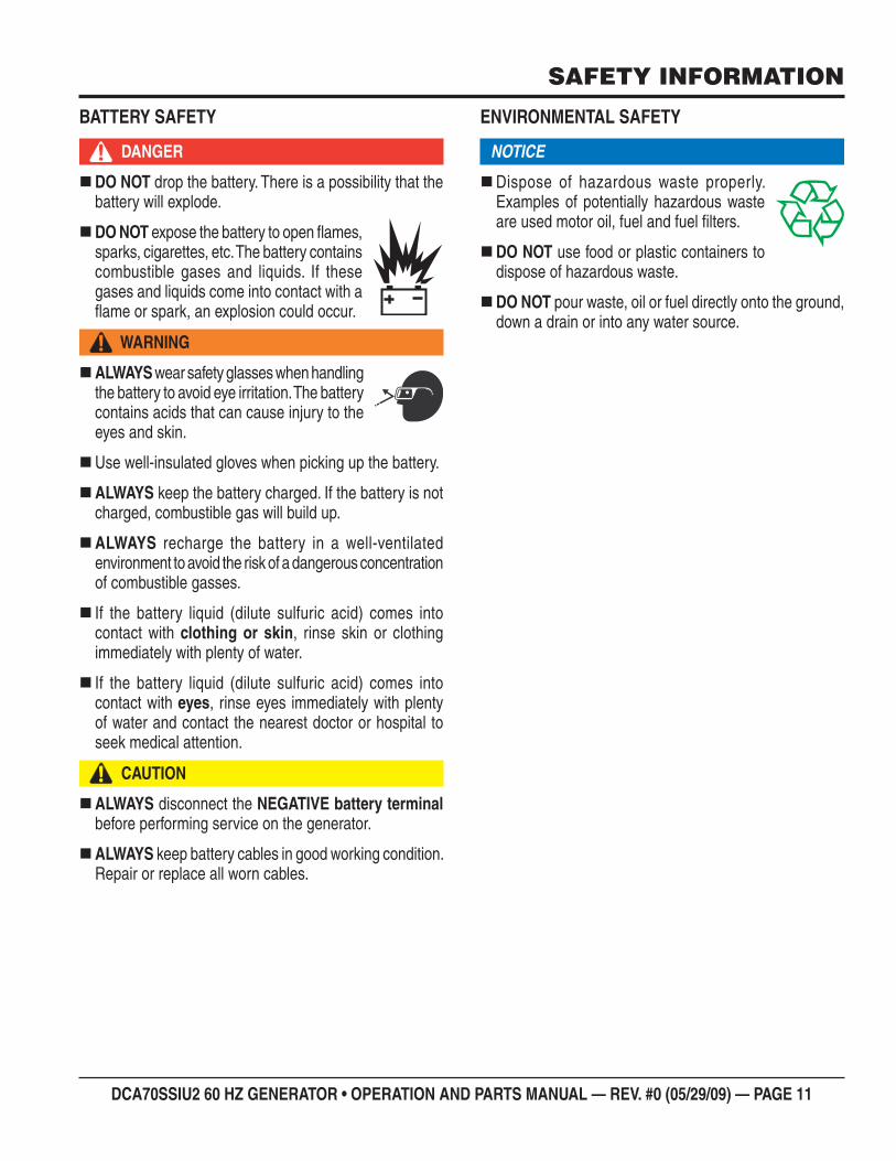
DCA70SSIU2 60 HZ GENERATOR • OPERATION AND PARTS MANUAL — REV. #0 (05/29/09) — PAGE 11
SAFETY INFORMATION
BATTERY SAFETY
DANGER
DO NOT drop the battery. There is a possibility that the battery will explode.
DO NOT expose the battery to open fl ames, sparks, cigarettes, etc. The battery contains combustible gases and liquids. If these gases and liquids come into contact with a fl ame or spark, an explosion could occur.
WARNING
ALWAYS wear safety glasses when handling the battery to avoid eye irritation. The battery contains acids that can cause injury to the eyes and skin.
Use well-insulated gloves when picking up the battery.
ALWAYS keep the battery charged. If the battery is not charged, combustible gas will build up.
ALWAYS recharge the battery in a well-ventilated environment to avoid the risk of a dangerous concentration of combustible gasses.
If the battery liquid (dilute sulfuric acid) comes into contact with clothing or skin, rinse skin or clothing immediately with plenty of water.
If the battery liquid (dilute sulfuric acid) comes into contact with eyes, rinse eyes immediately with plenty of water and contact the nearest doctor or hospital to seek medical attention.
CAUTION
ALWAYS disconnect the NEGATIVE battery terminal before performing service on the generator.
ALWAYS keep battery cables in good working condition. Repair or replace all worn cables.
ENVIRONMENTAL SAFETY
NOTICE
Dispose of hazardous waste properly. Examples of potentially hazardous waste are used motor oil, fuel and fuel fi lters.
DO NOT use food or plastic containers to dispose of hazardous waste.
DO NOT pour waste, oil or fuel directly onto the ground,down a drain or into any water source.
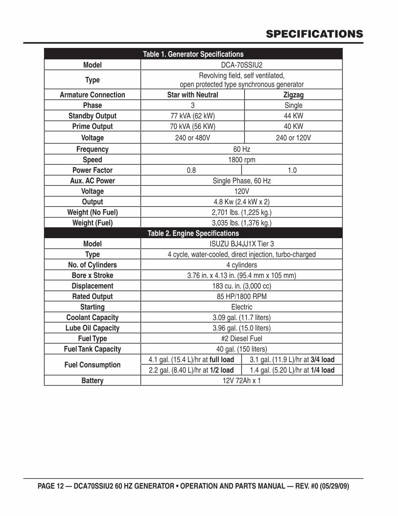
PAGE 12 — DCA70SSIU2 60 HZ GENERATOR • OPERATION AND PARTS MANUAL — REV. #0 (05/29/09)
Generator Specifi cationsTable 1. Model DCA-70SSIU2
Type Revolving fi eld, self ventilated,open protected type synchronous generator
Armature Connection Star with Neutral ZigzagPhase 3 Single
Standby Output 77 kVA (62 kW) 44 KWPrime Output 70 kVA (56 KW) 40 KW
Voltage 240 or 480V 240 or 120V
Frequency 60 HzSpeed 1800 rpm
Power Factor 0.8 1.0Aux. AC Power Single Phase, 60 Hz
Voltage 120VOutput 4.8 Kw (2.4 kW x 2)
Weight (No Fuel) 2,701 lbs. (1,225 kg.)Weight (Fuel) 3,035 lbs. (1,376 kg.)
Engine Specifi cationsTable 2. Model ISUZU BJ4JJ1X Tier 3Type 4 cycle, water-cooled, direct injection, turbo-charged
No. of Cylinders 4 cylindersBore x Stroke 3.76 in. x 4.13 in. (95.4 mm x 105 mm)Displacement 183 cu. in. (3,000 cc)Rated Output 85 HP/1800 RPM
Starting Electric Coolant Capacity 3.09 gal. (11.7 liters)Lube Oil Capacity 3.96 gal. (15.0 liters)
Fuel Type #2 Diesel FuelFuel Tank Capacity 40 gal. (150 liters)
Fuel Consumption4.1 gal. (15.4 L)/hr at full load 3.1 gal. (11.9 L)/hr at 3/4 load2.2 gal. (8.40 L)/hr at 1/2 load 1.4 gal. (5.20 L)/hr at 1/4 load
Battery 12V 72Ah x 1
SPECIFICATIONS
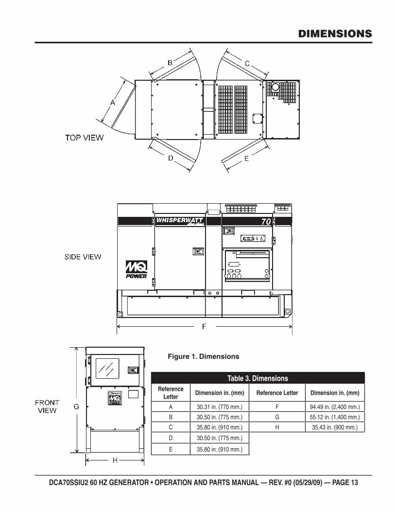
DCA70SSIU2 60 HZ GENERATOR • OPERATION AND PARTS MANUAL — REV. #0 (05/29/09) — PAGE 13
DIMENSIONS
DimensionsFigure 1.
DimensionsTable 3. Reference
LetterDimension in. (mm) Reference Letter Dimension in. (mm)
A 30.31 in. (770 mm.) F 94.49 in. (2,400 mm.)
B 30.50 in. (775 mm.) G 55.12 in. (1,400 mm.)
C 35.80 in. (910 mm.) H 35.43 in. (900 mm.)
D 30.50 in. (775 mm.)
E 35.80 in. (910 mm.)
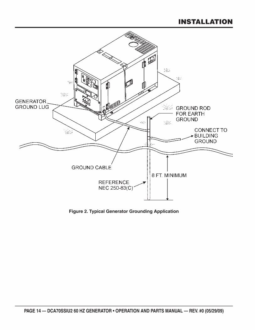
PAGE 14 — DCA70SSIU2 60 HZ GENERATOR • OPERATION AND PARTS MANUAL — REV. #0 (05/29/09)
INSTALLATION
Typical Generator Grounding ApplicationFigure 2.
DCA70SSIU2 60 HZ GENERATOR • OPERATION AND PARTS MANUAL — REV. #0 (05/29/09) — PAGE 15
INSTALLATION
OUTDOOR INSTALLATION
Install the generator in a area that is free of debris, bystanders, and overhead obstructions. Make sure the generator is on secure level ground so that it cannot slide or shift around. Also install the generator in a manner so that the exhaust will not be discharged in the direction of nearby homes.
The installation site must be relatively free from moisture and dust. All electrical equipment should be protected from excessive moisture. Failure to do will result in deterioration of the insulation and will result in short circuits and grounding.
Foreign materials such as dust, sand, lint and abrasive materials have a tendency to cause excessive wear to engine and alternator parts.
INDOOR INSTALLATION
Exhaust gases from diesel engines are extremely poisonous. Whenever an engine is installed indoors the exhaust fumes must be vented to the outside. The engine should be installed at least two feet from any outside wall. Using an exhaust pipe which is too long or too small can cause excessive back pressure which will cause the engine to heat excessively and possibly burn the valves.
MOUNTING
The generator must be mounted on a solid foundation (such as concrete) and set fi rmly on the foundation to isolate vibration of the generator when it is running. The generator must set at least 6 inches above the fl oor or grade level (in accordance to NFPA 110, Chapter 5-4.1). DO NOT remove the metal skids on the bottom of the generator. They are to resist damage to the bottom of the generator and to maintain alignment.
CAUTION
Pay close attention to ventilation when operating the generator inside tunnels and caves. The engine exhaust contains noxious elements. Engine exhaust must be routed to a ventilated area.
GENERATOR GROUNDING
To guard against electrical shock and possible damage to the equipment, it is important to provide a good EARTH ground.
Article 250 (Grounding) of the National Electrical Code (NEC) provides guide lines for proper grounding and specifi es that the cable ground shall be connected to the grounding system of the building as close to the point of cable entry as practical.
NEC articles 250-64(b) and 250-66 set the following grounding requirements:
Use one of the following wire types to connect the 1. generator to earth ground.
Copper - 10 AWG (5.3 mm2) or larger.a.
Aluminum - 8 AWG (8.4 mm2) or larger.b.
When grounding the generator (Figure 2) connect the 2. ground cable between the lock washer and the nut on the generator and tighten the nut fully. Connect the other end of the ground cable to earth ground.
NEC article 250-52(c) specifi es that the earth ground rod 3. should be buried a minimum of 8 ft. into the ground.
NOTICE
When connecting the generator to any buildings electrical system ALWAYS consult with a licensed electrician.
PAGE 16 — DCA70SSIU2 60 HZ GENERATOR • OPERATION AND PARTS MANUAL — REV. #0 (05/29/09)
GENERATORThe MQ Power Model DCA70SSIU2 generator (Figure 3) is a high quality portable (requires a trailer for transport) power source for telecom sites, lighting facilities, power tools, submersible pumps and other industrial and construction machinery.ENGINE OPERATING PANELThe “Engine Operating Panel” is provided with the following:
Tachometer Water Temperature Gauge Warning Lamp Pre-Heat Lamp Oil Pressure Gauge Charging Ammeter Gauge Fuel Level Gauge Panel Light/Panel Light Switch ECU Controller Engine Speed Switch
GENERATOR CONTROL PANELThe “Generator Control Panel” is provided with the following:
Frequency Meter (Hz) AC Ammeter (Amps) AC Voltmeter (Volts) Ammeter Change-Over Switch Voltmeter Change-Over Switch Voltage Regulator 3-Pole, 175 amp Main Circuit Breaker “Control Box” (located behind the Gen. Control Panel)
Automatic Voltage Regulator• Current Transformer• Over-Current Relay• Starter Relay• Voltage Selector Switch•
OUTPUT TERMINAL PANELThe “Output Terminal Panel” is provided with the following:
Three 120/240V output receptacles (CS-6369), 50A Three auxiliary circuit breakers, 50A Two 120V output receptacles (GFCI), 20A Two GFCI circuit breakers, 20A Five output terminal lugs (3Ø power)
OPEN DELTA EXCITATION SYSTEMThis generator is equipped with the state of the art “Open-Delta” excitation system. The open delta system consist of an electrically independent winding wound among stationary windings of the AC output section.There are four connections of the open delta A, B, C and D. During steady state loads, the power from the voltage regulator is supplied from the parallel connections of A to B, A to D, and C to D. These three phases of the voltage input to the voltage regulator are then rectifi ed and are the excitation current for the exciter section. When a heavy load, such as a motor starting or a short circuit occurs, the automatic voltage regulator (AVR) switches the confi guration of the open delta to the series connection of B to C. This has the effect of adding the voltages of each phase to provide higher excitation to the exciter section and thus better voltage response during the application of heavy loads. The connections of the AVR to the AC output windings are for sensing only. No power is required from these windings.The open-delta design provides virtually unlimited excitation current, offering maximum motor starting capabilities. The excitation does not have a “fi xed ceiling” and responds according the demands of the required load.ENGINEThis generator unit incorporates an ISUZU BJ-4JJ1X diesel engine. This engine is designed to meet every performance requirement for the generator. Reference Table 2 for engine specifi cations.
In keeping with MQ Power’s policy of constantly improving its products, the specifi cations quoted herein are subject to change without prior notice.ELECTRIC GOVERNOR SYSTEMThe electric governor system controls the RPMs of the engine. When the engine demand increases or decreases, the governor system regulates the frequency variation to ±.25%. EXTENSION CABLESWhen electric power is to be provided to various tools or loads at some distance from the generator, extension cords are normally used. Cables should be sized to allow for distance in length and amperage so that the voltage drop between the generator and point of use (load) is held to a minimum. Use the cable selection chart (Table 6) as a guide for selecting proper extension cable size.
GENERAL INFORMATION
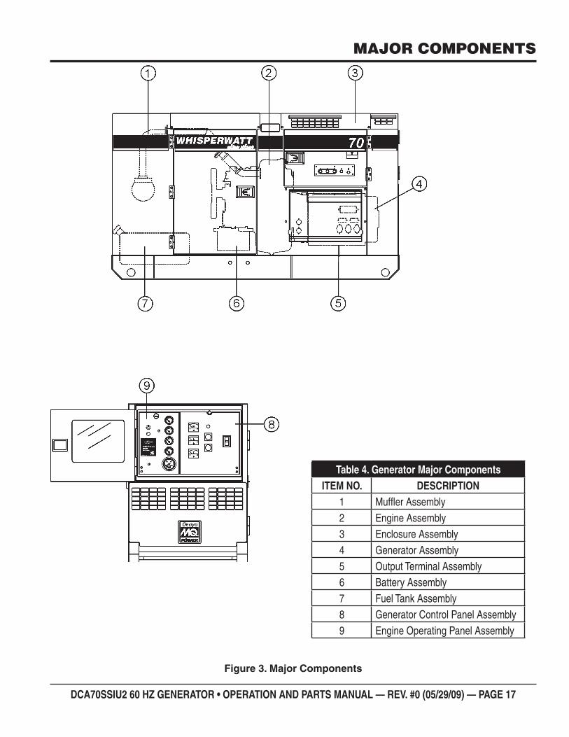
DCA70SSIU2 60 HZ GENERATOR • OPERATION AND PARTS MANUAL — REV. #0 (05/29/09) — PAGE 17
MAJOR COMPONENTS
Major ComponentsFigure 3.
Generator Major ComponentsTable 4. ITEM NO. DESCRIPTION
1 Muffl er Assembly2 Engine Assembly3 Enclosure Assembly4 Generator Assembly5 Output Terminal Assembly6 Battery Assembly7 Fuel Tank Assembly8 Generator Control Panel Assembly9 Engine Operating Panel Assembly
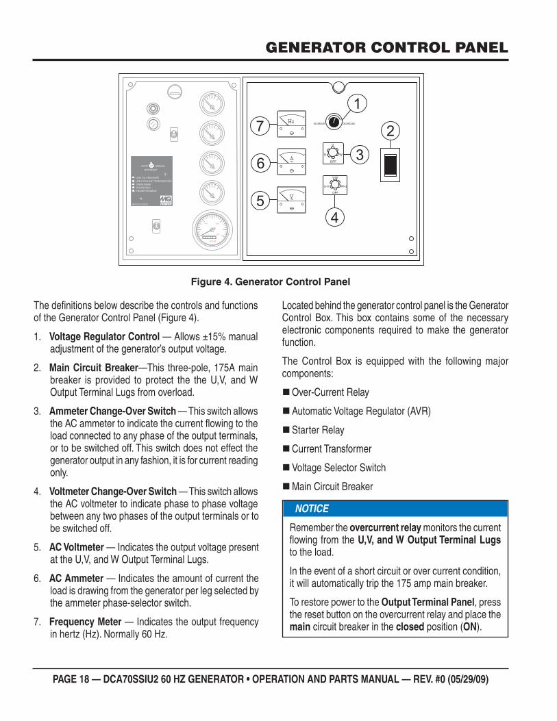
PAGE 18 — DCA70SSIU2 60 HZ GENERATOR • OPERATION AND PARTS MANUAL — REV. #0 (05/29/09)
GENERATOR CONTROL PANEL
Generator Control PanelFigure 4.
1000 2000
30000
R P M
OFF
WU
V
OFF
W-U
V-W
U-V
DECREASEINCREASE
AUTO MANUAL
OFF/RESET
LOW OIL PRESSURE
HIGH COOLANT TEMPERATURE
OVERCRANK
OVERSPEED
ENGINE RUNNING
MOOOOO-20001Q
1
2
4
36
7
5
The defi nitions below describe the controls and functions of the Generator Control Panel (Figure 4).
Voltage Regulator Control 1. — Allows ±15% manual adjustment of the generator’s output voltage.
Main Circuit Breaker2. —This three-pole, 175A main breaker is provided to protect the the U,V, and W Output Terminal Lugs from overload.
Ammeter Change-Over Switch 3. — This switch allows the AC ammeter to indicate the current fl owing to the load connected to any phase of the output terminals, or to be switched off. This switch does not effect the generator output in any fashion, it is for current reading only.
Voltmeter Change-Over Switch 4. — This switch allows the AC voltmeter to indicate phase to phase voltage between any two phases of the output terminals or to be switched off.
AC Voltmeter 5. — Indicates the output voltage present at the U,V, and W Output Terminal Lugs.
AC Ammeter 6. — Indicates the amount of current the load is drawing from the generator per leg selected by the ammeter phase-selector switch.
Frequency Meter 7. — Indicates the output frequency in hertz (Hz). Normally 60 Hz.
Located behind the generator control panel is the Generator Control Box. This box contains some of the necessary electronic components required to make the generator function.
The Control Box is equipped with the following major components:
Over-Current Relay
Automatic Voltage Regulator (AVR)
Starter Relay
Current Transformer
Voltage Selector Switch
Main Circuit Breaker
NOTICE
Remember the overcurrent relay monitors the current fl owing from the U,V, and W Output Terminal Lugs to the load.
In the event of a short circuit or over current condition, it will automatically trip the 175 amp main breaker.
To restore power to the Output Terminal Panel, press the reset button on the overcurrent relay and place the main circuit breaker in the closed position (ON).

DCA70SSIU2 60 HZ GENERATOR • OPERATION AND PARTS MANUAL — REV. #0 (05/29/09) — PAGE 19
NOTES
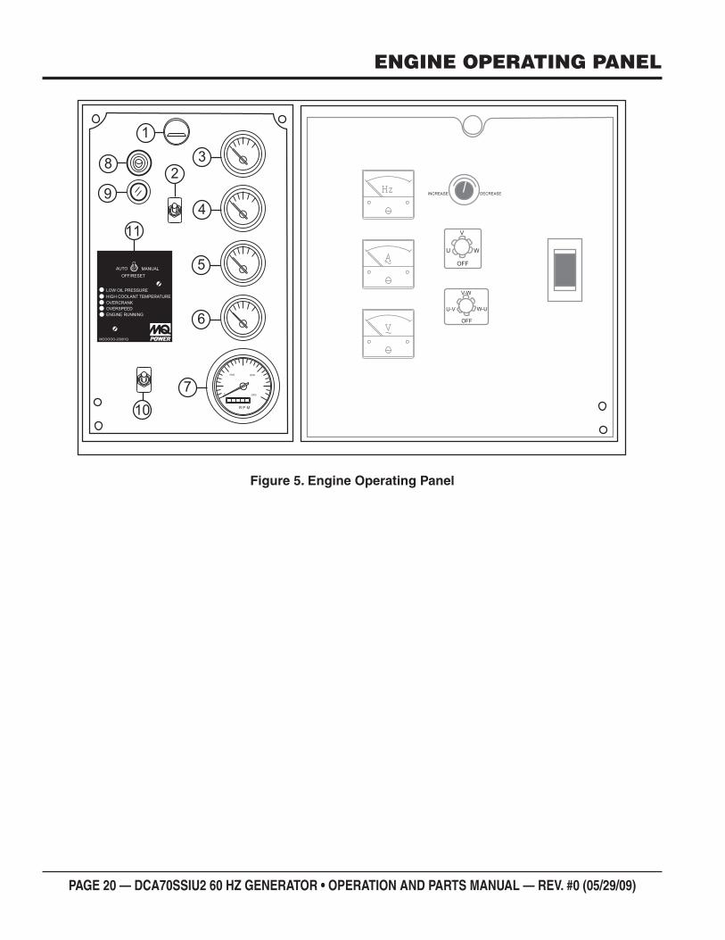
PAGE 20 — DCA70SSIU2 60 HZ GENERATOR • OPERATION AND PARTS MANUAL — REV. #0 (05/29/09)
ENGINE OPERATING PANEL
Engine Operating PanelFigure 5.
OFF
WU
V
OFF
W-U
V-W
U-V
DECREASEINCREASE
1000 2000
30000
R P M
AUTO MANUAL
OFF/RESET
LOW OIL PRESSURE
HIGH COOLANT TEMPERATURE
OVERCRANK
OVERSPEED
ENGINE RUNNING
MOOOOO-20001Q
3
4
5
6
7
10
9
8
11
2
1
DCA70SSIU2 60 HZ GENERATOR • OPERATION AND PARTS MANUAL — REV. #0 (05/29/09) — PAGE 21
The defi nitions below describe the controls and functions of the Engine Operating Panel (Figure 5).
Panel Light 1. — Normally used in dark areas or at night time. When activated, panel lights will illuminate. When the generator is not in use be sure to turn the panel light switch to the OFF position.Panel Light Switch 2. — When activated will turn on control panel light.Oil Pressure Gauge 3. — During normal operation this gauge should read between 42 ~71 psi. (290~490 kPa). When starting the generator the oil pressure may read a little higher, but after the engine warms up the oil pressure should return to the correct pressure range.Water Temperature Gauge 4. — During normal operation this gauge be should read between 167°~203°F (75° ~95°CCharging Ammeter Gauge 5. — Indicates the current being supplied by the engine’s alternator which provides current for generator’s control circuits and battery charging system.Fuel Gauge 6. — Indicates amount of diesel fuel available.Tachometer 7. — Indicates engine speed in RPM’s for 60 Hz operation. This meter should indicate 1800 RPM’s when the rated load is applied. In addition a built in hour meter will record the number of operational hours that the generator has been in use.Preheat Lamp 8. — As the engine cranks, this lamp will illuminate to indicate automatic preheating of the engine glow plugs. When the lamp turns off, this indicates that the preheat cycle is complte and the engine will start automatically.Warning Lamp 9. — This lamp will illuminate when a critical engine fault has occured.Engine Speed Switch 10. — This switch controls the speed of the engine (low/high).Auto START/STOP Engine Controller (ECU) 11. — This controller has a vertical row of status LED's (inset), that when lit, indicate that an engine malfunction (fault) has been detected. When a fault has been detected the engine controller will evaluate the fault and all major faults will shutdown the generator. During cranking cycle, the ECU will attempt to crank the engine for 10 seconds before disengaging.
If the engine does not engage (start) by the third attempt, the engine will be shutdown by the engine controller’s Over Crank Protection mode. If the engine engages at a speed (RPM's) that is not safe, the controller will shutdown the engine by initializing the Over Speed Protection mode.
Also the engine controller will shut down the engine in the event of low oil pressure, high coolant temperature, low coolant level, and loss of magnetic pickup. These conditions can be observed by monitoring the LED status indicators on the front of the controller module.
MPEC Control Switch A. — This switch controls the running of the unit. If this switch is set to the OFF/RESET position, the unit will not run. When this switch is set to the manual position, the generator will start immediately.
If the generator is to be connected to a building’s AC power source via an automatic transfer switch (isolation), place the switch in the AUTO position. In this position, should an outage occur, the automatic transfer switch (ATS) will start the generator automatically via the generator’s auto-start contacts connected to the ATS’s start contacts. Please refer to your ATS installation manual for further instructions for the correct installation of the auto-start contacts of the generator to the ATS.
Low Oil Pressure B. — Indicates the engine pressure has fallen below 15 psi (103 kPa). The oil pressure is detected using variable resistive values from the oil pressure sending unit. This is considered a major fault.
High Coolant Temperature C. — Indicates the engine temperature has exceeded 230°F (110°C). The engine temperature is detected using variable resistive values from the temperature sending unit. This is considered a major fault.
Overcrank Shutdown D. — Indicates the unit has attempted to start a pre- programmed number of times, and has failed to start. The number of cycles and duration are programmable. It is pre-set at 3 cycles with a 10 second duration. This is considered a major fault.
Overspeed Shutdown E. — Indicates the engine is running at an unsafe speed. This is considered a major fault.
Engine Running F. — Indicates that engine is running at a safe operating speed.
ENGINE OPERATING PANEL
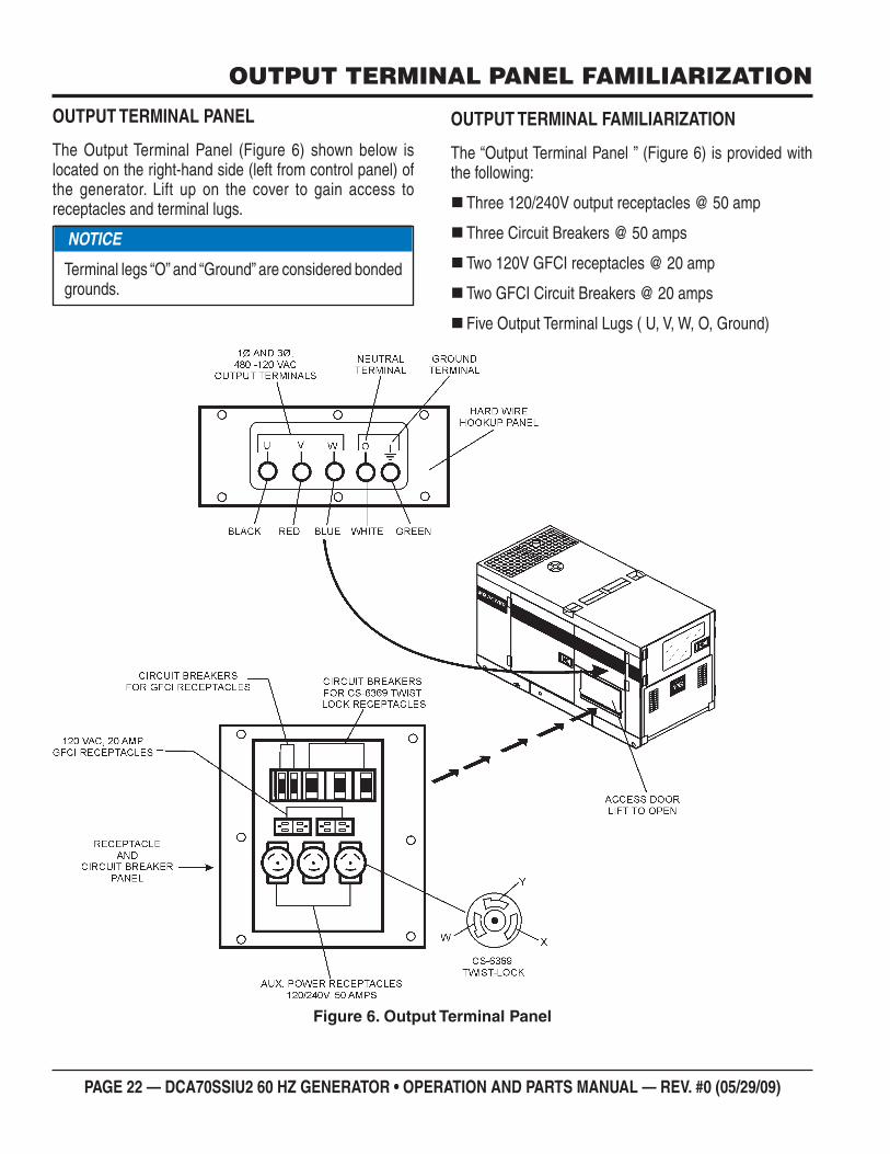
PAGE 22 — DCA70SSIU2 60 HZ GENERATOR • OPERATION AND PARTS MANUAL — REV. #0 (05/29/09)
OUTPUT TERMINAL PANEL FAMILIARIZATION
OUTPUT TERMINAL PANEL
The Output Terminal Panel (Figure 6) shown below is located on the right-hand side (left from control panel) of the generator. Lift up on the cover to gain access to receptacles and terminal lugs.
NOTICE
Terminal legs “O” and “Ground” are considered bonded grounds.
OUTPUT TERMINAL FAMILIARIZATION
The “Output Terminal Panel ” (Figure 6) is provided with the following:
Three 120/240V output receptacles @ 50 amp
Three Circuit Breakers @ 50 amps
Two 120V GFCI receptacles @ 20 amp
Two GFCI Circuit Breakers @ 20 amps
Five Output Terminal Lugs ( U, V, W, O, Ground)
Output Terminal PanelFigure 6.
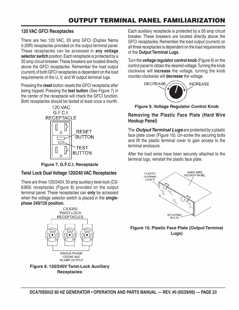
DCA70SSIU2 60 HZ GENERATOR • OPERATION AND PARTS MANUAL — REV. #0 (05/29/09) — PAGE 23
OUTPUT TERMINAL PANEL FAMILIARIZATION
120 VAC GFCI Receptacles
There are two 120 VAC, 20 amp GFCI (Duplex Nema 5-20R) receptacles provided on the output terminal panel. These receptacles can be accessed in any voltage selector switch position. Each receptacle is protected by a 20 amp circuit breaker. These breakers are located directly above the GFCI receptacles. Remember the load output (current) of both GFCI receptacles is dependent on the load requirements of the U, V, and W output terminal lugs.
Pressing the reset button resets the GFCI receptacle after being tripped. Pressing the test button (See Figure 7) in the center of the receptacle will check the GFCI function. Both receptacles should be tested at least once a month.
G.F.C.I. ReceptacleFigure 7.
Twist Lock Dual Voltage 120/240 VAC Receptacles
There are three 120/240V, 50 amp auxiliary twist-lock (CS-6369) receptacles (Figure 8) provided on the output terminal panel. These receptacles can only be accessed when the voltage selector switch is placed in the single-phase 240/120 position.
120/240V Twist-Lock Auxiliary Figure 8. Receptacles
Each auxiliary receptacle is protected by a 50 amp circuit breaker. These breakers are located directly above the GFCI receptacles. Remember the load output (current) on all three receptacles is dependent on the load requirements of the Output Terminal Lugs.
Turn the voltage regulator control knob (Figure 9) on the control panel to obtain the desired voltage. Turning the knob clockwise will increase the voltage, turning the knob counter-clockwise will decrease the voltage.
Voltage Regulator Control KnobFigure 9.
Removing the Plastic Face Plate (Hard Wire Hookup Panel)
The Output Terminal Lugs are protected by a plastic face plate cover (Figure 10). Un-screw the securing bolts and lift the plastic terminal cover to gain access to the terminal enclosure.
After the load wires have been securely attached to the terminal lugs, reinstall the plastic face plate.
Plastic Face Plate (Output Terminal Figure 10. Lugs)
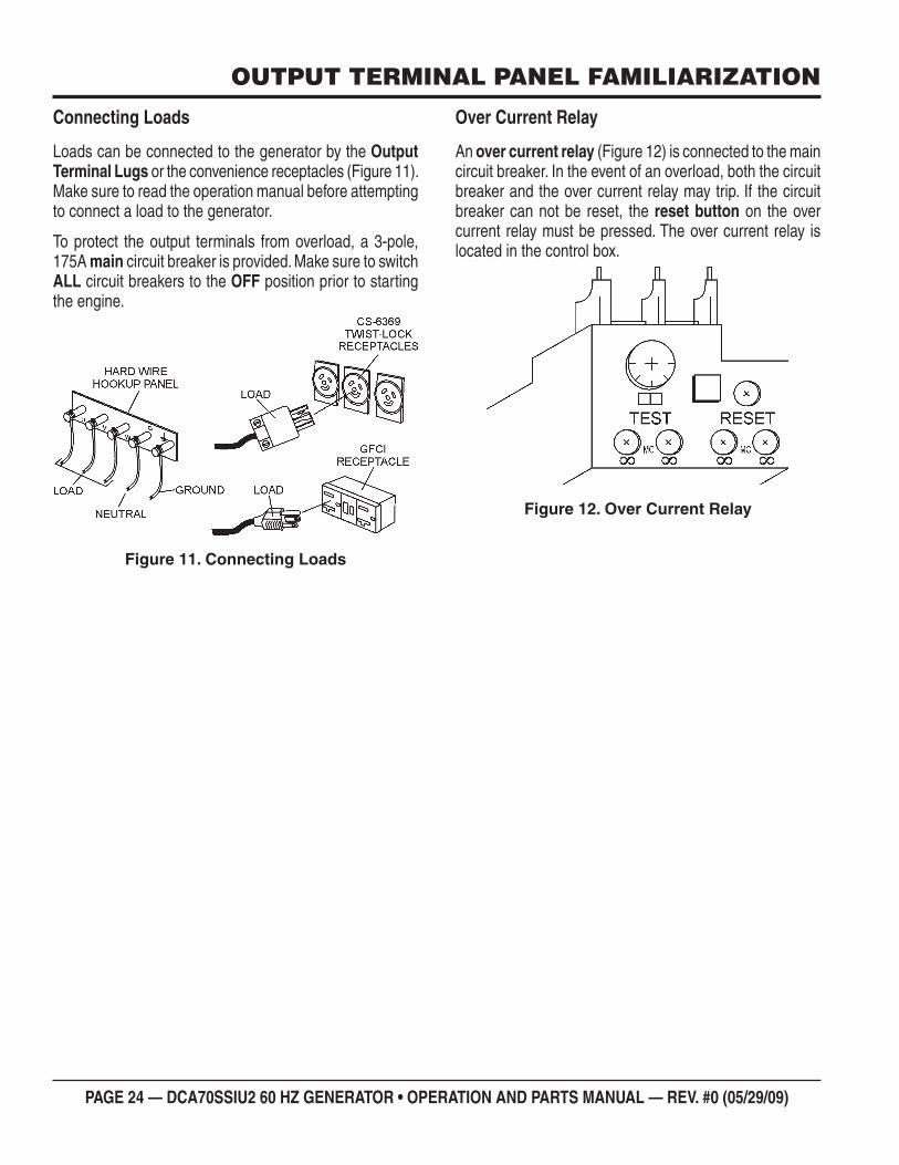
PAGE 24 — DCA70SSIU2 60 HZ GENERATOR • OPERATION AND PARTS MANUAL — REV. #0 (05/29/09)
OUTPUT TERMINAL PANEL FAMILIARIZATION
Connecting Loads
Loads can be connected to the generator by the Output Terminal Lugs or the convenience receptacles (Figure 11). Make sure to read the operation manual before attempting to connect a load to the generator.
To protect the output terminals from overload, a 3-pole, 175A main circuit breaker is provided. Make sure to switch ALL circuit breakers to the OFF position prior to starting the engine.
Connecting LoadsFigure 11.
Over Current Relay
An over current relay (Figure 12) is connected to the main circuit breaker. In the event of an overload, both the circuit breaker and the over current relay may trip. If the circuit breaker can not be reset, the reset button on the over current relay must be pressed. The over current relay is located in the control box.
Over Current RelayFigure 12.
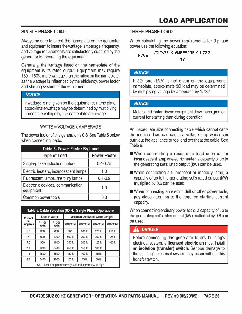
DCA70SSIU2 60 HZ GENERATOR • OPERATION AND PARTS MANUAL — REV. #0 (05/29/09) — PAGE 25
LOAD APPLICATION
SINGLE PHASE LOAD
Always be sure to check the nameplate on the generator and equipment to insure the wattage, amperage, frequency, and voltage requirements are satisfactorily supplied by the generator for operating the equipment.
Generally, the wattage listed on the nameplate of the equipment is its rated output. Equipment may require 130—150% more wattage than the rating on the nameplate, as the wattage is infl uenced by the effi ciency, power factor and starting system of the equipment.
WATTS = VOLTAGE x AMPERAGE
The power factor of this generator is 0.8. See Table 5 below when connecting loads.
Cable Selection (60 Hz, Single Phase Operation)Table 6.
Current in
Amperes
Load in Watts Maximum Allowable Cable Length
At 100 Volts
At 200 Volts #10 Wire #12 Wire #14 Wire #16 Wire
2.5 300 600 1000 ft. 600 ft. 375 ft. 250 ft.
5 600 1200 500 ft. 300 ft. 200 ft. 125 ft.
7.5 900 1800 350 ft. 200 ft. 125 ft. 100 ft.
10 1200 2400 250 ft. 150 ft. 100 ft.
15 1800 3600 150 ft. 100 ft. 65 ft.
20 2400 4800 125 ft. 75 ft. 50 ft.
CAUTION: Equipment damage can result from low voltage
NOTICE
If wattage is not given on the equipment’s name plate, approximate wattage may be determined by multiplying nameplate voltage by the nameplate amperage.
Power Factor By LoadTable 5. Type of Load Power Factor
Single-phase induction motors 0.4-0.75
Electric heaters, incandescent lamps 1.0Fluorescent lamps, mercury lamps 0.4-0.9Electronic devices, communication equipment 1.0
Common power tools 0.8
THREE PHASE LOAD
When calculating the power requirements for 3-phase power use the following equation:
An inadequate size connecting cable which cannot carry the required load can cause a voltage drop which can burn out the appliance or tool and overheat the cable. See Table 6.
When connecting a resistance load such as an incandescent lamp or electric heater, a capacity of up to the generating set’s rated output (kW) can be used.
When connecting a fl uorescent or mercury lamp, a capacity of up to the generating set’s rated output (kW) multiplied by 0.6 can be used.
When connecting an electric drill or other power tools, pay close attention to the required starting current capacity.
When connecting ordinary power tools, a capacity of up to the generating set’s rated output (kW) multiplied by 0.8 can be used.
NOTICE
Motors and motor-driven equipment draw much greater current for starting than during operation.
NOTICE
If 3Ø load (kVA) is not given on the equipment nameplate, approximate 3Ø load may be determined by multiplying voltage by amperage by 1.732.
DANGER
Before connecting this generator to any building’s electrical system, a licensed electrician must install an isolation (transfer) switch. Serious damage to the building’s electrical system may occur without this transfer switch.
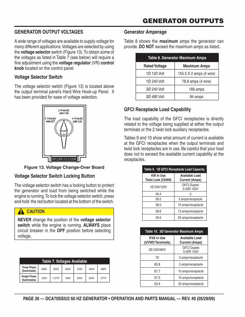
PAGE 26 — DCA70SSIU2 60 HZ GENERATOR • OPERATION AND PARTS MANUAL — REV. #0 (05/29/09)
GENERATOR OUTPUTS
GENERATOR OUTPUT VOLTAGES
A wide range of voltages are available to supply voltage for many different applications. Voltages are selected by using the voltage selector switch (Figure 13). To obtain some of the voltages as listed in Table 7 (see below) will require a fi ne adjustment using the voltage regulator (VR) control knob located on the control panel.
Voltage Selector Switch
The voltage selector switch (Figure 13) is located above the output terminal panel’s Hard Wire Hook-up Panel. It has been provided for ease of voltage selection.
Voltage Change-Over BoardFigure 13.
Voltage Selector Switch Locking Button
The voltage selector switch has a locking button to protect the generator and load from being switched while the engine is running. To lock the voltage selector switch, press and hold the red button located at the bottom of the switch.
CAUTION
NEVER change the position of the voltage selector switch while the engine is running. ALWAYS place circuit breaker in the OFF position before selecting voltage.
Voltages AvailableTable 7. Three Phase (Switchable) 208V 220V 240V 416V 440V 480V
Single Phase (Switchable)
120V 1127V 139V 240V 254V 277V
Generator Amperage
Table 8 shows the maximum amps the generator can provide. DO NOT exceed the maximum amps as listed..
GFCI Receptacle Load Capability
The load capability of the GFCI receptacles is directly related to the voltage being supplied at either the output terminals or the 2 twist lock auxiliary receptacles.
Tables 9 and 10 show what amount of current is available at the GFCI receptacles when the output terminals and twist lock receptacles are in use. Be careful that your load does not to exceed the available current capability at the receptacles.
Generator Maximum AmpsTable 8.
Rated Voltage Maximum Amps
1Ø 120 Volt 155.5 X 2 amps (4 wire)
1Ø 240 Volt 78.8 amps (4 wire)
3Ø 240 Volt 168 amps
3Ø 480 Volt 84 amps
1Ø GFCI Receptacle Load CapacityTable 9.
KW in UseTwist Lock (C6369)
Available LoadCurrent (Amps)
1Ø 240/120V GFCI Duplex5-20R 120V
40.4 039.2 5 amps/receptacle
38.0 10 amps/receptacle
38.6 15 amps/receptacle
35.6 20 amps/receptacle
3Ø Generator Maximum AmpsTable 10.
KVA in Use(UVWO Terminals)
Available LoadCurrent (Amps)
3Ø 240/480V GFCI Duplex5-20R 120V
70 0 amps/receptacle
65.8 5 amps/receptacle
61.7 10 amps/receptacle
57.5 15 amps/receptacle
53.4 20 amps/receptacle
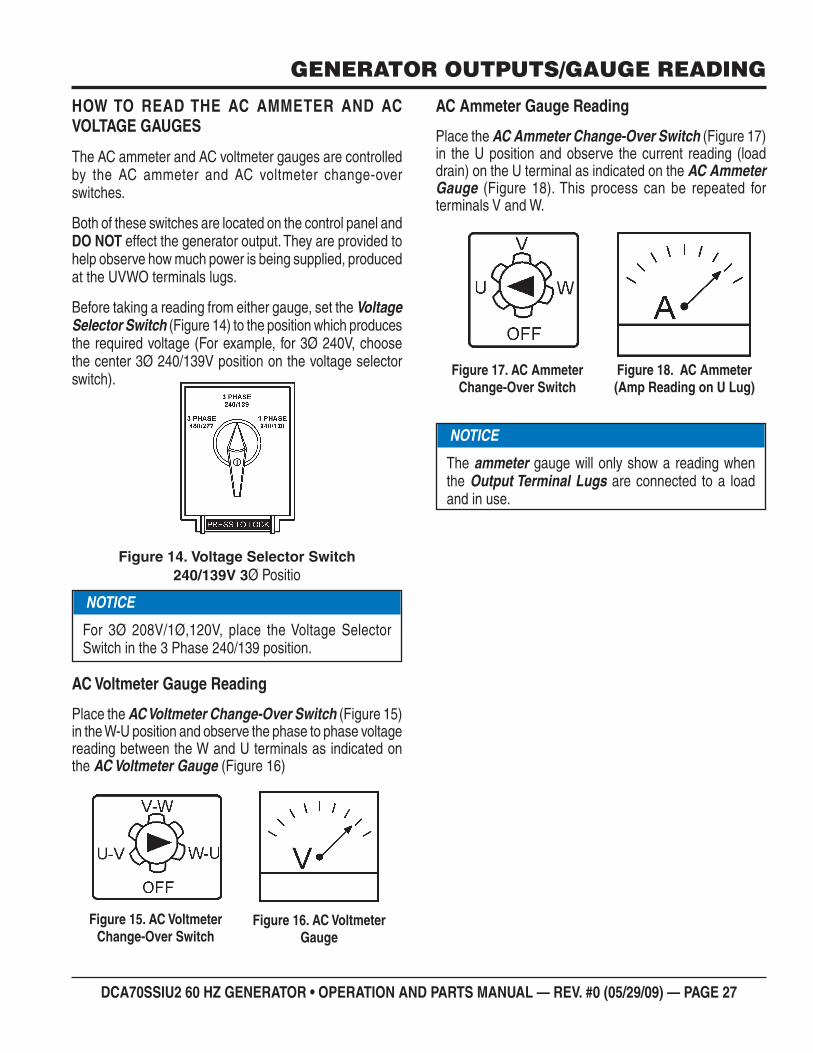
DCA70SSIU2 60 HZ GENERATOR • OPERATION AND PARTS MANUAL — REV. #0 (05/29/09) — PAGE 27
GENERATOR OUTPUTS/GAUGE READING
HOW TO READ THE AC AMMETER AND AC VOLTAGE GAUGES
The AC ammeter and AC voltmeter gauges are controlled by the AC ammeter and AC voltmeter change-over switches.
Both of these switches are located on the control panel and DO NOT effect the generator output. They are provided to help observe how much power is being supplied, produced at the UVWO terminals lugs.
Before taking a reading from either gauge, set the Voltage Selector Switch (Figure 14) to the position which produces the required voltage (For example, for 3Ø 240V, choose the center 3Ø 240/139V position on the voltage selector switch).
Voltage Selector SwitchFigure 14. 240/139V 3Ø Positio
AC Voltmeter Gauge Reading
Place the AC Voltmeter Change-Over Switch (Figure 15) in the W-U position and observe the phase to phase voltage reading between the W and U terminals as indicated on the AC Voltmeter Gauge (Figure 16)
NOTICE
For 3Ø 208V/1Ø,120V, place the Voltage Selector Switch in the 3 Phase 240/139 position.
AC Voltmeter Figure 15. Change-Over Switch
AC Voltmeter Figure 16. Gauge
AC Ammeter Gauge Reading
Place the AC Ammeter Change-Over Switch (Figure 17) in the U position and observe the current reading (load drain) on the U terminal as indicated on the AC Ammeter Gauge (Figure 18). This process can be repeated for terminals V and W.
AC Ammeter Figure 17. Change-Over Switch
AC AmmeterFigure 18. (Amp Reading on U Lug)
NOTICE
The ammeter gauge will only show a reading when the Output Terminal Lugs are connected to a load and in use.
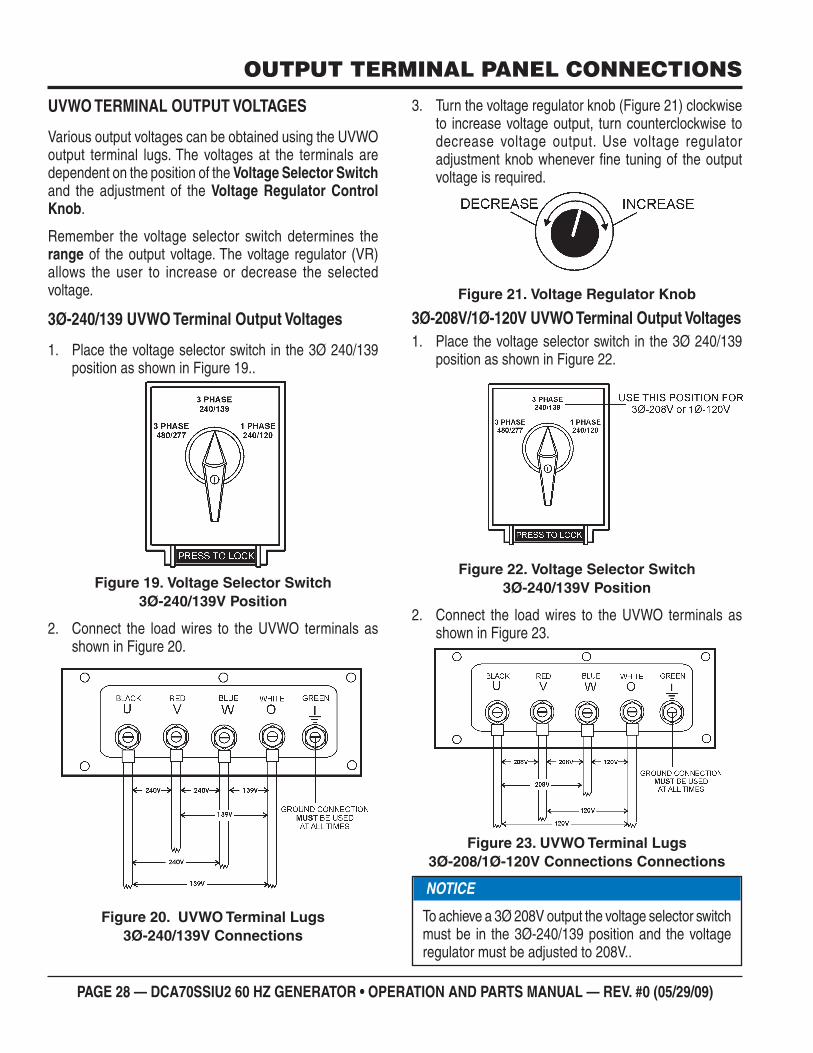
PAGE 28 — DCA70SSIU2 60 HZ GENERATOR • OPERATION AND PARTS MANUAL — REV. #0 (05/29/09)
OUTPUT TERMINAL PANEL CONNECTIONS
UVWO TERMINAL OUTPUT VOLTAGES
Various output voltages can be obtained using the UVWO output terminal lugs. The voltages at the terminals are dependent on the position of the Voltage Selector Switch and the adjustment of the Voltage Regulator Control Knob.
Remember the voltage selector switch determines the range of the output voltage. The voltage regulator (VR) allows the user to increase or decrease the selected voltage.
3Ø-240/139 UVWO Terminal Output Voltages
Place the voltage selector switch in the 3Ø 240/139 1. position as shown in Figure 19..
Voltage Selector SwitchFigure 19. 3Ø-240/139V Position
Connect the load wires to the UVWO terminals as 2. shown in Figure 20.
UVWO Terminal Lugs Figure 20. 3Ø-240/139V Connections
Turn the voltage regulator knob (Figure 21) clockwise 3. to increase voltage output, turn counterclockwise to decrease voltage output. Use voltage regulator adjustment knob whenever fi ne tuning of the output voltage is required.
Voltage Regulator KnobFigure 21.
3Ø-208V/1Ø-120V UVWO Terminal Output VoltagesPlace the voltage selector switch in the 3Ø 240/139 1. position as shown in Figure 22.
Voltage Selector SwitchFigure 22. 3Ø-240/139V Position
Connect the load wires to the UVWO terminals as 2. shown in Figure 23.
UVWO Terminal LugsFigure 23. 3Ø-208/1Ø-120V Connections Connections
NOTICE
To achieve a 3Ø 208V output the voltage selector switch must be in the 3Ø-240/139 position and the voltage regulator must be adjusted to 208V..
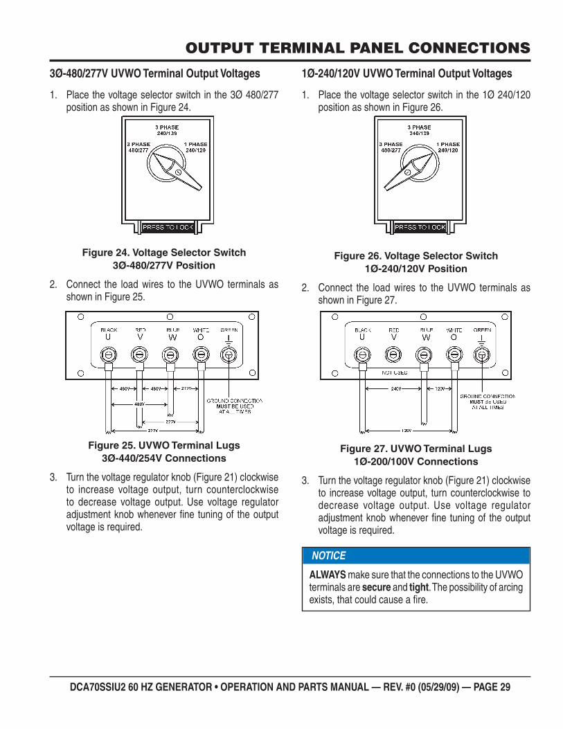
DCA70SSIU2 60 HZ GENERATOR • OPERATION AND PARTS MANUAL — REV. #0 (05/29/09) — PAGE 29
OUTPUT TERMINAL PANEL CONNECTIONS
3Ø-480/277V UVWO Terminal Output Voltages
Place the voltage selector switch in the 3Ø 480/277 1. position as shown in Figure 24.
Voltage Selector SwitchFigure 24. 3Ø-480/277V Position
Connect the load wires to the UVWO terminals as 2. shown in Figure 25.
UVWO Terminal Lugs Figure 25. 3Ø-440/254V Connections
Turn the voltage regulator knob (Figure 21) clockwise 3. to increase voltage output, turn counterclockwise to decrease voltage output. Use voltage regulator adjustment knob whenever fi ne tuning of the output voltage is required.
1Ø-240/120V UVWO Terminal Output Voltages
Place the voltage selector switch in the 1Ø 240/120 1. position as shown in Figure 26.
Voltage Selector SwitchFigure 26. 1Ø-240/120V Position
Connect the load wires to the UVWO terminals as 2. shown in Figure 27.
UVWO Terminal Lugs Figure 27. 1Ø-200/100V Connections
Turn the voltage regulator knob (Figure 21) clockwise 3. to increase voltage output, turn counterclockwise to decrease voltage output. Use voltage regulator adjustment knob whenever fi ne tuning of the output voltage is required.
NOTICE
ALWAYS make sure that the connections to the UVWO terminals are secure and tight. The possibility of arcing exists, that could cause a fi re.
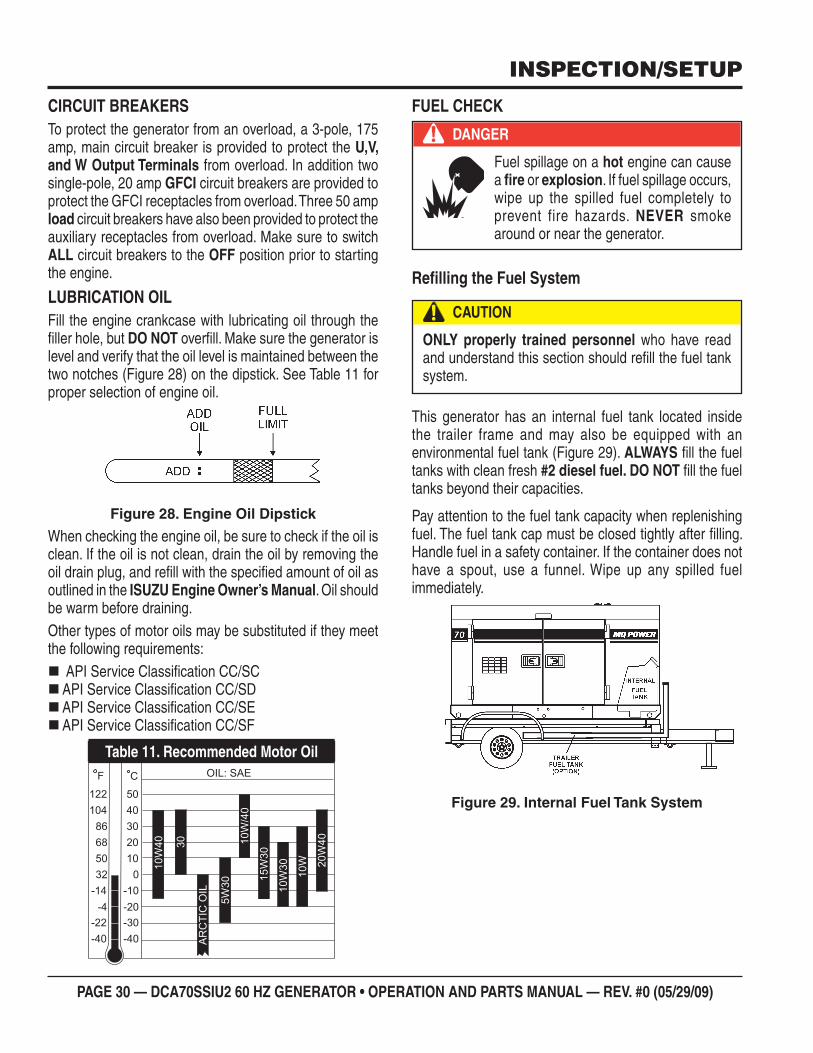
PAGE 30 — DCA70SSIU2 60 HZ GENERATOR • OPERATION AND PARTS MANUAL — REV. #0 (05/29/09)
INSPECTION/SETUP
CIRCUIT BREAKERSTo protect the generator from an overload, a 3-pole, 175 amp, main circuit breaker is provided to protect the U,V, and W Output Terminals from overload. In addition two single-pole, 20 amp GFCI circuit breakers are provided to protect the GFCI receptacles from overload. Three 50 amp load circuit breakers have also been provided to protect the auxiliary receptacles from overload. Make sure to switch ALL circuit breakers to the OFF position prior to starting the engine.
LUBRICATION OILFill the engine crankcase with lubricating oil through the fi ller hole, but DO NOT overfi ll. Make sure the generator is level and verify that the oil level is maintained between the two notches (Figure 28) on the dipstick. See Table 11 for proper selection of engine oil.
Engine Oil DipstickFigure 28.
When checking the engine oil, be sure to check if the oil is clean. If the oil is not clean, drain the oil by removing the oil drain plug, and refi ll with the specifi ed amount of oil as outlined in the ISUZU Engine Owner’s Manual. Oil should be warm before draining.Other types of motor oils may be substituted if they meet the following requirements:
API Service Classifi cation CC/SC API Service Classifi cation CC/SD API Service Classifi cation CC/SE API Service Classifi cation CC/SF
Recommended Motor OilTable 11.
FUEL CHECK
Refi lling the Fuel System
This generator has an internal fuel tank located inside the trailer frame and may also be equipped with an environmental fuel tank (Figure 29). ALWAYS fi ll the fuel tanks with clean fresh #2 diesel fuel. DO NOT fi ll the fuel tanks beyond their capacities.
Pay attention to the fuel tank capacity when replenishing fuel. The fuel tank cap must be closed tightly after fi lling. Handle fuel in a safety container. If the container does not have a spout, use a funnel. Wipe up any spilled fuel immediately.
Internal Fuel Tank SystemFigure 29.
DANGER
Fuel spillage on a hot engine can cause a fi re or explosion. If fuel spillage occurs, wipe up the spilled fuel completely to prevent fire hazards. NEVER smoke around or near the generator.
CAUTION
ONLY properly trained personnel who have read and understand this section should refi ll the fuel tank system.
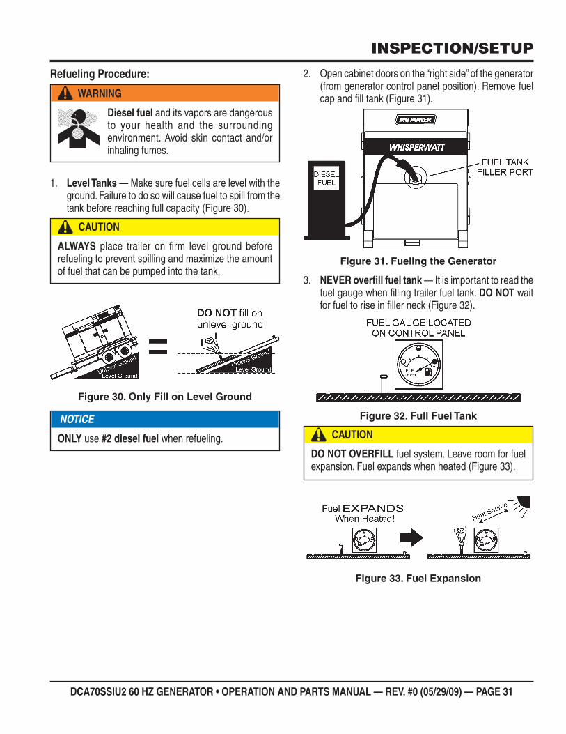
DCA70SSIU2 60 HZ GENERATOR • OPERATION AND PARTS MANUAL — REV. #0 (05/29/09) — PAGE 31
INSPECTION/SETUP
Refueling Procedure:
Level Tanks1. — Make sure fuel cells are level with the ground. Failure to do so will cause fuel to spill from the tank before reaching full capacity (Figure 30).
Only Fill on Level GroundFigure 30.
WARNING
Diesel fuel and its vapors are dangerous to your health and the surrounding environment. Avoid skin contact and/or inhaling fumes.
CAUTION
ALWAYS place trailer on fi rm level ground before refueling to prevent spilling and maximize the amount of fuel that can be pumped into the tank.
NOTICE
ONLY use #2 diesel fuel when refueling.
Open cabinet doors on the “right side” of the generator 2. (from generator control panel position). Remove fuel cap and fi ll tank (Figure 31).
Fueling the GeneratorFigure 31.
NEVER overfi ll fuel tank3. — It is important to read the fuel gauge when fi lling trailer fuel tank. DO NOT wait for fuel to rise in fi ller neck (Figure 32).
Full Fuel TankFigure 32.
Fuel ExpansionFigure 33.
CAUTION
DO NOT OVERFILL fuel system. Leave room for fuel expansion. Fuel expands when heated (Figure 33).
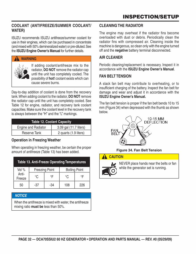
PAGE 32 — DCA70SSIU2 60 HZ GENERATOR • OPERATION AND PARTS MANUAL — REV. #0 (05/29/09)
COOLANT (ANTIFREEZE/SUMMER COOLANT/WATER)
ISUZU recommends ISUZU antifreeze/summer coolant for use in their engines, which can be purchased in concentrate (and mixed with 50% demineralized water) or pre-diluted. See the ISUZU Engine Owner’s Manual for further details.
Day-to-day addition of coolant is done from the recovery tank. When adding coolant to the radiator, DO NOT remove the radiator cap until the unit has completely cooled. See Table 12 for engine, radiator, and recovery tank coolant capacities. Make sure the coolant level in the recovery tank is always between the “H” and the “L” markings.
Operation in Freezing Weather
When operating in freezing weather, be certain the proper amount of antifreeze (Table 13) has been added.
WARNING
If adding coolant/antifreeze mix to the radiator, DO NOT remove the radiator cap until the unit has completely cooled. The possibility of hot! coolant exists which can cause severe burns.
Coolant CapacityTable 12. Engine and Radiator 3.09 gal (11.7 liters)
Reserve Tank 2 quarts (1.9 liters)
Anti-Freeze Operating TemperaturesTable 13.
Vol %Anti-
Freeze
Freezing Point Boiling Point
°C °F °C °F
50 -37 -34 108 226
NOTICE
When the antifreeze is mixed with water, the antifreeze mixing ratio must be less than 50%.
CLEANING THE RADIATOR
The engine may overheat if the radiator fi ns become overloaded with dust or debris. Periodically clean the radiator fi ns with compressed air. Cleaning inside the machine is dangerous, so clean only with the engine turned off and the negative battery terminal disconnected.
AIR CLEANER
Periodic cleaning/replacement is necessary. Inspect it in accordance with the ISUZU Engine Owner’s Manual.
FAN BELT TENSION
A slack fan belt may contribute to overheating, or to insuffi cient charging of the battery. Inspect the fan belt for damage and wear and adjust it in accordance with the ISUZU Engine Owner’s Manual.
The fan belt tension is proper if the fan belt bends 10 to 15 mm (Figure 34) when depressed with the thumb as shown below.
Fan Belt TensionFigure 34.
CAUTION
NEVER place hands near the belts or fan while the generator set is running.
INSPECTION/SETUP
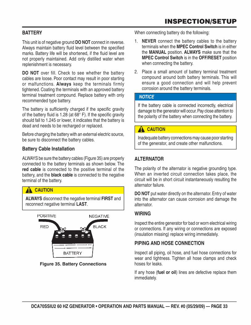
DCA70SSIU2 60 HZ GENERATOR • OPERATION AND PARTS MANUAL — REV. #0 (05/29/09) — PAGE 33
BATTERY
This unit is of negative ground DO NOT connect in reverse. Always maintain battery fl uid level between the specifi ed marks. Battery life will be shortened, if the fl uid level are not properly maintained. Add only distilled water when replenishment is necessary.
DO NOT over fill. Check to see whether the battery cables are loose. Poor contact may result in poor starting or malfunctions. Always keep the terminals firmly tightened. Coating the terminals with an approved battery terminal treatment compound. Replace battery with only recommended type battery.
The battery is suffi ciently charged if the specifi c gravity of the battery fl uid is 1.28 (at 68° F). If the specifi c gravity should fall to 1.245 or lower, it indicates that the battery is dead and needs to be recharged or replaced.
Before charging the battery with an external electric source, be sure to disconnect the battery cables.
Battery Cable Installation
ALWAYS be sure the battery cables (Figure 35) are properly connected to the battery terminals as shown below. The red cable is connected to the positive terminal of the battery, and the black cable is connected to the negative terminal of the battery.
Battery ConnectionsFigure 35.
CAUTION
ALWAYS disconnect the negative terminal FIRST and reconnect negative terminal LAST.
When connecting battery do the following:
NEVER1. connect the battery cables to the battery terminals when the MPEC Control Switch is in either the MANUAL position. ALWAYS make sure that the MPEC Control Switch is in the OFF/RESET position when connecting the battery.
Place a small amount of battery terminal treatment 2. compound around both battery terminals. This will ensure a good connection and will help prevent corrosion around the battery terminals.
ALTERNATOR
The polarity of the alternator is negative grounding type. When an inverted circuit connection takes place, the circuit will be in short circuit instantaneously resulting the alternator failure.
DO NOT put water directly on the alternator. Entry of water into the alternator can cause corrosion and damage the alternator.
WIRING
Inspect the entire generator for bad or worn electrical wiring or connections. If any wiring or connections are exposed (insulation missing) replace wiring immediately.
PIPING AND HOSE CONNECTION
Inspect all piping, oil hose, and fuel hose connections for wear and tightness. Tighten all hose clamps and check hoses for leaks.
If any hose (fuel or oil) lines are defective replace them immediately.
NOTICE
If the battery cable is connected incorrectly, electrical damage to the generator will occur. Pay close attention to the polarity of the battery when connecting the battery.
CAUTION
Inadequate battery connections may cause poor starting of the generator, and create other malfunctions.
INSPECTION/SETUP
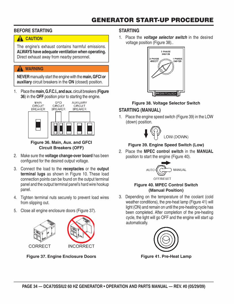
PAGE 34 — DCA70SSIU2 60 HZ GENERATOR • OPERATION AND PARTS MANUAL — REV. #0 (05/29/09)
GENERATOR START-UP PROCEDURE
BEFORE STARTING
Place the 1. main, G.F.C.I., and aux. circuit breakers (Figure 36) in the OFF position prior to starting the engine.
Main, Aux. and GFCI Figure 36. Circuit Breakers (OFF)
Make sure the 2. voltage change-over board has been confi gured for the desired output voltage.
Connect the load to the 3. receptacles or the output terminal lugs as shown in Figure 10. These load connection points can be found on the output terminal panel and the output terminal panel’s hard wire hookup panel.
Tighten terminal nuts securely to prevent load wires 4. from slipping out.
Close all engine enclosure doors (Figure 37).5.
Engine Enclosure DoorsFigure 37.
CAUTION
The engine’s exhaust contains harmful emissions. ALWAYS have adequate ventilation when operating. Direct exhaust away from nearby personnel.
WARNING
NEVER manually start the engine with the main, GFCI or auxiliary circuit breakers in the ON (closed) position.
INCORRECTCORRECT
STARTINGPlace the1. voltage selector switch in the desired voltage position (Figure 38)..
Voltage Selector SwitchFigure 38.
STARTING (MANUAL)Place the engine speed switch (Figure 39) in the LOW 1. (down) position.
Engine Speed Switch (Low)Figure 39.
Place the 2. MPEC control switch in the MANUAL position to start the engine (Figure 40).
MPEC Control Switch Figure 40. (Manual Position)
Depending on the temperature of the coolant (cold 3. weather conditions), the pre-heat lamp (Figure 41) will light (ON) and remain on until the pre-heating cycle has been completed. After completion of the pre-heating cycle, the light will go OFF and the engine will start up automatically.
Pre-Heat LampFigure 41.
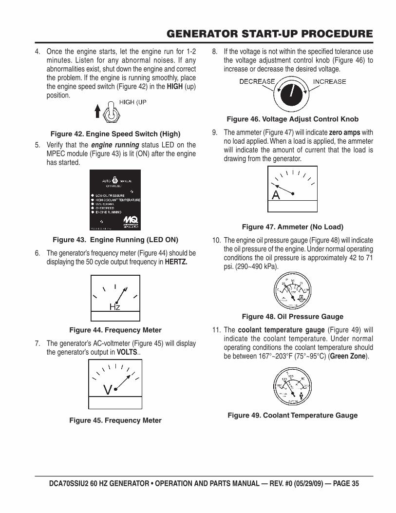
DCA70SSIU2 60 HZ GENERATOR • OPERATION AND PARTS MANUAL — REV. #0 (05/29/09) — PAGE 35
GENERATOR START-UP PROCEDURE
Once the engine starts, let the engine run for 1-2 4. minutes. Listen for any abnormal noises. If any abnormalities exist, shut down the engine and correct the problem. If the engine is running smoothly, place the engine speed switch (Figure 42) in the HIGH (up) position.
Engine Speed Switch (High)Figure 42.
Verify that the 5. engine running status LED on the MPEC module (Figure 43) is lit (ON) after the engine has started.
Engine Running (LED ON)Figure 43.
The generator’s frequency meter (Figure 44) should be 6. displaying the 50 cycle output frequency in HERTZ.
Frequency MeterFigure 44.
The generator’s AC-voltmeter (Figure 45) will display 7. the generator’s output in VOLTS..
Frequency MeterFigure 45.
If the voltage is not within the specifi ed tolerance use 8. the voltage adjustment control knob (Figure 46) to increase or decrease the desired voltage.
Voltage Adjust Control KnobFigure 46.
The ammeter (Figure 47) will indicate 9. zero amps with no load applied. When a load is applied, the ammeter will indicate the amount of current that the load is drawing from the generator.
Ammeter (No Load)Figure 47.
The engine oil pressure gauge (Figure 48) will indicate 10. the oil pressure of the engine. Under normal operating conditions the oil pressure is approximately 42 to 71 psi. (290~490 kPa).
Oil Pressure GaugeFigure 48.
The 11. coolant temperature gauge (Figure 49) will indicate the coolant temperature. Under normal operating conditions the coolant temperature should be between 167°~203°F (75°~95°C) (Green Zone).
Coolant Temperature GaugeFigure 49.
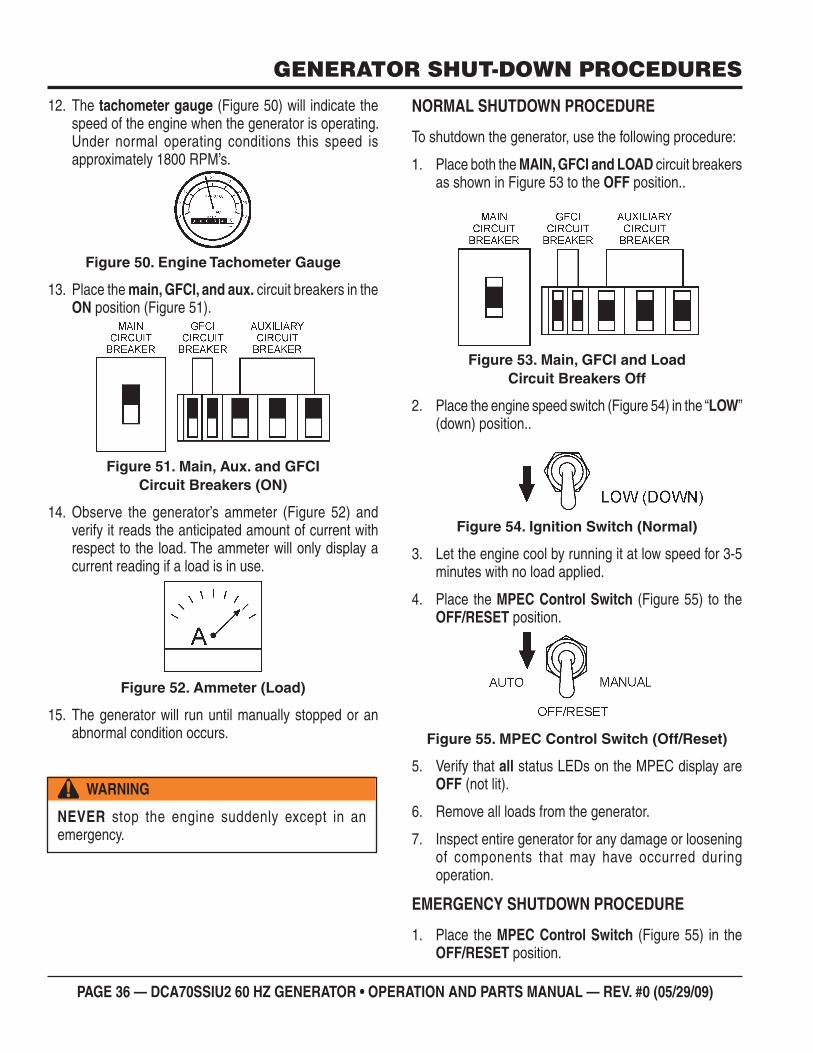
PAGE 36 — DCA70SSIU2 60 HZ GENERATOR • OPERATION AND PARTS MANUAL — REV. #0 (05/29/09)
GENERATOR SHUT-DOWN PROCEDURES
NORMAL SHUTDOWN PROCEDURE
To shutdown the generator, use the following procedure:
Place both the 1. MAIN, GFCI and LOAD circuit breakers as shown in Figure 53 to the OFF position..
Main, GFCI and LoadFigure 53. Circuit Breakers Off
Place the engine speed switch (Figure 54) in the “2. LOW” (down) position..
Ignition Switch (Normal)Figure 54.
Let the engine cool by running it at low speed for 3-5 3. minutes with no load applied.
Place the 4. MPEC Control Switch (Figure 55) to the OFF/RESET position.
MPEC Control Switch (Off/Reset)Figure 55.
Verify that 5. all status LEDs on the MPEC display are OFF (not lit).
Remove all loads from the generator.6.
Inspect entire generator for any damage or loosening 7. of components that may have occurred during operation.
EMERGENCY SHUTDOWN PROCEDURE
Place the 1. MPEC Control Switch (Figure 55) in the OFF/RESET position.
The12. tachometer gauge (Figure 50) will indicate the speed of the engine when the generator is operating. Under normal operating conditions this speed is approximately 1800 RPM’s.
Engine Tachometer GaugeFigure 50.
Place the 13. main, GFCI, and aux. circuit breakers in the ON position (Figure 51).
Main, Aux. and GFCI Figure 51. Circuit Breakers (ON)
Observe the generator’s ammeter (Figure 52) and 14. verify it reads the anticipated amount of current with respect to the load. The ammeter will only display a current reading if a load is in use.
Ammeter (Load)Figure 52.
The generator will run until manually stopped or an 15. abnormal condition occurs.
WARNING
NEVER stop the engine suddenly except in an emergency.
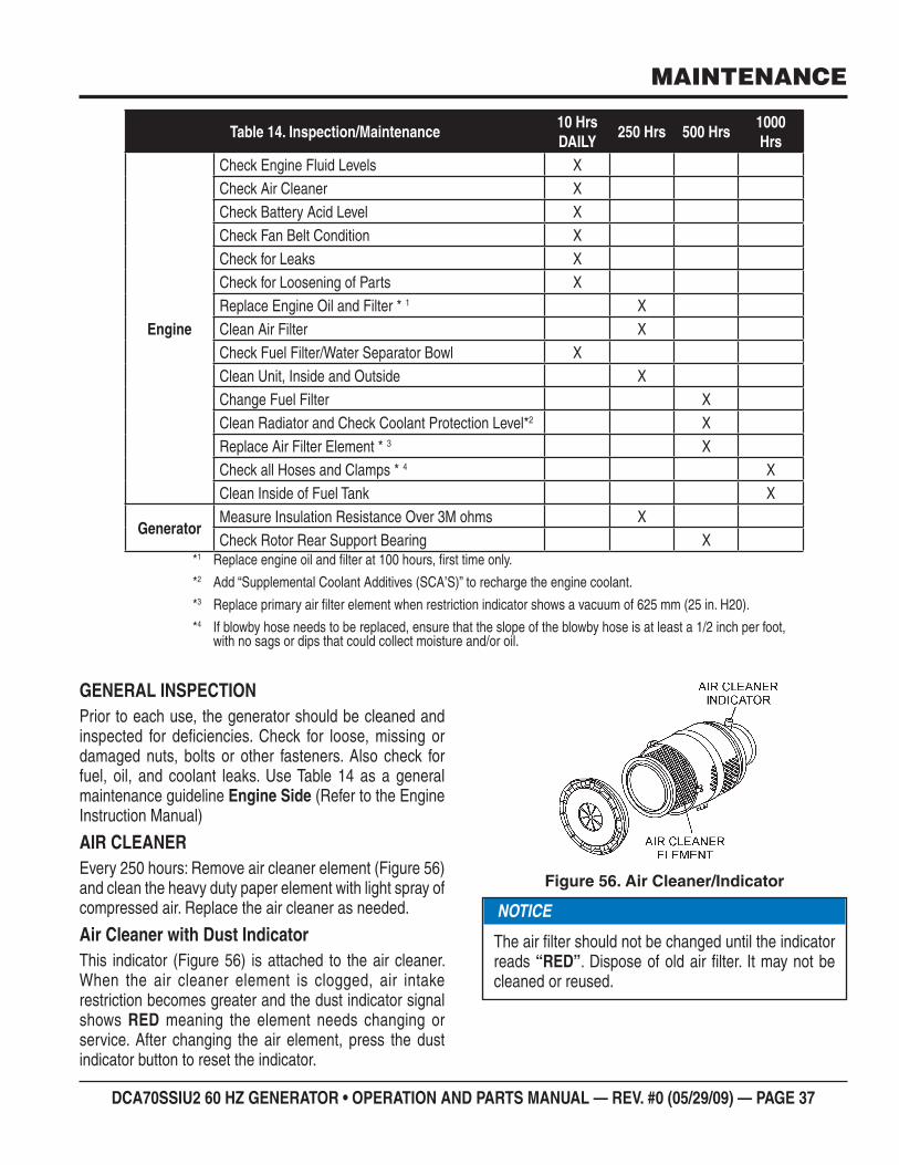
DCA70SSIU2 60 HZ GENERATOR • OPERATION AND PARTS MANUAL — REV. #0 (05/29/09) — PAGE 37
*1 Replace engine oil and fi lter at 100 hours, fi rst time only.
*2 Add “Supplemental Coolant Additives (SCA’S)” to recharge the engine coolant.
*3 Replace primary air fi lter element when restriction indicator shows a vacuum of 625 mm (25 in. H20).
*4 If blowby hose needs to be replaced, ensure that the slope of the blowby hose is at least a 1/2 inch per foot, with no sags or dips that could collect moisture and/or oil.
Inspection/MaintenanceTable 14. 10 Hrs DAILY
250 Hrs 500 Hrs1000 Hrs
Engine
Check Engine Fluid Levels XCheck Air Cleaner XCheck Battery Acid Level XCheck Fan Belt Condition XCheck for Leaks XCheck for Loosening of Parts XReplace Engine Oil and Filter * 1 XClean Air Filter XCheck Fuel Filter/Water Separator Bowl XClean Unit, Inside and Outside XChange Fuel Filter XClean Radiator and Check Coolant Protection Level*2 XReplace Air Filter Element * 3 XCheck all Hoses and Clamps * 4 XClean Inside of Fuel Tank X
GeneratorMeasure Insulation Resistance Over 3M ohms XCheck Rotor Rear Support Bearing X
MAINTENANCE
GENERAL INSPECTIONPrior to each use, the generator should be cleaned and inspected for defi ciencies. Check for loose, missing or damaged nuts, bolts or other fasteners. Also check for fuel, oil, and coolant leaks. Use Table 14 as a general maintenance guideline Engine Side (Refer to the Engine Instruction Manual)
AIR CLEANEREvery 250 hours: Remove air cleaner element (Figure 56) and clean the heavy duty paper element with light spray of compressed air. Replace the air cleaner as needed.
Air Cleaner with Dust IndicatorThis indicator (Figure 56) is attached to the air cleaner. When the air cleaner element is clogged, air intake restriction becomes greater and the dust indicator signal shows RED meaning the element needs changing or service. After changing the air element, press the dust indicator button to reset the indicator.
Air Cleaner/IndicatorFigure 56.
NOTICE
The air fi lter should not be changed until the indicator reads “RED”. Dispose of old air fi lter. It may not be cleaned or reused.
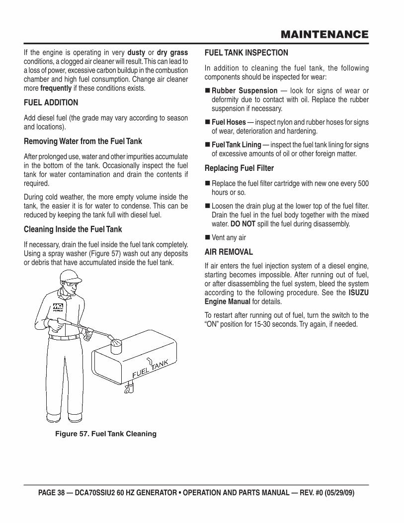
PAGE 38 — DCA70SSIU2 60 HZ GENERATOR • OPERATION AND PARTS MANUAL — REV. #0 (05/29/09)
MAINTENANCE
If the engine is operating in very dusty or dry grass conditions, a clogged air cleaner will result. This can lead to a loss of power, excessive carbon buildup in the combustion chamber and high fuel consumption. Change air cleaner more frequently if these conditions exists.
FUEL ADDITION
Add diesel fuel (the grade may vary according to season and locations).
Removing Water from the Fuel Tank
After prolonged use, water and other impurities accumulate in the bottom of the tank. Occasionally inspect the fuel tank for water contamination and drain the contents if required.
During cold weather, the more empty volume inside the tank, the easier it is for water to condense. This can be reduced by keeping the tank full with diesel fuel.
Cleaning Inside the Fuel Tank
If necessary, drain the fuel inside the fuel tank completely. Using a spray washer (Figure 57) wash out any deposits or debris that have accumulated inside the fuel tank.
Fuel Tank CleaningFigure 57.
FUEL TANK INSPECTION
In addition to cleaning the fuel tank, the following components should be inspected for wear:
Rubber Suspension — look for signs of wear or deformity due to contact with oil. Replace the rubber suspension if necessary.
Fuel Hoses — inspect nylon and rubber hoses for signs of wear, deterioration and hardening.
Fuel Tank Lining — inspect the fuel tank lining for signs of excessive amounts of oil or other foreign matter.
Replacing Fuel Filter
Replace the fuel fi lter cartridge with new one every 500 hours or so.
Loosen the drain plug at the lower top of the fuel fi lter. Drain the fuel in the fuel body together with the mixed water. DO NOT spill the fuel during disassembly.
Vent any air
AIR REMOVAL
If air enters the fuel injection system of a diesel engine, starting becomes impossible. After running out of fuel, or after disassembling the fuel system, bleed the system according to the following procedure. See the ISUZU Engine Manual for details.
To restart after running out of fuel, turn the switch to the “ON” position for 15-30 seconds. Try again, if needed.
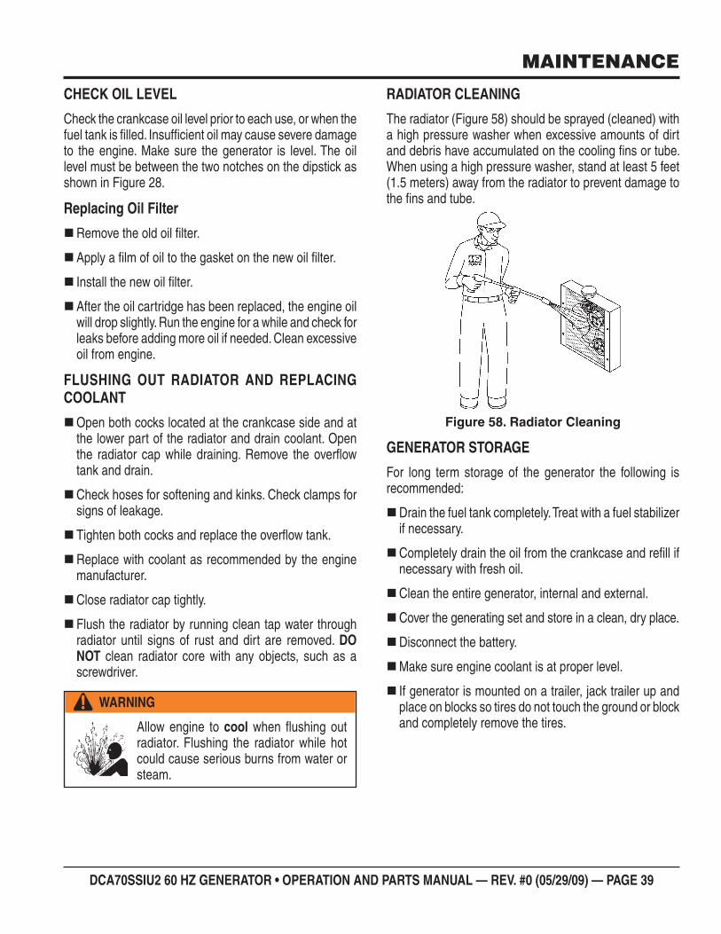
DCA70SSIU2 60 HZ GENERATOR • OPERATION AND PARTS MANUAL — REV. #0 (05/29/09) — PAGE 39
CHECK OIL LEVEL
Check the crankcase oil level prior to each use, or when the fuel tank is fi lled. Insuffi cient oil may cause severe damage to the engine. Make sure the generator is level. The oil level must be between the two notches on the dipstick as shown in Figure 28.
Replacing Oil Filter
Remove the old oil fi lter.
Apply a fi lm of oil to the gasket on the new oil fi lter.
Install the new oil fi lter.
After the oil cartridge has been replaced, the engine oil will drop slightly. Run the engine for a while and check for leaks before adding more oil if needed. Clean excessive oil from engine.
FLUSHING OUT RADIATOR AND REPLACING COOLANT
Open both cocks located at the crankcase side and at the lower part of the radiator and drain coolant. Open the radiator cap while draining. Remove the overfl ow tank and drain.
Check hoses for softening and kinks. Check clamps for signs of leakage.
Tighten both cocks and replace the overfl ow tank.
Replace with coolant as recommended by the engine manufacturer.
Close radiator cap tightly.
Flush the radiator by running clean tap water through radiator until signs of rust and dirt are removed. DO NOT clean radiator core with any objects, such as a screwdriver.
WARNING
Allow engine to cool when fl ushing out radiator. Flushing the radiator while hot could cause serious burns from water or steam.
RADIATOR CLEANING
The radiator (Figure 58) should be sprayed (cleaned) with a high pressure washer when excessive amounts of dirt and debris have accumulated on the cooling fi ns or tube. When using a high pressure washer, stand at least 5 feet (1.5 meters) away from the radiator to prevent damage to the fi ns and tube.
Radiator CleaningFigure 58.
GENERATOR STORAGE
For long term storage of the generator the following is recommended:
Drain the fuel tank completely. Treat with a fuel stabilizer if necessary.
Completely drain the oil from the crankcase and refi ll if necessary with fresh oil.
Clean the entire generator, internal and external.
Cover the generating set and store in a clean, dry place.
Disconnect the battery.
Make sure engine coolant is at proper level.
If generator is mounted on a trailer, jack trailer up and place on blocks so tires do not touch the ground or block and completely remove the tires.
MAINTENANCE
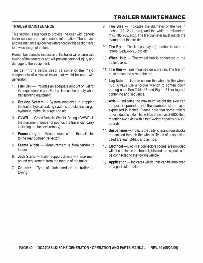
PAGE 40 — DCA70SSIU2 60 HZ GENERATOR • OPERATION AND PARTS MANUAL — REV. #0 (05/29/09)
TRAILER MAINTENANCE
TRAILER MAINTENANCE
This section is intended to provide the user with generic trailer service and maintenance information. The service and maintenance guidelines referenced in this section refer to a wide range of trailers.
Remember periodic inspection of the trailer will ensure safe towing of the generator and will prevent personal injury and damage to the equipment.
The definitions below describe some of the major components of a typical trailer that would be used with generator.
Fuel Cell 1. — Provides an adequate amount of fuel for the equipment in use. Fuel cells must be empty when transporting equipment.
Braking System 2. — System employed in stopping the trailer. Typical braking systems are electric, surge, hydraulic, hydraulic-surge and air.
GVWR 3. — Gross Vehicle Weight Rating (GVWR) is the maximum number of pounds the trailer can carry, including the fuel cell (empty).
Frame Length 4. — Measurement is from the ball hitch to the rear bumper (refl ector).
Frame Width 5. — Measurement is from fender to fender
Jack Stand 6. — Trailer support device with maximum pound requirement from the tongue of the trailer.
Coupler 7. — Type of hitch used on the trailer for towing.
Tire Size 8. — Indicates the diameter of the tire in inches (10,12,14, etc.), and the width in millimeters (175,185,205, etc.). The tire diameter must match the diameter of the tire rim.
Tire Ply 9. — The tire ply (layers) number is rated in letters; 2-ply,4-ply,6-ply, etc.
Wheel Hub 10. — The wheel hub is connected to the trailer’s axle.
Tire Rim 11. — Tires mounted on a tire rim. The tire rim must match the size of the tire.
Lug Nuts 12. — Used to secure the wheel to the wheel hub. Always use a torque wrench to tighten down the lug nuts. See Table 18 and Figure 61 for lug nut tightening and sequence.
Axle 13. — Indicates the maximum weight the axle can support in pounds, and the diameter of the axle expressed in inches. Please note that some trailers have a double axle. This will be shown as 2-6000 lbs., meaning two axles with a total weight capacity of 6000 pounds.
Suspension 14. — Protects the trailer chassis from shocks transmitted through the wheels. Types of suspension used are leaf, Q-fl ex, and air ride.
Electrical 15. — Electrical connectors (looms) are provided with the trailer so the brake lights and turn signals can be connected to the towing vehicle.
Application 16. — Indicates which units can be employed on a particular trailer.
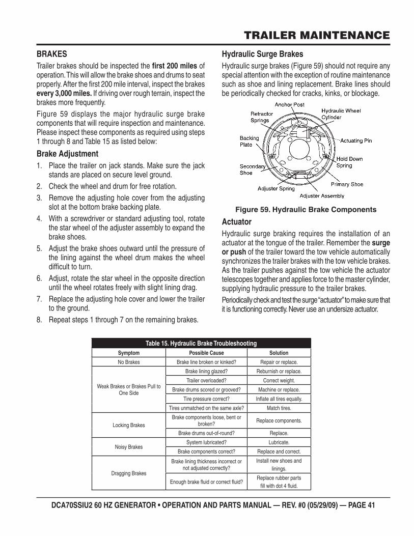
DCA70SSIU2 60 HZ GENERATOR • OPERATION AND PARTS MANUAL — REV. #0 (05/29/09) — PAGE 41
TRAILER MAINTENANCE
BRAKESTrailer brakes should be inspected the fi rst 200 miles of operation. This will allow the brake shoes and drums to seat properly. After the fi rst 200 mile interval, inspect the brakes every 3,000 miles. If driving over rough terrain, inspect the brakes more frequently.Figure 59 displays the major hydraulic surge brake components that will require inspection and maintenance. Please inspect these components as required using steps 1 through 8 and Table 15 as listed below:
Brake AdjustmentPlace the trailer on jack stands. Make sure the jack 1. stands are placed on secure level ground.Check the wheel and drum for free rotation.2. Remove the adjusting hole cover from the adjusting 3. slot at the bottom brake backing plate.With a screwdriver or standard adjusting tool, rotate 4. the star wheel of the adjuster assembly to expand the brake shoes.Adjust the brake shoes outward until the pressure of 5. the lining against the wheel drum makes the wheel diffi cult to turn.Adjust, rotate the star wheel in the opposite direction 6. until the wheel rotates freely with slight lining drag.Replace the adjusting hole cover and lower the trailer 7. to the ground.Repeat steps 1 through 7 on the remaining brakes.8.
Hydraulic Surge BrakesHydraulic surge brakes (Figure 59) should not require any special attention with the exception of routine maintenance such as shoe and lining replacement. Brake lines should be periodically checked for cracks, kinks, or blockage.
Hydraulic Brake ComponentsFigure 59.
ActuatorHydraulic surge braking requires the installation of an actuator at the tongue of the trailer. Remember the surge or push of the trailer toward the tow vehicle automatically synchronizes the trailer brakes with the tow vehicle brakes. As the trailer pushes against the tow vehicle the actuator telescopes together and applies force to the master cylinder, supplying hydraulic pressure to the trailer brakes.Periodically check and test the surge “actuator” to make sure that it is functioning correctly. Never use an undersize actuator.
Hydraulic Brake TroubleshootingTable 15. Symptom Possible Cause Solution
No Brakes Brake line broken or kinked? Repair or replace.
Weak Brakes or Brakes Pull to One Side
Brake lining glazed? Reburnish or replace.
Trailer overloaded? Correct weight.
Brake drums scored or grooved? Machine or replace.
Tire pressure correct? Infl ate all tires equally.
Tires unmatched on the same axle? Match tires.
Locking BrakesBrake components loose, bent or
broken? Replace components.
Brake drums out-of-round? Replace.
Noisy BrakesSystem lubricated? Lubricate.
Brake components correct? Replace and correct.
Dragging Brakes
Brake lining thickness incorrect or not adjusted correctly?
Install new shoes and linings.
Enough brake fl uid or correct fl uid?Replace rubber parts
fi ll with dot 4 fl uid.
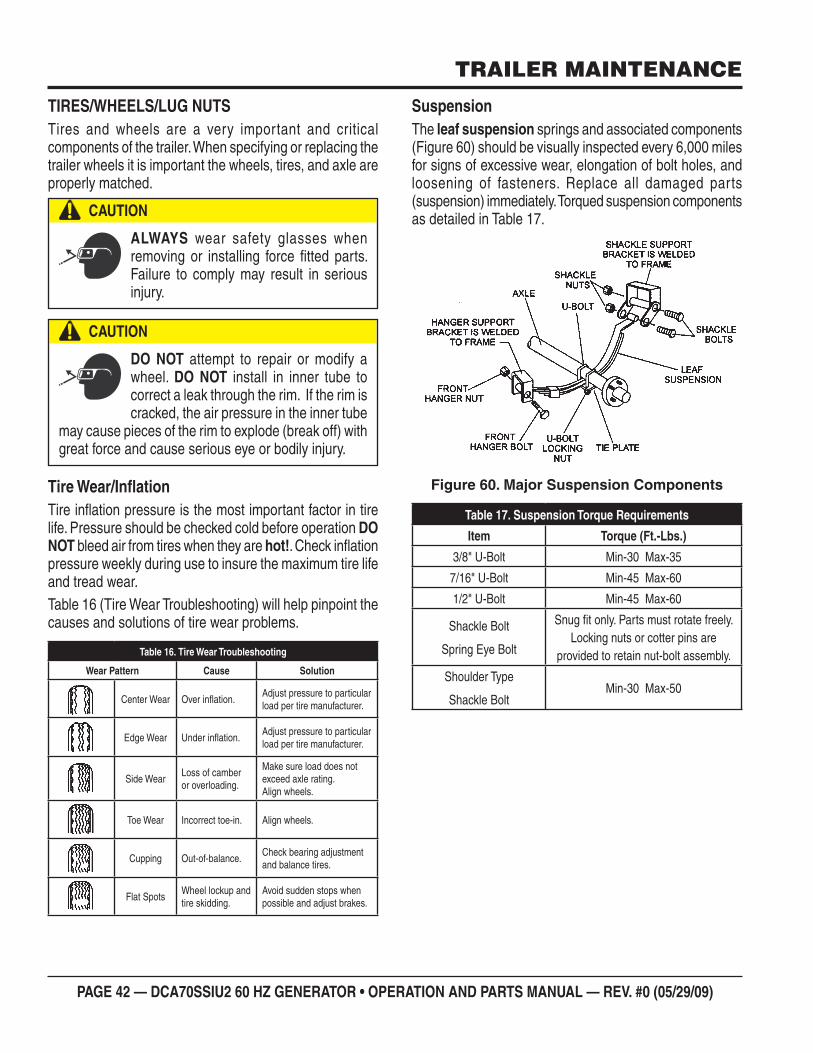
PAGE 42 — DCA70SSIU2 60 HZ GENERATOR • OPERATION AND PARTS MANUAL — REV. #0 (05/29/09)
TRAILER MAINTENANCE
TIRES/WHEELS/LUG NUTSTires and wheels are a very important and critical components of the trailer. When specifying or replacing the trailer wheels it is important the wheels, tires, and axle are properly matched.
Tire Wear/Infl ationTire infl ation pressure is the most important factor in tire life. Pressure should be checked cold before operation DO NOT bleed air from tires when they are hot!. Check infl ation pressure weekly during use to insure the maximum tire life and tread wear.Table 16 (Tire Wear Troubleshooting) will help pinpoint the causes and solutions of tire wear problems.
CAUTION
ALWAYS wear safety glasses when removing or installing force fi tted parts. Failure to comply may result in serious injury.
CAUTION
DO NOT attempt to repair or modify a wheel. DO NOT install in inner tube to correct a leak through the rim. If the rim is cracked, the air pressure in the inner tube
may cause pieces of the rim to explode (break off) with great force and cause serious eye or bodily injury.
Tire Wear TroubleshootingTable 16.
Wear Pattern Cause Solution
Center Wear Over infl ation.Adjust pressure to particular load per tire manufacturer.
Edge Wear Under infl ation.Adjust pressure to particular load per tire manufacturer.
Side WearLoss of camberor overloading.
Make sure load does not exceed axle rating. Align wheels.
Toe Wear Incorrect toe-in. Align wheels.
Cupping Out-of-balance.Check bearing adjustment and balance tires.
Flat SpotsWheel lockup andtire skidding.
Avoid sudden stops when possible and adjust brakes.
SuspensionThe leaf suspension springs and associated components (Figure 60) should be visually inspected every 6,000 miles for signs of excessive wear, elongation of bolt holes, and loosening of fasteners. Replace all damaged parts (suspension) immediately. Torqued suspension components as detailed in Table 17.
Major Suspension ComponentsFigure 60.
Suspension Torque RequirementsTable 17.
Item Torque (Ft.-Lbs.)
3/8" U-Bolt Min-30 Max-35
7/16" U-Bolt Min-45 Max-60
1/2" U-Bolt Min-45 Max-60
Shackle Bolt
Spring Eye Bolt
Snug fi t only. Parts must rotate freely.Locking nuts or cotter pins are
provided to retain nut-bolt assembly.
Shoulder Type
Shackle BoltMin-30 Max-50
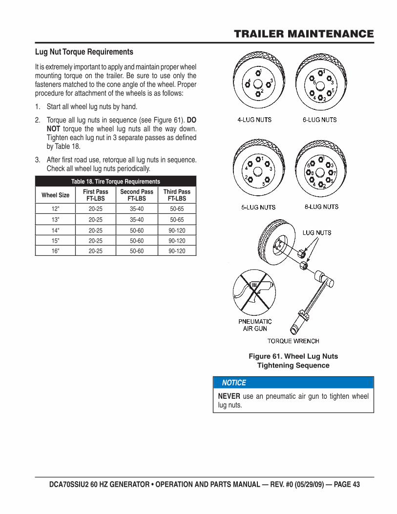
DCA70SSIU2 60 HZ GENERATOR • OPERATION AND PARTS MANUAL — REV. #0 (05/29/09) — PAGE 43
TRAILER MAINTENANCE
Lug Nut Torque Requirements
It is extremely important to apply and maintain proper wheel mounting torque on the trailer. Be sure to use only the fasteners matched to the cone angle of the wheel. Proper procedure for attachment of the wheels is as follows:
Start all wheel lug nuts by hand.1.
Torque all lug nuts in sequence (see Figure 61). 2. DO NOT torque the wheel lug nuts all the way down. Tighten each lug nut in 3 separate passes as defi ned by Table 18.
After fi rst road use, retorque all lug nuts in sequence. 3. Check all wheel lug nuts periodically.
Tire Torque RequirementsTable 18.
Wheel Size First PassFT-LBS
Second PassFT-LBS
Third PassFT-LBS
12" 20-25 35-40 50-65
13" 20-25 35-40 50-65
14" 20-25 50-60 90-120
15" 20-25 50-60 90-120
16" 20-25 50-60 90-120
Wheel Lug Nuts Figure 61. Tightening Sequence
NOTICE
NEVER use an pneumatic air gun to tighten wheel lug nuts.
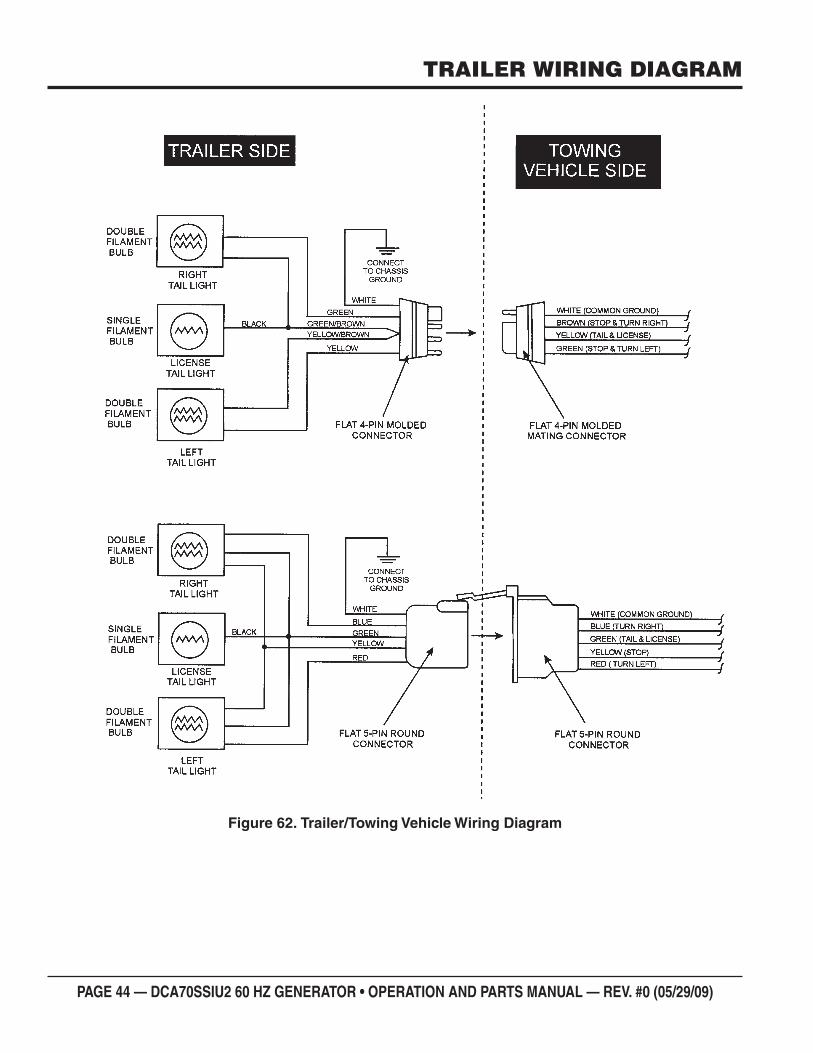
PAGE 44 — DCA70SSIU2 60 HZ GENERATOR • OPERATION AND PARTS MANUAL — REV. #0 (05/29/09)
TRAILER WIRING DIAGRAM
Trailer/Towing Vehicle Wiring DiagramFigure 62.
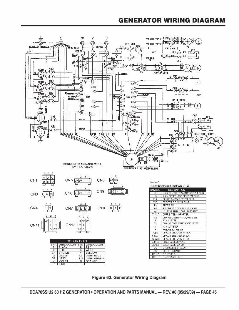
DCA70SSIU2 60 HZ GENERATOR • OPERATION AND PARTS MANUAL — REV. #0 (05/29/09) — PAGE 45
GENERATOR WIRING DIAGRAM
Generator Wiring DiagramFigure 63.
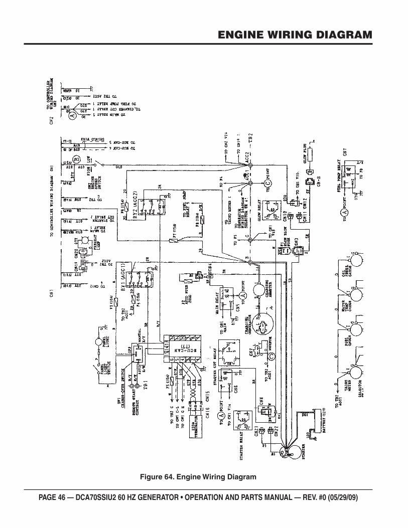
PAGE 46 — DCA70SSIU2 60 HZ GENERATOR • OPERATION AND PARTS MANUAL — REV. #0 (05/29/09)
ENGINE WIRING DIAGRAM
Engine Wiring DiagramFigure 64.
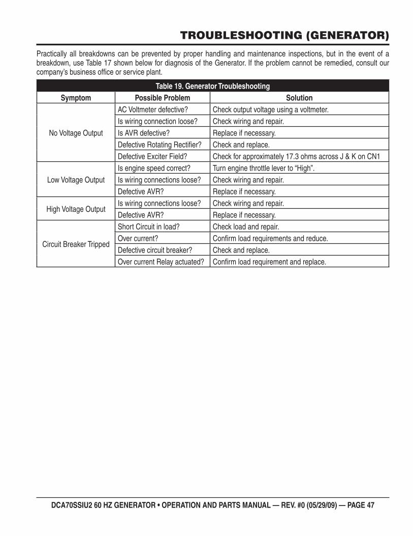
DCA70SSIU2 60 HZ GENERATOR • OPERATION AND PARTS MANUAL — REV. #0 (05/29/09) — PAGE 47
TROUBLESHOOTING (GENERATOR)
Practically all breakdowns can be prevented by proper handling and maintenance inspections, but in the event of a breakdown, use Table 17 shown below for diagnosis of the Generator. If the problem cannot be remedied, consult our company’s business offi ce or service plant.
Generator TroubleshootingTable 19. Symptom Possible Problem Solution
No Voltage Output
AC Voltmeter defective? Check output voltage using a voltmeter.Is wiring connection loose? Check wiring and repair.Is AVR defective? Replace if necessary.Defective Rotating Rectifi er? Check and replace.Defective Exciter Field? Check for approximately 17.3 ohms across J & K on CN1
Low Voltage OutputIs engine speed correct? Turn engine throttle lever to “High”.Is wiring connections loose? Check wiring and repair.Defective AVR? Replace if necessary.
High Voltage OutputIs wiring connections loose? Check wiring and repair.Defective AVR? Replace if necessary.
Circuit Breaker Tripped
Short Circuit in load? Check load and repair.Over current? Confi rm load requirements and reduce.Defective circuit breaker? Check and replace.Over current Relay actuated? Confi rm load requirement and replace.
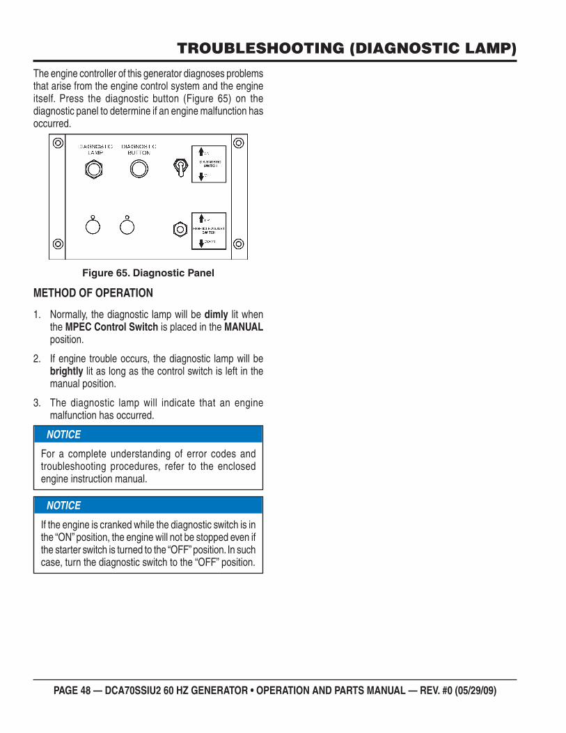
PAGE 48 — DCA70SSIU2 60 HZ GENERATOR • OPERATION AND PARTS MANUAL — REV. #0 (05/29/09)
TROUBLESHOOTING (DIAGNOSTIC LAMP)
The engine controller of this generator diagnoses problems that arise from the engine control system and the engine itself. Press the diagnostic button (Figure 65) on the diagnostic panel to determine if an engine malfunction has occurred.
Diagnostic PanelFigure 65.
METHOD OF OPERATION
Normally, the diagnostic lamp will be 1. dimly lit when the MPEC Control Switch is placed in the MANUAL position.
If engine trouble occurs, the diagnostic lamp will be 2. brightly lit as long as the control switch is left in the manual position.
The diagnostic lamp will indicate that an engine 3. malfunction has occurred.
NOTICE
For a complete understanding of error codes and troubleshooting procedures, refer to the enclosed engine instruction manual.
NOTICE
If the engine is cranked while the diagnostic switch is in the “ON” position, the engine will not be stopped even if the starter switch is turned to the “OFF” position. In such case, turn the diagnostic switch to the “OFF” position.
DCA70SSIU2 60 HZ GENERATOR • OPERATION AND PARTS MANUAL — REV. #0 (05/29/09) — PAGE 49
NOTES
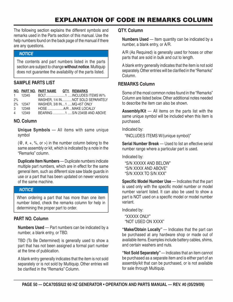
PAGE 50 — DCA70SSIU2 60 HZ GENERATOR • OPERATION AND PARTS MANUAL — REV. #0 (05/29/09)
EXPLANATION OF CODE IN REMARKS COLUMN
The following section explains the different symbols and remarks used in the Parts section of this manual. Use the help numbers found on the back page of the manual if there are any questions.
SAMPLE PARTS LIST
NO. PART NO. PART NAME QTY. REMARKS1 12345 BOLT ......................1 .....INCLUDES ITEMS W/%2% WASHER, 1/4 IN. ...........NOT SOLD SEPARATELY2% 12347 WASHER, 3/8 IN. ...1 .....MQ-45T ONLY3 12348 HOSE ..................A/R ...MAKE LOCALLY4 12349 BEARING ..............1 .....S/N 2345B AND ABOVE
NO. Column
Unique Symbols — All items with same unique symbol
(@, #, +, %, or >) in the number column belong to the same assembly or kit, which is indicated by a note in the “Remarks” column.
Duplicate Item Numbers — Duplicate numbers indicate multiple part numbers, which are in effect for the same general item, such as different size saw blade guards in use or a part that has been updated on newer versions of the same machine.
PART NO. Column
Numbers Used — Part numbers can be indicated by a number, a blank entry, or TBD.
TBD (To Be Determined) is generally used to show a part that has not been assigned a formal part number at the time of publication.
A blank entry generally indicates that the item is not sold separately or is not sold by Multiquip. Other entries will be clarified in the “Remarks” Column.
NOTICE
The contents and part numbers listed in the parts section are subject to change without notice. Multiquip does not guarantee the availability of the parts listed.
NOTICE
When ordering a part that has more than one item number listed, check the remarks column for help in determining the proper part to order.
QTY. Column
Numbers Used — Item quantity can be indicated by a number, a blank entry, or A/R.
A/R (As Required) is generally used for hoses or otherparts that are sold in bulk and cut to length.
A blank entry generally indicates that the item is not sold separately. Other entries will be clarified in the “Remarks” Column.
REMARKS Column
Some of the most common notes found in the “Remarks” Column are listed below. Other additional notes needed to describe the item can also be shown.
Assembly/Kit — All items on the parts list with thesame unique symbol will be included when this item is purchased.
Indicated by:“INCLUDES ITEMS W/(unique symbol)”
Serial Number Break — Used to list an effective serial number range where a particular part is used.
Indicated by: “S/N XXXXX AND BELOW”“S/N XXXX AND ABOVE”“S/N XXXX TO S/N XXX”
Specific Model Number Use — Indicates that the part is used only with the specific model number or model number variant listed. It can also be used to show a part is NOT used on a specific model or model numbervariant.
Indicated by:“XXXXX ONLY”“NOT USED ON XXXX”
“Make/Obtain Locally” — Indicates that the part can be purchased at any hardware shop or made out of available items. Examples include battery cables, shims, and certain washers and nuts.
“Not Sold Separately” — Indicates that an item cannotbe purchased as a separate item and is either part of an assembly/kit that can be purchased, or is not available for sale through Multiquip.
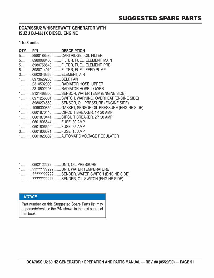
DCA70SSIU2 60 HZ GENERATOR • OPERATION AND PARTS MANUAL — REV. #0 (05/29/09) — PAGE 51
SUGGESTED SPARE PARTS
DCA70SSIU2 WHISPERWATT GENERATOR WITH ISUZU BJ-4JJ1X DIESEL ENGINE
1 to 3 units
QTY. P/N DESCRIPTION5............8980188580 ..........CARTRIDGE , OIL FILTER5............8980088400 ..........FILTER, FUEL, ELEMENT, MAIN5............8980758540 ..........FILTER, FUEL, ELEMENT, PRE5............8980714010 ..........FILTER, FUEL, FEED PUMP3............0602046365 ..........ELEMENT, AIR1............8973629260 ..........BELT, FAN1............2310502003 ..........RADIATOR HOSE, UPPER1............2310502103 ..........RADIATOR HOSE, LOWER1............8121468300 ..........SENSOR, WATER TEMP. (ENGINE SIDE)1............8971256001 ..........SWITCH, WARNING, OVERHEAT (ENGINE SIDE)1............8980274560 ..........SENSOR, OIL PRESSURE (ENGINE SIDE)1............1096300850 ..........GASKET, SENSOR OIL PRESSURE (ENGINE SIDE)1............0601870440 ..........CIRCUIT BREAKER, 1P, 20 AMP1............0601870441 ..........CIRCUIT BREAKER, 2P, 50 AMP1............0601806644 ..........FUSE, 30 AMP1............0601806640 ..........FUSE, 65 AMP3............0601806671 ..........FUSE, 15 AMP1............0601820602 ..........AUTOMATIC VOLTAGE REGULATOR
1............0602122272 ..........UNIT, OIL PRESSURE1............??????????? ........UNIT, WATER TEMPERATURE1............??????????? ........SENDER, WATER SWITCH (ENGINE SIDE)1............??????????? ........SENDER, OIL SWITCH (ENGINE SIDE)
NOTICE
Part number on this Suggested Spare Parts list may supersede/replace the P/N shown in the text pages of this book.
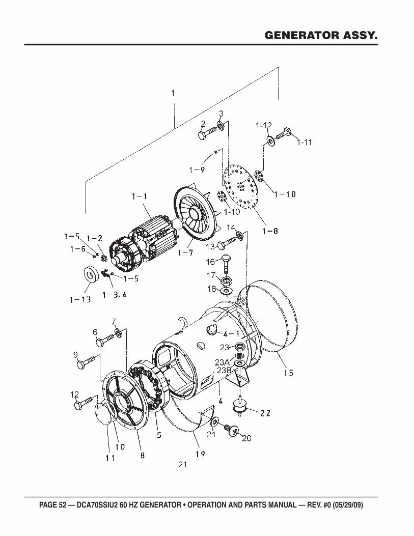
PAGE 52 — DCA70SSIU2 60 HZ GENERATOR • OPERATION AND PARTS MANUAL — REV. #0 (05/29/09)
GENERATOR ASSY.
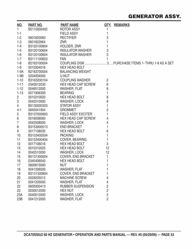
DCA70SSIU2 60 HZ GENERATOR • OPERATION AND PARTS MANUAL — REV. #0 (05/29/09) — PAGE 53
GENERATOR ASSY.
NO. PART NO. PART NAME QTY. REMARKS1 B5110000402 ROTOR ASSY 11-1 FIELD ASSY 11-2 0601820083 RECTIFIER 31-3 0601822664 ZNR 11-4 B3120100804 HOLDER, ZNR 11-5 B3120100604 INSULATOR WASHER 31-6 B3120100604 INSULATOR WASHER 51-7 B3111100603 FAN 11-8 B2163100004 COUPLING DISK ......................... 3 .....PURCHASE ITEMS 1- THRU 1-9 AS A SET1-9 0010304016 HEX HEAD BOLT1-9A B2163700004 BALANCING WEIGHT1-9B 0204004000 U-NUT1-10 B3163200104 COUPLING WASHER 21-11 0342612030 HEX HEAD CAP SCREW 61-12 0046512000 WASHER, FLAT 61-13 0071906309 BEARING 12 0010310020 HEX HEAD BOLT 83 0042510000 WASHER, LOCK 84 B5130000303 STATOR ASSY 14-1 0845041904 GROMMET 25 B3137000803 FIELD ASSY EXCITER 16 0016008060 HEX HEAD CAP SCREW 47 0042508000 WASHER, LOCK 48 B3153000513 END BRACKET 19 0017108035 HEX HEAD BOLT 610 B3153400504 PACKING 111 B3153400404 COVER, BEARING 112 0017106016 HEX HEAD BOLT 313 0010310025 HEX HEAD BOLT 1214 0042510000 WASHER, LOCK 1215 B5131300004 COVER, END BRACKET 116 0340406040 HEX HEAD BOLT 117 0600815000 NUT 118 0041206000 WASHER, FLAT 119 B3131300804 COVER, END BRACKET 120 0029205012 MACHINE SCREW 421 0041205000 WASHER, FLAT 422 0605000413 RUBBER SUSPENSION 223 0030012000 HEX NUT 223A 0040012000 WASHER, LOCK 223B 0041212000 WASHER, FLAT 2
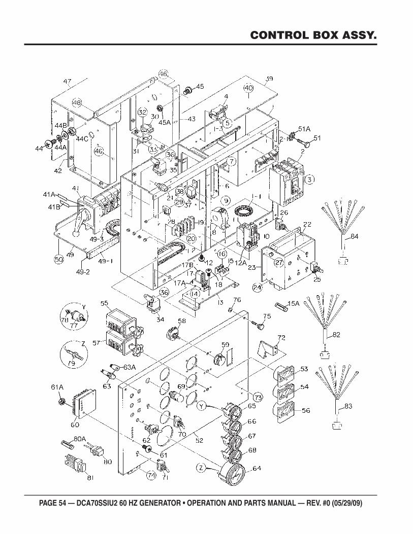
PAGE 54 — DCA70SSIU2 60 HZ GENERATOR • OPERATION AND PARTS MANUAL — REV. #0 (05/29/09)
CONTROL BOX ASSY.
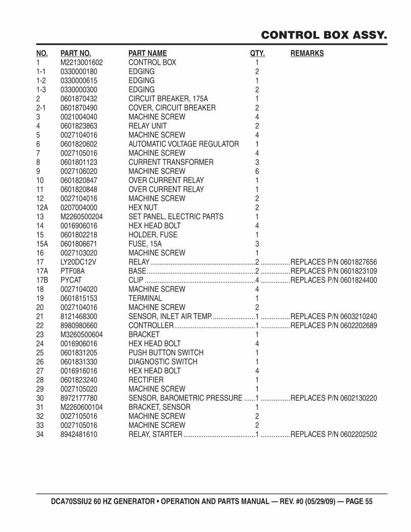
DCA70SSIU2 60 HZ GENERATOR • OPERATION AND PARTS MANUAL — REV. #0 (05/29/09) — PAGE 55
NO. PART NO. PART NAME QTY. REMARKS1 M2213001602 CONTROL BOX 11-1 0330000180 EDGING 21-2 0330000615 EDGING 11-3 0330000300 EDGING 22 0601870432 CIRCUIT BREAKER, 175A 12-1 0601870490 COVER, CIRCUIT BREAKER 23 0021004040 MACHINE SCREW 44 0601823863 RELAY UNIT 25 0027104016 MACHINE SCREW 46 0601820602 AUTOMATIC VOLTAGE REGULATOR 17 0027105016 MACHINE SCREW 48 0601801123 CURRENT TRANSFORMER 39 0027106020 MACHINE SCREW 610 0601820847 OVER CURRENT RELAY 111 0601820848 OVER CURRENT RELAY 112 0027104016 MACHINE SCREW 212A 0207004000 HEX NUT 213 M2260500204 SET PANEL, ELECTRIC PARTS 114 0016906016 HEX HEAD BOLT 415 0601802218 HOLDER, FUSE 115A 0601806671 FUSE, 15A 316 0027103020 MACHINE SCREW 117 LY20DC12V RELAY .........................................................2 ................REPLACES P/N 060182765617A PTF08A BASE ...........................................................2 ................REPLACES P/N 060182310917B PYCAT CLIP ............................................................4 ................REPLACES P/N 060182440018 0027104020 MACHINE SCREW 419 0601815153 TERMINAL 120 0027104016 MACHINE SCREW 221 8121468300 SENSOR, INLET AIR TEMP. .......................1 ................REPLACES P/N 060321024022 8980980660 CONTROLLER ............................................1 ................REPLACES P/N 060220268923 M3260500604 BRACKET 124 0016906016 HEX HEAD BOLT 425 0601831205 PUSH BUTTON SWITCH 126 0601831330 DIAGNOSTIC SWITCH 127 0016916016 HEX HEAD BOLT 428 0601823240 RECTIFIER 129 0027105020 MACHINE SCREW 130 8972177780 SENSOR, BAROMETRIC PRESSURE ......1 ................REPLACES P/N 060213022031 M2260600104 BRACKET, SENSOR 132 0027105016 MACHINE SCREW 233 0027105016 MACHINE SCREW 234 8942481610 RELAY, STARTER .......................................1 ................REPLACES P/N 0602202502
CONTROL BOX ASSY.
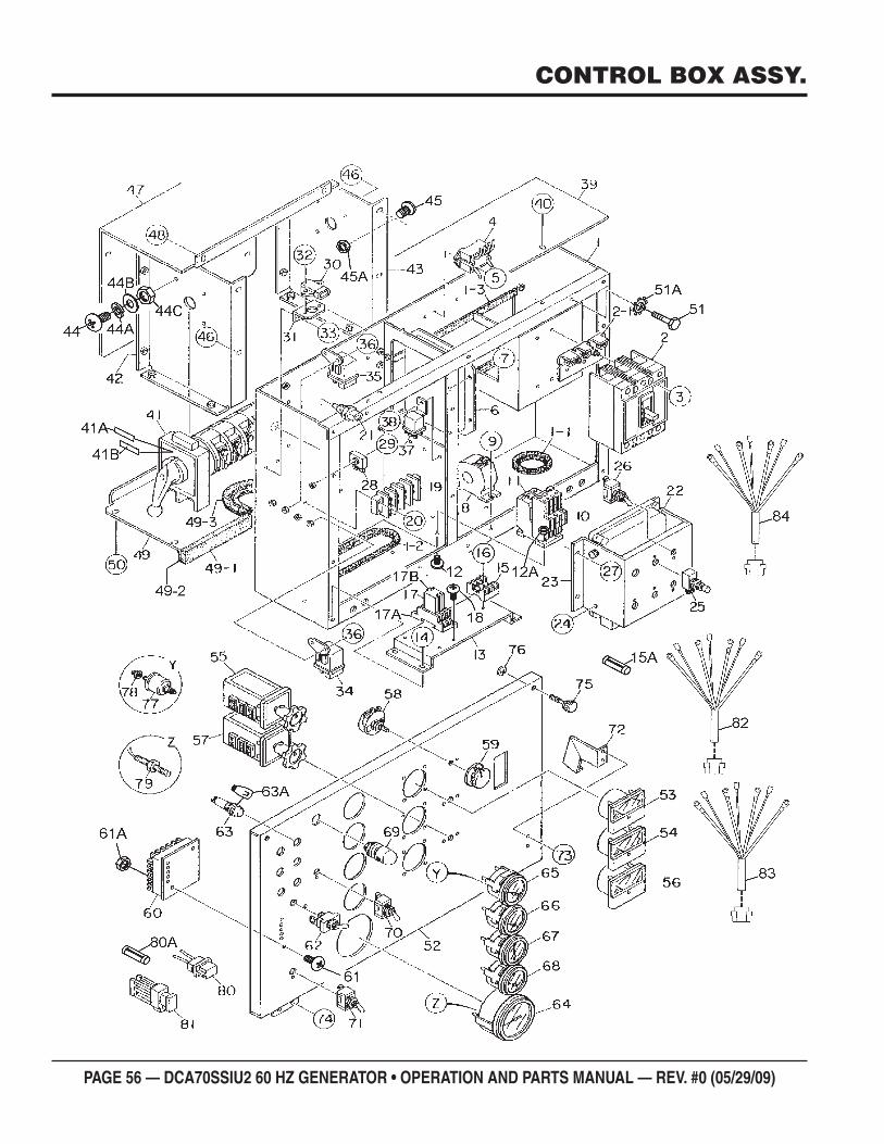
PAGE 56 — DCA70SSIU2 60 HZ GENERATOR • OPERATION AND PARTS MANUAL — REV. #0 (05/29/09)
CONTROL BOX ASSY.
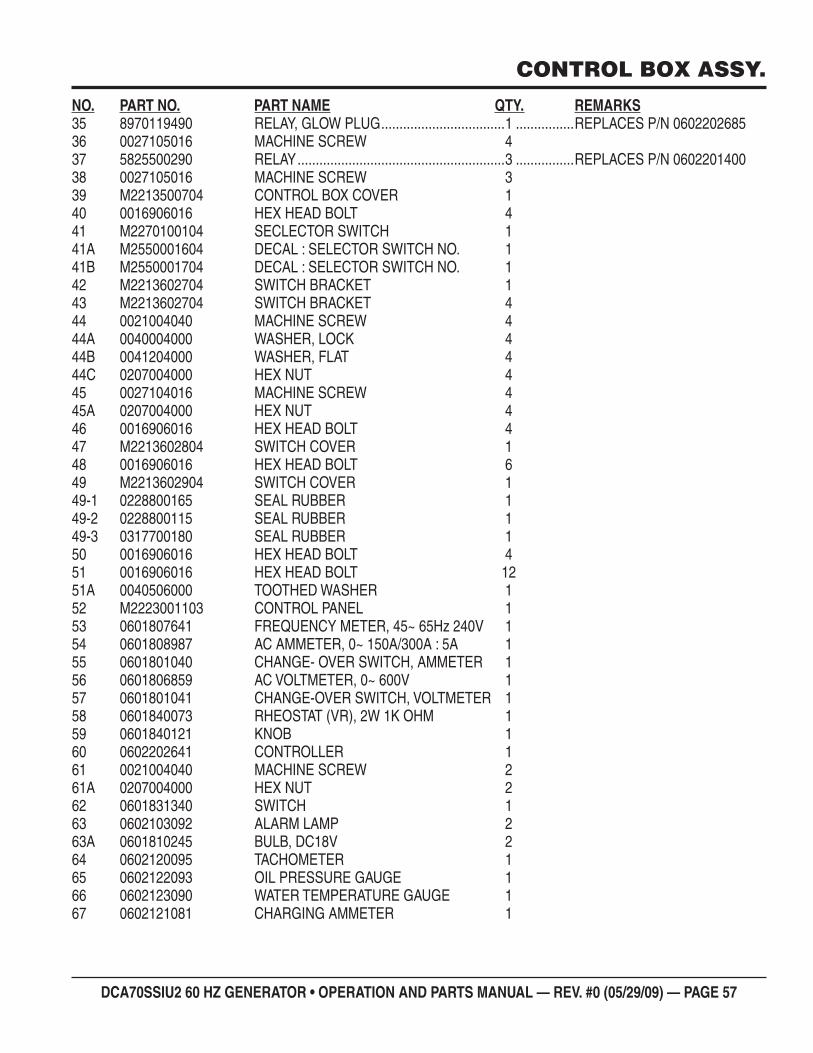
DCA70SSIU2 60 HZ GENERATOR • OPERATION AND PARTS MANUAL — REV. #0 (05/29/09) — PAGE 57
CONTROL BOX ASSY.
NO. PART NO. PART NAME QTY. REMARKS35 8970119490 RELAY, GLOW PLUG ..................................1 ................REPLACES P/N 060220268536 0027105016 MACHINE SCREW 437 5825500290 RELAY .........................................................3 ................REPLACES P/N 060220140038 0027105016 MACHINE SCREW 339 M2213500704 CONTROL BOX COVER 140 0016906016 HEX HEAD BOLT 441 M2270100104 SECLECTOR SWITCH 141A M2550001604 DECAL : SELECTOR SWITCH NO. 141B M2550001704 DECAL : SELECTOR SWITCH NO. 142 M2213602704 SWITCH BRACKET 143 M2213602704 SWITCH BRACKET 444 0021004040 MACHINE SCREW 444A 0040004000 WASHER, LOCK 444B 0041204000 WASHER, FLAT 444C 0207004000 HEX NUT 445 0027104016 MACHINE SCREW 445A 0207004000 HEX NUT 446 0016906016 HEX HEAD BOLT 447 M2213602804 SWITCH COVER 148 0016906016 HEX HEAD BOLT 649 M2213602904 SWITCH COVER 149-1 0228800165 SEAL RUBBER 149-2 0228800115 SEAL RUBBER 149-3 0317700180 SEAL RUBBER 150 0016906016 HEX HEAD BOLT 451 0016906016 HEX HEAD BOLT 1251A 0040506000 TOOTHED WASHER 152 M2223001103 CONTROL PANEL 153 0601807641 FREQUENCY METER, 45~ 65Hz 240V 154 0601808987 AC AMMETER, 0~ 150A/300A : 5A 155 0601801040 CHANGE- OVER SWITCH, AMMETER 156 0601806859 AC VOLTMETER, 0~ 600V 157 0601801041 CHANGE-OVER SWITCH, VOLTMETER 158 0601840073 RHEOSTAT (VR), 2W 1K OHM 159 0601840121 KNOB 160 0602202641 CONTROLLER 161 0021004040 MACHINE SCREW 261A 0207004000 HEX NUT 262 0601831340 SWITCH 163 0602103092 ALARM LAMP 263A 0601810245 BULB, DC18V 264 0602120095 TACHOMETER 165 0602122093 OIL PRESSURE GAUGE 166 0602123090 WATER TEMPERATURE GAUGE 167 0602121081 CHARGING AMMETER 1
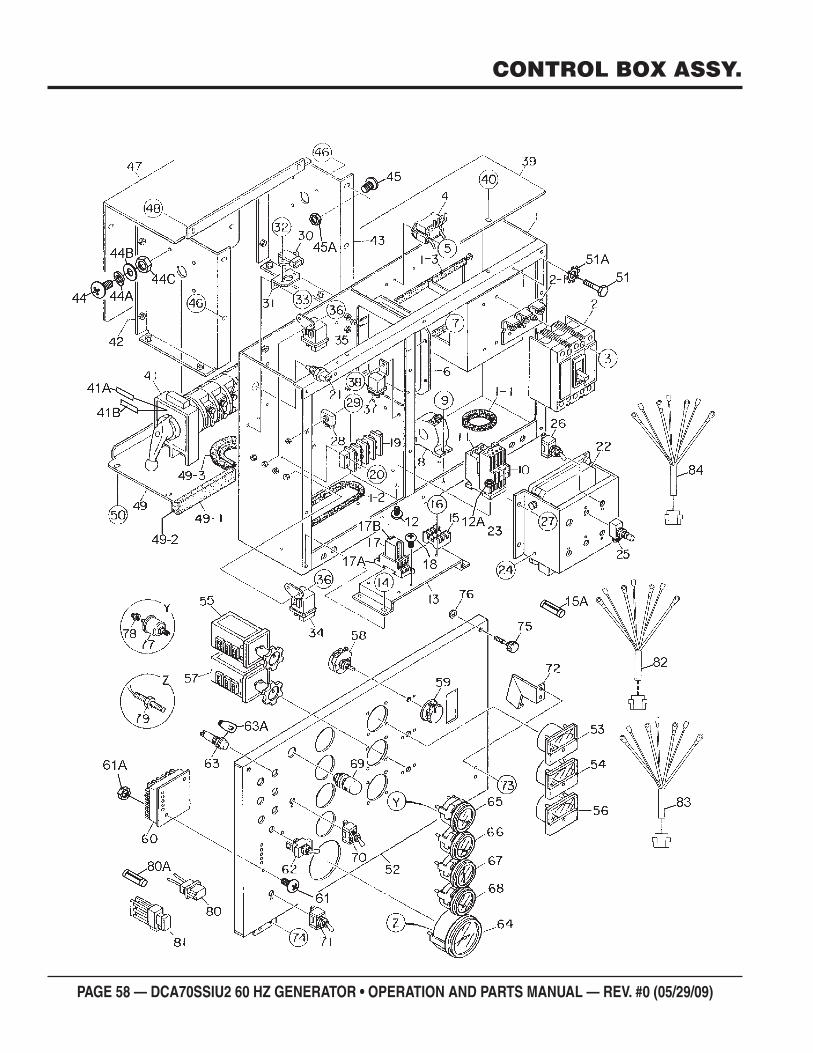
PAGE 58 — DCA70SSIU2 60 HZ GENERATOR • OPERATION AND PARTS MANUAL — REV. #0 (05/29/09)
CONTROL BOX ASSY.
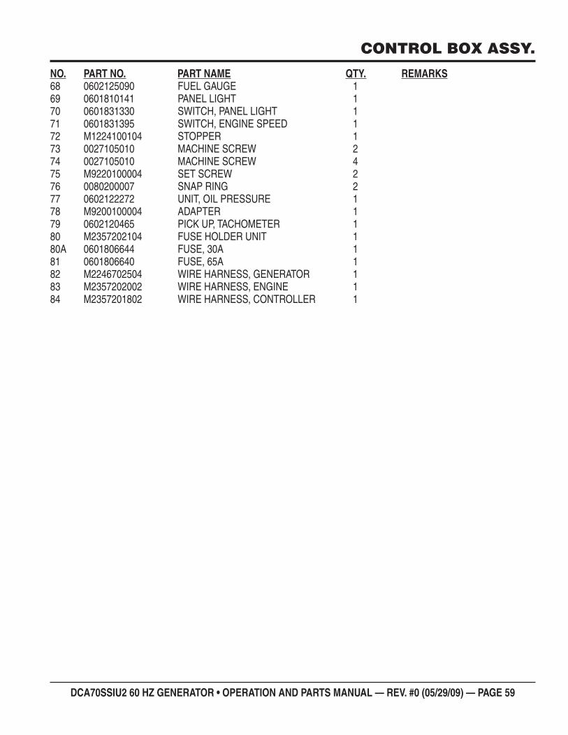
DCA70SSIU2 60 HZ GENERATOR • OPERATION AND PARTS MANUAL — REV. #0 (05/29/09) — PAGE 59
CONTROL BOX ASSY.
NO. PART NO. PART NAME QTY. REMARKS68 0602125090 FUEL GAUGE 169 0601810141 PANEL LIGHT 170 0601831330 SWITCH, PANEL LIGHT 171 0601831395 SWITCH, ENGINE SPEED 172 M1224100104 STOPPER 173 0027105010 MACHINE SCREW 274 0027105010 MACHINE SCREW 475 M9220100004 SET SCREW 276 0080200007 SNAP RING 277 0602122272 UNIT, OIL PRESSURE 178 M9200100004 ADAPTER 179 0602120465 PICK UP, TACHOMETER 180 M2357202104 FUSE HOLDER UNIT 180A 0601806644 FUSE, 30A 181 0601806640 FUSE, 65A 182 M2246702504 WIRE HARNESS, GENERATOR 183 M2357202002 WIRE HARNESS, ENGINE 184 M2357201802 WIRE HARNESS, CONTROLLER 1
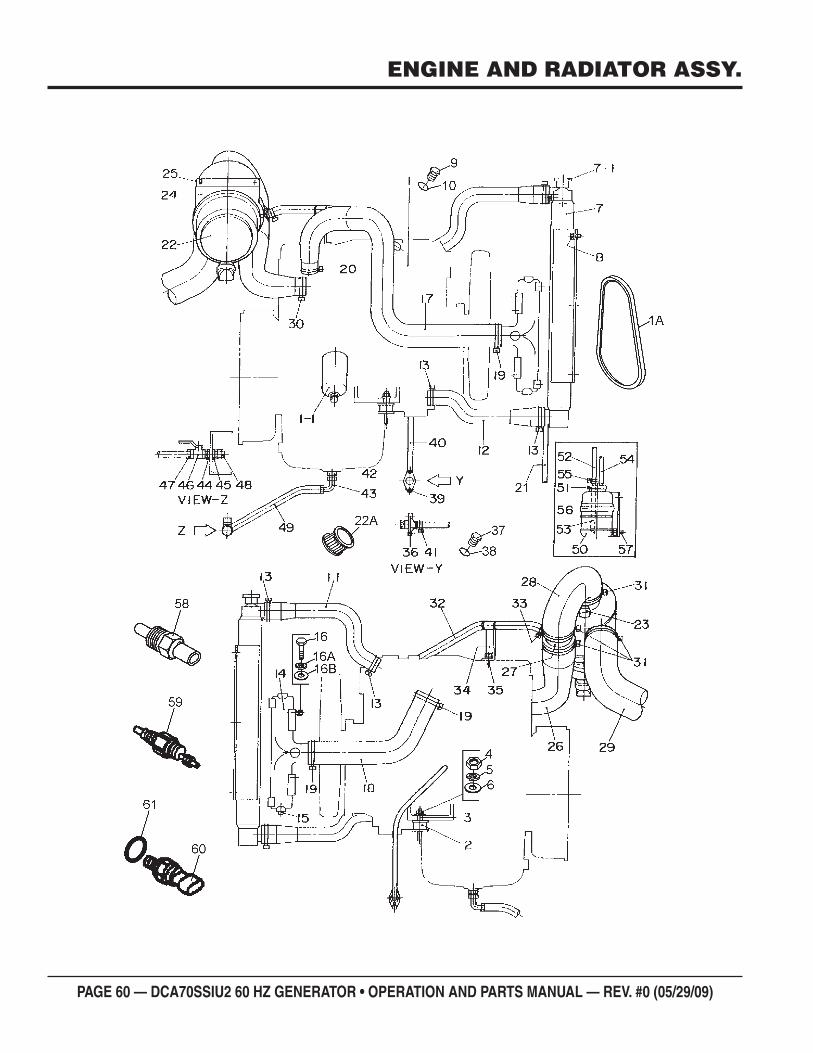
PAGE 60 — DCA70SSIU2 60 HZ GENERATOR • OPERATION AND PARTS MANUAL — REV. #0 (05/29/09)
ENGINE AND RADIATOR ASSY.
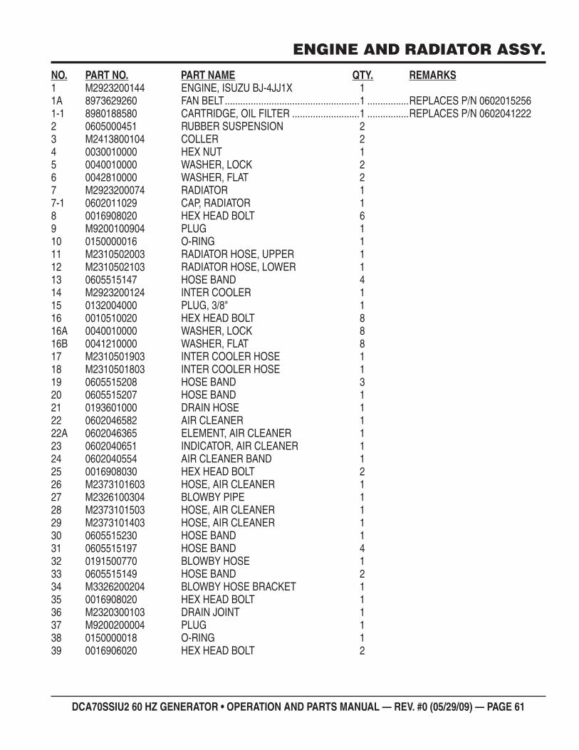
DCA70SSIU2 60 HZ GENERATOR • OPERATION AND PARTS MANUAL — REV. #0 (05/29/09) — PAGE 61
ENGINE AND RADIATOR ASSY.
NO. PART NO. PART NAME QTY. REMARKS1 M2923200144 ENGINE, ISUZU BJ-4JJ1X 11A 8973629260 FAN BELT ....................................................1 ................REPLACES P/N 06020152561-1 8980188580 CARTRIDGE, OIL FILTER ..........................1 ................REPLACES P/N 06020412222 0605000451 RUBBER SUSPENSION 23 M2413800104 COLLER 24 0030010000 HEX NUT 15 0040010000 WASHER, LOCK 26 0042810000 WASHER, FLAT 27 M2923200074 RADIATOR 17-1 0602011029 CAP, RADIATOR 18 0016908020 HEX HEAD BOLT 69 M9200100904 PLUG 110 0150000016 O-RING 111 M2310502003 RADIATOR HOSE, UPPER 112 M2310502103 RADIATOR HOSE, LOWER 113 0605515147 HOSE BAND 414 M2923200124 INTER COOLER 115 0132004000 PLUG, 3/8" 116 0010510020 HEX HEAD BOLT 816A 0040010000 WASHER, LOCK 816B 0041210000 WASHER, FLAT 817 M2310501903 INTER COOLER HOSE 118 M2310501803 INTER COOLER HOSE 119 0605515208 HOSE BAND 320 0605515207 HOSE BAND 121 0193601000 DRAIN HOSE 122 0602046582 AIR CLEANER 122A 0602046365 ELEMENT, AIR CLEANER 123 0602040651 INDICATOR, AIR CLEANER 124 0602040554 AIR CLEANER BAND 125 0016908030 HEX HEAD BOLT 226 M2373101603 HOSE, AIR CLEANER 127 M2326100304 BLOWBY PIPE 128 M2373101503 HOSE, AIR CLEANER 129 M2373101403 HOSE, AIR CLEANER 130 0605515230 HOSE BAND 131 0605515197 HOSE BAND 432 0191500770 BLOWBY HOSE 133 0605515149 HOSE BAND 234 M3326200204 BLOWBY HOSE BRACKET 135 0016908020 HEX HEAD BOLT 136 M2320300103 DRAIN JOINT 137 M9200200004 PLUG 138 0150000018 O-RING 139 0016906020 HEX HEAD BOLT 2
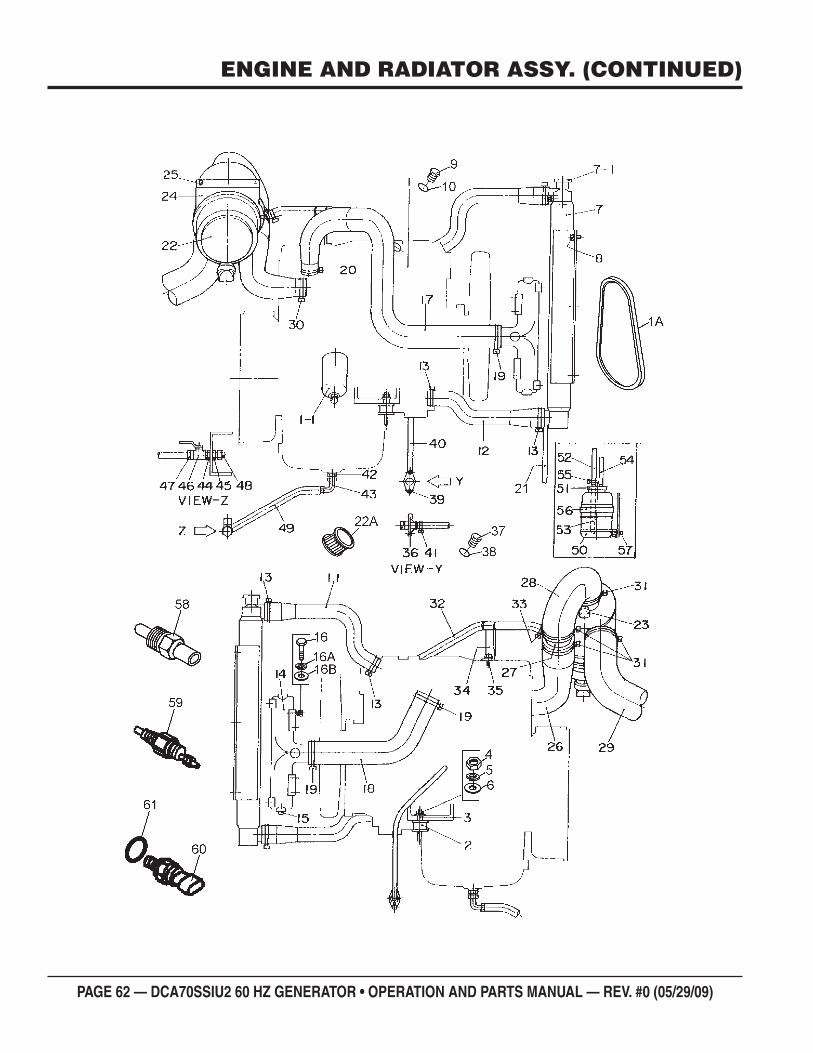
PAGE 62 — DCA70SSIU2 60 HZ GENERATOR • OPERATION AND PARTS MANUAL — REV. #0 (05/29/09)
ENGINE AND RADIATOR ASSY. (CONTINUED)
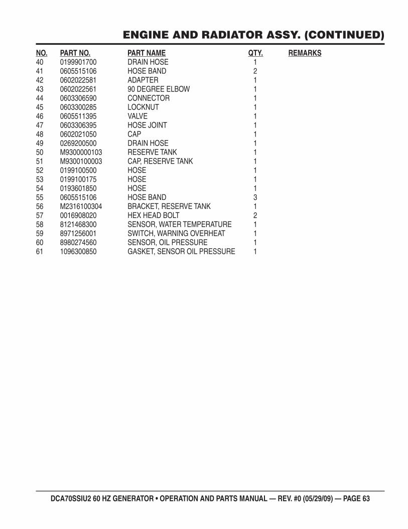
DCA70SSIU2 60 HZ GENERATOR • OPERATION AND PARTS MANUAL — REV. #0 (05/29/09) — PAGE 63
ENGINE AND RADIATOR ASSY. (CONTINUED)
NO. PART NO. PART NAME QTY. REMARKS40 0199901700 DRAIN HOSE 141 0605515106 HOSE BAND 242 0602022581 ADAPTER 143 0602022561 90 DEGREE ELBOW 144 0603306590 CONNECTOR 145 0603300285 LOCKNUT 146 0605511395 VALVE 147 0603306395 HOSE JOINT 148 0602021050 CAP 149 0269200500 DRAIN HOSE 150 M9300000103 RESERVE TANK 151 M9300100003 CAP, RESERVE TANK 152 0199100500 HOSE 153 0199100175 HOSE 154 0193601850 HOSE 155 0605515106 HOSE BAND 356 M2316100304 BRACKET, RESERVE TANK 157 0016908020 HEX HEAD BOLT 258 8121468300 SENSOR, WATER TEMPERATURE 159 8971256001 SWITCH, WARNING OVERHEAT 160 8980274560 SENSOR, OIL PRESSURE 161 1096300850 GASKET, SENSOR OIL PRESSURE 1
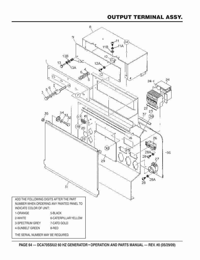
PAGE 64 — DCA70SSIU2 60 HZ GENERATOR • OPERATION AND PARTS MANUAL — REV. #0 (05/29/09)
OUTPUT TERMINAL ASSY.
ADD THE FOLLOWING DIGITS AFTER THE PART NUMBER WHEN ORDERING ANY PAINTED PANEL TO INDICATE COLOR OF UNIT:
1-ORANGE 5-BLACK
2-WHITE 6-CATERPILLAR YELLOW
3-SPECTRUM GREY 7-CATO GOLD
4-SUNBELT GREEN 8-RED
THE SERIAL NUMBER MAY BE REQUIRED.
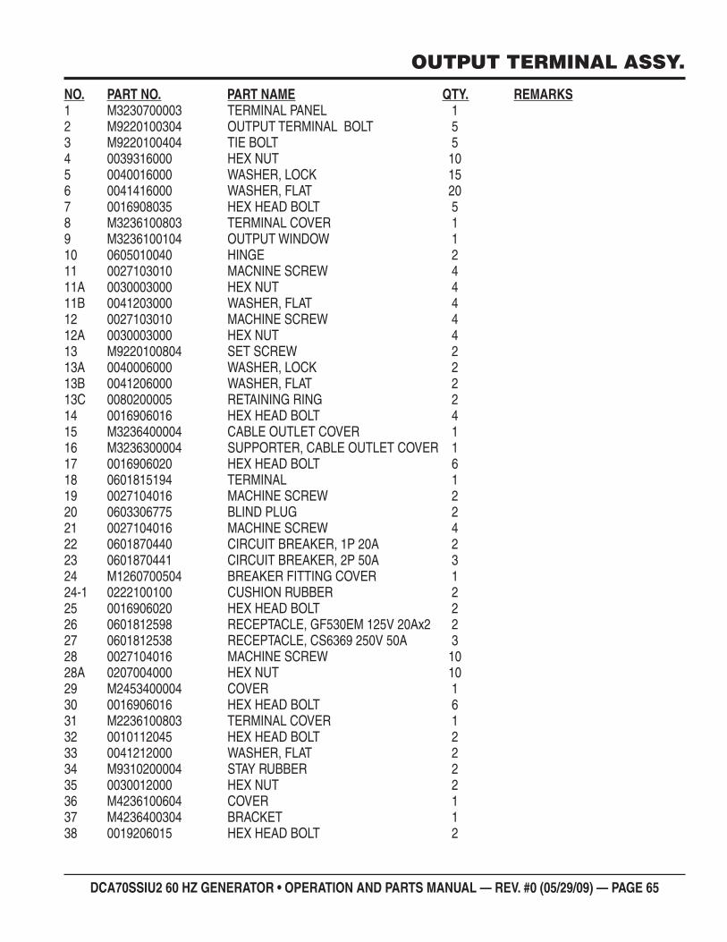
DCA70SSIU2 60 HZ GENERATOR • OPERATION AND PARTS MANUAL — REV. #0 (05/29/09) — PAGE 65
OUTPUT TERMINAL ASSY.
NO. PART NO. PART NAME QTY. REMARKS1 M3230700003 TERMINAL PANEL 12 M9220100304 OUTPUT TERMINAL BOLT 53 M9220100404 TIE BOLT 54 0039316000 HEX NUT 105 0040016000 WASHER, LOCK 156 0041416000 WASHER, FLAT 207 0016908035 HEX HEAD BOLT 58 M3236100803 TERMINAL COVER 19 M3236100104 OUTPUT WINDOW 110 0605010040 HINGE 211 0027103010 MACNINE SCREW 411A 0030003000 HEX NUT 411B 0041203000 WASHER, FLAT 412 0027103010 MACHINE SCREW 412A 0030003000 HEX NUT 413 M9220100804 SET SCREW 213A 0040006000 WASHER, LOCK 213B 0041206000 WASHER, FLAT 213C 0080200005 RETAINING RING 214 0016906016 HEX HEAD BOLT 415 M3236400004 CABLE OUTLET COVER 116 M3236300004 SUPPORTER, CABLE OUTLET COVER 117 0016906020 HEX HEAD BOLT 618 0601815194 TERMINAL 119 0027104016 MACHINE SCREW 220 0603306775 BLIND PLUG 221 0027104016 MACHINE SCREW 422 0601870440 CIRCUIT BREAKER, 1P 20A 223 0601870441 CIRCUIT BREAKER, 2P 50A 324 M1260700504 BREAKER FITTING COVER 124-1 0222100100 CUSHION RUBBER 225 0016906020 HEX HEAD BOLT 226 0601812598 RECEPTACLE, GF530EM 125V 20Ax2 227 0601812538 RECEPTACLE, CS6369 250V 50A 328 0027104016 MACHINE SCREW 1028A 0207004000 HEX NUT 1029 M2453400004 COVER 130 0016906016 HEX HEAD BOLT 631 M2236100803 TERMINAL COVER 132 0010112045 HEX HEAD BOLT 233 0041212000 WASHER, FLAT 234 M9310200004 STAY RUBBER 235 0030012000 HEX NUT 236 M4236100604 COVER 137 M4236400304 BRACKET 138 0019206015 HEX HEAD BOLT 2
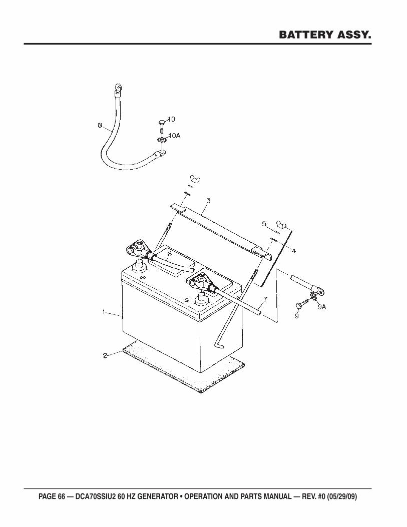
PAGE 66 — DCA70SSIU2 60 HZ GENERATOR • OPERATION AND PARTS MANUAL — REV. #0 (05/29/09)
BATTERY ASSY.
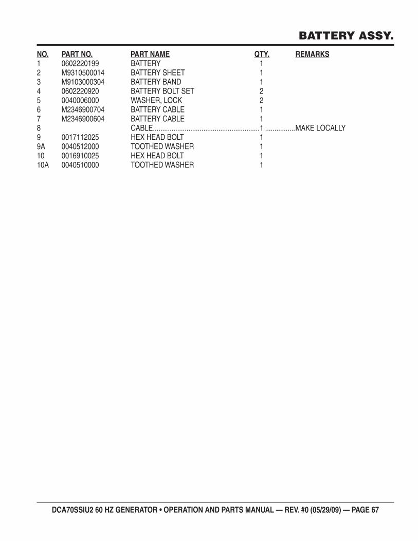
DCA70SSIU2 60 HZ GENERATOR • OPERATION AND PARTS MANUAL — REV. #0 (05/29/09) — PAGE 67
BATTERY ASSY.
NO. PART NO. PART NAME QTY. REMARKS1 0602220199 BATTERY 12 M9310500014 BATTERY SHEET 13 M9103000304 BATTERY BAND 14 0602220920 BATTERY BOLT SET 25 0040006000 WASHER, LOCK 26 M2346900704 BATTERY CABLE 17 M2346900604 BATTERY CABLE 18 CABLE .........................................................1 ................MAKE LOCALLY9 0017112025 HEX HEAD BOLT 19A 0040512000 TOOTHED WASHER 110 0016910025 HEX HEAD BOLT 110A 0040510000 TOOTHED WASHER 1
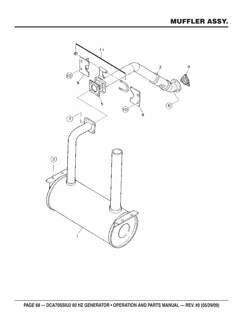
PAGE 68 — DCA70SSIU2 60 HZ GENERATOR • OPERATION AND PARTS MANUAL — REV. #0 (05/29/09)
MUFFLER ASSY.
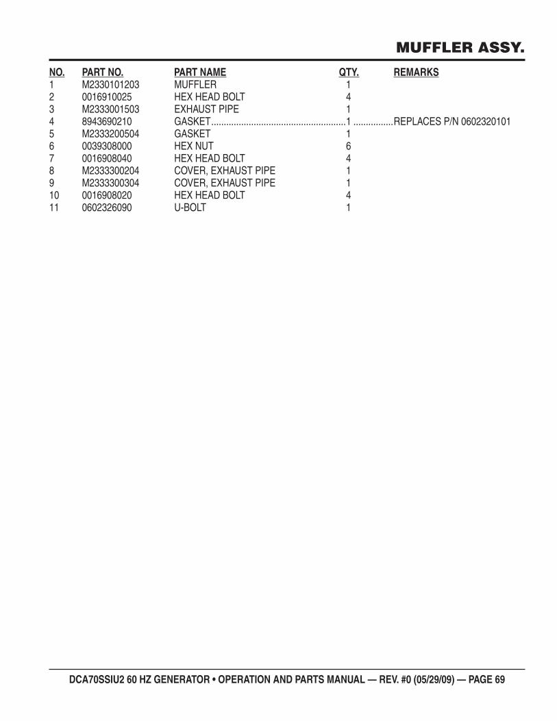
DCA70SSIU2 60 HZ GENERATOR • OPERATION AND PARTS MANUAL — REV. #0 (05/29/09) — PAGE 69
MUFFLER ASSY.
NO. PART NO. PART NAME QTY. REMARKS1 M2330101203 MUFFLER 12 0016910025 HEX HEAD BOLT 43 M2333001503 EXHAUST PIPE 14 8943690210 GASKET ......................................................1 ................REPLACES P/N 06023201015 M2333200504 GASKET 16 0039308000 HEX NUT 67 0016908040 HEX HEAD BOLT 48 M2333300204 COVER, EXHAUST PIPE 19 M2333300304 COVER, EXHAUST PIPE 110 0016908020 HEX HEAD BOLT 411 0602326090 U-BOLT 1
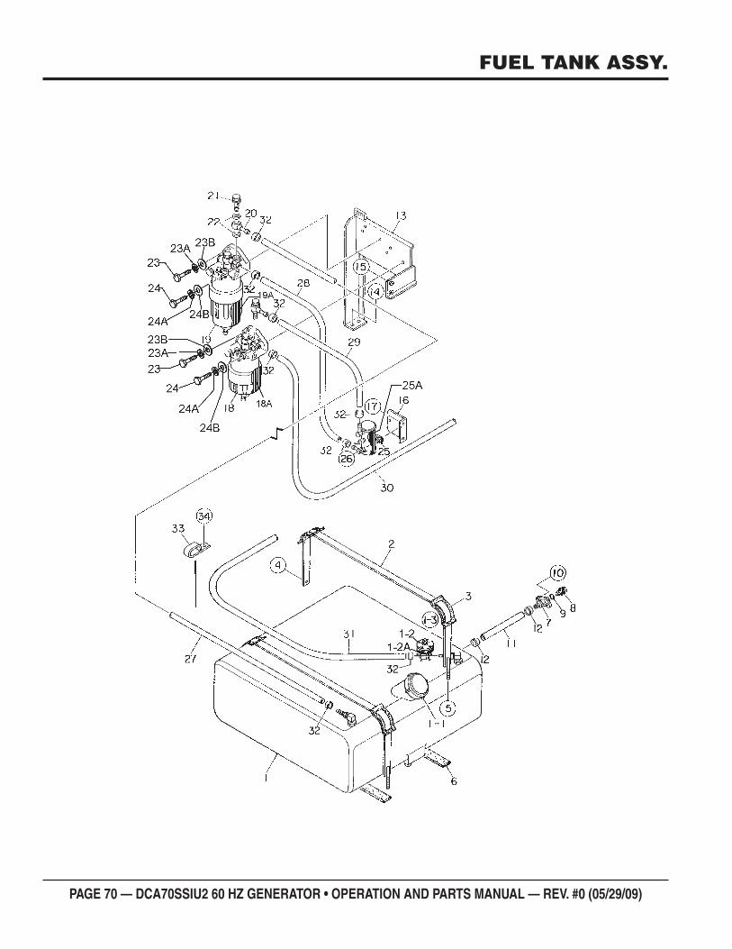
PAGE 70 — DCA70SSIU2 60 HZ GENERATOR • OPERATION AND PARTS MANUAL — REV. #0 (05/29/09)
FUEL TANK ASSY.
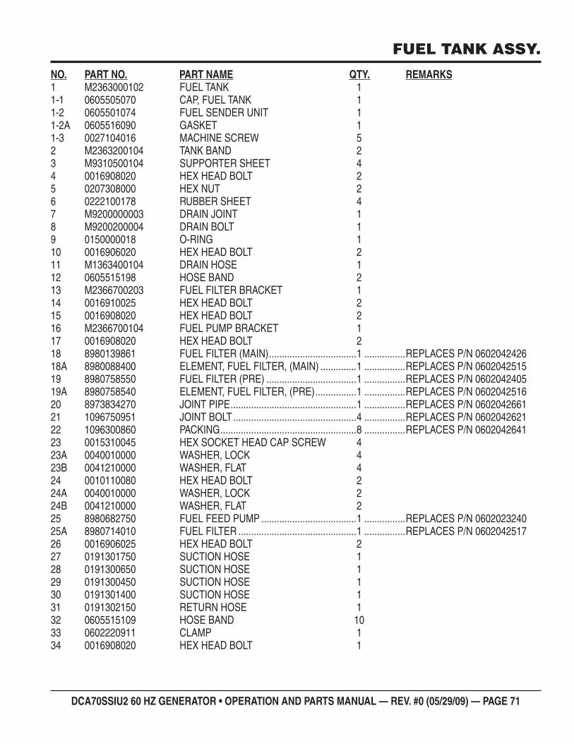
DCA70SSIU2 60 HZ GENERATOR • OPERATION AND PARTS MANUAL — REV. #0 (05/29/09) — PAGE 71
FUEL TANK ASSY.
NO. PART NO. PART NAME QTY. REMARKS1 M2363000102 FUEL TANK 11-1 0605505070 CAP, FUEL TANK 11-2 0605501074 FUEL SENDER UNIT 11-2A 0605516090 GASKET 11-3 0027104016 MACHINE SCREW 52 M2363200104 TANK BAND 23 M9310500104 SUPPORTER SHEET 44 0016908020 HEX HEAD BOLT 25 0207308000 HEX NUT 26 0222100178 RUBBER SHEET 47 M9200000003 DRAIN JOINT 18 M9200200004 DRAIN BOLT 19 0150000018 O-RING 110 0016906020 HEX HEAD BOLT 211 M1363400104 DRAIN HOSE 112 0605515198 HOSE BAND 213 M2366700203 FUEL FILTER BRACKET 114 0016910025 HEX HEAD BOLT 215 0016908020 HEX HEAD BOLT 216 M2366700104 FUEL PUMP BRACKET 117 0016908020 HEX HEAD BOLT 218 8980139861 FUEL FILTER (MAIN) ..................................1 ................REPLACES P/N 060204242618A 8980088400 ELEMENT, FUEL FILTER, (MAIN) ..............1 ................REPLACES P/N 060204251519 8980758550 FUEL FILTER (PRE) ...................................1 ................REPLACES P/N 060204240519A 8980758540 ELEMENT, FUEL FILTER, (PRE) ................1 ................REPLACES P/N 060204251620 8973834270 JOINT PIPE .................................................1 ................REPLACES P/N 060204266121 1096750951 JOINT BOLT ................................................4 ................REPLACES P/N 060204262122 1096300860 PACKING .....................................................8 ................REPLACES P/N 060204264123 0015310045 HEX SOCKET HEAD CAP SCREW 4 23A 0040010000 WASHER, LOCK 423B 0041210000 WASHER, FLAT 424 0010110080 HEX HEAD BOLT 224A 0040010000 WASHER, LOCK 224B 0041210000 WASHER, FLAT 225 8980682750 FUEL FEED PUMP .....................................1 ................REPLACES P/N 060202324025A 8980714010 FUEL FILTER ..............................................1 ................REPLACES P/N 060204251726 0016906025 HEX HEAD BOLT 227 0191301750 SUCTION HOSE 128 0191300650 SUCTION HOSE 129 0191300450 SUCTION HOSE 130 0191301400 SUCTION HOSE 131 0191302150 RETURN HOSE 132 0605515109 HOSE BAND 1033 0602220911 CLAMP 134 0016908020 HEX HEAD BOLT 1
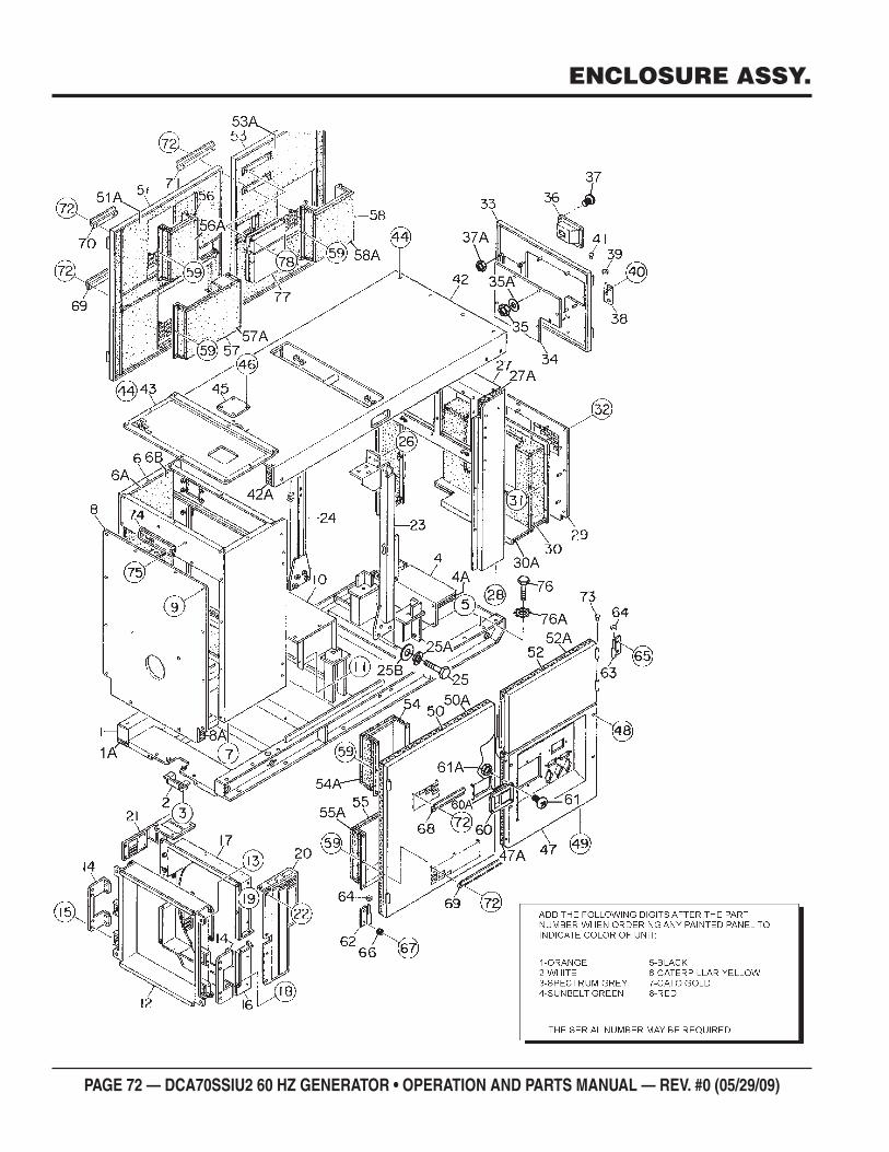
PAGE 72 — DCA70SSIU2 60 HZ GENERATOR • OPERATION AND PARTS MANUAL — REV. #0 (05/29/09)
ENCLOSURE ASSY.
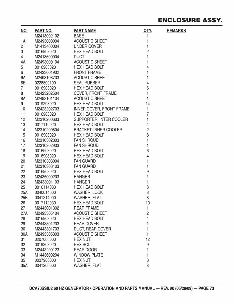
DCA70SSIU2 60 HZ GENERATOR • OPERATION AND PARTS MANUAL — REV. #0 (05/29/09) — PAGE 73
ENCLOSURE ASSY.
NO. PART NO. PART NAME QTY. REMARKS1 M2413002102 BASE 11A M2493000004 ACOUSTIC SHEET 12 M1413400004 UNDER COVER 13 0016908020 HEX HEAD BOLT 24 M2413600004 DUCT 14A M2493000104 ACOUSTIC SHEET 15 0016908020 HEX HEAD BOLT 46 M2423001902 FRONT FRAME 16A M2493108703 ACOUSTIC SHEET 16B 0228800100 SEAL RUBBER 47 0016908020 HEX HEAD BOLT 68 M2423202504 COVER, FRONT FRAME 18A M2493101104 ACOUSTIC SHEET 19 0019208020 HEX HEAD BOLT 1410 M2423202703 INNER COVER, FRONT FRAME 111 0016908020 HEX HEAD BOLT 712 M2310200603 SUPPORTER, INTER COOLER 113 0017110020 HEX HEAD BOLT 414 M2310200504 BRACKET, INNER COOLER 215 0016908020 HEX HEAD BOLT 816 M2310302803 FAN SHROUD 117 M2310302903 FAN SHROUD 118 0016908020 HEX HEAD BOLT 619 0016908020 HEX HEAD BOLT 420 M2310303004 FAN GUARD 121 M2310303103 FAN GUARD 122 0016908020 HEX HEAD BOLT 923 M2435000203 HANGER 124 M2433001103 HANGER 125 0010114030 HEX HEAD BOLT 825A 0040014000 WASHER, LOCK 825B 0041214000 WASHER, FLAT 826 0017112030 HEX HEAD BOLT 1027 M2443001302 REAR FRAME 127A M2493305404 ACOUSTIC SHEET 228 0016908020 HEX HEAD BOLT 429 M2443301203 REAR COVER 130 M2443301703 DUCT, REAR COVER 130A M2493305303 ACOUSTIC SHEET 131 0207006000 HEX NUT 1232 0019208020 HEX BOLT 933 M2443200123 REAR DOOR 134 M1443600204 WINDOW PLATE 135 0037906000 HEX NUT 835A 0041206000 WASHER, FLAT 8
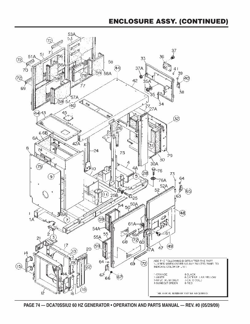
PAGE 74 — DCA70SSIU2 60 HZ GENERATOR • OPERATION AND PARTS MANUAL — REV. #0 (05/29/09)
ENCLOSURE ASSY. (CONTINUED)
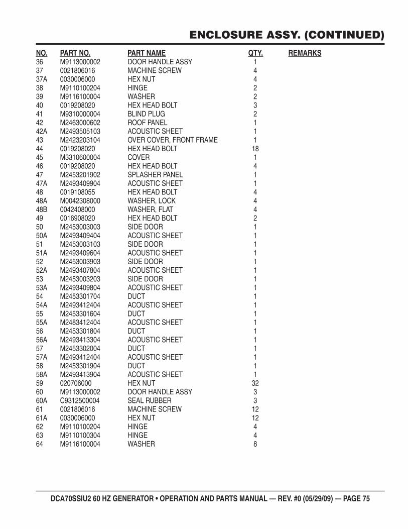
DCA70SSIU2 60 HZ GENERATOR • OPERATION AND PARTS MANUAL — REV. #0 (05/29/09) — PAGE 75
ENCLOSURE ASSY. (CONTINUED)
NO. PART NO. PART NAME QTY. REMARKS36 M9113000002 DOOR HANDLE ASSY 137 0021806016 MACHINE SCREW 437A 0030006000 HEX NUT 438 M9110100204 HINGE 239 M9116100004 WASHER 240 0019208020 HEX HEAD BOLT 341 M9310000004 BLIND PLUG 242 M2463000602 ROOF PANEL 142A M2493505103 ACOUSTIC SHEET 143 M2423203104 OVER COVER, FRONT FRAME 144 0019208020 HEX HEAD BOLT 1845 M3310600004 COVER 146 0019208020 HEX HEAD BOLT 447 M2453201902 SPLASHER PANEL 147A M2493409904 ACOUSTIC SHEET 148 0019108055 HEX HEAD BOLT 448A M0042308000 WASHER, LOCK 448B 0042408000 WASHER, FLAT 449 0016908020 HEX HEAD BOLT 250 M2453003003 SIDE DOOR 150A M2493409404 ACOUSTIC SHEET 151 M2453003103 SIDE DOOR 151A M2493409604 ACOUSTIC SHEET 152 M2453003903 SIDE DOOR 152A M2493407804 ACOUSTIC SHEET 153 M2453003203 SIDE DOOR 153A M2493409804 ACOUSTIC SHEET 154 M2453301704 DUCT 154A M2493412404 ACOUSTIC SHEET 155 M2453301604 DUCT 155A M2483412404 ACOUSTIC SHEET 156 M2453301804 DUCT 156A M2493413304 ACOUSTIC SHEET 157 M2453302004 DUCT 157A M2493412404 ACOUSTIC SHEET 158 M2453301904 DUCT 158A M2493413904 ACOUSTIC SHEET 159 020706000 HEX NUT 3260 M9113000002 DOOR HANDLE ASSY 360A C9312500004 SEAL RUBBER 361 0021806016 MACHINE SCREW 1261A 0030006000 HEX NUT 1262 M9110100204 HINGE 463 M9110100304 HINGE 464 M9116100004 WASHER 8
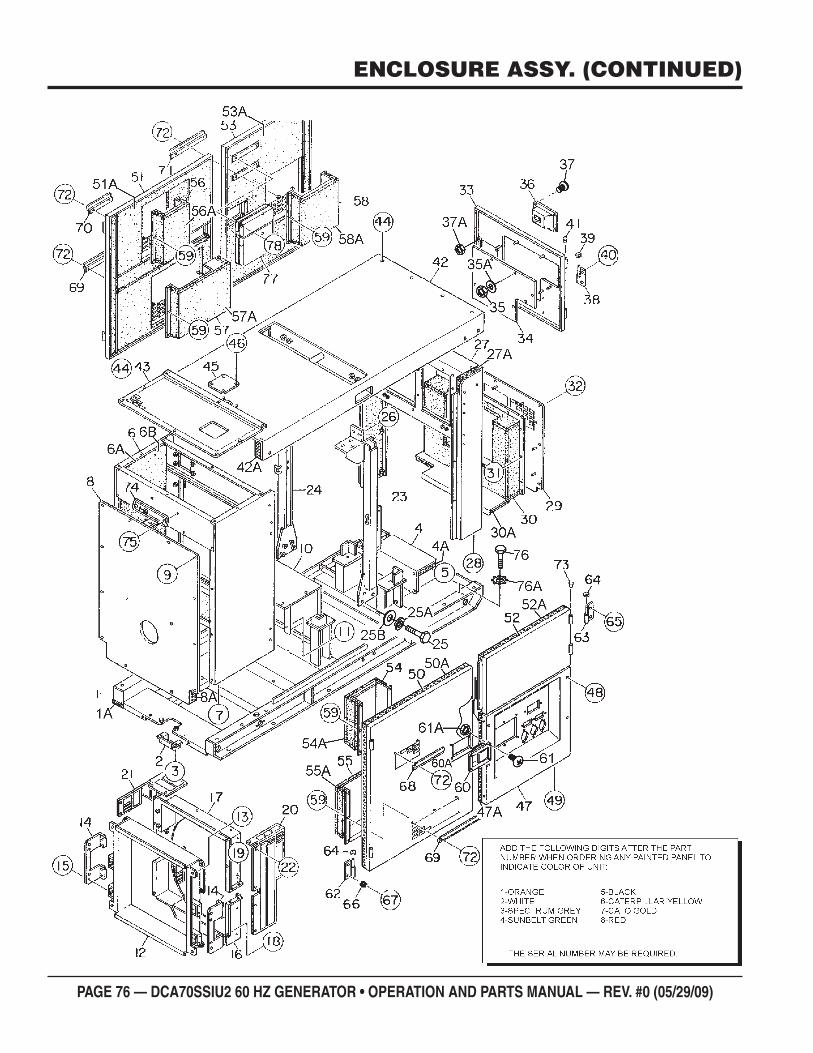
PAGE 76 — DCA70SSIU2 60 HZ GENERATOR • OPERATION AND PARTS MANUAL — REV. #0 (05/29/09)
ENCLOSURE ASSY. (CONTINUED)
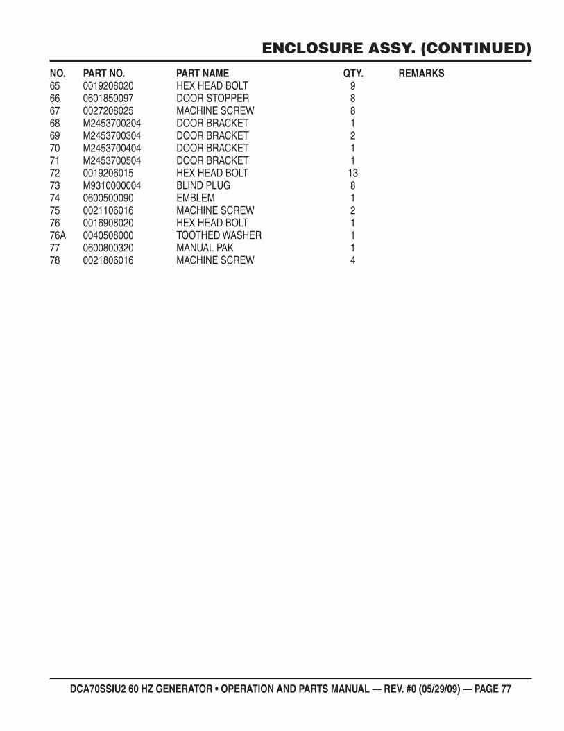
DCA70SSIU2 60 HZ GENERATOR • OPERATION AND PARTS MANUAL — REV. #0 (05/29/09) — PAGE 77
ENCLOSURE ASSY. (CONTINUED)
NO. PART NO. PART NAME QTY. REMARKS65 0019208020 HEX HEAD BOLT 966 0601850097 DOOR STOPPER 867 0027208025 MACHINE SCREW 868 M2453700204 DOOR BRACKET 169 M2453700304 DOOR BRACKET 270 M2453700404 DOOR BRACKET 171 M2453700504 DOOR BRACKET 172 0019206015 HEX HEAD BOLT 1373 M9310000004 BLIND PLUG 874 0600500090 EMBLEM 175 0021106016 MACHINE SCREW 276 0016908020 HEX HEAD BOLT 176A 0040508000 TOOTHED WASHER 177 0600800320 MANUAL PAK 178 0021806016 MACHINE SCREW 4
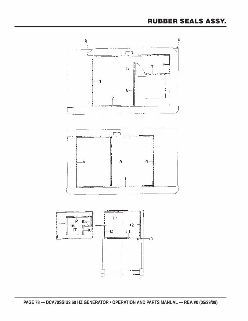
PAGE 78 — DCA70SSIU2 60 HZ GENERATOR • OPERATION AND PARTS MANUAL — REV. #0 (05/29/09)
RUBBER SEALS ASSY.
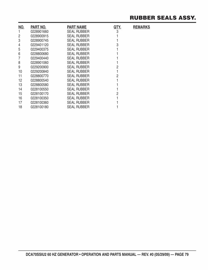
DCA70SSIU2 60 HZ GENERATOR • OPERATION AND PARTS MANUAL — REV. #0 (05/29/09) — PAGE 79
RUBBER SEALS ASSY.
NO. PART NO. PART NAME QTY. REMARKS1 0228901660 SEAL RUBBER 32 0228900915 SEAL RUBBER 13 0228900745 SEAL RUBBER 14 0229401120 SEAL RUBBER 35 0229400375 SEAL RUBBER 16 0228800680 SEAL RUBBER 17 0229400440 SEAL RUBBER 18 0228901060 SEAL RUBBER 19 0229200900 SEAL RUBBER 210 0229200840 SEAL RUBBER 111 0228800770 SEAL RUBBER 212 0228800540 SEAL RUBBER 113 0228800580 SEAL RUBBER 114 0228100550 SEAL RUBBER 115 0228100170 SEAL RUBBER 216 0228100350 SEAL RUBBER 117 0228100360 SEAL RUBBER 118 0228100180 SEAL RUBBER 1
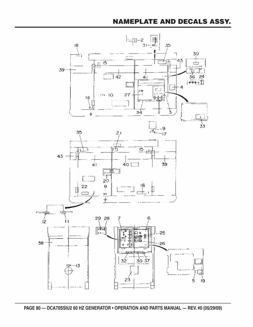
PAGE 80 — DCA70SSIU2 60 HZ GENERATOR • OPERATION AND PARTS MANUAL — REV. #0 (05/29/09)
NAMEPLATE AND DECALS ASSY.
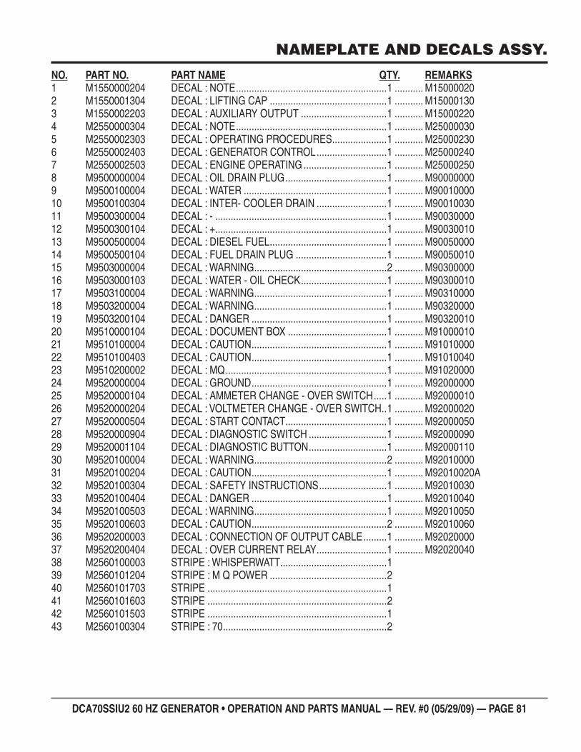
DCA70SSIU2 60 HZ GENERATOR • OPERATION AND PARTS MANUAL — REV. #0 (05/29/09) — PAGE 81
NAMEPLATE AND DECALS ASSY.
NO. PART NO. PART NAME QTY. REMARKS1 M1550000204 DECAL : NOTE ..........................................................1 ........... M150000202 M1550001304 DECAL : LIFTING CAP .............................................1 ........... M150001303 M1550002203 DECAL : AUXILIARY OUTPUT .................................1 ........... M150002204 M2550000304 DECAL : NOTE ..........................................................1 ........... M250000305 M2550002303 DECAL : OPERATING PROCEDURES .....................1 ........... M250002306 M2550002403 DECAL : GENERATOR CONTROL ...........................1 ........... M250002407 M2550002503 DECAL : ENGINE OPERATING ................................1 ........... M250002508 M9500000004 DECAL : OIL DRAIN PLUG .......................................1 ........... M900000009 M9500100004 DECAL : WATER .......................................................1 ........... M9001000010 M9500100304 DECAL : INTER- COOLER DRAIN ...........................1 ........... M9001003011 M9500300004 DECAL : - ..................................................................1 ........... M9003000012 M9500300104 DECAL : + ..................................................................1 ........... M9003001013 M9500500004 DECAL : DIESEL FUEL .............................................1 ........... M9005000014 M9500500104 DECAL : FUEL DRAIN PLUG ...................................1 ........... M9005001015 M9503000004 DECAL : WARNING ...................................................2 ........... M9030000016 M9503000103 DECAL : WATER - OIL CHECK .................................1 ........... M9030001017 M9503100004 DECAL : WARNING ...................................................1 ........... M9031000018 M9503200004 DECAL : WARNING ...................................................1 ........... M9032000019 M9503200104 DECAL : DANGER ....................................................1 ........... M9032001020 M9510000104 DECAL : DOCUMENT BOX ......................................1 ........... M9100001021 M9510100004 DECAL : CAUTION ....................................................1 ........... M9101000022 M9510100403 DECAL : CAUTION ....................................................1 ........... M9101004023 M9510200002 DECAL : MQ ..............................................................1 ........... M9102000024 M9520000004 DECAL : GROUND ....................................................1 ........... M9200000025 M9520000104 DECAL : AMMETER CHANGE - OVER SWITCH .....1 ........... M9200001026 M9520000204 DECAL : VOLTMETER CHANGE - OVER SWITCH ..1 ........... M9200002027 M9520000504 DECAL : START CONTACT .......................................1 ........... M9200005028 M9520000904 DECAL : DIAGNOSTIC SWITCH ..............................1 ........... M9200009029 M9520001104 DECAL : DIAGNOSTIC BUTTON ..............................1 ........... M9200011030 M9520100004 DECAL : WARNING ...................................................2 ........... M9201000031 M9520100204 DECAL : CAUTION ....................................................1 ........... M92010020A32 M9520100304 DECAL : SAFETY INSTRUCTIONS ..........................1 ........... M9201003033 M9520100404 DECAL : DANGER ....................................................1 ........... M9201004034 M9520100503 DECAL : WARNING ...................................................1 ........... M9201005035 M9520100603 DECAL : CAUTION ....................................................2 ........... M9201006036 M9520200003 DECAL : CONNECTION OF OUTPUT CABLE .........1 ........... M9202000037 M9520200404 DECAL : OVER CURRENT RELAY ...........................1 ........... M9202004038 M2560100003 STRIPE : WHISPERWATT.........................................139 M2560101204 STRIPE : M Q POWER .............................................240 M2560101703 STRIPE .....................................................................141 M2560101603 STRIPE .....................................................................242 M2560101503 STRIPE .....................................................................143 M2560100304 STRIPE : 70 ...............................................................2
PAGE 82 — DCA70SSIU2 60 HZ GENERATOR • OPERATION AND PARTS MANUAL — REV. #0 (05/29/09)
TERMS AND CONDITIONS OF SALE — PARTSPAYMENT TERMSTerms of payment for parts are net 30 days.
FREIGHT POLICYAll parts orders will be shipped collect or prepaid with the charges added to the invoice. All shipments are F.O.B. point of origin. Multiquip’s responsibility ceases when a signed manifest has been obtained from the carrier, and any claim for shortage or damage must be settled between the consignee and the carrier.
MINIMUM ORDERThe minimum charge for orders from Multiquip is $15.00 net. Customers will be asked for instructions regarding handling of orders not meeting this requirement.
RETURNED GOODS POLICYReturn shipments will be accepted and credit will be allowed, subject to the following provisions:
A Returned Material Authorization 1. must be approved by Multiquip prior to shipment.
To obtain a Return Material Authorization, 2. a list must be provided to Multiquip Parts Sales that defines item numbers, quantities, and descriptions of the items to be returned.
The parts numbers and descriptions a. must match the current parts price list.
The list must be typed or computer b. generated.
The list must state the reason(s) c. for the return.
The list must reference the sales d. order (s) or invoice (s) under which the items were originally purchased.
The list must include the name e. and phone number of the person requesting the RMA.
A copy of the Return Material Authorization 3. must accompany the return shipment.
Freight is at the sender’s expense. All 4. parts must be returned freight prepaid to Multiquip’s designated receiving point.
Parts must be in new and resalable 5. condition, in the original Multiquip package (if any), and with Multiquip part numbers clearly marked.
The following items are not returnable:6.
Obsolete parts. (If an item is in the a. price book and shows as being replaced by another item, it is obsolete.)
Any parts with a limited shelf life b. (such as gaskets, seals, “O” rings, and other rubber parts) that were purchased more than six months prior to the return date.
Any line item with an extended c. dealer net price of less than $5.00.
Special order items.d.
Electrical components.e.
Paint, chemicals, and lubricants.f.
Decals and paper products.g.
Items purchased in kits.h.
The sender will be notified of any material 7. received that is not acceptable.
Such material will be held for five 8. working days from notification, pending instructions. If a reply is not received within five days, the material will be returned to the sender at his expense.
Credit on returned parts will be issued 9. at dealer net price at time of the original purchase, less a 15% restocking charge.
In cases where an item is accepted, for 10. which the original purchase document can not be determined, the price will be based on the list price that was effective twelve months prior to the RMA date.
Credit issued will be applied to future 11. purchases only.
PRICING AND REBATESPrices are subject to change without prior notice. Price changes are effective on a specific date and all orders received on or after that date will be billed at the revised price. Rebates for price declines and added charges for price increases will not be made for stock on hand at the time of any price change.
Multiquip reserves the right to quote and sell direct to Government agencies, and toOriginal Equipment Manufacturer accounts who use our products as integral parts of their own products.
SPECIAL EXPEDITING SERVICEA $35.00 surcharge will be added to theinvoice for special handling including busshipments, insured parcel post or in cases where Multiquip must personally deliver theparts to the carrier.
LIMITATIONS OF SELLER’S LIABILITYMultiquip shall not be liable hereunder fordamages in excess of the purchase price of the item with respect to which damages areclaimed, and in no event shall Multiquip beliable for loss of profit or good will or for any other special, consequential or incidental damages.
LIMITATION OF WARRANTIESNo warranties, express or implied, are made in connection with the sale of parts or trade accessories nor as to any engine not manufactured by Multiquip. Such warranties made in connection with the sale of new, complete units are made exclusively by a statement of warranty packaged with such units, and Multiquip neither assumes nor authorizes any person to assume for it any other obligation or liability whatever in connection with the sale of its products. Apartfrom such written statement of warranty, there are no warranties, express, implied or statutory, which extend beyond the description of the products on the face hereof.
Effective: February 22, 2006

DCA70SSIU2 60 HZ GENERATOR • OPERATION AND PARTS MANUAL — REV. #0 (05/29/09) — PAGE 83
NOTES
Your Local Dealer is:
HERE’S HOW TO GET HELPPLEASE HAVE THE MODEL AND SERIAL
NUMBER ON-HAND WHEN CALLING
© COPYRIGHT 2009, MULTIQUIP INC.
MQ Power and the MQ Power logo are registered trademarks of Multiquip Inc. and may not be used, reproduced, or altered without written permission. All other trademarks are the property of their respective owners and used with permission.
This manual MUST accompany the equipment at all times. This manual is considered a permanent part of the equipment and should remain with the unit if resold.
The information and specifi cations included in this publication were in effect at the time of approval for printing. Illustrations, descriptions, references and technical data contained in this manual are for guidance only and may not be considered as binding. Multiquip Inc. reserves the right to discontinue or change specifi cations, design or the information published in this publication at any time without notice and without incurring any obligations.
MQ Power 1800 Water Ridge Rd. Tel. (800) 883-2551Suite 500/600 Fax (972) 315-1847Lewisville, TX 75057 Contact: [email protected]: www.mqpower.com
MQ Parts Department800-427-1244 Fax: 800-672-7877310-537-3700 Fax: 310-637-3284
Service/Tech Support/Warranty800-835-2551 Fax: 310-638-8046
Manufactured for Multiquip Inc.
byDENYO CO., LTD, JAPAN
OPERATION AND PARTS MANUAL

SUNSTAR SPACE HEATERS

INTRODUCING THE NEWSC MODEL SERIES FROM SUNSTAR®
New,Modern Styling Fits AnyDecor
Fireside Warmth At A Comfortable Price
©Copyright 2009, SunStar Heating Products Inc.
SunStar strives to improve quality and performance on a continuing basis and reserves the right to change specifications and materials without notice.12/09-FORM #A092
Sunstar Heating Products, Inc.A Subsidiary of Gas-Fired Products, Inc.PO Box 36271, Charlotte, NC 28236Toll Free 1-888-778-6782 Fax (704)332-5843Email: [email protected] Web: www.sunstarheaters.com
MAX BTU INPUT/NG 18,000 30,000
MAX BTU INPUT/LP 16,500 27,000
HEATER TYPE INFRARED INFRARED
WIDTH 19-3/4” 27-1/2”
DEPTH 9-1/2”
HEIGHT 25”
SHIPPING WEIGHT 24 lbs. 32 lbs.
MANUAL YES
THERMOSTAT YES
FRONT 36”
TOP 36”
SIDES 13”
BOTTOM (WALL MOUNT) 2”
FLOOR STAND INCLUDED
BLOWER YES
MODEL SC18 MODEL SC30
Dimensions
Temperature Control Options
Minimum ClearancesFrom Combustible Material
Accessory Options
SunStar is the choice for comfort. Turn down your central thermostat and turn up theheat in the room of your choice with a SunStar vent-free gas space heater. It’saffordable, reliable and virtually 100% efficient. And it even works during power outages.
All SunStar heaters feature attractive modern styling with up-to-date safety featureslike flame-failure protection and an oxygen detection safety-pilot or ODS. And, eachmodel is CSA design-certified to the current national safety standards. Choose theaffordable reliability of the SunStar heater that best fits your needs and turn up yourheat and turn down your costs.
SunStar heaters are priced affordably and offer a great value for your home, office orother hard-to-heat areas. SunStar infrared models produce a radiant form of heat thatinstantly heats people and objects like the sun. So, choose SunStar and choose value.
ForYour SafetyInstallation must be done by a qualified serviceperson. This installation must conform to state andlocal codes. In the absence of local codes, theinstallation must conform to the latest edition ofNFPA54/ANSI Z223. See your dealer for additionalinformation and thoroughly read the Owner's Manual
before installing and operating this heater.
SunStar has been designed with many options and features
� Manual &Thermostat Models� 5-Year No Hassle LimitedWarranty � ODS & Flame Failure Safety Features� Piezo Ignition – No Electricity Needed. Works Even During Power Outages�Wall Mount Or Floor Mount, As Needed (Floor Stand Included)� Optional Blowers AvailableWith Manual Or Thermostat Models.(Same Blowers Can Be Used On CK Models.)
� Can Be Installed In Mobile Homes As Permitted By State And Local Codes� Propane (LP Gas) or Natural Gas Models Available
BLOWEROPTION
To improve the distribution of the warmththroughout the room,
SC models accept an optionalblower accessory.
This same blower can be used on SunStar’sCK Series Heaters.
SC30
SC18
Related Documents


