FFRDC Team Working Draft Documents – 2017 NDAA 3134 Hanford Supplemental Low Activity Waste Treatment at the Hanford Reservation The following attached documents have been developed by the FFRDC Team and represent “working draft” information regarding assessment methodologies, technologies, and approaches under consideration and review per the FFRDC Program Plan developed for this study. The FFRDC Team recognizes that under the NDAA 3134 language, the collaboration with the NAS is critical to achieving the intended goal of the study. As such, working draft information is being shared. It is important for readers to understand that much of what is presented in these working draft documents has not been peer reviewed or technically edited and is not intended to imply any final conclusions or represent a complete analysis. Peer reviews and subsequent revision and refinement will be completed during the fall of 2018 and spring 2019. Until a final report is issued, all information presented is considered Pre-Decisional DRAFT. The intent of sharing the working draft documents is to stimulate dialog with the NAS Committee members and to ultimately obtain constructive feedback, comments, and technical ideas to improve on these draft documents and technical concepts as they mature into the ultimate final report(s). Bill Bates FFRDC Team Lead

Welcome message from author
This document is posted to help you gain knowledge. Please leave a comment to let me know what you think about it! Share it to your friends and learn new things together.
Transcript
FFRDC Team Working Draft Documents – 2017 NDAA 3134 Hanford Supplemental Low Activity Waste Treatment at the Hanford Reservation
The following attached documents have been developed by the FFRDC Team and represent “working draft” information regarding assessment methodologies, technologies, and approaches under consideration and review per the FFRDC Program Plan developed for this study.
The FFRDC Team recognizes that under the NDAA 3134 language, the collaboration with the NAS is critical to achieving the intended goal of the study. As such, working draft information is being shared.
It is important for readers to understand that much of what is presented in these working draft documents has not been peer reviewed or technically edited and is not intended to imply any final conclusions or represent a complete analysis. Peer reviews and subsequent revision and refinement will be completed during the fall of 2018 and spring 2019. Until a final report is issued, all information presented is considered Pre-Decisional DRAFT.
The intent of sharing the working draft documents is to stimulate dialog with the NAS Committee members and to ultimately obtain constructive feedback, comments, and technical ideas to improve on these draft documents and technical concepts as they mature into the ultimate final report(s).
Bill Bates
FFRDC Team Lead
SRNL-RP-2018-00687 Predecisional DRAFT 2018-07-15-DRAFT Page 1 of 197
Report of Analysis of Approaches to Supplemental Treatment of Low-Activity Waste at the Hanford Nuclear Reservation July 2018 PRELIMINARY DRAFT2018-07-15
SRNL-RP-2018-00687 Predecisional DRAFT 2018-07-15-DRAFT Page 2 of 197
DISCLAIMER
This work was prepared under an agreement with and funded by the U.S. Government. Neither the U.S. Government or its employees, nor any of its contractors, subcontractors or their employees, makes any express or implied:
1. warranty or assumes any legal liability for the accuracy, completeness, or for the use or results of such use of any information, product, or process disclosed; or
2. representation that such use or results of such use would not infringe privately owned rights; or
3. endorsement or recommendation of any specifically identified commercial product, process, or service.
Any views and opinions of authors expressed in this work do not necessarily state or reflect those of the United States Government, or its contractors, or subcontractors.
Printed in the United States of America Prepared for U.S. Department of Energy

SRNL-RP-2018-00687 Predecisional DRAFT 2018-07-15-DRAFT Page 3 of 197
Keywords: Hanford, Low Activity Waste, LAW, Waste Treatment and Immobilization Plant, WTP Retention: Permanent
Report of Analysis of Approaches to Supplemental Treatment of Low-Activity Waste at the Hanford Nuclear Reservation
July 2018
SRNL-RP-2018-00xxx

SRNL-RP-2018-00687 Predecisional DRAFT 2018-07-15-DRAFT Page 4 of 197
SIGNATURES HANFORD LAW ANALYSIS TEAM William F. Bates, Savannah River National Laboratory Date Low Activity Waste Analysis Team Lead Michael E. Stone, Savannah River National Laboratory Date Thomas M. Brouns, Pacific Northwest National Laboratory Date Christine A. Langton, Savannah River National Laboratory Date Robert T. Jubin, Oak Ridge National Laboratory Date Alex D. Cozzi, Savannah River National Laboratory Date Nick Soelberg, Idaho National Laboriatory Date George D. Guthrie, Los Alamos National Laboratory Date John R. Cochran, Sandia National Laboratories Date

SRNL-RP-2018-00687 Predecisional DRAFT 2018-07-15-DRAFT Page 5 of 197
ACKNOWLEDGEMENTS TBD
SRNL-RP-2018-00687 Predecisional DRAFT 2018-07-15-DRAFT Page 6 of 197
TABLE OF CONTENTS ACKNOWLEDGEMENTS ..............................................................................................................................................5 ACRONYMS AND ABBREVIATIONS..............................................................................................................................8 LIST OF TABLES ...........................................................................................................................................................9 LIST OF FIGURES .........................................................................................................................................................9 EXECUTIVE SUMMARY ............................................................................................................................................. 10 1.0 PARAMETERS OF THE ANALYSIS ........................................................................................................................ 11
1.1 STRATEGY ...................................................................................................................................................... 11
1.2 SCOPE ............................................................................................................................................................ 15
1.3 UNCERTAINTIES ............................................................................................................................................. 15
1.4 TECHNICAL CHALLENGES ............................................................................................................................... 18
1.5 COST ESTIMATION SUMMARY ...................................................................................................................... 19
2.0 HANFORD LAW OVERVIEW ............................................................................................................................... 20 2.1 BASELINE PROCESS FOR HANFORD LAW AND SUPPLEMENTAL LAW IMMOBILIZATION .............................. 20
2.2 SUMMARY OF OTHER OPTIONS CONSIDERED DURING THIS EVALUATION .................................................. 23
2.3 FEED VECTOR ................................................................................................................................................. 23
3.0 ANALYSIS RISK ASSESSMENT ............................................................................................................................. 26 4.0 ASSESSMENT AREA SUMMARIES ....................................................................................................................... 29
4.1 PRETREATMENT ............................................................................................................................................. 29
4.2 VITRIFICATION ............................................................................................................................................... 29
4.3 STEAM REFORMING ...................................................................................................................................... 29
4.4 GROUT ........................................................................................................................................................... 29
4.5 OTHER APPROACHES ..................................................................................................................................... 29
5.0 SUMMARY OF DISPOSAL SITE CONSIDERATIONS .............................................................................................. 30 6.0 SUMMARY OF TRANSPORATION CONSIDERATIONS ......................................................................................... 31 7.0 COMPARATIVE ANALYSIS OF APPROACHES SUMMARY .................................................................................... 32 APPENDIX A. EXPANDED DISCUSSION – PRETREATMENT ....................................................................................... 33 APPENDIX B. EXPANDED DISCUSSION – VITRIFICATION ......................................................................................... 43 APPENDIX C. EXPANDED DISCUSSION – STEAM REFORMING ................................................................................. 50 APPENDIX D. EXPANDED DISCUSSION – GROUT ..................................................................................................... 97 APPENDIX E. EXPANDED DISCUSSION – OTHER APPROACHES ............................................................................. 109 APPENDIX F. EXPANDED DISCUSSION: COMPARATIVE ANALYSIS OF APPROACHES ............................................. 110 APPENDIX G. EXPANDED DISCUSSION: COST ESTIMATE METHODOLOGY AND BASIS ......................................... 129 APPENDIX H. EXPANDED DISCUSSION – DISPOSAL SITE CONSIDERATIONS.......................................................... 136 APPENDIX I. EXPANDED DISCUSSION – TRANSPORTATION CONSIDERATIONS .................................................... 152 APPENDIX J. EXPANDED DISCUSSION – REGULATORY COMPLIANCE ................................................................... 165 APPENDIX K. EXPANDED DISCUSSION: FEED VECTOR ........................................................................................... 183 APPENDIX L. BIBLIOGRAPHY .................................................................................................................................. 194 ATTACHMENT 1. TEAM BIOs ................................................................................................................................. 197 ATTACHMENT 2. NATIONAL DEFENSE AUTHORIZATION ACT FOR FISCAL YEAR 2017, SECTION 3134, “ANALYSIS OF APPROACHES FOR SUPPLEMENTAL TREATMENT OF LOW-ACTIVITY WASTE AT HANFORD NUCLEAR RESERVATION”....................................................................................................................................................... 197
SRNL-RP-2018-00687 Predecisional DRAFT 2018-07-15-DRAFT Page 7 of 197
ATTACHMENT 3. PROGRAM PLAN FOR ANALYSIS OF APPROACHES TO SUPPLEMENTAL TREATMENT OF LOW-ACTIVITY WASTE AT THE HANFORD NUCLEAR RESERVATION .............................................................................. 197
SRNL-RP-2018-00687 Predecisional DRAFT 2018-07-15-DRAFT Page 8 of 197
ACRONYMS AND ABBREVIATIONS DOE Department of Energy EM DOE Office of Environmental Management EMNLN EM National Laboratory Network ETF Effluent Treatment Facility FFRDC Federally Funded Research and Development Center GAO Government Accounting Office IDF Integrated Disposal Facility INL Idaho National Laboratory HLW high level waste LANL Los Alamos National Laboratory LAW low-activity waste LAWPS Low Activity Waste Pretreatment Facility LDR Land Disposal Restrictions LERF Liquid Effluent Retention Facility NAS National Academies of Science, Engineering and Medicine NDAA National Defense Authorization Act ORNL Oak Ridge National Laboratory PA Performance assessment POC point of contact PNNL Pacific Northwest National Laboratory PT PreTreatment Facility PUREX Plutonium Uranium Extraction REDOX REDuction and OXidation SRNL Savannah River National Laboratory WTP Waste Treatment and Immobilization Plant
SRNL-RP-2018-00687 Predecisional DRAFT 2018-07-15-DRAFT Page 9 of 197
LIST OF TABLES Table 1-2 Application of GAO Best Practices for the Analysis of Alternatives .................................................. 12 LIST OF FIGURES Figure 2.1 Simplified Flow Sheet for Immobilization of Hanford Waste during Full WTP Operation 21
SRNL-RP-2018-00687 Predecisional DRAFT 2018-07-15-DRAFT Page 10 of 197
EXECUTIVE SUMMARY This report describes the results of the analysis of alternatives for supplemental treatment of low-activity waste (LAW) at the Department of Energy’s (DOE’s) Hanford Nuclear Reservation prescribed by the National Defense Authorization Act for Fiscal Year 2017 (NDAA17). The current design of the Waste Treatment and Immobilization Plant (WTP) at the Hanford site enables treatment of only a portion of Hanford’s LAW. To increase Hanford LAW treatment capacity, construction of an additional facility for treating the remainder of the LAW has been proposed. NDAA17 Section 3134, “Analysis of Approaches for Supplemental Treatment of Low-Activity Waste at Hanford Nuclear Reservation,” stipulates that a Federally Funded Research and Development Center (FFRDC) team conduct an analysis of approaches to treating the portion of LAW at the Hanford site that is intended for supplemental treatment. NDAA17 also directs the National Academies of Science, Engineering, and Medicine to conduct a review of the LAW analysis concurrent with the FFRDC performance of that analysis. This FFRDC core team was constituted through the Environmental Management National Laboratory Network (EMNLN), which recommended experts from the national laboratories who were accomplished in disciplines pertinent to key aspects of the analysis. As prescribed in the NDAA17, the FFRDC team analyzed several approaches to immobilization of Hanford LAW--vitrification, grouting, steam reforming, and “other” potential methods—as well as pretreatment requirements of those approaches. This main body of this report provides an overview of the base ad variant cases and the analysis of each one. Details are included in the appendices. This report provides results of the analysis of each option based on expert analysis of a broad set criteria. Non-technical parameters such as acceptance to stakeholders and political considerations were excluded from this analysis. The information in this report does not constitute formal design quality that would be required for conceptual design for any of the alternatives in the event that they are selected for implementation.

SRNL-RP-2018-00687 Predecisional DRAFT 2018-07-15-DRAFT Page 11 of 197
1.0 PARAMETERS OF THE ANALYSIS 1.1 STRATEGY As summarized in Table 1-2, the “Best Practices for the Analysis of Alternatives” established by the United States Government Accountability Office (GAO)1 was used to provide general guidelines for the analysis of alternatives for supplemental treatment of low-activity waste (LAW) at the Department of Energy’s (DOE’s) Hanford Nuclear Reservation. 1.1.1 Need and Requirements The current design of the Waste Treatment and Immobilization Plant (WTP) at DOE’s Hanford site in Richland, Washington enables treatment of only a portion of Hanford’s low-activity waste (LAW). To increase Hanford LAW treatment capacity, construction of an additional facility for treating the remainder of the LAW has been proposed. Section 3134, “Analysis of Approaches for Supplemental Treatment of Low-Activity Waste at Hanford Nuclear Reservation,” of the National Defense Authorization Act for Fiscal Year 2017 (NDAA17) stipulates that a Federally Funded Research and Development Center (FFRDC) team conduct an analysis of approaches to treating the portion of LAW at the Hanford site that is intended for supplemental treatment.2 FFRDCs, such as DOE’s national laboratories, are sponsored and funded by the United States Government to meet special long-term research or development needs that cannot be met effectively in-house or by contractors.3 NDAA17 Section 3134 also directs the National Academies of Science, Engineering, and Medicine to conduct a review of the LAW analysis concurrent with FFRDC performance of that analysis. 1.1.2 Methodology SRNL was asked by DOE-EM to lead the analysis. SRNL constituted the FFRDE team through the Environmental Management National Laboratory Network (EMNLN). The EMNLN facilitates the ability of the DOE Office of Environmental Management (EM) to access and leverage the capabilities of the DOE national laboratories to meet the objectives of EM’s legacy nuclear waste clean-up mission.4 Representing six national laboratories, the members of the core FFRDC team are expert and accomplished in disciplines pertinent to key aspects of the analysis and are readily able to “reach back” to utilize the broader experience, expertise, and capabilities of their own laboratories as well as to “reach out” to colleagues in other National Laboratories, industry, and academia for support as needed. The team developed a Program Plan to guide performance of the analysis.5 As prescribed in the NDAA17, the FFRDC team analyzed several approaches to immobilization of Hanford LAW--vitrification, grouting, steam reforming, and “other” potential methods—as well as pretreatment requirements of those methods. The analysis included the following major elements: • Development of pre-conceptual flow sheets 1 DOE AND NNSA Project Management: Analysis of Alternatives Could Be Improved by Incorporating Best Practices. GAO-15-37. December 2014. Report to the Committee on Armed Services, U.S. Senate. United States Government Accountability Office. 2 “Analysis of Approaches for Supplemental Treatment of Low Activity Waste at Hanford Nuclear Reservation.” National Defense Authorization Act for Fiscal Year 2017. January 4, 2016. Section 3134. 3 “Federally Funded Research and Development Centers.” 48 CFR 35.017. October 1, 2005. United States Code of Federal Regulations. 4 “EM National Laboratory Network Charter.” May 2017. 5 “Program Plan for Analysis of Approaches for Supplemental Treatment of Low-Activity Waste at the Hanford Nuclear Reservation.” SRNL-RP-2017-00242. June 2017.

SRNL-RP-2018-00687 Predecisional DRAFT 2018-07-15-DRAFT Page 12 of 197
• Development of variants, options, and opportunities • Development of criteria for analysis and comparison of options • Review of regulatory requirements for processing, transport, and disposal • Development of pre-conceptual cost estimates • Performance of an Expert Elicitation review and comparison of all options against the established criteria. The team applied a broad set of variously weighted technical, regulatory, cost, maturity, and other criteria to evaluate each of the 3 base cases as well as 9 variants identified by the team and then performed comparisons among the options. Section 7.0, “Analysis Summary,” provides the grading criteria and comparison of the options. Table 1-1 Application of GAO Best Practices for the Analysis of Alternatives
GAO 24 Steps
Description Assessment
Process Included in the General Principle Category
1 The customer defines the mission need and functional requirements without a predetermined solution
The mission need is per NDAA for 2017, Section 3134, “Analysis of Approaches for Supplemental Treatment of Low-Activity Waste at Hanford Nuclear Reservation.”
2 The customer defines functional requirements based on the mission need
Functional requirements are per NDAA for 2017, Section 3134. “Analysis of Approaches for Supplemental Treatment of Low-Activity Waste at Hanford Nuclear Reservation.”
3
The customer provides the team conducting the analysis of alternatives (AOA) with enough time to complete the AOA process to ensure a robust and complete analysis
The AOA team completed the AOA over a time spam of approximately two years.
4
The team includes members with diverse areas of expertise including, at a minimum, subject matter expertise, project management, cost estimating, and risk management
The team consisted of members with diverse areas of expertise, identified by the Department of Energy (DOE) Office of Environmental Management (EM) National Laboratory Network (EMNLN). Biographies of the members are included in the package.
5
The team creates a plan, including proposed methodologies, for identifying, analyzing, and selecting alternatives, before beginning the AOA process
A Program Plan, SRNL-RP-2017-00242, “Program Plan for Analysis of Approaches to Supplemental Treatment of Low-Activity Waste at the Hanford Nuclear Reservation,” was developed to identify the approach to the analysis of alternatives.
6 The team documents all steps taken to identify, analyze, and select alternatives in a single document
This report documents all steps pertinent to the analysis.
Process Included in the General Principle Category (continued)
SRNL-RP-2018-00687 Predecisional DRAFT 2018-07-15-DRAFT Page 13 of 197
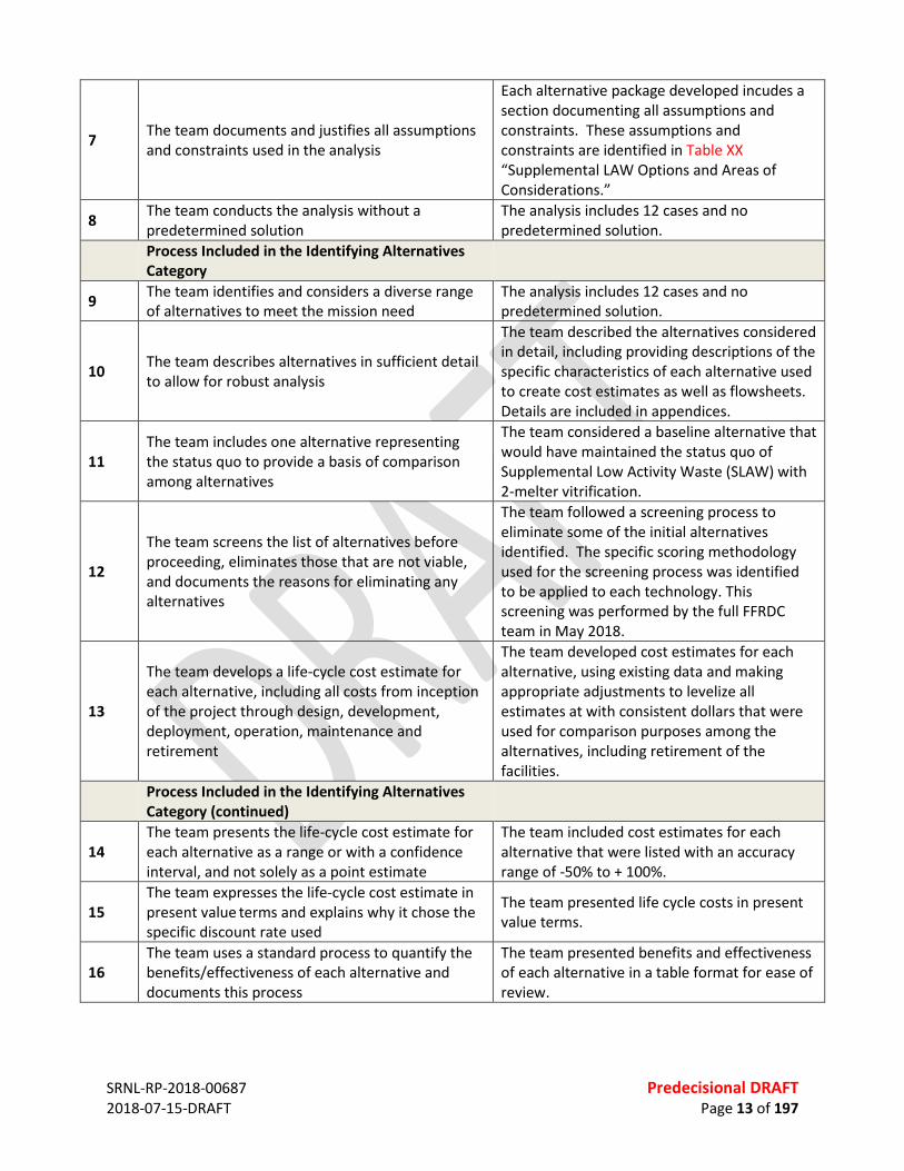
7 The team documents and justifies all assumptions and constraints used in the analysis
Each alternative package developed incudes a section documenting all assumptions and constraints. These assumptions and constraints are identified in Table XX “Supplemental LAW Options and Areas of Considerations.”
8 The team conducts the analysis without a predetermined solution
The analysis includes 12 cases and no predetermined solution.
Process Included in the Identifying Alternatives Category
9 The team identifies and considers a diverse range of alternatives to meet the mission need
The analysis includes 12 cases and no predetermined solution.
10 The team describes alternatives in sufficient detail to allow for robust analysis
The team described the alternatives considered in detail, including providing descriptions of the specific characteristics of each alternative used to create cost estimates as well as flowsheets. Details are included in appendices.
11 The team includes one alternative representing the status quo to provide a basis of comparison among alternatives
The team considered a baseline alternative that would have maintained the status quo of Supplemental Low Activity Waste (SLAW) with 2-melter vitrification.
12
The team screens the list of alternatives before proceeding, eliminates those that are not viable, and documents the reasons for eliminating any alternatives
The team followed a screening process to eliminate some of the initial alternatives identified. The specific scoring methodology used for the screening process was identified to be applied to each technology. This screening was performed by the full FFRDC team in May 2018.
13
The team develops a life-cycle cost estimate for each alternative, including all costs from inception of the project through design, development, deployment, operation, maintenance and retirement
The team developed cost estimates for each alternative, using existing data and making appropriate adjustments to levelize all estimates at with consistent dollars that were used for comparison purposes among the alternatives, including retirement of the facilities.
Process Included in the Identifying Alternatives Category (continued)
14 The team presents the life-cycle cost estimate for each alternative as a range or with a confidence interval, and not solely as a point estimate
The team included cost estimates for each alternative that were listed with an accuracy range of -50% to + 100%.
15 The team expresses the life-cycle cost estimate in present value
terms and explains why it chose the
specific discount rate used
The team presented life cycle costs in present value terms.
16 The team uses a standard process to quantify the benefits/effectiveness of each alternative and documents this process
The team presented benefits and effectiveness of each alternative in a table format for ease of review.

SRNL-RP-2018-00687 Predecisional DRAFT 2018-07-15-DRAFT Page 14 of 197
17 The team quantifies the benefits/effectiveness resulting from each alternative over that alternative’s full life cycle, if possible
The team quantified the benefits and effectiveness of each alternative of the alternative full life cycle, based on available information in a table format.
18 The team explains how each measure of benefit/effectiveness supports the mission need
Each measure of the benefit and effectiveness was document in table format for each alternative with some of these measures being subjective.
19 The team identifies and documents the significant risks and mitigation strategies for each alternative
The team developed a risk matrix for each alternative and briefly described the mitigation strategies for each risk.
20
The team tests and documents the sensitivity of both the cost and benefit/effectiveness estimates for each alternative to risks and changes in key assumptions
The team developed as part of the risk matrix, the sensitivity of both cost and schedule for each alternative to risks and key assumption changes.
Process Included in the Selecting a Preferred Alternative
21 The team or the decision maker defines selection criteria based on the mission need
The NDAA does not call for a recommendation or preferred alternative.
22 The team or the decision maker weights the selection criteria to reflect the relative importance of each criterion
The team weighted the selection criteria using a five point scale, with 5 indicating most positive and 1 the least positive criteria to evaluate each option. However, the NDAA does not call for a preferred alternative and the FFRDE team does not provide a recommended or preferred alternative.
Process Included in the Selecting a Preferred Alternative (Continued)
23 The team or the decision maker compares alternatives using net present value
The team used net present value in comparing alternatives.
24
An entity independent of the AOA process reviews the extent to which all best practices have been followed (for certain projects, additional independent reviews may be necessary at earlier stages of the process such as for reviewing the study plan or for reviewing the identification of viable alternatives)
NDAA17 directs the National Academies of Science, Engineering, and Medicine to conduct a review of the LAW analysis concurrent with the FFRDC performance of that analysis.
SRNL-RP-2018-00687 Predecisional DRAFT 2018-07-15-DRAFT Page 15 of 197
1.2 SCOPE The Section 3134 of NDAA2017 specifies: “Not later than 60 days after the date of the enactment of this Act, the Secretary of Energy shall enter into an arrangement with a federally funded research and development center to conduct an analysis of approaches for treating the portion of low-activity waste at the Hanford Nuclear Reservation, Richland, Washington, that, as of such date of enactment, is intended for supplemental treatment.” The only documentation specifying the feed stream intended to be processed through the Supplemental LAW is the One System River Protection Project Integrated Flowsheet. At the time of the enactment of the Act, revision 1 of the Integrated Flowsheet was issued6; Revision 2 was still in draft. Revision 2 was issued in September, 2017 based on processing assumptions in System Plan 8 and utilized updated glass modeling to reduce the size of the Supplemental LAW facility required. The models utilized during Revision 2 also allowed extraction of a monthly feed vector to Supplemental LAW while Revision 1 could only be utilized to provide an overall mission average. Older documents contain feed vectors for LAW78, but these documents contain assumptions about LAW processing that are no longer valid. In order to provide a common basis for evaluation of the immobilization technologies with enough fidelity to perform the evaluation, the feed to Supplemental LAW is assumed to be the Supplemental LAW feed vector from Revision 2 of the Integrated Flowsheet9. The initial evaluation of each flowsheet will utilize the Supplemental LAW feed vector with no modifications, and additional pre-treatment will be evaluated as needed. PT will be evaluated separately from the immobilization technology unless shown to be needed to make the immobilization technology viable. 1.3 UNCERTAINTIES The four major areas of uncertainty identified as impacting the evaluation of immobilization technology for Supplemental LAW are described in sections 1.3.1-1.3.4 below. 1.3.1 Feed Vector Composition The composition of the feed vector from the Integrated Flowsheet has three major sources of uncertainty. First, the Best Basis Inventory (BBI) is the source of the tank compositions used to create the feed vector. The uncertainty in BBI data has been evaluated previously10 as well as the impacts of a 20% variation for selected components on the baseline process11. The evaluation of uncertainty determined that 20% is not a bounding
6S.T. Arm, R.D. Claghorn, J.M. Colby, L.H. Cree, M.F. Fountain, D.W. Nelson, V.C. Nguyen, R.M. Russel, and M.E. Stone, “One System River Protection Project Integrated Flowsheet, RPP-RPT-57991, Rev. 1,” Office of River Protection One System, Richland, WA, 2015. 7 D.J. Swanberg, A.D. Cozzi, W.E. Daniel, R.E. Eibling, E.K. Hansen, M.M. Reigel, J. Westik, J.H., G.F. Piepel, M.J. Lindberg, P.G. Heasler, T.M. Mercier, and R.L. Russell, “Supplemental Immobilization of Hanford Low-Activity Waste: Cast Stone Screening Tests,” Washington River Protection Solutions, LLC., Richland, Washington, RPP-RPT-55960, Revision 0, 2013. 8 J.R. Baker, “Supplemental Treatment Project Immobilization System Feed Composition - Revision 0,” AEM Consulting, Richland, Washington, SVF-2007, 2010. 9 L.W. Cree, J.M. Colby, M.S. Fountain, D.W. Nelson, V.C. Nguyen, K.A. Anderson, M.D. Britton, S. Paudel, and M.E. Stone, “One System River Protection Project Integrated Flowsheet, RPP-RPT-57991, Rev 2, 24590-WTP-RPT-MGT-14-023, Rev. 2,” Washington River Protection Solutions (WRPS) One System, Richland, Washington, 2017. 10 R.A. Peterson, “Transmittal of Summary for Waste-3 Best Basis Inventory Data Quality and Uncertainty Work Scope,” Pacific Northwest National Laboratory, Richland, Washington, LTR-EMSP-0105, 2016. 11 J.D. Belsher, R.D. Adams, and K.L. Pierson, “Hanford Tank Waste Operations Simulator (HTWOS) Sensitivity Study,” Washington River Protection Solutions, Richland, Washington, RPP-RPT-51819, Rev 0, 2012.

SRNL-RP-2018-00687 Predecisional DRAFT 2018-07-15-DRAFT Page 16 of 197
value for the BBI uncertainty, even for major analytes. In addition, specific data for organic species are not provided by the BBI to allow assessments of the need for treatment to destroy organic species prior to a grout process. Selected RCRA metals, such as silver and barium, are considered supplemental analytes and data is available for only some of the wastes. Second, the feed vector provided from the Integrated Flowsheet is based on proposed processing for retrievals and facility startup times that may change prior to Supplemental LAW startup. Retrieval and batch preparation at the Savannah River Site indicates that compositions of the tanks can be different than expected and that operational issues can lead to frequent departures from the planned retrieval sequence12. Third, the TOPSim model used to generate the feed vector has many simplifications13. These simplifications include, but are not limited to: • single parameter “split factors” to determine partitioning of most species through each unit operation
including the melter and melter offgas system • lack of inclusion of the impact of melter idling on emissions from the melter • Supplemental LAW modeled as a “black box” • Flushes of transfer lines in the WTP are not modeled The use of single factor split factors and the lack of impacts from idling affect the recycle streams from the HLW and LAW melter offgas systems and could lead to non-conservative assumptions of semi-volatile species (129I, 99Tc, S, Cl, F, e.g.) in the feed to Supplemental LAW14. The single parameter split factors do not account for any process variation from changing feed compositions, but it is difficult to determine if the impact of this simplification would be conservative or non-conservative. The lack of flush water additions in WTP in the model primarily reduces the estimated amounts of secondary waste generated from LAW and Supplemental LAW processing, but additional impacts could occur if the diluted feed results in different partitioning than assumed. It should also be noted that the prediction of the concentration of soluble strontium and other species is often not within a factor of 2 of the actual concentration using the solubility models in TOPSim15. Thus, the uncertainty in the concentration data in the feed vector further compounds the uncertainty in the BBI source data. Thus, uncertainty in the compositions to be processed exist and could result in the feed vector from the Integrated Flowsheet being non-conservative for selected analytes. However, the feed vector is the best available information identified, and it is expected that a reasonable assessment of the viability of each technology can be ascertained from the use of the feed vector. The use of the maximum and minimum values versus an averaged value for the evaluations will provide an understanding of how components impact the immobilization technology. If a tank is retrieved and determined to be significantly outside the ranges evaluated, it is assumed that blending with other tank waste could mitigate the issue if the feed is determined to be out of the processing range for the chosen technology.
12 M.J. Cercy, D.K. Peeler, and M.E. Stone, “SRS Sludge Batch Qualification and Processing: Historical Perspective and Lessons Learned,” Savannah River National Laboratory, Aiken, South Carolina, SRNL-STI-2013-00585, 2013. 13 A.M. Schubick, J.K. Bernards, N.M. Kirch, S.D. Reaksecker, E.B. West, L.M. Bergmann, and S.N. Tilanus, “Topsim V2.1 Model Requirements, RPP-RPT-59470, Rev 1.,” Washington River Protection Solutions, Richland, Washington, 2016. 14 R.F. Gimpel, “DFLAW Sensitivity Studies for Melter Idling Impacts, 24590-WTP-MRR-PENG-16-004, Rev 0,” Bechtel National Incorporated, River Protection Project Waste Treatment Plant, Richland, WA, 2016. 15 Pierson, K. L. “Evaluation of the HTWOS Integrated Solubility Model Predictions.” RPP-RPT-53089. 2012. Washington River Protection Solutions. Richland, Washington.

SRNL-RP-2018-00687 Predecisional DRAFT 2018-07-15-DRAFT Page 17 of 197
1.3.2 Supplemental LAW Mission: Volume to be Processed Through Supplemental LAW In addition to the potential differences in the feed vector, evaluations are in progress that could change the way Hanford tank waste is processed. Rather than list each of the possible changes, it should be assumed that many aspects of tank waste retrieval and immobilization could change from the current assumptions. These changes have the potential to minimize the need for a single Supplemental LAW facility tied directly to the WTP facility as assumed in this evaluation and could potentially include smaller, modular systems designed to treat the waste at the individual tank farms or even individual tanks within a farm. It was assumed that the throughput through the current WTP LAW is not likely to change dramatically as the models used in the Integrated Flowsheet contain most of the expected improvement in waste loading. The model assumes 70% attainment and operation at nameplate capacity; two conditions that the WTP LAW facility is not likely to exceed. Thus, the throughput through the WTP LAW facility should not be expected to be higher than assumed in the flowsheet and that the amount of feed to Supplemental LAW will not decrease if the LAW mission schedule is not changed. Changes in the required throughput of Supplemental LAW could occur if the schedule for completion of LAW immobilization changes from the current assumption of 40 years after the start of HLW process (to allow the LAW mission end to coincide with HLW mission end)16. It is noted that acceleration of the mission is not simply a matter of building a bigger immobilization facility; tank farm operations would need to be scaled similarly to allow retrieval of waste to meet the processing needs of the larger facility. Finally, it was assumed that all wastes in the tank farms (except that classified as TRU waste in the Integrated Flowsheet) would be retrieved and immobilized. Some initiatives are underway to evaluate re-classification of portions of the tank waste, but these changes are not considered during this review. Therefore, the facilities for each immobilization technology will be sized as needed to process the feed vector as specified in the Integrated Flowsheet. Regarding project costs, the results from this evaluation should be scalable such that the results can be used to evaluate the technology for supplemental immobilization of LAW. Thus, it is assumed that the evaluation performed based on a single Supplemental LAW facility could be applied to smaller modular systems. It is noted that smaller, modular systems could allow the waste treatment to be tied to the specific needs of individual tank farms or tanks which may allow treatment options to be considered that would not be appropriate for all of the waste to be treated in the current assumptions for Supplemental LAW treatment. It is likely that a decrease in mission scale or duration would make capital cost intensive technologies less cost competitive while a technology that had low capital cost but higher operating costs would be less competitive if mission scale or duration increased. 1.3.3. IDF Performance Assessment The Performance Assessment (PA) for the Integrated Disposal Facility (IDF) is in progress, but not finalized. Any immobilized waste sent to IDF would need to meet these new requirements, but a lack of a final product leads to uncertainty in the evaluation for each waste form. Major changes are not expected from the drafts provided; therefore, the evaluation is proceeding at risk using the values in the draft PA.
16 L.W. Cree, J.M. Colby, M.S. Fountain, D.W. Nelson, V.C. Nguyen, K.A. Anderson, M.D. Britton, S. Paudel, and M.E. Stone, “One System River Protection Project Integrated Flowsheet, RPP-RPT-57991, Rev 2, 24590-WTP-RPT-MGT-14-023, Rev. 2,” Washington River Protection Solutions (WRPS) One System, Richland, Washington, 2017.
SRNL-RP-2018-00687 Predecisional DRAFT 2018-07-15-DRAFT Page 18 of 197
1.3.4 Programmatic Challenges with Using System Plan 8 A number of programmatic challenges, outside the scope of the review of Supplemental LAW, could impact the feed vector (both composition and volume). As stated above, the best estimate for the material to be processed through the Supplemental LAW facility is the current revision of the Integrated Flowsheet. This flowsheet is based on assumptions contained in System Plan 817. It is noted that System Plan 8 contains a number of different processing scenarios, the Integrated Flowsheet is based on the baseline scenario. A number of the assumptions in the System Plan impact the feed composition and size requirements for Supplemental LAW. The most significant of these assumptions are the funding levels needed to perform the mission as described in the System Plan, the retrieval rates of waste from tank farms, and the ongoing resolution of technical issues related to restarting the construction of the WTP PT and HLW facilities. The funding assumptions in the System Plan assume that funding is increased (unconstrained) whenever needed to perform capital projects to construct or upgrade facilities while operating existing facilities. The annual funding needed to support this assumption represents funding increases that could be double or triple the current annual expenditures. If the funding profile remains flat, then the required facilities to perform System Plan 8 will not be available when required. Thus, the mission need for Supplemental LAW could change depending on the actual funding levels provided. The retrieval rates assumed in System Plan 8 will require upgrades to the tank farm facilities and a change in operational paradigm to achieve. The single shell tanks at Hanford were “operationally closed” by isolating these tanks from other tanks by cutting and sealing transfer lines in and out of the tanks and the infrastructure that supported transfers was not maintained. Retrieval of waste from “C” farm has been completed, but challenges were identified, e.g. tank vapors, that slowed work. Resolution of these issues as well as the completion of the required upgrades is assumed in System Plan 8. In addition, System Plan 8 assumes retrieval and transfer efficiencies/improvements that have not yet been demonstrated by tank farm operations. The number of transfers needed to be performed in a year will need to increase by orders of magnitude to support WTP operation; the ability to accelerate processing to the levels assumed in System Plan 8 is not certain.18 1.4 TECHNICAL CHALLENGES By setting the scope as immobilization of the feed vector determined from the Integrated Flowsheet, the evaluation of Supplemental LAW technologies becomes a well-defined task for the three immobilization technologies. Each immobilization technology has been previously evaluated and some testing performed for the Hanford tank waste. Vitrification and grout have been previously utilized at West Valley and the Savannah River Site while steam reforming is currently being deployed at the Idaho Nuclear Technology and Engineering Center. Thus, determination of the technical feasibility of each immobilization technology becomes an exercise in comparing the known attributes of the treatment technology to the feed vector. If additional pretreatment is necessary to make a technology viable for the Hanford waste, it is noted that the flowsheets for these technologies could be at a lower technology readiness level than the immobilization technology. Schedule and cost estimates are expected to be more challenging for technologies at lower readiness levels as any issues that arise during any required technology development could significantly impact both.
17 “River Protection Project System Plan,” U.S. Department of Energy: Office of River Protection, Richland, Washington, ORP-11242, Rev 8, 2017. 18 Kosson, D. S.; D. R. Gallay, I. L. Pegg, R. G. Wymer. “External Technical Review of System Planning

SRNL-RP-2018-00687 Predecisional DRAFT 2018-07-15-DRAFT Page 19 of 197
Prediction of long term performance for each waste form presents some challenges for compositions that vary significantly from compositions where initial studies of each technology were performed. However, the immobilization technologies have been previously evaluated over a wide range of compositions that may sufficiently cover the range of compositions expected from the current feed vector. The evaluation of each immobilization technology case and variant identifies when the feed vector would result in an immobilized product outside the bounds of previous testing and addresses the impact on the viability of that technology. Developing realistic cost estimates for each technology involves uncertainty. It is noted that the initial estimates for some recent major line-item DOE projects (e.g., WTP at Hanford and the Mixed Oxide Fuel Fabrication Facility at the Savannah River Site) have been dramatically exceeded during design and construction illustrating the difficulty in accurate cost estimation. Because pre-conceptual designs are not developed for deployment of the technologies under review, comparisons to analog projects will be made based on the major unit operations needed. This methodology and the associated uncertainty is further discussed in Appendix F, “Cost Estimate Methodology and Basis.” 1.5 COST ESTIMATION SUMMARY The planning estimates for the proposed Supplemental LAW projects were developed from information mined from previous studies, current DOE facility construction projects and current DOE operating facilities. Cost estimating was performed for selected variants for each case base. These variants, which were selected during the team evaluation exercise, were estimated in the same manner as the base cases. To reflect the degree of uncertainty for the estimating process, variants that did not appear to change the capital costs or operating costs on the order of at least 25% were usually not estimated to the same rigor, or at all. The selected analog facilities provide the best available data for estimate bases. It is noted there is more deviation between certain analogs and the projected Supplemental LAW process. Adjustments were made to reflect significant increases in unit operations or complexity, or reductions in same. This limited number of individual estimates, but does not reflect the range expected for the various technologies. Further, the intent of the exercise was to compare the range defined within a technology, identify the degree to which technology cost estimated ranges do or do not overlap, and so therefore provide a Rough Order of Magnitude comparison. The project team subject-matter experts identified technical and / or programmatic gaps between selected facility analog and the pertinent technology. Adjustments were made to reflect the scale of these gaps – both in the total calculated cost and the confidence range of each estimate. See Appendix G for full discussion.

SRNL-RP-2018-00687 Predecisional DRAFT 2018-07-15-DRAFT Page 20 of 197
2.0 HANFORD LAW OVERVIEW 2.1 BASELINE PROCESS FOR HANFORD LAW AND SUPPLEMENTAL LAW IMMOBILIZATION 2.1.1 Summary The Supplemental LAW mission/scope is defined by the One System Integrated Flowsheet as immobilization of excess treated LAW supernate once the full capacity of the current LAW facility is exceeded. The excess supernate is generated because the amount of LAW supernate needed to transfer HLW to WTP combined with LAW feed from tank farms and the supernate generated during HLW pretreatment (washing and leaching operations) is greater than the capacity of the current LAW vitrification facility. If the WTP processing is adjusted to not exceed the LAW capacity, then HLW processing would be reduced and the overall mission length would be extended. The Supplemental LAW facility is expected to receive feed from two sources: LAWPS and the WTP PT. The feed vectors from each source have been estimated by the One System Integrated Flowsheet. The technology for immobilization has not been formally designated, but vitrification is assumed to be the baseline in the Integrated Flowsheet with grout considered as an option. Supplemental LAW is assumed to receive the LAW from the LAWPS and PT, immobilize the LAW, package and ship the waste to a disposal facility, and internally handle any secondary wastes that require treatment prior to disposal. 2.1.2 Background The Hanford site generated millions of gallons of radioactive waste during production of nuclear materials. A number of different chemical processes were used at Hanford to separate and purify plutonium, including the Bismuth Phosphate, REDuction and OXidation (REDOX), and Plutonium Uranium Extraction (PUREX) processes. In addition to the separation processes, cesium removal and other treatment processes were performed on the tank waste. As a result of the varied processes performed, the waste stored at Hanford varies significantly in chemical and radionuclide content, although some incidental blending of the various wastes has occurred during storage.19 The waste has been stored in 177 underground, carbon steel storage tanks. Many of these tanks are known to have developed leaks20; therefore, many tanks were treated to eliminate free liquid to the extent possible. The issues with the known leaks and the age of the storage tanks have led to restrictions on the type of processing allowed in the tank farms.21 The Hanford Waste Treatment and Immobilization Plant (WTP) is a complex of facilities22 designed to receive waste from the storage tanks and perform all pretreatment processes to prepare the waste for immobilization
19 Agnew, S.F.; J. Boyer, R.A. Corbun, T.B. Duran, J.R. FitzPatrick, T.P. Ortiz, and B.L. Young. “Hanford Tank Chemical and Radionuclide Inventories: HDW Model Rev. 4.” LA-UR-96-3860. January 1997. Los Alamos National Laboratory. Los Alamos, New Mexico. 20 Gephart, R.E. “A Short History of Hanford Tank Waste Generation, Storage, and Release.” PNNL-13605. Rev. 4. 2003. Pacific Northwest National Laboratory. Richland, Washington. 21 Smith, R.D. “Tank Farms Documented Safety Analysis.” RPP-13033. Revision 7-G. 2017. Washington River Protection Solutions. Richland, Washington. 22 Deng, Y.; B. Slettene, R. Fundak, R.C. Chen, M.R. Gross, R. Gimpel, and K. Jun. “Flowsheets Bases, Assumptions, and Requirements.” 24590-WTP-RPT-PT-02-005. Rev 8. 2016. Bechtel National, Inc. River Protection Project. Waste Treatment Plant. Richland, Washington.

SRNL-RP-2018-00687 Predecisional DRAFT 2018-07-15-DRAFT Page 21 of 197
and then immobilize the waste in borosilicate glass.23 A simplified diagram showing the tank farm, WTP, and other facilities required is shown in Figure 2.1.
Figure 2-1 Simplified Flow Sheet for Immobilization of Hanford Waste during Full WTP Operation The tank waste will be separated into supernate and slurry in the tank farm by allowing solids to settle, then decanting supernate. Slurries will be transferred to a characterization facility to allow representative samples to be taken and any size reduction of the solids to be performed prior to transfer to the Pretreatment Facility (PT). Supernate from the tank farms will be transferred directly to PT or the Low Activity Waste Pretreatment System (LAWPS). In PT, the supernate is combined with evaporated recycle (the supernate can also be sent to evaporation), and then with the slurry. Filtration is performed to separate the solids from supernate, then the concentrated solids slurry is “washed” to reduce the amount of soluble species in the slurry and can be chemically leached to remove aluminum and chromium. The solids slurry (along with the cesium extracted from the supernate) is combined with glass former chemicals and vitrified to form a borosilicate glass in the High Level Waste (HLW) facility. Canisters of the HLW will eventually be transferred to a geologic repository. Spent wash solutions are combined with the filtered supernate while spent leach solutions are transferred to the evaporator and recycled to the receipt process. The filtered supernate is treated to remove cesium using an ion exchange process, then combined with melter condensate from the LAW vitrification facility. After concentration by evaporation, the treated supernate is transferred to the LAW facility for immobilization in borosilicate glass. When the amount of LAW supernate generated is greater than can be processed by the WTP LAW facility, the excess is sent to Supplemental LAW for immobilization. It is currently estimated that approximately 2/3 of the treated supernate will be sent to Supplemental LAW. It should be noted that the
23 “River Protection Project System Plan.” ORP-11242. Rev 8. 2017. U.S. Department of Energy Office of River Protection. Richland, Washington

SRNL-RP-2018-00687 Predecisional DRAFT 2018-07-15-DRAFT Page 22 of 197
excess supernate is generated as a result of processing sufficient HLW to operate the HLW vitrification facility at capacity as supernate is required to retrieve and transfer the HLW solids to WTP and additional supernate is generated during solids washing and leaching operations. The WTP LAW facility utilizes two melters with a capacity of 30 metric tons per day to immobilize the treated supernate in borosilicate glass. The glass containers generated will be sent to the Integrated Disposal Facility (IDF) on the Hanford site. The melter offgas system condenses the water evaporated by the melter and recycles the condensate along with any particulates scrubbed from the offgas stream back to PT. The tank farm is predicted to be able to supply more supernate than the PT can process during portions of the immobilization mission. This supernate is sent to the LAWPS facility to remove solids and cesium (using filtration and ion exchange similar to PT) with the treated supernate sent to Supplemental LAW. 2.1.2.1 Direct Feed Options The LAWPS facility is expected to start operation prior to WTP PT and will feed WTP LAW vitrification until PT is started. Melter condensate will be handled by the Effluent Management Facility (not shown in Figure 2.1) during direct feeding of LAW from the LAWPS. Other processing options considered in the baseline flowsheet include adding the capability to directly feed the HLW vitrification from the Tank Waste Characterization and Staging Facility.24 2.1.3 Baseline Supplemental LAW Process A decision on the immobilization technology for Supplemental LAW has not been finalized; as stated in the Integrated Flowsheet, “the LAW supplemental treatment facility is assumed to be either a second LAW vitrification facility or a grout facility”. The Integrated Flowsheet defines the function of Supplemental LAW as immobilization of excess treated LAW supernate after the capacity of the existing LAW facility is met. Preliminary estimates for immobilized waste volume are performed in the Integrated Flowsheet for both the vitrification and grout options. The Supplemental LAW facility has two feed vectors in the current baseline flowsheet: Leftover LAW from PT and additional feed from LAWPS.25 Supplemental LAW is treated as a black box in the current flowsheet, meaning that no criteria have been set for minimum or maximum flow, etc. and that any material treated to the requirements for the LAW vitrification facility can be treated at Supplemental LAW. Supplemental LAW is also assumed to be a complete treatment facility with no returns of secondary waste to any WTP facility. Secondary liquid waste (condensate) is sent to the Liquid Effluent Retention Facility / Effluent Treatment Facility (LERF/ETF) while solid secondary waste is sent to treatment for land disposal (assumed to be encapsulation in grout with disposal at IDF) at the Land Disposal Restrictions (LDR) treatment facility. The immobilized waste from Supplemental LAW is assumed to be disposed at the IDF, but a final decision has not been made. The interfaces between Supplemental LAW and other facilities would change depending on the options chosen; for example, a grout facility would not be expected to generate a condensate stream to be treated at LERF/ETF.
24 Cree, L.W.; J.M. Colby, M.S. Fountain, D.W. Nelson, V.C. Nguyen, K.A. Anderson, M.D. Britton, S. Paudel, and M.E. Stone. “One System River Protection Project Integrated Flowsheet.” RPP-RPT-57991, Rev 2/24590-WTP-RPT-MGT-14-023, Rev. 2. 2017. Washington River Protection Solutions (WRPS) One System. Richland, Washington. 25Cree, L.H. “Re: Some Pending Requests for Help. ” Email from Laura Cree to Michael E Stone. 2017. Accessed on: Available at

SRNL-RP-2018-00687 Predecisional DRAFT 2018-07-15-DRAFT Page 23 of 197
2.2 SUMMARY OF OTHER OPTIONS CONSIDERED DURING THIS EVALUATION As stated above, a decision on the technology for Supplemental LAW has not been made, but vitrification using melters to generated containers of immobilized LAW waste with disposal at the IDF is the assumed baseline technology. Bulk vitrification has been evaluated in the past for LAW immobilization and is an option evaluated during this review. Grout is also mentioned as an option in the Integrated Flowsheet and will be considered as an alternate to vitrification during this review. Steam Reforming also is considered as a treatment option. The list of options considered and elected for evaluation are found in section 7.0. Offsite disposal includes sending the treated LAW supernate to a commercial vendor for immobilization and shipment to a commercial disposal facility or simply sending the immobilized product from an onsite immobilization facility to the commercial site. It is noted that treating individual tanks could lead to feed compositions to Supplemental LAW not bounded by feed vector from the Integrated Flowsheet, but it should be expected that tanks that would challenge the treatment technology would not be selected for individual treatment. Options not selected for additional consideration during this review include: • Immobilization of LAW into a hydroceramics26 • Vitrification into a non-borosilicate glass27 • Disposal of immobilized LAW at other DOE sites.] 2.3 FEED VECTOR The Supplemental LAW feed vector28 calculated for the One System River Protection Project Integrated Flowsheet29 6 will be used in the evaluation of the feasibility of proposed Supplemental LAW processes. This feed vector consists of remaining LAW supernate generated by PT and LAWPS processes after the existing WTP LAW vitrification facility reaches maximum capacity with no constraints on volumetric flow. This feed vector represents the only current information available for the streams assumed to be processed through the Supplemental LAW facility. The feed vector provided represents a single model run of the Integrated Flowsheet. The flowsheet is updated routinely by the One System Organization and calculates all process streams that will be generated during immobilization of Hanford tank wastes. The flowsheet includes the retrieval processes in the Hanford tank farms, processing through pretreatment facilities, and final waste form generation as well as estimates for secondary waste stream generation. 26 Bao, Y.; M.W. Grutzeck and C.M. Jantzen. “Preparation and Properties of Hydroceramic Waste Forms Made with Simulated Hanford Low Activity Waste.” Journal of the American Ceramic Society. Volume 88, Issue12. December 2005. Pages 3287-3302. 27 Kim, D.S.; W.C. Buchmiller, M.J. Schweiger, J.D. Vienna, D.E. Day, C.W. Kim, D. Zhu, T.E. Day, T. Neidt, D.K. Peeler, T.B. Edwards, I.A. Reamer, and R.J. Workman. “Iron Phosphate Glass as an Alternative Waste-Form for Hanford LAW.” PNNL-14251. 2003. Pacific Northwest National Laboratory. Richland, Washington. 28 Cree, L.H. “Re: Some Pending Requests for Help. ” Email from Laura Cree to Michael E Stone. 2017. Accessed on: Available at 29 Cree, L.W.; J.M. Colby, M.S. Fountain, D.W. Nelson, V.C. Nguyen, K.A. Anderson, M.D. Britton, S. Paudel, and M.E. Stone. “One System River Protection Project Integrated Flowsheet.” RPP-RPT-57991, Rev 2/24590-WTP-RPT-MGT-14-023, Rev. 2. 2017. Washington River Protection Solutions (WRPS) One System. Richland, Washington.
SRNL-RP-2018-00687 Predecisional DRAFT 2018-07-15-DRAFT Page 24 of 197
The assumptions made during flowsheet model runs (including tank farm retrieval sequencing, selection of feeds for LAWPS processing, etc.) significantly impact the results. In addition, the values in the feed vector represent monthly averages versus batch by batch processing. Therefore, while the Supplemental LAW feed vector is the best currently available, the actual waste processed through Supplemental LAW could be significantly different that the values shown. The varied methods used during the nuclear material separations processing at Hanford resulted in waste that varies significantly in composition. Typically, these varying waste types are segregated across the tank farms (although some incidental blending has occurred and will occur during retrieval) which can result in large swings in feed composition to the Supplemental LAW facility. Thus, any Supplemental LAW process would have to accommodate the expected extremes in waste feed compositions as sufficient lag storage is not expected to be provided to smooth these peaks. These compositional extremes are further exacerbated by the differences in sodium concentrations in the feed to Supplemental LAW from the PT facility (~8M) versus the LAWPS facility (~5.6M) as well as the inclusion of the LAW vitrification facility recycles in the feed from PT. The feed from PT to the LAW facility is identical in composition to the stream feed to the LAW vitrification facility from PT in the Integrated Flowsheet. In addition, as a result of the unconstrained model and the desire to achieve full capacity through the HLW vitrification facility, the Supplemental LAW will also need to accommodate extremes in feed volume. The use of the feed vector to determine the required size of the immobilization facility for cost estimation will provide a consistent capacity target for each immobilization technology. The cost estimate comparisons are expected to be scalable such that the differences noted in costs would be expected to be similar if a different capacity is chosen for Supplemental LAW. 2.4 INTEGRATED FLOWSHEET The One System Integrated Flowsheet was utilized as the source for the Supplemental LAW feed vector used in the evaluations of different immobilization technologies. The Integrated Flowsheet is a material balance surrounding the entire tank waste immobilization program at Hanford and is updated approximately every two years. It is the only source identified that calculates the feed vector for Supplemental LAW from up to date information that includes the impact of recent decisions on how the tank waste will be processed (such as the inclusion of direct feed options). The flowsheet calculations were performed using a TOPSim model as described in the model requirements document30 which lists the calculational techniques and assumptions made in the calculations for each unit operation. The TOPSim model has a number of simplifications that allow the entire Hanford waste disposition flowsheet to be modeled in a timely manner. These simplifications include, but are not limited to: • single parameter “split factors” to determine partitioning of most species through each unit operation
including the melter and melter offgas system • lack of inclusion of the impact of melter idling on emissions from the melter • Supplemental LAW modeled as a “black box” • Flushes of transfer lines in the WTP are not modeled The use of single factor split factors and the lack of impacts from idling impact the recycle streams from the HLW and LAW melter offgas systems and could lead to non-conservative assumptions of semi-volatile species (129I,
30 Schubick, A.M.; J.K. Bernards, N.M. Kirch, S.D. Reaksecker, E.B. West, L.M. Bergmann, and S.N. Tilanus. “Topsim V2.1 Model Requirements.” RPP-RPT-59470. Rev 1. 2016. Washington River Protection Solutions. Richland, Washington.
SRNL-RP-2018-00687 Predecisional DRAFT 2018-07-15-DRAFT Page 25 of 197
99Tc, S, Cl, F, e.g.) in the feed to Supplemental LAW.31 The single parameter split factors do not account for any process variation from changing feed compositions, but it is not possible to determine if the impact of this simplification would be conservative or non-conservative. The lack of flush water additions in WTP in the model primarily reduces the estimated amounts of secondary waste generated from LAW and Supplemental LAW processing, but additional impacts could occur if the diluted feed results in different partitioning than assumed. It should also be noted that the retrieval sequence and processing assumptions (direct feed option timing and processing amount, e.g.) impact the amount of feed processed through Supplemental LAW as well as the composition. As with the split factor assumptions, it is not possible to state whether the current estimates are conservative or non-conservative. An additional consideration for using the feed vector is that it could be possible to generate an integrated flowsheet that performs acceptably with some constraints placed on Supplemental LAW feeds to prevent the most extreme conditions noted in the current feed vector. Thus, a proposed flowsheet should not be automatically eliminated from consideration if a small set of conditions noted in the current vector are outside the ranges possible with the flowsheet. 2.5 CONCLUSIONS The feed vector provided by WRPS is the best information available and will be used to perform the assessment of proposed flowsheets for supplemental LAW disposition. The capacity of the Supplemental LAW facility should be based on the flowrates to Supplemental LAW in the feed vector. It is noted that the TOPSim model used contains simplifications that may result in non-conservative values for selected species. In addition, some of the peaks in the data may be avoidable by a different retrieval/staging strategy than utilized in the case prepared for the Integrated Flowsheet. In addition, treatment of individual tanks with at-tank treatment could also generate treated LAW that is not bounded by the feed vector.
31 Gimpel, R.F. “DFLAW Sensitivity Studies for Melter Idling Impacts.” 24590-WTP-MRR-PENG-16-004. Rev 0. 2016. Bechtel National Incorporated. River Protection Project. Waste Treatment Plant. Richland, WA.

SRNL-RP-2018-00687 Predecisional DRAFT 2018-07-15-DRAFT Page 26 of 197
3.0 ANALYSIS RISK ASSESSMENT 3.1 INTRODUCTION Risk Assessment is defined as a “systematic process of evaluating the potential risks that may be involved in a project activity or undertaking.”32 The NDAA 3134 Supplemental Treatment Study evaluates potential risks as part of its evaluation of supplemental treatment technology alternatives. However, there are many aspects of risk that could be evaluated. This chapter describes those risks being considered within the FFRDC scope of the NDAA study, and the means being used to assess those risks, either qualitatively or quantitatively. 3.2 BACKGROUND Risk assessment techniques can be applied at many different levels, and the term has different connotations when used in different applications. There are several areas of risk assessment that are relevant to the NDAA study, including: 1. Project Risks. The Project Management Institute defines project risks as "an uncertain event or condition
that, if it occurs, has a positive or negative effect on a project's objectives."33 The effect is frequently on project costs and schedule. Identifying risks and their potential impact, as well as risk mitigation approaches is important to project planning and execution.
2. Alternatives Risks. Similar to risk assessment used in planning and executing specific projects, GAO defined best practices for assessing risks in the early project stage where alternatives are being evaluated – such as waste treatment technology alternatives. Best practices included 1) identifying and documenting “…the significant risks and mitigation strategies for each alternative,” and 2) testing and documenting the “…sensitivity of both cost and benefit/effectiveness estimates for each alternative to risks and changes in key assumptions.”34
3. Environmental Risk Assessment. EPA defines risks to be the “chance of harmful effects to human health or to ecological systems resulting from exposure to an environmental stressor”, and describes environmental risk assessments as falling into either human health risk or ecological risk assessments.35 Environmental risk assessment is an important aspect of DOE decision making in terms of both NEPA analysis (e.g., environmental review such as an EIS) performed to evaluate potential DOE alternatives, as well as performance assessment analysis required to operate and maintain DOE LLW disposal facilities.36
3.3 APPLICATION OF RISK ASSESSMENT TECHNIQUES The FFRDC team (Team) identified and evaluated risks principally in areas 2 and 3 above. Specifically, for each primary alternative being evaluated, the team identified and documented significant risks and assumptions that support the evaluation of the alternatives, as well as estimating the total cost of each alternative. In addition, for the final disposal of the immobilized LAW, the team assessed the potential for compliance with disposal site
32 “Risk Assessment.” English – Oxford Living Dictionaries. Oxford University Press. Undated. https://en.oxforddictionaries.com/definition/risk_assessment. Web. 17 January 2018. 33 A Guide to the Project Management Body of Knowledge (PMBOK® Guide) – Fifth Edition. 2013. Project Management Institute Inc. 34 “GAO, DOE and NNSA Project Management: Analysis of Alternatives Could be Improved by Incorporating Best Practices.” GAO-15-37. 2014. U.S. Government Accountability Office. 35 “About Risk Assessment.” Risk Assessment. United States Environmental Protection Agency. https://www.epa.gov/risk/about-risk-assessment#whatisrisk. Web. 17 January 2018. 36 “LFRG DOE Order 435.1.” Office of Environmental Management. U.S. Department of Energy. Undated. https://www.energy.gov/em/lfrg-doe-order-4351. Web. 17 January 2018.

SRNL-RP-2018-00687 Predecisional DRAFT 2018-07-15-DRAFT Page 27 of 197
performance objectives. Specific approaches applied to each of these risk assessment activities are described below. 3.3.1 Alternatives Risk Assessment For each technology and its corresponding flowsheet, once narrowed to a finite list of options/alternatives for consideration, the Team evaluated each option against a set of predefined lines of inquiry (LOIs) (aka, areas of consideration and corresponding assessment criteria). Each LOI has a pre-established set of qualitative metrics defined. “Risks and Opportunities” represents a specific LOI, that is defined to address several key risks including: • Project risks associated with engineering, design, construction, and commissioning of the defined alternative • Operational execution risks representing the life of operations of the facilities once constructed • Technology maturation (aka technology readiness level [TRL]) risks associated with advancing each
alternative to operational status of maturity (e.g., TRL 8-9). A set of semi-quantitative metrics or definitions were also established to aid the Team in assessing each alternative against all LOI criteria. For the Risk LOIs, the Team chose a high, med, and low risk approach, where each alternative will be compared against the other alternatives in each of the three risk areas above – project, operational, and technology maturation. An expert elicitation approach was used to provide relative, semi-quantitative evaluation of risks, with the Team members serving as the evaluation experts. While this LOI focuses principally on explicit consideration of future project risks associated with delivering and operating the alternative processes, many of the other LOI criteria and their metrics also have implicit risk considerations. For example, the TRL and Complexity LOI includes consideration of challenges with major equipment replacement, and difficulty handing off-specification waste products as inputs. The Robust Operational Flexibility LOI includes consideration of compatibility of each alternative with challenging constituents and all feed streams. In addition, Regulatory, Safety, Cost, and Schedule LOIs will consider uncertainty and risks, and therefore assumptions and considerations in the evaluation of each alternative are documented, highlighting potential risks identified for each alternative specific to each criteria. 3.3.2 Disposal Environmental Risk Assessment Onsite (Hanford) and commercial offsite (e.g., WCS) disposal is considered in the study. The disposal site Waste Acceptance Criteria (WAC) is the primary means of evaluating whether the immobilized wastes (primary and secondary) produced from each alternative process will be acceptable for disposal. In the case of commercial offsite disposal, there is a defined, final WAC that has been accepted and approved by the responsible regulatory agency. For the Integrated Disposal Facility (IDF) at Hanford, a final approved WAC does not exist. In addition, the available DRAFT WAC, for LAW, is explicit to glass. Therefore, to evaluate and compare the Study alternative waste forms on an “apples to apples” basis, an IDF disposal assessment will be performed by the Team to assess the potential performance of each alternative waste form in an IDF environment. This approach is very similar to that conducted in 2003 for the initial supplemental treatment alternatives assessment. 37 The approach proposed for this assessment (aka Risk Assessment, or Mini-PA) includes: • Documentation of the waste form release mechanisms, waste form and disposal site assumptions including
configuration, inventory of key contaminants, recharge/infiltration, barrier life, waste form release rate parameters, values, and basis, and modeling/assessment tools employed. A comparison of assumptions, mechanisms, and parameters used in the 2003 Risk Assessment, 2014 EIS, and 2017 IDF Performance
37 Mann et al. Risk Assessment

SRNL-RP-2018-00687 Predecisional DRAFT 2018-07-15-DRAFT Page 28 of 197
Assessment38 are provided, along with a discussion of any differences in assumptions or input parameters used by the Study Team.
• Each waste form was modeled to the extent necessary to obtain release rate information for key contaminants of concern (CoCs) that have been identified from prior studies (e.g., Tc99, I129). The extent practical and achievable within the schedule and cost limitations of the study, a range of assumptions and parameter values were considered to assess the uncertainty in CoC release rates from the disposal facility (e.g., range of values).
• Groundwater impacts have been previously shown to be a primary are of concern relative to assessment of primary and secondary waste form disposal in IDF. Contaminant transport from the IDF to the groundwater and downgradient point of compliance is driven principally by the release rate from the IDF, and is assumed to be insensitive to the waste form type which was the source of the contaminant. Therefore, analysis from prior studies, including the most recent 2017 IDF PA, is used to quantitatively translate IDF release rate to the potential environmental impacts to groundwater and human receptors (e.g., groundwater concentration and dose).
38 2003 Risk Assessment, 2014 EIS, and 2017 IDF Performance Assessment
SRNL-RP-2018-00687 Predecisional DRAFT 2018-07-15-DRAFT Page 29 of 197
4.0 ASSESSMENT AREA SUMMARIES 4.1 PRETREATMENT TBD See full discussion in Appendix A. 4.2 VITRIFICATION TBD See full discussion in Appendix B. 4.3 STEAM REFORMING TBD See full discussion in Appendix C. 4.4 GROUT TBD See full discussion in Appendix D. 4.5 OTHER APPROACHES TBD See full discussion in Appendix E.

SRNL-RP-2018-00687 Predecisional DRAFT 2018-07-15-DRAFT Page 30 of 197
5.0 SUMMARY OF DISPOSAL SITE CONSIDERATIONS TBD See full discussion in Appendix H.

SRNL-RP-2018-00687 Predecisional DRAFT 2018-07-15-DRAFT Page 31 of 197
6.0 SUMMARY OF TRANSPORATION CONSIDERATIONS
TBD See full discussion in Appendix I

SRNL-RP-2018-00687 Predecisional DRAFT 2018-07-15-DRAFT Page 32 of 197
7.0 COMPARATIVE ANALYSIS OF APPROACHES SUMMARY TBD. See full discussion in Appendix F.

SRNL-RP-2018-00687 Predecisional DRAFT 2018-07-15-DRAFT Page 33 of 197
APPENDIX A. EXPANDED DISCUSSION – PRETREATMENT A.1 ASSUMPTIONS It is assumed that the feed vector will undergo treatment to remove Cs and be filtered to remove any suspended solids prior to SLAW pretreatment. Additional pretreatment could allow waste forms that have unacceptable performance to be considered in place of glass. These pretreatment processes would remove I, Tc, or other components as needed to allow the alternative waste form to be accepted. In addition, removal of Sr was identified as an opportunity that could reduce disposal costs at off-site facilities. A.2 REQUIREMENTS A.2.1 Strontium The removal requirements for Sr, if determined to be needed, are based on providing a significant degree of waste reclassification to justify the additional processing cost. As shown in Table A.1, with no Sr removal, grouting the base-line feed vector will result in the waste being classified as Class C for 33 of the 441 months with the balance being classified as Class B. The TRU content of the Feed Vector for the 33 of the month is the driving factor to Class C waste. 90% to 95% Sr removal only reduces the amount of Class B waste by 17-23%, whereas 99% Sr removal shifts 99.5% of the Class B waste to Class A. Table A.2 provides a similar analysis for glass or Steam Reformed waste packages. Table A.1. Impact of Sr removal on Waste Classification for Grout
Grout (1770 kg/m3, all nuclides retained and 1.8 multiplier) % Sr-90 removal
GTCC (months)
Class C (months)
Class B (months)
Class A (months)
Notes
None 0 33 408 0 TRU’s from WTP PT cause Class C 90% removal 0 33 338 70 95% removal 0 33 314 94 99% removal 0 33 2 406
Table A.2. Impact of Sr removal on Waste Classification for Glass or Steam Reformed Waste
Glass or Steam Reformed (2600 kg/m3, all nuclides and 1.0 multiplier) % Sr-90 removal
GTCC (months
Class C (months)
Class B (months)
Class A (months)
Notes
None 0 42 399 0 TRU’s from WTP PT cause Class C 90% removal 0 42 399 0 99% removal 0 42 1 398
It should be noted that the strontium concentrations in the Supplemental LAW feed vector may not be within a factor of 2 of the actual concentrations [Pierson, 2012]. The amount of soluble strontium in the supernate is predicted by the TOPSim model is based on the Integrated Solubility Model (ISM). ISM was shown to poorly predict soluble Sr-90 concentrations during saltcake dissolution studies. Thus, the amount of strontium removal required could be less than assumed; however, it is likely the amount of soluble Sr would still require some treatment to allow the waste to meet Class A requirements. It is noted that the ion exchange resin for cesium removal during DFLAW has been changed from spherical resourcinol-formaldehyde (sRF), an elutable resin, to Crystalline Silico-titanate (CST), a non-elutable resin [Oji, et
SRNL-RP-2018-00687 Predecisional DRAFT 2018-07-15-DRAFT Page 34 of 197
al., 2012]. CST will sorb some of the soluble Sr; additional research is required to better understand the amount of Sr removal expected. Thus, the need for Sr removal could be decreased by the changes to the cesium removal process during DFLAW. Finally, it is noted that a process has been developed and is planned for use in the tank farms to reduce soluble Sr and TRU from tanks AN-102 and AN-107. This process will add strontium nitrate to the tank to force most of the Sr-90 to precipitate. The concentration of strontium in the supernate is increased, but the amount of Sr-90 is decreased by isotopic dilution. This process will be followed by a sodium permanganate strike to precipitate TRU species. System Plan 8 [2017] and the feed vector from the Integrated Flowsheet [L. W. Cree, et al, 2017] already account for these processes for these tanks. A.2.2 Technetium The basis for the Tc removal is the 2017 Integrated Disposal Facility (IDF) Performance Assessment (PA). The underlying assumptions are that: • Liquid Secondary Waste (LSW) grout is conservative relative to performance of ILAW grout • LSW performance extrapolation linear to much higher Tc inventories • Fraction of Tc inventory for SLAW is 50%. Based on these assumptions and a maximum ground water limit of 900 pCi/l to meet regulatory requirement an overall Tc removal of ~92.2% would be required for a grout waste form. To limit the ground water concentration to 100 pCi/l an overall Tc removal of 99.1% would be required. It should be noted that the performance of ILAW grout may be significantly better than the LSW grout; therefore, the required pretreatment evaluated is assumed to be conservative. A.2.3 Iodine The basis for the iodine removal is the 2017 IDF PA. The underlying assumptions are that: • LSW grout is conservative relative to performance of ILAW grout • LSW performance extrapolation linear to the iodine inventories • Fraction of iodine inventory in LAW to be send to SLAW is 50-60% that to be sent to the LAW facility. Based on these assumptions and a maximum ground water limit of 1 pCi/l to meet regulatory requirement an overall Tc removal of ~48-57% would be required for a grout waste form. To limit the ground water concentration to 0.05 pCi/l an overall Tc removal of 97 - 98% would be required. It should be noted that the performance of ILAW grout may be significantly better than the LSW grout; therefore, the required pretreatment evaluated is assumed to be conservative. A.2.4 LDR Organics / Metals Establishing a firm removal requirement for either the LDR organics or metals is problematic at this point in time based on the current level of underlying characterization of the feed vector. Total organic carbon is used in the BBI to show the amount of organic species present in the waste. Further information is needed on the types and amounts of organic species to determine whether treatment for organics is required. Prudent planning would assume that for a least some portion of the feed vector, some pretreatment would be required to reduce the organic content if the immobilization process does not destroy organic species. The extent of removal for the

SRNL-RP-2018-00687 Predecisional DRAFT 2018-07-15-DRAFT Page 35 of 197
purposes of this analysis assumed to be 50 to 90%, but the final determination of the required treatment cannot be performed until the organics in the waste feeds are better characterized.. For the RCRA listed metals, some (e.g., silver and barium) are supplemental analytes in the BBI, and information on amounts of these metals in the waste is not available for all tanks. Like organic treatment, it is prudent to assess removal of RCRA metals from the feed stream or complexation within the waste form for selected waste forms. It is assumed that 50 to 90% removal or complexation would be sufficient to allow the immobilized waste to pass TCLP for this evaluation. It is noted that RCRA metal pretreatment is not considered as likely to be required, but the final determination of the required treatment needed cannot be performed until the waste feeds are better characterized. A.3 SELECTED PRETREATMENT TECHNOLOGIES A.3.1 Strontium A number of options have been identified for the removal of Sr from alkaline waste. These include both solvent extraction and ion exchange technologies. A.3.1.1 Solvent Extraction D2EHPA based strontium removal A method based on Di-2-ethyl hexyl phosphoric acid (D2EHPA) acting as a carrier in liquid membrane or as an extractant in simultaneous extraction-re-extraction for Sr removal from strong alkaline solutions in the presence of 1M NaOH and 3M NaNO, has been developed by. Kocherginsky, et al. (2002). Using liquid extraction-re-extraction 98% of Sr was removed at a rate of 4.5x10⁻⁹ mol-s-1-L-1. Caustic-Side Solvent Extraction (CSSX) Modified The combined extraction of cesium and strontium from caustic wastes has been studied at ORNL by Delmau et al (2006). This combined extraction is conducted by the addition of a crown ether, 4,4’(5’)-di(tert-butyl)cyclohexano-18-crown-6, and a carboxylic acid to the Caustic-Side Solvent Extraction (CSSX) solvent. This process has been tested using simulants and batch extractions. A.3.1.2 Ion Exchange Sylvester et al, (19xx) evaluated several inorganic ion-exchange materials for the removal of strontium from two simulated Hanford tank wastes (NCAW and 101SY-Cs5) using static batch experiments. Of the materials evaluated:
“sodium titanium silicate, Na2Ti2O3SiO4 ∙ 2H2O (NaTS), was the best material in NCAW with a Kd of 2.7 x 10⁵ mL/g at a volume-to-mass ratio of 200:1. In the 101SY-Cs5 simulant, strontium extraction was more difficult due to the presence of complexants and consequently Kds were greatly reduced. Sodium nonatitanate, NaTi, performed best in the presence of these complexants and gave a Kd of 295 mL/g, though none of the materials performed particularly well. Both the sodium titanate and the sodium titanosilicate performed better than IONSIV IE-911, a commercially available ion exchanger, in the NCAW simulant, and consequently could be used for the removal of 90Sr from highly alkaline tank wastes.”
Monosodium Titanate Wilmarth et al, (2011) conducted a review of pretreatment technologies that addressed both Se removal as well as Tc removal. This report discusses the removal requirements and differences between Hanford and SRS. They

SRNL-RP-2018-00687 Predecisional DRAFT 2018-07-15-DRAFT Page 36 of 197
indicate that pretreating LAW before immobilization (either as saltstone or borosilicate glass) requires the removal of 137Cs as well as other radionuclides to include, the TRU elements and 90Sr. The waste incidental-to-reprocessing documentation at Hanford indicated that the TRU content of the LAW glass must be less than 100 nCi/g. They indicate that only the complexant concentrate wastes (from tanks 241-AN-102 and 241-AN-107) need 90Sr and TRU removal but for purposes of altering the resulting waste classification significantly larger fractions of the feed vector will require treatment. Monosodium titanate (MST) has been selected the removal of TRU and Sr from the Savannah River waste whereas treatment with permanganate and nonradioactive strontium nitrate is the method of choice for the Hanford tanks 241-AN-102 and 241-AN-107 that contain high levels of organic complexants that render a process based on MST ineffective (Wilmarth, et al., 2011) MST was developed at Sandia National Laboratory (SNL) in the 1970’s as an inorganic sorbent material that exhibits high selectivity for strontium and actinide elements in the presence of strongly alkaline and high-sodium salt solutions. The Savannah River Site selected this material for 90Sr and plutonium removal from HLW solutions in the early 1980s as part of what was referred to as the In-Tank Precipitation (ITP) process (Wilmarth et al, 2011). In 2001, DOE selected MST for the strontium/actinide separation step within the SWPF. Subsequently, MST was selected for use in the Actinide Removal Process (ARP) to treat waste solutions low in cesium activity. Strontium removal is very rapid, whereas sorption of the plutonium and neptunium occurs at slower rates from the strongly alkaline and high-ionic-strength waste solutions. MST has been successfully deployed in the ARP at the Savannah River Site. Recent results from SRNL on a modified version of monosodium titanate show promise to reduce contact times for the strontium and TRU removal. Tests conducted by Hobbs, et al (2012) in support of proposed changes to the Actinide Removal Process facility operations evaluated potentially decreasing the MST concentration from 0.4 g/L to 0.2 g/L and the contact time from 12 hours to between 6 and 8 hours. In general, reducing the MST concentration from 0.4 to 0.2 g/L and increasing the ionic strength from 4.5 to 7.5 M in sodium concentration will decrease the measured decontamination factors for plutonium, neptunium, uranium and strontium. Sr DF above 100 are achievable. Initially plan on 0.4 g/l MST but this study shows some advantages of lower MST but could impact DF. Contact time 10 – 12 hours. They found that decreasing the MST concentration in the ARP from 0.4 g/L to 0.2 g/L will produce an increase in the filter flux, and could lead to longer operating times between filter cleaning. It was estimated that the reduction in MST could result in a reduction of filtration time of up to 20%. While the approach proposed in this analysis will use 0.4 g/l MST, the work at SRS showed some advantages of lower MST but could impact DF. The proposed contact time is 10 – 12 hours. A Technology Readiness Assessment Report was prepared in 2009 to examine the Salt waste processing facility at the Savannah River Site (DOE, 2009). This assessment included the Alpha Strike Process where the SWPF feed is chemically adjusted and MST added as well as the subsequent cross-flow filtration unit. The MST adsorbs the Sr and actinides, and the resulting MST slurry is filtered to produce a concentrated MST/sludge slurry and a Clarified Salt Solution (CSS) filtrate. The concentrated MST/sludge slurry is washed to reduce the sodium ion (Na+) concentration and transferred to the DWPF for vitrification while the CSS is routed to the CSSX process (DOE, 2009). The Feed Adjustment System was determined to be TRL 6 because of the range of laboratory- and bench-scale tests with actual waste and particularly by the large-scale equipment tests that involved batches of SWPF feed simulant. The cross flow filter system was also was evaluated and determined to be at TRL 6. Laboratory scale tests with real wastes and full scale tests with a range of simulants using prototypical equipment have been completed.

SRNL-RP-2018-00687 Predecisional DRAFT 2018-07-15-DRAFT Page 37 of 197
Complexed Sr removal Warrant et al, (2013) have examined a method to simultaneously remove chelated 90Sr and 241Am from the liquid phase of high-level nuclear waste using sodium permanganate and cold strontium nitrate. This work extended previous work for treating diluted waste in the Hanford Waste Treatment and Immobilization facility (WTP). Both diluted and more concentrated waste from Hanford tank AN-107 was treated with 3.0 M Sr(NO3)2 and 3.8 M NaMnO4. The removal of 90Sr was essentially identical at both levels of dilution while the removal of 241Am was slightly better in the diluted sample. Sylvester and Clearfield (1999), evaluated two inorganic ion-exchange materials, a sodium nonatitanate and a sodium titanosilicate, for the removal of strontium from two simulated Hanford tank wastes (101-SY and 107-AN) , both of which contained substantial amounts of complexing agents. They found that for simulant 101-SY, both exchangers gave distribution coefficients (Kds) , 220 mL/g at a volume-to-mass ratio of 200. However, for the 107-AN simulant, the titanosilicate gave a Kd of 2240 mL/g while the nonatitanate gave a similar Kd to the value obtained in the 101-SY simulant. This difference was attributed to the concentration of calcium in the waste simulants. High calcium concentration (as found in 107-AN) resulted in strontium, previously chelated by EDTA and other complexants, being released into solution and absorbed by the titanosilicate (Sylvester and Clearfield, 1999). Based on these finding they suggested the addition of calcium to the tank wastes to facilitate the removal of strontium by ion exchange as an economical approach to the remediation of complexant-bearing Hanford tank wastes A.3.2 Technetium A.3.2.1 Solvent Extraction Work reported by Chaiko et al., (1995) examined the use of aqueous biphasic extraction systems based on the use of polyethylene glycols (PEGS) for the selective extraction and recovery of long-lived radionuclides, such as 129I, 75Se, and 99Tc, from caustic solutions containing high concentrations of nitrate, nitrite, and carbonate. In this approach the anionic species such as I- and TcO-
4 are selectively transferred to the lighter PEG phase. The reported partition coefficients for a wide range of inorganic cations and anions, such as sodium, potassium, aluminum, nitrate, nitrite, and carbonate, are all less than one. Bruce Moyer’s (Moyer et al, 1999) group at ORNL developed a process (SrTalk) for removing Sr and Tc from wastewater in the late ‘90s. The Sr part did not work well in high alkalinity, but the Tc part worked well. A 12-stage SRTALK flowsheet was developed using a solvent consisting of 0.04 M DtBuCH18C6 and 1.8M TBP in Isopar® L (1:1 v:v TBP: Isopar® L). Test were conducted in 2 cm centrifugal contactors. The scrub section employed, 0.5 M NaOH and stripping was accomplished with 0.01 M HNO3. The centrifugal-contactor test performed as designed, demonstrating the clean separation of Tc from the bulk waste constituents, especially sodium. The Tc was concentrated by a factor of 9.9 with a DF of 10.7, and the sodium concentration was reduced by a factor of 5800 to 0.0010 M in the strip solution. A.3.2.2 Ion Exchange The review of pretreatment technologies conducted by Wilmarth et al., (2011) that addressed both Se removal also addressed Tc removal. They note that technetium-99 is, in most cases, present in the supernatant liquid as the pertechnetate ion (TcO4 −). They state that it is possible to remove this radionuclide through a number of processes, such as ion exchange, solvent extraction, crystallization, or precipitation with ion exchange been studied to the highest degree. DOE conducted extensive testing of commercial and developmental ion-exchange materials in the early 1990’s to determine suitable materials for separating various radionuclides from Hanford
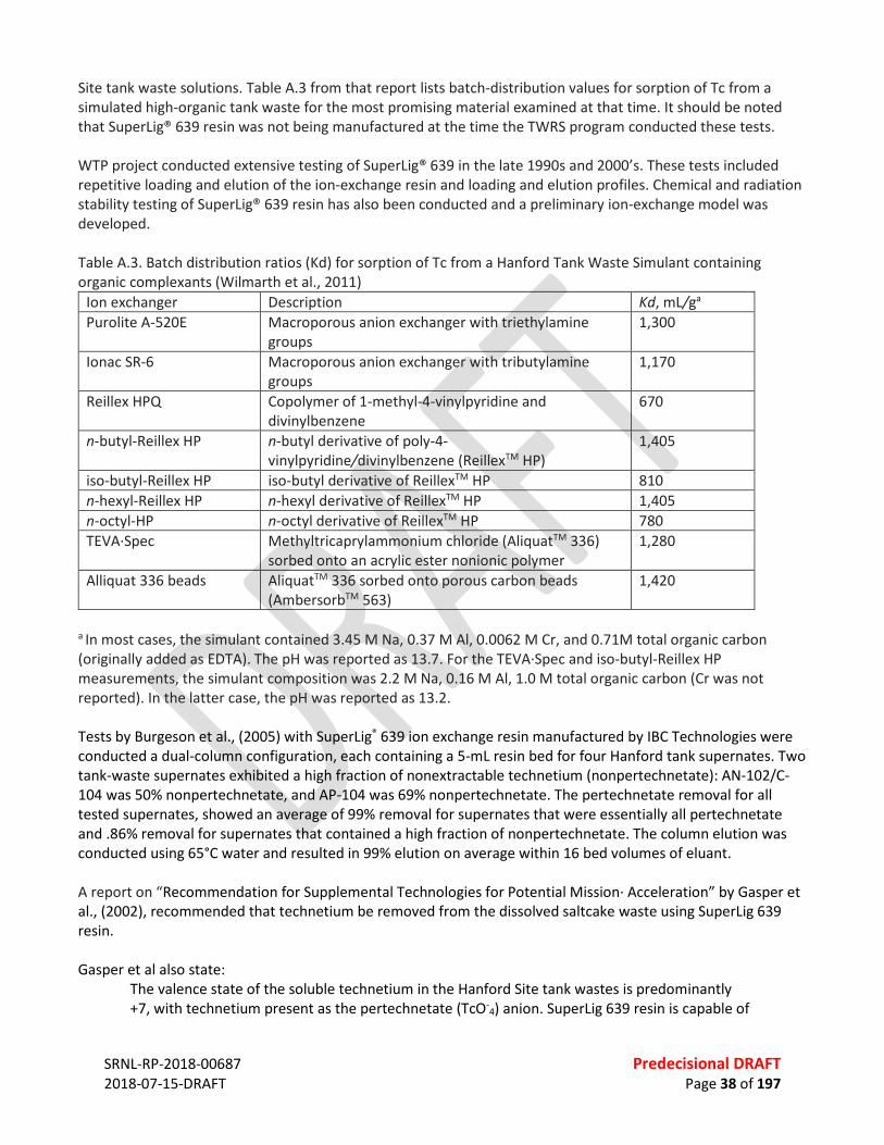
SRNL-RP-2018-00687 Predecisional DRAFT 2018-07-15-DRAFT Page 38 of 197
Site tank waste solutions. Table A.3 from that report lists batch-distribution values for sorption of Tc from a simulated high-organic tank waste for the most promising material examined at that time. It should be noted that SuperLig® 639 resin was not being manufactured at the time the TWRS program conducted these tests. WTP project conducted extensive testing of SuperLig® 639 in the late 1990s and 2000’s. These tests included repetitive loading and elution of the ion-exchange resin and loading and elution profiles. Chemical and radiation stability testing of SuperLig® 639 resin has also been conducted and a preliminary ion-exchange model was developed. Table A.3. Batch distribution ratios (Kd) for sorption of Tc from a Hanford Tank Waste Simulant containing organic complexants (Wilmarth et al., 2011)
Ion exchanger Description Kd, mL/ga Purolite A-520E Macroporous anion exchanger with triethylamine
groups 1,300
Ionac SR-6 Macroporous anion exchanger with tributylamine groups
1,170
Reillex HPQ Copolymer of 1-methyl-4-vinylpyridine and divinylbenzene
670
n-butyl-Reillex HP n-butyl derivative of poly-4-vinylpyridine/divinylbenzene (ReillexTM HP)
1,405
iso-butyl-Reillex HP iso-butyl derivative of ReillexTM HP 810 n-hexyl-Reillex HP n-hexyl derivative of ReillexTM HP 1,405 n-octyl-HP n-octyl derivative of ReillexTM HP 780 TEVA∙Spec Methyltricaprylammonium chloride (AliquatTM 336)
sorbed onto an acrylic ester nonionic polymer 1,280
Alliquat 336 beads AliquatTM 336 sorbed onto porous carbon beads (AmbersorbTM 563)
1,420
a In most cases, the simulant contained 3.45 M Na, 0.37 M Al, 0.0062 M Cr, and 0.71M total organic carbon (originally added as EDTA). The pH was reported as 13.7. For the TEVA∙Spec and iso-butyl-Reillex HP measurements, the simulant composition was 2.2 M Na, 0.16 M Al, 1.0 M total organic carbon (Cr was not reported). In the latter case, the pH was reported as 13.2. Tests by Burgeson et al., (2005) with SuperLig® 639 ion exchange resin manufactured by IBC Technologies were conducted a dual-column configuration, each containing a 5-mL resin bed for four Hanford tank supernates. Two tank-waste supernates exhibited a high fraction of nonextractable technetium (nonpertechnetate): AN-102/C-104 was 50% nonpertechnetate, and AP-104 was 69% nonpertechnetate. The pertechnetate removal for all tested supernates, showed an average of 99% removal for supernates that were essentially all pertechnetate and .86% removal for supernates that contained a high fraction of nonpertechnetate. The column elution was conducted using 65°C water and resulted in 99% elution on average within 16 bed volumes of eluant. A report on “Recommendation for Supplemental Technologies for Potential Mission∙ Acceleration” by Gasper et al., (2002), recommended that technetium be removed from the dissolved saltcake waste using SuperLig 639 resin. Gasper et al also state:
The valence state of the soluble technetium in the Hanford Site tank wastes is predominantly +7, with technetium present as the pertechnetate (TcO-
4) anion. SuperLig 639 resin is capable of
SRNL-RP-2018-00687 Predecisional DRAFT 2018-07-15-DRAFT Page 39 of 197
only removing technetium present as the pertechnetate anion. Batch contact and laboratory-scale ion exchange column tests have indicated that 1 to 5 percent of the technetium present in samples of non-complexed tank wastes is not present as the pertechnetate anion and cannot be extracted using SuperLig 639 resin (WSRC-MS-2001-00573)
But ultimately, it was determined that the 99Tc ion-exchange process would not be implemented in the Hanford WTP because the performance assessment for the LAW disposal site found it to be unnecessary for the safe disposition of the waste (Wilmarth et al., 2011). A.3.3 Iodine Iodine removal from tank waste supernates has not been evaluated to the extent of other radionuclides. Selected laboratory studies were found using silver absorbants, as described below, but these studies represent work at very low TRL levels. If iodine removal is determined to be required, extensive R&D will be required to develop and mature the technology needed. Kim, et al, (2017) have reported on some very recent work on the removal of radioactive iodine from alkaline solutions containing fission products. Their target goal to be practically applicable was to achieve a decontamination factor of at least 200. Their sorbent was an alumina doped material containing with silver nanoparticles (Ag NPs). They were able to achieve iodine removal and recovery efficiencies of 99.7%. A.3.4 LDR A.3.4.1 LDR Organics There are several organic management methods that could be applied. These include Chemical Oxidation (CHOXD) and Recovery of Organics (RORGS). CHOXD could be accomplished with the addition of permanganate or peroxides. RORGS includes the use of carbon adsorption, liquid / liquid extraction and physical phase separation or centrifugation. For this application, the addition of permanganate is proposed. Care must be taken relative to the addition of excess permanganate if subsequent processing steps require the use of chemical reductants to be effective. A.3.4.2 LDR Metals Bhattacharyya et al. (2006) found that sulfide precipitation with Na2S to be highly effective to achieve a high degree of separation of heavy metal cations (Cd, Zn, Cu, and Pb) and of the oxyanions of arsenic and selenium from complex wastewaters. These separations were evaluated with a dilute synthetic mixture and with actual copper smelting plant wastewater. They were able to achieve removals of Cd, Zn, and Cu from the actual wastewaters of greater than 99%, and As and Se removals of 98 and >92%, respectively. Cd, Cu, and Zn concentrations in the range of 0.05 to 0.1 mg/1 were achieved with sulfide precipitation. The use of sulfide precipitation resulted in metal separations and settling rates considerably higher than those obtained with conventional hydroxide precipitation (lime). A.4 APPROACH TO PRETREATMENT The conceptual flow sheet for pretreatment is shown in Figure A.1. It consists of 4 primary treatment blocks, some or all of which can be bypassed based on pretreatment needs for specific batches of feed. The feed enters one of two feed tanks that are used for chemical analysis to determine the pretreatment requirements. In this initial block of the flowsheet, should Sr removal be required it is conducted in this vessel with a preliminary MST strike. If additional removal is required (due to the presence of complexed Sr in the
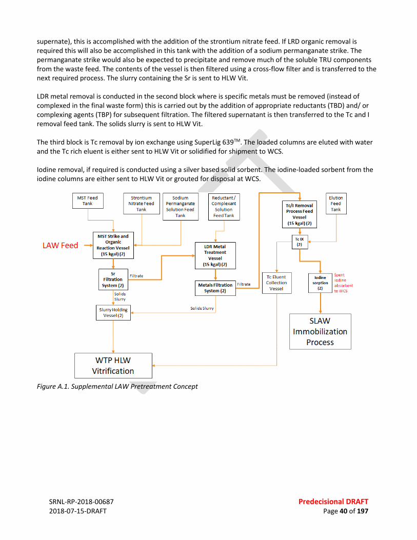
SRNL-RP-2018-00687 Predecisional DRAFT 2018-07-15-DRAFT Page 40 of 197
supernate), this is accomplished with the addition of the strontium nitrate feed. If LRD organic removal is required this will also be accomplished in this tank with the addition of a sodium permanganate strike. The permanganate strike would also be expected to precipitate and remove much of the soluble TRU components from the waste feed. The contents of the vessel is then filtered using a cross-flow filter and is transferred to the next required process. The slurry containing the Sr is sent to HLW Vit. LDR metal removal is conducted in the second block where is specific metals must be removed (instead of complexed in the final waste form) this is carried out by the addition of appropriate reductants (TBD) and/ or complexing agents (TBP) for subsequent filtration. The filtered supernatant is then transferred to the Tc and I removal feed tank. The solids slurry is sent to HLW Vit. The third block is Tc removal by ion exchange using SuperLig 639TM. The loaded columns are eluted with water and the Tc rich eluent is either sent to HLW Vit or solidified for shipment to WCS. Iodine removal, if required is conducted using a silver based solid sorbent. The iodine-loaded sorbent from the iodine columns are either sent to HLW Vit or grouted for disposal at WCS.
Figure A.1. Supplemental LAW Pretreatment Concept
SRNL-RP-2018-00687 Predecisional DRAFT 2018-07-15-DRAFT Page 41 of 197
REFERENCES Sr Pierson, K.L. “Evaluation of the HTWOS Integrated Solubility Model Predictions.”RPP-RPT-53089. December 28, 2012. Washington River Protection Solutions. Richland, Washington. Oji, L.N.; Martin, K.B.; Hobbs, D.T. “Selective Removal of Strontium and Cesium from Simulated Waste Solution with Titanate Ion-exchangers in a Filter Cartridge Configurations-1209 .“ SRNL-STI-2011-00697. February 26, 2012. Savannah River National Laboratory. Aiken, SC. “River Protection Project System Plan.” ORP-11242. Rev 8. 2017. U.S. Department of Energy Office of River Protection. Richland, Washington. L.W. Cree, J.M. Colby, M.S. Fountain, D.W. Nelson, V.C. Nguyen, K.A. Anderson, M.D. Britton, S. Paudel, and M.E. Stone, “One System River Protection Project Integrated Flowsheet, RPP-RPT-57991, Rev 2, 24590-WTP-RPT-MGT-14-023, Rev. 2,” Washington River Protection Solutions (WRPS) One System, Richland, Washington, 2017. N.M. Kocherginsky, Y.K. Zhang, J.W. Stucki, (2002), “D2EHPA based strontium removal from strongly alkaline nuclear waste” Desalination 144 (2002) 267-272. R. Wade Warrant, Jacob G. Reynolds, Michael E. Johnson, (2013) Removal of 90Sr and 241Am from concentrated Hanford chelate-bearing waste by precipitation with strontium nitrate and sodium permanganate, J. Radioanal Nucl Chem, 295:1575-1579, DOI: 10.1007/s10967-012-1948-y. Lætitia H. Delmau , Peter V. Bonnesen , Nancy L. Engle , Tamara J. Haverlock , Frederick V. Sloop Jr. & Bruce A. Moyer, (2006) Combined Extraction of Cesium and Strontium from Alkaline Nitrate Solutions, Solvent Extraction and Ion Exchange, 24:2, 197-217, DOI: 10.1080/07366290500511290. William R. Wilmarth , Gregg J. Lumetta , Michael E. Johnson , Michael R. Poirier , Major C. Thompson , Patricia C. Suggs & Nicholas P. Machara (2011) Review: Waste-Pretreatment Technologies for Remediation of Legacy Defense Nuclear Wastes, Solvent Extraction and Ion Exchange, 29:1, 1-48, DOI: 10.1080/07366299.2011.539134 D. T. Hobbs, M. J. Barnes, R. L. Pulmano, K. M. Marshall, T. B. Edwards, M. G. Bronikowski and S. D. Fink, Strontium and Actinide Separations from High Level Nuclear Waste Solutions using Monosodium Titanate 1. Simulant Testing, Savannah River National Laboratory, Westinghouse WSRC-MS-2005-00266 (2005) D. T. Hobbs, D. T. Herman, M. R. Poirier, Decontamination Factors and Filtration Flux Impact to ARP at Reduced MST Concentration, SRNL-STI-2012-00299, Revision 0, June 2012 Kurt D. Gerdes, Harry D. Harmon, Herbert G. Sutter, Major C. Thompson, John R. Shultz, Sahid C. Smith, “Savannah River Site Salt Waste Processing Facility, Technology Readiness Assessment Report,” July 13, 2009, Prepared by the U.S. Department of Energy, Washington, D.C. Paul Sylvester and Abraham Clearfield, (1999), The Removal of Strontium from Simulated Hanford Tank Wastes Containing Complexants, Separation Science and Technology, 34(13), pp. 2539–2551, DOI:10:1081/SS-100100789.
SRNL-RP-2018-00687 Predecisional DRAFT 2018-07-15-DRAFT Page 42 of 197
Paul Sylvester, Elizabeth A. Behrens, Gina M. Graziano, and Abraham Clearfield, (1999), An Assessment of Inorganic Ion-Exchange Materials for the Removal of Strontium from Simulated Hanford Tank Wastes, Separation Science and Technology, 30:10, 1981-1002, DOI: 10.1081/SS-100100750 Tc D. J. Chaiko , Y. Vojta & M. Takeuchi (1995) Extraction of Technetium From Simulated Hanford Tank Wastes, Separation Science and Technology, 30:7-9, 1123-1137, DOI: 10.1080/01496399508010336. Bruce A. Moyer, Peter V. Bonnesen, Laetitia H. Delmau, Tamara J. Haverlock, Richard A. Sachleben, Ralph A. Leonard, Cliff Conner, and Gregg J. Lumetta, Solvent Extraction of Tc and Cs from Alkaline Nitrate Wastes, ORNL/CP-.l01500, proceedings of the International Solvent Extraction Conference (ISEC ‘99), Barcelona, Spain, July 11-16, 1999 I. E. Burgeson , J. R. Deschane & D. L. Blanchard Jr. (2005) Removal of Technetium from Hanford Tank Waste Supernates, Separation Science and Technology, 40:1-3, 201-223, DOI: 10.1081/SS-200041916. K. A. Gasper, K. D. Boomer, M. E. Johnson, G. W. Reddick, Jr., A. F. Choho, J. S. Garfield, (2002) Recommendation for Supplemental Technologies for Potential Mission Acceleration, CH2MHill Hanford Group, Inc., RPP-11261 Revision 0, July 2002 I Taewoon Kim, Seung-Kon Lee, Suseung Lee, Jun Sig Lee, Sang Wook Kim, Development of silver nanoparticle–doped adsorbents for the separation and recovery of radioactive iodine from alkaline solutions, Applied Radiation and Isotopes 129 (2017) 215–221, http://dx.doi.org/10.1016/j.apradiso.2017.07.033. LDR D. Bhattacharyya, A. B. Jumawan Jr. & R. B. Grieves (2006) Separation of Toxic Heavy Metals by Sulfide Precipitation, Separation Science and Technology, 14:5, 441-452, DOI: 10.1080/01496397908058096.

SRNL-RP-2018-00687 Predecisional DRAFT 2018-07-15-DRAFT Page 43 of 197
APPENDIX B. EXPANDED DISCUSSION – VITRIFICATION B.1 TECHNOLOGY OVERVIEW Supplemental Low Activity Waste (SLAW) could be treated via vitrification, using an additional vitrification facility that will have similar attributes to the Waste Treatment and Immobilization Plant (WTP) LAW facility. This SLAW facility will receive treated supernate from the WTP Pretreatment facility (PT) and the LAW Pretreatment System (LAWPS).39 Incoming feed is sampled and a series of glass property models are used to determine the required amount of glass forming chemicals (GFCs), sugar (reductant), and rheological control water to add to the waste. Joule-heated ceramic-lined melters will convert the slurry of waste and GFCs into a vitrified waste form.40 The GFCs are weighed and blended in a cold feed area per the recipe calculated using the glass property models. The blended GFCs are then transferred to the SLAW facility, weighed, and mixed with the waste to form melter feed slurry. The slurry is fed to the melter where the feed is heated. The resulting glass is poured into containers where it solidifies into an immobilized LAW glass. Water, volatile components, and portions of the semi-volatile components are partitioned to the melter offgas system. The melter offgas treatment system will condense the water and volatile components as well as remove entrained particulate from the offgas.41 The resulting condensate is collected and transferred to an Effluent Management Facility (EMF). Additional treatment of the offgas is performed to remove mercury, iodine, acid gases, any remaining particulate, and any residual organics. The EMF will receive liquid effluents from the SLAW melters.42 These effluents will be evaporated and the overheads are transferred to the Liquid Effluent Receipt Facility/Effluent Treatment Facility (LERF/ETF) for further treatment. The concentrate will be and recycled to the front end of the SLAW process. B.2 DESCRIPTIONS OF FLOW SHEETS The baseline vitrification flowsheet mimics the Immobilized Low Activity Waste (ILAW) vitrification flowsheet with lessons learned incorporated into vessel sizing (to provide relief to sample analysis turnaround time) and select offgas components. Alternative flowsheets were also considered in this assessment. The baseline and alternative flowsheets are described in the sections that follow.
B.2.1 Baseline
The baseline flowsheet for this evaluation consists of 1) melter feed systems that include receipt and handing of treated waste from PT and LAWPS, receipt of concentrated effluent from EMF, as well as GFC handling and blending; 2) four melters; 3) four offgas trains (each with primary and secondary systems); 4) an EMF (the EMF currently under construction is sized to support LAWPS only, not SLAW); 5) and a glass container handing, decontamination, and temporary lag storage facility. Each of these unit operations is outlined in the figure below and described in the following subsections.
39 “LAW Melter Feed Process (LFP) and Concentrate Receipt Process (LCP) System Design Description,” Bechtel National
Incorporated, River Protection Project, Waste Treatment Plant, Richland, Washington, 2017. 40 “System Description for the System LMP, Low Activity Waste Melter,” Bechtel National Incorporated, River Protection
Project, Waste Treatment Plant, Richland, Washington, 2010. 41 “LAW Primary Offgas (LOP) and Secondary Offgas/Vessel Vent (LVP) System Design Description,” Bechtel National
Incorporated, River Protection Project, Waste Treatment Plant, Richland, Washington, 2016. 42 “WTP Direct Feed LAW Integrated Processing Strategy Description,” Bechtel National Incorporated, River Protection
Project, Waste Treatment Plant, Richland, Washington, 2017.
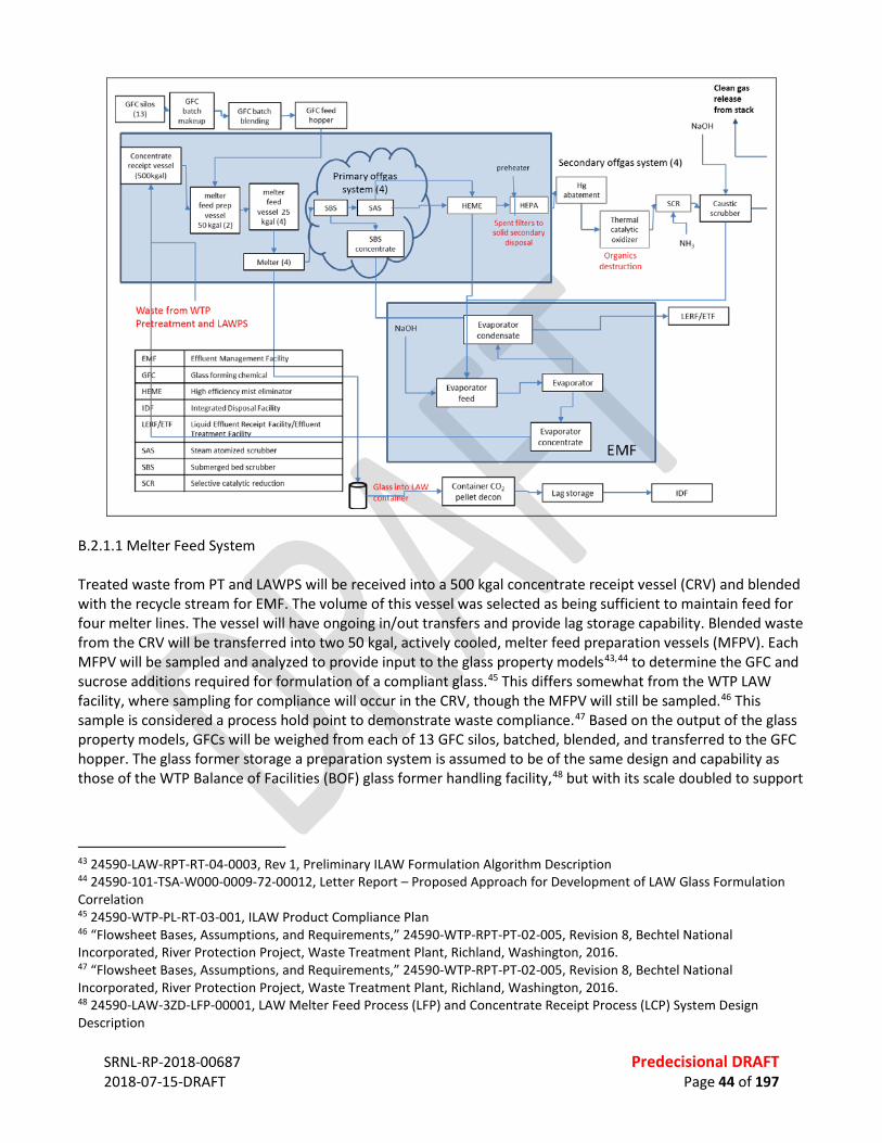
SRNL-RP-2018-00687 Predecisional DRAFT 2018-07-15-DRAFT Page 44 of 197
B.2.1.1 Melter Feed System Treated waste from PT and LAWPS will be received into a 500 kgal concentrate receipt vessel (CRV) and blended with the recycle stream for EMF. The volume of this vessel was selected as being sufficient to maintain feed for four melter lines. The vessel will have ongoing in/out transfers and provide lag storage capability. Blended waste from the CRV will be transferred into two 50 kgal, actively cooled, melter feed preparation vessels (MFPV). Each MFPV will be sampled and analyzed to provide input to the glass property models43,44 to determine the GFC and sucrose additions required for formulation of a compliant glass.45 This differs somewhat from the WTP LAW facility, where sampling for compliance will occur in the CRV, though the MFPV will still be sampled.46 This sample is considered a process hold point to demonstrate waste compliance.47 Based on the output of the glass property models, GFCs will be weighed from each of 13 GFC silos, batched, blended, and transferred to the GFC hopper. The glass former storage a preparation system is assumed to be of the same design and capability as those of the WTP Balance of Facilities (BOF) glass former handling facility,48 but with its scale doubled to support
43 24590-LAW-RPT-RT-04-0003, Rev 1, Preliminary ILAW Formulation Algorithm Description 44 24590-101-TSA-W000-0009-72-00012, Letter Report – Proposed Approach for Development of LAW Glass Formulation Correlation 45 24590-WTP-PL-RT-03-001, ILAW Product Compliance Plan 46 “Flowsheet Bases, Assumptions, and Requirements,” 24590-WTP-RPT-PT-02-005, Revision 8, Bechtel National Incorporated, River Protection Project, Waste Treatment Plant, Richland, Washington, 2016. 47 “Flowsheet Bases, Assumptions, and Requirements,” 24590-WTP-RPT-PT-02-005, Revision 8, Bechtel National Incorporated, River Protection Project, Waste Treatment Plant, Richland, Washington, 2016. 48 24590-LAW-3ZD-LFP-00001, LAW Melter Feed Process (LFP) and Concentrate Receipt Process (LCP) System Design Description

SRNL-RP-2018-00687 Predecisional DRAFT 2018-07-15-DRAFT Page 45 of 197
the operation of four melters. The GFCs, their mineral sources,49 and acceptable levels of impurities50 are assumed to be the same as those specified for the WTP LAW operation. Note that a risk exists regarding future availability of the selected mineral sources of the GFCsThe blended GFCs will be wetted to prevent dusting51 and fed to the MFPV. Dilution water massis added to the feed if needed to meet melter feed rheological requirements,52 with dilution water added as needed. After the GFCs and treated waste are blended in the MFPV, the slurry is transferred to one of the four 25 kgal, actively cooled, melter feed vessels (MFV). One MFV will feed each melter. Each MFV will have capabilities for mechanical agitation to maintain suspension of the GFC solids, pumps for transfer of blended feed to the melter, and pumps for return of the feed to the MFV in case of a melter shutdown. All unit operations of the melter feed system must be operational to maintain continuous feed to the melters as required to produce 15 metric tons of glass (MTG) per day per melter. The design of each unit operation is generally assumed to be equivalent to the corresponding unit operations of the WTP LAW melter feed process.53 B.2.1.2 Melters Melter feed slurry from the MFVs will be fed to each of the four identical melters. The melters are joule-heated, refractory ceramic-lined vessels heated to ~1150 °C to vitrify the waste, and are assumed to be of the same design as the WTP LAW melters.54 The outer surfaces of the melter and pour chambers are actively cooled. Glass temperatures are measured via submerged thermocouples and controlled by adjusting the electrode power. Each melter can produce 15 metric tons of glass per day.46 The glass must meet melter compatibility requirements including viscosity, electrical conductivity, and liquidus temperature.55 These properties are controlled via glass formulation as dictated by the glass property models.43,44 At steady-state, the melter operation (feed rate, melter power, bubbling rate, etc.) is controlled to maintain a cold cap of partially reacted feed on top of the pool of molten glass. Additional feed enters from side nozzles at the top of the melter. The cold cap assists with retention of volatile and semi-volatile components in the ILAW glass product. A range of chemical reactions occur as the feed is converted to glass in the cold cap, and water from the feed slurry is evaporated. Multiple compressed air bubblers are operated in the melter to agitate the molten glass pool, improve temperature uniformity, and transfer additional heat to the cold cap. The operation of the melter to maintain the cold cap represents a fine balance between under-feeding the melter which would allow the cold cap to burn off and over-feeding the melter which would allow excessive amounts of material to accumulate in the cold cap. This balance will be maintained in the LAW melter systems primarily through control of the feed rate and bubbling rate. The need to maintain a cold cap to aid in retention of semi-volatile species limits the turn-down ability of the melters as feed rates must be kept high enough to form a cold cap. It should be noted that entrainment of feed into the offgas is impacted by the feed and bubbling rates, with higher entrainment expected as feed or bubbling rate are increased.
49 R.F. Schumacher, “Characterization of HLW and Law Glass Formers,” Westinghouse Savannah River Company, Aiken, SC, WSRC-TR-2002-00282, Rev. 1, 2003. 50 SCT-M0SRLE60-00-175-01, Final Report - Characterization of HLW and LAW Glass Formers 51 CCN 077705, Evaluation of Wetting Agents for Glass Former Dusting Control (RTC 170) 52 24590-WTP-RPT-PO-03-007, LAW Melter Feed Rheology Assessment 53 24590-WTP-RPT-PT-02-005, Rev 8, Flowsheet Bases, Assumptions, and Requirements 54 24590-101-TSA-W000-0010-409-359, LAW Melter System Description 55 24590-LAW-3PS-AE00-T0001, Engineering Specification for Low Activity Waste Melters
SRNL-RP-2018-00687 Predecisional DRAFT 2018-07-15-DRAFT Page 46 of 197
When the feed to the melter is stopped, the cold cap is burned off and any semi-volatile species in the melt pool will gradually vaporize into the offgas stream as turning the melter off (or significantly reducing the temperature in the melter) could allow crystallive formations to form that would require replacement of the melter. The resulting glass exits the melter via one of two discharge chambers. An air lift in a riser displaces the glass up into a trough where it will gravity drain into a stainless steel LAW container. Electrical resistance heaters maintain sufficient temperature for the glass to flow within the discharge chambers. The glass pouring rate is higher than the rate of feed conversion to glass; thus, pouring occurs in incremental steps, alternating between the two chambers. The higher pouring rate also facilitates flow of glass to the periphery of the containers as they are filled. The glass level in the melter is monitored using pneumatic probes, and the level dictates the starting and stopping points of the pouring cycles. Approximately five pouring cycles are needed to fill each container. The design life of a melter is five years.46 Bubbler replacement is expected to be the most frequent maintenance requirement,46 with each bubbler having an estimated life span of 26 weeks.56,57 B.2.1.3 Offgas Trains The offgas systems treat the gases from the melters and vessels such that they meet air discharge permitting requirements. The offgas system design assumed for this evaluation is mostly similar to that for WTP LAW.46 The difference is the use of a steam atomized scrubber (SAS) and high efficiency mist eliminator (HEME) in place of a wet electrostatic precipitator (WESP). Assumptions regarding the types and quantities of offgas species, decontamination factors, particulate concentrations, and gas generation rates are equivalent to those for the WTP LAW facility.46
The offgas generated from each of the melters exits via a film cooler and enters the primary offgas train. The temperature of the offgas is reduced in the film cooler to reduce the amount of condensation in the system piping. A backup film cooler is available should the primary system fail. The cooled offgas will then be condensed in a submerged bed scrubber (SBS). The SBS also removes entrained particulates from the gas stream. As the offgas is condensed, the concentrate overflow from the SBS will be collected in a condensate vessel and transferred to the EMF evaporator feed tank. The offgas next passes through a SAS to remove additional particulates. Condensed liquids from the SAS will be recycled to support the HEME that will remove soluble components and protect the downstream high efficiency particulate air (HEPA) filter from moisture. The offgas will then enter the secondary offgas train. Vessel ventilation from the melter feed system joins the secondary offgas train at this point. The secondary offgas train is assumed to be identical to that designed for WTP LAW, and is described in further detail elsewhere.58 In short, HEPA filters will remove any remaining particulate material from the offgas. A preheater prior to the filters reduces the relative humidity of the gas to prevent condensation in the filters. Spent HEPA filters will be transferred to the Central Waste Complex for encapsulation as Secondary Solid Waste prior to disposal at the IDF.59 The resulting offgas will exit the radioactive containment area and will be treated to remove mercury, acid gas, and halides using activated carbon adsorbers. The gas stream is then reheated so that any remaining organics can be destroyed using thermal catalytic oxidation. The NOx will be reduced to nitrogen with ammonia using selective catalytic
56 24590-101-TSA-W000-0009-23-10, Rev 00C, Report – RPP Pilot Melter Bubbler Life Extension Test Results Report 57 CCN 103214, Update to the LAW Reliability, Availability, and Maintainability (RAM) Data for the LCP, LFP, LMP, GFR, LOP, and LVP Systems 58 24590-LAW-3YD-LOP-00001, Rev 3 59 “River Protection Project System Plan,” ORP-11242, Revision 8, DOE Office of River Protection, Richland, Washington,
2017.

SRNL-RP-2018-00687 Predecisional DRAFT 2018-07-15-DRAFT Page 47 of 197
reduction, and finally, any remaining acid gases will be neutralized in a caustic scrubber. The caustic scrubber solution will be transferred to the LERF/ETF. Offgas exiting the caustic scrubber is drawn through a set of exhausters, which maintain the motive force for offgas movement, and is released to the stack. B.2.1.4 Effluent Management Facility The WTP Effluent Management Facility (EMF) to support LAWPS is currently in design. The EMF to support SLAW is expected to handle twice the capacity of the WTP EMF. The SLAW EMF will receive effluents from the four offgas trains associated with the four melters, from line flushing and draining, and from various equipment decontamination operations within the SLAW facility. The effluents will be concentrated in the EMF evaporator. Anti-foam and caustic additions are available to control process chemistry. Concentrate will be recycled back into the CRV for immobilization and condensate will be transferred to the LERF/ETF for additional treatment. It is assumed that LERF/ETF has sufficient capability to process condensate from the SLAW EMF. For each gallon of waste in the CRV, the process produces ~ 0.5 gallons of glass. The current ILAW flowsheet is calculated to produce ~1.5 gallons of offgas effluent for each gallon of waste in the CRV, not including flushes in the WTP system.46 For comparison, the SRS Defense Waste Processing Facility (DWPF) returns 5 gallons of liquid to the tank farm for each gallon of sludge vitrified.60 Therefore, there is a risk that the current ILAW flowsheet underestimates the volume of liquid secondary waste that will be produced. B.2.1.5 Glass Containers The glass disposal containers are stainless steel, 4 ft in diameter and 7.5 ft tall (24590-LAW-M0-LRH-00004002, LAW Vitrification System LRH Product Container Weldment Details) right circular cylinders.46 Systems for the mechanical handling of canisters, from receipt of empty canisters into the facility to export of finished canisters for burial, are assumed to be the same as those designed for WTP LAW.61,62,63,64
The vitrified waste is poured into the containers, which hold ~6 metric tons (~2,000 gal) of vitrified waste.46 The containers are cooled, inspected for fill height (if fill height is not ≥ 90%, inert fill is added), and sealed. The sealed containers are decontaminated by CO2 pellet blasting to meet requirements for minimal removable contamination. This system is assumed to be of the same design as that for WTP LAW.46,65 The gas and particulate stream is drawn through HEPA filters, and then exhausts to the building ventilation system. Spent HEPA filters will be transferred to the Central Waste Complex for encapsulation as Secondary Solid Waste prior to disposal at the IDF.66 Finished containers are stored until transfer to the IDF.
60 “DWPF Recycle Evaporator Flowsheet Evaluation (U),” WSRC-TR-2005-00226, Revision 1, Savannah River National
Laboratory, Aiken, South Carolina, 2005. 61 24590-LAW-3ZD-LRH-00001, Rev 0, LAW Container Receipt Handling (LRH) System Design Description 62 24590-LAW-3ZD-LPH-00001, Rev 0, LAW Container Pour Handling (LPH) System Design Description 63 24590-LAW-3ZD-LFH-00001, Rev 0, LAW Container Finishing Handling (LFH) System Design Description 64 24590-LAW-3ZD-LEH-00001, Rev 0, LAW Container Export Handling (LEH) System Design Description 65 24590-LAW-M5-V17T-00013, Process Flow Diagram LAW Vitrification Container Decontamination (System CDG) 66 “River Protection Project System Plan,” ORP-11242, Revision 8, DOE Office of River Protection, Richland, Washington,
2017.
SRNL-RP-2018-00687 Predecisional DRAFT 2018-07-15-DRAFT Page 48 of 197
B.2.2 ALTERNATIVE FLOW SHEETS B.2.2.1 Vitrification with Offsite Disposal of Secondary Waste This alternative flowsheet is similar to SLAW immobilization via vitrification, with the difference being that the EMF evaporator concentrate will be immobilized in a grout waste form and shipped offsite for disposal, rather than being recycled back to the CRV at the front end of the vitrification process. Breaking the recycle loop would address the challenge of capturing volatile and semi-volatile contaminants of concern in the glass waste form, reduce the burden on the liquid secondary waste processing facilities, and reduce the source term for ILAW in the Hanford IDF. Implementation of the alternative flowsheet will require the design and construction of a facility for immobilizing liquid secondary waste in grout. DOE experience with similar facilities would be leveraged for this purpose. A grout waste form production facility is relatively simple, with four main unit operations: raw materials receipt, storage, and blending; mixing of raw materials with the liquid waste stream; pouring of the grout slurry into containers; and curing and shipping of the filled containers. It is assumed that secondary waste immobilized in grout would be acceptable at an offsite disposal facility, such as the Waste Control Specialists facility in far west Texas. It is also assumed that secondary waste immobilized in grout would meet shipping regulations for transportation to the disposal site. B.2.2.2 Next Generation Melters/Carbon Steel Containers The first alternative flowsheet will maintain the waste feed preparation systems and methodology of the baseline flowsheet. The four melters in the baseline flowsheet will be replaced by two, larger, next generation melters (NGM). The melters will have a larger surface area and thicker refractories than the WTP LAW melters. The melters will operate at a higher temperature (within the design range of the WTP LAW melters), leveraging the increase in refractory to maintain melter life at the high temperature. Each melter will have a dedicated primary offgas train and share a secondary offgas train. A redundant primary and secondary offgas train will be available to maintain production during offgas train maintenance. The melters will utilize both of the pour spouts associated with the melters (WTP LAW melters have two pour spouts but can only pour from one at a time). It is expected that the two NGMs can meet the production rate of the four WTP LAW melters. Vitrified waste will be poured into carbon steel containers that meet the performance requirements of the stainless steel containers in the baseline flowsheet. B.2.2.3 Bulk Vitrification For Bulk Vitrification, the SLAW facility will receive treated supernate from the WTP PT and LAWPS.39 Pre-blended GFCs and sugar or cellulose (reductant) are added to the waste. The waste and additives are blended and dried into melter feed. The dried feed is added to the melt container as melting occurs. Heating is provided via graphite electrodes that transfer the alternating electrical current through the dried waste.67 Offgas from the melting process is captured by a hood sealed to the container and will be treated similarly to the offgas train in the vitrification flowsheet described earlier.
67 “Bulk Vitrification Technology for the Treatment and Immobilization of Low-Activity Waste,” RPP-48703, Revision 0,
Washington River Protection Solutions, Richland, Washington, 2011.

SRNL-RP-2018-00687 Predecisional DRAFT 2018-07-15-DRAFT Page 49 of 197
B.3 ASSUMPTIONS The following assumptions are made regarding the baseline vitrification flow sheet: • Tank waste retrieval and pretreatment via WTP PT and LAWPS are fast enough to maintain continuous feed
to four SLAW vitrification lines • The CRV volume of 500 kgal is sufficient to provide continuous feed to four SLAW vitrification lines • The existing WTP LAB has sufficient capacity to support sampling and analysis of the four MFPVs • The WTP LAW Control Room has sufficient reserve capacity to support four SLAW vitrification lines • The Hanford IDF has sufficient capacity for disposal of the ILAW containers produced by SLAW vitrification • The Hanford IDF has sufficient capacity for disposal of encapsulated HEPA filters from SLAW vitrification,
including those from the offgas trains and from container decontamination • Plant availability and maintenance times are equivalent to those assumed for WTP LAW vitrification • Spent carbon beds, spent catalyst from the TCO, and spent catalyst from the SCR are disposed of in the
Hanford IDF as solid secondary waste • The EMF to support LAWPS is successfully designed, operated, and constructed, to serve as a basis for the
larger EMF assumed for SLAW vitrification • The Hanford LERF/ETF has sufficient capability to process condensate from the SLAW EMF.
The following assumptions are made regarding the alternative flowsheet for vitrification with offsite disposal of secondary waste: • Appropriate raw materials are available in the Hanford area for producing a grout waste form with the
secondary waste • Approvals can be obtained for transportation and offsite disposal of secondary waste immobilized in grout
B.4 RISKS Risks associated with the baseline vitrification flow sheet include: • Significant changes to the WTP LAW unit operations (from feed preparation through offgas treatment)
during startup and initial hot operations would directly impact SLAW immobilization via vitrification • The current assumptions for LAW WTP facility availability are higher than achievable in actual operation • Availability of the specified GFCs may change before facility operation begins • The radionuclide DFs of the full scale melter are lower than expected, increasing the burden on EMF and
recycle • The impact of melter idling on secondary waste volume generation is not considered in current integrated
flow-sheet models • The current ILAW flowsheet underestimates the volume of liquid secondary waste that will be produced
Risks associated with the alternative flowsheet for vitrification with offsite disposal of secondary waste include: • Appropriate raw materials are not available in the Hanford area for producing a grout waste form • Approval is not obtained for offsite transportation of secondary waste immobilized in grout • An offsite disposal facility is no longer available B.5 BENEFITS AND COST ESTIMATE (PROJECT AND LIFECYCLE) B.6 SCHEDULE B.7 REGULATORY COMPLIANCE (PROCESS, TRANSPORT, DISPOSAL/WASTE FORM) B.8 OBSTACLES

SRNL-RP-2018-00687 Predecisional DRAFT 2018-07-15-DRAFT Page 50 of 197
APPENDIX C. EXPANDED DISCUSSION – STEAM REFORMING INTRODUCTION Fluidized bed steam reforming (FBSR) has been researched, developed, and used commercially for over two decades for processing low level radioactive wastes. The commercial Erwin ResinSolutions Facility (formerly Studsvik Processing Facility) in Erwin, TN began operation in the late 1990’s to treat radioactive wastes such as ion exchange resins with contact radiation levels of up to 100 R/hr (Mason 1999, http://www.energysolutions.com/waste-processing/erwin-resin-processing/). Small-scale FBSR testing for treating liquid, highly acidic, radioactive sodium bearing waste (SBW) stored at the Idaho National Laboratory (INL) were also initiated in 1999. FBSR research and demonstration tests have been expanded since then from a nominal 3.5 in. diameter to most recent 24-in. diameter tests at Hazen Research Incorporated (Hazen or HRI) using non-radioactive simulants, and also bench-scale tests at Savannah River National Laboratory (SRNL) using actual radioactive Hanford LAW and radioactive-shimmed simulants. The properties and performance of the FBSR product depends on the design and operating conditions of the FBSR process. If the goal of the FBSR process is to primarily evaporate water, destroy nitrates, or destroy organics, without the need to produce a durable, solid waste form to contain the solid residue, then the FBSR may be operated to produce a solid product that is not durable, leach resistant solid waste forms. If the goal of the FBSR process is to accomplish all of the above and also convert the solid residue into a durable, leach-resistant waste form, then the FBSR process can be designed and operated to accomplish all those goals. Durable, Leach-Resistant Mineralized Na-Al-Si Waste Form Selected FBSR research and development programs for treating various liquid radioactive wastes performed between 2001 and 2011 are summarized in Table C-1 (from the report for the multi-laboratory SRNL, Oak Ridge National Laboratory [ORNL], Pacific Northwest National Laboratory [PNNL], and Washington River Protection Solutions [WRPS) mineral waste form performance test program downselection studies [Jantzen 2015a]). This table does not include all FBSR demonstrations between those years, but it focuses on those programs intended to produce a durable, leach-resistant mineralized Na-Al-Si waste form, designed to be “as good as glass,” from Hanford LAW. Studsvik, Inc. has also continued to develop and demonstrate steam reforming for various world-wide customers including ORANO (formerly AREVA). Various additional references for this table and for other tests include: Marshall 2003, Olson 2004a, Olson 2004b, Soelberg 2004a, Soelberg 2004b, Studsvik 2004a, Studsvik 2004b, TTT 2007a, TTT 2009a, and TTT 2009b. The durable, leach-resistant mineralized Na-Al-Si waste form is the intended waste form for the FBSR concept that would be Hanford SLAW. Sodium Carbonate-Based Product Steam reforming has also been developed and demonstrated to produce a granular carbonate-based product; that, while treated to destroy nitrates and organics and eliminate the liquid component of INL’s SBW or Savannah River Site’s Tank 48 waste, is not intended to be leach-resistant. In such cases, the intended permanent disposal site does not require the solidified product to perform “as good as glass.” Indeed, the carbonate product is quite (typically over 50 wt%) soluble in water.

SR
NL-
RP-2
018-
0068
7
Pr
edec
isio
nal D
RAFT
20
18-0
7-15
-DRA
FT
Pa
ge 5
1 of
197
Tabl
e C-
1 Su
mm
ary
of se
lect
ed F
BSR
rese
arch
and
dem
onst
ratio
n pr
ogra
ms (
adap
ted
from
SRN
L-O
RNL-
PNNL
-WRP
S do
wns
elec
t (Ja
ntze
n [Ja
ntze
n 20
15a]
).
Faci
lity
Scal
e Ra
dioa
ctiv
e or
N
on-
Radi
oact
ive?
FBSR
Bed
Di
amet
er,
inch
es
Exte
rnal
ly o
r Au
toth
erm
aly
Heat
ed?
Dual
or
Sing
le
Refo
rmer
Redu
ctan
t
Cata
lyst
? W
aste
INL
1999
-200
2 Be
nch-
scal
e
Non
-Rad
ioac
tive
3 Ex
tern
al
Sing
le
Vario
us
coal
s N
o IN
L SB
W
Stud
svik
-Be
chte
l 200
1 Pi
lot-
scal
e 6
inte
rnal
Si
ngle
Ch
arco
al
No
Hanf
ord
LAW
INL
2001
-200
2 Pi
lot
6 Ex
tern
al a
nd
auto
ther
mal
Si
ngle
BB
ch
arco
al
Yes
AN-1
07
SAIC
-STA
R 20
03-2
004
Pilo
t 6
Exte
rnal
and
au
toth
erm
al
Sing
le
BB
char
coal
N
o IN
L SB
W
Rass
at L
AW
TTT
ESTD
20
06
Engi
neer
ing
15
Auto
ther
mal
Du
al
Best
ac
coal
Ye
s IN
L SB
W
TTT
ESTD
20
08
Engi
neer
ing
15
Auto
ther
mal
Du
al
Best
ac
coal
Ye
s W
TP-S
W
(Mod
ule
A)
SRN
L BS
R 20
09
Benc
h-sc
ale
Radi
oact
ive
and
Non
-Rad
ioac
tive
2.75
Ex
tern
al a
nd
auto
ther
mal
Du
al
Best
ac
coal
N
o W
TP-S
W
(Mod
ule
A)
STAR
T O
F TH
E DO
E-EM
WFQ
PRO
GRA
M
TTT
ESTD
200
8 En
gine
erin
g N
on-R
adio
activ
e 15
Au
toth
erm
al
Dual
Be
stac
co
al
Yes
Rass
at L
AW
(Mod
ule
B)
SRN
L BS
R 20
10-2
011
Benc
h-sc
ale
Radi
oact
ive
and
Non
-Rad
ioac
tive
2.75
Ex
tern
al a
nd
auto
ther
mal
Du
al
Best
ac
coal
Som
e te
sts
Rass
at L
AW
(Mod
ule
B)
SX-1
05
(Mod
ule
C)
AN-1
03 (M
odul
e D)
SR
NL
BSR
2011
Be
nch-
scal
e N
on-R
adio
activ
e Ye
s AZ
-101
/ AZ-
102
(Mod
ule
E)
Pilo
t Tes
ting
Supp
ort f
or IW
TU
TTT
ESTD
20
16+
Engi
neer
ing
Non
-Rad
ioac
tive
12 a
nd 1
8 Au
toth
erm
al
Sing
le
Best
ac
coal
N
o IN
L SB
W
WTP
-SW
= W
TP S
econ
dary
Was
te; t
este
d to
show
that
FBS
R ca
n re
tain
Tc
from
the
mel
ter o
ff-ga
s. Ra
ssat
LAW
was
mad
e by
shim
min
g ac
tual
SRS
LAW
to c
ompo
sitio
n sim
ilar t
o Ra
ssat
67
tank
ble
nd.
The
SX-1
05, A
N-1
03, a
nd A
X-10
1/AZ
-102
ble
nds w
ere
actu
al H
anfo
rd L
AW.
SRNL-RP-2018-00687 Predecisional DRAFT 2018-07-15-DRAFT Page 52 of 197
The full-scale Integrated Waste Treatment Unit (IWTU) was designed and built at INL to treat the liquid SBW presently stored in tanks at INL, and produce a sodium carbonate-based product. The IWTU is currently in non-radioactive startup operations to make it ready to begin SBW treatment. The fluidized bed IWTU system is similar in some ways to the prior fluidized bed calcination facilities at INL – the Waste Calcining Facility (WCF) and New Waste Calcining Facility (NWCF) that had been used since the 1980’s to solidify high level waste (HLW) and SBW at the INL. The NWCF was replaced by the IWTU largely because (a) the (at the time) new Hazardous Waste Combustor (HWC) Maximum Achievable Control Technology (MACT) standards reduced regulatory limits for mercury, CO, and total hydrocarbons to levels below what the NWCF could achieve without modification, and (b) the NWCF emitted NOx in large enough concentrations that, while still regulatorily compliant, caused a highly visible brown plume that raised public concern and dissent to continued NWCF operation (Boardman 2001, Soelberg 2003). The IWTU is designed to easily comply with the HWC MACT standards and also destroy NOx to levels both regulatorily compliant and low enough to prevent the visible brown plume (TTT 2007b). The IWTU is a first-of-a-kind, full-scale demonstration of steam reforming technology and processes. Much of the ITWU system and subsystems including waste feed, the steam reformer vessel referred to as the Denitration Mineralizing Reformer [DMR], off-gas system components, and solids handling processes are representative full-scale demonstrations of the same features of the FBSR system conceived for treating Hanford SLAW. However, the highly soluble carbonate product does not represent the intended Na-Al-Si waste form that can be produced from the Hanford SLAW. Any implication that the Na-Al-Si waste form is highly soluble, because the IWTU carbonate product is highly soluble, is not correct. WHAT IS MINERALIZING FLUIDIZED BED STEAM REFORMING Steam reforming is broadly defined as a process in which superheated steam is used to crack and pyrolyze organic constituents, which in turn generates more free radicals that accelerate hydrocarbon compound decomposition and reactions with other solid and gaseous constituents. Radioactive liquid solutions such as Hanford LAW that contain dissolved nitrate/nitrite salts, mineral acids, alkali hydroxides, or residual organic solvents are chief candidates for steam reforming. Figure C-1 summarizes chemical reactions that occur when a radioactive, nitrate-bearing liquid waste is atomized into the Denitration Mineralizing Reformer (DMR) vessel of the steam reforming process. The DMR contains a bed of particles that are the right size and density to be continually fluidized by a superheated flow of steam that enters at the bottom of the vessel. The steam is superheated to nominally 500-600oC prior to entering the DMR. DMR Inputs and Outputs Coal and oxygen are fed into the DMR where they react (also with some of the steam) to (a) heat the DMR to the target mineralizing operating temperature of around 725oC, and (b) produce H2 and other reduced gas species such as CO and CH4 that react with the nitrates and nitrites in the waste feed, converting the nitrates and nitrites to N2 and H2O. The coal and coal char can also react heterogeneously with some of the feed nitrates/NOx. The coal and O2 feedrates are metered so that the overall DMR process is stoichiometrically reducing to destroy hazardous feed organics and achieve efficient NOx destruction on the order of 95-99%, with small residual amounts of reduced gas species including H2, CO, and hydrocarbon gas species in the DMR outlet gas.

SRNL-RP-2018-00687 Predecisional DRAFT 2018-07-15-DRAFT Page 53 of 197
Figure C-1 Simplified three-part DMR chemistry model: coal reactions, waste feed conversion, and gas-phase reactions.
A large variety of heterogeneous solid-gas and homogeneous gas-phase reactions occur during fluidized bed steam reforming (Soelberg 2004a and the SRNL-ORNL-PNNL-WRPS downselect [Jantzen 2015a]). The key ones are shown in Table C-2. This list is not exhaustive, nor does it show the carbon, hydrogen, hydroxyl and other ions and free-radical intermediate species, that along with the high mass and heat transfer rates and high gas-particle surface areas, make fluidized beds so effective at fast and efficient chemical reactions.
As a result of these heat generating, NOx destruction, and organics pyrolysis reactions, the DMR outlet gas contains nominally on the order of: • 65-70 vol% H2O • 10-15 vol% CO2 • 10-15 vol% N2 • 1-3 vol% H2 • 1 vol% CO • 0.5-1 vol% NOx • <0.1 vol% hydrocarbons • <100 ppmv other gas species such as SO2 and halogen gases

SRNL-RP-2018-00687 Predecisional DRAFT 2018-07-15-DRAFT Page 54 of 197
Table C-2. Heterogeneous solid-gas and homogeneous gas-phase reactions that occur under stoichiometrically reducing conditions during fluidized bed steam reforming.
C + O2 → CO2 C + ½O2 → CO Coal oxidation reactions for autothermal heat generation
C + H2O → CO + H2 CO + H2O → CO2 + H2
Water gas and water gas shift reactions that produce H2, effective in NOx destruction
NO3 + 2C → NO + 2CO NO3 + C → NO2 + CO 2NO3 + 4C → N2 + 2CO + 2CO2 2NO2 + 3C → N2 + 2CO + CO2 2NO + 2C → N2 + 2CO 2NO + 2CO → N2 + 2CO2 2NO + 2H2 → N2 + 2H2O
Nitrate and NOx destruction reactions
CxHy + xH2O → xCO + (x+y/2)H2 CxHy + (2x-y/2)H2 → xCH4
Waste organics pyrolysis reactions
2CO + O2 → 2CO2 2H2 + O2 → 2H2O CH4 + 2O2 → CO2 + 2H2O
Other CO, H2, and hydrocarbon oxidation reactions
The DMR stoichiometry is controlled by controlling the coal and oxygen inputs to autothermally generate the heat needed for the DMR process that operates at about 725oC, and destroy the nitrates, nitrites, NOx, and waste feed organics, while also minimizing the amount of reduced gas species H2, CO, and hydrocarbons. Most of the carbon content of the coal is fully oxidized to CO2 and H2O, needed to heat the DMR. The waste feed is premixed with kaolin clay prior to being fed as a slurry into the DMR. Kaolin clay is commercially available and widely used in industrial and commercial uses such as manufacture of porcelain bathroom fixtures. The resultant mixture is a liquid-solid slurry because the clay does not appreciably dissolve, although some mineralizing reactions can be initiated even at room temperature in the clay-waste mixture (Lorier 2006). The mixture has a consistency similar to an ice cream milkshake. The waste feed slurry is atomized using air or N2 atomization through the vessel wall directly into the hot fluidized bed. The atomized waste feed evaporates in less than 1 second as the waste feed heats to and beyond 100-120oC. With continued rapid heating, the nitrates decompose and organics pyrolyze, react with each other or other reducing or oxidizing species, and become gasified reaction products N2, CO, CO2, hydrocarbon gases, and H2O (and S and halogen gases if the organics contain those elements). Any Hg in the LAW volatilizes into the process gas and must be controlled downstream to meet applicable Hg emission limits. The remaining components of the SLAW (Na and lower-concentration elements including hazardous metals and radioactive elements) react with the clay to form the target mineralized waste form. These reaction products coat onto existing bed particles or form new bed particles. Fines elutriate from the fluidized bed and are captured in the Process Gas Filter (PGF). The mineralized product can exit the DMR when bed particles are removed from the DMR, or when attrited fines elutriate from the DMR with the process gas, and are captured in the PGF.

SRNL-RP-2018-00687 Predecisional DRAFT 2018-07-15-DRAFT Page 55 of 197
DMR Design and Operating Features These reaction processes are aided by the design and operation of the fluidized bed, which provides rapid gas-solid mixing and high particle surface areas which are stages for heterogeneous reactions. Figure C-2 illustrates a fluidized DMR vessel. Primary features include: • Haynes 556 alloy or equivalent for strength and corrosion tolerance at temperatures ~725oC (no refractory). • Preheated steam, O2, and N2 fluidizing gas flows up from the bottom. • Heated by coal oxidation with sufficient excess coal for stoichiometrically reducing conditions and
temperature to destroy waste feed nitrates, nitrites, and organics. • N2, O2, or air – atomized liquid/slurry waste feed nozzles. • Granular solid product removed from bottom. • Gas discharge out the top. • Sealed thermocouple ports. • Pressure ports penetrate through vessel wall and are N2-purged to keep clear of bed particles and prevent
moisture condensation. • Exterior is insulated (not shown) as needed for heat retention. While this exemplifies the primary features of the fluidized bed vessel, the actual design for Hanford SLAW treatment would be based on Hanford SLAW treatment system requirements. Specific features including operating temperature, size, throughput rate, feed injection design, fluidization distributor design, and product properties would be different from the IWTU design. The Mineralizing Process The mineralizing process begins with the kaolin clay (Al2Si2O5(OH)4) added to the waste feed (SRNL-ORNL-PNNL-WRPS downselect [Jantzen 2015]). The clay particles dehydrate as the OH●atoms are lost when the WF is heated above 550°C after WF injection into the DMR (Figure C-3). This causes the aluminum atoms to become charge-imbalanced and the clay becomes amorphous (loses its crystalline structure) and very reactive. This amorphous clay is called meta-kaolin. As the figure shows, the metakaolin can further evolve to feldspathoids68. Being charge-imbalanced, the metakaolin also readily reacts with cations in the salt waste such as Na to form nepheline (NaAlSiO4 with hexagonal symmetry) and carnegieite (nominally NaAlSiO4 with orthorhombic symmetry). Nepheline can further react with the waste to form sodalite(s) where the Na is exchanged with other cations such as Cs or K, and which provides a “cage” that can enclose a variety of waste anions. The resulting minerals include:
68 Nepheline, sodalite, and nosean are known as the feldspathoid minerals. Feldspathoid minerals and zeolites, including the sodalite and nosean, are a large and diverse classes of minerals characterized by a crystalline framework of tetrahedral Al and Si with a three-dimensional pore system that can accommodate a variety of anions. The common theme in sodalite group minerals is the flexible framework structure that can expand to enclathrate various guest anions by cooperative changes in the Al-O-Si bond angle. (Pauling 1930). Sodalites are classified as “clathrasils,” which are structures with large polyhedral cavities with “windows” in the cavity too small to allow the encaged polyatomic ions and/or molecules to pass through once the structure is formed (Liebau 1983, Mattigod 2006). Sodalites differ from zeolites in that the zeolites have tunnels or larger polyhedral cavities interconnected by windows large enough to allow diffusion of the guest species through the crystal.

SRNL-RP-2018-00687 Predecisional DRAFT 2018-07-15-DRAFT Page 56 of 197
Figure C-2 Illustration of a fluidized DMR vessel (from Olson 2004a). • Nepheline (nominally NaAlSiO4). • Sodalite (nominally M8(Al6Si6O24)X2, where M is an alkali cation such as Cs, K, Na, etc.—and X is a monovalent
anion or a monovalent or divalent oxyanion, such as Br-, Cl-, I-, TcO4-, ReO4-, SO4-2, etc.). • Nosean (nominally Na8[AlSiO4]6SO4 with a larger cubic sodalite structure). • Carnegieite (nominally NaAlSiO4 of orthorhombic symmetry). These nephelines and sodalites are the same mineral phases that have been developed as target mineral phases for not only FBSR mineral products but also high level waste (HLW) ceramic and glass bonded sodalite waste forms (Table C-3). Additions of kaolin clay form the desired sodalite and nephelines in a similar manner to the way in which glass formers are added to waste to form a borosilicate glass. The minerals offer atomic bonding of the radionuclides and hazardous metals comparable to glass, at higher Na2O and SO4
-2 waste loadings than glass. The higher FBSR Na2O and SO4
-2 waste loadings contribute to low disposal volumes and theoretically provide for more rapid processing of the LAW.
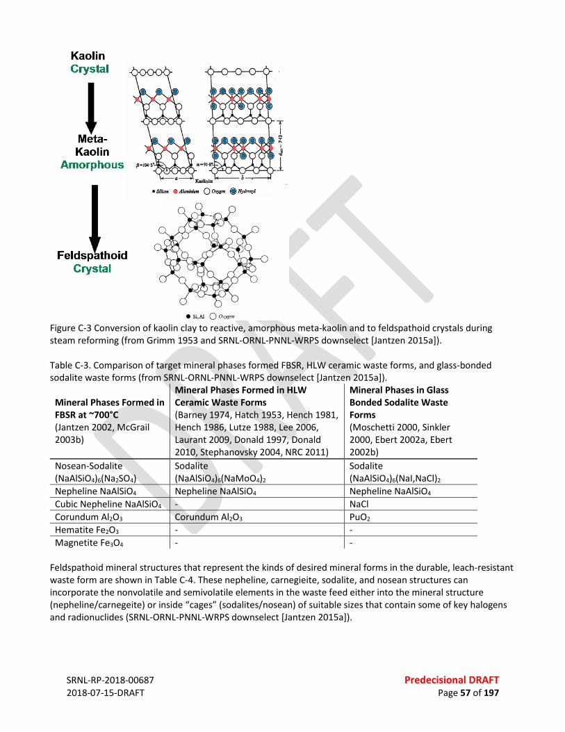
SRNL-RP-2018-00687 Predecisional DRAFT 2018-07-15-DRAFT Page 57 of 197
Figure C-3 Conversion of kaolin clay to reactive, amorphous meta-kaolin and to feldspathoid crystals during steam reforming (from Grimm 1953 and SRNL-ORNL-PNNL-WRPS downselect [Jantzen 2015a]). Table C-3. Comparison of target mineral phases formed FBSR, HLW ceramic waste forms, and glass-bonded sodalite waste forms (from SRNL-ORNL-PNNL-WRPS downselect [Jantzen 2015a]).
Mineral Phases Formed in FBSR at ~700°C (Jantzen 2002, McGrail 2003b)
Mineral Phases Formed in HLW Ceramic Waste Forms (Barney 1974, Hatch 1953, Hench 1981, Hench 1986, Lutze 1988, Lee 2006, Laurant 2009, Donald 1997, Donald 2010, Stephanovsky 2004, NRC 2011)
Mineral Phases in Glass Bonded Sodalite Waste Forms (Moschetti 2000, Sinkler 2000, Ebert 2002a, Ebert 2002b)
Nosean-Sodalite (NaAlSiO4)6(Na2SO4)
Sodalite (NaAlSiO4)6(NaMoO4)2
Sodalite (NaAlSiO4)6(NaI,NaCl)2
Nepheline NaAlSiO4 Nepheline NaAlSiO4 Nepheline NaAlSiO4 Cubic Nepheline NaAlSiO4 - NaCl Corundum Al2O3 Corundum Al2O3 PuO2 Hematite Fe2O3 - - Magnetite Fe3O4 - -
Feldspathoid mineral structures that represent the kinds of desired mineral forms in the durable, leach-resistant waste form are shown in Table C-4. These nepheline, carnegieite, sodalite, and nosean structures can incorporate the nonvolatile and semivolatile elements in the waste feed either into the mineral structure (nepheline/carnegeite) or inside “cages” (sodalites/nosean) of suitable sizes that contain some of key halogens and radionuclides (SRNL-ORNL-PNNL-WRPS downselect [Jantzen 2015a]).
SRNL-RP-2018-00687 Predecisional DRAFT 2018-07-15-DRAFT Page 58 of 197
Table C-5 shows oxidation states and atomic radii for anions that can be captured inside the sodalite crystalline cage structures. How Fluidized Bed Steam Reforming Would Treat Hanford Supplemental LAW The Supplemental LAW treatment system feed vector is expected to vary widely and presents flowrate and composition challenges for the SLAW treatment process. Table C-6 summarizes monthly feedrate and composition data along with the “turndown ratio” that is used to describe the month to month variability. The feedrate turndown ratio is the ratio of the maximum monthly flowrate divided by the minimum monthly flowrate ratio. The feedrate turndown ratio is a challenge that causes the need for (a) at least two FBSR systems to operate in parallel to maintain SLAW processing at average minimum rates even when one is off-line for maintenance, and (b) additional waste feed delay storage to reduce the turndown from over 50x.

SR
NL-
RP-2
018-
0068
7
Pr
edec
isio
nal D
RAFT
20
18-0
7-15
-DRA
FT
Pa
ge 5
9 of
197
Tabl
e C-
4. S
ubst
itutio
nal c
atio
ns a
nd o
xy-a
nion
s in
feld
spat
hoid
stru
ctur
es (f
rom
SRN
L-O
RNL-
PNN
L-W
RPS
dow
nsel
ect [
Jant
zen
2015
a]).
Nep
helin
e –
Kals
ilite
Str
uctu
res*
Ca
rneg
ieite
Str
uctu
res
Soda
lite
Stru
ctur
es**
N
osea
n St
ruct
ures
Na x
AlyS
i zO4 [
Deer
200
4] w
here
x=
1-1.
33, y
and
z =
0.55
-1.1
(H)
NaA
lSiO
4
high
car
negi
eite
(C)
[Sm
ith 1
957;
#11
-221
]
[Na 6
Al6S
i 6O24
](NaC
l) 2
[Dee
r 200
4, B
renc
hley
199
4, F
echt
elko
rd
2000
]
[Na 6
Al6S
i 6O24
](Na 2
SO4)
[D
eer 2
004,
Ges
ing
1998
, Dee
r 196
3]
NaA
lSiO
4 [PD
F #0
52-1
342;
Nay
ak
1998
] (O
)t
NaA
lSiO
4 low
car
negi
eite
[S
mith
195
7; P
DF #
11-2
20 n
o sy
mm
etry
giv
en]
[Na 6
Al6S
i 6O24
](NaF
l) 2 [D
eer 2
004]
[N
a 6Al
6Si 6O
24](N
a 2M
oO4)
[D
eer 2
004,
Bro
okin
s 198
4]
KAlS
iO4 [
Deer
200
4]
Na 1
.45A
l 1.45
Si0.
55O
4
[Tho
mps
on 1
998a
and
199
8b]
[Na 6
Al6S
i 6O24
](NaI
) 2
[Bab
ad 1
980,
Dee
r 196
3]
[Na 6
Al6S
i 6O24
]((Ca
,Na)
SO4) 1
-2
[Dan
a 19
32]
K 0.0
0Na 1
.00A
lSiO
4 to
K 0.2
5Na 0
.75A
lSiO
4 so
lid so
lutio
n
[Dee
r 200
4]
Na 1
.95A
l 1.95
Si0.
05O
4
[Tho
mps
on 1
998a
and
199
8b]
[Na 6
Al6S
i 6O24
](NaB
r)2 [
Deer
196
3]
[(Ca,
Na)
6Al 6S
i 6O24
]((Ca
,Na)
S,SO
4,Cl
) x
ƒ #17
-749
]
(Na 2
O) 0.
33N
aAlS
iO4
[Klin
genb
erg
1986
] (C)
N
a 1.7
5Al 17
5Si 0.
25O
4
[Tho
mps
on 1
998a
and
199
8b]
[Na 6
Al6S
i 6O24
]( N
aReO
4) 2 [M
attig
od 2
006]
CsAl
SiO
4 [De
er 2
004]
N
a 1.6
5Al 16
5Si 0.
35O
4
[Tho
mps
on 1
998a
and
199
8b]
[Na 6
Al6S
i 6O24
](NaM
nO4) 2
[Bar
rer 1
945,
Srd
anov
199
4]
RbAl
SiO
4 [D
eer 2
004]
N
a 1.5
5Al 15
5Si 04
5O4
[Tho
mps
on 1
998a
and
199
8b]
[NaA
lSiO
4] 6(N
aBO
4) 2
[Buh
l 198
9, T
obbe
ns 2
000]
(Ca 0
.5,S
r 0.5
)AlS
iO4 [
Deer
200
4]
Na 1
.15A
l 115S
i 085O
4
[Tho
mps
on 1
998a
and
199
8b]
(Fe,
Zn,M
n)4[B
e 3Si
3O12
]S [D
eer 1
963]
(Sr,B
a)Al
2O4
[Dee
r 200
4]
Na 3
MgA
lSi 2O
8
[Tho
mps
on 1
998a
and
199
8b]
Sr8[A
l 12O
24](C
rO4) 2
[Dep
mei
er 1
987]
KFeS
iO4 [
Deer
200
4]
N
a 8[A
lSiO
4] 6(S
CN) 2
[Buh
l 200
1]
(Na,
Ca0.
5)YSi
O4 [
Barr
er 1
945]
Na 6
Al6S
i 6O24
(Zeo
lite
A)
[Cam
pbel
l 200
0, S
hann
on 2
000]
(Na,
K)La
SiO
4 [Ba
rrer
194
5]
Na 8
[ABO
4] 6∙X
2, w
here
A=A
l and
Ga,
B=S
i an
d Ge
, and
X in
clud
es C
l− , Br− , I
− , (Cl
O3)− ,
(BrO
3)− , (HC
OO
)− , (M
nO4)− , (
SCN
)− and
(S
eCN
)− [Fle
et 1
989,
John
son
2000
]
(Na,
K,Ca
0.5)N
dSiO
4 [Ba
rrer
194
5]
N
a 7.5
0Fe2+
0.05
[Si 6.
07Al
5.93
]O24
Cl1.
99(S
O4) 0
.01
(hac
kman
ite) [
Pete
rson
198
3]
*
Iron,
Ti3+
, Mn,
Mg,
Ba,
Li,
Rb, S
r, Zr
, Ga,
Cu,
V, a
nd Y
b al
l sub
stitu
te in
trac
e am
ount
s in
neph
elin
e, [D
eer 2
004]
.
SR
NL-
RP-2
018-
0068
7
Pr
edec
isio
nal D
RAFT
20
18-0
7-15
-DRA
FT
Pa
ge 6
0 of
197
** H
ighe
r val
ent a
nion
ic g
roup
s suc
h as
AsO
43- a
nd C
rO42-
form
Na 2
XO4 g
roup
s in
the
cage
stru
ctur
e w
here
X=
Cr, S
e, W
, P, V
, and
As [
Barr
er
1945
]. ƒ
Pow
der D
iffra
ctio
n Fi
le
t M
ay b
e lo
w-c
arne
giei
te p
er o
rigin
al re
fere
nce.
(C
) is f
or c
ubic
cry
stal
sym
met
ry, (
H) is
for h
exag
onal
cry
stal
sym
met
ry, (
O) i
s for
ort
horh
ombi
c cr
ysta
l sym
met
ry.
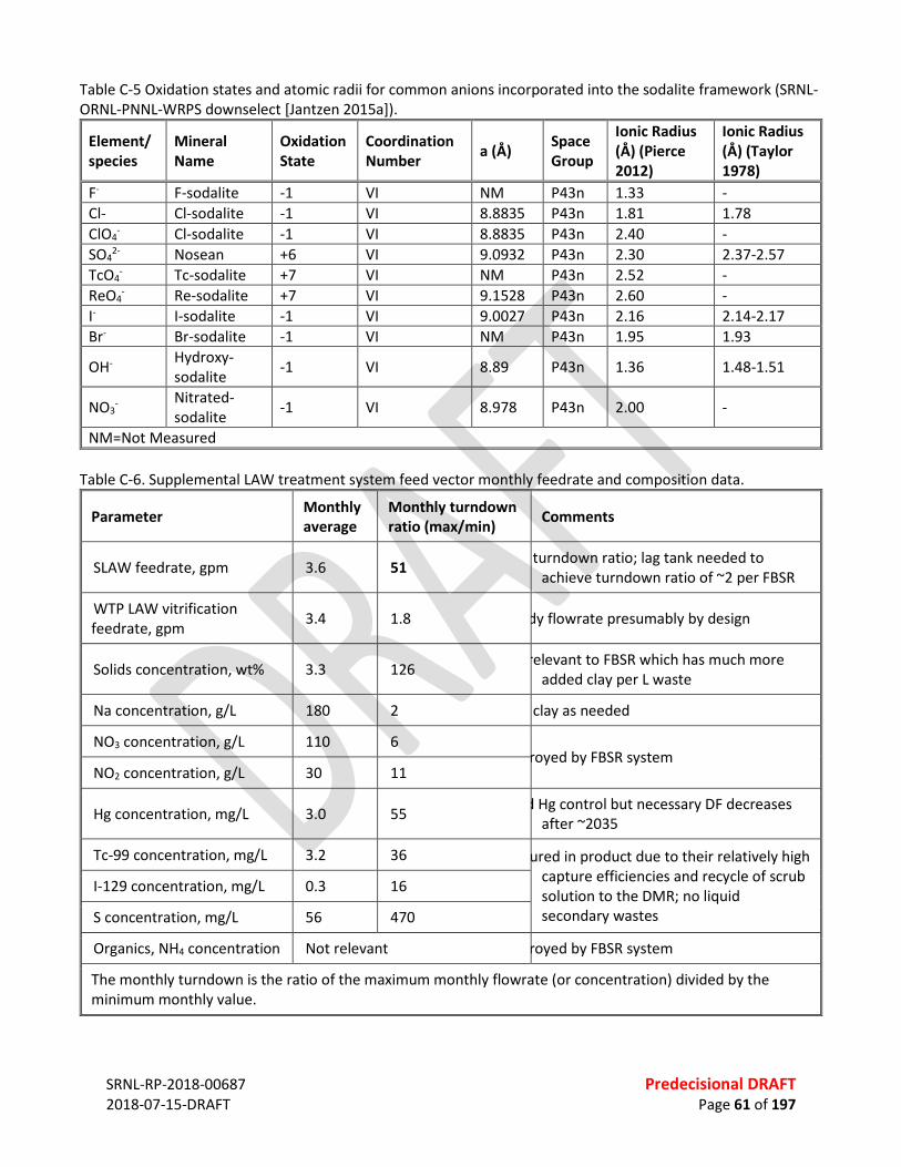
SRNL-RP-2018-00687 Predecisional DRAFT 2018-07-15-DRAFT Page 61 of 197
Table C-5 Oxidation states and atomic radii for common anions incorporated into the sodalite framework (SRNL-ORNL-PNNL-WRPS downselect [Jantzen 2015a]).
Element/ species
Mineral Name
Oxidation State
Coordination Number a (Å) Space
Group
Ionic Radius (Å) (Pierce 2012)
Ionic Radius (Å) (Taylor 1978)
F- F-sodalite -1 VI NM P43n 1.33 - Cl- Cl-sodalite -1 VI 8.8835 P43n 1.81 1.78 ClO4
- Cl-sodalite -1 VI 8.8835 P43n 2.40 - SO4
2- Nosean +6 VI 9.0932 P43n 2.30 2.37-2.57 TcO4
- Tc-sodalite +7 VI NM P43n 2.52 - ReO4
- Re-sodalite +7 VI 9.1528 P43n 2.60 - I- I-sodalite -1 VI 9.0027 P43n 2.16 2.14-2.17 Br- Br-sodalite -1 VI NM P43n 1.95 1.93
OH- Hydroxy-sodalite -1 VI 8.89 P43n 1.36 1.48-1.51
NO3- Nitrated-
sodalite -1 VI 8.978 P43n 2.00 -
NM=Not Measured Table C-6. Supplemental LAW treatment system feed vector monthly feedrate and composition data.
Parameter Monthly average
Monthly turndown ratio (max/min) Comments
SLAW feedrate, gpm 3.6 51 turndown ratio; lag tank needed to achieve turndown ratio of ~2 per FBSR
WTP LAW vitrification feedrate, gpm 3.4 1.8 dy flowrate presumably by design
Solids concentration, wt% 3.3 126 relevant to FBSR which has much more added clay per L waste
Na concentration, g/L 180 2 clay as needed
NO3 concentration, g/L 110 6 royed by FBSR system
NO2 concentration, g/L 30 11
Hg concentration, mg/L 3.0 55 d Hg control but necessary DF decreases after ~2035
Tc-99 concentration, mg/L 3.2 36 ured in product due to their relatively high capture efficiencies and recycle of scrub solution to the DMR; no liquid secondary wastes
I-129 concentration, mg/L 0.3 16
S concentration, mg/L 56 470
Organics, NH4 concentration Not relevant royed by FBSR system
The monthly turndown is the ratio of the maximum monthly flowrate (or concentration) divided by the minimum monthly value.

SRNL-RP-2018-00687 Predecisional DRAFT 2018-07-15-DRAFT Page 62 of 197
FBSR PROCESS FLOW OPTIONS AND DIAGRAMS Two FBSR options are proposed, based on the desired waste form. Treatment Option 3, the Steam Reforming Base Case (Figure C-4) provides a durable, mineralized waste form for storage and permanent disposal in the Hanford Integrated Disposal Facility (IDF). A geopolymer process downstream of the FBSR converts the granular FBSR product to a monolith, needed to meet the expected IDF 500 psi compressive strength limit. Secondary wastes in this option (spent filters, equipment, PPE, etc.) are also disposed in IDF. Treatment Option 3b, Steam Reforming to WCS (Figure C-5) excludes the geopolymer monolith process, because WCS does not have a compressive strength limit. Secondary wastes in this option (spent filters, equipment, PPE, etc.) are also disposed in WCS. Alternative Option 3_ (Figure C-6) features disposal of the granular waste form at IDF inside concrete high integrity containers (HICs) to meet the IDF compressive strength limit without the added geopolymer process. Secondary wastes in this option (spent filters, equipment, PPE, etc.) are also disposed in IDF.
Figure C-4 Base Case Mineralizing FBSR (Treatment Option 3): Two DMR systems; solid monolith product disposed at IDF (secondary wastes also disposed at IDF). Figure C-7 shows that the very highest sustained waste feedrates occur in about the first three years of SLAW treatment operations. After those first three years, the feedrate varies by over 50x turndown ratio. Both FBSR options include the following features that are driven by the high, sustained initial waste feedrate, and the 50x turndown ratio that occurs during the entire life of the facility. • Utilize 500,000 gal waste holding tank upstream of the SLAW treatment system. • Two 50,000 gal WF Hold tanks to provide time for filling and sample analysis prior to mixing with with
mineralizing clay. • Two 30,000 gal Mix/feed tanks for batch addition and mixing of clay/WF slurry. • Two identical FBSR systems to maximize available capacity in first ~3 yrs. • Shared waste staging, mixing, and feed system.

SRNL-RP-2018-00687 Predecisional DRAFT 2018-07-15-DRAFT Page 63 of 197
Figure C-5 Treatment Option 3b, Steam Reforming to WCS: Two DMR systems; granular solid product (secondary wastes also disposed at WCF).
Figure C-6 Treatment Option 3_, Steam Reforming to WCS: Two DMR systems; granular solid product disposed at IDF inside concrete HICs (secondary wastes also disposed at IDF).

SRNL-RP-2018-00687 Predecisional DRAFT 2018-07-15-DRAFT Page 64 of 197
Figure C-7 Variation in the monthly Hanford LAW stream flowrates from the feed vector. The figures show that the core DMR and PGF are actually only two of many components that comprise the feed systems, DMR system, off-gas system, and product handling system. While these boxes in the figure are not drawn to scale, the figure indicates that the core DMR and PGF represent only a fraction of the entire facility footprint. The size and configuration of the DMR was estimated based on the average, minimum, and maximum monthly feed vector values after passing through the tank farm 500,000 gal tank, the WF Hold tanks, and the Mix/feed tanks; and assuming a 20% volume increase when clay is added. The nominal diameter of each DMR was set at 5 ft inside diameter, scaled based on the average monthly feed vector flowrate of 4.4 gpm (20% greater than the average feed vector flowrate of 3.6 gpm). This diameter is 25% higher than the IWTU diameter of 4 ft, based on scaling the cross section areas according to the volumetric feedrate (1.75 times greater than the 2.5 gpm IWTU feedrate). The nominal vessel height dimensions were likewise scaled according to ratios for the IWTU: • Bed height = 5 ft (approximately equal to the bed diameter). • Bed section height = 8 ft (~25% more than the IWTU bed section height of 6.6 ft). • Freeboard (including conical section) = 23 ft (assumed to be 100% higher than the IWTU freeboard + cone
height of 11.6 ft, to allow for particle disengagement without the use of internal cyclones). The nominal volume of the 5-ft diameter, 5-ft high fluidized bed is ~100 ft3. With a fluidized density of about 0.7 g/cc (85% of the bulk product density of 0.8 g/cc), the nominal mass in the fluidized bed at any time is about 4,000 lb. Figure C-8 shows a concept design for the WF system for the purposes of this evaluation. The actual configuration may change in a specific detailed design. Either one of two WF Hold tanks receives SLAW from a 500,000 gal waste tank used to stage tank farm waste (only one WF Hold Tank is shown in the figure for simplicity). This nominal 50,000 gallon tank, together with the 500,000 gal tank farm tank, and two 30,000 gal

SRNL-RP-2018-00687 Predecisional DRAFT 2018-07-15-DRAFT Page 65 of 197
Mix/feed tanks, provide the needed feed tankage to (a) enable the two parallel FBSR systems, each with 70% availability on average, to process the maximum SLAW feedrate during the first three operating years, (b) provide 5-day turnaround time for batch sample analysis of the WF hold Tank contents before adding the clay, (c) provide 2 days for final feed blend sample analysis of each Mix-feed Tank, and (d) two days of feed time per Mix-feed Tank. Each WF Hold Tank can feed to either or both Mix-feed tanks, and either Mix-feed Tank can feed to either or both DMRs. The delivery system from each of the WF Hold tanks and Mix-feed tanks is configured to recycle pumped feed back to the same tank, so that the feed systems from each tank remain flowing at all times to prevent solids deposition in the piping.
Figure C-8 Conceptual FBSR WF system. Commercially available, fine-particle-size clay (such as is shown in Figure C-9) is added in a Clay Addition System for each Mix-feed Tank (such as is shown in Figure C-10). Dry clay is metered from a hopper into an in-line mixer where it is mixed with WF metered from one of the WF Hold tanks. This premixes the correct proportion of clay into the WF as it enters either Mix-feed Tank. The correct amount of clay to add is determined for each WF Hold Tank batch based on batch analysis of that tank. The WF can be fed to either or both of the two DMRs through between one and four feed nozzles that penetrate through the sides of each of the DMR vessels. Each DMR would have four feed nozzles oriented 90 degrees from each other around the circumference of the bed section. The flowrate to each feed nozzle is separately measured and controlled. Each feed nozzle is sized for an optimal WF rate of 1.3 gpm, approximately the same size as the IWTU feed nozzles, each sized for an optimal feedrate of 1.2 gpm. Water flushes (not shown in the figure) are used when feed nozzle flows are started and stopped to prevent clay sedimentation and drying in feed lines and feed nozzles.
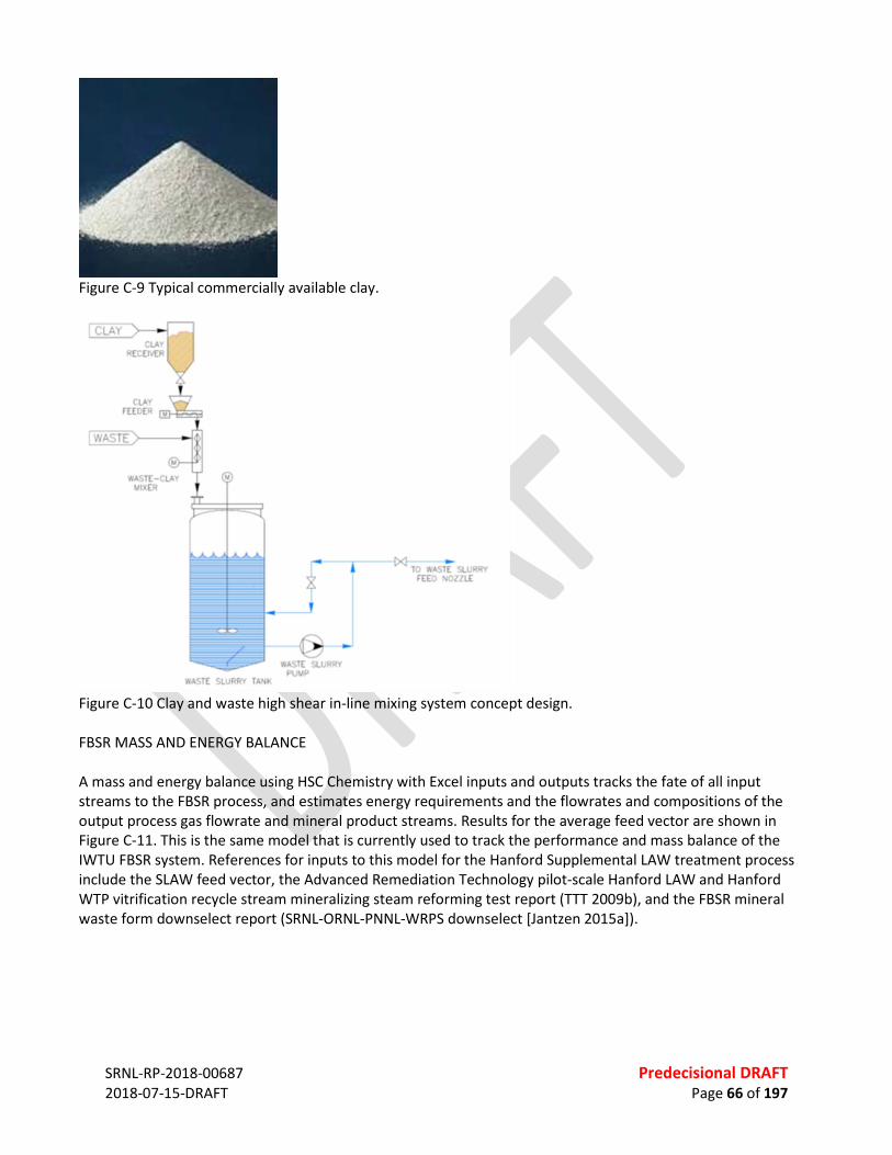
SRNL-RP-2018-00687 Predecisional DRAFT 2018-07-15-DRAFT Page 66 of 197
Figure C-9 Typical commercially available clay.
Figure C-10 Clay and waste high shear in-line mixing system concept design. FBSR MASS AND ENERGY BALANCE A mass and energy balance using HSC Chemistry with Excel inputs and outputs tracks the fate of all input streams to the FBSR process, and estimates energy requirements and the flowrates and compositions of the output process gas flowrate and mineral product streams. Results for the average feed vector are shown in Figure C-11. This is the same model that is currently used to track the performance and mass balance of the IWTU FBSR system. References for inputs to this model for the Hanford Supplemental LAW treatment process include the SLAW feed vector, the Advanced Remediation Technology pilot-scale Hanford LAW and Hanford WTP vitrification recycle stream mineralizing steam reforming test report (TTT 2009b), and the FBSR mineral waste form downselect report (SRNL-ORNL-PNNL-WRPS downselect [Jantzen 2015a]).
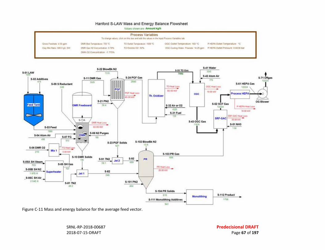
SRNL-RP-2018-00687 Predecisional DRAFT 2018-07-15-DRAFT Page 67 of 197
Figure C-11 Mass and energy balance for the average feed vector.
Gross f eedrate: l so-CJa.;M•R&.l£0fO .. t SN
S.01lAW t749
S.02Additlv01
S-04 Atom Al< •!0
S-060MR02 210
S.05A SH SlUm
S-09 S Reduc .. nt ,.~
I S.05SHCU
tm' 10)
S.OSB SH N2 t 97£·9 Su~rhtattr
S.OK SH Al< I - 2 O.H -, S-81 nl2
.u
Hanford S-LAW Mass and Energy Balance Flowsheet V•~ snown .am Amount kO/h
Process Vanab!es TocNf'l9e...,.. ck,_.v-.oc•l'l'ld•U..~•"'""~PJoc:utV~t•
DWR~I~...,. m·e ~ Glit t-QCCII'< .. -. 0 11"11 Ot.R02<:onc~ • , ns-.
TO Que~ r.,.,-... ~~ "C TObteuO<l' ~
OGCQuOttT~ .. t&O~ P .. P,o\~Tf"'Pe'An 'C: oce~w•• ,._., u29_.... PtEPAOulfoCPtnkn OUleNr
S-22 81ow9k N2 ,. S-11 OMRCu -
,.., .. ~t«~~at6
·~~(IQ tW
$-08 N2 Purg01
••
S-UPCFCos ~
Th. Oddl-:ut
~TO au 7st2
JO .... .C l MI . IOfiO t \'f
S.J2 Air or 02
S-23 PCF Solids $•1 02 81ow8k N.2 tU
U1nl2 $0•
S-82 244
S-92 Q.IO
S-101 PN2 4<
S-103 PRCas (,06
pq ........... 7iii"Wt-
S-111' PR Solids ... s -111 MonolllhlngAdditlvts .. ,
OGC
S-'1 Wtter ll•S
S'"'2AtomAir m
OOCKHII.OM
!Otot..w
S-61HEPACu
P .,[ f•A Kt11 Lftt ...--::...,:=-:-•
10Wlt\V
s~occcu ,,~1·
$Rt .... -.M' t • ., l • SM.CAC~.~ ~
S-51 NH3 ...
Monolfthlng S-112 Pro<tud
111>8
+ S-71 Ollg•s •m•
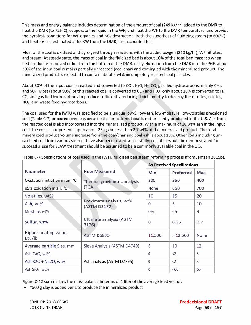
SRNL-RP-2018-00687 Predecisional DRAFT 2018-07-15-DRAFT Page 68 of 197
This mass and energy balance includes determination of the amount of coal (249 kg/hr) added to the DMR to heat the DMR (to 725oC), evaporate the liquid in the WF, and heat the WF to the DMR temperature, and provide the pyrolysis conditions for WF organics and NOx destruction. Both the superheat of fluidizing steam (to 600oC) and heat losses (estimated at 65 KW from the DMR) are accounted for. Most of the coal is oxidized and pyrolyzed through reactions with the added oxygen (210 kg/hr), WF nitrates, and steam. At steady state, the mass of coal in the fluidized bed is about 10% of the total bed mass; so when bed product is removed either from the bottom of the DMR, or by elutriation from the DMR into the PGF, about 20% of the input coal remains partially unreacted (coal char) and comingled with the mineralized product. The mineralized product is expected to contain about 5 wt% incompletely reacted coal particles. About 80% of the input coal is reacted and converted to CO2, H2O, H2, CO, gasified hydrocarbons, mainly CH4, and SOx. Most (about 90%) of this reacted coal is converted to CO2 and H2O; only about 10% is converted to H2, CO, and gasified hydrocarbons to produce sufficiently reducing stoichiometry to destroy the nitrates, nitrites, NOx, and waste feed hydrocarbons. The coal used for the IWTU was specified to be a unique low-S, low-ash, low-moisture, low-volatiles precalcined coal (Table C-7) procured overseas because this precalcined coal is not presently produced in the U.S. Ash from the reacted coal is also incorporated into the mineralized product. With a maximum of 10 wt% ash in the input coal, the coal ash represents up to about 25 kg/hr, less than 2.7 wt% of the mineralized product. The total mineralized product volume increase from the coal/char and coal ash is about 10%. Other coals including un-calcined coal from various sources have also been tested successfully; coal that would be demonstrated for successful use for SLAW treatment should be assumed to be a commonly available coal in the U.S. Table C-7 Specifications of coal used in the IWTU fluidized bed steam reforming process (from Jantzen 2015b).
Parameter
How Measured
As-Received Specifications
Min Preferred Max
Oxidation initiation in air, °C Thermal gravimetric analysis (TGA)
300 350 400
95% oxidation in air, °C None 650 700
Volatiles, wt% Proximate analysis, wt% (ASTM D3172)
10 15 20
Ash, wt% 0 5 10
Moisture, wt% 0% <5 9
Sulfur, wt% Ultimate analysis (ASTM 3176) 0 0.35 0.7
Higher heating value, Btu/lb ASTM D5875 11,500 > 12,500 None
Average particle Size, mm Sieve Analysis (ASTM D4749) 6 10 12
Ash CaO, wt%
Ash analysis (ASTM D2795)
0 <2 5
Ash K2O + Na2O, wt% 0 <2 3
Ash SiO2, wt% 0 <60 65 Figure C-12 summarizes the mass balance in terms of 1 liter of the average feed vector. • ~660 g clay is added per L to produce the mineralized product

SRNL-RP-2018-00687 Predecisional DRAFT 2018-07-15-DRAFT Page 69 of 197
• ~260 g coal is burned per L • ~1.0 kg (~1.2 L, at a bulk density of about 0.8 g/cc) of granular product is produced, including incompletely
reacted coal and coal ash. This could be reduced to about 0.8 kg (1 L) if the amount of incompletely reacted coal could be reduced.
• ~1.9 kg (~1.0 L at a density of 1.8 g/cc) geopolymer product. The volume of the monolith product is actually equal to or less than the volume of the granular product because of the differences in densities.
•
Figure C-12 Initial mass balance results for FBSR treatment of Hanford SLAW. MINERAL WASTE FORMS The mineral waste form produced from the mineralizing FBSR process was studied extensively between about 2002 to 2015. Results of these studies are reported in many individual documents, and also provided in the 2015 downselect report (SRNL-ORNL-PNNL-WRPS downselect [Jantzen 2015a]). Much of the following description and performance of the FBSR mineral waste form and is extracted from the downselect report. This reference, and references of this reference, contain extensive additional detail. Granular and Monolith Mineral Waste Forms Figure C-13 shows scanning electron micrographs of the granular mineralized waste form such as would be produced in Treatment Option 3b, Steam Reforming to WCS. The individual particles from the fluidized bed range in size from under 10 microns to about 1 mm. Larger particles, especially of incompletely oxidized coal up to about 1 cm (not shown in the figure), are also typically present and can be up to about 5 wt% of the total product mass. Figure C-14 shows a photograph of a monolith of FBSR mineral product formed with additives into a geopolymer monolith, such as would be produced in Treatment Option 3, the Steam Reforming Base Case.

SRNL-RP-2018-00687 Predecisional DRAFT 2018-07-15-DRAFT Page 70 of 197
Figure C-13 Scanning electron micrographs of FBSR bed product from INL SBW; Science Applications International Corporation Science and Technology Applications Research (SAIC-STAR) 6 in. diameter FBSR (SRNL-ORNL-PNNL-WRPS downselect [Jantzen 2015a]).
Figure C-14 Troy clay geopolymer monolith of Hanford LAW 60% FBSR product (SRNL-ORNL-PNNL-WRPS downselect [Jantzen 2015a]). Waste Form Mineralogy Control Multiple test programs and studies have used the “MINCALC” process control strategy developed at SRNL for determining best mix and amount of clay additive to use in the steam reforming process to produce the desired mineralized product. The clay additive, depending on the input feed composition, would be a choice of fine-particle-sized clays commercially available and commonly used for many processes including the manufacture of porcelain fixtures. The amount and type of clay is determined based on the input LAW composition so that the combined mixture achieves the target composition range shown in the ternary diagram shown in Figure C-15. This diagram has 100% Na2O at the lower left apex; 100% Al2O3 at the lower right apex; and 100% SiO2 at the top apex. Various waste streams tested in bench, pilot, and engineering scale mineralizing steam reforming demonstrations are

SRNL-RP-2018-00687 Predecisional DRAFT 2018-07-15-DRAFT Page 71 of 197
placed according to their original Na2O – Al2O3 ratios along the bottom axis. Various commercial clays are located on the top-right axis according to their Al2O3 – SiO2 ratios. The stoichiometrically desired Na2O – Al2O3 – SiO2 region in the ternary diagram is just off-center to the right of diagram. So the right clay, or mixture of clays, for each waste Na2O – Al2O3 ratio, is determined by a straight line between that Na2O – Al2O3 ratio on the bottom axis through the region of desired Na2O – Al2O3 – SiO2 stoichiometry, to the upper-right Al2O3 – SiO2 axis. That point in the upper-right axis defines the approximate target Al2O3 – SiO2 to obtain by the right selection or mixture of commercial clays. The granular product is a heterogeneous mixture of the mineralized WF product, incorporated coal ash, and incompletely reacted coal particles. It can contain appreciable dispersible fines and it has a low bulk density with void spaces between particles. The Base Case includes the conversion of this low-density, somewhat compressible waste form with dispersible fines into a monolith which actually increases the density but not the volume, and most important, eliminates the dispersible fines and increases the compressive strength to exceed 500 psig. This enables the waste form to the compressive strength limit without having to use such containers as High Integrity Containers (HICs). Alternatively, the granular product can be placed inside HICs such as metal or concrete containers or vaults to provide the needed compressive strength. The FBSR waste form performance ([a] ability to immobilize radioactive or hazardous constituents, and [b] durability [NRC 2011]) rather than HIC performance is the focus of this study. NRC 2011, “Waste Forms Technology and Performance, Final Report,” National Research Council of the National Academies, Committee on Waste Forms Technology and Performance, National Academies Press, Washington, DC. The downselect program studied monolith production using both fly ash and clay additives, along with added sodium silicate, to the granular mineralized product to produce a geopolymer monolith with an overall Na2O – Al2O3 – SiO2 stoichiometry similar to the target stoichiometry. The desired stoichiometry of the successfully-tested geopolymer monoliths are shown in Figure C-16; located in the Na2O – Al2O3 – SiO2 ternary diagram just to the left (higher Na2O) and higher (higher SiO2) than the original mineralized product stoichiometry. Product Analyses and Durability Tests This section contains information summarized from the FBSR mineral waste form downselect report (SRNL-ORNL-PNNL-WRPS downselect [Jantzen 2015a]). NRC 2011 findings include: • “Two essential characteristics of waste forms govern their performance in disposal systems: (1) capacity for
immobilizing radioactive or hazardous constituents, and (2) durability.” • “Waste form tests are used for three purposes: (1) to ensure waste form product consistency; (2) to
elucidate waste form release mechanisms; and (3) to measure waste form release rates NRC 2011 goes on to say “crystalline ceramic waste forms produced by fluidized bed steam reforming have good radionuclide retention properties and waste loadings comparable to, or greater than, borosilicate glass. This waste form material is also potentially useful for immobilizing LAW.” This statement was based on the mineralized waste form results available prior to 2011. Since then, additional FBSR waste form testing has been performed, which adds to the pre-2011 body of data.
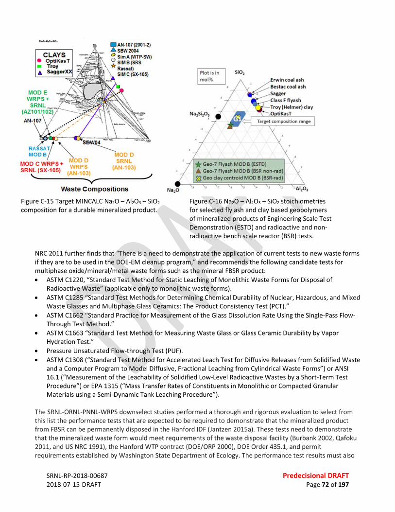
SRNL-RP-2018-00687 Predecisional DRAFT 2018-07-15-DRAFT Page 72 of 197
Figure C-15 Target MINCALC Na2O – Al2O3 – SiO2 composition for a durable mineralized product.
Figure C-16 Na2O – Al2O3 – SiO2 stoichiometries for selected fly ash and clay based geopolymers of mineralized products of Engineering Scale Test Demonstration (ESTD) and radioactive and non-radioactive bench scale reactor (BSR) tests.
NRC 2011 further finds that “There is a need to demonstrate the application of current tests to new waste forms if they are to be used in the DOE-EM cleanup program,” and recommends the following candidate tests for multiphase oxide/mineral/metal waste forms such as the mineral FBSR product: • ASTM C1220, “Standard Test Method for Static Leaching of Monolithic Waste Forms for Disposal of
Radioactive Waste” (applicable only to monolithic waste forms). • ASTM C1285 “Standard Test Methods for Determining Chemical Durability of Nuclear, Hazardous, and Mixed
Waste Glasses and Multiphase Glass Ceramics: The Product Consistency Test (PCT).” • ASTM C1662 “Standard Practice for Measurement of the Glass Dissolution Rate Using the Single-Pass Flow-
Through Test Method.” • ASTM C1663 “Standard Test Method for Measuring Waste Glass or Glass Ceramic Durability by Vapor
Hydration Test.” • Pressure Unsaturated Flow-through Test (PUF). • ASTM C1308 (“Standard Test Method for Accelerated Leach Test for Diffusive Releases from Solidified Waste
and a Computer Program to Model Diffusive, Fractional Leaching from Cylindrical Waste Forms”) or ANSI 16.1 (“Measurement of the Leachability of Solidified Low-Level Radioactive Wastes by a Short-Term Test Procedure”) or EPA 1315 (“Mass Transfer Rates of Constituents in Monolithic or Compacted Granular Materials using a Semi-Dynamic Tank Leaching Procedure”).
The SRNL-ORNL-PNNL-WRPS downselect studies performed a thorough and rigorous evaluation to select from this list the performance tests that are expected to be required to demonstrate that the mineralized product from FBSR can be permanently disposed in the Hanford IDF (Jantzen 2015a). These tests need to demonstrate that the mineralized waste form would meet requirements of the waste disposal facility (Burbank 2002, Qafoku 2011, and US NRC 1991), the Hanford WTP contract (DOE/ORP 2000), DOE Order 435.1, and permit requirements established by Washington State Department of Ecology. The performance test results must also
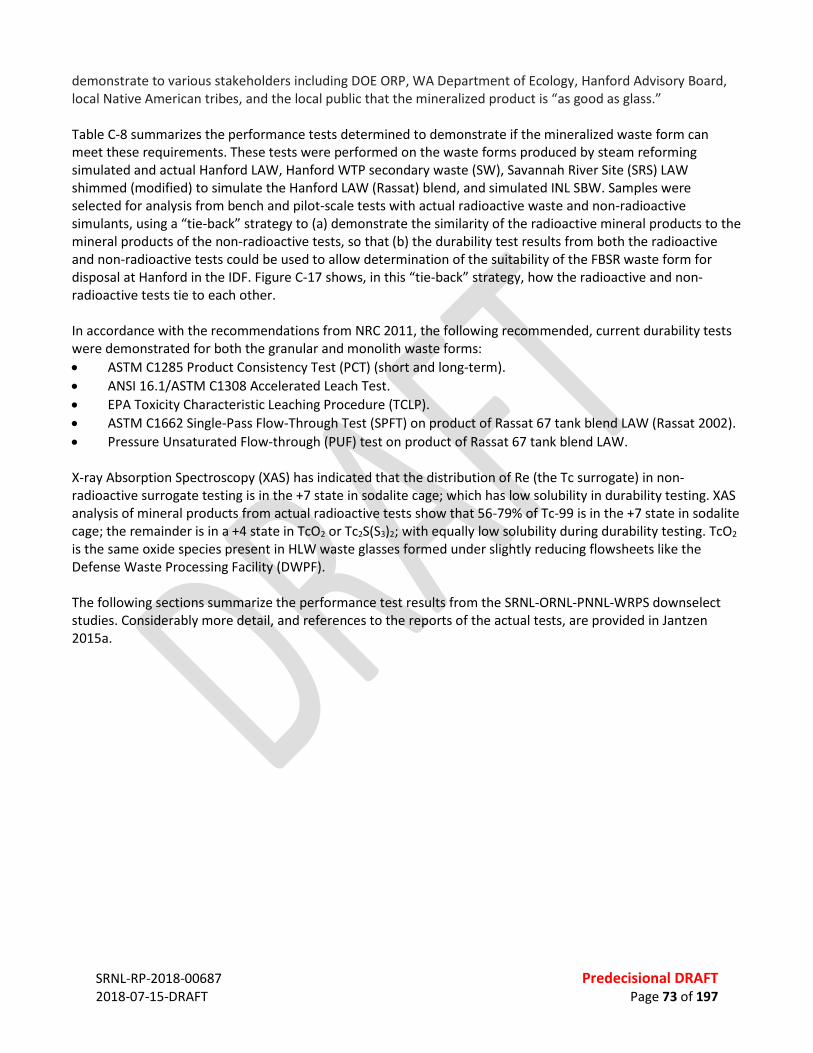
SRNL-RP-2018-00687 Predecisional DRAFT 2018-07-15-DRAFT Page 73 of 197
demonstrate to various stakeholders including DOE ORP, WA Department of Ecology, Hanford Advisory Board, local Native American tribes, and the local public that the mineralized product is “as good as glass.” Table C-8 summarizes the performance tests determined to demonstrate if the mineralized waste form can meet these requirements. These tests were performed on the waste forms produced by steam reforming simulated and actual Hanford LAW, Hanford WTP secondary waste (SW), Savannah River Site (SRS) LAW shimmed (modified) to simulate the Hanford LAW (Rassat) blend, and simulated INL SBW. Samples were selected for analysis from bench and pilot-scale tests with actual radioactive waste and non-radioactive simulants, using a “tie-back” strategy to (a) demonstrate the similarity of the radioactive mineral products to the mineral products of the non-radioactive tests, so that (b) the durability test results from both the radioactive and non-radioactive tests could be used to allow determination of the suitability of the FBSR waste form for disposal at Hanford in the IDF. Figure C-17 shows, in this “tie-back” strategy, how the radioactive and non-radioactive tests tie to each other. In accordance with the recommendations from NRC 2011, the following recommended, current durability tests were demonstrated for both the granular and monolith waste forms: • ASTM C1285 Product Consistency Test (PCT) (short and long-term). • ANSI 16.1/ASTM C1308 Accelerated Leach Test. • EPA Toxicity Characteristic Leaching Procedure (TCLP). • ASTM C1662 Single-Pass Flow-Through Test (SPFT) on product of Rassat 67 tank blend LAW (Rassat 2002). • Pressure Unsaturated Flow-through (PUF) test on product of Rassat 67 tank blend LAW. X-ray Absorption Spectroscopy (XAS) has indicated that the distribution of Re (the Tc surrogate) in non-radioactive surrogate testing is in the +7 state in sodalite cage; which has low solubility in durability testing. XAS analysis of mineral products from actual radioactive tests show that 56-79% of Tc-99 is in the +7 state in sodalite cage; the remainder is in a +4 state in TcO2 or Tc2S(S3)2; with equally low solubility during durability testing. TcO2 is the same oxide species present in HLW waste glasses formed under slightly reducing flowsheets like the Defense Waste Processing Facility (DWPF). The following sections summarize the performance test results from the SRNL-ORNL-PNNL-WRPS downselect studies. Considerably more detail, and references to the reports of the actual tests, are provided in Jantzen 2015a.
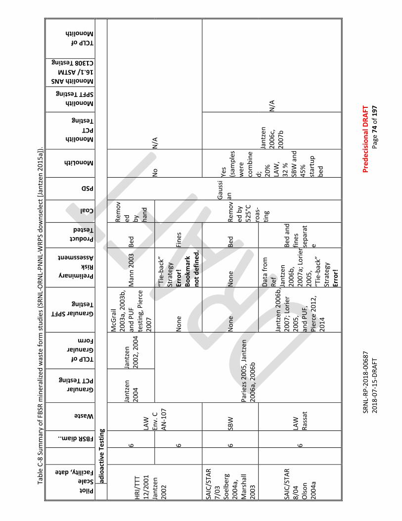
SR
NL-
RP-2
018-
0068
7
Pr
edec
isio
nal D
RAFT
20
18-0
7-15
-DRA
FT
Pa
ge 7
4 of
197
Tabl
e C-
8 Su
mm
ary
of F
BSR
min
eral
ized
was
te fo
rm st
udie
s (SR
NL-
ORN
L-PN
NL-
WRP
S do
wns
elec
t [Ja
ntze
n 20
15a]
). Pilot Scale Facility, date
FBSR diam..
Waste
Granular PCT Testing
TCLP of Granular Form
Granular SPFT Testing
Preliminary Risk Assessment
Product Tested
Coal
PSD
MonoLith
Monolith PCT Testing
Monolith SPFT Testing
Monolith ANS 16.1/ ASTM C1308 Testing
TCLP of Monolith
ad
ioac
tive
Test
ing
HRI/
TTT
12/2
001
Jant
zen
2002
6
LAW
En
v. C
AN
-107
Jant
zen
2004
Ja
ntze
n 20
02, 2
004
McG
rail
2003
a, 2
003b
, an
d PU
F te
stin
g, P
ierc
e 20
07
Man
n 20
03
Bed
Rem
oved
by
ha
nd
Gaus
sian
No
N/A
6
Parie
zs 2
005,
Jant
zen
2006
a, 2
006b
Non
e
“Tie
-bac
k”
Stra
tegy
Er
ror!
Bo
okm
ark
not d
efin
ed. Fi
nes
Rem
oved
by
525°
C ro
as-
ting
SAIC
/STA
R 7/
03
Soel
berg
20
04a,
M
arsh
all
2003
6 SB
W
Non
e N
one
Bed
Yes
(sam
ples
w
ere
com
bine
d;
20%
LA
W,
32 %
SB
W a
nd
45%
st
artu
p be
d
Jant
zen
2006
c,
2007
b N
/A
SAIC
/STA
R 8/
04
Olso
n 20
04a
6 LA
W
Rass
at
Jant
zen
2006
b,
2007
; Lor
ier
2005
, an
d PU
F,
Pier
ce 2
012,
20
14
Data
from
Re
f Ja
ntze
n 20
06b,
20
07a;
Lor
ier
2005
, “T
ie-b
ack”
St
rate
gy
Erro
r!
Bed
and
fines
se
para
te
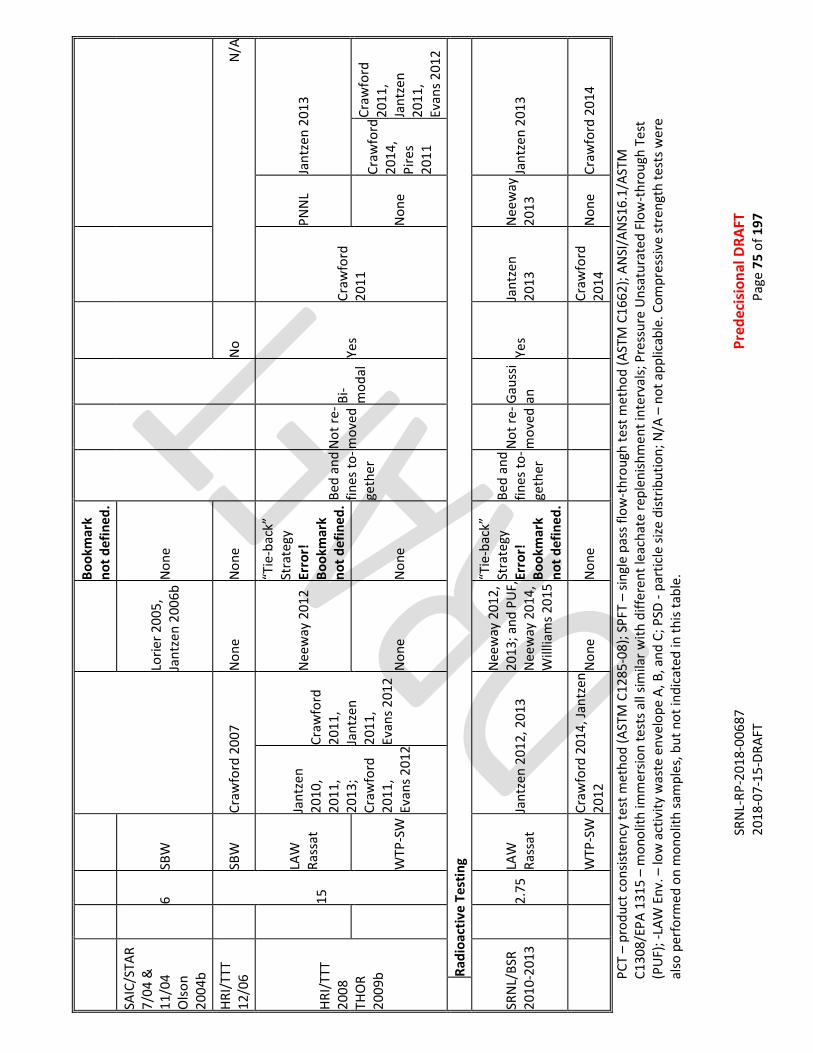
SR
NL-
RP-2
018-
0068
7
Pr
edec
isio
nal D
RAFT
20
18-0
7-15
-DRA
FT
Pa
ge 7
5 of
197
Book
mar
k no
t def
ined
.
SAIC
/STA
R 7/
04 &
11
/04
Olso
n 20
04b
6 SB
W
Lorie
r 200
5,
Jant
zen
2006
b N
one
HRI/
TTT
12/0
6
15
SBW
Cr
awfo
rd 2
007
Non
e N
one
No
N/A
HRI/
TTT
2008
TH
OR
2009
b
LAW
Ra
ssat
Ja
ntze
n 20
10,
2011
, 20
13;
Craw
ford
20
11,
Evan
s 201
2 Craw
ford
20
11,
Jant
zen
2011
, Ev
ans 2
012
Nee
way
201
2
“Tie
-bac
k”
Stra
tegy
Er
ror!
Bo
okm
ark
not d
efin
ed. Be
d an
d fin
es to
-ge
ther
Not
re-
mov
ed
Bi-
mod
al Ye
s Cr
awfo
rd
2011
PNN
L Ja
ntze
n 20
13
WTP
-SW
N
one
Non
e N
one
Craw
ford
20
14,
Pire
s 20
11
Craw
ford
20
11,
Jant
zen
2011
, Ev
ans 2
012
Ra
dioa
ctiv
e Te
stin
g
SRN
L/BS
R 20
10-2
013
2.75
LAW
Ra
ssat
Ja
ntze
n 20
12, 2
013
Nee
way
201
2,
2013
; and
PU
F,
Nee
way
201
4,
Will
liam
s 201
5
“Tie
-bac
k”
Stra
tegy
Er
ror!
Bo
okm
ark
not d
efin
ed. Be
d an
d fin
es to
-ge
ther
Not
re-
mov
ed Ga
ussi
an
Yes
Jant
zen
2013
N
eew
ay
2013
Ja
ntze
n 20
13
W
TP-S
W Cr
awfo
rd 2
014,
Jant
zen
2012
N
one
Non
e
Cr
awfo
rd
2014
N
one
Craw
ford
201
4
PCT
– pr
oduc
t con
siste
ncy
test
met
hod
(AST
M C
1285
-08)
; SPF
T –
singl
e pa
ss fl
ow-t
hrou
gh te
st m
etho
d (A
STM
C16
62);
ANSI
/AN
S16.
1/AS
TM
C130
8/EP
A 13
15 –
mon
olith
imm
ersio
n te
sts a
ll sim
ilar w
ith d
iffer
ent l
each
ate
repl
enish
men
t int
erva
ls; P
ress
ure
Uns
atur
ated
Flo
w-t
hrou
gh T
est
(PU
F); -
LAW
Env
. – lo
w a
ctiv
ity w
aste
env
elop
e A,
B, a
nd C
; PSD
- pa
rtic
le si
ze d
istrib
utio
n; N
/A –
not
app
licab
le. C
ompr
essiv
e st
reng
th te
sts w
ere
also
per
form
ed o
n m
onol
ith sa
mpl
es, b
ut n
ot in
dica
ted
in th
is ta
ble.

SR
NL-
RP-2
018-
0068
7
Pr
edec
isio
nal D
RAFT
20
18-0
7-15
-DRA
FT
Pa
ge 7
6 of
197
Fi
gure
C-1
7 Ti
e-ba
ck st
rate
gy b
etw
een
engi
neer
ing
scal
e no
n-ra
dioa
ctiv
e pi
lot t
estin
g (to
p ro
w) a
nd B
SR n
on-r
adio
activ
e an
d ra
dioa
ctiv
e te
stin
g (b
otto
m ro
w) (
SRN
L-O
RNL-
PNN
L-W
RPS
dow
nsel
ect [
Jant
zen
2015
a]).
(Not
es: I
n or
der o
f im
port
ance
, tie
-bac
k #1
is b
etw
een
the
radi
oact
ive
BSR
run
with
the
Tank
50
was
te sh
imm
ed to
be
like
the
Rass
at
Blen
d (t
his s
tudy
) and
the
non-
radi
oact
ive
engi
neer
ing
scal
e Ra
ssat
Ble
nd te
sted
in 2
008.
Tie
-bac
k #2
is b
etw
een
the
non-
radi
oact
ive
BSR
test
ing
with
Ras
sat B
lend
sim
ulan
t and
the
radi
oact
ive
BSR
test
ing
with
the
Tank
50
was
te sh
imm
ed to
be
like
the
Rass
at B
lend
. Tie
-bac
k #3
is b
etw
een
the
non-
radi
oact
ive
BSR
and
the
non-
radi
oact
ive
pilo
t tes
ting
with
the
Rass
at B
lend
sim
ulan
t. Ti
e-ba
ck #
4 is
betw
een
the
pilo
t sca
le te
stin
g pe
rfor
med
at S
AIC-
STAR
in 2
004
and
the
pilo
t sca
le te
stin
g pe
rfor
med
at H
RI in
200
8 w
ith th
e Ra
ssat
Ble
nd si
mul
ant.
Not
e th
at th
e ra
dioa
ctiv
e BS
R co
ntro
llers
and
dat
a ac
quisi
tion
are
in a
radi
oact
ive
hood
and
not
in th
e sh
ield
ed c
ells
[bot
tom
righ
t ph
oto]
).
SRNL-RP-2018-00687 Predecisional DRAFT 2018-07-15DRAFT Page 77 of 197
PCT Results • No impact of product reducing – oxidizing ratio (REDOX) on durability in short and long-term PCT tests
(except for Cr in TCLP, for which leachability can be controlled by adding some iron oxide to tie up the Cr in FeCr2O4).
• <2 g/m2 leachable per PCT for granular product and monoliths (using geometric surface area, equivalent to vitreous WFs).
• <2 orders of magnitude lower than 2 g/m2 if the Brunauer–Emmett–Teller (BET) surface area is used instead of the geometric surface area) for granular product.
• Durability results for the non-radioactive constituents from the 2-in. SRNL BSR testing and the 15-in. pilot plant agree with the previous data from 2001 and 2004 6-in. pilot plant tests.
• Re is a good Tc surrogate for this waste form. • Long-term PCT testing (1, 3, 6, and 12 month) at 90°C by ASTM C1285 has not shown any significant change
in the mineral assemblages as analyzed by XRD. SPFT Results • Relatively low forward dissolution rate ~10-3 g/(m2d). • Re release was similar to both I and Tc release in this waste form. • Re, I, Tc, and S all showed delayed release from the sodalite phase(s) confirming that the Si-O-Al bonds of
the sodalite cage have to dissolve before these species can be released. • Si release from the SRNL Bench Scale Reformer (BSR) Rassat product was two orders of magnitude lower
than for LAWA44 glass. PUF Test Results The PUF test simulates accelerated weathering of materials under hydraulically unsaturated conditions, thus mimicking the open-flow and transport properties that most likely will be present at the Hanford IDF. Results of several studies are summarized below (McGrail 2003b, Neeway 2014, Pierce 2007, Pierce 2012, Pierce 2014): • PUF tests 1-year long were performed on LAW FBSR granular products made in the BSR and in 15-in. pilot-
scale tests. • Na, Si, Al, and Cs release decreased as a function of time. • Iodine and Re release was steady. • Differences in the release rates of Na, Si, Al and Cs compared to I and Re suggest that I and Re release from
the sodalite cage occurs at a different rate compared with the dissolution of the predominant nepheline phase.
• The 2.5-year-long PUF test results for 2004 6-in. pilot scale FBSR products were similar to results of the 1-yr BSR and 15-in. pilot plant product PUF test results.
• Elemental release rates and geochemical modeling suggest that Al and Na release was controlled by nepheline solubility, whereas Si release was controlled by amorphous silica solubility after being released from the Na2O-Al2O3-SiO2 (NAS) matrix.
• Similar Re and S releases suggests that their release is either from the same phase or from different phases with similar stability.
• Re release was an order of magnitude lower than Tc release [(2.1 ± 0.3) x 10-2 g/(m2d)] from LAW AN102 glass.
• Geochemical calculations using PHREEQ-C on 200 day PUF data suggests the steadystate S and Re concentrations are within order of magnitude of solubility of phase pure nosean and Re-sodalite, respectively.
Re and S were released from a “mixed anion” sodalite phase (likely Re and SO4-bearing), which has a different stoichiometry in comparison to the pure mineral end-members; and a thermodynamic stability between the

SRNL-RP-2018-00687 Predecisional DRAFT 2018-07-15DRAFT Page 78 of 197
pure phase end-members; such a solid solution is already known between the Cl and SO4 sodalite/nosean endmembers and a mixed Re/Tc sodalite made at SRNL. Tests performed on mineralized product monoliths are listed in Table C-9. Results of these monolith tests are summarized below (SRNL-ORNL-PNNL-WRPS downselect [Jantzen 2015a]): • ASTM308/ANSI 16.1 test duration was up to 90 days. For the Hanford IDF, the solidified waste is considered
effectively treated for IDF disposal if the leach index (LI) for Re and Tc ≥ 9 after a few days and the LI for Na ≥ 6 in 2 hours.
• FBSR monoliths pass ANSI/ANS 16.1/ASTM C1308 durability testing with LI(Re) ≥9 in 5 days and achieving the LI(Na) in the first few hours.
• Clay monoliths had better durability than did fly ash durability. • ASTM308/ANSI 16.1 and PCT tests (with leach rates <2 g/m2) indicated that the binder material did not
degrade the granular product durability. • SPFT and PCT demonstrated slower releases from the monoliths than from the granular product but PUF
release rates for the monoliths were faster than for the granular product. • ASTM C39 Compressive Strength tests showed that the monoliths passed compression testing at >500 psi
but clay based monoliths performed better than fly ash based geopolymers. Table C-9. Tests performed on monoliths.
MO
NO
LITH
DRY
BASI
S FB
SR L
OAD
ING
(%
) CO
MPR
ESSI
ON
XRD
PHAS
ES
PCT
ANAL
YZED
CH
EMIC
AL
COM
POSI
TIO
N
TCLP
TE
STIN
G
BULK
DE
NSI
TY
AN
SI/A
NS
16.1
/ AS
TM C
1308
SPFT
/PU
F TE
STIN
G
Fly Ash GEO-7 ESTD LAW P-1B
t-Term Long-Term
Fly Ash GEO-7 Mod B Sim t-Term
Long-Term
Clay ESTD LAW P-1B
Clay Mod B Sim
Clay Mod B Rad t-Terma -Terma
a) Both the 42% and 65% WL Mod B radioactive monoliths made with clay were tested with PCT. The lower 42% WL PCT leachates were archived and the 65% WL PCT leachates were analyzed and reported.
b) Chemical compositions calculated from analyzed granular products and Na, Al, and Si oxide compositions of the additives.
AIR EMISSIONS COMPLIANCE AND RETENTION OF RADIONUCLIDES AND HAZARDOUS METALS FBSR is expected to meet emission requirements similar to WTP LAW vitrification as shown in Table C-10.
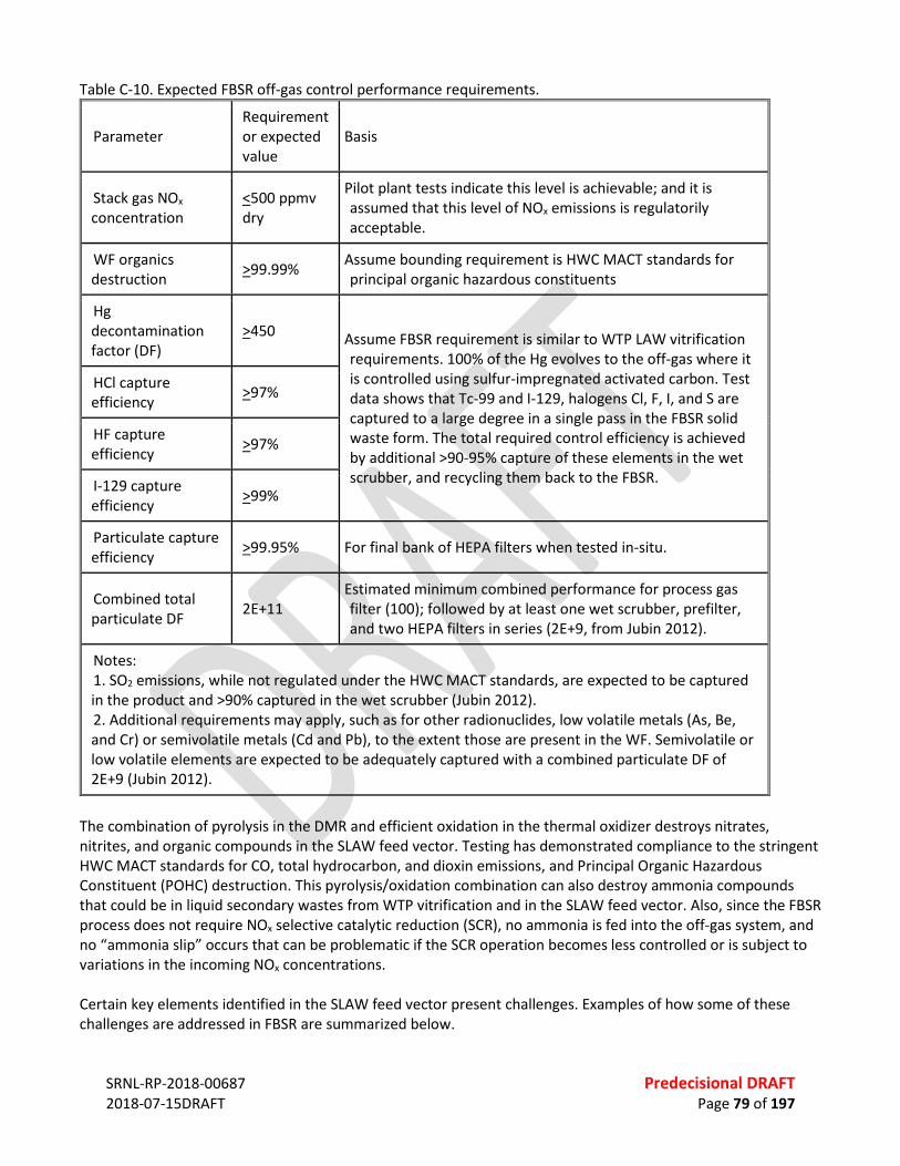
SRNL-RP-2018-00687 Predecisional DRAFT 2018-07-15DRAFT Page 79 of 197
Table C-10. Expected FBSR off-gas control performance requirements.
Parameter Requirement or expected value
Basis
Stack gas NOx concentration
<500 ppmv dry
Pilot plant tests indicate this level is achievable; and it is assumed that this level of NOx emissions is regulatorily acceptable.
WF organics destruction >99.99% Assume bounding requirement is HWC MACT standards for
principal organic hazardous constituents
Hg decontamination factor (DF)
>450 Assume FBSR requirement is similar to WTP LAW vitrification requirements. 100% of the Hg evolves to the off-gas where it is controlled using sulfur-impregnated activated carbon. Test data shows that Tc-99 and I-129, halogens Cl, F, I, and S are captured to a large degree in a single pass in the FBSR solid waste form. The total required control efficiency is achieved by additional >90-95% capture of these elements in the wet scrubber, and recycling them back to the FBSR.
HCl capture efficiency >97%
HF capture efficiency >97%
I-129 capture efficiency >99%
Particulate capture efficiency >99.95% For final bank of HEPA filters when tested in-situ.
Combined total particulate DF 2E+11
Estimated minimum combined performance for process gas filter (100); followed by at least one wet scrubber, prefilter, and two HEPA filters in series (2E+9, from Jubin 2012).
Notes: 1. SO2 emissions, while not regulated under the HWC MACT standards, are expected to be captured in the product and >90% captured in the wet scrubber (Jubin 2012). 2. Additional requirements may apply, such as for other radionuclides, low volatile metals (As, Be, and Cr) or semivolatile metals (Cd and Pb), to the extent those are present in the WF. Semivolatile or low volatile elements are expected to be adequately captured with a combined particulate DF of 2E+9 (Jubin 2012).
The combination of pyrolysis in the DMR and efficient oxidation in the thermal oxidizer destroys nitrates, nitrites, and organic compounds in the SLAW feed vector. Testing has demonstrated compliance to the stringent HWC MACT standards for CO, total hydrocarbon, and dioxin emissions, and Principal Organic Hazardous Constituent (POHC) destruction. This pyrolysis/oxidation combination can also destroy ammonia compounds that could be in liquid secondary wastes from WTP vitrification and in the SLAW feed vector. Also, since the FBSR process does not require NOx selective catalytic reduction (SCR), no ammonia is fed into the off-gas system, and no “ammonia slip” occurs that can be problematic if the SCR operation becomes less controlled or is subject to variations in the incoming NOx concentrations. Certain key elements identified in the SLAW feed vector present challenges. Examples of how some of these challenges are addressed in FBSR are summarized below.
SRNL-RP-2018-00687 Predecisional DRAFT 2018-07-15DRAFT Page 80 of 197
Table C-11 shows measured and estimated single-pass FBSR control efficiencies for elements that could be in FBSR waste feeds. This table includes single-pass control efficiencies measured in pilot and bench-scale tests. Single-pass control efficiencies have not been measured for all potentially relevant elements, so the table also shows how relative elemental volatilities as defined by the Environmental Protection Agency (EPA) and in other vitrification, used fuel reprocessing, and thermal process studies were used to estimate single-pass control efficiencies for elements not measured in pilot and bench-scale tests. Results of the pilot-scale tests are expected to be the most reliable for indicating performance of a full-scale FBSR system; followed by results of the bench-scale tests. The estimations of single-pass efficiencies from relative volatilities are least reliable. All of the measured and estimated single-pass control efficiencies for elements of greatest interest should be confirmed in full-scale demonstrations.

SRNL-RP-2018-00687 Predecisional DRAFT 2018-07-15DRAFT Page 81 of 197
Table C-11. FBSR single-pass elemental capture
Ref. 1 Ref. 2 minRef. 2 max
Ac --- --- --- NV NV 99.96%Ag 99.999% --- --- NV SV ---Al 99.998% --- NV NV --- ---Am --- --- --- NV NV 99.96%As 99.999% LVM --- NV --- ---Ba 99.998% --- --- NV NV ---Be --- --- --- LVM --- NV --- 99.96%Bi --- --- --- --- --- NV --- 99.96%C14 (organic) --- --- --- --- Gas Gas Gas 0.0%C14 (in CO3) --- --- --- --- --- --- --- 100.0%Ca --- --- --- --- --- NV --- 99.96%Cd 99.998% --- --- SVM SV SV SV ---Ce --- --- --- --- NV NV NV 99.96%Cl 90.8% 78% 100% --- SV Gas Gas 89.6%Cm --- --- --- --- --- NV NV 99.96%Co --- --- --- --- --- NV --- 99.96%Cr 99.99% --- --- LVM --- NV SV ---Cs 99.998% 87% 100% --- SV SV SV 95.7%Eu --- --- --- --- NV NV NV 99.96%F 84.6% --- --- --- SV Gas --- ---Fe 99.97% --- --- --- NV NV NV ---Gd --- --- --- --- NV NV NV 99.96%H3 --- --- --- --- Gas Gas Gas 0.0%Hg --- --- --- --- SV Gas --- 0.0%I 91.9% 75% 100% --- SV Gas Gas 89.0%Ir --- --- --- --- --- NV NV 99.96%K 99.9% --- --- --- --- SV --- ---La --- --- --- --- NV NV NV 99.96%Li --- --- --- --- --- SV --- 97.3%Mg 99.9% --- --- --- --- NV --- ---Mn --- --- --- --- --- NV --- 99.96%Mo --- --- --- --- --- NV SV 97.3%N --- --- --- --- --- Gas --- 0.0%Na 99.995% --- --- --- --- SV SV ---Nb --- --- --- --- --- NV NV 99.96%Nd --- --- --- --- NV NV NV 99.96%Ni 99.99% --- --- --- SV NV NV ---Np --- --- --- --- --- NV NV 99.96%P --- --- --- --- --- SV --- 97.3%Pa --- --- --- --- --- NV NV 99.96%Pb 99.998% --- --- SVM --- NV SV ---Pd --- --- --- --- --- NV NV 99.96%Pm --- --- --- --- NV NV NV 99.96%Pr --- --- --- --- NV NV NV 99.96%Pu --- --- --- --- --- NV NV 99.96%Rb --- --- --- --- --- SV SV 97.3%Re (Tc surrogate) 99.998% 71% 98% --- --- --- --- 84.5%Rh --- --- --- --- --- NV NV 99.96%Ru --- --- --- --- SV NV SV 97.3%
Measured capture efficiency, %
Ref. 3 (for melters)
Ref. 4 (for used fuel
separations)
Ref. 5 (for thermal
processes)Element
EPA HWC MACT
definition, Ref. 1
Relative volatil ityEstimated or
average capture efficiency, %
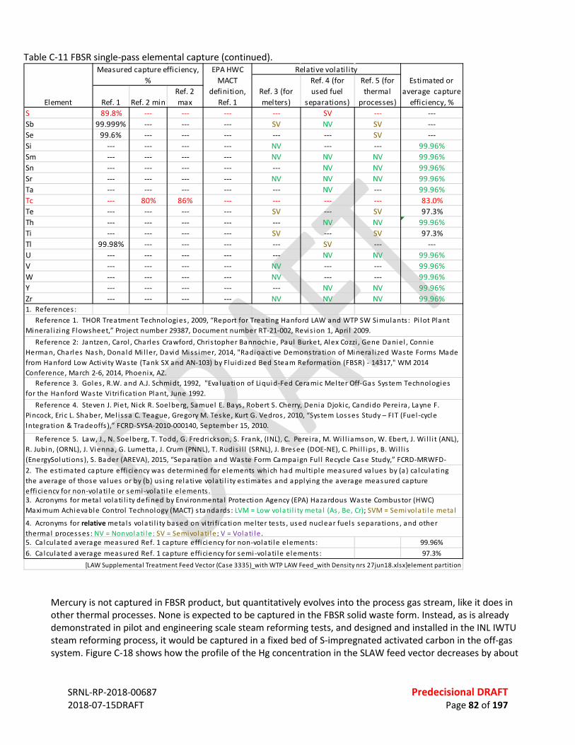
SRNL-RP-2018-00687 Predecisional DRAFT 2018-07-15DRAFT Page 82 of 197
Table C-11 FBSR single-pass elemental capture (continued).
Mercury is not captured in FBSR product, but quantitatively evolves into the process gas stream, like it does in other thermal processes. None is expected to be captured in the FBSR solid waste form. Instead, as is already demonstrated in pilot and engineering scale steam reforming tests, and designed and installed in the INL IWTU steam reforming process, it would be captured in a fixed bed of S-impregnated activated carbon in the off-gas system. Figure C-18 shows how the profile of the Hg concentration in the SLAW feed vector decreases by about
Ref. 1 Ref. 2 minRef. 2 max
S 89.8% --- --- --- --- SV --- ---Sb 99.999% --- --- --- SV NV SV ---Se 99.6% --- --- --- --- --- SV ---Si --- --- --- --- NV --- --- 99.96%Sm --- --- --- --- NV NV NV 99.96%Sn --- --- --- --- --- NV NV 99.96%Sr --- --- --- --- NV NV NV 99.96%Ta --- --- --- --- --- NV --- 99.96%Tc --- 80% 86% --- --- --- --- 83.0%Te --- --- --- --- SV --- SV 97.3%Th --- --- --- --- --- NV NV 99.96%Ti --- --- --- --- SV --- SV 97.3%Tl 99.98% --- --- --- --- SV --- ---U --- --- --- --- --- NV NV 99.96%V --- --- --- --- NV --- --- 99.96%W --- --- --- --- NV --- --- 99.96%Y --- --- --- --- --- NV NV 99.96%Zr --- --- --- --- NV NV NV 99.96%1. References :
5. Ca lculated average measured Ref. 1 capture efficiency for non-volati le elements : 99.96%6. Ca lculated average measured Ref. 1 capture efficiency for semi-volati le elements : 97.3%
[LAW Supplemental Treatment Feed Vector (Case 3335)_with WTP LAW Feed_with Density nrs 27jun18.xlsx]element partition
3. Acronyms for meta l volati l i ty defined by Environmenta l Protection Agency (EPA) Hazardous Waste Combustor (HWC) Maximum Achievable Control Technology (MACT) s tandards : LVM = Low volati l i ty meta l (As , Be, Cr); SVM = Semivolati le meta l
4. Acronyms for relative meta ls volati l i ty based on vi tri fi cation melter tests , used nuclear fuels separations , and other thermal processes : NV = Nonvolati le; SV = Semivolati le; V = Volati le.
2. The estimated capture efficiency was determined for elements which had multiple measured va lues by (a) ca lculating the average of those va lues or by (b) us ing relative volati l i ty estimates and applying the average measured capture efficiency for non-volati le or semi-volati le elements .
Reference 1. THOR Treatment Technologies , 2009, “Report for Treating Hanford LAW and WTP SW Simulants : Pi lot Plant Minera l i zing Flowsheet,” Project number 29387, Document number RT-21-002, Revis ion 1, Apri l 2009. Reference 2: Jantzen, Carol , Charles Crawford, Chris topher Bannochie, Paul Burket, Alex Cozzi , Gene Daniel , Connie Herman, Charles Nash, Donald Mi l ler, David Miss imer, 2014, "Radioactive Demonstration of Minera l i zed Waste Forms Made from Hanford Low Activi ty Waste (Tank SX and AN-103) by Fluidized Bed Steam Reformation (FBSR) - 14317," WM 2014 Conference, March 2-6, 2014, Phoenix, AZ. Reference 3. Goles , R.W. and A.J. Schmidt, 1992, "Eva luation of Liquid-Fed Ceramic Melter Off-Gas System Technologies for the Hanford Waste Vi tri fi cation Plant, June 1992. Reference 4. Steven J. Piet, Nick R. Soelberg, Samuel E. Bays , Robert S. Cherry, Denia Djokic, Candido Perei ra , Layne F. Pincock, Eric L. Shaber, Mel issa C. Teague, Gregory M. Teske, Kurt G. Vedros , 2010, “System Losses Study – FIT (Fuel -cycle Integration & Tradeoffs ),” FCRD-SYSA-2010-000140, September 15, 2010.
Reference 5. Law, J., N. Soelberg, T. Todd, G. Fredrickson, S. Frank, (INL), C. Perei ra , M. Wi l l iamson, W. Ebert, J. Wi l l i t (ANL), R. Jubin, (ORNL), J. Vienna, G. Lumetta , J. Crum (PNNL), T. Rudis i l l (SRNL), J. Bresee (DOE-NE), C. Phi l l ips , B. Wi l l i s (EnergySolutions), S. Bader (AREVA), 2015, “Separation and Waste Form Campaign Ful l Recycle Case Study,” FCRD-MRWFD-
Element
Measured capture efficiency, %
EPA HWC MACT
definition, Ref. 1
Relative volatil ityEstimated or
average capture efficiency, %
Ref. 3 (for melters)
Ref. 4 (for used fuel
separations)
Ref. 5 (for thermal
processes)
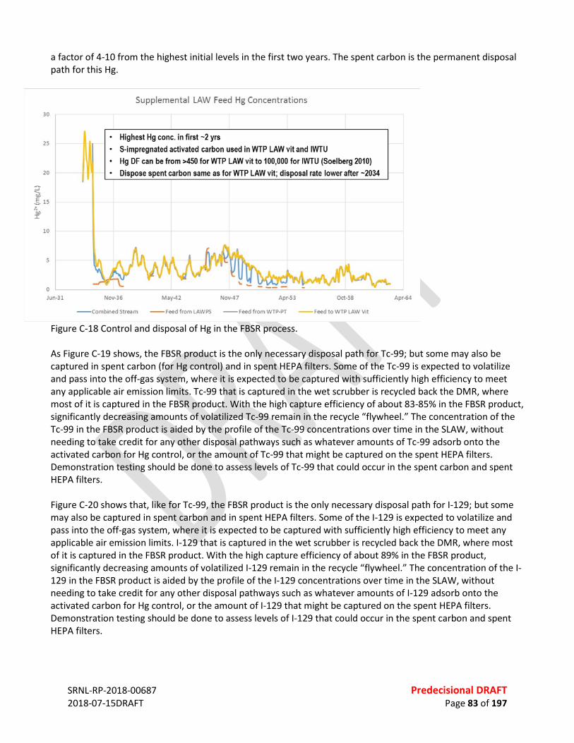
SRNL-RP-2018-00687 Predecisional DRAFT 2018-07-15DRAFT Page 83 of 197
a factor of 4-10 from the highest initial levels in the first two years. The spent carbon is the permanent disposal path for this Hg.
Figure C-18 Control and disposal of Hg in the FBSR process. As Figure C-19 shows, the FBSR product is the only necessary disposal path for Tc-99; but some may also be captured in spent carbon (for Hg control) and in spent HEPA filters. Some of the Tc-99 is expected to volatilize and pass into the off-gas system, where it is expected to be captured with sufficiently high efficiency to meet any applicable air emission limits. Tc-99 that is captured in the wet scrubber is recycled back the DMR, where most of it is captured in the FBSR product. With the high capture efficiency of about 83-85% in the FBSR product, significantly decreasing amounts of volatilized Tc-99 remain in the recycle “flywheel.” The concentration of the Tc-99 in the FBSR product is aided by the profile of the Tc-99 concentrations over time in the SLAW, without needing to take credit for any other disposal pathways such as whatever amounts of Tc-99 adsorb onto the activated carbon for Hg control, or the amount of Tc-99 that might be captured on the spent HEPA filters. Demonstration testing should be done to assess levels of Tc-99 that could occur in the spent carbon and spent HEPA filters. Figure C-20 shows that, like for Tc-99, the FBSR product is the only necessary disposal path for I-129; but some may also be captured in spent carbon and in spent HEPA filters. Some of the I-129 is expected to volatilize and pass into the off-gas system, where it is expected to be captured with sufficiently high efficiency to meet any applicable air emission limits. I-129 that is captured in the wet scrubber is recycled back the DMR, where most of it is captured in the FBSR product. With the high capture efficiency of about 89% in the FBSR product, significantly decreasing amounts of volatilized I-129 remain in the recycle “flywheel.” The concentration of the I-129 in the FBSR product is aided by the profile of the I-129 concentrations over time in the SLAW, without needing to take credit for any other disposal pathways such as whatever amounts of I-129 adsorb onto the activated carbon for Hg control, or the amount of I-129 that might be captured on the spent HEPA filters. Demonstration testing should be done to assess levels of I-129 that could occur in the spent carbon and spent HEPA filters.
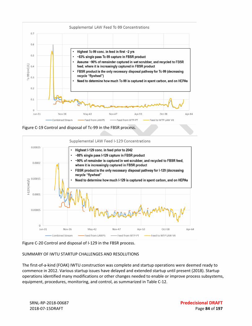
SRNL-RP-2018-00687 Predecisional DRAFT 2018-07-15DRAFT Page 84 of 197
Figure C-19 Control and disposal of Tc-99 in the FBSR process.
Figure C-20 Control and disposal of I-129 in the FBSR process. SUMMARY OF IWTU STARTUP CHALLENGES AND RESOLUTIONS The first-of-a-kind (FOAK) IWTU construction was complete and startup operations were deemed ready to commence in 2012. Various startup issues have delayed and extended startup until present (2018). Startup operations identified many modifications or other changes needed to enable or improve process subsystems, equipment, procedures, monitoring, and control, as summarized in Table C-12.

SRNL-RP-2018-00687 Predecisional DRAFT 2018-07-15DRAFT Page 85 of 197
Underlying Issues The startup challenges from 2012-2016 have been reviewed by Fluor Idaho, DOE-Idaho, and DOE Headquarters, and reported to the National Academy of Sciences as follows (Thompson 2018): • “The chemical reactions and hydrodynamic processes in the DMR are complex and intertwined. • There was insufficient technology maturation testing, modeling and engineering assessments to adequately
underpin the project. o Chemistry / reaction kinetics were not adequately understood. o Sufficiency of fluidization was not appropriately assessed. o Adequate modeling tools were not developed and utilized. o Insufficient technology maturation activities led to insufficient expertise and experience with this
process which impacted the design and operational approach. • Risks of first-of-a-kind systems were not recognized. • The lack of understanding led to:
o Various flaws in the design, specifications and operational procedures. o Contributed to mis-diagnosing testing outcomes which substantially lengthened the start-up and
commissioning phase. • Optimistic assumptions impacted the project approach relative to plant operability and reliability.
o Throughput assumptions and mission duration estimates drove poor decisions on preventative maintenance, spare parts, and redundancy.
• Several RadCon related controls and first-of-a-kind systems were not well thought out or not sufficiently developed/matured. o Examples include the canister fill system, sampling system, and vessel decontamination approach.”
Resolutions of Startup and Operating Challenges Many system and subsystem issues with the IWTU have now been solved; startup/commissioning may soon be complete, depending on the success of IWTU runs with non-radioactive simulant feed planned to be done in 2018. Startup of radioactive SBW treatment operations depend on satisfactory demonstration of the process, equipment, and procedures during non-radioactive operations. Some challenges remain. Successful operation related to the following issues for long term operation remains to be demonstrated:

SRNL-RP-2018-00687 Predecisional DRAFT 2018-07-15DRAFT Page 86 of 197
Table C-12 IWTU startup challenges and resolutions. June 2012: Overpressurization of the IWTU system during initial IWTU startup; breached filters; atmospheric release of coal and charcoal dust from the stack until process was shut down. No personnel were injured; no vessels or piping were damaged; and no radioactive or hazardous materials were in the facility or released. This caused a ~3-yr delay in IWTU startup between 2012 to 2015. Resolution: An investigation was performed and reported in “Investigation of the Integrated Waste Treatment Unit (IWTU) Over-Pressurization Event of June 16, 2012” (Idaho Completion Project report RPT-1119, August 2012). The investigation reviewed several related causes, and made recommendations how to prevent a recurrence. Coal and charcoal were fed at rates during startup higher than could react with the available oxygen feed. This created more coal and charcoal particles entrained in the process gas stream than could be filtered and removed from the process by the PGF and the Off-gas Filter (OGF, downstream of the Carbon Reduction Reformer [CRR]). This caused filter cake buildup, bridging between filter elements, and pressure drop across the filters that eventually caused PGF and OGF filter elements to lift off of the tubesheets, and allow unfiltered particles to pass on to, plug and breach the HEPA filter elements. When the HEPA filters breached, unfiltered coal and charcoal dust particles were emitted from the IWTU stack to the atmosphere. Other concurrent process responses and controls, such as the opening of a rupture disk used to prevent vessel overpressurization, also contributed to the dust release. This occurrence had multiple contributing causes including (a) insufficient/immature understanding of how to control the plant and what to expect, (b) inadequate instrumentation, monitoring, and process control strategy, (c) no real-time tracking and assessment of mass & energy balance conditions, (d) many design deficiencies for many facility subsystems and equipment, and (e) inadequate training, oversight, and technical inquisitiveness. The IWTU startup was delayed while changes were determined, tested, and implemented in all of these areas, such as (a) more detailed guidance on the process chemistry and hydrodynamics and better definition of operating limits, (b) implementation of a real-time process control mass/energy balance, (c) additional pressure and pressure drop monitoring, (d) prevention of filter element lifting off of the filter vessel tubesheets, (e) improved filter vessel operation (back-pulsing, hopper level control, and filter dust removal and management), (f) improved solids handling system equipment and operation, and (g) improved startup and operating procedures, control set-points, alarms, and corrective actions. Damaged filter elements, seals, etc. were replaced. The corrective actions solved this problem. As of 2018, the IWTU has operated without a repeat of these problems for thousands of hours. Various startup and operating issues, typical of a first-of-a-kind facility. These contributed to startup delays from 2015-2018. Resolutions: Various startup and operating issues listed below have, to date, been resolved through equipment or operating changes. These represent lessons learned that, where applicable, can be incorporated into the design for SLAW treatment, improving its technical readiness level.
) Performance of the solid product handling system: The solid product handling system now operates successfully after modifying solids eductors, operating temperatures and durations, modifying fluidization pads in hoppers, etc. This has been a multiyear improvement process.
) Various input gas flowrate measurement and control issues: Flow measurement and control for input steam, nitrogen, and oxygen has been revised with some new or different flow meter and flow controller choices, added electronic logging, and procedures.
) DMR and CRR charcoal and coal feed system reliability: The initial performance and reliability has been improved through determination of operating and control parameters, monitoring, maintenance, and changes in the lock-hopper equipment. This is an area of continued monitoring, repairs, and modification when needed. The CRR solid feed systems have been eliminated in the SLAW design.
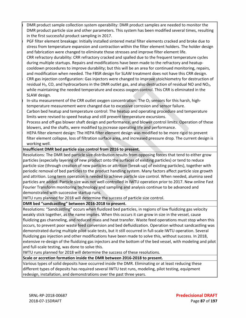
SRNL-RP-2018-00687 Predecisional DRAFT 2018-07-15DRAFT Page 87 of 197
) DMR product sample collection system operability: DMR product samples are needed to monitor the DMR product particle size and other parameters. This system has been modified several times, resulting in the first successful product sampling in 2017.
) PGF filter element breakage: Initially installed sintered metal filter elements cracked and broke due to stress from temperature expansion and contraction within the filter element holders. The holder design and fabrication were changed to eliminate those stresses and improve filter element life.
CRR refractory durability: CRR refractory cracked and spalled due to the frequent temperature cycles during multiple startups. Repairs and modifications have been made to the refractory and heatup-cooldown procedures to improve durability; but this will be an area for continued monitoring, repairs, and modification when needed. The FBSR design for SLAW treatment does not have this CRR design.
) CRR gas injection configuration: Gas injectors were changed to improve stoichiometry for destruction of residual H2, CO, and hydrocarbons in the DMR outlet gas, and also destruction of residual NO and NO2, while maintaining the needed temperature and excess oxygen control. This CRR is eliminated in the SLAW design.
) In-situ measurement of the CRR outlet oxygen concentration: The O2 sensors for this harsh, high-temperature measurement were changed due to excessive corrosion and sensor failure.
Carbon bed heatup and temperature control: The heatup and operating procedure and temperature limits were revised to speed heatup and still prevent temperature excursions.
Process and off-gas blower shaft design and performance, and blower control limits: Operation of these blowers, and the shafts, were modified to increase operating life and performance.
) HEPA filter element design: The HEPA filter element design was modified to be more rigid to prevent filter element collapse, loss of filtration surface area, and increased pressure drop. The current design is working well.
Insufficient DMR bed particle size control from 2016 to present. Resolutions: The DMR bed particle size distribution results from opposing forces that tend to either grow particles (especially layering of new product onto the surfaces of existing particles) or tend to reduce particle size (through creation of new particles or attrition [break-up] of existing particles), together with periodic removal of bed particles to the product handling system. Many factors affect particle size growth and attrition. Long term operation is needed to achieve particle size control. When needed, alumina seed particles are added. Particle size was not well controlled in IWTU operation prior to 2017. New online Fast Fourier Transform monitoring technology and sampling and analysis continue to be advanced and demonstrated with successive startup runs. IWTU runs planned for 2018 will determine the success of particle size control. DMR bed “sandcastling” between 2016-2018 to present. Resolutions: “Sandcastling” occurs when fluidized bed particles, in regions of low fluidizing gas velocity weakly stick together, as the name implies. When this occurs it can grow in size in the vessel, cause fluidizing gas channeling, and reduced mass and heat transfer. Waste feed operations must stop when this occurs, to prevent poor waste feed conversion and bed defluidization. Operation without sandcastling was demonstrated during multiple pilot-scale tests, but it still occurred in full-scale IWTU operation. Several fluidizing gas injection and other modifications have been made to solve this, without success. In 2018, extensive re-design of the fluidizing gas injectors and the bottom of the bed vessel, with modeling and pilot and full-scale testing, was done to solve this. IWTU runs planned for 2018 will determine the success of these resolutions. Scale or accretion formation inside the DMR between 2016-2018 to present. Various types of solid deposits have occurred inside the DMR. Eliminating or at least reducing these different types of deposits has required several IWTU test runs, modeling, pilot testing, equipment redesign, installation, and demonstrations over the past three years.
SRNL-RP-2018-00687 Predecisional DRAFT 2018-07-15DRAFT Page 88 of 197
Deposits in and around the auger-grinder plugged the auger-grinder until it was redesigned, tested, and installed, together with improved segregation of moisture and better temperature control low in the DMR. Wall scale formed during operation on in the inside surfaces of the DMR. Modeling and tests indicate that bed fluidization and waste conversion chemistry conditions can cause this wall scale. The modified bed fluidization design, together with chemistry modification through the waste feed additions, and control of particle size, bed temperature, and bed stoichiometry, is expected to provide needed wall scale control. Solid deposits on waste feed injectors can impair atomization into the fluidized bed. Feed injector design and optimization has been an ongoing activity during startup, to minimize deposits and maximize feed nozzle life. IWTU runs planned for 2018 will determine the success of these resolutions.
• Recirculating fluidization caused by having three waste feed nozzles all on one side of the DMR, configured for ease of maintenance instead of for waste feed injection equidistant every 120 degrees around the cylindrical DMR (modeled and mitigated by modifying the fluidizing gas configuration).
• Solids handling systems for the solid granular coal and coke fuels for the DMR and the Carbon Reduction Reformer (CRR), and for the granular product, which are based on mature commercial technology, and much improved during several thousand operating hours since 2012, but still prone to high maintenance.
• The refractory-lined, fluidized bed CRR, which has experienced refractory issues due to the heating-cooling cycles of the process, complicated by the vibration caused by the fluidized bed inside the CRR.
• Prevention of “sandcasting,” and control of wall scale and bed particle size in the DMR have not yet been demonstrated.
Since these startup and operating issues have been or may soon be solved at IWTU, those lessons learned can help prevent similar design and operating issues at Hanford. Indeed, some of the IWTU startup issues are not expected to apply to the mineralizing steam reformer process as conceptualized to treat Hanford SLAW. The chemistry of the mineralizing process needed for Hanford SLAW, and the differences between a Hanford SLAW steam reforming process (such as elimination of the fluidized bed Carbon Reduction Reformer (CRR) and the IWTU design, eliminates the following issues that occurred at the IWTU: • System overpressurization, and issues related to cleanable filter operation, input gas flowrate and flow
control, solids handling, carbon beds, HEPA filtration, and refractory: IWTU lessons learned will enable design and operation to avoid a repeat of this issue.
• DMR bed sandcastling and wall scale will be avoided because the mineralizing chemistry prevents these. • CRR solid fuel feeding, refractory, and gas injection issues will be avoided by replacing this fluidized bed
system with an open-chamber oxidizer.
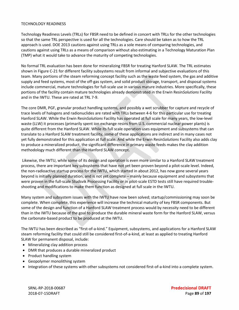
SRNL-RP-2018-00687 Predecisional DRAFT 2018-07-15DRAFT Page 89 of 197
TECHNOLOGY READINESS Technology Readiness Levels (TRLs) for FBSR need to be defined in concert with TRLs for the other technologies so that the same TRL perspective is used for all the technologies. Care should be taken as to how the TRL approach is used. DOE 2013 cautions against using TRLs as a sole means of comparing technologies, and cautions against using TRLs as a means of comparison without also estimating in a Technology Maturation Plan (TMP) what it would take to advance the maturity of competing technologies. No formal TRL evaluation has been done for mineralizing FBSR for treating Hanford SLAW. The TRL estimates shown in Figure C-21 for different facility subsystems result from informal and subjective evaluations of this team. Many portions of the steam reforming concept facility such as the waste feed system, the gas and additive supply and feed systems, most of the off-gas system, and solid product storage, transport, and disposal systems include commercial, mature technologies for full-scale use in various mature industries. More specifically, these portions of the facility contain mature technologies already demonstrated in the Erwin ResinSolutions Facility and in the IWTU. These are rated at TRL 7-9. The core DMR, PGF, granular product handling systems, and possibly a wet scrubber for capture and recycle of trace levels of halogens and radionuclides are rated with TRLs between 4-6 for this particular use for treating Hanford SLAW. While the Erwin ResinSolutions Facility has operated at full scale for many years, the low-level waste (LLW) it processes (primarily spent ion exchange resins from U.S. commercial nuclear power plants) is quite different from the Hanford SLAW. While its full scale operation uses equipment and subsystems that can translate to a Hanford SLAW treatment facility, some of these applications are indirect and in many cases not yet fully demonstrated for this application at full scale. And while the Erwin ResinSolutions Facility also adds clay to produce a mineralized product, the significant difference in primary waste feeds makes the clay addition methodology much different than the Hanford SLAW concept. Likewise, the IWTU, while some of its design and operation is even more similar to a Hanford SLAW treatment process, there are important key subsystems that have not yet been proven beyond a pilot-scale level. Indeed, the non-radioactive startup process for the IWTU, which started in about 2012, has now gone several years beyond is initially planned duration, and is not yet complete – mainly because equipment and subsystems that were proven in the full-scale Studsvik Processing Facility or in pilot-scale ESTD tests still have required trouble-shooting and modifications to make them function as designed at full scale in the IWTU. Many system and subsystem issues with the IWTU have now been solved; startup/commissioning may soon be complete. When complete, this experience will increase the technical maturity of key FBSR components. But some of the design and function of a Hanford SLAW treatment process would by necessity need to be different than in the IWTU because of the goal to produce the durable mineral waste form for the Hanford SLAW, versus the carbonate-based product to be produced at the IWTU. The IWTU has been described as “first-of-a-kind.” Equipment, subsystems, and applications for a Hanford SLAW steam reforming facility that could still be considered first-of-a-kind, at least as applied to treating Hanford SLAW for permanent disposal, include: • Mineralizing clay addition process • DMR that produces a durable mineralized product • Product handling system • Geopolymer monolithing system • Integration of these systems with other subsystems not considered first-of-a-kind into a complete system.
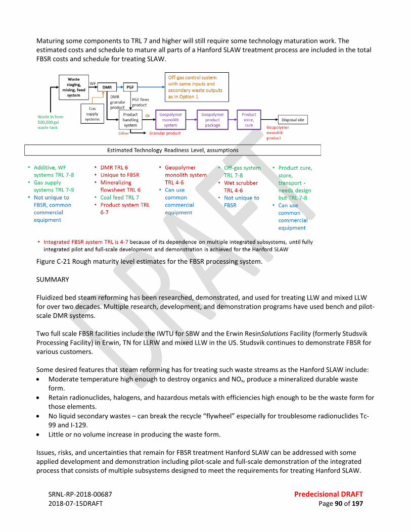
SRNL-RP-2018-00687 Predecisional DRAFT 2018-07-15DRAFT Page 90 of 197
Maturing some components to TRL 7 and higher will still require some technology maturation work. The estimated costs and schedule to mature all parts of a Hanford SLAW treatment process are included in the total FBSR costs and schedule for treating SLAW.
Figure C-21 Rough maturity level estimates for the FBSR processing system. SUMMARY Fluidized bed steam reforming has been researched, demonstrated, and used for treating LLW and mixed LLW for over two decades. Multiple research, development, and demonstration programs have used bench and pilot-scale DMR systems. Two full scale FBSR facilities include the IWTU for SBW and the Erwin ResinSolutions Facility (formerly Studsvik Processing Facility) in Erwin, TN for LLRW and mixed LLW in the US. Studsvik continues to demonstrate FBSR for various customers. Some desired features that steam reforming has for treating such waste streams as the Hanford SLAW include: • Moderate temperature high enough to destroy organics and NOx, produce a mineralized durable waste
form. • Retain radionuclides, halogens, and hazardous metals with efficiencies high enough to be the waste form for
those elements. • No liquid secondary wastes – can break the recycle “flywheel” especially for troublesome radionuclides Tc-
99 and I-129. • Little or no volume increase in producing the waste form. Issues, risks, and uncertainties that remain for FBSR treatment Hanford SLAW can be addressed with some applied development and demonstration including pilot-scale and full-scale demonstration of the integrated process that consists of multiple subsystems designed to meet the requirements for treating Hanford SLAW.
SRNL-RP-2018-00687 Predecisional DRAFT 2018-07-15DRAFT Page 91 of 197
REFERENCES BABAD, H. AND D.M. STRACHAN, 1980, “METHOD FOR IMMOBILIZING RADIOACTIVE IODINE”, U.S. PATENT #4,229,317 (October 1980). Barney, G., 1974, “Fixation of Radioactive Wastes by Hydrothermal Reactions with Clays,” Atlantic Richfield
Hanford Company, Richland, Washington (1974). Barrer, R.M. “Hydrothermal Chemistry of Zeolites,” 1945, Academic Press, New York, 360pp (1982): see
references by St. J. Thugutt, Z. Anorg. Chem, 2, 65 (1892) and E. Flint, W. Clarke, E.S. Newman, L. Shartsis, D. Bishop and L.S. Wells, J. Res. Natl. Bur. Stds, 36, 63 (1945).
Boardman, R. D., L. J. Young, N. R. Soelberg, and L. A. Matejka, 2001, “NWCF Calciner Emissions Inventory – Final Report for Phase IV Testing,” INEEL/EXT/01-00260, February 2001.
Brenchley, M.E. and M.T. Weller, 1994, “Synthesis and Structruer of M8[AlSiO4]6 (XO4)2, M = Na, Li, K; X = Cl, Mn Sodalites,” Zeolites, 14, 682-686 (1994).
Brookins, D.G., 1984, “Geochemical Aspects of Radioactive Waste Disposal,” Springer-Verlag: NY, 347pp (1984). Buhl, J.Ch., G. Englehardt, and J. Felsche, 1989, “Synthesis, X-ray Diffraction, and MAS N.M.R. Characteristics of
Tetrahydroxoborate Sodalite,” Zeolites, 9, 40-44 (1989). Buhl, J.C., T.M. Gesing, and C. Gurris, 2001, “Synthesis and crystal structure of rhodanide-enclathrated sodalite
Na8[AlSiO4]6(SCN)2,” Microporous and Mesoporous Materials, 50, 25-32 (2001). Burbank, D.A., 2002, “Waste Acceptance Criteria for the Immobilized Low-Activity Waste Disposal Facility,” US
DOE Report RPP-8401, CH2M HILL Hanford Group, Richland, Washington (May 2002). Campbell, B.J., J. Miguel Delgado, A.K. Cheetham, B.B. Iversen, N.P. Blake, S.R. Shannon, S. Satturner, and G.D.
Stucky, 2000, “The Cation-vacancy Ordering Transition in Dehydrated Na6 Sodalite,” Journal of Chemical Physics, 113[22], 10226-10239 (2000).
Caurant, D., P. Loiseau, O. Majerus, V. Aubin-Chevaldonnet, I. Bardez, and A. Quintas, “Glasses, Glass-Ceramics, and Ceramics for Immobilization of Highly Radioactive Nuclear Waste,” Nova Science Publishers, Inc., New York (2009).
Crawford, C.L. and C.M. Jantzen, 2007, “Durability Testing of Fluidized Bed Steam Reformer (FBSR) Waste Forms for Sodium Bearing Waste (SBW) at INL,” U.S. DOE Report WSRC-STI-2007-00319, Savannah River National Laboratory, Aiken, South Carolina (2007).
Crawford, C.L. and C.M. Jantzen, 2011, “Evaluation of THORTM Mineralized Waste Forms (Granular and Monolith) for the DOE Advanced Remediation Technologies (ART) Phase 2 Project,” U.S. DOE Report SRNL-STI-2009-00505, Savannah River Technology Center, Aiken, South Carolina (December 2011).
Crawford, C.L., P.R. Burket, A.D. Cozzi, W.E. Daniel, C.M. Jantzen, and D.M. Missimer, 2014, “Radioactive Demonstration of Mineralized Waste Forms Made from Hanford Waste Treatment Plant Secondary Waste (WTP-SW) by Fluidized Bed Steam Reformation (FBSR),” U.S. DOE Report, SRNL-STI-2011-00331, Rev. 1, Savannah River National Laboratory, Aiken, South Carolina (2014).
Dana, E.S., 1932, “A Textbook of Mineralogy,” John Wiley & Sons, Inc., New York, 851pp (1932). Deer, W.A., R.A. Howie, and J. Zussman, 1963, “Rock-Forming Minerals, V. 4,” John Wiley & Sons, Inc., New York,
435pp (1963). Deer, W.A., R.A. Howie, W.S. Wise, and J. Zussman, “Rock-Forming Minerals, Vol. 4B, Framework Silicates: Silica
Minerals, Feldspathoids and the Zeolites,” 2004, The Geological Society, London, UK (2004). Depmeier, W., 1987, “Structure of Cubic Aluminate Sodalite, Sr8[Al12O24](CrO4)2,” Acta Cryst., C43, 2251-2255
(1987). DOE 2013, “Technology Readiness Assessment (TRA) / Technology Maturation Plan (TMP) Process
Implementation Guide,” Revision 1, August 2013. DOE/ORP Contract with Bechtel National, Inc., 2000, “Design, Construction, and Commissioning of the Hanford
Tank Waste Treatment and Immobilization Plant,” Contract Number DE-AC27-01RV14136, U.S. Department of Energy, Office of River Protection, Richland, Washington (December 2000).
SRNL-RP-2018-00687 Predecisional DRAFT 2018-07-15DRAFT Page 92 of 197
Donald, I.W., B.L Metcalfe, and R.N.J. Taylor, 1997, “The Immobilization of High Level Radioactive Wastes Using Ceramics and Glasses,” J. Materials Science, 32, 5851-5887 (1997).
Donald, I.W., 2010, “Waste Immobilization in Glass and Ceramic Based Hosts,” John Wiley Ltd., West Sussex, UK, (2010).
Ebert, W.L., M.A. Lewis, and S.G. Johnson, 2002a, “Application of the PCT to the EBR II Ceramic Waste Form,” Proceedings of the DOE Spent Nuclear Fuel and Fissile Materials Management Meeting, Charleston, South Carolina, September 17–20 (2002).
Ebert, W.L., M.A. Lewis, and S.G. Johnson, 2002b, “The Precision of Product Consistency Tests Conducted with a Glass-Bonded Ceramic Waste Form,” Journal of Nuclear Materials, 305, 37–51 (2002).
Evans, B., A. Olson, J.B. Mason, K. Ryan, C.M. Jantzen, and C.L. Crawford, 2012,“Radioactive Bench Scale Reformer Demonstration of a Monolithic Steam Reformed Mineralized Waste Form for Hanford Waste Treatment Plant Secondary Waste,” Paper #12306, Waste Management 12, February 2012, Phoenix, Arizona.
Fechtelkord, M., 2000, “Influence of Sodium Ion Dynamics on the 235Na Quadrupolar Interaction in Sodalite: A High-Temperature 236Na MAS NMR Study,” Solid State Nuclear Magnetic Resonance 18, 70-88 (2000).
Fleet, M.E., 1989, “Structures of Sodium Alumino-Germanate Sodalites,” Acta Cryst., C45, 843-847 (1989). GAO 2016, “Technology Readiness Assessment Guide,” GAO-16-410G, August 2016. Gesing, T.M., and J.C. Buhl, 1998, “Crystal structure of a carbonate-nosean Na8[AlSiO4]6CO3,” European Journal
of Mineralogy 10[1], 71-77 (1998). Grimm, R.E., 1953, “Clay Mineralogy,” McGraw Hill Book Co., New York, 384pp (1953). Hatch, L.P., 1953, “Ultimate Disposal of Radioactive Wastes,” Am. Scientist, 41, 410-421 (1953). Hench, L.L, R.J. Charles, A.R. Cooper, R.C. Ewing, J.R. Hutchins, D.W. Readey, F.L. VerSnyder, and S.M.
Widerhorn, 1981, “The Evaluation and Selection of Candidate High Level Waste Forms,” Report No. 3, USDOE/TIC-11472, Alternative Waste Form Peer Review Panel (National Technical Information Service), Springfield, Virginia (1981).
Hench, L.L., D.E. Clark, and A.B. Harker, 1986, “Nuclear Waste Solids,” Journal of Materials Science, 21, 1457-1478 (1986).
Jantzen, C.M., 2002, “Engineering Study of the Hanford Low Activity Waste (LAW) Steam Reforming Process,” U.S. DOE Report WSRC-TR-2002-00317, Westinghouse Savannah River Co., Aiken, South Carolina (July 2002).
Jantzen, C.M., 2004, “Characterization and Performance of Fluidized Bed Steam Reforming (FBSR) Product as a Final Waste Form,” Ceramic Transactions, Vol. 155, J. D. Vienna, and D.R. Spearing, Eds.: 319-29 (2004).
Jantzen, C.M., J.M. Pareizs, T.H. Lorier, and J.C. Marra, 2006a, “Durability Testing of Fluidized Bed Steam Reforming (FBSR) Products,” Ceramic Transactions, V. 176, C. C. Herman, S.L. Marra, D.R. Spearing, L. Vance, and J.D. Vienna, Eds.; 121-37 (2006a).
Jantzen, C.M., T.H. Lorier, J.C. Marra, and J.M. Pareizs, 2006b, “Durability Testing of Fluidized Bed Steam Reforming (FBSR) Waste Forms,” Paper #6373, Waste Management 06, Tucson, Arizona (2006b).
Jantzen, C.M., 2006c, “Fluidized Bed Steam Reformer (FBSR) Product: Monolith Formation and Characterization,” WSRC-STI-2006-00033, Savannah River National Laboratory, Aiken, South Carolina (2006c).
Jantzen, C.M., T.H. Lorier, J.M. Pareizs, and J.C. Marra, 2007a, “Fluidized Bed Steam Reformed (FBSR) Mineral Waste Forms: Characterization and Durability Testing,” Scientific Basis for Nuclear Waste Management XXX, D. S. Dunn, C. Poinssot, and B. Begg, Eds.; 379-386 (2007a).
Jantzen, C.M., 2007b, “Fluidized Bed Steam Reformer (FBSR) Monolith Formation,” Paper #7075, Waste Management 07, Tucson, Arizona (2007b).
Jantzen, C.M. and C.L. Crawford, 2010, “Mineralization of Radioactive Wastes by Fluidized Bed Steam Reforming (FBSR): Radionuclide Incorporation, Monolith Formation, and Durability Testing,” Paper #10467 Waste Management 10, Phoenix, Arizona.
Jantzen, C.M., C.L. Crawford, P.R. Burket, W.E. Daniel, A.D. Cozzi, and C.J. Bannochie, 2011, “Radioactive Demonstrations of Fluidized Bed Steam Reforming (FBSR) as a Supplementary Treatment for Hanford’s Low

SRNL-RP-2018-00687 Predecisional DRAFT 2018-07-15DRAFT Page 93 of 197
Activity Waste (LAW) and Secondary Wastes (SW),” Paper #11593 Waste Management 11, Phoenix, Arizona (2011).
Jantzen, C.M., C.L. Crawford, C.J. Bannochie, P.R. Burket, A.D. Cozzi, W.E. Daniel, D.M. Missimer, and C.A. Nash, 2013, “Radioactive Demonstration of Mineralized Waste Forms Made from Hanford Low Activity Waste (Tank Farm Blend) by Fluidized Bed Steam Reformation (FBSR),” SRNL-STI-2011-00383, Savannah River National Laboratory, Aiken, South Carolina (August).
Jantzen, C.M., C.L. Crawford, P.R. Burket, C.J. Bannochie, W.E. Daniel, C.A. Nash, A.D. Cozzi, and C.C. Herman, 2012, “Radioactive Demonstrations of Fluidized Bed Steam Reforming (FBSR) with Actual Hanford Low Activity Wastes: Verifying FBSR as a Supplemental Treatment,” Paper #12317, Waste Management 12, February 2012, Phoenix, Arizona.
Jantzen, C.M., C.L. Crawford, C.J. Bannochie, P.R. Burket, A.D. Cozzi, W.E. Daniel, C.C. Herman, D.H. Miller, D.M. Missimer, and C.A. Nash, 2014, “Radioactive Demonstration of Mineralized Waste Forms Made from Hanford Low Activity Waste (Tank SX-105 and AN-103) by Fluidized Bed Steam Reformation (FBSR),” Paper #14317, Waste Management 2014, Phoenix, Arizona (2014).
Jantzen, C.M., E.M. Pierce, C.J. Bannochie, P.R. Burket, A.D. Cozzi, C.L. Crawford, W.E. Daniel, K.M. Fox, SRNL, C.C. Herman, D.H. Miller, D.M. Missimer, C.A. Nash, M.F. Williams, C.F. Brown, N. P. Qafoku, J.J. Neeway, M.M. Valenta, G.A. Gill, D.J. Swanberg, R.A. Robbins, L.E. Thompson, 2015a, “Fluidized Bed Steam Reformed Mineral Waste Form Performance Testing to Support Hanford Supplemental Low Activity Waste Immobilization Technology Selection,” SRNL-STI-2011-00387.
Jantzen, Carol M., David M. Missimer, Chris P. Guenther, Dushyant Shekhawat, Dirk T. VanEssendelft, Nicholas C. Means, 2015b, “Integrated Waste Treatment Unit (IWTU) Input Coal Analyses and Off-Gas Filter (OGF) Content Analyses,” SRNL-STI-2015-00015, Revision 0, April.
Johnson, G.M., P.J. Mead, and M.T. Weller, 2000, “Synthesis of a Range of Anion-containing Gallium and Germanium Sodalities,” Microporous and Mesoporous Materials, 38, 445-460 (2000).
Jubin, R.T, N.R. Soelberg, D.M. Strachan, and G. Ilas, “Fuel Age Impacts on Gaseous Fission Product Capture During Separations,” FCRD-SWF-2012-000089, 21 September 2012.
Klingenberg, R. and J. Felsche, 1986, “Interstitial Cristobalite-type Compounds (Na2O)0.33Na[AlSiO4],” J. Solid State Chemistry, 61, 40-46 (1986).
Law, J., N. Soelberg, T. Todd, G. Fredrickson, S. Frank, C. Pereira, M. Williamson, W. Ebert, J. Willit, R. Jubin, J. Vienna, G. Lumetta, J. Crum, T. Rudisill, J. Bresee, C. Phillips, B. Willis, S. Bader, 2015, “Separation and Waste Form Campaign Full Recycle Case Study,” FCRD-MRWFD-2015-000241, September 30, 2015.
Lee, W., M. Ojovan, M. Stennett, and N. Hyatt, 2006, “Immobilization of Radioactive Waste in Glasses, Glass Composite Materials, and Ceramics,” Advances in Applied Ceramics, 105[1], 3-12 (2006).
Liebau, F. “Zeolites and Clathrasils – Two Distinct Classes of Framework Silicates,” Zeolites, 1983, 3[7] 191-92. Lorier, T.H., J.M. Pareizs, and C.M. Jantzen, 2005, “Single Pass Flow through (SPFT) Testing of Fluidized Bed
Steam Reforming (FBSR) Waste Forms,” U.S. DOE Report WSRC-TR-2005-00124, Savannah River National Laboratory, Aiken, South Carolina (2005).
Lorier, T.H., C.M. Jantzen, J.C. Marra, and J.M. Pareizs, 2006, “Feed Reactivity Study for Fluidized Bed Steam Reformer Processing,” Ceramic Transactions V. 176, 111-119 (2006).
Lutze, W. and R.C. Ewing, 1988, “Radioactive Waste Forms for the Future,” Elsevier Science Publishers, Amsterdam, The Netherlands (1988).
Mann, F.M., R.J. Puigh, R. Khaleel, S. Finfrock, B.P. McGrail, D.H. Bacon, and R.J. Serne, “Risk Assessment Supporting the Decision on the Initial Selection of Supplemental ILAW Technologies,” RPP-17675, Pacific Northwest National Laboratory, Richland, Washington (2003).
Marshall, D. W., N. R. Soelberg, and K.M. Shaber, 2003, “THORsm Bench-scale Steam Reforming Demonstration, INEEL/EXT-03-00437, May 2003.
Mason, J. Bradley, Thomas W. Oliver, Marty P. Carson, G. Mike Hill, 1999, “Studsvik Processing Facility Pyrolysis/Steam Reforming Technology for Volume and Weight Reduction and Stabilization of LLRW and Mixed Wastes,” WM’99, February 28-March 4, 1999.

SRNL-RP-2018-00687 Predecisional DRAFT 2018-07-15DRAFT Page 94 of 197
Mattigod, S.V., B.P. McGrail, D.E. McCready, L. Wang, K.E. Parker, and J.S. Young, 2006, “Synthesis and Structure of Perrhenate Sodalite,” J. Microporous & Mesopourous Materials, 91(1-3), 139-144.
McGrail, B.P., E.M. Pierce, H.T. Schaef, E.A. Rodriques, J.L. Steele, A.T. Owen, and D.M. Wellman, 2003a, “Laboratory Testing of Bulk Vitrified and Steam-Reformed Low-Activity Forms to Support a Preliminary Assessment for an Integrated Disposal Facility,” PNNL-14414, Pacific Northwest National Laboratory, Richland, Washington (2003a).
McGrail, B.P., H.T. Schaef, P.F. Martin, D.H. Bacon, E.A. Rodriquez, D.E. McReady, A.N. Primak, and R.D. Orr, 2003b “Initial Evaluation of Steam-Reformed Low Activity Waste for Direct Land Disposal,” U.S. DOE Report PNWD-3288, Pacific Northwest National Laboratory, Richland, Washington (2003b).
Moschetti, T., W. Sinkler, T. DiSanto, M.H. Noy, A.R. Warren, D. Cummings, S.G. Johnson, K.M. Goff, K.J. Bateman, and S.M. Frank, 2000, “Characterization of a Ceramic Waste Form Encapsulating Radioactive Electrorefiner Salt,” in Scientific Basis for Nuclear Waste Management XXIII, R. Smith and D. Shoesmith, Eds.; Materials Research Society, Pittsburgh, Pennsylvania, 577-582 (2000).
Nayak, M. and T.R.N. Kutty, 1998, “Luminescence of Fe3+ Doped NaAlSiO4 Prepared by Conversion,” Materials Chem. And Phys. 57[2], 138-146 (1998).
Neeway, J.J., N.P. Qafoku, B.D. Williams, M.M. Valenta, E.A. Cordova, S.C. Strandquist, D.C. Dage, and C.F. Brown, 2012, “Single Pass Flow-Through (SPFT) Test Results of Fluidized Bed Steam Reforming (FBSR) Waste Forms used for LAW Immobilization,” Paper #12252, Waste Management 12, February 2012, Phoenix, Arizona.
Neeway, J.J., N.P. Qafoku, C.F. Brown, and R.A. Peterson, 2013, “Characterization and Leaching Tests of the Fluidized Bed Steam Reforming (FBSR) Waste Form for LAW Immobilization,” Paper #14300, Waste Management 13, March 2013, Phoenix, Arizona.
Neeway, J.J., N.P. Qafoku, B.D. Williams, R. Kenton, M.E. Bowden, C.F. Brown, and E.M. Pierce, 2014, “Performance of the Fluidized Bed Steam Reforming Product Under Hydraulically Unsaturated Conditions,” Journal of Environmental Radioactivity, 131, 119-138 (2014).
NRC 2011, “Waste Forms Technology and Performance, Final Report,” National Research Council of the National Academies, Committee on Waste Forms Technology and Performance, National Academies Press, Washington, DC.
Olson, A. L., N. R. Soelberg, D. W. Marshall, and G. L. Anderson, 2004a, “Fluidizing Bed Steam Reforming of Hanford LAW Using THORsm, Mineralizing Technology,” INEEL/EXT-04-02492, November 2004.
Olson, A. L., N. R. Soelberg, D. W. Marshall, and G. L. Anderson, 2004b, “Fluidizing Bed Steam Reforming of INEEL SBW Using THORsm, Mineralizing Technology,” INEEL/EXT-04-02564, December 2004.
Pareizs, J.M., C.M. Jantzen, and T.H. Lorier, 2005, “Durability Testing of Fluidized Bed Steam Reformer (FBSR) Waste Forms for High Sodium Wastes at Hanford and Idaho,” U.S. DOE Report, WSRC-TR-2005-00102, Savannah River National Laboratory, Aiken, South Carolina (2005).
Pauling, L., 1930, “The Structure of Sodalite and Helvite,” Zeitschrift fur Kristallographie, 74, 213-225, (1930). Peterson, R.C., 1983, “The Structure of Hackmanite, A Variety of Sodalite, from Mont St-Hilaire, Quebec,”
Canadian Mineralogist, 21, 549-552 (1983). Pierce, E.M., 2007, “Accelerated Weathering of Fluidized Bed Steam Reformation Material under Hydraulically
Unsaturated Conditions,” Proceedings from Materials Science & Technology, September 16-20, 2007, Detroit, Michigan.
Pierce, E.M., 2012,“Review of Existing Fluidized-Bed Steam Reformer Sodium Aluminosilicate Waste Form Performance Data,” ORNL/TM-2012/19, Rev. 1, Oak Ridge National Laboratory, Oak Ridge, TN (2012; 2014 in revision).
Pierce, E.M., W.W. Lukens, J. Fitts, C.M. Jantzen, and G. Tang, 2014, “Experimental Determination of the Sepeciation, Partitioning, and Release of Perrhenate as a Chemical Surrogate for Pertechnetate form a Sodalite-bearing Multiphase Ceramic Waste Form,” Applied Geochemistry, 42, 47-59 (2014).
SRNL-RP-2018-00687 Predecisional DRAFT 2018-07-15DRAFT Page 95 of 197
Pires, R.P., J.H. Westsick, R.J. Serene, E.C. Golovich, M.M. Valenta, and K.E. Parker, 2011,“Secondary Waste Form Screening Test Results - THOR Fluidized Bed Steam Reforming Product in a Geopolymer Matrix,” PNNL- 20551, Pacific Northwest National Laboratory, Richland, Washington (July 2011).
Qafoku, N.P., J.H. Westsik, D.M. Strachan, M.M. Valenta, and R.P. Pires, 2011, “Secondary Waste Form Down-Selection Data Package- Fluidized Bed Steam Reforming Waste Form,” U.S. DOE Report PNNL-20704, Pacific Northwest National Laboratory, Richland, Washington (September 2011).
Rassat, S.D., L.A. Mahoney, S.A. Bryan, and R.L. Sell, 2002, “Cold Dissolved Saltcake Waste Simulant Formulation,” PNNL, November 21, 2002.
Shannon, S.R, B.J. Campbell, H. Metiu, and N.P. Blake, 2000, “Cation-vacancy Ordering in Dehydrated Na6[AlSiO4]6,” Journal of Chemical Physics, 113[22], 10215-10225 (2000).
Smith, J.V. and O.F. Tuttle, 1957, “The Nepheline-Kalsilite System, Part I, X-ray Data for the Crystalline Phases,” Am. J. Sci., 255, 282-305 (1957).
Srdanov, V.I., W.T.A. Harrison, T.E. Gier, and G.D. Stucky, 1994, “Structure and Spectroscopy of Sodalite Containing MnO4,” Ions. Journal of Physical Chemistry B, 98, 4673-4676 (1994).
Soelberg, Nick, 2003, “MACT Compliance for the Calcination with MACT Upgrade SBW Treatment Alternative,” INEEL EDF-2211, September 2003.
Soelberg, N. R., D. W. Marshall, S. O. Bates, and D. D. Taylor, 2004a, “Phase 2 THOR Steam Reforming Tests for Sodium-Bearing Waste Treatment,” INEEL/EXT-04-01493, January 30, 2004.
Soelberg, Nick, Doug Marshall, Steve Bates, and Duane Siemer, 2004b, “SRS Tank 48H Steam Reforming Proof-of-Concept Test Results,” INEEL/EXT-03-01118, Revision 1, May 2004.
Stefanovsky, S., S. Yudintsev, R. Giere, and G. Lumpkin, 2004, “Nuclear Waste Forms,” in Energy, Waste, and the Environment: A Geochemical Perspective, R. Giere and P. Stille, Eds., Geological Society of London Special Publication, 36-63 (2004).
Studsvik, Inc., 2004a, “Hanford LAW Waste THORSM Steam Reforming Denitration and Sodium Conversion Demonstration, Final Report,” TR-SR01-1, Rev. 0.
Studsvik 2004b, “Steam reforming Technology for the Denitration and Immobilization of DOE Tank Wastes,” March 19 presentation.
Taylor, D. and C.M.B. Henderson, 1978, “A Computer Model for the Cubic Sodalite Structure,” Phys. and Chem. of Minerals, 2[4], 325-336 (1978).
Thompson, J.G., R.L. Withers, A. Melnitchenko, and S.R. Paletthorpe, 1998a, “Cristobalite-Related Phases in the NaAlO2-NaAlSiO4 System. I. Two Tetragonal and Two Orthorhombic Structures,” Acta Cryst., 1998, B54, 531-546.
Thompson, J.G., R.L. Withers, A. Melnitchenko, and S.R. Paletthorpe, 1998b, “Cristobalite-Related Phases in the NaAlO2-NaAlSiO4 System. II. A Commensurately Modulated Cubic Structure,” Acta Cryst. B54, 547-557 (1998).
Thompson, L., 2018, personal communication to Nick Soelberg, July 29. Tobbens, D.M. and J.C. Buhl, 2000, “Superstructure of Sodiumborate Sodalite,” Berline Neutron Scattering
Center (BENSC) Experimental Report E9, Helmholtz Zentrum fur Materialiene und Energie (formally the Hahn-Meitner Institute), Berlin, Germany (2000).
THOR Treatment Technologies, LLC, and Washington Group International, 2007a, “Pilot Plant Report for Treating SBW Simulants, Mineralizing Flowsheet,” Doc. No. 28266-WEC-RT-0001, Revision 1, Project Number 28276, Revision A, June 2007.
THOR Treatment Technologies, LLC, and Washington Group International, 2007b, “Pilot Plant Report for Treating Tank 48H Simulants, Carbonate Flowsheet,” Doc. No. 28927-WEC-RPT-0001, Revision 1, Project Number 28927, February 2007.
THOR Treatment Technologies, 2008, “Tank 48 Project—Validation Testing, Phase 1: Engineering Scale Technology Demonstration Preliminary Test Report.” Project Number 29616, Document Number 00-RT-001, September 18, 2008.

SRNL-RP-2018-00687 Predecisional DRAFT 2018-07-15DRAFT Page 96 of 197
THOR Treatment Technologies, “Tank 48 Project—Validation Testing, Phase 1: Engineering Scale Technology Demonstration Preliminary Test Report.” Project Number 29616, Document Number 00-RT-001, September 18, 2008.
THOR Treatment Technologies, 2009a, “THOR® Steam Reforming Pilot Plant AREVA Malvesi Lagoon Waste Treatment Demonstration Test Report,” Project number 07211-05460, Report number AML-TR-1, February 2009.
THOR Treatment Technologies, 2009b, “Report for Treating Hanford LAW and WTP SW Simulants: Pilot Plant Mineralizing Flowsheet,” Project number 29387, Document number RT-21-002, Revision 1, April 2009.
U.S. Nuclear Regulatory Commission, 1991, “Technical Position on Waste Form (Revision 1),” U.S. NRC Low-Level Waste Management Branch Division of Low-Level Waste Management and Decommissioning (January 1991).
Williams, B.D., J.J. Neeway, M.M. Valenta, M.E. Bowden, J.E. Amonette, B.W. Arey, E.M. Pierce, C.F. Brown, and N.P. Qafoku, 2015, “Release of Technetium and Iodine from a Sodalite-Bearing Ceramic Waste Form in Dilute-Solution Conditions,” Submitted to Applied Geochemistry 2015.
SRNL-RP-2018-00687 Predecisional DRAFT 2018-07-15DRAFT Page 97 of 197
APPENDIX D. EXPANDED DISCUSSION – GROUT D.1 TECHNOLOGY OVERVIEW D.1.2 Grout Grout technology involves mixing of an aqueous waste stream with various dry reagents to produce a slurry that is transferred into a waste container to solidify. The slurry reacts over a period of time to produce a solid, which encapsulates the constituents of concern in a solid waste-form. The initial solidification occurs over hours to days but reactions continue to evolve over years. The solidification reactions are exothermic. The reagents used in cementation processes are inorganic materials that react with water to form solid, moisture-resistant waste forms. Grout technology has a long history of being used to transform radioactive aqueous liquid and sludge waste streams into solid waste forms for disposal at ambient temperature or near ambient temperature. Two types of cement systems, hydraulic cements and acid-base cements, are used for radioactive waste treatment and conditioning as well as for radioactive particulate waste and debris encapsulation. The most common hydraulic cements used are based on ordinary Portland cement (OPC), which is a mixture of anhydrous calcium silicates, calcium aluminate, and calcium sulfate compounds. Often, grout technology utilizes dry mixes where the OPC is blended with other reactive ingredients selected to tailor characteristics of the final waste-form. Calcium aluminate cements, calcium sulfoaluminate cements, lime-pozzolan cements, calcium sulfate cements, and alkali activated slags and slag cements have also been successfully used. The most common acid-base cements used for radioactive waste conditioning are made by combining an acid (e.g., H3PO4 or KH2PO4, liquid or powder, respectively) with a powder base, e.g, MgO or CaO [IAEA, 2018 in press]. Grout technology can be tailored for a range of waste chemistries, available cement ingredients, and process, and final waste form requirements. It can also be used to chemically bind certain radionuclides and hazardous contaminants by precipitation of low solubility phases, sorption on hydrated particle surfaces and / or incorporated into layer structures of the hydrated phases. Advantages of using grout technology to treat / condition waste include: • Cements, mineral additives, and chemical admixtures are inexpensive and readily available • Simple and low-cost processing at ambient temperature • Several remote processing options have been demonstrated and are available • Cement matrix acts as a diffusion barrier and provides sorption and reaction sites • Suitable for sludge, liquors, emulsified organic liquids and dry solids • Suitable for a wide range of aqueous compositions • Good thermal, chemical and physical stability of waste-form • Alkaline chemistry which ensures low solubility for many key radionuclides • Non-flammable waste form • Good waste-form compressive strength which facilitates handling • Flexible formulation to meet particular waste form requirements • Processing options are demonstrated for a wide range of waste volumes from > 1.0E+05 L /day (saltstone) to
< 0.5 L batches. • Water in the feed is incorporated into the waste form, minimizing the volume of secondary liquid waste Grouting technology has been designated as BDAT for LAW at the Savannah River Site (SRS), where it has been used to process over 17 million gallons liquid waste since 1991. The resulting waste form is called saltstone. The

SRNL-RP-2018-00687 Predecisional DRAFT 2018-07-15DRAFT Page 98 of 197
feed solution to saltstone is currently decontaminated (Cs, Sr and actinide removal) in the Actinide Removal Process (ARP)/Modular Caustic Side Solvent Extraction Unit (MCU) prior to being transferred to Tank 50, which is the 1M gallon feed tank for the Saltstone Facility. Tank 50 is located in the H-Area tank farm about 1.6 miles from the saltstone processing facility, and salt solution is transferred from Tank 50 through a double jacketed line to a process feed tank in Z-Area where it is mixed with a blend of Portland cement, blast furnace slag (BFS), and class F fly ash (FA) in a ratio of 10:45:45 by weight. The dry blend is mixed with the liquid waste in a proportion of 0.58–0.6 water:dry-mix (w:dm). The addition of BFS helps to achieve a low activity of oxygen, which maintains some waste constituents (e.g., technetium) in a less-soluble reduced oxidation state. D.1.2 Cast Stone Several dry-blend mixes similar to saltstone have been investigated for various Hanford waste streams, leading to a suite of products with favorable properties generally termed cast stone. Lockrem (2005) presents a cast-stone recipe that has favorable properties for Hanford’s LAW streams, and it consists of dry blend ingredients in proportions similar to saltstone: 8 wt% OPC, 47 wt% BFS, 45 wt% FA. Other proportions of OPC-BFS-FA have also been investigated (e.g., Lockrem, 2005; Sundaram et al., 2011; Serne et al., 2016). Hydration of cast-stone dry mix results in reaction products that include a range of phases. A suite of amorphous phases (including calcium silicate hydrate) dominate the reaction products, but ettringite and other crystalline alumino-ferrous sulfate phases have also been identified in hydration products from cast stone formulations (e.g., Sundaram et al., 2011; Um et al., 2016). Calcium hydroxide—which can occur in hydration of pure OPC—does not occur in the cast-stone system due to the addition of BFS and FA. The properties of monoliths made from cast stone formulations differ significantly from those made for Hanford low activity waste (LAW) using earlier grout formulations that lacked BFS, particularly with respect to retention of many constituents of concern including at least some radionuclides. The addition of BFS to the dry mix alters the chemistry of cast stone, resulting in several characteristics favorable to Hanford’s LAW streams. As noted, BFS imparts reducing conditions (low oxygen activity) in the final hydrated product, which significantly lowers the release for several elements including chromium, technetium, and uranium; recent experiments quantifying this effect are described in section 5.3.0.3. Blast furnace slag is activated by alkalis (Wu et al., 1990), including the sodium sulfate and sodium hydroxide that are present in Hanford LAW; this results in a partial neutralization of high alkalinity of the waste stream and an improvement in the qualities of the hydrated product such as lower permeability and higher long-term strengths (Wu et al., 1990). A central question remains: How does a grout monolith oxidize under long-term disposal conditions, and how does this impact the long-term retention of redox-sensitive constituents? The materials used in the cast-stone formulation are readily available at present, and the materials needs for a cast-stone operation to handle projected volumes of SLAW is small compared with domestic production. As a rough guide, the materials needs to handle an 8 gallon per minute continuous feed of SLAW (i.e., continuous flow at maximum projected rates) for a cast stone mix are on the order of 0.004 million metric tons per year for OPC and 0.03 million metric tons per year for both BFS and FA. In 2016, domestic production of Portland cement is roughly 85 million metric tons, and production from the 97 domestic kilns is well below capacity (USGS, 2017). In 2016, domestic slag sales were 18 million metric tons, of which 47% was blast furnace slag (USGS, 2017); in addition, 2 million metric tons of slag were imported for consumption, primarily from Japan (33%), Canada (31%), and Spain (16%). The U.S. Geological Survey notes that domestic production of blast furnace slag continues to be problematic due to closure and/or idling of blast furnaces and the depletion of old slag piles; yet

SRNL-RP-2018-00687 Predecisional DRAFT 2018-07-15DRAFT Page 99 of 197
the demand for BFS may increase in some areas due to projected reductions in the supply of fly ash (USGS, 2017). It should be noted that BFS compositions and properties vary between sources, and this may impact the properties of cast stone monoliths (e.g., Westsik et al, 2013a). In 2016, total domestic fly ash production was 38 million short tons, of which 23 million short tons were used, primarily in the production of concrete and grout (ACAA, 2016a). Domestic production has steadily declined since 2010, while domestic use has remained constant (ACAA, 2016b). Fly ash varies in composition and properties depending on source, resulting in the broad categorizations of class F and class C (ASTM, C618-17a). Westsik et al. (2013a) have shown that compositional variations with fly ash can impact the properties of cast-stone monoliths. Generally, class F fly ash—which has pozzolanic qualities—is used in cast-stone and saltstone formulations . D.1.2.1 Retention Characteristics of Cast Stone To be written at a later time. D.2 DESCRIPTION OF FLOWSHEETS D.2.1 Base Case Scenario The base-case grout process flow diagram considered in this assessment is shown in Figure D-1, which assumes disposal at the Integrated Disposal Facility (IDF) and no pre-treatment beyond any pretreatment associated with the Waste Treatment and Immobilization Plant (WTP-PT) and/or any pretreatment associated with the low-activity waste pretreatment system (LAW-PS). The base case assumes a semi-continuous batch process. The choice of this scenario as a base case is not meant to imply that it was considered a viable option. Rather, this particular scenario was chosen as the base case because it is similar to those considered in previous studies (e.g., performance assessments and environmental impact assessments) inasmuch as it does not include any additional pretreatment for radionuclides or organics. The supplemental low-activity waste (SLAW) effluent is received into a 500,000 gallon tank for lag storage. This size tank is capable of accommodating roughly 40 days SLAW, assuming a constant input of 8 gallons per minute (maximum value anticipated in the current assessment). The process is based on a cast-stone formulation for the grout, which consists of a dry-blend mix of 8 wt% ordinary Portland cement, 47 wt% blast furnace slag, 45 wt% fly ash (Lockrem, 2005). Dry-mix silos are assumed to exist outside the grout plant footprint, allowing for the staging of dry ingredients; an additional silo is shown to note the ability to accommodate other mix ingredients as needed. Dry ingredients are fed to a blending tank prior to being introduced into the dry mix feed hopper. The base case assumes a semi-continuous batch process, whereby a specified mass of dry-mix feed and SLAW are mixed as a single batch, which is then transferred to containers. The process could also be run in a continuous process, but the incorporation of a large lag tank storage would enable the use of a semi-continuous operation, providing flexibility on operational decisions (e.g., staffing, tailoring of mix designs as needed, etc.). Containers are assumed to consist of a heavy duty polypropylene bag lining within an 8.4-m3 steel box used as a casting frame; this size was chosen to be compliant with disposal at WCS (which is considered in variant 2g2 described in Section A5.3.1.5 below). The batch mixer is cleaned with water at the end of each batch, with the transfer of the resulting flush water to a storage tank where it can then be incorporated into the next batch.

SRNL-RP-2018-00687 Predecisional DRAFT 2018-07-15DRAFT Page 100 of 197
Once the resulting cast-stone monoliths reach a specified curing stage, the bagged monoliths are transferred to a lag storage and transport facility prior to shipment to the IDF. A minimal amount of secondary wastes are anticipated in the base case, and these were assumed to be grouted and transferred to the IDF. The details of the secondary waste disposition are not shown. The technology readiness level for the base case process is estimated to be medium to high (quantitative range to be determined and provided in later revisions) based on maturity of similar grout-based processes (e.g., SRS saltstone, etc.).
Figure D-1. Process flow diagram for the base-case scenario considered for the grout (cast-stone) process. Base-case scenario assumes no pre-treatment of waste beyond the WTP-PT and LAW-PS as well as disposal at the Integrated Disposal Facility (IDF).
D.2.2 Variant Case with Organics Pretreatment (Variant 2d) Variant case 2d is similar to the base-case except it includes the addition of pre-treatment for organics and metals as needed to meet land disposal restrictions (LDR) associated with RCRA. The grout process does not inherently destroy organic compounds that may be contained in SLAW, so variant 2d assumes an additional treatment process to destroy these organics (e.g., by chemical oxidation). In addition, some metals could require an additional treatment step to ensure that the final waste form passes the Toxicity Characteristic Leaching Procedure (TCLP). Various processes are being evaluated in this assessment (see Section XXX). In Figure D-2, this treatment is shown occurring outside the footprint of the grout facility. The technology readiness level for the variant case 2d is estimated to be medium to high (quantitative range to be determined and provided in later revisions); the incorporation of LDR treatment has minimal impact to the

SRNL-RP-2018-00687 Predecisional DRAFT 2018-07-15DRAFT Page 101 of 197
TRL relative to the base case because organics-treatment is a mature technology and, extensive experience exists with the use of grout to stabilize various LDR metals.
Figure D-2. Process flow diagram for variant case 2d that incorporates a treatment process for organic compounds that may be contained in the SLAW feed (variant 2d).
D.2.3 Variant Cases with Pretreatment for Technetium and Iodine (Variants 2e1 and 2e2) Two variant cases were considered for the pretreatment of technetium (Tc) and iodine (I); both variant cases are otherwise similar to the base-case. As noted, new cast-stone grout formulations have been developed and tested to reduce the release of technetium and iodine, and other technologies (e.g., getters added to the SLAW feed) have also shown promise. However, variant cases 2e1 and 2e2 recognize the potential need to remove these constituents prior to forming the grout monoliths. Various processes are being evaluated in this assessment (see Section XXX). These processes are assumed to occur in a facility prior to SLAW feed being delivered to the grout facility, so they are shown generically outside of the grout-plant footprint. The assessment considered two scenarios for the disposition of the removed Tc/I. In Figure D-3a (variant 2e1), the removed Tc/I are transferred to the high-level vitrification facility, where they can be incorporated into the HLVIT process. In Figure D-3b (variant 2e2), the removed Tc/I are disposed of at the WCS facility in Texas; this disposal may require additional handling components (e.g., grouting), which are not shown (see Section XXX for details).

SRNL-RP-2018-00687 Predecisional DRAFT 2018-07-15DRAFT Page 102 of 197
The technology readiness levels for the variant cases 2e1 and 2e2 are estimated to be low (quantitative range to be determined and provided in later revisions) based on the separation challenges and the need to scale-up processes.
Figure D-3a. Process flow diagram for variant case 2e1 that incorporates a pretreatment process for technetium and iodine, which are transferred to the high-level vitrification facility.
Figure D-3b. Process flow diagram for variant case 2e2 that incorporates a pretreatment process for technetium and iodine, which are then disposed of at the WCS facility in Texas.
D.2.4 Variant Case with Storage at the WCS Facility (Variant 2g2) One variant case was considered for the storage of the grouted monoliths at the Waste Control Specialists (WCS) facility in Texas, which can store and dispose Class A, B and C low-level radioactive waste, hazardous waste, and byproduct materials. Figure D-4 shows the associated process flow diagram. Waste must still comply with RCRA requirements, so this variant assumes treatment of LDR organics and metals as needed. Solid secondary wastes for this variant are assumed to be disposed of at the IDF. The WCS facility can accommodate grouted SLAW wastes without any need for pretreatment to remove radionuclides. However, storage costs vary as a function of waste classification; hence, as noted below in Section xx, strontium removal could be considered as part of this variant as a potentially significant cost-savings measure. The technology readiness level for the variant case 2g2 is estimated to be medium to high (quantitative range to be determined and provided in later revisions); the incorporation of LDR treatment has minimal impact to the
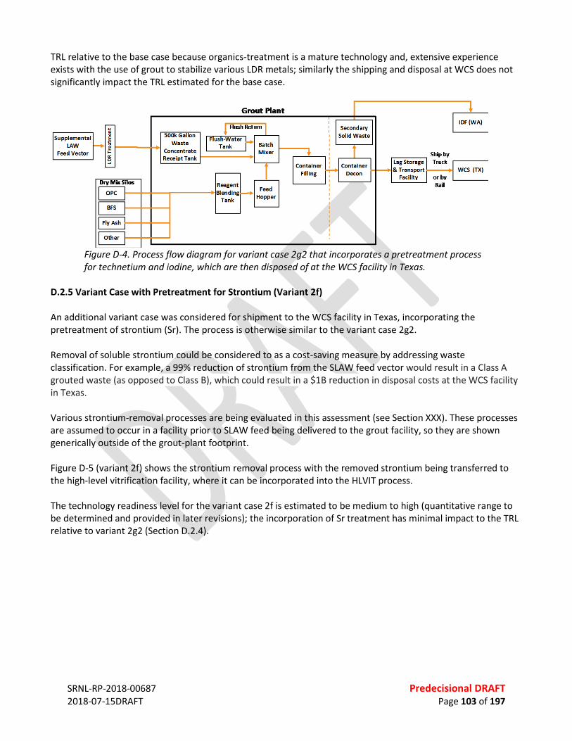
SRNL-RP-2018-00687 Predecisional DRAFT 2018-07-15DRAFT Page 103 of 197
TRL relative to the base case because organics-treatment is a mature technology and, extensive experience exists with the use of grout to stabilize various LDR metals; similarly the shipping and disposal at WCS does not significantly impact the TRL estimated for the base case.
Figure D-4. Process flow diagram for variant case 2g2 that incorporates a pretreatment process for technetium and iodine, which are then disposed of at the WCS facility in Texas.
D.2.5 Variant Case with Pretreatment for Strontium (Variant 2f) An additional variant case was considered for shipment to the WCS facility in Texas, incorporating the pretreatment of strontium (Sr). The process is otherwise similar to the variant case 2g2. Removal of soluble strontium could be considered to as a cost-saving measure by addressing waste classification. For example, a 99% reduction of strontium from the SLAW feed vector would result in a Class A grouted waste (as opposed to Class B), which could result in a $1B reduction in disposal costs at the WCS facility in Texas. Various strontium-removal processes are being evaluated in this assessment (see Section XXX). These processes are assumed to occur in a facility prior to SLAW feed being delivered to the grout facility, so they are shown generically outside of the grout-plant footprint. Figure D-5 (variant 2f) shows the strontium removal process with the removed strontium being transferred to the high-level vitrification facility, where it can be incorporated into the HLVIT process. The technology readiness level for the variant case 2f is estimated to be medium to high (quantitative range to be determined and provided in later revisions); the incorporation of Sr treatment has minimal impact to the TRL relative to variant 2g2 (Section D.2.4).

SRNL-RP-2018-00687 Predecisional DRAFT 2018-07-15DRAFT Page 104 of 197
Figure D-5. Process flow diagram for variant case 2f that incorporates a pretreatment process for strontium, which is then transferred to the high-level vitrification facility.
D.2.6 Opportunity to Cast Grout Directly into Large Disposal Units The Saltstone process at the Savannah River Site casts grout directly into large disposal units (termed “saltstone disposal units or SDUs) constructed in the waste storage facility. The size of these units has evolved over time (~2–32 million gallons). The use of a large disposal unit similar to an SDU could improve both waste-form performance and costs, so it was considered as an opportunity in this assessment. The process flow diagram for this opportunity would require locating of the grout plant near the final disposal site (presumed to be the IDF). Consequently, it would require installation of additional pipeline. However, the process would avoid the need for some components in the base case associated with containerization. The potential improvements to the performance and economics would need to be evaluated quantitatively, which was beyond the scope of this assessment.
Figure D-6. Process flow diagram for the direct pumping of grout into large disposal units (LDU) in the IDF.
D.3 ASSUMPTIONS To be written at a later time. D.4 RISKS

SRNL-RP-2018-00687 Predecisional DRAFT 2018-07-15DRAFT Page 105 of 197
D.4.1 Waste Acceptability The acceptability of the waste form was recognized as a potential risk with grout as an option for SLAW. Grout waste forms have not been permitted for disposal at the IDF, and the State of Washington has explicitly questioned the use of a grout waste form. This risk could potentially be mitigated in several ways: • Additional R&D that demonstrates grouted SLAW complies with long-term performance goalsA
demonstrated performance for a grouted waste form that is comparable to that for glass (which is permitted for disposal in the IDF);
• The use of the WCS facility in Texas for the disposition of the grouted SLAW waste form; • The removal (by pre-treatment) of radionuclides of concern (Tc and I).
For all primary SLAW waste form options (including vitrification and steam reforming), grout will likely be considered as a stabilization approach for any generated secondary wastes. If these wastes are destined for the IDF, this represents a risk for all primary SLAW waste forms, because grout is not permitted for disposal in the IDF. D.4.2 LDR Constituents Any acceptable pathway for grout as a waste form (either at IDF or WCS) will require addressing the potential presence of organics associated with LDR under RCRA. This is a risk that can be mitigated by inclusion of an organics treatment step in the process (e.g., degradation by oxidation). This treatment step would remove or destroy organics prior to the SLAW feed entering the grout facility, as considered in Sections A5.3.1.2 and A5.3.1.5. Any acceptable pathway for grout as a waste form (either at IDF or WCS) may also require addressing the potential presence of some metals associated with LDR under RCRA. A treatment step could be included if there is a concern that final waste forms would not pass TCLP. This treatment step would remove metals of concern prior to the SLAW feed entering the grout facility, as considered in Sections A5.3.1.2 and A5.3.1.5. D.4.3 Other Potential Risks Applicable to All Grout Processes Considered Other potential risks for selection of grout as an option include: • Future unavailability of reagents. This risk is discussed in Section A5.3.0.2, and it primarily ties to blast
furnace slag and fly ash. BFS limitations can be mitigated through either imports (for example from Canada or Japan). FA limitations can be mitigated through the identification and certification of an alternative material, such as a natural pozzolan (e.g., a Class N material, as identified in ASTM C618) or hydrated lime (e.g., Um et al., 2016). This risk was evaluated to be low because the materials needs are very low (<1%) relative to current domestic production. The risk could be mitigated by several strategies, including for example stockpiling of materials with appropriate properties. In addition, research on substitute materials could be considered as an anticipatory measure for blast furnace slag and fly ash
• Construction and start-up testing of a facility will not be met within budget or timeline. This risk was evaluated to be low due to extensive experience constructing similar facilities (i.e., DOE’s grouting experience) and based on it being a simple facility/process (ambient temperature, minimal offgas, commercially available reagents)
• Inability to mature a specific aspect of the process to a high TRL within time. This risk is most applicable to new formulations such as the use of getters for Tc and I. This risk was evaluated to be low due to relatively simple modifications needed to incorporate new formulations into the process and due to the existing body of testing on various formulations

SRNL-RP-2018-00687 Predecisional DRAFT 2018-07-15DRAFT Page 106 of 197
Potential risks associated with the operational phase of a grout process include: • The inability of a specific batch to meet acceptance criteria. This risk, for example, could relate to an
improperly proportioned batch and/or a batch with a composition outside of specifications resulting in a failure to set, low strength, bleeding, etc. This risk was evaluated to be low because this outcome is readily addressed with existing technology, whereby the monoliths could be identified in the lag storage facility and subsequently processed by grinding and re-grouting. In addition, adjustments to mix proportioning can be used to account for waste variability, thereby minimizing the likelihood of a poor batch.
• Insufficient capacity at the waste storage facility. This risk applies mostly to storage at WCS. This risk was evaluated to be low because the existing facility has a capacity significantly larger than the projected waste volume from a SLAW grout process, and adjacent land is available at WCS for expansion.
D.4.4 Additional Potential Risks Applicable to Specific Grout Processes Considered Base Case—Primary potential risks associated with the base case process (A5.3.1.1) include failure to achieve waste acceptance, the presence of LDR organics, and the failure of a specific monolith to meet waste specifications (e.g., failure of TCLP for LDR metals, failure to set, etc.). Variant 2d—Changes in primary potential risks associated with the variant case 2d (A5.3.1.2) relative to the base case include removing risk associated with the presence of LDR organics but adding risk associated with the potential impact of the organics-treatment process on waste form performance (e.g., increased mobility of redox-active metals). Variant 2e1—Changes in primary potential risks associated with the variant case 2e1 (A5.3.1.3) relative to the base case include reducing the risk of failing to achieve waste form acceptance at IDF by eliminating LDR organics and Tc/I. This option may include an additional risk associated with the inability to send Tc/I to the high level vitrification facility. Variant 2e2—Changes in primary potential risks associated with the variant case 2e1 (A5.3.1.3) relative to the base case include reducing the risk of failing to achieve waste form acceptance at IDF by eliminating LDR organics and Tc/I. This option may also mediate the additional risk for variant 2e1 associated with the inability to send Tc/I to the high level vitrification facility. Variant 2g2—Changes in primary potential risks associated with the variant case 2g2 (A5.3.1.4) relative to the base case include reducing the risk of failing to achieve waste form acceptance at IDF by shipping the primary waste to the WCS facility (which can accept Tc/I). This option could include an additional risk associated with waste form acceptance should the WCS option change in the future. Variant 2f—Changes in primary potential risks associated with the variant case 2f (A5.3.1.5) relative to the base case are those listed for variant 2g2. Opportunity to Store Waste in Large Disposal Unit—Changes in primary potential risks associated with the opportunity to pump the grout into large disposal units in the IDF relative to the base case include reducing the risk of failing waste form performance criteria (a larger sized waste form is projected to perform better than smaller sized waste forms in the context of radionuclide release). However, this option includes additional risk associated with permitting of a large disposal unit in the IDF. D.5 BENEFITS AND COST ESTIMATE To be written at a later time.
SRNL-RP-2018-00687 Predecisional DRAFT 2018-07-15DRAFT Page 107 of 197
D.6 SCHEDULE To be written at a later time. D.7 REGULATORY COMPLIANCE To be written at a later time. D.8 OBSTACLES To be written at a later time. REFERENCES American Coal Ash Association (ACCA), “2016 Coal Combustion Product (CCP) Production & Use Survey:
Results”, 2016a. (https://www.acaa-usa.org/Portals/9/Files/PDFs/2016-Survey-Results.pdf) American Coal Ash Association (ACCA), “2016 Coal Combustion Product (CCP) Production & Use Survey: Use
Charts”, 2016b. (https://www.acaa-usa.org/Portals/9/Files/PDFs/2016-Charts.pdf) ASTM International (ASTM), C618-17a, “Standard Specification for Coal Fly Ash and Raw or Calcined Natural
Pozzolan for Use in Concrete”. R. M. Asmussen, C. I. Pearce, B. W. Miller, A. R. Lawter, J. J. Neeway, W. W. Lukens, M. E. Bowden, M. A. Miller,
E. C. Buck, R. J. Serne, N. P. Qafoku, “Getters for improved technetium containment in cementitious waste forms” Journal of Hazardous Materials, 341:238–247, 2018.
D. H. Bacon, B. P. McGrail, “Waste form release calculations for the 2005 Integrated Disposal Facility performance assessment” Pacific Northwest National Laboratory, Richland, Washington, PNNL-15198, 2005.
T. Brouns, M. Lerchen, G. B. Mellinger, L. M. Bagaasen, “Preliminary assessment of supplemental grout and glass waste forms for disposal of low-activity waste” Pacific Northwest National Laboratory, Richland, Washington, PNNL-14280, 2003.
C. F. Brown, J. H. Westsik, Jr., R. J. Serne, B. M. Rapko, W. R. Wilmarth, D. J. McCabe, C. A. Nash, A. D. Cozzi, K. M. Fox, "Preliminary assessment of the low-temperature waste form technology coupled with technetium removal" Pacific Northwest National Laboratory, PNNL-22103 Savannah River National Laboratory SRNL-STI-2013-00002, 2014.
K. J. Cantrell, J. H. Westsik, Jr., R. J. Serne, W. Um, A. D. Cozzi, "Secondary Waste Cementitious Waste Form Data Package for the Integrated Disposal Facility Performance Assessment" Pacific Northwest National Laboratory, Richland, Washington, PNNL-25194, RPT-SWCS-006, Rev. 0, 2016.
L.W. Cree, J.M. Colby, M.S. Fountain, D.W. Nelson, V.C. Nguyen, K.A. Anderson, M.D. Britton, S. Paudel, and M.E. Stone, “One System River Protection Project Integrated Flowsheet, RPP-RPT-57991, Rev 2, 24590-WTP-RPT-MGT-14-023, Rev. 2,” Washington River Protection Solutions (WRPS) One System, Richland, Washington, 2017.
Y. Deng, B. Slettene, R. Fundak, R.C. Chen, M.R. Gross, R. Gimpel, and K. Jun, “Flowsheets Bases, Assumptions, and Requirements,” Bechtel National, Inc. River Protection Project Waste Treatment Plant, Richland, Washington, 24590-WTP-RPT-PT-02-005, Rev 8, 2016.
International Atomic Energy Agency (IAEA). “Conditioning of low and intermediate level liquid, solidified and solid waste.” 2018 (in press). IAEA. Vienna Austria.
Kosson, D. S.; D. R. Gallay, I. L. Pegg, R. G. Wymer. “External Technical Review of System Planning for Low-Activity Waste Treatment at Hanford.” November 2008.
Dr. Steven Krahn, U. S. Department of EnergyC. A. Langton "Technetium Oxidation in Slag-Based Sodium Salt Waste Forms Exposed to Water and Moist Hanford Soil" Revision 0, Savannah River National Laboratory, S SRNL-STI-2014-00399, 2014.
SRNL-RP-2018-00687 Predecisional DRAFT 2018-07-15DRAFT Page 108 of 197
L. L. Lockrem “Hanford containerized Cast Stone facility task 1—Process testing and development final report. RPP-RPT-26742 Revision 0, 2005.
F. M. Mann, R. J. Puigh, R. Khaleel, S. Finfrock, B. P. McGrail, D. H. Bacon, and R. J. Serne, "Risk assessment supporting the decision on the initial selection of supplemental ILAW technologies" RPP-17675, Rev. 0; CH2M HILL Hanford Group Inc., Richland, Washington, 2003.
S. V. Mattigod, J. H. Westsik, Jr., C. W. Chung, M. J. Lindberg, M. J. Lindberg, "Waste Acceptance Testing of Secondary Waste Forms: Cast Stone, Ceramicrete and DuraLith" Pacific Northwest National Laboratory, Richland, Washington, PNNL-20632, 2011.
H. J. Minwalla, "Cast stone technology for the treatment and immobilization of low activity waste" RPP-49062, Rev. 0; Washington River Protection Solutions, LLC, Richland, Washington, 2011.
A. C. A. Muller, “Characterization of porosity & C-S-H in cement pastes by 1H NMR”, Thesis #6339, École Polytechnique Fédérale de Lausanne, 2014.
N. P. Qafoku, J. J. Neeway, A. R. Lawter, T. G. Levitskaia, R. J. Serne, J. H. Westsik, Jr., M. M. Valenta Snyder, “Technetium and iodine getters to improve cast stone performance” Pacific Northwest National Laboratory, Richland, Washington, PNNL-23282, 2014.
“River Protection Project System Plan,” U.S. Department of Energy: Office of River Protection, Richland, Washington, ORP-11242, Rev 8, 2017.
R. J. Serne, D. C. Lanigan, JH Westsik, Jr., B. D. Williams, H. B. Jung, G. Wang "Extended leach testing of simulated LAW cast stone monoliths" Pacific Northwest National Laboratory, Richland, Washington, PNNL-24297 Rev. 1 RPT-SWCS-010, Rev. 0, 2016.
R. J. Serne and J. H. Westik, Jr., "Data package for secondary waste form down-selection—Cast stone" Pacific Northwest National Laboratory, Richland, Washington, PNNL-20706, 2011.
S. Simner, F. Coutelot, H. Chang, J. Seaman, "Technetium leaching from cementitious materials” MRS Advances, 2:717–722, 2017.
S. K. Sundaram, K. E. Parker, M. E. Valenta, S. G. Pitman, J. Chun, C. -W. Chung, M. L. Kimura, C. A. Burns, W. Um, J. H. Westsik, Jr, "Secondary Waste Form Development and Optimization— Cast Stone" Pacific Northwest National Laboratory, Richland, Washington, PNNL-20159 Rev. 1, 2011.
W. Um, B.D. Williams, M.M.V. Snyder, G. Wang, "Liquid Secondary Waste Grout Formulation and Preliminary Waste Form Qualification" Pacific Northwest National Laboratory, Richland, Washington, PNNL-25129 RPT-SWCS-005, Rev 0, 2016.
United States Geological Survey (USGS), “Mineral Commodities Summaries 2017” U.S. Department of the Interior, Washington, DC, 2017. (https://minerals.usgs.gov/minerals/pubs/mcs/2017/mcs2017.pdf)
J. H. Westsik, Jr, G. F. Piepel, M. J. Lindberg, P. G. Heasler, T. M. Mercier, R. L. Russell, A. D. Cozzi, W. E. Daniel, R. E. Eibling, E. K. Hansen, M. M. Reigel, D. J. Swanberg, "Supplemental Immobilization of Hanford Low-Activity Waste: Cast Stone Screening Tests" Pacific Northwest National Laboratory, PNNL-22747 Savannah River National Laboratory SRNL-STI-2013-00465, 2013a.
J. H. Westsik, Jr., R. J. Serne, E. M. Pierce, A. D. Cozzi, C. Chung, D. J. Swanberg, “Supplemental immobilization cast stone technology development and waste form qualification testing plan” Pacific Northwest National Laboratory, PNNL-21823, Rev. 1, 2013b.
X. Wu, W. Jiang, D. M. Roy “Early activation and properties of slag cement” Cement and Concrete Research, 20:961–974, 1990.

SRNL-RP-2018-00687 Predecisional DRAFT 2018-07-15DRAFT Page 109 of 197
APPENDIX E. EXPANDED DISCUSSION – OTHER APPROACHES TBD

SRNL-RP-2018-00687 Predecisional DRAFT 2018-07-15DRAFT Page 110 of 197
APPENDIX F. EXPANDED DISCUSSION: COMPARATIVE ANALYSIS OF APPROACHES F.1 SUMMARY The Analytical Hierarchy Process (AHP) decision-making tool was used to evaluate approaches for treatment of supplemental low-activity waste (LAW) at the Hanford Nuclear Reservation. The AHP was developed at the Wharton School of Business to assist in making complex decisions with multiple, often conflicting, criteria for the US Arms Control and Disarmament Agency. It has been widely used in business, government, research and development, defense, and other domains involving decisions in which choice, prioritization or forecasting is needed. Twenty-two potential approaches were identified by the team, and twelve options were fully evaluated and ranked as shown in Table F-1. They are listed in rank order from higher (green) to lower (red) overall scores. Ten of the options were not fully evaluated because the team felt that they were bounded by the cases listed in Table F-1. Table F-1. Ranking of Approaches for Supplemental Treatment of Low-Activity Waste
Options Evaluated Score (1 – 100) 2g2 - Grout with LDR pretreatment; Primary to WCS 87 2f - Grout with LDR and Sr pretreatment to HLVit, Primary to WCS 85 3b - Steam reforming to WCS, Secondary to WCS 77 1c - Vit to IDF, Secondary to WCS 67 2d - Grout with LDR pretreatment, Primary & secondary to IDF 67 2 - Grout - Base Case 65 1g - Bulk vit in large container to IDF, Secondary to WCS 63 2e2 - Grout with LDR and Tc & I pretreatment to WCS, Primary & secondary to IDF 63
2e1 - Grout with LDR and Tc & I pretreatment to HLVit, Primary & secondary to IDF 62
1 - Vitrification - Base Case 56 1d - Bulk vitrification 55 3 - Steam reforming - Base Case 53
The options of pretreating secondary LAW and grouting for disposal at WCS received the higher overall scores, followed by steam reforming for disposal at WCS. Vitrification, bulk vitrification, and steam reforming for disposal at IDF received the lower scores. Grouting (with or without pretreatment) for disposal at IDF and bulk vitrification for disposal at IDF ranked in the middle.

SRNL-RP-2018-00687 Predecisional DRAFT 2018-07-15DRAFT Page 111 of 197
F-2 EVALUATION METHODOLOGY The options analysis was performed using the AHP decision-modeling method developed at the Wharton School of Business at the University of Pennsylvania. This model provides a structured framework that allows ranking of both qualitative and quantitative selection criteria defined by the team of subject matter experts.69 The team identified criteria for evaluating the options and metrics to measure how well each option could meet the selection criteria. The relative importance of the selection criteria and metrics was determined using pairwise comparisons (for example, how does one weight “cost” as a criterion relative to “schedule”?). This approach provides decision makers with the ability to focus solely on the two decision criteria/metrics being evaluated in isolation, without the distraction or complicating effects of other criteria. The pairwise process generated weighting factors for each individual criterion and metric. A relative weighting factor was then developed for each metric by multiplying the weighting factor for the metric by the weighting factor for the associated criterion. The pairwise comparison tables are provided in the Tables F-11 and F-12, and the weighted selection criteria and metrics are summarized in Table F-2. Five ratings were used to determine how well an option satisfies a particular metric: 5-Strong, 4-Moderate/Strong, 3-Moderate, 2-Low, 1-None. Definitions were developed by the team for the ratings for each metric. The criteria and metrics definitions are given in the Table F-13. Each option was assigned a rating between 1 and 5 for each metric. The ratings were made by the team based on experience and guided by the metric definitions. Weighted ratings for the metrics were obtained by multiplying the ratings by the appropriate relative weights of the metrics from Table F-2. An overall score for an option was obtained by summing the weighted ratings. The highest possible score that can be obtained through this process is 100.
69 Thomas L. Saaty, “A Scaling Method for Priorities in Hierarchical Structures,” Journal of Mathematical Psychology, 15: 234–281, 1977.

SR
NL-
RP-2
018-
0068
7
Pr
edec
isio
nal D
RAFT
20
18-0
7-15
DRAF
T
Page
112
of 1
97
Tabl
e F-
2. C
riter
ia a
nd M
etric
s Wei
ghtin
g Fa
ctor
s
Crite
ria
Crite
ria
Wei
ghtin
g (%
) M
etric
s M
etric
W
eigh
ting
(%)
Rela
tive
Wei
ght
of M
etric
(%
)
Tech
nica
l Mat
urity
and
Pr
oces
s Sim
plic
ity a
nd
Relia
bilit
y —
TRL
7.6
0.45
M
atur
atio
n of
TRL
33
.6
1.97
N
umbe
r of u
nit o
pera
tions
13
.7
0.80
Si
mpl
icity
of f
eed
star
t-up
/shu
tdow
n 22
.3
1.31
Si
mpl
icity
of c
ontr
ol o
f uni
t ope
ratio
ns
22.8
1.
34
Safe
ty
—
Nuc
lear
and
radi
olog
ical
haz
ards
41
.5
2.07
Ch
emic
al h
azar
ds
23.2
1.
16
Phys
ical
haz
ards
12
.0
0.60
Tr
ansp
orta
tion
haza
rds
23.2
1.
16
Ope
ratio
nal F
lexi
bilit
y —
Abili
ty to
han
dle
rang
e of
feed
vec
tor c
ompo
sitio
ns
31.5
2.
63
Abili
ty to
han
dle
rang
e of
feed
vec
tor f
low
rate
s 19
.3
1.61
Ab
ility
to p
reve
nt/r
ewor
k of
f-spe
c pr
oduc
t 38
.8
3.23
An
alyt
ical
requ
irem
ents
10
.4
0.87
Econ
omy
12.0
Deve
lopm
ent c
ost
10.1
1.
22
Capi
tal c
ost (
incl
udes
per
mits
, dea
ctiv
atio
n an
d de
com
miss
ioni
ng e
tc.)
54.0
6.
51
Ope
ratio
nal /
ann
ual c
ost
35.9
4.
32
Sche
dule
(Spe
ed)
11.4
De
velo
pmen
t tim
e pr
ior t
o de
sign
20.0
2.
28
Tim
e to
com
plet
e de
sign,
con
stru
ctio
n, a
nd h
ot st
art-
up
80.0
9.
11
Impe
rvio
usne
ss to
Risk
s 7.
6 Pr
ojec
t risk
s 33
.3
2.52
O
pera
tiona
l exe
cutio
n ris
ks
19.0
1.
44
TRL-
rela
ted
risks
47
.6
3.61
Pr
imar
y W
aste
For
m
Com
plia
nce
19.0
Pr
imar
y w
aste
form
com
plia
nce
100.
0 18
.96
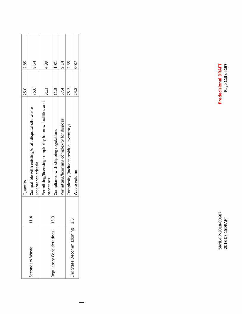
SR
NL-
RP-2
018-
0068
7
Pr
edec
isio
nal D
RAFT
20
18-0
7-15
DRAF
T
Page
113
of 1
97
Seco
ndar
y W
aste
11
.4
Qua
ntity
25
.0
2.85
Co
mpa
tible
with
exi
stin
g/dr
aft d
ispos
al si
te w
aste
ac
cept
ance
crit
eria
75
.0
8.54
Regu
lato
ry C
onsid
erat
ions
15
.9
Perm
ittin
g/lic
ensin
g co
mpl
exity
for n
ew fa
cilit
ies a
nd
proc
esse
s 31
.3
4.99
Com
plia
nce
with
ship
ping
regu
latio
ns
11.3
1.
81
Perm
ittin
g/lic
ensin
g co
mpl
exity
for d
ispos
al
57.4
9.
14
End
Stat
e De
com
miss
ioni
ng
3.5
Com
plex
ity (i
nclu
des r
esid
ual i
nven
tory
) 75
.2
2.65
W
aste
vol
ume
24.8
0.
87
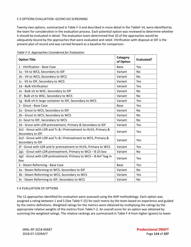
SRNL-RP-2018-00687 Predecisional DRAFT 2018-07-15DRAFT Page 114 of 197
F.3 OPTIONS EVALUATION: GO/NO GO SCREENING Twenty-two options, summarized in Table F-3 and described in more detail in the TableF-14, were identified by the team for consideration in the evaluation process. Each potential option was reviewed to determine whether it should be evaluated in detail. The evaluation team determined that 10 of the approaches would be adequately bound by the approaches that were evaluated and rated. Vitrification with disposal at IDF is the present plan of record and was carried forward as a baseline for comparison. Table F-3. Approaches Considered for Evaluation
Option Title Category of Option Evaluated?
1 - Vitrification - Base Case Base Yes 1a - Vit to WCS, Secondary to IDF Variant No 1b - Vit to WCS, Secondary to WCS Variant No 1c - Vit to IDF, Secondary to WCS Variant Yes 1d - Bulk Vitrification Variant Yes 1e - Bulk vit to WSC, Secondary to IDF Variant No 1f - Bulk vit to WSC, Secondary to WCS Variant No 1g - Bulk vit in large container to IDF, Secondary to WCS Variant Yes 2 - Grout - Base Case Base Yes 2a - Grout to WCS, Secondary to IDF Variant No 2b - Grout to WCS, Secondary to WCS Variant No 2c- Gout to IDF, Secondary to WCS Variant No 2d - Grout with LDR pretreatment, Primary & Secondary to IDF Variant Yes 2e1 - Grout with LDR and Tc & I Pretreatment to HLVit, Primary & Secondary to IDF Variant Yes
2e2 - Grout with LDR and Tc & I Pretreatment to WCS, Primary & Secondary to IDF Variant Yes
2f - Grout with LDR and Sr pretreatment to HLVit, Primary to WCS Variant Yes 2g1 - Grout with LDR pretreatment, Primary to WCS – B-25 box Variant No 2g2 - Grout with LDR pretreatment; Primary to WCS – 8.4m3 bag in box Variant Yes
3 - Steam Reforming - Base Case Base Yes 3a - Steam Reforming to WCS, Secondary to IDF Variant No 3b - Steam Reforming to WCS, Secondary to WCS Variant Yes 3c - Steam Reforming to IDF, Secondary to WCS Variant No
F.4 EVALUATION OF OPTIONS The 12 approaches identified for evaluation were assessed using the AHP methodology. Each option was assigned a rating between 1 and 5 (See Table F-15) for each metric by the team based on experience and guided by the metric definitions. Weighted ratings for the metrics were obtained by multiplying the ratings by the appropriate relative weights of the metrics from Table F-2. An overall score for an option was obtained by summing the weighted ratings. The relative rankings are summarized in Table F-4 from higher (green) to lower
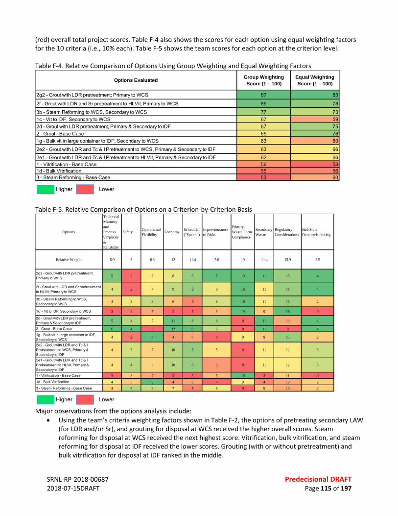
SRNL-RP-2018-00687 Predecisional DRAFT 2018-07-15DRAFT Page 115 of 197
(red) overall total project scores. Table F-4 also shows the scores for each option using equal weighting factors for the 10 criteria (i.e., 10% each). Table F-5 shows the team scores for each option at the criterion level. Table F-4. Relative Comparison of Options Using Group Weighting and Equal Weighting Factors
Table F-5. Relative Comparison of Options on a Criterion-by-Criterion Basis
Major observations from the options analysis include:
• Using the team’s criteria weighting factors shown in Table F-2, the options of pretreating secondary LAW (for LDR and/or Sr), and grouting for disposal at WCS received the higher overall scores. Steam reforming for disposal at WCS received the next highest score. Vitrification, bulk vitrification, and steam reforming for disposal at IDF received the lower scores. Grouting (with or without pretreatment) and bulk vitrification for disposal at IDF ranked in the middle.
Options Evaluated Group Weighting Score (1 – 100)
Equal Weighting Score (1 – 100)
2g2 - Grout with LDR pretreatment; Primary to WCS 87 83
2f - Grout with LDR and Sr pretreatment to HLVit, Primary to WCS 85 78
3b - Steam Reforming to WCS, Secondary to WCS 77 731c - Vit to IDF, Secondary to WCS 67 592d - Grout with LDR pretreatment, Primary & Secondary to IDF 67 752 - Grout - Base Case 65 761g - Bulk vit in large container to IDF, Secondary to WCS 63 60
2e2 - Grout with LDR and Tc & I Pretreatment to WCS, Primary & Secondary to IDF 63 662e1 - Grout with LDR and Tc & I Pretreatment to HLVit, Primary & Secondary to IDF 62 661 - Vitrification - Base Case 56 531d - Bulk Vitrification 55 563 - Steam Reforming - Base Case 53 60
Options
Technical Maturity and Process Simplicity & Reliability
Safety Operational Flexibility
Economy Schedule ("Speed")
Imperviousness to Risks
Primary Waste Form Compliance
Secondary Waste
Regulatory Considerations
End State Decommissioning
Relative Weight 5.9 5 8.3 12 11.4 7.6 19 11.4 15.9 3.5
2g2 - Grout with LDR pretreatment; Primary to WCS 5 2 7 8 8 7 19 11 15 4
2f - Grout with LDR and Sr pretreatment to HLVit, Primary to WCS
4 2 7 9 8 6 19 11 15 4
3b - Steam Reforming to WCS, Secondary to WCS
4 3 8 6 5 6 19 11 15 2
1c - Vit to IDF, Secondary to WCS 3 2 7 2 5 5 19 9 16 0
2d - Grout with LDR pretreatment, Primary & Secondary to IDF 5 4 7 11 8 6 0 11 10 4
2 - Grout - Base Case 6 4 6 12 9 6 0 11 8 41g - Bulk vit in large container to IDF, Secondary to WCS
4 2 8 4 6 4 9 9 15 2
2e2 - Grout with LDR and Tc & I Pretreatment to WCS, Primary & Secondary to IDF
4 3 7 10 8 5 0 11 12 3
2e1 - Grout with LDR and Tc & I Pretreatment to HLVit, Primary & Secondary to IDF
4 4 7 10 8 5 0 11 12 3
1 - Vitrification - Base Case 3 3 7 2 5 5 19 2 11 01d - Bulk Vitrification 4 3 8 4 6 4 9 4 10 23 - Steam Reforming - Base Case 4 4 8 7 5 6 0 9 10 2

SRNL-RP-2018-00687 Predecisional DRAFT 2018-07-15DRAFT Page 116 of 197
• When the 10 weighting factors were assigned equal weighs (10% each), the relative ranking of the options did not change significantly. The options of pretreating secondary LAW (for LDR and/or Sr) and grouting for disposal at WCS still received the higher overall scores. Grouting for disposal at IDF (with and without LDR pretreatment) moved up in the ranking. Steam reforming for disposal at IDF moved from a lower score to an “in between” middle range score. Vitrification and bulk vitrification for disposal at IDF remained the lower scored options.
• Individual criterion scores in Table F-5 indicate that the higher overall rated options (pretreating secondary LAW for LDR and/or Sr for disposal at WCS) received high ratings in all categories except safety and operational flexibility. The lower overall rated options (vitrification, bulk vitrification, and steam reforming for disposal at IDF) tended to receive high ratings in these categories and low ratings in the other criterion categories.
F.5 SENSITIVITY ANALYSIS A sensitivity analysis was performed to understand the impacts of the weighting factors on the various evaluation criteria. Five different criteria weighting factor schemes were evaluated for comparison to the team-generated weighting factors shown in Table F-4. In each scheme, each criterion was given a weighting factor ranging from 30% to 70%, and the remaining amount required to make 100% was equally divided among the other nine criteria. The results are shown in Tables F-6 through F-10. Table F-6. Comparison of Options with 30% Weighting on Criteria Named in Column and Residual Equally Divided Across Other Criteria
Options
Technical Maturity and Process Simplicity & Reliability
Safety Operational Flexibility
Economy Schedule ("Speed")
Imperviousness to Risks
Primary Waste Form Compliance
Secondary Waste
Regulatory Considerations
End State Decommissioning
2g2 - Grout with LDR pretreatment; Primary to WCS 87 77 86 82 82 88 89 89 87 89
2f - Grout with LDR and Sr pretreatment to HLVit, Primary to WCS 80 74 83 81 79 80 86 84 84 86
3b - Steam Reforming to WCS, Secondary to WCS 70 70 76 67 66 74 78 77 77 67
1c - Vit to IDF, Secondary to WCS 55 56 63 49 54 60 67 61 67 452d - Grout with LDR pretreatment, Primary & Secondary to IDF 80 76 79 81 75 79 60 82 74 82
2 - Grout - Base Case 81 79 75 81 76 77 59 81 70 811g - Bulk vit in large container to IDF, Secondary to WCS 64 60 70 57 60 61 60 65 69 60
2e2 - Grout with LDR and Tc & I Pretreatment to WCS, Primary & Secondary to IDF
68 68 72 71 69 69 53 74 70 70
2e1 - Grout with LDR and Tc & I Pretreatment to HLVit, Primary & Secondary to IDF
67 69 72 70 68 67 53 74 70 70
1 - Vitrification - Base Case 49 51 56 43 48 53 61 43 54 391d - Bulk Vitrification 59 56 65 52 55 57 55 52 58 553 - Steam Reforming - Base Case 60 62 66 59 56 62 46 63 60 57
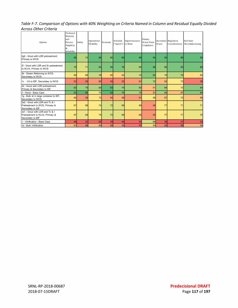
SRNL-RP-2018-00687 Predecisional DRAFT 2018-07-15DRAFT Page 117 of 197
Table F-7. Comparison of Options with 40% Weighting on Criteria Named in Column and Residual Equally Divided Across Other Criteria
Options
Technical Maturity and Process Simplicity & Reliability
Safety Operational Flexibility
Economy Schedule ("Speed")
Imperviousness to Risks
Primary Waste Form Compliance
Secondary Waste
Regulatory Considerations
End State Decommissioning
2g2 - Grout with LDR pretreatment; Primary to WCS
88 73 86 80 80 89 90 90 88 90
2f - Grout with LDR and Sr pretreatment to HLVit, Primary to WCS
79 71 84 80 78 80 88 86 85 88
3b - Steam Reforming to WCS, Secondary to WCS 69 68 78 65 63 74 82 79 79 65
1c - Vit to IDF, Secondary to WCS 53 55 65 45 52 61 72 63 72 38
2d - Grout with LDR pretreatment, Primary & Secondary to IDF 82 75 80 83 74 80 51 84 72 84
2 - Grout - Base Case 83 80 75 83 76 78 51 84 67 841g - Bulk vit in large container to IDF, Secondary to WCS 65 58 73 54 58 61 58 67 72 58
2e2 - Grout with LDR and Tc & I Pretreatment to WCS, Primary & Secondary to IDF
67 68 74 72 69 69 46 77 71 71
2e1 - Grout with LDR and Tc & I Pretreatment to HLVit, Primary & Secondary to IDF
67 69 74 72 69 66 45 77 71 70
1 - Vitrification - Base Case 48 52 60 39 46 55 66 39 57 331d - Bulk Vitrification 61 56 69 50 54 57 54 50 59 54

SRNL-RP-2018-00687 Predecisional DRAFT 2018-07-15DRAFT Page 118 of 197
Table F-8. Comparison of Options with 50% Weighting on Criteria Named in Column and Residual Equally Divided Across Other Criteria
Table F-9. Comparison of Options with 60% Weighting on Criteria Named in Column and Residual Equally Divided Across Other Criteria
Options
Technical Maturity and Process Simplicity & Reliability
Safety Operational Flexibility
Economy Schedule ("Speed")
Imperviousness to Risks
Primary Waste Form Compliance
Secondary Waste
Regulatory Considerations
End State Decommissioning
2g2 - Grout with LDR pretreatment; Primary to WCS
89 69 86 78 79 90 92 92 88 92
2f - Grout with LDR and Sr pretreatment to HLVit, Primary to WCS 78 67 84 80 77 79 90 87 86 90
3b - Steam Reforming to WCS, Secondary to WCS 68 67 80 62 60 75 85 82 81 62
1c - Vit to IDF, Secondary to WCS 52 54 68 40 50 62 76 65 76 32
2d - Grout with LDR pretreatment, Primary & Secondary to IDF 84 75 82 85 74 81 43 87 71 87
2 - Grout - Base Case 86 81 74 86 76 78 42 87 64 871g - Bulk vit in large container to IDF, Secondary to WCS 65 57 77 51 57 60 57 68 76 57
2e2 - Grout with LDR and Tc & I Pretreatment to WCS, Primary & Secondary to IDF
67 67 76 73 69 70 38 80 73 71
2e1 - Grout with LDR and Tc & I Pretreatment to HLVit, Primary & Secondary to IDF
67 70 76 73 69 66 38 79 72 71
1 - Vitrification - Base Case 48 52 63 36 45 57 72 36 59 281d - Bulk Vitrification 62 56 73 48 54 57 54 48 60 543 - Steam Reforming - Base Case 61 65 73 59 53 66 33 66 61 55
Options
Technical Maturity and Process Simplicity & Reliability
Safety Operational Flexibility
Economy Schedule ("Speed")
Imperviousness to Risks
Primary Waste Form Compliance
Secondary Waste
Regulatory Considerations
End State Decommissioning
2g2 - Grout with LDR pretreatment; Primary to WCS
90 65 87 76 77 91 94 94 89 94
2f - Grout with LDR and Sr pretreatment to HLVit, Primary to WCS 77 63 85 79 75 78 92 88 88 92
3b - Steam Reforming to WCS, Secondary to WCS 67 66 82 60 57 76 88 84 83 60
1c - Vit to IDF, Secondary to WCS 51 53 70 36 48 63 81 67 81 26
2d - Grout with LDR pretreatment, Primary & Secondary to IDF 86 74 83 87 73 82 34 90 69 90
2 - Grout - Base Case 88 83 74 88 75 79 34 89 61 891g - Bulk vit in large container to IDF, Secondary to WCS 66 56 80 48 56 60 56 69 79 56
2e2 - Grout with LDR and Tc & I Pretreatment to WCS, Primary & Secondary to IDF
66 67 78 74 69 70 30 82 74 72
2e1 - Grout with LDR and Tc & I Pretreatment to HLVit, Primary & Secondary to IDF
66 70 78 74 69 65 30 82 73 72
1 - Vitrification - Base Case 47 53 66 33 44 59 78 32 62 221d - Bulk Vitrification 63 56 78 45 53 57 53 46 60 533 - Steam Reforming - Base Case 62 66 76 59 51 67 26 68 62 54
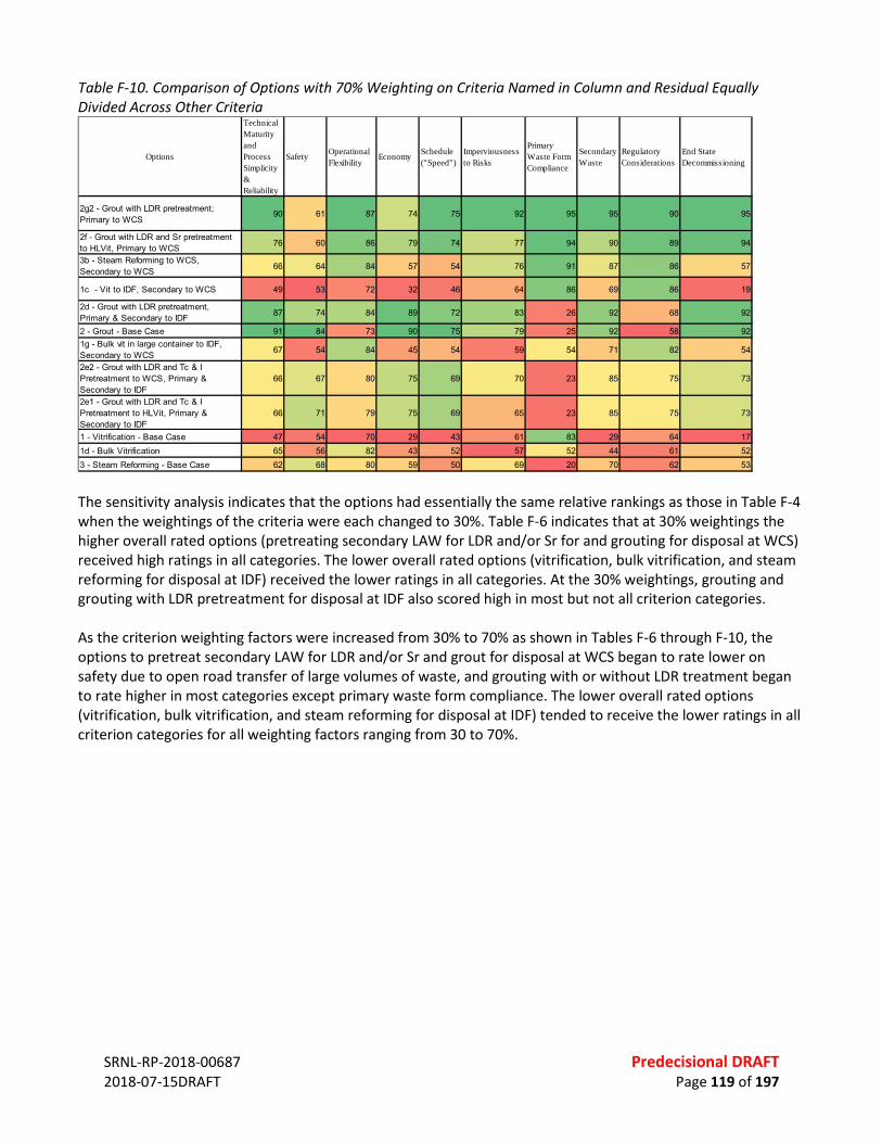
SRNL-RP-2018-00687 Predecisional DRAFT 2018-07-15DRAFT Page 119 of 197
Table F-10. Comparison of Options with 70% Weighting on Criteria Named in Column and Residual Equally Divided Across Other Criteria
The sensitivity analysis indicates that the options had essentially the same relative rankings as those in Table F-4 when the weightings of the criteria were each changed to 30%. Table F-6 indicates that at 30% weightings the higher overall rated options (pretreating secondary LAW for LDR and/or Sr for and grouting for disposal at WCS) received high ratings in all categories. The lower overall rated options (vitrification, bulk vitrification, and steam reforming for disposal at IDF) received the lower ratings in all categories. At the 30% weightings, grouting and grouting with LDR pretreatment for disposal at IDF also scored high in most but not all criterion categories. As the criterion weighting factors were increased from 30% to 70% as shown in Tables F-6 through F-10, the options to pretreat secondary LAW for LDR and/or Sr and grout for disposal at WCS began to rate lower on safety due to open road transfer of large volumes of waste, and grouting with or without LDR treatment began to rate higher in most categories except primary waste form compliance. The lower overall rated options (vitrification, bulk vitrification, and steam reforming for disposal at IDF) tended to receive the lower ratings in all criterion categories for all weighting factors ranging from 30 to 70%.
Options
Technical Maturity and Process Simplicity & Reliability
Safety Operational Flexibility
Economy Schedule ("Speed")
Imperviousness to Risks
Primary Waste Form Compliance
Secondary Waste
Regulatory Considerations
End State Decommissioning
2g2 - Grout with LDR pretreatment; Primary to WCS
90 61 87 74 75 92 95 95 90 95
2f - Grout with LDR and Sr pretreatment to HLVit, Primary to WCS 76 60 86 79 74 77 94 90 89 94
3b - Steam Reforming to WCS, Secondary to WCS 66 64 84 57 54 76 91 87 86 57
1c - Vit to IDF, Secondary to WCS 49 53 72 32 46 64 86 69 86 19
2d - Grout with LDR pretreatment, Primary & Secondary to IDF 87 74 84 89 72 83 26 92 68 92
2 - Grout - Base Case 91 84 73 90 75 79 25 92 58 921g - Bulk vit in large container to IDF, Secondary to WCS 67 54 84 45 54 59 54 71 82 54
2e2 - Grout with LDR and Tc & I Pretreatment to WCS, Primary & Secondary to IDF
66 67 80 75 69 70 23 85 75 73
2e1 - Grout with LDR and Tc & I Pretreatment to HLVit, Primary & Secondary to IDF
66 71 79 75 69 65 23 85 75 73
1 - Vitrification - Base Case 47 54 70 29 43 61 83 29 64 171d - Bulk Vitrification 65 56 82 43 52 57 52 44 61 523 - Steam Reforming - Base Case 62 68 80 59 50 69 20 70 62 53

SRNL-RP-2018-00687 Predecisional DRAFT 2018-07-15DRAFT Page 120 of 197
Table F-11 Pairwise Evaluation of Selection Criteria
Technical Maturity and Process Simplicity & Reliability X SafetyTechnical Maturity and Process Simplicity & Reliability X Operational FlexibilityTechnical Maturity and Process Simplicity & Reliability X EconomyTechnical Maturity and Process Simplicity & Reliability X Schedule ("Speed")Technical Maturity and Process Simplicity & Reliability X Imperviousness to RisksTechnical Maturity and Process Simplicity & Reliability X Primary Waste Form ComplianceTechnical Maturity and Process Simplicity & Reliability X Secondary WasteTechnical Maturity and Process Simplicity & Reliability X Regulatory ConsiderationsTechnical Maturity and Process Simplicity & Reliability X End State Decommissioning
Very
Str
ong
(4X
Criteria 1 Criteria 2Very
Str
ong
(4X
Stro
ng (3
X)
Mod
erat
e (2
X)
Equa
l
Mod
erat
e (2
X)
Stro
ng (3
X)
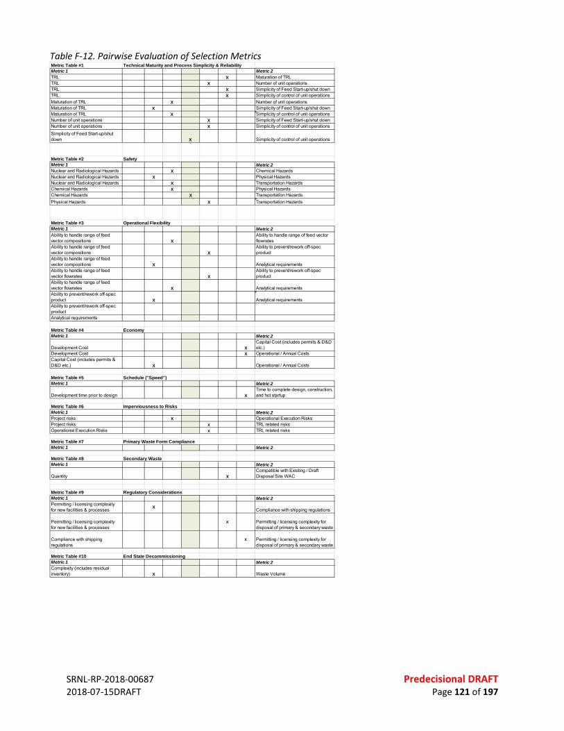
SRNL-RP-2018-00687 Predecisional DRAFT 2018-07-15DRAFT Page 121 of 197
Table F-12. Pairwise Evaluation of Selection Metrics
Metric Table #1 Technical Maturity and Process Simplicity & Reliability Metric 1 Metric 2TRL X Maturation of TRLTRL X Number of unit operationsTRL X Simplicity of Feed Start-up/shut downTRL X Simplicity of control of unit operationsMaturation of TRL X Number of unit operationsMaturation of TRL X Simplicity of Feed Start-up/shut downMaturation of TRL X Simplicity of control of unit operationsNumber of unit operations X Simplicity of Feed Start-up/shut downNumber of unit operations X Simplicity of control of unit operationsSimplicity of Feed Start-up/shut down X Simplicity of control of unit operations
Metric Table #2 SafetyMetric 1 Metric 2Nuclear and Radiological Hazards X Chemical HazardsNuclear and Radiological Hazards X Physical HazardsNuclear and Radiological Hazards X Transportation HazardsChemical Hazards X Physical HazardsChemical Hazards X Transportation HazardsPhysical Hazards X Transportation Hazards
Metric Table #3 Operational FlexibilityMetric 1 Metric 2Ability to handle range of feed vector compositions X
Ability to handle range of feed vector flowrates
Ability to handle range of feed vector compositions X
Ability to prevent/rework off-spec product
Ability to handle range of feed vector compositions X Analytical requirementsAbility to handle range of feed vector flowrates X
Ability to prevent/rework off-spec product
Ability to handle range of feed vector flowrates X Analytical requirementsAbility to prevent/rework off-spec product X Analytical requirementsAbility to prevent/rework off-spec productAnalytical requirements
Metric Table #4 EconomyMetric 1 Metric 2
Development Cost XCapital Cost (includes permits & D&D etc.)
Development Cost X Operational / Annual CostsCapital Cost (includes permits & D&D etc.) X Operational / Annual Costs
Metric Table #5 Schedule ("Speed")Metric 1 Metric 2
Development time prior to design XTime to complete design, construction, and hot startup
Metric Table #6 Imperviousness to RisksMetric 1 Metric 2Project risks X Operational Execution RisksProject risks X TRL related risksOperational Execution Risks X TRL related risks
Metric Table #7 Primary Waste Form ComplianceMetric 1 Metric 2
Metric Table #8 Secondary WasteMetric 1 Metric 2
Quantity XCompatible with Existing / Draft Disposal Site WAC
Metric Table #9 Regulatory ConsiderationsMetric 1 Metric 2Permitting / licensing complexity for new facilities & processes X Compliance with shipping regulations
Permitting / licensing complexity for new facilities & processes
X Permitting / licensing complexity for disposal of primary & secondary waste
Compliance with shipping regulations
X Permitting / licensing complexity for disposal of primary & secondary waste
Metric Table #10 End State DecommissioningMetric 1 Metric 2Complexity (includes residual inventory) X Waste Volume
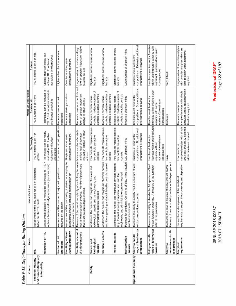
SR
NL-
RP-2
018-
0068
7
Pr
edec
isio
nal D
RAFT
20
18-0
7-15
DRAF
T
Page
122
of 1
97
Tabl
e F-
13. D
efin
ition
s for
Rat
ing
Opt
ions
5 - S
tron
gly
3 - M
oder
ate
1 - N
one
TRL
Ass
essm
ent o
f the
TR
L le
vels
for a
ll un
it op
erat
ions
ba
sed
on E
M T
RL
Gui
deTR
L is
judg
ed to
be
7 or
gr
eate
rTR
L is
judg
ed to
be
4 or
6TR
L is
judg
ed to
be
3 or
less
Mat
urat
ion
of T
RLA
sses
smen
t of a
bilit
y to
mat
ure
the
tech
nolo
gy to
TR
L 7
with
in s
ched
ule
and
budg
et c
onst
rain
ts (i
nclu
des
risks
)Te
chno
logy
can
be
read
ily
mat
ured
to T
RL
7 w
ithin
sc
hedu
le a
nd b
udge
t co
nstra
ints
Tech
nolo
gy c
an b
e m
atur
ed to
TR
L 7,
but
not
with
in s
ched
ule
and
budg
et c
onst
rain
ts
Unl
ikel
y th
at te
chno
logy
can
ac
hiev
e TR
L 7
with
in a
n ac
cept
able
tim
efra
me/
cost
Num
ber o
f Uni
t op
erat
ions
Ass
essm
ent o
f the
num
ber o
f maj
or u
nit o
pera
tions
re
quire
d by
the
optio
nLo
w n
umbe
r of u
nit o
pera
tions
Mod
erat
e nu
mbe
r of u
nit
oper
atio
nsH
igh
num
ber o
f uni
t ope
ratio
ns
Sim
plic
ity o
f Fee
d St
art-u
p/sh
ut d
own
Ass
essm
ent o
f the
com
plex
ity o
f sta
rting
or s
topp
ing
the
proc
essi
ng o
f was
te in
clud
ing
cons
ider
atio
n fo
r do
wns
tream
impa
cts
Sim
ple
and
shor
t sta
rt-up
/shu
tdow
n op
erat
ions
Mod
erat
e st
art-u
p/sh
utdo
wn
oper
atio
nsC
ompl
ex a
nd lo
ng s
tart-
up/s
hutd
own
oper
atio
ns
Sim
plic
ity o
f con
trol
of u
nit o
pera
tions
Mea
sure
of t
he o
vera
ll co
mpl
exity
of c
ontro
lling
the
entir
e w
aste
form
pro
duct
ion
proc
ess.
Num
ber o
f par
amet
ers
that
mus
t be
cont
rolle
d/m
onito
red.
Min
imal
num
ber o
f con
trols
an
d lo
w le
vel o
f ope
rato
r in
tera
ctio
n re
lativ
e to
oth
er
optio
ns
Mod
erat
e nu
mbe
r of c
ontro
ls a
nd
leve
l of o
pera
tor i
nter
actio
n re
lativ
e to
oth
er o
ptio
ns
Larg
e nu
mbe
r of c
ontro
ls a
nd h
igh
leve
l of o
pera
tor i
nter
actio
n re
lativ
e to
oth
er o
ptio
ns
Nucl
ear a
nd
Radi
olog
ical
Ha
zard
s
Add
ress
es th
e nu
mbe
r and
mag
nitu
de o
f nuc
lear
and
ra
diol
ogic
al h
azar
ds a
nd th
e en
gine
erin
g an
d ad
min
istra
tive
cont
rols
requ
ired
Few
haz
ards
requ
ire c
ontro
ls;
few
con
trols
are
act
ive
cont
rols
Mod
erat
e ha
zard
s re
quire
co
ntro
ls; m
oder
ate
num
ber o
f co
ntro
ls a
re a
ctive
con
trols
Sig
nific
ant a
ctive
con
trols
or n
ew
haza
rds
Chem
ical
Haz
ards
Add
ress
es th
e nu
mbe
r and
mag
nitu
de c
hem
ical
haz
ards
an
d th
e en
gine
erin
g an
d ad
min
istra
tive
cont
rols
requ
ired
Few
haz
ards
requ
ire c
ontro
ls;
few
con
trols
are
act
ive
cont
rols
Mod
erat
e ha
zard
s re
quire
co
ntro
ls; m
oder
ate
num
ber o
f co
ntro
ls a
re a
ctive
con
trols
Sig
nific
ant a
ctive
con
trols
or n
ew
haza
rds
Phys
ical
Haz
ards
Add
ress
es th
e nu
mbe
r and
mag
nitu
de p
hysi
cal h
azar
ds
(e.g
. the
rmal
, rot
atin
g eq
uipm
ent,
etc.
) and
the
engi
neer
ing
and
adm
inis
trativ
e co
ntro
ls re
quire
d
Few
haz
ards
requ
ire c
ontro
ls;
few
con
trols
are
act
ive
cont
rols
Mod
erat
e ha
zard
s re
quire
co
ntro
ls; m
oder
ate
num
ber o
f co
ntro
ls a
re a
ctive
con
trols
Sig
nific
ant a
ctive
con
trols
or n
ew
haza
rds
Tran
spor
tatio
n Ha
zard
sP
oten
tial f
or a
ccid
ents
, On-
site
vs
off-s
ite, m
iles
trave
led,
nu
mbe
r of s
hipm
ents
Low
shi
pmen
t mile
sM
oder
ate
ship
men
t mile
sLa
rge
num
ber o
f shi
pmen
t mile
s
Abili
ty to
han
dle
rang
e of
feed
vec
tor
com
posi
tions
Mea
sure
s th
e ab
ility
to s
olid
ify th
e fu
ll sp
ectru
m o
f fee
d ve
ctor
com
posi
tions
exp
ecte
dS
olid
ifies
all
feed
vec
tor
com
posi
tions
. N
o ad
ditio
nal
pret
reat
men
t is
requ
ired.
Sol
idifi
es m
ost f
eed
vect
or
com
posi
tions
. S
ome
addi
tiona
l pr
etre
atm
ent i
s re
quire
d.
Sol
idifi
es s
ome
feed
vec
tor
com
posi
tions
. E
xten
sive
add
ition
al
pret
reat
men
t is
requ
ired.
Abili
ty to
han
dle
rang
e of
feed
vec
tor
flow
rate
s
Mea
sure
s th
e ab
ility
to h
andl
e th
e fu
ll sp
ectru
m o
f fee
d ve
ctor
flow
rate
s ex
pect
ed.
A m
easu
re o
f the
turn
dow
n ra
tio o
f the
pro
cess
es
Han
dles
all
feed
vec
tor
flow
rate
s w
ithin
exi
stin
g su
rge
capa
city
with
no
upst
ream
/dow
nstre
am
cons
eque
nces
Han
dles
mos
t fee
d ve
ctor
flo
wra
tes
with
in e
xist
ing
surg
e ca
paci
ty w
ith s
ome
upst
ream
/dow
nstre
am
cons
eque
nces
Han
dles
som
e fe
ed v
ecto
r flo
wra
tes
with
in e
xist
ing
surg
e ca
paci
ty w
ith
sign
ifica
nt u
pstre
am/d
owns
tream
co
nseq
uenc
es
Abili
ty to
pr
even
t/rew
ork
off-
spec
pro
duct
Mea
sure
s th
e ea
se o
f avo
idin
g of
f-spe
c pr
oduc
t and
/or
the
easy
of r
ewor
k or
abi
lity
to d
eal w
ith o
ff-sp
ec p
rodu
ctE
asy
Mod
erat
eV
ery
diffi
cult
Anal
ytic
al
requ
irem
ents
The
num
ber a
nd c
ompl
exity
of t
he a
naly
tical
re
quire
men
ts to
sup
port
the
proc
essi
ng a
nd d
ispo
sitio
nLo
w n
umbe
r of
sam
ples
/ana
lyte
s w
ith s
impl
e an
alys
es a
nd e
asily
obt
aine
d w
ithin
tim
efra
me
requ
ired
Mod
erat
e nu
mbe
r of
sam
ples
/ana
lyte
s w
ith s
impl
e an
alys
es e
asily
obt
aine
d w
ithin
tim
efra
me
requ
ired
Larg
e nu
mbe
r of s
ampl
es/a
naly
tes
with
com
plex
ana
lyse
s w
hich
are
ha
rd to
obt
ain
with
in ti
mef
ram
e re
quire
d
Crite
riaM
etric
Met
ric D
efin
ition
Met
ric B
in D
escr
iptio
ns
Tech
nica
l Mat
urity
an
d Pr
oces
s Si
mpl
icity
&
Relia
bilit
y
Ope
ratio
nal F
lexi
bilit
y
Safe
ty
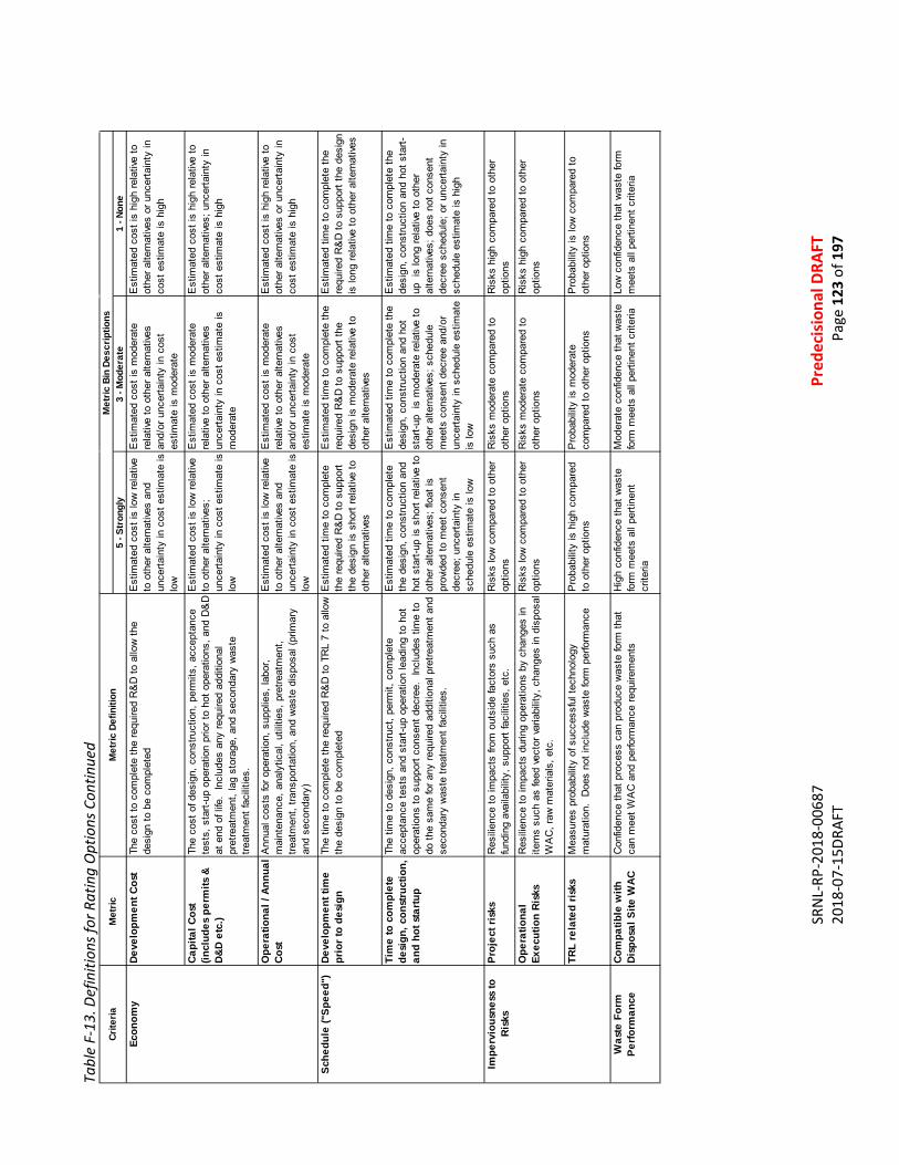
SR
NL-
RP-2
018-
0068
7
Pr
edec
isio
nal D
RAFT
20
18-0
7-15
DRAF
T
Page
123
of 1
97
Tabl
e F-
13. D
efin
ition
s for
Rat
ing
Opt
ions
Con
tinue
d
5 - S
tron
gly
3 - M
oder
ate
1 - N
one
Deve
lopm
ent C
ost
The
cost
to c
ompl
ete
the
requ
ired
R&
D to
allo
w th
e de
sign
to b
e co
mpl
eted
Est
imat
ed c
ost i
s lo
w re
lativ
e to
oth
er a
ltern
ative
s an
d un
certa
inty
in c
ost e
stim
ate
is
low
Est
imat
ed c
ost i
s m
oder
ate
rela
tive
to o
ther
alte
rnat
ives
and/
or u
ncer
tain
ty in
cos
t es
timat
e is
mod
erat
e
Est
imat
ed c
ost i
s hi
gh re
lativ
e to
ot
her a
ltern
ative
s or
unc
erta
inty
in
cost
est
imat
e is
hig
h
Capi
tal C
ost
(incl
udes
per
mits
&
D&D
etc.
)
The
cost
of d
esig
n, c
onst
ruct
ion,
per
mits
, acc
epta
nce
test
s, s
tart-
up o
pera
tion
prio
r to
hot o
pera
tions
, and
D&
D
at e
nd o
f life
. In
clud
es a
ny re
quire
d ad
ditio
nal
pret
reat
men
t, la
g st
orag
e, a
nd s
econ
dary
was
te
treat
men
t fac
ilitie
s.
Est
imat
ed c
ost i
s lo
w re
lativ
e to
oth
er a
ltern
ative
s;
unce
rtain
ty in
cos
t est
imat
e is
lo
w
Est
imat
ed c
ost i
s m
oder
ate
rela
tive
to o
ther
alte
rnat
ives
unce
rtain
ty in
cos
t est
imat
e is
m
oder
ate
Est
imat
ed c
ost i
s hi
gh re
lativ
e to
ot
her a
ltern
ative
s; u
ncer
tain
ty in
co
st e
stim
ate
is h
igh
Ope
ratio
nal /
Ann
ual
Cost
Ann
ual c
osts
for o
pera
tion,
sup
plie
s, la
bor,
mai
nten
ance
, ana
lytic
al, u
tiliti
es, p
retre
atm
ent,
treat
men
t, tra
nspo
rtatio
n, a
nd w
aste
dis
posa
l (pr
imar
y an
d se
cond
ary)
Est
imat
ed c
ost i
s lo
w re
lativ
e to
oth
er a
ltern
ative
s an
d un
certa
inty
in c
ost e
stim
ate
is
low
Est
imat
ed c
ost i
s m
oder
ate
rela
tive
to o
ther
alte
rnat
ives
and/
or u
ncer
tain
ty in
cos
t es
timat
e is
mod
erat
e
Est
imat
ed c
ost i
s hi
gh re
lativ
e to
ot
her a
ltern
ative
s or
unc
erta
inty
in
cost
est
imat
e is
hig
h
Deve
lopm
ent t
ime
prio
r to
desi
gnTh
e tim
e to
com
plet
e th
e re
quire
d R
&D
to T
RL
7 to
allo
w
the
desi
gn to
be
com
plet
edE
stim
ated
tim
e to
com
plet
e th
e re
quire
d R
&D
to s
uppo
rt th
e de
sign
is s
hort
rela
tive
to
othe
r alte
rnat
ives
Est
imat
ed ti
me
to c
ompl
ete
the
requ
ired
R&
D to
sup
port
the
desi
gn is
mod
erat
e re
lativ
e to
ot
her a
ltern
ative
s
Est
imat
ed ti
me
to c
ompl
ete
the
requ
ired
R&
D to
sup
port
the
desi
gn
is lo
ng re
lativ
e to
oth
er a
ltern
ative
s
Tim
e to
com
plet
e de
sign
, con
stru
ctio
n,
and
hot s
tartu
p
The
time
to d
esig
n, c
onst
ruct
, per
mit,
com
plet
e ac
cept
ance
test
s an
d st
art-u
p op
erat
ion
lead
ing
to h
ot
oper
atio
ns to
sup
port
cons
ent d
ecre
e. I
nclu
des
time
to
do th
e sa
me
for a
ny re
quire
d ad
ditio
nal p
retre
atm
ent a
nd
seco
ndar
y w
aste
trea
tmen
t fac
ilitie
s.
Est
imat
ed ti
me
to c
ompl
ete
the
desi
gn, c
onst
ruct
ion
and
hot s
tart-
up is
sho
rt re
lativ
e to
ot
her a
ltern
ative
s; fl
oat i
s pr
ovid
ed to
mee
t con
sent
de
cree
; unc
erta
inty
in
sche
dule
est
imat
e is
low
Est
imat
ed ti
me
to c
ompl
ete
the
desi
gn, c
onst
ruct
ion
and
hot
star
t-up
is m
oder
ate
rela
tive
to
othe
r alte
rnat
ives;
sch
edul
e m
eets
con
sent
dec
ree
and/
or
unce
rtain
ty in
sch
edul
e es
timat
e is
low
Est
imat
ed ti
me
to c
ompl
ete
the
desi
gn, c
onst
ruct
ion
and
hot s
tart-
up i
s lo
ng re
lativ
e to
oth
er
alte
rnat
ives;
doe
s no
t con
sent
de
cree
sch
edul
e; o
r unc
erta
inty
in
sche
dule
est
imat
e is
hig
h
Proj
ect r
isks
Res
ilien
ce to
impa
cts
from
out
side
fact
ors
such
as
fund
ing
avai
labi
lity,
sup
port
faci
litie
s, e
tc.
Ris
ks lo
w c
ompa
red
to o
ther
op
tions
Ris
ks m
oder
ate
com
pare
d to
ot
her o
ptio
nsR
isks
hig
h co
mpa
red
to o
ther
op
tions
Ope
ratio
nal
Exec
utio
n Ri
sks
Res
ilien
ce to
impa
cts
durin
g op
erat
ions
by
chan
ges
in
item
s su
ch a
s fe
ed v
ecto
r var
iabi
lity,
cha
nges
in d
ispo
sal
WA
C, r
aw m
ater
ials
, etc
.
Ris
ks lo
w c
ompa
red
to o
ther
op
tions
Ris
ks m
oder
ate
com
pare
d to
ot
her o
ptio
nsR
isks
hig
h co
mpa
red
to o
ther
op
tions
TRL
rela
ted
risks
Mea
sure
s pr
obab
ility
of s
ucce
ssfu
l tec
hnol
ogy
mat
urat
ion.
Doe
s no
t inc
lude
was
te fo
rm p
erfo
rman
ceP
roba
bilit
y is
hig
h co
mpa
red
to o
ther
opt
ions
Pro
babi
lity
is m
oder
ate
com
pare
d to
oth
er o
ptio
nsP
roba
bilit
y is
low
com
pare
d to
ot
her o
ptio
ns
Was
te F
orm
Pe
rform
ance
Com
patib
le w
ith
Disp
osal
Site
WAC
Con
fiden
ce th
at p
roce
ss c
an p
rodu
ce w
aste
form
that
ca
n m
eet W
AC
and
per
form
ance
requ
irem
ents
Hig
h co
nfid
ence
that
was
te
form
mee
ts a
ll pe
rtine
nt
crite
ria
Mod
erat
e co
nfid
ence
that
was
te
form
mee
ts a
ll pe
rtine
nt c
riter
ia
Low
con
fiden
ce th
at w
aste
form
m
eets
all
perti
nent
crit
eria
Impe
rvio
usne
ss to
Ri
sks
Crite
ria
Econ
omy
Sche
dule
("Sp
eed"
)
Met
ricM
etric
Def
initi
onM
etric
Bin
Des
crip
tions
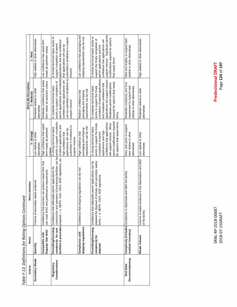
SR
NL-
RP-2
018-
0068
7
Pr
edec
isio
nal D
RAFT
20
18-0
7-15
DRAF
T
Page
124
of 1
97
Tabl
e F-
13. D
efin
ition
s for
Rat
ing
Opt
ions
Con
tinue
d
5 - S
tron
gly
3 - M
oder
ate
1 - N
one
Qua
ntity
Vol
ume
of s
econ
dary
was
te p
rodu
ced
Low
rela
tive
to o
ther
al
tern
ative
sM
oder
ate
rela
tive
to o
ther
al
tern
ative
sH
igh
rela
tive
to o
ther
alte
rnat
ives
Com
patib
le w
ith
Disp
osal
Site
WAC
Con
fiden
ce th
at p
roce
ss c
an p
rodu
ce w
aste
form
that
ca
n m
eet W
AC
and
per
form
ance
requ
irem
ents
Hig
h co
nfid
ence
that
was
te
form
mee
ts a
ll pe
rtine
nt
crite
ria
Mod
erat
e co
nfid
ence
that
was
te
form
mee
ts a
ll pe
rtine
nt c
riter
ia
Low
con
fiden
ce th
at w
aste
form
m
eets
all
perti
nent
crit
eria
Perm
ittin
g/lic
ensi
ng
com
plex
ity f
or n
ew
faci
litie
s &
proc
esse
s
Con
fiden
ce th
at d
efen
sibl
e pe
rmit
appl
icat
ions
for
cons
truct
ion
and
oper
atio
n of
pro
cess
ing
faci
litie
s ca
n be
pr
epar
ed, i
. e. N
EP
A, C
AA
, CW
A, D
OE
regu
latio
ns, e
tc.
A s
trong
tech
nica
l bas
is
exis
ts to
sup
port
com
plet
ion
of p
erm
it ap
plic
atio
ns a
nd
high
con
fiden
ce th
at
appl
icat
ions
will
can
be
subm
itted
in ti
mef
ram
e to
su
ppor
t mis
sion
A m
oder
ate
tech
nica
l bas
is
exis
ts to
sup
port
com
plet
ion
of
perm
it ap
plic
atio
ns a
nd m
oder
ate
conf
iden
ce th
at a
pplic
atio
ns w
ill
can
be s
ubm
itted
in ti
mef
ram
e to
su
ppor
t mis
sion
A li
mite
d te
chni
cal b
asis
exi
sts
to
supp
ort c
ompl
etio
n of
per
mit
appl
icat
ions
and
low
con
fiden
ce
that
app
licat
ions
will
can
be
subm
itted
in ti
mef
ram
e to
sup
port
mis
sion
Com
plia
nce
with
sh
ippi
ng re
gula
tions
Con
fiden
ce th
at s
hipp
ing
regu
latio
ns c
an b
e m
etH
igh
conf
iden
ce th
at
pack
agin
g an
d sh
ippi
ng
requ
irem
ents
can
be
met
Med
ium
con
fiden
ce th
at
pack
agin
g an
d sh
ippi
ng
requ
irem
ents
can
be
met
Low
con
fiden
ce th
at p
acka
ging
and
sh
ippi
ng re
quire
men
ts c
an b
e m
et
Perm
ittin
g/lic
ensi
ng
com
plex
ity fo
r di
spos
al
Con
fiden
ce th
at d
efen
sibl
e pe
rmit
appl
icat
ions
can
be
prep
ared
for d
ispo
sal o
f prim
ary
and
seco
ndar
y w
aste
fo
rms,
i. e
. NE
PA
, CW
A, D
OE
regu
latio
ns
A s
trong
tech
nica
l bas
is
exis
ts to
sup
port
the
timel
y co
mpl
etio
n of
per
mit
appl
icat
ions
and
hig
h co
nfid
ence
that
app
licat
ions
w
ill s
uppo
rt m
issi
on.
Min
or
perm
it m
odifi
catio
ns re
quire
d fo
r opt
ion'
s fin
al w
aste
form
s
A m
oder
ate
tech
nica
l bas
is
exis
ts to
sup
port
the
timel
y co
mpl
etio
n of
per
mit
appl
icat
ions
an
d m
oder
ate
conf
iden
ce th
at
appl
icat
ions
will
sup
port
mis
sion
. M
oder
ate
perm
it m
odifi
catio
ns
requ
ired
for o
ptio
n's
final
was
te
form
s
A li
mite
d te
chni
cal b
asis
exi
sts
to
supp
ort t
he ti
mel
y co
mpl
etio
n of
pe
rmit
appl
icat
ions
and
low
co
nfid
ence
that
app
licat
ions
will
su
ppor
t mis
sion
. S
igni
fican
t per
mit
mod
ifica
tions
requ
ired
for o
ptio
n's
final
was
te fo
rms
Com
plex
ity (i
nclu
des
resi
dual
inve
ntor
y)C
ompl
exity
to d
eact
ivate
and
D&
D th
e fa
cilit
yE
asy
and
quic
k to
sup
port
task
rela
tive
to o
ther
al
tern
ative
s
Mod
erat
e co
mpl
exity
and
tim
e re
quire
men
t to
supp
ort t
ask
rela
tive
to o
ther
alte
rnat
ives
Har
d an
d le
ngth
y to
sup
port
task
re
lativ
e to
oth
er a
ltern
ative
s
Was
te V
olum
eV
olum
e of
was
te p
rodu
ced
in th
e de
activ
atio
n an
d D
&D
of
the
faci
lity
Low
rela
tive
to o
ther
al
tern
ative
sM
oder
ate
rela
tive
to o
ther
al
tern
ative
sH
igh
rela
tive
to o
ther
alte
rnat
ives
End
Stat
e De
com
mis
sion
ing
Seco
ndar
y W
aste
Regu
lato
ry
Cons
ider
atio
ns
Crite
riaM
etric
Met
ric D
efin
ition
Met
ric B
in D
escr
iptio
ns
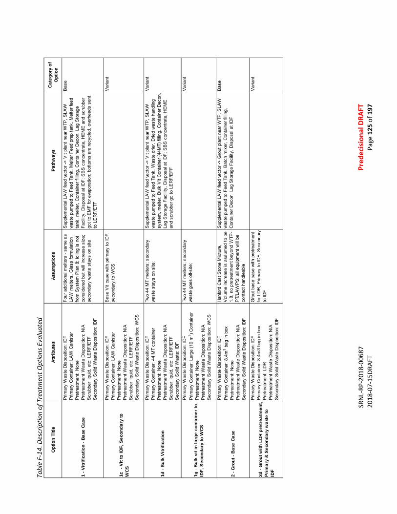
SR
NL-
RP-2
018-
0068
7
Pr
edec
isio
nal D
RAFT
20
18-0
7-15
DRAF
T
Page
125
of 1
97
Tabl
e F-
14. D
escr
iptio
n of
Tre
atm
ent O
ptio
ns E
valu
ated
Opt
ion
Title
Attri
bute
sAs
sum
ptio
nsPa
thw
ays
Cate
gory
of
Opt
ion
1 - V
itrifi
catio
n - B
ase
Case
Prim
ary
Was
te D
ispo
sitio
n: ID
FP
rimar
y C
onta
iner
: LA
W C
anis
ter
Pre
treat
men
t: N
one
Pre
treat
men
t Was
te D
ispo
sitio
n: N
/AS
crub
ber l
iqui
d, e
tc: L
ER
F/E
TFS
econ
dary
Sol
id W
aste
Dis
posi
tion:
IDF
Four
add
ition
al m
elte
rs -
sam
e as
LA
W m
elte
rs, G
lass
form
ulat
ion
from
Sys
tem
Pla
n 8;
idlin
g is
not
co
nsid
ered
but
will
incr
ease
siz
e;
seco
ndar
y w
aste
sta
ys o
n si
te
Sup
plem
enta
l LA
W fe
ed v
ecto
r ->
Vit
plan
t nea
r WTP
, SLA
W
was
te p
umpe
d to
Fee
d Ta
nk, M
elte
r Fee
d pr
ep ta
nk, M
elte
r fee
d ta
nk, m
elte
r, C
onta
iner
filli
ng, C
onta
iner
Dec
on, L
ag S
tora
ge
Faci
lity,
Dis
posa
l at I
DF;
SB
S c
once
ntra
te, H
EM
E a
nd s
crub
ber
got t
o E
MF
for e
vapo
ratio
n; b
otto
ms
are
recy
cled
, ove
rhea
ds s
ent
to L
ER
F/E
TF
Bas
e
1c -
Vit
to ID
F, S
econ
dary
to
WCS
Prim
ary
Was
te D
ispo
sitio
n: ID
FP
rimar
y C
onta
iner
: LA
W C
anis
ter
Pre
treat
men
t: N
one
Pre
treat
men
t Was
te D
ispo
sitio
n: N
/AS
crub
ber l
iqui
d, e
tc: L
ER
F/E
TFS
econ
dary
Sol
id W
aste
Dis
posi
tion:
WC
S
Bas
e V
it ca
se w
ith p
rimar
y to
IDF,
se
cond
ary
to W
CS
Var
iant
1d -
Bulk
Vitr
ifica
tion
Prim
ary
Was
te D
ispo
sitio
n: ID
FP
rimar
y C
onta
iner
: 44
MT
cont
aine
rP
retre
atm
ent:
Non
eP
retre
atm
ent W
aste
Dis
posi
tion:
N/A
Scr
ubbe
r liq
uid,
etc
: LE
RF/
ETF
Sec
onda
ry S
olid
Was
te: I
DF
Two
44 M
T m
elte
rs; s
econ
dary
w
aste
sta
ys o
n si
te;
Sup
plem
enta
l LA
W fe
ed v
ecto
r ->
Vit
plan
t nea
r WTP
, SLA
W
was
te p
umpe
d to
Fee
d Ta
nk, W
aste
drie
r, D
ried
was
te h
andl
ing
syst
em, m
elte
r, B
ulk
Vit
Con
tain
er (4
4MT)
filli
ng, C
onta
iner
Dec
on,
Lag
Sto
rage
Fac
ility
, Dis
posa
l at I
DF;
SB
S c
once
ntra
te, H
EM
E
and
scru
bber
go
to L
ER
F/E
FF
Var
iant
1g -
Bulk
vit
in la
rge
cont
aine
r to
IDF,
Sec
onda
ry to
WCS
Prim
ary
Was
te D
ispo
sitio
n: ID
FP
rimar
y C
onta
iner
: Lar
ge (1
0 m
3 ) Con
tain
erP
retre
atm
ent:
Non
eP
retre
atm
ent W
aste
Dis
posi
tion:
N/A
Sec
onda
ry S
olid
Was
te D
ispo
sitio
n: W
CS
Two
44 M
T m
elte
rs; s
econ
dary
w
aste
goe
s of
f-site
; V
aria
nt
2 - G
rout
- Ba
se C
ase
Prim
ary
Was
te D
ispo
sitio
n: ID
FP
rimar
y C
onta
iner
: 8.4
m3 b
ag in
box
Pre
treat
men
t: N
one
Pre
treat
men
t Was
te D
ispo
sitio
n: N
/AS
econ
dary
Sol
id W
aste
Dis
posi
tion:
IDF
Han
ford
Cas
t Sto
ne M
ixtu
re,
Vol
ume
incr
ease
is a
ssum
ed to
be
1.8,
no
pret
reat
men
t bey
ond
WTP
-P
T/LA
WP
S; a
ll eq
uipm
ent w
ill b
e co
ntac
t han
dlea
ble
Sup
plem
enta
l LA
W fe
ed v
ecto
r ->
Gro
ut p
lant
nea
r WTP
, SLA
W
was
te p
umpe
d to
Fee
d Ta
nk, B
atch
mix
er, C
onta
iner
filli
ng,
Con
tain
er D
econ
, Lag
Sto
rage
Fac
ility
, Dis
posa
l at I
DF
Bas
e
2d -
Gro
ut w
ith L
DR p
retre
atm
ent,
Prim
ary
& Se
cond
ary
was
te to
ID
F
Prim
ary
Was
te D
ispo
sitio
n: ID
FP
rimar
y C
onta
iner
: 8.4
m3
bag
in b
oxP
retre
atm
ent:
LDR
Pre
treat
men
t Was
te D
ispo
sitio
n: N
/AS
econ
dary
Sol
id W
aste
Dis
posi
tion:
IDF
Gro
ut b
ase
case
with
pre
treat
men
t fo
r LD
R, P
rimar
y to
IDF,
Sec
onda
ry
to ID
F
Var
iant

SR
NL-
RP-2
018-
0068
7
Pr
edec
isio
nal D
RAFT
20
18-0
7-15
DRAF
T
Page
126
of 1
97
Tabl
e F-
14. D
escr
iptio
n of
Tre
atm
ent O
ptio
ns E
valu
ated
Con
tinue
d
Opt
ion
Title
Attri
bute
sAs
sum
ptio
nsPa
thw
ays
Cate
gory
of
Opt
ion
2e1
- Gro
ut w
ith L
DR a
nd T
c &
I Pr
etre
atm
ent t
o HL
VIT
Prim
ary
& Se
cond
ary
was
te to
IDF
Prim
ary
Was
te D
ispo
sitio
n: ID
FP
rimar
y C
onta
iner
: 8.4
m3
bag
in b
oxP
retre
atm
ent:
LDR
, Tc,
IP
retre
atm
ent W
aste
Dis
posi
tion:
Tc,
I to
HLV
itS
econ
dary
Sol
id W
aste
Dis
posi
tion:
IDF
Gro
ut b
ase
case
with
pre
treat
men
t fo
r LD
R, T
c, I
sent
to H
LVIT
, S
econ
dary
to ID
F
Var
iant
2e2
- Gro
ut w
ith L
DR a
nd T
c &
I Pr
etre
atm
ent t
o W
CS P
rimar
y &
Seco
ndar
y w
aste
to ID
F
Prim
ary
Was
te D
ispo
sitio
n: ID
FP
rimar
y C
onta
iner
: 8.4
m3
bag
in b
oxP
retre
atm
ent:
LDR
, Tc,
IP
retre
atm
ent W
aste
Dis
posi
tion:
Tc,
I to
WC
SS
econ
dary
Sol
id W
aste
Dis
posi
tion:
IDF
Gro
ut b
ase
case
with
pre
treat
men
t fo
r LD
R, T
c, I
grou
ted
and
sent
to
WC
S, S
econ
dary
to ID
F
Var
iant
2f -
Gro
ut w
ith L
DR a
nd S
r pr
etre
atm
ent;
Prim
ary
was
te to
W
CS
Prim
ary
Was
te D
ispo
sitio
n: W
CS
Prim
ary
Con
tain
er: 8
.4m
3 ba
g in
box
Pre
treat
men
t: LD
R, S
rP
retre
atm
ent W
aste
Dis
posi
tion:
Sr t
o H
LVit
Sec
onda
ry S
olid
Was
te D
ispo
sitio
n: ID
F
Gro
ut b
ase
case
with
pre
treat
men
t fo
r LD
R, S
r to
HLV
IT, S
econ
dary
to
IDF
Var
iant
2g2
- Gro
ut w
ith L
DR
pret
reat
men
t; Pr
imar
y w
aste
to
WCS
Prim
ary
Was
te D
ispo
sitio
n: W
CS
Prim
ary
Con
tain
er: 8
.4m
3 ba
g in
box
Pre
treat
men
t: LD
RP
retre
atm
ent W
aste
Dis
posi
tion:
N/A
Sec
onda
ry S
olid
Was
te D
ispo
sitio
n: ID
F
Gro
ut b
ase
case
with
pre
treat
men
t fo
r LD
R; g
rout
ed s
econ
dary
to ID
FV
aria
nt
3 - S
team
Ref
orm
ing
- Bas
e Ca
se
Prim
ary
Was
te D
ispo
sitio
n: ID
FP
rimar
y C
onta
iner
: 8.4
m3
Pre
treat
men
t: N
one
Pre
treat
men
t Was
te D
ispo
sitio
n: N
/AS
econ
dary
Sol
id W
aste
Dis
posi
tion:
IDF
Two
com
plet
e FB
SR
sys
tem
s,
Gro
ut o
r geo
poly
mer
mon
olith
sy
stem
to e
ncap
sula
te th
e gr
anul
ar
prod
uct b
efor
e st
orag
e, C
aust
ic
scru
b go
es b
ack
to F
BS
R s
yste
m
Sup
plem
enta
l LA
W fe
ed v
ecto
r ->
FBS
R p
lant
nea
r WTP
, SLA
W
was
te p
umpe
d to
Fee
d Ta
nk, W
aste
Sta
ging
tank
, FB
SR
sys
tem
, w
aste
pro
duct
han
dlin
g sy
stem
, Con
tain
er fi
lling
, Lag
Sto
rage
Fa
cilit
y, D
ispo
sal a
t ID
F; o
ff-ga
s sy
stem
(The
rmal
oxi
datio
n,
Car
bon
bed
for H
g, C
aust
ic s
crub
for I
, HE
PA
)
Bas
e
3b -
Stea
m R
efor
min
g to
WCS
, Se
cond
ary
to W
CS
Prim
ary
Was
te D
ispo
sitio
n: W
CS
Prim
ary
Con
tain
er: 8
.4m
3P
retre
atm
ent:
Non
eP
retre
atm
ent W
aste
Dis
posi
tion:
N/A
Sec
onda
ry S
olid
Was
te D
ispo
sitio
n: W
CS
Not
mac
roen
caps
ulat
ed in
co
ntai
ners
to W
CS
. Drie
d,
pack
aged
SS
W to
WC
S
Var
iant
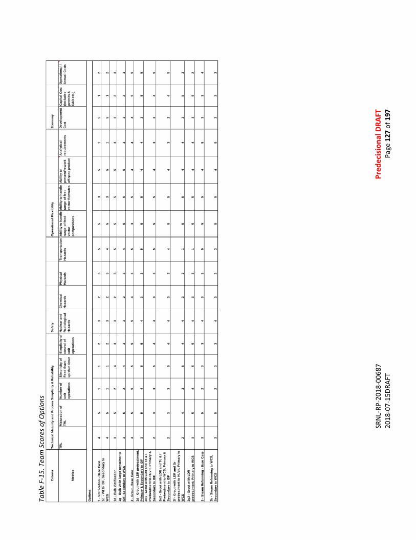
SR
NL-
RP-2
018-
0068
7
Pr
edec
isio
nal D
RAFT
20
18-0
7-15
DRAF
T
Page
127
of 1
97
Tabl
e F-
15. T
eam
Sco
res o
f Opt
ions
Crite
riaTe
chni
cal M
atur
ity a
nd P
roce
ss S
impl
icity
& R
elia
bilit
y Sa
fety
Ope
ratio
nal F
lexi
bilit
yEc
onom
y
Met
rics
TRL
Mat
urat
ion
of
TRL
Num
ber o
f un
it op
erat
ions
Sim
plic
ity o
f Fe
ed S
tart-
up/s
hut d
own
Sim
plic
ity o
f co
ntro
l of
unit
oper
atio
ns
Nucl
ear a
nd
Radi
olog
ical
Ha
zard
s
Chem
ical
Ha
zard
sPh
ysic
al
Haza
rds
Tran
spor
tatio
n Ha
zard
sAb
ility
to h
andl
e ra
nge
of fe
ed
vect
or
com
posi
tions
Abili
ty to
han
dle
rang
e of
feed
ve
ctor
flow
rate
s
Abili
ty to
pr
even
t/rew
ork
off-s
pec
prod
uct
Anal
ytic
al
requ
irem
ents
Deve
lopm
ent
Cost
Capi
tal C
ost
(incl
udes
pe
rmits
&
D&D
etc.
)
Ope
ratio
nal /
An
nual
Cos
ts
1 - V
itrifi
catio
n - B
ase
Case
45
11
23
23
55
35
15
12
1c -
Vit
to ID
F, S
econ
dary
to
WCS
4
51
12
32
34
53
51
51
2
1d -
Bulk
Vitr
ifica
tion
35
24
33
23
55
55
33
23
1g -
Bulk
vit
in la
rge
cont
aine
r to
IDF,
Sec
onda
ry to
WCS
35
24
33
23
45
55
33
23
2 - G
rout
- Ba
se C
ase
45
55
55
43
53
54
44
55
2d -
Gro
ut w
ith L
DR p
retre
atm
ent,
Prim
ary
& Se
cond
ary
to ID
F3
54
55
43
35
55
44
35
52e
1 - G
rout
with
LDR
and
Tc
& I
Pret
reat
men
t to
HLVi
t, Pr
imar
y &
Seco
ndar
y to
IDF
23
35
44
33
55
54
32
45
2e2
- Gro
ut w
ith L
DR a
nd T
c &
I Pr
etre
atm
ent t
o W
CS, P
rimar
y &
Seco
ndar
y to
IDF
23
35
44
33
45
54
32
45
2f -
Gro
ut w
ith L
DR a
nd S
r pr
etre
atm
ent t
o HL
Vit,
Prim
ary
to
WCS
24
35
44
33
15
54
43
53
2g2
- Gro
ut w
ith L
DR
pret
reat
men
t; Pr
imar
y to
WCS
35
45
54
33
15
54
43
52
3 - S
team
Ref
orm
ing
- Bas
e Ca
se3
52
33
43
35
55
45
33
4
3b -
Stea
m R
efor
min
g to
WCS
, Se
cond
ary
to W
CS3
52
33
43
33
55
45
33
3
Opt
ions
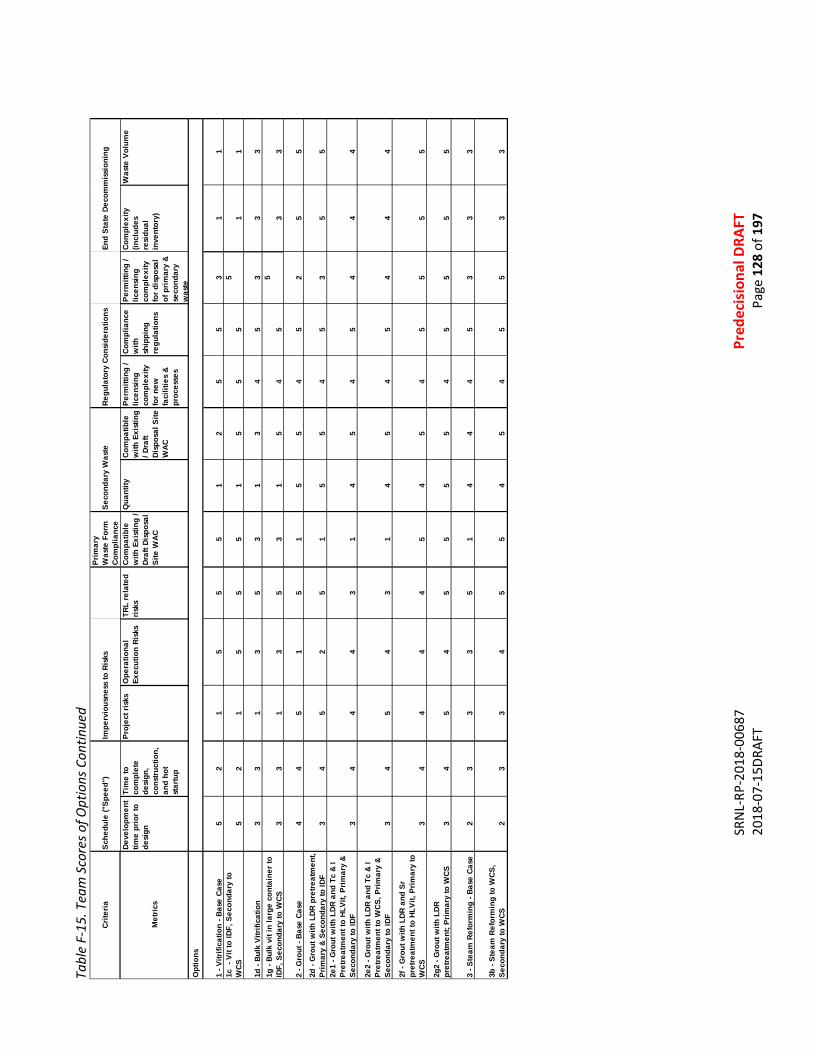
SR
NL-
RP-2
018-
0068
7
Pr
edec
isio
nal D
RAFT
20
18-0
7-15
DRAF
T
Page
128
of 1
97
Tabl
e F-
15. T
eam
Sco
res o
f Opt
ions
Con
tinue
d
Crite
riaSc
hedu
le ("
Spee
d")
Impe
rvio
usne
ss to
Ris
ksPr
imar
y W
aste
For
m
Com
plia
nce
Seco
ndar
y W
aste
Regu
lato
ry C
onsi
dera
tions
End
Stat
e De
com
mis
sion
ing
Met
rics
Deve
lopm
ent
time
prio
r to
desi
gn
Tim
e to
co
mpl
ete
desi
gn,
cons
truct
ion,
an
d ho
t st
artu
p
Proj
ect r
isks
Ope
ratio
nal
Exec
utio
n Ri
sks
TRL
rela
ted
risks
Com
patib
le
with
Exi
stin
g /
Draf
t Dis
posa
l Si
te W
AC
Qua
ntity
Com
patib
le
with
Exi
stin
g / D
raft
Disp
osal
Site
W
AC
Perm
ittin
g /
licen
sing
co
mpl
exity
fo
r new
fa
cilit
ies
& pr
oces
ses
Com
plia
nce
with
sh
ippi
ng
regu
latio
ns
Perm
ittin
g /
licen
sing
co
mpl
exity
fo
r dis
posa
l of
prim
ary
& se
cond
ary
was
te
Com
plex
ity
(incl
udes
re
sidu
al
inve
ntor
y)
Was
te V
olum
e
1 - V
itrifi
catio
n - B
ase
Case
52
15
55
12
55
31
11c
- V
it to
IDF,
Sec
onda
ry to
W
CS
52
15
55
15
55
51
1
1d -
Bulk
Vitr
ifica
tion
33
13
53
13
45
33
31g
- Bu
lk v
it in
larg
e co
ntai
ner t
o ID
F, S
econ
dary
to W
CS3
31
35
31
54
55
33
2 - G
rout
- Ba
se C
ase
44
51
51
55
45
25
5
2d -
Gro
ut w
ith L
DR p
retre
atm
ent,
Prim
ary
& Se
cond
ary
to ID
F3
45
25
15
54
53
55
2e1
- Gro
ut w
ith L
DR a
nd T
c &
I Pr
etre
atm
ent t
o HL
Vit,
Prim
ary
& Se
cond
ary
to ID
F3
44
43
14
54
54
44
2e2
- Gro
ut w
ith L
DR a
nd T
c &
I Pr
etre
atm
ent t
o W
CS, P
rimar
y &
Seco
ndar
y to
IDF
34
54
31
45
45
44
4
2f -
Gro
ut w
ith L
DR a
nd S
r pr
etre
atm
ent t
o HL
Vit,
Prim
ary
to
WCS
34
44
45
45
45
55
5
2g2
- Gro
ut w
ith L
DR
pret
reat
men
t; Pr
imar
y to
WCS
34
54
55
55
45
55
5
3 - S
team
Ref
orm
ing
- Bas
e Ca
se2
33
35
14
44
53
33
3b -
Stea
m R
efor
min
g to
WCS
, Se
cond
ary
to W
CS2
33
45
54
54
55
33
Opt
ions
SRNL-RP-2018-00687 Predecisional DRAFT 2018-07-15DRAFT Page 129 of 197
APPENDIX G. EXPANDED DISCUSSION: COST ESTIMATE METHODOLOGY AND BASIS G.1 SUMMARY This document lays out preliminary capital and life-cycle costs for the base case of each Supplemental Low Activity Waste (SLAW) technology and is considered a Class 5, Business Decision Estimate Range (BDER) based on the criteria found in the Association for the Advancement of Cost Engineering, International (AACEI), recommended practices. G.2 ESTIMATE PURPOSE To provide a Rough Order of Magnitude (ROM) Class 5 Planning Estimate for research and development, design, construction, life cycle costs including transportation and disposal. It also includes the disassembling and disposal cost for each technology; vitrification, grout and steam reforming, providing the most quantitative comparison possible between the treatment options. Class 5 estimates have the least project definition available (from 0% to 2%) and therefore have very wide accuracy ranges. They are the fastest of the five types of estimates to complete, but they are also the least accurate. These estimates were developed from information mined from previous studies, current Department of Energy (DOE) facility construction projects and current DOE operating facilities. The project team Subject Matter Experts (SME) identified technical and / or programmatic gaps between selected facility analog and the pertinent technology. Adjustments were made to reflect the scale of these gaps – both in the total calculated cost and the confidence range of each estimate. The accuracy associated with Class 5 estimates ranges from -20% / -50% to +30% / +100% and is a measure of the accuracy of the estimate after application of the Estimate Reserve. For this process, the accuracy reflected is -10% to +100%. Basic scope estimates for design, field installation and life cycle costs, including transportation and disposal will be developed by identification and utilization of analog facilities utilizing similar processes. The following assumptions have been made for the purpose, scope and assumptions of the planning estimate provided. G.3 ESTIMATE SCOPE • Perform Technology Development activities. • Procure Engineering / Design Subcontractor. • Perform design, via subcontract, of Facilities for SLAW including utility and process rooms, sample
collection stations, office space, control room as applicable, lag storage feed tanks, lag storage for containers with appropriate containment, truck and or rail unloading / loading facilities.
• Provide design oversight of Engineering / Design Subcontractor for above. • Procure Nuclear and Criticality Engineering Subcontractor services. • Procure competitive bid for Construction Subcontractor. • Construct SLAW Facilities as detailed above. • Provide construction oversight of Construction Subcontractor. • Subcontract (as appropriate) for offsite waste disposal including transportation.
SRNL-RP-2018-00687 Predecisional DRAFT 2018-07-15DRAFT Page 130 of 197
• Maintenance and Operations of the Liquid Waste Staging Building. • Secondary waste generation and disposal. • Life cycle costs including transportation. • Costs for electricity and other utilities. • Operations & Maintenance training costs and Operations & Maintenance staff. • Truck drivers, trucks and shipping costs. • Decommissioning and Dismantling (D&D) of the SLAW Facilities at the end of the project. G.4 ESTIMATE ASSUMPTIONS • Construction will be mostly performed in non-rad and non-hazardous waste environment except for
systems being tied into WTP operating systems as required. • Assumes this facility will be constructed within the vicinity of WTP unless option flowsheet specifies
other; utilities will be within 200' of new buildings /trailer location. • Construction Subcontractor will have sufficient Hanford trained craft and supervision to perform
work. • Construction Subcontractor will perform ground surveys of installation areas prior to work
performed in accordance with construction schedule dates. • Construction Subcontractor will perform ground surveys for soil disturbing activities in accordance
with construction schedule dates. • Lock and Tag-out and connecting to existing utilities will be performed by the Construction
Subcontractor with Hanford Operations support. • Construction Subcontractor will be responsible for disposal of construction waste. • No existing utilities will have to be rerouted. • Current existing utilities at new building locations are sufficient for capacity for supporting scope. • Sufficient competition between Construction Subcontractors will be available ensuring a
reasonable bidding and a project cost atmosphere. • Replacement costs of installed engineered equipment during operations will be determined. This
excludes consumable system units, such as melters or other key systems with known life expectancy.
G.5 ESTIMATE EXCLUSIONS Assumes non-consumable installed equipment will last the life time of the project. Estimate Flow Sheets Flow sheets were developed for the following options and sub options and support the development of the planning estimate, based on ORP-11242, revision 8, River Protection Project System Plan, as a general baseline. An iterative process involving technology and regulatory SME input, development and construction experience, and operations and logistics expertise was utilized and the following analog facilities were identified for use in the process of estimating. G.5.1 Vitrification Waste Treatment and Immobilization Plant (WTP) – Low Activity Waste (LAW) with Effluent Management

SRNL-RP-2018-00687 Predecisional DRAFT 2018-07-15DRAFT Page 131 of 197
Facility (EMF) at the Hanford Site Defense Waste Processing Facility (DWPF) at the Savannah River Site (SRS). WTP-LAW was selected as the best analog for Supplemental LAW vitrification. The prescribed flowsheet uses the same melters (4 versus 2) and the pertinent seismic and nuclear construction requirements will be more current than for DWPF. G.5.2 Grout Saltstone, with defined upgrades and logistics beyond the scope of SRS operations. Saltstone can produce at the same scale as required for Supplemental LAW grout. It is a good analog, but significant handling, pretreatment (for variants), and logistical unit operations must be included. G.5.3 Fluid Bed Steam Reforming (FBSR) Integrated Waste Treatment Unit (IWTU) at the Idaho Site. IWTU is nominally half the capacity required for Supplemental LAW fluidized bed steam reforming, and will produce a different mineral (aluminosilicate versus sodium carbonate) form, and is built for more highly radioactive material. It is the best available analog, though not as similar relative to the grout or glass analogs. G.6 ESTIMATE PLANNING The planning estimates for the proposed SLAW projects were developed from information mined from previous studies, current DOE facility construction projects and current DOE operating facilities. Key in development was the use of direct comparison for specific ancillary facilities, namely: • Pre-processing Facility • New unit operations • Post processing Facility • Balance of Facilities • Control Room This approach relies on existing information such as actual construction costs (with escalation) for operating facilities (such as Saltstone) or facilities undergoing start-up (such as the IWTU) or Estimate at Completion (EAC) data for facilities nearing start-up (such as WPT-LAW). These data were then adjusted for the scale of the proposed facility versus the analog. Vitrification and steam reforming options require double capacity of the closest analog. A multiplier, square root of 2, to capital costs of the analog was applied to reflect the increased footprint and the capacity required – but account for the consistency of design and engineering support. Cost estimating was also performed for selected variants for each case base. These variants, which were selected during the team evaluation exercise, were estimated in the same manner as the base cases. To reflect the degree of uncertainty for the estimating process, variants that did not appear to change the capital costs or operating costs on the order of at least 25% were usually not estimated to the same rigor, or at all.
SRNL-RP-2018-00687 Predecisional DRAFT 2018-07-15DRAFT Page 132 of 197
The selected analog facilities provide the best available data for estimate bases. It is also noted there is more deviation between certain analogs and the projected Supplemental LAW process. Adjustments were made to reflect significant increases in unit operations or complexity, or reductions in same. This limited number of individual estimates, but does not reflect the range expected for the various technologies. Further, the intent of the exercise was to compare the range defined within a technology, identify the degree to which technology cost estimated ranges do or do not overlap, and so therefore provide a ROM comparison. The project team SMEs identified technical and / or programmatic gaps between selected facility analog and the pertinent technology. Adjustments were made to reflect the scale of these gaps – both in the total calculated cost and the confidence range of each estimate. Logistics and transportation were considerations identified for all options. Key facets of this portion of the estimate includes preparation and storage offsite shipmen, transportation (nominally rail), and facility disposition (tipping fee). The study focused on only one offsite option, Waste Control Specialists, (WCS). WCS applies a volumetric charge to all incoming waste, within a given category. Operating costs were estimated in a similar manner as capital costs. Analog facility costs, or estimates, were applied to the respective technologies. Allowances were made for additional tankage and unit operations, control room, laboratory and logistic support. As per capital outlay, vitrification and steam reforming operating costs were increased by a factor of the square root of 2, to account for the increased (double) number of systems versus the closest existing analog. Scope requirements defined by the SMEs, as well as challenges and opportunities associated with the proposed process are as follows. A. For the vitrification process, the following facilities are included.
1. Lag storage capability of 500K gallons (minimum for all options) 2. WTP SLAW Vitrification Facility with 4 melters and off gas systems 3. WTP Effluent Management with equivalent capability 4. Balance of Facilities, consistent with WTP LAW 5. Lag Storage and Shipping Capability, consistent with WTP LAW
It was assumed that the existing control room and laboratory could be utilized for this option with minimal impact to normal operations. See Table G-1, Vitrification Base Scope. Another option for this process would be the use of two (2) melters and off gas systems. For transportation, an opportunity exists to use a rail system for glass container movement to the final storage location. See Table G-2, Vitrification Variant 1. B. For the grout process, the following facilities are included.
1. Lag storage capability of 500K gallons 2. WTP LAW grout facility including batch mixer, feed silos, hoppers, containerization and
decontamination facility 3. Balance of Facilities, as required 4. Lag Storage and Shipping Facility
A new control room and expected use of the WTP laboratory with some shift adjustments are assumed for this process. See Table G-3, Grout Base Scope

SRNL-RP-2018-00687 Predecisional DRAFT 2018-07-15DRAFT Page 133 of 197
High scope for this process assumes the need to remove Technetium (Tc) and Iodine (I). Other options are being developed including pretreatment for organics and ammonia, as required. See Table G-4, Grout Variant 1 Another variant evaluated was construction of the grout plant at IDF. See Table G-5, Grout Variant 2. Opportunities with type of shipping packaging and shipping options to final storage locations exist. C. For the Fluid Bed Steam Reforming (FBSR) process, the following facilities are included.
1. Facility with two (2) IWTU Facilities lines utilizing the Denitration Mineralization Reformer (DMR) process
2. Lag Storage capability of 1.5M gallons 3. Installation of cryogenic nitrogen and oxygen tanks 4. Balance of Facilities, as required 5. Lab Storage and Shipping Facility
A new control room and expected use of the WTP laboratory with some shift adjustments are assumed for this process. See Table G-6, Fluid Bed Steam Reforming Base Scope. High scope for this process assumes a grout plant is required for each DMR unit to form a monolithic product. See Table G-7, Fluid Bed Steam Reforming Base Variant. G.7 WORK BREAKDOWN STRUCTURE Development. Typically, a WBS would have a minimum of 10 to 12 legs to identify specific line items for labor hours, dollars, engineered equipment, bulk material and such. For the approach taken for this evaluation, a bottoms up approach to develop the estimates was not used. The estimates represent the enhancement of technology development, Total Estimated Cost (TEC), the Other Project Costs (OPC), Operations/ Life Cycle costs, including transportation and Deactivation and Decommissioning costs. Simplified WBS Elements are as follows. 01 Review and Enhancements of Technology Development 02 Engineering, Construction and Startup 03 Operations; annual operations and transportation costs 04 Deactivation and Decommissioning No design has been completed for this process and the estimates are based on flow sheets developed for each technology base operations and designated variants. Estimate Reserve, Technical & Programmatic Risk Assessment and Schedule Contingency will be applied to the estimate at 50% for the low scope. For the high scope, 60% reserve was used. Table G-1 – Vitrification Base Scope
Technology Development
TEC/OPC Life Cycle – Operations
D&D
Low Range $340M $6800M / $800M $10,000M $330M

SRNL-RP-2018-00687 Predecisional DRAFT 2018-07-15DRAFT Page 134 of 197
High Range $440M $8800M / $1040M $13,000M $430M Table G-2 – Vitrification Variant 1
Technology Development
TEC/OPC Life Cycle – Operations
D&D
Low Range $680M $6800M / $560M $8500M $330M High Range $880M $8800M / $730M $11,000M $430
Table G-3 – Grout Base Scope
Technology Development
TEC/OPC Life Cycle – Operations
D&D
Low Range $90M $300M / $200M $1100M $25M High Range $120M $390M / $260M $1400M $35M
Table G-4 – Grout Variant 1
Technology Development
TEC/OPC Life Cycle – Operations
D&D
Low Range $120M $400M / $250M $1200M $35M High Range $160M $520M / $320M $1600 $40M
Table G-5 – Grout Variant 2
Technology Development
TEC/OPC Life Cycle – Operations
D&D
Low Range $75M $250M / $200M $1000M $25M High Range $100M $320M / $260M $1300M $30M
TableG- 6 – Fluid Bed Steam Reforming Base Scope
Technology Development
TEC/OPC Life Cycle – Operations
D&D
Low Range $480M $1600M / $300M $2500M $95M High Range $620M $2100M / $390M $3300M $120M
Table G-7 – Fluid Bed Steam Reforming Variant 1
Technology Development
TEC/OPC Life Cycle – Operations
D&D
Low Range $520M $1800M / $400M $3300M $110M High Range $680M $2300M / $520M $4300M $140M
G.8 PROJECT SCHEDULE Project schedule assumes results of the Analysis of Alternatives (AoA) and a Project Requirements Document (PRD) will be completed in a timely fashion to support completion of technology development, design, construction and startup activities to support a startup of SLAW to support WTP operations schedule. Life cycle will run concurrent with WTP processing per System Plan 8. • Hot start 2033 • Full operations in 2036
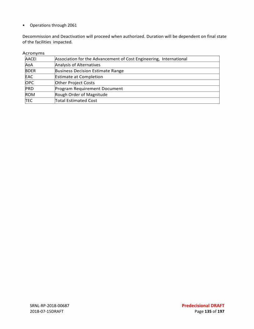
SRNL-RP-2018-00687 Predecisional DRAFT 2018-07-15DRAFT Page 135 of 197
• Operations through 2061 Decommission and Deactivation will proceed when authorized. Duration will be dependent on final state of the facilities impacted. Acronyms
AACEI Association for the Advancement of Cost Engineering, International AoA Analysis of Alternatives BDER Business Decision Estimate Range EAC Estimate at Completion OPC Other Project Costs PRD Program Requirement Document ROM Rough Order of Magnitude TEC Total Estimated Cost

SRNL-RP-2018-00687 Predecisional DRAFT 2018-07-15DRAFT Page 136 of 197
APPENDIX H. EXPANDED DISCUSSION – DISPOSAL SITE CONSIDERATIONS H.1 INTRODUCTION This chapter describes two disposal facilities that are being considered for disposal of the immobilized SLAW. The first facility, the Integrated Disposal Facility (IDF), is on-site and is being developed by the DOE. The second disposal facility, the Waste Control Specialists (WCS) facility, is off-site and is a commercially-operated facility licensed by the State of Texas. These two facilities present diverse options, where one facility can provide safe disposal of wastes with higher concentrations of I-129 and Tc-99, but the wastes must be shipped 2200 miles for that disposal, whereas the on-site facility is more limited in its ability to fully accomodate wastes with higher concentrations of I-129 and Tc-99 while meeting performance objectives, but no off-site shipping is required. This Section begins with a description of the key assumptions used in the analysis, and is followed by a review of the characteristics of the SLAW waste forms (WFs) requiring disposal. The remainder of this section is divided into two large subsections, one subsection addressing disposal at the IDF and one subsection addressing disposal at the WCS facility in west Texas. The general layout of each subsection is similar, beginning with a description of the facility, followed by a review of key regulatory requirements, the waste acceptance criteria (WAC), the classification of the wastes for disposal using the WAC, and finally, cost considerations. A simple schematic of the overarching activities is presented in Figure H-1. H.2 EVALUATION ASSUMPTIONS For this analysis, current conditions are assumed to prevail. This means that the analysis is based on current WAC for WCS, and the likely WAC for the IDF. Basing the analyses on current conditions prevents undue speculation about future conditions, while allowing an even-handed comparison of disposal at the two facilities. Where additional capacity might be needed, it is assumed that the additional capacity could be created within the existing facility boundaries, under existing (or similar) operating permit, licenses and costs.
Figure H-1 Simple Schematic of Overarching Activities H.3 WASTE FORM CHARACTERISTICS H.3.1 Characteristics of Waste to be Immobilized The characteristics of the SLAW that will be immobilized are described by the SLAW Supplemental Treatment Feed Vector (or simply the Feed Vector), which is discussed in detail in Section 2.3.
LAW PS
WTP PT Tank Wastes
Secondary
Classify wastes: - Shipping - Disposal
Ship Dispose
Primary Wastes
SLAW Immobilization: - Vitrify - Steam Reform - Grout HLW
VIT
Secondary
HLW Glass
Feed Vector Describes

SRNL-RP-2018-00687 Predecisional DRAFT 2018-07-15DRAFT Page 137 of 197
The SLAW wastes are derived from tank wastes that have been pretreated in one of two pretreatment facilities, the WTP PT and the LAW PS, and the SLAW also includes certain nuclides captured as secondary wastes during the verification of the HLW fraction. The SLAW is baselined to be produced from January of 2034 through February of 2063; a 29-year period. However, the production of significant volumes of SLAW do not begin until January 2035; a 28-year period. In summary, the Feed Vector provides data for 29 years, but volumes necessary for immobilization are generated over a 28-year period. The Feed Vector provides very detailed, projected information on the characteristics of the SLAW, which is important, as the Feed Vector describes the input to the immobilization facility for vitrification, steam reforming and grouting. The information in the Feed Vector includes: • The monthly volume of SLAW produced by pretreatment in the WTP PT and in the LAW PS, and • The specific activity of 47 nuclides in from each waste stream, for each month. The Feed Vector also provides useful summary statistics, including: • The average specific activity of each of the 47 nuclides across the 29 years • The highest and lowest specific activity of each nuclide across the 29 years, and • The highest volume of SLAW produced in one month and the lowest volume in one month. Importantly, the maximum resolution available in the Feed Vector is the monthly values – therefore all analyses are based on the monthly values provided by the Feed Vector – no greater resolution is available. Table H-1 provides summary statistics for the SLAW that will be immobilized and disposed; a total of 54,000,000 gallons (at 264.2 gallons/m3 = 204,400 m3). Table H-2 provides an example of a fraction of the information available in the Feed Vector for a specific month. Table H-2 presents the radiological content of SLAW from the WPT PT for April 2060. The month of April 2060 was picked as the example because zero volume of SLAW is produced the month earlier (in March 2060) and the row of values for April 2060 was easy to read, being below a vacant row. Table H 1 Summary Statistics for the SLAW to be Treated and Disposed
Total volume of SLAW to be immobilized Jan 2034 – Feb 2063 (349 months)
54 Mgal (204,400 m3)
Maximum volume in one month (WTP PT + LAW PS)
3700 kgal (14,000 m3) March 2040
Average monthly volume (= total volume/337 months)
Note: Jan 2035 is the first month with significant volume, so 337 months of immobilization, not 349
160 kgal (606.5 m3)
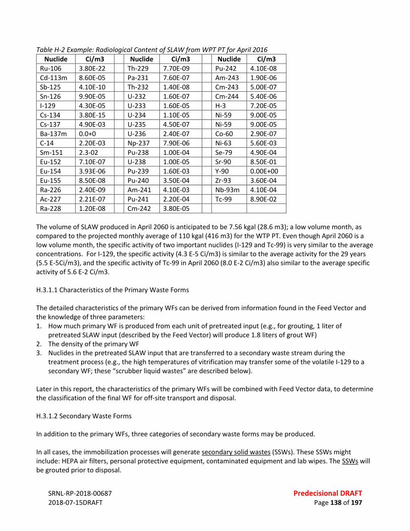
SRNL-RP-2018-00687 Predecisional DRAFT 2018-07-15DRAFT Page 138 of 197
Table H-2 Example: Radiological Content of SLAW from WPT PT for April 2016
Nuclide Ci/m3 Nuclide Ci/m3 Nuclide Ci/m3 Ru-106 3.80E-22 Th-229 7.70E-09 Pu-242 4.10E-08 Cd-113m 8.60E-05 Pa-231 7.60E-07 Am-243 1.90E-06 Sb-125 4.10E-10 Th-232 1.40E-08 Cm-243 5.00E-07 Sn-126 9.90E-05 U-232 1.60E-07 Cm-244 5.40E-06 I-129 4.30E-05 U-233 1.60E-05 H-3 7.20E-05 Cs-134 3.80E-15 U-234 1.10E-05 Ni-59 9.00E-05 Cs-137 4.90E-03 U-235 4.50E-07 Ni-59 9.00E-05 Ba-137m 0.0+0 U-236 2.40E-07 Co-60 2.90E-07 C-14 2.20E-03 Np-237 7.90E-06 Ni-63 5.60E-03 Sm-151 2.3-02 Pu-238 1.00E-04 Se-79 4.90E-04 Eu-152 7.10E-07 U-238 1.00E-05 Sr-90 8.50E-01 Eu-154 3.93E-06 Pu-239 1.60E-03 Y-90 0.00E+00 Eu-155 8.50E-08 Pu-240 3.50E-04 Zr-93 3.60E-04 Ra-226 2.40E-09 Am-241 4.10E-03 Nb-93m 4.10E-04 Ac-227 2.21E-07 Pu-241 2.20E-04 Tc-99 8.90E-02 Ra-228 1.20E-08 Cm-242 3.80E-05
The volume of SLAW produced in April 2060 is anticipated to be 7.56 kgal (28.6 m3); a low volume month, as compared to the projected monthly average of 110 kgal (416 m3) for the WTP PT. Even though April 2060 is a low volume month, the specific activity of two important nuclides (I-129 and Tc-99) is very similar to the average concentrations. For I-129, the specific activity (4.3 E-5 Ci/m3) is similar to the average activity for the 29 years (5.5 E-5Ci/m3), and the specific activity of Tc-99 in April 2060 (8.0 E-2 Ci/m3) also similar to the average specific activity of 5.6 E-2 Ci/m3. H.3.1.1 Characteristics of the Primary Waste Forms The detailed characteristics of the primary WFs can be derived from information found in the Feed Vector and the knowledge of three parameters: 1. How much primary WF is produced from each unit of pretreated input (e.g., for grouting, 1 liter of
pretreated SLAW input (described by the Feed Vector) will produce 1.8 liters of grout WF) 2. The density of the primary WF 3. Nuclides in the pretreated SLAW input that are transferred to a secondary waste stream during the
treatment process (e.g., the high temperatures of vitrification may transfer some of the volatile I-129 to a secondary WF; these “scrubber liquid wastes” are described below).
Later in this report, the characteristics of the primary WFs will be combined with Feed Vector data, to determine the classification of the final WF for off-site transport and disposal. H.3.1.2 Secondary Waste Forms In addition to the primary WFs, three categories of secondary waste forms may be produced. In all cases, the immobilization processes will generate secondary solid wastes (SSWs). These SSWs might include: HEPA air filters, personal protective equipment, contaminated equipment and lab wipes. The SSWs will be grouted prior to disposal.
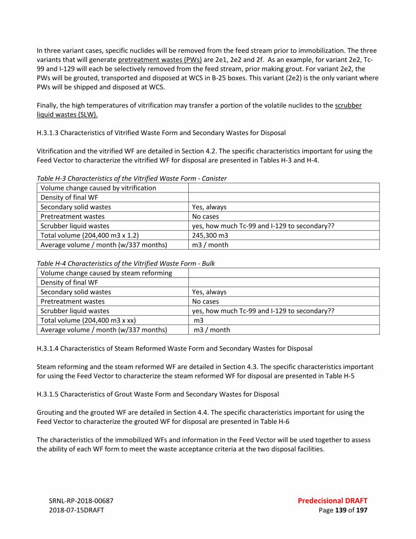
SRNL-RP-2018-00687 Predecisional DRAFT 2018-07-15DRAFT Page 139 of 197
In three variant cases, specific nuclides will be removed from the feed stream prior to immobilization. The three variants that will generate pretreatment wastes (PWs) are 2e1, 2e2 and 2f. As an example, for variant 2e2, Tc-99 and I-129 will each be selectively removed from the feed stream, prior making grout. For variant 2e2, the PWs will be grouted, transported and disposed at WCS in B-25 boxes. This variant (2e2) is the only variant where PWs will be shipped and disposed at WCS. Finally, the high temperatures of vitrification may transfer a portion of the volatile nuclides to the scrubber liquid wastes (SLW). H.3.1.3 Characteristics of Vitrified Waste Form and Secondary Wastes for Disposal Vitrification and the vitrified WF are detailed in Section 4.2. The specific characteristics important for using the Feed Vector to characterize the vitrified WF for disposal are presented in Tables H-3 and H-4. Table H-3 Characteristics of the Vitrified Waste Form - Canister
Volume change caused by vitrification Density of final WF Secondary solid wastes Yes, always Pretreatment wastes No cases Scrubber liquid wastes yes, how much Tc-99 and I-129 to secondary?? Total volume (204,400 m3 x 1.2) 245,300 m3 Average volume / month (w/337 months) m3 / month
Table H-4 Characteristics of the Vitrified Waste Form - Bulk
Volume change caused by steam reforming Density of final WF Secondary solid wastes Yes, always Pretreatment wastes No cases Scrubber liquid wastes yes, how much Tc-99 and I-129 to secondary?? Total volume (204,400 m3 x xx) m3 Average volume / month (w/337 months) m3 / month
H.3.1.4 Characteristics of Steam Reformed Waste Form and Secondary Wastes for Disposal Steam reforming and the steam reformed WF are detailed in Section 4.3. The specific characteristics important for using the Feed Vector to characterize the steam reformed WF for disposal are presented in Table H-5 H.3.1.5 Characteristics of Grout Waste Form and Secondary Wastes for Disposal Grouting and the grouted WF are detailed in Section 4.4. The specific characteristics important for using the Feed Vector to characterize the grouted WF for disposal are presented in Table H-6 The characteristics of the immobilized WFs and information in the Feed Vector will be used together to assess the ability of each WF form to meet the waste acceptance criteria at the two disposal facilities.

SRNL-RP-2018-00687 Predecisional DRAFT 2018-07-15DRAFT Page 140 of 197
Table H-5 Characteristics of Steam Reformed Waste Form - Granular Volume change caused by steam reforming 1.2 (increases volume & decreases specific activities) Density of final WF 800 kg/m3 (50 lb/ft3) Secondary solid wastes Yes, always Pretreatment wastes No cases Scrubber liquid wastes No cases Total volume (204,400 m3 x 1.2) 245,300 m3 Average volume (total/337 months) 728 m3 / month
Table H-6 Characteristics of Grouted Waste Form
Volume change caused by grouting 1.8 (increases volume & decreases specific activities) Density of final WF 1770 kg/m3 (110 lb/ft3) (0.0624 lb./ft per kg/m3) Secondary solid wastes Yes, always Pretreatment wastes Yes, for 2e1, 2e2 and 2f Scrubber liquid wastes No cases Total volume (204,400 m3 x 1.8) 367,900 m3 Average volume (total/337 months) 1092 m3 / month
H.4 INTEGRATED DISPOSAL FACILITY H.4.1 General Description The primary purpose for the Hanford Integrated Disposal Facility (IDF) is to provide for disposal of immobilized low-activity waste (ILAW) from the Waste Treatment Plant (WTP) and future supplemental LAW facility, solid mixed waste from WTP and SLAW operations, solidified waste from treatment of WTP and SLAW secondary liquid effluents, spent and failed LAW melters from the WTP, and incidental waste that results from the operation of IDF. The IDF was constructed in 2006. It consists of two segregated, separate cells: Cell 1 is for radioactive mixed low-level waste (MLLW) that contains dangerous or hazardous waste and is regulated under RCRA (See Ref. 1); Cell 2 is for radioactive only low-level waste that is regulated by DOE. Cell 1 is permitted by Ecology and is identified as Unit 11, under the Hanford Site Wide RCRA Permit, Cell 2 is regulated under DOE O 435.1. The IDF is an expandable landfill located in the 200 East Area of the Hanford Site. The IDF is 223 m by 233 m by 14 m deep. At this initial size, it has a disposal capacity is 82,000 m3. At full build out, the facility will measure approximately 446 m by 555 m by 14 m deep, providing a disposal capacity of about 900,000 m3. Cells 1 and 2 will be approximately equal sized. The IDF is a double-lined landfill that has a leachate collection and removal system that have secondary containment and leak detection systems. The Leachate Collection System is designed to segregate leachate collected from the individual cells. A high point down the center of the liner system ensures the leachate from the RCRA permitted cell does not contaminate the leachate from the non-RCRA cell. The IDF includes a secondary leak detection system (SLDS), the purpose of which is to provide access to the area immediately below the Leak Detection System (LDS) sump area. Both the RCRA and non-RCRA permitted cells of the IDF have a 90-day accumulation area for collection of leachate in a large tank for the Leachate Collection and Removal System and the LDS, and a smaller portable container for the SLDS. The tanks have secondary containment. Leak detection of the tanks is provided by monitoring of the secondary containment. The leachate is to be sampled before transfer to Hanford’s Liquid Effluent Retention Facility/Effluent Treatment Facility (LERF/ETF) for treatment.

SRNL-RP-2018-00687 Predecisional DRAFT 2018-07-15DRAFT Page 141 of 197
Figure H-2. Aerial View of IDF in the Hanford Site 200-East Area Southwest of WTP. H.4.2 Key Regulatory Requirements For purposes of this analysis, only disposal in the RCRA permitted portion of the IDF is considered. A DOE O 435.1 performance assessment (PA) has been developed and is undergoing review by the U.S. Nuclear Regulatory Commission (NRC)70. The DOE and Ecology agreed that they would complete one PA for the IDF that would satisfy the requirements of both DOE O 435.1 and RCRA. Before disposal, all waste must meet LDR requirements in 40 CFR 268, that is incorporated by reference into WAC 173-303-140. To date, IDF has not received any dangerous waste. The facility is in a “pre-active life” status. There are several IDF permit conditions that need to be met before the facility can begin to accept waste. The IDF permit conditions specifically address general waste management, waste analysis and waste acceptance, recordkeeping and reporting, security, preparedness and prevention, contingency planning, inspections, personnel training, closure and post-closure requirements, and groundwater monitoring. The DOE and its contractors completed a waste incidental to reprocessing (WIR), which documents that the DOE has satisfied all treatment requirements to determine that the waste is LAW and thus suitable for near-surface disposal. Per DOE O 435.1, DOE Headquarters must issue a Disposal Authorization (DA) statement which authorizes the IDF to begin accepting waste, assuming the balance of the RCRA permit conditions have been satisfied.
70 P. Lee. 2018. “Overview of the 2017 IDF Performance Assessment for LAW.” Presented at the National Academy of Sciences Supplemental Treatment of Low-Activity Waste at the Hanford Nuclear Reservation public meeting, February 28, 2018. TOC-PRES-18-0441-VA. Washington River Protection Solutions. Richland, Washington.
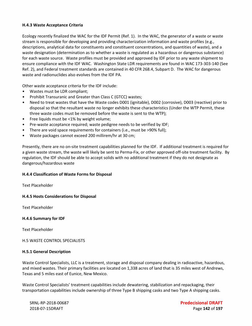
SRNL-RP-2018-00687 Predecisional DRAFT 2018-07-15DRAFT Page 142 of 197
H.4.3 Waste Acceptance Criteria Ecology recently finalized the WAC for the IDF Permit (Ref. 1). In the WAC, the generator of a waste or waste stream is responsible for developing and providing characterization information and waste profiles (e.g., descriptions, analytical data for constituents and constituent concentrations, and quantities of waste), and a waste designation (determination as to whether a waste is regulated as a hazardous or dangerous substance) for each waste source. Waste profiles must be provided and approved by IDF prior to any waste shipment to ensure compliance with the IDF WAC. Washington State LDR requirements are found in WAC 173-303-140 (See Ref. 2), and Federal treatment standards are contained in 40 CFR 268.4, Subpart D. The WAC for dangerous waste and radionuclides also evolves from the IDF PA. Other waste acceptance criteria for the IDF include: • Wastes must be LDR compliant; • Prohibit Transuranic and Greater than Class C (GTCC) wastes; • Need to treat wastes that have the Waste codes D001 (ignitable), D002 (corrosive), D003 (reactive) prior to
disposal so that the resultant waste no longer exhibits these characteristics (Under the WTP Permit, these three waste codes must be removed before the waste is sent to the WTP);
• Free liquids must be <1% by weight volume; • Pre-waste acceptance required; waste pedigree needs to be verified by IDF; • There are void space requirements for containers (i.e., must be >90% full); • Waste packages cannot exceed 200 millirem/hr at 30 cm; Presently, there are no on-site treatment capabilities planned for the IDF. If additional treatment is required for a given waste stream, the waste will likely be sent to Perma-Fix, or other approved off-site treatment facility. By regulation, the IDF should be able to accept solids with no additional treatment if they do not designate as dangerous/hazardous waste H.4.4 Classification of Waste Forms for Disposal Text Placeholder H.4.5 Hosts Considerations for Disposal Text Placeholder H.4.6 Summary for IDF Text Placeholder H.5 WASTE CONTROL SPECIALISTS H.5.1 General Description Waste Control Specialists, LLC is a treatment, storage and disposal company dealing in radioactive, hazardous, and mixed wastes. Their primary facilities are located on 1,338 acres of land that is 35 miles west of Andrews, Texas and 5 miles east of Eunice, New Mexico. Waste Control Specialists’ treatment capabilities include dewatering, stabilization and repackaging, their transportation capabilities include ownership of three Type B shipping casks and two Type A shipping casks.
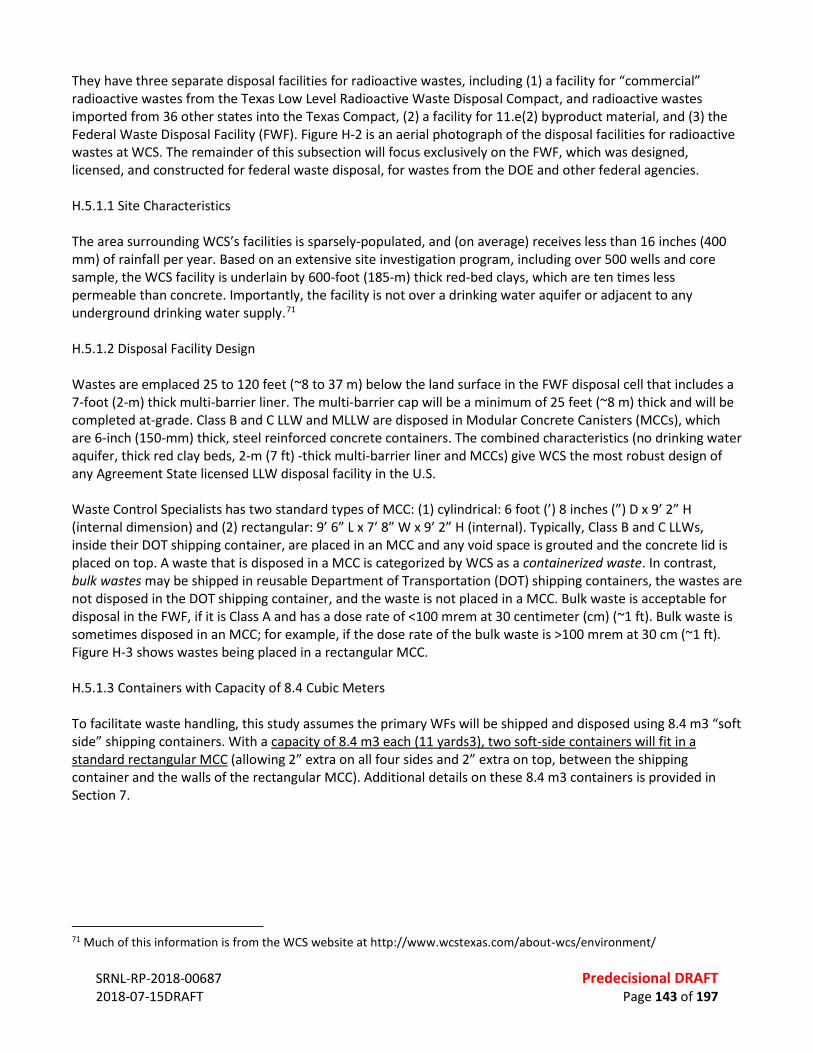
SRNL-RP-2018-00687 Predecisional DRAFT 2018-07-15DRAFT Page 143 of 197
They have three separate disposal facilities for radioactive wastes, including (1) a facility for “commercial” radioactive wastes from the Texas Low Level Radioactive Waste Disposal Compact, and radioactive wastes imported from 36 other states into the Texas Compact, (2) a facility for 11.e(2) byproduct material, and (3) the Federal Waste Disposal Facility (FWF). Figure H-2 is an aerial photograph of the disposal facilities for radioactive wastes at WCS. The remainder of this subsection will focus exclusively on the FWF, which was designed, licensed, and constructed for federal waste disposal, for wastes from the DOE and other federal agencies. H.5.1.1 Site Characteristics The area surrounding WCS’s facilities is sparsely-populated, and (on average) receives less than 16 inches (400 mm) of rainfall per year. Based on an extensive site investigation program, including over 500 wells and core sample, the WCS facility is underlain by 600-foot (185-m) thick red-bed clays, which are ten times less permeable than concrete. Importantly, the facility is not over a drinking water aquifer or adjacent to any underground drinking water supply.71 H.5.1.2 Disposal Facility Design Wastes are emplaced 25 to 120 feet (~8 to 37 m) below the land surface in the FWF disposal cell that includes a 7-foot (2-m) thick multi-barrier liner. The multi-barrier cap will be a minimum of 25 feet (~8 m) thick and will be completed at-grade. Class B and C LLW and MLLW are disposed in Modular Concrete Canisters (MCCs), which are 6-inch (150-mm) thick, steel reinforced concrete containers. The combined characteristics (no drinking water aquifer, thick red clay beds, 2-m (7 ft) -thick multi-barrier liner and MCCs) give WCS the most robust design of any Agreement State licensed LLW disposal facility in the U.S. Waste Control Specialists has two standard types of MCC: (1) cylindrical: 6 foot (’) 8 inches (”) D x 9’ 2” H (internal dimension) and (2) rectangular: 9’ 6” L x 7’ 8” W x 9’ 2” H (internal). Typically, Class B and C LLWs, inside their DOT shipping container, are placed in an MCC and any void space is grouted and the concrete lid is placed on top. A waste that is disposed in a MCC is categorized by WCS as a containerized waste. In contrast, bulk wastes may be shipped in reusable Department of Transportation (DOT) shipping containers, the wastes are not disposed in the DOT shipping container, and the waste is not placed in a MCC. Bulk waste is acceptable for disposal in the FWF, if it is Class A and has a dose rate of <100 mrem at 30 centimeter (cm) (~1 ft). Bulk waste is sometimes disposed in an MCC; for example, if the dose rate of the bulk waste is >100 mrem at 30 cm (~1 ft). Figure H-3 shows wastes being placed in a rectangular MCC. H.5.1.3 Containers with Capacity of 8.4 Cubic Meters To facilitate waste handling, this study assumes the primary WFs will be shipped and disposed using 8.4 m3 “soft side” shipping containers. With a capacity of 8.4 m3 each (11 yards3), two soft-side containers will fit in a standard rectangular MCC (allowing 2” extra on all four sides and 2” extra on top, between the shipping container and the walls of the rectangular MCC). Additional details on these 8.4 m3 containers is provided in Section 7.
71 Much of this information is from the WCS website at http://www.wcstexas.com/about-wcs/environment/
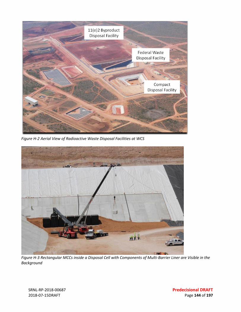
SRNL-RP-2018-00687 Predecisional DRAFT 2018-07-15DRAFT Page 144 of 197
Figure H-2 Aerial View of Radioactive Waste Disposal Facilities at WCS
Figure H-3 Rectangular MCCs inside a Disposal Cell with Components of Multi-Barrier Liner are Visible in the Background
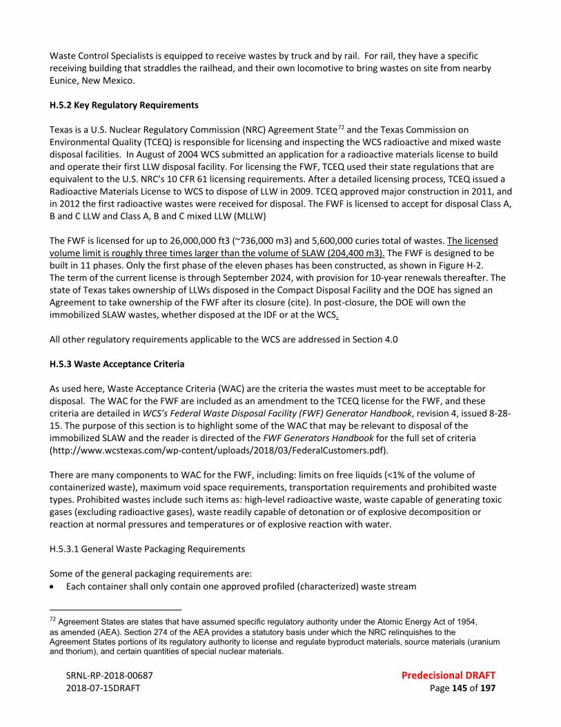
SRNL-RP-2018-00687 Predecisional DRAFT 2018-07-15DRAFT Page 145 of 197
Waste Control Specialists is equipped to receive wastes by truck and by rail. For rail, they have a specific receiving building that straddles the railhead, and their own locomotive to bring wastes on site from nearby Eunice, New Mexico. H.5.2 Key Regulatory Requirements Texas is a U.S. Nuclear Regulatory Commission (NRC) Agreement State72 and the Texas Commission on Environmental Quality (TCEQ) is responsible for licensing and inspecting the WCS radioactive and mixed waste disposal facilities. In August of 2004 WCS submitted an application for a radioactive materials license to build and operate their first LLW disposal facility. For licensing the FWF, TCEQ used their state regulations that are equivalent to the U.S. NRC’s 10 CFR 61 licensing requirements. After a detailed licensing process, TCEQ issued a Radioactive Materials License to WCS to dispose of LLW in 2009. TCEQ approved major construction in 2011, and in 2012 the first radioactive wastes were received for disposal. The FWF is licensed to accept for disposal Class A, B and C LLW and Class A, B and C mixed LLW (MLLW) The FWF is licensed for up to 26,000,000 ft3 (~736,000 m3) and 5,600,000 curies total of wastes. The licensed volume limit is roughly three times larger than the volume of SLAW (204,400 m3). The FWF is designed to be built in 11 phases. Only the first phase of the eleven phases has been constructed, as shown in Figure H-2. The term of the current license is through September 2024, with provision for 10-year renewals thereafter. The state of Texas takes ownership of LLWs disposed in the Compact Disposal Facility and the DOE has signed an Agreement to take ownership of the FWF after its closure (cite). In post-closure, the DOE will own the immobilized SLAW wastes, whether disposed at the IDF or at the WCS. All other regulatory requirements applicable to the WCS are addressed in Section 4.0 H.5.3 Waste Acceptance Criteria As used here, Waste Acceptance Criteria (WAC) are the criteria the wastes must meet to be acceptable for disposal. The WAC for the FWF are included as an amendment to the TCEQ license for the FWF, and these criteria are detailed in WCS’s Federal Waste Disposal Facility (FWF) Generator Handbook, revision 4, issued 8-28-15. The purpose of this section is to highlight some of the WAC that may be relevant to disposal of the immobilized SLAW and the reader is directed of the FWF Generators Handbook for the full set of criteria (http://www.wcstexas.com/wp-content/uploads/2018/03/FederalCustomers.pdf). There are many components to WAC for the FWF, including: limits on free liquids (<1% of the volume of containerized waste), maximum void space requirements, transportation requirements and prohibited waste types. Prohibited wastes include such items as: high-level radioactive waste, waste capable of generating toxic gases (excluding radioactive gases), waste readily capable of detonation or of explosive decomposition or reaction at normal pressures and temperatures or of explosive reaction with water. H.5.3.1 General Waste Packaging Requirements Some of the general packaging requirements are: • Each container shall only contain one approved profiled (characterized) waste stream
72 Agreement States are states that have assumed specific regulatory authority under the Atomic Energy Act of 1954, as amended (AEA). Section 274 of the AEA provides a statutory basis under which the NRC relinquishes to the Agreement States portions of its regulatory authority to license and regulate byproduct materials, source materials (uranium and thorium), and certain quantities of special nuclear materials.

SRNL-RP-2018-00687 Predecisional DRAFT 2018-07-15DRAFT Page 146 of 197
• Packages should weigh 10,000 lbs. (4,545 kg) or less, unless special arrangements have been made • All containers transported on public roads to WCS are required to meet the applicable DOT regulations • Except for bulk wastes and Large Components, waste packages must fit in a MCC. H.5.3.2 Land Disposal Restrictions Need short discussion LDRs and fact that WCS cannot accept for disposal wastes with LDRs H.5.3.3 Waste Classification The FWF is authorized for disposal of Class A, Class B, and Class C (as defined in 30 TAC §336.362) LLW and MLLW and bulk Class A LLW and MLLW in reusable packages with a dose rates of <100 mrem/hr. at 30 centimeters (~1’). Two tables are provided by WCS for classifying wastes as Class A, B or C for disposal; Greater-than-Class- C (GTCC) wastes are currently prohibited. The two tables from the FWF Generators Handbook are copied and inserted here as Table H-7 for long-lived nuclides and Table H-8 for short lived nuclides. Table H-7 Table I, Class A and C Waste - Long Lived Isotopes
Table H-8 Table II Class A, B and C Waste - Short Lived Isotopes
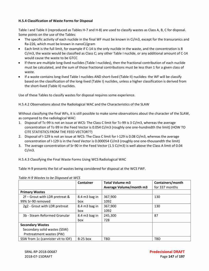
SRNL-RP-2018-00687 Predecisional DRAFT 2018-07-15DRAFT Page 147 of 197
H.5.4 Classification of Waste Forms for Disposal Table I and Table II (reproduced as Tables H-7 and H-8) are used to classify wastes as Class A, B, C for disposal. Some points on the use of the Tables: • The specific activity of each nuclide in the final WF must be known in Ci/m3, except for the transuranics and
Ra-226, which must be known in nanoCi/gram • Each limit is the full limit, for example if C-14 is the only nuclide in the waste, and the concentration is 8
Ci/m3, the waste would be classified as Class C; any other Table I nuclide, or any additional amount of C-14 would cause the waste to be GTCC
• lf there are multiple long-lived nuclides (Table I nuclides), then the fractional contribution of each nuclide must be calculated, and the sum of those fractional contributions must be less than 1 for a given class of waste.
• If a waste contains long-lived Table I nuclides AND short-lived (Table II) nuclides: the WF will be classify based on the classification of the long-lived (Table I) nuclides, unless a higher classification is derived from the short-lived (Table II) nuclides.
Use of these Tables to classify wastes for disposal requires some experience. H.5.4.2 Observations about the Radiological WAC and the Characteristics of the SLAW Without classifying the final WFs, it is still possible to make some observations about the character of the SLAW, as compared to the radiological WAC: 1. Disposal of Tc-99 is not an issue at WCS: The Class C limit for Tc-99 is 3 Ci/m3, whereas the average
concentration of Tc-99 in the Feed Vector is 0.054 Ci/m3 (roughly one one-hundredth the limit) (HOW TO CITE STATISTICS FROM THE FEED VECTOR??)
2. Disposal of I-129 is not an issue at WCS: The Class C limit for I-129 is 0.08 Ci/m3, whereas the average concentration of I-129 is in the Feed Vector is 0.000054 Ci/m3 (roughly one one-thousandth the limit)
3. The average concentration of Sr-90 in the Feed Vector (1.5 Ci/m3) is well above the Class A limit of 0.04 Ci/m3.
H.5.4.3 Classifying the Final Waste Forms Using WCS Radiological WAC Table H-9 presents the list of wastes being considered for disposal at the WCS FWF. Table H-9 Wastes to be Disposed at WCS
Container Total Volume m3 Average Volume/month m3
Containers/month for 337 months
Primary Wastes 2f – Grout with LDR pretreat & 99% Sr-90 removed
8.4 m3 bag in box
367,900 1092
130
2g2 - Grout with LDR pretreat 8.4 m3 bag in box
367,900 1092
130
3b - Steam Reformed Granular 8.4 m3 bag in box
245,300 728
87
Secondary Wastes Secondary solid wastes (SSW) Pretreatment wastes (PW)
SSW from 1c (cannister vit to IDF) B-25 box TBD TBD
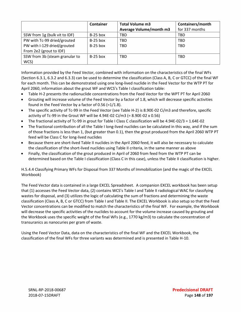
SRNL-RP-2018-00687 Predecisional DRAFT 2018-07-15DRAFT Page 148 of 197
Container Total Volume m3 Average Volume/month m3
Containers/month for 337 months
SSW from 1g (bulk vit to IDF) B-25 box TBD TBD PW with Tc-99 dried/grouted PW with I-129 dried/grouted From 2e2 (grout to IDF)
B-25 box B-25 box
TBD TBD
TBD TBD
SSW from 3b (steam granular to WCS)
B-25 box TBD TBD
Information provided by the Feed Vector, combined with information on the characteristics of the final WFs (Section 6.3.1, 6.3.2 and 6.3.3) can be used to determine the classification (Class A, B, C or GTCC) of the final WF for each month. This can be demonstrated using one long-lived nuclide in the Feed Vector for the WTP PT for April 2060, information about the grout WF and WCS’s Table I classification table: • Table H-2 presents the radionuclide concentrations from the Feed Vector for the WPT PT for April 2060 • Grouting will increase volume of the Feed Vector by a factor of 1.8, which will decrease specific activities
found in the Feed Vector by a factor of 0.56 (=1/1.8). • The specific activity of Tc-99 in the Feed Vector (see Table H-2) is 8.90E-02 Ci/m3 and therefore, specific
activity of Tc-99 in the Grout WF will be 4.94E-02 Ci/m3 (= 8.90E-02 x 0.56) • The fractional activity of Tc-99 in grout for Table I Class C classification will be 4.94E-02/3 = 1.64E-02 • The fractional contribution of all the Table I long-lived nuclides can be calculated in this way, and if the sum
of those fractions is less than 1, (but greater than 0.1), then the grout produced from the April 2060 WTP PT feed will be Class C for long-lived nuclides
• Because there are short-lived Table II nuclides in the April 2060 feed, it will also be necessary to calculate the classification of the short-lived nuclides using Table II criteria, in the same manner as above
• Finally, the classification of the grout produced in April of 2060 from feed from the WTP PT can be determined based on the Table I classification (Class C in this case), unless the Table II classification is higher.
H.5.4.4 Classifying Primary WFs for Disposal from 337 Months of Immobilization (and the magic of the EXCEL Workbook) The Feed Vector data is contained in a large EXCEL Spreadsheet. A companion EXCEL workbook has been setup that (1) accesses the Feed Vector data, (2) contains WCS’s Table I and Table II radiological WAC for classifying wastes for disposal, and (3) utilizes the logic of calculating the sum of fractions and determining the waste classification (Class A, B, C or GTCC) from Table I and Table II. The EXCEL Workbook is also setup so that the Feed Vector concentrations can be modified to match the characteristics of the final WF. For example, the Workbook will decrease the specific activities of the nuclides to account for the volume increase caused by grouting and the Workbook uses the specific weight of the final WFs (e.g., 1770 kg/m3) to calculate the concentration of transuranics as nanocuries per gram of waste. Using the Feed Vector Data, data on the characteristics of the final WF and the EXCEL Workbook, the classification of the final WFs for three variants was determined and is presented in Table H-10.
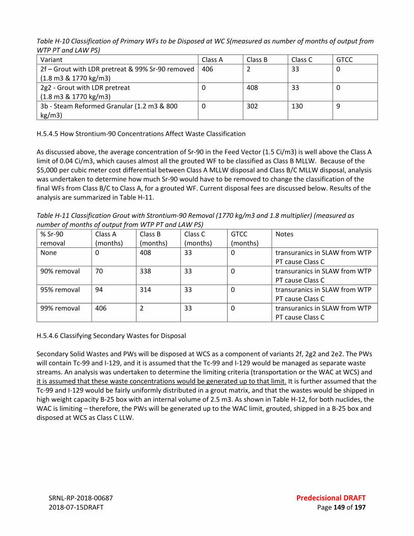
SRNL-RP-2018-00687 Predecisional DRAFT 2018-07-15DRAFT Page 149 of 197
Table H-10 Classification of Primary WFs to be Disposed at WC S(measured as number of months of output from WTP PT and LAW PS)
Variant Class A Class B Class C GTCC 2f – Grout with LDR pretreat & 99% Sr-90 removed (1.8 m3 & 1770 kg/m3)
406 2 33 0
2g2 - Grout with LDR pretreat (1.8 m3 & 1770 kg/m3)
0 408 33 0
3b - Steam Reformed Granular (1.2 m3 & 800 kg/m3)
0 302 130 9
H.5.4.5 How Strontium-90 Concentrations Affect Waste Classification As discussed above, the average concentration of Sr-90 in the Feed Vector (1.5 Ci/m3) is well above the Class A limit of 0.04 Ci/m3, which causes almost all the grouted WF to be classified as Class B MLLW. Because of the $5,000 per cubic meter cost differential between Class A MLLW disposal and Class B/C MLLW disposal, analysis was undertaken to determine how much Sr-90 would have to be removed to change the classification of the final WFs from Class B/C to Class A, for a grouted WF. Current disposal fees are discussed below. Results of the analysis are summarized in Table H-11. Table H-11 Classification Grout with Strontium-90 Removal (1770 kg/m3 and 1.8 multiplier) (measured as number of months of output from WTP PT and LAW PS)
% Sr-90 removal
Class A (months)
Class B (months)
Class C (months)
GTCC (months)
Notes
None 0 408 33 0 transuranics in SLAW from WTP PT cause Class C
90% removal 70 338 33 0 transuranics in SLAW from WTP PT cause Class C
95% removal 94 314 33 0 transuranics in SLAW from WTP PT cause Class C
99% removal 406 2 33 0 transuranics in SLAW from WTP PT cause Class C
H.5.4.6 Classifying Secondary Wastes for Disposal Secondary Solid Wastes and PWs will be disposed at WCS as a component of variants 2f, 2g2 and 2e2. The PWs will contain Tc-99 and I-129, and it is assumed that the Tc-99 and I-129 would be managed as separate waste streams. An analysis was undertaken to determine the limiting criteria (transportation or the WAC at WCS) and it is assumed that these waste concentrations would be generated up to that limit. It is further assumed that the Tc-99 and I-129 would be fairly uniformly distributed in a grout matrix, and that the wastes would be shipped in high weight capacity B-25 box with an internal volume of 2.5 m3. As shown in Table H-12, for both nuclides, the WAC is limiting – therefore, the PWs will be generated up to the WAC limit, grouted, shipped in a B-25 box and disposed at WCS as Class C LLW.
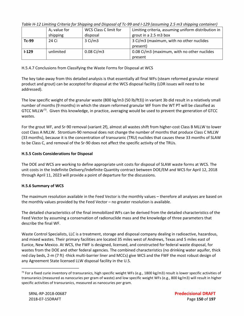
SRNL-RP-2018-00687 Predecisional DRAFT 2018-07-15DRAFT Page 150 of 197
Table H-12 Limiting Criteria for Shipping and Disposal of Tc-99 and I-129 (assuming 2.5 m3 shipping container) A2 value for
shipping WCS Class C limit for disposal
Limiting criteria, assuming uniform distribution in grout in a 2.5 m3 box
Tc-99 24 Ci 3 Ci/m3 3 Ci/m3 (maximum, with no other nuclides present)
I-129 unlimited 0.08 Ci/m3 0.08 Ci/m3 (maximum, with no other nuclides present
H.5.4.7 Conclusions from Classifying the Waste Forms for Disposal at WCS The key take-away from this detailed analysis is that essentially all final WFs (steam reformed granular mineral product and grout) can be accepted for disposal at the WCS disposal facility (LDR issues will need to be addressed). The low specific weight of the granular waste (800 kg/m3 (50 lb/ft3)) in variant 3b did result in a relatively small number of months (9 months) in which the steam reformed granular WF from the WT PT will be classified as GTCC MLLW73. Given this knowledge, in practice, averaging would be used to prevent the generation of GTCC wastes. For the grout WF, and Sr-90 removal (variant 2f), almost all wastes shift from higher-cost Class B MLLW to lower cost Class A MLLW. Strontium-90 removal does not change the number of months that produce Class C MLLW (33 months), because it is the concentration of transuranic (TRU) nuclides that causes these 33 months of SLAW to be Class C, and removal of the Sr-90 does not affect the specific activity of the TRUs. H.5.5 Costs Considerations for Disposal The DOE and WCS are working to define appropriate unit costs for disposal of SLAW waste forms at WCS. The unit costs in the Indefinite Delivery/Indefinite Quantity contract between DOE/EM and WCS for April 12, 2018 through April 11, 2023 will provide a point of departure for the discussions. H.5.6 Summary of WCS The maximum resolution available in the Feed Vector is the monthly values – therefore all analyses are based on the monthly values provided by the Feed Vector – no greater resolution is available. The detailed characteristics of the final immobilized WFs can be derived from the detailed characteristics of the Feed Vector by assuming a conservation of radionuclide mass and the knowledge of three parameters that describe the final WF. Waste Control Specialists, LLC is a treatment, storage and disposal company dealing in radioactive, hazardous, and mixed wastes. Their primary facilities are located 35 miles west of Andrews, Texas and 5 miles east of Eunice, New Mexico. At WCS, the FWF is designed, licensed, and constructed for federal waste disposal, for wastes from the DOE and other federal agencies. The combined characteristics (no drinking water aquifer, thick red clay beds, 2-m (7 ft) -thick multi-barrier liner and MCCs) give WCS and the FWF the most robust design of any Agreement State licensed LLW disposal facility in the U.S.
73 For a fixed curie inventory of transuranics, high specific weight WFs (e.g., 1800 kg/m3) result is lower specific activities of transuranics (measured as nanocuries per gram of waste) and low specific weight WFs (e.g., 800 kg/m3) will result in higher specific activities of transuranics, measured as nanocuries per gram.
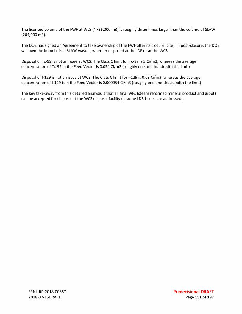
SRNL-RP-2018-00687 Predecisional DRAFT 2018-07-15DRAFT Page 151 of 197
The licensed volume of the FWF at WCS (~736,000 m3) is roughly three times larger than the volume of SLAW (204,000 m3). The DOE has signed an Agreement to take ownership of the FWF after its closure (cite). In post-closure, the DOE will own the immobilized SLAW wastes, whether disposed at the IDF or at the WCS. Disposal of Tc-99 is not an issue at WCS: The Class C limit for Tc-99 is 3 Ci/m3, whereas the average concentration of Tc-99 in the Feed Vector is 0.054 Ci/m3 (roughly one one-hundredth the limit) Disposal of I-129 is not an issue at WCS: The Class C limit for I-129 is 0.08 Ci/m3, whereas the average concentration of I-129 is in the Feed Vector is 0.000054 Ci/m3 (roughly one one-thousandth the limit) The key take-away from this detailed analysis is that all final WFs (steam reformed mineral product and grout) can be accepted for disposal at the WCS disposal facility (assume LDR issues are addressed).
SRNL-RP-2018-00687 Predecisional DRAFT 2018-07-15DRAFT Page 152 of 197
APPENDIX I. EXPANDED DISCUSSION – TRANSPORTATION CONSIDERATIONS I.1 INTRODUCTION This Section develops the programs that will be needed to transport primary and secondary WFs from the Hanford Reservation to the WCS disposal facilities in west Texas. I.2 GENERAL EVALUATION ASSUMPTIONS AND APPROACH For this analysis, current conditions are assumed to prevail. This means that the analysis is based on the current railroads, the current regulatory requirements for shipping and the current shipping and packaging technologies. Basing the analyses on current conditions prevents undue speculation about future conditions, while allowing an even-handed comparison of disposal of primary and second wastes at the IDF and the WCS disposal facilities. Where additional capacity might be needed, it is assumed that the additional capacity could be created within the existing infrastructure and at a similar cost. I.3 KEY REGULATORY CONSIDERAITONS The NRC regulates the packaging for the transport of radioactive materials. The DOT coordinates with the U.S. NRC to set rules for the packaging. The DOT also works with the NRC and affected States to regulator their transport. Radioactive materials are transported routinely and safely every day. As a relevant example – DOE completed ~ 5,500 shipments of radioactive materials in Fiscal Year (FY) 2016 with no reportable accidents (Office of Packaging and Transportation Annual Report FY2016). One of the reason for this safety record is that the transport of radioactive materials is very regulated. I.3.1 10 CFR 71 Packaging and Transportation of Radioactive Material The NRC’s 10 CFR 71 governs the “Packaging and Transportation of Radioactive Material.” This regulation defines the packaging and transportation performance criteria to ensure the safe transport of radioactive materials under normal and hypothetical accident conditions. The NRC’s regulation uses a graded approach in setting packaging criteria, to protect public health and the environment where: • “Low specific activity” (LSA),74 materials may be shipped in industrial packages (IPs) that are exempt from
NRC package certification (but not exempt from DOT requirements) • Materials that exceed the LSA limits, but are below the “A2” content limit75, must be shipped in Type A
packaging, and where
74 Low Specific Activity material means radioactive material with limited specific activity that is nonfissile or is excepted under 10 CFR 71.15, and satisfies the descriptions and limits for LSA-I, LSA-II, and LSA-III materials set forth in 10 CFR 71.4. Shielding materials surrounding the LSA material may not be considered in determining the estimated average specific activity of the package contents. (10 CFR 71.4). 75 The A2 value is the maximum amount of radioactive material (measured in becquerels or curies), other than special form, LSA, and Surface Contaminated Object materials, permitted in a Type A package. This value is either listed in 10 CFR Part 71, Appendix A, Table A-1, or may be derived in accordance with the procedures prescribed in 10 CFR Part 71, Appendix A. (10 CFR 71.4)
SRNL-RP-2018-00687 Predecisional DRAFT 2018-07-15DRAFT Page 153 of 197
• Higher-activity content materials that exceed the LSA limits, and that exceed the A2 content limit, must be shipped in Type B packaging, which meets the most stringent criteria (except for the air-transport criteria).
All packages for shipping radioactive material (IP or Type A or Type B) must be designed and prepared so that under conditions normally incident to transportation the radiation level does not exceed 2 millisievert/hour (mSv/h) (200 millirem/hour (mrem/h)) at any point on the external surface of the package, and the transport index does not exceed 10. (10 CFR 71.47) I.3.1.1 Shipping in Type A Containers The maximum amount of radioactive material that can be carried in a Type A container depends on the form of the material and the summed radiological content. The NRC defines two forms of material in Part 71, “special form” and “normal form.” In simple terms, normal form is dispersible in a transportation accident, and special form is not dispersible. Special form radioactive material means radioactive material that (1) is either a single solid piece or is contained in a sealed capsule that can be opened only by destroying the capsule, (2) has a certain minimum size and (3) it satisfies the rigorous requirements of 10 CFR 71.75. Special form materials are not easily dispersible. If a material is not special form, then the material is normal form. Sealed radioactive sources are an example of special form material. Most radioactive materials are normal form. The methodology and tables for determining if the amount of activity in a container exceeds the A2 limit are presented in Appendix A to 10 CFR 71. I.3.1.2 Shipping in Industrial Packages “Low specific activity” radioactive materials may be shipped as NRC-defined LSA material in IPs that are exempt from NRC certification, if the specific activity (the activity per unit mass) of the WFs is low enough, and other requirements are met. As discussed later, the LSA criteria are linked to the A2 quantity. The three types of LSA materials are discussed in detail in Section 7.6. I.3.2 49 CFR 171-173 Hazardous Materials Regulations The U.S. DOT’s 49 CFR 171-173 address many facets of the transport of radioactive materials, which are a subset of the DOT’s broader definition of “Hazardous Materials.” Each licensee who transports licensed material on public highways, or who delivers licensed material to a carrier for transport, must comply with the applicable requirements of the DOT regulations in 49 CFR. Some of the activities regulated by 49 CFR 171-173 include: • Packaging - 49 CFR part 173: subparts A, B, and I • Marking and labeling - 49 CFR part 172: subpart D; and §§ 172.400 through 172.407 and §§ 172.436 through
172.441 of subpart E • Placarding - 49 CFR part 172: subpart F, especially §§ 172.500 through 172.519 and 172.556; and appendices
B and C • Accident reporting - 49 CFR part 171: §§ 171.15 and 171.16 • Shipping papers and emergency information - 49 CFR part 172: subparts C and G • Hazardous material employee training - 49 CFR part 172: subpart H • Security plans - 49 CFR part 172: subpart I • Hazardous material shipper/carrier registration - 49 CFR part 107: subpart G, and • DOT regulations that are specific to transport by rail include 49 CFR part 174: subparts A through D and K.
SRNL-RP-2018-00687 Predecisional DRAFT 2018-07-15DRAFT Page 154 of 197
The DOT regulations also define “contamination,” which means the presence of a radioactive substance on a surface in quantities in excess of 0.4 Bq/cm2 for beta and gamma emitters and low toxicity alpha emitters or 0.04 Bq/cm2 for all other alpha emitters. There are two categories of contamination: (1) Fixed contamination means contamination that cannot be removed from a surface during normal conditions of transport. (2) Non-fixed contamination means contamination that can be removed from a surface during normal conditions of transport. (49 CFR 173.443) To ensure the appropriate scoping and costing, this study will rely on analogue costs from other programs, where the DOE has shipped radioactive wastes for disposal (e.g., shipping contaminated soils by rail for disposal). In this way, the scope and cost of meeting the requirements above will be captured, without summarizing the large number of safety requirements found in 49 CFR 171-173 for shipping radioactive materials. The NRC and DOT requirements for shipping LSA materials are detailed in Section 7.6. I.3.4 DOE Regulations and Orders DOE broad authorities to regulate all aspects of activities involving radioactive material that are undertaken by DOE or on its behalf, including transportation. Authorities for OPT flow from 41 Code of Federal Regulations (CFR) 109-40, Transportation and Traffic Management, and 49 CFR 173, Department of Transportation, Shippers – General Requirements for Shipments and Packagings, which establishes DOE’s transportation management and packaging certification authorities, and DOE Orders 460.1, Packaging and Transportation Safety, DOE Order 460.2, Departmental Materials and Transportation Management, and DOE Manual 460.2-1, Radioactive Material Transportation Practices Manual. DOE Order 460.1 establishes safety requirements for the proper packaging and transportation of offsite shipments and onsite transfers of hazardous materials, including radioactive materials. DOE Order 460.2 establishes standard transportation practices for DOE elements to use in planning and executing offsite shipments of radioactive material including radioactive waste. I.3.5 National Environmental Policy Act The National Environmental Policy Act (NEPA) is a U.S. law that requires Federal agencies to prepare an assessment of potential environmental impacts, to accompany reports and recommendations for Congressional funding. Actual implementation of a shipping program, such as outlined here, would probably require the development of an Environmental Impact Statement (EIS) that would detail potential impacts to: air quality, ecological resources, historic and cultural resources, noise, public and occupational health, etc. For transport of radioactive materials, the EIS analysis of a large transportation program might specifically address: • Impacts on Local and National Traffic -The impacts of additional trains on local and national tracks and the
associated impacts to: air quality, noise, and infrastructure • Radiological Impacts of Routine Transportation - Dose to a maximally exposed individual and the projected
population dose • Non-radiological Impacts of Transportation Accidents - Statistical number accidents and fatalities from a
proposed transportation program, and • Radiological Impacts of Transportation Accidents - Statistical doses from a hypothetical accident.
This NADA study is not a NEPA EIS, and the relative hazards from the proposed shipping program are identified through analogue NEPA studies of the safety of rail transport of radioactive materials (Section 7.8). I.4 NATURE AND VOLUME OF WASTES TO BE SHIPPED
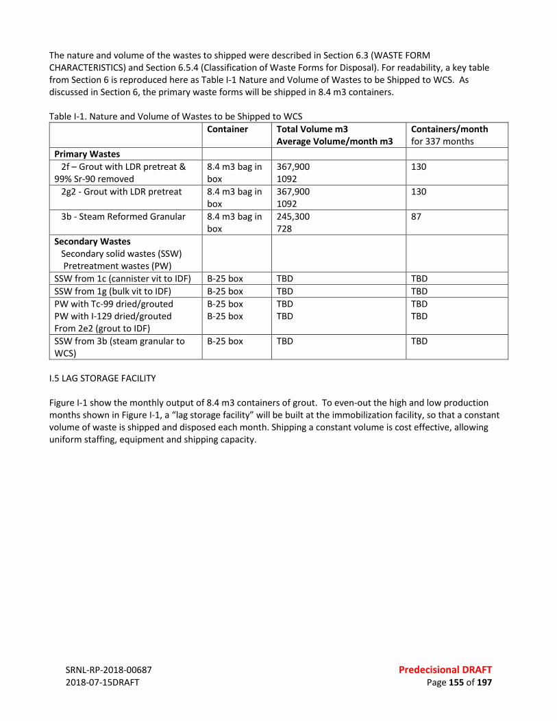
SRNL-RP-2018-00687 Predecisional DRAFT 2018-07-15DRAFT Page 155 of 197
The nature and volume of the wastes to shipped were described in Section 6.3 (WASTE FORM CHARACTERISTICS) and Section 6.5.4 (Classification of Waste Forms for Disposal). For readability, a key table from Section 6 is reproduced here as Table I-1 Nature and Volume of Wastes to be Shipped to WCS. As discussed in Section 6, the primary waste forms will be shipped in 8.4 m3 containers. Table I-1. Nature and Volume of Wastes to be Shipped to WCS
Container Total Volume m3 Average Volume/month m3
Containers/month for 337 months
Primary Wastes 2f – Grout with LDR pretreat & 99% Sr-90 removed
8.4 m3 bag in box
367,900 1092
130
2g2 - Grout with LDR pretreat 8.4 m3 bag in box
367,900 1092
130
3b - Steam Reformed Granular 8.4 m3 bag in box
245,300 728
87
Secondary Wastes Secondary solid wastes (SSW) Pretreatment wastes (PW)
SSW from 1c (cannister vit to IDF) B-25 box TBD TBD SSW from 1g (bulk vit to IDF) B-25 box TBD TBD PW with Tc-99 dried/grouted PW with I-129 dried/grouted From 2e2 (grout to IDF)
B-25 box B-25 box
TBD TBD
TBD TBD
SSW from 3b (steam granular to WCS)
B-25 box TBD TBD
I.5 LAG STORAGE FACILITY Figure I-1 show the monthly output of 8.4 m3 containers of grout. To even-out the high and low production months shown in Figure I-1, a “lag storage facility” will be built at the immobilization facility, so that a constant volume of waste is shipped and disposed each month. Shipping a constant volume is cost effective, allowing uniform staffing, equipment and shipping capacity.

SRNL-RP-2018-00687 Predecisional DRAFT 2018-07-15DRAFT Page 156 of 197
Given the average amount of grout produced each month (1092 m3 from Table I-1), the average number of 8.4 m3 containers of grout per month will be 130 containers. To determine the capacity of the lag storage facility, a simple program was setup, and for each month that produces more than 130 containers of grout, the excess is “counted” by the program, and for each month that the produces less than 130 containers of grout, the deficiency is removed from that count. Based on this simple program, Figure I-2 shows the number of 8.4 m3 containers in the lag storage at any point in time. Figure I-2 shows that the lag storage facility for grout will need to have a capacity of ~6000 containers. The analysis to determine the capacity of a lag storage facility for the steam reformed WF can be derived by multiplying the numbers of 8.4 m3 containers in Figure I-2 by 0.67 (= 1.2 for steam divided by 1.8 for grout), such that the lag storage facility for the steam reformed granular WF will need to have a capacity of ~ 4000 containers. In analyzing the data, approximately one-half of this storage capacity is needed to provide additional feed for the last five years of operation. Using two average shipping rates would greatly reduce the size of the storage facility – with one average shipping rate from January 2035 to August of 2058 and a second average rate from August 2058 to January of 2016.
Figure I-1. Number of 8.4 m3 Containers of Grout Produced per Month

SRNL-RP-2018-00687 Predecisional DRAFT 2018-07-15DRAFT Page 157 of 197
Figure I-2. Number of 8.4 m3 Containers of Grout in Lag Storage I.6 LOW-SPECIFIC ACTIVITY DETERMINATION AND PACKAGE REQUIREMENTS As noted earlier, LSA material means radioactive material with limited specific activity that is nonfissile or is excepted under 10 CFR 71.15, and satisfies the descriptions and limits for LSA set forth in 10 CFR 71.4. The NRC defines three categories of LSA: LSA-I, LSA-II and LSA-III. Working in tandem, the DOT defines the packaging requirements for LSA materials. LSA-I includes such materials as uranium and thorium ores, solid unirradiated natural uranium or depleted uranium or natural thorium, radioactive material for which the A2 value is unlimited; or other radioactive material in which the activity is distributed throughout and the estimated average specific activity does not exceed 30 times the value for exempt material activity concentration determined in accordance with Appendix A of 10 CFR 71. LSA-II includes … more details on LSA-II needed here … other material in which the activity is distributed throughout and the average specific activity is less than 10-4 A2/gram for solids and gases, and 10-5 A2/gram for liquids LSA-III includes solids (e.g., consolidated wastes, activated materials), excluding powders, that satisfy the requirements of § 71.77, in which: (i) The radioactive material is distributed throughout a solid or a collection of solid objects, or is essentially
uniformly distributed in a solid compact binding agent (such as concrete, bitumen, ceramic, etc.); (ii) The radioactive material is relatively insoluble, or it is intrinsically contained in a relatively insoluble material,
so that even under loss of packaging, the loss of radioactive material per package by leaching, when placed in normal pH water for 7 days, would not exceed 0.1 A2 (see 10 CFR 71.77 for additional details); and
(iii) The estimated average specific activity of the solid is less than 2 × 10⁻³ A2/gram.” (10 CFR 71.4)
Other criterial that the three categories of LSA materials must meet include:

SRNL-RP-2018-00687 Predecisional DRAFT 2018-07-15DRAFT Page 158 of 197
• External radiation at any point on the external surface of the shipping package must not exceed 2 mSv/h (200 mrem/h) (10 CFR 71.47(a))
• The material must have an external radiation dose less than or equal to 10 mSv/hour (1 rem/hour) at a distance of 3 m (10 ft) from the unshielded material (10 CFR71.14(b)(3)(i)) and 49 CFR 173.427).
Calculating the A2 Value for a Mixture of Radionuclides The formula for calculating the A2 for a mixture of radionuclides is presented in Figure I-3, which is coped from the NRC’s Appendix A of 10 CFR 71. As a potentially bounding assessment of the A2 value, the calculation was performed on the mixture of radionuclides from the month with the very highest Sum of Fractions for the long-lived nuclides for waste classification at WCS. From the EXCEL Workbook for classifying SLAW waste forms for disposal at WCS, it was determined that SLAW from the WTP PT for November 2035 had the very highest sum of fractions. The A2
calculation for wastes from November 2035 is presented in Table I-2. Table I-2. A2 Calculation using Concentrations from November 2035 from WTP PT
Symbol Element A2 (Ci) from Apx A 10 CFR 71
Concentration (Ci/m3) from Feed Vector
fraction contribution f(i)
f(i)/A2(i)
Ac-227 (a) Actinium 2.40E-03 6.24E-06 1.53E-06 6.39E-04 Am-241 Americium 2.70E-02 1.71E-01 4.20E-02 1.56E+00 Am-243 (a) 2.70E-02 6.02E-05 1.479E-05 5.48E-04 C-14 Carbon 81 3.77E-03 9.26E-04 1.14E-05 Cd-113m Cadmium 14 2.75E-03 6.76E-04 4.83E-05 Cm-242 Curium 0.27 6.11E-05 1.501E-05 5.56E-05 Cm-243 2.70E-02 3.04E-06 7.47E-07 2.77E-05 Cm-244 5.40E-02 4.85E-05 1.191E-05 2.21E-04 Co-60 Cobalt 11 7.69E-05 1.889E-05 1.72E-06 Cs-134 Cesium 19 4.26E-10 1.047E-10 5.51E-12 Cs-137 (a) 16 4.31E-02 0.0105879 6.62E-04 Eu-152 Europium 27 9.85E-05 2.42E-05 8.96E-07 Eu-154 16 1.89E-03 4.64E-04 2.90E-05 Eu-155 81 2.86E-04 7.03E-05 8.67E-07 I-129 Iodine Unlimited 1.44E-04 3.54E-05 0.00E+00 Nb-93m Niobium 810 1.02E-02 2.51E-03 3.09E-06 Ni-59 Nickel Unlimited 4.50E-04 1.11E-04 0.00E+00 Ni-63 810 2.39E-02 5.87E-03 7.25E-06 Np-237 Neptunium 5.40E-02 1.45E-04 3.562E-05 6.60E-04 Pa-231 Protactinium 1.10E-02 9.71E-06 2.385E-06 2.17E-04 Pu-238 Plutonium 2.70E-02 3.28E-04 8.058E-05 2.98E-03 Pu-239 2.70E-02 3.81E-03 0.000936 3.47E-02 Pu-240 2.70E-02 9.70E-04 0.0002383 8.83E-03
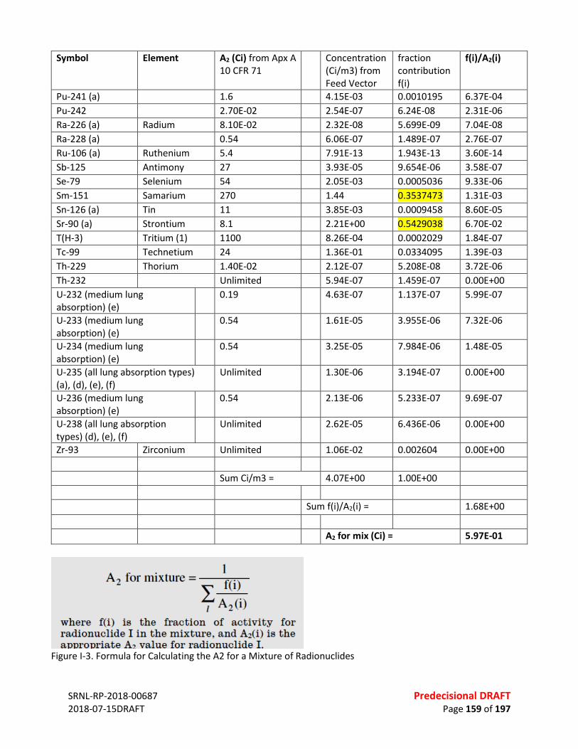
SRNL-RP-2018-00687 Predecisional DRAFT 2018-07-15DRAFT Page 159 of 197
Symbol Element A2 (Ci) from Apx A 10 CFR 71
Concentration (Ci/m3) from Feed Vector
fraction contribution f(i)
f(i)/A2(i)
Pu-241 (a) 1.6 4.15E-03 0.0010195 6.37E-04 Pu-242 2.70E-02 2.54E-07 6.24E-08 2.31E-06 Ra-226 (a) Radium 8.10E-02 2.32E-08 5.699E-09 7.04E-08 Ra-228 (a) 0.54 6.06E-07 1.489E-07 2.76E-07 Ru-106 (a) Ruthenium 5.4 7.91E-13 1.943E-13 3.60E-14 Sb-125 Antimony 27 3.93E-05 9.654E-06 3.58E-07 Se-79 Selenium 54 2.05E-03 0.0005036 9.33E-06 Sm-151 Samarium 270 1.44 0.3537473 1.31E-03 Sn-126 (a) Tin 11 3.85E-03 0.0009458 8.60E-05 Sr-90 (a) Strontium 8.1 2.21E+00 0.5429038 6.70E-02 T(H-3) Tritium (1) 1100 8.26E-04 0.0002029 1.84E-07 Tc-99 Technetium 24 1.36E-01 0.0334095 1.39E-03 Th-229 Thorium 1.40E-02 2.12E-07 5.208E-08 3.72E-06 Th-232 Unlimited 5.94E-07 1.459E-07 0.00E+00 U-232 (medium lung absorption) (e)
0.19 4.63E-07 1.137E-07 5.99E-07
U-233 (medium lung absorption) (e)
0.54 1.61E-05 3.955E-06 7.32E-06
U-234 (medium lung absorption) (e)
0.54 3.25E-05 7.984E-06 1.48E-05
U-235 (all lung absorption types) (a), (d), (e), (f)
Unlimited 1.30E-06 3.194E-07 0.00E+00
U-236 (medium lung absorption) (e)
0.54 2.13E-06 5.233E-07 9.69E-07
U-238 (all lung absorption types) (d), (e), (f)
Unlimited 2.62E-05 6.436E-06 0.00E+00
Zr-93 Zirconium Unlimited 1.06E-02 0.002604 0.00E+00 Sum Ci/m3 = 4.07E+00 1.00E+00 Sum f(i)/A2(i) = 1.68E+00 A2 for mix (Ci) = 5.97E-01
Figure I-3. Formula for Calculating the A2 for a Mixture of Radionuclides

SRNL-RP-2018-00687 Predecisional DRAFT 2018-07-15DRAFT Page 160 of 197
Classifying the Grout Waste Form as LSA-III The criteria for LSA-III specifically mentions concrete WFs, and the grout WF may be shipped as LSA-III if the specific activity of the WF is low enough and the other LSA-III criteria are met. This analysis focuses on the criteria for specific activity, and other criteria are discussed qualitatively. For the SLAW from the WTP PT for November 2035, the summed activity is 4.07 Ci/m3 (Table I-2). With an activity multiplier of 0.56 (=1/1.8) for grout and a specific density of 1770 kg/m3 (see Table 6-6), the specific activity of the grout is 1.2E-06 Ci/gram (= (4.07 x 0.56) / 1770,000). For the SLAW from the WTP PT for November 2035, the A2 is 5.97E-01 (Table I-2) and 2 × 10⁻³ of the A2/gram is 1.19E-03 Ci/gram. Therefore, the specific activity of the grout WF easily meets the specific activity criteria for shipping as LSA-III and specifically the WF is approximately 3 orders of magnitude less than the criteria for the November 2035 SLAW from the WTP PT. However, the A2 for other months also need to be calculated, because the A2 is not intuitive and because the bounding case for disposal may not be the bounding case for calculating the A2. Other criteria for LSA-III: • External radiation on the external surface of the shipping package must not exceed 2 mSv/h (200 mrem/h)
and an external radiation dose less than or equal to 10 mSv/hour (1 rem/hour) at a distance of 3 m (10 ft) from the unshielded material. Because the grout is self-shielding, and because the grout has a maximum of ~2 Ci/m3 of activity and because Sr-90 (a beta emitter) is one-half of those curies, it is assumed the grout would easily meet both dose-based criteria. Microshield calculations will be done in the future to confirm this assumption.
• The radioactivity is essentially uniformly distributed in a solid compact binding agent (such as concrete, bitumen, ceramic, etc.) – yes, grout will do this.
• The radioactive material is relatively insoluble, or it is intrinsically contained in a relatively insoluble material, so that even under loss of packaging, the loss of radioactive material per package by leaching, when placed in normal pH water for 7 days, would not exceed 0.1 A2. It is assumed that the large monolith of grout, with a limited surface area, limited activity, and a high pH would meet this criterion. Additional analysis will be conducted to validate this assumption.
Classifying the Steam Reformed Granular Waste Form as LSA-II The criteria for LSA-III specifically excludes “powders.” However, the steam reformed granular WF may be shipped as LSA-II if the specific activity of the WF is low enough and other LSA-II criteria are met. This analysis focuses on the criteria for specific activity, and other criteria are discussed qualitatively. Note that the criteria for LSA-II is an order of magnitude stricter (< 10-4 A2/gram) than the criteria for LSA-III classification. For the SLAW from the WTP PT for November 2035, the summed activity is 4.07 Ci/m3 (Table I-2). With a curie multiplier of 0.83 (=1/1.2) for steam reformed granular WF and a specific density of 800 kg/m3 (see Table 6-5), therefore, the specific activity of the steam reformed granular WF is 4.2E-06 Ci/gram (= (4.07 x 0.83) / 800,000). For the SLAW from the WTP PT for November 2035, the A2 is 5.97E-01 (Table I-1) and 10-4 of the A2/gram is 5.97E-05 Ci/gram. Therefore, the specific activity of the steam reformed granular WF meets the specific activity criteria for shipping as LSA-II, and specifically the WF is approximately one order of magnitude less than the criteria for wastes from November 2035. Other criteria for LSA-II:
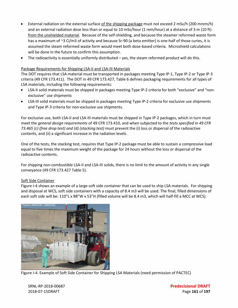
SRNL-RP-2018-00687 Predecisional DRAFT 2018-07-15DRAFT Page 161 of 197
• External radiation on the external surface of the shipping package must not exceed 2 mSv/h (200 mrem/h) and an external radiation dose less than or equal to 10 mSv/hour (1 rem/hour) at a distance of 3 m (10 ft) from the unshielded material. Because of the self-shielding, and because the steamer reformed waste form has a maximum of ~3 Ci/m3 of activity and because Sr-90 (a beta emitter) is one-half of those curies, it is assumed the steam reformed waste form would meet both dose-based criteria. Microshield calculations will be done in the future to confirm this assumption.
• The radioactivity is essentially uniformly distributed – yes, the steam reformed product will do this. Package Requirements for Shipping LSA-II and LSA-III Materials The DOT requires that LSA material must be transported in packages meeting Type IP-1, Type IP-2 or Type IP-3 criteria (49 CFR 173.411). The DOT in 49 CFR 173.427, Table 6 defines packaging requirements for all types of LSA materials, including the following requirements: • LSA-II solid materials must be shipped in packages meeting Type IP-2 criteria for both “exclusive” and “non-
exclusive” use shipments • LSA-III solid materials must be shipped in packages meeting Type IP-2 criteria for exclusive use shipments
and Type IP-3 criteria for non-exclusive use shipments. For exclusive use, both LSA-II and LSA-III materials must be shipped in Type IP-2 packages, which in turn must meet the general design requirements of 49 CFR 173.410, and when subjected to the tests specified in 49 CFR 73.465 (c) (free drop test) and (d) (stacking test) must prevent the (i) loss or dispersal of the radioactive contents, and (ii) a significant increase in the radiation levels. One of the tests, the stacking test, requires that Type IP-2 package must be able to sustain a compressive load equal to five times the maximum weight of the package for 24 hours without the loss or dispersal of the radioactive contents. For shipping non-combustible LSA-II and LSA-III solids, there is no limit to the amount of activity in any single conveyance (49 CFR 173.427 Table 5). Soft Side Container Figure I-4 shows an example of a large soft side container that can be used to ship LSA materials. For shipping and disposal at WCS, soft side containers with a capacity of 8.4 m3 will be used. The final, filled dimensions of each soft side will be: 110”L x 88”W x 53”H (filled volume will be 8.4 m3, which will half-fill a MCC at WCS).
Figure I-4. Example of Soft Side Container for Shipping LSA Materials (need permission of PACTEC)
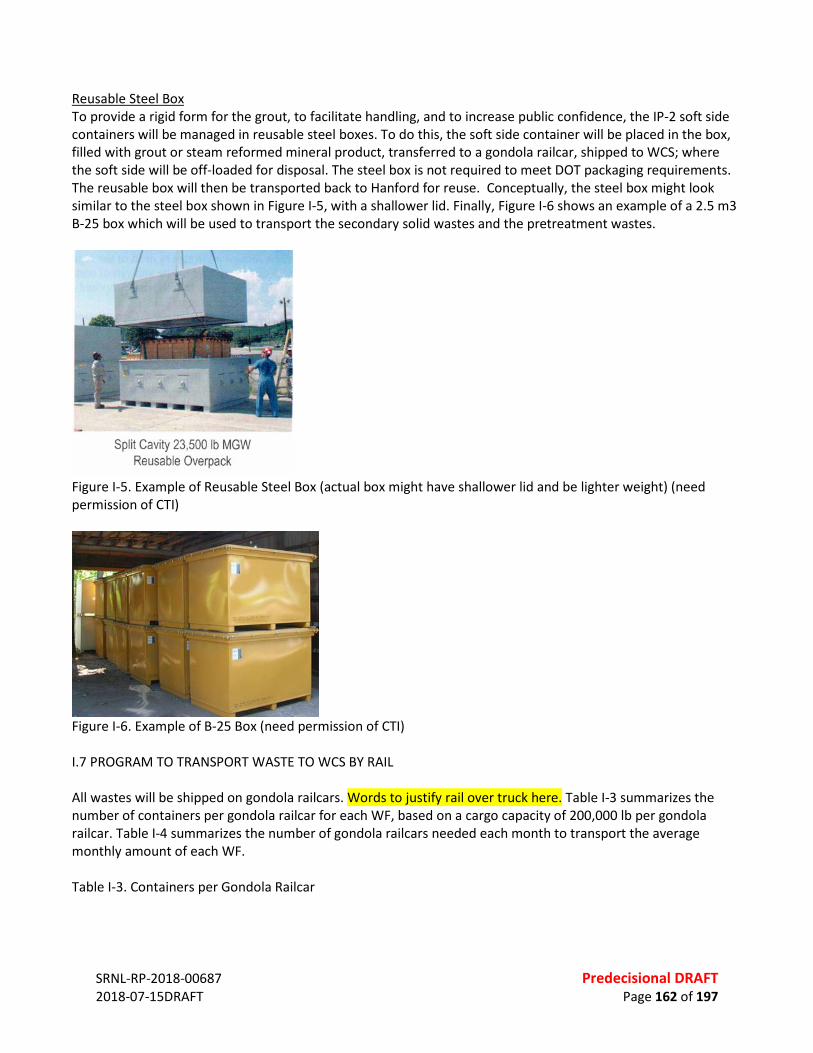
SRNL-RP-2018-00687 Predecisional DRAFT 2018-07-15DRAFT Page 162 of 197
Reusable Steel Box To provide a rigid form for the grout, to facilitate handling, and to increase public confidence, the IP-2 soft side containers will be managed in reusable steel boxes. To do this, the soft side container will be placed in the box, filled with grout or steam reformed mineral product, transferred to a gondola railcar, shipped to WCS; where the soft side will be off-loaded for disposal. The steel box is not required to meet DOT packaging requirements. The reusable box will then be transported back to Hanford for reuse. Conceptually, the steel box might look similar to the steel box shown in Figure I-5, with a shallower lid. Finally, Figure I-6 shows an example of a 2.5 m3 B-25 box which will be used to transport the secondary solid wastes and the pretreatment wastes.
Figure I-5. Example of Reusable Steel Box (actual box might have shallower lid and be lighter weight) (need permission of CTI)
Figure I-6. Example of B-25 Box (need permission of CTI) I.7 PROGRAM TO TRANSPORT WASTE TO WCS BY RAIL All wastes will be shipped on gondola railcars. Words to justify rail over truck here. Table I-3 summarizes the number of containers per gondola railcar for each WF, based on a cargo capacity of 200,000 lb per gondola railcar. Table I-4 summarizes the number of gondola railcars needed each month to transport the average monthly amount of each WF. Table I-3. Containers per Gondola Railcar
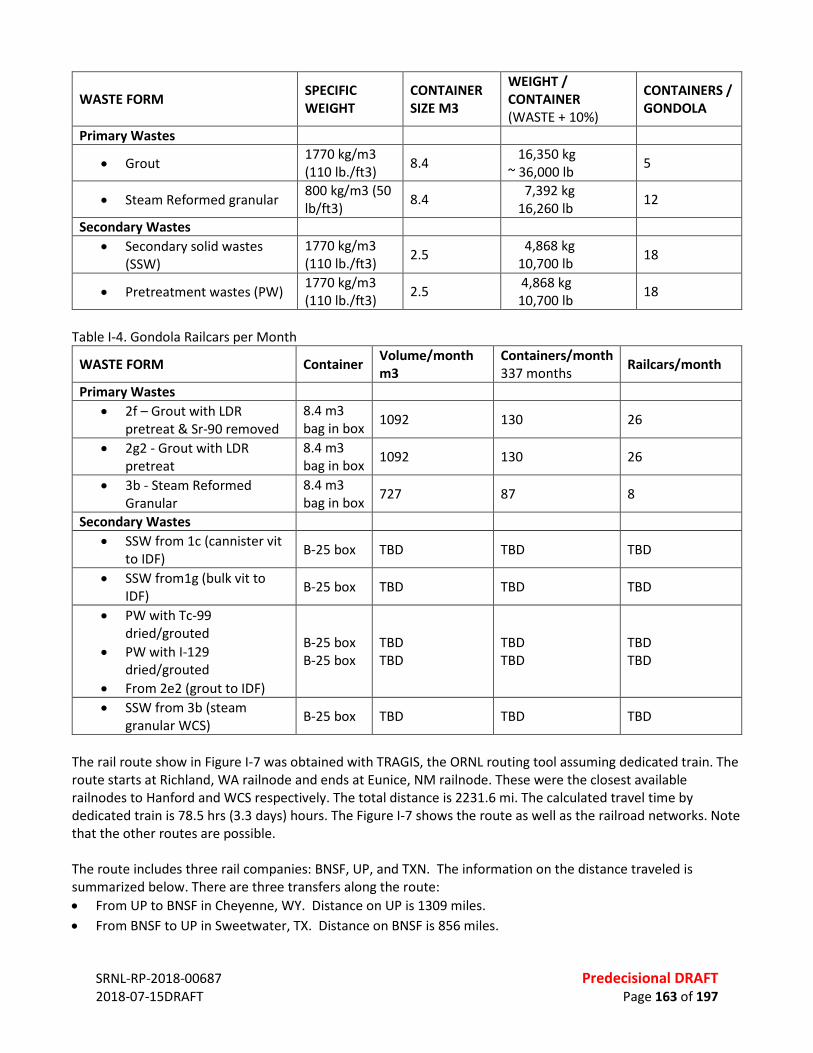
SRNL-RP-2018-00687 Predecisional DRAFT 2018-07-15DRAFT Page 163 of 197
WASTE FORM SPECIFIC WEIGHT
CONTAINER SIZE M3
WEIGHT / CONTAINER (WASTE + 10%)
CONTAINERS / GONDOLA
Primary Wastes
• Grout 1770 kg/m3 (110 lb./ft3) 8.4 16,350 kg
~ 36,000 lb 5
• Steam Reformed granular 800 kg/m3 (50 lb/ft3) 8.4 7,392 kg
16,260 lb 12
Secondary Wastes • Secondary solid wastes
(SSW) 1770 kg/m3 (110 lb./ft3) 2.5 4,868 kg
10,700 lb 18
• Pretreatment wastes (PW) 1770 kg/m3 (110 lb./ft3) 2.5 4,868 kg
10,700 lb 18
Table I-4. Gondola Railcars per Month
WASTE FORM Container Volume/month m3
Containers/month 337 months Railcars/month
Primary Wastes • 2f – Grout with LDR
pretreat & Sr-90 removed 8.4 m3 bag in box 1092 130 26
• 2g2 - Grout with LDR pretreat
8.4 m3 bag in box 1092 130 26
• 3b - Steam Reformed Granular
8.4 m3 bag in box 727 87 8
Secondary Wastes • SSW from 1c (cannister vit
to IDF) B-25 box TBD TBD TBD
• SSW from1g (bulk vit to IDF) B-25 box TBD TBD TBD
• PW with Tc-99 dried/grouted
• PW with I-129 dried/grouted
• From 2e2 (grout to IDF)
B-25 box B-25 box
TBD TBD
TBD TBD
TBD TBD
• SSW from 3b (steam granular WCS) B-25 box TBD TBD TBD
The rail route show in Figure I-7 was obtained with TRAGIS, the ORNL routing tool assuming dedicated train. The route starts at Richland, WA railnode and ends at Eunice, NM railnode. These were the closest available railnodes to Hanford and WCS respectively. The total distance is 2231.6 mi. The calculated travel time by dedicated train is 78.5 hrs (3.3 days) hours. The Figure I-7 shows the route as well as the railroad networks. Note that the other routes are possible. The route includes three rail companies: BNSF, UP, and TXN. The information on the distance traveled is summarized below. There are three transfers along the route: • From UP to BNSF in Cheyenne, WY. Distance on UP is 1309 miles. • From BNSF to UP in Sweetwater, TX. Distance on BNSF is 856 miles.
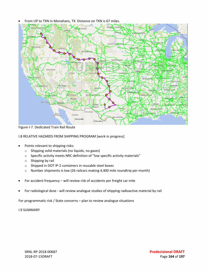
SRNL-RP-2018-00687 Predecisional DRAFT 2018-07-15DRAFT Page 164 of 197
• From UP to TXN in Monahans, TX. Distance on TXN is 67 miles.
Figure I-7. Dedicated Train Rail Route I.8 RELATIVE HAZARDS FROM SHIPPING PROGRAM [work in progress] • Points relevant to shipping risks:
o Shipping solid materials (no liquids, no gases) o Specific activity meets NRC definition of “low specific activity materials” o Shipping by rail o Shipped in DOT IP-2 containers in reusable steel boxes o Number shipments is low (26 railcars making 4,400 mile roundtrip per month)
• For accident frequency – will review risk of accidents per freight car mile
• For radiological dose - will review analogue studies of shipping radioactive material by rail
For programmatic risk / State concerns – plan to review analogue situations I.9 SUMMARY
SRNL-RP-2018-00687 Predecisional DRAFT 2018-07-15DRAFT Page 165 of 197
APPENDIX J. EXPANDED DISCUSSION – REGULATORY COMPLIANCE J.1 REGULATORY BACKGROUND The portion of low-activity waste at the Hanford Nuclear Reservation, Richland, Washington, that is intended for supplemental treatment and addressed in this assessment, is managed through U.S. Department of Energys’ (DOE) radioactive waste management activities as prescribed under various DOE orders, including DOE Order 435.1 (DOE O 435.1), “Radioactive Waste Management”.76 DOE O 435.1 was promulgated under Atomic Energy Act of 1954, as amended. DOE is the responsible party for the safe management and final disposal of all radioactive wastes arising from its operations. The objective of the activities required under this order is to ensure that the waste is managed in a manner that is protective of worker and public health and safety, and the environment. DOE O 435.1 requires that radioactive waste at DOE sites be managed to comply with applicable Federal, State, and local laws and regulations as well as Executive Orders and other DOE directives. Based on the guidance provided in DOE M 435.1-1, the regulations that may be applicable to the Hanford Site for the supplemental treatment of low activity waste, at a minimum, include: • Resource Conservation and Recovery Act (RCRA) requirements (40 CFR Parts 260—273) for mixed low-level
waste77 (See Ref. 1); • Applicable sections of Washington State (WA) regulations (WAC 173-303) that implement RCRA
requirements (See Ref. 2); • Clean Air Act (CAA) implementing regulations at 40 CFR Subchapter, Parts 50-97 (See Ref. 3); • Applicable sections of WA air regulations to include, criteria pollutants (WAC 173-400), toxic air pollutants
(TAPs) (WAC 173-460), and radioactive air pollutants (WAC 246-247) (See Ref. 4 to 6); • Occupational Radiation Protection requirements (10 CFR Part 835) for oversight of radioactive waste
management facilities, operations, and activities; • Toxic Substances Control Act (TSCA) requirements (40 CFR Part 761) for low-level waste containing
polychlorinated biphenyls, asbestos, or other such regulated toxic components78 (See Ref. 7); and • As low as reasonably achievable (ALARA) exposure requirements under Radiation Protection of the Public
and the Environment (10 CFR Part 834) and DOE 5400.5 In addition to the regulations listed above, various transportation and packaging requirements are applicable for on-site or off-site waste disposal. Packaging and transportation requirements are discussed in Chapter 7 in more detail. However, some applicable regulations include DOE orders 435.1, 460.1A, and 460.2, and other Department of Transportation (DOT) requirements. This chapter focuses on the regulations that are applicable to management and disposal of the portion of low-activity waste at the Hanford Nuclear Reservation intended for supplemental treatment. It summarizes an analysis of the compliance of treatment approaches with applicable technical standards associated with and
76 DOE Order 435.1 governs the management of radioactive waste at DOE sites, including criteria for wastes that are not considered high-level. 77 Under DOE M 435.1-1 Section IV.B.(1), Mixed Low-Level Waste is the low-level waste determined to contain both source, special nuclear, or byproduct material subject to the Atomic Energy Act of 1954, as amended, and a hazardous component subject to the Resource Conservation and Recovery Act (RCRA), as amended, and shall be managed in accordance with the requirements of RCRA and DOE O 435.1. 78 Under DOE G 435.1-1 Section IV.B, TSCA-Regulated Waste is the low-level waste containing polychlorinated biphenyls, asbestos, or other such regulated toxic components, and shall be managed in accordance with requirements derived from the Toxic Substances Control Act, as amended, and DOE O 435.1.
SRNL-RP-2018-00687 Predecisional DRAFT 2018-07-15DRAFT Page 166 of 197
contained in regulations prescribed pursuant to the Comprehensive Environmental Response, Compensation, and Liability Act of 1980 (42 U.S.C. 9601 et seq.), the Solid Waste Disposal Act (42 U.S.C. 6901 et seq.), the Federal Pollution Control Act (33 U.S.C. 1251 et seq.), the Clean Air Act (42 U.S.C. 7401 et seq.), and any corresponding State law. J.2 DESIGNATION OF HANFORD WASTE In 1997, DOE and Nuclear Regulatory Commission (NRC) provisionally agreed that the vast majority of waste from Hanford tanks is not high-level waste, but rather is low-level waste that is not subject to NRC’s licensing authority.79 The Hanford waste slated for disposal as low activity waste must be determined to meet the Waste Incidental to Reprocessing (WIR) criteria in DOE M 435.1-1(See Ref. 8). Incidental waste is managed under DOE’s regulatory authority in accordance with the requirements for low-level waste, as appropriate. Hanford incidental waste to be managed as low-level waste must be documented to meet the following criteria: 1. Have been processed, or will be processed, to remove key radionuclides to the maximum extent that is
technically and economically practical; 2. Managed to meet the safety requirements comparable to the performance objectives set out in 10 CFR Part
61, Subpart C, Performance Objectives; and 3. Managed pursuant to DOE’s authority under the Atomic Energy Act of 1954, as amended, and in accordance
with the provisions included in DOE M 435.1-1, Chapter IV, provided the waste will be incorporated in a solid physical form at a concentration that does not exceed the applicable concentration limits for Class C low-level waste as set out in 10 CFR 61.55, Waste Classification, or will meet alternative requirements for waste classification and characterization as DOE may authorize.
If the waste stream is shown to meet the criteria above, then it can be disposed in a near-surface permitted facility. For Hanford’s tank waste, criterion 1 is addressed through pretreatment processing of the tank waste either through the pretreatment facility within the WTP or the Low Activity Waste Pretreatment System (LAWPS) as shown in Fig. 2-1. This pretreatment processing, principally for removal of Cs and undissolved solids removes key radionuclides necessary to meet criterion 1. For this assessment, the LAW feed vector represents a post-pretreatment feed stream that has been processed to addressed criterion 1. Criterion 3 is addressed principally through the LAW processing to ultimately produce a LAW waste form, either through WTP LAW vitrification, or through supplemental LAW immobilization and any additional pretreatment options considered. Therefore, this assessment must address criterion 3 by selection and evaluation of processing options that will meet the solid physical form and concentration requirements of this criterion. Finally, criterion 2 is addressed through both the waste form and the disposal site considerations. Disposal sites demonstrate compliance with criteria 2 by developing performance assessment analyses, considering both the inventory of radionuclides, waste forms, and disposal site specific designs and environmental conditions to assess long-term compliance with prescribed performance objectives that meet or exceed the requirements of 10 CFR Part 61, Subpart C, Performance Objectives. This assessment must address this criterion, to the extent practical and appropriate given the waste form performance data and analysis available. J.3 HANFORD WASTE CLASSIFICATION UNDER RCRA AND TSCA The Hanford tank waste is considered “mixed waste”—hazardous waste mixed with radioactive material. Therefore, in addition to DOE orders, it is regulated under the Environmental Protection Agency’s (EPA) Resource Conservation and Recovery Act (RCRA) that governs the treatment and disposal of solid and hazardous
79 Kinzer, J. (Jun 23, 1997). Contract Number DE-AC06-96RL13200 – Nuclear Regulatory Commission (NRC) Agreement on Classification of Hanford Tank Waste [Memorandum]. Washington, DC: Department of Energy.
SRNL-RP-2018-00687 Predecisional DRAFT 2018-07-15DRAFT Page 167 of 197
waste. EPA has delegated its RCRA authorities to Washington State, who implements these requirements under WAC 173-303, Dangerous Waste Regulations. Hanford is considered a single facility for purposes of RCRA and the Washington State Hazardous Waste Management Act. The permit is referred to as the Hanford Site-Wide Permit Revision 8C (See Ref. 9), and the site has been issued EPA/state identification No. WA7890008967. The permit sets conditions based on the state’s laws and regulations that control the treatment, storage, and disposal of dangerous wastes The SSTs and DSTs are identified as individual units in the Permit. The DST farms operate under interim status requirements. A Part B permit application for the DSTs was submitted to Ecology in 2005. The TPA lays out the process and authority to operate non-RCRA-compliant SSTs pending closure and identifies the process and procedures for SST system closure. The RCRA Program establishes two ways of identifying solid wastes as hazardous: (1) a waste is considered hazardous if it exhibits certain hazardous “characteristics” (i.e., ignitability, corrosivity, reactivity, or toxicity); or (2) a waste is considered hazardous if it is “listed” in EPA’s list of hazardous wastes. Based on these characteristics and listed wastes, specific waste codes that have been assigned to Hanford tank waste are given in Table J-1 for the characteristic hazardous wastes, Table J-2 for listed hazardous wastes, and Table J-3 for WA State-only waste classifications, below.80 These codes are identified in the RCRA Part A issued by Ecology for both the single-shell tanks (SSTs) and the double-shell tanks (DSTs). The waste codes were determined either by chemical analyses of the tank waste, or by process knowledge, as provided in WAC 173-303. A new supplemental treatment unit would likely require a final status RCRA permit to be issued by Ecology. The RCRA regulations require a completed, certified engineering design. In the past, Ecology has worked with the DOE to allow the permitting process to begin as the design is being finalized. The Toxic Substances Control Act (Toxic Substances Control Act of 1976 (15 U.S.C. 2601 et seq.) provides EPA with the authority to require testing of chemical substances entering the environment and to regulate them as necessary. (See Ref. 9) Under TSCA, EPA is also authorized to impose strict limitations on the use and disposal of polychlorinated biphenyls (PCBs). The EPA regulations that establish prohibitions of, and requirements for PCBs and PCB items are found in 40 CFR 761, “Polychlorinated Biphenyls (PCBs) Manufacturing, Processing, Distribution in Commerce, and Use Prohibitions”. In August, 2000, the EPA, DOE and Ecology entered into the “The Hanford PCB Framework Agreement,” that provided their approach to resolve the regulatory issues with managing PCB remediation waste at the vitrification plant, tank farms (to include tank waste retrievals, transfers, and contaminated equipment), and affected upstream/downstream facilities to further the timely treatment and disposal of tank waste. (See Ref. 10) They further agreed that they would pursue a rational path based on a risk-based disposal approval option per 40 CFR 761.61 (c) for management of TSCA PCB remediation waste. The parties also agreed that RCRA and the CAA, as implemented through approved State programs, and Atomic Energy Act are expected to be the key regulatory drivers for tank waste retrieval, transfers, pretreatment, vitrification, disposal, and other activities impacted by the designation of tank waste as PCB remediation waste. The engineering design basis for the vitrification plant assumes up to 50 parts per million of PCBs in the waste feed to the vitrification plant. DOE has submitted two risk-based disposal applications to EPA Region 10 for their approval. The first application, titled “Transmittal of Toxic Substance Control Act (TSCA) Risk-Based Disposal Application for the Double Shell Tank (DST) System for 2001,” was submitted on January 2002. (See Ref. 11) The second application, 80 RPP-8402, Rev.1., DRAFT, Integrated Disposal Facility Waste Acceptance Criteria, 2005.
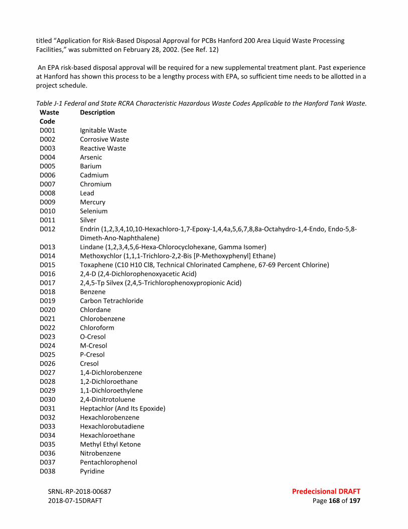
SRNL-RP-2018-00687 Predecisional DRAFT 2018-07-15DRAFT Page 168 of 197
titled “Application for Risk-Based Disposal Approval for PCBs Hanford 200 Area Liquid Waste Processing Facilities,” was submitted on February 28, 2002. (See Ref. 12) An EPA risk-based disposal approval will be required for a new supplemental treatment plant. Past experience at Hanford has shown this process to be a lengthy process with EPA, so sufficient time needs to be allotted in a project schedule. Table J-1 Federal and State RCRA Characteristic Hazardous Waste Codes Applicable to the Hanford Tank Waste.
Waste Code
Description
D001 Ignitable Waste D002 Corrosive Waste D003 Reactive Waste D004 Arsenic D005 Barium D006 Cadmium D007 Chromium D008 Lead D009 Mercury D010 Selenium D011 Silver D012 Endrin (1,2,3,4,10,10-Hexachloro-1,7-Epoxy-1,4,4a,5,6,7,8,8a-Octahydro-1,4-Endo, Endo-5,8-
Dimeth-Ano-Naphthalene) D013 Lindane (1,2,3,4,5,6-Hexa-Chlorocyclohexane, Gamma Isomer) D014 Methoxychlor (1,1,1-Trichloro-2,2-Bis [P-Methoxyphenyl] Ethane) D015 Toxaphene (C10 H10 Cl8, Technical Chlorinated Camphene, 67-69 Percent Chlorine) D016 2,4-D (2,4-Dichlorophenoxyacetic Acid) D017 2,4,5-Tp Silvex (2,4,5-Trichlorophenoxypropionic Acid) D018 Benzene D019 Carbon Tetrachloride D020 Chlordane D021 Chlorobenzene D022 Chloroform D023 O-Cresol D024 M-Cresol D025 P-Cresol D026 Cresol D027 1,4-Dichlorobenzene D028 1,2-Dichloroethane D029 1,1-Dichloroethylene D030 2,4-Dinitrotoluene D031 Heptachlor (And Its Epoxide) D032 Hexachlorobenzene D033 Hexachlorobutadiene D034 Hexachloroethane D035 Methyl Ethyl Ketone D036 Nitrobenzene D037 Pentachlorophenol D038 Pyridine

SRNL-RP-2018-00687 Predecisional DRAFT 2018-07-15DRAFT Page 169 of 197
D039 Tetrachloroethylene D040 Trichlorethylene D041 2,4,5-Trichlorophenol D042 2,4,6-Trichlorophenol D043 Vinyl Chloride
Table J-2 Federal and State RCRA Listed Hazardous Waste Codes Applicable to the Hanford Tank Waste.
Waste Code
Description
F001 The Following Spent Halogenated Solvents Used In Degreasing: Tetrachloroethylene, Trichlorethylene, Methylene Chloride, 1,1,1-Trichloroethane, Carbon Tetrachloride And Chlorinated Fluorocarbons; All Spent Solvent Mixtures/Blends Used In Degreasing Containing, Before Use, A Total Of Ten Percent Or More (By Volume) Of One Or More Of The Above Halogenated Solvents Or Those Solvents Listed In F002, F004, And F005; And Still Bottoms From The Recovery Of These Spent Solvents And Spent Solvent Mixtures.
F002 The Following Spent Halogenated Solvents: Tetrachloroethylene, Methylene Chloride, Trichloroethylene, 1,1,1-Trichloroethane, Chlorobenzene, 1,1,2-Trichloro-1,2,2-Trifluoroethane, Ortho-Dichlorobenzene, Trichlorofluoromethane, And 1,1,2, Trichloroethane; All Spent Solvent Mixtures/Blends Containing, Before Use, A Total Of Ten Percent Or More (By Volume) Of One Or More Of The Above Halogenated Solvents Or Those Solvents Listed In F001, F004, And F005; And Still Bottoms From The Recovery Of These Spent Solvents And Spent Solvent Mixtures.
F003 The Following Spent Nonhalogenated Solvents: Xylene, Acetone, Ethyl Acetate, Ethyl Benzene, Ethyl Ether, Methyl Isobutyl Ketone, N-Butyl Alcohol, Cyclohexanone, And Methanol; All Spent Solvent Mixtures/Blends Containing, Before Use, Only The Above Spent Nonhalogenated Solvents; And All Spent Solvent Mixtures/Blends Containing, Before Use, One Or More Of The Above Nonhalogenated Solvents, And A Total Of Ten Percent Or More (By Volume) Of One Or More Of Those Solvents Listed In F001, F002, F004, And F005; And Still Bottoms From The Recovery Of These Spent Solvents And Spent Solvent Mixtures.
F004 The Following Spent Nonhalogenated Solvents: Cresols, Cresylic Acid, And Nitrobenzene; And The Still Bottoms From The Recovery Of These Solvents; All Spent Solvent Mixtures/Blends Containing, Before Use, A Total Of Ten Percent Or More (By Volume) Of One Or More Of The Above Nonhalogenated Solvents Or Those Solvents Listed In F001, F002, And F005; And Still Bottoms From The Recovery Of These Spent Solvents And Spent Solvent Mixtures.
F005 The Following Spent Nonhalogenated Solvents: Toluene, Methyl Ethyl Ketone, Carbon Disulfide, Isobutanol, Pyridine, Benzene, 2-Ethoxyethanol, And 2-Nitropropane; All Spent Solvent Mixtures/Blends Containing, Before Use, A Total Of Ten Percent Or More (By Volume) Of One Or More Of The Above Nonhalogenated Solvents Or Those Solvents Listed In F001, F002, Or F004; And Still Bottoms From The Recovery Of These Spent Solvents And Spent Solvent Mixtures.
F006 Wastewater Treatment Sludges From Electroplating Operations, Except From The Following Processes: (1) Sulfuric Acid Anodizing Of Aluminum; (2) Tin Plating On Carbon Steel; (3) Zinc Plating (Segregated Basis) On Carbon Steel; (4) Aluminum Or Zinc-Aluminum Plating On Carbon Steel; (5) Cleaning/Stripping Associated With Tin, Zinc, And Aluminum Plating On Carbon Steel; And (6) Chemical Etching And Milling Of Aluminum.
F007 Spent Cyanide Plating Bath Solutions From Electroplating Operations. F008 Plating Bath Residues From The Bottom Of Plating Baths From Electroplating Operations In Which
Cyanides Are Used In The Process. F009 Spent Stripping And Cleaning Bath Solutions From Electroplating Operations In Which Cyanides Are
Used In The Process.

SRNL-RP-2018-00687 Predecisional DRAFT 2018-07-15DRAFT Page 170 of 197
F010 Quenching Bath Residues From Oil Baths From Metal Heat Treating Operations In Which Cyanides Are Used In The Process.
F011 Spent Cyanide Solutions From Slat Bath Pot Cleaning From Metal Heat Treating Operations. F012 Quenching Wastewater Treatment Sludges From Metal Heat Treating Operations In Which Cyanides
Are Used In The Process. F028 Residues Resulting From The Incineration Or Thermal Treatment Of Soil Contaminated With Epa
Hazardous Waste Nos. F020, F021, F022, F023, F026, And F027. F039 Leachate Resulting From The Treatment, Storage, Or Disposal Of Wastes Classified By More Than
One Waste Code Under Subpart D, Or From A Mixture Of Wastes Classified Under Subparts C And D Of This Part. (Leachate Resulting From The Management Of One Or More Of The Following Epa Hazardous Wastes And No Other Hazardous Wastes Retains Its Hazardous Waste Code(S): F020, F021, F022, F023, F026, F027, And/Or F028.)
Table J-3 WA State-only Waste Codes Applicable to the Hanford Tank Waste.
Waste Code
Description
WP01 Persistent dangerous wastes, halogenated organic compounds, extremely hazardous wastes (EHW) WP02 Persistent dangerous wastes, halogenated organic compounds, dangerous waste (DW) WP03 Persistent dangerous wastes, polycyclic aromatic hydrocarbons (EHW) WT01 Toxic dangerous waste, extremely hazardous (EHW) WT02 Toxic dangerous waste (DW)
J.3 LAND DISPOSAL REQUIREMENTS APPLICABLE TO HANFORD WASTE Under RCRA, Hanford tank waste is categorized as non-wastewater and radioactive mixed waste subject to Land Disposal Restriction (LDR).81 The tanks are considered a storage area for multiple upstream points of generation where the waste was originally produced.82 The LDR program (established under 40 CFR Part 268) requires treating hazardous waste or meeting specified levels for hazardous constituents before disposing of the waste on the land. EPA has established a treatment standard for each type of hazardous waste (given in Part 268, Subpart D). These standards are defined either as treatment technologies or contaminant concentration levels. The treatment standards are based on the performance of the best demonstrated available technology (BDAT) that reduces the toxicity and mobility of the hazardous waste.83 Vitrification of High Level Mixed Radioactive Waste (HLVIT) LDR standard was adopted by EPA in 1990 as a technology treatment standard for radioactive high level wastes generated during the reprocessing of fuel rods. Since the hazardous waste identification and LDR determinations are made at the point of generation under RCRA, EPA Region 10 and Ecology have determined that Hanford low activity waste is also subject to the HLVIT treatment standard as the high-level waste.6 [Need a TPA or other reference] Since this treatment standard was established by the EPA for high-level wastes, it may be possible to determine an alternative course of action for the low activity waste portion of Hanford tank waste to comply with RCRA requirements to ensure safe management and disposal. For example, wastes that do not meet treatment standards may be considered for a variance, extension, exclusion, or no migration petition under RCRA. For the low activity waste portion of Hanford’s tank waste, prohibitions for on land disposal do not apply if an exemption is granted pursuant to a
81 Non-wastewater is defined as a waste that has both Total Suspended Solids (TSS) and Total Organic Carbon (TOC) greater than 1% by weight. Non-wastewaters are one of the two main treatability groups under RCRA in addition to wastewater. 82 Winston, T.A.., 2013. HLVIT Applicability to Supplemental Immobilization: Impact of a RCRA New Point of Generation. RPP-RPT-52699, Rev.0. 83 EPA, 2005. Introduction to Land Disposal Restrictions (40 CR Part 268). EPA530-K-013.

SRNL-RP-2018-00687 Predecisional DRAFT 2018-07-15DRAFT Page 171 of 197
petition under 40 CFR Part 268.6. This petition, also referred to as “no-migration petition”, if granted, would allow wastes to be placed in land disposal units without first meeting their treatment standards. The petition requires a demonstration that hazardous constituents will not migrate from a unit at concentrations greater than EPA-approved health-based levels. A no-migration variance may be granted for up to 10 years84. It should be noted that other sites within the DOE complex do not vitrify the low activity portion of their tank waste. These include the Savannah River Site and the West Valley Site. Under 40 CFR Part 268.44, it is also possible to petition EPA for a variance from a treatment standard (treatability variance) if the wastes cannot be treated to achieve the established treatment standard, or when the treatment standards are not appropriate. (Note – it is currently planned that the DOE will be submitting a treatability variance for both the high level and low level vitrified waste forms that are planned to be produced at the WTP.) Wastes that may be eligible for a variance include the wastes that otherwise are different in physical or chemical properties from those wastes used to establish the treatment standard. This option does not exempt the waste, but instead establishes an alternative LDR treatment standard. Another alternative to the existing standards include a determination of equivalent treatment (DET) under 40 CFR Part 268.42(b). An application to the Administrator can be submitted to demonstrate that an alternative treatment method can achieve a measure of performance equivalent to that achieved by the applicable treatment standards. In the case of Hanford low activity waste, this may require a demonstration of equivalent performance to vitrification. The submitted information must demonstrate that the alternative treatment method is in compliance with federal, state, and local requirements and is protective of human health and the environment. In addition to the methods described above, the LAW fraction of Hanford waste may be eligible for recategorization as wastewater under 40 CFR Part 262.11(a). Under this requirement, the hazardous waste determination for each solid waste must be made at the point of waste generation, before any dilution, mixing, or other alteration of the waste occurs. However, if the waste has, or may have changed its properties in the course of the management of waste, RCRA classification of the waste may change as well. For Hanford tank waste such change may happen during the pretreatment process, i.e., the filtration and ion exchange process, where the tank waste is separated into its high activity and low activity portions per DOE O 435.1, resulting in LAW waste stream that may be considered wastewater.85 This may be considered a “new point of generation” requiring a new determination of applicable RCRA waste codes and LDR standards. In addition to HLVIT, some other RCRA concentration standards and Washington-state only standards are also applicable to Hanford tank wastes. Appendix H lists all applicable LDR standards for Hanford tank waste.
84 A no-migration petition is not technically credible for on-site Hanford disposal where there is a direct pathway to groundwater. However, for an appropriate off-site disposal location, such as WCS, a no-migration petition may be technically credible. 85 Under 40 CFR 268.2, wastewaters are defined as wastes that contain less than 1% by weight total organic carbon (TOC) and less than 1 % by weight total suspended solids (TSS).
SR
NL-
RP-2
018-
0068
7
Pr
edec
isio
nal D
RAFT
20
18-0
7-15
DRAF
T
Page
172
of 1
97
[Pla
ceho
lder
for t
he R
CRA
flow
char
t fig
ure,
a g
raph
ics e
dito
r may
be
able
to c
reat
e a
nice
flow
char
t bas
ed o
n ou
r exc
el sh
eet]

SRNL-RP-2018-00687 Predecisional DRAFT 2018-07-15DRAFT Page 173 of 197
J.4 REQUIREMENTS FOR AIR EMISSIONS For the processing of the law activity waste at Hanford, toxic air pollutant controls under WA state regulations (WAC 173-460) apply. The Clean Air Act is intended to protect and enhance the quality of the Nation‘s air resources so as to promote the public health and welfare and the productive capacity of its population. Section 118 of the Clean Air Act (42 U.S.C. 7401) requires each Federal agency with jurisdiction over any property or facility engaged in any activity that might result in the discharge of air pollutants to comply with all Federal, state, interstate, and local requirements‖ with regard to the control and abatement of air pollution. Most of the provisions of the Washington Clean Air Act mirror the requirements of the Federal Clean Air Act. The Hanford Site Air Operating Permit (AOP) regulates emissions of criteria pollutants (WAC 173-400, “General Regulations for Air Pollution Sources”), toxic air pollutants (TAPs) (WAC 173-460, “Controls for New Sources of Toxic Air Pollutants”), and radioactive air pollutants (WAC 246-247, “Radiation Protection – Air Emissions”) for all Hanford site sources. Hanford operates under state license No. FF-01. Prior to beginning any work that would result in creating a new or modified source of airborne emissions, a Notice of Construction application must be submitted to the Washington State Departments of Health and Ecology for review and approval. Ensuring adequate emission controls, emissions monitoring/sampling, and/or annual reporting of air emissions is a typical requirement for radioactive air emission sources. A New Source Review is conducted by Ecology for toxic air pollutants and criteria pollutants emissions, or the WDOH Office of Radiation Protection for radioactive emissions. Washington air regulations were recently revised to established requirements for determining the levels of dimethyl mercury (DMM) from emission sources, and to evaluate the potential exposures to humans and the environment from this contaminant. Dimethyl mercury is an organomercury compound that is very toxic to humans. A small skin exposure of a few drops has been. Dimethyl mercury is a colorless liquid that is volatile and insoluble in water. DMM has been identified in the Hanford tanks. The regulations require that all projects with emissions of toxics, such as DMM, in Washington Administrative Code (WAC) 173-460-150 that exceeds the de minimis levels are required to submit a first tier review. If modeled ambient concentrations exceed the acceptable source impact levels (ASIL) in WAC 173-460-150 a second tier review or Health Impacts Analysis (HIA) is required. The primary purpose of the review is to document the analysis and evaluation of the potential human health related impacts of dimethyl mercury (DMM) emissions and offsite ambient concentrations from a proposed facility. The study is intended to determine if the DMM emissions from a facility will pose an unacceptable risk to the public from an emission source. Several HIAs have been submitted to Ecology for tank farm emission sources that documented no potential health or environmental impacts from those sources. J.5 WASTE FORM PERFORMANCE REQUIREMENTS Waste form performance requirements for the immobilized LAW are defined principally by the enabling WIR criteria from DOE M 435.1-1, and waste acceptance criteria (WAC) of the disposal facility selected for final disposition of the immobilized LAW. Chapter 6 describes the two disposal facilities selected for consideration in this assessment, along with current regulatory , waste classification for disposal, and the two specific disposal sites considered in this analysis. The rest of this section on IDF will move to Chapter 6.

SRNL-RP-2018-00687 Predecisional DRAFT 2018-07-15DRAFT Page 174 of 197
Table J-4 All LDR standards applicable for Hanford tank waste. Hanford characteristics waste codes are specified in the Hanford Tank Waste RCRA Part A permit application.
Total Waste Standards
Waste Extract Standards Technology Standards
Constituent Common Name
Description
CAS Number
Wastewater Standard, Concentration in (mg/l) 3
Non-Wastewater Standard, Concentration in (mg/kg) unless noted as “mg/l TCLP” 5
Non-Wastewater Standard, Technology Code
Description Code
Characteristic Wastes D001 Ignitability NA DEACT and
meet 268.48 standards
DEACT and meet 268.48 standards
Ignitable Characteristic Wastes, except for the §261.21(a)(1) High TOC Subcategory. [> 10% TOC requires RORGS, CMBST, or POLYM]
DEACT and meet §268.48 standards; or RORGS; or CMBST
D002 Corrosivity NA DEACT and meet 268.48 standards
DEACT and meet 268.48 standards
Radioactive high level wastes generated during the reprocessing of fuel rods. (Note: This subcategory consists of nonwastewaters only.)
HLVIT
D004 Arsenic 7440-38-2 1.4 and meet 268.48 standards
5.0 mg/l TCLP and meet 268.48 standards
D005 Barium 7440-39-3 1.2 and meet 268.48 standards
21 mg/l TCLP and meet 268.48 standards
D006 Cadmium 7440-43-9 0.69 and meet 268.48 standards
0.11 mg/l TCLP and meet 268.48 standards

SRNL-RP-2018-00687 Predecisional DRAFT 2018-07-15DRAFT Page 175 of 197
Total Waste Standards
Waste Extract Standards Technology Standards
D007 Chromium 7440-47-3 2.77 and meet 268.48 standards
0.60 mg/l TCLP and meet 268.48 standards
D008 Lead 7439-92-1 0.69 and meet 268.48 standards
0.75 mg/l TCLP and meet 268.48 standards
D009 Mercury 7439-97-6 0.15 mg/l TCLP and meet 268.48 standards
0.025 mg/l TCLP and meet 268.48 standards
D010 Selenium 7782-49-2 0.82 and meet 268.48 standards
5.7 mg/l TCLP and meet 268.48 standards
D011 Silver 7440-22-4 0.43 and meet 268.48 standards
0.14 mg/l TCLP and meet 268.48 standards
D018 Benzene 71-43-2 0.14 and meet 268.48 standards
10 and meet 268.48 standards
N/A N/A
D019 Carbon Tetrachloride
56-23-5 0.057 and meet 268.48 standards
6.0 and meet 268.48 standards
N/A N/A
D022 Chloroform 67-66-3 0.046 and meet 268.48 standards
6.0 and meet 268.48 standards
N/A N/A
D028 1,2-dichloroethane
107-06-2 0.21 and meet 268.48 standards
6.0 and meet 268.48 standards
N/A N/A
D029 1,1-dichloroethylene
75-35-4 0.025 and meet 268.48 standards
6.0 and meet 268.48 standards
N/A N/A
D030 2,4-dinitrotoluene
121-14-12 0.32 and meet 268.48 standards
140 and meet 268.48 standards
N/A N/A
D033 Hexachlorobutadiene
87-68-3 0.055 and meet 268.48 standards
5.6 and meet 268.48 standards
N/A N/A

SRNL-RP-2018-00687 Predecisional DRAFT 2018-07-15DRAFT Page 176 of 197
Total Waste Standards
Waste Extract Standards Technology Standards
D034 Hexachloroethane
67-72-1 0.055 and meet 268.48 standards
30 and meet 268.48 standards
N/A N/A
D035 Methyl ethyl ketone
78-93-3 0.28 and meet 268.48 standards
36 and meet 268.48 standards
N/A N/A
D036 Nitrobenzene
98-95-3 0.068 and meet 268.48 standards
14 and meet 268.48 standards
N/A N/A
D038 Pyridine 110-86-1 0.014 and meet 268.48 standards
16 and meet 268.48 standards
N/A N/A
D039 Tetrachloroethylene
127-18-4 0.056 and meet 268.48 standards
6.0 and meet 268.48 standards
N/A N/A
D040 Trichloroethylene
79-01-6 0.054 and meet 268.48 standards
6.0 and meet 268.48 standards
N/A N/A
D041 2,4,5 Tricholorophenol
95-95-4 0.18 and meet 268.48 standards
7.4 and meet 268.48 standards
N/A N/A
D043 Vinyl Chloride
75-01-4 0.27 and meet 268.48 standards
6.0 and meet 268.48 standards
N/A N/A
WT01 (Washington State-only) - Toxic Dangerous Waste – Extremely Hazardous Waste
NA No numerical or concentration standard
No numerical or concentration standard
WT02 (Washington State-only) - Toxic Dangerous Waste
NA No numerical or concentration standard
No numerical or concentration standard
WP01 (Washington State-only) - Persistent Dangerous Waste – Halogenated
NA No numerical or concentration standard
No numerical or concentration standard
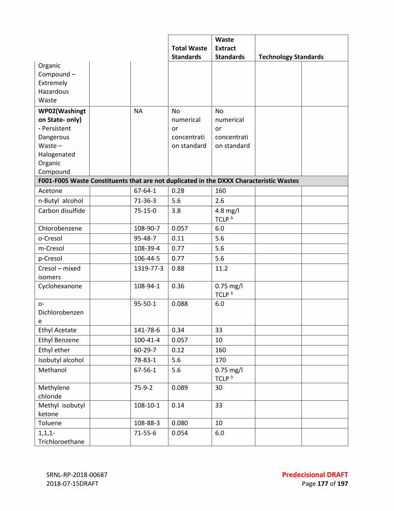
SRNL-RP-2018-00687 Predecisional DRAFT 2018-07-15DRAFT Page 177 of 197
Total Waste Standards
Waste Extract Standards Technology Standards
Organic Compound – Extremely Hazardous Waste WP02(Washington State- only) - Persistent Dangerous Waste – Halogenated Organic Compound
NA No numerical or concentration standard
No numerical or concentration standard
F001-F005 Waste Constituents that are not duplicated in the DXXX Characteristic Wastes Acetone 67-64-1 0.28 160 n-Butyl alcohol 71-36-3 5.6 2.6 Carbon disulfide 75-15-0 3.8 4.8 mg/l
TCLP b
Chlorobenzene 108-90-7 0.057 6.0 o-Cresol 95-48-7 0.11 5.6 m-Cresol 108-39-4 0.77 5.6 p-Cresol 106-44-5 0.77 5.6 Cresol – mixed isomers
1319-77-3 0.88 11.2
Cyclohexanone 108-94-1 0.36 0.75 mg/l TCLP b
o-Dichlorobenzene
95-50-1 0.088 6.0
Ethyl Acetate 141-78-6 0.34 33 Ethyl Benzene 100-41-4 0.057 10 Ethyl ether 60-29-7 0.12 160 Isobutyl alcohol 78-83-1 5.6 170 Methanol 67-56-1 5.6 0.75 mg/l
TCLP b
Methylene chloride
75-9-2 0.089 30
Methyl isobutyl ketone
108-10-1 0.14 33
Toluene 108-88-3 0.080 10 1,1,1-Trichloroethane
71-55-6 0.054 6.0

SRNL-RP-2018-00687 Predecisional DRAFT 2018-07-15DRAFT Page 178 of 197
Total Waste Standards
Waste Extract Standards Technology Standards
1,1,2-Trichloroethane
79-00-5 0.054 6.0
1,1,2-Trichloro-1,1,2- trifluoroethane
76-13-1 0.057 30
Trichloromonofluoromethane
75-69-4 0.020 30
Xylenes – mixed isomers
1330-20-7 0.32 30
2-Nitropropane c
79-46-9 (WETOX or CHOXD) fb CARBN or CMBST c
CMBST c
CMBST c
2-Ethoxyethanol d
110-80-5 BIODG; or CMBST d
CMBST d
CMBST d
UHCs that are not duplicated in characteristic or listed wastes 1,1,1,2-Tetrachloroethane
630-20-6 0.057 6.0
1,1,2,2-Tetrachloroethane
79-34-5 0.057 6.0
1,1-Dichloroethane
75-34-3 0.059 6.0
1,2,4-Trichlorobenzene
120-82-1 0.055 19
1,2-Dichloropropane
78-87-5 0.85 18
1 ,2-trans-Dichloroethene
156-60-5 0.054 30
1,3-Dichlorobenzene
541-73-1 0.036 6.0
1,4-Dichlorobenzene
106-46-7 0.090 6.0
l,4-Dioxane 123-91-1 12.0 170 2,3,4,6-Tetrachlorophenol
58-90-2 0.030 7.4
2,4,6-Trichlorophenol
88-06-2 0.035 7.4

SRNL-RP-2018-00687 Predecisional DRAFT 2018-07-15DRAFT Page 179 of 197
Total Waste Standards
Waste Extract Standards Technology Standards
2,4-Dichlorophenol
120-83-2 0.044 14
2-Chloronaphthalene
91-58-7 0.055 5.6
2-Chlorophenol 95-57-8 0.044 5.7 2-Methyl-2-propenenitrile
126-98-7 0.24 84
2-Nitrophenol 88-75-5 0.028 13 2-sec-Butyl-4,6- dinitrophenol (dinoseb)
88-85-7 0.066 2.5
3-Chloropropene
107-05-1 0.036 30
3-Methy1cholanthrene
56-49-5 0.0055 15
4-Bromophenylphenyl ether
101-55-3 0.055 15
4-Chloro-3-methy1pheno1
59-50-7 0.018 14
Acenaphthene 83-32-9 0.059 3.4 Acenaphthylene 208-96-8 0.059 3.4 Acetonitrile 75-05-8 5.6 38 Acetophenone 98-86-2 0.010 9.7 Acrolein 107-02-8 0.061 NA Acrylonitrile 107-13-1 0.24 84 Alpha-BHC 319-84-6 0.00014 0.066 Anthracene 120-12-7 0.059 3.4 Antimony 7440-36-0 1.9 1.15 mg/l
TCLP
Benzo( a )anthracene
56-55-3 0.059 3.4
Benzo( a)pyrene 50-32-8 0.061 3.4 Benzo(b) fluoranthene
205-99-2 0.11 6.8
Benzo(ghi)pery1ene
191-24-2 0.0055 1.8
Benzo(k)fluoranthene
207-08-9 0.11 6.8
Beryllium 7440-41-7 0.82 1.22 mg/l TCLP

SRNL-RP-2018-00687 Predecisional DRAFT 2018-07-15DRAFT Page 180 of 197
Total Waste Standards
Waste Extract Standards Technology Standards
Beta-BHC 319-85-7 0.00014 0.066 Bis(2-ethylhexyl) phthalate
117-81-7 0.28 28
Bromodichloromethane
75-27-4 0.35 15
Bromomethane 74-83-9 0.11 15 Butylbenzylphthalate
85-68-7 0.017 28
Chloroethane 75-00-3 0.27 6.0 Chloromethane 74-87-3 0.19 30 Cresols (total) – substituted for each cresols isomer
1319-77-3 0.11/0.77 5.6
Chrysene 218-01-9 0.059 3.4 cis-l,3-dichloropropene
10061-01-5
0.036 18
Cyanide (amenable)
57-12-5 0.86 30
Cyanide (total) 57-12-5 1.2 590 delta-BHC 319-86-8 0.023 0.066 Dibenz[ a,h] anthracene
53-70-3 0.055 8.2
Dibenz (a,e) pyrene
192-65-4 0.061 NA
Dichlorodifluoromethane
75-71-8 0.23 7.2
Diethyl phthalate
84-66-2 0.20 28
Di-n-butylphthalate
84-74-2 0.057 28
Di-n-octylphthalate
117-84-0 0.017 28
Ethylene dibromide
106-93-4 0.028 15
Fluoranthene 206-44-0 0.068 3.4 Fluorene 86-73-7 0.059 3.4 gamma-BHC (Lindane)
58-89-9 0.0017 0.066
Indeno( 1 ,2,3-cd)pyrene
193-39-5 0.0055 3.4
Isodrin 465-73-6 0.021 0.066
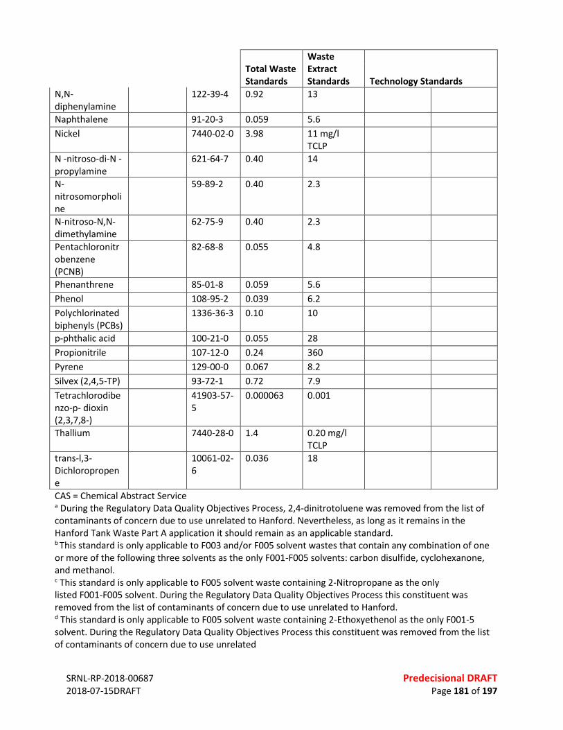
SRNL-RP-2018-00687 Predecisional DRAFT 2018-07-15DRAFT Page 181 of 197
Total Waste Standards
Waste Extract Standards Technology Standards
N,N-diphenylamine
122-39-4 0.92 13
Naphthalene 91-20-3 0.059 5.6 Nickel 7440-02-0 3.98 11 mg/l
TCLP
N -nitroso-di-N - propylamine
621-64-7 0.40 14
N-nitrosomorpholine
59-89-2 0.40 2.3
N-nitroso-N,N- dimethylamine
62-75-9 0.40 2.3
Pentachloronitrobenzene (PCNB)
82-68-8 0.055 4.8
Phenanthrene 85-01-8 0.059 5.6 Phenol 108-95-2 0.039 6.2 Polychlorinated biphenyls (PCBs)
1336-36-3 0.10 10
p-phthalic acid 100-21-0 0.055 28 Propionitrile 107-12-0 0.24 360 Pyrene 129-00-0 0.067 8.2 Silvex (2,4,5-TP) 93-72-1 0.72 7.9 Tetrachlorodibenzo-p- dioxin (2,3,7,8-)
41903-57-5
0.000063 0.001
Thallium 7440-28-0 1.4 0.20 mg/l TCLP
trans-l,3-Dichloropropene
10061-02-6
0.036 18
CAS = Chemical Abstract Service a During the Regulatory Data Quality Objectives Process, 2,4-dinitrotoluene was removed from the list of contaminants of concern due to use unrelated to Hanford. Nevertheless, as long as it remains in the Hanford Tank Waste Part A application it should remain as an applicable standard. b This standard is only applicable to F003 and/or F005 solvent wastes that contain any combination of one or more of the following three solvents as the only F001-F005 solvents: carbon disulfide, cyclohexanone, and methanol. c This standard is only applicable to F005 solvent waste containing 2-Nitropropane as the only listed F001-F005 solvent. During the Regulatory Data Quality Objectives Process this constituent was removed from the list of contaminants of concern due to use unrelated to Hanford. d This standard is only applicable to F005 solvent waste containing 2-Ethoxyethenol as the only F001-5 solvent. During the Regulatory Data Quality Objectives Process this constituent was removed from the list of contaminants of concern due to use unrelated

SRNL-RP-2018-00687 Predecisional DRAFT 2018-07-15DRAFT Page 182 of 197
REFERENCES Ref. 1 -- Resource Conservation and Recovery Act of 1976 (RCRA), U.S. Environmental Protection Agency, Washington, D.C. Ref. 2 -- WAC 173-303, “Dangerous Waste Regulations,” Washington Administrative Code, as amended. Ref 3 -- 40 CFR 61, “National Emission Standards for Hazardous Air Pollutants,” Code of Federal Regulations, as amended. Ref. 4 -- WAC 173-400, “General Regulations for Air Pollution Sources,” Washington Administrative Code, as amended. Ref. 5 -- WAC 173-460, “Controls for New Sources of Toxic Air Pollutants,” Washington Administrative Code, as amended. Ref. 6 -- WAC 246-247, “Radiation Protection – Air Emissions,” Washington Administrative Code, as amended. Ref. 7 -- 40 CFR 761, Polychlorinated Biphenyls (PCBs) Manufacturing, Processing, Distribution in Commerce, and Use Prohibitions. Ref. 8 -- DOE M 435.1-1, Chg 2, 2011, Radioactive Waste Management Manual, U.S. Department of Energy, Washington, D.C. Ref. 9 -- WA 7890008967, 2007, “Hanford Facility Dangerous Waste Permit,” Rev. 8C, State of Washington, Department of Ecology, Richland, Washington. Ref. 10 -- U.S. EPA, Region 10, Framework Agreement for Management of Polychlorinated Biphenyls (PCBs) in Hanford Tank Waste, August 31, 2000. Ref. 11 -- U. S. DOE, “Transmittal of Toxic Substance Control Act (TSCA) Risk-Based Disposal Application for the Double Shell Tank (DST) System for 2001,” January 15, 2002. Ref. 12 -- U.S. DOE, “Application for Risk-Based Disposal Approval for PCBs Hanford 200 Area Liquid Waste Processing Facilities”, February 28, 20002.
SRNL-RP-2018-00687 Predecisional DRAFT 2018-07-15DRAFT Page 183 of 197
APPENDIX K. EXPANDED DISCUSSION: FEED VECTOR K.1 SUMMARY The Hanford Waste Treatment and Immobilization Plant (WTP) is a complex of facilities4 designed to receive waste from the storage tanks and perform all pretreatment processes to prepare the waste for immobilization and then immobilize the waste in borosilicate glass5. A simplified diagram showing the tank farm, WTP, and other facilities required is shown in Figure K-1. The Supplemental Low Activity Waste (LAW) mission/scope is defined by the One System Integrated Flowsheet as immobilization of excess treated LAW supernate once the full capacity of the current LAW facility is exceeded. The excess supernate is generated because the amount of LAW supernate needed to transfer high level waste (HLW) to the WTP combined with the supernate generated during HLW pretreatment (washing and leaching operations) is greater than the capacity of the current LAW vitrification facility. If the WTP processing were adjusted to not exceed the LAW capacity, then HLW processing would be reduced and the overall mission length would be extended. The Supplemental LAW facility is expected to receive feed from two sources: the Low Activity Waste Pretreatment System (LAWPS) and the WTP Pretreatment (PT) facility. The feed vectors from each source have been estimated by the One System Integrated Flowsheet. The technology for immobilization has not been formally designated, but vitrification is assumed to be the baseline in the Integrated Flowsheet with grout considered as an option. Supplemental LAW is assumed to receive the LAW from the LAWPS and PT, immobilize the LAW, package and ship the waste to a disposal facility, and internally handle any secondary wastes that require treatment prior to disposal.

SRNL-RP-2018-00687 Predecisional DRAFT 2018-07-15DRAFT Page 184 of 197
Figure K-1. Simplified Flowsheet for Immobilization of Hanford Waste during Full WTP Operation
Green- Existing Facility Blue: Construction complete Orange: Construction in progress Brown - Design in progress Red- Future facility
Tank Waste Characterization
and St aging
'----r------·~ Slurry
Slurry \
Wash Solutions
Leach Solutions
.------+1 ~ Filtration
Receipt
'
Evaporation
s L u R R y
Supernate Filtered Supernate
Washed HLW Slurry
-
....
Process flows greatly simplified Dilute LAW feed can be sent to evaporation, not shown Evaporator condensate is sent to LERF/ETF, not shown for all evaporators Sol id secondary waste stream only shown for PT, applies to all facil ities
WTP- Pretreatment Facility Secondary Solid Wast e LDR
Treatment
I on Exchange
Cesium Eluate
Treated Supernate
.... M elter 14------+--------, .--------, Condensat e l
LERF/ETF
I I
l EMF
[ Evaporation
I I I I I ----.----
,
LAW Feed
1 I I •
WTP LAW
Vitrification ~-- ----000
000 M e Iter Condensate IIIII IIIII
Glass Containers o o o ~Superna_____,te
0 0 0 Tank Farms
000 Supernat e
WTP HLW
Vitrification
Glass , Canist ers
Offsite Repository
Cs Storage
Spent CST Columns
TF Tank
Supplemental LAW
Immobilized Waste
1---------------·
• Integrated Disposal ~ Facility
Low ActivityWaste Dashed Lines Represent DFLAW Processing Pret reatnAentSystem ~ ------------------------------------------------------------------------------------------------------
(or sinAilar TF t reatnAent)
_________________________________________________________________________________
SRNL-RP-2018-00687 Pre-Decisional DRAFT 2018-07-15DRAFT Page 185 of 197
K.2 PROCESSES FOR LAW IMMOBILIZATION AND SUPPLEMENTAL LAW IMMOBILIZATION K.2.1 Hanford Waste Background The Hanford site generated millions of gallons of radioactive waste during production of nuclear materials. A number of different chemical processes were used at Hanford to separate and purify plutonium, including the Bismuth Phosphate, REDuction and OXidation (REDOX), and Plutonium Uranium Extraction (PUREX) processes. In addition to the separation processes, cesium removal and other treatment processes were performed on the tank waste. As a result of the varied processes performed, the wastes stored at Hanford vary significantly in chemical and radionuclide content, although some incidental blending of the various wastes has occurred during storage1. The waste has been stored in 177 underground, carbon steel storage tanks. Many of these tanks are known to have developed leaks2; therefore, many tanks were treated to eliminate free liquid to the extent possible. The issues with the known leaks and the age of the storage tanks have led to restrictions on the type of processing allowed in the tank farms3. K.2.2 Baseline The Hanford Waste Treatment and Immobilization Plant (WTP) is a complex of facilities4 designed to receive waste from the storage tanks and perform all pretreatment processes to prepare the waste for immobilization and then immobilize the waste in borosilicate glass5. The tank waste will be separated into supernate and slurry in the tank farm by allowing solids to settle, then decanting supernate. Slurries will be transferred to a characterization facility to allow representative samples to be taken and any size reduction of the solids to be performed prior to transfer to the PT. Supernate from the tank farms will be transferred directly to PT or the LAWPS. In PT, the supernate is combined with evaporated recycle (the supernate can also be sent to evaporation), and then with the slurry. Filtration is performed to separate the solids from supernate; then the concentrated solids slurry is “washed” to reduce the amount of soluble species in the slurry and can be chemically leached to remove aluminum and chromium. The solids slurry (along with the cesium extracted from the supernate) is combined with glass-former chemicals and vitrified to form a borosilicate glass in the High Level Waste (HLW) facility. Canisters of the HLW will eventually be transferred to a geologic repository. Spent wash solutions are combined with the filtered supernate, while spent leach solutions are transferred to the evaporator and recycled to the receipt process. The filtered supernate is treated to remove cesium using an ion exchange process, then combined with melter condensate from the LAW vitrification facility. After concentration by evaporation, the treated supernate is transferred to the LAW facility for immobilization in borosilicate glass. When the amount of LAW supernate generated is greater than can be processed by the LAW facility, the excess is sent to Supplemental LAW for immobilization. It is currently estimated that approximately 2/3 of the treated supernate will be sent to Supplemental LAW. It should be noted that the excess supernate is generated as a result of processing sufficient HLW to operate the HLW vitrification facility at capacity as supernate is required to retrieve and transfer the HLW solids to WTP and additional supernate is generated during solids washing and leaching operations.
_________________________________________________________________________________
SRNL-RP-2018-00687 Pre-Decisional DRAFT 2018-07-15DRAFT Page 186 of 197
The LAW facility utilizes two melters with a capacity of 30 metric tons per day to immobilize the treated supernate in borosilicate glass. The glass containers generated will be sent to the Integrated Disposal Facility (IDF) on the Hanford site. The melter offgas system condenses the water evaporated by the melter and recycles the condensate along with any particulates scrubbed from the offgas stream back to PT. The tank farm is predicted to be able to supply more supernate than the PT can process during portions of the immobilization mission. This supernate is sent to the LAWPS facility to remove solids and cesium (using filtration and ion exchange similar to PT) with the treated supernate sent to Supplemental LAW. K.2.3 Direct Feed Options The LAWPS facility is expected to start operation prior to PT and will feed LAW vitrification until PT is started. Melter condensate will be handled by the Effluent Management Facility (not shown in Figure K-1) during direct feeding of LAW from the LAWPS. Other processing options considered in the baseline flowsheet include adding the capability to directly feed the HLW vitrification from the Tank Waste Characterization and Staging Facility6. Baseline Supplemental LAW Process A decision on the immobilization technology for Supplemental LAW has not been finalized; as stated in the Integrated Flowsheet, “the LAW supplemental treatment facility is assumed to be either a second LAW vitrification facility or a grout facility”6. The Integrated Flowsheet defines the function of Supplemental LAW as immobilization of excess treated LAW supernate after the capacity of the existing LAW facility is met. Preliminary estimates for immobilized waste volume are performed in the Integrated Flowsheet for both the vitrification and grout options. The Supplemental LAW facility has two feed vectors in the current baseline flowsheet: Leftover LAW from PT and additional feed from LAWPS7. Supplemental LAW is treated as a black box in the current flowsheet, meaning that no criteria have been set for minimum or maximum flow, etc. and that any material treated to the requirements for the LAW vitrification facility can be treated at Supplemental LAW. Supplemental LAW is also assumed to be a complete treatment facility with no returns of secondary waste to any WTP facility. Secondary liquid waste (condensate) is sent to the Liquid Effluent Retention Facility / Effluent Treatment Facility (LERF/ETF) while solid secondary waste is sent to treatment for land disposal (assumed to be encapsulation in grout with disposal at IDF) at the Land Disposal Restrictions (LDR) treatment facility. The immobilized waste from Supplemental LAW is assumed to be disposed at the IDF, but a final decision has not been made. The interfaces between Supplemental LAW and other facilities are described in Table K-1and shown in Figure K-2, based on the assumptions made in the One System Integrated Flowsheet6. These interfaces would change depending on the options chosen; for example, a grout facility would not be expected to generate a condensate stream to be treated at LERF/ETF. Table K-1. Supplemental LAW Interfaces
Stream Description
45 Treated LAW Feed to Supplemental LAW from PT 46 Treated LAW Feed to Supplemental LAW from LAWPS 47 Stack Exhaust from Supplemental LAW 48 Liquid secondary waste from Supplemental LAW to LERF/ETF 49 Immobilized LAW to IDF 79 Solid secondary waste to a facility to treat waste to permit disposal

_________________________________________________________________________________
SRNL-RP-2018-00687 Pre-Decisional DRAFT 2018-07-15DRAFT Page 187 of 197
Figure L-2. Supplemental LAW Detail: Interfaces K.2.4 Other Options Considered As stated above, a decision on the technology for Supplemental LAW has not been made, but vitrification using melters to generated containers of immobilized LAW waste is the assumed baseline technology with disposal at the IDF. Bulk vitrification has been evaluated in the past for LAW immobilization and is an option that will be evaluated during this review. Grout is also mentioned as an option in the Integrated Flowsheet and will be considered as an alternate to vitrification during this review. Steam reforming will also be considered as a treatment option. Additional options being considered during this review are to dispose the immobilized LAW at an offsite, commercial facility and options to directly treat individual tanks using a Tank Side Cesium Removal (TSCR) system to generate feed for Supplemental LAW. Offsite disposal includes sending the treated LAW supernate to a commercial vendor for immobilization and shipment to a commercial disposal facility or simply sending the immobilized product from an onsite immobilization facility to the commercial site. It is noted that treating individual tanks could lead to feed compositions to Supplemental LAW not bounded by feed vector from the Integrated Flowsheet, but it should be expected that tanks that would challenge the treatment technology would not be selected for individual treatment. Options not selected for additional consideration during this review include: • Immobilization of LAW into a hydroceramics8

_________________________________________________________________________________
SRNL-RP-2018-00687 Pre-Decisional DRAFT 2018-07-15DRAFT Page 188 of 197
• Vitrification into a non-borosilicate glass9 • Disposal of immobilized LAW at other DOE sites K.3 SUPPLEMENTAL LAW FEED VECTOR The Supplemental LAW feed vector 7 calculated for the One System River Protection Project Integrated Flowsheet 6 is being used in the evaluation of the feasibility of proposed Supplemental LAW processes. This feed vector represents any remaining LAW supernate generated by PT and LAWPS processes after the existing WTP LAW vitrification facility reaches maximum capacity with no constraints on volumetric flow. This feed vector represents the only current information available for the streams assumed to be processed through Supplemental LAW facility. The feed vector provided represents a single model run of the Integrated Flowsheet. The flowsheet is updated routinely by the One System Organization and calculates all process streams that will be generated during immobilization of Hanford tank wastes. The flowsheet includes the retrieval processes in the Hanford tank farms, processing through pretreatment facilities, and final waste form generation as well as estimates for secondary waste stream generation. The assumptions made during flowsheet model run (including tank farm retrieval sequencing, selection of feeds for LAWPS processing, etc.) significantly impact the results. In addition, the values in the feed vector represent monthly averages versus batch by batch processing. Therefore, while the Supplemental LAW feed vector is the best currently available, the actual waste processed through Supplemental LAW could be significantly different that the values shown. The varied methods used during the nuclear material separations processing at Hanford resulted in waste that varies significantly in composition. Typically, these varying waste types are segregated across the tank farms (although some incidental blending has occurred and will occur during retrieval) which can result in large swings in feed composition to the Supplemental LAW facility, as shown in Figure K-3, Figure K-4, Figure K-5, and Figure K-6. Thus, any Supplemental LAW process would have to accommodate the expected extremes in waste feed compositions as sufficient lag storage is not expected to be provided to smooth these peaks. These compositional extremes are further exacerbated by the differences in sodium concentrations in the feed to Supplemental LAW from the PT facility (~8M) versus the LAWPS facility (~5.6M) as well as the inclusion of the LAW vitrification facility recycles in the feed from PT. The feed from PT to the LAW facility is identical in composition to the stream feed to the LAW vitrification facility6 from PT in the Integrated Flowsheet.

_________________________________________________________________________________
SRNL-RP-2018-00687 Pre-Decisional DRAFT 2018-07-15DRAFT Page 189 of 197
Figure K-3. Sulfur to Sodium Ratio
Figure K-4. TOC Concentration
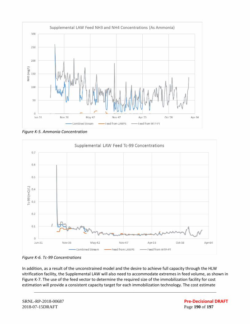
_________________________________________________________________________________
SRNL-RP-2018-00687 Pre-Decisional DRAFT 2018-07-15DRAFT Page 190 of 197
Figure K-5. Ammonia Concentration
Figure K-6. Tc-99 Concentrations In addition, as a result of the unconstrained model and the desire to achieve full capacity through the HLW vitrification facility, the Supplemental LAW will also need to accommodate extremes in feed volume, as shown in Figure K-7. The use of the feed vector to determine the required size of the immobilization facility for cost estimation will provide a consistent capacity target for each immobilization technology. The cost estimate
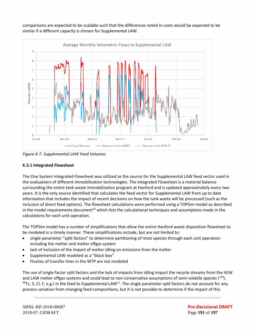
_________________________________________________________________________________
SRNL-RP-2018-00687 Pre-Decisional DRAFT 2018-07-15DRAFT Page 191 of 197
comparisons are expected to be scalable such that the differences noted in costs would be expected to be similar if a different capacity is chosen for Supplemental LAW.
Figure K-7. Supplemental LAW Feed Volumes K.3.1 Integrated Flowsheet The One System Integrated Flowsheet was utilized as the source for the Supplemental LAW feed vector used in the evaluations of different immobilization technologies. The Integrated Flowsheet is a material balance surrounding the entire tank waste immobilization program at Hanford and is updated approximately every two years. It is the only source identified that calculates the feed vector for Supplemental LAW from up to date information that includes the impact of recent decisions on how the tank waste will be processed (such as the inclusion of direct feed options). The flowsheet calculations were performed using a TOPSim model as described in the model requirements document10 which lists the calculational techniques and assumptions made in the calculations for each unit operation. The TOPSim model has a number of simplifications that allow the entire Hanford waste disposition flowsheet to be modeled in a timely manner. These simplifications include, but are not limited to: • single parameter “split factors” to determine partitioning of most species through each unit operation
including the melter and melter offgas system • lack of inclusion of the impact of melter idling on emissions from the melter • Supplemental LAW modeled as a “black box” • Flushes of transfer lines in the WTP are not modeled The use of single factor split factors and the lack of impacts from idling impact the recycle streams from the HLW and LAW melter offgas systems and could lead to non-conservative assumptions of semi-volatile species (129I, 99Tc, S, Cl, F, e.g.) in the feed to Supplemental LAW11. The single parameter split factors do not account for any process variation from changing feed compositions, but it is not possible to determine if the impact of this

_________________________________________________________________________________
SRNL-RP-2018-00687 Pre-Decisional DRAFT 2018-07-15DRAFT Page 192 of 197
simplification would be conservative or non-conservative. The lack of flush water additions in WTP in the model primarily reduces the estimated amounts of secondary waste generated from LAW and Supplemental LAW processing, but additional impacts could occur if the diluted feed results in different partitioning than assumed. It should also be noted that the retrieval sequence and processing assumptions (direct feed option timing and processing amount, e.g.) impact the amount of feed processed through Supplemental LAW as well as the composition. As with the split factor assumptions, it is not possible to state whether the current estimates are conservative or non-conservative. An additional consideration for using the feed vector is that it could be possible to generate an integrated flowsheet that performs acceptably with some constraints placed on Supplemental LAW feeds to prevent the most extreme conditions noted in the current feed vector. Thus, a proposed flowsheet should not be automatically eliminated from consideration if a small set of conditions noted in the current vector are outside the ranges possible with the flowsheet. K.4 CONCLUSIONS The feed vector provided by WRPS is the best information available and has been used to perform the assessment of proposed flowsheets for supplemental LAW disposition. The capacity of the Supplemental LAW facility should be based on the flowrates to Supplemental LAW in the feed vector. It is noted that the TOPSim model used contains simplifications that may result in non-conservative values for selected species. In addition, some of the peaks in the data may be avoidable by a different retrieval/staging strategy than utilized in the case prepared for the Integrated Flowsheet. In addition, treatment of individual tanks with at-tank treatment could also generate treated LAW that is not bounded by the feed vector. Acronyms
REDOX REDuction and OXidation PUREX Plutonium Uranium Extraction WTP Hanford Waste Treatment and Immobilization Plant PT PreTreatment Facility LAW Low Activity Waste HLW High Level Waste LERF/ETF Liquid Effluent Retention Facility / Effluent Treatment Facility LAWPS Low Activity Waste Pretreatment Facility IDF Integrated Disposal Facility LDR Land Disposal Restrictions
REFERENCES 1. Agnew, S.F.; J. Boyer, R.A. Corbun, T.B. Duran, J.R. FitzPatrick, T.P. Ortiz, and B.L. Young, “Hanford Tank
Chemical and Radionuclide Inventories: HDW Model Rev. 4,” Los Alamos National Laboratory, Los Alamos, New Mexico, LA-UR-96-3860, 1997.
2. Gephart, R.E. “A Short History of Hanford Tank Waste Generation, Storage, and Release,” Pacific
Northwest National Laboratory, Richland, Washington, PNNL-13605, Rev. 4, 2003. 3. Smith, R.D. “Tank Farms Documented Safety Analysis,” Washington River Protection Solutions, Richland,
Washington, RPP-13033, Revision 7-G, 2017.

_________________________________________________________________________________
SRNL-RP-2018-00687 Pre-Decisional DRAFT 2018-07-15DRAFT Page 193 of 197
4. Deng, Y.; B. Slettene, R. Fundak, R.C. Chen, M.R. Gross, R. Gimpel, and K. Jun, “Flowsheets Bases,
Assumptions, and Requirements,” Bechtel National, Inc. River Protection Project. Waste Treatment Plant, Richland, Washington, 24590-WTP-RPT-PT-02-005, Rev 8, 2016.
5. “River Protection Project System Plan,” U.S. Department of Energy: Office of River Protection, Richland,
Washington, ORP-11242, Rev 8, 2017. 6. Cree, L.W.; J.M. Colby, M.S. Fountain, D.W. Nelson, V.C. Nguyen, K.A. Anderson, M.D. Britton, S. Paudel,
and M.E. Stone, “One System River Protection Project Integrated Flowsheet, RPP-RPT-57991, Rev 2, 24590-WTP-RPT-MGT-14-023, Rev. 2,” Washington River Protection Solutions (WRPS) One System, Richland, Washington, 2017.
7. Cree, L.H. “Email from Laura Cree to Michael E Stone: Re: Some Pending Requests for Help, ” (2017)
Accessed on: Available at 8. Bao, Y.; M.W. Grutzeck, and C.M. Jantzen, “Preparation and Properties of Hydroceramic Waste Forms
Made with Simulated Hanford Low Activity Waste,” American Ceramic Society, 88 [12] 3287 - 302 (2005).
9. Kim, D.S.; W.C. Buchmiller, M.J. Schweiger, J.D. Vienna, D.E. Day, C.W. Kim, D. Zhu, T.E. Day, T. Neidt,
D.K. Peeler, T.B. Edwards, I.A. Reamer, and R.J. Workman, “Iron Phosphate Glass as an Alternative Waste-Form for Hanford LAW,” Pacific Northwest National Laboratory, Richland, Washington, PNNL-14251, 2003.
10. Schubick, A.M.; J.K. Bernards, N.M. Kirch, S.D. Reaksecker, E.B. West, L.M. Bergmann, and S.N. Tilanus,
“Topsim V2.1 Model Requirements, RPP-RPT-59470, Rev 1.,” Washington River Protection Solutions, Richland, Washington, 2016.
11. Gimpel, R.F. “DFLAW Sensitivity Studies for Melter Idling Impacts, 24590-WTP-MRR-PENG-16-004, Rev
0,” Bechtel National Incorporated, River Protection Project Waste Treatment Plant, Richland, WA, 2016.

_________________________________________________________________________________
SRNL-RP-2018-00687 Pre-Decisional DRAFT 2018-07-15DRAFT Page 194 of 197
APPENDIX L. BIBLIOGRAPHY “About Risk Assessment.” Risk Assessment. United States Environmental Protection Agency.
https://www.epa.gov/risk/about-risk-assessment#whatisrisk. Web. 17 January 2018. Agnew, S.F.; J. Boyer, R.A. Corbun, T.B. Duran, J.R. FitzPatrick, T.P. Ortiz, and B.L. Young. “Hanford Tank Chemical
and Radionuclide Inventories: HDW Model Rev. 4.” LA-UR-96-3860. January 1997. Los Alamos National Laboratory. Los Alamos, New Mexico.
A Guide to the Project Management Body of Knowledge (PMBOK® Guide) – Fifth Edition. 2013. Project Management Institute Inc.
American Coal Ash Association (ACCA), “2016 Coal Combustion Product (CCP) Production & Use Survey: Results”, 2016a. (https://www.acaa-usa.org/Portals/9/Files/PDFs/2016-Survey-Results.pdf)
American Coal Ash Association (ACCA), “2016 Coal Combustion Product (CCP) Production & Use Survey: Use Charts”, 2016b. (https://www.acaa-usa.org/Portals/9/Files/PDFs/2016-Charts.pdf)
“Analysis of Approaches for Supplemental Treatment of Low Activity Waste at Hanford Nuclear Reservation.” National Defense Authorization Act for Fiscal Year 2017. January 4, 2016. Section 3134.
Arm, S. T.; R.D. Claghorn, J.M. Colby, L.H. Cree, M.F. Fountain, D.W. Nelson, V.C. Nguyen, R.M. Russel, and M.E. Stone, “One System River Protection Project Integrated Flowsheet, RPP-RPT-57991, Rev. 1,” Office of River Protection One System, Richland, WA, 2015.
Asmussen, R. M.; C. I. Pearce, B. W. Miller, A. R. Lawter, J. J. Neeway, W. W. Lukens, M. E. Bowden, M. A. Miller, E. C. Buck, R. J. Serne, N. P. Qafoku. “Getters for improved technetium containment in cementitious waste forms.” Journal of Hazardous Materials. 341:238–247. 2018.
ASTM International (ASTM), C618-17a, “Standard Specification for Coal Fly Ash and Raw or Calcined Natural Pozzolan for Use in Concrete”.
Bacon, D. H.; B. P. McGrail, “Waste form release calculations for the 2005 Integrated Disposal Facility performance assessment” Pacific Northwest National Laboratory, Richland, Washington, PNNL-15198, 2005.
Baker, J. R. “Supplemental Treatment Project Immobilization System Feed Composition - Revision 0,” AEM Consulting, Richland, Washington, SVF-2007, 2010.
Bao, Y.; M.W. Grutzeck and C.M. Jantzen. “Preparation and Properties of Hydroceramic Waste Forms Made with Simulated Hanford Low Activity Waste.” Journal of the American Ceramic Society. Volume 88, Issue12. December 2005. Pages 3287-3302.
Belsher, J.D.; R.D. Adams and K.L. Pierson. “Hanford Tank Waste Operations Simulator (HTWOS) Sensitivity Study.” RPP-RPT-51819. Rev 0. 2012. Washington River Protection Solutions. Richland, Washington.
Brouns, T,; M. Lerchen, G. B. Mellinger, L. M. Bagaasen, “Preliminary assessment of supplemental grout and glass waste forms for disposal of low-activity waste.” PNNL-14280. 2003. Pacific Northwest National Laboratory. Richland, Washington.
Brown, C. F.; J. H. Westsik, Jr., R. J. Serne, B. M. Rapko, W. R. Wilmarth, D. J. McCabe, C. A. Nash, A. D. Cozzi, K. M. Fox. "Preliminary assessment of the low-temperature waste form technology coupled with technetium removal." PNNL-22103/SRNL-STI-2013-00002. 2014. Pacific Northwest National Laboratory/Savannah River National Laboratory.
Cantrell, K. J.; J. H. Westsik, Jr., R. J. Serne, W. Um, A. D. Cozzi. "Secondary Waste Cementitious Waste Form Data Package for the Integrated Disposal Facility Performance Assessment." PNNL-25194/RPT-SWCS-006. Rev. 0. 2016. Pacific Northwest National Laboratory. Richland, Washington.
Cercy, M.J.; D.K. Peeler and M.E. Stone. “SRS Sludge Batch Qualification and Processing: Historical Perspective and Lessons Learned.” SRNL-STI-2013-00585. 2013. Savannah River National Laboratory. Aiken, South Carolina.
“Conditioning of low and intermediate level liquid, solidified and solid waste.” 2018 (in press). International Atomic Energy Agency. Vienna, Austria.
_________________________________________________________________________________
SRNL-RP-2018-00687 Pre-Decisional DRAFT 2018-07-15DRAFT Page 195 of 197
Cree, L.H. “Re: Some Pending Requests for Help. ” Email from Laura Cree to Michael E Stone. 2017. Accessed on: Available at
Cree, L.W.; J.M. Colby, M.S. Fountain, D.W. Nelson, V.C. Nguyen, K.A. Anderson, M.D. Britton, S. Paudel, and M.E. Stone. “One System River Protection Project Integrated Flowsheet.” RPP-RPT-57991, Rev 2/24590-WTP-RPT-MGT-14-023, Rev. 2. 2017. Washington River Protection Solutions (WRPS) One System. Richland, Washington.
Deng, Y.; B. Slettene, R. Fundak, R.C. Chen, M.R. Gross, R. Gimpel, and K. Jun. “Flowsheets Bases, Assumptions, and Requirements.” 24590-WTP-RPT-PT-02-005. Rev 8. 2016. Bechtel National, Inc. River Protection Project. Waste Treatment Plant. Richland, Washington.
“EM National Laboratory Network Charter.” May 2017. “Federally Funded Research and Development Centers.” 48 CFR 35.017. October 1, 2005. United States Code of
Federal Regulations. Gephart, R.E. “A Short History of Hanford Tank Waste Generation, Storage, and Release.” PNNL-13605. Rev. 4.
2003. Pacific Northwest National Laboratory. Richland, Washington. “GAO, DOE and NNSA Project Management: Analysis of Alternatives Could be Improved by Incorporating Best
Practices.” GAO-15-37. 2014. U.S. Government Accountability Office. Gimpel, R. F. “DFLAW Sensitivity Studies for Melter Idling Impacts.” 24590-WTP-MRR-PENG-16-004. Rev 0. 2016.
Bechtel National Incorporated. River Protection Project. Waste Treatment Plant. Richland, WA. Smith, R. D. “Tank Farms Documented Safety Analysis.” RPP-13033. Revision 7-G. 2017. Washington River
Protection Solutions. Richland, Washington. Kim, D. S.; W. C. Buchmiller, M. J. Schweiger, J. D. Vienna, D. E. Day, C. W. Kim, D. Zhu, T. E. Day, T. Neidt, D. K.
Peeler, T. B. Edwards, I. A. Reamer, and R. J. Workman. “Iron Phosphate Glass as an Alternative Waste-Form for Hanford LAW.” PNNL-14251. 2003. Pacific Northwest National Laboratory. Richland, Washington.
Langton, C. A.. "Technetium Oxidation in Slag-Based Sodium Salt Waste Forms Exposed to Water and Moist Hanford Soil" Revision 0. SRNL-STI-2014-00399. 2014 Savannah River National Laboratory.
Lockrem, L. L. “Hanford containerized Cast Stone facility task 1—Process testing and development final report.” RPP-RPT-26742. Revision 0. 2005.
“LFRG DOE Order 435.1.” Office of Environmental Management. U.S. Department of Energy. Undated. https://www.energy.gov/em/lfrg-doe-order-4351. Web. 17 January 2018.
Mann, F. M.; R. J. Puigh, R. Khaleel, S. Finfrock, B. P. McGrail, D. H. Bacon, and R. J. Serne. "Risk assessment supporting the decision on the initial selection of supplemental ILAW technologies." RPP-17675. Rev. 0. 2003. CH2M HILL Hanford Group Inc. Richland, Washington.
Mattigod, S. V.; J. H. Westsik, Jr., C. W. Chung, M. J. Lindberg, M. J. Lindberg. "Waste Acceptance Testing of Secondary Waste Forms: Cast Stone, Ceramicrete and DuraLith." PNNL-20632, 2011. Pacific Northwest National Laboratory. Richland, Washington.
“Mineral Commodities Summaries 2017.” 2017. United States Geological Survey (USGS). U.S. Department of the Interior. Washington, DC. (https://minerals.usgs.gov/minerals/pubs/mcs/2017/mcs2017.pdf)
Minwalla, H. J. "Cast stone technology for the treatment and immobilization of low activity waste." RPP-49062. Rev. 0. 2011. Washington River Protection Solutions, LLC. Richland, Washington.
Muller, A. C. A. “Characterization of porosity & C-S-H in cement pastes by 1H NMR.” Thesis #6339, 2014. École Polytechnique Fédérale de Lausanne.
Qafoku, N. P.; J. J. Neeway, A. R. Lawter, T. G. Levitskaia, R. J. Serne, J. H. Westsik, Jr., M. M. Valenta Snyder. “Technetium and iodine getters to improve cast stone performance.” PNNL-23282. 2014. Pacific Northwest National Laboratory. Richland, Washington.
Peterson, R.A. “Transmittal of Summary for Waste-3 Best Basis Inventory Data Quality and Uncertainty Work Scope.” LTR-EMSP-0105. 2016. Pacific Northwest National Laboratory. Richland, Washington.

_________________________________________________________________________________
SRNL-RP-2018-00687 Pre-Decisional DRAFT 2018-07-15DRAFT Page 196 of 197
Pierson, K. L. “Evaluation of the HTWOS Integrated Solubility Model Predictions.” RPP-RPT-53089. 2012. Washington River Protection Solutions. Richland, Washington.
“Program Plan for Analysis of Approaches for Supplemental Treatment of Low-Activity Waste at the Hanford Nuclear Reservation.” SRNL-RP-2017-00242. June 2017.
“River Protection Project System Plan.” ORP-11242. Rev 8. 2017. U.S. Department of Energy Office of River Protection. Richland, Washington.
“Risk Assessment.” English – Oxford Living Dictionaries. Oxford University Press. Undated. https://en.oxforddictionaries.com/definition/risk_assessment. Web. 17 January 2018.
Saaty, Thomas L. “A Scaling Method for Priorities in Hierarchical Structures.” Journal of Mathematical Psychology. 15:234 281. 1977
Schubick, A.M.; J.K. Bernards, N.M. Kirch, S.D. Reaksecker, E.B. West, L.M. Bergmann, and S.N. Tilanus. “Topsim V2.1 Model Requirements.” RPP-RPT-59470. Rev 1. 2016. Washington River Protection Solutions. Richland, Washington.
Serne, R. J.; D. C. Lanigan, JH Westsik, Jr., B. D. Williams, H. B. Jung, G. Wang. "Extended leach testing of simulated LAW cast stone monoliths." PNNL-24297. Rev. 1/ RPT-SWCS-010, Rev. 0, 2016. Pacific Northwest National Laboratory, Richland, Washington,
Serne, R. J., and J. H. Westik, Jr. "Data package for secondary waste form down-selection—Cast stone." PNNL-20706. 2011. Pacific Northwest National Laboratory, Richland, Washington.
Simner, S.; F. Coutelot, H. Chang, J. Seaman. "Technetium leaching from cementitious materials.” MRS Advances, 2:717–722. 2017.
Sundaram, S. K.; K. E. Parker, M. E. Valenta, S. G. Pitman, J. Chun, C. -W. Chung, M. L. Kimura, C. A. Burns, W. Um, J. H. Westsik, Jr. "Secondary Waste Form Development and Optimization— Cast Stone." PNNL-20159. Rev. 1. 2011. Pacific Northwest National Laboratory. Richland, Washington.
Swanberg, D. J.; A.D. Cozzi, W.E. Daniel, R.E. Eibling, E.K. Hansen, M.M. Reigel, J. Westik, J.H., G.F. Piepel, M.J. Lindberg, P.G. Heasler, T.M. Mercier, and R.L. Russell, “Supplemental Immobilization of Hanford Low-Activity Waste: Cast Stone Screening Tests,” Washington River Protection Solutions, LLC., Richland, Washington, RPP-RPT-55960, Revision 0, 2013.
Um, W.; B.D. Williams, M. M. V. Snyder, G. Wang. "Liquid Secondary Waste Grout Formulation and Preliminary Waste Form Qualification." PNNL-25129/RPT-SWCS-005, Rev 0, 2016. Pacific Northwest National Laboratory. Richland, Washington.
Westsik, J. H., Jr.; G. F. Piepel, M. J. Lindberg, P. G. Heasler, T. M. Mercier, R. L. Russell, A. D. Cozzi, W. E. Daniel, R. E. Eibling, E. K. Hansen, M. M. Reigel, D. J. Swanberg. "Supplemental Immobilization of Hanford Low-Activity Waste: Cast Stone Screening Tests." PNNL-22747/SRNL-STI-2013-00465. 2013a. Pacific Northwest National Laboratory/Savannah River National Laboratory.
Westsik, J. H., Jr.; R. J. Serne, E. M. Pierce, A. D. Cozzi, C. Chung, D. J. Swanberg, “Supplemental immobilization cast stone technology development and waste form qualification testing plan.” PNNL-21823. Rev. 1. 2013b. Pacific Northwest National Laboratory.
Wu, X.; W. Jiang, D. M. Roy. “Early activation and properties of slag cement.” Cement and Concrete Research. 20:961–974, 1990.
_________________________________________________________________________________
SRNL-RP-2018-00687 Pre-Decisional DRAFT 2018-07-15DRAFT Page 197 of 197
ATTACHMENT 1. TEAM BIOs To be added to final report. ATTACHMENT 2. NATIONAL DEFENSE AUTHORIZATION ACT FOR FISCAL YEAR 2017, SECTION 3134, “ANALYSIS OF APPROACHES FOR SUPPLEMENTAL TREATMENT OF LOW-ACTIVITY WASTE AT HANFORD NUCLEAR RESERVATION” To be added to final report. ATTACHMENT 3. PROGRAM PLAN FOR ANALYSIS OF APPROACHES TO SUPPLEMENTAL TREATMENT OF LOW-ACTIVITY WASTE AT THE HANFORD NUCLEAR RESERVATION To be added to final report.
Related Documents