Welcome message from author
This document is posted to help you gain knowledge. Please leave a comment to let me know what you think about it! Share it to your friends and learn new things together.
Transcript
2017 Body Builder Manual
Body Builder’s Manual
Contents
Figures .................................................................................................................................................................................................................................................................... iii
Tables ....................................................................................................................................................................................................................................................................... v
Abbreviations....................................................................................................................................................................................................................................................... vi
Section1 Introduction
Section2Safety&Compliance SAFETY SIGNALS 2-1
FEDERAL MOTOR VEHICLE SAFETY STANDARDS COMPLIANCE 2-2
Incomplete Vehicle Certification ........................................................................................... 2-2
Noise and Emissions Requirements ...................................................................................... 2-3
Section3 Dimensions FRAME HEIGHT 3-1
TURNING RADIUS 3-2
CAB TILT 3-3
Model 220 W/19.5 Tires ....................................................................................................... 3-3
Model 220 W/22.5 Tires ....................................................................................................... 3-3
OVERALL DIMENSIONS 3-4
Side View - Model 220 ......................................................................................................... 3-4
Front and Rear Views — Model 220 ..................................................................................... 3-7
DETAIL VIEWS3-10
Left side: Chassis Heights – Model 220 ............................................................................ 3-10
Components Locations –Model 220 ....................................................................................... 3-12
Crossmember Locations—Model 220 ................................................................................ 3-14
Frame Rail Configurations ................................................................................................. 3-16
Battery Box, Fuel Tanks and Air Tanks — Model 220 ...................................................... 3-17
Exhaust Canister Locations –Model 220 ............................................................................ 3-18
Side View – Model 220 clear rail package ......................................................................... 3-19
Reyco 79KB Single Rear Axle Hendrickson HAS Single Rear Axle ............................. 3-20
TIRE DATA 3-20
FRAME AND CAB RELATED HEIGHTS 3-20
GROUND CLEARANCES 3-20
PTO CLEARANCES 3-21
Section4Exhaust & Aftertreatment EXHAUST AND AFTERTREATMENT INFORMATION 4-1
General Guidelines for DEF System ..................................................................................... 4-3
Installation Requirements and Dimensions for DEF System ................................................. 4-3
Measurement Reference Points ............................................................................................. 4-4
Routing to the Dosing Module (Injector) .............................................................................. 4-5
GENERAL EXHAUST INFORMATION 4-6
Section5 Frame layouts And Bodymounting FRAME LAYOUTS 5-1
Visual Index .......................................................................................................................... 5-1
CRITICAL CLEARANCES 5-4
Rear Wheels and Cab ............................................................................................................ 5-4
Body Mounting Using Brackets ............................................................................................ 5-5
Frame Sill .............................................................................................................................. 5-5
Brackets ................................................................................................................................. 5-6
Mounting Holes ..................................................................................................................... 5-6
Frame Drilling ....................................................................................................................... 5-7
Hole Location Guidelines ...................................................................................................... 5-7
BODY MOUNTING USING U–BOLTS 5-7
Spacers .................................................................................................................................. 5-7
REAR BODY MOUNT 5-9
i
Body Builder’s Manual
Contents
Section6 Frame Modifications FRAME MODIFICATIONS 6-1
Introduction ..................................................................................................................................... .6-1
DRILLING RAILS .......................................................................................................................................... 6-1
MODIFYING FRAME LENGTH ................................................................................................................... 6-1
CHANGING WHEELBASE ........................................................................................................................... 6-1
CROSSMEMBERS ......................................................................................................................................... 6-2
TORQUE REQUIREMENTS ......................................................................................................................... 6-3
Section7 Electrical ELECTRICAL INTRODUCTION .................................................................................................................. 7-1
ELECTRICAL CIRCUITS .............................................................................................................................. 7-1
Capacity........................................................................................................................................... .7-1
Data Bus Communication ............................................................................................................... 7-2
CAB/CHASSIS INTERFACE 7-3
The EJB (Electrical Junction Box) .................................................................................................. .7-3
CONTROLLERS 7-6
DASH CONTROLS 7-7
MODEL 220 PTO WIRING INFORMATION 7-11
Appendix A Vehicle Identification VEHICLE IDENTIFICATION NUMBER ..................................................................................................... A-1
VIN Location .................................................................................................................................. A-1
Chassis Number Locations .............................................................................................................. A-1
CERTIFICATION LABELS ............................................................................................................................ A-2
Components and Weights Label ...................................................................................................... A-2
Tire/Rim and Weight Rating Data Label ......................................................................................... A-2
Incomplete Vehicle Certification Label ........................................................................................... A-2
COMPONENT IDENTIFICATION ................................................................................................................ A-3
Engine Identification ....................................................................................................................... A-3
Transmission Identification ............................................................................................................. A-4
Front Axle Identification ................................................................................................................. A-4
Rear Axle Identification .................................................................................................................. A-4
Appendix B Weight Distribution INTRODUCTION ........................................................................................................................................... B-1
Abbreviations .................................................................................................................................. B-1
CALCULATIONS .......................................................................................................................................... B-2
Weight Distribution without Body .................................................................................................. B-2
Weight Distribution with Body ....................................................................................................... B-4
Chassis Weights .............................................................................................................................. B-4
Weight Distribution Analysis .......................................................................................................... B-8
Body Length .................................................................................................................................... B-8
ii
Figures
Figure 2-1 Incomplete Vehicle Certification Document ........................................................................................ 2-2
Figure 2-2 Locations of Certification Labels – Driver’s Door & Frame ............................................................... 2-2
Figure 3-1.1 Side View —Model 220 W/19.5 Tires Cab tilt Height and Pivot location Measurement ................ 3-3
Figure 3-1.2 Side View —Model 220 W/22.5 Tires Cab tilt Height and Pivot location Measurement ................ 3-3
Figure 3-2.1 Side View —Model 220 W/19.5 Tires Height and Length Measurement ......................................... 3-4
Figure 3-2.2 Side View —Model 220 W/19.5 Tires Height and Length Measurement ......................................... 3-6
Figure 3-3.1 Front & Rear View —Model 220 ..................................................................................................... 3-7
Figure 3-3.2 Model 220 Laden 22.5 Tires Front view: Width & Ground clearance Measurements: inches(mm) 3-8
Figure 3-3.3 Model 220 Laden 19.5 Tires Front view: Width & Ground clearance Measurements: inches(mm) 3-8
Figure 3-3.4 Model 220 Laden Rear view: Width & Ground clearance Measurements: inches(mm) .................... 3-9
Figure 3-4.1 Cab Floor: Side View, Left Side w/ 19.5 Tires ................................................................................. 3-10
Figure 3-4.2 Cab Floor: Side View, Left Side w/ 22.5 Tires ................................................................................. 3-11
Figure 3-5.1 Model 220 W/22.5 Tires, Battery Box, Fuel Tank, Air Tank, DEF Tank and Crossmember
Location Measured From Front Axle: inches (mm) .............................................................................. 3-12
Figure 3-5.2 Model 220 W/22.5 Tires, Battery Box, Dual Fuel Tanks, Air Tank, DEF Tank, and Crossmember
Location Measured From Front Axle: inches (mm) .............................................................................. 3-12
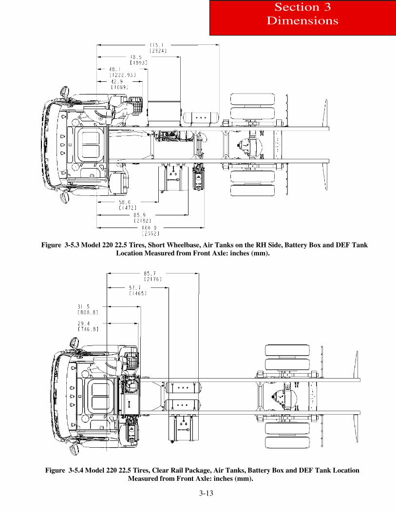
Figure 3-5.3 Model 220 W/22.5 Tires, Short wheelbase, Air tanks on RH side, Battery Box, Fuel Tanks,
DEF Tanks And Crossmember Location Measured From Front Axle: inches (mm) ........................... 3-13
Figure 3-5.4 Model 220 W/22.5 Tires, clear rail Package, Battery Box, Air Tank, Fuel tanks, DEF Tank,
And Crossmember Location Measured From Front Axle: inches (mm) .............................................. 3-13
Figure 3-6.1 Model 220 Crossmember Locations ................................................................................................ 3-14
Figure 3-6.2 Model 220 Crossmember Locations Measured from front Axle Centerline inches(mm) ................ 3-14
Figure 3-7 Model 220 Rail Measurements ............................................................................................................ 3-16
Figure 3-8 Model 220 Battery Box, Fuel Tank and Air Tanks Measurement mm (in) ........................................ 3-17
Figure 3-9.1 Model 220 Exhaust Measurements .................................................................................................. 3-18
Figure 3-9.2 Model 220 Exhaust Measurements .................................................................................................. 3-18
Figure 3-10.1 Side View - Model 220 CRP Laden Height and Length Measurement ........................................ 3-19
Figure 3-10.2 Model 220 Vertical Exhaust Measurements inches(mm) .............................................................. 3-19
Figure 3-11 Model 220 Reyco & Hendrickson Single Rear Axle Measurements ............................................... 3-20
Figure 3-12.1 PTO models installed on a 2000 Series Allison transmission ......................................................... 3-21
Figure 3-12.2 Model 220 PTO Clearances 1 of 2 .................................................................................................. 3-22
Figure 3-12.3 Model 220 PTO Clearances 2 of 2 .................................................................................................. 3-22
Figure 4-1.1 The DEF lines route to the after-treatment system ............................................................................. 4.1
Figure 4-1.2 The DEF lines route to the Engine Coolant ....................................................................................... 4.2
Figure 4-2 Measurement Location of DEF Supply Module (Pump) ...................................................................... 4-4
Figure 4-3 Measurement Location of DEF Dosing Module (Injector) ................................................................... 4-4
Figure 4-4 Orientation of Dosing Module .............................................................................................................. 4-5
Figure 4-5 Routing DEF Lines and DEF Trap ....................................................................................................... 4-5
Figure 4-6.1 Horizontal Exhaust Canister with Horizontal Tailpipe ....................................................................... 4-6
Figure 4-6.2 Top view of Horizontal Exhaust Canister with Horizontal Tailpipe .................................................... 4-6
Figure 4-6.3 Right view of Horizontal Exhaust Canister with Horizontal Tailpipe ................................................. 4-7
Figure 4-6.4 Back view of Horizontal Exhaust Canister with Horizontal Tailpipe ................................................. 4-7
Figure 4-7.1 Vertical Exhaust Canister with Horizontal Tailpipe ............................................................................ 4-8
Figure 4-7.2 Top view of Vertical Exhaust Canister with Horizontal Tailpipe ........................................................ 4-8
Figure 4-7.3 Right view of Vertical Exhaust Canister with Horizontal Tailpipe ...................................................... 4-9
Figure 4-7.4 Back view of Vertical Exhaust Canister with Horizontal Tailpipe ...................................................... 4-9
iii
Figures
Figure 5-1.1 Horizontal Exhaust Canister, RH horizontal tailpipe, LH BOC rectangular fuel tank, LH
BOC rectangular DEF tank and RH BOC battery box ........................................................................ 5-2
Figure 5-1.2 Horizontal Exhaust Canister, RH horizontal tailpipe, Duel BOC rectangular fuel tank,
LH BOC rectangular DEF tank and RH BOC battery box .................................................................. 5-2
Figure 5-1.3 Vertical Exhaust Canister, BOC Vertical tailpipe, LH BOC rectangular fuel tank, LH
BOC rectangular DEF tank and BOC battery box ............................................................................... 5-3
Figure 5-2 Minimum Clearance between Top Of Rear Tires And Body Structure Overhang ............................... 5-4
Figure 5-3 Minimum Back of Cab Clearance ........................................................................................................ 5-4
Figure 5-4 Spacer between Frame Sill and Body Rail - Rubber or Plastic ............................................................. 5-6
Figure 5-5. High Compression Spring between the Mounting Bolt and Upper Bracket ........................................ 5-6
Figure 5-6 Rubber Spacers between Brackets ........................................................................................................ 5-6
Figure 5-7 Hole Locations Guidelines for Frame Rail and Bracket ....................................................................... 5-6
Figure 5-8 Crossmember-Gusset Hole Pattern Requirements. [inches(mm)] ......................................................... 5-7
Figure 5-9 Acceptable U-Bolt Mounting with Wood and Fabricated Spacers ....................................................... 5-8
Figure 5-10 Clearance Space for Air Lines and Cables .......................................................................................... 5-8
Figure 5-11 Example of Fishplate Bracket at Rear End of Body, used with U-Bolts ............................................ 5-9
Figure 6-1 Wheelbase Customization ..................................................................................................................... 6-1
Figure 6-2 Crossmember Added When Distance Exceeds 60 Inches (1524 mm) .................................................. 6-2
Figure 7-1 Data Bus Communication Architecture ................................................................................................ 7-2
Figure 7-2.1 Electrical Junction Box Location....................................................................................................... 7-3
Figure 7-2.2 Inside View - Electrical Junction Box Location ................................................................................ 7-3
Figure 7-3 LF Euro 6 Cab Interface Names ........................................................................................................... 7-4
Figure 7-4 Controllers ............................................................................................................................................ 7-6
Figure 7-5.1 Dash Controls-1 ................................................................................................................................. 7-7
Figure 7-5.2 Dash Controls-2 ................................................................................................................................. 7-7
Figure 7-6.1 Power Distribution Center ................................................................................................................. 7-8
Figure 7-6.2 Power Distribution Center (Chassis) .................................................................................................. 7-9
Figure 7-7 Body Builder 9 Pin Connector ............................................................................................................ 7-10
Figure 7-8.1 Typical PTO Wiring for Euro 6 LFNA – 12V PTO Solenoid .......................................................... 7-12
Figure 7-8.2 Typical PTO Wiring for Euro 6 LFNA – 24V PTO Solenoid ......................................................... 7-13
Figure 7-9 A 12-pin Deutsch connector and remote PTO Controls ..................................................................... 7-14
Figure A-1 Vehicle Identification Number (VIN) ................................................................................................ A-1
Figure A-2 Drivers Door and Door Frame Label ................................................................................................. A-2
Figure A-3 Engine Identification Location ............................................................................................................ A-3
Figure A-4 Front Axle Identification .................................................................................................................... A-4
Figure A-5 Rear Axle Identification ...................................................................................................................... A-4
Figure B-1 Balanced Load: CGf 100 in. from front axle ...................................................................................... B-2
Figure B-2 Unbalanced Load: CGf 133 In. From Front Axle ............................................................................... B-3
Figure B-3 Balanced Body Unloaded: CGf 184.7 in. (4691.45 mm) from front axle .......................................... B-5
Figure B-4 Liftgate Example: CGf 322.2 in (8183.9 mm) from front axle ........................................................... B-5
Figure B-5. Balanced Body Loaded: CGf 184.7 in (4691.45 mm) from front axle……………………………...B-7
iv
Tables
Table: Abbreviations Used ...................................................................................................................................... vi
Table 3-1 Frame Height ........................................................................................................................................... 3-1
Table 3-2 Turning Radius ........................................................................................................................................ 3-2
Table 3-3 Cab Tilt Height ........................................................................................................................................ 3-3
Table 3-4 Cab Pivot Location .................................................................................................................................. 3-3
Table 3-5 Overall Dimensions ................................................................................................................................. 3-5
Table 3-6.1 Tires-Laden Ground clearance W/22.5 Tires ....................................................................................... 3-8
Table 3-6.2 Tires-Laden Ground clearance W/19.5 Tires ....................................................................................... 3-8
Table 3-7.1 Battery Box Step and Cab Floor Measurements w/ 19.5 Tires .......................................................... 3-10
Table 3-7.2 Battery Box Step and Cab Floor Measurements w/ 22.5 Tires .......................................................... 3-11
Table 3-8 Floor to Frame Measurements ............................................................................................................... 3-11
Table 3-9.1 Model 220 Crossmember Location Measured From Front Axle Centerline ...................................... 3-14
Table 3-9.2 Model 220 Crossmember Location Measured From Front Axle Centerline for Clear Rail Package . 3-15
Table 3-10 Frame Rail Strength Characteristics .................................................................................................... 3-16
Table 3-11 Model 220 Exhaust Location Measured From BOC inches (mm) ...................................................... 3-18
Table 3-12 Model 220 Exhaust Location Measured From BOC inches (mm) ...................................................... 3-18
Table 3-13 Model 220 Reyco & Hendrickson Single Rear Axle: Ride Height Measurement ............................... 3-20
Table 5-1 Symbols ................................................................................................................................................... 5-1
Table 6-1 Customary Grade 8 UNF or UNC ........................................................................................................... 6-3
Table 6-2 U.S. Customary – Grade 8 Metric Class 10.9 ......................................................................................... 6-3
Table 7-1 Additional Spare Circuits for Wiring ...................................................................................................... 7-9
Table 7.2 Body Builder 9 Pin Connector ............................................................................................................... 7-10
Table A-1. Model Year (Code) Designations ......................................................................................................... A-1
Table B-1. Model 220 Single Rear Axle “Bare” Chassis Tare Weights (no driver, no fuel) ................................. B-4
Table B-2.1. Model 220 Weight Distribution and Chassis Rating Calculation (sample) ....................................... B-7
Table B-3. Available Model 220 Body Lengths ..................................................................................................... B-9
v
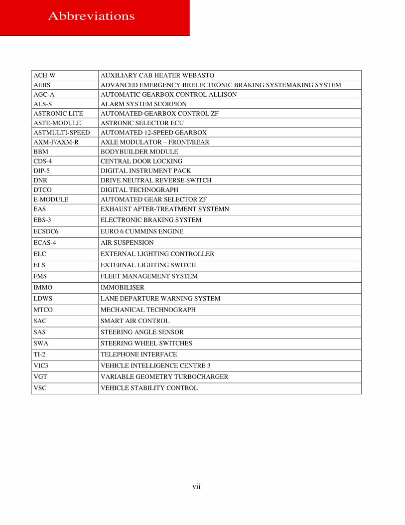
Abbreviations
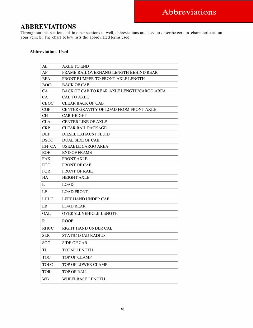
ABBREVIATIONS Throughout this section and in other sections as well, abbreviations are used to describe certain characteristics on your vehicle. The chart below lists the abbreviated terms used.
Abbreviations Used
vi
AE AXLE TO END
AF FRAME RAIL OVERHANG LENGTH BEHIND REAR
BFA FRONT BUMPER TO FRONT AXLE LENGTH
BOC BACK OF CAB
CA BACK OF CAB TO REAR AXLE LENGTH/CARGO AREA
CA CAB TO AXLE
CBOC CLEAR BACK OF CAB
CGF CENTER GRAVITY OF LOAD FROM FRONT AXLE
CH CAB HEIGHT
CLA CENTER LINE OF AXLE
CRP CLEAR RAIL PACKAGE
DEF DIESEL EXHAUST FLUID
DSOC DUAL SIDE OF CAB
EFF CA USEABLE CARGO AREA
EOF END OF FRAME
FAX FRONT AXLE
FOC FRONT OF CAB
FOR FRONT OF RAIL
HA HEIGHT AXLE
L LOAD
LF LOAD FRONT
LHUC LEFT HAND UNDER CAB
LR LOAD REAR
OAL OVERALL VEHICLE LENGTH
R ROOF
RHUC RIGHT HAND UNDER CAB
SLR STATIC LOAD RADIUS
SOC SIDE OF CAB
TL TOTAL LENGTH
TOC TOP OF CLAMP
TOLC TOP OF LOWER CLAMP
TOR TOP OF RAIL
WB WHEELBASE LENGTH
Abbreviations
vii
ACH-W AUXILIARY CAB HEATER WEBASTO
AEBS ADVANCED EMERGENCY BRELECTRONIC BRAKING SYSTEMAKING SYSTEM
AGC-A AUTOMATIC GEARBOX CONTROL ALLISON
ALS-S ALARM SYSTEM SCORPION
ASTRONIC LITE AUTOMATED GEARBOX CONTROL ZF
ASTE-MODULE ASTRONIC SELECTOR ECU
ASTMULTI-SPEED AUTOMATED 12-SPEED GEARBOX
AXM-F/AXM-R AXLE MODULATOR – FRONT/REAR
BBM BODYBUILDER MODULE
CDS-4 CENTRAL DOOR LOCKING
DIP-5 DIGITAL INSTRUMENT PACK
DNR DRIVE NEUTRAL REVERSE SWITCH
DTCO DIGITAL TECHNOGRAPH
E-MODULE AUTOMATED GEAR SELECTOR ZF
EAS EXHAUST AFTER-TREATMENT SYSTEMN
EBS-3 ELECTRONIC BRAKING SYSTEM
ECSDC6 EURO 6 CUMMINS ENGINE
ECAS-4 AIR SUSPENSION
ELC EXTERNAL LIGHTING CONTROLLER
ELS EXTERNAL LIGHTING SWITCH
FMS FLEET MANAGEMENT SYSTEM
IMMO IMMOBILISER
LDWS LANE DEPARTURE WARNING SYSTEM
MTCO MECHANICAL TECHNOGRAPH
SAC
SAS
SMART AIR CONTROL
SAS STEERING ANGLE SENSOR
SWA STEERING WHEEL SWITCHES
TI-2 TELEPHONE INTERFACE
VIC3 VEHICLE INTELLIGENCE CENTRE 3
VGT VARIABLE GEOMETRY TURBOCHARGER
VSC VEHICLE STABILITY CONTROL
1-1
Section 1
Introduction
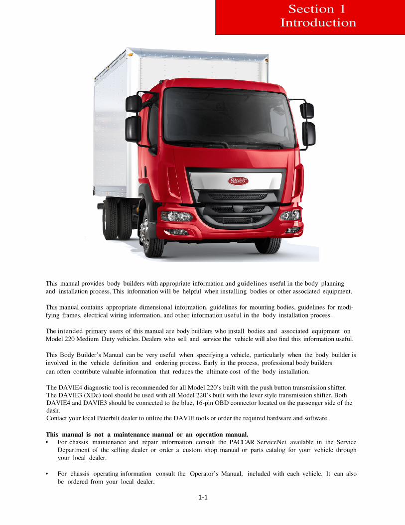
This manual provides body builders with appropriate information and guidelines useful in the body planning
and installation process. This information will be helpful when installing bodies or other associated equipment.
This manual contains appropriate dimensional information, guidelines for mounting bodies, guidelines for modi-
fying frames, electrical wiring information, and other information useful in the body installation process.
The intended primary users of this manual are body builders who install bodies and associated equipment on
Model 220 Medium Duty vehicles. Dealers who sell and service the vehicle will also find this information useful.
This Body Builder’s Manual can be very useful when specifying a vehicle, particularly when the body builder is
involved in the vehicle definition and ordering process. Early in the process, professional body builders
can often contribute valuable information that reduces the ultimate cost of the body installation.
The DAVIE4 diagnostic tool is recommended for all Model 220’s built with the push button transmission shifter.
The DAVIE3 (XDc) tool should be used with all Model 220’s built with the lever style transmission shifter. Both
DAVIE4 and DAVIE3 should be connected to the blue, 16-pin OBD connector located on the passenger side of the
dash.
Contact your local Peterbilt dealer to utilize the DAVIE tools or order the required hardware and software.
This manual is not a maintenance manual or an operation manual.
• For chassis maintenance and repair information consult the PACCAR ServiceNet available in the Service
Department of the selling dealer or order a custom shop manual or parts catalog for your vehicle through
your local dealer.
• For chassis operating information consult the Operator’s Manual, included with each vehicle. It can also
be ordered from your local dealer.
2-1
Section 2
Safety & Compliance
SAFETY SIGNALS
We have put a number of alerting messages in this book. Please read and follow them. They are there for your protection and information. These alerting messages can help you avoid injury to yourself or others and help prevent costly damage to the vehicle.
Key symbols and “signal words” are used to indicate what kind of message is going to follow. Pay special attention to
comments prefaced by “WARNING”, “CAUTION”, and “NOTE.” Please do not ignore an y of these alerts.
Warnings, Cautions, and Notes
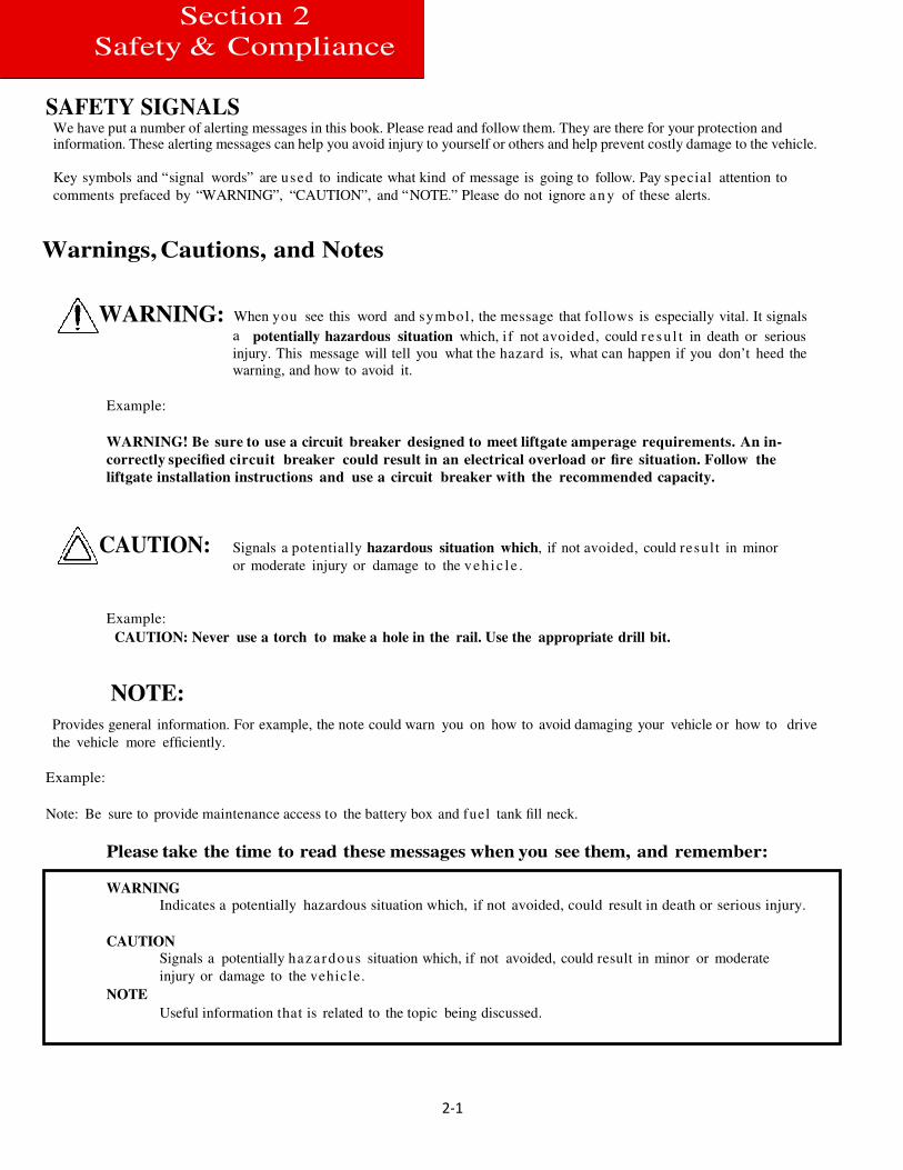
WARNING: When you see this word and symbol, the message that follows is especially vital. It signals
a potentially hazardous situation which, i f not avoided, could r e su l t in death or serious
injury. This message will tell you what the hazard is, what can happen if you don’t heed the
warning, and how to avoid it.
Example:
WARNING! Be sure to use a circuit breaker designed to meet liftgate amperage requirements. An in-
correctly specified circuit breaker could result in an electrical overload or fire situation. Follow the
liftgate installation instructions and use a circuit breaker with the recommended capacity.
CAUTION: Signals a potentially hazardous situation which, if not avoided, could resul t in minor
or moderate injury or damage to the veh ic l e .
Example:
CAUTION: Never use a torch to make a hole in the rail. Use the appropriate drill bit.
NOTE:
Provides general information. For example, the note could warn you on how to avoid damaging your vehicle or how to drive
the vehicle more efficiently.
Example:
Note: Be sure to provide maintenance access to the battery box and fuel tank fill neck.
Please take the time to read these messages when you see them, and remember:
WARNING
Indicates a potentially hazardous situation which, if not avoided, could result in death or serious injury.
CAUTION
Signals a potentially hazardous situation which, if not avoided, could result in minor or moderate
injury or damage to the vehicle.
NOTE
Useful information that is related to the topic being discussed.
2-2
Section 2
Safety & Compliance
FEDERAL MOTOR VEHICLE SAFETY STANDARDS COMPLIANCE
As an Original Equipment Manufacturer (OEM), Peterbilt Truck Co. ensures that our products comply with all applicable U.S.
or Canadian Federal Motor Vehicle Safety Standards. However, the fact that this vehicle has no fifth wheel and that a Body
Builder (Intermediate or Final Stage Manufacturer) will be doing additional modifications means that the vehicle was in-
complete when it left the build plant. See next section and Appendix A for additional information.
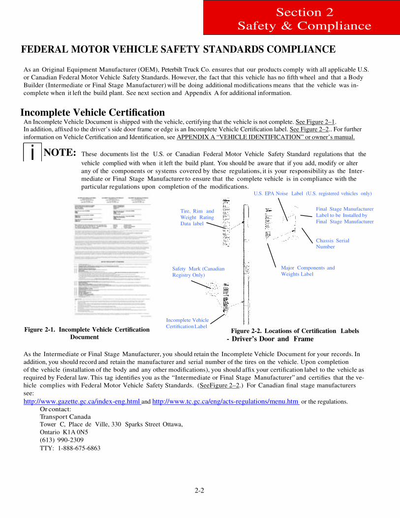
Incomplete Vehicle Certification An Incomplete Vehicle Document is shipped with the vehicle, certifying that the vehicle is not complete. See Figure 2–1.
In addition, affixed to the driver’s side door frame or edge is an Incomplete Vehicle Certification label. See Figure 2–2.. For further
information on Vehicle Certification and Identification, see APPENDIX A “VEHICLE IDENTIFICATION” or owner’s manual.
NOTE: These documents list the U.S. or Canadian Federal Motor Vehicle Safety Standard regulations that the
vehicle complied with when it left the build plant. You should be aware that if you add, modify or alter
any of the components or systems covered by these regulations, it is your responsibility as the Inter-
mediate or Final Stage Manufacturer to ensure that the complete vehicle is in compliance with the
particular regulations upon completion of the modifications.
Figure 2-1. Incomplete Vehicle Certification
Document
Tire, Rim and
Weight Rating
Data label
Safety Mark (Canadian
Registry Only)
Incomplete Vehicle
Certification Label
U.S. EPA Noise Label (U.S. registered vehicles only)
Final Stage Manufacturer
Label to be Installed by
Final Stage Manufacturer
Chassis Serial
Number
Major Components and
Weights Label
Figure 2-2. Locations of Certification Labels
- Driver’s Door and Frame
As the Intermediate or Final Stage Manufacturer, you should retain the Incomplete Vehicle Document for your records. In
addition, you should record and retain the manufacturer and serial number of the tires on the vehicle. Upon completion
of the vehicle (installation of the body and any other modifications), you should affix your certification label to the vehicle as
required by Federal law. This tag identifies you as the “Intermediate or Final Stage Manufacturer” and certifies that the ve-
hicle complies with Federal Motor Vehicle Safety Standards. (SeeFigure 2–2.) For Canadian final stage manufacturers
see:
http://www.gazette.gc.ca/index-eng.html and http://www.tc.gc.ca/eng/acts-regulations/menu.htm or the regulations.
Or contact:
Transport Canada
Tower C, Place de Ville, 330 Sparks Street Ottawa,
Ontario K1A 0N5
(613) 990-2309
TTY: 1-888-675-6863
2-3
Section 2
Safety & Compliance
Noise and Emissions Requirements
NOTE:
NOTE:
This truck may be equipped with a converter muffler unit in order to meet both noise and exhaust
emissions requirements. Removal or tampering with the converter muffler will not improve engine per-
formance. Also tampering is against the rules that are established by the U.S. Code of Federal Regu-
lations and Environment Canada Regulations. The converter muffler may only be replaced with an
approved part.
Relocation of converter muffler will affect noise and emission performance. Contact the engine manu-
facturer for any requirements and restrictions prior to any modifications. In particular, there are re-
quirements and restrictions for exhaust pipe materials and for maximum exhaust system lengths from
turbo outlet to muffler inlet.
3-1
Section 3
Dimensions
Frame Height
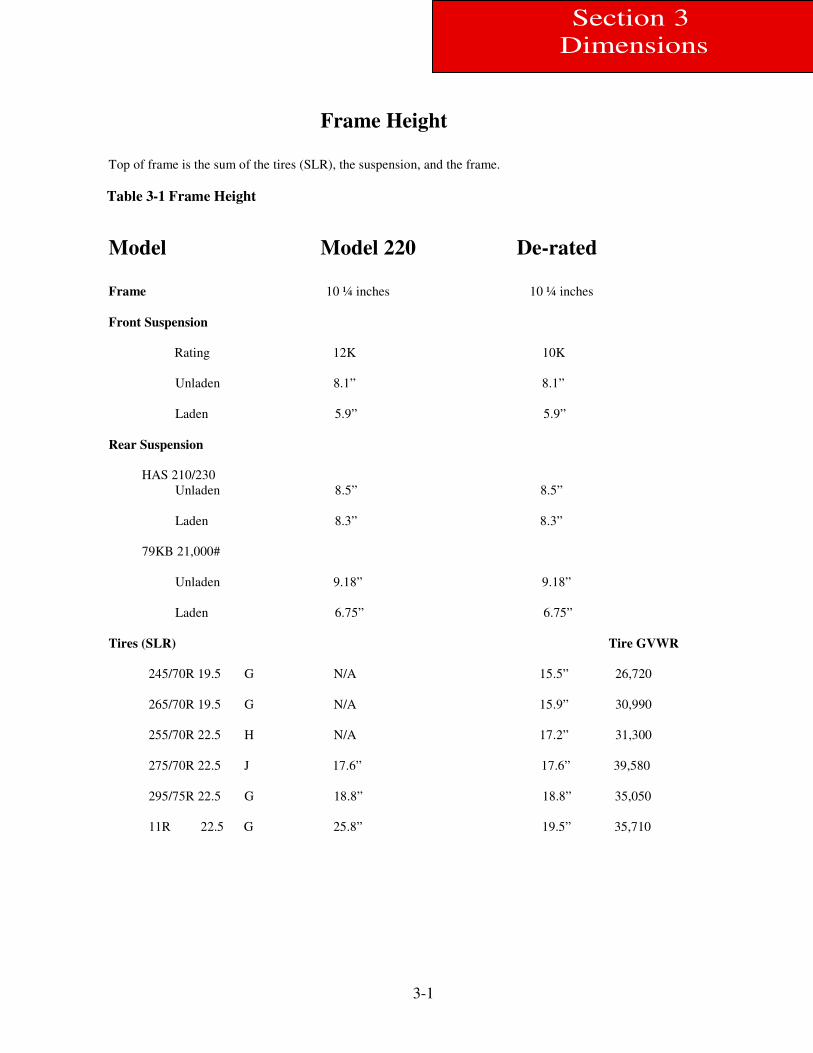
Top of frame is the sum of the tires (SLR), the suspension, and the frame.
Table 3-1 Frame Height
Model Model 220 De-rated
Frame 10 ¼ inches 10 ¼ inches
Front Suspension
Rating 12K 10K
Unladen 8.1” 8.1”
Laden 5.9” 5.9”
Rear Suspension
HAS 210/230
Unladen 8.5” 8.5”
Laden 8.3” 8.3”
79KB 21,000#
Unladen 9.18” 9.18”
Laden 6.75” 6.75”
Tires (SLR) Tire GVWR
245/70R 19.5 G N/A 15.5” 26,720
265/70R 19.5 G N/A 15.9” 30,990
255/70R 22.5 H N/A 17.2” 31,300
275/70R 22.5 J 17.6” 17.6” 39,580
295/75R 22.5 G 18.8” 18.8” 35,050
11R 22.5 G 25.8” 19.5” 35,710
3-2
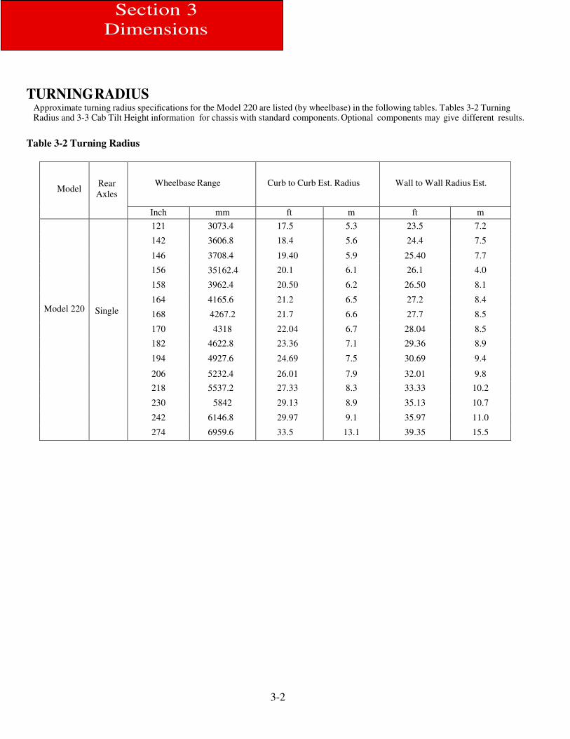
TURNING RADIUS Approximate turning radius specifications for the Model 220 are listed (by wheelbase) in the following tables. Tables 3-2 Turning Radius and 3-3 Cab Tilt Height information for chassis with standard components. Optional components may give different results.
Table 3-2 Turning Radius
Model
Rear
Axles
Wheelbase Range
Curb to Curb Est. Radius
Wall to Wall Radius Est.
Inch mm ft m ft m
Model 220
Single
121 3073.4 17.5 5.3 23.5 7.2
142 3606.8 18.4 5.6 24.4 7.5
146
3708.4 19.40 5.9 25.40 7.7
156 35162.4 20.1 6.1 26.1 4.0
158 3962.4 20.50 6.2 26.50 8.1
164 4165.6 21.2 6.5 27.2 8.4
168 4267.2 21.7 6.6 27.7 8.5
170 4318 22.04 6.7 28.04 8.5
182 4622.8 23.36 7.1 29.36 8.9
194 4927.6 24.69 7.5 30.69 9.4
206 5232.4 26.01 7.9 32.01 9.8
218 5537.2 27.33 8.3 33.33 10.2
230 5842 29.13 8.9 35.13 10.7
242 6146.8 29.97 9.1 35.97 11.0
274 6959.6 33.5 13.1 39.35 15.5
Section 3
Dimensions
3-3
Section 3
Dimensions
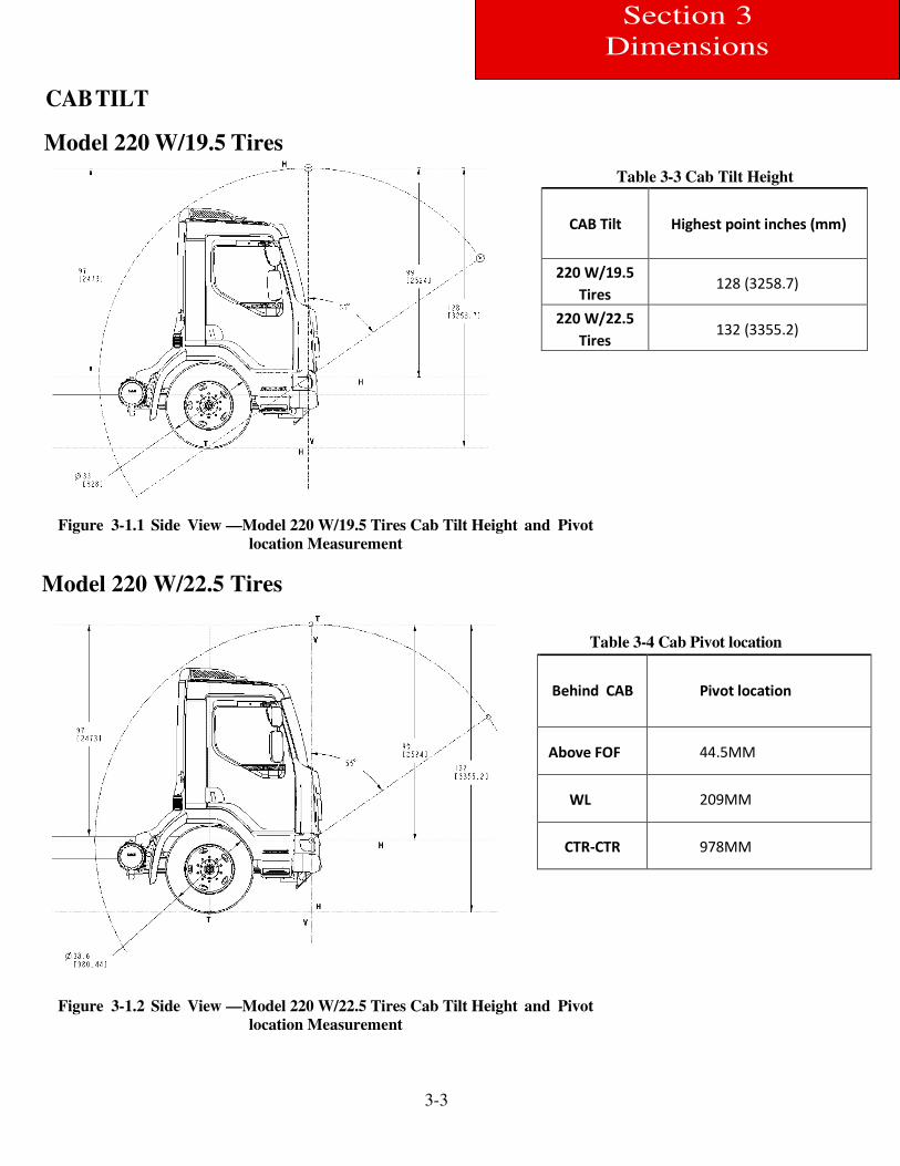
CAB TILT
Model 220 W/19.5 Tires
Figure 3-1.1 Side View —Model 220 W/19.5 Tires Cab Tilt Height and Pivot
location Measurement
Model 220 W/22.5 Tires
Figure 3-1.2 Side View —Model 220 W/22.5 Tires Cab Tilt Height and Pivot
location Measurement
Table 3-4 Cab Pivot location
Behind CAB
Pivot location
Above FOF 44.5MM
WL 209MM
CTR-CTR 978MM
Table 3-3 Cab Tilt Height
CAB Tilt
Highest point inches (mm)
220 W/19.5
Tires 128 (3258.7)
220 W/22.5
Tires 132 (3355.2)
3-4
Section 3
Dimensions
OVERALL DIMENSIONS
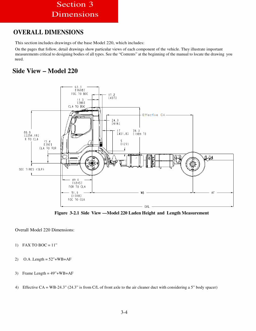
This section includes drawings of the base Model 220, which includes:
On the pages that follow, detail drawings show particular views of each component of the vehicle. They illustrate important
measurements critical to designing bodies of all types. See the “Contents” at the beginning of the manual to locate the drawing you
need.
Side View – Model 220
Figure 3-2.1 Side View —Model 220 Laden Height and Length Measurement
Overall Model 220 Dimensions:
1) FAX TO BOC = 11”
2) O.A .Length = 52”+WB+AF
3) Frame Length = 49”+WB+AF
4) Effective CA = WB-24.3” (24.3” is from C/L of front axle to the air cleaner duct with considering a 5” body spacer)
3-5
Section 3
Dimensions
Side View - Model 220
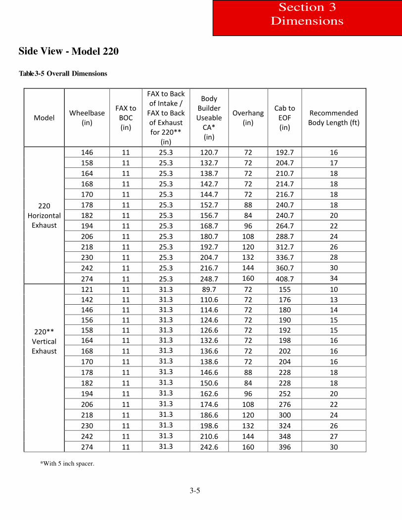
Table 3-5 Overall Dimensions
*With 5 inch spacer.
Model Wheelbase
(in)
FAX to
BOC
(in)
FAX to Back
of Intake /
FAX to Back
of Exhaust
for 220**
(in)
Body
Builder
Useable
CA*
(in)
Overhang
(in)
Cab to
EOF
(in)
Recommended
Body Length (ft)
220
Horizontal
Exhaust
146 11 25.3 120.7 72 192.7 16
158 11 25.3 132.7 72 204.7 17
164 11 25.3 138.7 72 210.7 18
168 11 25.3 142.7 72 214.7 18
170 11 25.3 144.7 72 216.7 18
178 11 25.3 152.7 88 240.7 18
182 11 25.3 156.7 84 240.7 20
194 11 25.3 168.7 96 264.7 22
206 11 25.3 180.7 108 288.7 24
218 11 25.3 192.7 120 312.7 26
230 11 25.3 204.7 132 336.7 28
242 11 25.3 216.7 144 360.7 30
274 11 25.3 248.7 160 408.7 34
220**
Vertical
Exhaust
121 11 31.3 89.7 72 155 10
142 11 31.3 110.6 72 176 13
146 11 31.3 114.6 72 180 14
156 11 31.3 124.6 72 190 15
158 11 31.3 126.6 72 192 15
164 11 31.3 132.6 72 198 16
168 11 31.3 136.6 72 202 16
170 11 31.3 138.6 72 204 16
178 11 31.3 146.6 88 228 18
182 11 31.3 150.6 84 228 18
194 11 31.3 162.6 96 252 20
206 11 31.3 174.6 108 276 22
218 11 31.3 186.6 120 300 24
230 11 31.3 198.6 132 324 26
242 11 31.3 210.6 144 348 27
274 11 31.3 242.6 160 396 30
3-6
Section 3
Dimensions
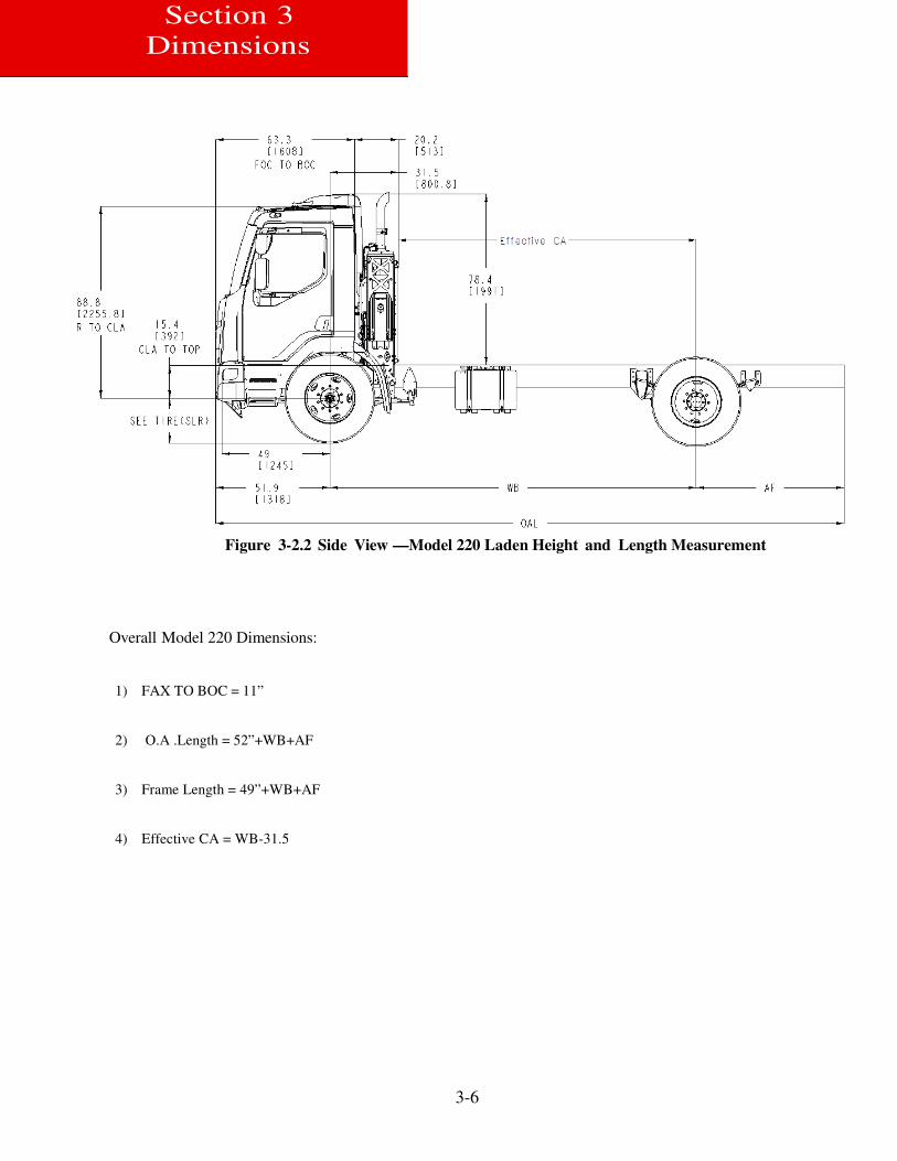
Figure 3-2.2 Side View —Model 220 Laden Height and Length Measurement
Overall Model 220 Dimensions:
1) FAX TO BOC = 11”
2) O.A .Length = 52”+WB+AF
3) Frame Length = 49”+WB+AF
4) Effective CA = WB-31.5

3-7
)
Front and Rear Views — Model 220 Inches (mm)
Section 3
Dimensions
Figure 3-3.1 Front & Rear View —Model 220
3-8
Section 3
Dimensions
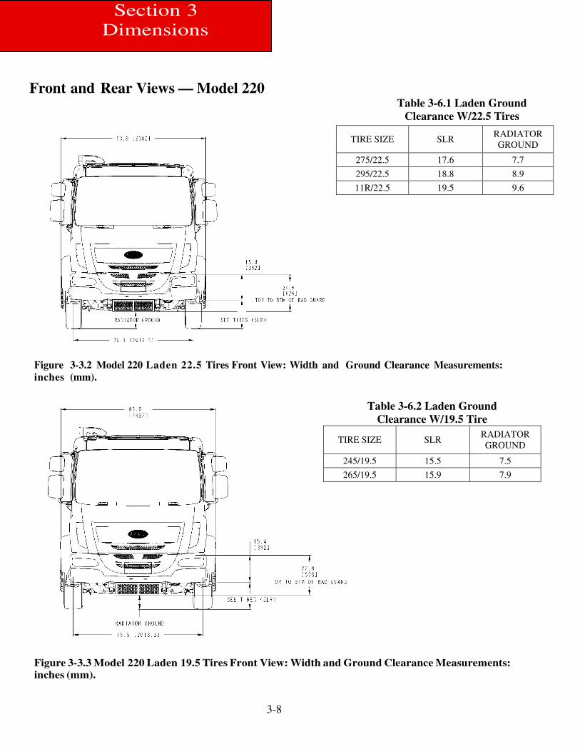
Front and Rear Views — Model 220
Table 3-6.1 Laden Ground
Clearance W/22.5 Tires
Figure 3-3.2 Model 220 Laden 22.5 Tires Front View: Width and Ground Clearance Measurements:
inches (mm).
Figure 3-3.3 Model 220 Laden 19.5 Tires Front View: Width and Ground Clearance Measurements:
inches (mm).
TIRE SIZE SLR RADIATOR
GROUND
275/22.5 17.6 7.7
295/22.5 18.8 8.9
11R/22.5 19.5 9.6
Table 3-6.2 Laden Ground clearance W/19.5 Tire
TIRE SIZE SLR RADIATOR
GROUND
245/19.5 15.5 7.5
265/19.5 15.9 7.9
Table 3-6.2 Laden Ground
Clearance W/19.5 Tire
TIRE SIZE SLR RADIATOR
GROUND
245/19.5 15.5 7.5
265/19.5 15.9 7.9
3-9
Section 3
Dimensions
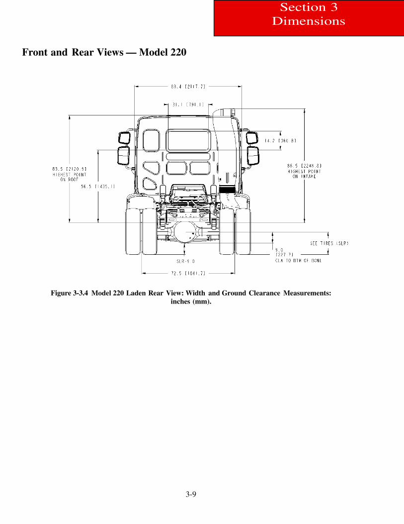
Front and Rear Views — Model 220
Figure 3-3.4 Model 220 Laden Rear View: Width and Ground Clearance Measurements:
inches (mm).
3-10
Section 3
Dimensions
Detail Views
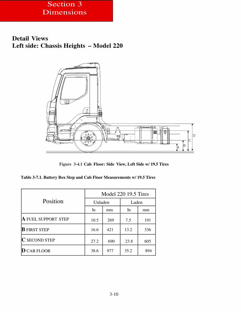
Left side: Chassis Heights – Model 220
Figure 3-4.1 Cab Floor: Side View, Left Side w/ 19.5 Tires
Table 3-7.1. Battery Box Step and Cab Floor Measurements w/ 19.5 Tires
Position
Model 220 19.5 Tires
Unladen Laden
In mm In mm
A FUEL SUPPORT STEP 10.5 269 7.5 191
B FIRST STEP 16.6 421 13.2 336
C SECOND STEP 27.2 690 23.8 605
D CAB FLOOR 38.6 977 35.2 894
3-11
Section 3
Dimensions
3 Dimensions
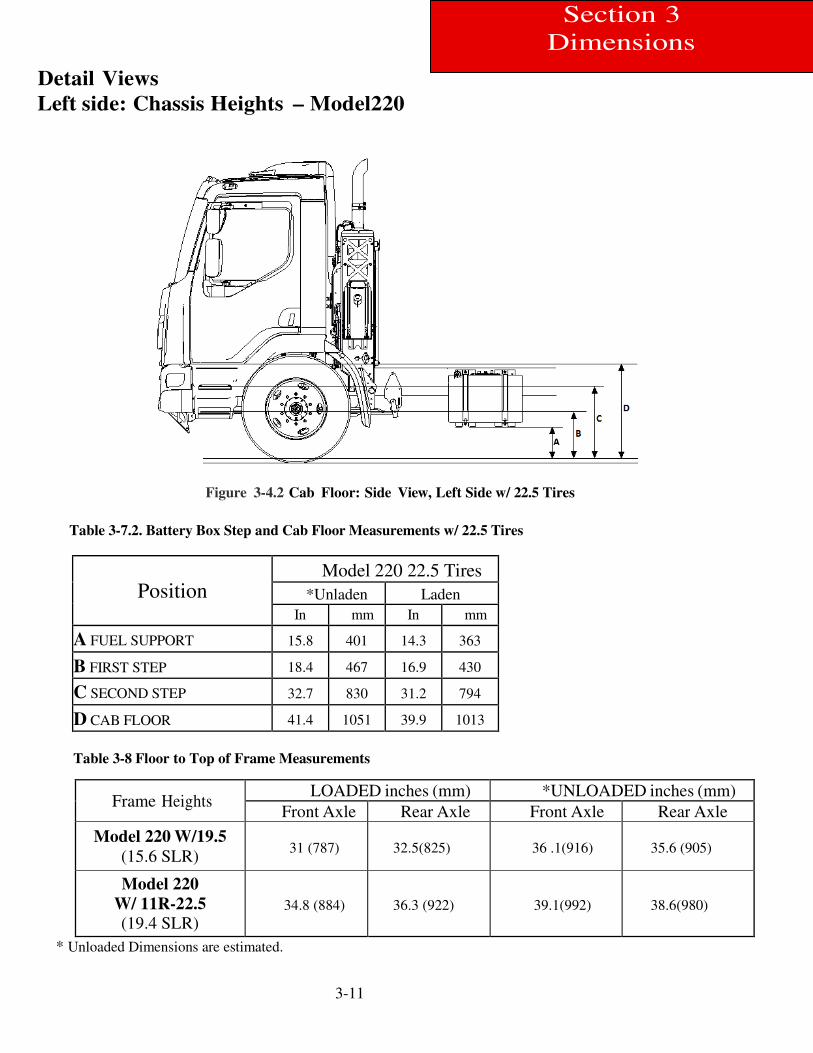
Detail Views
Left side: Chassis Heights – Model220ction
3ions
Figure 3-4.2 Cab Floor: Side View, Left Side w/ 22.5 Tires
Table 3-7.2. Battery Box Step and Cab Floor Measurements w/ 22.5 Tires
Position
Model 220 22.5 Tires
*Unladen Laden
In mm In mm
A FUEL SUPPORT 15.8 401 14.3 363
B FIRST STEP 18.4 467 16.9 430
C SECOND STEP 32.7 830 31.2 794
D CAB FLOOR 41.4 1051 39.9 1013
Table 3-8 Floor to Top of Frame Measurements
Frame Heights LOADED inches (mm) *UNLOADED inches (mm)
Front Axle Rear Axle Front Axle Rear Axle
Model 220 W/19.5
(15.6 SLR) 31 (787) 32.5(825) 36 .1(916) 35.6 (905)
Model 220
W/ 11R-22.5
(19.4 SLR) 34.8 (884) 36.3 (922) 39.1(992) 38.6(980)
* Unloaded Dimensions are estimated.
3-12
Section 3
Dimensions
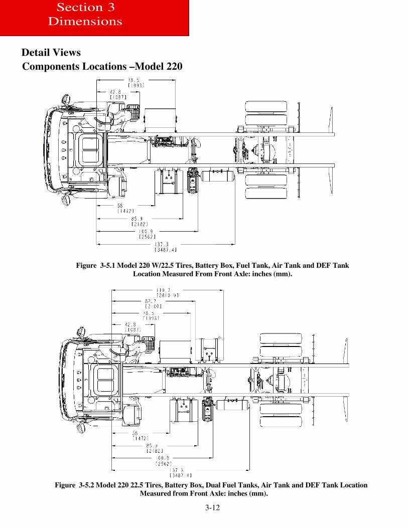
Detail Views
Components Locations –Model 220
Figure 3-5.1 Model 220 W/22.5 Tires, Battery Box, Fuel Tank, Air Tank and DEF Tank
Location Measured From Front Axle: inches (mm).
Figure 3-5.2 Model 220 22.5 Tires, Battery Box, Dual Fuel Tanks, Air Tank and DEF Tank Location
Measured from Front Axle: inches (mm).
3-13
Section 3
Dimensions
3 Dimensions
Figure 3-5.3 Model 220 22.5 Tires, Short Wheelbase, Air Tanks on the RH Side, Battery Box and DEF Tank
Location Measured from Front Axle: inches (mm).
Figure 3-5.4 Model 220 22.5 Tires, Clear Rail Package, Air Tanks, Battery Box and DEF Tank Location
Measured from Front Axle: inches (mm).
3-14
Section 3
Dimensions
Detail Views
Crossmember Locations –Model 220
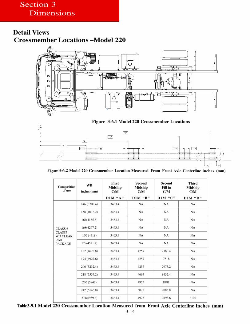
Figure 3-6.1 Model 220 Crossmember Locations
Figure 3-6.2 Model 220 Crossmember Location Measured From Front Axle Centerline inches (mm)
Composition
of use
WB
inches (mm)
First
Midship
C/M
D IM “ A”
Second
Midship
C/M
D IM “ B ”
Second
Fill in
C/M
D IM “ C”
Third
Midship
C/M
D IM “ D”
CLASS 6
CLASS7
WO CLEAR
RAIL
PACKAGE
146 (3708.4) 3463.4 NA NA NA
158 (4013.2) 3463.4 NA NA NA
164(4165.6) 3463.4 NA NA NA
168(4267.2) 3463.4 NA NA NA
170 (4318) 3463.4 NA NA NA
178(4521.2) 3463.4 NA NA NA
182 (4622.8) 3463.4 4257 7180.4 NA
194 (4927.6) 3463.4 4257 7518 NA
206 (5232.4) 3463.4 4257 7975.2 NA
218 (5537.2) 3463.4 4663 8432.4 NA
230 (5842) 3463.4 4975 8781 NA
242 (6146.8) 3463.4 5075 9085.8 NA
274(6959.6) 3463.4 4975 9898.6 6100
Table 3-9.1 Model 220 Crossmember Location Measured from Front Axle Centerline inches (mm)
3-15
Section 3
Dimensions
3 Dimensions
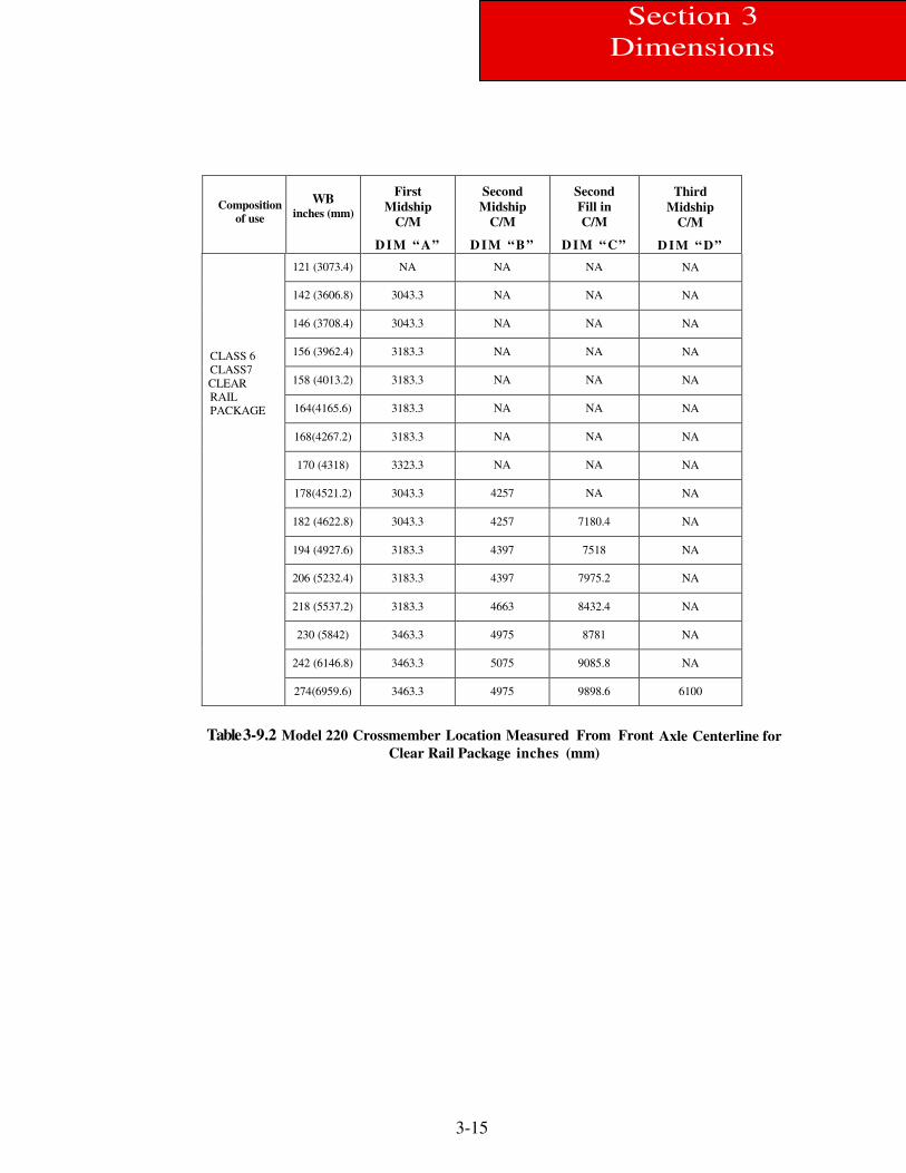
Composition
of use
WB inches (mm)
First
Midship
C/M
D IM “ A”
Second
Midship
C/M
D IM “ B ”
Second
Fill in
C/M
D IM “ C”
Third
Midship
C/M
D IM “ D”
CLASS 6
CLASS7
CLEAR
RAIL
PACKAGE
121 (3073.4) NA NA NA NA
142 (3606.8) 3043.3 NA NA NA
146 (3708.4) 3043.3 NA NA NA
156 (3962.4) 3183.3 NA NA NA
158 (4013.2) 3183.3 NA NA NA
164(4165.6) 3183.3 NA NA NA
168(4267.2) 3183.3 NA NA NA
170 (4318) 3323.3 NA NA NA
178(4521.2) 3043.3 4257 NA NA
182 (4622.8) 3043.3 4257 7180.4 NA
194 (4927.6) 3183.3 4397 7518 NA
206 (5232.4) 3183.3 4397 7975.2 NA
218 (5537.2) 3183.3 4663 8432.4 NA
230 (5842) 3463.3 4975 8781 NA
242 (6146.8) 3463.3 5075 9085.8 NA
274(6959.6) 3463.3 4975 9898.6 6100
Table 3-9.2 Model 220 Crossmember Location Measured From Front Axle Centerline for
Clear Rail Package inches (mm)
3-16
Section 3
Dimensions
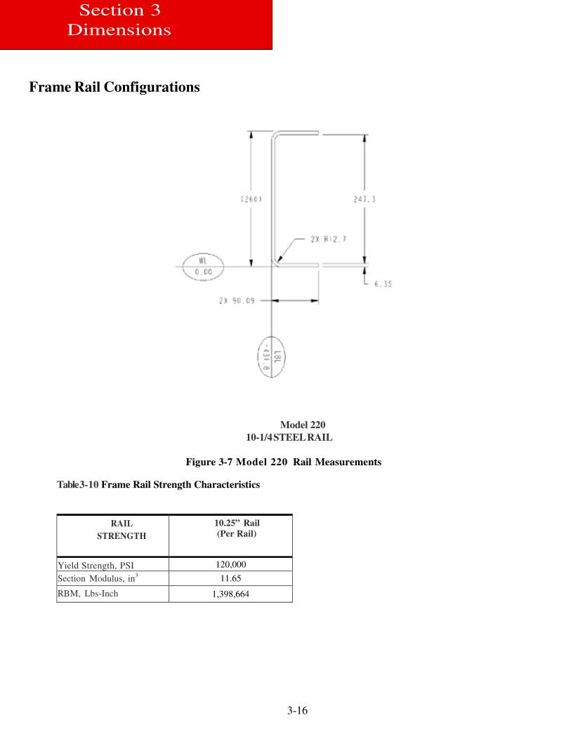
Frame Rail Configurations
Model 220
10-1/4 STEEL RAIL
Figure 3-7 Model 220 Rail Measurements
Table 3-10 Frame Rail Strength Characteristics
RAIL
STRENGTH
10.25” Rail
(Per Rail)
Yield Strength, PSI 120,000
Section Modulus, in3 11.65
RBM, Lbs-Inch 1,398,664
3-17
Section 3
Dimensions
3 Dimensions
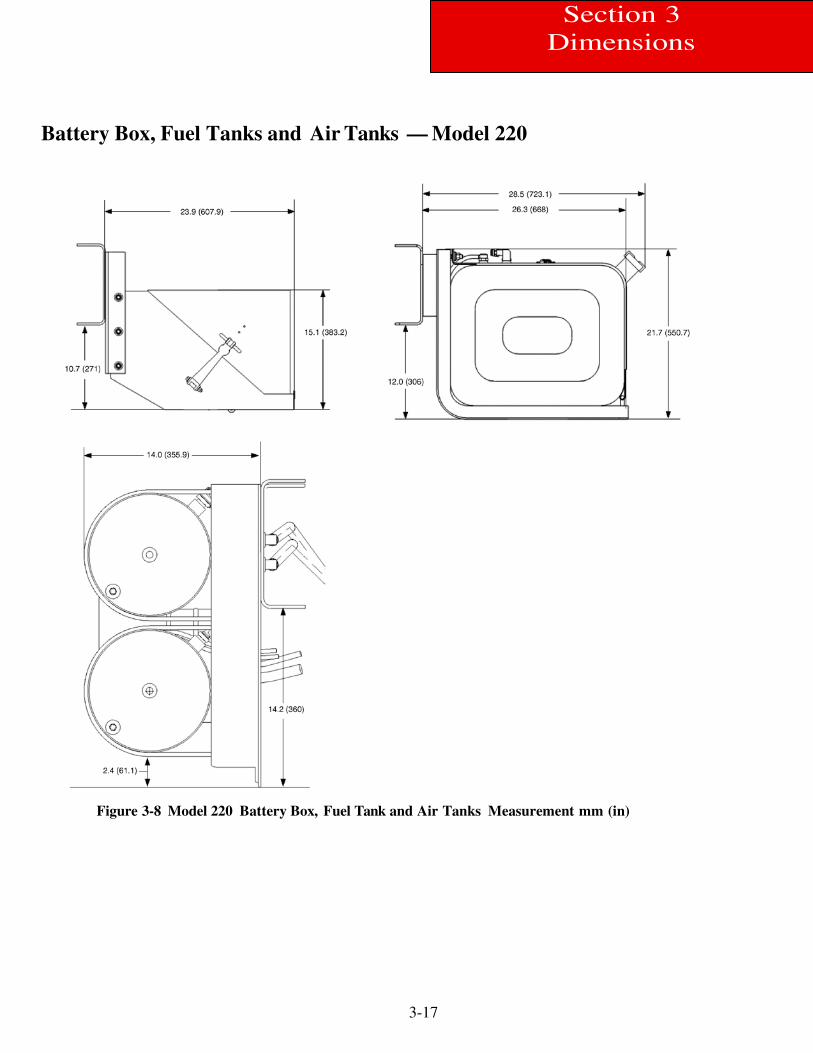
Battery Box, Fuel Tanks and Air Tanks — Model 220
Figure 3-8 Model 220 Battery Box, Fuel Tank and Air Tanks Measurement mm (in)
3-18
Section 3
Dimensions
Detail Views
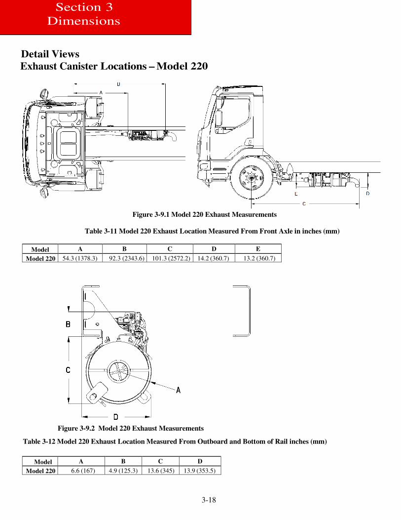
Exhaust Canister Locations – Model 220
Figure 3-9.1 Model 220 Exhaust Measurements
Table 3-11 Model 220 Exhaust Location Measured From Front Axle in inches (mm)
Model A B C D E
Model 220 54.3 (1378.3) 92.3 (2343.6) 101.3 (2572.2) 14.2 (360.7) 13.2 (360.7)
Figure 3-9.2 Model 220 Exhaust Measurements
Table 3-12 Model 220 Exhaust Location Measured From Outboard and Bottom of Rail inches (mm)
Model A B C D
Model 220 6.6 (167) 4.9 (125.3) 13.6 (345) 13.9 (353.5)
3-19
Section 3
Dimensions
3 Dimensions
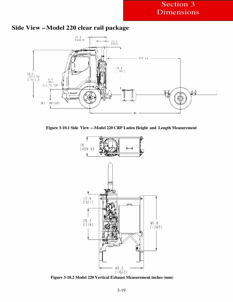
Side View – Model 220 clear rail package
Figure 3-10.1 Side View —Model 220 CRP Laden Height and Length Measurement
Figure 3-10.2 Model 220 Vertical Exhaust Measurement inches (mm)
3-20
Section 3
Dimensions
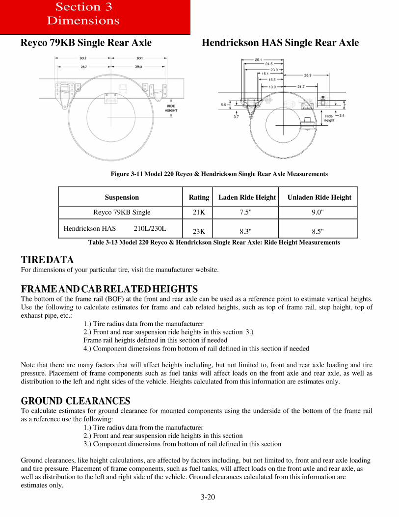
Reyco 79KB Single Rear Axle Hendrickson HAS Single Rear Axle
Figure 3-11 Model 220 Reyco & Hendrickson Single Rear Axle Measurements
Suspension Rating Laden Ride Height Unladen Ride Height
Reyco 79KB Single 21K 7.5" 9.0"
Hendrickson HAS 210L/230L
23K
8.3"
8.5"
Table 3-13 Model 220 Reyco & Hendrickson Single Rear Axle: Ride Height Measurements
TIRE DATA For dimensions of your particular tire, visit the manufacturer website.
FRAME AND CAB RELATED HEIGHTS The bottom of the frame rail (BOF) at the front and rear axle can be used as a reference point to estimate vertical heights.
Use the following to calculate estimates for frame and cab related heights, such as top of frame rail, step height, top of
exhaust pipe, etc.:
1.) Tire radius data from the manufacturer 2.) Front and rear suspension ride heights in this section 3.)
Frame rail heights defined in this section if needed
4.) Component dimensions from bottom of rail defined in this section if needed
Note that there are many factors that will affect heights including, but not limited to, front and rear axle loading and tire
pressure. Placement of frame components such as fuel tanks will affect loads on the front axle and rear axle, as well as
distribution to the left and right sides of the vehicle. Heights calculated from this information are estimates only.
GROUND CLEARANCES To calculate estimates for ground clearance for mounted components using the underside of the bottom of the frame rail
as a reference use the following:
1.) Tire radius data from the manufacturer
2.) Front and rear suspension ride heights in this section
3.) Component dimensions from bottom of rail defined in this section
Ground clearances, like height calculations, are affected by factors including, but not limited to, front and rear axle loading
and tire pressure. Placement of frame components, such as fuel tanks, will affect loads on the front axle and rear axle, as
well as distribution to the left and right side of the vehicle. Ground clearances calculated from this information are
estimates only.
3-21
Section 3
Dimensions
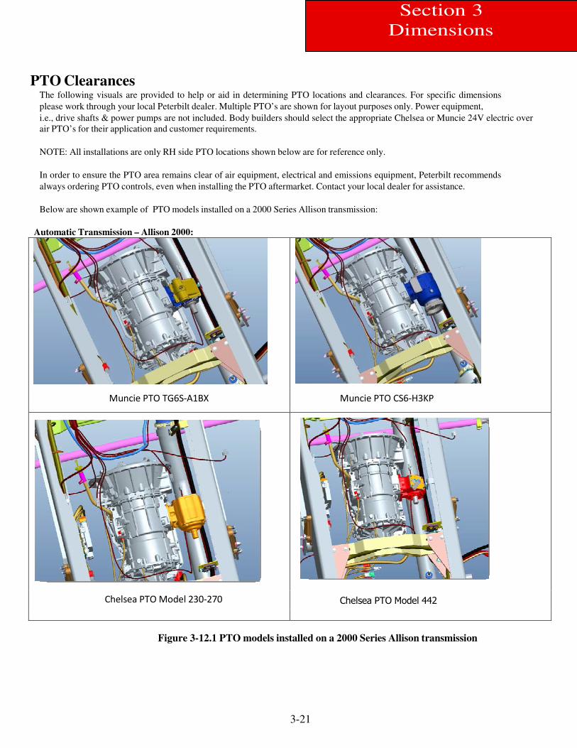
PTO Clearances The following visuals are provided to help or aid in determining PTO locations and clearances. For specific dimensions
please work through your local Peterbilt dealer. Multiple PTO’s are shown for layout purposes only. Power equipment,
i.e., drive shafts & power pumps are not included. Body builders should select the appropriate Chelsea or Muncie 24V electric over
air PTO’s for their application and customer requirements.
NOTE: All installations are only RH side PTO locations shown below are for reference only.
In order to ensure the PTO area remains clear of air equipment, electrical and emissions equipment, Peterbilt recommends
always ordering PTO controls, even when installing the PTO aftermarket. Contact your local dealer for assistance.
Below are shown example of PTO models installed on a 2000 Series Allison transmission:
Automatic Transmission – Allison 2000:
Muncie PTO TG6S-A1BX Muncie PTO CS6-H3KP
Chelsea PTO Model 230-270 Chelsea PTO Model 442
Figure 3-12.1 PTO models installed on a 2000 Series Allison transmission
3-22
Section 3
Dimensions
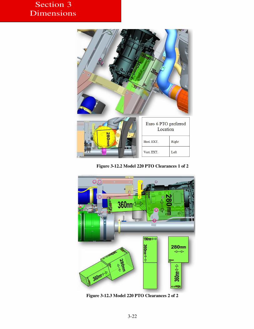
Figure 3-12.2 Model 220 PTO Clearances 1 of 2
Figure 3-12.3 Model 220 PTO Clearances 2 of 2

4-1
Section 4
Exhaust & Aftertreatment
EXHAUST AND AFTERTREATMENT INFORMATION (Did the Doser Change in
2017?)
The following section is designed to give you information regarding the exhaust and after-treatment systems on Peterbilt
chassis. All Peterbilt’s equipped with 2017 emission level engines will utilize Selective Catalyst Reduction (SCR). SCR is
a process in which Diesel Exhaust Fluid (DEF) is injected into the exhaust downstream of the engine. DEF is converted to
ammonia by the heat of the exhaust system. Inside of the SCR canister, a catalyst causes a chemical reaction between the
ammonia and NOx, turning it into water and nitrogen. For more information on the specific details of how SCR works,
please contact your local Peterbilt dealer.
On most Peterbilt chassis, the DEF Supply Module (or pump) is integrated into the DEF tank. Peterbilt does not allow
relocation of this pump. The following schematic details how the DEF lines route to the after-treatment system.
Figure 4-1.1 The DEF lines route to the after-treatment system

4-2
Section 4
Exhaust & Aftertreatment
DEF will freeze at approximately 11° F (-12° C). In order to keep DEF from freezing, all tanks will be heated with engine
coolant. The following schematic shows the routing of these lines. The coolant lines that run to and from the SCR system
must not be tampered with, or used for a source of heat and/or cooling for other components on the chassis. It is critical
that the system is not compromised in any manner.
Figure 4-1.2 The DEF lines route to the Engine Coolant
4-3
Section 4
Exhaust & Aftertreatment
General Guidelines for DEF System The installation of the DEF tank is a critical component of the SCR system. While Peterbilt does not recommend relocating
the DEF tank, there are applications and body installations that will require it. The guidelines below must be strictly
followed by any entity relocating the tank. Failure to follow the guidelines completely and accurately may result in engine
shut down situations. Peterbilt offers a variety of DEF tank sizes to meet every application.
The DEF tank volume is regulated by the E.P.A.
Peterbilt advises against modifying the tank volume after the truck has been delivered from the factory.
•Total DEF capacity must meet or exceed 6% of the useable fuel capacity on the truck. The calculation
to determine DEF capacity is:
Minimum DEF Tank Volume = Useable Fuel Capacity (gal) x 0.06.
Example: For a truck with 45 useable gallons of fuel, the equation is:
DEF required = 45 x 0.06 = 2.7 gallons or more of DEF.
PACCAR-approved DEF hoses are required when retrofitting for system to function properly. The use of unapproved
hoses for DEF lines will void warranty and may cause engine shut down situations. The DEF pump (or Supply Module)
cannot be relocated from the DEF tank. In addition, the Medium Duty Rectangular DEF Tank that is used to meet clear
back of cab requirements cannot be relocated.
Installation Requirements and Dimensions for DEF System When relocating any DEF system components, the locations must meet the guidelines below. Failure to comply may result
in non-conformance to EPA standards and engine shutdown.
DEF piping relative heights: In order to ensure proper functionality of DEF system, the height differences in the guidelines
below must be followed during line routing and component placement.
When relocating the components the maximum pressure DEF hose length from Supply module to Dosing Module is 3
meters (118”).
Maintain a minimum of 3” (76mm) clearance to shielded exhaust components when routing DEF lines to prevent possible
melting. If the DEF tank is relocated the coolant lines will need to be modified. During this process, if the tank is moved
forward on the chassis (ie closer to the engine), it is necessary to remove excess coolant lines and maintain the original
routing path. If the tank is moved rearward on the chassis, the additional length of the cooling line required to complete the
installation must be installed in a straight section of the existing coolant routing lines. This process will minimize the
change in coolant flow by minimizing changes in restrictions. Increase in restriction occurs with excessive line length and
bends. Work with your local Peterbilt dealer if you are unsure about the coolant line modifications.

4-4
Section 4
Exhaust & Aftertreatment
Measurement Reference Points For all relocation procedures, the measurement points referenced in the guidelines are taken from the following specific
points:
Supply Module: The supply module is commonly called a pump. The measurement point on the supply module is the top
of the DEF fluid pressure line. See Figure 4-2.
Figure 4-2 Measurement Location of DEF Supply Module (Pump)
Dosing Module: The dosing module is commonly called an injector; this injector is located towards the center of the
Exhaust Canister. The measurement point on the dosing module is the top of the DEF fluid pressure line. See Figure 4-3.
Figure 4-3 Measurement Location of DEF Dosing Module (Injector)
The following relocation guidelines are dependent on exhaust configuration and DEF tank type and location.
The Dosing Module should not need to be relocated, however if it is removed for any reason, it is critical that the module
is reinstalled at the correct orientation. Figure 4-4 below illustrates the correct installation orientations. The angle
references the vertical plane.
4-5
Section 4
Exhaust & Aftertreatment
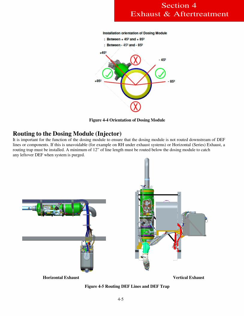
Figure 4-4 Orientation of Dosing Module
Routing to the Dosing Module (Injector) It is important for the function of the dosing module to ensure that the dosing module is not routed downstream of DEF
lines or components. If this is unavoidable (for example on RH under exhaust systems) or Horizontal (Series) Exhaust, a
routing trap must be installed. A minimum of 12” of line length must be routed below the dosing module to catch
any leftover DEF when system is purged.
Horizontal Exhaust Vertical Exhaust
Figure 4-5 Routing DEF Lines and DEF Trap
4-6
Section 4
Exhaust & Aftertreatment
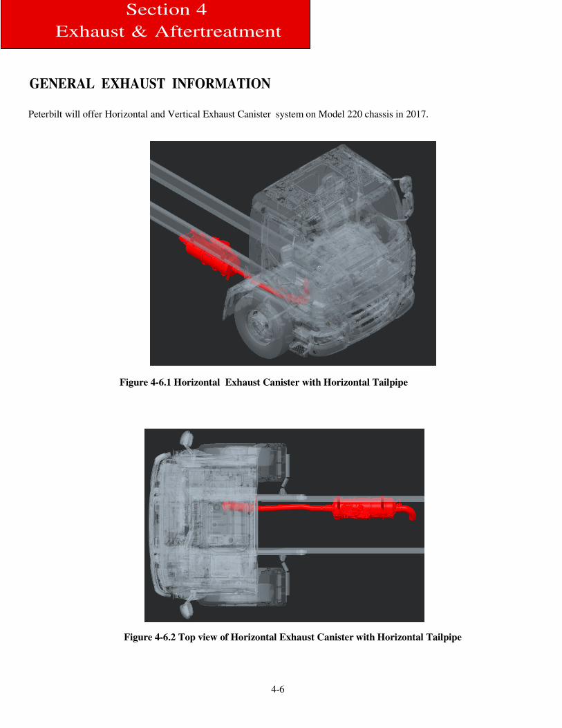
GENERAL EXHAUST INFORMATION
Peterbilt will offer Horizontal and Vertical Exhaust Canister system on Model 220 chassis in 2017.
Figure 4-6.1 Horizontal Exhaust Canister with Horizontal Tailpipe
Figure 4-6.2 Top view of Horizontal Exhaust Canister with Horizontal Tailpipe
4-7
Section 4
Exhaust & Aftertreatment
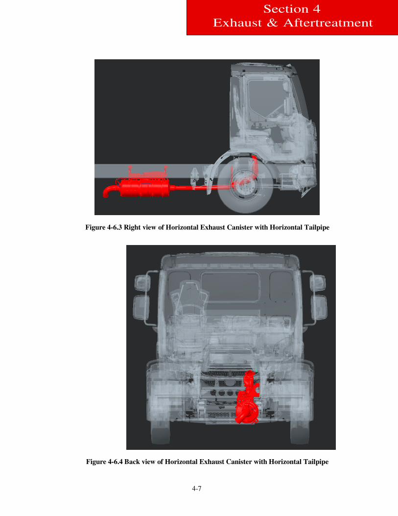
Figure 4-6.3 Right view of Horizontal Exhaust Canister with Horizontal Tailpipe
Figure 4-6.4 Back view of Horizontal Exhaust Canister with Horizontal Tailpipe
4-8
Section 4
Exhaust & Aftertreatment
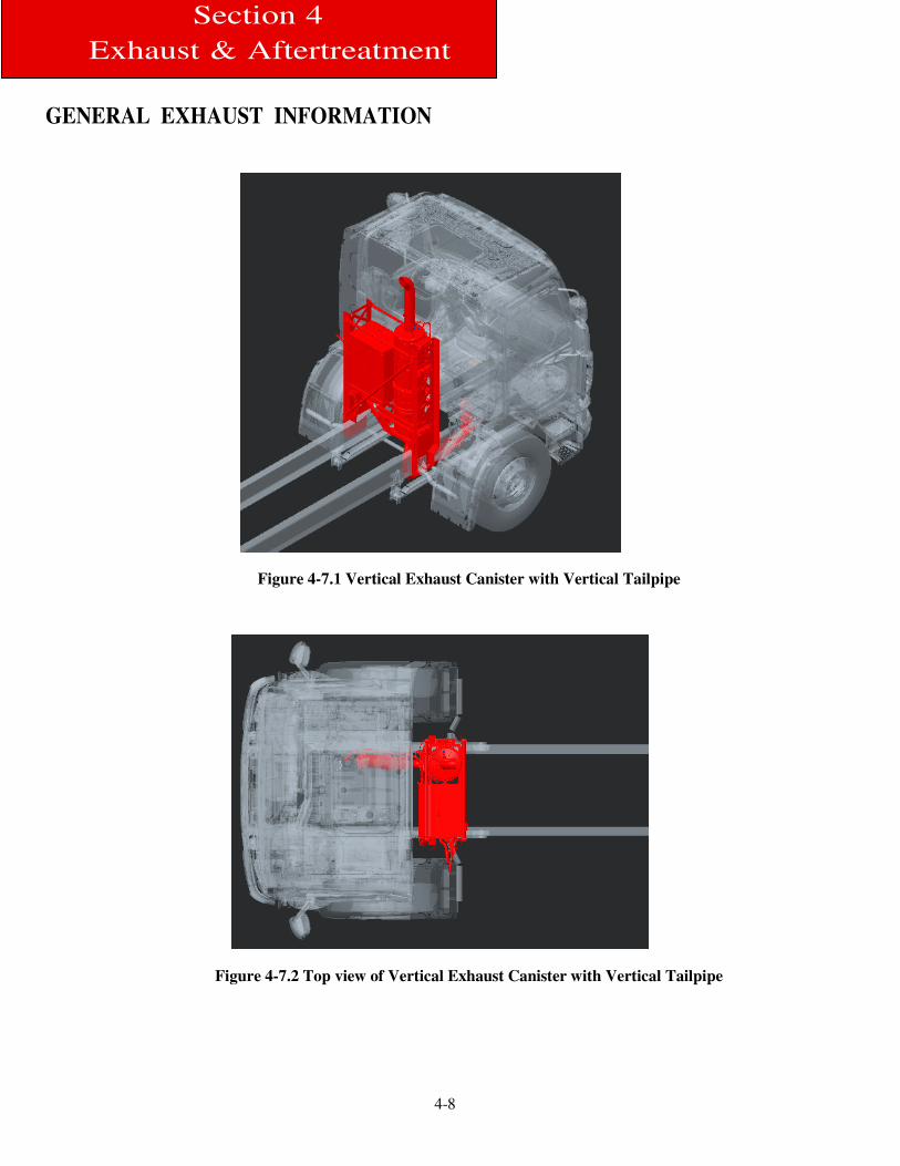
GENERAL EXHAUST INFORMATION
Figure 4-7.1 Vertical Exhaust Canister with Vertical Tailpipe
Figure 4-7.2 Top view of Vertical Exhaust Canister with Vertical Tailpipe
4-9
Section 4
Exhaust & Aftertreatment
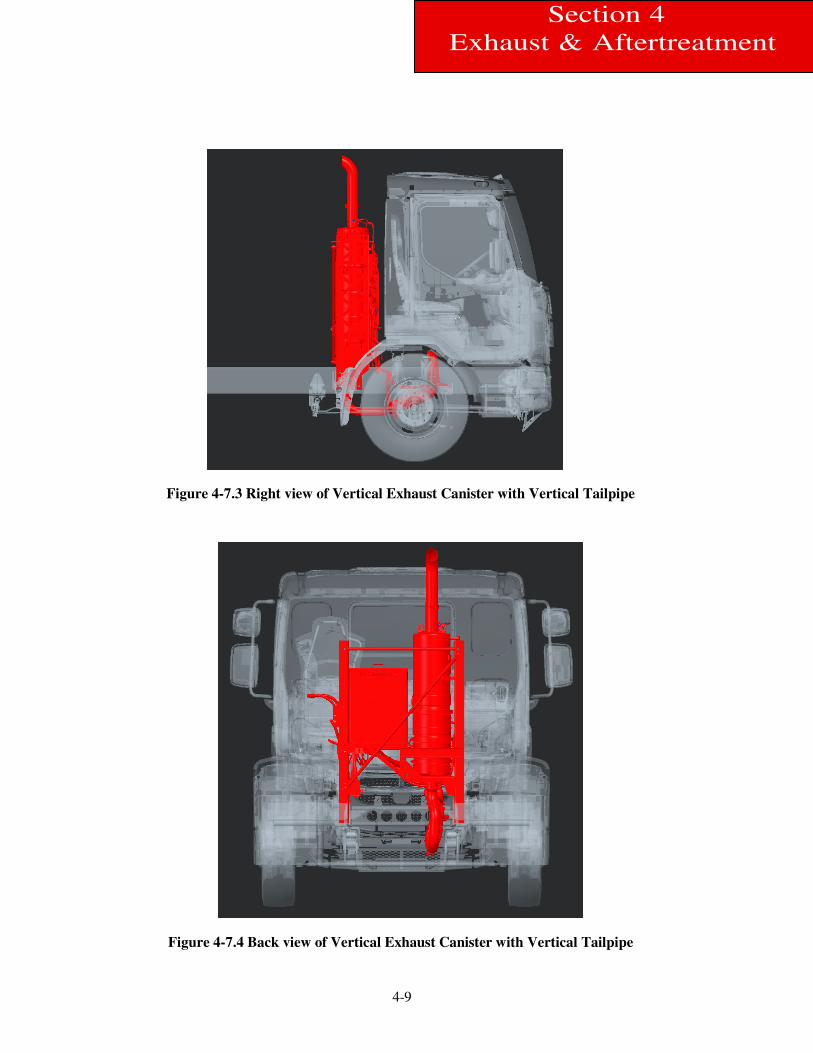
Figure 4-7.3 Right view of Vertical Exhaust Canister with Vertical Tailpipe
Figure 4-7.4 Back view of Vertical Exhaust Canister with Vertical Tailpipe

5-1
Section 5
Frame Layouts and Body
Mounting
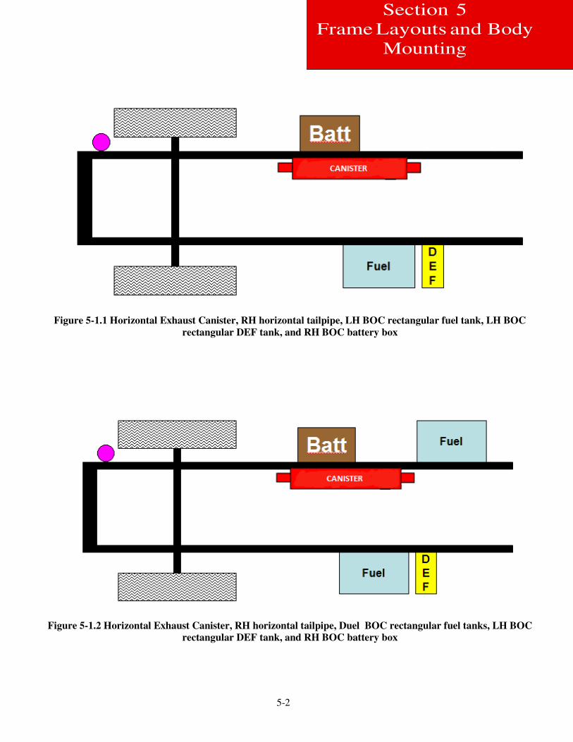
FRAME LAYOUTS The dimensions in the frame layout section are intended to aid in layout of the chassis, and to help determine the best
possible combination of fuel tanks, battery boxes, Exhaust Canister, and Diesel Exhaust Fluid (DEF) tank. For your
application, the layouts focus on the under cab area, with appropriate dimensional information in- cluded for pertinent
back of cab components. Not all optional equipment is included in this section; additional components may be placed on
the rail behind components shown. The Back of Cab components are shown primarily for reference. For more specific
requirements, work with your local Peterbilt Dealer. Please read the instructions carefully. The following dimensions are
consistent across the entire section to aid in the comparison of one layout option versus another.
The visual index that follows will give you a quick overview of the layout that is included.
Visual Index Table 5-1 Symbols
Symbol Description
Horizontal Exhaust
Canister
Vertical Exhaust Canister
Battery Box
Air Dryer
DEF Tank
Fuel Tank
5-2
Section 5
Frame Layouts and Body
Mounting
Figure 5-1.1 Horizontal Exhaust Canister, RH horizontal tailpipe, LH BOC rectangular fuel tank, LH BOC
rectangular DEF tank, and RH BOC battery box
Figure 5-1.2 Horizontal Exhaust Canister, RH horizontal tailpipe, Duel BOC rectangular fuel tanks, LH BOC
rectangular DEF tank, and RH BOC battery box
5-3
Section 5
Frame Layouts and Body
Mounting
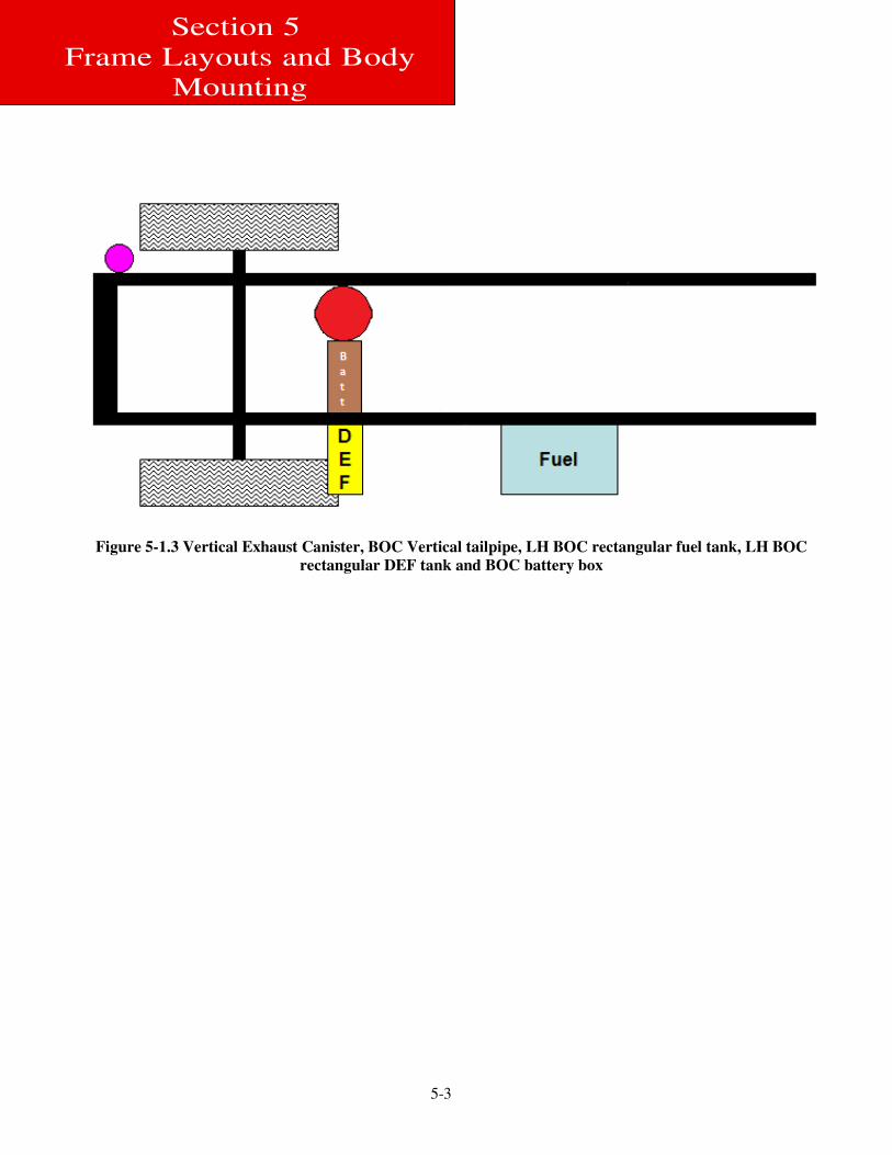
Figure 5-1.3 Vertical Exhaust Canister, BOC Vertical tailpipe, LH BOC rectangular fuel tank, LH BOC
rectangular DEF tank and BOC battery box
5-4
Section 5
Frame Layouts and Body
Mounting
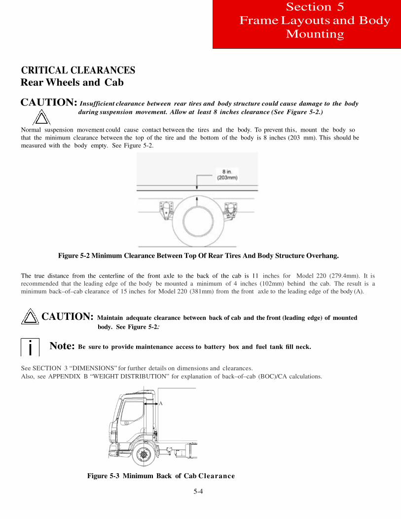
CRITICAL CLEARANCES
Rear Wheels and Cab
CAUTION: Insufficient clearance between rear tires and body structure could cause damage to the body
during suspension movement. Allow at least 8 inches clearance (See Figure 5-2.)
Normal suspension movement could cause contact between the tires and the body. To prevent this, mount the body so
that the minimum clearance between the top of the tire and the bottom of the body is 8 inches (203 mm). This should be
measured with the body empty. See Figure 5-2.
Figure 5-2 Minimum Clearance Between Top Of Rear Tires And Body Structure Overhang.
The true distance from the centerline of the front axle to the back of the cab is 11 inches for Model 220 (279.4mm). It is
recommended that the leading edge of the body be mounted a minimum of 4 inches (102mm) behind the cab. The result is a
minimum back–of–cab clearance of 15 inches for Model 220 (381mm) from the front axle to the leading edge of the body (A).
CAUTION: Maintain adequate clearance between back of cab and the front (leading edge) of mounted
body. See Figure 5-2.
Note: Be sure to provide maintenance access to battery box and fuel tank fill neck.
See SECTION 3 “DIMENSIONS” for further details on dimensions and clearances.
Also, see APPENDIX B “WEIGHT DISTRIBUTION” for explanation of back–of–cab (BOC)/CA calculations.
A
Figure 5-3 Minimum Back of Cab Clearance
5-5
Section 5
Frame Layouts and Body
Mounting
WARNING:If the frame rail flanges are modified or damaged, the rail could fail prematurely and cause an
accident. When mounting a body to the chassis, DO NOT drill holes in the upper or lower flange of the frame rail. Mount the body using body mounting brackets or U–bolts.
Body Mounting Using Brackets
CAUTION: Always install a spacer between the body subframe and the top flange of the frame rail. Failure
to do so could result in corrosion due to dissimilar materials.
Installation of a spacer between the body subframe and the top flange of the frame rail will help prevent premature
wear of the components due to chafing or corrosion.
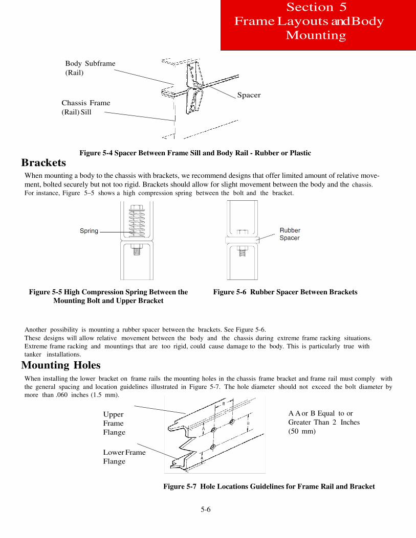
Frame Sill If the body is mounted to the frame with brackets, we recommend that the frame sill spacer be made from a strip of
rubber or plastic (delrin or nylon). These materials will not undergo large dimensional changes during periods of high or
low humidity. The strip will be less likely to fall out during extreme relative motion between body and chassis.
See Figure 5-4.
5-6
Section 5
Frame Layouts and Body
Mounting
Body Subframe
(Rail)
Chassis Frame
(Rail) Sill
Spacer
Brackets
Figure 5-4 Spacer Between Frame Sill and Body Rail - Rubber or Plastic
When mounting a body to the chassis with brackets, we recommend designs that offer limited amount of relative move-
ment, bolted securely but not too rigid. Brackets should allow for slight movement between the body and the chassis.
For instance, Figure 5–5 shows a high compression spring between the bolt and the bracket.
Figure 5-5 High Compression Spring Between the
Mounting Bolt and Upper Bracket
Figure 5-6 Rubber Spacer Between Brackets
Another possibility is mounting a rubber spacer between the brackets. See Figure 5-6.
These designs will allow relative movement between the body and the chassis during extreme frame racking situations.
Extreme frame racking and mountings that are too rigid, could cause damage to the body. This is particularly true with
tanker installations.
Mounting Holes When installing the lower bracket on frame rails the mounting holes in the chassis frame bracket and frame rail must comply with
the general spacing and location guidelines illustrated in Figure 5-7. The hole diameter should not exceed the bolt diameter by
more than .060 inches (1.5 mm).
Upper
Frame
Flange
Lower Frame
Flange
A A or B Equal to or
Greater Than 2 Inches
(50 mm)
Figure 5-7 Hole Locations Guidelines for Frame Rail and Bracket
5-7
Section 5
Frame Layouts and Body
Mounting
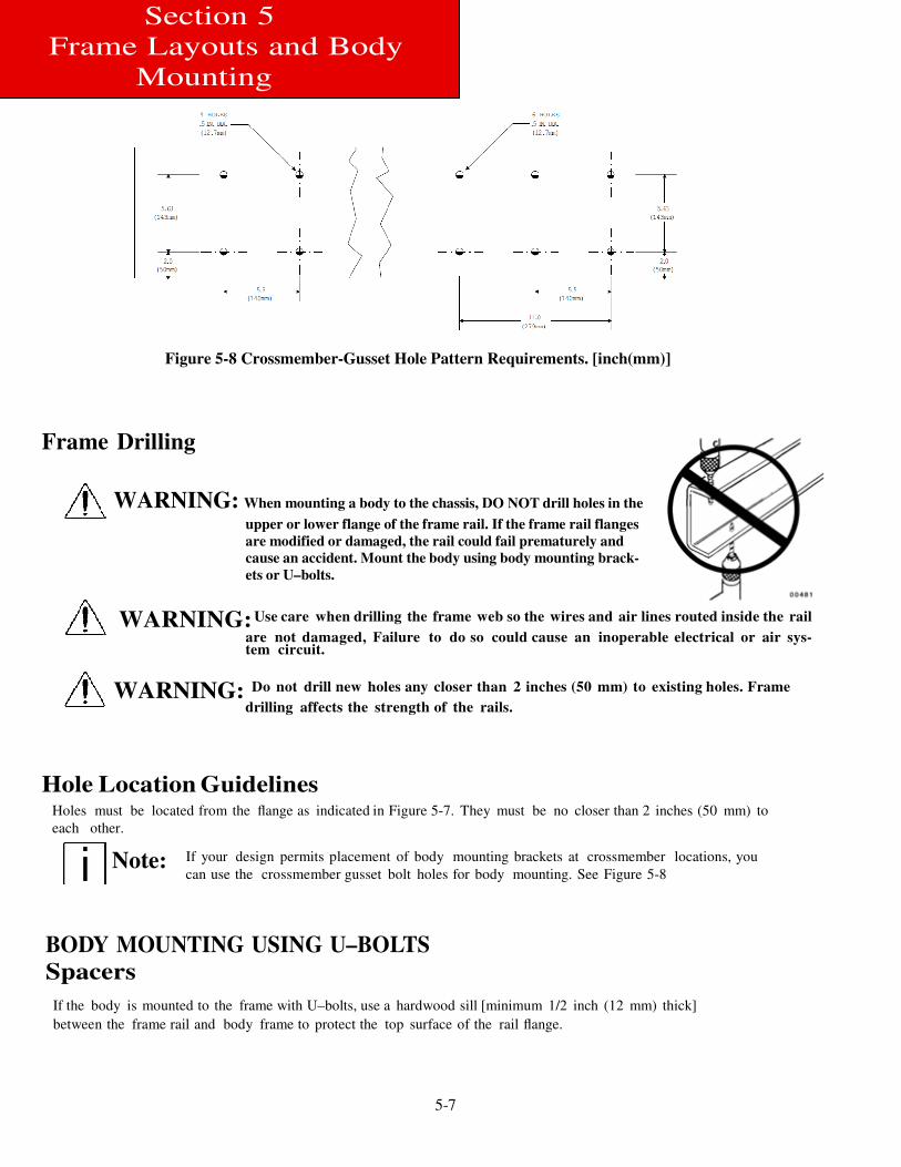
Figure 5-8 Crossmember-Gusset Hole Pattern Requirements. [inch(mm)]
Frame Drilling
WARNING: When mounting a body to the chassis, DO NOT drill holes in the
upper or lower flange of the frame rail. If the frame rail flanges
are modified or damaged, the rail could fail prematurely and
cause an accident. Mount the body using body mounting brack-
ets or U–bolts.
WARNING: Use care when drilling the frame web so the wires and air lines routed inside the rail
are not damaged, Failure to do so could cause an inoperable electrical or air sys- tem circuit.
WARNING: Do not drill new holes any closer than 2 inches (50 mm) to existing holes. Frame
drilling affects the strength of the rails.
Hole Location Guidelines Holes must be located from the flange as indicated in Figure 5-7. They must be no closer than 2 inches (50 mm) to
each other.
Note: If your design permits placement of body mounting brackets at crossmember locations, you
can use the crossmember gusset bolt holes for body mounting. See Figure 5-8
BODY MOUNTING USING U–BOLTS
Spacers
If the body is mounted to the frame with U–bolts, use a hardwood sill [minimum 1/2 inch (12 mm) thick]
between the frame rail and body frame to protect the top surface of the rail flange.
5-8
Section 5
Frame Layouts and Body
Mounting
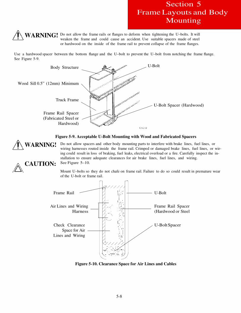
WARNING! Do not allow the frame rails or flanges to deform when tightening the U–bolts. It will
weaken the frame and could cause an accident. Use suitable spacers made of steel
or hardwood on the inside of the frame rail to prevent collapse of the frame flanges.
Use a hardwood spacer between the bottom flange and the U–bolt to prevent the U–bolt from notching the frame flange.
See Figure 5-9.
Body Structure
Wood Sill 0.5” (12mm) Minimum
Truck Frame
Frame Rail Spacer
(Fabricated Steel or
Hardwood)
U-Bolt
U-Bolt Spacer (Hardwood)
Figure 5-9. Acceptable U-Bolt Mounting with Wood and Fabricated Spacers
WARNING!
CAUTION:
Do not allow spacers and other body mounting parts to interfere with brake lines, fuel lines, or
wiring harnesses routed inside the frame rail. Crimped or damaged brake lines, fuel lines, or wir-
ing could result in loss of braking, fuel leaks, electrical overload or a fire. Carefully inspect the in-
stallation to ensure adequate clearances for air brake lines, fuel lines, and wiring.
See Figure 5–10.
Mount U–bolts so they do not chafe on frame rail. Failure to do so could result in premature wear
of the U-bolt or frame rail.
Frame Rail
Air Lines and Wiring
Harness
Check Clearance
Space for Air
Lines and Wiring
U-Bolt
Frame Rail Spacer
(Hardwood or Steel
U-Bolt Spacer
Figure 5-10. Clearance Space for Air Lines and Cables
5-9
Section 5
Frame Layouts and Body
Mounting
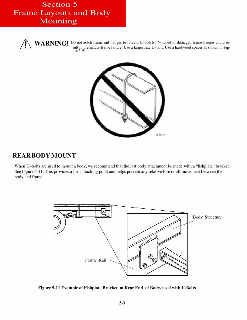
WARNING! Do not notch frame rail flanges to force a U–bolt fit. Notched or damaged frame flanges could re-
sult in premature frame failure. Use a larger size U–bolt. Use a hardwood spacer as shown in Fig- ure 5-9.
REAR BODY MOUNT
When U–bolts are used to mount a body, we recommend that the last body attachment be made with a “fishplate” bracket.
See Figure 5-11. This provides a firm attaching point and helps prevent any relative fore or aft movement between the
body and frame.
Body Structure
Frame Rail
Figure 5-11 Example of Fishplate Bracket at Rear End of Body, used with U-Bolts
6-1
Section 6
Frame Modifications
FRAME MODIFICATIONS
INTRODUCTION
Peterbilt offers customer specified wheelbases and frame overhangs. So, in most cases frame modifications should not be
necessary.
However, some body installations may require slight modifications, while other installations will require extensive
modifications. Sometimes an existing dealer stock chassis may need to have the wheelbase changed to better fit a
customer’s application. The modifications may be as simple as modifying the frame cutoff, or as complex as modifying
the wheelbase.
DRILLING RAILS
If frame holes need to be drilled in the rail, see SECTION 4 BODY MOUNTING for more information.
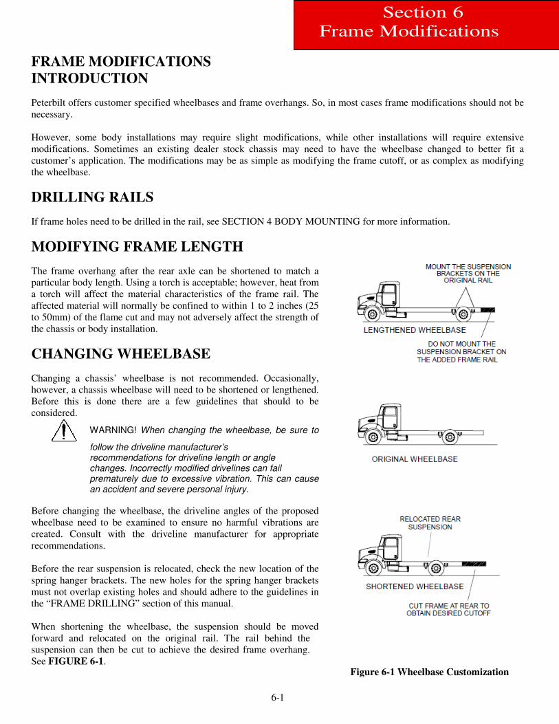
MODIFYING FRAME LENGTH
The frame overhang after the rear axle can be shortened to match a
particular body length. Using a torch is acceptable; however, heat from
a torch will affect the material characteristics of the frame rail. The
affected material will normally be confined to within 1 to 2 inches (25
to 50mm) of the flame cut and may not adversely affect the strength of
the chassis or body installation.
CHANGING WHEELBASE
Changing a chassis’ wheelbase is not recommended. Occasionally,
however, a chassis wheelbase will need to be shortened or lengthened.
Before this is done there are a few guidelines that should to be
considered.
WARNING! When changing the wheelbase, be sure to
follow the driveline manufacturer’s recommendations for driveline length or angle changes. Incorrectly modified drivelines can fail prematurely due to excessive vibration. This can cause an accident and severe personal injury.
Before changing the wheelbase, the driveline angles of the proposed
wheelbase need to be examined to ensure no harmful vibrations are
created. Consult with the driveline manufacturer for appropriate
recommendations.
Before the rear suspension is relocated, check the new location of the
spring hanger brackets. The new holes for the spring hanger brackets
must not overlap existing holes and should adhere to the guidelines in
the “FRAME DRILLING” section of this manual.
When shortening the wheelbase, the suspension should be moved
forward and relocated on the original rail. The rail behind the
suspension can then be cut to achieve the desired frame overhang.
See FIGURE 6-1.
Figure 6-1 Wheelbase Customization
6-2
Section 6
Frame Modifications
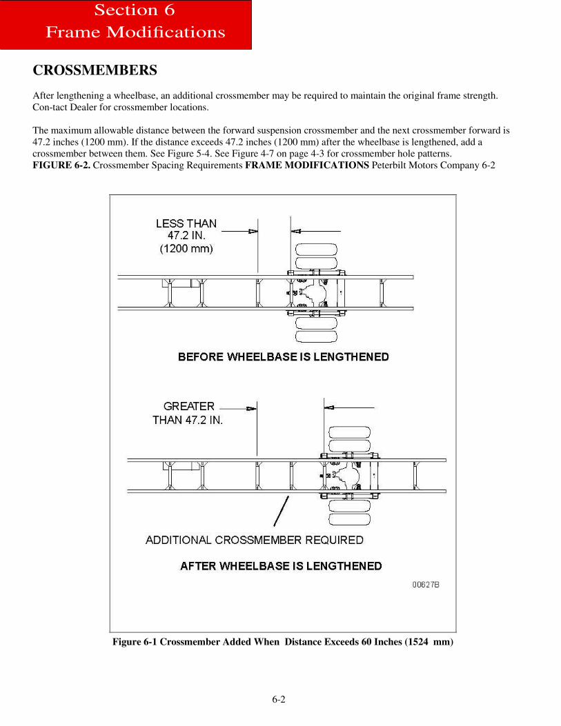
CROSSMEMBERS
After lengthening a wheelbase, an additional crossmember may be required to maintain the original frame strength.
Con-tact Dealer for crossmember locations.
The maximum allowable distance between the forward suspension crossmember and the next crossmember forward is
47.2 inches (1200 mm). If the distance exceeds 47.2 inches (1200 mm) after the wheelbase is lengthened, add a
crossmember between them. See Figure 5-4. See Figure 4-7 on page 4-3 for crossmember hole patterns.
FIGURE 6-2. Crossmember Spacing Requirements FRAME MODIFICATIONS Peterbilt Motors Company 6-2
Figure 6-1 Crossmember Added When Distance Exceeds 60 Inches (1524 mm)
6-3
Section 6
Frame Modifications
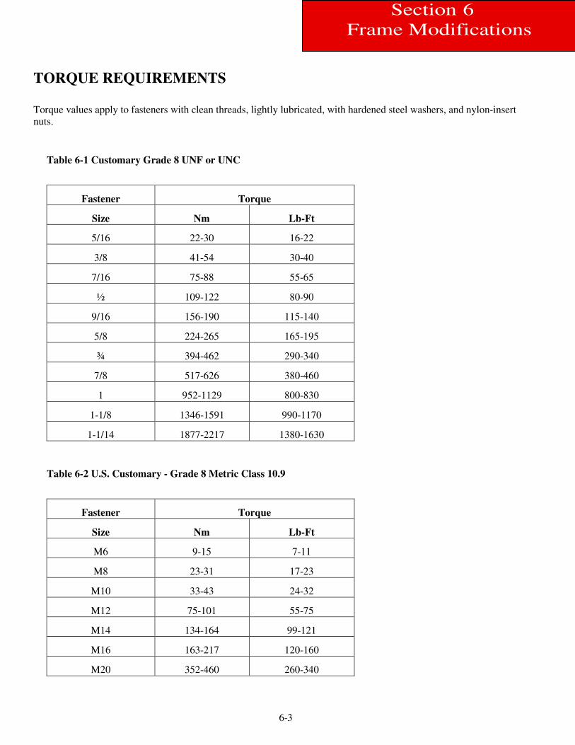
TORQUE REQUIREMENTS
Torque values apply to fasteners with clean threads, lightly lubricated, with hardened steel washers, and nylon-insert
nuts.
Table 6-1 Customary Grade 8 UNF or UNC
Fastener Torque
Size Nm Lb-Ft
5/16 22-30 16-22
3/8 41-54 30-40
7/16 75-88 55-65
½ 109-122 80-90
9/16 156-190 115-140
5/8 224-265 165-195
¾ 394-462 290-340
7/8 517-626 380-460
1 952-1129 800-830
1-1/8 1346-1591 990-1170
1-1/14 1877-2217 1380-1630
Table 6-2 U.S. Customary - Grade 8 Metric Class 10.9
Fastener Torque
Size Nm Lb-Ft
M6 9-15 7-11
M8 23-31 17-23
M10 33-43 24-32
M12 75-101 55-75
M14 134-164 99-121
M16 163-217 120-160
M20 352-460 260-340
7-1
Section 7
Electrical
ELECTRICAL Introduction
Through the use of an optional body harness and additional spare circuits, we have reduced the complexity associated with
adding common circuits to a body installation.
Note: The most common circuits that body builders may need are pre-connected to this optional wiring
harness.
.
ELECTRICAL C I R C U I T S
Capacity
WARNING! Do not install an electrical circuit that requires more amperage (electrical capacity) than what is
available in the specific chassis circuit. An overloaded circuit may cause severe damage. Compare
the amperage requirements of the new circuit to the electrical current capacity of the existing
chassis circuit before adding the body or other equipment.
7-2
Section 7
Electrical
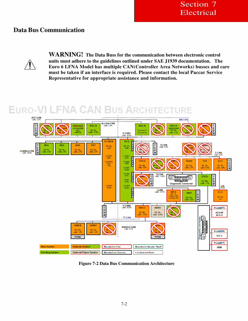
Data Bus Communication
WARNING! The Data Buss for the communication between electronic control
units must adhere to the guidelines outlined under SAE J1939 documentation. The
Euro 6 LFNA Model has multiple CAN(Controller Area Networks) busses and care
must be taken if an interface is required. Please contact the local Paccar Service
Representative for appropriate assistance and information.
Figure 7-2 Data Bus Communication Architecture
7-3
Section 7
Electrical
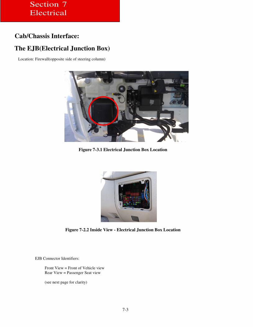
Cab/Chassis Interface:
The EJB(Electrical Junction Box)
Location: Firewall(opposite side of steering column)
Figure 7-3.1 Electrical Junction Box Location
Figure 7-2.2 Inside View - Electrical Junction Box Location
EJB Connector Identifiers:
Front View = Front of Vehicle view
Rear View = Passenger Seat view
(see next page for clarity)
7-4
Section 7
El Electrical
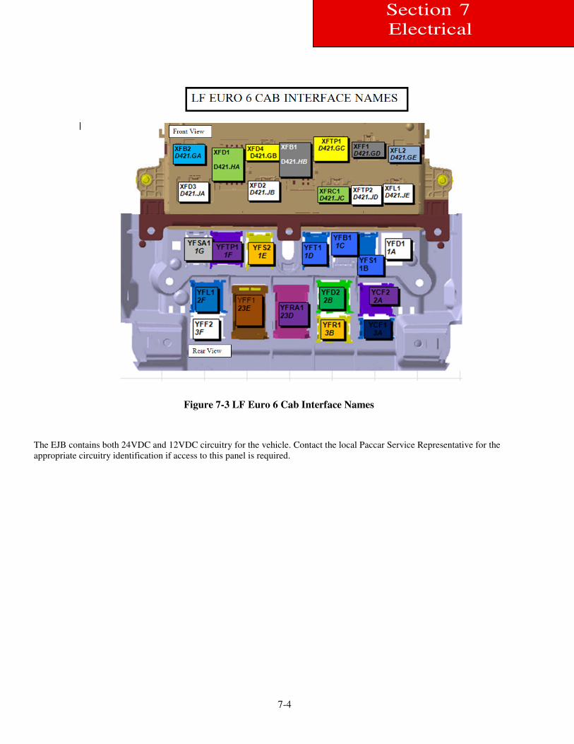
Figure 7-3 LF Euro 6 Cab Interface Names
The EJB contains both 24VDC and 12VDC circuitry for the vehicle. Contact the local Paccar Service Representative for the
appropriate circuitry identification if access to this panel is required.
7-5
Section 7
Electrical
7-6
Section 7
Electrical
Controllers
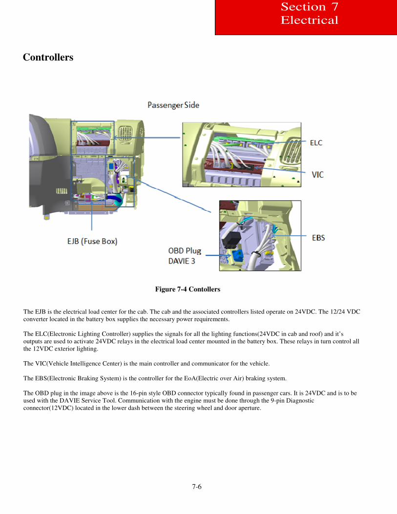
Figure 7-4 Contollers
The EJB is the electrical load center for the cab. The cab and the associated controllers listed operate on 24VDC. The 12/24 VDC
converter located in the battery box supplies the necessary power requirements.
The ELC(Electronic Lighting Controller) supplies the signals for all the lighting functions(24VDC in cab and roof) and it’s
outputs are used to activate 24VDC relays in the electrical load center mounted in the battery box. These relays in turn control all
the 12VDC exterior lighting.
The VIC(Vehicle Intelligence Center) is the main controller and communicator for the vehicle.
The EBS(Electronic Braking System) is the controller for the EoA(Electric over Air) braking system.
The OBD plug in the image above is the 16-pin style OBD connector typically found in passenger cars. It is 24VDC and is to be
used with the DAVIE Service Tool. Communication with the engine must be done through the 9-pin Diagnostic
connector(12VDC) located in the lower dash between the steering wheel and door aperture.
7-7
Section 7
Electrical
Dash Controls
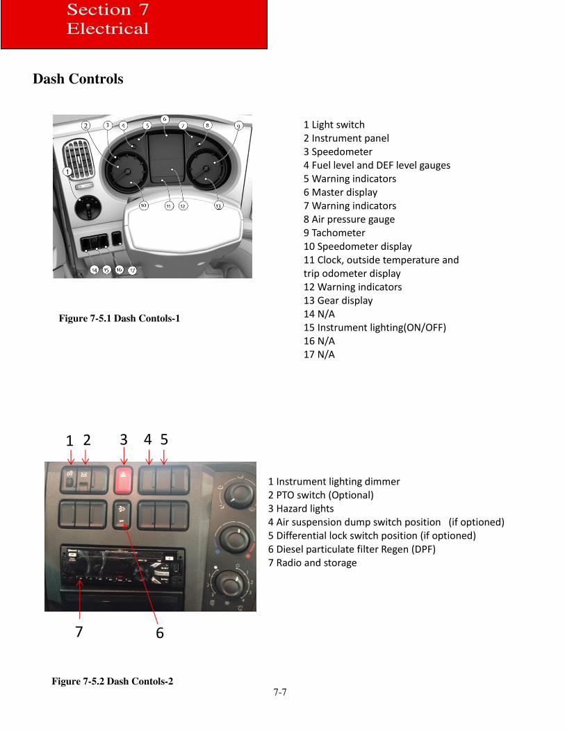
1 Light switch
2 Instrument panel
3 Speedometer
4 Fuel level and DEF level gauges
5 Warning indicators
6 Master display
7 Warning indicators
8 Air pressure gauge
9 Tachometer
10 Speedometer display
11 Clock, outside temperature and
trip odometer display
12 Warning indicators
13 Gear display
14 N/A
15 Instrument lighting(ON/OFF)
16 N/A
17 N/A
1 2 3 4 5
6 7
1 Instrument lighting dimmer
2 PTO switch (Optional)
3 Hazard lights
4 Air suspension dump switch position (if optioned)
5 Differential lock switch position (if optioned)
6 Diesel particulate filter Regen (DPF)
7 Radio and storage
Figure 7-5.1 Dash Contols-1
Figure 7-5.2 Dash Contols-2
7-8
Section 7
Electrical
Power Distribution Center.
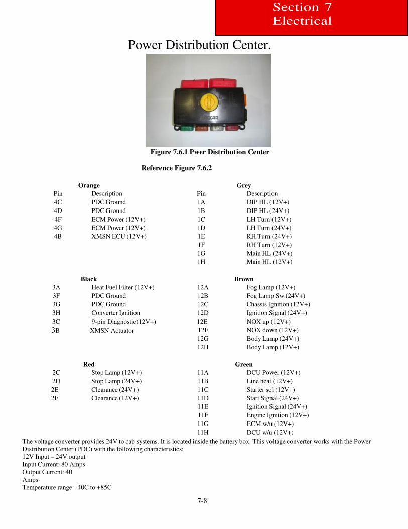
Figure 7.6.1 Pwer Distribution Center
Reference Figure 7.6.2
Pin
Orange
Description
Pin
Grey
Description 4C PDC Ground 1A DIP HL (12V+) 4D PDC Ground 1B DIP HL (24V+) 4F ECM Power (12V+) 1C LH Turn (12V+) 4G ECM Power (12V+) 1D LH Turn (24V+) 4B XMSN ECU (12V+) 1E RH Turn (24V+)
1F RH Turn (12V+)
1G Main HL (24V+)
1H Main HL (12V+)
3A
Black
Heat Fuel Filter (12V+)
12A
Brown
Fog Lamp (12V+) 3F PDC Ground 12B Fog Lamp Sw (24V+) 3G PDC Ground 12C Chassis Ignition (12V+) 3H Converter Ignition 12D Ignition Signal (24V+) 3C 9-pin Diagnostic(12V+) 3B XMSN Actuator
12E NOX up (12V+) 12F NOX down (12V+) 12G Body Lamp (24V+) 12H Body Lamp (12V+)
2C
Red
Stop Lamp (12V+)
11A
Green
DCU Power (12V+) 2D Stop Lamp (24V+) 11B Line heat (12V+) 2E Clearance (24V+) 11C Starter sol (12V+) 2F Clearance (12V+) 11D Start Signal (24V+)
11E Ignition Signal (24V+) 11F Engine Ignition (12V+) 11G ECM w/u (12V+) 11H DCU w/u (12V+)
The voltage converter provides 24V to cab systems. It is located inside the battery box. This voltage converter works with the Power
Distribution Center (PDC) with the following characteristics:
12V Input – 24V output
Input Current: 80 Amps
Output Current: 40
Amps
Temperature range: -40C to +85C
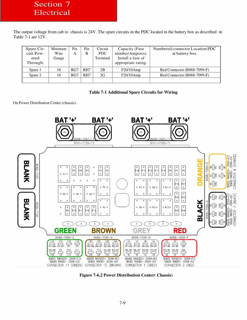
7-9
Section 7
Electrical
The output voltage from cab to chassis is 24V. The spare circuits in the PDC located in the battery box as described in
Table 7-1 are 12V.
Spare Cir-
cuit Pow-
ered
Through:
Minimum
Wire
Gauge
Pin
A Pin
B Circuit
PDC
Terminal
Capacity (Fuse
number/Amperes).
Install a fuse of
appropriate rating.
Numbered connector Location PDC
at battery box.
Spare 1 16 RG7 RH7 2B F20/10Amp Red Connector (B068-7099-F) Spare 2 16 RG7 RH7 2G F20/10Amp Red Connector (B068-7099-F)
Table 7-1 Additional Spare Circuits for Wiring
On Power Distribution Center (chassis).
Figure 7-6.2 Power Distribution Center( Chassis)
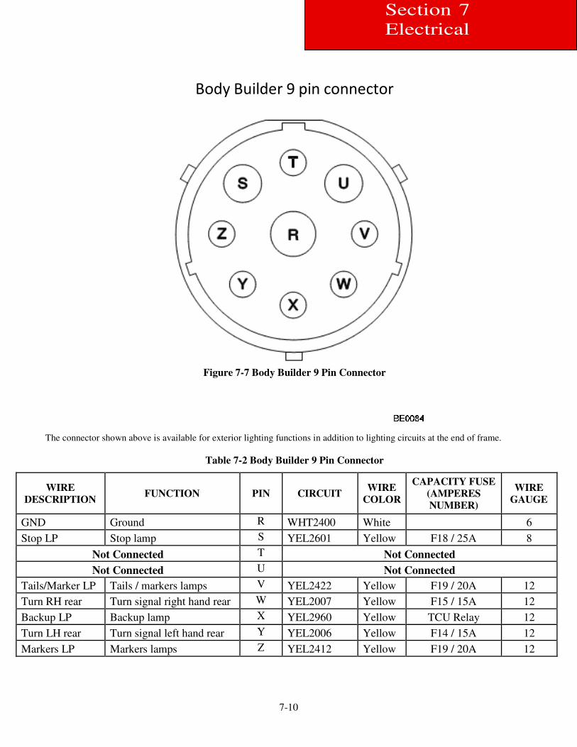
7-10
Section 7
Electrical
Body Builder 9 pin connector
Figure 7-7 Body Builder 9 Pin Connector
The connector shown above is available for exterior lighting functions in addition to lighting circuits at the end of frame.
Table 7-2 Body Builder 9 Pin Connector
WIRE
DESCRIPTION
FUNCTION
PIN
CIRCUIT
WIRE
COLOR
CAPACITY FUSE
(AMPERES
NUMBER)
WIRE
GAUGE
GND Ground R WHT2400 White 6
Stop LP Stop lamp S YEL2601 Yellow F18 / 25A 8
Not Connected T Not Connected
Not Connected U Not Connected
Tails/Marker LP Tails / markers lamps V YEL2422 Yellow F19 / 20A 12
Turn RH rear Turn signal right hand rear W YEL2007 Yellow F15 / 15A 12
Backup LP Backup lamp X YEL2960 Yellow TCU Relay 12
Turn LH rear Turn signal left hand rear Y YEL2006 Yellow F14 / 15A 12
Markers LP Markers lamps Z YEL2412 Yellow F19 / 20A 12
7-11
Section 7
Electrical
Model 220 PTO Wiring Information
Wiring of the Current Model 220 is different from previous version of the Model 220. Please see the information below for basic
wiring and functionality.
1) If equipped, the factory PTO dash switch will tell the VIC to go to PTO mode.
2) J124 connector on the transmission needs 12V to tell the Allison TCM to enable PTO mode.
3) J125 connector on the transmission is a ground output signal from the Allison TCM for the PTO.
4) J126 connector on the transmission is a 24V output signal from the VIC when the PTO dash switch is on.
5) J128 connector on the transmission needs a ground to feedback to the VIC for PTO engaged status (must occur within 3-4
seconds after PTO switch). Option 1: Provide a ground from the PTO engaged switch to J128. Option 2: J128 & J125 can be
spliced together for the feedback ground to the VIC. Please note: J128 & J125 will not mate together, so connectors will have to
be cut off and spliced.
6) Pin 10 of the 12-pin Remote PTO connector (P124) on the engine harness –OR- pin B of the 3-pin connector (J144) on the
engine harness needs a ground to feedback to the VIC for PTO engaged status. This performs the same function as item 5 above.
This is primarily used for remote set-ups outside the cab.
As an example for setting up a PTO if using the factory PTO dash switch and one pre-set RPM:
(Refer Figure 7.9)
A) Use J126 to drive your PTO solenoid. This is 24V, so you may need to use a relay if the PTO requires 12V or a ground.
B) Send 12V to connector J124 for the Allison TCM when the PTO is engaged. This 12V can be “borrowed” from the relay used in
step A) above.
C) Provide a ground to J128 for feedback to the VIC when the PTO is engaged. This can be done by either splicing J125 & J128
together or by running a separate wire from the switch directly on the PTO (if equipped) to J128. This ground must be applied
within 3-4 seconds after the PTO switch is enabled.
D) Set your desired engine RPM for pre-set speed with DAVIE. This is found under Customer Parameters.
Please note: This information relates only to setting up the mechanical PTO for operation. This does not address the additional
function of ESC (Engine Speed Control), as this is a separate function. Engine Speed Control must be enabled in the VIC
programming and requires a modified PRS file. Instructions for use of ESC follow.
Engine Speed Control (ESC)
ESC can be fixed (pre-programmed) engine speed or variable engine speed. The Euro 6 only has two pre-programmed engine
speeds N2 and N3. N VAR is available using the “SET+” and “SET-“ to increase and decrease speed.
To activate these speeds the ESC must first be enabled by providing a high signal (12-24V) on pin 12 of the 12-pin connector on the
engine harness (P124).
• The N2 and N3 can then be activated by providing a high signal on pins 7 and 6 respectively of the 12-pin
connector on the engine harness (P124).
• N VAR can be activated by providing a high signal on pin 8 of the 12-pin connector on the engine harness (P124).
(N refers to a Speed Set point)
If N VAR variable control is desired with the steering wheel switches:
• A high signal (12-24V) is provided to pin 12 of the 12pin connector on the engine harness (P124).
• A high signal is provided to pin 8 of the 12pin connector (P124).
• Use the “SET+” and “SET-“steering wheel switches to bump the throttle up and down.
• The parking brake must be set for proper functionality.
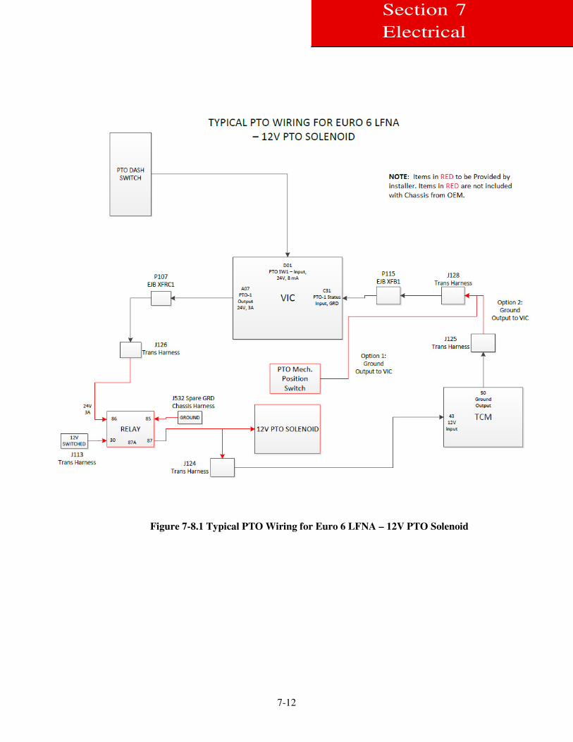
7-12
Section 7
Electrical
Figure 7-8.1 Typical PTO Wiring for Euro 6 LFNA – 12V PTO Solenoid
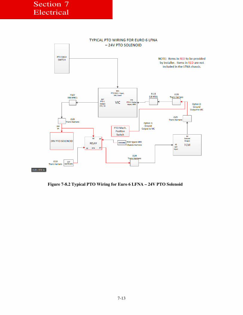
7-13
Section 7
Electrical
Figure 7-8.2 Typical PTO Wiring for Euro 6 LFNA – 24V PTO Solenoid
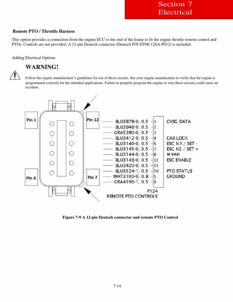
7-14
Section 7
Electrical
Remote PTO / Throttle Harness
This option provides a connection from the engine ECU to the end of the frame to fit the engine throttle remote control and
PTOs. Controls are not provided. A 12-pin Deutsch connector (Deutsch P/N DT06-12SA-P012) is included.
Adding Electrical Options
WARNING!
Follow the engine manufacturer’s guidelines for use of these circuits. See your engine manufacturer to verify that the engine is
programmed correctly for the intended applications. Failure to properly program the engine or wire these circuits could cause an
accident.
Figure 7-9 A 12-pin Deutsch connector and remote PTO Control
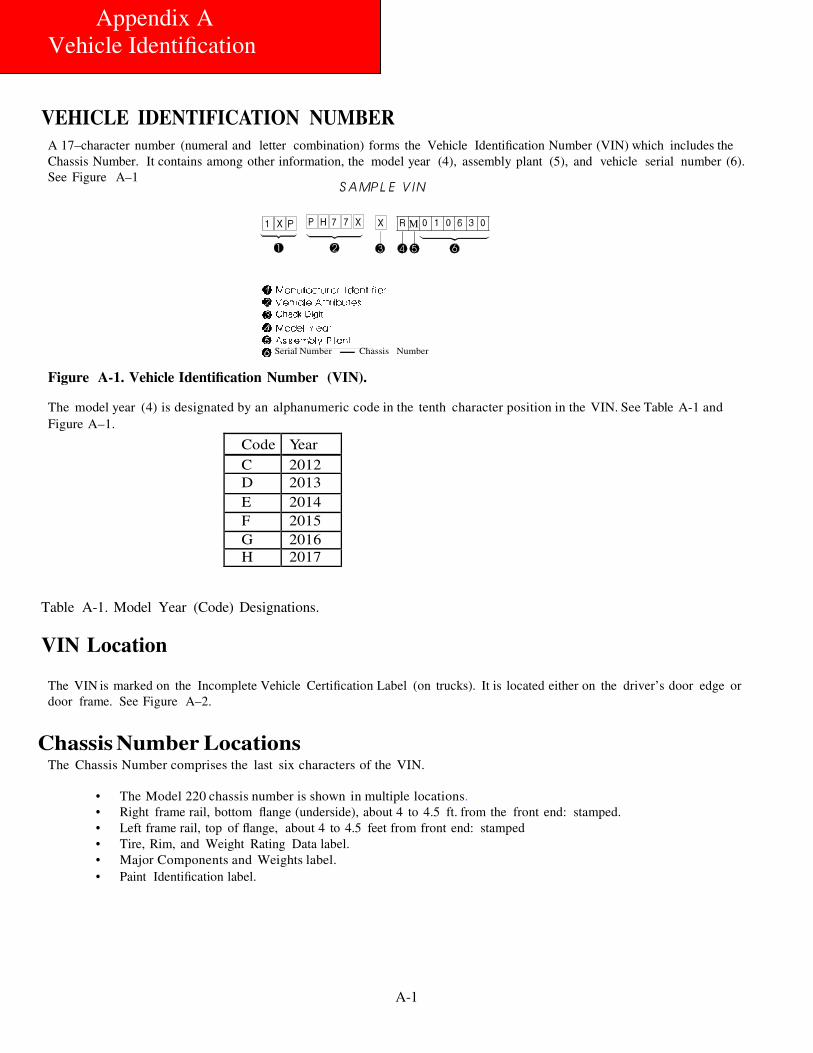
A-1
Appendix A
Vehicle Identification
VEHICLE IDENTIFICATION NUMBER
A 17–character number (numeral and letter combination) forms the Vehicle Identification Number (VIN) which includes the
Chassis Number. It contains among other information, the model year (4), assembly plant (5), and vehicle serial number (6).
See Figure A–1
Serial Number Chassis Number
Figure A-1. Vehicle Identification Number (VIN).
The model year (4) is designated by an alphanumeric code in the tenth character position in the VIN. See Table A-1 and
Figure A–1.
Code Year
C 2012 D 2013
E 2014
F 2015
G 2016 H 2017
Table A-1. Model Year (Code) Designations.
VIN Location
The VIN is marked on the Incomplete Vehicle Certification Label (on trucks). It is located either on the driver’s door edge or
door frame. See Figure A–2.
Chassis Number Locations The Chassis Number comprises the last six characters of the VIN.
• The Model 220 chassis number is shown in multiple locations.
• Right frame rail, bottom flange (underside), about 4 to 4.5 ft. from the front end: stamped.
• Left frame rail, top of flange, about 4 to 4.5 feet from front end: stamped
• Tire, Rim, and Weight Rating Data label.
• Major Components and Weights label.
• Paint Identification label.
M

A-2
CERTIFICATION LABELS
Components and Weights Label
Appendix A
Vehicle Identification
The Major Components and Weights Label is located on either the driver’s side door edge or on the door frame. See Fig-
ure A–2. It includes: chassis weight and gross weight; plus, model and serial numbers for the vehicle, engine, transmis-
sion, and axles.
Tire, Rim and
Weight Rating
Data label
Safety Mark (Canadian
Registry Only)
Final Stage Manufacturer
Label to be Installed by
Final Stage Manufacturer
Chassis Serial
Number
Major Components and
Weights Label
Incomplete Vehicle
Certification Label
Figure A-2. Locations of
Certification Labels - Driver’s Door
Figure A-2. Drivers Door and Door Frame Label
Tire/Rim and Weight Rating Data Label
The Tire/Rim and Weight Rating Data Label is located on the driver’s side door edge, above the door latch. See Figure
A–2. It contains the following information:
•
•
•
•
Note:
GVWR — Gross Vehicle Weight Rating
GAWR FRONT and REAR — Gross Axle Weight Ratings for Front and Rear Axle
TIRE/RIM SIZES AND INFLATION PRESSURES — Tire/Rim Sizes and Cold Pressure Minimums
Chassis (Serial) Number
GVWR is the TOTAL WEIGHT the vehicle is designed to carry. This includes the weight of the
empty vehicle, loading platform, occupants, fuel, and any load. Axle weight ratings are listed on
the edge of the driver’s door.
Incomplete Vehicle Certification Label
The Incomplete Vehicle Certification Label is located on the driver’s side door edge below the latch. See Figure A–
2. It contains the following information:
• DATE OF MANUFACTURE
• VIN — Vehicle Identification Number
• LISTING OF APPLICABLE FEDERAL MOTOR VEHICLE SAFETY STANDARDS
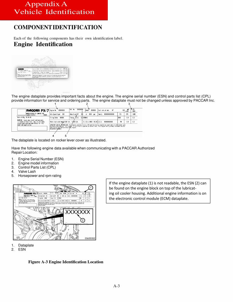
A-3
Appendix A
Vehicle Identification
COMPONENT IDENTIFICATION
Each of the following components has their own identification label.
Engine Identification
The engine dataplate provides important facts about the engine. The engine serial number (ESN) and control parts list (CPL) provide information for service and ordering parts. The engine dataplate must not be changed unless approved by PACCAR Inc.
The dataplate is located on rocker lever cover as illustrated.
Have the following engine data available when communicating with a PACCAR Authorized Repair Location:
1. Engine Serial Number (ESN) 2. Engine model information 3. Control Parts List (CPL) 4. Valve Lash 5. Horsepower and rpm rating
1. Dataplate 2. ESN
Figure A-3 Engine Identification Location
If the engine dataplate (1) is not readable, the ESN (2) can
be found on the engine block on top of the lubricat-
ing oil cooler housing. Additional engine information is on
the electronic control module (ECM) dataplate.
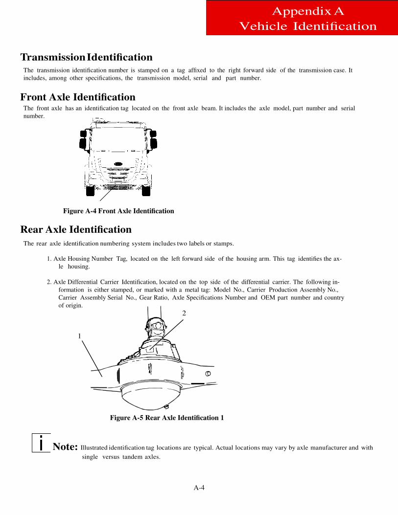
A-4
Appendix A
Vehicle Identification
Transmission Identification
The transmission identification number is stamped on a tag affixed to the right forward side of the transmission case. It
includes, among other specifications, the transmission model, serial and part number.
Front Axle Identification The front axle has an identification tag located on the front axle beam. It includes the axle model, part number and serial
number.
Figure A-4 Front Axle Identification
Rear Axle Identification
The rear axle identification numbering system includes two labels or stamps.
1. Axle Housing Number Tag, located on the left forward side of the housing arm. This tag identifies the ax-
le housing.
2. Axle Differential Carrier Identification, located on the top side of the differential carrier. The following in-
formation is either stamped, or marked with a metal tag: Model No., Carrier Production Assembly No.,
Carrier Assembly Serial No., Gear Ratio, Axle Specifications Number and OEM part number and country
of origin.
2
1
Figure A-5 Rear Axle Identification 1
Note: Illustrated identification tag locations are typical. Actual locations may vary by axle manufacturer and with
single versus tandem axles.
B-1
Appendix B
Weight Distribution
INTRODUCTION
In the Medium Duty truck market, matching the wheelbase to the body specification is extremely important. Se-
lection of the wrong wheelbase may lead to premature component failure, poor performance, and ultimately a
dissatisfied customer. Before selecting the proper wheelbase, it is important to have a basic understanding of
weight distribution.
Abbreviations
Throughout this section, abbreviations are used to describe certain features and requirements of the vehicle
(see the list below). Review this list frequently so you know what the abbreviations mean.
AF = Frame rail overhang length – behind the rear axle
BL = Body Length CA = Back of cab to centerline of rear axle
Note: The Model 220 CA figures are measured from the true back of cab to the centerline of the rear
axle. To obtain a usable CA the body builder must subtract any required space behind the cab, which may be needed for other equipment.
CG = Center of gravity: the balance point or center of a load. It is usually identified by a circle
with alternating black and white quarters.
CGf = Distance from the centerline of the front axle to the center of gravity of the load (L). The
load can be any load such as a fuel tank, a body, or the payload.
FA = Front Axle
GVWR = Gross Vehicle Weight Rating
L = Load: the weight that is carried. This could be the body, the payload or any item that has its
weight distributed between the two axles.
Lf = Portion of load (L) carried by front axle
Lr = Portion of load (L) carried by rear axle
RA = Rear Axle
WB = Wheelbase Length
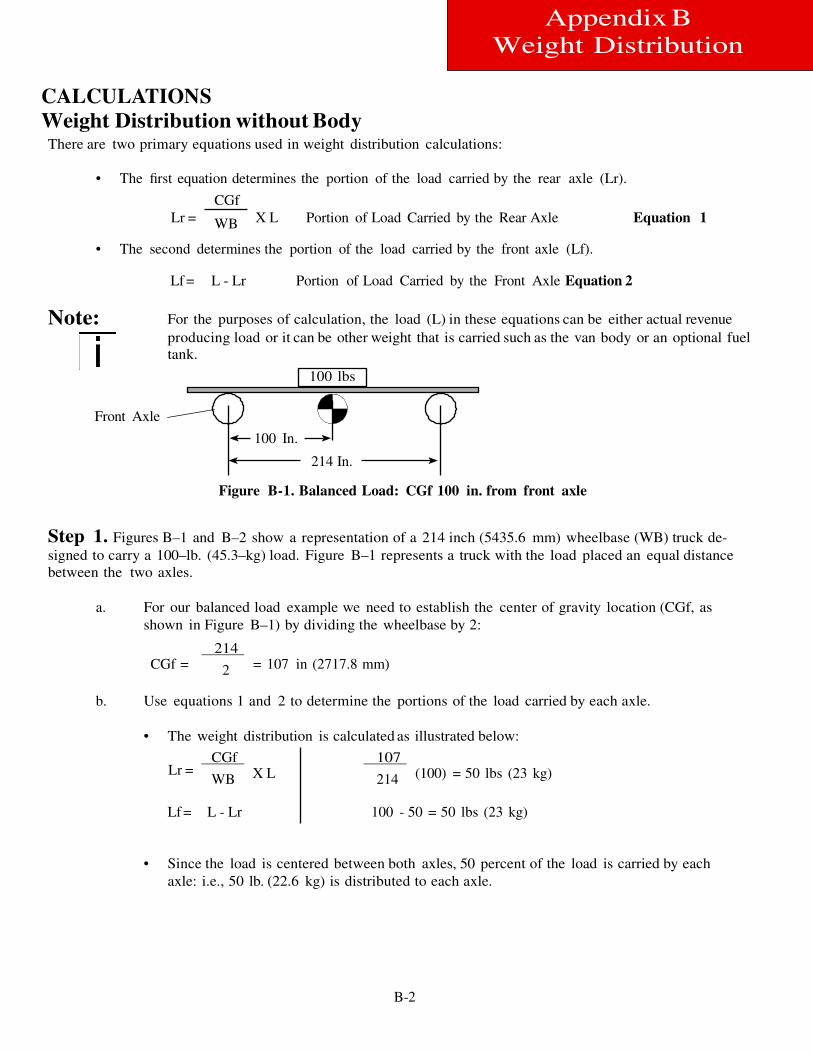
B-2
100 lbs
100 In.
214 In.
Appendix B
Weight Distribution
CALCULATIONS
Weight Distribution without Body There are two primary equations used in weight distribution calculations:
• The first equation determines the portion of the load carried by the rear axle (Lr).
CGf
Lr = WB X L Portion of Load Carried by the Rear Axle Equation 1
• The second determines the portion of the load carried by the front axle (Lf).
Lf = L - Lr Portion of Load Carried by the Front Axle Equation 2
Note: For the purposes of calculation, the load (L) in these equations can be either actual revenue
producing load or it can be other weight that is carried such as the van body or an optional fuel
tank.
Front Axle
Figure B-1. Balanced Load: CGf 100 in. from front axle
Step 1. Figures B–1 and B–2 show a representation of a 214 inch (5435.6 mm) wheelbase (WB) truck de-
signed to carry a 100–lb. (45.3–kg) load. Figure B–1 represents a truck with the load placed an equal distance
between the two axles.
a. For our balanced load example we need to establish the center of gravity location (CGf, as
shown in Figure B–1) by dividing the wheelbase by 2:
214 CGf = 2 = 107 in (2717.8 mm)
b. Use equations 1 and 2 to determine the portions of the load carried by each axle.
• The weight distribution is calculated as illustrated below:
Lr = CGf
WB X L 107
214 (100) = 50 lbs (23 kg)
Lf = L - Lr 100 - 50 = 50 lbs (23 kg)
• Since the load is centered between both axles, 50 percent of the load is carried by each
axle: i.e., 50 lb. (22.6 kg) is distributed to each axle.
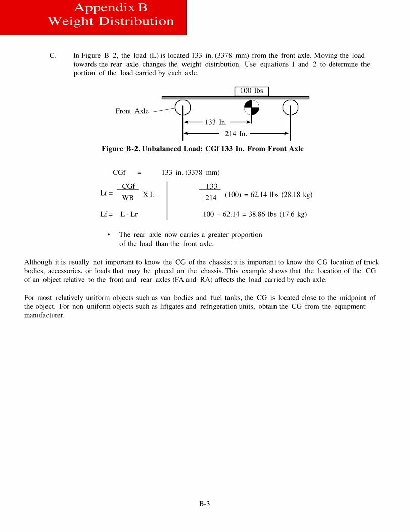
B-3
100 lbs
133 In.
214 In.
Appendix B
Weight Distribution
C. In Figure B–2, the load (L) is located 133 in. (3378 mm) from the front axle. Moving the load
towards the rear axle changes the weight distribution. Use equations 1 and 2 to determine the
portion of the load carried by each axle.
Front Axle
Figure B-2. Unbalanced Load: CGf 133 In. From Front Axle
CGf = 133 in. (3378 mm)
Lr = CGf
WB X L 133
214 (100) = 62.14 lbs (28.18 kg)
Lf = L - Lr 100 – 62.14 = 38.86 lbs (17.6 kg)
• The rear axle now carries a greater proportion
of the load than the front axle.
Although it is usually not important to know the CG of the chassis; it is important to know the CG location of truck
bodies, accessories, or loads that may be placed on the chassis. This example shows that the location of the CG
of an object relative to the front and rear axles (FA and RA) affects the load carried by each axle.
For most relatively uniform objects such as van bodies and fuel tanks, the CG is located close to the midpoint of
the object. For non–uniform objects such as liftgates and refrigeration units, obtain the CG from the equipment
manufacturer.
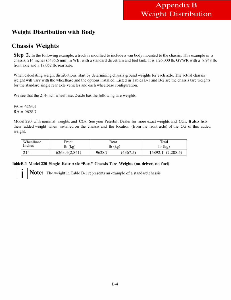
B-4
Appendix B
Weight Distribution
Weight Distribution with Body
Chassis Weights
Step 2. In the following example, a truck is modified to include a van body mounted to the chassis. This example is a
chassis, 214 inches (5435.6 mm) in WB, with a standard drivetrain and fuel tank. It is a 26,000 lb. GVWR with a 8,948 lb.
front axle and a 17,052 lb. rear axle.
When calculating weight distributions, start by determining chassis ground weights for each axle. The actual chassis
weight will vary with the wheelbase and the options installed. Listed in Tables B-1 and B-2 are the chassis tare weights
for the standard single rear axle vehicles and each wheelbase configuration.
We see that the 214-inch wheelbase, 2-axle has the following tare weights:
FA = 6263.4
RA = 9628.7
Model 220 with nominal weights and CGs. See your Peterbilt Dealer for more exact weights and CGs. It also lists
their added weight when installed on the chassis and the location (from the front axle) of the CG of this added
weight.
Wheelbase Inches
Front
lb (kg) Rear
lb (kg) Total
lb (kg)
214 6263.4 (2,841) 9628.7 (4367.5) 15892.1 (7,208.5)
Table B-1 Model 220 Single Rear Axle “Bare” Chassis Tare Weights (no driver, no fuel)
Note: The weight in Table B-1 represents an example of a standard chassis
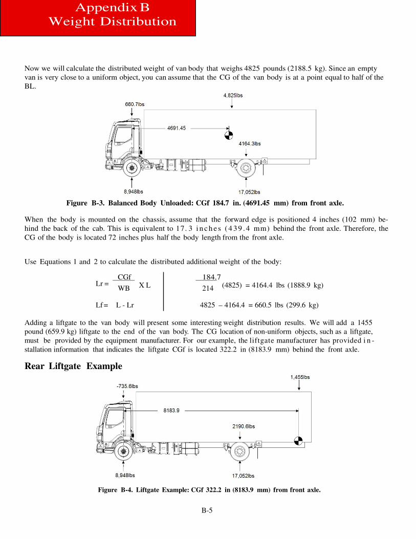
B-5
Appendix B
Weight Distribution
Now we will calculate the distributed weight of van body that weighs 4825 pounds (2188.5 kg). Since an empty
van is very close to a uniform object, you can assume that the CG of the van body is at a point equal to half of the
BL.
Figure B-3. Balanced Body Unloaded: CGf 184.7 in. (4691.45 mm) from front axle.
When the body is mounted on the chassis, assume that the forward edge is positioned 4 inches (102 mm) be-
hind the back of the cab. This is equivalent to 17. 3 i n c h e s ( 4 39 . 4 mm) behind the front axle. Therefore, the
CG of the body is located 72 inches plus half the body length from the front axle.
Use Equations 1 and 2 to calculate the distributed additional weight of the body:
Lr = CGf
WB X L 184.7
214 (4825) = 4164.4 lbs (1888.9 kg)
Lf = L - Lr 4825 – 4164.4 = 660.5 lbs (299.6 kg)
Adding a liftgate to the van body will present some interesting weight distribution results. We will add a 1455
pound (659.9 kg) liftgate to the end of the van body. The CG location of non-uniform objects, such as a liftgate,
must be provided by the equipment manufacturer. For our example, the liftgate manufacturer has provided i n -
stallation information that indicates the liftgate CGf is located 322.2 in (8183.9 mm) behind the front axle.
Rear Liftgate Example
Figure B-4. Liftgate Example: CGf 322.2 in (8183.9 mm) from front axle.
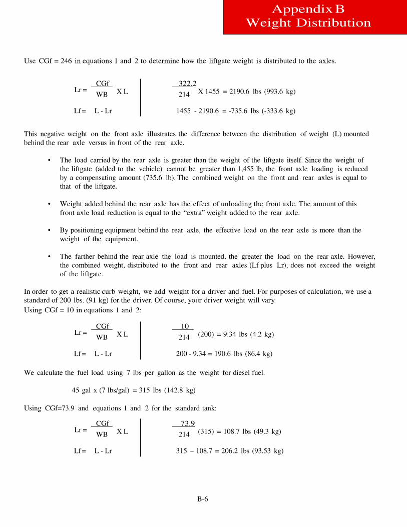
B-6
Appendix B
Weight Distribution
Use CGf = 246 in equations 1 and 2 to determine how the liftgate weight is distributed to the axles.
Lr =
CGf
WB X L
322.2
214 X 1455 = 2190.6 lbs (993.6 kg)
Lf = L - Lr 1455 - 2190.6 = -735.6 lbs (-333.6 kg)
This negative weight on the front axle illustrates the difference between the distribution of weight (L) mounted
behind the rear axle versus in front of the rear axle.
• The load carried by the rear axle is greater than the weight of the liftgate itself. Since the weight of
the liftgate (added to the vehicle) cannot be greater than 1,455 lb, the front axle loading is reduced
by a compensating amount (735.6 lb). The combined weight on the front and rear axles is equal to
that of the liftgate.
• Weight added behind the rear axle has the effect of unloading the front axle. The amount of this
front axle load reduction is equal to the “extra” weight added to the rear axle.
• By positioning equipment behind the rear axle, the effective load on the rear axle is more than the
weight of the equipment.
• The farther behind the rear axle the load is mounted, the greater the load on the rear axle. However,
the combined weight, distributed to the front and rear axles (Lf plus Lr), does not exceed the weight
of the liftgate.
In order to get a realistic curb weight, we add weight for a driver and fuel. For purposes of calculation, we use a
standard of 200 lbs. (91 kg) for the driver. Of course, your driver weight will vary.
Using CGf = 10 in equations 1 and 2:
Lr = CGf
WB X L 10
214 (200) = 9.34 lbs (4.2 kg)
Lf = L - Lr 200 - 9.34 = 190.6 lbs (86.4 kg)
We calculate the fuel load using 7 lbs per gallon as the weight for diesel fuel.
45 gal x (7 lbs/gal) = 315 lbs (142.8 kg)
Using CGf=73.9 and equations 1 and 2 for the standard tank:
Lr = CGf
WB X L 73.9
214 (315) = 108.7 lbs (49.3 kg)
Lf = L - Lr 315 – 108.7 = 206.2 lbs (93.53 kg)
Appendix B W
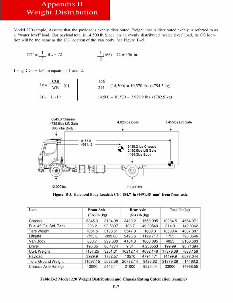
B-7
Appendix B
Weight Distribution
Model 220 sample, Assume that the payload is evenly distributed. Freight that is distributed evenly is referred to as
a “water level” load. Our payload total is 14,500 lb. Since it is an evenly distributed “water level” load, its CG loca-
tion will be the same as the CG location of the van body. See Figure B–5.
CGf = 1
2
BL + 72 1
(168) + 72 = 156 in. 2
Using CGf = 156 in equations 1 and 2:
Lr = CGf
WB X L 156
214 (14,500) = 10,570 lbs (4794.5 kg)
Lf = L - Lr 14,500 – 10,570 = 3,929.9 lbs (1782.5 kg)
Figure B-5. Balanced Body Loaded: CGf 184.7 in (4691.45 mm) from front axle.
Item Front Axle
(FA) lb (kg)
Rear Axle
(RA) lb (kg)
Total lb (kg)
Chassis 6845.3 3104.98 3439.2 1559.995 10284.5 4664.971 Fuel 45 Gal Std, Tank 206.2 93.5307 108.7 49.30549 314.9 142.8362 Tare Weight 7051.5 3198.51 3547.9 1609.3 10599.4 4807.807 Liftgate -735.6 -333.66 2490.6 1129.717 1755 796.0546 Van Body 660.7 299.688 4164.3 1888.895 4825 2188.583 Driver 190.65 86.4774 9.34 4.236553 199.99 90.71394 Curb Weight 7167.25 3251.01 10212.14 4632.149 17379.39 7883.159 Payload 3929.9 1782.57 10570 4794.471 14499.9 6577.044 Total Ground Weight 11097.15 5033.58 20782.14 9426.62 31879.29 14460.2 Chassis Axle Ratings 12000 5443.11 21000 9525.44 33000 14968.55
Table B-2 Model 220 Weight Distribution and Chassis Rating Calculation (sample)
B-8
Appendix B
Weight Distribution
Weight Distribution Analysis
Step 3. The final step is to total all of the front and rear axle weights to ensure that the axles are not overload-
ed. Table B-4 shows the assembled information in an easy to read format.
• Compare the calculated axle ground totals against the axle weight ratings to be sure that the truck is
properly specified to haul this load.
• From this, it is evident that the chassis is properly equipped for this job.
These calculations illustrate the importance of doing the weight distribution analysis. In some cases the addi-
tion of one component (for example, a liftgate) can produce a dramatic difference.
Body Length
Step 4. Your analysis may produce results that indicate an overloaded axle with a total loaded chassis weight
less than the GVW. This shows that you need to use a different body length for the truck. Each wheelbase
can accommodate several different body lengths. However, for each wheelbase and GVW one particular body
length will provide close to optimum weight distribution on both axles.
a. Table B-3 lists Recommended Body Lengths for a particular wheelbase and
GVW. These body lengths provide the best weight distribution for the listed wheelbase.
Note: These charts were generated assuming a plain van body with “water level”
loading. Any common additions such as lift gates or refrigeration units may
indicate a different wheelbase for a given body length. Also, different body
styles may require a different WB for a given size.
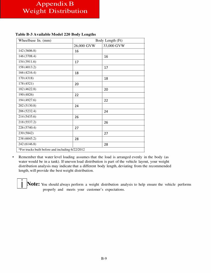
B-9
Appendix B
Weight Distribution
Table B-3 Available Model 220 Body Lengths
• Remember that water level loading assumes that the load is arranged evenly in the body (as
water would be in a tank). If uneven load distribution is part of the vehicle layout, your weight
distribution analysis may indicate that a different body length, deviating from the recommended
length, will provide the best weight distribution.
Note: You should always perform a weight distribution analysis to help ensure the vehicle performs
properly and meets your customer’s expectations.
Wheelbase In. (mm) Body Length (Ft)
26,000 GVW 33,000 GVW 142 (3606.8) 16
146 (3708.4) 16
154 (3911.6) 17
158 (4013.2) 17
166 (4216.4) 18
170 (4318) 18
178 (4521) 20
182 (4622.8) 20
190 (4826) 22
194 (4927.6) 22
202 (5130.8) 24
206 (5232.4) 24
214 (5435.6) 26
218 (5537.2) 26
226 (5740.4) 27
230 (5842) 27
238 (6045.2) 28
242 (6146.8) 28
*For trucks built before and including 6/22/2012
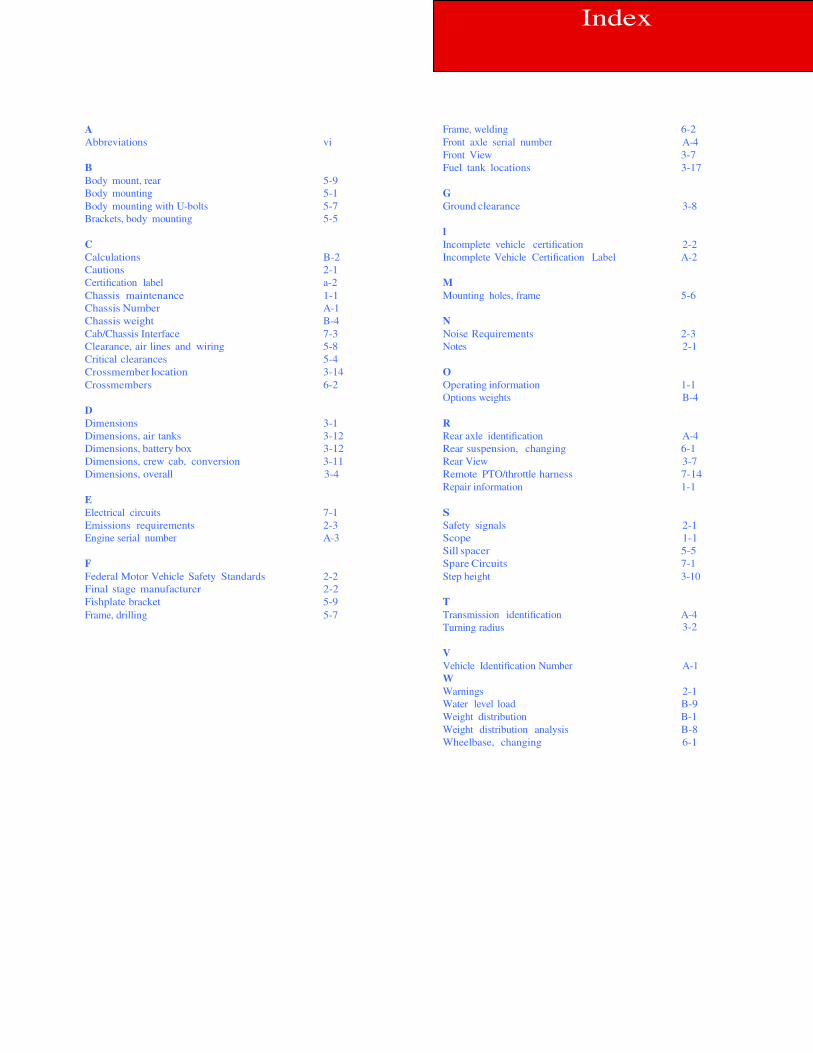
Index
A Frame, welding 6-2 Abbreviations vi Front axle serial number A-4 Front View 3-7 B Fuel tank locations 3-17 Body mount, rear 5-9 Body mounting 5-1 G Body mounting with U-bolts 5-7 Ground clearance 3-8 Brackets, body mounting 5-5 I C Incomplete vehicle certification 2-2 Calculations B-2 Incomplete Vehicle Certification Label A-2 Cautions 2-1 Certification label a-2 M Chassis maintenance 1-1 Mounting holes, frame 5-6 Chassis Number A-1 Chassis weight B-4 N Cab/Chassis Interface 7-3 Noise Requirements 2-3 Clearance, air lines and wiring 5-8 Notes 2-1 Critical clearances 5-4 Crossmember location 3-14 O Crossmembers 6-2 Operating information 1-1 Options weights B-4 D Dimensions 3-1 R Dimensions, air tanks 3-12 Rear axle identification A-4 Dimensions, battery box 3-12 Rear suspension, changing 6-1 Dimensions, crew cab, conversion 3-11 Rear View 3-7 Dimensions, overall 3-4 Remote PTO/throttle harness 7-14 Repair information 1-1 E Electrical circuits 7-1 S Emissions requirements 2-3 Safety signals 2-1 Engine serial number A-3 Scope 1-1 Sill spacer 5-5 F Spare Circuits 7-1 Federal Motor Vehicle Safety Standards 2-2 Step height 3-10 Final stage manufacturer 2-2 Fishplate bracket 5-9 T Frame, drilling 5-7 Transmission identification
Turning radius A-4
3-2
V
Vehicle Identification Number A-1 W Warnings 2-1 Water level load B-9 Weight distribution B-1 Weight distribution analysis B-8 Wheelbase, changing 6-1

A PACCAR COMPANY
Peterbilt Motors Company
P.O. Box 90208
Denton, Texas 76202
(800) FOR-PETERBILT
Related Documents