2017 ANNUAL DAM AND DIKE INSPECTION REPORT CCR PONDS COMPLEX OKLAUNION POWER STATION VERNON, TEXAS November, 2017 Prepared by: American Electric Power Service Corporation 1 Riverside Plaza Columbus, OH 43215 GERS-17-052

Welcome message from author
This document is posted to help you gain knowledge. Please leave a comment to let me know what you think about it! Share it to your friends and learn new things together.
Transcript

2017 ANNUAL DAM AND DIKE INSPECTION
REPORT
CCR PONDS COMPLEX
OKLAUNION POWER STATION
VERNON, TEXAS
November, 2017
Prepared by: American Electric Power Service Corporation
1 Riverside Plaza
Columbus, OH 43215
GERS-17-052


Annual Dam and Dike Inspection Report (2017) November 1st, 2017 Oklaunion Power Station CCR Ponds Complex
iii
TABLE OF CONTENTS 1.0 INTRODUCTION ................................................................................................................. 1 2.0 DESCRIPTIONS OF IMPOUNDMENT ............................................................................ 2 3.0 REVIEW OF AVAILABLE INFORMATION (257.83(b)(1)(i)) ....................................... 2 4.0 INSPECTION (257.83(b)(1)(ii)) ........................................................................................... 3
4.1 GENERAL ........................................................................................................................... 3 4.2 CHANGES IN GEOMETRY SINCE LAST INSPECTION (257.83(b)(2)(i)) ................... 4 4.3 CHANGES THAT EFFECT STABILITY OR OPERATION (257.83(b)(2)(vii)) ............. 4 4.4 IMPOUNDMENT CHARACTERISTICS (257.83(b)(2)(iii, iv, v)) ................................... 4 4.5 VISUAL INSPECTION (257.83(b)(2)(i)) ........................................................................... 5
Pond 6 - Wastewater Pond ..................................................................................................... 5 Pond 21 .................................................................................................................................. 5 Pond 22 .................................................................................................................................. 5 Pond 23 .................................................................................................................................. 5 Waste Water Sludge Pond ..................................................................................................... 6
4.6 INSTRUMENTATION (257.83(b)(2)(ii)) .......................................................................... 6 Piezometers ............................................................................................................................ 6
5.0 SUMMARY OF FINDINGS ................................................................................................. 8 5.1 MAINTENANCE ITEMS ................................................................................................... 8 5.2 ITEMS TO MONITOR........................................................................................................ 8 5.3 DEFICIENCIES (257.83(b)(2)(vi)) ..................................................................................... 8
LIST OF TABLES
Table 1 Summary of Relevant Storage Information for the CCR Ponds Complex Table 2 CCR Ponds Maximum recorded instruments reading since the previous annual inspection
LIST OF FIGURES Figure 1 Plant Inspection Vicinity Map Figure 2 CCR Pond Complex General Layout Figure 3A and B Piezometers Location Map Figure 4 CCR Ponds Piezometer Data Pond 21, Pond 22, Pond 23 and WWSP Figure 5 Pond 6 Piezometer Data
ATTACHMENT ATTACHMENT A: Photographs – CCR Ponds

Annual Dam and Dike Inspection Report (2017) November 1st, 2017 Oklaunion Power Station CCR Ponds Complex
Page 1 of 8
1.0 INTRODUCTION This report was prepared by AEP- Geotechnical Engineering Services (GES) section, in part, to fulfill requirements of 40 CFR 257.83 and to provide Public Service Company of Oklahoma and Oklaunion Power Station with an evaluation of the facility. The Oklaunion Power Station is owned by American Electric Power and is located at 12567 FM Rd 3430, Vernon, TX 76384. The plant is a coal-fired facility, which includes a number of wastewater evaporation ponds containing cooling tower blowdown. Five of the ponds are used to manage coal combustion residuals and other wastewater treatment solids. Figure 1 shows the plant inspection vicinity map. American Electric Power Service Corporation’s Civil Engineering Division administers the Oklaunion Power Station’s Dam Inspection and Maintenance Program (DIMP). As part of the DIMP, staff from the Geotechnical Engineering Services Section annually conducts dam and dike inspections. This report contains the inspection findings, observations, photographic descriptions, conclusions, and maintenance recommendations. This inspection report addresses the CCR Ponds Complex at the Oklaunion Power Station. A separate inspection report has been prepared for the wastewater ponds. The inspection was performed on October 31st, and November 1st 2017. Mr. Peter A. Civitarese, energy production superintendent was the plant contact. Mr. Mohammad Ajlouni and Mr. Brian Palmer conducted the field inspection. Weather conditions on October 31st were cloudy with temperatures in the mid to high 50's. Weather conditions on November 1st were sunny with good visibility, temperatures in the mid to high 70's. Inspection observations were briefly discussed with Plant Manager Monte McMahan, Maintenance Supervisor Nick Lee, Plant Environmental Coordinator Pat Hunter and Mr. Civitarese after completion of the field work.
Annual Dam and Dike Inspection Report (2017) November 1st, 2017 Oklaunion Power Station CCR Ponds Complex
Page 2 of 8
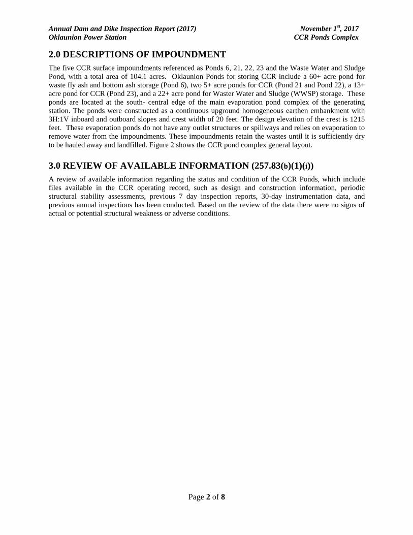
2.0 DESCRIPTIONS OF IMPOUNDMENT The five CCR surface impoundments referenced as Ponds 6, 21, 22, 23 and the Waste Water and Sludge Pond, with a total area of 104.1 acres. Oklaunion Ponds for storing CCR include a 60+ acre pond for waste fly ash and bottom ash storage (Pond 6), two 5+ acre ponds for CCR (Pond 21 and Pond 22), a 13+ acre pond for CCR (Pond 23), and a 22+ acre pond for Waster Water and Sludge (WWSP) storage. These ponds are located at the south- central edge of the main evaporation pond complex of the generating station. The ponds were constructed as a continuous upground homogeneous earthen embankment with 3H:1V inboard and outboard slopes and crest width of 20 feet. The design elevation of the crest is 1215 feet. These evaporation ponds do not have any outlet structures or spillways and relies on evaporation to remove water from the impoundments. These impoundments retain the wastes until it is sufficiently dry to be hauled away and landfilled. Figure 2 shows the CCR pond complex general layout.
3.0 REVIEW OF AVAILABLE INFORMATION (257.83(b)(1)(i)) A review of available information regarding the status and condition of the CCR Ponds, which include files available in the CCR operating record, such as design and construction information, periodic structural stability assessments, previous 7 day inspection reports, 30-day instrumentation data, and previous annual inspections has been conducted. Based on the review of the data there were no signs of actual or potential structural weakness or adverse conditions.

Annual Dam and Dike Inspection Report (2017) November 1st, 2017 Oklaunion Power Station CCR Ponds Complex
Page 3 of 8
4.0 INSPECTION (257.83(b)(1)(ii))
4.1 GENERAL
The summary of the visual observations uses terms to describe the general appearance or condition of an observed item, activity or structure. Their meaning is understood as follows:
Good: A condition or activity that is generally better or slightly better than what is minimally expected or anticipated from a design or maintenance point of view.
Fair or Satisfactory:
A condition or activity that generally meets what is minimally expected or anticipated from a design or maintenance point of view.
Poor: A condition or activity that is generally below what is minimally expected or anticipated from a design or maintenance point of view.
Minor: A reference to an observed item (e.g., erosion, seepage, vegetation, etc.) where the current maintenance condition is below what is normal or desired, but which is not currently causing concern from a structure safety or stability point of view.
Significant: A reference to an observed item (e.g. erosion, seepage, vegetation, etc.) where the current maintenance program has neglected to improve the condition. Usually, conditions that have been previously identified in the previous inspections, but have not yet been corrected.
Excessive: A reference to an observed item (e.g., erosion, seepage, vegetation, etc.) where the current maintenance condition is below or worse than what is normal or desired, and which may have affected the ability of the observer to properly evaluate the structure or particular area being observed or which may be a concern from a structure safety or stability point of view.
In addition, a “deficiency” is some evidence that a dam has developed a problem that could impact the structural integrity of the dam. There are four general categories of deficiencies. These four categories are described below:
1. Uncontrolled Seepage
Uncontrolled seepage is seepage that is not behaving as the design engineer has intended. An example of uncontrolled seepage is seepage that comes through or around the embankment and is not picked up and safely carried off by a drain. Seepage that is collected by a drain can still be uncontrolled if it is not safely collected and transported, such as seepage that is not clear. Seepage that is unable to be measured and/or observe it is considered uncontrolled seepage. [Wet or soft areas are not considered as uncontrolled seepage, but can lead to this type of deficiency. These areas should be monitored frequently.]
2. Displacement:
Displacement of the embankment is large scale movement of part of the dam. Common signs of displacement are cracks, scraps, bulges, depressions, sinkholes and slides.

Annual Dam and Dike Inspection Report (2017) November 1st, 2017 Oklaunion Power Station CCR Ponds Complex
Page 4 of 8
3. Blockage of Control Features:
Blockage of Control Features is the restriction of flow at spillways, decant or pipe spillways, or drains.
4. Erosion:
Erosion is the gradual movement of surface material by water, wind or ice. Erosion is considered a deficiency when it is more than a minor routine maintenance item.
4.2 CHANGES IN GEOMETRY SINCE LAST INSPECTION (257.83(b)(2)(i))
No modifications have been made to the geometry of the CCR Ponds Complex since the 2016 annual inspection. The geometry of the impoundment has remained essentially unchanged.
4.3 CHANGES THAT EFFECT STABILITY OR OPERATION (257.83(b)(2)(vii))
Based on interviews with plant personnel and field observations there were no changes to the CCR Ponds Complex since the last annual inspection that would affect the stability or operation of the impounding structure.
4.4 IMPOUNDMENT CHARACTERISTICS (257.83(b)(2)(iii, iv, v))
Table 2 is a summary of the minimum, maximum, and present depth and elevation of the impounded water since the previous annual inspection; the storage capacity of the impounding structure at the time of the inspection; and the approximate volume of the impounded water at the time of the inspection.
Table 1 Summary of Relevant Storage Information CCR Ponds Complex IMPOUNDMENT CHARACTERISTICS- CCR Pond Complex
Pond 6 Pond 21 Pond 22 Pond 23 WWSP
Approximate Minimum depth of impounded water since last annual
inspection
15ft
(1200)
18ft
(1208)
14ft
(1204)
14ft
(1208)
10ft
(1200) Approximate Maximum depth of
impounded water since last annual inspection
28ft
(1213)
23ft
(1213)
23ft
(1213)
23ft
(1213)
23ft
(1213) Approximate Present depth of
impounded water at the time of the inspection
28ft
(1213)
23ft
(1213)
23ft
(1213)
23ft
(1213)
23ft
(1213) Approximate Minimum depth of CCR
since last annual inspection
23ft (1208)
22ft
(1212)
21ft
(1211)
25ft
(1215)
22ft
(1212) Approximate Maximum depth of CCR since last annual inspection
29ft
(1214)
22ft
(1212)
22ft
(1212)
26ft
(1216)
24ft
(1214) Approximate Present depth of CCR at
the time of the inspection 29ft
(1214) 22ft
(1212) 22ft
(1212) 26ft
(1216) 24ft
(1214) Storage Capacity of impounding
structure at the time of the inspection 1100acre-ft
125acre-ft
125acre-ft
250 acre-ft
400 acre-ft
Approximate volume of impounded water at the time of the inspection
220 acre-ft
65acre-ft
55acre-ft
120 acre-ft
80 acre-ft
Approximate volume of CCR at the time of the inspection
880 acre-ft
45acre-ft
55acre-ft
125 acre-ft
320 acre-ft

Annual Dam and Dike Inspection Report (2017) November 1st, 2017 Oklaunion Power Station CCR Ponds Complex
Page 5 of 8
4.5 VISUAL INSPECTION (257.83(b)(2)(i))
A visual inspection of the CCR Ponds Complex was conducted to identify any signs of distress or malfunction of the impoundment and appurtenant structures. Specific items inspected included all structural elements of the dam such as upstream and downstream slopes, crest, and toe.
POND 6 - WASTEWATER POND
Pond #6 is located at the south-central edge of the main evaporation pond complex area. In 2015, Pond 6 dam embankment was raised to provide additional ash storage capacity. The crest elevation was raised from Elevation 1208 to Elevation 1215 feet.
The crest of the embankment appeared to be in good condition with no unusual cracking, rutting, settlement, deformation, or misalignment. (Observation 1, Photos 1-4)
The exterior slopes of the south and west dikes were in overall good condition (Observation 2, Photos #1-2). No signs of slope failure, slumping, or seepage were observed on the downstream slopes and no burrowing animal activity was noted. The slopes were adequately vegetated and no erosional features were noted. All slopes were free of woody vegetation.
The eastern slope of Pond #6 is also the western slope of the Pond #7 spillway discharge channel. The channel was in fair condition. The spillway of the adjacent Pond #7 has been substantially blocked and no discharge can occur. However, the discharge channel below, shown in Observation 2, Photo #3 and #4, also receives runoff from the surrounding area and should be monitored for erosion as part of the periodic visual inspections.
POND 21
The slopes of Pond 21 are in good condition. Pond 21 is an incised 5.1 acre bottom ash pond. The only visible dike portions are 3-5 ft above the normal pool levels. During the inspection there was some erosion damage was noticed on the interior slope of the Makeup Water Pond which is the exterior slope of Pond 21, see Observation 3, Photo #4. The plant will continue to monitor the exterior slope until the repair is performed.
Overall, Pond 21 appeared in good, stable and functional condition and there were no visual observations to indicate any structural deficiencies that would impact the integrity of the dikes. Observation 3 and 4 Photos #1-4 provide views of various components of the Pond 21 from the 2017 inspection. The geometry of the dike has not changed or altered since the last inspection.
POND 22
The slopes of Pond 22 are in good condition. Pond 22 is an incised 5.1 acre pond originally designed for storing bottom ash. The only visible dike portions of the pond are 3-5 ft above the normal pool levels. Based on the inspection there were no visual observations to indicate any structural deficiencies that would impact the integrity of the dikes. Observation 5, Photos #1-4 provide views of various components of the Pond 22 from the 2017 inspection.
POND 23
The slopes of Pond 23 are in good condition. Pond 23 is an incised 13.3 acre pond originally designed to contain fly ash. The only visible dike portions of the pond are 3-5ft above the normal pool levels. Based on the inspection there were no visual observations to indicate any structural deficiencies that would impact the integrity of the dikes. Observation 6, Photos #1-4 provide views of various components of the Pond 23 from the 2017 inspection.

Annual Dam and Dike Inspection Report (2017) November 1st, 2017 Oklaunion Power Station CCR Ponds Complex
Page 6 of 8
WASTE WATER SLUDGE POND
The slopes of the Waste Water and Sludge Pond (WWSP) are in good condition. WWSP is an incised 22.6 acre pond. The only visible dike portions are 3-5 ft above the normal pool levels. Based on the inspection there were no visual observations to indicate any structural deficiencies that would impact the integrity of the dikes. Observation 7, Photos #1-4 provide views of various components of the Pond WWSP from the 2017 inspection.
Overall the facility is in good condition. The impoundment is functioning as intended with no signs of potential structural weakness or conditions which are disrupting to the safe operation of the impoundment.
4.6 INSTRUMENTATION (257.83(b)(2)(ii))
Onsite instrumentations include open pipe type piezometers.
PIEZOMETERS
The location of the instrumentation is shown on Figure 3. The results of the measurements of various piezometers are shown in Figure 4 and 5. The maximum recorded readings of each instrument since the previous annual inspection is shown in Table 2. Table 2 CCR Ponds Maximum recorded instruments reading since the previous annual inspection
INSTRUMENTATION DATA CCR Ponds Complex
Instrument Type Maximum Reading since last
annual inspection Date
of Reading
B-1 Piezometer 1179.97 4/20/2017 B-3 Piezometer 1213.93 6/15/2017 B-4 Piezometer 1204.77 10/4/2017 B-5 Piezometer 1203.41 11/1/2017 B-6 Piezometer 1188.62 2/23/2017
B-1502A Piezometer 1179.47 5/18/2017 B-1506A Piezometer 1209.67 6/15/2017 B-1507A Piezometer 1214.75 7/13/2017 B-1508A Piezometer 1215.00 6/15/2017 B-1512 Piezometer 1215.00 5/18/2017 B-1513 Piezometer 1214.00 6/15/2017
Five piezometers (B-1, B-3, B-4, B-5, and B-6) were installed in July 2016 around the Pond 21, 22, 23 and WWSP. Each piezometer was installed at the crest surrounding the ponds. Figure 4 shows the static water levels of those piezometers and ponds pool levels measured during monthly plant inspections beginning in August, 2016. All of the ponds (#21, 22, 23, and WWSP) pool level were found to be consistent at an elevation 1,213 feet. Over periods of monthly measurement data, the static water levels in the piezometers have indicated some fluctuations. The readings of the 4 out of the 5 piezometers indicated higher than pool elevation which may indicate that rain/surface water is entering the pipes. When the readings fall above the pool level, plant maintenance is to contact AEP Civil Engineering Services which will be will be conducting further evaluation. Piezometers (B-1502A, B-1506A, B-1507A, B-1508A, B1512, and B1513) were installed in various locations along the crest of Pond 6 after raising the dikes in 2015. Figure 5 shows the static water levels

Annual Dam and Dike Inspection Report (2017) November 1st, 2017 Oklaunion Power Station CCR Ponds Complex
Page 7 of 8
of those piezometers measured during monthly plant inspections, along with the measured pool levels of Pond 6. All of the piezometers indicated static water levels below the pond pool level (1,213 feet). All piezometers indicated static water levels within expected tolerance except B-1508A. Piezometer B-1508A indicated about 10-foot increase in the water level since 8/2016. This increase in the static water shall be monitored for continuing evaluation.

Annual Dam and Dike Inspection Report (2017) November 1st, 2017 Oklaunion Power Station CCR Ponds Complex
Page 8 of 8
5.0 SUMMARY OF FINDINGS Based on the visual observations during the inspection, the dam and appurtenances are generally in good condition. A summary of our recommendations for general maintenance and continued monitoring, as well as any recommendations for remedial activities, is provided as follows:
5.1 MAINTENANCE ITEMS
The following maintenance items were identified during the visual inspection:
Drainage along the toe of Pond 6 east exterior dike is considered fair and requires visual inspections of the area to continue with the weekly/monthly inspections.
Vegetation management for the facility is considered good. Grassed areas should continue to be mowed regularly. Any areas that are not accessible to mowing equipment should be controlled by the use of weed trimmers, power brush cutters, or other suitable vegetation control method.
Plant inspection and monitoring procedures, maintenance activities, and reporting with respect to the dikes should be implemented in coordination with AEP Civil Engineering.
5.2 ITEMS TO MONITOR
The exterior slope of Pond 21 (the interior slope of the Make-Up Water Pond) is to be visually inspected periodically. Should further erosion occur the plant will take preventative actions by installing rip rap along the eroded area in order to protect slope.
Piezometer B-1508A shall be monitored monthly for further evaluation due to the increase in water levels since 8/2016.
Piezometers B-1, B-3, B-4, B-5, and B-6 surrounding Ponds 21, 22, 23 and the WWSP shall continue to be monitored monthly and AEP Civil Engineering services to be immediately notified should the piezometer readings shift above pool levels.
5.3 DEFICIENCIES (257.83(b)(2)(vi))
There were no deficiencies or signs of structural weakness or disruptive conditions that were observed at the time of the inspection that would require additional investigation or remedial action. There were no deficiencies noted during any of the quarterly inspections. If any of these conditions occur before the next annual inspection contact AEP Geotechnical Engineering immediately.
If you have any questions with regard to this report, please contact Mohammad Ajlouni at Audinet: 200-2939 or Gary Zych at Audinet: 200-2917.

Annual Dam and Dike Inspection Report (2017) November 1st, 2017 Oklaunion Power Station CCR Ponds Complex
Figures

©2010 Google – Map data ©2010 Google
AEP OKLAUNION POWER PLANT WILBARGER COUNTY, TX
FIGURE 1. PLANT INSPECTION VICINITY MAP
DATE: 2/17/2012

FIGURE 2. CCR Pond Complex General Layout

SCALE IN FEET
0250 250125
N DE
SIG
NE
D B
Y:
SC
ALE
:
AP
PV
D. B
Y:
DR
AW
N B
Y:
DA
TE
:
SH
EE
T N
O.:
JOB
NO
.
OF
BY
DE
SC
RIP
TIO
ND
AT
ER
EV
.
AC
AD
NO
.80
0 M
OR
RIS
ON
RO
AD
CO
LUM
BU
S, O
HIO
432
30
FA
X. (
614)
863
-047
5P
H. (
614)
863
-311
3
Co
nsu
ltin
g E
ng
ine
ers
an
d S
cie
ntists
Figur
e 3A
1"=
250'
8/29
/16
N41
6522
7
816b
orin
g1
BO
RIN
G L
OC
AT
ION
PLA
N
OK
LAU
NIO
N P
ON
DS
AR
EA
DIK
ES
AM
ER
ICA
N E
LEC
TR
IC P
OW
ER
OK
LAU
NIO
N P
OW
ER
ST
AT
ION
VE
RN
ON
TE
XA
S
KM
E
DA
B
MA
E
11
LEGENDTERRACON 2016 SOIL BORING
B-1
1256
7 F
M R
OA
D 3
430
WASTEWATER (WW)& SLUDGE POND
TERRACON 2015 SOIL BORINGB-15-06(OW)
(OW) - DENOTES BORING COMPLETED AS
GROUNDWATER OBSERVATION WELL
(PIEZOMETER)
20408CONTROL POINT
CPT-15-09TERRACON 2016 CONE
PENETROMETER TEST
INDICATES BORING COMPLETED AS
PIEZOMETER*
* * *
*
*

SCALE IN FEET
0250 250125
N
DE
SIG
NE
D B
Y:
SC
ALE
:
AP
PV
D. B
Y:
DR
AW
N B
Y:
DA
TE
:
SH
EE
T N
O.:
JOB
NO
.
OF
BY
DE
SC
RIP
TIO
ND
AT
ER
EV
.
AC
AD
NO
.80
0 M
OR
RIS
ON
RO
AD
CO
LUM
BU
S, O
HIO
432
30
FA
X. (
614)
863
-047
5P
H. (
614)
863
-311
3
Co
nsu
ltin
g E
ng
ine
ers
an
d S
cie
ntists
FIGU
RE 3B
1"=
250'
4/4/
16
N41
5510
8
sb-t
ppla
nsb2
EX
PLO
RA
TIO
N P
LAN
DA
M R
AIS
ING
-EV
AP
OR
AT
ION
PO
ND
NO
. 6
AM
ER
ICA
N E
LEC
TR
IC P
OW
ER
OLK
AU
NIO
N P
OW
ER
ST
AT
ION
VE
RN
ON
TE
XA
S
KM
E
DA
B
AK
B
11
LEGEND
TERRACON 2015 SOIL BORINGB-15-04
EXISTING MONITORING WELLMW-3/AD-14
EVAPORATION
POND NO. 6
(OW)
(OW) - DENOTES BORING COMPLETED AS
GROUNDWATER OBSERVATION WELL
1256
7 F
M R
OA
D 3
430
20408CONTROL POINT
APPROXIMATE TEST PIT LOCATIONTP-15-01
CENTERLINE OF 1987
AS-BUILT BERM
SLOPE STABILTY ANALYIS CROSS
SECTIONS
A
JM
A
NOTES:
1. THE EXISTING TOPOGRAPHY ON THE INSIDE OF
THE PERIMETER OF POND NO. 6 IS DATED:
3/16/15, FROM SHEPPARD SURVEYING CO., INC.
2. THE EXISTING TOPOGRAPHY ON THE TOP AND
OUTSIDE PERIMETER OF THE POND IS FROM A
SURVEY DATED: 7/16/15, FROM CRAFTON TULL.
3. SOIL BORING AND TEST PIT LOCATION/
ELEVATION DATA FROM CRAFTON TULL SURVEY
DATED: 7/16/2015
N
LIMIT OF CRAFTON TULL
SURVEY DATED: 7/16/2015
CPT-15-01CPT LOCATION
APPROXIMATE WESTERN
EXTENT OF SOUTH
EMBANKMENT CLAY TOE KEY
APPROXIMATE EASTERN
EXTENT OF SOUTH
EMBANKMENT CLAY TOE KEY

1205.00
1207.00
1209.00
1211.00
1213.00
1215.00
7/29/2016 9/17/2016 11/6/2016 12/26/2016 2/14/2017 4/5/2017 5/25/2017 7/14/2017 9/2/2017 10/22/2017 12/11/2017
Eleveatio
n (ft.)
FIGURE 4. CCR Ponds Piezometer Data Pond 21, Pond 22, Pond 23 and WWSP
B‐1
B‐3
B‐4
B‐5
B‐6
Pool Level
Date

1170.00
1175.00
1180.00
1185.00
1190.00
1195.00
1200.00
1205.00
1210.00
1215.00
1/3
1/2
016
5/1
0/2
016
8/1
8/2
016
11/
26
/20
16
3/6
/20
17
6/1
4/2
017
9/2
2/2
017
12/
31
/20
17
Eleveatio
n (ft.)
Date
FIGURE 5. Pond 6 Piezometer Data
Pool Level
B‐1502A
B‐1506A
B‐1507A
B‐1508A
B‐1512
B‐1513

Annual Dam and Dike Inspection Report (2017) November 1st, 2017 Oklaunion Power Station CCR Ponds Complex
ATTACHMENT A: Photographs – CCR Ponds Complex

Plant Name: Oklaunion Observation #: 1
Photo #1
Photo #2
Description: Crest
November 1, 2017Unit: Pond 6
Notes: Typical Crest in Good Condition.
Location: West Dike
Location: North Dike. Between Pond 6 and Make-Up Water Pond
Notes: Typical Crest in Good Condition.
Description: Crest
AEP GES Dam and Dike Inspection

Photo #3
Photo #4
Description: Crest
Description: Interior Slope
AEP GES Dam and Dike Inspection
Location: South Dike
Notes: Typical Crest in Good Condition.
Location: Pond 6 Raised Dike
Notes: Typical Interior Slope in Good Condition.

Plant Name: Oklaunion Observation #: 2
Photo #1
Photo #2
Description: Exterior Slope
November 1, 2017Unit: Pond 6
Notes: West Exterior Slope in Good Condition.
Location: West Exterior Slope
Location: South Exterior Slope.
Notes: Typical South Exterior Slope in Good Condition
Description: Exterior Slope
AEP GES Dam and Dike Inspection

Photo #3
Photo #4
Description: Exterior Slope
Description: Exterior Slope
AEP GES Dam and Dike Inspection
Location: Pond 6 East Exterior Slope
Notes: East Exterior Slope in Fair Condition. Note that the channel receives run off from surrounding area. Plant to Monitor
Location: Exterior Slope after 2015 Dike Raising
Notes: Typical Exterior Slope and Retaining wall in Good Condition

Plant Name: Oklaunion Observation #: 3
Photo #1
Photo #2
Description: Interior Slope
November 1, 2017Unit: Pond 21
Notes: Interior Slopes in Good Condition
Location: South of Pond 21. Looking North.
Location: Interior Slope of Pond 21. Looking West
Notes: Interior Slope in Good Condition
Description: Interior Slope
AEP GES Dam and Dike Inspection
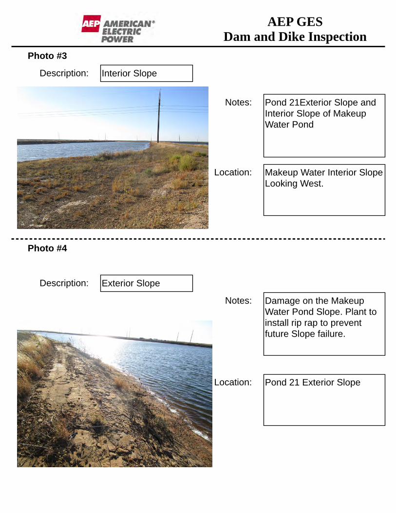
Photo #3
Photo #4
Description: Interior Slope
Description: Exterior Slope
AEP GES Dam and Dike Inspection
Location: Makeup Water Interior Slope Looking West.
Notes: Pond 21Exterior Slope and Interior Slope of Makeup Water Pond
Location: Pond 21 Exterior Slope
Notes: Damage on the Makeup Water Pond Slope. Plant to install rip rap to prevent future Slope failure.

Plant Name: Oklaunion Observation #: 4
Photo #1
Photo #2
Description: Crest
November 1, 2017Unit: Pond 21
Notes: Crest in Good Condition
Location: Dike between Pond 21 and Pond 22. Looking South
Location: Between Pond 21 and Makeup Water Pond. Looking South.
Notes: Crest in Good Condition
Description: Crest
AEP GES Dam and Dike Inspection
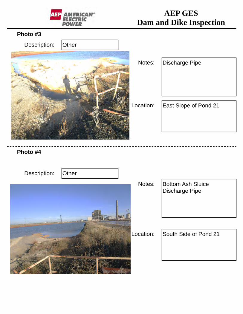
Photo #3
Photo #4
Description: Other
Description: Other
AEP GES Dam and Dike Inspection
Location: East Slope of Pond 21
Notes: Discharge Pipe
Location: South Side of Pond 21
Notes: Bottom Ash Sluice Discharge Pipe

Plant Name: Oklaunion Observation #: 5
Photo #1
Photo #2
Description: Interior Slope
November 1, 2017Unit: Pond 22
Notes: Typical Interior Slope in Good Condition.
Location: North Side of Pond 22
Location: Dike between Pond 22 and Pond 23.
Notes: Typical Crest in Good Condition
Description: Crest
AEP GES Dam and Dike Inspection

Photo #3
Photo #4
Description: Interior Slope
Description: Other
AEP GES Dam and Dike Inspection
Location: West Interior Slope
Notes: Typical Interior Slope in Good Condition
Location: South End of Pond
Notes: Discharge Pipe

Plant Name: Oklaunion Observation #: 6
Photo #1
Photo #2
Description: Interior Slope
November 1, 2017Unit: Pond 23
Notes: Interior Slope in Good Condition
Location: South Side Interior Slope
Location: East Interior Slope. Looking North
Notes: Interior Slope in Good Condition
Description: Interior Slope
AEP GES Dam and Dike Inspection

Photo #3
Photo #4
Description: Interior Slope
Description: Crest
AEP GES Dam and Dike Inspection
Location: West Interior Slope. Looking North
Notes: Interior Slope in Good Condition
Location: Dike between Pond 23 and WWSP
Notes: Typical Crest in Good Condition

Plant Name: Oklaunion Observation #: 7
Photo #1
Photo #2
Description: Interior Slope
November 1, 2017Unit: WWSP
Notes: Interior Slope in Good Condition
Location: South Interior Slope
Location: West Interior Slope Looking South.
Notes: Interior Slope in Good Condition
Description: Interior Slope
AEP GES Dam and Dike Inspection

Photo #3
Photo #4
Description: Interior Slope
Description: Crest
AEP GES Dam and Dike Inspection
Location: North Interior Slope. Looking East
Notes: Interior Slope in Good Condition
Location: Dike between WWSP and Pond 7
Notes: Typical Crest in Good Condition
Related Documents