Computational Methodology for Optimal Design of Additive Layer Manufactured Turbine Bracket Hector U. Levatti 1* , Mauro S. Innocente 1 , H. Dawn Morgan 1 , John Cherry 1 , Nicholas P. Lavery 1 , Shahid Mehmood 1 , Ian Cameron 1 and Johann Sienz 1 1 College of Engineering, Swansea University, Singleton Park, Swansea, SA2 8PP, Wales, UK * Corresponding author: [email protected] Abstract The design of critical components for aircrafts, cars or any other kind of machinery today is typically subject to two conflicting objectives, namely the maximisation of strength and the minimisation of weight. The conflicting nature of these two objectives makes it impossible to obtain a design that is optimal for both. The most common approach aiming for a single objective optimisation problem in aerospace is to maintain the weight minimisation as the objective, whilst setting strength requirements as constraints to be satisfied. However, manufacturing methods incorporate additional restrictions for an optimal design to be considered feasible, even when satisfying all constraints in the formulation of the optimisation problem. In this context, Additive Layer Manufacturing adds remarkably higher flexibility to the manufacturability of shape designs when compared with traditional processes. It is fair to note, however, that there are still some restrictions such as the infeasibility of building unsupported layers forming angles smaller than 45 degrees with respect to the underlying one. Nowadays, it is common practice to use a set of software tools to deal with these kinds of problems, namely Computer Aided Design (CAD), Finite Element Analysis (FEA), and optimisation packages. The adequate use of these tools results in an increase in efficiency and quality of the final product. In this paper, a case study was undertaken consisting of a turbine bracket from a General Electric challenge (Figure 5). A computational methodology is used, which consists of a topology optimisation considering an isotropic material at first instance, followed by the manual refinement of the resulting shape taking into account the manufacturability requirements. To this end, we used SolidWorks ® 2013 for the CAD, Ansys Workbench ® 14.0 for the FEA, and HyperWorks ® 11 for the topology optimisation. A future methodology will incorporate the automation of the shape optimisation stage, and perhaps the inclusion of the manufacturability restriction within the optimisation formulation. 1. Introduction Today, in industry and in an academic environment, stress analysis using Finite Element Method (FEM), Structural Optimisation, Additive Manufacturing (AM) and Hot Isostatic Pressing (HIP) post-treatment are used in order to improve existing designs or design new parts for several fields such as automotive or aerospace. In order to manage so many areas of expertise, a multidisciplinary team is needed. Although, a multidisciplinary team can relatively simply meet, the demands of this type of challenge, the team needs to work logistically in order to amalgamate the KES Transactions on Sustainable Design and Manufacturing I Sustainable Design and Manufacturing 2014 : pp.641-652 : Paper sdm14-037 InImpact: The Journal of Innovation Impact | ISSN 2051-6002 | http://www.inimpact.org Copyright © 2014 Future Technology Press and the authors 641

Welcome message from author
This document is posted to help you gain knowledge. Please leave a comment to let me know what you think about it! Share it to your friends and learn new things together.
Transcript
Computational Methodology for Optimal Design of
Additive Layer Manufactured Turbine Bracket
Hector U. Levatti1*
, Mauro S. Innocente1, H. Dawn Morgan
1, John Cherry
1,
Nicholas P. Lavery1, Shahid Mehmood
1, Ian Cameron
1 and Johann Sienz
1
1College of Engineering, Swansea University, Singleton Park, Swansea, SA2 8PP,
Wales, UK *Corresponding author: [email protected]
Abstract
The design of critical components for aircrafts, cars or any other kind of machinery today is typically subject to two conflicting objectives, namely the maximisation of strength and the minimisation of weight. The conflicting nature of these two objectives makes it impossible to obtain a design that is optimal for both. The most common approach aiming for a single objective optimisation problem in aerospace is to maintain the weight minimisation as the objective, whilst setting strength requirements as constraints to be satisfied. However, manufacturing methods incorporate additional restrictions for an optimal design to be considered feasible, even when satisfying all constraints in the formulation of the optimisation problem. In this context, Additive Layer Manufacturing adds remarkably higher flexibility to the manufacturability of shape designs when compared with traditional processes. It is fair to note, however, that there are still some restrictions such as the infeasibility of building unsupported layers forming angles smaller than 45 degrees with respect to the underlying one.
Nowadays, it is common practice to use a set of software tools to deal with these kinds of problems, namely Computer Aided Design (CAD), Finite Element Analysis (FEA), and optimisation packages. The adequate use of these tools results in an increase in efficiency and quality of the final product. In this paper, a case study was undertaken consisting of a turbine bracket from a General Electric challenge (Figure 5). A computational methodology is used, which consists of a topology optimisation considering an isotropic material at first instance, followed by the manual refinement of the resulting shape taking into account the manufacturability requirements. To this end, we used SolidWorks
®2013 for the CAD, Ansys
Workbench®14.0 for the FEA, and HyperWorks
®11 for the topology optimisation. A future
methodology will incorporate the automation of the shape optimisation stage, and perhaps the inclusion of the manufacturability restriction within the optimisation formulation.
1. Introduction Today, in industry and in an academic environment, stress analysis using Finite Element Method (FEM), Structural Optimisation, Additive Manufacturing (AM) and Hot Isostatic Pressing (HIP) post-treatment are used in order to improve existing designs or design new parts for several fields such as automotive or aerospace. In order to manage so many areas of expertise, a multidisciplinary team is needed. Although, a multidisciplinary team can relatively simply meet, the demands of this type of challenge, the team needs to work logistically in order to amalgamate the
KES Transactions on Sustainable Design and Manufacturing ISustainable Design and Manufacturing 2014 : pp.641-652 : Paper sdm14-037
InImpact: The Journal of Innovation Impact | ISSN 2051-6002 | http://www.inimpact.orgCopyright © 2014 Future Technology Press and the authors
641
knowledge of the team members. Developing a working methodology we ensure that the goals are achieved in a more effective way. AM [3] is a process for making a three-dimensional solid object from a digital model. AM is achieved using an additive process where successive layers of material are laid down in different shapes. AM is also considered distinct from traditional machining techniques (subtractive), which mostly rely on the removal of material by methods such as cutting, drilling or laser. AM consists of both building an object “from scratch” or from a semi-finished part acting as substrate. Nowadays, these processes are used for rapid manufacturing purposes [7] and [8]. This new technology has produced a breakthrough in manufacturing technology followed by a breakthrough in design that at the moment is in process. Renishaw’ s laser melting process is an emerging manufacturing technology with a presence in the medical (orthopaedics) industry as well as the aerospace and high technology engineering and electronics sectors. Laser melting (LMe) is a digitally driven additive manufacturing process that uses focused laser energy to fuse metallic powders in to 3D objects. In this paper general ALMa (Additive Laser Manufacturing) concepts and ALMe (Additive Laser Melting) technology are presented through the solution for the General Electric (GE) Challenge presented a few months ago on GrabCAD platform online. Renishaw’ s laser melting is an additive manufacturing technology that uses a high powered ytterbium fibre laser to fuse fine metallic powders together to form functional 3-dimensional parts. The process is digitally driven, direct from sliced 3D CAD data, in layer thicknesses ranging from 20 to 100 microns that form a 2D cross section. The process then builds the part by distributing an even layer of metallic powder using a recoater, then fusing each layer in turn under a tightly controlled inert atmosphere. Once complete, the part is removed from the powder bed and undergoes heat treatment and finishing depending on the application. For the case study presented in this paper, the characteristics of the present technology available in the College of Engineering at Swansea University were accounted for. 2. Jet Engine Bracket Challenge for General Electric. GrabCAD Platform
Online. GrabCAD is a community online where it is possible to share CAD files and put forward design challenges. General Electric has used this platform to launch its challenge called “Jet Engine Bracket Challenge”. Details about it can be found in https://grabcad.com/challenges/ge-jet-engine-bracket-challenge. The case study presented in this paper is the result of our participation (ASTUTE Team, College of Engineering, Swansea University) in the challenge mentioned above. 2.1. The Bracket Loading brackets on jet engines play a very critical role. They must support the weight of the engine during handling without breaking or warping. The brackets
Computational Methodology for Optimal Design of Additive Layer Manufactured Turbine BracketHector Levatti, Nicholas Lavery
642
may be used only periodically, but they stay on the engine at all times, including during flight. New technologies like ALMe can contribute to reduced costs and improve the structural characteristic of components such as this. The requirements needed to be fulfilled during the design process for the GE challenge are listed in the next section.
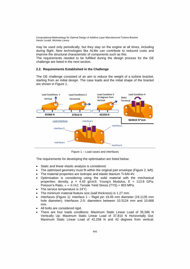
2.2. Requirements Established in the Challenge The GE challenge consisted of an aim to reduce the weight of a turbine bracket, starting from an initial design. The case loads and the initial shape of the bracket are shown in Figure 1.
Figure 1 – Load cases and interfaces
The requirements for developing the optimisation are listed below:
Static and linear elastic analysis is considered.
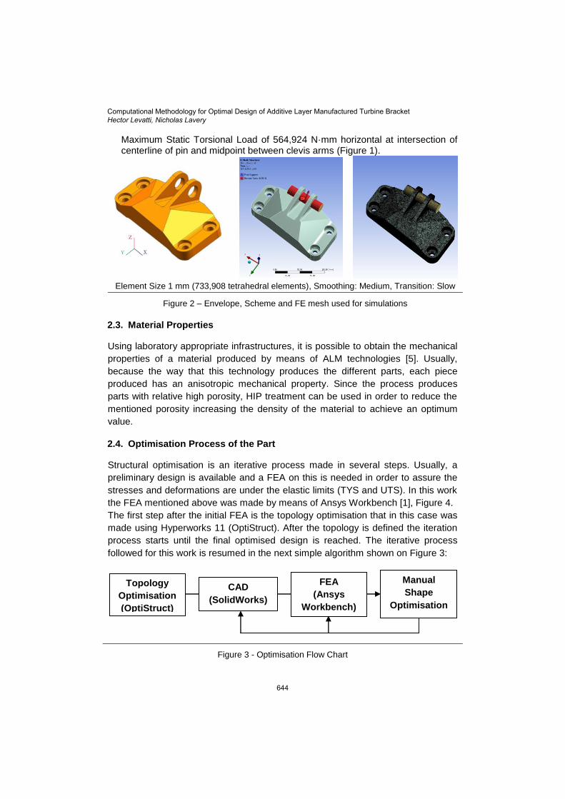
The optimised geometry must fit within the original part envelope (Figure 2, left).
The material properties are isotropic and elastic titanium Ti-6Al-4V.
Optimisation is considering using the solid material with the mechanical properties: density, ρ = 4.43 g/cm3; Young’s Modulus, E = 113.8 GPa; Poisson’s Ratio, ; Tensile Yield Stress (TYS) = 903 MPa.
The service temperature is 24°C.
The minimum material feature size (wall thickness) is 1.27 mm.
Interfaces (Figure 1): Interface 1 – Rigid pin 19.05 mm diameter (19.1135 mm hole diameter); Interfaces 2-5: diameters between 10.3124 mm and 10.668 mm.
All bolts are considered rigid.
There are four loads conditions: Maximum Static Linear Load of 35,586 N Vertically Up; Maximum Static Linear Load of 37,810 N Horizontally Out; Maximum Static Linear Load of 42,258 N and 42 degrees from vertical;
Computational Methodology for Optimal Design of Additive Layer Manufactured Turbine BracketHector Levatti, Nicholas Lavery
643
Maximum Static Torsional Load of 564,924 N·mm horizontal at intersection of centerline of pin and midpoint between clevis arms (Figure 1).
Element Size 1 mm (733,908 tetrahedral elements), Smoothing: Medium, Transition: Slow
Figure 2 – Envelope, Scheme and FE mesh used for simulations
2.3. Material Properties
Using laboratory appropriate infrastructures, it is possible to obtain the mechanical
properties of a material produced by means of ALM technologies [5]. Usually,
because the way that this technology produces the different parts, each piece
produced has an anisotropic mechanical property. Since the process produces
parts with relative high porosity, HIP treatment can be used in order to reduce the
mentioned porosity increasing the density of the material to achieve an optimum
value.
2.4. Optimisation Process of the Part
Structural optimisation is an iterative process made in several steps. Usually, a
preliminary design is available and a FEA on this is needed in order to assure the
stresses and deformations are under the elastic limits (TYS and UTS). In this work
the FEA mentioned above was made by means of Ansys Workbench [1], Figure 4.
The first step after the initial FEA is the topology optimisation that in this case was
made using Hyperworks 11 (OptiStruct). After the topology is defined the iteration
process starts until the final optimised design is reached. The iterative process
followed for this work is resumed in the next simple algorithm shown on Figure 3:
Figure 3 - Optimisation Flow Chart
Topology
Optimisation
(OptiStruct)
CAD
(SolidWorks)
FEA
(Ansys
Workbench)
Manual
Shape
Optimisation
Computational Methodology for Optimal Design of Additive Layer Manufactured Turbine BracketHector Levatti, Nicholas Lavery
644
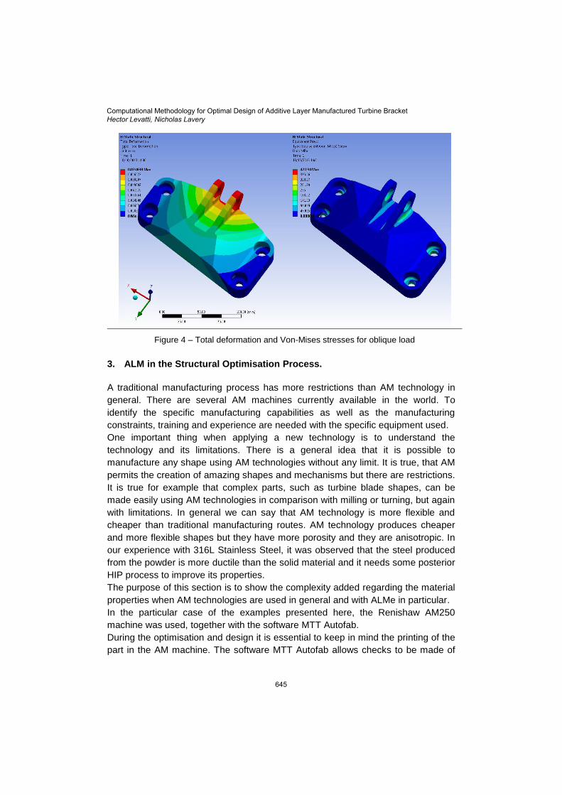
Figure 4 – Total deformation and Von-Mises stresses for oblique load
3. ALM in the Structural Optimisation Process.
A traditional manufacturing process has more restrictions than AM technology in
general. There are several AM machines currently available in the world. To
identify the specific manufacturing capabilities as well as the manufacturing
constraints, training and experience are needed with the specific equipment used.
One important thing when applying a new technology is to understand the
technology and its limitations. There is a general idea that it is possible to
manufacture any shape using AM technologies without any limit. It is true, that AM
permits the creation of amazing shapes and mechanisms but there are restrictions.
It is true for example that complex parts, such as turbine blade shapes, can be
made easily using AM technologies in comparison with milling or turning, but again
with limitations. In general we can say that AM technology is more flexible and
cheaper than traditional manufacturing routes. AM technology produces cheaper
and more flexible shapes but they have more porosity and they are anisotropic. In
our experience with 316L Stainless Steel, it was observed that the steel produced
from the powder is more ductile than the solid material and it needs some posterior
HIP process to improve its properties.
The purpose of this section is to show the complexity added regarding the material
properties when AM technologies are used in general and with ALMe in particular.
In the particular case of the examples presented here, the Renishaw AM250
machine was used, together with the software MTT Autofab.
During the optimisation and design it is essential to keep in mind the printing of the
part in the AM machine. The software MTT Autofab allows checks to be made of
Computational Methodology for Optimal Design of Additive Layer Manufactured Turbine BracketHector Levatti, Nicholas Lavery
645
alternative methods of construction, to allow the user to make a decision which is
the best strategy regarding support, cost and time.
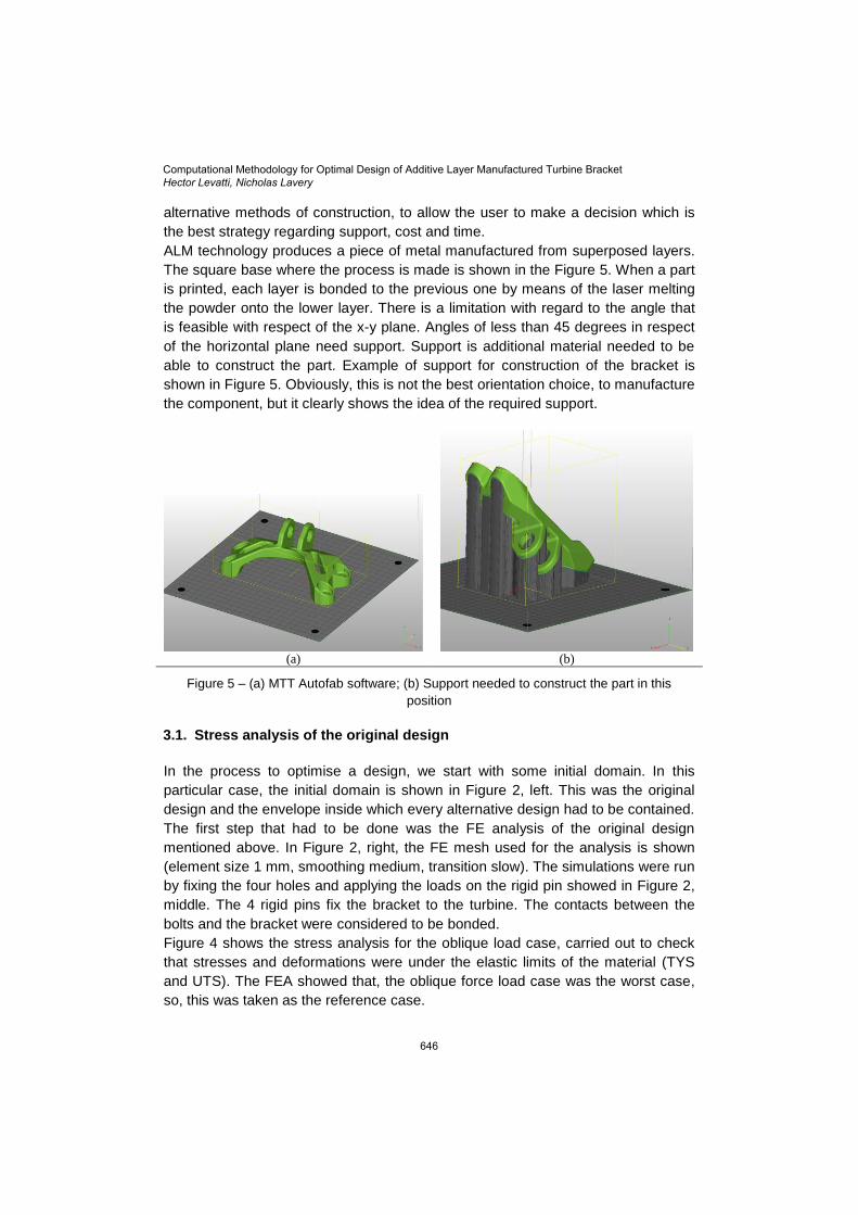
ALM technology produces a piece of metal manufactured from superposed layers.
The square base where the process is made is shown in the Figure 5. When a part
is printed, each layer is bonded to the previous one by means of the laser melting
the powder onto the lower layer. There is a limitation with regard to the angle that
is feasible with respect of the x-y plane. Angles of less than 45 degrees in respect
of the horizontal plane need support. Support is additional material needed to be
able to construct the part. Example of support for construction of the bracket is
shown in Figure 5. Obviously, this is not the best orientation choice, to manufacture
the component, but it clearly shows the idea of the required support.
(a) (b)
Figure 5 – (a) MTT Autofab software; (b) Support needed to construct the part in this
position 3.1. Stress analysis of the original design
In the process to optimise a design, we start with some initial domain. In this
particular case, the initial domain is shown in Figure 2, left. This was the original
design and the envelope inside which every alternative design had to be contained.
The first step that had to be done was the FE analysis of the original design
mentioned above. In Figure 2, right, the FE mesh used for the analysis is shown
(element size 1 mm, smoothing medium, transition slow). The simulations were run
by fixing the four holes and applying the loads on the rigid pin showed in Figure 2,
middle. The 4 rigid pins fix the bracket to the turbine. The contacts between the
bolts and the bracket were considered to be bonded.
Figure 4 shows the stress analysis for the oblique load case, carried out to check
that stresses and deformations were under the elastic limits of the material (TYS
and UTS). The FEA showed that, the oblique force load case was the worst case,
so, this was taken as the reference case.
Computational Methodology for Optimal Design of Additive Layer Manufactured Turbine BracketHector Levatti, Nicholas Lavery
646
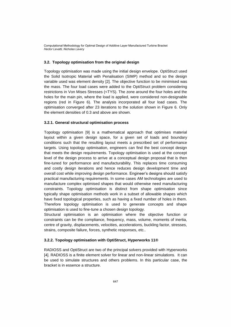
3.2. Topology optimisation from the original design
Topology optimisation was made using the initial design envelope. OptiStruct used
the Solid Isotropic Material with Penalisation (SIMP) method and so the design
variable used was element density [2]. The objective function to be minimised was
the mass. The four load cases were added to the OptiStruct problem considering
restrictions in Von Mises Stresses (<TYS). The zone around the four holes and the
holes for the main pin, where the load is applied, were considered non-designable
regions (red in Figure 6). The analysis incorporated all four load cases. The
optimisation converged after 23 iterations to the solution shown in Figure 6. Only
the element densities of 0.3 and above are shown.
3.2.1. General structural optimisation process
Topology optimisation [9] is a mathematical approach that optimises material
layout within a given design space, for a given set of loads and boundary
conditions such that the resulting layout meets a prescribed set of performance
targets. Using topology optimisation, engineers can find the best concept design
that meets the design requirements. Topology optimisation is used at the concept
level of the design process to arrive at a conceptual design proposal that is then
fine-tuned for performance and manufacturability. This replaces time consuming
and costly design iterations and hence reduces design development time and
overall cost while improving design performance. Engineer’s designs should satisfy
practical manufacturing requirements. In some cases AM technologies are used to
manufacture complex optimised shapes that would otherwise need manufacturing
constraints. Topology optimisation is distinct from shape optimisation since
typically shape optimisation methods work in a subset of allowable shapes which
have fixed topological properties, such as having a fixed number of holes in them.
Therefore topology optimisation is used to generate concepts and shape
optimisation is used to fine-tune a chosen design topology.
Structural optimisation is an optimisation where the objective function or
constraints can be the compliance, frequency, mass, volume, moments of inertia,
centre of gravity, displacements, velocities, accelerations, buckling factor, stresses,
strains, composite failure, forces, synthetic responses, etc..
3.2.2. Topology optimisation with OptiStruct, Hyperworks 11®
RADIOSS and OptiStruct are two of the principal solvers provided with Hyperworks
[4]. RADIOSS is a finite element solver for linear and non-linear simulations. It can
be used to simulate structures and others problems. In this particular case, the
bracket is in essence a structure.
Computational Methodology for Optimal Design of Additive Layer Manufactured Turbine BracketHector Levatti, Nicholas Lavery
647
Altair OptiStruct is an award winning CAE technology for conceptual design
synthesis and structural optimisation. OptiStruct uses the analysis capabilities of
RADIOSS to compute responses for optimisation.
Topology Optimisation generates an optimised material distribution for a set of
loads and constraints within a given design space. The design space can be
defined using shell or solid elements, or both. Both the classical topology
optimisation set up solving the minimum compliance problem, and the dual
formulation with multiple constraints are available. Constraints on von Mises stress
and buckling factor are available with limitations. Manufacturing constraints can be
imposed using a minimum member size constraint, draw direction constraints,
extrusion constraints, symmetry planes, pattern grouping, and pattern repetition. A
conceptual design can be imported into a CAD system [6] using an iso-surface
generated with OSSmooth, which is part of the OptiStruct package.
The overall cost of design development can be reduced substantially by avoiding
concept changes introduced in the testing phase of the design. This is the major
benefit of modifying the design process by introducing topology and topography
optimisation.
In the real world, the design process is not as straightforward as described
above. The design is not just driven by one performance measure -- it has to be
viewed as a multidisciplinary task. Today, the different disciplines work more or
less independently. Analysis and optimisation is performed for single phenomena
such as linear static behavior or noise, vibration and harshness. Still, the idea
persists that if one performance measure improves, the whole performance
improves. A simple example shows that this is not quite true. Take the design of a
car high stiffness is necessary for good driving and handling characteristics, and
high deformability is important for the crashworthiness of the design. This shows
that improving one measure may result in degrading another. Therefore,
compromises must go into the formulation of the optimisation problem. The
definition of the design problem and of the design target is most important. The
solution can be found through computational route. Multidisciplinary
considerations, especially in the conceptual design, are, in many ways, still active
research topics and are being covered by future developments of topology
optimisation. However, the inclusion of manufacturing constraints into topology
and topography optimisation is already implemented in OptiStruct.
OptiStruct can be used to solve and optimise a wide variety of design problems in
which the structural and system behaviour can be simulated using finite element
and multi-body dynamics analysis.
3.2.2.1. Bracket Topology Optimisation In structural optimisation the simplest case is when there is only one part to be
optimised. There are other cases where optimisation of mechanisms are needed.
Computational Methodology for Optimal Design of Additive Layer Manufactured Turbine BracketHector Levatti, Nicholas Lavery
648
Although, in those cases each component is a simple part, we have to analyse not
only each part but the interactions between them.
Figure 6 – Topology optimisation of the turbine bracket
Figure 6 shows the result of the topology optimisation conducted with HyperWorks
– OptiStruct 11. The red zones around the holes are non-design material and
topology optimisation was made on the rest of the original envelop. The result
appears logical and suggests a kind of design based on triangulation of the
structure in order to transmit the load on the main pin to the four holes where the
bracket is fixed to the turbine.
3.2.3. Concept Design
From the topology study the concept design shown in Figure 6 was obtained. From
this concept design several iterations were made and at each stage that the four
load cases were checked by running FE simulations with Ansys Workbench. In
other words, the shape optimisation process was made by hand.
The topology optimisation suggests a triangulated structure formed by 4 legs
connecting the main pin with the four holes and reinforcing the space between the
legs with some material in the middle. This preferred reinforcement was to use
triangulating material in order to generate a sort of truss.
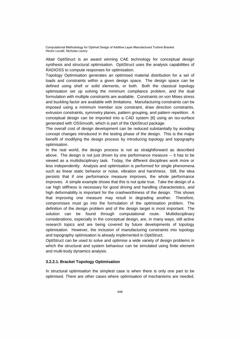
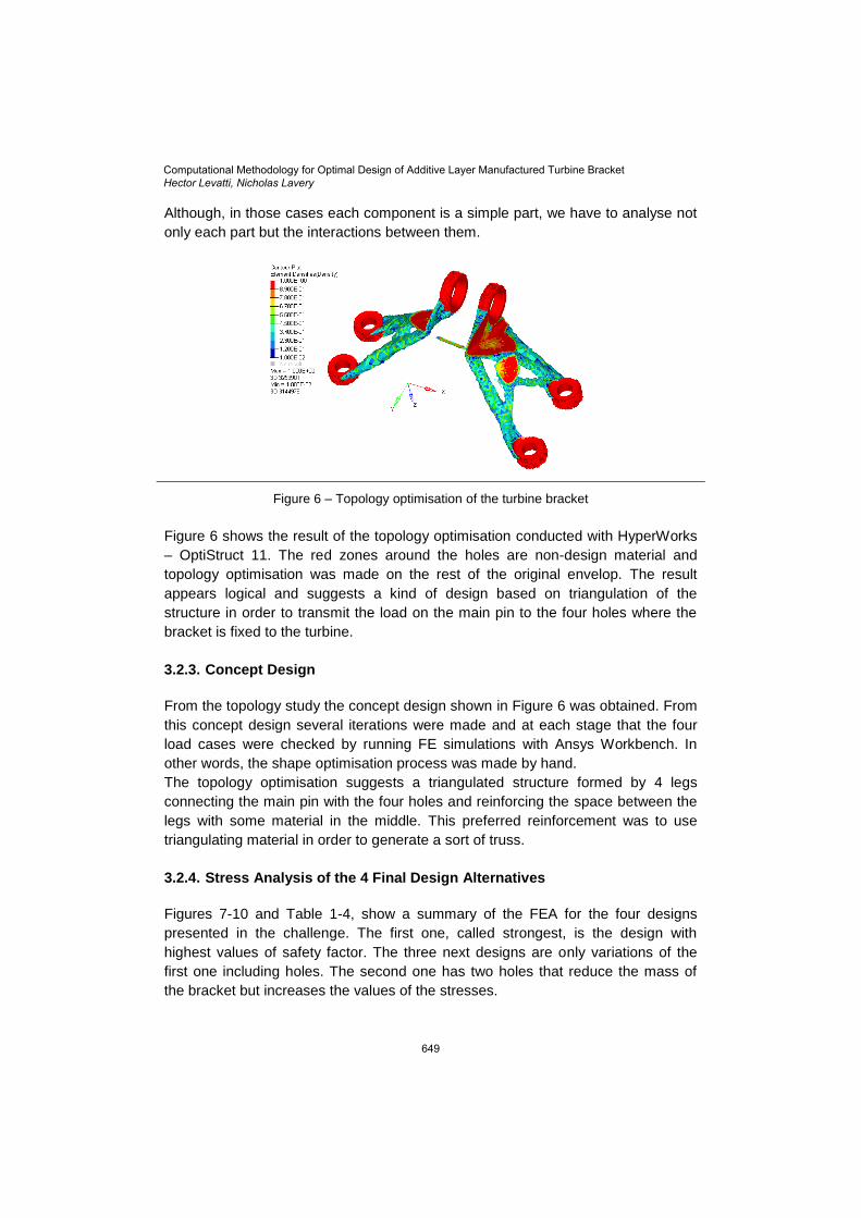
3.2.4. Stress Analysis of the 4 Final Design Alternatives
Figures 7-10 and Table 1-4, show a summary of the FEA for the four designs
presented in the challenge. The first one, called strongest, is the design with
highest values of safety factor. The three next designs are only variations of the
first one including holes. The second one has two holes that reduce the mass of
the bracket but increases the values of the stresses.
Computational Methodology for Optimal Design of Additive Layer Manufactured Turbine BracketHector Levatti, Nicholas Lavery
649
Arrows indicate the construction direction by means of ALMe
Figure 7 – General Electric Challenge - Strongest Version (v55f)
Table 1 – Design Strongest: 763 grams (63% mass reduction)
Yield limit 903
MPa
Total Deformation
[mm]
Maximum Von-Mises Stress
(MPa)
Safety
factor
Vertical Load 0.39 760 1.19
Horizontal Load 0.36 582 1.55
Oblique Load 0.16 648 1.39
Torsion Load 0.13 503 1.79
Arrows indicate the construction direction by means of ALMe
Figure 8 - General Electric Challenge - Lightest Version (v58)
Table 2 – Design Lightest: 650 grams (68% mass reduction)
Yield limit 903
MPa
Total Deformation
[mm]
Maximum Von Mises Stress
(MPa)
Safety
factor
Vertical Load 0.52 891 1.01
Horizontal Load 0.49 695 1.30
Oblique Load 0.21 690 1.31
Torsion Load 0.16 509 1.77
Computational Methodology for Optimal Design of Additive Layer Manufactured Turbine BracketHector Levatti, Nicholas Lavery
650
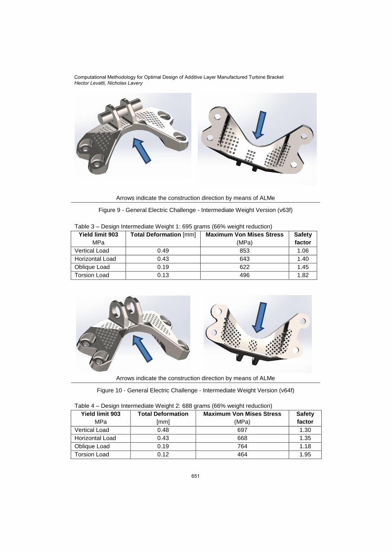
Arrows indicate the construction direction by means of ALMe
Figure 9 - General Electric Challenge - Intermediate Weight Version (v63f)
Table 3 – Design Intermediate Weight 1: 695 grams (66% weight reduction)
Yield limit 903
MPa
Total Deformation [mm] Maximum Von Mises Stress
(MPa)
Safety
factor
Vertical Load 0.49 853 1.06
Horizontal Load 0.43 643 1.40
Oblique Load 0.19 622 1.45
Torsion Load 0.13 496 1.82
Arrows indicate the construction direction by means of ALMe
Figure 10 - General Electric Challenge - Intermediate Weight Version (v64f)
Table 4 – Design Intermediate Weight 2: 688 grams (66% weight reduction)
Yield limit 903
MPa
Total Deformation
[mm]
Maximum Von Mises Stress
(MPa)
Safety
factor
Vertical Load 0.48 697 1.30
Horizontal Load 0.43 668 1.35
Oblique Load 0.19 764 1.18
Torsion Load 0.12 464 1.95
Computational Methodology for Optimal Design of Additive Layer Manufactured Turbine BracketHector Levatti, Nicholas Lavery
651
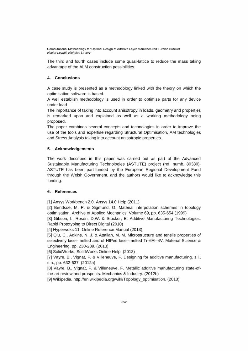
The third and fourth cases include some quasi-lattice to reduce the mass taking
advantage of the ALM construction possibilities.
4. Conclusions
A case study is presented as a methodology linked with the theory on which the
optimisation software is based.
A well establish methodology is used in order to optimise parts for any device
under load.
The importance of taking into account anisotropy in loads, geometry and properties
is remarked upon and explained as well as a working methodology being
proposed.
The paper combines several concepts and technologies in order to improve the
use of the tools and expertise regarding Structural Optimisation, AM technologies
and Stress Analysis taking into account anisotropic properties.
5. Acknowledgements
The work described in this paper was carried out as part of the Advanced
Sustainable Manufacturing Technologies (ASTUTE) project (ref. numb. 80380).
ASTUTE has been part-funded by the European Regional Development Fund
through the Welsh Government, and the authors would like to acknowledge this
funding.
6. References
[1] Ansys Workbench 2.0. Ansys 14.0 Help (2011)
[2] Bendsoe, M. P. & Sigmund, O. Material interpolation schemes in topology
optimisation. Archive of Applied Mechanics, Volume 69, pp. 635-654 (1999)
[3] Gibson, I., Rosen, D.W. & Stucker, B. Additive Manufacturing Technologies:
Rapid Prototyping to Direct Digital (2010)
[4] Hyperwoks 11, Online Reference Manual (2013)
[5] Qiu, C., Adkins, N. J. & Attallah, M. M. Microstructure and tensile properties of
selectively laser-melted and of HIPed laser-melted Ti–6Al–4V. Material Science &
Engineering, pp. 230-239. (2013)
[6] SolidWorks, SolidWorks Online Help. (2013)
[7] Vayre, B., Vignat, F. & Villeneuve, F. Designing for additive manufacturing. s.l.,
s.n., pp. 632-637. (2012a)
[8] Vayre, B., Vignat, F. & Villeneuve, F. Metallic additive manufacturing state-of-
the-art review and prospects. Mechanics & Industry. (2012b)
[9] Wikipedia. http://en.wikipedia.org/wiki/Topology_optimisation. (2013)
Computational Methodology for Optimal Design of Additive Layer Manufactured Turbine BracketHector Levatti, Nicholas Lavery
652
Related Documents