Sensors and Actuators A 223 (2015) 49–60 Contents lists available at ScienceDirect Sensors and Actuators A: Physical j ourna l h o mepage: www.elsevier.com/locate/sna Dynamic modeling of a bidirectional magnetoelastic rotary micro-motor Jinhong Qu a,∗ , Jun Tang b , Yogesh B. Gianchandani a,b , Kenn R. Oldham a , Scott R. Green b a Department of Mechanical Engineering, University of Michigan, Ann Arbor, MI 48109, USA b Department of Electrical Engineering and Computer Science, University of Michigan, Ann Arbor, MI 48109, USA a r t i c l e i n f o Article history: Received 30 September 2014 Received in revised form 1 December 2014 Accepted 26 December 2014 Available online 4 January 2015 Keywords: Magnetostrictive Wireless actuation Resonant actuation Modal analysis Collision model Transient model a b s t r a c t A dynamic model is presented for a novel magnetoelastic rotary micro-motor. Magnetoelastic excitation results in a rotary motor with comparatively large payload even under direct wireless actuation, but the resulting stator behavior is significantly different from that of prior micro-scale rotary motors. A parametric modal model is developed from conservation of momentum, a second order linear distributed stator and ballistic rotor motion. The modes and a pre-stressed finite element model are also described to support the parametric modal model. The typical simulated model output and parametric analyses are presented with important trends and behaviors of the micro-motor motion, including stochastic features of rotary and vertical motion, and experimental validation. The dynamics of the micro-motor under certain inputs and design parameters are also estimated by the model. © 2015 Elsevier B.V. All rights reserved. 1. Introduction Chip-scale rotary micro-motors based on magnetoelastic trans- duction have recently been demonstrated [1]. These motors join other transduction mechanisms for realizing chip-scale rotary motion, including electrostatic, piezoelectric and others [2,3]. In general, micro-motors based on smart materials and fabricated by MEMS technology have demonstrated better efficiency than chip- scale versions of traditional electromagnetic motors [3]. Chip-scale rotary micro-motors are useful in a broad range of applications [4–8]. One emerging opportunity is to integrate rotary motion with a MEMS gyroscope and control electronics to real- ize on-chip calibration of long-term gyroscope gain and bias drift [9,10]. However, such an application requires exceptionally high motion accuracies; a representative gyroscope calibration require- ment is rotation at up to 1000 degree/s over arbitrary angles with a resolution better than ±10 milli-degrees. To reach such accuracy, the dynamic behavior of a micro-motor must be well understood and distilled into an analytical or numerical model. A model that captures essential behaviors, including transient and steady-state stator motions, stator-to-rotor momentum transfer mechanics, and energy loss mechanisms, is important for predictive design. Such ∗ Corresponding author at: 3632 GGB (George G. Brown Laboratory), 2350 Hay- ward, Ann Arbor, MI 48109, USA. Tel.: +1 734 353 2760. E-mail address: [email protected] (J. Qu). a model is also needed for improving motion estimation accuracy using Kalman filters or other estimation and control schemes. This paper describes the first detailed dynamic modeling of a rotary micro-motor based specifically on magnetoelastic excitation. Magnetoelastic rotary micro-motors [1] can be driven with a larger payload than other motors at the same scale; this feature is helpful for carrying on-chip gyroscopes for calibration. Magneto- elastic motors can also be remotely, wirelessly actuated without coupling circuitry. The direction of rotation is selected by changing the electromagnetic field input frequency between well-defined resonant modes. The model presented in this paper focuses on a micro-motor designed for the in situ gyroscope calibration task described above. Fig. 1(a) shows a scanning electron microscopy (SEM) image of a magnetoelastic micro-motor stator and Fig. 1(b) shows the schematic of the device. Many studies have been completed on rotary micro-motor dynamics based on other transduction mechanisms. Electrostatic micro-motors [2,11], for example, have been extensively stud- ied [12–14]. These motors are actuated through non-contact interactions that are significantly different from the stator–rotor interaction in a magnetoelastic micro-motor. Piezoelectric micro- motors are more closely related, being based on contact between stator and rotor, as in the magnetoelastic motor. Many piezoelec- tric motor models have been proposed; types of these models include: (1) dynamic models based on nonlinear stator–rotor con- tact, without considering the reaction of the stator to contact with the rotor [15]; (2) models based on the Rayleigh–Ritz assumed http://dx.doi.org/10.1016/j.sna.2014.12.029 0924-4247/© 2015 Elsevier B.V. All rights reserved.

Welcome message from author
This document is posted to help you gain knowledge. Please leave a comment to let me know what you think about it! Share it to your friends and learn new things together.
Transcript
Dm
Ja
b
a
ARRAA
KMWRMCT
1
domgMs
ami[mmatacse
w
h0
Sensors and Actuators A 223 (2015) 49–60
Contents lists available at ScienceDirect
Sensors and Actuators A: Physical
j ourna l h o mepage: www.elsev ier .com/ locate /sna
ynamic modeling of a bidirectional magnetoelastic rotaryicro-motor
inhong Qua,∗, Jun Tangb, Yogesh B. Gianchandania,b, Kenn R. Oldhama, Scott R. Greenb
Department of Mechanical Engineering, University of Michigan, Ann Arbor, MI 48109, USADepartment of Electrical Engineering and Computer Science, University of Michigan, Ann Arbor, MI 48109, USA
r t i c l e i n f o
rticle history:eceived 30 September 2014eceived in revised form 1 December 2014ccepted 26 December 2014vailable online 4 January 2015
a b s t r a c t
A dynamic model is presented for a novel magnetoelastic rotary micro-motor. Magnetoelastic excitationresults in a rotary motor with comparatively large payload even under direct wireless actuation, butthe resulting stator behavior is significantly different from that of prior micro-scale rotary motors. Aparametric modal model is developed from conservation of momentum, a second order linear distributedstator and ballistic rotor motion. The modes and a pre-stressed finite element model are also described
eywords:agnetostrictiveireless actuation
esonant actuationodal analysis
ollision model
to support the parametric modal model. The typical simulated model output and parametric analysesare presented with important trends and behaviors of the micro-motor motion, including stochasticfeatures of rotary and vertical motion, and experimental validation. The dynamics of the micro-motorunder certain inputs and design parameters are also estimated by the model.
© 2015 Elsevier B.V. All rights reserved.
ransient model
. Introduction
Chip-scale rotary micro-motors based on magnetoelastic trans-uction have recently been demonstrated [1]. These motors jointher transduction mechanisms for realizing chip-scale rotaryotion, including electrostatic, piezoelectric and others [2,3]. In
eneral, micro-motors based on smart materials and fabricated byEMS technology have demonstrated better efficiency than chip-
cale versions of traditional electromagnetic motors [3].Chip-scale rotary micro-motors are useful in a broad range of
pplications [4–8]. One emerging opportunity is to integrate rotaryotion with a MEMS gyroscope and control electronics to real-
ze on-chip calibration of long-term gyroscope gain and bias drift9,10]. However, such an application requires exceptionally high
otion accuracies; a representative gyroscope calibration require-ent is rotation at up to 1000 degree/s over arbitrary angles with
resolution better than ±10 milli-degrees. To reach such accuracy,he dynamic behavior of a micro-motor must be well understoodnd distilled into an analytical or numerical model. A model that
aptures essential behaviors, including transient and steady-statetator motions, stator-to-rotor momentum transfer mechanics, andnergy loss mechanisms, is important for predictive design. Such∗ Corresponding author at: 3632 GGB (George G. Brown Laboratory), 2350 Hay-ard, Ann Arbor, MI 48109, USA. Tel.: +1 734 353 2760.
E-mail address: [email protected] (J. Qu).
ttp://dx.doi.org/10.1016/j.sna.2014.12.029924-4247/© 2015 Elsevier B.V. All rights reserved.
a model is also needed for improving motion estimation accuracyusing Kalman filters or other estimation and control schemes. Thispaper describes the first detailed dynamic modeling of a rotarymicro-motor based specifically on magnetoelastic excitation.
Magnetoelastic rotary micro-motors [1] can be driven with alarger payload than other motors at the same scale; this feature ishelpful for carrying on-chip gyroscopes for calibration. Magneto-elastic motors can also be remotely, wirelessly actuated withoutcoupling circuitry. The direction of rotation is selected by changingthe electromagnetic field input frequency between well-definedresonant modes. The model presented in this paper focuses on amicro-motor designed for the in situ gyroscope calibration taskdescribed above. Fig. 1(a) shows a scanning electron microscopy(SEM) image of a magnetoelastic micro-motor stator and Fig. 1(b)shows the schematic of the device.
Many studies have been completed on rotary micro-motordynamics based on other transduction mechanisms. Electrostaticmicro-motors [2,11], for example, have been extensively stud-ied [12–14]. These motors are actuated through non-contactinteractions that are significantly different from the stator–rotorinteraction in a magnetoelastic micro-motor. Piezoelectric micro-motors are more closely related, being based on contact betweenstator and rotor, as in the magnetoelastic motor. Many piezoelec-
tric motor models have been proposed; types of these modelsinclude: (1) dynamic models based on nonlinear stator–rotor con-tact, without considering the reaction of the stator to contact withthe rotor [15]; (2) models based on the Rayleigh–Ritz assumed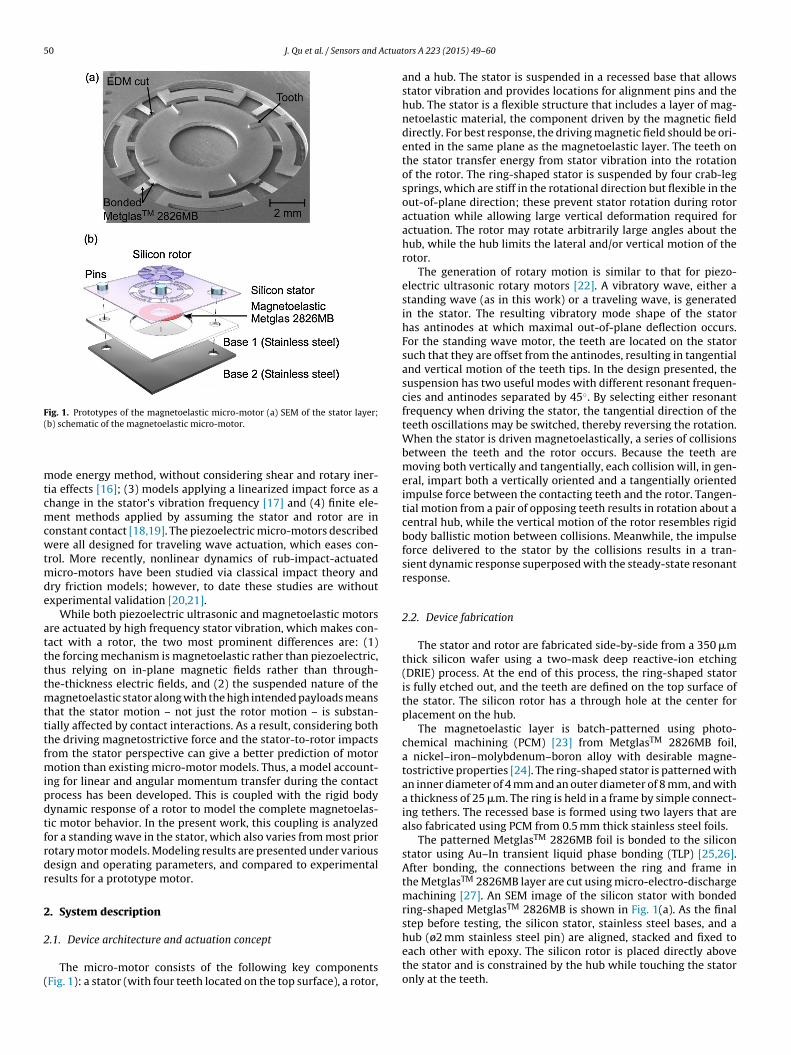
50 J. Qu et al. / Sensors and Actuat
Fig. 1. Prototypes of the magnetoelastic micro-motor (a) SEM of the stator layer;(
mtcmcwtmde
attttmtttfmipdtfrdr
2
2
(
b) schematic of the magnetoelastic micro-motor.
ode energy method, without considering shear and rotary iner-ia effects [16]; (3) models applying a linearized impact force as ahange in the stator’s vibration frequency [17] and (4) finite ele-ent methods applied by assuming the stator and rotor are in
onstant contact [18,19]. The piezoelectric micro-motors describedere all designed for traveling wave actuation, which eases con-
rol. More recently, nonlinear dynamics of rub-impact-actuatedicro-motors have been studied via classical impact theory and
ry friction models; however, to date these studies are withoutxperimental validation [20,21].
While both piezoelectric ultrasonic and magnetoelastic motorsre actuated by high frequency stator vibration, which makes con-act with a rotor, the two most prominent differences are: (1)he forcing mechanism is magnetoelastic rather than piezoelectric,hus relying on in-plane magnetic fields rather than through-he-thickness electric fields, and (2) the suspended nature of the
agnetoelastic stator along with the high intended payloads meanshat the stator motion – not just the rotor motion – is substan-ially affected by contact interactions. As a result, considering bothhe driving magnetostrictive force and the stator-to-rotor impactsrom the stator perspective can give a better prediction of motor
otion than existing micro-motor models. Thus, a model account-ng for linear and angular momentum transfer during the contactrocess has been developed. This is coupled with the rigid bodyynamic response of a rotor to model the complete magnetoelas-ic motor behavior. In the present work, this coupling is analyzedor a standing wave in the stator, which also varies from most priorotary motor models. Modeling results are presented under variousesign and operating parameters, and compared to experimentalesults for a prototype motor.
. System description
.1. Device architecture and actuation concept
The micro-motor consists of the following key componentsFig. 1): a stator (with four teeth located on the top surface), a rotor,
ors A 223 (2015) 49–60
and a hub. The stator is suspended in a recessed base that allowsstator vibration and provides locations for alignment pins and thehub. The stator is a flexible structure that includes a layer of mag-netoelastic material, the component driven by the magnetic fielddirectly. For best response, the driving magnetic field should be ori-ented in the same plane as the magnetoelastic layer. The teeth onthe stator transfer energy from stator vibration into the rotationof the rotor. The ring-shaped stator is suspended by four crab-legsprings, which are stiff in the rotational direction but flexible in theout-of-plane direction; these prevent stator rotation during rotoractuation while allowing large vertical deformation required foractuation. The rotor may rotate arbitrarily large angles about thehub, while the hub limits the lateral and/or vertical motion of therotor.
The generation of rotary motion is similar to that for piezo-electric ultrasonic rotary motors [22]. A vibratory wave, either astanding wave (as in this work) or a traveling wave, is generatedin the stator. The resulting vibratory mode shape of the statorhas antinodes at which maximal out-of-plane deflection occurs.For the standing wave motor, the teeth are located on the statorsuch that they are offset from the antinodes, resulting in tangentialand vertical motion of the teeth tips. In the design presented, thesuspension has two useful modes with different resonant frequen-cies and antinodes separated by 45◦. By selecting either resonantfrequency when driving the stator, the tangential direction of theteeth oscillations may be switched, thereby reversing the rotation.When the stator is driven magnetoelastically, a series of collisionsbetween the teeth and the rotor occurs. Because the teeth aremoving both vertically and tangentially, each collision will, in gen-eral, impart both a vertically oriented and a tangentially orientedimpulse force between the contacting teeth and the rotor. Tangen-tial motion from a pair of opposing teeth results in rotation about acentral hub, while the vertical motion of the rotor resembles rigidbody ballistic motion between collisions. Meanwhile, the impulseforce delivered to the stator by the collisions results in a tran-sient dynamic response superposed with the steady-state resonantresponse.
2.2. Device fabrication
The stator and rotor are fabricated side-by-side from a 350 �mthick silicon wafer using a two-mask deep reactive-ion etching(DRIE) process. At the end of this process, the ring-shaped statoris fully etched out, and the teeth are defined on the top surface ofthe stator. The silicon rotor has a through hole at the center forplacement on the hub.
The magnetoelastic layer is batch-patterned using photo-chemical machining (PCM) [23] from MetglasTM 2826MB foil,a nickel–iron–molybdenum–boron alloy with desirable magne-tostrictive properties [24]. The ring-shaped stator is patterned withan inner diameter of 4 mm and an outer diameter of 8 mm, and witha thickness of 25 �m. The ring is held in a frame by simple connect-ing tethers. The recessed base is formed using two layers that arealso fabricated using PCM from 0.5 mm thick stainless steel foils.
The patterned MetglasTM 2826MB foil is bonded to the siliconstator using Au–In transient liquid phase bonding (TLP) [25,26].After bonding, the connections between the ring and frame inthe MetglasTM 2826MB layer are cut using micro-electro-dischargemachining [27]. An SEM image of the silicon stator with bondedring-shaped MetglasTM 2826MB is shown in Fig. 1(a). As the finalstep before testing, the silicon stator, stainless steel bases, and a
hub (ø2 mm stainless steel pin) are aligned, stacked and fixed toeach other with epoxy. The silicon rotor is placed directly abovethe stator and is constrained by the hub while touching the statoronly at the teeth.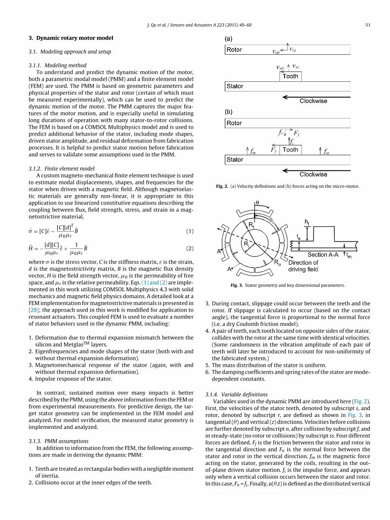
Actuators A 223 (2015) 49–60 51
3
3
3
b(pbdtlTpdpa
3
tstacn
�
H
wdvsmmF[ro
1
2
3
4
dfgai
3
t
1
2
Fig. 2. (a) Velocity definitions and (b) forces acting on the micro-motor.
J. Qu et al. / Sensors and
. Dynamic rotary motor model
.1. Modeling approach and setup
.1.1. Modeling methodTo understand and predict the dynamic motion of the motor,
oth a parametric modal model (PMM) and a finite element modelFEM) are used. The PMM is based on geometric parameters andhysical properties of the stator and rotor (certain of which muste measured experimentally), which can be used to predict theynamic motion of the motor. The PMM captures the major fea-ures of the motor motion, and is especially useful in simulatingong durations of operation with many stator-to-rotor collisions.he FEM is based on a COMSOL Multiphysics model and is used toredict additional behavior of the stator, including mode shapes,riven stator amplitude, and residual deformation from fabricationrocesses. It is helpful to predict stator motion before fabricationnd serves to validate some assumptions used in the PMM.
.1.2. Finite element modelA custom magneto-mechanical finite element technique is used
o estimate modal displacements, shapes, and frequencies for thetator when driven with a magnetic field. Although magnetoelas-ic materials are generally non-linear, it is appropriate in thispplication to use linearized constitutive equations describing theoupling between flux, field strength, stress, and strain in a mag-etostrictive material,
� = [C]�ε − [C][d]T
�0�r
�B (1)
� = − [d][C]
�0�r�ε + 1
�0�r
�B (2)
here � is the stress vector, C is the stiffness matrix, ε is the strain, is the magnetostrictivity matrix, B is the magnetic flux densityector, H is the field strength vector, �0 is the permeability of freepace, and �r is the relative permeability. Eqs. (1) and (2) are imple-ented in this work utilizing COMSOL Multiphysics 4.3 with solidechanics and magnetic field physics domains. A detailed look at a
EM implementation for magnetostrictive materials is presented in28]; the approach used in this work is modified for application toesonant actuators. This coupled FEM is used to evaluate a numberf stator behaviors used in the dynamic PMM, including:
. Deformation due to thermal expansion mismatch between thesilicon and MetglasTM layers.
. Eigenfrequencies and mode shapes of the stator (both with andwithout thermal expansion deformation).
. Magnetomechanical response of the stator (again, with andwithout thermal expansion deformation).
. Impulse response of the stator.
In contrast, sustained motion over many impacts is betterescribed by the PMM, using the above information from the FEM orrom experimental measurements. For predictive design, the tar-et stator geometry can be implemented in the FEM model andnalyzed. For model verification, the measured stator geometry ismplemented and analyzed.
.1.3. PMM assumptionsIn addition to information from the FEM, the following assump-
ions are made in deriving the dynamic PMM:
. Teeth are treated as rectangular bodies with a negligible momentof inertia.
. Collisions occur at the inner edges of the teeth.
Fig. 3. Stator geometry and key dimensional parameters.
3. During contact, slippage could occur between the teeth and therotor. If slippage is calculated to occur (based on the contactangle), the tangential force is proportional to the normal force(i.e. a dry Coulomb friction model).
4. A pair of teeth, each tooth located on opposite sides of the stator,collides with the rotor at the same time with identical velocities.(Some randomness in the vibration amplitude of each pair ofteeth will later be introduced to account for non-uniformity ofthe fabricated system.)
5. The mass distribution of the stator is uniform.6. The damping coefficients and spring rates of the stator are mode-
dependent constants.
3.1.4. Variable definitionsVariables used in the dynamic PMM are introduced here (Fig. 2).
First, the velocities of the stator teeth, denoted by subscript s, androtor, denoted by subscript r, are defined as shown in Fig. 3, intangential (�) and vertical (z) directions. Velocities before collisionsare further denoted by subscript o, after collision by subscript f, andin steady-state (no rotor or collisions) by subscript ss. Four differentforces are defined. Ff is the friction between the stator and rotor inthe tangential direction and Fn is the normal force between thestator and rotor in the vertical direction. fm is the magnetic forceacting on the stator, generated by the coils, resulting in the out-
of-plane driven stator motion. fi is the impulse force, and appearsonly when a vertical collision occurs between the stator and rotor.In this case, Fn = fi. Finally, u(�,t) is defined as the distributed vertical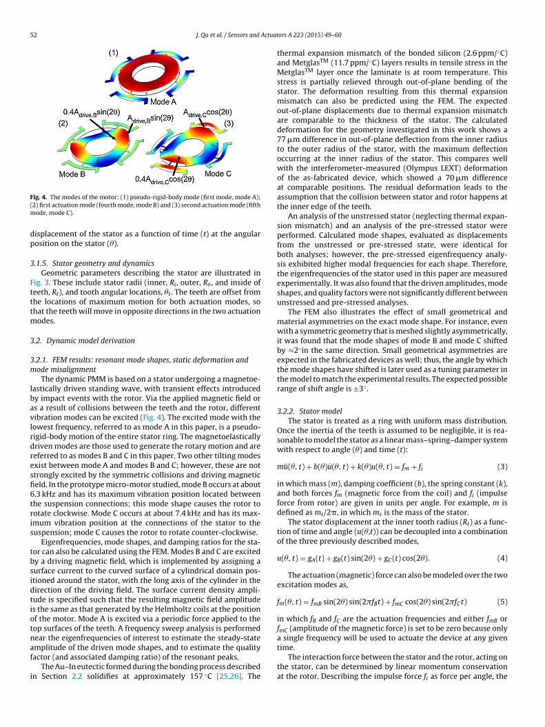
52 J. Qu et al. / Sensors and Actuat
F(m
dp
3
Ftttm
3
3m
lbavlrdresfi6tris
tbsidtiotnaf
i
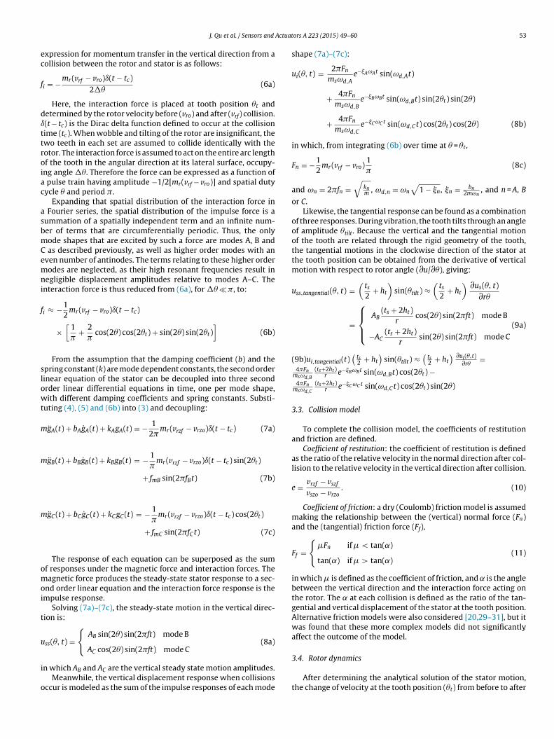
ig. 4. The modes of the motor: (1) pseudo-rigid-body mode (first mode, mode A);2) first actuation mode (fourth mode, mode B) and (3) second actuation mode (fifth
ode, mode C).
isplacement of the stator as a function of time (t) at the angularosition on the stator (�).
.1.5. Stator geometry and dynamicsGeometric parameters describing the stator are illustrated in
ig. 3. These include stator radii (inner, Ri, outer, Ro, and inside ofeeth, Rt), and tooth angular locations, �t. The teeth are offset fromhe locations of maximum motion for both actuation modes, sohat the teeth will move in opposite directions in the two actuation
odes.
.2. Dynamic model derivation
.2.1. FEM results: resonant mode shapes, static deformation andode misalignment
The dynamic PMM is based on a stator undergoing a magnetoe-astically driven standing wave, with transient effects introducedy impact events with the rotor. Via the applied magnetic field ors a result of collisions between the teeth and the rotor, differentibration modes can be excited (Fig. 4). The excited mode with theowest frequency, referred to as mode A in this paper, is a pseudo-igid-body motion of the entire stator ring. The magnetoelasticallyriven modes are those used to generate the rotary motion and areeferred to as modes B and C in this paper. Two other tilting modesxist between mode A and modes B and C; however, these are nottrongly excited by the symmetric collisions and driving magneticeld. In the prototype micro-motor studied, mode B occurs at about.3 kHz and has its maximum vibration position located betweenhe suspension connections; this mode shape causes the rotor tootate clockwise. Mode C occurs at about 7.4 kHz and has its max-mum vibration position at the connections of the stator to theuspension; mode C causes the rotor to rotate counter-clockwise.
Eigenfrequencies, mode shapes, and damping ratios for the sta-or can also be calculated using the FEM. Modes B and C are excitedy a driving magnetic field, which is implemented by assigning aurface current to the curved surface of a cylindrical domain pos-tioned around the stator, with the long axis of the cylinder in theirection of the driving field. The surface current density ampli-ude is specified such that the resulting magnetic field amplitudes the same as that generated by the Helmholtz coils at the positionf the motor. Mode A is excited via a periodic force applied to theop surfaces of the teeth. A frequency sweep analysis is performedear the eigenfrequencies of interest to estimate the steady-state
mplitude of the driven mode shapes, and to estimate the qualityactor (and associated damping ratio) of the resonant peaks.The Au–In eutectic formed during the bonding process describedn Section 2.2 solidifies at approximately 157 ◦C [25,26]. The
ors A 223 (2015) 49–60
thermal expansion mismatch of the bonded silicon (2.6 ppm/◦C)and MetglasTM (11.7 ppm/◦C) layers results in tensile stress in theMetglasTM layer once the laminate is at room temperature. Thisstress is partially relieved through out-of-plane bending of thestator. The deformation resulting from this thermal expansionmismatch can also be predicted using the FEM. The expectedout-of-plane displacements due to thermal expansion mismatchare comparable to the thickness of the stator. The calculateddeformation for the geometry investigated in this work shows a77 �m difference in out-of-plane deflection from the inner radiusto the outer radius of the stator, with the maximum deflectionoccurring at the inner radius of the stator. This compares wellwith the interferometer-measured (Olympus LEXT) deformationof the as-fabricated device, which showed a 70 �m differenceat comparable positions. The residual deformation leads to theassumption that the collision between stator and rotor happens atthe inner edge of the teeth.
An analysis of the unstressed stator (neglecting thermal expan-sion mismatch) and an analysis of the pre-stressed stator wereperformed. Calculated mode shapes, evaluated as displacementsfrom the unstressed or pre-stressed state, were identical forboth analyses; however, the pre-stressed eigenfrequency analy-sis exhibited higher modal frequencies for each shape. Therefore,the eigenfrequencies of the stator used in this paper are measuredexperimentally. It was also found that the driven amplitudes, modeshapes, and quality factors were not significantly different betweenunstressed and pre-stressed analyses.
The FEM also illustrates the effect of small geometrical andmaterial asymmetries on the exact mode shape. For instance, evenwith a symmetric geometry that is meshed slightly asymmetrically,it was found that the mode shapes of mode B and mode C shiftedby ≈2◦in the same direction. Small geometrical asymmetries areexpected in the fabricated devices as well; thus, the angle by whichthe mode shapes have shifted is later used as a tuning parameter inthe model to match the experimental results. The expected possiblerange of shift angle is ±3◦.
3.2.2. Stator modelThe stator is treated as a ring with uniform mass distribution.
Once the inertia of the teeth is assumed to be negligible, it is rea-sonable to model the stator as a linear mass–spring–damper systemwith respect to angle (�) and time (t):
mu(�, t) + b(�)u(�, t) + k(�)u(�, t) = fm + fi (3)
in which mass (m), damping coefficient (b), the spring constant (k),and both forces fm (magnetic force from the coil) and fi (impulseforce from rotor) are given in units per angle. For example, m isdefined as ms/2�, in which ms is the mass of the stator.
The stator displacement at the inner tooth radius (Rt) as a func-tion of time and angle (u(�,t)) can be decoupled into a combinationof the three previously described modes,
u(�, t) = gA(t) + gB(t) sin(2�) + gC (t) cos(2�). (4)
The actuation (magnetic) force can also be modeled over the twoexcitation modes as,
fm(�, t) = fmB sin(2�) sin(2�fBt) + fmC cos(2�) sin(2�fCt) (5)
in which fB and fC are the actuation frequencies and either fmB orfmC (amplitude of the magnetic force) is set to be zero because onlya single frequency will be used to actuate the device at any given
time.The interaction force between the stator and the rotor, acting onthe stator, can be determined by linear momentum conservationat the rotor. Describing the impulse force fi as force per angle, the
Actuat
ec
f
dıttroiac
asbmCemni
f
slowt
m
m
m
omoi
t
u
i
o
J. Qu et al. / Sensors and
xpression for momentum transfer in the vertical direction from aollision between the rotor and stator is as follows:
i = −mr(vrf − vro)ı(t − tc)2��
(6a)
Here, the interaction force is placed at tooth position �t andetermined by the rotor velocity before (vro) and after (vrf) collision.(t − tc) is the Dirac delta function defined to occur at the collisionime (tc). When wobble and tilting of the rotor are insignificant, thewo teeth in each set are assumed to collide identically with theotor. The interaction force is assumed to act on the entire arc lengthf the tooth in the angular direction at its lateral surface, occupy-ng angle ��. Therefore the force can be expressed as a function of
pulse train having amplitude −1/2[mr(vrf − vro)] and spatial dutyycle � and period �.
Expanding that spatial distribution of the interaction force in Fourier series, the spatial distribution of the impulse force is aummation of a spatially independent term and an infinite num-er of terms that are circumferentially periodic. Thus, the onlyode shapes that are excited by such a force are modes A, B and
as described previously, as well as higher order modes with anven number of antinodes. The terms relating to these higher orderodes are neglected, as their high resonant frequencies result in
egligible displacement amplitudes relative to modes A–C. Thenteraction force is thus reduced from (6a), for �� � �, to:
i ≈ −12
mr(vrf − vro)ı(t − tc)
×[
1�
+ 2�
cos(2�) cos(2�t) + sin(2�) sin(2�t)]
(6b)
From the assumption that the damping coefficient (b) and thepring constant (k) are mode dependent constants, the second orderinear equation of the stator can be decoupled into three secondrder linear differential equations in time, one per mode shape,ith different damping coefficients and spring constants. Substi-
uting (4), (5) and (6b) into (3) and decoupling:
gA(t) + bAgA(t) + kAgA(t) = − 12�
mr(vrzf − vrzo)ı(t − tc) (7a)
gB(t) + bBgB(t) + kBgB(t) = − 1�
mr(vrzf − vrzo)ı(t − tc) sin(2�t)
+ fmB sin(2�fBt) (7b)
gC (t) + bCgC (t) + kCgC (t) = − 1�
mr(vrzf − vrzo)ı(t − tc) cos(2�t)
+ fmC sin(2�fCt) (7c)
The response of each equation can be superposed as the sumf responses under the magnetic force and interaction forces. Theagnetic force produces the steady-state stator response to a sec-
nd order linear equation and the interaction force response is thempulse response.
Solving (7a)–(7c), the steady-state motion in the vertical direc-ion is:
ss(�, t) ={
AB sin(2�) sin(2�ft) mode B
AC cos(2�) sin(2�ft) mode C(8a)
n which AB and AC are the vertical steady state motion amplitudes.Meanwhile, the vertical displacement response when collisions
ccur is modeled as the sum of the impulse responses of each mode
ors A 223 (2015) 49–60 53
shape (7a)–(7c):
ui(�, t) = 2�Fn
msωd,Ae−AωAt sin(ωd,At)
+ 4�Fn
msωd,Be−BωBt sin(ωd,Bt) sin(2�t) sin(2�)
+ 4�Fn
msωd,Ce−C ωC t sin(ωd,Ct) cos(2�t) cos(2�) (8b)
in which, from integrating (6b) over time at � = �t,
Fn = −12
mr(vrf − vro)1�
(8c)
and ωn = 2�fn =√
knm , ωd,n = ωn
√1 − n, n = bn
2mωn, and n = A, B
or C.Likewise, the tangential response can be found as a combination
of three responses. During vibration, the tooth tilts through an angleof amplitude �tilt. Because the vertical and the tangential motionof the tooth are related through the rigid geometry of the tooth,the tangential motions in the clockwise direction of the stator atthe tooth position can be obtained from the derivative of verticalmotion with respect to rotor angle (∂u/∂�), giving:
uss,tangential(�, t) =(
ts
2+ ht
)sin(�tilt) ≈
(ts
2+ ht
) ∂us(�, t)∂r�
=
⎧⎪⎨⎪⎩
AB(ts + 2ht)
rcos(2�) sin(2�ft) mode B
−AC(ts + 2ht)
rsin(2�) sin(2�ft) mode C
(9a)
(9b)ui,tangential(t)(
ts2 + ht
)sin(�tilt) ≈
(ts2 + ht
) ∂ui(�,t)∂r�
=4�Fn
msωd,B
(ts+2ht )r e−BωBt sin(ωd,Bt) cos(2�t) −
4�Fnmsωd,C
(ts+2ht )r e−C ωC t sin(ωd,Ct) cos(2�t) sin(2�)
3.3. Collision model
To complete the collision model, the coefficients of restitutionand friction are defined.
Coefficient of restitution: the coefficient of restitution is definedas the ratio of the relative velocity in the normal direction after col-lision to the relative velocity in the vertical direction after collision.
e = vrzf − vszf
vszo − vrzo. (10)
Coefficient of friction: a dry (Coulomb) friction model is assumedmaking the relationship between the (vertical) normal force (Fn)and the (tangential) friction force (Ff),
Ff ={
�Fn if � < tan(˛)
tan(˛) if � > tan(˛)(11)
in which � is defined as the coefficient of friction, and is the anglebetween the vertical direction and the interaction force acting onthe rotor. The at each collision is defined as the ratio of the tan-gential and vertical displacement of the stator at the tooth position.Alternative friction models were also considered [20,29–31], but itwas found that these more complex models did not significantlyaffect the outcome of the model.
3.4. Rotor dynamics
After determining the analytical solution of the stator motion,the change of velocity at the tooth position (�t) from before to after
5 Actuat
a
ı
3b
(
at
v
v
abt
v
mcidppaem
fmrdd
maaa
m
J
it
3
tectpp
4 J. Qu et al. / Sensors and
collision can be derived from (8b) in analytical form:
ui(�t, 0) = 2�Fn
ms+ 4�Fn
mssin2(2�t) + 4�Fn
mscos2(2�t)
= 2�Fn
ms+ 4�Fn
ms(12a)
Substituting (12a) into (8c) and defining a mass ratio, rm, asmr/ms, the relation between the velocities of the stator/rotorefore/after collision becomes:
vszf − vszo) = ıui(�t, 0) = −rm(vrzf − vrzo) (12b)
Given the definition of the coefficient of restitution from (10)nd (12b), the expression for vszf (stator velocity after collision atooth position) and vrf can be derived:
szf = vszo − rm (evszo − (e + 1)vrzo)1 + rm
(13a)
rzf = e(vszo − vrzo) + vszf (13b)
Finally, the tangential velocity of the rotor after collision, vr�f, canlso be written as a function of the tangential velocity of the rotorefore collision, vr�o, depending on whether the friction exceedshe maximum allowance:
r�f =
⎧⎪⎨⎪⎩
vr�o + �mr(vrzf − vrzo)rJ
if � < tan(˛)
vr�o + tan(˛)mr(vrzf − vrzo)rJ
if � > tan(˛)
(13c)
To verify the appropriateness of the above approach, the FEModel was used. The transient response of the stator to a single
ollision is simulated by applying identical downward Gaussianmpulses to the top surfaces of the two colliding teeth in a timeomain analysis. The response of the stator is calculated and com-ared to the impulse response predicted by the PMM with identicalarameters to those of the FEM; this comparison shows excellentgreement. This agreement and the PMM’s relative computationalfficiency explain the utility of the PMM in simulating large rotorotions where many hundreds of stator–rotor collisions occur.In the basic actuator, the rotor is just an annulus with some small
eatures on the top surface for optical testing purposes, so only theass (mr) and the radius of the collision point (r, the same as the
adius of collision position on stator) are considered in the verticalirection model and the moment of inertia (Jr) in the tangentialirection.
After a collision, the transient motion of the rotor is a ballisticotion affected by the gravity force, squeeze film damping force
nd the drag force. The upward and clockwise directions are defineds positive vertical and tangential motion. The vertical velocity (vrz)nd tangential velocity (vr�) can be written as follows:
r vrz = −mrg − bzvrz (14a)
r ωr� = −b�ωr� with ˛r� = ωr� ωr� = vr�
r(14b)
n which bz and b� are the damping coefficients in the vertical andangential directions.
.5. Parameter identification
Before the PMM can generate numerical results, several sys-em parameters must be defined. Parameters can be determinedither from prior literature, such as coefficient of restitution and
oefficient of friction, or experimentally, such as rotor mass or sta-or steady-state vibration amplitude. If the model is to be usedredictively, the stator vibration characteristics and associatedarameters can be estimated using the FEM.ors A 223 (2015) 49–60
3.5.1. Coefficient of restitutionIn general, coefficients of restitution may range from 0 to 1.
These coefficients depend on the speed of collision, the materials,and the geometries of the surfaces involved in the collision. Previ-ous studies have shown the coefficient of restitution of collisionsbetween poly-silicon and silicon micro-geometries to range from0.57 to 0.642 [32,33]. Within that range, coefficient of restitutioncan be used as a tuning parameter to better match the measuredresults.
3.5.2. Coefficient of frictionThe coefficient of friction (�) for silicon-on-silicon interaction
has been shown to vary widely depending on the exact conditionsof the interaction, from 0.03 to 0.69 [34,35]. This coefficient thuscan also be considered as a tuning parameter for this model.
3.5.3. Rotor massThe mass of the rotor can be measured accurately as a discrete
component. It is measured to be 46 ± 0.5 mg. The mass of the statoris estimated from the stator geometry to be 10.7 mg.
3.5.4. Squeeze film damping and drag coefficientsFrom previous literature, squeeze film damping coefficient
(damping coefficient bz) can be approximated by a few differentmodels [36,37]. First, from [36], bz is estimated at 0.6 mNs/m. bz,while from [37], at about 3.6 mNs/m. Due to the wide range of rea-sonable damping coefficients, this parameter was also treated as atuning parameter for the model.
The viscous drag coefficient (drag coefficient b�) from air act-ing to oppose tangential motion was estimated to be 43 pNs/m, byintegrating drag forces about the circumference of the hub [38].
3.5.5. Mode shiftThe modes of the stator can be shifted in orientation by asym-
metries in stator fabrication or the materials themselves. Becausethe exact value of this shift could not be measured accurately; anestimated range of the mode shift angle (�m) is given as −3 to +3◦
based on the FEM results shown in Section 4.2. �m is defined to bepositive in the counterclockwise direction. The shift would be samefor both actuation modes. In simulation, �m is picked to be −2.5◦.
For the prototype motor, the steady-state motion of the statorin magnetic field can be measured experimentally, rather than esti-mated from the FEM. The mode frequencies and amplitudes of thestator are measured experimentally by giving a frequency sweepto the sinusoidal voltage input and measuring the motion responseof the stator.
The full description of the system parameters obtained is shownin Table 1(a–c). The values of parameters used in nominal simula-tions are listed as “Nom” and their variation.
3.6. Simulation features
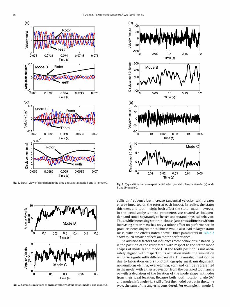
Using the parameters in Table 1(a–c), simulation code wasimplemented in MATLAB to predict dynamic motor behavior. Thesimulation includes a 0.5% random variation in stator vibrationamplitude, similar to that measured from an unloaded statorusing Laser Doppler Vibrometry (LDV). Figs. 5–10 show sampleresults from the simulated rotor motion. The vertical motion of therotor can be recognized as a ballistic motion between collisions(Figs. 5 and 6), with the vertical velocity having a sudden change at
impacts and otherwise affected only by gravity and squeeze-filmdamping. The tangential velocity increases from rest at the begin-ning of the simulation and eventually oscillates around a stablevalue (Fig. 7).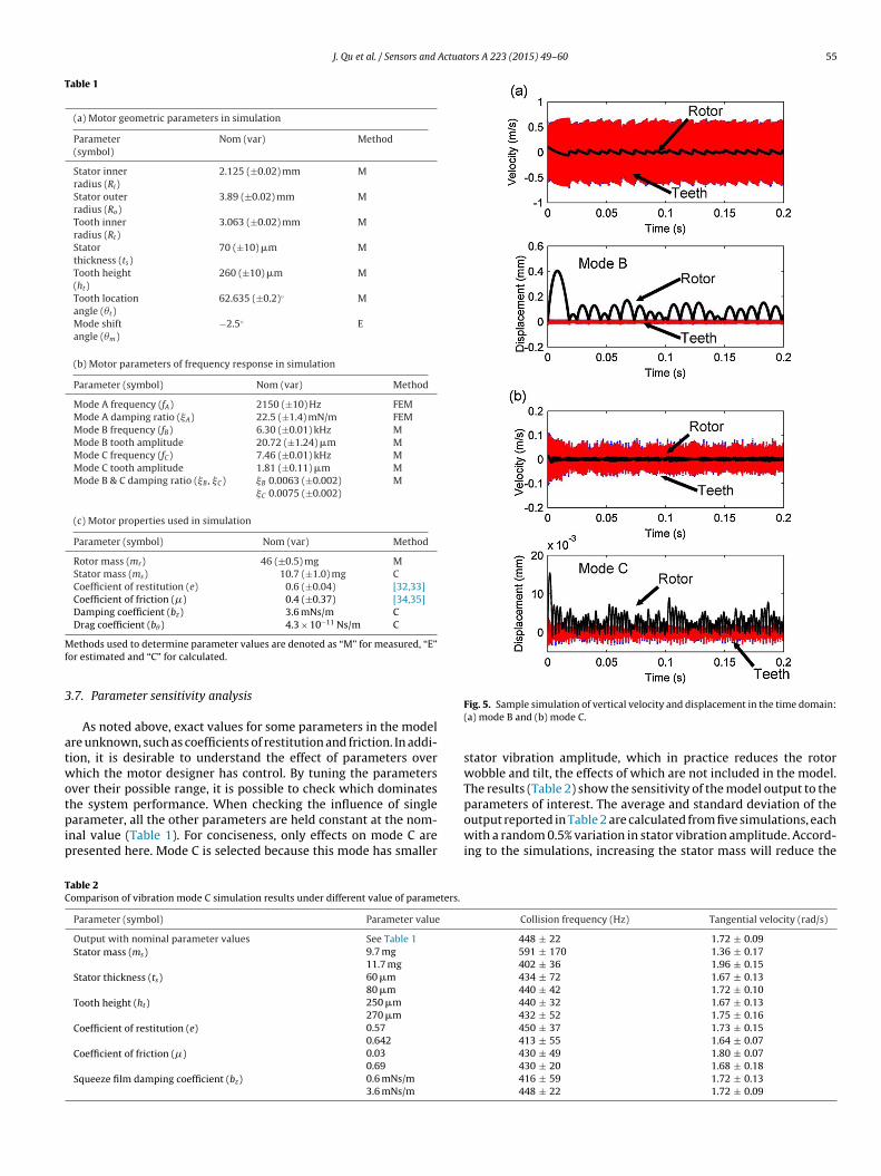
J. Qu et al. / Sensors and Actuators A 223 (2015) 49–60 55
Table 1
(a) Motor geometric parameters in simulation
Parameter(symbol)
Nom (var) Method
Stator innerradius (Ri)
2.125 (±0.02) mm M
Stator outerradius (Ro)
3.89 (±0.02) mm M
Tooth innerradius (Rt)
3.063 (±0.02) mm M
Statorthickness (ts)
70 (±10) �m M
Tooth height(ht)
260 (±10) �m M
Tooth locationangle (�t)
62.635 (±0.2)◦ M
Mode shiftangle (�m)
−2.5◦ E
(b) Motor parameters of frequency response in simulation
Parameter (symbol) Nom (var) Method
Mode A frequency (fA) 2150 (±10) Hz FEMMode A damping ratio (A) 22.5 (±1.4) mN/m FEMMode B frequency (fB) 6.30 (±0.01) kHz MMode B tooth amplitude 20.72 (±1.24) �m MMode C frequency (fC) 7.46 (±0.01) kHz MMode C tooth amplitude 1.81 (±0.11) �m MMode B & C damping ratio (B , C) B 0.0063 (±0.002)
C 0.0075 (±0.002)M
(c) Motor properties used in simulation
Parameter (symbol) Nom (var) Method
Rotor mass (mr) 46 (±0.5) mg MStator mass (ms) 10.7 (±1.0) mg CCoefficient of restitution (e) 0.6 (±0.04) [32,33]Coefficient of friction (�) 0.4 (±0.37) [34,35]Damping coefficient (bz) 3.6 mNs/m CDrag coefficient (b�) 4.3 × 10⁻¹¹ Ns/m C
Mf
3
atwotpip
TC
ethods used to determine parameter values are denoted as “M” for measured, “E”or estimated and “C” for calculated.
.7. Parameter sensitivity analysis
As noted above, exact values for some parameters in the modelre unknown, such as coefficients of restitution and friction. In addi-ion, it is desirable to understand the effect of parameters overhich the motor designer has control. By tuning the parameters
ver their possible range, it is possible to check which dominates
he system performance. When checking the influence of singlearameter, all the other parameters are held constant at the nom-nal value (Table 1). For conciseness, only effects on mode C areresented here. Mode C is selected because this mode has smaller
able 2omparison of vibration mode C simulation results under different value of parameters.
Parameter (symbol) Parameter value
Output with nominal parameter values See Table 1
Stator mass (ms) 9.7 mg
11.7 mg
Stator thickness (ts) 60 �m
80 �m
Tooth height (ht) 250 �m
270 �m
Coefficient of restitution (e) 0.57
0.642
Coefficient of friction (�) 0.03
0.69
Squeeze film damping coefficient (bz) 0.6 mNs/m
3.6 mNs/m
Fig. 5. Sample simulation of vertical velocity and displacement in the time domain:(a) mode B and (b) mode C.
stator vibration amplitude, which in practice reduces the rotorwobble and tilt, the effects of which are not included in the model.The results (Table 2) show the sensitivity of the model output to the
parameters of interest. The average and standard deviation of theoutput reported in Table 2 are calculated from five simulations, eachwith a random 0.5% variation in stator vibration amplitude. Accord-ing to the simulations, increasing the stator mass will reduce theCollision frequency (Hz) Tangential velocity (rad/s)
448 ± 22 1.72 ± 0.09591 ± 170 1.36 ± 0.17402 ± 36 1.96 ± 0.15434 ± 72 1.67 ± 0.13440 ± 42 1.72 ± 0.10440 ± 32 1.67 ± 0.13432 ± 52 1.75 ± 0.16450 ± 37 1.73 ± 0.15413 ± 55 1.64 ± 0.07430 ± 49 1.80 ± 0.07430 ± 20 1.68 ± 0.18416 ± 59 1.72 ± 0.13448 ± 22 1.72 ± 0.09
56 J. Qu et al. / Sensors and Actuators A 223 (2015) 49–60
Fig. 6. Detail view of simulation in the time domain: (a) mode B and (b) mode C.
Fig. 7. Sample simulations of angular velocity of the rotor (mode B and mode C).
Fig. 8. Typical time domain experimental velocity and displacement under (a) modeB and (b) mode C.
collision frequency but increase tangential velocity, with greaterenergy imparted on the rotor at each impact. In reality, the statorthickness and tooth height both affect the stator mass; however,in the trend analysis these parameters are treated as indepen-dent and tuned separately to better understand physical behavior.Thus, while increasing stator thickness (and thus stiffness) withoutincreasing stator mass has only a minor effect on performance, inpractice increasing stator thickness would also lead to larger statormass, with the effects noted above. Other parameters in Table 2show much smaller effects on motor performance.
An additional factor that influences rotor behavior substantiallyis the position of the rotor teeth with respect to the stator modeshapes of mode B and mode C. If the tooth position is not accu-rately aligned with respect to its actuation mode, the simulationwill give significantly different results. This misalignment can bedue to fabrication errors (photolithography mask misalignment,non-uniform etching, over-etching, etc.) and can be representedin the model with either a deviation from the designed tooth angle
or with a deviation of the location of the mode shape antinodesfrom their ideal location. Because both tooth location angle (�t)and mode shift angle (�m) will affect the model output in the sameway, the sum of the angles is considered. For example, in mode B,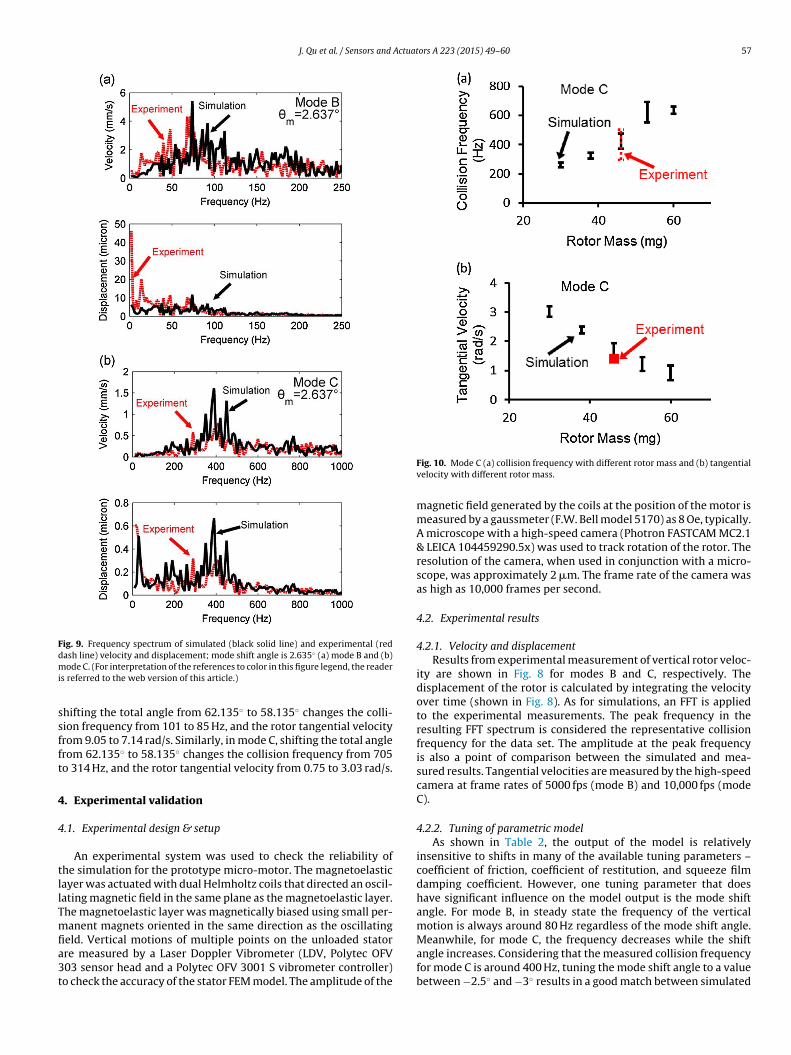
J. Qu et al. / Sensors and Actuators A 223 (2015) 49–60 57
Fig. 9. Frequency spectrum of simulated (black solid line) and experimental (redd ◦
mi
ssfft
4
4
tllTmfia3t
ash line) velocity and displacement; mode shift angle is 2.635 (a) mode B and (b)ode C. (For interpretation of the references to color in this figure legend, the reader
s referred to the web version of this article.)
hifting the total angle from 62.135◦ to 58.135◦ changes the colli-ion frequency from 101 to 85 Hz, and the rotor tangential velocityrom 9.05 to 7.14 rad/s. Similarly, in mode C, shifting the total anglerom 62.135◦ to 58.135◦ changes the collision frequency from 705o 314 Hz, and the rotor tangential velocity from 0.75 to 3.03 rad/s.
. Experimental validation
.1. Experimental design & setup
An experimental system was used to check the reliability ofhe simulation for the prototype micro-motor. The magnetoelasticayer was actuated with dual Helmholtz coils that directed an oscil-ating magnetic field in the same plane as the magnetoelastic layer.he magnetoelastic layer was magnetically biased using small per-anent magnets oriented in the same direction as the oscillating
eld. Vertical motions of multiple points on the unloaded statorre measured by a Laser Doppler Vibrometer (LDV, Polytec OFV03 sensor head and a Polytec OFV 3001 S vibrometer controller)o check the accuracy of the stator FEM model. The amplitude of the
Fig. 10. Mode C (a) collision frequency with different rotor mass and (b) tangentialvelocity with different rotor mass.
magnetic field generated by the coils at the position of the motor ismeasured by a gaussmeter (F.W. Bell model 5170) as 8 Oe, typically.A microscope with a high-speed camera (Photron FASTCAM MC2.1& LEICA 104459290.5x) was used to track rotation of the rotor. Theresolution of the camera, when used in conjunction with a micro-scope, was approximately 2 �m. The frame rate of the camera wasas high as 10,000 frames per second.
4.2. Experimental results
4.2.1. Velocity and displacementResults from experimental measurement of vertical rotor veloc-
ity are shown in Fig. 8 for modes B and C, respectively. Thedisplacement of the rotor is calculated by integrating the velocityover time (shown in Fig. 8). As for simulations, an FFT is appliedto the experimental measurements. The peak frequency in theresulting FFT spectrum is considered the representative collisionfrequency for the data set. The amplitude at the peak frequencyis also a point of comparison between the simulated and mea-sured results. Tangential velocities are measured by the high-speedcamera at frame rates of 5000 fps (mode B) and 10,000 fps (modeC).
4.2.2. Tuning of parametric modelAs shown in Table 2, the output of the model is relatively
insensitive to shifts in many of the available tuning parameters –coefficient of friction, coefficient of restitution, and squeeze filmdamping coefficient. However, one tuning parameter that doeshave significant influence on the model output is the mode shiftangle. For mode B, in steady state the frequency of the verticalmotion is always around 80 Hz regardless of the mode shift angle.
Meanwhile, for mode C, the frequency decreases while the shiftangle increases. Considering that the measured collision frequencyfor mode C is around 400 Hz, tuning the mode shift angle to a valuebetween −2.5◦ and −3◦ results in a good match between simulated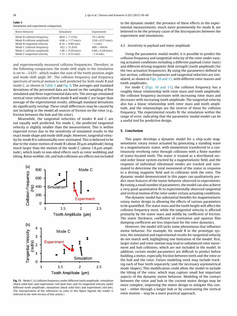
58 J. Qu et al. / Sensors and Actuat
Table 3Simulation and experiment comparison.
Rotor behavior Simulated Experiment
Mode B collision frequency 88.8 ± 7.13 Hz 76 ± 20 HzMode B collision amplitude 4.08 ± 1.17 mm/s 3.94 ± 0.57 mm/sMode B tangential velocity 8.16 ± 0.80 rad/s ∼1 rad/s
atiasmdsvadnf
nveeidmtt
F(d(r
Mode C collision frequency 422 ± 51.8 Hz 400 ± 104 HzMode C collision amplitude 1.48 ± 0.26 mm/s 0.88 ± 0.28 mm/sMode C tangential velocity 1.72 ± 0.22 rad/s ∼1.4 rad/s
nd experimentally measured collision frequencies. Therefore, inhe following comparison, the mode shift angle in the simulations set to −2.635◦, which makes the sum of the tooth position anglend mode shift angle 30◦. The collision frequency and frequencypectrum of vertical motion is well predicted for both mode B andode C, as shown in Table 3 and Fig. 9. The averages and standard
eviations of the presented data are based on the sampling of fiveimulated and three experimental data sets. The average simulatedertical rotor velocities of both mode B and mode C are larger thanverage of the experimental results, although standard deviationso significantly overlap. These small differences may be caused byot including in the model all sources of friction on the rotor (e.g.,
riction between the hub and the rotor).Meanwhile, the tangential velocities of modes B and C are
ot equally well predicted. For mode C, the predicted tangentialelocity is slightly smaller than the measurement. This is withinxpected errors due to the sensitivity of simulated results to thexact mode shape and mode shift angle. However, tangential veloc-ty for mode B is substantially over-estimated. This is believed to be
ue to the stator motion of mode B (about 20 �m amplitude) beinguch larger than the motion of the mode C (about 1.8 �m ampli-ude), which leads to non-ideal effects such as rotor wobbling andilting. Rotor wobble, tilt, and hub collisions are effects not included
ig. 11. Mode C (a) collision frequency under different tooth amplitude: simulationblack solid line) and experiment (red dash line) and (b) tangential velocity underifferent tooth amplitude: simulation (black solid line) and experiment (red dot).For interpretation of the references to color in this figure legend, the reader iseferred to the web version of this article.)
ors A 223 (2015) 49–60
in the dynamic model; the presence of these effects in the exper-imental measurements, much more prominently for mode B, arebelieved to be the primary cause of the discrepancies between theexperiment and simulations.
4.3. Sensitivity to payload and stator amplitude
Using the parametric modal model, it is possible to predict thecollision frequency and tangential velocity of the rotor under vary-ing actuation conditions including a different payload (rotor mass)and different driving magnetic field strength (tooth amplitude) forthe two actuation frequencies. By using the parameters defined inlast section, collision frequencies and tangential velocities are sim-ulated, as shown in Figs. 10 and 11, with different rotor masses andtooth amplitudes.
For mode C (Figs. 10 and 11), the collision frequency has aroughly linear relationship with rotor mass and tooth amplitude;the collision frequency increases with increasing rotor mass anddecreases with increasing tooth amplitude. The tangential velocityalso has a linear relationship with rotor mass and tooth ampli-tude, and the relationships are the inverse of those for collisionfrequency. The experimental results fit the simulation within therange of error, indicating that the parametric modal model can bea useful tool for predictive design.
5. Conclusion
This paper develops a dynamic model for a chip-scale mag-netoelastic rotary motor actuated by generating a standing wavein a magnetoelastic stator, with momentum transferred to a con-tinuously revolving rotor through collisions with a finite numberof stator-located teeth. The stator is treated as a distributed sec-ond order linear system excited by a magnetoelastic field, and theresponse of individual vibrational modes are tracked and sum-mated to determine the total movement of the stator in responseto a driving magnetic field and to collisions with the rotor. Thedynamic model demonstrated in this paper can qualitatively pre-dict most features of the motor behavior observed in experiments.By tuning a small number of parameters, the model can also achievea very good quantitative fit to experimentally observed tangentialand vertical motion of the rotor under certain actuating conditions.
The dynamic model has substantial benefits for magnetoelasticrotary motor design in allowing the effects of various parametersto be quantified. The stator mass and the tooth height will affect thecollision frequency most, while the tangential velocity is affectedprimarily by the stator mass and mildly by coefficient of friction.The stator thickness, coefficient of restitution and squeeze filmdamping coefficient are less important for the rotor dynamics.
However, the model still lacks some phenomena that influencemotor behavior. For example, for mode B in the prototype sys-tem, the simulated and experimental results for tangential velocitydo not match well, highlighting one limitation of the model: first,larger stator and rotor motion may lead to unbalanced rotor move-ment and hub collisions, which are not included in the model. Inaddition, certain model parameters are difficult to predict beforebuilding a motor, especially friction between teeth and the rotor orthe hub and the rotor. Future modeling work may include track-ing each of four teeth separately (and the necessary asymmetricalmode shapes). This modification could allow the model to includethe tilting of the rotor, which may capture small but importantaspects of the dynamic motor behavior. Modeling of the contact
between the rotor and hub in the current motor design may bemore complex; improving the motor design to mitigate this con-tact – either through a longer hub or by constraining the verticalrotor motion – may be a more practical approach.
Actuat
A
Vc
R
[
[
[
[
[
[
[
[
[
[
[
[
[
[[[
[
[
[
[
[
[
[
[
[
[
[
[
[
J. Qu et al. / Sensors and
cknowledgements
The authors thank Prof. Karl Grosh for providing access to a Laseribrometer used in testing. This work is supported by DARPA MTO,ontract W31P4Q-12-1-0002 (PASCAL Program).
eferences
[1] J. Tang, S.R. Green, Y.B. Gianchandani, Miniature wireless magnetoelasticresonant motor with frequency selectable bidirectional rotation, J. Microelec-tromech. Syst. 22 (2013) 730–738.
[2] L.-S. Fan, Y.-C. Tai, R.S. Muller, IC-processed electrostatic micromotors, Sens.Actuators 20 (1989) 41–47.
[3] K. Uchino, Piezoelectric ultrasonic motors: overview, Smart Mater. Struct. 7(1998) 273.
[4] R. Moroney, R. White, R. Howe, Ultrasonic micromotors: physics andapplications, in: Micro Electro Mechanical Systems 1990. Proceedings, AnInvestigation of Micro Structures, Sensors, Actuators, Machines and RobotsIEEE, IEEE1990, 1990, pp. 182–187.
[5] M.L. Chan, B. Yoxall, H. Park, Z. Kang, I. Izyumin, J. Chou, et al., Design andcharacterization of MEMS micromotor supported on low friction liquid bearing,Sens. Actuators A: Phys. 177 (2012) 1–9.
[6] T. Wang, C. Lancée, R. Beurskens, J. Meijer, B. Knapen, A.F. van der Steen,et al., Development of a high-speed synchronous micro motor and its appli-cation in intravascular imaging, Sens. Actuators A: Phys. 218 (2014) 60–68.
[7] T. Hosobata, A. Yamamoto, T. Higuchi, An electrostatic induction motor utiliz-ing electrical resonance for torque enhancement, Sens. Actuators A: Phys. 173(2012) 180–189.
[8] X. Lu, J. Hu, L. Yang, C. Zhao, A novel dual stator-ring rotary ultrasonic motor,Sens. Actuators A: Phys. 189 (2013) 504–511.
[9] N. Yazdi, F. Ayazi, K. Najafi, Micromachined inertial sensors, Proc. IEEE 86 (1998)1640–1659.
10] K. Shcheglov, C. Evans, R. Gutierrez, T.K. Tang, Temperature dependent char-acteristics of the JPL silicon MEMS gyroscope, in: Aerospace ConferenceProceedings, 2000 IEEE, 2000, pp. 403–411.
11] Y.-C. Tai, L.-S. Fan, R.S. Muller, IC-processed micro-motors: design, technology,and testing, in: Micro Electro Mechanical Systems, 1980. Proceedings, An Inves-tigation of Micro Structures, Sensors, Actuators, Machines and Robots IEEE,IEEE1989, 1989, pp. 1–6.
12] S.F. Bart, M. Mehregany, L.S. Tavrow, J.H. Lang, S.D. Senturia, Electric micromo-tor dynamics, IEEE Trans. Electron Devices 39 (1992) 566–575.
13] A. Endemano, J. Fourniols, H. Camon, A. Marchese, S. Muratet, F. Bony, et al.,VHDL–AMS modelling and simulation of a planar electrostatic micromotor, J.Micromech. Microeng. 13 (2003) 580.
14] I. Dufour, E. Sarraute, A. Abbas, Optimization of the geometry of electrostaticmicromotors using only analytical equations, J. Micromech. Microeng. 6 (1996)108.
15] J. Maas, P. Ide, N. Frohleke, H. Grotstollen, Simulation model for ultrasonicmotors powered by resonant converters, in: Industry Applications Conference,1995. Thirtieth IAS Annual Meeting, IAS’95, Conference Record of the 1995 IEEE,IEEE1995, 1995, pp. 111–120.
16] N.W. Hagood IV, A.J. McFarland, Modeling of a piezoelectric rotary ultra-sonic motor, IEEE Trans. Ultrason. Ferroelectr. Freq. Control 42 (1995)210–224.
17] J. Maas, T. Schulte, N. Frohleke, Model-based control for ultrasonic motors,IEEE/ASME Trans. Mechatron. 5 (2000) 165–180.
18] A. Frangi, A. Corigliano, M. Binci, P. Faure, Finite element modelling of a rotatingpiezoelectric ultrasonic motor, Ultrasonics 43 (2005) 747–755.
19] D. Sun, J. Liu, X. Ai, Modeling and performance evaluation of traveling-wavepiezoelectric ultrasonic motors with analytical method, Sens. Actuators A:Phys. 100 (2002) 84–93.
20] W.-M. Zhang, G. Meng, D. Chen, J.-B. Zhou, J.-Y. Chen, Nonlinear dynamics of arub-impact micro-rotor system with scale-dependent friction model, J. SoundVib. 309 (2008) 756–777.
21] G. Meng, W.-M. Zhang, H. Huang, H.-G. Li, D. Chen, Micro-rotor dynamics formicro-electro-mechanical systems (MEMS), Chaos Solitons Fractals 40 (2009)538–562.
22] A. Iino, K. Suzuki, M. Kasuga, M. Suzuki, T. Yamanaka, Development of a self-oscillating ultrasonic micro-motor and its application to a watch, Ultrasonics38 (2000) 54–59.
23] ASM Handbook, ASM International, 1989.24] I. Metglas, Magnetic Alloy 2826MB (nickel-based) Technical Bulletin.25] C.C. Lee, C.Y. Wang, G. Matijasevic, Au–In bonding below the eutec-
tic temperature, IEEE Trans. Compon. Hybrids Manuf. Technol. 16 (1993)
311–316.26] W.W. So, C.C. Lee, Fluxless process of fabricating In–Au joints on copper sub-strates, IEEE Trans. Compon. Packag. Technol. 23 (2000) 377–382.
27] K. Takahata, Y.B. Gianchandani, Batch mode micro-electro-discharge machin-ing, J. Microelectromech. Syst. 11 (2002) 102–110.
ors A 223 (2015) 49–60 59
28] J. Benatar, A. Flatau, FEM implementation of a magnetostrictive transducer, in:Smart Structures and Materials, International Society for Optics and Photonics,2005, pp. 482–493.
29] S.F. Foerster, M.Y. Louge, H. Chang, K. Allia, Measurements of the col-lision properties of small spheres, Phys. Fluids (1994-present) 6 (1994)1108–1115.
30] W.-M. Zhang, G. Meng, Numerical simulation of sliding wear between the rotorbushing and ground plane in micromotors, Sens. Actuators A: Phys. 126 (2006)15–24.
31] M. Behzad, M. Alvandi, D. Mba, J. Jamali, A finite element-based algorithmfor rubbing induced vibration prediction in rotors, J. Sound Vib. 332 (2013)5523–5542.
32] S. Demiri, Geometric Effects on the Wear of Microfabricated Silicon JournalBearings, 2010.
33] A.P. Lee, A.P. Pisano, Repetitive impact testing of micromechanical structures,Sens. Actuators A: Phys. 39 (1993) 73–82.
34] B. Bhushan, Nanotribology and nanomechanics of MEMS devices, in:Micro Electro Mechanical Systems, 1996. MEMS’96, Proceedings’ An Inves-tigation of Micro Structures, Sensors, Actuators, Machines and Systems’IEEE, The Ninth Annual International Workshop on, IEEE1996, 1996,pp. 91–98.
35] B. Bhushan, X. Li, Micromechanical and tribological characterization of dopedsingle-crystal silicon and polysilicon films for microelectromechanical systems,J. Mater. Res. 12 (1997) 54–63.
36] M. Bao, H. Yang, Squeeze film air damping in MEMS, Sens. Actuators A: Phys.136 (2007) 3–27.
37] W. Griffin, H.H. Richardson, S. Yamanami, A study of fluid squeeze-film damp-ing, J. Basic Eng. 88 (1966) 451.
38] M.Y. Okiishi, B. Munson, D. Young, Fundamentals of Fluid Mechanics, JohnWiley & Sons, Inc., 2006.
Biographies
Jinhong Qu received a B.S. (2011) in engineering physicsfrom the University of Michigan, Ann Arbor, a B.S. (2011)in mechanical engineering from Shanghai Jiao Tong Uni-versity, Shanghai, China, and a M.S. (2012) in mechanicalengineering from the University of Michigan, Ann Arbor.He is currently a doctoral student at the Universityof Michigan. His research interests include the design,sensing, and control of MEMS devices.
Jun Tang received the B.S. degree in electronic scienceand technology from Huazhong University of Scienceand Technology, Wuhan, China, in 2007 and the M.S.degree in microelectronics and solid-state electronicsfrom Shanghai Jiao Tong University, Shanghai, China, in2010. He received the Ph.D. degree in the Department ofMechanical Engineering from University of Michigan, AnnArbor, MI, USA, with a focus on microelectromechanicalsystems. His Ph.D research interests include wireless mag-netoelastic sensors and actuators. He is currently a MEMSdesigner at Freescale Semiconductor Inc., Tempe, Arizona.
Yogesh B. Gianchandani is a Professor at the Universityof Michigan, Ann Arbor, with a primary appointment inthe Electrical Engineering and Computer Science Depart-ment and a courtesy appointment in the MechanicalEngineering Department. He also serves as the Directorfor the Center for Wireless Integrated MicroSensing andSystems (WIMS2).Dr. Gianchandani’s research interests include allaspects of design, fabrication, and packaging of micro-machined sensors and actuators (http://www.eecs.umich.edu/∼yogesh/). He has published over 300 papersin journals and conferences, and has over 40 US patentsissued or pending. He was a Chief Co-Editor of Compre-
hensive Microsystems: Fundamentals, Technology, and Applications, published in
2008. Dr. Gianchandani has served on the editorial boards and program committeesof a number of conferences and journals. From 2007 to 2009 he also served at theNational Science Foundation, as the program director for Micro and Nano Systemswithin the Electrical, Communication, and Cyber Systems Division (ECCS). Dr.Gianchandani is a Fellow of IEEE. Dr. Gianchandani is a Fellow of IEEE.
6 Actuat
currently is an Assistant Research Scientist at the Univer-
0 J. Qu et al. / Sensors and
Kenn R. Oldham is an Associate Professor of MechanicalEngineering at the University of Michigan. Prof. Oldhamreceived the Ph.D. in Mechanical Engineering from theUniversity of California at Berkeley in 2006 and the B.S.in Mechanical Engineering from Carnegie Mellon Univer-sity in 2000. He joined the University of Michigan in 2007following a post-doctoral fellowship at the Army ResearchLaboratory. Prof. Oldham and his research group study theintersection of control systems and micro-scale sensing
and actuation, with interests in design for controllability,optimal and robust control, and novel sensor and actua-tor design. Applications of this research include terrestrialmicro-robotics, endoscopic microscopy, and inertial andphysiological sensing.ors A 223 (2015) 49–60
Scott R. Green received a B.S. in mechanical engineeringfrom Rose-Hulman Institute of Technology in 2003, andan M.S. (2008) and Ph.D (2009) in mechanical engineer-ing from the University of Michigan, Ann Arbor, with afocus in Microsystems. He worked as a senior design engi-neer at Stryker Corporation in the Instruments divisionfrom 2003-2005 developing minimally invasive surgicaldevices for vertebroplasty and discectomy procedures. He
sity of Michigan, Ann Arbor. Research interests includewireless magnetoelastic sensors and actuators, miniatureimplantable medical systems, and miniature and micro-fabricated high-vacuum sputter ion pumps.
Related Documents