VW Golf & GTI Quick Reference Specification Book • January 2014 i 2014 Volkswagen Golf, GTI, & Golf R Quick Reference Specification Book TABLE OF CONTENTS DTC Chart ....................................................................... 1 Engine Codes CBFA.............................................................1 Fuel and Air Mixture, Additional Emission Regulations ....................................... 1 Ignition System ........................................................................ 9 Additional Exhaust Regulation............................................... 11 Speed and Idle Control .......................................................... 13 Control Module and Output Signals....................................... 13 Fuel and Air Ratios Control Module ....................................... 16 Additional Emissions Regulations ......................................... 19 DTC Chart ..................................................................... 21 Engine Codes CCTA...........................................................21 Fuel and Air Mixture, Additional Emission Regulations ..................................... 21 Ignition System ...................................................................... 29 Additional Exhaust Regulation............................................... 31 Speed and Idle Control .......................................................... 32 Control Module and Output Signals....................................... 32 Fuel and Air Ratios Control Module ....................................... 35 Ignition System ...................................................................... 38 Additional Emissions Regulations ......................................... 39 DTC Chart ..................................................................... 40 Engine Codes CJAA ..........................................................40 Fuel and Air Mixture, Additional Emission Regulations ..................................... 40 Ignition System ...................................................................... 55 Additional Exhaust Regulation............................................... 56 Speed and Idle Control .......................................................... 58 Control Module and Output Signals....................................... 60

Welcome message from author
This document is posted to help you gain knowledge. Please leave a comment to let me know what you think about it! Share it to your friends and learn new things together.
Transcript
VW Golf & GTI Quick Reference Specification Book • January 2014 i
2014 Volkswagen Golf, GTI, & Golf R Quick Reference Specification Book
TaBle of ConTenTS
DTC Chart ....................................................................... 1Engine Codes CBFA .............................................................1
Fuel and Air Mixture, Additional Emission Regulations .......................................1
Ignition System ........................................................................9Additional Exhaust Regulation ...............................................11Speed and Idle Control ..........................................................13Control Module and Output Signals .......................................13Fuel and Air Ratios Control Module .......................................16Additional Emissions Regulations .........................................19
DTC Chart ..................................................................... 21Engine Codes CCTA ...........................................................21
Fuel and Air Mixture, Additional Emission Regulations .....................................21
Ignition System ......................................................................29Additional Exhaust Regulation ...............................................31Speed and Idle Control ..........................................................32Control Module and Output Signals .......................................32Fuel and Air Ratios Control Module .......................................35Ignition System ......................................................................38Additional Emissions Regulations .........................................39
DTC Chart ..................................................................... 40Engine Codes CJAA ..........................................................40
Fuel and Air Mixture, Additional Emission Regulations .....................................40
Ignition System ......................................................................55Additional Exhaust Regulation ...............................................56Speed and Idle Control ..........................................................58Control Module and Output Signals .......................................60
ii VW Golf & GTI Quick Reference Specification Book • January 2014
DTC Chart ..................................................................... 63Engine Codes CRZA ..........................................................63
Fuel and Air Mixture, Additional Emission Regulations .....................................63
Ignition System ......................................................................68Additional Exhaust Regulation ...............................................71Speed and Idle Control ..........................................................72Control Module and Output Signals .......................................72Fuel and Air Ratios Control Module .......................................74Additional Emissions Regulations .........................................76
DTC Chart ..................................................................... 78Engine Codes CBTA and CBUA .........................................78
Fuel and Air Mixture, Additional Emission Regulations .....................................78
Ignition System ......................................................................87Additional Exhaust Regulation ...............................................89Speed and Idle Control ..........................................................90Control Module and Output Signals .......................................91
VW Golf & GTI Quick Reference Specification Book • January 2014 1
DTC
Cha
rt
DTC CharT
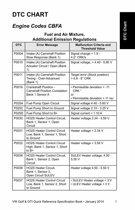
Engine Codes CBFAFuel and air Mixture,
additional Emission regulationsDTC Error Message Malfunction Criteria and
Threshold ValueP000A Intake (A) Camshaft Position
Slow Response (Bank 1)Signal change < 1.9 - 4.2° CRK/s
P0010 Intake (A) Camshaft Position Actuator Circuit / Open (Bank 1)
Signal voltage, > 4.40 - 5.60 V
P0011 Intake (A) Camshaft Position Timing - Over-Advanced (Bank 1)
Target error (Stuck position) > 6.8 - 8° CRK
P0016 Crankshaft Position - Camshaft Position Correlation Bank 1 Sensor A
• Permissible deviation < -11 CRK °
or• Permissible deviation > 11 rev
P025A Fuel Pump Open Circuit Signal voltage 4.40 - 5.60 VP025C Fuel Pump Short to Ground Signal voltage 2.15 - 3.25 VP025D Fuel Pump Short to B+ Signal current > 1.10 AP0030 HO2S Heater Control Circuit,
Bank 1, Sensor 1, Open Circuit
Heater voltage 2.34 - 3.59 V
P0031 HO2S Heater Control Circuit Low, Bank 1, Sensor 1, Short to Ground
Heater voltage < 2.34 V
P0032 HO2S Heater Control Circuit High, Bank 1, Sensor 1, Short to B+
Heater voltage > 3.59 V
P0036 HO2S Heater Control Circuit, Bank 1, Sensor 2, Open Circuit
SULEV Heater voltage, 4.50 - 5.50 V
P0036 HO2S Heater Circuit,Bank 1, Sensor 3, Open Circuit SULEV
Heater voltage 4.50 - 5.50 V
P0037 HO2S Heater Control Circuit Low, Bank 1, Sensor 2, Short to Ground
• SULEV Heater voltage < 3 V • ULEV Heater voltage < 3 V
2 VW Golf & GTI Quick Reference Specification Book • January 2014
DTC Error Message Malfunction Criteria and Threshold Value
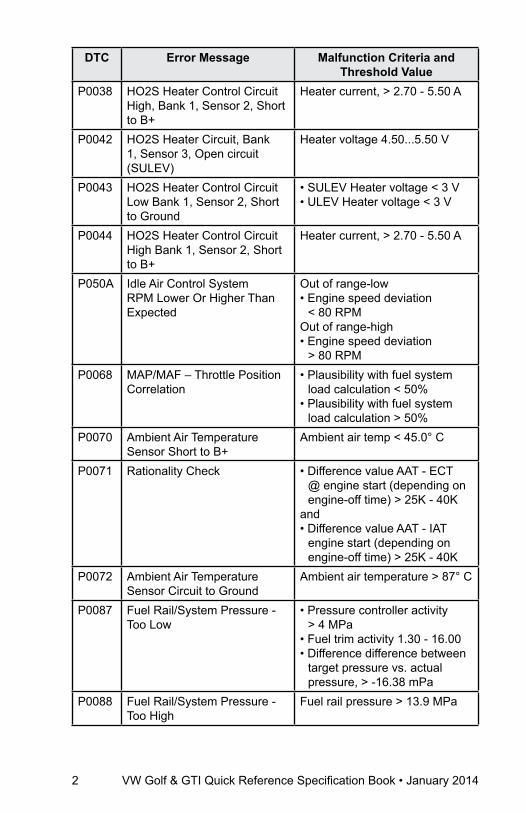
P0038 HO2S Heater Control Circuit High, Bank 1, Sensor 2, Short to B+
Heater current, > 2.70 - 5.50 A
P0042 HO2S Heater Circuit, Bank 1, Sensor 3, Open circuit (SULEV)
Heater voltage 4.50...5.50 V
P0043 HO2S Heater Control Circuit Low Bank 1, Sensor 2, Short to Ground
• SULEV Heater voltage < 3 V• ULEV Heater voltage < 3 V
P0044 HO2S Heater Control Circuit High Bank 1, Sensor 2, Short to B+
Heater current, > 2.70 - 5.50 A
P050A Idle Air Control System RPM Lower Or Higher Than Expected
Out of range-low• Engine speed deviation
< 80 RPMOut of range-high• Engine speed deviation
> 80 RPMP0068 MAP/MAF – Throttle Position
Correlation• Plausibility with fuel system
load calculation < 50% • Plausibility with fuel system
load calculation > 50% P0070 Ambient Air Temperature
Sensor Short to B+Ambient air temp < 45.0° C
P0071 Rationality Check • Difference value AAT - ECT @ engine start (depending on engine-off time) > 25K - 40K
and• Difference value AAT - IAT
engine start (depending on engine-off time) > 25K - 40K
P0072 Ambient Air Temperature Sensor Circuit to Ground
Ambient air temperature > 87° C
P0087 Fuel Rail/System Pressure - Too Low
• Pressure controller activity > 4 MPa
• Fuel trim activity 1.30 - 16.00• Difference difference between
target pressure vs. actual pressure, > -16.38 mPa
P0088 Fuel Rail/System Pressure - Too High
Fuel rail pressure > 13.9 MPa

VW Golf & GTI Quick Reference Specification Book • January 2014 3
DTC
Cha
rt
DTC Error Message Malfunction Criteria and Threshold Value
P0089 Fuel Pressure Regulator 1 Performance
Actual pressure Deviation• < 100 kPa• > 100 kPa
P0100 Mass or Volume Air Flow A Circuit
MAF sensor signal 0 µs
P0101 Mass or Volume Air Flow A Circuit Range/Performance
• Mass air flow vs lower threshold model < 12%
• Mass air flow vs upper threshold < 12%
• Load calculation >21%. 23 for ULEV only
and• Fuel system (mult) <-19%. -23
ULEV only• Load calculation <21%. -23 for
ULEV onlyand• Fuel system (mult) >19%. 23
ULEV onlyP0102 Mass or Volume Air Flow A
Circuit Low InputMAF sensor signal < 66 µs
P0103 Mass or Volume Air Flow A Circuit High Input
MAF sensor signal > 4500 µs
P0106 Manifold Absolute Pressure/Barometric Sensor Range/Performance
Boost pressure signal• < Altitude sensor -210 hPa• > Altitude sensor +230 hPa
P0111 Intake Air Temperature Sensor 1 Rationality check ULEV only
• Difference value: IAT - ECT @ engine start (depending on engine-off time, > 25 - 40 K
and• Difference value: IAT - AAT @
engine start (depending on engine-off time), > 25 - 40 K
P0112 Intake Air Temperature Sensor 1 Circuit Low Input
IAT, < 45.80° C
P0113 Intake Air Temperature Sensor 1 Circuit High Input
IAT, < 45.80° C
P0116 Engine Coolant Temperature Sensor 1 Circuit Range/Performance. Only SULEV
Stuck high (140° C): • No change of signal, < 1.5K
P0116 Engine Coolant Temperature Sensor 1 Circuit Range/Performance. Only SULEV
Stuck low (-40° C): • No change of signal, < 1.5K
4 VW Golf & GTI Quick Reference Specification Book • January 2014
DTC Error Message Malfunction Criteria and Threshold Value
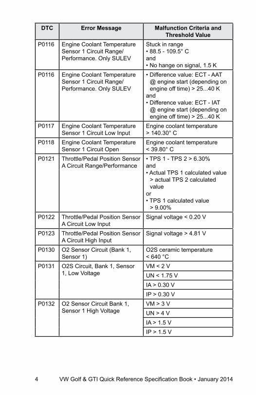
P0116 Engine Coolant Temperature Sensor 1 Circuit Range/Performance. Only SULEV
Stuck in range• 88.5 - 109.5° Cand• No hange on signal, 1.5 K
P0116 Engine Coolant Temperature Sensor 1 Circuit Range/Performance. Only SULEV
• Difference value: ECT - AAT @ engine start (depending on engine off time) > 25...40 K
and• Difference value: ECT - IAT
@ engine start (depending on engine off time) > 25...40 K
P0117 Engine Coolant Temperature Sensor 1 Circuit Low Input
Engine coolant temperature > 140.30° C
P0118 Engine Coolant Temperature Sensor 1 Circuit Open
Engine coolant temperature < 39.80° C
P0121 Throttle/Pedal Position Sensor A Circuit Range/Performance
• TPS 1 - TPS 2 > 6.30%and• Actual TPS 1 calculated value
> actual TPS 2 calculated value
or• TPS 1 calculated value
> 9.00%P0122 Throttle/Pedal Position Sensor
A Circuit Low InputSignal voltage < 0.20 V
P0123 Throttle/Pedal Position Sensor A Circuit High Input
Signal voltage > 4.81 V
P0130 O2 Sensor Circuit (Bank 1, Sensor 1)
O2S ceramic temperature < 640 °C
P0131 O2S Circuit, Bank 1, Sensor 1, Low Voltage
VM < 2 VUN < 1.75 VIA > 0.30 VIP > 0.30 V
P0132 O2 Sensor Circuit Bank 1, Sensor 1 High Voltage
VM > 3 VUN > 4 VIA > 1.5 VIP > 1.5 V
VW Golf & GTI Quick Reference Specification Book • January 2014 5
DTC
Cha
rt
DTC Error Message Malfunction Criteria and Threshold Value
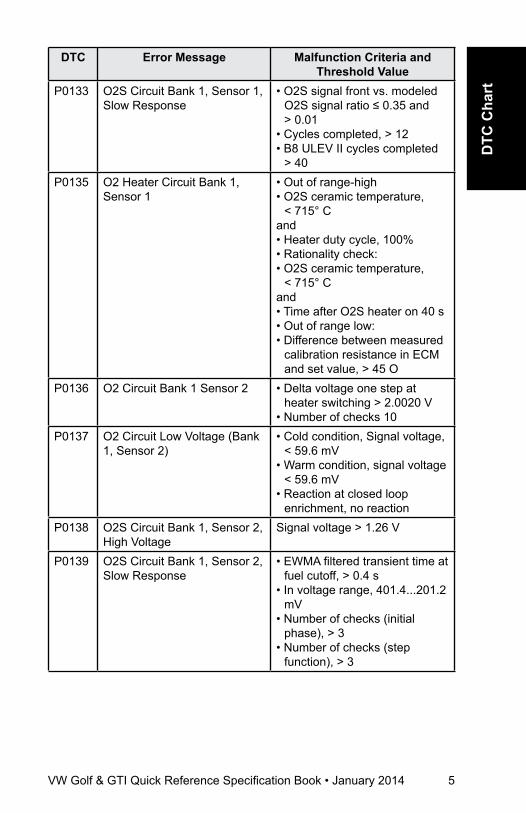
P0133 O2S Circuit Bank 1, Sensor 1, Slow Response
• O2S signal front vs. modeled O2S signal ratio ≤ 0.35 and > 0.01
• Cycles completed, > 12• B8 ULEV II cycles completed
> 40P0135 O2 Heater Circuit Bank 1,
Sensor 1• Out of range-high• O2S ceramic temperature,
< 715° Cand• Heater duty cycle, 100%• Rationality check:• O2S ceramic temperature,
< 715° Cand• Time after O2S heater on 40 s• Out of range low:• Difference between measured
calibration resistance in ECM and set value, > 45 O
P0136 O2 Circuit Bank 1 Sensor 2 • Delta voltage one step at heater switching > 2.0020 V
• Number of checks 10P0137 O2 Circuit Low Voltage (Bank
1, Sensor 2)• Cold condition, Signal voltage,
< 59.6 mV• Warm condition, signal voltage
< 59.6 mV• Reaction at closed loop
enrichment, no reactionP0138 O2S Circuit Bank 1, Sensor 2,
High VoltageSignal voltage > 1.26 V
P0139 O2S Circuit Bank 1, Sensor 2, Slow Response
• EWMA filtered transient time at fuel cutoff, > 0.4 s
• In voltage range, 401.4...201.2 mV
• Number of checks (initial phase), > 3
• Number of checks (step function), > 3
6 VW Golf & GTI Quick Reference Specification Book • January 2014
DTC Error Message Malfunction Criteria and Threshold Value
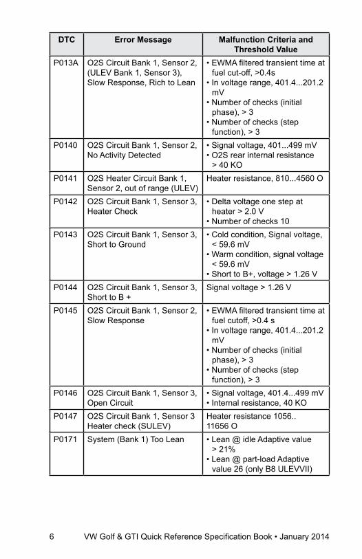
P013A O2S Circuit Bank 1, Sensor 2, (ULEV Bank 1, Sensor 3),Slow Response, Rich to Lean
• EWMA filtered transient time at fuel cut-off, >0.4s
• In voltage range, 401.4...201.2 mV
• Number of checks (initial phase), > 3
• Number of checks (step function), > 3
P0140 O2S Circuit Bank 1, Sensor 2, No Activity Detected
• Signal voltage, 401...499 mV• O2S rear internal resistance
> 40 KOP0141 O2S Heater Circuit Bank 1,
Sensor 2, out of range (ULEV)Heater resistance, 810...4560 O
P0142 O2S Circuit Bank 1, Sensor 3, Heater Check
• Delta voltage one step at heater > 2.0 V
• Number of checks 10P0143 O2S Circuit Bank 1, Sensor 3,
Short to Ground• Cold condition, Signal voltage,
< 59.6 mV• Warm condition, signal voltage
< 59.6 mV• Short to B+, voltage > 1.26 V
P0144 O2S Circuit Bank 1, Sensor 3, Short to B +
Signal voltage > 1.26 V
P0145 O2S Circuit Bank 1, Sensor 2, Slow Response
• EWMA filtered transient time at fuel cutoff, >0.4 s
• In voltage range, 401.4...201.2 mV
• Number of checks (initial phase), > 3
• Number of checks (step function), > 3
P0146 O2S Circuit Bank 1, Sensor 3, Open Circuit
• Signal voltage, 401.4...499 mV• Internal resistance, 40 KO
P0147 O2S Circuit Bank 1, Sensor 3 Heater check (SULEV)
Heater resistance 1056.. 11656 O
P0171 System (Bank 1) Too Lean • Lean @ idle Adaptive value > 21%
• Lean @ part-load Adaptive value 26 (only B8 ULEVVII)

VW Golf & GTI Quick Reference Specification Book • January 2014 7
DTC
Cha
rt
DTC Error Message Malfunction Criteria and Threshold Value
P0172 System (Bank 1) Too Rich • Too rich at idle Adaptive value < 5.02% (< 6.0 only B8 ULEV)
• Too rich at part-load Adaptive value < 21% (-26 (only B8 ULEVVII)
P0190 Fuel Rail Pressure Sensor A Circuit
Signal voltage > 4.8 V
P0191 Fuel Rail Control Valve, High Pressure Side
Actual pressure > 20.6 MPa
P0192 Fuel Rail Pressure Sensor A Circuit Low Input
Signal voltage < 0.2 V
P0201 Injector Circuit/Open - Cylinder 1
• Low side signal current < 2.1 A
P0202 Injector Circuit/Open - Cylinder 2
• Low side signal current < 2.1 A
P0203 Injector Circuit/Open - Cylinder 3
• Low side signal current < 2.1 A
P0204 Injector Circuit/Open - Cylinder 4
• Low side signal current < 2.1 A
P0221 Throttle / Pedal Position Sensor / Switch B Circuit Range / Performance
• TPS 1 - TPS 2 > 6.30%and• Actual TPS 2 calculated value
> TPS 1 calculated valueor• TPS 2 calculated value
> 9.00%P0222 Throttle / Pedal Position
Sensor / Switch B Circuit Low Input
Signal voltage < 0.20 V
P0223 Throttle / Pedal Position Sensor / Switch B Circuit High Input
Signal voltage > 4.81 V
P0234 Turbocharger / Supercharger Overboost Condition Rationality Check High
Difference of set value boost pressure vs altitude sensor signal > 260 - 1275 hPa
P0236 Turbocharger / Supercharger Boost Sensor A Plausibility check (ULEV)
• Difference boost pressure signal vs altitude sensor signal, > 230 hPa
• Difference boost pressure signal vs altitude sensor signal, < 130 hPa
8 VW Golf & GTI Quick Reference Specification Book • January 2014
DTC Error Message Malfunction Criteria and Threshold Value
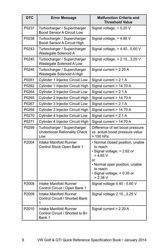
P0237 Turbocharger / Supercharger Boost Sensor A Circuit Low
Signal voltage, < 0.20 V
P0238 Turbocharger / Supercharger Boost Sensor A Circuit High
Signal voltage, > 4.88 V
P0243 Turbocharger / Supercharger Wastegate Solenoid A
Signal voltage, > 4.40...5.60 V
P0245 Turbocharger / Supercharger Wastegate Solenoid A Low
Signal voltage, < 2.15...3.25 V
P0246 Turbocharger / Supercharger Wastegate Solenoid A High
Signal current > 2.20 A
P0261 Cylinder 1 Injector Circuit Low Signal current < 2.1 AP0262 Cylinder 1 Injector Circuit High Signal current > 14.70 AP0264 Cylinder 2 Injector Circuit Low Signal current < 2.1 AP0265 Cylinder 2 Injector Circuit High Signal current > 14.70 AP0267 Cylinder 3 Injector Circuit Low Signal current < 2.1 AP0268 Cylinder 3 Injector Circuit High Signal current > 14.70 AP0270 Cylinder 4 Injector Circuit Low Signal current < 2.1 AP0271 Cylinder 4 Injector Circuit High Signal current > 14.70 AP0299 Turbocharger / Supercharger
Underboost Rationality Check Low
Difference of set boost pressure vs. actual boost pressure value > 150 hPa
P2004 Intake Manifold Runner Control Stuck Open Bank 1
• Normal closed position, unable to reach
• Signal voltage, < 2.62 or > 4.65 V
or• Normal open position, unable
to reach• Signal voltage, < 0.35 or
> 2.38 VP2008 Intake Manifold Runner
Control Circuit / Open Bank 1Signal voltage 4.40 - 5.60 V
P2009 Intake Manifold Runner Control Circuit / Shorted Bank 1
Signal voltage 2.15...3.25 V
P2010 Intake Manifold Runner Control Circuit / Shorted to B+ Bank 1
Signal current > 2.20 A
VW Golf & GTI Quick Reference Specification Book • January 2014 9
DTC
Cha
rt
DTC Error Message Malfunction Criteria and Threshold Value
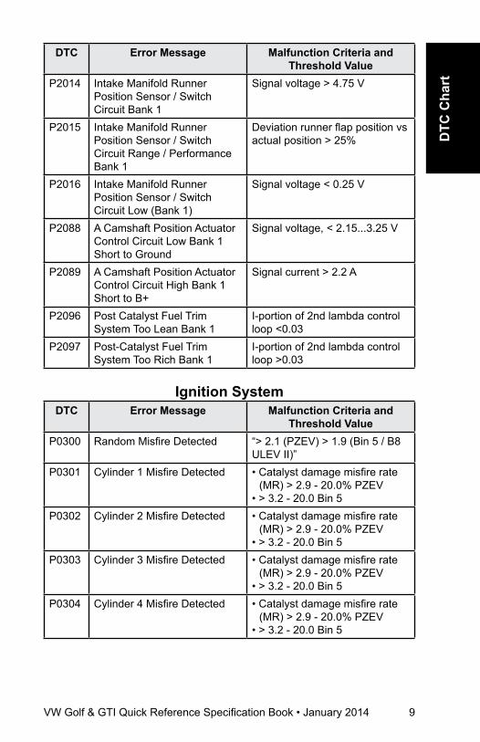
P2014 Intake Manifold Runner Position Sensor / Switch Circuit Bank 1
Signal voltage > 4.75 V
P2015 Intake Manifold Runner Position Sensor / Switch Circuit Range / Performance Bank 1
Deviation runner flap position vs actual position > 25%
P2016 Intake Manifold Runner Position Sensor / Switch Circuit Low (Bank 1)
Signal voltage < 0.25 V
P2088 A Camshaft Position Actuator Control Circuit Low Bank 1 Short to Ground
Signal voltage, < 2.15...3.25 V
P2089 A Camshaft Position Actuator Control Circuit High Bank 1 Short to B+
Signal current > 2.2 A
P2096 Post Catalyst Fuel Trim System Too Lean Bank 1
I-portion of 2nd lambda control loop <0.03
P2097 Post-Catalyst Fuel Trim System Too Rich Bank 1
I-portion of 2nd lambda control loop >0.03
Ignition SystemDTC Error Message Malfunction Criteria and
Threshold ValueP0300 Random Misfire Detected “> 2.1 (PZEV) > 1.9 (Bin 5 / B8
ULEV II)”P0301 Cylinder 1 Misfire Detected • Catalyst damage misfire rate
(MR) > 2.9 - 20.0% PZEV• > 3.2 - 20.0 Bin 5
P0302 Cylinder 2 Misfire Detected • Catalyst damage misfire rate (MR) > 2.9 - 20.0% PZEV
• > 3.2 - 20.0 Bin 5P0303 Cylinder 3 Misfire Detected • Catalyst damage misfire rate
(MR) > 2.9 - 20.0% PZEV• > 3.2 - 20.0 Bin 5
P0304 Cylinder 4 Misfire Detected • Catalyst damage misfire rate (MR) > 2.9 - 20.0% PZEV
• > 3.2 - 20.0 Bin 5
10 VW Golf & GTI Quick Reference Specification Book • January 2014
DTC Error Message Malfunction Criteria and Threshold Value
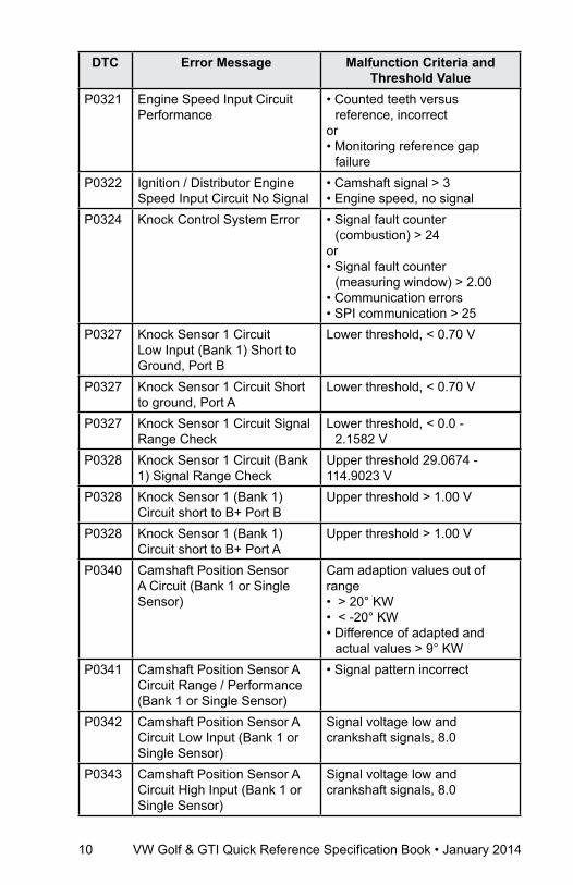
P0321 Engine Speed Input Circuit Performance
• Counted teeth versus reference, incorrect
or• Monitoring reference gap
failureP0322 Ignition / Distributor Engine
Speed Input Circuit No Signal• Camshaft signal > 3• Engine speed, no signal
P0324 Knock Control System Error • Signal fault counter (combustion) > 24
or • Signal fault counter
(measuring window) > 2.00• Communication errors• SPI communication > 25
P0327 Knock Sensor 1 Circuit Low Input (Bank 1) Short to Ground, Port B
Lower threshold, < 0.70 V
P0327 Knock Sensor 1 Circuit Short to ground, Port A
Lower threshold, < 0.70 V
P0327 Knock Sensor 1 Circuit Signal Range Check
Lower threshold, < 0.0 - 2.1582 V
P0328 Knock Sensor 1 Circuit (Bank 1) Signal Range Check
Upper threshold 29.0674 - 114.9023 V
P0328 Knock Sensor 1 (Bank 1) Circuit short to B+ Port B
Upper threshold > 1.00 V
P0328 Knock Sensor 1 (Bank 1) Circuit short to B+ Port A
Upper threshold > 1.00 V
P0340 Camshaft Position Sensor A Circuit (Bank 1 or Single Sensor)
Cam adaption values out of range • > 20° KW• < -20° KW• Difference of adapted and
actual values > 9° KWP0341 Camshaft Position Sensor A
Circuit Range / Performance (Bank 1 or Single Sensor)
• Signal pattern incorrect
P0342 Camshaft Position Sensor A Circuit Low Input (Bank 1 or Single Sensor)
Signal voltage low and crankshaft signals, 8.0
P0343 Camshaft Position Sensor A Circuit High Input (Bank 1 or Single Sensor)
Signal voltage low and crankshaft signals, 8.0

VW Golf & GTI Quick Reference Specification Book • January 2014 11
DTC
Cha
rt
DTC Error Message Malfunction Criteria and Threshold Value
P0351 Ignition Coil A Primary / Secondary Circuit
• Signal current 0.25 to -2.0 mA or• Internal check failed
P0352 Ignition Coil B Primary / Secondary Circuit
• Signal current 0.25 to -2.0 mA or• Internal check failed
P0353 Ignition Coil C Primary / Secondary Circuit
• Signal current 0.25 to -2.0 mA or• Internal check failed
P0354 Ignition Coil D Primary / Secondary Circuit
• Signal current 0.25 to -2.0 mA or• Internal check failed
P2300 Ignition Coil A Primary Control Circuit Low
Signal current > 24.0 mA
P2301 Ignition Coil A Primary Control Circuit High
Signal voltage > 5.1 - 7.0 V
P2303 Ignition Coil B Primary Control Circuit Low
Signal current > 24.0 mA
P2304 Ignition Coil B Primary Control Circuit High
Signal voltage > 5.1 - 7.0 V
P2306 Ignition Coil C Primary Control Circuit Low
Signal current > 24.0 mA
P2307 Ignition Coil C Primary Control Circuit High
Signal voltage > 5.1 - 7.0 V
P2309 Ignition Coil D Primary Control Circuit Low
Signal current > 24.0 mA
P2310 Ignition Coil D Primary Control Circuit High
Signal voltage > 5.1 - 7.0 V
additional Exhaust regulationDTC Error Message Malfunction Criteria and
Threshold ValueP0410 System Check after SAI PZEV
OnlyDeviation SAI pressure > 50.0 hPa
P0413 Open Circuit PZEV Only Signal voltage, 9.25...11.25 V P0414 Short to Ground PZEV Only Signal voltage < 6.00 VP0415 Short to B+ PZEV Only Signal current 2.20...4.20 AP0418 Air Pump Relay. Open Circuit.
PZEV Only• Signal voltage 4.50 - 5.50 V
12 VW Golf & GTI Quick Reference Specification Book • January 2014
DTC Error Message Malfunction Criteria and Threshold Value
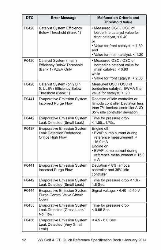
P0420 Catalyst System Efficiency Below Threshold (Bank 1)
• Measured OSC / OSC of borderline catalyst value for front catalyst, < 0.40
or• Value for front catalyst, < 1.30and• Value for main catalyst, < 1.20
P0420 Catalyst System (main) Efficiency Below Threshold (Bank 1) PZEV Only
• Measured OSC / OSC of borderline catalyst value for main catalyst, < 0.90
while• Value for front catalyst, < 2.00
P0420 Catalyst System (only Bin 5, ULEV) Efficiency Below Threshold (Bank 1)
Measured OSC / OSC of borderline catalyst. EWMA filter value for catalyst, < .20
P0441 Evaporative Emission System Incorrect Purge Flow
Reaction of idle controller or lambda controller Deviation less than 7% lambda controller AND 35% idle controller deviation
P0442 Evaporative Emission System Leak Detected (Small Leak)
Time for pressure drop < 1.55...1.75s.
P043F Evaporative Emission System Leak Detection Reference Orifice High Flow
Engine off• EVAP pump current during
reference measurement < 15.0 mA
Engine on• EVAP pump current during
reference measurement > 15.0 mA
P0441 Evaporative Emission System Incorrect Purge Flow
Deviation < 8% lambda controller and 35% idle controller
P0442 Evaporative Emission System Leak Detected (Small Leak)
Time for pressure drop < 1.6 - 1.8 Sec.
P0444 Evaporative Emission System Purge Control Valve Circuit Open
Signal voltage > 4.40 - 5.40 V
P0455 Evaporative Emission System Leak Detected (Gross Leak/No Flow)
Time for pressure drop < 0.95 Sec.
P0456 Evaporative Emission System Leak Detected (Very Small Leak)
< 4.5 - 6.0 Sec

VW Golf & GTI Quick Reference Specification Book • January 2014 13
DTC
Cha
rt
DTC Error Message Malfunction Criteria and Threshold Value
P0458 Evaporative Emission System Purge Control Valve Circuit Low
Signal voltage 2.15 - 3.26 V
P0459 Evaporative Emission System Purge Control Valve Circuit High
Signal current > 2.2 A
P0491 Secondary Air Injection System Insufficient Flow. Flow Check during Cat. Heating. SULEV Only
SAI pressure measured with SAI pressure sensor vs modeled < 0.6 (0.62) %
Speed and Idle ControlDTC Error Message Malfunction Criteria and
Threshold ValueP0501 Vehicle Speed Sensor A
Range / PerformanceVSS signal < 4 km/h
P0501 Vehicle Speed Sensor A Range / Performance Only (ULEV)
VSS signal < 4 km/h
P0503 Vehicle Speed Sensor A Out of range high
Vehicle speed > 200 km/h
P0506 Idle Air Control System RPM Lower Than Expected
Engine speed deviation < -80 RPM
P0507 Idle Air Control System RPM Higher Than Expected
Engine speed deviation > -80 RPM
Control Module and Output SignalsDTC Error Message Malfunction Criteria and
Threshold ValueP0601 Internal Control Module
Memory Check Sum ErrorInternal check sum, incorrect
P0604 Internal Control Module Random Access Memory (RAM) Error
Write ability check, failed
P0605 Internal Control Module Read Only Memory (ROM) Error
Checksum Incorrect
P0606 ECM Processor Powerup calibration• EEPROM check, failedA/D channel conversion• Check failed

14 VW Golf & GTI Quick Reference Specification Book • January 2014
DTC Error Message Malfunction Criteria and Threshold Value
P0627 Fuel Pump “A” Control Circuit /Open
• Internal error fuel pump control unit
• Feedback from fuel pump control unit Pump blocked short circuit to battery +, ground or open circuit
P0638 Throttle Actuator Control Range / Performance - Bank 1
Rationality check:• Time to close to reference
point > 0.56s.and• Reference point 2.88%Signal range check:• Duty cycle > 80%and • ECM power stage, no failure
P0641 Sensor Reference Voltage A Circuit Open
Signal voltage deviation > ± 0.3 V
P0642 Sensor Reference Voltage A Circuit Low
Signal voltage, < 4.6-5 V
P0643 Sensor Reference Voltage A Circuit High
5 V supply voltage > 4.99-5.41 V
P0651 Sensor Reference Voltage B Circuit Open
Signal voltage deviation > ± 0.3 V
P0652 Sensor Reference Voltage B Circuit Low
Signal voltage, < 4.6-5 V
P0653 Sensor Reference Voltage B Circuit High
5 V supply voltage >4.99-5.41 V
P0657 Actuator Supply Voltage A Circuit Open
Signal voltage > 4.40 - 5.60 V
P0658 Actuator Supply Voltage A Circuit Low
Signal voltage < 2.15 - 3.25 V
P0659 Actuator Supply Voltage A Circuit High
Signal current > 1.10 A
P0685 ECM / PCM Power Relay Control Circuit/Open
• Signal voltage, 2.6-3.7 V• Sense circuit voltage, > 6 V
P0686 ECM / PCM Power Relay Control Circuit Low
• Signal voltage, 2.6-3.7 V• Sense circuit voltage, > 6 V
P0687 ECM / PCM Power Relay Control Circuit High
• Signal current, >1.4-0.7 A• Sense circuit voltage, < 6 V
VW Golf & GTI Quick Reference Specification Book • January 2014 15
DTC
Cha
rt
DTC Error Message Malfunction Criteria and Threshold Value
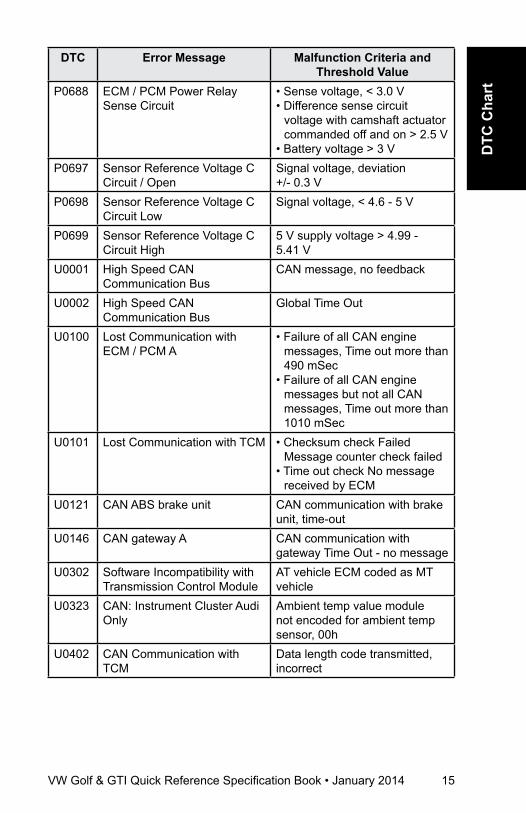
P0688 ECM / PCM Power Relay Sense Circuit
• Sense voltage, < 3.0 V• Difference sense circuit
voltage with camshaft actuator commanded off and on > 2.5 V
• Battery voltage > 3 VP0697 Sensor Reference Voltage C
Circuit / OpenSignal voltage, deviation +/- 0.3 V
P0698 Sensor Reference Voltage C Circuit Low
Signal voltage, < 4.6 - 5 V
P0699 Sensor Reference Voltage C Circuit High
5 V supply voltage > 4.99 - 5.41 V
U0001 High Speed CAN Communication Bus
CAN message, no feedback
U0002 High Speed CAN Communication Bus
Global Time Out
U0100 Lost Communication with ECM / PCM A
• Failure of all CAN engine messages, Time out more than 490 mSec
• Failure of all CAN engine messages but not all CAN messages, Time out more than 1010 mSec
U0101 Lost Communication with TCM • Checksum check Failed Message counter check failed
• Time out check No message received by ECM
U0121 CAN ABS brake unit CAN communication with brake unit, time-out
U0146 CAN gateway A CAN communication with gateway Time Out - no message
U0302 Software Incompatibility with Transmission Control Module
AT vehicle ECM coded as MT vehicle
U0323 CAN: Instrument Cluster Audi Only
Ambient temp value module not encoded for ambient temp sensor, 00h
U0402 CAN Communication with TCM
Data length code transmitted, incorrect

16 VW Golf & GTI Quick Reference Specification Book • January 2014
DTC Error Message Malfunction Criteria and Threshold Value
U0404 Invalid Data Received From Gear Shift Control Module
• If the value of message counter is permanent, constant, or change exceeds a threshold, increment an event counter
• Maximum change of message counter > 5
U0415 CAN link to speed sensor • Speed sensor initialization failed
U0422 CAN: Instrument Cluster Ambient temp. value (initialization), Audi, 01h
U0447 CAN Gateway CAN message incorrectU102E LIN Communication LIN message incorrectU102F LIN Communication Time outU1030 LIN Communication Not active
Fuel and air ratios Control ModuleDTC Error Message Malfunction Criteria and
Threshold ValueP1114 Internal Resistance Too Large
(Bank 1, Sensor 2)Heater resistance, (128-648)*(8-40)1.02-25.9 k O (dep. on mod. exhaust temp. and heater power)
P12A1 Fuel Rail Pressure Sensor Inappropriately Low
• Pressure control activity > 2.50 MPa
and• Fuel trim activity < 0.80and• Difference between actual
pressure vs target pressure -16.38 to 16.38 MPa
P12A2 Fuel Rail Pressure Sensor Inappropriately High
• Pressure control activity < -0.05 MPa
• Fuel trim activity > 1.30• Difference between target
pressure and actual pressure -16.38 to 16.38 MPa
VW Golf & GTI Quick Reference Specification Book • January 2014 17
DTC
Cha
rt
DTC Error Message Malfunction Criteria and Threshold Value
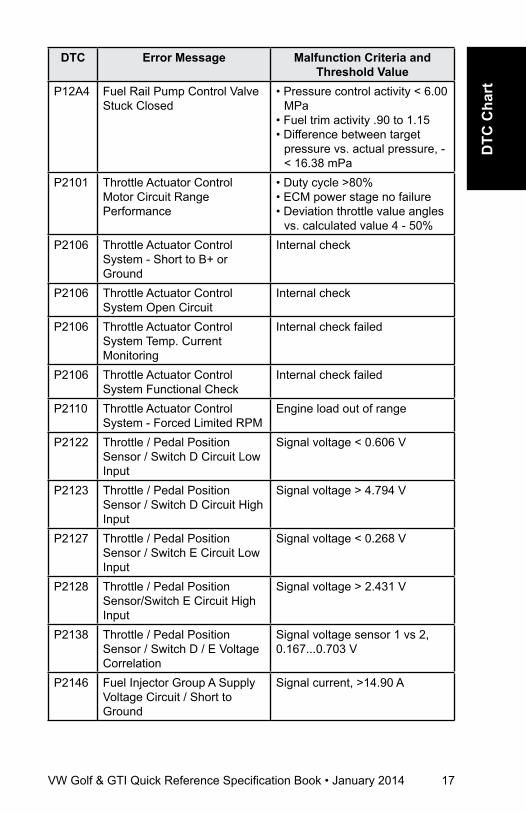
P12A4 Fuel Rail Pump Control Valve Stuck Closed
• Pressure control activity < 6.00 MPa
• Fuel trim activity .90 to 1.15• Difference between target
pressure vs. actual pressure, - < 16.38 mPa
P2101 Throttle Actuator Control Motor Circuit Range Performance
• Duty cycle >80%• ECM power stage no failure• Deviation throttle value angles
vs. calculated value 4 - 50%P2106 Throttle Actuator Control
System - Short to B+ or Ground
Internal check
P2106 Throttle Actuator Control System Open Circuit
Internal check
P2106 Throttle Actuator Control System Temp. Current Monitoring
Internal check failed
P2106 Throttle Actuator Control System Functional Check
Internal check failed
P2110 Throttle Actuator Control System - Forced Limited RPM
Engine load out of range
P2122 Throttle / Pedal Position Sensor / Switch D Circuit Low Input
Signal voltage < 0.606 V
P2123 Throttle / Pedal Position Sensor / Switch D Circuit High Input
Signal voltage > 4.794 V
P2127 Throttle / Pedal Position Sensor / Switch E Circuit Low Input
Signal voltage < 0.268 V
P2128 Throttle / Pedal Position Sensor/Switch E Circuit High Input
Signal voltage > 2.431 V
P2138 Throttle / Pedal Position Sensor / Switch D / E Voltage Correlation
Signal voltage sensor 1 vs 2, 0.167...0.703 V
P2146 Fuel Injector Group A Supply Voltage Circuit / Short to Ground
Signal current, >14.90 A
18 VW Golf & GTI Quick Reference Specification Book • January 2014
DTC Error Message Malfunction Criteria and Threshold Value
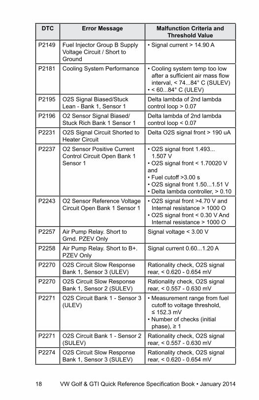
P2149 Fuel Injector Group B Supply Voltage Circuit / Short to Ground
• Signal current > 14.90 A
P2181 Cooling System Performance • Cooling system temp too low after a sufficient air mass flow interval, < 74...84° C (SULEV)
• < 60...84° C (ULEV)P2195 O2S Signal Biased/Stuck
Lean - Bank 1, Sensor 1Delta lambda of 2nd lambda control loop > 0.07
P2196 O2 Sensor Signal Biased/Stuck Rich Bank 1 Sensor 1
Delta lambda of 2nd lambda control loop < 0.07
P2231 O2S Signal Circuit Shorted to Heater Circuit
Delta O2S signal front > 190 uA
P2237 O2 Sensor Positive Current Control Circuit Open Bank 1 Sensor 1
• O2S signal front 1.493... 1.507 V
• O2S signal front < 1.70020 Vand• Fuel cutoff >3.00 s• O2S signal front 1.50...1.51 V• Delta lambda controller, > 0.10
P2243 O2 Sensor Reference Voltage Circuit Open Bank 1 Sensor 1
• O2S signal front >4.70 V and Internal resistance > 1000 O
• O2S signal front < 0.30 V And Internal resistance > 1000 O
P2257 Air Pump Relay. Short to Grnd. PZEV Only
Signal voltage < 3.00 V
P2258 Air Pump Relay. Short to B+. PZEV Only
Signal current 0.60...1.20 A
P2270 O2S Circuit Slow Response Bank 1, Sensor 3 (ULEV)
Rationality check, O2S signal rear, < 0.620 - 0.654 mV
P2270 O2S Circuit Slow Response Bank 1, Sensor 2 (SULEV)
Rationality check, O2S signal rear, < 0.557 - 0.630 mV
P2271 O2S Circuit Bank 1 - Sensor 3 (ULEV)
• Measurement range from fuel cutoff to voltage threshold, ≤ 152.3 mV
• Number of checks (initial phase), ≥ 1
P2271 O2S Circuit Bank 1 - Sensor 2 (SULEV)
Rationality check, O2S signal rear, < 0.557 - 0.630 mV
P2274 O2S Circuit Slow Response Bank 1, Sensor 3 (SULEV)
Rationality check, O2S signal rear, < 0.620 - 0.654 mV
VW Golf & GTI Quick Reference Specification Book • January 2014 19
DTC
Cha
rt
DTC Error Message Malfunction Criteria and Threshold Value
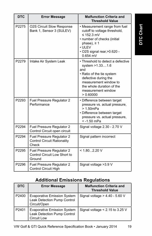
P2275 O2S Circuit Slow Response Bank 1, Sensor 3 (SULEV)
• Measurement range from fuel cutoff to voltage threshold, ≤ 152.3 mV
• number of checks (initial phase), ≥ 1
• ULEV• O2S signal rear,>0.620 -
0.654 mVP2279 Intake Air System Leak • Threshold to detect a defective
system >1.33....1.6and• Ratio of the tie system
defective during the measurement window to the whole duration of the measurement window > 0.60000
P2293 Fuel Pressure Regulator 2 Performance
• Difference between target pressure vs. actual pressure, > 1.50mPa
• Difference between target pressure vs. actual pressure, < -1.50 mPa
P2294 Fuel Pressure Regulator 2 Control Circuit open circuit
Signal voltage 2.30 - 2.70 V
P2294 Fuel Pressure Regulator 2 Control Circuit Rationality Check
Signal pattern incorrect
P2295 Fuel Pressure Regulator 2 Control Circuit Low Short to Ground
< 1.80...2.20 V
P2296 Fuel Pressure Regulator 2 Control Circuit High
Signal voltage >3.9 V
additional Emissions regulationsDTC Error Message Malfunction Criteria and
Threshold ValueP2400 Evaporative Emission System
Leak Detection Pump Control Circuit/Open
Signal voltage > 4.40 - 5.60 V
P2401 Evaporative Emission System Leak Detection Pump Control Circuit Low
Signal voltage < 2.15 to 3.25 V
20 VW Golf & GTI Quick Reference Specification Book • January 2014
DTC Error Message Malfunction Criteria and Threshold Value
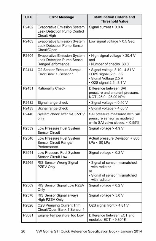
P2402 Evaporative Emission System Leak Detection Pump Control Circuit High
Signal current > 3.0 A
P2403 Evaporative Emission System Leak Detection Pump Sense Circuit/Open
Low signal voltage > 0.5 Sec.
P2404 Evaporative Emission System Leak Detection Pump Sense Range/Performance
• High signal voltage > 30.4 Vand• Number of checks 30.0
P2414 O2 Sensor Exhaust Sample Error Bank 1, Sensor 1
• Signal voltage 3.10...4.81 V• O2S signal, 2.5...3.2• Signal Voltage 2.5 V• O2S signal 2.5...3.1 V
P2431 Rationality Check Difference between SAI pressure and ambient pressure, NOT -25.0...25.00 hPa
P2432 Signal range check • Signal voltage < 0.40 VP2433 Signal range check • Signal voltage > 4.65 VP2440 System check after SAI PZEV
onlySAI pressure measured with SAI pressure sensor vs modeled while SAI valve closed. < 0.55%
P2539 Low Pressure Fuel System Sensor Circuit
Signal voltage > 4.9 V
P2540 Low Pressure Fuel System Sensor Circuit Range/Performance
Actual pressure Deviation < 800 kPa < 80 kPa
P2541 Low Pressure Fuel System Sensor Circuit Low
Signal voltage < 0.2 V
P2568 RIS Sensor Wrong Signal PZEV Only
• Signal of sensor mismatched with radiator
or• Signal of sensor mismatched
with radiatorP2569 RIS Sensor Signal Low PZEV
OnlySignal voltage < 0.2 V
P2570 RIS Sensor Signal always High PZEV Only
Signal voltage > 5.0 V
P2626 O2S Pumping Current Trim Circuit/Open Bank 1 Sensor 1
O2S signal front > 4.81 V
P3081 Engine Temperature Too Low Difference between ECT and modeled ECT > 9.80° K

VW Golf & GTI Quick Reference Specification Book • January 2014 21
DTC
Cha
rt
DTC CharT
Engine Codes CCTAFuel and air Mixture,
additional Emission regulationsDTC Error Message Malfunction Criteria and
Threshold ValueP000A Intake (A) Camshaft Position
Slow Response (Bank 1)Signal change < 1.9 - 4.2° CRK/s
P0010 Intake (A) Camshaft Position Actuator Circuit / Open (Bank 1)
Signal voltage, >4.40 - 5.60 V
P0011 Intake (A) Camshaft Position Timing - Over-Advanced (Bank 1)
Target error (Stuck position) > 6.8 - 8° CRK
P0016 Crankshaft Position - Camshaft Position Correlation Bank 1 Sensor A
• Permissible deviation < -11° Rev
or• Permissible deviation
> 11° RevP0030 HO2S Heater Control Circuit,
Bank 1, Sensor 1, Open Circuit
Heater voltage 2.34 - 3.59 V
P0031 HO2S Heater Control Circuit Low, Bank 1, Sensor 1, Short to Ground
Heater voltage < 2.34 V
P0032 HO2S Heater Control Circuit High, Bank 1, Sensor 1, Short to B+
Heater voltage > 3.59 V
P0036 HO2S Heater Control Circuit Bank 1 Sensor 2 Open Circuit
SULEV Heater voltage, 4.50 - 5.50 V
P0036 HO2S Heater Control Circuit Bank 1 Sensor 2 Open Circuit SULEV
Heater voltage, 4.50 - 5.50 V
P0037 HO2S Heater Control Circuit Low, Bank 1, Sensor 2, Short to ground
• SULEV Heater voltage < 3 V • ULEV Heater voltage < 3 V
P0038 HO2S Heater Control Circuit High, Bank 1, Sensor 2, Short to B+
Heater current, > 2.70 - 5.50 A

22 VW Golf & GTI Quick Reference Specification Book • January 2014
DTC Error Message Malfunction Criteria and Threshold Value
P0042 HO2S Heater Circuit, Bank 1, Sensor 3, Open Circuit (SULEV)
Heater voltage 4.50...5.50 V
P0043 HO2S Heater Control Circuit Low Bank 1, Sensor 2, Short to Ground
• SULEV Heater voltage < 3 V • ULEV Heater voltage < 3 V
P0044 HO2S Heater Control Circuit High Bank 1, Sensor 2, Short to B+
Heater current, > 2.70 - 5.50 A
P050A Idle Air Control System RPM Lower Or Higher Than Expected
Out of range-low• Engine speed deviation < 80
RPMOut of range-high• Engine speed deviation > 80
RPMP0068 MAP/MAF – Throttle Position
Correlation• Plausibility with fuel system,
load calculation < 50%• Plausibility with fuel system,
load calculation > 50%P0070 Ambient air temp sensor short
to B+Ambient air temperature < 45.0° C
P0071 Rationality Check • Difference value AAT - ECT @ engine start (depending on engine-off time) > 25K - 40K
and• Difference value AAT - IAT
engine start (depending on engine-off time) > 25K - 40K
P0072 Ambient Air Temp Sensor Short to Ground
Ambient air temperature > 87.0° C
P0087 Fuel Rail/System Pressure - Too Low
• Pressure controller activity > 4.00 MPa
• Fuel trim activity, 1.30 - 16.00and• Difference between target
pressure vs. actual pressure, > -16.38 mPa
P0088 Fuel Rail/System Pressure - Too High
Fuel rail pressure > 13.9 MPa
P0089 Fuel Pressure Regulator 1 Performance
Actual pressure Deviation• < 100 kPa• > 100 kPa
VW Golf & GTI Quick Reference Specification Book • January 2014 23
DTC
Cha
rt
DTC Error Message Malfunction Criteria and Threshold Value
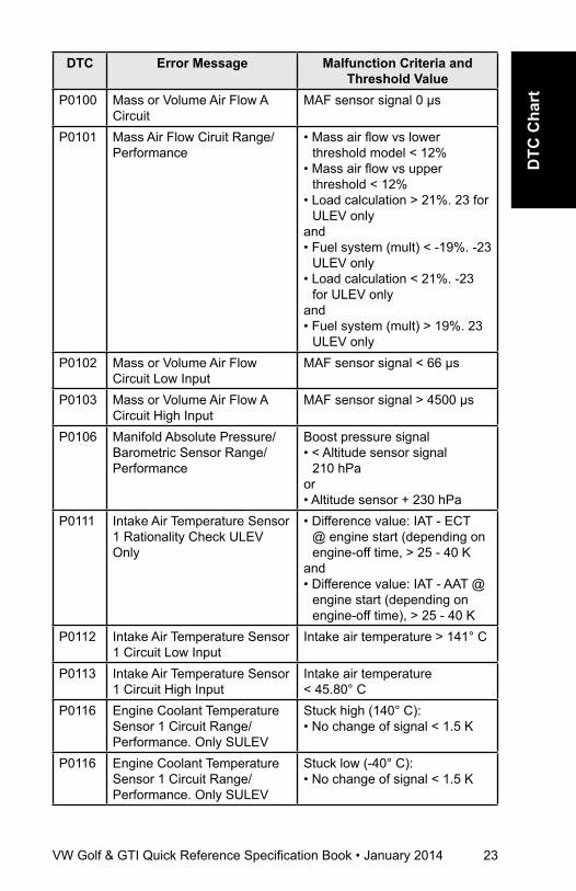
P0100 Mass or Volume Air Flow A Circuit
MAF sensor signal 0 µs
P0101 Mass Air Flow Ciruit Range/Performance
• Mass air flow vs lower threshold model < 12%
• Mass air flow vs upper threshold < 12%
• Load calculation > 21%. 23 for ULEV only
and• Fuel system (mult) < -19%. -23
ULEV only• Load calculation < 21%. -23
for ULEV onlyand• Fuel system (mult) > 19%. 23
ULEV onlyP0102 Mass or Volume Air Flow
Circuit Low InputMAF sensor signal < 66 µs
P0103 Mass or Volume Air Flow A Circuit High Input
MAF sensor signal > 4500 µs
P0106 Manifold Absolute Pressure/Barometric Sensor Range/Performance
Boost pressure signal• < Altitude sensor signal
210 hPaor• Altitude sensor + 230 hPa
P0111 Intake Air Temperature Sensor 1 Rationality Check ULEV Only
• Difference value: IAT - ECT @ engine start (depending on engine-off time, > 25 - 40 K
and• Difference value: IAT - AAT @
engine start (depending on engine-off time), > 25 - 40 K
P0112 Intake Air Temperature Sensor 1 Circuit Low Input
Intake air temperature > 141° C
P0113 Intake Air Temperature Sensor 1 Circuit High Input
Intake air temperature < 45.80° C
P0116 Engine Coolant Temperature Sensor 1 Circuit Range/Performance. Only SULEV
Stuck high (140° C):• No change of signal < 1.5 K
P0116 Engine Coolant Temperature Sensor 1 Circuit Range/Performance. Only SULEV
Stuck low (-40° C):• No change of signal < 1.5 K
24 VW Golf & GTI Quick Reference Specification Book • January 2014
DTC Error Message Malfunction Criteria and Threshold Value
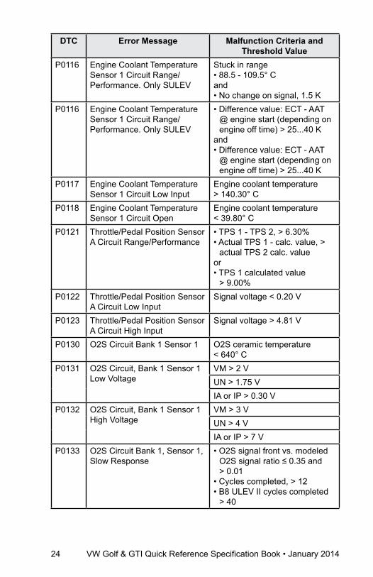
P0116 Engine Coolant Temperature Sensor 1 Circuit Range/Performance. Only SULEV
Stuck in range• 88.5 - 109.5° Cand• No change on signal, 1.5 K
P0116 Engine Coolant Temperature Sensor 1 Circuit Range/Performance. Only SULEV
• Difference value: ECT - AAT @ engine start (depending on engine off time) > 25...40 K
and• Difference value: ECT - AAT
@ engine start (depending on engine off time) > 25...40 K
P0117 Engine Coolant Temperature Sensor 1 Circuit Low Input
Engine coolant temperature > 140.30° C
P0118 Engine Coolant Temperature Sensor 1 Circuit Open
Engine coolant temperature < 39.80° C
P0121 Throttle/Pedal Position Sensor A Circuit Range/Performance
• TPS 1 - TPS 2, > 6.30% • Actual TPS 1 - calc. value, >
actual TPS 2 calc. valueor• TPS 1 calculated value
> 9.00%P0122 Throttle/Pedal Position Sensor
A Circuit Low InputSignal voltage < 0.20 V
P0123 Throttle/Pedal Position Sensor A Circuit High Input
Signal voltage > 4.81 V
P0130 O2S Circuit Bank 1 Sensor 1 O2S ceramic temperature < 640° C
P0131 O2S Circuit, Bank 1 Sensor 1 Low Voltage
VM > 2 VUN > 1.75 VIA or IP > 0.30 V
P0132 O2S Circuit, Bank 1 Sensor 1 High Voltage
VM > 3 VUN > 4 VIA or IP > 7 V
P0133 O2S Circuit Bank 1, Sensor 1, Slow Response
• O2S signal front vs. modeled O2S signal ratio ≤ 0.35 and > 0.01
• Cycles completed, > 12• B8 ULEV II cycles completed
> 40

VW Golf & GTI Quick Reference Specification Book • January 2014 25
DTC
Cha
rt
DTC Error Message Malfunction Criteria and Threshold Value
P0135 O2S Heater Circuit Bank 1 Sensor 1
• Out of range-high• O2S ceramic temperature,
< 715° Cand• Heater duty cycle, 100%• Rationality check:• O2S ceramic temperature,
< 715° Cand• Time after O2S heater on 40 s• Out of range low:• Difference between measured
calibration resistance in ECM and set value, > 45 O
P0136 O2S Circuit Bank 1 Sensor 2 Malfunction
• Delta voltage one step at heater switching > 2.0020 V
• Number of checks 10P0137 O2S Circuit Low Voltage Bank
1 Sensor 2• Cold condition, signal voltage,
< 59.6 mV• Warm condition, signal voltage
< 59.6 mV• Reaction at closed loop
enrichment, no reactionP0138 O2S Circuit Bank 1, Sensor 2,
High VoltageSignal voltage > 1.26 V.
P0139 O2S Circuit Bank 1, Sensor 2, Slow Response
• EWMA filtered transient time at fuel cutoff > 0.4 s
• In voltage range, 401.4...201.2 mV
• Number of checks, > 3• Number of checks (step
function), > 3P013A O2S Circuit Bank 1, Sensor 2,
(ULEV Bank 1, Sensor 3),Slow Response, Rich to Lean
• EWMA filtered transient time at fuel cutoff > 0.4 s
• In voltage range, 401.4...201.2 mV
• Number of checks, > 3• Number of checks (step
function), > 3P0140 O2S Circuit Bank 1, Sensor 2,
No Activity Detected• Signal voltage, 401...499 mVInternal resistance• > 40 KO
P0141 O2S Heater Circuit Bank 1, Sensor 2, out of range (ULEV)
Heater resistance, 810...4560 O
26 VW Golf & GTI Quick Reference Specification Book • January 2014
DTC Error Message Malfunction Criteria and Threshold Value
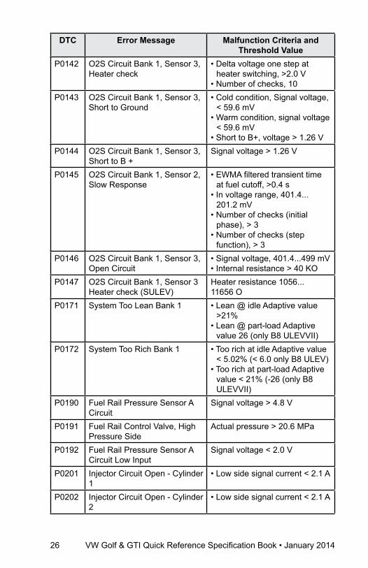
P0142 O2S Circuit Bank 1, Sensor 3, Heater check
• Delta voltage one step at heater switching, >2.0 V
• Number of checks, 10P0143 O2S Circuit Bank 1, Sensor 3,
Short to Ground• Cold condition, Signal voltage,
< 59.6 mV• Warm condition, signal voltage
< 59.6 mV• Short to B+, voltage > 1.26 V
P0144 O2S Circuit Bank 1, Sensor 3, Short to B +
Signal voltage > 1.26 V
P0145 O2S Circuit Bank 1, Sensor 2, Slow Response
• EWMA filtered transient time at fuel cutoff, >0.4 s
• In voltage range, 401.4... 201.2 mV
• Number of checks (initial phase), > 3
• Number of checks (step function), > 3
P0146 O2S Circuit Bank 1, Sensor 3, Open Circuit
• Signal voltage, 401.4...499 mV• Internal resistance > 40 KO
P0147 O2S Circuit Bank 1, Sensor 3 Heater check (SULEV)
Heater resistance 1056... 11656 O
P0171 System Too Lean Bank 1 • Lean @ idle Adaptive value >21%
• Lean @ part-load Adaptive value 26 (only B8 ULEVVII)
P0172 System Too Rich Bank 1 • Too rich at idle Adaptive value < 5.02% (< 6.0 only B8 ULEV)
• Too rich at part-load Adaptive value < 21% (-26 (only B8 ULEVVII)
P0190 Fuel Rail Pressure Sensor A Circuit
Signal voltage > 4.8 V
P0191 Fuel Rail Control Valve, High Pressure Side
Actual pressure > 20.6 MPa
P0192 Fuel Rail Pressure Sensor A Circuit Low Input
Signal voltage < 2.0 V
P0201 Injector Circuit Open - Cylinder 1
• Low side signal current < 2.1 A
P0202 Injector Circuit Open - Cylinder 2
• Low side signal current < 2.1 A

VW Golf & GTI Quick Reference Specification Book • January 2014 27
DTC
Cha
rt
DTC Error Message Malfunction Criteria and Threshold Value
P0203 Injector Circuit Open - Cylinder 3
• Low side signal current < 2.1 A
P0204 Injector Circuit Open - Cylinder 4
• Low side signal current < 2.1 A
P0221 Throttle / Pedal Position Sensor / Switch B Circuit Range / Performance
• TPS 1 - TPS 2 > 6.30%and• Actual TPS 2 calculated value
> actual TPS 1 calculated value
or• TPS 2 calculated value
> 9.00%P0222 Throttle / Pedal Position
Sensor / Switch B Circuit Low Input
Signal voltage < 0.20 V
P0223 Throttle / Pedal Position Sensor / Switch B Circuit High Input
Signal voltage > 4.81 V
P0234 Turbocharger / Supercharger Overboost Condition Rationality Check High
Difference set value boost pressure vs actual boost pressure value, > 200... 1275 hPa
P0236 Turbocharger / Supercharger Boost Sensor A Plausibility check (ULEV)
• Diff. boost pressure signal vs altitude sensor signal, >230 hPa
• Diff. boost pressure signal vs altitude sensor signal, <130 hPa
P0237 Turbocharger / Supercharger Boost Sensor A Circuit Low
Signal voltage < 0.20 V
P0238 Turbocharger / Supercharger Boost Sensor A Circuit High
Signal voltage > 4.88 V
P0243 Turbocharger / Supercharger Wastegate Solenoid A
Signal voltage, > 4.40...5.60 V
P0245 Turbocharger / Supercharger Wastegate Solenoid A Low
Signal voltage, < 2.15...3.25 V
P0246 Turbocharger / Supercharger Wastegate Solenoid A High
Signal current > 2.20 A
P025A Fuel Pump Open Circuit Signal voltage > 4.40 - 5.60 V P025C Fuel Pump Short to Ground Signal voltage 2.15 - 3.25 VP025D Fuel Pump Short to B+ Signal current > 1.10 AP0261 Cylinder 1 Injector Circuit Low Signal current < 2.10 A

28 VW Golf & GTI Quick Reference Specification Book • January 2014
DTC Error Message Malfunction Criteria and Threshold Value
P0262 Cylinder 1 Injector Circuit High Signal current > 14.70 AP0264 Cylinder 2 Injector Circuit Low Signal current < 2.10 AP0265 Cylinder 2 Injector Circuit High Signal current > 14.70 AP0267 Cylinder 3 Injector Circuit Low Signal current < 2.10 AP0268 Cylinder 3 Injector Circuit High Signal current > 14.70 AP0270 Cylinder 4 Injector Circuit Low Signal current < 2.10 AP0271 Cylinder 4 Injector Circuit High Signal current > 14.70 AP0299 Turbocharger / Supercharger
Underboost Rationality Check Low
Difference of set boost pressure vs actual boost pressure value > 150 hPa
P2004 Intake Manifold Runner Control Stuck Open Bank 1
• Normal closed position, unable to reach
• Signal voltage, < 2.62 or > 4.65 V
and• Normal open position, unable
to reach• Signal voltage, < 0.35 or
> 2.38 VP2008 Intake Manifold Runner
Control Circuit / Open Bank 1Signal voltage 4.40 - 5.60 V
P2009 Intake Manifold Runner Control Circuit / Shorted Bank 1
Signal voltage 2.15 - 3.25 V
P2010 Intake Manifold Runner Control Circuit / Shorted to B+ Bank 1
Signal current > 2.20 A
P2014 Intake Manifold Runner Position Sensor / Switch Circuit Bank 1
Signal voltage > 4.75 V
P2015 Intake Manifold Runner Position Sensor / Switch Circuit Range / Performance Bank 1
Deviation runner flap target position vs actual position > 25%
P2016 Intake Manifold Runner Position Sensor / Switch Circuit Low (Bank 1)
Signal voltage < 0.25 V
P2088 A Camshaft Position Actuator Control Circuit Low Bank 1 Short to Ground
Signal voltage, < 2.15...3.25 V
VW Golf & GTI Quick Reference Specification Book • January 2014 29
DTC
Cha
rt
DTC Error Message Malfunction Criteria and Threshold Value
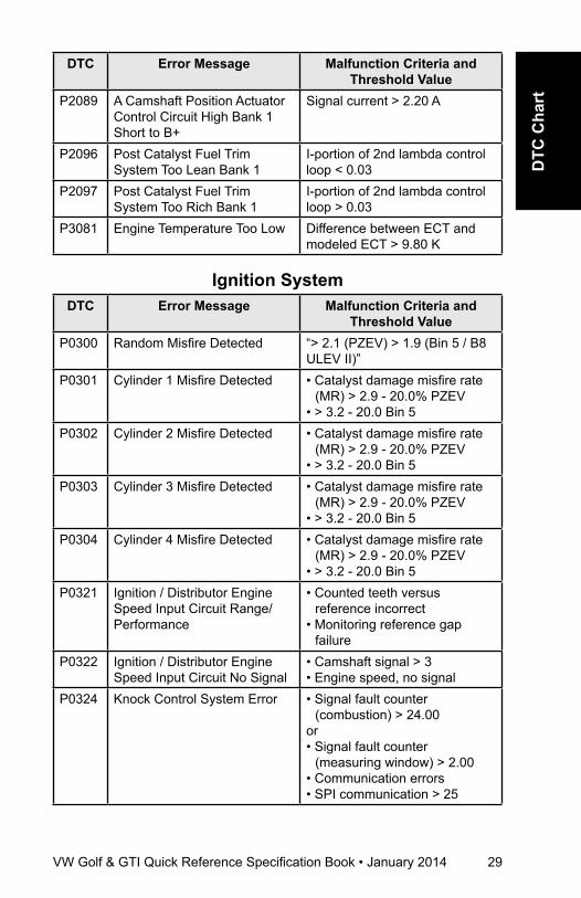
P2089 A Camshaft Position Actuator Control Circuit High Bank 1 Short to B+
Signal current > 2.20 A
P2096 Post Catalyst Fuel Trim System Too Lean Bank 1
I-portion of 2nd lambda control loop < 0.03
P2097 Post Catalyst Fuel Trim System Too Rich Bank 1
I-portion of 2nd lambda control loop > 0.03
P3081 Engine Temperature Too Low Difference between ECT and modeled ECT > 9.80 K
Ignition SystemDTC Error Message Malfunction Criteria and
Threshold ValueP0300 Random Misfire Detected “> 2.1 (PZEV) > 1.9 (Bin 5 / B8
ULEV II)”P0301 Cylinder 1 Misfire Detected • Catalyst damage misfire rate
(MR) > 2.9 - 20.0% PZEV• > 3.2 - 20.0 Bin 5
P0302 Cylinder 2 Misfire Detected • Catalyst damage misfire rate (MR) > 2.9 - 20.0% PZEV
• > 3.2 - 20.0 Bin 5P0303 Cylinder 3 Misfire Detected • Catalyst damage misfire rate
(MR) > 2.9 - 20.0% PZEV• > 3.2 - 20.0 Bin 5
P0304 Cylinder 4 Misfire Detected • Catalyst damage misfire rate (MR) > 2.9 - 20.0% PZEV
• > 3.2 - 20.0 Bin 5P0321 Ignition / Distributor Engine
Speed Input Circuit Range/Performance
• Counted teeth versus reference incorrect
• Monitoring reference gap failure
P0322 Ignition / Distributor Engine Speed Input Circuit No Signal
• Camshaft signal > 3• Engine speed, no signal
P0324 Knock Control System Error • Signal fault counter (combustion) > 24.00
or • Signal fault counter
(measuring window) > 2.00• Communication errors• SPI communication > 25
30 VW Golf & GTI Quick Reference Specification Book • January 2014
DTC Error Message Malfunction Criteria and Threshold Value
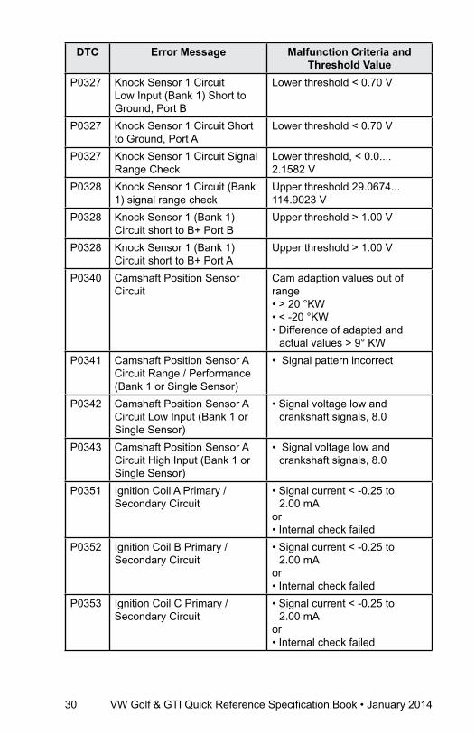
P0327 Knock Sensor 1 Circuit Low Input (Bank 1) Short to Ground, Port B
Lower threshold < 0.70 V
P0327 Knock Sensor 1 Circuit Short to Ground, Port A
Lower threshold < 0.70 V
P0327 Knock Sensor 1 Circuit Signal Range Check
Lower threshold, < 0.0.... 2.1582 V
P0328 Knock Sensor 1 Circuit (Bank 1) signal range check
Upper threshold 29.0674... 114.9023 V
P0328 Knock Sensor 1 (Bank 1) Circuit short to B+ Port B
Upper threshold > 1.00 V
P0328 Knock Sensor 1 (Bank 1) Circuit short to B+ Port A
Upper threshold > 1.00 V
P0340 Camshaft Position Sensor Circuit
Cam adaption values out of range• > 20 °KW• < -20 °KW• Difference of adapted and
actual values > 9° KWP0341 Camshaft Position Sensor A
Circuit Range / Performance (Bank 1 or Single Sensor)
• Signal pattern incorrect
P0342 Camshaft Position Sensor A Circuit Low Input (Bank 1 or Single Sensor)
• Signal voltage low and crankshaft signals, 8.0
P0343 Camshaft Position Sensor A Circuit High Input (Bank 1 or Single Sensor)
• Signal voltage low and crankshaft signals, 8.0
P0351 Ignition Coil A Primary / Secondary Circuit
• Signal current < -0.25 to 2.00 mA
or• Internal check failed
P0352 Ignition Coil B Primary / Secondary Circuit
• Signal current < -0.25 to 2.00 mA
or• Internal check failed
P0353 Ignition Coil C Primary / Secondary Circuit
• Signal current < -0.25 to 2.00 mA
or• Internal check failed

VW Golf & GTI Quick Reference Specification Book • January 2014 31
DTC
Cha
rt
DTC Error Message Malfunction Criteria and Threshold Value
P0354 Ignition Coil D Primary / Secondary Circuit
• Signal current < -0.25 to 2.00 mA
or• Internal check failed
additional Exhaust regulationDTC Error Message Malfunction Criteria and
Threshold ValueP0420 Catalyst System Efficiency
Below Threshold (Bank 1)• Measured OSC / OSC of
borderline catalyst value for front catalyst , < 0.40
or• Value for front catalyst, < 1.30and• Value for main catalyst, < 1.20
P0420 Catalyst System (main) Efficiency Below Threshold (Bank 1) PZEV Only
• Measured OSC / OSC of borderline catalyst value for main catalyst, < 0.90
• While• Value for front catalyst, < 2.00
P0420 Catalyst System (only bin 5, ULEV) Efficiency Below Threshold (Bank 1)
Measured OSC / OSC of borderline catalyst. EWMA filter value for catalyst, < .20
P0441 Evaporative Emission System Incorrect Purge Flow
Reaction of idle controller or lambda controller Deviation less than 7% lambda controller AND 35% idle controller deviation
P0442 Evaporative Emission System Leak Detected (Small Leak)
Time for pressure drop < 1.55...1.75s.
P0444 Evaporative Emission System Purge Control Valve Circuit Open
Signal voltage> 4.40... 5.40 V
P0455 Evaporative Emission System Leak Detected Gross Leak/No Flow
Time for pressure drop < 0.95 Sec.
P0456 Evaporative Emission System Leak Detected Very Small Leak
< 4.5 - 6.0 s.
P0458 Evaporative Emission System Purge Control Valve Circuit Low
Signal voltage 2.15 - 3.25 V

32 VW Golf & GTI Quick Reference Specification Book • January 2014
DTC Error Message Malfunction Criteria and Threshold Value
P0459 Evaporative Emission System Purge Control Valve Circuit High
Signal current > 2.20 A
Speed and Idle ControlDTC Error Message Malfunction Criteria and
Threshold ValueP0501 Vehicle Speed Sensor A
Range / PerformanceVSS signal, < 4 km/h
P0501 Vehicle Speed Sensor A Range / Performance Only (ULEV)
VSS signal, < 4 km/h
P0503 Vehicle Speed Sensor A Out of range high
Vehicle speed > 200 km/h
P0506 Idle Air Control System - RPM Lower Than Expected
Engine speed deviation <-80 RPM
P0507 Idle Air Control System - RPM Higher Than Expected
Engine speed deviation > -80 RPM
Control Module and Output SignalsDTC Error Message Malfunction Criteria and
Threshold ValueP0601 Internal Control Module
Memory Check Sum ErrorInternal check sum, incorrect
P0604 Internal Control Module Random Access Memory (RAM) Error
Write ability check, failed
P0605 Internal Control Module Read Only Memory (ROM) Error
Checksum incorrect
P0606 ECM Processor Powerup calibration• EEPROM check, failedA/D channel conversion• Check failed
P0627 Fuel Pump “A” Control Circuit /Open
• Internal error fuel pump control unit
• Feedback from fuel pump control unit Pump blocked short circuit to battery +, ground or open circuit
VW Golf & GTI Quick Reference Specification Book • January 2014 33
DTC
Cha
rt
DTC Error Message Malfunction Criteria and Threshold Value
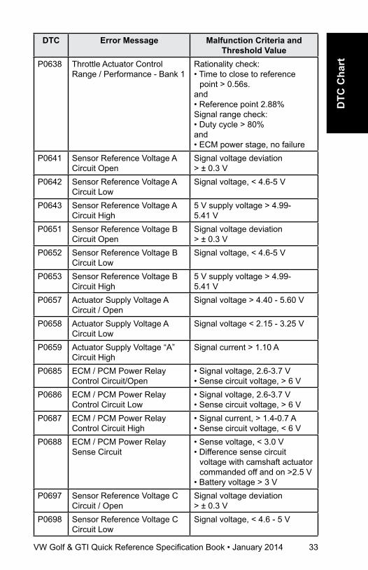
P0638 Throttle Actuator Control Range / Performance - Bank 1
Rationality check:• Time to close to reference
point > 0.56s.and• Reference point 2.88%Signal range check:• Duty cycle > 80%and• ECM power stage, no failure
P0641 Sensor Reference Voltage A Circuit Open
Signal voltage deviation > ± 0.3 V
P0642 Sensor Reference Voltage A Circuit Low
Signal voltage, < 4.6-5 V
P0643 Sensor Reference Voltage A Circuit High
5 V supply voltage > 4.99- 5.41 V
P0651 Sensor Reference Voltage B Circuit Open
Signal voltage deviation > ± 0.3 V
P0652 Sensor Reference Voltage B Circuit Low
Signal voltage, < 4.6-5 V
P0653 Sensor Reference Voltage B Circuit High
5 V supply voltage > 4.99- 5.41 V
P0657 Actuator Supply Voltage A Circuit / Open
Signal voltage > 4.40 - 5.60 V
P0658 Actuator Supply Voltage A Circuit Low
Signal voltage < 2.15 - 3.25 V
P0659 Actuator Supply Voltage “A” Circuit High
Signal current > 1.10 A
P0685 ECM / PCM Power Relay Control Circuit/Open
• Signal voltage, 2.6-3.7 V• Sense circuit voltage, > 6 V
P0686 ECM / PCM Power Relay Control Circuit Low
• Signal voltage, 2.6-3.7 V• Sense circuit voltage, > 6 V
P0687 ECM / PCM Power Relay Control Circuit High
• Signal current, > 1.4-0.7 A• Sense circuit voltage, < 6 V
P0688 ECM / PCM Power Relay Sense Circuit
• Sense voltage, < 3.0 V• Difference sense circuit
voltage with camshaft actuator commanded off and on >2.5 V
• Battery voltage > 3 VP0697 Sensor Reference Voltage C
Circuit / OpenSignal voltage deviation > ± 0.3 V
P0698 Sensor Reference Voltage C Circuit Low
Signal voltage, < 4.6 - 5 V
34 VW Golf & GTI Quick Reference Specification Book • January 2014
DTC Error Message Malfunction Criteria and Threshold Value
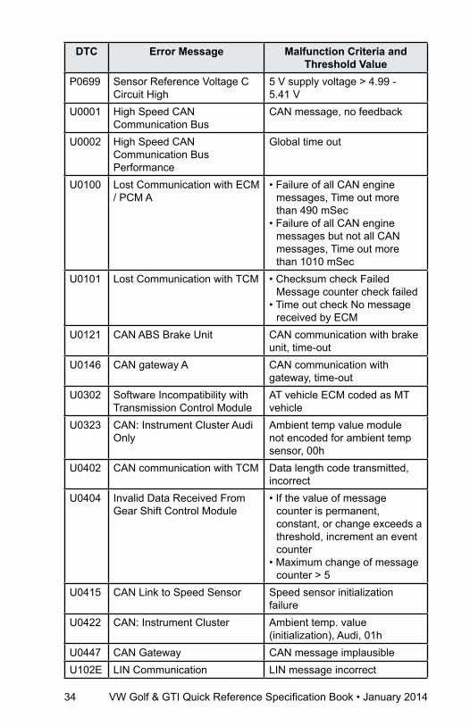
P0699 Sensor Reference Voltage C Circuit High
5 V supply voltage > 4.99 - 5.41 V
U0001 High Speed CAN Communication Bus
CAN message, no feedback
U0002 High Speed CAN Communication Bus Performance
Global time out
U0100 Lost Communication with ECM / PCM A
• Failure of all CAN engine messages, Time out more than 490 mSec
• Failure of all CAN engine messages but not all CAN messages, Time out more than 1010 mSec
U0101 Lost Communication with TCM • Checksum check Failed Message counter check failed
• Time out check No message received by ECM
U0121 CAN ABS Brake Unit CAN communication with brake unit, time-out
U0146 CAN gateway A CAN communication with gateway, time-out
U0302 Software Incompatibility with Transmission Control Module
AT vehicle ECM coded as MT vehicle
U0323 CAN: Instrument Cluster Audi Only
Ambient temp value module not encoded for ambient temp sensor, 00h
U0402 CAN communication with TCM Data length code transmitted, incorrect
U0404 Invalid Data Received From Gear Shift Control Module
• If the value of message counter is permanent, constant, or change exceeds a threshold, increment an event counter
• Maximum change of message counter > 5
U0415 CAN Link to Speed Sensor Speed sensor initialization failure
U0422 CAN: Instrument Cluster Ambient temp. value (initialization), Audi, 01h
U0447 CAN Gateway CAN message implausibleU102E LIN Communication LIN message incorrect
VW Golf & GTI Quick Reference Specification Book • January 2014 35
DTC
Cha
rt
DTC Error Message Malfunction Criteria and Threshold Value
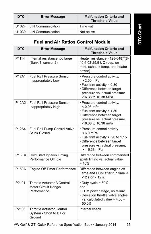
U102F LIN Communication Time outU1030 LIN Communication Not active
Fuel and air ratios Control ModuleDTC Error Message Malfunction Criteria and
Threshold ValueP1114 Internal resistance too large
(Bank 1, sensor 2)Heater resistance, (128-648)*(8-40)1.02-25.9 k O (dep. on mod. exhaust temp. and heater power)
P12A1 Fuel Rail Pressure Sensor Inappropriately Low
• Pressure control activity, > 2.50 mPa
• Fuel trim activity < 0.80• Difference between target
pressure vs. actual pressure -16.38 to 16.38 MPa
P12A2 Fuel Rail Pressure Sensor Inappropriately High
• Pressure control activity, < 0.05 mPa
• Fuel trim activity > 1.30• Difference between target
pressure vs. actual pressure -16.38 to 16.38 mPa
P12A4 Fuel Rail Pump Control Valve Stuck Closed
• Pressure control activity < 6.0 mPa
• Fuel trim activity > .90 to 1.15• Difference between target
pressure vs. actual pressure, -< 16.38 mPa
P13EA Cold Start Ignition Timing Performance Off Idle
Difference between commanded spark timing vs. actual value > 40%
P150A Engine Off Timer Performance Difference between engine off time and ECM after run time < -12 s or > 12 s.
P2101 Throttle Actuator A Control Motor Circuit Range/Performance
• Duty cycle > 80%and• ECM power stage, no failure• Deviation throttle valve angles
vs. calculated value > 4.00 - 50.0%
P2106 Throttle Actuator Control System - Short to B+ or Ground
Internal check

36 VW Golf & GTI Quick Reference Specification Book • January 2014
DTC Error Message Malfunction Criteria and Threshold Value
P2106 Throttle Actuator Control System Open Circuit
Internal check
P2106 Throttle Actuator Control System Temp. Current Monitoring
Internal check failed
P2106 Throttle Actuator Control System Functional Check
Internal check failed
P2110 Throttle Actuator Control System - Forced Limited RPM
Engine load out of range
P2122 Throttle / Pedal Position Sensor / Switch D Circuit Low Input
Signal voltage < 0.606 V
P2123 Throttle / Pedal Position Sensor / Switch D Circuit High Input
Signal voltage > 4.794 V
P2127 Throttle / Pedal Position Sensor / Switch E Circuit Low Input
Signal voltage < 0.268 V
P2128 Throttle / Pedal Position Sensor/Switch E Circuit High Input
Signal voltage > 2.431 V
P2138 Throttle / Pedal Position Sensor / Switch D / E Voltage Correlation
Signal voltage sensor 1 vs 2, 0.167...0.703 V
P2146 Fuel Injector Group A Supply Voltage Circuit / Short to Ground
• Signal current > 14.90 A
P2149 Fuel Injector Group B Supply Voltage Circuit Open
• Signal current < 2.60 A or• Signal current > 14.90 A
P2181 Cooling System Performance • Cooling system temp too low after a sufficient air mass flow interval, < 74...84° C (SULEV)
• < 60...84° C (ULEV)P2195 O2S Signal Biased/Stuck Lean
- Bank 1, Sensor 1Delta lambda of 2nd lambda control loop > 0.07
P2196 O2S Signal Biased / Stuck Rich - Bank 1, Sensor 1
Delta lambda of 2nd lambda control loop < 0.07
P2231 O2S Signal Circuit Shorted to Heater Circuit
Delta O2S signal front, > 190 uA
VW Golf & GTI Quick Reference Specification Book • January 2014 37
DTC
Cha
rt
DTC Error Message Malfunction Criteria and Threshold Value
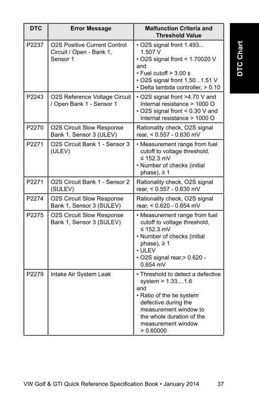
P2237 O2S Positive Current Control Circuit / Open - Bank 1, Sensor 1
• O2S signal front 1.493... 1.507 V
• O2S signal front < 1.70020 Vand• Fuel cutoff > 3.00 s• O2S signal front 1.50...1.51 V• Delta lambda controller, > 0.10
P2243 O2S Reference Voltage Circuit / Open Bank 1 - Sensor 1
• O2S signal front >4.70 V and Internal resistance > 1000 O
• O2S signal front < 0.30 V and Internal resistance > 1000 O
P2270 O2S Circuit Slow Response Bank 1, Sensor 3 (ULEV)
Rationality check, O2S signal rear, < 0.557 - 0.630 mV
P2271 O2S Circuit Bank 1 - Sensor 3 (ULEV)
• Measurement range from fuel cutoff to voltage threshold, ≤ 152.3 mV
• Number of checks (initial phase), ≥ 1
P2271 O2S Circuit Bank 1 - Sensor 2 (SULEV)
Rationality check, O2S signal rear, < 0.557 - 0.630 mV
P2274 O2S Circuit Slow Response Bank 1, Sensor 3 (SULEV)
Rationality check, O2S signal rear, < 0.620 - 0.654 mV
P2275 O2S Circuit Slow Response Bank 1, Sensor 3 (SULEV)
• Measurement range from fuel cutoff to voltage threshold, ≤ 152.3 mV
• Number of checks (initial phase), ≥ 1
• ULEV• O2S signal rear,> 0.620 -
0.654 mVP2279 Intake Air System Leak • Threshold to detect a defective
system > 1.33....1.6and• Ratio of the tie system
defective during the measurement window to the whole duration of the measurement window > 0.60000
38 VW Golf & GTI Quick Reference Specification Book • January 2014
DTC Error Message Malfunction Criteria and Threshold Value
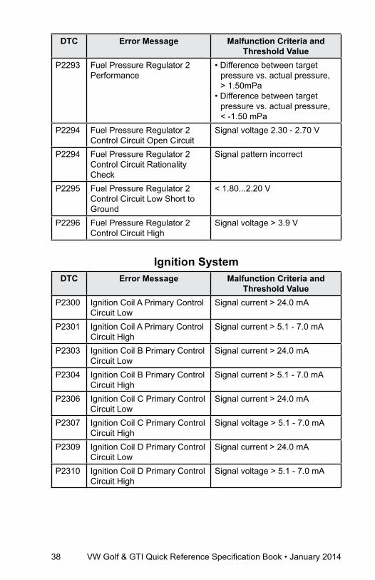
P2293 Fuel Pressure Regulator 2 Performance
• Difference between target pressure vs. actual pressure, > 1.50mPa
• Difference between target pressure vs. actual pressure, < -1.50 mPa
P2294 Fuel Pressure Regulator 2 Control Circuit Open Circuit
Signal voltage 2.30 - 2.70 V
P2294 Fuel Pressure Regulator 2 Control Circuit Rationality Check
Signal pattern incorrect
P2295 Fuel Pressure Regulator 2 Control Circuit Low Short to Ground
< 1.80...2.20 V
P2296 Fuel Pressure Regulator 2 Control Circuit High
Signal voltage > 3.9 V
Ignition SystemDTC Error Message Malfunction Criteria and
Threshold ValueP2300 Ignition Coil A Primary Control
Circuit LowSignal current > 24.0 mA
P2301 Ignition Coil A Primary Control Circuit High
Signal current > 5.1 - 7.0 mA
P2303 Ignition Coil B Primary Control Circuit Low
Signal current > 24.0 mA
P2304 Ignition Coil B Primary Control Circuit High
Signal current > 5.1 - 7.0 mA
P2306 Ignition Coil C Primary Control Circuit Low
Signal current > 24.0 mA
P2307 Ignition Coil C Primary Control Circuit High
Signal voltage > 5.1 - 7.0 mA
P2309 Ignition Coil D Primary Control Circuit Low
Signal current > 24.0 mA
P2310 Ignition Coil D Primary Control Circuit High
Signal voltage > 5.1 - 7.0 mA
VW Golf & GTI Quick Reference Specification Book • January 2014 39
DTC
Cha
rt
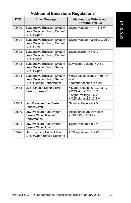
additional Emissions regulationsDTC Error Message Malfunction Criteria and
Threshold ValueP2400 Evaporative Emission System
Leak Detection Pump Control Circuit Open
Signal voltage > 4.4 - 5.6 V
P2401 Evaporative Emission System Leak Detection Pump Control Circuit Low
Signal voltage < 2.15 to 3.25 V
P2402 Evaporative Emission System Leak Detection Pump Control Circuit High
Signal current > 3.0 A
P2403 Evaporative Emission System Leak Detection Pump Sense Circuit Open
Low signal voltage > 0.5 s
P2404 Evaporative Emission System Leak Detection Pump Sense Circuit Range/Performance
• High signal voltage > 30.4 Vand• Number of checks = 30
P2414 O2S Exhaust Sample Error Bank 1, Sensor 1
• Signal voltage 3.10...4.81 V• O2S signal, 2.5...3.2• Signal Voltage 2.5 V • O2S signal 2.5...3.1 V
P2539 Low Pressure Fuel System Sensor Circuit
Signal voltage > 4.9 V
P2540 Low Pressure Fuel System Sensor Circuit Range/Performance
Actual pressure Deviation < 800 kPa < 80 kPa
P2541 Low Pressure Fuel System Sensor Circuit Low
Signal voltage < 0.2 V
P2626 O2S Pumping Current Trim Circuit/Open Bank 1 Sensor 1
O2S signal front > 4.81 V

40 VW Golf & GTI Quick Reference Specification Book • January 2014
DTC CharT
Engine Codes CJAA Fuel and air Mixture,
additional Emission regulationsDTC Error Message Malfunction Criteria and
Threshold ValueP000E HO2 Sensors
Adaptive Correction of the Lambda- Pre Control Signal
• Number of learning points at adaptation limits ≥ 8 of 64
• Upper limit > 1.2P0045 Wastegate Bypass Regulator
Valve Circuit OpenSignal Voltage < 4.7 V
P0047 Wastegate Bypass Regulator Valve Circuit Short to Ground
Signal Voltage < 2.97 V
P0048 Wastegate Bypass Regulator Valve Circuit Short to Battery Voltage
Signal current > 3.0 A
P0071 Ambient Air Temperature Sensor Circuit Range/Performance
Temperature difference to at least 3 other temperature sensors at startup > 45° K
P0072 Ambient Air Temperature Sensor Circuit Low
Error message sent from Cluster to ECU
P0073 Ambient Air Temperature Sensor Circuit High
Error message sent from Cluster to ECU
P0087 Fuel Rail/System Pressure - Too Low
• Control deviation > 150 - 200 Bar
• Exceeding absolute rail pressure limits < 120 - 125 Bar
P0088 Fuel Rail Pressure Control Too High
• Control deviation < -200 to -300 Bar
• Exceeding absolute rail pressure limits > 1950 Bar
P0090 Fuel Pressure Regulator Circuit Open
Signal Voltage < 4.7 V
P0091 Fuel Pressure Regulator Circuit Short to Ground
Signal Voltage < 2.97 V
P0092 Fuel Pressure Regulator Control Circuit Short to Battery Voltage
Signal Current > 3.0 A

VW Golf & GTI Quick Reference Specification Book • January 2014 41
DTC
Cha
rt
DTC Error Message Malfunction Criteria and Threshold Value
P00AF Charge Air Pressure Dynamic Response
Characteristic value (amplitude of air mass) < 1 - 1.7%
P00C6 Fuel Rail Pressure Control Monitoring of Fuel Pressure During Engine Start (Cranking)
Fuel rail pressure is < 120 to 180 bar
P00D1 HO2 Sensor Heater Control Performance
• Battery voltage < exhaust gas flow rate, exhaust gas temperature at sensor element
• Sensor temperature < 720° CP00D2 O2S Bank 1 Sensor 2 Heater
Output Warm Up Time Exceeded
• Battery voltage < f(exhaust gas flow rate, exhaust gas temperature at sensor element)
• Sensor temperature < 720° CP00D5 HO2 Sensor 1 and HO2
Sensor 2 Offset AdaptionOffset air fuel ratio > 0.05 [-]
P0101 Mass Air Flow Circuit Plausibility check
Mass Air Flow Circuit Range Check High Temp. Calculated Value
Mass Air Flow Circuit Range Check Low Temp. Calculated Value
Plausibility check by model air mass min.• Ratio of model air mass and
actual airflow mass < 0.84 [-]Plausibility check by model air mass max• Ratio of model air mass and
actual airflow mass > 1.8 [-]
• PWM signal period time > 60 ms
• PWM signal period time < 40 ms
P0102 Mass Air Flow Circuit Low Input
Range check low calculated value:
• PWM signal period time > 83 µs (854 kg/h)
Range check low Raw value• PWM signal period time
> 71.4 µs (900 kg/h)
42 VW Golf & GTI Quick Reference Specification Book • January 2014
DTC Error Message Malfunction Criteria and Threshold Value
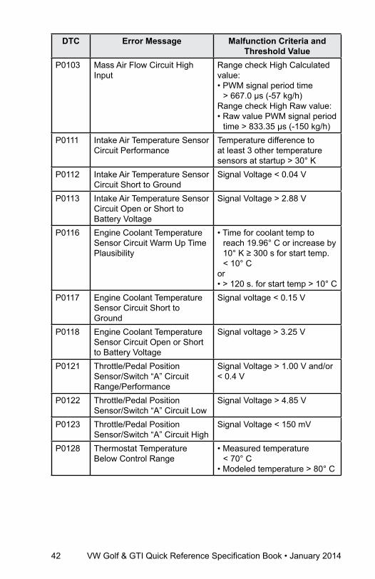
P0103 Mass Air Flow Circuit High Input
Range check High Calculated value: • PWM signal period time
> 667.0 µs (-57 kg/h)Range check High Raw value:• Raw value PWM signal period
time > 833.35 µs (-150 kg/h)P0111 Intake Air Temperature Sensor
Circuit PerformanceTemperature difference to at least 3 other temperature sensors at startup > 30° K
P0112 Intake Air Temperature Sensor Circuit Short to Ground
Signal Voltage < 0.04 V
P0113 Intake Air Temperature Sensor Circuit Open or Short to Battery Voltage
Signal Voltage > 2.88 V
P0116 Engine Coolant Temperature Sensor Circuit Warm Up Time Plausibility
• Time for coolant temp to reach 19.96° C or increase by 10° K ≥ 300 s for start temp. < 10° C
or• > 120 s. for start temp > 10° C
P0117 Engine Coolant Temperature Sensor Circuit Short to Ground
Signal voltage < 0.15 V
P0118 Engine Coolant Temperature Sensor Circuit Open or Short to Battery Voltage
Signal voltage > 3.25 V
P0121 Throttle/Pedal Position Sensor/Switch “A” Circuit Range/Performance
Signal Voltage > 1.00 V and/or < 0.4 V
P0122 Throttle/Pedal Position Sensor/Switch “A” Circuit Low
Signal Voltage > 4.85 V
P0123 Throttle/Pedal Position Sensor/Switch “A” Circuit High
Signal Voltage < 150 mV
P0128 Thermostat Temperature Below Control Range
• Measured temperature < 70° C
• Modeled temperature > 80° C

VW Golf & GTI Quick Reference Specification Book • January 2014 43
DTC
Cha
rt
DTC Error Message Malfunction Criteria and Threshold Value
P0130 O2 Sensor Circuit Bank 1 Sensor 1
• Virtual ground (VM) > 3 V• Nernst voltage (UN) > 4 V• Adjustment voltage (IP)
> 1.5 VShort to Ground • Virtual ground (VM) < 2
• Nernst voltage (UN) < 1.75 V• Adjustment voltage (IP)
< 0.3 VP0132 O2 Sensor Circuit High
Voltage Bank 1 Sensor 1Signal voltage > 3.2 V
P0133 O2 Sensor Circuit Slow Response Bank 1 Sensor 1
• Time to 30% of expected concentration increase > 2.6 s
or• Time to 60% minus time to
30% > 1.5 s or• Time to 60% of expected
concentration increase > 4.1 s.
P0135 O2 Sensor Heater Circuit Bank 1 Sensor 1
• HO2S ceramic temp. > 840° C
• HO2S ceramic temp. < 720° C
Short to Battery voltage • Signal current > 2.2 AShort to Ground • Signal voltage < 2.15 VOpen • Signal voltage > 4.4 V
P0136 O2 Sensor Circuit Bank 1 Sensor 2
• Virtual ground (VM) > 3 V• Nernst voltage (UN) > 4 V• Adjustment voltage (IP)
> 1.5 VShort to Ground • Virtual ground (VM) < 2 V
• Nernst voltage (UN) < 1.75 V• adjustment voltage (IP)
< 0.3 VDynamic Check virtual ground (VM)
• Virtual ground (VM) internal resistance > 1104 O
• Internal signal voltage < 1.4 V and/or > 1.6 V
Dynamic Check Nernst voltage (UN)
• Nernst voltage (UN) internal resistance > 1104O
• Internal signal voltage > 3 VDynamic Check pump current (IP)
• Pump current (IP) < 0.005 [-]
44 VW Golf & GTI Quick Reference Specification Book • January 2014
DTC Error Message Malfunction Criteria and Threshold Value
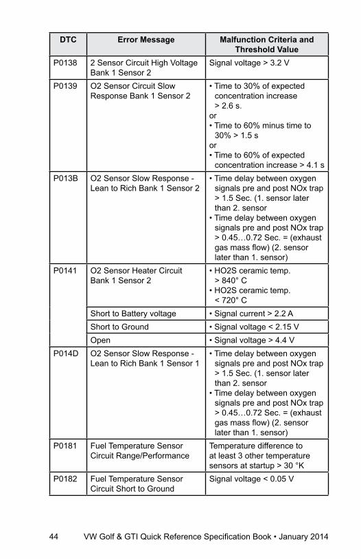
P0138 2 Sensor Circuit High Voltage Bank 1 Sensor 2
Signal voltage > 3.2 V
P0139 O2 Sensor Circuit Slow Response Bank 1 Sensor 2
• Time to 30% of expected concentration increase > 2.6 s.
or• Time to 60% minus time to
30% > 1.5 s or• Time to 60% of expected
concentration increase > 4.1 sP013B O2 Sensor Slow Response -
Lean to Rich Bank 1 Sensor 2• Time delay between oxygen
signals pre and post NOx trap > 1.5 Sec. (1. sensor later than 2. sensor
• Time delay between oxygen signals pre and post NOx trap > 0.45…0.72 Sec. = (exhaust gas mass flow) (2. sensor later than 1. sensor)
P0141 O2 Sensor Heater Circuit Bank 1 Sensor 2
• HO2S ceramic temp. > 840° C
• HO2S ceramic temp. < 720° C
Short to Battery voltage • Signal current > 2.2 AShort to Ground • Signal voltage < 2.15 VOpen • Signal voltage > 4.4 V
P014D O2 Sensor Slow Response - Lean to Rich Bank 1 Sensor 1
• Time delay between oxygen signals pre and post NOx trap > 1.5 Sec. (1. sensor later than 2. sensor
• Time delay between oxygen signals pre and post NOx trap > 0.45…0.72 Sec. = (exhaust gas mass flow) (2. sensor later than 1. sensor)
P0181 Fuel Temperature Sensor Circuit Range/Performance
Temperature difference to at least 3 other temperature sensors at startup > 30 °K
P0182 Fuel Temperature Sensor Circuit Short to Ground
Signal voltage < 0.05 V

VW Golf & GTI Quick Reference Specification Book • January 2014 45
DTC
Cha
rt
DTC Error Message Malfunction Criteria and Threshold Value
P0183 Fuel Temperature Sensor Circuit Open or Short to Battery Voltage
Signal voltage > 4.7 V
P0191 Fuel Pressure Sensor Circuit Offset Detection During Keep Alive Time
• Signal voltage < 0.409 V or > 0.620 V
Fuel Pressure Sensor Circuit Adaptation of Pressure Control Valve (PCV)
• Adaptation value out of limit > 130 % or < 83 %
P0192 Fuel Pressure Sensor CircuitShort to Ground
Signal voltage < 200 mV
P0193 Fuel Pressure Sensor Circuit Short to Battery Voltage
• Signal voltage > 4.8 V
P0201 Cylinder 1 Injector Circuit Open
Signal voltage > 60 V
P0202 Cylinder 2 Injector Circuit Open
Signal voltage > 60 V
P0203 Cylinder 3 Injector Circuit Open
Signal voltage > 60 V
P0204 Cylinder 4 Injector Circuit Open
Signal voltage > 60 V
P020A Cylinder 1 Injection Timing • Control error < limit from MAP (engine speed and desired torque) -8° CA to -4° CA
or• Control error < limit from MAP
(engine speed and desired torque) +8° CA to +4° CA
P020B Cylinder 2 Injection Timing • Control error < limit from MAP (engine speed and desired torque) -8° CA to -4° CA
or• Control error < limit from MAP
(engine speed and desired torque) +8° CA to +4° CA
P020C Cylinder 3 Injection Timing • Control error < limit from MAP (engine speed and desired torque) -8° CA to -4° CA
or• Control error < limit from MAP
(engine speed and desired torque) +8° CA to +4° CA

46 VW Golf & GTI Quick Reference Specification Book • January 2014
DTC Error Message Malfunction Criteria and Threshold Value
P020D Cylinder 4 Injection Timing • Control error < limit from MAP (engine speed and desired torque) -8° CA to -4° CA
or• Control error < limit from MAP
(engine speed and desired torque) +8° CA to +4° CA
P0234 Charge Air Boost Pressure Rationality Check Low
Absolute value of control deviation > -300 - -800 hPa
P0236 Charge Air Pressure Sensor Circuit Plausibility Check
Difference between barometric and boost pressure signal > 150 hPa
P0237 Charge Air Pressure Sensor Circuit Short to Ground
Signal voltage < 0.68 V
P0238 Charge Air Pressure Sensor Circuit Open or Short to Battery Voltage
Signal Voltage > 4.88 V
P0263 Cylinder 1 Zero Fuel Calibration (monitoring of fuel calibration values)
Calibration value of injector energizing time > 217 µs or < 117µs (at 1400 bar rail pressure).
P0266 Cylinder 2 Zero Fuel Calibration (monitoring of fuel calibration values)
Calibration value of injector energizing time > 217 µs or < 117µs (at 1400 bar rail pressure).
P0269 Cylinder 3 Zero Fuel Calibration (monitoring of fuel calibration values)
Calibration value of injector energizing time > 217 µs or < 117µs (at 1400 bar rail pressure).
P026A Charge Air Cooler Efficiency Below Threshold
Charge air intercooler efficiency < 0.4
P0272 Cylinder 4 Zero Fuel Calibration (monitoring of fuel calibration values)
Calibration value of injector energizing time > 217 µs or < 117µs (at 1400 bar rail pressure).
P0299 Charge Air Boost Pressure Rationality Check High
Absolute value of control deviation > 400 - 800 hPa
P1004 Torque Difference Cylinder 1 Limiting Value Exceeded
Control error < limit from MAP f (engine speed and desired torque) -50 to -30 Nm or +50 to +30 Nm

VW Golf & GTI Quick Reference Specification Book • January 2014 47
DTC
Cha
rt
DTC Error Message Malfunction Criteria and Threshold Value
P1005 Torque Difference Cylinder 2 Limiting Value Exceeded
Control error < limit from MAP f (engine speed and desired torque) -50 to -30 Nm or +50 to +30 Nm
P1006 Torque Difference Cylinder 3 Limiting Value Exceeded
Control error < limit from MAP f (engine speed and desired torque) -50 to -30 Nm or +50 to +30 Nm
P1007 Torque Difference Cylinder 4 Limiting Value Exceeded
Control error < limit from MAP f (engine speed and desired torque) -50 to -30 Nm or +50 to +30 Nm
P13CE Cylinder 1 Pressure Sensor Circuit Short to Battery Voltage
Signal voltage > 3.17 V
P13CF Cylinder 1 Pressure Sensor Circuit Short to Ground
Cylinder pressure sensor voltage < 0.13 V
P13D0 Cylinder 1 Pressure Sensor Circuit Out of Range
Signal voltage < 0.33 V and/or > 3.09 V
Cylinder 1 Constant Pressure Deviation between maximum and minimum cylinder pressure sensor 1 < 20 bar
Cylinder 1 Pressure Sensor Offset
Offset out of range < -7 or > 7 bar
Cylinder 1 Plausibility with Calculated Pressure
Difference between calculated cylinder pressure, based on intake air pressure and compression ratio, and measured cylinder pressure sensor #1 out of range < -10 bar and/or > 10 bar
P13D1 Cylinder 2 Pressure Sensor Circuit Open or Short to Battery Voltage
Signal voltage > 3.17 V
P13D2 Cylinder 2 Pressure Sensor Circuit Short to Ground
Signal voltage < 0.13 V
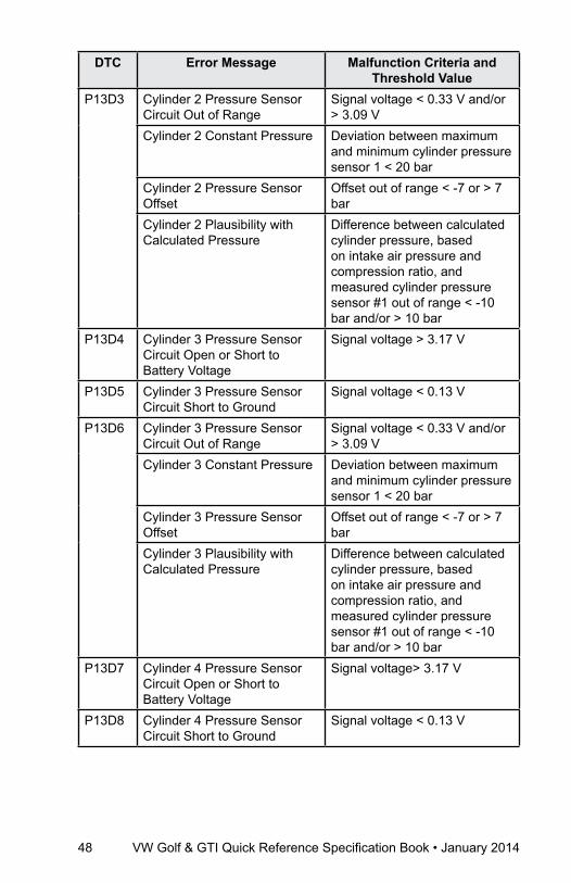
48 VW Golf & GTI Quick Reference Specification Book • January 2014
DTC Error Message Malfunction Criteria and Threshold Value
P13D3 Cylinder 2 Pressure Sensor Circuit Out of Range
Signal voltage < 0.33 V and/or > 3.09 V
Cylinder 2 Constant Pressure Deviation between maximum and minimum cylinder pressure sensor 1 < 20 bar
Cylinder 2 Pressure Sensor Offset
Offset out of range < -7 or > 7 bar
Cylinder 2 Plausibility with Calculated Pressure
Difference between calculated cylinder pressure, based on intake air pressure and compression ratio, and measured cylinder pressure sensor #1 out of range < -10 bar and/or > 10 bar
P13D4 Cylinder 3 Pressure Sensor Circuit Open or Short to Battery Voltage
Signal voltage > 3.17 V
P13D5 Cylinder 3 Pressure Sensor Circuit Short to Ground
Signal voltage < 0.13 V
P13D6 Cylinder 3 Pressure Sensor Circuit Out of Range
Signal voltage < 0.33 V and/or > 3.09 V
Cylinder 3 Constant Pressure Deviation between maximum and minimum cylinder pressure sensor 1 < 20 bar
Cylinder 3 Pressure Sensor Offset
Offset out of range < -7 or > 7 bar
Cylinder 3 Plausibility with Calculated Pressure
Difference between calculated cylinder pressure, based on intake air pressure and compression ratio, and measured cylinder pressure sensor #1 out of range < -10 bar and/or > 10 bar
P13D7 Cylinder 4 Pressure Sensor Circuit Open or Short to Battery Voltage
Signal voltage> 3.17 V
P13D8 Cylinder 4 Pressure Sensor Circuit Short to Ground
Signal voltage < 0.13 V
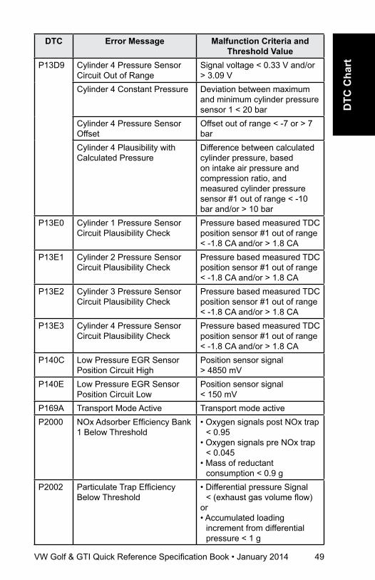
VW Golf & GTI Quick Reference Specification Book • January 2014 49
DTC
Cha
rt
DTC Error Message Malfunction Criteria and Threshold Value
P13D9 Cylinder 4 Pressure Sensor Circuit Out of Range
Signal voltage < 0.33 V and/or > 3.09 V
Cylinder 4 Constant Pressure Deviation between maximum and minimum cylinder pressure sensor 1 < 20 bar
Cylinder 4 Pressure Sensor Offset
Offset out of range < -7 or > 7 bar
Cylinder 4 Plausibility with Calculated Pressure
Difference between calculated cylinder pressure, based on intake air pressure and compression ratio, and measured cylinder pressure sensor #1 out of range < -10 bar and/or > 10 bar
P13E0 Cylinder 1 Pressure Sensor Circuit Plausibility Check
Pressure based measured TDC position sensor #1 out of range < -1.8 CA and/or > 1.8 CA
P13E1 Cylinder 2 Pressure Sensor Circuit Plausibility Check
Pressure based measured TDC position sensor #1 out of range < -1.8 CA and/or > 1.8 CA
P13E2 Cylinder 3 Pressure Sensor Circuit Plausibility Check
Pressure based measured TDC position sensor #1 out of range < -1.8 CA and/or > 1.8 CA
P13E3 Cylinder 4 Pressure Sensor Circuit Plausibility Check
Pressure based measured TDC position sensor #1 out of range < -1.8 CA and/or > 1.8 CA
P140C Low Pressure EGR Sensor Position Circuit High
Position sensor signal > 4850 mV
P140E Low Pressure EGR Sensor Position Circuit Low
Position sensor signal < 150 mV
P169A Transport Mode Active Transport mode activeP2000 NOx Adsorber Efficiency Bank
1 Below Threshold• Oxygen signals post NOx trap
< 0.95• Oxygen signals pre NOx trap
< 0.045• Mass of reductant
consumption < 0.9 gP2002 Particulate Trap Efficiency
Below Threshold• Differential pressure Signal
< (exhaust gas volume flow)or• Accumulated loading
increment from differential pressure < 1 g

50 VW Golf & GTI Quick Reference Specification Book • January 2014
DTC Error Message Malfunction Criteria and Threshold Value
P2002* Particulate Trap Efficiency Below Threshold
• Differential pressure signal < f (exhaust gas volume flow)
or• Ratio of filtered temperature
dynamic upstream and downstream of the PM trap < 1.2 [-]
P2004 Intake Manifold Runner Flap Stuck Open
Intake Manifold Runner Stuck (open) > 12%
P2006 Intake Manifold Runner FlapStuck Closed
Intake Manifold Runner Stuck (closed) < 12%
P2008 Intake Manifold Runner Motor Circuit Open
Signal voltage > 0.8 or < 2.0 V
P2009 Intake Manifold Runner Motor Circuit Short to Ground
Signal current > 8 - 18 A
P2010 Intake Manifold Runner Motor Circuit Short to Battery Voltage
Signal current > 8 - 18 A
P2015 Intake Manifold Runner Position Sensor Circuit Physical Signal Range Check High
Signal Voltage > 4.61 V
Intake Manifold Runner Position Sensor Circuit Physical Signal Range Check Low
Signal Voltage < 0.39 V
P2016 Intake Manifold Runner Position Sensor Circuit Short to Ground
Signal Voltage < 0.25 V
P2017 Intake Manifold Runner Position Sensor Circuit Short to Battery Voltage
Signal Voltage > 4.75 V
P2031 Exhaust Gas Temperature Sensor 3 Circuit Open or Short to Battery Voltage
Signal voltage > 1.72 V
P2032 Exhaust Gas Temperature Sensor 3 Circuit Short to Ground
Signal voltage < 0.45 V
P2080 Exhaust Gas Temperature Sensor 1 Circuit Plausibility Check
Sensor temperature < 85° C
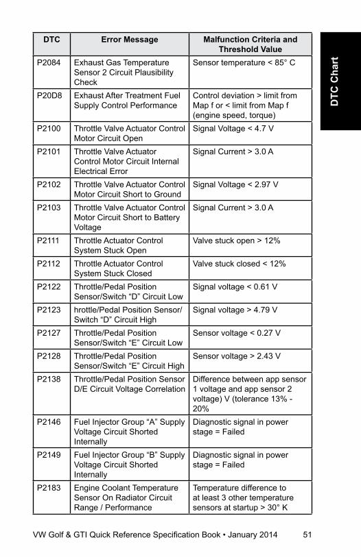
VW Golf & GTI Quick Reference Specification Book • January 2014 51
DTC
Cha
rt
DTC Error Message Malfunction Criteria and Threshold Value
P2084 Exhaust Gas Temperature Sensor 2 Circuit Plausibility Check
Sensor temperature < 85° C
P20D8 Exhaust After Treatment Fuel Supply Control Performance
Control deviation > limit from Map f or < limit from Map f (engine speed, torque)
P2100 Throttle Valve Actuator Control Motor Circuit Open
Signal Voltage < 4.7 V
P2101 Throttle Valve Actuator Control Motor Circuit Internal Electrical Error
Signal Current > 3.0 A
P2102 Throttle Valve Actuator Control Motor Circuit Short to Ground
Signal Voltage < 2.97 V
P2103 Throttle Valve Actuator Control Motor Circuit Short to Battery Voltage
Signal Current > 3.0 A
P2111 Throttle Actuator Control System Stuck Open
Valve stuck open > 12%
P2112 Throttle Actuator Control System Stuck Closed
Valve stuck closed < 12%
P2122 Throttle/Pedal Position Sensor/Switch “D” Circuit Low
Signal voltage < 0.61 V
P2123 hrottle/Pedal Position Sensor/Switch “D” Circuit High
Signal voltage > 4.79 V
P2127 Throttle/Pedal Position Sensor/Switch “E” Circuit Low
Sensor voltage < 0.27 V
P2128 Throttle/Pedal Position Sensor/Switch “E” Circuit High
Sensor voltage > 2.43 V
P2138 Throttle/Pedal Position Sensor D/E Circuit Voltage Correlation
Difference between app sensor 1 voltage and app sensor 2 voltage) V (tolerance 13% - 20%
P2146 Fuel Injector Group “A” Supply Voltage Circuit Shorted Internally
Diagnostic signal in power stage = Failed
P2149 Fuel Injector Group “B” Supply Voltage Circuit Shorted Internally
Diagnostic signal in power stage = Failed
P2183 Engine Coolant Temperature Sensor On Radiator Circuit Range / Performance
Temperature difference to at least 3 other temperature sensors at startup > 30° K
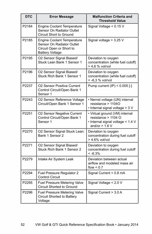
52 VW Golf & GTI Quick Reference Specification Book • January 2014
DTC Error Message Malfunction Criteria and Threshold Value
P2184 Engine Coolant Temperature Sensor On Radiator Outlet Circuit Short to Ground
Signal Voltage < 0.15 V
P2185 Engine Coolant Temperature Sensor On Radiator Outlet Circuit Open or Short to Battery Voltage
Signal voltage > 3.25 V
P2195 O2 Sensor Signal Biased/Stuck Lean Bank 1 Sensor 1
Deviation to oxygen concentration (while fuel cutoff) > 4,6 % vol/vol
P2196 O2 Sensor Signal Biased/Stuck Rich Bank 1 Sensor 1
Deviation to oxygen concentration (while fuel cutoff) < -6,3 % vol/vol
P2237 O2 Sensor Positive Current Control Circuit/Open Bank 1 Sensor 1
Pump current (IP) < 0.005 [-]
P2243 O2 Sensor Reference Voltage Circuit/Open Bank 1 Sensor 1
• Nernst voltage (UN) internal resistance > 1104O
• Internal signal voltage > 3 VP2251 O2 Sensor Negative Current
Control Circuit/Open Bank 1 Sensor 1
• Virtual ground (VM) internal resistance > 1104 O
• Internal signal voltage < 1.4 V and/or > 1.6 V
P2270 O2 Sensor Signal Stuck Lean; Bank 1 Sensor 2
Deviation to oxygen concentration during fuel cutoff > 4.6% vol/vol
P2271 O2 Sensor Signal Biased/Stuck Rich Bank 1 Sensor 2
Deviation to oxygen concentration during fuel cutoff < -6.3%
P2279 Intake Air System Leak Deviation between actual airflow and modeled mass air flow < 0.7
P2294 Fuel Pressure Regulator 2 Control Circuit
Signal Current < 0.8 mA
P2295 Fuel Pressure Metering Valve Circuit Shorted to Ground
Signal Voltage < 2.0 V
P2296 Fuel Pressure Metering Valve Circuit Shorted to Battery Voltage
Signal Current > 3.0 A
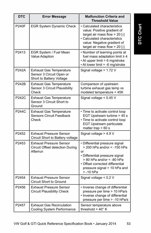
VW Golf & GTI Quick Reference Specification Book • January 2014 53
DTC
Cha
rt
DTC Error Message Malfunction Criteria and Threshold Value
P240F EGR System Dynamic Check • Calculated characteristics value: Positive gradient of target air mass flow > 20 [-]
• Calculated characteristics value: Negative gradient of target air mass flow > 20 [-]
P2413 EGR System / Fuel Mean Value Adaption
• Number of learning points at fuel mass adaptation limit ≥ 4
• At upper limit = 6 mg/stroke• At lower limit = -6 mg/stroke
P242A Exhaust Gas Temperature Sensor 3 Circuit Open or Short to Battery Voltage
Signal voltage > 1.72 V
P242B Exhaust Gas Temperature Sensor 3 Circuit Plausibility Check
Comparison of upstream turbine exhaust gas temp vs modeled temperature < 45K
P242C Exhaust Gas Temperature Sensor 3 Circuit Short to Ground
Signal voltage < 0.45 V
P244C Exhaust Gas Temperature Sensors Circuit Feedback Check
• Time to activate control loop EGT Upstream turbine > 45 s
• Time to activate control loop EGT Upstream particulate matter trap > 60 s
P2452 Exhaust Pressure Sensor Circuit Short to Battery voltage
Signal voltage > 4.9 V
P2453 Exhaust Pressure Sensor Circuit Offset detection During Afterrun
• Differential pressure signal > 200 hPa and/or < -150 hPa
or• Differential pressure signal
> 80 hPa and/or < -80 hPa• Offset corrected differential
pressure signal > 10 hPa and < -10 hPa
P2454 Exhaust Pressure Sensor Circuit Short to Ground
Signal voltage < 0.2 V
P2456 Exhaust Pressure Sensor Circuit Plausibility Check
• Inverse change of differential pressure per time > 10 hPa/s
• Inverse change of differential pressure per time > -10 hPa/s
P2457 Exhaust Gas Recirculation Cooling System Performance
Sensor temperature above threshold = 40° K

54 VW Golf & GTI Quick Reference Specification Book • January 2014
DTC Error Message Malfunction Criteria and Threshold Value
P2458 Diesel Particulate Filter Regeneration Duration
Regeneration time > 90 mins.
P2459 Diesel Particulate Filter Regeneration Frequency
PM trap loading > dynamically rising threshold f (simulated engine emissions)
P2463 Diesel Particulate Filter Soot Accumulation
Calculated particulate matter trap loading > 40 g
P246E Exhaust Gas Temperature Sensor 4 Circuit Open or Short to Battery Voltage
Signal voltage > 1.72 V
P246F Exhaust Gas Temperature Sensor 4 Circuit Plausibility Check
• Sensor temperature < 230° Cor• Temperature difference to
other temp sensors during cold start < 45° K
P2470 Exhaust Gas Temperature Sensor 4 Circuit Short to Ground
Signal voltage < 0.45 V
P2478 Exhaust Gas Temperature Sensor 1 Circuit Out of Range
Control deviation > 40 K
P247A Exhaust Gas Temperature Sensor 3 Circuit Out of Range
• Control deviation > limit from Map
or• < limit from Map f (engine
speed, torqueP2563 Charge Pressure Actuator
Position Sensor Circuit Range / Performance
Signal voltage > 4.5 V and/or < 0.3 V
Charge Pressure Actuator Position Sensor Circuit Desired Range (Closed)
Signal voltage > 1.72 V and/or < 0.3 V
P2564 Charge Pressure Actuator Position Sensor Circuit Short to Ground
Signal voltage < 0.15 V
P2565 Charge Pressure Actuator Position Sensor Circuit Open or Short to Battery Voltage
Signal voltage > 4.85 V
P2610 ECM/PCM Internal Engine Off Timer Performance
Quantity count over time threshold < 7.52 or > 8.48 Sec
P2632 Auxiliary In-line Fuel Pump Circuit Open
Signal current < 0.8 mA

VW Golf & GTI Quick Reference Specification Book • January 2014 55
DTC
Cha
rt
DTC Error Message Malfunction Criteria and Threshold Value
P2633 Auxiliary In-line Fuel Pump Circuit Short to Ground
Signal voltage < 2.0 V
P2634 Auxiliary In-line Fuel Pump Circuit Short to Battery Voltage
Signal current > 1.0 A
P268A Fuel Injectors Calibration Not Learned / Programmed
Accumulated global release time of zero fuel calibration but disabled by rail pressure deviation > 35 s
Ignition SystemDTC Error Message Malfunction Criteria and
Threshold ValueP0300 Misfire Detected Multiple
Cylinder • Rise in engine speed after
fuel injection: Calculated based on values from last two engine revolutions
• Error threshold: 180 counts over 440 crankshaft revolutions
P0301 Cylinder 1 Misfire Detected • Misfire rate within 1000 engine revolutions > 10%
• Misfire event detection if actual inner torque < 2.5 Nm
P0302 Cylinder 2 Misfire Detected • Misfire rate within 1000 engine revolutions > 10%
• Misfire event detection if actual inner torque < 2.5 Nm
P0303 Cylinder 3 Misfire Detected • Misfire rate within 1000 engine revolutions > 10%
• Misfire event detection if actual inner torque < 2.5 Nm
P0304 Cylinder 4 Misfire Detected • Misfire rate within 1000 engine revolutions > 10%
• Misfire event detection if actual inner torque < 2.5 Nm
P0321 Engine Speed Input Circuit Rationality Check
• Consecutive not plausible signals > 15
• Cam phase signals without plausible signal > 4 cam rotations.
• Monitoring reference gap = failure
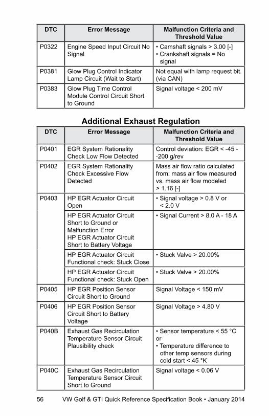
56 VW Golf & GTI Quick Reference Specification Book • January 2014
DTC Error Message Malfunction Criteria and Threshold Value
P0322 Engine Speed Input Circuit No Signal
• Camshaft signals > 3.00 [-]• Crankshaft signals = No
signal P0381 Glow Plug Control Indicator
Lamp Circuit (Wait to Start)Not equal with lamp request bit. (via CAN)
P0383 Glow Plug Time Control Module Control Circuit Short to Ground
Signal voltage < 200 mV
additional Exhaust regulationDTC Error Message Malfunction Criteria and
Threshold ValueP0401 EGR System Rationality
Check Low Flow DetectedControl deviation: EGR < -45 - -200 g/rev
P0402 EGR System Rationality Check Excessive Flow Detected
Mass air flow ratio calculated from: mass air flow measured vs. mass air flow modeled > 1.16 [-]
P0403 HP EGR Actuator Circuit Open
• Signal voltage > 0.8 V or < 2.0 V
HP EGR Actuator Circuit Short to Ground or Malfunction ErrorHP EGR Actuator Circuit Short to Battery Voltage
• Signal Current > 8.0 A - 18 A
HP EGR Actuator Circuit Functional check: Stuck Close
• Stuck Valve > 20.00%
HP EGR Actuator Circuit Functional check: Stuck Open
• Stuck Valve > 20.00%
P0405 HP EGR Position Sensor Circuit Short to Ground
Signal Voltage < 150 mV
P0406 HP EGR Position Sensor Circuit Short to Battery Voltage
Signal Voltage > 4.80 V
P040B Exhaust Gas Recirculation Temperature Sensor Circuit Plausibility check
• Sensor temperature < 55 °Cor• Temperature difference to
other temp sensors during cold start < 45 °K
P040C Exhaust Gas Recirculation Temperature Sensor Circuit Short to Ground
Signal voltage < 0.06 V
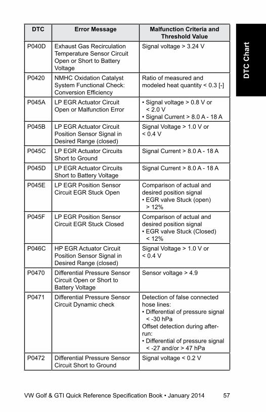
VW Golf & GTI Quick Reference Specification Book • January 2014 57
DTC
Cha
rt
DTC Error Message Malfunction Criteria and Threshold Value
P040D Exhaust Gas Recirculation Temperature Sensor Circuit Open or Short to Battery Voltage
Signal voltage > 3.24 V
P0420 NMHC Oxidation Catalyst System Functional Check: Conversion Efficiency
Ratio of measured and modeled heat quantity < 0.3 [-]
P045A LP EGR Actuator Circuit Open or Malfunction Error
• Signal voltage > 0.8 V or < 2.0 V
• Signal Current > 8.0 A - 18 AP045B LP EGR Actuator Circuit
Position Sensor Signal in Desired Range (closed)
Signal Voltage > 1.0 V or < 0.4 V
P045C LP EGR Actuator CircuitsShort to Ground
Signal Current > 8.0 A - 18 A
P045D LP EGR Actuator CircuitsShort to Battery Voltage
Signal Current > 8.0 A - 18 A
P045E LP EGR Position Sensor Circuit EGR Stuck Open
Comparison of actual and desired position signal• EGR valve Stuck (open)
> 12% P045F LP EGR Position Sensor
Circuit EGR Stuck ClosedComparison of actual and desired position signal• EGR valve Stuck (Closed)
< 12% P046C HP EGR Actuator Circuit
Position Sensor Signal in Desired Range (closed)
Signal Voltage > 1.0 V or < 0.4 V
P0470 Differential Pressure Sensor Circuit Open or Short to Battery Voltage
Sensor voltage > 4.9
P0471 Differential Pressure Sensor Circuit Dynamic check
Detection of false connected hose lines:• Differential of pressure signal
< -30 hPaOffset detection during after-run:• Differential of pressure signal
< -27 and/or > 47 hPaP0472 Differential Pressure Sensor
Circuit Short to GroundSignal voltage < 0.2 V
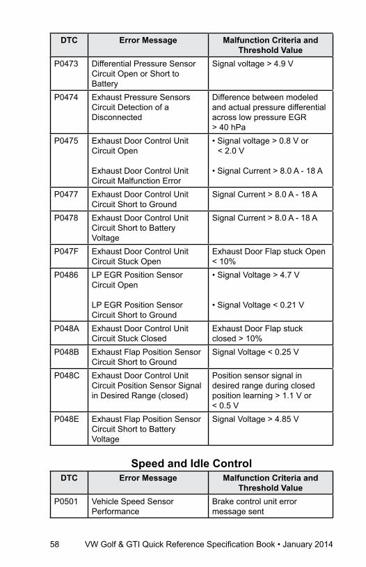
58 VW Golf & GTI Quick Reference Specification Book • January 2014
DTC Error Message Malfunction Criteria and Threshold Value
P0473 Differential Pressure Sensor Circuit Open or Short to Battery
Signal voltage > 4.9 V
P0474 Exhaust Pressure Sensors Circuit Detection of a Disconnected
Difference between modeled and actual pressure differential across low pressure EGR > 40 hPa
P0475 Exhaust Door Control Unit Circuit Open
Exhaust Door Control Unit Circuit Malfunction Error
• Signal voltage > 0.8 V or < 2.0 V
• Signal Current > 8.0 A - 18 A
P0477 Exhaust Door Control Unit Circuit Short to Ground
Signal Current > 8.0 A - 18 A
P0478 Exhaust Door Control Unit Circuit Short to Battery Voltage
Signal Current > 8.0 A - 18 A
P047F Exhaust Door Control Unit Circuit Stuck Open
Exhaust Door Flap stuck Open < 10%
P0486 LP EGR Position Sensor Circuit Open
LP EGR Position Sensor Circuit Short to Ground
• Signal Voltage > 4.7 V
• Signal Voltage < 0.21 V
P048A Exhaust Door Control Unit Circuit Stuck Closed
Exhaust Door Flap stuck closed > 10%
P048B Exhaust Flap Position Sensor Circuit Short to Ground
Signal Voltage < 0.25 V
P048C Exhaust Door Control Unit Circuit Position Sensor Signal in Desired Range (closed)
Position sensor signal in desired range during closed position learning > 1.1 V or < 0.5 V
P048E Exhaust Flap Position Sensor Circuit Short to Battery Voltage
Signal Voltage > 4.85 V
Speed and Idle ControlDTC Error Message Malfunction Criteria and
Threshold ValueP0501 Vehicle Speed Sensor
PerformanceBrake control unit error message sent

VW Golf & GTI Quick Reference Specification Book • January 2014 59
DTC
Cha
rt
DTC Error Message Malfunction Criteria and Threshold Value
P0502 Vehicle Speed Sensor Circuit Low Input
Brake control unit error message sent
P0503 Vehicle Speed Sensor Intermittent High Signal
Vehicle speed > 320 km/h
P0506 Idle Control System RPM Lower than Expected
Control deviation < 10%
P0507 Idle Control System RPM Higher than Expected
Control deviation > 10%
P050E Cold Start Engine Exhaust Temperature Too Low
• Sensor temperature < 170° C• Control deviation > limit from
map (engine speed, torque)P0534 Vehicle Speed Sensor “A”
Intermittent/Erratic/High -
P0544 Exhaust Gas Temperature Sensor Circuit (Upstream Turbocharger) Open or Short to Battery Voltage
Signal voltage > 1.72 V
P0545 Exhaust Gas Temperature Sensor Circuit (Upstream Turbocharger) Short to Ground
Signal voltage < 0.45 V
P054E Idle Control System Fuel Quantity Higher Than Expected
Fuel quantity < 0.004 g/rev
P054F Idle Control System Fuel Quantity Lower Than Expected
Fuel quantity > 0.0182 - 0.0325 g/rev
P0562 System Voltage Low Voltage Internal check failure of voltage supply for ECM off timer
P2563 Charge Pressure Actuator Position Sensor Circuit Range / Performance
Signal voltage > 4.5 V and/or < 0.3 V
Charge Pressure Actuator Position Sensor Circuit Desired Range (Closed)
Signal voltage > 1.72 V and/or < 0.3 V
P2564 Charge Pressure Actuator Position Sensor Circuit Short to Ground
Signal voltage < 0.15 V
P2565 Charge Pressure Actuator Position Sensor Circuit Open or Short to Battery Voltage
Signal voltage > 4.85 V
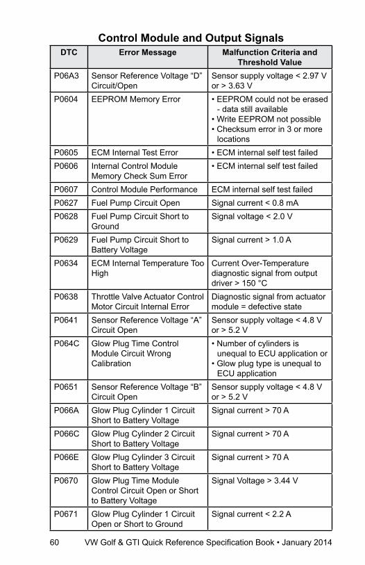
60 VW Golf & GTI Quick Reference Specification Book • January 2014
Control Module and Output SignalsDTC Error Message Malfunction Criteria and
Threshold ValueP06A3 Sensor Reference Voltage “D”
Circuit/OpenSensor supply voltage < 2.97 V or > 3.63 V
P0604 EEPROM Memory Error • EEPROM could not be erased - data still available
• Write EEPROM not possible• Checksum error in 3 or more
locationsP0605 ECM Internal Test Error • ECM internal self test failed P0606 Internal Control Module
Memory Check Sum Error • ECM internal self test failed
P0607 Control Module Performance ECM internal self test failedP0627 Fuel Pump Circuit Open Signal current < 0.8 mAP0628 Fuel Pump Circuit Short to
GroundSignal voltage < 2.0 V
P0629 Fuel Pump Circuit Short to Battery Voltage
Signal current > 1.0 A
P0634 ECM Internal Temperature Too High
Current Over-Temperature diagnostic signal from output driver > 150 °C
P0638 Throttle Valve Actuator Control Motor Circuit Internal Error
Diagnostic signal from actuator module = defective state
P0641 Sensor Reference Voltage “A” Circuit Open
Sensor supply voltage < 4.8 V or > 5.2 V
P064C Glow Plug Time Control Module Circuit Wrong Calibration
• Number of cylinders is unequal to ECU application or
• Glow plug type is unequal to ECU application
P0651 Sensor Reference Voltage “B” Circuit Open
Sensor supply voltage < 4.8 V or > 5.2 V
P066A Glow Plug Cylinder 1 Circuit Short to Battery Voltage
Signal current > 70 A
P066C Glow Plug Cylinder 2 Circuit Short to Battery Voltage
Signal current > 70 A
P066E Glow Plug Cylinder 3 Circuit Short to Battery Voltage
Signal current > 70 A
P0670 Glow Plug Time Module Control Circuit Open or Short to Battery Voltage
Signal Voltage > 3.44 V
P0671 Glow Plug Cylinder 1 Circuit Open or Short to Ground
Signal current < 2.2 A

VW Golf & GTI Quick Reference Specification Book • January 2014 61
DTC
Cha
rt
DTC Error Message Malfunction Criteria and Threshold Value
P0672 Glow Plug Cylinder 2 Circuit Open or Short to Ground
Signal current < 2.2 A
P0673 Glow Plug Cylinder 3 Circuit Open or Short to Ground
Signal current < 2.2 A
P0674 Glow Plug Cylinder 4 Circuit Open or Short to Ground
Signal current < 2.2 A
P067A Glow Plug Cylinder 4 Circuit Short to Battery Voltage
Signal current > 70 A
P0684 low Plug Time Control Module Circuit No PCM Communication
• Missing communication from the Glow Control Unit
• Automatic Glow Time Control Module = Error Message
P068A ECM Power Relay Performance - Open to Early
Internal test
P068B ECM Power Relay Performance - Stuck
Internal test
P0697 Sensor Reference Voltage “C” Circuit Open
Sensor supply voltage < 3.168 V or > 3.432 V
P06B9 Glow Plug Cylinder 1 Resistance Check
Glow plug resistance time interval after glow start:• 4 - 9 s (< 0,3 O),• 9 - 14 s (< 0.4 O) • after 14 s (< 0.5 O) • anytime ( > 1.2 O)
P06BA Glow Plug Cylinder 2 Resistance Check
Glow plug resistance time interval after glow start:• 4 - 9 s (< 0,3 O),• 9 - 14 s (< 0.4 O) • after 14 s (< 0.5 O) • anytime ( > 1.2 O)
P06BB Glow Plug Cylinder 3Resistance Check
Glow plug resistance time interval after glow start:• 4 - 9 s (< 0,3 O),• 9 - 14 s (< 0.4 O) • after 14 s (< 0.5 O) • anytime ( > 1.2 O)
P06BC Glow Plug Cylinder 4 Resistance Check
Glow plug resistance time interval after glow start:• 4 - 9 s (< 0,3 O),• 9 - 14 s (< 0.4 O) • after 14 s (< 0.5 O) • anytime ( > 1.2 O)
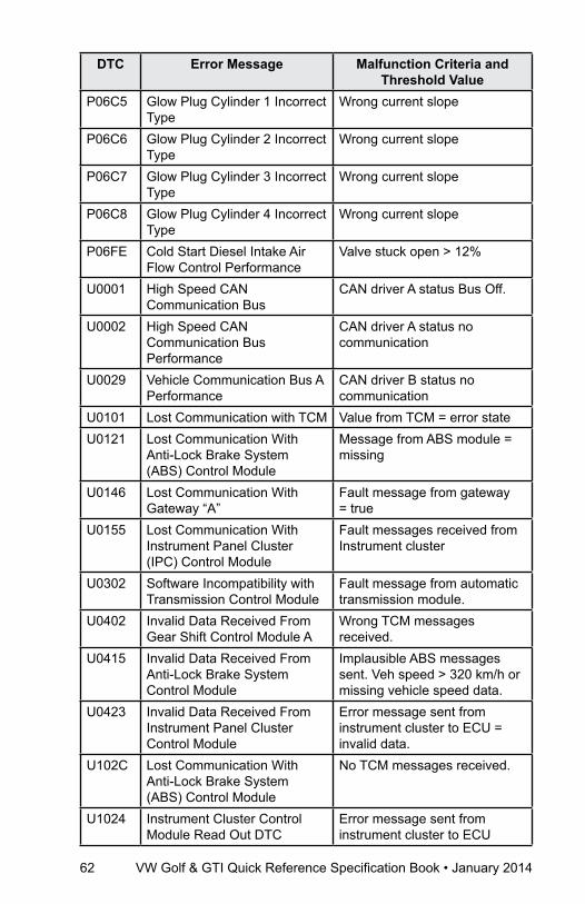
62 VW Golf & GTI Quick Reference Specification Book • January 2014
DTC Error Message Malfunction Criteria and Threshold Value
P06C5 Glow Plug Cylinder 1 Incorrect Type
Wrong current slope
P06C6 Glow Plug Cylinder 2 Incorrect Type
Wrong current slope
P06C7 Glow Plug Cylinder 3 Incorrect Type
Wrong current slope
P06C8 Glow Plug Cylinder 4 Incorrect Type
Wrong current slope
P06FE Cold Start Diesel Intake Air Flow Control Performance
Valve stuck open > 12%
U0001 High Speed CAN Communication Bus
CAN driver A status Bus Off.
U0002 High Speed CAN Communication Bus Performance
CAN driver A status no communication
U0029 Vehicle Communication Bus A Performance
CAN driver B status no communication
U0101 Lost Communication with TCM Value from TCM = error stateU0121 Lost Communication With
Anti-Lock Brake System (ABS) Control Module
Message from ABS module = missing
U0146 Lost Communication With Gateway “A”
Fault message from gateway = true
U0155 Lost Communication With Instrument Panel Cluster (IPC) Control Module
Fault messages received from Instrument cluster
U0302 Software Incompatibility with Transmission Control Module
Fault message from automatic transmission module.
U0402 Invalid Data Received From Gear Shift Control Module A
Wrong TCM messages received.
U0415 Invalid Data Received From Anti-Lock Brake System Control Module
Implausible ABS messages sent. Veh speed > 320 km/h or missing vehicle speed data.
U0423 Invalid Data Received From Instrument Panel Cluster Control Module
Error message sent from instrument cluster to ECU = invalid data.
U102C Lost Communication With Anti-Lock Brake System (ABS) Control Module
No TCM messages received.
U1024 Instrument Cluster Control Module Read Out DTC
Error message sent from instrument cluster to ECU
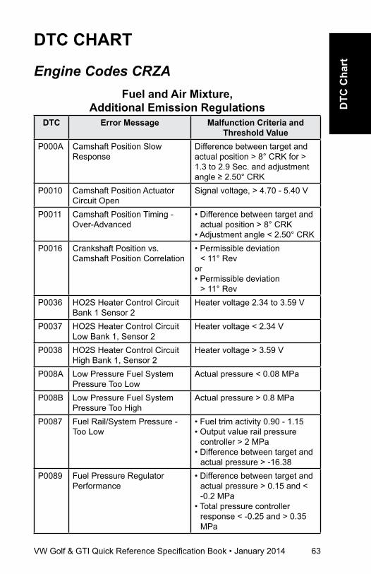
VW Golf & GTI Quick Reference Specification Book • January 2014 63
DTC
Cha
rt
DTC CharT
Engine Codes CRZAFuel and air Mixture,
additional Emission regulationsDTC Error Message Malfunction Criteria and
Threshold ValueP000A Camshaft Position Slow
Response Difference between target and actual position > 8° CRK for > 1.3 to 2.9 Sec. and adjustment angle ≥ 2.50° CRK
P0010 Camshaft Position Actuator Circuit Open
Signal voltage, > 4.70 - 5.40 V
P0011 Camshaft Position Timing - Over-Advanced
• Difference between target and actual position > 8° CRK
• Adjustment angle < 2.50° CRKP0016 Crankshaft Position vs.
Camshaft Position Correlation• Permissible deviation
< 11° Rev or• Permissible deviation
> 11° RevP0036 HO2S Heater Control Circuit
Bank 1 Sensor 2Heater voltage 2.34 to 3.59 V
P0037 HO2S Heater Control Circuit Low Bank 1, Sensor 2
Heater voltage < 2.34 V
P0038 HO2S Heater Control Circuit High Bank 1, Sensor 2
Heater voltage > 3.59 V
P008A Low Pressure Fuel System Pressure Too Low
Actual pressure < 0.08 MPa
P008B Low Pressure Fuel System Pressure Too High
Actual pressure > 0.8 MPa
P0087 Fuel Rail/System Pressure - Too Low
• Fuel trim activity 0.90 - 1.15• Output value rail pressure
controller > 2 MPa• Difference between target and
actual pressure > -16.38P0089 Fuel Pressure Regulator
Performance• Difference between target and
actual pressure > 0.15 and < -0.2 MPa
• Total pressure controller response < -0.25 and > 0.35 MPa
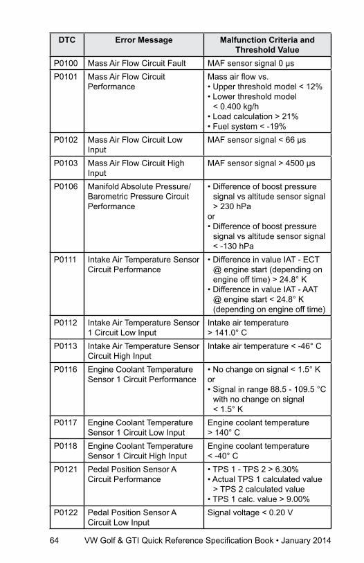
64 VW Golf & GTI Quick Reference Specification Book • January 2014
DTC Error Message Malfunction Criteria and Threshold Value
P0100 Mass Air Flow Circuit Fault MAF sensor signal 0 µsP0101 Mass Air Flow Circuit
PerformanceMass air flow vs.• Upper threshold model < 12%• Lower threshold model
< 0.400 kg/h• Load calculation > 21%• Fuel system < -19%
P0102 Mass Air Flow Circuit Low Input
MAF sensor signal < 66 µs
P0103 Mass Air Flow Circuit High Input
MAF sensor signal > 4500 µs
P0106 Manifold Absolute Pressure/Barometric Pressure Circuit Performance
• Difference of boost pressure signal vs altitude sensor signal > 230 hPa
or• Difference of boost pressure
signal vs altitude sensor signal < -130 hPa
P0111 Intake Air Temperature Sensor Circuit Performance
• Difference in value IAT - ECT @ engine start (depending on engine off time) > 24.8° K
• Difference in value IAT - AAT @ engine start < 24.8° K (depending on engine off time)
P0112 Intake Air Temperature Sensor 1 Circuit Low Input
Intake air temperature > 141.0° C
P0113 Intake Air Temperature Sensor Circuit High Input
Intake air temperature < -46° C
P0116 Engine Coolant Temperature Sensor 1 Circuit Performance
• No change on signal < 1.5° Kor • Signal in range 88.5 - 109.5 °C
with no change on signal < 1.5° K
P0117 Engine Coolant Temperature Sensor 1 Circuit Low Input
Engine coolant temperature > 140° C
P0118 Engine Coolant Temperature Sensor 1 Circuit High Input
Engine coolant temperature < -40° C
P0121 Pedal Position Sensor A Circuit Performance
• TPS 1 - TPS 2 > 6.30% • Actual TPS 1 calculated value
> TPS 2 calculated value• TPS 1 calc. value > 9.00%
P0122 Pedal Position Sensor A Circuit Low Input
Signal voltage < 0.20 V
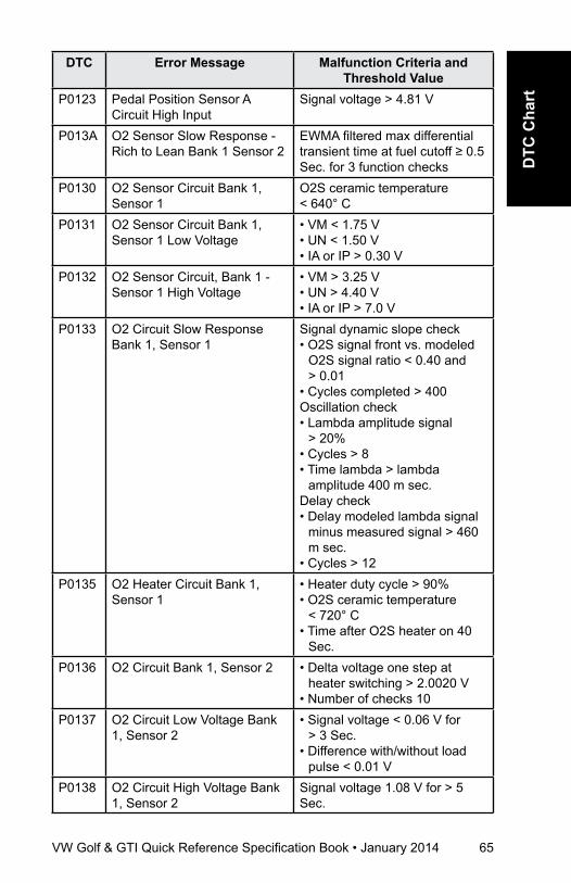
VW Golf & GTI Quick Reference Specification Book • January 2014 65
DTC
Cha
rt
DTC Error Message Malfunction Criteria and Threshold Value
P0123 Pedal Position Sensor A Circuit High Input
Signal voltage > 4.81 V
P013A O2 Sensor Slow Response - Rich to Lean Bank 1 Sensor 2
EWMA filtered max differential transient time at fuel cutoff ≥ 0.5 Sec. for 3 function checks
P0130 O2 Sensor Circuit Bank 1, Sensor 1
O2S ceramic temperature < 640° C
P0131 O2 Sensor Circuit Bank 1, Sensor 1 Low Voltage
• VM < 1.75 V• UN < 1.50 V• IA or IP > 0.30 V
P0132 O2 Sensor Circuit, Bank 1 - Sensor 1 High Voltage
• VM > 3.25 V• UN > 4.40 V• IA or IP > 7.0 V
P0133 O2 Circuit Slow Response Bank 1, Sensor 1
Signal dynamic slope check • O2S signal front vs. modeled
O2S signal ratio < 0.40 and > 0.01
• Cycles completed > 400Oscillation check• Lambda amplitude signal
> 20%• Cycles > 8• Time lambda > lambda
amplitude 400 m sec.Delay check• Delay modeled lambda signal
minus measured signal > 460 m sec.
• Cycles > 12P0135 O2 Heater Circuit Bank 1,
Sensor 1• Heater duty cycle > 90%• O2S ceramic temperature
< 720° C• Time after O2S heater on 40
Sec.P0136 O2 Circuit Bank 1, Sensor 2 • Delta voltage one step at
heater switching > 2.0020 V• Number of checks 10
P0137 O2 Circuit Low Voltage Bank 1, Sensor 2
• Signal voltage < 0.06 V for > 3 Sec.
• Difference with/without load pulse < 0.01 V
P0138 O2 Circuit High Voltage Bank 1, Sensor 2
Signal voltage 1.08 V for > 5 Sec.
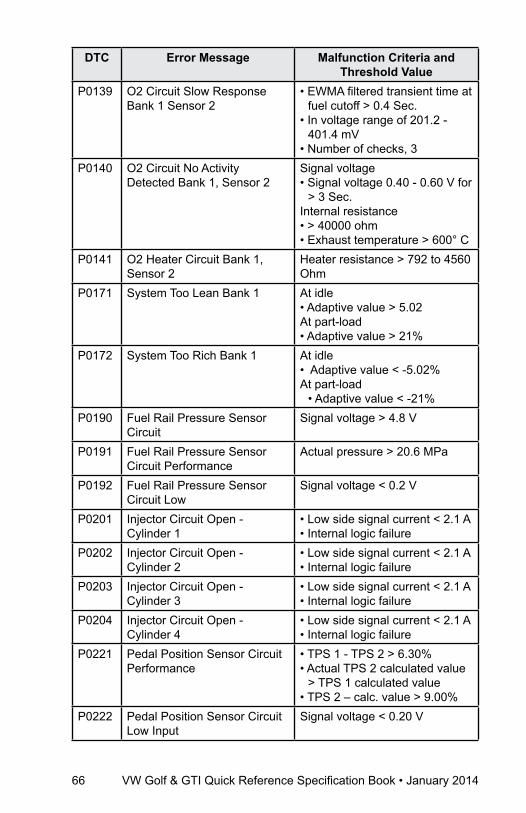
66 VW Golf & GTI Quick Reference Specification Book • January 2014
DTC Error Message Malfunction Criteria and Threshold Value
P0139 O2 Circuit Slow Response Bank 1 Sensor 2
• EWMA filtered transient time at fuel cutoff > 0.4 Sec.
• In voltage range of 201.2 - 401.4 mV
• Number of checks, 3P0140 O2 Circuit No Activity
Detected Bank 1, Sensor 2Signal voltage• Signal voltage 0.40 - 0.60 V for
> 3 Sec.Internal resistance • > 40000 ohm• Exhaust temperature > 600° C
P0141 O2 Heater Circuit Bank 1, Sensor 2
Heater resistance > 792 to 4560 Ohm
P0171 System Too Lean Bank 1 At idle • Adaptive value > 5.02At part-load • Adaptive value > 21%
P0172 System Too Rich Bank 1 At idle • Adaptive value < -5.02%At part-load
• Adaptive value < -21%P0190 Fuel Rail Pressure Sensor
CircuitSignal voltage > 4.8 V
P0191 Fuel Rail Pressure Sensor Circuit Performance
Actual pressure > 20.6 MPa
P0192 Fuel Rail Pressure Sensor Circuit Low
Signal voltage < 0.2 V
P0201 Injector Circuit Open - Cylinder 1
• Low side signal current < 2.1 A• Internal logic failure
P0202 Injector Circuit Open - Cylinder 2
• Low side signal current < 2.1 A• Internal logic failure
P0203 Injector Circuit Open - Cylinder 3
• Low side signal current < 2.1 A• Internal logic failure
P0204 Injector Circuit Open - Cylinder 4
• Low side signal current < 2.1 A• Internal logic failure
P0221 Pedal Position Sensor Circuit Performance
• TPS 1 - TPS 2 > 6.30%• Actual TPS 2 calculated value
> TPS 1 calculated value• TPS 2 – calc. value > 9.00%
P0222 Pedal Position Sensor Circuit Low Input
Signal voltage < 0.20 V

VW Golf & GTI Quick Reference Specification Book • January 2014 67
DTC
Cha
rt
DTC Error Message Malfunction Criteria and Threshold Value
P0223 Pedal Position Sensor Circuit High Input
Signal voltage > 4.81 V
P0234 Turbocharger Overboost Condition
Difference of set value boost pressure vs altitude sensor signal > 260 - 1275 hPa
P0237 Turbocharger Boost Sensor Circuit Low
Signal voltage < 0.2 V
P0238 Turbocharger Boost Sensor Circuit High
Signal voltage > 4.88 V
P0243 Turbocharger Wastegate Solenoid Circuit Performance
Signal voltage > 5.6 - 4.4 V
P0245 Turbocharger Wastegate Solenoid Low
Signal voltage < 3.25 - 2.15 V
P0246 Turbocharger Wastegate Solenoid High
Signal current > 2.2 to 4 A
P025A Fuel Pump Module Control Circuit Open
Signal voltage 4.80 - 5.30 V
P025C Fuel Pump Module Control Circuit Low
Signal voltage 2.70 - 3.25 V
P025D Fuel Pump Module Control Circuit High
Signal current > 0.6 mA
P0261 Cylinder 1 Injector Circuit Low Signal current < 2.1 AP0262 Cylinder 1 Injector Circuit High Signal current > 14.70 AP0264 Cylinder 2 Injector Circuit Low Signal current < 2.1 AP0265 Cylinder 2 Injector Circuit High Signal current > 14.70 AP0267 Cylinder 3 Injector Circuit Low Signal current < 2.1 AP0268 Cylinder 3 Injector Circuit High Signal current > 14.70 AP0270 Cylinder 4 Injector Circuit Low Low side signal current < 2.1 AP0271 Cylinder 4 Injector Circuit High Signal current > 14.70 AP0299 Turbocharger Underboost Difference of set boost pressure
vs. actual boost pressure value > 150 hPa
P12A1 Fuel Rail Pressure Sensor Inappropriately Low
• Pressure control activity > 0.20 MPa
• Fuel trim activity < 0.80• Difference between actual
pressure vs target pressure -16.38 to 16.38 MPa
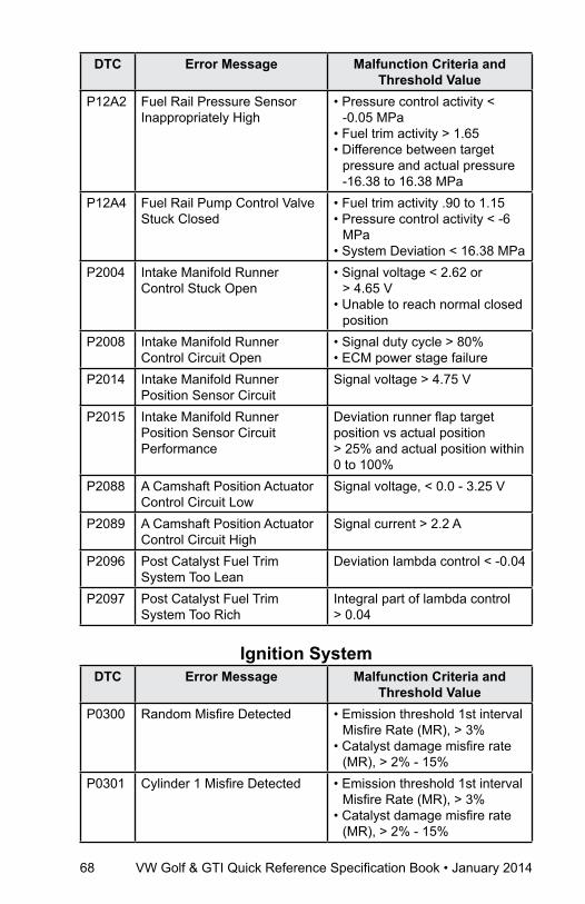
68 VW Golf & GTI Quick Reference Specification Book • January 2014
DTC Error Message Malfunction Criteria and Threshold Value
P12A2 Fuel Rail Pressure Sensor Inappropriately High
• Pressure control activity < -0.05 MPa
• Fuel trim activity > 1.65• Difference between target
pressure and actual pressure -16.38 to 16.38 MPa
P12A4 Fuel Rail Pump Control Valve Stuck Closed
• Fuel trim activity .90 to 1.15• Pressure control activity < -6
MPa• System Deviation < 16.38 MPa
P2004 Intake Manifold Runner Control Stuck Open
• Signal voltage < 2.62 or > 4.65 V
• Unable to reach normal closed position
P2008 Intake Manifold Runner Control Circuit Open
• Signal duty cycle > 80%• ECM power stage failure
P2014 Intake Manifold Runner Position Sensor Circuit
Signal voltage > 4.75 V
P2015 Intake Manifold Runner Position Sensor Circuit Performance
Deviation runner flap target position vs actual position > 25% and actual position within 0 to 100%
P2088 A Camshaft Position Actuator Control Circuit Low
Signal voltage, < 0.0 - 3.25 V
P2089 A Camshaft Position Actuator Control Circuit High
Signal current > 2.2 A
P2096 Post Catalyst Fuel Trim System Too Lean
Deviation lambda control < -0.04
P2097 Post Catalyst Fuel Trim System Too Rich
Integral part of lambda control > 0.04
Ignition SystemDTC Error Message Malfunction Criteria and
Threshold ValueP0300 Random Misfire Detected • Emission threshold 1st interval
Misfire Rate (MR), > 3% • Catalyst damage misfire rate
(MR), > 2% - 15% P0301 Cylinder 1 Misfire Detected • Emission threshold 1st interval
Misfire Rate (MR), > 3%• Catalyst damage misfire rate
(MR), > 2% - 15%
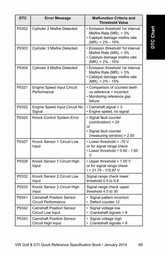
VW Golf & GTI Quick Reference Specification Book • January 2014 69
DTC
Cha
rt
DTC Error Message Malfunction Criteria and Threshold Value
P0302 Cylinder 2 Misfire Detected • Emission threshold 1st interval Misfire Rate (MR), > 3%
• Catalyst damage misfire rate (MR), > 2% - 15%
P0303 Cylinder 3 Misfire Detected • Emission threshold 1st interval Misfire Rate (MR), > 3%
• Catalyst damage misfire rate (MR), > 2% - 15%
P0304 Cylinder 4 Misfire Detected • Emission threshold 1st interval Misfire Rate (MR), > 3%
• Catalyst damage misfire rate (MR), > 2% - 15%
P0321 Engine Speed Input Circuit Performance
• Comparison of counted teeth vs reference = incorrect
• Monitoring reference gap failure
P0322 Engine Speed Input Circuit No Signal
• Camshaft signal > 3• Engine speed, no signal
P0324 Knock Control System Error • Signal fault counter (combustion) > 24
or • Signal fault counter
(measuring window) > 2.00P0327 Knock Sensor 1 Circuit Low
Input• Lower threshold < -70 V or for signal range check• Lower threshold < 0.60 - 1.60
VP0328 Knock Sensor 1 Circuit High
Input• Upper threshold > 1.00 Vor for signal range check • > 21.75 - 115.87 V
P0332 Knock Sensor 2 Circuit Low Input
Signal range check lower threshold 0.5 to 0.8
P0333 Knock Sensor 2 Circuit High Input
Signal range check upper threshold 4.5 to 30
P0341 Camshaft Position Sensor Circuit Performance
• Signal pattern incorrect• Defect counter 12
P0342 Camshaft Position Sensor Circuit Low Input
• Signal voltage low• Crankshaft signals = 8
P0343 Camshaft Position Sensor Circuit High Input
• Signal voltage high• Crankshaft signals = 8
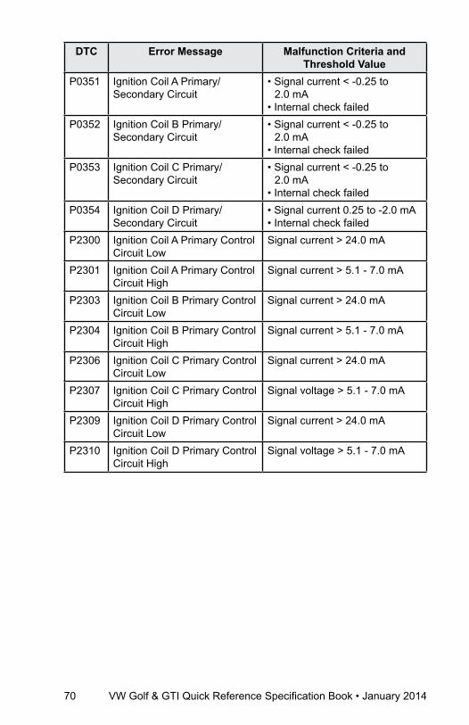
70 VW Golf & GTI Quick Reference Specification Book • January 2014
DTC Error Message Malfunction Criteria and Threshold Value
P0351 Ignition Coil A Primary/Secondary Circuit
• Signal current < -0.25 to 2.0 mA
• Internal check failedP0352 Ignition Coil B Primary/
Secondary Circuit• Signal current < -0.25 to
2.0 mA• Internal check failed
P0353 Ignition Coil C Primary/Secondary Circuit
• Signal current < -0.25 to 2.0 mA
• Internal check failedP0354 Ignition Coil D Primary/
Secondary Circuit• Signal current 0.25 to -2.0 mA• Internal check failed
P2300 Ignition Coil A Primary Control Circuit Low
Signal current > 24.0 mA
P2301 Ignition Coil A Primary Control Circuit High
Signal current > 5.1 - 7.0 mA
P2303 Ignition Coil B Primary Control Circuit Low
Signal current > 24.0 mA
P2304 Ignition Coil B Primary Control Circuit High
Signal current > 5.1 - 7.0 mA
P2306 Ignition Coil C Primary Control Circuit Low
Signal current > 24.0 mA
P2307 Ignition Coil C Primary Control Circuit High
Signal voltage > 5.1 - 7.0 mA
P2309 Ignition Coil D Primary Control Circuit Low
Signal current > 24.0 mA
P2310 Ignition Coil D Primary Control Circuit High
Signal voltage > 5.1 - 7.0 mA
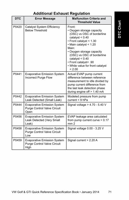
VW Golf & GTI Quick Reference Specification Book • January 2014 71
DTC
Cha
rt
additional Exhaust regulationDTC Error Message Malfunction Criteria and
Threshold ValueP0420 Catalyst System Efficiency
Below ThresholdFront: • Oxygen storage capacity
(OSC) vs OSC of borderline catalyst < 0.40
• Front catalyst < 1.30• Main catalyst < 1.20Main: • Oxygen storage capacity
(OSC) vs OSC of borderline catalyst < 0.40
• Front catalyst< .90• While value for front catalyst
< 2.00P0441 Evaporative Emission System
Incorrect Purge FlowActual EVAP pump current difference between reference measurement to idle divided by pump current difference from the last leak detection phase during engine off > 1.40 mA
P0442 Evaporative Emission System Leak Detected (Small Leak)
Modeled pressure from pump current < 9 hPa
P0444 Evaporative Emission System Purge Control Valve Circuit Open
Signal voltage > 4.70 - 5.40 V
P0456 Evaporative Emission System Leak Detected (Very Small Leak)
EVAP leakage area calculated from pump current curve > 0.17 mm 2
P0458 Evaporative Emission System Purge Control Valve Circuit Low
Signal voltage 0.00 - 3.25 V
P0459 Evaporative Emission System Purge Control Valve Circuit High
Signal current > 2.20 A
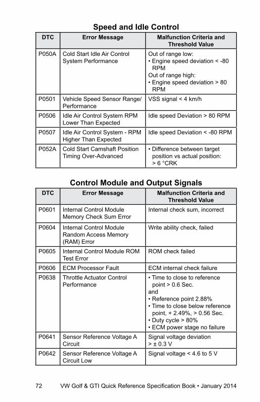
72 VW Golf & GTI Quick Reference Specification Book • January 2014
Speed and Idle ControlDTC Error Message Malfunction Criteria and
Threshold ValueP050A Cold Start Idle Air Control
System PerformanceOut of range low:• Engine speed deviation < -80
RPM Out of range high:• Engine speed deviation > 80
RPMP0501 Vehicle Speed Sensor Range/
PerformanceVSS signal < 4 km/h
P0506 Idle Air Control System RPM Lower Than Expected
Idle speed Deviation > 80 RPM
P0507 Idle Air Control System - RPM Higher Than Expected
Idle speed Deviation < -80 RPM
P052A Cold Start Camshaft Position Timing Over-Advanced
• Difference between target position vs actual position: > 6 °CRK
Control Module and Output SignalsDTC Error Message Malfunction Criteria and
Threshold ValueP0601 Internal Control Module
Memory Check Sum ErrorInternal check sum, incorrect
P0604 Internal Control Module Random Access Memory (RAM) Error
Write ability check, failed
P0605 Internal Control Module ROM Test Error
ROM check failed
P0606 ECM Processor Fault ECM internal check failureP0638 Throttle Actuator Control
Performance• Time to close to reference
point > 0.6 Sec.and• Reference point 2.88%• Time to close below reference
point, + 2.49%, > 0.56 Sec.• Duty cycle > 80% • ECM power stage no failure
P0641 Sensor Reference Voltage A Circuit
Signal voltage deviation > ± 0.3 V
P0642 Sensor Reference Voltage A Circuit Low
Signal voltage < 4.6 to 5 V

VW Golf & GTI Quick Reference Specification Book • January 2014 73
DTC
Cha
rt
DTC Error Message Malfunction Criteria and Threshold Value
P0643 Sensor Reference Voltage A Circuit High
Signal voltage > 5 to 5.4 V
P0651 Sensor Reference Voltage B Circuit
Signal voltage deviation > +/- 0.3 V
P0652 Sensor Reference Voltage B Circuit Low
Signal voltage < 4.6 - 5.0 V
P0653 Sensor Reference Voltage B Circuit High
Signal voltage > 5 to 5.4 V
P0657 Actuator Supply Voltage A Circuit Open
Signal voltage > 4.4 - 5.6 V
P0658 Actuator Supply Voltage A Circuit Low
Signal voltage < 2.15 - 3.25 V
P0659 Actuator Supply Voltage A Circuit High
Signal current > 1.1 A
P0685 ECM Power Relay Control Circuit Open
Control voltage 2.6 to 3.7 V and Sense circuit voltage < 6 V
P0686 ECM Power Relay Control Circuit Low
Control voltage 2.6 to 3.7 V and Sense circuit voltage > 6 V
P0687 ECM Power Relay Control Circuit High
Signal current > 1.4 to 0.7 A and Sense circuit voltage < 6 V
P0688 ECM Power Relay Sense Circuit Open
• Sense voltage > 3 V with main relay commanded on
• Sense voltage < 3 V with main relay commanded off
P0697 Sensor Reference Voltage C Circuit Open
Signal voltage deviation > ± 0.3 V
P0698 Sensor Reference Voltage C Circuit Low
Signal voltage < 4.6 - 5.0 V
P0699 Sensor Reference Voltage C Circuit High
Signal voltage > 5 to 5.4 V
U0001 High Speed CAN Communication Bus
Bus Off failure
U0002 High Speed CAN Communication Bus Performance
Global Time Out failure
U0121 Lost Communication with Anti-Lock Brake System (ABS) Control Module
CAN communication with ABS, time out
U0146 Lost Communication With Gateway A
CAN communication with gateway, time out

74 VW Golf & GTI Quick Reference Specification Book • January 2014
DTC Error Message Malfunction Criteria and Threshold Value
U0155 Lost Communication With Instrument Panel Cluster (IPC) Control Module
CAN messages not received
U0415 CAN Communication with ABS Error
• Speed sensor initialization failed
• Speed sensor low voltage error failed
• Speed > 326 km/hU0422 Invalid Data Received From
Body Control Module (Cluster)Ambient temperature value initialization failure.
U0423 Invalid Data Received From Instrument Panel Cluster Control Module
Implausible Ambient Air Temperature Sensor value message received from IPC
Fuel and air ratios Control ModuleDTC Error Message Malfunction Criteria and
Threshold ValueP12A1 Fuel Rail Pressure Sensor
Inappropriately Low• Pressure control activity
> 0.25 MPa• Fuel trim activity < 0.80• Difference between actual
pressure vs target pressure -16.38 to 16.38 MPa
P12A2 Fuel Rail Pressure Sensor Inappropriately High
• Pressure control activity > 0.25 MPa
• Fuel trim activity > 1.65• Difference between target
pressure and actual pressure -16.38 to 16.38 MPa
P12A4 Fuel Rail Pump Control Valve Stuck Closed
• Fuel trim activity 0.90 to 1.15• Pressure control activity
< -6 MPa• System Deviation < 16.38 MPa
P2004 Intake Manifold Runner Control Stuck Open
• Signal voltage < 2.62 or > 4.65 V
• Unable to reach normal closed position
P2008 Intake Manifold Runner Control Circuit Open
• Signal duty cycle > 80%• ECM power stage failure
P2014 Intake Manifold Runner Position Sensor Circuit
• Signal voltage > 4.75 V

VW Golf & GTI Quick Reference Specification Book • January 2014 75
DTC
Cha
rt
DTC Error Message Malfunction Criteria and Threshold Value
P2015 Intake Manifold Runner Position Sensor Circuit Performance
• Deviation runner flap target position vs actual position > 25% and actual position within 0 to 100%
P2088 A Camshaft Position Actuator Control Circuit Low
Signal voltage, < 0.0 - 3.25 V
P2089 A Camshaft Position Actuator Control Circuit High
Signal current > 2.2 A
P2096 Post Catalyst Fuel Trim System Too Lean
Deviation lambda control < -0.04
P2097 Post Catalyst Fuel Trim System Too Rich
Integral part of lambda control > 0.04
P2101 Throttle Actuator Control Motor Circuit Performance
• Duty cycle >80%• Deviation throttle value angles
vs. calculated value 4 - 50%• ECM power stage no failure
P2106 Throttle Actuator Control System Forced Limited Power
Internal check failed
P2122 Pedal Position Sensor D Circuit High Input
Signal voltage < 0.61 V
P2123 Pedal Position Sensor D Circuit High Input
Signal voltage > 4.79 V
P2127 Pedal Position Sensor E Circuit Low Input
Signal voltage < 0.27 V
P2128 Pedal Position Sensor E Circuit High Input
Signal voltage > 2.43 V
P2138 Pedal Position Sensor D / E Voltage Correlation
Signal voltage: Difference between signal APP1 and APP2 > 0.17 - 0.70 V
P2146 Fuel Injector A Supply Voltage Circuit Open
• Signal current, < 2.6 Aor • Signal current > 14.90 A
P2149 Fuel Injector B Supply Voltage Circuit Open
• Signal current, < 2.6 Aor • Signal current > 14.70 A
P2181 Cooling System Performance Cooling system temperature too low after a sufficient mass air flow integral 74 - 84° C
P2195 O2 Sensor Signal Biased/Stuck Lean Bank 1, Sensor 1
Delta lambda of 2nd lambda control loop > 0.06
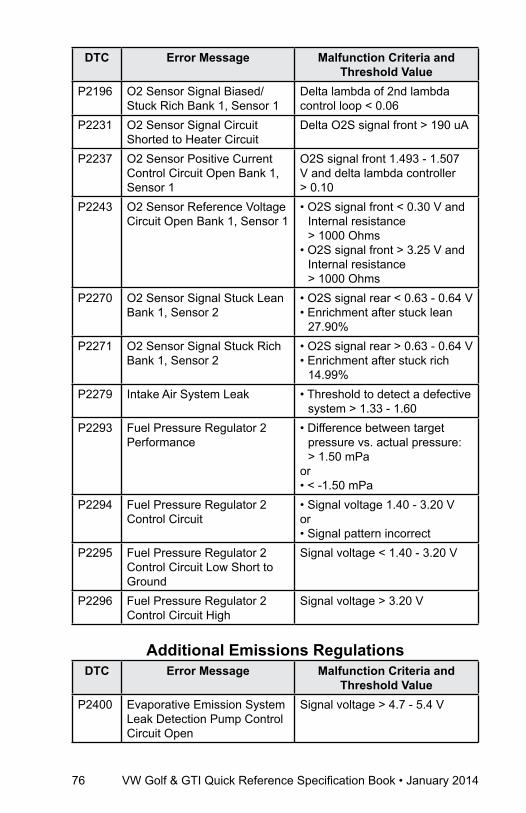
76 VW Golf & GTI Quick Reference Specification Book • January 2014
DTC Error Message Malfunction Criteria and Threshold Value
P2196 O2 Sensor Signal Biased/Stuck Rich Bank 1, Sensor 1
Delta lambda of 2nd lambda control loop < 0.06
P2231 O2 Sensor Signal Circuit Shorted to Heater Circuit
Delta O2S signal front > 190 uA
P2237 O2 Sensor Positive Current Control Circuit Open Bank 1, Sensor 1
O2S signal front 1.493 - 1.507 V and delta lambda controller > 0.10
P2243 O2 Sensor Reference Voltage Circuit Open Bank 1, Sensor 1
• O2S signal front < 0.30 V and Internal resistance > 1000 Ohms
• O2S signal front > 3.25 V and Internal resistance > 1000 Ohms
P2270 O2 Sensor Signal Stuck Lean Bank 1, Sensor 2
• O2S signal rear < 0.63 - 0.64 V• Enrichment after stuck lean
27.90%P2271 O2 Sensor Signal Stuck Rich
Bank 1, Sensor 2• O2S signal rear > 0.63 - 0.64 V• Enrichment after stuck rich
14.99%P2279 Intake Air System Leak • Threshold to detect a defective
system > 1.33 - 1.60P2293 Fuel Pressure Regulator 2
Performance• Difference between target
pressure vs. actual pressure: > 1.50 mPa
or• < -1.50 mPa
P2294 Fuel Pressure Regulator 2 Control Circuit
• Signal voltage 1.40 - 3.20 Vor• Signal pattern incorrect
P2295 Fuel Pressure Regulator 2 Control Circuit Low Short to Ground
Signal voltage < 1.40 - 3.20 V
P2296 Fuel Pressure Regulator 2 Control Circuit High
Signal voltage > 3.20 V
additional Emissions regulationsDTC Error Message Malfunction Criteria and
Threshold ValueP2400 Evaporative Emission System
Leak Detection Pump Control Circuit Open
Signal voltage > 4.7 - 5.4 V
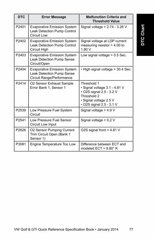
VW Golf & GTI Quick Reference Specification Book • January 2014 77
DTC
Cha
rt
DTC Error Message Malfunction Criteria and Threshold Value
P2401 Evaporative Emission System Leak Detection Pump Control Circuit Low
Signal voltage > 2.74 - 3.26 V
P2402 Evaporative Emission System Leak Detection Pump Control Circuit High
Signal voltage at LDP current measuring resistor > 4.00 to 1.80 V
P2403 Evaporative Emission System Leak Detection Pump Sense Circuit/Open
Low signal voltage > 0.5 Sec.
P2404 Evaporative Emission System Leak Detection Pump Sense Circuit Range/Performance
• High signal voltage > 30.4 Sec.
P2414 O2 Sensor Exhaust Sample Error Bank 1, Sensor 1
Threshold 1• Signal voltage 3.1 - 4.81 V• O2S signal 2.5 - 3.2 VThreshold 2• Signal voltage 2.5 V• O2S signal 2.5 - 3.1 V
P2539 Low Pressure Fuel System Circuit
Signal voltage > 4.9 V
P2541 Low Pressure Fuel Sensor Circuit Low Input
Signal voltage < 0.2 V
P2626 O2 Sensor Pumping Current Trim Circuit Open (Bank 1 Sensor 1)
O2S signal front > 4.81 V
P3081 Engine Temperature Too Low Difference between ECT and modeled ECT > 9.80° K

78 VW Golf & GTI Quick Reference Specification Book • January 2014
DTC CharT
Engine Codes CBTA and CBUAFuel and air Mixture,
additional Emission regulationsDTC Error Message Malfunction Criteria and
Threshold ValueP000A Intake Camshaft Position Slow
Response Bank 1• Difference between target and
actual > 8° CRK for > 1.8 to 2.5 Sec.
• Adjustment angle < 3° CRK rotation
P0010 Intake Camshaft Position Actuator Circuit Open Bank 1
Signal voltage > 4.70 - 5.40 V
P0011 Intake Camshaft Position Timing - Over-Advanced Bank 1
• Difference between target and actual > 8° CRK rotation
• Adjustment angle < 3° CRK rotation
P0016 Camshaft Position Sensor Angular Offset Check
Permissible deviation < -13.49 or >13.49 CRK deg.
P0030 HO2S Heater Control Circuit Bank 1 Sensor 1
Heater voltage 4.70 to 5.40 V
P0031 HO2S Heater Control Circuit Low Bank 1 Sensor 1
Heater voltage 0 to 3.26 V
P0032 HO2S Heater Control Circuit High Bank 1 Sensor 1
Heater current > 5.50 A
P0036 HO2S Heater Control Circuit Bank 1 Sensor 2
Heater voltage 2.34 to 3.59 V
P0037 HO2S Heater Control Circuit Low (Bank 1, Sensor 2)
Heater voltage < 2.34 V
P0038 HO2S Heater Control Circuit High (Bank 1, Sensor 2)
Heater voltage > 3.59 A
P0042 O2 Sensor Heater Control Circuit Bank 1 Sensor 3 (CBUA ONLY)
Heater voltage 2.34 to 3.59 V
P0043 O2 Sensor Heater Control Circuit Bank 1 Sensor 3 Low (CBUA ONLY)
Heater voltage < 2.34 V
P0044 O2 Sensor Heater Control Circuit Bank 1 Sensor 3 High (CBUA ONLY)
Heater voltage > 3.59 V

VW Golf & GTI Quick Reference Specification Book • January 2014 79
DTC
Cha
rt
DTC Error Message Malfunction Criteria and Threshold Value
P0070 Ambient Air Temperature • Ambient air temp < -50° CP0071 Ambient Air Temperature
Sensor Range/Performance• Difference of ECT vs. IAT or
IAT vs. AAT at start > 25 K (kelvin) or AAT vs. ECT at start < 25 K
P0072 Ambient Air Temperature Sensor Circuit Low
• Ambient air temp > 87° C
P0106 Manifold Absolute Pressure to Barometric Pressure Circuit Range/Performance
• Difference manifold pressure - lower threshold model < 0. Model range 45 to 845 hPa
• Difference manifold pressure - upper threshold model > 0. Model range 640 - 1055
• Difference. altitude sensor signal vs. manifold pressure signal at engine start > 60 hPa
P0107 Manifold Absolute Pressure Circuit High Input
Signal voltage < 0.20 V
P0108 Manifold Absolute Pressure Circuit High Input
Signal voltage > 4.86 V
P0111 Intake Air Temperature Circuit Range/Performance
• Difference of ECT vs. IAT or IAT vs. AAT at start > 25 K (kelvin) or AAT vs. ECT at start < 25 K
P0112 Intake Air Temperature Circuit Low Input
• IAT > 130.0° C
P0113 Intake Air Temperature Sensor Circuit High Input
• IAT < -46° C
P0116 Engine Coolant Temperature Sensor 1 Circuit Range/Performance
• No change on signal 2° K• ECT signal stuck in range
75 - 105° C and no change in signal 2° K
P0117 Engine Coolant Temperature Sensor 1 Circuit Low Input
• ECT > 140° C
P0118 Engine Coolant Temperature Sensor 1 Circuit High Input
ECT < -40° C
P0121 Accelerator Pedal Position Sensor A Circuit Range/Performance
• TPS 1 - TPS 2 > 5.10 to 6.30% • TPS 1 calc. value > 9.00%
P0122 Accelerator Pedal Position Sensor A Circuit Low Input
Signal voltage < 0.20 V
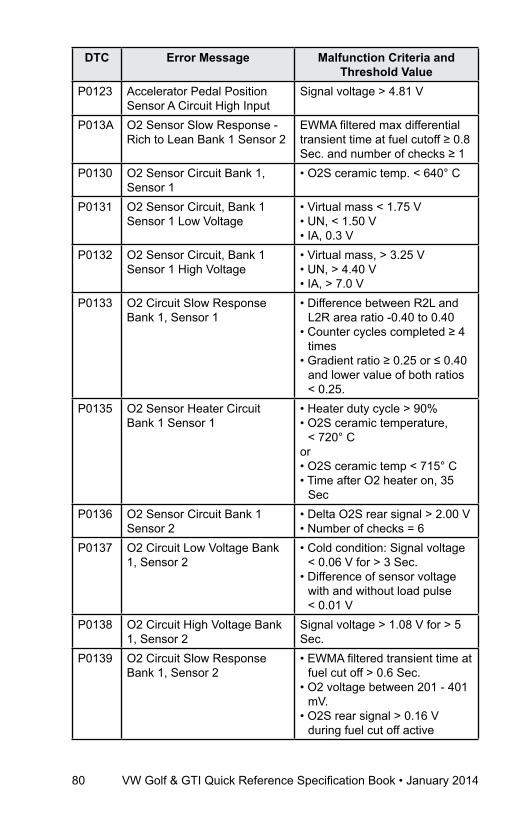
80 VW Golf & GTI Quick Reference Specification Book • January 2014
DTC Error Message Malfunction Criteria and Threshold Value
P0123 Accelerator Pedal Position Sensor A Circuit High Input
Signal voltage > 4.81 V
P013A O2 Sensor Slow Response - Rich to Lean Bank 1 Sensor 2
EWMA filtered max differential transient time at fuel cutoff ≥ 0.8 Sec. and number of checks ≥ 1
P0130 O2 Sensor Circuit Bank 1, Sensor 1
• O2S ceramic temp. < 640° C
P0131 O2 Sensor Circuit, Bank 1 Sensor 1 Low Voltage
• Virtual mass < 1.75 V• UN, < 1.50 V• IA, 0.3 V
P0132 O2 Sensor Circuit, Bank 1 Sensor 1 High Voltage
• Virtual mass, > 3.25 V• UN, > 4.40 V• IA, > 7.0 V
P0133 O2 Circuit Slow Response Bank 1, Sensor 1
• Difference between R2L and L2R area ratio -0.40 to 0.40
• Counter cycles completed ≥ 4 times
• Gradient ratio ≥ 0.25 or ≤ 0.40 and lower value of both ratios < 0.25.
P0135 O2 Sensor Heater Circuit Bank 1 Sensor 1
• Heater duty cycle > 90%• O2S ceramic temperature,
< 720° Cor• O2S ceramic temp < 715° C• Time after O2 heater on, 35
SecP0136 O2 Sensor Circuit Bank 1
Sensor 2• Delta O2S rear signal > 2.00 V• Number of checks = 6
P0137 O2 Circuit Low Voltage Bank 1, Sensor 2
• Cold condition: Signal voltage < 0.06 V for > 3 Sec.
• Difference of sensor voltage with and without load pulse < 0.01 V
P0138 O2 Circuit High Voltage Bank 1, Sensor 2
Signal voltage > 1.08 V for > 5 Sec.
P0139 O2 Circuit Slow Response Bank 1, Sensor 2
• EWMA filtered transient time at fuel cut off > 0.6 Sec.
• O2 voltage between 201 - 401 mV.
• O2S rear signal > 0.16 V during fuel cut off active
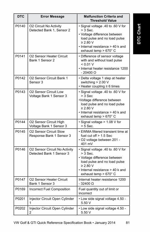
VW Golf & GTI Quick Reference Specification Book • January 2014 81
DTC
Cha
rt
DTC Error Message Malfunction Criteria and Threshold Value
P0140 O2 Circuit No Activity Detected Bank 1, Sensor 2
• Signal voltage .40 to .60 V for > 3 Sec.
• Voltage difference between load pulse and no load pulse ≥ 2.80 V
• Internal resistance > 40 k and exhaust temp > 670° C
P0141 O2 Sensor Heater Circuit Bank 1 Sensor 2
• Difference of sensor voltage with and without load pulse < 0.01 V
• Internal heater resistance 1200 - 20400 O
P0142 O2 Sensor Circuit Bank 1 Sensor 3
• Delta voltage 1 step at heater switching > 2.00 V
• Heater coupling ≥ 6 timesP0143 O2 Sensor Circuit Low
Voltage Bank 1 Sensor 3• Signal voltage .40 to .60 V for
> 3 Sec•Voltage difference between
load pulse and no load pulse ≥ 2.80 V
• Internal resistance > 40 k and exhaust temp > 670° C
P0144 O2 Sensor Circuit High Voltage Bank 1 Sensor 3
• Signal voltage > 1.08 V for > 5 Sec.
P0145 O2 Sensor Circuit Slow Response Bank 1 Sensor 3
• EWMA filtered transient time at fuel cut off > 1.5 Sec
• O2 voltage between 201 - 401 mV
P0146 O2 Sensor Circuit No Activity Detected Bank 1 Sensor 3
• Signal voltage .40 to .60 V for > 3 Sec.
• Voltage difference between load pulse and no load pulse ≥ 2.80 V
• Internal resistance > 40 k and exhaust temp > 670° C
P0147 O2 Sensor Heater Circuit Bank 1 Sensor 3
Internal heater resistance 1200 - 32400 Ω
P0169 Incorrect Fuel Composition Fuel quantity out of limit or incorrect
P0201 Injector Circuit Open Cylinder 1
• Low side signal voltage 4.50 - 5.50 V
P0202 Injector Circuit Open Cylinder 2
• Low side signal voltage 4.50 - 5.50 V
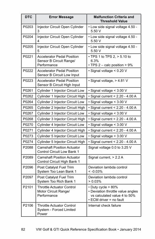
82 VW Golf & GTI Quick Reference Specification Book • January 2014
DTC Error Message Malfunction Criteria and Threshold Value
P0203 Injector Circuit Open Cylinder 3
• Low side signal voltage 4.50 - 5.50 V
P0204 Injector Circuit Open Cylinder 4
• Low side signal voltage 4.50 - 5.50 V
P0205 Injector Circuit Open Cylinder 5
• Low side signal voltage 4.50 - 5.50 V
P0221 Accelerator Pedal Position Sensor B Circuit Range/Performance
• TPS 1 to TPS 2, > 5.10 to 6.3%
• TPS 2 – calc position > 9%P0222 Accelerator Pedal Position
Sensor B Circuit Low Input• Signal voltage < 0.20 V
P0223 Accelerator Pedal Position Sensor B Circuit High Input
• Signal voltage, > 4.81 V
P0261 Cylinder 1 Injector Circuit Low • Signal voltage < 3.00 VP0262 Cylinder 1 Injector Circuit High • Signal current < 2.20 - 4.00 AP0264 Cylinder 2 Injector Circuit Low • Signal voltage < 3.00 VP0265 Cylinder 2 Injector Circuit High • Signal current < 2.20 - 4.00 AP0267 Cylinder 3 Injector Circuit Low • Signal voltage < 3.00 VP0268 Cylinder 3 Injector Circuit High • Signal current < 2.20 - 4.00 AP0270 Cylinder 4 Injector Circuit Low • Signal voltage < 3.00 VP0271 Cylinder 4 Injector Circuit High • Signal current < 2.20 - 4.00 AP0273 Cylinder 5 Injector Circuit Low • Signal voltage < 3.00 VP0274 Cylinder 5 Injector Circuit High • Signal current < 2.20 - 4.00 AP2088 Camshaft Position Actuator
Control Circuit Low Bank 1Signal voltage 0.0 to 3.25 V
P2089 Camshaft Position Actuator Control Circuit High Bank 1
Signal current, > 2.2 A
P2096 Post Catalyst Fuel Trim System Too Lean Bank 1
Deviation lambda control < -0.03%
P2097 Post Catalyst Fuel Trim System Too Rich Bank 1
Deviation lambda control ˃ 0.03%
P2101 Throttle Actuator Control Motor Circuit Range/Performance
• Duty cycle > 80%• Deviation throttle value angles
vs calculated value 4 to 50%• ECM driver = no fault
P2106 Throttle Actuator Control System - Forced Limited Power
Internal check failure
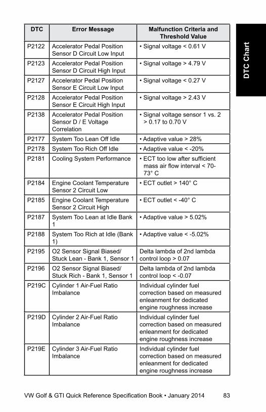
VW Golf & GTI Quick Reference Specification Book • January 2014 83
DTC
Cha
rt
DTC Error Message Malfunction Criteria and Threshold Value
P2122 Accelerator Pedal Position Sensor D Circuit Low Input
• Signal voltage < 0.61 V
P2123 Accelerator Pedal Position Sensor D Circuit High Input
• Signal voltage > 4.79 V
P2127 Accelerator Pedal Position Sensor E Circuit Low Input
• Signal voltage < 0.27 V
P2128 Accelerator Pedal Position Sensor E Circuit High Input
• Signal voltage > 2.43 V
P2138 Accelerator Pedal Position Sensor D / E Voltage Correlation
• Signal voltage sensor 1 vs. 2 > 0.17 to 0.70 V
P2177 System Too Lean Off Idle • Adaptive value > 28%P2178 System Too Rich Off Idle • Adaptive value < -20%P2181 Cooling System Performance • ECT too low after sufficient
mass air flow interval < 70- 73° C
P2184 Engine Coolant Temperature Sensor 2 Circuit Low
• ECT outlet > 140° C
P2185 Engine Coolant Temperature Sensor 2 Circuit High
• ECT outlet < -40° C
P2187 System Too Lean at Idle Bank 1
• Adaptive value > 5.02%
P2188 System Too Rich at Idle (Bank 1)
• Adaptive value < -5.02%
P2195 O2 Sensor Signal Biased/Stuck Lean - Bank 1, Sensor 1
Delta lambda of 2nd lambda control loop > 0.07
P2196 O2 Sensor Signal Biased/Stuck Rich - Bank 1, Sensor 1
Delta lambda of 2nd lambda control loop < -0.07
P219C Cylinder 1 Air-Fuel Ratio Imbalance
Individual cylinder fuel correction based on measured enleanment for dedicated engine roughness increase
P219D Cylinder 2 Air-Fuel Ratio Imbalance
Individual cylinder fuel correction based on measured enleanment for dedicated engine roughness increase
P219E Cylinder 3 Air-Fuel Ratio Imbalance
Individual cylinder fuel correction based on measured enleanment for dedicated engine roughness increase

84 VW Golf & GTI Quick Reference Specification Book • January 2014
DTC Error Message Malfunction Criteria and Threshold Value
P219F Cylinder 4 Air-Fuel Ratio Imbalance
Individual cylinder fuel correction based on measured enleanment for dedicated engine roughness increase
P21A0 Cylinder 5 Air-Fuel Ratio Imbalance
Individual cylinder fuel correction based on measured enleanment for dedicated engine roughness increase
P2237 O2 Sensor Positive Current Control Circuit Open Bank 1, Sensor 1
• O2S signal front 1.49 to 1.51 V• Fuel cutoff > 3 Sec.• Delta lambda controller > 0.10
P2243 O2 Sensor Reference Voltage Circuit Open Bank 1, Sensor 1
• O2S signal front > 4.70 V and Internal resistance > 950 Ω
• O2S signal front < 0.20 V And Internal resistance > 950 Ω
P2251 O2 Sensor Negative Current Control Circuit Open
• O2S signal front 1.47 to 1.53 V and > 950 Ω
P2257 Secondary Air Injection System Control Circuit Low
• Signal voltage 0 to 3.26 V
P2258 Secondary Air Injection System Control Circuit High
•Signal current .60 to 2.40 A
P2270 O2 Sensor Signal Stuck Lean Bank 1 Sensor 2
• O2S signal rear not oscillating at reference < 598 mV and enrichment after stuck lean 20%
P2271 O2 Sensor Signal Stuck Rich Bank 1 Sensor 2
• O2S signal rear not oscillating at reference > 598 mV and enrichment after stuck rich 15%
P2274 O2 Sensor Signal Stuck Lean Bank 1 Sensor 3
• O2S rear not oscillating at reference < 0.64 to 0.65 V and enrichment after stuck lean 20%
P2275 O2 Sensor Signal Stuck Rich Bank 1 Sensor 3
• O2S rear not oscillating at reference > 0.64 to 0.65 V and enrichment after stuck rich 15%
or • Sensor voltage of ≥ 0.15 V
after oxygen mass flow (after fuel cutoff) > 3500 mg with ≥ 1 check

VW Golf & GTI Quick Reference Specification Book • January 2014 85
DTC
Cha
rt
DTC Error Message Malfunction Criteria and Threshold Value
P2279 Intake Air System Leak Offset value throttle mass flow > 13 kg/h
P2300 Ignition Coil A Primary Control Circuit Low
• Signal current > 24 mA
P2301 Ignition Coil A Primary Control Circuit High
• Signal voltage > 5.1 - 7.0 mA
P2303 Ignition Coil B Primary Control Circuit Low
• Signal current > 24 mA
P2304 Ignition Coil B Primary Control Circuit High
• Signal voltage > 5.1 - 7.0 mA
P2306 Ignition Coil C Primary Control Circuit Low
• Signal current > 24 mA
P2307 Ignition Coil C Primary Control Circuit High
• Signal voltage > 5.1 - 7.0 mA
P2309 Ignition Coil D Primary Control Circuit Low
• Signal current > 24 mA
P2310 Ignition Coil D Primary Control Circuit High
• Signal voltage > 5.1 - 7.0 mA
P2312 Ignition Coil “E” Primary Control Circuit Low
• Signal current > 24 mA
P2313 Ignition Coil “E” Primary Control Circuit High
• Signal voltage > 5.1 - 7.0 mA
P240A Evaporative Emission System Leak Detection Pump Heater Control Circuit Open
• Signal voltage > 4.7 to 5.4 V
P240B Evaporative Emission System Leak Detection Pump Heater Control Circuit Low
• Signal voltage < 2.74 to 3.26 V
P240C Evaporative Emission System Leak Detection Pump Heater Control Circuit High
• Signal current > 2.2 to 4 A
P2400 Evaporative Emission System Leak Detection Pump Control Circuit/Open
• Signal voltage > 4.70 to 5.40 V
P2401 Evaporative Emission System Leak Detection Pump Control Circuit Low
• Signal voltage < 2.74 to 3.26 V
P2402 Evaporative Emission System Leak Detection Pump Control Circuit High
• Signal voltage > 4.00 or >1.80 V
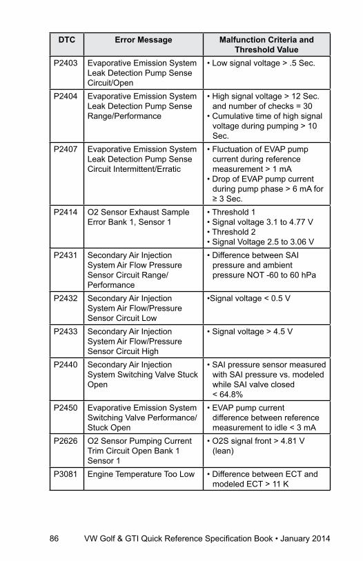
86 VW Golf & GTI Quick Reference Specification Book • January 2014
DTC Error Message Malfunction Criteria and Threshold Value
P2403 Evaporative Emission System Leak Detection Pump Sense Circuit/Open
• Low signal voltage > .5 Sec.
P2404 Evaporative Emission System Leak Detection Pump Sense Range/Performance
• High signal voltage > 12 Sec. and number of checks = 30
• Cumulative time of high signal voltage during pumping > 10 Sec.
P2407 Evaporative Emission System Leak Detection Pump Sense Circuit Intermittent/Erratic
• Fluctuation of EVAP pump current during reference measurement > 1 mA
• Drop of EVAP pump current during pump phase > 6 mA for ≥ 3 Sec.
P2414 O2 Sensor Exhaust Sample Error Bank 1, Sensor 1
• Threshold 1• Signal voltage 3.1 to 4.77 V• Threshold 2• Signal Voltage 2.5 to 3.06 V
P2431 Secondary Air Injection System Air Flow Pressure Sensor Circuit Range/Performance
• Difference between SAI pressure and ambient pressure NOT -60 to 60 hPa
P2432 Secondary Air Injection System Air Flow/Pressure Sensor Circuit Low
•Signal voltage < 0.5 V
P2433 Secondary Air Injection System Air Flow/Pressure Sensor Circuit High
• Signal voltage > 4.5 V
P2440 Secondary Air Injection System Switching Valve Stuck Open
• SAI pressure sensor measured with SAI pressure vs. modeled while SAI valve closed < 64.8%
P2450 Evaporative Emission System Switching Valve Performance/Stuck Open
• EVAP pump current difference between reference measurement to idle < 3 mA
P2626 O2 Sensor Pumping Current Trim Circuit Open Bank 1 Sensor 1
• O2S signal front > 4.81 V (lean)
P3081 Engine Temperature Too Low • Difference between ECT and modeled ECT > 11 K
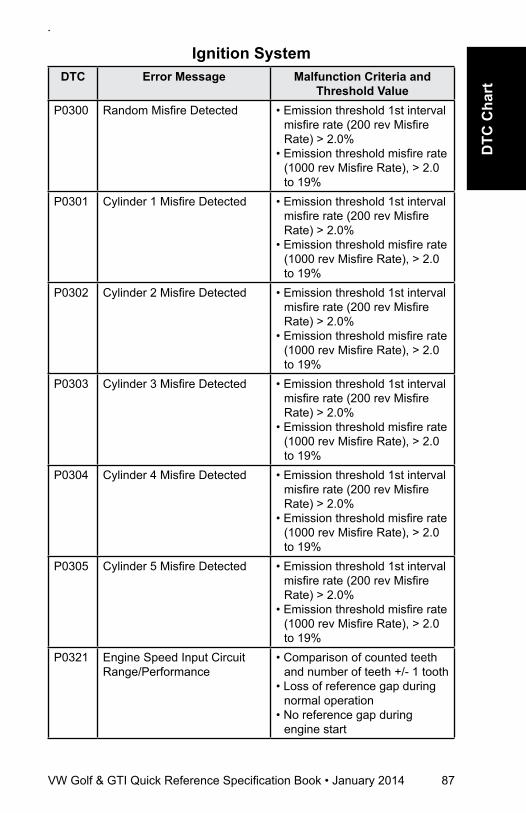
VW Golf & GTI Quick Reference Specification Book • January 2014 87
DTC
Cha
rt
Ignition SystemDTC Error Message Malfunction Criteria and
Threshold ValueP0300 Random Misfire Detected • Emission threshold 1st interval
misfire rate (200 rev Misfire Rate) > 2.0%
• Emission threshold misfire rate (1000 rev Misfire Rate), > 2.0 to 19%
P0301 Cylinder 1 Misfire Detected • Emission threshold 1st interval misfire rate (200 rev Misfire Rate) > 2.0%
• Emission threshold misfire rate (1000 rev Misfire Rate), > 2.0 to 19%
P0302 Cylinder 2 Misfire Detected • Emission threshold 1st interval misfire rate (200 rev Misfire Rate) > 2.0%
• Emission threshold misfire rate (1000 rev Misfire Rate), > 2.0 to 19%
P0303 Cylinder 3 Misfire Detected • Emission threshold 1st interval misfire rate (200 rev Misfire Rate) > 2.0%
• Emission threshold misfire rate (1000 rev Misfire Rate), > 2.0 to 19%
P0304 Cylinder 4 Misfire Detected • Emission threshold 1st interval misfire rate (200 rev Misfire Rate) > 2.0%
• Emission threshold misfire rate (1000 rev Misfire Rate), > 2.0 to 19%
P0305 Cylinder 5 Misfire Detected • Emission threshold 1st interval misfire rate (200 rev Misfire Rate) > 2.0%
• Emission threshold misfire rate (1000 rev Misfire Rate), > 2.0 to 19%
P0321 Engine Speed Input Circuit Range/Performance
• Comparison of counted teeth and number of teeth +/- 1 tooth
• Loss of reference gap during normal operation
• No reference gap during engine start
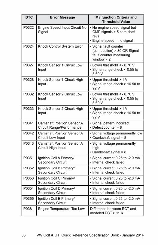
88 VW Golf & GTI Quick Reference Specification Book • January 2014
DTC Error Message Malfunction Criteria and Threshold Value
P0322 Engine Speed Input Circuit No Signal
• No engine speed signal but CMP signals > 5 cam shaft revs
• Engine speed = no signal P0324 Knock Control System Error • Signal fault counter
(combustion) > 30 OR Signal fault counter measuring window > 2
P0327 Knock Sensor 1 Circuit Low Input
• Lower threshold < - 0.70 V• Signal range check < 0.55 to
5.60 VP0328 Knock Sensor 1 Circuit High
Input• Upper threshold > 1 V • Signal range check > 16.50 to
92 VP0332 Knock Sensor 2 Circuit Low
Input• Lower threshold < - 0.70 V• Signal range check < 0.55 to
5.60 VP0333 Knock Sensor 2 Circuit High
Input• Upper threshold > 1 V• Signal range check > 16.50 to
92 VP0341 Camshaft Position Sensor A
Circuit Range/Performance• Signal pattern incorrect• Defect counter = 8
P0342 Camshaft Position Sensor A Circuit Low Input
• Signal voltage permanently low• Crankshaft signal = 8
P0343 Camshaft Position Sensor A Circuit High Input
• Signal voltage permanently high
• Crankshaft signal = 8P0351 Ignition Coil A Primary/
Secondary Circuit• Signal current 0.25 to -2.0 mA• Internal check failed
P0352 Ignition Coil B Primary/Secondary Circuit
• Signal current 0.25 to -2.0 mA• Internal check failed
P0353 Ignition Coil C Primary/Secondary Circuit
• Signal current 0.25 to -2.0 mA• Internal check failed
P0354 Ignition Coil D Primary/Secondary Circuit
• Signal current 0.25 to -2.0 mA• Internal check failed
P0355 Ignition Coil E Primary/Secondary Circuit
• Signal current 0.25 to -2.0 mA• Internal check failed
P0381 Engine Temperature Too Low Difference between ECT and modeled ECT > 11 K

VW Golf & GTI Quick Reference Specification Book • January 2014 89
DTC
Cha
rt
additional Exhaust regulationDTC Error Message Malfunction Criteria and
Threshold ValueP0410 Secondary Air Injection
System• Deviation SAI pressure > 50
hPaP0413 Secondary Air Injection
System Switching Valve Circuit Open
• Signal voltage 9.25 to 11.25 V
P0414 Secondary Air Injection System Switching Valve Circuit Shorted
• Signal voltage > 6.0 Vor• Signal current > 2.20 A
P0418 Secondary Air Injection System Control Circuit
• Signal voltage 4.70 to 5.40 V
P0420 Catalyst System Efficiency Below Threshold
• Oxygen storage capacity (OSC) vs OSC value of borderline catalyst < 1.00
P043E Evaporative Emission System Leak Detection Reference Orifice Low Flow
• EVAP pump current during reference measurement > 40 mA
P043F Evaporative Emission System Leak Detection Reference Orifice High Flow
• EVAP pump current during reference measurement < 15 mA
P0441 Evaporative Emission System Incorrect Purge Flow - Stuck Closed
• Actual EVAP pump current vs. difference from last reading > 1.0 mA
P0442 Evaporative Emission System Leak Detected (Small Leak)
Time for pressure drop < 1.9 Sec
P0444 Evaporative Emission System Purge Control Valve Circuit Open
• Signal voltage 4.70 - 5.40 V
P0447 Evaporative Emission System Vent Control Circuit Open
• Signal voltage > 4.70 - 5.40 V
P0448 Evaporative Emission System Vent Control Circuit Shorted
• Signal current > 2.2 to 4 A or• Signal voltage < 2.74 to 3.26 V
P0455 Evaporative Emission System Leak Detected (gross leak)
• Time for pressure drop < 1 Sec.
P0456 Evaporative Emission System Leak Detected (very small leak)
Time for pressure drop < 5.8 Sec
P0458 Evaporative Emission System Purge Control Valve Circuit Low
• Signal voltage 0 to 3.26 V
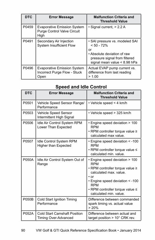
90 VW Golf & GTI Quick Reference Specification Book • January 2014
DTC Error Message Malfunction Criteria and Threshold Value
P0459 Evaporative Emission System Purge Control Valve Circuit High
• Signal current, > 2.2 A
P0491 Secondary Air Injection System Insufficient Flow
• SAI pressure vs. modeled SAI < 50 - 72%
or• Absolute deviation of raw
pressure signal from filtered signal mean value < 8.98 hPa
P0496 Evaporative Emission System Incorrect Purge Flow - Stuck Open
Actual EVAP pump current vs. difference from last reading > 1.00
Speed and Idle ControlDTC Error Message Malfunction Criteria and
Threshold ValueP0501 Vehicle Speed Sensor Range/
Performance• Vehicle speed < 4 km/h
P0503 Vehicle Speed Sensor Intermittent High Signal
• Vehicle speed > 325 km/h
P0506 Idle Air Control System RPM Lower Than Expected
• Engine speed deviation > 100 RPM
• RPM controller torque value ≥ calculated max value.
P0507 Idle Control System RPM Higher than Expected
• Engine speed deviation < -100 RPM
• RPM controller torque value ≤ calculated min. value.
P050A Idle Air Control System Out of Range
• Engine speed deviation > 100 RPM
• RPM controller torque value ≥ calculated max. value.
• or• Engine speed deviation < -100
RPM • RPM controller torque value ≤
calculated min. value.P050B Cold Start Ignition Timing
PerformanceDifference between commanded spark timing vs. actual value > 20%
P052A Cold Start Camshaft Position Timing Over-Advanced
Difference between actual and target position > 10° CRK rev.
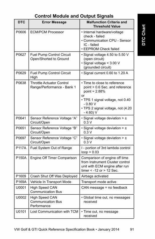
VW Golf & GTI Quick Reference Specification Book • January 2014 91
DTC
Cha
rt
Control Module and Output SignalsDTC Error Message Malfunction Criteria and
Threshold ValueP0606 ECM/PCM Processor • Internal hardware/voltage
check - failed• Communication CPU - Sensor
IC - failed• EEPROM Check failed
P0627 Fuel Pump Control Circuit Open/Shorted to Ground
• Signal voltage 4.50 to 5.50 V (open circuit)
• Signal voltage < 3.00 V (grounded circuit)
P0629 Fuel Pump Control Circuit High
• Signal current 0.60 to 1.20 A
P0638 Throttle Actuator Control Range/Performance - Bank 1
• Time to close to reference point > 0.6 Sec. and reference point = 2.88%
or• TPS 1 signal voltage, not 0.40
- 0.80 V• TPS 2 signal voltage, not (4.20
- 4.60) VP0641 Sensor Reference Voltage “A”
Circuit/Open• Signal voltage deviation > ±
0.3 VP0651 Sensor Reference Voltage “B”
Circuit/Open• Signal voltage deviation > ±
0.3 VP0697 Sensor Reference Voltage “C”
Circuit/Open• Signal voltage deviation > ±
0.3 VP117A Fuel System Out of Range I - portion of 3rd lambda control
loop > 0.03P150A Engine Off Timer Comparison Comparison of engine off time
from Instrument Cluster control unit with ECM engine after run timer < -12 or > 12 Sec.
P1609 Crash Shut Off Was Deployed Airbags activatedP169A Vehicle In Transport Mode Transport mode activeU0001 High Speed CAN
Communication BusCAN message = no feedback
U0002 High Speed CAN Communication Bus Performance
• Global time out, no messages received
U0101 Lost Communication with TCM • Time out, no message received

92 VW Golf & GTI Quick Reference Specification Book • January 2014
DTC Error Message Malfunction Criteria and Threshold Value
U0121 Lost Communication with Anti-Lock Brake System (ABS) Control Module
• No CAN messages received
U0146 Lost Communication with Gateway “A”
•No CAN messages received
U0155 Lost Communication with Instrument Panel Cluster (IPC) Control Module
• No CAN messages received
U0302 Software Incompatibility with Transmission Control Module
Manual transmission coded ECM but automatic transmission messages received from TCM
U0402 Invalid Data Received From Transmission Control Module
• Implausible data message received
U0415 Invalid Data Received From Anti-Lock Brake System Control Module
• Sensor signal failure• None, or implausible
information• CAN 1 VSS signal incorrect
> 327.08 km/hU0422 Invalid Data Received From
Body Control Module• Ambient temperature value
initialization = 00hU0423 Invalid Data Received From
Instrument Panel Control (IPC) Module
• AAT sensor reading from cluster to ECM implausible or no message
U0447 Invalid Data Received From Gateway Module
• CAN message incorrect

Volkswagen Group of America works constantly to develop and improve its products. We must therefore reserve the right to change or update any part of this technical manual at any time. No legal commitment can therefore be derived from the information, illustrations or descriptions in this manual.
The texts, illustrations and standards in this manual are based on the information available at the time of printing. No part of this manual may be reprinted, reproduced or translated without the written permission of Volkswagen Group of America.
All rights under the copyright laws are expressly reserved by Volkswagen Group of America. Subject to alteration and amendment.
Printed in the United States of America © 2014 Volkswagen Group of America, Inc.

January 2014
Related Documents