FORD MOTOR COMPANY REVISION DATE: JUNEL 4, 2013 PAGE 1 OF 183 2014 MY OBD System Operation Summary for Plug In and Hybrid Electric Vehicles Table of Contents Introduction Hybrid Electric Vehicles ................................................................. 5 HEV Powertrain Description........................................................................ 5 Benefits of Hybrid Electric Vehicles ............................................................ 6 Key Powertrain Components ...................................................................... 6 Engine .......................................................................................................... 6 Inverter Control Module (ISC) ..................................................................... 6 Transaxle...................................................................................................... 7 Battery .......................................................................................................... 7 Propulsion Modes ........................................................................................ 8 Series Mode ................................................................................................. 8 Positive Split Mode ...................................................................................... 8 Negative Split Mode..................................................................................... 8 Electric Mode ............................................................................................... 9 City & Highway Traffic Scenarios................................................................ 9 PHEV On Board Charger .......................................................................... 10 Hybrid Electric Vehicle Control System .......................................................... 13 Catalyst Efficiency Monitor ............................................................................... 15 Misfire Monitor................................................................................................... 22

Welcome message from author
This document is posted to help you gain knowledge. Please leave a comment to let me know what you think about it! Share it to your friends and learn new things together.
Transcript

FORD MOTOR COMPANY REVISION DATE: JUNEL 4, 2013 PAGE 1 OF 183
2014 MY OBD System Operation
Summary for Plug In and Hybrid Electric Vehicles
Table of Contents
Introduction Hybrid Electric Vehicles ................................................................. 5
HEV Powertrain Description ........................................................................ 5
Benefits of Hybrid Electric Vehicles ............................................................ 6
Key Powertrain Components ...................................................................... 6
Engine .......................................................................................................... 6
Inverter Control Module (ISC) ..................................................................... 6
Transaxle ...................................................................................................... 7
Battery .......................................................................................................... 7
Propulsion Modes ........................................................................................ 8
Series Mode ................................................................................................. 8
Positive Split Mode ...................................................................................... 8
Negative Split Mode ..................................................................................... 8
Electric Mode ............................................................................................... 9
City & Highway Traffic Scenarios ................................................................ 9
PHEV On Board Charger .......................................................................... 10
Hybrid Electric Vehicle Control System .......................................................... 13
Catalyst Efficiency Monitor ............................................................................... 15
Misfire Monitor................................................................................................... 22

FORD MOTOR COMPANY REVISION DATE: JUNEL 4, 2013 PAGE 2 OF 183
Low Data Rate System .............................................................................. 22
Generic Misfire Algorithm Processing ...................................................... 22
Profile Correction ....................................................................................... 23
EVAP System Monitor - Overview .................................................................. 27
Evap Monitor Overview ............................................................................. 27
Fuel Systems Hardware – Sealed (PHEV) vs non-Sealed (HEV) .......... 30
EVAP System Monitor – Engine Running Diagnostics .................................. 31
EVAP System Monitor – Engine Off Diagnostics ........................................... 37
ELCM Leak Detection 0.020" Monitor Entry Conditions .......................... 37
EVAP System Monitor Engine Off Component Checks ................................ 43
PHEV Re-Fueling System ......................................................................... 51
Fuel System Monitor ........................................................................................ 56
FAOSC (Rear Fuel Trim) Monitor ............................................................. 62
Air Fuel Ratio Imbalance Monitor .............................................................. 64
Front UEGO Monitor ........................................................................................ 67
Front UEGO Signal .................................................................................... 67
Front UEGO Slow/Delayed Response Monitor (2010 MY and beyond) 75
UEGO Heaters ........................................................................................... 78
Rear HO2S Monitor .......................................................................................... 81
Rear HO2S Signal ..................................................................................... 81
Rear HO2S Decel Fuel Shut Off Response Test .................................... 84
EWMA Fault Filtering ................................................................................. 87
Rear HO2S Heaters, ................................................................................. 90
Stepper Motor EGR System Monitor .............................................................. 92
PCV System Monitor ........................................................................................ 97
Enhanced Thermostat Monitor ........................................................................ 98
HEV/PHEV Cooling System Diagnostics ...................................................... 100
Cold Start Emission Reduction Component Monitor ................................... 105
Cold Start Emission Reduction System Monitor .......................................... 108
Variable Cam Timing System Monitor .......................................................... 111

FORD MOTOR COMPANY REVISION DATE: JUNEL 4, 2013 PAGE 3 OF 183
Electronic Throttle Control .............................................................................. 115
Transmission Range Sensor Inputs ....................................................... 117
Accelerator and Throttle Position Sensor Inputs .................................... 118
Electronic Throttle Monitor ....................................................................... 120
Throttle Plate Position Controller (TPPC) Outputs ................................. 121
Comprehensive Component Monitor - Engine ............................................. 122
Engine Temperature Sensor Inputs ........................................................ 122
IAT Rationality Test .................................................................................. 125
Throttle Position Sensor .......................................................................... 127
Mass Air Flow Sensor .............................................................................. 127
MAF/TP Rationality Test ......................................................................... 128
Miscellaneous CPU Tests ....................................................................... 129
Ignition ...................................................................................................... 131
Engine Outputs ........................................................................................ 134
Mechanical Returnless Fuel System (MRFS) — Dual Speed .............. 135
Battery and Battery Charging Systems ......................................................... 137
Low Voltage Battery Charging System - Overview ................................ 137
High Voltage Battery Charging System - Overview ............................... 138
High Voltage Battery - Overview ............................................................. 144
Battery Energy Control Module (BECM) ................................................ 146
Powersplit Transaxle ...................................................................................... 153
Transmission Overview ........................................................................... 153
Transmission Control System Architecture ............................................ 155
Transmission Inputs ................................................................................. 155
HPCM Outputs ......................................................................................... 156
Hybrid Powertrain Control Module (HPCM) ........................................... 156
Hybrid Powertrain Control Module ................................................................ 157
Hybrid Powertrain Control Module (HPCM) External Inputs ................. 157
Transmission Range Sensor Inputs ....................................................... 171
Transmission Auxiliary Oil Pump ............................................................ 172

FORD MOTOR COMPANY REVISION DATE: JUNEL 4, 2013 PAGE 4 OF 183
PCM On Board Diagnostic Executive ........................................................... 178
Exponentially Weighted Moving Average ..................................................... 180
I/M Readiness Code ....................................................................................... 182
Catalyst Temperature Model ......................................................................... 183
Serial Data Link MIL Illumination ................................................................... 183

FORD MOTOR COMPANY REVISION DATE: JUNEL 4, 2013 PAGE 5 OF 183
Introduction Hybrid Electric Vehicles
HEV Powertrain Description
A hybrid electric vehicle is powered by a conventional engine with an electric motor added for enhanced fuel economy and reduced emissions. The electric motor can also be used to boost power and enhance performance (like an extra "charge"). This type of vehicle is well suited for the environmentally aware driver who wants better fuel economy and fewer pollutants, but doesn't want the hassle of plug-ins. A vehicle can be "more" of a hybrid than another. There are various levels of "hybridization," mild, full, and plug-in. With all HEV variants, the engine turns off when it is not needed, reducing fuel waste, and instantly restarts when the need for power is detected. In addition, all hybrids provide electric assist, in that the combustion engine gets a boost of electric power from the battery pack. This provides additional acceleration performance when needed, without additional use of fuel. The main difference between the HEV variants is in the relative sizing of the electric powertrain to the combustion powertrain. A mild hybrid has a relatively small electric motor to provide traction power and a small capacity battery. It is designed to provide a start-stop function along with a small amount of acceleration power (used to assist the combustion engine) and a small amount of regenerative braking (meaning vehicle energy that would otherwise would be wasted, is collected during braking to recharge the battery). A full hybrid provides the same functions as a mild hybrid, but to a larger degree. Since it uses a larger electric motor and battery, it can provide greater amount of acceleration and regenerative braking power. In addition, a full hybrid provides an electric launch, whereby the electric motor can accelerate the vehicle without the combustion engine for small distances. The electric motor can be used to accelerate by itself (in pure electric mode) or in combination with the internal combustion engine (for greater power). Plug-In hybrids have all of the functions and capabilities of a full hybrid, however, they use a larger battery which gives them greater electric-only driving range. In addition, plug-in hybrids have a charge port which can be used to charge the battery externally from electric mains to allow them to have full electric range without having to run the combustion engine.

FORD MOTOR COMPANY REVISION DATE: JUNEL 4, 2013 PAGE 6 OF 183
Benefits of Hybrid Electric Vehicles
Reduces emissions by increasing average engine efficiency.
Engine shuts down, when the vehicle is stopped.
Electric motor boosts acceleration performance.
Regenerative brakes recapture energy, to recharge the battery.
Improved fuel economy stretches a tank of gas further, saves you money, and helps you conserve our limited petroleum resources.
Driving performance is optimized because both the gas engine and electric motor are working for you.
No battery plug-ins required for mild and full hybrids, and optional for plug-in hybrid.
An HEV offers all the conveniences of conventional vehicles: spacious seating, storage room, creature comforts, and extended driving range.
All Ford/Lincoln hybrids will be delivered, sold, and serviced at local Ford and Lincoln dealers.
Key Powertrain Components
Engine
I-4 Gasoline Engine
Electronic Throttle Control
Atkinson Cycle to improve efficiency by reducing pumping losses
o For Otto Cycle, expansion ratio equals compression ratio
o Atkinson Cycle expansion ratio greater than compression ratio
Leaves intake valve open longer during compression stroke pushing air back into intake manifold
Operates with less vacuum and greater throttle opening to maintain air charge
Inverter Control Module (ISC)
Main hybrid control module
Vehicle energy management functions
Low level motor & gen control electronics and software
Power electronics (motor and generator)
Voltage boost converter
Integrated heat exchanger
Chassis mounted

FORD MOTOR COMPANY REVISION DATE: JUNEL 4, 2013 PAGE 7 OF 183
Transaxle
64 kW Permanent Magnet AC Generator Motor
88 kW Permanent Magnet AC Traction Motor
Connected to ISC by 3-phase cables for each motor
Planetary gear set and final drive gears
Connected to front 2-wheel or all-wheel driveline
Battery
Lithium-Ion battery chemistry
Nearly twice the power density of previous model
35 kW power rating (new)

FORD MOTOR COMPANY REVISION DATE: JUNEL 4, 2013 PAGE 8 OF 183
Propulsion Modes
Series Mode
Used only when vehicle is not moving and the engine is running
Engine may be running for battery charging, cabin or battery temperature control, or catalyst warm-up.
Positive Split Mode
Engine is ON and driving the generator motor to produce electricity
Power from the engine is split between the direct path to the road and the path through the generator motor
Generator power can flow to the battery or to the traction motor
The traction motor can operate as a motor or a generator to make up the difference between the engine power and the desired power
This is the preferred mode whenever the battery needs to be charged or when at moderate loads and low vehicle speeds
Negative Split Mode
The engine is on and the generator motor consumes electrical energy to reduce engine speed
The traction motor can operate as a motor or a generator to make up the difference between the engine power and the desired power
Typical highway mode
Occurs when the engine needs to be on, the system can not be operated in parallel mode and the battery is charged near its upper limit

FORD MOTOR COMPANY REVISION DATE: JUNEL 4, 2013 PAGE 9 OF 183
Electric Mode
The vehicle is propelled by stored electrical energy only
The engine is turned off
The tractive torque supplied from the traction motor
Preferred mode whenever the desired power is low enough such that it can be produced more efficiently by electrical system than engine
Preferred mode in reverse because the engine can not deliver reverse torque
Separate electric pump maintains power assisted steering
City & Highway Traffic Scenarios
Stopped The engine will be off unless it needs to be on for reasons other than tractive power (Max A/C, vacuum,
catalyst temp, heat, purge, low SOC)
Launching At low speed or low power demand, the launch mode will be electric, unless the engine needs to be on for
other reasons.
At moderate speed or high desired power, the engine will come on.
Entering highway or Passing At high acceleration demand, the engine power will be boosted with battery power through the traction
motor to provide quick V-6 like response.
Cruising At light load, the system may operate in parallel, positive split or negative split mode depending on the
battery charge.
At heavy load (due to high speeds, weight, towing or grade), the system will be limited to engine only performance (no battery support).
Limited regenerative braking will be used.
Exiting highway Provides an opportunity for regenerative braking.
Braking At high speed, the engine torque is ramped down, the traction motor regenerates to a limit and the
foundation brakes are applied as necessary (at the traction motor or battery regen limits).
At moderate and low speed, the engine will be turned off.

FORD MOTOR COMPANY REVISION DATE: JUNEL 4, 2013 PAGE 10 OF 183
PHEV On Board Charger
Charge Fault HMI (Human Machine Interface) On the Vehicle
Vehicle Interior
o Cluster - Upon a charger fault, the BCCM and BECM can request the P/T malfunction indicator on the instrument cluster (amber wrench light). No specific message to point to the charge system which is similar to other onboard requests for this telltale.
o 8” Centerstack Screen - A charging fault message will be displayed in 8” centerstack.
Vehicle Exterior The vehicle will have a light ring around the charge port located on the driver’s fender. Upon a charge fault, all segments of the light ring will flash rapidly for 20-30 minutes.
Lighted ring indicates fault and state of charge Ring illuminates in 4 segments representing 25% increments of battery state of charge

FORD MOTOR COMPANY REVISION DATE: JUNEL 4, 2013 PAGE 11 OF 183
Charge Fault HMI Near the Vehicle
120V Convenience Cord The convenience cord includes a CCID box with HMI display. A triangle with a (!) LED in the center indicates the following fault conditions:
o CCID self test failure o CCID microprocessor failure o GFCI final fault o Over current protection “final” fault
240V Wall Mount Charger Red LED light illuminates indicating fault conditions. LED blinks unique codes depending on fault:
o Vehicle fault – 1x / 2 sec o Contactor fault – 1x / 1 sec o CCID fault – 2x / 1 sec o Ground missing – 10x / 1 sec o Failed internal self test – on steady

FORD MOTOR COMPANY REVISION DATE: JUNEL 4, 2013 PAGE 12 OF 183
Charge Fault HMI Remote from the Vehicle
MyFord Mobile App Standard feature allowing cellular communication between vehicle and cell phone/computer New vehicle purchase includes pre-paid 5 year subscription (renewable) Upon charge fault, automatic alerts will be sent to the owner’s cell phone and/or computer via text/email message. The following reasons will trigger an alert:
o Charging Fault (during charging only) o Scheduled Charge Not Occurring o Accidental Unplug - if charger is unplugged and vehicle not driven within 15 minutes
Upon request by owner, MyFord Mobile App also sends vehicle reports containing other information that could point to a charging fault:
o Charge status, including: generic fault (not known if in the car or out of the car), fault inside car, fault outside car, charge in progress, charge scheduled, and charge complete
o Plug status o Battery health – if BECM not requesting telltale, health is ok

FORD MOTOR COMPANY REVISION DATE: JUNEL 4, 2013 PAGE 13 OF 183
Hybrid Electric Vehicle Control System
The Hybrid Electric Vehicle Control System uses four modules to control hybrid electric powertrain functions:
The Engine Control Module (ECM) monitors driver inputs and controls engine related functions.
The Hybrid Powertrain Control Module (HPCM) interprets driver inputs and controls energy
management and generator and motor functions.
The Battery Energy Control Module (BECM) controls the high voltage battery pack.
The Brake System Control Module (BSCM) monitors driver braking requests and controls the braking
functions.
All these modules use CAN communication for all diagnostic functions and normal-mode communications. The ECM is a stand-alone OBD-II control module and meets all J1979 requirements. These include generic DIDs, freeze frame storage, pending and confirmed DTC retrieval and clearing, Mode 06 test data, Mode 08 evap system test, Mode 09 VIN, CALID and CVN, and Mode 0A Permanent DTCs. The OBD-II monitors for the engine are similar to the monitors used by a conventional gasoline vehicle. The basic difference between a conventional gasoline engine and the hybrid engine is that the engine often shuts down while in electric mode. This sometimes requires active intervention by the diagnostic executive to ensure that all OBD-II monitor can complete. The HPCM is a stand-alone OBD-II control module and meets all J1979 requirements. These include generic DIDs, freeze frame storage, pending and confirmed DTC retrieval and clearing, and Mode 09 CALID and CVN, and Mode 0A Permanent DTCs. Some of the OBD-II monitors for hybrid system are similar to the monitors used by a conventional transmission; however, many of the monitors are unique to the hybrid generator and motor sensors and controls. The HPCM is housed within the Inverter Control System (ISC) models, and is not serviceable with the exception of reflashing memory.
ECM – Engine Control Module HPCM – Hybrid Powertrain Control Module BECM – Battery Energy Control Module BSCM – Brake System Control Module APPS – Acceleration Pedal Position Sensor BPPS – Brake Pedal Position Sensor (master cylinder pressure) PRNDL – Transmission Range Sensor SC – Speed Control
Ford HEV Powertrain Control System
ring
sun
ring
gen
motor
planetary
Engine
HV bus
Transaxle
SC
BPPS
PRNDL
Energy management
& control
Determine
torque sign determine
desired wheel torque
determine gear mode
BSCM / Regenerative
Brakes
engine torque desired
acceleration torque desired
BECM/ Battery
ECM
deceleration torque desired
APPS
gear mode
HPCM
Motor & Generator
Controls
Air/fuel control
Battery Power
Management

FORD MOTOR COMPANY REVISION DATE: JUNEL 4, 2013 PAGE 14 OF 183
The Battery Energy Control Module (BECM) is a stand-alone OBD-II control module and meets all J1979 requirements. These include generic PIDs, freeze frame storage, pending and confirmed DTC retrieval and clearing, and Mode 09 CALID and CVN. The BECM is housed within the battery pack and is not serviceable with the exception of reflashing memory. As a result, the BECM supports J1979 Mode 09 CALID and CVN. The Brake System Control Module (BSCM) is not an OBD-II control module because there are no regenerative braking faults that affect emissions.
FORD MOTOR COMPANY REVISION DATE: JUNEL 4, 2013 PAGE 15 OF 183
Catalyst Efficiency Monitor
The Catalyst Efficiency Monitor uses an oxygen sensor after the catalyst to infer the hydrocarbon efficiency based
on oxygen storage capacity of the ceria and precious metals in the washcoat. Under normal, closed-loop fuel
conditions, high efficiency catalysts have significant oxygen storage. This makes the switching frequency of the
rear HO2S very slow and reduces the amplitude. As catalyst efficiency deteriorates due to thermal and/or chemical
deterioration, its ability to store oxygen declines and the post-catalyst HO2S signal begins to switch more rapidly
with increasing amplitude. The predominant failure mode for high mileage catalysts is chemical deterioration
(phosphorus deposition on the front brick of the catalyst), not thermal deterioration.
Integrated Air/Fuel Method
The Integrated Air/Fuel Catalyst Monitor assesses the oxygen storage capacity of a catalyst after a fuel cut event.
The monitor integrates how much excess fuel is needed to drive the monitored catalyst to a rich condition starting
from an oxygen-saturated, lean condition. Therefore, the monitor is a measure of how much fuel is required to
force catalyst breakthrough from lean to rich. To accomplish this, the monitor runs during fuel reactivation following
a Decel Fuel Shut Off (DFSO) event. The monitor completes after a calibrated number of DFSO monitoring events
have occurred. The IAF catalyst monitor can be used with either a wide range O2 sensor (UEGO) or a
conventional switching sensor (HEGO).
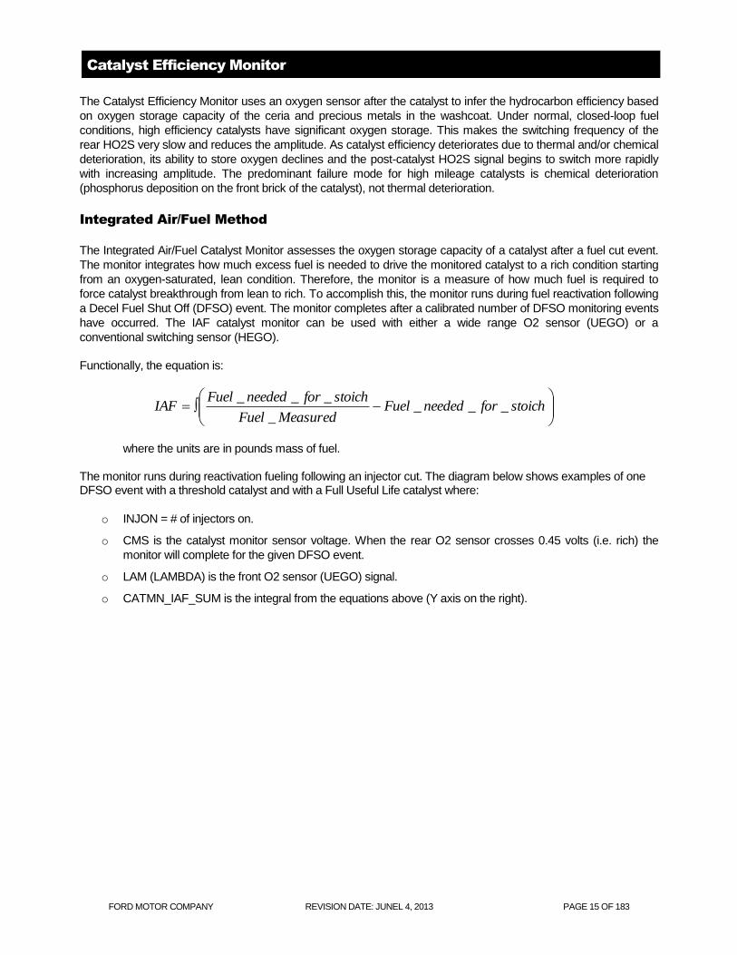
Functionally, the equation is:
where the units are in pounds mass of fuel. The monitor runs during reactivation fueling following an injector cut. The diagram below shows examples of one DFSO event with a threshold catalyst and with a Full Useful Life catalyst where:
o INJON = # of injectors on.
o CMS is the catalyst monitor sensor voltage. When the rear O2 sensor crosses 0.45 volts (i.e. rich) the
monitor will complete for the given DFSO event.
o LAM (LAMBDA) is the front O2 sensor (UEGO) signal.
o CATMN_IAF_SUM is the integral from the equations above (Y axis on the right).
stoichforneededFuel
MeasuredFuel
stoichforneededFuelIAF ___
_
___

FORD MOTOR COMPANY REVISION DATE: JUNEL 4, 2013 PAGE 16 OF 183
In this example, CATMN_IAF_SUM is small because it doesn't take much fuel to break though a low oxygen
storage threshold catalyst.
In this example, CATMN_IAF_SUM is much larger because it takes a substantial amount of fuel to break though a
high oxygen storage threshold catalyst.
There are two sets of entry conditions into the IAF catalyst monitor. The high level entry conditions determine that
the monitor would like to run following the next injector fuel cut event. The lower level entry conditions determine
that the fuel cut-off event was suitable for monitoring and the monitor will run as soon as the injectors come back
on.
Threshold Catalyst - IAF Catalyst Monitor Integration CATMN_IAF_SUM
0
0.5
1
1.5
2
2.5
3
0 0.2 0.4 0.6 0.8 1 1.2 1.4 1.6 1.8 2
Time (sec)
Vo
ltag
e / IN
JO
N
0
0.002
0.004
0.006
0.008
0.01
0.012
0.014
0.016
0.018
0.02
Fu
el (l
bm
)
INJONCMSLAMCATMN_IAF_SUM
Full Useful Life Catalyst - IAF Catalyst Monitor Integration CATMN_IAF_SUM
0
0.5
1
1.5
2
2.5
3
0 0.2 0.4 0.6 0.8 1 1.2 1.4 1.6 1.8 2
Time (sec)
Vo
ltag
e / IN
JO
N
0
0.002
0.004
0.006
0.008
0.01
0.012
0.014
0.016
0.018
0.02
Fu
el (l
bm
)
INJONCMSLAMCATMN_IAF_SUM
FORD MOTOR COMPANY REVISION DATE: JUNEL 4, 2013 PAGE 17 OF 183
1. The high level entry conditions are met when:
o There are no senor/hardware faults
o The base monitor entry conditions have been met (ECT, IAT, cat temp, fuel level, air mass)
o Required number of DFSO monitoring event have not yet completed
2. The lower level entry conditions are met when:
o The injectors are off
o The catalyst is believed to be saturated with oxygen (rear O2 indicates lean)
o The catalyst/rear O2 has been rich at least once since the last monitor event.
General Catalyst Monitor Operation
Rear HO2S sensors can be located in various ways to monitor different kinds of exhaust systems. In-line engines
and many V-engines are monitored by individual bank. A rear HO2S sensor is used along with the front, fuel-
control HO2S sensor for each bank. Two sensors are used on an in-line engine; four sensors are used on a V-
engine. Some V-engines have exhaust banks that combine into a single underbody catalyst. These systems are
referred to as Y-pipe systems. They use only one rear HO2S sensor along with the two front, fuel-control HO2S
sensors. Y-pipe system use three sensors in all. For Y-pipe systems which utilize switching front O2 sensors, the
two front HO2S sensor signals are combined by the software to infer what the HO2S signal would have been in
front of the monitored catalyst. The inferred front HO2S signal and the actual single, rear HO2S signal is then used
to calculate the switch ratio.
Many vehicles monitor less than 100% of the catalyst volume – often the first catalyst brick of the catalyst system.
Partial volume monitoring is done on LEV-II vehicles in order to meet the 1.75 * emission-standard threshold for
NMHC and NOx. The rationale for this practice is that the catalysts nearest the engine deteriorate first, allowing the
catalyst monitor to be more sensitive and illuminate the MIL properly at lower emission standards.
Many applications that utilize partial-volume monitoring place the rear HO2S sensor after the first light-off catalyst
can or, after the second catalyst can in a three-can per bank system. (A few applications placed the HO2S in the
middle of the catalyst can, between the first and second bricks.)
The new Integrated Air/Fuel Catalyst Monitor can be used to monitor the entire catalyst volume, even on LEV-II
vehicles.
Index ratios for ethanol (Flex fuel) vehicles vary based on the changing concentration of alcohol in the fuel. The
malfunction threshold typically increases as the percent alcohol increases. For example, a malfunction threshold of
0.5 may be used at E10 (10% ethanol) and 0.9 may be used at E85 (85% ethanol). The malfunction thresholds are
therefore adjusted based on the % alcohol in the fuel. (Note: Normal gasoline is allowed to contain up to 10%
ethanol (E10)).
Vehicles with the Index Ratio Method Using a Switching HO2S Sensor employ an Exponentially Weighted Moving
Average (EWMA) algorithm to improve the robustness of the catalyst monitor. During normal customer driving, a
malfunction will illuminate the MIL, on average, in 3 to 6 driving cycles. If KAM is reset (battery disconnected) or
DTCs are cleared, a malfunction will illuminate the MIL in 2 driving cycles. See the section on EWMA for additional
information.

FORD MOTOR COMPANY REVISION DATE: JUNEL 4, 2013 PAGE 18 OF 183
Vehicles with the Index Ratio Method Using a Wide Range HO2S Sensor (UEGO) or the Integrated Air/Fuel
catalyst monitor employ an improved version of the EWMA algorithm.
The EWMA logic incorporates several important CARB requirements. These are:
Fast Initial Response (FIR): The first 4 tests after a battery disconnect or code clear will
process unfiltered data to quickly indicate a fault. The FIR will use a 2-trip MIL. This will help
the service technician determine that a fault has been fixed.
Step-change Logic (SCL): The logic will detect an abrupt change from a no-fault condition to
a fault condition. The SCL will be active after the 4th catalyst monitor cycle and will also use a
2-trip MIL. This will illuminate the MIL when a fault is instantaneously induced.
Normal EWMA (NORM): This is the normal mode of operation and uses an Exponentially
Weighted Moving Average (EWMA) to filter the catalyst monitor test data. It is employed after
the 4th catalyst test and will illuminate a MIL during the drive cycle where the EWMA value
exceeds the fault threshold. (1 trip MIL).
Starting in the 2010 ½ Model Year and later, the catalyst monitor will employ catalyst break-in logic. This logic will
prevent the catalyst monitor from running until after a catalyst break-in period.
The catalyst monitor will not run on a new vehicle from the assembly plant until 60 minutes of time above a catalyst
temperature (typically 800 to 1100 deg F) has been accumulated or 300 miles has elapsed.
New modules at the assembly plant will have an NVRAM flag initialized to delay the catalyst monitor. Service
modules and re-flash software will have the flag set to allow that catalyst monitor to run. The flag cannot be reset to
delay the catalyst monitor from running by any tool or service procedure.

FORD MOTOR COMPANY REVISION DATE: JUNEL 4, 2013 PAGE 19 OF 183
Integrated Air Fuel Catalyst Monitor

FORD MOTOR COMPANY REVISION DATE: JUNEL 4, 2013 PAGE 20 OF 183
CATALYST MONITOR OPERATION:
DTCs P0420 Bank 1
Monitor execution once per driving cycle
Monitor Sequence HO2S response test complete and no DTCs (P0133/P0153) prior to calculating
switch ratio, no SAIR pump stuck on DTCs (P0412/P1414), no evap leak check
DTCs (P0442/P0456), no EGR stuck open DTCs (P0402)
Sensors OK M ECT, IAT, TP, VSS, CKP, MAF, no misfire DTCs (P0300, P0310), no ignition
coil DTCs (P0351-P0358), no fuel monitor DTCs (P0171, P0172, P0174.
P0175), no VCT DTCs (P0010-P0017, P052A, P052B, P0344, P0365, P0369-
bank1) (P0018 thru P0025,P052C, P052D, P0349, P0390, P0394- bank2 ).no
evap system DTCs (P0443, P0446, P0455, P0457, P1450), no ETC system
DTCs (P0122, P0123, P0222, P0223, P02135) (P2101, P2107, P2111, P2112)
(P0600, P060A, P060B, P060C, P061B, P061C, P061D, P1674, U0300).
Monitoring Duration Approximately 700 seconds during appropriate FTP conditions (approximately
100 to 200 oxygen sensor switches are collected) for switching O2 control
sensors
Approximately 10 to 20 seconds for wide range O2 index ratio monitor.
3 Decel Fuel Cutoff events for IAF catalyst monitor
TYPICAL IAF CATALYST MONITOR ENTRY CONDITIONS:
Entry condition Minimum Maximum
Engine Coolant Temp 125 oF 220
oF
Intake Air Temp 20 oF 140
oF
Inferred catalyst mid-bed temperature 800 oF 1590
oF
Fuel Level 15%
Air Mass 4.0 lb/min
Minimum inferred rear O2 sensor temperature 800 oF
Fuel monitor learned within limits 98% 102%
Rear O2 sensor rich since last monitor attempt 0.45 volts
Rear O2 sensor lean with injectors off (voltage needed to enter monitor) 0.1 volts
Rear O2 sensor reads rich after fuel turned back on (voltage needed to
complete monitor)
0.45 volts
TYPICAL MALFUNCTION THRESHOLDS:
Catalyst monitor index ratio > 0.75 (bank monitor)

FORD MOTOR COMPANY REVISION DATE: JUNEL 4, 2013 PAGE 21 OF 183
Mode $06 reporting for IAF Catalyst Monitor
The catalyst monitor results are converted to a ratio for Mode $06 reporting to keep the same look and feel for the
service technician. The equation for calculating the Mode $06 monitor result is:
1 – (Actual reactivation fuel/ Good catalyst reactivation fuel)
Good catalyst reactivation fuel is intended to represent what the monitor would measure for a green catalyst.
J1979 CATALYST MONITOR MODE $06 DATA
Monitor ID Test ID Description for CAN
$21 $80 Bank 1 index-ratio and max. limit unitless
** NOTE: In this document, a monitor or sensor is considered OK if there are no DTCs stored for that component
or system at the time the monitor is running.

FORD MOTOR COMPANY REVISION DATE: JUNEL 4, 2013 PAGE 22 OF 183
Misfire Monitor
The HEV uses the Low Data Rate misfire monitor. The LDR system is capable of meeting “full-range” misfire
monitoring requirements on 4-cylinder engines. The software allows for detection of any misfires that occur 6
engine revolutions after initially cranking the engine. This meets the new OBD-II requirement to identify misfires
within 2 engine revolutions after exceeding the warm drive, idle rpm.
Low Data Rate System
The LDR Misfire Monitor uses a low-data-rate crankshaft position signal, (i.e. one position reference signal at 10
deg BTDC for each cylinder event). The PCM calculates crankshaft rotational velocity for each cylinder from this
crankshaft position signal. The acceleration for each cylinder can then be calculated using successive velocity
values. The changes in overall engine rpm are removed by subtracting the median engine acceleration over a
complete engine cycle. The crankshaft acceleration is then processed by two algorithms. The first is optimized for
detection of sporadic and single cylinder patterns of misfire; the second is optimized for multi-cylinder patterns. The
resulting deviant cylinder acceleration values are used in evaluating misfire in the “General Misfire Algorithm
Processing” section below.
Generic Misfire Algorithm Processing
The acceleration that a piston undergoes during a normal firing event is directly related to the amount of torque that
cylinder produces. The calculated piston/cylinder acceleration value(s) are compared to a misfire threshold that is
continuously adjusted based on inferred engine torque. Deviant accelerations exceeding the threshold are
conditionally labeled as misfires. A threshold multiplier is used during startup CSER to compensate the thresholds
for the reduction in signal amplitude during spark retard conditions.
The calculated deviant acceleration value(s) are also evaluated for noise. Normally, misfire results in a non-
symmetrical loss of cylinder acceleration. Mechanical noise, such as rough roads or high rpm/light load conditions,
will produce symmetrical, positive acceleration variations. A noise limit is calculated by applying a negative
multiplier to the misfire threshold. If the noise limit is exceeded, a noisy signal condition is inferred and the misfire
monitor is suspended for a brief interval. Noise-free deviant acceleration exceeding a given threshold is labeled a
misfire.
The number of misfires is counted over a continuous 200 revolution and 1000 revolution period. (The revolution
counters are not reset if the misfire monitor is temporarily disabled such as for negative torque mode, etc.) At the
end of the evaluation period, the total misfire rate and the misfire rate for each individual cylinder is computed. The
misfire rate evaluated every 200 revolution period (Type A) and compared to a threshold value obtained from an
engine speed/load table. This misfire threshold is designed to prevent damage to the catalyst due to sustained
excessive temperature (1650°F for Pt/Pd/Rh advanced washcoat and 1800°F for Pd-only high tech washcoat). If
the misfire threshold is exceeded and the catalyst temperature model calculates a catalyst mid-bed temperature
that exceeds the catalyst damage threshold, the MIL blinks at a 1 Hz rate while the misfire is present. If the misfire
occurs again on a subsequent driving cycle, the MIL is illuminated.
If a single cylinder is determined to be consistently misfiring in excess of the catalyst damage criteria, the fuel
injector to that cylinder will be shut off for 30 seconds to prevent catalyst damage. Up to two cylinders may be
disabled at the same time on 6 and 8 cylinder engines and one cylinder is disabled on 4 cylinder engines. This fuel
shut-off feature is used on all engines starting in the 2005 MY. After 30 seconds, the injector is re-enabled. If
misfire on that cylinder is again detected after 200 revs (about 5 to 10 seconds), the fuel injector will be shut off
again and the process will repeat until the misfire is no longer present. Note that ignition coil primary circuit failures
(see CCM section) will trigger the same type of fuel injector disablement.
The misfire rate is also evaluated every 1000 rev period and compared to a single (Type B) threshold value to
indicate an emission-threshold malfunction, which can be either a single 1000 rev exceedence from startup or four
subsequent 1000 rev exceedences on a drive cycle after start-up. Some vehicles will set a P0316 DTC if the Type
B malfunction threshold is exceeded during the first 1,000 revs after engine startup. This DTC is normally stored in
addition to the normal P03xx DTC that indicates the misfiring cylinder(s). If misfire is detected but cannot be

FORD MOTOR COMPANY REVISION DATE: JUNEL 4, 2013 PAGE 23 OF 183
attributed to a specific cylinder, a P0300 is stored. This may occur on some vehicles at higher engine speeds, for
example, above 3,500 rpm.
Profile Correction
"Profile correction" software is used to "learn" and correct for mechanical inaccuracies in the crankshaft position
wheel tooth spacing. Since the sum of all the angles between crankshaft teeth must equal 360o, a correction factor
can be calculated for each misfire sample interval that makes all the angles between individual teeth equal. . The
LDR misfire system learns one profile correction factor per cylinder (ex. 4 correction factors for a 4 cylinder engine),
while the HDR system learns 36, 40 or 60 correction factors depending on the number of crankshaft wheel teeth
(ex. 35 for some V6/V8 engines, 39 for V10 engines, 58 for some I4/V6 engines).
The corrections are calculated from several engine cycles of misfire sample interval data. The correction factors
are the average of a selected number of samples. In order to assure the accuracy of these corrections, a tolerance
is placed on the incoming values such that an individual correction factor must be repeatable within the tolerance
during learning. This is to reduce the possibility of learning bad corrections due to crankshaft velocity disturbances.
To prevent any fueling or combustion differences from affecting the correction factors, learning is done during
decel-fuel cutout. This can be done during closed-throttle, non-braking, de-fueled decelerations in the 60 to 40 mph
range after exceeding 60 mph (likely to correspond to a freeway exit condition). In order to minimize the learning
time for the correction factors, a more aggressive decel-fuel cutout strategy may be employed when the conditions
for learning are present and are typically learned in a single 60 to 40 MPH deceleration, but can be learned during
up to 3 such decelerations, or over a higher number of shorter duration decelerations..
For Hybrid Electric Vehicles profile is learned by using the electric drive to spin the crankshaft on the first engine
shutdown during which time profile is calculated.
Since inaccuracies in the wheel tooth spacing can produce a false indication of misfire, the misfire monitor is not
active until the corrections are learned. In the event of battery disconnection or loss of Keep Alive Memory the
correction factors are lost and must be relearned. If the software is unable to learn a profile after three 60 to 40
mph decels, or for HEV's after 6 failed attempts to learn, a P0315 DTC is set.
Neutral Profile Correction and Non-Volatile Memory
Neutral profile learning is used at End of Line to learn profile correction via a series of one or more neutral engine
rpm throttle snaps. This allows the Misfire Monitor to be activated at the Assembly Plant. A Test Tool command is
required to enable this method of learning, so this method will only be performed by a Plant or Service technician.
Learning profile correction factors at high-speed (3,000 rpm) neutral conditions versus during 60-40 mph decels
optimizes correction factors for higher rpms where they are most needed and eliminates driveline/transmission and
road noise effects. This improves signal to noise characteristics which means improved detection capability.
The profile correction factors learned at the Assembly Plant are stored into non-volatile memory. This eliminates
the need for specific customer drive cycles. However, misfire profiles may need to be relearned in the Service Bay
using a service procedure if major engine work is done or the PCM is replaced. (Re-learning is not required for a
reflash.)
The engine shutdown profile learning algorithm has been left active in the software as a backup.

FORD MOTOR COMPANY REVISION DATE: JUNEL 4, 2013 PAGE 24 OF 183
Low Data Rate and High Data Rate Systems
Measure Delta
Time Intervals
Profile Correction
Calculate Velocity
Low Pass Filter
Calculate
Acceleration
Median Filter
Pattern
Cancellation Filter
Window and Peak
Detect
Measure Delta
Time Intervals
Profile Correction
Calculate Velocity
Calculate
Acceleration
Median Filter
Monitor Entry
Conditions
Misfire Detection
Thresholds
Noisy Signal
Filtering
Tally Misfire Event
Counters
Cat Damage Test
(every 200 revs)
Emissions Test
(every 1000 revs)
Fault Codes,
Freeze Frame
Inferred Catalyst
Temperature
Cylinder Acceleration
Values
Generic Misfire
Algorithm
Processing
Low Data Rate
Algorithm
High Data Rate
Algorithm
MIL
(Type A Misfire)
(Type B Misfire)
Crankshaft Position Sensor Input

FORD MOTOR COMPANY REVISION DATE: JUNEL 4, 2013 PAGE 25 OF 183
Misfire Monitor Operation:
DTCs P0300 to P0304 (general and specific cylinder misfire)
P0315 (unable to learn profile)
P0316 (misfire during first 1,000 revs after start-up)
P1336 (unable to synch CKP and CMP signals)
Monitor execution Continuous, misfire rate calculated every 200 or 1000 revs
Monitor Sequence None
Sensors OK CKP, CMP, MAF, ECT/CHT
Monitoring Duration Entire driving cycle (see disablement conditions below)
Typical misfire monitor entry conditions:
Entry condition Minimum Maximum
Time since engine start-up 0 seconds 0 seconds
Engine Coolant Temperature 20 oF 250
oF
RPM Range (Full-Range Misfire certified, with 2 rev
delay)
2 revs after exceeding 150
rpm below “drive” idle rpm
5900 rpm
Profile correction factors learned in NVRAM Yes
Fuel tank level 15%
Typical misfire temporary disablement conditions:
Temporary disablement conditions:
Closed throttle decel (negative torque, engine being driven) > -100 ft lbs
Fuel shut-off due to vehicle-speed limiting or engine-rpm limiting mode
High rate of change of torque (heavy throttle tip-in or tip out) > -1024 deg/sec or 1023 deg/sec; > -200 ft
lbs/sec or > 200 ft lbs/sec
Typical misfire monitor malfunction thresholds:
Type A (catalyst damaging misfire rate): misfire rate is an rpm/load table ranging from 20% at idle to 5% at
high rpm and loads
Type B (emission threshold rate): 0.89%

FORD MOTOR COMPANY REVISION DATE: JUNEL 4, 2013 PAGE 26 OF 183
J1979 Misfire Mode $06 Data
Monitor ID Test ID Description for CAN
A1 $80 Total engine misfire and catalyst damage misfire rate (updated every
200 revolutions)
percent
A1 $81 Total engine misfire and emission threshold misfire rate (updated
every 1,000 revolutions)
percent
A1 $82 Highest catalyst-damage misfire and catalyst damage threshold misfire
rate (updated when DTC set or clears)
percent
A1 $83 Highest emission-threshold misfire and emission threshold misfire rate
(updated when DTC set or clears)
percent
A1 $84 Inferred catalyst mid-bed temperature oC
A2 – AD $0B EWMA misfire counts for last 10 driving cycles events
A2 – AD $0C Misfire counts for last/current driving cycle events
A2 – AD $80 Cylinder X misfire rate and catalyst damage misfire rate (updated
every 200 revolutions)
percent
A2 – AD $81 Cylinder X misfire rate and emission threshold misfire rate (updated
every 1,000 revolutions)
percent

FORD MOTOR COMPANY REVISION DATE: JUNEL 4, 2013 PAGE 27 OF 183
EVAP System Monitor - Overview
Evap Monitor Overview
For 2013 MY, a new family of Hybrid Electric Vehicles (HEV) will be introduced. Some of these vehicles will be able to charge the battery by plugging the vehicle into the grid as well as using an engine –driven generator and regenerative brakes to charge the battery while driving (Plug in Hybrid Electric Vehicles (PHEV)); others will only be using an engine –driven generator and regenerative brakes to charge the battery while driving (Hybrid Electric Vehicles (HEV)). For both types of vehicle, depending on the vehicle drive cycle, there could be very little or no engine operation during the driving cycle. This poses a challenge as historically, evaporative system leak diagnostics has relied on engine vacuum to evacuate the fuel tank and perform a large portion of the leak check and purge flow diagnostics. Additionally, the Engine Off Natural Vacuum (EONV) test that runs after key off relies on a exhaust system to heat up underbody components and reject heat into the fuel tank. It is the cooling of the fuel in the tank that generates the vacuum that enables to EONV test to perform the 0.020" leak check. If the engine does not run, both of the current engine-running and engine –off evap system diagnostics are not feasible. In spite of this, the OBD-II regulations still require manufacturers to monitor the evaporative system for leaks and to perform a functional purge flow check. One solution is to add a vacuum pump that can generate vacuum on demand to facilitate the evaporative system diagnostics. The system that is being used is manufactured by the Denso Corporation and is called Evaporative Leak Check Module (ELCM).
The ELCM consists of a vacuum pump, an absolute pressure sensor, a 0.020" reference orifice and a change-over valve (COV). The 0.020" reference orifice is used to obtain a 0.020" reference every time the monitor is run. This reference check becomes the threshold for passing or failing a 0.020" leak. Since the threshold is dynamically established at the beginning of the test, many of the noise/control factors (e.g. fuel level, ambient temperature, barometric pressure) are accounted for. The ELCM system is illustrated below:
ELCM
Canister
COV
ELCM Pressure Sensor
Ref Orifice
Filt
er
Filt
er
Atmosphere
Pump
FORD MOTOR COMPANY REVISION DATE: JUNEL 4, 2013 PAGE 28 OF 183
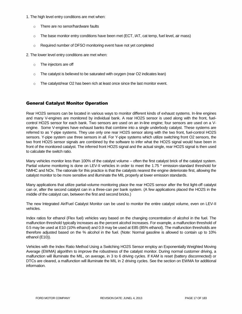
During normal operation, the ELCM is vented to atmosphere through the COV. This allows for purging during engine operation as well as fuel fill. During ELCM leak detection execution, the vacuum pump is turned on. With the pump on, vacuum is drawn across the reference orifice and the ensuing vacuum level becomes the threshold for pass/fail criteria. Once the reference is established, it is time to perform the actual leak testing. This is accomplished by energizing the COV and turning on the vacuum pump. Depending on the volume of the evaporative system being evacuated, it could take anywhere from 2 to15 minutes for the vacuum level to saturate. Once saturation vacuum is reached, the vacuum level is compared against the vacuum level when the reference check was performed. Vacuum levels lower than the reference check are considered to be fails and vacuum levels above the reference check are considered to be passes. The diagrams below illustrate this.
Typical purge flow/fuel fill configuration. Yellow denotes the vacuum/pressure path.
Typical reference check configuration (Pump ON). Yellow denotes the vacuum path.
Typical system leak check configuration (Pump On, COV On). Yellow denotes the vacuum path.
COV Off
Atm
Canister
Ref Orifice
PS
COV Off
Atm
Canister
Ref Orifice
PS
COV On
Atm
Canister
Ref Orifice
PS
FORD MOTOR COMPANY REVISION DATE: JUNEL 4, 2013 PAGE 29 OF 183
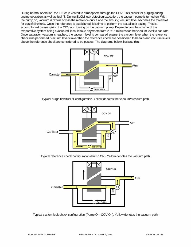
Below is a typical plot of a test sequence. First, a reference check is obtained. The system is then relieved back to atmosphere before the COV is energized and the pump is turned on again. If the resulting vacuum signal crosses below the reference check line, then the system is deemed to be leak-free. If the vacuum signal "flat lines" above the reference check line, then the system is determined to have a leak > 0.020".
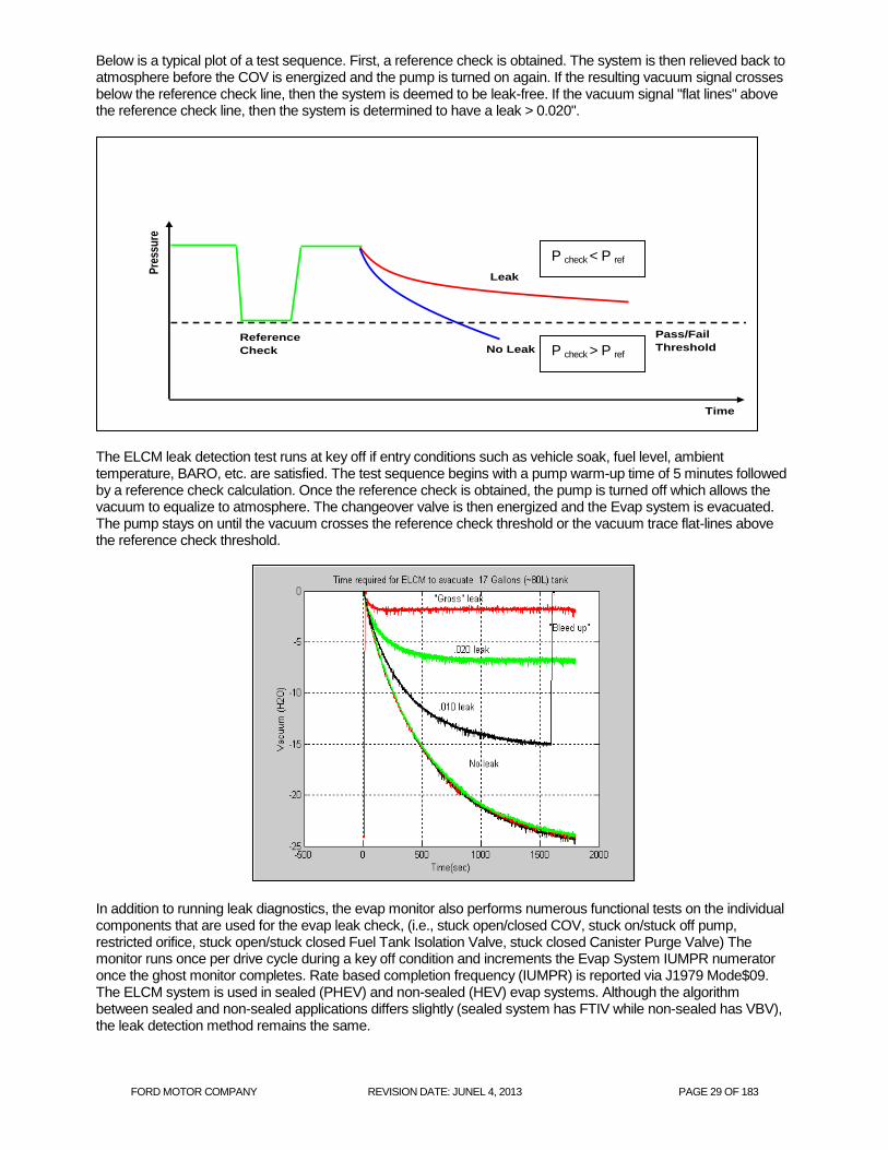
The ELCM leak detection test runs at key off if entry conditions such as vehicle soak, fuel level, ambient temperature, BARO, etc. are satisfied. The test sequence begins with a pump warm-up time of 5 minutes followed by a reference check calculation. Once the reference check is obtained, the pump is turned off which allows the vacuum to equalize to atmosphere. The changeover valve is then energized and the Evap system is evacuated. The pump stays on until the vacuum crosses the reference check threshold or the vacuum trace flat-lines above the reference check threshold.
In addition to running leak diagnostics, the evap monitor also performs numerous functional tests on the individual components that are used for the evap leak check, (i.e., stuck open/closed COV, stuck on/stuck off pump, restricted orifice, stuck open/stuck closed Fuel Tank Isolation Valve, stuck closed Canister Purge Valve) The monitor runs once per drive cycle during a key off condition and increments the Evap System IUMPR numerator once the ghost monitor completes. Rate based completion frequency (IUMPR) is reported via J1979 Mode$09. The ELCM system is used in sealed (PHEV) and non-sealed (HEV) evap systems. Although the algorithm between sealed and non-sealed applications differs slightly (sealed system has FTIV while non-sealed has VBV), the leak detection method remains the same.
Reference
Check
Leak
No Leak
Time
Pre
ssu
re
Pass/Fail
ThresholdP check > P ref
P check < P ref

FORD MOTOR COMPANY REVISION DATE: JUNEL 4, 2013 PAGE 30 OF 183
Fuel Systems Hardware – Sealed (PHEV) vs non-Sealed (HEV)
HEVs use a traditional non-sealed evaporative system. This is because the engine is expected to run for extended periods of time on an HEV so fuel vapors will get purged on a regular basis.
o Uses traditional Canister Purge Valve (CPV) o Uses traditional Vapor Blocking Valve (VBV) o Uses traditional (low pressure) Fuel Tank Pressure Transducer (FTPT) o ELCM replaces Canister Vent Valve (CVV). o VBV de-energized state is open
Plug in HEVs (PHEV) use a sealed evaporative system. The sealed fuel system is designed to contain fuel vapors while not refueling. This is because the engine may not run for extended periods of time on a PHEV so fuel vapors do not get purged on a regular basis. Internally, the sealed system is known as a NIRCOS (Non-Integrated Refueling Canister Only System).
o Canister sized for refueling vapors only o Uses a structurally improved steel fuel tank o Tank pressure relief at -2.5 psi and 5.5 psi o Requires an electric refueling system to relieve the pressure in the tank o Uses traditional Canister Purge Valve (CPV) o Uses High Pressure Fuel Tank Pressure Transducer (HPFTPT) o Uses Fuel Tank Isolation Valve (FTIV) in place of Vapor Blocking Valve (VBV) o FTIV de-energized state is closed o When FTIV is closed, it splits the evap system into two separately diagnosable system – the "fuel tank
side" and the "fresh air side"
Canister
Carbon
Intake
Manifold
CPV
Canister Circuit
nonNIRCOS: VBV
VBV FTPT
Fuel Tank
HPFTPTFTIV
Tank CircuitNIRCOS:Integrated FTIV
ELCM Pump
Ref
Orifice 0
.020"
Fresh Air
ELCMPS

FORD MOTOR COMPANY REVISION DATE: JUNEL 4, 2013 PAGE 31 OF 183
EVAP System Monitor – Engine Running Diagnostics
The EVAP diagnostics can be split into two categories: Engine Running Diagnostics (HEV and PHEV), consisting of:
o A purge flow/gross leak (P04ED) o Excessive vacuum (P1450) o Fresh air line blockage (P144B) o Canister Purge Valve component checks (P0443) o Vapor Blocking Valve stuck open (P2450) (HEV only)
Engine Off (After-run) Diagnostics, consisting of:
o The 0.020" /0.040" leak check o All other EVAP system and component diagnostics are executed during the engine off period.
The engine running diagnostics are described below:
The Canister Purge Valve (CPV) output circuit is checked for opens and shorts (P0443)
Note that a stuck closed CPV generates a P04ED, a leaking or stuck open CPV generates a P1450.
Canister Purge Valve Circuit Check Operation:
DTCs P0443 – Evaporative Emission System Purge Control Valve "A" Circuit
Monitor execution engine running, continuous
Monitor Sequence None
Sensors OK not applicable
Monitoring Duration 5 seconds to obtain smart driver status
Typical Canister Purge Valve Circuit Check malfunction thresholds:
P0443: open/shorted

FORD MOTOR COMPANY REVISION DATE: JUNEL 4, 2013 PAGE 32 OF 183
This test checks to see if the fresh air line to ELCM unit is clogged or restricted. The fresh air line flow test is
performed with the engine running, the Change Over Valve (COV) off and purge flow commanded on.
Fresh Air Line Flow Check Operation:
DTCs P144B - EVAP System Secondary Purge Vapor Line Restricted/Blocked
Monitor execution engine running, once per driving cycle
Monitor Sequence P1450 completed and OK
Sensors/Components OK P0456, P0457, P24B9, P24BA, P24BB, P0100, P0102, P0103, P0106, P0107,
P0108, P0720 P0452, P0453, P0454, P24BC, P0452, P0453, P0454, P24C1,
P24C0, P2402, P2450, P0443, P2418, P2402, P2401, P2227, P2228, P2229
Monitoring Duration
Fresh Air Line Flow Check entry conditions
Entry condition Minimum Maximum
Air Mass > 0 lbs/min
Vehicle Speed (vehicle speed sensor OK) 0 mph
BARO (<8,000 ft altitude) 22.0 “ Hg
Battery Voltage 11 volts 18 volts
Closed loop fuel control (HO2S sensors OK)
Purge Flow 0.04 lbm/min
Manifold Vacuum 2.0 in Hg
COV commanded open
ELCM absolute pressure change from power up value 60 inH2O
VBV/FTIV Closed
ELCM BARO Updated
Typical Fresh Air Line Flow Check malfunction thresholds:
Relative vacuum at ELCM < -20.0 inH2O / 4981.78 Pa OR
Absolute vacuum at ELCM > 60 inH2O / 14945.3 Pa
J1979 Fresh Air Line Flow Check Mode $06 Data
Monitor ID Comp ID Description for CAN Units
$3D $85 Blocked EVAP System Fresh Air Line Pa
Note: Default values (0.0) will be displayed for all the above TIDs if the evap monitor has never completed. The appropriate TID will be updated based on the current or last driving cycle, default values will be displayed for any phases that have not completed.

FORD MOTOR COMPANY REVISION DATE: JUNEL 4, 2013 PAGE 33 OF 183
This test is a functional check on the HEV for excessive leakage through the EVAP Switching Valve (Vapor
Blocking Valve) when it is commanded closed. It runs during the flow test during engine running. This test only
completes on the full hybrid. The Plug In hybrid tests the FTIV during the key off ELCM monitor.
EVAP Switching Valve Functional Check Operation:
DTCs P2450 – EVAP System Switching Valve Performance/Stuck Open
Monitor execution engine running, once per driving cycle
Monitor Sequence P1450 not running
Sensors/Components OK P0456, P0457, P24B9, P24BA, P24BB, P0100, P0102, P0103, P0106, P0107,
P0108, P0720, P0452, P0453, P0454, P24BC, P0452, P0453, P0454, P24C1,
P24C0, P2402, P2450, P0443, P2418, P2402, P2401, P2227, P2228, P2229
Monitoring Duration 4 sec
EVAP Switching Valve Functional Check entry conditions
Entry condition Minimum Maximum
Vapor Blocking Valve (VBV) commanded closed
Air Mass > 0 lbs/min
Vehicle Speed (vehicle speed sensor OK) 0 mph
Intake Air Temperature 40 deg F 95 deg F
Fuel Level 15% 85%
BARO (<8,000 ft altitude) 22.0 “ Hg
Battery Voltage 11 volts 18 volts
Purge Flow 0.08 lbm/min
Manifold Vacuum 2.0 in Hg
Relative ELCM Pressure -99 in H2O
Time Since Last Abort 20 sec
Closed loop fuel control (HO2S sensors OK)
Tank Pressure -50 InH20 125 InH2O
ELCM BARO Updated
ELCM absolute pressure change from power up value 60 InH2O
Typical EVAP Switching Valve Functional Check malfunction thresholds:
ELCM pressure sensor rate of change during flow test > 20.0 inH2O / 4981.78 Pa

FORD MOTOR COMPANY REVISION DATE: JUNEL 4, 2013 PAGE 34 OF 183
J1979 EVAP Switching Valve Functional Mode $06 Data
Monitor ID Comp ID Description for CAN Units
$3D $82 Vapor Blocking Valve Performance Pa
$3D $86 Fuel Tank Isolation Valve Stuck Open Pa/sec
$3D $87 Fuel Tank Isolation Valve Stuck Closed Pa/sec
Note: Default values (0.0) will be displayed for all the above TIDs if the evap monitor has never completed. The appropriate TID will be updated based on the current or last driving cycle, default values will be displayed for any phases that have not completed.
This is a functional check for a stuck open canister purge valve. This generates too much vacuum during the purge
flow test
EVAP Flow Check Operation:
DTCs P1450 – Unable to Bleed Up Fuel Tank Vacuum
Monitor execution engine running, once per driving cycle
Monitor Sequence
Sensors/Components OK P0456, P0457, P24B9, P24BA, P24BB, P0100, P0102, P0103, P0106, P0107,
P0108, P0720, P0452, P0453, P0454, P24BC, P0452, P0453, P0454, P24C1,
P24C0, P2402, P2450, P0443, P2418, P2402, P2401, P2227, P2228, P2229
Monitoring Duration 5 sec
EVAP Flow Check entry conditions
Entry condition Minimum Maximum
Purge Flow 0.0 lbm/min
Manifold Vacuum 2.0 in Hg
BARO (<8,000 ft altitude) 22.0 “ Hg
Battery Voltage 11 volts 18 volts
FTIV or VBV commanded closed
COV commanded closed
Closed loop fuel control (HO2S Sensors OK)
Relative ELCM Pressure -99 in H2O
Tank Pressure -50 InH20 125 InH2O
Fuel Level 15% 85%
Intake Air Temperature 20 deg F 95 deg F
ELCM BARO Updated
Power up Time 5 sec 15 sec
Time since purge off 4 sec
Engine speed 200 rpm

FORD MOTOR COMPANY REVISION DATE: JUNEL 4, 2013 PAGE 35 OF 183
Typical EVAP Flow Check malfunction thresholds:
Relative vacuum at ELCM > -10.0 inH2O / -2490.89 Pa.
J1979 EVAP Flow Check Functional Mode $06 Data
Monitor ID Comp ID Description for CAN Units
$3D $83 Purge Valve Stuck Open Pa
$3D $84 Purge Valve Stuck Closed Pa
Note: Default values (0.0) will be displayed for all the above TIDs if the evap monitor has never completed. The appropriate TID will be updated based on the current or last driving cycle, default values will be displayed for any phases that have not completed.
FORD MOTOR COMPANY REVISION DATE: JUNEL 4, 2013 PAGE 36 OF 183
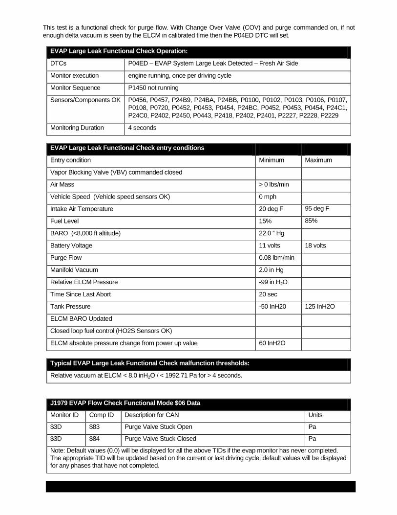
This test is a functional check for purge flow. With Change Over Valve (COV) and purge commanded on, if not
enough delta vacuum is seen by the ELCM in calibrated time then the P04ED DTC will set.
EVAP Large Leak Functional Check Operation:
DTCs P04ED – EVAP System Large Leak Detected – Fresh Air Side
Monitor execution engine running, once per driving cycle
Monitor Sequence P1450 not running
Sensors/Components OK P0456, P0457, P24B9, P24BA, P24BB, P0100, P0102, P0103, P0106, P0107,
P0108, P0720, P0452, P0453, P0454, P24BC, P0452, P0453, P0454, P24C1,
P24C0, P2402, P2450, P0443, P2418, P2402, P2401, P2227, P2228, P2229
Monitoring Duration 4 seconds
EVAP Large Leak Functional Check entry conditions
Entry condition Minimum Maximum
Vapor Blocking Valve (VBV) commanded closed
Air Mass > 0 lbs/min
Vehicle Speed (Vehicle speed sensors OK) 0 mph
Intake Air Temperature 20 deg F 95 deg F
Fuel Level 15% 85%
BARO (<8,000 ft altitude) 22.0 “ Hg
Battery Voltage 11 volts 18 volts
Purge Flow 0.08 lbm/min
Manifold Vacuum 2.0 in Hg
Relative ELCM Pressure -99 in H2O
Time Since Last Abort 20 sec
Tank Pressure -50 InH20 125 InH2O
ELCM BARO Updated
Closed loop fuel control (HO2S Sensors OK)
ELCM absolute pressure change from power up value 60 InH2O
Typical EVAP Large Leak Functional Check malfunction thresholds:
Relative vacuum at ELCM < 8.0 inH2O / < 1992.71 Pa for > 4 seconds.
J1979 EVAP Flow Check Functional Mode $06 Data
Monitor ID Comp ID Description for CAN Units
$3D $83 Purge Valve Stuck Open Pa
$3D $84 Purge Valve Stuck Closed Pa
Note: Default values (0.0) will be displayed for all the above TIDs if the evap monitor has never completed. The appropriate TID will be updated based on the current or last driving cycle, default values will be displayed for any phases that have not completed.

FORD MOTOR COMPANY REVISION DATE: JUNEL 4, 2013 PAGE 37 OF 183
EVAP System Monitor – Engine Off Diagnostics
ELCM Leak Detection 0.020" Monitor Entry Conditions
Engine Off and Key Off (After-run) Diagnostics, consisting of: o The 0.020" leak check o All other EVAP system and component diagnostics are executed during the engine off period.
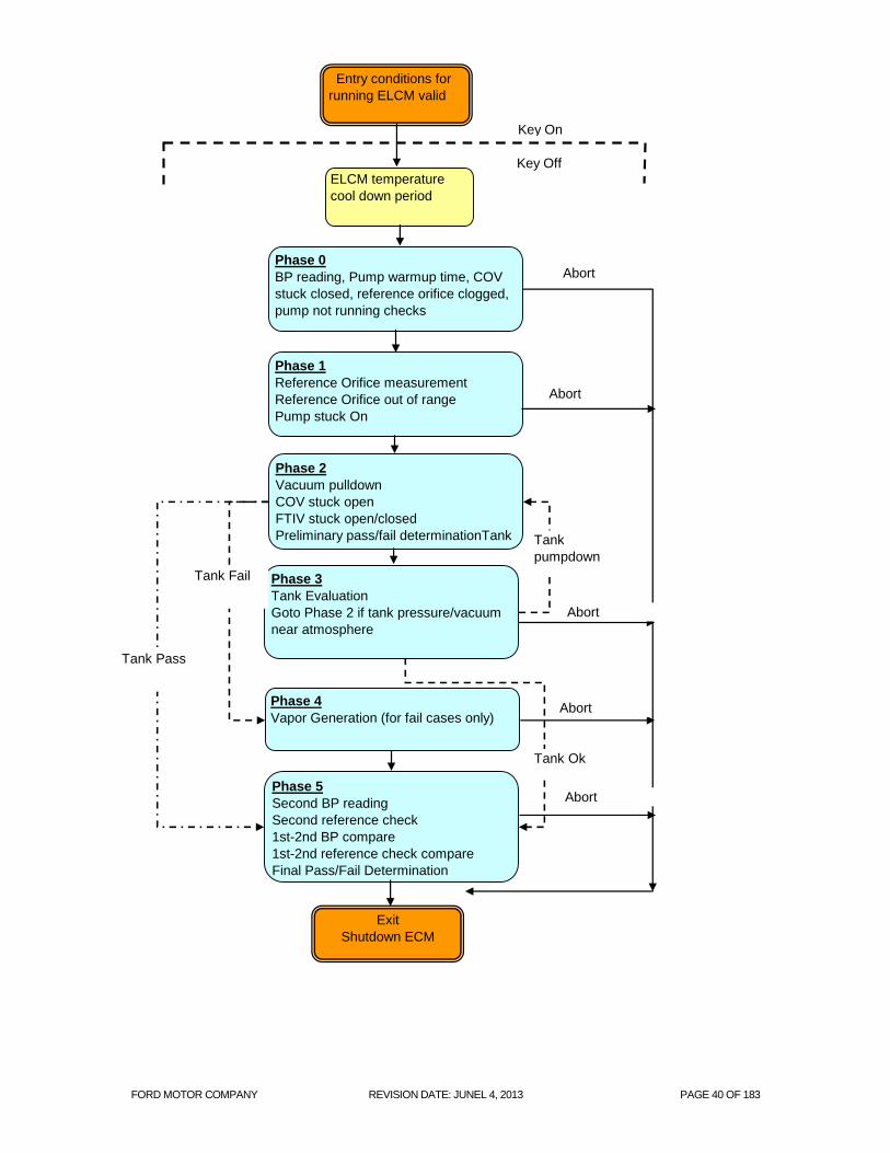
Note: there is a “Wait” period after key-off to ensure that ELCM pump temperature is within the specified operating temperature. The “Wait” time is a function of ambient temperature (5 – 17 min). The entry conditions for the engine off monitor are evaluated while the vehicle is being driven, prior to shut down. Basic entry conditions for the leak diagnostics are a combination of conditions mandated by CARB and others intended to make the monitor robust to false calls. Phase 0: BARO Reference/ELCM Functional Tests The first phase starts by obtaining a BARO reading. The PCM opens the CPV and vents any trapped vacuum. After some stabilization time, with all the ELCM actuators in their unpowered state, the monitor obtains a BARO reading. Then the ELCM pump is turned on (COV not energized) to send flow through the reference orifice. If the slope of the ELCMPS pressure is less than a threshold value, then the monitor tentatively infers that the COV is stuck in the energized state and flow is not going through the reference orifice. This will set a P24C0 unless the pump functional test fails later in the test. Once the COV functional test is complete, the orifice functional test is performed. The stabilized ELCMPS pressure is compared to a threshold value to see if too much vacuum was produced. This would be an indication of a clogged/restricted orifice. In this case, the monitor aborts and a P043E DTC is set. The stabilized ELCMPS pressure is compared to a threshold value to see if too little vacuum was produced. This would be an indication of a high flow orifice. In this case, the monitor aborts and a P043F DTC is set. The last part of Phase 0 is the pump warm-up time (typically 5 min). Once the warm-up time is met, the ELCMPS pressure is compared against a threshold to determine how much vacuum was generated across the orifice during the warm-up time. Too little vacuum is an indication that the pump is stuck off in which case the monitor aborts and sets P2401 DTC. If all tests pass, monitor goes on to Phase 1. Note: The ELCMPS sensor is an absolute sensor whereas the HPFTPT is a relative sensor. To compare the two sensors, the ELCMPS signal is converted to gauge by subtracting the BARO reading. Phase 1: 1st Reference Pressure Measurement In Phase 1, the resulting ELCMPS relative pressure is averaged and stored as a 0.020" reference. This 1st reference check is compared against a table of min and max reference pressures as a function of BARO. If the reference pressure is outside the min and max, the monitor aborts and sets a P24B9 DTC. Then, the vacuum pump is commanded off and the ELCMPS pressure is compared to atmospheric pressure. If the ELCMPS pressure does not go back up above a threshold pressure, the monitor infers that the vacuum pump is stuck on, aborts and sets a P2402 DTC. Otherwise, the monitor continues on with the next phase provided that the vacuum dissipates back near atmospheric pressure. Failure to dissipate the vacuum is indicative of blockages. The monitor aborts and next time the flow test runs, it should flag a blocked fresh air line. Phase 2: Vacuum Pull/Leak Detection Phase 2 is the most critical phase in the ELCM monitor. This is where the Evap system (canister side only or the entire system) is evacuated using the ELCM vacuum pump. The COV as well as the vacuum pump are turned on. The COV stuck functional test is performed again to check whether the COV is stuck in the de-energized position. The rate of change of the ELCMPS pressure is compared to a threshold. The monitor aborts and set a P24C1 DTC if the ELCMPS vacuum slope is too high. If the COV test passes, the monitor goes on to check the FTIV valve for being stuck open. The rate of change of the ELCMPS pressure is calculated again and compared to a threshold. If the slope is too low, the FTIV is inferred to be stuck open and the monitor aborts and sets a P2450

FORD MOTOR COMPANY REVISION DATE: JUNEL 4, 2013 PAGE 38 OF 183
DTC. If the FTIV had been commanded open and the rate of change of the ELCMPS pressure is greater than a threshold, then the FTIV is inferred to be stuck closed and the monitor aborts and sets a P2451 DTC. Once the functional tests are complete, the monitor goes on perform the leak check using the averaged, stabilized pressure. Leak test results are normalized to the reference pressure obtained in Phase 1. A normalized pressure greater than the 0.020” leak threshold (> 1.0) is a pass. For HEV, the test goes on to Phase 5. For PHEV, the test goes on to Phase 3 The monitor periodically computes the slope of the pressure value. If the slope indicates that the signal is “flat lining” without crossing the reference check threshold, the determination is that a leak is present, pending the vapor generation analysis. If the signal “flat lines” for an HEV, the monitor sets a preliminary P0456 failure flag and goes to Phase 5. For a PHEV, if the signal “flat lines”, the monitor sets a preliminary P04EF failure flag indicating a leak on the fresh air side of the Evap system and the test goes on to Phase 3. Phase 3: Tank Pressure Evaluation (PHEV only, sealed evap system) In Phase 3, the filtered tank pressure is evaluated to determine whether the tank is leak-free or not. If there is sufficient pressure or vacuum buildup in the tank and the pressure/vacuum variation in the tank is low, the tank is properly sealed and there are no leaks. In such a case, the FTIV is left in its normally closed position and only the canister side of the Evap system is monitored for leaks. If the tank pressure/vacuum is near atmosphere or if the tank pressure/vacuum is high but has considerable variation, then the FTIV is commanded open and the entire Evap system is monitored for leaks. The monitor goes back to phase 2 to evacuate the entire Evap system.
If the monitor fails with the FTIV open, a fail flag is set to indicate a potential leak in the entire Evap system (P04EE). There are no abort conditions in this phase. Note that there is a delay to allow the pressure to stabilize to atmospheric pressure between the tank and canister side checks. Phase 4: Vapor Generation/CPV Stuck Closed (PHEV only, seal evap system) This is the phase where the full Evap system is diagnosed for vapor generation in the case where a failure occurred in the second Phase 2 while the FTIV was open. Vapor generation for the fuel results in a positive pressure build up. It is typically caused by high RVP fuels and/or hot weather. The positive pressure can overwhelm the vacuum being generated by the low flow ELCM pump. Depending on the magnitude of the vapors, an otherwise sealed Evap system could be diagnosed as having a leak; therefore, the vapor generation check is needed to qualify any leak monitor fail calls. The vapor generation routine is based on the ideal gas law. The temperature is assumed to be constant during the duration of the test. The volume is also assumed constant since the PHEV evap system uses a rigid, metal fuel tank. Any pressure change is, therefore, due to fuel vapors. Phase 4 starts out by turning off the vacuum pump and commands the COV to its vent position. With the FTIV open, the system is allowed to vent to atmosphere until the pressure climbs to near atmosphere or times out. In the case of a timeout, the tank is assumed to have intense vapors whereby even when it is open to atmosphere, the pressure is unable to equalize with atmospheric pressure. Once the vented tank pressure is close to atmosphere, the FTIV is closed and the tank is sealed for a calibrated time period. A positive pressure buildup more than a threshold value results in an abort and discarding the fail call (i.e. a “no call”). In the case of a “pass” call in phase 2, the vapor generation test is not run. Phase 5: 2nd Reference Pressure Measurement This is the final phase in the ELCM monitor. The purpose of this phase is to validate that the 1
st reference check is
accurate by obtaining a 2nd
reference check and comparing the two. After some stabilization time, another BARO reading is obtained and compared to the first BARO reading. If the BARO readings do not match within a calibrated limit, the monitor aborts. If the BARO readings are consistent, the monitor continues by turning on the vacuum pump for a calibrated warm-up time. The 2
nd reference check is compared against a table of min and max
reference pressures as a function of BARO. If the reference pressure is outside the min and max, the monitor

FORD MOTOR COMPANY REVISION DATE: JUNEL 4, 2013 PAGE 39 OF 183
aborts and sets a P24B9 DTC. If the reference check is OK, then the 1st and 2
nd reference checks are compared to
each other. If they disagree by more than a calibrated limit, then the monitor aborts and sets a P24B9 DTC. If the BARO readings and reference pressures are reliable, then any evap system failures determined previously are confirmed. NOTE – When the monitor passes, execution does not end. A “ghost” monitor continues to execute as if a failure had been detected. The ghost monitor is time based and executes to the maximum allowable time allotted for the “leak” failure case.
FORD MOTOR COMPANY REVISION DATE: JUNEL 4, 2013 PAGE 40 OF 183
Entry conditions for
running ELCM valid
ELCM temperature
cool down period
Key On
Key Off
Phase 0
BP reading, Pump warmup time, COV
stuck closed, reference orifice clogged,
pump not running checks
Phase 1
Reference Orifice measurement
Reference Orifice out of range
Pump stuck On
Phase 2
Vacuum pulldown
COV stuck open
FTIV stuck open/closed
Preliminary pass/fail determinationTank
Pressure Evaluation
Phase 3
Tank Evaluation
Goto Phase 2 if tank pressure/vacuum
near atmosphere
Exit
Shutdown ECM
Abort
Abort
Abort
Phase 4
Vapor Generation (for fail cases only)
Phase 5
Second BP reading
Second reference check
1st-2nd BP compare
1st-2nd reference check compare
Final Pass/Fail Determination
Abort
Abort
Tank
pumpdown
Tank Fail
Tank Pass
Tank Ok

FORD MOTOR COMPANY REVISION DATE: JUNEL 4, 2013 PAGE 41 OF 183
0.020” ELCM EVAP Monitor Operation:
DTCs P0456 – EVAP System Very Small Leak Detected (HEV)
P0457 – EVAP System Leak Detected (fuel cap loose/off) (HEV/PHEV)
P04EE – EVAP System Very Small Leak Detected – Fuel Tank Side (PHEV)
P04EF – EVAP System Very Small Leak Detected – Fresh Air Side (PHEV)
Monitor execution Once per key-off when entry conditions are met during drive.
Monitor Sequence none
Sensors/Components OK P0443, P2418, P24BE, P24BF, P2401, P2402, P144B, P04ED, P1450,
P24BA, P24BB, P0451, P0452, P0453, P0454, P2610, P0112, P0113,
P043E, P043F, P24C0, P24C1, P2450, P2451, P24BC, P2610, P0112,
P0113
Monitoring Duration 45 minutes in key-off state if fault present.
Typical 0.020” EONV EVAP monitor entry conditions:
Entry conditions seen just prior to engine off Minimum Maximum
ELCM 24 hour run time 60 min
Time Since Pump ran 180 minutes
Ambient Temperature 40 oF 95
oF
Battery Voltage 11 volts 16 volts
Engine Speed 1 rpm
Vehicle Speed 0.1 mph
Fuel level 15% 85%
Not a refueling event
BARO 22 in Hg
Accumulated Aar mass flow summation 1000000000 lbm/min
Delay period in after run 5 min 17 min
Too much time in after run 2300 sec for HEV,
2485 sec for PHEV
Tank pressure -50 InH2O 125 InH2O
Typical 0.020” ELCM EVAP key-off abort conditions:
Tank pressure > 0.8 " H20 during the 5 minute key-off stabilization phase (indicates excessive vapor)
OR
Ignition key on, battery voltage low/high, refueling event, engine speed, shifter not in Park, BARO did not
update, tank being vented , any other hardware/circuit fault
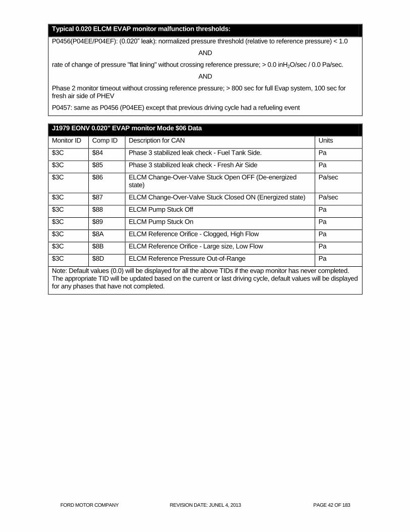
FORD MOTOR COMPANY REVISION DATE: JUNEL 4, 2013 PAGE 42 OF 183
Typical 0.020 ELCM EVAP monitor malfunction thresholds:
P0456(P04EE/P04EF): (0.020” leak): normalized pressure threshold (relative to reference pressure) < 1.0
AND
rate of change of pressure "flat lining" without crossing reference pressure; > 0.0 inH2O/sec / 0.0 Pa/sec.
AND
Phase 2 monitor timeout without crossing reference pressure; > 800 sec for full Evap system, 100 sec for fresh air side of PHEV
P0457: same as P0456 (P04EE) except that previous driving cycle had a refueling event
J1979 EONV 0.020" EVAP monitor Mode $06 Data
Monitor ID Comp ID Description for CAN Units
$3C $84 Phase 3 stabilized leak check - Fuel Tank Side. Pa
$3C $85 Phase 3 stabilized leak check - Fresh Air Side Pa
$3C $86 ELCM Change-Over-Valve Stuck Open OFF (De-energized state)
Pa/sec
$3C $87 ELCM Change-Over-Valve Stuck Closed ON (Energized state) Pa/sec
$3C $88 ELCM Pump Stuck Off Pa
$3C $89 ELCM Pump Stuck On Pa
$3C $8A ELCM Reference Orifice - Clogged, High Flow Pa
$3C $8B ELCM Reference Orifice - Large size, Low Flow Pa
$3C $8D ELCM Reference Pressure Out-of-Range Pa
Note: Default values (0.0) will be displayed for all the above TIDs if the evap monitor has never completed. The appropriate TID will be updated based on the current or last driving cycle, default values will be displayed for any phases that have not completed.

FORD MOTOR COMPANY REVISION DATE: JUNEL 4, 2013 PAGE 43 OF 183
EVAP System Monitor Engine Off Component Checks
Additional malfunctions that are identified as part of the evaporative system integrity check are as follows:
The Canister Purge Valve (CPV) output circuit is checked for opens and shorts (P0443)
Note that a stuck closed CPV generates a P04ED, a leaking or stuck open CPV generates a P1450.
Canister Purge Valve Circuit Check Operation:
DTCs P0443 – Evaporative Emission System Purge Control Valve "A" Circuit
Monitor execution engine off, continuous
Monitor Sequence None
Sensors OK not applicable
Monitoring Duration 5 seconds to obtain smart driver status
Typical Canister Purge Valve Circuit Check malfunction thresholds:
P0443: open/shorted
The Evap Fuel Tank Switching Valve (EVAPSV) control circuit is checked for opens and shorts (P2418). For the
PHEV, this component is the FTIV (Fuel Tank Isolation Valve). For the HEV, this component is the VBV (Vapor
Blocking Valve).
Note that a stuck closed Evap Switching Valve generates a P2451; a stuck open Evap Switching Valve generates
a P2450.
Evap Switching Valve Check Operation:
DTCs P2418 - Evap Switching Valve Circuit
Monitor execution continuous
Monitor Sequence None
Sensors OK not applicable
Monitoring Duration 5 seconds to obtain smart driver status
Evap Switching Valve check malfunction thresholds:
P2418 (Evap Switching Valve Circuit): open/shorted

FORD MOTOR COMPANY REVISION DATE: JUNEL 4, 2013 PAGE 44 OF 183
The ELCM Leak Detection Pump Control Circuit is checked for opens and shorts and functionally.
ELCM Pump Control Check Operation:
DTCs P2401 - EVAP System Leak Detection Pump Control Circuit Low
P2402 - EVAP System Leak Detection Pump Control Circuit High
Monitor execution continuous
Monitor Sequence None
Sensors OK not applicable
Monitoring Duration 5 seconds to obtain smart driver status
Typical ELCM Pump Control check malfunction thresholds:
P2401/P2402 - output driver open/shorted
ELCM Pump Control Functional Check Operation:
DTCs P2401 - EVAP System Leak Detection Pump Control Circuit Low
P2402 - EVAP System Leak Detection Pump Control Circuit High
Monitor execution during Phase 0 of evap monitor leak check
Monitor Sequence Evap monitor leak detection condition met
Sensors OK not applicable
Monitoring Duration 360 seconds in Phase 0, 5 seconds on Phase 1
Typical ELCM Pump Control Functional Check malfunction thresholds:
P2401: pressure at the end of 360 sec of warm-up time in Phase 0 too low; > -2.0 inH2O / -498.18 Pa.
P2402: pressure increasing in Phase 1 after pump shut off for 5 sec; > 4.0 inH2O / 996.35 Pa.
ELCM Pump Control Flow Check Operation:
DTCs P043E - EVAP System Leak Detection Reference Orifice Low Flow
P043F - EVAP System Leak Detection Reference Orifice High Flow
Monitor execution once per key off, after entry conditions have been met during pre-key off drive
cycle
Monitor Sequence during Phase 0 of evap monitor leak check
Sensors OK not applicable
Monitoring Duration 60 seconds in Phase 0
Typical ELCM Pump Control flow check malfunction thresholds:
P043E: stabilized pressure at the end of Phase 0 too low <= -20.2 inH2O / 5031.6 Pa
P043F: stabilized pressure at the end of Phase 0 too high > -2.8 inH2O / > -697.45 Pa.

FORD MOTOR COMPANY REVISION DATE: JUNEL 4, 2013 PAGE 45 OF 183
The Evap Leak Detection Pump Vacuum Switching Valve / (Change Over Valve) control circuit is checked for
opens and shorts and functionally.
Evap Vacuum Switching Valve Circuit Check Operation:
DTCs P24BE - EVAP Leak Detection Pump Vacuum Switching Valve Control Circuit Low
P24BF - EVAP Leak Detection Pump Vacuum Switching Valve Control Circuit High
Monitor execution continuous
Monitor Sequence None
Sensors OK not applicable
Monitoring Duration 5 seconds to obtain smart driver status
Evap Vacuum Switching Valve Circuit Check malfunction thresholds:
P24BE/P24BF - output driver open/shorted
Evap Vacuum Switching Valve Functional Check Operation:
DTCs P24C0 - EVAP System Leak Detection Pump Vacuum Switching Valve Stuck On
P24C1 - EVAP System Leak Detection Pump Vacuum Switching Valve
Performance/Stuck Off
Monitor execution P24C0 during Phase 0 of evap monitor leak check, P24C1 during Phase 2 of evap
monitor leak check
Monitor Sequence Evap monitor leak detection condition met
Sensors OK P0443, P2418, P24BE, P24BF, P2401, P2402, P144B, P04ED, P1450, P24BA,
P24BB, P0451, P0452, P0453, P0454, P2610, P0112, P0113, P043E, P043F,
P24C0, P24C1, P2450, P2451 P24BC, P2610, P0112, P0113
Monitoring Duration 65 seconds in Phase 0, 2 seconds in Phase 2
Evap Vacuum Switching Valve check malfunction thresholds:
P24C0: rate of change of pressure too low; < 1.2 inH2O / 174.36 Pa
P24C1: rate of change of pressure too high; > 4.0 inH2O / 996.35 Pa.

FORD MOTOR COMPANY REVISION DATE: JUNEL 4, 2013 PAGE 46 OF 183
The EVAP System Leak Detection Pump Pressure Sensor input circuit is checked for opens and shorts, out of
range values and noisy readings.
Leak Detection Pump Pressure Sensor Check Operation:
DTCs P24BA - EVAP System Leak Detection Pump Pressure Sensor Circuit Low
P24BB - EVAP System Leak Detection Pump Pressure Sensor Circuit High
P24B9 - EVAP System Leak Detection Pump Pressure Sensor Circuit
Range/Performance
P24BC - EVAP System Leak Detection Pump Pressure Sensor Circuit Intermittent
(noisy)
Monitor execution continuous
Monitor Sequence None
Sensors OK not applicable
Monitoring Duration 20 seconds for electrical malfunctions, 10 seconds for noisy sensor test
Typical Leak Detection Pump Pressure Sensor check malfunction thresholds:
P24BA (Circuit low): < 168.96 inH20 / 42.08 kPa.
P0453 (Circuit high): > 496.93 inH20 / 123.78 kPa.
P24B9 (Reference out of range) > -1.5 to -5.5 in H2O (function of BARO) OR
< -17.5 to -21.5 in H2O (function of BARO)
P24BC (noisy): open circuit, short circuit or > 25.0 inH2O / 6.227 kPa change between samples, sampled every 100 milliseconds, filtered fault level of 25% will set code in 10 seconds

FORD MOTOR COMPANY REVISION DATE: JUNEL 4, 2013 PAGE 47 OF 183
The Fuel Tank Pressure Sensor input circuit is checked for out of range values (P0452 short, P0453 open), noisy
readings (P0454 noisy) and an offset (P0451 offset).
Note that for the PHEV, this component is the FTPTHP (Fuel Tank Pressure Transducer – High Pressure). For the
HEV, this component is the FTPT (Fuel Tank Pressure Transducer).
Fuel Tank Pressure Sensor Transfer Function
FTP volts = [ Vref * ( 0.14167 * Tank Pressure) + 2.6250 ] / 5.00
Volts A/D Counts in PCM Fuel Tank Pressure, Inches H2O
0.100 20 -17.82
0.500 102 -15.0
1.208 247 -10.0
2.625 464 0
3.475. 712 6.0
4.750 973 15.0
4.90 1004 16.06
High Pressure Fuel Tank Pressure Sensor Transfer Function
FTP volts = [ Vref * ( 0.015 * Pump Pressure) + 1.15 ] / 5.00
Volts A/D Counts in PCM Fuel Tank Pressure, Inches H2O
0.25 51 -60.0
0.50 102 -43.33
1.15 235 0.00
2.05 419 60.00
3.00 614 123.33
4.50 921 223.33
4.75 970 240.0
Fuel Tank Pressure Sensor Check Operation:
DTCs P0452 – Fuel Tank Pressure Sensor Circuit Low
P0453 – Fuel Tank Pressure Sensor Circuit High
P0454 – Fuel Tank Pressure Sensor Intermittent/Erratic (noisy)
Monitor execution continuous
Monitor Sequence None
Sensors OK not applicable
Monitoring Duration 5 seconds for electrical malfunctions, 10 seconds for noisy sensor test

FORD MOTOR COMPANY REVISION DATE: JUNEL 4, 2013 PAGE 48 OF 183
Typical Fuel Tank Pressure Sensor check malfunction thresholds:
P0452 (Fuel Tank Pressure Sensor Circuit Low): < -17.82 in H2O
P0452 (High Pressure Fuel Tank Pressure Sensor Circuit Low): < -60.00 in H2O
P0453 (Fuel Tank Pressure Sensor Circuit High): > 16.06 in H2O
P0453 (High Pressure Fuel Tank Pressure Sensor Circuit High): > 2401.00 in H2O
P0454 (Fuel Tank Pressure Sensor Circuit Noisy): open circuit, short circuit or > 25 in H2O change between samples, sampled every 100 milliseconds, filtered fault level of 25% will set code in 10 seconds
Fuel Tank Pressures Sensor Offset Check Operation
DTCs P0451(HEV Only) – Fuel Tank Pressure Sensor
Range/Performance (offset)
Monitor execution once per driving cycle
Monitor Sequence No P0443 or P1450, P2402, , P2450, P2451, P2418, P24BF,
P24C0 DTCs
Sensors OK not applicable
Monitoring Duration < 1 second
Typical Fuel Tank Pressure Sensor Offset Check Entry Conditions:
Entry condition Minimum Maximum
Ignition key on, engine off, engine rpm 0 rpm
Purge Duty Cycle 0%
Engine off (soak) time 240 min
Fuel Tank Pressure Sensor Variation during test 0.5 in H2O
Battery Voltage 11.0 Volts
Not a refueling event
Tank pressure -17.8 InH2O 16 InH2O
Typical Fuel Tank Pressure Sensor Offset Check Malfunction Thresholds:
Fuel tank pressure at key on, engine off is 0.0 in H2O +/- 1.7 in H2O

FORD MOTOR COMPANY REVISION DATE: JUNEL 4, 2013 PAGE 49 OF 183
The Fuel Level Input is checked for out of range values (opens/ shorts). The FLI input is obtained from the serial
data link from the instrument cluster. If the FLI signal is open or shorted, the appropriate DTC is set, (P0462 circuit
low and P0463 circuit high).
Finally, the Fuel Level Input is checked for noisy readings. If the FLI input changes from an in-range to out-of-range
value repeatedly, a P0461 DTC is set.
Fuel Level Input Check Operation:
DTCs P0460 – Fuel Level Sensor A Circuit
P0461 – Fuel Level Sensor A Circuit Noisy
P0462 – Fuel Level Sensor A Circuit Low
P0463 – Fuel Level Sensor A Circuit High
Monitor execution continuous
Monitor Sequence None
Sensors OK not applicable
Monitoring Duration 30 seconds for electrical malfunctions
Typical Fuel Level Input check malfunction thresholds:
P0460 or P0462 (Fuel Level Input Circuit Low): < 5 ohms (< 1 A/D count)
P0460 or P0463 (Fuel Level Input Circuit High): > 200 ohms (>1022 A/D counts)
P0461 (Fuel Level Input Noisy): > 40% change between samples, > 100 occurrences, sampled every 0.100 seconds
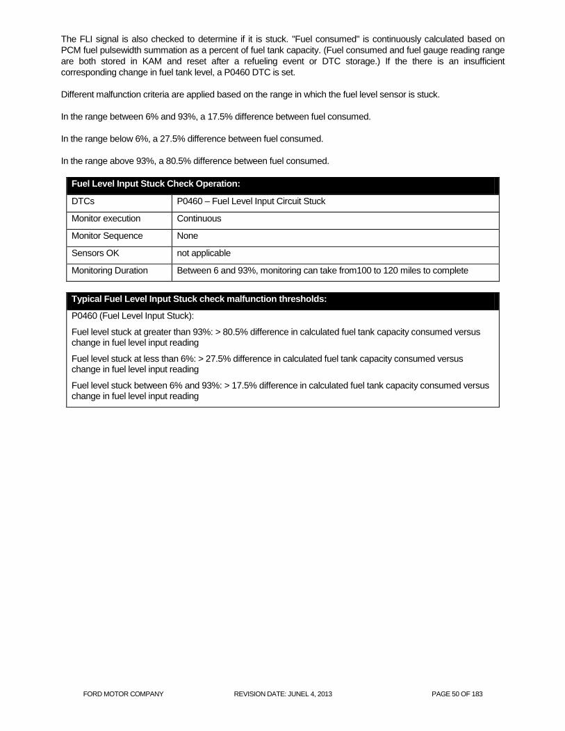
FORD MOTOR COMPANY REVISION DATE: JUNEL 4, 2013 PAGE 50 OF 183
The FLI signal is also checked to determine if it is stuck. "Fuel consumed" is continuously calculated based on
PCM fuel pulsewidth summation as a percent of fuel tank capacity. (Fuel consumed and fuel gauge reading range
are both stored in KAM and reset after a refueling event or DTC storage.) If the there is an insufficient
corresponding change in fuel tank level, a P0460 DTC is set.
Different malfunction criteria are applied based on the range in which the fuel level sensor is stuck.
In the range between 6% and 93%, a 17.5% difference between fuel consumed.
In the range below 6%, a 27.5% difference between fuel consumed.
In the range above 93%, a 80.5% difference between fuel consumed.
Fuel Level Input Stuck Check Operation:
DTCs P0460 – Fuel Level Input Circuit Stuck
Monitor execution Continuous
Monitor Sequence None
Sensors OK not applicable
Monitoring Duration Between 6 and 93%, monitoring can take from100 to 120 miles to complete
Typical Fuel Level Input Stuck check malfunction thresholds:
P0460 (Fuel Level Input Stuck):
Fuel level stuck at greater than 93%: > 80.5% difference in calculated fuel tank capacity consumed versus change in fuel level input reading
Fuel level stuck at less than 6%: > 27.5% difference in calculated fuel tank capacity consumed versus change in fuel level input reading
Fuel level stuck between 6% and 93%: > 17.5% difference in calculated fuel tank capacity consumed versus change in fuel level input reading

FORD MOTOR COMPANY REVISION DATE: JUNEL 4, 2013 PAGE 51 OF 183
PHEV Re-Fueling System
The PHEV uses a pressurized evap system. In order to refuel the vehicle, the customer needs to push a fuel door button in the cabin. This allows the PCM to both open a latch on the spring-loaded fuel fill door on the outside of the vehicle to provide access to the fuel filler inlet and open an FTIV (Fuel Tank Isolation Valve) which vents the evap system to the canister and allows refueling fuel vapors to enter the canister. If the FTIV is not open, the evap system will vent when the customer pushes the fuel fill nozzle into the fuel fill inlet and the customer will not be able to refuel the vehicle because the displaced vapors have no where to go).
Refueling Process:
Customer presses “refuel button” Signal is sent from BCM to PCM PCM opens FTIV & reads FTPT PCM sends cluster message “Please wait to refuel” Once fuel pressure is relieved, PCM unlocks fuel door solenoid. PCM sends cluster message “Ready to Refuel” Customer dispenses fuel Customer closes fuel door PCM recognizes closed fuel door by switch state FTIV closes
Mechanical Fail Safe Mode:
Customer presses “refuel button” Customer activates mechanical override of locking solenoid PCM recognizes fuel door is open by switch position Continue from "Refueling Process", third item (PCM opens FTIV & reads FTPT.
Refuel Button

FORD MOTOR COMPANY REVISION DATE: JUNEL 4, 2013 PAGE 52 OF 183
Fuel Tank
Isolation
Valve
(FTIV)
Body
Control
Module
(BCM)
Fuel Door
Momentary
Dash Switch
(Cabin)
PCM/ECM
Message
Center
(MC)
Fuel Tank
Pressure
Transducer
(FTPT)
Fuel Door
switch
(pop-open)
Fuel Door
Locking
Solenoid
Wake up
(h/w)
h/w
HS-CAN
HS-CAN
h/w
h/w
h/w
h/w
Vehicle
Speed
Ignition
key
CAN Network
Communication layer
+12V from
Power
saver relay
Fuel Door Locking
Solenoid Mechanical
Override

FORD MOTOR COMPANY REVISION DATE: JUNEL 4, 2013 PAGE 53 OF 183
The Fuel Door Switch is checked for opens and shorts and functionally.
Fuel Door Switch Check Operation:
DTCs P04BA - Fuel Fill Door Position Sensor / Switch Circuit High
P04B5 - Fuel Fill Door Stuck Open
Monitor execution continuous, engine off
Monitor Sequence After refueling is requested, P04B5 after refueling is completed
Sensors OK not applicable
Monitoring Duration 5 seconds
Typical Fuel Door Switch check malfunction thresholds:
P04BA:
1) Shorted to battery (door closed). Fuel door opens after unlock solenoid is energized but no indication to PCM. No indication to PCM to close FTIV after refueling. FTIV stays open longer than required. FTIV will close after timeout period. FTIV closes if vehicle starts to move > 7 mph or after 20 minutes.
2) Mechanically stuck (door closed). Fuel door opens after unlock solenoid is energized but no indication to PCM. No indication to PCM to close FTIV after refueling. FTIV stays open longer than required. FTIV will close after timeout period. FTIV closes if vehicle starts to move > 7 mph or after 20 minutes.
3) Mechanically stuck latched. Customer cannot refuel vehicle
P04B5:
1) Mechanically stuck (door open) or customer did not close fuel door. No indication to close FTIV after refueling. FTIV will stay open, evap system not a closed system any more, requires MIL.

FORD MOTOR COMPANY REVISION DATE: JUNEL 4, 2013 PAGE 54 OF 183
The Cabin Refuel Switch is checked for opens and shorts and functionally.
Cabin Refuel Switch Check Operation:
DTCs P04C9 - Fuel Fill Door Open Request Sensor / Switch Performance / Stuck Off.
P04CD - Fuel Fill Door Open Request Sensor / Switch Performance / Stuck On.
U0140 – Lost Communication With Body Control Module
U0442 – Invalid Data Received from Body Control Module
Monitor execution continuous, engine off, > 5 mph for P04CD
Monitor Sequence After refueling is requested
Sensors OK not applicable
Monitoring Duration 5 seconds
Cabin Refuel Switch check malfunction thresholds:
P04C9:
1) Circuit shorted to battery. No request to open fuel door or FTIV. Customer cannot refuel vehicle without using manual override. Once door is open, system works as designed.
2) Circuit open. No request to open fuel door or FTIV. Customer cannot refuel vehicle without using manual override. Once door is open, system works as designed.
3) Button mechanically stuck not depressed. No request to open fuel door or FTIV. Customer cannot refuel vehicle without using manual override. Once door is open, system works as designed.
P04CD:
1) Circuit shorted to ground. Always requesting vent and fuel door unlock when vehicle is stopped and in park or neutral with park brake activated. FTIV will close after timeout period. Once door is open, system works as designed.
2) Button mechanically stuck depressed. Always requesting vent and fuel door unlock when vehicle is stopped and in park or neutral with park brake activated. FTIV will close after timeout period. Once door is open, system works as designed.
U0140/U422:
1) CAN message between BCM and PCM missing or invalid. No request to open fuel door or FTIV. Customer cannot refuel vehicle without using manual override. Once door is open, system works as designed.
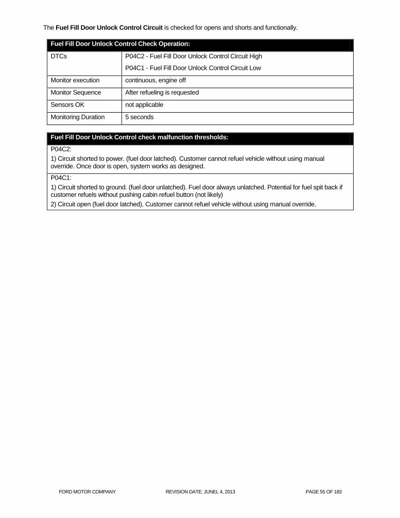
FORD MOTOR COMPANY REVISION DATE: JUNEL 4, 2013 PAGE 55 OF 183
The Fuel Fill Door Unlock Control Circuit is checked for opens and shorts and functionally.
Fuel Fill Door Unlock Control Check Operation:
DTCs P04C2 - Fuel Fill Door Unlock Control Circuit High
P04C1 - Fuel Fill Door Unlock Control Circuit Low
Monitor execution continuous, engine off
Monitor Sequence After refueling is requested
Sensors OK not applicable
Monitoring Duration 5 seconds
Fuel Fill Door Unlock Control check malfunction thresholds:
P04C2:
1) Circuit shorted to power. (fuel door latched). Customer cannot refuel vehicle without using manual override. Once door is open, system works as designed.
P04C1:
1) Circuit shorted to ground. (fuel door unlatched). Fuel door always unlatched. Potential for fuel spit back if customer refuels without pushing cabin refuel button (not likely)
2) Circuit open (fuel door latched). Customer cannot refuel vehicle without using manual override.

FORD MOTOR COMPANY REVISION DATE: JUNEL 4, 2013 PAGE 56 OF 183
Fuel System Monitor
The adaptive fuel strategy uses O2 sensors for fuel feedback. The fuel equation includes short and long term fuel
trim modifiers:
FUEL MASS = AIR MASS * SHRTFT * LONGFT
EQUIV_RATIO * 14.64
Where:
Fuel Mass = desired fuel mass
Air Mass = measured air mass, from MAF sensor
SHRTFT = Short Term Fuel Trim, calculated
LONGFT = Long Term Fuel Trim, learned table value, stored in Keep Alive Memory
EQUIV_RATIO = Desired equivalence ratio, 1.0 = stoich, > 1.0 is lean, < 1.0 is rich
14.64 = Stoichiometric ratio for gasoline
A conventional O2 sensor (not a wide-range sensor) can only indicate if the mixture is richer or leaner than
stoichiometric. During closed loop operation, short term fuel trim values are calculated by the PCM using oxygen
sensor inputs in order to maintain a stoichiometric air/fuel ratio. The PCM is constantly making adjustments to the
short term fuel trim, which causes the oxygen sensor voltage to switch from rich to lean around the stoichiometric
point. As long as the short term fuel trim is able to cause the oxygen sensor voltage to switch, a stoichiometric
air/fuel ratio is maintained.
When initially entering closed loop fuel, SHRTFT starts 1.0 and begins adding or subtracting fuel in order to
make the oxygen sensor switch from its current state. If the oxygen sensor signal sent to the PCM is greater than
0.45 volts, the PCM considers the mixture rich and SHRTFT shortens the injector pulse width. When the cylinder
fires using the new injector pulse width, the exhaust contains more oxygen. Now when the exhaust passes the
oxygen sensor, it causes the voltage to switch below 0.45 volts, the PCM considers the mixture lean, and
SHRTFT lengthens the injector pulse width. This cycle continues as long as the fuel system is in closed loop
operation.
O2 sensor voltage
SHRTFT, Short Term
Fuel Trim

FORD MOTOR COMPANY REVISION DATE: JUNEL 4, 2013 PAGE 57 OF 183
O2 sensor voltage
SHRTFT, Short Term
Fuel Trim
O2 sensor voltage
SHRTFT, Short Term
Fuel Trim

FORD MOTOR COMPANY REVISION DATE: JUNEL 4, 2013 PAGE 58 OF 183
As fuel, air, or engine components age or otherwise change over the life of the vehicle, the adaptive fuel strategy
learns deviations from stoichiometry while running in closed loop fuel. Corrections are only learned during closed
loop operation, and are stored in the PCM as long term fuel trim values (LONGFT). They may be stored into an
8x10 rpm/load table or they may be stored as a function of air mass. LONGFT values are only learned when
SHRTFT values cause the oxygen sensor to switch. If the average SHRTFT value remains above or below
stoichiometry, the PCM “learns” a new LONGFT value, which allows the SHRTFT value to return to an average
value near 1.0. LONGFT values are stored in Keep Alive Memory as a function of air mass. The LONGFT value
displayed on the scan tool is the value being used for the current operating condition.
O2 sensor voltage
O2 sensor voltage
SHRTFT, Short Term Fuel Trim, shifted rich
LONGFT, Long Term Fuel Trim, learning the rich correction
O2 sensor voltage
SHRTFT, Short Term
Fuel Trim, shifted rich
LONGFT, Long Term Fuel Trim, learning the rich correction

FORD MOTOR COMPANY REVISION DATE: JUNEL 4, 2013 PAGE 59 OF 183
As components continue to change beyond normal limits or if a malfunction occurs, the long-term fuel trim values
will reach a calibratable rich or lean limit where the adaptive fuel strategy is no longer allowed to compensate for
additional fuel system changes. Long term fuel trim corrections at their limits, in conjunction with a calibratable
deviation in short term fuel trim, indicate a rich or lean fuel system malfunction.
Note that in the PCM, both long and short-term fuel trim are multipliers in the fuel pulse width equation. Scan tools
normally display fuel trim as percent adders. If there were no correction required, a scan tool would display 0%
even though the PCM was actually using a multiplier of 1.0 in the fuel pulse width equation.
SHRTFT, Short Term
Fuel Trim, shifted rich
LONGFT, Long Term Fuel Trim, learning the rich correction

FORD MOTOR COMPANY REVISION DATE: JUNEL 4, 2013 PAGE 60 OF 183
Fuel System Monitor
START
Monitor Entry Conditions
Met?
Continuously monitor short term fuel trim (SHRTFT) and long term fuel trim (LONGFT) corrections.
Engine conditions (O2 sensors warm, closed loop fuel requests)
SRTFT + LONGFT > threshold?
No
Yes
Fuel system malfunction
Fault Management - MIL after 2
Driving Cycles w/malfunction
MIL
Fuel system OK
No
END, return to START

FORD MOTOR COMPANY REVISION DATE: JUNEL 4, 2013 PAGE 61 OF 183
Fuel Monitor Operation:
DTCs P0171 Bank 1 Lean
P0172 Bank 1 Rich
Monitor execution continuous while in closed loop fuel
Monitor Sequence none
Sensors OK Fuel Rail Pressure (if available), IAT, CHT/ECT, MAF, TP
Monitoring Duration 2 seconds to register malfunction
Typical fuel monitor entry conditions:
Entry condition Minimum Maximum
Engine Coolant Temp 155 oF 230
oF
Intake Air Temp -40 oF 150
oF
Engine Load 30%
Purge Duty Cycle 0% 0%
Fuel Level 15%
Typical fuel monitor malfunction thresholds:
Long Term Fuel Trim correction cell currently being utilized in conjunction with Short Term Fuel Trim:
Lean malfunction: LONGFT > 28%, SHRTFT > 2%
Rich malfunction: LONGFT < 24%, SHRTFT < -2%

FORD MOTOR COMPANY REVISION DATE: JUNEL 4, 2013 PAGE 62 OF 183
FAOSC (Rear Fuel Trim) Monitor
As the front UEGO sensor ages and gets exposed to contaminants, it can develop a rich or lean bias in its transfer
function. The rear bias control (also called FAOSC – Fore/Aft Oxygen Sensor Control) system is designed to
compensate for any of these bias shifts (offsets) using the downstream HO2S sensor. The "FAOS" monitor looks
for any bias shifts at the stoichiometric point of the front UEGO sensor lambda curve. If the UEGO has developed a
bias beyond the point for which it can be compensated for, lean (P2096, P2098) or rich (P2097, P2099) fault codes
will be set.
UEGO "FAOS
Monitor" Operation:
DTCs P2096 – Post catalyst fuel trim system too lean (Bank 1)
P2097 – Post catalyst fuel trim system too rich (Bank 1)
Monitor execution Continuous while in closed loop fuel
Monitor Sequence > 30 seconds time in lack of movement test, > 30 seconds time in lack of switch
test
Sensors OK ECT, IAT, MAF, MAP, VSS, TP, ETC, FRP, FVR, DPFE EGR, VCT, VMV/EVMV,
CVS, CPV, EVAPSV, FTP, CKP, CMP, ignition coils, injectors, no misfire DTCs,
no system failures affecting fuel, no EVAP gross leak failure, UEGO heaters OK,
rear HO2S heaters OK, no "lack of switching" malfunction, no "lack of movement"
malfunction, no UEGO circuit malfunction, no rear stream 2 HO2S circuit
malfunction, no rear stream 2 HO2S functional DTCs, no rear stream 2 HO2S
response rate malfunction.
Monitoring Duration 5 seconds to register a malfunction

FORD MOTOR COMPANY REVISION DATE: JUNEL 4, 2013 PAGE 63 OF 183
Typical UEGO "FAOS Monitor" entry conditions:
Entry condition Minimum Maximum
Closed loop stoich fuel control
Time since engine start 2 seconds
Engine Coolant Temp 150 oF 235
oF
Time since entering closed loop fuel 95 seconds
Fuel Level 15%
Short Term Fuel Trim Range -13% 18%
Short Term Fuel Trim Absolute Change 17%
Air mass range 1.5 lbm/min 8 lbm/min
Learning conditions stability time (based on air mass) 15 seconds
Injector fuel pulsewidth (not at minimum clip) 850 usec
Inferred HO2S 2 Heated Tip Temperature 800 oF
No excessive movement between currently utilized long term fuel
trim cells (1 = complete change from one cell to adjacent cell)
UEGO sensor within +/- 2 % from the fuel control target
UEGO ASIC not in recalibration mode
Stream1 UEGO response test not running
Intrusive UEGO catalyst monitor not running
Not performing intrusive UEGO Lack-of-Movement fuel control defib
Battery Voltage 11.0 Volts 18.0 Volts
Typical UEGO "FAOS Monitor" malfunction thresholds:
>= 5 seconds since reaching the FAOSC lean or rich limits while system bias maturity is met.

FORD MOTOR COMPANY REVISION DATE: JUNEL 4, 2013 PAGE 64 OF 183
Air Fuel Ratio Imbalance Monitor
The Air Fuel Imbalance Monitor is designed to monitor the cylinder-to-cylinder air fuel imbalance per engine bank.
When an Air Fuel (A/F) imbalance is present, the front UEGO signal becomes noisier. The monitor uses the high
frequency component from the UEGO signal as an indicator of A/F imbalance. "Hash" is the difference between
two consecutive front UEGO voltage samples. The UEGO signal is monitored continuously and a differential or
"hash" value is continuously calculated. When the hash is below a threshold, it is indicative of normal operation. If
the hash exceeds the threshold, an A/F imbalance is assumed which increments a hash error counter. The counter
accumulates hash during series of calibratable rpm windows. Typically, a single window consists of 50 engine
revolutions. A total rpm window counter calculates number of completed rpm windows. Monitor completion typically
requires 30 rpm windows. When the monitor completes, an A/Fuel imbalance index is calculated. The monitor
index is defined as the ratio of the failed rpm windows over the total rpm windows required to complete monitor. If
the monitor imbalance ratio index exceeds the threshold value, an A/F imbalance DTC is set.
0 5 10 15 20 25 300
0.1
0.2
0.3
0.4
0.5
0.6
0.7
0.8
0.9
1
Time
VE
GO
11-R
aw
hig
h f
requency d
ata
VEGO11
VEGO12
“hash” is the voltage difference between consecutive samples of a high frequency UEGO sensor signal.
20% lean shift Normal cylinder

FORD MOTOR COMPANY REVISION DATE: JUNEL 4, 2013 PAGE 65 OF 183
0 10 20 30 40 50 60 701
1.5
2
Bank 1
Time(sec)
uego11
0 10 20 30 40 50 60 700
0.2
0.4
Time(sec)
diff u
ego11
0 10 20 30 40 50 60 700
2000
4000
Time(sec)
uego11
0 2000 4000 6000 8000 10000 120000
50
100
150
200
250
300
350
400
Time(sec)
10 s
ec c
ounte
r, e
rror
counte
r
hash error counter and threshold
Calculated hash and hash threshold
UEGO sensor signal with hash
one rpm window

FORD MOTOR COMPANY REVISION DATE: JUNEL 4, 2013 PAGE 66 OF 183
Air Fuel Ratio Imbalance Operation
DTCs P219A – Bank 1 Air-Fuel Ratio Imbalance
Monitor execution Once per driving cycle during closed loop
Monitor Sequence Monitor runs after fuel monitor has adapted
Sensors OK ECT, IAT, MAF, VSS, TP, ETC, FRP, DPFE EGR, VCT, VMV/EVMV, CVS, FTP,
CKP, CMP, ignition coils, injectors, no misfire DTCs, no system failures affecting
fuel, no EVAP gross leak failure, UEGO heaters OK, rear HO2S heaters OK, no
"lack of switching" malfunction, no "lack of movement" malfunction, no UEGO
circuit malfunction, no rear stream 2 HO2S circuit malfunction, no rear stream 2
HO2S functional DTCs, no rear stream 2 HO2S response rate malfunction.
Monitoring Duration Time to complete monitor ranges from 300 to 700 seconds
Air Fuel Ratio Imbalance entry conditions:
Entry condition Minimum Maximum
Closed Loop Fuel Control
Engine Air Mass 1.5 lb/min 10 lb/min
Engine RPM 1250 rpm 2750 rpm
Engine Load 5% 75%
Engine Coolant Temp 150 oF 235
oF
Intake Air Temp 20 oF 150
oF
Throttle Position Rate of Change 0.122 v/100 msec
Fuel percentage from purge 40%
Fuel Level 15%
Fuel monitor has adapted
No purge on/off transition
Fuel type leaning is complete (FFV only)
Air Fuel Ratio Imbalance malfunction thresholds:
Imbalance Ratio Bank 1 > .65
J1979 AFIMN MONITOR MODE $06 DATA
Monitor ID Test ID Description
$81 $80 Bank 1 imbalance-ratio and max. limit (P219A/P219B) unitless

FORD MOTOR COMPANY REVISION DATE: JUNEL 4, 2013 PAGE 67 OF 183
Front UEGO Monitor
Front UEGO Signal
The UEGO sensor infers an air fuel ratio relative to the stoichiometric (chemically balanced) air fuel ratio by
balancing the amount of oxygen pumped in or out of a measurement chamber. As the exhaust gasses get richer or
leaner, the amount of oxygen that must be pumped in or out to maintain a stoichiometric air fuel ratio in the
measurement chamber varies in proportion to the air fuel ratio. By measuring the current required to pump the
oxygen in or out, the air fuel ratio (lambda) can be estimated. Note that the measured air fuel ratio is actually the
output from the UEGO ASIC pumping current controller and not a signal that comes directly from the sensor.
Bosch UEGO sensor interface:
IP – primary pumping current that flows through the sensing resistor
IA – current flow through trim resistor in parallel with sense resistor.
VM – Virtual ground, approximately 2.5 volts above PCM ground.
RE – Nernst cell voltage, 450mv from VM. Also carries current for pumped reference.
H+ – Heater voltage – to battery.
H- – Heater ground side – Duty cycle on/off to control sensor temperature.
Detection
Cavity
Reference Air
Diffusion
Passage
Heater
O-
Exhaust Gasses
O2,
HC,CO
NOx, H2…
Trim Resistor
(30 – 300 Ohm)
Pumping Cell
Nernst cell (EGO)
Connector
IP
IA
IN
RE
H-
H+
Measurement
Resistor
(61.9 Ohm)
B+
Heater
Control Ground
Impedance
Measuremen
t
+ -
Pump
Current Measurement
+
-
450 mV
ref. +2.5V Virtual
Ground
Total
Pumping
Current
Measured
Pumping Current
Measured
Impedanc
e
PCM
Sensor
20ma reference pump
current
O-
Bosch LSU 4.9

FORD MOTOR COMPANY REVISION DATE: JUNEL 4, 2013 PAGE 68 OF 183
Start
Closed Loop Fuel, O2 sensor
temperature, fuel pressure, fuel level
Front O2 Sensor Signal Status –
rich/lean, Short Term Fuel Trim at limits
O2 Sensor Voltage Heater
Voltage and
Current
Front O2 Sensor Lambda
Switching Test Entry Conditions
Met?
Time at trim limit <
threshold?
Monitor UEGO circuits, Heater CKT
voltage and current
UEGO ASIC or smart driver
indicates malfunction or current < or >
threshold?
Lack of movement
suspected ?
Initiate Defib jump/ramp wave and monitor
Activity
Magnitude >
threshold ?
Response Test Entry Conditions
Met? Modulate fuel request and monitor voltage activity
Magnitude >
threshold ?
END
Fault management – MIL after 2 driving
cycles w/ malfunction
Front O2 Sensor
voltage
NO
NO
NO
NO
NO
YES
YES
YES
YES
YES
NO
Upstream UEGO Monitor
YES
NO
YES
Time between O2 switches <
max?
Front O2 Sensor Lambda
NO
YES
Monitor UEGO heater
temperature
control
Time heater control
voltage at limit <
threshold?
NO
YES
MIL

FORD MOTOR COMPANY REVISION DATE: JUNEL 4, 2013 PAGE 69 OF 183
The primary component of a UEGO sensor is the diffusion passage that controls the flow of exhaust gasses into a detection cavity, a Nernst cell (essentially an EGO sensor inside the UEGO sensor) that measures the air fuel ratio in the detection cavity. A control circuitry in the ASIC chip (mounted in the PCM) controls the pumping current (IP) to keep the detection cavity near stoichiometry by holding the Nernst cell at 450 mV. This Nernst cell voltage (RE, VS) is 450mV from the virtual ground (VM, COM), which is approximately 2.5V (Bosch UEGO) or 3.6V (NTK UEGO) above the PCM ground. For the Nernst cell to generate a voltage when the detection cavity is rich, it needs an oxygen differential across the cell. In older UEGO (and HEGO) sensor designs, this was provided by a reference chamber that was connected to outside air through the wire harness that was subject to contamination and "Characteristic Shift Down (CSD)". The new UEGO sensor uses a pumped reference chamber, which is sealed from the outside to eliminate the potential for contamination. The necessary oxygen is supplied by supplying a 20 mA pumping current across the Nernst cell to pump small amounts of oxygen from the detection cavity to the reference chamber. The pumping cell pumps oxygen ions in and out of the detection cavity from and to the exhaust gasses in response to the changes in the Nernst cell voltage. The pumping current flows through the sense resistor and the voltage drop across the sense resistor is measured and amplified. Offset volts are sent out of the ASIC to one of the PCM's A/D inputs. The PCM measures the voltage supplied by the ASIC, determines the pumping current, and converts the pumping current to measured lambda. In general, the circuitry that measures the pumping current is used to estimate the air fuel ratio in the exhaust system. The UEGO sensor also has a trim (IA) or label resistor (RL). The biggest source of part to part variability in the measured air fuel ratio is difference in the diffusion passage. This source of variation is simply the piece-to-piece differences from the manufacturing process. To compensate for this source of error, each sensor is tested at the factory and a trim or label resistor is installed in the connector. The value of this resistor is chosen to correlate with the measured difference between a particular sensor and a nominal sensor For Bosch UEGO, the trim resistor is connected in parallel to the pumping current sense resistor and the pumping current flows through both. The trim resistor adjusts the measured pumping current back to the expected nominal value at any given air fuel ratio (correcting for the sensor to sensor variations in the diffusion passage). Small trim resistors are required for sensors that require more pumping current at any particular lambda. Conversely, for sensors with lower diffusion rates than average, less pumping current is required, so a higher than average impedance trim resistor is installed. When IA circuit is open, all of the pumping current flows through the measuring resistor which increases the measured voltage. Since the pumping current is amplified, the UEGO pumping current to lambda transfer function will reflect the error. The slope of the UEGO sensor transfer function changes, which results in the wrong output of the UEGO signal (the slope of the pumping current to lambda relationship can increase or decrease). For "stoichiometric" air/fuel control applications, an open IA circuit is not monitored since the lambda error is minimal in "stoichiometric" mode. A worst case (40 ohm resistor) open IA was tested on a 2008MY 3.5L Taurus PZEV and showed no impact on tailpipe emissions. For "Non-Stoichiometric Closed Loop (NSCL)" air/fuel control applications, a continuous open IA diagnostics (Air Rationality Test) is required since the lambda error is more significant in this mode. The air rationality test will always monitor the UEGO sensor voltage reading during Decel Fuel Shut Off (DFSO) event. The monitor compares the UEGO sensor voltage reading in air against the expected value for pure air. If the UEGO sensor voltage during DFSO exceeds the maximum UEGO voltage in air threshold, then the fault timer increments. If the fault timer exceeds the fault time threshold, then open IA DTC P2626 and/or P2629 will set. Since transient sources of fuel in the exhaust after injector cut can contribute to the UEGO sensor voltage to read lower (rich), the air rationality monitor will not call a pass until the transient sources of fuel have been exhausted and pure air entry conditions during DFSO are met (i.e. all injectors must be off, purge must be off, no fuel must be leaking around the PCV valve, and a few transport delays must have passed to allow the last fuel transients to be exhausted leaving nothing for the sensor to see, but air).

FORD MOTOR COMPANY REVISION DATE: JUNEL 4, 2013 PAGE 70 OF 183
The time spent at the limits of the short term fuel trim and the time when the measured lambda is nearly 1.0 are
monitored after vehicle startup when closed loop fuel has been requested, during closed loop fuel conditions, or
when open loop fuel has been requested due to UEGO sensor fault. Excessive time with short term fuel trim at its
limits (up to +/- 40%), or no rich / lean activity seen since startup indicates a "lack of switch" malfunction. Also,
excessive time without measured lambda deviating from 1.0, in spite of attempts to force activity (defib) in the
measured lambda, indicates a "lack of movement" malfunction. Since “lack of switching” malfunctions can be
caused by UEGO sensor malfunctions or by shifts in the fuel system, DTCs are stored that provide additional
information for the “lack of switching” malfunction. Different DTCs indicate whether the sensor always indicates
lean (P2195, P2197), or always indicates rich (P2196, P2198). "Lack of movement" malfunction, (Bosch UEGO
application only), typically indicating a disconnected wire (pumping current, IP), results in P0134, P0154 DTCs.
UEGO equipped vehicles will also monitor the circuitry between the PCM and the UEGO sensor via the wire
diagnostics capability included on the UEGO ASIC chip. The wire diagnostics will detect wires (IP, IA, VM/COM,
RE/VS) shorted to battery, or ground, and in most cases will detect open circuits (IP, VM/COM, RE/VS). The
diagnostic bits are transmitted to the PCM via SPI (serial peripheral interface). The SPI communication is validated
continuously, and if a SPI communication failure is detected, fault code(s) P064D and/or P064E will be set. The
ASIC is also capable of detecting internal circuitry failure; in which case, an ASIC failure DTC (P1646, P1647)
along with the SPI communication failure DTC (P064D, P064E) will be set.

FORD MOTOR COMPANY REVISION DATE: JUNEL 4, 2013 PAGE 71 OF 183
UEGO “Lack of Switching” Operation:
DTCs P2195 - Lack of switching, sensor indicates lean, Bank 1
P2196 - Lack of switching, sensor indicates rich, Bank 1
Monitor execution continuous, from startup and while in closed loop fuel or open loop fuel due to
UEGO sensor fault
Monitor Sequence None
Sensors OK ECT, IAT, MAF, VSS, TP, ETC, VCT, VMV/EVMV, CVS, FTP, CKP, CMP,
ignition coils, injectors, no misfire DTCs, no system failures affecting fuel, no
EVAP gross leak failure, UEGO heaters OK, no "lack of movement"
malfunction, no UEGO circuit malfunction
Monitoring Duration 30 seconds to register a malfunction
Typical UEGO “Lack of Switching" entry conditions:
Entry condition Minimum Maximum
Closed Loop or Open Loop Requested due to UEGO
sensor fault
No fuel flow entering thru PCV during cold start when
flashing off fuel in oil (for O2 Sensor Stuck Rich DTCs only)
Inferred Ambient Temperature -40 oF
Time within entry conditions 10 seconds
Fuel Tank Pressure 10 in H2O HEV,
50 in H2O PHEV
Fuel Level 15%
Battery Voltage 11.0 Volts 18.0 Volts
Typical UEGO “Lack of Switching” malfunction thresholds:
Stage 1: > 60 seconds since reaching the short term fuel trim limits while closed loop fuel or
Stage 2: < 1 second rich or < 1 seconds lean since startup for > 60 seconds in test conditions while open loop
fuel is requested due to UEGO sensor fault.

FORD MOTOR COMPANY REVISION DATE: JUNEL 4, 2013 PAGE 72 OF 183
UEGO “Lack of Movement – Open Pump Current Circuit” Operation (Bosch UEGO only):
DTCs P2237 – O2 Sensor Positive Current Control Circuit/Open (Bank 1, Sensor 1)
(replaces P0134)
Monitor execution continuous, from startup and while in closed loop fuel or open loop fuel due to
UEGO sensor fault
Monitor Sequence None
Sensors OK ignition coils, injectors, no misfire DTCs, no system failures affecting fuel,
UEGO heaters OK, no "lack of switching" malfunction, no "lack of movement-
open reference ground circuit" malfunction, no UEGO circuit malfunction
Monitoring Duration 10 - 20 seconds to register a malfunction
Typical UEGO “Lack of Movement – Open Pump Current Circuit " entry conditions
(Bosch UEGO only):
Entry condition Minimum Maximum
Closed Loop or Open Loop Requested due to UEGO sensor fault
Constant lambda near stoich (~1) 0.99 1.01
Time since no lambda activity seen since start up 30 sec
Time since no lambda activity during intrusive Stream 1 response monitor 3 sec
Inferred Ambient Temperature - 40 oF
Injector fuel pulsewidth 650 usec
UEGO ASIC not in recalibration mode
No air passing through during valve overlap (scavenging).
Battery Voltage 11.0 Volts 18.0 Volts
Typical UEGO “Lack of Movement – Open Pump Current Circuit” malfunction thresholds
(Bosch UEGO only):
Stage 1: > 20 seconds in test conditions without lambda movement during fuel control and reference current
"defib" while in closed loop fuel and < = 0.05 change in lambda movement.
Stage 2: < 0.2 seconds without lambda movement since startup for > 30 seconds in test conditions during
reference current "defib" while open loop fuel is requested due to UEGO sensor fault and < = 0.05 change in
lambda movement.

FORD MOTOR COMPANY REVISION DATE: JUNEL 4, 2013 PAGE 73 OF 183
UEGO “Lack of Movement – Open Reference Ground Circuit ” Operation (Bosch UEGO only):
DTCs P2251 – O2 Sensor Negative Current Control Circuit/Open (Bank 1, Sensor 1)
(replaces P0130)
Monitor execution continuous, from startup and while in closed loop fuel or open loop fuel due to
UEGO sensor fault
Monitor Sequence None
Sensors OK ignition coils, injectors, no misfire DTCs, no system failures affecting fuel,
UEGO heaters OK, no "lack of switching" malfunction, no "lack of movement-
open pump current circuit" malfunction, no UEGO circuit malfunction
Monitoring Duration 10 - 20 seconds to register a malfunction
Typical UEGO “Lack of Movement – Open Reference Ground Circuit " entry conditions
(Bosch UEGO only):
Entry condition Minimum Maximum
Closed Loop or Open Loop Requested due to UEGO sensor fault
Constant lambda near stoich (~1) 0.99 1.01
Time since no lambda activity seen since start up 30 sec
Time since no lambda activity during intrusive Stream 1 response monitor 3 sec
Injector fuel pulsewidth 650 usec
UEGO ASIC not in recalibration mode
No air passing through during valve overlap (scavenging).
Battery Voltage 11.0 Volts 18.0 Volts
Typical UEGO “Lack of Movement – Open Reference Ground Circuit” malfunction thresholds
(Bosch UEGO only):
Stage 1: > 20 seconds in test conditions without lambda movement during fuel control and reference current
"defib" while in closed loop fuel and > 0.05 change in lambda movement.
Stage 2: > 20 seconds in test conditions without lambda movement during reference current "defib" while
open loop fuel is requested due to UEGO sensor fault and > 0.05 change in lambda movement.

FORD MOTOR COMPANY REVISION DATE: JUNEL 4, 2013 PAGE 74 OF 183
UEGO equipped vehicles monitor the circuitry between the PCM and the UEGO sensor via the wire diagnostics
capability included on the UEGO ASIC chip. The wire diagnostics will detect wires (IP, IA, VM/COM, RE/VS)
shorted to battery, or ground, and in most cases will detect open circuits (IP, VM/COM, RE/VS). The diagnostic bits
are transmitted to the PCM via SPI (serial peripheral interface). The SPI communication is validated continuously,
and if a SPI communication failure is detected, fault code(s) P064D and/or P064E will be set. The ASIC is also
capable of detecting internal circuitry failure; in which case, an ASIC failure DTC (P1646, P1647) along with the
SPI communication failure DTC (P064D, P064E) will be set.
UEGO "Wire Diagnostic via ASIC" Operation:
DTCs P0131 – O2 circuit low voltage (Bank 1, Sensor 1). (Note: Sets for short to ground on
Bosch UEGO- IP, IA, RE, VM; NTK UEGO – IP, VS, COM. Replaces P0130
in Bosch UEGO applications.)
P0132 – O2 circuit high voltage (Bank 1, Sensor 1). (Note: Sets for short to battery on
Bosch UEGO- IP, IA, RE, VM; NTK UEGO – IP, VS, COM. Replaces P0130
in Bosch UEGO applications.)
P1646 – Linear O2 sensor control chip, Bank 1.
P064D – Internal control module O2 sensor processor performance (Bank 1).
Monitor execution continuous
Monitor Sequence None
Sensors OK UEGO heaters OK
Monitoring Duration 10 seconds to register a malfunction
Typical UEGO "Wire Diagnostic via ASIC" entry conditions:
Entry condition Minimum Maximum
Fault reported by UEGO ASIC
Battery Voltage 11.0 Volts 18.0 Volts
Typical UEGO "Wire Diagnostic via ASIC " malfunction thresholds:
UEGO ASIC indicated malfunction, DTC sets after 10 seconds when circuit failure is present.

FORD MOTOR COMPANY REVISION DATE: JUNEL 4, 2013 PAGE 75 OF 183
Front UEGO Slow/Delayed Response Monitor (2010 MY and beyond)
The front UEGO monitor also detects malfunctions on the UEGO sensor such as reduced response or delayed response that would cause vehicle emissions to exceed 1.5x the standard (2.5x the standard for PZEV). The response rate is evaluated by entering a special 0.5 Hz square wave, fuel control routine. This routine drives the air/fuel ratio around stoichiomentry at a calibratable frequency and magnitude, producing predictable oxygen sensor signal amplitude. A UEGO slow or delayed sensor will show an increased response time which is compared to a no-fault polygon. Combinations of the rich to lean and lean to rich response times that fall outside the polygon indicate a sensor malfunction (P0133 Bank 1).
UEGO "Response Rate" Operation:
DTCs P0133 (slow/delayed response Bank 1)
Monitor execution once per driving cycle
Monitor Sequence > 30 seconds time in lack of movement test, > 30 seconds time in lack of switch test
Sensors OK ECT, IAT, MAF, VSS, TP, ETC, VCT, VMV/EVMV, CVS, FTP, CKP, CMP, ignition
coils, injectors, no misfire DTCs, no system failures affecting fuel, no EVAP gross leak
failure, UEGO heaters OK, no "lack of switching" malfunction, no "lack of movement"
malfunction, no UEGO circuit malfunction, no UEGO FAOS monitor malfunction
Monitoring Duration 6 seconds
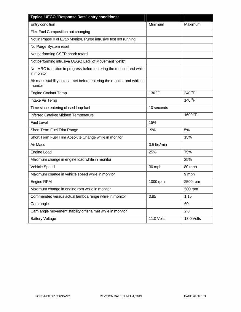
FORD MOTOR COMPANY REVISION DATE: JUNEL 4, 2013 PAGE 76 OF 183
Typical UEGO "Response Rate" entry conditions:
Entry condition Minimum Maximum
Flex Fuel Composition not changing
Not in Phase 0 of Evap Monitor, Purge intrusive test not running
No Purge System reset
Not performing CSER spark retard
Not performing intrusive UEGO Lack of Movement "defib"
No IMRC transition in progress before entering the monitor and while
in monitor
Air mass stability criteria met before entering the monitor and while in
monitor
Engine Coolant Temp 130 oF 240
oF
Intake Air Temp 140 oF
Time since entering closed loop fuel 10 seconds
Inferred Catalyst Midbed Temperature 1600 oF
Fuel Level 15%
Short Term Fuel Trim Range -9% 5%
Short Term Fuel Trim Absolute Change while in monitor 15%
Air Mass 0.5 lbs/min
Engine Load 25% 75%
Maximum change in engine load while in monitor 25%
Vehicle Speed 30 mph 80 mph
Maximum change in vehicle speed while in monitor 9 mph
Engine RPM 1000 rpm 2500 rpm
Maximum change in engine rpm while in monitor 500 rpm
Commanded versus actual lambda range while in monitor 0.85 1.15
Cam angle 60
Cam angle movement stability criteria met while in monitor 2.0
Battery Voltage 11.0 Volts 18.0 Volts

FORD MOTOR COMPANY REVISION DATE: JUNEL 4, 2013 PAGE 77 OF 183
Typical UEGO "Response Rate" malfunction thresholds:
Threshold depends on failure type (symmetric slow/delay vs. asymmetric slow/delay)
J1979 Front UEGO Mode $06 Data
Monitor ID Test ID Description for CAN
$01 $87 UEGO11 Rich to Lean Response Time seconds
$01 $88 UEGO11 Lean to Rich Response Time seconds
-0.2 0 0.2 0.4 0.6 0.8 1 1.2 1.4-0.2
0
0.2
0.4
0.6
0.8
1
Threshold (red) and No-Fault (green) data vs. No Fault Zone (Bank 1)
Ric
h t
o L
ean
Re
spo
nse
Tim
e,
sec
Lean to Rich Response Time, sec
Example shown with lean-to-rich (0.2 sec), rich-to-lean (0.2 sec), and symmetric (0.6 sec) thresholds creating the yellow no-fault zone. The completeted monitor results in two measurements, a lean-to-rich response time and a rich-to-lean response time. These response time values are used as x-y pairs to make a single point and then compared to the no-fault zone. Anywhere in the yellow is a pass and outside the yellow is a failure.

FORD MOTOR COMPANY REVISION DATE: JUNEL 4, 2013 PAGE 78 OF 183
UEGO Heaters
The UEGO heater is controlled as a function of the measured impedance to keep the sensor at a near constant temperature (Bosch: 780 deg C, NTK: 800 deg C). The impedance of the Nernst cell decreases as the sensor temperature increases. This impedance is measured by periodically applying a small current across the Nernst cell and measuring the change in the voltage. The output voltage is then sent to an A/D input on the PCM. After a cold start, the UEGO heater ramps up to the maximum duty cycle to heat the sensor. After a few seconds, the measured impedance will start to decrease and when the target value is crossed, the heater goes into closed loop heater control to maintain the sensor at a near constant temperature. The "UEGO Heater Temperature Control Monitor" tracks the time at the maximum duty cycle during the open loop sensor warm up phase. If the measured impedance does not come down to the target value to allow the system to transition from open loop heater control to closed loop heater control within a specified time, then a fault code is set. This monitor also sets a malfunction when the closed loop heater control reaches a maximum or minimum value for a period of time indicating that the controller is no longer able to maintain the target temperature, however, if the inferred exhaust temperature is high enough that the sensor will be above the target temperature even with no heat, then this monitor is disabled.
The UEGO heaters are also monitored for proper voltage and current. A UEGO heater voltage fault is determined
by turning the heater on and off and looking for corresponding voltage change in the heater output driver circuit in
the PCM.
A separate current-monitoring circuit monitors heater current once per driving cycle. This monitor normally runs in
closed loop heater control after all the exhaust gas sensor functional tests are completed, however, it can also run
intrusively. When the UEGO sensor indicates cold, but the heater is inferred to have been adequately warm, the
current monitor is forced to run intrusively prior to the completion of the heater temperature control monitor. The
heater current is actually sampled three times. If the current value for two of the three samples falls below or above
a calibratable threshold, the heater is assumed to be degraded or malfunctioning. (Multiple samples are taken for
protection against noise on the heater current circuit.)
UEGO Heater Monitor Operation:
DTCs
P0030 Heater Temperature Control Failure, Bank 1
P0135 O2 Heater Circuit, Bank 1
P0053 O2 Heater Resistance, Bank 1
Monitor execution once per driving cycle for heater current monitor, continuous for voltage monitoring
and heater temperature control monitoring
Monitor Sequence Heater current monitor: Stream 1 UEGO response test complete, Stream 2 and 3
HO2S functional tests complete, Stream 1 UEGO heater voltage check complete.
Heater temperature control monitor: intrusive heater current monitor completed.
Sensors OK Heater current monitor: no HO2S/UEGO heater circuit malfunction,
Heater temperature control monitor: no UEGO circuit malfunction, no UEGO heater circuit malfunction, no UEGO heater current monitor DTCs.
Monitoring Duration < 10 seconds for heater voltage check, < 5 seconds for heater current check, >= 30
seconds for the heater temperature control monitor to register a malfunction

FORD MOTOR COMPANY REVISION DATE: JUNEL 4, 2013 PAGE 79 OF 183
Typical UEGO heater monitor entry conditions:
Entry condition Minimum Maximum
Inferred UEGO unheated tip temperature (heater voltage check only) 75 oF 1562
oF
Inferred UEGO heated tip temperature (heater current check only) 1346 oF 1526
oF
UEGO heater-on time (heater current check only) 30 seconds
Engine RPM (heater current check only) 5000 rpm
Inferred UEGO unheated tip temperature (heater control monitor
only)
75 oF 1000
oF
Battery Voltage 11.0 Volts 18.0 Volts
Typical UEGO heater check malfunction thresholds:
Smart driver status indicated malfunction (heater voltage check)
Number monitor retries allowed for malfunction > = 30 (heater voltage check)
Heater current outside limits:
< 1.0 amps or > 3 amps (intrusive test) or < 0.55 amps or > 3 amps (Bosch UEGO)
Heater temperature control monitor: > = 30 seconds to register a malfunction while the heater control
integrator is at its maximum or minimum limit
J1979 UEGO Heater Mode $06 Data
Monitor ID Test ID Description for CAN Units
$01 $81 HO2S11 Heater Current Amps
$05 $81 HO2S21 Heater Current Amps

FORD MOTOR COMPANY REVISION DATE: JUNEL 4, 2013 PAGE 80 OF 183
Start
Closed Loop Fuel, O2 sensor
temperature, fuel pressure, fuel level
Front O2 Sensor Signal Status –
rich/lean, Short Term Fuel Trim at limits
O2 Sensor Voltage Heater Voltage and
Current
Front O2 Sensor Lambda
Switching Test Entry Conditions
Met?
Time at trim limit <
threshold?
Monitor UEGO circuits, Heater CKT
voltage and current
UEGO ASIC or smart driver
indicates malfunction or current < or >
threshold?
Lack of movement
suspected ?
Initiate Defib jump/ramp wave and monitor
Activity
Magnitude >
threshold ?
Response Test Entry Conditions
Met? Modulate fuel request and monitor voltage activity
O2 Sensor Voltage Magnitude > threshold ?
Or O2 Sensor Response
Time < threshold ?
END
Fault management – MIL after 2 driving
cycles w/ malfunction
Front O2 Sensor Voltage
Or Front O2 Sensor Response Time
NO
NO
NO
NO
NO
YES
YES
YES
YES
YES
NO
Upstream UEGO Monitor
YES
NO
YES
Time between O2 switches <
max?
Front O2 Sensor Lambda
NO
YES
Monitor UEGO heater
temperature
control
Time heater control
voltage at limit <
threshold?
NO
YES
MIL
Monitor O2 sensor voltage every DFSO
event (NSCL only)
O2 Sensor Voltage
O2 sensor voltage >
threshold ?
YES
NO
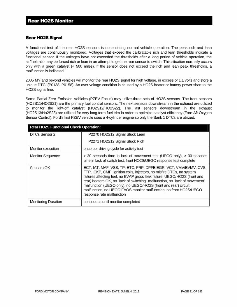
FORD MOTOR COMPANY REVISION DATE: JUNEL 4, 2013 PAGE 81 OF 183
Rear HO2S Monitor
Rear HO2S Signal
A functional test of the rear HO2S sensors is done during normal vehicle operation. The peak rich and lean
voltages are continuously monitored. Voltages that exceed the calibratable rich and lean thresholds indicate a
functional sensor. If the voltages have not exceeded the thresholds after a long period of vehicle operation, the
air/fuel ratio may be forced rich or lean in an attempt to get the rear sensor to switch. This situation normally occurs
only with a green catalyst (< 500 miles). If the sensor does not exceed the rich and lean peak thresholds, a
malfunction is indicated.
2005 MY and beyond vehicles will monitor the rear HO2S signal for high voltage, in excess of 1.1 volts and store a
unique DTC. (P0138, P0158). An over voltage condition is caused by a HO2S heater or battery power short to the
HO2S signal line.
Some Partial Zero Emission Vehicles (PZEV Focus) may utilize three sets of HO2S sensors. The front sensors
(HO2S11/HO2S21) are the primary fuel control sensors. The next sensors downstream in the exhaust are utilized
to monitor the light-off catalyst (HO2S12/HO2S22). The last sensors downstream in the exhaust
(HO2S13/Ho2S23) are utilized for very long term fuel trim in order to optimize catalyst efficiency (Fore Aft Oxygen
Sensor Control). Ford's first PZEV vehicle uses a 4-cylinder engine so only the Bank 1 DTCs are utilized.
Rear HO2S Functional Check Operation:
DTCs Sensor 2
P2270 HO2S12 Signal Stuck Lean
P2271 HO2S12 Signal Stuck Rich
Monitor execution once per driving cycle for activity test
Monitor Sequence > 30 seconds time in lack of movement test (UEGO only), > 30 seconds
time in lack of switch test, front HO2S/UEGO response test complete
Sensors OK ECT, IAT, MAF, VSS, TP, ETC, FRP, DPFE EGR, VCT, VMV/EVMV, CVS, FTP, CKP, CMP, ignition coils, injectors, no misfire DTCs, no system failures affecting fuel, no EVAP gross leak failure, UEGO/HO2S (front and rear) heaters OK, no "lack of switching" malfunction, no "lack of movement" malfunction (UEGO only), no UEGO/HO2S (front and rear) circuit malfunction, no UEGO FAOS monitor malfunction, no front HO2S/UEGO response rate malfunction
Monitoring Duration continuous until monitor completed

FORD MOTOR COMPANY REVISION DATE: JUNEL 4, 2013 PAGE 82 OF 183
Typical Rear HO2S functional check entry conditions:
Entry condition Minimum Maximum
Stream 1 HO2S not in CSD recovery mode
Flex Fuel Composition not changing
Not in Phase 0 of Evaporative System Monitor
No Purge System reset
Purge intrusive test not running
Not performing CSER spark retard
Engine Coolant Temp 125 oF 240
oF
Intake Air Temp 140 oF
Time since entering closed loop fuel 10 seconds
Inferred Catalyst Midbed Temperature 1600 oF
Heater-on Inferred Sensor(s) 2/3 HO2S Temperature Range 400 oF 1400
oF
Sensor(s) 2/3 HO2S heater-on time 90 seconds
Short Term Fuel Trim Range -5% 5%
Fuel Level (forced excursion only) 15%
Inferred exhaust temperature range 400 oF 1400
oF
Throttle position Part throttle
Engine RPM (forced excursion only) 1000 rpm 2000 rpm
Battery Voltage 11.0 Volts 18.0 Volts
Typical Rear HO2S functional check malfunction thresholds:
Does not exceed rich and lean threshold envelope:
Rich < 0.42 volts
Lean > 0.48 volts
J1979 Rear HO2S Functional Check Mode $06 Data
Monitor ID Test ID Description for CAN
$02 $01 HO2S12 sensor switch-point voltage volts
$06 $01 HO2S22 sensor switch-point voltage volts
$03 $01 HO2S13 sensor switch-point voltage volts
$07 $01 HO2S23 sensor switch-point voltage volts

FORD MOTOR COMPANY REVISION DATE: JUNEL 4, 2013 PAGE 83 OF 183
Rear HO2S “Over Voltage Test” Operation:
DTCs P0138 HO2S12 Over voltage
Monitor execution continuous
Monitor Sequence None
Sensors OK rear HO2S heaters OK
Monitoring Duration 10 seconds to register a malfunction
Typical HO2S “Over Voltage Test” entry conditions:
Entry condition Minimum Maximum
Inferred Stream 2 HO2S Temperature 400 oF
Battery Voltage 11.0 Volts 18.0 Volts
Typical HO2S “Over Voltage Test” malfunction thresholds:
> 1.1 volts for 10 seconds for over voltage test

FORD MOTOR COMPANY REVISION DATE: JUNEL 4, 2013 PAGE 84 OF 183
Rear HO2S Decel Fuel Shut Off Response Test
The catalyst monitor tracks and uses the length of the rear HO2S signal. The rear HO2S is also known as the
Catalyst Monitor Sensor (CMS). As the catalyst ages, air/fuel fluctuations begin to break through the catalyst and
the length of this signal increases. Eventually the length of the CMS signal becomes long enough to identify a
failure for the catalyst monitor.
When an HO2S sensor degrades, it's response to air/fuel fluctuations slows down. The effect of a slow rear
HO2S sensor on the catalyst monitor is to reduce the length of the signal. A slow CMS sensor, therefore, may
cause the catalyst monitor to incorrectly pass a failed catalyst. The purpose of the Rear DFSO Response
diagnostic is to ensure the catalyst monitor has a valid CMS sensor with which to perform the catalyst monitor
diagnostic. The monitor is set to trigger at the level of degradation that will cause the catalyst monitor to falsely
pass a malfunction threshold catalyst.
The OBD-II regulations require this monitor to utilize Decel Fuel Shut Off (DFSO). Ford plans to aggressively use
DFSO starting in the 2009 MY on many applications to improve fuel economy. The DFSO rear O2 response test
will be phased in coincident with this feature.
The main part of the test is the measured rich to lean response rate. It is determined by a "slew" rate calculation
which determines the rich to lean slope of the sensor during a Decel Fuel Shut Off (DFSO) event which occurs
during closed pedal at vehicle speeds higher than 28 mph. The calculation for the slew rate (mV/sec) is illustrated
below.
Linear interpolation is performed to calculate the Slew Rate.
1. Interpolate between points P1 and P2 to determine the time at which the rich limit threshold of 0.6 volts was
crossed.
2. Interpolate between points P3 and P4 to determine the time at which the lean limit threshold of 0.2 volts was
crossed.
3. Use the Interpolated times and the thresholds to calculate the slope or "slew rate" of the CMS sensor from 0.6
to 0.2 volts.
CMS DFSO Slew Rate Calculation
0
0.1
0.2
0.3
0.4
0.5
0.6
0.7
0.8
2.5 2.55 2.6 2.65 2.7 2.75
CMS_DFSO_TMR (sec)
Vo
ltag
e .
CMS
Voltage
CMS
Slew Rate
-6.51
P1
P4
P3
P2
T4
Interpolated Lean
Crossing Point
T3
Interpolated
Rich Crossing
Point

FORD MOTOR COMPANY REVISION DATE: JUNEL 4, 2013 PAGE 85 OF 183
Diagnostic Data Acquisition Event Plot is a schematic of what happens when the pedal is closed and the engine
enters DFSO.
The top half of the graph shows the following signals:
Closed pedal timer (ego_dcms_cptmr).
PPS (Pedal Position Sensor)
INJON (# of fuel injectors turned on)
The bottom half of the graph shows a CMS signal with black lines and a "Tx" number representing all of the
points of interest where the monitor captures data.
CMS DFSO Diagnostic Event Plot
0
0.1
0.2
0.3
0.4
0.5
0.6
0.7
0.8
0.9
1
1.1
1.2
1.3
1.4
1.5
1.6
1.7
1.8
1.9
2
0 1 2 3 4 5 6 7 8 9 10
Time (sec)
-10
-9
-8
-7
-6
-5
-4
-3
-2
-1
0
1
2
3
4
5
6
7
8
9
10
PPS
INJON
ego_dcms_cptmr
T0
T0: PPS = 0
T1: Fuel Cut
T2: CMS Peak
T3: CMS_R2L_RL
T4: CMS_R2L_LL1
T5: CMS_R2L_LL2
T6: CMS_MINDT
T7: CMS_MIN
T8: Fuel On
T9: CMS_L2R_LL
T10: CMS_L2R_RL
T2 T1 T3
T4
T5
T6 T7 T8
T9
T10 CMS
Voltage
State 1 State 2 State 3 State 4 State 5
Intrusive fuel control

FORD MOTOR COMPANY REVISION DATE: JUNEL 4, 2013 PAGE 86 OF 183
The monitor measures the CMS Rich to Lean slew rate during a DFSO event. The CMS voltage must be rich
prior to the injector cut for a valid measurement event. Each fuel cut can only yield 1 valid event. The monitor will
complete after 3 valid events. Additional valid event results will be stored and applied over the next drive cycle if
necessary for monitor completion.
The slope or slew rate of the CMS sensor going from rich to lean is a negative number with the units of
mVolts/sec. The measured slew rate changes as an O2 sensor degrades, but it will also change as a function of
catalyst oxygen storage/age; therefore, the slew rate is normalized using an offset based on catalyst oxygen
storage/age. The catalyst oxygen storage/age is calculated by integrating the level of oxygen mass in the exhaust
stream from the time the injectors turn off to the time where the slew rate calculation begins. The fault line (red
line in the chart below) is calibrated to 80% of the fault distribution for various levels of oxygen storage/catalyst
age. As shown below, the integrated oxygen mass becomes smaller with catalyst age.
The final output of the monitor = the measured slew rate – normalized fault line, therefore, any positive number
will represent a fault. For the step change logic the fault threshold will represent 50% of the failed distribution (~
0.3).
DFSO CMS Monitor O2 Mass Normalization
0
0.5
1
1.5
2
2.5
3
3.5
4
-14 -13 -12 -11 -10 -9 -8 -7 -6 -5 -4 -3 -2 -1 0
Slew Rate
O2 M
ass @
T3 .
Fault Detection O2 Mass Example Points
Calibrate a function
to represent the
80% fault line.
80% of the fault
data would lie to
the right of this
function of O2
mass @ T3.
All Slew Rate results are Normalized to O2 mass
by taking the difference between the measured
slew rate and the calibrated fault slew rate
function.
Offset = -8.4
Offset = -4.4
Offset = -2.9
Offset = 1.49

FORD MOTOR COMPANY REVISION DATE: JUNEL 4, 2013 PAGE 87 OF 183
The delayed response part of the test indicates that the sensor is stuck in range. The code sets if the sensor can't
get above a calibrated rich or lean voltage prior to a calibrated time out period. This time out must happen three
times in a row to set the fault. If it happens once or twice and then the response monitor completes, the counter
will be reset and the sensor will have to fail 3 times in a row to again set the DTC.
Due to the fact that intrusively driving the CMS sensor rich will cause drivability and emission concerns, there are
other several condition counters that have to fail prior to intrusively forcing the sensor to go rich. The sequence of
events to get to the rich failure is shown below:
Initially, in order to avoid excess emissions, the monitor will only run if the CMS voltage is rich (> 0.6
volts) or CMS sensor is transitioning from lean to rich (large positive slope . 0.2).
o Successive failures are counted up; when the count exceeds 5 to 10 failures the monitor will
now intrusively force rich fuel to run the test.
In order to avoid a drivability issues as a result of a lean shifted bank, the first phase of intrusive
control has a short time out (1 to 2 seconds).
o Successive failures are counted up; when the count exceeds 3 failures the monitor will now
intrusively force rich fuel to failure or a rich sensor.
All controllable measures have failed to force the sensor to switch, so the strategy will drive rich until
the sensor switches or the failure time out is exceeded (5 to 10 seconds).
o Successive failures are counted up; when the count exceeds 3 failures the monitor will now
set a fault (P013E for bank 1 or P014A for bank 2).
If the sensor is stuck rich (can't get lean) the fault procedure is:
While the injectors remain off, the sensor must get lean (<0.1 volts) prior to the failure time which must
be set to account for a green catalyst (5 to 10 seconds).
o Successive failures are counted up; when the count exceeds 3 failures the monitor will now
set a fault (P013E for bank 1 or P014A for bank 2).
EWMA Fault Filtering
The EWMA logic incorporates several important CARB requirements. These are:
Fast Initial Response (FIR): The first 4 tests after a battery disconnect or code clear will
process unfiltered data to quickly indicate a fault. The FIR will use a 2-trip MIL. This will help
the service technician determine that a fault has been fixed.
Step-change Logic (SCL): The logic will detect an abrupt change from a no-fault condition to
a fault condition. The SCL will be active after the 4th DCMS monitor cycle and will also use a
2-trip MIL. This will illuminate the MIL when a fault is instantaneously induced.
Normal EWMA (NORM): This is the normal mode of operation and uses an Exponentially
Weighted Moving Average (EWMA) to filter the EONV test data. It is employed after the 4th
EONV test and will illuminate a MIL during the drive cycle where the EWMA value exceeds
the fault threshold. (1 trip MIL).

FORD MOTOR COMPANY REVISION DATE: JUNEL 4, 2013 PAGE 88 OF 183
Rear O2 DFSO Response Monitor Operation:
DTCs P013A - O2 Sensor Slow Response - Rich to Lean (Bank 1 Sensor 2)
P013E - O2 Sensor Delayed Response - Rich to Lean (Bank 1 Sensor 2) (sensor
stuck in range)
Monitor execution Once per driving cycle, after 3 DFSO events.
Monitor Sequence > 30 seconds time in lack of movement test (UEGO only), > 30 seconds time in lack
of switch test, front HO2S/UEGO response test complete, HO2S 2 and 3 functional
tests complete, HO2S/UEGO heater voltage and current checks complete, FAOS
monitor system bias maturity met (UEGO applications only)
Sensors OK ECT, IAT, MAF, VSS, TP, ETC, FRP, EGR, VCT, VMV/EVMV, CVS, FTP, CKP,
CMP, ignition coils, injectors, no misfire DTCs, no system failures affecting fuel, no
EVAP gross leak failure, UEGO heaters OK, rear HO2S heaters OK, no "lack of
switching" malfunction, no "lack of movement" malfunction, no UEGO circuit
malfunction, no rear stream 2 HO2S circuit malfunction, no rear stream 2 HO2S
functional DTCs, Not performing CSER spark retard. Flex fuel composition not
changing. No intrusive EGO monitors running.
Monitoring Duration 3 DFSO events.
Typical DFSO Response Monitor entry conditions:
Entry condition Minimum Maximum
Air Mass 0.2 7
Vehicle Speed 90
Inlet Air Temp 140
Engine Coolant Temp 130 oF 240
oF
Catalyst Temperature (Inferred) 800 oF 1600
oF
Rear Ego Tip Temperature (Inferred) 800 oF
Fuel Level 15%
Fuel In Control -9% 5%
Adaptive Fuel Within Limits -5% 5%
Battery Voltage 11.0 Volts 18.0 Volts
Rich Voltage on downstream CMS sensor(s) 0.6 Volts
Rich Voltage on upstream HEGO / UEGO sensor(s) 0.45 Volts (HEGO) 1 (UEGO)

FORD MOTOR COMPANY REVISION DATE: JUNEL 4, 2013 PAGE 89 OF 183
Typical DFSO response rate malfunction thresholds:
Rich to lean slew rate thresholds:
Normal Threshold = > 0.0 mV/sec
Fast Initial Response Threshold = > 0.0 mV/sec
Step Change Threshold = > 0.3 mV/sec
Note that the thresholds use a normalized offset and the threshold is set at "zero".
Typical DFSO delayed response malfunction thresholds:
Successive failures are counted up (5 to 10 faults). Monitor will now intrusively force rich fuel to run the test.
Intrusive controls will time out based on drivability (1 to 2 sec).
Successive drivability failures are counted up (3 faults).
Intrusive controls will now time out at a slower time (5 to 10 sec) and count a fault. After 3 faults are counted,
a DTC is set.
J1979 DFSO response rate Mode $06 Data
Monitor ID Test ID Description for CAN
$02 $85 HO2S12 Fuel Shut off Rich to Lean Response Rate mV/sec
$02 $86 HO2S12 Fuel Shut off Rich to Lean Response Time msec
$06 $85 HO2S22 Fuel Shut off Rich to Lean Response Rate mV/sec
$06 $86 HO2S22 Fuel Shut off Rich to Lean Response Time msec

FORD MOTOR COMPANY REVISION DATE: JUNEL 4, 2013 PAGE 90 OF 183
Rear HO2S Heaters,
The HO2S heaters are monitored for proper voltage and current. A HO2S heater voltage fault is determined by
turning the heater on and off and looking for corresponding voltage change in the heater output driver circuit in the
PCM.
A separate current-monitoring circuit monitors heater current once per driving cycle. The heater current is actually
sampled three times. If the current value for two of the three samples falls below a calibratable threshold, the
heater is assumed to be degraded or malfunctioning. (Multiple samples are taken for protection against noise on
the heater current circuit.)
HO2S Heater Monitor Operation:
DTCs Sensor 2
P0141 O2 Heater Circuit, Bank 1
P0054 O2 Heater Resistance, Bank 1
Monitor execution once per driving cycle for heater current, continuous for voltage monitoring
Monitor Sequence Heater current monitor: Stream 1 HO2S/UEGO response test complete, Stream
2 and 3 HO2S functional tests complete, HO2S/UEGO heater voltage check
complete
Sensors OK Heater current monitor: no HO2S/UEGO heater voltage DTCs
Monitoring Duration < 10 seconds for heater voltage check, < 5 seconds for heater current check
Typical HO2S heater monitor entry conditions:
Entry condition Minimum Maximum
Inferred HO2S 2/3 Temperature (heater voltage check only) 400 oF 1400
oF
Inferred HO2S 2 Temperature (heater current check only) 250 oF 1400
oF
Inferred HO2S 3 Temperature (heater current check only) 250 oF 1400
oF
HO2S 1/2/3 heater-on time (heater current check only) 30 seconds
Engine RPM (heater current check only) 5000 rpm
Battery Voltage (heater voltage check only) 11.0 18.0 Volts
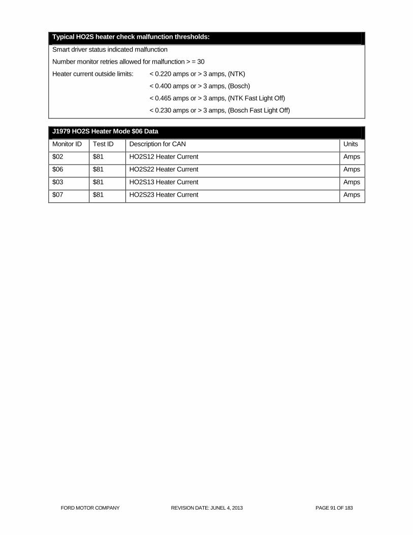
FORD MOTOR COMPANY REVISION DATE: JUNEL 4, 2013 PAGE 91 OF 183
Typical HO2S heater check malfunction thresholds:
Smart driver status indicated malfunction
Number monitor retries allowed for malfunction > = 30
Heater current outside limits: < 0.220 amps or > 3 amps, (NTK)
< 0.400 amps or > 3 amps, (Bosch)
< 0.465 amps or > 3 amps, (NTK Fast Light Off)
< 0.230 amps or > 3 amps, (Bosch Fast Light Off)
J1979 HO2S Heater Mode $06 Data
Monitor ID Test ID Description for CAN Units
$02 $81 HO2S12 Heater Current Amps
$06 $81 HO2S22 Heater Current Amps
$03 $81 HO2S13 Heater Current Amps
$07 $81 HO2S23 Heater Current Amps

FORD MOTOR COMPANY REVISION DATE: JUNEL 4, 2013 PAGE 92 OF 183
Stepper Motor EGR System Monitor
The Electric Stepper Motor EGR System uses an electric stepper motor to directly actuate an EGR valve rather
than using engine vacuum and a diaphragm on the EGR valve. The EGR valve is controlled by commanding
from 0 to 52 discreet increments or “steps” to get the EGR valve from a fully closed to fully open position. The
position of the EGR valve determines the EGR flow. Control of the EGR valve is achieved by a non-feedback,
open loop control strategy. Because there is no EGR valve position feedback, monitoring for proper EGR flow
requires the addition of a MAP sensor.
PCM
FRESH AIR INLET
Stepper Motor
EGR Valve
Intake Manifold
Stepper Motor EGR System
ExhaustGates
Map
Sensor
Note: Some configurations may differ slightly
0403
0400
PCM
FRESH AIR INLET
Stepper Motor
EGR Valve
Intake Manifold
Stepper Motor EGR System
ExhaustGates
Map
Sensor
Note: Some configurations may differ slightly
0403
0400

FORD MOTOR COMPANY REVISION DATE: JUNEL 4, 2013 PAGE 93 OF 183
The Stepper Motor EGR Monitor consists of an electrical and functional test that checks the stepper motor and
the EGR system for proper flow.
The stepper motor electrical test is a continuous check of the four electric stepper motor coils and circuits to the
PCM. A malfunction is indicated if an open circuit, short to power, or short to ground has occurred in one or more
of the stepper motor coils for a calibrated period of time. If a malfunction has been detected, the EGR system will
be disabled, and additional monitoring will be suspended for the remainder of the driving cycle, until the next
engine start-up.
EGR Stepper Monitor Electrical Check Operation:
DTCs P0403
Monitor execution continuous
Monitor Sequence none
Sensors OK
Monitoring Duration 4 seconds to register a malfunction
Stepper motor electrical check entry conditions:
Battery voltage > 11.0 volts
Typical EGR electrical check malfunction thresholds:
“Smart” Coil Output Driver status indicates open or short to ground, or short to power
EGR flow is monitored using an analog Manifold Absolute Pressure Sensor (MAP). If a malfunction has been
detected in the MAP sensor, the EGR monitor will not perform the EGR flow test.
The MAP sensor is checked for opens, shorts, or out-of-range values by monitoring the analog-to-digital (A/D)
input voltage.
MAP Sensor Check Operation
DTCs P0107 (low voltage), P0108 (high voltage)
Monitor execution continuous
Monitor Sequence none
Sensors OK not applicable
Monitoring Duration 5 seconds to register a malfunction
MAP electrical check entry conditions:
Battery voltage > 11.0 volts
Typical MAP sensor check malfunction thresholds:
Voltage < 0.19 volts or voltage > 4.88 volts

FORD MOTOR COMPANY REVISION DATE: JUNEL 4, 2013 PAGE 94 OF 183
The MAP sensor is also checked for rational values. The value of inferred MAP is checked against the actual value
of MAP at idle and non-idle engine operating conditions.
MAP Sensor Rationality Check Operation
DTCs P0106
Monitor execution continuous
Monitor Sequence None
Sensors OK not applicable
Monitoring Duration 10 seconds to register a malfunction
Typical MAP Rationality check entry conditions:
Entry Conditions Minimum Maximum
Change in load 5%
Engine rpm 975 rpm 1650 rpm
Throttle Angle 1.5 degrees 83 degrees
Typical MAP Rationality check malfunction thresholds:
Difference between inferred MAP and actual MAP > 8 in Hg
The MAP sensor is also checked for intermittent MAP faults.
MAP Sensor Intermittent Check Operation
DTCs P0109 (non-MIL)
Monitor execution Continuous
Monitor Sequence None
Sensors OK not applicable
Monitoring Duration 2 seconds to register a malfunction
Typical MAP Intermittent check malfunction thresholds:
Voltage < 0.024 volts or voltage > 4.96 volts

FORD MOTOR COMPANY REVISION DATE: JUNEL 4, 2013 PAGE 95 OF 183
When EGR is delivered into the intake manifold, intake manifold vacuum is reduced and thus manifold absolute
pressure (MAP) is increased. A MAP sensor and inferred MAP are used by this monitor to determine how much
EGR is flowing. A MAP sensor located in the intake manifold measures the pressure when EGR is being delivered
and when EGR is not being delivered. The pressure difference between EGR-on and EGR-off is calculated and
averaged. If the vehicle also has a MAF sensor fitted, then the monitor also calculates and averages an inferred
MAP value in the above calculation and resulting average. After a calibrated number of EGR-on and EGR-off
cycles are taken, the measured and inferred MAP values are added together and compared to a minimum
threshold to determine if a flow failure (P0400) in the EGR system has occurred.
EGR Flow Check Operation:
DTCs P0400
Monitor execution once per driving cycle
Monitor Sequence None
Sensors OK CPS, ECT, IAT, MAF, MAP (P0106/7/8), TP, BARO not available yet
Monitoring Duration 200 seconds (600 data samples)
Typical EGR flow check entry conditions:
Entry Condition Minimum Maximum
Inferred Ambient Air Temperature 38 oF 200
oF
Engine Coolant Temperature 130 oF 240
oF
Desired EGR ass 0.1 lbm/min
Engine RPM Steady (change/0.100 sec) 250 rpm
MAP Steady (change/0.100 sec) 0.35 in Hg
Engine Load Steady (change/0.100 sec) 10 %
BARO 22.5 "Hg
Intake Manifold Vacuum 3.5 "Hg 12.0 "Hg
Vehicle Speed 25 MPH 80 MPH
Engine Throttle Angle steady(absolute change) 0.0 degrees 4.0 degrees
Purge Flow Rate 1 lbs/min
Typical EGR flow check malfunction thresholds:
< 1.0 MAP differential
J1979 Mode $06 Data
Monitor ID Test ID Description for CAN Units
$33 $82 Normalized MAP differential (range 0 – 2) None

FORD MOTOR COMPANY REVISION DATE: JUNEL 4, 2013 PAGE 96 OF 183
I/M Readiness Indication
If the inferred ambient temperature is less than 20 oF, greater than 130
oF, or the altitude is greater than 8,000 feet
(BARO < 22.5 "Hg), the EGR flow test cannot be reliably done. In these conditions, the EGR flow test is
suspended and a timer starts to accumulate the time in these conditions. If the vehicle leaves these extreme
conditions, the timer starts decrementing, and, if conditions permit, will attempt to complete the EGR flow monitor.
If the timer reaches 800 seconds, the EGR flow test is disabled for the remainder of the current driving cycle and
the EGR Monitor I/M Readiness bit will be set to a “ready” condition after one such driving cycle. Two such
consecutive driving cycles are required for the EGR Monitor I/M Readiness bit to be set to a "ready" condition.

FORD MOTOR COMPANY REVISION DATE: JUNEL 4, 2013 PAGE 97 OF 183
PCV System Monitor
The PCV valve is installed into an oil separator that is bolted to the side of the block. The PCV valve is designed
to last the full useful life of the engine and is not designed to be removed from the oil separator. The PVC valve is
connected to the intake manifold hose using a quick connect. Because the PCV valve cannot be removed from
the oil separator, the quick connect will be disconnected in the event vehicle service is required. Molded plastic
lines are used from the PCV valve to the intake manifold. The diameter of the lines and the intake manifold have
been increased to 0.625" so that inadvertent disconnection of the quick connect will cause either an immediate
engine stall or will not allow the engine to be restarted. The crank case ventilation hose on the cam cover is
connected to the air induction system using quick connects. The cam cover also incorporates an oil separator.
In the event that the vehicle does not stall if the line between the intake manifold and PCV valve is disconnected,
the vehicle will have a large vacuum leak that will cause the vehicle to run lean at idle. This will illuminate the MIL
after two consecutive driving cycles and will store one or more of the following codes: Lack of O2 sensor
switches, Bank 1 (P2195), Fuel System Lean, Bank 1 (P0171) and MAP/Baro sensor intermittent (P0109).

FORD MOTOR COMPANY REVISION DATE: JUNEL 4, 2013 PAGE 98 OF 183
Enhanced Thermostat Monitor
For the 2009 MY, the thermostat test has been enhanced to reduce the time it takes to identify a malfunctioning
thermostat. The enhanced monitor includes a model which infers engine coolant temperature.
During a cold start, when the thermostat should be closed, the monitor uses a model of ECT to determine
whether actual ECT should have crossed the Warm Up Temperature (WUT) threshold.
Once the ECT model exceeds the thermostat regulating temperature for 3 seconds, measured ECT is compared
to the WUT threshold to determine if ECT has warmed up enough. If ECT has warmed up to at least the WUT
threshold, the thermostat is functioning properly. If ECT is too low, the thermostat is most likely stuck open and a
P0128 is set.
The WUT threshold is normally set to 20 degrees F below the thermostat regulating temperature.
fnengt_warm_eng_temp
(malfunction threshold)
engt_thms_reg_temp
(tstat regulating temp)
time (sec)
Coo
lan
t T
em
p (
de
g.
F.)
Black – Inferred coolant temp (expected temp with good tstat)
Blue – Measured coolant temp with good tstat
Red – Measured coolant temp with bad tstat
Completion Condition:
engt_inf_ect > engt_thms_reg_temp
(inferred ect > regulating temperature)
Call Delay:
engt_call_dly_tm
(call is made when inferred ect
has exceeded regulating
temperature for this length of time)
Pass/Fail Call:
ect > fnengt_warm_eng_temp ?
(actual ect > malfunction threshold ?)

FORD MOTOR COMPANY REVISION DATE: JUNEL 4, 2013 PAGE 99 OF 183
There are some circumstances that could lead to a false diagnosis of the thermostat. These are conditions where
the vehicle cabin heater is extracting more heat than the engine is making. One example where this can occur is
on large passenger vans which have "dual" heaters, one heater core for the driver and front passengers and
another heater core for the passengers in the rear of the vehicle. At very cold ambient temperatures, even a
properly functioning thermostat may never warm up to regulating temperature. Another example is a vehicle that
is started and simply sits at idle with the heater on high and the defroster fan on high.
There are two features that are used to prevent a false thermostat diagnosis. For vehicles with dual heaters, the
WUT threshold is reduced at cold ambient temperatures below 50 deg F. For cases where the engine is not
producing sufficient heat, a timer is used to track time at idle or low load conditions (e.g. decels). If the ratio of
time at idle/low load versus total engine run time exceeds 50% at the time the fault determination is made, the
thermostat diagnostic does not make a fault determination for that driving cycle, i.e. "no-call".
THERMOSTAT MONITOR OPERATION
DTC P0128 - Coolant Thermostat (Coolant temperature below thermostat regulating
temperature)
Monitor Execution Once per driving cycle, during a cold start
Monitoring Duration Drive cycle dependent. Monitor completes in less than 300 seconds when inferred
ECT exceeds threshold(at 70 deg F ambient temperature)
TYPICAL THERMOSTAT MONITOR ENTRY AND COMPLETION CONDITIONS
Entry conditions Minimum Maximum
Engine Coolant Temperature at start None 125 °F
Intake Air Temperature at start (ambient temp) 20 °F None
Inferred Percent Ethanol (flex fuel vehicles only) Learned N/A
Completion condition Minimum Maximum
Modeled ECT 180 °F None
Time Since Modeled ECT Exceeded WUT Threshold 3 sec. None
Time at Idle/Low Load Compared with Total Engine Run Time None 50%
TYPICAL MALFUNCTION THRESHOLD
Engine Coolant Temperature < 160 °F (for the 180 °F thermostat)

FORD MOTOR COMPANY REVISION DATE: JUNEL 4, 2013 PAGE 100 OF 183
HEV/PHEV Cooling System Diagnostics
The cooling system in the Plug-in Hybrid has been designed to include two functional cooling loops. This system is
designed to maximize cooling efficiency when the vehicle is running on either the gas engine or the electric motor.
The system operates in one of two different modes.
The first mode is the main or "combined" cooling loop mode which provides coolant flow through both the gas
engine and the cabin heater core. While in this loop, both the gas engine and an electric heater can be used to
maximize the heat transfer to the coolant thus providing both an increase in the engine metal temperature and heat
for the vehicle cabin.
The second cooling mode is the "isolated" loop mode where coolant flow through the cabin heater core is isolated
from the engine block. This loop is intended to provide cabin heat when the gas engine is not running. Coolant flow
is maintained in the "combined" loop by default (isolation valve de-energized), and by energizing the isolation valve
coolant flow is maintained in the "isolated" loop.
While in the "combined" cooling loop, coolant flow is maintained by a PCM-controlled Engine Coolant Pump
(internally known as the electric Water Pump (eWP)). The Engine Coolant Pump is a pulse width modulated pump
that can be used to control coolant flow rates independent of engine speed. This allows the PCM to maximize fuel
economy by minimizing cooling system power consumption as compared to a traditional belt-driven water pump.
Additionally, it can be used to improve engine metal temperature heating/cooling rates. Even though the Engine
Coolant Pump can provide coolant flow while the engine is off, it's primary purpose is to provide coolant flow while
the engine is running. A low power consumption auxiliary water pump in the "isolation" loop is the primary source of
coolant flow for cabin heating when the vehicle is operating in electric mode.
Byp
as
Check Valve
Degas Return
ECT_eWP
eWP sensor signal
Ra
dia
tor
DM
58-8
005-A
Degas
Bottle
Fan
DM
58-8
C6
07
-A
T-Stat
Elec
Water
Pump
ECT -- Inferred from CHT
Coolant
Outlet
Engine
2.0L Atk HEV
Inlet
EGR
Valve
CHT
Heater
Core
Aux
Heater
Pump
Coolant Temp
Sensor ECT2
Electric Heater
Byp
as
Check Valve
Degas Return
ECT_eWP
eWP sensor signal
Ra
dia
tor
DM
58-8
005-A
Degas
Bottle
Fan
DM
58-8
C6
07
-A
T-Stat
Elec
Water
Pump
ECT -- Inferred from CHT
Coolant
Outlet
Engine
2.0L Atk HEV
Inlet
EGR
Valve
CHT
Heater
Core
Aux
Heater
Pump
Coolant Temp
Sensor ECT2
Electric Heater
ECT_eWP
eWP sensor signal
Ra
dia
tor
DM
58-8
005-A
Degas
Bottle
Fan
DM
58-8
C6
07
-A
T-Stat
Elec
Water
Pump
ECT -- Inferred from CHT
Coolant
Outlet
Engine
2.0L Atk HEV
Inlet
EGR
Valve
CHT
Heater
Core
Aux
Heater
Pump
Coolant Temp
Sensor ECT2
Electric Heater
Ra
dia
tor
DM
58-8
005-A
Degas
Bottle
Fan
DM
58-8
C6
07
-A
T-Stat
Elec
Water
Pump
ECT -- Inferred from CHT
Coolant
Outlet
Engine
2.0L Atk HEV
Inlet
EGR
Valve
CHT
Heater
Core
Aux
Heater
Pump
Coolant Temp
Sensor ECT2
Electric Heater
T-Stat
Elec
Water
Pump
T-Stat
Elec
Water
Pump
Elec
Water
Pump
ECT -- Inferred from CHT
Coolant
Outlet
Engine
2.0L Atk HEV
Inlet
EGR
Valve
CHT
Heater
Core
Aux
Heater
Pump
Coolant Temp
Sensor ECT2
Electric Heater
Coolant
Outlet
Engine
2.0L Atk HEV
Inlet
EGR
Valve
CHT
Coolant
Outlet
Engine
2.0L Atk HEV
Inlet
EGR
Valve
CHT
Heater
Core
Aux
Heater
Pump
Coolant Temp
Sensor ECT2
Electric HeaterHeater
Core
Aux
Heater
Pump
Coolant Temp
Sensor ECT2
Electric HeaterHeater
Core
Aux
Heater
Pump
Aux
Heater
Pump
Coolant Temp
Sensor ECT2
Electric Heater

FORD MOTOR COMPANY REVISION DATE: JUNEL 4, 2013 PAGE 101 OF 183
The Engine Coolant Bypass Valve position determined whether the cooling system operates in a combined loop
(engine-heated coolant flowing through the heater core) or in an isolated loop (engine is off, cabin heat provided by
PTC heater). The ECBV is checked for circuit faults and for actual valve position after the valve is determined to be
electrically failed.
Engine Coolant Bypass Valve Circuit check operation
DTCs P2682 – Engine Coolant Bypass Valve "A" Control Circuit Low
P2683 - Engine Coolant Bypass Valve "A" Control Circuit High
P26AB - Engine Coolant Bypass Valve "A" Stuck/Open (valve stuck in combined
loop)
Monitor execution Continuous
Monitor Sequence None for P2682/P2683
P2682 must set before P26AB will complete
Monitoring Conditions
Monitoring Duration 5 seconds to register a malfunction
Typical Engine Coolant Bypass Valve Circuit malfunction thresholds:
P2682: Driver indicates circuit fault > 5 sec
P2683: Driver indicated circuit fault > 5 sec
P26AB: ECT2 - ECT >5 deg F within 60 seconds of circuit fault

FORD MOTOR COMPANY REVISION DATE: JUNEL 4, 2013 PAGE 102 OF 183
The Engine Coolant Pump (eWP) is a smart pump with four pins. Two of the pins are connected directly to battery
power and electrical ground. The other circuits are connected to the PCM. One is connected to the LIN bus
(primary PCM control) and the other is called the Emergency Run Input (ERI) line that can be used to control the
pump with a PWM signal if the LIN bus goes down. This ERI line has been wired directly to ignition power so that
the pump will be commanded to run any time the LIN bus is failed and ignition is on.
Below is a summary of the diagnostics associated with the Engine Coolant Pump. Circuit faults for the LIN bus and
ERI lines are detected by the PCM while the pump power and ground line faults are detected by the Engine
Coolant Pump Control Module and communicated to the PCM through the LIN bus line. All mechanical faults are
detected by the Engine Coolant Pump Control Module and also communicated to the PCM over the LIN bus.
The Engine Coolant Pump speed is controlled by the PCM and communicated to the Engine Coolant Pump Control Module over the LIN bus. A LIN bus communication fault (U019F) is set when the engine coolant pump speed echoed back from the Engine Coolant Pump Control Module doesn't match the desired speed sent from the PCM (requires no other electric water pump faults exist).
Engine Coolant Pump communication check operation
DTCs U019F - Lost Communication With Engine Coolant Pump Control Module
Monitor execution Continuous
Monitor Sequence None
Sensors OK Over-temperature (P26D2), over-current (P26CB), blocked impeller (P26CB), or
dry run (P26CE).
Monitoring Duration 10 seconds to register a malfunction
Typical Engine Coolant Pump communication check malfunction thresholds:
Difference between desired pump speed and actual pump speed > 300 RPM

FORD MOTOR COMPANY REVISION DATE: JUNEL 4, 2013 PAGE 103 OF 183
Failures on the Emergency Run Input (ERI) line are detected by checking the status of the ERI line communicated to the PCM over LIN. Since the ERI line is hardwired to the vehicle ignition key, the returned ERI line state should always match the vehicle ignition state. When there is a mismatch, a DTC P26CA is set. This monitor requires that the LIN communications bus has not failed.
Engine Coolant Pump Emergency Run Input check operation
DTCs P26CA – Engine Coolant Pump Control Circuit/Open
Monitor execution Continuous
Monitor Sequence None
Monitoring Conditions No LIN bus communication faults (U019F).
Monitoring Duration 5 seconds to register a malfunction
Typical Engine Coolant Pump Emergency Run Input check malfunction thresholds:
Difference between ERI state reported by ECPCM and actual ERI state at PCM
The Engine Coolant Pump power and ground line status is not communicated to the PCM by Engine Coolant Pump Control Module. Therefore, the status of these lines is inferred by the PCM. If either of these lines is faulted, the Engine Coolant Pump will not run, and there will no LIN bus communications from the Engine Coolant Pump Control Module to the PCM. The PCM first checks to see if a fault on the communication line (U019F). If the communication line is faulted and the engine coolant temperature is increasing then it is assumed that the pump is not running and a P26D3 DTC is set. If the engine coolant temperature is not increasing then the PCM identifies the communications fault only.
Engine Coolant Pump Control Module Power/Ground check operation
DTCs P26D3 – Engine Coolant Pump Supply Voltage Circuit
Monitor execution Continuous
Monitor Sequence None
Monitoring Conditions None
Monitoring Duration 5 seconds to register a malfunction
Electric Water Pump Control Module Power/Ground Signal Fault malfunction thresholds:
LIN bus comm. fault (U019F) and accumulated engine coolant temp increase > 10oC
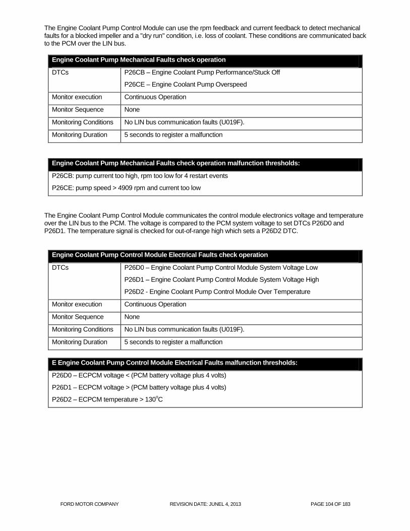
FORD MOTOR COMPANY REVISION DATE: JUNEL 4, 2013 PAGE 104 OF 183
The Engine Coolant Pump Control Module can use the rpm feedback and current feedback to detect mechanical faults for a blocked impeller and a "dry run" condition, i.e. loss of coolant. These conditions are communicated back to the PCM over the LIN bus.
Engine Coolant Pump Mechanical Faults check operation
DTCs P26CB – Engine Coolant Pump Performance/Stuck Off
P26CE – Engine Coolant Pump Overspeed
Monitor execution Continuous Operation
Monitor Sequence None
Monitoring Conditions No LIN bus communication faults (U019F).
Monitoring Duration 5 seconds to register a malfunction
Engine Coolant Pump Mechanical Faults check operation malfunction thresholds:
P26CB: pump current too high, rpm too low for 4 restart events
P26CE: pump speed > 4909 rpm and current too low
The Engine Coolant Pump Control Module communicates the control module electronics voltage and temperature over the LIN bus to the PCM. The voltage is compared to the PCM system voltage to set DTCs P26D0 and P26D1. The temperature signal is checked for out-of-range high which sets a P26D2 DTC.
Engine Coolant Pump Control Module Electrical Faults check operation
DTCs P26D0 – Engine Coolant Pump Control Module System Voltage Low
P26D1 – Engine Coolant Pump Control Module System Voltage High
P26D2 - Engine Coolant Pump Control Module Over Temperature
Monitor execution Continuous Operation
Monitor Sequence None
Monitoring Conditions No LIN bus communication faults (U019F).
Monitoring Duration 5 seconds to register a malfunction
E Engine Coolant Pump Control Module Electrical Faults malfunction thresholds:
P26D0 – ECPCM voltage < (PCM battery voltage plus 4 volts)
P26D1 – ECPCM voltage > (PCM battery voltage plus 4 volts)
P26D2 – ECPCM temperature > 130oC

FORD MOTOR COMPANY REVISION DATE: JUNEL 4, 2013 PAGE 105 OF 183
Cold Start Emission Reduction Component Monitor
Engine Speed and Spark Timing Component Monitor (2010 MY and beyond)
Entry Conditions and Monitor Flow
The System Monitor and 2010 Component Monitor share the same entry conditions and monitor flow. During the
first 15 seconds of a cold start, the monitor checks the entry conditions, counts time in idle, observes catalyst
temperature, calculates the average difference between desired and actual engine speed, and calculates the
average difference between desired and commanded spark.
If the expected change in catalyst temperature is large enough, the monitor then begins the waiting period, which
lasts until 300 seconds after engine start. This 5-minute wait allows time to diagnose other components and
systems that affect the validity of the test. During this waiting period, there are no constraints on drive cycle and
the monitor cannot be disabled without turning off the key.
If the System monitor result falls below its threshold and all of the Component monitor results are below their
respective thresholds, the monitor determines whether the idle time was sufficient. If so, it considers the tests a
pass and the monitor is complete. If idle time was not sufficient, the monitor does not make a pass call and does
not complete. This prevents tip-ins from resulting in false passes.
Cold Start Engine Speed Monitor
Once the waiting period is complete, the monitor compares the average difference between desired and actual engine speeds to a calibratable threshold that is a function of ECT at start. If the magnitude of the discrepancy exceeds the threshold, P050A is set.
Cold Start Spark Timing Monitor
Once the waiting period is complete, the monitor compares the average difference between desired and
commanded spark to a calibratable threshold that is a function of ECT at start. If the magnitude of the discrepancy
exceeds the threshold, P050B is set.
CSER COMPONENT MONITOR OPERATION
Component Monitor DTCs P050A: Cold Start Idle Air Control System Performance
P050B: Cold Start Ignition Timing Performance
Monitor Execution Once per driving cycle, during a cold start
Monitor Sequence Monitor data collection takes place during first 15 seconds of cold start
Sensors OK No fault is present in any of the sensors or systems affecting the catalyst
temperature model: Mass Air Flow (P0102, P0103), Throttle Position (P0122,
P0123, P0222, P0223), Misfire (P0316, P0300-P0312), Injectors (P0201-
P0212), Fuel System (P0171, P0172, P0174, P0175), Secondary Air (P0412,
P2258), Crank Position Sensor (P0320), Ignition Coil (P0351-P0360), Intake
Air Temp (P0112, P0113), Engine Coolant Temp/Cylinder Head Temp
(P0117, P0118, P1289, P1290), Variable Cam Timing (P0010, P0020, P0011,
P0012, P0021, P0022), Intake Manifold Runner Control (P2008).
Monitoring Duration Monitor completes 300 seconds after initial engine start

FORD MOTOR COMPANY REVISION DATE: JUNEL 4, 2013 PAGE 106 OF 183
TYPICAL CSER COMPONENT MONITOR ENTRY AND COMPLETION CONDITIONS
Entry condition Minimum Maximum
Barometric Pressure 22 in. Hg
Engine Coolant Temperature at Start 35 °F 100 °F
Catalyst Temperature at Start 35 °F 125 °F
Fuel Level 15%
BARO 22.5" Hg
No Torque Reduction by Injector Cutout
Power Takeout Not Active
Completion condition Minimum Maximum
Length of Time Entry Conditions are Satisfied 11 sec.
Expected Change in Catalyst Temperature 50 °F
Time in Idle 10 sec.
Selected Gear Neutral Drive
TYPICAL CSER COMPONENT MONITOR MALFUNCTION THRESHOLDS
Engine speed discrepancy > 200 rpm
Spark timing discrepancy > 10 deg.

FORD MOTOR COMPANY REVISION DATE: JUNEL 4, 2013 PAGE 107 OF 183
Cold Start Variable Cam Timing Monitor (2008 MY and beyond)
If the VCT cam phasing is used during a cold start to improved catalyst heating, the VCT system is checked
functionally by monitoring the closed loop cam position error correction. If the proper cam position cannot be
maintained and the system has an advance or retard error greater than the malfunction threshold, a cold start
emission reduction (CSER) VCT control malfunction is indicated (P052A/P052B (Bank 1), P052C/P052D (Bank2).
This test is the same test that was used previously for monitoring the VCT system under Comprehensive
Component Monitoring requirements.
CSER VCT Target Error Check Operation:]
DTCs P052A – Cold start camshaft position timing over-advanced (Bank 1)
P052B – Cold start camshaft timing over-retarded (Bank 1)
Monitor execution Continuous
Monitor Sequence None
Sensors OK
Monitoring Duration 2 seconds
Typical CSER VCT target error entry conditions:
Entry condition Minimum Maximum
VCT control enabled and commanded to advance or
retard cam during CSER
n/a n/a
Time since start of CSER cam phase monitoring 60 seconds
Typical CSER VCT target error malfunction thresholds:
CSER Response/target error - VCT over-advance: 11 degrees
CSER Response/target error - VCT over-retard: 11 degrees
CSER Response/Stuck Pin – 10 degrees phasing commanded, and not seeing at least 2 degrees of
movement.

FORD MOTOR COMPANY REVISION DATE: JUNEL 4, 2013 PAGE 108 OF 183
Cold Start Emission Reduction System Monitor
The Cold Start Emission Reduction System Monitor is being introduced for the 2007 MY on vehicles that meet the
LEV-II emission standards. The System Monitor detects the lack of catalyst warm up resulting from a failure to
apply sufficient CSER during a cold start. It does this by using the inferred catalyst temperature model to
determine how closely the actual catalyst temperature follows the expected catalyst temperature during a cold
start. How closely the actual temperature follows the expected temperature is reflected in a ratio which is
compared with a calibratable threshold.
Temperatures Used
The actual catalyst temperature is the same inferred catalyst temperature that is used by other portions of the
engine control system, including the CSER control system. The inputs to this actual temperature are measured
engine speed, measured air mass, and commanded spark.
The expected catalyst temperature is calculated using the same algorithm as the actual catalyst temperature, but
the inputs are different. Desired engine speed replaces measured engine speed, desired air mass replaces
measured air mass, and desired cold start spark replaces commanded spark. The resulting temperature
represents the catalyst temperature that is expected if CSER is functioning properly.
Ratio Calculation
A ratio is calculated to reflect how closely the actual temperature has followed the expected temperature. This
ratio is the difference between the two temperatures at a certain time-since-start divided by the increase in
expected temperature over the same time period. The ratio, then, provides a measure of how much loss of
catalyst heating occurred over that time period.
This ratio correlates to tailpipe emissions. Therefore applying a threshold to it allows illumination of the MIL at the
appropriate emissions level. The threshold is a function of ECT at engine start.
General CSER Monitor Operation
During the first 15 seconds of a cold start, the monitor checks the entry conditions, counts time in idle, and
observes catalyst temperature.
If the expected change in catalyst temperature is large enough, the monitor calculates the ratio as described
above. Otherwise the monitor does not make a call.
The monitor then begins the waiting period, which lasts from the time the ratio is calculated (15 seconds after
engine start) until 300 seconds after engine start. This 5-minute wait allows time to diagnose other components
and systems that affect the validity of the catalyst temperature model. During this waiting period, there are no
constraints on drive cycle and the monitor cannot be disabled without turning off the key.
At the end of the waiting period, if no other faults that could compromise the validity of the catalyst temperature
model are found, the monitor compares the ratio to the threshold.
If the ratio exceeds the threshold, the monitor considers the test a fail, and the monitor is complete.
If the ratio falls below the threshold, and all of the component monitor results are below their respective thresholds,
the monitor determines whether the idle time was sufficient. If so, it considers the test a pass and the monitor is
complete. If idle time was not sufficient, the monitor does not make a pass call and does not complete. This
prevents tip-ins from resulting in false passes.

FORD MOTOR COMPANY REVISION DATE: JUNEL 4, 2013 PAGE 109 OF 183

FORD MOTOR COMPANY REVISION DATE: JUNEL 4, 2013 PAGE 110 OF 183
CSER SYSTEM MONITOR OPERATION
DTC P050E: Cold Start Engine Exhaust Temperature Too Low
Monitor Execution Once per driving cycle, during a cold start
Monitor Sequence Monitor data collection takes place during first 15 seconds of cold start
Sensors OK No fault is present in any of the sensors or systems affecting the catalyst
temperature model: Mass Air Flow (P0102, P0103), Throttle Position (P0122,
P0123, P0222, P0223), Misfire (P0316, P0300-P0312), Injectors (P0201-
P0212), Fuel System (P0171, P0172, P0174, P0175), Secondary Air (P0412,
P2258), Crank Position Sensor (P0320), Ignition Coil (P0351-P0360), Intake
Air Temp (P0112, P0113), Engine Coolant Temp/Cylinder Head Temp
(P0117, P0118, P1289, P1290), Variable Cam Timing (P0010, P0020, P0011,
P0012, P0021, P0022), Intake Manifold Runner Control (P2008).
Monitoring Duration Monitor completes 300 seconds after initial engine start
TYPICAL CSER SYSTEM MONITOR ENTRY AND COMPLETION CONDITIONS
Entry condition Minimum Maximum
Barometric Pressure 22 in. Hg
Engine Coolant Temperature at Start 35 °F 100 °F
Catalyst Temperature at Start 35 °F 125 °F
Fuel Level 15%
No Torque Reduction by Injector Cutout
Power Takeout Not Active
Completion condition Minimum Maximum
Length of Time Entry Conditions are Satisfied 11 sec.
Expected Change in Catalyst Temperature 50 °F
Time in Idle 10 sec.
Selected Gear Neutral Drive
TYPICAL CSER SYSTEM MALFUNCTION THRESHOLD
Cold start warm-up temperature ratio > 0.2

FORD MOTOR COMPANY REVISION DATE: JUNEL 4, 2013 PAGE 111 OF 183
Variable Cam Timing System Monitor
Variable Cam Timing (VCT) enables rotation of the camshaft(s) relative to the crankshaft (phase-shifting) as a
function of engine operating conditions. There are four possible types of VCT with DOHC engines:
Intake Only (phase-shifting only the intake cam);
Exhaust Only (phase-shifting only the exhaust cam);
Dual Equal (phase-shifting the intake and exhaust cams equally);
Dual Independent (phase-shifting the intake and exhaust cams independently).
All four types of VCT are used primarily to increase internal residual dilution at part throttle to reduce NOx, and to
improve fuel economy. This allows for elimination the external EGR system.
With Exhaust Only VCT, the exhaust camshaft is retarded at part throttle to delay exhaust valve closing for
increased residual dilution and to delay exhaust valve opening for increased expansion work.
With Intake Only VCT, the intake camshaft is advanced at part throttle and WOT (at low to mid-range engine
speeds) to open the intake valve earlier for increased residual dilution and close the intake valve earlier in the
compression stroke for increased power. When the engine is cold, opening the intake valve earlier warms the
charge which improves fuel vaporization for less HC emissions; when the engine is warm, the residual burned
gasses limit peak combustion temperature to reduce NOx formation.
With Dual Equal VCT, both intake and exhaust camshafts are retarded from the default, fully advanced position to
increase EGR residual and improve fuel economy by reducing intake vacuum pumping losses. The residual
charge for NOx control is obtained by backflow through the late-closing exhaust valve as the piston begins its
intake stroke.
The VCT system hardware consists of a control solenoid and a pulse ring on the camshaft. The PCM calculates
relative cam position using the CMP input to process variable reluctance sensor pulses coming from the pulse ring
mounted on the camshaft. Each pulse wheel has N + 1 teeth where N = the number of cylinders per bank. The N
equally spaced teeth are used for cam phasing; the remaining tooth is used to determine cylinder # 1 position.
Relative cam position is calculated by measuring the time between the rising edge of profile ignition pickup (PIP)
and the falling edges of the VCT pulses.
The PCM continually calculates a cam position error value based on the difference between the desired and actual
position and uses this information to calculate a commanded duty cycle for the VCT solenoid valve. When
energized, engine oil is allowed to flow to the VCT unit thereby advancing and retarding cam timing. The variable
cam timing unit assembly is coupled to the camshaft through a helical spline in the VCT unit chamber. When the
flow of oil is shifted from one side of the chamber to the other, the differential change in oil pressure forces the
piston to move linearly along the axis of the camshaft. This linear motion is translated into rotational camshaft
motion through the helical spline coupling. A spring installed in the chamber is designed to hold the camshaft in the
low-overlap position when oil pressure is too low (~15 psi) to maintain adequate position control. The camshaft is
allowed to rotate up to 30 degrees.
Although the VCT system has been monitored under Comprehensive Component Monitoring requirements for
many years, a new, emission-based VCT monitor is being introduced for the 2006 MY on vehicles that meet LEV-II
emission standards. The intent of the new VCT monitoring requirements is to detect slow VCT system response
that could cause emissions to increase greater than 1.5 * std. in addition to detecting functional problems (target
errors).
The new logic calculates the instantaneous variance in actual cam position (the squared difference between actual
cam position and commanded cam position), then calculates the long term variance using a rolling average filter
(Exponentially Weighted Moving Average). Continued, slow response from the VCT system will eventually
accumulate large variances.

FORD MOTOR COMPANY REVISION DATE: JUNEL 4, 2013 PAGE 112 OF 183
This same logic will also detect target errors that were detected by the previous CCM monitor. If the VCT system is
stuck in one place, the monitor will detect a variance which will quickly accumulate.
There are three variance indices that monitor cam variance in the retard direction, the advance direction, and for V-
engines, the difference between banks. If any variance index is greater than the malfunction threshold, a VCT slow
response/target error malfunction will be indicated (P0011, P0012 Bank 1, 0021, P0022 Bank 2). Target errors will
tend to generate only a single over-advanced or over-retarded code while slow response will tend to generate both
codes.
In addition, logic has been added to determine whether the camshaft and crankshaft are misaligned by one or
more teeth. This test calculates the absolute offset between one of the camshaft teeth and the crankshaft missing
tooth at idle when that can is at its stop. If the error is greater than the malfunction threshold, a cam/crank
misalignment error will be indicated (P0016 Bank 1, P0018 Bank 2).
For systems that phase the cams immediately off of a cold start for reducing emissions or CSER (Cold Start
Emissions Reduction) the cam position is monitored for functionality during this period of time. There are two ways
to set failures.
Error between the actual position and the expected position is calculated. If the error is greater than a
specified amount, and the Error persists for a period of time, a P052x code is set designating over
advanced or retarded and the bank number. The diagnostic is only executed during CSER phasing.
The diagnostic also checks for a cam position request above a threshold for a period of time, and
determines that the VCT actuator pin is stuck if the cam does not move from the locked position by a
certain amount. This is also only done during CSER operation. If the locking pin is determined to be stuck
then the Oil Control Solenoid (OCS) is cycled on and off for a calibratable amount to allow pressure to
build in the system to unseat the locking pin. If attempts to unstick the locking pin fail, then a P052x code
is set.
The in-use performance ratio numerator for the VCT monitor can be incremented only if the VCT system has been
monitored for both functional and response faults. If the vehicle is operated in a manner that does not ask the VCT
actuators to change position, it may not be possible to evaluate whether they are working properly. As a result, the
in-use ratio numerator checks to see if the commanded VCT position changes sufficiently to detect possible target
errors and with a sufficiently high rate to detect possible slow response. For each drive cycle in which both criteria
are met, the VCT in-use performance numerator will be incremented.
Similar to the previous CCM monitor, the VCT solenoid output driver in the PCM is checked electrically for opens
and shorts (P0010 Bank 1, P0020 Bank 2).

FORD MOTOR COMPANY REVISION DATE: JUNEL 4, 2013 PAGE 113 OF 183
VCT Monitor Operation:
DTCs P0010 - Camshaft Position Actuator Circuit (Bank 1)
P0011 - Cam Position Actuator Over Advanced (Bank 1)
P0012 - Cam Position Actuator Over Retarded (Bank 1)
P0016 - Crank/Cam Position Correlation (Bank 1)
Monitor execution Continuous
Monitor Sequence None
Sensors OK IAT, ECT, EOT, IMRC, TP, MAF, CKP, and CMP
Monitoring Duration 5 - 10 seconds for circuit faults and functional checks, 300 seconds for target
error
Typical VCT response/functional monitor entry conditions:
Entry condition Minimum Maximum
Engine RPM (for P0016/P0018 only) 850 4500
Engine Coolant Temperature 18 oF
Engine Oil Temperature 280 oF
VCT control enabled and commanded to advance or
retard cam **
n/a n/a
** VCT control of advance and retard by the engine is disabled in crank mode, when engine oil is cold (< 150 oF), while learning the cam/crank offset, while the control system is "cleaning" the solenoid oil passages,
throttle actuator control in failure mode, and if one of the following sensor failures occur: IAT, ECT, EOT,
MAF, TP, CKP, CMP, or IMRC.

FORD MOTOR COMPANY REVISION DATE: JUNEL 4, 2013 PAGE 114 OF 183
Typical VCT monitor malfunction thresholds:
VCT solenoid circuit: Open/short fault set by the PCM driver
Cam/crank misalignment: > or = 7.5 crank degrees
Response/target error - VCT over-advance variance too high: 100 degrees squared
Response/target error - VCT over-retard variance too high: 400 degrees squared
Typical In-Use Performance monitoring thresholds:
Monitoring thresholds to increment the numerator:
Amount of cam change required for target error fault: > 160 degrees squared
Amount of rate of change required for slow response fault: > 5 degrees squared
J1979 VCT Monitor Mode $06 Data
Monitor ID Test ID Description for CAN Units
$35 $80 Camshaft Advanced Position Error Bank 1 Unsigned, Angular degrees
$35 $81 Camshaft Retarded Position Error Bank 1 Unsigned, Angular degrees

FORD MOTOR COMPANY REVISION DATE: JUNEL 4, 2013 PAGE 115 OF 183
Electronic Throttle Control
The Electronic Throttle Control (ETC) system uses a strategy that delivers engine or torque, based on driver
demand, utilizing an electronically controlled throttle body. ETC strategy was developed mainly to improve fuel
economy. This is possible by decoupling throttle angle (produces engine torque) from pedal position (driver
demand). This allows the powertrain control strategy to optimize fuel control and transmission shift schedules
while delivering the requested engine or wheel torque.
Because safety is a major concern with ETC systems, a complex safety monitor strategy (hardware and
software) was developed. The monitor system is distributed across two processors: the main powertrain control
processor and a monitoring processor called a Quizzer processor.
The primary monitoring function is performed by the Independent Plausibility Check (IPC) software, which resides
on the main processor. It is responsible for determining the driver-demanded torque and comparing it to an
estimate of the actual torque delivered. If the generated torque exceeds driver demand by specified amount, the
IPC takes appropriate mitigating action.
Since the IPC and main controls share the same processor, they are subject to a number of potential, common-
failure modes. Therefore, the Quizzer processor was added to redundantly monitor selected PCM inputs and to
act as an intelligent watchdog and monitor the performance of the IPC and the main processor. If it determines
that the IPC function is impaired in any way, it takes appropriate Failure Mode and Effects Management (FMEM)
actions.

FORD MOTOR COMPANY REVISION DATE: JUNEL 4, 2013 PAGE 116 OF 183
ETC System Failure Mode and Effects Management:
Effect Failure Mode
No Effect on Drivability A loss of redundancy or loss of a non-critical input could result in a concern that does not affect driveability. The powertrain malfunction indicator (wrench) and the malfunction indicator lamp (MIL) do not illuminate, however the speed control may be disabled. A DTC is set to indicate the component or circuit with the concern.
Delayed APP Sensor Response with Brake Override
This mode is caused by the loss of one APP sensor input due to sensor, wiring, or PCM concerns. The system is unable to verify the APP sensor input and driver demand. The throttle plate response to the APP sensor input is delayed as the accelerator pedal is applied. The engine returns to idle RPM whenever the brake pedal is applied. The powertrain malfunction indicator (wrench) illuminates, but the MIL does not illuminate in this mode. An APP sensor related DTC is set.
LOS Supercreep Loss of both APP sensor inputs due to sensor, wiring, or PCM concerns, or internal control mode torque performance, or generator speed or crankshaft position (CKP) sensor or harness. There is no response when the accelerator pedal is applied. The engine returns to idle RPM and driver demanded torque returns to zero whenever the brake pedal is applied. The powertrain malfunction indicator (wrench) illuminates, but the MIL does not illuminate in this mode. An internal control module torque performance or internal control module drive motor/generator/engine speed sensor or APP sensor DTC is set
LOS Supercreep Creep mode is caused by the loss of one brake pedal position (BPP) and one APP sensor input. The system is unable to determine driver demand. There is no response when the accelerator pedal is applied. The powertrain malfunction indicator (wrench) illuminates, but the MIL does not illuminate in this mode. An APP and BPP sensor, or harness related DTC is set.
RPM Guard with Pedal Follower
In this mode, the throttle plate control is disabled due to the loss of both TP sensor inputs, loss of throttle plate control, stuck throttle plate, significant processor concerns, or other major electronic throttle body concern. The spring returns the throttle plate to the default (limp home) position. A maximum allowed RPM is determined based on the position of the accelerator pedal (RPM Guard). If the actual RPM exceeds this limit, spark and fuel are used to bring the RPM below the limit. The powertrain malfunction indicator (wrench) and the MIL illuminate in this mode and a DTC for an ETC related component is set. EGR and VCT outputs are set to default values and speed control is disabled.
Shutdown If a significant processor concern is detected, the monitor forces the vehicle to shutdown by disabling engine, generator and traction motor. The powertrain malfunction indicator (wrench), MIL, and hazard indicator may illuminate.

FORD MOTOR COMPANY REVISION DATE: JUNEL 4, 2013 PAGE 117 OF 183
Transmission Range Sensor Inputs
Transmission Range Sensor Check Operation:
DTCs P2800 – Transmission Range Sensor B Circuit (PRNDL input) (wrench light,
non-MIL)
P2801 – Transmission Range Sensor B Circuit Range/Performance (wrench
light, non-MIL)
P2802 – Transmission Range Sensor B Circuit Low (wrench light, non-MIL)
P2803 – Transmission Range Sensor B Circuit High (wrench light, non-MIL)
P2806 – Transmission Range Sensor Alignment (wrench light, non-MIL)
Monitor execution continuous
Monitor Sequence None
Sensors OK not applicable
Monitoring Duration < 1 seconds to register a malfunction
Transmission range sensor check malfunction thresholds:
TR Sensor Park Reverse Neutral Drive Low
TR_A1 (VOLTS 3.84 - 4.77 2.58 - 3.31 1.82 - 2.56 0.97 - 1.79 0.20 - 0.92
TR_A2 (VOLTS 0.20 - 1.08 1.56 - 2.25 2.26 - 2.96 2.97 - 3.74 3.77 - 4.45
Range/performance – disagreement between sensors > 3.85 degrees

FORD MOTOR COMPANY REVISION DATE: JUNEL 4, 2013 PAGE 118 OF 183
Accelerator and Throttle Position Sensor Inputs
On-demand KOEO / KOER Sensor Check Operation:
DTCs P1575 – APP out of self-test range (non-MIL)
Monitor execution On-demand
Monitor Sequence None
Sensors OK not applicable
Monitoring Duration < 1 seconds to register a malfunction
Accelerator Pedal Position Sensor Check Operation:
DTCs P2122, P2123 – APP D circuit continuity (wrench light, non-MIL)
P2127, P2128 – APP E circuit continuity (wrench light, non-MIL)
P2138 – APP D/E circuit disagreement (wrench light, non-MIL)
Monitor execution continuous
Monitor Sequence none
Sensors OK not applicable
Monitoring Duration < 1 seconds to register a malfunction
APP sensor check malfunction thresholds:
Circuit continuity - Voltage < 0.25 volts or voltage > 4.75 volts
Range/performance – disagreement between sensors > 1.1 degrees
Brake Switch Check Operation:
DTCs P0504 – Brake switch A/B correlation (wrench light, non-MIL)
P0572 – Brake switch circuit low (wrench light, non-MIL)
P0573 – Brake switch circuit high (wrench light, non-MIL)
Monitor execution Continuous
Monitor Sequence None
Sensors OK not applicable
Monitoring Duration > 25 brake application cycles to register a malfunction

FORD MOTOR COMPANY REVISION DATE: JUNEL 4, 2013 PAGE 119 OF 183
Throttle Position Sensor Check Operation:
DTCs P0122, P0123 – TP A circuit continuity (MIL, wrench light)
P0222, P0223 – TP B circuit continuity (MIL, wrench light)
P2135 – TP A / TP B correlation (non-MIL, wrench light)
Monitor execution Continuous
Monitor Sequence None
Sensors OK not applicable
Monitoring Duration < 1 seconds to register a malfunction
TP sensor check malfunction thresholds:
Circuit continuity - Voltage < 0.25 volts or voltage > 4.75 volts
Correlation and range/performance – disagreement between sensors > 7 degrees

FORD MOTOR COMPANY REVISION DATE: JUNEL 4, 2013 PAGE 120 OF 183
Electronic Throttle Monitor
Electronic Throttle Monitor Operation:
DTCs U0300 – ETC software version mismatch, IPC or Quizzer (MIL, Hazard, wrench light
for Gen3 / Gen4)
P0600 – Serial Communication Link (MIL, Hazard, wrench light for Gen3 / Gen4)
P060A – Internal control module monitoring processor performance (MIL, Hazard,
wrench light for Gen3 / Gen4)
P060B – Internal control module A/D processing performance (MIL, Hazard, wrench
light)
P060C – Internal control module main processor performance (MIL, Hazard, wrench
light)
P060D – Internal control module accelerator pedal performance (non-MIL) [Gen3 /
Gen4 only]
P061A – Internal control module Torque Performance (MIL, wrench light)
P0A18 – Motor Torque Sensor Circuit Range/Performance (MIL, Hazard, wrench
light)
P0A23 – Generator Torque Sensor Circuit Range/Performance (MIL, Hazard,
wrench light)
P0C2F – Internal Control Module Drive Motor/Generator/Engine Speed Performance
(MIL, wrench light)
P1A0D – Hybrid Powertrain Control Module – Generator Disabled (MIL, Hazard,
wrench light)
P1A0E - Hybrid Powertrain Control Module – Motor Disabled (MIL, Hazard, wrench
light)
P061F – Internal control module throttle actuator controller performance (non-MIL,
wrench light for Gen3 / Gen4)
P1674 – Internal control module software corrupted (MIL, hazard, wrench light for
Gen3 / Gen4)
Monitor execution Continuous
Monitor Sequence None
Sensors OK not applicable
Monitoring Duration < 1 seconds to register a malfunction

FORD MOTOR COMPANY REVISION DATE: JUNEL 4, 2013 PAGE 121 OF 183
Throttle Plate Position Controller (TPPC) Outputs
The purpose of the TPPC is to control the throttle position to the desired throttle angle. The current ETC systems
have the eTPPC function integrated in the main PCM processor.
The desired angle is relative to the hard-stop angle. The hard-stop angle is learned during each key-up process
before the main CPU requests the throttle plate to be closed against the hard-stop. The output of the (e)TPPC is
a voltage request to the H-driver (also in PCM). The H driver is capable of positive or negative voltage to the
Electronic Throttle Body Motor.
Throttle Plate Controller and Actuator Operation:
DTCs P2107 – processor test (MIL, wrench light)
P2111 – throttle actuator system stuck open (MIL, wrench light)
P2112 – throttle actuator system stuck closed (MIL, wrench light)
P2101 – throttle actuator range/performance test (MIL, wrench light)
P115E – throttle actuator airflow trim at max limit (MIL)
Monitor execution Continuous
Monitor Sequence None
Monitoring Duration < 5 seconds to register a malfunction
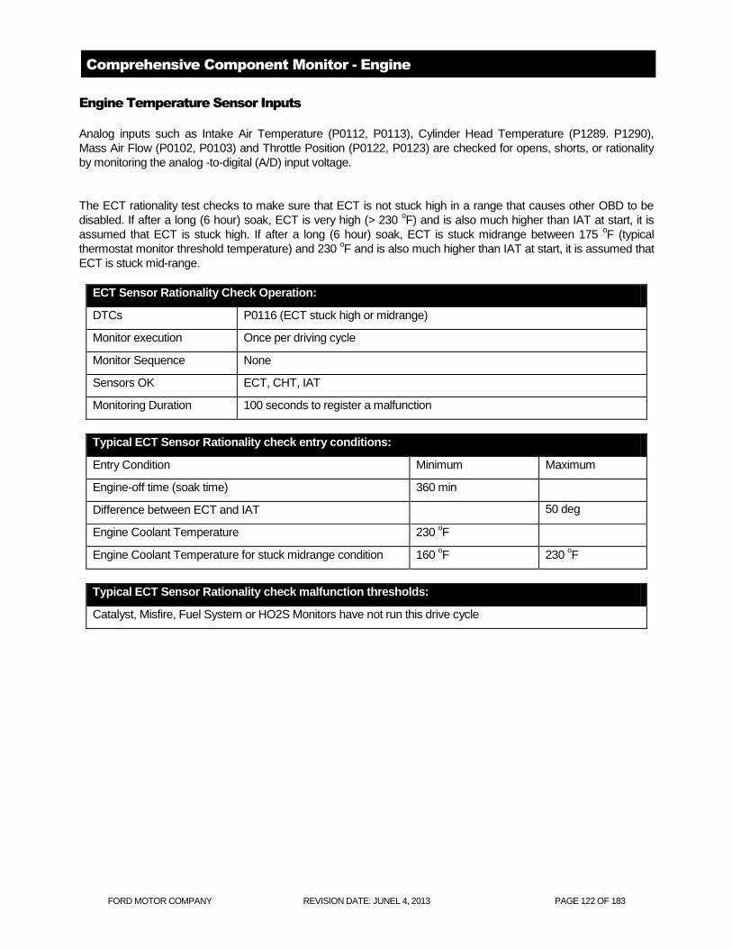
FORD MOTOR COMPANY REVISION DATE: JUNEL 4, 2013 PAGE 122 OF 183
Comprehensive Component Monitor - Engine
Engine Temperature Sensor Inputs
Analog inputs such as Intake Air Temperature (P0112, P0113), Cylinder Head Temperature (P1289. P1290),
Mass Air Flow (P0102, P0103) and Throttle Position (P0122, P0123) are checked for opens, shorts, or rationality
by monitoring the analog -to-digital (A/D) input voltage.
The ECT rationality test checks to make sure that ECT is not stuck high in a range that causes other OBD to be
disabled. If after a long (6 hour) soak, ECT is very high (> 230 oF) and is also much higher than IAT at start, it is
assumed that ECT is stuck high. If after a long (6 hour) soak, ECT is stuck midrange between 175 oF (typical
thermostat monitor threshold temperature) and 230 oF and is also much higher than IAT at start, it is assumed that
ECT is stuck mid-range.
ECT Sensor Rationality Check Operation:
DTCs P0116 (ECT stuck high or midrange)
Monitor execution Once per driving cycle
Monitor Sequence None
Sensors OK ECT, CHT, IAT
Monitoring Duration 100 seconds to register a malfunction
Typical ECT Sensor Rationality check entry conditions:
Entry Condition Minimum Maximum
Engine-off time (soak time) 360 min
Difference between ECT and IAT 50 deg
Engine Coolant Temperature 230 oF
Engine Coolant Temperature for stuck midrange condition 160 oF 230
oF
Typical ECT Sensor Rationality check malfunction thresholds:
Catalyst, Misfire, Fuel System or HO2S Monitors have not run this drive cycle

FORD MOTOR COMPANY REVISION DATE: JUNEL 4, 2013 PAGE 123 OF 183
The CHT sensor measures cylinder head metal temperature as opposed to engine coolant temperature. At lower
temperatures, CHT temperature is equivalent to ECT temperature. At higher temperatures, ECT reaches a
maximum temperature (dictated by coolant composition and pressure) whereas CHT continues to indicate cylinder
head metal temperature. If there is a loss of coolant or air in the cooling system, the CHT sensor will still provides
an accurate measure of cylinder head metal temperature. If a vehicle uses a CHT sensor, the PCM software
calculates both CHT and ECT values for use by the PCM control and OBD systems.
Cylinder Head Temperature Sensor Check Operation:
DTCs P1289 (high input), P1290 (low input), P1299 (fail-safe cooling activated)
Monitor execution continuous
Monitor Sequence none
Sensors OK not applicable
Monitoring Duration 5 seconds to register a malfunction
Typical CHT sensor check malfunction thresholds:
Voltage < 0.41 volts or voltage > 4.95 volts
For P1299, MIL illuminates immediately if CHT > 270 o.
Fuel shut-off is activated to reduce engine and coolant
temperature
Intake Air Temperature Sensor Check Operation:
DTCs P0112 (low input), P0113 (high input)
Monitor execution continuous
Monitor Sequence none
Sensors OK not applicable
Monitoring Duration 5 seconds to register a malfunction
Typical IAT sensor check malfunction thresholds:
Voltage < 0.20 volts or voltage > 4.93 volts

FORD MOTOR COMPANY REVISION DATE: JUNEL 4, 2013 PAGE 124 OF 183
ECT, IAT, EOT Temperature Sensor Transfer Function
Volts A/D counts in PCM Temperature, degrees F
4.89 1001 -40
4.86 994 -31
4.81 983 -22
4.74 970 -13
4.66 954 -4
4.56 934 5
4.45 910 14
4.30 880 23
4.14 846 32
3.95 807 41
3.73 764 50
3.50 717 59
3.26 666 68
3.00 614 77
2.74 561 86
2.48 508 95
2.23 456 104
1.99 407 113
1.77 361 122
1.56 319 131
1.37 280 140
1.20 246 149
1.05 215 158
0.92 188 167
0.80 165 176
0.70 144 185
0.61 126 194
0.54 110 203
0.47 96 212
0.41 85 221
0.36 74 230
0.32 65 239
0.28 57 248
0.25 51 257
0.22 45 266
0.19 40 275
0.17 35 284
0.15 31 293
0.14 28 302

FORD MOTOR COMPANY REVISION DATE: JUNEL 4, 2013 PAGE 125 OF 183
IAT Rationality Test
The IAT rationality test determines if the IAT sensor is producing an erroneous temperature indication within the
normal range of IAT sensor input.
The IAT sensor rationality test is run only once per power-up. The IAT sensor input is compared to the CHT
sensor input (ECT sensor input on some applications) at key-on after a long (6 hour) soak. If the IAT sensor input
and the CHT (ECT) sensor input agree within a tolerance (+/- 30 deg F), no malfunction is indicated and the test is
complete. If the IAT sensor input and the CHT (ECT) sensor input differ by more than the tolerance, the vehicle
must be driven over maximum electric vehicle speed for 5 minutes to confirm the fault. This is intended to address
noise factors like sun load that can cause the IAT sensor to indicate a much higher temperature than the CHT
(ECT) sensor after a long soak. Driving the vehicle attempts to bring the IAT sensor reading within the test
tolerance. If the IAT sensor input remains outside of the tolerance after the vehicle drive conditions have been
met, the test indicates a malfunction and the test is complete.
In addition to the start-up rationality check, an IAT "Out of Range" check is also performed. The test continuously,
checks to see if IAT is greater than the “IAT Out of Range High threshold”, approximately 150 deg F. In order to
prevent setting false DTC during extreme ambient or vehicle soak conditions, the same count up/count down timer
used for the IAT startup rationality test is used to validate the fault. If IAT is greater than 150 deg F and vehicle
speed is greater than ~ 40 mph for 250 seconds then set a P0111.
Either the IAT startup rationality test or the IAT Out of Range High test can set a P0111 DTC. The logic is designed
so that either fault can trigger a P0111, however, both faults must be OK before the P0111 DTC is cleared.
Block heater detection results in a no-call.
Intake Air Temperature Sensor Range/Performance Check Operation:
DTCs P0111 (range/performance)
Monitor execution Once per driving cycle, at start-up
Monitor Sequence None
Sensors OK ECT/CHT, IAT, VSS
Monitoring Duration Immediate or up to 30 minutes to register a malfunction
Typical Intake Air Temperature Sensor Range/Performance Entry Conditions
Entry condition Minimum Maximum
Air Mass 1.2 lbm/min
Engine off (soak) time 6 hours
Battery Voltage 11.0 Volts
Time since engine start (if driving req'd) 30 min
Vehicle speed (if driving req'd) 35 mph
Time above minimum vehicle speed (if driving req'd) 5 min
IAT - ECT at start (block heater inferred) -30 °F -90 °F
Typical IAT sensor check malfunction thresholds:
IAT and ECT/CHT error at start-up > +/-30 deg F

FORD MOTOR COMPANY REVISION DATE: JUNEL 4, 2013 PAGE 126 OF 183
Intake Air Temperature Sensor Out of Range High Check Operation:
DTCs P0111 (Out of Range High)
Monitor execution Continuous
Monitor Sequence None
Sensors OK ECT/CHT, IAT, VSS
Monitoring Duration 250 seconds to register a malfunction
Typical Intake Air Temperature Sensor Out of Range high Entry Conditions
Entry condition Minimum Maximum
Engine off (soak) time 6 hours
Battery Voltage 11.0 Volts
Vehicle speed 35 mph
Time above minimum vehicle speed (if driving req'd) 5 min
Typical IAT Sensor Out of Range High check malfunction thresholds:
IAT > 150 deg F

FORD MOTOR COMPANY REVISION DATE: JUNEL 4, 2013 PAGE 127 OF 183
Throttle Position Sensor
Throttle Position Sensor Check Operation:
DTCs P0122 (low input), P0123 (high input)
Monitor execution continuous
Monitor Sequence none
Sensors OK not applicable
Monitoring Duration 5 seconds to register a malfunction
Typical TP sensor check malfunction thresholds:
Voltage < 0.20 volts or voltage > 4.80 volts
Mass Air Flow Sensor
MAF Sensor Check Operation:
DTCs P0102 (low input), P0103 (high input)
Monitor execution continuous
Monitor Sequence none
Sensors OK not applicable
Monitoring Duration 5 seconds to register a malfunction
Typical MAF sensor check malfunction thresholds:
Voltage < 0.244 volts and engine running or voltage > 4.785 volts engine rpm < 4,000 rpm

FORD MOTOR COMPANY REVISION DATE: JUNEL 4, 2013 PAGE 128 OF 183
MAF/TP Rationality Test
The MAF and TP sensors are cross-checked to determine whether the sensor readings are rational and
appropriate for the current operating conditions. (P1A0C)
MAF/TP Rationality Check Operation:
DTCs P1A0C
Monitor execution Continuous
Monitor Sequence None
Sensors OK
Monitoring Duration 5 seconds within test entry conditions
Typical MAF/TP rationality check entry conditions:
Entry Condition Minimum Maximum
Engine RPM 1025 rpm minimum of 3800 rpm
Engine Coolant Temp 40 oF
Typical MAF/TP rationality check malfunction thresholds:
Load > 55% and TP < 0.288 volts or Load < 20% and TP > 1.953 volts

FORD MOTOR COMPANY REVISION DATE: JUNEL 4, 2013 PAGE 129 OF 183
5 Volt Sensor Reference Voltage Check:
DTCs P0642 (low input), P0643 (high input)
Monitor execution continuous
Monitor Sequence None
Sensors OK not applicable
Monitoring Duration 5 seconds to register a malfunction
Typical sensor check malfunction thresholds:
Voltage < 4.5 volts or voltage > 5.5 volts
Miscellaneous CPU Tests
Loss of Keep Alive Memory (KAM) power (a separate wire feeding the PCM) results is a P1633 DTC and immediate MIL illumination on most applications.
Vehicles that require tire/axle information and VIN to be programmed into the PCM Vehicle ID block (VID) will store
a P1639 if the VID block is not programmed or corrupted.
Additional DTCs will be stored to indicate various internal PCM hardware malfunctions:
P0602 - Powertrain Control Module Programming Error indicates that the Vehicle ID block check sum test failed.
P0603 - Powertrain Control Module Keep Alive Memory (KAM) Error indicates the Keep Alive Memory check sum
test failed.
P0604 - Powertrain Control Module Random Access Memory (RAM) Error indicates the Random Access Memory
read/write test failed.
P0605 - Powertrain Control Module Read Only Memory (ROM) Error indicates a Read Only Memory check sum
test failed.
P0607 - Powertrain Control Module Performance indicates incorrect CPU instruction set operation, or excessive
CPU resets.
P068A - ECM/PCM Power Relay De-energized - Too Early. This fault indicates that NVRAM write did not complete
successfully after the ignition key was turned off, prior to PCM shutdown.
P06B8 - Internal Control Module Non-Volatile Random Access Memory (NVRAM) Error indicates Permanent DTC
check sum test failed
The PCM "engine off" or "soak" timer is tested to ensure that it is functional. The value of engine coolant
temperature decays after the engine is turned off. This decay is modeled as a function of ECT, IAT and soak time.
If, during a cold start, (difference between ECT and IAT is low), the actual ECT at start is much lower than the
predicted ECT at start, it means that the soak timer is not functioning and a P2610 DTC is stored. (If the timer fails,
it will read zero seconds and the model will predict that ECT will be the same temperature as when the engine was
last turned off.)
U0101 – Lost Communication With TCM
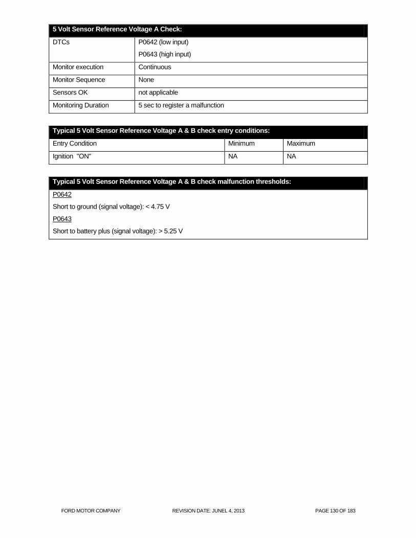
FORD MOTOR COMPANY REVISION DATE: JUNEL 4, 2013 PAGE 130 OF 183
5 Volt Sensor Reference Voltage A Check:
DTCs P0642 (low input)
P0643 (high input)
Monitor execution Continuous
Monitor Sequence None
Sensors OK not applicable
Monitoring Duration 5 sec to register a malfunction
Typical 5 Volt Sensor Reference Voltage A & B check entry conditions:
Entry Condition Minimum Maximum
Ignition "ON" NA NA
Typical 5 Volt Sensor Reference Voltage A & B check malfunction thresholds:
P0642
Short to ground (signal voltage): < 4.75 V
P0643
Short to battery plus (signal voltage): > 5.25 V

FORD MOTOR COMPANY REVISION DATE: JUNEL 4, 2013 PAGE 131 OF 183
Ignition
New floating point processors no longer use an EDIS chip for ignition signal processing. The crank and cam
position signals are now directly processed by the PCM/ECM microprocessor using a special interface chip called
a Time Processing Unit or TPU. The 36-tooth crankshaft and camshaft position signals come directly into the TPU.
The signals to fire the ignition coil drivers also come from the TPU.
The ignition system is checked by monitoring three ignition signals during normal vehicle operation:
CKP, the signal from the crankshaft 60-2-tooth wheel. The missing teeth are used to locate the cylinder
pair associated with cylinder # 1 The TPU also generates the Profile Ignition Pickup (PIP) signal, a 50%
duty cycle, square wave signal that has a rising edge at 10 deg BTDC.
Camshaft Position (CMP), a signal derived from the camshaft to identify the #1 cylinder
First, several relationships are checked on the 60-2 tooth CKP signal. The TPU looks for the proper number of
teeth (58) after the missing teeth are recognized; time between teeth too low (< 30 rpm or > 9,000 rpm); or the
missing teeth were not where it was expected to be. If an error occurs, the TPU shuts off fuel and the ignition coils
and attempts to resynchronize itself. It takes on revolution to verify the missing tooth, and another revolution to
verify cylinder #1 using the CMP input. Note that if a P0320 DTC is set on a vehicle with Electronic Throttle Control,
(ETC), the ETC software will also set a P2106.
If the proper ratio of CMP events to PIP events is not being maintained (for example, 1 CMP edge for every 8 PIP
edges for an 8-cylinder engine), it indicates a missing or noisy CMP signal (P0340). On applications with Variable
Cam Timing (VCT), the CMP wheel has five teeth to provide the VCT system with more accurate camshaft control.
The TPU checks the CMP signal for an intermittent signal. If an intermittent is detected, the VCT system is
disabled and a P0344 (CMP Intermittent Bank 1) or P0349 (CMP intermittent Bank 2) is set.

FORD MOTOR COMPANY REVISION DATE: JUNEL 4, 2013 PAGE 132 OF 183
CKP Ignition System Check Operation:
DTCs P0320 - Ignition Engine Speed Input Circuit
Monitor execution continuous
Monitor Sequence none
Sensors OK
Monitoring Duration < 5 seconds
Typical CKP ignition check entry conditions:
Entry Condition Minimum Maximum
Engine RPM for CKP 200 rpm
Typical CKP ignition check malfunction thresholds:
Incorrect number of teeth after the missing tooth is recognized,
Time between teeth too low (< 30 rpm or > 9,000 rpm)
Missing tooth was not where it was expected to be.
CMP Ignition System Check Operation:
DTCs P0340 - Intake Cam Position Circuit, Bank 1
Monitor execution continuous
Monitor Sequence none
Sensors OK
Monitoring Duration < 5 seconds
Typical CMP ignition check entry conditions:
Entry Condition Minimum Maximum
Engine RPM for CMP 200 rpm
Typical CMP ignition check malfunction thresholds:
Ratio of PIP events to CMP events: 4:1, 6:1, 8:1 or 10:1 based on engine cyl

FORD MOTOR COMPANY REVISION DATE: JUNEL 4, 2013 PAGE 133 OF 183
Coil Primary Ignition System Check Operation:
DTCs P0351 – P0354 (Coil primary)
Monitor execution Continuous
Monitor Sequence None
Sensors OK
Monitoring Duration < 5 seconds
Typical Coil primary ignition check entry conditions:
Entry Condition Minimum Maximum
Engine RPM for coil primary 200 rpm Minimum of 3200 rpm
Positive engine torque Positive torque
Battery Voltage 11 volts 16 volts
Typical Coil primary ignition check malfunction thresholds:
Ratio of PIP events to IDM or NOMI events 1:1

FORD MOTOR COMPANY REVISION DATE: JUNEL 4, 2013 PAGE 134 OF 183
Engine Outputs
The PCM will monitor the "smart" driver fault status bit that indicates either an open circuit, short to power or short to ground.
Injector Check Operation:
DTCs P0201 through P0204 (opens/shorts)
Monitor execution Continuous within entry conditions
Monitor Sequence None
Monitoring Duration 10 seconds
Typical injector circuit check entry conditions:
Entry Condition Minimum Maximum
Battery Voltage 11.0 volts
Engine Coolant Temp 240 oF
Intake Air Temp 150 oF
The Idle Air Control is functionally checked by monitoring the closed loop idle speed correction required to maintain
the desired idle rpm. If the proper idle rpm cannot be maintained and the system has a high rpm (+100) or low rpm
error (-200) greater than the malfunction threshold, an IAC malfunction is indicated. (P0507, P0506)
IAC Check Operation:
DTCs P0507 (functional - overspeed)
P0506 (functional - underspeed)
Monitor execution once per driving cycle
Monitor Sequence None
Sensors OK
Monitoring Duration 15 seconds
Typical IAC functional check entry conditions:
Entry Condition Minimum Maximum
Engine Coolant Temp 130 oF
Time since engine start-up 100 seconds
Closed loop fuel Yes
Throttle Position (at idle, closed throttle, no dashpot) Closed Closed
Typical IAC functional check malfunction thresholds:
For underspeed error: Actual rpm 100 rpm below target, closed-loop IAC correction > 1 lb/min
For overspeed error: Actual rpm 200 rpm above target, closed-loop IAC correction < .2 lb/min

FORD MOTOR COMPANY REVISION DATE: JUNEL 4, 2013 PAGE 135 OF 183
Mechanical Returnless Fuel System (MRFS) — Dual Speed
The FP signal is a duty cycle command sent from the PCM to the fuel pump control module. The fuel pump control module uses the FP command to operate the fuel pump at the speed requested by the PCM or to turn the fuel pump off. A valid duty cycle to command the fuel pump on, is in the range of 15-47%. The fuel pump control module doubles the received duty cycle and provides this voltage to the fuel pump as a percent of the battery voltage. When the ignition is turned on, the fuel pump runs for about 1 second and is requested off by the PCM if engine rotation is not detected.
FUEL PUMP DUTY CYCLE OUTPUT FROM PCM
FP Duty Cycle Command
PCM Status Fuel Pump Control Module Actions
0-15% Invalid off duty cycle The fuel pump control module sends a 20% duty cycle signal on the fuel pump monitor (FPM) circuit. The fuel pump is off.
37% Normal low speed operation. The fuel pump control module operates the fuel pump at the speed requested. The fuel pump control module sends a 60% duty cycle signal on FPM circuit.
47% Normal high speed operation. The fuel pump control module operates the fuel pump at the speed requested. The fuel pump control module sends a 60% duty cycle signal on FPM circuit.
51-67% Invalid on duty cycle. The fuel pump control module sends a 20% duty cycle signal on the FPM circuit. The fuel pump is off.
67-83% Valid off duty cycle The fuel pump control module sends a 60% duty cycle signal on FPM circuit. The fuel pump is off.
83-100% Invalid on duty cycle. The fuel pump control module sends a 20% duty cycle signal on the FPM circuit. The fuel pump is off.
The fuel pump control module communicates diagnostic information to the PCM through the FPM circuit. This information is sent by the fuel pump control module as a duty cycle signal. The 4 duty cycle signals that may be sent are listed in the following table.
FUEL PUMP CONTROL MODULE DUTY CYCLE SIGNALS Duty Cycle Comments 20% This duty cycle indicates the fuel pump control module is receiving an invalid duty cycle from the
PCM. 40%
For vehicles with event notification signal, this duty cycle indicates the fuel pump control module is receiving an invalid event notification signal from the RCM. For vehicles without event notification signal, this duty cycle indicates the fuel pump control module is functioning normally.
60%
For vehicles with event notification signal, this duty cycle indicates the fuel pump control module is functioning normally.
80% This duty cycle indicates the fuel pump control module is detecting a concern with the secondary circuits.

FORD MOTOR COMPANY REVISION DATE: JUNEL 4, 2013 PAGE 136 OF 183
MRFS Check Operation:
DTCs P025A – Fuel Pump Control Circuit (opens/shorts)
P025B – Invalid Fuel Pump Control Data (20% duty cycle from FPM)
P0627 – Fuel Pump Secondary Circuit (80% duty cycle from PFM)
U2010B – Fuel Pump Disabled Circuit (40% duty cycle from FPM)
U0109 – Loss of Communication with Fuel Pump Module
Monitor execution once per driving cycle
Monitor Sequence None
Sensors OK
Monitoring Duration 2 seconds
Typical MRFS check entry conditions:
Entry Condition Minimum Maximum
Battery Voltage 11 volts
Typical MRFS check malfunction thresholds:
P025A
FP output driver indicates fault
P025B, P0627, U210B
Fuel Pump Monitor duty cycle feedback of 20, 40 or 80%
U0191
No Fuel Pump Monitor duty cycle feedback

FORD MOTOR COMPANY REVISION DATE: JUNEL 4, 2013 PAGE 137 OF 183
Battery and Battery Charging Systems
Low Voltage Battery Charging System - Overview
The 12V battery is charged by the Direct Current/Direct Current (DC/DC) converter control module. It is enabled
when the high voltage battery contactors have closed, providing high-voltage power to the DC/DC converter
control module.
The Battery Monitoring Sensor continuously monitors the battery state of charge condition and provides the BCM
with this information. The BCM communicates this information to the PCM over the High Speed CAN network (HS-
CAN). The PCM communicates the battery desired set point to the DC/DC converter control module which
supplies the necessary charge voltage to the 12V battery. The Battery Monitoring Sensor also estimates losses in
the battery capacity over time. The Battery Monitoring Sensor should only be reset when the battery is replaced.
The Battery Monitoring Sensor is clamped directly to the negative terminal of the battery and grounds to the vehicle
at the chassis ground connection point through the negative battery cable and eyelet. It is part of the negative
battery cable and cannot be serviced separately.
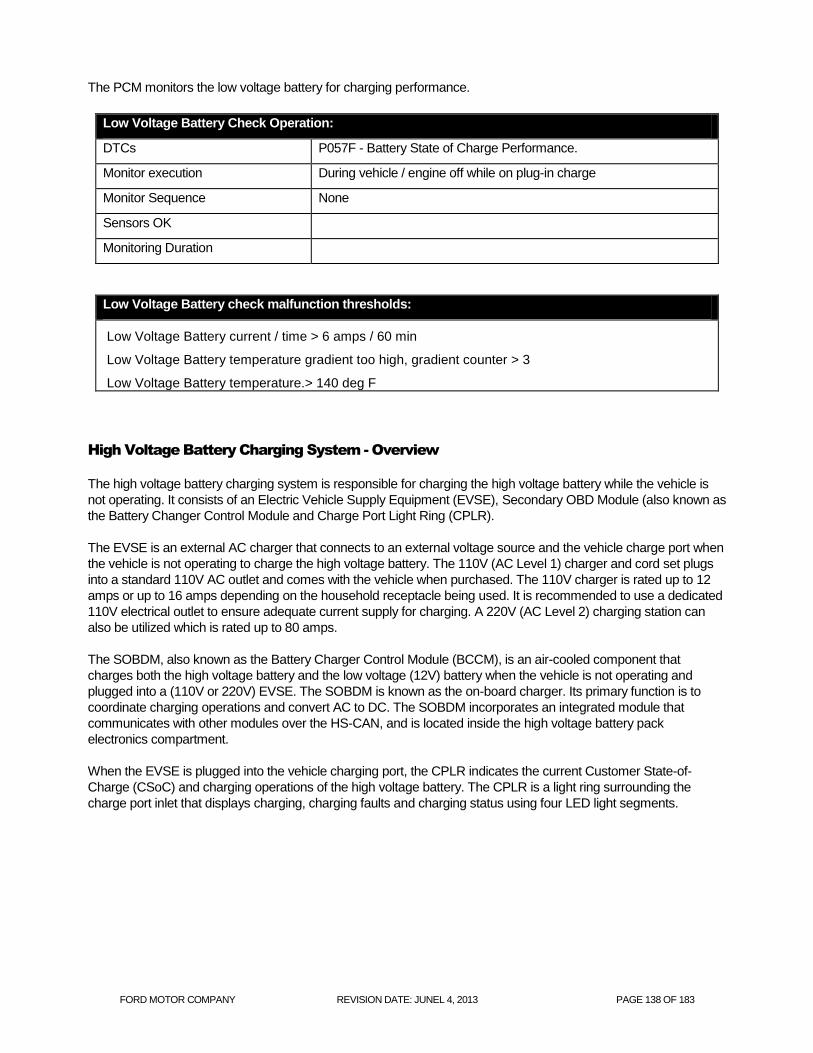
FORD MOTOR COMPANY REVISION DATE: JUNEL 4, 2013 PAGE 138 OF 183
The PCM monitors the low voltage battery for charging performance.
Low Voltage Battery Check Operation:
DTCs P057F - Battery State of Charge Performance.
Monitor execution During vehicle / engine off while on plug-in charge
Monitor Sequence None
Sensors OK
Monitoring Duration
Low Voltage Battery check malfunction thresholds:
Low Voltage Battery current / time > 6 amps / 60 min
Low Voltage Battery temperature gradient too high, gradient counter > 3
Low Voltage Battery temperature.> 140 deg F
High Voltage Battery Charging System - Overview
The high voltage battery charging system is responsible for charging the high voltage battery while the vehicle is
not operating. It consists of an Electric Vehicle Supply Equipment (EVSE), Secondary OBD Module (also known as
the Battery Changer Control Module and Charge Port Light Ring (CPLR).
The EVSE is an external AC charger that connects to an external voltage source and the vehicle charge port when
the vehicle is not operating to charge the high voltage battery. The 110V (AC Level 1) charger and cord set plugs
into a standard 110V AC outlet and comes with the vehicle when purchased. The 110V charger is rated up to 12
amps or up to 16 amps depending on the household receptacle being used. It is recommended to use a dedicated
110V electrical outlet to ensure adequate current supply for charging. A 220V (AC Level 2) charging station can
also be utilized which is rated up to 80 amps.
The SOBDM, also known as the Battery Charger Control Module (BCCM), is an air-cooled component that
charges both the high voltage battery and the low voltage (12V) battery when the vehicle is not operating and
plugged into a (110V or 220V) EVSE. The SOBDM is known as the on-board charger. Its primary function is to
coordinate charging operations and convert AC to DC. The SOBDM incorporates an integrated module that
communicates with other modules over the HS-CAN, and is located inside the high voltage battery pack
electronics compartment.
When the EVSE is plugged into the vehicle charging port, the CPLR indicates the current Customer State-of-
Charge (CSoC) and charging operations of the high voltage battery. The CPLR is a light ring surrounding the
charge port inlet that displays charging, charging faults and charging status using four LED light segments.

FORD MOTOR COMPANY REVISION DATE: JUNEL 4, 2013 PAGE 139 OF 183
The SOBDM, also known as the BCCM (Battery Charger Control Module), charges the high voltage battery and
has an internal DC to DC Converter Control Module to maintain the 12V battery while vehicle is plugged into an
external 110V or 220V AC EVSE. The SOBDM is an air-cooled component that converts an input voltage of (120
or 240 volts) AC to high-voltage DC and low-voltage DC power, while maintaining electrical isolation between the
systems. When plugged into an external power source the SOBDM is enabled and charges the high voltage
battery (168-361 volts) and the low-voltage battery (12-15 volts). The SOBDM steps the high-voltage down to a
low-voltage (between 12 and 15 volts, depending on vehicle needs), providing power to charge the vehicle low-
voltage battery. During charge the SOBDM incorporates an internal DC/DC converter to charge the low-voltage
battery directly.
When the EVSE cord is plugged in the SOBDM wakes up by sensing a control pilot signal. The pilot signal duty
cycle is analyzed to determine AC line capacity and the frequency is monitored to make sure it is in the proper
range. The EVSE monitors the pilot signal to determine when to turn on AC output. A separate proximity circuit
signal is analyzed to confirm if the connection is stable and the S3 button on the external charger cord is released.
If both signals are in correct range, the SOBDM transmits an on-plug message via HEV HS-CAN. The SOBDM
confirms the gear position is in park and that the vehicle is not in torque producing mode via HEV HS-CAN and
closes an internal S2 switch signaling the EVSE to send AC voltage to the SOBDM. The high voltage system does
not charge if the gear position is is not in park or if the vehicle is started.
Switch S2 detection is determined by the pilot signal voltage change. If the AC voltage input is within range the
SOBDM enables 12V battery charging and wakes up the BECM. While waiting to enter high voltage charging
state, the SOBDM sets low voltage output to a minimum of 12.6V until it receives a low-voltage setpoint from the
PCM via HEV HS-CAN. The SOBDM is ready for high voltage power conversion when it transmits a charger-ready
message via the HEV HS-CAN.
The SOBDM internally transitions from a ready state to charging state of the high voltage battery upon receipt of a
battery charge ready or charging message from the BECM via the HEV HS-CAN. When the BECM status goes
from a charge ready to a charging state the charge contactors are closed to begin charging the high voltage
battery. The SOBDM limits the voltage and current to the high voltage battery based on the maximum voltage and

FORD MOTOR COMPANY REVISION DATE: JUNEL 4, 2013 PAGE 140 OF 183
current requests from the BECM via the HEV HS-CAN. The SOBDM transmits high voltage and current output
internal measurements to the BECM via the HEV HS-CAN.
During high voltage charging the BECM commands the outside air (OSA) duct mode door actuator to open. This
allows outside air to be pulled into the High Voltage Battery pack to cool SOBDM. The BECM monitors the mode
door position and motor circuits and sets a DTC if a fault is detected. The SOBDM monitors its internal temperature
and commands the charger cooling fan speed accordingly to prevent overheating. When high-voltage charging is
complete the BECM charging state HEV HS-CAN message switches from charging to charging complete and
opens the high voltage charge contactors. The SOBDM continues to charge the 12V battery while AC input is
present except when commanded off by the SOBDMC.
During high 12V electrical loads or if the ignition is turned on while the vehicle is plugged in the main DC to DC
Converter Control Module is enabled to charge the 12V battery. If this occurs, the SOBDM disables its low-voltage
support and no longer charges the 12V battery. However, it continues charging the high voltage battery. The
SOBDM shuts down if the PCM no longer requests low-voltage support and the BECM status is charge complete.
If the release button (S3) on the EVSE is pressed while low-voltage or high-voltage charging is in progress, the
SOBDM detects a change of proximity circuit voltage. The high-voltage and the low-voltage DC charging
simultaneously stops. The SOBDM disables power conversion and opens the internal S2 switch. When the EVSE
detects an open S2 switch by sensing a pilot signal voltage change, it drops the AC voltage output to zero so the
charger cord can be safely removed. This prevents arcing of the charge port terminals when the EVSE cord is
disconnected.
The CPLR displays the current CSoC and charging operations of the high voltage battery. When plugged into an
external power source (120 or 240 volts), the CPLR activates the light ring around the charge inlet port and
performs a cord acknowledgment. If successful, this sequence flashes one light segment one at a time in order.
The segments shut off and this sequence repeats 2 times. The CPLR displays charging, charging faults, and
charging status. The light ring is segmented into 4 equal LEDs, each indicating the state of charge: • One segment
flashing < 25% charged • One segment lit (one segment flashing) > 25% charged • Two segments lit (one segment
flashing) > 50% charged • Three segments lit (one segment flashing) > 75% charged. A flashing ring segment
indicates a charge is in progress. When all four rings are solidly lit, the charging operation is complete. If less than
four rings are lit solid charging is not ready. When the charge is complete an internal timer starts to do a 3-5 minute
shutoff to turn the LEDs off and put the module to sleep. The LEDs remain off until a Puddle Light Activation
command is sent via the key fob or door handle. If there is a fault, all LED segments flash rapidly for no more than
5 minutes before going to sleep. LEDs illumination varies depending if it is daytime or nighttime.
To remove the EVSE cord press the release button to stop the charging process. All the LEDs shut off indicating it
is safe to unplug the cord. There is a customer preference setting in the APIM to customize the operation of the
CPLR. The options available include: 1. LEDs On (normal operation) 2. LEDs Off except for Cord
Acknowledgements and Puddle Light Activation requests, 3. LEDs Off (this setting prevents LED operation for any
reason).

FORD MOTOR COMPANY REVISION DATE: JUNEL 4, 2013 PAGE 141 OF 183
Battery Charge Control Module Performance Check Operation:
DTCs P0D24 - Battery Charger Temperature Too High
P0562 - System Voltage Low
P0DAA - Battery Charging System Isolation Fault
Monitor execution Charger active, on-plug, connected to EVSE and charging
Monitor Sequence None
Sensors OK
Monitoring Duration 60 sec
Battery Charge Control Module Performance malfunction thresholds:
P0D24 - Internal temperature too high
P0562 - < 10.5V DC for 60 sec measured at charger B+ terminal
P0DAA - The measured leakage voltage is used to calculate the resistance between each high voltage bus and chassis < 41 kohm when charge contactors are closed.
Battery Charge Control Module Functional Check Operation:
DTCs P0D59 - Proximity Detection Circuit High.
P0D80 - Battery Charger Input Circuit/Open.
Monitor execution P0D59: Charger is ON, PSR applied or active EVSE connected
P0D80: On-Plug, EVSE active. connected to EVSE , and S2 closed
Monitor Sequence None
Sensors OK
Monitoring Duration 60 sec
Battery Charge Control Module Functional malfunction thresholds:
P0D59 - EVSE proximity circuit detected open. Proximity circuit detected >4.8V DC for 5 seconds.
P0D80 – A/C Utility input not present after EVSE S2 switch closed. A/C Input voltage < 85 VAC for 30 seconds.

FORD MOTOR COMPANY REVISION DATE: JUNEL 4, 2013 PAGE 142 OF 183
Battery Charge Control Module Performance Check Operation:
DTCs P0D67 - Battery Charger Control Module Performance.
Monitor execution Charger active; connected to EVSE, S2 closed, and utility A/C is
present to charger input
Monitor Sequence None
Sensors OK
Monitoring Duration 60 sec
Battery Charge Control Module Performance malfunction thresholds:
Internal on-board charger module fault detected that prevents charging functionality. Failure conditions include:
Low Voltage circuit overvoltage, High Voltage circuit overvoltage, PFC failure, High Voltage circuit voltage or current control circuit fault, High Voltage circuit current sensor failure.
Battery Charging System Contactor Check Operation:
DTCs P0D0F - Battery Charging System Negative Contactor Stuck Closed
P0D09 - Battery Charging System Positive Contactor Stuck Open
Monitor execution
Monitor Sequence None
Sensors OK
Monitoring Duration < 1sec
Battery Charging System Contactor malfunction thresholds:
P0D0F - Negative charge contactor status remains closed. Contactor measurement voltage reported over CAN to the BECM is >= (pack voltage - 20v) When charge negative contactor is being commanded from close to open.
P0D09 - Charge positive contactor reported charger voltage over CAN to the BECM is > +/- 5% of Pack voltage AND the reported charger current over CAN to the BECM is < 0.5 amps AND both charge contactors are commanded closed AND both charge contactors have power when charge positive contactor is closed.

FORD MOTOR COMPANY REVISION DATE: JUNEL 4, 2013 PAGE 143 OF 183
Battery Charging System Contactor Check Operation:
DTCs P0D0A - Battery Charging System Positive Contactor Control Circuit/Open
P0D0D - Battery Charging System Positive Contactor Control Circuit High
P0D0B - Battery Charging System Positive Contactor Control Circuit
Range/Performance
P0D14 - Battery Charging System Negative Contactor Control Circuit High
Monitor execution
Monitor Sequence None
Sensors OK
Monitoring Duration < 1sec
Battery Charging System Contactor malfunction thresholds:
P0D0A - Charge positive contactor reported charger voltage over CAN to the BECM is > +/- 5% of Pack voltage AND the reported charger current over CAN to the BECM is < 0.5 amps AND both charge contactors are commanded closed AND one or both charge contactors DO NOT have power when charge positive contactor is closed.
P0D0D - Charge positive contactor low side driver in limited current mode.
P0D0B - Charge contactor high side driver in overcurrent mode when any charge contactor is closed.
P0D14 - Charge negative contactor low side driver in limited current mode.

FORD MOTOR COMPANY REVISION DATE: JUNEL 4, 2013 PAGE 144 OF 183
High Voltage Battery - Overview
The plug in hybrid can be used as an electric vehicle, conventional hybrid vehicle, or both. The high voltage battery
on the plug in hybrid application has more capacity than a full hybrid application and can be fully charged using
EVSE (Electric Vehicle Supply Equipment) connected to the vehicle charge port. An EV button is located on the
steering wheel to change the vehicle operating strategy.
The vehicle can be placed in electric mode only (EV NOW) allowing only the electric motor to propel the vehicle. In
this mode the high voltage battery depletes and the gas engine does not operate unless a calibratable condition
exists such as a malfunction, heavy acceleration, high electric motor temperature, elevated high voltage battery
temperature, low high voltage battery state of charge, or certain climate control functions are selected (e.g.
defrost).
The high-voltage system utilizes approximately 300 volts DC, provided through high-voltage cables to its components and modules. The high-voltage cables and wiring are identified by orange harness tape or orange wire covering. All high-voltage components are marked with high-voltage warning labels with a high-voltage symbol.
The high voltage battery pack consists of the following components:
High voltage battery service disconnect
High voltage battery RH and LH cooling inlet ducts
High voltage battery cooling fan and air outlet duct
High voltage battery inlet air temperature sensor
SOBDM/BCCM (Battery Charger Control Module)
SOBDM outside air duct
SOBDM cooling fan
BECM (Battery Energy Control Module)
DC/DC (Direct Current/Direct Current) converter control module
High voltage battery junction box
High voltage low current fuse (x3)
High voltage high current fuse
High voltage battery cell array cover (not serviceable)
High voltage battery cell arrays (not serviceable)
High voltage battery wiring harness (not serviceable)
The high voltage battery cell array cover, high voltage battery cell arrays, and high voltage battery wiring harness
are serviced as part of the entire high voltage battery pack.
Direct Current/Direct Current (DC/DC) Converter Control Module
The Direct Current/Direct Current (DC/DC) converter control module is an air-cooled component that converts high voltage (168-361 volt) DC power to low-voltage (12 volt) DC power. The converter provides power to the vehicle 12-volt battery and low-voltage electrical systems. The SOBDMC requests the DC/DC converter control module to turn ON through an enable message over HS-CAN. The PCM sends a charging voltage setpoint request over HS-CAN to DC/DC converter control module. Depending on the vehicle and environmental conditions, the DC/DC converter control module is capable of outputting as many as 145 amps to the 12-volt battery.

FORD MOTOR COMPANY REVISION DATE: JUNEL 4, 2013 PAGE 145 OF 183

FORD MOTOR COMPANY REVISION DATE: JUNEL 4, 2013 PAGE 146 OF 183
Battery Energy Control Module (BECM)
The BECM manages the condition of the high voltage battery to control its charging and discharging. The BECM also manages the cooling of the high voltage battery by controlling a fan attached to the high voltage battery pack cooling outlet duct. The BECM monitors the individual cell voltages and temperature sensors internal to the battery arrays. The BECM also monitors the battery current using a sensor located in the high voltage battery junction box. This information is needed by the BECM to control the high voltage battery and determine its ability to receive and provide power to the vehicle. The BECM communicates with other vehicle modules on the High Speed Controller Area Network (HS-CAN).
The BECM receives the following hard-wired inputs:
High voltage battery service disconnect interlock status
Cabin Coolant heater interlock status (PHEV)
Event notification status from the RCM
High Speed Controller Area Network (HS-CAN)
High voltage battery inlet air temperature sensor
High voltage battery cooling fan feedback
Outside air duct mode door actuator position (PHEV)
The BECM provides the following outputs:
High voltage battery cooling fan PWM supply voltage
Outside air duct mode door actuator (PHEV)
High voltage battery junction box contactor control
High Speed Controller Area Network (HS-CAN) information
Battery Energy Control Module Performance Check Operation:
DTCs U0300 - Internal Control Module Software Incompatibility
U019B - Lost Communication With Battery Charger Control Module
U3012 - Control Module Improper Wake-up Performance
B11D5 - Restraints Event - Vehicle Disabled
P0AA6 - Hybrid/EV Battery Voltage System Isolation Fault
Monitor execution
Monitor Sequence None
Sensors OK
Monitoring Duration < 1 sec
Battery Energy Control Module Performance malfunction thresholds:
U0300 - HW version and SW version not compatible
U019B - BCCM CAN message missing for 5 sec
U3012 - Power Sustain Relay Voltage <= 5.225 V or Contactor Open Request Not Received. Contactors are latched open due to LOW PSR but HPCM still requests contactors closed.
B11D5 - CAN signal from the Restraints Control Module indicates restraints event (crash) occurred.
P0AA6 - Leakage resistance < 195 kohm when charge contactors are closed.

FORD MOTOR COMPANY REVISION DATE: JUNEL 4, 2013 PAGE 147 OF 183
Battery Pack Current Sensor Check Operation:
DTCs P0AC1 - Hybrid/EV Battery Pack Current Sensor "A" Circuit Low
P0AC2 - Hybrid/EV Battery Pack Current Sensor "A" Circuit High
P0AC0 - Hybrid/EV Battery Pack Current Sensor "A" Circuit Range/Performance
P0AC3 - Hybrid/EV Battery Pack Current Sensor "A" Circuit Intermittent/Erratic
Monitor execution P0AC0: At a power up before contactors are closed
All others: continuous
Monitor Sequence None
Sensors OK
Monitoring Duration < 1 sec
Battery Pack Current Sensor malfunction thresholds:
P0AC1 – Battery current <= 293.75 A
P0AC2 – Battery current => 293.75 A
P0AC0 – Battery current <= 3A or => 3A at power up before contactors are closed
P0AC3 – Battery current reference voltage > 5.5V or < 4.5 V
Battery Pack Sensor Check Operation:
DTCs P0AA7 - Hybrid/EV Battery Voltage Isolation Sensor Circuit
P1A3A - Hybrid/EV Battery Pack Voltage Sense System - Multiple Sensor Correlation
P1A39 - Hybrid/EV Battery Temperature Sensor System - Multiple Sensor Correlation
Monitor execution
Monitor Sequence None
Sensors OK
Monitoring Duration < 1 sec
Battery Pack Sensor malfunction thresholds:
P0AA7 - The estimated pack voltage derived from the sum of the positive and negative leakage voltage is not <= 22.3982 v of the actual measured pack voltage
P1A3A - Pack voltage > 390 V, or < 1/2 of sum of cell voltages, and Half pack voltage < 35 V, or > 200V
P1A39 - Multiple temperature sensor faults. Sensor fault can be either of the following:
Measurement > 95 deg C, or < -50 deg C.
| Any temp sensor - average of all temp sensors | > 25 deg C.

FORD MOTOR COMPANY REVISION DATE: JUNEL 4, 2013 PAGE 148 OF 183
Battery Pack Performance Check Operation:
DTCs P0B24 - Hybrid/EV Battery ""A"" Voltage Unstable
P0C30 - Hybrid/EV Battery Pack State of Charge High
P0AFB - Hybrid/EV Battery System Voltage High
P0B25 - Hybrid/EV Battery "A" Voltage Low
P0D37 - Hybrid/EV Battery System Current High
P0A7F - Hybrid/EV Battery Pack Deterioration
Monitor execution
Monitor Sequence None
Sensors OK
Monitoring Duration < 15 seconds
Battery Pack Performance malfunction thresholds:
P0B24 - Average cell voltage minus any cell voltage > 0.5 volts for 15 sec
P0C30 -
State of charge => 100% when charge contactors are open (main contactors open or closed)
Cell voltage > 4.5V when charge contactors are open (main contactors open or closed)
State for charge => 101% when charge contactors are closed
Cell voltage > 4.14 V when charge contactors are closed
P0AFB – Pack voltage > 362 V
P0B25 – State of change = 0% with main contactors open or closed
P0D37 – Battery current > 180 A for 200 sec, or > 250 A for 60 sec.
P0A7F – Battery pack power < 12 KW

FORD MOTOR COMPANY REVISION DATE: JUNEL 4, 2013 PAGE 149 OF 183
Cell Balancing Individual cells can deviate over the life of the high voltage battery. The purpose of cell balancing is to equalize the individual cell charges. By balancing the cells the high voltage battery maintains top efficiency. The BECM continuously monitors individual battery cell voltages and will perform balancing automatically only when required. When balancing is performed BECM discharges individual cells with the highest voltage to match the remaining cells.
Battery Pack Cell Balance Circuit Check Operation:
DTCs P0DAD - Hybrid/EV Battery Cell Balancing Circuit "A" Stuck On.
P0DB1 - Hybrid/EV Battery Cell Balancing Circuit "B" Stuck On.
P0DB5 - Hybrid/EV Battery Cell Balancing Circuit "C" Stuck On.
P0DB9 - Hybrid/EV Battery Cell Balancing Circuit "D" Stuck On.
P0DBD - Hybrid/EV Battery Cell Balancing Circuit "E" Stuck On.
P0DC1 - Hybrid/EV Battery Cell Balancing Circuit "F" Stuck On.
P0DC5 - Hybrid/EV Battery Cell Balancing Circuit "G" Stuck On.
P0DC9 - Hybrid/EV Battery Cell Balancing Circuit "H" Stuck On.
P0DCD - Hybrid/EV Battery Cell Balancing Circuit "I" Stuck On.
P0DD1 - Hybrid/EV Battery Cell Balancing Circuit "J" Stuck On.
P0DD5 - Hybrid/EV Battery Cell Balancing Circuit "K" Stuck On.
P0DD9 - Hybrid/EV Battery Cell Balancing Circuit "L" Stuck On.
P0DDD - Hybrid/EV Battery Cell Balancing Circuit "M" Stuck On.
P0DE1 - Hybrid/EV Battery Cell Balancing Circuit "N" Stuck On.
P0DAE - Hybrid/EV Battery Cell Balancing Circuit "A" Stuck Off.
P0DB2 - Hybrid/EV Battery Cell Balancing Circuit "B" Stuck Off.
P0DB6 - Hybrid/EV Battery Cell Balancing Circuit "C" Stuck Off.
P0DBA. Hybrid/EV Battery Cell Balancing Circuit "D" Stuck Off.
P0DBE. Hybrid/EV Battery Cell Balancing Circuit "E" Stuck Off.
P0DC2 - Hybrid/EV Battery Cell Balancing Circuit "F" Stuck Off.
P0DC6 - Hybrid/EV Battery Cell Balancing Circuit "G" Stuck Off.
P0DCA - Hybrid/EV Battery Cell Balancing Circuit "H" Stuck Off.
P0DCE. Hybrid/EV Battery Cell Balancing Circuit "I" Stuck Off.
P0DD2 - Hybrid/EV Battery Cell Balancing Circuit "J" Stuck Off.
P0DD6 - Hybrid/EV Battery Cell Balancing Circuit "K" Stuck Off.
P0DDA - Hybrid/EV Battery Cell Balancing Circuit "L" Stuck Off.
P0DDE - Hybrid/EV Battery Cell Balancing Circuit "M" Stuck Off.
P0DE2 - Hybrid/EV Battery Cell Balancing Circuit "N" Stuck Off.
Monitor execution At a power up before contactors are closed, and two consecutive
power cycles
Monitor Sequence None
Sensors OK
Monitoring Duration 100 msec

FORD MOTOR COMPANY REVISION DATE: JUNEL 4, 2013 PAGE 150 OF 183
Battery Pack Cell Balance Circuit Check malfunction thresholds:
For the 6 cells monitored by each circuit: Any individual cell voltage differs from the average cell voltage by > 75 mV
Battery Pack Contactor Check Operation:
DTCs P0AA4 - Hybrid/EV Battery Negative Contactor Circuit Stuck Closed
P0AA5 - Hybrid/EV Battery Negative Contactor Circuit Stuck Open
P0AA2 - Hybrid/EV Battery Positive Contactor Circuit Stuck Open
P0B37 - High Voltage Service Disconnect Open
Monitor execution
Monitor Sequence None
Sensors OK
Monitoring Duration < 1 sec
Battery Pack Contactor malfunction thresholds:
P0AA4 - Negative contactor status remains closed.
• Negative Contactor Measurement is > 90% Negative Half Pack voltage AND
• Negative Contactor Measurement is < 110% Negative Half Pack voltage AND
• Negative Contactor Measurement is > 30 volts.
P0AA5 - Negative contactor is commanded closed AND there is power to the contactor AND the contactor state is determined open.
Open is defined as NOT closed (i.e. mutually exclusive). Closed is defined above:
P0AA2 - Positive contactor is commanded closed AND there is power to the contactor AND the contactor state is determined open.
Open is defined as NOT closed (i.e. mutually exclusive). Closed is defined as:
• Negative Contactor Measurement is > 90% Negative Half Pack voltage AND
• Positive Contactor Measurement is < 110% Positive Half Pack voltage AND
• Positive Contactor Measurement is > 30 volts
P0B37 - The interlock and disconnect are mechanically interconnected such that removing the disconnect opens the interlock. Interlock status is reported open for the following criteria: PSR OR Charge wakeup is High, ACL latch is reported tripped by low level driver and interlock is reported open by low level driver. (ACL is anti-chatter latch).

FORD MOTOR COMPANY REVISION DATE: JUNEL 4, 2013 PAGE 151 OF 183
Battery Pack Contactor Check Operation:
DTCs P0ADD - Hybrid/EV Battery Negative Contactor Control Circuit/Open
P0AE0 - Hybrid/EV Battery Negative Contactor Control Circuit High
P0AD9 - Hybrid/EV Battery Positive Contactor Control Circuit/Open
P0ADC - Hybrid/EV Battery Positive Contactor Control Circuit High
P0ADA - Hybrid/EV Battery Positive Contactor Control Circuit Range/Performance.
Monitor execution
Monitor Sequence None
Sensors OK
Monitoring Duration < 1 sec
Battery Pack Contactor malfunction thresholds:
P0ADD - battery interlock is normal AND PSR or Charge Wakeup is High AND Negative Contactor state is open AND one of the following is TRUE when negative contactor is closed:
1.) completed the power up sequence and contactors are commanded closed but no power
2.) pre-charge is NOT yet complete and contactors are commanded closed but no power.
P0AE0 - Negative contactor low side driver in limited current mode.
P0AD9 - battery interlock is normal AND PSR or Charge Wakeup is High AND Positive Contactor state is open AND one of the following is TRUE when positive contactor is closed:
1.) completed the power up sequence and contactors are commanded closed but no power
2.) pre-charge is NOT yet complete and contactors are commanded closed but no power.
P0ADC - Positive contactor low side driver in limited current mode.
P0ADA – Positive contactor high side driver in over current mode.

FORD MOTOR COMPANY REVISION DATE: JUNEL 4, 2013 PAGE 152 OF 183
Battery Pack Precharge Contactor Check Operation:
DTCs P0AE1 - Hybrid/EV Battery Precharge Contactor Circuit
P0AE7 - Hybrid/EV Battery Precharge Contactor Control Circuit High
P0AE5 - Hybrid/EV Battery Precharge Contactor Control Circuit Range/Performance
Monitor execution
Monitor Sequence None
Sensors OK
Monitoring Duration < 1 sec
Battery Pack Precharge Contactor malfunction thresholds:
P0AE1 - Battery current < -10A or > -10A when precharge contactor is commanded closed
P0AE7 - Precharge contactor lowside driver in limited current mode
P0AE5 - | Pack voltage - sum of contactor voltages | > 20V when precharge contactor is commanded closed.
Battery Pack Cooling Fan Check Operation:
DTCs P0A81 - Hybrid/EV Battery Pack Cooling Fan 1 Control Circuit
P0A82 - Hybrid/EV Battery Pack Cooling Fan 1 Performance/Stuck Off
Monitor execution
Monitor Sequence None
Sensors OK
Monitoring Duration < 45 sec
Battery Pack Cooling Fan malfunction thresholds:
P0A81 – Command fan PWM signal is reported out of range for 5 sec.
P0A82 - Commanded fan speed > 699 RPM and feedback is less than 400 for 45 sec.

FORD MOTOR COMPANY REVISION DATE: JUNEL 4, 2013 PAGE 153 OF 183
Powersplit Transaxle
Transmission Overview
The Electronically Controlled Continuously Variable Transmission (eCVT) has the following internal components:
Traction Motor
Generator/Starter
High voltage terminals
Pump and filter assembly
Transmission fluid auxiliary pump
Transmission Range (TR) sensor
Transmission Fluid Temperature (TFT) sensor
Planetary carrier
Differential carrier When the transmission range is in the park position the park pawl locks the final drive to the transmission case and the vehicle cannot be moved. The vehicle can be turned on and the ready indicator light illuminates to indicate the selector lever can be moved out of park and the vehicle can be driven. When the transmission range is in the reverse position, the TCM changes the polarity of the field coil which reverses the electric motor to move the vehicle in reverse. When the transmission range is in the neutral position, the electric motor does not provide power to or hold the final drive and the final drive can spin freely. When the transmission range is in the drive position, the TCM provides high voltage current to the electric motor to transfer torque to the final drive. When the transmission range is in the low position, the transmission increases regenerative braking when the accelerator pedal is released to provide an engine braking feeling and increased battery charging. The TFT sensor is a thermistor located on the internal transmission harness. It sends a voltage signal to the TCM. The voltage signal varies with TFT. The TFT sensor cannot be serviced in vehicle, the transmission must be removed and disassembled. The TR sensor assembly is an internally mounted sensor that includes the detent bracket. The components of the TR sensor are factory adjusted and installed as a calibrated assembly. The TR sensor contains electronic circuitry that provides the PCM a fixed frequency duty cycle for each of the various positions of the manual lever (PARK, REVERSE, NEUTRAL, DRIVE and LOW). The TR sensor cannot be serviced in vehicle, the transmission must be removed and disassembled. The PCM uses the TR sensor signal for range selection, torque calculation and reverse lamp operation. In electric mode, torque flows from the electric motor to the transfer shaft and to the final drive ring gear. When the engine is off, the planetary carrier is held and the planetary ring gear is driven by the transfer shaft. This action causes the sun gear and the generator/starter to rotate. Under certain conditions, the SOBDMC will command the generator/starter to produce electricity for the electric motor and to charge the batteries. To start the engine, the final drive works as a holding element to the ring gear in the planetary assembly. The generator/starter turns the sun gear to start the engine. To charge the batteries, the final drive works as a holding element to the ring gear in the planetary assembly. The engine turns the carrier. This action allows the generator/starter to produce current to charge the batteries and power the electric motor.

FORD MOTOR COMPANY REVISION DATE: JUNEL 4, 2013 PAGE 154 OF 183
When additional torque is needed to propel the vehicle, the generator/starter works as a holding element to the planetary sun gear. The flow of torque from the transfer shaft to the planetary ring gear is reversed and torque from the engine combines with the electric motor torque at the transfer shaft. The system diagram is shown below.

FORD MOTOR COMPANY REVISION DATE: JUNEL 4, 2013 PAGE 155 OF 183
Transmission Control System Architecture
The primary function of the Powersplit transaxle is to
manage torque between the electric motors, engine,
and driveline. The planetary gear set provides series,
parallel and split paths for power distribution from the
battery and engine. The torque ratio between the
series path and the parallel path is fixed by the
geometry of the planetary gear set. The power split
between the series path and the parallel path is
determined by the relative speeds (all series if vehicle
speed is zero and engine is on; all parallel if generator
is stopped; split otherwise)
The system behavior is similar to a CVT with the
effective gear ratio between the engine and the wheels
is determined by the split.
The transaxle is controlled directly by the Hybrid
Powertrain Control Module (HPCM). The HPCM
communicates to the Engine Control Module (ECM),
ABS Module, Battery Energy Control Module (BECM),
and Body Control Module (BCM) using the high speed
CAN communication link. The HPCM incorporates a
standalone OBD-II system. The HPCM independently
processes and stores fault codes, freeze frame,
supports industry-standard PIDs as well as J1979
Mode 09 CALID and CVN. The HPCM does not
directly illuminate the MIL, but requests the ECM to do
so. The HPCM is located inside the Inverter System
Controller (ISC) which also houses the motor and generator power electronics and the Variable Voltage Controller
(VVC) hardware. It is not internally serviceable with the exception of reprogramming.
Transmission Inputs
Rotor Position Sensors
A Rotor position sensor (resolver) is located on both the electric Motor and Generator and is used to detect the
angular position of the rotor. The analog waveform generated by the resolver is converted into a digital signal by
the Resolver to Digital (R/D) converter. The digital signal is used to calculate speed and angular acceleration which
is used to control the electric Motor and Generator. The speed information is also used to calculate vehicle speed
and is broadcasted to other modules over CAN. If a resolver hardware or wiring fault is detected, or a failure with
the R/D converter is detected, a P0A90-xx fault for the motor or a P0A92-xx fault for the generator will be stored. If
the resolver was not properly configured (initialized) by the assembly plant or if the ISC is replaced, a P0A3F-55
will be stored for the motor, or P0A4B-55 will be stored for the generator.
Temperature Sensors
The Transmission Fluid Temperature Sensor (TFT) is monitored for open and short circuit faults and for in-range
faults (P0710-xx) where Trans Fluid, Motor Coil and Generator Coil temperatures do not correlate properly.
The Motor and Generator Coil Temperature Sensors are monitored for open and short circuit faults and for in-
range faults where Trans Fluid, Motor Coil and Generator Coil temperatures do not correlate properly. P0A2A-xx
and P0A2B-xx are related to Motor Coil Sensor failure, P0A36-xx and P0A37-xx are related to Generator Coil
Sensor failure. The Motor and Generator coils are also monitored for over-temperature (P0A2F-94).

FORD MOTOR COMPANY REVISION DATE: JUNEL 4, 2013 PAGE 156 OF 183
The Motor and Generator Inverter Temperature Sensors are monitored for open and short circuit faults. P0A78-11
and P0A78-13 are related to Motor Inverter Sensor failure, P0A7A-11 and P0A78-13 are related to Generator
Inverter Sensor failure. The Motor and Generator Inverters are also monitored for over-temperature (P0A3C-94).
HPCM Outputs
Inverter Control
Upon receiving the wheel torque demanded by the driver from the ECM over CAN communication, the HPCM
calculates the required torque of the electric Motor and Generator to meet driver demand. The HPCM will then
control the inverter over U, V, and W phase gate signals to regulate DC current into AC current that is fed into the
stator.
The Motor and Generator gate signal lines are monitored for open circuits. A P0A78-1C and P0A78-11 faults are
for the Motor and a P0A7A-1C and P0A78-11 are for the Generator. The inverter is also monitored for various
faults such as over current, current sensor fault, current regulation fault, temperature sensor fault, etc. and will store
a P0A78 fault for the Motor and a P0A7A fault for the Generator upon detection of a malfunction.
Hybrid Powertrain Control Module (HPCM)
The HPCM monitors itself by using various software monitoring functions. The flash ROM is checked using a
checksum calculation, and will set P0605-00 if ROM errors are detected. The EEPROM is emulated in the flash
ROM.
The Motor/Generator Control Unit (MGCU) use similar types of RAM/ROM tests. If a fault is detected, a the MGCU
will request to store P0A1B-06, P0A1B-49, P060C-41, or P060C-43 and these will be reported by the HPCM.
CAN Communications error
The HPCM receives information from the ECM (and various other modules) via CAN. If the CAN link fails, the
HPCM no longer has torque or engine speed information available. The HPCM will store a U0100-00 fault code if it
doesn’t receive any more CAN messages from the ECM.
The HPCM receives wheel speed and brake torque request information from the Antilock Brake System (ABS)
module. The HPCM will store U0121-00 fault code if communication with the ABS module is lost. The HPCM also
receives information from the Battery Energy Control Module (BECM) and a U0111-00 fault will be stored if the
communication with the BECM is lost.

FORD MOTOR COMPANY REVISION DATE: JUNEL 4, 2013 PAGE 157 OF 183
Hybrid Powertrain Control Module
Hybrid Powertrain Control Module (HPCM) External Inputs
The HPCM monitors several hardwired inputs from the following sources:
High Voltage (HV) Interlock (HVIL) is a switched input that monitors access to the HV DC connectors. If opened, it will cause the HV circuit to be de-energized and the vehicle will be shut down.
Clean Tach Out (CTO) is a signal from the ECM, which is used to determine Engine Speed.
Electric Motor Position Sensors are used to measure the angular position of the rotor for the motor and generator.
Electric Drive Temperature Sensors are used to monitor hardware component temperatures that are critical to the electric drive system.
Electric Vehicle (EV) Mode is a driver-selectable switched input that determines the driver’s request for one of the special EV driving modes (PHEV only).
High Voltage Interlock The HV Interlock (HVIL) monitors access to the high voltage DC connectors. When the cover for the high voltage DC connectors at the ISC is removed, the HVIL circuit is opened, thus causing the HPCM to request the HV contactors to be opened and the vehicle to shutdown.
High Voltage Interlock Open Check Operation:
DTCs P0A0A (High Voltage System Interlock Circuit)
Monitor execution Continuous
Monitor Sequence None
Sensors OK
Monitoring Duration 100 msec
High Voltage Interlock Open check entry conditions:
Entry Conditions Minimum Maximum
Time after vehicle power up 500 msec none
12V Battery voltage 8.0 V -
Vehicle Speed - < 2 kph
High Voltage Interlock Open check malfunction thresholds:
HVIL input circuit is OPEN (0 v).

FORD MOTOR COMPANY REVISION DATE: JUNEL 4, 2013 PAGE 158 OF 183
CTO (Clean Tach Out) The CTO signal is sent from the ECM to the HPCM. The signal is sent at 10 degrees before Top Dead Center (TDC) for each cylinder. Thus, for a 4 cylinder engine, this translates into the HPCM seeing this signal every 180 degrees of engine rotation. This signal is used to calculate Engine Speed and engine rotational position.
CTO Signal Check Operation:
DTCs P0726 (Engine Speed Input Circuit Range/Performance Signal
Compare Failure)
Monitor execution Continuous
Monitor Sequence None
Monitoring Duration 2000 msec
CTO Input Circuit Failure and Out- of- Range check entry conditions:
Entry Conditions Minimum Maximum
Time after vehicle power up 500 msec none
12V Battery voltage 6.0 V 19.0 V
Engine Speed 50 rad/s 200 rad/s
CTO Input Circuit Out-of-Range check malfunction thresholds:
| ECM Engine Speed (CAN signal) – ECM Engine Speed (based on CTO) | > 50 rad/s for more than 200
msec
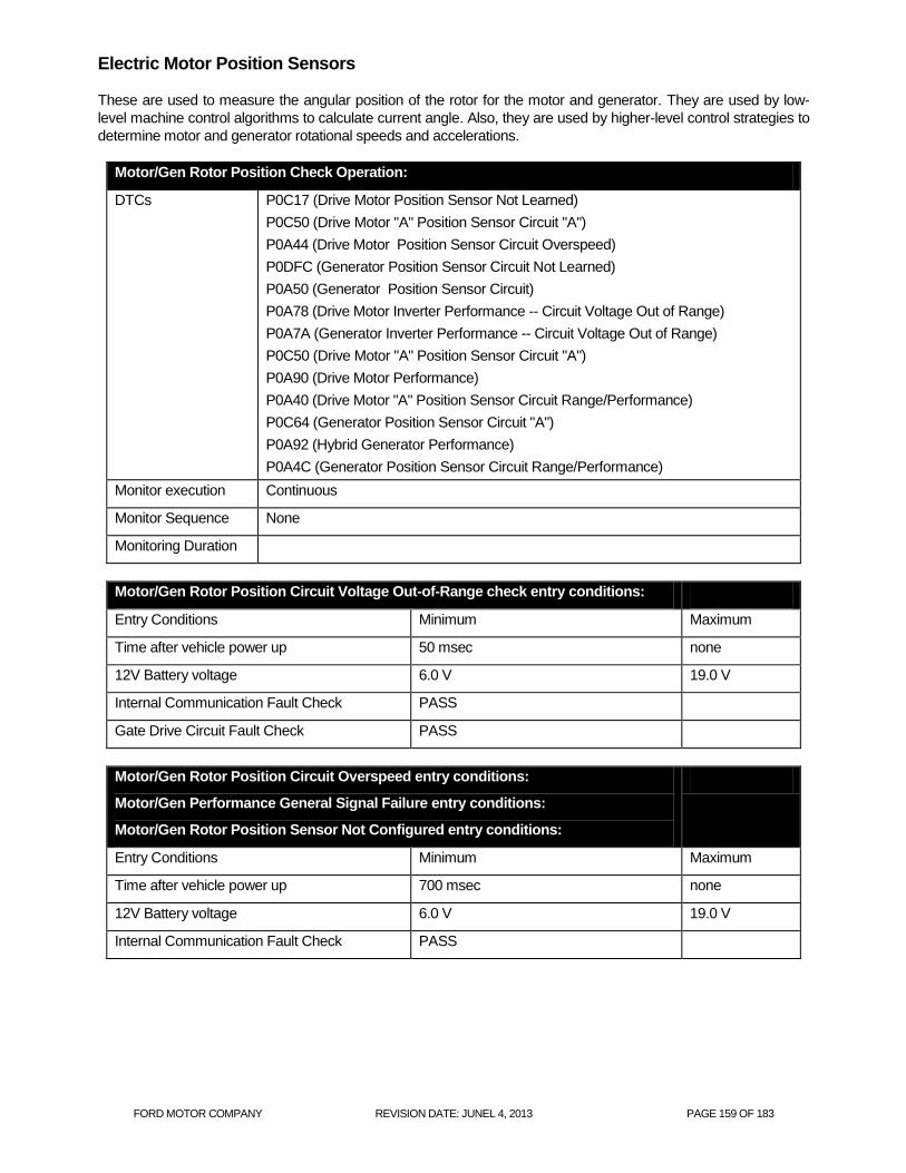
FORD MOTOR COMPANY REVISION DATE: JUNEL 4, 2013 PAGE 159 OF 183
Electric Motor Position Sensors
These are used to measure the angular position of the rotor for the motor and generator. They are used by low-
level machine control algorithms to calculate current angle. Also, they are used by higher-level control strategies to
determine motor and generator rotational speeds and accelerations.
Motor/Gen Rotor Position Check Operation:
DTCs P0C17 (Drive Motor Position Sensor Not Learned)
P0C50 (Drive Motor "A" Position Sensor Circuit "A")
P0A44 (Drive Motor Position Sensor Circuit Overspeed)
P0DFC (Generator Position Sensor Circuit Not Learned)
P0A50 (Generator Position Sensor Circuit)
P0A78 (Drive Motor Inverter Performance -- Circuit Voltage Out of Range)
P0A7A (Generator Inverter Performance -- Circuit Voltage Out of Range)
P0C50 (Drive Motor "A" Position Sensor Circuit "A")
P0A90 (Drive Motor Performance)
P0A40 (Drive Motor "A" Position Sensor Circuit Range/Performance)
P0C64 (Generator Position Sensor Circuit "A")
P0A92 (Hybrid Generator Performance)
P0A4C (Generator Position Sensor Circuit Range/Performance)
Monitor execution Continuous
Monitor Sequence None
Monitoring Duration
Motor/Gen Rotor Position Circuit Voltage Out-of-Range check entry conditions:
Entry Conditions Minimum Maximum
Time after vehicle power up 50 msec none
12V Battery voltage 6.0 V 19.0 V
Internal Communication Fault Check PASS
Gate Drive Circuit Fault Check PASS
Motor/Gen Rotor Position Circuit Overspeed entry conditions:
Motor/Gen Performance General Signal Failure entry conditions:
Motor/Gen Rotor Position Sensor Not Configured entry conditions:
Entry Conditions Minimum Maximum
Time after vehicle power up 700 msec none
12V Battery voltage 6.0 V 19.0 V
Internal Communication Fault Check PASS

FORD MOTOR COMPANY REVISION DATE: JUNEL 4, 2013 PAGE 160 OF 183
Motor/Gen Performance Circuit Voltage Below Threshold entry conditions
Entry Conditions Minimum Maximum
Time after vehicle power up 50 msec none
12V Battery voltage 6.0 V 19.0 V
Internal Communication Fault Check PASS
Internal Reference Voltages Fault Check PASS
Gate Drive Circuit Fault Check PASS
Motor/Gen Performance Invalid Serial Data entry conditions:
Entry Conditions Minimum Maximum
Time after vehicle power up 50 msec none
12V Battery voltage 6.0 V 19.0 V
Internal Communication Fault Check PASS
Mot/Gen Speed > 0 RPM
Mot/Gen Inverter Over Current Fault FAIL
Motor/Gen Rotor Position Sensor Not Configured malfunction thresholds:
Motor/Generator Resolver Position (stored in EEPROM) is not in acceptable range.
Motor/Gen Rotor Position Circuit Overspeed malfunction thresholds:
( Motor measured speed is greater than 1596 for greater than 10 msec OR
Motor measured speed is greater than 1544 for greater than 100 msec. )
( Generator measured speed is greater than 1596 for greater than 10 msec OR
Generator measured speed is greater than 1544 for greater than 100 msec. )
Motor/Gen Rotor Position Circuit Voltage Out-of-Range malfunction thresholds:
Motor/Generator Gate Drive Power Supply > 15.08 V OR
Motor/Generator Resolver Power Supply less than 4.7 V OR greater than 5.3 V
Motor/Gen Drive Motor Performance General Signal Failure malfunction thresholds:
Motor/Generator Resolver hardwired fault line indicates faulted high-> 10ms if RUNNING. OR > 600ms at
powerup OR Motor/Generator Resolver hardwired fault line intermittent
Motor/Gen Performance Circuit Voltage Below Threshold malfunction thresholds:
Motor/Generator Resolver circuit power supply less than 15.6 V OR greater than 21.5 V
Motor/Gen Performance Invalid Serial Data malfunction thresholds:
Motor/Generator Resolver ABZ data differs from serial data by more than 3.6 deg for more than 20 msec.
Motor/Gen Performance
35A difference between command and feedback for 500ms continuously.

FORD MOTOR COMPANY REVISION DATE: JUNEL 4, 2013 PAGE 161 OF 183
Electric Motor HV Current Sensors
These are used by the MGCU (Motor/Generator Control Unit) to measure the AC current for each phase of the
motor and generator. They are used by low-level machine control algorithms to calculate current magnitude and
angle. Also, they are used by to insure correct connection of the AC 3-phase circuits to the motor and generator.
Motor/Gen Current Sensor Check Operation:
DTCs P0A78 (Drive Motor Inverter Performance - Current Above Threshold)
P0A7A (Generator Inverter Performance - Current Above Threshold)
P0C00 Drive Motor "A" Current Low)
P0C03 (Drive Motor "B" Current Low)
P1A16 (Variable Voltage Controller Voltage Control Circuit - Current
Above Threshold)
P0D2D (Drive Motor "A" Inverter Voltage Sensor Circuit)
Monitor execution Continuous
Monitor Sequence None
Monitoring Duration
Motor/Gen Inverter Performance Current Above Threshold entry conditions:
Entry Conditions Minimum Maximum
Time after vehicle power up 50 msec none
12V Battery voltage 6.0 V 19.0 V
Internal Reference Voltages Fault Check PASS
Internal Inverter Fault Check PASS
Motor/Gen Inverter Performance Current Out-Of Range entry conditions:
Entry Conditions Minimum Maximum
Time after vehicle power up 50 msec none
12V Battery voltage 6.0 V 19.0 V
Internal Reference Voltages Fault Check PASS
Mot/Gen Operating Mode Any mode except Terminate
Variable Voltage Controller Control Circuit Current Above Threshold entry
conditions:
Entry Conditions Minimum Maximum
Time after vehicle power up 50 msec none
12V Battery voltage 6.0 V 19.0 V
Internal Reference Voltages Fault Check PASS
VVC Operating Mode Boost Mode

FORD MOTOR COMPANY REVISION DATE: JUNEL 4, 2013 PAGE 162 OF 183
Motor/Gen Inverter Performance Current Above Threshold malfunction thresholds:
Motor/Gen current sensor over current declared by MGCU:
Motor current magnitude > 600A for 400us OR > 30 A for 200ms at power up
Generator current magnitude > 300A for 400us OR > 15 A for 200ms at powerup
Motor/Gen Inverter Performance Current Out-Of Range malfunction thresholds:
Motor/Gen phase circuit fault declared by MGCU - < 5 A for duration of test (100ms) at power up
Variable Voltage Controller Control Circuit Current Above Threshold malfunction thresholds:
Variable Voltage Controller current measured greater than 300 amps.
Inverter DC Voltage Sensor Circuit malfunction thresholds:
< 0.235V for 100ms at power up

FORD MOTOR COMPANY REVISION DATE: JUNEL 4, 2013 PAGE 163 OF 183
Electric Drive Temperature Inputs Motor/Generator Coil Temperature Sensors These temperature sensors are located on the coil windings of the stators of the motor and the generator.
Motor/Generator Coil Temperature Sensor check Operation:
DTCs P0A2C (Drive Motor "A" Temperature Sensor Circuit Low)
P0A2D (Drive Motor "A" Temperature Sensor Circuit High)
P0A2B (Drive Motor "A" Temperature Sensor Circuit Range/Performance)
P0A2F (Drive Motor "A" Over Temperature -- Unexpected Operation)
P0A38 (Generator Temperature Sensor Circuit Low)
P0A39 (Generator Temperature Sensor Circuit High)
P0A37 (Generator Temperature Sensor Circuit Range/Performance)
Monitor execution Continuous
Monitor Sequence None
Sensors OK
Monitoring Duration 200 msec
Motor/Generator Coil Temp Circuit Short/Open check entry conditions:
Entry Conditions Minimum Maximum
Time after vehicle power up 2 seconds none
12V Battery voltage 6.0 V 19.0 V
Internal Reference Voltages Fault Check PASS
Motor/Generator Coil Temp Over Temp check entry conditions:
Entry Conditions Minimum Maximum
Time after vehicle power up 500 msec none
12V Battery voltage 6.0V 19.0 V
Sensors OK Motor Temp Sensor = OK
Generator Temp Sensor = OK
Oil Temp Sensor = OK
Internal Reference Voltages Fault Check PASS

FORD MOTOR COMPANY REVISION DATE: JUNEL 4, 2013 PAGE 164 OF 183
Motor/Generator Coil Temp In-Range/Performance entry conditions:
Entry Conditions Minimum Maximum
Time after vehicle power up 2 seconds 10 seconds
12V Battery voltage 6.0V 19.0 V
Sensors OK Motor Temp Sensor = OK
Generator Temp Sensor = OK
Oil Temp Sensor = OK
Internal Reference Voltages Fault Check PASS
Key-off timer 200 minutes
Motor/Generator Coil Temp Sensor Low check malfunction thresholds:
Motor/Generator Coil Temp input voltage < 0.1 V for more than 32 msec
Motor/Generator Coil Temp Sensor High check malfunction thresholds:
Motor/Generator Coil Temp input voltage > 4.8 V for more than 32 msec
Motor/Generator Coil Temp Sensor Range/Performance check malfunction thresholds:
Motor Coil Temp (P0A2B)
| Transmission Fluid Temperature - Generator Coil Temp | < 10 deg C AND
| Transmission Fluid Temperature - Motor Coil Temp | > 30 deg C AND
| Motor Coil Temp - Generator Coil Temp | > 30 deg C
Generator Coil Temp (P0A37)
| Transmission Fluid Temperature - Generator Coil Temp | > 30 deg C AND
| Transmission Fluid Temperature - Motor Coil Temp | < 10 deg C AND
| Motor Coil Temp - Generator Coil Temp | > 30 deg C
Motor/Generator Coil Temp Over Temp check malfunction thresholds:
Motor/Generator Coil Temp over Temp
Motor/Generator Coil Temp > 140 deg C OR Transmission Oil Temp > 115 deg C

FORD MOTOR COMPANY REVISION DATE: JUNEL 4, 2013 PAGE 165 OF 183
Transmission Fluid (Oil) Temperature Sensor The Transmission Fluid Temperature sensor measures the temperature of the transmission fluid.
Trans Fluid Temperature check Operation:
DTCs P0713 (Transmission Fluid Temp Sensor Circuit High)
P0712 (Transmission Fluid Temp Sensor Circuit Low)
P0711 (Transmission Fluid Temp Sensor Circuit Range/Performance
Monitor execution Continuous
Monitor Sequence None
Sensors OK
Monitoring Duration 200 msec
Trans Fluid Temp Circuit Low/High check entry conditions:
Entry Conditions Minimum Maximum
Time after vehicle power up 0.5 seconds
12V Battery voltage 6.0V 19.0 V
Internal Reference Voltages Fault Check PASS
Trans Fluid Temp Signal Range/Performance entry conditions:
Entry Conditions Minimum Maximum
Time after vehicle power up 2 seconds 30 seconds
12V Battery voltage 6.0V 19.0 V
Internal Reference Voltages Fault Check PASS
Sensors OK Motor Temp Sensor = OK
Generator Temp Sensor = OK
Oil Temp Sensor = OK
Key-off timer 200 minutes
Trans Fluid Temp Sensor Circuit High malfunction thresholds:
Transmission Fluid Temp input voltage < 0.1 V for more than 32 msec
Trans Fluid Temp Sensor Circuit Low malfunction thresholds:
Motor Coil Temperature > 10 deg C AND
Generator Coil Temperature > 10 deg C AND
Transmission Fluid Temp input voltage > 4.86 V for more than 32 msec
Trans Fluid Temp Sensor Range/Performance failure check malfunction thresholds:
| Transmission Fluid Temperature - Generator Coil Temp | > 30 deg C AND
| Transmission Fluid Temperature - Motor Coil Temp | > 30 deg C AND
| Motor Coil Temp - Generator Coil Temp | < 10 deg C

FORD MOTOR COMPANY REVISION DATE: JUNEL 4, 2013 PAGE 166 OF 183
Motor/Generator Inverter Temperature Sensors These temperature sensors are located on the Motor and Generator Inverters.
Motor/Generator Inverter Temperature Check Operation:
DTCs P0AEF (Drive Motor Inverter Temperature Sensor "A" Circuit Low)
P0AF0 (Drive Motor Inverter Temperature Sensor "A" Circuit High)
P0AEE (Drive Motor Inverter Temperature Sensor "A" Circuit Range/Performance)
P0A3C (Drive Motor "A" Inverter Over Temperature)
P0BCE (Generator Inverter Temperature Sensor "A" Circuit Low)
P0CF (Generator Inverter Temperature Sensor "A" Circuit High)
P0BCD (Generator Inverter Temperature Sensor "A" Circuit Range/Performance)
Monitor execution Continuous
Monitor Sequence None
Sensors OK
Monitoring Duration Continuous
Motor/Generator Inverter Temp Sensor Circuit Short/Open check entry conditions:
Entry Conditions Minimum Maximum
Time after vehicle power up 500 msec none
12V Battery voltage 6.0V 19.0 V
Internal Reference Voltages Fault Check PASS
Motor/Generator Inverter Temp Sensor Circuit Short/Open check entry conditions:
Entry Conditions Minimum Maximum
Time after vehicle power up 500 msec none
12V Battery voltage 6.0V 19.0 V
Internal Reference Voltages Fault Check PASS
Sensors OK Motor Inverter Temp sensor = OK
Generator Inverter Temp sensor = OK
VVC IGBT Temp Sensor = OK
VVC Inductor Temp Sensor = OK
Motor/Generator Inverter Temp Sensor Short check malfunction thresholds:
Motor Inverter Temp input voltage < 0.78 V
Motor/Generator Inverter Temp Sensor Open check malfunction thresholds:
Motor Inverter Temp input voltage > 4.56 V
Motor/Generator Inverter Temp Over Temp check malfunction thresholds:
Voltage Boost Converter (VVC) IGBT temperature > 139 deg C OR
Voltage Boost Converter (VVC) Inductor temperature > 159 deg C OR
Generator Inverter IGBT temperature > 123 deg C OR
Motor Inverter IGBT temperature > 123 deg C

FORD MOTOR COMPANY REVISION DATE: JUNEL 4, 2013 PAGE 167 OF 183
Motor/Generator Temp Sensor Range/Performance failure check malfunction thresholds:
| Motor Temperature – Engine Coolant Temp | > 30 deg C AND
Engin Off Soak Time > 210 min
High Voltage DC/DC Converter
Inverter High Voltage Sensor Check Operation:
DTCs P1A07 - Inverter High Voltage Performance
P0C79 - Drive Motor "A" Inverter Voltage Too High
P0DA8 - Hybrid/EV Battery Voltage/Drive Motor "A" Inverter Voltage Correlation
Monitor execution Continuous
Monitor Sequence None
Sensors OK U0111, P0D2D
Monitoring Duration Continuous
Inverter High Voltage Sensor check entry conditions:
Entry Conditions Minimum Maximum
Time after vehicle power up 500 msec none
12V Battery voltage 6.0V 19.0 V
Inverter High Voltage Sensor check malfunction thresholds:
P1A07 - Battery voltage CAN signal < 150V for 100ms OR measured input voltage signal voltage < 150V for
100ms
P0C79 - DC bus voltage measurement voltage > 516V for 10ms.
P0DA8 - Difference between High Voltage Battery voltage sensor and inverter input voltage sensor > 60V
OR difference between input/output inverter voltage sensors > 60V.

FORD MOTOR COMPANY REVISION DATE: JUNEL 4, 2013 PAGE 168 OF 183
Inverter DC/DC Converter Check Operation:
DTCs P1A16 - Variable Voltage Controller Voltage Control Circuit
P1A17 - Variable Voltage Controller Processor
P0A94 - DC/DC Converter Performance
Monitor execution Continuous
Monitor Sequence None
Sensors OK P0560, P0562, U0111, P1A07
Monitoring Duration Continuous
Inverter DC/DC Converter check entry conditions:
Entry Conditions Minimum Maximum
Time after vehicle power up 500 msec none
12V Battery voltage 6.0V 19.0 V
Inverter DC/DC Converter check malfunction thresholds:
P1A16:
Input voltage sensor reading below < 0.235V for 10 msec. OR
Current sensor reading > 300 Amps for 1 sec. OR
Motor/generator torque de-rate for voltage protection > 50% for 1 sec. OR
Voltage difference across Variable Voltage Converter > 30 V for 100 msec. during self-test OR
Variable Voltage Controller upper switch hardware failure for >200 usec.
P1A17:
Variable Voltage Controller Gate Drive power supply > 15.3V, < 0.1V OR
Variable Voltage Controller upper switch temperature sensor fault > 4.55V , < 0.779V OR
Variable Voltage Controller lower switch temperature sensor fault > 4.55V , < 0.779V OR
Variable Voltage Controller lower switch hardware failure for >200 usec
Variable Voltage Controller inductor current sensor offset > 15A at power-up
Variable Voltage Controller inductor current sensor voltage < 4.5V or > 6.0V
P0A94:
Calculated Inductor current is > 50 A different from measured current in controlled operating conditions for >
4 sec.

FORD MOTOR COMPANY REVISION DATE: JUNEL 4, 2013 PAGE 169 OF 183
Inverter Inductor Temperature Sensor Check Operation:
DTCs P1A18 - Variable Voltage Controller Inductor Temperature Sensor Circuit
P1A19 - Variable Voltage Controller Driver Temperature Sensor Circuit
Monitor execution Continuous
Monitor Sequence None
Sensors OK P0560, P2610
Monitoring Duration Continuous
Inverter Inductor Temperature Sensor check entry conditions:
Entry Conditions Minimum Maximum
Time after vehicle power up 500 msec none
12V Battery voltage 6.0V 19.0 V
Inverter Inductor Temperature Sensor check malfunction thresholds:
P1A18:
Inductor temperature sensor voltage < 0.067V, > 4.86V OR
Inductor Overtemperature conditions > 165 deg C for 1 sec OR
Inductor temperature differs from ECT > 30 deg C after a 180 min engine off soak time.
P1A19:
Power Electronics temperature differs from ECT > 30 deg C after a 180 min engine off soak time.

FORD MOTOR COMPANY REVISION DATE: JUNEL 4, 2013 PAGE 170 OF 183
EV Mode Input Switch (PHEV only) Electric Vehicle (EV) Mode is driver-selectable switched input that determines the driver’s request for one of the three EV driving modes: Auto – this is normal PHEV operation (charge depleting) which attempts to minimize use of internal combustion engine operation until PHEV battery is mostly depleted then reverts to conventional hybrid (charge sustaining) operation, EV Now – this mode forces the internal combustion engine off under all non-faulted driving conditions, and EV Later – this mode forces the vehicle into conventional hybrid (charge sustaining) to allow a reserve of battery energy to be used later once driver selects Auto mode again.
EV (transmission) Mode Check Operation:
DTCs P071A (Transmission Mode Switch “A” Circuit -- intermittent)
P071B (Transmission Mode Switch “A” Circuit Low)
Monitor execution Continuous
Monitor Sequence None
Sensors OK
Monitoring Duration Continuous
EV (transmission) Mode Check Circuit check entry conditions:
Entry Conditions Minimum Maximum
Time after vehicle power up 500 msec none
12V Battery voltage 6.0V 19.0 V
EV (transmission) Mode Check Circuit intermittent check malfunction thresholds:
EV Switch transitions low to high more than 10 times in 300 msec.
EV (transmission) Mode Check Circuit Low malfunction thresholds:
EV Switch input remains low for more than 30 seconds.

FORD MOTOR COMPANY REVISION DATE: JUNEL 4, 2013 PAGE 171 OF 183
Transmission Range Sensor Inputs
Transmission Range Sensor Check Operation:
DTCs P2800 – Transmission Range Sensor B Circuit (PRNDL input)
P2806 – Transmission Range Sensor Alignment
Monitor execution continuous
Monitor Sequence None
Sensors OK not applicable
Monitoring Duration < 1 seconds to register a malfunction
Transmission range sensor check malfunction thresholds:
TR Sensor Park Reverse Neutral Drive Low
TR_A1 (VOLTS 3.84 - 4.77 2.58 - 3.31 1.82 - 2.56 0.97 - 1.79 0.20 - 0.92
TR_A2 (VOLTS 0.20 - 1.08 1.56 - 2.25 2.26 - 2.96 2.97 - 3.74 3.77 - 4.45
Transmission range sensor check malfunction thresholds:
P20800: INVALID gear position signal received over CAN from ECM.
P2806: Mechanical Parking Pawl failure. Motor rotates > 9 radians when parking pawl is expected to be
engaged in transaxle.

FORD MOTOR COMPANY REVISION DATE: JUNEL 4, 2013 PAGE 172 OF 183
Transmission Auxiliary Oil Pump
The transmission fluid pump is an internal pump bolted to the transmission case. The transmission fluid pump is turned by the input shaft and circulates transmission fluid through the transmission for lubrication and through an oil-to-air cooler mounted in the front of the radiator for transmission cooling. The transmission fluid pump only operates when the engine is running. PHEVs also have an electric auxiliary transmission fluid pump to circulate the transmission fluid during extended drive times without engine charging. The auxiliary transmission fluid pump is controlled by the TCM.
Transmission Auxiliary Oil Pump Check Operation:
DTCs P175A - Transmission Fluid Over Temperature Condition - Electric Transmission
Fluid Pump Disabled
P0B0D - Electric/Auxiliary Transmission Fluid Pump Motor Control Module
P0C27 - Electric/Auxiliary Transmission Fluid Pump "A" Motor Current Low
P0C28 - Electric/Auxiliary Transmission Fluid Pump "A" Motor Current High
P0C29 - Electric/Auxiliary Transmission Fluid Pump "A" Driver Circuit Performance
P0C2A - Electric/Auxiliary Transmission Fluid Pump "A" Motor Stalled
P0C2C - Electric Transmission Fluid Pump Control Module Feedback Signal
Range/Performance
P0C2D - Electric Transmission Fluid Pump Control Module Feedback Signal Low
P0C2E - Electric Transmission Fluid Pump Control Module Feedback Signal High
P2796 - Electric Transmission Fluid Pump Control Circuit
Monitor execution continuous
Monitor Sequence None
Sensors OK not applicable
Monitoring Duration < 1 seconds to register a malfunction
Transmission Auxiliary Oil Pump check entry conditions:
Entry Conditions Minimum Maximum
Ambient Temperature 10 deg C
12V Battery voltage 6.0V 19.0 V

FORD MOTOR COMPANY REVISION DATE: JUNEL 4, 2013 PAGE 173 OF 183
Transmission Auxiliary Oil Pump check malfunction thresholds:
P175A: TAOP circuit board temperature > 130 deg C for 3 sec.
P0B0D: TAOP speed is > 105% or < 95% of commanded speed for 3 sec
P0C27: TAOP current is < 0.5 Amps at 1000rpm to <1.2 Amps at 4000rpm. For 3 sec
P0C28: TAOP current is > 12.5 Amps for 3 sec
P0C29: TAOP current and speed meet conditions for P0B0D and either P0C27 or P0C28 for 3 sec.
P0C2A: Pump speed =0 when commanded non-zero for 3 sec, OR circuit board temp > 135 deg C OR Over-
current > 12.5 Amps for > 20 sec. OR Pump supplied voltage < 6.0 Volts or > 18.0 Volts for 325 ms.
P0C2C: Duty cycle of PWM signal measured by TAOP outside the 10 defined zones of operation > 3.0 sec.
P0C2D: Duty cycle of PWM signal measured from TAOP is < 9 % duty cycle for 3 seconds.
P0C2E: Duty cycle of PWM signal measured from TAOP is > 91 % duty cycle for 3 seconds.
P2796: PWM speed command signal on the separate control circuit < 80 Hz or > 120 Hz for 3 sec.

FORD MOTOR COMPANY REVISION DATE: JUNEL 4, 2013 PAGE 174 OF 183
Motor Electronics Coolant Pump Control Circuit
Motor Electronics Coolant Pump Control Circuit Check Operation:
DTCs P0A06 (Motor Electronics Coolant Pump (MECP) Control Circuit Low)
P0A07 (Motor Electronics Coolant Pump (MECP) Control Circuit High)
P0C73 (Motor Electronics Coolant Pump "A" Control Performance)
Monitor execution Continuous
Monitor Sequence None
Sensors OK
Monitoring Duration 5 sec
Motor Electronics Coolant Pump Control Circuit check entry conditions:
Entry Conditions Minimum Maximum
Time after vehicle power up 500 msec none
12V Battery voltage 6.0V 19.0 V
Motor Electronics Coolant Pump Control Circuit check malfunction thresholds:
P0A06 – MECP output driver faulted for > 5 sec
P0A07 - MECP output driver faulted (overcurrent) for > 0.25 sec
P0C73 – No communication received from pump > 9.25 sec OR communication received from pump that a
confirmed fault exists > 1.25 sec OR communication received from pump outside of expected
frequency/duty cycle > 1 sec.

FORD MOTOR COMPANY REVISION DATE: JUNEL 4, 2013 PAGE 175 OF 183
General System Voltage Checks
General System Voltage Check Operation:
DTCs P0560 – System Voltage
P0562 – System Voltage Low
P0563 – System Voltage High
P0A23 – Generator Torque Sensor Circuit Range/Performance
P0A18 – Motor Torque Sensor Circuit Range/Performance
P1633 - Keep Alive Power Voltage Too Low
Monitor execution Continuous
Monitor Sequence None
Sensors OK
Monitoring Duration < 1 sec
General System Voltage Check entry conditions:
Entry Conditions Minimum Maximum
Time after vehicle power up 500 msec none
12V Battery voltage 6.0V 19.0 V
General System Voltage check malfunction thresholds:
P0560:
5V power supply out of range (4.75V > x) OR (x > 5.25V)
3.3V power supply out of range (3.46V < x) OR (x < 3.13V)
1.5 V power supply out of range (1.57V < x) OR (x < 1.42V)
P0562:
Battery voltage when vehicle is running and in a torque producing state < 8.2V
KAPWR voltage out of range (x > 19.0V) OR (x < 5.95V)
P0563:
Battery voltage too high> 19.0V
P0A23:
Generator sensor reference voltage out of range > 6V or < 4.50V for 500ms.
P0A18:
Motor current sensor reference voltage out of range > 6V or < 4.50V for 500ms.
P1633
Voltage below 6.0V for 20 seconds, or 5 seconds during module self-test.

FORD MOTOR COMPANY REVISION DATE: JUNEL 4, 2013 PAGE 176 OF 183
Internal ECU Checks
Internal ECU Check Operation:
DTCs P0600 – Serial Communication Link
P0603 - Internal Control Module Keep Alive Memory (KAM) Error
P0604 - Internal Control Module Random Access Memory (RAM) Error
P0605 - Internal Control Module Read Only Memory (ROM) Error
P0607 - Internal Control Module Read Only Memory (ROM) Error
P060A – Internal Control Module Monitoring Processor
P060B - Internal Control Module A/D Processing Performance
P060C - Internal Control Module Main Processor Performance
P0613 – TCM Processor
P061A - Internal Control Module Torque Performance
P06B8 - Internal Control Module Non-Volatile Random Access Memory
(NVRAM) Error
P0A1D - Hybrid/EV Powertrain Control Module "A"
P1A08 - Generator Mode Signal
Monitor execution Continuous
Monitor Sequence None
Sensors OK
Monitoring Duration < 1 sec
Internal ECU Check malfunction thresholds:
P0600 – SPI message fault (checksum/header/timing/frame)
P0603 – KAM checksum error
P0604 – RAM checksum error
P0605 – ROM checksum error
P0607 - Error detected in CPU instruction test
P060A – Error detected in Motor Control Unit (RAM/ROM/Communications/Safety Monitor)
P060B – A/D redundant check error compared with main software A/D
P060C – CAN network data errors (torque/motor speed/pedal/gear/torque)
P0613 – Processor resets, micro software mismatch, torque validity
P061A – Excess torque detected
P06B8 – NVRAM read/write failure
P0A1D - Inter-processor Serial Communication failure
P1A08 - Generator mode command invalid for Neutral Gear operation when vehicle speed < 2 kph and gear
position is NEUTRAL for < 1 sec.

FORD MOTOR COMPANY REVISION DATE: JUNEL 4, 2013 PAGE 177 OF 183
General Hybrid System
General System Check Operation:
DTCs P0A1A - Generator Control Module
P0A1B - Drive Motor “A” Control Module
P1920 – Engine Speed Signal
P1A13 - Hybrid Powertrain Control Module - Regenerative Braking Disabled
P1A1B - Brake System Control Module - Forced Engine Running
U0100 - Lost Communication With ECM / PCM "A"
U0121 - Lost Communication With Anti-Lock Brake System (ABS) Control Module
U0164 - Lost Communication With HVAC Control Module
U0300 - Internal Control Module Software Incompatibility
U0401 - Invalid Data Received from ECM/PCM "A"
U0412 - Invalid Data Received from Battery Energy Control Module "A"
U0418 - Invalid Data Received from Brake System Control Module "A"
Monitor execution Continuous
Monitor Sequence None
Sensors OK P0A23, P0A92, P0A7A, P0C64 for P0A1A
P1A18, P0A90, P0A78,P0C50 for P1A1B
Monitoring Duration Continuous
General System Check malfunction thresholds:
P0A1A - Generator Torque estimate error, difference between Generator torque estimate and command >
40Nm for 550 ms or Total Torque estimate error, difference between Total torque command and Total torque
> 800Nm more than demand for > 500ms.
P0A1B - Motor Torque Estimate Error, Difference between Motor torque estimate and command > 60Nm for
550 ms or Total Torque estimate error, Difference between Total torque command and Total torque estimate
> 800Nm more than demand for > 500ms.
P1920 - Difference between engine speed CAN signal and internal engine speed calculation > 500 rpm for
500 ms OR > 550rpm for 1000 ms.
P1A13 - Regenerative Braking Disabled by request of Brake System Control Module due to regenerative
braking system fault.
P1A1B – Forced Engine Running by request of Brake System Control Module due to regenerative braking
system fault.
U0100 – Lost Communication with PCM > 1 sec.
U0121 – Lost Communication with ABS module > 1 sec.
U0164 - Lost Communication with HVAC module > 1 sec.
U0300 - Internal HPCM monitor software version mismatch.
U0401 - Invalid Data Received from ECM/PCM "A"
U0412 - Invalid Data Received from Battery Energy Control Module "A"
U0418 - Invalid Data Received from Brake System Control Module "A"

FORD MOTOR COMPANY REVISION DATE: JUNEL 4, 2013 PAGE 178 OF 183
PCM On Board Diagnostic Executive
The On-Board Diagnostic (OBD) Executive is a portion of the PCM strategy that manages the diagnostic trouble codes and operating modes for all diagnostic tests. It is the "traffic cop" of the diagnostic system. The Diagnostic Executive performs the following functions:
Sequence the OBD monitors such that when a test runs, each input that it relies upon has already been tested. For 2008 MY and beyond ISO 14229 programs, the OBD monitors are no longer sequenced by the diagnostic executive.
Controls and co-ordinates the execution of the individual OBD system monitors: Catalyst, Misfire, EGR, O2, Fuel, AIR, EVAP and, Comprehensive Component Monitor (CCM). For 2008 MY and beyond ISO 14229 programs, the execution of the OBD monitors is no longer controlled and coordinated by the diagnostic executive.
Stores freeze frame and "similar condition" data.
Manages storage and erasure of Diagnostic Trouble Codes as well as MIL illumination.
Controls and co-ordinates the execution of the On-Demand tests: Key On Engine Off (KOEO)Key On Engine Running (KOER), and the Output Test Mode (OTM). For 2008 MY and beyond ISO 14229 programs, the Output Test Mode is no longer supported by the diagnostic executive.
Performs transitions between various states of the diagnostic and powertrain control system to minimize the effects on vehicle operation.
Interfaces with the diagnostic test tools to provide diagnostic information (I/M readiness, various J1979 test modes) and responses to special diagnostic requests (J1979 Mode 08 and 09).
Tracks and manages indication of the driving cycle which includes the time between two key on events that include an engine start and key off.
The diagnostic executive also controls several overall, global OBD entry conditions.
The battery voltage must fall between 11.0 and 18.0 volts to initiate monitoring cycles.
The engine must be started to initiate the engine started, engine running, and engine off monitoring cycles.
The Diagnostic Executive suspends OBD monitoring when battery voltage falls below 11.0 volts.
The Diagnostic Executive suspends monitoring of fuel-system related monitors (catalyst, misfire, evap,
O2, AIR and fuel system) when fuel level falls below 15%. For 2005 MY and beyond, the execution of
the fuel related OBD monitors is no longer suspended for fuel level by the diagnostic executive.
The diagnostic executive controls the setting and clearing of pending and confirmed DTCs.
A pending DTC and freeze frame data is stored after a fault is confirmed on the first monitoring cycle. If the
fault recurs on the next driving cycle, a confirmed DTC is stored, freeze frame data is updated, and the
MIL is illuminated. If confirmed fault free on the next driving cycle, the pending DTC and freeze frame data
is erased on the next power-up.
For the 2005 MY and later, pending DTCs will be displayed as long as the fault is present. Note that OBD-
II regulations required a complete fault-free monitoring cycle to occur before erasing a pending DTC. In
practice, this means that a pending DTC is erased on the next power-up after a fault-free monitoring cycle.
For clearing comprehensive component monitoring (CCM) pending DTCs, the specific monitor must
determine that no fault is present, and a 2-hour engine off soak has occurred prior to starting the vehicle.
The 2-hour soak criteria for clearing CCM confirmed and pending DTCs has been utilized since the 2000
MY. For 2008 MY and beyond ISO 14229 programs, the engine off soak is no longer used by the
diagnostic executive.
After a confirmed DTC is stored and the MIL has been illuminated, three consecutive confirmed fault-free
monitoring cycles must occur before the MIL can be extinguished on the next (fourth) power-up. After 40
engine warm-ups, the DTC and freeze frame data is erased.

FORD MOTOR COMPANY REVISION DATE: JUNEL 4, 2013 PAGE 179 OF 183
The diagnostic executive controls the setting and clearing of permanent DTCs.
A permanent DTC is stored when a confirmed DTC is stored, the MIL has been illuminated, and there are
not yet six permanent DTCs stored.
After a permanent DTC is stored, three consecutive confirmed fault-free monitoring cycles must occur
before the permanent DTC can be erased.
After a permanent DTC is stored, one confirmed fault-free monitoring cycle must occur, following a DTC
reset request, before the permanent DTC can be erased. For 2010MY and beyond ISO 14229 programs
a driving cycle including the following criteria must also occur, following the DTC reset request, before a
permanent DTC can be erased: o Cumulative time since engine start is greater than or equal to 600 seconds; o Cumulative vehicle operation at or above 25 miles per hour occurs for greater than or equal
to 300 seconds (medium-duty vehicles with diesel engines certified on an engine dynamometer may use cumulative operation at or above 15% calculated load in lieu of at or above 25 miles per hour for purposes of this criteria); and
o Continuous vehicle operation at idle (i.e., accelerator pedal released by driver and vehicle speed less than or equal to one mile per hour) for greater than or equal to 30 seconds.
A permanent DTC can not be erased by a KAM clear (battery disconnect). Additionally, its confirmed DTC
counterpart will be restored after completion of the KAM reset (battery reconnect).

FORD MOTOR COMPANY REVISION DATE: JUNEL 4, 2013 PAGE 180 OF 183
Exponentially Weighted Moving Average
Exponentially Weighted Moving Averaging is a well-documented statistical data processing technique that is used
to reduce the variability on an incoming stream of data. Use of EWMA does not affect the mean of the data,
however, it does affect the distribution of the data. Use of EWMA serves to “filter out” data points that exhibit
excessive and unusual variability and could otherwise erroneously light the MIL.
The simplified mathematical equation for EWMA implemented in software is as follows:
New Average = [New data point * “filter constant”] + [( 1 - “filter constant” ) * Old Average]
This equation produces an exponential response to a step-change in the input data. The "Filter Constant"
determines the time constant of the response. A large filter constant (i.e. 0.90 ) means that 90% of the new data
point is averaged in with 10% of the old average. This produces a very fast response to a step change.
Conversely, a small filter constant (i.e. 0.10 ) means that only 10% of the new data point is averaged in with 90%
of the old average. This produces a slower response to a step change.
When EWMA is applied to a monitor, the new data point is the result from the latest monitor evaluation. A new
average is calculated each time the monitor is evaluated and stored in Keep Alive Memory (KAM). This normally
occurs each driving cycle. The MIL is illuminated and a DTC is stored based on the New Average store in KAM.
In order to facilitate repair verification and DDV demonstration, 2 different filter constants are used. A “fast filter
constant” is used after KAM is cleared or DTCs are erased and a “normal filter constant” is used for normal
customer driving. The “fast filter” is used for 2 driving cycles after KAM is cleared/DTCs are erased, and then the
“normal filter” is used. The “fast filter” allows for easy repair verification and monitor demonstration in 2 driving
cycles, while the normal filter is used to allow up to 6 driving cycles, on average, to properly identify a malfunction
and illuminate the MIL. This feature is called Fast Initial Response (FIR). The fast filter is always calibrated to 1.0
which means that the EWMA is effectively disabled because the new average is 100% of the new data point.
Since the EWMA is effectively disabled, it takes twp driving cycles to set the MIL. The first driving cycle with a
fault will set a pending DTC; the second driving cycle will set a confirmed code and illuminate the MIL.
The other unique feature used with EWMA is called Step Change Logic (SCL). This logic detects an abrupt
change from a no-fault condition to a fault condition. This is done by comparing the new data point to the EWMA
old average. If the two points differ by more than a calibrated amount (i.e. the new data point is outside the
normal distribution), it means that a catastrophic failure has occurred. The fast filter is then used in the same
manner as for the FIR feature above. Since the EWMA is effectively disabled, it takes twp driving cycles to set the
MIL. The first driving cycle with a fault will set a pending DTC; the second driving cycle will set a confirmed code
and illuminate the MIL. The SCL becomes active after the 4th "normal" monitoring cycle to give the EWMA a
chance to stabilize.
During "normal" EWMA operation, a slower filter constant is used. The "normal filer" allows the MIL to be
illuminated in 1 to 6 driving cycles. A confirmed code is set and the MIL is illuminated as soon as the EWMA
crosses the malfunction threshold. There is no pending DTC because EWMA uses a 1-trip MIL.
In order to relate filter constants to driving cycles for MIL illumination, filter constants must be converted to time
constants. The mathematical relationship is described below:
Time constant = [ ( 1 / filter constant ) - 1 ] * evaluation period
The evaluation period is a driving cycle. The time constant is the time it takes to achieve 68% of a step-change to
an input. Two time constants achieve 95% of a step change input.

FORD MOTOR COMPANY REVISION DATE: JUNEL 4, 2013 PAGE 181 OF 183
EWMA Examples
EWMA with FIR and SCL has been incorporated in the catalyst monitor, the Rear O2 response test and the EONV
Evaporative system leak check monitor. There are 3 calibrateable parameters that determine the MIL illumination
characteristics.
“Fast” filter constant (0.9999), used for 2 driving cycles after DTCs are cleared/KAM is reset (FIR) and for Step
Change Logic (SCL)
“Normal” filter constant( typically 0.4),, used for all subsequent, “normal” customer driving
Number of driving cycles to use fast filter after KAM clear (normally set to 2 driving cycles)
Several examples for a typical catalyst monitor calibration are shown in the tables below. The first example does
not show SCL in order to better illustrate the EWMA calculation and the 1-trip MIL.
Monitor
evaluation
(“new data”)
EWMA Filter Calculation,
“normal” filter constant
set to 0.4
Malfunction threshold = .75
Weighted
Average
(“new
average”)
Driving
cycle
number
Action/Comment
0.15 .15 * (0.4) + .15 * ( 1 - 0.4) 0.15 normal 120K system
1.0 1.0 * (0.4) + .15 * ( 1 - 0.4) 0.49 1 large failure occurs
1.0 1.0 * (0.4) + .49 * ( 1 - 0.4) 0.69 2
1.0 1.0 * (0.4) + .69 * ( 1 - 0.4) 0.82 3 exceeds threshold, MIL on
1.0 1.0 * (0.4) + .82 * ( 1 - 0.4) 0.89 4 MIL on
0.8 0.8 * (0.4) + .15 * ( 1 - 0.4) 0.41 1 1.5 * threshold failure
0.8 0.8 * (0.4) + .41 * ( 1 - 0.4) 0.57 2
0.8 0.8 * (0.4) + .57 * ( 1 - 0.4) 0.66 3
0.8 0.8 * (0.4) + .66 * ( 1 - 0.4) 0.72 4
0.8 0.8 * (0.4) + .72 * ( 1 - 0.4) 0.75 5 equals threshold, MIL on
0.8 0.8 * (0.4) + .75 * ( 1 - 0.4) 0.77 6 MIL on
0.8 0.8 * (0.99) + 0* ( 1 - 0.99) 0.8 1 1.5 * threshold failure after
code clear, pending DTC
0.8 0.8 * (0.99) + .8 * ( 1 - 0.99) 0.8 2 MIL on (I/M Readiness set
to "ready"

FORD MOTOR COMPANY REVISION DATE: JUNEL 4, 2013 PAGE 182 OF 183
I/M Readiness Code
The readiness function is implemented based on the J1979 format. A battery disconnection or clearing codes
using a scan tool results in the various I/M readiness bits being set to a “not-ready” condition. As each non-
continuous monitor completes a full diagnostic check, the I/M readiness bit associated with that monitor is set to a
“ready” condition. This may take one or two driving cycles based on whether malfunctions are detected or not.
The readiness bits for comprehensive component monitoring, misfire and fuel system monitoring are considered
complete once all the non-continuous monitors have been evaluated. Because the evaporative system monitor
requires ambient conditions between 40 and 100 oF and BARO > 22.5 " Hg (< 8,000 ft.) to run, special logic can
“bypass” the running the evap monitor for purposes of clearing the evap system I/M readiness bit due to the
continued presence of these extreme conditions.
Evap bypass logic:
If the evaporative system monitor conditions are met with the exception of the 40 to 100 oF ambient temperatures
or BARO range, a timer is incremented. The timer value is representative of conditions where the Evap monitor
could have run (all entry conditions met except IAT and BARO) but did not run due to the presence of those
extreme conditions. If the timer continuously exceeds 30 seconds during a driving cycle in which all continuous
and non-continuous monitors were evaluated, the evaporative system monitor is then considered complete. If the
above conditions are repeated during a second driving cycle, the I/M readiness bit for the evaporative system is
set to a “ready” condition.

FORD MOTOR COMPANY REVISION DATE: JUNEL 4, 2013 PAGE 183 OF 183
Catalyst Temperature Model
A catalyst temperature model is currently used for entry into the catalyst and oxygen sensor monitors. The
catalyst temperature model uses various PCM parameters to infer exhaust/catalyst temperature. For the 1998
MY, the catalyst temperature model has been enhanced and incorporated into the Type A misfire monitoring
logic. The model has been enhanced to include a misfire-induced exotherm prediction. This allows the model to
predict catalyst temperature in the presence of misfire.
The catalyst damage misfire logic (Type A) for MIL illumination has been modified to require that both the catalyst
damage misfire rate and the catalyst damage temperature is being exceeded prior to MIL illumination. This
change is intended to prevent the detection of unserviceable, unrepeatable, burst misfire during cold engine start-
up while ensuring that the MIL is properly illuminated for misfires that truly damage the catalyst.
Beginning with the 2007 MY, the catalyst temperature model is also used to generate the primary inputs to the
CSER Monitor as described in that section of this document.
Serial Data Link MIL Illumination
The instrument cluster on some vehicles uses the CAN data link to receive and display various types of
information from the PCM. For example, the engine coolant temperature information displayed on the instrument
cluster comes from the same ECT sensor used by the PCM for all its internal calculations.
These same vehicles use the CAN data link to illuminate the MIL rather than a circuit, hard-wired to the PCM.
The PCM periodically sends the instrument cluster a message that tells it to turn on the MIL, turn off the MIL or
blink the MIL. If the instrument cluster fails to receive a message within a 5-second timeout period, the instrument
cluster itself illuminates the MIL. If communication is restored, the instrument cluster turns off the MIL after 5
seconds. Due to its limited capabilities, the instrument cluster does not generate or store Diagnostic Trouble
Codes.
Related Documents