2012/8/14 R Liew 1 1 Local Buckling & Section Classification CE5509 R Liew 2 Introduction Classes of Cross‐Sections Maximum Width to Thickness Ratios for Compression Parts Internal Compression Parts Outstand Compression Parts Angles & Tubular Sections Effective Cross‐Section for Class 4 Sections Class 3 Web + Class 1 or 2 Flange Examples Example SC‐1 (Section classification for combined bending and compression) Example SC‐2 (Effective area of a Class 4 compression member) Example SC‐3 (Section with Class 3 web and Class 1 flanges) Outline CE5509 R Liew

Welcome message from author
This document is posted to help you gain knowledge. Please leave a comment to let me know what you think about it! Share it to your friends and learn new things together.
Transcript
2012/8/14
R Liew 1
1
Local Buckling &Section Classification
CE5509 R Liew
2
Introduction
Classes of Cross‐Sections
Maximum Width to Thickness Ratios for Compression PartsInternal Compression PartsOutstand Compression PartsAngles & Tubular Sections
Effective Cross‐Section for Class 4 Sections
Class 3 Web + Class 1 or 2 Flange
ExamplesExample SC‐1 (Section classification for combined bending and compression)Example SC‐2 (Effective area of a Class 4 compression member)Example SC‐3 (Section with Class 3 web and Class 1 flanges)
OutlineCE5509 R Liew
2012/8/14
R Liew 2
3
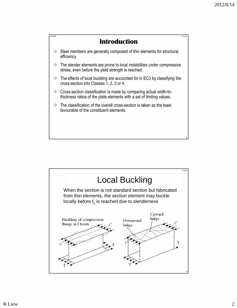
Steel members are generally composed of thin elements for structural efficiency.
The slender elements are prone to local instabilities under compressive stress, even before the yield strength is reached.
The effects of local buckling are accounted for in EC3 by classifying the cross-section into Classes 1, 2, 3 or 4.
Cross-section classification is made by comparing actual width-to-thickness ratios of the plate elements with a set of limiting values.
The classification of the overall cross-section is taken as the least favourable of the constituent elements.
IntroductionCE5509 R Liew
Local BucklingWhen the section is not standard section but fabricated from thin elements, the section element may buckle locally before fy is reached due to slenderness
4
R Liew
2012/8/14
R Liew 3
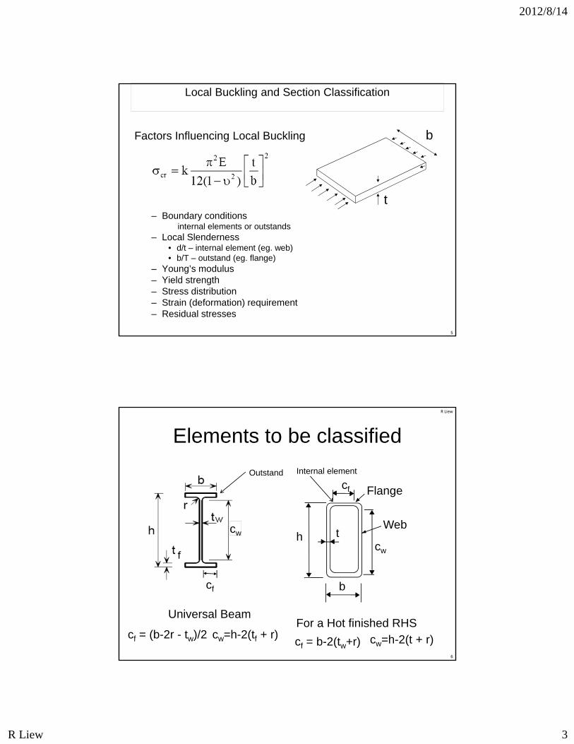
Local Buckling and Section Classification
Factors Influencing Local Buckling
– Boundary conditions internal elements or outstands
– Local Slenderness• d/t – internal element (eg. web)• b/T – outstand (eg. flange)
– Young’s modulus– Yield strength– Stress distribution– Strain (deformation) requirement– Residual stresses
b
t
5
Elements to be classified
For a Hot finished RHScf = (b-2r - tw)/2 cw=h-2(tf + r)
Universal Beam
cf = b-2(tw+r) cw=h-2(t + r)6
R Liew
cf
hcw
b
tWeb
Flange
Outstand
cf
Internal element
cw
2012/8/14
R Liew 4
R Liew
7
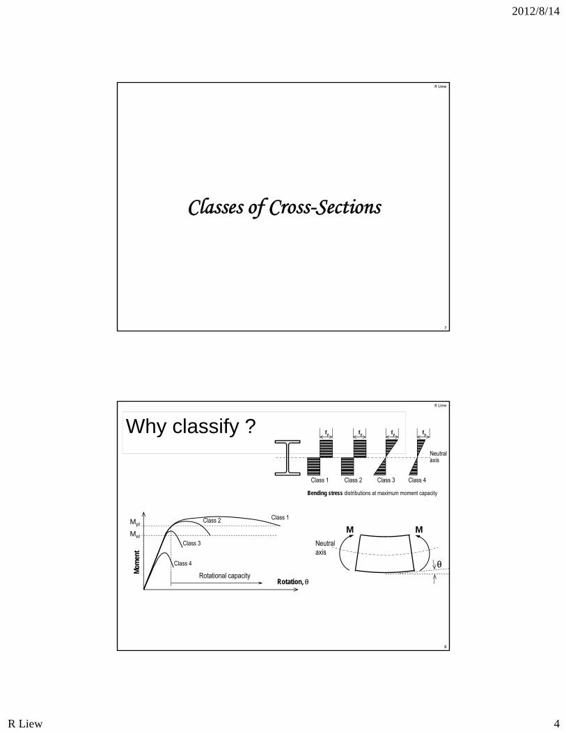
Classes of Cross-Sections
Why classify ?
Class 1
Rotation,
Mom
ent
Mpl
Mel
Rotational capacity
Class 2
Class 3
Class 4
MM
Neutral axis
Neutral axis
Bending stress distributions at maximum moment capacity
Class 2
fy
Class 3
fy
Class 4
fy
Class 1
fy
8
R Liew
2012/8/14
R Liew 5
9
Strain
Stre
ss
fy
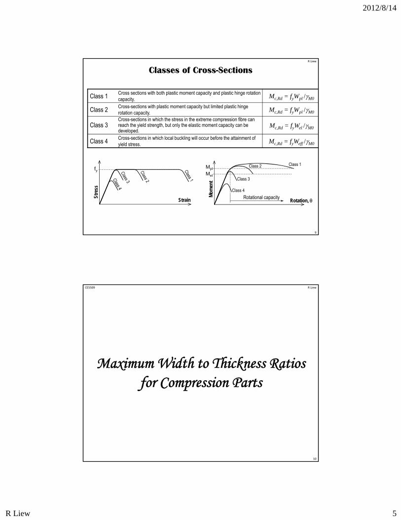
Classes of Cross-Sections
Class 1 Cross sections with both plastic moment capacity and plastic hinge rotation capacity. Mc,Rd = fyWpl /M0
Class 2 Cross-sections with plastic moment capacity but limited plastic hinge rotation capacity. Mc,Rd = fyWpl /M0
Class 3Cross-sections in which the stress in the extreme compression fibre can reach the yield strength, but only the elastic moment capacity can be developed.
Mc,Rd = fyWel /M0
Class 4 Cross-sections in which local buckling will occur before the attainment of yield stress. Mc,Rd = fyWeff /M0
Class 1
Rotation,
Mom
ent
Mpl
Mel
Rotational capacity
Class 2
Class 3
Class 4
R Liew
10
Maximum Width to Thickness Ratios for Compression Parts
CE5509 R Liew
2012/8/14
R Liew 6
R Liew
11
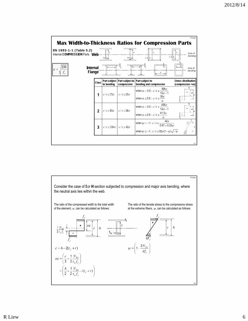
Internal COMPRESSION Parts
ClassPart subject to bending
Part subject to compression
Part subject to Stress distributionbending and compression (compression +ve)
1
2
3
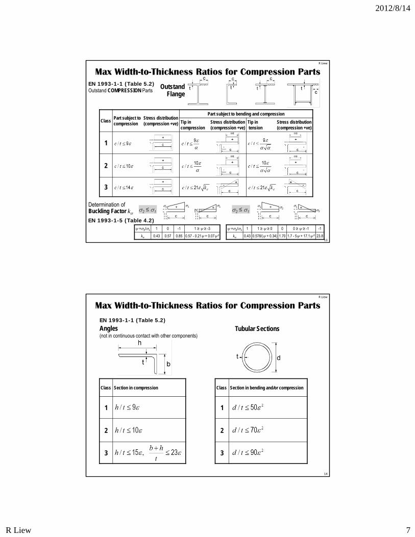
Max Width-to-Thickness Ratios for Compression Parts
Web
Internal Flange
EN 1993-1-1 (Table 5.2)
12
Consider the case of I or H section subjected to compression and major axis bending, where the neutral axis lies within the web.
+
–
The ratio of the tensile stress to the compressive stress at the extreme fibers, , can be calculated as follows:
The ratio of the compressed width to the total width of the element, , can be calculated as follows:
+
–
tf
tw
R Liew
2012/8/14
R Liew 7
13
ClassPart subject to Stress distributioncompression (compression +ve)
Part subject to bending and compression
Tip in Stress distributioncompression (compression +ve)
Tip in Stress distributiontension (compression +ve)
1
2
3
Outstand COMPRESSION Parts
Max Width-to-Thickness Ratios for Compression Parts
Outstand Flange
Determination of Buckling Factor k
c
+ 12
c
+1
2 -
=2/1 1 0 -1 1 ≥ ≥ -3
k 0.43 0.57 0.85 0.57 - 0.21 + 0.07 2
c
+ 21
c
+ 2
1
-
=2/1 1 1 ≥ ≥ 0 0 0 ≥ ≥ -1 -1
k 0.43 0.578/( + 0.34) 1.70 1.7 - 5 + 17.1 2 23.8
2 ≤ 1 2 ≤ 1
EN 1993-1-1 (Table 5.2)
EN 1993-1-5 (Table 4.2)
R Liew
14
Class Section in compression
1
2
3
Angles(not in continuous contact with other components)
Max Width-to-Thickness Ratios for Compression Parts
Tubular Sections
Class Section in bending and/or compression
1
2
3
EN 1993-1-1 (Table 5.2)
R Liew
2012/8/14
R Liew 8
15
Effective Cross-Section for Class 4 Sections
CE5509 R Liew
16
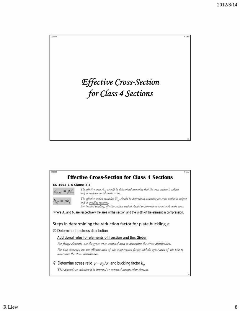
Effective Cross-Section for Class 4 SectionsEN 1993-1-5 Clause 4.4
Steps in determining the reduction factor for plate buckling Determine the stress distribution
Additional rules for elements of I section and Box Girder
For flange elements, use the gross cross-sectional area to determine the stress distribution.
For web elements, use the effective area of the compression flange and the gross area of the web to determine the stress distribution.
Determine stress ratio 2 /1 and buckling factor kThis depends on whether it is internal or external compression element.
The effective area Aeff should be determined assuming that the cross section is subject only to uniform axial compression.
The effective section modulus Weff should be determined assuming the cross section is subject only to bending moment. For biaxial bending, effective section moduli should be determined about both main axes.
where Ac and bc are respectively the area of the section and the width of the element in compression.
CE5509 R Liew
2012/8/14
R Liew 9
17
2
1
2
1
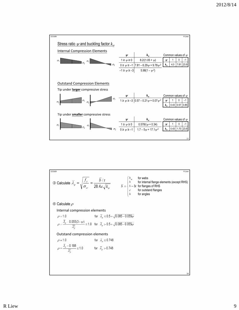
Internal Compression Elements
1 0 –1
k 4.0 7.81 23.9
Common values of
Outstand Compression Elements
1
212
2
1
2
1
1 0 –1
k 0.43 0.57 0.85
Common values of
Tip under larger compressive stress
1 0 –1
k 0.43 1.70 23.8
Common values of Tip under smaller compressive stress
k
1 ≥ ≥ 0 8.2/(1.05 + )
0 ≥ ≥ –1 7.81 – 6.29 + 9.78 2
–1 ≥ ≥ –3 5.98(1 – 2)
k
1 ≥ ≥ –3 0.57 – 0.21 + 0.07 2
k
1 ≥ ≥ 0 0.578/( + 0.34)
0 ≥ ≥ –1 1.7 – 5 + 17.1 2
Stress ratio and buckling factor k
CE5509 R Liew
18
Calculatebw for websb for internal flange elements (except RHS)b – 3t for flanges of RHSc for outstand flangesh for angles
Calculate Internal compression elements
Outstand compression elements
CE5509 R Liew
2012/8/14
R Liew 10
19
2
1
2
1
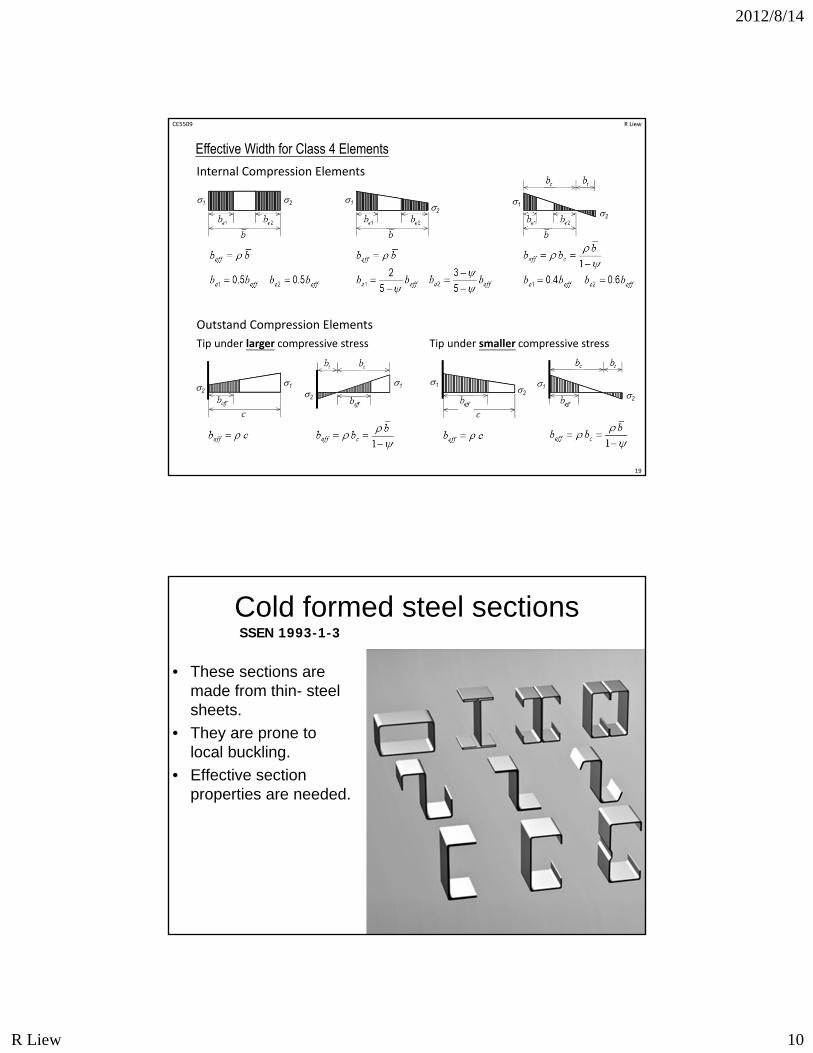
Internal Compression Elements
Outstand Compression Elements
1
2
12 2
1
2
1
Tip under larger compressive stress Tip under smaller compressive stress
21
Effective Width for Class 4 Elements
CE5509 R Liew
Cold formed steel sections
• These sections are made from thin- steel sheets.
• They are prone to local buckling.
• Effective section properties are needed.
20
SSEN 1993-1-3
2012/8/14
R Liew 11
21
Class 3 Web + Class 1 or 2 Flange
CE5509 R Liew
CE5509 R Liew
22
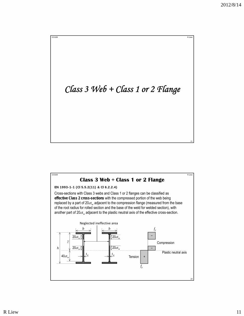
Class 3 Web + Class 1 or 2 FlangeEN 1993-1-1 (Cl 5.5.2(11) & Cl 6.2.2.4)
Cross-sections with Class 3 webs and Class 1 or 2 flanges can be classified as effective Class 2 cross-sections with the compressed portion of the web being replaced by a part of 20tw adjacent to the compression flange (measured from the base of the root radius for rolled section and the base of the weld for welded section), with another part of 20tw adjacent to the plastic neutral axis of the effective cross-section.
b
20tw
h
tw
20tw
Compression
TensionPlastic neutral axis
fy
fy
–
+
–
Neglected ineffective area
20tw
20tw
tw
b
40tw
2012/8/14
R Liew 12
8/14/2012
23
Implications for Design
• Class 1. Plastic – must be used in plasticdesign, can sustain high strain. Can beused without restriction in “normal” design
• Class 2 Compact –can be used with theplastic modulus in bending
• Class3 Semi-compact – when inbending the elastic modulus or aneffective plastic modulus must be used
• Class 4 Slender – Effective sectionproperties must be used
Section and Design Tables
Steel building design: Design data, Publication P363, The Steel Construction Institute and the British Constructional Steelwork Association UK, 2009.
24
2012/8/14
R Liew 13
8/14/2012
25
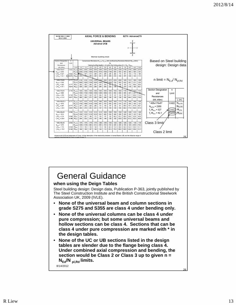
Based on Steel building design: Design data
n limit = NE,d/ Npl,Rd
Class 2 limit
Class 3 limit
8/14/201226
General Guidancewhen using the Deign Tables Steel building design: Design data, Publication P-363, jointly published by The Steel Construction Institute and the British Constructional Steelwork Association UK, 2009 (IVLE).
• None of the universal beam and column sections in grade S275 and S355 are class 4 under bending only.
• None of the universal columns can be class 4 under pure compression; but some universal beams and hollow sections can be class 4. Sections that can be class 4 under pure compression are marked with * in the design tables.
• None of the UC or UB sections listed in the design tables are slender due to the flange being class 4. Under combined axial compression and bending, the section would be Class 2 or Class 3 up to given n = NEd/N pl,Rd limits.
2012/8/14
R Liew 14
8/14/2012
27
Summary of design procedure
1 Select, from experience, a suitable section based on the factored load effects
2Determine the section classification
3 If necessary calculate effective plastic modulus for Class 3 (semi-compact) sections
4 If necessary calculate effective section properties for class 4(slender sections)
5 Proceed with design procedures suitable for the section classification
R Liew
28
Examples
CE5509
2012/8/14
R Liew 15
R Liew
29
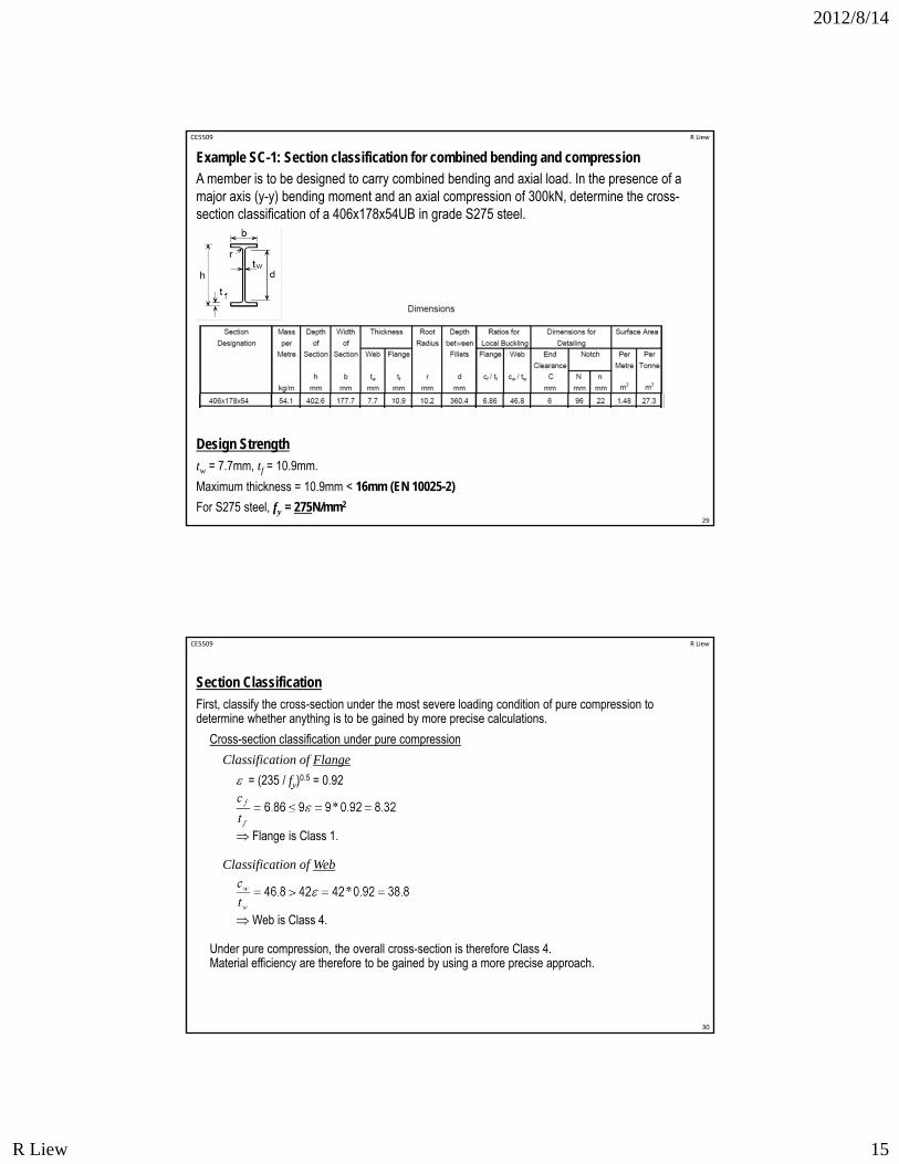
Design Strength
tw = 7.7mm, tf = 10.9mm.
Maximum thickness = 10.9mm < 16mm (EN 10025-2)
For S275 steel, fy = 275N/mm2
Example SC-1: Section classification for combined bending and compression
A member is to be designed to carry combined bending and axial load. In the presence of a major axis (y-y) bending moment and an axial compression of 300kN, determine the cross-section classification of a 406x178x54UB in grade S275 steel.
CE5509
R Liew
30
Section Classification
First, classify the cross-section under the most severe loading condition of pure compression to determine whether anything is to be gained by more precise calculations.
Cross-section classification under pure compression
Classification of Flange
= (235 / fy)0.5 = 0.92
Flange is Class 1.
Classification of Web
Web is Class 4.
Under pure compression, the overall cross-section is therefore Class 4. Material efficiency are therefore to be gained by using a more precise approach.
CE5509
2012/8/14
R Liew 16
R Liew
31
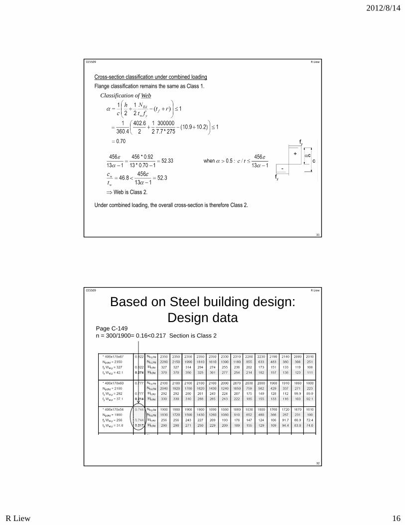
Cross-section classification under combined loading
Flange classification remains the same as Class 1.
Classification of Web
Web is Class 2.
Under combined loading, the overall cross-section is therefore Class 2.
CE5509
CE5509 R Liew
32
Page C-149 n = 300/1900= 0.16<0.217 Section is Class 2
Based on Steel building design: Design data
2012/8/14
R Liew 17
8/14/2012
33
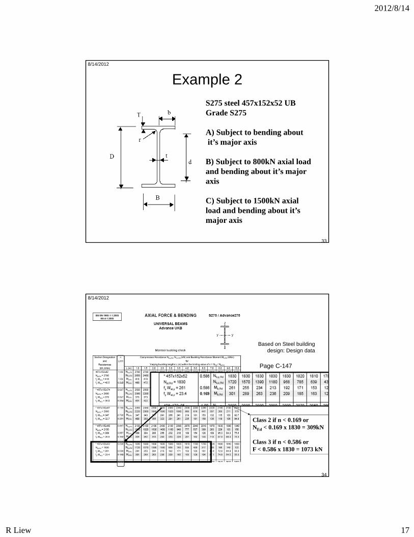
Example 2
S275 steel 457x152x52 UBGrade S275
A) Subject to bending aboutit’s major axis
B) Subject to 800kN axial load and bending about it’s major axis
C) Subject to 1500kN axial load and bending about it’s major axis
8/14/2012
34
Class 2 if n < 0.169 orNEd < 0.169 x 1830 = 309kN
Class 3 if n < 0.586 orF < 0.586 x 1830 = 1073 kN
Page C-147
Based on Steel building design: Design data
2012/8/14
R Liew 18
8/14/2012
35
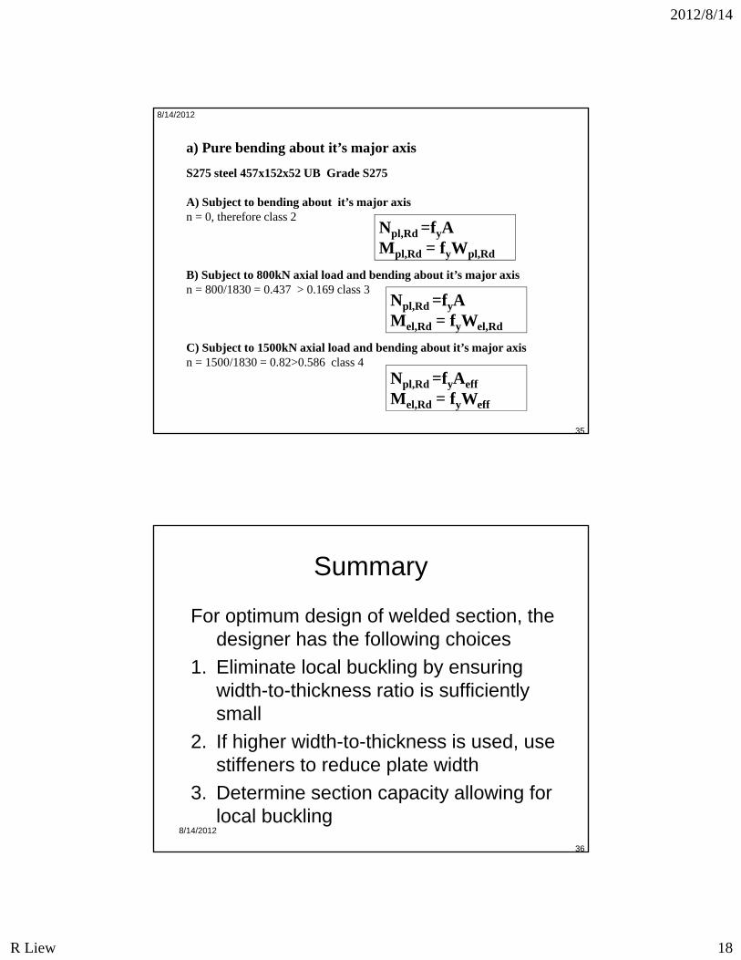
a) Pure bending about it’s major axis
S275 steel 457x152x52 UB Grade S275
A) Subject to bending about it’s major axisn = 0, therefore class 2
B) Subject to 800kN axial load and bending about it’s major axisn = 800/1830 = 0.437 > 0.169 class 3
C) Subject to 1500kN axial load and bending about it’s major axisn = 1500/1830 = 0.82>0.586 class 4
Npl,Rd =fyAeff
Mel,Rd = fyWeff
Npl,Rd =fyAMpl,Rd = fyWpl,Rd
Npl,Rd =fyAMel,Rd = fyWel,Rd
8/14/2012
36
Summary
For optimum design of welded section, the designer has the following choices
1. Eliminate local buckling by ensuring width-to-thickness ratio is sufficiently small
2. If higher width-to-thickness is used, use stiffeners to reduce plate width
3. Determine section capacity allowing for local buckling
2012/8/14
R Liew 19
8/14/2012
37
Q1 What happen when the limiting plate slenderness ratios are exceeded?
Cross section strength cannot be fully developed.
i.e., cross section strength is governed by local buckling instead of yielding.
Q2 How can we prevent local buckling of a plate component?
Ensure that b/t ratio is compact. Provide plate stiffener
Questions
8/14/2012
38
Q3 What effect does a slender and unstiffened element have on the strength of compression member as opposed to that of a non-slender element?
Slender element reduces the compression resistance of the compression member because of local buckling effect
2012/8/14
R Liew 20
8/14/2012
39
8/14/2012
40
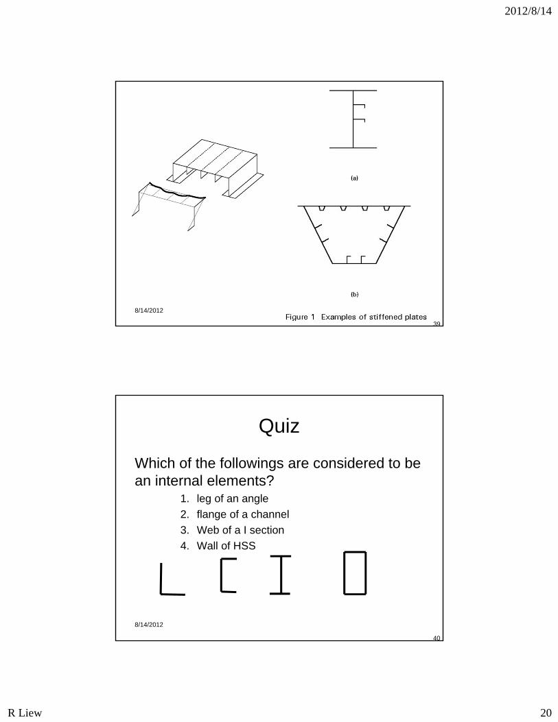
Quiz
Which of the followings are considered to be an internal elements?
1. leg of an angle
2. flange of a channel
3. Web of a I section
4. Wall of HSS
2012/8/14
R Liew 21
8/14/2012
41
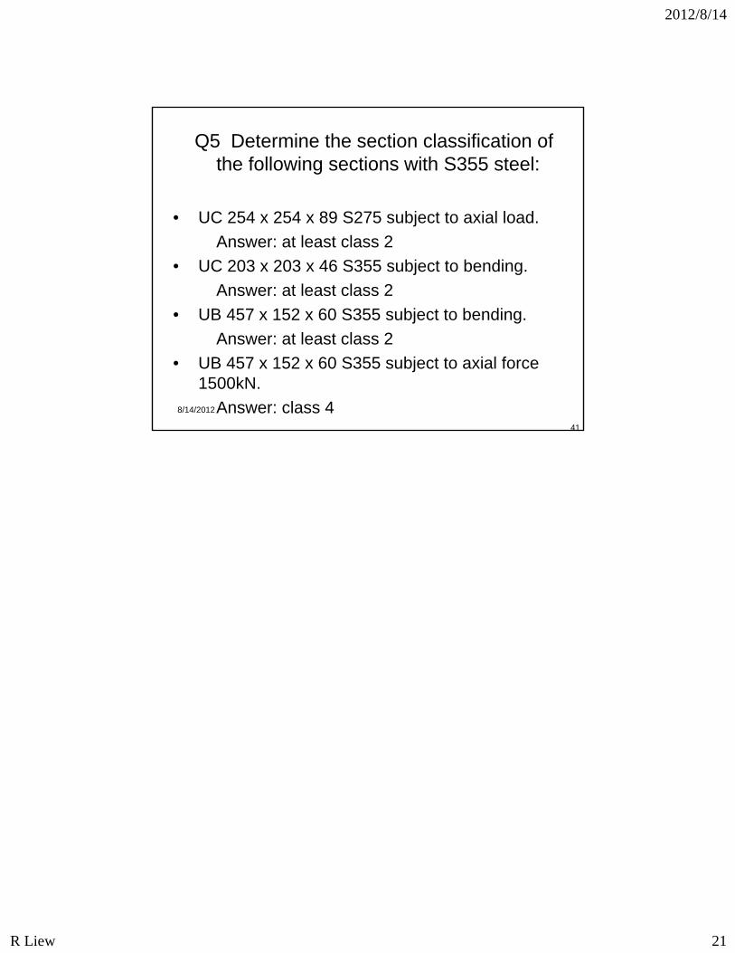
Q5 Determine the section classification of the following sections with S355 steel:
• UC 254 x 254 x 89 S275 subject to axial load.
Answer: at least class 2
• UC 203 x 203 x 46 S355 subject to bending.
Answer: at least class 2
• UB 457 x 152 x 60 S355 subject to bending.
Answer: at least class 2
• UB 457 x 152 x 60 S355 subject to axial force 1500kN.
Answer: class 4
Related Documents