2012 Stationary Industrial Exhaust Product Guide Product Specifications/Performance Engine Exhaust Silencers Silencer Accessories Technical Capabilities Part Number Index Nelson Global Products, Inc. is the industry leader in noise control and air filtration. Our products are integrated components of complete noise control solutions for industrial process, power generation, oil and gas, marine, and emissions industry applications. Original Equipment Manufacturers rely on Nelson Global Products for a wide selection of reliable, durable products that deliver first class performance.

Welcome message from author
This document is posted to help you gain knowledge. Please leave a comment to let me know what you think about it! Share it to your friends and learn new things together.
Transcript

2012 Stationary Industrial Exhaust Product Guide
Product Specifications/Performance
Engine Exhaust Silencers
Silencer Accessories
Technical Capabilities
Part Number Index
Nelson Global Products, Inc. is the industry leader in noise control and air filtration. Our products are integrated components of complete noise control solutions for industrial process, power generation, oil and gas, marine, and emissions industry applications. Original Equipment Manufacturers rely on Nelson Global Products for a wide selection of reliable, durable products that deliver first class performance.

Nelson Global Products, Inc. Warranty to the Original Equipment ManufacturerExhaust Products Limited WarrantyWarranty: This Warranty is provided to each original equipment manufacturer (OEM) with its purchase of any of the Nelson Global Products, Inc. products listed in the table below. Any Nelson Global Products, Inc. product determined by Nelson Global Products, Inc. to be defective in material or workmanship will, at Nelson Global Products, Inc. election, be replaced by another Nelson Global Products, Inc. product or by a credit for the original Nelson Global Products, Inc. selling price of the product. In the event that such a Nelson Global Products, Inc. product defect necessitates repair of the engine or components, Nelson Global Products, Inc. will reimburse the OEM reasonable costs to repair or replace, whichever is less, the damaged engine or components to a condition equivalent to that existing just prior to the failure.
Any claim under this Warranty for replacement or credit must be submitted in writing to Nelson Global Products, Inc. within thirty (30) days of discovering the claimed defect.
For the purpose of reviewing Warranty claim validity, Nelson Global Products, Inc. or its representatives will, at Nelson Global Products, Inc. discretion, have the right to:
a. Physically inspect the claimed defective product and/or equipment using the product.
b. Information available from purchaser or user relative to the actual application and/or use and maintenance of the product.
Duration: This Warranty extends from the in-service date of the Nelson Global Products, Inc. product installed by the original equipment manufacturer through the duration of the OEM’s base warranty, but will not exceed the coverage period stated in the table below.
Limitation: Nelson Global Products, Inc. is not responsible for product failures and/or repair costs resulting from misuse (e.g. not allowing the muffler to cool which causes an after fire event), faulty installation, alteration, misapplication, faulty maintenance practices (e.g. cleaning or servicing of spark arrestors), neglect, or accident; nor is Nelson Global Products, Inc. responsible for downtime, loss of income, living expenses, or other incidental or consequential damages. Unless otherwise agreed to in writing, this Warranty is the sole warranty made by Nelson Global Products, Inc. NELSON GLOBAL PRODUCTS, INC. MAKES NO OTHER WARRANTIES, EXPRESS OR IMPLIED, OF MERCHANTABILITY OR FITNESS FOR A PARTICULAR PURPOSE.
Exhaust Products Warranty Coverage Periods for Nelson Global Products, Inc.
Duration of Warranty period (whichever occurs first)
Application / Product YearsDistance
(miles/km)On-Highway
Heavy Duty (Class 8) 1 100,000 / 161,000
Medium Duty (Class thru 7) 1 100,000 / 161,000
Transit Bus 1 50,000 / 80,500
Coach bus 1 100,000 / 161,000
Off-highway 1 N/A
Product / Parts
Mufflers – O.E. / Std. Line 1 N/A
Tubes – Formed / Assemblies 1 N/A
Accessories - clamps, rain caps, heat-shields, adaptors, etc.
1 N/A
Pre-treatment exhaust assemblies * 1 N/A
Post-Treatment exhaust assemblies * 1 N/A
Chrome or aesthetic coated components 1 N/A
Flex pipe (interlocking/bellows design) None Sold “as is”
Retrofit kits 1 100,000 / 161,000
Catalytic Exhaust Mufflers – Gas/Diesel 1 100,000 / 161,000
* Note: Purchaser is responsible for all application, endurance and verification testing prior to production release.

Table of Contents
iii
Section 1: General Information ....................................... 1-1Introduction ................................................................ 1-3Determining the Exhaust Flow Rate ............................ 1-3Method 1 ................................................................... 1-4Method 2 ................................................................... 1-5What Else Should I Know? ......................................... 1-5Introduction ................................................................ 1-6
Section 2: Engine Exhaust Silencers .............................. 2-1Type 1 ............................................................................. 2-3
End In/Opposite End Out ........................................... 2-3Type 3 ............................................................................. 2-6
Side In/End Out .......................................................... 2-6Type 4 ............................................................................. 2-9
Middle Side In/End Out .............................................. 2-9Low Pressure Drop ....................................................... 2-10
Performance ............................................................ 2-10End In/Opposite End Out ......................................... 2-11
Space Saver ................................................................. 2-13Performance ............................................................ 2-13Slotted Connections ................................................. 2-14Flanged Connections ............................................... 2-15
Section 3: Silencer Accessories ...................................... 3-1Benefits ...................................................................... 3-3About the Blankets ..................................................... 3-3Specifications ............................................................. 3-3
Insulation Blankets .......................................................... 3-3Wye Assembly ........................................................... 3-5Reducing Flex Connectors ......................................... 3-5
Connectors ..................................................................... 3-5ANSI Flanged Connectors .......................................... 3-5Male NPT Connectors ................................................ 3-5
Covers and Caps ............................................................ 3-6Explosion Relief Cover ................................................ 3-6Rain Caps .................................................................. 3-6Inspection Openings .................................................. 3-7Slotted Pipe End Adapters ......................................... 3-7
Openings, Adapters and Gaskets ................................... 3-7Gasket Kit/Gasket ...................................................... 3-7

Table of Contents
iv
Clamps and Elbows ........................................................ 3-8Outlet Extensions ....................................................... 3-8Mounting Bracket Clamp – Style 1 ............................. 3-8Mounting Bracket Clamp – Style 2 ............................. 3-890° Outlet Elbows ...................................................... 3-8
Custom Weld-On Mounting Brackets .............................. 3-9Mounting Flanges ......................................................... 3-10
Mounting Flanges (Unthreaded) ................................ 3-10Mounting Flanges (Threaded) ................................... 3-10

Section 1: General Information

Table of ContentsSection 1: General Information
Selecting a Silencing Solution ..........................................................1-3Introduction ...............................................................................1-3Determining the Exhaust Flow Rate ...........................................1-3Method 1 ...................................................................................1-4Method 2 ...................................................................................1-5What Else Should I Know? .........................................................1-5
Product Specifications ....................................................................1-6Introduction ...............................................................................1-6
Product Performance ......................................................................1-7

nelsonglobalproducts.com 1-3
General Information
IntroductionSelecting a silencing solution for your application is simple. There are two methods used to make the selection:
• Use Method 1 when the pressure drop requirement is greater than 1.0 inches Hg (approximately 13.62 inches H2O).
• Use Method 2 when the Pressure Drop requirement is less than 1.0 inches Hg (approximately 13.62 inches H2O).
Determining the Exhaust Flow RateRegardless of the method you choose, you will need to know the Exhaust Flow Rate. If this value is not known, use the following equation to estimate the Exhaust Flow Rate, then proceed with Method 1 or 2 to select a silencing solution.
D × Full Load RPM × E × (T + 460°) C x 941,760where:
D = Displacement in in3
E = 0.85 efficiency for naturally aspirated engines = 1.2 for engines with scavenging blower = 1.4 for turbo-charged engines
T = Exhaust temperature (if unknown, use 900 °F (482 °C) for diesel and 1,200 °F (649 °C) for gas engines)
C = 1.0 (one-cycle engine) or 2.0 (two-cycle engine)
Estimated Exhaust Flow Rate =
Selecting a Silencing Solution
nelsonglobalproducts.com1-4
General Information
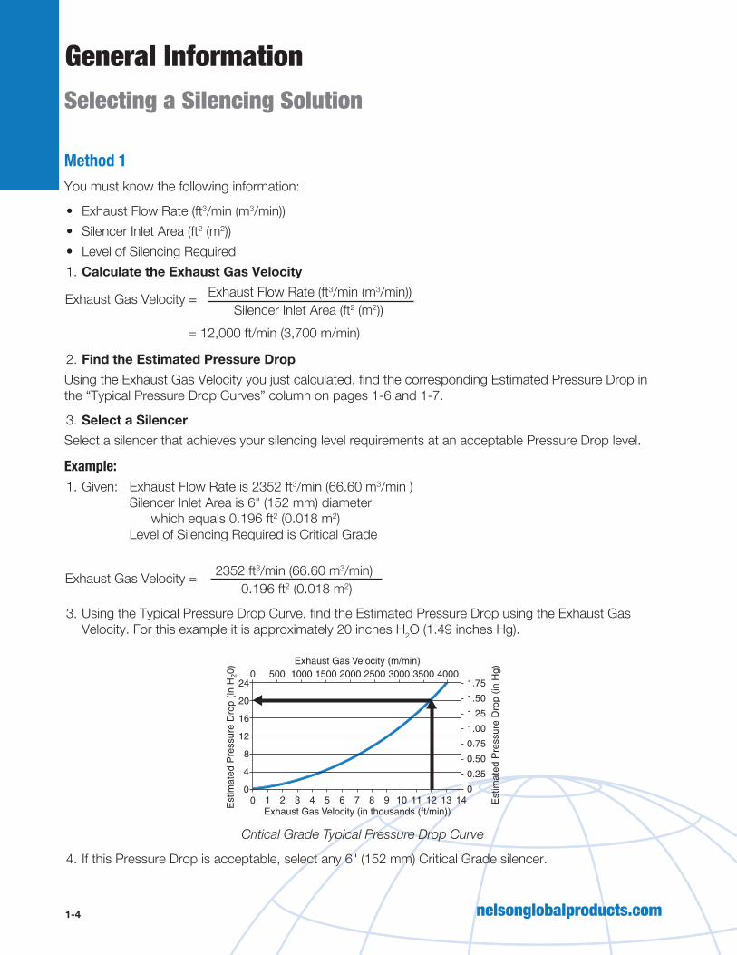
Method 1You must know the following information:
• Exhaust Flow Rate (ft3/min (m3/min))• Silencer Inlet Area (ft2 (m2))• Level of Silencing Required1. Calculate the Exhaust Gas Velocity Exhaust Flow Rate (ft3/min (m3/min)) Silencer Inlet Area (ft2 (m2))
2. Find the Estimated Pressure DropUsing the Exhaust Gas Velocity you just calculated, find the corresponding Estimated Pressure Drop in the “Typical Pressure Drop Curves” column on pages 1-6 and 1-7.
3. Select a SilencerSelect a silencer that achieves your silencing level requirements at an acceptable Pressure Drop level.
Example:1. Given: Exhaust Flow Rate is 2352 ft3/min (66.60 m3/min )
Silencer Inlet Area is 6" (152 mm) diameter which equals 0.196 ft2 (0.018 m2) Level of Silencing Required is Critical Grade
2352 ft3/min (66.60 m3/min) 0.196 ft2 (0.018 m2)
3. Using the Typical Pressure Drop Curve, find the Estimated Pressure Drop using the Exhaust Gas Velocity. For this example it is approximately 20 inches H2O (1.49 inches Hg).
0 1
0 500 1000 1500 2000 2500 3000 3500 4000
2 3 4 5 6 7 8 9 10 11 12 13 14Exhaust Gas Velocity (in thousands (ft/min))
Exhaust Gas Velocity (m/min)
Est
imat
ed P
ress
ure
Dro
p (in
H20
)
Est
imat
ed P
ress
ure
Dro
p (in
Hg)
24
4 0.25
0
0.50
0.75
1.00
1.25
1.50
1.75
0
8
12
16
20
Critical Grade Typical Pressure Drop Curve
4. If this Pressure Drop is acceptable, select any 6" (152 mm) Critical Grade silencer.
Exhaust Gas Velocity =
Exhaust Gas Velocity =
= 12,000 ft/min (3,700 m/min)
Selecting a Silencing Solution

nelsonglobalproducts.com 1-5
General Information
Method 2Using the Exhaust Flow Rate, select the correct silencing solution from the Quick Selection Table shown below. Find the lowest flow rate greater than or equal to the engine flow rate at the required silencing level.
Inlet Pipe Areaft2 (m2)
Pipe Dimensionsin (mm)
Silencing Level dB
Industrial Silencer Residential Silencer Critical Silencer Hospital Silencer0.0031 (0.0003) 0.75 (19.1) 41 35 29 —
0.0055 (0.0005) 1.0 (25.4) 73 63 52 —
0.0085 (0.0007) 1.25 (31.8) 113 98 80 —
0.0123 (0.0011) 1.5 (38.1) 163 142 117 —
0.0218 (0.0020) 2.0 (50.8) 288 250 206 —
0.0341 (0 0032) 2.5 (63.5) 450 380 325 —
0.0491 (0.0046) 3.0 (76.2) 650 565 470 —
0.0668 (0.0062) 3.5 (88.9) 880 770 640 —
0.0873 (0.0081) 4.0 (101.6) 1,160 1,000 830 790
0.1363 (0.0127) 5.0 (127.0) 1,810 1,580 1,290 1,290
0.1963 (0.0182) 6.0 (152.4) 2,600 2,250 1,870 1,770
0.3491 (0.0324) 8.0 (203.2) 4,600 3,900 3,340 3,150
0.5454 (0.0507) 10.0 (254.0) 7,200 6,200 5,200 4,950
0.7854 (0.0730) 12.0 (304.8) 10,200 8,800 7,500 7,100
1.069 (0.0996) 14.0 (355.6) 14,000 12,000 10,200 9,700
1.438 (0.1336) 16.0 (406.4) 18,000 15,500 13,700 13,000
1.760 (0.1635) 18.0 (457.2) 23,000 19,800 16,800 16,000
2.180 (0.0617) 20.0 (508.0) 28,400 24,300 20,900 19,700
2.640 (0.7476) 22.0 (558.8) 34,400 29,500 25,300 24,000Note: Exhaust flow rates are based on end-in end-out silencers. Refer to product specification sheets when determining side-in or middle side-in back pressure.
Velocity should not exceed 15,000 ft/min (4572 m/min) regardless of the allowable back pressure (10,000 ft/min (3048 m/min) for spark arresting silencers).
What Else Should I Know?Nelson Global Products exhaust silencers provide optimum performance for all applications by offering silencers crafted for four different attenuation grades. Due to the variability of different applications, performance levels are most accurately shown as broad range “expected attenuation bands,” which are based upon typical conditions. These bands will not define the exact insertion loss for a specific application, since insertion loss is influenced by engine size, type, speed, and unsilenced noise levels (see product spec sheets for attenuation, back pressure, and design details).
Note: Keep in mind that silencers are not designed to support their weight from the inlet or outlet tube, or support other components of the exhaust system, such as stacks. For the most efficient operation of all silencing units, proper mounting attachments are required.
Selecting a Silencing Solution

nelsonglobalproducts.com1-6
General Information
IntroductionDrains are standard on all models with a 9" (229 mm) O.D. or larger. Models with a 26" (660 mm) O.D. or smaller have a coat of high heat-resistant paint. Models larger than 26" (660 mm) O.D. have a rust-inhibiting primer under high heat-resistant paint. Maximum operating temperature is 1,250°F (677 °C) for aluminized units. Heat-resistant paint maintains its properties up to 900°F (482 °C) on aluminized steel and 1,100°F (593 °C) on mild steel.
Industrial Silencer
Residential Silencer
Critical Silencer
Hospital Silencer
LPD-1 Silencer
LPD-2 Silencer
Space Saver Silencer
Appl
icat
ion
Attenuation Level 12-18 dB 18-25 dB 25-35 dB 35-42 dB 28 dB 34 dB 25 dB
Silencing Required
Minimum Moderate Maximum Maximum ModerateModerate to Maximum
Moderate to Maximum
Ambient NoiseMedium to
HighLow to
MediumLow Low
Medium to High
Low to Medium
Low to Medium
Fitti
ng
Flanged • • • • • • •
Pipe Threads • • • •
Slotted Pipe End •
Companion Flanges Offered
4-22" (102-559 mm)
4-22" (102-559 mm)
4-22" (102-559 mm)
4-14" (102-356 mm)
4-22" (102-559 mm)
4-22" (102-559 mm)
4-22" (102-559 mm)
Cons
truct
ion
Double-Wrapped Body
• • •
Type 1 End-In, End-Out
• • • • • •
Type 2 Side-In, Side-Out
• • • • • •
Type 3 Side-In, End-Out
• • • •
Type 4 Middle Side-In,
End-Out• • • •
Up to 26" (660 mm) O.D.
Aluminized Steel*
Aluminized Steel*
Aluminized Steel*
Aluminized Steel*
Aluminized Steel*
Aluminized Steel*
Aluminized Steel*
26" (660 mm) to 36" (914 mm) O.D.
Aluminized/ Mild Steel*
Aluminized/ Mild Steel*
Aluminized/ Mild Steel*
Aluminized/ Mild Steel*
Aluminized/ Mild Steel*
Aluminized/ Mild Steel*
Aluminized/ Mild Steel*
Greater than 36" (914 mm) O.D.
Mild Steel* Mild Steel*Aluminized/ Mild Steel*
Aluminized/ Mild Steel*
Mild Steel* Mild Steel*Aluminized/ Mild Steel*
* Also available in stainless steel, which provides exceptional resistance to corrosion and has a maximum operating temperature of 1,500 °F (816 °C).
“A” Mounting FlangeStandard in sizes 4"-22"
(102-559 mm). Drilling matches 125/150# standard.
“B” Male Pipe ThreadsNPT ends offered in sizes 4" (102 mm) and smaller.
“S” Slotted Pipe EndSlotted Ends offered in
sizes 2-6" (51-152 mm).
Product Specifications

nelsonglobalproducts.com 1-7
General Information
Typical Attenuation Curves Typical Pressure Drop Curves
31.5 63 125 250 500 1000 2000 4000 8000
Octave Band Center Frequency, Hz
Inse
rtio
n Lo
ss, d
B
40
51015
0
20253035
Industrial Grade (12-18 dB Attenuation)
31.5 63 125 250 500 1000 2000 4000 8000
Octave Band Center Frequency, Hz
Inse
rtio
n Lo
ss, d
B
40
51015
0
20253035
Residential Grade (18-25 dB Attenuation)
0 1
0 500 1000 1500 2000 2500 3000 3500 4000
2 3 4 5 6 7 8 9 10 11 12 13 14Exhaust Gas Velocity (in thousands (ft/min))
Exhaust Gas Velocity (m/min)
Est
imat
ed P
ress
ure
Dro
p (in
H20
)
Est
imat
ed P
ress
ure
Dro
p (in
Hg)
24
4 0.25
0
0.50
0.75
1.00
1.25
1.50
1.75
0
8
12
16
20
0 1
0 500 1000 1500 2000 2500 3000 3500 4000
2 3 4 5 6 7 8 9 10 11 12 13 14Exhaust Gas Velocity (in thousands (ft/min))
Exhaust Gas Velocity (m/min)
Est
imat
ed P
ress
ure
Dro
p (in
H20
)
Est
imat
ed P
ress
ure
Dro
p (in
Hg)
24
4 0.25
0
0.50
0.75
1.00
1.25
1.50
1.75
0
8
12
16
20
Product Performance
Note: When figuring Pressure Drop for side or middle side inlet units, add 3 inches H2O (0.22 inches Hg) to back pressure shown on curve.

nelsonglobalproducts.com1-8
General InformationProduct Performance
31.5 63 125 250 500
Octave Band Center Frequency, Hz
Inse
rtio
n Lo
ss, d
B
1000 2000 4000 8000
40
51015
0
20253035
Critical Grade (25-35 dB Attenuation)
31.5 63 125 250 500 1000 2000 4000 8000
Octave Band Center Frequency, Hz
Inse
rtio
n Lo
ss, d
B
4045
51015
0
20253035
Hospital Grade (35-42 dB Attenuation)
0 1
0 500 1000 1500 2000 2500 3000 3500 4000
2 3 4 5 6 7 8 9 10 11 12 13 14Exhaust Gas Velocity (in thousands (ft/min))
Exhaust Gas Velocity (m/min)
Est
imat
ed P
ress
ure
Dro
p (in
H20
)
Est
imat
ed P
ress
ure
Dro
p (in
Hg)
24
4 0.25
0
0.50
0.75
1.00
1.25
1.50
1.75
0
8
12
16
20
0 1
0 500 1000 1500 2000
2 3 4 5 6 7 8 9 10 11 12 13 14Exhaust Gas Velocity (in thousands (ft/min))
Exhaust Gas Velocity (m/min)
Est
imat
ed P
ress
ure
Dro
p (in
H20
)
Est
imat
ed P
ress
ure
Dro
p (in
Hg)
24
4 0.25
0
0.50
0.75
1.00
1.25
1.50
1.75
0
8
12
16
20
2500 3000 3500 4000
Note: When figuring Pressure Drop for side or middle side inlet units, add 3 inches H2O (0.22 inches Hg) to back pressure shown on curve.
Typical Attenuation Curves Typical Pressure Drop Curves

Section 2: Engine Exhaust Silencers

Table of ContentsSection 2: Engine Exhaust Silencers
Type 1 .............................................................................................2-3End In/Opposite End Out ...........................................................2-3
Type 3 .............................................................................................2-6Side In/End Out .........................................................................2-6
Type 4 .............................................................................................2-9Middle Side In/End Out ..............................................................2-9
Low Pressure Drop .......................................................................2-10Performance ............................................................................2-10End In/Opposite End Out .........................................................2-11
Space Saver .................................................................................2-13Performance ............................................................................2-13Slotted Connections ................................................................2-14Flanged Connections ...............................................................2-15

nelsonglobalproducts.com 2-3
Engine Exhaust Silencers
Type
A Nominal
InletDiameterin (mm)
B Outside
BodyDiameterin (mm)
C
BodyLengthin (mm)
D
Overall Lengthin (mm)
E
InletOffset
in (mm)
F
OutletOffset
in (mm)
G
InletLengthin (mm)
PartNumber
Indu
stria
l Gra
de 1
2-18
dB
Atte
nuat
ion
2.00 (50.80) 7.6 (193.0) 22.8 (579.1) 26.6 (675.6) — — 1.8 (45.72) 41120P
2.50 (63.50) 8.1 (205.7) 27.2 (690.9) 32.6 (828.0) — — 2.7 (68.58) 41125P
3.00 (76.20) 8.5 (215.9) 31.1 (789.9) 36.6 (929.6) — — 2.7 (68.58) 41130P
3.50 (88.90) 9.0 (228.6) 32.8 (833.1) 37.6 (955.0) — — 2.4 (60.96) 41135P
4.00 (101.60) 10.1 (256.5) 32.2 (817.9) 38.0 (965.2) 2.30 (58.42) 2.30 (58.42) 2.9 (73.66) 41140*
5.00 (127.00) 12.1 (307.3) 32.3 (820.4) 37.9 (962.7) 2.80 (71.12) 2.80 (71.12) 2.8 (71.12) 41150F
6.00 (152.40) 14.1 (358.1) 32.9 (835.7) 38.4 (975.4) 3.40 (86.36) 3.40 (86.36) 2.8 (71.12) 41160F
8.00 (203.20) 18.1 (459.7) 48.8 (1239.5) 58.0 (1473.2) — — 4.6 (116.84) 41180F
10.00 (254.00) 22.1 (561.3) 50.6 (1285.2) 58.0 (1473.2) — — 3.7 (93.98) 41182F
12.00 (304.80) 22.2 (563.9) 65.6 (1666.2) 73.0 (1854.2) — — 3.7 (93.98) 41184F
14.00 (355.60) 36.2 (919.5) 70.6 (1793.2) 76.0 (1930.4) — — 2.7 (68.58) 41186F
16.00 (406.40) 42.2 (1071.9) 84.2 (2138.7) 90.8 (2306.3) — — 3.3 (83.82) 41188F
18.00 (457.20) 42.2 (1071.9) 96.2 (2443.5) 103.0 (2616.2) — — 3.4 (86.36) 41199F
20.00 (508.00) 48.3 (1226.8) 98.4 (2499.4) 104.0 (2641.6) — — 2.8 (71.12) 41121F
22.00 (558.80) 54.3 (1379.2) 99.6 (2529.8) 107.3 (2725.4) — — 3.9 (99.06) 41122F
DC
B
G
EFA
A
Type 1End In/Opposite End Out
* Specify “F” for flanged or “P” for pipe threads.Drains are standard on all silencers with a 9" (225 mm) body diameter or larger.Specifications subject to change without notice.

nelsonglobalproducts.com
Engine Exhaust Silencers
2-4
Type
A Nominal
InletDiameterin (mm)
B Outside
BodyDiameterin (mm)
C
BodyLengthin (mm)
D
Overall Lengthin (mm)
E
InletOffset
in (mm)
F
OutletOffset
in (mm)
G
InletLengthin (mm)
PartNumber
Resi
dent
ial G
rade
18-2
5 dB
Atte
nuat
ion
2.00 (50.80) 8.1 (205.7) 31.7 (805.2) 35.6 (904.2) 1.25 (31.75) 1.25 (31.75) 1.9 (48.26) 41220P
2.50 (63.50) 9.0 (228.6) 38.8 (985.5) 42.8 (1087.1) 1.50 (38.10) 1.50 (38.10) 2.0 (50.80) 41225P
3.00 (76.20) 10.1 (256.5) 38.2 (970.3) 44.0 (1117.6) 2.75 (69.85) 2.75 (69.85) 2.9 (73.66) 41230P
3.50 (88.90) 10.1 (256.5) 44.2 (1122.7) 50.0 (1270.0) 2.06 (52.32) 2.06 (52.32) 2.9 (73.66) 41235P
4.00 (101.60) 10.1 (256.5) 49.2 (1249.7) 55.0 (1397.0) 2.31 (58.67) 2.31 (58.67) 2.9 (73.66) 41240*
5.00 (127.00) 14.1 (358.1) 43.5 (1104.9) 51.4 (1305.6) 3.61 (91.69) 3.61 (91.69) 4.0 (101.60) 41250F
6.00 (152.40) 14.1 (358.1) 57.5 (1460.5) 65.4 (1661.2) 3.60 (91.44) 3.60 (91.44) 4.0 (101.60) 41260F
8.00 (203.20) 22.2 (563.9) 56.6 (1437.6) 64.0 (1625.6) — — 3.7 (93.98) 41280F
10.00 (254.00) 22.2 (563.9) 84.7 (2151.4) 92.0 (2336.8) — — 3.7 (93.98) 41282F
12.00 (304.80) 26.2 (665.5) 79.7 (2024.4) 87.0 (2209.8) — — 3.7 (93.98) 41284F
14.00 (355.60) 36.2 (919.5) 94.6 (2402.8) 101.0 (2565.4) — — 3.2 (81.28) 41286F
16.00 (406.40) 42.2 (1071.9) 108.2 (2748.3) 115.0 (2921.0) — — 3.4 (86.36) 41288F
18.00 (457.20) 42.3 (1074.4) 108.2 (2748.3) 114.9 (2918.5) — — 3.3 (83.82) 41299F
20.00 (508.00) 48.3 (1226.8) 134.1 (3406.1) 140.1 (3558.5) — — 3.0 (76.20) 41221F
22.00 (558.80) 54.3 (1379.2) 135.5 (3441.7) 143.2 (3637.3) — — 3.9 (99.06) 41222F
DC
B
G
EFA
A
Type 1End In/Opposite End Out
* Specify “F” for flanged or “P” for pipe threads.Drains are standard on all silencers with a 9" (225 mm) body diameter or larger.Specifications subject to change without notice.

nelsonglobalproducts.com 2-5
Engine Exhaust Silencers
Type
A Nominal
InletDiameterin (mm)
B Outside
BodyDiameterin (mm)
C
BodyLengthin (mm)
D
Overall Lengthin (mm)
E
InletOffset
in (mm)
F
OutletOffset
in (mm)
G
InletLengthin (mm)
PartNumber
Criti
cal G
rade
25-3
5 dB
Atte
nuat
ion
0.75 (19.05) 4.2 (106.7) 21.3 (541.0) 23.8 (604.5) — — 1.3 (33.02) 41307P
1.00 (25.40) 5.0 (127.0) 23.4 (594.4) 27.0 (685.8) 0.75 (19.05) 0.72 (18.29) 1.8 (45.72) 41310P
1.25 (31.75) 6.1 (154.9) 27.5 (698.5) 31.2 (792.5) — — 1.8 (45.72) 41313P
1.50 (38.10) 8.1 (205.7) 30.7 (779.8) 34.6 (878.8) — — 1.9 (48.26) 41315P
2.00 (50.80) 9.0 (228.6) 40.8 (1036.3) 44.0 (1117.6) — — 1.6 (40.64) 41320P
2.50 (63.50) 10.1 (256.5) 47.2 (1198.9) 52.0 (1320.8) — — 2.4 (60.96) 41325P
3.00 (76.20) 11.1 (281.9) 49.5 (1257.3) 55.6 (1412.2) — — 3.1 (78.74) 41330P
3.50 (88.90) 12.1 (307.3) 51.3 (1303.0) 57.0 (1447.8) — — 2.3 (58.42) 41335P
4.00 (101.60) 12.1 (307.3) 58.3 (1480.8) 64.0 (1625.6) 1.80 (45.72) 1.80 (45.72) 2.9 (73.66) 41340*
5.00 (127.00) 14.1 (358.1) 63.5 (1612.9) 71.4 (1813.6) 2.60 (66.04) 2.60 (66.04) 4.0 (101.60) 41350F
6.00 (152.40) 16.1 (408.9) 72.0 (1828.8) 80.8 (2052.3) 2.00 (50.80) 2.00 (50.80) 4.4 (111.76) 41360F
8.00 (203.20) 22.1 (561.3) 78.7 (1999.0) 86.0 (2184.4) — — 3.7 (93.98) 41380F
10.00 (254.00) 26.2 (665.5) 79.7 (2024.4) 87.0 (2209.8) — — 3.7 (93.98) 41382F
12.00 (304.80) 30.2 (767.1) 104.8 (2661.9) 112.0 (2844.8) — — 3.6 (91.44) 41384F
14.00 (355.60) 42.2 (1071.9) 108.2 (2748.3) 115.0 (2921.0) — — 3.4 (86.36) 41386F
16.00 (406.40) 42.2 (1071.9) 156.2 (3967.5) 163.0 (4140.2) — — 3.4 (86.36) 41388F
18.00 (457.20) 48.2 (1224.3) 133.9 (3401.1) 139.9 (3553.5) — — 3.1 (78.74) 41399F
20.00 (508.00) 54.3 (1379.2) 159.6 (4053.8) 165.5 (4203.7) — — 3.3 (83.82) 41321F
22.00 (558.80) 60.3 (1531.6) 161.3 (4097.0) 166.8 (4236.7) — — 2.8 (71.12) 41322F
Hosp
ital G
rade
35-
42 d
B At
tenu
atio
n 4.00 (101.60) 14.1 (358.1) 66.5 (1689.1) 72.0 (1828.8) 4.00 (101.60) 4.00 (101.60) 2.8 (71.12) 41440F
5.00 (127.00) 16.1 (408.9) 72.4 (1839.0) 80.0 (2032.0) 4.70 (119.38) 4.70 (119.38) 3.8 (96.52) 41450F
6.00 (152.40) 18.1 (459.7) 82.7 (2100.6) 90.0 (2286.0) 5.00 (127.00) 5.00 (127.00) 3.7 (93.98) 41460F
8.00 (203.20) 26.1 (662.9) 91.7 (2329.2) 98.9 (2512.1) — — 3.6 (91.44) 41480F
10.00 (254.00) 30.2 (767.1) 104.8 (2661.9) 112.0 (2844.8) — — 3.4 (86.36) 41482F
12.00 (304.80) 36.2 (919.5) 130.6 (3317.2) 137.0 (3479.8) — — 3.2 (81.28) 41484F
14.00 (355.60) 42.2 (1071.9) 132.2 (3357.9) 138.9 (3528.1) — — 3.4 (86.36) 41486F
DC
B
G
EFA
A
* Specify “F” for flanged or “P” for pipe threads.Drains are standard on all silencers with a 9" (225 mm) body diameter or larger.Specifications subject to change without notice.
Type 1End In/Opposite End Out

nelsonglobalproducts.com
Engine Exhaust Silencers
2-6
Type 3Side In/End Out
�
�
�
�
�
DC
B
GE
FH
A
A
Type
A Nominal
InletDiameterin (mm)
B Outside
BodyDiameterin (mm)
C
BodyLengthin (mm)
D
Overall Lengthin (mm)
E
InletOffset
in (mm)
F
OutletOffset
in (mm)
G
InletLengthin (mm)
H
OutletLengthin (mm)
PartNumber
Indu
stria
l Gra
de12
-18
dB A
ttenu
atio
n
2.0 (50.8) 7.6 (193.0) 22.4 (569.0) 24.5 (622.3) 3.2 (81.3) — 2.0 (50.8) 2.1 (53.3) 43120P
2.5 (63.5) 8.1 (205.7) 27.7 (703.6) 30.2 (767.1) 3.9 (99.1) — 2.5 (63.5) 2.4 (61.0) 43125P
3.0 (76.2) 8.5 (215.9) 30.6 (777.2) 33.6 (853.4) 3.8 (96.5) — 3.0 (76.2) 2.3 (58.4) 43130P
3.5 (88.9) 9.0 (228.6) 32.8 (833.1) 35.4 (899.2) 4.9 (124.5) — 3.0 (76.2) 2.6 (66.0) 43135P
4.0 (101.6) 9.0 (228.6) 32.8 (833.1) 35.4 (899.2) 5.4 (137.2) — 3.0 (76.2) 2.6 (66.0) 43140*
5.0 (127.0) 12.1 (307.3) 30.4 (772.2) 34.2 (868.7) 5.7 (144.8) — 4.0 (101.6) 3.8 (96.5) 43150F
6.0 (152.4) 14.1 (358.1) 30.6 (777.2) 34.5 (876.3) 6.8 (172.7) — 4.0 (101.6) 3.9 (99.1) 43160F
8.0 (203.2) 18.1 (459.7) 48.4 (1229.4) 53.2 (1351.3) 9.2 (233.7) — 4.0 (101.6) 4.8 (121.9) 43180F
10.0 (254.0) 22.2 (563.9) 50.6 (1285.2) 54.3 (1379.2) 12.3 (312.4) — 4.0 (101.6) 3.7 (94.0) 43182F
12.0 (304.8) 22.2 (563.9) 65.6 (1666.2) 69.3 (1760.2) 14.3 (363.2) — 4.0 (101.6) 3.7 (94.0) 43184F
14.0 (355.6) 36.2 (919.5) 70.6 (1793.2) 73.8 (1874.5) 15.3 (388.6) — 4.0 (101.6) 3.2 (81.3) 43186F
16.0 (406.4) 42.2 (1071.9) 84.2 (2138.7) 87.5 (2222.5) 18.1 (459.7) — 4.0 (101.6) 3.3 (83.8) 43188F
18.0 (457.2) 42.3 (1074.4) 96.2 (2443.5) 99.6 (2529.8) 19.0 (482.6) — 4.0 (101.6) 3.3 (83.8) 43199F
20.0 (508.0) 48.3 (1226.8) 97.9 (2486.7) 101.2 (2570.5) 20.0 (508.0) — 4.0 (101.6) 3.3 (83.8) 43121F
22.0 (558.8) 54.3 (1379.2) 99.6 (2529.8) 103.5 (2628.9) 21.8 (553.7) — 4.0 (101.6) 3.9 (99.1) 43122F
* Specify “F” for flanged or “P” for pipe threads.Drains are standard on all silencers with a 9" (225 mm) body diameter or larger.Specifications subject to change without notice.

nelsonglobalproducts.com 2-7
Engine Exhaust Silencers
Type
A Nominal
InletDiameterin (mm)
B Outside
BodyDiameterin (mm)
C
BodyLengthin (mm)
D
Overall Lengthin (mm)
E
InletOffset
in (mm)
F
OutletOffset
in (mm)
G
InletLengthin (mm)
H
OutletLengthin (mm)
PartNumber
Resi
dent
ial G
rade
18-2
5 dB
Atte
nuat
ion
2.0 (50.8) 8.1 (205.7) 31.7 (805.2) 32.8 (833.1) 3.4 (86.4) — 2.0 (50.8) 1.9 (48.3) 43220P
2.5 (63.5) 9.0 (228.6) 38.8 (985.5) 40.8 (1036.3) 4.4 (111.8) 1.5 (38.1) 2.5 (63.5) 2.0 (50.8) 43225P
3.0 (76.2) 10.1 (256.5) 38.2 (970.3) 41.1 (1043.9) 4.1 (104.1) 1.8 (45.7) 3.0 (76.2) 2.9 (73.7) 43230P
3.5 (88.9) 10.1 (256.5) 44.2 (1122.7) 47.1 (1196.3) 4.6 (116.8) 2.1 (53.3) 3.0 (76.2) 2.9 (73.7) 43235P
4.0 (101.6) 10.1 (256.5) 49.2 (1249.7) 51.0 (1295.4) 5.1 (129.5) — 3.0 (76.2) 2.9 (73.7) 43240*
5.0 (127.0) 14.1 (358.1) 43.5 (1104.9) 45.7 (1160.8) 5.8 (147.3) 2.6 (66.0) 4.0 (101.6) 3.9 (99.1) 43250F
6.0 (152.4) 14.1 (358.1) 57.6 (1463.0) 61.5 (1562.1) 6.8 (172.7) 3.1 (78.7) 4.0 (101.6) 3.9 (99.1) 43260F
8.0 (203.2) 22.2 (563.9) 56.6 (1437.6) 60.3 (1531.6) 11.3 (287.0) — 4.0 (101.6) 3.7 (94.0) 43280F
10.0 (254.0) 22.2 (563.9) 84.7 (2151.4) 88.3 (2242.8) 11.3 (287.0) — 4.0 (101.6) 3.6 (91.4) 43282F
12.0 (304.8) 26.2 (665.5) 79.8 (2026.9) 83.4 (2118.4) 12.9 (327.7) — 4.0 (101.6) 3.6 (91.4) 43284F
14.0 (355.6) 36.2 (919.5) 94.7 (2405.4) 97.9 (2486.7) 15.3 (388.6) — 4.0 (101.6) 3.2 (81.3) 43286F
16.0 (406.4) 42.1 (1069.3) 108.2 (2748.3)111.6 (2834.6) 16.1 (408.9) — 4.0 (101.6) 3.4 (86.4) 43288F
18.0 (457.2) 42.2 (1071.9) 108.2 (2748.3)111.5 (2832.1) 19.1 (485.1) — 4.0 (101.6) 3.3 (83.8) 43299F
20.0 (508.0) 48.3 (1226.8) 134.1 (3406.1)137.1 (3482.3) 19.8 (502.9) — 4.0 (101.6) 3.0 (76.2) 43221F
22.0 (558.8) 54.3 (1379.2) 135.6 (3444.2)139.4 (3540.8) 21.8 (553.7) — 4.0 (101.6) 3.8 (96.5) 43222F
�
�
�
�
�
DC
B
GE
FH
A
A
Type 3Side In/End Out
* Specify “F” for flanged or “P” for pipe threads.Drains are standard on all silencers with a 9" (225 mm) body diameter or larger.Specifications subject to change without notice.

nelsonglobalproducts.com
Engine Exhaust Silencers
2-8
�
�
�
�
�
DC
B
GE
FH
A
A
Type 3Side In/End Out
Type
A Nominal
InletDiameterin (mm)
B Outside
BodyDiameterin (mm)
C
BodyLengthin (mm)
D
Overall Lengthin (mm)
E
InletOffset
in (mm)
F
OutletOffset
in (mm)
G
InletLengthin (mm)
H
OutletLengthin (mm)
PartNumber
Criti
cal G
rade
25-3
5 dB
Atte
nuat
ion
2.0 (50.8) 9.0 (228.6) 40.8 (1036.3) 42.4 (1077.0) 3.9 (99.1) — 2.0 (50.8) 1.6 (40.6) 43320P
2.5 (63.5) 10.1 (256.5) 46.6 (1183.6) 49.3 (1252.2) 3.8 (96.5) — 2.5 (63.5) 2.7 (68.6) 43325P
3.0 (76.2) 11.1 (281.9) 50.0 (1270.0) 52.8 (1341.1) 4.5 (114.3) — 3.0 (76.2) 2.8 (71.1) 43330P
3.5 (88.9) 12.1 (307.3) 51.4 (1305.6) 54.2 (1376.7) 5.2 (132.1) — 4.0 (101.6) 2.8 (71.1) 43335P
4.0 (101.6) 12.1 (307.3) 58.4 (1483.4) 61.2 (1554.5) 5.7 (144.8) 1.8 (45.7) 4.0 (101.6) 2.8 (71.1) 43340*
5.0 (127.0) 14.1 (358.1) 63.5 (1612.9) 67.4 (1712.0) 5.8 (147.3) 2.6 (66.0) 4.0 (101.6) 3.9 (99.1) 43350F
6.0 (152.4) 16.1 (408.9) 72.0 (1828.8) 76.4 (1940.6) 6.5 (165.1) 3.1 (78.7) 4.0 (101.6) 4.4 (111.8) 43360F
8.0 (203.2) 22.1 (561.3) 78.7 (1999.0) 82.3 (2090.4) 11.3 (287.0) — 4.0 (101.6) 3.6 (91.4) 43380F
10.0 (254.0) 26.2 (665.5) 79.9 (2029.5) 83.4 (2118.4) 12.9 (327.7) — 4.0 (101.6) 3.5 (88.9) 43382F
12.0 (304.8) 30.2 (767.1) 104.8 (2661.9)108.4 (2753.4) 14.4 (365.8) — 4.0 (101.6) 3.6 (91.4) 43384F
14.0 (355.6) 42.2 (1071.9) 108.2 (2748.3)111.6 (2834.6) 16.1 (408.9) — 4.0 (101.6) 3.4 (86.4) 43386F
16.0 (406.4) 42.2 (1071.9) 156.2 (3967.5)159.6 (4053.8) 16.1 (408.9) — 4.0 (101.6) 3.4 (86.4) 43388F
18.0 (457.2) 48.2 (1224.3) 134.0 (3403.6)137.0 (3479.8) 19.9 (505.5) — 4.0 (101.6) 3.0 (76.2) 43399F
20.0 (508.0) 54.3 (1379.2) 159.7 (4056.4)162.9 (4137.7) 22.1 (561.3) — 4.0 (101.6) 3.2 (81.3) 43321F
22.0 (558.8) 60.3 (1531.6) 161.3 (4097.0)164.1 (4168.1) 22.6 (574.0) — 4.0 (101.6) 2.8 (71.1) 43322F
Hosp
ital G
rade
35-
42 d
B At
tenu
atio
n 4.0 (101.6) 14.1 (358.1) 66.6 (1691.6) 69.3 (1760.2) 5.8 (147.3) 4.0 (101.6) 3.0 (76.2) 2.7 (68.6) 43440F
5.0 (127.0) 16.1 (408.9) 72.4 (1839.0) 77.0 (1955.8) 6.0 (152.4) 4.7 (119.4) 4.0 (101.6) 3.8 (96.5) 43450F
6.0 (152.4) 18.1 (459.7) 82.6 (2098.0) 86.3 (2192.0) 6.8 (172.7) 5.0 (127.0) 4.0 (101.6) 3.7 (94.0) 43460F
8.0 (203.2) 26.2 (665.5) 91.8 (2331.7) 95.5 (2425.7) 10.9 (276.9) — 4.0 (101.6) 3.7 (94.0) 43480F
10.0 (254.0) 30.2 (767.1) 104.8 (2661.9)108.4 (2753.4) 12.4 (315.0) — 4.0 (101.6) 3.6 (91.4) 43482F
12.0 (304.8) 36.2 (919.5) 130.6 (3317.2)133.8 (3398.5) 14.3 (363.2) — 4.0 (101.6) 3.2 (81.3) 43484F
14.0 (355.6) 42.2 (1071.9) 132.2 (3357.9)135.6 (3444.2) 16.1 (408.9) — 4.0 (101.6) 3.4 (86.4) 43486F
* Specify “F” for flanged or “P” for pipe threads.Drains are standard on all silencers with a 9" (225 mm) body diameter or larger.Specifications subject to change without notice.

nelsonglobalproducts.com 2-9
Engine Exhaust Silencers
Type
A Nominal
InletDiameterin (mm)
B Outside
BodyDiameterin (mm)
C
BodyLengthin (mm)
D
Overall Lengthin (mm)
E
InletOffset
in (mm)
F
OutletOffset
in (mm)
G
InletLengthin (mm)
H
OutletLengthin (mm)
PartNumber
Indu
stria
l Gra
de12
-18
dB A
ttenu
atio
n 4.0 (101.6) 9.0 (228.6) 32.8 (833.1) 35.4 (899.2) 16.4 (416.6) – 3.0 (76.2) 2.6 (66.0) 44540F
5.0 (127.0) 12.1 (307.3) 30.3 (769.6) 34.2 (868.7) 15.2 (386.1) – 4.0 (101.6) 3.8 (96.5) 44550F
6.0 (152.4) 14.1 (358.1) 30.6 (777.2) 34.5 (876.3) 15.3 (388.6) – 4.0 (101.6) 3.9 (99.1) 44560F
8.0 (203.2) 18.1 (459.7) 48.6 (1,234.4) 53.3 (1,353.8) 24.5 (622.3) – 4.0 (101.6) 4.7 (119.4) 44580F
10.0 (254.0) 22.2 (563.9) 50.6 (1,285.2) 54.3 (1,379.2) 25.3 (642.6) – 4.0 (101.6) 3.7 (94.0) 44582F
12.0 (304.8) 26.2 (665.5) 49.8 (1,264.9) 53.4 (1,356.4) 24.9 (632.5) 6.5 (165.1) 4.0 (101.6) 3.6 (91.4) 44584F
14.0 (355.6) 36.2 (919.5) 70.6 (1,793.2) 73.8 (1,874.5) 35.3 (896.6) – 4.0 (101.6) 3.2 (81.3) 44586F
Resi
dent
ial G
rade
18-2
5 dB
Atte
nuat
ion 4.0 (101.6) 10.1 (256.5) 49.2 (1,249.7) 52.1 (1,323.3) 24.6 (624.8) – 3.0 (76.2) 2.9 (73.7) 44640F
5.0 (127.0) 14.1 (358.1) 43.6 (1,107.4) 47.5 (1,206.5) 21.8 (553.7) 2.6 (66.0) 4.0 (101.6) 3.9 (99.1) 44650F
6.0 (152.4) 14.1 (358.1) 57.6 (1,463.0) 61.5 (1,562.1) 28.8 (731.5) 3.1 (78.7) 4.0 (101.6) 3.9 (99.1) 44660F
8.0 (203.2) 22.1 (561.3) 54.6 (1,386.8) 58.3 (1,480.8) 26.3 (668.0) – 4.0 (101.6) 3.7 (94.0) 44680F
10.0 (254.0) 22.1 (561.3) 84.6 (2,148.8) 88.2 (2,240.3) 42.3 (1,074.4) – 4.0 (101.6) 3.6 (91.4) 44682F
12.0 (304.8) 26.1 (662.9) 79.5 (2,019.3) 83.4 (2,118.4) 39.9 (1,013.5) – 4.0 (101.6) 3.6 (91.4) 44684F
14.0 (355.6) 36.2 (919.5) 88.7 (2,253.0) 91.9 (2,334.3) 44.3 (1,125.2) – 4.0 (101.6) 3.2 (81.3) 44686F
Criti
cal G
rade
25-3
5 dB
Atte
nuat
ion 4.0 (101.6) 12.1 (307.3) 58.4 (1,483.4) 61.2 (1,554.5) 29.2 (741.7) 1.8 (45.7) 3.0 (76.2) 2.8 (71.1) 44740F
5.0 (127.0) 14.1 (358.1) 63.6 (1,615.4) 67.5 (1,714.5) 31.8 (807.7) 2.6 (66.0) 4.0 (101.6) 3.9 (99.1) 44750F
6.0 (152.4) 16.1 (408.9) 72.0 (1,828.8) 76.4 (1,940.6) 36.0 (914.4) 3.1 (78.7) 4.0 (101.6) 4.4 (111.8) 44760F
8.0 (203.2) 22.1 (561.3) 78.7 (1,999.0) 82.3 (2,090.4) 39.3 (998.2) – 4.0 (101.6) 3.6 (91.4) 44780F
10.0 (254.0) 26.2 (665.5) 79.9 (2,029.5) 83.4 (2,118.4) 39.9 (1,013.5) – 4.0 (101.6) 3.5 (88.9) 44782F
12.0 (304.8) 30.2 (767.1) 104.8 (2,661.9) 108.4 (2,753.4) 52.4 (1,331.0) – 4.0 (101.6) 3.6 (91.4) 44784F
14.0 (355.6) 42.2 (1,071.9)108.2 (2,748.3) 111.5 (2,832.1) 54.1 (1,374.1) – 4.0 (101.6) 3.3 (83.8) 44786F
Hosp
italG
rade
35-4
2 dB
Atte
nuat
ion 4.0 (101.6) 14.1 (358.1) 66.5 (1,689.1) 69.2 (1,757.7) 33.3 (845.8) 4.0 (101.6) 3.0 (76.2) 2.7 (68.6) 44840F
5.0 (127.0) 16.1 (408.9) 72.4 (1,839.0) 76.2 (1,935.5) 36.2 (919.5) 4.7 (119.4) 4.0 (101.6) 3.8 (96.5) 44850F
6.0 (152.4) 18.1 (459.7) 82.6 (2,098.0) 86.3 (2,192.0) 41.3 (1,049.0) 5.0 (127.0) 4.0 (101.6) 3.7 (94.0) 44860F
8.0 (203.2) 26.2 (665.5) 91.9 (2,334.3) 95.5 (2,425.7) 46.0 (1,168.4) – 4.0 (101.6) 3.6 (91.4) 44880F
10.0 (254.0) 30.2 (767.1) 104.8 (2,661.9) 108.2 (2,748.3) 52.4 (1,331.0) – 4.0 (101.6) 3.4 (86.4) 44882F
12.0 (304.8) 36.2 (919.5) 130.6 (3,317.2) 133.9 (3,401.1) 65.3 (1,658.6) – 4.0 (101.6) 3.3 (83.8) 44884F
14.0 (355.6) 42.2 (1,071.9)132.2 (3,357.9) 135.6 (3,444.2) 66.1 (1,678.9) – 4.0 (101.6) 3.4 (86.4) 44886F
DC
B F
H
A
�G
E
A
Type 4Middle Side In/End Out
* Specify “F” for flanged or “P” for pipe threads.Drains are standard on all silencers with a 9" (225 mm) body diameter or larger.Specifications subject to change without notice.

nelsonglobalproducts.com
Engine Exhaust Silencers
2-10
31.5 63 125 250 500 1K 2K 4K 8K 16K 32K
32
48
12
0
16202428
Typi
cal A
ttenu
atio
n, d
B
Octave Band Center Frequency, Hz
Low Pressure Drop 1
31.5 63 125 250 500 1K 2K 4K 8K 16K 32K
32
48
12
0
16202428
Typi
cal A
ttenu
atio
n, d
B
Octave Band Center Frequency, Hz
Low Pressure Drop 2
Low Pressure Drop 1
0 1
0 500 1000 1500 2000 2500 3000 3500 4000
2 3 4 5 6 7 8 9 10 11 12 13 14Exhaust Gas Velocity (in thousands (ft/min))
Exhaust Gas Velocity (m/min)
Est
imat
ed P
ress
ure
Dro
p (in
H20
)
Est
imat
ed P
ress
ure
Dro
p (in
Hg)
24
4 0.25
0
0.50
0.75
1.00
1.25
1.50
1.75
0
8
12
16
20
Low Pressure Drop 2
0 1
0 500 1000 1500 2000 2500 3000 3500 4000
2 3 4 5 6 7 8 9 10 11 12 13 14Exhaust Gas Velocity (in thousands (ft/min))
Exhaust Gas Velocity (m/min)
Est
imat
ed P
ress
ure
Dro
p (in
H20
)
Est
imat
ed P
ress
ure
Dro
p (in
Hg)
24
4 0.25
0
0.50
0.75
1.00
1.25
1.50
1.75
0
8
12
16
20
Note: When figuring Pressure Drop for side or middle side inlet units, add 3 inches H2O (0.22 inches Hg) to back pressure shown on curve.
Low Pressure DropPerformance
Typical Attenuation Curves Typical Pressure Drop Curves

nelsonglobalproducts.com 2-11
Engine Exhaust Silencers
Type
A Nominal
InletDiameterin (mm)
B Outside
BodyDiameterin (mm)
C
BodyLengthin (mm)
D
Overall Lengthin (mm)
PartNumber
Low
Pre
ssur
e Dr
op 1
4.0 (101.6) 14.1 (358.1) 48.0 (1,219.2) 53.5 (1,358.9) 47200F
5.0 (127.0) 16.1 (408.9) 48.0 (1,219.2) 56.0 (1,422.4) 47201F
6.0 (152.4) 18.1 (459.7) 55.0 (1,397.0) 64.3 (1,633.2) 47202F
8.0 (203.2) 26.2 (665.5) 60.0 (1,524.0) 66.3 (1,684.0) 47203F
10.0 (254.0) 30.2 (767.1) 85.0 (2,159.0) 90.2 (2,291.1) 47204F
12.0 (304.8) 36.2 (919.5) 80.0 (2,032.0) 87.4 (2,220.0) 47205F
14.0 (355.6) 36.2 (919.5) 95.0 (2,413.0) 102.4 (2,601.0) 47206F
16.0 (406.4) 42.2 (1,071.9) 108.0 (2,743.2) 114.8 (2,915.9) 47207F
18.0 (457.2) 48.3 (1,226.8) 108.0 (2,743.2) 115.1 (2,923.5) 47208F
20.0 (508.0) 48.3 (1,226.8) 133.8 (3,398.5) 143.0 (3,632.2) 47209F
22.0 (558.8) 54.3 (1,379.2) 135.5 (3,441.7) 145.0 (3,683.0) 47210F
Low
Pre
ssur
e Dr
op 2
4.0 (101.6) 16.1 (408.9) 51.0 (1,295.4) 59.0 (1,498.6) 47300F
5.0 (127.0) 18.1 (459.7) 50.7 (1,287.8) 56.3 (1,430.0) 47301F
6.0 (152.4) 22.2 (563.9) 59.9 (1,521.5) 65.3 (1,658.6) 47302F
8.0 (203.2) 26.2 (665.5) 67.7 (1,719.6) 74.0 (1,879.6) 47303F
10.0 (254.0) 30.1 (764.5) 80.0 (2,032.0) 85.2 (2,164.1) 47304F
12.0 (304.8) 36.2 (919.5) 100.0 (2,540.0) 107.4 (2,728.0) 47305F
14.0 (355.6) 42.2 (1,071.9) 120.0 (3,048.0) 125.8 (3,195.3) 47306F
16.0 (406.4) 42.2 (1,071.9) 132.2 (3,357.9) 139.0 (3,530.6) 47307F
18.0 (457.2) 48.3 (1,226.8) 133.9 (3,401.1) 141.0 (3,581.4) 47308F
20.0 (508.0) 54.3 (1,379.2) 159.7 (4,056.4) 167.2 (4,246.9) 47309F
22.0 (558.8) 60.3 (1,531.6) 169.3 (4,300.2) 176.3 (4,478.0) 47310F
A B A
DC Low Pressure Drop
End In/Opposite End Out

nelsonglobalproducts.com
Engine Exhaust Silencers
2-12
Type
A Nominal
InletDiameterin (mm)
B Outside
BodyDiameterin (mm)
C
BodyLengthin (mm)
D
Overall Lengthin (mm)
E
InletOffset
in (mm)
F
OutletOffset
in (mm)
G
InletLengthin (mm)
PartNumber
Low
Pre
ssur
e Dr
op 1
4.0 (101.6) 14.1 (358.1) 48.1 (1,221.7) 50.8 (1,290.3) 5.8 (147.3) 4.0 (101.6) 2.7 (68.6) 47211F
5.0 (127.0) 16.1 (408.9) 48.0 (1,219.2) 52.0 (1,320.8) 5.5 (139.7) 4.0 (101.6) 4.0 (101.6) 47212F
6.0 (152.4) 18.1 (459.7) 54.9 (1,394.5) 59.6 (1,513.8) 6.8 (172.7) 4.0 (101.6) 4.7 (119.4) 47213F
8.0 (203.2) 26.2 (665.5) 60.1 (1,526.5) 63.2 (1,605.3) 11.0 (279.4) 4.0 (101.6) 3.1 (78.7) 47214F
10.0 (254.0) 30.2 (767.1) 85.0 (2,159.0) 87.6 (2,225.0) 12.4 (315.0) 4.0 (101.6) 2.6 (66.0) 47215F
12.0 (304.8) 36.2 (919.5) 80.0 (2,032.0) 83.7 (2,126.0) 13.3 (337.8) 4.0 (101.6) 3.7 (94.0) 47216F
14.0 (355.6) 36.2 (919.5) 95.0 (2,413.0) 98.7 (2,507.0) 15.3 (388.6) 4.0 (101.6) 3.7 (94.0) 47217F
16.0 (406.4) 42.2 (1,071.9) 108.0 (2,743.2) 111.4 (2,829.6) 21.1 (535.9) 4.0 (101.6) 3.4 (86.4) 47218F
18.0 (457.2) 48.3 (1,226.8) 107.9 (2,740.7) 111.5 (2,832.1) 20.9 (530.9) 4.0 (101.6) 3.6 (91.4) 47219F
20.0 (508.0) 48.3 (1,226.8) 133.8 (3,398.5) 138.4 (3,515.4) 20.9 (530.9) 4.0 (101.6) 4.6 (116.8) 47220F
22.0 (558.8) 54.3 (1,379.2) 135.6 (3,444.2) 140.3 (3,563.6) 21.8 (553.7) 4.0 (101.6) 4.7 (119.4) 47221F
Low
Pre
ssur
e Dr
op 2
4.0 (101.6) 16.1 (408.9) 51.0 (1,295.4) 55.0 (1,397.0) 5.5 (139.7) 4.0 (101.6) 4.0 (101.6) 47311F
5.0 (127.0) 18.1 (459.7) 49.9 (1,267.5) 53.1 (1,348.7) 5.3 (134.6) 4.0 (101.6) 3.2 (81.3) 47312F
6.0 (152.4) 22.2 (563.9) 59.9 (1,521.5) 62.6 (1,590.0) 8.8 (223.5) 4.0 (101.6) 2.7 (68.6) 47313F
8.0 (203.2) 26.2 (665.5) 67.8 (1,722.1) 70.9 (1,800.9) 9.4 (238.8) 4.0 (101.6) 3.1 (78.7) 47314F
10.0 (254.0) 30.2 (767.1) 80.0 (2,032.0) 82.6 (2,098.0) 12.4 (315.0) 4.0 (101.6) 2.6 (66.0) 47315F
12.0 (304.8) 36.2 (919.5) 100.0 (2,540.0) 103.7 (2,634.0) 13.3 (337.8) 4.0 (101.6) 3.7 (94.0) 47316F
14.0 (355.6) 42.2 (1,071.9) 119.8 (3,042.9) 122.8 (3,119.1) 16.0 (406.4) 4.0 (101.6) 3.0 (76.2) 47317F
16.0 (406.4) 42.2 (1,071.9) 132.2 (3,357.9) 135.6 (3,444.2) 16.1 (408.9) 4.0 (101.6) 3.4 (86.4) 47318F
18.0 (457.2) 48.3 (1,226.8) 134.0 (3,403.6) 137.4 (3,490.0) 20.9 (530.9) 4.0 (101.6) 3.6 (91.4) 47319F
20.0 (508.0) 54.3 (1,379.2) 159.7 (4,056.4) 163.4 (4,150.4) 21.8 (553.7) 4.0 (101.6) 3.7 (94.0) 47320F
22.0 (558.8) 60.3 (1,531.6) 169.3 (4,300.2) 172.8 (4,389.1) 22.6 (574.0) 4.0 (101.6) 3.5 (88.9) 47321F
A
A
B
EE
DC GLow Pressure Drop
End In/Opposite End Out

nelsonglobalproducts.com 2-13
Engine Exhaust Silencers
31.5 63 125 250 500 1000 2000 4000 8000
Octave Band Center Frequency, Hz
Inse
rtio
n Lo
ss, d
B
40
51015
0
20253035
Space Saver
Space Saver
0 1
0 500 1000 1500 2000 2500 3000 3500 4000
2 3 4 5 6 7 8 9 10 11 12 13 14Exhaust Gas Velocity (in Thousands (ft/min))
Exhaust Gas Velocity (m/min)Estim
ated Pressure D
rop (" H2 0)
Estim
ated Pressure D
rop (" Hg)
24
4 0.25
0
0.50
0.75
1.00
1.25
1.50
1.75
0
8
12
16
20
Note: When figuring Pressure Drop for side or middle side inlet units, add 3 inches H2O (0.22 inches Hg) to back pressure shown on curve.
• Space Saver silencers are designed for side in, end out mounting, although either end can be used as in inlet. Using end in, side out can result in lower attenuation reductions.
• Condensate drains are standard on all units.
Space SaverPerformance
Typical Attenuation Curve
Typical Pressure Drop Curve

nelsonglobalproducts.com
Engine Exhaust Silencers
2-14
Type
A Inlet/Outlet
Diameterin (mm)
B Outside
BodyDiameterin (mm)
C
BodyLengthin (mm)
D
Overall Lengthin (mm)
E
InletOffset
in (mm)
F
OutletOffset
in (mm)
G
InletLengthin (mm)
H
Length to Flangein (mm)
IFlange
toFlangein (mm)
JOffset
Seam toInlet
in (mm)Part
Number
A2.0
(50.8)7.00
(177.80)8.0
(203.2)12.70
(322.58)1.10
(27.94)–
4.0 (101.6)
12.0 (304.8)
4.0 (101.6)
4.0 (101.6)
47820S
A2.5
(63.5)8.50
(215.90)8.5
(215.9)13.33
(338.58)1.60
(40.64)–
4.0 (101.6)
12.5 (317.5)
4.0 (101.6)
4.3 (109.2)
47825S
A3.0
(76.2)12.11
(307.59)9.3
(236.2)14.65
(372.11)– –
4.0 (101.6)
13.1 (332.7)
3.9 (99.1)
4.6 (116.8)
47830S
A3.5
(88.9)12.11
(307.59)12.0
(304.8)19.42
(493.27)2.70
(68.58)–
4.0 (101.6)
18.0 (457.2)
6.0 (152.4)
6.0 (152.4)
47835S
A4.0
(101.6)12.11
(307.59)16.0
(406.4)23.32
(592.33)2.40
(60.96)–
4.0 (101.6)
21.9 (556.3)
5.9 (149.9)
8.0 (203.2)
47840S
A5.0
(127.0)16.11
(409.19)16.5
(419.1)23.89
(606.81)3.70
(93.98)–
4.0 (101.6)
22.4 (569.0)
5.9 (149.9)
8.2 (208.3)
47850S
B6.0
(152.4)16.11
(409.19)22.0
(558.8)29.49
(749.05)2.50
(63.50)1.5
(38.1)4.0
(101.6)28.0
(711.2)6.0
(152.4)11.0
(279.4)47860S
D
G
B A
A
Type A
3 Slots0.12 x 1.2
(3.1 x 30.5)
E
HC
JI
D
G
BA
A
Type B
3 Slots0.12 x 1.2
(3.1 x 30.5)
E
F
HC
JI
Space SaverSlotted Connections

nelsonglobalproducts.com 2-15
Engine Exhaust Silencers
Type
A
Inlet/OutletDia-
meterin
(mm)
B
OutsideBodyDia-
meterin
(mm)
C
BodyLength
in (mm)
D
Overall Length
in (mm)
E
InletOffset
in (mm)
F
OutletOffset
in (mm)
G
InletLength
in (mm)
H
Length to
Flangein
(mm)
I
Flangeto
Flangein
(mm)
J
Offset Seam
toInletin
(mm)
K
Mount-ing
Flange Boltin
(mm)
L
BoltHoleDia-
meterin
(mm)
MMount -ing
FlangeDia-
meterin
(mm)Part
Number
A4.0
(101.6)12.11
(307.59)16.0
(406.4)23.32
(592.33)2.40
(60.96)—
4.0 (101.6)
21.9 (556.3)
5.9 (149.9)
8.0 (203.2)
0.750 (19.050)
7.50 (190.50)
9.0 (228.6)
47840F
A5.0
(127.0)16.11
(409.19)16.5
(419.1)23.89
(606.81)3.70
(93.98)—
4.0 (101.6)
22.4 (569.0)
5.9 (149.9)
8.3 (210.8)
0.875 (22.225)
8.50 (215.90)
10.0 (254.0)
47850F
A6.0
(152.4)16.11
(409.19)22.0
(558.8)29.49
(749.05)2.50
(63.50)1.5
(38.1)4.0
(101.6)28.0
(711.2)6.0
(152.4)11.0
(279.4)0.875
(22.225)9.50
(241.30)11.0
(279.4)47860F
A8.0
(203.2)22.15
(562.61)25.0
(635.0)36.28
(921.51)4.50
(114.30)3.4
(86.4)4.0
(101.6)33.0
(838.2)8.0
(203.2)12.5
(317.5)0.875
(22.225)11.75
(298.45)13.5
(342.9)47880F
A10.0
(254.0)26.15
(664.21)30.0
(762.0)41.87
(1,063.50)4.42
(112.27)4.0
(101.6)4.0
(101.6)38.0
(965.2)8.0
(203.2)15.0
(381.0)1.000
(25.400)14.25
(361.95)16.0
(406.4)47882F
B12.0
(304.8)30.21
(767.33)36.0
(914.4)48.41
(1,229.61)3.58
(90.93)3.5
(88.9)4.0
(101.6)44.0
(1,117.6)8.0
(203.2)18.0
(457.2)1.000
(25.400)17.00
(431.80)19.0
(482.6)47884F
B14.0
(355.6)36.21
(919.73)36.0
(914.4)51.29
(1,302.77)6.50
(165.10)5.0
(127.0)4.0
(101.6)46.0
(1,168.4)10.0
(254.0)18.0
(457.2)1.125
(28.575)18.78
(477.01)21.0
(533.4)47886F
D
G
B
A
AM
0.625 (15.9)(thickness)Mild Steel
0.625 (15.9)(thickness)Mild Steel
E
L
15°30° Typical
HC
J
K
I
F
Type A
D
G
B A
AF
M
0.625 (15.9)(thickness)Mild Steel
0.625 (15.9)(thickness)Mild Steel
E
L
HC
J I
15°
30° Typical
K
Type B
Space SaverFlanged Connections

nelsonglobalproducts.com
Engine Exhaust Silencers
2-16
Notes

Section 3: Silencer Accessories

Table of ContentsSection 3: Silencer Accessories
Insulation Blankets ..........................................................................3-3Benefits .....................................................................................3-3About the Blankets ....................................................................3-3Specifications ............................................................................3-3
Connectors .....................................................................................3-5Wye Assembly ...........................................................................3-5Reducing Flex Connectors .........................................................3-5ANSI Flanged Connectors .........................................................3-5Male NPT Connectors ...............................................................3-5
Covers and Caps ............................................................................3-6Explosion Relief Cover ...............................................................3-6Rain Caps ..................................................................................3-6
Openings, Adapters and Gaskets ....................................................3-7Inspection Openings ..................................................................3-7Slotted Pipe End Adapters .........................................................3-7Gasket Kit/Gasket .....................................................................3-7
Clamps and Elbows ........................................................................3-8Outlet Extensions .......................................................................3-8Mounting Bracket Clamp – Style 1 .............................................3-8Mounting Bracket Clamp – Style 2 .............................................3-890° Outlet Elbows ......................................................................3-8
Custom Weld-On Mounting Brackets ..............................................3-9
Mounting Flanges ..........................................................................3-10Mounting Flanges (Unthreaded) ...............................................3-10Mounting Flanges (Threaded) ...................................................3-10

nelsonglobalproducts.com 3-3
Silencer Accessories
BenefitsInsulation blankets on diesel exhaust systems offer the following benefits:
• Reduce external system surface temperature by as much as 1,000 °F (538 °C)
• Silence sound by as much as 3 dB• Substantially reduce heat transfer into buildings
and enclosures• Multi-use – remove and reuse on other diesel
exhaust systems
About the BlanketsNelson Global Products brand insulated blankets are constructed of three unique plies:
Inside Ply is made of a knitted stainless steel wire mesh
Middle Ply is a Type E fiberglass insulation*
Outer Ply is made from silicone-impregnated fiberglass fabric
High-temperature resistant silicone provides significantly longer life and improved resistance to abrasion, flexing wear, tears, and punctures. The heavy-duty inner lining fabric is resistant to oils and acids/alkalis, as well as being flame retardant.
All blanket edges are machine-stitched using high grade fiberglass thread and fastened with permanently mounted stainless steel hooks. The blankets are laced in place “boot-style” with stainless steel tie wire, resulting in a custom-made “glove fit.”* Type E fiberglass insulation is designed for insulation within high-
temperature equipment. It is manufactured from chopped fiberglass fibers and is free of resinous binders, which enables its use in the high-temperature ranges. Type E insulation is flexible, lightweight, and will not compact under vibration.
SpecificationsEach insulation blanket conforms with the requirements of Military Specifications MIL-I-164-E, Type II.
3402 Woven Fiberglass Fabric
.008 StainlessSteel Mesh
Type E Fiberglass Mat Mounting Flange
Insulation Blanket
SilencerInsulationBlanket
Insulation Blankets

nelsonglobalproducts.com3-4
Silencer Accessories
SilencerPart
Number
BlanketPart
Number41120P 901120P41125P 901125P41130P 901130P41135P 901135P41140P 901140P41140F 901140F41150F 901150F41160F 901160F41180F 901180F41182F 901182F41184F 901184F41186F 901186F41188F 901188F41199F 901199F41121F 901121F41122F 901122F41220P 901220P41225P 901225P41230P 901230P41235P 901235P41240P 901240P41240F 901240F41250F 901250F41260F 901260F41280F 901280F71282F 901282F71284F 901284F41286F 901286F41288F 901288F41299F 901299F41221F 901221F41222F 901222F41307P 901307P41310P 901310P41313P 901313P41315P 901315P41320P 901320P41325P 901325P41330P 901330P41335P 901335P41340P 901340P41340F 901340F41350F 901350F
SilencerPart
Number
BlanketPart
Number41360F 901360F41380F 901380F41382F 901382F41384F 901384F41386F 901386F41388F 901388F41399F 901399F41321F 901321F41322F 901322F41440F 901440F41450F 901450F41460F 901460F41480F 901480F41482F 901482F41484F 901484F41486F 901486F43120P 903120P43125P 903125P43130P 903130P43135P 903135P43140P 903140F43140F 903140F43150F 903150F43160F 903160F43180F 903180F43182F 903182F43184F 903184F43186F 903186F43188F 903188F43199F 903199F43121F 903121F43122F 903122F43220P 903220P43225P 903225P43230P 903230P43235P 903235P43240P 903240P43240F 903240F43250F 903250F43260F 903260F43280F 903280F43282F 903282F43284F 903284F
SilencerPart
Number
BlanketPart
Number43286F 903286F43288F 903288F43299F 903299F43221F 903221F43222F 903222F43320P 903320P43325P 903325P43330P 903330P43335P 903335P43340P 903340P43340F 903340F43350F 903350F43360F 903360F43380F 903380F43382F 903382F43384F 903384F43386F 903386F43388F 903388F43399F 903399F43321F 903321F43322F 903322F43440F 903440F43450F 903450F43460F 903460F43480F 903480F43482F 903482F43484F 903484F43486F 903486F44540F 904540F44550F 904550F44560F 904560F44580F 904580F44582F 904582F44584F 904584F44586F 904586F44640F 904640F44650F 904650F44660F 904660F44680F 904680F44682F 904682F44684F 904684F44686F 904686F44740F 904740F
SilencerPart
Number
BlanketPart
Number44750F 904750F44760F 904760F44780F 904780F44782F 904782F44784F 904784F44786F 904786F44840F 904840F44850F 904850F44860F 904860F44880F 904800F44882F 904882F44884F 904884F44886F 904886F47200F 907200F47201F 907201F47202F 907202F47203F 907203F47204F 907204F47205F 907205F47206F 907206F47207F 907207F47208F 907208F47209F 907209F47210F 907210F47211F 907211F47212F 907212F47213F 907213F47214F 907214F47215F 907215F47216F 907216F47217F 907217F47218F 907218F47219F 907219F47220F 907220F47221F 907221F47300F 907300F47301F 907301F47302F 907302F47303F 907303F47304F 907304F47305F 907305F47306F 907306F47307F 907307F
SilencerPart
Number
BlanketPart
Number47308F 907308F47309F 907309F47310F 907310F47311F 907311F47312F 907312F47312F 907313F47313F 907314F47315F 907315F47316F 907316F47317F 907317F47318F 907318F47319F 907319F47320F 907320F47321F 907321F47820S 907820S47825S 978525S47830S 907830S47835S 907835S47840S 907840S47850S 907840F47860S 907860F47840F 907840F47850F 907850F47860F 907860F47880F 907880F47882F 907882F47884F 907884F47886F 907886F49325U 909325U49330U 909330U49335U 909335U49340U 909340U49350U 909350U49360U 909360U49380U 909380U49382U 909382U49384U 909384U49386U 909386U49388U 909388U49399U 909399U49321U 909321U49322U 909322U49415U 909415U
SilencerPart
Number
BlanketPart
Number49420U 909420U49425U 909425U49430U 909430U49435U 909435U49440U 909440U49450U 909450U49460U 909460U49480U 909480U49482U 909482U49484U 909484U49486U 909486U49540U 909540U49550U 909550U49560U 909560U49580U 909280U49582U 909582U49584U 909584U49640U 909640U49650U 909650U49660U 909660U49680U 909680U49682U 909682U49684U 909684U49686U 909686U49740U 909740U49750U 909750U49760U 909760U49780U 909780U49782U 909782U49784U 909784U49786U 909786U49840U 909840U49850U 909850U49860U 909860U49880U 909880U49882U 909882U49884U 909884U49886U 909886U
Insulation Blankets

nelsonglobalproducts.com 3-5
Silencer Accessories
Sizein (mm) Engine Model
PartNumber
5 × 5 × 8 (127 × 127 × 203) Detroit Diesel® 12V71TA 909910Y
5 × 5 × 8 (127 × 127 × 203) Detroit Diesel 12V92T 909911Y
5 × 5 × 8 (127 × 127 × 203) Detroit Diesel 16V71T 909912Y
5 × 5 × 8 (127 × 127 × 203) Detroit Diesel 16V92T 909913Y
5 × 5 × 8 (127 × 127 × 203) Onan™ VTA28G1/2 909905Y
6 × 6 × 8 (152 × 152 × 203) Caterpillar® 398/399 909901Y
6 × 6 × 10 (152 × 152 × 254) Onan KTA38G1/2 909906Y
6 × 6 × 10 (152 × 152 × 254) Onan KTA38G3/4/5 909907Y
6 × 6 × 10 (152 × 152 × 254) Onan KTA50G1/2 909908Y
8 × 8 × 12 (203 × 203 × 305) Detroit Diesel 12V149T 909914Y
8 × 8 × 14 (203 × 203 × 356) Caterpillar 3516 Quad Turbo 909902Y
8 × 8 × 14 (203 × 203 × 356) Onan KTTA50G2 909909Y
8 × 8 × 16 (203 × 203 × 406) Caterpillar 3516 Quad Turbo 909903Y
8 × 8 × 18 (203 × 203 × 457) Caterpillar 3516 Quad Turbo 909904Y
8 × 10 × 14 (203 × 254 × 356) Detroit Diesel 20V149TI 909919Y
10 × 10 × 14 (254 × 254 × 356) Detroit Diesel 12V149TIB 909915Y
10 × 10 × 14 (254 × 254 × 356) Detroit Diesel 16V149T 909916Y
10 × 10 × 14 (254 × 254 × 356) Detroit Diesel 16V149TIB 909917Y
10 × 10 × 14 (254 × 254 × 356) Detroit Diesel 24V71TA 909918Y
Sizein (mm)
PartNumber
5 × 8 × 18 (127 × 203 × 457) 901100F
6 × 8 × 18 (152 × 203 × 457) 901101F
8 × 10 × 18 (203 × 254 × 457) 901102FSize
in (mm)Part
Number3 × 18 (76 × 457) 909230F
3.5 × 18 (89 × 457) 909235F
4 × 18 (102 × 457) 909240F
5 × 18 (127 × 457) 909250F
6 × 18 (152 × 457) 909260F
8 × 18 (203 × 457) 909280F
10 × 18 (254 × 457) 909282F
12 × 18 (305 × 457) 909284F
14 × 18 (356 × 457) 909286F
16 × 18 (406 × 457) 909288F
Sizein (mm)
PartNumber
1 × 18 (25 × 457) 909110P
1.25 × 18 (32 × 457) 909113P
1.5 × 18 (38 × 457) 909115P
2 × 18 (51 × 457) 909120P
2.5 × 18 (64 × 457) 909125P
3 × 18 (76 × 457) 909130P
3.5 × 18 (89 × 457) 909135P
4 × 18 (102 × 457) 909140P
5 × 18 (127 × 457) 909150P
6 × 18 (152 × 457) 909160P
8 × 18 (203 × 457) 909180P
• All assemblies are heli-arc welded to ensure that the base material is not undercut.
• Expanded and slotted cuffs can be substituted for male pipe threads at no charge.
• Caterpillar® or Nelson Global Products flanges can be substituted for an ANSI flange at no charge.
• Wye Assembly can be modified with large outlet flanges upon request.
• We verify engine outlet flange dimensions and outlet centerline spreads on each order due to continuous changes by engine manufacturers.
Note: 14–16" (356-406 mm) no deduct below 18" (457 mm); furnished with 150 lb (68 kg) standard flanges and stainless steel bellows.
Reducing Flex Connectors
Wye Assembly
ANSI Flanged Connectors
Male NPT Connectors
Connectors

nelsonglobalproducts.com3-6
Silencer Accessories
Exhaust Stack
Outside Diameterin (mm)
Part Number
2.00 (50.80) 89420A
2.50 (63.50) 89425A
3.00 (76.20) 89430A
3.50 (88.90) 89435A
4.00 (101.60) 89440A
5.00 (127.00) 89450A
6.00 (152.40) 89460A
8.00 (203.20) 89480A
8.25 (209.55) 89483A
10.00 (254.00) 89482A
10.40 (264.16) 89495A
12.00 (304.80) 89484A
12.40 (314.96) 89498A
14.00 (355.60) 89486A
16.00 (406.40) 89488A
18.00 (457.20) 89492A
20.00 (508.00) 89494A
22.00 (558.80) 89496A
Explosion Relief Cover• Explosion relief covers are designed to
open at 5 lb/in2 (35 kPa) to protect silencer shell against rupture in case of backfire or explosion of residual gases within the exhaust system. One unit in the first chamber of silencer is adequate.
Rain Caps
ExplosionRelief CoverGasket
InspectionOpening
SilencerInlet
P
Diameter
Body Sizein (mm)
Pressure Relief Cover Diameter
in (mm)Part
Number10-14 (254-356) 4.125 (104.775) Q34361
16-18 (406-457) 8.125 (206.375) Q34362
22-26 (559-660) 8.250 (209.550) Q34363
30-36 (762-914) 12.375 (314.325) Q34853
42-48 (1,067-1,219) 16.000 (406.400) Q34854
54-60 (1,372-1,524) 20.000 (508.000) Q34855
Covers and Caps

nelsonglobalproducts.com 3-7
Silencer Accessories
Size (P)in (mm)
Gasket Kit (Nut/Bolt)
Part NumberGasket Part
Number4.0 (101.6) Q347458 Q04166
5.0 (127.0) Q347459 Q04167
6.0 (152.4) Q347460 Q04168
8.0 (203.2) Q347461 Q04169
10.0 (254.0) Q347462 Q04170
12.0 (304.8) Q347463 Q04171
14.0 (355.6) Q347464 Q04172
16.0 (406.4) Q347465 Q79468
18.0 (457.2) Q347466 Q79469
20.0 (508.0) Q347467 Q79470
22.0 (558.8) Q347468 Q79471
Inspection Opening Size
in (mm)Weightlb (kg)
Part Number
5 × 7 (127 × 178) 6.0 (2.7) Q34822
8 × 10 (203 × 254) 12.0 (5.4) Q34852
Inspection Openings• Inspection openings have
removable covers to provide access to silencer internals for inspection or cleaning. One opening per silencer is recommended.
Gasket Kit/Gasket
Slotted Pipe End Adapters
CD
A
B16 Gauge
Size NPTin (mm)
A Inside
Diameterin (mm)
B
Slotsin (mm)
COverallLengthin (mm)
DNeck
Lengthin (mm)
Part Number
0.75 (19.05) 0.755/0.755(19.177/19.177) 2 2.5 (63.5) 0.81 (20.57) 40707K
1.00 (25.40) 1.005/1.025(25.527/26.035) 2 2.5 (63.5) 1.00 (25.40) 40710K
1.25 (31.75) 1.255/1.275(31.877/32.385) 2 3.0 (76.2) 1.00 (25.40) 40713K
1.50 (38.10) 1.505/1.525(38.227/38.735) 2 3.0 (76.2) 1.00 (25.40) 40715K
2.00 (50.80) 2.005/2.025(50.927/51.435) 4 4.0 (101.6) 1.10 (27.94) 40720K
2.50 (63.50) 2.505/2.535(63.627/64.389) 4 5.0 (127.0) 1.60 (40.64) 40725K
3.00 (76.20) 3.005/3.035(76.327/77.089) 4 5.5 (139.7) 1.60 (40.64) 40730K
3.50 (88.90) 3.505/3.545(89.027/90.043) 4 6.0 (152.4) 1.70 (43.18) 40735K
4.00 (101.60) 4.005/4.045(101.727/102.743) 6 6.5 (165.1) 1.70 (43.18) 40740K
Openings, Adapters and Gaskets

nelsonglobalproducts.com3-8
Silencer AccessoriesClamps and Elbows
Sizein (mm)
Lengthin (mm)
Part Number
4.0 (101.6) 8.5 (215.9) 40340K
5.0 (127.0) 10.5 (266.7) 40350K
6.0 (152.4) 12.5 (317.5) 40360K
8.0 (203.2) 16.5 (419.1) 40380K
10.0 (254.0) 20.6 (523.2) 40382K
12.0 (304.8) 24.6 (624.8) 40384K
14.0 (355.6) 28.6 (726.4) 40386K
16.0 (406.4) 28.5 (723.9) 40388K
StyleA
in (mm)B
in (mm)C
in (mm)Part
Number1 4.000 (101.600) 6.5 (165.1) 7.5 (190.5) 40640K
1 5.000 (127.000) 8.5 (215.9) 9.0 (228.6) 40650K
1 6.000 (152.400) 12.5 (317.5) 12.0 (304.8) 40660K
2 8.250 (209.550) 12.0 (304.8) 12.0 (304.8) 40680K
2 10.375 (263.525) 14.0 (355.6) 14.0 (355.6) 40682K
2 12.375 (314.325) 16.0 (406.4) 16.0 (406.4) 40684K
Sizein (mm)
Tin (mm)
Bin (mm)
Din (mm)
Gin (mm)
Part Number
9.0 (228.6) 0.09 (2.29) 4.25 (107.95) 4.5 (114.3) 0.88 (22.35) Q186091
10.0 (254.0) 0.09 (2.29) 1.50 (38.10) 5.0 (127.0) 0.82 (20.83) Q27240
11.0 (279.4) 0.09 (2.29) 1.25 (31.75) 5.0 (127.0) 0.88 (22.35) Q186092
12.0 (304.8) 0.09 (2.29) 1.50 (38.10) 5.0 (127.0) 0.82 (20.83) Q27241
14.0 (355.6) 0.09 (2.29) 1.50 (38.10) 6.0 (152.4) 0.94 (23.88) Q27242
16.0 (406.4) 0.09 (2.29) 1.50 (38.10) 6.0 (152.4) 0.94 (23.88) Q27243
Sizein (mm)
Tin (mm)
Bin (mm)
Din (mm)
Gin (mm)
Part Number
18.0 (457.2) 18.30 (464.82) 9.0 (228.6) 0.63 (16.00) 11.12 (282.45) Q27244
22.0 (558.8) 22.15 (562.61) 11.0 (279.4) 0.63 (16.00) 13.62 (345.95) Q27245
26.0 (660.4) 26.15 (664.21) 13.0 (330.2) 0.63 (16.00) 15.44 (392.18) Q27246
30.0 (762.0) 30.25 (768.35) 15.0 (381.0) 0.63 (16.00) 17.25 (438.15) Q27247
36.0 (914.4) 36.25 (920.75) 18.0 (457.2) 0.63 (16.00) 20.12 (511.05) Q27248
Outlet Extensions
Mounting Bracket Clamp – Style 1
Mounting Bracket Clamp – Style 2
90° Outlet Elbows
Length
Size
A
C
B
Style 1 Style 2A
C
B
DB
G
T
A
C
D
B
Note: 90° Outlet Elbows include nuts, bolts, gaskets and 125/150# ASA drilled flanges; Style 1 – short radius 90° (14 gauge D.Q.S.K. aluminized steel); Style 2 – 90° mitered tube (12 gauge aluminized steel).
Note: Outlet Extensions include nuts, bolts, and gasket.
Note: Mounting bracket clamps are available for silencers up to 36" (914 mm) body diameter. Split design allows for easier installation of larger silencers. Each part consists of two mounting brackets.

nelsonglobalproducts.com 3-9
Silencer Accessories
Vertical Installation
Horizontal Installation
Type B Bracket
Type E Bracket
Type F Bracket
Type D Bracket
(Optional)
Silencers that require custom weld-on bracket mounting are available upon review.
Nelson Global Products has a standard bracket type (B, D, E and F) per silencer body diameter.
Contact your Nelson Global Products representative for more information.
Custom Weld-On Mounting Brackets

nelsonglobalproducts.com3-10
Silencer AccessoriesMounting Flanges
Nominal Pipe Sizein (mm)
Ain (mm)
Bin (mm)
Cin (mm)
Din (mm)
Ein (mm) Holes Part Number
4.0 (101.6) 4.563 (115.900) 7.50 (190.50) 0.750 (19.050) 9.0 (228.6) 0.500 (12.700) 8 40140K
5.0 (127.0) 5.625 (142.875) 8.50 (215.90) 0.875 (22.225) 10.0 (254.0) 0.500 (12.700) 8 40150K
6.0 (152.4) 6.187 (157.150) 9.50 (241.30) 0.875 (22.225) 11.0 (279.4) 0.500 (12.700) 8 40160K
8.0 (203.2) 8.750 (222.250) 11.75 (298.45) 0.875 (22.225) 13.5 (342.9) 0.500 (12.700) 8 40180K
10.0 (254.0) 10.875 (276.225) 14.25 (361.95) 1.000 (25.400) 16.0 (406.4) 0.625 (15.875) 12 40182K
12.0 (304.8) 12.875 (327.025) 17.00 (431.80) 1.000 (25.400) 19.0 (482.6) 0.625 (15.875) 12 40184K
14.0 (355.6) 14.188 (360.375) 18.75 (476.25) 1.125 (28.575) 21.0 (533.4) 0.625 (15.875) 12 40186K
16.0 (406.4) 16.000 (406.400) 21.25 (539.75) 1.125 (28.575) 23.5 (596.9) 0.625 (15.875) 16 40188K
18.0 (457.2) 18.000 (457.200) 22.75 (577.85) 1.250 (31.750) 25.0 (635.0) 0.625 (15.875) 16 40199K
20.0 (508.0) 20.000 (508.000) 25.00 (635.00) 1.250 (31.750) 27.5 (698.5) 0.750 (19.050) 20 40121K
22.0 (558.8) 22.000 (558.800) 27.25 (692.15) 1.375 (34.925) 29.5 (749.3) 0.750 (19.050) 20 40122K
Ain (mm)
Bin (mm)
Cin (mm)
Din (mm)
Ein (mm)
Fin (mm)
Gin (mm) Holes Part Number
4 (102) 7.50 (190.50) 0.750 (19.050) 9.0 (228.6) 1.31 (33.27) 0.94 (23.88) 5.31 (134.87) 8 40040K
5 (127) 8.50 (215.90) 0.875 (22.225) 10.0 (254.0) 1.44 (36.58) 0.94 (23.88) 6.44 (163.58) 8 40050K
6 (152) 9.50 (241.30) 0.875 (22.225) 11.0 (279.4) 1.56 (39.62) 1.00 (25.40) 7.56 (192.02) 8 40060K
8 (203) 11.75 (298.45) 0.875 (22.225) 13.5 (342.9) 1.75 (44.45) 1.12 (28.45) 9.75 (247.65) 8 40080K
Mounting Flanges (Unthreaded)• A “kit” consists of a mounting flange for each inlet and
outlet, a gasket, and one capscrew and nut for each inlet and outlet mounting hole.
• Available in dual or single flange kits. Listed part number is for dual flange kits. Call for single flange kits.
Mounting Flanges (Threaded)• A “kit” consists of a mounting flange for each
inlet and outlet, a gasket, and one capscrew and nut for each inlet and outlet mounting hole.
• Available in dual or single flange kits. Listed part number is for dual flange kits. Call for single flange kits.
DDiameter
+0.600-0.000
ADiameter
ECDiameter
BDiameter
GDiameter
DDiameter
F
E
NominalPipe Size
CDiameter
BDiameter

nelsonglobalproducts.com Index-1
Index40040K . . . . . . . . . . . . . . . . 3-1040050K . . . . . . . . . . . . . . . . 3-1040060K . . . . . . . . . . . . . . . . 3-1040080K . . . . . . . . . . . . . . . . 3-1040121K . . . . . . . . . . . . . . . . 3-1040122K . . . . . . . . . . . . . . . . 3-1040140K . . . . . . . . . . . . . . . . 3-1040150K . . . . . . . . . . . . . . . . 3-1040160K . . . . . . . . . . . . . . . . 3-1040180K . . . . . . . . . . . . . . . . 3-1040182K . . . . . . . . . . . . . . . . 3-1040184K . . . . . . . . . . . . . . . . 3-1040186K . . . . . . . . . . . . . . . . 3-1040188K . . . . . . . . . . . . . . . . 3-1040199K . . . . . . . . . . . . . . . . 3-1040340K . . . . . . . . . . . . . . . . . 3-840350K . . . . . . . . . . . . . . . . . 3-840360K . . . . . . . . . . . . . . . . . 3-840380K . . . . . . . . . . . . . . . . . 3-840382K . . . . . . . . . . . . . . . . . 3-840384K . . . . . . . . . . . . . . . . . 3-840386K . . . . . . . . . . . . . . . . . 3-840388K . . . . . . . . . . . . . . . . . 3-840640K . . . . . . . . . . . . . . . . . 3-840650K . . . . . . . . . . . . . . . . . 3-840660K . . . . . . . . . . . . . . . . . 3-840680K . . . . . . . . . . . . . . . . . 3-840682K . . . . . . . . . . . . . . . . . 3-840684K . . . . . . . . . . . . . . . . . 3-840707K . . . . . . . . . . . . . . . . . 3-740710K . . . . . . . . . . . . . . . . . 3-740713K . . . . . . . . . . . . . . . . . 3-740715K . . . . . . . . . . . . . . . . . 3-740720K . . . . . . . . . . . . . . . . . 3-740725K . . . . . . . . . . . . . . . . . 3-740730K . . . . . . . . . . . . . . . . . 3-740735K . . . . . . . . . . . . . . . . . 3-740740K . . . . . . . . . . . . . . . . . 3-741120P . . . . . . . . . . . . . 2-3, 3-441121F . . . . . . . . . . . . . 2-3, 3-441122F . . . . . . . . . . . . . 2-3, 3-441125P . . . . . . . . . . . . . 2-3, 3-441130P . . . . . . . . . . . . . 2-3, 3-441135P . . . . . . . . . . . . . 2-3, 3-441140F . . . . . . . . . . . . . 2-3, 3-441140P . . . . . . . . . . . . . 2-3, 3-441150F . . . . . . . . . . . . . 2-3, 3-441160F . . . . . . . . . . . . . 2-3, 3-441180F . . . . . . . . . . . . . 2-3, 3-441182F . . . . . . . . . . . . . 2-3, 3-441184F . . . . . . . . . . . . . 2-3, 3-441186F . . . . . . . . . . . . . 2-3, 3-441188F . . . . . . . . . . . . . 2-3, 3-441199F . . . . . . . . . . . . . 2-3, 3-441220P . . . . . . . . . . . . . 2-4, 3-441221F . . . . . . . . . . . . . 2-4, 3-441222F . . . . . . . . . . . . . 2-4, 3-441225P . . . . . . . . . . . . . 2-4, 3-441230P . . . . . . . . . . . . . 2-4, 3-441235P . . . . . . . . . . . . . 2-4, 3-4
41240F . . . . . . . . . . . . . 2-4, 3-441240P . . . . . . . . . . . . . 2-4, 3-441250F . . . . . . . . . . . . . 2-4, 3-441260F . . . . . . . . . . . . . 2-4, 3-441280F . . . . . . . . . . . . . 2-4, 3-441282F . . . . . . . . . . . . . . . . . 2-441284F . . . . . . . . . . . . . . . . . 2-441286F . . . . . . . . . . . . . 2-4, 3-441288F . . . . . . . . . . . . . 2-4, 3-441299F . . . . . . . . . . . . . 2-4, 3-441307P . . . . . . . . . . . . . 2-5, 3-441310P . . . . . . . . . . . . . 2-5, 3-441313P . . . . . . . . . . . . . 2-5, 3-441315P . . . . . . . . . . . . . 2-5, 3-441320P . . . . . . . . . . . . . 2-5, 3-441321F . . . . . . . . . . . . . 2-5, 3-441322F . . . . . . . . . . . . . 2-5, 3-441325P . . . . . . . . . . . . . 2-5, 3-441330P . . . . . . . . . . . . . 2-5, 3-441335P . . . . . . . . . . . . . 2-5, 3-441340F . . . . . . . . . . . . . 2-5, 3-441340P . . . . . . . . . . . . . 2-5, 3-441350F . . . . . . . . . . . . . 2-5, 3-441360F . . . . . . . . . . . . . 2-5, 3-441380F . . . . . . . . . . . . . 2-5, 3-441382F . . . . . . . . . . . . . 2-5, 3-441384F . . . . . . . . . . . . . 2-5, 3-441386F . . . . . . . . . . . . . 2-5, 3-441388F . . . . . . . . . . . . . 2-5, 3-441399F . . . . . . . . . . . . . 2-5, 3-441440F . . . . . . . . . . . . . 2-5, 3-441450F . . . . . . . . . . . . . 2-5, 3-441460F . . . . . . . . . . . . . 2-5, 3-441480F . . . . . . . . . . . . . 2-5, 3-441482F . . . . . . . . . . . . . 2-5, 3-441484F . . . . . . . . . . . . . 2-5, 3-441486F . . . . . . . . . . . . . 2-5, 3-443120P . . . . . . . . . . . . . 2-6, 3-443121F . . . . . . . . . . . . . 2-6, 3-443122F . . . . . . . . . . . . . 2-6, 3-443125P . . . . . . . . . . . . . 2-6, 3-443130P . . . . . . . . . . . . . 2-6, 3-443135P . . . . . . . . . . . . . 2-6, 3-443140 . . . . . . . . . . . . . . . . . . 2-643140F . . . . . . . . . . . . . . . . . 3-443140P . . . . . . . . . . . . . . . . . 3-443150F . . . . . . . . . . . . . 2-6, 3-443160F . . . . . . . . . . . . . 2-6, 3-443180F . . . . . . . . . . . . . 2-6, 3-443182F . . . . . . . . . . . . . 2-6, 3-443184F . . . . . . . . . . . . . 2-6, 3-443186F . . . . . . . . . . . . . 2-6, 3-443188F . . . . . . . . . . . . . 2-6, 3-443199F . . . . . . . . . . . . . 2-6, 3-443220P . . . . . . . . . . . . . 2-7, 3-443221F . . . . . . . . . . . . . 2-7, 3-443222F . . . . . . . . . . . . . 2-7, 3-443225P . . . . . . . . . . . . . 2-7, 3-443230P . . . . . . . . . . . . . 2-7, 3-443235P . . . . . . . . . . . . . 2-7, 3-4
43240F . . . . . . . . . . . . . 2-7, 3-443240P . . . . . . . . . . . . . 2-7, 3-443250F . . . . . . . . . . . . . 2-7, 3-443260F . . . . . . . . . . . . . 2-7, 3-443280F . . . . . . . . . . . . . 2-7, 3-443282F . . . . . . . . . . . . . 2-7, 3-443284F . . . . . . . . . . . . . 2-7, 3-443286F . . . . . . . . . . . . . 2-7, 3-443288F . . . . . . . . . . . . . 2-7, 3-443299F . . . . . . . . . . . . . 2-7, 3-443320P . . . . . . . . . . . . . 2-8, 3-443321F . . . . . . . . . . . . . 2-8, 3-443322F . . . . . . . . . . . . . 2-8, 3-443325P . . . . . . . . . . . . . 2-8, 3-443330P . . . . . . . . . . . . . 2-8, 3-443335P . . . . . . . . . . . . . 2-8, 3-443340F . . . . . . . . . . . . . 2-8, 3-443340P . . . . . . . . . . . . . 2-8, 3-443350F . . . . . . . . . . . . . 2-8, 3-443360F . . . . . . . . . . . . . 2-8, 3-443380F . . . . . . . . . . . . . 2-8, 3-443382F . . . . . . . . . . . . . 2-8, 3-443384F . . . . . . . . . . . . . 2-8, 3-443386F . . . . . . . . . . . . . 2-8, 3-443388F . . . . . . . . . . . . . 2-8, 3-443399F . . . . . . . . . . . . . 2-8, 3-443440F . . . . . . . . . . . . . 2-8, 3-443450F . . . . . . . . . . . . . 2-8, 3-443460F . . . . . . . . . . . . . 2-8, 3-443480F . . . . . . . . . . . . . 2-8, 3-443482F . . . . . . . . . . . . . 2-8, 3-443484F . . . . . . . . . . . . . 2-8, 3-443486F . . . . . . . . . . . . . 2-8, 3-444540F . . . . . . . . . . . . . 2-9, 3-444550F . . . . . . . . . . . . . 2-9, 3-444560F . . . . . . . . . . . . . 2-9, 3-444580F . . . . . . . . . . . . . 2-9, 3-444582F . . . . . . . . . . . . . 2-9, 3-444584F . . . . . . . . . . . . . 2-9, 3-444586F . . . . . . . . . . . . . 2-9, 3-444640F . . . . . . . . . . . . . 2-9, 3-444650F . . . . . . . . . . . . . 2-9, 3-444660F . . . . . . . . . . . . . 2-9, 3-444680F . . . . . . . . . . . . . 2-9, 3-444682F . . . . . . . . . . . . . 2-9, 3-444684F . . . . . . . . . . . . . 2-9, 3-444686F . . . . . . . . . . . . . 2-9, 3-444740F . . . . . . . . . . . . . 2-9, 3-444750F . . . . . . . . . . . . . 2-9, 3-444760F . . . . . . . . . . . . . 2-9, 3-444780F . . . . . . . . . . . . . 2-9, 3-444782F . . . . . . . . . . . . . 2-9, 3-444784F . . . . . . . . . . . . . 2-9, 3-444786F . . . . . . . . . . . . . 2-9, 3-444840F . . . . . . . . . . . . . 2-9, 3-444850F . . . . . . . . . . . . . 2-9, 3-444860F . . . . . . . . . . . . . 2-9, 3-444880F . . . . . . . . . . . . . 2-9, 3-444882F . . . . . . . . . . . . . 2-9, 3-444884F . . . . . . . . . . . . . 2-9, 3-4
44886F . . . . . . . . . . . . . 2-9, 3-447200F . . . . . . . . . . . . 2-11, 3-447201F . . . . . . . . . . . . 2-11, 3-447202F . . . . . . . . . . . . 2-11, 3-447203F . . . . . . . . . . . . 2-11, 3-447204F . . . . . . . . . . . . 2-11, 3-447205F . . . . . . . . . . . . 2-11, 3-447206F . . . . . . . . . . . . 2-11, 3-447207F . . . . . . . . . . . . 2-11, 3-447208F . . . . . . . . . . . . 2-11, 3-447209F . . . . . . . . . . . . 2-11, 3-447210F . . . . . . . . . . . . 2-11, 3-447211F . . . . . . . . . . . . 2-12, 3-447212F . . . . . . . . . . . . 2-12, 3-447213F . . . . . . . . . . . . 2-12, 3-447214F . . . . . . . . . . . . 2-12, 3-447215F . . . . . . . . . . . . 2-12, 3-447216F . . . . . . . . . . . . 2-12, 3-447217F . . . . . . . . . . . . 2-12, 3-447218F . . . . . . . . . . . . 2-12, 3-447219F . . . . . . . . . . . . 2-12, 3-447220F . . . . . . . . . . . . 2-12, 3-447221F . . . . . . . . . . . . 2-12, 3-447300F . . . . . . . . . . . . 2-11, 3-447301F . . . . . . . . . . . . 2-11, 3-447302F . . . . . . . . . . . . 2-11, 3-447303F . . . . . . . . . . . . 2-11, 3-447304F . . . . . . . . . . . . 2-11, 3-447305F . . . . . . . . . . . . 2-11, 3-447306F . . . . . . . . . . . . 2-11, 3-447307F . . . . . . . . . . . . 2-11, 3-447308F . . . . . . . . . . . . 2-11, 3-447309F . . . . . . . . . . . . 2-11, 3-447310F . . . . . . . . . . . . 2-11, 3-447311F . . . . . . . . . . . . 2-12, 3-447312F . . . . . . . . . . . . 2-12, 3-447313F . . . . . . . . . . . . 2-12, 3-447314F . . . . . . . . . . . . . . . . 2-1247315F . . . . . . . . . . . . 2-12, 3-447316F . . . . . . . . . . . . 2-12, 3-447317F . . . . . . . . . . . . 2-12, 3-447318F . . . . . . . . . . . . 2-12, 3-447319F . . . . . . . . . . . . 2-12, 3-447320F . . . . . . . . . . . . 2-12, 3-447321F . . . . . . . . . . . . 2-12, 3-447820S . . . . . . . . . . . . 2-14, 3-447825S . . . . . . . . . . . . 2-14, 3-447830S . . . . . . . . . . . . 2-14, 3-447835S . . . . . . . . . . . . 2-14, 3-447840F . . . . . . . . . . . . 2-15, 3-447840S . . . . . . . . . . . . 2-14, 3-447850F . . . . . . . . . . . . 2-15, 3-447850S . . . . . . . . . . . . 2-14, 3-447860F . . . . . . . . . . . . 2-15, 3-447860S . . . . . . . . . . . . 2-14, 3-447880F . . . . . . . . . . . . 2-15, 3-447882F . . . . . . . . . . . . 2-15, 3-447884F . . . . . . . . . . . . 2-15, 3-447886F . . . . . . . . . . . . 2-15, 3-449321U . . . . . . . . . . . . . . . . . 3-4

nelsonglobalproducts.com
Index
Index-2
49322U . . . . . . . . . . . . . . . . . 3-449325U . . . . . . . . . . . . . . . . . 3-449330U . . . . . . . . . . . . . . . . . 3-449335U . . . . . . . . . . . . . . . . . 3-449340U . . . . . . . . . . . . . . . . . 3-449350U . . . . . . . . . . . . . . . . . 3-449360U . . . . . . . . . . . . . . . . . 3-449380U . . . . . . . . . . . . . . . . . 3-449382U . . . . . . . . . . . . . . . . . 3-449384U . . . . . . . . . . . . . . . . . 3-449386U . . . . . . . . . . . . . . . . . 3-449388U . . . . . . . . . . . . . . . . . 3-449399U . . . . . . . . . . . . . . . . . 3-449415U . . . . . . . . . . . . . . . . . 3-449420U . . . . . . . . . . . . . . . . . 3-449425U . . . . . . . . . . . . . . . . . 3-449430U . . . . . . . . . . . . . . . . . 3-449435U . . . . . . . . . . . . . . . . . 3-449440U . . . . . . . . . . . . . . . . . 3-449450U . . . . . . . . . . . . . . . . . 3-449460U . . . . . . . . . . . . . . . . . 3-449480U . . . . . . . . . . . . . . . . . 3-449482U . . . . . . . . . . . . . . . . . 3-449484U . . . . . . . . . . . . . . . . . 3-449486U . . . . . . . . . . . . . . . . . 3-449540U . . . . . . . . . . . . . . . . . 3-449550U . . . . . . . . . . . . . . . . . 3-449560U . . . . . . . . . . . . . . . . . 3-449580U . . . . . . . . . . . . . . . . . 3-449582U . . . . . . . . . . . . . . . . . 3-449584U . . . . . . . . . . . . . . . . . 3-449640U . . . . . . . . . . . . . . . . . 3-449650U . . . . . . . . . . . . . . . . . 3-449660U . . . . . . . . . . . . . . . . . 3-449680U . . . . . . . . . . . . . . . . . 3-449682U . . . . . . . . . . . . . . . . . 3-449684U . . . . . . . . . . . . . . . . . 3-449686U . . . . . . . . . . . . . . . . . 3-449740U . . . . . . . . . . . . . . . . . 3-449750U . . . . . . . . . . . . . . . . . 3-449760U . . . . . . . . . . . . . . . . . 3-449780U . . . . . . . . . . . . . . . . . 3-449782U . . . . . . . . . . . . . . . . . 3-449784U . . . . . . . . . . . . . . . . . 3-449786U . . . . . . . . . . . . . . . . . 3-449840U . . . . . . . . . . . . . . . . . 3-449850U . . . . . . . . . . . . . . . . . 3-449860U . . . . . . . . . . . . . . . . . 3-449880U . . . . . . . . . . . . . . . . . 3-449882U . . . . . . . . . . . . . . . . . 3-449884U . . . . . . . . . . . . . . . . . 3-449886U . . . . . . . . . . . . . . . . . 3-471282F . . . . . . . . . . . . . . . . . 3-471284F . . . . . . . . . . . . . . . . . 3-489420A . . . . . . . . . . . . . . . . . 3-689425A . . . . . . . . . . . . . . . . . 3-689430A . . . . . . . . . . . . . . . . . 3-689435A . . . . . . . . . . . . . . . . . 3-689440A . . . . . . . . . . . . . . . . . 3-689450A . . . . . . . . . . . . . . . . . 3-6
89460A . . . . . . . . . . . . . . . . . 3-689480A . . . . . . . . . . . . . . . . . 3-689482A . . . . . . . . . . . . . . . . . 3-689483A . . . . . . . . . . . . . . . . . 3-689484A . . . . . . . . . . . . . . . . . 3-689486A . . . . . . . . . . . . . . . . . 3-689488A . . . . . . . . . . . . . . . . . 3-689492A . . . . . . . . . . . . . . . . . 3-689494A . . . . . . . . . . . . . . . . . 3-689495A . . . . . . . . . . . . . . . . . 3-689496A . . . . . . . . . . . . . . . . . 3-689498A . . . . . . . . . . . . . . . . . 3-6901100F . . . . . . . . . . . . . . . . 3-5901101F . . . . . . . . . . . . . . . . 3-5901102F . . . . . . . . . . . . . . . . 3-5901120P . . . . . . . . . . . . . . . . 3-4901121F . . . . . . . . . . . . . . . . 3-4901122F . . . . . . . . . . . . . . . . 3-4901125P . . . . . . . . . . . . . . . . 3-4901130P . . . . . . . . . . . . . . . . 3-4901135P . . . . . . . . . . . . . . . . 3-4901140F . . . . . . . . . . . . . . . . 3-4901140P . . . . . . . . . . . . . . . . 3-4901150F . . . . . . . . . . . . . . . . 3-4901160F . . . . . . . . . . . . . . . . 3-4901180F . . . . . . . . . . . . . . . . 3-4901182F . . . . . . . . . . . . . . . . 3-4901184F . . . . . . . . . . . . . . . . 3-4901186F . . . . . . . . . . . . . . . . 3-4901188F . . . . . . . . . . . . . . . . 3-4901199F . . . . . . . . . . . . . . . . 3-4901220P . . . . . . . . . . . . . . . . 3-4901221F . . . . . . . . . . . . . . . . 3-4901222F . . . . . . . . . . . . . . . . 3-4901225P . . . . . . . . . . . . . . . . 3-4901230P . . . . . . . . . . . . . . . . 3-4901235P . . . . . . . . . . . . . . . . 3-4901240F . . . . . . . . . . . . . . . . 3-4901240P . . . . . . . . . . . . . . . . 3-4901250F . . . . . . . . . . . . . . . . 3-4901260F . . . . . . . . . . . . . . . . 3-4901280F . . . . . . . . . . . . . . . . 3-4901282F . . . . . . . . . . . . . . . . 3-4901284F . . . . . . . . . . . . . . . . 3-4901286F . . . . . . . . . . . . . . . . 3-4901288F . . . . . . . . . . . . . . . . 3-4901299F . . . . . . . . . . . . . . . . 3-4901307P . . . . . . . . . . . . . . . . 3-4901310P . . . . . . . . . . . . . . . . 3-4901313P . . . . . . . . . . . . . . . . 3-4901315P . . . . . . . . . . . . . . . . 3-4901320P . . . . . . . . . . . . . . . . 3-4901321F . . . . . . . . . . . . . . . . 3-4901322F . . . . . . . . . . . . . . . . 3-4901325P . . . . . . . . . . . . . . . . 3-4901330P . . . . . . . . . . . . . . . . 3-4901335P . . . . . . . . . . . . . . . . 3-4901340F . . . . . . . . . . . . . . . . 3-4901340P . . . . . . . . . . . . . . . . 3-4901350F . . . . . . . . . . . . . . . . 3-4
901360F . . . . . . . . . . . . . . . . 3-4901380F . . . . . . . . . . . . . . . . 3-4901382F . . . . . . . . . . . . . . . . 3-4901384F . . . . . . . . . . . . . . . . 3-4901386F . . . . . . . . . . . . . . . . 3-4901388F . . . . . . . . . . . . . . . . 3-4901399F . . . . . . . . . . . . . . . . 3-4901440F . . . . . . . . . . . . . . . . 3-4901450F . . . . . . . . . . . . . . . . 3-4901460F . . . . . . . . . . . . . . . . 3-4901480F . . . . . . . . . . . . . . . . 3-4901482F . . . . . . . . . . . . . . . . 3-4901484F . . . . . . . . . . . . . . . . 3-4901486F . . . . . . . . . . . . . . . . 3-4903120P . . . . . . . . . . . . . . . . 3-4903121F . . . . . . . . . . . . . . . . 3-4903122F . . . . . . . . . . . . . . . . 3-4903125P . . . . . . . . . . . . . . . . 3-4903130P . . . . . . . . . . . . . . . . 3-4903135P . . . . . . . . . . . . . . . . 3-4903140F . . . . . . . . . . . . . . . . 3-4903150F . . . . . . . . . . . . . . . . 3-4903160F . . . . . . . . . . . . . . . . 3-4903180F . . . . . . . . . . . . . . . . 3-4903182F . . . . . . . . . . . . . . . . 3-4903184F . . . . . . . . . . . . . . . . 3-4903186F . . . . . . . . . . . . . . . . 3-4903188F . . . . . . . . . . . . . . . . 3-4903199F . . . . . . . . . . . . . . . . 3-4903220P . . . . . . . . . . . . . . . . 3-4903221F . . . . . . . . . . . . . . . . 3-4903222F . . . . . . . . . . . . . . . . 3-4903225P . . . . . . . . . . . . . . . . 3-4903230P . . . . . . . . . . . . . . . . 3-4903235P . . . . . . . . . . . . . . . . 3-4903240F . . . . . . . . . . . . . . . . 3-4903240P . . . . . . . . . . . . . . . . 3-4903250F . . . . . . . . . . . . . . . . 3-4903260F . . . . . . . . . . . . . . . . 3-4903280F . . . . . . . . . . . . . . . . 3-4903282F . . . . . . . . . . . . . . . . 3-4903284F . . . . . . . . . . . . . . . . 3-4903286F . . . . . . . . . . . . . . . . 3-4903288F . . . . . . . . . . . . . . . . 3-4903299F . . . . . . . . . . . . . . . . 3-4903320P . . . . . . . . . . . . . . . . 3-4903321F . . . . . . . . . . . . . . . . 3-4903322F . . . . . . . . . . . . . . . . 3-4903325P . . . . . . . . . . . . . . . . 3-4903330P . . . . . . . . . . . . . . . . 3-4903335P . . . . . . . . . . . . . . . . 3-4903340F . . . . . . . . . . . . . . . . 3-4903340P . . . . . . . . . . . . . . . . 3-4903350F . . . . . . . . . . . . . . . . 3-4903360F . . . . . . . . . . . . . . . . 3-4903380F . . . . . . . . . . . . . . . . 3-4903382F . . . . . . . . . . . . . . . . 3-4903384F . . . . . . . . . . . . . . . . 3-4903386F . . . . . . . . . . . . . . . . 3-4903388F . . . . . . . . . . . . . . . . 3-4
903399F . . . . . . . . . . . . . . . . 3-4903440F . . . . . . . . . . . . . . . . 3-4903450F . . . . . . . . . . . . . . . . 3-4903460F . . . . . . . . . . . . . . . . 3-4903480F . . . . . . . . . . . . . . . . 3-4903482F . . . . . . . . . . . . . . . . 3-4903484F . . . . . . . . . . . . . . . . 3-4903486F . . . . . . . . . . . . . . . . 3-4904540F . . . . . . . . . . . . . . . . 3-4904550F . . . . . . . . . . . . . . . . 3-4904560F . . . . . . . . . . . . . . . . 3-4904580F . . . . . . . . . . . . . . . . 3-4904582F . . . . . . . . . . . . . . . . 3-4904584F . . . . . . . . . . . . . . . . 3-4904586F . . . . . . . . . . . . . . . . 3-4904640F . . . . . . . . . . . . . . . . 3-4904650F . . . . . . . . . . . . . . . . 3-4904660F . . . . . . . . . . . . . . . . 3-4904680F . . . . . . . . . . . . . . . . 3-4904682F . . . . . . . . . . . . . . . . 3-4904684F . . . . . . . . . . . . . . . . 3-4904686F . . . . . . . . . . . . . . . . 3-4904740F . . . . . . . . . . . . . . . . 3-4904750F . . . . . . . . . . . . . . . . 3-4904760F . . . . . . . . . . . . . . . . 3-4904780F . . . . . . . . . . . . . . . . 3-4904782F . . . . . . . . . . . . . . . . 3-4904784F . . . . . . . . . . . . . . . . 3-4904786F . . . . . . . . . . . . . . . . 3-4904800F . . . . . . . . . . . . . . . . 3-4904840F . . . . . . . . . . . . . . . . 3-4904850F . . . . . . . . . . . . . . . . 3-4904860F . . . . . . . . . . . . . . . . 3-4904882F . . . . . . . . . . . . . . . . 3-4904884F . . . . . . . . . . . . . . . . 3-4904886F . . . . . . . . . . . . . . . . 3-4907200F . . . . . . . . . . . . . . . . 3-4907201F . . . . . . . . . . . . . . . . 3-4907202F . . . . . . . . . . . . . . . . 3-4907203F . . . . . . . . . . . . . . . . 3-4907204F . . . . . . . . . . . . . . . . 3-4907205F . . . . . . . . . . . . . . . . 3-4907206F . . . . . . . . . . . . . . . . 3-4907207F . . . . . . . . . . . . . . . . 3-4907208F . . . . . . . . . . . . . . . . 3-4907209F . . . . . . . . . . . . . . . . 3-4907210F . . . . . . . . . . . . . . . . 3-4907211F . . . . . . . . . . . . . . . . 3-4907212F . . . . . . . . . . . . . . . . 3-4907213F . . . . . . . . . . . . . . . . 3-4907214F . . . . . . . . . . . . . . . . 3-4907215F . . . . . . . . . . . . . . . . 3-4907216F . . . . . . . . . . . . . . . . 3-4907217F . . . . . . . . . . . . . . . . 3-4907218F . . . . . . . . . . . . . . . . 3-4907219F . . . . . . . . . . . . . . . . 3-4907220F . . . . . . . . . . . . . . . . 3-4907221F . . . . . . . . . . . . . . . . 3-4907300F . . . . . . . . . . . . . . . . 3-4907301F . . . . . . . . . . . . . . . . 3-4

nelsonglobalproducts.com Index-3
Index907302F . . . . . . . . . . . . . . . . 3-4907303F . . . . . . . . . . . . . . . . 3-4907304F . . . . . . . . . . . . . . . . 3-4907305F . . . . . . . . . . . . . . . . 3-4907306F . . . . . . . . . . . . . . . . 3-4907307F . . . . . . . . . . . . . . . . 3-4907308F . . . . . . . . . . . . . . . . 3-4907309F . . . . . . . . . . . . . . . . 3-4907310F . . . . . . . . . . . . . . . . 3-4907311F . . . . . . . . . . . . . . . . 3-4907312F . . . . . . . . . . . . . . . . 3-4907313F . . . . . . . . . . . . . . . . 3-4907314F . . . . . . . . . . . . . . . . 3-4907315F . . . . . . . . . . . . . . . . 3-4907316F . . . . . . . . . . . . . . . . 3-4907317F . . . . . . . . . . . . . . . . 3-4907318F . . . . . . . . . . . . . . . . 3-4907319F . . . . . . . . . . . . . . . . 3-4907320F . . . . . . . . . . . . . . . . 3-4907321F . . . . . . . . . . . . . . . . 3-4907820S . . . . . . . . . . . . . . . . 3-4907830S . . . . . . . . . . . . . . . . 3-4907835S . . . . . . . . . . . . . . . . 3-4907840F . . . . . . . . . . . . . . . . 3-4907840S . . . . . . . . . . . . . . . . 3-4907850F . . . . . . . . . . . . . . . . 3-4907860F . . . . . . . . . . . . . . . . 3-4907880F . . . . . . . . . . . . . . . . 3-4907882F . . . . . . . . . . . . . . . . 3-4907884F . . . . . . . . . . . . . . . . 3-4907886F . . . . . . . . . . . . . . . . 3-4909110P . . . . . . . . . . . . . . . . 3-5909113P . . . . . . . . . . . . . . . . 3-5909115P . . . . . . . . . . . . . . . . 3-5909120P . . . . . . . . . . . . . . . . 3-5909125P . . . . . . . . . . . . . . . . 3-5909130P . . . . . . . . . . . . . . . . 3-5909135P . . . . . . . . . . . . . . . . 3-5909140P . . . . . . . . . . . . . . . . 3-5909150P . . . . . . . . . . . . . . . . 3-5909160P . . . . . . . . . . . . . . . . 3-5909180P . . . . . . . . . . . . . . . . 3-5909230F . . . . . . . . . . . . . . . . 3-5909235F . . . . . . . . . . . . . . . . 3-5909240F . . . . . . . . . . . . . . . . 3-5909250F . . . . . . . . . . . . . . . . 3-5909260F . . . . . . . . . . . . . . . . 3-5909280F . . . . . . . . . . . . . . . . 3-5909280U . . . . . . . . . . . . . . . . 3-4909282F . . . . . . . . . . . . . . . . 3-5909284F . . . . . . . . . . . . . . . . 3-5909286F . . . . . . . . . . . . . . . . 3-5909288F . . . . . . . . . . . . . . . . 3-5909321U . . . . . . . . . . . . . . . . 3-4909322U . . . . . . . . . . . . . . . . 3-4909325U . . . . . . . . . . . . . . . . 3-4909330U . . . . . . . . . . . . . . . . 3-4909335U . . . . . . . . . . . . . . . . 3-4909340U . . . . . . . . . . . . . . . . 3-4909350U . . . . . . . . . . . . . . . . 3-4
909360U . . . . . . . . . . . . . . . . 3-4909380U . . . . . . . . . . . . . . . . 3-4909382U . . . . . . . . . . . . . . . . 3-4909384U . . . . . . . . . . . . . . . . 3-4909386U . . . . . . . . . . . . . . . . 3-4909388U . . . . . . . . . . . . . . . . 3-4909399U . . . . . . . . . . . . . . . . 3-4909415U . . . . . . . . . . . . . . . . 3-4909420U . . . . . . . . . . . . . . . . 3-4909425U . . . . . . . . . . . . . . . . 3-4909430U . . . . . . . . . . . . . . . . 3-4909435U . . . . . . . . . . . . . . . . 3-4909440U . . . . . . . . . . . . . . . . 3-4909450U . . . . . . . . . . . . . . . . 3-4909460U . . . . . . . . . . . . . . . . 3-4909480U . . . . . . . . . . . . . . . . 3-4909482U . . . . . . . . . . . . . . . . 3-4909484U . . . . . . . . . . . . . . . . 3-4909486U . . . . . . . . . . . . . . . . 3-4909540U . . . . . . . . . . . . . . . . 3-4909550U . . . . . . . . . . . . . . . . 3-4909560U . . . . . . . . . . . . . . . . 3-4909582U . . . . . . . . . . . . . . . . 3-4909584U . . . . . . . . . . . . . . . . 3-4909640U . . . . . . . . . . . . . . . . 3-4909650U . . . . . . . . . . . . . . . . 3-4909660U . . . . . . . . . . . . . . . . 3-4909680U . . . . . . . . . . . . . . . . 3-4909682U . . . . . . . . . . . . . . . . 3-4909684U . . . . . . . . . . . . . . . . 3-4909686U . . . . . . . . . . . . . . . . 3-4909740U . . . . . . . . . . . . . . . . 3-4909750U . . . . . . . . . . . . . . . . 3-4909760U . . . . . . . . . . . . . . . . 3-4909780U . . . . . . . . . . . . . . . . 3-4909782U . . . . . . . . . . . . . . . . 3-4909784U . . . . . . . . . . . . . . . . 3-4909786U . . . . . . . . . . . . . . . . 3-4909840U . . . . . . . . . . . . . . . . 3-4909850U . . . . . . . . . . . . . . . . 3-4909860U . . . . . . . . . . . . . . . . 3-4909880U . . . . . . . . . . . . . . . . 3-4909882U . . . . . . . . . . . . . . . . 3-4909884U . . . . . . . . . . . . . . . . 3-4909886U . . . . . . . . . . . . . . . . 3-4909901Y . . . . . . . . . . . . . . . . 3-5909902Y . . . . . . . . . . . . . . . . 3-5909903Y . . . . . . . . . . . . . . . . 3-5909904Y . . . . . . . . . . . . . . . . 3-5909905Y . . . . . . . . . . . . . . . . 3-5909906Y . . . . . . . . . . . . . . . . 3-5909907Y . . . . . . . . . . . . . . . . 3-5909908Y . . . . . . . . . . . . . . . . 3-5909909Y . . . . . . . . . . . . . . . . 3-5909910Y . . . . . . . . . . . . . . . . 3-5909911Y . . . . . . . . . . . . . . . . 3-5909912Y . . . . . . . . . . . . . . . . 3-5909913Y . . . . . . . . . . . . . . . . 3-5909914Y . . . . . . . . . . . . . . . . 3-5909915Y . . . . . . . . . . . . . . . . 3-5
909916Y . . . . . . . . . . . . . . . . 3-5909917Y . . . . . . . . . . . . . . . . 3-5909918Y . . . . . . . . . . . . . . . . 3-5909919Y . . . . . . . . . . . . . . . . 3-5978525S . . . . . . . . . . . . . . . . 3-4Q04166 . . . . . . . . . . . . . . . . . 3-7Q04167 . . . . . . . . . . . . . . . . . 3-7Q04168 . . . . . . . . . . . . . . . . . 3-7Q04169 . . . . . . . . . . . . . . . . . 3-7Q04170 . . . . . . . . . . . . . . . . . 3-7Q04171 . . . . . . . . . . . . . . . . . 3-7Q04172 . . . . . . . . . . . . . . . . . 3-7Q27240 . . . . . . . . . . . . . . . . . 3-8Q27241 . . . . . . . . . . . . . . . . . 3-8Q27242 . . . . . . . . . . . . . . . . . 3-8Q27243 . . . . . . . . . . . . . . . . . 3-8Q27244 . . . . . . . . . . . . . . . . . 3-8Q27245 . . . . . . . . . . . . . . . . . 3-8Q27246 . . . . . . . . . . . . . . . . . 3-8Q27247 . . . . . . . . . . . . . . . . . 3-8Q27248 . . . . . . . . . . . . . . . . . 3-8Q34361 . . . . . . . . . . . . . . . . . 3-6Q34362 . . . . . . . . . . . . . . . . . 3-6Q34363 . . . . . . . . . . . . . . . . . 3-6Q34822 . . . . . . . . . . . . . . . . . 3-7Q34852 . . . . . . . . . . . . . . . . . 3-7Q34853 . . . . . . . . . . . . . . . . . 3-6Q34854 . . . . . . . . . . . . . . . . . 3-6Q34855 . . . . . . . . . . . . . . . . . 3-6Q79468 . . . . . . . . . . . . . . . . . 3-7Q79469 . . . . . . . . . . . . . . . . . 3-7Q79470 . . . . . . . . . . . . . . . . . 3-7Q79471 . . . . . . . . . . . . . . . . . 3-7Q186091 . . . . . . . . . . . . . . . . 3-8Q186092 . . . . . . . . . . . . . . . . 3-8Q347458 . . . . . . . . . . . . . . . . 3-7Q347459 . . . . . . . . . . . . . . . . 3-7Q347460 . . . . . . . . . . . . . . . . 3-7Q347461 . . . . . . . . . . . . . . . . 3-7Q347462 . . . . . . . . . . . . . . . . 3-7Q347463 . . . . . . . . . . . . . . . . 3-7Q347464 . . . . . . . . . . . . . . . . 3-7Q347465 . . . . . . . . . . . . . . . . 3-7Q347466 . . . . . . . . . . . . . . . . 3-7Q347467 . . . . . . . . . . . . . . . . 3-7Q347468 . . . . . . . . . . . . . . . . 3-7

nelsonglobalproducts.com
Index
Index-4
Notes

The name to know... the technology to trust
Related Documents