2012 Pogo DSTF Construction and Maintenance Plan Prepared by: Sumitomo Metal Mining Pogo LLC P.O. Box 145 Delta Junction, Alaska 99737 March 2012

Welcome message from author
This document is posted to help you gain knowledge. Please leave a comment to let me know what you think about it! Share it to your friends and learn new things together.
Transcript

2012 Pogo DSTF Construction
and Maintenance Plan
Prepared by:
Sumitomo Metal Mining Pogo LLC
P.O. Box 145
Delta Junction, Alaska 99737
March 2012

Sumitomo Metal Mining Pogo LLC 2012 Pogo DSTF Construction and Maintenance Plan
March 2012 Page ii
Table of Contents
1.0 INTRODUCTION ............................................................................................................. 1
1.1 Objective ...................................................................................................................... 1
1.2 Document Control and Responsibility .......................................................................... 2
2.0 FACILITY DESCRIPTIONS ............................................................................................. 3
2.1 Major Components ....................................................................................................... 3
2.1.1 Flow-Through Drains ............................................................................................ 3
2.1.2 Starter Berm and Toe Berm .................................................................................. 5
2.1.3 Shell Area ............................................................................................................. 5
2.1.4 General Placement Area (GPA) ............................................................................ 6
2.2 Environmental Management ........................................................................................ 6
2.2.1 Water Management .............................................................................................. 6
2.2.2 Sedimentation Control .......................................................................................... 7
2.2.3 Dust Control .......................................................................................................... 7
3.0 CONSTRUCTION DESIGN CRITERIA............................................................................ 8
3.1 Placement Schedule .................................................................................................... 8
3.2 Tailings Characterization.............................................................................................10
3.3 Development Rock Characterization ...........................................................................10
3.4 Structural Stability Evaluation .....................................................................................11
3.4.1 Design Criteria .....................................................................................................11
3.4.2 Material Strength Parameters ..............................................................................12
3.4.3 Stability Analysis ..................................................................................................14
3.4.4 Results.................................................................................................................15
4.0 COMPACTION TEST IN MARCH 2011 ............................................................................17
4.1 Methodology ...............................................................................................................17
4.2 Results ........................................................................................................................18
4.2.1 Soil Temperatures and Frost Penetration .............................................................18
4.2.2 Material Properties and Field Density Measurements ..........................................18
4.2.3 Shear Strength .....................................................................................................19
4.2.4 Major Findings from Compaction Test in March 2011 ..........................................20
5.0 CONSTRUCTION PROCEDURES .................................................................................21
5.1 General Placement Area .............................................................................................21
5.1.1 Shell 1 Construction .............................................................................................21
5.1.2 Flow-Through Drain and Perimeter Preparation ...................................................21
5.1.3 Drystack Tailings Placement ................................................................................21
5.1.4 Mineralized Rock Placement ................................................................................22
5.2 Shell Area ...................................................................................................................22
5.2.1 Construction Period .............................................................................................22
5.2.2 Flow-Through Drain and Toe Berm ......................................................................23
Sumitomo Metal Mining Pogo LLC 2012 Pogo DSTF Construction and Maintenance Plan
March 2012 Page iii
5.2.3 Shell Construction Procedures .............................................................................23
6.0 MONITORING ................................................................................................................25
6.1 Geotechnical Monitoring .............................................................................................25
6.1.1 Geotechnical Monitoring for Shell Construction ....................................................25
6.2 Annual Survey ............................................................................................................26
6.3 Reporting ....................................................................................................................26
7.0 INSPECTION .................................................................................................................28
7.1 Weekly Inspection .......................................................................................................28
7.2 Occasional Inspection .................................................................................................28
8.0 REFERENCES ...............................................................................................................29
List of Tables
Table 1.1: Revisions .................................................................................................................... i
Table 1.2: Table of Significant Changes ...................................................................................... ii
Table 3.1: Material Placement Schedule at the DSTF* ............................................................... 9
Table 3.2: Geotechnical Properties of Drystack Tailings ...........................................................10
Table 3.3: Design Criteria for Stability Analyses ........................................................................12
Table 3.4: Material Properties Used for Stability Analysis .........................................................13
Table 3.5: Friction Angles of Materials Used for Stability Analysis ............................................15
Table 3.6: Factor of Safety with Phreatic Surface 10 ft Below Surface ......................................16
Table 3.7: Factor of Safety with Phreatic Surface at Original Ground ........................................16
Table 3.8: Factor of Safety with Phreatic Surface Near Crest Elevation ....................................16
Table 4.1: Summary of Soil Temperature of Dumped Tailings Piles ..........................................18
Table 4.2: Laboratory Tests Results – Material Properties ........................................................19
Table 4.3: Field Density Measurements ....................................................................................19
Table 4.4: Summary of Direct Shear Results ............................................................................20
Table 6.1: Geotechnical Monitoring Items during Shell Construction .........................................27
List of Figures
Figure 1: General Configuration of Drystack Tailings Facility (SRK, 2011a) ............................... 4
Figure 2: Typical Cross Section of Flow-Through Drain ............................................................. 5
Figure 3: Typical Cross Section of Shell 2 and Shell 3 ............................................................... 6
Sumitomo Metal Mining Pogo LLC 2012 Pogo DSTF Construction and Maintenance Plan
March 2012 Page iv
List of Drawings
Drawing 1: DSTF Plan and Section End of 2010
Drawing 2: DSTF Plan and Section End of 2011
Drawing 3: DSTF Plan and Section End of 2012
Drawing 4: DSTF Plan and Section End of 2013
Drawing 5: DSTF Plan and Section End of 2014
Drawing 6: DSTF Plan and Section End of 2015
Drawing 7: DSTF Plan and Section End of 2016
Drawing 8: DSTF Plan and Section End of 2017
Drawing 9.1: DSTF Plan and Section (20 Mtons)
Drawing 10: Failure Surface Analyzed for Expanded DSTF
List of Appendices
Appendix A: DSTF Shell Geotechnical Monitoring Data Sheet
Appendix B: Weekly Inspection Form
Appendix C: Drawings
Sumitomo Metal Mining Pogo LLC 2012 Pogo DSTF Construction and Maintenance Plan
March 2012 Page i
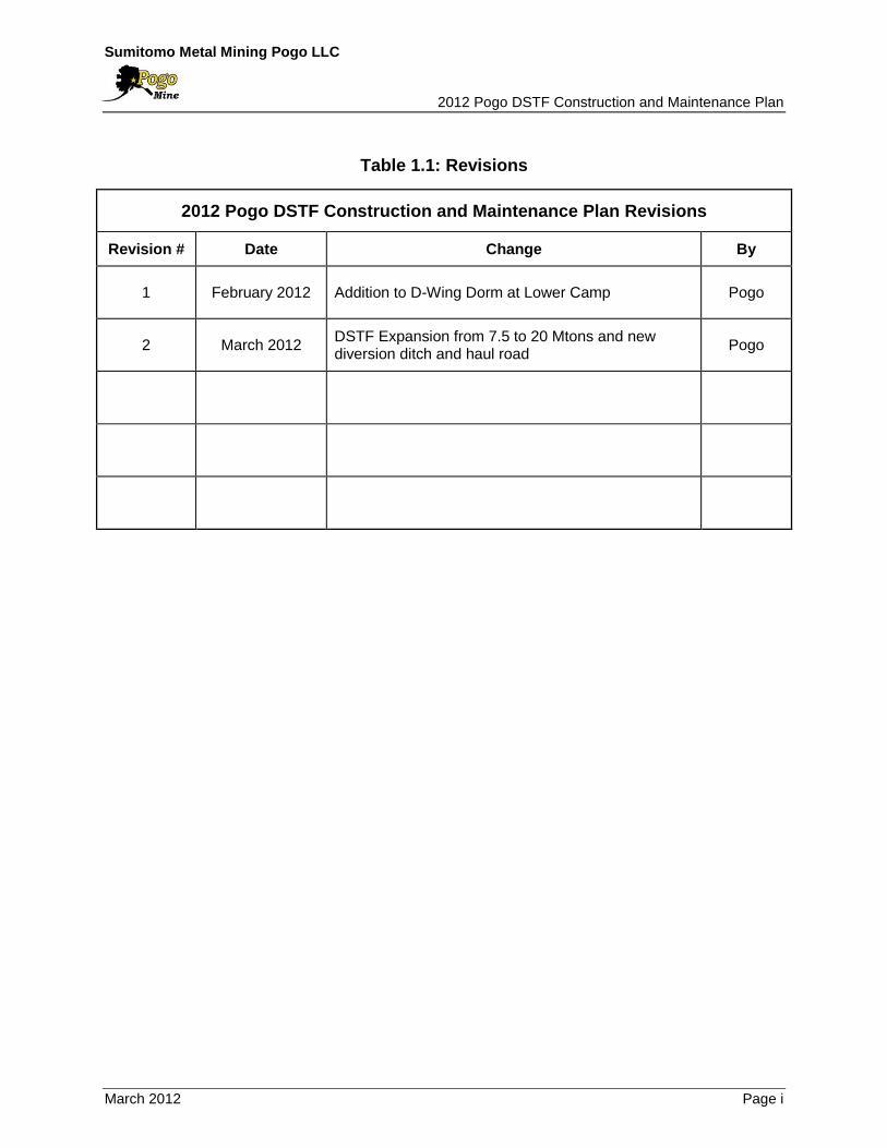
Table 1.1: Revisions
2012 Pogo DSTF Construction and Maintenance Plan Revisions
Revision # Date Change By
1 February 2012 Addition to D-Wing Dorm at Lower Camp Pogo
2 March 2012 DSTF Expansion from 7.5 to 20 Mtons and new diversion ditch and haul road
Pogo
Sumitomo Metal Mining Pogo LLC 2012 Pogo DSTF Construction and Maintenance Plan
March 2012 Page ii
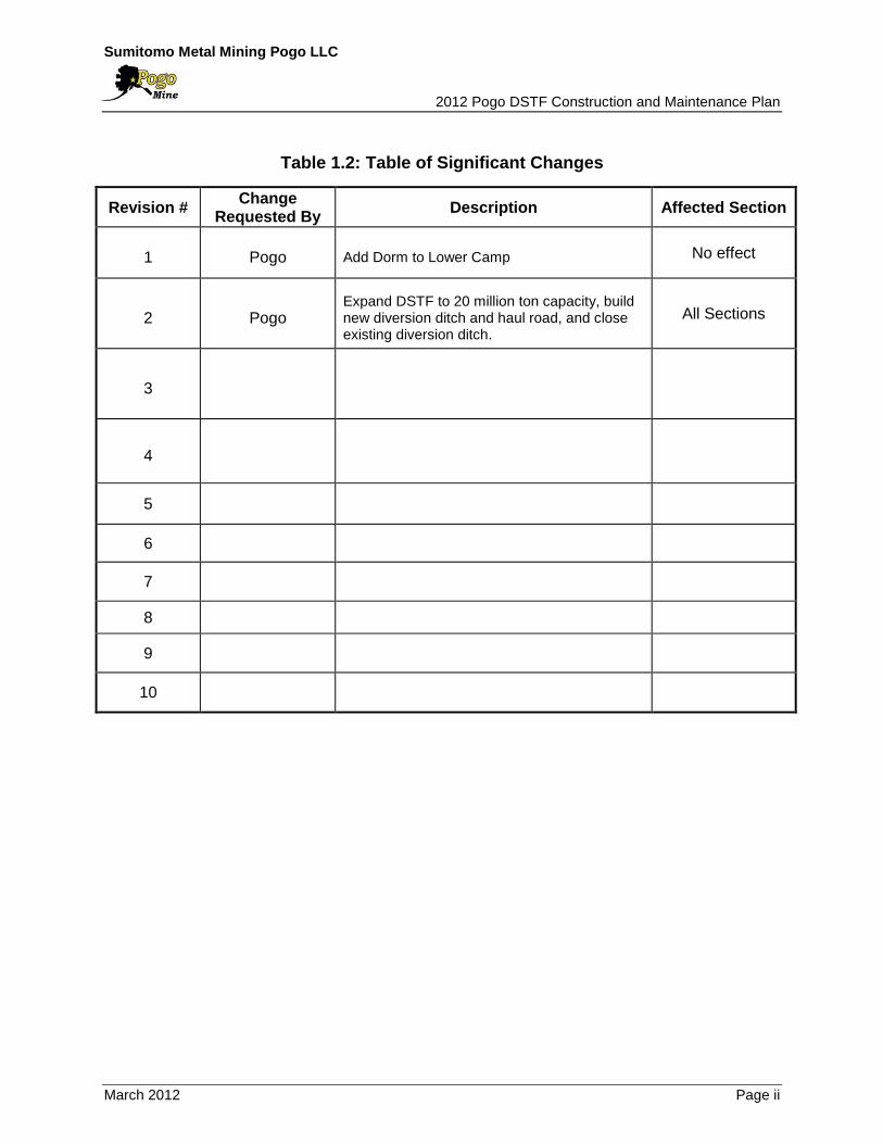
Table 1.2: Table of Significant Changes
Revision # Change
Requested By Description Affected Section
1 Pogo Add Dorm to Lower Camp No effect
2 Pogo Expand DSTF to 20 million ton capacity, build new diversion ditch and haul road, and close existing diversion ditch.
All Sections
3
4
5
6
7
8
9
10

Sumitomo Metal Mining Pogo LLC 2012 Pogo DSTF Construction and Maintenance Plan
March 2012 Page 1
1.0 INTRODUCTION
1.1 Objective
Sumitomo Metal Mining Pogo LLC (SMM Pogo) is the operator of the Pogo gold mine,
located 38 miles northeast of Delta Junction, Alaska.
The Drystack Tailings Facility (DSTF) has been in operation since February 2006.
Through 2011, about 5.8 million tons (Mtons) of material has been placed, which
includes 3.5 Mtons of drystack tailings and 2.3 Mtons of waste rock. The capacity of the
current facility is estimated to be about 20 Mtons (2012 POO Rev 2).
Pogo’s Waste Management Permit 2011DB0012 issued by the Alaska Department of
Environmental Conservation (ADEC) on February 23, 2012 approves placement of
materials in the DSTF up to 20 Mtons. Pogo’s 404 Permit (POA-1996-211-M8) as
amended by the US Army Engineer District, Alaska Regulatory Division on February 23,
2012 approves the construction of a new diversion ditch and haul road and extends the
permit until 2017.
The DSTF was originally designed by AMEC (AMEC, 2004), and the Operating,
Maintenance and Surveillance (OMS) Manual was issued in January 2006 by AMEC
(AMEC, 2006) as a guidance document for the construction of the DSTF. It was revised
by AMEC in December 2007 (AMEC, 2007). The OMS Manual was revised by Pogo
and renamed the DSTF Construction and Maintenance Plan in 2011. It should be noted
that the geochemical monitoring plan is described in the 2012 Pogo Mine Monitoring
Plan (Pogo, 2012).
SRK Consulting (Canada) Inc. (SRK) conducted a preliminary DSTF study in 2011. The
study includes an update of the DSTF material balance and an assessment of the
structural stability of the expanded DSTF. Pogo submitted the report, titled “Pogo Mine
Dry Stack Tailings Facility Expansion Preliminary Study” to ADNR on May 17, 2011
(SRK, 2011a). In order to place more than 7.5 Mtons of material in the DSTF, a new
diversion ditch and haul road must be constructed. The final DSTF diversion ditch and
haul road design was prepared by SRK. Construction is planned in three phases:
Phase I: Construct new North Diversion Ditch and Haul Road; Phase II: Construct new
South Diversion Ditch: and Phase III: Close Existing Diversion Ditch. Pogo is
prohibited from placing tailings over the existing diversion ditch until obtaining approval
from ADNR.

Sumitomo Metal Mining Pogo LLC 2012 Pogo DSTF Construction and Maintenance Plan
March 2012 Page 2
1.2 Document Control and Responsibility
The Safety, Health and Environmental Manager is responsible for the preparation and
administration of this Plan. Any revisions or updates to the Plan shall be submitted to
Alaska Department of Natural Resources (ADNR).
The Maintenance Manager is responsible for the construction of the DSTF. The site
specific Standard of Procedure (SOP) will be established in accordance with this Plan
and will be informed to all relevant personnel.
The Safety, Health and Environmental Manager is responsible to implement the
monitoring and inspection required by this Plan, and to report to the relevant agencies.

Sumitomo Metal Mining Pogo LLC 2012 Pogo DSTF Construction and Maintenance Plan
March 2012 Page 3
2.0 FACILITY DESCRIPTIONS
2.1 Major Components
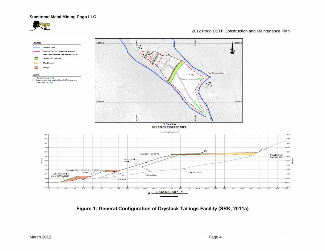
Figure 1 shows the plan and section views of the DSTF as of end of 2010. The major
components of DSTF include:
Flow-Through Drains;
Starter Berm and Toe Berm;
Shell Area; and
General Placement Area (GPA).
2.1.1 Flow-Through Drains
All runoff in and around the DSTF is directed to the RTP by means of a network of
drains. Flow-through drains are constructed in the existing stream valleys within the
DSTF area to augment the existing drainage courses and allow them to pass runoff
under the stack. The drains are extended upstream of the existing stream as the
elevation of GPA rises.
Figure 2 shows the cross-section of the flow-through drains. The rock fill used in the
flow-through drains is between 12 inch and 36 inch in size, and covered with a filter
material to prevent fines migrating in from the drystack tailings. The rock fill is placed at
about 1H:1V, resulting in a drain base width of 21 feet (ft), crest width of 9 ft and height
of 6 ft.
The filter of flow-through drain consists of two layers: Filter 1 and Filter 2. The sand
(0.04 inch to 0.2 inch in size) should be used for Filter 1, and the gravel (0.2 inch to 4
inch in size) should be used for Filter 2.
The corresponding flow capacity of the flow-through drains are calculated to be
approximately 120 times the daily average flow of 0.47 cubic feet per second (cfs) or
200 gallons per minute (gpm) measured at the United States Geological Survey gauge
on Liese Creek, and this is approximately equivalent to a 1:10,000-year/24-hour storm
event with no allowance for freeboard and without the benefits of the diversion ditch.
Sumitomo Metal Mining Pogo LLC
2012 Pogo DSTF Construction and Maintenance Plan
March 2012 Page 4
Figure 1: General Configuration of Drystack Tailings Facility (SRK, 2011a)

Sumitomo Metal Mining Pogo LLC 2012 Pogo DSTF Construction and Maintenance Plan
March 2012 Page 5 Page 5
Figure 2: Typical Cross Section of Flow-Through Drain
2.1.2 Starter Berm and Toe Berm
The starter berm was constructed as the initial containment for the GPA with the
material from nearby colluvium excavations. The toe berm, downstream of the starter
berm was constructed of non-mineralized rock and acts as a foundation of the shell
area. The toe berm was extended to downstream before the construction of the second
and third shell.
2.1.3 Shell Area
There are three shells on the DSTF. The first shell (Shell 1) was constructed using non-
mineralized rock only to a width of 100 ft on the 3:1 slope. The haul road was
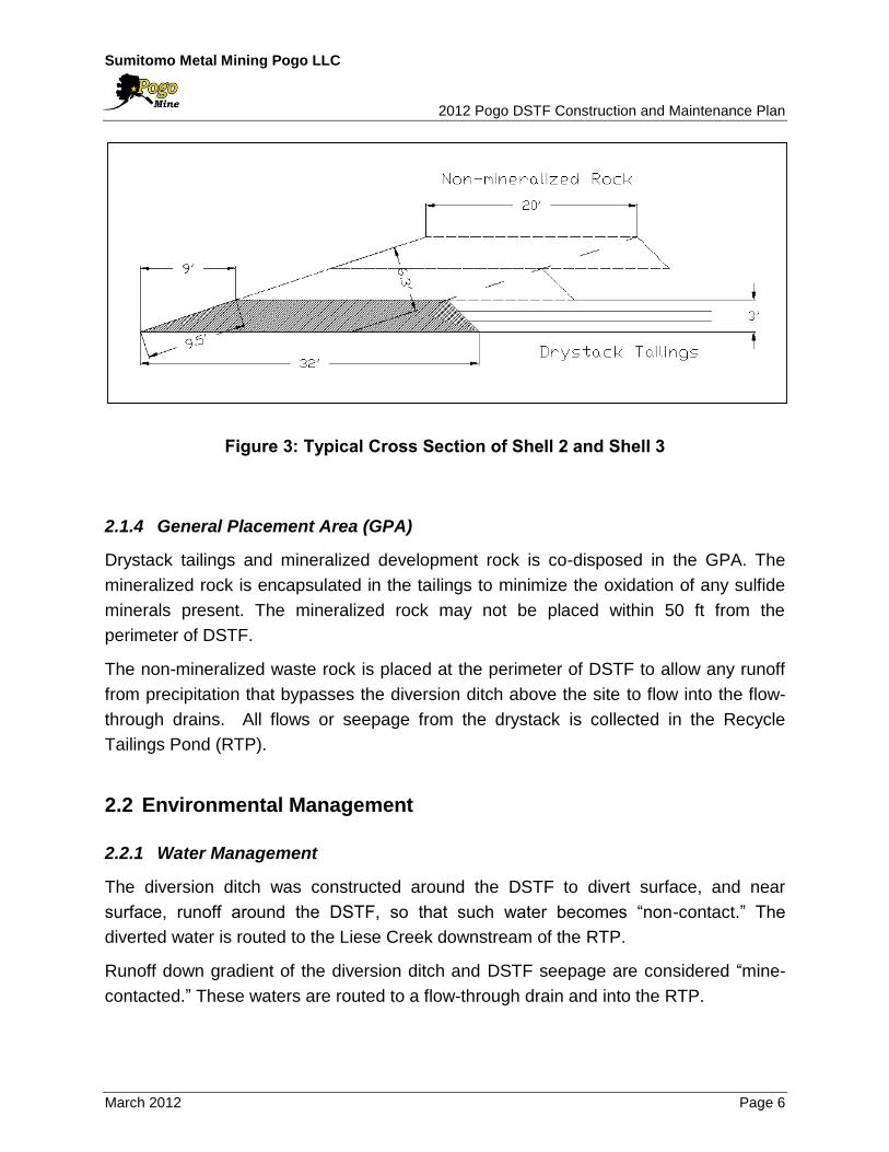
constructed on the Shell 1. The second shell (Shell 2), which has been constructed
since 2009, is a composite shell which consists of non-mineralized rock and drystack
tailings. Non-mineralized rock is placed at the face slope to a width of 20 feet, and then
the drystack tailings is placed inside of the non-mineralized rock and compacted (see
Figure 3). The construction of the third shell (Shell 3) commenced in 2011 using the
same method as Shell 2. The width of the Shell 2 and Shell 3 is about 180 ft and 150 ft,
respectively.
Sumitomo Metal Mining Pogo LLC 2012 Pogo DSTF Construction and Maintenance Plan
March 2012 Page 6 Page 6
Figure 3: Typical Cross Section of Shell 2 and Shell 3
2.1.4 General Placement Area (GPA)
Drystack tailings and mineralized development rock is co-disposed in the GPA. The
mineralized rock is encapsulated in the tailings to minimize the oxidation of any sulfide
minerals present. The mineralized rock may not be placed within 50 ft from the
perimeter of DSTF.
The non-mineralized waste rock is placed at the perimeter of DSTF to allow any runoff
from precipitation that bypasses the diversion ditch above the site to flow into the flow-
through drains. All flows or seepage from the drystack is collected in the Recycle
Tailings Pond (RTP).
2.2 Environmental Management
2.2.1 Water Management
The diversion ditch was constructed around the DSTF to divert surface, and near
surface, runoff around the DSTF, so that such water becomes “non-contact.” The
diverted water is routed to the Liese Creek downstream of the RTP.
Runoff down gradient of the diversion ditch and DSTF seepage are considered “mine-
contacted.” These waters are routed to a flow-through drain and into the RTP.
Sumitomo Metal Mining Pogo LLC 2012 Pogo DSTF Construction and Maintenance Plan
March 2012 Page 7 Page 7
2.2.2 Sedimentation Control
The drystack tailings erosion translates into a sediment load in the RTP, thus specific
sedimentation control measures are used to keep erosion to a minimum:
The slope of each shell is covered with non-mineralized rock, which minimizes
the erosion of drystack tailings;
The surface of GPA has two percent slopes to limit erosion on the tailings; and
The materials dumped on the DSTF are compacted as soon as possible.
2.2.3 Dust Control
Tailings have the potential to create dust, especially when they have been frozen or
desiccated by the sun. Best management practices are used to control dust during
drystack operations such as; compacting the tailings, controlling traffic on the drystack,
and limiting the use of equipment to active placement area(s) only. Summer moisture
from rainfall assists in keeping the surface moisture content within an acceptable range
although prolonged periods of warm weather with low humidity may require building silt
fences around non-active placement areas.
Sumitomo Metal Mining Pogo LLC 2012 Pogo DSTF Construction and Maintenance Plan
March 2012 Page 8 Page 8
3.0 CONSTRUCTION DESIGN CRITERIA
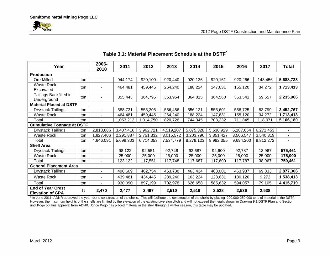
3.1 Placement Schedule
The placement schedule was updated in December 2010, based on the as-built survey
data from September 2010 and the life of mine plan issued on January 2010.
Operational experience from building the shell during the 2010 summer season was
also considered. Table 3.1 shows the placement schedule between 2011 and 2017.
Major assumptions used for scheduling are as follows:
Dry densities of the compacted materials are assumed based on the in-situ
measurements and engineering judgments. The calculated volume using the
tonnage record and the assumed dry densities shows good correlation with the
surveyed volume. As of September 2010, the surveyed volume of DSTF was
about 76.0 million cubic feet (ft3). The calculated volume from the tonnage record
was 79.0 million ft3. The discrepancy between these volumes is less than 4
percent (%).
Assumed material dry densities for scheduling
o Drystack tailings (compacted): 104 lb/ft3 or 19.2 ft3/ton; and
o Waste rock (compacted): 125 lb/ft3 or 16.0 ft3/ton.
The tonnage of drystack tailings placed on the Shell area is limited to 93,000 –
98,000 tons per year, assuming that:
o The shell can be constructed for four months in a year; and
o During the construction season, 60% of drystack tailings produced at the
Mill will be placed on the Shell.
All waste rocks including mineralized rock and non-mineralized rock excavated at
the underground mine will be placed at the DSTF.
In Appendix C, Drawings 1 - 8 are the year-by-year drawings for the DSTF between
2010 and 2017. It is expected that the surface of GPA will exceed the elevation of the
current diversion ditch in 2013. Pogo proposes to construct a new diversion ditch
approximately 150 ft above the current diversion ditch (2012 POO Rev 2).
Sumitomo Metal Mining Pogo LLC 2012 Pogo DSTF Construction and Maintenance Plan
March 2012 Page 9
Table 3.1: Material Placement Schedule at the DSTF*
Year 2006-2010
2011 2012 2013 2014 2015 2016 2017 Total
Production
Ore Milled ton - 944,174 920,100 920,440 920,136 920,161 920,266 143,456 5,688,733
Waste Rock Excavated
ton - 464,481 459,445 264,240 188,224 147,631 155,120 34,272 1,713,413
Tailings Backfilled in Underground
ton - 355,443 364,795 363,954 364,015 364,560 363,541 59,657 2,235,966
Material Placed at DSTF
Drystack Tailings ton - 588,731 555,305 556,486 556,121 555,601 556,725 83,799 3,452,767
Waste Rock ton - 464,481 459,445 264,240 188,224 147,631 155,120 34,272 1,713,413
Total ton - 1,053,212 1,014,750 820,726 744,345 703,232 711,845 118,071 5,166,180
Cumulative Tonnage at DSTF
Drystack Tailings ton 2,818,686 3,407,416 3,962,721 4,519,207 5,075,328 5,630,929 6,187,654 6,271,453 -
Waste Rock ton 1,827,406 2,291,887 2,751,332 3,015,572 3,203,796 3,351,427 3,506,547 3,540,819 -
Total ton 4,646,091 5,699,303 6,714,053 7,534,779 8,279,123 8,982,355 9,694,200 9,812,272 -
Shell Area
Drystack Tailings ton - 98,122 92,551 92,748 92,687 92,600 92,787 13,967 575,461
Waste Rock ton - 25,000 25,000 25,000 25,000 25,000 25,000 25,000 175,000
Total ton - 123,122 117,551 117,748 117,687 117,600 117,787 38,967 750,461
General Placement Area
Drystack Tailings ton - 490,609 462,754 463,738 463,434 463,001 463,937 69,833 2,877,306
Waste Rock ton - 439,481 434,445 239,240 163,224 123,631 130,120 9,272 1,538,413
Total ton - 930,090 897,199 702,978 626,658 585,632 594,057 79,105 4,415,719
End of Year Crest Elevation of GPA
ft 2,470 2,477 2,497 2,510 2,519 2,528 2,536 2,538
* In June 2011, ADNR approved the year-round construction of the shells. This will facilitate the construction of the shells by placing 200,000-250,000 tons of material in the DSTF. However, the maximum heights of the shells are limited by the elevation of the existing diversion ditch and will not exceed the height shown in Drawing 9.1 DSTF Plan and Section until Pogo obtains approval from ADNR. Once Pogo has placed material in the shell through a winter season, this table may be updated.
Sumitomo Metal Mining Pogo LLC 2012 Pogo DSTF Construction and Maintenance Plan
March 2012 Page 10
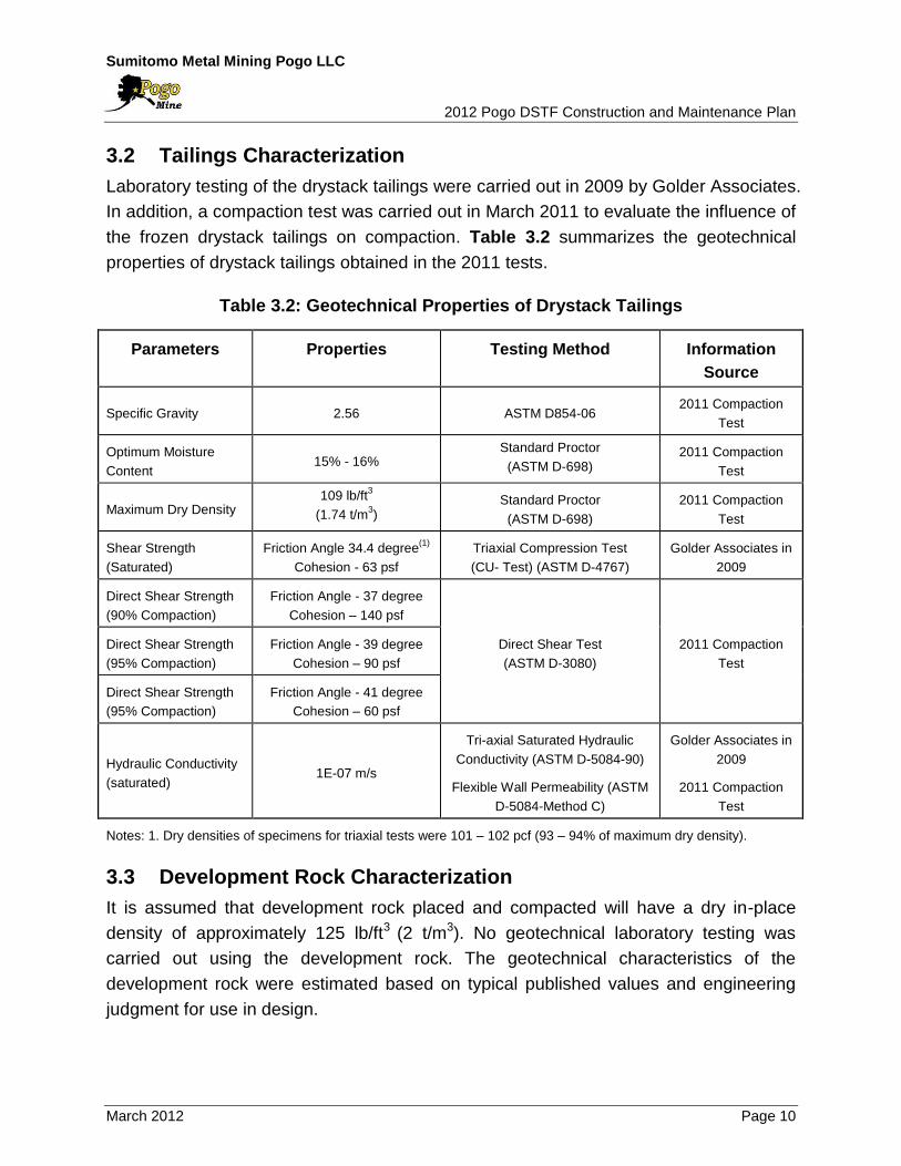
3.2 Tailings Characterization
Laboratory testing of the drystack tailings were carried out in 2009 by Golder Associates.
In addition, a compaction test was carried out in March 2011 to evaluate the influence of
the frozen drystack tailings on compaction. Table 3.2 summarizes the geotechnical
properties of drystack tailings obtained in the 2011 tests.
Table 3.2: Geotechnical Properties of Drystack Tailings
Parameters Properties Testing Method Information
Source
Specific Gravity 2.56 ASTM D854‐06 2011 Compaction
Test
Optimum Moisture
Content 15% - 16%
Standard Proctor
(ASTM D-698) 2011 Compaction
Test
Maximum Dry Density 109 lb/ft
3
(1.74 t/m3)
Standard Proctor
(ASTM D-698)
2011 Compaction
Test
Shear Strength
(Saturated)
Friction Angle 34.4 degree(1)
Cohesion - 63 psf
Triaxial Compression Test
(CU- Test) (ASTM D-4767)
Golder Associates in
2009
Direct Shear Strength
(90% Compaction)
Friction Angle - 37 degree
Cohesion – 140 psf
Direct Shear Test
(ASTM D-3080)
2011 Compaction
Test
Direct Shear Strength
(95% Compaction)
Friction Angle - 39 degree
Cohesion – 90 psf
Direct Shear Strength
(95% Compaction)
Friction Angle - 41 degree
Cohesion – 60 psf
Hydraulic Conductivity
(saturated) 1E-07 m/s
Tri-axial Saturated Hydraulic
Conductivity (ASTM D-5084-90)
Flexible Wall Permeability (ASTM
D-5084-Method C)
Golder Associates in
2009
2011 Compaction
Test
Notes: 1. Dry densities of specimens for triaxial tests were 101 – 102 pcf (93 – 94% of maximum dry density).
3.3 Development Rock Characterization
It is assumed that development rock placed and compacted will have a dry in-place
density of approximately 125 lb/ft3 (2 t/m3). No geotechnical laboratory testing was
carried out using the development rock. The geotechnical characteristics of the
development rock were estimated based on typical published values and engineering
judgment for use in design.
Sumitomo Metal Mining Pogo LLC 2012 Pogo DSTF Construction and Maintenance Plan
March 2012 Page 11
3.4 Structural Stability Evaluation
SRK developed the construction design for the expanded DSTF with total capacity of 20
Mtons (see Appendix C, Drawing 9.1), and evaluated its structural stability considering
the variability of pseudo-static loadings, phreatic surfaces, and strength parameter
(friction angle) of materials (SRK, 2011a). This section summarizes the results of
stability evaluation.
3.4.1 Design Criteria
The design criteria used for this stability analysis were consistent with those specified in
the original design report (AMEC, 2004). Stability analysis of embankment slopes
requires assessment of the structure’s ability to withstand the effects of self-weight
(static) and earthquake induced (pseudo-static) loading conditions under both operating
and closure conditions. In the 2004 DSTF design, AMEC considered the minimum
allowable factor of safety (FoS) under static loading conditions during operations and
closure conditions to be 1.5. During pseudo-static conditions, the minimum allowable
FoS was selected as 1.1.
Seismic design criteria were developed for the Pogo site during completion of the
project’s Feasibility Study (Teck-Pogo, 2004) and reiterated in the Recycle Tailings
Pond Dam Design Report (AMEC, 2004). As described in the Pogo Feasibility Study,
the near surface M7.9 seismic event that occurred on 3 November 2002 within 75 miles
of Fairbanks was selected as the operating basis earthquake for the project. Seismic
hazard mapping completed by the USGS after the 2002 event indicated that a peak
ground acceleration (PGA) of 0.1g would have a return period of 475 years (10% of
occurrence in 50 years) at the Pogo mine site. Therefore, Seismic design criteria used
by AMEC during the original design (0.05g for operation, 0.1g for closure phase) are
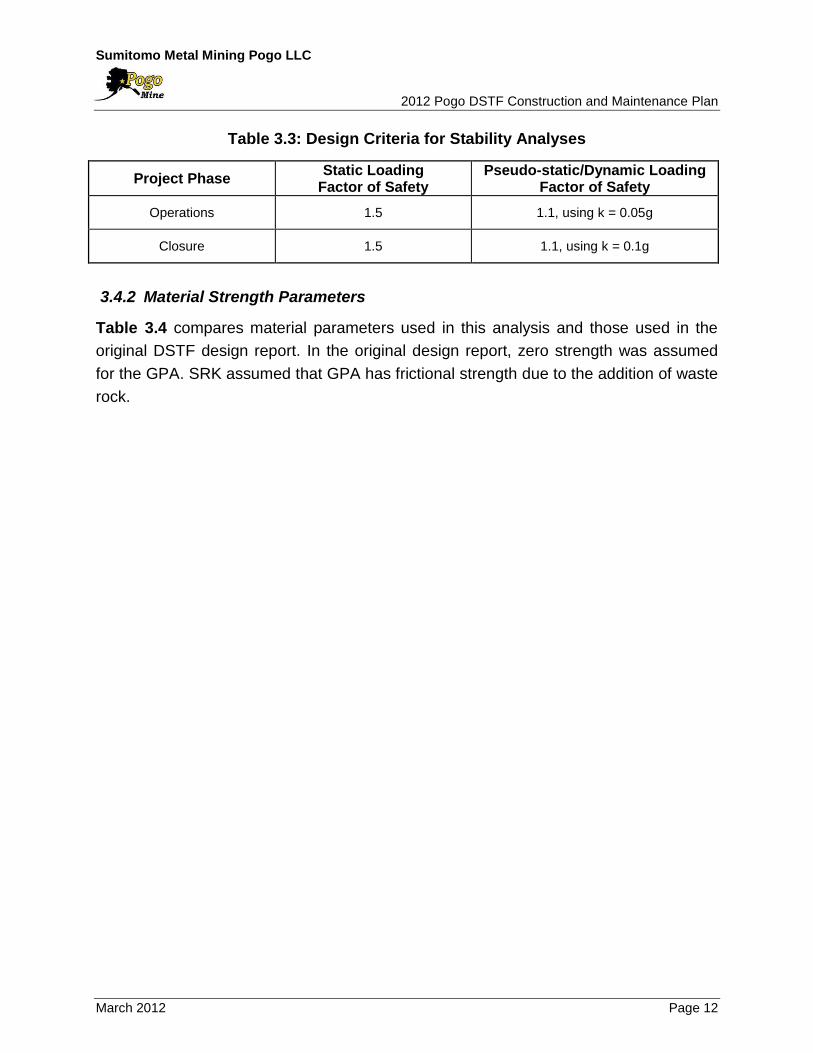
considered reasonable and accepted for use in this analysis. Table 3.3 summarizes the
design criteria used for stability analysis. SRK also conducted sensitivity analysis by
increasing the PGA up to 0.2g for the most critical failure mode (Deep Failure through
GPA).
Sumitomo Metal Mining Pogo LLC 2012 Pogo DSTF Construction and Maintenance Plan
March 2012 Page 12
Table 3.3: Design Criteria for Stability Analyses
Project Phase Static Loading
Factor of Safety Pseudo-static/Dynamic Loading
Factor of Safety
Operations 1.5 1.1, using k = 0.05g
Closure 1.5 1.1, using k = 0.1g
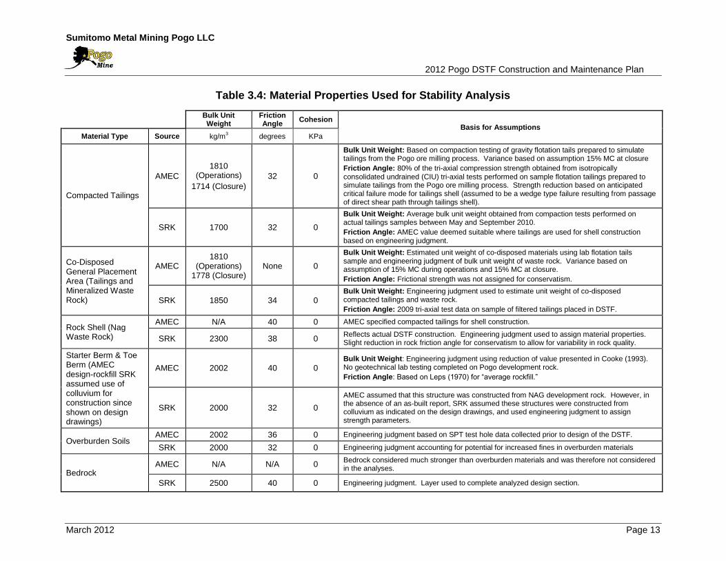
3.4.2 Material Strength Parameters
Table 3.4 compares material parameters used in this analysis and those used in the
original DSTF design report. In the original design report, zero strength was assumed
for the GPA. SRK assumed that GPA has frictional strength due to the addition of waste
rock.
Sumitomo Metal Mining Pogo LLC 2012 Pogo DSTF Construction and Maintenance Plan
March 2012 Page 13
Table 3.4: Material Properties Used for Stability Analysis
Bulk Unit Weight
Friction Angle
Cohesion Basis for Assumptions
Material Type Source kg/m3 degrees KPa
Compacted Tailings
AMEC
1810 (Operations)
1714 (Closure)
32 0
Bulk Unit Weight: Based on compaction testing of gravity flotation tails prepared to simulate tailings from the Pogo ore milling process. Variance based on assumption 15% MC at closure
Friction Angle: 80% of the tri-axial compression strength obtained from isotropically consolidated undrained (CIU) tri-axial tests performed on sample flotation tailings prepared to simulate tailings from the Pogo ore milling process. Strength reduction based on anticipated critical failure mode for tailings shell (assumed to be a wedge type failure resulting from passage of direct shear path through tailings shell).
SRK 1700 32 0
Bulk Unit Weight: Average bulk unit weight obtained from compaction tests performed on actual tailings samples between May and September 2010.
Friction Angle: AMEC value deemed suitable where tailings are used for shell construction based on engineering judgment.
Co-Disposed General Placement Area (Tailings and Mineralized Waste Rock)
AMEC 1810
(Operations) 1778 (Closure)
None 0
Bulk Unit Weight: Estimated unit weight of co-disposed materials using lab flotation tails sample and engineering judgment of bulk unit weight of waste rock. Variance based on assumption of 15% MC during operations and 15% MC at closure.
Friction Angle: Frictional strength was not assigned for conservatism.
SRK 1850 34 0 Bulk Unit Weight: Engineering judgment used to estimate unit weight of co-disposed compacted tailings and waste rock.
Friction Angle: 2009 tri-axial test data on sample of filtered tailings placed in DSTF.
Rock Shell (Nag Waste Rock)
AMEC N/A 40 0 AMEC specified compacted tailings for shell construction.
SRK 2300 38 0 Reflects actual DSTF construction. Engineering judgment used to assign material properties. Slight reduction in rock friction angle for conservatism to allow for variability in rock quality.
Starter Berm & Toe Berm (AMEC design-rockfill SRK assumed use of colluvium for construction since shown on design drawings)
AMEC 2002 40 0 Bulk Unit Weight: Engineering judgment using reduction of value presented in Cooke (1993). No geotechnical lab testing completed on Pogo development rock.
Friction Angle: Based on Leps (1970) for “average rockfill.”
SRK 2000 32 0
AMEC assumed that this structure was constructed from NAG development rock. However, in the absence of an as-built report, SRK assumed these structures were constructed from colluvium as indicated on the design drawings, and used engineering judgment to assign strength parameters.
Overburden Soils AMEC 2002 36 0 Engineering judgment based on SPT test hole data collected prior to design of the DSTF.
SRK 2000 32 0 Engineering judgment accounting for potential for increased fines in overburden materials
Bedrock AMEC N/A N/A 0
Bedrock considered much stronger than overburden materials and was therefore not considered in the analyses.
SRK 2500 40 0 Engineering judgment. Layer used to complete analyzed design section.
Sumitomo Metal Mining Pogo LLC 2012 Pogo DSTF Construction and Maintenance Plan
March 2012 Page 14
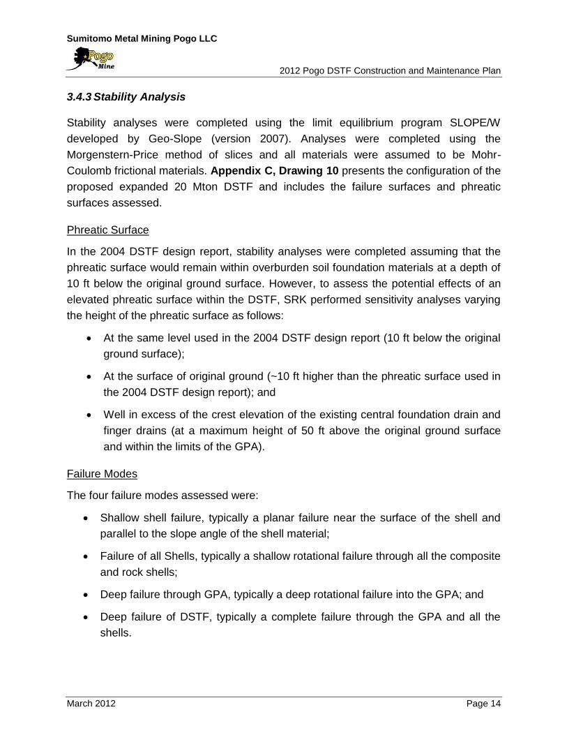
3.4.3 Stability Analysis
Stability analyses were completed using the limit equilibrium program SLOPE/W
developed by Geo-Slope (version 2007). Analyses were completed using the
Morgenstern-Price method of slices and all materials were assumed to be Mohr-
Coulomb frictional materials. Appendix C, Drawing 10 presents the configuration of the
proposed expanded 20 Mton DSTF and includes the failure surfaces and phreatic
surfaces assessed.
Phreatic Surface
In the 2004 DSTF design report, stability analyses were completed assuming that the
phreatic surface would remain within overburden soil foundation materials at a depth of
10 ft below the original ground surface. However, to assess the potential effects of an
elevated phreatic surface within the DSTF, SRK performed sensitivity analyses varying
the height of the phreatic surface as follows:
At the same level used in the 2004 DSTF design report (10 ft below the original
ground surface);
At the surface of original ground (~10 ft higher than the phreatic surface used in
the 2004 DSTF design report); and
Well in excess of the crest elevation of the existing central foundation drain and
finger drains (at a maximum height of 50 ft above the original ground surface
and within the limits of the GPA).
Failure Modes
The four failure modes assessed were:
Shallow shell failure, typically a planar failure near the surface of the shell and
parallel to the slope angle of the shell material;
Failure of all Shells, typically a shallow rotational failure through all the composite
and rock shells;
Deep failure through GPA, typically a deep rotational failure into the GPA; and
Deep failure of DSTF, typically a complete failure through the GPA and all the
shells.
Sumitomo Metal Mining Pogo LLC 2012 Pogo DSTF Construction and Maintenance Plan
March 2012 Page 15
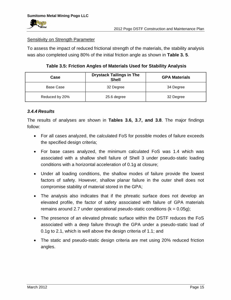
Sensitivity on Strength Parameter
To assess the impact of reduced frictional strength of the materials, the stability analysis
was also completed using 80% of the initial friction angle as shown in Table 3. 5.
Table 3.5: Friction Angles of Materials Used for Stability Analysis
Case Drystack Tailings in The
Shell GPA Materials
Base Case 32 Degree 34 Degree
Reduced by 20% 25.6 degree 32 Degree
3.4.4 Results
The results of analyses are shown in Tables 3.6, 3.7, and 3.8. The major findings
follow:
For all cases analyzed, the calculated FoS for possible modes of failure exceeds
the specified design criteria;
For base cases analyzed, the minimum calculated FoS was 1.4 which was
associated with a shallow shell failure of Shell 3 under pseudo-static loading
conditions with a horizontal acceleration of 0.1g at closure;
Under all loading conditions, the shallow modes of failure provide the lowest
factors of safety. However, shallow planar failure in the outer shell does not
compromise stability of material stored in the GPA;
The analysis also indicates that if the phreatic surface does not develop an
elevated profile, the factor of safety associated with failure of GPA materials
remains around 2.7 under operational pseudo-static conditions (k = 0.05g);
The presence of an elevated phreatic surface within the DSTF reduces the FoS
associated with a deep failure through the GPA under a pseudo-static load of
0.1g to 2.1, which is well above the design criteria of 1.1; and
The static and pseudo-static design criteria are met using 20% reduced friction
angles.

Sumitomo Metal Mining Pogo LLC 2012 Pogo DSTF Construction and Maintenance Plan
March 2012 Page 16
Table 3.6: Factor of Safety with Phreatic Surface 10 ft Below Surface
Failure Mode
Base Case Friction Angle of Drystack
Tailings in the Shell reduced by 20%
Friction Angle of Drystack Tailings in the Shell and GPA
Material reduced by 20%
Static Pseudo-
static (k=0.05)
Pseudo-static
(k=0.10) Static
Pseudo-static
(k=0.05)
Pseudo-static
(k=0.10) Static
Pseudo-static
(k=0.05)
Pseudo-static
(k=0.10)
Shallow Shell Failure
1.9 1.7 1.4 1.5 1.3 1.1 1.5 1.3 1.1
Failure of all Shells
2.6 2.1 1.8 2.3 1.9 1.6 2.3 1.9 1.6
Deep Failure Through
GPA 3.4 2.7 2.2 3.3 2.6 2.2 2.8 2.2 1.8
Deep Failure of DSTF
5.0 3.6 2.8 5.0 3.6 2.8 3.8 2.8 2.2
Table 3.7: Factor of Safety with Phreatic Surface at Original Ground
Failure Mode
Base Case Friction Angle of Drystack
Tailings in the Shell reduced by 20%
Friction Angle of Drystack Tailings in the Shell and GPA
Material reduced by 20%
Static Pseudo-
static (k=0.05)
Pseudo-static
(k=0.10) Static
Pseudo-static
(k=0.05)
Pseudo-static
(k=0.10) Static
Pseudo-static
(k=0.05)
Pseudo-static
(k=0.10)
Shallow Shell Failure
1.9 1.6 1.4 1.5 1.3 1.1 1.5 1.3 1.1
Failure of all Shells
2.6 2.1 1.8 2.3 1. 9 1.6 2.3 1. 9 1.6
Deep Failure Through
GPA
3.4 2. 7 2.2 3.3 2.6 2.2 2. 8 2.2 1.8
Deep Failure of DSTF
4.7 3.4 2. 7 4.7 3.4 2.7 3.8 2.8 2.2
Table 3.8: Factor of Safety with Phreatic Surface Near Crest Elevation
Failure Mode
Base Case Friction Angle of Drystack
Tailings in the Shell reduced by 20%
Friction Angle of Drystack Tailings in the Shell and GPA
Material reduced by 20%
Static Pseudo-
static (k=0.05)
Pseudo-static
(k=0.10) Static
Pseudo-static
(k=0.05)
Pseudo-static
(k=0.10) Static
Pseudo-static
(k=0.05)
Pseudo-static
(k=0.10)
Shallow Shell Failure
1.9 1.6 1.4 1.5 1.3 1.1 1.5 1.3 1.1
Failure of all Shells
2.6 2.1 1.8 2.3 1.9 1.6 2.3 1. 9 1.6
Deep Failure Through
GPA
3.2 2.5 2.1 3.1 2.5 2.0 2.6 2.1 1.7
Deep Failure of DSTF
4.0 2.9 2.3 3.9 2.9 2.2 3.3 2.4 1.9

Sumitomo Metal Mining Pogo LLC 2012 Pogo DSTF Construction and Maintenance Plan
March 2012 Page 17
4.0 COMPACTION TEST IN MARCH 2011
The previous DSTF OMS Manual describes that “windrows of tailings have to be dozed
down and spread within 1 hour” during winter conditions. However, it is not always
practical to implement this rule.
In order to evaluate the influence of frozen drystack tailings on the compaction and to
establish appropriate compaction procedures during winter season, a compaction test
was conducted in March 2011. A technical memorandum was provided by SRK (SRK,
2011b). This section summarizes the results of this test.
4.1 Methodology
Four different scenarios were tested on site to assess the potential impact of time lags
between the dumping of tailings material into heaps on the surface of the DSTF and
subsequent spreading of that material under freezing conditions. The four time lags
tested were 1, 2, 3, and 7 days between the time tailings were dumped on the surface
of the DSTF and when material was spread into one foot thick lifts and then compacted
with a vibratory roller. Air temperature measured during the test period was between -9
and 27 degrees F.
At each site when the specified time had elapsed dumped materials were spread using
a CAT D7 track type dozer to create a one foot thick lift that was approximately 30 ft by
60 ft. Each pad was then subjected to three different of compaction passes (four, six
and eight passes) with a CAT CS 563 vibratory compactor (approximately 12 tons
operating weight).
The following field measurements and laboratory tests were conducted:
Soil temperature measurements using a handheld infrared gauge;
In-situ density and water content measurements using nuclear densometer
(ASTM D6983-10);
Sand cone test (ASTM D1556-07);
Standard Proctor (ASTM D698-07);
Moisture content (ASTM D2216); and
Direct shear test (ASTM D3080).
Sumitomo Metal Mining Pogo LLC 2012 Pogo DSTF Construction and Maintenance Plan
March 2012 Page 18
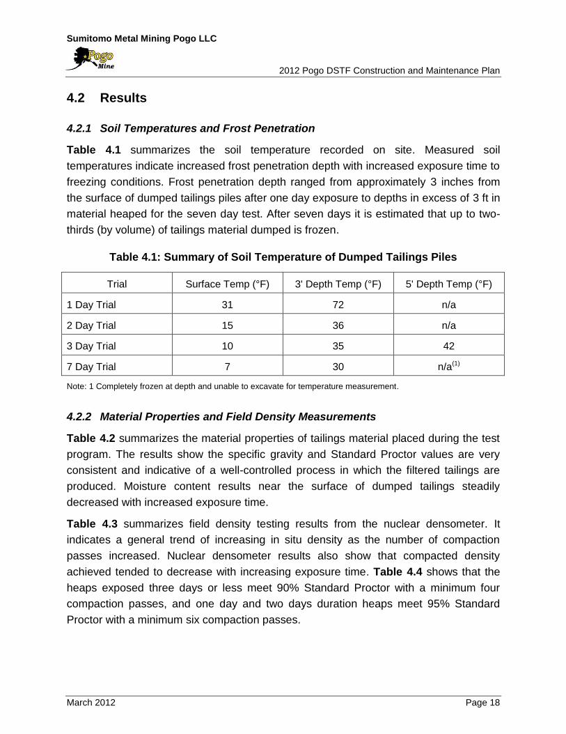
4.2 Results
4.2.1 Soil Temperatures and Frost Penetration
Table 4.1 summarizes the soil temperature recorded on site. Measured soil
temperatures indicate increased frost penetration depth with increased exposure time to
freezing conditions. Frost penetration depth ranged from approximately 3 inches from
the surface of dumped tailings piles after one day exposure to depths in excess of 3 ft in
material heaped for the seven day test. After seven days it is estimated that up to two-
thirds (by volume) of tailings material dumped is frozen.
Table 4.1: Summary of Soil Temperature of Dumped Tailings Piles
Trial Surface Temp (°F) 3' Depth Temp (°F) 5' Depth Temp (°F)
1 Day Trial 31 72 n/a
2 Day Trial 15 36 n/a
3 Day Trial 10 35 42
7 Day Trial 7 30 n/a(1)
Note: 1 Completely frozen at depth and unable to excavate for temperature measurement.
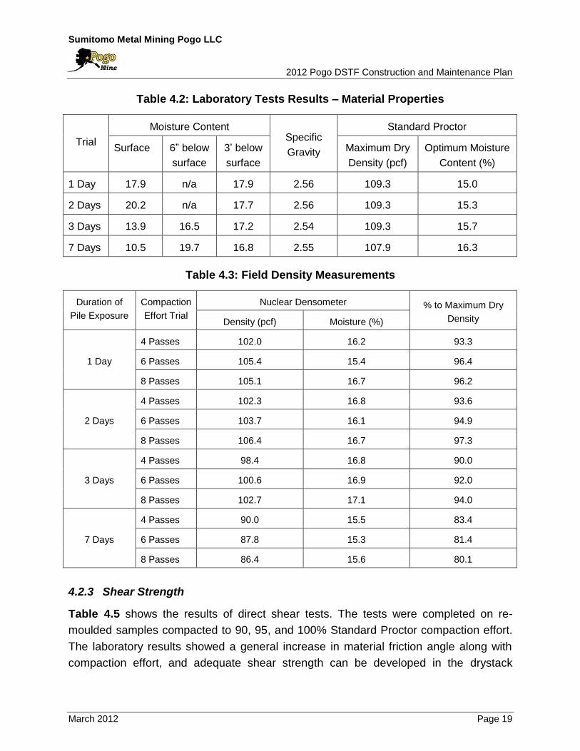
4.2.2 Material Properties and Field Density Measurements
Table 4.2 summarizes the material properties of tailings material placed during the test
program. The results show the specific gravity and Standard Proctor values are very
consistent and indicative of a well-controlled process in which the filtered tailings are
produced. Moisture content results near the surface of dumped tailings steadily
decreased with increased exposure time.
Table 4.3 summarizes field density testing results from the nuclear densometer. It
indicates a general trend of increasing in situ density as the number of compaction
passes increased. Nuclear densometer results also show that compacted density
achieved tended to decrease with increasing exposure time. Table 4.4 shows that the
heaps exposed three days or less meet 90% Standard Proctor with a minimum four
compaction passes, and one day and two days duration heaps meet 95% Standard
Proctor with a minimum six compaction passes.
Sumitomo Metal Mining Pogo LLC 2012 Pogo DSTF Construction and Maintenance Plan
March 2012 Page 19
Table 4.2: Laboratory Tests Results – Material Properties
Trial
Moisture Content Specific
Gravity
Standard Proctor
Surface 6” below
surface
3’ below
surface
Maximum Dry
Density (pcf)
Optimum Moisture
Content (%)
1 Day 17.9 n/a 17.9 2.56 109.3 15.0
2 Days 20.2 n/a 17.7 2.56 109.3 15.3
3 Days 13.9 16.5 17.2 2.54 109.3 15.7
7 Days 10.5 19.7 16.8 2.55 107.9 16.3
Table 4.3: Field Density Measurements
Duration of
Pile Exposure
Compaction
Effort Trial
Nuclear Densometer % to Maximum Dry
Density Density (pcf) Moisture (%)
1 Day
4 Passes 102.0 16.2 93.3
6 Passes 105.4 15.4 96.4
8 Passes 105.1 16.7 96.2
2 Days
4 Passes 102.3 16.8 93.6
6 Passes 103.7 16.1 94.9
8 Passes 106.4 16.7 97.3
3 Days
4 Passes 98.4 16.8 90.0
6 Passes 100.6 16.9 92.0
8 Passes 102.7 17.1 94.0
7 Days
4 Passes 90.0 15.5 83.4
6 Passes 87.8 15.3 81.4
8 Passes 86.4 15.6 80.1
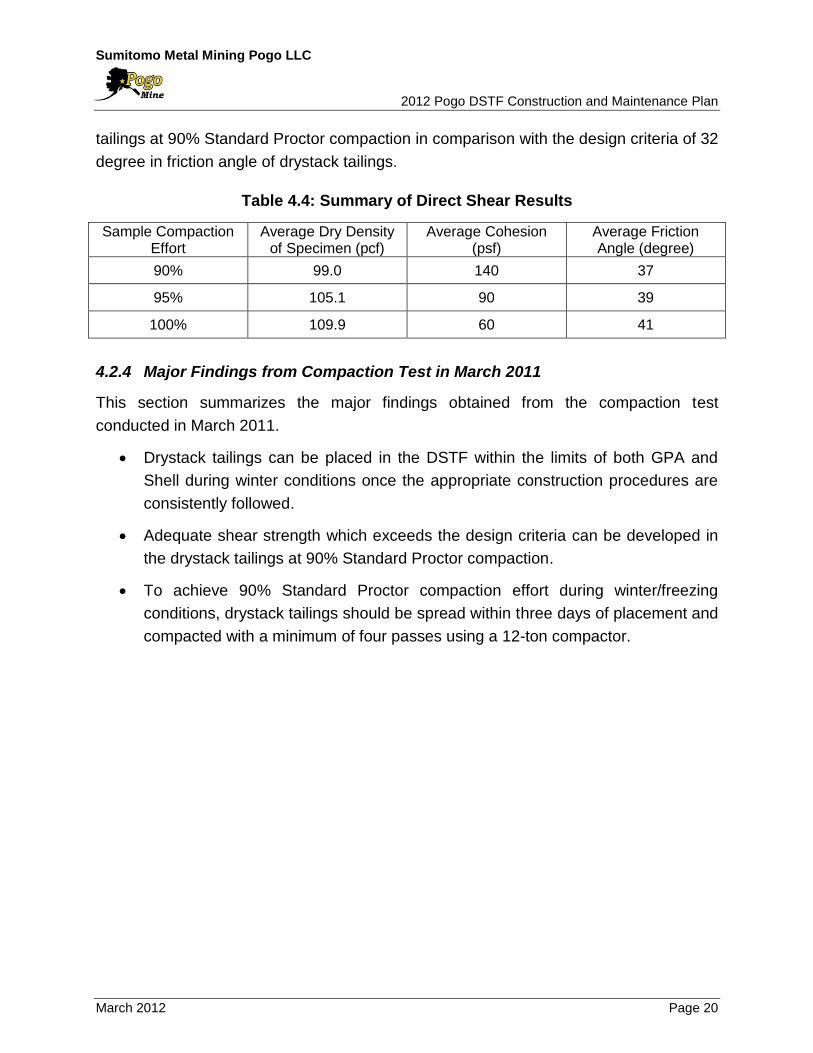
4.2.3 Shear Strength
Table 4.5 shows the results of direct shear tests. The tests were completed on re-
moulded samples compacted to 90, 95, and 100% Standard Proctor compaction effort.
The laboratory results showed a general increase in material friction angle along with
compaction effort, and adequate shear strength can be developed in the drystack
Sumitomo Metal Mining Pogo LLC 2012 Pogo DSTF Construction and Maintenance Plan
March 2012 Page 20
tailings at 90% Standard Proctor compaction in comparison with the design criteria of 32
degree in friction angle of drystack tailings.
Table 4.4: Summary of Direct Shear Results
Sample Compaction Effort
Average Dry Density of Specimen (pcf)
Average Cohesion (psf)
Average Friction Angle (degree)
90% 99.0 140 37
95% 105.1 90 39
100% 109.9 60 41
4.2.4 Major Findings from Compaction Test in March 2011
This section summarizes the major findings obtained from the compaction test
conducted in March 2011.
Drystack tailings can be placed in the DSTF within the limits of both GPA and
Shell during winter conditions once the appropriate construction procedures are
consistently followed.
Adequate shear strength which exceeds the design criteria can be developed in
the drystack tailings at 90% Standard Proctor compaction.
To achieve 90% Standard Proctor compaction effort during winter/freezing
conditions, drystack tailings should be spread within three days of placement and
compacted with a minimum of four passes using a 12-ton compactor.
Sumitomo Metal Mining Pogo LLC 2012 Pogo DSTF Construction and Maintenance Plan
March 2012 Page 21
5.0 CONSTRUCTION PROCEDURES
This section describes the construction procedures of the DSTF.
5.1 General Placement Area
Materials are placed on the GPA year-round. This section describes the construction
procedures for the GPA including Shell 1 and associated structures.
5.1.1 Shell 1 Construction
The first shell (Shell 1) has been constructed using non-mineralized rock since the
commencement of operation. Shell 1 has a width of 100 ft on the 3:1 slope. Non-
mineralized rock is dampened and spread into 3-ft loose lift. Then the lift is compacted
with three passes of a D7 Dozer.
A temporary single lane haul road may be constructed on the slope of Shell 1.
5.1.2 Flow-Through Drain and Perimeter Preparation
The flow-through drain along the creek will be extended upward as necessary. The
specifications of the flow-through drain are described in Section 2.1.1.
The trees, shrubs, and topsoil along the perimeter of DSTF are removed and non-
mineralized rock is placed on the slope surface at a thickness of approx. 1 ft. This layer
works as water drainage to route the run-off water on the GPA into the flow-through
drain.
5.1.3 Drystack Tailings Placement
The drystack tailings is dumped 15-ft apart, and then spread into maximum 12-inch
loose lift. Compaction then proceeds with a minimum of four passes of a smooth drum
roller having a minimum 12-ton equivalent weight.
Operation During Winter Conditions
During winter season (October to May), some additional work is required:
Windrows of drystack tailings have to be dozed down and spread within three
days; and
Sumitomo Metal Mining Pogo LLC 2012 Pogo DSTF Construction and Maintenance Plan
March 2012 Page 22
The placement area needs to be regularly cleared to prevent build-up of snow
and ice.
Operation in Wet Conditions
During rainy periods, the drystack tailings may become difficult to compact if water is
allowed to infiltrate. In order to minimize the adverse effect on compaction, the following
actions may be taken:
Keep tailings placement area as small as possible;
Prior to placement of tailings in this small area, the saturated and softened
surface will be scraped off;
If the tailings cannot be compacted immediately, then they will not be spread at
all, but left in a pile. If the tailings remain in a pile, the rain will generally only
penetrate the outer shell of the pile; and
Once drystack tailings placement in the area is complete, the tailings surface will
be smooth, free of water traps, and graded to allow water to run off the surface.
5.1.4 Mineralized Rock Placement
The mineralized rock needs to be encapsulated in the drystack tailings and the following
procedures applied:
The mineralized rock won’t be placed within 50 ft from the perimeter of DSTF;
The mineralized rock is dumped and then spread into 3-feet loose lift.
Compaction then proceeds with minimum three passes of a D7 dozer; and
Once three lifts are placed, the mineralized rock will be covered with two one-foot
drystack tailings layers before placing another lift of mineralized rock.
5.2 Shell Area
This section describes the construction procedures for Shell 2 and Shell 3 which consist
of non-mineralized rock and drystack tailings.
5.2.1 Construction Period
The previous DSTF OMS Manual (AMEC, 2007) prescribed that the Shell would be
constructed during a typical four month summer construction period. However,
Sumitomo Metal Mining Pogo LLC 2012 Pogo DSTF Construction and Maintenance Plan
March 2012 Page 23
compaction test conducted in March 2011 confirmed that the drystack tailings can be
compacted appropriately during winter/freezing conditions once the appropriate
construction procedures are consistently followed. Pogo began placing drystack tailings
during winter months in 2011.
5.2.2 Flow-Through Drain and Toe Berm
The flow-through drain and toe berm for the Shell 2 and Shell 3 have already been
constructed. If additional shell(s) are needed, the flow-through drain and toe berm can
be sufficiently advanced. The specifications of the flow-through drain are described in
Section 2.1.1.
The toe berm is constructed using non-mineralized rock and acts as a foundation for the
shells.
5.2.3 Shell Construction Procedures
Shell 2 and Shell 3 are composite shells which consist of compacted drystack tailings
and non-mineralized rock placed on the slope surface of the shells. The construction
procedures for these shells are as follows:
Non-mineralized rock is used to form a crest of the shells. Non-mineralized rock
is dumped on the slope side of the shells and then spread into 3-ft loose lift.
Compaction then proceeds with a minimum of three passes of a D7 dozer. The
crest of non-mineralized rock will have a width of 20 ft on the 3:1 slope; and
The drystack tailings is dumped 15-ft apart within the crest, and then spread into
maximum 12-inch loose lift. Compaction then proceeds with a minimum of six
passes of a smooth drum roller having a minimum 12-ton equivalent weight.
Though adequate shear strength can be developed in the drystack tailings with a
minimum of four passes compaction, six passes compaction is applied for Shell
construction to minimize the variability of operation.
Operation During Winter Condition
During winter season (October to May), some additional work is required:
Between November and February, the windrows of drystack tailings have to be
dozed down and spread within one day;
Sumitomo Metal Mining Pogo LLC 2012 Pogo DSTF Construction and Maintenance Plan
March 2012 Page 24
In October and March to May, the windrows of drystack tailings have to be dozed
down and spread within three days; and
The placement area needs to be regularly clear to prevent build-up of snow and
ice.
Operation in Wet Conditions
During rainy periods, the drystack tailings may become difficult to compact to achieve
the target density if water is allowed to infiltrate. In order to minimize the adverse effect
on compaction, the following actions may be taken:
Prior to placement of drystack tailings, the saturated and softened surface will be
scraped off;
Windrows of drystack tailings have to be dozed down and compacted as soon as
possible; and
If the amount of rainfall begins to reach extreme levels (more than 0.5 inches in
24 hours), placement of drystack tailings in the shell area will be suspended.
Sumitomo Metal Mining Pogo LLC 2012 Pogo DSTF Construction and Maintenance Plan
March 2012 Page 25
6.0 MONITORING
6.1 Geotechnical Monitoring
The compaction of drystack tailings at the Shells is important for overall stability of the
DSTF and to ensure volume capacity. It is necessary to achieve a nominal 90%
Standard Proctor of the dry density to secure the designed shear strength. The
construction procedures for GPA and Shells aim to compact the drystack tailings to
achieve a minimum of 90% Standard Proctor of the dry density. The geotechnical
monitoring will verify compaction of the drystack tailings during the construction of Shell
2 and Shell 3 for adherence to design standards.
There is no specific monitoring requirement for the drystack tailings placement at GPA,
because it can be deduced from the monitoring results at the Shell, and cumulative
compaction effort by piling up the lifts can be expected at GPA.
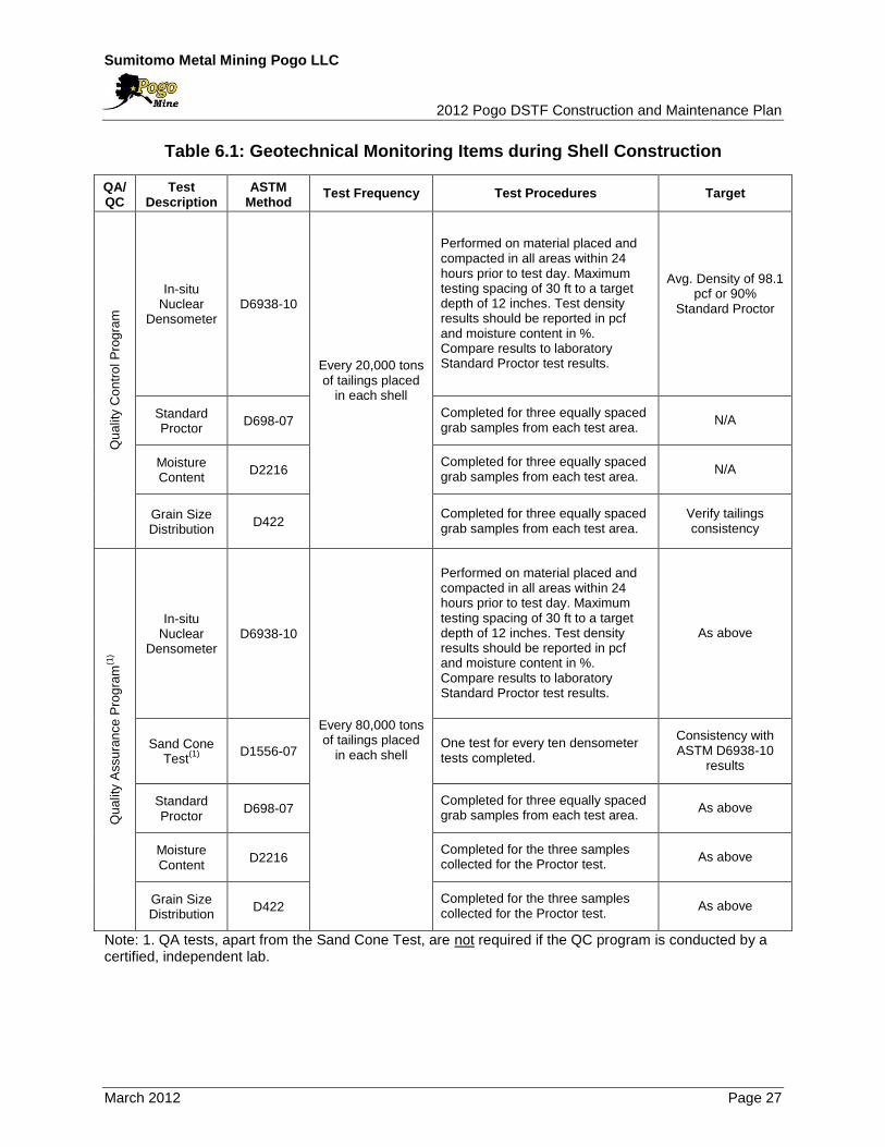
6.1.1 Geotechnical Monitoring for Shell Construction
During construction of Shell 2 and Shell 3, the QA/QC program shown in Table 6.1 will
be implemented.
The location of densometer readings and grab samples will be documented using
handheld GPS and indicated on a site plan, and included with the data collected for the
QC program. If QC testing is completed by an independent third party technician and
soils testing laboratory, only the sand cone testing indicated in the proposed QA plan
will be completed at a frequency of every 80,000 tons of tailings placed and compacted
within each shell. If QC testing is completed by Pogo personnel, QA testing will be
carried out by an independent certified technician and soils testing laboratory.
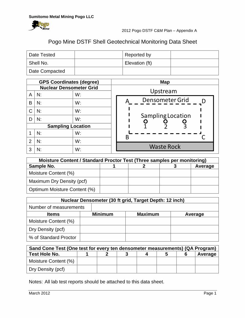
The results of geotechnical monitoring will be recorded using the data sheet shown in
Appendix A.
In case the average of in-situ dry densities is less than the target (90% of Standard
Proctor), that layer of drystack tailings will be re-compacted until the target dry density
will be achieved.
Sumitomo Metal Mining Pogo LLC 2012 Pogo DSTF Construction and Maintenance Plan
March 2012 Page 26
6.2 Annual Survey
A detailed survey of DSTF will be conducted annually in September. The survey data
will be compared with the year-by-year plan. If a significant discrepancy is identified, the
plan may be updated.
6.3 Reporting
The results of the monitoring described in this section will be reported in the quarterly
monitoring reports and annual monitoring report.
Sumitomo Metal Mining Pogo LLC 2012 Pogo DSTF Construction and Maintenance Plan
March 2012 Page 27
Table 6.1: Geotechnical Monitoring Items during Shell Construction
QA/ QC
Test Description
ASTM Method
Test Frequency Test Procedures Target
Qu
alit
y C
on
tro
l P
rog
ram
In-situ Nuclear
Densometer D6938-10
Every 20,000 tons of tailings placed
in each shell
Performed on material placed and compacted in all areas within 24 hours prior to test day. Maximum testing spacing of 30 ft to a target depth of 12 inches. Test density results should be reported in pcf and moisture content in %. Compare results to laboratory Standard Proctor test results.
Avg. Density of 98.1 pcf or 90%
Standard Proctor
Standard Proctor
D698-07 Completed for three equally spaced grab samples from each test area.
N/A
Moisture Content
D2216 Completed for three equally spaced grab samples from each test area.
N/A
Grain Size Distribution
D422 Completed for three equally spaced grab samples from each test area.
Verify tailings consistency
Qu
alit
y A
ssu
ran
ce P
rog
ram
(1)
In-situ Nuclear
Densometer D6938-10
Every 80,000 tons of tailings placed
in each shell
Performed on material placed and compacted in all areas within 24 hours prior to test day. Maximum testing spacing of 30 ft to a target depth of 12 inches. Test density results should be reported in pcf and moisture content in %. Compare results to laboratory Standard Proctor test results.
As above
Sand Cone Test
(1)
D1556-07 One test for every ten densometer tests completed.
Consistency with ASTM D6938-10
results
Standard Proctor
D698-07 Completed for three equally spaced grab samples from each test area.
As above
Moisture Content
D2216 Completed for the three samples collected for the Proctor test.
As above
Grain Size Distribution
D422 Completed for the three samples collected for the Proctor test.
As above
Note: 1. QA tests, apart from the Sand Cone Test, are not required if the QC program is conducted by a certified, independent lab.

Sumitomo Metal Mining Pogo LLC 2012 Pogo DSTF Construction and Maintenance Plan
March 2012 Page 28
7.0 INSPECTION
7.1 Weekly Inspection
Environmental personnel will conduct visual inspection of the DSTF on a weekly basis.
Environmental personnel will look for any unusual physical conditions paying particular
attention to:
Any ponding of water on drystack;
Evidence of deformation on the slope of the shell; and
Evidence of excessive erosion or seepage of the slope of the shell.
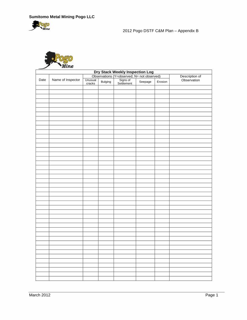
The results of inspections will be documented using the designated form (see
Appendix B). If any unusual situation is found, it will be reported to the Maintenance
Manager and Safety, Health and Environmental Manager.
7.2 Occasional Inspection
The DSTF will be inspected by Environmental personnel after extreme rainfall (two
inches within 24 hours) or an appreciable earthquake (felt by site personnel).
Sumitomo Metal Mining Pogo LLC 2012 Pogo DSTF Construction and Maintenance Plan
March 2012 Page 29
8.0 REFERENCES
AMEC, 2004, Drystack Tailings Facility Geotechnical Design Report.
AMEC, 2004, RTP Dam Design Report.
Teck-Pogo, 2004, Pogo Project Final Feasibility Study
AMEC, 2007, Pogo Mine Drystack Tailings Facility OMS Manual – Revision Two.
Pogo, 2012, Pogo Mine Monitoring Plan.
SRK, 2011a, Pogo Drystack Tailings Facility Expansion Preliminary Study.
SRK, 2011b, Pogo Mine – Findings of Winter Field Program and Preliminary
Recommendations for Dry Stack Storage Facility Construction and QA/QC Procedures.
SRK, 20112, Technical Specifications for Pogo Dry Stack Tailings Facility Expansion,
Revision 2, December 21, 2011.
SRK, 2012a, Dry Stack Tailings Facility (DSTF) Expansion Detailed Design, February
2012.
Appendix A
DSTF Shell Geotechnical Monitoring Data Sheet
Sumitomo Metal Mining Pogo LLC 2012 Pogo DSTF C&M Plan – Appendix A
March 2012 Page 1
Pogo Mine DSTF Shell Geotechnical Monitoring Data Sheet
Date Tested Reported by
Shell No. Elevation (ft)
Date Compacted
GPS Coordinates (degree) Map
Nuclear Densometer Grid
A N: W:
B N: W:
C N: W:
D N: W:
Sampling Location
1 N: W:
2 N: W:
3 N: W:
Moisture Content / Standard Proctor Test (Three samples per monitoring)
Sample No. 1 2 3 Average
Moisture Content (%)
Maximum Dry Density (pcf)
Optimum Moisture Content (%)
Nuclear Densometer (30 ft grid, Target Depth: 12 inch)
Number of measurements
Items Minimum Maximum Average
Moisture Content (%)
Dry Density (pcf)
% of Standard Proctor
Sand Cone Test (One test for every ten densometer measurements) (QA Program)
Test Hole No. 1 2 3 4 5 6 Average
Moisture Content (%)
Dry Density (pcf)
Notes: All lab test reports should be attached to this data sheet.
Waste Rock
Upstream
Densometer GridA
B
D
C
Sampling Location
1 2 3
Appendix B
Weekly Inspection Form
Sumitomo Metal Mining Pogo LLC 2012 Pogo DSTF C&M Plan – Appendix B
March 2012 Page 1
Dry Stack Weekly Inspection Log
Date Name of Inspector Observations (Y=observed; N= not observed) Description of
Observation Unusual cracks
Bulging Signs of
Settlement Seepage Erosion

Appendix C
Drawings
Note: The year-by-year drawings in this appendix were created assuming the shells
would be constructed during the summer season and that 93,000 – 98,000 tons of
tailings material would be placed annually at the DSTF. In June 2011, ADNR approved
to construct the shells year-round and it will facilitate the shell construction by placing
200,000 – 250,000 tons of tailings material at the drystack annually. The year-by-year
drawings will be updated after Pogo completes at least one full winter season of shell
construction.
Related Documents