Nanolithography on Responsive Materials Proton-fountain Electric-field-assisted Nanolithography (PEN) PNNA Seminar Nanomaterials Fabrication - Spring-2011 PSU Andres La Rosa, 1 Mindi Yan, 2 Damian Hegsted, 1 and Hui Wang 2 Physics 1 and Chemistry 2 Department, Portland State University, Portland OR NanoFab 2011 Acknowledgment Xiaohua Wang, Xin Wang, Carsten Maedler, Leo Ocola, Rodolfo Fernandez, Sailaja Chada,* and Xiquan Cui

Welcome message from author
This document is posted to help you gain knowledge. Please leave a comment to let me know what you think about it! Share it to your friends and learn new things together.
Transcript

Nanolithography on Responsive MaterialsProton-fountain Electric-field-assisted
Nanolithography (PEN)
PNNA Seminar Nanomaterials Fabrication - Spring-2011 PSU
Andres La Rosa,1 Mindi Yan,2Damian Hegsted,1 and Hui Wang2
Physics1 and Chemistry2 Department, Portland State University, Portland OR
NanoFab 2011
AcknowledgmentXiaohua Wang, Xin Wang, Carsten Maedler, Leo Ocola,
Rodolfo Fernandez, Sailaja Chada,* and Xiquan Cui

PNNA Seminar Nanomaterials Fabrication - Spring-2011 PSU
In memoriamSailaja Chada
Nanolithography on Responsive MaterialsProton-fountain Electric-field-assisted
Nanolithography (PEN)

PNNA Seminar Nanomaterials Fabrication - Spring-2011 PSU
I. Motivation: Underlying emerging biomimetic engineeringPEN as a method for creating erasable nanostructures usingresponsive materials
II. Comparison between “PEN” and “Dip pen nanolithgraphy”
III. Fabrication procedure III.A Preparation of P4VP responsive materialIII.B Preparation of acidic fountain tip
IV. Underlying working mechanisms of swelling in hydrogelsThe osmotic pressure. Lattice model for calculating the entropy: Ideal liquid vs Polymer solutions.
Nanolithography on Responsive MaterialsProton-fountain Electric-field-assisted
Nanolithography (PEN)
P4VP
Si
P4VP
Swollen feature
Water meniscus
+V
H3O+
[ H3O+ ]
‘Pen’ preparation
Polymer film preparation
F
Patterns formationon soft materials
Si
+V
F
PNNA Seminar Nanomaterials Fabrication - Spring-2011 PSU
Silicon wafer(“Piranha”
cleaned)
Spin coatedP4VP film)
(uv-cross-linked)
AFM probe k = 40 N/m
acidic phosphate buffer
Pattern formation in responsive polymer films
triggered by local protonation
P4VP

PNNA Seminar Nanomaterials Fabrication - Spring-2011 PSU
Responsive materialsRespond to a stimulus (mechanical, chemical, optical,changes in environmental conditions, etc.)Ref: B. Bhushan, “Biomimetics: lessons from nature-an overview,” Phil. Trans. R. Soc. A 367, 1445 (2009).
One current focus in biomimetic materialsDevelopment of versatile synthetic responsive thin films
Underlying emerging biomimetic technologies
In one approach, the complex synthetic hierarchy (needed to mimic natural bio-systems)is conceived as a combination of domains separated by stimuli-responsive thin films that regulate the interactions between the domain compartments.Ref: Tokarev, M. Motornov, and S. Minko; “Molecular-engineered stimuli-responsive thin polymer film: a platform for the development of integrated multifunctional intelligent materials,” J. Mater. Chem. 19, 6932 (2009).

PNNA Seminar Nanomaterials Fabrication - Spring-2011 PSU
Underlying emerging biomimetic technologies
In another approach, a cell is conceived not just as a chemical but also as a mechanical device,It is found that the cell membrane is very sensitive to the mechanical properties of its surrounding matrix (affecting their growth, differentiation, migration, and, eventually, apoptosis,) Ref: C. Cofield, “Cell is mechanical device,” The American Physical Society, APS news, Series II, 19, 4 (June 2010).
Both approaches emphasize the need for harnessing thefabrication of synthetic thin film responsive materials

PNNA Seminar Nanomaterials Fabrication - Spring-2011 PSU
Underlying emerging biomimetic technologiesTop-Down and Bottom-up approaches
Research on biomimetic materials have resulted in the design of a variety of responsive building blocks hydrogels, brushes, hybrid systems with inorganicparticles
that respond selectively to pH, temperature, optical, and magnetic external stimuli.
Following the “bottom-up” route: self-assembly of polymeric supramolecules.
Progress using “top-down” approach: responsive polymer brushes,growth of polymers from DPN-patterned templates,chain polymerization triggered by local stimulation using a STM stylus.

PNNA Seminar Nanomaterials Fabrication - Spring-2011 PSU
Underlying emerging biomimetic technologiesTop-Down and Bottom-up approaches
PEN falls in the top-down category approach.Atomic force Dip pen PENmicroscopy nanolithography
Our description concentrates on hydrogels,since the latter describes closer the experimental results obtained in current applications of PEN.
PNNA Seminar Nanomaterials Fabrication - Spring-2011 PSU
Underlying emerging biomimetic technologiesTop-Down and Bottom-up approaches
Hydrogels,A flexible (typically) hydrophilic cross-linked polymer network and a fluid filling the interstitial spaces.The entire network holds the liquid in place thus giving the system a solid aspect. Contrary to other solid materials, these wet and soft systems are capable of undergoing very large deformation (greater than 100%).
Polymer solution Lattice model
Polymer segmentSolvent
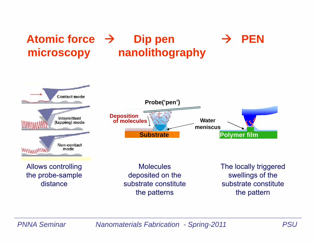
Atomic force Dip pen PENmicroscopy nanolithography
PNNA Seminar Nanomaterials Fabrication - Spring-2011 PSU
Probe(’pen’)
Substrate
Water meniscus
Polymer film
Deposition of molecules
Molecules deposited on the
substrate constitute the patterns
The locally triggered swellings of the
substrate constitute the pattern
Allows controlling the probe-sample
distance

Deposition of
molecules(“ink”)
PNNA Seminar Nanomaterials Fabrication - Spring-2011 PSU
Probe (’pen’)
http://mcf.tamu.edu/instruments/dip-pen-nanolithographer
Substrate (’paper’)
Dip pen nanolithography

Deposition of
molecules(“ink”)
PNNA Seminar Nanomaterials Fabrication - Spring-2011 PSU
Probe‘Ink’
http://mcf.tamu.edu/instruments/dip-pen-nanolithographer
Dip pen nanolithography
“ink’ molecules deposited on the substrate constitute the pattern

+H
++
++
HH
HH
P4VPPolymer
P4VPPolymer
Coulomb repulsion between thepyridinium ions leads to an increaseof the film thickness.
PNNA Seminar Nanomaterials Fabrication - Spring-2011 PSU
Pattern formation in responsive polymer films triggered by local protonation
Swelling mechanism

P4VP
Si
P4VP
Swollen feature
Water meniscus
+V
H3O+
[ H3O+ ]
‘Pen’ preparation
Polymer film preparation (soft material)
F
Patterns formation
Si
+V
F
PNNA Seminar Nanomaterials Fabrication - Sprng-2011 PSU
Silicon wafer(“Piranha”
cleaned)
Spin coatedP4VP film)
(uv-cross-linked)
AFM probe k = 40 N/m
acidic phosphate buffer
Pattern formation in responsive polymer films
triggered by local protonation
P4VP
The locally triggered swellings of the film constitute the pattern

Robust attachment• Scotch tape test• Boiling solvent
Ease of preparation Substrate-independent
1) Coat polymer2) UV irradiate3) Solvent extract
0
5
10
15
20
25
30
35
40
45
50
Bef
ore
UV
Afte
r 5 m
inU
V
Afte
rex
tract
ion
Thic
knes
s (n
m)
Preparation of polymer thin films Immobilization by direct UV Irradiation
Yan, M.; Harnish, B. Adv. Mater., 2003, 15, 224.

CHH2C < 280 nm
CH2C
CHCH
HC
•
•
•
CH2 • +
+ H •
+ H •
CHH2C < 280 nm
CH2C
CHCH
HC
•
•
•
CH2 • +
+ H •
+ H •
R. Rånby, J. F. Rabek, Photodegradation, Photo-oxidation and Photostabilization of Polymers, 1975, p167-172.
CH2C•
•CH2C
+ CH2CCH2C
crosslinking
HC•
+ H •
H2C
chain scission
CH2C•
•
+ O2
CH2COO
CH2CO
CH2
OH
UV
CH
CH2CO
CH2 CH
•
CH2CO
CH2 CH•
+
Oxidative Degradation
Polystyrene

OH
CH CH2
UV irradiation< 290 nm
O
CH CH2
H
OH
C CH2
H
Poly(4-vinyl phenol)
OH
CH2C
O2
OH
CH2COO
RH-R
OH
CH2COOH
CH2 CH
OH
- OH
OH
CH2CO
CH2 CH
OHOH
CH2C CH2 CH
OH
O
OH
C CH2
OH
C CH2
OH
C CH2
OH
C CH2
HC O
HC O
HC O
HC O
HC O
HC O
Uppalapati, S.; Chada, S.; Engelhard, M. H.; Yan, M. Macromol. Chem. Phys. 2010, 211, 461.
HC
O
HC
O
CH2 CH
O
CH
O
CH2
CH2
0 1 2 3 4 5 6 7 8
0
1000
2000
3000
P4VPPNVPPSGold
pH
0 500 1000 1500 2000 2500-3000
-2000
-1000
0
1.0 2.0 3.0 3.5 4.0 4.5 5.0 6.0 7.0
pH
time (s)
n
N
n
P4VP PS
NnO
PNVP
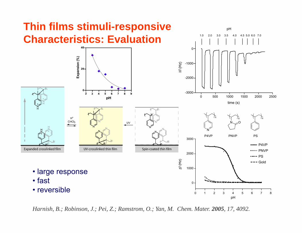
• large response • fast • reversible
Harnish, B.; Robinson, J.; Pei, Z.; Ramstrom, O.; Yan, M. Chem. Mater. 2005, 17, 4092.
Thin films stimuli-responsiveCharacteristics: Evaluation

Protontransfer
Swelling
acidic phosphate buffer
molecules
C. Maedler, S. Chada, X. Cui, M. Taylor, M. Yan, and A. La Rosa, J. Appl. Phys. 104, 014311 (2008).
Probe
PNNA Seminar Nanomaterials Fabrication - Spring-2011 PSU
P4VPPolymer
Electrostaticrepulsion
Dwelling time: 6 s, 4 s, 2 s
Pattern formation
Pattern formation in responsive polymer films triggered by local protonation
Swollenstructure

Protontransfer
Swelling
acidic phosphate buffer
molecules
Probe
PNNA Seminar Nanomaterials Fabrication - Sprng-2011 PSU
P4VPPolymer
Electrostaticrepulsion
Writing: rate=0.04 line/s; i.e. 100 nm/s or 1 pixel / 250ms)
Imaging: rate=2 line/s; i.e. 5 µm/s or 1pixel / 5ms)
Sequential fabrication and imaging
A. La Rosa and, M. Yan, in “Tip Base Nanolithography” (to be published in June-2011)
Pattern formation in responsive polymer films via local protonation

Role of humidity
PNNA Seminar Nanomaterials Fabrication - Sprng-2011 PSU
AFM Chamber
Water
Nitrogen
C. Maedler, H. Graaf, S. Chada, M. Yan, and A. La Rosa, "Nano-structure Formation Driven by Local Protonation of Polymer Thin Films", Proc. SPIE 7364, 736409-1 – 736409-8 (2009).

Effect of Electric Field and Contact Force
P4VPSi
Water meniscus
+V
Applied bias voltage (V)
Applied contact force (N)
Force
Xiaohua Wang, Xin Wang, R. Fernandez, L. Ocola, M. Yan, and A. La Rosa; “Electric Field-Assisted Dip-Pen Nanolithography on Poly(4-vinyl Pyridine) Films,” ACS Appl. Mater. Interface 2, 2904–2909 (2010).

PENFinest line structures
P4VPSi
Water meniscus
+V
Force
Xiaohua Wang, Xin Wang, R. Fernandez, L. Ocola, M. Yan, and A. La Rosa; “Electric Field-Assisted Dip-Pen Nanolithography on Poly(4-vinyl Pyridine) Films,” ACS Appl. Mater. Interface 2, 2904–2909 (2010).

PENReversibility
Xiaohua Wang, Xin Wang, R. Fernandez, L. Ocola, M. Yan, and A. La Rosa; “Electric Field-Assisted Dip-Pen Nanolithography on Poly(4-vinyl Pyridine) Films,” ACS Appl. Mater. Interface 2, 2904–2909 (2010).

Underlying working mechanisms of swelling in hydrogels
A. La Rosa and, M. Yan, in “Tip Base Nanolithography” (to be published in June-2011)
A B Semi-permeable membrane Polymer solution
Solvent + solute Pure solvent
SoluteSolvent
Polymer segmentSolvent
h
Lattice model Lattice model Vapor of pure solvent
P2 P1
Chemical potential of water in phase-A (pure solvent water)is greater thanthe chemical potential of water in phase-B (solven + solute)
AP,waterB
P,water <

Underlying working mechanisms of swelling in hydrogels
Gibbs free energy G = G (T, P, N).
Being the temperature T and pressure P intensive quantities, G has to have the form
G = N f(T, P),
where N is the number of particles of the analyzed system.
Since dG = -S dT + V dP + dN and = (dG/dN)T,P, the extensive property G = N f(T, P) implies that is only a function of T and P; that is,
= G/N = f(T, P).

Underlying working mechanisms of swelling in hydrogels
Accordingly, is the Gibbs free energy per molecule, andit is a quantity independent of N. Thus,
d(G/N) = d = - (S/N) dT + (V/N) dP,
which implies,
V/NPd
d
.

Underlying working mechanisms of swelling in hydrogels
This expression is pertinent to the quantification of the osmotic pressure. In effect, it reflects the change in chemical potential due to an increase in pressure, =( V/N) P (where it has been assumed that the volume does not change with pressure.) Using v ≡ ( V/N), one obtains
.
BP2,water A
P1,water- = v (P2 – P1),
BP2,water A
P1,water- = v osmotic
Related Documents