THE NEW GENERATION torque reduction up to 30 % reduced axial forces increased tool life improved surface finish quality GUHRING – YOUR WORLD-WIDE PARTNER Pionex the new generation FLUTELESS MACHINE TAPS

Welcome message from author
This document is posted to help you gain knowledge. Please leave a comment to let me know what you think about it! Share it to your friends and learn new things together.
Transcript

THE NEW GENERATION torque reduction up to 30 % reduced axial forces increased tool life improved surface finish quality
GUHRING – YOUR WORLD-WIDE PARTNER
Pionex the new generation FLUTELESS MACHINE TAPS

Optimised polygon form Based to a geometric modification
the contact surface between tool and
functionality area could be optimised.
This reduced torque by up to 30 %.
New lubricating groove geometry
Thanks to the optimised lubricating grooves the lubricating effect has been clearly improved in the forming lead area.
A special surface finish treatment in combination with the TiCN-coating ensures increased wear-resistance.
Tool material
Increased wear-resistance thanks to the application of a new powder metallurgical base material.
Shank tolerance h6
Due to the shank tolerance h6 the new fluteless tap generation can be applied in all standard clamping chucks.
Pionexthe new generation FLUTELESS MACHINE TAPS
≤3xDHSS-E-PM
C E C E
h6 h6 h6 h6
====
M6HX
6GX
MF6HX
6GX
UNC 2BX
UNF 2BX
G - X
/ / / / / / / / / /
P
P1 ≤800 N/mm²S235JR 1.0037
C15 1.0401 25 25 25 2511SMnPb30 1.0718
P2 800 - 1000 N/mm²
S355J2 1.0577C60 1.0601 25 25 25 25
31CrMo12 1.8515
P3 800 - 1200 N/mm²
42CrMo4 1.7225
15 15 15 1536CrNiMo4 1.6511X36CrMo17 1.2316
HS 6-5-2 1.3343
M
M1 ≤1000 N/mm²
X5CrNi18-10 1.4301X6CrNiTi18-10 1.4571 15 15 15 15X8CrNiS18-9 1.4305
M2 ≤1000 N/mm²
X17CrNi16-2 1.4057X90CrMoV18 1.4112 10 10 10 10
X2CrTi12 1.4512
M3 ≤1300 N/mm²
X2CrNiMoN22-5-3 1.4462X2CrNiMoN25-7-4 1.4410 6 6 6 6
X2CrNiMoCuWN25-7-4 1.4501
K
K1 300 HBEN-GJL-150 0.6015EN-GJL-250 0.6025EN-GJL-300 0.6030
K2 350 HBEN-GJS-400-15 0.7040
30 30 30 30EN-GJS-600-3 0.7060EN-GJS-700-2 0.7070
K31000 N/mm2 EN-GJS1000-5
25 25 25 25350 HB EN-GJV250EN-GJV400
N
N1 ≤450 N/mm²Al99,5H 3.0250AlMgSi1 32315 15 15 15 15
AlZn4,5Mg 3.4335
N2 ≤600 N/mm²
GD-AlSi5Cu1Mg 3.2134GD-AlSi8Cu3 3.2162
30 30 30 30G-AlSi9Mg 3.2373G-AlSi12 3.2581
N3 ≤500 N/mm² GDMgAl8Zn1 3.5812.08
N4
CuZn20 2.0250 30 30 30 30CuZn37Pb0,5 2.0332CuZn39Pb2 2.0380CuZn43Pb2 2.0410
N5 ≤1400 N/mm² Ampco
N6 PMMA, POM,PVCPertinax
S
S1≤ 1200 N/mm²
Titan 3.702<5TiAl5Sn2 3.7115 8 8 8 8TiAl6V4 3.7165
S2 ≤ 1400 N/mm²
Hastelloy C4 2.46108 8 8 8Inconel 718 2.4668
Nimonic 105 2.4634
HH1 45 - 55 HRCH2 55 - 62 HRC
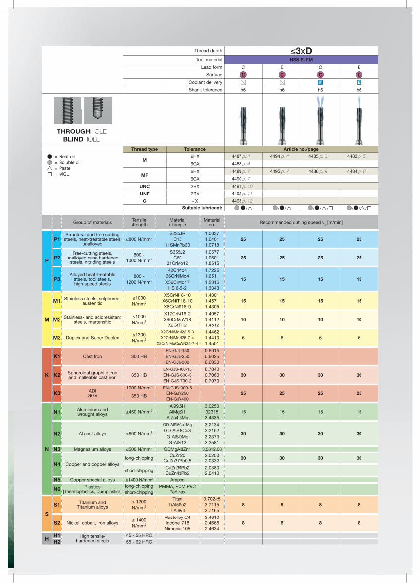
Group of materials Tensilestrength
Materialexample
Materialno. Recommended cutting speed vc [m/min]
Structural and free cuttingsteels, heat-treatable steels
unalloyed
Free-cutting steels,unalloyed case hardened
steels, nitriding steels
Alloyed heat-treatablesteels, tool steels,high speed steels
Stainless steels, sulphured,austenitic
Stainless- and acidresistantsteels, martensitic
Duplex and Super Duplex
Cast Iron
Spheroidal graphite ironand malleable cast iron
ADIGGV
Aluminium andwrought alloys
Al cast alloys
Magnesium alloys
Copper and copper alloyslong-chipping
short-chipping
Copper special alloysPlastics
[Thermoplastics, Duroplastics]long-chippingshort-chipping
Titanium andTitanium alloys
Nickel, cobalt, iron alloys
High tensile/hardened steels
Thread depth
Tool material
Lead form
Surface
Coolant delivery
Shank tolerance
THROUGHHOLEBLINDHOLE
Neat oilSoluble oilPasteMQL
Thread type Tolerance Article no./page4487 p. 4 4494 p. 4 4485 p. 6 4483 p. 5
4488 p. 4
4489 p. 7 4495 p. 7 4486 p. 9 4484 p. 8
4490 p. 7
4491 p. 10
4492 p. 11
4493 p. 12Suitable lubricant:
the new generation FLUTELESS MACHINE TAPS

4
Article no. 4487 from Ø M2 with oil grooves, Ø tolerance ≤ M1.4 = 4HX
DIN 2174 ~DIN 371/~DIN 376 Article no. 4487 4488 4494
Discount group 208 208 208
d1 P d2 SW dk l1 l2 l5 Code no. Availability
mm mm mm mm mm mm mm
M1 0.250 2.500 2.100 0.90 40.000 4.000 1.000 • M1,2 0.250 2.500 2.100 1.10 40.000 4.800 1.200 • M1,4 0.300 2.500 2.100 1.25 40.000 5.600 1.400 • M1,6 0.350 2.500 2.100 1.45 40.000 6.400 1.600 • M1,7 0.350 2.500 2.100 1.55 40.000 6.800 1.700 • M1,8 0.350 2.500 2.100 1.65 40.000 7.300 1.800 • M2 0.400 2.800 2.100 1.85 45.000 8.000 13.500 2.000 • • •
M2,5 0.450 2.800 2.100 2.30 50.000 9.000 14.500 2.500 • • •M3 0.500 3.500 2.700 2.80 56.000 10.000 18.000 3.000 • • •M4 0.700 4.500 3.400 3.70 63.000 12.000 21.000 4.000 • • •M5 0.800 6.000 4.900 4.65 70.000 14.000 25.000 5.000 • • •M6 1.000 6.000 4.900 5.55 80.000 16.000 30.000 6.000 • • •M8 1.250 8.000 6.200 7.40 90.000 17.000 35.000 8.000 • • •M10 1.500 10.000 8.000 9.30 100.000 20.000 39.000 10.000 • • •M12 1.750 9.000 7.000 11.20 110.000 24.000 49.000 12.000 • • •M14 2.000 11.000 9.000 13.10 110.000 26.000 53.000 14.000 • • •M16 2.000 12.000 9.000 15.10 110.000 26.000 54.000 16.000 • • •M20 2.500 16.000 12.000 18.90 140.000 32.000 62.000 20.000 • • •
Fluteless machine taps for ISO metric threads
RTool material HSS-E-PM
Tolerance on Ø 4HX/6HX 6GX 6HX
Surface
P ● Type N N N
M ● Form C C E
K ● Internal cooling
N ○
~ DIN 371
dk
d1
l1
SWd2
l2
P
l5
S ●
H
~ DIN 376
dk
d1
l1
SW d2
l2
P
l5
Fluteless machine taps

5
DIN 2174 ~DIN 371/~DIN 376 Article no. 4483
Discount group 208
d1 P d2 SW dk l1 l2 l5 Code no. Availability
mm mm mm mm mm mm mm M5 0.800 6.000 4.900 4.65 70.000 8.500 25.000 5.000 •M6 1.000 6.000 4.900 5.55 80.000 11.000 30.000 6.000 •M8 1.250 8.000 6.200 7.40 90.000 14.000 35.000 8.000 •M10 1.500 10.000 8.000 9.30 100.000 16.000 39.000 10.000 •M12 1.750 9.000 7.000 11.20 110.000 18.500 49.000 12.000 •M14 2.000 11.000 9.000 13.10 110.000 20.000 53.000 14.000 •M16 2.000 12.000 9.000 15.10 110.000 20.000 54.000 16.000 •M20 2.500 16.000 12.000 18.90 140.000 25.000 62.000 20.000 •
Oil feed fluteless taps f. ISO metric threads
RTool material HSS-E-PM
Tolerance on Ø 6HX
Surface
P ● Type N
M ● Form E
K ● Internal cooling
N ○
~ DIN 371
dk
d1
l1
SWd2
l2
P
l5
S ●
H
~ DIN 376
dk
d1
l1
SW d2
l2l5
Fluteless machine taps

6
DIN 2174 ~DIN 371/~DIN 376 Article no. 4485
Discount group 208
d1 P d2 SW dk l1 l2 l5 Code no. Availability
mm mm mm mm mm mm mm M5 0.800 6.000 4.900 4.65 70.000 8.500 25.000 5.000 •M6 1.000 6.000 4.900 5.55 80.000 11.000 30.000 6.000 •M8 1.250 8.000 6.200 7.40 90.000 14.000 35.000 8.000 •M10 1.500 10.000 8.000 9.30 100.000 16.000 39.000 10.000 •M12 1.750 9.000 7.000 11.20 110.000 18.500 49.000 12.000 •M14 2.000 11.000 9.000 13.10 110.000 20.000 53.000 14.000 •M16 2.000 12.000 9.000 15.10 110.000 20.000 54.000 16.000 •M20 2.500 16.000 12.000 18.90 140.000 25.000 62.000 20.000 •
Oil feed fluteless taps f. ISO metric threads
RTool material HSS-E-PM
Tolerance on Ø 6HX
Surface
P ● Type N
M ● Form C
K ● Internal cooling
N ○
~ DIN 371
dk
d1
l1
SWd2
l2
P
l5
S ●
H
~ DIN 376
dk
d1
l1
SW d2
l2
P
l5
Fluteless machine taps

7
DIN 2174 ~DIN 374 Article no. 4489 4490 4495
Discount group 208 208 208
d1 d2 SW dk l1 l2 l5 Code no. Availability
mm mm mm mm mm mm
M8 x 1 6.000 4.900 7.55 90.000 16.000 35.000 8.005 • • •M10 x 1 7.000 5.500 9.55 90.000 16.000 35.000 10.005 • • •
M10 x 1,25 7.000 5.500 9.40 100.000 20.000 39.000 10.006 • • •M12 x 1,25 9.000 7.000 11.40 100.000 20.000 40.000 12.006 • • •M12 x 1,5 9.000 7.000 11.30 100.000 20.000 40.000 12.007 • • •M14 x 1,25 11.000 9.000 13.40 100.000 20.000 40.000 14.006 • • •M14 x 1,5 11.000 9.000 13.30 100.000 20.000 40.000 14.007 • • •M16 x 1,5 12.000 9.000 15.30 100.000 22.000 44.000 16.007 • • •M20 x 1,5 16.000 12.000 19.30 125.000 25.000 44.000 20.007 • • •
Fluteless machine taps for ISO metric fine threads
RTool material HSS-E-PM
Tolerance on Ø 6HX 6GX 6HX
Surface
P ● Type N N N
M ● Form C C E
K ● Internal cooling
N ○
S ●
H
DIN 371
dk
d1
SW d2
l1
l2
l5
Fluteless machine taps

8
DIN 2174 ~DIN 374 Article no. 4484
Discount group 208
d1 d2 SW dk l1 l2 l5 Code no. Availability
mm mm mm mm mm mm M8 x 1 6.000 4.900 7.55 90.000 11.000 35.000 8.005 •M10 x 1 7.000 5.500 9.55 90.000 11.000 35.000 10.005 •
M10 x 1,25 7.000 5.500 9.40 100.000 14.000 39.000 10.006 •M12 x 1,25 9.000 7.000 11.40 100.000 16.000 40.000 12.006 •M12 x 1,5 9.000 7.000 11.30 100.000 16.000 40.000 12.007 •M14 x 1,25 11.000 9.000 13.40 100.000 15.000 40.000 14.006 •M14 x 1,5 11.000 9.000 13.30 100.000 15.000 40.000 14.007 •M16 x 1,5 12.000 9.000 15.30 100.000 15.000 44.000 16.007 •M20 x 1,5 16.000 12.000 19.30 125.000 16.000 44.000 20.007 •
Oil feed fluteless taps f. ISO metric fine threads
RTool material HSS-E-PM
Tolerance on Ø 6HX
Surface
P ● Type N
M ● Form E
K ● Internal cooling
N ○
S ●
H
~ DIN 374
dk
d1
l1
SW d2
l2l5
Fluteless machine taps

9
DIN 2174 ~DIN 374 Article no. 4486
Discount group 208
d1 d2 SW dk l1 l2 l5 Code no. Availability
mm mm mm mm mm mm M8 x 1 6.000 4.900 7.55 90.000 11.000 35.000 8.005 •M10 x 1 7.000 5.500 9.55 90.000 11.000 35.000 10.005 •
M10 x 1,25 7.000 5.500 9.40 100.000 14.000 39.000 10.006 •M12 x 1,25 9.000 7.000 11.40 100.000 16.000 40.000 12.006 •M12 x 1,5 9.000 7.000 11.30 100.000 16.000 40.000 12.007 •M14 x 1,25 11.000 9.000 13.40 100.000 15.000 40.000 14.006 •M14 x 1,5 11.000 9.000 13.30 100.000 15.000 40.000 14.007 •M16 x 1,5 12.000 9.000 15.30 100.000 15.000 44.000 16.007 •M20 x 1,5 16.000 12.000 19.30 125.000 16.000 44.000 20.007 •
Oil feed fluteless taps f. ISO metric fine threads
RTool material HSS-E-PM
Tolerance on Ø 6HX
Surface
P ● Type N
M ● Form C
K ● Internal cooling
N ○
S ●
H
~ DIN 374
dk
d1
l1
SW d2
l2
P
l5
Fluteless machine taps

10
DIN 2184-1 ~DIN 371/~DIN 376 Article no. 4491
Discount group 208
d1 d2 SW dk l1 l2 l5 Code no. Availability
mm mm mm mm mm mm 4 - 40 3.500 2.700 2.55 56.000 11.000 18.000 2.845 •6 - 32 4.000 3.000 3.15 56.000 12.000 20.000 3.505 •8 - 32 4.500 3.400 3.80 63.000 12.000 21.000 4.166 •10 - 24 6.000 4.900 4.35 70.000 14.000 25.000 4.826 •12 - 24 6.000 4.900 5.00 80.000 16.000 30.000 5.486 •1/4 - 20 7.000 5.500 5.75 80.000 16.000 30.000 6.350 •5/16 - 18 8.000 6.200 7.30 90.000 18.000 35.000 7.938 •3/8 - 16 10.000 8.000 8.80 90.000 20.000 35.000 9.525 •7/16 - 14 8.000 6.200 10.30 100.000 22.000 42.000 11.113 •1/2 - 13 9.000 7.000 11.80 100.000 25.000 40.000 12.700 •9/16 - 12 11.000 9.000 13.30 100.000 28.000 40.000 14.288 •5/8 - 11 12.000 9.000 14.80 100.000 30.000 44.000 15.875 •3/4 - 10 14.000 11.000 17.90 110.000 33.000 44.000 19.050 •
Fluteless machine taps for UNC-threads
RTool material HSS-E-PM
Tolerance on Ø 2BX
Surface
P ● Type N
M ● Form C
K ● Internal cooling
N ○
~ DIN 371
dk
d1
l1
SWd2
l2
P
l5
S ●
H
~ DIN 376
dk
d1
l1
SW d2
l2
P
l5
Fluteless machine taps

11
DIN 2184-1 ~DIN 371/~DIN 374 Article no. 4492
Discount group 208
d1 d2 SW dk l1 l2 l5 Code no. Availability
mm mm mm mm mm mm 4 - 48 3.500 2.700 2.60 56.000 10.000 18.000 2.845 •6 - 40 4.000 3.000 3.20 56.000 11.000 20.000 3.505 •8 - 36 4.500 3.400 3.85 63.000 12.000 21.000 4.166 •10 - 32 6.000 4.900 4.45 70.000 14.000 25.000 4.826 •12 - 28 6.000 4.900 5.10 80.000 16.000 30.000 5.486 •1/4 - 28 7.000 5.500 5.95 80.000 16.000 30.000 6.350 •5/16 - 24 8.000 6.200 7.45 90.000 18.000 35.000 7.938 •3/8 - 24 10.000 8.000 9.05 100.000 18.000 39.000 9.525 •7/16 - 20 8.000 6.200 10.55 100.000 22.000 42.000 11.113 •1/2 - 20 9.000 7.000 12.10 100.000 20.000 40.000 12.700 •9/16 - 18 11.000 9.000 13.65 100.000 22.000 40.000 14.288 •5/8 - 18 12.000 9.000 15.25 100.000 22.000 44.000 15.875 •3/4 - 16 14.000 11.000 18.35 110.000 25.000 44.000 19.050 •
Fluteless machine taps for UNF-threads
RTool material HSS-E-PM
Tolerance on Ø 2BX
Surface
P ● Type N
M ● Form C
K ● Internal cooling
N ○
~ DIN 371
dk
d1
l1
SWd2
l2
P
l5
S ●
H
~ DIN 374
dk
d1
l1
SW d2
l2
P
l5
Fluteless machine taps

12
DIN 2184-1 DIN 2189 Article no. 4493
Discount group 208
d1 P d2 SW dk l1 l2 l5 Code no. Availability
G/inch mm mm mm mm mm mm G1/8 28.000 7.000 5.500 9.30 90.000 18.000 35.000 9.728 •G1/4 19.000 11.000 9.000 12.50 100.000 20.000 40.000 13.157 •G3/8 19.000 12.000 9.000 16.00 100.000 22.000 44.000 16.662 •G1/2 14.000 16.000 12.000 20.00 125.000 25.000 44.000 20.955 •
Fluteless machine taps for BSP-threads
RTool material HSS-E-PM
Tolerance on Ø
Surface
P ● Type N
M ● Form C
K ● Internal cooling
N ○
S ●
H
dk
d1
l1
SW d2
l2
P
l5
Fluteless machine taps

13
M 17 x 1.50 16.30 16.26 16.38 15.376 15.751M 18 x 1.00 17.55 17.52 17.62 16.917 17.217M 18 x 1.50 17.30 17.26 17.38 16.376 16.751M 18 x 2.00 17.10 17.05 17.20 15.835 16.310M 20 x 1.00 19.55 19.52 19.62 18.917 19.217M 20 x 1.50 19.30 19.26 19.38 18.376 19.751M 24 x 1.00 23.55 23.52 23.62 22.917 23.217M 24 x 1.50 23.30 23.26 23.38 22.376 22.751M 24 x 2.00 23.10 23.05 23.20 21.835 22.310M 27 x 1.50 26.30 26.26 26.38 25.376 25.751M 30 x 1.50 29.30 29.26 29.38 28.376 28.751M 33 x 1.50 32.30 32.26 32.38 31.376 31.751M 36 x 1.50 35.30 35.26 35.38 34.376 34.751M 39 x 1.50 38.30 38.26 38.38 37.376 37.751M 42 x 1.50 41.30 41.26 41.38 42.376 42.751
M 2.5 x 0.35 2.35 2.35 2.38 2.121 2.221M 3 x 0.35 2.85 2.85 2.88 2.621 2.721M 4 x 0.35 3.85 3.85 3.88 3.621 3.721M 4 x 0.50 3.80 3.78 3.83 3.459 3.639M 5 x 0.50 4.80 4.78 4.83 4.459 4.639M 5.5 x 0.50 5.30 5.28 5.33 4.959 5.139M 6 x 0.75 5.65 5.62 5.70 5.188 5.424M 7 x 0.75 6.65 6.62 6.70 6.188 6.424M 8 x 0.75 7.65 7.62 7.70 7.188 7.424M 8 x 1.00 7.55 7.52 7.62 6.917 7.217M 9 x 0.75 8.65 8.62 8.70 8.188 8.424M 9 x 1.00 8.55 8.52 8.62 7.917 8.217M 10 x 0.75 9.65 9.62 9.70 9.188 9.424M 10 x 1.00 9.55 9.52 9.62 8.917 9.217M 10 x 1.25 9.40 9.36 9.47 8.647 8.982M 11 x 0.75 10.65 10.62 10.70 10.188 10.424M 11 x 1.00 10.55 10.52 10.62 9.917 10.217M 12 x 1.00 11.55 11.52 11.62 10.917 11.217M 12 x 1.25 11.40 11.36 11.47 10.647 10.982M 12 x 1.50 11.30 11.26 11.38 10.376 10.751M 14 x 1.00 13.55 13.52 13.62 12.917 13.217M 14 x 1.25 13.40 13.36 13.47 12.647 12.982M 14 x 1.50 13.30 13.26 13.38 12.376 12.751M 15 x 1.00 14.55 14.52 14.62 13.917 14.217M 15 x 1.50 14.30 14.26 14.38 13.376 13.751M 16 x 1.00 15.55 15.52 15.62 14.917 15.217M 16 x 1.50 15.30 15.26 15.38 14.376 14.751M 17 x 1.00 16.55 16.52 16.62 15.917 16.217
M1 0.25 0.90 0.89 0.92 0.729 0.819M1.2 0.25 1.10 1.09 1.12 0.929 1.019M1.4 0.30 1.28 1.27 1.30 1.075 1.181M1.6 0.35 1.46 1.45 1.48 1.221 1.346M1.7 0.35 1.56 1.55 1.58 1.321 1.446M1.8 0.35 1.66 1.65 1.68 1.421 1.546M 2 0.40 1.85 1.84 1.88 1.567 1.679M 2.2 0.45 2.00 2.01 2.05 1.713 1.838M 2.5 0.45 2.30 2.28 2.32 2.013 2.138M 3 0.50 2.80 2.78 2.85 2.459 2.639M 3.5 0.60 3.25 3.23 3.30 2.850 3.050M 4 0.70 3.70 3.68 3.76 3.242 3.466M 4.5 0.75 4.20M 5 0.80 4.65 4.62 4.71 4.134 4.384M 6 1.00 5.55 5.52 5.62 4.917 5.217M 7 1.00 6.55 6.52 6.62 5.917 6.217M 8 1.25 7.40 7.36 7.47 6.647 6.982M 9 1.25 8.40 8.36 8.47 7.647 7.982M 10 1.50 9.30 9.26 9.38 8.376 8.751M 11 1.50 10.30 10.26 10.38 9.376 9.751M 12 1.75 11.20 11.15 11.29 10.106 10.531M 14 2.00 13.10 13.05 13.20 11.835 12.310M 16 2.00 15.10 15.05 15.20 13.835 14.310M 18 2.50 16.90 16.83 17.02 15.294 15.854M 20 2.50 18.90 18.83 19.02 17.294 17.854M 22 2.50 20.90 20.83 21.02 19.294 19.854M 24 3.00 22.70 22.62 22.80 20.752 21.382M 27 3.00 25.70 25.62 25.80 23.752 24.382M 30 3.50 28.50 28.40 28.60 26.211 26.921M 33 3.50 31.50 31.40 31.60 29.211 29.921M 36 4.00 34.30 34.17 34.40 31.670 32.420M 39 4.00 37.30 37.17 37.40 34.670 35.420M 42 4.50 40.10 39.95 40.20 37.129 37.979
nom. x pitch tapp. tapp. size core Ø Ø size hole Ø of int. thread 7H*
hole Ømin. max. min. max.
mm mm mm mm mm mm
nom. x pitch tapp. tapp. size core Ø Ø size hole Ø of int. thread 7H*
hole Ømin. max. min. max.
mm mm mm mm mm mm
ISO metric fine threadsDIN 13
nom. pitch tapp. tapp. size core Ø Ø size hole Ø of int. thread 7H*
hole Ømin. max. min. max.
mm mm mm mm mm mm
Std. ISO metric threads DIN 13
TAPPING SIZE HOLE AND HOLE DIAMETER
Tapping size hole diameter tolerance zone for thread forming (to DIN 13. section 50)Due to the tensile strength it is not necessary to adhere to the tapping size hole diameter tolerance class 6H; tolerance class 7H satisfies the requirementthat the flank coverage of external and internal threads should not fall below 0.32 x P. In addition. formed threads generally possess a higher tensile strength in comparison to cut threads thanks to an uninterrupted grain flow and subsequent work hardening.
* M 2 up to M 2.5 tapping size hole of int. thread 6H
* M 2.5 x 0.35 up to M 4 x 0.35 tapping size hole of int. thread 6H
Recommended tapping size holes for thread forming
G 1/16 28 7.30 7.28 7.35 6.561 6.843G 1/8 28 9.30 9.28 9.35 8.566 8.848G 1/4 19 12.50 12.48 12.55 11.445 11.890G 3/8 19 16.00 15.98 16.05 14.950 15.395G 1/2 14 20.00 19.98 20.12 18.631 19.172G 5/8 14 22.00 21.98 22.12 20.587 21.128G 3/4 14 25.50 25.48 25.62 24.117 24.658G 7/8 14 29.25 29.23 29.37 27.877 28.418G 1 11 32.00 31.98 32.15 30.291 30.931G 11/4 11 40.75 40.70 40.85 38.952 39.592
Nr. 1 - 72 1.70 1.69 1.72 1.473 1.610Nr. 2 - 64 2.00 1.99 2.03 1.755 1.910Nr. 3 - 56 2.30 2.29 2.34 2.024 2.197Nr. 4 - 48 2.60 2.59 2.63 2.271 2.459Nr. 5 - 44 2.90 2.89 2.93 2.550 2.741Nr. 6 - 40 3.20 3.19 3.24 2.819 3.023Nr. 8 - 36 3.85 3.83 3.88 3.404 3.607Nr. 10 - 32 4.45 3.43 4.49 3.962 4.166Nr. 12 - 28 5.10 5.07 5.13 4.496 4.7241/4 - 28 5.95 5.92 5.99 5.359 5.5885/16 - 24 7.45 7.42 7.50 6.782 7.0363/8 - 24 9.05 9.02 9.10 8.838 8.6367/16 - 20 10.55 10.48 10.58 9.728 10.0331/2 - 20 12.10 12.08 12.18 11.328 11.6089/16 - 18 13.65 13.61 13.72 12.751 13.0815/8 - 18 15.25 15.21 15.32 14.351 14.6813/4 - 16 18.35 15.30 18.41 17.323 17.6787/8 - 14 21.40 21.35 21.49 20.269 20.6501 - 12 24.45 24.40 24.54 23.114 23.571
Nr. 1 - 64 1.68 1.67 1.70 1.425 1.580Nr. 2 - 56 1.98 1.97 2.01 1.694 1.872Nr. 3 - 48 2.28 2.27 2.32 1.941 2.146Nr. 4 - 40 2.55 2.54 2.59 2.157 2.385Nr. 5 - 40 2.90 2.89 2.94 2.487 2.698Nr. 6 - 32 3.15 3.14 3.19 2.642 2.896Nr. 8 - 32 3.80 3.78 3.82 3.302 3.531Nr. 10 - 24 4.35 4.33 4.39 3.683 3.937Nr. 12 - 24 5.00 4.97 5.03 4.343 4.5971/4 - 20 5.75 5.72 5.80 4.978 5.2585/16 - 18 7.30 7.26 7.37 6.401 6.7313/8 - 16 8.80 8.77 8.88 7.798 8.1537/16 - 14 10.30 10.27 10.37 9.144 9.5501/2 - 13 11.80 11.77 11.88 10.592 11.0249/16 - 12 13.30 13.28 13.39 11.989 12.4465/8 - 11 14.80 14.78 14.90 13.386 13.8683/4 - 10 17.90 17.85 17.97 16.307 16.8407/8 - 9 21.00 20.95 21.10 19.177 19.7611 - 8 24.00 23.95 24.12 21.971 22.606
UNC-threadsASME B1.1
UNF-threadsASME B1.1
(Whitworth-) pipe thread GDIN EN ISO 228-1
nom. pitch tapp. tapp. size core Ø Ø size hole Ø of int. thread
hole Øper min. max. min. max.
inch inch mm mm mm mm mm
nom. pitch tapp. tapp. size core Ø Ø size hole Ø of int. thread 2B
hole Ø per min. max. min. max.inch mm mm mm mm mm
nom. pitch tapp. tapp. size core Ø Ø size hole Ø of int. thread 2B
hole Øper min. max. min. max.inch mm mm mm mm mm

14
Dk
D2
DH
A
P
GENERAL INFORMATION THREAD FORMING
Fluteless taps are used for the forming of internal threads without chip removal. In contrast to conventional tapping where material is cut from the workpiece, thread forming is a pressure deformation process without chip removal for the production of internal threads. During the process the material is cold formed without interrupting the grain flow.
According to DIN 8583, thread forming is described as “pres-sing the thread into the workpiece with a tool possessing a spiral working area”. The spiral threaded, polygonal portion of the fluteless tap is “screwed” into the pre-drilled workpiece with an appropriate constant feed rate equal to the thread pitch. Hereby the thread profile is pressed gradually via the forming lead into the material of the workpiece so to speak. Subsequently, the pressure in the deformation zone exceeds the compression limit, the workpiece becomes ductile and is deformed. The material yields radially, “flows” along the thread profile in the unoccupied base of the tool and forms the minor diameter of the nut thread. The flow process creates the pro-cess specific form pockets (claws).
The tapping size hole diameter is heavily dependent on the formability of the material, the workpiece geometry and the required effective depth of the thread. In comparison to con-ventional tapping, a larger diameter tapping size hole should be selected. With a larger diameter tapping size hole the load on the tool is reduced whilst increasing the tool life. Thanks to the uninterrupted grain flow, the loading capacity of the thread remains sufficient with a 50% effective thread depth.
The partially formed crests of the thread with decreasing ef-fective thread depth are a typical characteristic of threads produced by the thread forming process. With the flanks of the thread fully formed, they have no influence on the tensile strength of the thread. If necessary, the required deformation level of the thread should be determinded by performing a test.
Lubrication is of significant importance. The lubrication pre-vents material from building up on the thread flanks and en-sures that the necessary torque for the forming process is not too high. Therefore, under no circumstances should there ever be a break-down in lubrication! Preference should be given to lubricants such as cooling agents of oils containing graphite such as those used in rolling processes. Always follow the rule: “The better the lubrication the easier the thread forming pro-cess!”
forming leadformedthread
oil grooves
pressure points
Fluteless tap
chamfer leadcutthread
flutes
ProcessThe production of internal threads without chip removal (thread forming)in comparison to conventional tapping
Conventional tap
Flow characteristics of the material during thread forming andthe deformation process
fluteless tap
D = nom.-ØD2 = flank-ØDk = hole-ØH = profile heightP = pitchA = form pocket (claw)
finished nut thread
Thread production by pressure deformation
workpieceforming lead
It offers the following advantages:• no chip formation.• one tool for the production of threads in through and blind
holes.• application in wide range of materials.• no cutting errors.• pitch and angle of thread errors that can occur with thread cutting are eliminated.• internal threads produced by thread forming possess a hig-
her tensile strength particularly at the thread flanks thanks to the so-called “uninterrupted grain flow” and the cold forming process.• the surface of the thread is improved.• fluteless taps can be applied at higher speeds because the formability of many materials increases with the forming speed. This does not have a negative effect on the tool life.• reduced danger of breakage through rigid design

15
X
X
D1
D
For the user, a longer tool life and increa-sed cutting speeds are the benefits of this special process. The tool life can be increased considerably depending on the material to be machined and the ap-plication condi-tions. A 100% increase in tool life is not unusual.
The improved surface topography is not only of benefit to tools with bright finish. Particularly coated tools also benefit from the new process. Outer contour and forming lead greatly determine the performance of the fluteless tap. Nume-rous tests have shown that fluteless taps with optimal pressure point geometry and quantity achieve increased tool life and dimensional accuracy.
Optimised surface of a Guhring Profilefluteless tap
Conventional fluteless taps, produced by a grinding process only, show traces of microscopic, very fine grinding marks on the surface of the tool. This also applies to the threaded portion of the tool required to perform the thread forming operation.
This surface topography (structure) has a negative effect on the friction between the tool and the material to be re-formed as well as on the herewith associated heat development, on the necessary tor-que and last but not least on the wear of the pressure points of the fluteless tap. In addition, the “grinding marks” encourage the build-up of the material to be re-for-med in the thread flanks of the fluteless tap. This is also called cold welding.
Thanks to a special process to improve the surface topography (structure), Guhring’s new Profile fluteless taps no longer possess these “grinding marks”. This has been confirmed in research and tool life studies in varying mate-rials under production conditions.
Cross section of fluteless tap
detail xD1 = flank diameterD = nominal diameter
The principle Types of tapping size hole
with fluteless taps without oil groovesfor thread depth ≤ 1 x D
with fluteless taps with oil groovesfor all thread depths
for thread depth ≥ 1 x D
thre
ad p
ortio
n
form
ing
lead
tappingsize hole-Ø
nom.-Ø
Surface of a conventional fluteless tap
Further improvements in quality are achieved when the fluteless tap is pro-duced completely in one setting and with one grinding wheel - set-up with a speci-al roll. Pitch errors between the thread crests and former lead transition area do not occur as with the conventional grin-ding process.
“Profile“ – Guhring’s new fluteless tap generationCharacteristics and advantages
GENERAL INFORMATION THREAD FORMING

16
1
2
3
4
5
6
O O OOOOOO OOO OOO
O O O
GENERAL INFORMATION THREAD FORMING
Definitions, angles, centres, thread tolerances and fits
Thread portion
without oil grooves
with oil grooves
chamferlead length
thread length
shank dia.length of driving
square
flute length
overall length
oil grooves
drivingsquare
Thread tolerances and fits
Screw-in lengths
guidesection
The following fit should be selected for normal screw-in length N:To ensure a tighter fit of thread connections, we recommendfor short screw-in lengths a narrower fit.
The quality of thread connection is also affected by the screwin length. The ISO tolerance system was, especially as regards the pitch diameter, divided into three groups, i.e.
S (Short) = short screw-in lengthN (Normal) = normal screw-in length L (Long) = long screw-in length
Medium tolerance zone (N):
Thread dia. rangemm
Centre on cutting section
Centre on shankwith chamfer forms A, C, D, E
with chamfer formB
≤ 5.6 1 1 4 5 6
> 5.6 … 12.8 1 2 3 1 2 3 4 5 6
> 12.8 3 3 6
Types of centres (standard, to DIN 2197/DIN 2175)
solid cone
stepped cone onshank
internal centre(form A or R to DIN 322
acc. to manufact. specification)
on cuttingsection
solid cone
chamfer
internal centre(form A or R to DIN 322acc. to manufact. specification)
Fine tolerance zone (S):For precision threads, when only a small variation in the fit is permitted.
Fits between internal and external threads are separated by a diagonal stroke, as for example 6H/6g (internal/external thread). The fit has to be selected in conjunction with the appropriate thread connection.The tolerance zones of the tolerance classes fine, medium and coarse are allocated to three screw-in lengths short S), normal (N) and long (L). Generally, the following rules apply for selec-ting a tolerance class:
Coarse tolerance zone (L):There are no special precision requirements and in cases where production difficulties may occur, e.g. thread productionin hot-rolled rods, deep blind holes or plastic components.
General application

17
GENERAL INFORMATION THREAD FORMING
Tapping size hole diameterWith fluteless tapping, the tapping size hole diameter influen-ces the distinction of the formed thread. A too small tapping size hole diameter results in an over-forming of the thread which must definitely be prevented because this can lead to
tool breakage. A too large tapping size hole is acceptable with certain tolerances because formed threads have a sufficient loading capacity from a 50% bearing depth.
The thread M18x1.5 mm example clearly shows theinfluence of the tapping size hole diameter selection:
Pre-drilling Ø 17.1 mm Pre-drilling Ø 17.3 mm Pre-drilling Ø 17.4 mm
Tapping size hole diameteris too small:• thread over-formed• no form pocket (claw)• profile too high
Optimal tapping size holediameter:• thread fully formed• small form pocket (claw)• optimal height of profile
Tapping size hole diameteris too large:• thread not formed• large form pocket (claw)• height of profile too low
Tapping size holediameter tolerancezone to DIN 13, part 50
The optimisation of the pre-drilling diameter isespecially worthwhile in mass production.The larger it is, the longer the tool life and the lessthe required torque is. The graphic clearly showsthe relationship.
Influence of the tapping size hole on tool life,torque and process reliability
M 18 x 1.00 17.55 17.52 17.62 16.917 17.217M 18 x 1.50 17.30 17.26 17.38 16.376 16.751M 18 x 2.00 17.10 17.05 17.20 15.835 16.310
min.max.
Minimum dimension
Nominal dimension
Maximum dimension
Tool life
Torque

18
6 7 8 9 10 12 20 50 100
GENERAL INFORMATION THREAD FORMING
Concentration content of the cooling lubricant (in %)Tool life
Friction
Cooling lubricants with fluteless taps
With fluteless taps the main task of the coolant is lubrication.The better the lubrication with the maximum concentration, thelonger the tool life.There are two different types of lubricant:
These soluble lubricants are a concentrate thinned to anemulsion prior to the use with water. The concentration mustnot be below 6%. A content more than 12% is ideal in order toachieve a long life thanks to a good lubrication effect.
Soluble lubricants
These are mineral oils with the best lubricating characteristics.They reduce friction and achieve optimal life.
Oil based lubricants
Lubrication for thread formingFor tool design four different cases should be differentiated between.
Vertical machining of a blind hole Vertical machining of a through hole (> 1.5xDN)
Lubrication grooves and internal coolant delivery is not necessary;external coolant delivery is sufficient(Axial coolant is recommended for very deep threads).
Lubrication grooves are required; internal coolant delivery is notnecessary. Via the lubrication grooves the externally deliveredcoolant can advance to the form edges(Radial coolant is recommended for very deep threads).
Horizontal machining of blind hole Horizontal machining of through hole
Lubrication grooves and internal coolant delivery is necessary.Axial coolant exit is sufficient.
Lubrication grooves are required. Internal coolant delivery withradial exit is recommended.

18
PM
2BX 4HX 6GX 6HX
R
C E
On the following price and programme pages you will find for every tool recommendations regardingsuitability for the application groups and details of max. tensile strength and hardness: optimal suitability limited suitability
Coatings
PictogramsTool material
High-speed steel
Tolerance on Ø
Thread type
Blind hole Through holes and blind holes
Cutting direction
right
Internal coolant
with IC without IC
Form
Type
ISO codeP Steel, high-alloyed steel
M Stainless steel
K Grey cast iron, spher, graphite/mall. cast iron
N Aluminium and other non-ferrous metals
S Special, super and titanium alloys
H Hardened steel and chilled cast iron
TiN

Special solutions
Milling
Tapping/Thread milling/
Fluteless tapping
Modular systems
Drilling
Services
Grooving systems
PCD
Countersinking
Reaming
No liability can be accepted for printing errors or technical changes of any kind.Our Conditions of Sale and Terms of Payment apply. Available on request.
T +49 74 31 17-0F +49 74 31 17-21279
P.O. Box 100247 • 72423 AlbstadtHerderstrasse 50-54 • 72458 Albstadt
148
898/
1755
-VI-
22 |
Prin
ted
in G
erm
any
| 201
7
Related Documents