10th August 2010 Insert a picture here Australian Geomechanics Society Australasian Tunnelling Society Diaphragm Walls - Design and Construction

20100810-RonanLeroy.pdf
Dec 06, 2015
Welcome message from author
This document is posted to help you gain knowledge. Please leave a comment to let me know what you think about it! Share it to your friends and learn new things together.
Transcript

10th August 2010
Insert a picture here
Australian Geomechanics Society Australasian Tunnelling Society
Diaphragm Walls - Design and Construction

Diaphragm Wall- Principles and Applications- Le Havre Port 2000- The Sail

AGS-ATS Perth Aug 2010
D-Wall : retaining, cut off, foundation
AGS-ATS Perth Aug 2010
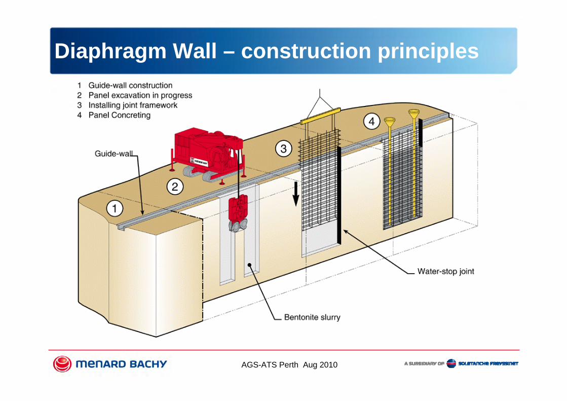
Diaphragm Wall – construction principles

AGS-ATS Perth Aug 2010
Diaphragm Wall – construction principles

AGS-ATS Perth Aug 2010
Diaphragm Wall – construction principles

AGS-ATS Perth Aug 2010
Diaphragm Wall – construction principles

AGS-ATS Perth Aug 2010
Diaphragm Wall – Equipment

AGS-ATS Perth Aug 2010
Diaphragm Wall – Equipment

AGS-ATS Perth Aug 2010
Diaphragm Wall – Equipment

AGS-ATS Perth Aug 2010
Diaphragm Wall – Equipment

AGS-ATS Perth Aug 2010
Application: retaining structure

AGS-ATS Perth Aug 2010
Application : TBM shaft, metro station,..
AGS-ATS Perth Aug 2010
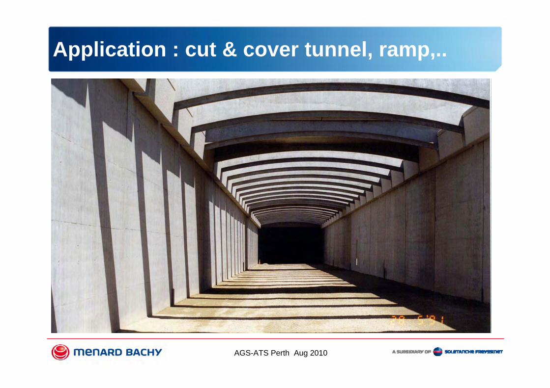
Application : cut & cover tunnel, ramp,..

AGS-ATS Perth Aug 2010
Application : cut off

AGS-ATS Perth Aug 2010
Application : UG tanks, water station,..

AGS-ATS Perth Aug 2010
Application : car park, basement,..

AGS-ATS Perth Aug 2010
Diaphragm wall – indicative figures
Geometry Widths : 0.5 to 1.5mDepths : 25 to 45 m are common (max 150 m)Verticality: 1% is common
Material Tremie mix concrete, 20 mm slump Steel: 70 to 200 kg/m3
PropertiesMoments: 1200 kN/m for 0,8 m wall; 4 000 kN.m for 1,5 m wallPermeability: 10 E-7 m/s to 10 E-9 m/s

AGS-ATS Perth Aug 2010
PORT AUTONOME DU HAVRE
TheThe site on site on 10/09/200110/09/2001
Le Havre : Design

AGS-ATS Perth Aug 2010
Plan View
Le Havre : Design

AGS-ATS Perth Aug 2010
A reinforced concrete
front wall.
Sheet piled as rear wall
Tie – rods between the
walls.
Capping beam with bollards and
fenders
Le Havre : Design

AGS-ATS Perth Aug 2010
Le Havre : Design
Quay : 1600 lm Diaphragm Wall
42 m deep, 1,2 m wide, 150 kg/m3
67 000 m2, 80 000 m3 concrete, 12 000 t steel
Dewatering 180 wells, 1900 m3/dyAnchors 5,600TSheet Piles 1,000TDredging 11,000,000 m3Earthworks 3,000,000 m3Civil Works 30,000 m3Bored piles 500 nr, 17ml, 520 mm

AGS-ATS Perth Aug 2010
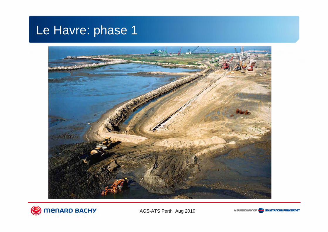
PHASE 1Preparation of working platform
Construction of Guide WallsInstallation of Well Points
Le Havre: phase 1
AGS-ATS Perth Aug 2010
Le Havre: phase 1

AGS-ATS Perth Aug 2010
PHASE 2Construction of Diaphragm Walls
Le Havre: phase 2

AGS-ATS Perth Aug 2010
Le Havre: phase 1

AGS-ATS Perth Aug 2010
AGS-ATS Perth Aug 2010
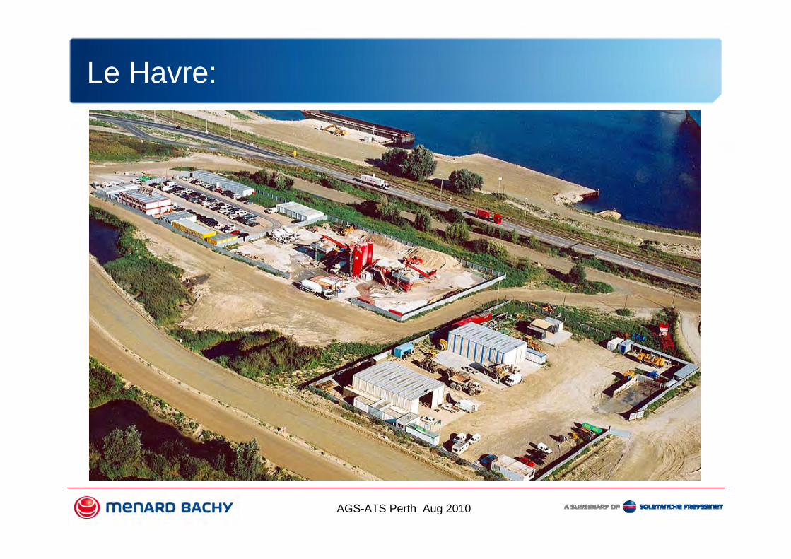
Le Havre:

AGS-ATS Perth Aug 2010
PHASE 3Removal of the guide walls
Excavation in front of the wall during dewatering
Le Havre: phase 3

AGS-ATS Perth Aug 2010
Le Havre: phase 3

AGS-ATS Perth Aug 2010
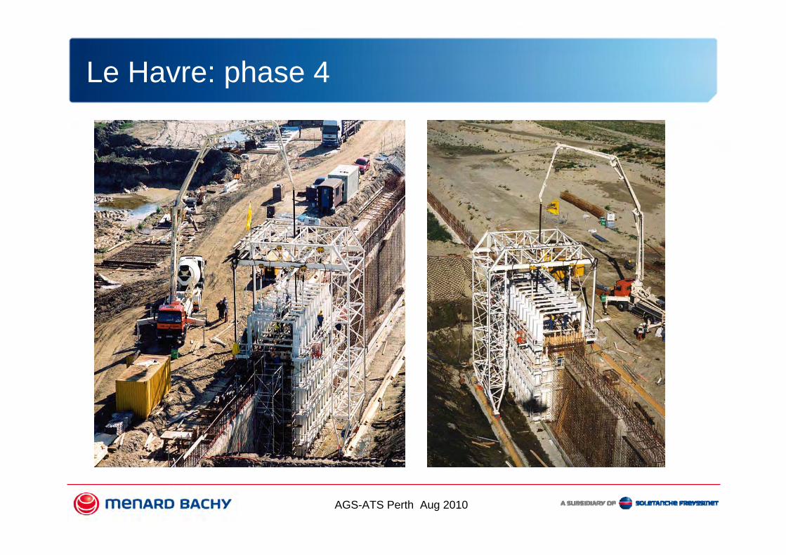
PHASE 4Cast capping beam and dock buffers
Le Havre: phase 4
AGS-ATS Perth Aug 2010
Le Havre: phase 4

AGS-ATS Perth Aug 2010
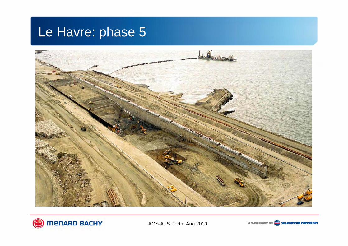
PHASE 5Earthwork excavation behind wall during
dewatering
Le Havre: phase 5
AGS-ATS Perth Aug 2010
Le Havre: phase 5

AGS-ATS Perth Aug 2010
PHASE 6Installation of sheet pile curtain
Lay lower layer of anchors
Le Havre: phase 6

AGS-ATS Perth Aug 2010
Le Havre: phase 6

AGS-ATS Perth Aug 2010
Le Havre: phase 6

AGS-ATS Perth Aug 2010
PHASE 6Backfill to level upper anchor layer and
lay upper layer of anchors
Le Havre: phase 6

AGS-ATS Perth Aug 2010
Le Havre: phase 6

AGS-ATS Perth Aug 2010
Sheet pilesSheet piles
DWall 1,20 mDWall 1,20 m
FF -7.50 Tie backsTie backs
Sea side
Land side
Le Havre: phase 6
AGS-ATS Perth Aug 2010
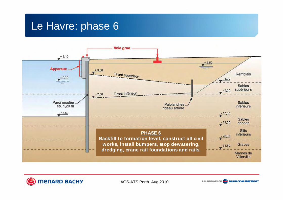
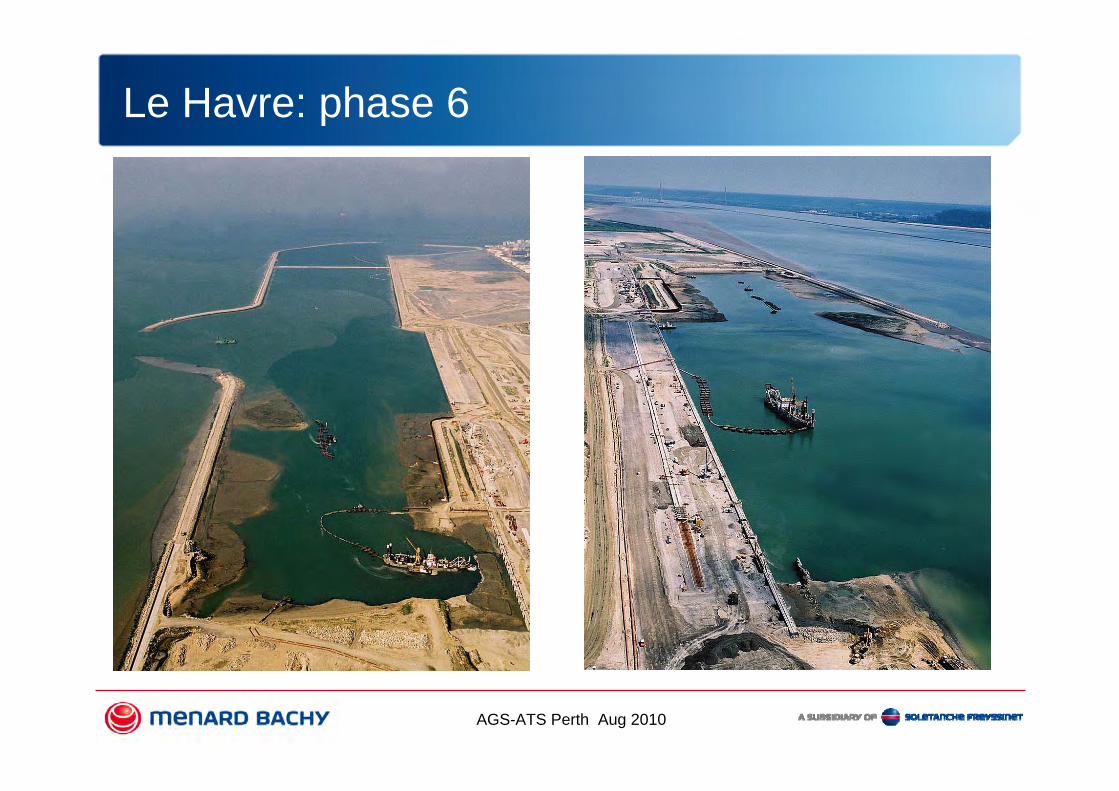
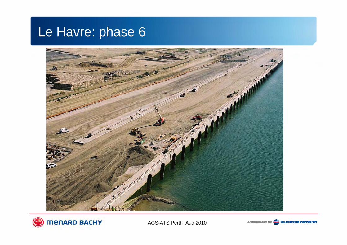
PHASE 6Backfill to formation level, construct all civil
works, install bumpers, stop dewatering, dredging, crane rail foundations and rails.
Le Havre: phase 6

AGS-ATS Perth Aug 2010
Le Havre: phase 6
AGS-ATS Perth Aug 2010
Le Havre: phase 6
AGS-ATS Perth Aug 2010
Le Havre: phase 6

AGS-ATS Perth Aug 2010
Le Havre: Now

AGS-ATS Perth Aug 2010
Now in Cotonou

AGS-ATS Perth Aug 2010
Now in Cotonou

AGS-ATS Perth Aug 2010
The Sail @ Marina bay
Owner: City Dvpt /American
International
Engineer: Meinhardt
Main Contractor: Dragages

AGS-ATS Perth Aug 2010
9,090.9 sqmSite Area
118,182 sqmPermissible GFA
No of floors: 70Typical Floor GFA: 1,026 sqmHeight: 242m
Tower 1
No of floors: 63Typical Floor GFA: 746 sqmHeight: 202m
Tower 2
No of floors: 7Typical Floor Plate: 3,726 sqm
Podium
The Sail@ Marina Bay

AGS-ATS Perth Aug 2010
Site Condition (1995)
The Sail@ Marina Bay

AGS-ATS Perth Aug 2010
BH-5BH-5BH-5
Tower 2
Tower 1Expected Fort Canning
Boulder Bed
Existing Buried Pier
8m Canal
CST
The Sail: IssuesSite specificities• Thick marine clay (up to 35m
of Kallang formation = very soft to soft)
• Fort Canning Boulder Bed• UG obstacle = old pier below
the tower• MTR running tunnel & CS
excavation along the siteProject issues• To control movement of
MRT tunnels & CS Tunnel is a REAL must
• Very tight program = 6 months for foundations + excavation

AGS-ATS Perth Aug 2010
The Sail : Design Philosophy
Alternative solution by SB : Circular structure design• naturally self stabilising and VERY rigid • excavation possible with no jet grouting and no struting+ staggered equipments working units
safe solution in term of deflection/displacement as well as program

AGS-ATS Perth Aug 2010
The Sail: Design
AGS-ATS Perth Aug 2010
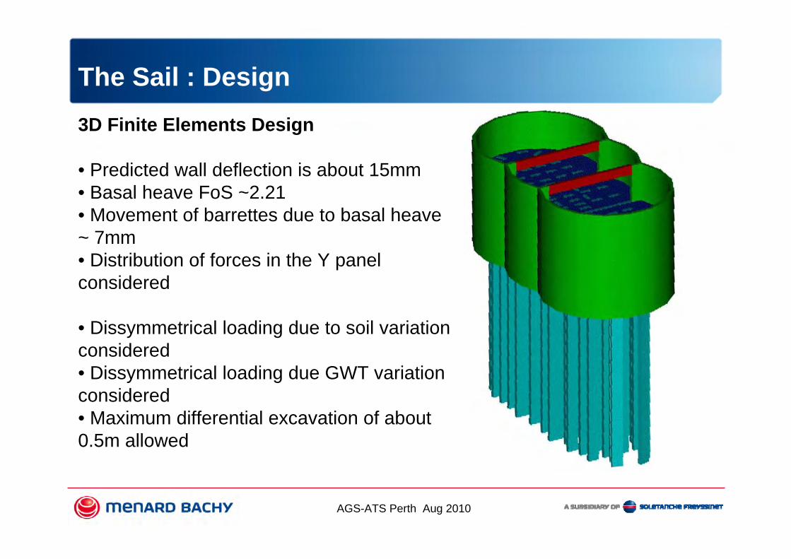
The Sail : Design 3D Finite Elements Design
• Predicted wall deflection is about 15mm• Basal heave FoS ~2.21• Movement of barrettes due to basal heave ~ 7mm• Distribution of forces in the Y panel considered
• Dissymmetrical loading due to soil variation considered• Dissymmetrical loading due GWT variation considered• Maximum differential excavation of about 0.5m allowed
AGS-ATS Perth Aug 2010
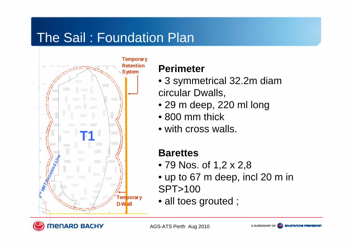
The Sail : Foundation PlanTemporaryRetentionSystem
T1
3rd
MRT R
eser
ved
Line
TemporaryD-W all
Perimeter • 3 symmetrical 32.2m diam circular Dwalls, • 29 m deep, 220 ml long• 800 mm thick• with cross walls.
Barettes • 79 Nos. of 1,2 x 2,8• up to 67 m deep, incl 20 m in SPT>100• all toes grouted ;

AGS-ATS Perth Aug 2010
The Sail: Works

AGS-ATS Perth Aug 2010
The Sail: Works

AGS-ATS Perth Aug 2010
Ultimate Load test
• 1 ultimate load test with smaller barrette 600 x 2400 @ 2.5 WL carried out – 2700 TONS
• 2 working barrette tests on 1000 x 2800 barrette carried out with settlement <15mm @ 1.5 WL –max 3660 TONS
• All the tests were done using kentledge method

AGS-ATS Perth Aug 2010
The Sail: Today

AGS-ATS Perth Aug 2010
Isle of Grain

AGS-ATS Perth Aug 2010
Conclusion
Le Havre Port 2000Site opportunity : shallow waterIssue : optimisation (phasage/dewatering/quantities/..)
The SailProject constraint: tight program, neighb. structuresIssue : design, execution
Ronan Le [email protected]
Related Documents


![Huawei HSPA+ Whitepaper V3[1].0 (20100810)](https://static.cupdf.com/doc/110x72/542c0f1d219acd9e178b4591/huawei-hspa-whitepaper-v310-20100810.jpg)