Installation Instructions for: 2010+ Toyota Tundra 5.7L -For Flex Fuel Trucks- -For Flex Fuel Trucks- Step-by-step instructions for installation of the supercharger system. 89-89-67-005 Rev G Magnuson Products LLC 1990 Knoll Drive, Bldg A, Ventura, CA 93003 (805) 642-8833 phone magnusonsuperchargers.com ATTENTION! Your MAGNUSON SUPERCHARGER kit is sensitive to corrosion! Use only the vehicle manufacturer recommended coolant for your engine in the intercooler system as well. * PREMIUM 91 OCTANE GASOLINE FUEL REQUIRED * * PREMIUM 91 OCTANE GASOLINE FUEL REQUIRED * DO NOT USE E85 FUEL DO NOT USE E85 FUEL. THE USE OF E85 FUEL WILL RESULT . THE USE OF E85 FUEL WILL RESULT IN ENGINE DAMAGE OR FAILURE AND IS NOT RECOMMENDED IN ENGINE DAMAGE OR FAILURE AND IS NOT RECOMMENDED ONCE THE SUPERCHARGER KIT HAS BEEN INSTALLED. ONCE THE SUPERCHARGER KIT HAS BEEN INSTALLED.

Welcome message from author
This document is posted to help you gain knowledge. Please leave a comment to let me know what you think about it! Share it to your friends and learn new things together.
Transcript

Installation Instructions for:2010+ Toyota Tundra 5.7L
-For Flex Fuel Trucks--For Flex Fuel Trucks-
Step-by-step instructions for installation of the supercharger system.
89-89-67-005 Rev G
Magnuson Products LLC1990 Knoll Drive, Bldg A, Ventura, CA 93003
(805) 642-8833 phonemagnusonsuperchargers.com
ATTENTION!Your MAGNUSON SUPERCHARGER kit
is sensitive to corrosion! Use only the vehicle manufacturer recommended coolant for your engine in
the intercooler system as well.
* PREMIUM 91 OCTANE GASOLINE FUEL REQUIRED ** PREMIUM 91 OCTANE GASOLINE FUEL REQUIRED *DO NOT USE E85 FUELDO NOT USE E85 FUEL. THE USE OF E85 FUEL WILL RESULT . THE USE OF E85 FUEL WILL RESULT
IN ENGINE DAMAGE OR FAILURE AND IS NOT RECOMMENDED IN ENGINE DAMAGE OR FAILURE AND IS NOT RECOMMENDED ONCE THE SUPERCHARGER KIT HAS BEEN INSTALLED.ONCE THE SUPERCHARGER KIT HAS BEEN INSTALLED.
INSTALLATION MANUALMagnuson Supercharger Kit: Flex Fuel Toyota Tundra 5.7L Please take a few moments to review this manual thoroughly before you begin work: Make a quick parts check to be certain your kit is complete (see Bill of Material (BOM) parts list inside the accessory box). If you discover shipping damage or shortage, please call our offi ce immediately. Take a look at exactly what you are going to need in terms of tools, time, and experience. Review our limited warranty with care.
Use only premium gasoline fuel, 91 octane or better.Use only premium gasoline fuel, 91 octane or better.
Magnuson Products recommend that you run a minimum of two (2) tanks of premium 91 octane or better fuel through your vehicle prior to installation of the system to prevent any possible damage that may occur due to running the supercharged engine on lower octane fuel. DO NOT RUN E85 FUEL WITH THE DO NOT RUN E85 FUEL WITH THE SUPERCHARGER.SUPERCHARGER.
Magnuson Products Supercharger systems are designed for engines and vehicles in “GOOD” mechanical condition. Magnuson Products recommend that a basic engine system “Health Check” be performed prior to the installation of this supercharger system. Be sure to check for any pending or actual OBDII codes and fi x/repair any of the stock systems/components causing these codes. If there are codes prior to the installation they will be there after the installation.
Magnuson Products also recommend the following services to be performed on your vehicle before starting and running the vehicle post supercharger system installation:• Fuel Filter change• Engine oil and fi lter change using brand name oil (organic or synthetic) and fi lter Note: It is VERY IMPORTANT to use the factory specifi ed oil viscosity. The original equipment manufacturer has selected this grade of oil to work with your other engine systems such as hydraulic chain tensioner and variable cam controls. Deviation from this specifi cation may cause these systems to fail or not function properly. Please refer to your owner’s manual for the recommended oil viscosity for your engine and application.
• On newer vehicles not requiring new spark plugs it is important to verify the spark plug air gap.
On older vehicles Magnuson Products recommend these additional services to be performed:
• New spark plugs with the air gap set at the factory specifi cations OR new specifi cations if required by the installation manual. • Coolant system pressure test and fl ush. NOTE: YOU MUST USE TOYOTA SPECIFIED COOLANT NOTE: YOU MUST USE TOYOTA SPECIFIED COOLANT MIXTURE!MIXTURE!
Non “Magnuson Approved” calibrations or “tuning” will Void ALL warranties and CARB certifi cation.
Our supplied calibration is designed for use with the components provided in this kit. Any adjustment to the intake, or exhaust systems or other engine components may adversely affect engine performance and may trigger your check engine light.
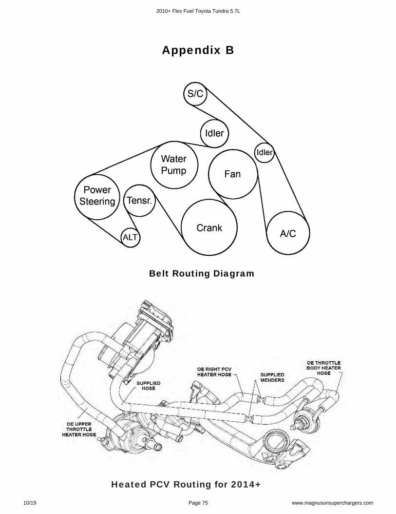
Drive belt = Dayco 5081125
Tools RequiredMetric wrench setMetric 3/8” and 1/2” drive metric socket set (standard & deep)3/8” and 1/2” drive ft-lbs and in-lbs torque wrenchesMetric Allen socket set 3/8 driveMetric Allen wrenchesPhillips and fl at head screwdriversSerpentine belt tool FunnelDrain panHose cuttersHose clamp pliersSafety glassesNut driverCompressed airAir gunHeat gunTorx socket set 3/8 driveFuel tank lock-ring toolAnti-sieze assembly lube (for spark plugs)
Contact Information:
Magnuson Superchargers1990 Knoll Drive, Bldg AVentura, CA 93003
Sales/Technical Support Line (805) 642-8833Websites www.magnusonsuperchargers.comEmail [email protected]
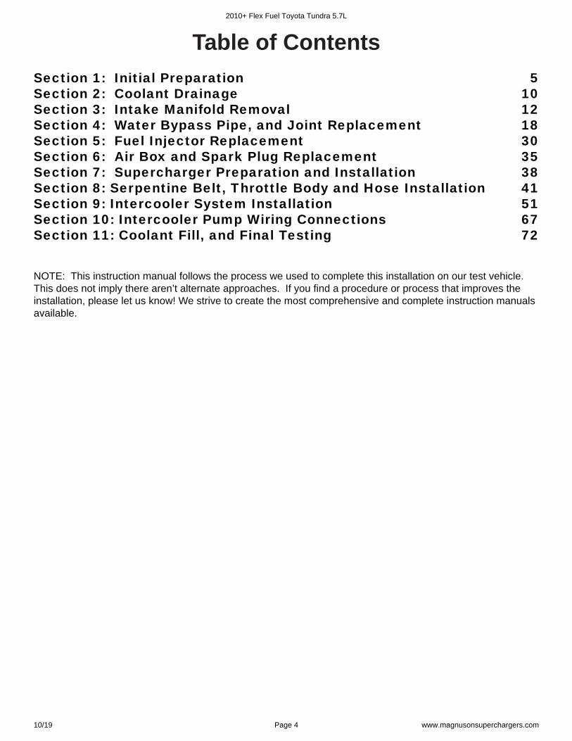
NOTE: This instruction manual follows the process we used to complete this installation on our test vehicle. This does not imply there aren’t alternate approaches. If you fi nd a procedure or process that improves the installation, please let us know! We strive to create the most comprehensive and complete instruction manuals available.
Table of ContentsSection 1: Initial Preparation 5Section 2: Coolant Drainage 10Section 3: Intake Manifold Removal 12Section 4: Water Bypass Pipe, and Joint Replacement 18Section 5: Fuel Injector Replacement 30Section 6: Air Box and Spark Plug Replacement 35Section 7: Supercharger Preparation and Installation 38Section 8: Serpentine Belt, Throttle Body and Hose Installation 41Section 9: Intercooler System Installation 51Section 10: Intercooler Pump Wiring Connections 67Section 11: Coolant Fill, and Final Testing 72
2010+ Flex Fuel Toyota Tundra 5.7L
10/19 Page 4 www.magnusonsuperchargers.com
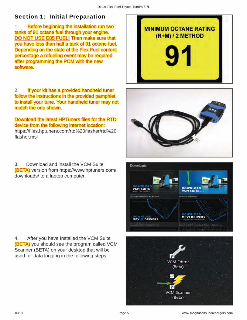
Section 1: Initial Preparation1. Before beginning the installation run two Before beginning the installation run two tanks of 91 octane fuel through your engine. tanks of 91 octane fuel through your engine. DO NOT USE E85 FUEL!DO NOT USE E85 FUEL! Then make sure that Then make sure that you have less than half a tank of 91 octane fuel. you have less than half a tank of 91 octane fuel. Depending on the state of the Flex Fuel content Depending on the state of the Flex Fuel content percentage a refueling event may be required percentage a refueling event may be required after programming the PCM with the new after programming the PCM with the new software.software.
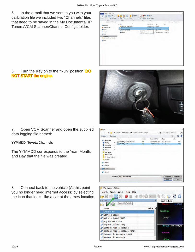
2. If your kit has a provided handheld tunerIf your kit has a provided handheld tuner follow the instructions in the provided pamphlet follow the instructions in the provided pamphlet to install your tune.to install your tune. Your handheld tuner may not Your handheld tuner may not match the one shown.match the one shown.
Download the latest HPTuners fi les for the RTD Download the latest HPTuners fi les for the RTD device from the following internet location:device from the following internet location:https://fi les.hptuners.com/rtd%20fl asher/rtd%20fl asher.msi
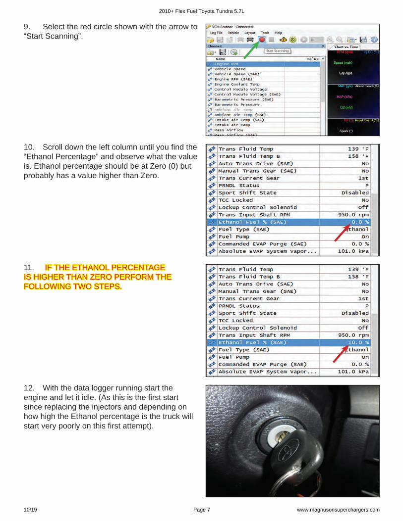
3. Download and install the VCM Suite (BETA)(BETA) version from https://www.hptuners.com/downloads/ to a laptop computer.
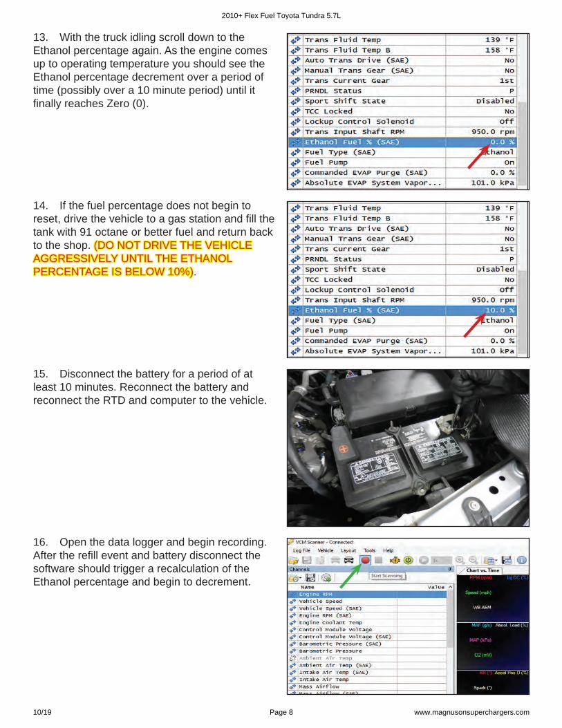
4. After you have Installed the VCM Suite (BETA)(BETA) you should see the program called VCM Scanner (BETA) on your desktop that will be used for data logging in the following steps.
2010+ Flex Fuel Toyota Tundra 5.7L
10/19 Page 5 www.magnusonsuperchargers.com
5. In the e-mail that we sent to you with your calibration fi le we included two “Channels” fi les that need to be saved in the My Documents/HP Tuners/VCM Scanner/Channel Confi gs folder.
6. Turn the Key on to the “Run” position. DO DO NOT START the engine.NOT START the engine.
7. Open VCM Scanner and open the supplied data logging fi le named:
YYMMDD_Toyota.Channels
The YYMMDD corresponds to the Year, Month, and Day that the fi le was created.
8. Connect back to the vehicle (At this point you no longer need internet access) by selecting the icon that looks like a car at the arrow location.
2010+ Flex Fuel Toyota Tundra 5.7L
10/19 Page 6 www.magnusonsuperchargers.com
9. Select the red circle shown with the arrow to “Start Scanning”.
10. Scroll down the left column until you fi nd the “Ethanol Percentage” and observe what the value is. Ethanol percentage should be at Zero (0) but probably has a value higher than Zero.
11. IF THE ETHANOL PERCENTAGE IF THE ETHANOL PERCENTAGE IS HIGHER THAN ZERO PERFORM THE IS HIGHER THAN ZERO PERFORM THE FOLLOWING TWO STEPS.FOLLOWING TWO STEPS.
12. With the data logger running start the engine and let it idle. (As this is the fi rst start since replacing the injectors and depending on how high the Ethanol percentage is the truck will start very poorly on this fi rst attempt).
2010+ Flex Fuel Toyota Tundra 5.7L
10/19 Page 7 www.magnusonsuperchargers.com
13. With the truck idling scroll down to the Ethanol percentage again. As the engine comes up to operating temperature you should see the Ethanol percentage decrement over a period of time (possibly over a 10 minute period) until it fi nally reaches Zero (0).
14. If the fuel percentage does not begin to reset, drive the vehicle to a gas station and fi ll the tank with 91 octane or better fuel and return back to the shop. (DO NOT DRIVE THE VEHICLE (DO NOT DRIVE THE VEHICLE AGGRESSIVELY UNTIL THE ETHANOL AGGRESSIVELY UNTIL THE ETHANOL PERCENTAGE IS BELOW 10%)PERCENTAGE IS BELOW 10%).
15. Disconnect the battery for a period of at least 10 minutes. Reconnect the battery and reconnect the RTD and computer to the vehicle.
16. Open the data logger and begin recording. After the refi ll event and battery disconnect the software should trigger a recalculation of the Ethanol percentage and begin to decrement.
2010+ Flex Fuel Toyota Tundra 5.7L
10/19 Page 8 www.magnusonsuperchargers.com
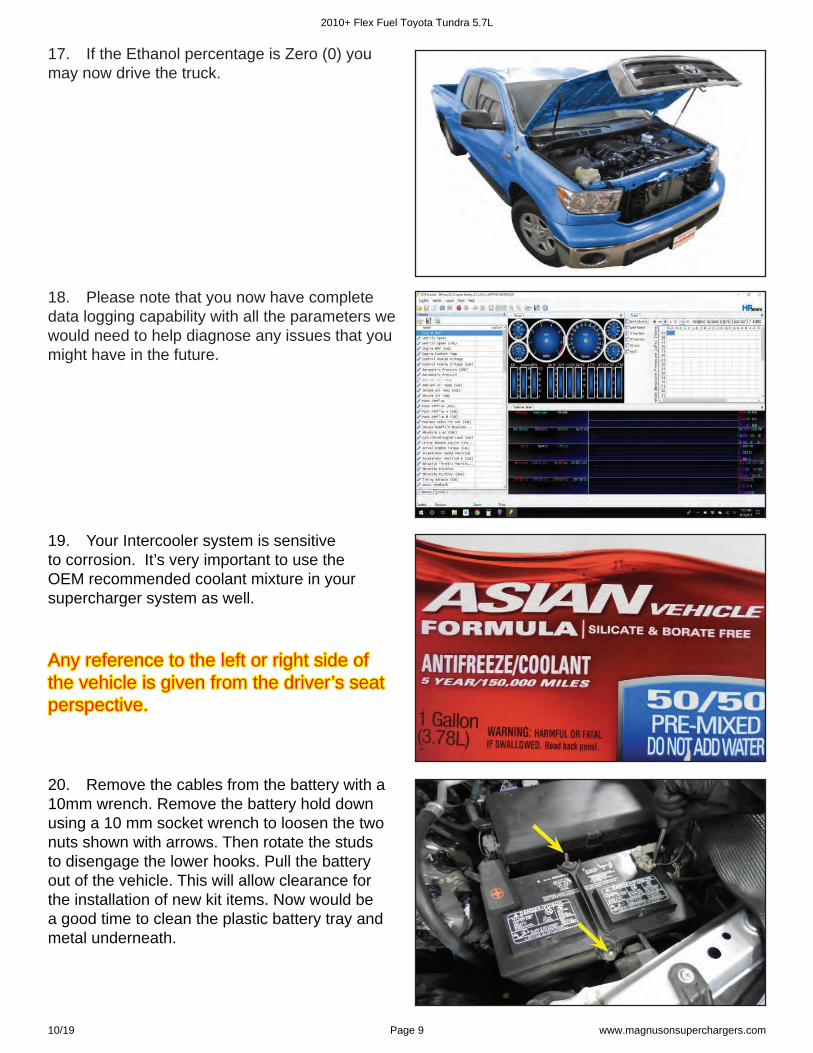
17. If the Ethanol percentage is Zero (0) you may now drive the truck.
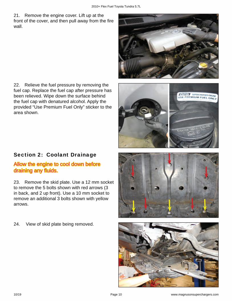
18. Please note that you now have complete data logging capability with all the parameters we would need to help diagnose any issues that you might have in the future.
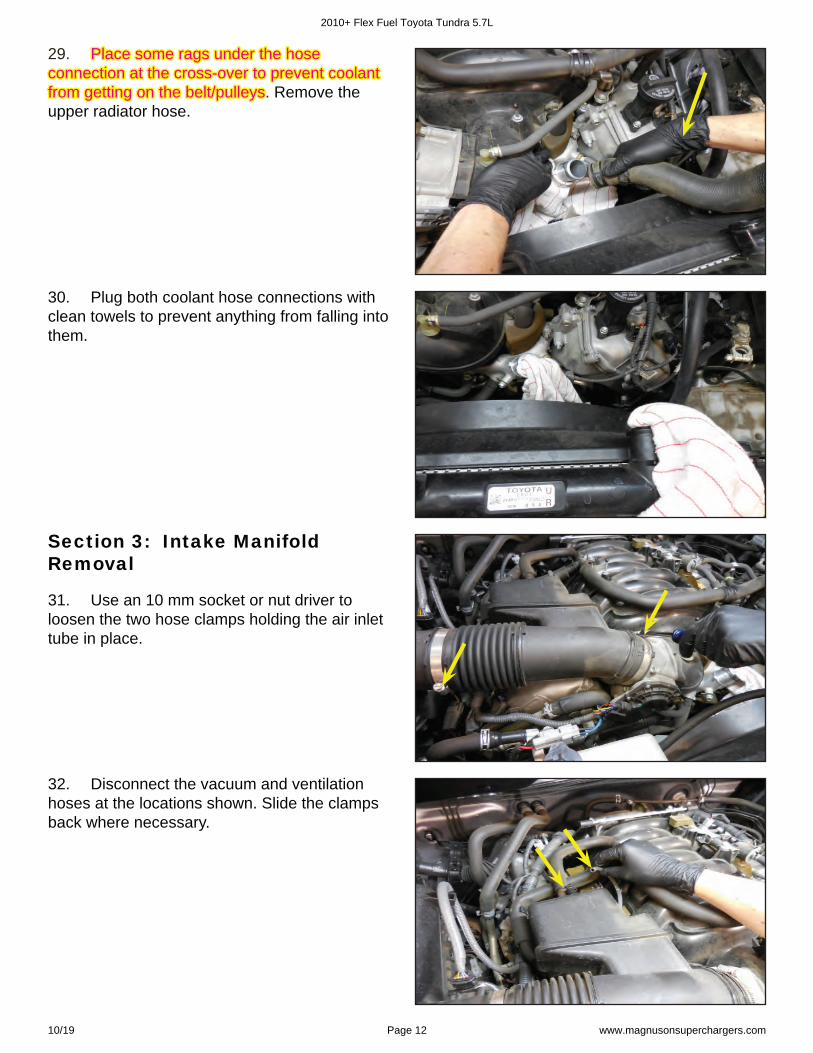
20. Remove the cables from the battery with a 10mm wrench. Remove the battery hold down using a 10 mm socket wrench to loosen the two nuts shown with arrows. Then rotate the studs to disengage the lower hooks. Pull the battery out of the vehicle. This will allow clearance for the installation of new kit items. Now would be a good time to clean the plastic battery tray and metal underneath.
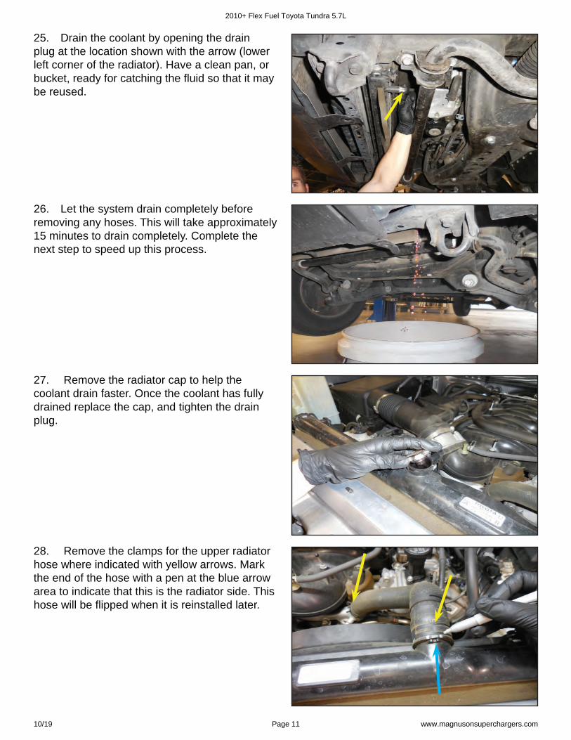
Any reference to the left or right side of Any reference to the left or right side of the vehicle is given from the driver’s seat the vehicle is given from the driver’s seat perspective. perspective.
19. Your Intercooler system is sensitive to corrosion. It’s very important to use the OEM recommended coolant mixture in your supercharger system as well.
2010+ Flex Fuel Toyota Tundra 5.7L
10/19 Page 9 www.magnusonsuperchargers.com
21. Remove the engine cover. Lift up at the front of the cover, and then pull away from the fi re wall.
22. Relieve the fuel pressure by removing the fuel cap. Replace the fuel cap after pressure has been relieved. Wipe down the surface behind the fuel cap with denatured alcohol. Apply the provided “Use Premium Fuel Only” sticker to the area shown.
23. Remove the skid plate. Use a 12 mm socket to remove the 5 bolts shown with red arrows (3 in back, and 2 up front). Use a 10 mm socket to remove an additional 3 bolts shown with yellow arrows.
24. View of skid plate being removed.
Section 2: Coolant Drainage
Allow the engine to cool down before Allow the engine to cool down before draining any fl uids. draining any fl uids.
2010+ Flex Fuel Toyota Tundra 5.7L
10/19 Page 10 www.magnusonsuperchargers.com
25. Drain the coolant by opening the drain plug at the location shown with the arrow (lower left corner of the radiator). Have a clean pan, or bucket, ready for catching the fl uid so that it may be reused.
26. Let the system drain completely before removing any hoses. This will take approximately 15 minutes to drain completely. Complete the next step to speed up this process.
28. Remove the clamps for the upper radiator hose where indicated with yellow arrows. Mark the end of the hose with a pen at the blue arrow area to indicate that this is the radiator side. This hose will be fl ipped when it is reinstalled later.
27. Remove the radiator cap to help the coolant drain faster. Once the coolant has fully drained replace the cap, and tighten the drain plug.
2010+ Flex Fuel Toyota Tundra 5.7L
10/19 Page 11 www.magnusonsuperchargers.com
29. 29. Place some rags under the hose Place some rags under the hose connection at the cross-over to prevent coolant connection at the cross-over to prevent coolant from getting on the belt/pulleysfrom getting on the belt/pulleys.. Remove the upper radiator hose.
30. Plug both coolant hose connections with clean towels to prevent anything from falling into them.
31. Use an 10 mm socket or nut driver to loosen the two hose clamps holding the air inlet tube in place.
32. Disconnect the vacuum and ventilation hoses at the locations shown. Slide the clamps back where necessary.
Section 3: Intake Manifold Removal
2010+ Flex Fuel Toyota Tundra 5.7L
10/19 Page 12 www.magnusonsuperchargers.com
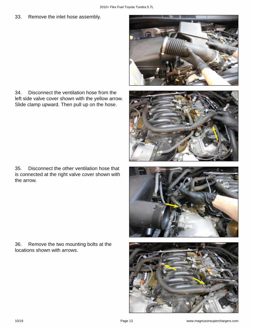
33. Remove the inlet hose assembly.
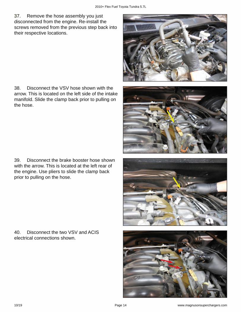
34. Disconnect the ventilation hose from the left side valve cover shown with the yellow arrow. Slide clamp upward. Then pull up on the hose.
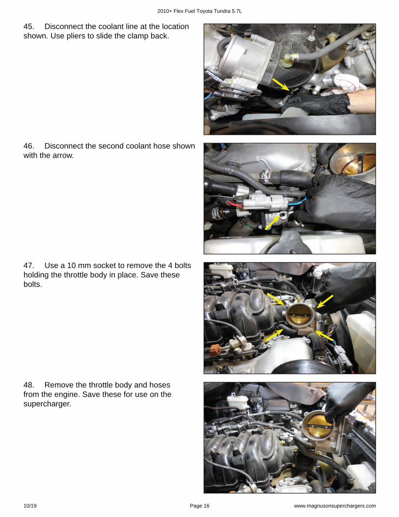
36. Remove the two mounting bolts at the locations shown with arrows.
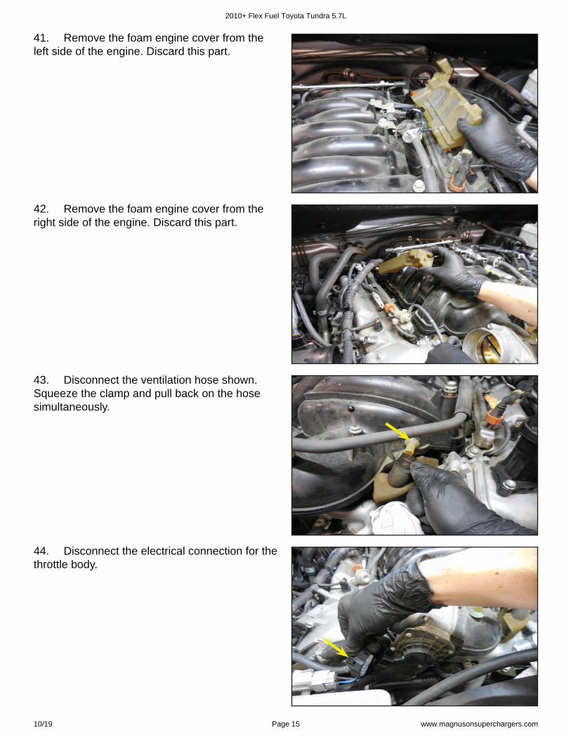
35. Disconnect the other ventilation hose that is connected at the right valve cover shown with the arrow.
2010+ Flex Fuel Toyota Tundra 5.7L
10/19 Page 13 www.magnusonsuperchargers.com
37. 37. Remove the hose assembly you just disconnected from the engine. Re-install the screws removed from the previous step back into their respective locations.
38. Disconnect the VSV hose shown with the arrow. This is located on the left side of the intake manifold. Slide the clamp back prior to pulling on the hose.
39. Disconnect the brake booster hose shown with the arrow. This is located at the left rear of the engine. Use pliers to slide the clamp back prior to pulling on the hose.
40. Disconnect the two VSV and ACIS electrical connections shown.
2010+ Flex Fuel Toyota Tundra 5.7L
10/19 Page 14 www.magnusonsuperchargers.com
41. Remove the foam engine cover from the left side of the engine. Discard this part.
42. Remove the foam engine cover from the right side of the engine. Discard this part.
44. Disconnect the electrical connection for the throttle body.
43. Disconnect the ventilation hose shown. Squeeze the clamp and pull back on the hose simultaneously.
2010+ Flex Fuel Toyota Tundra 5.7L
10/19 Page 15 www.magnusonsuperchargers.com
45. 45. Disconnect the coolant line at the location shown. Use pliers to slide the clamp back.
46. Disconnect the second coolant hose shown with the arrow.
47. Use a 10 mm socket to remove the 4 bolts holding the throttle body in place. Save these bolts.
48. Remove the throttle body and hoses from the engine. Save these for use on the supercharger.
2010+ Flex Fuel Toyota Tundra 5.7L
10/19 Page 16 www.magnusonsuperchargers.com
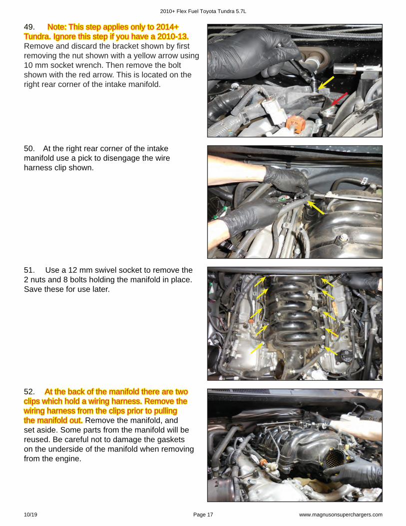
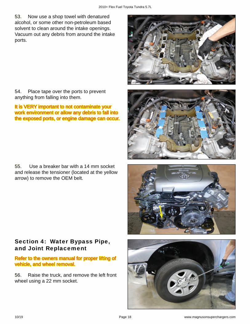
50. At the right rear corner of the intake manifold use a pick to disengage the wire harness clip shown.
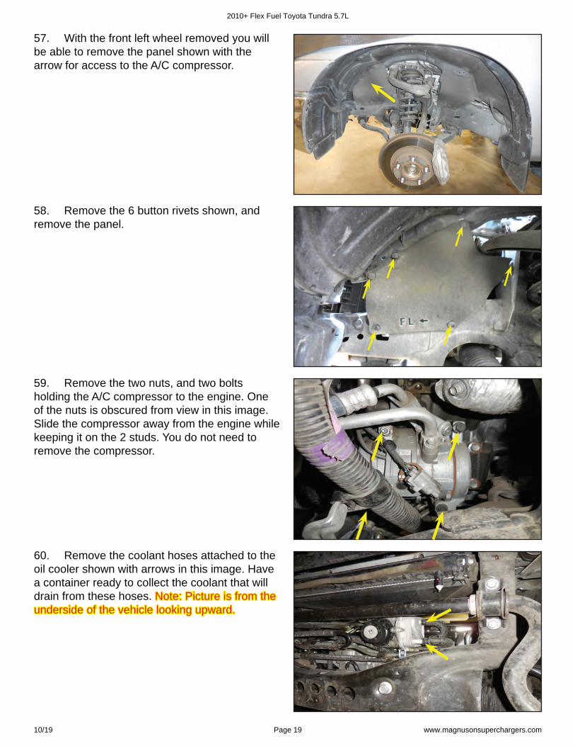
51. Use a 12 mm swivel socket to remove the 2 nuts and 8 bolts holding the manifold in place. Save these for use later.
49. 49. Note: This step applies only to 2014+ Note: This step applies only to 2014+ Tundra. Ignore this step if you have a 2010-13. Tundra. Ignore this step if you have a 2010-13. Remove and discard the bracket shown by fi rst removing the nut shown with a yellow arrow using 10 mm socket wrench. Then remove the bolt shown with the red arrow. This is located on the right rear corner of the intake manifold.
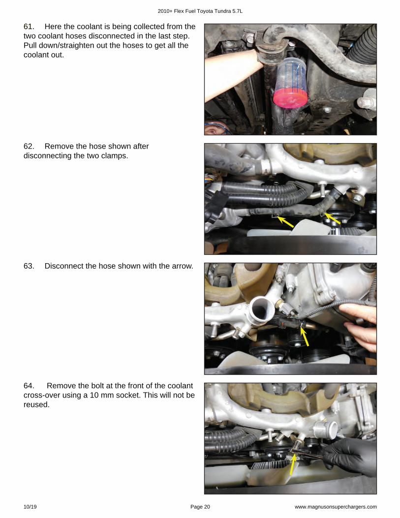
52. 52. At the back of the manifold there are two At the back of the manifold there are two clips which hold a wiring harness. Remove the clips which hold a wiring harness. Remove the wiring harness from the clips prior to pulling wiring harness from the clips prior to pulling the manifold out.the manifold out. Remove the manifold, and set aside. Some parts from the manifold will be reused. Be careful not to damage the gaskets on the underside of the manifold when removing from the engine.
2010+ Flex Fuel Toyota Tundra 5.7L
10/19 Page 17 www.magnusonsuperchargers.com
53. 53. Now use a shop towel with denatured alcohol, or some other non-petroleum based solvent to clean around the intake openings. Vacuum out any debris from around the intake ports.
54. Place tape over the ports to prevent anything from falling into them.
55. 55. Use a breaker bar with a 14 mm socket and release the tensioner (located at the yellow arrow) to remove the OEM belt.
56. 56. Raise the truck, and remove the left front wheel using a 22 mm socket.
It is VERY important to not contaminate your It is VERY important to not contaminate your work environment or allow any debris to fall into work environment or allow any debris to fall into the exposed ports, or engine damage can occur.the exposed ports, or engine damage can occur.
Refer to the owners manual for proper lifting of Refer to the owners manual for proper lifting of vehicle, and wheel removal.vehicle, and wheel removal.
Section 4: Water Bypass Pipe, and Joint Replacement
2010+ Flex Fuel Toyota Tundra 5.7L
10/19 Page 18 www.magnusonsuperchargers.com
57. With the front left wheel removed you will be able to remove the panel shown with the arrow for access to the A/C compressor.
58. Remove the 6 button rivets shown, and remove the panel.
59. Remove the two nuts, and two bolts holding the A/C compressor to the engine. One of the nuts is obscured from view in this image. Slide the compressor away from the engine while keeping it on the 2 studs. You do not need to remove the compressor.
60. Remove the coolant hoses attached to the oil cooler shown with arrows in this image. Have a container ready to collect the coolant that will drain from these hoses. Note: Picture is from the Note: Picture is from the underside of the vehicle looking upward.underside of the vehicle looking upward.
2010+ Flex Fuel Toyota Tundra 5.7L
10/19 Page 19 www.magnusonsuperchargers.com
61. 61. Here the coolant is being collected from the two coolant hoses disconnected in the last step. Pull down/straighten out the hoses to get all the coolant out.
62. Remove the hose shown after disconnecting the two clamps.
63. Disconnect the hose shown with the arrow.
64. Remove the bolt at the front of the coolant cross-over using a 10 mm socket. This will not be reused.
2010+ Flex Fuel Toyota Tundra 5.7L
10/19 Page 20 www.magnusonsuperchargers.com
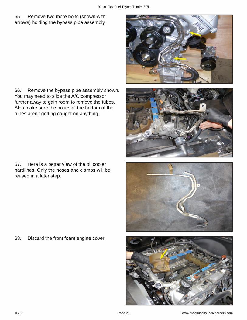
65. Remove two more bolts (shown with arrows) holding the bypass pipe assembly.
66. Remove the bypass pipe assembly shown. You may need to slide the A/C compressor further away to gain room to remove the tubes. Also make sure the hoses at the bottom of the tubes aren’t getting caught on anything.
67. Here is a better view of the oil cooler hardlines. Only the hoses and clamps will be reused in a later step.
68. Discard the front foam engine cover.
2010+ Flex Fuel Toyota Tundra 5.7L
10/19 Page 21 www.magnusonsuperchargers.com
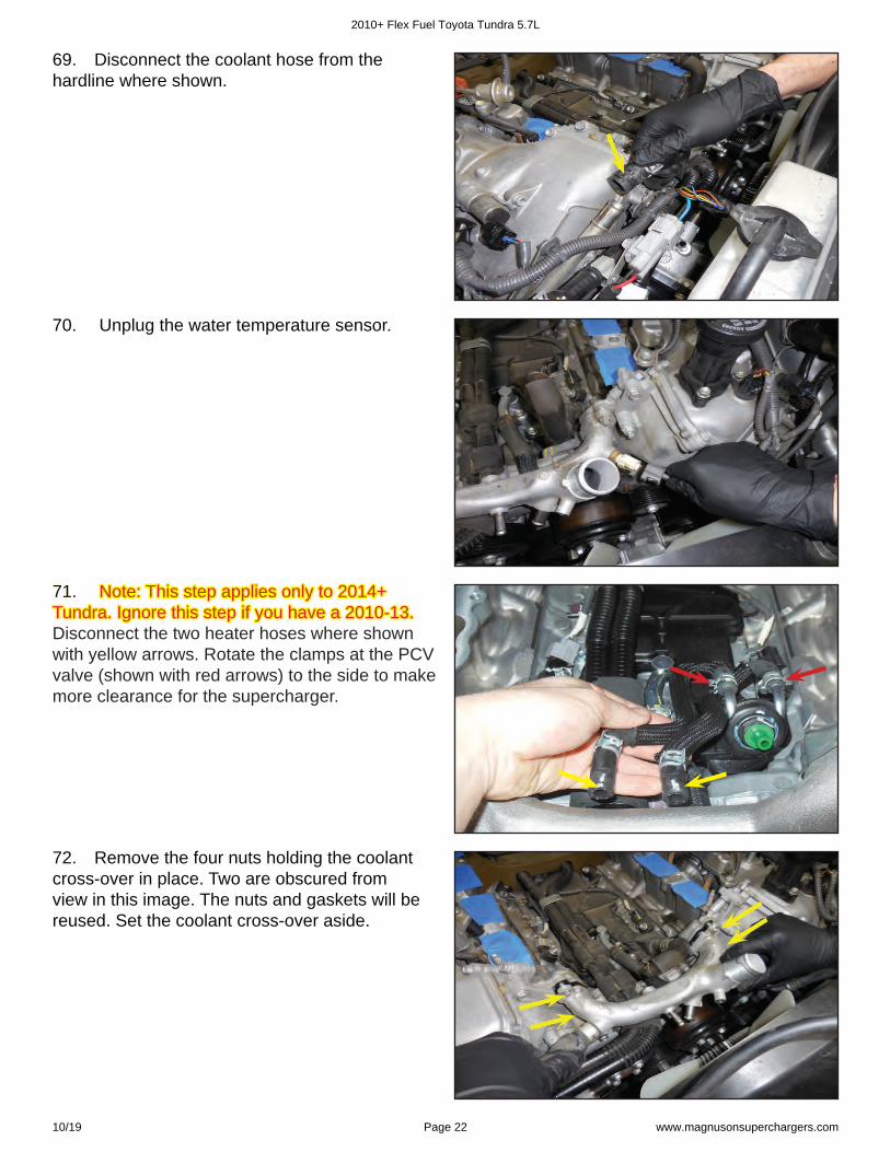
69. Disconnect the coolant hose from the hardline where shown.
70. Unplug the water temperature sensor.
72. Remove the four nuts holding the coolant cross-over in place. Two are obscured from view in this image. The nuts and gaskets will be reused. Set the coolant cross-over aside.
71. 71. Note: This step applies only to 2014+ Note: This step applies only to 2014+ Tundra. Ignore this step if you have a 2010-13. Tundra. Ignore this step if you have a 2010-13. Disconnect the two heater hoses where shown with yellow arrows. Rotate the clamps at the PCV valve (shown with red arrows) to the side to make more clearance for the supercharger.
2010+ Flex Fuel Toyota Tundra 5.7L
10/19 Page 22 www.magnusonsuperchargers.com
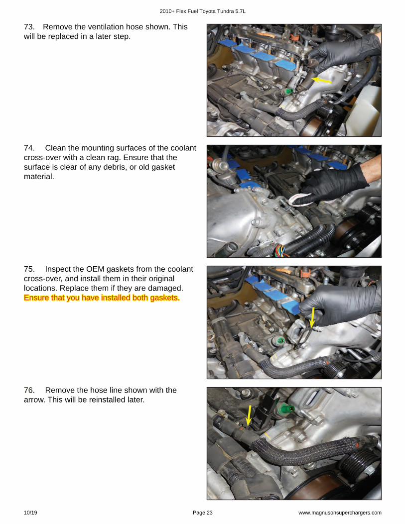
73. Remove the ventilation hose shown. This will be replaced in a later step.
74. Clean the mounting surfaces of the coolant cross-over with a clean rag. Ensure that the surface is clear of any debris, or old gasket material.
75. Inspect the OEM gaskets from the coolant cross-over, and install them in their original locations. Replace them if they are damaged. Ensure that you have installed both gaskets.Ensure that you have installed both gaskets.
76. 76. Remove the hose line shown with the arrow. This will be reinstalled later.
2010+ Flex Fuel Toyota Tundra 5.7L
10/19 Page 23 www.magnusonsuperchargers.com

79. 79. Remove the section of hose from the OEM coolant cross-over. This will be reused.
78. Install the supplied coolant cross-over, and secure it with the OEM nuts. Torque the nuts to Torque the nuts to 15 ft-lb.15 ft-lb. Ensure that the OEM gaskets are being Ensure that the OEM gaskets are being reused to seal the coolant cross-over.reused to seal the coolant cross-over.
80. Reinstall the OEM hose on the supplied coolant cross-over from the last step using the OEM clamps.
77. Apply a thin bead of coolant safe RTV to the surface of the supplied coolant cross-over.
2010+ Flex Fuel Toyota Tundra 5.7L
10/19 Page 24 www.magnusonsuperchargers.com
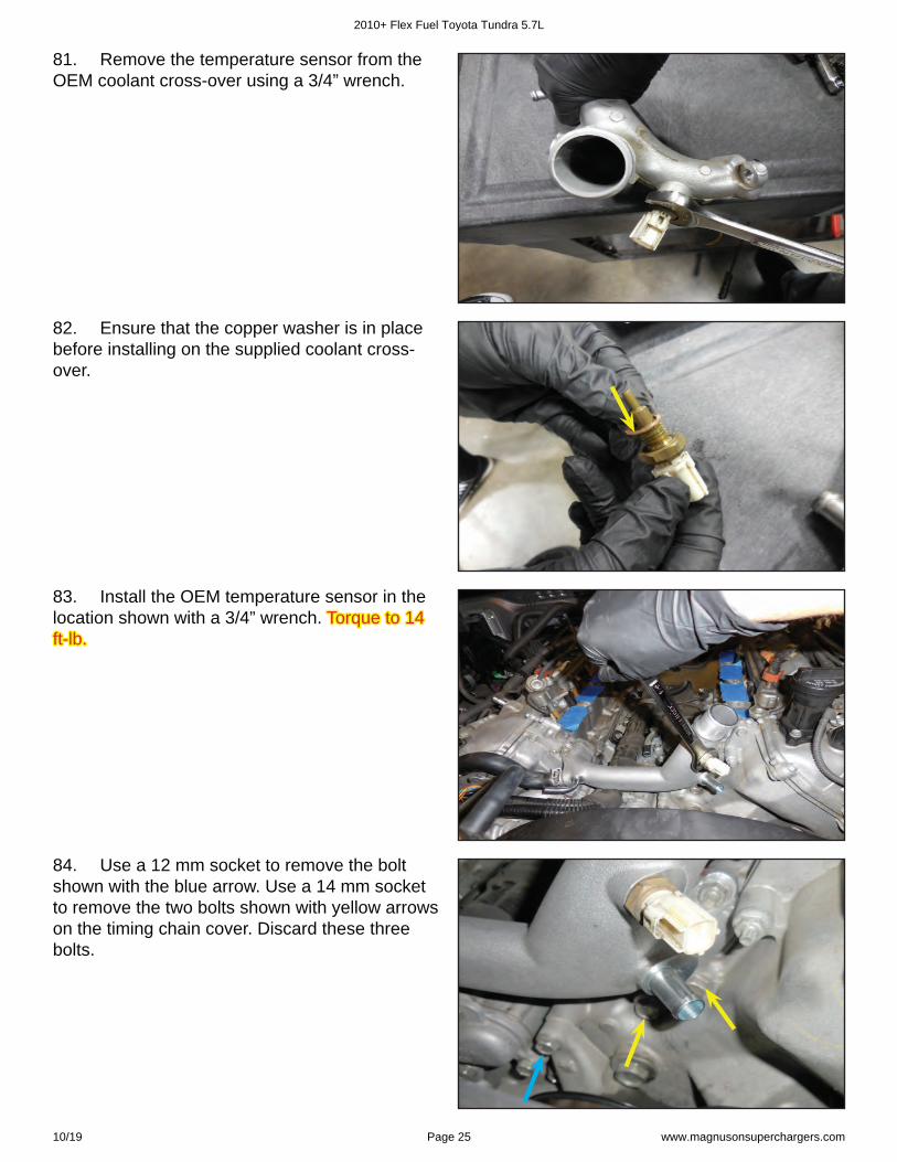
81. Remove the temperature sensor from the OEM coolant cross-over using a 3/4” wrench.
82. Ensure that the copper washer is in place before installing on the supplied coolant cross-over.
83. Install the OEM temperature sensor in the location shown with a 3/4” wrench. Torque to 14 Torque to 14 ft-lb.ft-lb.
84. Use a 12 mm socket to remove the bolt shown with the blue arrow. Use a 14 mm socket to remove the two bolts shown with yellow arrows on the timing chain cover. Discard these three bolts.
2010+ Flex Fuel Toyota Tundra 5.7L
10/19 Page 25 www.magnusonsuperchargers.com
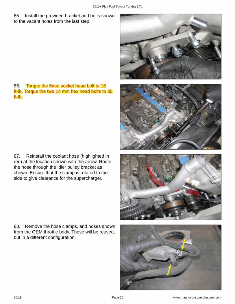
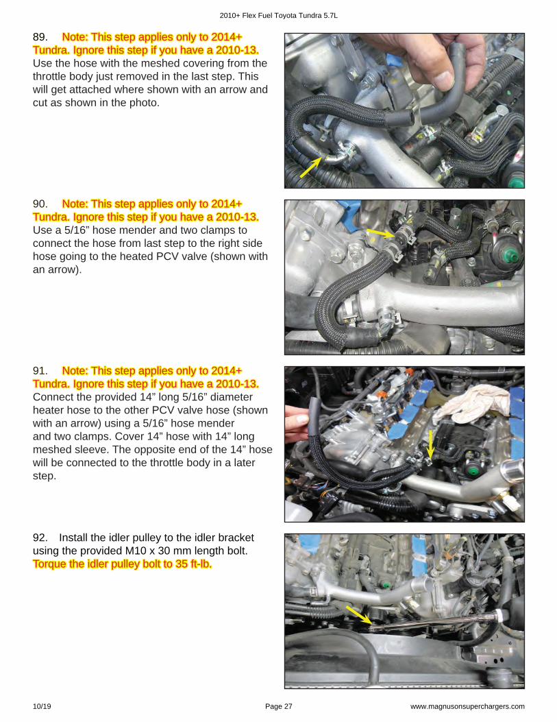
86. Torque the 6mm socket head bolt to 18 Torque the 6mm socket head bolt to 18 ft-lb, Torque the two 14 mm hex head bolts to 35 ft-lb, Torque the two 14 mm hex head bolts to 35 ft-lb. ft-lb.
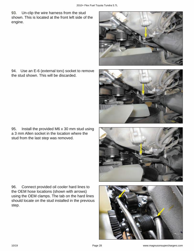
87. Reinstall the coolant hose (highlighted in red) at the location shown with the arrow. Route the hose through the idler pulley bracket as shown. Ensure that the clamp is rotated to the side to give clearance for the supercharger.
85. Install the provided bracket and bolts shown to the vacant holes from the last step.
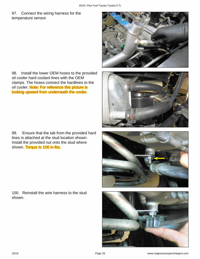
88. Remove the hose clamps, and hoses shown from the OEM throttle body. These will be reused, but in a different confi guration.
2010+ Flex Fuel Toyota Tundra 5.7L
10/19 Page 26 www.magnusonsuperchargers.com
89. 89. Note: This step applies only to 2014+ Note: This step applies only to 2014+ Tundra. Ignore this step if you have a 2010-13. Tundra. Ignore this step if you have a 2010-13. Use the hose with the meshed covering from the throttle body just removed in the last step. This will get attached where shown with an arrow and cut as shown in the photo.
90. 90. Note: This step applies only to 2014+ Note: This step applies only to 2014+ Tundra. Ignore this step if you have a 2010-13.Tundra. Ignore this step if you have a 2010-13. Use a 5/16” hose mender and two clamps to connect the hose from last step to the right side hose going to the heated PCV valve (shown with an arrow).
91. 91. Note: This step applies only to 2014+ Note: This step applies only to 2014+ Tundra. Ignore this step if you have a 2010-13.Tundra. Ignore this step if you have a 2010-13. Connect the provided 14” long 5/16” diameter heater hose to the other PCV valve hose (shown with an arrow) using a 5/16” hose mender and two clamps. Cover 14” hose with 14” long meshed sleeve. The opposite end of the 14” hose will be connected to the throttle body in a later step.
92. Install the idler pulley to the idler bracket using the provided M10 x 30 mm length bolt. Torque the idler pulley bolt to 35 ft-lb.Torque the idler pulley bolt to 35 ft-lb.
2010+ Flex Fuel Toyota Tundra 5.7L
10/19 Page 27 www.magnusonsuperchargers.com
93. 93. Un-clip the wire harness from the stud shown. This is located at the front left side of the engine.
94. Use an E-6 (external torx) socket to remove the stud shown. This will be discarded.
95. Install the provided M6 x 30 mm stud using a 3 mm Allen socket in the location where the stud from the last step was removed.
96. Connect provided oil cooler hard lines to the OEM hose locations (shown with arrows)using the OEM clamps. The tab on the hard lines should locate on the stud installed in the previous step.
2010+ Flex Fuel Toyota Tundra 5.7L
10/19 Page 28 www.magnusonsuperchargers.com
97. Connect the wiring harness for the temperature sensor.
99. 99. Ensure that the tab from the provided hard lines is attached at the stud location shown. Install the provided nut onto the stud where shown. Torque to 106 in-lbs.Torque to 106 in-lbs.
98. Install the lower OEM hoses to the provided oil cooler hard coolant lines with the OEM clamps. The hoses connect the hardlines to the oil cooler. Note: For reference this picture is Note: For reference this picture is looking upward from underneath the cooler.looking upward from underneath the cooler.
100. Reinstall the wire harness to the stud shown.
2010+ Flex Fuel Toyota Tundra 5.7L
10/19 Page 29 www.magnusonsuperchargers.com
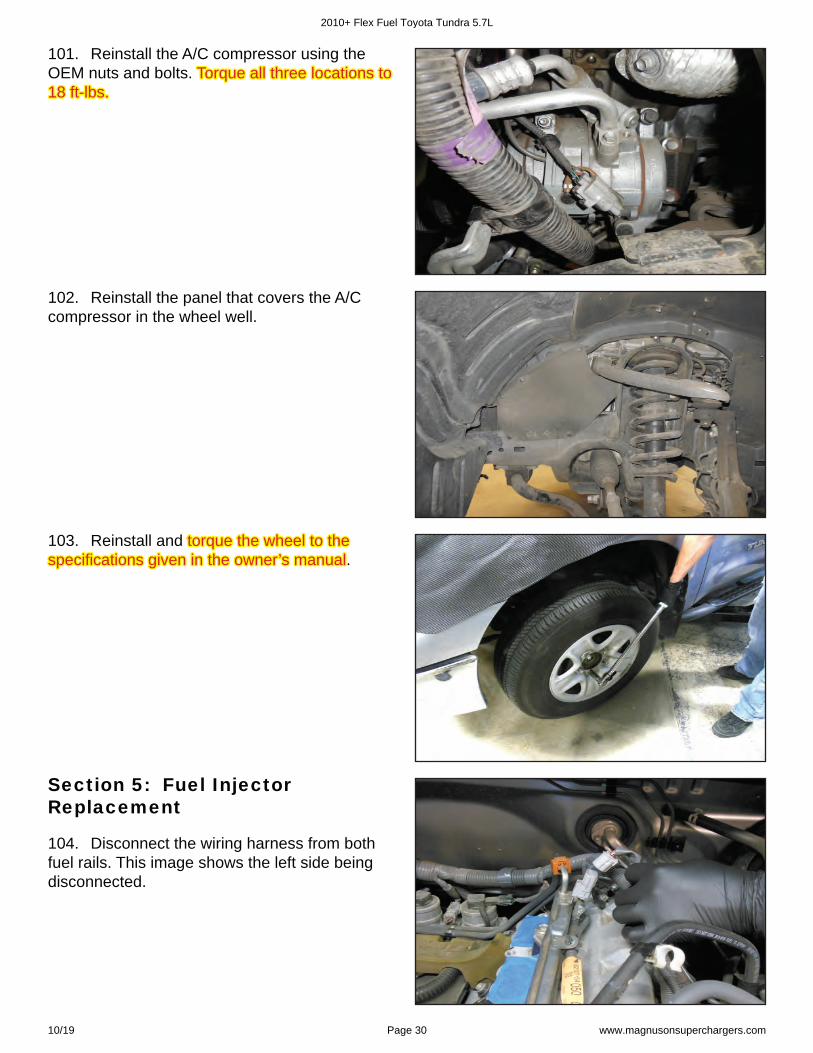
101. Reinstall the A/C compressor using the OEM nuts and bolts. Torque all three locations to Torque all three locations to 18 ft-lbs.18 ft-lbs.
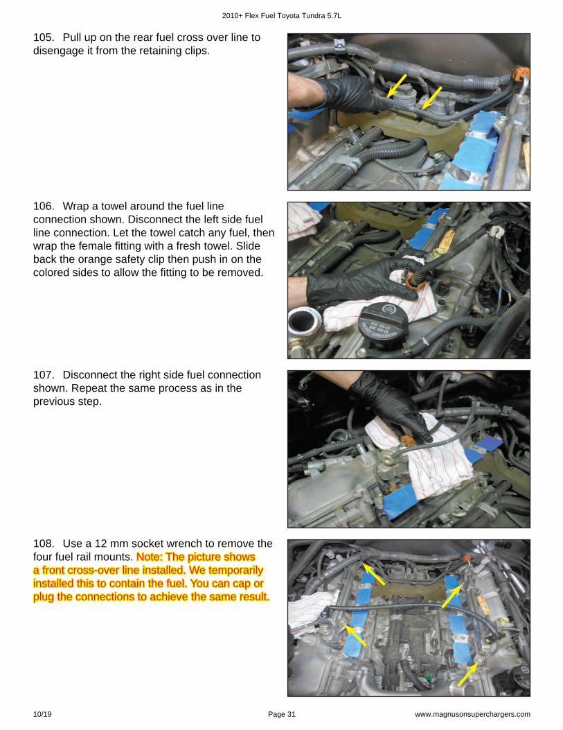
102. Reinstall the panel that covers the A/C compressor in the wheel well.
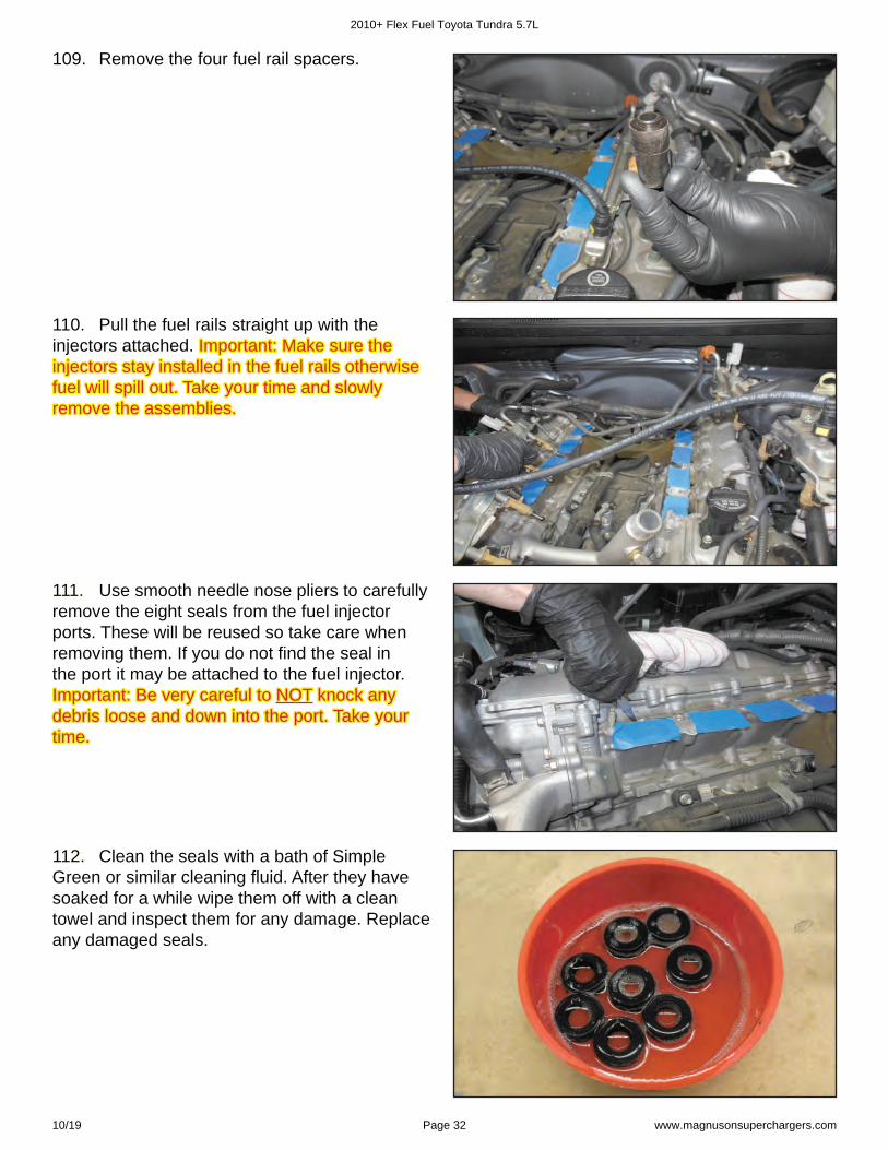
103. Reinstall and torque the wheel to the torque the wheel to the specifi cations given in the owner’s manualspecifi cations given in the owner’s manual.
104. Disconnect the wiring harness from both fuel rails. This image shows the left side being disconnected.
Section 5: Fuel Injector Replacement
2010+ Flex Fuel Toyota Tundra 5.7L
10/19 Page 30 www.magnusonsuperchargers.com
106. Wrap a towel around the fuel line connection shown. Disconnect the left side fuel line connection. Let the towel catch any fuel, then wrap the female fi tting with a fresh towel. Slide back the orange safety clip then push in on the colored sides to allow the fi tting to be removed.
107. Disconnect the right side fuel connection shown. Repeat the same process as in the previous step.
105. Pull up on the rear fuel cross over line to disengage it from the retaining clips.
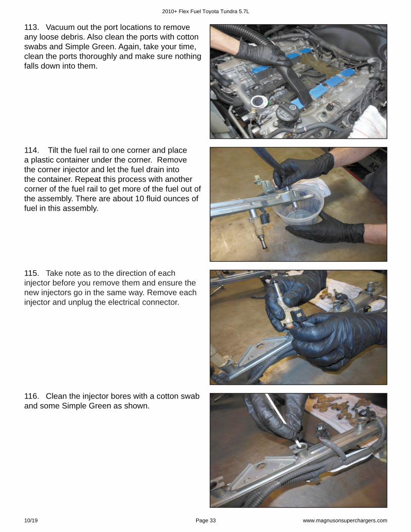
108. Use a 12 mm socket wrench to remove the four fuel rail mounts. Note: The picture shows Note: The picture shows a front cross-over line installed. We temporarily a front cross-over line installed. We temporarily installed this to contain the fuel. You can cap or installed this to contain the fuel. You can cap or plug the connections to achieve the same result.plug the connections to achieve the same result.
2010+ Flex Fuel Toyota Tundra 5.7L
10/19 Page 31 www.magnusonsuperchargers.com
109. Remove the four fuel rail spacers.
110. Pull the fuel rails straight up with the injectors attached. Important: Make sure the Important: Make sure the injectors stay installed in the fuel rails otherwise injectors stay installed in the fuel rails otherwise fuel will spill out. Take your time and slowly fuel will spill out. Take your time and slowly remove the assemblies. remove the assemblies.
111. 111. Use smooth needle nose pliers to carefully remove the eight seals from the fuel injector ports. These will be reused so take care when removing them. If you do not fi nd the seal in the port it may be attached to the fuel injector. Important: Be very careful to Important: Be very careful to NOTNOT knock any knock any debris loose and down into the port. Take your debris loose and down into the port. Take your time. time.
112. 112. Clean the seals with a bath of Simple Green or similar cleaning fl uid. After they have soaked for a while wipe them off with a clean towel and inspect them for any damage. Replace any damaged seals.
2010+ Flex Fuel Toyota Tundra 5.7L
10/19 Page 32 www.magnusonsuperchargers.com
113. Vacuum out the port locations to remove any loose debris. Also clean the ports with cotton swabs and Simple Green. Again, take your time, clean the ports thoroughly and make sure nothing falls down into them.
114. Tilt the fuel rail to one corner and place a plastic container under the corner. Remove the corner injector and let the fuel drain into the container. Repeat this process with another corner of the fuel rail to get more of the fuel out of the assembly. There are about 10 fl uid ounces of fuel in this assembly.
115. Take note as to the direction of each injector before you remove them and ensure the new injectors go in the same way. Remove each injector and unplug the electrical connector.
116. Clean the injector bores with a cotton swab and some Simple Green as shown.
2010+ Flex Fuel Toyota Tundra 5.7L
10/19 Page 33 www.magnusonsuperchargers.com
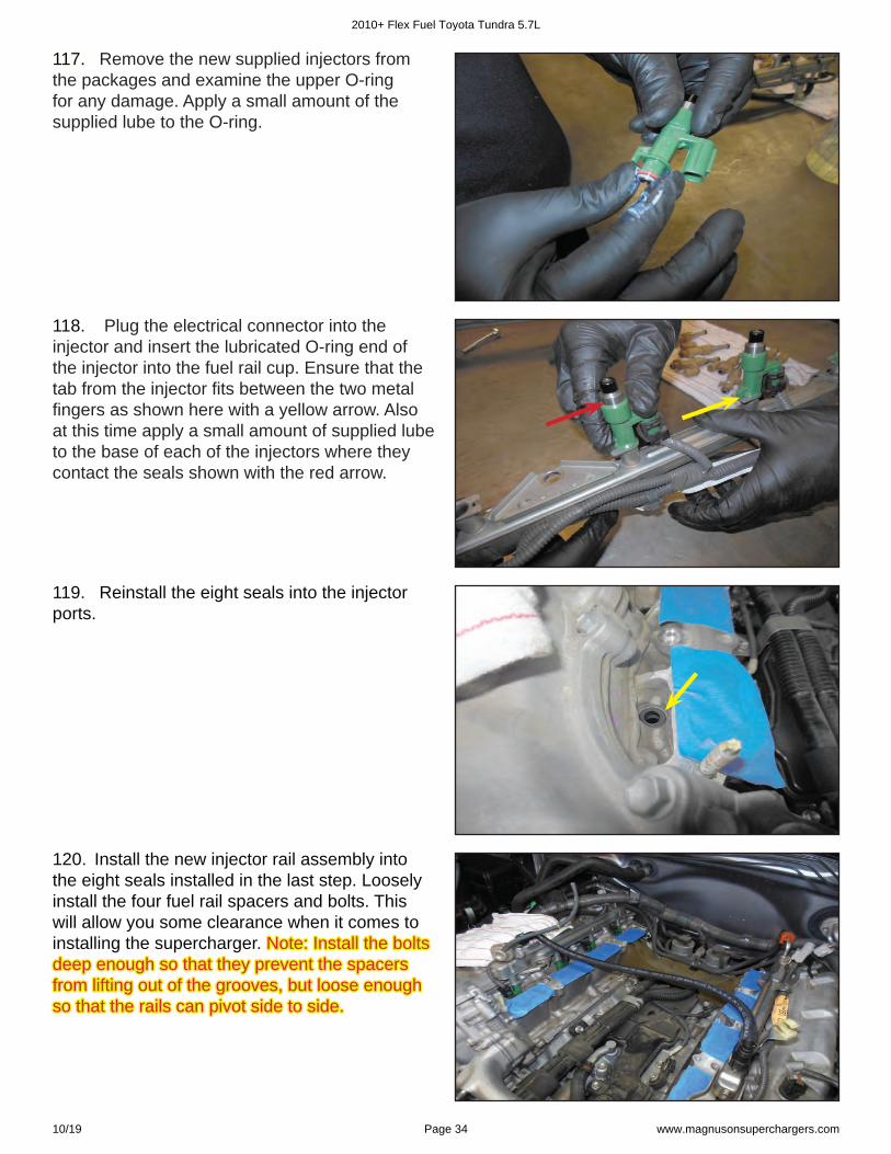
117. 117. Remove the new supplied injectors from the packages and examine the upper O-ring for any damage. Apply a small amount of the supplied lube to the O-ring.
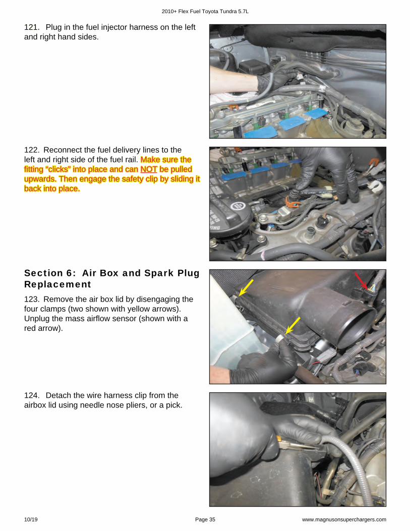
118. Plug the electrical connector into the injector and insert the lubricated O-ring end of the injector into the fuel rail cup. Ensure that the tab from the injector fi ts between the two metal fi ngers as shown here with a yellow arrow. Also at this time apply a small amount of supplied lube to the base of each of the injectors where they contact the seals shown with the red arrow.
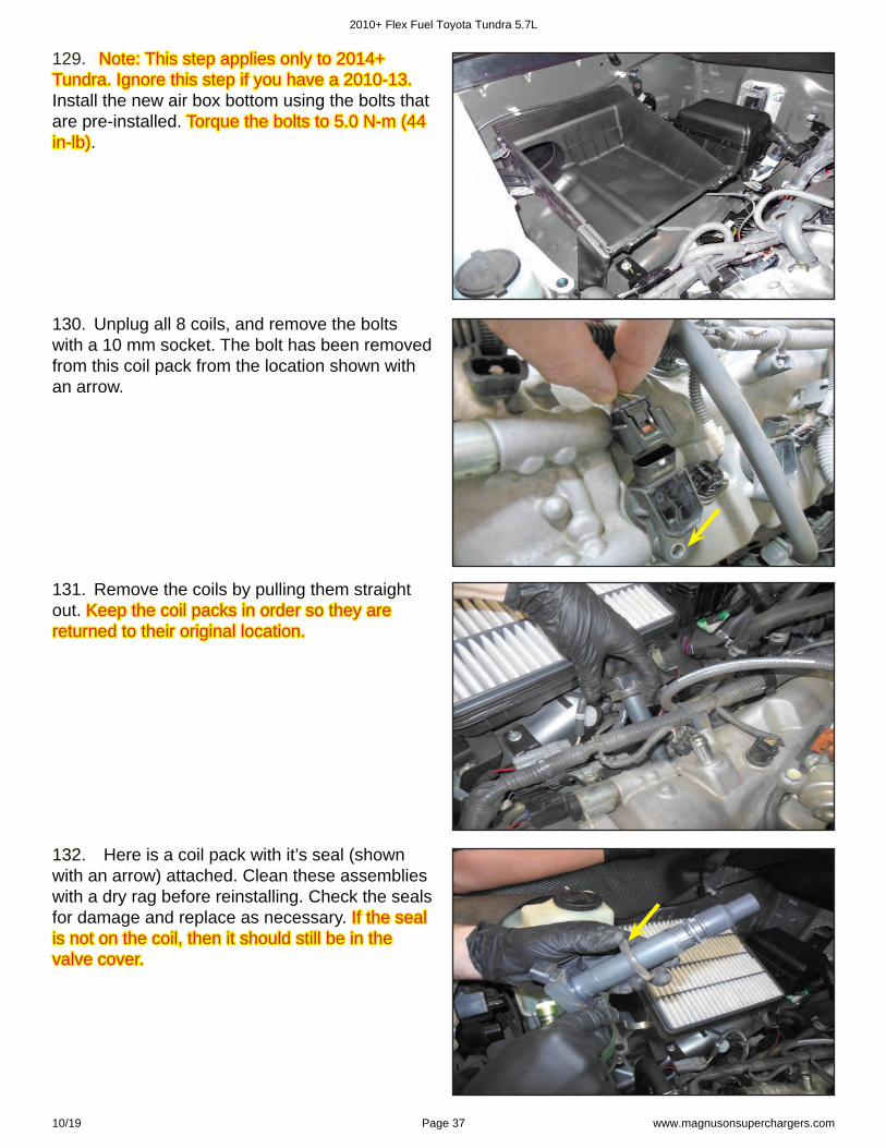
120. Install the new injector rail assembly into the eight seals installed in the last step. Loosely install the four fuel rail spacers and bolts. This will allow you some clearance when it comes to installing the supercharger. Note: Install the bolts Note: Install the bolts deep enough so that they prevent the spacers deep enough so that they prevent the spacers from lifting out of the grooves, but loose enough from lifting out of the grooves, but loose enough so that the rails can pivot side to side. so that the rails can pivot side to side.
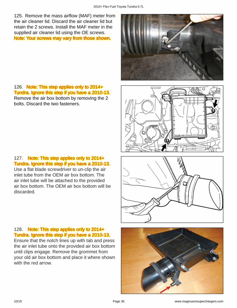
119. Reinstall the eight seals into the injector ports.
2010+ Flex Fuel Toyota Tundra 5.7L
10/19 Page 34 www.magnusonsuperchargers.com
121. 121. Plug in the fuel injector harness on the left and right hand sides.
122. Reconnect the fuel delivery lines to the left and right side of the fuel rail. Make sure the Make sure the fi tting “clicks” into place and can fi tting “clicks” into place and can NOTNOT be pulled be pulled upwards. Then engage the safety clip by sliding it upwards. Then engage the safety clip by sliding it back into place. back into place.
123. Remove the air box lid by disengaging the four clamps (two shown with yellow arrows). Unplug the mass airfl ow sensor (shown with a red arrow).
Section 6: Air Box and Spark Plug Replacement
124. Detach the wire harness clip from the airbox lid using needle nose pliers, or a pick.
2010+ Flex Fuel Toyota Tundra 5.7L
10/19 Page 35 www.magnusonsuperchargers.com
125. Remove the mass airfl ow (MAF) meter from the air cleaner lid. Discard the air cleaner lid but retain the 2 screws. Install the MAF meter in the supplied air cleaner lid using the OE screws. Note: Your screws may vary from those shown.Note: Your screws may vary from those shown.
126. 126. Note: This step applies only to 2014+ Note: This step applies only to 2014+ Tundra. Ignore this step if you have a 2010-13. Tundra. Ignore this step if you have a 2010-13. Remove the air box bottom by removing the 2 bolts. Discard the two fasteners.
127. 127. Note: This step applies only to 2014+ Note: This step applies only to 2014+ Tundra. Ignore this step if you have a 2010-13. Tundra. Ignore this step if you have a 2010-13. Use a fl at blade screwdriver to un-clip the air inlet tube from the OEM air box bottom. The air inlet tube will be attached to the provided air box bottom. The OEM air box bottom will be discarded.
128. 128. Note: This step applies only to 2014+ Note: This step applies only to 2014+ Tundra. Ignore this step if you have a 2010-13. Tundra. Ignore this step if you have a 2010-13. Ensure that the notch lines up with tab and press the air inlet tube onto the provided air box bottom until clips engage. Remove the grommet from your old air box bottom and place it where shown with the red arrow.
2010+ Flex Fuel Toyota Tundra 5.7L
10/19 Page 36 www.magnusonsuperchargers.com
129. 129. Note: This step applies only to 2014+ Note: This step applies only to 2014+ Tundra. Ignore this step if you have a 2010-13. Tundra. Ignore this step if you have a 2010-13. Install the new air box bottom using the bolts that are pre-installed. Torque the bolts to 5.0 N-m (44 Torque the bolts to 5.0 N-m (44 in-lb)in-lb).
130. Unplug all 8 coils, and remove the bolts with a 10 mm socket. The bolt has been removed from this coil pack from the location shown with an arrow.
131. Remove the coils by pulling them straight out. Keep the coil packs in order so they are Keep the coil packs in order so they are returned to their original location.returned to their original location.
132. 132. Here is a coil pack with it’s seal (shown with an arrow) attached. Clean these assemblies with a dry rag before reinstalling. Check the seals for damage and replace as necessary. If the seal If the seal is not on the coil, then it should still be in the is not on the coil, then it should still be in the valve cover.valve cover.
2010+ Flex Fuel Toyota Tundra 5.7L
10/19 Page 37 www.magnusonsuperchargers.com
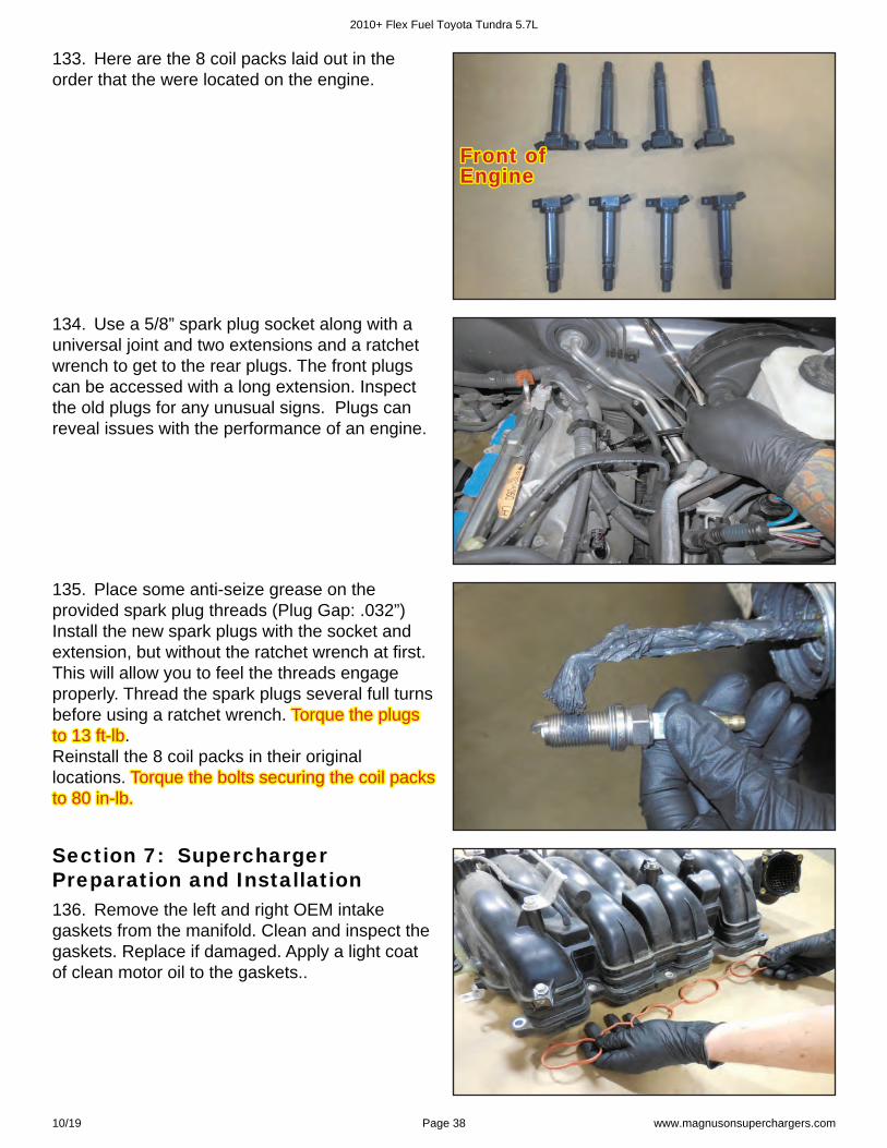
133. Here are the 8 coil packs laid out in the order that the were located on the engine.
Front of Front of EngineEngine
134. Use a 5/8” spark plug socket along with a universal joint and two extensions and a ratchet wrench to get to the rear plugs. The front plugs can be accessed with a long extension. Inspect the old plugs for any unusual signs. Plugs can reveal issues with the performance of an engine.
135. Place some anti-seize grease on the provided spark plug threads (Plug Gap: .032”) Install the new spark plugs with the socket and extension, but without the ratchet wrench at fi rst. This will allow you to feel the threads engage properly. Thread the spark plugs several full turns before using a ratchet wrench. Torque the plugs Torque the plugs to 13 ft-lbto 13 ft-lb. Reinstall the 8 coil packs in their original locations. Torque the bolts securing the coil packs Torque the bolts securing the coil packs to 80 in-lb.to 80 in-lb.
136. Remove the left and right OEM intake gaskets from the manifold. Clean and inspect the gaskets. Replace if damaged. Apply a light coat of clean motor oil to the gaskets..
Section 7: Supercharger Preparation and Installation
2010+ Flex Fuel Toyota Tundra 5.7L
10/19 Page 38 www.magnusonsuperchargers.com
137. Place the OEM gaskets into the supercharger runner grooves as shown.
138. Remove the two nuts holding the harness clamps at the rear of the manifold. Install these clamps onto the back of the supercharger in similar location. These will be used to secure the wiring harness.
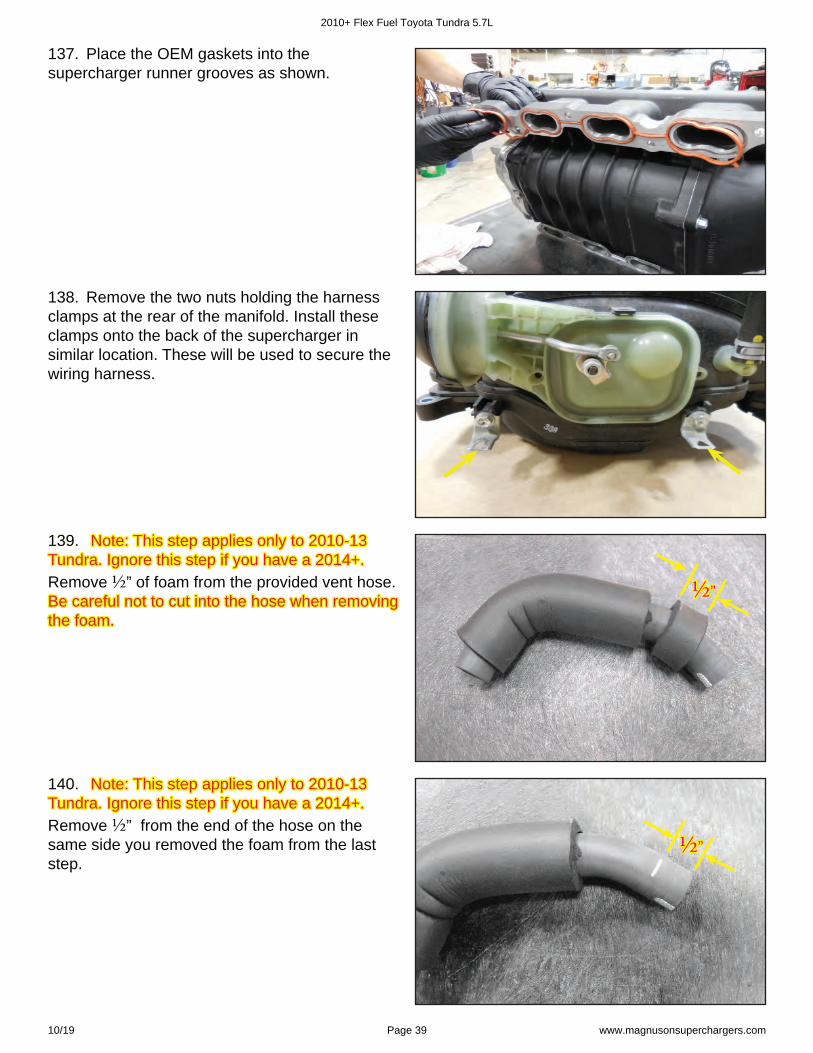
139. 139. Note: This step applies only to 2010-13 Note: This step applies only to 2010-13 Tundra. Ignore this step if you have a 2014+. Tundra. Ignore this step if you have a 2014+. Remove ½ ” of foam from the provided vent hose. Be careful not to cut into the hose when removing Be careful not to cut into the hose when removing the foam.the foam.
½ ½ ””
140. 140. Note: This step applies only to 2010-13 Note: This step applies only to 2010-13 Tundra. Ignore this step if you have a 2014+. Tundra. Ignore this step if you have a 2014+. Remove ½ ” from the end of the hose on the same side you removed the foam from the last step.
½ ½ ””
2010+ Flex Fuel Toyota Tundra 5.7L
10/19 Page 39 www.magnusonsuperchargers.com
141. Attach the OEM spring clamp to the end of the provided PCV hose, and install at the location shown with an arrow.
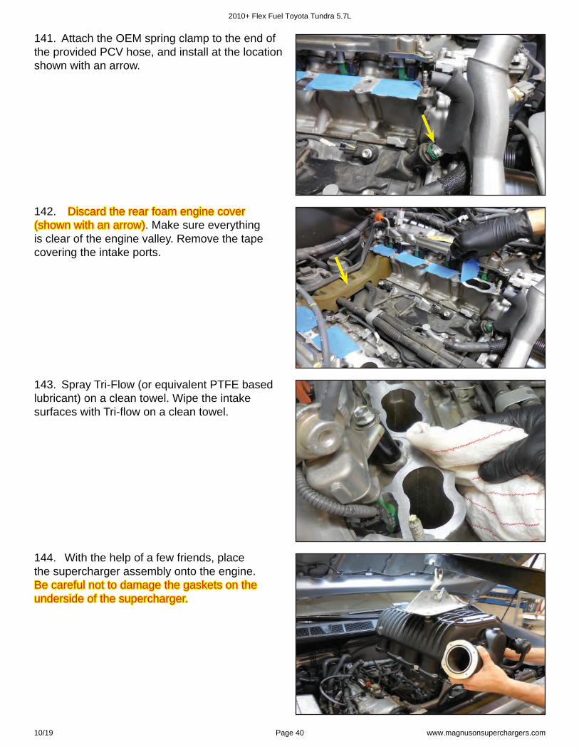
142. Discard the rear foam engine cover Discard the rear foam engine cover (shown with an arrow)(shown with an arrow). . Make sure everything is clear of the engine valley. Remove the tape covering the intake ports.
143. Spray Tri-Flow (or equivalent PTFE based lubricant) on a clean towel. Wipe the intake surfaces with Tri-fl ow on a clean towel.
144. With the help of a few friends, place the supercharger assembly onto the engine. Be careful not to damage the gaskets on the Be careful not to damage the gaskets on the underside of the supercharger.underside of the supercharger.
2010+ Flex Fuel Toyota Tundra 5.7L
10/19 Page 40 www.magnusonsuperchargers.com
145. Install the OE bolts and nuts to secure the supercharger in place. Use a telescoping magnet (shown with a yellow arrow) to drop the bolts in place. Note: The boost port location is shown in Note: The boost port location is shown in this photo with a red arrow. It has a rubber cap this photo with a red arrow. It has a rubber cap over it. over it.
146. 146. Follow the torque sequence given in the Follow the torque sequence given in the diagram at the back of this manual. diagram at the back of this manual. Torque the Torque the manifold bolts to 15 ft-lbs. Also at this time torque manifold bolts to 15 ft-lbs. Also at this time torque the 4 fuel rail bolts to 15 ft-lbs.the 4 fuel rail bolts to 15 ft-lbs.
147. Install the supplied belt according to the belt diagram at the back of this manual.
Section 8: Serpentine Belt, Throttle Body and Hose Installation
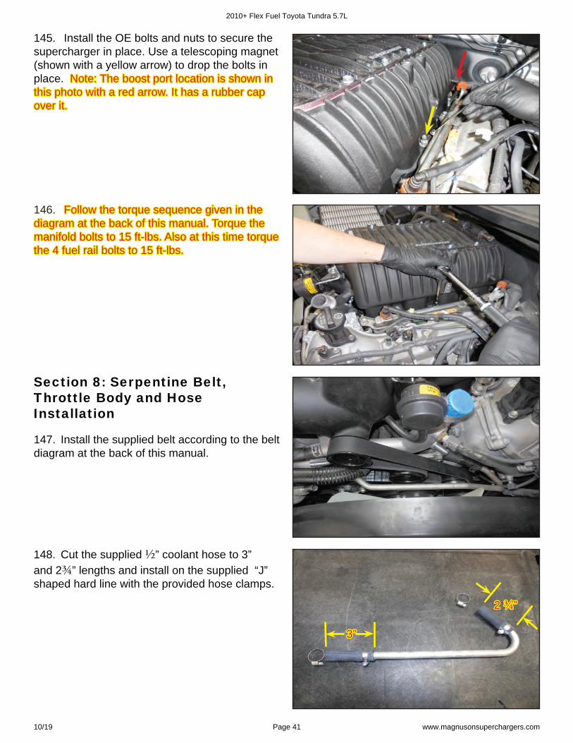
148. Cut the supplied ½ ” coolant hose to 3” and 2¾ ” lengths and install on the supplied “J” shaped hard line with the provided hose clamps.
2 2 ¾ ¾ ””
3”3”
2010+ Flex Fuel Toyota Tundra 5.7L
10/19 Page 41 www.magnusonsuperchargers.com
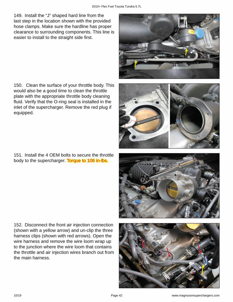
149. Install the “J” shaped hard line from the last step in the location shown with the provided hose clamps. Make sure the hardline has proper clearance to surrounding components. This line is easier to install to the straight side fi rst.
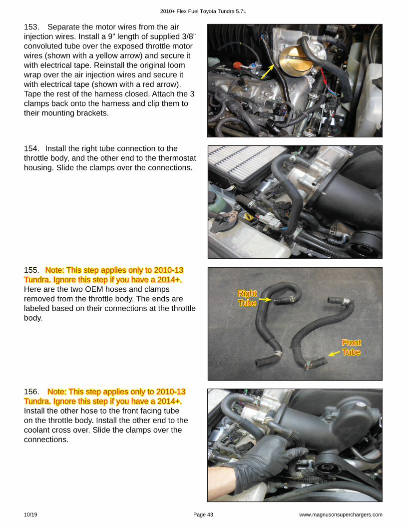
150. Clean the surface of your throttle body. This would also be a good time to clean the throttle plate with the appropriate throttle body cleaning fl uid. Verify that the O-ring seal is installed in the inlet of the supercharger. Remove the red plug if equipped.
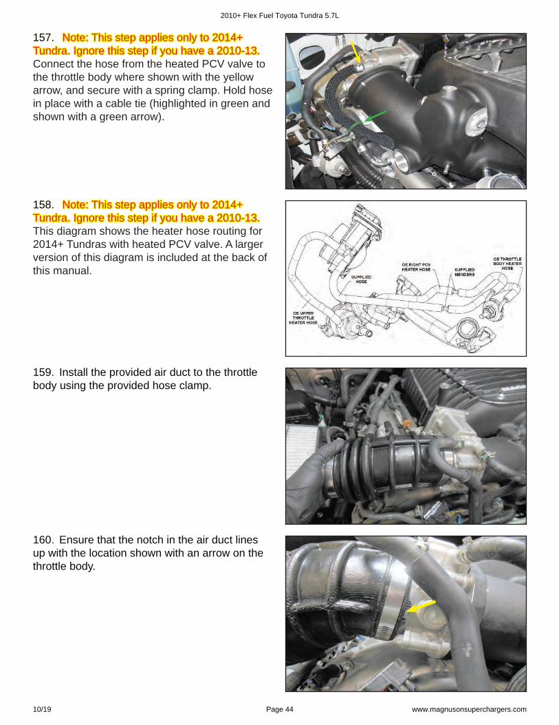
151. Install the 4 OEM bolts to secure the throttle body to the supercharger. Torque to 106 in-lbs.Torque to 106 in-lbs.
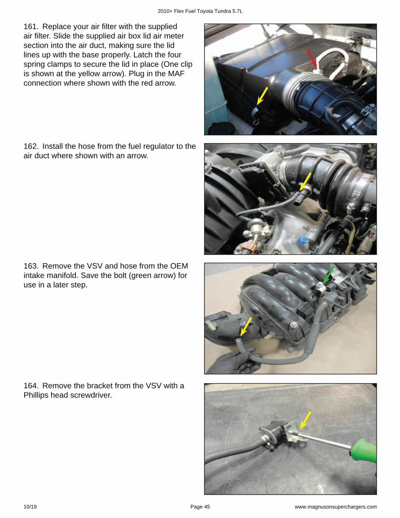
152. Disconnect the front air injection connection (shown with a yellow arrow) and un-clip the three harness clips (shown with red arrows). Open the wire harness and remove the wire loom wrap up to the junction where the wire loom that contains the throttle and air injection wires branch out from the main harness.
2010+ Flex Fuel Toyota Tundra 5.7L
10/19 Page 42 www.magnusonsuperchargers.com
154. Install the right tube connection to the throttle body, and the other end to the thermostat housing. Slide the clamps over the connections.
Right Right TubeTube
Front Front TubeTube
153. Separate the motor wires from the air injection wires. Install a 9” length of supplied 3/8” convoluted tube over the exposed throttle motor wires (shown with a yellow arrow) and secure it with electrical tape. Reinstall the original loom wrap over the air injection wires and secure it with electrical tape (shown with a red arrow). Tape the rest of the harness closed. Attach the 3 clamps back onto the harness and clip them to their mounting brackets.
155. 155. Note: This step applies only to 2010-13 Note: This step applies only to 2010-13 Tundra. Ignore this step if you have a 2014+.Tundra. Ignore this step if you have a 2014+. Here are the two OEM hoses and clamps removed from the throttle body. The ends are labeled based on their connections at the throttle body.
156. 156. Note: This step applies only to 2010-13 Note: This step applies only to 2010-13 Tundra. Ignore this step if you have a 2014+. Tundra. Ignore this step if you have a 2014+. Install the other hose to the front facing tube on the throttle body. Install the other end to the coolant cross over. Slide the clamps over the connections.
2010+ Flex Fuel Toyota Tundra 5.7L
10/19 Page 43 www.magnusonsuperchargers.com
157. 157. Note: This step applies only to 2014+ Note: This step applies only to 2014+ Tundra. Ignore this step if you have a 2010-13. Tundra. Ignore this step if you have a 2010-13. Connect the hose from the heated PCV valve to the throttle body where shown with the yellow arrow, and secure with a spring clamp. Hold hose in place with a cable tie (highlighted in green and shown with a green arrow).
158. 158. Note: This step applies only to 2014+ Note: This step applies only to 2014+ Tundra. Ignore this step if you have a 2010-13.Tundra. Ignore this step if you have a 2010-13. This diagram shows the heater hose routing for 2014+ Tundras with heated PCV valve. A larger version of this diagram is included at the back of this manual.
159. Install the provided air duct to the throttle body using the provided hose clamp.
160. Ensure that the notch in the air duct lines up with the location shown with an arrow on the throttle body.
2010+ Flex Fuel Toyota Tundra 5.7L
10/19 Page 44 www.magnusonsuperchargers.com
161. Replace your air fi lter with the supplied air fi lter. Slide the supplied air box lid air meter section into the air duct, making sure the lid lines up with the base properly. Latch the four spring clamps to secure the lid in place (One clip is shown at the yellow arrow). Plug in the MAF connection where shown with the red arrow.
162. Install the hose from the fuel regulator to the air duct where shown with an arrow.
163. Remove the VSV and hose from the OEM intake manifold. Save the bolt (green arrow) for use in a later step.
164. Remove the bracket from the VSV with a Phillips head screwdriver.
2010+ Flex Fuel Toyota Tundra 5.7L
10/19 Page 45 www.magnusonsuperchargers.com
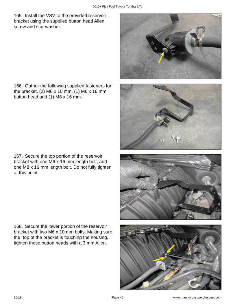
165. Install the VSV to the provided reservoir bracket using the supplied button head Allen screw and star washer.
166. Gather the following supplied fasteners for the bracket. (2) M6 x 10 mm, (1) M6 x 16 mm button head and (1) M8 x 16 mm.
167. Secure the top portion of the reservoir bracket with one M6 x 16 mm length bolt, and one M8 x 16 mm length bolt. Do not fully tighten at this point.
168. Secure the lower portion of the reservoir bracket with two M6 x 10 mm bolts. Making sure the top of the bracket is touching the housing, tighten these button heads with a 3 mm Allen.
2010+ Flex Fuel Toyota Tundra 5.7L
10/19 Page 46 www.magnusonsuperchargers.com
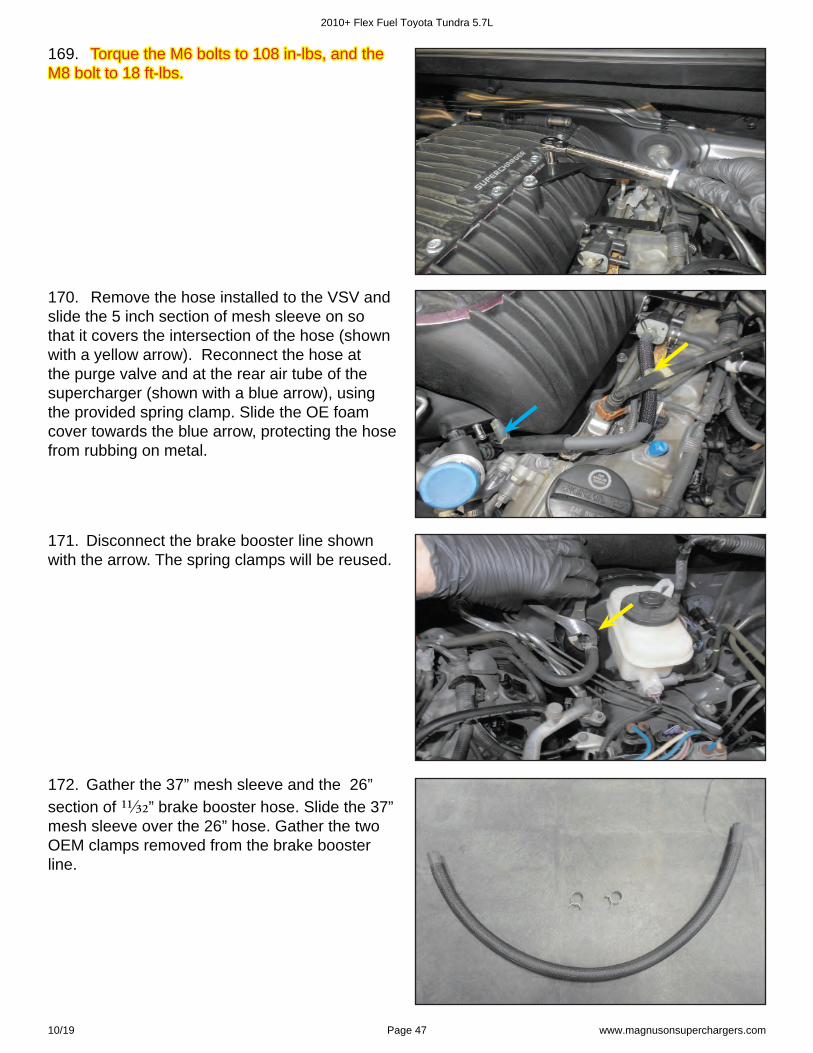
169. Torque the M6 bolts to 108 in-lbs, and the Torque the M6 bolts to 108 in-lbs, and the M8 bolt to 18 ft-lbs. M8 bolt to 18 ft-lbs.
170. Remove the hose installed to the VSV and slide the 5 inch section of mesh sleeve on so that it covers the intersection of the hose (shown with a yellow arrow). Reconnect the hose at the purge valve and at the rear air tube of the supercharger (shown with a blue arrow), using the provided spring clamp. Slide the OE foam cover towards the blue arrow, protecting the hose from rubbing on metal.
171. Disconnect the brake booster line shown with the arrow. The spring clamps will be reused.
172. Gather the 37” mesh sleeve and the 26” section of 1⅓ 2” brake booster hose. Slide the 37” mesh sleeve over the 26” hose. Gather the two OEM clamps removed from the brake booster line.
2010+ Flex Fuel Toyota Tundra 5.7L
10/19 Page 47 www.magnusonsuperchargers.com
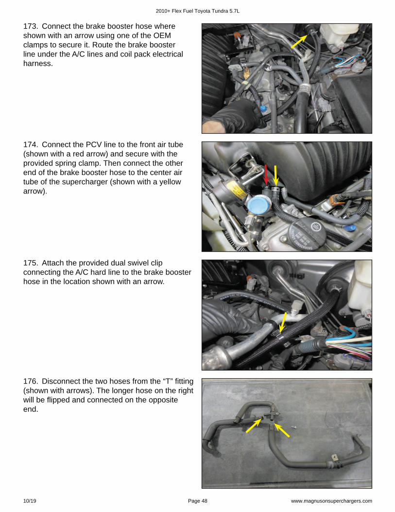
173. Connect the brake booster hose where shown with an arrow using one of the OEM clamps to secure it. Route the brake booster line under the A/C lines and coil pack electrical harness.
174. Connect the PCV line to the front air tube (shown with a red arrow) and secure with the provided spring clamp. Then connect the other end of the brake booster hose to the center air tube of the supercharger (shown with a yellow arrow).
175. Attach the provided dual swivel clip connecting the A/C hard line to the brake booster hose in the location shown with an arrow.
176. Disconnect the two hoses from the “T” fi tting (shown with arrows). The longer hose on the right will be fl ipped and connected on the opposite end.
2010+ Flex Fuel Toyota Tundra 5.7L
10/19 Page 48 www.magnusonsuperchargers.com
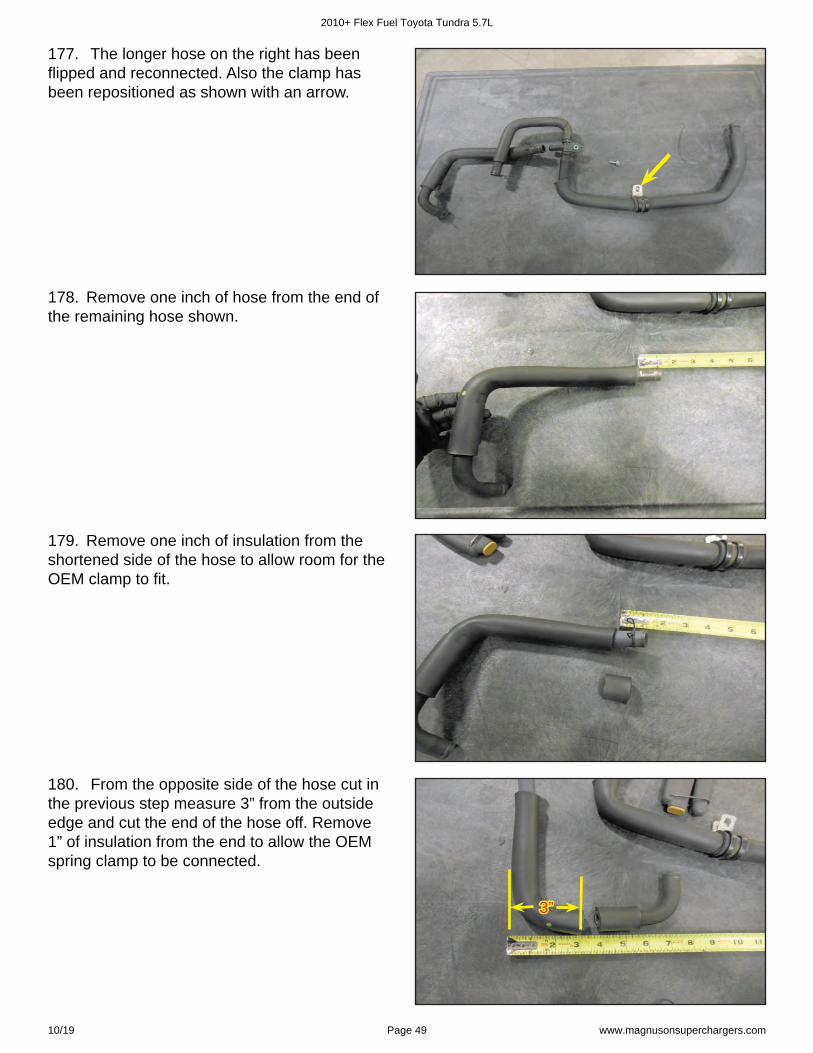
177. The longer hose on the right has been fl ipped and reconnected. Also the clamp has been repositioned as shown with an arrow.
178. Remove one inch of hose from the end of the remaining hose shown.
179. Remove one inch of insulation from the shortened side of the hose to allow room for the OEM clamp to fi t.
180. From the opposite side of the hose cut in the previous step measure 3” from the outside edge and cut the end of the hose off. Remove 1” of insulation from the end to allow the OEM spring clamp to be connected.
3”3”
2010+ Flex Fuel Toyota Tundra 5.7L
10/19 Page 49 www.magnusonsuperchargers.com
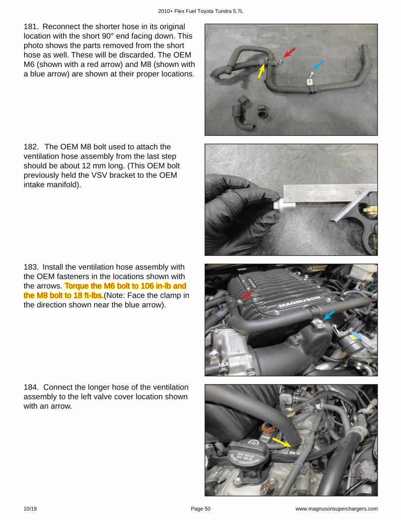
181. Reconnect the shorter hose in its original location with the short 90° end facing down. This photo shows the parts removed from the short hose as well. These will be discarded. The OEM M6 (shown with a red arrow) and M8 (shown with a blue arrow) are shown at their proper locations.
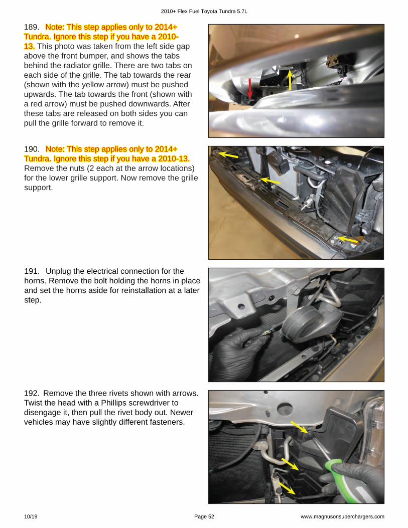
182. The OEM M8 bolt used to attach the ventilation hose assembly from the last step should be about 12 mm long. (This OEM bolt previously held the VSV bracket to the OEM intake manifold).
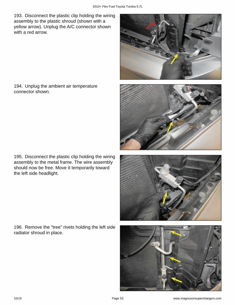
183. Install the ventilation hose assembly with the OEM fasteners in the locations shown with the arrows. Torque the M6 bolt to 106 in-lb and Torque the M6 bolt to 106 in-lb and the M8 bolt to 18 ft-lbs.the M8 bolt to 18 ft-lbs.(Note: Face the clamp in the direction shown near the blue arrow).
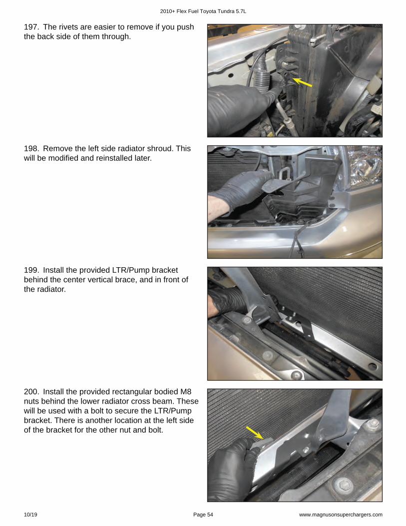
184. Connect the longer hose of the ventilation assembly to the left valve cover location shown with an arrow.
2010+ Flex Fuel Toyota Tundra 5.7L
10/19 Page 50 www.magnusonsuperchargers.com

185. Connect the unaltered hose of the ventilation hose assembly to the fi tting on the air duct.
186. Connect the fi nal end of the ventilation hose assembly to the right valve cover location shown with an arrow.
187. Reconnect the radiator hose. Flip this hose end for end from its original location. Earlier you should have marked the radiator end, This end should now be attached to the coolant crossover. The clamps in this picture are not shown in their fi nal securing positions.
Section 9: Intercooler System Installation188. 188. Note: This step applies only to 2014+ Note: This step applies only to 2014+ Tundra. Ignore this step if you have a 2010-Tundra. Ignore this step if you have a 2010-13. 13. Remove the four bolts at the yellow arrows locations. Disengage the two clip rivet fasteners at the red arrow locations by pulling up on the center fi rst with a small screwdriver, and then pull up on the outside of the clip rivet.
2010+ Flex Fuel Toyota Tundra 5.7L
10/19 Page 51 www.magnusonsuperchargers.com
191. Unplug the electrical connection for the horns. Remove the bolt holding the horns in place and set the horns aside for reinstallation at a later step.
190. 190. Note: This step applies only to 2014+ Note: This step applies only to 2014+ Tundra. Ignore this step if you have a 2010-13. Tundra. Ignore this step if you have a 2010-13. Remove the nuts (2 each at the arrow locations) for the lower grille support. Now remove the grille support.
189. 189. Note: This step applies only to 2014+ Note: This step applies only to 2014+ Tundra. Ignore this step if you have a 2010-Tundra. Ignore this step if you have a 2010-13.13. This photo was taken from the left side gap above the front bumper, and shows the tabs behind the radiator grille. There are two tabs on each side of the grille. The tab towards the rear (shown with the yellow arrow) must be pushed upwards. The tab towards the front (shown with a red arrow) must be pushed downwards. After these tabs are released on both sides you can pull the grille forward to remove it.
192. Remove the three rivets shown with arrows. Twist the head with a Phillips screwdriver to disengage it, then pull the rivet body out. Newer vehicles may have slightly different fasteners.
2010+ Flex Fuel Toyota Tundra 5.7L
10/19 Page 52 www.magnusonsuperchargers.com
193. Disconnect the plastic clip holding the wiring assembly to the plastic shroud (shown with a yellow arrow). Unplug the A/C connector shown with a red arrow.
194. Unplug the ambient air temperature connector shown.
195. Disconnect the plastic clip holding the wiring assembly to the metal frame. The wire assembly should now be free. Move it temporarily toward the left side headlight.
196. Remove the “tree” rivets holding the left side radiator shroud in place.
2010+ Flex Fuel Toyota Tundra 5.7L
10/19 Page 53 www.magnusonsuperchargers.com
197. The rivets are easier to remove if you push the back side of them through.
198. Remove the left side radiator shroud. This will be modifi ed and reinstalled later.
199. Install the provided LTR/Pump bracket behind the center vertical brace, and in front of the radiator.
200. Install the provided rectangular bodied M8 nuts behind the lower radiator cross beam. These will be used with a bolt to secure the LTR/Pump bracket. There is another location at the left side of the bracket for the other nut and bolt.
2010+ Flex Fuel Toyota Tundra 5.7L
10/19 Page 54 www.magnusonsuperchargers.com
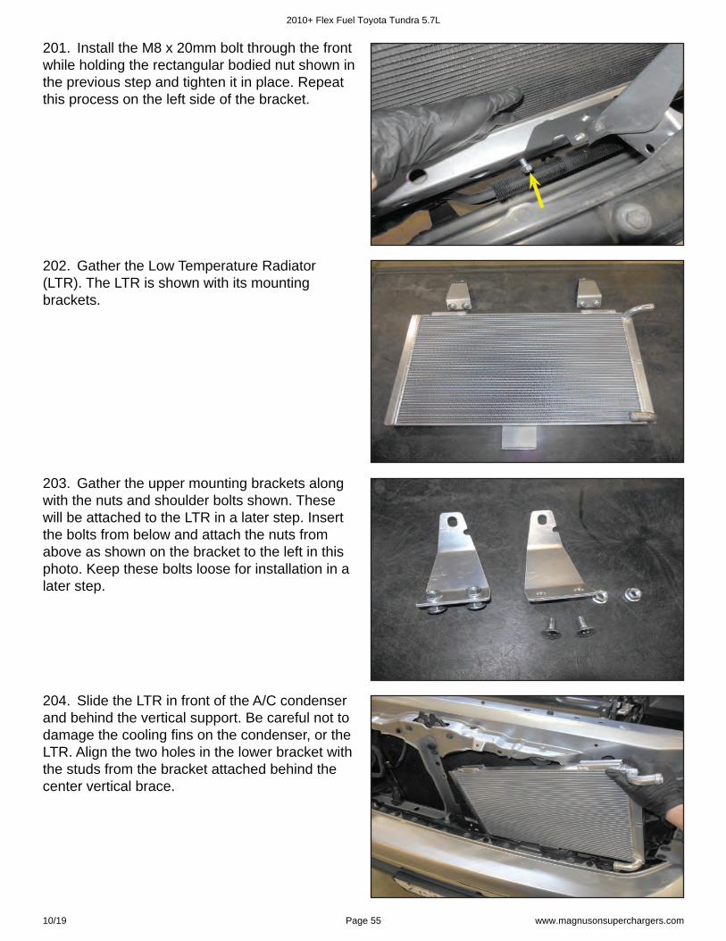
201. Install the M8 x 20mm bolt through the front while holding the rectangular bodied nut shown in the previous step and tighten it in place. Repeat this process on the left side of the bracket.
202. Gather the Low Temperature Radiator (LTR). The LTR is shown with its mounting brackets.
203. Gather the upper mounting brackets along with the nuts and shoulder bolts shown. These will be attached to the LTR in a later step. Insert the bolts from below and attach the nuts from above as shown on the bracket to the left in this photo. Keep these bolts loose for installation in a later step.
204. Slide the LTR in front of the A/C condenser and behind the vertical support. Be careful not to damage the cooling fi ns on the condenser, or the LTR. Align the two holes in the lower bracket with the studs from the bracket attached behind the center vertical brace.
2010+ Flex Fuel Toyota Tundra 5.7L
10/19 Page 55 www.magnusonsuperchargers.com
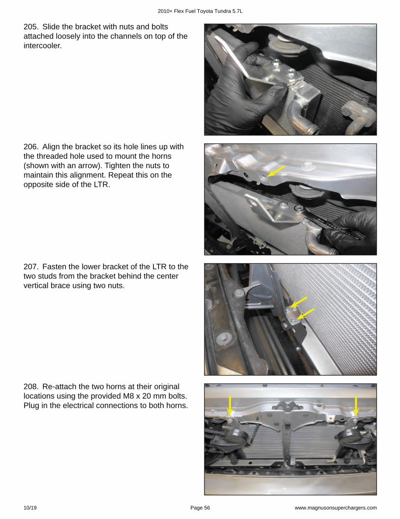
205. Slide the bracket with nuts and bolts attached loosely into the channels on top of the intercooler.
206. Align the bracket so its hole lines up with the threaded hole used to mount the horns (shown with an arrow). Tighten the nuts to maintain this alignment. Repeat this on the opposite side of the LTR.
207. Fasten the lower bracket of the LTR to the two studs from the bracket behind the center vertical brace using two nuts.
208. Re-attach the two horns at their original locations using the provided M8 x 20 mm bolts. Plug in the electrical connections to both horns.
2010+ Flex Fuel Toyota Tundra 5.7L
10/19 Page 56 www.magnusonsuperchargers.com
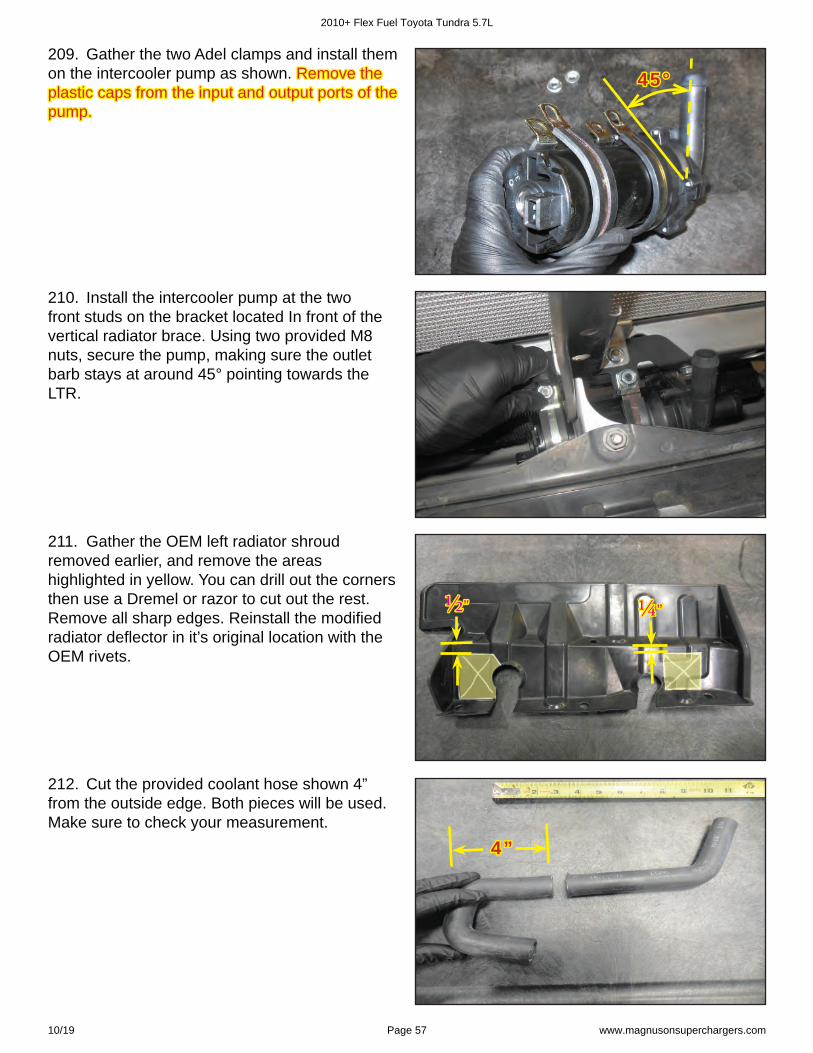
209. Gather the two Adel clamps and install them on the intercooler pump as shown. Remove the Remove the plastic caps from the input and output ports of the plastic caps from the input and output ports of the pump.pump.
45°45°
210. Install the intercooler pump at the two front studs on the bracket located In front of the vertical radiator brace. Using two provided M8 nuts, secure the pump, making sure the outlet barb stays at around 45° pointing towards the LTR.
211. Gather the OEM left radiator shroud removed earlier, and remove the areas highlighted in yellow. You can drill out the corners then use a Dremel or razor to cut out the rest. Remove all sharp edges. Reinstall the modifi ed radiator defl ector in it’s original location with the OEM rivets.
½ ½ ”” ¼ ¼ ””
212. Cut the provided coolant hose shown 4” from the outside edge. Both pieces will be used. Make sure to check your measurement.
4”4”
2010+ Flex Fuel Toyota Tundra 5.7L
10/19 Page 57 www.magnusonsuperchargers.com
3”3”
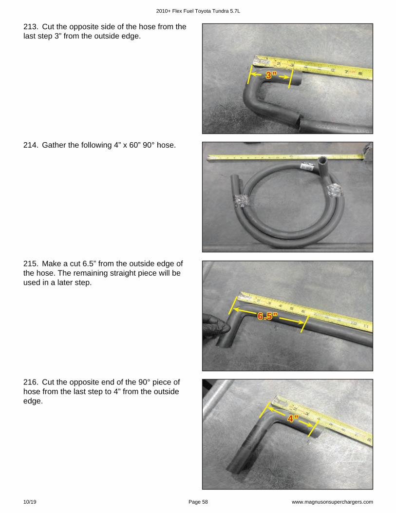
213. Cut the opposite side of the hose from the last step 3” from the outside edge.
214. Gather the following 4” x 60” 90° hose.
6.5”6.5”
215. Make a cut 6.5” from the outside edge of the hose. The remaining straight piece will be used in a later step.
4”4”
216. Cut the opposite end of the 90° piece of hose from the last step to 4” from the outside edge.
2010+ Flex Fuel Toyota Tundra 5.7L
10/19 Page 58 www.magnusonsuperchargers.com
44”44”
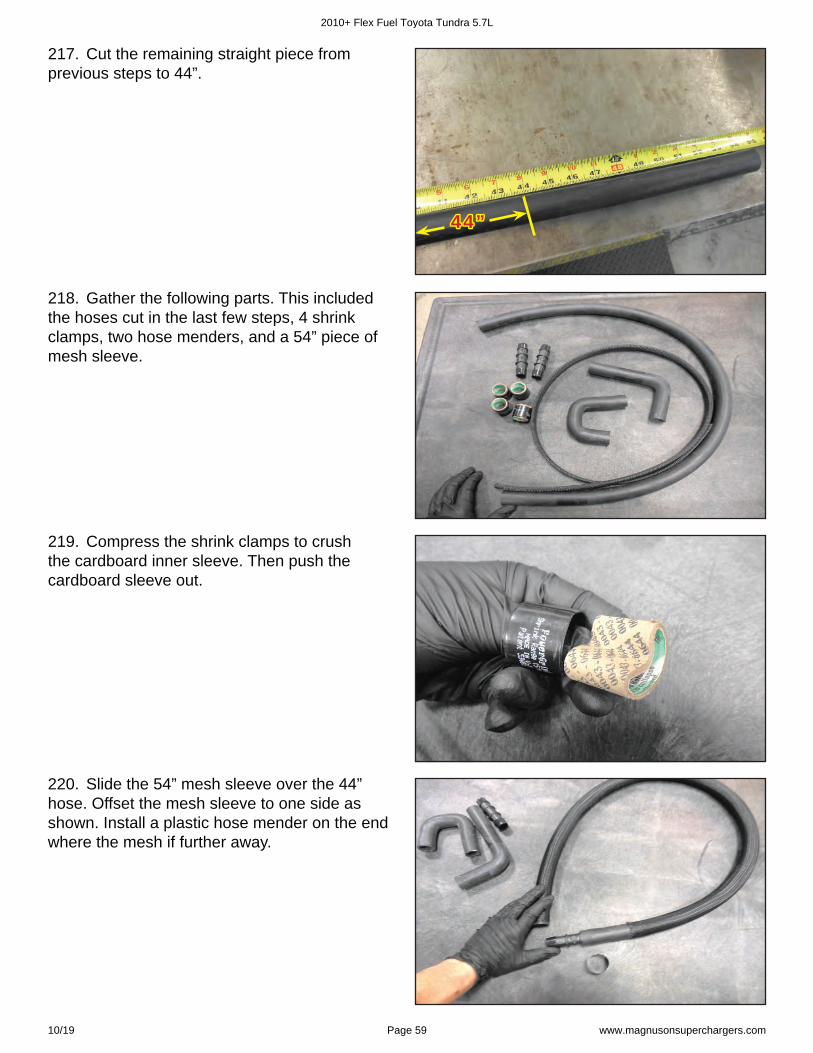
217. Cut the remaining straight piece from previous steps to 44”.
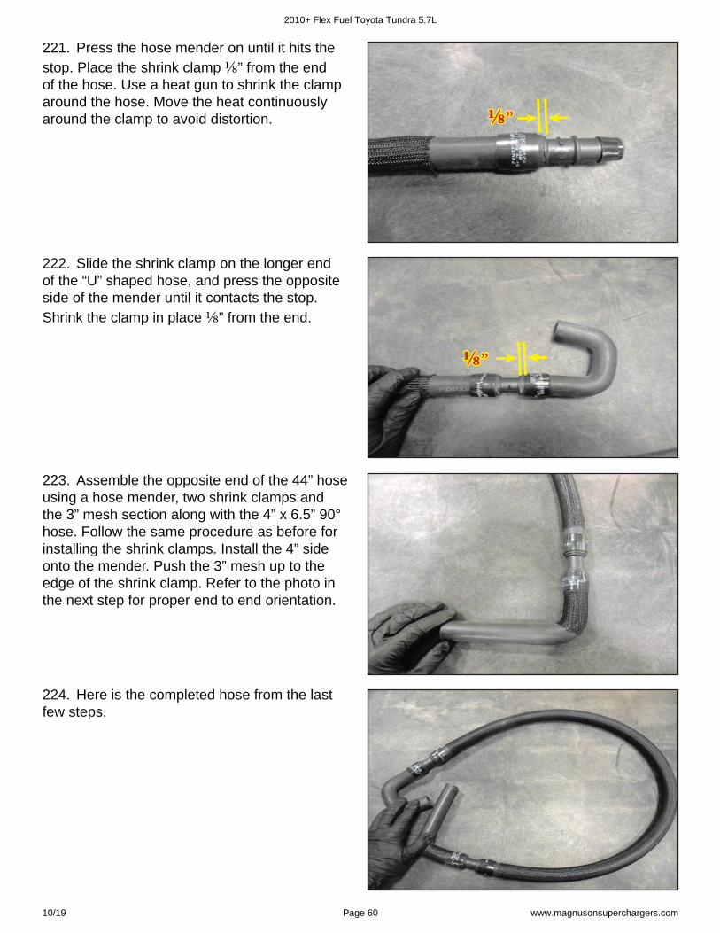
218. Gather the following parts. This included the hoses cut in the last few steps, 4 shrink clamps, two hose menders, and a 54” piece of mesh sleeve.
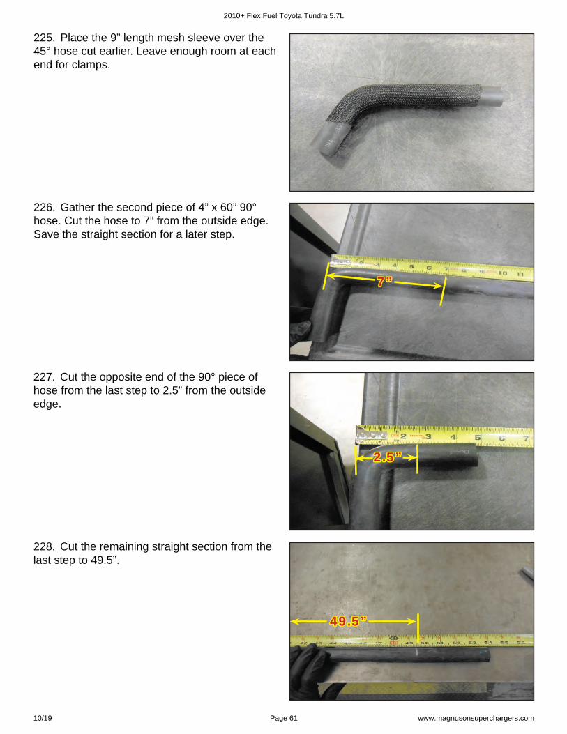
219. Compress the shrink clamps to crush the cardboard inner sleeve. Then push the cardboard sleeve out.
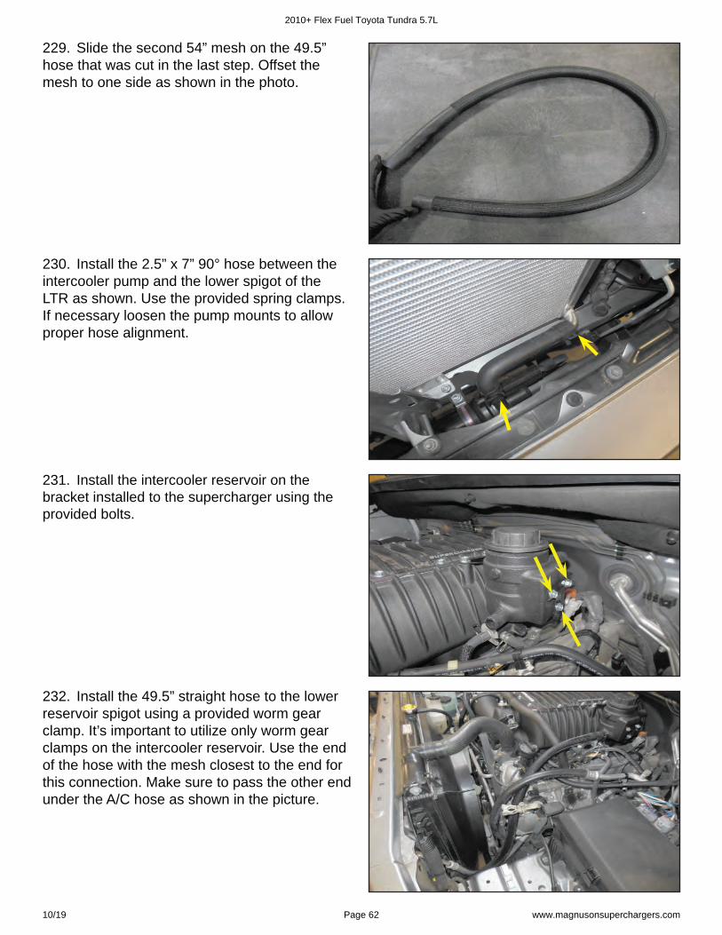
220. Slide the 54” mesh sleeve over the 44” hose. Offset the mesh sleeve to one side as shown. Install a plastic hose mender on the end where the mesh if further away.
2010+ Flex Fuel Toyota Tundra 5.7L
10/19 Page 59 www.magnusonsuperchargers.com
221. Press the hose mender on until it hits the stop. Place the shrink clamp ⅛ ” from the end of the hose. Use a heat gun to shrink the clamp around the hose. Move the heat continuously around the clamp to avoid distortion. ⅛ ⅛ ””
222. Slide the shrink clamp on the longer end of the “U” shaped hose, and press the opposite side of the mender until it contacts the stop. Shrink the clamp in place ⅛ ” from the end.
⅛ ⅛ ””
223. Assemble the opposite end of the 44” hose using a hose mender, two shrink clamps and the 3” mesh section along with the 4” x 6.5” 90° hose. Follow the same procedure as before for installing the shrink clamps. Install the 4” side onto the mender. Push the 3” mesh up to the edge of the shrink clamp. Refer to the photo in the next step for proper end to end orientation.
224. Here is the completed hose from the last few steps.
2010+ Flex Fuel Toyota Tundra 5.7L
10/19 Page 60 www.magnusonsuperchargers.com
225. Place the 9” length mesh sleeve over the 45° hose cut earlier. Leave enough room at each end for clamps.
226. Gather the second piece of 4” x 60” 90° hose. Cut the hose to 7” from the outside edge. Save the straight section for a later step.
7”7”
227. Cut the opposite end of the 90° piece of hose from the last step to 2.5” from the outside edge.
2.5”2.5”
228. Cut the remaining straight section from the last step to 49.5”.
49.5”49.5”
2010+ Flex Fuel Toyota Tundra 5.7L
10/19 Page 61 www.magnusonsuperchargers.com
229. Slide the second 54” mesh on the 49.5” hose that was cut in the last step. Offset the mesh to one side as shown in the photo.
230. Install the 2.5” x 7” 90° hose between the intercooler pump and the lower spigot of the LTR as shown. Use the provided spring clamps. If necessary loosen the pump mounts to allow proper hose alignment.
231. Install the intercooler reservoir on the bracket installed to the supercharger using the provided bolts.
232. Install the 49.5” straight hose to the lower reservoir spigot using a provided worm gear clamp. It’s important to utilize only worm gear clamps on the intercooler reservoir. Use the end of the hose with the mesh closest to the end for this connection. Make sure to pass the other end under the A/C hose as shown in the picture.
2010+ Flex Fuel Toyota Tundra 5.7L
10/19 Page 62 www.magnusonsuperchargers.com
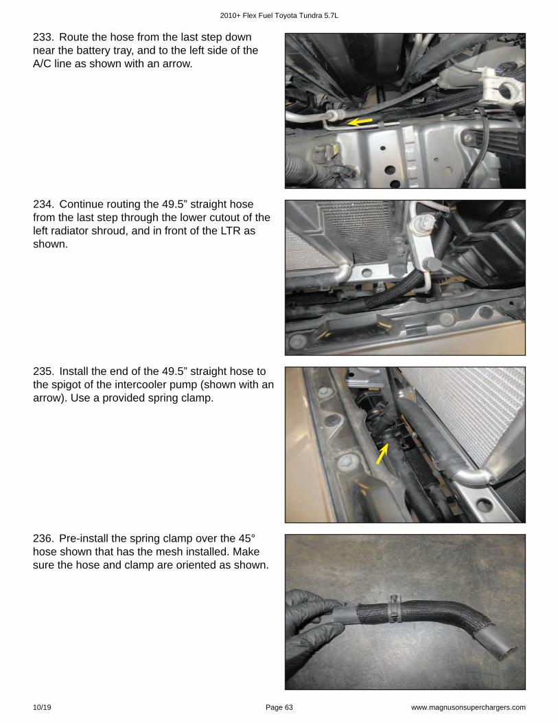
233. Route the hose from the last step down near the battery tray, and to the left side of the A/C line as shown with an arrow.
234. Continue routing the 49.5” straight hose from the last step through the lower cutout of the left radiator shroud, and in front of the LTR as shown.
235. Install the end of the 49.5” straight hose to the spigot of the intercooler pump (shown with an arrow). Use a provided spring clamp.
236. Pre-install the spring clamp over the 45° hose shown that has the mesh installed. Make sure the hose and clamp are oriented as shown.
2010+ Flex Fuel Toyota Tundra 5.7L
10/19 Page 63 www.magnusonsuperchargers.com
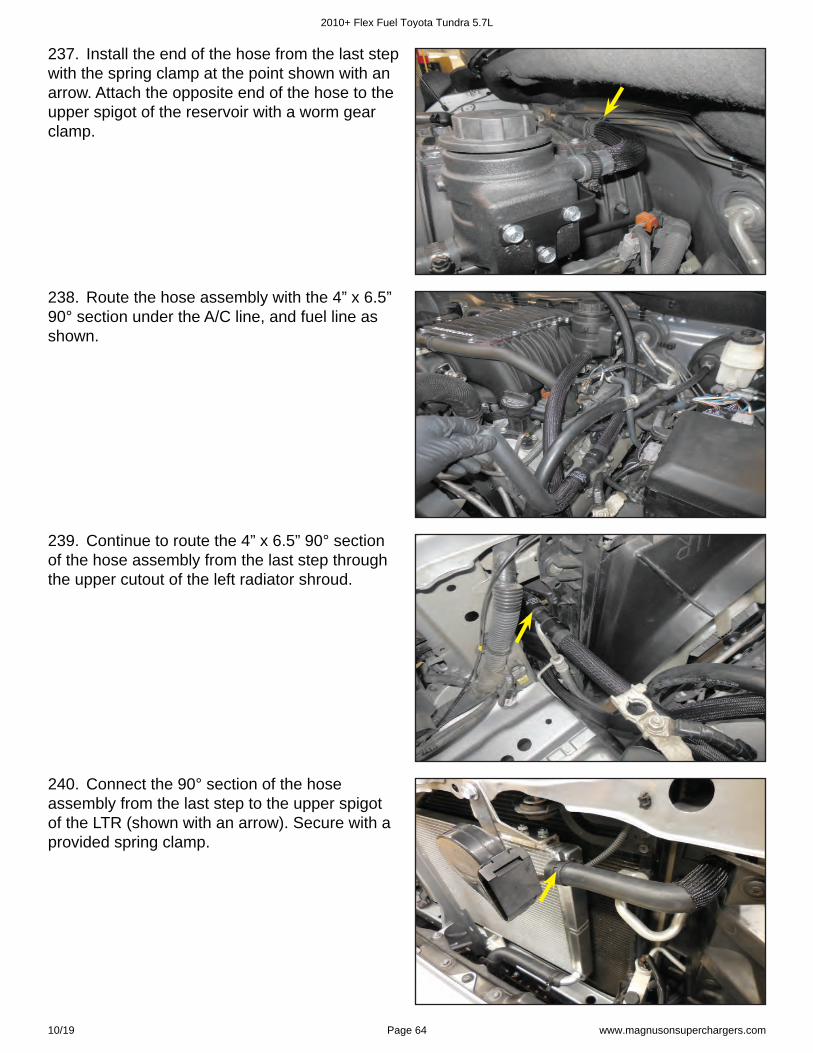
237. Install the end of the hose from the last step with the spring clamp at the point shown with an arrow. Attach the opposite end of the hose to the upper spigot of the reservoir with a worm gear clamp.
238. Route the hose assembly with the 4” x 6.5” 90° section under the A/C line, and fuel line as shown.
239. Continue to route the 4” x 6.5” 90° section of the hose assembly from the last step through the upper cutout of the left radiator shroud.
240. Connect the 90° section of the hose assembly from the last step to the upper spigot of the LTR (shown with an arrow). Secure with a provided spring clamp.
2010+ Flex Fuel Toyota Tundra 5.7L
10/19 Page 64 www.magnusonsuperchargers.com
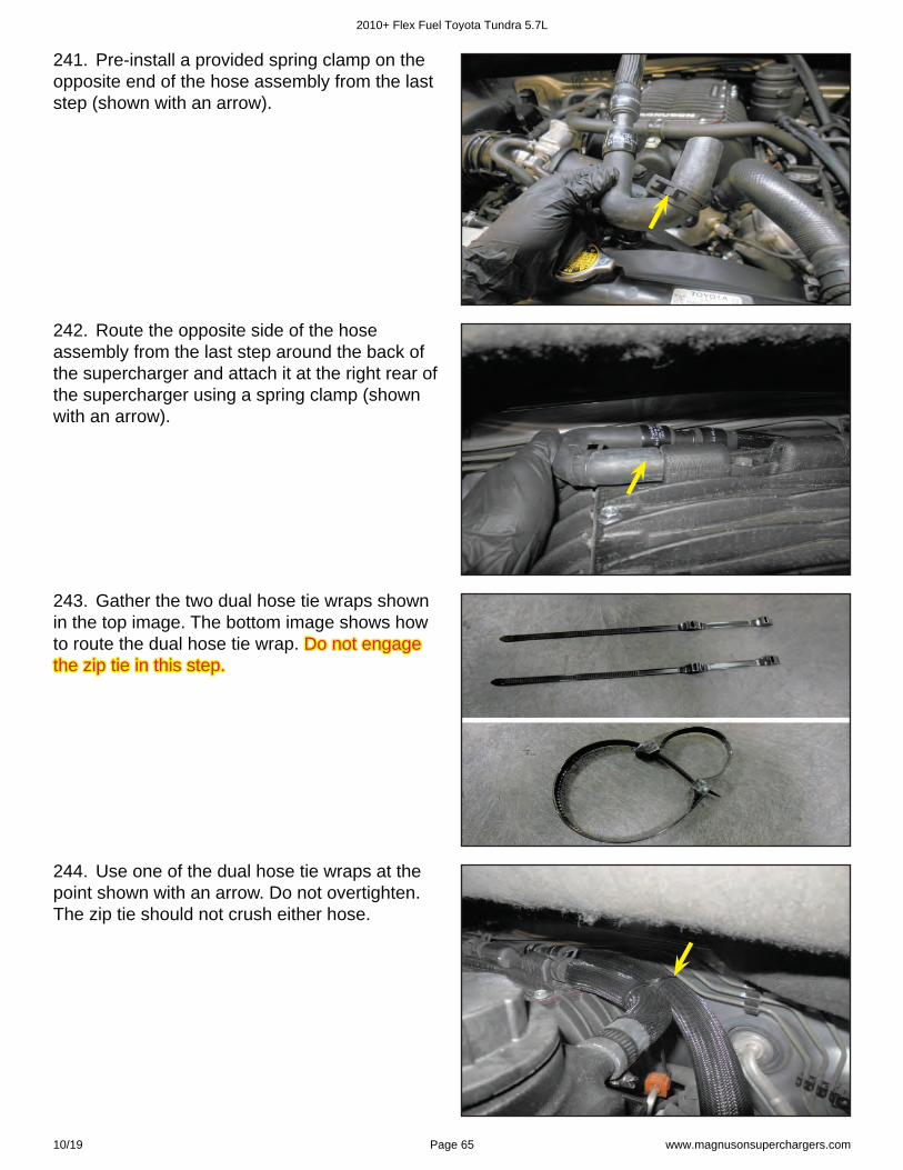
241. Pre-install a provided spring clamp on the opposite end of the hose assembly from the last step (shown with an arrow).
242. Route the opposite side of the hose assembly from the last step around the back of the supercharger and attach it at the right rear of the supercharger using a spring clamp (shown with an arrow).
243. Gather the two dual hose tie wraps shown in the top image. The bottom image shows how to route the dual hose tie wrap. Do not engage Do not engage the zip tie in this step. the zip tie in this step.
244. Use one of the dual hose tie wraps at the point shown with an arrow. Do not overtighten. The zip tie should not crush either hose.
2010+ Flex Fuel Toyota Tundra 5.7L
10/19 Page 65 www.magnusonsuperchargers.com
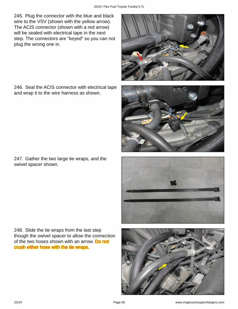
245. Plug the connector with the blue and black wire to the VSV (shown with the yellow arrow). The ACIS connector (shown with a red arrow) will be sealed with electrical tape in the next step. The connectors are “keyed” so you can not plug the wrong one in.
246. Seal the ACIS connector with electrical tape and wrap it to the wire harness as shown.
247. Gather the two large tie wraps, and the swivel spacer shown.
248. Slide the tie wraps from the last step though the swivel spacer to allow the connection of the two hoses shown with an arrow. Do not Do not crush either hose with the tie wraps. crush either hose with the tie wraps.
2010+ Flex Fuel Toyota Tundra 5.7L
10/19 Page 66 www.magnusonsuperchargers.com
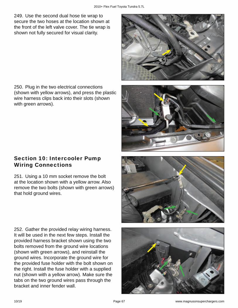
249. Use the second dual hose tie wrap to secure the two hoses at the location shown at the front of the left valve cover. The tie wrap is shown not fully secured for visual clarity.
250. Plug in the two electrical connections (shown with yellow arrows), and press the plastic wire harness clips back into their slots (shown with green arrows).
251. Using a 10 mm socket remove the bolt at the location shown with a yellow arrow. Also remove the two bolts (shown with green arrows) that hold ground wires.
Section 10: Intercooler Pump Wiring Connections
252. Gather the provided relay wiring harness. It will be used in the next few steps. Install the provided harness bracket shown using the two bolts removed from the ground wire locations (shown with green arrows), and reinstall the ground wires. Incorporate the ground wire for the provided fuse holder with the bolt shown on the right. Install the fuse holder with a supplied nut (shown with a yellow arrow). Make sure the tabs on the two ground wires pass through the bracket and inner fender wall.
2010+ Flex Fuel Toyota Tundra 5.7L
10/19 Page 67 www.magnusonsuperchargers.com
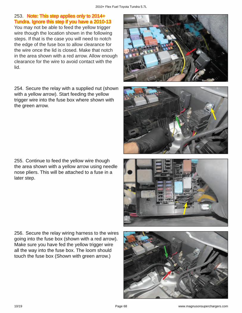
253. 253. Note: This step applies only to 2014+ Note: This step applies only to 2014+ Tundra. Ignore this step if you have a 2010-13 Tundra. Ignore this step if you have a 2010-13 You may not be able to feed the yellow trigger wire though the location shown in the following steps. If that is the case you will need to notch the edge of the fuse box to allow clearance for the wire once the lid is closed. Make that notch in the area shown with a red arrow. Allow enough clearance for the wire to avoid contact with the lid.
255. Continue to feed the yellow wire though the area shown with a yellow arrow using needle nose pliers. This will be attached to a fuse in a later step.
256. Secure the relay wiring harness to the wires going into the fuse box (shown with a red arrow). Make sure you have fed the yellow trigger wire all the way into the fuse box. The loom should touch the fuse box (Shown with green arrow.)
254. Secure the relay with a supplied nut (shown with a yellow arrow). Start feeding the yellow trigger wire into the fuse box where shown with the green arrow.
2010+ Flex Fuel Toyota Tundra 5.7L
10/19 Page 68 www.magnusonsuperchargers.com
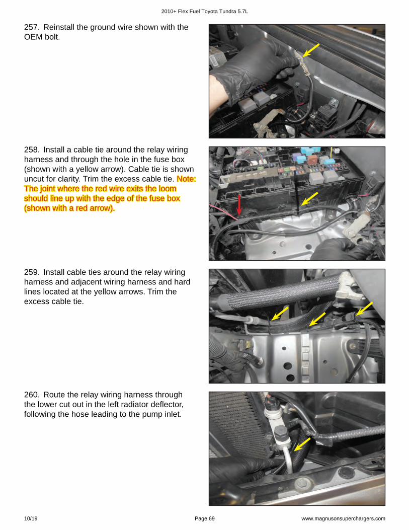
257. Reinstall the ground wire shown with the OEM bolt.
258. Install a cable tie around the relay wiring harness and through the hole in the fuse box (shown with a yellow arrow). Cable tie is shown uncut for clarity. Trim the excess cable tie. Note: Note: The joint where the red wire exits the loom The joint where the red wire exits the loom should line up with the edge of the fuse box should line up with the edge of the fuse box (shown with a red arrow). (shown with a red arrow).
259. Install cable ties around the relay wiring harness and adjacent wiring harness and hard lines located at the yellow arrows. Trim the excess cable tie.
260. Route the relay wiring harness through the lower cut out in the left radiator defl ector, following the hose leading to the pump inlet.
2010+ Flex Fuel Toyota Tundra 5.7L
10/19 Page 69 www.magnusonsuperchargers.com
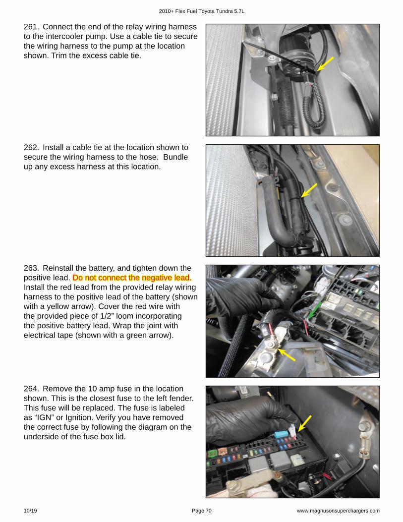
261. Connect the end of the relay wiring harness to the intercooler pump. Use a cable tie to secure the wiring harness to the pump at the location shown. Trim the excess cable tie.
263. Reinstall the battery, and tighten down the positive lead. Do not connect the negative lead.Do not connect the negative lead. Install the red lead from the provided relay wiring harness to the positive lead of the battery (shown with a yellow arrow). Cover the red wire with the provided piece of 1/2” loom incorporating the positive battery lead. Wrap the joint with electrical tape (shown with a green arrow).
262. Install a cable tie at the location shown to secure the wiring harness to the hose. Bundle up any excess harness at this location.
264. Remove the 10 amp fuse in the location shown. This is the closest fuse to the left fender. This fuse will be replaced. The fuse is labeled as “IGN” or Ignition. Verify you have removed the correct fuse by following the diagram on the underside of the fuse box lid.
2010+ Flex Fuel Toyota Tundra 5.7L
10/19 Page 70 www.magnusonsuperchargers.com
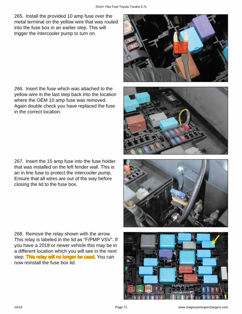
265. Install the provided 10 amp fuse over the metal terminal on the yellow wire that was routed into the fuse box in an earlier step. This will trigger the intercooler pump to turn on.
266. Insert the fuse which was attached to the yellow wire in the last step back into the location where the OEM 10 amp fuse was removed. Again double check you have replaced the fuse in the correct location.
267. Insert the 15 amp fuse into the fuse holder that was installed on the left fender wall. This is an in line fuse to protect the intercooler pump. Ensure that all wires are out of the way before closing the lid to the fuse box.
268. Remove the relay shown with the arrow. This relay is labeled in the lid as “F/PMP VSV”. If you have a 2018 or newer vehicle this may be in a different location which you will see in the next step. This relay will no longer be used.This relay will no longer be used. You can now reinstall the fuse box lid.
2010+ Flex Fuel Toyota Tundra 5.7L
10/19 Page 71 www.magnusonsuperchargers.com
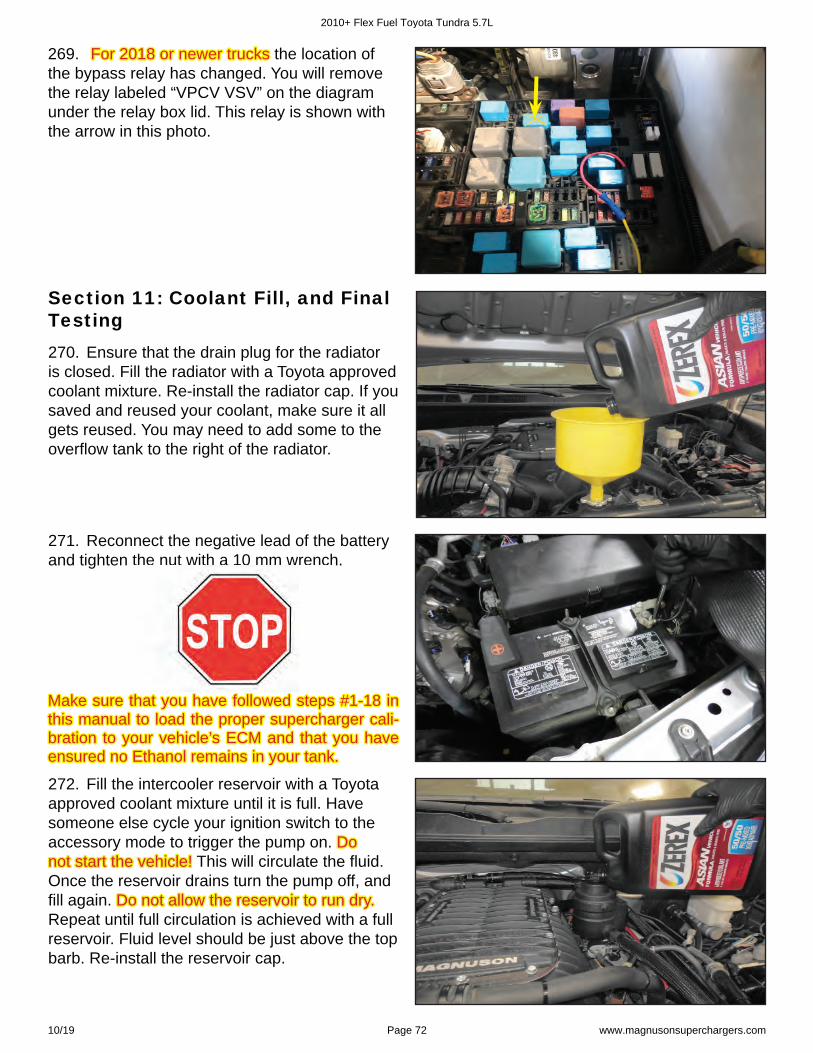
271. Reconnect the negative lead of the battery and tighten the nut with a 10 mm wrench.
272. Fill the intercooler reservoir with a Toyota approved coolant mixture until it is full. Have someone else cycle your ignition switch to the accessory mode to trigger the pump on. Do Do not start the vehicle!not start the vehicle! This will circulate the fl uid. Once the reservoir drains turn the pump off, and fi ll again. Do not allow the reservoir to run dry.Do not allow the reservoir to run dry. Repeat until full circulation is achieved with a full reservoir. Fluid level should be just above the top barb. Re-install the reservoir cap.
Make sure that you have followed steps #1-18 in Make sure that you have followed steps #1-18 in this manual to load the proper supercharger cali-this manual to load the proper supercharger cali-bration to your vehicle’s ECM and that you have bration to your vehicle’s ECM and that you have ensured no Ethanol remains in your tank.ensured no Ethanol remains in your tank.
Section 11: Coolant Fill, and Final Testing270. Ensure that the drain plug for the radiator is closed. Fill the radiator with a Toyota approved coolant mixture. Re-install the radiator cap. If you saved and reused your coolant, make sure it all gets reused. You may need to add some to the overfl ow tank to the right of the radiator.
269. For 2018 or newer trucksFor 2018 or newer trucks the location of the bypass relay has changed. You will remove the relay labeled “VPCV VSV” on the diagram under the relay box lid. This relay is shown with the arrow in this photo.
2010+ Flex Fuel Toyota Tundra 5.7L
10/19 Page 72 www.magnusonsuperchargers.com
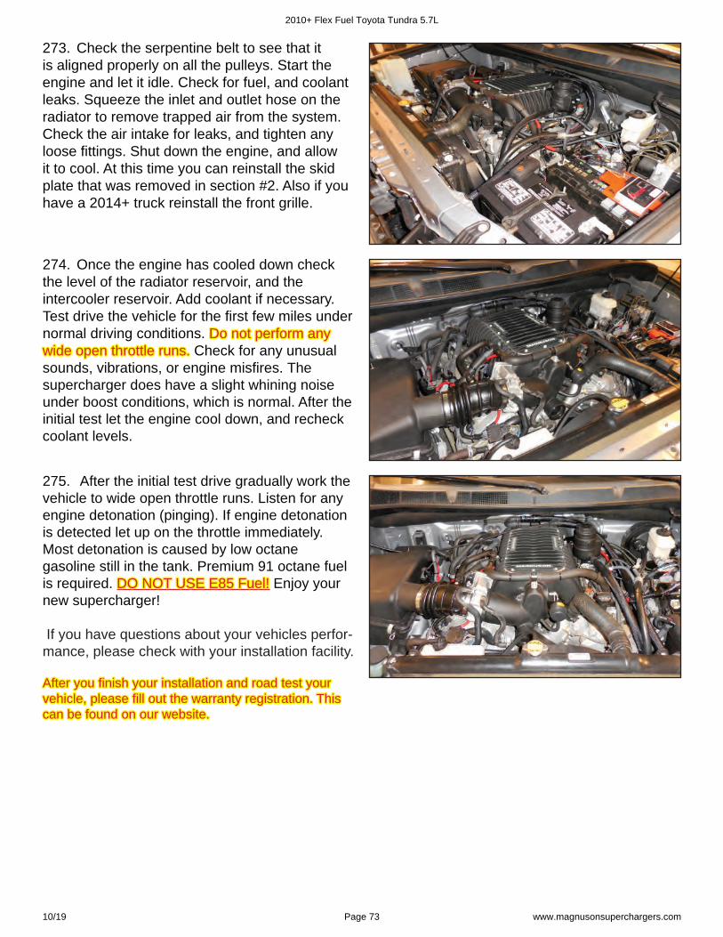
273. Check the serpentine belt to see that itis aligned properly on all the pulleys. Start theengine and let it idle. Check for fuel, and coolantleaks. Squeeze the inlet and outlet hose on theradiator to remove trapped air from the system.Check the air intake for leaks, and tighten anyloose fi ttings. Shut down the engine, and allowit to cool. At this time you can reinstall the skidplate that was removed in section #2. Also if youhave a 2014+ truck reinstall the front grille.
274. Once the engine has cooled down checkthe level of the radiator reservoir, and theintercooler reservoir. Add coolant if necessary.Test drive the vehicle for the fi rst few miles undernormal driving conditions. Do not perform anyDo not perform anywide open throttle runs. wide open throttle runs. Check for any unusualsounds, vibrations, or engine misfi res. Thesupercharger does have a slight whining noiseunder boost conditions, which is normal. After theinitial test let the engine cool down, and recheckcoolant levels.
If you have questions about your vehicles perfor-mance, please check with your installation facility.
275. After the initial test drive gradually work thevehicle to wide open throttle runs. Listen for anyengine detonation (pinging). If engine detonationis detected let up on the throttle immediately.Most detonation is caused by low octanegasoline still in the tank. Premium 91 octane fuelis required. DO NOT USE E85 Fuel!DO NOT USE E85 Fuel! Enjoy yournew supercharger!
After you fi nish your installation and road test your After you fi nish your installation and road test your vehicle, please fi ll out the warranty registration. This vehicle, please fi ll out the warranty registration. This can be found on our website.can be found on our website.
2010+ Flex Fuel Toyota Tundra 5.7L
10/19 Page 73 www.magnusonsuperchargers.com
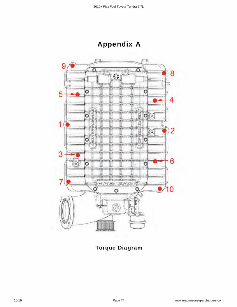
Appendix A
Torque Diagram
2010+ Flex Fuel Toyota Tundra 5.7L
10/19 Page 74 www.magnusonsuperchargers.com
Appendix B
Belt Routing Diagram
Heated PCV Routing for 2014+
2010+ Flex Fuel Toyota Tundra 5.7L
10/19 Page 75 www.magnusonsuperchargers.com
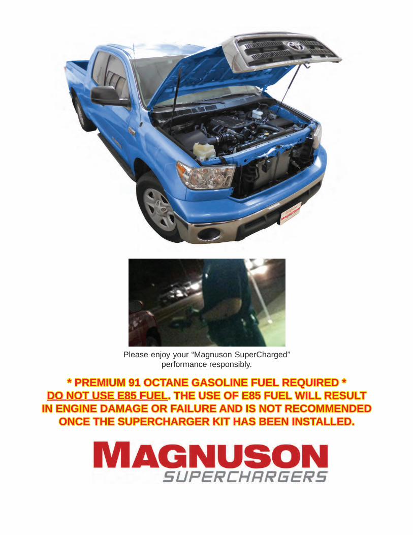
Please enjoy your “Magnuson SuperCharged” performance responsibly.
* PREMIUM 91 OCTANE GASOLINE FUEL REQUIRED ** PREMIUM 91 OCTANE GASOLINE FUEL REQUIRED *DO NOT USE E85 FUELDO NOT USE E85 FUEL. THE USE OF E85 FUEL WILL RESULT . THE USE OF E85 FUEL WILL RESULT
IN ENGINE DAMAGE OR FAILURE AND IS NOT RECOMMENDED IN ENGINE DAMAGE OR FAILURE AND IS NOT RECOMMENDED ONCE THE SUPERCHARGER KIT HAS BEEN INSTALLED.ONCE THE SUPERCHARGER KIT HAS BEEN INSTALLED.
Related Documents


![2007-2009 TOYOTA TUNDRA 5.7L PART NO. 19230 · 2007-2009 TOYOTA TUNDRA 5.7L PART NO. 19230 HARDWARE KIT: 1. [7] 2.50" Torca Clamp 2. [2] 2.75" Torca Clamp 3. [1] Rubber Insulator](https://static.cupdf.com/doc/110x72/5f10cd247e708231d44ae1e7/2007-2009-toyota-tundra-57l-part-no-19230-2007-2009-toyota-tundra-57l-part-no.jpg)