P. 1 2010 MATE International ROV Competition Kwok Tak Seng Catholic Secondary School IT School Team ROV Name: KTSCSS Team Members: Members Chow LAP (Leader) Chan Ho Hin Ip Chun Ting Lam Tze Ho Team Advisors: Mr. Lee Siu Fung

Welcome message from author
This document is posted to help you gain knowledge. Please leave a comment to let me know what you think about it! Share it to your friends and learn new things together.
Transcript
P. 1
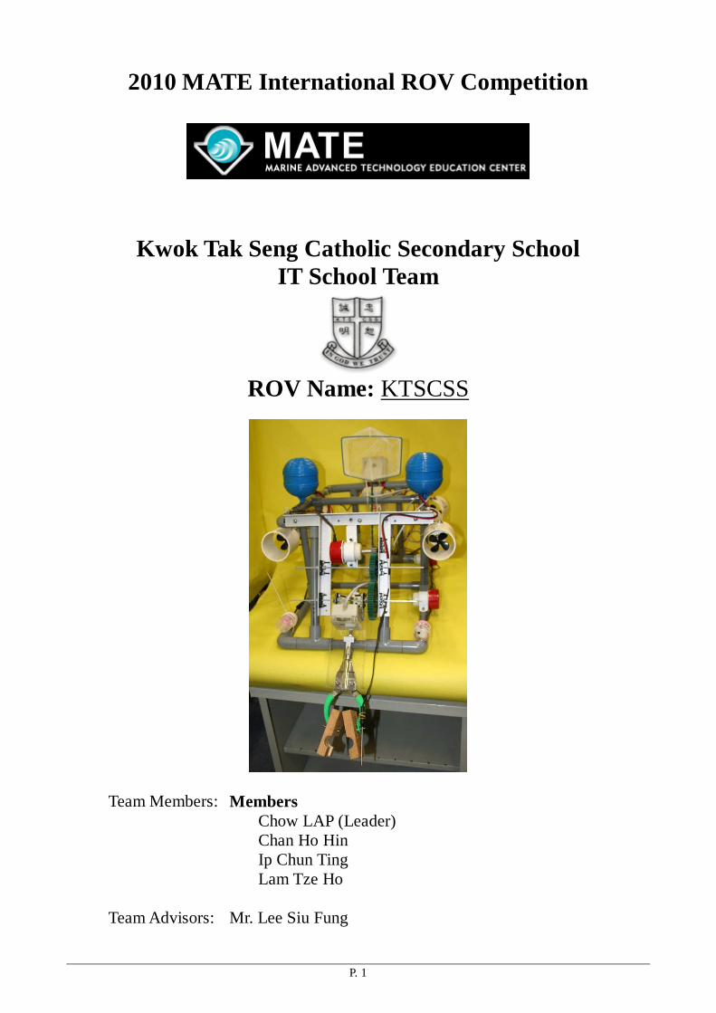
2010 MATE International ROV Competition
Kwok Tak Seng Catholic Secondary School IT School Team
ROV Name: KTSCSS
Team Members: Members Chow LAP (Leader) Chan Ho Hin Ip Chun Ting Lam Tze Ho
Team Advisors: Mr. Lee Siu Fung

P. 2
Abstract
The scenario of this year’s ROV competition is to resurrect HUGO and collect temperature data
and samples of geologic features on the Loihi seamount. We need to build different components to tackle
the following four tasks:
Task 1: Resurrect HUGO
Task 2: Collect samples of a new species of crustacean
Task 3: Sample a new vent site
Task 4: Collect a sample of a bacterial mat
Basically, the ROV should capable of moving under water, grabbing objects and measuring
temperature in various part of vent site. First of all, focusing on the four tasks, we designed four
devices to achieve these tasks.
To deal with the first task, a Rotational pliers which is motivated by pneumatic system is built
to grab and hold object (Pins, HRH, HUGO cap, HRH-power connector) under water. The pliers
can also be moved. Two Water-proof cameras are built. One of them is located on the top of pliers
for viewing the target object. Another one is located at the top of the ROV in order to inspect the
view of the Loihi seamount and to locate targets. A Pneumatic driving trap is built to collect the
crustacean samples in the cave for task 2. For task 3, a Thermometer is put on the front of ROV in
order to measure the temperature of the Vent chimney. For collecting bacterial mat, a sucking tube
with seesaw cutting end is built to penetrate into the agar and grab the bacterial sample.

P. 3
Table of content
1. Design rationale
2. Detail design
3. Electrical schematic
4. Challenge faced
5. Troubleshooting techniques
6. Description of lesson learned or skill gained
7. Future Improvement
8. Reflection
9. Budget Sheet
10. Loihi seamount
11. Teamwork
12. Reference
13. Acknowledgements

P. 4
1. Design Rationale
In order to complete all tasks, we made out the ROV step by step following the requirements of different missions. 1. ROV body - We made the frame of the ROV using PVC conduit. It is controlled by six sets of
thrusters. Four thrusters can be switched independently to perform Mono-directional movement of the ROV. They drive the ROV to move forward, backward , left turn and right turn. Two sets of thrusters perform bidirectional movement to move the ROV up and down, shift the entire ROV towards left and right.
2. Pneumatic Rotational pliers - We made the pliers which are motivated by pneumatics for
clipping objects under water like to grab and hold object (Pins, HRH, HUGO cap, HRH-power connector) under water. The pliers can also be moved upward and downward.
3. Water-proofed cameras - We also made two water-proofed cameras, each connected with a
bundle of metal wire which can be bent for a better and flexible sight. Two cameras must be needed to minimize the vision illusion by only one camera. One of them is located on the top of pliers for viewing the target object. Another one is located at the top of the ROV in order to inspect the view of the Loihi seamount and to locate targets.
4. Pneumatic driving trap - For the second task, a trap which is driven by pneumatics was made
to complete the mission of collecting the crustacean samples. 5. A Thermometer is put on the front of ROV attached on the pliers such that its position can be
adjusted in order to measure the temperature of the Vent chimney in various height. 6. A Hydrophone is made with a standard microphone. I will be connected to an amplifier with
loud speaker. The hydrophone is used to identifying which of three potential sites is rumbling. 7. For collecting bacterial mat, a collection of sucking tube made by syringe is built to penetrate
into the agar and collect bacterial samples. 8. After that, all those tools are connected with the main frame and the motors are added to
activate different parts of the ROV. 9. At last, we add some floating material to the robot, in order to meet the equilibrium of the
floating force and the sinking force.
P. 5
2. Detail design 1. ROV
A) Control System The whole electronic circuit of the ROV is driven by a 12V DC power supply
for all parts and accessories. We have built four simple thrusters by four
water-proofed motors and propellers. Each thruster is connected to a 12V D.C.
power supply with a 1A fuse in positive pole. These four thrusters can operate
independently with one directional ONLY.
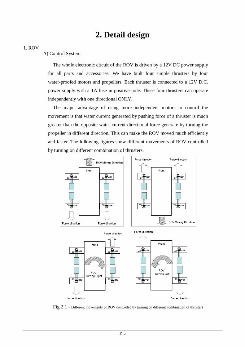
The major advantage of using more independent motors to control the
movement is that water current generated by pushing force of a thruster is much
greater than the opposite water current directional force generate by turning the
propeller in different direction. This can make the ROV moved much efficiently
and faster. The following figures show different movements of ROV controlled
by turning on different combination of thrusters.
Fig 2.1 - Different movements of ROV controlled by turning on different combination of thrusters

P. 6
Fig 2.2 – Thrusters showing in different view of ROV
Individual switch to perform different bi-directional movement of the ROV.
One thruster responses for up and down movement. To let ROV works under
water and float back to water surface, downward force and upward force can be
provided by the thruster.
Another set of thruster shift the entire ROV towards left or right. Apart from
turning, some fine movement of ROV is also essential to locate the target
position.
B) ROV Body Structure
To complete the four missions, different devices have been made to
accomplish different tasks. The devices include water-proofed cameras,
pneumatic driving pliers, a net and a shovel. To assemble all devices into the
ROV, the ROV body structure needs to be built to equip all devices into the
ROV body.
Fig 2.3 – Overall design of ROV body structure

P. 7
The front end of the ROV is designed as a 30 degree slope to accomplish the Pneumatic Rotational Pliers to be moved in greater angle to explorer the scene under water and to grab objects more easily.
Fig 2.4 – Front part of ROV body
2. Cameras
Three water-proofed cameras are powered by a 12V DC power supply.
The video signal of cameras will be sent to the TV set through RCA signal
cable. The CCD cameras act as the eyes underwater to locate objects. A
waterproof CCD camera is used to capture the underwater views.
One of camera is used for viewing and exploring the scene underwater. It
gives wider angle of view so that we can locate target more easily.
Fig 2.5 – Camera location 1
The last camera is located on the rotational pliers and focus on the tip of the
pliers. This helps us to locate objects that needed to be hold or transport
underwater. As it always follows the movement of the arm of pliers, we can
easily see the holding object. It also focus the pliers which can help us for
picking up an object and drop an object underwater.
Focus on forward view.

P. 8
Fig 2.5 – Camera location 2
Another one is look at the bottom of the seabed. It provides a top view for
pilot to locate the bacterial sample.
Fig 2.6 – Camera location 3
Fig 2.7 – Making of a water-proofed box with Rubber Tubing for Water proof function of the camera
The major reason to install a camera in a water-proofed box is the price. It is
very expensive to buy a ready-made water-proofed camera, so we decide to make
one by ourselves. The rubber tubing surround the closure of the box can prevent
water immersed into the box.
Point at pliers for grabbing a target object.
Look at the seabed / bacterial mud

P. 9
3. Pneumatic Rotational pliers A. pliers
The head of the pliers is made of plastic which is light weighted. A wooden holder is
added to grab objects under water. The pliers is controlled by pneumatics which uses air
pressure to push a cylinder to move forward and backward such that it can adjust the
pliers to grab and release object. The pliers can be controlled remotely by pumping and
releasing the air in the cylinder through a long wire on land to change its air pressure. The
pliers can open widely or close tightly and the object can be picked up and dropped down
underwater by the pliers.
Fig 2.8 – The Pneumatic Rotational pliers
B. Pneumatics System:
Fig 2.9 – Cross section of a cylinder Figure 2.10 An attached pump
The pump is used on land to control the air pressure of the pneumatic cylinder.
When air is pumped into the device, air is transported through the connecting tube to the
cylinder of the system. Hence, air pressure can be controlled by us.

P. 10
Fig 2.11 – Photo of the pneumatic System
Fig 2.12 Diagram showing the mechanism of the pneumatic System
The pneumatic system works based on the change in air pressure inside different
parts of the cylinder. When the pump is blow air into the rear part of the cylinder, the air
pressure at the rear part increases. As the air pressure becomes larger than that at the
front, the tube inside the cylinder separating the front and the rear part is forced to move
forward. The tubing is then extended out of the cylinder and the arm is opened. The
principle is the same when making the arm closes but this the pump has to push air into
the front of the cylinder to force the tube to move backward.
Fig 2.13 – Moveable pliers governed by a gear system and motor
The position of the pliers will be adjusted by a gear system driven by a water
proofed motor. The motor controller is done by an electrical circuit board is added. It is
used for controlling the speed of rotation together with direction of rotation such that the
arm can turn clockwise and anticlockwise in different speed. Hence, the robotic arm can
be simulated as a human arm. One of the gear is attached to the body of pliers so that the
motor can drive the gear to make the pliers lift up and down

P. 11
Fig 2.14 – Driving motor of the gear system
To control the robotic pliers, an electrical circuit board is added. It is used for controlling
the speed of movement and lifting direction (up and down)
Fig 2.15 – Circuit Board for controlling the speed and direction of rotation of motor
Fig 2.16 – Electric diagram of the circuit board

P. 12
4. Pneumatic driving trap - For the second task, a trap which is driven by pneumatics was made
to complete the mission of collecting the crustacean samples.
A trap is located at the lower bottom of the
ROV to collect the crustacean samples by
sweeping. And the net at the bottom part will
be closed when the crustacean is trapped by
the net.
The opening and closing of the trap (net) is
controlled by a pneumatic system.
Fig 2.17 – Pneumatic driving trap
5. A Thermometer is put on the front of ROV in order to measure the temperature of the Vent
chimney.
An electric thermometer is purchased from
the market. In order to extend the length of
the cable, we need to cut and reconnect it.
The thermometer is attached to the pliers so
that by the movement of the pliers, it can be
moved to measure temperature of the vent
chimney in various heights more accurately.
Fig 2.18 – Thermometer and its position

P. 13
6. A Hydrophone is made with a standard microphone. I will be connected to an amplifier with
loud speaker. The hydrophone is used to identifying which of three potential sites is rumbling.
Fig 2.19 – Making of Hydrophone and the amplifier
Fig 2.20 – Circuit of a hydrophone connect to the amplifier
The amplitude of the sound signal is not high enough to produce the sound signal. Hence we
have to add a 9V battery to produce higher amplitude for the amplifier to produce a loud signal.
Fig 2.21 – Two hydrophones located at the left and right of the front of the ROV

P. 14
7. For collecting bacterial mat, a collection of sucking tube made by syringe is built to penetrate
into the agar for sucking the bacterial sample into syringes. When syringes are pulled a negative pressure is created to suck the agar gel from the bacterial mat.
Fig 2.22 – a collection of sucking tube made by syringe
3. Electrical schematic
4. Challenge Faced

P. 15
We have faced lots of challenges while making the ROV. And these make the creation of our
ROV a lot difficult.
First, the members of our team are from different classes, so we have different timetables and
all of us are really busy in our own study. Thus it is pretty hard for us to manage time for meetings
and discussions for this project.
Besides, during discussions, we often have different ideas or conceptions of how the design of
the robot can be improved. And we sometimes argue for that. Luckily, after a controversy over the
suggestions, we can finally reach a common consensus and find out the best idea.
On the other hand, for technical challenges, we found that friction of the wire and the plastic
tube will greatly increase power loss. To solve the problem, we use lubricating oil to lubricate both
wire and the inner wall of the tube. After we finish this work, the friction between the wire and the
plastic tube were decreased and we can transfer most of the energy to the robot from the control
centre. We get this idea from the gear set of toy car, which needs lubricating oil to reduce power
loss. Another problem is the lubricating oil may peel off from the wire and the inner wall of tube,
grease which is water-proof is added between the space of the wire and the wall so that less
lubricating oil will peel off.
5. Troubleshooting techniques
Firstly, one of the most challenging tasks is the construction of the camera. We were facing
batches of problems and they must be solved because we could not finish all the tasks in ‘blind’
state. In order to make our sight clear after the robot is put into the water, we took lots of time to
convert the camera to a water-proofed one. We put the camera inside a box which is sealed up and
we kept all the connective parts of the wires inside the box. Hence, water can barely enter the box
Secondly, as if the pliers are controlled through the motor which is activated by electricity, the
force produced would not be enough to finish the mission. That is because the total power provided
is fixed, all the electrical devices have to be activated by that fixed power. Therefore, the more the
electrical devices are used, the less the power that each electrical device can have. As the
consequence, not enough electrical power would be provided to the motor controlling the pliers and
not enough power would be generated for the movement of the pliers. Furthermore, some power
would also loss as heat from the motor to the surrounding. Therefore, we use a different design
which uses air pressure to push the pliers to move. The pliers are controlled by the pneumatic
system which uses air pressure to push a cylinder to move forward and backward so it can adjust the

P. 16
pliers to grab and release objects. The pliers can be controlled remotely by pumping and releasing
the air in the cylinder through a long wire on land to change its air pressure Thus, less electricity is
consumed and the pliers can function well. In addition, as the pliers do not need electricity to
activate, more electricity can be used for the other parts of the robot.
A thermometer and the hydrophone are firstly made by Welfare company’s Kit set. However,
we cannot successfully make all the components work. Hence we decide to modify some ready
products from the market in order to fulfil the requirement and perform the missions.
6. Description of lesson learned or skill gained
We have found that front engine is more convenient to change the direction that the ROV is
facing since it can reduce the distant error made during rotations. This moving system can help us to
move the vehicle more accurately.
Also, rubber band performs better in bringing things back to their initial positions in water than
other kinds of wires.
Apart from that, we also found that power would lose when the distance between the ROV and
the control centre increases. That is probably because of ohmic loss through the connecting wires.
Part of the electrical power is consumed to against the resistance of the wires before the power
reach the robot.
Despite these lessons, we have also acquired the skills to seal the electrical wires. When we are
building the temperature sensor, we have learn how to use the to solder the electrical wire and the
connecting wire of the sensor together.
Besides, we have also learned the properties of different motors. Some of them would keep
going at one direction unless we turned it off while some of them would easily blow off by back
e.m.f. when we alter its rotating direction frequently. Through these understanding of the structure
of varies kinds of motors, we know how to choose the most suitable motors for our ROV.
At last, we knew that it takes a lot of caution while making the water-proofed camera. All the
rims and gaps must be sealed up carefully. There should be no gap in order to make sure water
would be unable to get into the box. Otherwise, the sight would be blurred.

P. 17
7. Future Improvement Due to the limitation of our knowledge, we have explored ways using relays or electric control
board to control the movement of ROV. After we explored the possibilities using them to control the
motors, we finally fail to make it works due to the limitation of fund, time and knowledge. As a
result, for the future improvement of the ROV, we would like to use electrical control board and
relay to control it by transmit analogue signals from the control box to the responding electric board
installed in the ROV underwater. The major advantage is to minimize the motor wires and hence
minimize the resistance of all wires which may waste the power of the entire ROV control system.
We would like to improve the efficiency of motor by using fast but cheap motor. We need to
conceal the motor in a water-proof situation.
It is also better to reduce the size of the robot. If the size of the robot is smaller, less power is
needed to move the robot. So the robot can move faster. Also, the movement of the robot would be
far flexible if the size of it is smaller.
We also like to combine the use of mechanical pliers with the pneumatic system to grab object
more efficiently and easily. In this year, we had already us the pneumatic system to control the
pliers but the force is not strong enough to hold things tight. On the other hand, using only
mechanical devices controlled by motors is not a good enough as it draw part of current from the
electrical circuit which result in slow down the moving of ROV. We hope we can solve all these
problem next year.
8. Reflection
Through this project, we have learnt how to use the force produced by the motor properly to complete the missions. We have understood that to make the robot works, coordination is very important. We have had to corporate with each other to make suitable decisions and that was how our robot was made out.
This is the first time for us to try soldering the circuit board. We found that it takes both speed and skill to finish so. It was really challenging but also fascinating. We hope that we will have more chances to try and learn more new skills even though we fail to use
During the project, we always come up with different ideas and we cannot wait to try. However, sometimes it is too hurry for us to try the ideas. Therefore the design is not complete. After several times of failure, we finally learnt that it really takes time for better consideration. Wishing for a better result, it is always better to consider thoughtfully.
To conclusion, we have got lots of valuable experience from this project. Plenty of skills are also learnt. This is definitely a worthy project for us to join.

P. 18
9. Budget Sheet Funds / Donations : Kwok Tak Seng Catholic Secondary School for Building of ROV - US$ 447 Kwok Tak Seng Catholic Secondary School for Travel allowance - US$ 3076 Sponsor :
City University ROV workshop for 3 set of motors and control switches. Expenses of making the ROV

P. 19
10. Loihi seamount
Loihi seamount, sometimes known as the "youngest volcano" in the Hawaiian chain, is an undersea
mountain rising more than 3000 meters above the floor of the Pacific Ocean.
LLLLooooihi Seamountihi Seamountihi Seamountihi Seamount is an active undersea volcano located around 35 km (22 mi) off the southeast coast of the
island of Hawaii.[5]
It lies on the flank of Mauna Loa, the largest shield volcano on Earth. Loihi Seamount
is the newest volcano in the Hawaiian-Emperor seamount chain, a string of volcanoes that stretches over
5,800 km (3,600 mi) northwest of Loihi and the island of Hawaii.
Unlike most active volcanoes in the Pacific ocean that make up the active plate margins on the Pacific
Ring of Fire, Loihi and the other volcanoes of the Hawaiian-Emperor seamount chain are hotspot
volcanoes and formed well away from the nearest plate boundary.
Volcanoes in the Hawaiian Islands arise from the Hawaii hotspot, and as the youngest volcano in the
chain, Loihi is the only Hawaiian volcano in the deep submarine preshield stage of development.
Loihi began forming around 400,000 years ago and is expected to begin emerging above sea level about
10,000–100,000 years from now. At its summit, Loihi Seamount stands more than 3,000 m (10,000 ft)
above the seafloor, making it taller than Mount St. Helens was before its catastrophic 1980 eruption. A
diverse microbial community resides around Loihi's many hydrothermal vents.
Resource
http://en.wikipedia.org/wiki/Loihi_Seamount
http://www.soest.hawaii.edu/GG/HCV/loihi.html

P. 20
11. Teamwork In order to complete this project, first we have to designed the ROV’ s outline. We spent three weeks in designing our ROV. After we have designed the outline, we started to make the ROV. As we are at different forms and classes, so we have to stay after school to complete it for a month. Finally, we have used one week to do a report to conclude and present our project.
12. Reference Websites
http://www.smchk.com/
http://en.wikipedia.org/wiki/Submarine
http://web.islandnet.com/~yesmag/how_work/submarine.html
http://www.homebuiltrovs.com/seafoxretrofitconstruction.html
http://forums.makezine.com/comments.php?DiscussionID=1714
http://jesuitrobotics.org/
http://www.instructables.com/id/Underwater_ROV/step7/Control-ROV-side/
http://www.ozitronics.com
http://www.kidsrus.com
Books
1. Jane's underwater security systems and technology.
by Coulsdon, Surrey ; Alexandria, VA : Jane's Information Group, 2007
13. Acknowledgement
MATE Centre
City University of Hong Kong
Mr. Lee Siu Fung
Related Documents