Journey OWNER’S MANUAL 2010

Welcome message from author
This document is posted to help you gain knowledge. Please leave a comment to let me know what you think about it! Share it to your friends and learn new things together.
Transcript

JourneyOWNER ’ S M AN U A L
2 0 1 0
Information Provided by:
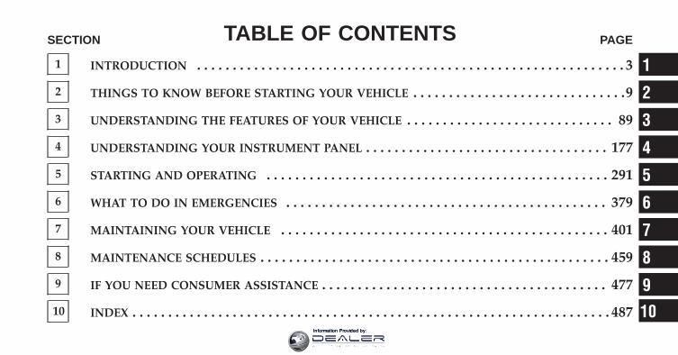
TABLE OF CONTENTSSECTION PAGE
1 INTRODUCTION . . . . . . . . . . . . . . . . . . . . . . . . . . . . . . . . . . . . . . . . . . . . . . . . . . . . . . . . . . . . 3
2 THINGS TO KNOW BEFORE STARTING YOUR VEHICLE . . . . . . . . . . . . . . . . . . . . . . . . . . . . . .9
3 UNDERSTANDING THE FEATURES OF YOUR VEHICLE . . . . . . . . . . . . . . . . . . . . . . . . . . . . . 89
4 UNDERSTANDING YOUR INSTRUMENT PANEL . . . . . . . . . . . . . . . . . . . . . . . . . . . . . . . . . . 177
5 STARTING AND OPERATING . . . . . . . . . . . . . . . . . . . . . . . . . . . . . . . . . . . . . . . . . . . . . . . . 291
6 WHAT TO DO IN EMERGENCIES . . . . . . . . . . . . . . . . . . . . . . . . . . . . . . . . . . . . . . . . . . . . . 379
7 MAINTAINING YOUR VEHICLE . . . . . . . . . . . . . . . . . . . . . . . . . . . . . . . . . . . . . . . . . . . . . . 401
8 MAINTENANCE SCHEDULES . . . . . . . . . . . . . . . . . . . . . . . . . . . . . . . . . . . . . . . . . . . . . . . . . 459
9 IF YOU NEED CONSUMER ASSISTANCE . . . . . . . . . . . . . . . . . . . . . . . . . . . . . . . . . . . . . . . . 477
10 INDEX . . . . . . . . . . . . . . . . . . . . . . . . . . . . . . . . . . . . . . . . . . . . . . . . . . . . . . . . . . . . . . . . . . . 487
1
2
3
4
5
6
7
8
9
10Information Provided by:

Information Provided by:

INTRODUCTION
CONTENTS
� Introduction . . . . . . . . . . . . . . . . . . . . . . . . . . . 4
� How To Use This Manual . . . . . . . . . . . . . . . . . . 4
� Warnings And Cautions . . . . . . . . . . . . . . . . . . . 6
� Vehicle Identification Number . . . . . . . . . . . . . . 6
� Vehicle Modifications/Alterations . . . . . . . . . . . . 7
1
Information Provided by:

INTRODUCTIONCongratulations on selecting your new Chrysler GroupLLC vehicle. Be assured that it represents precisionworkmanship, distinctive styling, and high quality - allessentials that are traditional to our vehicles.
This Owner’s Manual has been prepared with the assis-tance of service and engineering specialists to acquaintyou with the operation and maintenance of your vehicle.It is supplemented by a Warranty Information Booklet,located on the DVD, and various customer-orienteddocuments. Please take the time to read these publica-tions carefully. Following the instructions and recom-mendations in this manual will help assure safe andenjoyable operation of your vehicle.
NOTE: After you read the manual, it should be storedin the vehicle for convenient referencing and remainwith the vehicle when sold, so that the new owner willbe aware of all safety warnings.
When it comes to service, remember that your authorizeddealer knows your vehicle best, has factory-trained tech-nicians and genuine MOPAR� parts, and cares aboutyour satisfaction.
HOW TO USE THIS MANUALConsult the Table of Contents to determine which sectioncontains the information you desire.
The detailed Index at the back of this manual contains acomplete listing of all subjects.
Consult the following table for a description of thesymbols that may be used on your vehicle or throughoutthis Owner’s Manual.
4 INTRODUCTION
Information Provided by:

1
INTRODUCTION 5
Information Provided by:
WARNINGS AND CAUTIONSThis Owners Manual contains WARNINGS against op-erating procedures that could result in an accident orbodily injury. It also contains CAUTIONS against proce-dures that could result in damage to your vehicle. If youdo not read this entire Owners Manual, you may missimportant information. Observe all Warnings and Cau-tions.
VEHICLE IDENTIFICATION NUMBERThe Vehicle Identification Number (VIN) is on the leftfront corner of the instrument panel and is visible fromoutside of the vehicle through the windshield. Thisnumber also appears on the Automobile InformationDisclosure Label affixed to a window on your vehicle, thevehicle registration, and the title.
NOTE: It is illegal to remove or alter the VIN.VIN Location
6 INTRODUCTION
Information Provided by:

VEHICLE MODIFICATIONS/ALTERATIONS
WARNING!
Any modifications or alterations to this vehicle couldseriously affect its roadworthiness and safety andmay lead to an accident resulting in serious injury ordeath.
1
INTRODUCTION 7
Information Provided by:

Information Provided by:
THINGS TO KNOW BEFORE STARTING YOUR VEHICLE
CONTENTS
� A Word About Your Keys . . . . . . . . . . . . . . . . . 12
▫ Wireless Ignition Node (WIN) . . . . . . . . . . . . 12
▫ Key FOB . . . . . . . . . . . . . . . . . . . . . . . . . . . 13
▫ Tip Start Feature . . . . . . . . . . . . . . . . . . . . . . 14
▫ Removing Key FOB From Ignition . . . . . . . . . 14
▫ Key-In-Ignition Reminder . . . . . . . . . . . . . . . 15
� Sentry Key� . . . . . . . . . . . . . . . . . . . . . . . . . . 15
▫ Replacement Keys . . . . . . . . . . . . . . . . . . . . . 16
▫ Customer Key Programming . . . . . . . . . . . . . 17
▫ General Information . . . . . . . . . . . . . . . . . . . 17
� Vehicle Security Alarm — If Equipped . . . . . . . . 17
▫ Rearming Of The System . . . . . . . . . . . . . . . . 17
▫ To Arm The System . . . . . . . . . . . . . . . . . . . 17
▫ To Disarm The System . . . . . . . . . . . . . . . . . 18
� Illuminated Entry . . . . . . . . . . . . . . . . . . . . . . 18
� Remote Keyless Entry (RKE) . . . . . . . . . . . . . . 19
▫ To Unlock The Doors And Liftgate . . . . . . . . . 20
▫ To Lock The Doors And Liftgate . . . . . . . . . . 22
2
Information Provided by:

▫ Using The Panic Alarm . . . . . . . . . . . . . . . . . 23
▫ Remote Open Window Featuree . . . . . . . . . . . 23
▫ Programming Additional Transmitters . . . . . . 23
▫ Transmitter Battery Replacement . . . . . . . . . . 24
▫ General Information . . . . . . . . . . . . . . . . . . . 25
� Remote Starting System — If Equipped . . . . . . . 25
▫ How To Use Remote Start . . . . . . . . . . . . . . . 25
� Door Locks . . . . . . . . . . . . . . . . . . . . . . . . . . . 28
▫ Manual Door Locks . . . . . . . . . . . . . . . . . . . 28
▫ Power Door Locks . . . . . . . . . . . . . . . . . . . . 29
▫ Child Protection Door Lock System(Rear Doors) . . . . . . . . . . . . . . . . . . . . . . . . . 32
� Windows . . . . . . . . . . . . . . . . . . . . . . . . . . . . 34
▫ Power Windows . . . . . . . . . . . . . . . . . . . . . . 34
▫ Wind Buffeting . . . . . . . . . . . . . . . . . . . . . . . 37
� Liftgate . . . . . . . . . . . . . . . . . . . . . . . . . . . . . 38
� Occupant Restraints . . . . . . . . . . . . . . . . . . . . . 39
▫ Lap/Shoulder Belts . . . . . . . . . . . . . . . . . . . . 41
▫ Lap/Shoulder Belt Untwisting Procedure . . . . 46
▫ Automatic Locking Retractors (ALR) Mode— If Equipped . . . . . . . . . . . . . . . . . . . . . . . 47
▫ Seat Belt Pretensioners — If Equipped . . . . . . 47
▫ Supplemental Active Head Restraints (AHR) . . 48
▫ Enhanced Seat Belt Use Reminder System(BeltAlert�) . . . . . . . . . . . . . . . . . . . . . . . . . 52
10 THINGS TO KNOW BEFORE STARTING YOUR VEHICLE
Information Provided by:

▫ Seat Belts And Pregnant Women . . . . . . . . . . 53
▫ Seat Belt Extender . . . . . . . . . . . . . . . . . . . . . 53
▫ Supplemental Restraint System (SRS) —Airbags . . . . . . . . . . . . . . . . . . . . . . . . . . . . 54
▫ Advanced Front Airbag Features . . . . . . . . . . 56
▫ Airbag Deployment Sensors And Controls . . . 61
▫ Event Data Recorder (EDR) . . . . . . . . . . . . . . 69
▫ Child Restraints . . . . . . . . . . . . . . . . . . . . . . 71
� Engine Break-In Recommendations . . . . . . . . . . 83
� Safety Tips . . . . . . . . . . . . . . . . . . . . . . . . . . . 84
▫ Transporting Passengers . . . . . . . . . . . . . . . . 84
▫ Exhaust Gas . . . . . . . . . . . . . . . . . . . . . . . . . 85
▫ Safety Checks You Should Make Inside TheVehicle . . . . . . . . . . . . . . . . . . . . . . . . . . . . . 86
▫ Periodic Safety Checks You Should MakeOutside The Vehicle . . . . . . . . . . . . . . . . . . . 88
2
THINGS TO KNOW BEFORE STARTING YOUR VEHICLE 11
Information Provided by:

A WORD ABOUT YOUR KEYSYour vehicle uses a keyless ignition system. This systemconsists of a Key Fob with Remote Keyless Entry (RKE)transmitter and a Wireless Ignition Node (WIN) withintegral ignition switch. You can insert the Key Fob intothe ignition switch with either side up.
Wireless Ignition Node (WIN)The Wireless Ignition Node (WIN) operates similarly toan ignition switch. It has four operating positions, threeof which are detented and one spring-loaded. The de-tented positions are LOCK, ACC, and ON. The STARTposition is a spring-loaded momentary contact position.When released from the START position, the switchautomatically returns to the detented ON position.
Wireless Ignition Node (WIN)
1 — LOCK2 — ACC (ACCESSORY)3 — ON4 — START
12 THINGS TO KNOW BEFORE STARTING YOUR VEHICLE
Information Provided by:

Key FobThe Key Fob operates the ignition switch. It also containsthe Remote Keyless Entry (RKE) transmitter and anemergency key, which stores in the rear of the Key Fob.
The emergency key allows for entry into the vehicleshould the battery in the vehicle or the Key Fob go dead.You can keep the emergency key with you when valetparking.
To remove the emergency key, slide the mechanical latchat the top of the Key Fob sideways with your thumb andthen pull the key out with your other hand.
NOTE:• You can insert the double-sided emergency key into
the lock cylinder with either side up.
• Only the drivers door is equipped with a lock cylinder.
Emergency Key Removal
2
THINGS TO KNOW BEFORE STARTING YOUR VEHICLE 13
Information Provided by:

Tip Start FeatureDo not press the accelerator. Use the Key Fob to brieflyturn the ignition switch to the START position andrelease it as soon as the starter engages. The starter motorwill continue to run, and it will disengage automaticallywhen the engine is running.
Removing Key Fob From IgnitionPlace the shift lever in PARK. Turn the key to the LOCKposition and then remove the Key Fob.
NOTE:• For vehicles not equipped with the Electronic Vehicle
Information Center (EVIC), the power windowswitches, radio, power sunroof (if equipped), andignition-powered power outlets will remain active forapproximately 45 seconds after the ignition switch isturned to the LOCK position. Opening either frontdoor will cancel this feature.
• For vehicles equipped with the EVIC, the powerwindow switches, radio, power sunroof (if equipped),and ignition-powered power outlets will remain activefor up to 10 minutes after the ignition switch is turnedto the LOCK position. Opening either front door willcancel this feature. The time for this feature is pro-grammable. Refer to “Electronic Vehicle InformationCenter (EVIC)/Personal Settings (Customer-Programmable Features)” in “Understanding Your In-strument Panel” for further information.
WARNING!
Never leave children alone in a vehicle. Leavingunattended children in a vehicle is dangerous for anumber of reasons. A child or others could be seri-ously or fatally injured. Don’t leave the key in theignition. A child could operate power windows,other controls, or move the vehicle.
14 THINGS TO KNOW BEFORE STARTING YOUR VEHICLE
Information Provided by:

CAUTION!
An unlocked car is an invitation to thieves. Alwaysremove the key from the ignition and lock all doorswhen leaving the vehicle unattended.
Key-In-Ignition ReminderOpening the driver’s door when the Key Fob is in theignition and the ignition switch position is LOCK orACC, a chime will sound to remind you to remove thekey.
NOTE: The Key-In-Ignition reminder only soundswhen the Key Fob is placed in the LOCK or ACCposition.
SENTRY KEY�The Sentry Key� Immobilizer system prevents unautho-rized vehicle operation by disabling the engine. Thesystem does not need to be armed or activated. Operation
is automatic, regardless of whether the vehicle is lockedor unlocked.
The system uses Key Fob with factory-mated RemoteKeyless Entry (RKE) transmitter and Wireless IgnitionNode (WIN) to prevent unauthorized vehicle operation.Therefore, only Key Fobs that are programmed to thevehicle can be used to start and operate the vehicle. Thesystem will shut the engine off in two seconds if aninvalid Key Fob is used to start the engine.
After turning the ignition switch to the ON position, theVehicle Security Light will turn on for three seconds for abulb check. If the light remains on after the bulb check, itindicates that there is a problem with the electronics. Thiscondition will result in the engine being shut off after twoseconds.
2
THINGS TO KNOW BEFORE STARTING YOUR VEHICLE 15
Information Provided by:

If the Vehicle Security Light turns on during normalvehicle operation (vehicle running for longer than 10 sec-onds), it indicates that there is a fault in the electronics.Should this occur, have the vehicle serviced as soon aspossible by an authorized dealer.
NOTE: The Sentry Key� Immobilizer system is notcompatible with aftermarket remote starting systems.Use of these systems may result in vehicle startingproblems and loss of security protection.
All of the Key Fobs provided with your new vehicle havebeen programmed to the vehicle electronics.
Replacement Keys
NOTE: Only Key Fobs that are programmed to thevehicle electronics can be used to start and operate thevehicle. Once a Key Fob is programmed to a vehicle, itcannot be programmed to any other vehicle.
CAUTION!
Always remove the Key Fobs from the vehicle andlock all doors when leaving the vehicle unattended.
At the time of purchase, the original owner is providedwith a four-digit Personal Identification Number (PIN).Keep the PIN in a secure location. This number isrequired for authorized dealer replacement of Key Fobs.Duplication of Key Fobs may be performed at an autho-rized dealer, this procedure consists of programming ablank Key Fobs to the vehicle electronics. A blank KeyFob is one that has never been programmed.
NOTE: When having the Sentry Key� Immobilizersystem serviced, bring all vehicle Key Fobs with you tothe authorized dealer.
16 THINGS TO KNOW BEFORE STARTING YOUR VEHICLE
Information Provided by:

Customer Key ProgrammingProgramming Key Fobs or RKE transmitters may beperformed at an authorized dealer.
General InformationThe Sentry Key� system complies with FCC rules Part 15and with RSS-210 of Industry Canada. Operation issubject to the following conditions:
• This device may not cause harmful interference.
• This device must accept any interference that may bereceived, including interference that may cause undes-ired operation.
VEHICLE SECURITY ALARM — IF EQUIPPEDThe Vehicle Security Alarm (VSA) system monitors thevehicle doors and liftgate for unauthorized entry. Ifsomething triggers the alarm, the system will sound thehorn intermittently, flash the headlights, park lamps
and/or turn signals and flash the Vehicle Security Lightin the instrument cluster.
Rearming of the SystemIf something triggers the alarm, and no action is taken todisarm it, the system will turn off the horn after threeminutes, turn off all of the visual signals after 15 minutes,and then the system will rearm itself.
To Arm the System
1. Remove the key from the ignition switch and exit thevehicle.
2. Lock the doors and liftgate by pressing the power doorLOCK switch or the LOCK button on the Remote KeylessEntry (RKE) transmitter.
NOTE: The system will not arm if you lock the doorswith the manual door LOCK plungers or the door LOCKcylinder on the driver’s door.
2
THINGS TO KNOW BEFORE STARTING YOUR VEHICLE 17
Information Provided by:
3. Close all doors. The Vehicle Security Light in theinstrument cluster will flash to signal that the system isarming. During this period, opening any door or theliftgate will cancel the arming process.
NOTE: For added security, whenever the SecurityAlarm is armed, the HomeLink�/Garage Door Opener(if equipped) is disabled as well.
To Disarm the SystemEither press the UNLOCK button on the RKE transmitteror insert a valid ignition key into the ignition lockcylinder and turn the key to the ON position.
NOTE:• Unlocking the doors with the manual door LOCK
plungers or the door LOCK cylinder on the driver’sdoor will not disarm the system.
• When the system is armed, the interior power doorLOCK switches will not unlock the doors.
The Security Alarm system is designed to protect yourvehicle; however, you can create conditions where thesystem will give you a false alarm. If the previouslydescribed arming sequence has occurred, the system willarm regardless of whether you are inside or outside thevehicle. If you remain inside the vehicle and open a door,the alarm will sound. If this occurs, disarm the system.
Tamper AlertIf something has triggered the alarm in your absence, thehorn will sound three times when you unlock the doors.Check the vehicle for tampering.
ILLUMINATED ENTRYThe interior lights will turn on when you press theUNLOCK button on the Remote Keyless Entry (RKE)transmitter or open a door or the liftgate.
18 THINGS TO KNOW BEFORE STARTING YOUR VEHICLE
Information Provided by:

This feature also turns on the approach lighting (ifequipped). Refer to “Electronic Vehicle Information Cen-ter (EVIC)/Personal Settings (Customer-ProgrammableFeatures)” in “Understanding Your Instrument Panel” forfurther information.
The interior lights will fade to off after approximately30 seconds or they will immediately fade to off once theignition switch is turned ON.
NOTE: The illuminated entry system will not operatethe interior lights if the Dimmer Control is in the extremedownward (Defeat) position.
REMOTE KEYLESS ENTRY (RKE)This system allows you to lock or unlock the doors andliftgate or activate the Panic Alarm from distances up toapproximately 66 ft (20 m) using a hand-held Key Fobwith Remote Keyless Entry (RKE) transmitter. The RKEtransmitter does not need to be pointed at the vehicle toactivate the system.
NOTE: Inserting the Key Fob into the ignition switchdisables all buttons on that RKE transmitter; however, thebuttons on the remaining RKE transmitters will continueto work. Driving at speeds 5 mph (8 km/h) and abovedisables all RKE transmitter buttons for all Key Fobs.
Key Fob With Remote Keyless Entry (RKE) Transmitter
2
THINGS TO KNOW BEFORE STARTING YOUR VEHICLE 19
Information Provided by:

To Unlock the Doors and LiftgatePress and release the UNLOCK button on the RKEtransmitter once to unlock the driver’s door or twicewithin five seconds to unlock all doors and liftgate. Theturn signal lights will flash to acknowledge the unlocksignal. The illuminated entry system will also turn on.
Remote Key Unlock, Driver Door/All Doors FirstThis feature lets you program the system to unlock eitherthe driver’s door or all doors on the first press of theUNLOCK button on the RKE transmitter. To change thecurrent setting, proceed as follows:
• For vehicles equipped with the Electronic VehicleInformation Center (EVIC), refer to “Electronic VehicleInformation Center (EVIC)/Personal Settings(Customer-Programmable Features)” in “Understand-ing Your Instrument Panel” for further information.
• For vehicles not equipped with the EVIC, perform thefollowing steps:
1. Press and hold the LOCK button on a programmedRKE transmitter for at least 4 seconds, but no longer than10 seconds. Then, press and hold the UNLOCK buttonwhile still holding the LOCK button.
2. Release both buttons at the same time.
3. Test the feature while outside of the vehicle by press-ing the LOCK/UNLOCK buttons on the RKE transmitterwith the ignition switch in the LOCK position and theKey Fob removed.
4. Repeat these steps if you want to return this feature toits previous setting.
NOTE: Pressing the LOCK button on the RKE transmit-ter while you are inside the vehicle will activate theSecurity Alarm. Opening a door with the Security Alarmactivated will cause the alarm to sound. Press the UN-LOCK button to deactivate the Security Alarm.
20 THINGS TO KNOW BEFORE STARTING YOUR VEHICLE
Information Provided by:

Flash Lights with Remote Key LockThis feature will cause the turn signal lights to flash whenthe doors are locked or unlocked with the RKE transmit-ter. This feature can be turned on or turned off. To changethe current setting, proceed as follows:
• For vehicles equipped with the EVIC, refer to “Elec-tronic Vehicle Information Center (EVIC)/PersonalSettings (Customer-Programmable Features)” in “Un-derstanding Your Instrument Panel” for further infor-mation.
• For vehicles not equipped with the EVIC, perform thefollowing steps:
1. Press and hold the UNLOCK button on a programmedRKE transmitter for at least 4 seconds, but no longer than10 seconds. Then, press and hold the LOCK button whilestill holding the UNLOCK button.
2. Release both buttons at the same time.
3. Test the feature while outside of the vehicle by press-ing the LOCK/UNLOCK buttons on the RKE transmitterwith the ignition switch in the LOCK position and theKey Fob removed.
4. Repeat these steps if you want to return this feature toits previous setting.
NOTE: Pressing the LOCK button on the RKE transmit-ter while you are in the vehicle will activate the SecurityAlarm. Opening a door with the Security Alarm activatedwill cause the alarm to sound. Press the UNLOCK buttonto deactivate the Security Alarm.
Illuminated Approach — If EquippedThis feature activates the headlights for up to 90 secondswhen the doors are unlocked with the RKE transmitter.The time for this feature is programmable on vehiclesequipped with the EVIC. Refer to “Electronic Vehicle
2
THINGS TO KNOW BEFORE STARTING YOUR VEHICLE 21
Information Provided by:

Information Center (EVIC)/Personal Settings (Customer-Programmable Features)” in “Understanding Your In-strument Panel” for further information.
To Lock the Doors and LiftgatePress and release the LOCK button on the RKE transmit-ter to lock all doors and liftgate. The turn signal lightswill flash and the horn will chirp to acknowledge thesignal.
Sound Horn with Remote Key LockThis feature will cause the horn to chirp when the doorsare locked with the RKE transmitter. This feature can beturned on or turned off. To change the current setting,proceed as follows:
• For vehicles equipped with the EVIC, refer to “Elec-tronic Vehicle Information Center (EVIC)/PersonalSettings (Customer-Programmable Features)” in “Un-derstanding Your Instrument Panel” for further infor-mation.
• For vehicles not equipped with the EVIC, perform thefollowing steps:
1. Press the LOCK button on a programmed RKE trans-mitter for at least 4 seconds, but no longer than 10 sec-onds. Then, press the PANIC button while still holdingthe LOCK button.
2. Release both buttons at the same time.
3. Test the feature while outside of the vehicle by press-ing the LOCK button on the RKE transmitter with theignition switch in the LOCK position and the Key Fobremoved.
4. Repeat these steps if you want to return this feature toits previous setting.
NOTE: Pressing the LOCK button on the RKE transmit-ter while you are in the vehicle will activate the Security
22 THINGS TO KNOW BEFORE STARTING YOUR VEHICLE
Information Provided by:

Alarm. Opening a door with the Security Alarm activatedwill cause the alarm to sound. Press the UNLOCK buttonto deactivate the Security Alarm.
Using the Panic AlarmTo turn the Panic Alarm feature ON or OFF, press andhold the PANIC button on the RKE transmitter for atleast one second and release. When the Panic Alarm is on,the headlights and park lights will flash, the horn willpulse on and off, and the interior lights will turn on.
The Panic Alarm will stay on for three minutes unlessyou turn it off by either pressing the PANIC button asecond time or drive the vehicle at a speed of 5 mph(8 km/h) or greater.
NOTE:• The interior lights will turn off if you turn the ignition
switch to the ACC or ON position while the Panic
Alarm is activated. However, the exterior lights andhorn will remain on.
• You may need to be less than 35 ft (11 m) from thevehicle when using the RKE transmitter to turn off thePanic Alarm due to the radio frequency noises emittedby the system.
Remote Open Window FeatureeThis feature allows you to remotely lower both front doorwindows at the same time. To use this feature, press andrelease the UNLOCK button on the RKE transmitter andthen immediately press and hold the UNLOCK buttonuntil the windows lower to the level desired or until theylower completely.
Programming Additional TransmittersProgramming Key Fobs or RKE transmitters may beperformed at an authorized dealer.
2
THINGS TO KNOW BEFORE STARTING YOUR VEHICLE 23
Information Provided by:
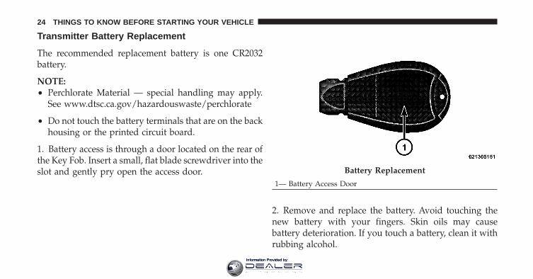
Transmitter Battery Replacement
The recommended replacement battery is one CR2032battery.
NOTE:• Perchlorate Material — special handling may apply.
See www.dtsc.ca.gov/hazardouswaste/perchlorate
• Do not touch the battery terminals that are on the backhousing or the printed circuit board.
1. Battery access is through a door located on the rear ofthe Key Fob. Insert a small, flat blade screwdriver into theslot and gently pry open the access door.
2. Remove and replace the battery. Avoid touching thenew battery with your fingers. Skin oils may causebattery deterioration. If you touch a battery, clean it withrubbing alcohol.
Battery Replacement
1— Battery Access Door
24 THINGS TO KNOW BEFORE STARTING YOUR VEHICLE
Information Provided by:

3. Reposition the access door panel over the batteryopening and snap into place.
General InformationThis device complies with Part 15 of the FCC rules andRSS 210 of Industry Canada. Operation is subject to thefollowing conditions:
• This device may not cause harmful interference.
• This device must accept any interference received,including interference that may cause undesiredoperation.
NOTE: Changes or modifications not expressly ap-proved by the party responsible for compliance couldvoid the user’s authority to operate the equipment.
If your RKE transmitter fails to operate from a normaldistance, check for these two conditions:
1. A weak battery in the transmitter. The expected life ofthe battery is a minimum of three years.
2. Closeness to a radio transmitter such as a radio stationtower, airport transmitter, and some mobile or CB radios.
REMOTE STARTING SYSTEM — IF EQUIPPEDThis system uses the Remote Keyless Entry (RKE) trans-mitter to start the engine conveniently from outside thevehicle while still maintaining security. The system has arange of approximately 300 ft (91 m).
NOTE: The vehicle must be equipped with an auto-matic transmission to be equipped with Remote Start.
How To Use Remote StartAll of the following conditions must be met before theengine will remote start:
• Shift lever in PARK
• Doors closed
2
THINGS TO KNOW BEFORE STARTING YOUR VEHICLE 25
Information Provided by:

• Hood closed
• Liftgate closed
• HAZARD switch off
• BRAKE switch inactive (brake pedal not pressed)
• Ignition key removed from ignition switch
• Battery at an acceptable charge level, and
• RKE PANIC button not pressed.
WARNING!
• Do not start or run an engine in a closed garage orconfined area. Exhaust gas contains Carbon Mon-oxide (CO) which is odorless and colorless. Car-bon Monoxide is poisonous and can cause seriousinjury or death when inhaled.
(Continued)
WARNING! (Continued)• Keep Remote Keyless Entry (RKE) transmitters
away from children. Operation of the Remote StartSystem, windows, door locks or other controlscould cause serious injury or death.
To Enter Remote Start ModePress and release the REMOTE START buttonon the RKE transmitter twice within five sec-onds. The vehicle doors will lock, parkinglights will flash and horn will chirp twice (if
programmed). Then, the engine will start and the vehiclewill remain in the Remote Start mode for a 15-minutecycle.
NOTE:• The park lamps will turn on and remain on during
Remote Start mode.
26 THINGS TO KNOW BEFORE STARTING YOUR VEHICLE
Information Provided by:

• For security, power window and power sunroof op-eration (if equipped) are disabled when the vehicle isin the Remote Start mode.
• The engine can be started two consecutive times (two15-minute cycles) with the RKE transmitter. However,the ignition switch must be cycled to the ON positionbefore you can repeat the start sequence for a thirdcycle.
To Exit Remote Start Mode without Driving theVehicleAllow the engine to run for the entire 15-minute cycle.
To Exit Remote Start Mode and Drive the VehicleBefore the end of the 15-minute cycle, press and releasethe UNLOCK button on the RKE transmitter to unlock
the doors and disarm the Vehicle Security Alarm (ifequipped). Then, insert the Key Fob into the ignitionswitch and turn the switch to the ON position.
NOTE: The ignition switch must be in the ON positionin order to drive the vehicle.
To Turn Off the Engine While in Remote StartModePress and release the REMOTE START button one time.
NOTE: To avoid unintentional shut downs, the systemwill disable the one time press of the REMOTE STARTbutton for two seconds after receiving a valid RemoteStart request.
2
THINGS TO KNOW BEFORE STARTING YOUR VEHICLE 27
Information Provided by:

DOOR LOCKS
Manual Door LocksTo lock each door, push the door lock plunger on eachdoor trim panel downward. To unlock the front doors,pull the inside door handle to the first detent. To unlockthe rear doors, pull the door lock plunger on the doortrim panel upward.
If the door lock plunger is down when you shut the door,the door will lock. Therefore, make sure the key is notinside the vehicle before closing the door.
NOTE: The manual door locks will not lock or unlockthe liftgate.
Manual Door Lock Plunger
28 THINGS TO KNOW BEFORE STARTING YOUR VEHICLE
Information Provided by:

WARNING!
• For personal security and safety in the event of anaccident, lock the vehicle doors before you drive aswell as when you park and leave the vehicle.
• When leaving the vehicle, always remove the keyfrom the ignition and lock your vehicle. Unsuper-vised use of vehicle equipment may cause severepersonal injuries and death.
• Never leave children alone in a vehicle. Leavingunattended children in a vehicle is dangerous for anumber of reasons. A child or others could beseriously or fatally injured. Do not leave the key inthe ignition. A child could operate power win-dows, other controls, or move the vehicle.
Power Door LocksA power door lock switch is on each front door trimpanel. Use this switch to lock or unlock the doors andliftgate.
Power Door Lock Switch Location
1 — Unlock 2 — Lock
2
THINGS TO KNOW BEFORE STARTING YOUR VEHICLE 29
Information Provided by:

To prevent you from locking your Key Fob in the vehicle,the power door lock switch will not operate when theKey Fob is in the ignition and either front door is open. Achime will sound as a reminder to remove the Key Fob.
Automatic Door Locks — If EquippedThe auto door lock feature can be enabled or disabled byyour authorized dealer. See your authorized dealer forprogramming.
Automatic Unlock Doors on ExitThe doors will unlock automatically if:
1. The Automatic Unlock Doors On Exit feature is en-abled
2. The transaxle was in gear and the vehicle speedreturned to 0 mph (0 km/h)
3. The transaxle is in NEUTRAL or PARK
4. The driver’s door is opened
5. The doors were not previously unlocked
6. The vehicle speed is 0 mph (0 km/h).
Automatic Unlock Doors on ExitIf Auto Unlock is enabled, this feature will unlock all thedoors when the driver’s door is opened if the vehicle isstopped and in PARK or NEUTRAL. Refer to “ElectronicVehicle Information Center (EVIC)/Personal Settings(Customer-Programmable Features)” in “UnderstandingYour Instrument Panel” for further information.
The doors will unlock automatically if:
1. The Automatic Unlock Doors On Exit feature is en-abled
2. The transaxle was in gear and the vehicle speedreturned to 0 mph (0 km/h)
3. The transaxle is in NEUTRAL or PARK
4. The driver’s door is opened
30 THINGS TO KNOW BEFORE STARTING YOUR VEHICLE
Information Provided by:

5. The doors were not previously unlocked
6. The vehicle speed is 0 mph (0 km/h).
Automatic Unlock Doors on Exit ProgrammingThe Automatic Unlock Doors On Exit feature can beenabled or disabled as follows:
• For vehicles equipped with the EVIC, refer to “Elec-tronic Vehicle Information Center (EVIC)/PersonalSettings (Customer-Programmable Features)” in “Un-derstanding Your Instrument Panel” for further infor-mation.
• For vehicles not equipped with the EVIC, perform thefollowing steps:
1. Enter the vehicle and close all doors.
2. Place the Key Fob in the ignition switch.
3. Within 15 seconds, cycle the ignition switch betweenLOCK and ON and then back to LOCK four times endingup in the LOCK position. However, do not start theengine.
4. Within 30 seconds, press the power door unlockswitch to unlock the doors.
5. A single chime will indicate the completion of theprogramming.
NOTE: If you do not hear the chime, it means that thesystem did not enter the programming mode and youwill need to repeat the procedure.
6. Repeat these steps if you want to return this feature toits previous setting.
NOTE: Use the Automatic Unlock Doors On Exit featurein accordance with local laws.
2
THINGS TO KNOW BEFORE STARTING YOUR VEHICLE 31
Information Provided by:

Child Protection Door Lock System (Rear Doors)To provide a safer environment for small children ridingin the rear seats, the rear doors are equipped with a ChildProtection Door Lock system.
To Engage the Child Protection Door Lock System
1. Open the rear door.
2. Insert the tip of the emergency key (or alike) into thechild lock control and rotate it to the LOCK position.
3. Repeat Steps 1 and 2 for the opposite rear door.
NOTE: When the Child Protection Door Lock system isengaged, the door can be opened only by using theoutside door handle even though the inside door lock isin the unlocked position.
Child Lock Control
32 THINGS TO KNOW BEFORE STARTING YOUR VEHICLE
Information Provided by:

WARNING!
Avoid trapping anyone in a vehicle in a collision.Remember that the rear doors can only be openedfrom the outside when the child protection locks areengaged. Failure to follow this warning may result inserious injury or death.
NOTE:• After engaging the Child Protection Door Lock sys-
tem, always test the door from the inside to makecertain it is in the desired position.
• For emergency exit with the system engaged, movethe lock plunger up to the UNLOCK position, rolldown the window, and open the door with the outsidedoor handle.
To Disengage the Child Protection Door LockSystem
1. Open the rear door.
2. Insert the tip of the emergency key (or alike) into thechild lock control and rotate it to the UNLOCK position.
Child Lock Control
2
THINGS TO KNOW BEFORE STARTING YOUR VEHICLE 33
Information Provided by:

3. Repeat Steps 1 and 2 for the opposite rear door.
NOTE: After disengaging the Child Protection DoorLock system, always test the door from the inside tomake certain it is in the desired position.
WINDOWS
Power WindowsThe window controls on the driver’s door trim panelcontrol all of the door windows.
There are single window controls on each passenger doortrim panel, which operate the passenger door windows.The window controls will operate when the ignitionswitch is in the ON or ACC position.
Power Window Switches
34 THINGS TO KNOW BEFORE STARTING YOUR VEHICLE
Information Provided by:
NOTE:• For vehicles not equipped with the Electronic Vehicle
Information Center (EVIC), the power windowswitches will remain active for 45 seconds after theignition switch is turned to the LOCK position. Open-ing either front door will cancel this feature.
• For vehicles equipped with the EVIC, the powerwindow switches will remain active for up to 10 min-utes after the ignition switch is turned to the LOCKposition. Opening either front door will cancel thisfeature. The time for this feature is programmable.Refer to “Electronic Vehicle Information Center(EVIC)/Personal Settings (Customer-ProgrammableFeatures)” in “Understanding Your Instrument Panel”for further information.
WARNING!
Never leave children in a vehicle with the key in theignition switch. Occupants, particularly unattendedchildren, can become entrapped by the windowswhile operating the power window switches. Suchentrapment may result in serious injury or death.
Auto-Down FeatureThe driver’s power window switch has an Auto-downfeature. Press the window switch past the first detent,release, and the window will go down automatically.
To open the window part way, press the window switchto the first detent and release it when you want thewindow to stop.
To stop the window from going all the way down duringthe Auto-down operation, pull up on the switch briefly.
2
THINGS TO KNOW BEFORE STARTING YOUR VEHICLE 35
Information Provided by:

Auto-Up Feature with Anti-Pinch Protection — IfEquippedOn some models, the driver’s and front passenger’spower window switch has an Auto-up feature. Pull thewindow switch up to the second detent, release, and thewindow will go up automatically.
To stop the window from going all the way up during theAuto-up operation, push down on the switch briefly.
To close the window part way, pull the window switchup to the first detent and release it when you want thewindow to stop.
NOTE:• If the window runs into any obstacle during Auto-
closure, it will reverse direction and then go backdown. Remove the obstacle and use the windowswitch again to close the window.
• Any impact due to rough road conditions may triggerthe auto-reverse function unexpectedly during auto-closure. If this happens, pull the switch lightly to thefirst detent and hold to close window manually.
WARNING!
There is no anti-pinch protection when the windowis almost closed. To avoid personal injury, be sure toclear your arms, hands, fingers, and objects from thewindow path before closing the window. Such en-trapment may result in serious injury.
Window Lockout SwitchThe window lockout switch on the driver’s door trimpanel allows you to disable the window control on theother doors. To disable the window controls, press andrelease the window lockout button (setting it in the down
36 THINGS TO KNOW BEFORE STARTING YOUR VEHICLE
Information Provided by:

position). To enable the window controls, press andrelease the window lockout button again (setting it in theup position).
ResetIt may be necessary at some point in time to reactivate theAuto-up/Auto-down feature. To do so, perform thefollowing steps:
1. Pull the window switch up to close window com-pletely and continue to hold the switch up for anadditional two seconds after the window is closed.
2. Push the window switch down firmly to the seconddetent to open the window completely and continue tohold the switch down for an additional two seconds afterthe window is fully open.
Wind BuffetingWind buffeting can be described as the perception ofpressure on the ears or a helicopter-type sound in theears. Your vehicle may exhibit wind buffeting with thewindows down, or the sunroof (if equipped) in certainopen or partially open positions. This is a normal occur-rence and can be minimized. If the buffeting occurs with
Window Lockout Switch
2
THINGS TO KNOW BEFORE STARTING YOUR VEHICLE 37
Information Provided by:

the rear windows open, then open the front and rearwindows together to minimize the buffeting. If thebuffeting occurs with the sunroof open, adjust the sun-roof opening to minimize the buffeting or open anywindow.
LIFTGATEThe liftgate can be unlocked or locked with the RemoteKeyless Entry (RKE) transmitter or by activating thepower door lock switch located on either front door trimpanel.
NOTE: The liftgate cannot be unlocked or locked withthe manual door lock plungers on the door trim panels orthe door lock cylinder on the driver’s door.
To open the unlocked liftgate, squeeze the handle andpull the liftgate toward you. Gas props will raise andsupport the liftgate in the open position.
NOTE: Because the gas pressure drops with tempera-ture, it may be necessary to assist the props whenopening the liftgate in cold weather.
Liftgate Release
38 THINGS TO KNOW BEFORE STARTING YOUR VEHICLE
Information Provided by:

WARNING!
• Driving with the liftgate open can allow poison-ous exhaust gases into your vehicle. These fumescould injure you and your passengers. Keep theliftgate closed when you are operating the vehicle.
• If you are required to drive with the liftgate open,make sure that all windows are closed, and theblower switch on the climate control is set at highspeed. DO NOT use the recirculation mode.
OCCUPANT RESTRAINTSSome of the most important safety features in yourvehicle are the restraint systems:
• Three-point lap and shoulder belts for all seatingpositions
• Advanced Front Airbags for driver and front passen-ger
• Supplemental Active Head Restraints (AHR) locatedon top of the front seats (integrated into the headrestraint)
• Supplemental Side Airbag Inflatable Curtains (SABIC)that span the front, second, and third row seating forthe driver and passengers seated next to a window —if equipped
• Supplemental Seat-Mounted Side Airbags (SAB) — ifequipped
• An energy-absorbing steering column and steeringwheel
• Knee bolsters/blockers for front seat occupants
• Front seat belts incorporate pretensioners to enhanceoccupant protection by managing occupant energyduring an impact event — if equipped
2
THINGS TO KNOW BEFORE STARTING YOUR VEHICLE 39
Information Provided by:

• All seat belt systems (except the driver’s) includeAutomatic Locking Retractors (ALRs), which lock theseat belt webbing into position by extending the beltall the way out and then adjusting the belt to thedesired length to restrain a child seat or secure a largeitem in a seat — if equipped
If you will be carrying children too small for adult-sizedseat belts, the seat belts or the Lower Anchors and Tetherfor CHildren (LATCH) feature also can be used to holdinfant and child restraint systems. For more informationon LATCH, see Lower Anchors and Tether for CHildren(LATCH).
NOTE: The Advanced Front Airbags have a multistageinflator design. This allows the airbag to have differentrates of inflation based on the severity and type ofcollision.
Please pay close attention to the information in thissection. It tells you how to use your restraint systemproperly, to keep you and your passengers as safe aspossible.
WARNING!
In a collision, you and your passengers can suffermuch greater injuries if you are not properly buckledup. You can strike the interior of your vehicle or otherpassengers, or you can be thrown out of the vehicle.Always be sure you and others in your vehicle arebuckled up properly.
Buckle up even though you are an excellent driver, evenon short trips. Someone on the road may be a poor driverand cause a collision that includes you. This can happenfar away from home or on your own street.
40 THINGS TO KNOW BEFORE STARTING YOUR VEHICLE
Information Provided by:

Research has shown that seat belts save lives, and theycan reduce the seriousness of injuries in a collision. Someof the worst injuries happen when people are thrownfrom the vehicle. Seat belts reduce the possibility ofejection and the risk of injury caused by striking theinside of the vehicle. Everyone in a motor vehicle shouldbe belted at all times.
Lap/Shoulder BeltsAll seating positions in your vehicle are equipped withcombination lap/shoulder belts.
The belt webbing retractor is designed to lock duringvery sudden stops or impacts. This feature allows theshoulder part of the belt to move freely with you undernormal conditions. However, in a collision, the belt willlock and reduce your risk of striking the inside of thevehicle or being thrown out.
WARNING!
• It is dangerous to ride in a cargo area, inside oroutside of a vehicle. In a collision, people riding inthese areas are more likely to be seriously injuredor killed.
• Do not allow people to ride in any area of yourvehicle that is not equipped with seats and seatbelts.
• Be sure everyone in your vehicle is in a seat andusing a seat belt properly.
• Wearing a seat belt incorrectly is dangerous. Seatbelts are designed to go around the large bones ofyour body. These are the strongest parts of yourbody and can take the forces of a collision best.
(Continued)
2
THINGS TO KNOW BEFORE STARTING YOUR VEHICLE 41
Information Provided by:
WARNING! (Continued)• Wearing your belt in the wrong place could make
your injuries in a collision much worse. You mightsuffer internal injuries, or you could even slide outof part of the belt. Follow these instructions towear your seat belt safely and to keep your pas-sengers safe, too.
• Two people should never be belted into a singleseat belt. People belted together can crash into oneanother in a collision, hurting one another badly.Never use a lap/shoulder belt or a lap belt for morethan one person, no matter what their size.
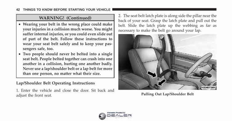
Lap/Shoulder Belt Operating Instructions
1. Enter the vehicle and close the door. Sit back andadjust the front seat.
2. The seat belt latch plate is along side the pillar near theback of your seat. Grasp the latch plate and pull out thebelt. Slide the latch plate up the webbing as far asnecessary to make the belt go around your lap.
Pulling Out Lap/Shoulder Belt
42 THINGS TO KNOW BEFORE STARTING YOUR VEHICLE
Information Provided by:

3. When the belt is long enough to fit, insert the latchplate into the buckle until you hear a “click.”
WARNING!
• A belt that is buckled into the wrong buckle willnot protect you properly. The lap portion couldride too high on your body, possibly causinginternal injuries. Always buckle your belt into thebuckle nearest you.
• A belt that is too loose will not protect youproperly. In a sudden stop, you could move too farforward, increasing the possibility of injury. Wearyour seat belt snugly.
(Continued)
Connecting Latch Plate To Buckle
2
THINGS TO KNOW BEFORE STARTING YOUR VEHICLE 43
Information Provided by:

WARNING! (Continued)• A belt that is worn under your arm is dangerous.
Your body could strike the inside surfaces of thevehicle in a collision, increasing head and neckinjury. A belt worn under the arm can causeinternal injuries. Ribs aren’t as strong as shoulderbones. Wear the belt over your shoulder so thatyour strongest bones will take the force in acollision.
• A shoulder belt placed behind you will not protectyou from injury during a collision. You are morelikely to hit your head in a collision if you do notwear your shoulder belt. The lap and shoulder beltare meant to be used together.
4. Position the lap belt across your thighs, below yourabdomen. To remove slack in the lap belt portion, pull upa bit on the shoulder belt. To loosen the lap belt if it is too
tight, tilt the latch plate and pull on the lap belt. A snugbelt reduces the risk of sliding under the belt in acollision.
Removing Slack From Belt
44 THINGS TO KNOW BEFORE STARTING YOUR VEHICLE
Information Provided by:

WARNING!
• A lap belt worn too high can increase the risk ofinternal injury in a collision. The belt forces won’tbe at the strong hip and pelvic bones, but acrossyour abdomen. Always wear the lap belt as low aspossible and keep it snug.
• A twisted belt can’t do its job properly. In acollision, it could even cut into you. Be sure thebelt is straight. If you can’t straighten a belt inyour vehicle, take it to your authorized dealerimmediately and have it fixed.
5. Position the shoulder belt on your chest so that it iscomfortable and not resting on your neck. The retractorwill withdraw any slack in the belt.
6. To release the belt, push the red button on the buckle.The belt will automatically retract to its stowed position.If necessary, slide the latch plate down the webbing toallow the belt to retract fully.
WARNING!
A frayed or torn belt could rip apart in a collision andleave you with no protection. Inspect the belt systemperiodically, checking for cuts, frays, or loose parts.Damaged parts must be replaced immediately. Donot disassemble or modify the system. Seat beltassemblies must be replaced after a collision if theyhave been damaged (bent retractor, torn webbing,etc.).
Adjustable Upper Shoulder Belt AnchorageIn the driver’s seat and front passenger’s seat, the shoul-der belt can be adjusted upward or downward to posi-tion the belt away from your neck. Push and fully
2
THINGS TO KNOW BEFORE STARTING YOUR VEHICLE 45
Information Provided by:
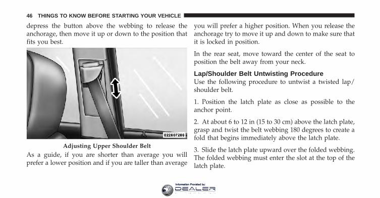
depress the button above the webbing to release theanchorage, then move it up or down to the position thatfits you best.
As a guide, if you are shorter than average you willprefer a lower position and if you are taller than average
you will prefer a higher position. When you release theanchorage try to move it up and down to make sure thatit is locked in position.
In the rear seat, move toward the center of the seat toposition the belt away from your neck.
Lap/Shoulder Belt Untwisting ProcedureUse the following procedure to untwist a twisted lap/shoulder belt.
1. Position the latch plate as close as possible to theanchor point.
2. At about 6 to 12 in (15 to 30 cm) above the latch plate,grasp and twist the belt webbing 180 degrees to create afold that begins immediately above the latch plate.
3. Slide the latch plate upward over the folded webbing.The folded webbing must enter the slot at the top of thelatch plate.
Adjusting Upper Shoulder Belt
46 THINGS TO KNOW BEFORE STARTING YOUR VEHICLE
Information Provided by:

4. Continue to slide the latch plate up until it clears thefolded webbing.
Automatic Locking Retractors (ALR) Mode — IfEquippedIn this mode, the shoulder belt is automatically pre-locked. The belt will still retract to remove any slack inthe shoulder belt. The Automatic Locking Mode is avail-able on all passenger-seating positions with a combina-tion lap/shoulder belt.
When To Use The Automatic Locking ModeUse the Automatic Locking Mode anytime a child safetyseat is installed in a seating position that has a belt withthis feature. Children 12 years old and under shouldalways be properly restrained in the rear seat.
How To Engage The Automatic Locking Mode
1. Buckle the combination lap and shoulder belt.
2. Grasp the shoulder portion and pull downward untilthe entire belt is extracted.
3. Allow the belt to retract. As the belt retracts, you willhear a clicking sound. This indicates the safety belt isnow in the Automatic Locking Mode.
How To Disengage The Automatic Locking ModeUnbuckle the combination lap/shoulder belt and allow itto retract completely to disengage the Automatic LockingMode and activate the vehicle sensitive (emergency)locking mode.
Seat Belt Pretensioners — If EquippedThe seat belts for both front seating positions may beequipped with pretensioning devices that are designed toremove slack from the seat belt in the event of a collision.These devices improve the performance of the seat beltby assuring that the belt is tight about the occupant earlyin a collision. Pretensioners work for all size occupants,including those in child restraints.
2
THINGS TO KNOW BEFORE STARTING YOUR VEHICLE 47
Information Provided by:

NOTE: These devices are not a substitute for proper seatbelt placement by the occupant. The seat belt still must beworn snugly and positioned properly.
The pretensioners are triggered by the Occupant Re-straint Controller (ORC). Like the airbags, the pretension-ers are single use items. A deployed pretensioner or adeployed airbag, must be replaced immediately.
Supplemental Active Head Restraints (AHR)These head restraints are passive, deployable compo-nents, and vehicles with this equipment can not bereadily identified by any markings, only through visualinspection of the head restraint. The head restraint will besplit in two halves, with the front half being soft foamand trim, the back half being decorative plastic.
How the Active Head Restraints (AHR) WorkThe Occupant Restraint Controller (ORC) determineswhether the severity, or type of rear impact will require
the Active Head Restraints (AHR) to deploy. If a rearimpact requires deployment, both the driver and frontpassenger seat AHRs will be deployed.
When AHRs deploy during a rear impact, the front halfof the head restraint extends forward to minimize the gapbetween the back of the occupant’s head and the AHR.This system is designed to help prevent or reduce theextent of injuries to the driver and front passenger incertain types of rear impacts.
NOTE: The Active Head Restraints (AHR) may or maynot deploy in the event of a front or side impact.However if during a front impact, a secondary rearimpact occurs, the AHR may deploy based on the sever-ity and type of the impact.
48 THINGS TO KNOW BEFORE STARTING YOUR VEHICLE
Information Provided by:

CAUTION!
All occupants, including the driver, should not oper-ate a vehicle or sit in a vehicle’s seat until the headrestraints are placed in their proper positions in orderto minimize the risk of neck injury in the event of acollision.
NOTE: For more information on properly adjusting andpositioning the head restraint, refer to “Adjusting ActiveHead Restraints” in “Understanding The Features OfYour Vehicle”.
Resetting Active Head Restraints (AHR)If the Active Head Restraints are triggered in a collision,you must reset the head restraint on the driver’s andfront passenger seat. You can recognize when the ActiveHead Restraint has been triggered by the fact that theyhave moved forward (as shown in step three of theresetting procedure).
Active Head Restraint (AHR) Components
1 — Head Restraint Front Half(Soft Foam and Trim)
3 — Head Restraint Back Half(Decorative Plastic RearCover)
2 — Seatback 4 — Head Restraint GuideTubes
2
THINGS TO KNOW BEFORE STARTING YOUR VEHICLE 49
Information Provided by:

1. Grasp the deployed AHR from the rear seat.
2. Position the hands on the top of the deployed AHR ata comfortable position.
3. Pull down then rearward towards the rear of thevehicle then down to engage the locking mechanism.
Hand Positioning Points On AHR1 — Downward Movement2 — Rearward Movement
50 THINGS TO KNOW BEFORE STARTING YOUR VEHICLE
Information Provided by:

4. The AHR front soft foam and trim half should lockinto the back decorative plastic half.
NOTE:• If you have difficulties or problems resetting the
Active Head Restraints, see an authorized dealer.
• For safety reasons, have the Active Head Restraintschecked by a qualified specialist at an authorizeddealer.
3 — Final Downward Movement To Engage Locking Mecha-nism
AHR In Reset Position
2
THINGS TO KNOW BEFORE STARTING YOUR VEHICLE 51
Information Provided by:

Enhanced Seat Belt Use Reminder System(BeltAlert�)If the driver’s or front passenger’s (if equipped with beltalert) seat belt has not been buckled within 60 seconds ofstarting the vehicle and if the vehicle speed is greaterthan 5 mph (8 km/h), the Enhanced Warning System(BeltAlert�) will alert the driver or front passenger tobuckle the seat belt. The driver should also instruct allother occupants to buckle their seat belts. Once thewarning is triggered, BeltAlert� will continue to chimeand flash the Seat Belt Reminder Light for 96 seconds oruntil the driver’s or front passenger’s seat belt is buckled.BeltAlert� will be reactivated if the driver’s or passen-ger’s seat belt is unbuckled for more than 10 seconds andthe vehicle speed is greater than 5 mph (8 km/h).
For front passenger seats equipped with BeltAlert, yourvehicle is equipped to detect when it is occupied. TheBeltAlert� warning system is not activated when the
front passenger seat is unoccupied. The BeltAlert� warn-ing system may be triggered when an animal or heavyobject is on the front passenger seat or when the seat isfolded flat (if equipped). It is recommended that pets berestrained in the rear seat in pet harnesses or pet carriersthat are secured by seat belts and cargo is properlystowed.
BeltAlert� ProgrammingThe BeltAlert� can be enabled or disabled by yourauthorized dealer or by performing the following steps:
NOTE: The following steps must occur within the first60 seconds of the ignition switch being turned to the ONor START position. Chrysler Group LLC does not recom-mend deactivating BeltAlert�.
1. With all doors closed, and the ignition switch in anyposition except ON or START, buckle the driver’s seatbelt.
52 THINGS TO KNOW BEFORE STARTING YOUR VEHICLE
Information Provided by:

2. Turn the ignition switch to the ON position, (do notstart the engine). Wait for the Seat Belt Reminder Light toturn off and then proceed to the next step.
3. Unbuckle the driver’s seat belt, allow the seat belt toretract, and then re-buckle the driver’s seat belt at leastthree times, ending with the seat belt buckled.
NOTE: Watch for the Seat Belt Reminder Light to turnon while the seat belt retracts and turn off while re-buckling the seat belt. It may be necessary to completelyretract the seat belt each time.
4. Turn the ignition switch to the OFF position. A singlechime will sound to signify that you have successfullycompleted the programming.
The BeltAlert� can be reactivated by repeating this pro-cedure.
NOTE: When the BeltAlert� is deactivated, the Seat BeltReminder Light will continue to illuminate as long as thedriver’s seat belt is unbuckled or retracted.
Seat Belts and Pregnant WomenWe recommend that pregnant women use the seat beltsthroughout their pregnancy. Keeping the mother safe isthe best way to keep the baby safe.
Pregnant women should wear the lap part of the beltacross the thighs and as snug across the hips as possible.Keep the belt low so that it does not come across theabdomen. That way the strong bones of the hips will takethe force if there is a collision.
Seat Belt ExtenderIf a seat belt is too short even when fully extended andwhen the adjustable upper shoulder belt anchorage (ifequipped) is in its lowest position, your authorizeddealer can provide you with a seat belt extender. This
2
THINGS TO KNOW BEFORE STARTING YOUR VEHICLE 53
Information Provided by:
extender should be used only if the existing belt is notlong enough. When it is not required, remove the ex-tender and store it.
WARNING!
Using a seat belt extender when not needed canincrease the risk of injury in a collision. Only usewhen the seat belt is not long enough when it is wornlow and snug and in the recommended seating posi-tions. Remove and store the extender when notneeded.
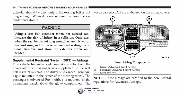
Supplemental Restraint System (SRS) — AirbagsThis vehicle has Advanced Front Airbags for both thedriver and front passenger as a supplement to the seatbelt restraint systems. The driver’s Advanced Front Air-bag is mounted in the center of the steering wheel. Thepassenger’s Advanced Front Airbag is mounted in theinstrument panel, above the glove compartment. The
words SRS AIRBAG are embossed on the airbag covers.
NOTE: These airbags are certified to the new Federalregulations for Advanced Airbags.
Front Airbag Components
1 — Driver Advanced Front Airbag2 — Passenger Advanced Front Airbag3 — Knee Bolsters
54 THINGS TO KNOW BEFORE STARTING YOUR VEHICLE
Information Provided by:

The Advanced Front Airbags have a multistage inflatordesign. This allows the airbag to have different rates ofinflation based on the severity and type of collision.
This vehicle may be equipped with driver and/or frontpassenger seat track position sensors that may adjust theinflation rate of the Advanced Front Airbags based uponseat position.
This vehicle may be equipped with a driver and/or frontpassenger seat belt buckle switch that detects whetherthe driver or front passenger seat belt is fastened. Theseat belt buckle switch may adjust the inflation rate of theAdvanced Front Airbags.
This vehicle may also be equipped with SupplementalSide Airbag Inflatable Curtains (SABIC) to protect thedriver, front, and rear passengers sitting next to a win-dow. If the vehicle is equipped with SABIC airbags, theyare located above the side windows and their covers arealso labeled: SRS AIRBAG.
This vehicle may also be equipped with SupplementalSeat-Mounted Side Airbags (SAB). If the vehicle isequipped with Supplemental Seat-Mounted Side Airbagsthey are marked with an airbag label sewn into theoutboard side of the front seats.
NOTE:• Airbag covers may not be obvious in the interior trim;
but they will open during airbag deployment.
• After any collision, the vehicle should be taken to anauthorized dealer immediately.
Airbag System ComponentsYour vehicle may be equipped with the following airbagsystem components:
• Occupant Restraint Controller (ORC)
• Airbag Warning Light
• Steering Wheel and Column
2
THINGS TO KNOW BEFORE STARTING YOUR VEHICLE 55
Information Provided by:

• Instrument Panel
• Knee Impact Bolster
• Driver Advanced Front Airbag
• Passenger Advanced Front Airbag
• Supplemental Seat-Mounted Side Airbags (SAB)
• Supplemental Side Airbag Inflatable Curtains (SABIC)
• Front and Side Impact Sensors
• Front Seat Belt Pretensioners, Seat Belt Buckle Switch,and Seat Track Position Sensors
• Supplemental Active Head Restraint for Driver andFront Passenger
Advanced Front Airbag FeaturesThe Advanced Front Airbag system has multistage driverand front passenger airbags. This system provides outputappropriate to the severity and type of collision as
determined by the Occupant Restraint Controller (ORC),which may receive information from the front impactsensors.
The first stage inflator is triggered immediately during animpact that requires airbag deployment. The timing ofthe second stage determines whether the output force islow, medium, or high. If a low output is sufficient to meetthe need, the remaining gas in the inflator is expended.
WARNING!
• No objects should be placed over or near theairbag on the instrument panel, because any suchobjects could cause harm if the vehicle is in acollision severe enough to cause the airbag toinflate.
(Continued)
56 THINGS TO KNOW BEFORE STARTING YOUR VEHICLE
Information Provided by:

WARNING! (Continued)• Do not put anything on or around the airbag
covers or attempt to open them manually. You maydamage the airbags and you could be injuredbecause the airbags may no longer be functional.The protective covers for the airbag cushions aredesigned to open only when the airbags are inflat-ing.
• Do not drill, cut or tamper with the knee bolster inany way.
• Do not mount any accessories to the knee bolstersuch as alarm lights, stereos, citizen band radios,etc.
Supplemental Seat-Mounted Side Airbags (SAB) —If EquippedSupplemental Seat-Mounted Side Airbags provide en-hanced protection to help protect an occupant during a
side impact. The Supplemental Seat-Mounted Side Air-bag is marked with an airbag label sewn into the out-board side of the front seats.
When the airbag deploys, it opens the seam between thefront and side of the seat’s trim cover. Each airbag
Seat Mounted Side Airbag Label
2
THINGS TO KNOW BEFORE STARTING YOUR VEHICLE 57
Information Provided by:
deploys independently, that is a left side impact deploysthe left airbag only and a right-side impact deploys onlythe right airbag.
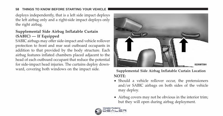
Supplemental Side Airbag Inflatable Curtain(SABIC) — If EquippedSABIC airbags may offer side-impact and vehicle rolloverprotection to front and rear seat outboard occupants inaddition to that provided by the body structure. Eachairbag features inflated chambers placed adjacent to thehead of each outboard occupant that reduce the potentialfor side-impact head injuries. The curtains deploy down-ward, covering both windows on the impact side.
NOTE:• Should a vehicle rollover occur, the pretensioners
and/or SABIC airbags on both sides of the vehiclemay deploy.
• Airbag covers may not be obvious in the interior trim;but they will open during airbag deployment.
Supplemental Side Airbag Inflatable Curtain Location
58 THINGS TO KNOW BEFORE STARTING YOUR VEHICLE
Information Provided by:
The system includes side impact sensors adjacent to bothfront and rear seat occupants that are calibrated to deploythe SABIC airbags during impacts that require airbagoccupant protection.
WARNING!
• If your vehicle is equipped with left and rightSupplemental Side Airbag Inflatable Curtain(SABIC), do not stack luggage or other cargo uphigh enough to block the location of the SABIC.The area where the SABIC is located should re-main free from any obstructions.
• Do not use accessory seat covers or place objectsbetween you and the side airbags; the performancecould be adversely affected and/or objects couldbe pushed into you, causing serious injury.
Knee Impact BolstersThe Knee Impact Bolsters help protect the knees of thedriver and the front passenger, and position front occu-pants for the best interaction with the Advanced FrontAirbags.
Along with seat belts and pretensioners, Advanced FrontAirbags work with the knee bolsters to provide improvedprotection for the driver and front passenger. Side airbagsalso work with seat belts to improve occupant protection.
Here are some simple steps you can take to minimize therisk of harm from a deploying airbag:
Children 12 years old and under should always ridebuckled up in a rear seat.
2
THINGS TO KNOW BEFORE STARTING YOUR VEHICLE 59
Information Provided by:

WARNING!
Infants in rear-facing child restraints should NEVERride in the front seat of a vehicle with a passengerAdvanced Front Airbag. An airbag deployment cancause severe injury or death to infants in that posi-tion.
Children that are not big enough to wear the vehicle seatbelt properly (see Section on Child Restraints) should besecured in the rear seat in child restraints or belt-positioning booster seats. Older children who do not usechild restraints or belt-positioning booster seats shouldride properly buckled up in the rear seat. Never allowchildren to slide the shoulder belt behind them or undertheir arm.
If a child from 1 to 12 years old (not in a rear facing childseat) must ride in the front passenger seat, move the seatas far back as possible and use the proper child restraint.(Refer to “Child Restraints”)
You should read the instructions provided with yourchild restraint to make sure that you are using it properly.
All occupants should ALWAYS wear their lap and shoul-der belts properly.
The driver and front passenger seats should be movedback as far as practical to allow the Advanced FrontAirbags room to inflate.
Do not lean against the door or window. If your vehiclehas side airbags, and deployment occurs, the side airbagswill inflate forcefully into the space between you and thedoor.
60 THINGS TO KNOW BEFORE STARTING YOUR VEHICLE
Information Provided by:

If the airbag system in this vehicle needs to be modifiedto accommodate a disabled person, contact the CustomerCenter. Phone numbers are provided under �If You NeedAssistance�.
WARNING!
• Relying on the airbags alone could lead to moresevere injuries in a collision. The airbags workwith your seat belt to restrain you properly. Insome collisions, the airbags won’t deploy at all.Always wear your seat belts even though you haveairbags.
(Continued)
WARNING! (Continued)• Being too close to the steering wheel or instrument
panel during Advanced Front Airbag deploymentcould cause serious injury, including death. Air-bags need room to inflate. Sit back, comfortablyextending your arms to reach the steering wheel orinstrument panel.
• Side airbags also need room to inflate. Do not leanagainst the door or window. Sit upright in thecenter of the seat.
Airbag Deployment Sensors and Controls
Occupant Restraint Controller (ORC)The ORC is part of a Federally regulated safety systemrequired for this vehicle.
The ORC determines if deployment of the front and/orside airbags in a frontal or side collision is required.Based on the impact sensors signals, a central electronic
2
THINGS TO KNOW BEFORE STARTING YOUR VEHICLE 61
Information Provided by:

ORC deploys the Advanced Front Airbags, SABIC air-bags — if equipped, Supplemental Seat-Mounted SideAirbags — if equipped, and front seat belt pretensioners— if equipped, as required, depending on the severityand type of impact.
Advanced Front Airbags are designed to provide addi-tional protection by supplementing the seat belts incertain frontal collisions depending on the severity andtype of collision. Advanced Front Airbags are not ex-pected to reduce the risk of injury in rear, side, or rollovercollisions.
The Advanced Front Airbags will not deploy in all frontalcollisions, including some that may produce substantialvehicle damage — for example, some pole collisions,truck underrides, and angle offset collisions. On the otherhand, depending on the type and location of impact,
Advanced Front Airbags may deploy in crashes withlittle vehicle front-end damage but that produce a severeinitial deceleration.
The side airbags will not deploy in all side collisions. Sideairbag deployment will depend on the severity and typeof collision.
Because airbag sensors measure vehicle deceleration overtime, vehicle speed and damage by themselves are notgood indicators of whether or not an airbag should havedeployed.
Seat belts are necessary for your protection in all colli-sions, and also are needed to help keep you in position,away from an inflating airbag.
The ORC monitors the readiness of the electronic parts ofthe airbag system whenever the ignition switch is in theSTART or ON position. If the key is in the LOCK position,
62 THINGS TO KNOW BEFORE STARTING YOUR VEHICLE
Information Provided by:

in the ACC position, or not in the ignition, the airbagsystem is not on and the airbags will not inflate.
The ORC contains a backup power supply system thatmay deploy the airbags even if the battery loses power orit becomes disconnected prior to deployment.
Also, the ORC turns on the Airbag WarningLight in the instrument panel for approxi-mately four to six seconds for a self-checkwhen the ignition is first turned on. After the
self-check, the Airbag Warning Light will turn off. If theORC detects a malfunction in any part of the system, itturns on the Airbag Warning Light, either momentarilyor continuously. A single chime will sound if the lightcomes on again after initial startup.
It also includes diagnostics that will illuminate the instru-ment cluster Airbag Warning Light if a malfunction isnoted that could affect the airbag system. The diagnosticsalso record the nature of the malfunction.
WARNING!
Ignoring the Airbag Warning Light in your instru-ment panel could mean you won’t have the airbags toprotect you in a collision. If the light does not comeon, stays on after you start the vehicle, or if it comeson as you drive, have the airbag system checked rightaway by an authorized dealer.
Driver and Passenger Airbag Inflator UnitsThe Driver and Passenger Airbag Inflator Units arelocated in the center of the steering wheel and the rightside of the instrument panel. When the ORC detects acollision requiring the Advanced Front Airbags, it signalsthe inflator units. A large quantity of non-toxic gas isgenerated to inflate the Advanced Front Airbags. Differ-ent airbag inflation rates are possible, based on thecollision type and severity. The steering wheel hub trimcover and the upper right side of the instrument panel
2
THINGS TO KNOW BEFORE STARTING YOUR VEHICLE 63
Information Provided by:

separate and fold out of the way as the airbags inflate totheir full size. The airbags fully inflate in about 50 to 70milliseconds. This is about half of the time it takes toblink your eyes. The airbags then quickly deflate whilehelping to restrain the driver and front passenger.
The Advanced Front Airbag gas is vented through thevent holes in the sides of the airbag. In this way, theairbags do not interfere with your control of the vehicle.
Supplemental Seat-Mounted Side Airbag InflatorUnits — If EquippedThe Side Impact (SRS) Seat-Mounted Side Airbags aredesigned to activate only in certain side collisions.
The ORC determines if a side collision requires the sideairbags to inflate based on the severity and type ofcollision.
The ORC monitors the readiness of the electronic parts ofthe airbag system whenever the ignition switch is in theSTART or ON positions. These include all of the itemspreviously mentioned.
Based on the severity and type of collision, the sideairbag inflator on the crash side of the vehicle may betriggered, releasing a quantity of non-toxic gas. Theinflating side airbag exits through the seat seam into thespace between the occupant and the door. The sideairbags fully inflate in about 10 milliseconds. The sideairbag moves at a very high speed and with such a highforce, that it could injure you if you are not seatedproperly, or if items are positioned in the area where theside airbag inflates. This especially applies to children.
Supplemental Side Airbag Inflatable Curtain(SABIC) Inflator Units — If EquippedDuring collisions where the impact is confined to aparticular area of the side of the vehicle, the ORC may
64 THINGS TO KNOW BEFORE STARTING YOUR VEHICLE
Information Provided by:

deploy the SABIC airbags, depending on the severity andtype of collision. In these events, the ORC will deploy theSABIC only on the impact side of the vehicle.
A quantity of non-toxic gas is generated to inflate the sidecurtain airbag. The inflating side curtain airbag pushesthe outside edge of the headliner out of the way andcovers the window. The airbag inflates in about 30 ms(about one-quarter of the time that it takes to blink youreyes) with enough force to injure you if you are not beltedand seated properly, or if items are positioned in the areawhere the side curtain airbag inflates. This especiallyapplies to children. The side curtain airbag is only about3-1/2 in (9 cm) thick when it is inflated.
Because airbag sensors estimate deceleration over time,vehicle speed and damage are not good indicators ofwhether or not an airbag should have deployed.
NOTE: In a rollover the pretensioners and/or SABICairbags may deploy on both sides of the vehicle.
Front and Side Impact SensorsIn front and side impacts, impact sensors can aid theORC in determining appropriate response to impactevents. Additional sensors in the ORC determine thelevel of airbag deployment and provide verification.
Enhanced Accident Response SystemIn the event of an impact causing airbag deployment, ifthe communication network remains intact, and thepower remains intact, depending on the nature of theevent the ORC will determine whether to have theEnhanced Accident Response System perform the follow-ing functions:
• Cut off fuel to the engine.
• Flash hazard lights as long as the battery has power oruntil the ignition key is turned off.
2
THINGS TO KNOW BEFORE STARTING YOUR VEHICLE 65
Information Provided by:

• Turn on the interior lights, which remain on as long asthe battery has power or until the ignition key isremoved.
• Unlock the doors automatically.
If a Deployment OccursThe front airbags are designed to deflate immediatelyafter deployment.
NOTE: Front and/or side airbags will not deploy in allcollisions. This does not mean something is wrong withthe airbag system.
If you do have a collision which deploys the airbags, anyor all of the following may occur:
• The nylon airbag material may sometimes cause abra-sions and/or skin reddening to the driver and frontpassenger as the airbags deploy and unfold. The
abrasions are similar to friction rope burns or thoseyou might get sliding along a carpet or gymnasiumfloor. They are not caused by contact with chemicals.They are not permanent and normally heal quickly.However, if you haven’t healed significantly within afew days, or if you have any blistering, see your doctorimmediately.
• As the airbags deflate, you may see some smoke-likeparticles. The particles are a normal by-product of theprocess that generates the non-toxic gas used forairbag inflation. These airborne particles may irritatethe skin, eyes, nose, or throat. If you have skin or eyeirritation, rinse the area with cool water. For nose orthroat irritation, move to fresh air. If the irritationcontinues, see your doctor. If these particles settle onyour clothing, follow the garment manufacturer’s in-structions for cleaning.
66 THINGS TO KNOW BEFORE STARTING YOUR VEHICLE
Information Provided by:

Do not drive your vehicle after the airbags have de-ployed. If you are involved in another collision, theairbags will not be in place to protect you.
WARNING!
Deployed airbags and seat belt pretensioners cannotprotect you in another collision. Have the airbags,seat belt pretensioners, and the front passenger seatbelt retractor assembly replaced by an authorizeddealer as soon as possible. Also, have the OccupantRestraint Controller (ORC) system serviced as well.
Maintaining Your Airbag System
WARNING!
• Modifications to any part of the airbag systemcould cause it to fail when you need it. You couldbe injured if the airbag system is not there toprotect you. Do not modify the components orwiring, including adding any kind of badges orstickers to the steering wheel hub trim cover or theupper right side of the instrument panel. Do notmodify the front bumper, vehicle body structure,or add aftermarket side steps or running boards.
• It is dangerous to try to repair any part of theairbag system yourself. Be sure to tell anyone whoworks on your vehicle that it has an airbag system.
(Continued)
2
THINGS TO KNOW BEFORE STARTING YOUR VEHICLE 67
Information Provided by:

WARNING! (Continued)• Do not attempt to modify any part of your ad-
vanced airbag system. The airbag may inflateaccidentally or may not function properly if modi-fications are made. Take your vehicle to an autho-rized dealer for any advanced airbag system ser-vice. If your seat, including your trim cover andcushion, needs to be serviced in any way (includ-ing removal or loosening/tightening of seat attach-ment bolts), take the vehicle to your authorizeddealer. Only manufacturer approved seat accesso-ries may be used. If it is necessary to modify theairbag system for persons with disabilities, contactyour authorized dealer.
Airbag Warning LightYou will want to have the airbags ready toinflate for your protection in a collision. Whilethe airbag system is designed to be mainte-nance free, if any of the following occurs, have
an authorized dealer service the system immediately.
• The Airbag Warning Light does not come on forapproximately four to six seconds when the ignitionswitch is first turned ON.
• The Airbag Warning Light remains on after the ap-proximate four to six-second interval.
• The Airbag Warning Light comes on intermittently orremains on while driving.
NOTE: If the speedometer, tachometer, or any enginerelated gauges are not working, the Occupant RestraintController (ORC) may also be disabled. The airbags maynot be ready to inflate for your protection. Promptly
68 THINGS TO KNOW BEFORE STARTING YOUR VEHICLE
Information Provided by:

check the fuse block for blown fuses. Refer to the labellocated on the inside of the fuse block cover for theproper airbag fuses. See your authorized dealer if thefuse is good.
Event Data Recorder (EDR)In the event of a collision, your vehicle is designed torecord up to five seconds of specific vehicle data param-eters (see list below) in an event data recorder prior to themoment of airbag deployment, or near deployment (ifapplicable), and up to a quarter second of either high-speed deceleration data or change in velocity duringand/or after airbag deployment or near-deployment.EDR data is ONLY recorded if an airbag deploys, ornearly deploys, and is otherwise unavailable.
NOTE:1. A near-deployment event occurs when the airbagsensor detects severe vehicle deceleration usually indica-tive of a crash, but not severe enough to warrant airbagdeployment.
2. Under certain circumstances, EDR data may not berecorded (e.g., loss of battery power).
In conjunction with other data gathered during a com-plete accident investigation, the electronic data may beused by Chrysler Group LLC and others to learn moreabout the possible causes of crashes and associatedinjuries in order to assess and improve vehicle perfor-mance. In addition to crash investigations initiated byChrysler Group LLC, such investigations may be re-quested by customers, insurance carriers, governmentofficials, and professional crash researchers, such as thoseassociated with universities, and with hospital and insur-ance organizations.
2
THINGS TO KNOW BEFORE STARTING YOUR VEHICLE 69
Information Provided by:

In the event that an investigation is undertaken byChrysler Group LLC (regardless of initiative), the com-pany or its designated representative will first obtainpermission of the appropriate custodial entity for thevehicle (usually the vehicle owner or lessee) beforeaccessing the electronic data stored, unless ordered toimage the data by a court with legal jurisdiction (i.e.,pursuant to a warrant). A copy of the data will beprovided to the custodial entity upon request. Generaldata that does not identify particular vehicles or crashesmay be released for incorporation in aggregate crashdatabases, such as those maintained by the U.S. govern-ment and various states. Data of a potentially sensitivenature, such as would identify a particular driver, ve-hicle, or crash, will be treated confidentially. Confidentialdata will not be disclosed by Chrysler Group LLC to anythird party except when:
1. Used for research purposes, such as to match datawith a particular crash record in an aggregate database,provided confidentiality of personal data is thereafterpreserved.
2. Used in defense of litigation involving a ChryslerGroup LLC product.
3. Requested by police under a legal warrant.
4. Otherwise required by law.
Data parameters that are recorded:
• Diagnostic trouble code(s) and warning light status forelectronically-controlled safety systems, including theairbag system
• Vehicle speed
• Engine RPM
• Brake switch status
70 THINGS TO KNOW BEFORE STARTING YOUR VEHICLE
Information Provided by:

• Pedal position
• And other parameters depending on vehicleconfiguration
Child RestraintsEveryone in your vehicle needs to be buckled up all thetime, including babies and children. Every state in theUnited States and all Canadian provinces require thatsmall children ride in proper restraint systems. This is thelaw, and you can be prosecuted for ignoring it.
Children 12 years and younger should ride properlybuckled up in a rear seat, if available. According to crashstatistics, children are safer when properly restrained inthe rear seats rather than in the front.
WARNING!
In a collision, an unrestrained child, even a tiny baby,can become a projectile inside the vehicle. The forcerequired to hold even an infant on your lap couldbecome so great that you could not hold the child, nomatter how strong you are. The child and otherscould be badly injured. Any child riding in yourvehicle should be in a proper restraint for the child’ssize.
There are different sizes and types of restraints forchildren from newborn size to the child almost largeenough for an adult safety belt. Always check the childseat Owner’s Manual to ensure you have the correct seatfor your child. Use the restraint that is correct for yourchild.
2
THINGS TO KNOW BEFORE STARTING YOUR VEHICLE 71
Information Provided by:

Infants and Child Restraints
• Safety experts recommend that children riderearward-facing in the vehicle until they are at leastone year old and weigh at least 20 lbs (9 kg). Two typesof child restraints can be used rearward-facing, infantcarriers and convertible child seats.
• The infant carrier is only used rearward-facing in thevehicle. It is recommended for children who weigh upto about 20 lbs (9 kg). Convertible child seats can beused either rearward-facing or forward-facing in thevehicle. Convertible child seats often have a higherweight limit in the rearward-facing direction thaninfant carriers do, so they can be used rearward-facingby children who weigh more than 20 lbs (9 kg) but areless than one year old. Both types of child restraints areheld in the vehicle by the lap/shoulder belt or theLATCH child restraint anchor system. Refer to“LATCH — Child Seat Anchor System (Lower An-chors and Tether for CHildren)”.
• Rearward-facing child seats must NEVER be used inthe front seat of a vehicle with the front passengerairbag unless the airbag is turned off. An airbagdeployment could cause severe injury or death toinfants in this position.
Older Children and Child RestraintsChildren who weigh more than 20 lbs (9 kg) and who areolder than one year can ride forward-facing in thevehicle. Forward-facing child seats and convertible childseats used in the forward-facing direction are for childrenwho weigh 20 to 40 lbs (9 to 18 kg) and who are olderthan one year. These child seats are also held in thevehicle by the lap/shoulder belt or the LATCH childrestraint anchorage system. Refer to “LATCH — ChildSeat Anchorage System (Lower Anchors and Tether forCHildren)”.
The belt-positioning booster seat is for children weighingmore than 40 lbs (18 kg), but who are still too small to fit
72 THINGS TO KNOW BEFORE STARTING YOUR VEHICLE
Information Provided by:

the vehicle’s seat belts properly. If the child cannot sitwith knees bent over the vehicle’s seat cushion while thechild’s back is against the seatback, they should use abelt-positioning booster seat. The child and belt-positioning booster seat are held in the vehicle by thelap/shoulder belt.
Integrated Child Booster Seat — If EquippedThe Integrated Child Booster Seat is located in eachoutboard second-row passenger seat. The Booster Seat isdesigned for children weighing between 48 and 85 lbs (22and 39 kg) and between 47 in (119 cm) and 57 in (145 cm)tall.
To position a child into the Integrated Child Booster Seatfollow these steps:
1. Slide the second row seat to the full rear position touse the Integrated Child Booster Seat.
NOTE: The second row bench with Integrated ChildBooster Seat must remain in the full rear position duringuse.
2. Pull the release loop forward to release the latch andseat cushion.
Release Loop
2
THINGS TO KNOW BEFORE STARTING YOUR VEHICLE 73
Information Provided by:

3. Lift the seat cushion up and push back to lock it in thebooster seat position.
4. Place the child upright in the seat with their backfirmly against the seatback.
5. Grasp the latch plate and pull out the seat belt.
6. Slide the latch plate up the webbing as far as necessaryto allow the seat belt to go around the child’s lap.
NOTE: The lap portion of the seat belt should be low onthe hips and as snug as possible.
7. Once the seat belt is long enough to fit properly, insertthe latch plate into the buckle until you hear a “click.”
Booster Seat
74 THINGS TO KNOW BEFORE STARTING YOUR VEHICLE
Information Provided by:

8. To remove the slack from the lap belt, pull upward onthe shoulder portion of the seat belt.
9. To release the seat belt, push the red button on thebuckle.
WARNING!
Be certain that the seat cushion is locked securelyinto position before using the seat. Otherwise, theseat will not provide the proper stability for childseats and/or passengers. An improperly latched seatcushion could cause serious injury.
Children too Large for Booster SeatsChildren who are large enough to wear the shoulder beltcomfortably and whose legs are long enough to bendover the front of the seat when their back is against theseatback should use the lap/shoulder belt in a rear seat.
• Make sure that the child is upright in the seat.
• The lap portion should be low on the hips and as snugas possible.
• Check belt fit periodically. A child’s squirming orslouching can move the belt out of position.
• If the shoulder belt contacts the face or neck, move thechild closer to the center of the vehicle. Never allow achild to put the shoulder belt under an arm or behindtheir back.
NOTE: For additional information, refer towww.seatcheck.org or call 1–866–SEATCHECK. Cana-dian residents, should refer to Transport Canada’s web-site for additional information. http://www.tc.gc.ca/roadsafety/safedrivers/childsafety/index.htm
2
THINGS TO KNOW BEFORE STARTING YOUR VEHICLE 75
Information Provided by:

WARNING!
• Improper installation can lead to failure of aninfant or child restraint. It could come loose in acollision. The child could be badly injured orkilled. Follow the manufacturer’s directions ex-actly when installing an infant or child restraint.
• A rearward-facing child restraint should only beused in a rear seat. A rearward-facing child re-straint in the front seat may be struck by a deploy-ing passenger airbag, which may cause severe orfatal injury to the infant.
Here are some tips on getting the most out of your childrestraint:
• Before buying any restraint system, make sure that ithas a label certifying that it meets all applicable Safety
Standards. We also recommend that you make surethat you can install the child restraint in the vehiclewhere you will use it before you buy it.
• The restraint must be appropriate for your child’sweight and height. Check the label on the restraint forweight and height limits.
• Carefully follow the instructions that come with therestraint. If you install the restraint improperly, it maynot work when you need it.
• Buckle the child into the seat according to the childrestraint manufacturer’s directions.
• When your child restraint is not in use, secure it in thevehicle with the seat belt or remove it from the vehicle.Do not leave it loose in the vehicle. In a sudden stop orcollision, it could strike the occupants or seatbacks andcause serious personal injury.
76 THINGS TO KNOW BEFORE STARTING YOUR VEHICLE
Information Provided by:

LATCH — Child Seat Anchor System (LowerAnchors and Tether for CHildren)Your vehicle’s second row passenger seats are equippedwith the child restraint anchor system called LATCH. TheLATCH system provides for the installation of the childrestraint without using the vehicle’s seat belts, insteadsecuring the child restraint using lower anchors andupper tether straps from the child restraint to the vehiclestructure.
LATCH-compatible child restraint systems are now avail-able. However, because the lower anchors are to be
introduced over a period of years, child restraint systemshaving attachments for those anchors will continue tohave features for installation using the vehicle’s seatbelts. Child restraints having tether straps and hooks forconnection to the top tether anchors have been availablefor some time. For some older child restraints, manychild restraint manufacturers offer add-on tether strapkits or retrofit kits. You are urged to take advantage of allthe available attachments provided with your child re-straint in any vehicle.
2
THINGS TO KNOW BEFORE STARTING YOUR VEHICLE 77
Information Provided by:

All three second-row passenger seating positions havelower anchors that are capable of accommodatingLATCH-compatible child seats. You should NEVER in-stall LATCH-compatible child seats so that two seatsshare a common lower anchorage. If installing child seatsin adjacent seating positions, or if your child restraintsare not LATCH-compatible, install the restraints usingthe vehicle’s seat belts.
Latch Anchorages1 — Outer 60% Seating Position. Use Lower Anchor Loops A and B. If placing a sec-ond child seat in the vehicle, use the Outer 40% Seating Position and Lower AnchorLoops D and E. DO NOT USE Middle 60% Seating Position and Lower AnchorageLoops B and C.2 — Middle 60% Seating Position. Use Lower Anchor Loops B and C. If placing a sec-ond child seat in the vehicle, use the Outer 40% Seating Position and Lower AnchorLoops D and E. DO NOT USE Outer 60% Seating Position and Lower Anchor LoopsA and B.3 — Outer 40% Seating Position. Use Lower Anchor Loops D and E. If placing a sec-ond child seat in the vehicle, use Outer 60% Seating Position and Lower AnchorLoops A and B or Middle 60% Seating Position and Lower Anchor Loops B and C.
78 THINGS TO KNOW BEFORE STARTING YOUR VEHICLE
Information Provided by:

Installing the LATCH-Compatible Child RestraintSystemWe urge you to follow the manufacturer’s directionscarefully when installing your child restraint. Not allchild restraint systems will be installed as described here.Again, carefully follow the installation instructions thatare provided with the child restraint system.
NOTE: When installing a child restraint, if it interfereswith the Head Restraint, recline the seatback slightly toremove the interference.
The lower anchors are round bars located at therear of the seat cushion where it meets theseatback and are just visible when you leaninto the rear seat to install the child restraint.
You will easily feel them if you run your finger along theintersection of the seatback and seat cushion surfaces.
In addition, there are tether strap anchors located behindeach rear seatback, near to the floor.
Many, but not all restraint systems will be equipped withseparate straps on each side, with each having a hook orconnector for attachment to the lower anchor and ameans of adjusting the tension in the strap. Forward-facing toddler restraints and some rear-facing infantrestraints will also be equipped with a tether strap, a
Tether Strap Anchors
2
THINGS TO KNOW BEFORE STARTING YOUR VEHICLE 79
Information Provided by:

hook for attachment to the tether strap anchor and ameans of adjusting the tension of the strap.
You will first loosen the adjusters on the lower straps andon the tether strap so that you can more easily attach thehooks or connectors to the vehicle anchors. Next, attachthe lower hooks or connectors over the top of theseatcover material. Then attach the tether strap to theanchor directly behind the seat where you are placing thechild restraint, being careful to route the tether strap toprovide the most direct path between the anchor and thechild restraint, preferably between the head restraintposts underneath the head restraint. Finally, tighten allthree straps as you push the child restraint rearward anddownward into the seat, removing slack in the strapsaccording to the child restraint manufacturer’s instruc-tions.
NOTE:• Ensure that the tether strap does not slip into the
opening between the seatbacks as you remove slack inthe strap.
• When using the LATCH attaching system to install achild restraint, please ensure that all seat belts notbeing used for occupant restraints are stowed and outof reach of children. It is recommended that beforeinstalling the child restraint, buckle the seat belt so theseat belt is tucked behind the child restraint. Thisshould stow the seat belt out of the reach of aninquisitive child. Remind all children in the vehiclethat the seat belts are not toys and that they should notplay with them. In addition, never leave unattendedchildren in the vehicle.
80 THINGS TO KNOW BEFORE STARTING YOUR VEHICLE
Information Provided by:
WARNING!
Improper installation of a child restraint to theLATCH anchorages can lead to failure of an infant orchild restraint. The child could be badly injured orkilled. Follow the manufacturer’s directions exactlywhen installing an infant or child restraint.
Installing Child Restraints Using the Vehicle SeatBeltThe seat belts in the passenger seating positions areequipped with either an Automatic Locking Retractor(ALR) or a cinching latch plate or both. Both types of seatbelts are designed to keep the lap portion of the seat belttight around the child restraint so that it is not necessaryto use a locking clip. The ALR will make a ratchetingnoise if you extract the entire belt from the retractor and
then allow the belt to retract into the retractor. Foradditional information on ALR, refer to “AutomaticLocking Mode”.
To install a child restraint, first, pull enough of the seatbelt webbing from the retractor to route it through thebelt path of the child restraint and slide the latch plateinto the buckle. Next, extract all the seat belt webbing outof the retractor and then allow the belt to retract into theretractor. Finally, pull on any excess webbing to tightenthe lap portion around the child restraint. Any seat beltsystem will loosen with time, so check the belt occasion-ally, and pull it tight if necessary.
NOTE: When installing a child restraint, if it interfereswith the Head Restraint, recline the seatback slightly toremove the interference.
2
THINGS TO KNOW BEFORE STARTING YOUR VEHICLE 81
Information Provided by:

To attach a child restraint tether strap:
• Route the tether strap to provide the most direct pathfor the strap between the anchor and the child seat,preferably between the head restraint posts underneaththe head restraint.
• If necessary, move the seat forward to provide betteraccess to the tether anchor.
• Attach the tether strap hook of the child restraint to thetether anchor and remove slack in the tether strapaccording to the child restraint manufacturer’s instruc-tions.
Tether Strap Mounting
Seat Track Release Lever
82 THINGS TO KNOW BEFORE STARTING YOUR VEHICLE
Information Provided by:

NOTE: Ensure that the tether strap does not slip into theopening between the seatbacks as you remove slack inthe strap.
WARNING!
An incorrectly anchored tether strap could lead toincreased head motion and possible injury to thechild. Use only the anchor positions directly behindthe child seat to secure a child restraint top tetherstrap.
Transporting PetsAirbags deploying in the front seat could harm your pet.An unrestrained pet will be thrown about and possiblyinjured, or injure a passenger during panic braking or ina collision.
Pets should be restrained in the rear seat in pet harnessesor pet carriers that are secured by seat belts.
ENGINE BREAK-IN RECOMMENDATIONSA long break-in period is not required for the engine anddrivetrain (transmission and axle) in your vehicle.
Drive moderately during the first 300 mi (500 km). Afterthe initial 60 mi (100 km), speeds up to 50 or 55 mph (80or 90 km/h) are desirable.
While cruising, brief full-throttle acceleration, within thelimits of local traffic laws, contributes to a good break-in.Wide-open throttle acceleration in low gear can be detri-mental and should be avoided.
The engine oil installed in the engine at the factory is ahigh-quality energy-conserving type lubricant. Oilchanges should be consistent with anticipated climateconditions under which vehicle operations will occur. Forthe recommended viscosity and quality grades refer to“Maintenance Procedures” in “Maintaining Your Ve-hicle”. NON-DETERGENT OR STRAIGHT MINERALOILS MUST NEVER BE USED.
2
THINGS TO KNOW BEFORE STARTING YOUR VEHICLE 83
Information Provided by:

A new engine may consume some oil during its first fewthousand miles (kilometers) of operation. This should beconsidered a normal part of the break-in and not inter-preted as an indication of difficulty.
SAFETY TIPS
Transporting PassengersNEVER TRANSPORT PASSENGERS IN THE CARGOAREA.
WARNING!
• Do not leave children or animals inside parkedvehicles in hot weather. Interior heat build-up maycause serious injury or death.
(Continued)
WARNING! (Continued)• It is extremely dangerous to ride in a cargo area,
inside or outside of a vehicle. In a collision, peopleriding in these areas are more likely to be seri-ously injured or killed.
• Do not allow people to ride in any area of yourvehicle that is not equipped with seats and seatbelts.
• Be sure everyone in your vehicle is in a seat andusing a seat belt properly.
• On seven passenger models, do not drive thevehicle with the second row passenger seat in theeasy entry/exit position (seat cushion flipped up-ward and seat moved forward), as this position isonly intended for entering and exiting the thirdrow seats. Failure to follow this warning mayresult in personal injury.
(Continued)
84 THINGS TO KNOW BEFORE STARTING YOUR VEHICLE
Information Provided by:

WARNING! (Continued)• On seven passenger models, do not allow a pas-
senger to sit in a third row seat with the secondrow seatback(s) folded flat. In a collision, thepassenger could slide underneath the seat belt andbe seriously or even fatally injured.
Exhaust Gas
WARNING!
• Exhaust gases can injure or kill. They containcarbon monoxide (CO), which is colorless andodorless. Breathing it can make you unconsciousand can eventually poison you. To avoid breathingCO follow these safety tips:
Do not run the engine in a closed garage or in confinedareas any longer than needed to move your vehicle in orout of the area.
If it is necessary to sit in a parked vehicle with the enginerunning, adjust your heating or cooling controls to forceoutside air into the vehicle. Set the blower at high speed.
If you are required to drive with the liftgate open, makesure that all windows are closed, and the blower switchon the climate control is set at high speed. DO NOT usethe recirculation mode.
The best protection against carbon monoxide entry intothe vehicle body is a properly maintained engine exhaustsystem.
Whenever a change is noticed in the sound of the exhaustsystem, when exhaust fumes can be detected inside thevehicle, or when the underside or rear of the vehicle is
2
THINGS TO KNOW BEFORE STARTING YOUR VEHICLE 85
Information Provided by:

damaged, have a competent mechanic inspect the com-plete exhaust system and adjacent body areas for broken,damaged, deteriorated, or mispositioned parts. Openseams or loose connections could permit exhaust fumesto seep into the passenger compartment. In addition,inspect the exhaust system each time the vehicle is raisedfor lubrication or oil change. Replace as required.
Safety Checks You Should Make Inside theVehicle
Seat BeltsInspect the seat belt system periodically, checking forcuts, frays, and loose parts. Damaged parts must bereplaced immediately. Do not disassemble or modify thesystem.
Front seat belt assemblies must be replaced after acollision. Rear seat belt assemblies must be replaced aftera collision if they have been damaged (i.e., bent retractor,
torn webbing, etc.). If there is any question regarding beltor retractor condition, replace the seat belt.
Airbag Warning LightThe light should turn on and remain on for four to sixseconds as a bulb check when the ignition switch is firstturned ON. If the light is not lit during starting, or if thelight stays on, flickers, or turns on while driving, have thesystem checked by an authorized dealer.
DefrosterCheck operation by selecting the defrost mode and placethe blower control on high speed. You should be able tofeel the air directed against the windshield. See yourauthorized dealer for service if your defroster isinoperable.
Floor Mat Safety InformationAlways use floor mats designed to fit the foot well ofyour vehicle. Use only floor mats that leave the pedalarea unobstructed and that are firmly secured so that
86 THINGS TO KNOW BEFORE STARTING YOUR VEHICLE
Information Provided by:

they cannot slip out of position and interfere with thepedals or impair safe operation of your vehicle in otherways.
WARNING!
Pedals that cannot move freely can cause loss ofvehicle control and increase the risk of serious per-sonal injury.• Always make sure that floor mats are properly
attached to the floor mat fasteners.• Never place or install floor mats or other floor
coverings in the vehicle that cannot be properlysecured to prevent them from moving and inter-fering with the pedals or the ability to control thevehicle.
(Continued)
WARNING! (Continued)• Never put floor mats or other floor coverings on
top of already installed floor mats. Additionalfloor mats and other coverings will reduce the sizeof the pedal area and interfere with the pedals.
• Check mounting of mats on a regular basis. Al-ways properly reinstall and secure floor mats thathave been removed for cleaning.
• Always make sure that objects cannot fall into thedriver foot well while the vehicle is moving.Objects can become trapped under the brake pedaland accelerator pedal causing a loss of vehiclecontrol.
• If required, mounting posts must be properlyinstalled, if not equipped from the factory.
(Continued)
2
THINGS TO KNOW BEFORE STARTING YOUR VEHICLE 87
Information Provided by:

WARNING! (Continued)Failure to properly follow floor mat installation ormounting can cause interference with the brakepedal and accelerator pedal operation causing loss ofcontrol of the vehicle.
Periodic Safety Checks You Should Make Outsidethe Vehicle
TiresExamine tires for excessive tread wear and uneven wearpatterns. Check for stones, nails, glass, or other objectslodged in the tread. Inspect the tread and sidewall forcuts and cracks. Check the wheel nuts for tightness.Check the tires (including spare) for proper pressure.
LightsHave someone observe the operation of exterior lightswhile you work the controls. Check Turn Signal and HighBeam Indicator Lights on the instrument panel.
Door LatchesCheck for positive closing, latching, and locking.
Fluid LeaksCheck area under vehicle after overnight parking for fuel,engine coolant, oil, or other fluid leaks. Also, if gasolinefumes are detected or if fuel, power steering fluid, orbrake fluid leaks are suspected, the cause should belocated and corrected immediately.
88 THINGS TO KNOW BEFORE STARTING YOUR VEHICLE
Information Provided by:

UNDERSTANDING THE FEATURES OF YOUR VEHICLE
CONTENTS
� Mirrors . . . . . . . . . . . . . . . . . . . . . . . . . . . . . . 94
▫ Inside Day/Night Mirror . . . . . . . . . . . . . . . . 94
▫ Automatic Dimming Mirror — If Equipped . . . 95
▫ Outside Mirrors . . . . . . . . . . . . . . . . . . . . . . 95
▫ Outside Mirrors Folding Feature — IfEquipped . . . . . . . . . . . . . . . . . . . . . . . . . . . 96
▫ Power Mirrors . . . . . . . . . . . . . . . . . . . . . . . 96
▫ Heated Mirrors — If Equipped . . . . . . . . . . . . 97
▫ Illuminated Vanity Mirrors — If Equipped . . . 97
� Uconnect™ Phone — If Equipped . . . . . . . . . . . 98
� Voice Command — If Equipped . . . . . . . . . . . . 98
� Seats . . . . . . . . . . . . . . . . . . . . . . . . . . . . . . . 98
▫ Manual Front Seat Adjustments . . . . . . . . . . . 99
▫ Recliner Adjustment . . . . . . . . . . . . . . . . . . 100
▫ Lumbar Support — If Equipped . . . . . . . . . . 101
▫ Driver’s Seat Height Adjustment — IfEquipped . . . . . . . . . . . . . . . . . . . . . . . . . . 102
▫ Fold Flat Front Passenger Seat — IfEquipped . . . . . . . . . . . . . . . . . . . . . . . . . . 102
3
Information Provided by:

▫ Power Seat — If Equipped . . . . . . . . . . . . . . 104
▫ Adjusting Active Head Restraints . . . . . . . . . 105
▫ Second Row Passenger Seats . . . . . . . . . . . . 108
▫ Third Row Passenger Seats — SevenPassenger Models . . . . . . . . . . . . . . . . . . . . 108
▫ Heated Seats — If Equipped . . . . . . . . . . . . 108
▫ 60/40 Split Second-Row Passenger Seats . . . . 109
▫ 50/50 Split Third-Row Passenger Seats WithFold-Flat Feature —Seven Passenger Models . . . . . . . . . . . . . . . 117
� To Open And Close The Hood . . . . . . . . . . . . 119
� Lights . . . . . . . . . . . . . . . . . . . . . . . . . . . . . 121
▫ Multifunction Lever . . . . . . . . . . . . . . . . . . 121
▫ Headlights And Parking Lights . . . . . . . . . . 122
▫ Automatic Headlights — If Equipped . . . . . . 122
▫ Headlights With Wipers (Available WithAutomatic Headlights Only) . . . . . . . . . . . . 123
▫ Headlight Time Delay — If Equipped . . . . . . 123
▫ Instrument Panel Dimmer . . . . . . . . . . . . . . 124
▫ Daytime Running Lights — If Equipped . . . . 125
▫ Lights-On Reminder . . . . . . . . . . . . . . . . . . 125
▫ Fog Lights — If Equipped . . . . . . . . . . . . . . 125
▫ Turn Signals . . . . . . . . . . . . . . . . . . . . . . . . 126
▫ Lane Change Assist . . . . . . . . . . . . . . . . . . . 127
▫ High/Low Beam Switch . . . . . . . . . . . . . . . 127
▫ Flash-To-Pass . . . . . . . . . . . . . . . . . . . . . . . 127
▫ Interior Lights . . . . . . . . . . . . . . . . . . . . . . 127
90 UNDERSTANDING THE FEATURES OF YOUR VEHICLE
Information Provided by:

▫ Battery Saver Feature . . . . . . . . . . . . . . . . . 128
▫ Cargo Light . . . . . . . . . . . . . . . . . . . . . . . . 128
� Windshield Wipers And Washers . . . . . . . . . . 128
▫ Windshield Wiper Operation . . . . . . . . . . . . 129
▫ Intermittent Wiper System . . . . . . . . . . . . . . 130
▫ Windshield Washers . . . . . . . . . . . . . . . . . . 131
▫ Mist Feature . . . . . . . . . . . . . . . . . . . . . . . . 132
▫ Headlights With Wipers (Available WithAutomatic Headlights Only) . . . . . . . . . . . . 132
� Tilt/Telescoping Steering Column — IfEquipped . . . . . . . . . . . . . . . . . . . . . . . . . . . . 133
� Electronic Speed Control — If Equipped . . . . . 134
▫ To Activate . . . . . . . . . . . . . . . . . . . . . . . . . 134
▫ To Set a Desired Speed . . . . . . . . . . . . . . . . 135
▫ To Deactivate . . . . . . . . . . . . . . . . . . . . . . . 135
▫ To Resume Speed . . . . . . . . . . . . . . . . . . . . 135
▫ To Vary The Speed Setting . . . . . . . . . . . . . . 136
▫ To Accelerate For Passing . . . . . . . . . . . . . . 136
� Parkview� Rear Back Up Camera — IfEquipped . . . . . . . . . . . . . . . . . . . . . . . . . . . . 137
▫ Turning Parkview� On Or Off — WithNavigation/Multimedia Radio . . . . . . . . . . . 138
▫ Turning Parkview� On Or Off — WithoutNavigation/Multimedia Radio . . . . . . . . . . . 138
� Overhead Console . . . . . . . . . . . . . . . . . . . . . 139
▫ Courtesy/Reading Lights . . . . . . . . . . . . . . 139
▫ Sunglasses Storage . . . . . . . . . . . . . . . . . . . 140
▫ Interior Observation Mirror . . . . . . . . . . . . . 140
3
UNDERSTANDING THE FEATURES OF YOUR VEHICLE 91
Information Provided by:

▫ Power Sunroof Switch — If Equipped . . . . . . 140
� Garage Door Opener — If Equipped . . . . . . . . 140
▫ Programming HomeLink� . . . . . . . . . . . . . . 142
▫ Gate Operator/Canadian Programming . . . . 144
▫ Using HomeLink� . . . . . . . . . . . . . . . . . . . 145
▫ Reprogramming A Single HomeLink�Button . . . . . . . . . . . . . . . . . . . . . . . . . . . . 145
▫ Security . . . . . . . . . . . . . . . . . . . . . . . . . . . 145
▫ Troubleshooting Tips . . . . . . . . . . . . . . . . . . 146
▫ General Information . . . . . . . . . . . . . . . . . . 146
� Power Sunroof — If Equipped . . . . . . . . . . . . 147
▫ Opening Sunroof — Manually . . . . . . . . . . . 148
▫ Opening Sunroof — Express . . . . . . . . . . . . 148
▫ Closing Sunroof — Manually . . . . . . . . . . . . 148
▫ Closing Sunroof — Express . . . . . . . . . . . . . 148
▫ Pinch Protect Feature . . . . . . . . . . . . . . . . . 148
▫ Pinch Protect Override . . . . . . . . . . . . . . . . 149
▫ Venting Sunroof — Express . . . . . . . . . . . . . 149
▫ Sunshade Operation . . . . . . . . . . . . . . . . . . 149
▫ Wind Buffeting . . . . . . . . . . . . . . . . . . . . . . 149
▫ Sunroof Maintenance . . . . . . . . . . . . . . . . . 149
▫ Ignition Off Operation . . . . . . . . . . . . . . . . . 150
▫ Sunroof Fully Closed . . . . . . . . . . . . . . . . . . 150
� Electrical Power Outlets . . . . . . . . . . . . . . . . . 150
� Power Inverter — If Equipped . . . . . . . . . . . . 153
� Cupholders . . . . . . . . . . . . . . . . . . . . . . . . . . 156
92 UNDERSTANDING THE FEATURES OF YOUR VEHICLE
Information Provided by:

� Storage . . . . . . . . . . . . . . . . . . . . . . . . . . . . . 158
▫ Instrument Panel Storage Compartment —If Equipped . . . . . . . . . . . . . . . . . . . . . . . . 158
▫ Console Storage . . . . . . . . . . . . . . . . . . . . . 158
▫ Flip ’n Stow™ Front Passenger Seat Storage— If Equipped . . . . . . . . . . . . . . . . . . . . . . 160
▫ Second-Row Passenger Seat TemporaryStorage Bin . . . . . . . . . . . . . . . . . . . . . . . . . 161
▫ Second-Row Map Pocket And GroceryRetainers — If Equipped . . . . . . . . . . . . . . . 161
▫ In-Floor Storage Bin With Removable Liner . . 162
� Chill Zone� Beverage Cooler StorageCompartment . . . . . . . . . . . . . . . . . . . . . . . . . 163
▫ Chill Zone� Beverage Cooler Operation . . . . 164
� Cargo Area Features . . . . . . . . . . . . . . . . . . . 165
▫ Rechargeable Flashlight — If Equipped . . . . . 165
▫ Cargo Management System . . . . . . . . . . . . . 166
� Rear Window Features . . . . . . . . . . . . . . . . . . 171
▫ Rear Window Wiper/Washer . . . . . . . . . . . . 171
▫ Rear Window Defroster . . . . . . . . . . . . . . . . 172
� Roof Luggage Rack — If Equipped . . . . . . . . . 173
3
UNDERSTANDING THE FEATURES OF YOUR VEHICLE 93
Information Provided by:

MIRRORS
Inside Day/Night MirrorA two-point pivot system allows for horizontal andvertical mirror adjustment. Adjust the mirror to center onthe view through the rear window.
Headlight glare can be reduced by moving the smallcontrol under the mirror to the night position (toward therear of the vehicle). The mirror should be adjusted whileset in the day position (toward the windshield).
Manual Rearview Mirror
94 UNDERSTANDING THE FEATURES OF YOUR VEHICLE
Information Provided by:

Automatic Dimming Mirror — If EquippedThis mirror automatically adjusts for headlight glarefrom vehicles behind you. You can turn the feature on oroff by pressing the button at the base of the mirror. A lightnext to the button will illuminate to indicate when thedimming feature is activated.
CAUTION!
To avoid damage to the mirror during cleaning, neverspray any cleaning solution directly onto the mirror.Apply the solution onto a clean cloth and wipe themirror clean.
Outside MirrorsTo receive maximum benefit, adjust the outside mirror(s)to center on the adjacent lane of traffic and a slightoverlap of the view obtained from the inside mirror.
NOTE: The passenger side convex outside mirror willgive a much wider view to the rear, and especially of thelane next to your vehicle.
Automatic Dimming Mirror
3
UNDERSTANDING THE FEATURES OF YOUR VEHICLE 95
Information Provided by:

WARNING!
Vehicles and other objects seen in the passenger sideconvex mirror will look smaller and farther awaythan they really are. Relying too much on yourpassenger side convex mirror could cause you tocollide with another vehicle or other object. Use yourinside mirror when judging the size or distance of avehicle seen in the passenger side convex mirror.Failure to follow this warning may result in seriousinjury or death.
Outside Mirrors Folding Feature — If EquippedSome models have exterior mirrors that are hinged. Thehinge allows the mirror to pivot forward and rearward toresist damage. The hinge has three detent positions:forward, rearward and normal.
Power MirrorsThe power mirror switch is located on the driver’s doortrim panel.
Power Mirror Switches
1 — Mirror Direction Control2 — Right Mirror Select3 — Left Mirror Select
96 UNDERSTANDING THE FEATURES OF YOUR VEHICLE
Information Provided by:

Models without Express Window FeaturePress the mirror select button marked L (left) or R (right)and then press one of the four arrow buttons to move themirror in the direction the arrow is pointing.
Models with Express Window FeaturePress and release the mirror select button marked L (left)or R (right) and then press one of the four arrow buttonsto move the mirror in the direction the arrow is pointing.The selection times out after 30 seconds of inactivity inorder to guard against accidentally changing a mirrorposition following an adjustment.
Heated Mirrors — If EquippedThese mirrors are heated to melt frost or ice. Thisfeature is activated whenever you turn on the rear
window defroster. Refer to “Rear Window Features” in“Understanding the Features of Your Vehicle” for furtherinformation.
Illuminated Vanity Mirrors — If EquippedAn illuminated vanity mirror is on each sun visor. To usethe mirror, rotate the sun visor downward and swing themirror cover upward. The light will turn on automati-cally. Closing the mirror cover will turn off the light.
Illuminated Vanity Mirror
3
UNDERSTANDING THE FEATURES OF YOUR VEHICLE 97
Information Provided by:

Sun Visor “Slide-On Rod” Feature — If EquippedThis feature allows for additional flexibility in position-ing the visor to block out the sun.
1. Fold down the sun visor.
2. Unclip the visor from the center clip.
3. Pull the sun visor toward the inside rearview mirror toextend it.
Uconnect™ Phone — IF EQUIPPEDRefer to “Uconnect™ Phone” in the Uconnect™ UserManual located on the DVD for further details.
VOICE COMMAND — IF EQUIPPEDVoice Command can be initiated by pressing the VRbutton located on the radio or steering wheelcontrols (if equipped).
Refer to “Voice Command” in the Uconnect™ PhoneUser Manual located on the DVD for further details.
SEATSSeats are a primary part of the Occupant Restraint Systemof the vehicle. They need to be used properly for safeoperation of the vehicle.
WARNING!
• DO NOT allow people to ride in any area of yourvehicle that is not equipped with seats and seatbelts. In a collision, people riding in these areasare more likely to be seriously injured or killed.
• Be sure everyone in your vehicle is in a seat andusing a seat belt properly.
98 UNDERSTANDING THE FEATURES OF YOUR VEHICLE
Information Provided by:

Manual Front Seat AdjustmentsThe manual seat adjustment bar is at the front of the seat,near the floor. Pull the bar upward to move the seatforward or rearward. Release the bar once the seat is inthe position desired. Using body pressure, move forwardand rearward on the seat to be sure that the seat adjustershave latched.
WARNING!
Adjusting a seat while the vehicle is moving isdangerous. The sudden movement of the seat couldcause you to lose control. The seat belt might not beadjusted properly and you could be injured. Adjustany seat only while the vehicle is parked.
Manual Seat Adjustment
3
UNDERSTANDING THE FEATURES OF YOUR VEHICLE 99
Information Provided by:

Recliner AdjustmentThe control lever is on the outboard side of the seat. Torecline the seat, lean forward slightly, lift the lever, leanback to the desired position and release the lever. Toreturn the seatback to its normal upright position, leanforward and lift the lever. Release the lever once theseatback is in the upright position.
Seatback Release
100 UNDERSTANDING THE FEATURES OF YOUR VEHICLE
Information Provided by:

WARNING!
• Adjusting a seat while the vehicle is moving isdangerous. The sudden movement of the seatcould cause you to lose control. The seat belt mightnot be adjusted properly and you could be injured.Adjust the seat only while the vehicle is parked.
• Do not ride with the seatback reclined so that theshoulder belt is no longer resting against yourchest. In a collision you could slide under the seatbelt and be seriously or even fatally injured. Usethe recliner only when the vehicle is parked.
Lumbar Support — If EquippedThe control lever is on the outboard side of the seatback.Turn the control lever downward to increase the lumbarsupport or upward to decrease the lumbar support asdesired.
Lumbar Control
3
UNDERSTANDING THE FEATURES OF YOUR VEHICLE 101
Information Provided by:

Driver’s Seat Height Adjustment — If EquippedThe control lever is located on the outboard side of theseat. Raise the lever to raise the seat. Lower the lever tolower the seat. The total seat travel is approximately2.15 in (55 mm).
Fold Flat Front Passenger Seat — If EquippedThis feature allows for extended cargo space. When theseat is folded flat, it is an extension of the load floorsurface (allowing long cargo to fit from the rear hatch upto the instrument panel). The fold-flat seatback also has ahardback surface that you can use as a work surfacewhen the seat is folded flat and the vehicle is not inmotion.
Seat Height Adjustment Lever
102 UNDERSTANDING THE FEATURES OF YOUR VEHICLE
Information Provided by:

Pull upward on the lever to fold or unfold the seat. WARNING!
Adjusting a seat while the vehicle is moving isdangerous. The sudden movement of the seat couldcause you to lose control. Adjust any seat only whilethe vehicle is parked.
Fold-Flat Seat Seatback Release
3
UNDERSTANDING THE FEATURES OF YOUR VEHICLE 103
Information Provided by:

Power Seat — If EquippedThe power seat switch is on the outboard side of the seatnear the floor. Use this switch to move the seat up, down,forward, rearward or to tilt the seat.
WARNING!
Adjusting a seat while the vehicle is moving isdangerous. The sudden movement of the seat couldcause you to lose control. The seat belt might not beadjusted properly and you could be injured. Adjustany seat only while the vehicle is parked.
CAUTION!
DO NOT place any article under a power seat orimpede its ability to move as it may cause damage tothe seat controls. Seat travel may become limited ifmovement is stopped by an obstruction in the seat’spath.
Power Seat Switch
104 UNDERSTANDING THE FEATURES OF YOUR VEHICLE
Information Provided by:

Adjusting Active Head RestraintsActive Head Restraints can reduce the risk of injury inthe event of a rear impact. The Active Head Restraintshould be adjusted so the top of the head restraint islocated above the top of your ear.
To raise the head restraint, pull upward on the headrestraint (on some models, you may need to press thepush button). To lower the head restraint, press the pushbutton, located at the base of the head restraint, and pushdownward on the head restraint.
Adjusted Head Restraint Push Button
3
UNDERSTANDING THE FEATURES OF YOUR VEHICLE 105
Information Provided by:

For comfort the Active Head Restraints can be tiltedforward and backward. To tilt the head restraint closer tothe back of your head, pull outward on the bottom of thehead restraint. Push rearward on the bottom of the headrestraint to move the head restraint away from yourhead.
NOTE:• The head restraints should only be removed by quali-
fied technicians, for service purposes only. If either ofthe head restraints require removal, see your autho-rized dealer.
Active Head Restraint (Normal Position)
Active Head Restraint (Tilted)
106 UNDERSTANDING THE FEATURES OF YOUR VEHICLE
Information Provided by:

• In the event of deployment of an Active Head Re-straint, refer to “Occupant Restraints/Resetting ActiveHead Restraints (AHR)” in “Things to Know BeforeStarting Your Vehicle” for further information.
WARNING!
• Driving a vehicle with the head restraints removedor improperly adjusted could cause serious injuryor death in the event of a collision. The headrestraints should always be checked prior to oper-ating the vehicle and never adjusted while thevehicle is in motion. Always adjust the headrestraints when the vehicle is in PARK.
(Continued)
WARNING! (Continued)• Do not place items over the top of the Active Head
Restraint, such as coats, seat covers or portableDVD players. These items may interfere with theoperation of the Active Head Restraint in the eventof an accident and could result in serious injury ordeath.
• Active Head Restraints may be deployed if theyare struck by an object such as a hand, foot or loosecargo. To avoid accidental deployment of the Ac-tive Head Restraint ensure that all cargo is se-cured, as loose cargo could contact the Active HeadRestraint during sudden stops. Failure to followthis warning could cause personal injury if theActive Head Restraint is deployed.
3
UNDERSTANDING THE FEATURES OF YOUR VEHICLE 107
Information Provided by:

Second Row Passenger Seats
These head restraints are non-adjustable andnon-removable.
Third Row Passenger Seats — Seven PassengerModelsThese head restraints are non-adjustable and non-removable. However, you can fold them forward whenthey are not in use by passengers. Refer to “50/50 SplitThird-Row Passenger Seats with Fold-Flat Feature” forfurther information.
WARNING!
Do not allow a passenger to sit in a third row seatwithout having the head restraint unfolded andlocked in place. Failure to follow this warning mayresult in personal injury to the passenger in the eventof an accident.
Heated Seats — If EquippedThe driver and front passenger seats are heated. Theheaters provide the same heat level for both cushion andseatback. The controls for each heater are located in theswitch bank in the center of the instrument panel.
After turning ON the ignition, you can choose from High,Low, or Off heat settings. Amber indicator lights in eachswitch indicate the level of heat in use. Two indicatorlights will illuminate for high, one for low, and none foroff.
Press the switch once to select High-level heat-ing. Press the switch a second time to selectLow-level heating. Press the switch a third timeto shut the heating elements Off.
If High-level heating is selected, the system automaticallyswitches to Low-level heating and turns one indicatorlight off after approximately 30 minutes of continuousoperation. It will turn the heater and the remaining
108 UNDERSTANDING THE FEATURES OF YOUR VEHICLE
Information Provided by:

indicator light off after an additional 30 minutes ofcontinuous operation. If Low-level heating is selected,the system automatically turns the heater and the indi-cator light off after approximately 30 minutes of continu-ous operation.
NOTE: Once a heat setting is selected, heat will be feltwithin two to five minutes.
WARNING!
• Persons who are unable to feel pain to the skinbecause of advanced age, chronic illness, diabetes,spinal cord injury, medication, alcohol use, ex-haustion or other physical condition must exercisecare when using the seat heater. It may cause burnseven at low temperatures, especially if used forlong periods of time.
(Continued)
WARNING! (Continued)• Do not place anything on the seat that insulates
against heat, such as a blanket or cushion. Thismay cause the seat heater to overheat. Sitting in aseat that has been overheated could cause seriousburns due to the increased surface temperature ofthe seat.
CAUTION!
Repeated overheating of the seat could damage theheating element and/or degrade the material of theseat.
60/40 Split Second-Row Passenger SeatsTo provide additional storage area, each second-rowpassenger seat can be folded flat. This allows for ex-tended cargo space and still maintains some seating roomif needed.
3
UNDERSTANDING THE FEATURES OF YOUR VEHICLE 109
Information Provided by:

NOTE: Prior to folding the second-row passenger seat,make sure the front seatback is not in a reclined position.This will allow the seat to fold easily.
WARNING!
• It is extremely dangerous to ride in a cargo area,inside or outside of a vehicle. In a collision, peopleriding in these areas are more likely to be seri-ously injured or killed.
• Do not allow people to ride in any area of yourvehicle that is not equipped with seats and seatbelts.
• Be sure everyone in your vehicle is in a seat andusing a seat belt properly.
(Continued)
WARNING! (Continued)• On seven passenger models, do not allow a pas-
senger to sit in a third row seat with the secondrow seatback(s) folded flat. In a collision, thepassenger could slide underneath the seat belt andbe seriously or even fatally injured.
To Fold the Seat
1. Locate the control lever on the lower outboard side ofthe seat.
110 UNDERSTANDING THE FEATURES OF YOUR VEHICLE
Information Provided by:

2. Place one hand on the seatback and apply a gentlepressure.
3. Lift the control lever with the other hand, allow theseatback to move forward slightly, and then release thelever.
WARNING!
To prevent personal injury or damage to objects,keep your head, arms, and objects out of the foldingpath of the seatback.
4. Gently guide the seatback into the folded position.
To Unfold the SeatRaise the seatback and lock it in place.
WARNING!
Be certain that the seatback is locked securely intoposition. Otherwise, the seat will not provide theproper stability for child seats and/or passengers. Animproperly latched seat could cause serious injury.
Seatback Release
3
UNDERSTANDING THE FEATURES OF YOUR VEHICLE 111
Information Provided by:

Forward and Rearward AdjustmentThe control lever is on the outboard side of the seat. Liftthe lever to move the seat forward or rearward. Releasethe lever once the seat is in the position desired. Then,using body pressure, move forward and rearward on theseat to be sure that the seat adjusters have latched.
WARNING!
Adjusting a seat while the vehicle is moving isdangerous. The sudden movement of the seat couldcause you to lose control. The seat belt might not beadjusted properly and you could be injured. Adjustany seat only while the vehicle is parked.
Recliner AdjustmentThe control lever is on the outboard side of the seat. Torecline the seat, lean back, lift the lever, position theseatback as desired, and then release the lever. To returnthe seatback to its normal upright position, lean back, liftthe lever, lean forward, and then release the lever oncethe seatback is in the upright position.
Manual Seat Adjustment
112 UNDERSTANDING THE FEATURES OF YOUR VEHICLE
Information Provided by:

WARNING!
• Adjusting a seat while the vehicle is moving isdangerous. The sudden movement of the seatcould cause you to lose control. The seat belt mightnot be adjusted properly and you could be injured.Adjust the seat only while the vehicle is parked.
• Do not ride with the seatback reclined so that theshoulder belt is no longer resting against yourchest. In a collision you could slide under the seatbelt and be seriously or even fatally injured. Usethe recliner only when the vehicle is parked.
Seatback Release
3
UNDERSTANDING THE FEATURES OF YOUR VEHICLE 113
Information Provided by:

Seatback/Armrest — Second Row Passenger SeatThe latch release-loop is located at the top of theseatback/armrest. Pull the release-loop upward to re-lease the latch and then downward to lower theseatback/armrest.
Raise the seatback/armrest and lock it in place when notin use or when additional seating area is required.
WARNING!
Keep the latch clean and free of objects and becertain that the seatback is locked securely intoposition. Otherwise, the seat will not provide theproper stability for child seats and/or passengers. Animproperly latched seat could cause serious injury.
Stadium Tip ’n Slide™ (Easy Entry/Exit Seat) —Seven Passenger ModelsThis feature allows passengers to easily enter or exit thethird-row passenger seats from either side of the vehicle.
To Move the Second-Row Passenger Seat Forward
NOTE: Raise the seatback/armrest before moving theseat to allow for full seat travel.
Latch Release-Loop
114 UNDERSTANDING THE FEATURES OF YOUR VEHICLE
Information Provided by:

Move the control lever on the upper outboard side of theseatback forward, and in one fluid motion, the seatcushion flips upward and the seat moves forward on itstracks.
Tip ’n Slide™ Control Lever
Tip n Slide Seat™
3
UNDERSTANDING THE FEATURES OF YOUR VEHICLE 115
Information Provided by:

NOTE: A hand-grip is molded into the front of eachquarter trim panel near the door opening to assist entryand exit from the third-row passenger seats.
WARNING!
Do not drive the vehicle with the seat in this posi-tion, as it is only intended for entering and exitingthe third row seats. Failure to follow this warningmay result in personal injury.
To Unfold and Move the Second-Row Passenger SeatRearward
1. Move the seatback rearward until it locks in place andthen continue sliding the seat rearward on its tracks untilit locks in place.
2. Push the seat cushion downward to lock it in place.
3. Adjust the seat track position as desired. Using bodypressure, move forward and rearward on the seat to besure that the seat adjusters have latched.
Grab Handle
116 UNDERSTANDING THE FEATURES OF YOUR VEHICLE
Information Provided by:

WARNING!
Be certain that the seatback and seat are lockedsecurely into position. Otherwise, the seat will notprovide the proper stability for child seats and/orpassengers. An improperly latched seat could causeserious injury.
50/50 Split Third-Row Passenger Seats withFold-Flat Feature — Seven Passenger ModelsTo provide additional storage area, each third-row pas-senger seat can be folded flat. This allows for extendedcargo space and still maintains some rear seating room ifneeded.
NOTE: Prior to folding the third-row passenger seat,make sure the second-row passenger seat is not in areclined position. This will allow the seat to fold easily.
To Fold the SeatPull the latch release-loop located at the top of theseatback upward, push the seat forward slightly, andrelease the release-loop. Then, continue to push the seatforward. The head restraints will fold automatically asthe seat moves forward.
Seatback Release
3
UNDERSTANDING THE FEATURES OF YOUR VEHICLE 117
Information Provided by:

To Unfold the SeatGrasp the assist strap loop on the seatback and pull ittoward you to raise the seatback. Continue to raise theseatback until it locks in place. Raise the head restraint tolock it in place.
The seatback can also be locked in a reclined position. Todo so, pull the latch release-loop located at the top of theseatback upward, allow the seatback to recline, andrelease the release-loop.
WARNING!
• Be certain that the seatback is locked securely intoposition. Otherwise, the seat will not provide theproper stability for passengers. An improperlylatched seat could cause serious injury.
• Do not allow a passenger to sit in a third row seatwithout having the head restraint unfolded andlocked in place. Failure to follow this warning mayresult in personal injury to the passenger in theevent of an accident.
(Continued)Assist Strap
118 UNDERSTANDING THE FEATURES OF YOUR VEHICLE
Information Provided by:

WARNING! (Continued)• Do not allow a passenger to sit in a third row seat
with the second row seatback(s) folded flat. In acollision, the passenger could slide underneath theseat belt and be seriously or even fatally injured.
TO OPEN AND CLOSE THE HOODTwo latches must be released to open the hood.
1. Pull the hood release lever located under the left sideof the instrument panel.
Hood Release
3
UNDERSTANDING THE FEATURES OF YOUR VEHICLE 119
Information Provided by:

2. Outside of the vehicle, locate the safety latch levernear the center of the grille between the grille and hoodopening. Push the safety latch lever to the right and thenraise the hood.
Use the hood prop rod to secure the hood in the openposition. Place the upper end of the prop rod in the holeon the underside of the hood.
Underhood Safety LatchHood Prop Rod
120 UNDERSTANDING THE FEATURES OF YOUR VEHICLE
Information Provided by:

CAUTION!
To prevent possible damage:• Before closing hood, make sure the hood prop rod
is fully seated into its storage retaining clips.• Do not slam the hood to close it. Use a firm
downward push at the center front edge of thehood to ensure that both latches engage. Neverdrive your vehicle unless the hood is fully closed,with both latches engaged.
WARNING!
Be sure the hood is fully latched before driving yourvehicle. If the hood is not fully latched, it could openwhen the vehicle is in motion and block your vision.Failure to follow this warning could result in seriousinjury or death.
LIGHTS
Multifunction LeverThe multifunction lever controls the operation of theheadlights, parking lights, turn signal lights, instrumentpanel lights, instrument panel light dimming, interiorlights and fog lights (if equipped). The multifunctionlever is located on the left side of the steering column.
Multifunction Lever
3
UNDERSTANDING THE FEATURES OF YOUR VEHICLE 121
Information Provided by:

Headlights and Parking LightsTurn the end of the multifunction lever to the first detentfor parking light operation. Turn the end of the lever tothe second detent for headlight operation.
Automatic Headlights — If EquippedThis system automatically turns the headlights on or offaccording to ambient light levels. To turn the system on,turn the end of the multifunction lever to the AUTOposition (third detent). When the system is on, theheadlight time delay feature is also on. This means theheadlights will stay on for up to 90 seconds after you turnthe ignition switch to the LOCK position. To turn theAutomatic System off, turn the end of the multifunctionlever out of the AUTO position.
Headlight Switch
122 UNDERSTANDING THE FEATURES OF YOUR VEHICLE
Information Provided by:

NOTE: The engine must be running before the head-lights will turn on in the automatic mode.
Headlights with Wipers (Available with AutomaticHeadlights Only)When this feature is active, the headlights will turn onapproximately 10 seconds after the wipers are turned onif the multifunction lever is placed in the AUTO position.
In addition, the headlights will turn off when the wipersare turned off if they were turned on by this feature.
The Headlights with Wipers feature can be turned on oroff through the Electronic Vehicle Information Center(EVIC) (if equipped). Refer to “Electronic Vehicle Infor-mation Center (EVIC)/Customer-Programmable Fea-tures” in “Understanding Your Instrument Panel” forfurther information.
Headlight Time Delay — If EquippedThis feature is particularly useful when exiting yourvehicle in an unlit area. It provides the safety of headlightillumination for up to 90 seconds after turning theignition switch to the LOCK position.
To activate the delay, turn the ignition switch to theLOCK position while the headlights are still on. Then,turn off the headlights within 45 seconds. The delayinterval begins when you turn off the headlights. Onlythe headlights will illuminate during this time.
Headlight Switch
3
UNDERSTANDING THE FEATURES OF YOUR VEHICLE 123
Information Provided by:

If you turn the headlights, or parking lights, or ignitionswitch ON again, the system will cancel the delay.
If you turn the headlights off before the ignition, they willturn off in the normal manner.
The headlight delay time is programmable on vehiclesequipped with the EVIC. Refer to “Electronic VehicleInformation Center (EVIC)/Customer-ProgrammableFeatures” in “Understanding Your Instrument Panel” forfurther information.
Instrument Panel DimmerRotate the center potion of the lever to the extremebottom position to fully dim the instrument panel lightsand prevent the interior lights from illuminating when adoor is opened.
Rotate the center portion of the lever up to increase thebrightness of the instrument panel lights when the park-ing lights or headlights are on.
Rotate the center portion of the lever upward to the nextdetent position to brighten the odometer and radio whenthe parking lights or headlights are on.
Rotate the center portion of the lever upward to the lastdetent to turn on the interior lighting.
Dimmer Control
124 UNDERSTANDING THE FEATURES OF YOUR VEHICLE
Information Provided by:

Daytime Running Lights — If EquippedThe high beam headlights will turn on as DaytimeRunning Lights (DRL) and operate at DRL (lower) inten-sity, whenever the ignition is ON, the engine is running,the headlight switch is off, the parking brake is off, theturn signal is off, and the shift lever is in any positionexcept PARK.
NOTE: The DRL’s will turn off automatically when theturn signal is in operation and turn on again when theturn signal is not operating.
Lights-On ReminderIf the headlights or parking lights are on after the ignitionis turned to the LOCK position, a continuous chime willsound to alert the driver when the driver’s door isopened.
Fog Lights — If EquippedTo activate the front fog lights, turn on the parkinglights or the low beam headlights and pull out theend of the multifunction lever.
Front Fog Light
3
UNDERSTANDING THE FEATURES OF YOUR VEHICLE 125
Information Provided by:

NOTE: The front fog lights will only operate with theheadlights on low beam. Selecting high beam headlightswill turn off the front fog lights.
Turn SignalsMove the multifunction lever upward or downward andthe corresponding turn signal indicator on the instru-ment panel will flash to show proper operation of thefront and rear turn signal lights.
NOTE: If either turn signal indicator has a very fastflash rate, check for an inoperative outside light bulb. Ifan indicator fails to light when the lever is moved, seeyour authorized dealer for service.
Turn Signal Control
126 UNDERSTANDING THE FEATURES OF YOUR VEHICLE
Information Provided by:

Lane Change AssistTap the lever up or down once, without moving beyondthe detent, and the turn signal (right or left) will flashthree times then automatically turn off.
High/Low Beam SwitchPush the multifunction lever away from you to switchthe headlights to high beam. Pull the lever toward you, toswitch the headlights back to low beam.
Flash-to-PassYou can signal another vehicle with your headlights bylightly pulling the multifunction lever toward you. Thiswill turn on the high beam headlights until the lever isreleased.
NOTE: If the multifunction lever is held in the flash-to-pass position for more than 15 seconds, the high beamswill shut off. If this occurs, wait 30 seconds beforeactivating the flash-to-pass function again.
Interior Lights
Courtesy/Reading Lights
Models with Overhead ConsoleThese lights are mounted in the overhead console be-tween the sun visors. They are also located in theheadliner above the second row passenger seats. Pressand release the lens to turn ON or turn OFF the lightmanually. These lights also turn on when you press theUNLOCK button on the Remote Keyless Entry (RKE)transmitter, open a door or the liftgate, or turn theDimmer Control completely upward to the second de-tent. For models equipped with LED lighting, you canswivel the lens socket to direct the light as desired.
Models without Overhead ConsoleThere are two courtesy/reading lights mounted in theheadliner between the sun visors. Press and release thebutton next to the lens to turn the lights on or off
3
UNDERSTANDING THE FEATURES OF YOUR VEHICLE 127
Information Provided by:

manually. A courtesy light is also mounted in the head-liner above the second row passenger seats. Press andrelease the lens to turn ON or turn OFF the lightmanually. These lights also turn on when you press theUNLOCK button on the RKE transmitter, open a door orthe liftgate, or turn the dimmer control completely up-ward to the second detent.
Battery Saver FeatureTo protect the battery, the interior lights will turn offautomatically within 10 minutes of turning the ignitionswitch to the LOCK position. This will occur if theinterior lights were switched on manually or are onbecause a door is open.
Cargo LightThis light is mounted in the liftgate trim panel. It turns onwhen you press the UNLOCK button on the RKE trans-mitter, open a door or the liftgate, or turn the dimmercontrol completely upward to the second detent.
WINDSHIELD WIPERS AND WASHERSThe windshield wiper/washer control lever is located onthe right side of the steering column. The front wipers areoperated by rotating a switch, located at the end of thelever. For information on using the rear window wiper/washer, refer to “Rear Window Features” in “Under-standing the Features of Your Vehicle”.
Windshield Wiper/Washer Lever
128 UNDERSTANDING THE FEATURES OF YOUR VEHICLE
Information Provided by:

Windshield Wiper OperationRotate the end of the lever upward to the LO position forlow-speed wiper operation.
Rotate the end of the lever upward to the HI position forhigh-speed wiper operation.
NOTE: The wipers will automatically return to the“park” position if you turn OFF the ignition switch whilethey are operating. The wipers will resume operationwhen you turn the ignition switch back to the ONposition.
CAUTION!
• Turn the windshield wipers OFF when drivingthrough an automatic car wash. Damage to thewindshield wipers may result if the wiper controlis left in any position other than OFF.
• In cold weather, always turn OFF the wiper switchand allow the wipers to return to the park positionbefore turning OFF the engine. If the wiper switchis left ON and the wipers freeze to the windshield,damage to the wiper motor may occur when thevehicle is restarted.
(Continued)Front Wiper Control
3
UNDERSTANDING THE FEATURES OF YOUR VEHICLE 129
Information Provided by:

CAUTION! (Continued)• Always remove any buildup of snow that prevents
the windshield wiper blades from returning to thepark position. If the windshield wiper control isturned OFF and the blades cannot return to thepark position, damage to the wiper motor mayoccur.
Intermittent Wiper SystemUse the intermittent wiper system when weather condi-tions make a single wiping cycle with a variable pausebetween cycles desirable. Rotate the end of the wind-shield wiper/washer control lever to the first detent, andthen turn the end of the lever to select the desired delayinterval.
There are five delay settings, which allow you to regulatethe wipe interval from a minimum of two cycles everysecond to a maximum of approximately 36 secondsbetween cycles at vehicles speeds below 10 mph(16 km/h), or from a minimum of one cycle every second
Front Wiper Control
130 UNDERSTANDING THE FEATURES OF YOUR VEHICLE
Information Provided by:
to a maximum of approximately 18 seconds betweencycles at vehicle speeds greater than 10 mph (16 km/h).
NOTE: The wiper delay times depend on vehicle speed.If the vehicle is moving less than 10 mph (16 km/h),delay times will be doubled.
Windshield WashersTo use the washer, pull the windshield wiper/washercontrol lever toward you and hold it for as long aswasher spray is desired.
If you activate the washer while the wiper control is inthe delay range, the wipers will operate in low-speed fortwo or three wipe cycles after releasing the lever and thenresume the intermittent interval previously selected.
If you activate the washer while the wiper control is inthe OFF position, the wipers will operate for two or threewipe cycles and then turn OFF.
WARNING!
Sudden loss of visibility through the windshieldcould lead to an accident. You might not see othervehicles or other obstacles. To avoid sudden icing ofthe windshield during freezing weather, warm thewindshield with the defroster before and duringwindshield washer use.
3
UNDERSTANDING THE FEATURES OF YOUR VEHICLE 131
Information Provided by:

Mist FeaturePush downward on the windshield wiper/washer con-trol lever to activate a single wipe cycle to clear thewindshield of road mist or spray from a passing vehicle.The wipers will continue to operate until you release thelever.
Headlights With Wipers (Available with AutomaticHeadlights Only)When this feature is active, the headlights will turn onapproximately 10 seconds after the wipers are turned ONif the multifunction lever (on the left side of the steeringcolumn) is placed in the AUTO position. In addition, theheadlights will turn off when the wipers are turned OFFif they were turned ON by this feature.
The “Headlights with Wipers” feature can be turned onor off through the Electronic Vehicle Information Center(EVIC) (if equipped). Refer to “Electronic Vehicle Infor-mation Center (EVIC)/Personal Settings (Customer-Programmable Features)” in “Understanding Your In-strument Panel” for further information.
Mist Control
132 UNDERSTANDING THE FEATURES OF YOUR VEHICLE
Information Provided by:

TILT/TELESCOPING STEERING COLUMN — IFEQUIPPEDThis feature allows you to tilt the steering columnupward or downward. It also allows you to lengthen orshorten the steering column. The tilt/telescoping controlhandle is located below the steering wheel at the end ofthe steering column.
To unlock the steering column, push the control handledownward. To tilt the steering column, move the steeringwheel upward or downward as desired. To lengthen orshorten the steering column, pull the steering wheeloutward or push it inward as desired. To lock the steeringcolumn in position, pull the control handle upward untilfully engaged.
WARNING!
Do not adjust the steering column while driving.Adjusting the steering column while driving or driv-ing with the steering column unlocked, could causethe driver to lose control of the vehicle. Be sure thesteering column is locked before driving your ve-hicle. Failure to follow this warning may result inserious injury or death.
Tilt/Telescoping Steering Control Handle
3
UNDERSTANDING THE FEATURES OF YOUR VEHICLE 133
Information Provided by:
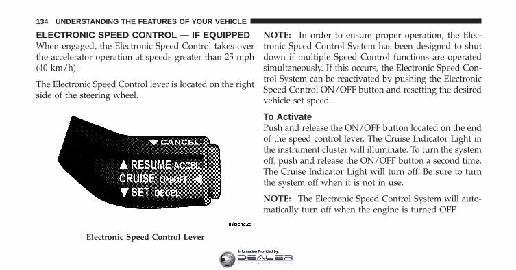
ELECTRONIC SPEED CONTROL — IF EQUIPPEDWhen engaged, the Electronic Speed Control takes overthe accelerator operation at speeds greater than 25 mph(40 km/h).
The Electronic Speed Control lever is located on the rightside of the steering wheel.
NOTE: In order to ensure proper operation, the Elec-tronic Speed Control System has been designed to shutdown if multiple Speed Control functions are operatedsimultaneously. If this occurs, the Electronic Speed Con-trol System can be reactivated by pushing the ElectronicSpeed Control ON/OFF button and resetting the desiredvehicle set speed.
To ActivatePush and release the ON/OFF button located on the endof the speed control lever. The Cruise Indicator Light inthe instrument cluster will illuminate. To turn the systemoff, push and release the ON/OFF button a second time.The Cruise Indicator Light will turn off. Be sure to turnthe system off when it is not in use.
NOTE: The Electronic Speed Control System will auto-matically turn off when the engine is turned OFF.
Electronic Speed Control Lever
134 UNDERSTANDING THE FEATURES OF YOUR VEHICLE
Information Provided by:

WARNING!
Leaving the Electronic Speed Control system onwhen not in use is dangerous. You could accidentallyset the system or cause it to go faster than you want.You could lose control and have an accident. Alwaysleave the system off when you are not using it.
To Set a Desired SpeedWhen the vehicle reaches the speed desired, press down-ward on the lever to SET DECEL and release. Release theaccelerator pedal and the vehicle will operate at theselected speed.
NOTE:• The vehicle must be traveling at least 25 mph
(40 km/h) for the speed control to set.
• The vehicle should be traveling at a steady speed andon level ground before pressing the lever to SETDECEL.
To DeactivateA soft tap on the brake pedal, or pulling the speed controllever toward you to CANCEL, or normal brake pressurewhile slowing the vehicle will deactivate the speedcontrol without erasing the set speed from memory.Pressing the ON/OFF button or turning the ignition OFFerases the set speed from memory.
To Resume SpeedIf you deactivate the Electronic Speed Control withouterasing the set speed from memory and your vehiclespeed is above 20 mph (32 km/h) you can resume theprevious set speed. To do so, push the lever upward toRESUME ACCEL and release and then remove your footfrom the accelerator pedal.
3
UNDERSTANDING THE FEATURES OF YOUR VEHICLE 135
Information Provided by:

To Vary the Speed SettingWhen the Electronic Speed Control is set, you can in-crease speed by pushing up and holding the RESUMEACCEL lever. If the lever is continually held in theRESUME ACCEL position, the set speed will continue toincrease until the lever is released, then the new set speedwill be established.
Tapping RESUME ACCEL once will result in a 1 mph(1.6 km/h) speed increase. Each time the lever is tapped,speed increases so that tapping the lever three times willincrease speed by 3 mph (5 km/h), etc.
To decrease speed while the Electronic Speed Control isset, push down and hold the SET DECEL lever. If thelever is continually held in the SET DECEL position, theset speed will continue to decrease until the lever isreleased. Release the lever when the desired speed isreached, and the new set speed will be established.
Tapping the SET DECEL lever once will result in a 1 mph(1.6 km/h) speed decrease. Each time the lever is tapped,speed decreases.
To Accelerate for PassingPress the accelerator pedal as you would normally. Whenthe pedal is released, the vehicle will return to the setspeed.
Using Speed Control on Hills
NOTE: The Electronic Speed Control system maintainsspeed up and down hills. A slight speed change onmoderate hills is normal.
On steep hills, a greater speed loss or gain may occur soit may be preferable to drive without Electronic SpeedControl.
136 UNDERSTANDING THE FEATURES OF YOUR VEHICLE
Information Provided by:

WARNING!
Electronic Speed Control can be dangerous where thesystem cannot maintain a constant speed. Your ve-hicle could go too fast for the conditions, and youcould lose control. An accident could be the result.Do not use Electronic Speed Control in heavy trafficor on roads that are winding, icy, snow-covered, orslippery.
PARKVIEW� REAR BACK UP CAMERA — IFEQUIPPEDYour vehicle may be equipped with the ParkView� RearBack Up Camera that allows you to see an on-screenimage of the rear of your vehicle whenever the shift leveris put into REVERSE. The image will be displayed on theNavigation/Multimedia radio display screen.
WARNING!
Drivers must be careful when backing up even whenusing the ParkView� Rear Back Up Camera. Alwayscheck carefully behind your vehicle, and be sure tocheck for pedestrians, animals, other vehicles, ob-structions, or blind spots before backing up. You areresponsible for the safety of your surroundings andmust continue to pay attention while backing up.Failure to do so can result in serious injury or death.
CAUTION!
• To avoid vehicle damage, ParkView� should onlybe used as a parking aid. The ParkView� camera isunable to view every obstacle or object in yourdrive path.
(Continued)
3
UNDERSTANDING THE FEATURES OF YOUR VEHICLE 137
Information Provided by:

CAUTION! (Continued)• To avoid vehicle damage, the vehicle must be
driven slowly when using ParkView� to be able tostop in time when an obstacle is seen. It is recom-mended that the driver look frequently over his/her shoulder when using ParkView�.
NOTE: If snow, ice, mud, or anything else builds up onthe camera lens, clean the lens, rinse with water, and drywith a soft cloth. Do not cover the lens.
Turning ParkView� On or Off — WithNavigation/Multimedia Radio
1. Press the “menu” hard key.
2. Select “system setup” soft key.
3. Press the “camera setup” soft key.
4. Enable or disable the rear camera feature by selecting“enable rear camera in reverse” soft key.
5. Press the “save” soft key.
6. When the vehicle is shifted into REVERSE, an image ofthe rear of the vehicle will appear with a caution note to“check entire surroundings” displayed across the top ofthe screen. After five seconds this note will disappear.
7. When the vehicle is shifted out of REVERSE, the rearcamera mode is exited and the navigation or audio screenappears again.
Turning ParkView� On or Off — WithoutNavigation/Multimedia Radio
1. Press the “menu” hard key.
2. Select “system setup” soft key.
3. Enable or disable the rear camera feature by selecting“enable rear camera in reverse” soft key.
138 UNDERSTANDING THE FEATURES OF YOUR VEHICLE
Information Provided by:

4. When the vehicle is shifted into REVERSE, an image ofthe rear of the vehicle will appear with a caution note to“check entire surroundings” displayed across the top ofthe screen.
5. When the vehicle is shifted out of REVERSE, the rearcamera mode is exited and the audio screen appearsagain.
OVERHEAD CONSOLEThe overhead console contains courtesy/reading lights,storage for sunglasses, an interior observation mirror andan optional power sunroof switch.
Courtesy/Reading LightsRefer to “Lights/Courtesy/Reading Lights” in “Under-standing the Features of Your Vehicle” for furtherinformation.
Overhead Console
3
UNDERSTANDING THE FEATURES OF YOUR VEHICLE 139
Information Provided by:

Sunglasses StorageTo access the storage compartment, press on the raisedbars on the compartment door in the center of the consoleand release and the door will swing downward.
Interior Observation MirrorThe convex interior observation mirror provides thedriver and front seat passenger a wide field of view toconveniently view passengers sitting in the rear passen-ger seats. To use the interior observation mirror, press onthe raised bars on the compartment door and release (thedoor will swing downward), then raise the door until it isalmost closed and release. The door will latch in positionto use the interior observation mirror.
Power Sunroof Switch — If EquippedRefer to “Power Sunroof” in “Understanding the Fea-tures of Your Vehicle” for further information.
GARAGE DOOR OPENER — IF EQUIPPEDHomeLink� replaces up to three remote controls (hand-held transmitters) that operate devices such as garagedoor openers, motorized gates, lighting or home securitysystems. The HomeLink� unit operates off your vehicle’sbattery.
The HomeLink� buttons that are located in the headlineror sun visor designate the three different HomeLink�channels.
140 UNDERSTANDING THE FEATURES OF YOUR VEHICLE
Information Provided by:

NOTE: HomeLink� is disabled when the Vehicle Secu-rity Alarm is active.
WARNING!
• Your motorized door or gate will open and closewhile you are training the Universal Transceiver.Do not train the transceiver if people, pets or otherobjects are in the path of the door or gate. Only usethis transceiver with a garage door opener that hasa “stop and reverse” feature as required by Federalsafety standards. This includes most garage dooropener models manufactured after 1982. Do notuse a garage door opener without these safetyfeatures. Call toll-free 1–800–355–3515 or, on theInternet at www.HomeLink.com for safety infor-mation or assistance.
• Vehicle exhaust contains carbon monoxide, a dan-gerous gas. Do not run your vehicle in the garagewhile training the transceiver. Exhaust gas cancause serious injury or death.
HomeLink� Buttons
3
UNDERSTANDING THE FEATURES OF YOUR VEHICLE 141
Information Provided by:
Programming HomeLink�
Before You BeginIf you have not trained any of the HomeLink� buttons,erase all channels before you begin training.
To do this, press and hold the two outside buttons for20 seconds until the red indicator flashes.
It is recommended that a new battery be placed in thehandheld transmitter of the device that is being copied toHomeLink� for more efficient training and accuratetransmission of the radio-frequency signal.
Your vehicle should be parked outside of the garagewhen programming.
1. Turn the ignition switch to the ON/RUN position.
2. Hold the battery side of the handheld transmitteraway from the HomeLink� button you wish to program.
Place the handheld transmitter 1–3 in (3-8 cm) away fromthe HomeLink� button you wish to program whilekeeping the indicator light in view.
3. Simultaneously press and hold both the chosenHomeLink� button and the handheld transmitter buttonuntil the HomeLink� indicator changes from a slow to arapidly blinking light, then release both the HomeLink�and handheld transmitter buttons.
Watch for the HomeLink� indicator to change flash rates.When it changes, it is programmed. It may take up to30 seconds or longer in rare cases. The garage door mayopen and close while you train.
NOTE:• Some gate operators and garage door openers may
require you to replace Step 3 with procedures noted inthe “Gate Operator/Canadian Programming” section.
142 UNDERSTANDING THE FEATURES OF YOUR VEHICLE
Information Provided by:

• After training a HomeLink� channel, if the garagedoor does not operate with HomeLink� and the ga-rage door opener was manufactured after 1995, thegarage door opener may have a rolling code. If so,proceed to the heading “Programming A Rolling CodeSystem.”
4. Press and hold the just-trained HomeLink� buttonand observe the indicator light.
If the indicator light stays on constantly, programming iscomplete and the garage door (or device) should activatewhen the HomeLink� button is pressed.
If the indicator light blinks rapidly for two seconds, andthen turns to a constant light, continue with program-ming for a Rolling Code.
5. PROGRAMMING A ROLLING CODE SYSTEMAt the garage door opener motor (in the garage), locatethe “Learn” or “Training” button.
This can usually be found where the hanging antennawire is attached to the garage door opener motor (it isNOT the button normally used to open and close thedoor).
1 — Garage Door Opener2 — Training Button
3
UNDERSTANDING THE FEATURES OF YOUR VEHICLE 143
Information Provided by:

6. Firmly press and release the LEARN or TRAININGbutton. The name and color of the button may vary bymanufacturer.
NOTE: You have 30 seconds in which to initiate the nextstep after the LEARN button has been pressed.
7. Return to the vehicle and press the programmedHomeLink� button twice (holding the button for twoseconds each time). If the device is plugged in andactivates, programming is complete.
If the device does not activate, press the button a thirdtime (for two seconds) to complete the training.
If you have any problems, or require assistance, pleasecall toll-free 1–800–355–3515 or, on the Internet atwww.HomeLink.com for information or assistance.
To program the remaining two HomeLink� buttons,repeat each step for each remaining button. DO NOTerase the channels.
Gate Operator/Canadian ProgrammingCanadian radio-frequency laws require transmitter sig-nals to “time-out” (or quit) after several seconds oftransmission – which may not be long enough forHomeLink� to pick up the signal during programming.Similar to this Canadian law, some U.S. gate operators aredesigned to “time-out” in the same manner.
It may be helpful to unplug the device during the cyclingprocess to prevent possible overheating of the garagedoor or gate motor.
If you are having difficulties programming a garage dooropener or a gate operator, replace “ProgrammingHomeLink�” Step 3 with the following:
3. Continue to press and hold the HomeLink� button,while you press and release (“cycle”), your handheldtransmitter every two seconds until HomeLink� has
144 UNDERSTANDING THE FEATURES OF YOUR VEHICLE
Information Provided by:

successfully accepted the frequency signal. The indica-tor light will flash slowly and then rapidly when fullytrained.
If you unplugged the device for training, plug it back inat this time.
Then proceed with Step 4 under “ProgrammingHomeLink�” earlier in this section.
Using HomeLink�To operate, press and release the programmedHomeLink� button. Activation will now occur for thetrained device (i.e., garage door opener, gate operator,Security system, entry door lock, home/office lighting,etc.,). The handheld transmitter of the device may also beused at any time.
Reprogramming A Single HomeLink� ButtonTo reprogram a channel that has been previously trained,follow these steps:
1. Turn the ignition switch to the ON/RUN position.
2. Press and hold the desired HomeLink� button untilthe indicator light begins to flash after 20 seconds. Do notrelease the button.
3. Without releasing the button, proceed with Program-ming HomeLink� Step 2 and follow all remaining steps.
SecurityIt is advised to erase all channels before you sell or turnin your vehicle.
To do this, press and hold the two outside buttons for20 seconds until the red indicator flashes. Note that allchannels will be erased. Individual channels cannot beerased.
The HomeLink� Universal Transceiver is disabled whenthe Vehicle Security Alarm is active.
3
UNDERSTANDING THE FEATURES OF YOUR VEHICLE 145
Information Provided by:

Troubleshooting TipsIf you are having trouble programming HomeLink�, hereare some of the most common solutions:
• Replace the battery in the original transmitter.
• Press the LEARN button on the Garage Door Openerto complete the training for a Rolling Code.
• Did you unplug the device for training, and rememberto plug it back in?
If you have any problems, or require assistance, pleasecall toll-free 1–800–355–3515 or, on the Internet atwww.HomeLink.com for information or assistance.
General InformationThis device complies with FCC rules Part 15 and IndustryCanada RSS-210. Operation is subject to the followingtwo conditions:
1. This device may not cause harmful interference.
2. This device must accept any interference that may bereceived including interference that may cause undesiredoperation.
NOTE: The transmitter has been tested and it complieswith FCC and IC rules. Changes or modifications notexpressly approved by the party responsible for compli-ance could void the user’s authority to operate thedevice.
The term IC before the certification/registration numberonly signifies that Industry Canada technical specifica-tions were met.
146 UNDERSTANDING THE FEATURES OF YOUR VEHICLE
Information Provided by:

POWER SUNROOF — IF EQUIPPEDThe power sunroof switch is located between the sunvisors on the overhead console.
WARNING!
• Never leave children in a vehicle with the key inthe ignition switch. Occupants, particularly unat-tended children, can become entrapped by thepower sunroof while operating the power sunroofswitch. Such entrapment may result in seriousinjury or death.
• In an accident, there is a greater risk of beingthrown from a vehicle with an open sunroof. Youcould also be seriously injured or killed. Alwaysfasten your seat belt properly and make sure allpassengers are also properly secured.
• Do not allow small children to operate the sun-roof. Never allow your fingers, other body parts, orany object to project through the sunroof opening.Injury may result.
Power sunroof Switch
3
UNDERSTANDING THE FEATURES OF YOUR VEHICLE 147
Information Provided by:

Opening Sunroof — ManuallyPress and hold the switch in the rearward position.Release the switch when the sunroof is in the positiondesired and it will stop moving. If you continue to holdthe switch in the rearward position, the sunroof will openfully and then stop automatically. Release the switch oncethe sunroof stops moving.
Opening Sunroof — ExpressPress the switch rearward and release, and the sunroofwill open automatically from any position. The sunroofwill open fully and then stop automatically. This is called“Express Open”. During Express Open operation, anymovement of the sunroof switch will stop the sunroof.
Closing Sunroof — ManuallyPress and hold the switch in the forward position.Release the switch when the sunroof is in the positiondesired and it will stop moving. If you continue to hold
the switch in the forward position, the sunroof will closefully and then stop automatically. Release the switch oncethe sunroof stops moving.
Closing Sunroof — ExpressPress the switch forward and release, and the sunroofwill close automatically from any position. The sunroofwill close fully and stop automatically. This is called“Express Close”. During Express Close operation, anymovement of the sunroof switch will stop the sunroof.
Pinch Protect FeatureThis feature will detect an obstruction in the opening ofthe sunroof during Express Close operation. If an ob-struction in the path of the sunroof is detected, thesunroof will automatically retract. Remove the obstruc-tion if this occurs, then press the switch forward andrelease to Express Close.
148 UNDERSTANDING THE FEATURES OF YOUR VEHICLE
Information Provided by:

Pinch Protect OverrideIf a known obstruction (ice, debris, etc.) prevents closing,press the switch forward and hold for two seconds afterthe reversal occurs. This allows the sunroof to movetowards the closed position.
NOTE: Pinch protection is disabled while the switch ispressed.
Venting Sunroof — ExpressPress and release the �V� button in the center of theswitch, and the sunroof will open to the vent position.This is called “Express Vent”. which operates regardlessof sunroof position. During Express Vent operation, anymovement of the sunroof switch will stop the sunroof.
Sunshade OperationThe sunshade can be opened manually. However, thesunshade will open automatically as the sunroof opens.
NOTE: The sunshade cannot be closed if the sunroof isopen.
Wind BuffetingWind buffeting can be described as the perception ofpressure on the ears or a helicopter-type sound in theears. Your vehicle may exhibit wind buffeting with thewindows down, or the sunroof in certain open or par-tially open positions. This is a normal occurrence and canbe minimized. If the buffeting occurs with the rearwindows open, then open the front and rear windowstogether to minimize the buffeting. If the buffeting occurswith the sunroof open, then adjust the sunroof opening tominimize the buffeting or open any window.
Sunroof MaintenanceUse only a nonabrasive cleaner and a soft cloth to cleanthe glass panel.
3
UNDERSTANDING THE FEATURES OF YOUR VEHICLE 149
Information Provided by:

Ignition Off OperationFor vehicles not equipped with the Electronic VehicleInformation Center (EVIC), the power sunroof switchwill remain active for 45 seconds after the ignition switchis turned to the LOCK position. Opening either frontdoor will cancel this feature.
For vehicles equipped with the EVIC, the power sunroofswitch will remain active for up to 10 minutes after theignition switch is turned to the LOCK position. Openingeither front door will cancel this feature. The time isprogrammable. Refer to “Electronic Vehicle InformationCenter (EVIC)/Personal Settings (Customer-Programmable Features)” in “Understanding Your In-strument Panel” for further information.
Sunroof Fully ClosedPress the switch forward and release to ensure that thesunroof is fully closed.
ELECTRICAL POWER OUTLETSThere are two fused 12 Volt (13 Amp) power outletslocated in the center console below the radio. The poweroutlet on the top has power available when the ignitionswitch in the ON or ACC position. The power outlet onthe bottom has power available when the ignition switchis in the LOCK, ON, or ACC position.
This power outlet will also operate a conventional cigarlighter unit. To preserve the heating element, do nothold the lighter in the heating position.
150 UNDERSTANDING THE FEATURES OF YOUR VEHICLE
Information Provided by:

A third fused 12 Volt power outlet is located on the backof the center console. This power outlet has poweravailable when the ignition switch is in the LOCK, ON orACC position.
Front Power Outlets
1 — Switched Power2 — Battery Power
Rear Power Outlet
3
UNDERSTANDING THE FEATURES OF YOUR VEHICLE 151
Information Provided by:
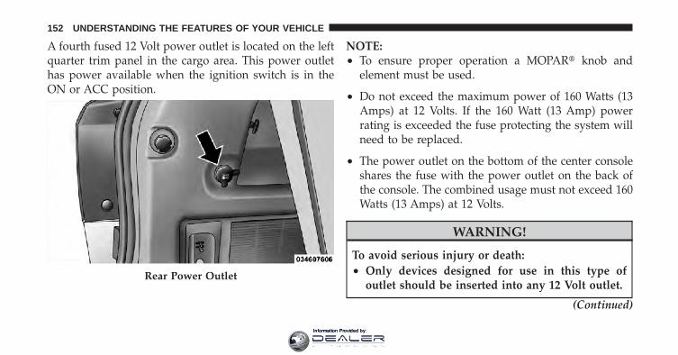
A fourth fused 12 Volt power outlet is located on the leftquarter trim panel in the cargo area. This power outlethas power available when the ignition switch is in theON or ACC position.
NOTE:• To ensure proper operation a MOPAR� knob and
element must be used.
• Do not exceed the maximum power of 160 Watts (13Amps) at 12 Volts. If the 160 Watt (13 Amp) powerrating is exceeded the fuse protecting the system willneed to be replaced.
• The power outlet on the bottom of the center consoleshares the fuse with the power outlet on the back ofthe console. The combined usage must not exceed 160Watts (13 Amps) at 12 Volts.
WARNING!
To avoid serious injury or death:• Only devices designed for use in this type of
outlet should be inserted into any 12 Volt outlet.
(Continued)
Rear Power Outlet
152 UNDERSTANDING THE FEATURES OF YOUR VEHICLE
Information Provided by:
WARNING! (Continued)• Do not touch with wet hands.• Close the lid when not in use and while driving
the vehicle.• If this outlet is mishandled, it may cause an
electric shock and failure.
CAUTION!
• Many accessories that can be plugged in drawpower from the vehicle’s battery, even when not inuse (i.e., cellular phones, etc.). Eventually, ifplugged in long enough, the vehicle’s battery willdischarge sufficiently to degrade battery lifeand/or prevent the engine from starting.
(Continued)
CAUTION! (Continued)• Accessories that draw higher power (i.e., coolers,
vacuum cleaners, lights, etc.) will degrade thebattery even more quickly. Only use these inter-mittently and with greater caution.
• After the use of high power draw accessories, orlong periods of the vehicle not being started (withaccessories still plugged in), the vehicle must bedriven a sufficient length of time to allow thealternator to recharge the vehicle’s battery.
• Power outlets are designed for accessory plugsonly. Do not hang any type of accessory or acces-sory bracket from the plug.
POWER INVERTER — IF EQUIPPEDYour vehicle may be equipped with a 115 Volt AC (150Watt maximum) power outlet located on the back of thecenter console. This outlet can power cellular phones,
3
UNDERSTANDING THE FEATURES OF YOUR VEHICLE 153
Information Provided by:

electronics and other low power devices requiring powerup to 150 Watts. Certain high-end video games, such asPlaystation3 and XBox360 will exceed this power limit, aswill most power tools.
The power inverter is designed with built-in overloadprotection. If the power rating of 150 Watts is exceeded,the power inverter will automatically shut down. Oncethe electrical device has been removed from the outlet theinverter should automatically reset. If the power ratingexceeds approximately 170 Watts, the power invertermay have to be reset manually. To reset the invertermanually press the power inverter button OFF and ON.To avoid overloading the circuit, check the power ratingson electrical devices prior to using the inverter.
The control switch for the outlet is located in the switchbank above the climate controls.
Power Inverter
154 UNDERSTANDING THE FEATURES OF YOUR VEHICLE
Information Provided by:

Press and release the switch once to turn on the poweroutlet. A status indicator in the switch will illuminate inapproximately one second to indicate that power isavailable at the outlet. Press and release the switch againto turn off the power outlet. The status indicator will alsoturn off.
NOTE: Due to built-in overload protection, the poweroutlet will shut down if the 115 Volt AC (150 Wattmaximum) power rating is exceeded.
WARNING!
To avoid serious injury or death:• Do not use a three-prong adaptor.• Do not insert any objects into the receptacles.• Do not touch with wet hands.• Close the lid when not in use.• If this outlet is mishandled, it may cause an
electric shock and failure.
Power Inverter Switch
3
UNDERSTANDING THE FEATURES OF YOUR VEHICLE 155
Information Provided by:

CUPHOLDERSThere are two cupholders, located in the center floorconsole, for the front passengers.
For passengers in the second row there are two cuphold-ers, located in the center armrest between the two seats.
Center Console CupholdersArmrest Cupholders
156 UNDERSTANDING THE FEATURES OF YOUR VEHICLE
Information Provided by:

For vehicles equipped with third row seating, there areadditional cupholders located in the trim panels.
In addition to cupholders, vehicles may also be equippedwith bottle holders. The bottle holders are located on thedoor trim panels.
WARNING!
If containers of hot liquid are placed in the bottleholder, they can spill when the door is closed, burn-ing the occupants. Be careful when closing the doorsto avoid injury.
Quarter Trim Panel Cupholders (Seven PassengerModels)
Door Bottle Holder
3
UNDERSTANDING THE FEATURES OF YOUR VEHICLE 157
Information Provided by:

STORAGE
Instrument Panel Storage Compartment — IfEquippedPress and release the button on the door to open it. Thedoor swings upward to allow easy access to the compart-ment.
Console StorageOpen storage areas, or cubby bins, are located in the floorconsole and center console.
Instrument Panel Storage Compartment
Floor Console Cubby Bin
158 UNDERSTANDING THE FEATURES OF YOUR VEHICLE
Information Provided by:

There is additional storage under the center consolearmrest. Pull upward on the release lever, located on thefront of the lid.
NOTE: The sliding armrest (if equipped) must be in therearward position to access the release button on thefront of the bin door.
Center Console Cubby Bin Center Console Storage Bin
3
UNDERSTANDING THE FEATURES OF YOUR VEHICLE 159
Information Provided by:

Flip ’n Stow™ Front Passenger Seat Storage — IfEquippedThe seat latch release-loop is located in the center of theseat cushion between the seat cushion and the seatback.Pull the loop upward to release the latch and thenforward to open the seat to the detent position.
NOTE: Make sure that objects inside the bin do notinterfere with the latch before closing the seat. Push theseat cushion downward after closing it to make sure itlatches to the base.
WARNING!
Be certain that the seat cushion is locked securelyinto position before using the seat. Otherwise, theseat will not provide the proper stability for passen-gers. An improperly latched seat cushion could causeserious injury.
Front Passenger Seat Storage Compartment
160 UNDERSTANDING THE FEATURES OF YOUR VEHICLE
Information Provided by:
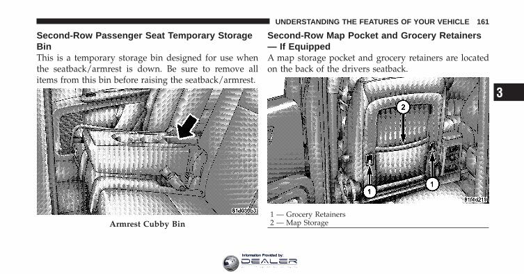
Second-Row Passenger Seat Temporary StorageBinThis is a temporary storage bin designed for use whenthe seatback/armrest is down. Be sure to remove allitems from this bin before raising the seatback/armrest.
Second-Row Map Pocket and Grocery Retainers— If EquippedA map storage pocket and grocery retainers are locatedon the back of the drivers seatback.
Armrest Cubby Bin1 — Grocery Retainers2 — Map Storage
3
UNDERSTANDING THE FEATURES OF YOUR VEHICLE 161
Information Provided by:

In-Floor Storage Bin with Removable Liner
NOTE: Position the front seat to at least a mid-trackposition to provide easier access to the storage bin.
An in-floor storage bin is located behind each front seat.Each 1.6 gal (5.9 l) bin can hold up to 12, 12 oz (0.35 l)cans, plus ice, or other items. The removable bin linerallows for easy filling, emptying, and cleaning.
To access the bin, position the floor mat aside (ifequipped). Pull the door latch release-loop upward torelease the latch and then forward to open the bin door.
The liner can be removed for easy cleaning by lifting onthe notches as shown.
In-Floor Storage Bin
162 UNDERSTANDING THE FEATURES OF YOUR VEHICLE
Information Provided by:

CHILL ZONE� BEVERAGE COOLER STORAGECOMPARTMENTThe Chill Zone� Beverage Cooler Storage Compartmentcan keep chilled beverages cool depending on ambienttemperature and climate control setting. Chill Zone� isintended for nonperishable beverages only.
The Chill Zone� compartment is located on the passengerside of the instrument panel above the glove compart-ment. The beverage retainer inside the cooler is designedto hold up to two 12 oz (0.35L) cans when placedhorizontally in the retainer. The beverage retainer isremovable to allow for storage of other items in thecompartment when not in use as a beverage cooler.
Removable Liner
Beverage Cooler/Storage Compartment
3
UNDERSTANDING THE FEATURES OF YOUR VEHICLE 163
Information Provided by:

Press and release the button on the door to open it. thelarge door will swing upward to allow easy access to thecompartment contents.
Chill Zone� Beverage Cooler OperationThe blower speed setting on the climate control sets therate at which the air flows into the compartment. Theairflow control valve inside the compartment determineshow much air flows into the compartment. Turning thevalve rearward increases the airflow, while turning thevalve forward decreases the airflow. Turning the valve allthe way forward will turn off the airflow into thecompartment. Airflow Control Valve
164 UNDERSTANDING THE FEATURES OF YOUR VEHICLE
Information Provided by:

The compartment cools when the airflow is open, theengine is running and the Air Conditioning (A/C) is onor the Automatic Temperature Control (ATC) system isset for automatic operation (if equipped). This allows youto cool the compartment when the climate control is inthe cooling or heating mode.
NOTE: Whether operating a Manual Heating and A/Csystem or operating an ATC system in the manual mode,the A/C indicator must be ON to cool the compartment.
CARGO AREA FEATURES
Rechargeable Flashlight — If EquippedThe rechargeable LED flashlight stores in its chargingstation in the left rear quarter trim panel. To remove it,press on the indent on the side of the flashlight andrelease.
NOTE: Be sure to return the flashlight to its chargingstation when not in use to ensure it is ready for operationthe next time you need it.
Rechargeable Flashlight
3
UNDERSTANDING THE FEATURES OF YOUR VEHICLE 165
Information Provided by:

Cargo Management System
Five Passenger System Features
• A raised load floor that sits on top of a large built-instorage bin.
• A tri-fold door built into the load floor that allows easyaccess to items in the built-in storage bin.
• 60/40 split second-row passenger seats with fold flatfeature, which allows for extended cargo space. Referto “Seats” in “Understanding the Features of YourVehicle” for further information.
• An optional front passenger seat with fold flat feature,which extends cargo space even further. Refer to“Seats” in “Understanding the Features of Your Ve-hicle” for further information.
• Cargo tie-downs.
• A retractable cargo area cover (if equipped).
Seven Passenger System Features
• A large built-in storage bin with a hinged hardcoverlocated in the floor behind the third-row passengerseats.
• 60/40 split second-row passenger seats with fold flatfeature, which allows for extended cargo space. Referto “Seats” in “Understanding the Features of YourVehicle” for further information.
• 50/50 split third-row passenger seats with fold flatfeature, which allows for extended cargo space. Referto “Seats” in “Understanding the Features of YourVehicle” for further information.
• An optional front passenger seat with fold flat feature,which extends cargo space even further. Refer to“Seats” in “Understanding the Features of Your Ve-hicle” for further information.
• Cargo tie-downs.
166 UNDERSTANDING THE FEATURES OF YOUR VEHICLE
Information Provided by:

Cargo Tie-Downs
WARNING!
Cargo tie-downs are not safe anchors for a child seattether strap. In a sudden stop or collision, a tie-downcould pull loose and allow the child seat to comeloose. A child could be badly injured. Use only theanchors provided for child seat tethers.
Cargo tie-downs are located on both rear trim panels.These tie-downs should be used to secure loads safelywhen the vehicle is moving. Cargo Tie-Downs
3
UNDERSTANDING THE FEATURES OF YOUR VEHICLE 167
Information Provided by:

WARNING!
The weight and position of cargo and passengers canchange the vehicle center of gravity and vehiclehandling. To avoid loss of control resulting in per-sonal injury, follow these guidelines for loading yourvehicle:
• Do not carry loads that exceed the load limits de-scribed on the label attached to the left door or leftdoor center pillar.
• Always place cargo evenly on the cargo floor. Putheavier objects as low and as far forward as possible.
• Place as much cargo as possible in front of the rearaxle. Too much weight or improperly placed weightover or behind the rear axle can cause the vehicle tosway.
• Do not pile luggage or cargo higher than the top of theseatback. This could impair visibility or become adangerous projectile in a sudden stop or collision.
• To help protect against personal injury, passengersshould not be seated in the rear cargo area. The rearcargo space is intended for load carrying purposesonly, not for passengers, who should sit in seats anduse seat belts.
Retractable Cargo Area Cover (If Equipped) — FivePassenger Models
NOTE: The purpose of this cover is for privacy, not tosecure loads. It will not prevent cargo from shifting orprotect passengers from loose cargo.
The removable retractable cargo area cover mounts in thecargo area behind the top of the rear seats.
168 UNDERSTANDING THE FEATURES OF YOUR VEHICLE
Information Provided by:

The cover, when extended, covers the cargo area to keepitems out of sight. Notches in the trim panels near theliftgate opening secure the extended cover in place.
The cover rolls away neatly inside its housing when notin use. You can also remove the cover from the vehicle tomake more room in the cargo area.
To install the cover, position it in the vehicle so that theflat side of the housing faces upward. Then, insert eitherthe left or the right spring-loaded post (located on theends of the cover housing) into the left attachment pointor the right attachment point (shown).
Insert the spring-loaded post on the opposite end of thecover housing into the attachment point on the oppositeside of the vehicle.
Installing Retractable Cargo Area Cover
3
UNDERSTANDING THE FEATURES OF YOUR VEHICLE 169
Information Provided by:

Grab the cover handle and pull it toward you. As thecover nears the liftgate opening, guide the rear attach-ment posts (on both ends of the cover) into the notches inthe trim panels. Lower the cover to position the posts intothe bottom of the notches and release the handle.
WARNING!
A cargo cover that is unsecured in the vehicle couldcause injury in an accident. It could become airborneduring a sudden stop and strike someone inside thevehicle. Do not store the cargo cover on the cargofloor or in the passenger compartment. Remove thecover from the vehicle when taken from its mount-ing. Do not store it in the vehicle.
Positioning Retractable Cargo Area Cover
170 UNDERSTANDING THE FEATURES OF YOUR VEHICLE
Information Provided by:
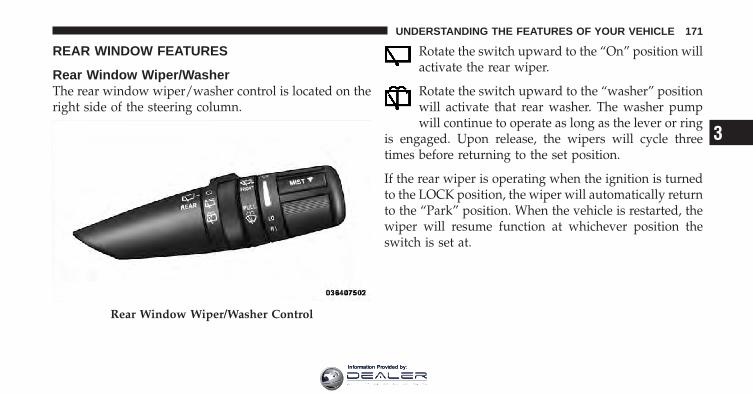
REAR WINDOW FEATURES
Rear Window Wiper/WasherThe rear window wiper/washer control is located on theright side of the steering column.
Rotate the switch upward to the “On” position willactivate the rear wiper.
Rotate the switch upward to the “washer” positionwill activate that rear washer. The washer pumpwill continue to operate as long as the lever or ring
is engaged. Upon release, the wipers will cycle threetimes before returning to the set position.
If the rear wiper is operating when the ignition is turnedto the LOCK position, the wiper will automatically returnto the “Park” position. When the vehicle is restarted, thewiper will resume function at whichever position theswitch is set at.
Rear Window Wiper/Washer Control
3
UNDERSTANDING THE FEATURES OF YOUR VEHICLE 171
Information Provided by:

CAUTION!
• Turn the rear wiper off when driving through anautomatic car wash. Damage to the rear wiper mayresult if the rear wiper switch is left in the onposition.
• In cold weather, always turn off the rear wiperswitch and allow the rear wiper to return to thepark position before turning off the engine. If therear wiper switch is left on and the rear wiperfreezes to the window, damage to the rear wipermotor may occur when the vehicle is restarted.
• Always remove any buildup of snow that preventsthe rear wiper blade from returning to the parkposition. If the rear wiper control is turned off andthe blade cannot return to the park position, dam-age to the rear wiper motor may occur.
Rear Window DefrosterThe rear window defroster button is located on theclimate control panel. Press this button to turn on
the rear window defroster and the heated outside mirrors(if equipped). An indicator in the button will illuminatewhen the rear window defroster is on. The rear windowdefroster automatically turns off after approximately10 minutes.
NOTE: To prevent excessive battery drain, use the rearwindow defroster only when the engine is operating.
172 UNDERSTANDING THE FEATURES OF YOUR VEHICLE
Information Provided by:

CAUTION!
Failure to follow these cautions can cause damage tothe heating elements:• Use care when washing the inside of the rear
window. Do not use abrasive window cleaners onthe interior surface of the window. Use a soft clothand a mild washing solution, wiping parallel tothe heating elements. Labels can be peeled offafter soaking with warm water.
• Do not use scrapers, sharp instruments, or abra-sive window cleaners on the interior surface of thewindow.
• Keep all objects a safe distance from the window.
ROOF LUGGAGE RACK — IF EQUIPPEDThe roof rack cross rails and side rails are designed tocarry cargo weight. The load must not exceed 150 lbs(68 kg), and it should be distributed uniformly over thecross rails. In addition, the roof rack does not increase thetotal load carrying capacity of the vehicle. Be sure thetotal load of cargo inside the vehicle plus that on the roofrack does not exceed the maximum vehicle load capacity.
3
UNDERSTANDING THE FEATURES OF YOUR VEHICLE 173
Information Provided by:

To Move the Cross Rails
1. Loosen the knobs on top of each cross rail approxi-mately six turns to disengage the clamp tooth from theside rail.
2. Relocate the cross rails, aligning the cross rail stan-chions (end pieces) with one of the vertical marks on theoutboard surface of the side rail for proper positioning.There are four frontward marks for the front cross railand four rearward marks for the rear cross rail. Makesure the cross rails remain equally spaced or parallel atany position for proper function.
3. Tighten the knobs on each cross rail to lock it inposition. As you tighten the knob, make sure the clamptooth engages completely into the side rail slot.
4. Attempt to move the cross rail to ensure that it islocked in position.
NOTE:• To help control wind noise when installing the cross
rails, make sure the arrows marked on the undersideof the cross rails face the front of the vehicle.Roof Luggage Rack
174 UNDERSTANDING THE FEATURES OF YOUR VEHICLE
Information Provided by:

• To help reduce the amount of wind noise when thecross rails are not in use, fasten the front cross rail inthe fourth position from the front and the rear crossrail in the eighth position.
The tie down holes on the cross rail ends should alwaysbe used to tie down the load. Check the straps frequentlyto be sure that the load remains securely attached.
CAUTION!
• Cross rails should remain equally spaced or paral-lel at any luggage rack position for proper func-tion. Noncompliance could result in damage to theroof rack, cargo, and vehicle.
• To avoid damage to the roof rack and vehicle, donot exceed the maximum roof rack load capacity of150 lbs (68 kg). Always distribute loads as evenlyas possible and secure the load appropriately.
(Continued)
CAUTION! (Continued)• Long loads, which extend over the windshield,
such as wood panels or surfboards, or loads withlarge frontal area should be secured to both thefront and rear of the vehicle.
• Place a blanket or other protection between thesurface of the roof and the load.
• Travel at reduced speeds and turn corners care-fully when carrying large or heavy loads on theroof rack. Wind forces, due to natural causes ornearby truck traffic, can add sudden upward lift toloads. This is especially true on large flat loadsand may result in damage to the cargo or yourvehicle.
3
UNDERSTANDING THE FEATURES OF YOUR VEHICLE 175
Information Provided by:

WARNING!
Cargo must be securely tied before driving yourvehicle. Improperly secured loads can fly off thevehicle, particularly at high speeds, resulting in per-sonal injury or property damage. Follow the RoofRack Cautions when carrying cargo on your roofrack.
176 UNDERSTANDING THE FEATURES OF YOUR VEHICLE
Information Provided by:

UNDERSTANDING YOUR INSTRUMENT PANEL
CONTENTS
� Instrument Panel Features . . . . . . . . . . . . . . . 181
� Instrument Cluster . . . . . . . . . . . . . . . . . . . . 182
� Instrument Cluster Descriptions . . . . . . . . . . . 183
� Compass Mini-Trip Computer (CMTC) — IfEquipped . . . . . . . . . . . . . . . . . . . . . . . . . . . . 198
▫ CMTC Reset Buttons . . . . . . . . . . . . . . . . . . 198
▫ Compass/Temperature Display . . . . . . . . . . 200
� Electronic Vehicle Information Center(EVIC) — If Equipped . . . . . . . . . . . . . . . . . . . 202
▫ Electronic Vehicle Information Center (EVIC)Displays . . . . . . . . . . . . . . . . . . . . . . . . . . . 204
▫ Oil Change Required . . . . . . . . . . . . . . . . . . 205
▫ Trip Functions . . . . . . . . . . . . . . . . . . . . . . 206
▫ Compass Display / ECO (Fuel Saver Mode)— If Equipped . . . . . . . . . . . . . . . . . . . . . . 208
▫ Personal Settings (Customer-ProgrammableFeatures) . . . . . . . . . . . . . . . . . . . . . . . . . . 210
� Media Center 230 (REQ) — AM/FM StereoRadio And 6–Disc CD/DVD Changer(MP3/WMA AUX Jack) . . . . . . . . . . . . . . . . . . 214
4
Information Provided by:

▫ Operating Instructions - Radio Mode . . . . . . 214
▫ Operation Instructions - (Disc Mode For CDAnd MP3/WMA Audio Play, DVD-Video) . . . 222
▫ Notes On Playing MP3/WMA Files . . . . . . . 224
▫ List Button (Disc Mode ForMP3/WMA Play) . . . . . . . . . . . . . . . . . . . . 227
▫ Info Button (Disc Mode For MP3/WMAPlay) . . . . . . . . . . . . . . . . . . . . . . . . . . . . . 227
� Media Center 130 (RES) — AM/FM StereoRadio With CD Player (MP3 AUX Jack). . . . . . . 230
▫ Operating Instructions — Radio Mode . . . . . 230
▫ Operation Instructions — CD Mode For CDAnd MP3 Audio Play . . . . . . . . . . . . . . . . . 233
▫ Notes On Playing MP3 Files . . . . . . . . . . . . 235
▫ Operation Instructions - Auxiliary Mode . . . . 238
� Media Center 130 (RES/RSC) — AM/FMStereo Radio With CD Player (MP3 AUX Jack)And Sirius Radio . . . . . . . . . . . . . . . . . . . . . . 239
▫ Operating Instructions — Radio Mode . . . . . 239
▫ Operation Instructions — CD Mode For CDAnd MP3 Audio Play . . . . . . . . . . . . . . . . . 245
▫ Notes On Playing MP3 Files . . . . . . . . . . . . 247
▫ List Button (CD Mode For MP3 Play) . . . . . . 250
▫ Info Button (CD Mode For MP3 Play) . . . . . . 250
� Media Center 830N (REU) — AM/FM StereoRadio And 6–Disc CD/DVD/HDD/NAVChanger — If Equipped. . . . . . . . . . . . . . . . . . 251
▫ Operating Instructions — Uconnect™Multimedia (Satellite Radio) . . . . . . . . . . . . . 252
178 UNDERSTANDING YOUR INSTRUMENT PANEL
Information Provided by:
▫ Operating Instructions —Uconnect™ Phone . . . . . . . . . . . . . . . . . . . . 252
▫ Clock Setting Procedure . . . . . . . . . . . . . . . 252
� Uconnect™ Multimedia (Satellite Radio) —If Equipped (REN/REQ/RER/RES/REU/RBZRadios Only) . . . . . . . . . . . . . . . . . . . . . . . . . 256
▫ System Activation . . . . . . . . . . . . . . . . . . . . 256
▫ Electronic Serial Number/SiriusIdentification Number (ESN/SID) . . . . . . . . . 256
▫ Selecting Uconnect™ Multimedia (Satellite)Mode . . . . . . . . . . . . . . . . . . . . . . . . . . . . . 257
▫ Satellite Antenna . . . . . . . . . . . . . . . . . . . . . 257
▫ Reception Quality . . . . . . . . . . . . . . . . . . . . 257
▫ Operating Instructions — Uconnect™Multimedia (Satellite) Mode . . . . . . . . . . . . . 258
▫ Operating Instructions — Uconnect™ Phone(If Equipped) . . . . . . . . . . . . . . . . . . . . . . . 261
▫ Operating Instructions — VideoEntertainment System (VES)™(If Equipped) . . . . . . . . . . . . . . . . . . . . . . . 261
� Uconnect™ Multimedia(Sirius Backseat TV™) — If Equipped . . . . . . . . 261
� Video Entertainment System (VES)™ —If Equipped . . . . . . . . . . . . . . . . . . . . . . . . . . 261
� Universal Consumer Interface (UCI) 0.5 —If Equipped . . . . . . . . . . . . . . . . . . . . . . . . . . 263
▫ Connecting The iPod� Device . . . . . . . . . . . 263
▫ Controlling The iPod� UsingRadio Buttons . . . . . . . . . . . . . . . . . . . . . . . 263
▫ Play Mode . . . . . . . . . . . . . . . . . . . . . . . . . 264
4
UNDERSTANDING YOUR INSTRUMENT PANEL 179
Information Provided by:

▫ List Or Browse Mode . . . . . . . . . . . . . . . . . 265
� Remote Sound System Controls —If Equipped . . . . . . . . . . . . . . . . . . . . . . . . . . 267
▫ Right-Hand Switch Functions . . . . . . . . . . . . 267
▫ Left-Hand Switch Functions For RadioOperation . . . . . . . . . . . . . . . . . . . . . . . . . . 268
▫ Left-Hand Switch Functions For Media (i.e.,CD) Operation . . . . . . . . . . . . . . . . . . . . . . 268
� CD/DVD Disc Maintenance . . . . . . . . . . . . . . 268
� Radio Operation And Cellular Phones . . . . . . . 269
� Climate Controls . . . . . . . . . . . . . . . . . . . . . . 269
▫ Manual Heating And Air ConditioningSystem . . . . . . . . . . . . . . . . . . . . . . . . . . . . 270
▫ Three-Zone Manual Air Conditioning AndHeating Systems — If Equipped . . . . . . . . . . 274
▫ Two- And Three-Zone AutomaticTemperature Control (ATC) Systems — IfEquipped . . . . . . . . . . . . . . . . . . . . . . . . . . 277
▫ Operating Tips . . . . . . . . . . . . . . . . . . . . . . 286
180 UNDERSTANDING YOUR INSTRUMENT PANEL
Information Provided by:

INSTRUMENT PANEL FEATURES
1 — Side Window Demist Outlet 5 — Hazard Switch 9 — Climate Control2 — Air Outlet 6 — Switch Bank 10 — Radio3 — Instrument Cluster 7 — Beverage Cooler/Storage Compartment* 11 — Ignition Switch4 — Storage Compartment or Remote DisplayPanel*
8 — Glove Box * If Equipped
4
UNDERSTANDING YOUR INSTRUMENT PANEL 181
Information Provided by:

INSTRUMENT CLUSTER
182 UNDERSTANDING YOUR INSTRUMENT PANEL
Information Provided by:

INSTRUMENT CLUSTER DESCRIPTIONS
1. Coolant Temperature GaugeThe temperature gauge indicates engine coolant tem-perature. Any reading within the normal range indicatesthat the cooling system is operating satisfactorily. Thegauge pointer will likely indicate a high temperaturewhen driving in hot weather, up mountain grades, inheavy traffic, or when towing a trailer. If the pointer risesto the “H” mark, safely pull over and stop the vehicle. Ifthe Air Conditioning A/C system is on, turn it off. Also,shift the transmission into NEUTRAL and idle the ve-hicle. If the needle remains on the “H” mark, turn theengine OFF immediately and call for service.
NOTE: The gauge pointer will remain near its lastreading when the engine is turned off. It will return to atrue reading when the engine is restarted.
CAUTION!
Do not leave your vehicle unattended with the en-gine running, as you would not be able to react to thetemperature indicator light if the engine overheats.
2. Fuel GaugeThe fuel gauge shows the level of fuel in the tank whenignition switch is in the ON position.
3. Fuel Cap IndicatorThis symbol indicates the side of the vehiclewhere the fuel filler cap is located.
4. Coolant Temperature Warning LightThis light warns of an overheated engine condi-tion. If the light turns on while driving, safely pullover and stop the vehicle. If the A/C system is on,
turn it off. Also, shift the transmission into NEUTRAL
4
UNDERSTANDING YOUR INSTRUMENT PANEL 183
Information Provided by:

and idle the vehicle. If the temperature reading does notreturn to normal, turn the engine off immediately andcall for service.
NOTE: As the coolant temperature gauge approaches�H,� this indicator will illuminate and a single chime willsound. Further overheating will cause the temperaturegauge to pass �H.� In this case, the indicator light willflash continuously and a continuous chime will sound,until the engine is allowed to cool.
CAUTION!
Driving with a hot cooling system could damageyour vehicle. If the temperature gauge reads “H,”safely pull over and stop the vehicle. Idle the vehiclewith the A/C turned off until the pointer drops backinto the normal range. If the pointer remains on the“H,” and you hear continuous chimes, turn the en-gine OFF immediately, and call for service.
WARNING!
A hot engine cooling system is dangerous. You orothers could be badly burned by steam or boilingcoolant. You may want to call a service center if yourvehicle overheats. If you decide to look under thehood yourself, refer to “Maintaining Your Vehicle”and follow the warnings under the Cooling SystemPressure Cap paragraph.
5. Front Fog Light Indicator — If EquippedThis indicator will illuminate when the fog lightsare on.
6. Low Fuel Warning LightThis indicator lights when the fuel level drops toapproximately one-eighth tank.
184 UNDERSTANDING YOUR INSTRUMENT PANEL
Information Provided by:

7. Turn Signal Indicator LightThe left or right arrow will flash in unison with thecorresponding front and rear turn signal lights when
the turn signal switch is operated.
NOTE:• A chime will sound if the vehicle is driven more than
1 mi (1.6 km) with either turn signal on.
• Check for an inoperative outside light bulb if eitherindicator flashes at a rapid rate.
8. High Beam IndicatorThis light shows that the high beam headlights areon. Pull the multifunction lever on the left side of
the steering column toward you to switch to low beam.
9. SpeedometerShows the vehicle speed.
10. Vehicle Security Light — If EquippedThis light will flash rapidly for approximately16 seconds when the vehicle Security system isarming and then flash slowly when the systemis armed. The light will also turn on for about
three seconds when the ignition switch is first turnedON.
11. All-Wheel Drive (AWD) Failure Indicator Light —If Equipped
This light monitors the All-Wheel-Drive(AWD) system. The light will turn on for a bulbcheck when the ignition switch is turned to theON position and may stay on for as long as
three seconds.
When lit solid: There is an AWD system fault. AWDperformance will be at a reduced level. Service the AWDsystem soon.
4
UNDERSTANDING YOUR INSTRUMENT PANEL 185
Information Provided by:

When blinking: The AWD system is temporarily dis-abled due to overload condition.
12. TachometerThis gauge measures engine revolutions per minute(RPM x 1000). Before the pointer reaches the red area,ease up on the accelerator to prevent engine damage.
13. Shift Lever IndicatorThe Shift Lever Indicator is self-contained within theinstrument cluster. It displays the gear position of theautomatic transmission.
14. Seat Belt Reminder LightThis light will turn on for several seconds after theignition switch is turned ON as a reminder to“buckle up.” This light will remain on as long as
the driver’s seat belt remains unbuckled. Refer to “Occu-pant Restraints” in “Things To Know Before StartingYour Vehicle” for further information.
15. Odometer/Trip Odometer Display AreaThe odometer shows the total distance the vehicle hasbeen driven. The trip odometer shows individual tripmileage. Refer to “Trip Odometer button” for additionalinformation.
NOTE: U.S. Federal regulations require that upon trans-fer of vehicle ownership, the seller certify to the pur-chaser the correct mileage that the vehicle has beendriven. If your odometer needs to be repaired or serviced,the repair technician should leave the odometer readingthe same as it was before the repair or service. If s/hecannot do so, then the odometer must be set at zero, anda sticker must be placed in the door jamb stating what themileage was before the repair or service. It is a good ideafor you to make a record of the odometer reading beforethe repair/service, so that you can be sure that it isproperly reset, or that the door jamb sticker is accurate ifthe odometer must be reset at zero.
186 UNDERSTANDING YOUR INSTRUMENT PANEL
Information Provided by:

Vehicle Odometer MessagesWhen the appropriate conditions exist, the followingmessages will display in the odometer:
ECO . . . . . . . . . . . . . . . . . . . Fuel Saver Indicator OffECO-on . . . . . . . . . . . . . . . . . Fuel Saver Indicator Ondoor . . . . . . . . . . . . . . . . . . . . . . . . . . . . . Door AjargATE . . . . . . . . . . . . . . . . . . . . . . . . . . . Liftgate AjargASCAP . . . . . . . . . . . . . . . . . . . . . . . Fuel Cap FaultLoW tirE. . . . . . . . . . . . . . . . . . . . . Low Tire PressurenoFUSE . . . . . . . . . . . . . . . . . . . . . . . . . . Fuse FaultCHAngE OIL . . . . . . . . . . . . . . . Oil Change RequiredLoCOOL . . . . . . . . . . . . . . . . . . . . . . . . Low CoolantLoWASH . . . . . . . . . . . . . . . . . . . . Low Washer FluidESPOFF . . . . . . . . . . . . . . . . . . . . . . ESP Deactivated
NOTE: If the instrument cluster is equipped with theoptional Electronic Vehicle Information Center (EVIC),then most warnings will display in the EVIC. For further
information refer to “Electronic Vehicle Information Cen-ter (EVIC)” in “Understanding Your Instrument Panel”.
ECO / ECO-on (Fuel Saver Indicator) — If EquippedThe ECO-on indicator will illuminate when you aredriving in a fuel efficient manner and can be used tomodify driving habits in order to increase fuel economy.The ECO display will toggle between ECO and ECO-ondepending on driving habits and vehicle usage. Press theOdometer / Trip Odometer / ECO (Fuel Saver Indicator)button to change the display from odometer to either ofthe two trip odometer settings or the “ECO” display.
gASCAP MessageIf the vehicle diagnostic system determines that the fuelfiller cap is loose, improperly installed, or damaged, theword “gASCAP” will display in the odometer displayarea. If this occurs, tighten the fuel filler cap until a
4
UNDERSTANDING YOUR INSTRUMENT PANEL 187
Information Provided by:

“clicking” sound is heard. Then press the TRIP ODOM-ETER button to turn off the message. If the problempersists, the message will appear the next time thevehicle is started.
A loose, improperly installed, or damaged fuel filler capmay also turn on the MIL.
LoW tirEWhen the appropriate tire pressure is low, the odometerdisplay will toggle between LoW and tirE for threecycles.
noFUSEIf the vehicle diagnostic system determines that theIgnition Off Draw (IOD) fuse is improperly installed, ordamaged, a “noFUSE” message will display in the odom-eter display area. For further information on fuses andfuse locations refer to “Fuses” in “Maintaining YourVehicle”.
CHAngE OIL Message (Base And Mid Line ClustersOnly)Your vehicle is equipped with an engine oil changeindicator system. The “CHANgE OIL” message will flashin the instrument cluster odometer for approximately12 seconds after a single chime has sounded to indicatethe next scheduled oil change interval. The engine oilchange indicator system is duty cycle based, whichmeans the engine oil change interval may fluctuatedependent upon your personal driving style.
Unless reset, this message will continue to display eachtime you turn the ignition switch to the ON position. Toturn off the message temporarily, press and release theTRIP ODOMETER button on the instrument cluster. Toreset the oil change indicator system (after performingthe scheduled maintenance) perform the following pro-cedure:
188 UNDERSTANDING YOUR INSTRUMENT PANEL
Information Provided by:

1. Turn the ignition switch to the ON position. (Do notstart the engine).
2. Fully depress the accelerator pedal slowly threetimes within 10 seconds.
3. Turn the ignition switch to the LOCK position.
NOTE: If the indicator message illuminates when youstart the vehicle, the oil change indicator system did notreset. If necessary, repeat this procedure.
16. Electronic Throttle Control (ETC) Warning Light —If Equipped
This light will turn on briefly as a bulb checkwhen the ignition switch is turned ON. Thislight will also turn on while the engine isrunning if there is a problem with the Elec-
tronic Throttle Control (ETC) system.
If the light turns on while the engine is running, safelybring the vehicle to a complete stop as soon as possible,
place the shift lever in PARK, and cycle the ignition key.The light should turn off. If the light remains lit with theengine running, your vehicle will usually be drivable.However, see your authorized dealer for service as soonas possible.
If the light is flashing when the engine is running,immediate service is required. In this case, you mayexperience reduced performance, an elevated/rough idleor engine stall, and your vehicle may require towing.
Also, have the system checked by an authorized dealer ifthe light does not turn on during starting.
17. Oil Pressure Warning LightThis light shows low engine oil pressure. The lightwill turn on and remain on when the ignition
switch is turned from the LOCK or ACC position to theON position. The light will turn off after the engine isstarted.
4
UNDERSTANDING YOUR INSTRUMENT PANEL 189
Information Provided by:

If the light does not turn on during starting, have thesystem checked by an authorized dealer.
If the light turns on and remains on while driving, safelybring the vehicle to a stop and shut off the engine. DONOT OPERATE THE VEHICLE UNTIL THE CAUSE ISCORRECTED. This light does not show the quantity ofoil in the engine. The engine oil level must be checkedusing the proper procedure.
18. Charging System Warning LightThis light shows the status of the electrical charg-ing system. The light should turn on when the
ignition switch is first turned ON and remain on brieflyas a bulb check. If the light stays on or turns on whiledriving, turn off some of the vehicle’s electrical devices,such as the fog lights or rear defroster. If the light remainson, it means that the charging system is experiencing aproblem. See your local authorized dealer to obtainservice immediately.
If jump starting is required, refer to “Jump StartingProcedures” in “What To Do In Emergencies”.
19. Cruise Indicator Light — If EquippedThis indicator lights when the electronic speedcontrol system is turned on.
20. Trip Odometer / ECO (Fuel Saver Indicator) Button— If Equipped
Changing the DisplayPress this button to change the display from odometer toeither of two trip odometer settings or the ECO display.The letter “A” or “B” will appear when in the tripodometer mode. Push in and hold the button for twoseconds to reset the trip odometer to 0 miles (km). Theodometer must be in TRIP mode to reset it.
190 UNDERSTANDING YOUR INSTRUMENT PANEL
Information Provided by:

Resetting the Trip OdometerDisplay the trip mileage that you want to reset, “Trip A”or “Trip B.” Then push and hold the button (approxi-mately two seconds) until the display resets to 0. Theodometer must be in Trip Mode to reset the trip odom-eter.
21. Tire Pressure Monitoring Telltale Light — IfEquipped
Each tire, including the spare (if provided),should be checked monthly when cold andinflated to the inflation pressure recommendedby the vehicle manufacturer on the vehicle
placard or tire inflation pressure label. (If your vehiclehas tires of a different size than the size indicated on thevehicle placard or tire inflation pressure label, you shoulddetermine the proper tire inflation pressure for thosetires.)
As an added safety feature, your vehicle has beenequipped with a tire pressure monitoring system (TPMS)that illuminates a low tire pressure telltale when one ormore of your tires is significantly under-inflated. Accord-ingly, when the low tire pressure telltale light illuminates,you should stop and check your tires as soon as possible,and inflate them to the proper pressure. Driving on asignificantly under-inflated tire causes the tire to over-heat and can lead to tire failure. Under-inflation alsoreduces fuel efficiency and tire tread life, and may affectthe vehicle’s handling and stopping ability.
Please note that the TPMS is not a substitute for propertire maintenance, and it is the driver’s responsibility tomaintain correct tire pressure, even if under-inflation hasnot reached the level to trigger illumination of the TPMSlow tire pressure telltale.
4
UNDERSTANDING YOUR INSTRUMENT PANEL 191
Information Provided by:

Your vehicle has also been equipped with a TPMSmalfunction indicator to indicate when the system is notoperating properly. The TPMS malfunction indicator iscombined with the low tire pressure telltale. When thesystem detects a malfunction, the telltale will flash forapproximately one minute and then remain continuouslyilluminated. This sequence will continue upon subse-quent vehicle start-ups as long as the malfunction exists.When the malfunction indicator is illuminated, the sys-tem may not be able to detect or signal low tire pressureas intended. TPMS malfunctions may occur for a varietyof reasons, including the installation of replacement oralternate tires or wheels on the vehicle that prevent theTPMS from functioning properly. Always check theTPMS malfunction telltale light after replacing one ormore tires or wheels on your vehicle to ensure that thereplacement or alternate tires and wheels allow the TPMSto continue to function properly.
CAUTION!
The TPMS has been optimized for the originalequipment tires and wheels. TPMS pressures andwarning have been established for the tire sizeequipped on your vehicle. Undesirable system opera-tion or sensor damage may result when using re-placement equipment that is not of the same size,type, and/or style. Aftermarket wheels can causesensor damage. Do not use aftermarket tire sealantsor balance beads if your vehicle is equipped with aTPMS, as damage to the sensors may result. (Refer to“Tire Inflation Pressures” under “Tires — GeneralInformation” and to “Tire Pressure Monitor System(TPMS)” in “Starting And Operating” for furtherinformation).
192 UNDERSTANDING YOUR INSTRUMENT PANEL
Information Provided by:

22. Anti-Lock Brake (ABS) LightThis light monitors the Anti-Lock Brake System(ABS). The light will turn on when the ignitionswitch is turned to the ON position and maystay on for as long as four seconds.
If the ABS light remains on or turns on while driving, itindicates that the Anti-Lock portion of the brake systemis not functioning and that service is required. However,the conventional brake system will continue to operatenormally if the Brake System Warning Light is not on.
If the ABS light is on, the brake system should be servicedas soon as possible to restore the benefit of Anti-Lockbrakes. Furthermore, the ABS light should be checkedfrequently to assure that it is operating properly. If thelight does not turn on, have the system checked by anauthorized dealer.
23. Electronic Stability Program (ESP)/TractionControl System (TCS) Indicator Light
If this indicator light flashes during accelera-tion, ease up on the accelerator and apply aslittle throttle as possible. Adapt your speed anddriving to the prevailing road conditions.
24. Malfunction Indicator Light (MIL)The Malfunction Indicator Light (MIL) is part ofan onboard diagnostic system, called OBD, thatmonitors engine and automatic transmission con-
trol systems. The light will illuminate when the key is inthe ON position, before engine start. If the bulb does notcome on when turning the key from OFF to ON, have thecondition checked promptly.
4
UNDERSTANDING YOUR INSTRUMENT PANEL 193
Information Provided by:

Certain conditions such as a loose or missing gas cap,poor fuel quality, etc., may illuminate the MIL afterengine start. The vehicle should be serviced if the MILstays on through several of your typical driving cycles. Inmost situations, the vehicle will drive normally and willnot require towing.
CAUTION!
Prolonged driving with the MIL on could causedamage to the engine control system. It also couldaffect fuel economy and drivability. If the MIL isflashing, severe catalytic converter damage andpower loss will soon occur. Immediate service isrequired.
WARNING!
A malfunctioning catalytic converter, as referencedabove, can reach higher temperatures than in normaloperating conditions. This can cause a fire if youdrive slowly or park over flammable substances suchas dry plants or wood or cardboard, etc. This couldresult in death or serious injury to the driver, occu-pants or others.
25. Electronic Stability Program (ESP)/Brake AssistSystem (BAS) Malfunction Indicator Light — IfEquipped
The malfunction light for the Electronic Stabil-ity Program (ESP) is combined with BrakeAssist System (BAS). The yellow “ESP/BASWarning Light” comes on when the ignition
switch is turned to the “ON” position. They should goout with the engine running. If the “ESP/BAS Warning
194 UNDERSTANDING YOUR INSTRUMENT PANEL
Information Provided by:

Light” comes on continuously with the engine running, amalfunction has been detected in either the ESP or theBAS system. If this light remains on after several ignitioncycles, and the vehicle has been driven several miles(kilometers) at speeds greater than 30 mph (48 km/h), seean authorized dealer as soon as possible.
WARNING!
If a warning light remains on the system may not beworking and you will not have the benefit of ESP orBAS. Under certain driving conditions, where ESP orBAS would be beneficial, you - if you have notadjusted your driving speeds and stopping in or toaccount for the lack of the feature, may be in acci-dent.
26. Brake Warning LightThis light monitors various brake functions,including brake fluid level and parking brakeapplication. If the brake light turns on, it mayindicate that the parking brake is applied, that
the brake fluid level is low, or that there is a problem withthe anti-lock brake system reservoir.
If the light remains on when the parking brake has beendisengaged, and the fluid level is at the full mark on themaster cylinder reservoir, it indicates a possible brakehydraulic system malfunction or that a problem with theBrake Booster has been detected by the Anti-Lock BrakeSystem (ABS) / Electronic Stability Program (ESP) sys-tem. In this case, the light will remain on until thecondition has been corrected. If the problem is related tothe brake booster, the ABS pump will run when applyingthe brake and a brake pedal pulsation may be felt duringeach stop.
4
UNDERSTANDING YOUR INSTRUMENT PANEL 195
Information Provided by:

The dual brake system provides a reserve braking capac-ity in the event of a failure to a portion of the hydraulicsystem. A leak in either half of the dual brake system isindicated by the Brake Warning Light, which will turn onwhen the brake fluid level in the master cylinder hasdropped below a specified level.
The light will remain on until the cause is corrected.
NOTE: The light may flash momentarily during sharpcornering maneuvers, which change fluid level condi-tions. The vehicle should have service performed, andthe brake fluid level checked.
If brake failure is indicated, immediate repair is neces-sary.
WARNING!
Driving a vehicle with the red brake light on isdangerous. Part of the brake system may have failed.It will take longer to stop the vehicle. You could havean accident. Have the vehicle checked immediately.
Vehicles equipped with the Anti-Lock Brake System(ABS), are also equipped with Electronic Brake ForceDistribution (EBD). In the event of an EBD failure, theBrake Warning Light will turn on along with the ABSLight. Immediate repair to the ABS system is required.
Operation of the Brake Warning Light can be checked byturning the ignition switch from the OFF position to theON position. The light should illuminate for approxi-mately two seconds. The light should then turn off unlessthe parking brake is applied or a brake fault is detected.If the light does not illuminate, have the light inspectedby an authorized dealer.
196 UNDERSTANDING YOUR INSTRUMENT PANEL
Information Provided by:

The light also will turn on when the parking brake isapplied with the ignition switch in the ON position.
NOTE: This light shows only that the parking brake isapplied. It does not show the degree of brake application.
27. Airbag Warning LightThis light will turn on for four to six seconds asa bulb check when the ignition switch is firstturned ON. If the light is either not on duringstarting, or stays on, or turns on while driving,
then have the system inspected at your authorized dealeras soon as possible. Refer to “Occupant Restraints” in“Things To Know Before Starting Your Vehicle” forfurther information.
28. Compass/Temperature Display Button — IfEquippedOperates the Compass/Temperature display in the Com-pass Mini-Trip Computer (CMTC) display.
29. Electronic Vehicle Information Center(EVIC)/Compass Mini–Trip Computer (CMTC) Display— If EquippedOn vehicles equipped with a Premium Cluster, thisdisplay shows the Electronic Vehicle Information Center(EVIC) messages when the appropriate conditions exist.Refer to Electronic Vehicle Information Center (EVIC) forfurther information.
On vehicles equipped with a Mid Line Cluster, thisdisplay shows the compass heading (N, S, E, W, NE, NW,SE, and SW) and the outside temperature. TheCOMPASS/TEMPERATURE DISPLAY button operatesthis display. Press and release the button once to turn onthe display. Press and release it again to turn off thedisplay. Refer to Compass Mini-Trip Computer (CMTC)for further information.
4
UNDERSTANDING YOUR INSTRUMENT PANEL 197
Information Provided by:

COMPASS MINI-TRIP COMPUTER (CMTC) — IFEQUIPPED
NOTE:• The compass on your vehicle is self-calibrating, elimi-
nating the need to manually calibrate the compass.
• If the vehicle is equipped with a Chrysler � gps(Navigation Radio), the NAV system will provide thecompass direction, and the variance and calibrationmenus will be unavailable. The compass will performaccurately, based on GPS signals instead of the Earth’smagnetic field.
The Compass Mini-Trip Computer is located in theinstrument cluster and features a driver-interactive dis-play (displays information on outside temperature, com-pass direction, and trip information).
NOTE: The system will display the last known outsidetemperature when starting the vehicle and may need tobe driven several minutes before the updated tempera-ture is displayed. Engine temperature can also affect thedisplayed temperature, therefore temperature readingsare not updated when the vehicle is not moving.
CMTC Reset Buttons
CMTC Reset ButtonPress the left reset button located on the instrumentcluster to scroll through sub menus (i.e., Trip Functions:AVG Fuel Economy, DTE, Elapsed Time, and Units).
To reset the display shown, turn the ignition switch to theON position, then press and hold the reset button forapproximately two seconds.
198 UNDERSTANDING YOUR INSTRUMENT PANEL
Information Provided by:

When the appropriate conditions exist, the followingmessages will display:
NE . . . . . . . Eight-point compass headings are displayed(N, S, E, W, NE, NW, SE, SW)
14°F . . . . . . . . . . . . Temperature (Fahrenheit or Celsius)AVG . . . . . . . Average Fuel Economy (English or Metric)DTE . . . . . . . . . . . . . . . . . . . . . . . Distance to EmptyET . . . . . . . . . . . . . . . . . . . . . . . . . . . . Elapsed Time
CMTC Trip Odometer (ODO) / ECO (Fuel SaverIndicator) — If EquippedThis display shows the distance traveled since the lastreset. Press and release the right button on the instrumentcluster to switch from odometer, to Trip A or Trip B, or toECO. Press and hold the right button while theodometer/trip odometer is displayed to reset.
Trip AShows the total distance traveled for Trip A since the lastreset.
Trip BShows the total distance traveled for Trip B since the lastreset.
ECO (Fuel Saver Indicator) — If EquippedThe ECO-ON indicator will illuminate when you aredriving in a fuel efficient manner and can be used tomodify driving habits in order to increase fuel economy.The ECO display will toggle between ECO and ECO-ONdepending on driving habits and vehicle usage.
4
UNDERSTANDING YOUR INSTRUMENT PANEL 199
Information Provided by:

Compass/Temperature Display
Compass VarianceCompass Variance is the difference between MagneticNorth and Geographic North. To ensure compass accu-racy, the compass variance should be properly set accord-ing to the variance map for the zone where the vehiclewill be driven. When properly set, the compass willautomatically account for this difference.
NOTE:• A good calibration requires a level surface and an
environment free from large metallic objects such asbuildings, bridges, underground cables, railroadtracks, etc.
• Magnetic and battery powered devices, (such as cellphones, iPod’s, radar detectors, PDA’s and laptops)should be kept away from the top of the instrument
panel. This is where the compass module is locatedand such devices may interfere and cause false com-pass readings.
To Set the VarianceStart the engine and leave the transmission gear selectorlever in the PARK position. Press and hold the CMTC
Compass Variance Map
200 UNDERSTANDING YOUR INSTRUMENT PANEL
Information Provided by:

reset button (for approximately ten seconds) until thecurrent variance zone number is displayed. To change thezone, press and release the CMTC reset button to increasethe variance one step. Repeat as necessary until thedesired variance is achieved.
NOTE: The factory default zone is 8. During program-ming, the zone value will wrap around from zone 15 tozone 1.
Manual Compass CalibrationIf the compass appears erratic or inaccurate, and thevariance has been properly set, you may wish to manu-ally recalibrate the compass. To manually calibrate thecompass:
1. Start the engine and leave the transmission in thePARK position.
2. Press and hold the CMTC reset button (for approxi-mately 10 seconds) until the current variance zone num-ber is displayed.
3. Release the CMTC reset button, then press and holdagain for approximately 10 seconds, until the direction isdisplayed, with the CAL indicator on continuously in thedisplay.
4. To complete the compass calibration, drive the vehiclein one or more complete 360–degree circles, under 5 mph(8 km/h) in an area free from power lines and largemetallic objects, until the CAL indicator turns off. Thecompass will now function normally.
4
UNDERSTANDING YOUR INSTRUMENT PANEL 201
Information Provided by:

ELECTRONIC VEHICLE INFORMATION CENTER(EVIC) — IF EQUIPPEDThe Electronic Vehicle Information Center (EVIC) fea-tures a driver-interactive display. It is located in theinstrument cluster below the fuel and temperaturegauges. Vehicles equipped with steering wheel-mountedbuttons are also equipped with the EVIC. The EVICconsists of the following:
• Compass display
• Outside temperature display
• Trip computer functions
• System status, including vehicle information warningmessage displays, and Tire Pressure Monitor System(TPMS) displays (if equipped)
• Personal Settings (Customer-Programmable Features)
The system allows the driver to select information bypressing the following buttons mounted on the steeringwheel.
Electronic Vehicle Information Center (EVIC)
202 UNDERSTANDING YOUR INSTRUMENT PANEL
Information Provided by:
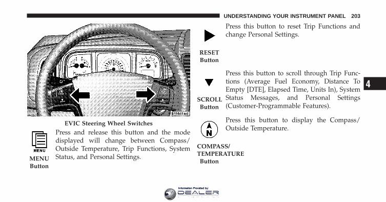
Press and release this button and the modedisplayed will change between Compass/Outside Temperature, Trip Functions, SystemStatus, and Personal Settings.
Press this button to reset Trip Functions andchange Personal Settings.
Press this button to scroll through Trip Func-tions (Average Fuel Economy, Distance ToEmpty [DTE], Elapsed Time, Units In), SystemStatus Messages, and Personal Settings(Customer-Programmable Features).
Press this button to display the Compass/Outside Temperature.
EVIC Steering Wheel Switches
MENUButton
RESETButton
SCROLLButton
COMPASS/TEMPERATUREButton
4
UNDERSTANDING YOUR INSTRUMENT PANEL 203
Information Provided by:

Electronic Vehicle Information Center (EVIC)DisplaysWhen the appropriate conditions exist, the EVIC displaysthe following messages:
• Turn Signal On (with a continuous warning chime ifthe vehicle is driven more than 1 mile [1.6 km] witheither turn signal on)
• Left Front Turn Signal Light Out (with a single chime)
• Left Rear Turn Signal Light Out (with a single chime)
• Right Front Turn Signal Light Out (with a singlechime)
• Right Rear Turn Signal Light Out (with a single chime)
• RKE Battery Low (with a single chime)
• Personal Settings Not Available – Vehicle Not in PARK
• Channel # Transmit. Refer to “Garage Door Opener” in“Things To Know Before Starting Your Vehicle”.
• Channel # Training. Refer to “Garage Door Opener” in“Things To Know Before Starting Your Vehicle”.
• Channel # Trained. Refer to “Garage Door Opener” in“Things To Know Before Starting Your Vehicle”.
• Clearing Channels. Refer to “Garage Door Opener” in“Things To Know Before Starting Your Vehicle”.
• Channels Cleared. Refer to “Garage Door Opener” in“Things To Know Before Starting Your Vehicle”.
• Did Not Train. Refer to “Garage Door Opener” in“Things To Know Before Starting Your Vehicle”.
• Left Front Low Pressure (with a single chime). Refer toinformation on “Tire Pressure” and “Tire PressureMonitor” in “Starting And Operating”.
204 UNDERSTANDING YOUR INSTRUMENT PANEL
Information Provided by:

• Left Rear Low Pressure (with a single chime). Refer toinformation on “Tire Pressure” and “Tire PressureMonitor” in “Starting And Operating”.
• Right Front Low Pressure (with a single chime). Referto information on “Tire Pressure” and “Tire PressureMonitor” in “Starting And Operating”.
• Right Rear Low Pressure (with a single chime). Referto information on “Tire Pressure” and “Tire PressureMonitor” in “Starting And Operating”.
• Check TPM System (with a single chime). Refer toinformation on “Tire Pressure Monitor” in “StartingAnd Operating”.
• Low Fuel
• Cal
• Oil Change Required (with a single chime)
• Low Washer Fluid
• Coolant Low
• Key in Ignition
• Lights On
• ECO (Fuel Saver Indicator) — If Equipped
Oil Change RequiredYour vehicle is equipped with an engine oil changeindicator system. The “Oil Change Required” messagewill display in the EVIC for approximately 5 secondsafter a single chime has sounded to indicate the nextscheduled oil change interval. The engine oil changeindicator system is duty cycle based, which means theengine oil change interval may fluctuate dependent uponyour personal driving style.
Unless reset, this message will continue to display eachtime you turn the ignition switch to the ON position. Toturn off the message temporarily, press and release the
4
UNDERSTANDING YOUR INSTRUMENT PANEL 205
Information Provided by:

MENU button. To reset the oil change indicator system(after performing the scheduled maintenance) performthe following procedure:
1. Turn the ignition switch to the ON position (Do notstart the engine).
2. Fully depress the accelerator pedal slowly three timeswithin 10 seconds.
3. Turn the ignition switch to the LOCK position.
NOTE: If the indicator message illuminates when youstart the vehicle, the oil change indicator system did notreset. If necessary, repeat this procedure.
Trip FunctionsPress and release the MENU button until one of thefollowing Trip Functions displays in the EVIC:
• Average Fuel Economy
• Distance To Empty
• Elapsed Time
• Units In
Press the SCROLL button to cycle through all the TripComputer functions.
The Trip Functions mode displays the following informa-tion.
• Average Fuel EconomyShows the average fuel economy since the last reset.When the fuel economy is reset, the display will read“RESET” or show dashes for two seconds. Then, thehistory information will be erased, and the averaging willcontinue from the last fuel average reading before thereset.
• Distance To Empty (DTE)Shows the estimated distance that can be traveled withthe fuel remaining in the tank. This estimated distance isdetermined by a weighted average of the instantaneous
206 UNDERSTANDING YOUR INSTRUMENT PANEL
Information Provided by:

and average fuel economy, according to the current fueltank level. DTE cannot be reset through the RESETbutton.
NOTE: Significant changes in driving style or vehicleloading will greatly affect the actual drivable distance ofthe vehicle, regardless of the DTE displayed value.
• When the DTE value is less than 30 miles (48 km)estimated driving distance, the DTE display willchange to a text display of �LOW FUEL.� This displaywill continue until the vehicle runs out of fuel. Addinga significant amount of fuel to the vehicle will turn offthe �LOW FUEL� text and a new DTE value willdisplay.
• Elapsed TimeShows the total elapsed time of travel since the last resetwhen the ignition switch is in the ACC position. Elapsedtime will increment when the ignition switch is in the ONor START position.
• Units InThe EVIC, odometer, and navigation system (ifequipped) can be changed between English and Metricunits of measure. To make your selection, press andrelease the RESET button until “U.S.” or “METRIC”appears.
To Reset The DisplayReset will only occur while a resettable function is beingdisplayed. Press and release the RESET button once toclear the resettable function being displayed. To reset allresettable functions, press and release the RESET buttona second time within three seconds of resetting thecurrently-displayed function. (>Reset ALL will displayduring this three-second window).
4
UNDERSTANDING YOUR INSTRUMENT PANEL 207
Information Provided by:

Compass Display / ECO (Fuel Saver Mode) — IfEquipped
Press and release this button to displayone of eight compass readings and theoutside temperature. The compassreadings indicate the direction the ve-hicle is facing.
NOTE: The system will display the last known outsidetemperature when starting the vehicle and may need tobe driven several minutes before the updated tempera-ture is displayed. Engine temperature can also affect thedisplayed temperature, therefore temperature readingsare not updated when the vehicle is not moving.
ECO (Fuel Saver Mode) — If EquippedThe ECO message will display below the outside tem-perature in the EVIC display. This message will appearwhenever you are driving in a fuel efficient manner.
This feature allows you to monitor when you are drivingin a fuel efficient manner, and it can be used to modifydriving habits in order to increase fuel economy.
Automatic Compass CalibrationThis compass is self-calibrating, which eliminates theneed to calibrate the compass manually. When the ve-hicle is new, the compass may appear erratic and theEVIC will display “CAL” until the compass is calibrated.You may calibrate the compass by slowly completing oneor more 360-degree turns (in an area free from large metalor metallic objects) until the “CAL” message displayed inthe EVIC turns off. The compass will now functionnormally.
COMPASS/TEMPERATURE
Button
208 UNDERSTANDING YOUR INSTRUMENT PANEL
Information Provided by:

Manual Compass CalibrationIf the compass appears erratic or is inaccurate, you cancalibrate the compass manually by performing the fol-lowing steps.
1. Turn the ignition switch ON.
2. Press and release the MENU button until PersonalSettings displays in the EVIC.
3. Press the SCROLL button until “CALIBRATE COM-PASS” displays in the EVIC.
4. Press and release the RESET button to start the cali-bration. The message “CAL” will display in the EVIC.
5. Slowly complete one or more 360-degree turns (in anarea free from large metal or metallic objects) until the“CAL” message turns off. The compass will now functionnormally.
Compass VarianceCompass Variance is the difference between magneticNorth and geographic North. To allow the compassmodule to compensate for that difference and ensureaccuracy, you can set the variance in the compass moduleto the zone where the vehicle is located according to theCompass Variance Map. To set the variance, perform thefollowing steps.
NOTE:• The default variance setting is Zone 8. When setting
the variance, the numbering will wrap around fromZone 15 to Zone 1.
4
UNDERSTANDING YOUR INSTRUMENT PANEL 209
Information Provided by:

• Magnetic materials should be kept away from the topof the instrument panel, as this is where the compasssensor is located.
1. Turn the ignition switch ON.
2. Press and release the MENU button until PersonalSettings displays in the EVIC.
3. Press the SCROLL button until “COMPASS VARI-ANCE” message and the last variance zone numberdisplays in the EVIC.
4. Press and release RESET button until the propervariance zone is selected according to the map.
5. Press and release the COMPASS/TEMPERATUREbutton to exit.
Personal Settings (Customer-ProgrammableFeatures)Personal Settings allows the driver to set and recallfeatures when the transaxle is in PARK.
Press and release the MENU button until Personal Set-tings displays in the EVIC.
Use the SCROLL button to display one of the followingchoices.
Compass Variance Map
210 UNDERSTANDING YOUR INSTRUMENT PANEL
Information Provided by:

“Language”When in this display you may select one of three lan-guages for all display nomenclature, including the tripfunctions and the navigation system (if equipped). Pressthe RESET button while in this display to select English,French, or Spanish. Then, as you continue, the informa-tion will display in the selected language.
NOTE: The EVIC will not change the Uconnect™ lan-guage selection.
“Auto UNLK On Exit”When ON is selected, all doors and the liftgate willunlock when the vehicle is stopped and the transaxle is inthe PARK or NEUTRAL position and the driver’s door isopened. To make your selection, press and release theRESET button until “ON” or “OFF” appears.
“RKE Unlock”When Driver Door 1st Press is selected, only the driver’sdoor will unlock on the first press of the Remote KeylessEntry (RKE) UNLOCK button. When Driver Door 1stPress is selected, you must press the RKE UNLOCKbutton twice to unlock the passenger doors and liftgate.When All Doors 1st Press is selected, all doors and theliftgate will unlock on the first press of the RKE UN-LOCK button. To make your selection, press and releasethe RESET button until “Driver Door 1st Press” or “AllDoors 1st Press” appears.
“Sound Horn With Lock”When ON is selected, a short horn sound will occur whenthe RKE LOCK button is pressed. This feature may beselected with or without the Flash Lamp with Lockfeature. To make your selection, press and release theRESET button until “ON” or “OFF” appears.
4
UNDERSTANDING YOUR INSTRUMENT PANEL 211
Information Provided by:

“Flash Lamp With Lock”When ON is selected, the front and rear turn signals willflash when the doors are locked or unlocked with theRKE transmitter. This feature may be selected with orwithout the sound horn on lock feature selected. To makeyour selection, press and release the RESET button until“ON” or “OFF” appears.
“Headlamp Off Delay”When this feature is selected, the driver can choose tohave the headlights remain on for 0, 30, 60, or 90 secondsafter turning the ignition to the LOCK position. To makeyour selection, press and release the RESET button until“0,” “30,” “60,” or “90” appears.
“Headlamps With Wipers” (Available with AutoHeadlights Only)When ON is selected, and the multifunction lever isplaced in the AUTO position, the headlights will turn onapproximately 10 seconds after the wipers are turned
ON. The headlights will also turn off when the wipers areturned OFF if they were turned ON by this feature. Tomake your selection, press and release the RESET buttonuntil “ON” or “OFF” appears.
“Key-Off Power Delay”When this feature is selected, the power windowswitches, radio, Uconnect™ Phone (if equipped), DVDvideo system (if equipped), power sunroof (if equipped),and ignition powered outlets will remain active for up to10 minutes after the ignition switch is turned OFF.Opening a vehicle door will cancel this feature. To makeyour selection, press and release the RESET button until“Off,” “45 sec.,” “5 min.,” or “10 min.” appears.
212 UNDERSTANDING YOUR INSTRUMENT PANEL
Information Provided by:
“ILLUMIN Approach”When this feature is selected, the headlights will activateand remain on for up to 90 seconds when the doors areunlocked with the RKE transmitter. To make your selec-tion, press and hold the RESET button until “Off,”“30 sec,” “60 sec,” or “90 sec” appears.
Display ECO — If EquippedThe “ECO” message can be turned on or off. To makeyour selection, press and release the FUNCTION SE-LECT button until “ON” or “OFF” appears.
“Display Units In”The EVIC, odometer, and navigation system (ifequipped) can be changed between English and Metricunits of measure. To make your selection, press and
release the RESET button until “ENGLISH” or “MET-RIC” appears.
“NAV Turn By Turn” — If EquippedWhen ON is selected, the Turn-by-Turn directions willappear in the display as the vehicle approaches a desig-nated turn within a programmed route. To make yourselection, press and release the RESET button until “ON”or “OFF” appears.
Compass VarianceRefer to “Compass Variance” under “Compass Display.”
Calibrate CompassRefer to “Manual Compass Calibration” under “Com-pass Display.”
4
UNDERSTANDING YOUR INSTRUMENT PANEL 213
Information Provided by:

MEDIA CENTER 230 (REQ) — AM/FM STEREORADIO AND 6–DISC CD/DVD CHANGER(MP3/WMA AUX JACK)
NOTE: The radio sales code is located on the lower rightside of the radio faceplate.
Operating Instructions - Radio Mode
NOTE: The ignition switch must be in the ON or ACCposition to operate the radio.
Power Switch/Volume Control (Rotary)Push the ON/VOLUME control knob to turn on theradio. Press the ON/VOLUME control knob a secondtime to turn off the radio.
Electronic Volume ControlThe electronic volume control turns continuously (360degrees) in either direction without stopping. Turning theON/VOLUME control knob to the right increases thevolume and to the left decreases it.
When the audio system is turned ON, the sound will beset at the same volume level as last played.
REQ Radio
214 UNDERSTANDING YOUR INSTRUMENT PANEL
Information Provided by:

SEEK ButtonsPress and release the SEEK buttons to search for the nextlistenable station in AM/FM mode. Press the right switchto seek up and the left switch to seek down. The radiowill remain tuned to the new station until you makeanother selection. Holding either button will bypassstations without stopping until you release it.
SCAN ButtonPressing the SCAN button causes the tuner to search forthe next listenable station in AM, FM or Satellite (ifequipped) frequencies, pausing for five seconds at eachlistenable station before continuing to the next. To stopthe search, press the SCAN button a second time.
Voice Command Button Uconnect™ Phone — IfEquippedPress this button to operate the Uconnect™ Phone feature(if equipped). Refer to “Uconnect™ Phone” in “Under-standing The Features Of Your Vehicle”.
If your vehicle is not equipped with or this feature is notavailable on your vehicle, a “Not Equipped WithUconnect” message will display on the radio screen.
Phone Button Uconnect™ Phone — If EquippedPress this button to operate the Uconnect™ Phone feature(if equipped). Refer to “Uconnect™ Phone” in “Under-standing The Features Of Your Vehicle”.
If your vehicle is not equipped with or this feature is notavailable on your vehicle, a “Not Equipped WithUconnect” message will display on the radio screen.
TIME ButtonPress the TIME button to alternate locations of the timeand frequency display.
Clock Setting Procedure
1. Press and hold the TIME button until the hours blink.
4
UNDERSTANDING YOUR INSTRUMENT PANEL 215
Information Provided by:

2. Adjust the hours by turning the right side TUNE/SCROLL control knob.
3. After adjusting the hours, press the right side TUNE/SCROLL control knob to set the minutes. The minuteswill begin to blink.
4. Adjust the minutes using the right side TUNE/SCROLL control knob. Press the TUNE/SCROLL controlknob to save the time change.
5. To exit, press any button/knob or wait five seconds.
The clock can also be set by pressing the SETUP buttonand selecting the “SET HOME CLOCK” entry. Once inthis display follow the above procedure, starting atstep 2.
INFO ButtonPress the INFO button for an RDS station (one with callletters displayed). The radio will return a Radio Textmessage broadcast from an FM station (FM mode only).
RW/FFPressing the RW (Rewind) or FF (Fast Forward) buttonscauses the tuner to search for the next frequency in thedirection of the arrows. This feature operates in AM, FMor Satellite (if equipped) frequencies.
TUNE ControlTurn the rotary TUNE/SCROLL control knob clockwiseto increase or counterclockwise to decrease the frequency.
Setting the Tone, Balance, and FadePush the rotary TUNE/SCROLL control knob and BASSwill display. Turn the TUNE/SCROLL control knob tothe right or left to increase or decrease the bass tones.
Push the rotary TUNE/SCROLL control knob a secondtime and MID will display. Turn the TUNE/SCROLLcontrol knob to the right or left to increase or decrease themid-range tones.
216 UNDERSTANDING YOUR INSTRUMENT PANEL
Information Provided by:

Push the rotary TUNE/SCROLL control knob a thirdtime and TREBLE will display. Turn the TUNE/SCROLLcontrol knob to the right or left to increase or decrease thetreble tones.
Push the rotary TUNE/SCROLL control knob a fourthtime and BALANCE will display. Turn the TUNE/SCROLL control knob to the right or left to adjust thesound level from the right or left side speakers.
Push the rotary TUNE/SCROLL control knob a fifth timeand FADE will display. Turn the TUNE/SCROLL controlknob to the left or right to adjust the sound level betweenthe front and rear speakers.
Push the rotary TUNE/SCROLL control knob again toexit setting tone, balance, and fade.
MUSIC TYPE ButtonPressing this button once will turn on the Music Typemode for five seconds. Pressing the MUSIC TYPE button
or turning the TUNE/SCROLL control knob within fiveseconds will allow the program format type to be se-lected. Many radio stations do not currently broadcastMusic Type information.
Toggle the MUSIC TYPE button to select the followingformat types:
Program Type 16-Digit CharacterDisplay
No program typeor undefined None
Adult Hits Adlt HitClassical Classicl
Classic Rock Cls RockCollege CollegeCountry Country
Foreign Language LanguageInformation Inform
4
UNDERSTANDING YOUR INSTRUMENT PANEL 217
Information Provided by:

Program Type 16-Digit CharacterDisplay
Jazz JazzNews News
Nostalgia NostalgaOldies Oldies
Personality PersnltyPublic Public
Rhythm and Blues R & BReligious Music Rel MuscReligious Talk Rel Talk
Rock RockSoft Soft
Soft Rock Soft RckSoft Rhythm and Blues Soft R & B
Sports SportsTalk Talk
Program Type 16-Digit CharacterDisplay
Top 40 Top 40Weather Weather
By pressing the SEEK button when the Music Type iconis displayed, the radio will be tuned to the next frequencystation with the same selected Music Type name. TheMusic Type function only operates when in the FMmode.
If a preset button is activated while in the Music Type(Program Type) mode, the Music Type mode will beexited and the radio will tune to the preset station.
218 UNDERSTANDING YOUR INSTRUMENT PANEL
Information Provided by:

SETUP ButtonPressing the SETUP button allows you to select betweenthe following items:
NOTE: Turn the TUNE/SCROLL control knob to scrollthrough the entries. Push the AUDIO/SELECT button toselect an entry and make changes.
• DVD Enter - When the disc is in DVD Menu mode,selecting DVD Enter will allow you to play the currenthighlighted selection. Use the remote control to scrollup and down the menu (if equipped).
• DISC Play/Pause - You can toggle betweenplaying the DVD and pausing the DVD bypushing the SELECT button (if equipped).
• DVD Play Options - Selecting the DVD Play Optionswill display the following:
• Subtitle – Repeatedly pressing SELECT will switchsubtitles to different subtitle languages that areavailable on the disc (if equipped).
• Audio Stream – Repeatedly pressing SELECT willswitch to different audio languages (if supported onthe disc) (if equipped).
• Angle – Repeatedly pressing SELECT will changethe viewing angle if supported by the DVD disc (ifequipped).
NOTE:• The available selections for each of the above entries
varies depending upon the disc.
• These selections can only be made while playing aDVD.
• VES™ Power - Allows you to turn VES™ ON andOFF (if equipped).
4
UNDERSTANDING YOUR INSTRUMENT PANEL 219
Information Provided by:

• VES™ Lock - Locks out rear VES™ remote controls (ifequipped).
• VES™ CH1/CH2 - Allows the user to change themode of either the IR1 or IR2 wireless headphones bypressing the AUDIO/SELECT button (if equipped).
• Set Home Clock - Pressing the SELECT button allowsyou to set the clock. Turn the TUNE/SCROLL controlknob to adjust the hours and then press and turn theTUNE/SCROLL control knob to adjust the minutes.Press the TUNE/SCROLL control knob again to savechanges.
• Player Defaults - Selecting this item will allow theuser to scroll through the following items and setdefaults according to customer preference.
Menu Language — If EquippedSelecting this item will allow the user to choose thedefault startup DVD menu language (effective only if
language supported by disc). If you want to select alanguage not listed, then scroll down and select �other.�Enter the four-digit country code using the TUNE/SCROLL control knob to scroll up and down to select thenumber and then push to select.
Audio Language — If EquippedSelecting this item allows you to choose a default audiolanguage (effective only if the language is supported bythe disc). You can select a language not listed by scrollingdown and selecting �other.� Enter the country code usingthe TUNE/SCROLL control knob to scroll up and downto select the number and then push to select.
Subtitle Language — If EquippedSelecting this item allows you to choose a default subtitlelanguage (effective only if the language is supported bythe disc). You can select a language not listed by scrollingdown and selecting �other.� Enter the country code using
220 UNDERSTANDING YOUR INSTRUMENT PANEL
Information Provided by:

the TUNE/SCROLL control knob to scroll up and downto select the number and then push to select.
Subtitles — If EquippedSelecting this item allows you to choose between subtitleOff or On.
Audio DRC — If EquippedSelecting this item allows you to limit maximum audiodynamic range. The default is set to �High,� and underthis setting, dialogues will play at 11 db higher than if thesetting is �Normal.�
Aspect Ratio — If EquippedSelecting this item allows you to choose between widescreen, pan scan, and letter box.
AutoPlay — If EquippedWhen this is set to On and a DVD video is inserted, it willbypass the DVD menu screen and automatically play themovie. In some rare cases, the DVD player may not
auto-play the main title. In such cases, use the MENUbutton on the remote control to select desired title to play.
NOTE: The user will have to set these defaults beforeloading a disc. If changes are made to these settings aftera disc is loaded, changes will not be effective. Also, thedefaults are effective only if the disc supports thecustomer-preferred settings.
AM and FM ButtonsPress the buttons to select AM or FM mode.
SET Button — To Set the Pushbutton MemoryWhen you are receiving a station that you wish tocommit to pushbutton memory, press the SET button.The symbol SET 1 will now show in the display window.Select the button (1-6) you wish to lock onto this stationand press and release that button. If a button is notselected within five seconds after pressing the SET but-ton, the station will continue to play but will not bestored into pushbutton memory.
4
UNDERSTANDING YOUR INSTRUMENT PANEL 221
Information Provided by:

You may add a second station to each pushbutton byrepeating the above procedure with this exception: Pressthe SET button twice and SET 2 will show in the displaywindow. Each button can be set for SET 1 and SET 2 inboth AM and FM. This allows a total of 12 AM, 12 FM,and 12 Satellite (if equipped) stations to be stored intopushbutton memory. The stations stored in SET 2memory can be selected by pressing the pushbuttontwice.
Every time a preset button is used, a correspondingbutton number will display.
Buttons 1 - 6These buttons tune the radio to the stations that youcommit to pushbutton memory {12 AM, 12 FM, and 12Satellite (if equipped) stations}.
DISC ButtonPressing the DISC button will allow you to switch fromAM/FM modes to Disc modes.
Operation Instructions - (DISC MODE for CD andMP3/WMA Audio Play, DVD-VIDEO)The radio DVD player and many DVD discs are coded bygeographic region. These region codes must match inorder for the disc to play. If the region code for the DVDdisc does not match the region code for the radio DVDplayer, it will not play the disc. Customers may take theirvehicle to an authorized dealer to change the region codeof the player a maximum of five times.
CAUTION!
The radio may shut down during extremely hotconditions. When this occurs, the radio will indicate“Disc Hot” and shut off until a safe temperature isreached. This shutdown is necessary to protect theoptics of the DVD player and other radio internalcomponents.
222 UNDERSTANDING YOUR INSTRUMENT PANEL
Information Provided by:

NOTE: The ignition switch must be in the ON or ACCposition to operate the radio.
LOAD Button — Loading Compact Disc(s)Press the LOAD button and the pushbutton with thecorresponding number (1-6) where the CD is beingloaded. The radio will display PLEASE WAIT andprompt when to INSERT DISC. After the radio displays�INSERT DISC,� insert the CD into the player.
Radio display will show �LOADING DISC� when the discis loading and “READING DISC” when the radio isreading the disc.
CAUTION!
This CD player will accept 4–3/4 in (12 cm) discs only.The use of other sized discs may damage the CDplayer mechanism.
Eject Button — Ejecting Compact Disc(s)Press the EJECT button and the pushbuttonwith the corresponding number (1-6) where theCD was loaded and the disc will unload andmove to the entrance for easy removal. Radio
display will show �EJECTING DISC� when the disc isbeing ejected and prompt the user to remove the disc.
Press and hold the EJECT button for five seconds and allCDs will be ejected from the radio.
The disc can be ejected with the radio and ignition OFF.
SEEK Button (CD MODE)Press the right SEEK button for the next selection on theCD. Press the left SEEK button to return to the beginningof the current selection, or return to the beginning of theprevious selection if the CD is within the first second ofthe current selection. Pressing and holding the SEEKbutton will allow you to scroll through the tracks faster inCD and MP3/MWA modes.
4
UNDERSTANDING YOUR INSTRUMENT PANEL 223
Information Provided by:

SCAN Button (CD MODE)Press the SCAN button to scan through each track on theCD currently playing.
TIME Button (CD MODE)Press this button to change the display from a large CDplaying time display to a small CD playing time display.
RW/FF (CD MODE)Press and hold FF (Fast Forward) and the CD player willbegin to fast forward until FF is released, or RW oranother CD button is pressed. The RW (Rewind) buttonworks in a similar manner.
AM or FM Button (CD MODE)Switches the radio into the AM or FM radio mode.
Notes On Playing MP3/WMA FilesThe radio can play MP3/WMA files; however, acceptableMP3/WMA file recording media and formats are limited.When writing MP3/WMA files, pay attention to thefollowing restrictions.
Supported Media (Disc Types)The MP3/WMA file recording media supported by theradio are CDDA, CD-R, CD-RW, MP3,WMA, DVD Video,DVD-R, DVD-RW, DVD+R, DVD+RW, and CDDA+MP3.
Supported Medium Formats (File Systems)The medium formats supported by the radio are ISO 9660Level 1 and Level 2 and includes the Joliet extension.When reading discs recorded using formats other thanISO 9660 Level 1 and Level 2, the radio may fail to readfiles properly and may be unable to play the file nor-mally. UDF and Apple HFS formats are not supported.
224 UNDERSTANDING YOUR INSTRUMENT PANEL
Information Provided by:
The radio uses the following limits for file systems:
• Maximum number of directory levels: 8
• Maximum number of files: 255
• Maximum number of folders: 100
• Maximum number of characters in file/folder names:
• Level 1: 12 (including a separator �.� and a three-character extension)
• Level 2: 31 (including a separator �.� and a three-character extension)
Multisession disc formats are supported by the radio.Multisession discs may contain combinations of normalCD audio tracks and computer files (including MP3/WMA files). Discs created with an option such as �keepdisc open after writing� are most likely multisessiondiscs. The use of multisession for CD audio or MP3/WMA playback may result in longer disc loading times.
If a disc contains multi-formats, such as CD audio andMP3/WMA tracks, the radio will only play the MP3/WMA tracks on that disc.
Supported MP3/WMA File FormatsThe radio will recognize only files with the *.MP3/WMAextension as MP3/WMA files. Non-MP3/WMA filesnamed with the *.MP3/WMA extension may cause play-back problems. The radio is designed to recognize the fileas an invalid MP3/WMA and will not play the file.
When using the MP3/WMA encoder to compress audiodata to an MP3/WMA file, the bit rate and samplingfrequencies in the following table are supported. Inaddition, variable bit rates (VBR) are also supported. Themajority of MP3/WMA files use a 44.1 kHz sampling rateand a 192, 160, 128, 96 or VBR bit rates.
4
UNDERSTANDING YOUR INSTRUMENT PANEL 225
Information Provided by:
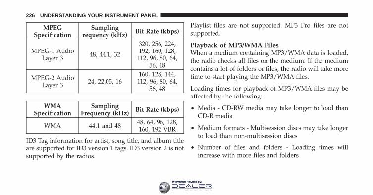
MPEGSpecification
Samplingrequency (kHz) Bit Rate (kbps)
MPEG-1 AudioLayer 3 48, 44.1, 32
320, 256, 224,192, 160, 128,
112, 96, 80, 64,56, 48
MPEG-2 AudioLayer 3 24, 22.05, 16
160, 128, 144,112, 96, 80, 64,
56, 48
WMASpecification
SamplingFrequency (kHz) Bit Rate (kbps)
WMA 44.1 and 48 48, 64, 96, 128,160, 192 VBR
ID3 Tag information for artist, song title, and album titleare supported for ID3 version 1 tags. ID3 version 2 is notsupported by the radios.
Playlist files are not supported. MP3 Pro files are notsupported.
Playback of MP3/WMA FilesWhen a medium containing MP3/WMA data is loaded,the radio checks all files on the medium. If the mediumcontains a lot of folders or files, the radio will take moretime to start playing the MP3/WMA files.
Loading times for playback of MP3/WMA files may beaffected by the following:
• Media - CD-RW media may take longer to load thanCD-R media
• Medium formats - Multisession discs may take longerto load than non-multisession discs
• Number of files and folders - Loading times willincrease with more files and folders
226 UNDERSTANDING YOUR INSTRUMENT PANEL
Information Provided by:
To increase the speed of disc loading, it is recommendedto use CD-R media and single-session discs. To create asingle-session disc, enable the “Disc at Once” optionbefore writing to the disc.
LIST Button (DISC Mode for MP3/WMA Play)Pressing the LIST button will bring up a list of all folderson the disc. Scrolling up or down the list is done byturning the TUNE/SCROLL control knob. Selecting afolder by pressing the TUNE/SCROLL control knob willbegin playing the files contained in that folder (or thenext folder in sequence if the selection does not containplayable files).
The folder list will time out after five seconds.
INFO Button (DISC Mode for MP3/WMA Play)Pressing the INFO button repeatedly will scroll throughthe following TAG information: Song Title, Artist, FileName, and Folder Name (if available).
Press the INFO button once more to return to �elapsedtime� priority mode.
Press and hold the INFO button for three seconds ormore and radio will display song titles for each file.
Press and hold the INFO button again for three secondsto return to �elapsed time� display.
Operation Instructions - Auxiliary ModeThe auxiliary (AUX) jack is an audio input jack whichallows the user to plug in a portable device such as anMP3/WMA player, cassette player, or microphone andutilize the vehicle’s audio system to amplify the sourceand play through the vehicle speakers.
Pressing the AUX button will change the mode to auxil-iary device if the AUX jack is connected.
4
UNDERSTANDING YOUR INSTRUMENT PANEL 227
Information Provided by:
NOTE: The AUX device must be turned on and thedevice’s volume set to the proper level. If the AUX audiois not loud enough, turn the device’s volume up. If theAUX audio sounds distorted, turn the device’s volumedown.
SEEK Button (Auxiliary Mode)No function.
SCAN Button (Auxiliary Mode)No function.
EJECT Button (Auxiliary Mode)No function.
TIME Button (Auxiliary Mode)Press the TIME button to change the display fromelapsed playing time to time of day. The time of day willdisplay for five seconds.
RW/FF (Auxiliary Mode)No function.
SET Button (Auxiliary Mode)No function.
Operating Instructions — Voice Command System(If Equipped)For the radio, refer to “Voice Command” in “Understand-ing The Features Of Your Vehicle”.
For Uconnect™ “Voice Command,” refer to “Uconnect™Phone” in “Understanding The Features Of YourVehicle”.
228 UNDERSTANDING YOUR INSTRUMENT PANEL
Information Provided by:

Operating Instructions - Uconnect™ Phone (IfEquipped)Refer to “Uconnect™ Phone” in “Understanding TheFeatures Of Your Vehicle”.
Operating Instructions - Uconnect™ Multimedia(Satellite Radio) (If Equipped)Refer to “Uconnect™ Multimedia (Satellite Radio)”.
Operating Instructions - Video EntertainmentSystem (VES)™ (If Equipped)Refer to separate “Video Entertainment System (VES)™Guide.”
Dolby�Manufactured under license from Dolby� Laboratories.�Dolby�� and the double-D symbol are trademarks ofDolby� Laboratories.
MacrovisionThis product incorporates copyright protection technol-ogy that is protected by U.S. patents and other intellec-tual property rights. Use of this copyright protectiontechnology must be authorized by Macrovision, and isintended for home and other limited viewing uses only,unless otherwise authorized by Macrovision. Reverseengineering or disassembly is prohibited.
DTS™�DTS™� and �DTS™ 2.0� are trademarks of Digital The-ater Systems, Inc.
4
UNDERSTANDING YOUR INSTRUMENT PANEL 229
Information Provided by:

MEDIA CENTER 130 (RES) — AM/FM STEREORADIO WITH CD PLAYER (MP3 AUX JACK)
NOTE: The radio sales code is located on the lower rightside of the radio faceplate.
Operating Instructions — Radio Mode
NOTE: The ignition switch must be in the ON or ACCposition to operate the radio.
Power Switch/Volume Control (Rotary)Push the ON/VOLUME control knob to turn on theradio. Push the ON/VOLUME control knob a secondtime to turn off the radio.
Electronic Volume ControlThe electronic volume control turns continuously (360degrees) in either direction, without stopping. Turningthe ON/VOLUME control knob to the right increases thevolume, and to the left decreases it.
When the audio system is turned on, the sound will beset at the same volume level as last played.
SEEK ButtonsPress and release the SEEK buttons to search for the nextlistenable station in AM/FM mode. Press the right switch
RES Radio
230 UNDERSTANDING YOUR INSTRUMENT PANEL
Information Provided by:

to seek up and the left switch to seek down. The radiowill remain tuned to the new station until you makeanother selection. Holding either button will bypassstations without stopping, until you release it.
TIME ButtonPress the TIME button to alternate display of the timeand radio frequency.
Clock Setting Procedure
1. Press and hold the TIME button until the hours blink.
2. Adjust the hours by turning the right side TUNE/SCROLL control knob.
3. After adjusting the hours, press the right side TUNE/SCROLL control knob to set the minutes. The minuteswill begin to blink.
4. Adjust the minutes using the right side TUNE/SCROLL control knob. Press the TUNE/SCROLL controlknob to save time change.
5. To exit, press any button/knob, or wait five seconds.
RW/FFPressing the RW (Rewind) or FF (Fast Forward) buttonscauses the tuner to search for the next frequency in thedirection of the arrows. This feature operates in eitherAM or FM frequencies.
TUNE ControlTurn the rotary TUNE/SCROLL control knob clockwiseto increase or counterclockwise to decrease the frequency.
Setting the Tone, Balance, and FadePush the rotary TUNE/SCROLL control knob and BASSwill display. Turn the TUNE/SCROLL control knob tothe right or left to increase or decrease the bass tones.
4
UNDERSTANDING YOUR INSTRUMENT PANEL 231
Information Provided by:

Push the rotary TUNE/SCROLL control knob a secondtime and MID will display. Turn the TUNE/SCROLLcontrol knob to the right or left to increase or decrease themid-range tones.
Push the rotary TUNE/SCROLL control knob a thirdtime and TREBLE will display. Turn the TUNE/SCROLLcontrol knob to the right or left to increase or decrease thetreble tones.
Push the rotary TUNE/SCROLL control knob a fourthtime and BALANCE will display. Turn the TUNE/SCROLL control knob to the right or left to adjust thesound level from the right or left side speakers.
Push the rotary TUNE/SCROLL control knob a fifth timeand FADE will display. Turn the TUNE/SCROLL controlknob to the left or right to adjust the sound level betweenthe front and rear speakers.
Push the rotary TUNE/SCROLL control knob again toexit setting tone, balance, and fade.
AM/FM ButtonPress the buttons to select either AM or FM mode.
SET/RND Button — To Set the PushbuttonMemoryWhen you are receiving a station that you wish tocommit to pushbutton memory, press the SET/RNDbutton. The symbol SET 1 will now show in the displaywindow. Select the button (1 to 6) you wish to lock ontothis station and press and release that button. If a buttonis not selected within five seconds after pressing theSET/RND button, the station will continue to play butwill not be stored into pushbutton memory.
You may add a second station to each pushbutton byrepeating the above procedure with this exception: Pressthe SET/RND button twice and SET 2 will show in thedisplay window. Each button can be set for SET 1 and
232 UNDERSTANDING YOUR INSTRUMENT PANEL
Information Provided by:

SET 2 in both AM and FM. This allows a total of 12 AMand 12 FM stations to be stored into pushbutton memory.The stations stored in SET 2 memory can be selected bypressing the pushbutton twice.
Every time a preset button is used, a correspondingbutton number will display.
Buttons 1 - 6These buttons tune the radio to the stations that youcommit to pushbutton memory (12 AM and 12 FMstations).
DISC ButtonPressing the DISC button will allow you to switch fromAM/FM modes to Disc modes.
Operation Instructions — CD MODE For CD AndMP3 Audio Play
NOTE:• The ignition switch must be in the ON or ACC
position to operate the radio.
• This radio is capable of playing compact discs (CD),recordable compact discs (CD-R), rewritable compactdiscs (CD-RW), compact discs with MP3 tracks andmultisession compact discs with CD and MP3 tracks.
Inserting Compact Disc(s)Gently insert one CD into the CD player with the CDlabel facing up. The CD will automatically be pulled intothe CD player and the CD icon will illuminate on theradio display. If a CD does not go into the slot more than1.0 in (2.5 cm), a disc may already be loaded and must beejected before a new disc can be loaded.
4
UNDERSTANDING YOUR INSTRUMENT PANEL 233
Information Provided by:

If you insert a disc with the ignition ON and the radioON, the unit will switch from radio to CD mode andbegin to play when you insert the disc. The display willshow the track number, and index time in minutes andseconds. Play will begin at the start of track 1.
CAUTION!
• This CD player will accept 4-3/4 in (12 cm) discsonly. The use of other sized discs may damage theCD player mechanism.
• Do not use adhesive labels. These labels can peelaway and jam the player mechanism.
• RES is a single CD player. Do not attempt to inserta second CD if one is already loaded.
• Dual-media disc types (one side is a DVD, theother side is a CD) should not be used, and theycan cause damage to the player.
EJECT Button - Ejecting a CDPress the EJECT button to eject the CD.
If you have ejected a disc and have not removed it within10 seconds, it will be reloaded. If the CD is not removed,the radio will reinsert the CD but will not play it.
A disc can be ejected with the radio and ignition OFF.
NOTE: Ejecting with the ignition OFF is not allowed onconvertible or soft-top models (if equipped).
SEEK ButtonPress the right SEEK button for the next selection on theCD. Press the left SEEK button to return to the beginningof the current selection, or return to the beginning of theprevious selection if the CD is within the first second of
234 UNDERSTANDING YOUR INSTRUMENT PANEL
Information Provided by:

the current selection. Pressing and holding the SEEKbutton will allow faster scrolling through the tracks inCD and MP3 modes.
TIME ButtonPress this button to change the display from a large CDplaying time display to a small CD playing time display.
RW/FFPress and hold the FF (Fast Forward) button and the CDplayer will begin to fast forward until FF is released, orRW or another CD button is pressed. The RW (Reverse)button works in a similar manner.
AM/FM ButtonPress the button to select either AM or FM mode.
SET/RND Button (Random Play Button)Press this button while the CD is playing to activateRandom Play. This feature plays the selections on thecompact disc in random order to provide an interestingchange of pace.
Press the right SEEK button to move to the next ran-domly selected track.
Press the RND button a second time to stop RandomPlay.
Notes on Playing MP3 FilesThe radio can play MP3 files; however, acceptable MP3file recording media and formats are limited. Whenwriting MP3 files, pay attention to the following restric-tions.
Supported Media (Disc Types)The MP3 file recording media supported by the radio areCDDA, CD-R, CD-RW, MP3, and CDDA+MP3.
4
UNDERSTANDING YOUR INSTRUMENT PANEL 235
Information Provided by:
Supported Medium Formats (File Systems)The medium formats supported by the radio are ISO 9660Level 1 and Level 2 and includes the Joliet extension.When reading discs recorded using formats other thanISO 9660 Level 1 and Level 2, the radio may fail to readfiles properly and may be unable to play the file nor-mally. UDF and Apple HFS formats are not supported.
The radio uses the following limits for file systems:
• Maximum number of folder levels: 8
• Maximum number of files: 255
• Maximum number of folders. (The radio display of filenames and folder names is limited. For large numbersof files and/or folders, the radio may be unable todisplay the file name and folder name, and will assigna number instead. With a maximum number of files,
exceeding 20 folders will result in this display. With200 files, exceeding 50 folders will result in thisdisplay.)
• Maximum number of characters in file/folder names:
• Level 1: 12 (including a separator �.� and a three-character extension)
• Level 2: 31 (including a separator �.� and a three-character extension)
Multisession disc formats are supported by the radio.Multisession discs may contain combinations of normalCD audio tracks and computer files (including MP3 files).Discs created with an option such as �keep disc open afterwriting� are most likely multisession discs. The use ofmultisession for CD audio or MP3 playback may result inlonger disc loading times.
236 UNDERSTANDING YOUR INSTRUMENT PANEL
Information Provided by:

Supported MP3 File FormatsThe radio will recognize only files with the *.MP3 exten-sion as MP3 files. Non-MP3 files named with the *.MP3extension may cause playback problems. The radio isdesigned to recognize the file as an invalid MP3 and willnot play the file.
When using the MP3 encoder to compress audio data toan MP3 file, the bit rate and sampling frequencies in thefollowing table are supported. In addition, variable bitrates (VBR) are also supported. The majority of MP3 filesuse a 44.1 kHz sampling rate and a 192, 160, 128, 96 orVBR bit rate.
MPEGSpecification
SamplingFrequency (kHz) Bit Rate (kbps)
MPEG-1 AudioLayer 3 48, 44.1, 32
320, 256, 224,192, 160, 128,
112, 96, 80, 64,56, 48, 40, 32
MPEGSpecification
SamplingFrequency (kHz) Bit Rate (kbps)
MPEG-2 AudioLayer 3 24, 22.05, 16
160, 128, 144,112, 96, 80, 64,
56, 48, 40, 32, 24,16, 8
ID3 Tag information for artist, song title, and album titleare supported for version 1 ID3 tags. ID3 version 2 is notsupported by the radios.
Playlist files are not supported. MP3 Pro files are notsupported.
Playback of MP3 FilesWhen a medium containing MP3 data is loaded, theradio checks all files on the medium. If the mediumcontains a lot of folders or files, the radio will take moretime to start playing the MP3 files.
4
UNDERSTANDING YOUR INSTRUMENT PANEL 237
Information Provided by:

Loading times for playback of MP3 files may be affectedby the following:
• Media - CD-RW media may take longer to load thanCD-R media
• Medium formats - Multisession discs may take longerto load than non-multisession discs
• Number of files and folders - Loading times willincrease with more files and folders
To increase the speed of disc loading, it is recommendedto use CD-R media and single-session discs. To create asingle-session disc, enable the “Disc at Once” optionbefore writing to the disc.
Operation Instructions - Auxiliary ModeThe auxiliary (AUX) jack is an audio input jack, whichallows the user to plug in a portable device, such as an
MP3 player, or cassette player, and utilize the vehicle’saudio system to amplify the source and play through thevehicle speakers.
Pressing the DISC/AUX button will change the mode toauxiliary device if the AUX jack is connected.
NOTE: The AUX device must be turned on and thedevice’s volume set to proper level. If the AUX audio isnot loud enough, turn the device’s volume up. If the AUXaudio sounds distorted, turn the device’s volume down.
TIME Button (Auxiliary Mode)Press this button to change the display to time of day. Thetime of day will display for five seconds (when ignition isOFF).
238 UNDERSTANDING YOUR INSTRUMENT PANEL
Information Provided by:

MEDIA CENTER 130 (RES/RSC) — AM/FMSTEREO RADIO WITH CD PLAYER (MP3 AUXJACK) AND SIRIUS RADIO
NOTE: The radio sales code is located on the lower rightside of the radio faceplate.
Operating Instructions — Radio Mode
NOTE: The ignition switch must be in the ON or ACCposition to operate the radio.
Power Switch/Volume Control (Rotary)Push the ON/VOLUME control knob to turn on theradio. Push the ON/VOLUME control knob a secondtime to turn off the radio.
Electronic Volume ControlThe electronic volume control turns continuously (360degrees) in either direction without stopping. Turning theON/VOLUME control knob to the right increases thevolume and to the left decreases it.
When the audio system is turned on, the sound will beset at the same volume level as last played.
RES/RSC Radio
4
UNDERSTANDING YOUR INSTRUMENT PANEL 239
Information Provided by:

SEEK ButtonsPress and release the SEEK buttons to search for the nextlistenable station in AM/FM mode. Press the right switchto seek up and the left switch to seek down. The radiowill remain tuned to the new station until you makeanother selection. Holding either button will bypassstations without stopping until you release it.
Voice Command System (Radio) — If EquippedRefer to “Voice Command” in “Understanding The Fea-tures If Your Vehicle”.
Voice Command Button Uconnect™ Phone — IfEquippedPress this button to operate the Uconnect™ Phone feature(if equipped). Refer to “Uconnect™ Phone” in “Under-standing The Features If Your Vehicle”.
If your vehicle is not equipped with or this feature is notavailable on your vehicle, a “Not Equipped WithUconnect” message will display on the radio screen.
Phone Button Uconnect™ Phone — If EquippedPress this button to operate the Uconnect™ Phone feature(if equipped). Refer to “Uconnect™ Phone” in “Under-standing The Features If Your Vehicle”.
If your vehicle is not equipped with or this feature is notavailable on your vehicle, a “Not Equipped WithUconnect” message will display on the radio screen.
TIME ButtonPress the TIME button to alternate display of the timeand radio frequency.
Clock Setting Procedure
1. Press and hold the TIME button until the hours blink.
2. Adjust the hours by turning the right side TUNE/SCROLL control knob.
240 UNDERSTANDING YOUR INSTRUMENT PANEL
Information Provided by:

3. After adjusting the hours, press the right side TUNE/SCROLL control knob to set the minutes. The minuteswill begin to blink.
4. Adjust the minutes using the right side TUNE/SCROLL control knob. Press the TUNE/SCROLL controlknob to save time change.
5. To exit, press any button/knob or wait five seconds.
The clock can also be set by pressing the SETUP button.For vehicles equipped with satellite radio, press theSETUP button, use the TUNE/SCROLL control to selectSET CLOCK, and then follow the above procedure,starting at Step 2. For vehicles not equipped with satelliteradio, press the SETUP button and then follow the aboveprocedure, starting at Step 2.
INFO ButtonPress the INFO button for an RDS station (one with callletters displayed). The radio will return a Radio Textmessage broadcast from an FM station (FM mode only).
RW/FFPressing the RW (Rewind) or FF (Fast Forward) buttonscauses the tuner to search for the next frequency in thedirection of the arrows. This feature operates in eitherAM or FM frequencies.
TUNE ControlTurn the rotary TUNE/SCROLL control knob clockwiseto increase or counterclockwise to decrease the frequency.
Setting the Tone, Balance, and FadePush the rotary TUNE/SCROLL control knob and BASSwill display. Turn the TUNE/SCROLL control knob tothe right or left to increase or decrease the bass tones.
4
UNDERSTANDING YOUR INSTRUMENT PANEL 241
Information Provided by:
Push the rotary TUNE/SCROLL control knob a secondtime and MID will display. Turn the TUNE/SCROLLcontrol knob to the right or left to increase or decrease themid-range tones.
Push the rotary TUNE/SCROLL control knob a thirdtime and TREBLE will display. Turn the TUNE/SCROLLcontrol knob to the right or left to increase or decrease thetreble tones.
Push the rotary TUNE/SCROLL control knob a fourthtime and BALANCE will display. Turn the TUNE/SCROLL control knob to the right or left to adjust thesound level from the right or left side speakers.
Push the rotary TUNE/SCROLL control knob a fifth timeand FADE will display. Turn the TUNE/SCROLL controlknob to the left or right to adjust the sound level betweenthe front and rear speakers.
Push the rotary TUNE/SCROLL control knob again toexit setting tone, balance, and fade.
MUSIC TYPE ButtonPressing this button once will turn on the Music Typemode for five seconds. Pressing the MUSIC TYPE buttonor turning the TUNE/SCROLL control knob within fiveseconds will allow the program format type to be se-lected. Many radio stations do not currently broadcastMusic Type information.
Toggle the MUSIC TYPE button to select the followingformat types:
Program Type 16-Digit CharacterDisplay
No program typeor undefined None
Adult Hits Adlt HitClassical Classicl
242 UNDERSTANDING YOUR INSTRUMENT PANEL
Information Provided by:
Program Type 16-Digit CharacterDisplay
Classic Rock Cls RockCollege CollegeCountry Country
Foreign Language LanguageInformation Inform
Jazz JazzNews News
Nostalgia NostalgaOldies Oldies
Personality PersnltyPublic Public
Rhythm and Blues R & BReligious Music Rel MuscReligious Talk Rel Talk
Rock Rock
Program Type 16-Digit CharacterDisplay
Soft SoftSoft Rock Soft Rck
Soft Rhythm and Blues Soft R&BSports SportsTalk Talk
Top 40 Top 40Weather Weather
By pressing the SEEK button when the Music Type iconis displayed, the radio will be tuned to the next frequencystation with the same selected Music Type name. TheMusic Type function only operates when in the FMmode.
If a preset button is activated while in the Music Type(Program Type) mode, the Music Type mode will beexited and the radio will tune to the preset station.
4
UNDERSTANDING YOUR INSTRUMENT PANEL 243
Information Provided by:

SETUP ButtonPressing the SETUP button allows you to select betweenthe following items:
• Set Clock — Pressing the SELECT button will allowyou to set the clock. Adjust the hours by turning theTUNE/SCROLL control knob. After adjusting thehours, press the TUNE/SCROLL control knob to setthe minutes. The minutes will begin to blink. Adjustthe minutes using the right side TUNE/SCROLLcontrol knob. Press the TUNE/SCROLL control knobto save time change.
AM/FM ButtonPress the button to select either AM or FM mode.
SET/RND Button — To Set the PushbuttonMemoryWhen you are receiving a station that you wish tocommit to pushbutton memory, press the SET/RNDbutton. The symbol SET 1 will now show in the display
window. Select the button (1–6) you wish to lock onto thisstation and press and release that button. If a button isnot selected within five seconds after pressing the SET/RND button, the station will continue to play but will notbe stored into pushbutton memory.
You may add a second station to each pushbutton byrepeating the above procedure with this exception: Pressthe SET/RND button twice and SET 2 will show in thedisplay window. Each button can be set for SET 1 andSET 2 in both AM and FM. This allows a total of 12 AMand 12 FM stations to be stored into pushbutton memory.The stations stored in SET 2 memory can be selected bypressing the pushbutton twice.
Every time a preset button is used, a correspondingbutton number will display.
244 UNDERSTANDING YOUR INSTRUMENT PANEL
Information Provided by:

Buttons 1 - 6These buttons tune the radio to the stations that youcommit to pushbutton memory (12 AM and 12 FMstations).
DISC/AUX ButtonPressing the DISC/AUX button will allow you to switchfrom AM/FM modes to DISC/AUX mode.
Operation Instructions — CD MODE for CD andMP3 Audio Play
NOTE:• The ignition switch must be in the ON or ACC
position to operate the radio.
• This radio is capable of playing compact discs (CD),recordable compact discs (CD-R), rewritable compactdiscs (CD-RW), compact discs with MP3 tracks andmultisession compact discs with CD and MP3 tracks.
Inserting Compact Disc(s)Gently insert one CD into the CD player with the CDlabel facing up. The CD will automatically be pulled intothe CD player and the CD icon will illuminate on theradio display. If a CD does not go into the slot more than1.0 in (2.5 cm), a disc may already be loaded and must beejected before a new disc can be loaded.
If you insert a disc with the ignition ON and the radioON, the unit will switch from radio to CD mode andbegin to play when you insert the disc. The display willshow the track number, and index time in minutes andseconds. Play will begin at the start of track 1.
4
UNDERSTANDING YOUR INSTRUMENT PANEL 245
Information Provided by:

CAUTION!
• This CD player will accept 4–3/4 in (12 cm) discsonly. The use of other sized discs may damage theCD player mechanism.
• Do not use adhesive labels. These labels can peelaway and jam the player mechanism.
• RES is a single CD player. Do not attempt to inserta second CD if one is already loaded.
• Dual-media disc types (one side is a DVD, theother side is a CD) should not be used, and theycan cause damage to the player.
EJECT Button - Ejecting a CDPress the EJECT button to eject the CD.
If you have ejected a disc and have not removed it within10 seconds, it will be reloaded. If the CD is not removed,the radio will reinsert the CD but will not play it.
A disc can be ejected with the radio and ignition OFF.
NOTE: Ejecting with the ignition OFF is not allowed onconvertible or soft-top models (if equipped).
SEEK ButtonPress the right SEEK button for the next selection on theCD. Press the left SEEK button to return to the beginningof the current selection, or return to the beginning of theprevious selection if the CD is within the first second ofthe current selection. Pressing and holding the SEEKbutton will allow faster scrolling through the tracks inCD and MP3 modes.
TIME ButtonPress this button to change the display from a large CDplaying time display to a small CD playing time display.
246 UNDERSTANDING YOUR INSTRUMENT PANEL
Information Provided by:

RW/FFPress and hold FF (Fast Forward) and the CD player willbegin to fast forward until FF is released or RW oranother CD button is pressed. The RW (Reverse) buttonworks in a similar manner.
AM/FM ButtonPress the button to select either AM or FM mode.
SET/RND Button (Random Play Button)Press this button while the CD is playing to activateRandom Play. This feature plays the selections on thecompact disc in random order to provide an interestingchange of pace.
Press the right SEEK button to move to the next ran-domly selected track.
Press the SET/RND button a second time to stop Ran-dom Play.
Notes On Playing MP3 FilesThe radio can play MP3 files; however, acceptable MP3file recording media and formats are limited. Whenwriting MP3 files, pay attention to the following restric-tions.
Supported Media (Disc Types)The MP3 file recording media supported by the radio areCDDA, CD-R, CD-RW, MP3, and CDDA+MP3.
Supported Medium Formats (File Systems)The medium formats supported by the radio are ISO 9660Level 1 and Level 2 and includes the Joliet extension.When reading discs recorded using formats other thanISO 9660 Level 1 and Level 2, the radio may fail to readfiles properly and may be unable to play the file nor-mally. UDF and Apple HFS formats are not supported.
4
UNDERSTANDING YOUR INSTRUMENT PANEL 247
Information Provided by:
The radio uses the following limits for file systems:
• Maximum number of folder levels: 8
• Maximum number of files: 255
• Maximum number of folders. (The radio display of filenames and folder names is limited. For large numbersof files and/or folders, the radio may be unable todisplay the file name and folder name and will assigna number instead. With a maximum number of files,exceeding 20 folders will result in this display. With200 files, exceeding 50 folders will result in thisdisplay.)
• Maximum number of characters in file/folder names:
• Level 1: 12 (including a separator �.� and a three-character extension)
• Level 2: 31 (including a separator �.� and a three-character extension)
Multisession disc formats are supported by the radio.Multisession discs may contain combinations of normalCD audio tracks and computer files (including MP3 files).Discs created with an option such as �keep disc open afterwriting� are most likely multisession discs. The use ofmultisession for CD audio or MP3 playback may result inlonger disc loading times.
Supported MP3 File FormatsThe radio will recognize only files with the *.MP3 exten-sion as MP3 files. Non-MP3 files named with the *.MP3extension may cause playback problems. The radio isdesigned to recognize the file as an invalid MP3 and willnot play the file.
When using the MP3 encoder to compress audio data toan MP3 file, the bit rate and sampling frequencies in thefollowing table are supported. In addition, variable bitrates (VBR) are also supported. The majority of MP3 filesuse a 44.1 kHz sampling rate and a 192, 160, 128, 96 orVBR bit rates.
248 UNDERSTANDING YOUR INSTRUMENT PANEL
Information Provided by:
MPEGSpecification
SamplingFrequency (kHz) Bit Rate (kbps)
MPEG-1 AudioLayer 3 48, 44.1, 32
320, 256, 224,192, 160, 128,
112, 96, 80, 64,56, 48, 40, 32
MPEG-2 AudioLayer 3 24, 22.05, 16
160, 128, 144,112, 96, 80, 64,
56, 48, 40, 32, 24,16, 8
ID3 Tag information for artist, song title, and album titleare supported for version 1 ID3 tags. ID3 version 2 is notsupported by the radios.
Playlist files are not supported. MP3 Pro files are notsupported.
Playback of MP3 FilesWhen a medium containing MP3 data is loaded, theradio checks all files on the medium. If the mediumcontains a lot of folders or files, the radio will take moretime to start playing the MP3 files.
Loading times for playback of MP3 files may be affectedby the following:
• Media - CD-RW media may take longer to load thanCD-R media
• Medium formats - Multisession discs may take longerto load than non-multisession discs
• Number of files and folders - Loading times willincrease with more files and folders
To increase the speed of disc loading, it is recommendedto use CD-R media and single-session discs. To create asingle-session disc, enable the “Disc at Once” optionbefore writing to the disc.
4
UNDERSTANDING YOUR INSTRUMENT PANEL 249
Information Provided by:
LIST Button (CD Mode for MP3 Play)Pressing the LIST button will bring up a list of all folderson the disc. Scrolling up or down the list is done byturning the TUNE/SCROLL control knob. Selecting afolder by pressing the TUNE/SCROLL control knob willbegin playing the files contained in that folder (or thenext folder in sequence if the selection does not containplayable files).
The folder list will time out after five seconds.
INFO Button (CD Mode for MP3 Play)Pressing the INFO button repeatedly will scroll throughthe following TAG information: Song Title, Artist, FileName, and Folder Name (if available).
Press the INFO button once more to return to �elapsedtime� priority mode.
Press and hold the INFO button for three seconds ormore and the radio will display song titles for each file.
Press and hold the INFO button again for three secondsto return to �elapsed time� display.
Operation Instructions - Auxiliary ModeThe auxiliary (AUX) jack is an audio input jack whichallows the user to plug in a portable device such as anMP3 player or cassette player and utilize the vehicle’saudio system to amplify the source and play through thevehicle speakers.
Pressing the AUX button will change the mode to auxil-iary device if the AUX jack is connected.
NOTE: The AUX device must be turned on and thedevice’s volume set to the proper level. If the AUX audiois not loud enough, turn the device’s volume up. If theAUX audio sounds distorted, turn the device’s volumedown.
250 UNDERSTANDING YOUR INSTRUMENT PANEL
Information Provided by:

TIME Button (Auxiliary Mode)Press this button to change the display to time of day. Thetime of day will display for five seconds (when theignition is OFF).
Operating Instructions - Uconnect™ Phone (IfEquipped)Refer to “Uconnect™ Phone” in “Understanding TheFeatures If Your Vehicle”.
Operating Instructions - Uconnect™ Multimedia(Satellite Radio) (If Equipped)Refer to “Uconnect™ Multimedia (Satellite Radio)”.
MEDIA CENTER 830N (REU) — AM/FM STEREORADIO AND 6–DISC CD/DVD/HDD/NAV CHANGER— IF EQUIPPED
NOTE: The sales code is located on the lower right sideof the unit’s faceplate.
The REU Multimedia system contains a radio, SiriusSatellite Radio player, navigation system, six disc CD/DVD player, USB port, 30-gigabyte hard drive (HDD),and the uconnect™ phone cellular system.
A 7 in (17.8 cm) remote screen allows easy menu selec-tion, while the Advanced Voice Dialog System recognizesmore than 1,000 words for audio, navigation, entertain-ment, and hands-free mobile phone use.
The satellite navigation capability combines a Global-Positioning System (GPS)-based navigation system witha remote color screen to provide maps, turn identifica-tion, selection menus, and instructions for selecting avariety of destinations and routes.
A shared HDD for the navigation system, the database,and other radio features allows uploads of music andphotos from CDs or through the USB port. The Gracenotedatabase finds the artist, track, and title for the music.
4
UNDERSTANDING YOUR INSTRUMENT PANEL 251
Information Provided by:

An auxiliary input jack permits passengers to listen to aportable MP3 player through the vehicle’s speakers. Forvehicles equipped with the Video Entertainment System(VES)™, separate audio outputs allow passengers tolisten to the vehicle speakers while different audio tracksplay through the system’s wireless headphones. Thismeans rear-seat passengers can watch a DVD on theoptional rear-seat entertainment system while the driverand front-seat passenger listen to the radio.
Other special features include music type selections,traffic messaging (optional), easy store presets, parentallockout for VES™ (if equipped), and a backup cameradisplay for vehicles equipped with a backup camera.Refer to your “Navigation User’s Manual” for detailedoperating instructions.
Operating Instructions — Uconnect™ Multimedia(Satellite Radio)Refer to your “Navigation User’s Manual” for detailedoperating instructions.
Operating Instructions — Uconnect™ PhoneRefer to your “Navigation User’s Manual” for detailedoperating instructions.
Clock Setting ProcedureThe GPS receiver in this system is synchronized to thetime data being transmitted by the GPS satellites. Thesatellites’ clock is Greenwich Mean Time (GMT). This isthe worldwide standard for time. This makes the sys-tem’s clock very accurate once the appropriate time zoneand daylight savings information is set.
252 UNDERSTANDING YOUR INSTRUMENT PANEL
Information Provided by:

Changing the Time Zone
NOTE: You can skip Steps 2 and 3 by pressing andholding the “TIME” button on the radio for three sec-onds.
1. Turn on the multimedia system.
2. Press and release the “SETUP” button on the radio.
3. If “Time Setup” is highlighted on the menu, press andrelease the joystick in the center of the radio. Otherwise,turn the knob surrounding the joystick to select “TimeSetup,” and then press and release the joystick.
4. Turn the knob surrounding the joystick to scroll to“Time Zone,” and then press and release the joystick.
5. If the desired time zone setting has a check mark nextto it, proceed to the next step. Otherwise, turn the knob
surrounding the joystick to select the desired time zonesetting, and then press and release the joystick. A checkmark will display next to the selection.
6. Press and release the “SETUP” button to exit thescreen.
Changing Daylight Savings TimeWhen On is selected, this feature will display the time ofday in daylight savings time. Proceed as follows tochange the current setting:
NOTE: You can skip Steps 2 and 3 by pressing andholding the “TIME” button on the radio for three sec-onds.
1. Turn on the multimedia system.
2. Press and release the “SETUP” button on the radio.
3. If “Time Setup” is highlighted on the menu, press andrelease the joystick in the center of the radio. Otherwise,
4
UNDERSTANDING YOUR INSTRUMENT PANEL 253
Information Provided by:

turn the knob surrounding the joystick to select “TimeSetup,” and then press and release the joystick.
4. Turn the knob surrounding the joystick to scroll to“Daylight Savings,” and then press and release thejoystick.
5. If the desired setting has a check mark next to it,proceed to the next step. Otherwise, turn the knobsurrounding the joystick to select “Off” or “On,” andthen press and release the joystick. A check mark willdisplay next to the selection.
6. Press and release the “SETUP” button to exit thescreen.
Setting the User ClockIf you wish to set the clock to a time different from thesystem clock, you can manually adjust the time byperforming the following:
NOTE: You can skip Steps 2 and 3 by pressing andholding the “TIME” button on the radio for three sec-onds.
1. Turn on the multimedia system.
2. Press and release the “SETUP” button on the radio.
3. If “Time Setup” is highlighted on the menu, press andrelease the joystick in the center of the radio. Otherwise,turn the knob surrounding the joystick to select “TimeSetup,” and then press and release the joystick.
4. If “User Time” has a check mark next to it, proceed tothe next step. Otherwise, turn the knob surrounding thejoystick to scroll to “User Time,” and then press andrelease the joystick.
5. Turn the knob surrounding the joystick to select “SetHours,” and then press and release the joystick.
254 UNDERSTANDING YOUR INSTRUMENT PANEL
Information Provided by:

6. Turn the knob surrounding the joystick to set the hourhighlighted on the clock on the screen. Press and releasethe joystick when done.
7. Turn the knob surrounding the joystick to select “SetMinutes,” and then press and release the joystick.
8. Turn the knob surrounding the joystick to set theminutes highlighted on the clock on the screen. Press andrelease the joystick when done.
9. Press and release the “SETUP” button to exit thescreen.
Show Time if Radio is OffWhen selected, this feature will display the time of dayon the screen when the system is turned off. Proceed asfollows to change the current setting:
NOTE: You can skip Steps 2 and 3 by pressing andholding the “TIME” button on the radio for three sec-onds.
1. Turn on the multimedia system.
2. Press and release the “SETUP” button on the radio.
3. If “Time Setup” is highlighted on the menu, press andrelease the joystick in the center of the radio. Otherwise,turn the knob surrounding the joystick to select “TimeSetup,” and then press and release the joystick.
4. Turn the knob surrounding the joystick to scroll to“Clock if Radio off,” and then press and release thejoystick to change the current setting. A check mark willdisplay next to “Clock if Radio off” when the feature isselected.
5. Press and release the “SETUP” button to exit thescreen.
4
UNDERSTANDING YOUR INSTRUMENT PANEL 255
Information Provided by:

Uconnect™ Multimedia (SATELLITE RADIO) — IFEQUIPPED (REN/REQ/RER/RES/REU/RBZRADIOS ONLY)Satellite radio uses direct satellite-to-receiver broadcast-ing technology to provide clear digital sound, coast tocoast. The subscription service provider is Sirius SatelliteRadio. This service offers over 130 channels of music,sports, news, entertainment, and programming for chil-dren, directly from its satellites and broadcasting studios.
NOTE: Sirius service is not available in Hawaii and haslimited coverage in Alaska.
System ActivationSirius Satellite Radio service is pre-activated and youmay begin listening immediately to the one year of audioservice that is included with the factory-installed satelliteradio system in your vehicle. Sirius will supply a wel-come kit that contains general information, includinghow to setup your on-line listening account. For further
information, call the toll-free number 888-539-7474, orvisit the Sirius web site at www.sirius.com, or at www-.siriuscanada.ca for Canadian residents.
Electronic Serial Number/Sirius IdentificationNumber (ESN/SID)Please have the following information available whencalling:
1. The Electronic Serial Number/Sirius IdentificationNumber (ESN/SID).
2. Your Vehicle Identification Number.
To access the ESN/SID, refer to the following steps:
ESN/SID Access With REQ/RES RadiosWith the ignition switch in the ON/RUN or ACC posi-tion and the radio on, press the SETUP button and scrollusing the TUNE/SCROLL control knob until Sirius ID isselected. Press the TUNE/SCROLL control knob and the
256 UNDERSTANDING YOUR INSTRUMENT PANEL
Information Provided by:

Sirius ID number will display. The Sirius ID numberdisplay will time out in two minutes. Press any button onthe radio to exit this screen.
ESN/SID Access With REN/RER/RBZ RadiosWhile in SAT mode, press the MENU button on the radiofaceplate.
Next, touch the SUBSCRIPTION tab on the touch screen.All the ESNs that apply to your vehicle will display.
ESN/SID Access With REU RadioWhile in SAT mode, press the MENU button on the radiofaceplate.
Next, turn the knob surrounding the joystick in the centerof the radio to scroll to Subscription, and then press andrelease the joystick. All of the ESNs that apply to yourvehicle will display.
Selecting Uconnect™ Multimedia (Satellite) ModePress the SAT button until �SAT� appears in the display. ACD may remain in the radio while in the Satellite radiomode.
Satellite AntennaTo ensure optimum reception, do not place items on theroof around the rooftop antenna location or strap items tothe trunk lid around the trunk lid antenna (if equipped).Metal objects placed within the line of sight of theantenna will cause decreased performance. Larger lug-gage items such as bikes should be placed as far rearwardas possible, within the loading design of the rack. Do notplace items directly on or above the antenna.
Reception QualitySatellite reception may be interrupted due to one of thefollowing reasons:
• The vehicle is parked in an underground parkingstructure or under a physical obstacle.
4
UNDERSTANDING YOUR INSTRUMENT PANEL 257
Information Provided by:

• Dense tree coverage may interrupt reception in theform of short audio mutes.
• Driving under wide bridges or along tall buildings cancause intermittent reception.
• Placing objects over or too close to the antenna cancause signal blockage.
Operating Instructions — Uconnect™ Multimedia(Satellite) Mode
NOTE: The ignition switch must be in the ON or ACCposition to operate the radio.
SEEK ButtonsPress and release the SEEK buttons to search for the nextchannel in Satellite mode. Press the right switch to seekup and the left switch to seek down. The radio willremain tuned to the new channel until you make anotherselection. Holding either button will bypass channelswithout stopping until you release it.
SCAN Button (When Equipped)Pressing the SCAN button causes the tuner to search forthe next channel, pausing for eight seconds before con-tinuing to the next. To stop the search, press the SCANbutton a second time.
INFO Button — Except REU RadioPressing the INFO button will cycle the display informa-tion between Artist, Song Title, and Composer (if avail-able). Also, pressing and holding the INFO button for anadditional three seconds will make the radio display thesong title all of the time (press and hold again to return tonormal display).
INFO Button — REU RadioPressing the INFO button will display information aboutArtist, Song Title, and Composer (if available). Pressingthe INFO button again will close the INFO screen.
258 UNDERSTANDING YOUR INSTRUMENT PANEL
Information Provided by:

RW/FFPressing the RW (Rewind) or FF (Fast Forward) buttonscauses the tuner to search for the next channel in thedirection of the arrows.
TUNE Control (Rotary)Turn the rotary TUNE/SCROLL control knob clockwiseto increase or counterclockwise to decrease the channel.
MUSIC TYPE Button — Except REU RadioPressing this button once will turn on the Music Typemode for five seconds. Pressing the MUSIC TYPE buttonor turning the TUNE/SCROLL control knob within fiveseconds will allow the program format type to be se-lected.
Toggle the MUSIC TYPE button again to select the musictype.
By pressing the SEEK button when the Music Typefunction is active, the radio will be tuned to the nextchannel with the same selected Music Type name.
If a preset button is activated while in the Music Type(Program Type) mode, the Music Type mode will beexited and the radio will tune to the preset channel.
MUSIC TYPE Button — REU RadioPressing this button provides a Music Type list fromwhich you can make a selection. Once a selection ismade, you can seek up or down or scan the channels andthe radio will tune to the next station matching theselected format. There is no time-out for this screen.Pressing the MUSIC TYPE button again will close theMusic Type screen. Once closed, seek up, seek down, andscan will no longer be based on your selection.
4
UNDERSTANDING YOUR INSTRUMENT PANEL 259
Information Provided by:

SETUP ButtonPressing the SETUP button allows you to select thefollowing items:
• Display Sirius ID number — Press the AUDIO/SELECT button to display the Sirius ID number. Thisnumber is used to activate, deactivate, or change theSirius subscription.
SET Button – To Set the Pushbutton MemoryWhen you are receiving a channel that you wish tocommit to pushbutton memory, press the SET button.The symbol SET 1 will now show in the display window.Select the button (1-6) you wish to lock onto this channeland press and release that button. If a button is notselected within five seconds after pressing the SET but-ton, the channel will continue to play but will not bestored into pushbutton memory.
You may add a second channel to each pushbutton byrepeating the above procedure with this exception: Pressthe SET button twice and SET 2 will show in the displaywindow. Each button can be set for SET 1 and SET 2. Thisallows a total of 12 Satellite channels to be stored intopushbutton memory. The channels stored in SET 2memory can be selected by pressing the pushbuttontwice.
Every time a preset button is used, a correspondingbutton number will display.
Buttons 1 - 6These buttons tune the radio to the channels that youcommit to pushbutton memory (12 Satellite stations).
260 UNDERSTANDING YOUR INSTRUMENT PANEL
Information Provided by:

Operating Instructions — Uconnect™ Phone (IfEquipped)Refer to “Uconnect™ Phone” in “Understanding TheFeatures Of Your Vehicle”.
Operating Instructions — Video EntertainmentSystem (VES)™ (If Equipped)Refer to separate “Video Entertainment System (VES)™Guide.”
Uconnect™ Multimedia (SIRIUS BACKSEAT TV™)— IF EQUIPPEDSatellite video uses direct satellite receiver broadcastingtechnology to provide streaming video. The subscriptionservice provider is SIRIUS Satellite Radio. SIRIUS Back-seat TV™ offers three video channels for family enter-tainment, directly from its satellites and broadcastingstudios.
NOTE: SIRIUS service is not available in Hawaii orCanada and has limited coverage in Alaska.
Refer to your Video Entertainment System (VES)™, RERNavigation, RBZ Multimedia or REN Multimedia UserManuals for detailed operating instructions.
VIDEO ENTERTAINMENT SYSTEM (VES)™ — IFEQUIPPEDThe optional Video Entertainment System (VES)™ in-cludes the following components for rear seat entertain-ment:
• A diagonal 8 in (20 cm) Liquid Crystal Display (LCD)screen integrated into the center overhead console.The screen features brightness control for optimumdaytime and nighttime viewing.
4
UNDERSTANDING YOUR INSTRUMENT PANEL 261
Information Provided by:

• The LCD Screen swings down from the console toallow the rear seat passenger(s) to view the display.
• The touch screen radio and DVD player controls allowfront seat operation for easy setup in the case ofyounger rear seat passengers.
• A battery-powered infrared remote control that snapsinto a molded compartment in the center console.
• Two wireless infrared headsets allow rear seat passen-gers to listen to the same or individual audio sources.
Audio/Video RCA Jacks (AUX Jacks)on the rear of the center console enablethe monitor to display video directlyfrom a video camera, connect videogames for display on the screen, orplay music directly from an MP3player.
1. Video in (yellow)
2. Left audio in (white)
3. Right audio in (red)
NOTE: Refer to your “Video Entertainment System(VES)™ User Manual” for detailed operating instructions.
VES™ with Rear HVAC Controls
262 UNDERSTANDING YOUR INSTRUMENT PANEL
Information Provided by:

UNIVERSAL CONSUMER INTERFACE (UCI) 0.5 —IF EQUIPPED
NOTE: This section is for sales code RES/REL andREQ/RET radios only with uconnect�. For sales codeRBZ/REN/REZ touch screen radio and REU/REX/RE1radio, refer to the separate User’s Manual.
This feature allows an iPod� mobile digital device to beplugged into the vehicle’s sound system through a con-nector (UCI connector) using an optional connectioncable (available through MOPAR�). See your authorizeddealer for details.
Using this feature,
• the iPod� audio can be played on the vehicle’s soundsystem, providing metadata (Track Title, Artist, Al-bum, etc.) information display on radio.
• the iPod� can be controlled using the radio buttons toPlay, Browse and List the iPod� contents.
• The iPod� battery charges when plugged into the UCIconnector (if supported by the specific iPod� device)
Connecting The iPod� DeviceUse the optional connection cable to connect an iPod� tothe vehicle’s UCI connector (which is located in the glovebox or center console on some vehicles. This location mayvary with vehicle). Once the iPod� is connected andsynchronized to the vehicle system (this may take a fewseconds to connect), the vehicle brand logo appears onthe iPod� display, and it starts charging and is ready foruse by pressing radio switches as described below.
Controlling The iPod� Using Radio ButtonsTo get into the UCI (iPod�) mode and access a connectediPod�, press the “AUX” button on the radio faceplate.Once in the UCI (iPod�) mode, the iPod� audio track (ifavailable from iPod�) will start playing over the vehicleaudio system.
4
UNDERSTANDING YOUR INSTRUMENT PANEL 263
Information Provided by:

Play ModeWhen switched to UCI mode, the iPod� automaticallystarts Play mode. In Play mode, use the following buttonson the radio faceplate to control the iPod� and displaydata:
Tune/Scroll KnobUse the Tune/Scroll knob to go to the next or previoustrack.
The Tune/Scroll knob functions similar to the scrollwheel on the iPod� mobile digital device.
Turning it clockwise (forward) by one click while playinga track skips to the next track.
Turning it counterclockwise (backward) by one clickduring the first two seconds of the track will jump to theprevious track in the list and turning this button at anyother time in the track will jump to the beginning of thecurrent track.
RW (Rewind) ButtonPress and hold the RW button to move backward in thecurrent track. Holding the RW button long enough willjump back to the beginning of the current track.
Pressing and releasing the RW button will go back fiveseconds of the current track.
FF (Fast Forward) ButtonPress and hold the FF button to move forward in thecurrent track.
Pressing and releasing the FF button will go forward fiveseconds of the current track.
SEEK ButtonsUse the SEEK buttons to move to the previous or the nexttrack.
If the left (down) button is pressed during the first twoseconds of the current track, it will go back to the
264 UNDERSTANDING YOUR INSTRUMENT PANEL
Information Provided by:

previous track in the list; pressing this button at any othertime in the current track it will go back to the beginningof the track.
If the right (up) button is pressed during Play mode, itwill go to the next track in the list.
INFO ButtonPress the INFO button while a track is playing to see theinformation (Track Title, Artist, Album, etc.) for thattrack. Each press of the INFO button will go to the nextscreen of data for that track. Once all screens have beenviewed, the last press of the INFO button will go back tothe Play mode screen on the radio.
REPEAT ButtonPress the REPEAT button to repeat the current playingtrack.
SCAN ButtonPressing the SCAN button will play the first five secondsof each track in the current list and then forward to thenext song. To stop the SCAN mode and start playing thedesired track, press the SCAN button again.
During the SCAN mode, pressing the SEEK button to theleft or right will go to the previous or next tracks.
RND (Random) Button (RES/REL Radios Only)Pressing the RND button will switch between the shuffleon and shuffle off modes of the iPod�. If the RND icon isshowing on the radio display then the Shuffle mode is on.
List or Browse ModeDuring Play mode, pressing any of the buttons describedbelow, will bring up List mode. List mode enablesscrolling through the list of menus and tracks on theiPod�.
4
UNDERSTANDING YOUR INSTRUMENT PANEL 265
Information Provided by:

Tune/Scroll KnobIn the List mode, the Tune/Scroll knob functions in asimilar manner as the scroll wheel on the iPod�.
Turning the Tune/Scroll knob clockwise (forward) andcounterclockwise (backward) scrolls through lists, dis-playing the track detail on the radio display. Once thetrack to be played is highlighted on the radio display,press the Tune/Scroll knob to select and start playing thetrack. By turning the Tune/Scroll knob fast, the devicewill jump through the list faster. During fast scroll, aslight delay in updating the information on the radiodisplay may be noticed.
During all List modes, the iPod� will display all lists in“wrap-around” mode. So if the track to be selected is atthe bottom of the list, just turn the Tune/Scroll knobbackward (counterclockwise) to get to the track faster.
Radio Preset ButtonsIn the List mode, the radio preset buttons are used asshortcuts to the following lists on the iPod� device.
• 1 – Playlists
• 2 – Artists
• 3 – Albums
• 4 – Genres
• 5 – Audiobooks
• 6 – Podcasts
After pressing a preset button, the list selected is on thetop line and the first item in that list on the second line.
To exit the List mode without selecting a track, press thesame preset button again to go back to Play mode.
266 UNDERSTANDING YOUR INSTRUMENT PANEL
Information Provided by:

LIST ButtonPressing the LIST button will take the iPod� to the toplevel menu. Turn the Tune/Scroll knob to list the topmenu item to be selected and then press the Tune/Scrollknob. This will take jump to the next sub menu list itemof the iPod� and follow the same steps to go to thedesired track in that list. Not all iPod� sub menu levelsare available on this system.
MUSIC TYPE ButtonThe MUSIC TYPE button is another shortcut button tothe genre listing on your iPod�.
REMOTE SOUND SYSTEM CONTROLS — IFEQUIPPEDThe remote sound system controls are located on the rearsurface of the steering wheel. The left and right-handcontrols are rocker-type switches with a pushbutton inthe center of each switch. Reach behind the steeringwheel to access the switches.
Right-Hand Switch Functions
• Press the top of the switch to increase the volume.
• Press the bottom of the switch to decrease the volume.
• Press the button in the center of the switch to changemodes (i.e., AM, FM, etc.).
Remote Sound Controls (Back View Of Steering Wheel)
4
UNDERSTANDING YOUR INSTRUMENT PANEL 267
Information Provided by:

Left-Hand Switch Functions for Radio Operation
• Press the top of the switch to SEEK the next listenablestation up from the current setting.
• Press the bottom of the switch to SEEK the nextlistenable station down from the current setting.
• Press the button in the center of the switch to tune tothe next preset that you have programmed.
Left-Hand Switch Functions for Media (i.e., CD)Operation
• Press the top of the switch once to listen to the nexttrack.
• Press the bottom of the switch once either to listen tothe beginning of the current track or to listen to thebeginning of the previous track if it is within onesecond after the current track begins to play.
• Press the switch up or down twice to listen to thesecond track, three times to listen to the third track,and so forth.
• Press the button located in the center of the switch tochange to the next preset that you have programmed.
CD/DVD DISC MAINTENANCETo keep a CD/DVD in good condition, take the followingprecautions:
1. Handle the disc by its edge; avoid touching thesurface.
2. If the disc is stained, clean the surface with a soft cloth,wiping from center to edge.
268 UNDERSTANDING YOUR INSTRUMENT PANEL
Information Provided by:

3. Do not apply paper or tape to the disc; avoid scratch-ing the disc.
4. Do not use solvents such as benzene, thinner, cleaners,or anti-static sprays.
5. Store the disc in its case after playing.
6. Do not expose the disc to direct sunlight.
7. Do not store the disc where temperatures may becometoo high.
NOTE: If you experience difficulty in playing a particu-lar disc, it may be damaged (i.e., scratched, reflectivecoating removed, a hair, moisture or dew on the disc)oversized, or have protection encoding. Try a knowngood disc before considering disc player service.
RADIO OPERATION AND CELLULAR PHONESUnder certain conditions, the cellular phone being on inyour vehicle can cause erratic or noisy performance fromyour radio. This condition may be lessened or eliminatedby relocating the cellular phone antenna. This conditionis not harmful to the radio. If your radio performancedoes not satisfactorily “clear” by the repositioning of theantenna, it is recommended that the radio volume beturned down or off during cellular phone operation.
CLIMATE CONTROLSThe Climate Control System allows you to regulate thetemperature, amount, and direction of air circulatingthroughout the vehicle. The controls are located in thecenter stack of the instrument panel.
4
UNDERSTANDING YOUR INSTRUMENT PANEL 269
Information Provided by:

Manual Heating and Air Conditioning System
Blower ControlThere are four blower speeds. Use thiscontrol to regulate the amount of airforced through the system in anymode you select. The blower speedincreases as you move the controlclockwise from the off position.
NOTE: For vehicles equipped with Remote Start, theclimate controls will not function during Remote Startoperation if the blower control is left in the “O” (Off)position.
Temperature ControlUse this control to regulate the tem-perature of the air inside the passengercompartment. Rotating the knob coun-terclockwise, from top center into theblue area indicates cooler tempera-tures. Rotating the knob clockwise,into the red area, indicates warmertemperatures.
NOTE: If your air conditioning performance seemslower than expected, check the front of the A/C con-denser (located in front of the radiator), for an accumu-lation of dirt or insects. Clean with a gentle water sprayfrom behind the radiator and through the condenser.
Single-Zone Manual Climate Control
270 UNDERSTANDING YOUR INSTRUMENT PANEL
Information Provided by:

Fabric front fascia protectors may reduce airflow to thecondenser, reducing air conditioning performance.
Mode ControlMode control allows you to choosefrom several selections of air distribu-tion. You can select either a primarymode, as identified by the symbols, ora blend of two of these modes. Thecloser the control is to a particularmode, the more air distribution you
receive from that mode.
Panel ModeAir is directed through the outlets in the instrumentpanel. These outlets can be adjusted for direction,
and turned on or off to control airflow.
NOTE: For maximum airflow to the rear, the centerinstrument panel outlets can be directed toward the rearseat passengers.
Bi-Level ModeAir is directed through the panel and floor outlets.
NOTE: There is a difference in temperature (in anyconditions other than full cold or full hot), between theupper and lower outlets for added comfort. The warmerair goes to the floor outlets. This feature gives improvedcomfort during sunny but cool conditions.
Floor ModeAir is directed through the floor outlets with asmall amount through the defrost and side window
demist outlets.
Mix ModeAir is directed through the floor, defrost and sidewindow demist outlets. This setting works best incold or snowy conditions that require extra heat at
the windshield. This setting is good for maintainingcomfort, while reducing moisture on the windshield.
4
UNDERSTANDING YOUR INSTRUMENT PANEL 271
Information Provided by:

Defrost ModeAir is directed through the windshield and sidewindow demist outlets. Use DEFROST mode with
maximum blower and temperature settings for bestwindshield and side window defrosting.
NOTE: The air conditioning compressor operates inMIX and DEFROST, or a blend of these modes even if theA/C button is not pressed. This dehumidifies the air tohelp dry the windshield. To improve fuel economy, usethese modes only when necessary.
Recirculation ControlPress this button to choose between outside airintake or recirculation of the air inside thevehicle. A lamp will illuminate when you are inRECIRCULATION mode. Only use the RECIR-
CULATION mode to temporarily block out any outside
odors, smoke, or dust, and to cool the interior rapidlyupon initial start-up in very hot or humid weather.
NOTE:• If the RECIRCULATION button is pressed when the
system is in MIX, DEFROST, or FLOOR mode theRECIRCULATION LED indicator will flash 3 timesand then turn off to indicate RECIRCULATION modeis not allowed.
• Continuous use of the RECIRCULATION mode maymake the inside air stuffy and window fogging mayoccur. Extended use of this mode is not recommended.
• In cold or damp weather, the use of the RECIRCULA-TION mode will cause windows to fog on the insidebecause of moisture buildup inside the vehicle. Formaximum defogging, select the outside air position.
272 UNDERSTANDING YOUR INSTRUMENT PANEL
Information Provided by:

• In order to prevent fogging, when the RECIRCULA-TION button is pressed and the mode control is set toPANEL, the A/C will engage automatically.
• The A/C can be deselected manually without disturb-ing the mode control selection.
Economy ModeIf ECONOMY mode is desired, press the A/C button toturn off the indicator light and the A/C compressor.Rotate the temperature control knob to the desiredtemperature.
Air Conditioning OperationPush on this button to engage the AirConditioning (A/C). A light will illu-minate when the A/C System is en-gaged.
NOTE: The air conditioning compressor will not engageuntil the engine has been running for about 10 seconds.
Max A/CFor maximum cooling use the A/C and RECIRCULA-TION mode buttons at the same time.
4
UNDERSTANDING YOUR INSTRUMENT PANEL 273
Information Provided by:

Three-Zone Manual Air Conditioning and HeatingSystems — If EquippedWith the Three-Zone Temperature Control System, eachfront seat occupant can independently control the Heat-ing, Ventilation, and Air Conditioning operations comingfrom the outlets on their side of the vehicle.
Three-Zone Manual Climate Control
1 — Left Temperature 7 — Right Temperature2 — PANEL 8 — Rear DEFROST3 — BI-LEVEL 9 — RECIRCULATION4 — Front Blower 10 — Front DEFROST5 — FLOOR 11 — Air Conditioning (A/C)6 — MIX
274 UNDERSTANDING YOUR INSTRUMENT PANEL
Information Provided by:
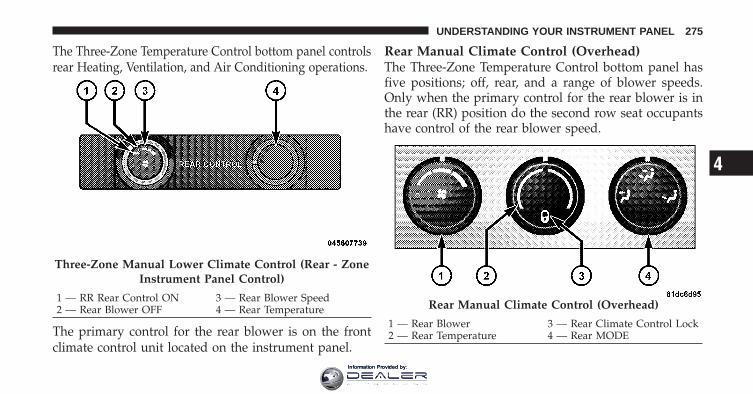
The Three-Zone Temperature Control bottom panel controlsrear Heating, Ventilation, and Air Conditioning operations.
The primary control for the rear blower is on the frontclimate control unit located on the instrument panel.
Rear Manual Climate Control (Overhead)The Three-Zone Temperature Control bottom panel hasfive positions; off, rear, and a range of blower speeds.Only when the primary control for the rear blower is inthe rear (RR) position do the second row seat occupantshave control of the rear blower speed.
Three-Zone Manual Lower Climate Control (Rear - ZoneInstrument Panel Control)
1 — RR Rear Control ON 3 — Rear Blower Speed2 — Rear Blower OFF 4 — Rear Temperature Rear Manual Climate Control (Overhead)
1 — Rear Blower 3 — Rear Climate Control Lock2 — Rear Temperature 4 — Rear MODE
4
UNDERSTANDING YOUR INSTRUMENT PANEL 275
Information Provided by:

Rear Blower ControlThe primary control for the rear blower is on the frontclimate control unit, located on the instrument panel.
Only when the front control for the rear blower is in theRR position do the second row seat occupants havecontrol of the rear blower speed.
The rear blower control, located in the rear overheadconsole, has an off position and a range of blower speeds.This allows the second row seat occupants to control thevolume of air circulated in the rear of the vehicle.
When the blower knob on the Three-Zone Manual lowerClimate Control (Instrument Panel control) is set to anyposition other than the RR, settings will be controlled bythe Instrument Panel lower control.
Rear Temperature ControlTo change the temperature in the rear of the vehicle,rotate the temperature control knob counterclockwise forcold air, and clockwise for heated air.
When rear controls are locked by the front system, thelock symbol on the temperature knob is illuminated, andthe rear overhead adjustments are inoperable.
The rear airflow modes will mirror the front unit opera-tion. Rear PANEL mode is automatically selected whenthe front control is in the PANEL mode. When the frontunit is in BI-LEVEL mode, airflow will be emitted fromboth the upper and lower rear outlets. When the frontcontrol is in FLOOR, DEFROST, or MIX modes, airflowwill be directed out of the rear floor outlets.
276 UNDERSTANDING YOUR INSTRUMENT PANEL
Information Provided by:
Rear Mode Control
Headliner ModeAir comes from the outlets in the headliner. Each ofthese outlets can be individually adjusted to direct
the flow of air. Moving the air vanes of the outlets to oneside will shut off the airflow.
Bi-Level ModeAir comes from both the headliner outlets and thefloor outlets.
NOTE: In many temperature positions, the BI-LEVELmode is designed to provide cooler air out of the head-liner outlets and warmer air from the floor outlets.
Floor ModeAir comes from the floor outlets.
Two- and Three-Zone Automatic TemperatureControl (ATC) Systems — If Equipped
• Front Two-and Three-Zone ATC allows both driverand front passenger seat occupant, and rear seatoccupants to select individual comfort settings.
• Occupants in the vehicle select AUTO mode operationby a button press on the right rotary knob and acomfort temperature setting using rotary knobs on thecontrol unit.
• The system can be controlled manually, if desired.
• SYNC feature links the controls for all three zones,allowing one comfort setting for the cabin, if desired.
4
UNDERSTANDING YOUR INSTRUMENT PANEL 277
Information Provided by:

The Two- and Three-Zone ATC System automaticallymaintain the interior comfort level desired by the driverand all passengers. The system automatically adjusts theair temperature, the airflow volume, amount of outsideair recirculation and the airflow direction. This maintainsa comfortable temperature, even under changing condi-tions.
Two-Zone ATC
1 — System On/Off 7 — Front MODE2 — Left Front Temperature 8 — Electric Rear Window De-
froster Button3 — Display Screen 9 — Front DEFROST4 — Right Front Temperature 10 — Front Blower Speed5 — Air Conditioning (A/C)On/Off
11 — AUTO Mode / Blower
6 — RECIRCULATE
278 UNDERSTANDING YOUR INSTRUMENT PANEL
Information Provided by:
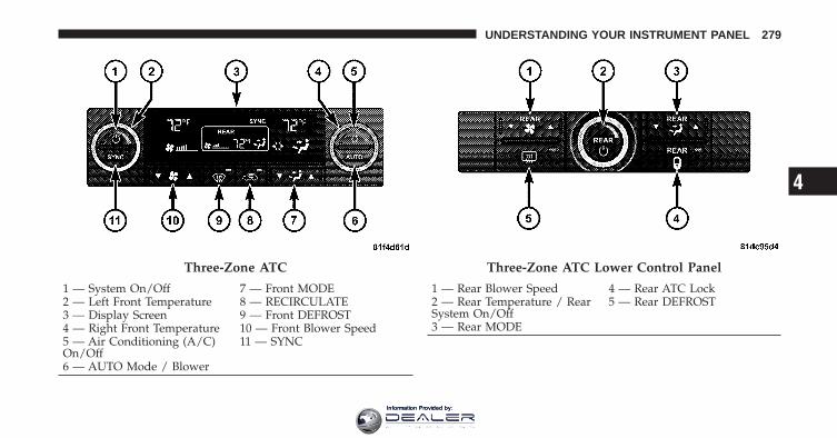
Three-Zone ATC
1 — System On/Off 7 — Front MODE2 — Left Front Temperature 8 — RECIRCULATE3 — Display Screen 9 — Front DEFROST4 — Right Front Temperature 10 — Front Blower Speed5 — Air Conditioning (A/C)On/Off
11 — SYNC
6 — AUTO Mode / Blower
Three-Zone ATC Lower Control Panel
1 — Rear Blower Speed 4 — Rear ATC Lock2 — Rear Temperature / RearSystem On/Off
5 — Rear DEFROST
3 — Rear MODE
4
UNDERSTANDING YOUR INSTRUMENT PANEL 279
Information Provided by:

Automatic Operation
1. Press the AUTO button on the Front Upper ATC Paneland the word AUTO will illuminate in the front ATCdisplay, along with three temperatures for driver, frontpassenger, and rear seats. The system will then automati-cally regulate the amount of airflow.
2. Next, adjust the temperature you would like thesystem to maintain, by adjusting the driver, front passen-ger, and rear seat rotary temperature knobs. Once thedesired temperature is displayed, the system will achieveand automatically maintain that comfort level.
3. When the system is set up for your comfort level, it isnot necessary to change the settings. You will experiencethe greatest efficiency by simply allowing the system tofunction automatically.
NOTE:• It is not necessary to move the temperature settings for
cold or hot vehicles. The system automatically adjuststhe temperature, mode and fan speed to providecomfort as quickly as possible.
• The temperature can be displayed in English or Metricunits by selecting the “Display Units of Measure in”customer-programmable feature. Refer to the “Elec-tronic Vehicle Information Center (EVIC) — Customer-Programmable Features” in this Section.
To provide you with maximum comfort in the automaticmode, during cold start-ups, the blower fan will remainon low and the DELAY symbol will appear in the frontATC display, until the engine warms up. The fan willengage immediately if the DEFROST mode is selected, orby pressing the Front Upper ATC Panel blower rockerbutton and setting the fan to any fixed blower speed.
280 UNDERSTANDING YOUR INSTRUMENT PANEL
Information Provided by:

Manual OperationThis system offers a full complement of manual overridefeatures. The AUTO symbol in the front ATC display willbe turned off when the system is being used in themanual mode.
NOTE: Each of these features operate independentlyfrom each other. If any one feature is controlled manually,the temperature doors will continue to operate automati-cally.
The blower fan speed can be set to any fixed speed bypressing the Front Upper ATC Panel blower rockerbutton. The fan will now operate at a fixed speed untiladditional speeds are selected. This allows the frontoccupants to control the volume of air circulated in thevehicle and cancel the AUTO mode.
The operator can also select the direction of the airflowby selecting one of the following positions.
Panel ModeAir is directed through the outlets in the instrumentpanel. These outlets can be adjusted for direction,
and turned on or off to control airflow.
NOTE: For maximum airflow to the rear, the centerinstrument panel outlets can be directed toward the rearseat passengers.
Bi-Level ModeAir comes from the instrument panel outlets, flooroutlets and defrost outlets. A slight amount of air is
also directed through the side window demister outlets.
NOTE: In many temperature positions, the BI-LEVELmode is designed to provide cooler air out of the paneloutlets and warmer air from the floor outlets.
4
UNDERSTANDING YOUR INSTRUMENT PANEL 281
Information Provided by:

Floor ModeAir comes from the floor outlets. A slight amount ofair is directed through the defrost and side window
demister outlets.
Mix ModeAir comes from the floor, defrost and side windowdemist outlets. This mode works best in cold orsnowy conditions. It allows you to stay comfort-
able, while keeping the windshield clear.
Defrost ModeAir comes from the windshield and side windowdemist outlets. Use DEFROST mode with maxi-
mum blower and temperature settings for best wind-shield and side window defrosting.
NOTE: While operating in the other modes, the systemwill not automatically sense the presence of fog, mist orice on the windshield. DEFROST mode must be manuallyselected to clear the windshield and side glass.
The SNOWFLAKE button, or A/C button, allowsthe operator to manually activate or deactivate theair conditioning system. When in SNOWFLAKE
mode, and the ATC display is on cool, dehumidified airflows through the air outlets. If ECONOMY mode isdesired, press the SNOWFLAKE button to turn off theSNOWFLAKE mode in the ATC display, and deactivatethe A/C system.
NOTE:• If the system is in Mix or Defrost Mode, the SNOW-
FLAKE can be turned off, but the A/C system shallremain active to prevent fogging of the windows.
• If fog or mist appears on the windshield or side glass,select DEFROST mode and increase blower speed.
282 UNDERSTANDING YOUR INSTRUMENT PANEL
Information Provided by:

Recirculation ControlWhen outside air contains smoke, odors, orhigh humidity, or if rapid cooling is desired,you may wish to recirculate interior air bypressing the RECIRCULATION mode control
button. RECIRCULATION mode should only be usedtemporarily. The recirculation symbol will illuminate inthe display when this button is selected. Push the buttona second time to turn off the RECIRCULATION modeLED and allow outside air into the vehicle.
NOTE: In cold weather, use of the RECIRCULATIONmode may lead to excessive window fogging. The RE-CIRCULATION mode is not allowed in the FLOOR, MIXand DEFROST modes to improve window clearing op-eration. Recirculation will be disabled automatically ifthese modes are selected.
Rear Automatic Temperature Control (ATC) — IfEquippedThe Rear ATC System has floor air outlets at the rear ofthe right side sliding door, and overhead outlets at eachoutboard rear seating position. The system providesheated air through the floor outlets or cool, dehumidifiedair through the headliner outlets.
The Three-Zone ATC Climate control for the Rear ATCSystem is on the front lower ATC panel located on theinstrument panel.
Pressing the REAR LOCK button for the Rear ATCSystem from the Three-Zone ATC Climate control, illu-minates a LOCK symbol in the rear display. The reartemperature and air source are controlled from the Three-Zone ATC Climate control.
Rear second row occupants can only adjust the rear ATCcontrol when the REAR LOCK button is turned off.
4
UNDERSTANDING YOUR INSTRUMENT PANEL 283
Information Provided by:
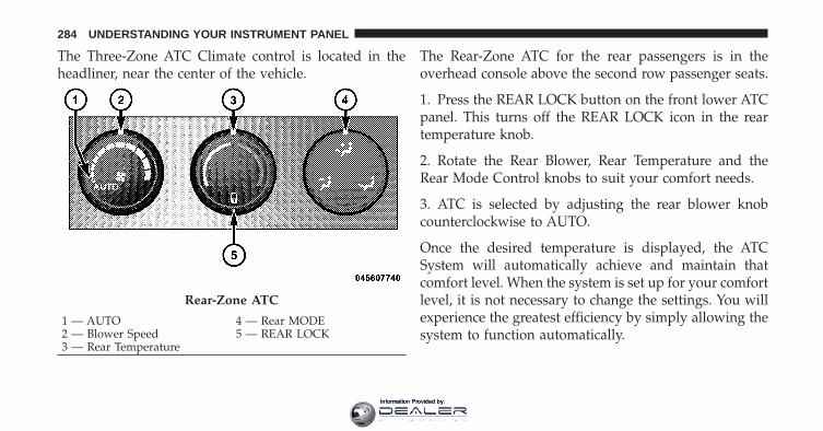
The Three-Zone ATC Climate control is located in theheadliner, near the center of the vehicle.
The Rear-Zone ATC for the rear passengers is in theoverhead console above the second row passenger seats.
1. Press the REAR LOCK button on the front lower ATCpanel. This turns off the REAR LOCK icon in the reartemperature knob.
2. Rotate the Rear Blower, Rear Temperature and theRear Mode Control knobs to suit your comfort needs.
3. ATC is selected by adjusting the rear blower knobcounterclockwise to AUTO.
Once the desired temperature is displayed, the ATCSystem will automatically achieve and maintain thatcomfort level. When the system is set up for your comfortlevel, it is not necessary to change the settings. You willexperience the greatest efficiency by simply allowing thesystem to function automatically.
Rear-Zone ATC
1 — AUTO 4 — Rear MODE2 — Blower Speed 5 — REAR LOCK3 — Rear Temperature
284 UNDERSTANDING YOUR INSTRUMENT PANEL
Information Provided by:

NOTE:• It is not necessary to move the temperature settings for
cold or hot vehicles. The system automatically adjuststhe temperature, mode and fan speed to providecomfort as quickly as possible.
• The temperature can be displayed in English or Metricunits by selecting the “Display Units of Measure in”customer-programmable feature. Refer to the “Elec-tronic Vehicle Information Center (EVIC) — Customer-Programmable Features” in this Section.
Rear Blower ControlThe rear blower control knob can be manually set to off,or any fixed blower speed, by rotating the knob from lowto high. This allows the rear seat occupants to control thevolume of air circulated in the rear of the vehicle.
CAUTION!
Interior air enters the Rear Automatic TemperatureControl System through an intake grille, located inthe passenger side trim panel behind the third rowseats. The heater outlets are located in the passengerside trim panel, just behind the sliding door. Do notblock or place objects directly in front of the inletgrille or heater outlets. The electrical system couldoverload causing damage to the blower motor.
Rear Temperature ControlTo change the temperature in the rear of the vehicle,rotate the temperature knob counterclockwise to lowerthe temperature, and clockwise to increase the tempera-ture. The REAR temperature settings are displayed in thefront upper ATC panel.
4
UNDERSTANDING YOUR INSTRUMENT PANEL 285
Information Provided by:

When rear controls are locked by the front system, theLOCK symbol on the temperature knob is illuminatedand any rear overhead adjustments are ignored.
Rear Mode Control
Auto ModeThe rear system automatically maintains the correctmode and comfort level desired by the rear seat occu-pants.
Headliner ModeAir comes from the outlets in the headliner. Each ofthese outlets can be individually adjusted to direct
the flow of air. Moving the air vanes of the outlets to oneside will shut off the airflow.
Bi-Level ModeAir comes from both the headliner outlets and thefloor outlets.
NOTE: In many temperature positions, the BI-LEVELmode is designed to provide cooler air out of the head-liner outlets and warmer air from the floor outlets.
Floor ModeAir comes from the floor outlets.
Operating Tips
NOTE: Refer to the chart at the end of this section forsuggested control settings for various weather condi-tions.
Summer OperationThe engine cooling system in air-conditioned vehiclesmust be protected with a high-quality antifreeze coolantto provide proper corrosion protection and to protectagainst engine overheating. Refer to “Cooling System”
286 UNDERSTANDING YOUR INSTRUMENT PANEL
Information Provided by:
under “Maintenance Procedures” and to “Fluids, Lubri-cants, and Genuine Parts” in “Maintaining Your Vehicle”for information pertaining to the cooling system andcoolant selection.
Winter OperationUse of the air Recirculation mode during Winter monthsis not recommended because it may cause windowfogging.
Vacation StorageAnytime you store your vehicle, or keep it out of service(i.e., vacation) for two weeks or more, run the airconditioning system at idle for about five minutes in thefresh air and high blower settings. This will ensureadequate system lubrication to minimize the possibilityof compressor damage when the system is started again.
Window FoggingInterior fogging on the windshield can be quickly re-moved by turning the mode selector to Defrost. TheDefrost/Floor mode can be used to maintain a clearwindshield and provide sufficient heating. If side win-dow fogging becomes a problem, increase blower speed.Vehicle windows tend to fog on the inside in mild butrainy or humid weather.
NOTE: Recirculate without A/C should not be used forlong periods as fogging may occur.
Side Window DemistersA side window demister outlet is located at each end ofthe instrument panel. These non-adjustable outlets directair toward the side windows when the system is in theFloor, Mix, or Defrost mode. The air is directed at the areaof the windows through which you view the outsidemirrors.
4
UNDERSTANDING YOUR INSTRUMENT PANEL 287
Information Provided by:
Outside Air IntakeMake sure the air intake, located directly in front of thewindshield, is free of obstructions such as leaves. Leavescollected in the air intake may reduce airflow, and if theyenter the plenum, they could plug the water drains. InWinter months, make sure the air intake is clear of ice,slush, and snow.
A/C Air Filter — If EquippedThe A/C Air Filter will reduce, but not eliminate, dieseland agricultural smells. The filter acts on air coming fromoutside the vehicle and recirculated air within the pas-senger compartment. Refer to “Maintenance Procedures”in “Maintaining Your Vehicle” for A/C Air Filter serviceinformation or see your authorized dealer for service.Refer to “Maintenance Schedules” for filter serviceintervals.
288 UNDERSTANDING YOUR INSTRUMENT PANEL
Information Provided by:

Control Setting Suggestions for Various Weather Conditions
4
UNDERSTANDING YOUR INSTRUMENT PANEL 289
Information Provided by:

Information Provided by:

STARTING AND OPERATING
CONTENTS
� Starting Procedures . . . . . . . . . . . . . . . . . . . . 295
▫ Automatic Transmission . . . . . . . . . . . . . . . 295
▫ Normal Starting (Tip Start) . . . . . . . . . . . . . 296
▫ Extreme Cold Weather (Below �20°F Or�29°C) . . . . . . . . . . . . . . . . . . . . . . . . . . . . 296
▫ If Engine Fails To Start . . . . . . . . . . . . . . . . 296
▫ After Starting . . . . . . . . . . . . . . . . . . . . . . . 297
� Engine Block Heater — If Equipped . . . . . . . . 297
� Automatic Transmission . . . . . . . . . . . . . . . . . 298
▫ Key Ignition Park Interlock . . . . . . . . . . . . . 300
▫ Brake/Transmission Interlock System . . . . . . 300
▫ Automatic Transmission Ignition InterlockSystem . . . . . . . . . . . . . . . . . . . . . . . . . . . . 301
▫ Four-Speed Or Six-Speed AutomaticTransmission . . . . . . . . . . . . . . . . . . . . . . . 301
▫ Gear Ranges . . . . . . . . . . . . . . . . . . . . . . . . 301
� AutoStick� — If Equipped . . . . . . . . . . . . . . . 305
▫ Operation . . . . . . . . . . . . . . . . . . . . . . . . . 305
▫ General Information . . . . . . . . . . . . . . . . . . 306
5
Information Provided by:

� All Wheel Drive (AWD) — If Equipped . . . . . . 307
� Driving On Slippery Surfaces . . . . . . . . . . . . . 307
▫ Acceleration . . . . . . . . . . . . . . . . . . . . . . . . 307
▫ Traction . . . . . . . . . . . . . . . . . . . . . . . . . . . 308
� Driving Through Water . . . . . . . . . . . . . . . . . 308
▫ Flowing/Rising Water . . . . . . . . . . . . . . . . . 309
� Power Steering . . . . . . . . . . . . . . . . . . . . . . . 311
▫ Power Steering Fluid Check . . . . . . . . . . . . . 312
� Parking Brake . . . . . . . . . . . . . . . . . . . . . . . . 312
� Brake System . . . . . . . . . . . . . . . . . . . . . . . . 315
▫ Anti-Lock Brake System (ABS) . . . . . . . . . . . 316
� Electronic Brake Control System . . . . . . . . . . . 317
▫ Anti-Lock Brake System (ABS) . . . . . . . . . . . 317
▫ Brake Assist System (BAS) . . . . . . . . . . . . . . 319
▫ Traction Control System (TCS) . . . . . . . . . . . 320
▫ Electronic Roll Mitigation (ERM) . . . . . . . . . 320
▫ Electronic Stability Program (ESP) . . . . . . . . 321
▫ ESP/BAS Warning Light And ESP/TCSIndicator Light . . . . . . . . . . . . . . . . . . . . . . 324
▫ Trailer Sway Control (TSC) . . . . . . . . . . . . . 324
� Tire Safety Information . . . . . . . . . . . . . . . . . 325
▫ Tire Markings . . . . . . . . . . . . . . . . . . . . . . . 325
▫ Tire Terminology And Definitions . . . . . . . . . 330
▫ Tire Loading And Tire Pressure . . . . . . . . . . 331
� Tires — General Information . . . . . . . . . . . . . 335
▫ Tire Pressure . . . . . . . . . . . . . . . . . . . . . . . 335
292 STARTING AND OPERATING
Information Provided by:

▫ Tire Inflation Pressures . . . . . . . . . . . . . . . . 336
▫ Radial-Ply Tires . . . . . . . . . . . . . . . . . . . . . 338
▫ Compact Spare Tire . . . . . . . . . . . . . . . . . . . 338
▫ Tire Spinning . . . . . . . . . . . . . . . . . . . . . . . 339
▫ Tread Wear Indicators . . . . . . . . . . . . . . . . . 340
▫ Life Of Tire . . . . . . . . . . . . . . . . . . . . . . . . 341
▫ Replacement Tires . . . . . . . . . . . . . . . . . . . . 341
� Tire Chains . . . . . . . . . . . . . . . . . . . . . . . . . . 343
� Snow Tires . . . . . . . . . . . . . . . . . . . . . . . . . . 343
� Tire Rotation Recommendations . . . . . . . . . . . 343
� Tire Pressure Monitor System (TPMS) . . . . . . . 344
▫ Base System . . . . . . . . . . . . . . . . . . . . . . . . 347
▫ Premium System – If Equipped . . . . . . . . . . 349
▫ General Information . . . . . . . . . . . . . . . . . . 352
� Fuel Requirements . . . . . . . . . . . . . . . . . . . . . 353
▫ 2.4L Engine . . . . . . . . . . . . . . . . . . . . . . . . 353
▫ 3.5L Engine . . . . . . . . . . . . . . . . . . . . . . . . 353
▫ Reformulated Gasoline . . . . . . . . . . . . . . . . 354
▫ Gasoline/Oxygenate Blends . . . . . . . . . . . . . 354
▫ MMT In Gasoline . . . . . . . . . . . . . . . . . . . . 355
▫ Materials Added To Fuel . . . . . . . . . . . . . . . 355
▫ Fuel System Cautions . . . . . . . . . . . . . . . . . 355
▫ Carbon Monoxide Warnings . . . . . . . . . . . . 356
� Adding Fuel . . . . . . . . . . . . . . . . . . . . . . . . . 357
▫ Fuel Filler Cap (Gas Cap) . . . . . . . . . . . . . . 357
▫ Loose Fuel Filler Cap Message . . . . . . . . . . . 359
5
STARTING AND OPERATING 293
Information Provided by:

� Vehicle Loading . . . . . . . . . . . . . . . . . . . . . . 359
▫ Vehicle Certification Label . . . . . . . . . . . . . . 359
▫ Gross Vehicle Weight Rating (GVWR) . . . . . . 360
▫ Gross Axle Weight Rating (GAWR) . . . . . . . . 360
▫ Overloading . . . . . . . . . . . . . . . . . . . . . . . . 360
▫ Loading . . . . . . . . . . . . . . . . . . . . . . . . . . . 361
� Trailer Towing . . . . . . . . . . . . . . . . . . . . . . . . 361
▫ Common Towing Definitions . . . . . . . . . . . . 361
▫ Trailer Hitch Classification . . . . . . . . . . . . . . 366
▫ Trailer Towing Weights (Maximum TrailerWeight Ratings) . . . . . . . . . . . . . . . . . . . . . 367
▫ Trailer And Tongue Weight . . . . . . . . . . . . . 369
▫ Towing Requirements . . . . . . . . . . . . . . . . . 370
▫ Towing Tips . . . . . . . . . . . . . . . . . . . . . . . . 375
� Recreational Towing(Behind Motorhome, Etc.) . . . . . . . . . . . . . . . . 377
▫ Towing This Vehicle Behind Another Vehicle(Flat Towing With All Four Wheels On TheGround) . . . . . . . . . . . . . . . . . . . . . . . . . . . 377
294 STARTING AND OPERATING
Information Provided by:
STARTING PROCEDURESBefore starting your vehicle, adjust your seat, adjust theinside and outside mirrors, fasten your seat belt, and ifpresent, instruct all other occupants to buckle their seatbelts.
WARNING!
Never leave children alone in a vehicle. Leavingunattended children in a vehicle is dangerous for anumber of reasons. A child or others could be seri-ously or fatally injured. Do not leave the key fob inthe ignition switch. A child could operate powerwindows, other controls, or move the vehicle.
Automatic TransmissionThe shift lever must be in the NEUTRAL or PARKposition before you can start the engine. Apply the brakesbefore shifting into any driving gear.
CAUTION!
Damage to the transmission may occur if the follow-ing precautions are not observed:• Shift into PARK only after the vehicle has come to
a complete stop.• Shift into or out of REVERSE only after the
vehicle has come to a complete stop and the engineis at idle speed.
• Do not shift from REVERSE, PARK, or NEUTRALinto any forward gear when the engine is aboveidle speed.
• Before shifting into any gear, make sure your footis firmly on the brake pedal.
5
STARTING AND OPERATING 295
Information Provided by:

Normal Starting (Tip Start)
NOTE: Normal starting of either a cold or a warmengine is obtained without pumping or pressing theaccelerator pedal.
Do not press the accelerator. Use the Fob with IntegratedKey to briefly turn the ignition switch to the STARTposition and release it as soon as the starter engages. Thestarter motor will continue to run, and it will disengageautomatically when the engine is running. If the enginefails to start, the starter will disengage automatically in10 seconds. If this occurs, turn the ignition switch to theLOCK position, wait 10 to 15 seconds, then repeat the“Normal Starting” procedure.
Extreme Cold Weather (Below �20°F or �29°C)To ensure reliable starting at these temperatures, use ofan externally powered electric engine block heater (avail-able from your authorized dealer) is recommended.
If Engine Fails To Start
WARNING!
• Never pour fuel or other flammable liquids intothe throttle body air inlet opening in an attempt tostart the vehicle. This could result in a flash firecausing serious personal injury.
(Continued)
296 STARTING AND OPERATING
Information Provided by:

WARNING! (Continued)• Do not attempt to push or tow your vehicle to get
it started. Vehicles equipped with an automatictransmission cannot be started this way. Unburnedfuel could enter the catalytic converter and oncethe engine has started, ignite and damage theconverter and vehicle. If the vehicle has a dis-charged battery, booster cables may be used toobtain a start from a booster battery or the batteryin another vehicle. This type of start can be dan-gerous if done improperly. Refer to “Jump Start-ing” in “What To Do In Emergencies” for furtherinformation.
If the engine fails to start after you have followed the“Normal Starting” or “Extreme Cold Weather” proce-dures, it may be flooded. To clear any excess fuel, pushthe accelerator pedal all the way to the floor and hold it.Then, turn the ignition switch to the START position and
release it as soon as the starter engages. The starter motorwill disengage automatically in 10 seconds. Once thisoccurs, release the accelerator pedal, turn the ignitionswitch to the LOCK position, wait 10 to 15 seconds, thenrepeat the “Normal Starting” procedure.
CAUTION!
To prevent damage to the starter, wait 10 to 15 sec-onds before trying again.
After StartingThe idle speed is controlled automatically and it willdecrease as the engine warms up.
ENGINE BLOCK HEATER — IF EQUIPPEDThe engine block heater warms engine coolant andpermits quicker starts in cold weather. Connect the cordto a standard 110-115 Volt AC electrical outlet with agrounded, three-wire extension cord.
5
STARTING AND OPERATING 297
Information Provided by:

The engine block heater cord is bundled under the hoodbetween the headlight assembly and the Totally Inte-grated Power Module (Fuse Box) on the driver’s side ofthe vehicle.
WARNING!
Remember to disconnect the cord before driving.Damage to the 110-115 Volt electrical cord could causeelectrocution.
AUTOMATIC TRANSMISSION
CAUTION!
Damage to the transmission may occur if the follow-ing precautions are not observed:• Shift into PARK only after the vehicle has come to
a complete stop.
(Continued)
CAUTION! (Continued)• Shift into or out of REVERSE only after the
vehicle has come to a complete stop and the engineis at idle speed.
• Do not shift from REVERSE, PARK, or NEUTRALinto any forward gear when the engine is aboveidle speed.
• Before shifting into any gear, make sure your footis firmly on the brake pedal.
NOTE: You must press and hold the brake pedal downwhile shifting out of PARK.
298 STARTING AND OPERATING
Information Provided by:

WARNING!
• It is dangerous to move the shift lever out of PARKor NEUTRAL if the engine speed is higher thanidle speed. If your foot is not firmly on the brakepedal, the vehicle could accelerate quickly forwardor in reverse. You could lose control of the vehicleand hit someone or something. Only shift intogear when the engine is idling normally and whenyour right foot is firmly on the brake pedal.
(Continued)
WARNING! (Continued)• Unintended movement of a vehicle could injure
those in and near the vehicle. As with all vehicles,you should never exit a vehicle while the engine isrunning. Before exiting a vehicle, you shouldalways shift the vehicle into PARK, remove thekey fob from the ignition switch, and apply theparking brake. Once the key fob is removed fromthe ignition switch, the shift lever is locked in thePARK position, securing the vehicle against un-wanted movement. Furthermore, you should neverleave unattended children inside a vehicle.
5
STARTING AND OPERATING 299
Information Provided by:

Key Ignition Park InterlockThis vehicle is equipped with a Key Ignition Park Inter-lock which requires the shift lever to be placed in PARKprior to rotating the key fob to the LOCK position. Thekey fob can only be removed from the ignition when theignition is in the LOCK position and once removed theshift lever is locked in PARK.
Brake/Transmission Interlock SystemThis vehicle is equipped with a Brake Transmission ShiftInterlock System (BTSI) that holds the shift lever in thePARK position when the ignition switch is in the LOCKposition. To move the shift lever out of the PARKposition, the ignition switch must be turned to the ON orSTART position (engine running or not) and the brakepedal must be pressed.
BTSI OverrideThere is an override for the BTSI that allows you to movethe shift lever out of the PARK position if an electricalsystem malfunction occurs (i.e., dead battery). To activatethe override system, perform the following steps:
1. Firmly apply the parking brake.
2. Insert the key fob into the ignition switch and rotate itto the ON position.
3. Remove the cubby bin liner located in the centerconsole behind the shift lever.
4. Insert a screwdriver or similar small tool into the holeat the front of the cubby bin and push the manualoverride release lever forward.
5. While holding the release lever forward, move theshift lever from PARK to NEUTRAL.
6. Release the manual override.
300 STARTING AND OPERATING
Information Provided by:
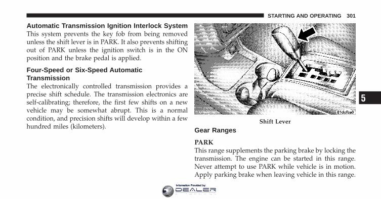
Automatic Transmission Ignition Interlock SystemThis system prevents the key fob from being removedunless the shift lever is in PARK. It also prevents shiftingout of PARK unless the ignition switch is in the ONposition and the brake pedal is applied.
Four-Speed or Six-Speed AutomaticTransmissionThe electronically controlled transmission provides aprecise shift schedule. The transmission electronics areself-calibrating; therefore, the first few shifts on a newvehicle may be somewhat abrupt. This is a normalcondition, and precision shifts will develop within a fewhundred miles (kilometers). Gear Ranges
PARKThis range supplements the parking brake by locking thetransmission. The engine can be started in this range.Never attempt to use PARK while vehicle is in motion.Apply parking brake when leaving vehicle in this range.
Shift Lever
5
STARTING AND OPERATING 301
Information Provided by:
When parking on a flat surface, place the shift lever in thePARK position first, and then apply the parking brake.
When parking on a hill, it is important to set the parkingbrake before placing the shift lever in PARK, otherwisethe load on the transmission locking mechanism maymake it difficult to move the shift lever out of PARK. Asan added precaution, turn the front wheels toward thecurb on a downhill grade and away from the curb on anuphill grade.
WARNING!
• Never use the PARK position as a substitute forthe parking brake. Always apply the parkingbrake fully when parked to guard against vehiclemovement and possible injury or damage.
(Continued)
WARNING! (Continued)• Never leave children in the vehicle alone. Leaving
unattended children in a vehicle is dangerous for anumber of reasons. The child or others could beseriously or fatally injured. They could operate thewindows, other vehicle controls or move thevehicle.
CAUTION!
DO NOT race the engine when shifting from PARKor NEUTRAL positions into another gear range asthis can damage the drivetrain.
REVERSEThis range is for moving the vehicle backward. Shift intoREVERSE only after the vehicle has come to a completestop.
302 STARTING AND OPERATING
Information Provided by:

NEUTRALThis range is used when vehicle is standing for pro-longed periods with engine running. Engine may bestarted in this range. Set the parking brake if you mustleave the vehicle.
WARNING!
Do not coast in NEUTRAL and never turn off theignition to coast down a hill. These are unsafepractices that limit your response to changing trafficor road conditions. You might lose control of thevehicle and have an accident.
DRIVE — Six-Speed TransmissionThis range should be used for most city and highwaydriving. It provides the smoothest upshifts, downshifts,and best fuel economy. However, use the AutoStick�mode and select the “5” range when frequent transmis-sion shifting occurs while using the DRIVE range, such as
when operating the vehicle under heavy loading condi-tions, (i.e., in hilly terrain, traveling into strong headwinds or while towing heavy trailers). Under theseconditions, using the “5” range will improve perfor-mance and extend transmission life by reducing exces-sive shifting and heat build-up.
“D” (Overdrive) — Four-Speed TransmissionThis range should be used for most city and highwaydriving. It provides the smoothest upshifts, downshifts,and best fuel economy. However, select the “3” rangewhen frequent transmission shifting occurs while usingthe “D” (Overdrive) range, such as when operating thevehicle under heavy loading conditions, (i.e., in hillyterrain, traveling into strong head winds or while towingheavy trailers). Under these conditions, using the “3”range will improve performance and extend transmissionlife by reducing excessive shifting and heat build-up.
5
STARTING AND OPERATING 303
Information Provided by:
“3” (Drive) — Four-Speed TransmissionThis range eliminates shifts into “D” (Overdrive). Thetransmission will operate normally in first, second, andthird gear while in this range. The “3” (Drive) rangeshould also be used when descending steep grades toprevent brake system distress.
NOTE: Using the “3” (Drive) range while operating thevehicle under heavy operating conditions will improveperformance and extend transmission life by reducingexcessive shifting and heat build up.
“L” (Low) — Four-Speed TransmissionThis range should be used for engine braking whendescending very steep grades. In this range, upshifts willoccur only to prevent engine overspeed while downshiftsoccur earlier than other gear range selections.
CAUTION!
If the transmission operating temperature exceedsacceptable limits, the vehicle computer will override“D” (Overdrive) and “5” range (for six-speedAutoStick� transmission) and “3” range (for four-speed auto transmission) by changing shift points.This is done to prevent transmission damage due tooverheating.
Reset Mode - Electronic TransmissionThe transmission is monitored electronically for abnor-mal conditions. If a condition is detected that could causedamage, the transmission automatically shifts into sec-ond gear (third gear for six-speed). The transmissionremains in second gear (third gear for six-speed) despitethe forward gear selected. PARK, REVERSE, and NEU-TRAL will continue to operate. This Reset feature allows
304 STARTING AND OPERATING
Information Provided by:

the vehicle to be driven to an authorized dealer forservice without damaging the transmission.
In the event of a momentary problem, the transmissioncan be reset to regain all forward gears by performing thefollowing steps:
1. Stop the vehicle.
2. Shift into PARK.
3. Turn the ignition switch to the LOCK position.
4. Restart the engine.
5. Shift into the desired gear range and resume driving.
NOTE: Even if the transmission can be reset, it isrecommended that you visit an authorized dealer at yourearliest possible convenience. Your authorized dealer hasdiagnostic equipment to determine if the problem couldrecur.
If the transmission cannot be reset, authorized dealerservice is required.
AUTOSTICK� — IF EQUIPPEDAutoStick� is a driver-interactive transmission that offerssix manual ratio changes to provide you with morecontrol of the vehicle. AutoStick� allows you to maximizeengine braking, eliminate undesirable upshifts anddownshifts, and improve overall vehicle performance.This system can also provide you with more controlduring passing, city driving, cold slippery conditions,mountain driving, trailer towing, and many other situa-tions.
OperationBy placing the shift lever one shift-level below the DRIVEposition, it can be moved from side to side. This allowsthe driver to select a higher or lower range of gears.Moving the shift lever to the left (-) triggers a downshift
5
STARTING AND OPERATING 305
Information Provided by:
and to the right (+) an upshift. The gear position willdisplay in the instrument cluster on the transmissionrange indicator.
NOTE: In AutoStick� mode, the transmission will onlyshift up or down when the driver moves the shift lever tothe right (+) or left (-). AutoStick� is deactivated when theshift lever is moved out of the AutoStick� (+/-) position.
General Information
• You can launch the vehicle from a stop in any gearexcept top gear. The system will ignore attempts toupshift into top gear at too low of a vehicle speed.(sixth for six-speed, fourth for four-speed).
• If a ratio other than first is selected, and the vehicle isbrought to a stop, the transmission control logic willautomatically select the first gear ratio.
• Starting out in second gear is helpful in snow or icyconditions.
• Avoid using speed control when AutoStick� is en-gaged.
• The transmission will automatically shift up whenmaximum engine speed is reached while AutoStick� isengaged.
• Transmission shifting will be more noticeable whenAutoStick� is engaged.
• If a low range is selected and the engine accelerates tothe rev limit, the transmission will automatically selectthe next higher ratio.
• If a downshift would cause the engine to over-speed,that shift will not occur until it is safe for the engine.
• Mostly the transmission will stay in the manuallyselected ratio, however:
306 STARTING AND OPERATING
Information Provided by:
− If the system detects powertrain overheating, thetransmission will revert to the automatic shift modeand remain in that mode until the powertrain cools off.
− If the system detects a problem, it will disable theAutoStick� mode and the transmission will return tothe automatic mode until the problem is corrected.
ALL WHEEL DRIVE (AWD) — IF EQUIPPEDThis feature provides on-demand All-Wheel Drive(AWD). The system is automatic with no driver inputs oradditional driving skills required. Under normal drivingconditions, the front wheels provide most of the traction.If the front wheels begin to lose traction, power is shiftedautomatically to the rear wheels. The greater the frontwheel traction loss, the greater the power transfer to therear wheels.
Additionally, on dry pavement under heavy throttleinput (where one may have no wheel spin), torque will besent to the rear in a pre-emptive effort to improve vehiclelaunch and performance characteristics.
CAUTION!
All wheels must have the same size and type tires.Unequal tire sizes must not be used. Unequal tiresize may cause failure of the power transfer unit.
DRIVING ON SLIPPERY SURFACES
AccelerationRapid acceleration on snow covered, wet, or other slip-pery surfaces may cause the front wheels to pull errati-cally to the right or left. This phenomenon occurs whenthere is a difference in the surface traction under the front(driving) wheels.
5
STARTING AND OPERATING 307
Information Provided by:

WARNING!
Rapid acceleration on slippery surfaces is dangerous.Unequal traction can cause sudden pulling of thefront wheels. You could lose control of the vehicleand possibly have an accident. Accelerate slowly andcarefully whenever there is likely to be poor traction(ice, snow, wet, mud, loose sand, etc.).
TractionWhen driving on wet or slushy roads, it is possible for awedge of water to build up between the tire and roadsurface. This is hydroplaning and may cause partial orcomplete loss of vehicle control and stopping ability. Toreduce this possibility, the following precautions shouldbe observed:
1. Slow down during rainstorms or when roads areslushy.
2. Slow down if the road has standing water or puddles.
3. Replace the tires when tread wear indicators firstbecome visible.
4. Keep the tires properly inflated.
5. Maintain enough distance between your vehicle andthe vehicle in front of you to avoid a collision in a suddenstop.
DRIVING THROUGH WATERDriving through water more than a few inches/centimeters deep will require extra caution to ensuresafety and prevent damage to your vehicle.
308 STARTING AND OPERATING
Information Provided by:

Flowing/Rising Water
WARNING!
Do not drive on, or cross, a road or a path wherewater is flowing and/or rising (as in storm run-off).Flowing water can wear away the road or path’ssurface and cause your vehicle to sink into deeperwater. Furthermore, flowing and/or rising water cancarry your vehicle away swiftly. Failure to follow thiswarning may result in injuries that are serious orfatal to you, your passengers, and others around you.
Shallow Standing WaterAlthough your vehicle is capable of driving throughshallow standing water, consider the following Cautionand Warning before doing so.
CAUTION!
• Always check the depth of the standing waterbefore driving through it. Never drive throughstanding water that is deeper than the bottom ofthe tire rims mounted on the vehicle.
• Determine the condition of the road or the paththat is under water, and if there are any obstaclesin the way, before driving through the standingwater.
• Do not exceed 5 mph (8 km/h) when drivingthrough standing water. This will minimize waveeffects.
5
STARTING AND OPERATING 309
Information Provided by:

CAUTION!
• Driving through standing water may cause dam-age to your vehicle’s drivetrain components. Al-ways inspect your vehicle’s fluids (i.e., engine oil,transmission, axle, etc.) for signs of contamination(i.e., fluid that is milky or foamy in appearance)after driving through standing water. Do not con-tinue to operate the vehicle if any fluid appearscontaminated, as this may result in further dam-age. Such damage is not covered by the NewVehicle Limited Warranty.
• Getting water inside your vehicle’s engine cancause it to lock up and stall out, and cause seriousinternal damage to the engine. Such damage is notcovered by the New Vehicle Limited Warranty.
WARNING!
• Driving through standing water limits your vehi-cle’s traction capabilities. Do not exceed 5 mph(8 km/h) when driving through standing water.
• Driving through standing water limits your vehi-cle’s braking capabilities, which increases stop-ping distances. Therefore, after driving throughstanding water, drive slowly and lightly press onthe brake pedal several times to dry the brakes.
• Getting water inside your vehicle’s engine cancause it to lock up and stall out, and leave youstranded.
• Failure to follow these warnings may result ininjuries that are serious or fatal to you, yourpassengers, and others around you.
310 STARTING AND OPERATING
Information Provided by:

POWER STEERINGThe standard power steering system will give you goodvehicle response and increased ease of maneuverabilityin tight spaces. The system will provide mechanicalsteering capability if power assist is lost.
If for some reason the power assist is interrupted, it willstill be possible to steer your vehicle. Under these condi-tions, you will observe a substantial increase in steeringeffort, especially at very low vehicle speeds and duringparking maneuvers.
NOTE:• Increased noise levels at the end of the steering wheel
travel are considered normal and do not indicate thatthere is a problem with the power steering system.
• Upon initial start-up in cold weather, the power steer-ing pump may make noise for a short amount of time.This is due to the cold, thick fluid in the steering
system. This noise should be considered normal, and itdoes not in any way damage the steering system.
WARNING!
Continued operation with reduced power steeringassist could pose a safety risk to yourself and others.Service should be obtained as soon as possible.
CAUTION!
Prolonged operation of the steering system at the endof the steering wheel travel will increase the steeringfluid temperature and it should be avoided whenpossible. Damage to the power steering pump mayoccur.
5
STARTING AND OPERATING 311
Information Provided by:

Power Steering Fluid CheckChecking the power steering fluid level at a definedservice interval is not required. The fluid should only bechecked if a leak is suspected, abnormal noises areapparent, and/or the system is not functioning as antici-pated. Coordinate inspection efforts through an autho-rized dealer.
CAUTION!
Do not use chemical flushes in your power steeringsystem as the chemicals can damage your powersteering components. Such damage is not covered bythe New Vehicle Limited Warranty.
WARNING!
Fluid level should be checked on a level surface andwith the engine off to prevent injury from movingparts and to ensure accurate fluid level reading. Donot overfill. Use only manufacturer’s recommendedpower steering fluid.
If necessary, add fluid to restore to the proper indicatedlevel. With a clean cloth, wipe any spilled fluid from allsurfaces. Refer to “Fluids, Lubricants, and GenuineParts” in “Maintaining Your Vehicle” for the correct fluidtype.
PARKING BRAKEBefore leaving the vehicle, make sure that the parkingbrake is fully applied. Also, be certain to leave thetransmission in PARK.
312 STARTING AND OPERATING
Information Provided by:

The foot operated parking brake is located below thelower left corner of the instrument panel. To apply thepark brake, firmly push the park brake pedal fully. Torelease the parking brake, press the park brake pedal asecond time and let your foot up as you feel the brakedisengage.
When the parking brake is applied with the ignitionswitch ON, the “Brake Warning Light” in the instrumentcluster will illuminate.
NOTE:• When the parking brake is applied and the transmis-
sion is placed in gear, the “Brake Warning Light” willflash. If vehicle speed is detected, a chime will soundto alert the driver. Fully release the parking brakebefore attempting to move the vehicle.
• This light only shows that the parking brake is ap-plied. It does not show the degree of brake application.
When parking on a hill, it is important to turn the frontwheels toward the curb on a downhill grade and awayfrom the curb on an uphill grade. For vehicles equippedwith an automatic transmission, apply the parking brakebefore placing the shift lever in PARK, otherwise the loadon the transmission locking mechanism may make it
Parking Brake
5
STARTING AND OPERATING 313
Information Provided by:

difficult to move the shift lever out of PARK. The parkingbrake should always be applied whenever the driver isnot in the vehicle.
WARNING!
• Never use the PARK position as a substitute forthe parking brake. Always apply the parkingbrake fully when parked to guard against vehiclemovement and possible injury or damage.
• Never leave children alone in a vehicle. Leavingunattended children in a vehicle is dangerous for anumber of reasons. A child or others could beseriously or fatally injured.
• Do not leave the key fob in the ignition switch. Achild could operate power windows, other con-trols, or move the vehicle.
(Continued)
WARNING! (Continued)• Be sure the parking brake is fully disengaged
before driving; failure to do so can lead to brakefailure and an accident.
• Always fully apply the parking brake when leav-ing your vehicle or it may roll and cause damage orinjury. Also, be certain to leave the transmission inPARK. Failure to do so may cause the vehicle toroll and cause damage or injury.
CAUTION!
If the “Brake Warning Light” remains on with theparking brake released, a brake system malfunctionis indicated. Have the brake system serviced by anauthorized dealer immediately.
314 STARTING AND OPERATING
Information Provided by:

BRAKE SYSTEMYour vehicle is equipped with dual hydraulicbrake systems. If either of the two hydraulicsystems loses normal capability, the remainingsystem will still function. However, there will
be some loss of overall braking effectiveness. This will beevident by increased pedal travel during application andgreater pedal force required to slow or stop the vehicle. Inaddition, if the malfunction is caused by a leak in thehydraulic system, the “Brake Warning Light” will turn onas the brake fluid level drops in the master cylinder.
In the event power assist is lost for any reason (i.e.,repeated brake applications with the engine OFF) thebrakes will still function. However, the effort required tobrake the vehicle will be much greater than that requiredwith the power system operating.
WARNING!
• Riding the brakes can lead to brake failure andpossibly an accident. Driving with your foot rest-ing or riding on the brake pedal can result inabnormally high brake temperatures, excessivelining wear, and possible brake damage. Youwould not have your full braking capacity in anemergency.
• Driving a vehicle with the “Brake Warning Light”on is dangerous. A significant decrease in brakingperformance or vehicle stability during brakingmay occur. It will take you longer to stop thevehicle or will make your vehicle harder to con-trol. You could have an accident. Have the vehiclechecked immediately.
5
STARTING AND OPERATING 315
Information Provided by:

Anti-Lock Brake System (ABS)
This system aids the driver in maintaining vehicle controlunder adverse braking conditions. The system controlshydraulic brake pressure to prevent wheel lock-up tohelp avoid skidding on slippery surfaces during braking.Refer to “Anti-Lock Brake System (ABS)” under “Elec-tronic Brake Control System” in this section for moreinformation.
WARNING!
The ABS cannot prevent the natural laws of physicsfrom acting on the vehicle, nor can it increase thetraction afforded by prevailing road conditions. ABScannot prevent accidents, including those resultingfrom excessive speed in turns, driving on very slip-pery surfaces, or hydroplaning. Only a safe, attentive,and skillful driver can prevent accidents. The capa-bilities of an ABS-equipped vehicle must never beexploited in a reckless or dangerous manner, whichcould jeopardize the user’s safety or the safety ofothers.
316 STARTING AND OPERATING
Information Provided by:

ELECTRONIC BRAKE CONTROL SYSTEMYour vehicle is equipped with an advanced electronicbrake control system commonly referred to as ESP. Thissystem includes Anti-Lock Brake System (ABS), BrakeAssist System (BAS), Traction Control System (TCS),Electronic Roll Mitigation (ERM), and Electronic StabilityProgram (ESP). These systems work together to enhanceboth vehicle stability and control in various drivingconditions.
Anti-Lock Brake System (ABS)The Anti-Lock Brake System (ABS) provides increasedvehicle stability and brake performance under mostbraking conditions. The system automatically “pumps”the brakes during severe braking conditions to preventwheel lock-up.
When the vehicle is driven over 7 mph (11 km/h), youmay also hear a slight clicking sound as well as some
related motor noises. These noises are the system per-forming its self check cycle to ensure that the ABS isworking properly. This self check occurs each time thevehicle is started and accelerated past 7 mph (11 km/h).
ABS is activated during braking under certain road orstopping conditions. ABS-inducing conditions can in-clude ice, snow, gravel, bumps, railroad tracks, loosedebris, or panic stops.
You also may experience the following when the brakesystem goes into Anti-lock:
• The ABS motor running (it may continue to run for ashort time after the stop),
• The clicking sound of solenoid valves,
• Brake pedal pulsations, and
• A slight drop or fall away of the brake pedal at the endof the stop.
5
STARTING AND OPERATING 317
Information Provided by:

These are all normal characteristics of ABS.
WARNING!
• The ABS contains sophisticated electronic equip-ment that may be susceptible to interferencecaused by improperly installed or high outputradio transmitting equipment. This interferencecan cause possible loss of anti-lock braking capa-bility. Installation of such equipment should beperformed by qualified professionals.
• Pumping of the Anti-Lock Brakes will diminishtheir effectiveness and may lead to an accident.Pumping makes the stopping distance longer. Justpress firmly on your brake pedal when you needto slow down or stop.
(Continued)
WARNING! (Continued)• The ABS cannot prevent the natural laws of phys-
ics from acting on the vehicle, nor can it increasebraking or steering efficiency beyond that af-forded by the condition of the vehicle brakes andtires or the traction afforded.
• The ABS cannot prevent accidents, includingthose resulting from excessive speed in turns,following another vehicle too closely, or hydro-planing. Only a safe, attentive, and skillful drivercan prevent accidents.
• The capabilities of an ABS equipped vehicle mustnever be exploited in a reckless or dangerousmanner, which could jeopardize the user’s safetyor the safety of others.
All vehicle wheels and tires must be the same size andtype and tires must be properly inflated to produceaccurate signals for the computer.
318 STARTING AND OPERATING
Information Provided by:
Anti-Lock Brake LightThe Anti-Lock Brake Light monitors the ABS.The light will turn on when the ignition switchis turned to the ON position and may stay onfor as long as four seconds.
If the ABS Light remains on or comes on while driving, itindicates that the Anti-Lock portion of the brake systemis not functioning and that service is required. However,the conventional brake system will continue to operatenormally if the Brake System Warning Light is not on.
If the ABS Light is on, the brake system should beserviced as soon as possible to restore the benefits ofAnti-Lock brakes. If the ABS Light does not come onwhen the ignition switch is turned to the ON position,have the light repaired as soon as possible.
If both the Brake System Warning Light and the ABSLight remain on, the ABS and Electronic Brake ForceDistribution (EBD) systems are not functioning. Immedi-ate repair to the ABS system is required.
Brake Assist System (BAS)The BAS is designed to optimize the vehicle’s brakingcapability during emergency braking maneuvers. Thesystem detects an emergency braking situation by sens-ing the rate and amount of brake application and thenapplies optimum pressure to the brakes. This can helpreduce braking distances. The BAS complements theABS. Applying the brakes very quickly results in the bestBAS assistance. To receive the benefit of the system, youmust apply continuous braking pressure during thestopping sequence, (do not “pump” the brakes). Do notreduce brake pedal pressure unless braking is no longerdesired. Once the brake pedal is released, the BAS isdeactivated.
5
STARTING AND OPERATING 319
Information Provided by:

WARNING!
BAS cannot prevent the natural laws of physics fromacting on the vehicle, nor can it increase the tractionafforded by prevailing road conditions. BAS cannotprevent accidents, including those resulting fromexcessive speed in turns, driving on very slipperysurfaces, or hydroplaning. Only a safe, attentive, andskillful driver can prevent accidents. The capabilitiesof a BAS-equipped vehicle must never be exploitedin a reckless or dangerous manner, which couldjeopardize the user’s safety or the safety of others.
Traction Control System (TCS)
This system monitors the amount of wheel spin of each ofthe driven wheels. If wheel spin is detected, brakepressure is applied to the slipping wheel(s) and enginepower is reduced to provide enhanced acceleration andstability. A feature of the TCS functions similar to a
limited slip differential and controls the wheel spinacross a driven axle. If one wheel on a driven axle isspinning faster than the other, the system will apply thebrake of the spinning wheel. This will allow more enginetorque to be applied to the wheel that is not spinning.This feature remains active even if TCS and ESP are in the“Partial Off” mode. Refer to “ESP (Electronic StabilityProgram)” in this section for more information.
Electronic Roll Mitigation (ERM)This system anticipates the potential for wheel lift bymonitoring the driver’s steering wheel input and thespeed of the vehicle. When ERM determines that the rateof change of the steering wheel angle and vehicle’s speedare sufficient to potentially cause wheel lift, it thenapplies the appropriate brake and may also reduceengine power to lessen the chance that wheel lift willoccur. ERM will only intervene during very severe orevasive driving maneuvers. ERM can only reduce thechance of wheel lift occurring during severe or evasive
320 STARTING AND OPERATING
Information Provided by:

driving maneuvers. It cannot prevent wheel lift due toother factors, such as road conditions, leaving the road-way, or striking objects or other vehicles.
WARNING!
Many factors, such as vehicle loading, road condi-tions, and driving conditions, influence the chancethat wheel lift or rollover may occur. ERM cannotprevent all wheel lift or rollovers, especially thosethat involve leaving the roadway or striking objectsor other vehicles. Only a safe, attentive, and skillfuldriver can prevent accidents. The capabilities of anERM-equipped vehicle must never be exploited in areckless or dangerous manner, which could jeopar-dize the user’s safety or the safety of others.
Electronic Stability Program (ESP)This system enhances directional control and stability ofthe vehicle under various driving conditions. ESP cor-rects for over-steering and under-steering the vehicle byapplying the brake of the appropriate wheel. Enginepower may also be reduced to help the vehicle maintainthe desired path.
The ESP uses sensors in the vehicle to determine the paththat the driver intends to steer the vehicle and comparesit to the actual path of the vehicle. When the actual pathdoes not match the intended path, the ESP applies thebrake of the appropriate wheel to assist in counteractingthe condition of over-steer or under-steer.
• Over-steer - when the vehicle is turning more thanappropriate for the steering wheel position.
• Under-steer - when the vehicle is turning less thanappropriate for the steering wheel position.
5
STARTING AND OPERATING 321
Information Provided by:
ESP/TCS Indicator LightThe ESP/TCS Indicator Light located in theinstrument cluster, starts to flash as soon as thetires lose traction and the ESP system becomesactive. The ESP/TCS Indicator Light also
flashes when TCS is active. If the ESP/TCS IndicatorLight begins to flash during acceleration, ease up on theaccelerator and apply as little throttle as possible. Be sureto adapt your speed and driving to the prevailing roadconditions.
WARNING!
ESP cannot prevent the natural laws of physics fromacting on the vehicle, nor can it increase the tractionafforded by prevailing road conditions. ESP cannotprevent accidents, including those resulting fromexcessive speed in turns, driving on very slipperysurfaces, or hydroplaning. Only a safe, attentive, andskillful driver can prevent accidents. The capabilitiesof an ESP-equipped vehicle must never be exploitedin a reckless or dangerous manner, which couldjeopardize the user’s safety or the safety of others.
ESP Operating ModesThe ESP system has two available operating modes.
322 STARTING AND OPERATING
Information Provided by:

Full OnThis is the normal operating mode for ESP. Whenever thevehicle is started the system will be in this mode. Thismode should be used for most driving situations. ESPshould only be turned to “Partial Off” for specific reasonsas noted. Refer to “Partial Off” for additional informa-tion.
Partial OffThe ESP OFF button is located in the switch bank abovethe climate Control. To enter the “Partial Off” mode,momentarily press the ESP OFF button and the ESP/TCSIndicator Light will illuminate. To turn the ESP on again,momentarily press the ESP OFF button and the ESP/TCSIndicator Light will turn off. This will restore the normal“ESP On” mode of operation.
NOTE: To improve the vehicle’s traction when drivingwith snow chains, or when starting off in deep snow,sand, or gravel, it may be desirable to switch to the“Partial Off” mode by momentarily pressing the ESP OFFbutton. Once the situation requiring “Partial Off” mode isovercome, turn ESP back on by momentarily pressing theESP OFF button. This may be done while the vehicle is inmotion.
ESP OFF Button
5
STARTING AND OPERATING 323
Information Provided by:

ESP/BAS Warning Light and ESP/TCS IndicatorLight
The malfunction indicator for the ESP is com-bined with the BAS indicator. The ESP/BASMalfunction Indicator Light and the ESP/TCSIndicator Light in the instrument cluster both
turn on when the ignition switch is turned to the ONposition. They should both turn off with the enginerunning. If the ESP/BAS Malfunction Indicator Lightturns on continuously with the engine running, a mal-function has been detected in either the ESP or the BASsystem, or both. If this light remains on after severalignition cycles, and the vehicle has been driven severalmiles (kilometers) at speeds greater than 30 mph(48 km/h), see your authorized dealer as soon as possibleto have the problem diagnosed and corrected.
NOTE:• �The ESP/TCS Indicator Light and the ESP/BAS Mal-
function Indicator Light will turn on momentarilyeach time the ignition switch is turned ON.
• Each time the ignition is turned ON, the ESP Systemwill be ON even if it was turned off previously.
• The ESP Control System will make buzzing or clickingsounds when it is active. This is normal; the soundswill stop when ESP becomes inactive following themaneuver that caused the ESP activation.
Trailer Sway Control (TSC)TSC uses sensors in the vehicle to recognize an exces-sively swaying trailer. TSC activates automatically oncethe excessively swaying trailer is recognized. When TSCis functioning, the ESP/TCS Indicator Light will flash,the engine power will be reduced, and you will feel thebrake being applied to individual wheels in an attempt tostop the trailer from swaying.
324 STARTING AND OPERATING
Information Provided by:
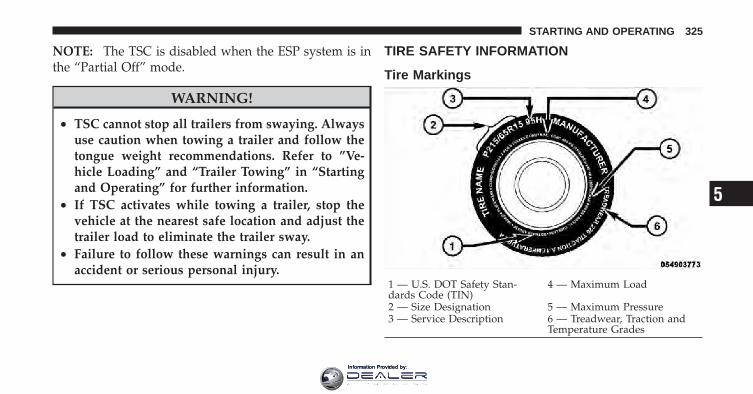
NOTE: The TSC is disabled when the ESP system is inthe “Partial Off” mode.
WARNING!
• TSC cannot stop all trailers from swaying. Alwaysuse caution when towing a trailer and follow thetongue weight recommendations. Refer to ”Ve-hicle Loading” and “Trailer Towing” in “Startingand Operating” for further information.
• If TSC activates while towing a trailer, stop thevehicle at the nearest safe location and adjust thetrailer load to eliminate the trailer sway.
• Failure to follow these warnings can result in anaccident or serious personal injury.
TIRE SAFETY INFORMATION
Tire Markings
1 — U.S. DOT Safety Stan-dards Code (TIN)
4 — Maximum Load
2 — Size Designation 5 — Maximum Pressure3 — Service Description 6 — Treadwear, Traction and
Temperature Grades
5
STARTING AND OPERATING 325
Information Provided by:

NOTE:• P (Passenger) - Metric tire sizing is based on U.S.
design standards. P-Metric tires have the letter “P”molded into the sidewall preceding the size designa-tion. Example: P215/65R15 95H.
• European-Metric tire sizing is based on Europeandesign standards. Tires designed to this standard havethe tire size molded into the sidewall beginning withthe section width. The letter �P� is absent from this tiresize designation. Example: 215/65R15 96H.
• LT (Light Truck) - Metric tire sizing is based on U.S.design standards. The size designation for LT-Metric
tires is the same as for P-Metric tires except for theletters “LT” that are molded into the sidewall preced-ing the size designation. Example: LT235/85R16.
• Temporary spare tires are high-pressure compactspares designed for temporary emergency use only.Tires designed to this standard have the letter “T”molded into the sidewall preceding the size designa-tion. Example: T145/80D18 103M.
• High flotation tire sizing is based on U.S. designstandards, and it begins with the tire diameter moldedinto the sidewall. Example: 31x10.5 R15 LT.
326 STARTING AND OPERATING
Information Provided by:

Tire Sizing Chart
TIRE SIZING TERMSSize Designation:
P = Passenger Car tire size based on U.S. design standards�....blank....� = Passenger Car tire based on European design standardsLT = Light Truck tire based on U.S. design standardsT = Temporary spare tire31 = Overall diameter in inches (in)215 = Section width in millimeters (mm)65 = Aspect ratio in percent (%)
— Ratio of section height to section width of tire10.5 = Section width in inches (in)R = Construction code
— �R� means radial construction—�D� means diagonal or bias construction
15 = Rim diameter in inches (in)
5
STARTING AND OPERATING 327
Information Provided by:

TIRE SIZING TERMSService Description:
95 = Load Index— A numerical code associated with the maximum load a tire can carry
H = Speed Symbol— A symbol indicating the range of speeds at which a tire can carry a load correspondingto its load index under certain operating conditions— The maximum speed corresponding to the speed symbol should only be achieved underspecified operating conditions (i.e., tire pressure, vehicle loading, road conditions, andposted speed limits)
Load Identification:�....blank....� = Absence of any text on the sidewall of the tire indicates a Standard Load (SL) TireExtra Load (XL) = Extra load (or reinforced) tireLight Load = Light load tireC, D, E = Load range associated with the maximum load a tire can carry at a specified pressure
Maximum Load — Maximum load indicates the maximum load this tire is designed to carryMaximum Pressure — Maximum pressure indicates the maximum permissible cold tire inflation pressure forthis tire
328 STARTING AND OPERATING
Information Provided by:

Tire Identification Number (TIN)The TIN may be found on one or both sides of the tire,however, the date code may only be on one side. Tireswith white sidewalls will have the full TIN, including thedate code, located on the white sidewall side of the tire.
Look for the TIN on the outboard side of black sidewalltires as mounted on the vehicle. If the TIN is not found onthe outboard side, then you will find it on the inboardside of the tire.
TIRE IDENTIFICATION NUMBEREXAMPLE: DOT MA L9 ABCD 0301DOT = Department of Transportation
— This symbol certifies that the tire is in compliance with the U.S. Department of Transportation tiresafety standards, and is approved for highway use
MA = Code representing the tire manufacturing location (two digits)L9 = Code representing the tire size (two digits)ABCD = Code used by the tire manufacturer (one to four digits)03 = Number representing the week in which the tire was manufactured (two digits)
—03 means the 3rd week.01 = Number representing the year in which the tire was manufactured (two digits)
—01 means the year 2001— Prior to July 2000, tire manufacturers were only required to have one number to represent theyear in which the tire was manufactured. Example: 031 could represent the 3rd week of 1981 or 1991
5
STARTING AND OPERATING 329
Information Provided by:

Tire Terminology and Definitions
Term DefinitionB-Pillar The vehicle B-Pillar is a structural member of the body located
between the front and rear door (of a four-door vehicle) runningfrom the sill to the roof.
Cold Tire Pressure Cold tire inflation pressure is defined as the tire pressure after thevehicle has not been driven for at least 3 hours, or driven lessthan 1 mile (1.6 km) after sitting for a three hour period. Inflationpressure is measured in units of PSI (pounds per square inch) orKPa (kilopascals).
Maximum Inflation Pressure The maximum inflation pressure is the maximum permissible coldtire inflation pressure for this tire. The max inflation pressure ismolded into the sidewall.
Recommended Inflation Pressure Vehicle manufacturer’s recommended tire inflation pressure asshown on the tire placard.
Tire Placard A paper label permanently attached to the vehicle showing thevehicle’s loading capacity, the original equipment tire size and therecommended inflation pressure.
330 STARTING AND OPERATING
Information Provided by:

Tire Loading and Tire Pressure
Tire Placard Location
NOTE: The proper cold tire inflation pressure is listedon the driver’s side B-Pillar.
Tire and Loading Information Placard
This placard tells you important information about the:1) number of people that can be carried in the vehicle2) total weight your vehicle can carry3) tire size designed for your vehicle4) cold tire inflation pressures for the front, rear, andspare tires.
Tire Placard Location
Tire and Loading Information Placard
5
STARTING AND OPERATING 331
Information Provided by:

LoadingThe vehicle maximum load on the tire must not exceedthe load carrying capacity of the tire on your vehicle. Youwill not exceed the tire’s load carrying capacity if youadhere to the loading conditions, tire size, and cold tireinflation pressures specified on the Tire and LoadingInformation placard and in the “Vehicle Loading” sectionof this manual.
NOTE: Under a maximum loaded vehicle condition,gross axle weight ratings (GAWRs) for the front and rearaxles must not be exceeded. For further information onGAWRs, vehicle loading, and trailer towing, refer to“Vehicle Loading” in this section.
To determine the maximum loading conditions of yourvehicle, locate the statement “The combined weight ofoccupants and cargo should never exceed XXX kg or XXXlbs.” on the Tire and Loading Information placard. The
combined weight of occupants, cargo/luggage andtrailer tongue weight (if applicable) should never exceedthe weight referenced here.
Steps for Determining Correct Load Limit
1. Locate the statement “The combined weight of occu-pants and cargo should never exceed XXX kg or XXX lbs”on your vehicle’s placard.
2. Determine the combined weight of the driver andpassengers that will be riding in your vehicle.
3. Subtract the combined weight of the driver and pas-sengers from XXX kg or XXX lbs.
4. The resulting figure equals the available amount ofcargo and luggage load capacity. For example, if “XXX”amount equals 1,400 lbs (635 kg) and there will be five150 lb (68 kg) passengers in your vehicle, the amount of
332 STARTING AND OPERATING
Information Provided by:
available cargo and luggage load capacity is 650 lbs(295 kg) (since 5 x 150 = 750, and 1400 – 750 = 650 lbs[295 kg]).
5. Determine the combined weight of luggage and cargobeing loaded on the vehicle. That weight may not safelyexceed the available cargo and luggage load capacitycalculated in Step 4.
6. If your vehicle will be towing a trailer, load from yourtrailer will be transferred to your vehicle. Consult thismanual to determine how this reduces the availablecargo and luggage load capacity of your vehicle.
NOTE: The following table shows examples on how tocalculate total load, cargo/luggage, and towing capaci-ties of your vehicle with varying seating configurationsand number and size of occupants. This table is forillustration purposes only and may not be accurate forthe seating and load carry capacity of your vehicle.
NOTE: For the following example, the combined weightof occupants and cargo should never exceed 865 lbs(392 kg). 5
STARTING AND OPERATING 333
Information Provided by:

334 STARTING AND OPERATING
Information Provided by:

WARNING!
Overloading of your tires is dangerous. Overloadingcan cause tire failure, affect vehicle handling, andincrease your stopping distance. Use tires of therecommended load capacity for your vehicle. Neveroverload them.
TIRES — GENERAL INFORMATION
Tire PressureProper tire inflation pressure is essential to the safe andsatisfactory operation of your vehicle. Three primaryareas are affected by improper tire pressure:
Safety
WARNING!
• Improperly inflated tires are dangerous and cancause accidents.
• Under-inflation increases tire flexing and can re-sult over-heating and in tire failure.
• Over-inflation reduces a tire’s ability to cushionshock. Objects on the road and chuckholes cancause damage that result in tire failure.
• Unequal tire pressures can cause steering prob-lems. You could lose control of your vehicle.
• Over-inflated or under-inflated tires can affectvehicle handling and can fail suddenly, resultingin loss of vehicle control.
(Continued)
5
STARTING AND OPERATING 335
Information Provided by:

WARNING! (Continued)• Unequal tire pressures from one side of the ve-
hicle to the other can cause the vehicle to drift tothe right or left.
• Always drive with each tire inflated to the recom-mended cold tire inflation pressure.
EconomyImproper inflation pressures can cause uneven wearpatterns to develop across the tire tread. These abnormalwear patterns will reduce tread life resulting in a need forearlier tire replacement. Under-inflation, also increasestire rolling resistance and results in higher fuelconsumption.
Ride Comfort and Vehicle StabilityProper tire inflation contributes to a comfortable ride.Over-inflation produces a jarring and uncomfortableride.
Tire Inflation PressuresThe proper cold tire inflation pressure is listed on thedriver’s side B-Pillar.
Some vehicles may have Supplemental Tire PressureInformation for vehicle loads that are less than themaximum loaded vehicle condition. These pressure con-ditions will be found in the “Supplemental Tire PressureInformation” section of this manual.
The pressure should be checked and adjusted as well asinspecting for signs of tire wear or visible damage at leastonce a month. Use a good quality pocket-type gauge tocheck tire pressure. Do not make a visual judgementwhen determining proper inflation. Radial tires may lookproperly inflated even when they are under-inflated.
336 STARTING AND OPERATING
Information Provided by:

CAUTION!
After inspecting or adjusting the tire pressure, al-ways reinstall the valve stem cap. This will preventmoisture and dirt from entering the valve stem,which could damage the valve stem.
Inflation pressures specified on the placard are always“cold tire inflation pressure.” Cold tire inflation pressureis defined as the tire pressure after the vehicle has notbeen driven for at least three hours, or driven less than1 mile (1.6 km) after a three hour period. The cold tireinflation pressure must not exceed the maximum infla-tion pressure molded into the tire sidewall.
Check tire pressures more often if subject to a wide rangeof outdoor temperatures, as tire pressures vary withtemperature changes.
Tire pressures change by approximately 1 psi (7 kPa) per12°F (7°C) of air temperature change. Keep this in mindwhen checking tire pressure inside a garage, especially inthe winter.
Example: If garage temperature = 68°F (20°C) and theoutside temperature = 32°F (0°C) then the cold tireinflation pressure should be increased by 3 psi (21 kPa),which equals 1 psi (7 kPa) for every 12°F (7°C) for thisoutside temperature condition.
Tire pressure may increase from 2 to 6 psi (13 to 40 kPa)during operation. DO NOT reduce this normal pressurebuild up or your tire pressure will be too low.
Tire Pressures for High Speed OperationThe manufacturer advocates driving at safe speedswithin posted speed limits. Where speed limits or condi-tions are such that the vehicle can be driven at highspeeds, maintaining correct tire inflation pressure is veryimportant. Increased tire pressure and reduced vehicle
5
STARTING AND OPERATING 337
Information Provided by:

loading may be required for high-speed vehicle opera-tion. Refer to original equipment or an authorized tiredealer for recommended safe operating speeds, loadingand cold tire inflation pressures.
WARNING!
High speed driving with your vehicle under maxi-mum load is dangerous. The added strain on yourtires could cause them to fail. You could have aserious accident. Do not drive a vehicle loaded to themaximum capacity at continuous speeds above75 mph (120 km/h).
Radial-Ply Tires
WARNING!
Combining radial ply tires with other types of tireson your vehicle will cause your vehicle to handlepoorly. The instability could cause an accident. Al-ways use radial ply tires in sets of four. Nevercombine them with other types of tires.
Cuts and punctures in radial tires are repairable only inthe tread area because of sidewall flexing. Consult yourauthorized tire dealer for radial tire repairs.
Compact Spare TireThe compact spare is for temporary emergency use withradial tires. It is engineered to be used on your stylevehicle only. Since this tire has limited tread life, theoriginal tire should be repaired (or replaced) and rein-stalled at the first opportunity.
338 STARTING AND OPERATING
Information Provided by:

WARNING!
Temporary use spare tires are for emergency use only.With these tires, do not drive more than 50 mph(80 km/h). Temporary-use spare tires have limitedtread life. When the tread is worn to the tread wearindicators, the temporary use spare tire needs to bereplaced. Be sure to follow the warnings, whichapply to your spare. Failure to do so could result inspare tire failure and loss of vehicle control.
CAUTION!
Prolonged use of limited use spare, or an incorrecttire size on either front wheel, may damage transmis-sion differential and result in loss of vehicle mobil-ity.
Do not install a wheel cover or attempt to mount aconventional tire on the compact spare wheel since thewheel is designed specifically for the compact spare.
Do not install more than one compact spare tire/wheelon the vehicle at any given time.
CAUTION!
Because of the reduced ground clearance, do not takeyour vehicle through an automatic car wash with thecompact spare installed. Damage to the vehicle mayresult.
Tire SpinningWhen stuck in mud, sand, snow, or icy conditions, do notspin your vehicle’s wheels faster than 30 mph (48 km/h)or for longer than 30 seconds continuously withoutstopping.
5
STARTING AND OPERATING 339
Information Provided by:

Refer to “Freeing A Stuck Vehicle” in “What To Do InEmergencies” for further information.
WARNING!
Fast spinning tires can be dangerous. Forces gener-ated by excessive wheel speeds may cause tire dam-age or failure. A tire could explode and injure some-one. Do not spin your vehicle’s wheels faster than30 mph (48 km/h) or for more than 30 secondscontinuously when you are stuck, and do not letanyone near a spinning wheel, no matter what thespeed.
Tread Wear IndicatorsTread wear indicators are in the original equipment tiresto help you in determining when your tires should bereplaced.
These indicators are molded into the bottom of the treadgrooves. They will appear as bands when the tread depthbecomes 1/16 in (2 mm). When the tread is worn to thetread wear indicators, the tire should be replaced.
1 — Worn Tire2 — New Tire
340 STARTING AND OPERATING
Information Provided by:

Life of TireThe service life of a tire is dependent upon varyingfactors including but not limited to:
• Driving style
• Tire pressure
• Distance driven
WARNING!
Tires and spare tire should be replaced after six years,regardless of the remaining tread. Failure to followthis warning can result in sudden tire failure. Youcould lose control and have an accident resulting inserious injury or death.
Keep dismounted tires in a cool, dry place with as littleexposure to light as possible. Protect tires from contactwith oil, grease, and gasoline.
Replacement TiresThe tires on your new vehicle provide a balance of manycharacteristics. They should be inspected regularly forwear and correct cold tire inflation pressure. The manu-facturer strongly recommends that you use tires equiva-lent to the originals in size, quality and performancewhen replacement is needed (refer to the paragraph on“Tread Wear Indicators”). Refer to the “Tire and LoadingInformation” placard for the size designation of your tire.The service description and load identification will befound on the original equipment tire. Failure to useequivalent replacement tires may adversely affect thesafety, handling, and ride of your vehicle. We recommendthat you contact your original equipment or an autho-rized tire dealer with any questions you may have on tirespecifications or capability.
5
STARTING AND OPERATING 341
Information Provided by:
WARNING!
• Do not use a tire, wheel size or rating other thanthat specified for your vehicle. Some combinationsof unapproved tires and wheels may change sus-pension dimensions and performance characteris-tics, resulting in changes to steering, handling, andbraking of your vehicle. This can cause unpredict-able handling and stress to steering and suspen-sion components. You could lose control and havean accident resulting in serious injury or death.Use only the tire and wheel sizes with load ratingsapproved for your vehicle.
• Never use a tire with a smaller load index orcapacity, other than what was originally equippedon your vehicle. Using a tire with a smaller loadindex could result in tire overloading and failure.You could lose control and have an accident.
(Continued)
WARNING! (Continued)• Failure to equip your vehicle with tires having
adequate speed capability can result in sudden tirefailure and loss of vehicle control.
CAUTION!
Replacing original tires with tires of a different sizemay result in false speedometer and odometer read-ings.
342 STARTING AND OPERATING
Information Provided by:
TIRE CHAINSDue to limited clearance, tire chains are not recom-mended.
CAUTION!
Damage to the vehicle may result if tire chains areused.
SNOW TIRESSome areas of the country require the use of snow tiresduring the winter. Standard tires are of the all season typeand satisfy this requirement as indicated by the M+Sdesignation on the tire sidewall.
If you need snow tires, select tires equivalent in size andtype to the original equipment tires. Use snow tires onlyin sets of four. Failure to do so may adversely affect thesafety and handling of your vehicle.
Snow tires generally have lower speed ratings than whatwas originally equipped with your vehicle and shouldnot be operated at sustained speeds over 75 mph(120 km/h).
TIRE ROTATION RECOMMENDATIONSTires on the front and rear axles of vehicles operate atdifferent loads and perform different steering, driving,and braking functions. For these reasons, they wear atunequal rates.
These effects can be reduced by timely rotation of tires.The benefits of rotation are especially worthwhile withaggressive tread designs such as those on all season typetires. Rotation will increase tread life, help to maintainmud, snow and wet traction levels, and contribute to asmooth, quiet ride.
5
STARTING AND OPERATING 343
Information Provided by:

Refer to “Maintenance Schedule” for the proper mainte-nance intervals. More frequent rotation is permissible ifdesired. The reasons for any rapid or unusual wearshould be corrected prior to rotation being performed.
The suggested rotation method is shown in the followingdiagram.
TIRE PRESSURE MONITOR SYSTEM (TPMS)The Tire Pressure Monitor System (TPMS) will warn thedriver of a low tire pressure based on the vehicle recom-mended cold placard pressure.
The tire pressure will vary with temperature by about1 psi (6.9 kPa) for every 12°F (6.5°C). This means thatwhen the outside temperature decreases, the tire pressurewill decrease. Tire pressure should always be set basedon cold inflation tire pressure. This is defined as the tirepressure after the vehicle has not been driven for at leastthree hours, or driven less than 1 mile (1.6 km) after athree hour period. The cold tire inflation pressure mustnot exceed the maximum inflation pressure molded intothe tire sidewall. Refer to “Tires – General Information”in “Starting and Operating” for information on how toproperly inflate the vehicle’s tires. The tire pressure willalso increase as the vehicle is driven. This is normal andthere should be no adjustment for this increased pres-sure.Tire Rotation
344 STARTING AND OPERATING
Information Provided by:

The TPMS will warn the driver of a low tire pressure ifthe tire pressure falls below the low-pressure warninglimit for any reason, including low temperature effectsand natural pressure loss through the tire.
The TPMS will continue to warn the driver of low tirepressure as long as the condition exists, and will not turnoff until the tire pressure is at or above the recommendedcold placard pressure. Once the low tire pressure warn-ing (Tire Pressure Monitoring Telltale light) illuminates,you must increase the tire pressure to the recommendedcold placard pressure in order for the Tire PressureMonitoring Telltale light to turn off. The system willautomatically update and the Tire Pressure MonitoringTelltale light will turn off once the system receives theupdated tire pressures. The vehicle may need to bedriven for up to 20 minutes above 15 mph (25 km/h) inorder for the TPMS to receive this information.
For example, your vehicle may have a recommendedcold (parked for more than three hours) placard pressureof 33 psi (227 kPa). If the ambient temperature is 68°F(20°C) and the measured tire pressure is 28 psi (193 kPa),a temperature drop to 20°F (-7°C) will decrease the tirepressure to approximately 24 psi (165 kPa). This tirepressure is low enough to turn ON the Tire PressureMonitoring Telltale light. Driving the vehicle may causethe tire pressure to rise to approximately 28 psi (193 kPa),but the Tire Pressure Monitoring Telltale light will still beon. In this situation, the Tire Pressure Monitoring Telltalelight will turn off only after the tires are inflated to thevehicle’s recommended cold placard pressure value.
5
STARTING AND OPERATING 345
Information Provided by:

CAUTION!
• The TPMS has been optimized for the originalequipment tires and wheels. TPMS pressures andwarning have been established for the tire sizeequipped on your vehicle. Undesirable systemoperation or sensor damage may result when us-ing replacement equipment that is not of the samesize, type, and/or style. Aftermarket wheels cancause sensor damage. Do not use aftermarket tiresealants or balance beads if your vehicle isequipped with a TPMS, as damage to the sensorsmay result.
• After inspecting or adjusting the tire pressure,always reinstall the valve stem cap. This willprevent moisture and dirt from entering the valvestem, which could damage the Tire Pressure Moni-toring Sensor.
NOTE:• The TPMS is not intended to replace normal tire care
and maintenance, or to provide warning of a tirefailure or condition.
• The TPMS should not be used as a tire pressure gaugewhile adjusting your tire pressure.
• Driving on a significantly under-inflated tire causesthe tire to overheat and can lead to tire failure.Under-inflation also reduces fuel efficiency and tiretread life, and may affect the vehicle’s handling andstopping ability.
• The TPMS is not a substitute for proper tire mainte-nance, and it is the driver’s responsibility to maintaincorrect tire pressure using an accurate tire pressuregauge, even if under-inflation has not reached thelevel to trigger illumination of the Tire Pressure Moni-toring Telltale light.
346 STARTING AND OPERATING
Information Provided by:

• Seasonal temperature changes will affect tire pressure,and the TPMS will monitor the actual tire pressure inthe tire.
Base SystemThe Tire Pressure Monitor System (TPMS) uses wirelesstechnology with wheel rim mounted electronic sensors tomonitor tire pressure levels. Sensors, mounted to eachwheel as part of the valve stem, transmit tire pressurereadings to the receiver module.
NOTE: It is particularly important for you to check thetire pressure in all of the tires on your vehicle monthlyand to maintain the proper pressure.
The TPMS consists of the following components:
• Receiver Module
• Four Tire Pressure Monitoring Sensors
• Tire Pressure Monitoring Telltale light
Tire Pressure Monitoring Low Pressure WarningsThe Tire Pressure Monitoring Telltale light willilluminate in the instrument cluster and a chimewill sound when tire pressure is low in one or
more of the four active road tires. Should this occur, youshould stop as soon as possible, check the inflationpressure of each tire on your vehicle, and inflate each tireto the vehicle’s recommended cold placard pressurevalue. Once the system receives the updated tire pres-sures, the system will automatically update and the TirePressure Monitoring Telltale light will turn off. Thevehicle may need to be driven for up to 20 minutes above15 mph (25 km/h) in order for the TPMS to receive thisinformation.
Check TPMS WarningWhen a system fault is detected, the Tire Pressure Moni-toring Telltale light will flash on and off for 75 secondsand then remain on solid. The system fault will alsosound a chime. If the ignition switch is cycled, this
5
STARTING AND OPERATING 347
Information Provided by:

sequence will repeat, providing the system fault stillexists. The Tire Pressure Monitoring Telltale light willturn off when the fault condition no longer exists. Asystem fault can occur due to any of the following:
1. Jamming due to electronic devices or driving next tofacilities emitting the same Radio Frequencies as theTPMS sensors.
2. Installing some form of aftermarket window tintingthat affects radio wave signals.
3. Lots of snow or ice around the wheels or wheelhousings.
4. Using tire chains on the vehicle.
5. Using wheels/tires not equipped with TPMS sensors.
NOTE:1. The compact spare tire does not have a tire pressuremonitoring sensor. Therefore, the TPMS will not monitorthe pressure in the compact spare tire.
2. If you install the compact spare tire in place of a roadtire that has a pressure below the low-pressure warninglimit, a chime will sound and the TPMS Telltale light willturn on upon the next ignition switch cycle.
3. After driving the vehicle for up to 20 minutes above15 mph (25 km/h), the TPMS Telltale light will flash onand off for 75 seconds and then remain on solid.
4. For each subsequent ignition switch cycle, a chime willsound and the TPMS Telltale light will flash on and offfor 75 seconds and then remain on solid.
5. Once you repair or replace the original road tire andreinstall it on the vehicle in place of the compact spare,the TPMS will update automatically and the TPMS
348 STARTING AND OPERATING
Information Provided by:
Telltale light will turn off, as long as no tire pressure isbelow the low-pressure warning limit in any of the fouractive road tires. The vehicle may need to be driven forup to 20 minutes above 15 mph (25 km/h) in order for theTPMS to receive this information.
Premium System – If EquippedThe Tire Pressure Monitor System (TPMS) uses wirelesstechnology with wheel rim mounted electronic sensors tomonitor tire pressure levels. Sensors, mounted to eachwheel as part of the valve stem, transmit tire pressurereadings to the receiver module.
NOTE: It is particularly important for you to check thetire pressure in all of the tires on your vehicle monthlyand to maintain the proper pressure.
The TPMS consists of the following components:
• Receiver module
• Four Tire Pressure Monitoring Sensors
• Three Trigger modules (mounted in three of the fourwheel-wells)
• Various Tire Pressure Monitoring System messages,which display in the Electronic Vehicle InformationCenter (EVIC)
• Tire Pressure Monitoring Telltale light
Tire Pressure Monitoring Low Pressure WarningsThe Tire Pressure Monitoring Telltale light willilluminate in the instrument cluster and a chimewill sound when tire pressure is low in one or
more of the four active road tires. In addition, theElectronic Vehicle Information Center (EVIC) will displaya graphic showing the pressure values of each tire withthe low tire pressure values flashing.
5
STARTING AND OPERATING 349
Information Provided by:

Should this occur, you should stop as soon as possibleand inflate the tires with low pressure (those flashing inthe EVIC graphic) to the vehicle’s recommended coldplacard pressure value. Once the system receives theupdated tire pressures, the system will automaticallyupdate, the graphic display in the EVIC will stop flash-ing, and the Tire Pressure Monitoring Telltale light will
turn off. The vehicle may need to be driven for up to20 minutes above 15 mph (25 km/h) in order for theTPMS to receive this information.
Check TPMS WarningWhen a system fault is detected, the Tire Pressure Moni-toring Telltale light will flash on and off for 75 secondsand then remain on solid. The system fault will alsosound a chime. In addition, the EVIC will display a�CHECK TPM SYSTEM� message for three seconds andthen display dashes (- -) in place of the pressure value toindicate which sensor is not being received.
350 STARTING AND OPERATING
Information Provided by:

If the ignition switch is cycled, this sequence will repeat,providing the system fault still exists. If the system faultno longer exists, the Tire Pressure Monitoring Telltalelight will no longer flash, and the �CHECK TPM SYS-TEM� message will no longer display, and a pressurevalue will display in place of the dashes. A system faultcan occur due to any of the following:
1. Jamming due to electronic devices or driving next tofacilities emitting the same radio frequencies as the TPMSsensors.
2. Installing some form of aftermarket window tintingthat affects radio wave signals.
3. Lots of snow or ice around the wheels or wheelhousings.
4. Using tire chains on the vehicle.
5. Using wheels/tires not equipped with TPMS sensors.
NOTE:1. The compact spare tire does not have a tire pressuremonitoring sensor. Therefore, the TPMS will not monitorthe pressure in the compact spare tire.
2. If you install the compact spare tire in place of a roadtire that has a pressure below the low-pressure warninglimit, upon the next ignition switch cycle, the TPMS
5
STARTING AND OPERATING 351
Information Provided by:

Telltale light will remain on and a chime will sound. Inaddition, the graphic in the EVIC will still display aflashing pressure value.
3. After driving the vehicle for up to 20 minutes above15 mph (25 km/h), the TPMS Telltale light will flash onand off for 75 seconds and then remain on solid. Inaddition, the EVIC will display a �CHECK TPM SYS-TEM� message for three seconds and then display dashes(- -) in place of the pressure value.
4. For each subsequent ignition switch cycle, a chime willsound, the TPMS Telltale light will flash on and off for75 seconds and then remain on solid, and the EVIC willdisplay a �CHECK TPM SYSTEM� message for threeseconds and then display dashes (- -) in place of thepressure value.
5. Once you repair or replace the original road tire andreinstall it on the vehicle in place of the compact spare,the TPMS will update automatically. In addition, the
TPMS Telltale light will turn off and the graphic in theEVIC will display a new pressure value instead of dashes(- -), as long as no tire pressure is below the low-pressurewarning limit in any of the four active road tires. Thevehicle may need to be driven for up to 20 minutes above15 mph (25 km/h) in order for the TPMS to receive thisinformation.
General InformationThis device complies with Part 15 of the FCC rules andRSS 210 of Industry Canada. Operation is subject to thefollowing conditions:
• This device may not cause harmful interference.
• This device must accept any interference received,including interference that may cause undesiredoperation.
352 STARTING AND OPERATING
Information Provided by:
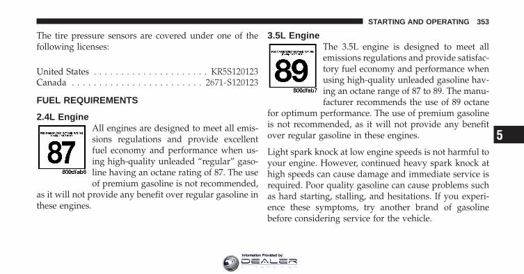
The tire pressure sensors are covered under one of thefollowing licenses:
United States . . . . . . . . . . . . . . . . . . . . . KR5S120123Canada . . . . . . . . . . . . . . . . . . . . . . . . 2671-S120123
FUEL REQUIREMENTS
2.4L EngineAll engines are designed to meet all emis-sions regulations and provide excellentfuel economy and performance when us-ing high-quality unleaded “regular” gaso-line having an octane rating of 87. The useof premium gasoline is not recommended,
as it will not provide any benefit over regular gasoline inthese engines.
3.5L EngineThe 3.5L engine is designed to meet allemissions regulations and provide satisfac-tory fuel economy and performance whenusing high-quality unleaded gasoline hav-ing an octane range of 87 to 89. The manu-facturer recommends the use of 89 octane
for optimum performance. The use of premium gasolineis not recommended, as it will not provide any benefitover regular gasoline in these engines.
Light spark knock at low engine speeds is not harmful toyour engine. However, continued heavy spark knock athigh speeds can cause damage and immediate service isrequired. Poor quality gasoline can cause problems suchas hard starting, stalling, and hesitations. If you experi-ence these symptoms, try another brand of gasolinebefore considering service for the vehicle.
5
STARTING AND OPERATING 353
Information Provided by:

Over 40 auto manufacturers worldwide have issued andendorsed consistent gasoline specifications (the WorldWide Fuel Charter, WWFC) which define fuel propertiesnecessary to deliver enhanced emissions, performance,and durability for your vehicle. The manufacturer recom-mends the use of gasolines that meet the WWFC speci-fications, if they are available.
Reformulated GasolineMany areas of the country require the use of cleanerburning gasoline referred to as “Reformulated Gasoline.”Reformulated gasolines contain oxygenates and are spe-cifically blended to reduce vehicle emissions and im-prove air quality.
The manufacturer supports the use of reformulated gaso-lines. Properly blended reformulated gasolines will pro-vide excellent performance and durability of engine andfuel system components.
Gasoline/Oxygenate BlendsSome fuel suppliers blend unleaded gasoline with oxy-genates such as 10% ethanol, MTBE, and ETBE. Oxygen-ates are required in some areas of the country during theWinter months to reduce carbon monoxide emissions.Fuels blended with these oxygenates may be used inyour vehicle.
CAUTION!
DO NOT use gasolines containing Methanol or E85Ethanol. Use of these blends may result in startingand driveability problems and may damage criticalfuel system components.
Problems that result from using methanol/gasoline orE85 ethanol blends are not the responsibility of themanufacturer. While MTBE is an oxygenate made fromMethanol, it does not have the negative effects ofmethanol.
354 STARTING AND OPERATING
Information Provided by:

MMT In GasolineMMT is a manganese-containing metallic additive that isblended into some gasoline to increase octane. Gasolineblended with MMT provides no performance advantagebeyond gasoline of the same octane number withoutMMT. Gasoline blended with MMT reduces spark pluglife and reduces emission system performance in somevehicles. The manufacturer recommends that gasolinewithout MMT be used in your vehicle. The MMT contentof gasoline may not be indicated on the gasoline pump,therefore, you should ask your gasoline retailer whetherthe gasoline contains MMT. It is even more important tolook for gasoline without MMT in Canada, because MMTcan be used at levels higher than those allowed in theUnited States. MMT is prohibited in Federal and Califor-nia reformulated gasoline.
Materials Added to FuelAll gasoline sold in the United States is required tocontain effective detergent additives. Use of additionaldetergents or other additives is not needed under normalconditions and they would result in additional cost.Therefore, you should not have to add anything to thefuel.
Fuel System Cautions
CAUTION!
Follow these guidelines to maintain your vehicle’sperformance:• The use of leaded gas is prohibited by Federal law.
Using leaded gasoline can impair engine perfor-mance and damage the emissions control system.
(Continued)
5
STARTING AND OPERATING 355
Information Provided by:

CAUTION! (Continued)• An out-of-tune engine or certain fuel or ignition
malfunctions can cause the catalytic converter tooverheat. If you notice a pungent burning odor orsome light smoke, your engine may be out of tuneor malfunctioning and may require immediateservice. Contact your authorized dealer for serviceassistance.
• The use of fuel additives, which are now beingsold as octane enhancers, is not recommended.Most of these products contain high concentra-tions of methanol. Fuel system damage or vehicleperformance problems resulting from the use ofsuch fuels or additives is not the responsibility ofthe manufacturer.
NOTE: Intentional tampering with the emissions con-trol system can result in civil penalties being assessedagainst you.
Carbon Monoxide Warnings
WARNING!
Carbon monoxide (CO) in exhaust gases is deadly.Follow the precautions below to prevent carbonmonoxide poisoning:• Do not inhale exhaust gases. They contain carbon
monoxide, a colorless and odorless gas, which cankill. Never run the engine in a closed area, such asa garage, and never sit in a parked vehicle with theengine running for an extended period. If thevehicle is stopped in an open area with the enginerunning for more than a short period, adjust theventilation system to force fresh, outside air intothe vehicle.
(Continued)
356 STARTING AND OPERATING
Information Provided by:

WARNING! (Continued)• Guard against carbon monoxide with proper
maintenance. Have the exhaust system inspectedevery time the vehicle is raised. Have any abnor-mal conditions repaired promptly. Until repaired,drive with all side windows fully open.
• Keep the liftgate closed when driving your vehicleto prevent carbon monoxide and other poisonousexhaust gases from entering the vehicle.
ADDING FUEL
Fuel Filler Cap (Gas Cap)The gas cap is located behind the fuel filler door on theleft side of the vehicle. If the gas cap is lost or damaged,be sure the replacement cap has been designed for usewith this vehicle.
NOTE: When removing the fuel filler cap, lay the captether in the hook, located on the fuel filler door rein-forcement.
Fuel Filler Cap (Gas Cap)
5
STARTING AND OPERATING 357
Information Provided by:

CAUTION!
• Damage to the fuel system or emissions controlsystem could result from using an improper fueltank filler tube cap (gas cap).
• A poorly fitting gas cap could let impurities intothe fuel system.
• A poorly fitting gas cap may cause the “Malfunc-tion Indicator Light (MIL)” to turn on.
• To avoid fuel spillage and overfilling, do not “topoff” the fuel tank after filling. When the fuelnozzle “clicks” or shuts off, the fuel tank is full.
WARNING!
• Never have any smoking materials lit in or nearthe vehicle when the gas cap is removed or thetank filled.
(Continued)
WARNING! (Continued)• Never add fuel to the vehicle when the engine is
running.• A fire may result if gasoline is pumped into a
portable container that is inside of a vehicle. Youcould be burned. Always place gas containers onthe ground while filling.
• Failure to follow this warning may result in seri-ous injury or death.
NOTE:• Tighten the gas cap until you hear a “clicking” sound.
This is an indication that the gas cap is tightenedproperly. The MIL in the instrument cluster may turnon if the gas cap is not secured properly. Make surethat the gas cap is tightened each time the vehicle isrefueled.
358 STARTING AND OPERATING
Information Provided by:

• When the fuel nozzle “clicks” or shuts off, the fueltank is full.
Loose Fuel Filler Cap MessageIf the vehicle diagnostic system determines that the fuelfiller cap is loose, improperly installed, or damaged, theword “gASCAP” will display in the odometer. If thisoccurs, tighten the fuel filler cap until a “clicking” soundis heard and press the TRIP ODOMETER button to turnoff the message. If the problem persists, the message willappear the next time the vehicle is started.
A loose, improperly installed, or damaged fuel filler capmay also turn on the MIL. Refer to “Onboard DiagnosticSystem” in “Maintaining Your Vehicle” for furtherinformation.
VEHICLE LOADINGThe load carrying capacity of your vehicle is shown onthe “Vehicle Certification Label.” This information
should be used for passenger and luggage loading asindicated.
Do not exceed the specified Gross Vehicle Weight Rating(GVWR) or the Gross Axle Weight Rating (GAWR).
Vehicle Certification LabelYour vehicle has a Vehicle Certification Label affixed tothe rear of the driver’s door.
The label contains the following information:
• Name of manufacturer
• Month and year of manufacture
• Gross Vehicle Weight Rating (GVWR)
• Gross Axle Weight Rating (GAWR) front
• Gross Axle Weight Rating (GAWR) rear
• Vehicle Identification Number (VIN)
5
STARTING AND OPERATING 359
Information Provided by:

• Type of Vehicle
• Month Day and Hour of Manufacture (MDH)
The bar code allows a computer scanner to read the VIN.
Gross Vehicle Weight Rating (GVWR)The GVWR is the total allowable weight of your vehicle.This includes driver, passengers, and cargo. The totalload must be limited so that you do not exceed theGVWR.
Gross Axle Weight Rating (GAWR)The GAWR is the maximum capacity of the front and rearaxles. Distribute the load over the front and rear axlesevenly. Make sure that you do not exceed either front orrear GAWR.
WARNING!
Because the front wheels steer the vehicle, it isimportant that you do not exceed the maximum frontor rear GAWR. A dangerous driving condition canresult if either rating is exceeded. You could losecontrol of the vehicle and have an accident.
OverloadingThe load carrying components (axle, springs, tires,wheels, etc.) of your vehicle will provide satisfactoryservice as long as you do not exceed the GVWR and thefront and rear GAWR.
The best way to figure out the total weight of yourvehicle is to weigh it when it is fully loaded and ready foroperation. Weigh it on a commercial scale to ensure thatit is not over the GVWR.
360 STARTING AND OPERATING
Information Provided by:

Figure out the weight on the front and rear of the vehicleseparately. It is important that you distribute the loadevenly over the front and rear axles.
Overloading can cause potential safety hazards andshorten useful service life. Heavier axles or suspensioncomponents do not necessarily increase the vehicle’sGVWR.
LoadingTo load your vehicle properly, first figure out its emptyweight, axle-by-axle and side-by-side. Store heavier itemsdown low and be sure you distribute their weight asevenly as possible. Stow all loose items securely beforedriving. If weighing the loaded vehicle shows that youhave exceeded either GAWR, but the total load is withinthe specified GVWR, you must redistribute the weight.Improper weight distribution can have an adverse effecton the way your vehicle steers and handles and the waythe brakes operate.
TRAILER TOWINGIn this section, you will find safety tips and informationon limits to the type of towing you can reasonably dowith your vehicle. Before towing a trailer, carefullyreview this information to tow your load as efficientlyand safely as possible.
To maintain warranty coverage, follow the requirementsand recommendations in this manual concerning ve-hicles used for trailer towing.
Common Towing DefinitionsThe following trailer towing related definitions will assistyou in understanding the following information:
Gross Vehicle Weight Rating (GVWR)The GVWR is the total allowable weight of your vehicle.This includes driver, passengers, cargo, and tongueweight. The total load must be limited so that you do not
5
STARTING AND OPERATING 361
Information Provided by:

exceed the GVWR. Refer to “Vehicle Loading/VehicleCertification Label” in “Starting and Operating” forfurther information.
Gross Trailer Weight (GTW)The GTW is the weight of the trailer plus the weight of allcargo, consumables, and equipment (permanent or tem-porary) loaded in or on the trailer in its �loaded andready for operation� condition.
The recommended way to measure GTW is to put yourfully loaded trailer on a vehicle scale. The entire weightof the trailer must be supported by the scale.
Gross Combination Weight Rating (GCWR)The GCWR is the total permissible weight of your vehicleand trailer when weighed in combination.
NOTE: The GCWR rating includes a 150 lbs (68 kg)allowance for the presence of a driver.
Gross Axle Weight Rating (GAWR)The GAWR is the maximum capacity of the front and rearaxles. Distribute the load over the front and rear axlesevenly. Make sure that you do not exceed either front orrear GAWR. Refer to “Vehicle Loading/Vehicle Certifica-tion Label” in “Starting and Operating” for furtherinformation.
WARNING!
It is important that you do not exceed the maximumfront or rear GAWR. A dangerous driving conditioncan result if either rating is exceeded. You could losecontrol of the vehicle and have an accident.
Tongue Weight (TW)The tongue weight is the downward force exerted on thehitch ball by the trailer. In most cases, it should not be lessthan 10% or more than 15% of the trailer load. You mustconsider this as part of the load on your vehicle.
362 STARTING AND OPERATING
Information Provided by:

Frontal AreaThe frontal area is the maximum height multiplied by themaximum width of the front of a trailer.
Trailer Sway Control – ElectronicRefer to “Electronic Brake Control System/Trailer SwayControl (TSC)” in “Starting and Operating” for furtherinformation.
Trailer Sway Control – MechanicalThe trailer sway control is a telescoping link that can beinstalled between the hitch receiver and the trailer tonguethat typically provides adjustable friction associated withthe telescoping motion to dampen any unwanted trailerswaying motions while traveling.
Weight-Carrying HitchA weight-carrying hitch supports the trailer tongueweight, just as if it were luggage located at a hitch ball orsome other connecting point of the vehicle. These kinds
of hitches are the most popular on the market today andthey are commonly used to tow small- and medium-sized trailers.
Weight-Distributing HitchA weight-distributing system works by applying lever-age through spring (load) bars. They are typically usedfor heavier loads to distribute trailer tongue weight to thetow vehicle’s front axle and the trailer axle(s). When usedin accordance with the manufacturers directions, it pro-vides for a more level ride, offering more consistentsteering and brake control thereby enhancing towingsafety. The addition of a friction / hydraulic sway controlalso dampens sway caused by traffic and crosswinds andcontributes positively to tow vehicle and trailer stability.Trailer sway control and a weight distributing (loadequalizing) hitch are recommended for heavier TongueWeights (TW) and may be required depending on vehicleand trailer configuration/loading to comply with GrossAxle Weight Rating (GAWR) requirements.
5
STARTING AND OPERATING 363
Information Provided by:

WARNING!
• An improperly adjusted weight distributing hitchsystem may reduce handling, stability, brakingperformance, and could result in an accident.
• Weight distributing systems may not be compat-ible with surge brake couplers. Consult with yourhitch and trailer manufacturer or a reputable rec-reational vehicle dealer for additionalinformation.
Without Weight-Distributing Hitch (Incorrect)
364 STARTING AND OPERATING
Information Provided by:

With Weight-Distributing Hitch (Correct) Improper Adjustment of Weight-Distributing Hitch(Incorrect)
5
STARTING AND OPERATING 365
Information Provided by:

Trailer Hitch ClassificationYour vehicle may be factory equipped for safe towing oftrailers weighing over 2,000 lbs (907 kg) with the optionalTrailer Tow Prep Package. See your authorized dealer forpackage content.
The following chart provides the industry standard forthe maximum trailer weight a given trailer hitch class cantow and should be used to assist you in selecting thecorrect trailer hitch for your intended towing condition.
Trailer Hitch Classification DefinitionsClass Max. Trailer Hitch
Industry StandardsClass I - Light Duty 2,000 lbs (907 kg)Class II - MediumDuty
3,500 lbs (1 587 kg)
Class III - Heavy Duty 5,000 lbs (2 268 kg)Class IV - ExtraHeavy Duty
10,000 lbs (4 540 kg)
Refer to the “Trailer Towing Weights (MaximumTrailer Weight Ratings)” chart for the MaximumGross Trailer Weight (GTW) towable for your givendrivetrain.
All trailer hitches should be professionally installed onyour vehicle.
366 STARTING AND OPERATING
Information Provided by:

Trailer Towing Weights (Maximum Trailer Weight Ratings)The following chart provides the maximum trailer weight ratings towable for your given drivetrain.
Engine/Transmission GCWR (Gross Com-bined Wt. Rating) Frontal Area Max. GTW (Gross
Trailer Wt.) Max. Tongue Wt.
2.4L/Automatic 6,000 lbs (2 722 kg) 22 sq ft (2.0 sq m)1,000 lbs (454 kg)
which includes up to5 persons & Luggage
100 lbs (45 kg)
3.5L/Automatic(without Trailer Tow
Prep Package
7,300 lbs (3 311 kg) 32 sq ft (3.0 sq m)2,000 lbs (907 kg)
which includes 1 to 2persons & Luggage
200 lbs (91 kg)
7,300 lbs (3 311 kg) 32 sq ft (3.0 sq m)1,500 lbs (680 kg)
which includes 3 to 4persons & Luggage
150 lbs (68 kg)
7,300 lbs (3 311 kg) 32 sq ft (3.0 sq m)1,000 lbs (454 kg)
which includes 5 to 7persons & Luggage
100 lbs (45 kg) *Ex-cept for AWD mod-
els.
5
STARTING AND OPERATING 367
Information Provided by:

Engine/Transmission GCWR (Gross Com-bined Wt. Rating) Frontal Area Max. GTW (Gross
Trailer Wt.) Max. Tongue Wt.
3.5L/Automatic(with Trailer Tow
Prep Package
8,300 lbs (3 765 kg) 40 sq ft (3.7 sq m)3,500 lbs (1 588 kg)
which includes 1 to 2persons & Luggage
350 lbs (159 kg)
8,300 lbs (3 765 kg) 40 sq ft (3.7 sq m)3,000 lbs (1 361 kg)
which includes 3 to 4persons & Luggage
300 lbs (136 kg)
8,300 lbs (3 765 kg) 40 sq ft (3.7 sq m)2,500 lbs (1 134 kg)
which includes 5 to 6persons & Luggage
250 lbs (113 kg) *Ex-cept for AWD mod-
els.
8,300 lbs (3 765 kg) 40 sq ft (3.7 sq m)2,500 lbs (1 134 kg)
which includes 7persons & Luggage
100 lbs (113 kg) *Ex-cept for AWD mod-
els.
368 STARTING AND OPERATING
Information Provided by:

NOTE:• The trailer tongue weight must be considered as part
of the combined weight of occupants and cargo, andshould never exceed the weight referenced on the Tireand Loading Information placard. Refer to “Tire SafetyInformation” in “Starting and Operating” for furtherinformation.
• * For All Wheel Drive (AWD) models carrying 5 to 7persons and luggage will exceed the rear Gross AxleWeight Rating (GAWR) and therefore should not beattempted.
Trailer and Tongue WeightAlways load a trailer with 60% to 65% of the weight inthe front of the trailer. This places 10% to 15% of theGross Trailer Weight (GTW) on the tow hitch of yourvehicle. Loads balanced over the wheels or heavier in therear can cause the trailer to sway severely side to side
which will cause loss of control of the vehicle and trailer.Failure to load trailers heavier in front is the cause ofmany trailer accidents.
Never exceed the maximum tongue weight stamped onyour bumper or trailer hitch.
5
STARTING AND OPERATING 369
Information Provided by:

Consider the following items when computing theweight on the rear axle of the vehicle:
• The tongue weight of the trailer.
• The weight of any other type of cargo or equipmentput in or on your vehicle.
• The weight of the driver and all passengers.
NOTE: Remember that everything put into or on thetrailer adds to the load on your vehicle. Also, additionalfactory-installed options or authorized dealer-installedoptions must be considered as part of the total load onyour vehicle. Refer to the “Tire and Loading Information”placard for the maximum combined weight of occupantsand cargo for your vehicle.
Towing RequirementsTo promote proper break-in of your new vehicle drive-train components the following guidelines are recom-mended:
CAUTION!
• Do not tow a trailer at all during the first 500 miles(805 km) the new vehicle is driven. The engine,axle or other parts could be damaged.
• Then, during the first 500 miles (805 km) that atrailer is towed, do not drive over 50 mph(80 km/h) and do not make starts at full throttle.This helps the engine and other parts of thevehicle wear in at the heavier loads.
Perform the maintenance listed in the “MaintenanceSchedule.” Refer to “Maintenance Schedule” for furtherinformation. When towing a trailer, never exceed theGAWR, or GCWR, ratings.
370 STARTING AND OPERATING
Information Provided by:

WARNING!
Improper towing can lead to an injury accident.Follow these guidelines to make your trailer towingas safe as possible:• Make certain that the load is secured in the trailer
and that it will not shift during travel. Whentrailering cargo that is not fully secured, dynamicload shifts can occur that may be difficult for thedriver to control. You could lose control of yourvehicle and have an accident.
• When hauling cargo or towing a trailer, do notoverload your vehicle or trailer. Overloading cancause a loss of control, poor performance, or dam-age to brakes, axle, engine, transmission, steering,suspension, chassis structure, or tires.
(Continued)
WARNING! (Continued)• Safety chains must always be used between your
vehicle and trailer. Always connect the chains tothe frame or hook retainers of the vehicle hitch.Cross the chains under the trailer tongue andallow enough slack for turning corners.
• Vehicles with trailers should not be parked on agrade. When parking, apply the parking brake onthe tow vehicle. Put the tow vehicle automatictransmission in PARK. Always, block or �chock�the trailer wheels.
• GCWR must not be exceeded.• Total weight must be distributed between the tow
vehicle and the trailer such that the following fourratings are not exceeded:1. GVWR2. GTW
(Continued)
5
STARTING AND OPERATING 371
Information Provided by:

WARNING! (Continued)3. GAWR4. Tongue weight rating for the trailer hitch utilized.(This requirement may limit the ability to alwaysachieve the 10% to 15% range of tongue weight as apercentage of total trailer weight.)
Towing Requirements – Tires
− Do not attempt to tow a trailer while using a compactspare tire.
− Proper tire inflation pressures are essential to the safeand satisfactory operation of your vehicle. Refer to“Tires – General Information” in “Starting and Oper-ating” for proper tire inflation procedures.
− Check the trailer tires for proper tire inflation pres-sures before trailer usage.
− Check for signs of tire wear or visible tire damagebefore towing a trailer. Refer to “Tires – GeneralInformation” in “Starting and Operating” for theproper inspection procedure.
− When replacing tires, refer to “Tires – General Infor-mation” in “Starting and Operating” for informationon replacement tires and for the proper tire replace-ment procedures. Replacing tires with a higher loadcarrying capacity will not increase the vehicle’s GVWRand GAWR limits.
Towing Requirements – Trailer Brakes
− Do not interconnect the hydraulic brake system orvacuum system of your vehicle with that of the trailer.This could cause inadequate braking and possiblepersonal injury.
− An electronically actuated trailer brake controller isrequired when towing a trailer with electronically
372 STARTING AND OPERATING
Information Provided by:

actuated brakes. When towing a trailer equipped witha hydraulic surge actuated brake system, an electronicbrake controller is not required.
− Trailer brakes are recommended for trailers over1,000 lbs (454 kg) and required for trailers in excess of2,000 lbs (907 kg).
CAUTION!
If the trailer weighs more than 1,000 lbs (454 kg)loaded, it should have its own brakes, and theyshould be of adequate capacity. Failure to do thiscould lead to accelerated brake lining wear, higherbrake pedal effort, and longer stopping distances.
WARNING!
• Do not connect trailer brakes to your vehicle’shydraulic brake lines. It can overload your brakesystem and cause it to fail. You might not havebrakes when you need them and could have anaccident.
• Towing any trailer will increase your stoppingdistance. When towing, you should allow for ad-ditional space between your vehicle and the ve-hicle in front of you. Failure to do so could resultin an accident.
5
STARTING AND OPERATING 373
Information Provided by:

Towing Requirements – Trailer Lights and WiringWhenever you pull a trailer, regardless of the trailer size,stoplights and turn signals on the trailer are required formotoring safety.
The Trailer Tow Package may include a four- and seven-pin wiring harness. Use a factory approved trailer har-ness and connector.
NOTE: Do not cut or splice wiring into the vehicleswiring harness.
The electrical connections are all complete to the vehiclebut you must mate the harness to a trailer connector.Refer to the following illustrations.
Four-Pin Connector
1 — Female Pins 4 — Park2 — Male Pin 5 — Left Stop/Turn3 — Ground 6 — Right Stop/Turn
374 STARTING AND OPERATING
Information Provided by:

Towing TipsBefore setting out on a trip, practice turning, stopping,and backing up the trailer in an area located away fromheavy traffic.
Automatic TransmissionThe DRIVE range can be selected when towing. How-ever, if frequent shifting occurs while in this range, selectthe “3” range for four-speed automatic or the “5” rangefor six-speed automatic.
NOTE: Using the “3” or “5” range while operating thevehicle under heavy operating conditions will improveperformance and extend transmission life by reducingexcessive shifting and heat build up. This action will alsoprovide better engine braking.
If you REGULARLY tow a trailer for more than 45 min-utes of continuous operation, then change the transmis-sion fluid and filter according to the interval specified for
Seven-Pin Connector
1 — Battery 5 — Ground2 — Backup Lamps 6 — Left Stop/Turn3 — Right Stop/Turn 7 — Running Lamps4 — Electric Brakes
5
STARTING AND OPERATING 375
Information Provided by:

“police, taxi, fleet, or frequent trailer towing.” Refer to“Maintenance Schedule” for the proper maintenanceintervals.
NOTE: Check the four-speed transmission fluid levelbefore towing. The six-speed transmission is sealed andthe fluid level cannot be checked. See your authorizeddealer for assistance.
Electronic Speed Control – If Equipped
− Do not use in hilly terrain or with heavy loads.
− When using the speed control, if you experience speeddrops greater than 10 mph (16 km/h), disengage untilyou can get back to cruising speed.
− Use speed control in flat terrain and with light loads tomaximize fuel efficiency.
AutoStick� – If Equipped
− By using the AutoStick� modes and selecting a specificgear range, frequent shifting can be avoided. Thehighest gear range should be selected that allows foradequate performance. For example, choose “4” if thedesired speed can be maintained. Choose “3” or “2” ifneeded to maintain the desired speed.
− Extended driving at high RPM should be avoided toprevent excess heat generation. A reduction in vehiclespeed may be required to avoid extended driving athigh RPM. Return to a higher gear range or vehiclespeed when road conditions and RPM level allows.
376 STARTING AND OPERATING
Information Provided by:

Cooling SystemTo reduce potential for engine and transmission over-heating, take the following actions:
− City DrivingWhen stopped for short periods, shift the transmissioninto NEUTRAL and increase engine idle speed.
− Highway DrivingReduce speed.
− Air ConditioningTurn off temporarily.
RECREATIONAL TOWING (BEHINDMOTORHOME, ETC.)
TOWING THIS VEHICLE BEHIND ANOTHERVEHICLE (Flat Towing With All Four Wheels OnThe Ground)Recreational towing for this vehicle is not recommended.
NOTE: If the vehicle requires towing, make sure all fourwheels are off the ground.
5
STARTING AND OPERATING 377
Information Provided by:

Information Provided by:

WHAT TO DO IN EMERGENCIES
CONTENTS
� Hazard Warning Flasher . . . . . . . . . . . . . . . . 380
� If Your Engine Overheats . . . . . . . . . . . . . . . . 380
� Jacking And Tire Changing . . . . . . . . . . . . . . . 381
▫ Jack Location . . . . . . . . . . . . . . . . . . . . . . . 382
▫ Spare Tire Location . . . . . . . . . . . . . . . . . . . 383
▫ Preparations For Jacking . . . . . . . . . . . . . . . 383
▫ Spare Tire Removal . . . . . . . . . . . . . . . . . . . 383
▫ Spare Tire Stowage . . . . . . . . . . . . . . . . . . . 385
▫ Jacking Instructions . . . . . . . . . . . . . . . . . . . 387
� Jump-Starting . . . . . . . . . . . . . . . . . . . . . . . . 392
▫ Preparations For Jump-Start . . . . . . . . . . . . . 393
▫ Jump-Starting Procedure . . . . . . . . . . . . . . . 395
� Freeing A Stuck Vehicle . . . . . . . . . . . . . . . . . 396
� Towing A Disabled Vehicle . . . . . . . . . . . . . . . 398
▫ Without The Ignition Key . . . . . . . . . . . . . . 398
▫ Towing This Vehicle Behind Another Vehicle(Flat Towing With The Key In The IgnitionAnd All Four Wheels On The Ground) . . . . . 398
▫ Towing This Vehicle Behind Another VehicleWith A Tow Dolly . . . . . . . . . . . . . . . . . . . . 400
6
Information Provided by:

HAZARD WARNING FLASHERThe Hazard Warning flasher switch is located in theinstrument panel switch bank, above the climate controls.
Press the switch to turn on the Hazard Warningflasher. When the switch is activated, all directionalturn signals will flash on and off to warn oncoming
traffic of an emergency. Press the switch a second time toturn off the Hazard Warning flasher.
This is an emergency warning system and it should notbe used when the vehicle is in motion. Use it when yourvehicle is disabled and it is creating a safety hazard forother motorists.
When you must leave the vehicle to seek assistance, theHazard Warning flasher will continue to operate eventhough the ignition switch is in the LOCK position.
NOTE: With extended use, the Hazard Warning flashermay wear down your battery.
IF YOUR ENGINE OVERHEATSIn any of the following situations, you can reduce thepotential for overheating by taking the appropriate ac-tion.
• On the highways — Slow down.
• In city traffic — While stopped, put the transaxle inNEUTRAL, but do not increase engine idle speed.
CAUTION!
Driving with a hot cooling system could damageyour vehicle. If the temperature gauge reads “H,”safely pull over and stop the vehicle. Idle the vehiclewith the A/C turned off until the pointer drops backinto the normal range. If the pointer remains on the“H,” and you hear continuous chimes, turn the en-gine OFF immediately, and call for service.
380 WHAT TO DO IN EMERGENCIES
Information Provided by:

NOTE: There are steps that you can take to slow downan impending overheat condition:
• If your air conditioner (A/C) is on, turn it off. The A/Csystem adds heat to the engine cooling system andturning the A/C off can help remove this heat.
• You can also turn the temperature control to maximumheat, the mode control to floor and the blower controlto high. This allows the heater core to act as asupplement to the radiator and aids in removing heatfrom the engine cooling system.
WARNING!
You or others can be badly burned by hot enginecoolant (antifreeze) or steam from your radiator. Ifyou see or hear steam coming from under the hood,do not open the hood until the radiator has had timeto cool. Never try to open a cooling system pressurecap when the radiator or coolant bottle is hot.
JACKING AND TIRE CHANGING
WARNING!
• Do not attempt to change a tire on the side of thevehicle close to moving traffic. Pull far enough offthe road to avoid the danger of being hit whenoperating the jack or changing the wheel.
(Continued)
6
WHAT TO DO IN EMERGENCIES 381
Information Provided by:

WARNING! (Continued)• Getting under a jacked-up vehicle is dangerous.
The vehicle could slip off the jack and fall on you.You could be crushed. Never get any part of yourbody under a vehicle that is on a jack. Never startor run the engine while the vehicle is on a jack. Ifyou need to get under a raised vehicle, take it to aservice center where it can be raised on a lift.
• The jack is designed to use as a tool for changingtires only. The jack should not be used to lift thevehicle for service purposes. The vehicle shouldbe jacked on a firm level surface only. Avoid ice orslippery areas.
• A loose tire or jack thrown forward in a collisionor hard stop could endanger the occupants of thevehicle. Always stow the jack parts and the sparetire in the places provided.
Jack LocationThe jack and jack-handle are stowed underneath a coverin the rear storage bin in the cargo area.
Jack Storage Location
382 WHAT TO DO IN EMERGENCIES
Information Provided by:

Spare Tire LocationThe spare tire is stowed underneath the rear of thevehicle and is held in place by means of a cable winchmechanism.
Preparations For Jacking
1. Park the vehicle on a firm level surface as far from theedge of the roadway as possible, avoid icy or slipperyareas.
WARNING!
Do not attempt to change a tire on the side of thevehicle close to moving traffic. Pull far enough offthe road to avoid the danger of being hit whenoperating the jack or changing the wheel.
2. Set the parking brake.
3. Place the shift lever in PARK.
4. Turn OFF the ignition.
5. Turn on the Hazard Warning flashers.
6. Block both the front and rear of thewheel diagonally opposite of the jack-ing position. For example, if changingthe right front tire, block the left rearwheel.
NOTE: Passengers should not remain in the vehiclewhen the vehicle is being jacked.
Spare Tire Removal
NOTE: On Seven-Passenger Models, fold the third-rowpassenger seats flat. This will provide more space whenaccessing the jacking tools and when operating the winchmechanism.
6
WHAT TO DO IN EMERGENCIES 383
Information Provided by:

1. Remove the jack-handle components 1, 2 and 3 fromstorage and assemble them.
NOTE: Assemble components 2 and 3 by seating thesmall ball at the end of component 2 in the small hole atthe end of component 3. This will lock these componentstogether. Assemble components 1 and 2 so that the wheel
nut socket at the end of component 1 faces upward whenseated on component 2. This will make it easier to rotatethe assembly when operating the winch mechanism.
2. Fit the assembled jack-handle over the winch drivenut located in the jack storage area. Rotate the jack-handle assembly counterclockwise until the spare tire ison the ground with enough cable slack to allow you topull the spare tire out from underneath the vehicle.
CAUTION!
The winch mechanism is designed for use with thejack-handle only. Use of an air wrench or other powertools is not recommended and it can damage thewinch.
3. Pull the spare tire out from underneath the vehicle andraise it upright so the tire’s tread is on the ground.
Lowering/Raising Spare Tire
384 WHAT TO DO IN EMERGENCIES
Information Provided by:

4. Tilt the retainer at the end of the winch cable andremove it from the center of the wheel.
Spare Tire Stowage
NOTE: On seven-passenger models, fold the third-rowpassenger seats flat. This will provide more space whenaccessing the jacking tools and when operating the winchmechanism.
1. Remove the jack-handle components 1, 2, and 3 fromstorage and assemble them.
Spare Tire Retainer
6
WHAT TO DO IN EMERGENCIES 385
Information Provided by:

NOTE: Assemble components 2 and 3 by seating thesmall ball at the end of component 2 in the small hole atthe end of component 3. This will lock these componentstogether. Assemble components 1 and 2 so that the wheelnut socket at the end of component 1 faces upward when
seated on component 2. This will make it easier to rotatethe assembly when operating the winch mechanism.
2. Fit the assembled jack-handle over the winch drivenut located in the jack storage area. Rotate the jack-handle assembly counterclockwise until there is enoughcable slack to allow you to pull the cable and retainer outfrom underneath the vehicle.
CAUTION!
The winch mechanism is designed for use with thejack-handle only. Use of an air wrench or other powertools is not recommended and it can damage thewinch.
3. Place the spare tire near to the winch cable. Hold thespare upright so that the tire’s tread is on the ground andthe valve stem is at the top of the wheel and facing awayfrom the rear of the vehicle.
Lowering/Raising Spare Tire
386 WHAT TO DO IN EMERGENCIES
Information Provided by:

4. Tilt the retainer at the end of the winch cable and dropit through the center of the wheel. Then place the sparetire with the cable and retainer underneath the vehicle.
5. Fit the assembled jack-handle over the winch drivenut. Rotate the jack-handle assembly clockwise to raisethe spare tire into the storage area. Continue to rotate the
jack-handle assembly until you hear the winch mecha-nism click three times. It cannot be over tightened. Pushagainst the tire several times to be sure it is held securelyin place.
Jacking Instructions
WARNING!
Carefully follow these tire changing warnings tohelp prevent personal injury or damage to yourvehicle:• Always park on a firm, level surface as far from
the edge of the roadway as possible before raisingthe vehicle.
• Block the wheel diagonally opposite the wheel tobe raised.
• Set the parking brake firmly and set an automatictransmission in PARK.
(Continued)
Spare Tire Retainer
6
WHAT TO DO IN EMERGENCIES 387
Information Provided by:

WARNING! (Continued)• Never start or run the engine with the vehicle on a
jack.• Do not let anyone sit in the vehicle when it is on a
jack.• Do not get under the vehicle when it is on a jack.• Only use the jack in the positions indicated and
for lifting this vehicle during a tire change.• If working on or near a roadway, be extremely
careful of motor traffic.• To assure that spare tires, flat or inflated, are
securely stowed, spares must be stowed with thevalve stem facing the ground.
• Turn on the Hazard Warning flasher.
1. Remove the spare tire, jack, and jack-handle fromstowage.
2. Loosen, but do not remove, the wheel nuts on thewheel with the flat tire. Turn the wheel nuts counter-clockwise one turn while the wheel is still on the ground.
3. Place the jack underneath the lift area that is closest tothe flat tire. Turn the jack screw clockwise to firmlyengage the jack saddle with the lift area of the sill flange.
Jack Warning Label
388 WHAT TO DO IN EMERGENCIES
Information Provided by:

4. Raise the vehicle by turning the jack screw clockwisewith the jack handle. Raise the vehicle until the tire justclears the road surface and enough clearance is obtainedto install the spare tire. Minimum tire lift providesmaximum stability.
Front Jacking Location Rear Jacking Location6
WHAT TO DO IN EMERGENCIES 389
Information Provided by:

WARNING!
Raising the vehicle higher than necessary can makethe vehicle less stable. It could slip off the jack andhurt someone near it. Raise the vehicle only enoughto remove the tire.
5. Remove the wheel nuts. For vehicles so equipped,remove the wheel cover from the wheel by hand. Do notpry the wheel cover off. Then pull the wheel off the hub.
WARNING!
To avoid possible personal injury, handle the wheelcovers with care to avoid contact with any sharpedges.
NOTE: For vehicles so equipped, the wheel cover isheld on the wheel by the wheel nuts. When reinstallingthe original wheel, properly align the wheel cover to thevalve stem, place the wheel cover onto the wheel, andthen install the wheel nuts.
6. Install the spare tire.
NOTE:• For vehicles so equipped, do not attempt to install a
center cap or wheel cover on the compact spare.
• Refer to “Compact Spare Tire” and to “Limited-UseSpare” under “Tires — General Information” in “Start-ing and Operating” for additional warnings, cautions,and information about the spare tire, its use, andoperation.
7. Install the wheel nuts with the cone shaped end of thenut toward the wheel. Lightly tighten the wheel nuts.
390 WHAT TO DO IN EMERGENCIES
Information Provided by:

WARNING!
To avoid the risk of forcing the vehicle off the jack,do not tighten the wheel nuts fully until the vehiclehas been lowered. Failure to follow this warning mayresult in personal injury or death.
8. Lower the vehicle by turning the jack screw counter-clockwise with the jack handle.
9. Finish tightening the wheel nuts. Push down on thewrench while tightening for increased leverage. Alternatewheel nuts until each nut has been tightened twice. Thecorrect wheel nut tightness is 95 ft lbs (130 N·m). If indoubt about the correct tightness, have them checkedwith a torque wrench by your authorized dealer or at aservice station.
10. Lower the jack to its fully closed position.
WARNING!
A loose tire or jack, thrown forward in a collision orhard stop could endanger the occupants of the ve-hicle. Always stow the jack parts and the spare tire inthe places provided. Have the deflated (flat) tirerepaired or replaced immediately.
11. Place the deflated (flat) tire in the cargo area. Do notstow the deflated tire in the spare tire stowage location.Have the deflated (flat) tire repaired or replaced as soonas possible.
12. To stow the winch cable and retainer, fit the as-sembled jack-handle over the winch drive nut. Rotate thejack-handle assembly clockwise until you hear the winchmechanism click three times. It cannot be over tightened.
13. Stow the jack-handle and jack.
6
WHAT TO DO IN EMERGENCIES 391
Information Provided by:

14. Check the tire pressure as soon as possible. Adjust thetire pressure as required.
Wheel NutsTighten all wheel nuts occasionally to eliminate thepossibility of wheel studs being sheared or the bolt holesin the wheels becoming elongated. This is especiallyimportant during the first few hundred miles (kilome-ters) of operation and after changing a tire. This allowsthe wheel nuts to seat properly. All wheel nuts shouldfirst be firmly seated against the wheel. The wheel nutsshould then be tightened to recommended torque.Tighten the wheel nuts to the final torque in increments.Progress around the bolt circle, tightening the nut oppo-site of the one you previously tightened until the finaltorque is achieved. Recommended torque is 95 ft lbs(130 N·m).
JUMP-STARTINGIf your vehicle has a discharged battery it can be jump-started using a set of jumper cables and a battery inanother vehicle or by using a portable battery boosterpack. Jump-starting can be dangerous if done improperlyso please follow the procedures in this section carefully.
NOTE: When using a portable battery booster packfollow the manufacturer’s operating instructions andprecautions.
CAUTION!
Do not use a portable battery booster pack or anyother booster source with a system voltage greaterthan 12 Volts or damage to the battery, starter motor,alternator or electrical system may occur.
392 WHAT TO DO IN EMERGENCIES
Information Provided by:

WARNING!
Do not attempt jump-starting if the battery is frozen.It could rupture or explode and cause personal injury.
Preparations for Jump-StartThe battery in your vehicle is located between the leftfront headlight assembly and the left front wheel splashshield. To allow jump-starting there are remote batteryposts located on the left side of the engine compartment.
Remote Battery Posts
1 — Remote Positive (+) Post (covered with protective cap)2 — Remote Negative (-) Post
6
WHAT TO DO IN EMERGENCIES 393
Information Provided by:

WARNING!
• Take care to avoid the radiator cooling fan when-ever the hood is raised. It can start anytime theignition switch is on. You can be injured bymoving fan blades.
• Remove any metal jewelry such as watch bands orbracelets that might make an inadvertent electricalcontact. You could be seriously injured.
• Batteries contain sulfuric acid that can burn yourskin or eyes and generate hydrogen gas which isflammable and explosive. Keep open flames orsparks away from the battery.
1. Set the parking brake, shift the automatic transmissioninto PARK and turn the ignition to LOCK.
2. Turn off the heater, radio, and all unnecessary electri-cal accessories.
3. Remove the protective cover over the remote positive(+) battery post. To remove the cover, press the lockingtab and pull upward on the cover.
4. If using another vehicle to jump-start the battery, parkthe vehicle within the jumper cables reach, set theparking brake and make sure the ignition is OFF.
Locking Tab
394 WHAT TO DO IN EMERGENCIES
Information Provided by:

WARNING!
Do not allow vehicles to touch each other as thiscould establish a ground connection and personalinjury could result.
Jump-Starting Procedure
WARNING!
Failure to follow this procedure could result in per-sonal injury or property damage due to battery ex-plosion.
CAUTION!
Failure to follow these procedures could result indamage to the charging system of the booster vehicleor the discharged vehicle.
1. Connect the positive (+) end of the jumper cable to theremote positive (+) post of the discharged vehicle.
2. Connect the opposite end of the positive (+) jumpercable to the positive (+) post of the booster battery.
3. Connect the negative end (-) of the jumper cable to thenegative (-) post of the booster battery.
4. Connect the opposite end of the negative (-) jumpercable to the remote negative (-) post of the vehicle withthe discharged battery.
WARNING!
Do not connect the cable to the negative post (-) of thedischarged battery. The resulting electrical sparkcould cause the battery to explode and could result inpersonal injury.
6
WHAT TO DO IN EMERGENCIES 395
Information Provided by:

5. Start the engine in the vehicle that has the boosterbattery, let the engine idle a few minutes, and then startthe engine in the vehicle with the discharged battery.
Once the engine is started, remove the jumper cables inthe reverse sequence:
6. Disconnect the negative (-) jumper cable from theremote negative (-) post of the vehicle with the dis-charged battery.
7. Disconnect the negative end (-) of the jumper cablefrom the negative (-) post of the booster battery.
8. Disconnect the opposite end of the positive (+) jumpercable from the positive (+) post of the booster battery.
9. Disconnect the positive (+) end of the jumper cablefrom the remote positive (+) post of the dischargedvehicle.
10. Reinstall the protective cover over the remote posi-tive (+) battery post of the discharged vehicle.
If frequent jump-starting is required to start your vehicleyou should have the battery and charging system in-spected at your authorized dealer.
CAUTION!
Accessories that can be plugged into the vehiclepower outlets draw power from the vehicle’s battery,even when not in use (i.e., cellular phones, etc.).Eventually, if plugged in long enough, the vehicle’sbattery will discharge sufficiently to degrade batterylife and/or prevent the engine from starting.
FREEING A STUCK VEHICLEIf your vehicle becomes stuck in mud, sand, or snow, itcan often be moved by a rocking motion. Turn yoursteering wheel right and left to clear the area around the
396 WHAT TO DO IN EMERGENCIES
Information Provided by:

front wheels. Then shift back and forth between RE-VERSE and 1st gear. Using the least accelerator pedalpressure to maintain the rocking motion without spin-ning the wheels is most effective.
NOTE:
If your vehicle is equipped with Traction Con-trol, turn the system OFF before attempting to“rock” the vehicle. Refer to “Electronic StabilityProgram (ESP)” in “Starting and Operating”
for further information.
CAUTION!
• When “rocking” a stuck vehicle by moving be-tween 1st and REVERSE, do not spin the wheelsfaster than 15 mph (24 km/h), or drivetrain damagemay result.
(Continued)
CAUTION! (Continued)• Revving the engine or spinning the wheels too fast
may lead to transmission overheating and failure.It can also damage the tires. Do not spin thewheels above 30 mph (48 km/h) while in gear (notransmission shifting occurring).
WARNING!
Fast spinning tires can be dangerous. Forces gener-ated by excessive wheel speeds may cause damage, oreven failure, of the axle and tires. A tire couldexplode and injure someone. Do not spin your vehi-cle’s wheels faster than 30 mph (48 km/h) or forlonger than 30 seconds continuously without stop-ping when you are stuck and do not let anyone neara spinning wheel, no matter what the speed.
6
WHAT TO DO IN EMERGENCIES 397
Information Provided by:
TOWING A DISABLED VEHICLE
Without The Ignition Key
Front Wheel Drive (FWD)Special care must be taken when the vehicle is towedwith the ignition in the LOCK position. Flatbed towing isthe preferred towing method. However, if a flatbedtowing vehicle is not available, a wheel lift towingvehicle may be used. Furthermore, rear towing is notrecommended with the front wheels on the ground, astransaxle damage can result. If rear towing is the onlyalternative, a front end dolly must be used. Propertowing equipment is necessary to prevent damage to thevehicle.
All Wheel Drive (AWD)The manufacturer requires towing your vehicle with allfour wheels OFF the ground using a flatbed.
CAUTION!
Towing this vehicle using any other method couldresult in extensive damage to the transfer case and/ortransmission. Such damage is not covered by theNew Vehicle Limited Warranty.
Towing This Vehicle Behind Another Vehicle (FlatTowing With The Key In The Ignition And All FourWheels On The Ground)
CAUTION!
• If the vehicle being towed requires steering, theignition switch must be in the ON position, not inthe LOCK or ACC position.
(Continued)
398 WHAT TO DO IN EMERGENCIES
Information Provided by:

CAUTION! (Continued)• Do not attempt to tow this vehicle from the front
with sling-type towing equipment. Damage to thefront fascia will result.
• Do not push or tow this vehicle with anothervehicle as damage to the bumper fascia and trans-axle may result.
If you must use the accessories (wipers, defrosters, etc.)while being towed, the key must be in the ON position,not the ACC position. Make certain the transaxle remainsin NEUTRAL.
Front Wheel Drive (FWD)Your vehicle may be towed under the following condi-tions:
• The shift lever must be in NEUTRAL.
• The distance to be traveled must not exceed 15 miles(25 km).
• The towing speed must not exceed 25 mph (40 km/h).
CAUTION!
Exceeding these towing limits may cause a transaxlefailure. Such damage is not covered by the NewVehicle Limited Warranty. If the transaxle is notoperative, or if the vehicle is to be towed more than15 miles (25 km), the vehicle must be transportedeither with a flatbed truck or with the front wheelsoff the ground.
All Wheel Drive (AWD)Your vehicle may be towed under the following condi-tions:
• The shift lever must be in NEUTRAL.
6
WHAT TO DO IN EMERGENCIES 399
Information Provided by:

• The distance to be traveled must not exceed 15 miles(25 km).
• The towing speed must not exceed 25 mph (40 km/h),and both front and rear wheels must be on the ground.
CAUTION!
Exceeding these towing limits may cause a transaxlefailure. Such damage is not covered by the NewVehicle Limited Warranty. If the transaxle is notoperative, or if the vehicle is to be towed more than15 miles (25 km), the vehicle must be transported ona flatbed truck.
Towing This Vehicle Behind Another Vehicle WithA Tow Dolly
Front Wheel Drive (FWD)Rear towing is not recommended with the front wheelson the ground, as transaxle damage can result. If rear
towing is the only alternative, a front end dolly must beused. Proper towing equipment is necessary to preventdamage to the vehicle.
All Wheel Drive (AWD)The manufacturer requires towing your vehicle with allfour wheels OFF the ground using a flatbed.
CAUTION!
Towing this vehicle using any other method couldresult in extensive damage to the transfer case and/ortransmission. Such damage is not covered by theNew Vehicle Limited Warranty.
400 WHAT TO DO IN EMERGENCIES
Information Provided by:

MAINTAINING YOUR VEHICLE
CONTENTS
� Engine Compartment — 2.4L . . . . . . . . . . . . . 403
� Engine Compartment — 3.5L . . . . . . . . . . . . . 404
� Onboard Diagnostic System — OBD II . . . . . . 405
▫ Loose Fuel Filler Cap Message . . . . . . . . . . . 405
� Emissions Inspection And MaintenancePrograms . . . . . . . . . . . . . . . . . . . . . . . . . . . . 406
� Replacement Parts . . . . . . . . . . . . . . . . . . . . . 407
� Dealer Service . . . . . . . . . . . . . . . . . . . . . . . . 407
� Maintenance Procedures . . . . . . . . . . . . . . . . . 408
▫ Engine Oil . . . . . . . . . . . . . . . . . . . . . . . . . 409
▫ Engine Oil Filter . . . . . . . . . . . . . . . . . . . . . 412
▫ Engine Air Cleaner Filter . . . . . . . . . . . . . . . 412
▫ Maintenance-Free Battery . . . . . . . . . . . . . . 413
▫ Air Conditioner Maintenance . . . . . . . . . . . . 414
▫ A/C Air Filter – If Equipped . . . . . . . . . . . . 416
▫ Body Lubrication . . . . . . . . . . . . . . . . . . . . 417
▫ Wiper Blades . . . . . . . . . . . . . . . . . . . . . . . 418
▫ Adding Washer Fluid . . . . . . . . . . . . . . . . . 420
7
Information Provided by:

▫ Exhaust System . . . . . . . . . . . . . . . . . . . . . 421
▫ Cooling System . . . . . . . . . . . . . . . . . . . . . 424
▫ Brake System . . . . . . . . . . . . . . . . . . . . . . . 430
▫ Automatic Transmission . . . . . . . . . . . . . . . 432
▫ Appearance Care And Protection FromCorrosion . . . . . . . . . . . . . . . . . . . . . . . . . . 435
▫ Cleaning The Cupholders . . . . . . . . . . . . . . 440
� Fuses . . . . . . . . . . . . . . . . . . . . . . . . . . . . . . 440
▫ Totally Integrated Power Module . . . . . . . . . 440
� Vehicle Storage . . . . . . . . . . . . . . . . . . . . . . . 448
� Replacement Bulbs . . . . . . . . . . . . . . . . . . . . 449
� Bulb Replacement . . . . . . . . . . . . . . . . . . . . . 450
▫ Low Beam Headlamp, High BeamHeadlamp, Front Turn Signal/Park Lamp,Side Marker Lamp . . . . . . . . . . . . . . . . . . . 450
▫ Front Fog Lamp . . . . . . . . . . . . . . . . . . . . . 451
▫ Tail/Stop Lamp, Rear Turn Signal Lamp, TailLamp, Backup Lamp . . . . . . . . . . . . . . . . . . 452
▫ License Plate Lamp . . . . . . . . . . . . . . . . . . . 454
� Fluid Capacities . . . . . . . . . . . . . . . . . . . . . . 455
� Fluids, Lubricants, And Genuine Parts . . . . . . . 456
▫ Engine . . . . . . . . . . . . . . . . . . . . . . . . . . . . 456
▫ Chassis . . . . . . . . . . . . . . . . . . . . . . . . . . . 457
402 MAINTAINING YOUR VEHICLE
Information Provided by:

ENGINE COMPARTMENT — 2.4L
1 — Engine Coolant Reservoir 7 — Totally Integrated Power Module (TIPM)2 — Power Steering Fluid Reservoir 8 — Automatic Transmission Dipstick3 — Engine Oil Fill 9 — Washer Fluid Reservoir4 — Brake Fluid Reservoir 10 — Coolant Pressure Cap5 — Remote Jump Start (Positive Battery Post) 11 — Engine Oil Dipstick6 — Remote Jump Start (Negative Battery Post)
7
MAINTAINING YOUR VEHICLE 403
Information Provided by:

ENGINE COMPARTMENT — 3.5L
1 — Engine Coolant Reservoir 6 — Totally Integrated Power Module (TIPM)2 — Power Steering Fluid Reservoir 7 — Air Cleaner Filter3 — Brake Fluid Reservoir 8 — Washer Fluid Reservoir4 — Remote Jump Start (Positive Battery Post) 9 — Engine Oil Dipstick5 — Remote Jump Start (Negative Battery Post) 10 — Engine Oil Fill
404 MAINTAINING YOUR VEHICLE
Information Provided by:

ONBOARD DIAGNOSTIC SYSTEM — OBD IIYour vehicle is equipped with a sophisticated OnboardDiagnostic system called OBD II. This system monitorsthe performance of the emissions, engine, and automatictransmission control systems. When these systems areoperating properly, your vehicle will provide excellentperformance and fuel economy, as well as engine emis-sions well within current government regulations.
If any of these systems require service, the OBD II systemwill turn on the “Malfunction Indicator Light (MIL).” Itwill also store diagnostic codes and other information toassist your service technician in making repairs. Al-though your vehicle will usually be drivable and notneed towing, see your authorized dealer for service assoon as possible.
CAUTION!
• Prolonged driving with the MIL on could causefurther damage to the emissions control system. Itcould also affect fuel economy and driveability.The vehicle must be serviced before any emissionstests can be performed.
• If the MIL is flashing while the engine is running,severe catalytic converter damage and power losswill soon occur. Immediate service is required.
Loose Fuel Filler Cap MessageIf the vehicle diagnostic system determines that the fuelfiller cap is loose, improperly installed, or damaged, theword “gASCAP” will display in the odometer. If thisoccurs, tighten the fuel filler cap until a “clicking” soundis heard and press the TRIP ODOMETER button to turnoff the message. If the problem persists, the message willappear the next time the vehicle is started.
7
MAINTAINING YOUR VEHICLE 405
Information Provided by:

A loose, improperly installed, or damaged fuel filler capmay also turn on the MIL.
EMISSIONS INSPECTION AND MAINTENANCEPROGRAMSIn some localities, it may be a legal requirement to passan inspection of this vehicle’s emissions control system.Failure to pass could prevent vehicle registration.
For states that require an Inspection and Mainte-nance (I/M), this check verifies the MalfunctionIndicator Light (MIL) is functioning and is not on
when the engine is running, and that the OBD II systemis ready for testing.
Normally, the OBD II system will be ready. The OBD IIsystem may not be ready if the vehicle was recentlyserviced, recently had a dead battery, or a battery replace-ment. If the OBD II system should be determined notready for the I/M test, the vehicle may fail the test.
This vehicle has a simple ignition key-actuated test,which you can use prior to going to the test station. Tocheck if this vehicle’s OBD II system is ready, you mustdo the following:
1. Insert the ignition key into the ignition switch.
2. Turn the ignition to the ON position, but do not crankor start the engine.
3. If you crank or start the engine, you will have to startthis test over.
4. As soon as you turn the ignition key to the ONposition, you will see the MIL symbol come on as part ofa normal bulb check.
5. Approximately 15 seconds later, one of two things willhappen:
a. The MIL will flash for about 10 seconds and thenreturn to being fully illuminated until you turn OFF
406 MAINTAINING YOUR VEHICLE
Information Provided by:

the ignition key or start the engine. This means that thevehicle’s OBD II system is not ready and you shouldnot proceed to the I/M station.
b. The MIL will not flash at all and will remain fullyilluminated until you turn OFF the ignition key or startthe engine. This means that the vehicle’s OBD IIsystem is ready, and you can proceed to the I/Mstation.
If the OBD II system is not ready, you should see anauthorized dealer or repair facility. If this vehicle wasrecently serviced or had a battery failure or replacement,you may need to do nothing more than drive the vehicleas you normally would in order for the OBD II system toupdate. A recheck with the above test routine may thenindicate that the system is now ready.
Regardless of whether the vehicle’s OBD II system isready or not ready, if the MIL is illuminated duringnormal vehicle operation, you should have the vehicle
serviced before going to the I/M station. The I/M stationcan fail the vehicle because the MIL is on with the enginerunning.
REPLACEMENT PARTSUse of genuine MOPAR� parts for normal/scheduledmaintenance and repairs is highly recommended to en-sure the designed performance. Damage or failurescaused by the use of non-MOPAR� parts for maintenanceand repairs will not be covered by the manufacturer’swarranty.
DEALER SERVICEYour authorized dealer has the qualified service person-nel, special tools, and equipment to perform all serviceoperations in an expert manner. Service Manuals areavailable which include detailed service information foryour vehicle. Refer to these Service Manuals beforeattempting any procedure yourself.
7
MAINTAINING YOUR VEHICLE 407
Information Provided by:

NOTE: Intentional tampering with emissions controlsystems may void your warranty and could result in civilpenalties being assessed against you.
WARNING!
You can be badly injured working on or around amotor vehicle. Only do service work for which youhave the knowledge and the proper equipment. Ifyou have any doubt about your ability to perform aservice job, take your vehicle to a competent me-chanic.
MAINTENANCE PROCEDURESThe pages that follow contain the required maintenanceservices determined by the engineers who designed yourvehicle.
Besides those maintenance items specified in the fixedmaintenance schedule, there are other components whichmay require servicing or replacement in the future.
CAUTION!
• Failure to properly maintain your vehicle or per-form repairs and service when necessary couldresult in more costly repairs, damage to othercomponents or negatively impact vehicle perfor-mance. Immediately have potential malfunctionsexamined by an authorized Chrysler Group LLCdealership or qualified repair center.
(Continued)
408 MAINTAINING YOUR VEHICLE
Information Provided by:

CAUTION! (Continued)• Your vehicle has been built with improved fluids
that protect the performance and durability ofyour vehicle and also allow extended maintenanceintervals. Do not use chemical flushes in thesecomponents as the chemicals can damage yourengine, transmission, power steering or air condi-tioning. Such damage is not covered by the NewVehicle Limited Warranty. If a flush is neededbecause of component malfunction, use only thespecified fluid for the flushing procedure.
Engine Oil
Checking Oil LevelTo assure proper engine lubrication, the engine oil mustbe maintained at the correct level. Check the oil level atregular intervals, such as every fuel stop. The best time tocheck the engine oil level is about five minutes after a
fully warmed engine is shut off. Do not check oil levelbefore starting the engine after it has sat overnight.Checking engine oil level when the engine is cold willgive you an incorrect reading.
Checking the oil while the vehicle is on level ground andonly when the engine is hot, will improve the accuracy ofthe oil level readings. Maintain the oil level between therange markings on the dipstick. Either the range mark-ings consist of a crosshatch zone marked SAFE or acrosshatch zone marked with MIN at the low end of therange and MAX at the high end of the range. Adding1.0 qt (1.0 l) of oil when the reading is at the low end ofthe range marking will raise the oil level to the high endof the range marking.
7
MAINTAINING YOUR VEHICLE 409
Information Provided by:

CAUTION!
Do not overfill the engine. Overfilling the enginewill cause oil aeration, which can lead to loss of oilpressure and an increase in oil temperature. Thiscould damage your engine.
Change Engine OilThe oil change indicator system will remind you that it istime to take your vehicle in for scheduled maintenance.Refer to “Maintenance Schedule” for further information.
NOTE: Under no circumstances should oil changeintervals exceed 6,000 miles (10 000 km) or six months,whichever occurs first.
Engine Oil SelectionFor best performance and maximum protection under alltypes of operating conditions, the manufacturer only
recommends engine oils that are API Certified and meetthe requirements of Chrysler Material Standard MS-6395.
American Petroleum Institute (API) Engine OilIdentification Symbol
This symbol means that the oil hasbeen certified by the AmericanPetroleum Institute (API). Themanufacturer only recommendsAPI Certified engine oils.
CAUTION!
Do not use chemical flushes in your engine oil as thechemicals can damage your engine. Such damage isnot covered by the New Vehicle Limited Warranty.
410 MAINTAINING YOUR VEHICLE
Information Provided by:
Engine Oil Viscosity (SAE Grade) – 2.4L EngineSAE 5W-20 engine oil is recommended for all operatingtemperatures. This engine oil improves low temperaturestarting and vehicle fuel economy.
The engine oil filler cap also shows the recommendedengine oil viscosity for your engine. For information onthe engine oil filler cap location, refer to “Engine Com-partment” in “Maintaining Your Vehicle” for furtherinformation.
Lubricants that do not have both, the engine oil certifi-cation mark and the correct SAE viscosity grade numbershould not be used.
Engine Oil Viscosity (SAE Grade) – 3.5L EngineSAE 10W-30 engine oil is recommended for all operatingtemperatures.
The engine oil filler cap also shows the recommendedengine oil viscosity for your engine. For information on
engine oil filler cap location, refer to “Engine Compart-ment” in “Maintaining Your Vehicle” for further informa-tion.
Lubricants that do not have both, the engine oil certifi-cation mark and the correct SAE viscosity grade numbershould not be used.
Synthetic Engine OilsYou may use synthetic engine oils provided the recom-mended oil quality requirements are met, and the recom-mended maintenance intervals for oil and filter changesare followed.
Materials Added to Engine OilDo not add any supplemental materials, other than leakdetection dyes, to the engine oil. Engine oil is an engi-neered product and its performance may be impaired bysupplemental additives.
7
MAINTAINING YOUR VEHICLE 411
Information Provided by:

Disposing of Used Engine Oil and Oil FiltersCare should be taken in disposing of used engine oil andoil filters from your vehicle. Used oil and oil filters,indiscriminately discarded, can present a problem to theenvironment. Contact your authorized dealer, servicestation, or governmental agency for advice on how andwhere used oil and oil filters can be safely discarded inyour area.
Engine Oil FilterThe engine oil filter should be replaced with a new filterat every engine oil change.
Engine Oil Filter SelectionThis manufacturer’s engines have a full-flow type dispos-able oil filter. Use a filter of this type for replacement. Thequality of replacement filters varies considerably. Onlyhigh quality filters should be used to assure most efficientservice. MOPAR� engine oil filters are high quality oilfilters and are recommended.
Engine Air Cleaner FilterRefer to “Maintenance Schedule” for further information.
WARNING!
The air induction system (air cleaner, hoses, etc.) canprovide a measure of protection in the case of enginebackfire. Do not remove the air induction system (aircleaner, hoses, etc.) unless such removal is necessaryfor repair or maintenance. Make sure that no one isnear the engine compartment before starting thevehicle with the air induction system (air cleaner,hoses, etc.) removed. Failure to do so can result inserious personal injury.
Engine Air Cleaner Filter SelectionThe quality of replacement engine air cleaner filtersvaries considerably. Only high quality filters should be
412 MAINTAINING YOUR VEHICLE
Information Provided by:

used to assure most efficient service. MOPAR� engine aircleaner filters are a high quality filter and arerecommended.
Maintenance-Free BatteryYour vehicle is equipped with a maintenance-free battery.You will never have to add water, nor is periodic main-tenance required.
NOTE: The battery is stored in a compartment that islocated behind the left front fender and is accessiblethrough the wheel well. The wheel and tire assemble donot need to be removed to access the compartment.Remote battery terminals are located in the engine com-partment for jump-starting. Refer to “Jump-Starting Pro-cedures” in “What To Do In Emergencies” for furtherinformation.
To access the battery, turn the steering wheel fully to theright and remove the access panel from the inner fendershield.
WARNING!
• Battery fluid is a corrosive acid solution and canburn or even blind you. Do not allow battery fluidto contact your eyes, skin, or clothing. Do not leanover a battery when attaching clamps. If acidsplashes in eyes or on skin, flush the area imme-diately with large amounts of water.
• Battery gas is flammable and explosive. Keepflame or sparks away from the battery. Do not usea booster battery or any other booster source withan output greater than 12 Volts. Do not allow cableclamps to touch each other.
• Battery posts, terminals, and related accessoriescontain lead and lead compounds. Wash handsafter handling.
7
MAINTAINING YOUR VEHICLE 413
Information Provided by:

CAUTION!
• It is essential when replacing the cables on thebattery that the positive cable is attached to thepositive post and the negative cable is attached tothe negative post. Battery posts are marked posi-tive (+) and negative (-) and are identified on thebattery case. Cable clamps should be tight on theterminal posts and free of corrosion.
• If a “fast charger” is used while the battery is inthe vehicle, disconnect both vehicle battery cablesbefore connecting the charger to the battery. Donot use a “fast charger” to provide starting voltage.
Air Conditioner MaintenanceFor best possible performance, your air conditionershould be checked and serviced by an authorized dealerat the start of each warm season. This service shouldinclude cleaning of the condenser fins and a performancetest. Drive belt tension should also be checked at thistime.
CAUTION!
Do not use chemical flushes in your air conditioningsystem as the chemicals can damage your air condi-tioning components. Such damage is not covered bythe New Vehicle Limited Warranty.
414 MAINTAINING YOUR VEHICLE
Information Provided by:

WARNING!
• Use only refrigerants and compressor lubricantsapproved by the manufacturer for your air condi-tioning system. Some unapproved refrigerants areflammable and can explode, injuring you. Otherunapproved refrigerants or lubricants can causethe system to fail, requiring costly repairs. Refer toWarranty Information Book, located on the DVD,for further warranty information.
• The air conditioning system contains refrigerantunder high pressure. To avoid risk of personalinjury or damage to the system, adding refrigerantor any repair requiring lines to be disconnectedshould be done by an experienced technician.
Refrigerant Recovery and RecyclingR-134a Air Conditioning Refrigerant is a hydrofluoro-carbon (HFC) that is endorsed by the EnvironmentalProtection Agency and is an ozone-saving product. How-ever, the manufacturer recommends that air conditioningservice be performed by authorized dealers or otherservice facilities using recovery and recycling equipment.
NOTE: Use only manufacturer approved A/C systemsealers, stop leak products, seal conditioners, compressoroil, and refrigerants.
7
MAINTAINING YOUR VEHICLE 415
Information Provided by:

A/C Air Filter – If EquippedRefer to “Maintenance Schedule” for further information.
WARNING!
Do not remove the A/C air filter while the blower isoperating or personal injury may result.
The A/C air filter is located in the fresh air inlet behindthe glove box. Perform the following steps to replace thefilter:
1. Open the glove box and remove all contents.
2. Push the retaining tab on each side of the glove boxinward while gently pulling the glove box door outwarduntil both tabs clear the door opening in the instrumentpanel.
3. Pivot the glove box downward.
4. Disengage the two retaining tabs that secure the filtercover to the HVAC housing and remove the cover.
Glove Box Removal
416 MAINTAINING YOUR VEHICLE
Information Provided by:
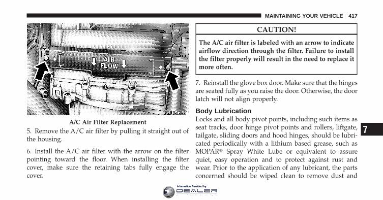
5. Remove the A/C air filter by pulling it straight out ofthe housing.
6. Install the A/C air filter with the arrow on the filterpointing toward the floor. When installing the filtercover, make sure the retaining tabs fully engage thecover.
CAUTION!
The A/C air filter is labeled with an arrow to indicateairflow direction through the filter. Failure to installthe filter properly will result in the need to replace itmore often.
7. Reinstall the glove box door. Make sure that the hingesare seated fully as you raise the door. Otherwise, the doorlatch will not align properly.
Body LubricationLocks and all body pivot points, including such items asseat tracks, door hinge pivot points and rollers, liftgate,tailgate, sliding doors and hood hinges, should be lubri-cated periodically with a lithium based grease, such asMOPAR� Spray White Lube or equivalent to assurequiet, easy operation and to protect against rust andwear. Prior to the application of any lubricant, the partsconcerned should be wiped clean to remove dust and
A/C Air Filter Replacement7
MAINTAINING YOUR VEHICLE 417
Information Provided by:

grit; after lubricating excess oil and grease should beremoved. Particular attention should also be given tohood latching components to ensure proper function.When performing other underhood services, the hoodlatch, release mechanism and safety catch should becleaned and lubricated.
The external lock cylinders should be lubricated twice ayear, preferably in the Fall and Spring. Apply a smallamount of a high quality lubricant, such as MOPAR�Lock Cylinder Lubricant or equivalent directly into thelock cylinder.
Wiper BladesClean the rubber edges of the wiper blades and thewindshield and rear window periodically with a spongeor soft cloth and a mild nonabrasive cleaner. This willremove accumulations of salt, waxes, or road film, andhelp reduce streaking and smearing.
Operation of the wipers on dry glass for long periodsmay cause deterioration of the wiper blades. Always usewasher fluid when using the wipers to remove salt or dirtfrom a dry windshield or rear window.
Avoid using the wiper blades to remove frost or ice fromthe windshield or rear window. Make sure that they arenot frozen to the glass before turning them on to avoiddamaging the blade. Keep the blade rubber out of contactwith petroleum products such as engine oil, gasoline, etc.
NOTE: Life expectancy of wiper blades varies depend-ing on geographical area and frequency of use. Poorperformance of blades may be present with chattering,marks, water lines or wet spots. If any condition ispresent please proceed to clean wiper blades with humidcloth removing any debris that may be affecting itsfunction.
418 MAINTAINING YOUR VEHICLE
Information Provided by:

Rear Wiper Removal/Installation
1. Lift the pivot cap on the rear wiper arm upward, thiswill allow the rear wiper blade to be raised off of theliftgate glass.
NOTE: The rear wiper arm cannot be raised fullyupward unless the pivot cap is raised first.
2. Lift the rear wiper arm upward to raise the wiperblade off of the liftgate glass.
1 — Wiper Arm2 — Pivot Cap
7
MAINTAINING YOUR VEHICLE 419
Information Provided by:

3. Grab the bottom of the wiper blade and rotate itforward to unsnap the blade pivot pin from the wiperblade holder.
4. Install the wiper blade pivot pin into the wiper bladeholder at the end of the wiper arm, and firmly press thewiper blade until it snaps into place.
5. Lower the wiper blade and snap the pivot cap intoplace.
Adding Washer FluidThe windshield washer and the rear window washershare the same fluid reservoir. The fluid reservoir islocated in the engine compartment. Be sure to check thefluid level in the reservoir at regular intervals. Fill thereservoir with windshield washer solvent (not radiatorantifreeze) and operate the system for a few seconds toflush out the residual water.
When refilling the washer fluid reservoir, apply somewasher fluid to a cloth or towel and wipe the wiperblades clean. This will help blade performance.
1 — Wiper Blade2 — Blade Pivot Pin3 — Wiper Arm4 — Wiper Blade Holder
420 MAINTAINING YOUR VEHICLE
Information Provided by:

To prevent freeze-up of your windshield washer systemin cold weather, select a solution or mixture that meets orexceeds the temperature range of your climate. Thisrating information can be found on most washer fluidcontainers.
The fluid reservoir will hold nearly 1 gal (4 l) of washerfluid when the message “LoWASH” appears in theinstrument cluster.
WARNING!
Commercially available windshield washer solventsare flammable. They could ignite and burn you. Caremust be exercised when filling or working aroundthe washer solution.
Exhaust SystemThe best protection against carbon monoxide entry intothe vehicle body is a properly maintained engine exhaustsystem.
If you notice a change in the sound of the exhaust system;or if the exhaust fumes can be detected inside the vehicle;or when the underside or rear of the vehicle is damaged;have an authorized technician inspect the complete ex-haust system and adjacent body areas for broken, dam-aged, deteriorated, or mispositioned parts. Open seamsor loose connections could permit exhaust fumes to seepinto the passenger compartment. In addition, inspect theexhaust system each time the vehicle is raised for lubri-cation or oil change. Replace as required.
7
MAINTAINING YOUR VEHICLE 421
Information Provided by:

WARNING!
• Exhaust gases can injure or kill. They containcarbon monoxide (CO), which is colorless andodorless. Breathing it can make you unconsciousand can eventually poison you. To avoid breathingCO, refer to “Safety Tips/Exhaust Gas” in “ThingsTo Know Before Starting Your Vehicle” for furtherinformation.
• A hot exhaust system can start a fire if you parkover materials that can burn. Such materials mightbe grass or leaves coming into contact with yourexhaust system. Do not park or operate your ve-hicle in areas where your exhaust system cancontact anything that can burn.
CAUTION!
• The catalytic converter requires the use of un-leaded fuel only. Leaded gasoline will destroy theeffectiveness of the catalyst as an emissions con-trol device and may seriously reduce engine per-formance and cause serious damage to the engine.
• Damage to the catalytic converter can result if yourvehicle is not kept in proper operating condition.In the event of engine malfunction, particularlyinvolving engine misfire or other apparent loss ofperformance, have your vehicle serviced promptly.Continued operation of your vehicle with a severemalfunction could cause the converter to overheat,resulting in possible damage to the converter andvehicle.
422 MAINTAINING YOUR VEHICLE
Information Provided by:

Under normal operating conditions, the catalytic con-verter will not require maintenance. However, it is im-portant to keep the engine properly tuned to assureproper catalyst operation and prevent possible catalystdamage.
NOTE: Intentional tampering with emissions controlsystems can result in civil penalties being assessedagainst you.
In unusual situations involving grossly malfunctioningengine operation, a scorching odor may suggest severeand abnormal catalyst overheating. If this occurs, stopthe vehicle, turn off the engine and allow it to cool.Service, including a tune-up to manufacturer’s specifica-tions, should be obtained immediately.
To minimize the possibility of catalytic converter dam-age:
• Do not shut off the engine or interrupt the ignition,when the transmission is in gear and the vehicle is inmotion.
• Do not try to start the engine by pushing or towing thevehicle.
• Do not idle the engine with any spark plug wiresdisconnected or removed, such as when diagnostictesting, or for prolonged periods during very roughidle or malfunctioning operating conditions.
7
MAINTAINING YOUR VEHICLE 423
Information Provided by:

Cooling System
WARNING!
• When working near the radiator cooling fan, dis-connect the fan motor lead or turn the ignitionswitch to the LOCK position. The fan is tempera-ture controlled and can start at any time theignition switch is in the ON position.
• You or others can be badly burned by hot coolantor steam from your radiator. If you see or hearsteam coming from under the hood, do not openthe hood until the radiator has had time to cool.Never try to open a cooling system pressure capwhen the radiator is hot.
Coolant ChecksCheck the engine coolant (antifreeze) protection every12 months (before the onset of freezing weather, whereapplicable). If the engine coolant (antifreeze) is dirty orrusty in appearance, the system should be drained,flushed, and refilled with fresh engine coolant (anti-freeze). Check the front of the A/C condenser for anyaccumulation of bugs, leaves, etc. If dirty, clean by gentlyspraying water from a garden hose vertically down theface of the condenser.
Check the coolant recovery bottle tubing for brittle rub-ber, cracking, tears, cuts, and tightness of the connectionat the bottle and radiator. Inspect the entire system forleaks.
424 MAINTAINING YOUR VEHICLE
Information Provided by:

Cooling System – Drain, Flush and RefillRefer to “Maintenance Schedule” for further information.
If the engine coolant (antifreeze) is dirty or contains aconsiderable amount of sediment, clean and flush with areliable cooling system cleaner. Follow with a thoroughrinsing to remove all deposits and chemicals. Properlydispose of the old engine coolant (antifreeze).
Selection of CoolantUse only the manufacturer’s recommended engine cool-ant (antifreeze). Refer to “Fluids, Lubricants, and Genu-ine Parts” in “Maintaining Your Vehicle” for furtherinformation.
CAUTION!
• Mixing of engine coolant (antifreeze) other thanspecified HOAT engine coolant (antifreeze), mayresult in engine damage and may decrease corro-sion protection. If a non-HOAT engine coolant(antifreeze) is introduced into the cooling systemin an emergency, it should be replaced with thespecified engine coolant (antifreeze) as soon aspossible.
• Do not use water alone or alcohol-based enginecoolant (antifreeze) products. Do not use addi-tional rust inhibitors or antirust products, as theymay not be compatible with the radiator enginecoolant (antifreeze) and may plug the radiator.
(Continued)
7
MAINTAINING YOUR VEHICLE 425
Information Provided by:

CAUTION! (Continued)• This vehicle has not been designed for use with
propylene glycol-based engine coolant (anti-freeze). Use of propylene glycol-based enginecoolant (antifreeze) is not recommended.
Adding CoolantYour vehicle has been built with an improved enginecoolant (antifreeze) that allows extended maintenanceintervals. This engine coolant (antifreeze) can be used upto five years or 102,000 miles (170 000 km) beforereplacement. To prevent reducing this extended mainte-nance period, it is important that you use the sameengine coolant (antifreeze) throughout the life of yourvehicle. Please review these recommendations for usingHybrid Organic Additive Technology (HOAT) enginecoolant (antifreeze).
When adding engine coolant (antifreeze):
• The manufacturer recommends using MOPAR�Antifreeze/Coolant 5 Year/100,000 Mile FormulaHOAT (Hybrid Organic Additive Technology) orequivalent.
• Mix a minimum solution of 50% HOAT engine coolant(antifreeze) and distilled water. Use higher concentra-tions (not to exceed 70%) if temperatures below �34°F(�37°C) are anticipated.
• Use only high purity water such as distilled or deion-ized water when mixing the water/engine coolant(antifreeze) solution. The use of lower quality waterwill reduce the amount of corrosion protection in theengine cooling system.
426 MAINTAINING YOUR VEHICLE
Information Provided by:

Please note that it is the owner’s responsibility to main-tain the proper level of protection against freezing ac-cording to the temperatures occurring in the area wherethe vehicle is operated.
NOTE: Mixing engine coolant (antifreeze) types willdecrease the life of the engine coolant (antifreeze) andwill require more frequent engine coolant (antifreeze)changes.
Cooling System Pressure CapThe cap must be fully tightened to prevent loss of enginecoolant (antifreeze), and to ensure that engine coolant(antifreeze) will return to the radiator from the coolantrecovery bottle.
The cap should be inspected and cleaned if there is anyaccumulation of foreign material on the sealing surfaces.
WARNING!
• The warning words “DO NOT OPEN HOT” onthe cooling system pressure cap are a safety pre-caution. Never add engine coolant (antifreeze)when the engine is overheated. Do not loosen orremove the cap to cool an overheated engine. Heatcauses pressure to build up in the cooling system.To prevent scalding or injury, do not remove thepressure cap while the system is hot or underpressure.
• Do not use a pressure cap other than the onespecified for your vehicle. Personal injury or en-gine damage may result. 7
MAINTAINING YOUR VEHICLE 427
Information Provided by:

Disposal of Used CoolantUsed ethylene glycol-based engine coolant (antifreeze) isa regulated substance requiring proper disposal. Checkwith your local authorities to determine the disposalrules for your community. To prevent ingestion by ani-mals or children, do not store ethylene glycol-basedengine coolant (antifreeze) in open containers or allow itto remain in puddles on the ground. If ingested by a childor pet, seek emergency assistance immediately. Clean upany ground spills immediately.
Coolant Level2.4L Engine – the coolant bottle provides a quick visualmethod for determining that the coolant level is ad-equate. With the engine idling and warm to normaloperating temperature, the level of the coolant in thebottle should be between the “ADD” and “FULL” lines,shown on the bottle.
3.5L Engine – the level of the coolant in the pressurizedcoolant bottle should be between the “COLD” and“FULL” range on the bottle when the engine is cold.
The radiator normally remains completely full, so there isno need to remove the radiator cap unless checking forcoolant freeze point or replacing engine coolant (anti-freeze). Advise your service attendant of this. As long asthe engine operating temperature is satisfactory, thecoolant bottle need only be checked once a month. Whenadditional engine coolant (antifreeze) is needed to main-tain the proper level, it should be added to the coolantbottle. Do not overfill.
Points to Remember
NOTE: When the vehicle is stopped after a few miles(kilometers) of operation, you may observe vapor comingfrom the front of the engine compartment. This is nor-mally a result of moisture from rain, snow, or high
428 MAINTAINING YOUR VEHICLE
Information Provided by:

humidity accumulating on the radiator and being vapor-ized when the thermostat opens, allowing hot enginecoolant (antifreeze) to enter the radiator.
If an examination of your engine compartment shows noevidence of radiator or hose leaks, the vehicle may besafely driven. The vapor will soon dissipate.
• Do not overfill the coolant recovery bottle.
• Check the engine coolant (antifreeze) freeze point inthe radiator and in the coolant recovery bottle. Ifengine coolant (antifreeze) needs to be added, thecontents of coolant recovery bottle must also be pro-tected against freezing.
• If frequent engine coolant (antifreeze) additions arerequired, or if the level in the coolant recovery bottledoes not drop when the engine cools, the coolingsystem should be pressure tested for leaks.
• Maintain engine coolant (antifreeze) concentration at50% HOAT engine coolant (antifreeze) (minimum)and distilled water for proper corrosion protection ofyour engine, which contains aluminum components.
• Make sure that the radiator and coolant recoverybottle overflow hoses are not kinked or obstructed.
• Keep the front of the radiator clean. If your vehicle isequipped with air conditioning, keep the front of thecondenser clean.
• Do not change the thermostat for Summer or Winteroperation. If replacement is ever necessary, installONLY the correct type thermostat. Other designs mayresult in unsatisfactory engine coolant (antifreeze)performance, poor gas mileage, and increasedemissions.
7
MAINTAINING YOUR VEHICLE 429
Information Provided by:

Brake SystemIn order to assure brake system performance, all brakesystem components should be inspected periodically.Refer to “Maintenance Schedule” for further information.
WARNING!
Riding the brakes can lead to brake failure andpossibly an accident. Driving with your foot restingor riding on the brake pedal can result in abnormallyhigh brake temperatures, excessive lining wear, andpossible brake damage. You would not have your fullbraking capacity in an emergency.
Master Cylinder – Brake Fluid Level CheckCheck the fluid level in the master cylinder immediatelyif the “Brake Warning Light” indicates system failure.
Check the fluid level in the master cylinder when per-forming underhood services.
Clean the top of the master cylinder area before removingthe cap. If necessary, add fluid to bring the fluid level upto the requirements described on the brake fluid reser-voir.
Overfilling of fluid is not recommended because it maycause leaking in the system.
Fluid level can be expected to fall as the brake pads wear.Brake fluid level should be checked when pads arereplaced. However, low fluid level may be caused by aleak and a checkup may be needed.
Use only manufacturer’s recommended brake fluid. Re-fer to “Fluids, Lubricants, and Genuine Parts” in “Main-taining Your Vehicle” for further information.
430 MAINTAINING YOUR VEHICLE
Information Provided by:

WARNING!
• Use only manufacturer’s recommended brakefluid. Refer to “Fluids, Lubricants, and GenuineParts” in “Maintaining Your Vehicle” for furtherinformation. Using the wrong type of brake fluidcan severely damage your brake system and/orimpair its performance. The proper type of brakefluid for your vehicle is also labeled on the origi-nal factory installed hydraulic master cylinderreservoir.
(Continued)
WARNING! (Continued)• To avoid contamination from foreign matter or
moisture, use only new brake fluid or fluid thathas been in a tightly closed container. Keep themaster cylinder reservoir cap secured at all times.Brake fluid in a open container absorbs moisturefrom the air resulting in a lower boiling point.This may cause it to boil unexpectedly during hardor prolonged braking, resulting in sudden brakefailure. This could result in a accident.
• Overfilling the brake fluid reservoir can result inspilling brake fluid on hot engine parts, causingthe brake fluid to catch fire. Brake fluid can alsodamage painted and vinyl surfaces, care should betaken to avoid its contact with these surfaces.
(Continued)
7
MAINTAINING YOUR VEHICLE 431
Information Provided by:

WARNING! (Continued)• Do not allow petroleum based fluid to contami-
nate the brake fluid. Brake seal components couldbe damaged, causing partial or complete brakefailure. This could result in an accident.
Automatic TransmissionThe automatic transmission and differential assembly arecontained within a single housing.
The fluid level in the automatic transmission should bechecked whenever the vehicle is serviced. Operation withan improper fluid level will greatly reduce the life of thetransmission and the fluid.
Fluid Level Check – 2.4L EngineUse the following procedure to check the automatictransmission fluid level properly:
1. Park the vehicle on level ground.
2. Run the engine at curb idle speed for a minimum of60 seconds.
3. Apply the parking brake fully.
4. Place the shift lever momentarily in each gear positionending with the lever in PARK.
5. Wipe the area around the dipstick clean to eliminatethe possibility of dirt entering the transmission.
6. Remove the dipstick and determine if the fluid is hotor cold. Hot fluid is approximately 180°F (82°C), which isthe normal operating temperature after the vehicle isdriven at least 15 miles (24 km). Hot fluid cannot be heldcomfortably between the fingertips. Cold fluid is at atemperature below 80°F (27°C).
7. Wipe the dipstick clean and reinsert until seated. Then,remove dipstick and note the reading.
432 MAINTAINING YOUR VEHICLE
Information Provided by:

a. If the fluid is hot, the reading should be in thecrosshatched area marked “HOT” (between the uppertwo holes in the dipstick).
b. If the fluid is cold, the fluid level should be betweenthe lower two holes in the area marked “COLD.”
If the fluid level is low, add sufficient fluid through thefiller (dipstick) tube to bring it to the proper level. Do notoverfill.
CAUTION!
• Using a transmission fluid other than the manu-facturer’s recommended fluid may cause deterio-ration in transmission shift quality and/or torqueconverter shudder. Using a transmission fluidother than that recommended by the manufacturerwill result in more frequent fluid and filterchanges. Refer to “Fluids, Lubricants, and Genu-ine Parts” in “Maintaining Your Vehicle” for fur-ther information.
• Dirt and water in the transmission can causeserious damage. To prevent dirt and water fromentering the transmission after checking or replen-ishing fluid, make certain that the dipstick cap isre-seated properly.
7
MAINTAINING YOUR VEHICLE 433
Information Provided by:

Fluid Level Check – 3.5L EngineThe automatic transmission has no dipstick and is dealerserviced only.
Fluid and Filter ChangesRefer to “Maintenance Schedule” for further information.
In addition, change the fluid and filter if the transmissionis disassembled for any reason.
Selection of LubricantIt is important that the proper lubricant is used in thetransmission to assure optimum transmission perfor-mance. Use only manufacturer’s recommended transmis-sion fluid. Refer to “Fluids, Lubricants, and GenuineParts” in “Maintaining Your Vehicle” for further informa-tion. It is important that the transmission fluid be main-tained at the prescribed level using the recommendedfluid. No chemical flushes should be used in any trans-mission; only the approved lubricant may be used.
Special AdditivesAutomatic Transmission Fluid (ATF) is an engineeredproduct and its performance may be impaired by supple-mental additives. Therefore, do not add any fluid addi-tives to the transmission. The only exception to thispolicy is the use of special dyes to aid in detecting fluidleaks. In addition, avoid using transmission sealers asthey may adversely affect seals.
CAUTION!
Do not use chemical flushes in your transmission asthe chemicals can damage your transmission compo-nents. Such damage is not covered by the NewVehicle Limited Warranty.
434 MAINTAINING YOUR VEHICLE
Information Provided by:

Appearance Care and Protection from Corrosion
Protection of Body and Paint from CorrosionVehicle body care requirements vary according to geo-graphic locations and usage. Chemicals that make roadspassable in snow and ice and those that are sprayed ontrees and road surfaces during other seasons are highlycorrosive to the metal in your vehicle. Outside parking,which exposes your vehicle to airborne contaminants,road surfaces on which the vehicle is operated, extremehot or cold weather and other extreme conditions willhave an adverse effect on paint, metal trim, and under-body protection.
The following maintenance recommendations will enableyou to obtain maximum benefit from the corrosionresistance built into your vehicle.
What Causes Corrosion?Corrosion is the result of deterioration or removal ofpaint and protective coatings from your vehicle.
The most common causes are:
• Road salt, dirt, and moisture accumulation.
• Stone and gravel impact.
• Insects, tree sap, and tar.
• Salt in the air near seacoast localities.
• Atmospheric fallout/industrial pollutants.
Washing
• Wash your vehicle regularly. Always wash your ve-hicle in the shade using MOPAR� Car Wash or a mildcar wash soap, and rinse the panels completely withclear water.
7
MAINTAINING YOUR VEHICLE 435
Information Provided by:

• If insects, tar, or other similar deposits have accumu-lated on your vehicle, use MOPAR� Super Kleen Bugand Tar Remover or equivalent to remove.
• Use a high quality cleaner wax, such as MOPAR�Cleaner Wax to remove road film, stains and to protectyour paint finish. Take care never to scratch the paint.
• Avoid using abrasive compounds and power buffingthat may diminish the gloss or thin out the paintfinish.
CAUTION!
• Do not use abrasive or strong cleaning materialssuch as steel wool or scouring powder that willscratch metal and painted surfaces.
• Use of power washers exceeding 1,200 psi(8 274 kPa) can result in damage or removal ofpaint and decals.
Special Care
• If you drive on salted or dusty roads or if you drivenear the ocean, hose off the undercarriage at least oncea month.
• It is important that the drain holes in the lower edgesof the doors, rocker panels, and cargo area be keptclear and open.
• If you detect any stone chips or scratches in the paint,touch them up immediately. The cost of such repairs isconsidered the responsibility of the owner.
• If your vehicle is damaged due to an accident orsimilar cause, which destroys the paint and protectivecoating, have your vehicle repaired as soon as pos-sible. The cost of such repairs is considered the respon-sibility of the owner.
436 MAINTAINING YOUR VEHICLE
Information Provided by:

• If you carry special cargo such as chemicals, fertilizers,de-icer salt, etc., be sure that such materials are wellpackaged and sealed.
• If a lot of driving is done on gravel roads, considermud or stone shields behind each wheel.
• Use MOPAR� Touch Up Paint or equivalent onscratches as soon as possible. Your authorized dealerhas touch up paint to match the color of your vehicle.
Wheel and Wheel Trim CareAll wheels and wheel trim, especially aluminum andchrome-plated wheels should be cleaned regularly with amild soap and water to prevent corrosion. To removeheavy soil and/or excessive brake dust, use MOPAR�Wheel Cleaner or equivalent or select a nonabrasive,non-acidic cleaner. Do not use scouring pads, steel wool,a bristle brush, or metal polishes. Only MOPAR� orequivalent is recommended. Do not use oven cleaner.
Avoid automatic car washes that use acidic solutions orharsh brushes that may damage the wheels’ protectivefinish.
Stain Repel Fabric Cleaning Procedure – IfEquippedStain Repel seats may be cleaned in the following man-ner:
• Remove as much of the stain as possible by blottingwith a clean, dry towel.
• Blot any remaining stain with a clean, damp towel.
• For tough stains, apply MOPAR� Total Clean or a mildsoap solution to a clean, damp cloth and remove thestain. Use a fresh, damp towel to remove soap residue.
• For grease stains, apply MOPAR� Multi-PurposeCleaner or equivalent to a clean, damp cloth andremove the stain. Use a fresh, damp towel to removesoap residue.
7
MAINTAINING YOUR VEHICLE 437
Information Provided by:
• Do not use any harsh solvents or any other form ofprotectants on Stain Repel products.
Interior Care
Instrument Panel CoverThe instrument panel cover has a low glare surface,which minimizes reflections in the windshield. Do notuse protectants or other products, which may causeundesirable reflections. Use soap and warm water torestore the low glare surface.
Cleaning Interior TrimInterior Trim should be cleaned starting with a dampcloth, a damp cloth with MOPAR� Total Clean or equiva-lent, then MOPAR� Spot & Stain Remover or equivalentif absolutely necessary. Do not use harsh cleaners orArmor All�. Use MOPAR� Total Clean or equivalent toclean vinyl upholstery
Cleaning Leather UpholsteryMOPAR� Total Clean or equivalent is specifically recom-mended for leather upholstery.
Your leather upholstery can be best preserved by regularcleaning with a damp soft cloth. Small particles of dirtcan act as an abrasive and damage the leather upholsteryand should be removed promptly with a damp cloth.Stubborn soils can be removed easily with a soft clothand MOPAR� Total Clean or equivalent. Care should betaken to avoid soaking your leather upholstery with anyliquid. Please do not use polishes, oils, cleaning fluids,solvents, detergents, or ammonia-based cleaners to cleanyour leather upholstery. Application of a leather condi-tioner is not required to maintain the original condition.
438 MAINTAINING YOUR VEHICLE
Information Provided by:

WARNING!
Do not use volatile solvents for cleaning purposes.Many are potentially flammable, and if used inclosed areas they may cause respiratory harm.
Cleaning HeadlightsYour vehicle has plastic headlights that are lighter andless susceptible to stone breakage than glass headlights.
Plastic is not as scratch resistant as glass and thereforedifferent lens cleaning procedures must be followed.
To minimize the possibility of scratching the lenses andreducing light output, avoid wiping with a dry cloth. Toremove road dirt, wash with a mild soap solution fol-lowed by rinsing.
Do not use abrasive cleaning components, solvents, steelwool or other aggressive material to clean the lenses.
Glass SurfacesAll glass surfaces should be cleaned on a regular basiswith MOPAR� Glass Cleaner or any commercialhousehold-type glass cleaner. Never use an abrasive typecleaner. Use caution when cleaning the inside rear win-dow equipped with an electric defroster. Do not usescrapers or other sharp instruments that may scratch theelements.
When cleaning the rear view mirror, spray cleaner on thetowel or rag that you are using. Do not spray cleanerdirectly on the mirror.
Cleaning Plastic Instrument Cluster LensesThe lenses in front of the instruments in this vehicle aremolded in clear plastic. When cleaning the lenses, caremust be taken to avoid scratching the plastic.
7
MAINTAINING YOUR VEHICLE 439
Information Provided by:

1. Clean with a wet soft rag. A mild soap solution may beused, but do not use high alcohol content or abrasivecleaners. If soap is used, wipe clean with a clean damprag.
2. Dry with a soft tissue.
Seat Belt MaintenanceDo not bleach, dye, or clean the belts with chemicalsolvents or abrasive cleaners. This will weaken the fabric.Sun damage can also weaken the fabric.
If the belts need cleaning, use a mild soap solution orlukewarm water. Do not remove the belts from the car towash them.
Replace the belts if they appear frayed or worn or if thebuckles do not work properly.
Dry with a soft tissue.
Cleaning The CupholdersClean with a damp cloth or towel using a mild detergent.
FUSES
Totally Integrated Power ModuleThe Totally Integrated Power Module (TIPM) is locatedin the engine compartment near the air cleaner assembly.This center contains fuses and relays.
440 MAINTAINING YOUR VEHICLE
Information Provided by:

CAUTION!
• When installing the power module cover, it isimportant to ensure the cover is properly posi-tioned and fully latched. Failure to do so mayallow water to get into the TIPM, and possiblyresult in an electrical system failure.
• When replacing a blown fuse, it is important touse only a fuse having the correct amperage rating.The use of a fuse with a rating other than indicatedmay result in a dangerous electrical system over-load. If a properly rated fuse continues to blow, itindicates a problem in the circuit that must becorrected.
Totally Integrated Power Module (TIPM)7
MAINTAINING YOUR VEHICLE 441
Information Provided by:

Cavity CartridgeFuse
Mini-Fuse Description
J1 40 AmpGreen — Power Folding Seat
J2 30 AmpPink — Transfer Case Module
– If EquippedJ3 30 Amp
Pink — Rear Door Module
J4 25 AmpNatural — Driver Door Node
J5 25 AmpNatural — Passenger Door Node
J6 40 AmpGreen —
Anti-Lock Brake Sys-tem (ABS) Pump/Electronic StabilityProgram (ESP)
Cavity CartridgeFuse
Mini-Fuse Description
J7 30 AmpPink —
Anti-Lock Brake Sys-tem (ABS) Valve/Electronic StabilityProgram (ESP)
J8 40 AmpGreen — Power Memory Seat –
If EquippedJ9 40 Amp
Green — Flex Fuel/PZEV Mo-tor – If Equipped
J10 30 AmpPink —
(If Equipped) Head-lamp Washer Relay-(BUX), Manifold Tun-ing Valve
J11 30 AmpPink —
(If Equipped) SwayBar/Thatchum Secu-rity (BUX)/PowerSliding Door
442 MAINTAINING YOUR VEHICLE
Information Provided by:

Cavity CartridgeFuse
Mini-Fuse Description
J13 60 AmpYellow — Ignition Off Draw
(IOD) MainJ14 40 Amp
Green — Electric Back Light(EBL)
J15 30 AmpPink — Rear Blower – If
EquippedJ17 40 Amp
Green — Starter Solenoid
J18 20 AmpBlue —
NGC (PowertrainControl Module)/Transmission Range
J19 60 AmpYellow — Radiator Fan Motor
J20 30 AmpPink — Front Windshield
Wiper Hi/LowJ21 20 Amp
Blue — Front/Rear Washer
Cavity CartridgeFuse
Mini-Fuse Description
J22 25 AmpNatural — Sunroof Module – If
EquippedM1 — 15 Amp
BlueCenter High MountedStop Light (CHMSL)
M2 — 20 AmpYellow
Trailer Lights – IfEquipped
M3 — 20 AmpYellow
Front/Rear Axle,AWD Mod
M4 — 10 AmpRed
Trailer Tow – IfEquipped
M5 — 25 AmpNatural
Power Inverter – IfEquipped
M6—
20 AmpYellow
Power Outlet #1/Accessory (ACC) RainSensor
7
MAINTAINING YOUR VEHICLE 443
Information Provided by:
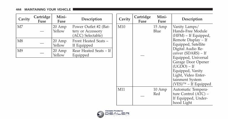
Cavity CartridgeFuse
Mini-Fuse Description
M7—
20 AmpYellow
Power Outlet #2 (Bat-tery or Accessory(ACC) Selectable)
M8 — 20 AmpYellow
Front Heated Seats –If Equipped
M9 — 20 AmpYellow
Rear Heated Seats – IfEquipped
Cavity CartridgeFuse
Mini-Fuse Description
M10
—
15 AmpBlue
Vanity Lamps/Hands-Free Module(HFM) – If Equipped,Remote Display – IfEquipped, SatelliteDigital Audio Re-ceiver (SDARS) – IfEquipped, UniversalGarage Door Opener(UGDO) – IfEquipped, VanityLight, Video Enter-tainment System(VES)™ – If Equipped
M11
—
10 AmpRed
Automatic Tempera-ture Control (ATC) –If Equipped, Under-hood Light
444 MAINTAINING YOUR VEHICLE
Information Provided by:

Cavity CartridgeFuse
Mini-Fuse Description
M12 — 30 AmpGreen
Radio, Amplifier(AMP)
M13
—
20 AmpYellow
Cabin CompartmentNode (CCN), Multi-function Switch/SirenModule, ITM
M14 — 20 AmpYellow
Trailer Tow (BUX) – IfEquipped
M15
—
20 AmpYellow
Auto Dim RearviewMirror – If Equipped,Infrared Sensor (IR) –If Equipped, Multi-function Switch, TirePressure Monitor Sys-tem (TPMS) – IfEquipped, TransferCase Module – IfEquipped
Cavity CartridgeFuse
Mini-Fuse Description
M16
—
10 AmpRed
Occupant RestraintController (ORC)/Occupant Classifica-tion Module (OCM)
M17—
15 AmpBlue
Left Park/SideMarker/Running/TailLights, License Lights
M18—
15 AmpBlue
Right Park/SideMarker/Running/TailLights
M19 — 25 AmpNatural
Auto Shut Down(ASD) #1 and #2 7
MAINTAINING YOUR VEHICLE 445
Information Provided by:

Cavity CartridgeFuse
Mini-Fuse Description
M20
—
15 AmpBlue
Electronic Vehicle In-formation Center(EVIC) – If Equipped,Interior Lighting,Steering WheelSwitches – IfEquipped, SwitchBank
M21 — 20 AmpYellow
Auto Shut Down(ASD) #3
M22 — 10 AmpRed
Right Horn
M23 — 10 AmpRed
Left Horn
M24 — 25 AmpNatural
Rear Wiper
Cavity CartridgeFuse
Mini-Fuse Description
M25 — 20 AmpYellow
Fuel Pump/DieselLift Pump
M26—
10 AmpRed
Power MIRRORSSwitch/Drivers Win-dow Switch
M27
—
10 AmpRed
Steering ColumnLock, Wireless Igni-tion Node (WIN)/PEM
M28
—
10 AmpRed
NGC (PowertrainControl Module)/Transmission Feed(Batt)
M29 — 10 AmpRed
Occupant Classifica-tion Module (OCM)
446 MAINTAINING YOUR VEHICLE
Information Provided by:

Cavity CartridgeFuse
Mini-Fuse Description
M30
—
15 AmpBlue
Rear Wiper ModuleModule/Power Fold-ing Mirror, J1962 DiagFeed
M31 — 20 AmpYellow
Back-Up Lights
M32 — 10 AmpRed
Occupant RestraintController (ORC)
M33—
10 AmpRed
NGC (PowertrainControl Module) Bat-tery Feed/TCM
Cavity CartridgeFuse
Mini-Fuse Description
M34
—
10 AmpRed
Power Assist Module,HVAC Module, Head-lamp Washers, Com-pass Module – IfEquipped, Flashlight– If Equipped, RADFan Diesel
M35 — 10 AmpRed
Heated Mirrors – IfEquipped
M36 — 20 AmpYellow
Power Outlet #3(Batt)
M37
—
10 AmpRed
Anti-Lock Brake Sys-tem (ABS), ElectronicStability Program(ESP), Stop LightSwitch
7
MAINTAINING YOUR VEHICLE 447
Information Provided by:

Cavity CartridgeFuse
Mini-Fuse Description
M38 — 25 AmpNatural
Lock/Unlock Motors
K1 — — Ignition Run/Accessory Relay
K2 — — Ignition Run RelayK3 — — Starter Solenoid RelayK4 — — Ignition Run/Start
RelayK5
—— (NGC) Powertrain
Control ModuleRelay/PCM
K6 — — Electric Back Light(EBL) Relay
K7 — — —K8 — — —K9 — — Rear Blower RelayK10 — — ASD Relay (Feed for
M19 and M21)K11 — — Radiator Fan Relay
Low Speed
VEHICLE STORAGEIf you will not be using your vehicle for more than21 days you may want to take steps to preserve yourbattery. You may:
• Remove the IOD (Ignition Off-Draw) mini-fuses fromthe Totally Integrated Power Module located in theengine compartment.
• Or, disconnect the battery negative cable.
448 MAINTAINING YOUR VEHICLE
Information Provided by:

REPLACEMENT BULBSAll the inside bulbs are brass or glass wedge base.Aluminum base bulbs are not approved and should notbe used for replacement.
LIGHT BULBS – Interior Bulb NumberCourtesy/Reading Lamps (Incandescent) . . . . . . . . 578Courtesy/Reading Lamps(Optional LED) . . . . . . . . . . . . . . . . . . . . . . . . . LED
(Serviced at Authorized Dealer)Glove Box Lamp . . . . . . . . . . . . . . . . . . . . . . . . . 194Cargo Lamp . . . . . . . . . . . . . . . . . . . . . . . . . . . . 579Optional Door MapPocket/Cupholder . . . . . . . . . . . . . . . . . . . . . . . LED
(Serviced at Authorized Dealer)
NOTE: For lighted switches, see your authorized dealerfor replacement instructions.
LIGHTS BULBS – Exterior Bulb No.Low Beam Headlamp. . . . . . . . . . . . . . . . . . . . . 9006High Beam Headlamp . . . . . . . . . . . . . . . . . . . . 9005Front Park/Turn Signal . . . . . . . . . . . . . . . . . 3757AKSide Marker Lamp. . . . . . . . . . . . . . . . . . . . . . . . 168Front Fog Lamp . . . . . . . . . . . . . . . . . . . . . . PSX24WCenter High Mounted Stop Lamp(CHMSL) . . . . . . . LED (Serviced at Authorized Dealer)Rear Tail/Stop/Turn Signal . . . . . . . . . . . . . . . 3157KRear Tail . . . . . . . . . . . . . . . . . . . . . . . . . . . . . 3157KBackup Lamp . . . . . . . . . . . . . . . . . . . . . . . . . 3157KLicense Lamp . . . . . . . . . . . . . . . . . . . . . . . . . . . 168
7
MAINTAINING YOUR VEHICLE 449
Information Provided by:
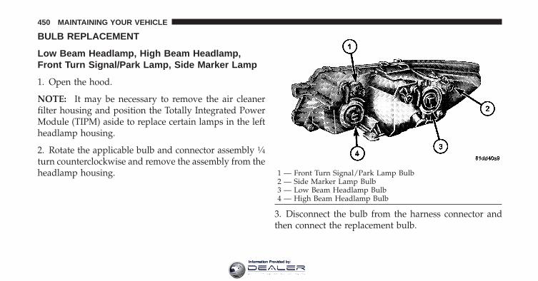
BULB REPLACEMENT
Low Beam Headlamp, High Beam Headlamp,Front Turn Signal/Park Lamp, Side Marker Lamp
1. Open the hood.
NOTE: It may be necessary to remove the air cleanerfilter housing and position the Totally Integrated PowerModule (TIPM) aside to replace certain lamps in the leftheadlamp housing.
2. Rotate the applicable bulb and connector assembly 1⁄4turn counterclockwise and remove the assembly from theheadlamp housing.
3. Disconnect the bulb from the harness connector andthen connect the replacement bulb.
1 — Front Turn Signal/Park Lamp Bulb2 — Side Marker Lamp Bulb3 — Low Beam Headlamp Bulb4 — High Beam Headlamp Bulb
450 MAINTAINING YOUR VEHICLE
Information Provided by:

CAUTION!
Do not touch the new bulb with your fingers. Oilcontamination will severely shorten bulb life. If thebulb comes in contact with any oily surface, clean thebulb with rubbing alcohol.
4. Install the bulb and connector assembly into theheadlamp housing and rotate it 1⁄4 turn clockwise to lockit in place.
Front Fog Lamp
NOTE: Turn the steering wheel to the right if replacingthe left front fog lamp or to the left if replacing the rightfront fog lamp to allow for easier access to the front of thewheel well.
1. Remove the fasteners retaining the front lower wheelwell access panel and remove the access panel.
2. Remove the electrical connector from the fog lamphousing.
3. Remove the bulb from the connector socket and installthe replacement bulb.
7
MAINTAINING YOUR VEHICLE 451
Information Provided by:

CAUTION!
Do not touch the new bulb with your fingers. Oilcontamination will severely shorten bulb life. If thebulb comes in contact with an oily surface, clean thebulb with rubbing alcohol.
4. Install the bulb and connector assembly into the foglamp housing and rotate the connector 1⁄4 turn clockwiseto lock it in place.
5. Reinstall the front lower wheel well access panel andfasteners.
Tail/Stop Lamp, Rear Turn Signal Lamp, TailLamp, Backup LampThe taillamps are a two-piece design. The tail/stop/rearturn signal lamps are located in the rear corner bodypanels. The tail and backup lamps are located in theliftgate.
Changing the Tail/Stop/Rear Turn Signal Lamp
1. Open the liftgate.
2. Remove the two fasteners from the inboard side of thetaillamp housing.
3. Carefully insert a trim stick (plastic flat-blade tool)between the body panel and the outboard side of thetaillamp housing with one hand and grasp the flange onthe inboard side of the taillamp housing with the otherhand. Use the trim stick and hand pressure together todisengage the taillamp housing from the vehicle.
4. Rotate the applicable bulb’s electrical connector 1⁄4turn counterclockwise and remove it from the taillamphousing.
5. Remove the bulb from the connector socket and installthe replacement bulb.
452 MAINTAINING YOUR VEHICLE
Information Provided by:

6. Install the bulb and connector assembly into thetaillamp housing and rotate the connector 1⁄4 turn clock-wise to lock it in place.
7. Reinstall the taillamp housing and fasteners.
Changing the Tail Lamp or Backup Lamp
1. Open the liftgate.
2. Remove the two fasteners retaining the taillamp hous-ing to the liftgate from the inboard face of the liftgate.
3. Carefully insert a trim stick (plastic flat-blade tool)between the taillamp housing and the liftgate. Use thetrim stick and hand pressure together to disengage thetaillamp housing from the liftgate.
4. Rotate the applicable bulb’s electrical connector 1⁄4turn counterclockwise and remove it from the housing.
5. Remove the bulb from the connector socket and installthe replacement bulb.
6. Install the bulb and connector assembly into thehousing and rotate the connector 1⁄4 turn clockwise tolock it in place.
1 — Tail Lamp Bulb2 — Backup Lamp Bulb 7
MAINTAINING YOUR VEHICLE 453
Information Provided by:

7. Reinstall the taillamp housing and fasteners.
License Plate Lamp
1. Push the small locking tab sticking out of the end ofthe lens toward the side of the vehicle and hold it in thatposition.
2. Insert a small flat-blade tool between the end of thelens with the locking tab and the surrounding housingand then pivot the tool to separate the lens from thehousing.
3. Hold the lens with one hand and rotate the bulb’selectrical connector 1⁄4 turn counterclockwise with theother hand and then separate the bulb and connectorassembly from the lens.
4. Remove the bulb from the connector socket and installthe replacement bulb.
5. Install the bulb and connector assembly into the lensand rotate the connector 1⁄4 turn clockwise to lock it inplace.
6. Insert the end of the lens without the locking tab intothe housing on the liftgate and then push the oppositeend of the lens into the housing, making sure it locks inthe housing.License Lamp
454 MAINTAINING YOUR VEHICLE
Information Provided by:

FLUID CAPACITIES
U.S. MetricFuel (Approximate)Front Wheel Drive (FWD) Models with 2.4L PZEV Engine 18.5 Gallons 70 LitersFront Wheel Drive (FWD) Models without 2.4L PZEV and 3.5L Engine 20.5 Gallons 77.6 LitersAll-Wheel Drive Models 21 Gallons 79.8 LitersEngine Oil with Filter2.4L Engine (SAE 5W-20, API Certified) 4.5 Quarts 4.26 Liters3.5L Engine (SAE 10W-30, API Certified) 5.5 Quarts 5.2 LitersCooling System *2.4L Engine and Single- or Dual-Zone Climate Control System (MOPAR�Antifreeze/Coolant 5 Year/100,000 Mile Formula or equivalent)
7.9 Quarts 7.5 Liters
2.4L Engine and Three-Zone Climate Control System (MOPAR�Antifreeze/Coolant 5 Year/100,000 Mile Formula or equivalent)
9.8 Quarts 9.3 Liters
3.5L Engine and Single- or Dual-Zone Climate Control System (MOPAR�Antifreeze/Coolant 5 Year/100,000 Mile Formula or equivalent)
9.8 Quarts 9.3 Liters
3.5L Engine and Three-Zone Climate Control System (MOPAR�Antifreeze/Coolant 5 Year/100,000 Mile Formula or equivalent)
12 Quarts 11.4 Liters
* Includes heater and coolant recovery bottle filled to MAX level.
7
MAINTAINING YOUR VEHICLE 455
Information Provided by:

FLUIDS, LUBRICANTS, AND GENUINE PARTS
Engine
Component Fluid, Lubricant, or Genuine Part
Engine Coolant MOPAR� Antifreeze/Coolant 5 Year/100,000 Mile Formula HOAT (Hy-brid Organic Additive Technology) or equivalent.
Engine Oil – 2.4L EngineUse API Certified SAE 5W-20 Engine Oil, meeting the requirements ofChrysler Material Standard MS-6395. Refer to your engine oil filler cap forcorrect SAE grade.
Engine Oil – 3.5L EngineUse API Certified SAE 10W-30 Engine Oil, meeting the requirements ofChrysler Material Standard MS-6395. Refer to your engine oil filler cap forcorrect SAE grade.
Engine Oil Filter MOPAR� Engine Oil Filter or equivalent.Spark Plugs – 2.4L Engine ZFR5F-11 (Gap 0.044 in [1.12 mm])Spark Plugs – 3.5L Engine ZFR5LP-13G (Gap 0.050 in [1.27 mm])Fuel Selection – 2.4L Engine 87 OctaneFuel Selection – 3.5L Engine 87 Octane Acceptable – 89 Octane Recommended
456 MAINTAINING YOUR VEHICLE
Information Provided by:

Chassis
Component Fluid, Lubricant, or Genuine Part
Automatic Transmission MOPAR� ATF+4� Automatic Transmission Fluid or equivalent licensedATF+4� product.
Power Transfer Unit (PTU) MOPAR� Gear Lubricant 75W-90 or equivalent.Rear Drive Assembly (RDA) MOPAR� Gear Lubricant 75W-90 or equivalent.
Brake Master CylinderMOPAR� DOT 3, SAE J1703 or equivalent should be used. If DOT 3 brakefluid is not available, then DOT 4 is acceptable. Use only recommendedbrake fluids.
Power Steering Reservoir MOPAR� Power Steering Fluid + 4, MOPAR� ATF+4� Automatic Trans-mission Fluid or equivalent licensed ATF+4� product.
7
MAINTAINING YOUR VEHICLE 457
Information Provided by:

Information Provided by:

MAINTENANCE SCHEDULES
CONTENTS
� Emissions Control System Maintenance . . . . . . 460
� Maintenance Schedule . . . . . . . . . . . . . . . . . . 460
▫ Required Maintenance Intervals . . . . . . . . . . 462
8
MAINTENANCE
SCHEDULES
Information Provided by:

EMISSIONS CONTROL SYSTEM MAINTENANCEThe Scheduled Maintenance services listed in bold type,must be done at the times or mileages specified to ensurethe continued proper functioning of the Emissions Con-trol System. These, and all other maintenance servicesincluded in this manual, should be done to provide bestvehicle performance and reliability. More frequent main-tenance may be needed for vehicles in severe operatingconditions, such as dusty areas and very short tripdriving.
Inspection and service should also be done anytime amalfunction is suspected.
NOTE: Maintenance, replacement, or repair of the emis-sions control devices and systems on your vehicle may beperformed by any automotive repair establishment orindividual using any automotive part that has beencertified pursuant to U.S. EPA or in the State of Califor-nia, California Air Resources Board regulations.
MAINTENANCE SCHEDULEThe oil change indicator system will remind you that it istime to take your vehicle in for scheduled maintenance.
On Electronic Vehicle Information Center (EVIC)equipped vehicles “Oil Change Required” will be dis-played in the EVIC and a single chime will sound,indicating that an oil change is necessary.
On Non-EVIC equipped vehicles “Change Oil” will flashin the instrument cluster odometer and a single chimewill sound, indicating that an oil change is necessary.
Based on engine operation conditions the oil changeindicator message will illuminate, this means that serviceis required for your vehicle. Have your vehicle servicedas soon as possible, within the next 500 miles (805 km).8
MAINTENANCE
SCHEDULES
460 MAINTENANCE SCHEDULES
Information Provided by:

NOTE:• The oil change indicator message will not monitor the
time since the last oil change. Change your vehicles oilif it has been 6 months since your last oil change evenif the oil change indicator message is NOT illumi-nated.
• Change your engine oil more often if you drive yourvehicle off-road for an extended period of time.
• Under no circumstances should oil change intervalsexceed 6,000 miles (10 000 km) or six months, which-ever comes first.
Your authorized dealer will reset the oil change indicatormessage after completing the scheduled oil change. If ascheduled oil change is performed by someone otherthan your authorized dealer, the message can be reset byreferring to the steps described under “Electronic VehicleInformation Center (EVIC)/Oil Change Required” in
“Understanding Your Instrument Panel” or under “In-strument Cluster Description/Odometer/Trip Odom-eter” in “Understanding Your Instrument Panel” forfurther information.
At Each Stop for Fuel
• Check the engine oil level about five minutes after afully warmed engine is shut off. Checking the oil levelwhile the vehicle is on level ground will improve theaccuracy of the oil level reading. Add oil only whenthe level is at or below the ADD or MIN mark.
• Check the windshield washer solvent and add ifrequired.
8
MAINTENANCE
SCHEDULES
MAINTENANCE SCHEDULES 461
Information Provided by:
Once a Month
• Check tire pressure and look for unusual wear ordamage.
• Inspect the battery and clean and tighten the terminalsas required.
• Check the fluid levels of coolant reservoir, brakemaster cylinder, and transmission and add as needed.
• Check all lights and other electrical items for correctoperation.
At Each Oil Change
• Change the engine oil filter.
• Inspect the brake hoses and lines.
CAUTION!
Failure to perform the required maintenance itemsmay result in damage to the vehicle.
Required Maintenance IntervalsRefer to the Maintenance Schedules on the followingpages for the required maintenance intervals.
8
MAINTENANCE
SCHEDULES
462 MAINTENANCE SCHEDULES
Information Provided by:

6,000 Miles (10,000 km) or6 Months Maintenance ServiceSchedule❏ Change the engine oil and engine oil
filter.❏ Rotate tires.
Odometer Reading Date
Repair Order # Dealer Code
Signature Authorized Chrysler Dealer
12,000 Miles (20,000 km) or 12 Months Maintenance ServiceSchedule❏ Change the engine oil and engine oil filter.❏ Rotate tires.❏ If using your vehicle in dusty or off-road conditions, inspect the engine air cleaner filter, and
replace if necessary.❏ Inspect the brake linings, and replace if necessary.❏ Replace the air conditioning filter (if equipped).❏ Inspect the CV joints. Perform the first inspection at 12,000 miles (20 000 km) or
12 months.❏ Inspect the exhaust system. Perform the first inspection at 12,000 miles (20 000 km) or
12 months.❏ Inspect the front suspension, tie rod ends and boot seals for cracks or leaks and all parts for
damage, wear, improper looseness or end play; replace if necessary.
Odometer Reading Date
Repair Order # Dealer Code
Signature Authorized Chrysler Dealer
8
MAINTENANCE
SCHEDULES
MAINTENANCE SCHEDULES 463
Information Provided by:

18,000 Miles (30,000 km) or18 Months MaintenanceService Schedule❏ Change the engine oil and engine oil
filter.❏ Rotate tires.
Odometer Reading Date
Repair Order # Dealer Code
Signature Authorized Chrysler Dealer
24,000 Miles (40,000 km) or 24 Months Maintenance ServiceSchedule❏ Change the engine oil and engine oil filter.❏ Rotate tires.❏ If using your vehicle in dusty or off-road conditions, inspect the engine air cleaner filter, and
replace if necessary.❏ Inspect the brake linings, and replace if necessary.❏ Replace the air conditioning filter (if equipped).❏ Inspect the CV joints.❏ Inspect the exhaust system.❏ Inspect the front suspension, tie rod ends and boot seals for cracks or leaks and all parts for
damage, wear, improper looseness or end play; replace if necessary.
Odometer Reading Date
Repair Order # Dealer Code
Signature Authorized Chrysler Dealer
8
MAINTENANCE
SCHEDULES
464 MAINTENANCE SCHEDULES
Information Provided by:

30,000 Miles (50,000 km) or30 Months MaintenanceService Schedule❏ Change the engine oil and engine oil
filter.❏ Rotate tires.❏ Replace the engine air cleaner filter.❏ Replace the spark plugs (2.4L Engine).
Odometer Reading Date
Repair Order # Dealer Code
Signature Authorized Chrysler Dealer
36,000 Miles (60,000 km) or 36 Months Maintenance ServiceSchedule❏ Change the engine oil and engine oil filter.❏ Rotate tires.❏ If using your vehicle in dusty or off-road conditions, inspect the engine air cleaner filter, and
replace if necessary.❏ Inspect the brake linings, and replace if necessary.❏ Replace the air conditioning filter (if equipped).❏ Inspect the front suspension, tie rod ends and boot seals for cracks or leaks and all parts for
damage, wear, improper looseness or end play; replace if necessary.
Odometer Reading Date
Repair Order # Dealer Code
Signature Authorized Chrysler Dealer
8
MAINTENANCE
SCHEDULES
MAINTENANCE SCHEDULES 465
Information Provided by:

42,000 Miles (70,000 km) or42 Months MaintenanceService Schedule❏ Change the engine oil and engine oil
filter.❏ Rotate tires.
Odometer Reading Date
Repair Order # Dealer Code
Signature Authorized Chrysler Dealer
48,000 Miles (80,000 km) or 48 Months Maintenance ServiceSchedule❏ Change the engine oil and engine oil filter.❏ Rotate tires.❏ If using your vehicle in dusty or off-road conditions, inspect the engine air cleaner filter, and
replace if necessary.❏ Inspect the brake linings, and replace if necessary.❏ Replace the air conditioning filter (if equipped).❏ Inspect the CV joints.❏ Inspect the exhaust system.❏ Inspect the front suspension, tie rod ends and boot seals for cracks or leaks and all parts for
damage, wear, improper looseness or end play; replace if necessary.
Odometer Reading Date
Repair Order # Dealer Code
Signature Authorized Chrysler Dealer
8
MAINTENANCE
SCHEDULES
466 MAINTENANCE SCHEDULES
Information Provided by:

54,000 Miles (90,000 km) or54 Months MaintenanceService Schedule❏ Change the engine oil and engine oil
filter.❏ Rotate tires.
Odometer Reading Date
Repair Order # Dealer Code
Signature Authorized Chrysler Dealer
60,000 Miles (100,000 km) or 60 Months Maintenance ServiceSchedule❏ Change the engine oil and engine oil filter.❏ Rotate tires.❏ Replace the engine air cleaner filter.❏ Replace the spark plugs (2.4L Engine).❏ Inspect the brake linings, and replace if necessary.❏ Replace the air conditioning filter (if equipped).❏ Change Rear Drive Assembly (RDA) fluid.❏ Change Power Transfer Case (PTU) fluid.❏ Change the automatic transmission fluid and external filter.❏ Inspect the front suspension, tie rod ends and boot seals for cracks or leaks and all parts for
damage, wear, improper looseness or end play; replace if necessary.
Odometer Reading Date
Repair Order # Dealer Code
Signature Authorized Chrysler Dealer
8
MAINTENANCE
SCHEDULES
MAINTENANCE SCHEDULES 467
Information Provided by:

66,000 Miles (110,000 km) or66 Months MaintenanceService Schedule❏ Change the engine oil and engine oil
filter.❏ Rotate tires.
Odometer Reading Date
Repair Order # Dealer Code
Signature Authorized Chrysler Dealer
72,000 Miles (120,000 km) or 72 Months Maintenance ServiceSchedule❏ Change the engine oil and engine oil filter.❏ Rotate tires.❏ If using your vehicle in dusty or off-road conditions, inspect the engine air cleaner filter, and
replace if necessary.❏ Inspect the brake linings, and replace if necessary.❏ Replace the air conditioning filter (if equipped).❏ Inspect the CV joints.❏ Inspect the exhaust system.❏ Inspect the front suspension, tie rod ends and boot seals for cracks or leaks and all parts for
damage, wear, improper looseness or end play; replace if necessary.
Odometer Reading Date
Repair Order # Dealer Code
Signature Authorized Chrysler Dealer
8
MAINTENANCE
SCHEDULES
468 MAINTENANCE SCHEDULES
Information Provided by:

78,000 Miles (130,000 km) or78 Months MaintenanceService Schedule❏ Change the engine oil and engine oil
filter.❏ Rotate tires.
Odometer Reading Date
Repair Order # Dealer Code
Signature Authorized Chrysler Dealer
84,000 Miles (140,000 km) or 84 Months Maintenance ServiceSchedule❏ Change the engine oil and engine oil filter.❏ Rotate tires.❏ If using your vehicle in dusty or off-road conditions, inspect the engine air cleaner filter, and
replace if necessary.❏ Inspect the brake linings, and replace if necessary.❏ Replace the air conditioning filter (if equipped).❏ Inspect the front suspension, tie rod ends and boot seals for cracks or leaks and all parts for
damage, wear, improper looseness or end play; replace if necessary.
Odometer Reading Date
Repair Order # Dealer Code
Signature Authorized Chrysler Dealer
8
MAINTENANCE
SCHEDULES
MAINTENANCE SCHEDULES 469
Information Provided by:

90,000 Miles (150,000 km) or90 Months MaintenanceService Schedule❏ Change the engine oil and engine oil
filter.❏ Rotate tires.❏ Replace the engine air cleaner filter.❏ Replace the spark plugs (2.4L Engine).❏ Inspect and replace PCV valve if
necessary.†
Odometer Reading Date
Repair Order # Dealer Code
Signature Authorized Chrysler Dealer
96,000 Miles (160,000 km) or 96 Months Maintenance ServiceSchedule❏ Change the engine oil and engine oil filter.❏ Rotate tires.❏ If using your vehicle in dusty or off-road conditions, inspect the engine air cleaner filter, and
replace if necessary.❏ Inspect the brake linings, and replace if necessary.❏ Replace the air conditioning filter (if equipped).❏ Inspect the CV joints.❏ Inspect the exhaust system.❏ Inspect the front suspension, tie rod ends and boot seals for cracks or leaks and all parts for
damage, wear, improper looseness or end play; replace if necessary.
Odometer Reading Date
Repair Order # Dealer Code
Signature Authorized Chrysler Dealer
8
MAINTENANCE
SCHEDULES
470 MAINTENANCE SCHEDULES
Information Provided by:

102,000 Miles (170,000 km) or102 Months MaintenanceService Schedule❏ Change the engine oil and engine oil
filter.❏ Rotate tires.❏ Flush and replace the engine coolant.
Odometer Reading Date
Repair Order # Dealer Code
Signature Authorized Chrysler Dealer
108,000 Miles (180,000 km) or 108 Months Maintenance ServiceSchedule❏ Change the engine oil and engine oil filter.❏ Rotate tires.❏ If using your vehicle in dusty or off-road conditions, inspect the engine air cleaner filter, and
replace if necessary.❏ Inspect the brake linings, and replace if necessary.❏ Replace the air conditioning filter (if equipped).❏ Inspect the front suspension, tie rod ends and boot seals for cracks or leaks and all parts for
damage, wear, improper looseness or end play; replace if necessary.
Odometer Reading Date
Repair Order # Dealer Code
Signature Authorized Chrysler Dealer
8
MAINTENANCE
SCHEDULES
MAINTENANCE SCHEDULES 471
Information Provided by:

114,000 Miles (190,000 km) or114 Months MaintenanceService Schedule❏ Change the engine oil and engine oil
filter.❏ Rotate tires.
Odometer Reading Date
Repair Order # Dealer Code
Signature Authorized Chrysler Dealer
120,000 Miles (200,000 km) or 120 Months Maintenance ServiceSchedule❏ Change the engine oil and engine oil filter.❏ Rotate tires.❏ Replace the engine air cleaner filter.❏ Replace the spark plugs (2.4L Engine).❏ Inspect the brake linings, and replace if necessary.❏ Replace the air conditioning filter (if equipped).❏ Inspect the CV joints.❏ Inspect the exhaust system.❏ Change Rear Drive Assembly (RDA) fluid.❏ Change Power Transfer Case (PTU) fluid.❏ Change the automatic transmission and fluid.❏ Replace the accessory drive belt (2.4L Engine).❏ Inspect the front suspension, tie rod ends and boot seals for cracks or leaks and all parts for
damage, wear, improper looseness or end play; replace if necessary.
Odometer Reading Date
Repair Order # Dealer Code
Signature Authorized Chrysler Dealer
8
MAINTENANCE
SCHEDULES
472 MAINTENANCE SCHEDULES
Information Provided by:

126,000 Miles (210,000 km) or126 Months MaintenanceService Schedule❏ Change the engine oil and engine oil
filter.❏ Rotate tires.
Odometer Reading Date
Repair Order # Dealer Code
Signature Authorized Chrysler Dealer
132,000 Miles (220,000 km) or 132 Months Maintenance ServiceSchedule❏ Change the engine oil and engine oil filter.❏ Rotate tires.❏ If using your vehicle in dusty or off-road conditions, inspect the engine air cleaner filter, and
replace if necessary.❏ Inspect the brake linings, and replace if necessary.❏ Replace the air conditioning filter (if equipped).❏ Inspect the front suspension, tie rod ends and boot seals for cracks or leaks and all parts for
damage, wear, improper looseness or end play; replace if necessary.
Odometer Reading Date
Repair Order # Dealer Code
Signature Authorized Chrysler Dealer
8
MAINTENANCE
SCHEDULES
MAINTENANCE SCHEDULES 473
Information Provided by:
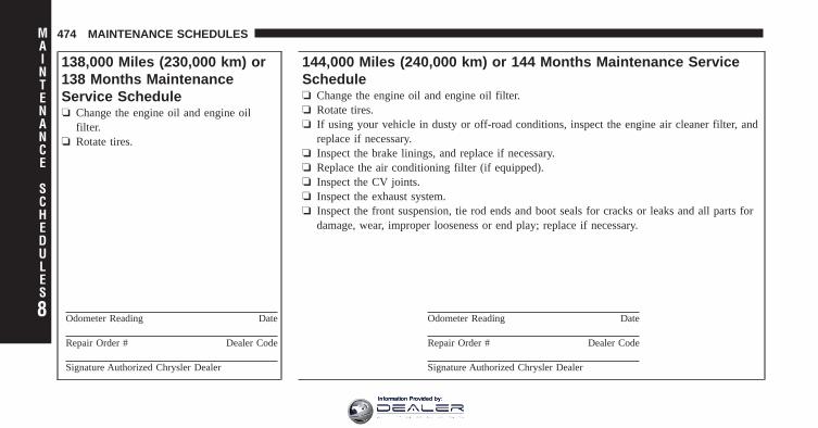
138,000 Miles (230,000 km) or138 Months MaintenanceService Schedule❏ Change the engine oil and engine oil
filter.❏ Rotate tires.
Odometer Reading Date
Repair Order # Dealer Code
Signature Authorized Chrysler Dealer
144,000 Miles (240,000 km) or 144 Months Maintenance ServiceSchedule❏ Change the engine oil and engine oil filter.❏ Rotate tires.❏ If using your vehicle in dusty or off-road conditions, inspect the engine air cleaner filter, and
replace if necessary.❏ Inspect the brake linings, and replace if necessary.❏ Replace the air conditioning filter (if equipped).❏ Inspect the CV joints.❏ Inspect the exhaust system.❏ Inspect the front suspension, tie rod ends and boot seals for cracks or leaks and all parts for
damage, wear, improper looseness or end play; replace if necessary.
Odometer Reading Date
Repair Order # Dealer Code
Signature Authorized Chrysler Dealer
8
MAINTENANCE
SCHEDULES
474 MAINTENANCE SCHEDULES
Information Provided by:

† This maintenance is recommended by the manufacturerto the owner, but is not required to maintain emissionswarranty.
WARNING!
• You can be badly injured working on or around amotor vehicle. Do only service work for which youhave the knowledge and the right equipment. Ifyou have any doubt about your ability to performa service job, take your vehicle to a competentmechanic.
• Failure to properly inspect and maintain yourvehicle could result in a component malfunctionand effect vehicle handling and performance. Thiscould cause an accident
150,000 Miles (250,000 km) or150 Months MaintenanceService Schedule❏ Change the engine oil and engine oil
filter.❏ Rotate tires.❏ Replace the engine air cleaner filter.❏ Replace the spark plugs (2.4L Engine).
Odometer Reading Date
Repair Order # Dealer Code
Signature Authorized Chrysler Dealer
8
MAINTENANCE
SCHEDULES
MAINTENANCE SCHEDULES 475
Information Provided by:

Information Provided by:

IF YOU NEED CONSUMER ASSISTANCE
CONTENTS
� Suggestions For Obtaining Service For YourVehicle . . . . . . . . . . . . . . . . . . . . . . . . . . . . . . 479
▫ Prepare For The Appointment . . . . . . . . . . . 479
▫ Prepare A List . . . . . . . . . . . . . . . . . . . . . . 479
▫ Be Reasonable With Requests . . . . . . . . . . . . 479
� If You Need Assistance . . . . . . . . . . . . . . . . . 479
▫ Chrysler Group LLC Customer Center . . . . . 480
▫ Chrysler Canada Inc. Customer Center . . . . . 480
▫ In Mexico Contact . . . . . . . . . . . . . . . . . . . . 480
▫ Customer Assistance For The Hearing OrSpeech Impaired (TDD/TTY) . . . . . . . . . . . . 481
▫ Service Contract . . . . . . . . . . . . . . . . . . . . . 481
� Warranty Information . . . . . . . . . . . . . . . . . . 482
� MOPAR� Parts . . . . . . . . . . . . . . . . . . . . . . . 482
� Reporting Safety Defects . . . . . . . . . . . . . . . . 482
▫ In The 50 United States And Washington,D.C. . . . . . . . . . . . . . . . . . . . . . . . . . . . . . . 482
▫ In Canada . . . . . . . . . . . . . . . . . . . . . . . . . 483 9
Information Provided by:

� Publication Order Forms . . . . . . . . . . . . . . . . 483
� Department Of Transportation Uniform TireQuality Grades . . . . . . . . . . . . . . . . . . . . . . . . 485
▫ Treadwear . . . . . . . . . . . . . . . . . . . . . . . . . 485
▫ Traction Grades . . . . . . . . . . . . . . . . . . . . . 485
▫ Temperature Grades . . . . . . . . . . . . . . . . . . 486
478 IF YOU NEED CONSUMER ASSISTANCE
Information Provided by:

SUGGESTIONS FOR OBTAINING SERVICE FORYOUR VEHICLE
Prepare For The AppointmentIf you’re having warranty work done, be sure to have theright papers with you. Take your warranty folder. Allwork to be performed may not be covered by thewarranty. Discuss additional charges with the servicemanager. Keep a maintenance log of your vehicle’sservice history. This can often provide a clue to thecurrent problem.
Prepare A ListMake a written list of your vehicle’s problems or thespecific work you want done. If you’ve had an accidentor work done that is not on your maintenance log, let theservice advisor know.
Be Reasonable With RequestsIf you list a number of items and you must have yourvehicle by the end of the day, discuss the situation with
the service advisor and list the items in order of priority.At many authorized dealers, you may obtain a rentalvehicle at a minimal daily charge. If you need a rental, itis advisable to make these arrangements when you callfor an appointment.
IF YOU NEED ASSISTANCEThe manufacturer and its authorized dealers are vitallyinterested in your satisfaction. We want you to be happywith our products and services.
Warranty service must be done by an authorized dealer.We strongly recommend that you take the vehicle to anauthorized dealer. They know your vehicle the best, andare most concerned that you get prompt and high qualityservice. The manufacturer’s authorized dealers have thefacilities, factory-trained technicians, special tools, andthe latest information to ensure the vehicle is fixedcorrectly and in a timely manner. 9
IF YOU NEED CONSUMER ASSISTANCE 479
Information Provided by:

This is why you should always talk to an authorizeddealer’s service manager first. Most matters can be re-solved with this process.
• If for some reason you are still not satisfied, talk to thegeneral manager or owner of the authorized dealer-ship. They want to know if you need assistance.
• If an authorized dealership is unable to resolve theconcern, you may contact the manufacturer’s customercenter.
Any communication to the manufacturer’s customer cen-ter should include the following information:
• Owner’s name and address
• Owner’s telephone number (home and office)
• Authorized dealership name
• Vehicle Identification Number (VIN)
• Vehicle delivery date and mileage
Chrysler Group LLC Customer CenterP.O. Box 21–8004Auburn Hills, MI 48321–8004Phone: (800) 423–6343
Chrysler Canada Inc. Customer CenterP.O. Box 1621Windsor, Ontario N9A 4H6Phone: (800) 465–2001
In Mexico contact:Av. Prolongacion Paseo de la Reforma, 1240Sante Fe C.P. 05109Mexico, D. F.In Mexico City: 5081-7568Outside Mexico City: 1-800-505-1300
480 IF YOU NEED CONSUMER ASSISTANCE
Information Provided by:

Customer Assistance For The Hearing Or SpeechImpaired (TDD/TTY)To assist customers who have hearing difficulties, themanufacturer has installed special TDD (Telecommuni-cation Devices for the Deaf) equipment at its customercenter. Any hearing or speech impaired customer, whohas access to a TDD or a conventional teletypewriter(TTY) in the United States, can communicate with themanufacturer by dialing 1–800–380–CHRY.Canadian residents with hearing difficulties that requireassistance can use the special needs relay service offeredby Bell Canada. For TTY teletypewriter users, dial 711and for Voice callers, dial 1 800 855-0511 to connect witha Bell Relay Service operator.
Service ContractYou may have purchased a service contract for a vehicleto help protect you from the high cost of unexpectedrepairs after the manufacturer’s New Vehicle LimitedWarranty expires. The manufacturer stands behind only
the manufacturer’s service contracts. If you purchased amanufacturer’s service contract, you will receive PlanProvisions and an Owner Identification Card in the mailwithin three weeks of the vehicle delivery date. If youhave any questions about the service contract, call themanufacturer’s Service Contract National Customer Hot-line at 1-800-521-9922 (Canadian residents, call 1-800-485-2001).
The manufacturer will not stand behind any servicecontract that is not the manufacturer’s service contract. Itis not responsible for any service contract other than themanufacturer’s service contract. If you purchased a ser-vice contract that is not a manufacturer’s service contract,and you require service after the manufacturer’s NewVehicle Limited Warranty expires, please refer to thecontract documents, and contact the person listed inthose documents. 9
IF YOU NEED CONSUMER ASSISTANCE 481
Information Provided by:

We appreciate that you have made a major investmentwhen you purchased the vehicle. An authorized dealerhas also made a major investment in facilities, tools, andtraining to assure that you are absolutely delighted withthe ownership experience. You’ll be pleased with theirsincere efforts to resolve any warranty issues or relatedconcerns.
WARNING!
Engine exhaust, some of its constituents, and certainvehicle components contain, or emit, chemicalsknown to the State of California to cause cancer andbirth defects, or other reproductive harm. In addi-tion, certain fluids contained in vehicles and certainproducts of component wear contain, or emit, chemi-cals known to the State of California to cause cancerand birth defects, or other reproductive harm.
WARRANTY INFORMATIONSee the Warranty Information Booklet, located on theDVD, for the terms and provisions of Chrysler GroupLLC warranties applicable to this vehicle and market.
MOPAR� PARTSMOPAR� fluids, lubricants, parts, and accessories areavailable from an authorized dealer. They are recom-mended for your vehicle in order to help keep the vehicleoperating at its best.
REPORTING SAFETY DEFECTS
In the 50 United States and Washington, D.C.If you believe that your vehicle has a defect that couldcause a crash or cause injury or death, you shouldimmediately inform the National Highway Traffic SafetyAdministration (NHTSA) in addition to notifying themanufacturer.
482 IF YOU NEED CONSUMER ASSISTANCE
Information Provided by:

If NHTSA receives similar complaints, it may open aninvestigation, and if it finds that a safety defect exists ina group of vehicles, it may order a recall and remedycampaign. However, NHTSA cannot become involved inindividual problems between you, your authorizeddealer, and the manufacturer.
To contact NHTSA, you may either call the Auto SafetyHotline toll free at 1–888–327–4236 (TTY: 1–800–424–9153), or go to http://www.safercar.gov; or write to:Administrator, NHTSA, 1200 New Jersey Avenue, SE.,West Building, Washington, D.C. 20590. You can alsoobtain other information about motor vehicle safety fromhttp://www.safercar.gov.
In CanadaIf you believe that your vehicle has a safety defect, youshould contact the Customer Service Department immedi-ately. Canadian customers who wish to report a safety
defect to the Canadian government should write to: Trans-port Canada, Motor Vehicle Defect Investigations andRecalls, 2780 Sheffield Road, Ottawa, Ontario K1B 3V9.
PUBLICATION ORDER FORMSTo order the following manuals, you may use either thewebsite or the phone numbers listed below. Visa, Mas-tercard, American Express, and Discover orders are ac-cepted. If you prefer mailing your payment, please callfor an order form.
NOTE: A street address is required when orderingmanuals (no P.O. Boxes).
• Service Manuals
These comprehensive Service Manuals provide theinformation that students and professional techniciansneed in diagnosing/troubleshooting, problem solving,maintaining, servicing, and repairing Chrysler GroupLLC vehicles. A complete working knowledge of the
9
IF YOU NEED CONSUMER ASSISTANCE 483
Information Provided by:

vehicle, system, and/or components is written instraightforward language with illustrations, diagrams,and charts.
• Diagnostic Procedure Manuals
Diagnostic Procedure Manuals are filled with dia-grams, charts and detailed illustrations. These practi-cal manuals make it easy for students and techniciansto find and fix problems on computer-controlled ve-hicle systems and features. They show exactly how tofind and correct problems the first time, using step-by-step troubleshooting and drivability procedures,proven diagnostic tests and a complete list of all toolsand equipment.
• Owner’s Manuals
These Owner’s Manuals have been prepared with theassistance of service and engineering specialists toacquaint you with specific Chrysler Group LLC ve-hicles. Included are starting, operating, emergencyand maintenance procedures as well as specifications,capabilities and safety tips.
Call toll free at:
• 1–800–890–4038 (U.S.)
• 1–800–387–1143 (Canada)
Or
Visit us on the Worldwide Web at:
• www.techauthority.com
484 IF YOU NEED CONSUMER ASSISTANCE
Information Provided by:

DEPARTMENT OF TRANSPORTATION UNIFORMTIRE QUALITY GRADESThe following tire grading categories were established bythe National Highway Traffic Safety Administration. Thespecific grade rating assigned by the tire’s manufacturerin each category is shown on the sidewall of the tires onyour vehicle.
All passenger car tires must conform to Federal safetyrequirements in addition to these grades.
TreadwearThe Treadwear grade is a comparative rating, based onthe wear rate of the tire when tested under controlledconditions on a specified government test course. Forexample, a tire graded 150 would wear one and one-halftimes as well on the government course as a tire graded100. The relative performance of tires depends upon theactual conditions of their use, however, and may depart
significantly from the norm due to variations in drivinghabits, service practices, and differences in road charac-teristics and climate.
Traction GradesThe Traction grades, from highest to lowest, are AA, A, B,and C. These grades represent the tire’s ability to stop onwet pavement, as measured under controlled conditionson specified government test surfaces of asphalt andconcrete. A tire marked C may have poor traction perfor-mance.
WARNING!
The traction grade assigned to this tire is based onstraight-ahead braking traction tests, and does notinclude acceleration, cornering, hydroplaning, orpeak traction characteristics.
9
IF YOU NEED CONSUMER ASSISTANCE 485
Information Provided by:
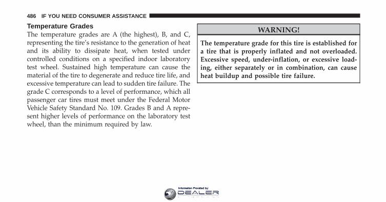
Temperature GradesThe temperature grades are A (the highest), B, and C,representing the tire’s resistance to the generation of heatand its ability to dissipate heat, when tested undercontrolled conditions on a specified indoor laboratorytest wheel. Sustained high temperature can cause thematerial of the tire to degenerate and reduce tire life, andexcessive temperature can lead to sudden tire failure. Thegrade C corresponds to a level of performance, which allpassenger car tires must meet under the Federal MotorVehicle Safety Standard No. 109. Grades B and A repre-sent higher levels of performance on the laboratory testwheel, than the minimum required by law.
WARNING!
The temperature grade for this tire is established fora tire that is properly inflated and not overloaded.Excessive speed, under-inflation, or excessive load-ing, either separately or in combination, can causeheat buildup and possible tire failure.
486 IF YOU NEED CONSUMER ASSISTANCE
Information Provided by:

INDEX
10Information Provided by:

About Your Brakes . . . . . . . . . . . . . . . . . . . . 312,315ABS (Anti-Lock Brake System) . . . . . . . . . 193,316,317Adding Engine Coolant (Antifreeze) . . . . . . . . . . 426Adding Fuel . . . . . . . . . . . . . . . . . . . . . . . . . . . 357Adding Washer Fluid . . . . . . . . . . . . . . . . . . . . . 420Additives, Fuel . . . . . . . . . . . . . . . . . . . . . . . . . 355Air Cleaner, Engine (Engine Air Cleaner Filter) . . . 412Air Conditioner Maintenance . . . . . . . . . . . . . . . 414Air Conditioning . . . . . . . . . . . . . . . . . . . . . 270,274Air Conditioning Controls . . . . . . . . . . . . . . . 270,274Air Conditioning Filter . . . . . . . . . . . . . . . . . 288,416Air Conditioning, Operating Tips . . . . . . . . . . . . 289Air Conditioning, Rear Zone . . . . . . . . . . . . . . . . 283Air Conditioning Refrigerant . . . . . . . . . . . . . 414,415Air Conditioning System . . . . . . . . . . 270,274,277,414Air Pressure, Tires . . . . . . . . . . . . . . . . . . . . 191,336Airbag . . . . . . . . . . . . . . . . . . . . . . . . . . . . . . 54,64Airbag Deployment . . . . . . . . . . . . . . . . . . . . . . . 66Airbag Light . . . . . . . . . . . . . . . . . . . . . 63,68,86,197
Airbag Maintenance . . . . . . . . . . . . . . . . . . . . . . . 67Airbag, Side . . . . . . . . . . . . . . . . . . . . . . . . 57,61,64Airbag, Window (Side Curtain) . . . . . . . . . . . 58,61,64Alarm, Panic . . . . . . . . . . . . . . . . . . . . . . . . . . . . 23Alarm (Security Alarm) . . . . . . . . . . . . . . . . . 17,185Alarm System (Security Alarm) . . . . . . . . . . . . . . . 17All Wheel Drive (AWD) . . . . . . . . . . . . . . . . . . . 307Alterations/Modifications, Vehicle . . . . . . . . . . . . . 7Antenna, Satellite Radio . . . . . . . . . . . . . . . . . . . 257Antifreeze (Engine Coolant) . . . . . . . . . . . 425,426,455
Disposal . . . . . . . . . . . . . . . . . . . . . . . . . . . . 428Anti-Lock Brake System (ABS) . . . . . . . . . . . . 316,317Anti-Lock Warning Light . . . . . . . . . . . . . 193,317,319Anti-Theft Security Alarm (Theft Alarm) . . . . . . . . 17Anti-Theft System . . . . . . . . . . . . . . . . . . . . . . . 185Appearance Care . . . . . . . . . . . . . . . . . . . . . . . . 435Arming Theft System (Security Alarm) . . . . . . . . . 17Audio Systems (Radio) . . . . . . . . . . . . . . . . . . . . 251Auto Down Power Windows . . . . . . . . . . . . . . . . 35
488 INDEX
Information Provided by:

Auto Unlock, Doors . . . . . . . . . . . . . . . . . . . . . . . 30Automatic Dimming Mirror . . . . . . . . . . . . . . . . . 95Automatic Door Locks . . . . . . . . . . . . . . . . . . . . . 30Automatic Headlights . . . . . . . . . . . . . . . . . . . . 122Automatic Oil Change Indicator . . . . . . . . . . 188,205Automatic Temperature Control (ATC) . . . . . . . . . 277Automatic Transaxle . . . . . . . . . . . . . . . . . . . 298,432
Adding Fluid . . . . . . . . . . . . . . . . . . . 432,434,457Filter . . . . . . . . . . . . . . . . . . . . . . . . . . . . . . . 434Fluid and Filter Changes . . . . . . . . . . . . . . . . . 434Fluid Level Check . . . . . . . . . . . . . . . . . . . 432,434Interlock System . . . . . . . . . . . . . . . . . . . . 300,301Reset Mode . . . . . . . . . . . . . . . . . . . . . . . . . . 304Selection Of Lubricant . . . . . . . . . . . . . . . . . . . 457Shifting . . . . . . . . . . . . . . . . . . . . . . . . . . . . . 298Special Additives . . . . . . . . . . . . . . . . . . . . . . 434
Autostick . . . . . . . . . . . . . . . . . . . . . . . . . . . . . 305Auxiliary Electrical Outlet (Power Outlet) . . . . . . 150Auxiliary Power Outlet . . . . . . . . . . . . . . . . . . . 150
Back-Up Lights . . . . . . . . . . . . . . . . . . . . . . . . . 452Battery . . . . . . . . . . . . . . . . . . . . . . . . . . . . . . . 413
Charging System Light . . . . . . . . . . . . . . . . . . 190Keyless Transmitter Replacement (RKE) . . . . . . . 24Location . . . . . . . . . . . . . . . . . . . . . . . . . . . . 413
Belts, Seat . . . . . . . . . . . . . . . . . . . . . . . . . . . . 41,86Body Mechanism Lubrication . . . . . . . . . . . . . . . 417Booster Seat . . . . . . . . . . . . . . . . . . . . . . . . . . . . 73B-Pillar Location . . . . . . . . . . . . . . . . . . . . . . . . 331Brake Assist System . . . . . . . . . . . . . . . . . . . . . . 319Brake Assist Warning Light . . . . . . . . . . . . . . . . . 194Brake Control System, Electronic . . . . . . . . . . . . . 317Brake Fluid . . . . . . . . . . . . . . . . . . . . . . . . . . . . 457Brake, Parking . . . . . . . . . . . . . . . . . . . . . . . . . . 312Brake System . . . . . . . . . . . . . . . . . . . . . . . . 315,430
Anti-Lock (ABS) . . . . . . . . . . . . . . . . . . . . 316,317Fluid Check . . . . . . . . . . . . . . . . . . . . . . . 430,457Master Cylinder . . . . . . . . . . . . . . . . . . . . . . . 430Parking . . . . . . . . . . . . . . . . . . . . . . . . . . . . . 312 10
INDEX 489
Information Provided by:

Warning Light . . . . . . . . . . . . . . . . . . . . . . . . 195Brakes . . . . . . . . . . . . . . . . . . . . . . . . . . . . . 315,430Brake/Transaxle Interlock . . . . . . . . . . . . . . . . . . 300Break-In Recommendations, New Vehicle . . . . . . . . 83Bulb Replacement . . . . . . . . . . . . . . . . . . . . . 449,450Bulbs, Light . . . . . . . . . . . . . . . . . . . . . . . . . . 88,449
Calibration, Compass . . . . . . . . . . . . . . . . . . 201,209Camera, Rear . . . . . . . . . . . . . . . . . . . . . . . . . . . 137Capacities, Fluid . . . . . . . . . . . . . . . . . . . . . . . . 455Caps, Filler
Fuel . . . . . . . . . . . . . . . . . . . . . . . . . . . . . . . 357Oil (Engine) . . . . . . . . . . . . . . . . . . . . 403,404,411Power Steering . . . . . . . . . . . . . . . . . . . . . . . . 312Radiator (Coolant Pressure) . . . . . . . . . . . . . . . 427
Car Washes . . . . . . . . . . . . . . . . . . . . . . . . . . . . 435Carbon Monoxide Warning . . . . . . . . . . . . . . . 85,356Cargo Area Cover . . . . . . . . . . . . . . . . . . . . . . . 168Cargo Area Features . . . . . . . . . . . . . . . . . . . . . . 165
Cargo Compartment . . . . . . . . . . . . . . . . . . . . . . 165Light . . . . . . . . . . . . . . . . . . . . . . . . . . . . 128,165Luggage Carrier . . . . . . . . . . . . . . . . . . . . . . . 173
Cargo Light . . . . . . . . . . . . . . . . . . . . . . . . . . . . 128Cargo Load Floor . . . . . . . . . . . . . . . . . . . . . . . . 166Cargo Management System . . . . . . . . . . . . . . . . . 166
Rollaway Tonneau Cover . . . . . . . . . . . . . . . . 168Tri-Fold Load Floor . . . . . . . . . . . . . . . . . . . . . 166
Cargo Tie-Downs . . . . . . . . . . . . . . . . . . . . . . . . 167Cargo (Vehicle Loading) . . . . . . . . . . . . . . . . 166,359CD (Compact Disc) Player . . . . . . . . . . . . . . . . . 251Cellular Phone . . . . . . . . . . . . . . . . . . 98,251,252,269Certification Label . . . . . . . . . . . . . . . . . . . . . . . 359Chains, Tire . . . . . . . . . . . . . . . . . . . . . . . . . . . . 343Changing A Flat Tire . . . . . . . . . . . . . . . . . . . . . 381Charging System Light . . . . . . . . . . . . . . . . . . . . 190Chart, Tire Sizing . . . . . . . . . . . . . . . . . . . . . . . . 327Check Engine Light(Malfunction Indicator Light) . . . . . . . . . . . . . . . 406
490 INDEX
Information Provided by:

Checking Your Vehicle For Safety . . . . . . . . . . . . . 84Checks, Safety . . . . . . . . . . . . . . . . . . . . . . . . . . . 84Child Booster Seat . . . . . . . . . . . . . . . . . . . . . . . . 73Child Restraint . . . . . . . . . . . . . . . . . . 71,72,75,79,81Child Restraint Tether Anchors . . . . . . . . . . . . . 77,79Child Safety Locks . . . . . . . . . . . . . . . . . . . . . . . . 32Clean Air Gasoline . . . . . . . . . . . . . . . . . . . . . . . 354Cleaning
Wheels . . . . . . . . . . . . . . . . . . . . . . . . . . . . . 437Windshield Wiper Blades . . . . . . . . . . . . . . . . 418
Climate Control . . . . . . . . . . . . . . . . . . . . . . . . . 269Clock . . . . . . . . . . . . . . . . . . . . . . . . 215,231,240,252Coin Holder . . . . . . . . . . . . . . . . . . . . . . . . . . . 158Cold Weather Operation . . . . . . . . . . . . . . . . . . . 296Compact Disc (CD) Maintenance . . . . . . . . . . . . . 268Compact Spare Tire . . . . . . . . . . . . . . . . . . . . . . 338Compass . . . . . . . . . . . . . . . . . . . . . . . . 198,201,208Compass Calibration . . . . . . . . . . . . . . . . . . 201,209Compass Variance . . . . . . . . . . . . . . . . . . . . 200,209
Computer, Trip/Travel . . . . . . . . . . . . . . . . . . . . 206Connector
UCI . . . . . . . . . . . . . . . . . . . . . . . . . . . . . . . . 263Universal Consumer Interface (UCI) . . . . . . . . . 263
Conserving Fuel . . . . . . . . . . . . . . . . . . . . . . . . 206Console, Floor . . . . . . . . . . . . . . . . . . . . . . . . . . 158Console, Overhead . . . . . . . . . . . . . . . . . . . . . . . 139Contract, Service . . . . . . . . . . . . . . . . . . . . . . . . 481Coolant Pressure Cap (Radiator Cap) . . . . . . . . . . 427Cooling System . . . . . . . . . . . . . . . . . . . . . . . . . 424
Adding Coolant (Antifreeze) . . . . . . . . . . . . . . 426Coolant Capacity . . . . . . . . . . . . . . . . . . . . . . 455Coolant Level . . . . . . . . . . . . . . . . . . . . . . 424,428Disposal of Used Coolant . . . . . . . . . . . . . . . . 428Drain, Flush, and Refill . . . . . . . . . . . . . . . . . . 425Inspection . . . . . . . . . . . . . . . . . . . . . . . . . . . 428Points to Remember . . . . . . . . . . . . . . . . . . . . 428Pressure Cap . . . . . . . . . . . . . . . . . . . . . . . . . 427Radiator Cap . . . . . . . . . . . . . . . . . . . . . . . . . 427 10
INDEX 491
Information Provided by:

Selection of Coolant (Antifreeze) . . . . . . 425,455,456Temperature Gauge . . . . . . . . . . . . . . . . . . . . 183
Corrosion Protection . . . . . . . . . . . . . . . . . . . . . 435Cruise Control (Speed Control) . . . . . . . . . . . . . . 134Cruise Light . . . . . . . . . . . . . . . . . . . . . . . . . . . 190Cupholders . . . . . . . . . . . . . . . . . . . . . . . . . 156,440Customer Assistance . . . . . . . . . . . . . . . . . . . . . 479Customer Programmable Features . . . . . . . . . . . . 210
Daytime Running Lights . . . . . . . . . . . . . . . . . . . 125Dealer Service . . . . . . . . . . . . . . . . . . . . . . . . . . 407Defroster, Rear Window . . . . . . . . . . . . . . . . . . . 172Defroster, Windshield . . . . . . . . . . . . . 86,271,272,282Delay (Intermittent) Wipers . . . . . . . . . . . . . . . . . 130Diagnostic System, Onboard . . . . . . . . . . . . . . . . 405Digital Video Disc (DVD) Player . . . . . . . . . . . . . 251Dimmer Switch, Headlight . . . . . . . . . . . . . . . . . 127Dipsticks
Automatic Transaxle . . . . . . . . . . . . . . . . . 432,434
Oil (Engine) . . . . . . . . . . . . . . . . . . . . . . . . . . 409Power Steering . . . . . . . . . . . . . . . . . . . . . . . . 312
Disabled Vehicle Towing . . . . . . . . . . . . . . . . . . . 398Disposal
Antifreeze (Engine Coolant) . . . . . . . . . . . . . . . 428Engine Oil . . . . . . . . . . . . . . . . . . . . . . . . . . . 412
Door Locks . . . . . . . . . . . . . . . . . . . . . . . . . . . . . 28Door Locks, Automatic . . . . . . . . . . . . . . . . . . . . 30Door Opener, Garage . . . . . . . . . . . . . . . . . . . . . 140Driving
On Slippery Surfaces . . . . . . . . . . . . . . . . . . . 307Through Flowing, Rising, or ShallowStanding Water . . . . . . . . . . . . . . . . . . . . . . . . 308
DVD Player (Video Entertainment System™) . . . . 261
Electric Remote Mirrors . . . . . . . . . . . . . . . . . . . . 96Electrical Outlet, Auxiliary (Power Outlet) . . . . . . 150Electrical Power Outlets . . . . . . . . . . . . . . . . . . . 150Electronic Brake Control System . . . . . . . . . . . . . 317
492 INDEX
Information Provided by:

Anti-Lock Brake System . . . . . . . . . . . . . . . . . 316Brake Assist System . . . . . . . . . . . . . . . . . . . . 319Electronic Roll Mitigation . . . . . . . . . . . . . . . . 320Electronic Stability Program . . . . . . . . . . . . . . . 321Traction Control System . . . . . . . . . . . . . . . . . 320
Electronic Roll Mitigation (ERM) . . . . . . . . . . . . . 320Electronic Speed Control (Cruise Control) . . . . . . 134Electronic Stability Program (ESP) . . . . . . . . . 194,321Electronic Throttle Control Warning Light . . . . . . 189Electronic Vehicle Information Center(EVIC) . . . . . . . . . . . . . . . . . . . . . . . . . . . . . 137,202Emergency, In Case of
Freeing Vehicle When Stuck . . . . . . . . . . . . . . . 396Hazard Warning Flasher . . . . . . . . . . . . . . . . . 380Jacking . . . . . . . . . . . . . . . . . . . . . . . . . . . . . 381Jump Starting . . . . . . . . . . . . . . . . . . . . . . . . . 392Overheating . . . . . . . . . . . . . . . . . . . . . . . . . . 380Towing . . . . . . . . . . . . . . . . . . . . . . . . . . . . . 398
Emission Control System Maintenance . . . . . . 406,460
Engine . . . . . . . . . . . . . . . . . . . . . . . . . . 83,403,404Air Cleaner . . . . . . . . . . . . . . . . . . . . . . . . . . 412Block Heater . . . . . . . . . . . . . . . . . . . . . . . . . 297Break-In Recommendations . . . . . . . . . . . . . . . . 83Checking Oil Level . . . . . . . . . . . . . . . . . . . . . 409Compartment . . . . . . . . . . . . . . . . . . . . . . . . . 403Coolant (Antifreeze) . . . . . . . . . . . . . . . . . 424,456Cooling . . . . . . . . . . . . . . . . . . . . . . . . . . . . . 424Exhaust Gas Caution . . . . . . . . . . . . . . . . 39,85,356Fails to Start . . . . . . . . . . . . . . . . . . . . . . . . . . 296Flooded, Starting . . . . . . . . . . . . . . . . . . . . . . 296Fuel Requirements . . . . . . . . . . . . . . . . . . . . . 353Jump Starting . . . . . . . . . . . . . . . . . . . . . . . . . 392Oil . . . . . . . . . . . . . . . . . . . . . . . . . . . 409,455,456Oil Change Interval . . . . . . . . . . . . . . . 188,205,410Oil Filler Cap . . . . . . . . . . . . . . . . . . . 403,404,411Oil Filter . . . . . . . . . . . . . . . . . . . . . . . . . . . . 412Oil Filter Disposal . . . . . . . . . . . . . . . . . . . . . 412Oil Selection . . . . . . . . . . . . . . . . . . . . . . . 410,455 10
INDEX 493
Information Provided by:
Oil Synthetic . . . . . . . . . . . . . . . . . . . . . . . . . 411Operation . . . . . . . . . . . . . . . . . . . . . . . . . . . . 83Overheating . . . . . . . . . . . . . . . . . . . . . . . . . . 380Starting . . . . . . . . . . . . . . . . . . . . . . . . . . . . . 295Temperature Gauge . . . . . . . . . . . . . . . . . . . . 183
Engine Oil Viscosity . . . . . . . . . . . . . . . . . . . . . . 411Enhanced Accident Response Feature . . . . . . . . . . 65Entry System, Illuminated . . . . . . . . . . . . . . . . . . 18Ethanol . . . . . . . . . . . . . . . . . . . . . . . . . . . . . . . 354Exhaust Gas Caution . . . . . . . . . . . . . . . . . 39,85,356Exhaust System . . . . . . . . . . . . . . . . . . . . . . . 85,421Express Down Windows . . . . . . . . . . . . . . . . . . . 23Exterior Folding Mirrors . . . . . . . . . . . . . . . . . . . 96Exterior Light Service . . . . . . . . . . . . . . . . . . . . . 450Exterior Lights . . . . . . . . . . . . . . . . . . . . . . . . 88,450
Fabric Care . . . . . . . . . . . . . . . . . . . . . . . . . . . . 438Filler Location Fuel . . . . . . . . . . . . . . . . . . . . . . 357
FiltersAir Cleaner . . . . . . . . . . . . . . . . . . . . . . . . . . 412Air Conditioning . . . . . . . . . . . . . . . . . . . . 288,416Automatic Transaxle . . . . . . . . . . . . . . . . . . . . 434Engine Oil . . . . . . . . . . . . . . . . . . . . . . . . 412,456Engine Oil Disposal . . . . . . . . . . . . . . . . . . . . 412
FlashersHazard Warning . . . . . . . . . . . . . . . . . . . . . . . 380Turn Signal . . . . . . . . . . . . . . . . . . . . . . 88,126,185
Flash-To-Pass . . . . . . . . . . . . . . . . . . . . . . . . . . . 127Flooded Engine Starting . . . . . . . . . . . . . . . . . . . 296Floor Console . . . . . . . . . . . . . . . . . . . . . . . . . . 158Fluid, Brake . . . . . . . . . . . . . . . . . . . . . . . . . . . 457Fluid Capacities . . . . . . . . . . . . . . . . . . . . . . . . . 455Fluid Leaks . . . . . . . . . . . . . . . . . . . . . . . . . . . . . 88Fluid Level Checks
Automatic Transaxle . . . . . . . . . . . . . . . . . 432,434Brake . . . . . . . . . . . . . . . . . . . . . . . . . . . . 430,457Cooling System . . . . . . . . . . . . . . . . . . . . . . . 424
494 INDEX
Information Provided by:

Engine Oil . . . . . . . . . . . . . . . . . . . . . . . . . . . 409Power Steering . . . . . . . . . . . . . . . . . . . . . 312,457
Fluids . . . . . . . . . . . . . . . . . . . . . . . . . . . . . . . . 456Fluids, Lubricants and Genuine Parts . . . . . . . . . . 456Fog Light Service . . . . . . . . . . . . . . . . . . . . . . . . 451Fog Lights . . . . . . . . . . . . . . . . . . . . 121,125,184,451Folding Rear Seat . . . . . . . . . . . . . . . . . . . . . 117,109Freeing A Stuck Vehicle . . . . . . . . . . . . . . . . . . . 396Fuel . . . . . . . . . . . . . . . . . . . . . . . . . . . . . . . . . 353
Adding . . . . . . . . . . . . . . . . . . . . . . . . . . . . . 357Additives . . . . . . . . . . . . . . . . . . . . . . . . . . . . 355Clean Air . . . . . . . . . . . . . . . . . . . . . . . . . . . . 354Conserving . . . . . . . . . . . . . . . . . . . . . . . . . . 206Ethanol . . . . . . . . . . . . . . . . . . . . . . . . . . . . . 354Filler Cap (Gas Cap) . . . . . . . . . . . . . . . . . . . . 357Gasoline . . . . . . . . . . . . . . . . . . . . . . . . . . . . 353Gauge . . . . . . . . . . . . . . . . . . . . . . . . . . . . . . 183Materials Added . . . . . . . . . . . . . . . . . . . . . . . 355Methanol . . . . . . . . . . . . . . . . . . . . . . . . . . . . 354
Octane Rating . . . . . . . . . . . . . . . . . . . . . . 353,456Requirements . . . . . . . . . . . . . . . . . . . . . . . . . 353Saver Mode . . . . . . . . . . . . . . . . . . . . . . . . . . 206Specifications . . . . . . . . . . . . . . . . . . . . . . . . . 456Tank Capacity . . . . . . . . . . . . . . . . . . . . . . . . 455
Fuel System Caution . . . . . . . . . . . . . . . . . . . . . 358Fueling . . . . . . . . . . . . . . . . . . . . . . . . . . . . . . . 357Fuses . . . . . . . . . . . . . . . . . . . . . . . . . . . . . . . . 440
Garage Door Opener (HomeLink�) . . . . . . . . . . . 140Gas Cap (Fuel Filler Cap) . . . . . . . . . . . . . . . 357,405Gas Gauge (Fuel Gauge) . . . . . . . . . . . . . . . . . . . 183Gasoline, Clean Air . . . . . . . . . . . . . . . . . . . . . . 354Gasoline (Fuel) . . . . . . . . . . . . . . . . . . . . . . . . . 353
Conserving . . . . . . . . . . . . . . . . . . . . . . . . . . 206Gasoline, Reformulated . . . . . . . . . . . . . . . . . . . 354Gauges
Coolant Temperature . . . . . . . . . . . . . . . . . . . 183Fuel . . . . . . . . . . . . . . . . . . . . . . . . . . . . . . . 183 10
INDEX 495
Information Provided by:
Odometer . . . . . . . . . . . . . . . . . . . . . . . . . . . 186Speedometer . . . . . . . . . . . . . . . . . . . . . . . . . 185Tachometer . . . . . . . . . . . . . . . . . . . . . . . . . . 186
Gear Ranges . . . . . . . . . . . . . . . . . . . . . . . . . . . 301Gearshift . . . . . . . . . . . . . . . . . . . . . . . . . . . . . . 301General Information . . . . . . . . . . . . . . . 17,25,306,352General Maintenance . . . . . . . . . . . . . . . . . . . . . 408Glass Cleaning . . . . . . . . . . . . . . . . . . . . . . . . . . 439Gross Axle Weight Rating . . . . . . . . . . . . . . . 360,362Gross Vehicle Weight Rating . . . . . . . . . . . . . 360,361GVWR . . . . . . . . . . . . . . . . . . . . . . . . . . . . . . . 360
Hands-Free Phone (Uconnect™) . . . . . . . . . 98,251,252Hard Drive (HDD) . . . . . . . . . . . . . . . . . . . . . . . 251Hazard
Driving Through Flowing, Rising, orShallow Standing Water . . . . . . . . . . . . . . . . . 308
Hazard Warning Flasher . . . . . . . . . . . . . . . . . . . 380Head Restraints . . . . . . . . . . . . . . . . . . . . . . . . . 105
Headlights . . . . . . . . . . . . . . . . . . . . . . . . . . 121,122Automatic . . . . . . . . . . . . . . . . . . . . . . . . . . . 122Bulb Replacement . . . . . . . . . . . . . . . . . . . . . . 450Cleaning . . . . . . . . . . . . . . . . . . . . . . . . . . . . 439Delay . . . . . . . . . . . . . . . . . . . . . . . . . . . . . . 123High Beam . . . . . . . . . . . . . . . . . . . . . . . . . . 450High Beam/Low Beam Select Switch . . . . . . . . 127Lights On Reminder . . . . . . . . . . . . . . . . . . . . 125On With Wipers . . . . . . . . . . . . . . . . . . . . 123,132Passing . . . . . . . . . . . . . . . . . . . . . . . . . . . . . 127Switch . . . . . . . . . . . . . . . . . . . . . . . . . . . 121,122Time Delay . . . . . . . . . . . . . . . . . . . . . . . . . . 123
Heated Mirrors . . . . . . . . . . . . . . . . . . . . . . . . . . 97Heated Seats . . . . . . . . . . . . . . . . . . . . . . . . . . . 108Heater . . . . . . . . . . . . . . . . . . . . . . . . . . . . . 270,274Heater, Engine Block . . . . . . . . . . . . . . . . . . . . . 297High Beam Indicator . . . . . . . . . . . . . . . . . . . . . 185High Beam/Low Beam Select(Dimmer) Switch . . . . . . . . . . . . . . . . . . . . . . . . 127
496 INDEX
Information Provided by:
HitchesTrailer Towing . . . . . . . . . . . . . . . . . . . . . . . . 366
Holder, Coin . . . . . . . . . . . . . . . . . . . . . . . . . . . 158Holder, Cup . . . . . . . . . . . . . . . . . . . . . . . . . . . 156HomeLink� (Garage Door Opener) Transmitter . . . 140Hood Release . . . . . . . . . . . . . . . . . . . . . . . . . . 119
Ignition . . . . . . . . . . . . . . . . . . . . . . . . . . . . . . . 14Key . . . . . . . . . . . . . . . . . . . . . . . . . . . . . . . 12,14
Ignition Key Removal . . . . . . . . . . . . . . . . . . . . . 14Illuminated Entry . . . . . . . . . . . . . . . . . . . . . . . . 18Immobilizer (Sentry Key) . . . . . . . . . . . . . . . . . . . 15Indicator, Traction Control . . . . . . . . . . . . . . . . . 193Infant Restraint . . . . . . . . . . . . . . . . . . . . . . . . 71,72Inflation Pressure Tires . . . . . . . . . . . . . . . . . . . . 191Information Center, Vehicle . . . . . . . . . . . . . . . . . 202Inside Rearview Mirror . . . . . . . . . . . . . . . . . . . . 94Instrument Cluster . . . . . . . . . . . . . . . . . . . . 182,183Instrument Panel and Controls . . . . . . . . . . . . . . 181
Instrument Panel Cover . . . . . . . . . . . . . . . . . . . 438Instrument Panel Lens Cleaning . . . . . . . . . . . . . 439Integrated Power Module (Fuses) . . . . . . . . . . . . 440Interior Appearance Care . . . . . . . . . . . . . . . . . . 438Interior Lighting . . . . . . . . . . . . . . . . . . . . . . 121,127Intermittent Wipers (Delay Wipers) . . . . . . . . . . . 130Introduction . . . . . . . . . . . . . . . . . . . . . . . . . . . . . 4Inverter, Power . . . . . . . . . . . . . . . . . . . . . . . . . 153
Jack Location . . . . . . . . . . . . . . . . . . . . . . . . . . . 382Jack Operation . . . . . . . . . . . . . . . . . . . . . . . 381,387Jacking Instructions . . . . . . . . . . . . . . . . . . . . . . 387Jump Starting . . . . . . . . . . . . . . . . . . . . . . . . . . 392
Key, Programming . . . . . . . . . . . . . . . . . . . . . . . . 17Key, Replacement . . . . . . . . . . . . . . . . . . . . . . . . 16Key, Sentry (Immobilizer) . . . . . . . . . . . . . . . . . . . 15Key-In Reminder . . . . . . . . . . . . . . . . . . . . . . . . . 15Keyless Entry System . . . . . . . . . . . . . . . . . . . . . . 19 10
INDEX 497
Information Provided by:

Keys . . . . . . . . . . . . . . . . . . . . . . . . . . . . . . . . . 12Knee Bolster . . . . . . . . . . . . . . . . . . . . . . . . . . . . 54
Lane Change and Turn Signals . . . . . . . . . . . . . . 126Lap/Shoulder Belts . . . . . . . . . . . . . . . . . . . . . . . 41LATCH (Lower Anchors and Tether forCHildren) . . . . . . . . . . . . . . . . . . . . . . . . . . . . 77,79Latch Plate . . . . . . . . . . . . . . . . . . . . . . . . . . . . . 42Latches . . . . . . . . . . . . . . . . . . . . . . . . . . . . . . . . 88
Hood . . . . . . . . . . . . . . . . . . . . . . . . . . . . . . . 119Lead Free Gasoline . . . . . . . . . . . . . . . . . . . . . . 353Leaks, Fluid . . . . . . . . . . . . . . . . . . . . . . . . . . . . 88Life of Tires . . . . . . . . . . . . . . . . . . . . . . . . . . . . 341Liftgate . . . . . . . . . . . . . . . . . . . . . . . . . . . . . . . . 38Liftgate Window Wiper/Washer . . . . . . . . . . . . . 171Light Bulbs . . . . . . . . . . . . . . . . . . . . . . . . . . 88,449Light Replacement . . . . . . . . . . . . . . . . . . . . . . . 450Lights . . . . . . . . . . . . . . . . . . . . . . . . . . . 88,121,450
Airbag . . . . . . . . . . . . . . . . . . . . . . . . 63,68,86,197
Anti-Lock . . . . . . . . . . . . . . . . . . . . . . . . . . . 319Anti-Lock Warning . . . . . . . . . . . . . . . . . . . . . 193Automatic Headlights . . . . . . . . . . . . . . . . . . . 122Back-Up . . . . . . . . . . . . . . . . . . . . . . . . . . . . 452Battery Saver . . . . . . . . . . . . . . . . . . . . . . . . . 128Brake Assist Warning . . . . . . . . . . . . . . . . 194,324Brake Warning . . . . . . . . . . . . . . . . . . . . . . . . 195Bulb Replacement . . . . . . . . . . . . . . . . . . . . . . 450Cargo . . . . . . . . . . . . . . . . . . . . . . . . . . . . . . 128Courtesy/Reading . . . . . . . . . . . . . . . . . . . . . 127Cruise . . . . . . . . . . . . . . . . . . . . . . . . . . . . . . 190Daytime Running . . . . . . . . . . . . . . . . . . . . . . 125Dimmer Switch, Headlight . . . . . . . . . . . . . 121,127Electronic Stability Program (ESP)Indicator . . . . . . . . . . . . . . . . . . . . . . . 194,322,324Electronic Throttle Control Warning . . . . . . . . . 189Exterior . . . . . . . . . . . . . . . . . . . . . . . . . . . . . . 88Fog . . . . . . . . . . . . . . . . . . . . . . . . . . 125,184,451Hazard Warning Flasher . . . . . . . . . . . . . . . . . 380
498 INDEX
Information Provided by:

Headlight Switch . . . . . . . . . . . . . . . . . . . 121,122Headlights . . . . . . . . . . . . . . . . . . . . . . . . 122,450Headlights On Reminder . . . . . . . . . . . . . . . . . 125Headlights On With Wipers . . . . . . . . . . . . 123,132High Beam . . . . . . . . . . . . . . . . . . . . . 127,185,450High Beam Indicator . . . . . . . . . . . . . . . . . . . . 185High Beam/Low Beam Select . . . . . . . . . . . . . 127Illuminated Entry . . . . . . . . . . . . . . . . . . . . . . . 18Instrument Cluster . . . . . . . . . . . . . . . . . . 121,183Interior . . . . . . . . . . . . . . . . . . . . . . . . . . . . . 127License . . . . . . . . . . . . . . . . . . . . . . . . . . . . . 454Lights On Reminder . . . . . . . . . . . . . . . . . . . . 125Low Fuel . . . . . . . . . . . . . . . . . . . . . . . . . 183,184Low Tire . . . . . . . . . . . . . . . . . . . . . . . . . . . . 191Malfunction Indicator (Check Engine) . . . . . . . . 193Map Reading . . . . . . . . . . . . . . . . . . . . . . . . . 127Oil Pressure . . . . . . . . . . . . . . . . . . . . . . . . . . 189Park . . . . . . . . . . . . . . . . . . . . . . . . . . 121,122,450Passing . . . . . . . . . . . . . . . . . . . . . . . . . . . . . 127
Rear Servicing . . . . . . . . . . . . . . . . . . . . . 450,452Rear Tail . . . . . . . . . . . . . . . . . . . . . . . . . . . . 452Seat Belt Reminder . . . . . . . . . . . . . . . . . . . . . 186Service . . . . . . . . . . . . . . . . . . . . . . . . . . . 449,450Service Engine Soon (Malfunction Indicator) . . . 193Side Marker . . . . . . . . . . . . . . . . . . . . . . . . . . 450Tire Pressure Monitoring (TPMS) . . . . . . . . 191,344Traction Control . . . . . . . . . . . . . . . . . 193,322,324Turn Signal . . . . . . . . . . . . . 88,121,126,185,450,452Vanity Mirror . . . . . . . . . . . . . . . . . . . . . . . . . . 97Warning (Instrument Cluster Description) . . . . . 183
Load Floor, Cargo . . . . . . . . . . . . . . . . . . . . . . . 166Loading Vehicle . . . . . . . . . . . . . . . . . . . . . . 359,361
Capacities . . . . . . . . . . . . . . . . . . . . . . . . . . . 361Tires . . . . . . . . . . . . . . . . . . . . . . . . . . . . . . . 331
Locks . . . . . . . . . . . . . . . . . . . . . . . . . . . . . . . . . 28Auto Unlock . . . . . . . . . . . . . . . . . . . . . . . . . . 30Child Protection . . . . . . . . . . . . . . . . . . . . . . . . 32Door . . . . . . . . . . . . . . . . . . . . . . . . . . . . . . . . 28 10
INDEX 499
Information Provided by:

Power Door . . . . . . . . . . . . . . . . . . . . . . . . . . . 29Low Tire Pressure System . . . . . . . . . . . . . . . . . . 344Lower Anchors and Tether for CHildren(LATCH) . . . . . . . . . . . . . . . . . . . . . . . . . . . . 77,79Lubrication, Body . . . . . . . . . . . . . . . . . . . . . . . 417Luggage Rack (Roof Rack) . . . . . . . . . . . . . . . . . 173Lumbar Support . . . . . . . . . . . . . . . . . . . . . . . . 101
Maintenance Free Battery . . . . . . . . . . . . . . . . . . 413Maintenance, General . . . . . . . . . . . . . . . . . . . . . 408Maintenance Procedures . . . . . . . . . . . . . . . . . . . 408Maintenance Schedule . . . . . . . . . . . . . . . . . . . . 460Maintenance, Sunroof . . . . . . . . . . . . . . . . . . . . . 149Malfunction Indicator Light (Check Engine) . . 193,406Manual, Service . . . . . . . . . . . . . . . . . . . . . . . . . 483Map/Reading Lights . . . . . . . . . . . . . . . . . . . . . 127Marker Lights, Side . . . . . . . . . . . . . . . . . . . . . . 450Master Cylinder (Brakes) . . . . . . . . . . . . . . . . . . 430Methanol . . . . . . . . . . . . . . . . . . . . . . . . . . . . . 354
Mini-Trip Computer . . . . . . . . . . . . . . . . . . . 198,206Mirrors . . . . . . . . . . . . . . . . . . . . . . . . . . . . . 94,140
Automatic Dimming . . . . . . . . . . . . . . . . . . . . . 95Electric Powered . . . . . . . . . . . . . . . . . . . . . . . 96Electric Remote . . . . . . . . . . . . . . . . . . . . . . . . 96Exterior Folding . . . . . . . . . . . . . . . . . . . . . . . . 96Heated . . . . . . . . . . . . . . . . . . . . . . . . . . . . . . 97Outside . . . . . . . . . . . . . . . . . . . . . . . . . . . . . . 95Rearview . . . . . . . . . . . . . . . . . . . . . . . . . . . . . 94Vanity . . . . . . . . . . . . . . . . . . . . . . . . . . . . . . . 97
ModeFuel Saver . . . . . . . . . . . . . . . . . . . . . . . . . . . 206
Modifications/Alterations, Vehicle . . . . . . . . . . . . . 7Monitor, Tire Pressure System . . . . . . . . . . . . . . . 344Mopar Parts . . . . . . . . . . . . . . . . . . . . . . . . . 407,482MP3 Player . . . . . . . . . . . . . . . . . . . . . . . . . . . . 251MTBE/ETBE . . . . . . . . . . . . . . . . . . . . . . . . . . . 354Multi-Function Control Lever . . . . . . . . . . . . . . . 121
500 INDEX
Information Provided by:

Navigation Radio (Uconnect� gps) . . . . . . . . . . . 251Navigation System (Uuconnect� gps) . . . . . . . 137,251New Vehicle Break-In Period . . . . . . . . . . . . . . . . 83
Occupant Restraints . . . . . . . . . . . . . . . . . . . 39,61,66Occupant Restraints (Sedan) . . . . . . . . . . . 57,58,61,64Octane Rating, Gasoline (Fuel) . . . . . . . . . . . . 353,456Odometer
Trip . . . . . . . . . . . . . . . . . . . . . . . . . . . . . 190,197Oil Change Indicator . . . . . . . . . . . . . . . . . . 188,205Oil Change Indicator, Reset . . . . . . . . . . . . . . 188,205Oil, Engine . . . . . . . . . . . . . . . . . . . . . . . . . 409,456
Capacity . . . . . . . . . . . . . . . . . . . . . . . . . . . . 455Change Interval . . . . . . . . . . . . . . . . . . 188,205,410Checking . . . . . . . . . . . . . . . . . . . . . . . . . . . . 409Dipstick . . . . . . . . . . . . . . . . . . . . . . . . . . . . . 409Disposal . . . . . . . . . . . . . . . . . . . . . . . . . . . . 412Filter . . . . . . . . . . . . . . . . . . . . . . . . . . . . 412,456Filter Disposal . . . . . . . . . . . . . . . . . . . . . . . . 412
Identification Logo . . . . . . . . . . . . . . . . . . . . . 410Materials Added to . . . . . . . . . . . . . . . . . . . . . 411Recommendation . . . . . . . . . . . . . . . . . . . 410,455Synthetic . . . . . . . . . . . . . . . . . . . . . . . . . . . . 411Viscosity . . . . . . . . . . . . . . . . . . . . . . . . . . 411,455
Oil Filter, Change . . . . . . . . . . . . . . . . . . . . . . . . 412Oil Filter, Selection . . . . . . . . . . . . . . . . . . . . . . . 412Onboard Diagnostic System . . . . . . . . . . . . . . 405,406Opener, Garage Door (HomeLink�) . . . . . . . . . . . 140Operating Precautions . . . . . . . . . . . . . . . . . . . . 405Outside Rearview Mirrors . . . . . . . . . . . . . . . . . . 95Overdrive . . . . . . . . . . . . . . . . . . . . . . . . . . 186,303Overhead Console . . . . . . . . . . . . . . . . . . . . . . . 139Overheating, Engine . . . . . . . . . . . . . . . . . . . 184,380Owner’s Manual (Operator Manual) . . . . . . . . . . 483
Paint Care . . . . . . . . . . . . . . . . . . . . . . . . . . . . . 435Panic Alarm . . . . . . . . . . . . . . . . . . . . . . . . . . . . 23Parking Brake . . . . . . . . . . . . . . . . . . . . . . . . . . 312 10
INDEX 501
Information Provided by:

Passenger Seat Back Tilt (Easy Entry System) . . . . 114Passing Light . . . . . . . . . . . . . . . . . . . . . . . . . . . 127Personal Settings . . . . . . . . . . . . . . . . . . . . . . . . 210Pets . . . . . . . . . . . . . . . . . . . . . . . . . . . . . . . . . . 83Phone, Cellular . . . . . . . . . . . . . . . . . . . . 98,251,252Phone, Hands-Free (Uconnect™) . . . . . . . . 98,251,252Placard, Tire and Loading Information . . . . . . . . . 331Port
Universal Serial Bus (USB) . . . . . . . . . . . . . . . 251USB . . . . . . . . . . . . . . . . . . . . . . . . . . . . . . . 251
PowerBrakes . . . . . . . . . . . . . . . . . . . . . . . . . . . . . . 315Door Locks . . . . . . . . . . . . . . . . . . . . . . . . . . . 29Inverter . . . . . . . . . . . . . . . . . . . . . . . . . . . . . 153Mirrors . . . . . . . . . . . . . . . . . . . . . . . . . . . . . . 96Outlet (Auxiliary Electrical Outlet) . . . . . . . . . . 150Seats . . . . . . . . . . . . . . . . . . . . . . . . . . . . . . . 104Steering . . . . . . . . . . . . . . . . . . . . . . . . . . 311,312Sunroof . . . . . . . . . . . . . . . . . . . . . . . . . . . . . 147
Windows . . . . . . . . . . . . . . . . . . . . . . . . . . . . . 34Windows, Express Down . . . . . . . . . . . . . . . . . 23
Power Steering Fluid . . . . . . . . . . . . . . . . . . . . . 457Power Transfer Unit . . . . . . . . . . . . . . . . . . . . . . 457Pregnant Women and Seat Belts . . . . . . . . . . . . . . 53Preparation for Jacking . . . . . . . . . . . . . . . . . . . . 383Pretensioners
Seat Belts . . . . . . . . . . . . . . . . . . . . . . . . . . . . 47Programmable Electronic Features . . . . . . . . . . . . 210Programming Transmitters(Remote Keyless Entry) . . . . . . . . . . . . . . . . . . . . 19
Radial Ply Tires . . . . . . . . . . . . . . . . . . . . . . . . . 338Radiator Cap (Coolant Pressure Cap) . . . . . . . . . . 427Radio, Navigation (Uconnect� gps) . . . . . . . . . . . 251Radio Operation . . . . . . . . . . . . . . . . . . . . . . 252,269Radio Remote Controls . . . . . . . . . . . . . . . . . . . . 267Radio, Satellite (Uconnect� studios) . . . 251,252,256,261Radio (Sound Systems) . . . . . . . . . . . . . . . . . . . . 251
502 INDEX
Information Provided by:

Rear Air Conditioning . . . . . . . . . . . . . . . . . . . . 283Rear Camera . . . . . . . . . . . . . . . . . . . . . . . . . . . 137Rear Cupholder . . . . . . . . . . . . . . . . . . . . . . . . . 156Rear Liftgate . . . . . . . . . . . . . . . . . . . . . . . . . . . . 38Rear Seat, Folding . . . . . . . . . . . . . . . . . . . . 109,117Rear Window Defroster . . . . . . . . . . . . . . . . . . . 172Rear Window Features . . . . . . . . . . . . . . . . . . . . 171Rear Wiper/Washer . . . . . . . . . . . . . . . . . . . . . . 171Rearview Mirrors . . . . . . . . . . . . . . . . . . . . . . . . 94Reclining Front Seats . . . . . . . . . . . . . . . . . . . . . 100Reclining Rear Seats . . . . . . . . . . . . . . . . . . . 112,117Recreational Towing . . . . . . . . . . . . . . . . . . . . . . 377Reformulated Gasoline . . . . . . . . . . . . . . . . . . . . 354Refrigerant . . . . . . . . . . . . . . . . . . . . . . . . . . . . 415Release, Hood . . . . . . . . . . . . . . . . . . . . . . . . . . 119Reminder, Lights On . . . . . . . . . . . . . . . . . . . . . 125Reminder, Seat Belt . . . . . . . . . . . . . . . . . . . . . . . 52Remote Control
Starting System . . . . . . . . . . . . . . . . . . . . . . . . 25
Remote Keyless Entry (RKE) . . . . . . . . . . . . . . . . . 19Remote Sound System (Radio) Controls . . . . . . . . 267Remote Starting System . . . . . . . . . . . . . . . . . . . . 25Replacement Bulbs . . . . . . . . . . . . . . . . . . . . . . . 449Replacement Keys . . . . . . . . . . . . . . . . . . . . . . . . 16Replacement Parts . . . . . . . . . . . . . . . . . . . . . . . 407Replacement Tires . . . . . . . . . . . . . . . . . . . . . . . 341Reporting Safety Defects . . . . . . . . . . . . . . . . . . . 482Resetting Oil Change Indicator . . . . . . . . . . . 188,205Restraint, Head . . . . . . . . . . . . . . . . . . . . . . . . . 105Restraints, Child . . . . . . . . . . . . . . . . . . . . . . . . . 71Restraints, Occupant . . . . . . . . . . . . . . . . . . . . . . 39Retractable Cargo Area Cover . . . . . . . . . . . . . . . 168Reverse Lights . . . . . . . . . . . . . . . . . . . . . . . . . . 452Rocking Vehicle When Stuck . . . . . . . . . . . . . . . . 396Roof Rack (Luggage Rack) . . . . . . . . . . . . . . . . . 173Rotation, Tires . . . . . . . . . . . . . . . . . . . . . . . . . . 343
Safety Checks Inside Vehicle . . . . . . . . . . . . . . . . . 86 10
INDEX 503
Information Provided by:

Safety Checks Outside Vehicle . . . . . . . . . . . . . . . 88Safety Defects, Reporting . . . . . . . . . . . . . . . . . . 482Safety, Exhaust Gas . . . . . . . . . . . . . . . . . . . . . 39,85Safety Information, Tire . . . . . . . . . . . . . . . . . . . 325Safety Tips . . . . . . . . . . . . . . . . . . . . . . . . . . . . . 84Satellite Radio Antenna . . . . . . . . . . . . . . . . . . . 257Satellite Radio (Uconnect� studios) . . . 251,252,256,261Schedule, Maintenance . . . . . . . . . . . . . . . . . . . . 460Seat Belt Maintenance . . . . . . . . . . . . . . . . . . . . 440Seat Belt Reminder . . . . . . . . . . . . . . . . . . . . . . . 52Seat Belts . . . . . . . . . . . . . . . . . . . . . . . . . . 39,41,86
Adjustable Upper Shoulder Anchorage . . . . . . . . 45And Pregnant Women . . . . . . . . . . . . . . . . . . . 53Child Restraint . . . . . . . . . . . . . . . . . . . 71,72,75,81Extender . . . . . . . . . . . . . . . . . . . . . . . . . . . . . 53Front Seat . . . . . . . . . . . . . . . . . . . . . . . . . . 41,42Inspection . . . . . . . . . . . . . . . . . . . . . . . . . . . . 86Operating Instructions . . . . . . . . . . . . . . . . . . . 42Pretensioners . . . . . . . . . . . . . . . . . . . . . . . . . . 47
Rear Seat . . . . . . . . . . . . . . . . . . . . . . . . . . . . . 41Reminder . . . . . . . . . . . . . . . . . . . . . . . . . . . . 186Untwisting Procedure . . . . . . . . . . . . . . . . . . . . 46
Seats . . . . . . . . . . . . . . . . . . . . . . . . . . . . . . . . . 98Adjustment . . . . . . . . . . . . . . . . . . . . . . . . . . . 98Child Booster . . . . . . . . . . . . . . . . . . . . . . . . . . 73Easy Entry . . . . . . . . . . . . . . . . . . . . . . . . . . . 114Heated . . . . . . . . . . . . . . . . . . . . . . . . . . . . . 108Height Adjustment . . . . . . . . . . . . . . . . . . 102,104Lumbar Support . . . . . . . . . . . . . . . . . . . . . . . 101Power . . . . . . . . . . . . . . . . . . . . . . . . . . . . . . 104Rear Folding . . . . . . . . . . . . . . . . . . . . . . . 109,117Reclining . . . . . . . . . . . . . . . . . . . . . . . . . . . . 100Reclining Rear . . . . . . . . . . . . . . . . . . . . . 112,117Seatback Release . . . . . . . . . . . . . . . . . 102,109,117Tilting . . . . . . . . . . . . . . . . . . . . . . . . . . . . . . 104
Security Alarm (Theft Alarm) . . . . . . . . . . . . . 17,185Selection of Coolant (Antifreeze) . . . . . . . . . . 425,456Selection of Oil . . . . . . . . . . . . . . . . . . . . . . . . . 410
504 INDEX
Information Provided by:
Sentry Key (Immobilizer) . . . . . . . . . . . . . . . . . . . 15Sentry Key Programming . . . . . . . . . . . . . . . . . . . 17Sentry Key Replacement . . . . . . . . . . . . . . . . . . . 16Service Assistance . . . . . . . . . . . . . . . . . . . . . . . 479Service Contract . . . . . . . . . . . . . . . . . . . . . . . . . 481Service Engine Soon Light(Malfunction Indicator) . . . . . . . . . . . . . . . . . . . . 193Service Manuals . . . . . . . . . . . . . . . . . . . . . . . . 483Setting the Clock . . . . . . . . . . . . . . . . 215,231,240,252Settings, Personal . . . . . . . . . . . . . . . . . . . . . . . . 210Shifting
Automatic Transaxle . . . . . . . . . . . . . . . . . . . . 298Shoulder Belt Upper Anchorage . . . . . . . . . . . . . . 45Shoulder Belts . . . . . . . . . . . . . . . . . . . . . . . . . . . 41Side Airbag . . . . . . . . . . . . . . . . . . . . . . . . . . . . . 64Side View Mirror Adjustment . . . . . . . . . . . . . . . . 95Side Window Demisters (Defrosters) . . . . . . . . . . 287Signals, Turn . . . . . . . . . . . . . . . . . . . 88,126,185,452Sirius Backseat TV™ (Uconnect� studios) . . . . . . . 261
Slippery Surfaces, Driving On . . . . . . . . . . . . . . . 307Snow Chains (Tire Chains) . . . . . . . . . . . . . . . . . 343Snow Tires . . . . . . . . . . . . . . . . . . . . . . . . . . . . 343Sound Systems (Radio) . . . . . . . . . . . . . . . . . . . . 251Spare Tire . . . . . . . . . . . . . . . . . . . . . . . . . . 338,383Spark Plugs . . . . . . . . . . . . . . . . . . . . . . . . . . . . 456Specifications
Fuel (Gasoline) . . . . . . . . . . . . . . . . . . . . . . . . 456Oil . . . . . . . . . . . . . . . . . . . . . . . . . . . . . . 410,456
Speed Control (Cruise Control) . . . . . . . . . . . . . . 134Speedometer . . . . . . . . . . . . . . . . . . . . . . . . . . . 185Starting . . . . . . . . . . . . . . . . . . . . . . . . . . . . . 25,295
Automatic Transmission . . . . . . . . . . . . . . . . . 295Cold Weather . . . . . . . . . . . . . . . . . . . . . . . . . 296Engine Fails to Start . . . . . . . . . . . . . . . . . . . . 296Remote . . . . . . . . . . . . . . . . . . . . . . . . . . . . . . 25
Starting and Operating . . . . . . . . . . . . . . . . . . . . 295Starting Procedures . . . . . . . . . . . . . . . . . . . . . . 295
10
INDEX 505
Information Provided by:

SteeringColumn Lock . . . . . . . . . . . . . . . . . . . . . . . . . 133Power . . . . . . . . . . . . . . . . . . . . . . . . . . . 311,312Tilt Column . . . . . . . . . . . . . . . . . . . . . . . . . . 133Wheel, Tilt . . . . . . . . . . . . . . . . . . . . . . . . . . . 133
Steering Wheel Mounted SoundSystem Controls . . . . . . . . . . . . . . . . . . . . . . . . . 267Storage . . . . . . . . . . . . . . . . . . . . . . . . . . . . 158,448Storage, Vehicle . . . . . . . . . . . . . . . . . . . . . . . . . 287Stuck, Freeing . . . . . . . . . . . . . . . . . . . . . . . . . . 396Sun Roof . . . . . . . . . . . . . . . . . . . . . . . . . . . . . . 147Sun Visor Extension . . . . . . . . . . . . . . . . . . . . . . . 98Sunglasses Storage . . . . . . . . . . . . . . . . . . . . . . . 140Sunroof Maintenance . . . . . . . . . . . . . . . . . . . . . 149Supplemental Restraint System - Airbag . . . . . . . . 54Sway Control, Trailer . . . . . . . . . . . . . . . . . . 324,363Synthetic Engine Oil . . . . . . . . . . . . . . . . . . . . . . 411System, Navigation (Uconnect� gps) . . . . . . . . . . 251System, Remote Starting . . . . . . . . . . . . . . . . . . . . 25
Tachometer . . . . . . . . . . . . . . . . . . . . . . . . . . . . 186Taillights . . . . . . . . . . . . . . . . . . . . . . . . . . . . . . 452Telescoping Steering Column . . . . . . . . . . . . . . . 133Temperature Control, Automatic (ATC) . . . . . . . . 277Temperature Gauge, Engine Coolant . . . . . . . . . . 183Tether Anchor, Child Restraint . . . . . . . . . . . . . . . 77Theft Alarm (Security Alarm) . . . . . . . . . . . . . . . . 17Theft System (Security Alarm) . . . . . . . . . . . . . . . 17Tie Down Hooks, Cargo . . . . . . . . . . . . . . . . . . . 167Tilt Steering Column . . . . . . . . . . . . . . . . . . . . . 133Time Delay, Headlight . . . . . . . . . . . . . . . . . . . . 123Tip Start . . . . . . . . . . . . . . . . . . . . . . . . . . . . . . . 14Tire and Loading Information Placard . . . . . . . . . 331Tire Identification Number (TIN) . . . . . . . . . . . . . 329Tire Markings . . . . . . . . . . . . . . . . . . . . . . . . . . 325Tire Safety Information . . . . . . . . . . . . . . . . . . . . 325Tires . . . . . . . . . . . . . . . . . . . . . . . . . . . . 88,335,485
Aging (Life of Tires) . . . . . . . . . . . . . . . . . . . . 341Air Pressure . . . . . . . . . . . . . . . . . . . . . . . . . . 335
506 INDEX
Information Provided by:

Chains . . . . . . . . . . . . . . . . . . . . . . . . . . . . . . 343Changing . . . . . . . . . . . . . . . . . . . . . . . . . . . . 381Compact Spare . . . . . . . . . . . . . . . . . . . . . . . . 338General Information . . . . . . . . . . . . . . . . . . . . 335High Speed . . . . . . . . . . . . . . . . . . . . . . . . . . 337Inflation Pressures . . . . . . . . . . . . . . . . . . . . . 336Jacking . . . . . . . . . . . . . . . . . . . . . . . . . . . . . 381Life of Tires . . . . . . . . . . . . . . . . . . . . . . . . . . 341Load Capacity . . . . . . . . . . . . . . . . . . . . . 331,332Pressure Monitor System (TPMS) . . . . . . . . . . . 344Quality Grading . . . . . . . . . . . . . . . . . . . . . . . 485Radial . . . . . . . . . . . . . . . . . . . . . . . . . . . . . . 338Replacement . . . . . . . . . . . . . . . . . . . . . . . . . 341Rotation . . . . . . . . . . . . . . . . . . . . . . . . . . . . 343Safety . . . . . . . . . . . . . . . . . . . . . . . . . . . 325,335Sizes . . . . . . . . . . . . . . . . . . . . . . . . . . . . . . . 327Snow Tires . . . . . . . . . . . . . . . . . . . . . . . . . . . 343Spare Tire . . . . . . . . . . . . . . . . . . . . . . . . . . . 383Spinning . . . . . . . . . . . . . . . . . . . . . . . . . . . . 339
Trailer Towing . . . . . . . . . . . . . . . . . . . . . . . . 372Tread Wear Indicators . . . . . . . . . . . . . . . . . . . 340
To Open Hood . . . . . . . . . . . . . . . . . . . . . . . . . . 119Tongue Weight/Trailer Weight . . . . . . . . . . . . . . 369Towing . . . . . . . . . . . . . . . . . . . . . . . . . . . . . . . 361
Behind a Motor Home . . . . . . . . . . . . . . . . . . 377Disabled Vehicle . . . . . . . . . . . . . . . . . . . . . . . 398Guide . . . . . . . . . . . . . . . . . . . . . . . . . . . . . . 367Recreational . . . . . . . . . . . . . . . . . . . . . . . . . . 377Weight . . . . . . . . . . . . . . . . . . . . . . . . . . . . . . 367
Towing Vehicle Behind a Motor Home . . . . . . . . . 377Traction . . . . . . . . . . . . . . . . . . . . . . . . . . . . . . 308Traction Control . . . . . . . . . . . . . . . . . . . . . . 193,320Trailer Sway Control (TSC) . . . . . . . . . . . . . . . . . 324Trailer Towing . . . . . . . . . . . . . . . . . . . . . . . . . . 361
Cooling System Tips . . . . . . . . . . . . . . . . . . . . 377Hitches . . . . . . . . . . . . . . . . . . . . . . . . . . . . . 366Minimum Requirements . . . . . . . . . . . . . . . . . 370Tips . . . . . . . . . . . . . . . . . . . . . . . . . . . . . . . . 375 10
INDEX 507
Information Provided by:
Trailer and Tongue Weight . . . . . . . . . . . . . . . 369Wiring . . . . . . . . . . . . . . . . . . . . . . . . . . . . . . 374
Trailer Towing Guide . . . . . . . . . . . . . . . . . . . . . 367Trailer Weight . . . . . . . . . . . . . . . . . . . . . . . . . . 367Transaxle
Additives . . . . . . . . . . . . . . . . . . . . . . . . . . . . 434Automatic . . . . . . . . . . . . . . . . . . . . . . . . 298,432Autostick . . . . . . . . . . . . . . . . . . . . . . . . . . . . 305Filter . . . . . . . . . . . . . . . . . . . . . . . . . . . . . . . 434Maintenance . . . . . . . . . . . . . . . . . . . . . . . . . 432Operation . . . . . . . . . . . . . . . . . . . . . . . . . . . 298Overdrive . . . . . . . . . . . . . . . . . . . . . . . . . . . 303Selection of Lubricant . . . . . . . . . . . . . . . . . . . 457
Transmission . . . . . . . . . . . . . . . . . . . . . See TransaxleTransmitter Battery Service(Remote Keyless Entry) . . . . . . . . . . . . . . . . . . . . 24Transmitter, Garage Door Opener (HomeLink�) . . 140Transmitter Programming(Remote Keyless Entry) . . . . . . . . . . . . . . . . . . . . 19
Transmitter, Remote Keyless Entry (RKE) . . . . . . . . 19Transporting Pets . . . . . . . . . . . . . . . . . . . . . . . . 83Tread Wear Indicators . . . . . . . . . . . . . . . . . . . . 340Trip Computer . . . . . . . . . . . . . . . . . . . . . . . . . . 198Trip Odometer . . . . . . . . . . . . . . . . . . . . . . . . . . 186Trip Odometer Reset Button . . . . . . . . . . . . . 190,197Turn Signals . . . . . . . . . . . . . . . . . . . 121,126,185,452
UCI Connector . . . . . . . . . . . . . . . . . . . . . . . . . 263Uconnect™ (Hands-Free Phone) . . . . . . . . . . . 98,251Uniform Tire Quality Grades . . . . . . . . . . . . . . . . 485Universal Consumer Interface (UCI) Connector . . . 263Universal Serial Bus (USB) Port . . . . . . . . . . . . . . 251Universal Transmitter . . . . . . . . . . . . . . . . . . . . . 140Unleaded Gasoline . . . . . . . . . . . . . . . . . . . . . . . 353Untwisting Procedure, Seat Belt . . . . . . . . . . . . . . 46Upholstery Care . . . . . . . . . . . . . . . . . . . . . . . . 438USB Port . . . . . . . . . . . . . . . . . . . . . . . . . . . . . . 251
508 INDEX
Information Provided by:
Vanity Mirrors . . . . . . . . . . . . . . . . . . . . . . . . . . . 97Variance, Compass . . . . . . . . . . . . . . . . . . . . 200,209Vehicle Certification Label . . . . . . . . . . . . . . . . . 359Vehicle Identification Number (VIN) . . . . . . . . . . . . 6Vehicle Loading . . . . . . . . . . . . . . . . . . . 332,359,361Vehicle Modifications/Alterations . . . . . . . . . . . . . . 7Vehicle Storage . . . . . . . . . . . . . . . . . . . . . . . 287,448Vehicle Theft Alarm (Security Alarm) . . . . . . . . . . 17Video Entertainment System™(Rear Seat Video System) . . . . . . . . . . . . . . . . . . 261Viscosity, Engine Oil . . . . . . . . . . . . . . . . . . . . . . 411Voice Recognition System (VR) . . . . . . . . . . . . . . . 98
Warning Flasher, Hazard . . . . . . . . . . . . . . . . . . 380Warning Lights(Instrument Cluster Description) . . . . . . . . . . . . . 183Warnings and Cautions . . . . . . . . . . . . . . . . . . . . . 6
Warranty Information . . . . . . . . . . . . . . . . . . . . . 482Washer, Adding Fluid . . . . . . . . . . . . . . . . . . . . . 420Washers, Windshield . . . . . . . . . . . . . . . . 128,131,420Washing Vehicle . . . . . . . . . . . . . . . . . . . . . . . . . 435Water
Driving Through . . . . . . . . . . . . . . . . . . . . . . 308Wheel and Wheel Trim . . . . . . . . . . . . . . . . . . . . 437Wheel and Wheel Trim Care . . . . . . . . . . . . . . . . 437Wheel Nut Torque . . . . . . . . . . . . . . . . . . . . . . . 392Wind Buffeting . . . . . . . . . . . . . . . . . . . . . . . 37,149Window Fogging . . . . . . . . . . . . . . . . . . . . . . . . 287Windows . . . . . . . . . . . . . . . . . . . . . . . . . . . . . . 34
Power . . . . . . . . . . . . . . . . . . . . . . . . . . . . . . . 34Windows, Express Down . . . . . . . . . . . . . . . . . . . 23Windshield Defroster . . . . . . . . . . . . . . . . . . . . . . 86Windshield Washers . . . . . . . . . . . . . . . . . . . 128,131
Fluid . . . . . . . . . . . . . . . . . . . . . . . . . . . . . . . 420
10
INDEX 509
Information Provided by:

Windshield Wiper Blades . . . . . . . . . . . . . . . . . . 418Windshield Wipers . . . . . . . . . . . . . . . . . . . . . . . 128Wiper Blade Replacement . . . . . . . . . . . . . . . . . . 418Wiper, Delay . . . . . . . . . . . . . . . . . . . . . . . . . . . 130
Wiper, Rear . . . . . . . . . . . . . . . . . . . . . . . . . . . . 171Wipers, Intermittent . . . . . . . . . . . . . . . . . . . . . . 130Wrecker Towing . . . . . . . . . . . . . . . . . . . . . . . . . 398
510 INDEX
Information Provided by:

Chrysler Group LLC10D41-126-AC 3rd Edition Printed in U.S.A.Information Provided by:
Related Documents