200GBASE-DR4: A Baseline Proposal for the 200G 500m Objective Brian Welch (Luxtera) IEEE 802.3bs Task Force, May 2016

Welcome message from author
This document is posted to help you gain knowledge. Please leave a comment to let me know what you think about it! Share it to your friends and learn new things together.
Transcript

200GBASE-DR4: A Baseline Proposal for the 200G 500m Objective
Brian Welch (Luxtera)
IEEE 802.3bs Task Force, May 2016
Supporters
• Tom Issenhuth (Microsoft)
• Rob Stone (Broadcom)
• Eric Baden (Broadcom)
• Steve Swanson (Corning)
• Doug Coleman (Corning)
• Brad Booth (Microsoft)
• Kohichi Tamura (Oclaro)
• Chris Cole (Finisar)
• Jonathan King (Finisar)
• Jeff Maki (Juniper Networks)
• Hai-Feng Liu (Intel)
• Scott Kipp (Brocade)
• Tom Palkert (Molex)
IEEE 802.3bs Task Force Ad Hoc Meeting 2

Notes
• Differences from draft presented in April 19th SMF Ad Hoc highlighted in blue.
• Updated from prior version presented in SMF Ad Hoc meetings to use TDECQ in place of TDP.
• Updated from prior version presented in SMF Ad Hoc meetings to use SECQ as an SRS test condition.
IEEE 802.3bs Task Force Ad Hoc Meeting 3

200G-DR4
• Configuration: A 4x50 Gb/s parallel SMF interconnect.• Four fibers per direction
• Reach >= 500m
• Lane Speed: 50 Gb/s per lane using 25 GBaud-PAM4 optical signaling
• Uncorrected BER < 2.4e-4
• Single wavelength solution
IEEE 802.3bs Task Force Ad Hoc Meeting 4
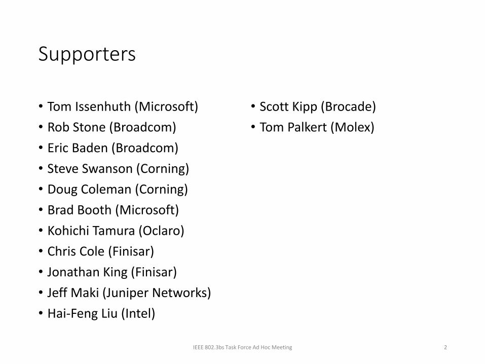
200G-DR4 Block Diagram
IEEE 802.3bs Task Force Ad Hoc Meeting 5

Transmitter Specifications
IEEE 802.3bs Task Force Ad Hoc Meeting 6
• Max OMA and ER specified based on outer Tx_OMAouter
• Sensitivity and link budget based on inner Tx_OMAlow/mid/upp
• Spec applies to minimum of 3 inner eye transitions
Tx_OMAouter
Tx_OMAlow
Tx_OMAmid
Tx_OMAupp

200G-DR4: Transmitter Specifications (TP2)
Description Value Unit
Signaling rate, each lane (Range) 26.5625 ± 100 ppm GBd
Modulation Format PAM4
Lane wavelengths (range) 1304.5 to 1317.5 nm
Side-mode suppression ratio (SMSR), (min) 30 dB
Average launch power, each lane (max) 3 dBm
Average launch power, each lane (min) -4.6 dBm
Outer Optical Modulation Amplitude (OMAouter), each lane(max) 2.8 dBm
Outer Optical Modulation Amplitude (OMAouter), each lane(min) -2.5 dBm
Launch power in OMAouter minus TDECQ, each lane (min) -3.5 dBm
Transmitter and dispersion eye closure (TDECQ), each lane (max) 2.5 dB
Average launch power of OFF transmitter, each lane (max) -30 dBm
Extinction ratio, each lane, (min) 4.5 dB
RIN25 OMA (max) -142 dB/Hz
Optical return loss tolerance (max) 24.7 dB
Transmitter reflectance (max) -26 dB
IEEE 802.3bs Task Force Ad Hoc Meeting 7All Parameters Subject to Change
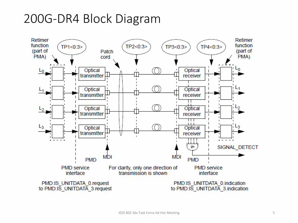
200G-DR4: Receiver Specifications (TP3)Description Value Unit
Signaling rate, each lane (Range) 26.5625 ± 100 ppm GBd
Modulation Format PAM4
Lane wavelengths (range) 1304.5 to 1317.5 nm nm
Damage threshold, each lane 6.5 dBm
Average receive power, each lane (max) 3.0 dBm
Average receive power, each lane (min) -7.6 dBm
Receive power, each lane (OMAouter) (max) 2.8 dBm
Receiver reflectance (max) -26 dB
Receiver sensitivity (OMAinner), each lane (max) -11.4 dBm
Stressed receiver sensitivity (OMAouter), each lane (max)† -4.1 dBm
Conditions of stressed receiver sensitivity test:
SECQ† 2.5 dB
OMAouter of each aggressor lane 2.8 dBm
IEEE 802.3bs Task Force Ad Hoc Meeting 8
† Links with lower OMA and TDEQ values must not have BER > 2.4e-4

200G-DR4 : Link ParametersDescription Value Unit
Operating distance 500 m
Signaling rate, each lane (Range) 26.5625 ± 100 ppm GBd
Encoding type PAM4
Lane wavelength (range) 1304.5 to 1317.5 nm nm
Uncorrected BER < 2.4e-4
Channel insertion loss (max) 3 dB
Channel insertion loss (min) 0 dB
Allocation for penalties, at max TDECQ (dB)‡ 2.6 dB
MPI Penalty 0.1 dB
Power margin, at min TDECQ 9.1 dB
Maximum discrete reflectance -45 dB
Max number of -45 dB reflections 4
Positive dispersion (max) 0.8 ps/nm
Negative dispersion (min) -0.93 ps/nm
DGD_max 2.24 ps
Optical return loss (min) 39 dB
IEEE 802.3bs Task Force Ad Hoc Meeting 9
All Parameters Subject to Change

200G-DR4 : Link Parameters (continued)Description Value Unit
Nominal fiber specification wavelength 1310 nm
Cabled optical fiber attenuation (max) 0.5 dB/km
Zero dispersion wavelength (λ0) 1300 ≤ λ0 ≤ 1324 nm
Dispersion slope (max) (S0) 0.093 ps/nm2km
IEEE 802.3bs Task Force Ad Hoc Meeting 10
All Parameters Subject to Change
PMD type Dispersion (ps/nm) Insertion Loss
Optical Return Loss
Max mean DGD
Minimum Maximum
200GBASE-DR4 0.0011625xλx[1-(1324/λ)4] 0.0011625xλx[1-(1300/λ)4] Minimum 24.7 0.5 ps

Optical Lane Assignments
• The four transmit and four receive optical lanes of 200GBASE-DR4shall occupy the positions depicted in Figure xxx-x when looking intothe MDI receptacle with the connector keyway feature on top. Theinterface contains eight active lanes within twelve total positions. Thetransmit optical lanes occupy the left-most four positions. Thereceive optical lanes occupy the right-most four positions. The fourcenter positions are unused.
IEEE 802.3bs Task Force Ad Hoc Meeting 11
Figure xxx-x- 200GBASE-DR4 optical lane assignments

MDI Specifications• The MDI shall meet the dimensional specifications of IEC 61754-7-1 interface 7-
1-9: MPO device receptacle, angled interface. The plug terminating the optical fiber cabling shall meet the dimensional specifications of IEC 61754-7-1 interface 7-1-1: MPO female plug connector, down-angled interface for 2 to 12 fibers. The MDI shall optically mate with the plug on the optical fiber cabling. The below figures shows the MPO female plug connector and MDI receptacle. The MDI shall meet the interface performance specifications of IEC 61753-012-2 for performance level D/2.
IEEE 802.3bs Task Force Ad Hoc Meeting 12

200G-DR4
• Configuration: A 4x50 Gb/s parallel SMF interconnect.• Four fibers per direction
• Reach >= 500m
• Lane Speed: 50 Gb/s per lane using 25 GBaud-PAM4 optical signaling
• Uncorrected BER < 2.4e-4
• Single wavelength solution
IEEE 802.3bs Task Force Ad Hoc Meeting 13

200GBASE-DR4: A Baseline Proposal for the 200G 500m Objective
Thank You
Related Documents