By – vinayak v. susladkar (2009156) INDO-GERMAN TOOL ROOM AURANGABAD PROJECT PRESENTATION ON PROGRESSIVE PRESS TOOL

Welcome message from author
This document is posted to help you gain knowledge. Please leave a comment to let me know what you think about it! Share it to your friends and learn new things together.
Transcript

By –vinayak v. susladkar(2009156)
INDO-GERMAN TOOL ROOM
AURANGABADPROJECT
PRESENTATIONON
PROGRESSIVE PRESS TOOL

Progessive distance layer tool
WORK ORDER NO. - 1421620CUSTOMER - ELRING KLINGERCOMPONENT - GasketMATERIAL - Stainless steelSHEET THICKNESS - 0.5mm
`

CONTENTS:-1. INTRODUCTION TO PROGESSIVE TOOL2. COMPONENT DETAILS3. TOOL DATA4. CALCULATION5. SPECIAL FEATURES6. ASSEMBLY DETAILS
INTRODUCTION TO Progressive TOOL
In this type of press tool a number of various cutting and non-cutting operations are performed at different stages in order to obtain the required component.
Beading:
Beading is a deep drawing process.
In Material is displaced to create a larger, or smaller, diameter ring of same material beyond the original body diameter of a part.

COMPONENT DETAILSCOMPONENT - GasketMATERIAL - Stainless steelDENSITY - 1.14g/cm3SHEET THICKNESS - 0.5mmPROJECTED AREA - 1142cm2MASS - 0.13kgPERIMETER - 1018.5mm

GASKET A gasket is a mechanical seal which fills the space between two or
more mating surfaces, generally to prevent leakage from or into the joined objects while under compression.
Gaskets come in many different designs based on industrial usage, budget, chemical contact and physical parameters:
Sheet gaskets. Solid material gaskets. Spiral-wound gaskets. Constant seating stress gaskets. Double-jacketed gaskets. Kammprofile gaskets. Flange gasket.

TOOL DATA
PRESS - 200T(EILN)&400TONE(EILA)OVERALL SIZE– 1100x967x444mmVolume - 160.75cm3TOTAL PROJECTED AREA – 86700mm2OVERALL WT. – 1700kgSHUT HIEGHT -300mmTONNAGE REQ.- 105 ton

FLOW CHART FOR MANUFACTURING i. DESIGN
ii. PART DRAWING RELEASE
iii. RAW MATERIAL
iv. MATERIAL PREPARATION
v. PRE-MACHINING
vi. BENCH WORK
vii. PRECISION MACHINING
viii. HEAT TREATMENT
ix. GRINDING
x. POLISHING
xi. INSPECTION
xii. ASSEMBLY
xiii. TRIAL OUT
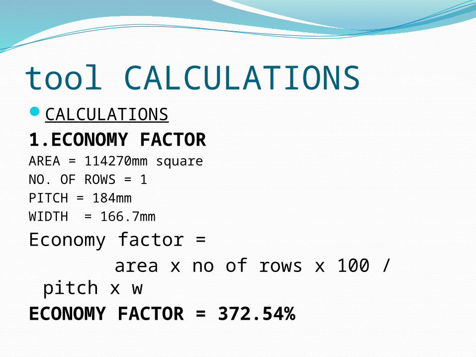
tool CALCULATIONSCALCULATIONS
1.ECONOMY FACTOR AREA = 114270mm square
NO. OF ROWS = 1
PITCH = 184mm
WIDTH = 166.7mm
Economy factor =
area x no of rows x 100 / pitch x w
ECONOMY FACTOR = 372.54%

TOTAL TONNAGE REQUIRED:-
1. PIERCING FORCE:-
PERIMETER (L) = 1018.88mm
SHEET THICKNESS (T) = 0.5mm
STRESS (S) = 60kg/mm square
Piercing force= perimeter x t x stressPIERCING FORCE = 30.56TON

2.BEADING FORCE :- BEADING AREA = 7850mm square
BEADING DEPTH = 0.07mm
YIELD STRENGTH = 60kg/mm square
BEADING FORCE = 32.97TON
3.BLANKING FORCE:-BLANKING PERIMETER (L) = 1018.88mm
STRIP THICKNESS (T)= 0.5mm
S.s = 60kg/meter cube
Blank force = perimeter x t x s / 1000
BLANKING FORCE = 30.5664TON

TOTAL FORCE= piercing force + blanking force + beading force
TOTAL FORCE = 94.10TON
STRIPPING FORCE = Total force x 0.1
STRIPPING FORCE = 9.41TON
TOTAL REQUIRED FORCE =
Total force + stripping force
TOTAL TONNAGE REQUIRED = 103.51TON

OPERATION OF TOOL

Some design features:-
i. ROLLER LIFTERS:-
The die is designed with roller lifters at 1st and 3rd station.
Roller lifters have a roller at the top so that the strip could be fed smoothly
It also incorporates a sping in lower body which ensures that roller goes below the die surface during the stroke and retain its position as stroke is over.

ii. MISSFEED SENSOR:
Many a times to sustain high-speed production, sensors are on all of its dies to prevent collisions or missfeed and the production of defective parts that would bring its process to a halt.
A pin lazer type sensor is used to guide the strip in this tool
If the strip is being missfed or any slug strike the strip the sensor autoamtically stops the stroke.
Overfeed sensor, slug sensor, stripper sensors are also used in presstools.

iii. AIR EJECTION TECHNIQUE :
Air ejection is provided at three punches of first station.
This system consists of an ejector plate, ejection disc, spring end bolts.
In this technique air is fed into punch holder trough a slot machined on its bottom.this air causes the ejector plate to move forward and the aluminium disc also move forward to ensure that the strip is not stuck to to the punch.the disc is again retained to original position with help of springs as tool is closed again.

Problem during manufacturingi. At the first station the stripper plate width was
having 2mm extra material it caused stripper plate to strike on the strip guide.
Solution :
The stripper plate material was removed.
ii. Pillar bush clamps were not given in the design.
Solution :
holes for pillar bush clamp had to be machined on hardford.
iii. Beading die plate was bend in 60 microns which affected the beading depth during trial.
Solution :
grind cut was given to the die plate on half magnet.
iv. Air channel location was in front of the guide bush so there was problem to fix the air pipe.
Solution :
a new hexagonal part was designed having a drill on adjacent face to fix the air pipe.

v. In fourth station relieve was not provided on stripper plate for the beading section it affect the beading surface.
Solution :
relieve was machined in stripper plate.
vi. In first station hole of dowel in thrust plate was offset
Solution :
required re-machining.

achivementsWe got an upportunity to work on an advanced design
press tool.The project was a medium for us to enhance our
knowledge in the field of tool & Die Designing & Manufacturing. It helped us a lot in better understanding of the concepts of progessive tool manufacturing, beading process.
During the project we had to communicate with various departments and authorities to solve the problems and difficulties around in between. It has helped to improve our abilities to work as a team.

The tool was required to be completed in a specific period of time for which we had to work to the best of our abilities to complete the tool.
In the project work we were given an opportunity to study the Progressive tool from designing to trial out .
It was a nice opportunity for us to learn about such a tool, thus enhancing our knowledge
