November 2021 Project Proposed Residential Development, Parkside Phase 5B at Belmayne, Dublin 13 Report Title Infrastructure Design Report Client Cairn Homes Properties Ltd.

Welcome message from author
This document is posted to help you gain knowledge. Please leave a comment to let me know what you think about it! Share it to your friends and learn new things together.
Transcript
November 2021
Project
Proposed Residential Development,
Parkside Phase 5B at Belmayne, Dublin 13
Report Title
Infrastructure Design Report
Client
Cairn Homes Properties Ltd.
Parkside Phase 5B at Belmayne, Dublin 13
Infrastructure Design Report November 2021
DBFL Consulting Engineers 200036-DBFL-CS-ST-RP-C-3001 IDR i
Job Title: Parkside Phase 5B at Belmayne, Dublin 13
Job Number: 200036
Report Title: Infrastructure Design Report
Report Reference: 200036-DBFL-CS-ST-RP-C-3001 IDR
Author: Conor O’ Loughlin
Approved by: Noel Gorman
Date: November 2021
Distribution: Client: Cairn home properties Ltd.
MCORM Architects
Dublin City Council
File
DBFL Consulting Engineers
Ormond House
Upper Ormond Quay
Dublin 7
Tel 01 4004000
Fax 01 4004050
Email [email protected]
Web www.dbfl.ie
Revision Issue Date Description Prepared Reviewed Approved
- 10/12/2020 Draft COL NCG DJR
P1 16/12/2020 SHD Stage 2 COL NCG DJR
P2 06/10/2021 Draft SHD Stage 3 COL NCG DJR
P3 08/11/2021 SHD Stage 3 COL NCG DJR
Parkside Phase 5B at Belmayne, Dublin 13
Infrastructure Design Report November 2021
DBFL Consulting Engineers 200036-DBFL-CS-ST-RP-C-3001 IDR ii
TABLE OF CONTENTS
1.0 INTRODUCTION .................................................................................... 1
1.1 Background ................................................................................................................ 1
1.2 Location & Topography .............................................................................................. 1
1.3 Existing Site ................................................................................................................ 2
1.4 Existing Ground Conditions ........................................................................................ 4
1.5 Proposed Development .............................................................................................. 5
2.0 FLOOD RISK .......................................................................................... 6
3.0 SITE ACCESS AND ROAD LAYOUT .................................................... 7
3.1 Existing Access .......................................................................................................... 7
3.2 Belmayne Main Street ................................................................................................ 7
3.3 Proposed Greenlink ................................................................................................... 7
3.4 Proposed Roads and Access ..................................................................................... 8
3.5 Pavement Design Standards ..................................................................................... 8
3.6 Cyclist and Pedestrian Connectivity ........................................................................... 8
3.7 Vehicle Tracking ......................................................................................................... 9
3.8 Quality Audit ............................................................................................................... 9
3.9 Traffic & Transportation .............................................................................................. 9
4.0 EXISTING SERVICES AND UTILITIES ................................................ 10
4.1 General ..................................................................................................................... 10
4.2 Surface Water Drainage ........................................................................................... 10
4.3 Foul Sewer ............................................................................................................... 13
4.4 Water Supply ............................................................................................................ 13
5.0 PROPOSED SURFACE WATER DRAINAGE ..................................... 15
5.1 Surface Water Policy ................................................................................................ 15
5.2 General Surface Water Design ................................................................................ 15
5.3 Surface Water Strategy ............................................................................................ 16
5.4 Design Standards ..................................................................................................... 23
5.5 Climate Change........................................................................................................ 24
5.6 Flooding Provision .................................................................................................... 24
5.7 Surface Water Quality Impact .................................................................................. 24
5.8 Maintenance ............................................................................................................. 25
5.9 Interception ............................................................................................................... 25
6.0 PROPOSED FOUL DRAINAGE ........................................................... 26
6.1 Proposed Foul Layout .............................................................................................. 26
Parkside Phase 5B at Belmayne, Dublin 13
Infrastructure Design Report November 2021
DBFL Consulting Engineers 200036-DBFL-CS-ST-RP-C-3001 IDR iii
6.2 Design Calculations ................................................................................................. 26
6.3 Compliance with Irish Water Standards ................................................................... 27
7.0 WATER SUPPLY AND DISTRIBUTION .............................................. 28
7.1 Proposed Water main and Supply ........................................................................... 28
7.2 Hydrants ................................................................................................................... 28
7.3 Design Calculations ................................................................................................. 28
7.4 Compliance with Irish Water Standards ................................................................... 29
Parkside Phase 5B at Belmayne, Dublin 13
Infrastructure Design Report November 2021
DBFL Consulting Engineers 200036-DBFL-CS-ST-RP-C-3001 IDR iv
APPENDICES
Appendix A . QUALITY AUDIT
Appendix B . STORMWATER ATTENUATION CALCULATIONS
Appendix C . STORMWATER NETWORK CALCULATIONS
Appendix D . FOUL SEWER CALCULATIONS
Appendix E . CONFIRMATION OF FEASABILITY
Appendix F . IRISH WATER STATEMENT OF DESIGN ACCEPTANCE
Parkside Phase 5B at Belmayne, Dublin 13
Infrastructure Design Report November 2021
DBFL Consulting Engineers 200036-DBFL-CS-ST-RP-C-3001 IDR 1
1.0 INTRODUCTION
1.1 Background
DBFL have been commissioned to prepare an Infrastructure Design Report to
accompany a planning application for a proposed residential development at Parkside,
Dublin 13. The proposed development site is located within the Clongriffin – Belmayne
Local Area Plan and is approximately 8km north-east of the City Centre
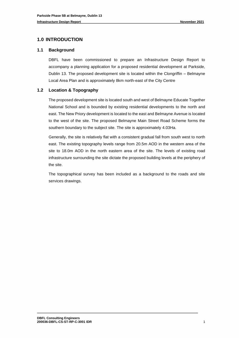
1.2 Location & Topography
The proposed development site is located south and west of Belmayne Educate Together
National School and is bounded by existing residential developments to the north and
east. The New Priory development is located to the east and Belmayne Avenue is located
to the west of the site. The proposed Belmayne Main Street Road Scheme forms the
southern boundary to the subject site. The site is approximately 4.03Ha.
Generally, the site is relatively flat with a consistent gradual fall from south west to north
east. The existing topography levels range from 20.5m AOD in the western area of the
site to 18.0m AOD in the north eastern area of the site. The levels of existing road
infrastructure surrounding the site dictate the proposed building levels at the periphery of
the site.
The topographical survey has been included as a background to the roads and site
services drawings.
Parkside Phase 5B at Belmayne, Dublin 13
Infrastructure Design Report November 2021
DBFL Consulting Engineers 200036-DBFL-CS-ST-RP-C-3001 IDR 2
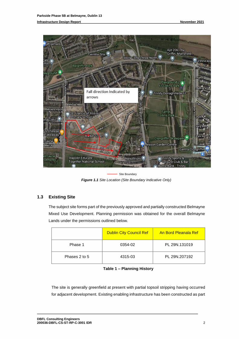
Site Boundary
Figure 1.1 Site Location (Site Boundary Indicative Only)
1.3 Existing Site
The subject site forms part of the previously approved and partially constructed Belmayne
Mixed Use Development. Planning permission was obtained for the overall Belmayne
Lands under the permissions outlined below.
Dublin City Council Ref An Bord Pleanala Ref
Phase 1 0354-02 PL 29N.131019
Phases 2 to 5 4315-03 PL 29N.207192
Table 1 – Planning History
The site is generally greenfield at present with partial topsoil stripping having occurred
for adjacent development. Existing enabling infrastructure has been constructed as part
Parkside Phase 5B at Belmayne, Dublin 13
Infrastructure Design Report November 2021
DBFL Consulting Engineers 200036-DBFL-CS-ST-RP-C-3001 IDR 3
of the overall Belmayne Infrastructure Works (Circa 2005 to 2008) and as part of
Parkside Phase 1 to 5A (Circa 2015 to present).
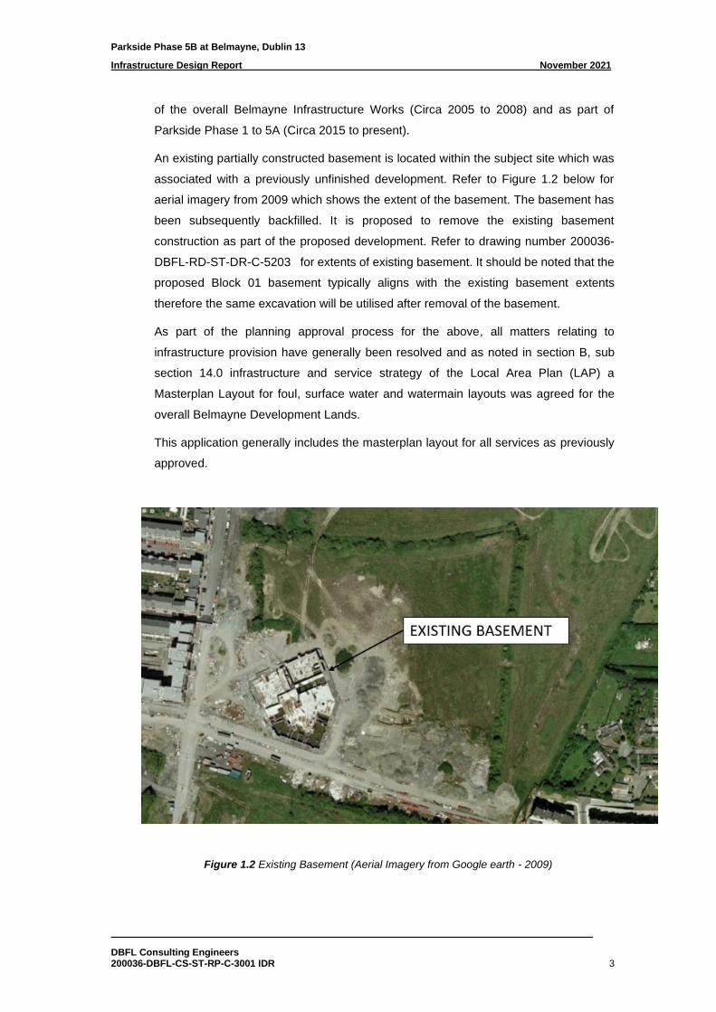
An existing partially constructed basement is located within the subject site which was
associated with a previously unfinished development. Refer to Figure 1.2 below for
aerial imagery from 2009 which shows the extent of the basement. The basement has
been subsequently backfilled. It is proposed to remove the existing basement
construction as part of the proposed development. Refer to drawing number 200036-
DBFL-RD-ST-DR-C-5203 for extents of existing basement. It should be noted that the
proposed Block 01 basement typically aligns with the existing basement extents
therefore the same excavation will be utilised after removal of the basement.
As part of the planning approval process for the above, all matters relating to
infrastructure provision have generally been resolved and as noted in section B, sub
section 14.0 infrastructure and service strategy of the Local Area Plan (LAP) a
Masterplan Layout for foul, surface water and watermain layouts was agreed for the
overall Belmayne Development Lands.
This application generally includes the masterplan layout for all services as previously
approved.
Figure 1.2 Existing Basement (Aerial Imagery from Google earth - 2009)
Parkside Phase 5B at Belmayne, Dublin 13
Infrastructure Design Report November 2021
DBFL Consulting Engineers 200036-DBFL-CS-ST-RP-C-3001 IDR 4
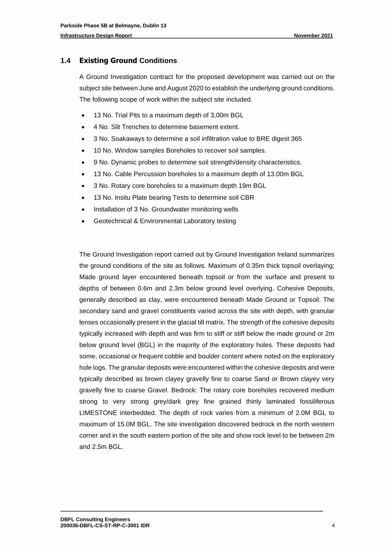
1.4 Existing Ground Conditions
A Ground Investigation contract for the proposed development was carried out on the
subject site between June and August 2020 to establish the underlying ground conditions.
The following scope of work within the subject site included.
• 13 No. Trial Pits to a maximum depth of 3,00m BGL
• 4 No. Slit Trenches to determine basement extent.
• 3 No. Soakaways to determine a soil infiltration value to BRE digest 365
• 10 No. Window samples Boreholes to recover soil samples.
• 9 No. Dynamic probes to determine soil strength/density characteristics.
• 13 No. Cable Percussion boreholes to a maximum depth of 13.00m BGL
• 3 No. Rotary core boreholes to a maximum depth 19m BGL
• 13 No. Insitu Plate bearing Tests to determine soil CBR
• Installation of 3 No. Groundwater monitoring wells
• Geotechnical & Environmental Laboratory testing
The Ground Investigation report carried out by Ground Investigation Ireland summarizes
the ground conditions of the site as follows. Maximum of 0.35m thick topsoil overlaying;
Made ground layer encountered beneath topsoil or from the surface and present to
depths of between 0.6m and 2.3m below ground level overlying. Cohesive Deposits,
generally described as clay, were encountered beneath Made Ground or Topsoil. The
secondary sand and gravel constituents varied across the site with depth, with granular
lenses occasionally present in the glacial till matrix. The strength of the cohesive deposits
typically increased with depth and was firm to stiff or stiff below the made ground or 2m
below ground level (BGL) in the majority of the exploratory holes. These deposits had
some, occasional or frequent cobble and boulder content where noted on the exploratory
hole logs. The granular deposits were encountered within the cohesive deposits and were
typically described as brown clayey gravelly fine to coarse Sand or Brown clayey very
gravelly fine to coarse Gravel. Bedrock: The rotary core boreholes recovered medium
strong to very strong grey/dark grey fine grained thinly laminated fossiliferous
LIMESTONE interbedded. The depth of rock varies from a minimum of 2.0M BGL to
maximum of 15.0M BGL. The site investigation discovered bedrock in the north western
corner and in the south eastern portion of the site and show rock level to be between 2m
and 2.5m BGL.
Parkside Phase 5B at Belmayne, Dublin 13
Infrastructure Design Report November 2021
DBFL Consulting Engineers 200036-DBFL-CS-ST-RP-C-3001 IDR 5
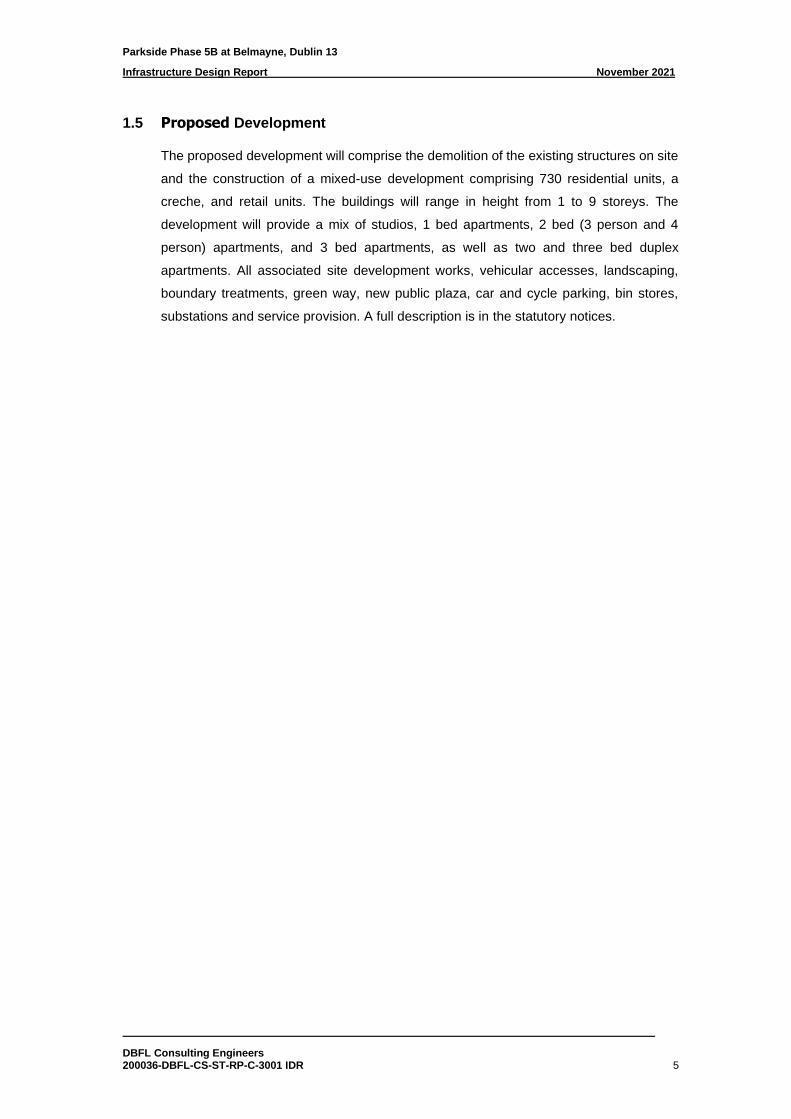
1.5 Proposed Development
The proposed development will comprise the demolition of the existing structures on site
and the construction of a mixed-use development comprising 730 residential units, a
creche, and retail units. The buildings will range in height from 1 to 9 storeys. The
development will provide a mix of studios, 1 bed apartments, 2 bed (3 person and 4
person) apartments, and 3 bed apartments, as well as two and three bed duplex
apartments. All associated site development works, vehicular accesses, landscaping,
boundary treatments, green way, new public plaza, car and cycle parking, bin stores,
substations and service provision. A full description is in the statutory notices.

Parkside Phase 5B at Belmayne, Dublin 13
Infrastructure Design Report November 2021
DBFL Consulting Engineers 200036-DBFL-CS-ST-RP-C-3001 IDR 6
2.0 Flood Risk
A separate Site-Specific Flood Risk Assessment has been prepared as part of this planning
application (refer to DBFL Report No. 200036-DBFLSW-ST-RP-C-3002 SSFRA).
This flood risk assessment has been undertaken by reviewing information from the Office
of Public Works (OPW) National Flood Hazard Mapping (www.floods.ie) and the Eastern
CFRAM Study and has been carried out in accordance with the OPW’s Guidelines for
Planning Authorities – The Planning System and Flood Risk Management (November
2009).
Parkside Phase 5B at Belmayne, Dublin 13
Infrastructure Design Report November 2021
DBFL Consulting Engineers 200036-DBFL-CS-ST-RP-C-3001 IDR 7
3.0 SITE ACCESS AND ROAD LAYOUT
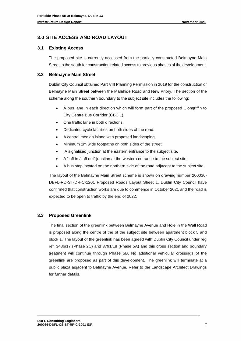
3.1 Existing Access
The proposed site is currently accessed from the partially constructed Belmayne Main
Street to the south for construction related access to previous phases of the development.
3.2 Belmayne Main Street
Dublin City Council obtained Part VIII Planning Permission in 2019 for the construction of
Belmayne Main Street between the Malahide Road and New Priory. The section of the
scheme along the southern boundary to the subject site includes the following:
• A bus lane in each direction which will form part of the proposed Clongriffin to
City Centre Bus Corridor (CBC 1).
• One traffic lane in both directions.
• Dedicated cycle facilities on both sides of the road.
• A central median island with proposed landscaping.
• Minimum 2m wide footpaths on both sides of the street.
• A signalised junction at the eastern entrance to the subject site.
• A “left in / left out” junction at the western entrance to the subject site.
• A bus stop located on the northern side of the road adjacent to the subject site.
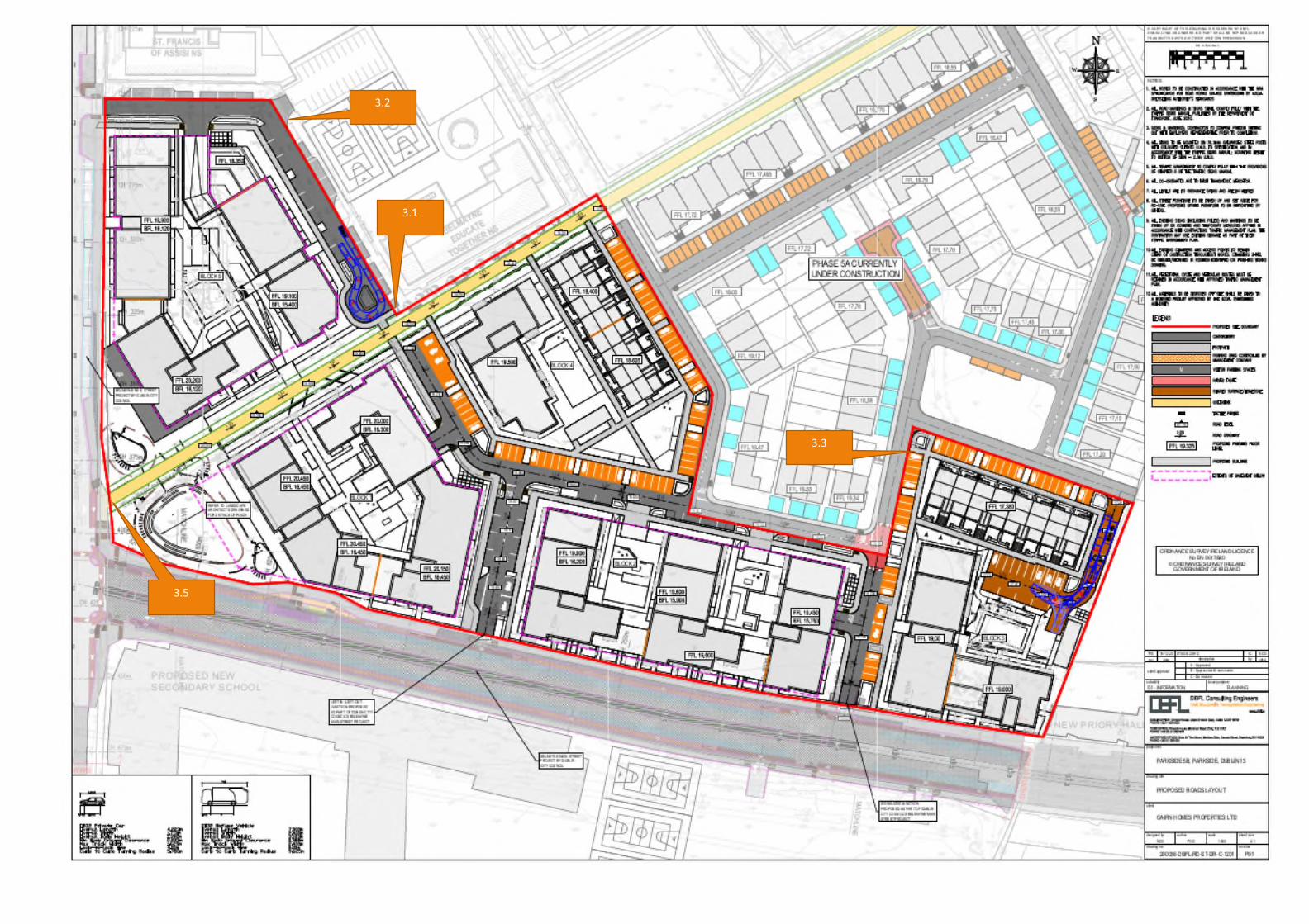
The layout of the Belmayne Main Street scheme is shown on drawing number 200036-
DBFL-RD-ST-DR-C-1201 Proposed Roads Layout Sheet 1. Dublin City Council have
confirmed that construction works are due to commence in October 2021 and the road is
expected to be open to traffic by the end of 2022.
3.3 Proposed Greenlink
The final section of the greenlink between Belmayne Avenue and Hole in the Wall Road
is proposed along the centre of the of the subject site between apartment block 5 and
block 1. The layout of the greenlink has been agreed with Dublin City Council under reg
ref. 3486/17 (Phase 2C) and 3791/18 (Phase 5A) and this cross section and boundary
treatment will continue through Phase 5B. No additional vehicular crossings of the
greenlink are proposed as part of this development. The greenlink will terminate at a
public plaza adjacent to Belmayne Avenue. Refer to the Landscape Architect Drawings
for further details.
Parkside Phase 5B at Belmayne, Dublin 13
Infrastructure Design Report November 2021
DBFL Consulting Engineers 200036-DBFL-CS-ST-RP-C-3001 IDR 8
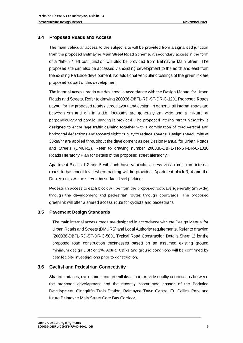
3.4 Proposed Roads and Access
The main vehicular access to the subject site will be provided from a signalised junction
from the proposed Belmayne Main Street Road Scheme. A secondary access in the form
of a “left-in / left out” junction will also be provided from Belmayne Main Street. The
proposed site can also be accessed via existing development to the north and east from
the existing Parkside development. No additional vehicular crossings of the greenlink are
proposed as part of this development.
The internal access roads are designed in accordance with the Design Manual for Urban
Roads and Streets. Refer to drawing 200036-DBFL-RD-ST-DR-C-1201 Proposed Roads
Layout for the proposed roads / street layout and design. In general, all internal roads are
between 5m and 6m in width, footpaths are generally 2m wide and a mixture of
perpendicular and parallel parking is provided. The proposed internal street hierarchy is
designed to encourage traffic calming together with a combination of road vertical and
horizontal deflections and forward sight visibility to reduce speeds. Design speed limits of
30km/hr are applied throughout the development as per Design Manual for Urban Roads
and Streets (DMURS). Refer to drawing number 200036-DBFL-TR-ST-DR-C-1010
Roads Hierarchy Plan for details of the proposed street hierarchy.
Apartment Blocks 1,2 and 5 will each have vehicular access via a ramp from internal
roads to basement level where parking will be provided. Apartment block 3, 4 and the
Duplex units will be served by surface level parking.
Pedestrian access to each block will be from the proposed footways (generally 2m wide)
through the development and pedestrian routes through courtyards. The proposed
greenlink will offer a shared access route for cyclists and pedestrians.
3.5 Pavement Design Standards
The main internal access roads are designed in accordance with the Design Manual for
Urban Roads and Streets (DMURS) and Local Authority requirements. Refer to drawing
(200036-DBFL-RD-ST-DR-C-5001 Typical Road Construction Details Sheet 1) for the
proposed road construction thicknesses based on an assumed existing ground
minimum design CBR of 3%. Actual CBRs and ground conditions will be confirmed by
detailed site investigations prior to construction.
3.6 Cyclist and Pedestrian Connectivity
Shared surfaces, cycle lanes and greenlinks aim to provide quality connections between
the proposed development and the recently constructed phases of the Parkside
Development, Clongriffin Train Station, Belmayne Town Centre, Fr. Collins Park and
future Belmayne Main Street Core Bus Corridor.
Parkside Phase 5B at Belmayne, Dublin 13
Infrastructure Design Report November 2021
DBFL Consulting Engineers 200036-DBFL-CS-ST-RP-C-3001 IDR 9
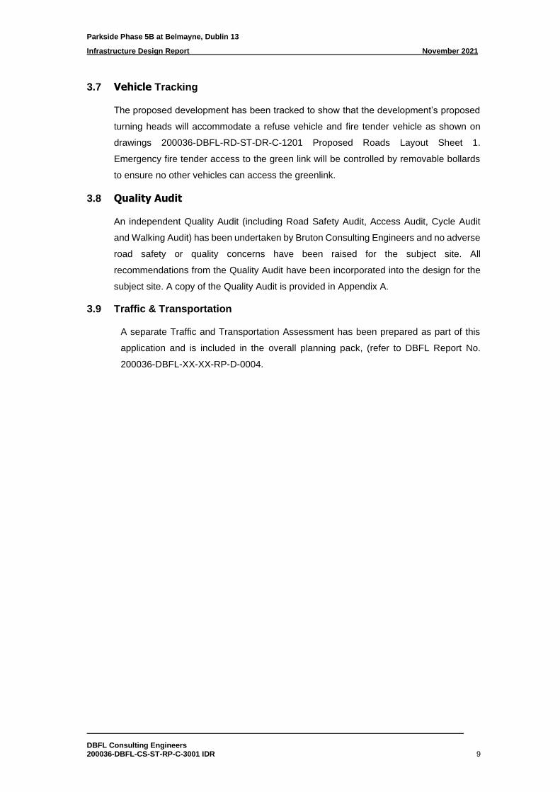
3.7 Vehicle Tracking
The proposed development has been tracked to show that the development’s proposed
turning heads will accommodate a refuse vehicle and fire tender vehicle as shown on
drawings 200036-DBFL-RD-ST-DR-C-1201 Proposed Roads Layout Sheet 1.
Emergency fire tender access to the green link will be controlled by removable bollards
to ensure no other vehicles can access the greenlink.
3.8 Quality Audit
An independent Quality Audit (including Road Safety Audit, Access Audit, Cycle Audit
and Walking Audit) has been undertaken by Bruton Consulting Engineers and no adverse
road safety or quality concerns have been raised for the subject site. All
recommendations from the Quality Audit have been incorporated into the design for the
subject site. A copy of the Quality Audit is provided in Appendix A.
3.9 Traffic & Transportation
A separate Traffic and Transportation Assessment has been prepared as part of this
application and is included in the overall planning pack, (refer to DBFL Report No.
200036-DBFL-XX-XX-RP-D-0004.
Parkside Phase 5B at Belmayne, Dublin 13
Infrastructure Design Report November 2021
DBFL Consulting Engineers 200036-DBFL-CS-ST-RP-C-3001 IDR 10
4.0 EXISTING SERVICES AND UTILITIES
4.1 General
A comprehensive topographical survey was carried out for the subject site and existing
drainage and utility records in the vicinity of the site obtained and surveyed in detail. A
summary of the existing main services is provided below.
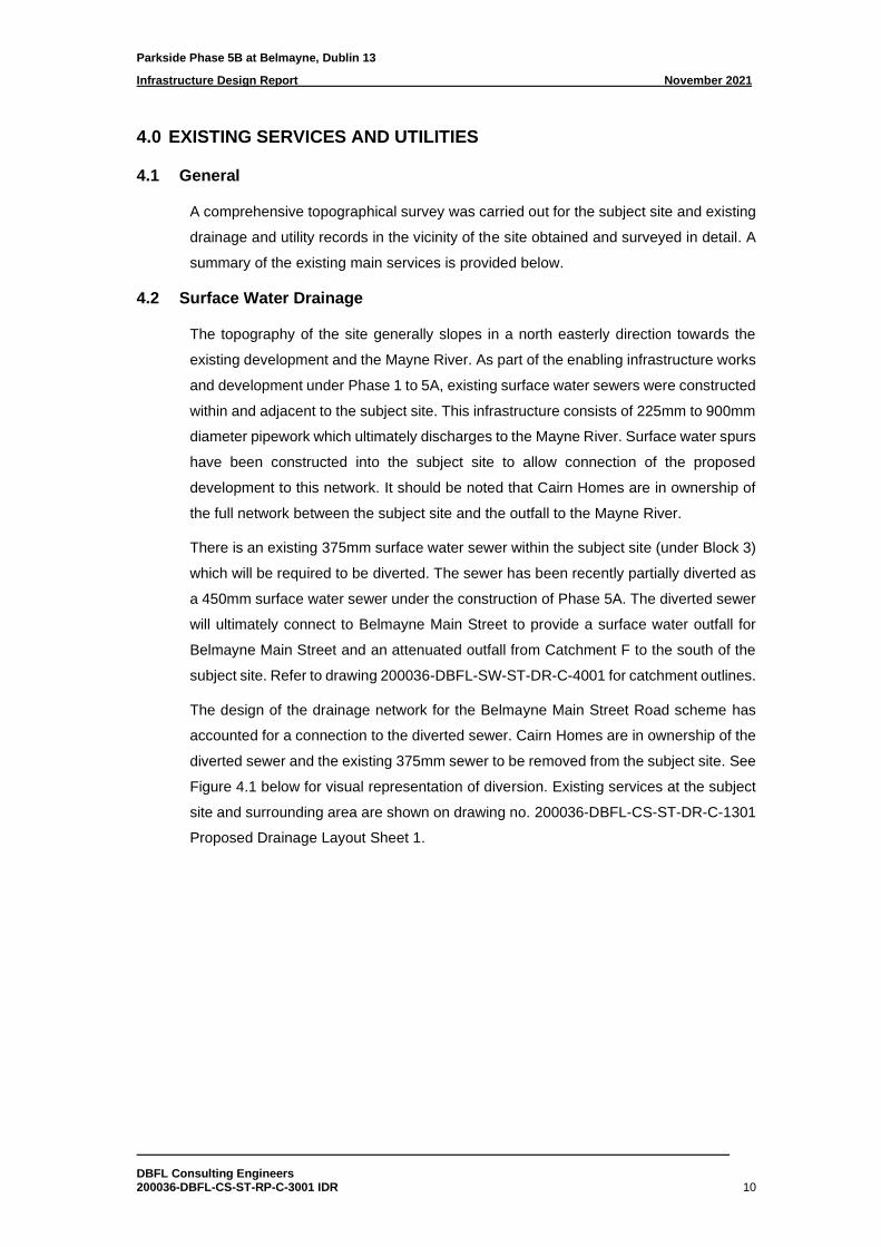
4.2 Surface Water Drainage
The topography of the site generally slopes in a north easterly direction towards the
existing development and the Mayne River. As part of the enabling infrastructure works
and development under Phase 1 to 5A, existing surface water sewers were constructed
within and adjacent to the subject site. This infrastructure consists of 225mm to 900mm
diameter pipework which ultimately discharges to the Mayne River. Surface water spurs
have been constructed into the subject site to allow connection of the proposed
development to this network. It should be noted that Cairn Homes are in ownership of
the full network between the subject site and the outfall to the Mayne River.
There is an existing 375mm surface water sewer within the subject site (under Block 3)
which will be required to be diverted. The sewer has been recently partially diverted as
a 450mm surface water sewer under the construction of Phase 5A. The diverted sewer
will ultimately connect to Belmayne Main Street to provide a surface water outfall for
Belmayne Main Street and an attenuated outfall from Catchment F to the south of the
subject site. Refer to drawing 200036-DBFL-SW-ST-DR-C-4001 for catchment outlines.
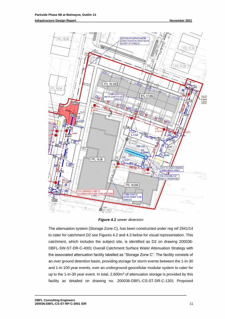
The design of the drainage network for the Belmayne Main Street Road scheme has
accounted for a connection to the diverted sewer. Cairn Homes are in ownership of the
diverted sewer and the existing 375mm sewer to be removed from the subject site. See
Figure 4.1 below for visual representation of diversion. Existing services at the subject
site and surrounding area are shown on drawing no. 200036-DBFL-CS-ST-DR-C-1301
Proposed Drainage Layout Sheet 1.
Parkside Phase 5B at Belmayne, Dublin 13
Infrastructure Design Report November 2021
DBFL Consulting Engineers 200036-DBFL-CS-ST-RP-C-3001 IDR 11
Figure 4.1 sewer diversion
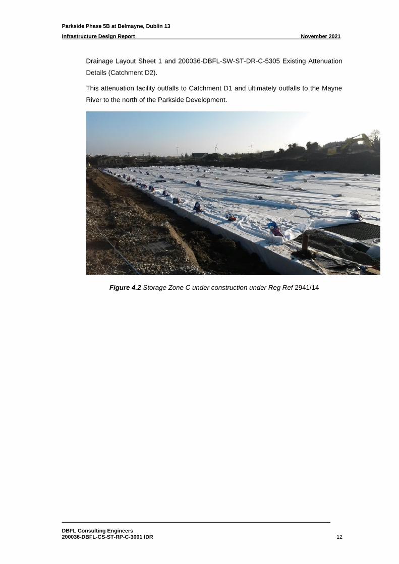
The attenuation system (Storage Zone C), has been constructed under reg ref 2941/14
to cater for catchment D2 see Figures 4.2 and 4.3 below for visual representation. This
catchment, which includes the subject site, is identified as D2 on drawing 200036-
DBFL-SW-ST-DR-C-4001 Overall Catchment Surface Water Attenuation Strategy with
the associated attenuation facility labelled as “Storage Zone C”. The facility consists of
an over ground detention basin, providing storage for storm events between the 1-in-30
and 1-in-100 year events, over an underground geocellular modular system to cater for
up to the 1-in-30 year event. In total, 2,600m3 of attenuation storage is provided by this
facility as detailed on drawing no. 200036-DBFL-CS-ST-DR-C-1301 Proposed
Parkside Phase 5B at Belmayne, Dublin 13
Infrastructure Design Report November 2021
DBFL Consulting Engineers 200036-DBFL-CS-ST-RP-C-3001 IDR 12
Drainage Layout Sheet 1 and 200036-DBFL-SW-ST-DR-C-5305 Existing Attenuation
Details (Catchment D2).
This attenuation facility outfalls to Catchment D1 and ultimately outfalls to the Mayne
River to the north of the Parkside Development.
Figure 4.2 Storage Zone C under construction under Reg Ref 2941/14
Parkside Phase 5B at Belmayne, Dublin 13
Infrastructure Design Report November 2021
DBFL Consulting Engineers 200036-DBFL-CS-ST-RP-C-3001 IDR 13
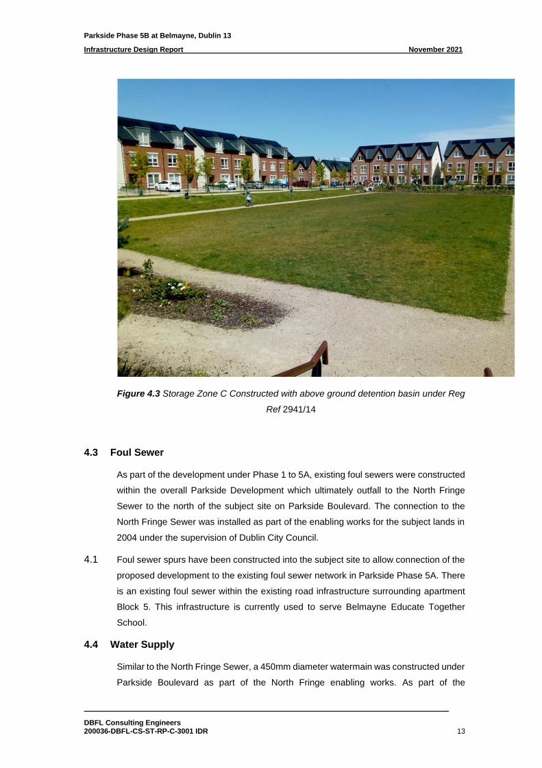
Figure 4.3 Storage Zone C Constructed with above ground detention basin under Reg
Ref 2941/14
4.3 Foul Sewer
As part of the development under Phase 1 to 5A, existing foul sewers were constructed
within the overall Parkside Development which ultimately outfall to the North Fringe
Sewer to the north of the subject site on Parkside Boulevard. The connection to the
North Fringe Sewer was installed as part of the enabling works for the subject lands in
2004 under the supervision of Dublin City Council.
4.1 Foul sewer spurs have been constructed into the subject site to allow connection of the
proposed development to the existing foul sewer network in Parkside Phase 5A. There
is an existing foul sewer within the existing road infrastructure surrounding apartment
Block 5. This infrastructure is currently used to serve Belmayne Educate Together
School.
4.4 Water Supply
Similar to the North Fringe Sewer, a 450mm diameter watermain was constructed under
Parkside Boulevard as part of the North Fringe enabling works. As part of the

Parkside Phase 5B at Belmayne, Dublin 13
Infrastructure Design Report November 2021
DBFL Consulting Engineers 200036-DBFL-CS-ST-RP-C-3001 IDR 14
development under Phase 1 to 5A, watermains were constructed within the overall
Parkside Development which are fed from the north fringe watermain. A 250mm
diameter spine main was constructed from north to south through the development
which will ultimately connect to a 315mm diameter watermain proposed as part of the
Dublin City Council Belmayne Main Street Road project.
Watermain spurs have been constructed into the subject site from the previous phases
of Parkside and the watermain spurs are proposed from the Dublin City Council
Belmayne Main Street Road project.
Parkside Phase 5B at Belmayne, Dublin 13
Infrastructure Design Report November 2021
DBFL Consulting Engineers 200036-DBFL-CS-ST-RP-C-3001 IDR 15
5.0 PROPOSED SURFACE WATER DRAINAGE
5.1 Surface Water Policy
The management of surface water for the proposed development has been designed
to comply with the policies and guidelines outlined in the Greater Dublin Strategic
Drainage Study (GDSDS) and with the requirements of Dublin City Council. The
guidelines require the following 4 main criteria to be provided by the design;
• Criterion 1: River Water Quality Protection – satisfied by providing interception
storage and treatment within the green roof, attenuation systems and green
podiums and garden.
• Criterion 2: River Regime Protection – satisfied by attenuating to greenfield run-off
rates.
• Criterion 3: Level of Service (flooding) for the site – satisfied by the development’s
surface water drainage design, planned flood routing, run-off contained within site,
flood storage and building set greater than 0.5m above the 100-year flood level.
• Criterion 4: River flood protection – attenuation volume and discharge limit designed
to greenfield run-off rates (long term storage not provided).
In order to comply with the local area plan (LAP) objectives for drainage the following
drainage design SUDS measures shall, where feasible, be incorporated into the
development in line with appropriate sustainable drainage practices: a) Infiltration
systems including infiltration trenches, infiltration basins, permeable paving,
landscaping, soak ways and green roofs. b) Filtration systems including swales, bio
retention systems and filter strips. c) Retention systems including retention swales. d)
Detention systems including underground tanks, underground attenuation, detention
basins and filter drawings. Section 5.3 below outline the proposed SUDS features in
greater detail.
5.2 General Surface Water Design
The subject site forms part of a wider catchment area and is subject to a surface water
catchment plan and attenuation strategy. This surface water catchment plan and
attenuation strategy was agreed with Dublin City Council under the planning application
for Parkside Phase 1 (planning reference 2941/14).
As noted in Section 4.0 above, the attenuation facility has been constructed for the
subject site under planning reference 2941/14 and surface water spurs have been
constructed into the subject site.
Parkside Phase 5B at Belmayne, Dublin 13
Infrastructure Design Report November 2021
DBFL Consulting Engineers 200036-DBFL-CS-ST-RP-C-3001 IDR 16
It is proposed to use a Sustainable Urban Drainage System (SUDS) approach to
stormwater management within the development in compliance with the requirements
of the GDSDS as described in the following sections of the report.
5.3 Surface Water Strategy
To meet the requirements of the surface water policy above, the surface water strategy
has been described in this section to give a clearer indication of how the design
development has progressed to the submitted design. To give a clearer understanding
of each SUDS element, and the different stages of the treatment train, the strategy has
been broken down to different levels, which include roof, podium, ground level and road
network. An overview of the different SUDS features incorporated within the
development proposals can be seen on 200036-DBFL-CS-ST-DR-C-1301 Proposed
Drainage Layout Sheet 1 and DBFL Drawing 20036-DBFL-SW-ST-DR-C-1321
Proposed Suds.
Roof Level and Terraces:
As the first part of the treatment train, the SuDS features have been designed to
prioritise interception and reduction of flow rates. The features that will be incorporated
into the design are:
• Green roof - this will be an extensive type green roof with 80mm minimum
construction depth. All necessary safety requirements will be designed and
constructed to ensure safe maintenance can occur. The green roof will provide
interception and reduction of flow rates at the beginning of the treatment train,
providing source control for a large area of the development. DBFL Drawing
20036-DBFL-SW-ST-DR-C-1321 Proposed Suds shows the extents of the
green roof. A minimum of 70% of the roof area is proposed to be green roof.
After surface water has passed through the green roof, this will pass through to
the surface water drainage network to the attenuation system.
• Planters will also be installed on the roof terraces locally acting to reduce run
off and allowing an element of interception to occur.
• The hardstanding of roof terraces will drain to the underlying free draining
aggregate and drainage board allowing the surface water to slowly percolate
through the build-up before being discharged to the open-bottomed attenuation
system.
• Impermeable roof areas will be sloped towards the green roof where possible
to infiltrate water runoff through the green roof build up before draining to the
attenuation system.
Parkside Phase 5B at Belmayne, Dublin 13
Infrastructure Design Report November 2021
DBFL Consulting Engineers 200036-DBFL-CS-ST-RP-C-3001 IDR 17
• Remaining roof areas such as plant areas will drain via a positive drainage
system to the below surface water network and open-bottomed attenuation
facility.
Podium Level (Ground Floor):
• The proposed podiums of the development will predominantly be green
landscaping which will act as a SUDs feature. Paved areas are provided for
pedestrian access. Generally, these paved areas will drain to the green
landscaping and where not possible will drain to slot drains which outfall to the
free draining aggregate and drainage board below. Refer to DBFL Drawing
20036-DBFL-SW-ST-DR-C-1321 Proposed Suds.
The green landscaped areas will constitute what is similar to an intensive green
roof build-up, allowing surface water run-off to slowly percolate through the
vegetation, planters and build-up medium reducing the flows through the
drainage network and also allowing vegetation to intercept run-off creating a
reduction in run-off volumes before discharging to the drainage board below.
• Paved areas will generally drain to the green areas or to slot drains which outfall
to the free draining aggregate and drainage board below allowing a reduction
in flows within the drainage network.
• Once the rainwater has filtered through the various build-up mediums and
drainage board, run-off will drain to gullies located at the structural slab level
and then conveyed to the below ground system via slung drainage.
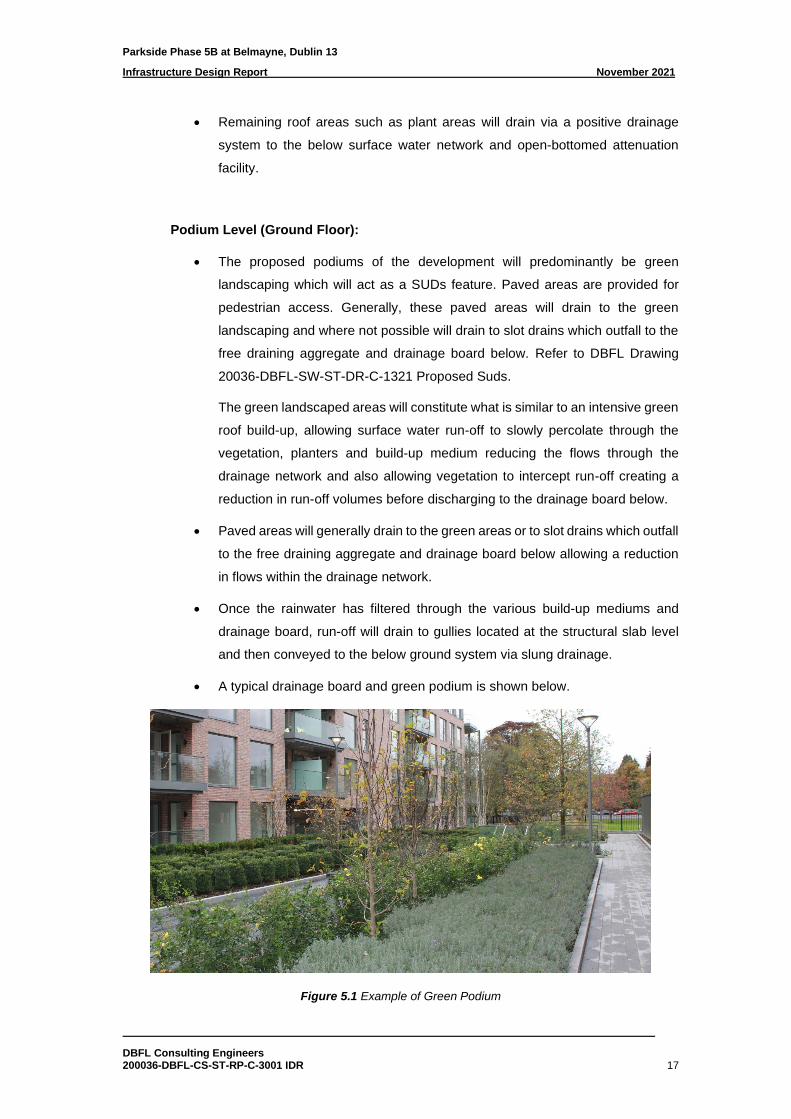
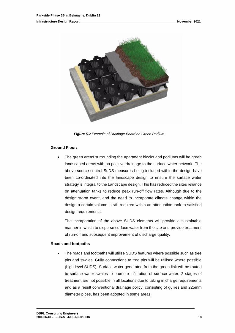
• A typical drainage board and green podium is shown below.
Figure 5.1 Example of Green Podium
Parkside Phase 5B at Belmayne, Dublin 13
Infrastructure Design Report November 2021
DBFL Consulting Engineers 200036-DBFL-CS-ST-RP-C-3001 IDR 18
Figure 5.2 Example of Drainage Board on Green Podium
Ground Floor:
• The green areas surrounding the apartment blocks and podiums will be green
landscaped areas with no positive drainage to the surface water network. The
above source control SuDS measures being included within the design have
been co-ordinated into the landscape design to ensure the surface water
strategy is integral to the Landscape design. This has reduced the sites reliance
on attenuation tanks to reduce peak run-off flow rates. Although due to the
design storm event, and the need to incorporate climate change within the
design a certain volume is still required within an attenuation tank to satisfied
design requirements.
The incorporation of the above SUDS elements will provide a sustainable
manner in which to disperse surface water from the site and provide treatment
of run-off and subsequent improvement of discharge quality.
Roads and footpaths
• The roads and footpaths will utilise SUDS features where possible such as tree
pits and swales. Gully connections to tree pits will be utilised where possible
(high level SUDS). Surface water generated from the green link will be routed
to surface water swales to promote infiltration of surface water. 2 stages of
treatment are not possible in all locations due to taking in charge requirements
and as a result conventional drainage policy, consisting of gullies and 225mm
diameter pipes, has been adopted in some areas.
Parkside Phase 5B at Belmayne, Dublin 13
Infrastructure Design Report November 2021
DBFL Consulting Engineers 200036-DBFL-CS-ST-RP-C-3001 IDR 19
The impermeable areas contributing to the attenuation volume have the following
reduction factors applied:
Roof Level:
• Green roofs, the proposed build-up will be a mix of intensive and extensive type
with 80mm minimum construction depth. The soil build-up will primarily absorb
some of the initial run-off and once saturated will reduce the flow of run-off
through the green roof medium. Therefore, a reduction of volume and flow rate
will occur due to the presence of the green roof. Also, the green roof plant life
will absorb a percentage of the run-off, further reducing volume that will drain
to the surface water network. Therefore a 30% reduction factor has been
applied.
• Flat impermeable roof and roads, a 5% reduction of the surface area is applied
to take account of run-off not collected and stored within the micro and macro
texture of the surfacing (various sources recommend different reduction
coefficients e.g. IS EN752 recommends Runoff Coefficient (C for the Rational
Method) of 0.9 to 1.0 for impermeable areas and steeply sloping roofs. For flat
roofs it recommends 0.5 to 1.0 depending on area).
Podium Level & Ground Floor:
• Green areas over podium, a reduction factor of 50% has been applied. The
deep soil build-up, vegetation and planting will primarily absorb a substantial
amount of the initial run-off and once saturated will reduce the flow of run-off
through the green roof medium.
• Paved Areas on podium and terraces will generally drain to the green areas or
to slot drains which outfall to the free draining aggregate and drainage board
below allowing a reduction in flows within the drainage network. Rainfall will
‘wet’ the initial surface of the paving allowing water to be stored in the micro
and macrotexture of the surfacing and will be lost to evapotranspiration, as the
run-off drains through the drainage board it will also ‘wet’ giving another volume
reduction due to evapotranspiration and natural storage within the SuDS
feature. A reduction in velocity will also occur as the aggregate used will slow
the run-off at source, changing the input hydrograph which will ultimately reduce
the peak inflow for attenuation calculations. A reduction factor of 10% has been
applied for these reasons.
Parkside Phase 5B at Belmayne, Dublin 13
Infrastructure Design Report November 2021
DBFL Consulting Engineers 200036-DBFL-CS-ST-RP-C-3001 IDR 20
Roads and footpaths
• A reduction factor of 5% has been applied to calculate roads and footpaths
draining to gullies as some areas will benefit from swales and tree pits.
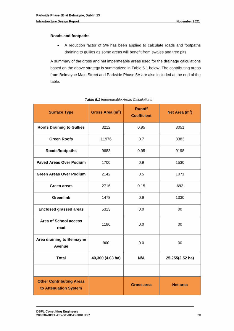
A summary of the gross and net impermeable areas used for the drainage calculations
based on the above strategy is summarized in Table 5.1 below. The contributing areas
from Belmayne Main Street and Parkside Phase 5A are also included at the end of the
table.
Table 5.1 Impermeable Areas Calculations
Surface Type Gross Area (m2) Runoff
Coefficient Net Area (m2)
Roofs Draining to Gullies 3212 0.95 3051
Green Roofs 11976 0.7 8383
Roads/footpaths 9683 0.95 9198
Paved Areas Over Podium 1700 0.9 1530
Green Areas Over Podium 2142 0.5 1071
Green areas 2716 0.15 692
Greenlink 1478 0.9 1330
Enclosed grassed areas 5313 0.0 00
Area of School access
road 1180 0.0 00
Area draining to Belmayne
Avenue 900 0.0 00
Total 40,300 (4.03 ha) N/A 25,255(2.52 ha)
Other Contributing Areas
to Attenuation System Gross area Net area
Parkside Phase 5B at Belmayne, Dublin 13
Infrastructure Design Report November 2021
DBFL Consulting Engineers 200036-DBFL-CS-ST-RP-C-3001 IDR 21
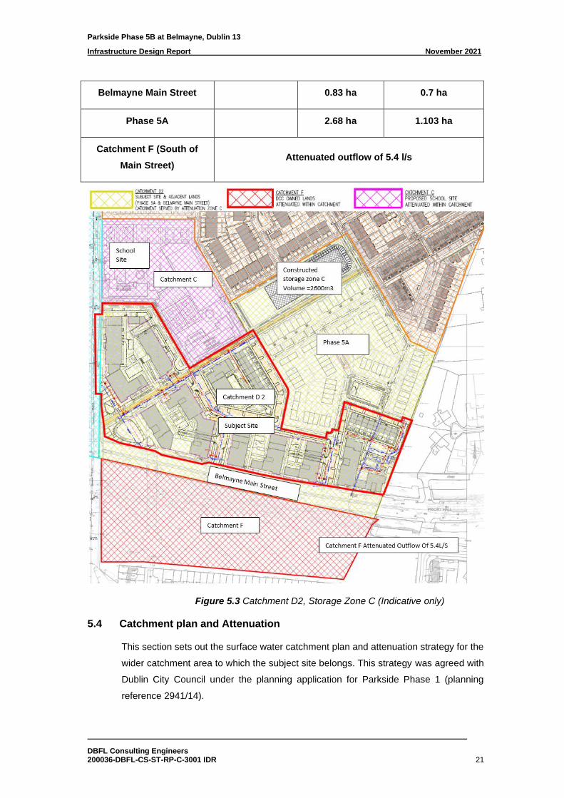
Belmayne Main Street 0.83 ha 0.7 ha
Phase 5A 2.68 ha 1.103 ha
Catchment F (South of
Main Street) Attenuated outflow of 5.4 l/s
Figure 5.3 Catchment D2, Storage Zone C (Indicative only)
5.4 Catchment plan and Attenuation
This section sets out the surface water catchment plan and attenuation strategy for the
wider catchment area to which the subject site belongs. This strategy was agreed with
Dublin City Council under the planning application for Parkside Phase 1 (planning
reference 2941/14).
Parkside Phase 5B at Belmayne, Dublin 13
Infrastructure Design Report November 2021
DBFL Consulting Engineers 200036-DBFL-CS-ST-RP-C-3001 IDR 22
The discharge of run-off from the site will be limited to 2 l/s/ha as per the conditions of
planning under the planning application 2941/14. The overall Parkside lands were sub-
divided into two sub-catchments, D1 and D2, as identified on drawing 200036-DBFL-
SW-ST-DR-C-4001 Overall Catchment Surface Water Attenuation Strategy.
Attenuation systems, Storage Zone B and Storage Zone C have been constructed for
catchment D1 and D2 respectively under planning reference 2941/14. Storage Zone C
has an existing hydrobrake manhole limiting flows to 21L/S. This is broken down into
15.6L/S for catchment D2 and an additional 5.4L/S to account for the flow from
catchment F.
Storage Zone C in the centre of the development, has been constructed under reg ref
2941/14 to cater for catchment D2. This catchment, which includes the subject site, is
identified as D2 on drawing 200036-DBFL-SW-ST-DR-C-4001 Overall Catchment
Surface Water Attenuation Strategy with the associated attenuation facility labelled as
“Storage Zone C”. The facility consists of an over ground detention basin, providing
storage for storm events between the 1-in-30 and 1-in-100 year events, over an
underground geocellular modular system to cater for up to the 1-in-30 year event. In
total, 2,600m3 of attenuation storage is provided by this facility as detailed on drawing
no. 200036-DBFL-CS-ST-DR-C-1301 Proposed Drainage Layout Sheet 1 and 200036-
DBFL-SW-ST-DR-C-5305 Existing Attenuation Details (Catchment D2).
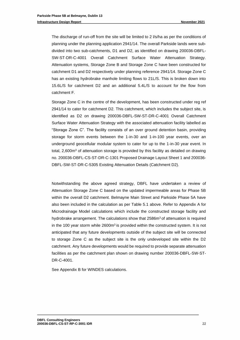
Notwithstanding the above agreed strategy, DBFL have undertaken a review of
Attenuation Storage Zone C based on the updated impermeable areas for Phase 5B
within the overall D2 catchment. Belmayne Main Street and Parkside Phase 5A have
also been included in the calculation as per Table 5.1 above. Refer to Appendix A for
Microdrainage Model calculations which include the constructed storage facility and
hydrobrake arrangement. The calculations show that 2586m3 of attenuation is required
in the 100 year storm while 2600m3 is provided within the constructed system. It is not
anticipated that any future developments outside of the subject site will be connected
to storage Zone C as the subject site is the only undeveloped site within the D2
catchment. Any future developments would be required to provide separate attenuation
facilities as per the catchment plan shown on drawing number 200036-DBFL-SW-ST-
DR-C-4001.
See Appendix B for WINDES calculations.
Parkside Phase 5B at Belmayne, Dublin 13
Infrastructure Design Report November 2021
DBFL Consulting Engineers 200036-DBFL-CS-ST-RP-C-3001 IDR 23
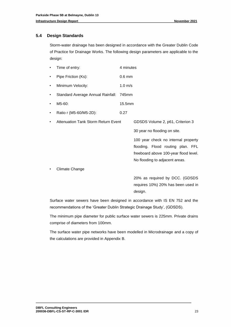
5.4 Design Standards
Storm-water drainage has been designed in accordance with the Greater Dublin Code
of Practice for Drainage Works. The following design parameters are applicable to the
design:
• Time of entry: 4 minutes
• Pipe Friction (Ks): 0.6 mm
• Minimum Velocity: 1.0 m/s
• Standard Average Annual Rainfall: 745mm
• M5-60: 15.5mm
• Ratio r (M5-60/M5-2D): 0.27
• Attenuation Tank Storm Return Event GDSDS Volume 2, p61, Criterion 3
30 year no flooding on site.
100 year check no internal property
flooding. Flood routing plan. FFL
freeboard above 100-year flood level.
No flooding to adjacent areas.
• Climate Change
20% as required by DCC. (GDSDS
requires 10%) 20% has been used in
design.
Surface water sewers have been designed in accordance with IS EN 752 and the
recommendations of the ‘Greater Dublin Strategic Drainage Study’, (GDSDS).
The minimum pipe diameter for public surface water sewers is 225mm. Private drains
comprise of diameters from 100mm.
The surface water pipe networks have been modelled in Microdrainage and a copy of
the calculations are provided in Appendix B.
Parkside Phase 5B at Belmayne, Dublin 13
Infrastructure Design Report November 2021
DBFL Consulting Engineers 200036-DBFL-CS-ST-RP-C-3001 IDR 24
5.5 Climate Change
Surface water calculations for the development made use of rainfall values for the
Parkside Area as provided by Met Eireann. Rainfall intensities were increased by a
factor of 20% to take account of climate change, as required by Dublin City Council.
5.6 Flooding Provision
The surface water network is designed to accommodate a 100 year storm event and
includes climate change provision. For storms in excess of 100 years, the development
has been designed to provide an overland flood route from the development towards
the Mayne River. Further details of same are included in the Site Specific Flood Risk
Assessment which accompanies this application.
5.7 Surface Water Quality Impact
The type of development is low risk i.e. it does not present a high risk of run-off
contamination. The development’s design and layout further reduce the risk of
contaminants entering the surface water network as a high portion of the site coverage
will either be roof area or green / pedestrianised podium areas with a high portion of
vehicle parking provided within the basement. Run-off from roofs will have a first stage
of treatment by draining through green-roof medium which in turn drain to the open
bottom attenuation storage systems. Soft and hard landscaped podiums will drain via
their build-ups to a slung system which in turn also drain via the geo-cellular open
bottom attenuation storage systems which provide further secondary removal of
pollutants due to the geotextiles and filter stone. Each apartment block within the
development shall be drained via an outfall manhole to the regional Code of Practice
Purple book. An existing Class 1 Bypass Separator is provided on the outfall to the
Mayne River to the north of the development. The roads and footpaths will utilise SUDS
features where possible such as tree pits and swales. 2 stages of treatment are not
possible in all locations due to the taking in charge requirements as a result
conventional drainage policy, consisting of gullies and 225mm diameter pipes, has been
adopted in some areas.
In this way it is considered that the development provides treatment of collected run-off,
provides a SUDS treatment train approach and is low risk of pollutants. The proposed
surface water system has therefore been designed to incorporate SuDS techniques
which naturally reduce pollutants and improve water quality.
Parkside Phase 5B at Belmayne, Dublin 13
Infrastructure Design Report November 2021
DBFL Consulting Engineers 200036-DBFL-CS-ST-RP-C-3001 IDR 25
All incidental drainage from basement car parks is discharged separately via a Class 2
oil separator and pumped to the foul sewer network. The pumping station will be
alarmed and connected to the building management system to alert management
personnel if the pumps are running excessively or not working.
5.8 Maintenance
Regular maintenance of the attenuation facilities, hydrobrake and interceptors is
required in accordance with the manufacturer’s recommendations. They will also be
inspected after every major storm event, end of winter (April) – to collect winter debris,
mid-summer (July/August) – to collect dust, flower and grass-type deposits, and after
autumn leaf fall (November). A yearly inspection report will be forwarded to Dublin City
Council Maintenance Department including maintenance details of the hydrobrake,
smart manhole, interceptor and attenuation system.
5.9 Interception
The GDSDS recommends that no run-off should pass directly to a river for rainfall
depths of 5mm and up to 10mm if possible, i.e. interception. The development’s
drainage design allows for collection of a majority of the site’s run-off via SuDS features
e.g. green roofs, tree pits and landscaped podiums, providing interception at source. In
turn resulting runoff is conveyed to an open bottomed attenuation storage system which
remove pollutants and provide a level of further interception. This equates to 126m3 for
the subject site’s effective drained area of 2.51Ha. The proposed green roofs, existing
attenuation system, tree pits, blue podiums and swales provide in excess of 135m3 of
interception storage.
Parkside Phase 5B at Belmayne, Dublin 13
Infrastructure Design Report November 2021
DBFL Consulting Engineers 200036-DBFL-CS-ST-RP-C-3001 IDR 26
6.0 PROPOSED FOUL DRAINAGE
6.1 Proposed Foul Layout
It is proposed to outfall the subject site to the constructed foul sewer network in Phase
1 and 5A of the Parkside development. This foul outfall for the site has been approved
under the overall parent permission for the site, (reg ref 4315-03). This foul outfall
serving the overall Parkside Lands connects to the North Fringe Sewer to the north of
the subject site. The connection to the North Fringe Sewer was installed as part of the
enabling works for the overall lands in 2004 under the supervision of Dublin City
Council.
It is proposed to provide a new foul system comprising 225mm & 300mm diameter main
foul sewers to serve the subject site. Slung drainage will be provided within the
basements of block 1, 2 and 5 to serve the apartment blocks above.
Basement incidental car park drainage will be provided in each basement before
passing through a Class 2 Light Liquid Separator and pumped to the foul network as
required by GDSDS. The pumping station will be alarmed and connected to the building
management system to alert management personnel if the pumps are running
excessively or not working.
The proposed foul drainage network can be found on DBFL drawing 200036-DBFL-CS-
ST-DR-C-1301 Proposed Drainage Layout Sheet 1.
6.2 Design Calculations
Minimum gradients and pipe diameters for gravity collector and main sewers are
designed in accordance with the Building Regulations and Irish Water’s Code of
Practice for wastewater infrastructure and Standard Details for wastewater
infrastructure.
The sewer network is designed in accordance with the principles and methods set out
in Irish Water’s Code of Practice for Wastewater Infrastructure Connections and
Developer Services Design & Construction Requirements for Self-Lay Developments
July 2020, IS EN 752 (2008), IS EN12056: Part2 and Building Regulations Part H.
The foul sewer pipe networks have been modelled in Microdrainage and a copy of the
calculations are provided in Appendix D.
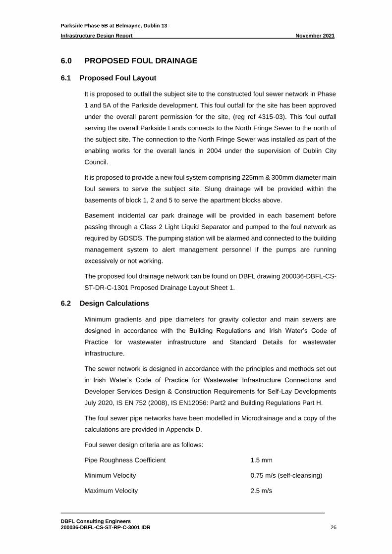
Foul sewer design criteria are as follows:
Pipe Roughness Coefficient 1.5 mm
Minimum Velocity 0.75 m/s (self-cleansing)
Maximum Velocity 2.5 m/s
Parkside Phase 5B at Belmayne, Dublin 13
Infrastructure Design Report November 2021
DBFL Consulting Engineers 200036-DBFL-CS-ST-RP-C-3001 IDR 27
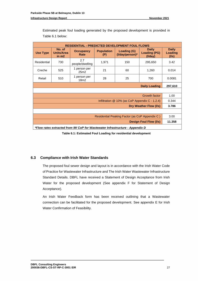
Estimated peak foul loading generated by the proposed development is provided in
Table 6.1 below:
RESIDENTIAL - PREDICTED DEVELOPMENT FOUL FLOWS
Use Type No. of
Units/Area in m2
Occupancy Rate
Population (P)
Loading (G) (l/day/person)*
Daily Loading (PG)
(l/day)
Daily Loading
(l/s)
Residential 730 2.7
people/dwelling 1,971 150 295,650 3.42
Creche 525 1 person per
25m2 21 60 1,260 0.014
Retail 510 1 person per
18m2 28 25 700 0.0081
Daily Loading 297,610
Growth factor 1.00
Infiltration @ 10% (as CoP Appendix C - 1.2.4) 0.344
Dry Weather Flow (l/s) 3.786
Residential Peaking Factor (as CoP Appendix C ) 3.00
Design Foul Flow (l/s) 11.358
*Flow rates extracted from IW CoP for Wastewater Infrastructure - Appendix D
Table 6.1: Estimated Foul Loading for residential development
6.3 Compliance with Irish Water Standards
The proposed foul sewer design and layout is in accordance with the Irish Water Code
of Practice for Wastewater Infrastructure and The Irish Water Wastewater Infrastructure
Standard Details. DBFL have received a Statement of Design Acceptance from Irish
Water for the proposed development (See appendix F for Statement of Design
Acceptance).
An Irish Water Feedback form has been received outlining that a Wastewater
connection can be facilitated for the proposed development. See appendix E for Irish
Water Confirmation of Feasibility.
Parkside Phase 5B at Belmayne, Dublin 13
Infrastructure Design Report November 2021
DBFL Consulting Engineers 200036-DBFL-CS-ST-RP-C-3001 IDR 28
7.0 WATER SUPPLY AND DISTRIBUTION
7.1 Proposed Water main and Supply
A watermain strategy for the overall Parkside Lands was agreed with Dublin City
Council as part of the Phase 1 development. The proposals included a 250mm
watermain running from north to south through the overall Parkside Lands. This 250mm
watermain was recently constructed through Phase 5A under the supervision of Irish
Water.
Watermain spurs have been constructed into the subject site from Phase 5A and a
connection is proposed from the Belmayne Main Street Scheme.
Refer to DBFL Drawing 200036-DBFL-WM-ST-DR-C-1351 Proposed Watermain
Layout Sheet 1 for the watermain layout within the proposed development. The
proposed watermains will connect to the domestic water plant room of each block where
it will be pumped to feed individual apartments.
Standard house connections with boundary boxes will be installed for the proposed
duplexes.
7.2 Hydrants
Hydrants shall comply with the requirements of BS 750:2012 and shall be installed in
accordance with Irish Water’s Code of Practice and Standard Details.
7.3 Design Calculations
The water demand is designed in accordance with the principles and methods set out
in Irish Water’s Code of Practice for Water Infrastructure Connections and Developer
Services Design & Construction Requirements for Self-Lay Developments July 2020:
Overall water demand is calculated using IW CoP for Water Infrastructure section 3.7.2,
as outlined below:
Per-capita consumption 150l/person/day
Average day/week demand factor 1.25
Peak demand factor 5.0
Average daily domestic demand = Total occupancy * Per-capita consumption
Average day/peak week demand = Average daily domestic demand * Average
day/week demand factor
Peak hour water demand = Average day/peak week demand * Peak demand factor
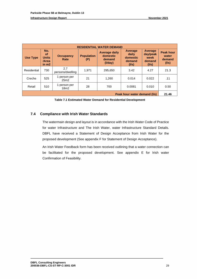
Estimated water demand for the proposed development is provided in Table 7.1:
Parkside Phase 5B at Belmayne, Dublin 13
Infrastructure Design Report November 2021
DBFL Consulting Engineers 200036-DBFL-CS-ST-RP-C-3001 IDR 29
RESIDENTIAL WATER DEMAND
Use Type
No. of
Units /Area in m2
Occupancy Rate
Population (P)
Average daily domestic demand (l/day)
Average daily
domestic demand
(l/s)
Average day/peak
week demand
(l/s)
Peak hour water
demand (l/s)
Residential 730 2.7
persons/dwelling 1,971 295,650 3.42 4.27 21.3
Creche 525 1 person per
25m2 21 1,260 0.014 0.022 .11
Retail 510 1 person per
18m2 28 700 0.0081 0.010 0.50
Peak hour water demand (l/s) 21.46
Table 7.1 Estimated Water Demand for Residential Development
7.4 Compliance with Irish Water Standards
The watermain design and layout is in accordance with the Irish Water Code of Practice
for water Infrastructure and The Irish Water, water Infrastructure Standard Details.
DBFL have received a Statement of Design Acceptance from Irish Water for the
proposed development (See appendix F for Statement of Design Acceptance).
An Irish Water Feedback form has been received outlining that a water connection can
be facilitated for the proposed development. See appendix E for Irish water
Confirmation of Feasibility.

Parkside Phase 5B at Belmayne, Dublin 13
Infrastructure Design Report November 2021
DBFL Consulting Engineers 200036-DBFL-CS-ST-RP-C-3001 IDR
Appendix A
QUALITY AUDIT
Title: QUALITY AUDIT
INCLUDING
Road Safety Audit, Access Audit, Cycle Audit and Walking
Audit.
For;
Parkside Phase 5B, Belmayne, Co. Dublin.
Client: DBFL Consulting Engineers Ltd.
Date: September 2021
Report reference: 1161R01
VERSION: FINAL
Prepared By:
Bruton Consulting Engineers Ltd
Glaspistol Tel: 041 9881456
Clogherhead Mob: 086 8067075
Drogheda E: [email protected]
Co. Louth. W: www.brutonceng.ie
QUALITYAUDIT–PARKSIDEPHASE 5BDBFL
© Bruton Consulting Engineers Ltd 2021 1 1161R01
CONTENTS SHEET
Contents1.0 Introduction ...................................................................................................................................... 2
2.0 Background ....................................................................................................................................... 3
3.0 Issues Identified ................................................................................................................................ 5
3.1 Problem..................................................................................................................................... 5
3.2 Problem..................................................................................................................................... 6
3.3 Problem..................................................................................................................................... 7
3.4 Problem..................................................................................................................................... 8
3.5 Problem..................................................................................................................................... 8
4.0 Quality Audit Statement ................................................................................................................... 9
Appendix A.................................................................................................................................................. 10
Appendix B .................................................................................................................................................. 11
Appendix C .................................................................................................................................................. 13
QUALITYAUDIT–PARKSIDEPHASE 5BDBFL
© Bruton Consulting Engineers Ltd 2021 2 1161R01
1.0 IntroductionThis report was prepared in response to a request from Mr. Noel Gorman, DBFL Consulting Engineers,
for a Quality Audit of the proposed strategic housing development (SHD) known as Parkside Phase 5B at
Belmayne, Co. Dublin.
The Quality Audit has been carried out in accordance with the guidance in the Design Manual for Urban
Roads and Streets (DMURS), produced by Department of Transport Tourism and Sport in March 2013
and as updated in June 2019.
This portion of the Quality Audit is a design stage audit and includes a road safety audit (in accordance
with TII Publication GE-DTY-01024, dated December 2017), an access audit, a walking audit and a cycling
audit. (i.e. aspects of a quality Audit carried out independent of the Design Team and generally included
as appendices to the overall Audit)
The Road Safety and Quality Audit Team comprised of;
Team Leader: Norman Bruton, BE CEng FIEI, Cert Comp RSA.
TII Road safety Auditor approval number: NB 168446
Team Member: Sayed Ahmad Saeed, BEng Tech, BEng (Hons), MIEI
TII Road Safety Auditor approval number: SS 3419515
This portion of the Quality Audit involved the examination of drawings and other material and a site visit
by the Audit Team, on the 15th of September 2021. The weather at the time of the site visit was dry and
the road surface was also dry.
The problems raised in this Quality Audit may belong to more than one of the categories of Audit named
above. A table has been provided at the start of Section 3 of this report detailing which category of audit
each problem is associated with.
Recommendations have been provided to help improve the quality of the design with regard to the
areas described above. A feedback form has also been provided for the designer to complete indicating
whether or not he/she will accept those recommendations or provide alternative recommendations for
implementation.
The information supplied to the Audit Team is listed in Appendix A.
A feedback form for the Designer to complete is contained in Appendix B.
A plan drawing showing the problem locations is contained in Appendix C.
QUALITYAUDIT–PARKSIDEPHASE 5BDBFL
© Bruton Consulting Engineers Ltd 2021 3 1161R01
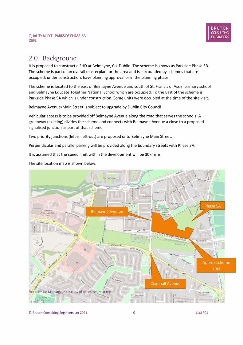
2.0 BackgroundIt is proposed to construct a SHD at Belmayne, Co. Dublin. The scheme is knows as Parkside Phase 5B.
The scheme is part of an overall masterplan for the area and is surrounded by schemes that are
occupied, under construction, have planning approval or in the planning phase.
The scheme is located to the east of Belmayne Avenue and south of St. Francis of Assisi primary school
and Belmayne Educate Together National School which are occupied. To the East of the scheme is
Parkside Phase 5A which is under construction. Some units were occupied at the time of the site visit.
Belmayne Avenue/Main Street is subject to upgrade by Dublin City Council.
Vehicular access is to be provided off Belmayne Avenue along the road that serves the schools. A
greenway (existing) divides the scheme and connects with Belmayne Avenue a close to a proposed
signalised junction as part of that scheme.
Two priority junctions (left-in left-out) are proposed onto Belmayne Main Street.
Perpendicular and parallel parking will be provided along the boundary streets with Phase 5A.
It is assumed that the speed limit within the development will be 30km/hr.
The site location map is shown below.
Site Location Map (image courtesy of openstreetmap.org
Phase 5A
Approx scheme
area
Clarehall Avenue
Belmayne Avenue
QUALITYAUDIT–PARKSIDEPHASE 5BDBFL
© Bruton Consulting Engineers Ltd 2021 4 1161R01
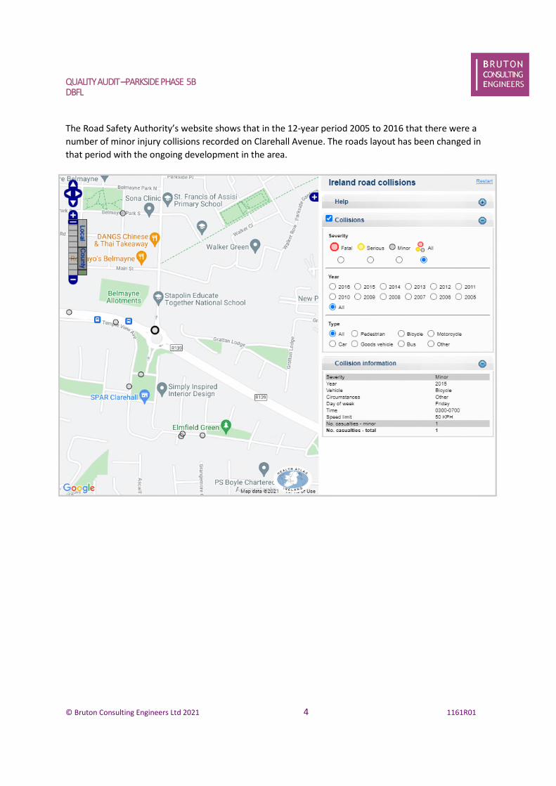
The Road Safety Authority’s website shows that in the 12-year period 2005 to 2016 that there were a
number of minor injury collisions recorded on Clarehall Avenue. The roads layout has been changed in
that period with the ongoing development in the area.
QUALITYAUDIT–PARKSIDEPHASE 5BDBFL
© Bruton Consulting Engineers Ltd 2021 5 1161R01
3.0 Issues IdentifiedSummary Table of Problem Categories
ProblemReference
Access Audit Walking Audit Cycling Audit Road SafetyAudit
Quality Audit
3.1
3.2
3.3
3.4
3.5
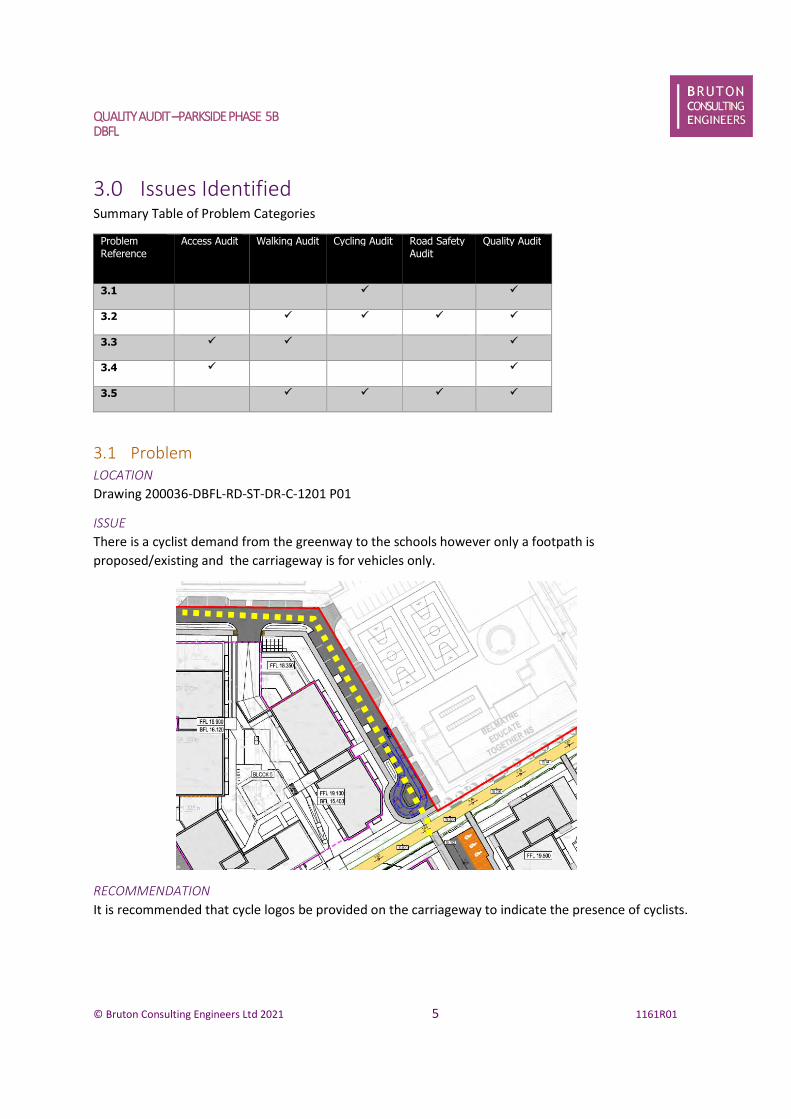
3.1 ProblemLOCATION
Drawing 200036-DBFL-RD-ST-DR-C-1201 P01
ISSUE
There is a cyclist demand from the greenway to the schools however only a footpath is
proposed/existing and the carriageway is for vehicles only.
RECOMMENDATION
It is recommended that cycle logos be provided on the carriageway to indicate the presence of cyclists.
QUALITYAUDIT–PARKSIDEPHASE 5BDBFL
© Bruton Consulting Engineers Ltd 2021 6 1161R01
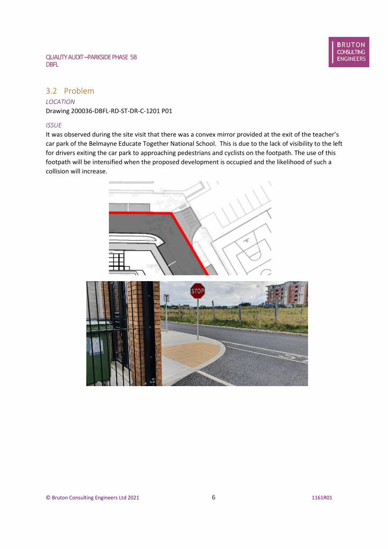
3.2 ProblemLOCATION
Drawing 200036-DBFL-RD-ST-DR-C-1201 P01
ISSUE
It was observed during the site visit that there was a convex mirror provided at the exit of the teacher’s
car park of the Belmayne Educate Together National School. This is due to the lack of visibility to the left
for drivers exiting the car park to approaching pedestrians and cyclists on the footpath. The use of this
footpath will be intensified when the proposed development is occupied and the likelihood of such a
collision will increase.
QUALITYAUDIT–PARKSIDEPHASE 5BDBFL
© Bruton Consulting Engineers Ltd 2021 7 1161R01
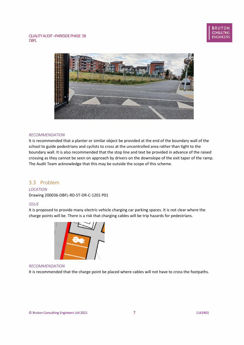
RECOMMENDATION
It is recommended that a planter or similar object be provided at the end of the boundary wall of the
school to guide pedestrians and cyclists to cross at the uncontrolled area rather than tight to the
boundary wall. It is also recommended that the stop line and text be provided in advance of the raised
crossing as they cannot be seen on approach by drivers on the downslope of the exit taper of the ramp.
The Audit Team acknowledge that this may be outside the scope of this scheme.
3.3 ProblemLOCATION
Drawing 200036-DBFL-RD-ST-DR-C-1201 P01
ISSUE
It is proposed to provide many electric vehicle charging car parking spaces. It is not clear where the
charge points will be. There is a risk that charging cables will be trip hazards for pedestrians.
RECOMMENDATION
It is recommended that the charge point be placed where cables will not have to cross the footpaths.
QUALITYAUDIT–PARKSIDEPHASE 5BDBFL
© Bruton Consulting Engineers Ltd 2021 8 1161R01
3.4 ProblemLOCATION
Drawing 200036-DBFL-RD-ST-DR-C-1201 P01
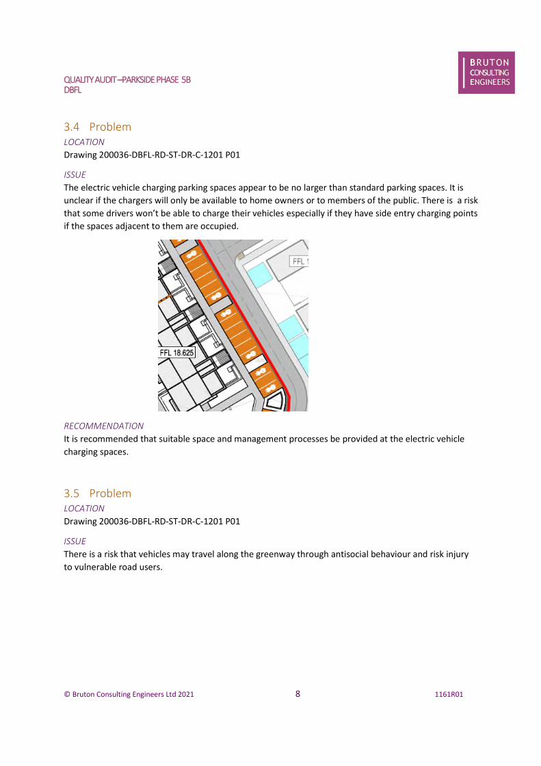
ISSUE
The electric vehicle charging parking spaces appear to be no larger than standard parking spaces. It is
unclear if the chargers will only be available to home owners or to members of the public. There is a risk
that some drivers won’t be able to charge their vehicles especially if they have side entry charging points
if the spaces adjacent to them are occupied.
RECOMMENDATION
It is recommended that suitable space and management processes be provided at the electric vehicle
charging spaces.
3.5 ProblemLOCATION
Drawing 200036-DBFL-RD-ST-DR-C-1201 P01
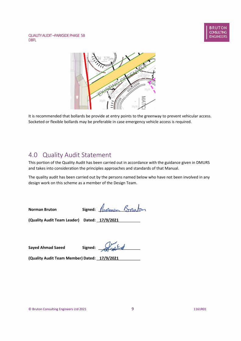
ISSUE
There is a risk that vehicles may travel along the greenway through antisocial behaviour and risk injury
to vulnerable road users.
QUALITYAUDIT–PARKSIDEPHASE 5BDBFL
© Bruton Consulting Engineers Ltd 2021 9 1161R01
It is recommended that bollards be provide at entry points to the greenway to prevent vehicular access.
Socketed or flexible bollards may be preferable in case emergency vehicle access is required.
4.0 Quality Audit StatementThis portion of the Quality Audit has been carried out in accordance with the guidance given in DMURS
and takes into consideration the principles approaches and standards of that Manual.
The quality audit has been carried out by the persons named below who have not been involved in any
design work on this scheme as a member of the Design Team.
Norman Bruton Signed:
(Quality Audit Team Leader) Dated: 17/9/2021
Sayed Ahmad Saeed Signed:
(Quality Audit Team Member) Dated: 17/9/2021
QUALITYAUDIT–PARKSIDEPHASE 5BDBFL
© Bruton Consulting Engineers Ltd 2021 10 1161R01
Appendix AList of Material Supplied for this Quality Audit;
Drawing 200036-DBFL-RD-ST-DR-C-1201 P01
Drawing 200036-DBFL-SW-ST-DR-C-5301 Typical Drainage Details Sheet 1
Drawing 200036-DBFL-SW-ST-DR-C-5302 Typical Drainage Details Sheet 2
Drawing 200036-DBFL-SW-ST-DR-C-5303 Typical Drainage Details Sheet 3
Drawing 200036-DBFL-SW-ST-DR-C-5304 Typical Drainage Details Sheet 4
Drawing 200036-DBFL-TR-ST-DR-C-1001 Existing Public Transportation Linkages Plan
Drawing 200036-DBFL-TR-ST-DR-C-1002 Proposed Public Transportation LinkagesPlan
Drawing 200036-DBFL-TR-ST-DR-C-1010 Roads Hierarchy Plan
Drawing 200036-DBFL-WM-ST-DR-C-1351 Proposed Watermain Layout Sheet 1
Drawing SES 12021 Parkside 5B - Public Lighting Layout - DRAFT - Cairn Homes
Drawing 18D06b-DR-200
Drawing 200036-DBFL-CS-ST-DR-C-1301 Proposed Drainage Layout Sheet 1
Drawing 200036-DBFL-RD-ST-DR-C-1201 Proposed Roads Layout
Drawing 200036-DBFL-RD-ST-DR-C-5201 Typical Road Construction Details Sheet 1
Drawing 200036-DBFL-RD-ST-DR-C-5202 Typical Road Construction Details Sheet 2
QUALITYAUDIT–PARKSIDEPHASE 5BDBFL
© Bruton Consulting Engineers Ltd 2021 11 1161R01
Appendix B
Feedback Form

QUALITY AUDIT FORM – FEEDBACK ON QUALITY AUDIT REPORT
Scheme: Parkside Phase 5B
Quality Audit- Stage 1
Date Audit (site visit) Completed 15-9-2021
Paragraph No.
in Quality
Audit Report
Problem
accepted
(yes/no)
Recommended
measure
accepted
(yes/no)
Alternative measures (describe)
Alternative
measures
accepted by
Auditors
(Yes/No)
3.1 Y Y
3.2 Y N
As this area is controlled by the
Department of Education. The issue
will be notified to the Department of
Education.
Yes
3.3 Y YNote: Charge points are relocated
adjacent to island.Yes
3.4 Y N
Note: Car Parking spaces will be
managed by a management company
and allocated to apartment owners
therefore the user will be familiar
with the space and an increased
buffer is not required. E charging has
been added to one disabled space.
Yes
3.5 Y Y
Signed………… Date 17/09/2021
Design Team Leader
Signed…………………………………. Date: …17/9/2021………………
Audit Team Leader

QUALITYAUDIT–PARKSIDEPHASE 5BDBFL
© Bruton Consulting Engineers Ltd 2021 13 1161R01
Appendix C
Problem Location Plan.
3.1
3.2
3.3
3.5

Parkside Phase 5B at Belmayne, Dublin 13
Infrastructure Design Report November 2021
DBFL Consulting Engineers 200036-DBFL-CS-ST-RP-C-3001 IDR
Appendix B
STORM WATER ATTENUATION CALCULATIONS
DBFL Consulting Engineers Page 1Ormond House 200036Upper Ormond Quay Parkside Existing AttenuationDublin 7 Catchment D2Date 06/10/2021 Designed by COLFile ATTENUATION STORAGE ZON... Checked by NCGInnovyze Source Control 2019.1
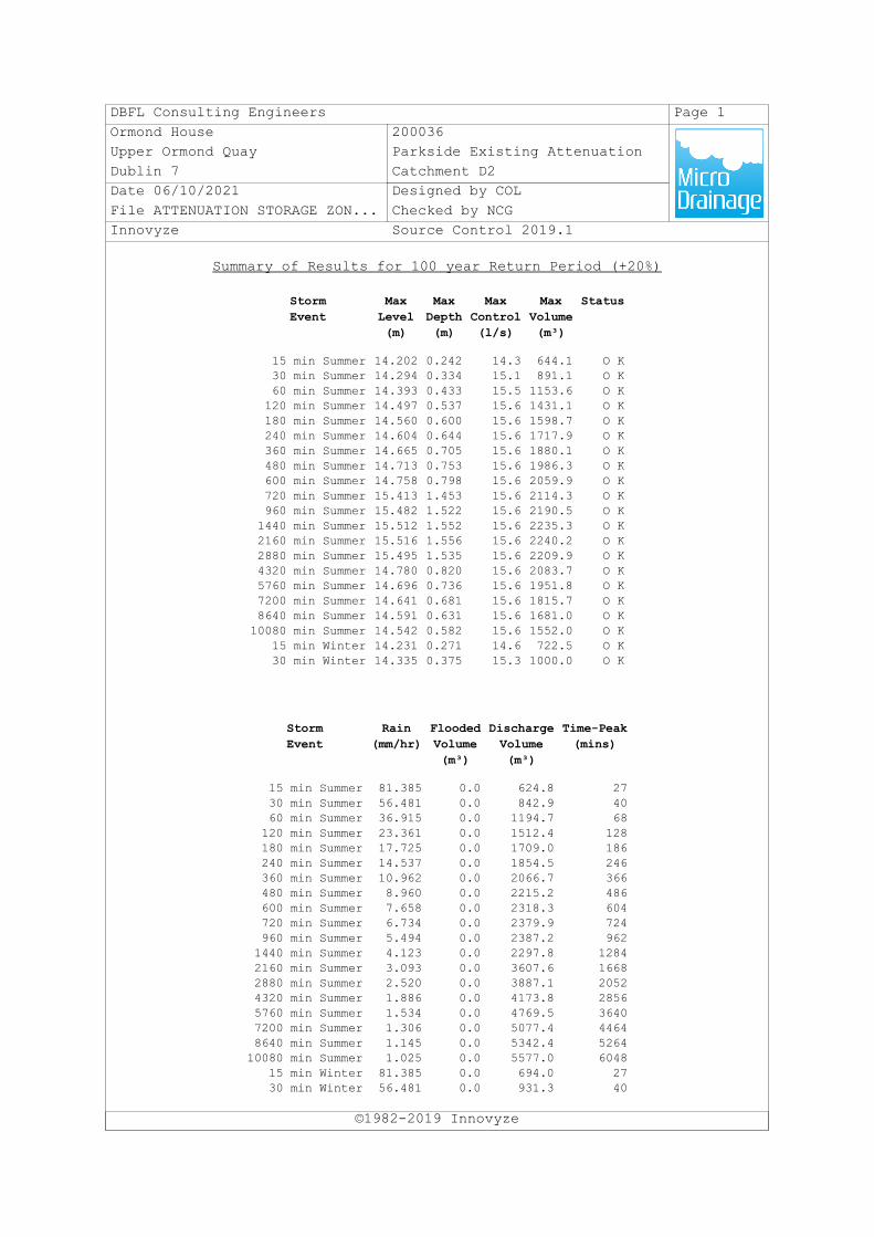
Summary of Results for 100 year Return Period (+20%)
©1982-2019 Innovyze
StormEvent
MaxLevel(m)
MaxDepth(m)
MaxControl(l/s)
MaxVolume(m³)
Status
15 min Summer 14.202 0.242 14.3 644.1 O K30 min Summer 14.294 0.334 15.1 891.1 O K60 min Summer 14.393 0.433 15.5 1153.6 O K120 min Summer 14.497 0.537 15.6 1431.1 O K180 min Summer 14.560 0.600 15.6 1598.7 O K240 min Summer 14.604 0.644 15.6 1717.9 O K360 min Summer 14.665 0.705 15.6 1880.1 O K480 min Summer 14.713 0.753 15.6 1986.3 O K600 min Summer 14.758 0.798 15.6 2059.9 O K720 min Summer 15.413 1.453 15.6 2114.3 O K960 min Summer 15.482 1.522 15.6 2190.5 O K1440 min Summer 15.512 1.552 15.6 2235.3 O K2160 min Summer 15.516 1.556 15.6 2240.2 O K2880 min Summer 15.495 1.535 15.6 2209.9 O K4320 min Summer 14.780 0.820 15.6 2083.7 O K5760 min Summer 14.696 0.736 15.6 1951.8 O K7200 min Summer 14.641 0.681 15.6 1815.7 O K8640 min Summer 14.591 0.631 15.6 1681.0 O K10080 min Summer 14.542 0.582 15.6 1552.0 O K
15 min Winter 14.231 0.271 14.6 722.5 O K30 min Winter 14.335 0.375 15.3 1000.0 O K
StormEvent
Rain(mm/hr)
FloodedVolume(m³)
DischargeVolume(m³)
Time-Peak(mins)
15 min Summer 81.385 0.0 624.8 2730 min Summer 56.481 0.0 842.9 4060 min Summer 36.915 0.0 1194.7 68120 min Summer 23.361 0.0 1512.4 128180 min Summer 17.725 0.0 1709.0 186240 min Summer 14.537 0.0 1854.5 246360 min Summer 10.962 0.0 2066.7 366480 min Summer 8.960 0.0 2215.2 486600 min Summer 7.658 0.0 2318.3 604720 min Summer 6.734 0.0 2379.9 724960 min Summer 5.494 0.0 2387.2 9621440 min Summer 4.123 0.0 2297.8 12842160 min Summer 3.093 0.0 3607.6 16682880 min Summer 2.520 0.0 3887.1 20524320 min Summer 1.886 0.0 4173.8 28565760 min Summer 1.534 0.0 4769.5 36407200 min Summer 1.306 0.0 5077.4 44648640 min Summer 1.145 0.0 5342.4 526410080 min Summer 1.025 0.0 5577.0 6048
15 min Winter 81.385 0.0 694.0 2730 min Winter 56.481 0.0 931.3 40
DBFL Consulting Engineers Page 2Ormond House 200036Upper Ormond Quay Parkside Existing AttenuationDublin 7 Catchment D2Date 06/10/2021 Designed by COLFile ATTENUATION STORAGE ZON... Checked by NCGInnovyze Source Control 2019.1
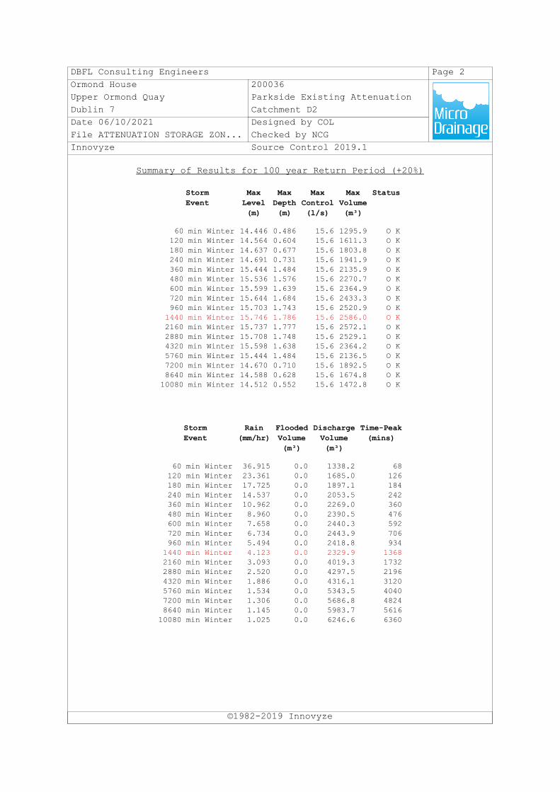
Summary of Results for 100 year Return Period (+20%)
©1982-2019 Innovyze
StormEvent
MaxLevel(m)
MaxDepth(m)
MaxControl(l/s)
MaxVolume(m³)
Status
60 min Winter 14.446 0.486 15.6 1295.9 O K120 min Winter 14.564 0.604 15.6 1611.3 O K180 min Winter 14.637 0.677 15.6 1803.8 O K240 min Winter 14.691 0.731 15.6 1941.9 O K360 min Winter 15.444 1.484 15.6 2135.9 O K480 min Winter 15.536 1.576 15.6 2270.7 O K600 min Winter 15.599 1.639 15.6 2364.9 O K720 min Winter 15.644 1.684 15.6 2433.3 O K960 min Winter 15.703 1.743 15.6 2520.9 O K1440 min Winter 15.746 1.786 15.6 2586.0 O K2160 min Winter 15.737 1.777 15.6 2572.1 O K2880 min Winter 15.708 1.748 15.6 2529.1 O K4320 min Winter 15.598 1.638 15.6 2364.2 O K5760 min Winter 15.444 1.484 15.6 2136.5 O K7200 min Winter 14.670 0.710 15.6 1892.5 O K8640 min Winter 14.588 0.628 15.6 1674.8 O K10080 min Winter 14.512 0.552 15.6 1472.8 O K
StormEvent
Rain(mm/hr)
FloodedVolume(m³)
DischargeVolume(m³)
Time-Peak(mins)
60 min Winter 36.915 0.0 1338.2 68120 min Winter 23.361 0.0 1685.0 126180 min Winter 17.725 0.0 1897.1 184240 min Winter 14.537 0.0 2053.5 242360 min Winter 10.962 0.0 2269.0 360480 min Winter 8.960 0.0 2390.5 476600 min Winter 7.658 0.0 2440.3 592720 min Winter 6.734 0.0 2443.9 706960 min Winter 5.494 0.0 2418.8 9341440 min Winter 4.123 0.0 2329.9 13682160 min Winter 3.093 0.0 4019.3 17322880 min Winter 2.520 0.0 4297.5 21964320 min Winter 1.886 0.0 4316.1 31205760 min Winter 1.534 0.0 5343.5 40407200 min Winter 1.306 0.0 5686.8 48248640 min Winter 1.145 0.0 5983.7 561610080 min Winter 1.025 0.0 6246.6 6360

Parkside Phase 5B at Belmayne, Dublin 13
Infrastructure Design Report November 2021
DBFL Consulting Engineers 200036-DBFL-CS-ST-RP-C-3001 IDR
Appendix C
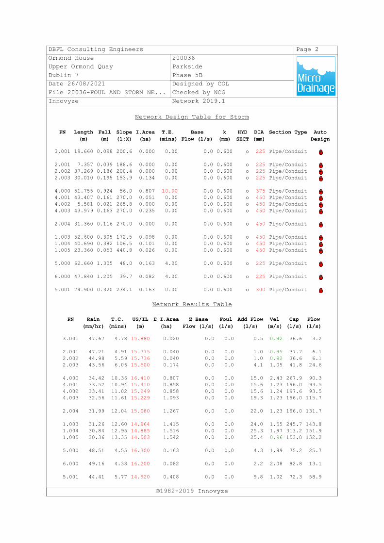
STORMWATER NETWORK CALCULATIONS
DBFL Consulting Engineers Page 1Ormond House 200036Upper Ormond Quay ParksideDublin 7 Phase 5BDate 26/08/2021 Designed by COLFile 20036-FOUL AND STORM NE... Checked by NCGInnovyze Network 2019.1
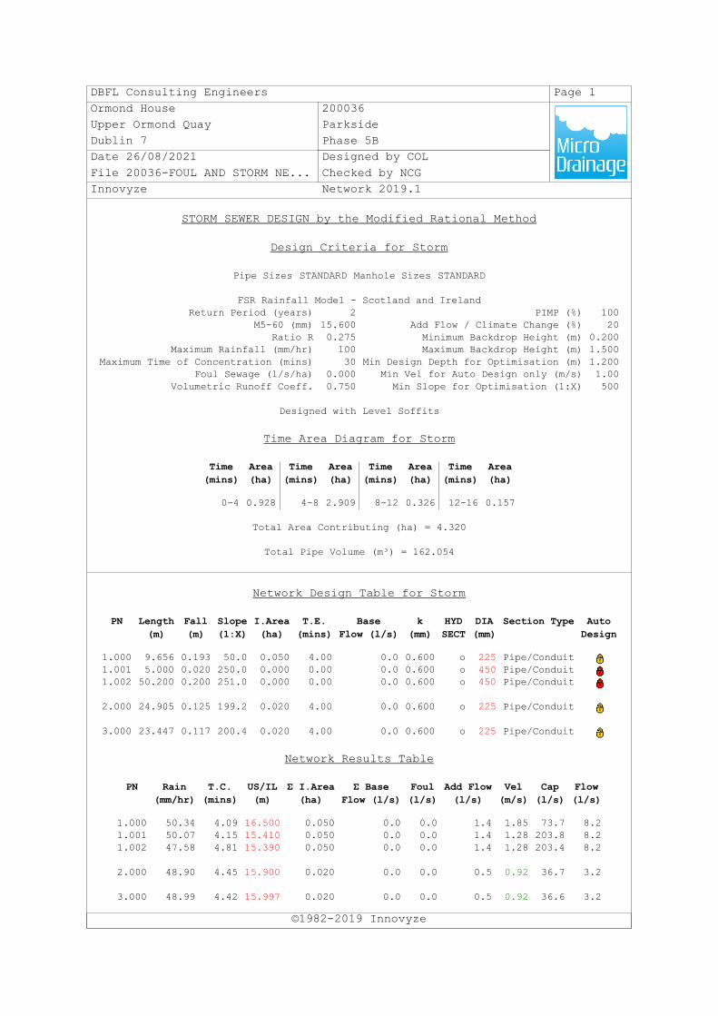
STORM SEWER DESIGN by the Modified Rational Method
Design Criteria for Storm
©1982-2019 Innovyze
Pipe Sizes STANDARD Manhole Sizes STANDARD
FSR Rainfall Model - Scotland and IrelandReturn Period (years) 2 PIMP (%) 100
M5-60 (mm) 15.600 Add Flow / Climate Change (%) 20Ratio R 0.275 Minimum Backdrop Height (m) 0.200
Maximum Rainfall (mm/hr) 100 Maximum Backdrop Height (m) 1.500Maximum Time of Concentration (mins) 30 Min Design Depth for Optimisation (m) 1.200
Foul Sewage (l/s/ha) 0.000 Min Vel for Auto Design only (m/s) 1.00Volumetric Runoff Coeff. 0.750 Min Slope for Optimisation (1:X) 500
Designed with Level Soffits
Time Area Diagram for Storm
Time(mins)
Area(ha)
Time(mins)
Area(ha)
Time(mins)
Area(ha)
Time(mins)
Area(ha)
0-4 0.928 4-8 2.909 8-12 0.326 12-16 0.157
Total Area Contributing (ha) = 4.320
Total Pipe Volume (m³) = 162.054
Network Design Table for Storm
PN Length(m)
Fall(m)
Slope(1:X)
I.Area(ha)
T.E.(mins)
BaseFlow (l/s)
k(mm)
HYDSECT
DIA(mm)
Section Type AutoDesign
1.000 9.656 0.193 50.0 0.050 4.00 0.0 0.600 o 225 Pipe/Conduit1.001 5.000 0.020 250.0 0.000 0.00 0.0 0.600 o 450 Pipe/Conduit1.002 50.200 0.200 251.0 0.000 0.00 0.0 0.600 o 450 Pipe/Conduit
2.000 24.905 0.125 199.2 0.020 4.00 0.0 0.600 o 225 Pipe/Conduit
3.000 23.447 0.117 200.4 0.020 4.00 0.0 0.600 o 225 Pipe/Conduit
Network Results Table
PN Rain(mm/hr)
T.C.(mins)
US/IL(m)
Σ I.Area(ha)
Σ BaseFlow (l/s)
Foul(l/s)
Add Flow(l/s)
Vel(m/s)
Cap(l/s)
Flow(l/s)
1.000 50.34 4.09 16.500 0.050 0.0 0.0 1.4 1.85 73.7 8.21.001 50.07 4.15 15.410 0.050 0.0 0.0 1.4 1.28 203.8 8.21.002 47.58 4.81 15.390 0.050 0.0 0.0 1.4 1.28 203.4 8.2
2.000 48.90 4.45 15.900 0.020 0.0 0.0 0.5 0.92 36.7 3.2
3.000 48.99 4.42 15.997 0.020 0.0 0.0 0.5 0.92 36.6 3.2
DBFL Consulting Engineers Page 2Ormond House 200036Upper Ormond Quay ParksideDublin 7 Phase 5BDate 26/08/2021 Designed by COLFile 20036-FOUL AND STORM NE... Checked by NCGInnovyze Network 2019.1
Network Design Table for Storm
©1982-2019 Innovyze
PN Length(m)
Fall(m)
Slope(1:X)
I.Area(ha)
T.E.(mins)
BaseFlow (l/s)
k(mm)
HYDSECT
DIA(mm)
Section Type AutoDesign
3.001 19.660 0.098 200.6 0.000 0.00 0.0 0.600 o 225 Pipe/Conduit
2.001 7.357 0.039 188.6 0.000 0.00 0.0 0.600 o 225 Pipe/Conduit2.002 37.269 0.186 200.4 0.000 0.00 0.0 0.600 o 225 Pipe/Conduit2.003 30.010 0.195 153.9 0.134 0.00 0.0 0.600 o 225 Pipe/Conduit
4.000 51.755 0.924 56.0 0.807 10.00 0.0 0.600 o 375 Pipe/Conduit4.001 43.407 0.161 270.0 0.051 0.00 0.0 0.600 o 450 Pipe/Conduit4.002 5.581 0.021 265.8 0.000 0.00 0.0 0.600 o 450 Pipe/Conduit4.003 43.979 0.163 270.0 0.235 0.00 0.0 0.600 o 450 Pipe/Conduit
2.004 31.360 0.116 270.0 0.000 0.00 0.0 0.600 o 450 Pipe/Conduit
1.003 52.600 0.305 172.5 0.098 0.00 0.0 0.600 o 450 Pipe/Conduit1.004 40.690 0.382 106.5 0.101 0.00 0.0 0.600 o 450 Pipe/Conduit1.005 23.360 0.053 440.8 0.026 0.00 0.0 0.600 o 450 Pipe/Conduit
5.000 62.660 1.305 48.0 0.163 4.00 0.0 0.600 o 225 Pipe/Conduit
6.000 47.840 1.205 39.7 0.082 4.00 0.0 0.600 o 225 Pipe/Conduit
5.001 74.900 0.320 234.1 0.163 0.00 0.0 0.600 o 300 Pipe/Conduit
Network Results Table
PN Rain(mm/hr)
T.C.(mins)
US/IL(m)
Σ I.Area(ha)
Σ BaseFlow (l/s)
Foul(l/s)
Add Flow(l/s)
Vel(m/s)
Cap(l/s)
Flow(l/s)
3.001 47.67 4.78 15.880 0.020 0.0 0.0 0.5 0.92 36.6 3.2
2.001 47.21 4.91 15.775 0.040 0.0 0.0 1.0 0.95 37.7 6.12.002 44.98 5.59 15.736 0.040 0.0 0.0 1.0 0.92 36.6 6.12.003 43.56 6.06 15.500 0.174 0.0 0.0 4.1 1.05 41.8 24.6
4.000 34.42 10.36 16.410 0.807 0.0 0.0 15.0 2.43 267.9 90.34.001 33.52 10.94 15.410 0.858 0.0 0.0 15.6 1.23 196.0 93.54.002 33.41 11.02 15.249 0.858 0.0 0.0 15.6 1.24 197.6 93.54.003 32.56 11.61 15.229 1.093 0.0 0.0 19.3 1.23 196.0 115.7
2.004 31.99 12.04 15.080 1.267 0.0 0.0 22.0 1.23 196.0 131.7
1.003 31.26 12.60 14.964 1.415 0.0 0.0 24.0 1.55 245.7 143.81.004 30.84 12.95 14.885 1.516 0.0 0.0 25.3 1.97 313.2 151.91.005 30.36 13.35 14.503 1.542 0.0 0.0 25.4 0.96 153.0 152.2
5.000 48.51 4.55 16.300 0.163 0.0 0.0 4.3 1.89 75.2 25.7
6.000 49.16 4.38 16.200 0.082 0.0 0.0 2.2 2.08 82.8 13.1
5.001 44.41 5.77 14.920 0.408 0.0 0.0 9.8 1.02 72.3 58.9
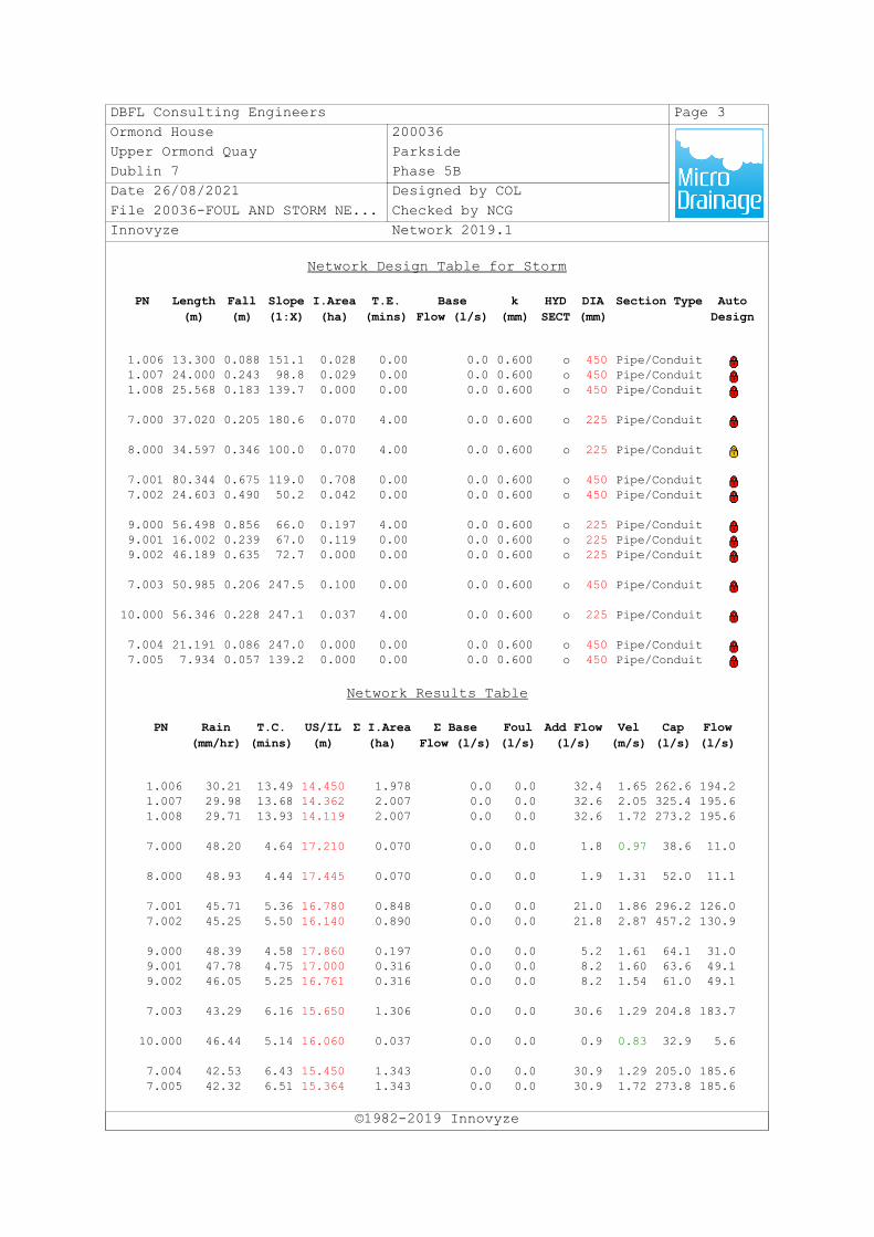
DBFL Consulting Engineers Page 3Ormond House 200036Upper Ormond Quay ParksideDublin 7 Phase 5BDate 26/08/2021 Designed by COLFile 20036-FOUL AND STORM NE... Checked by NCGInnovyze Network 2019.1
Network Design Table for Storm
©1982-2019 Innovyze
PN Length(m)
Fall(m)
Slope(1:X)
I.Area(ha)
T.E.(mins)
BaseFlow (l/s)
k(mm)
HYDSECT
DIA(mm)
Section Type AutoDesign
1.006 13.300 0.088 151.1 0.028 0.00 0.0 0.600 o 450 Pipe/Conduit1.007 24.000 0.243 98.8 0.029 0.00 0.0 0.600 o 450 Pipe/Conduit1.008 25.568 0.183 139.7 0.000 0.00 0.0 0.600 o 450 Pipe/Conduit
7.000 37.020 0.205 180.6 0.070 4.00 0.0 0.600 o 225 Pipe/Conduit
8.000 34.597 0.346 100.0 0.070 4.00 0.0 0.600 o 225 Pipe/Conduit
7.001 80.344 0.675 119.0 0.708 0.00 0.0 0.600 o 450 Pipe/Conduit7.002 24.603 0.490 50.2 0.042 0.00 0.0 0.600 o 450 Pipe/Conduit
9.000 56.498 0.856 66.0 0.197 4.00 0.0 0.600 o 225 Pipe/Conduit9.001 16.002 0.239 67.0 0.119 0.00 0.0 0.600 o 225 Pipe/Conduit9.002 46.189 0.635 72.7 0.000 0.00 0.0 0.600 o 225 Pipe/Conduit
7.003 50.985 0.206 247.5 0.100 0.00 0.0 0.600 o 450 Pipe/Conduit
10.000 56.346 0.228 247.1 0.037 4.00 0.0 0.600 o 225 Pipe/Conduit
7.004 21.191 0.086 247.0 0.000 0.00 0.0 0.600 o 450 Pipe/Conduit7.005 7.934 0.057 139.2 0.000 0.00 0.0 0.600 o 450 Pipe/Conduit
Network Results Table
PN Rain(mm/hr)
T.C.(mins)
US/IL(m)
Σ I.Area(ha)
Σ BaseFlow (l/s)
Foul(l/s)
Add Flow(l/s)
Vel(m/s)
Cap(l/s)
Flow(l/s)
1.006 30.21 13.49 14.450 1.978 0.0 0.0 32.4 1.65 262.6 194.21.007 29.98 13.68 14.362 2.007 0.0 0.0 32.6 2.05 325.4 195.61.008 29.71 13.93 14.119 2.007 0.0 0.0 32.6 1.72 273.2 195.6
7.000 48.20 4.64 17.210 0.070 0.0 0.0 1.8 0.97 38.6 11.0
8.000 48.93 4.44 17.445 0.070 0.0 0.0 1.9 1.31 52.0 11.1
7.001 45.71 5.36 16.780 0.848 0.0 0.0 21.0 1.86 296.2 126.07.002 45.25 5.50 16.140 0.890 0.0 0.0 21.8 2.87 457.2 130.9
9.000 48.39 4.58 17.860 0.197 0.0 0.0 5.2 1.61 64.1 31.09.001 47.78 4.75 17.000 0.316 0.0 0.0 8.2 1.60 63.6 49.19.002 46.05 5.25 16.761 0.316 0.0 0.0 8.2 1.54 61.0 49.1
7.003 43.29 6.16 15.650 1.306 0.0 0.0 30.6 1.29 204.8 183.7
10.000 46.44 5.14 16.060 0.037 0.0 0.0 0.9 0.83 32.9 5.6
7.004 42.53 6.43 15.450 1.343 0.0 0.0 30.9 1.29 205.0 185.67.005 42.32 6.51 15.364 1.343 0.0 0.0 30.9 1.72 273.8 185.6
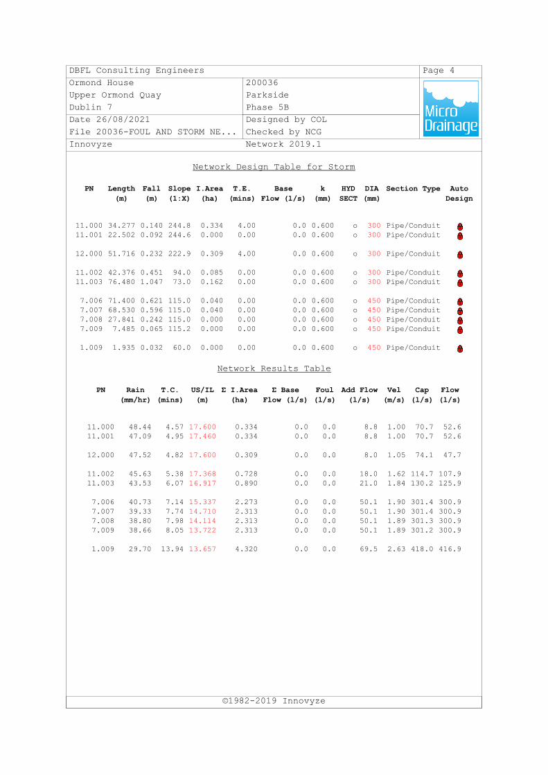
DBFL Consulting Engineers Page 4Ormond House 200036Upper Ormond Quay ParksideDublin 7 Phase 5BDate 26/08/2021 Designed by COLFile 20036-FOUL AND STORM NE... Checked by NCGInnovyze Network 2019.1
Network Design Table for Storm
©1982-2019 Innovyze
PN Length(m)
Fall(m)
Slope(1:X)
I.Area(ha)
T.E.(mins)
BaseFlow (l/s)
k(mm)
HYDSECT
DIA(mm)
Section Type AutoDesign
11.000 34.277 0.140 244.8 0.334 4.00 0.0 0.600 o 300 Pipe/Conduit11.001 22.502 0.092 244.6 0.000 0.00 0.0 0.600 o 300 Pipe/Conduit
12.000 51.716 0.232 222.9 0.309 4.00 0.0 0.600 o 300 Pipe/Conduit
11.002 42.376 0.451 94.0 0.085 0.00 0.0 0.600 o 300 Pipe/Conduit11.003 76.480 1.047 73.0 0.162 0.00 0.0 0.600 o 300 Pipe/Conduit
7.006 71.400 0.621 115.0 0.040 0.00 0.0 0.600 o 450 Pipe/Conduit7.007 68.530 0.596 115.0 0.040 0.00 0.0 0.600 o 450 Pipe/Conduit7.008 27.841 0.242 115.0 0.000 0.00 0.0 0.600 o 450 Pipe/Conduit7.009 7.485 0.065 115.2 0.000 0.00 0.0 0.600 o 450 Pipe/Conduit
1.009 1.935 0.032 60.0 0.000 0.00 0.0 0.600 o 450 Pipe/Conduit
Network Results Table
PN Rain(mm/hr)
T.C.(mins)
US/IL(m)
Σ I.Area(ha)
Σ BaseFlow (l/s)
Foul(l/s)
Add Flow(l/s)
Vel(m/s)
Cap(l/s)
Flow(l/s)
11.000 48.44 4.57 17.600 0.334 0.0 0.0 8.8 1.00 70.7 52.611.001 47.09 4.95 17.460 0.334 0.0 0.0 8.8 1.00 70.7 52.6
12.000 47.52 4.82 17.600 0.309 0.0 0.0 8.0 1.05 74.1 47.7
11.002 45.63 5.38 17.368 0.728 0.0 0.0 18.0 1.62 114.7 107.911.003 43.53 6.07 16.917 0.890 0.0 0.0 21.0 1.84 130.2 125.9
7.006 40.73 7.14 15.337 2.273 0.0 0.0 50.1 1.90 301.4 300.97.007 39.33 7.74 14.710 2.313 0.0 0.0 50.1 1.90 301.4 300.97.008 38.80 7.98 14.114 2.313 0.0 0.0 50.1 1.89 301.3 300.97.009 38.66 8.05 13.722 2.313 0.0 0.0 50.1 1.89 301.2 300.9
1.009 29.70 13.94 13.657 4.320 0.0 0.0 69.5 2.63 418.0 416.9
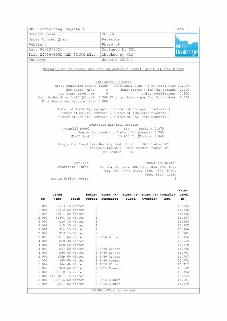
DBFL Consulting Engineers Page 1Ormond House 200036Upper Ormond Quay ParksideDublin 7 Phase 5BDate 06/10/2021 Designed by COLFile 20036-FOUL AND STORM NE... Checked by NCGInnovyze Network 2019.1
Summary of Critical Results by Maximum Level (Rank 1) for Storm
©1982-2019 Innovyze
Simulation CriteriaAreal Reduction Factor 1.000 Additional Flow - % of Total Flow 20.000
Hot Start (mins) 0 MADD Factor * 10m³/ha Storage 2.000Hot Start Level (mm) 0 Inlet Coeffiecient 0.800
Manhole Headloss Coeff (Global) 0.500 Flow per Person per Day (l/per/day) 0.000Foul Sewage per hectare (l/s) 0.000
Number of Input Hydrographs 0 Number of Storage Structures 4Number of Online Controls 2 Number of Time/Area Diagrams 0Number of Offline Controls 0 Number of Real Time Controls 0
Synthetic Rainfall DetailsRainfall Model FSR Ratio R 0.275
Region Scotland and Ireland Cv (Summer) 0.750M5-60 (mm) 15.600 Cv (Winter) 0.840
Margin for Flood Risk Warning (mm) 300.0 DVD Status OFFAnalysis Timestep Fine Inertia Status OFF
DTS Status ON
Profile(s) Summer and WinterDuration(s) (mins) 15, 30, 60, 120, 180, 240, 360, 480, 600,
720, 960, 1440, 2160, 2880, 4320, 5760,7200, 8640, 10080
Return Period (years) 2
PNUS/MHName Storm
ReturnPeriod
First (X)Surcharge
First (Y)Flood
First (Z)Overflow
OverflowAct.
Water Level(m)
1.000 S65-3 15 Winter 2 16.5551.001 S65-2 60 Winter 2 15.7321.002 S65-1 60 Winter 2 15.7322.000 S14-1 15 Winter 2 15.9473.000 S16 15 Winter 2 16.0443.001 S15 15 Winter 2 15.9272.001 S14 15 Winter 2 15.8462.002 S13 15 Winter 2 15.8012.003 S65B-1 60 Winter 2 2/60 Winter 15.7564.000 S69 30 Winter 2 16.5624.001 S68 60 Winter 2 15.7794.002 S67 60 Winter 2 2/60 Winter 15.7664.003 S66 60 Winter 2 2/60 Winter 15.7612.004 S65B 60 Winter 2 2/30 Winter 15.7471.003 S65 60 Winter 2 2/30 Summer 15.7321.004 S64 60 Winter 2 2/15 Winter 15.7121.005 S63 60 Winter 2 2/15 Summer 15.6925.000 S62-1B 15 Winter 2 16.3946.000 S62-1A-1 15 Winter 2 16.2625.001 S62-1A 60 Winter 2 2/15 Summer 15.6911.006 S62-1 60 Winter 2 2/15 Summer 15.676
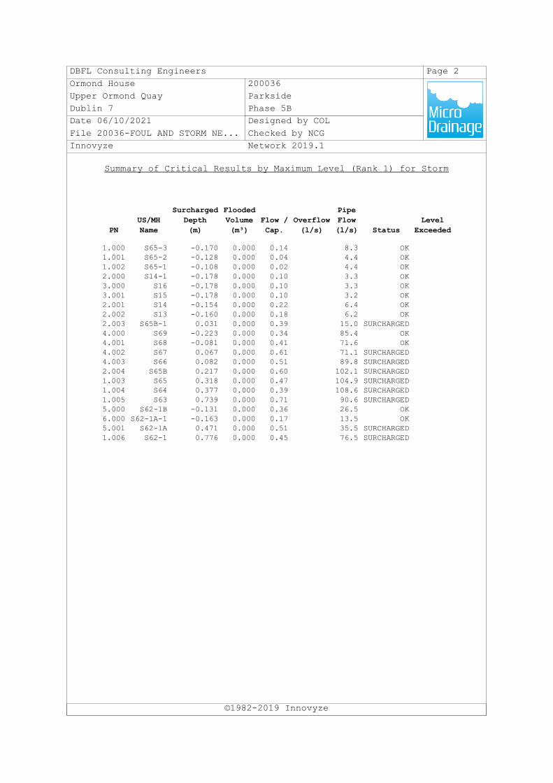
DBFL Consulting Engineers Page 2Ormond House 200036Upper Ormond Quay ParksideDublin 7 Phase 5BDate 06/10/2021 Designed by COLFile 20036-FOUL AND STORM NE... Checked by NCGInnovyze Network 2019.1
Summary of Critical Results by Maximum Level (Rank 1) for Storm
©1982-2019 Innovyze
PNUS/MHName
SurchargedDepth(m)
FloodedVolume(m³)
Flow /Cap.
Overflow(l/s)
PipeFlow(l/s) Status
LevelExceeded
1.000 S65-3 -0.170 0.000 0.14 8.3 OK1.001 S65-2 -0.128 0.000 0.04 4.4 OK1.002 S65-1 -0.108 0.000 0.02 4.4 OK2.000 S14-1 -0.178 0.000 0.10 3.3 OK3.000 S16 -0.178 0.000 0.10 3.3 OK3.001 S15 -0.178 0.000 0.10 3.2 OK2.001 S14 -0.154 0.000 0.22 6.4 OK2.002 S13 -0.160 0.000 0.18 6.2 OK2.003 S65B-1 0.031 0.000 0.39 15.0 SURCHARGED4.000 S69 -0.223 0.000 0.34 85.4 OK4.001 S68 -0.081 0.000 0.41 71.6 OK4.002 S67 0.067 0.000 0.61 71.1 SURCHARGED4.003 S66 0.082 0.000 0.51 89.8 SURCHARGED2.004 S65B 0.217 0.000 0.60 102.1 SURCHARGED1.003 S65 0.318 0.000 0.47 104.9 SURCHARGED1.004 S64 0.377 0.000 0.39 108.6 SURCHARGED1.005 S63 0.739 0.000 0.71 90.6 SURCHARGED5.000 S62-1B -0.131 0.000 0.36 26.5 OK6.000 S62-1A-1 -0.163 0.000 0.17 13.5 OK5.001 S62-1A 0.471 0.000 0.51 35.5 SURCHARGED1.006 S62-1 0.776 0.000 0.45 76.5 SURCHARGED
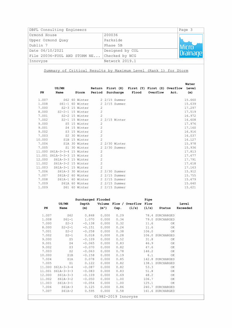
DBFL Consulting Engineers Page 3Ormond House 200036Upper Ormond Quay ParksideDublin 7 Phase 5BDate 06/10/2021 Designed by COLFile 20036-FOUL AND STORM NE... Checked by NCGInnovyze Network 2019.1
Summary of Critical Results by Maximum Level (Rank 1) for Storm
©1982-2019 Innovyze
PNUS/MHName Storm
ReturnPeriod
First (X)Surcharge
First (Y)Flood
First (Z)Overflow
OverflowAct.
Water Level(m)
1.007 S62 60 Winter 2 2/15 Summer 15.6601.008 S61-1 60 Winter 2 2/15 Summer 15.6397.000 S2-3 15 Winter 2 17.2978.000 S2-2-1 15 Winter 2 17.5197.001 S2-2 15 Winter 2 16.9727.002 S2-1 15 Winter 2 2/15 Winter 16.6089.000 S5 15 Winter 2 17.9769.001 S4 15 Winter 2 17.1609.002 S3 15 Winter 2 16.9167.003 S2 30 Winter 2 16.03710.000 S1B 15 Winter 2 16.1277.004 S1A 30 Winter 2 2/30 Winter 15.9787.005 S1 30 Winter 2 2/30 Summer 15.93611.000 S61A-3-3-4 15 Winter 2 17.81311.001 S61A-3-3-3 15 Winter 2 17.67712.000 S61A-3-3 15 Winter 2 17.79111.002 S61A-3-2 15 Winter 2 17.61811.003 S61A-3-1 15 Winter 2 17.1637.006 S61A-3 30 Winter 2 2/30 Summer 15.9127.007 S61A-2 60 Winter 2 2/15 Summer 15.7557.008 S61A-1 60 Winter 2 2/15 Summer 15.6797.009 S61A 60 Winter 2 2/15 Summer 15.6401.009 S61 60 Winter 2 2/15 Summer 15.621
PNUS/MHName
SurchargedDepth(m)
FloodedVolume(m³)
Flow /Cap.
Overflow(l/s)
PipeFlow(l/s) Status
LevelExceeded
1.007 S62 0.848 0.000 0.29 78.4 SURCHARGED1.008 S61-1 1.070 0.000 0.34 79.0 SURCHARGED7.000 S2-3 -0.138 0.000 0.32 11.6 OK8.000 S2-2-1 -0.151 0.000 0.24 11.6 OK7.001 S2-2 -0.258 0.000 0.38 106.0 OK7.002 S2-1 0.018 0.000 0.28 106.0 SURCHARGED9.000 S5 -0.109 0.000 0.52 31.8 OK9.001 S4 -0.065 0.000 0.83 46.9 OK9.002 S3 -0.070 0.000 0.82 47.6 OK7.003 S2 -0.063 0.000 0.78 146.2 OK10.000 S1B -0.158 0.000 0.19 6.1 OK7.004 S1A 0.078 0.000 0.85 142.8 SURCHARGED7.005 S1 0.122 0.000 0.82 138.1 SURCHARGED11.000 S61A-3-3-4 -0.087 0.000 0.82 53.3 OK11.001 S61A-3-3-3 -0.083 0.000 0.83 51.8 OK12.000 S61A-3-3 -0.109 0.000 0.69 48.2 OK11.002 S61A-3-2 -0.050 0.000 1.00 106.7 OK11.003 S61A-3-1 -0.054 0.000 1.00 125.1 OK7.006 S61A-3 0.125 0.000 0.86 240.7 SURCHARGED7.007 S61A-2 0.595 0.000 0.58 161.6 SURCHARGED
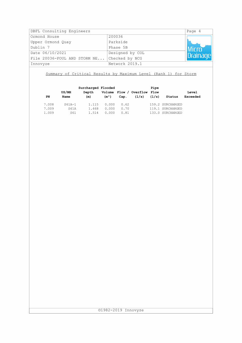
DBFL Consulting Engineers Page 4Ormond House 200036Upper Ormond Quay ParksideDublin 7 Phase 5BDate 06/10/2021 Designed by COLFile 20036-FOUL AND STORM NE... Checked by NCGInnovyze Network 2019.1
Summary of Critical Results by Maximum Level (Rank 1) for Storm
©1982-2019 Innovyze
7.008 S61A-1 1.115 0.000 0.62 159.2 SURCHARGED7.009 S61A 1.468 0.000 0.70 119.1 SURCHARGED1.009 S61 1.514 0.000 0.81 133.0 SURCHARGED
PNUS/MHName
SurchargedDepth(m)
FloodedVolume(m³)
Flow /Cap.
Overflow(l/s)
PipeFlow(l/s) Status
LevelExceeded

Parkside Phase 5B at Belmayne, Dublin 13
Infrastructure Design Report November 2021
DBFL Consulting Engineers 200036-DBFL-CS-ST-RP-C-3001 IDR
Appendix D
FOUL SEWER CALCULATIONS
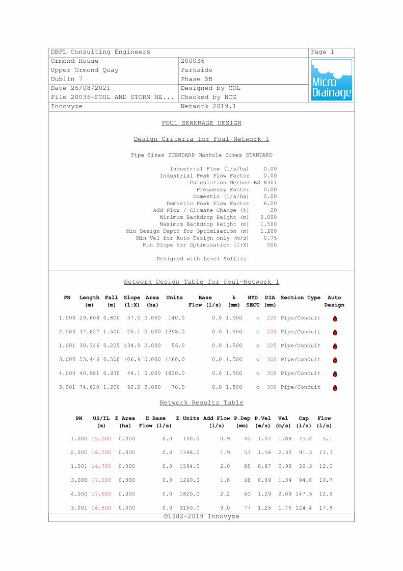
DBFL Consulting Engineers Page 1Ormond House 200036Upper Ormond Quay ParksideDublin 7 Phase 5BDate 26/08/2021 Designed by COLFile 20036-FOUL AND STORM NE... Checked by NCGInnovyze Network 2019.1
FOUL SEWERAGE DESIGN
Design Criteria for Foul-Network 1
©1982-2019 Innovyze
Pipe Sizes STANDARD Manhole Sizes STANDARD
Industrial Flow (l/s/ha) 0.00Industrial Peak Flow Factor 0.00
Calculation Method BS 8301Frequency Factor 0.00Domestic (l/s/ha) 0.00
Domestic Peak Flow Factor 6.00Add Flow / Climate Change (%) 20Minimum Backdrop Height (m) 0.000Maximum Backdrop Height (m) 1.500
Min Design Depth for Optimisation (m) 1.200Min Vel for Auto Design only (m/s) 0.75Min Slope for Optimisation (1:X) 500
Designed with Level Soffits
Network Design Table for Foul-Network 1
PN Length(m)
Fall(m)
Slope(1:X)
Area(ha)
Units BaseFlow (l/s)
k(mm)
HYDSECT
DIA(mm)
Section Type AutoDesign
1.000 29.608 0.800 37.0 0.000 140.0 0.0 1.500 o 225 Pipe/Conduit
2.000 37.627 1.500 25.1 0.000 1398.0 0.0 1.500 o 225 Pipe/Conduit
1.001 30.346 0.225 134.9 0.000 56.0 0.0 1.500 o 225 Pipe/Conduit
3.000 53.446 0.500 106.9 0.000 1260.0 0.0 1.500 o 300 Pipe/Conduit
4.000 40.981 0.930 44.1 0.000 1820.0 0.0 1.500 o 300 Pipe/Conduit
3.001 74.620 1.200 62.2 0.000 70.0 0.0 1.500 o 300 Pipe/Conduit
Network Results Table
PN US/IL(m)
Σ Area(ha)
Σ BaseFlow (l/s)
Σ Units Add Flow(l/s)
P.Dep(mm)
P.Vel(m/s)
Vel(m/s)
Cap(l/s)
Flow(l/s)
1.000 15.500 0.000 0.0 140.0 0.9 40 1.07 1.89 75.2 5.1
2.000 16.200 0.000 0.0 1398.0 1.9 53 1.56 2.30 91.3 11.3
1.001 14.700 0.000 0.0 1594.0 2.0 85 0.87 0.99 39.3 12.0
3.000 17.000 0.000 0.0 1260.0 1.8 68 0.89 1.34 94.8 10.7
4.000 17.600 0.000 0.0 1820.0 2.2 60 1.29 2.09 147.9 12.9
3.001 16.500 0.000 0.0 3150.0 3.0 77 1.25 1.76 124.4 17.8
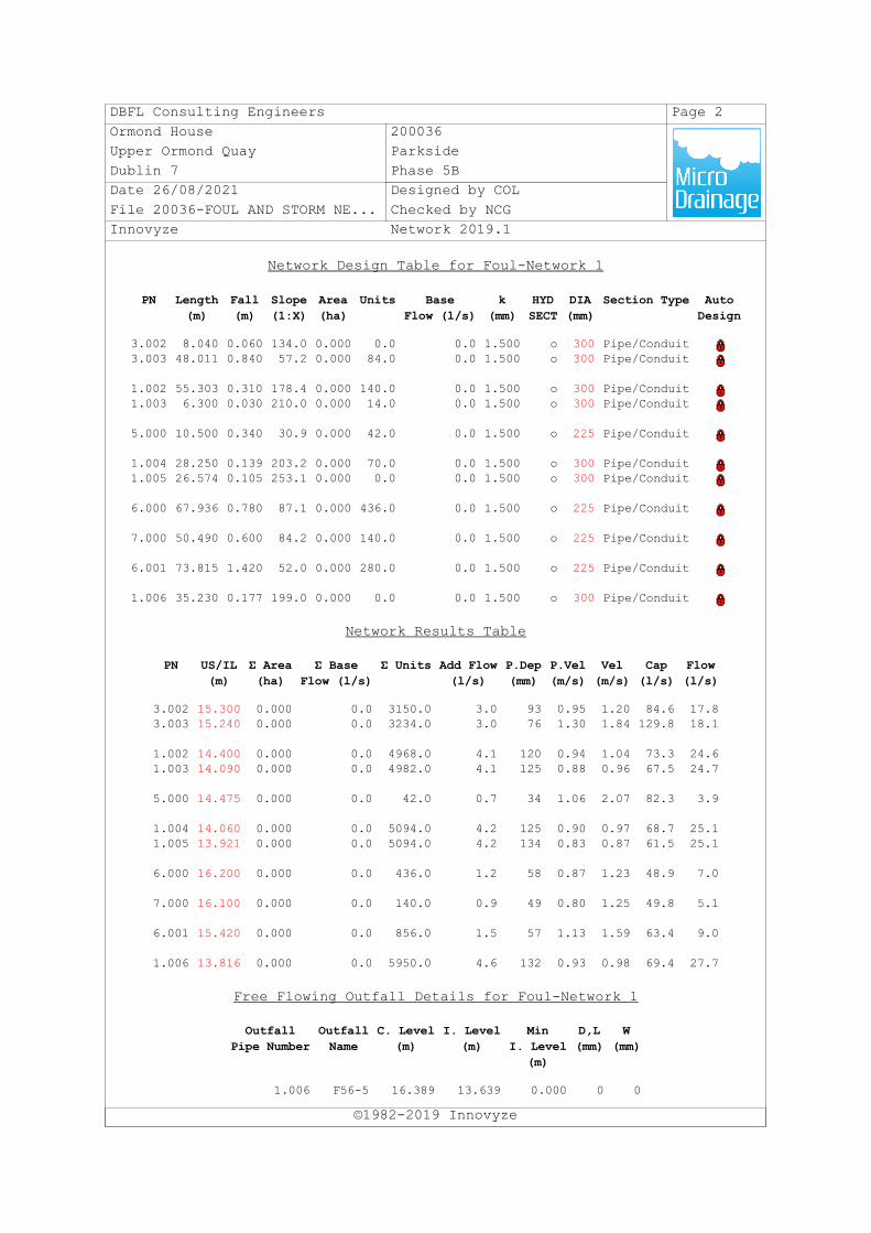
DBFL Consulting Engineers Page 2Ormond House 200036Upper Ormond Quay ParksideDublin 7 Phase 5BDate 26/08/2021 Designed by COLFile 20036-FOUL AND STORM NE... Checked by NCGInnovyze Network 2019.1
Network Design Table for Foul-Network 1
©1982-2019 Innovyze
PN Length(m)
Fall(m)
Slope(1:X)
Area(ha)
Units BaseFlow (l/s)
k(mm)
HYDSECT
DIA(mm)
Section Type AutoDesign
3.002 8.040 0.060 134.0 0.000 0.0 0.0 1.500 o 300 Pipe/Conduit3.003 48.011 0.840 57.2 0.000 84.0 0.0 1.500 o 300 Pipe/Conduit
1.002 55.303 0.310 178.4 0.000 140.0 0.0 1.500 o 300 Pipe/Conduit1.003 6.300 0.030 210.0 0.000 14.0 0.0 1.500 o 300 Pipe/Conduit
5.000 10.500 0.340 30.9 0.000 42.0 0.0 1.500 o 225 Pipe/Conduit
1.004 28.250 0.139 203.2 0.000 70.0 0.0 1.500 o 300 Pipe/Conduit1.005 26.574 0.105 253.1 0.000 0.0 0.0 1.500 o 300 Pipe/Conduit
6.000 67.936 0.780 87.1 0.000 436.0 0.0 1.500 o 225 Pipe/Conduit
7.000 50.490 0.600 84.2 0.000 140.0 0.0 1.500 o 225 Pipe/Conduit
6.001 73.815 1.420 52.0 0.000 280.0 0.0 1.500 o 225 Pipe/Conduit
1.006 35.230 0.177 199.0 0.000 0.0 0.0 1.500 o 300 Pipe/Conduit
Network Results Table
PN US/IL(m)
Σ Area(ha)
Σ BaseFlow (l/s)
Σ Units Add Flow(l/s)
P.Dep(mm)
P.Vel(m/s)
Vel(m/s)
Cap(l/s)
Flow(l/s)
3.002 15.300 0.000 0.0 3150.0 3.0 93 0.95 1.20 84.6 17.83.003 15.240 0.000 0.0 3234.0 3.0 76 1.30 1.84 129.8 18.1
1.002 14.400 0.000 0.0 4968.0 4.1 120 0.94 1.04 73.3 24.61.003 14.090 0.000 0.0 4982.0 4.1 125 0.88 0.96 67.5 24.7
5.000 14.475 0.000 0.0 42.0 0.7 34 1.06 2.07 82.3 3.9
1.004 14.060 0.000 0.0 5094.0 4.2 125 0.90 0.97 68.7 25.11.005 13.921 0.000 0.0 5094.0 4.2 134 0.83 0.87 61.5 25.1
6.000 16.200 0.000 0.0 436.0 1.2 58 0.87 1.23 48.9 7.0
7.000 16.100 0.000 0.0 140.0 0.9 49 0.80 1.25 49.8 5.1
6.001 15.420 0.000 0.0 856.0 1.5 57 1.13 1.59 63.4 9.0
1.006 13.816 0.000 0.0 5950.0 4.6 132 0.93 0.98 69.4 27.7
Free Flowing Outfall Details for Foul-Network 1
OutfallPipe Number
OutfallName
C. Level(m)
I. Level(m)
MinI. Level
(m)
D,L(mm)
W(mm)
1.006 F56-5 16.389 13.639 0.000 0 0
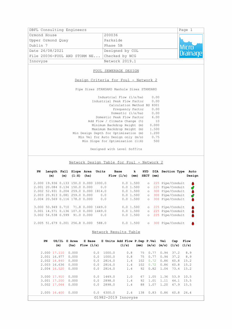
DBFL Consulting Engineers Page 1Ormond House 200036Upper Ormond Quay ParksideDublin 7 Phase 5BDate 26/08/2021 Designed by COLFile 20036-FOUL AND STORM NE... Checked by NCGInnovyze Network 2019.1
FOUL SEWERAGE DESIGN
Design Criteria for Foul - Network 2
©1982-2019 Innovyze
Pipe Sizes STANDARD Manhole Sizes STANDARD
Industrial Flow (l/s/ha) 0.00Industrial Peak Flow Factor 0.00
Calculation Method BS 8301Frequency Factor 0.00Domestic (l/s/ha) 0.00
Domestic Peak Flow Factor 6.00Add Flow / Climate Change (%) 10Minimum Backdrop Height (m) 0.000Maximum Backdrop Height (m) 1.500
Min Design Depth for Optimisation (m) 1.200Min Vel for Auto Design only (m/s) 0.75Min Slope for Optimisation (1:X) 500
Designed with Level Soffits
Network Design Table for Foul - Network 2
PN Length(m)
Fall(m)
Slope(1:X)
Area(ha)
Units BaseFlow (l/s)
k(mm)
HYDSECT
DIA(mm)
Section Type AutoDesign
2.000 19.936 0.133 150.0 0.000 1000.0 0.0 1.500 o 225 Pipe/Conduit2.001 20.084 0.134 150.0 0.000 0.0 0.0 1.500 o 225 Pipe/Conduit2.002 52.931 0.204 259.0 0.000 1814.0 0.0 1.500 o 300 Pipe/Conduit2.003 20.913 0.081 259.0 0.000 0.0 0.0 1.500 o 300 Pipe/Conduit2.004 20.569 0.116 178.0 0.000 0.0 0.0 1.500 o 300 Pipe/Conduit
3.000 50.949 0.710 71.8 0.000 1449.0 0.0 1.500 o 225 Pipe/Conduit3.001 14.571 0.136 107.0 0.000 1449.0 0.0 1.500 o 225 Pipe/Conduit3.002 54.538 0.599 91.0 0.000 0.0 0.0 1.500 o 225 Pipe/Conduit
2.005 51.679 0.201 256.8 0.000 588.0 0.0 1.500 o 300 Pipe/Conduit
Network Results Table
PN US/IL(m)
Σ Area(ha)
Σ BaseFlow (l/s)
Σ Units Add Flow(l/s)
P.Dep(mm)
P.Vel(m/s)
Vel(m/s)
Cap(l/s)
Flow(l/s)
2.000 17.110 0.000 0.0 1000.0 0.8 75 0.77 0.94 37.2 8.92.001 16.977 0.000 0.0 1000.0 0.8 75 0.77 0.94 37.2 8.92.002 16.840 0.000 0.0 2814.0 1.4 102 0.72 0.86 60.8 15.22.003 16.636 0.000 0.0 2814.0 1.4 102 0.72 0.86 60.8 15.22.004 16.520 0.000 0.0 2814.0 1.4 92 0.82 1.04 73.4 15.2
3.000 17.910 0.000 0.0 1449.0 1.0 67 1.05 1.36 53.9 10.53.001 17.200 0.000 0.0 2898.0 1.4 92 1.01 1.11 44.1 15.53.002 17.064 0.000 0.0 2898.0 1.4 88 1.07 1.20 47.9 15.5
2.005 16.400 0.000 0.0 6300.0 2.4 138 0.83 0.86 60.8 26.4
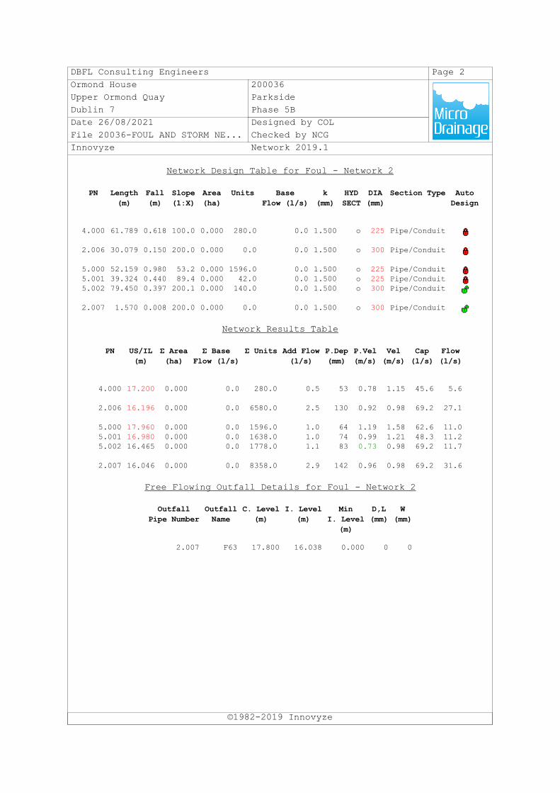
DBFL Consulting Engineers Page 2Ormond House 200036Upper Ormond Quay ParksideDublin 7 Phase 5BDate 26/08/2021 Designed by COLFile 20036-FOUL AND STORM NE... Checked by NCGInnovyze Network 2019.1
Network Design Table for Foul - Network 2
©1982-2019 Innovyze
PN Length(m)
Fall(m)
Slope(1:X)
Area(ha)
Units BaseFlow (l/s)
k(mm)
HYDSECT
DIA(mm)
Section Type AutoDesign
4.000 61.789 0.618 100.0 0.000 280.0 0.0 1.500 o 225 Pipe/Conduit
2.006 30.079 0.150 200.0 0.000 0.0 0.0 1.500 o 300 Pipe/Conduit
5.000 52.159 0.980 53.2 0.000 1596.0 0.0 1.500 o 225 Pipe/Conduit5.001 39.324 0.440 89.4 0.000 42.0 0.0 1.500 o 225 Pipe/Conduit5.002 79.450 0.397 200.1 0.000 140.0 0.0 1.500 o 300 Pipe/Conduit
2.007 1.570 0.008 200.0 0.000 0.0 0.0 1.500 o 300 Pipe/Conduit
Network Results Table
PN US/IL(m)
Σ Area(ha)
Σ BaseFlow (l/s)
Σ Units Add Flow(l/s)
P.Dep(mm)
P.Vel(m/s)
Vel(m/s)
Cap(l/s)
Flow(l/s)
4.000 17.200 0.000 0.0 280.0 0.5 53 0.78 1.15 45.6 5.6
2.006 16.196 0.000 0.0 6580.0 2.5 130 0.92 0.98 69.2 27.1
5.000 17.960 0.000 0.0 1596.0 1.0 64 1.19 1.58 62.6 11.05.001 16.980 0.000 0.0 1638.0 1.0 74 0.99 1.21 48.3 11.25.002 16.465 0.000 0.0 1778.0 1.1 83 0.73 0.98 69.2 11.7
2.007 16.046 0.000 0.0 8358.0 2.9 142 0.96 0.98 69.2 31.6
Free Flowing Outfall Details for Foul - Network 2
OutfallPipe Number
OutfallName
C. Level(m)
I. Level(m)
MinI. Level
(m)
D,L(mm)
W(mm)
2.007 F63 17.800 16.038 0.000 0 0

Parkside Phase 5B at Belmayne, Dublin 13
Infrastructure Design Report November 2021
DBFL Consulting Engineers 200036-DBFL-CS-ST-RP-C-3001 IDR
Appendix E
CONFIRMATION OF FEASABILITY
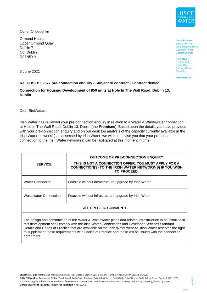
Conor O' Loughlin
Ormond House
Upper Ormond Quay
Dublin 7
Co. Dublin
D07N5YH
3 June 2021
Re: CDS21002577 pre-connection enquiry - Subject to contract | Contract denied
Connection for Housing Development of 850 units at Hole In The Wall Road, Dublin 13,
Dublin
Dear Sir/Madam,
Irish Water has reviewed your pre-connection enquiry in relation to a Water & Wastewater connection
at Hole In The Wall Road, Dublin 13, Dublin (the Premises). Based upon the details you have provided
with your pre-connection enquiry and on our desk top analysis of the capacity currently available in the
Irish Water network(s) as assessed by Irish Water, we wish to advise you that your proposed
connection to the Irish Water network(s) can be facilitated at this moment in time.
SERVICE
OUTCOME OF PRE-CONNECTION ENQUIRY
THIS IS NOT A CONNECTION OFFER. YOU MUST APPLY FOR A CONNECTION(S) TO THE IRISH WATER NETWORK(S) IF YOU WISH
TO PROCEED.
Water Connection Feasible without infrastructure upgrade by Irish Water
Wastewater Connection Feasible without infrastructure upgrade by Irish Water
SITE SPECIFIC COMMENTS
The design and construction of the Water & Wastewater pipes and related infrastructure to be installed in this development shall comply with the Irish Water Connections and Developer Services Standard Details and Codes of Practice that are available on the Irish Water website. Irish Water reserves the right to supplement these requirements with Codes of Practice and these will be issued with the connection agreement.
General Notes:
1) The initial assessment referred to above is carried out taking into account water demand and
wastewater discharge volumes and infrastructure details on the date of the assessment. The
availability of capacity may change at any date after this assessment.
2) This feedback does not constitute a contract in whole or in part to provide a connection to any
Irish Water infrastructure. All feasibility assessments are subject to the constraints of the Irish
Water Capital Investment Plan.
3) The feedback provided is subject to a Connection Agreement/contract being signed at a later
date.
4) A Connection Agreement will be required to commencing the connection works associated with
the enquiry this can be applied for at https://www.water.ie/connections/get-connected/
5) A Connection Agreement cannot be issued until all statutory approvals are successfully in place.
6) Irish Water Connection Policy/ Charges can be found at
https://www.water.ie/connections/information/connection-charges/
7) Please note the Confirmation of Feasibility does not extend to your fire flow requirements.
8) Irish Water is not responsible for the management or disposal of storm water or ground waters.
You are advised to contact the relevant Local Authority to discuss the management or disposal of
proposed storm water or ground water discharges
9) To access Irish Water Maps email [email protected]
10) All works to the Irish Water infrastructure, including works in the Public Space, shall have to be
carried out by Irish Water.
If you have any further questions, please contact Marina Byrne from the design team via
[email protected]. For further information, visit www.water.ie/connections.
Yours sincerely,
Yvonne Harris Head of Customer Operations

Parkside Phase 5B at Belmayne, Dublin 13
Infrastructure Design Report November 2021
DBFL Consulting Engineers 200036-DBFL-CS-ST-RP-C-3001 IDR
Appendix F
IRISH WATER STATEMENT OF DESIGN ACCEPTANCE

Conor O' Loughlin Ormond House Upper Ormond Quay Dublin 7, Co. Dublin D07N5YH 1 October 2021
Re: Design Submission for Hole In The Wall Road, Dublin 13, Dublin (the “Development”) (the “Design Submission”) / Connection Reference No: CDS21002577
Dear Conor O' Loughlin, Many thanks for your recent Design Submission. We have reviewed your proposal for the connection(s) at the Development. Based on the information provided, which included the documents outlined in Appendix A to this letter, Irish Water has no objection to your proposals. This letter does not constitute an offer, in whole or in part, to provide a connection to any Irish Water infrastructure. Before you can connect to our network you must sign a connection agreement with Irish Water. This can be applied for by completing the connection application form at www.water.ie/connections. Irish Water’s current charges for water and wastewater connections are set out in the Water Charges Plan as approved by the Commission for Regulation of Utilities (CRU)(https://www.cru.ie/document_group/irish-waters-water-charges-plan-2018/). You the Customer (including any designers/contractors or other related parties appointed by you) is entirely responsible for the design and construction of all water and/or wastewater infrastructure within the Development which is necessary to facilitate connection(s) from the boundary of the Development to Irish Water’s network(s) (the “Self-Lay Works”), as reflected in your Design Submission. Acceptance of the Design Submission by Irish Water does not, in any way, render Irish Water liable for any elements of the design and/or construction of the Self-Lay Works. If you have any further questions, please contact your Irish Water representative: Name: Marina Byrne Phone: 01 89 25991/ 087619321 Email: [email protected] Yours sincerely,
Yvonne Harris Head of Customer Operations

Appendix A Document Title & Revision
• [200036-DBFL-CS-ST-DR-C-1301 Proposed Drainage Layout Sheet 1]
• [200036-DBFL-WM-ST-DR-C-1351 Proposed Watermain Layout Sheet 1]
For further information, visit www.water.ie/connections Notwithstanding any matters listed above, the Customer (including any appointed designers/contractors, etc.) is entirely responsible for the design and construction of the Self-Lay Works. Acceptance of the Design Submission by Irish Water will not, in any way, render Irish Water liable for any elements of the design and/or construction of the Self-Lay Works.
Related Documents