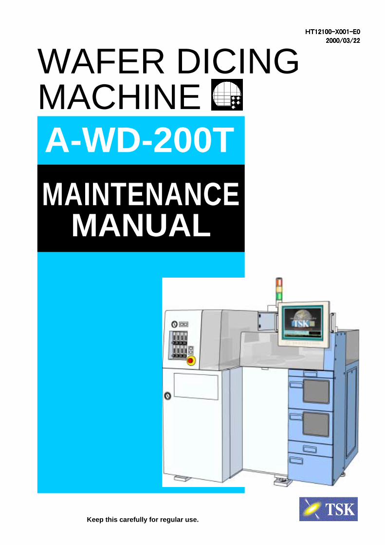
HT HT HT HT12100-X001-E0 12100-X001-E0 12100-X001-E0 12100-X001-E0 2000/03/22 2000/03/22 2000/03/22 2000/03/22 WAFER DICING MACHINE A-WD-200T MAINTENANCE MANUAL Keep this carefully for regular use.

Welcome message from author
This document is posted to help you gain knowledge. Please leave a comment to let me know what you think about it! Share it to your friends and learn new things together.
Transcript
HTHTHTHT12100-X001-E012100-X001-E012100-X001-E012100-X001-E0
2000/03/222000/03/222000/03/222000/03/22
WAFER DICINGMACHINE
A-WD-200TM
AINTENANCEMANUAL
Keep this carefully for regular use.

MAINTENANCE MANUALContents

A-WD-200T Contents
Contents-1
Introduction1
Range of Product Warrantee and Liability 2
Definition of Intended Manual Reader 6
Chapter 1 Safety
1-1 Before Using A-WD-200T ........................................................................ 1-1
1-2 WARNING, DANGER and CAUTION in this Manual............................... 1-2
1-2-1 Hazard level ................................................................................................................... 1-2
1-2-2 Symbols.......................................................................................................................... 1-4
1-3 Hazard Warning Label ............................................................................. 1-5
1-3-1 Hazard warning label types............................................................................................ 1-6
1-3-2 Locations of hazard warning labels................................................................................ 1-7
A-WD-200T Contents
Contents-2
1-4 Safety Countermeasures....................................................................... 1-12
1-4-1 Safety precautions........................................................................................................ 1-12
1-4-2 Safety interlock system ................................................................................................ 1-14
1-4-3 Lockout / tagout............................................................................................................ 1-17
1-4-4 Protective equipment ................................................................................................... 1-21
1-5 Emergency ............................................................................................. 1-22
1-5-1 Emergency machine off switch (EMO)......................................................................... 1-22
1-5-2 Emergency countermeasure ........................................................................................ 1-27
1-6 A-WD-200T Hazardous Locations......................................................... 1-31
1-6-1 Hazardous driving sections .......................................................................................... 1-31
1-6-2 High voltage hazardous sections ................................................................................. 1-34
1-6-3 Hazardous highly heated sections ............................................................................... 1-35
Chapter 2 Configuration and Calibration
2-1 Appearance and Parts ............................................................................. 2-2
2-1-1 Front View ...................................................................................................................... 2-2
2-1-2 Left View......................................................................................................................... 2-3
2-1-3 Right View ...................................................................................................................... 2-4
2-1-4 Back View....................................................................................................................... 2-5
2-1-5 Top View......................................................................................................................... 2-6
2-2 Main Features........................................................................................... 2-7
2-2-1 Main body....................................................................................................................... 2-7
2-2-2 Spinner Cleaning Unit .................................................................................................. 2-16
A-WD-200T Contents
Contents-3
2-2-3 Loader Unit................................................................................................................... 2-17
2-2-4 Control System............................................................................................................. 2-20
2-2-5 Other Units ................................................................................................................... 2-20
2-2-6 Special Options ............................................................................................................ 2-24
2-3 Calibration Preparation ......................................................................... 2-25
2-3-1 Exterior Panel............................................................................................................... 2-25
2-3-2 Release Cover Interlock............................................................................................... 2-29
2-4 Maintenance ........................................................................................... 2-30
2-4-1 X-axis ........................................................................................................................... 2-30
2-4-2 Y-axis ........................................................................................................................... 2-32
2-4-3 Z-axis............................................................................................................................ 2-34
2-4-4 Theta Axis .................................................................................................................... 2-35
2-4-5 Spindle ......................................................................................................................... 2-36
2-4-6 Flange Cover................................................................................................................ 2-40
2-4-7 Optical Cutter Set ......................................................................................................... 2-43
2-4-8 Spinner ......................................................................................................................... 2-44
2-4-9 Revolving Arm.............................................................................................................. 2-47
2-4-10 Elevator ...................................................................................................................... 2-52
2-4-11 Cassette ..................................................................................................................... 2-55
2-4-12 Calibration .................................................................................................................. 2-61
Chapter 3 Periodic Maintenance Service List
3-1 Periodical MaintenancePeriodical MaintenancePeriodical MaintenancePeriodical Maintenance ................................................................................ 3-1
3-2 Recommended Periodical Maintenance ListRecommended Periodical Maintenance ListRecommended Periodical Maintenance ListRecommended Periodical Maintenance List .................................................. 3-2
A-WD-200T Contents
Contents-4
Chapter 4 Maintenance And Check List
4-1 Daily Check List4-1 Daily Check List4-1 Daily Check List4-1 Daily Check List ........................................................................................................................................................................................................................................................................................................................................................................................................................................................................ 4-14-14-14-1
4-1-1 Verify Air Pressure.......................................................................................................... 4-1
4-1-2 Verify Cooling, Cutting And Cleaning Water Flow.......................................................... 4-2
4-1-3 Water leakage around the Machine ............................................................................... 4-3
4-1-4 Cleaning the X Axis Bellows .......................................................................................... 4-4
4-2 Weekly Check List4-2 Weekly Check List4-2 Weekly Check List4-2 Weekly Check List ........................................................................................................................................................................................................................................................................................................................................................................................................................................................ 4-54-54-54-5
4-2-1 Verify the Nozzles........................................................................................................... 4-5
Spinner Table Check.............................................................................................................. 4-7
4-2-3 Cutting Table rotation center check................................................................................ 4-8
4-2-4 Cleaning Oil Pan .......................................................................................................... 4-10
4-3 Monthly Check List4-3 Monthly Check List4-3 Monthly Check List4-3 Monthly Check List............................................................................................................................................................................................................................................................................................................................................................................................................................................ 4-114-114-114-11
4-3-1 Focus.............................................................................................................................4-11
4-3-2 Revolving Arm Precision .............................................................................................. 4-12
4-3-3 Flange surface thrust direction runout.......................................................................... 4-13
4-3-4 Water Leakage from the Machine ................................................................................ 4-14
4-3-5 Cleaning the Tables...................................................................................................... 4-15
4-3-6 Wafer Table Planarity Measurement ......................................................................... 4-16
4-3-7 Y Axis Feed Precision .................................................................................................. 4-17
4-3-8 Frame Vacuum Pad...................................................................................................... 4-18
4-4 3 Months Check List4-4 3 Months Check List4-4 3 Months Check List4-4 3 Months Check List ................................................................................................................................................................................................................................................................................................................................................................................................................................ 4-194-194-194-19
4-4-1 Y Axis Linear Scale Lissajou Wave.............................................................................. 4-19
4-4-2 Cleaning X Axis Guide Area......................................................................................... 4-20
4-4-3 Camera Magnification Offset........................................................................................ 4-21
A-WD-200T Contents
Contents-5
4-5 64-5 64-5 64-5 6 Months Check ListMonths Check ListMonths Check ListMonths Check List ................................................................................................................................................................................................................................................................................................................................................................................................................................ 4-224-224-224-22
4-5-1 Current Leakage Breaker Operation ............................................................................ 4-22
4-5-2 Greasing to the Y Axis Guide/Ball Screw..................................................................... 4-23
4-5-3 Greasing to the Z Axis Guide/Ball Screw..................................................................... 4-23
4-5-4 Greasing to the Elevator Axis Guide/Ball Screw.......................................................... 4-23
4-6 Yearly Check List4-6 Yearly Check List4-6 Yearly Check List4-6 Yearly Check List ........................................................................................................................................................................................................................................................................................................................................................................................................................................................ 4-244-244-244-24
4-6-1 X Axis Straightness (Vertically) .................................................................................... 4-24
4-6-2 X Axis Straightness (Horizontally)................................................................................ 4-24
4-6-3 Spindle Axis & X Axis Perpendicularity........................................................................ 4-24
4-6-4 Z Axis Precision Repeatability Measurement .............................................................. 4-24
4-6-5 Spindle Run Out Measurement (Radial Direction)....................................................... 4-24
4-6-6 Replacement of the Air Filter Element ......................................................................... 4-25
4-7 4-7 4-7 4-7 Blade CalibrationBlade CalibrationBlade CalibrationBlade Calibration ............................................................................................................................................................................................................................................................................................................................................................................................................................................................ 4-264-264-264-26
4-8 Replace Camera Lamp4-8 Replace Camera Lamp4-8 Replace Camera Lamp4-8 Replace Camera Lamp .................................................................................................................................................................................................................................................................................................................................................................................................................... 4-284-284-284-28
4-9 Greasing4-9 Greasing4-9 Greasing4-9 Greasing ............................................................................................................................................................................................................................................................................................................................................................................................................................................................................................................................ 4-294-294-294-29
Chapter 5 Accuracy
5-1 Precision Tolerance5-1 Precision Tolerance5-1 Precision Tolerance5-1 Precision Tolerance................................................................................................................................................................................................................................................................................................................................................................................................................................................ 5-25-25-25-2
5-2 Precision Inspection5-2 Precision Inspection5-2 Precision Inspection5-2 Precision Inspection ............................................................................................................................................................................................................................................................................................................................................................................................................................................ 5-35-35-35-3
5-2-1 X-axis Straightness (Horizontally) .................................................................................. 5-3
5-2-2 X-axis Straightness (Verticaliy) ...................................................................................... 5-4
5-2-3 Wafer Table Planarity ..................................................................................................... 5-5
5-2-4 Y-axis Index Precision.................................................................................................... 5-6
5-2-5 Z-axis Repeatability........................................................................................................ 5-7

A-WD-200T Contents
Contents-6
5-2-6 Spindle Axis Perpendicularity Against X-axis ................................................................ 5-8
5-2-7 Spindle Run Out (Radial Direction) ................................................................................ 5-9
5-2-8 Spindle Run Out (Thrust Direction) .............................................................................. 5-10
5-2-9 Flange End Surface Run Out ........................................................................................5-11
5-2-10 Dynamic Accuracy...................................................................................................... 5-12
Chapter 6 Troubleshooting
Chapter 7 Error Message

Introduction

A-WD-200T Introduction
Introduction-1
IntroductionThank you for your purchase of our product.
This operation and maintenance manual for full-automatic wafer dicing machine A-WD-200T(“Manual” hereafter) explains effective and life-maximizing operation and maintenance of AW-200T.
Contents of this manual are based on standard specifications, and therefore may slightly differfrom specifications of your A-WD-200T.
If you have any queries or anything uncertain about A-WD-200T, do not hesitate to contact usthrough following address.
Tokyo Seimitsu CorporationTokyo Semiconductor Branch Phone +81-422-48-1018
FAX +81-422-49-7315
A-WD-200T Introduction
Introduction-2
Range of Product Warrantee andLiability
We would like you to acknowledge following items that concern warrantee and liability relatedto full-automatic wafer dicing machine A-WD-200T (“Product” hereafter).
Product liability and warrantee• Product Warrantee
Tokyo Seimitsu Corporation (“Company” hereafter) warrantees that this product isfree of any defect in its craftpersonship and quality.
Any damage and/or trouble that occurred to the Product when you were using theProduct in conjunction with part (s) of other company and when such part (s) werein any of following conditions will NOT be subject of Company’s warrantee.
- You failed not submit Company safety certificate of such part (s).- We did not approve safety certificate of such part(s) you submitted to Company.
Note even if Company approves certificate of part (s) you submit to Company,Company does not warrantee that such part(s) are free of any defect in theircraftpersonship or quality.
• European product liability (CE Marking)This System is evaluated and found to be in compliance with the followingdirectives and standards that European product liability law demands. With yourfull understanding of the instructions in the Manual, you are assured that theSystem is designed to minimize the possibility of accidents.
Machinery directive (98/37/EC)
EN292-1, EN292-2, EN60204-1
Low voltage directive (73/23/EEC,93/68/EEC)
EN60204-1
EMC directive (89/336/EEC, 92/31/EEC,93/68/EEC)
EN55011 Class A Group 1: 1991
EN50082-2: 1995
• Period of WarranteeFor period of warrantee, see sales contract.
A-WD-200T Introduction
Introduction-3
• Range of WarranteeTroubles or damages that occurred under following conditions will not be subjectof warrantee.
- Force majeure.- You modified the Product without our approval.- Wrong operation or use that do not comply items described in this manual.- Use of inappropriate process material.
Costs of consumable parts, spare parts after expiration of warrantee, labor ortransportation should be at your expense.
• Damage and liabilityObey national or local regulations upon use of the Product, or disposal of Productand/or its component.
Read our documents including operation- and maintenance manual well andreceive proper Product-related training from our trainer prior to your use of theProduct. Obey DANGER, WARNING and CAUTION under any circumstance.
We are not liable of damages that occurred due to your inappropriate operation ormaintenance.
A-WD-200T Introduction
Introduction-4
We are not liable for any damage caused by modification or change done todocuments (including operation manual and maintenance manual) related to theProduct, did by anyone other than Company.
This System is in compliance with EMC Directive that is a part of the Europeanproduct liability law, CE marking. All the parts and units of the System werecarefully chosen to comply with EMC Directive. Therefore, the System may fail tooperate properly with the use of components or parts that are acquired fromanyone other than Daifuku’s employees or anyone not appointed by Daifuku tomaintain or modify this System.
Product may not be able to operate with full capability or act wrongly when, andCompany is not liable for damages caused when you use components or partsyou acquired from anyone other than Company or anyone not appointed byCompany to maintain or modify this Product.
We are not liable for any damages caused by defects of components or parts evenif acquired such components or parts from those appointed by Company.
We are not liable for any loss or damage of which supposed reason is act ofrunning this Product.
We are liable to pay responsibility over bodily hazard caused by Company’s act orfunction of the Product.
Software warrantee and liabilityBe informed of following upon use of system software (“Software” hereafter) thatCompany supply bundled with Product.
• DisclaimerWe grant nonexclusive and untransferable right of use to Customer underfollowing conditions.
• Limit of UseYour use of software is limited to following.
- For your own internal use.
- You should not modify, sell or lease the Software.
- On the Product only.
- Copying of this Software is forbidden.
- You are not permitted to reverse-engineer, reverse-compile or disassemble theSoftware.
A-WD-200T Introduction
Introduction-5
• CopyrightIntellectual propriety and copyright of the Software, attached documents includingmanuals of the Software, and duplicate of the Software are reserved by theCompany and those approved by the Company. You are not permitted to discloseinformation included in the Software, documents including manuals of theSoftware and attached documents including manuals of the Software to third partywithout our permission.
Manual warrantee and liabilityThis manual is copyrighted by Tokyo Seimitsu Corporation.
Purpose of this manual is limited to support use of the Product only. Use of thismanual for any other purpose is strictly forbidden.
Copying of whole or part of this manual without our prior consent is strictlyforbidden.
Act of rewriting or translating whole or part of this manual is strictly forbidden.
Contents of this manual are liable to change without prior notice.
A-WD-200T Introduction
Introduction-6
Definition of Intended Manual ReaderThough this manual assumes anyone who relates with A-WD-200T as reader, definitions oftargeted personnels (correspondent to abilities and experiences) are provided to each ofdescriptions, for safety concern.
We define personnels to following three classes. Manual clearly indicates targeted class(together with referent symbols) as follows. To carry out a certain work, you should belong tolisted applicable class.
Operator
Operators are, with A-WD-200T, permitted to conduct auto operation, lot operation andsetup (replacement of table/blade), but prohibited to do any other work.
Which mean, operators are not allowed to turn on power supply, startup, or open anycovers or panels of A-WD-200T under any circumstance.
Operators are requested to read contents of operation manual of AWD-200T to sufficientlyunderstand work procedure before actually starting the work.
Maintainer
Maintainers are, with A-WD-200T permitted to conduct all works that operators arepermitted to, plus setup, editing of parameters, maintenance and registration ofscreens, in addition to permitted to supply and replace consumable parts.
Maintainers MUST attend our training and gain sufficient knowledge and operative skillwith A-WD-200T. Maintainers are also requested to thoroughly read contents ofoperation-and-maintenance manual of A-WD-200T to understand characteristic of A-WD-200T and all contents of their work before actually starting the work.
Service engineer
Service engineers are personnels in charge of works that require special knowledge andskill, like installation of A-WD-200T or Configuration.
Basically, our service technical staffs are supposed to do service engineering.
Which means, operators and maintainers are not allowed to install/modify A-WD-200T,change system data or control data, change option setting or install software under anycircumstance.
A-WD-200T Introduction
Introduction-7
System Installation ConditionThis System is declared to be in compliance with EMC Directive under the condition of Class A,Group 1 described in EN55011.
Therefore, customer need to fulfill the following installation conditions, otherwise thecompliance with EMC Directive will not be satisfied.
EN55011 Class A, Group 1
WARNING
The apparatus shall not be used in the residential, commercial and light-industrialenvironment unless the apparatus also conform to the relevant standards. (EN55011,group 1 class A)
This System is an automatic freight transportation system that is designed to be installed in theindustrial environment (the environment where no residential area, medical facility, andcommercial region are nearby). The System must not be installed outside the targetedenvironment against the requirement of EMC directive for CE marking.
WARNING
The Installation is carried out by formal employee of the Daifuku Europe Ltd or theDaifuku Co., Ltd who have participate and completed the full training curriculum by andat the Daifuku Europe Ltd or the Daifuku Co., Ltd.
The installation and reinstallation of the System by the customer is prohibited. When suchoperations are required, please contact Daifuku.
WARNING
This System is designed with the premise that it be used in the controlledenvironment. In order to assure the safety operation, routine medicalcheckup shall be performed on all the relevant personnels in accordancewith local law of the country where the System is installed. And those thatrequire or diagnosed by a doctor to have the support of heart pacemaker orother electrical medical equipment should not be assigned to perform tasksrelating to this System or tasks require being around this System. It ispossible to cause malfunction of their electrical medical equipment and leadto critical condition.

Chapter 1 Safety
A-WD-200T Chapter 1 Safety
1-1
1-1 Before Using A-WD-200T
This “Safety” chapter explains safety-related items you need to be careful when
you handle A-WD-200T.
A-WD-200T operates under high voltage, and contains various sections (like
blades and driving mechanisms) that may harm human bodies if you handle
incorrectly.
Therefore, not only those who operate A-WD-200T but anyone who maintain or
work nearby A-WD-200T are requested to read well and understand safety-
related items in this manual.
Users of A-WD-200T amanual and maintenaandbe free trained witinstructor before actu
WARNINGWARNINGWARNINGWARNING
re requested to read our operationnce manual bundled with A-WD-200Th operation of A-WD-200T by ourally working with A-WD-200T.
A-WD-200T Chapter 1 Safety
1-2
1-2 WARNING, DANGER and CAUTION in this
Manual1-2-1 Hazard level
This manual classifies level of hazards during operation and maintenance of A-
WD-200T by three categories – DANGER, WARNING and CAUTION. Read and
understand the indications fully before your operation or maintenance of A-WD-
200T.
DANGER / WARNING / CAUTION titles depend on seriousness of hazards
(DANGER > WARNING > CAUTION) described as follows.
“Notes” without hazard indication describes items that may cause damage tothe system, equipment or units if you disobey described prevention.
NotesNotesNotesNotes
DANGER describes most dangerous of hazards. If you disobey describedprevention, directly serious or even fatal bodily injury occurs.
DANGERDANGERDANGERDANGER
WARNINGWARNINGWARNINGWARNINGWARNING describes second dangerous of hazards. If you disobey describedprevention, serious or even fatal bodily injury may occur.
CAUTIONCAUTIONCAUTIONCAUTIONCAUTION describes third dangerous of hazards. If you disobey describedprevention, moderate bodily injury may occur.

A-WD-200T Chapter 1 Safety
1-3
In addition to hazard level indications described so far, you can find following
notices in this manual.
Information personnels must know.
IMPORTANTIMPORTANTIMPORTANTIMPORTANT
Useful information and tips.
REMARKREMARKREMARKREMARK
A-WD-200T Chapter 1 Safety
1-4
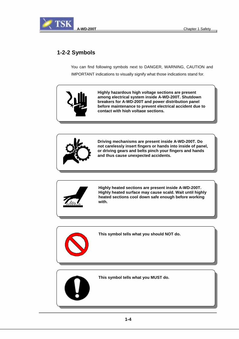
1-2-2 Symbols
You can find following symbols next to DANGER, WARNING, CAUTION and
IMPORTANT indications to visually signify what those indications stand for.
Driving mechanisms are present inside A-WD-200T. Donot carelessly insert fingers or hands into inside of panel,or driving gears and belts pinch your fingers and handsand thus cause unexpected accidents.
Highly hazardous high voltage sections are presentamong electrical system inside A-WD-200T. Shutdownbreakers for A-WD-200T and power distribution panelbefore maintenance to prevent electrical accident due tocontact with high voltage sections.
Highly heated sections are present inside A-WD-200T.Highly heated surface may cause scald. Wait until highlyheated sections cool down safe enough before workingwith.
This symbol tells what you should NOT do.
This symbol tells what you MUST do.
A-WD-200T Chapter 1 Safety
1-5
1-3 Hazard Warning Label
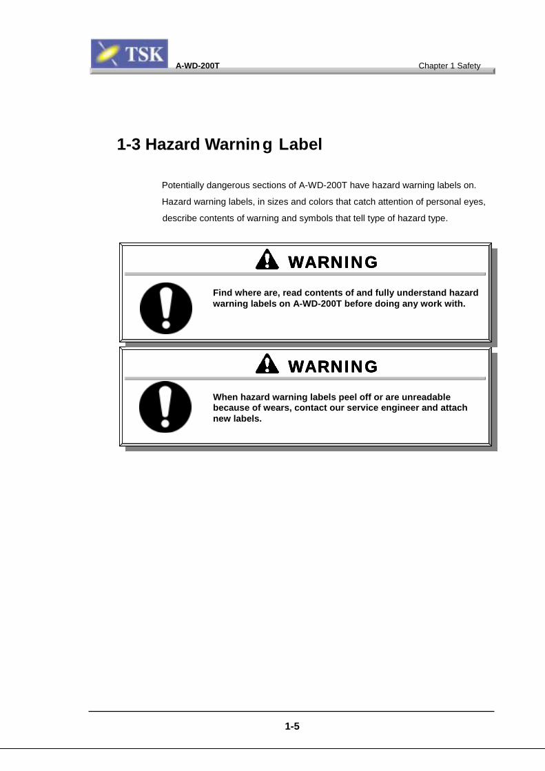
Potentially dangerous sections of A-WD-200T have hazard warning labels on.
Hazard warning labels, in sizes and colors that catch attention of personal eyes,
describe contents of warning and symbols that tell type of hazard type.
WARNINGWARNINGWARNINGWARNINGWhen hazard warning labels peel off or are unreadablebecause of wears, contact our service engineer and attachnew labels.
WARNINGWARNINGWARNINGWARNINGFind where are, read contents of and fully understand hazardwarning labels on A-WD-200T before doing any work with.
A-WD-200T Chapter 1 Safety
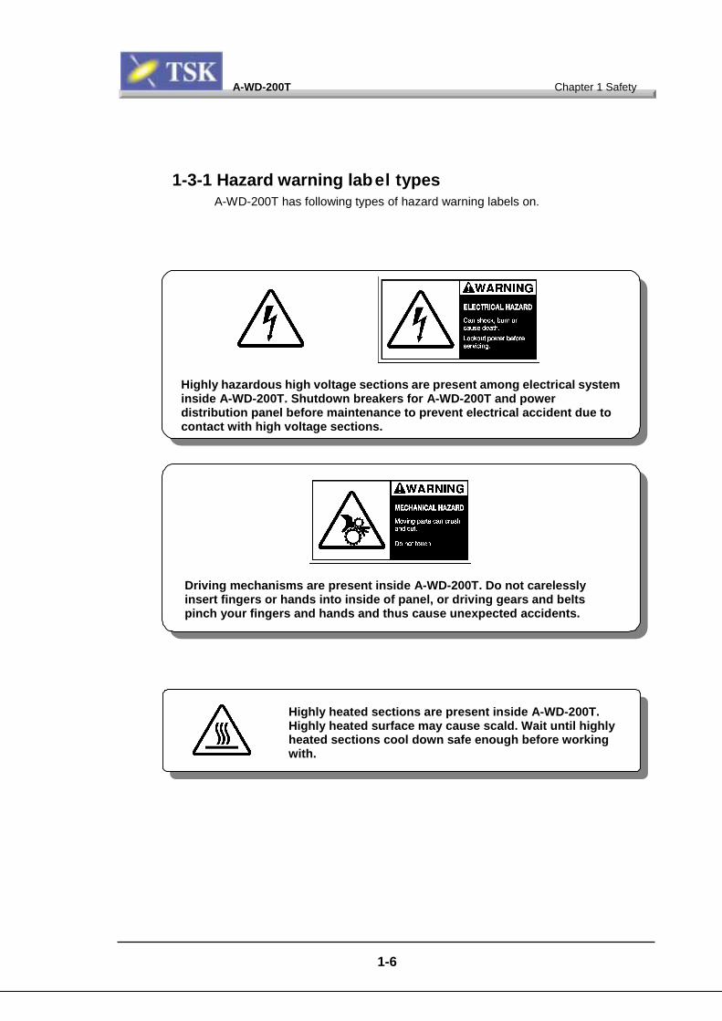
1-3-1 Hazard warning label typesA-WD-200T has following types of hazard warning labels on.
Highly hazardous high voltage sections are present among electrical systeminside A-WD-200T. Shutdown breakers for A-WD-200T and powerdistribution panel before maintenance to prevent electrical accident due tocontact with high voltage sections.
Driving mechanisms are present inside A-WD-200T. Do not carelesslyinsert fingers or hands into inside of panel, or driving gears and beltspinch your fingers and hands and thus cause unexpected accidents.
1-6
Highly heated sections are present inside A-WD-200T.Highly heated surface may cause scald. Wait until highlyheated sections cool down safe enough before workingwith.
A-WD-200T Chapter 1 Safety
1-7
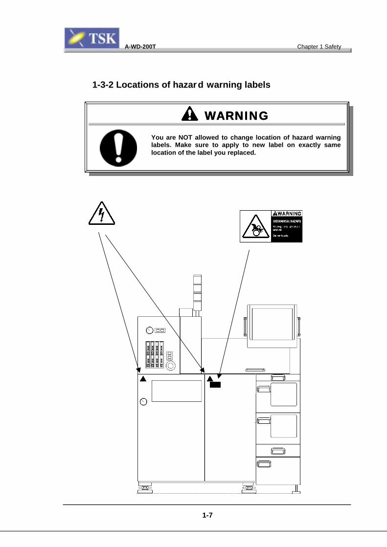
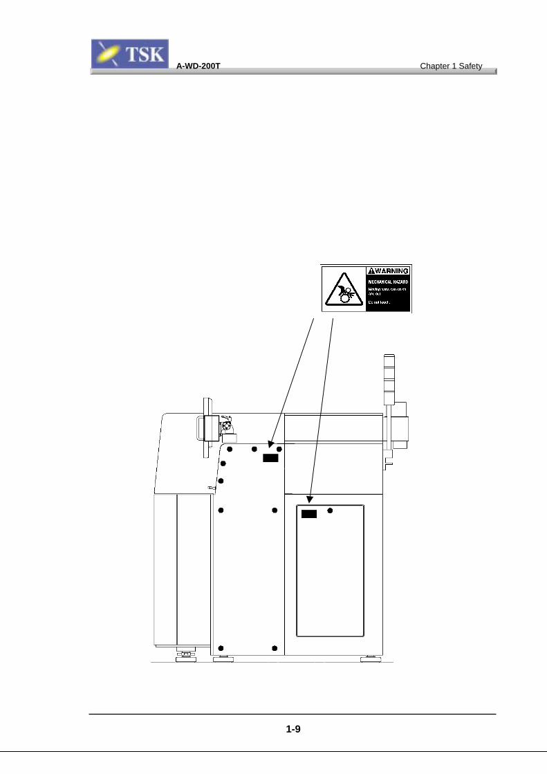
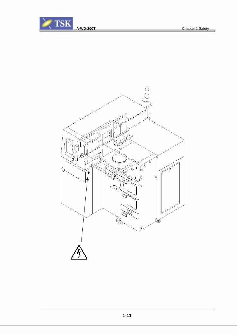
1-3-2 Locations of hazard warning labels
WARNINGWARNINGWARNINGWARNINGYou are NOT allowed to change location of hazard warninglabels. Make sure to apply to new label on exactly samelocation of the label you replaced.
A-WD-200T Chapter 1 Safety
1-8
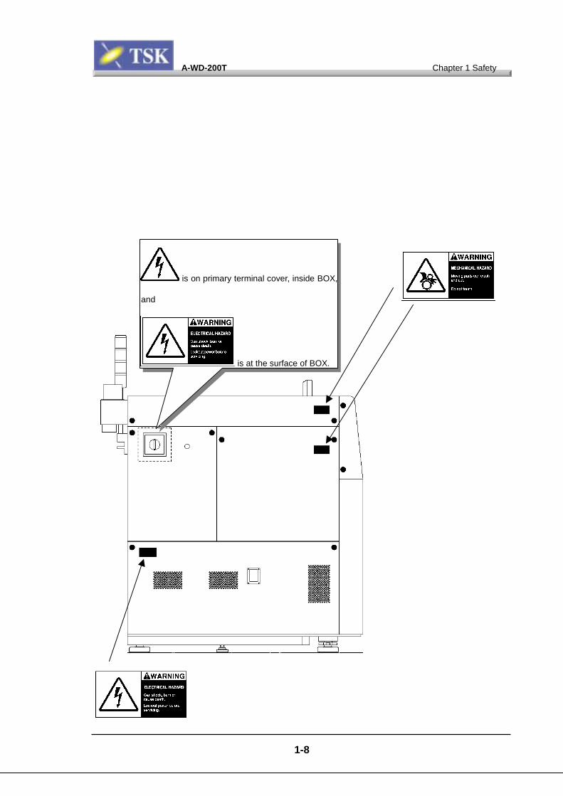
is on primary terminal cover, inside BOX,
and
is at the surface of BOX.
A-WD-200T Chapter 1 Safety
1-9

A-WD-200T Chapter 1 Safety
1-10
A-WD-200T Chapter 1 Safety
1-11

A-WD-200T Chapter 1 Safety
1-12
1-4 Safety Countermeasures1-4-1 Safety precautions
While A-WD-200T is protected by various safety devices including safety
interlocks, following basic safety-related cautions are for you to read.
- Read and understand this manual fully before actually using A-WD-200T.
- Alert everyone who are working nearby A-WD-200T you are maitaining before
you operate that A-WD-200T.
- Use correct tools by proper procedures.
- Wear proper protective gears properly.
- Remove metals (like rings or wristwatches) from your body before you work on
active electric circuit.
- When you work on running electric circuit, do not work by yourself alone, and
make sure someone who can visibly or audibly notice you is present.
- Learn emergency process (See 1-5 Emergency process), where are medikits,
and locations of and how to use fire extinguishers.
- Put up notice showing emergency evacuation route guidance in any working
area.
Observe following instructions by any means when you use A-WD-200T. Otherwise, bodily injuries or hazardous accidents mayoccur.
DANGERDANGERDANGERDANGER

A-WD-200T Chapter 1 Safety
1-13
- Remember emergency evacuation route and site.
- Make sure emergency evacuation route is not blocked by objects.
- Indicate emergency contact address in any working area.
- Carry heavy objects by more than one persons.
A-WD-200T Chapter 1 Safety
1-14
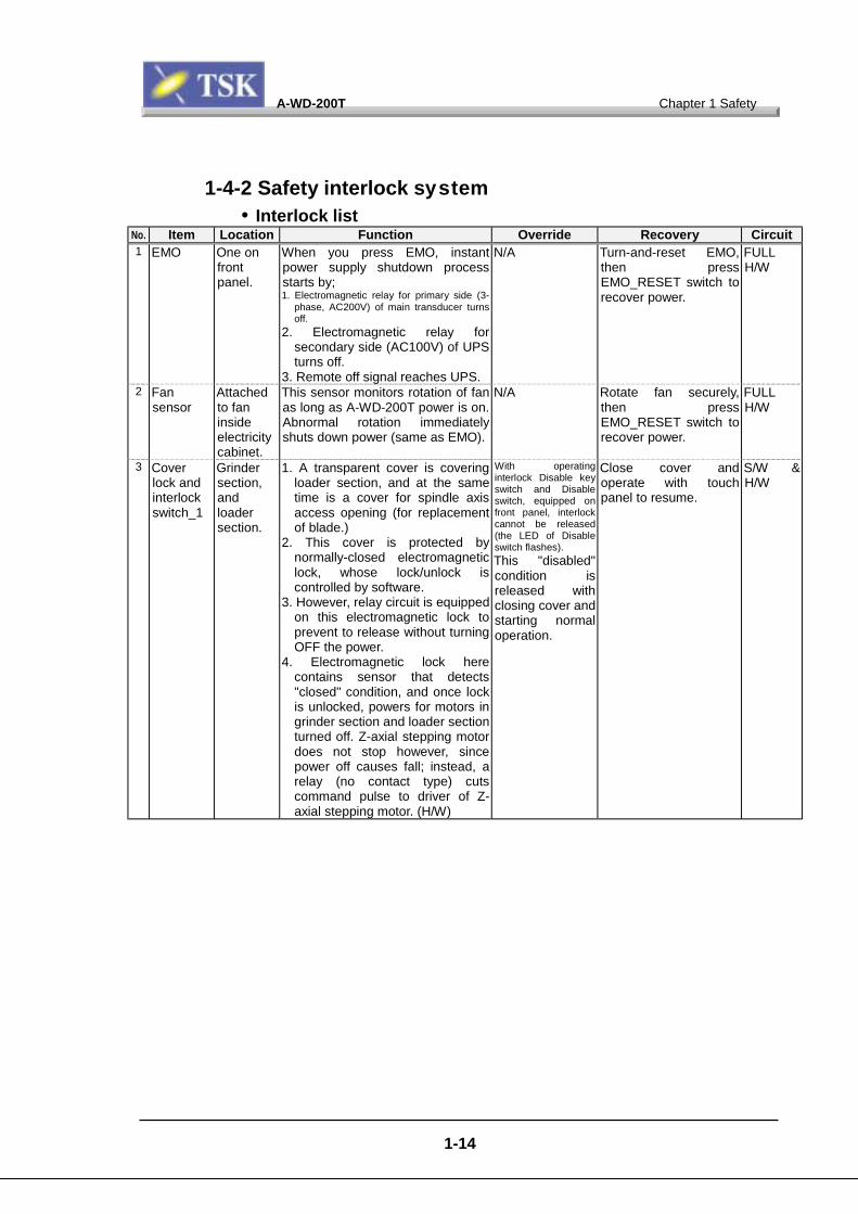
1-4-2 Safety interlock system• Interlock list
No. Item Location Function Override Recovery Circuit1 EMO One on
frontpanel.
When you press EMO, instantpower supply shutdown processstarts by;1. Electromagnetic relay for primary side (3-
phase, AC200V) of main transducer turnsoff.
2. Electromagnetic relay forsecondary side (AC100V) of UPSturns off.
3. Remote off signal reaches UPS.
N/A Turn-and-reset EMO,then pressEMO_RESET switch torecover power.
FULLH/W
2 Fansensor
Attachedto faninsideelectricitycabinet.
This sensor monitors rotation of fanas long as A-WD-200T power is on.Abnormal rotation immediatelyshuts down power (same as EMO).
N/A Rotate fan securely,then pressEMO_RESET switch torecover power.
FULLH/W
3 Coverlock andinterlockswitch_1
Grindersection,andloadersection.
1. A transparent cover is coveringloader section, and at the sametime is a cover for spindle axisaccess opening (for replacementof blade.)
2. This cover is protected bynormally-closed electromagneticlock, whose lock/unlock iscontrolled by software.
3. However, relay circuit is equippedon this electromagnetic lock toprevent to release without turningOFF the power.
4. Electromagnetic lock herecontains sensor that detects"closed" condition, and once lockis unlocked, powers for motors ingrinder section and loader sectionturned off. Z-axial stepping motordoes not stop however, sincepower off causes fall; instead, arelay (no contact type) cutscommand pulse to driver of Z-axial stepping motor. (H/W)
With operatinginterlock Disable keyswitch and Disableswitch, equipped onfront panel, interlockcannot be released(the LED of Disableswitch flashes).This "disabled"condition isreleased withclosing cover andstarting normaloperation.
Close cover andoperate with touchpanel to resume.
S/W &H/W
A-WD-200T Chapter 1 Safety
1-15
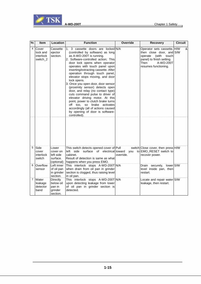
No. Item Location Function Override Recovery Circuit
4 Coverlock andinterlockswitch_2
Cassetteejectorsection.
1. 3 cassette doors are locked(controlled by software) as longas A-WD-200T is running.
2. Software-controlled action; Thisdoor lock opens when operatoroperates with touch panel uponinserting/extracting cassette. Afteroperation through touch panel,elevator stops moving, and doorlock opens.
3. Once you open door, door sensor(proximity sensor) detects opendoor, and relay (no contact type)cuts command pulse to driver ofelevator driving motor. At thispoint, power to clutch brake turnsoff too, so brake activatesaccordingly (all of actions causedby opening of door is software-controlled).
N/A Operator sets cassette,then close door, andoperate (with touchpanel) to finish setting.Then A-WD-200Tresumes functioning.
H/W &S/W
5 Sidecoverinterlockswitch
Lowercover onleft sidesurface.(optional)
This switch detects opened cover ofleft side surface of electricalcabinet.Result of detection is same as whathappens when you press EMO.
Pull switchtoward you tooverride.
Close cover, then pressEMO_RESET switch torecover power.
H/W
6 Overflowsensor
Left innerof oil panin grindersection.
This interlock stops A-WD-200Twhen drain from oil pan in grindersection is clogged, thus raising levelin oil pan.
N/A Drain securely, lowerlevel inside pan, thenrestart.
S/W
7 Waterleakagedetectorband
Directlybelow oilpan ingrindersection.
This interlock stops A-WD-200Tupon detecting leakage from lowerof oil pan in grinder section isdetected.
N/A Locate and repair waterleakage, then restart.
S/W
A-WD-200T Chapter 1 Safety
1-16
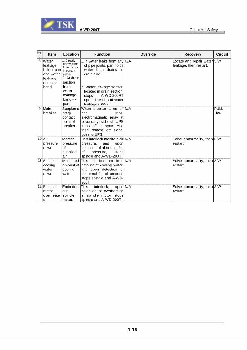
No. Item Location Function Override Recovery Circuit8 Water
leakageholder panand waterleakagedetectorband
1. Directlybelow jointsfrom pan ->importantpipes.2. At drainsectionfromwaterleakageband ->pan.
1. If water leaks from anyof pipe joints, pan holdswater then drains todrain side.
2. Water leakage sensor,located in drain section,stops A-WD-200RTupon detection of waterleakage.(S/W)
N/A Locate and repair waterleakage, then restart.
S/W
9 Mainbreaker
Supplementarycontactpoint ofbreaker.
When breaker turns offand trips,electromagnetic relay atsecondary side of UPSturns off in sync. Andthen remote off signalgoes to UPS.
N/A FULLH/W
10 Airpressuredown
Masterpressureofsuppliedair.
This interlock monitors airpressure, and upondetection of abnormal fallof pressure, stopsspindle and A-WD-200T.
N/A Solve abnormality, thenrestart.
S/W
11 Spindlecoolingwaterdown
Monitoredamount ofcoolingwater.
This interlock monitorsamount of cooling water,and upon detection ofabnormal fall of amount,stops spindle and A-WD-200T.
N/A Solve abnormality, thenrestart.
S/W
12 Spindlemotoroverheated
Embedded inspindlemotor.
This interlock, upondetection of overheatingin spindle motor, stopsspindle and A-WD-200T.
N/A Solve abnormality, thenrestart.
S/W
A-WD-200T Chapter 1 Safety
1-17
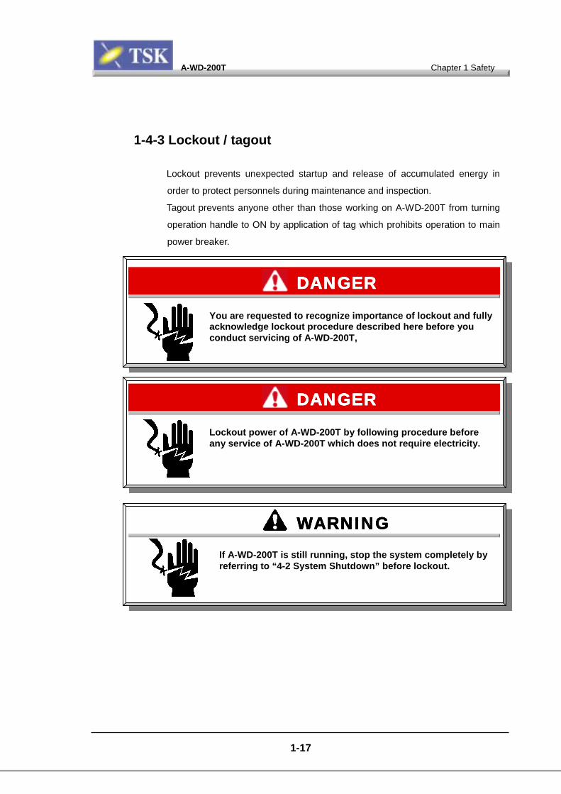
1-4-3 Lockout / tagout
Lockout prevents unexpected startup and release of accumulated energy in
order to protect personnels during maintenance and inspection.
Tagout prevents anyone other than those working on A-WD-200T from turning
operation handle to ON by application of tag which prohibits operation to main
power breaker.
You are requested to recognize importance of lockout and fullyacknowledge lockout procedure described here before youconduct servicing of A-WD-200T,
DANGERDANGERDANGERDANGER
Lockout power of A-WD-200T by following procedure beforeany service of A-WD-200T which does not require electricity.
DANGERDANGERDANGERDANGER
WARNINGWARNINGWARNINGWARNINGIf A-WD-200T is still running, stop the system completely byreferring to “4-2 System Shutdown” before lockout.

A-WD-200T Chapter 1 Safety
1-18
• Lockout / tagout procedure
Shutdown main power by rotating
handle of main breaker (on left side
surface of A-WD-200T) to [O] off side.
WARNINGWARNINGWARNINGWARNINGIn any case more than one workers do service of A-WD-200Ttogther at the same time, appoint a "supervisor" whosupervises all of such workers.Supervisor is requested to be aware of working status all thetime, and to play unique role in lockout procedure.
A-WD-200T Chapter 1 Safety
1-19
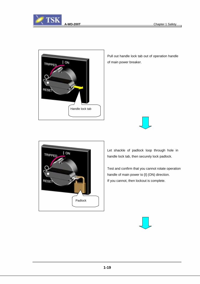
Pull out handle lock tab out of operation handle
of main power breaker.
Let shackle of padlock loop through hole in
handle lock tab, then securely lock padlock.
Test and confirm that you cannot rotate operation
handle of main power to [I] (ON) direction.
If you cannot, then lockout is complete.
Handle lock tab
Padlock
A-WD-200T Chapter 1 Safety
1-20
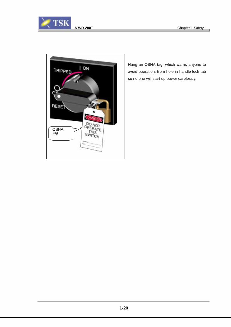
Hang an OSHA tag, which warns anyone to
avoid operation, from hole in handle lock tab
so no one will start up power carelessly.
OSHAtag
A-WD-200T Chapter 1 Safety
1-21
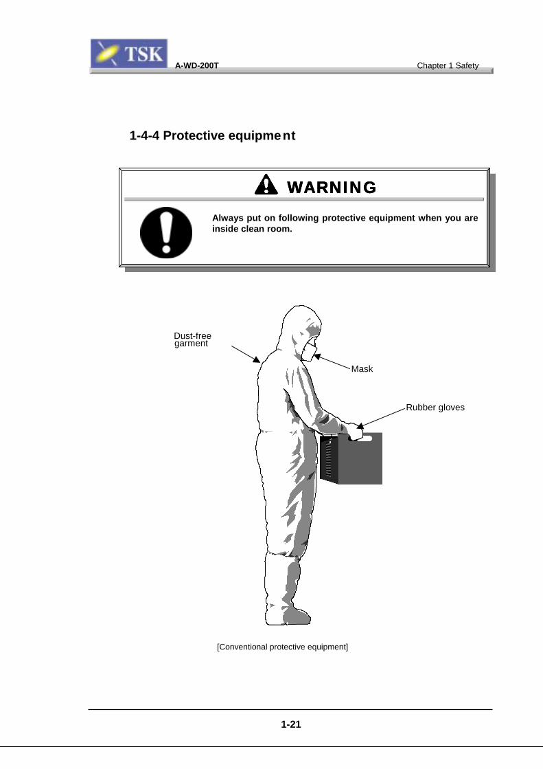
1-4-4 Protective equipment
Dust-freegarment
Mask
Rubber gloves
WARNINGWARNINGWARNINGWARNINGAlways put on following protective equipment when you areinside clean room.
[Conventional protective equipment]
A-WD-200T Chapter 1 Safety
1-
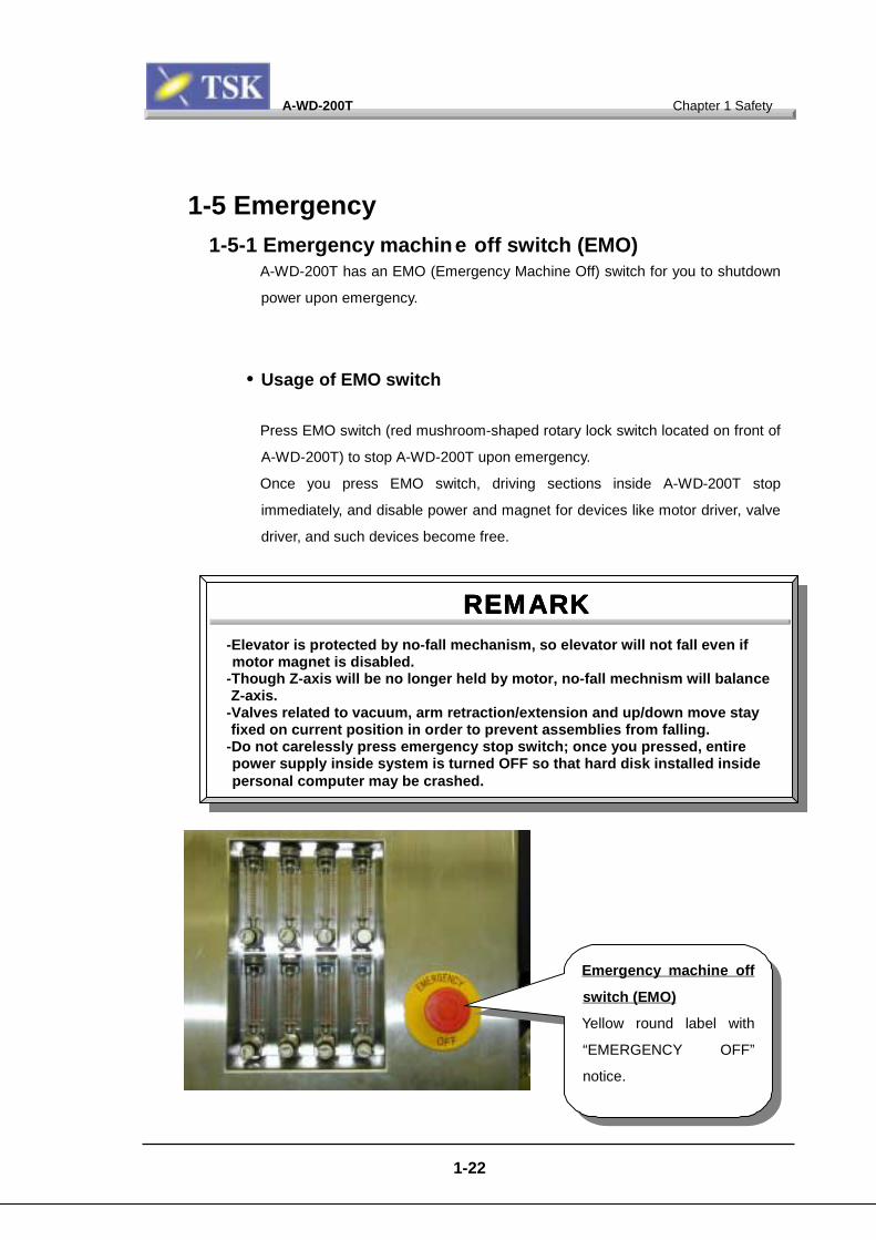
1-5 Emergency1-5-1 Emergency machine off switch (EMO)
A-WD-200T has an EMO (Emergency Machine Off) switch for you to shutdown
power upon emergency.
• Usage of EMO switch
Press EMO switch (red mushroom-shaped rotary lock switch located on front of
A-WD-200T) to stop A-WD-200T upon emergency.
Once you press EMO switch, driving sections inside A-WD-200T stop
immediately, and disable power and magnet for devices like motor driver, valve
driver, and such devices become free.
-Elevator is protected by no-fall memotor magnet is disabled.
-Though Z-axis will be no longer hZ-axis.
-Valves related to vacuum, arm retfixed on current position in order
-Do not carelessly press emergencpower supply inside system is turpersonal computer may be crashe
RRRR
EMARKEMARKEMARKEMARK22
chanism, so elevator will not fall even if
eld by motor, no-fall mechnism will balance
raction/extension and up/down move stayto prevent assemblies from falling.y stop switch; once you pressed, entirened OFF so that hard disk installed insided.
Emergency machine off
switch (EMO)
Yellow round label with
“EMERGENCY OFF”
notice.
A-WD-200T Chapter 1 Safety
1-23
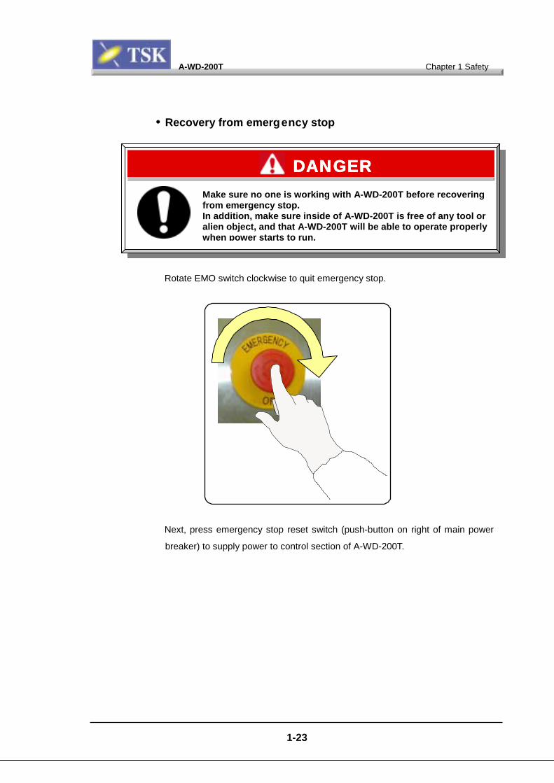
• Recovery from emergency stop
Rotate EMO switch clockwise to quit emergency stop.
Next, press emergency stop reset switch (push-button on right of main power
breaker) to supply power to control section of A-WD-200T.
Make sure no one is working with A-WD-200T before recoveringfrom emergency stop.In addition, make sure inside of A-WD-200T is free of any tool oralien object, and that A-WD-200T will be able to operate properlywhen power starts to run.
DANGERDANGERDANGERDANGER
A-WD-200T Chapter 1 Safety
1-24
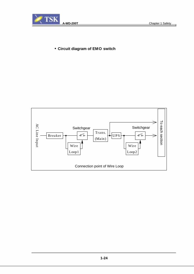
• Circuit diagram of EMO switch
Connection point of Wire Loop
Switchgear
Wire
Loop1
Trans.
(Main)Breaker
Switchgear
Wire
Loop2
UPS
To each section
AC
Lin
e Inpu
t

A-WD-200T Chapter 1 Safety
1-25
Pow
er
Conn
ecto
rM
ain
Bre
aker
EL
Bre
aker
Nois
eFilt
er
Mag
netic
Rela
y
CN
CN
CN
CN 1 111
QF
QF
QF
QF 1 111
QF
QF
QF
QF 2 222
NF
NF
NF
NF 1 111
KM
KM
KM
KM 1 111
UP
SU
PS
UP
SU
PS
KM
KM
KM
KM 3 333
Min
iTra
ns2
AC100Vin
AC100Vout
KM
KM
KM
KM 2 222
CB1
CB1
CB1
CB1
0.5
A0.5
A0.5
A0.5
A
CB
CB
CB
CB 4 444 5A
5A5A
5A
TC
2TC
2TC
2TC
2
TC1
TC1
TC1
TC1
Mai
nTra
ns
CB
CB
CB
CB 3 333
30A
30A
30A
30A
CB
CB
CB
CB 6 666 1A
1A1A
1A
CB
CB
CB
CB 7 777 5A
5A5A
5A
Wire L
oop 1
Wire L
oop
2
Min
iTra
ns1
TC
3TC
3TC
3TC
3
AC100VoutAC100Vout
3phaseACin
ACin
AC24Vout
ACin
AC24Vout
AC24Vout
AC24Vin
AC24Vin
AC24Vout AC24Vout
Mag
netic
Rela
y
Mag
netic
Rela
y
ACin3phase
200V/220V/380V/415V
AC100V
SU
PPLY1
AC100V
SU
PPLY2

A-WD-200T Chapter 1 Safety
1-26
WireLoop1
SwitchgearKM1AC24V-H1
AC24V-N1
RL35
RL42
Latch
EMO event
contact1
EMO Reset
In standard specification, EMO event means:
1. EMO switch
2. FAN sensor
WireLoop2
SwitchgearKM3
AC24V-H2
AC24V-N2
RL36
Latch
EMO Reset
KM2
RL44
RL45
RL37 JP8
JP7
RL31
RL38
RL32
RL43
+24V_MTR1
RL-UPS-off
RL43=Timer Relay
EMO event
contact2
Switchgear

A-WD-200T Chapter 1 Safety
1-27
1-5-2 Emergency countermeasure• Bodily accident
Once any personal bodily accident occur when A-WD-200T is operating, act as
follows.
Once you spot the accident, inform nearby personnels at once.
Remove suffering person to safe place and give proper medical treatment.
1. Press EMO switch.
2. Confirm that power is shut down, and all driving sections are stopped.
3. Those responsible for the work hear details of accident from those who were
doing work at the time of accident, and find out circumstance and cause of
accident.
4. Those responsible for the work report us details of the accident.
5. Extinguish fire using fire extinguisher for chemicals.
6. Worker’s responsibility should contact us.
Once any accident occurs while A-WD-200T is running, pressEMO switch immediately to stop A-WD-200T in order to preventsecondary hazard.
DANGERDANGERDANGERDANGER
WARNINGWARNINGWARNINGWARNINGPlease do not fail to report us details of any accident,regardless of size or cause.
A-WD-200T Chapter 1 Safety
1-28
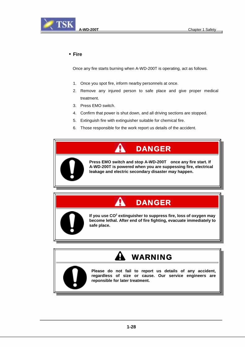
• Fire
Once any fire starts burning when A-WD-200T is operating, act as follows.
1. Once you spot fire, inform nearby personnels at once.
2. Remove any injured person to safe place and give proper medical
treatment.
3. Press EMO switch.
4. Confirm that power is shut down, and all driving sections are stopped.
5. Extinguish fire with extinguisher suitable for chemical fire.
6. Those responsible for the work report us details of the accident.
Press EMO switch and stop A-WD-200T once any fire start. IfA-WD-200T is powered when you are suppessing fire, electricalleakage and electric secondary disaster may happen.
DANGERDANGERDANGERDANGER
WARNINGWARNINGWARNINGWARNINGPlease do not fail to report us details of any accident,regardless of size or cause. Our service engineers arereponsible for later treatment.
If you use CO2 extinguisher to suppress fire, loss of oxygen maybecome lethal. After end of fire fighting, evacuate immediately tosafe place.
DANGERDANGERDANGERDANGER

A-WD-200T Chapter 1 Safety
1-29
• Earthquake
Once any earthquake happens when A-WD-200T is operating, act as follows.
1 Press EMO switch.
2. Remove any injured person to safe place and give proper medical
treatment.
3. Those who were responsible for the work should guide every working
personnels to safe place according to standard at your side.
4. Once chance for next earthquake is presumably none and resume of
operation with A-WD-200T is considered possible, check following.
- Damage to A-WD-200T.
- Anything that fell nearby or inside A-WD-200T.
- Utility connection and condition of piping.
- Any abnormality in power supply.
5. If you spot any abnormality during these checks, contact us. Our service
engineers treat such abnormality accordingly.
Do NOT approach A-WD-200T until earthquake is over for sure.
DANGERDANGERDANGERDANGER
A-WD-200T Chapter 1 Safety
• Power failure
Once power fails when A-WD-200T is operating, act as follows.
1. Confirm power supply to primary and secondary side is active.
2. Confirm absence of abnormality, then restart the system by referring to
Chapter 4 4-1 Startup in operation manual.
A-WD-200T equipped with uninstatus as long as effect of powOtherwies, interlock activates,
1-30
terruptible power supply (UPS) retains runninger failure was up to secondary side or less.and escape action ensues.
IMPORTANTIMPORTANTIMPORTANTIMPORTANT
A-WD-200T Chapter 1 Safety
1-31
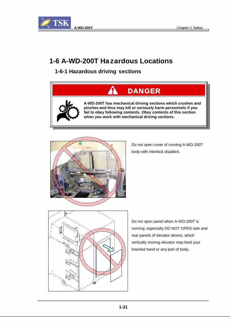
1-6 A-WD-200T Hazardous Locations1-6-1 Hazardous driving sections
A-WD-200T has mechanpinches and thus may kfail to obey following cowhen you work with mec
Do not open cover of running A-WD-200T
body with interlock disabled.
Do not open panel when A-WD-200T is
running; especially DO NOT OPEN side and
rear panels of elevator device, which
vertically moving elevator may bind your
inserted hand or any part of body.
ical driving sections which crushes andill or seriously harm personnels if yountents. Obey contents of this sectionhanical driving sections.
DANGERDANGERDANGERDANGER
A-WD-200T Chapter 1 Safety
1-32
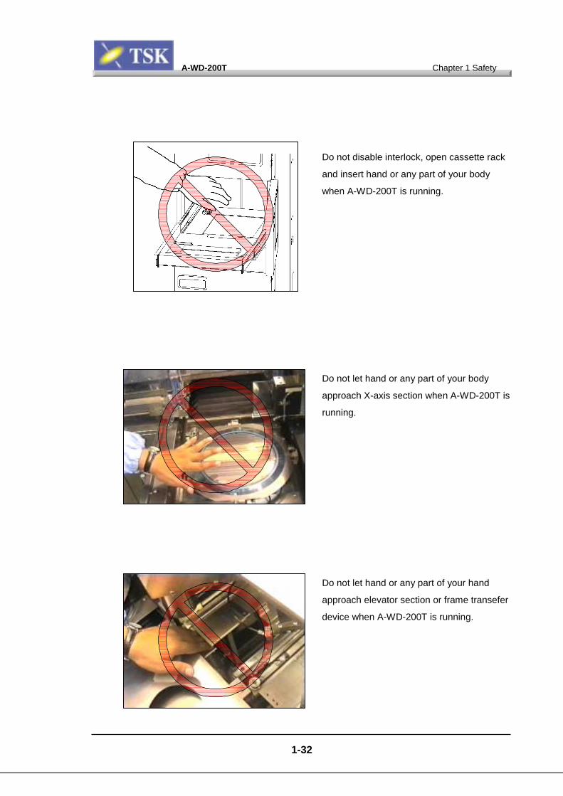
Do not disable interlock, open cassette rack
and insert hand or any part of your body
when A-WD-200T is running.
Do not let hand or any part of your body
approach X-axis section when A-WD-200T is
running.
Do not let hand or any part of your hand
approach elevator section or frame transefer
device when A-WD-200T is running.

A-WD-200T Chapter 1 Safety
1-33
Do not let hand or any part of your hand
approach shutter section or spinner section
when A-WD-200T is running.
Do not insert your hand or body into Y-axial
section when A-WD-200T is running.
Do not insert your hand or body into Z-axial
section when A-WD-200T is running.
A-WD-200T Chapter 1 Safety
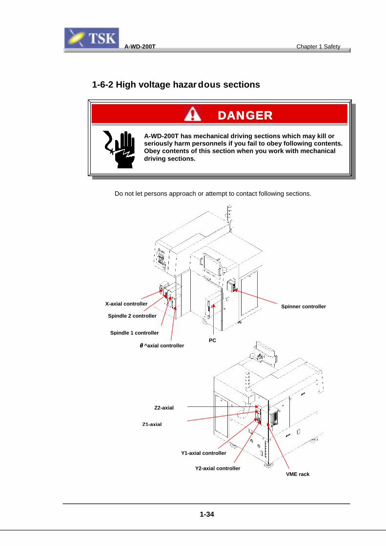
1-6-2 High voltage hazardous sections
Do not let persons approach or attempt to contact following sections.
A-WD-200T has mechanical driving sections which may kill orseriously harm personnels if you fail to obey following contents.Obey contents of this section when you work with mechanicaldriving sections.
DANGERDANGERDANGERDANGER
X-axial controller
S
pindle 2 controllerS
pindle 1 controllerθθ
θθ^axial controller1-3
Z
Z1-axial
Y
Y
PC
4
Spinner controller
2-axial
1-axial controller
2-axial controller
V ME rack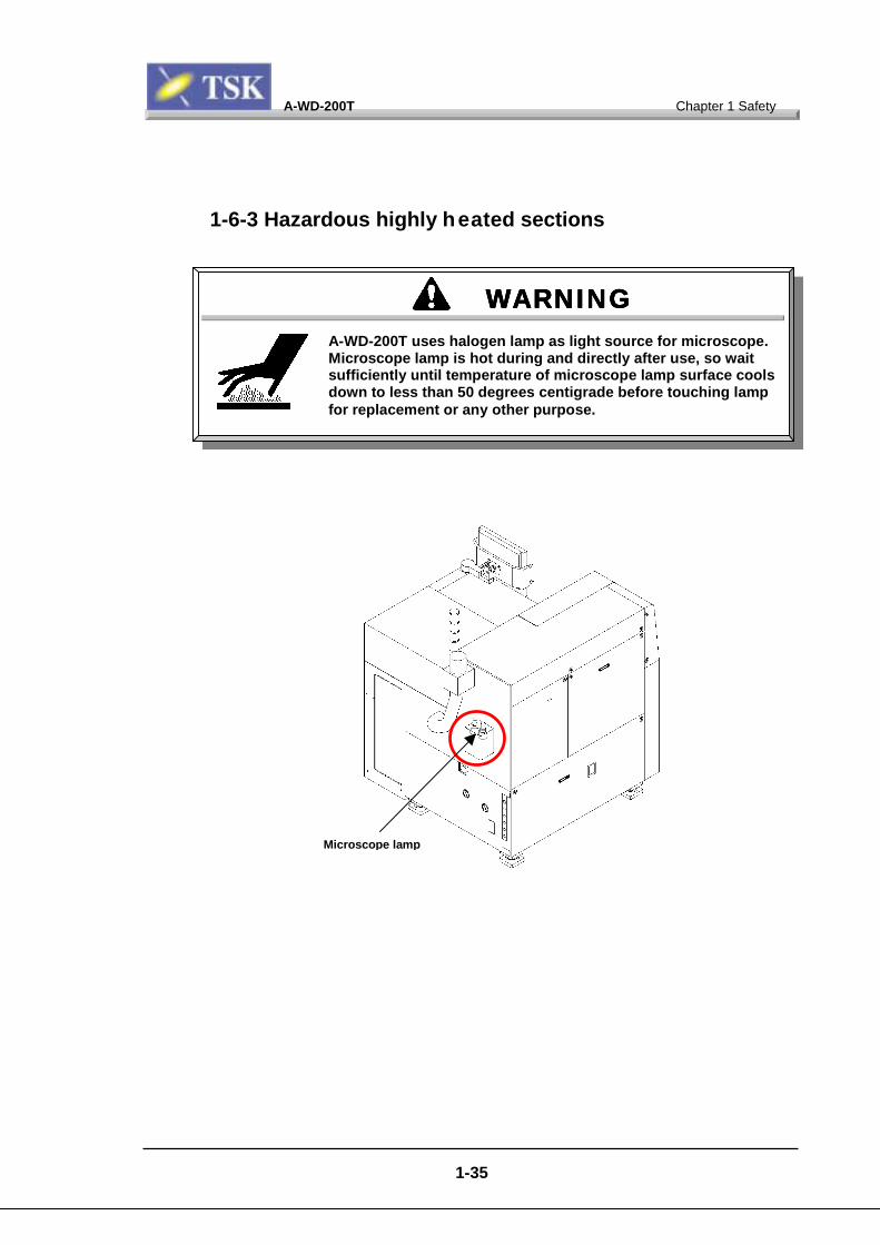
A-WD-200T Chapter 1 Safety
1-6-3 Hazardous highly heated sections
M
WARNINGWARNINGWARNINGWARNINGA-WD-200T uses halogen lamp as light source for microscope.Microscope lamp is hot during and directly after use, so waitsufficiently until temperature of microscope lamp surface coolsdown to less than 50 degrees centigrade before touching lampfor replacement or any other purpose.
icroscope lamp
1-35
Chapter 2 Configuration andCalibration
A-WD-200TA-WD-200TA-WD-200TA-WD-200T Chapter 2Chapter 2Chapter 2Chapter 2 Configuration and CalibrationConfiguration and CalibrationConfiguration and CalibrationConfiguration and Calibration
2-1111
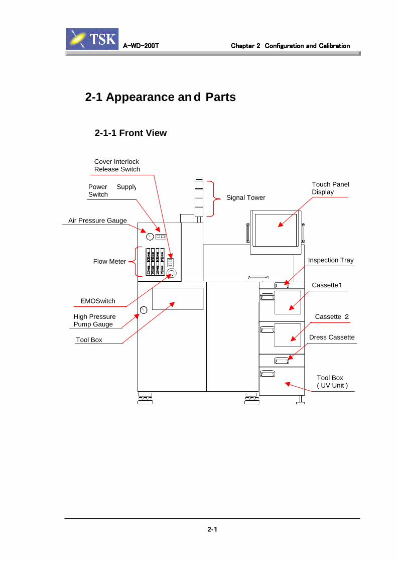
2-1 Appearance an d Parts
2-1-1 Front View
Flow Meter
EMOSwitch
Air Pressure Gauge
Power SupplySwitch
Touch PanelDisplay
Inspection Tray
Cassette1
Cassette 2
Dress CassetteTool Box
High PressurePump Gauge
Tool Box( UV Unit )
Cover InterlockRelease Switch
Signal Tower

A-WD-200TA-WD-200TA-WD-200TA-WD-200T Chapter 2Chapter 2Chapter 2Chapter 2 Configuration and CalibrationConfiguration and CalibrationConfiguration and CalibrationConfiguration and Calibration
2-2222
2-1-2 Left View
Signal Tower
Main Breaker
Exhaust DuctEMO Reset Switch
UPSSwitch & Indicator

A-WD-200TA-WD-200TA-WD-200TA-WD-200T Chapter 2Chapter 2Chapter 2Chapter 2 Configuration and CalibrationConfiguration and CalibrationConfiguration and CalibrationConfiguration and Calibration
2-3333
2-1-3 Right View
Cover InterlockMechanical Switch
Signal Tower
Touch PanelDisplay
A-WD-200TA-WD-200TA-WD-200TA-WD-200T Chapter 2Chapter 2Chapter 2Chapter 2 Configuration and CalibrationConfiguration and CalibrationConfiguration and CalibrationConfiguration and Calibration
2-4444
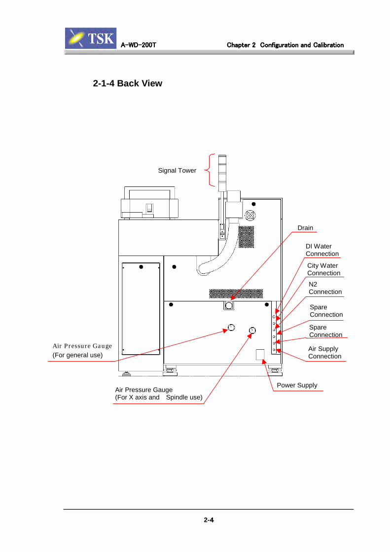
2-1-4 Back View
Signal Tower
DI WaterConnection
City WaterConnection
N2Connection
SpareConnection
SpareConnection
Air SupplyConnection
Drain
Power SupplyAir Pressure Gauge(For X axis and Spindle use)
Air Pressure Gauge(For general use)

A-WD-200TA-WD-200TA-WD-200TA-WD-200T Chapter 2Chapter 2Chapter 2Chapter 2 Configuration and CalibrationConfiguration and CalibrationConfiguration and CalibrationConfiguration and Calibration
2-5555
2-1-5 Top View
Loader Cover (Front)
Loader Cover (Rear)
Touch PanelDisplay
Exhaust Duct
Spindle Cover
A-WD-200TA-WD-200TA-WD-200TA-WD-200T Chapter 2Chapter 2Chapter 2Chapter 2 Configuration and CalibrationConfiguration and CalibrationConfiguration and CalibrationConfiguration and Calibration
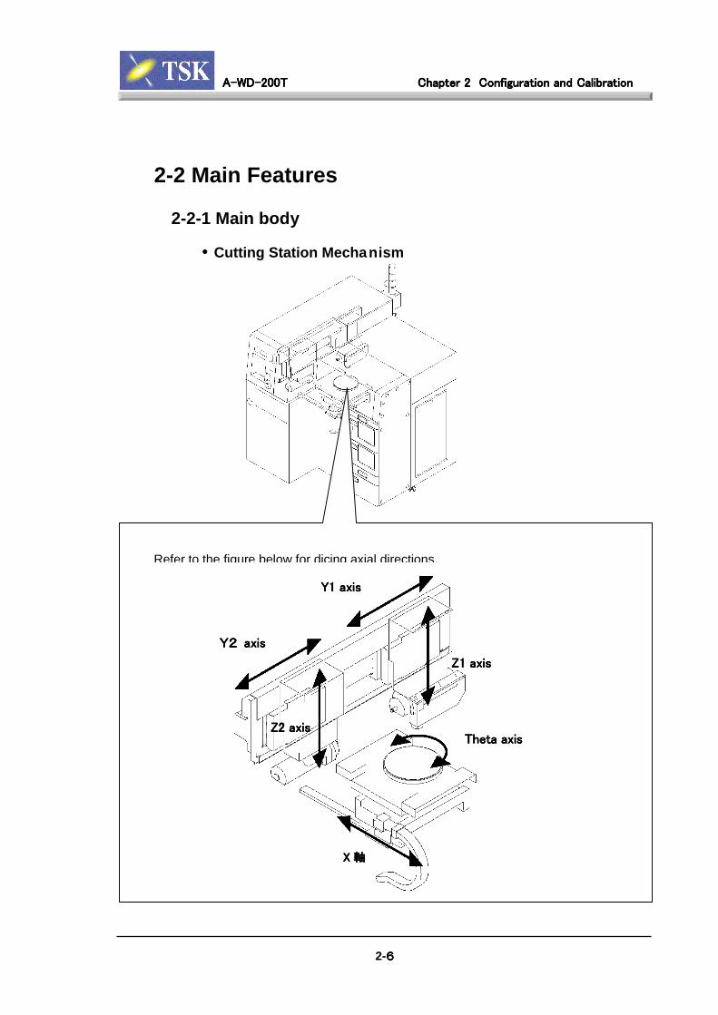
2-2 Main Features
2-2-1 Main body
• Cutting Station Mechanism
Refer to the figure below for dicing axial directions.
2-6666
XXXX 軸軸軸軸
Theta axisTheta axisTheta axisTheta axis
Y1 axisY1 axisY1 axisY1 axis
Z1 axisZ1 axisZ1 axisZ1 axis
Z2 axisZ2 axisZ2 axisZ2 axis
Y2Y2Y2Y2 axis axis axis axis
A-WD-200TA-WD-200TA-WD-200TA-WD-200T Chapter 2Chapter 2Chapter 2Chapter 2 Configuration and CalibrationConfiguration and CalibrationConfiguration and CalibrationConfiguration and Calibration
2-7777
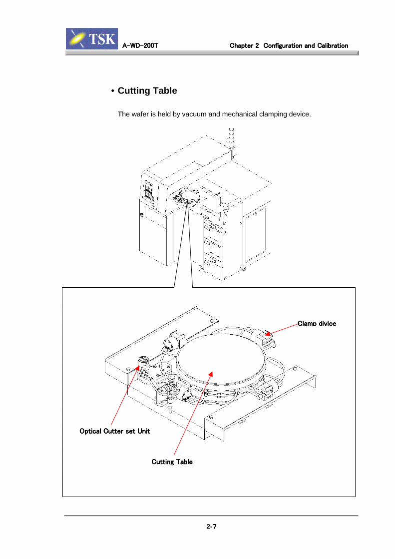
• Cutting Table
The wafer is held by vacuum and mechanical clamping device.
Optical Cutter set UnitOptical Cutter set UnitOptical Cutter set UnitOptical Cutter set Unit
Cutting TableCutting TableCutting TableCutting Table
Clamp Clamp Clamp Clamp divicedivicedivicedivice

A-WD-200TA-WD-200TA-WD-200TA-WD-200T Chapter 2Chapter 2Chapter 2Chapter 2 Configuration and CalibrationConfiguration and CalibrationConfiguration and CalibrationConfiguration and Calibration
2-8888
• X Axis
The X-axis of the cutting table is a carrier mechanism moving in the
alignment and cutting directions driven by linear motor.
A-WD-200TA-WD-200TA-WD-200TA-WD-200T Chapter 2Chapter 2Chapter 2Chapter 2 Configuration and CalibrationConfiguration and CalibrationConfiguration and CalibrationConfiguration and Calibration
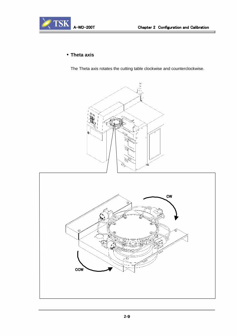
• Theta axis
The Theta axis rotates the cutting table clockwise and counterclockwise.
CWCWCWCW
CCWCCWCCWCCW
2-9999

A-WD-200TA-WD-200TA-WD-200TA-WD-200T Chapter 2Chapter 2Chapter 2Chapter 2 Configuration and CalibrationConfiguration and CalibrationConfiguration and CalibrationConfiguration and Calibration
• Y1-axis, Y2-axis
Each Y1-axis and Y2-axis moves the spindle back and forth individually,
driven by stepping motor.
Spindle unit located rear side called Y1, and that in front side called Y2.
Y1-axisY1-axisY1-axisY1-axis
Y2-axisY2-axisY2-axisY2-axis
2-10101010

A-WD-200TA-WD-200TA-WD-200TA-WD-200T Chapter 2Chapter 2Chapter 2Chapter 2 Configuration and CalibrationConfiguration and CalibrationConfiguration and CalibrationConfiguration and Calibration
2-11111111
• Z1-axis, Z2-axis
Move the spindles up and down.
The unit located rear side called Z1, and that in front side called Z2.
Stepping MotorStepping MotorStepping MotorStepping Motor
Linear GuideLinear GuideLinear GuideLinear Guide
Z1-axisZ1-axisZ1-axisZ1-axis
Z2-axisZ2-axisZ2-axisZ2-axis

A-WD-200TA-WD-200TA-WD-200TA-WD-200T Chapter 2Chapter 2Chapter 2Chapter 2 Configuration and CalibrationConfiguration and CalibrationConfiguration and CalibrationConfiguration and Calibration
2-12121212
• Spindles (SP1 and SP 2)
The spindles are powered with a brushless DC motor that rotates dicing blade in
a high speed. Spindle 1 is in the back. Spindle 2 is in the front.
Blade
Blade Cooling Water N
Cutting Water Nozzle ozzleCleaningWater Nozzle
Flange Cover
Blade Breakage Detector
Spindle 1
Spindle 2

A-WD-200TA-WD-200TA-WD-200TA-WD-200T Chapter 2Chapter 2Chapter 2Chapter 2 Configuration and CalibrationConfiguration and CalibrationConfiguration and CalibrationConfiguration and Calibration
2-13131313
• Microscope(CCD Camera)
The microscope camera captures the image used for automatic wafer alignment
and kerf check functions.
Viewer Air
Camera Blow Air
Microscope Unit

A-WD-200TA-WD-200TA-WD-200TA-WD-200T Chapter 2Chapter 2Chapter 2Chapter 2 Configuration and CalibrationConfiguration and CalibrationConfiguration and CalibrationConfiguration and Calibration
2-14141414
• Pre-Cleaning Unit
During cutting, the shutter is closed. The nozzle on the bottom side of the
shutter sprays water and/or air to clean sawing dust from the topside of the
wafer.
Shutter
Water Nozzle
Air Nozzle
A-WD-200TA-WD-200TA-WD-200TA-WD-200T Chapter 2Chapter 2Chapter 2Chapter 2 Configuration and CalibrationConfiguration and CalibrationConfiguration and CalibrationConfiguration and Calibration
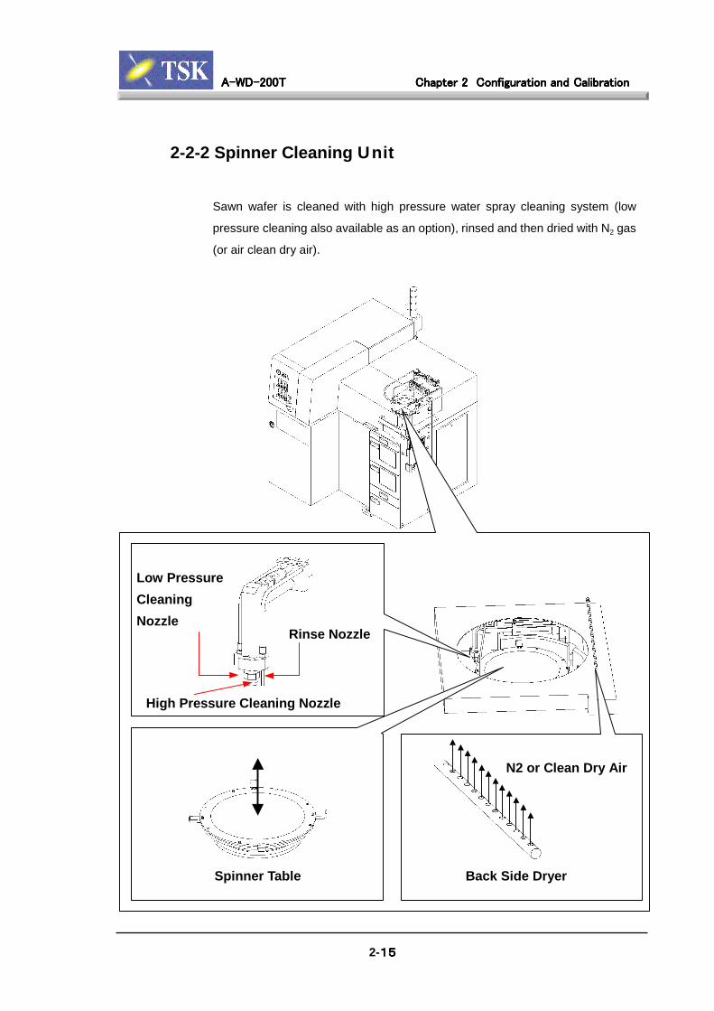
2-2-2 Spinner Cleaning Unit
Sawn wafer is cleaned with high pressure water spray cleaning system (low
pressure cleaning also available as an option), rinsed and then dried with N2 gas
(or air clean dry air).
Low PressureCleaningNozzle
2-15151515
Spinner Table Back Side Dryer
N2 or Clean Dry Air
Rinse Nozzle
High Pressure Cleaning Nozzle
A-WD-200TA-WD-200TA-WD-200TA-WD-200T Chapter 2Chapter 2Chapter 2Chapter 2 Configuration and CalibrationConfiguration and CalibrationConfiguration and CalibrationConfiguration and Calibration
2-16161616
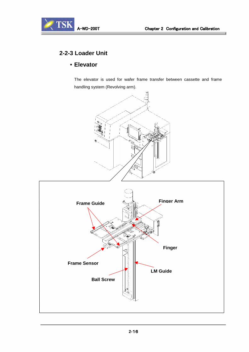
2-2-3 Loader Unit
• Elevator
The elevator is used for wafer frame transfer between cassette and frame
handling system (Revolving arm).
Frame Guide
Frame Sensor
Finger Arm
Finger
LM Guide
Ball Screw
A-WD-200TA-WD-200TA-WD-200TA-WD-200T Chapter 2Chapter 2Chapter 2Chapter 2 Configuration and CalibrationConfiguration and CalibrationConfiguration and CalibrationConfiguration and Calibration
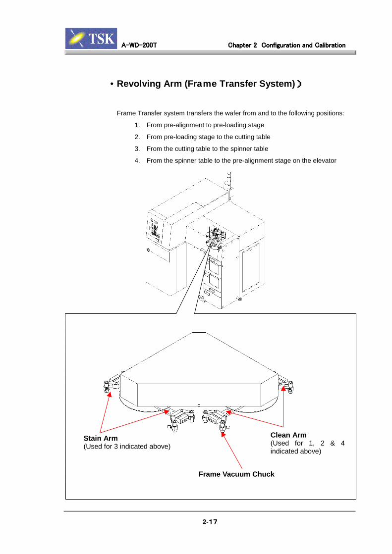
• Revolving Arm (Frame Transfer System)))))
Frame Transfer system transfers the wafer from and to the following positions:
1. From pre-alignment to pre-loading stage
2. From pre-loading stage to the cutting table
3. From the cutting table to the spinner table
4. From the spinner table to the pre-alignment stage on the elevator
Clean Arm(Used for 1, 2 & 4
S(
tain ArmUsed for 3 indicated above)
2-17171717
indicated above)
Frame Vacuum Chuck

A-WD-200TA-WD-200TA-WD-200TA-WD-200T Chapter 2Chapter 2Chapter 2Chapter 2 Configuration and CalibrationConfiguration and CalibrationConfiguration and CalibrationConfiguration and Calibration
• Cassette Rack
Cassette Rack is used to store the wafer cassettes before and after cutting.
Stores wafers for waferinspection or singlewafer cutting.
[C
assette 1 / 2][Inspection Tray]
Stores wafers for
Protection Bar
Base Sensor
Cassette Sensor
Cassette Guide
[Dress Cassette]
2-18181818
blade dressing.
A-WD-200TA-WD-200TA-WD-200TA-WD-200T Chapter 2Chapter 2Chapter 2Chapter 2 Configuration and CalibrationConfiguration and CalibrationConfiguration and CalibrationConfiguration and Calibration
2-19191919
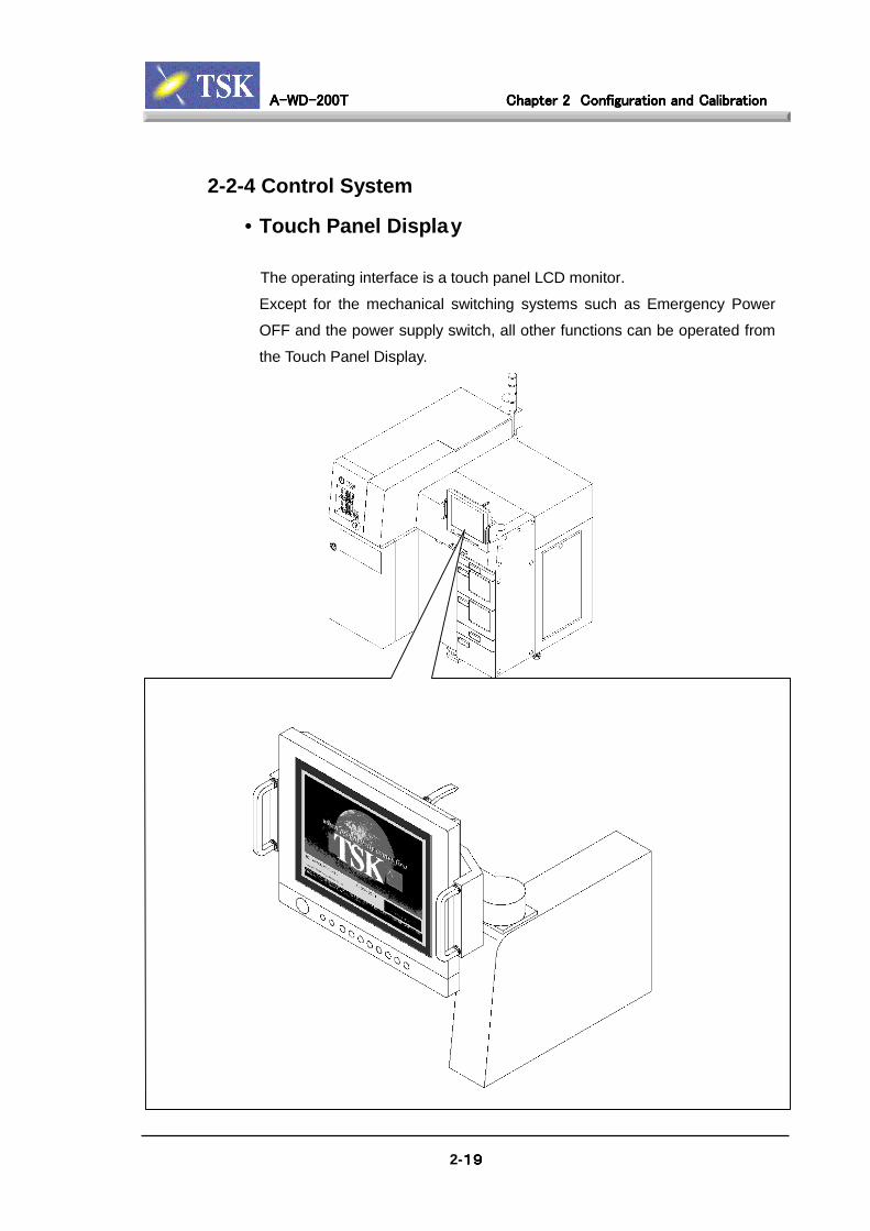
2-2-4 Control System
• Touch Panel Display
The operating interface is a touch panel LCD monitor.
Except for the mechanical switching systems such as Emergency Power
OFF and the power supply switch, all other functions can be operated from
the Touch Panel Display.
A-WD-200TA-WD-200TA-WD-200TA-WD-200T Chapter 2Chapter 2Chapter 2Chapter 2 Configuration and CalibrationConfiguration and CalibrationConfiguration and CalibrationConfiguration and Calibration
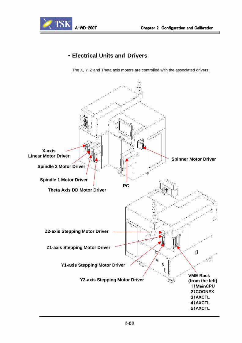
• Electrical Units and Drivers
The X, Y, Z and Theta axis motors are controlled with the associated drivers.
XLinear
Sp
S
-axisMotor Driver
2-20202020
Z2-axis Stepping Motor Driver
Y1-axis Stepping Motor Driver
Y2-axis Stepping Motor Driver
indle 2 Motor Driver
pindle 1 Motor Driver
Theta Axis DD Motor DriverPC
Spinner Motor Driver
VME Rack(from the left) 1)Main1)Main1)Main1)MainCPU 2)2)2)2)COGNEX 3)3)3)3)AXCTL 4)4)4)4)AXCTL 5)5)5)5)AXCTL
Z1-axis Stepping Motor Driver
A-WD-200TA-WD-200TA-WD-200TA-WD-200T Chapter 2Chapter 2Chapter 2Chapter 2 Configuration and CalibrationConfiguration and CalibrationConfiguration and CalibrationConfiguration and Calibration
2-21212121
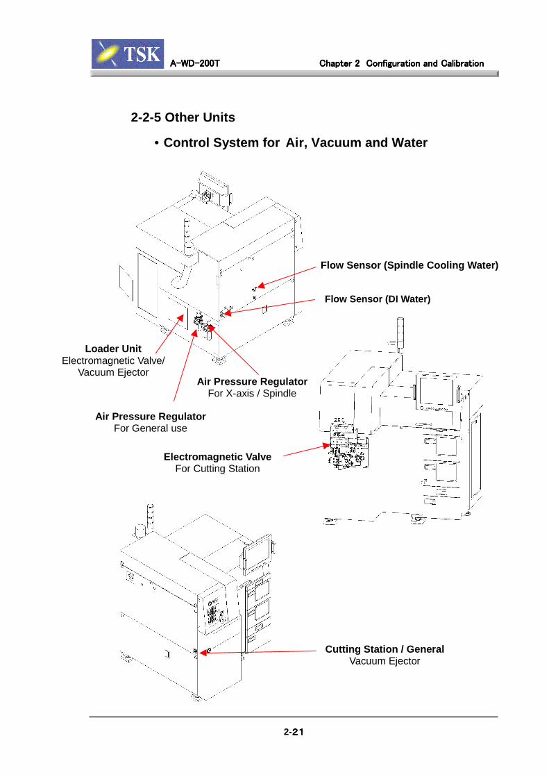
2-2-5 Other Units
• Control System for Air, Vacuum and Water
Air Pressure RegulatorFor X-axis / Spindle
Flow Sensor (DI Water)
Flow Sensor (Spindle Cooling Water)
Loader UnitElectromagnetic Valve/
Vacuum Ejector
Electromagnetic ValveFor Cutting Station
Cutting Station / GeneralVacuum Ejector
Air Pressure RegulatorFor General use

A-WD-200TA-WD-200TA-WD-200TA-WD-200T Chapter 2Chapter 2Chapter 2Chapter 2 Configuration and CalibrationConfiguration and CalibrationConfiguration and CalibrationConfiguration and Calibration
2-22222222
• PC Protection: (UPS)
The Uninterrupted Power Supply (UPS) device activates in the event of
power failure to ensure uninterrupted power to the controller and PC system.
Power Switch
Reset
Battery Check
Bypass
A-WD-200TA-WD-200TA-WD-200TA-WD-200T Chapter 2Chapter 2Chapter 2Chapter 2 Configuration and CalibrationConfiguration and CalibrationConfiguration and CalibrationConfiguration and Calibration
2-23232323
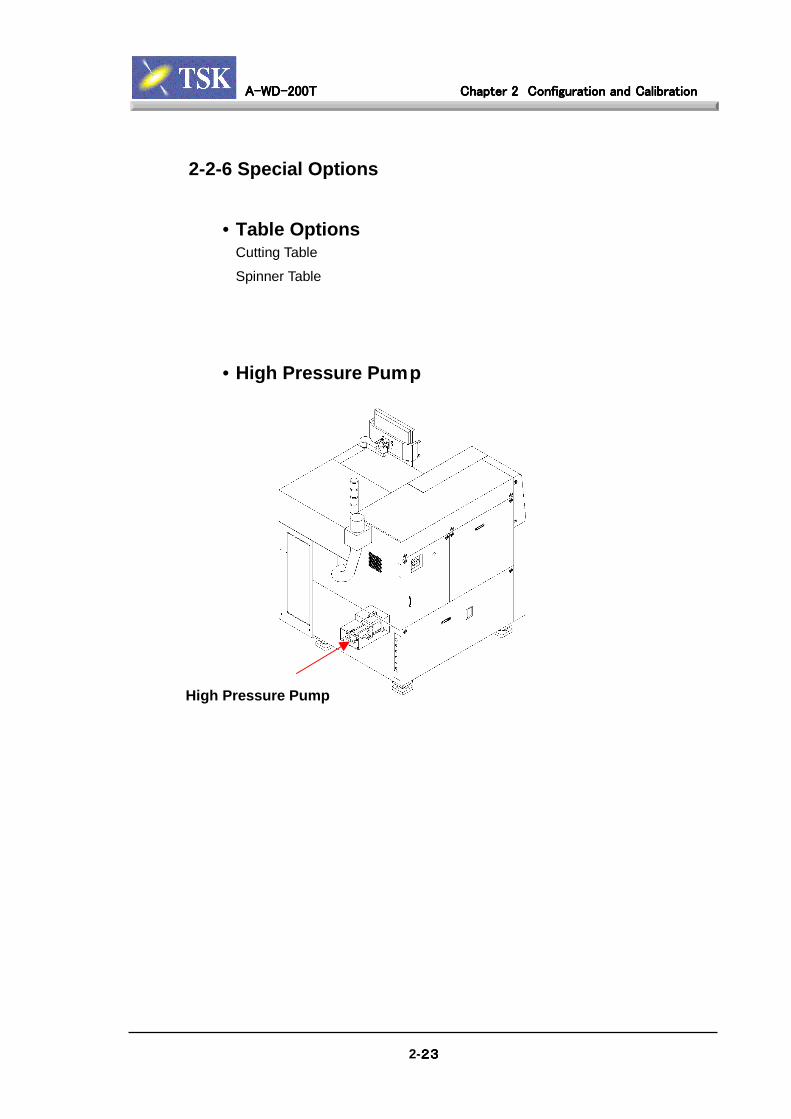
2-2-6 Special Options
• Table OptionsCutting Table
Spinner Table
• High Pressure Pump
High Pressure Pump

A-WD-200TA-WD-200TA-WD-200TA-WD-200T Chapter 2Chapter 2Chapter 2Chapter 2 Configuration and CalibrationConfiguration and CalibrationConfiguration and CalibrationConfiguration and Calibration
2-24242424
2-3 Calibration Preparation
2-3-1 Exterior Panel
The exterior cover panels are fixed in 2 methods.
Cover panels with key holes are fixed by a key locking system.
Others are fixed with bolts.
The vertical panels are held up with a support hook underneath the cover.
When installing, hook the cover onto the support hook at first.
Refer below for the name of some of the major cover panels.
Spindle Cover
Loader Cover
Rear Loader Cover
Front Cover A Front Cover C Front Cover B
Flow Gauge Panel
A-WD-200TA-WD-200TA-WD-200TA-WD-200T Chapter 2Chapter 2Chapter 2Chapter 2 Configuration and CalibrationConfiguration and CalibrationConfiguration and CalibrationConfiguration and Calibration
2-25252525
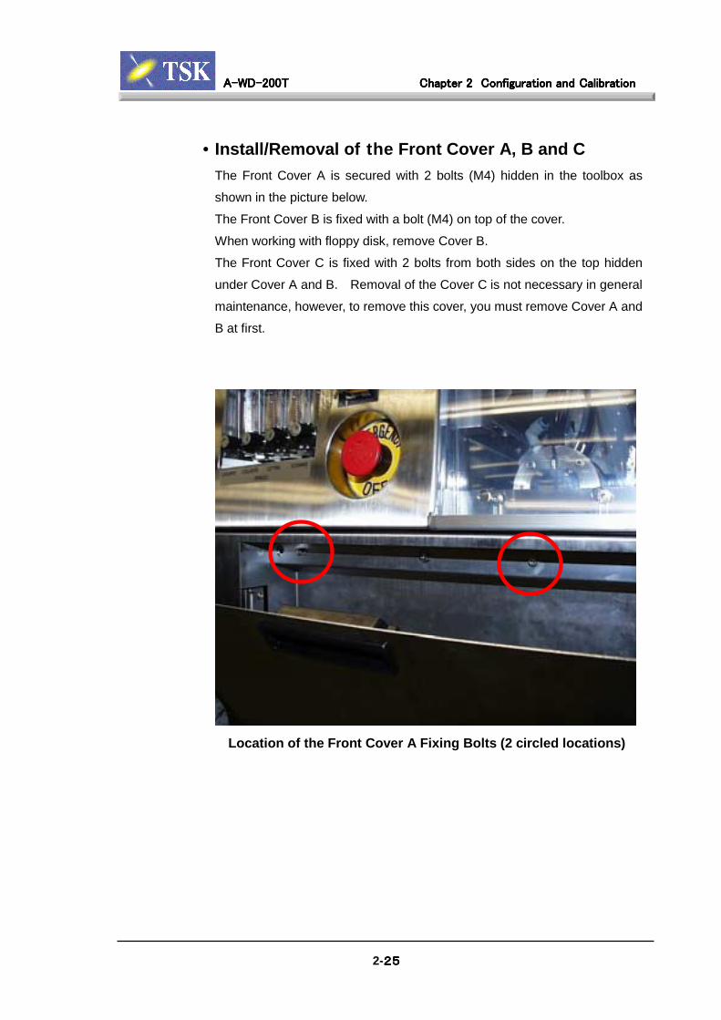
• Install/Removal of the Front Cover A, B and CThe Front Cover A is secured with 2 bolts (M4) hidden in the toolbox as
shown in the picture below.
The Front Cover B is fixed with a bolt (M4) on top of the cover.
When working with floppy disk, remove Cover B.
The Front Cover C is fixed with 2 bolts from both sides on the top hidden
under Cover A and B. Removal of the Cover C is not necessary in general
maintenance, however, to remove this cover, you must remove Cover A and
B at first.
Location of the Front Cover A Fixing Bolts (2 circled locations)

A-WD-200TA-WD-200TA-WD-200TA-WD-200T Chapter 2Chapter 2Chapter 2Chapter 2 Configuration and CalibrationConfiguration and CalibrationConfiguration and CalibrationConfiguration and Calibration
2-26262626
• Install/Removal of Keyed CoversCovers with a keyhole can be installed and removed by key. Insert the pointed
side of the key (tool) into the keyhole, continue pushing the key until you hear a
click, then the cover can be removed. The key tool can be used for handles to
carry covers. To remove the key, turn it over 90° and pull it out. It can not
remove without rotating for safety.
Key (Tool)
Insert the Key into the Keyhole

A-WD-200TA-WD-200TA-WD-200TA-WD-200T Chapter 2Chapter 2Chapter 2Chapter 2 Configuration and CalibrationConfiguration and CalibrationConfiguration and CalibrationConfiguration and Calibration
2-27272727
• Install/Removal of the Rear Loader CoverThe rear loader cover is fixed with 3 bolts (1 in the back, 2 in the front of the
machine). The bolts in the front are on the loader cover support frame (refer to
figure below).
To open the cover while the machine power is ON, you must release the
interlock at first. (Refer to next Chapter “2-3-2: Release Interlock” )
Location of Rear Loader cover Fixing Bolts in Front Side
A-WD-200TA-WD-200TA-WD-200TA-WD-200T Chapter 2Chapter 2Chapter 2Chapter 2 Configuration and CalibrationConfiguration and CalibrationConfiguration and CalibrationConfiguration and Calibration
2-28282828
2-3-2 Release Cover Interlock
For safety reason, the loader cover is locked while the machine is operating.
To open the cover while the machine is operating, release the interlock by
following the steps as follows.
When the interlock is released, the machine can be operated while the cover
is open. Hands or fingers must be kept out of axis to avoid injury. To
avoid serious injuries, make sure that the Emergency Power Off is always
able to access.
W A R N I N G
The machine can be operated while the loader cover is open if the coverinterlock is released. However, the interlock must remain untouchedunless it is necessary for maintenance work. During maintenance work,you must be fully responsible for your own safety. Please be aware thateach axis is able to operate individually, in case of operation error, it cancause damage to the machine. Service Engineers must have fullknowledge of the machine before performing any maintenance work.

A-WD-200TA-WD-200TA-WD-200TA-WD-200T Chapter 2Chapter 2Chapter 2Chapter 2 Configuration and CalibrationConfiguration and CalibrationConfiguration and CalibrationConfiguration and Calibration
2-29292929
1)1)1)1)Release Mechanical SwitchUse a screwdriver to turn the mechanical switch located at the upper right
front of the machine to UNLOCK position.
Cover Interlock Mechanical Switch (Right Side of the Machine)
2)2)2)2)Release Key and SwitchInsert the key into the keyhole on the front panel release switch, turn it 90°
counter clockwise (note that the key cannot be removed at this position).
Press the release switch button, interlock is deactivated when the button is
flashing. After work, turn the mechanical switch back to LOCK position.
Verify that the release switch is no longer flashing.
Release Key(Effective Position)
ReleaseSwitch
Interlock Release Key and Switch
A-WD-200T Chapter 2 Configuration and Calibration
2-30303030
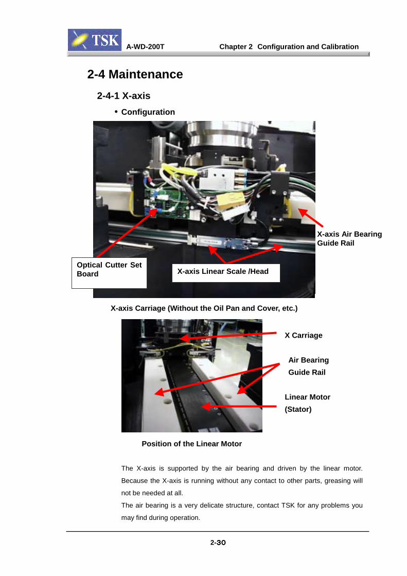
2-4 Maintenance2-4-1 X-axis
• Configuration
Optical Cutter SetBoard X-axis Linear Scale /Head
X-axis Air BearingGuide Rail
X-axis Carriage (Without the Oil Pan and Cover, etc.)
Position of the Linear Motor
The X-axis is supported by the air bearing and driven by the linear motor.
Because the X-axis is running without any contact to other parts, greasing will
not be needed at all.
The air bearing is a very delicate structure, contact TSK for any problems you
may find during operation.
Air BearingGuide Rail
Linear Motor(Stator)
X Carriage
A-WD-200T Chapter 2 Configuration and Calibration
2-31313131
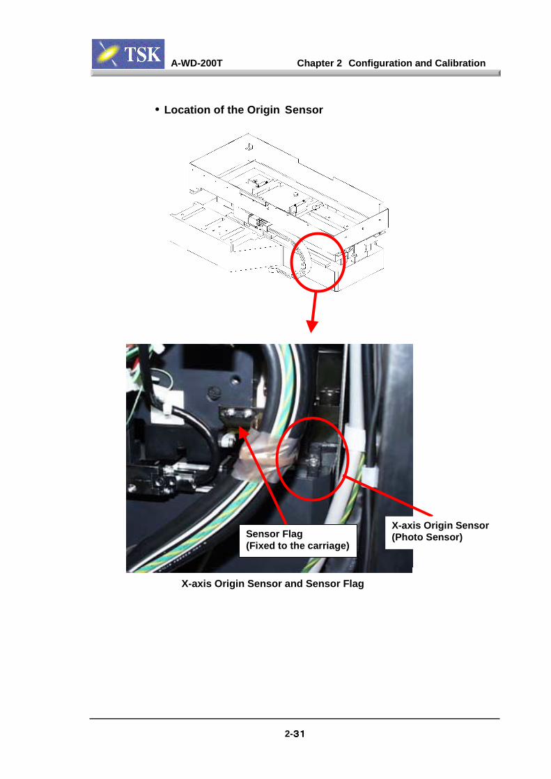
• Location of the Origin Sensor
X-axis Origin Sensor(Photo Sensor)Sensor Flag
(Fixed to the carriage)
X-axis Origin Sensor and Sensor Flag
A-WD-200T Chapter 2 Configuration and Calibration
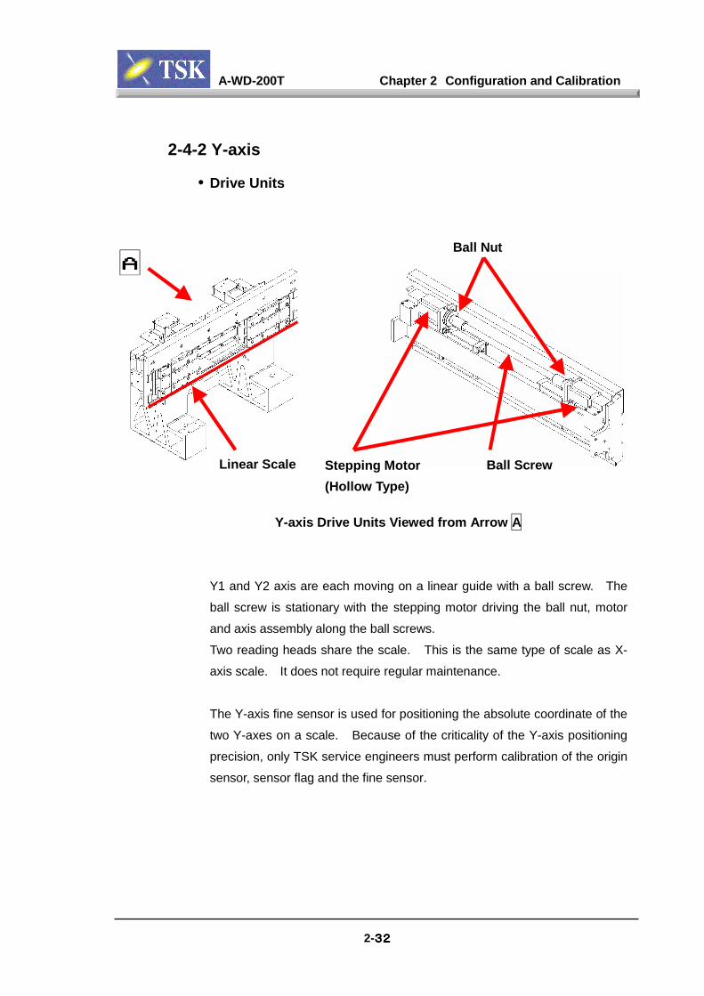
2-4-2 Y-axis
• Drive Units
Ball Nut
2-32323232
Y-axis Drive Units Viewed from Arrow A
Y1 and Y2 axis are each moving on a linear guide with a ball screw. The
ball screw is stationary with the stepping motor driving the ball nut, motor
and axis assembly along the ball screws.
Two reading heads share the scale. This is the same type of scale as X-
axis scale. It does not require regular maintenance.
The Y-axis fine sensor is used for positioning the absolute coordinate of the
two Y-axes on a scale. Because of the criticality of the Y-axis positioning
precision, only TSK service engineers must perform calibration of the origin
sensor, sensor flag and the fine sensor.
Stepping Motor(Hollow Type)
Ball Screw
AAAA
Linear Scale

A-WD-200T Chapter 2 Configuration and Calibration
2-33333333
• Sensor Locations
Origin Sensor Locations (Photo Shows Y1-axis Side)
Y-axis Fine Sensor
Origin Sensor(Photo Sensor)
Ball Screw
SteppingMotor
BBD RelayBoard
Sensor
Sensor(Head)

A-WD-200T Chapter 2 Configuration and Calibration
2-34343434
2-4-3 Z-axis
• Configuration and Sensors
Z-axis Origin Sensor Locations
Z-axis uses stepping motor with encoder to move the ball screw.
Stepping Motor(With Encoder)
Origin Sensor(Photo Sensor)
Sensor Flag
A-WD-200T Chapter 2 Configuration and Calibration
2-35353535
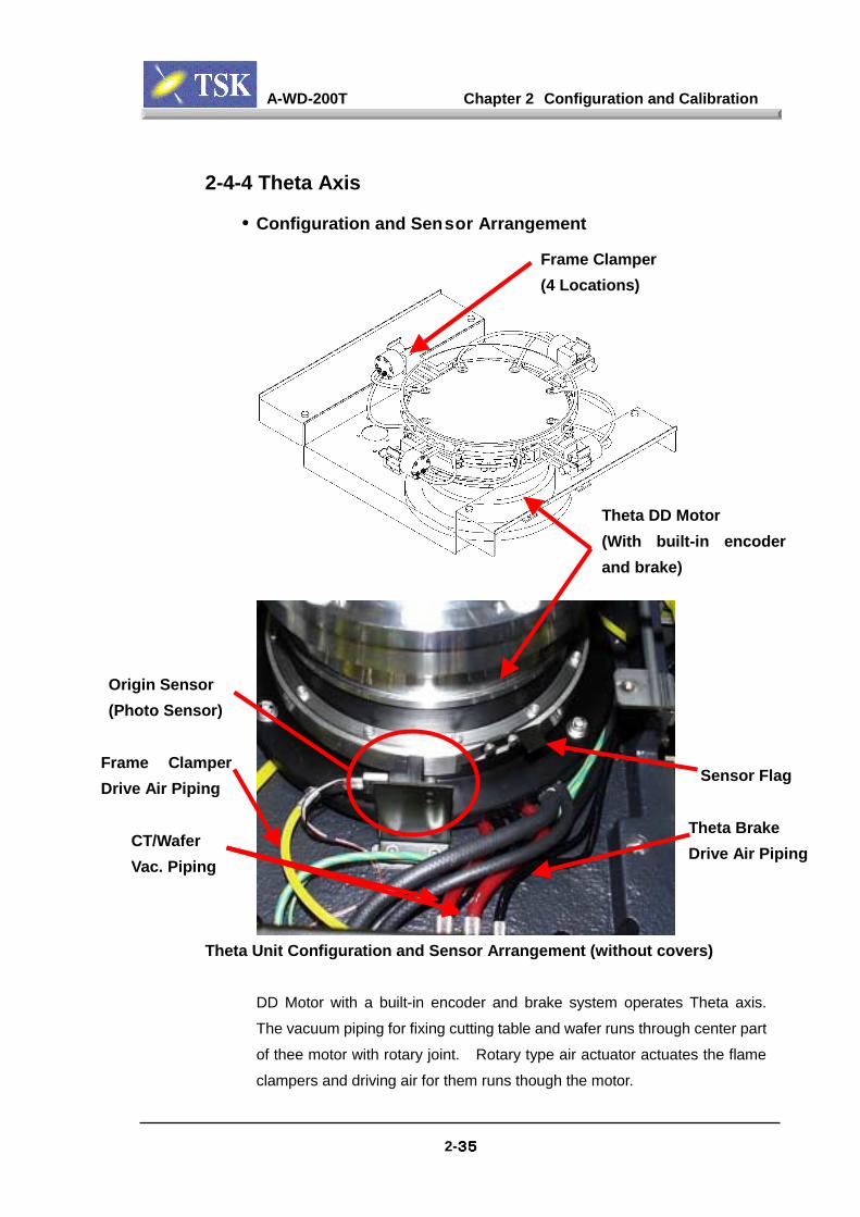
2-4-4 Theta Axis
• Configuration and Sensor Arrangement
Theta Unit Configuration and Sensor Arrangement (without covers)
DD Motor with a built-in encoder and brake system operates Theta axis.
The vacuum piping for fixing cutting table and wafer runs through center part
of thee motor with rotary joint. Rotary type air actuator actuates the flame
clampers and driving air for them runs though the motor.
Theta DD Motor(With built-in encoderand brake)
Frame Clamper(4 Locations)
Origin Sensor(Photo Sensor)
Sensor FlagFrame ClamperDrive Air Piping
CT/WaferVac. Piping
Theta BrakeDrive Air Piping

A-WD-200T Chapter 2 Configuration and Calibration
2-36363636
2-4-5 Spindle• Replace Brush
The spindle is an air bearing structure. Two carbon brushes are used to
make contact with the spindle shaft for contact cutter set to verify the
electrical constantly between the cutting table and the blade. If error occur
repeatedly, check the shaft and the contact surface for abrasions or
damage.
Make sure to shutdown the power and air prior to removal/install of the
spindle brush. When the air is ON, it will be difficult to mount the brush
and this may cause problems later on.
Spindle Brush (two screws hold the brush from back of the brush)
Install/Removal Spindle Brush:1) Shutdown the power and air.
2) Remove the brush cover in the back of the spindle.
3) Remove the screws from the brush (2 on the outer side), gently remove
the two brushes in the center. (The carbon brush is fixed on the tip of
spring.)
4) Install the brush (opposite procedures as removal). Do not forget to
mount the O ring when you install the brush cover.
Brush Cover
Fixing Screwof Brush
Encoder Cover(Do not remove)
A-WD-200T Chapter 2 Configuration and Calibration
2-37373737
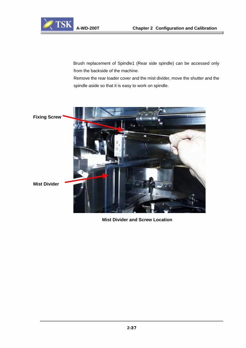
Brush replacement of Spindle1 (Rear side spindle) can be accessed only
from the backside of the machine.
Remove the rear loader cover and the mist divider, move the shutter and the
spindle aside so that it is easy to work on spindle.
Mist Divider and Screw Location
Fixing Screw
Mist Divider
A-WD-200T Chapter 2 Configuration and Calibration
2-38383838
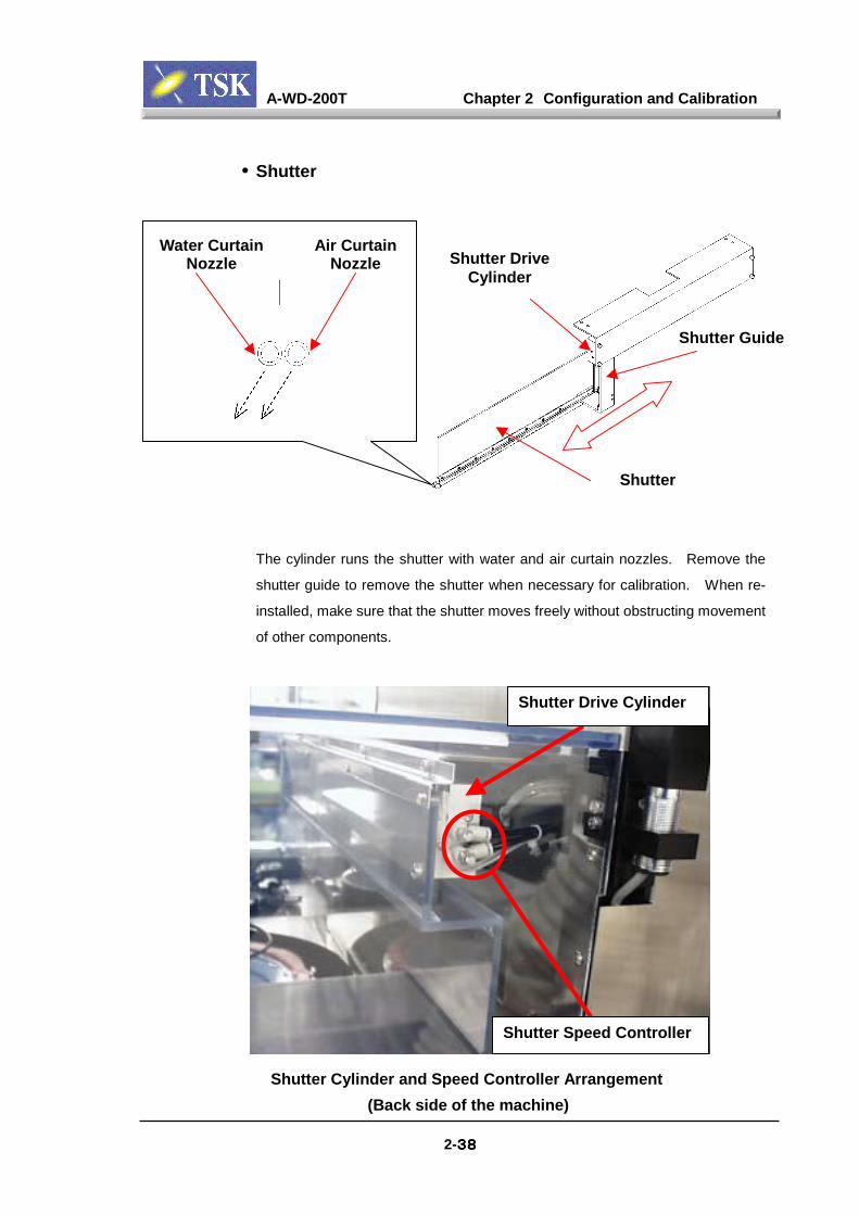
• Shutter
The cylinder runs the shutter with water and air curtain nozzles.
shutter guide to remove the shutter when necessary for calibratio
installed, make sure that the shutter moves freely without obstructi
of other components.
Shutter Speed Controlle
Shutter Drive Cylinde
Shutter Cylinder and Speed Controller Arrangement (Back side of the machine)
Shutter
Water CurtainNozzle
Air CurtainNozzle Shutter Drive
Cylinder
Shutter Guide
Remove the
n. When re-
ng movement
r
r

A-WD-200T Chapter 2 Configuration and Calibration
2-39393939
Cylinder Sensor Position
Shutter Cylinder Sensor Position
A-WD-200T Chapter 2 Configuration and Calibration
2-40404040
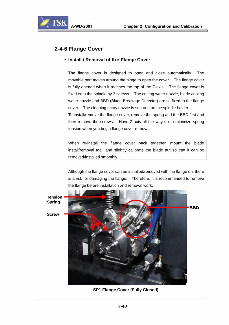
2-4-6 Flange Cover
• Install / Removal of the Flange Cover
The flange cover is designed to open and close automatically. The
movable part moves around the hinge to open the cover. The flange cover
is fully opened when it reaches the top of the Z-axis. The flange cover is
fixed onto the spindle by 3 screws. The cutting water nozzle, blade cooling
water nozzle and BBD (Blade Breakage Detector) are all fixed to the flange
cover. The cleaning spray nozzle is secured on the spindle holder.
To install/remove the flange cover, remove the spring and the BBD first and
then remove the screws. Have Z-axis all the way up to minimize spring
tension when you begin flange cover removal.
When re-install the flange cover back together, mount the blade
install/removal tool, and slightly calibrate the blade nut so that it can be
removed/installed smoothly.
Although the flange cover can be installed/removed with the flange on, there
is a risk for damaging the flange. Therefore, it is recommended to remove
the flange before installation and removal work.
Screw
TensionSpring
BBDBBDBBDBBD
SP1 Flange Cover (Fully Closed)
A-WD-200T Chapter 2 Configuration and Calibration
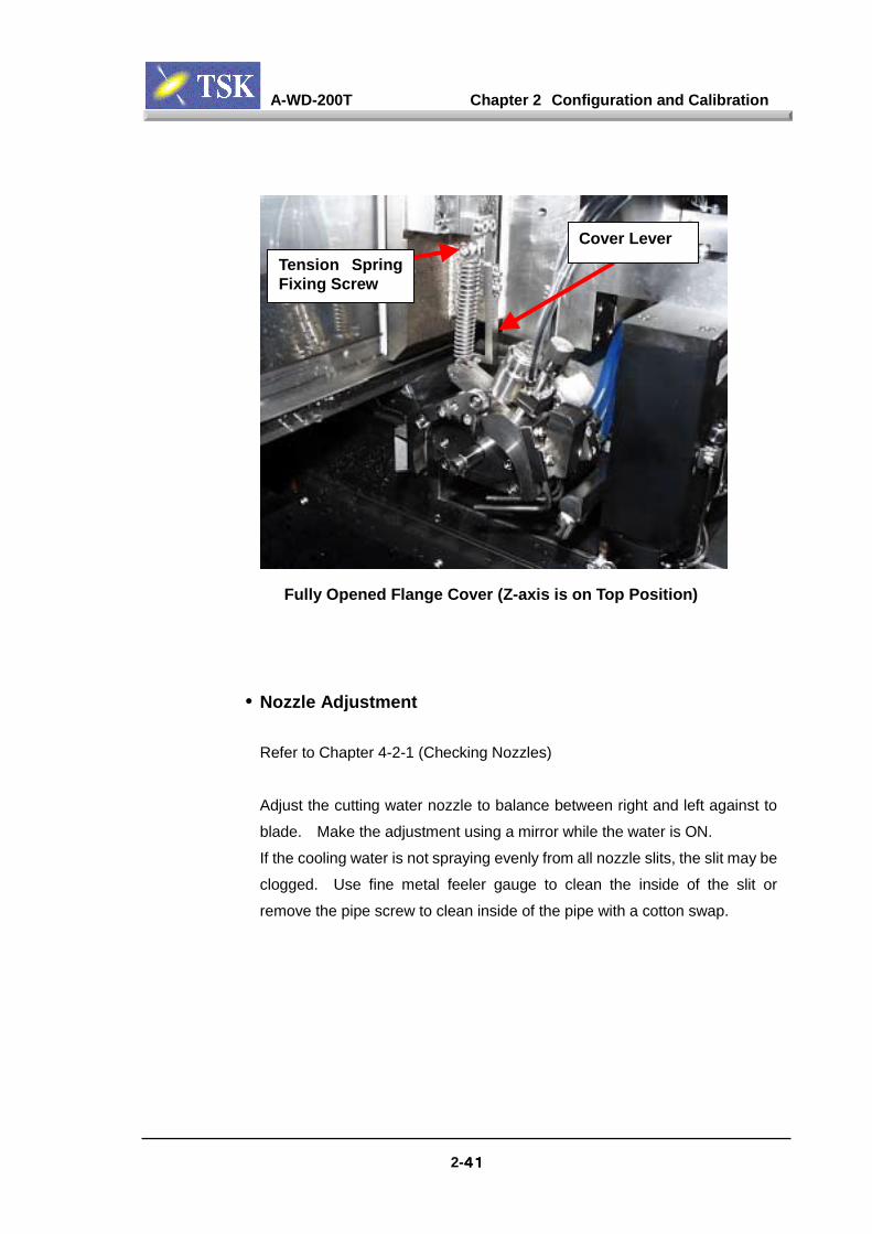
2-41414141
Tension SpringFixing Screw
Cover Lever
Fully Opened Flange Cover (Z-axis is on Top Position)
• Nozzle Adjustment
Refer to Chapter 4-2-1 (Checking Nozzles)
Adjust the cutting water nozzle to balance between right and left against to
blade. Make the adjustment using a mirror while the water is ON.
If the cooling water is not spraying evenly from all nozzle slits, the slit may be
clogged. Use fine metal feeler gauge to clean the inside of the slit or
remove the pipe screw to clean inside of the pipe with a cotton swap.
A-WD-200T Chapter 2 Configuration and Calibration
2-42424242
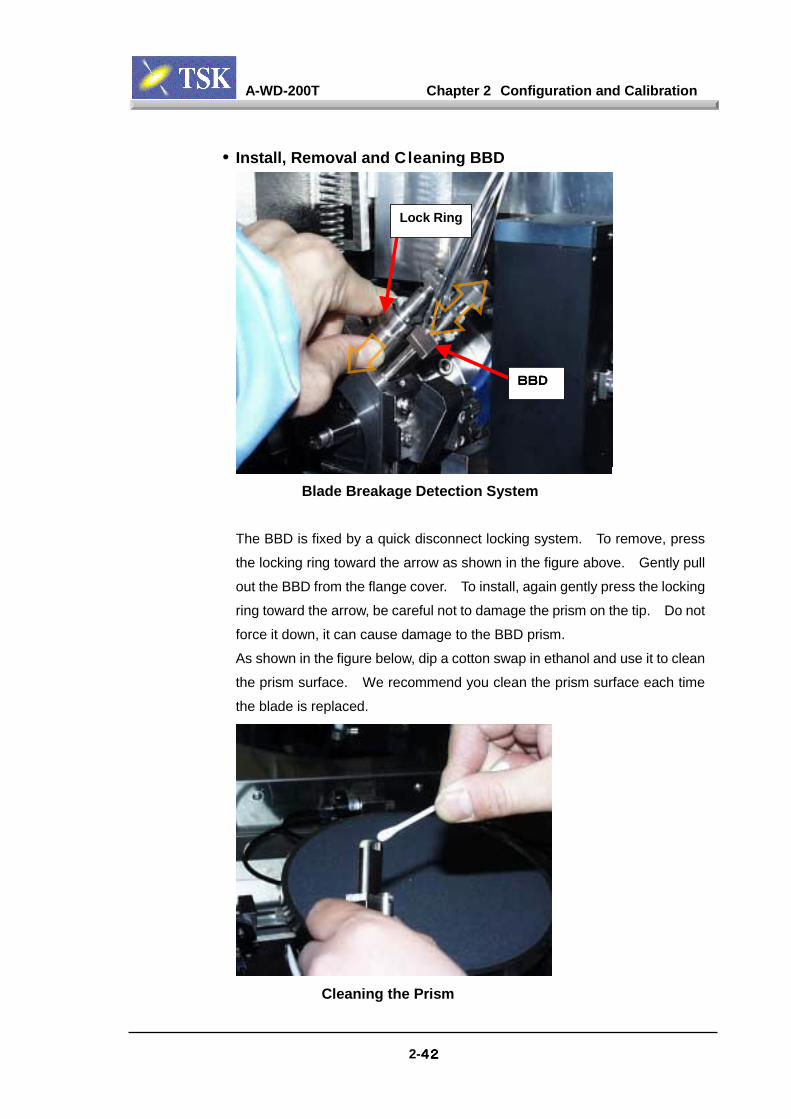
• Install, Removal and Cleaning BBD
BBDBBDBBDBBD
Lock Ring
Blade Breakage Detection System
The BBD is fixed by a quick disconnect locking system. To remove, press
the locking ring toward the arrow as shown in the figure above. Gently pull
out the BBD from the flange cover. To install, again gently press the locking
ring toward the arrow, be careful not to damage the prism on the tip. Do not
force it down, it can cause damage to the BBD prism.
As shown in the figure below, dip a cotton swap in ethanol and use it to clean
the prism surface. We recommend you clean the prism surface each time
the blade is replaced.
Cleaning the Prism
A-WD-200T Chapter 2 Configuration and Calibration
2-43434343
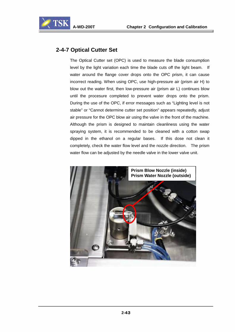
2-4-7 Optical Cutter Set
The Optical Cutter set (OPC) is used to measure the blade consumption
level by the light variation each time the blade cuts off the light beam. If
water around the flange cover drops onto the OPC prism, it can cause
incorrect reading. When using OPC, use high-pressure air (prism air H) to
blow out the water first, then low-pressure air (prism air L) continues blow
until the procesure completed to prevent water drops onto the prism.
During the use of the OPC, if error messages such as “Lighting level is not
stable” or “Cannot determine cutter set position” appears repeatedly, adjust
air pressure for the OPC blow air using the valve in the front of the machine.
Although the prism is designed to maintain cleanliness using the water
spraying system, it is recommended to be cleaned with a cotton swap
dipped in the ethanol on a regular bases. If this dose not clean it
completely, check the water flow level and the nozzle direction. The prism
water flow can be adjusted by the needle valve in the lower valve unit.
Prism Blow Nozzle (inside)Prism Water Nozzle (outside)
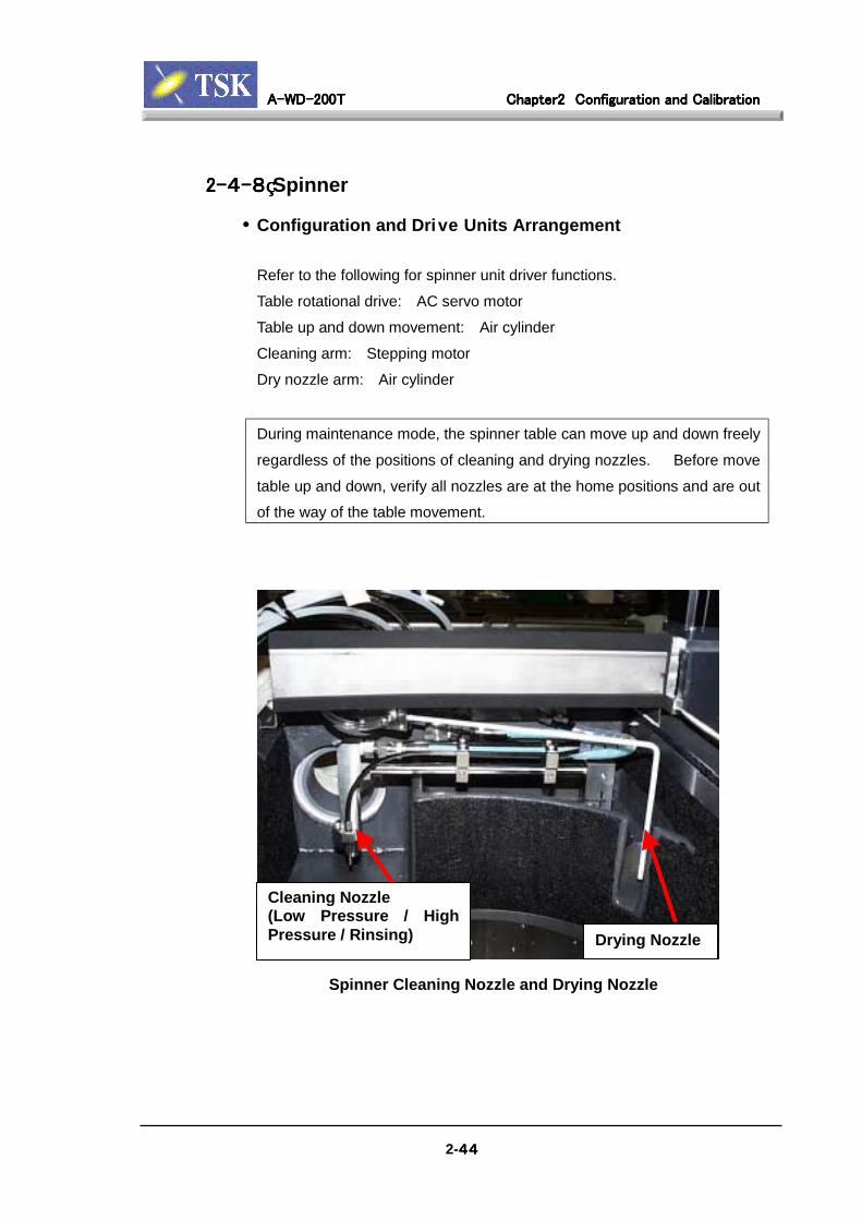
A-WD-200TA-WD-200TA-WD-200TA-WD-200T Chapter2Chapter2Chapter2Chapter2 Configuration and CalibrationConfiguration and CalibrationConfiguration and CalibrationConfiguration and Calibration
2-44444444
2-2-2-2-4444----8888 Spinner
• Configuration and Drive Units Arrangement
Refer to the following for spinner unit driver functions.
Table rotational drive: AC servo motor
Table up and down movement: Air cylinder
Cleaning arm: Stepping motor
Dry nozzle arm: Air cylinder
During maintenance mode, the spinner table can move up and down freely
regardless of the positions of cleaning and drying nozzles. Before move
table up and down, verify all nozzles are at the home positions and are outof the way of the table movement.
洗浄ノズル
(低圧/高圧/リンス)
Cleaning Nozzle(Low Pressure / HighPressure / Rinsing) Drying Nozzle
Spinner Cleaning Nozzle and Drying Nozzle

A-WD-200TA-WD-200TA-WD-200TA-WD-200T Chapter2Chapter2Chapter2Chapter2 Configuration and CalibrationConfiguration and CalibrationConfiguration and CalibrationConfiguration and Calibration
2-45454545
Spinner Up & Down Cylinder(With 2 position sensors )
Spinner ServoMotor Driver
Spinner Table Up/Down Cylinder and Spinner Motor Driver (Without the right cover and internal protection cover)
Cleaning ArmStepping Motor
Stepping Motor for Spinner Cleaning Arm Drive(Backside of the Machine)

A-WD-200TA-WD-200TA-WD-200TA-WD-200T Chapter2Chapter2Chapter2Chapter2 Configuration and CalibrationConfiguration and CalibrationConfiguration and CalibrationConfiguration and Calibration
2-46464646
Drying Nozzle Cylinder Cylinder SensorNozzle CylinderSpeed Controller
Drying Air FlowControl Valve
Drying Air (N2)Pipe
High PressureWater PipeRinse Water Pipe
Back SideDrying Air FlowControl Valve
Drying Nozzle Driver and Piping (Backside of the Machine)
Spinner Table Vacuum Sensor (in the circle)
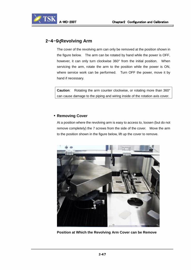
A-WD-200TA-WD-200TA-WD-200TA-WD-200T Chapter2Chapter2Chapter2Chapter2 Configuration and CalibrationConfiguration and CalibrationConfiguration and CalibrationConfiguration and Calibration
2-47474747
2-2-2-2-4444----9999 Revolving Arm
The cover of the revolving arm can only be removed at the position shown in
the figure below. The arm can be rotated by hand while the power is OFF,
however, it can only turn clockwise 360° from the initial position. Whenservicing the arm, rotate the arm to the position while the power is ON,
where service work can be performed. Turn OFF the power, move it by
hand if necessary.
Caution: Rotating the arm counter clockwise, or rotating more than 360°
can cause damage to the piping and wiring inside of the rotation axis cover.
• Removing CoverAt a position where the revolving arm is easy to access to, loosen (but do not
remove completely) the 7 screws from the side of the cover. Move the arm
to the position shown in the figure below, lift up the cover to remove.
Position at Which the Revolving Arm Cover can be Remove
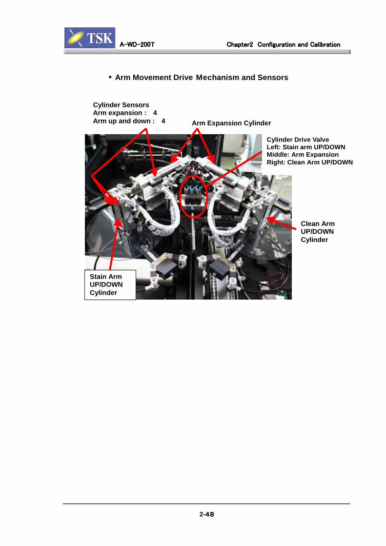
A-WD-200TA-WD-200TA-WD-200TA-WD-200T Chapter2Chapter2Chapter2Chapter2 Configuration and CalibrationConfiguration and CalibrationConfiguration and CalibrationConfiguration and Calibration
2-48484848
• Arm Movement Drive Mechanism and Sensors
Clean ArmUP/DOWNCylinder
Cylinder Drive ValveLeft: Stain arm UP/DOWNMiddle: Arm ExpansionRight: Clean Arm UP/DOWN
Stain ArmUP/DOWNCylinder
Cylinder SensorsArm expansion : 4Arm up and down : 4 Arm Expansion Cylinder
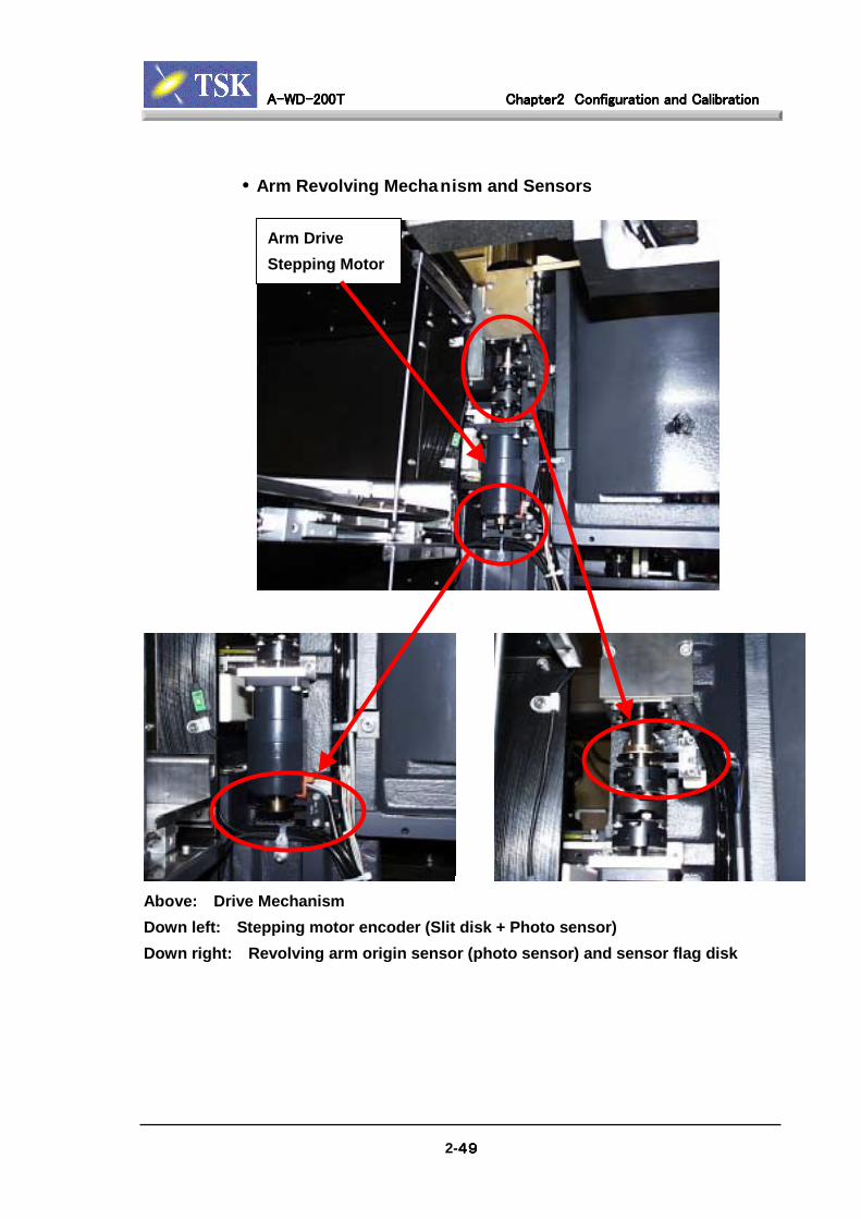
A-WD-200TA-WD-200TA-WD-200TA-WD-200T Chapter2Chapter2Chapter2Chapter2 Configuration and CalibrationConfiguration and CalibrationConfiguration and CalibrationConfiguration and Calibration
2-49494949
• Arm Revolving Mechanism and Sensors
Above: Drive MechanismDown left: Stepping motor encoder (Slit disk + Photo sensor)Down right: Revolving arm origin sensor (photo sensor) and sensor flag disk
Arm DriveStepping Motor
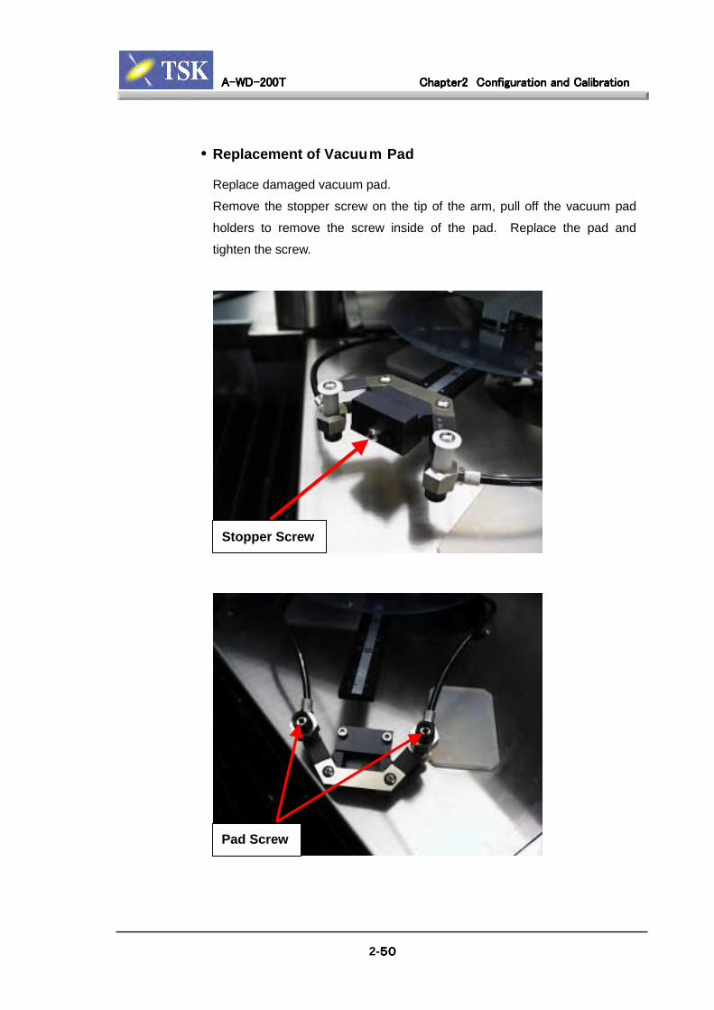
A-WD-200TA-WD-200TA-WD-200TA-WD-200T Chapter2Chapter2Chapter2Chapter2 Configuration and CalibrationConfiguration and CalibrationConfiguration and CalibrationConfiguration and Calibration
2-50505050
• Replacement of Vacuum Pad
Replace damaged vacuum pad.
Remove the stopper screw on the tip of the arm, pull off the vacuum pad
holders to remove the screw inside of the pad. Replace the pad and
tighten the screw.
Stopper Screw
Pad Screw
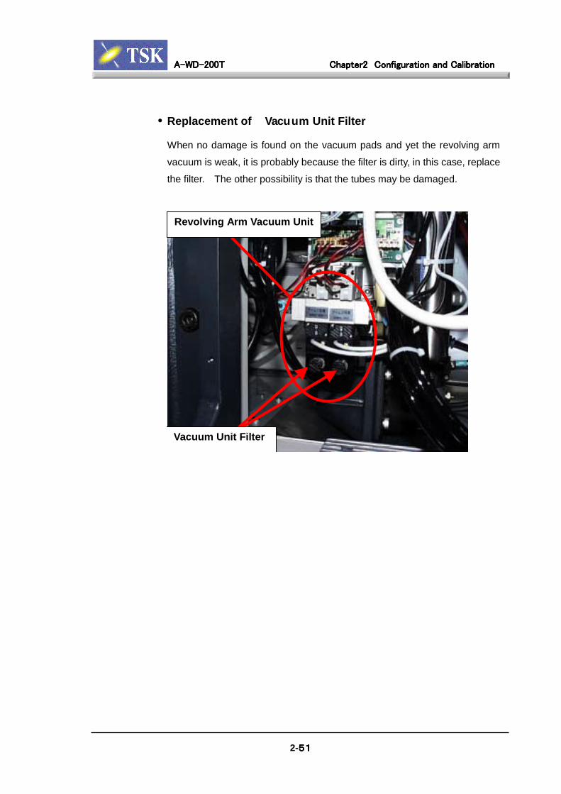
A-WD-200TA-WD-200TA-WD-200TA-WD-200T Chapter2Chapter2Chapter2Chapter2 Configuration and CalibrationConfiguration and CalibrationConfiguration and CalibrationConfiguration and Calibration
2-51515151
• Replacement of Vacuum Unit Filter
When no damage is found on the vacuum pads and yet the revolving arm
vacuum is weak, it is probably because the filter is dirty, in this case, replace
the filter. The other possibility is that the tubes may be damaged.
Revolving Arm Vacuum Unit
Vacuum Unit Filter

A-WD-200TA-WD-200TA-WD-200TA-WD-200T Chapter2Chapter2Chapter2Chapter2 Configuration and CalibrationConfiguration and CalibrationConfiguration and CalibrationConfiguration and Calibration
2-2-2-2-4444----10101010 Elevator
• Configuration
Frame Sensor
Elevator Axis Origin Sensor(Backside)
Pre-alignment Wafer Sensor
Finger Drive MotorFinger Axis Origin Sensor
(Backside)
Elevator Axis Drive Motor(with Built-in Brake)
Finger Unit
Pre-alignment stage
2-52525252
エレベータモータElevator Axis OriginSensor(Photo Sensor)
Finger Axis OriginSensor(Photo Sensor)
Elevator Drive Stepping Motor and Origin Sensor(Back view of the Machine)
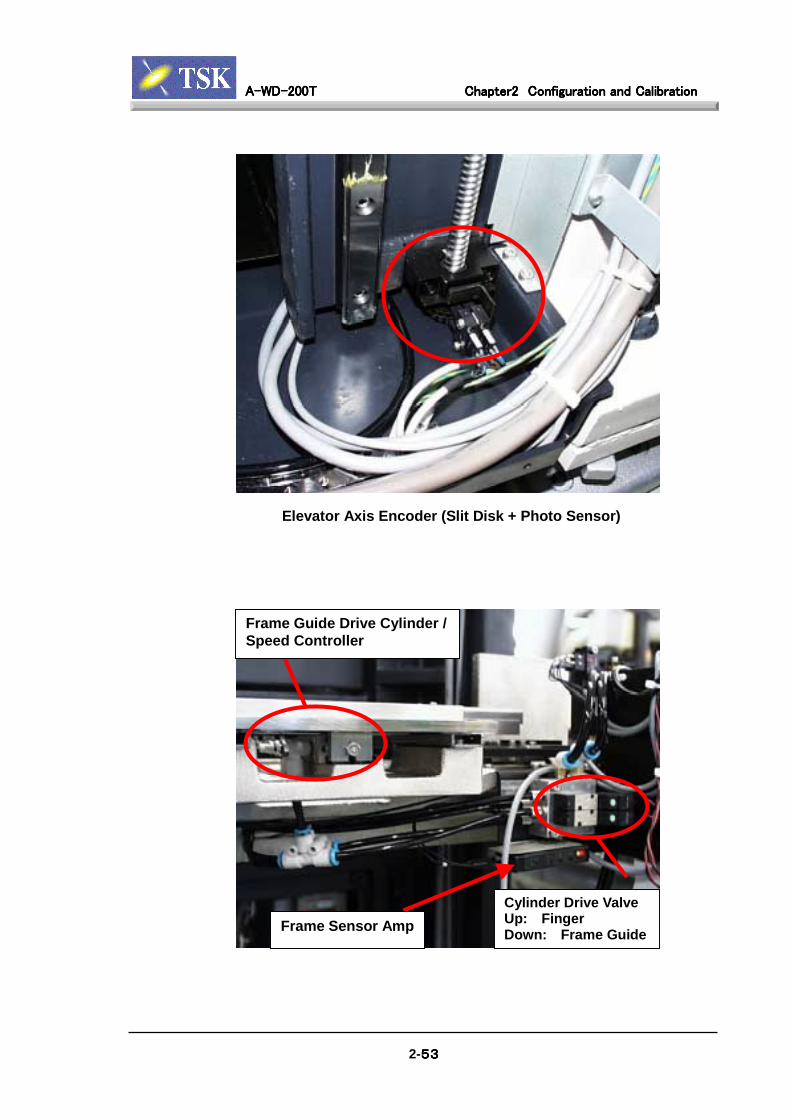
A-WD-200TA-WD-200TA-WD-200TA-WD-200T Chapter2Chapter2Chapter2Chapter2 Configuration and CalibrationConfiguration and CalibrationConfiguration and CalibrationConfiguration and Calibration
2-53535353
Elevator Axis Encoder (Slit Disk + Photo Sensor)
Frame Guide Drive Cylinder /Speed Controller
Frame Sensor AmpCylinder Drive ValveUp: FingerDown: Frame Guide
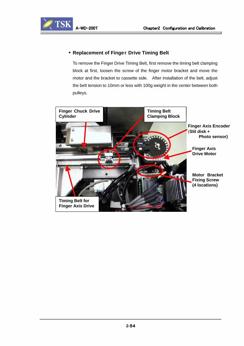
A-WD-200TA-WD-200TA-WD-200TA-WD-200T Chapter2Chapter2Chapter2Chapter2 Configuration and CalibrationConfiguration and CalibrationConfiguration and CalibrationConfiguration and Calibration
2-54545454
• Replacement of Finger Drive Timing Belt
To remove the Finger Drive Timing Belt, first remove the timing belt clamping
block at first, loosen the screw of the finger motor bracket and move the
motor and the bracket to cassette side. After installation of the belt, adjust
the belt tension to 10mm or less with 100g weight in the center between both
pulleys.
Timing Belt forFinger Axis Drive
Finger Chuck DriveCylinder
Timing BeltClamping Block
Finger AxisDrive Motor
Motor BracketFixing Screw(4 locations)
Finger Axis Encoder(Slit disk + Photo sensor)
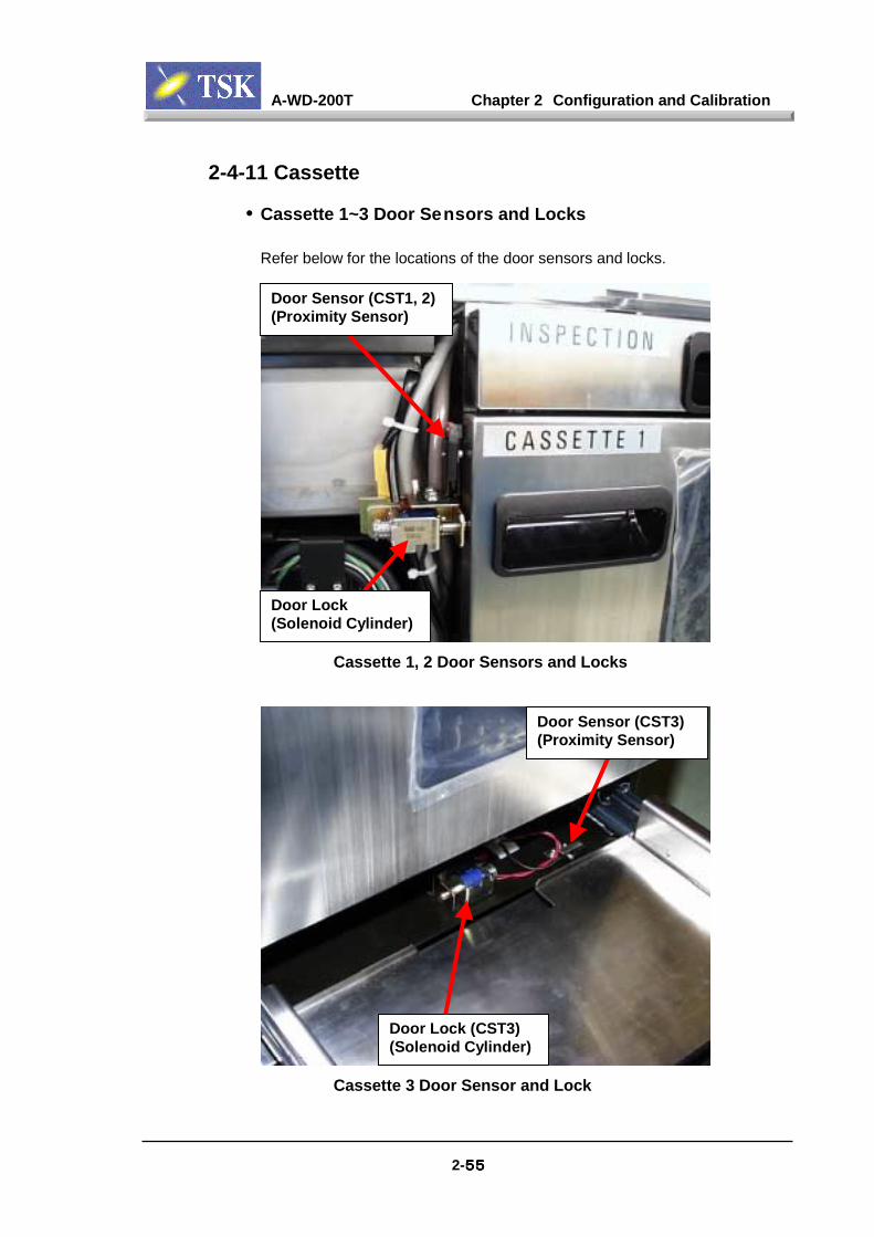
A-WD-200T Chapter 2 Configuration and Calibration
2-55555555
2-4-11 Cassette
• Cassette 1~3 Door Sensors and Locks
Refer below for the locations of the door sensors and locks.
Door Sensor (CST1, 2)(Proximity Sensor)
Door Lock(Solenoid Cylinder)
Cassette 1, 2 Door Sensors and Locks
Door Lock (CST3)(Solenoid Cylinder)
Door Sensor (CST3)(Proximity Sensor)
Cassette 3 Door Sensor and Lock
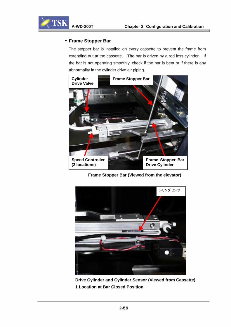
A-WD-200T Chapter 2 Configuration and Calibration
2-56565656
• Frame Stopper BarThe stopper bar is installed on every cassette to prevent the frame from
extending out at the cassette. The bar is driven by a rod less cylinder. If
the bar is not operating smoothly, check if the bar is bent or if there is any
abnormality in the cylinder drive air piping.
Frame Stopper BarCylinderDrive Valve
Frame Stopper BarDrive Cylinder
Speed Controller(2 locations)
Frame Stopper Bar (Viewed from the elevator)
シリンダセンサ
Drive Cylinder and Cylinder Sensor (Viewed from Cassette)1 Location at Bar Closed Position
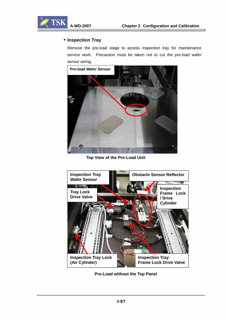
A-WD-200T Chapter 2 Configuration and Calibration
2-57575757
• Inspection TrayRemove the pre-load stage to access inspection tray for maintenance
service work. Precaution must be taken not to cut the pre-load wafer
sensor wiring.
Pre-load Wafer Sensor
Top View of the Pre-Load Unit
Inspection Tray Lock(Air Cylinder)
Inspection TrayFrame Lock Drive Valve
Obstacle Sensor ReflectorInspection TrayWafer Sensor
Tray LockDrive Valve
InspectionFrame Lock/ DriveCylinder
Pre-Load without the Top Panel
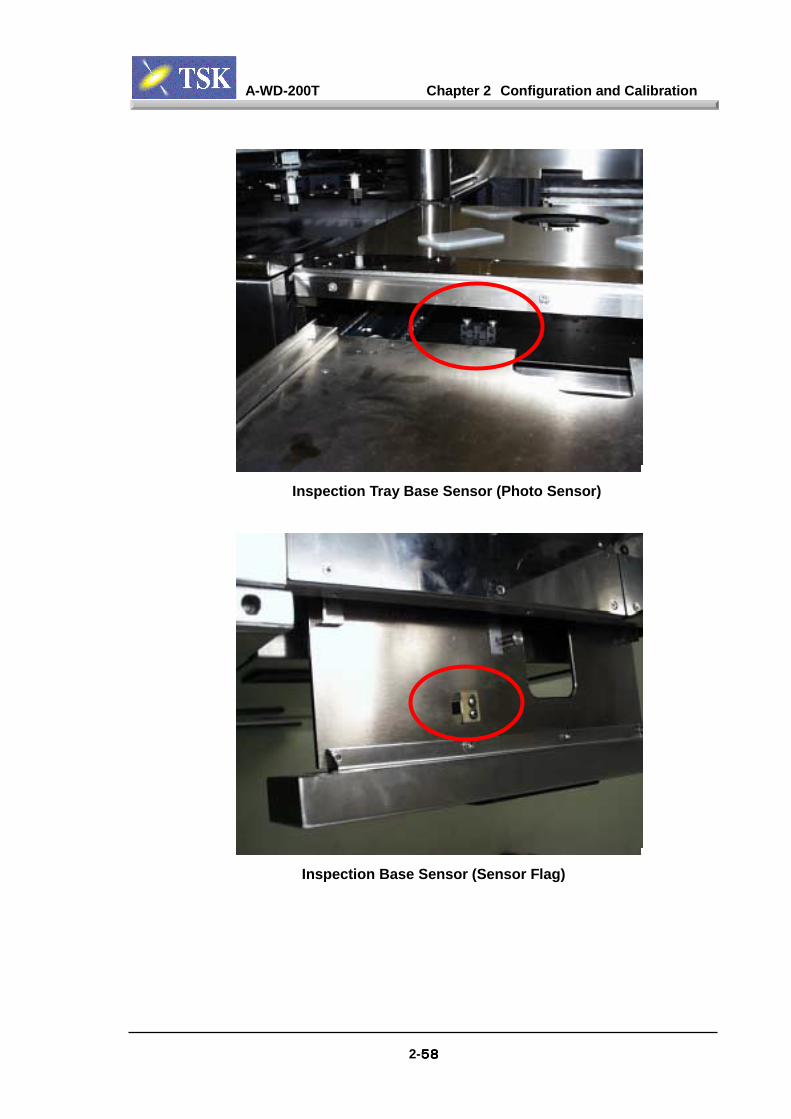
A-WD-200T Chapter 2 Configuration and Calibration
2-58585858
Inspection Tray Base Sensor (Photo Sensor)
Inspection Base Sensor (Sensor Flag)

A-WD-200T Chapter 2 Configuration and Calibration
2-59595959
• Cassette Sensor / Sensor FlagIf the machine does not recognize the cassette, first check if the cassette is
set up correctly. The sensor will not sense the sensor flag if the cassette
does not push the detection lever all the way down. If the cassette sensor
seems to be out of order, pull out the cassette tray, insert a piece of paper
instead of the flag to test the sensor operation (the LED should lit when the
sensor is ON).
Cassette Sensor(Photo Sensor)
Cassette DetectionLever
Sensor Flag
Cassette Detection Lever
Cassette Detection Mechanism (Sensor / Sensor Flag)
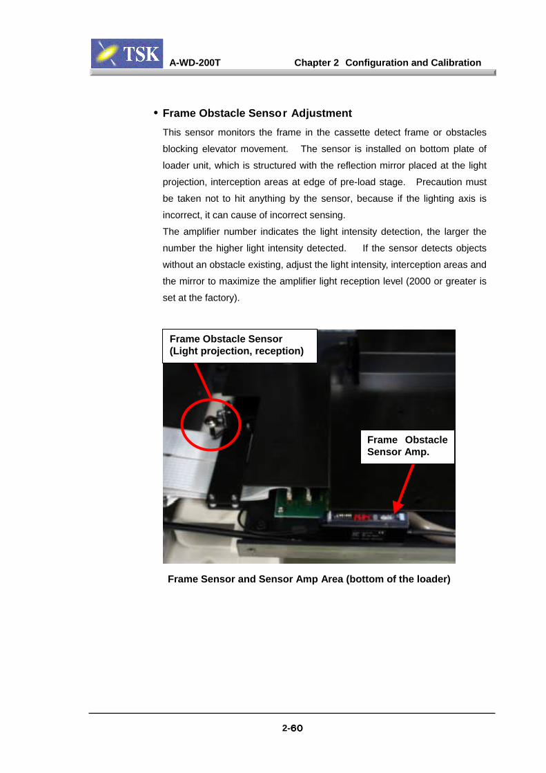
A-WD-200T Chapter 2 Configuration and Calibration
2-60606060
• Frame Obstacle Sensor AdjustmentThis sensor monitors the frame in the cassette detect frame or obstacles
blocking elevator movement. The sensor is installed on bottom plate of
loader unit, which is structured with the reflection mirror placed at the light
projection, interception areas at edge of pre-load stage. Precaution must
be taken not to hit anything by the sensor, because if the lighting axis is
incorrect, it can cause of incorrect sensing.
The amplifier number indicates the light intensity detection, the larger the
number the higher light intensity detected. If the sensor detects objects
without an obstacle existing, adjust the light intensity, interception areas and
the mirror to maximize the amplifier light reception level (2000 or greater is
set at the factory).
Frame ObstacleSensor Amp.
Frame Obstacle Sensor(Light projection, reception)
Frame Sensor and Sensor Amp Area (bottom of the loader)
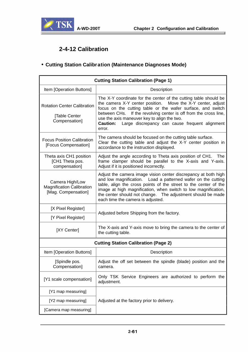
A-WD-200T Chapter 2 Configuration and Calibration
2-61616161
2-4-12 Calibration
• Cutting Station Calibration (Maintenance Diagnoses Mode)
Cutting Station Calibration (Page 1)
Item [Operation Buttons] Description
Rotation Center Calibration
[Table CenterCompensation]
The X-Y coordinate for the center of the cutting table should bethe camera X-Y center position. Move the X-Y center, adjustfocus on the cutting table or the wafer surface, and switchbetween CHs. If the revolving center is off from the cross line,use the axis maneuver key to align the two.Caution: Large discrepancy can cause frequent alignmenterror.
Focus Position Calibration[Focus Compensation]
The camera should be focused on the cutting table surface.Clear the cutting table and adjust the X-Y center position inaccordance to the instruction displayed.
Theta axis CH1 position[CH1 Theta pos.compensation]
Adjust the angle according to Theta axis position of CH1. Theframe clamper should be parallel to the X-axis and Y-axis.Adjust if it is positioned incorrectly.
Camera High/LowMagnification Calibration
[Mag. Compensation]
Adjust the camera image vision center discrepancy at both highand low magnification. Load a patterned wafer on the cuttingtable, align the cross points of the street to the center of theimage at high magnification, when switch to low magnification,the center should not change. The adjustment should be madeeach time the camera is adjusted.
[X Pixel Register]
[Y Pixel Register]Adjusted before Shipping from the factory.
[XY Center] The X-axis and Y-axis move to bring the camera to the center ofthe cutting table.
Cutting Station Calibration (Page 2)
Item [Operation Buttons] Description
[Spindle pos.Compensation]
Adjust the off set between the spindle (blade) position and thecamera.
[Y1 scale compensation] Only TSK Service Engineers are authorized to perform theadjustment.
[Y1 map measuring]
[Y2 map measuring]
[Camera map measuring]
Adjusted at the factory prior to delivery.
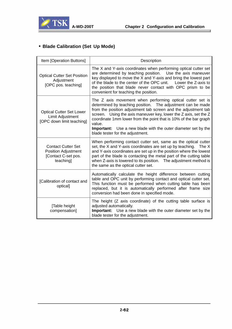
A-WD-200T Chapter 2 Configuration and Calibration
2-62626262
• Blade Calibration (Set Up Mode)
Item [Operation Buttons] Description
Optical Cutter Set PositionAdjustment
[OPC pos. teaching]
The X and Y-axis coordinates when performing optical cutter setare determined by teaching position. Use the axis maneuverkey displayed to move the X and Y-axis and bring the lowest partof the blade to the center of the OPC unit. Lower the Z-axis tothe position that blade never contact with OPC prism to beconvenient for teaching the position.
Optical Cutter Set LowerLimit Adjustment
[OPC down limit teaching]
The Z axis movement when performing optical cutter set isdetermined by teaching position. The adjustment can be madefrom the position adjustment tab screen and the adjustment tabscreen. Using the axis maneuver key, lower the Z axis, set the Zcoordinate 1mm lower from the point that is 10% of the bar graphvalue.Important: Use a new blade with the outer diameter set by theblade tester for the adjustment.
Contact Cutter SetPosition Adjustment[Contact C-set pos.
teaching]
When performing contact cutter set, same as the optical cutterset, the X and Y-axis coordinates are set up by teaching. The Xand Y-axis coordinates are set up in the position where the lowestpart of the blade is contacting the metal part of the cutting tablewhen Z-axis is lowered to its position. The adjustment method isthe same as the optical cutter set.
[Calibration of contact andoptical]
Automatically calculate the height difference between cuttingtable and OPC unit by performing contact and optical cutter set.This function must be performed when cutting table has beenreplaced, but it is automatically performed after frame sizeconversion had been done in specified mode.
[Table heightcompensation]
The height (Z axis coordinate) of the cutting table surface isadjusted automatically.Important: Use a new blade with the outer diameter set by theblade tester for the adjustment.

A-WD-200T Chapter 2 Configuration and Calibration
2-63636363
• Handling Station Calibration (Maintenance Diagnosis Mode)
Handling Station Calibration (Page 1)
Item [Operation Buttons] Description
Elevator ReferencePosition Compensation
[Elevator pos.compensation]
The elevator axis reference positions (load/Unload, inspectionand the first slot of cassette 1~3) are set by teaching. Use thecassette that frame is set in the 1st slot of it to teach eachreference positions.Load/unload position should be set in the position where therevolving arm (clean arm) vacuum pads are fully depressedagainst the frame. When setting the inspection position, in orderfor the frame in the inspection tray to be pulled out smoothly, besure to place the pre-alignment frame guide surface slightly underthe inspection frame guide surface (the position may vary by thetype of frame used). Cassette 1~3 should be set in the samemanner as the inspection position. After setting the referenceposition, set the offset position for the frame sensor. The framesensor optical beam should be set in the center of the 1st slotframe as frame sensor off set. Refer to the guide messagedisplayed for position settings.
[Finger acting pos.Compensation]
Adjust the finger position for draw out frame from cassette. Setthe frame in the cassette, and make sure that the frame clampingdevice of finger axis can be clamped firmly.
[Finger centercompensation ]
The center of the finger should be set at where the revolving armpicks up the frame in the pre-alignment area.This position affects positioning of frame handling positions onboth cutting and spinner table.
[Rev. arm compensation ]Adjust the revolving coordinate of the revolving arm. Theadjustment must be made with caution to avoid error when itmoves frames from one section to another.
[Water nozzle centercompensation]
The spinner cleaning area should be set in the center of thespinner table as the reference position. Use the axis maneuverkey to align the nozzle to the revolving center of the spinner table.
[Handling station initialize][Machine initialize] Initialize all units of the handling station or the machine.
Handling Station Calibration (Page 2)
[--------- initialize] Each area in the name of button is initialized individually.
Chapter 3 Periodic MaintenanceService List
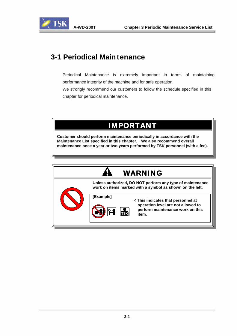
A-WD-200T Chapter 3 Periodic Maintenance Service List
3-1 Periodical Main tenance
Periodical Maintenance is extremely important in terms of maintaining
performance integrity of the machine and for safe operation.
We strongly recommend our customers to follow the schedule specified in this
chapter for periodical maintenance.
Customer should perform mMaintenance List specified maintenance once a year or
IIII
Unless awork on
[Example
MPORTANTMPORTANT
aintenance periodically in accordance with thein this chapter. We also recommend overall two years performed by TSK personnel (with a fee).
MPORTANTMPORTANT
WWWWuthorizeitems m
]
3-1
ARNINGARNINGARNINGARNINGd, DO NOT perform any type of maintenancearked with a symbol as shown on the left.
< This indicates that personnel atoperation level are not allowed toperform maintenance work on thisitem.

A-WD-200T Chapter 3 Periodic Maintenance Service List
3-2
3-2 Recommended Periodical Maintenance ListRefer to the Periodic Maintenance List below for this machine.
* Danger Classification indicates the type of the danger potential during
maintenance work.
Daily Check ListCheck List Check Method Remarks Worker Class Hazard
Class
Verify AirPressure
Check the air pressuregauge in front andback of the machine.
When it is lower than0.5Mpa, adjust it with theregulator in the back inaccordance with Chapter“4-1-1”
Verify TheCutter Water
Flow
Check the flow gaugein the front whilewater is running.
The water flow should be atthe specified level andsprayed evenly from thenozzles. Refer to Chapter“4-1-2”.
Water LeakageAround The
Machine
Check to see if there iswater leaks around themachine
Check the pipe joints. Referto Chapter “4-1-3”.
Cleaning of X-axial bellows Remove wafer scraps. Refer to Chapter “4-1-4”.
Monthly Check ListCheck List Check Method Remarks Worker Class Hazard
ClassVerify Each
Nozzle Check spinner nozzle stroke Refer to Chapter“4-2-1”
Spinner TablePosition
Verify the table stop originposition
Refer to Chapter“4-2-2”
Spinner TableUp/Down
Movement
The up/down movement shouldbe smooth
Refer to Chapter“4-2-2”
RevolvingCenter
After X/Y movement, thediscrepancy between the +electron line in the center of thescreen and the revolving centershould be less than ±20µm
Refer to Chapter“4-2-3”
Cleaning of oilpan
Remove the X axis bellows, washoff the wafer scraps in the oil pan.
Refer to Chapter“4-2-4”
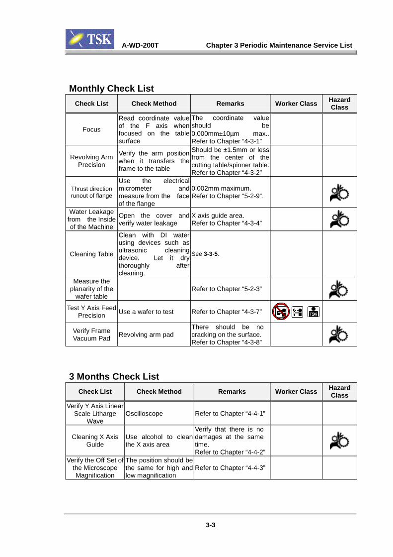
A-WD-200T Chapter 3 Periodic Maintenance Service List
3-3
Monthly Check ListCheck List Check Method Remarks Worker Class Hazard
Class
Focus
Read coordinate valueof the F axis whenfocused on the tablesurface
The coordinate valueshould be0.000mm±10µm max..Refer to Chapter “4-3-1”
Revolving ArmPrecision
Verify the arm positionwhen it transfers theframe to the table
Should be ±1.5mm or lessfrom the center of thecutting table/spinner table.Refer to Chapter “4-3-2”
Thrust directionrunout of flange
Use the electricalmicrometer andmeasure from the faceof the flange
0.002mm maximum.Refer to Chapter “5-2-9”.
Water Leakagefrom the Insideof the Machine
Open the cover andverify water leakage
X axis guide area.Refer to Chapter “4-3-4”
Cleaning Table
Clean with DI waterusing devices such asultrasonic cleaningdevice. Let it drythoroughly aftercleaning.
See 3-3-5.
Measure theplanarity of the
wafer tableRefer to Chapter “5-2-3”
Test Y Axis FeedPrecision Use a wafer to test Refer to Chapter “4-3-7”
Verify FrameVacuum Pad Revolving arm pad
There should be nocracking on the surface.Refer to Chapter “4-3-8”
3 Months Check ListCheck List Check Method Remarks Worker Class Hazard
ClassVerify Y Axis Linear
Scale LithargeWave
Oscilloscope Refer to Chapter “4-4-1”
Cleaning X AxisGuide
Use alcohol to cleanthe X axis area
Verify that there is nodamages at the sametime.Refer to Chapter “4-4-2”
Verify the Off Set ofthe MicroscopeMagnification
The position should bethe same for high andlow magnification
Refer to Chapter “4-4-3”

A-WD-200T Chapter 3 Periodic Maintenance Service List
3-4
6 Months Check ListCheck List Check Method Remarks Worker Class Hazard
Class
Verify the ElectricalLeakage Breaker
Press test button totest its function
Refer to Chapter“4-5-1”
Grease the Y Axis Guideand Ball Screw
Refer to Chapter“4-9”
Grease the Z Axis Guideand Ball Screw
Refer to Chapter“4-9”
Grease the Elevator AxisGuide and Ball Screw
Refer to Chapter“4-9”
Yearly Check ListCheck List Check Method Remarks Worker Class Hazard
ClassMeasure X Axis
Straightness(Vertically)
Refer to Chapter “5-2-1”
Measure the of the XAxis Straightness
(Horizontally)
Refer to Chapter “5-2-2”
Verify theperpendicularity of
Spindle and the X Axis
Refer to Chapter “5-2-8”
Measure Z AxisRepeatability
Refer to Chapter “5-2-5”
Measure the runout ofSpindle Shaft (radial
direction)
Refer to Chapter “5-2-7”
Spindle Brush CheckUp
Refer to Chapter “2-4-5”
Replace Air FilterElement
Refer to Chapter “4-6-6”
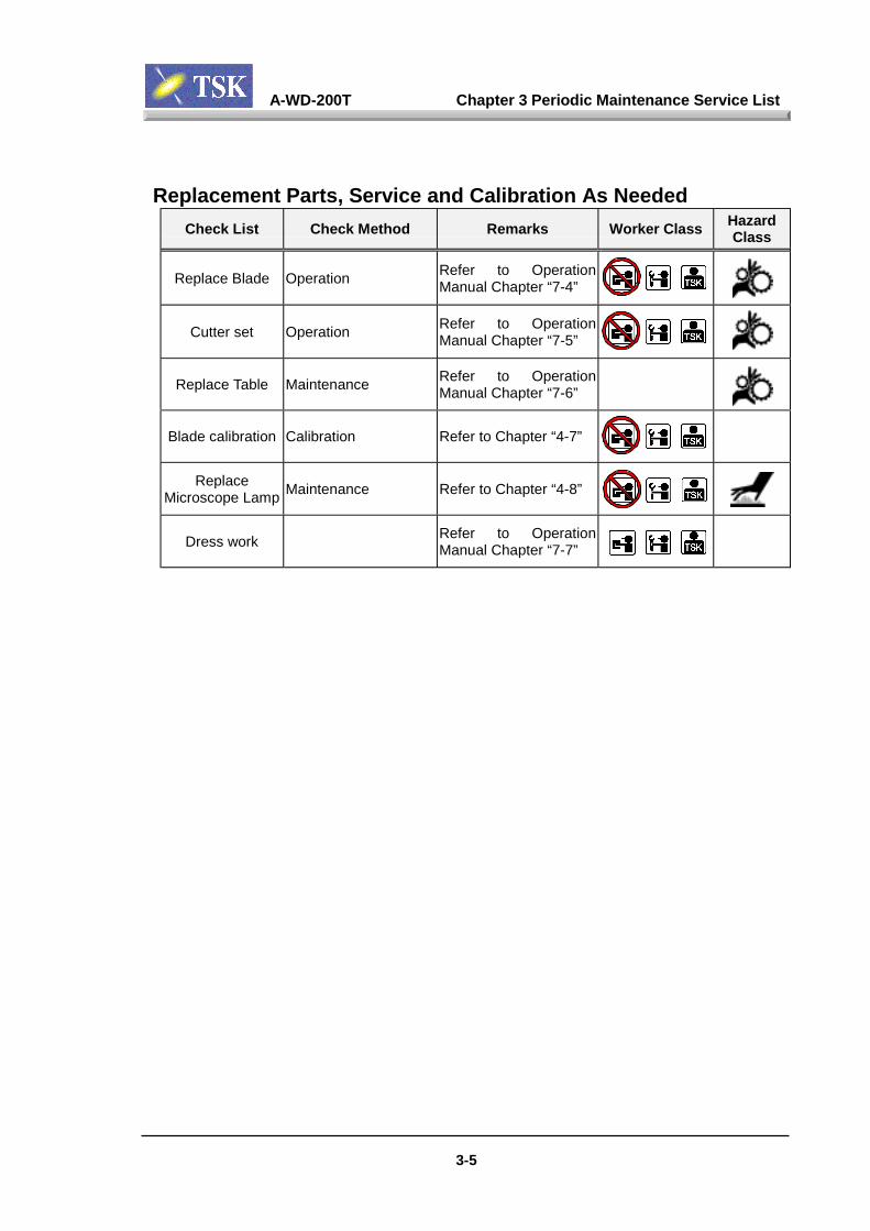
A-WD-200T Chapter 3 Periodic Maintenance Service List
3-5
Replacement Parts, Service and Calibration As NeededCheck List Check Method Remarks Worker Class Hazard
Class
Replace Blade Operation Refer to OperationManual Chapter “7-4”
Cutter set Operation Refer to OperationManual Chapter “7-5”
Replace Table Maintenance Refer to OperationManual Chapter “7-6”
Blade calibration Calibration Refer to Chapter “4-7”
ReplaceMicroscope Lamp Maintenance Refer to Chapter “4-8”
Dress work Refer to OperationManual Chapter “7-7”

Chapter 4 Maintenance And Check List
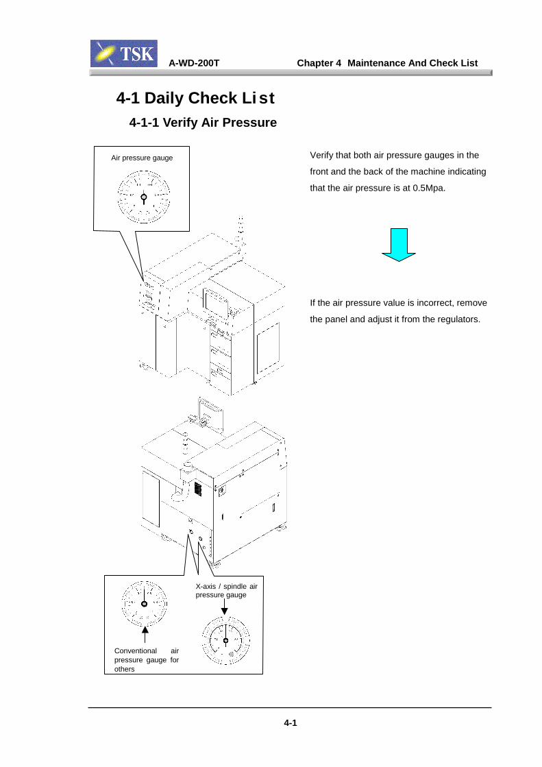
A-WD-200T Chapter 4 Maintenance And Check List
4-1
4-1 Daily Check Li st4-1-1 Verify Air Pressure
Verify that both air pressure gauges in the
front and the back of the machine indicating
that the air pressure is at 0.5Mpa.
If the air pressure value is incorrect, remove
the panel and adjust it from the regulators.
Air pressure gauge
Conventional airpressure gauge forothers
X-axis / spindle airpressure gauge
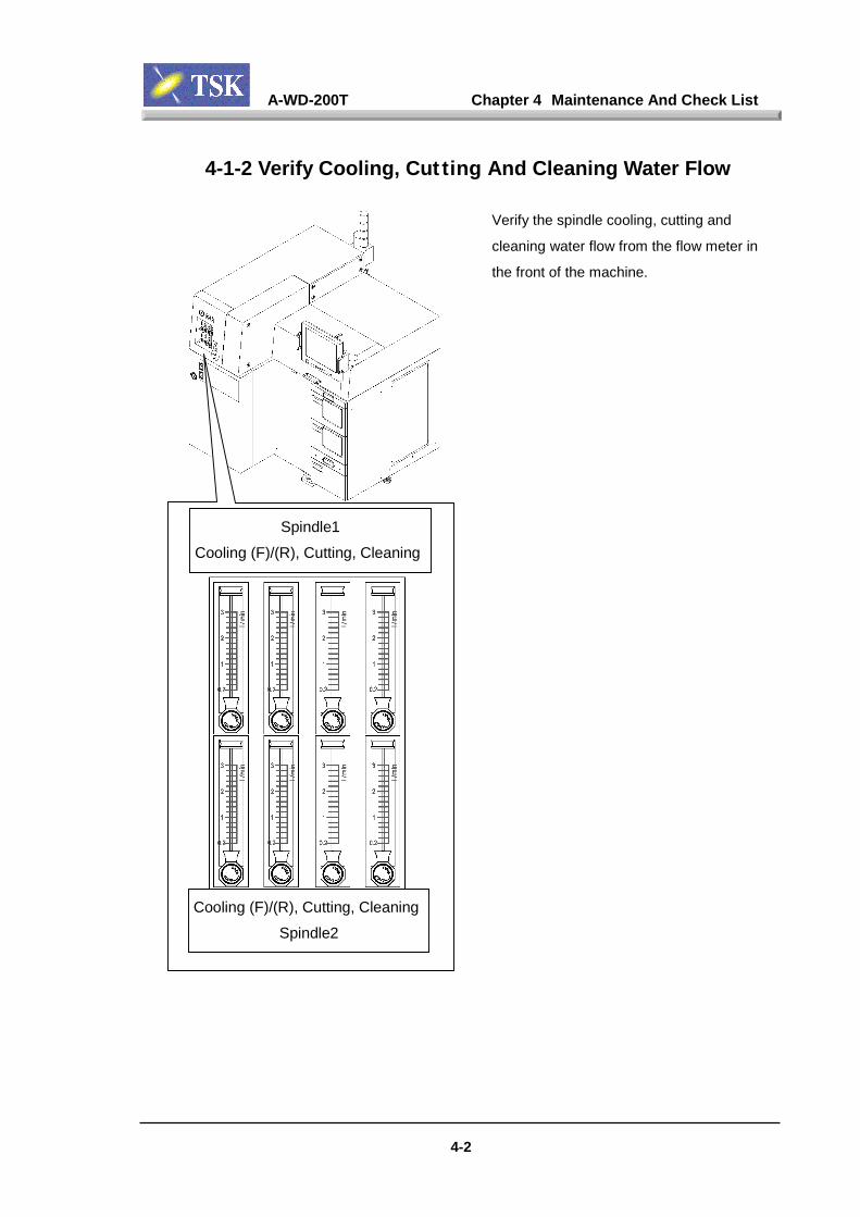
A-WD-200T Chapter 4 Maintenance And Check List
4-2
4-1-2 Verify Cooling, Cut ting And Cleaning Water Flow
Verify the spindle cooling, cutting and
cleaning water flow from the flow meter in
the front of the machine.
Spindle1Cooling (F)/(R), Cutting, Cleaning
Cooling (F)/(R), Cutting, CleaningSpindle2

A-WD-200T Chapter 4 Maintenance And Check List
4-3
4-1-3 Water leakage around the Machine
Verify that there is no water leakage on the
floor under or around machine.
There should be
NO water leakage !
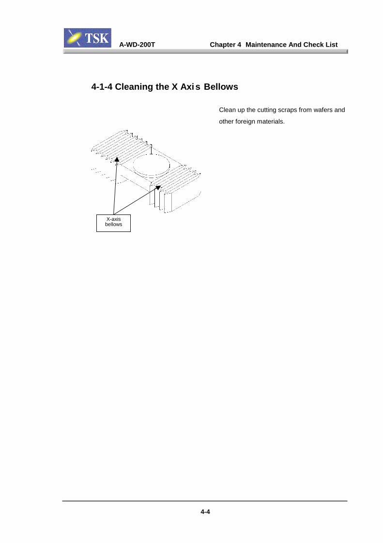
A-WD-200T Chapter 4 Maintenance And Check List
4-4
4-1-4 Cleaning the X Axis Bellows
Clean up the cutting scraps from wafers and
other foreign materials.
X-axisbellows
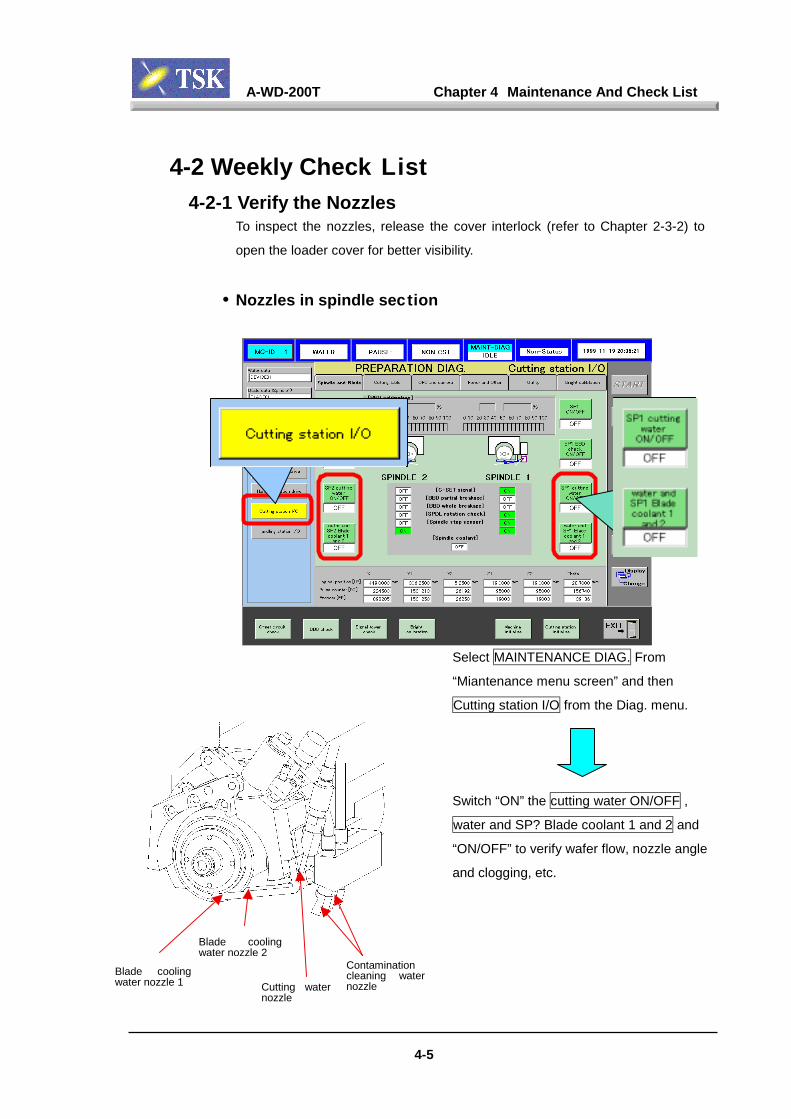
A-WD-200T Chapter 4 Maintenance And Check List
4-2 Weekly Check List4-2-1 Verify the Nozzles
To inspect the nozzles, release the cover interlock (refer to Chapter 2-3-2) to
open the loader cover for better visibility.
• Nozzles in spindle section
Select MAINTENANCE DIAG. From
“Miantenance menu screen” and then
Cutting station I/O from the Diag. menu.
Switch “ON” the cutting water ON/OFF ,
water and SP? Blade coolant 1 and 2 and
“ON/OFF” to verify wafer flow, nozzle angle
and clogging, etc.
Blade coolingwater nozzle 1
Blade coolingwater nozzle 2
4-5
Cutting waternozzle
Contaminationcleaning waternozzle
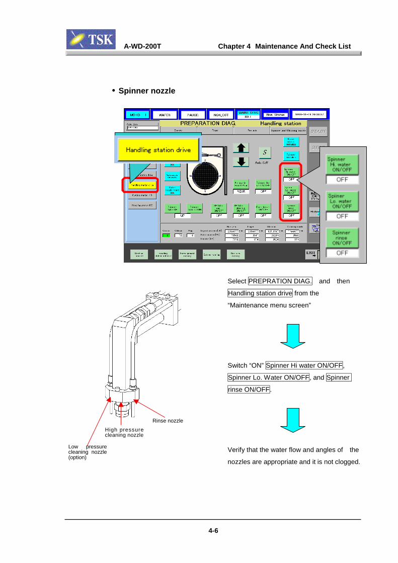
A-WD-200T Chapter 4 Maintenance And Check List
• Spinner nozzle
Select PREPRATION DIAG. and then
Handling station drive from the
“Maintenance menu screen”
Switch “ON” Spinner Hi water ON/OFF,
Spinner Lo. Water ON/OFF, and Spinner
rinse ON/OFF.
Rinse nozzle
High pressurecleaning nozzleVerify that the water flow and angles of the
nozzles are appropriate and it is not clogged.
Low pressurecleaning nozzle(option)
4-6

A-WD-200T Chapter 4 Maintenance And Check List
4-2-2 Spinner Table Check
Select PREPARATION DIAG. and then
Handling station drive from “maintenance
menu screen”
Press the Spinner initialize button, and
verify that the table origin position is correct
and that the table up/down movement is
smooth.
Spinner table
4-7
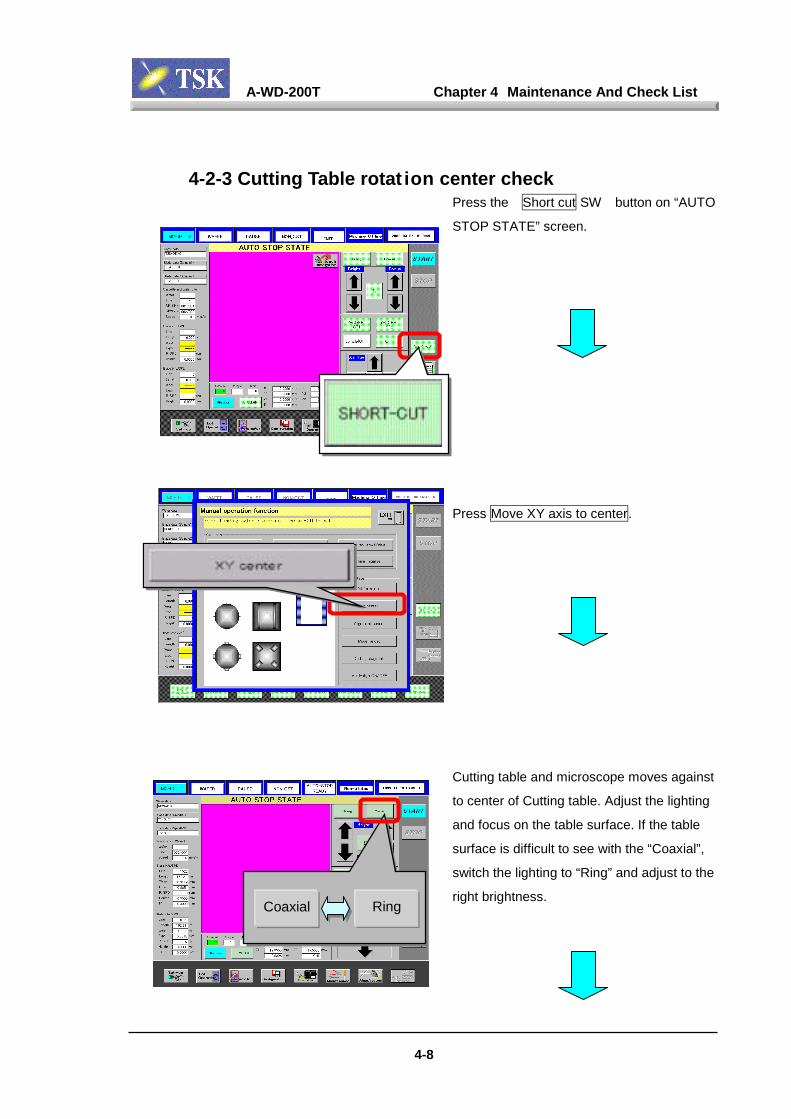
A-WD-200T Chapter 4 Maintenance And Check List
4-8
4-2-3 Cutting Table rotat ion center checkPress the Short cut SW button on “AUTO
STOP STATE” screen.
Press Move XY axis to center.
Cutting table and microscope moves against
to center of Cutting table. Adjust the lighting
and focus on the table surface. If the table
surface is difficult to see with the “Coaxial”,
switch the lighting to “Ring” and adjust to the
right brightness.Coaxial Ring
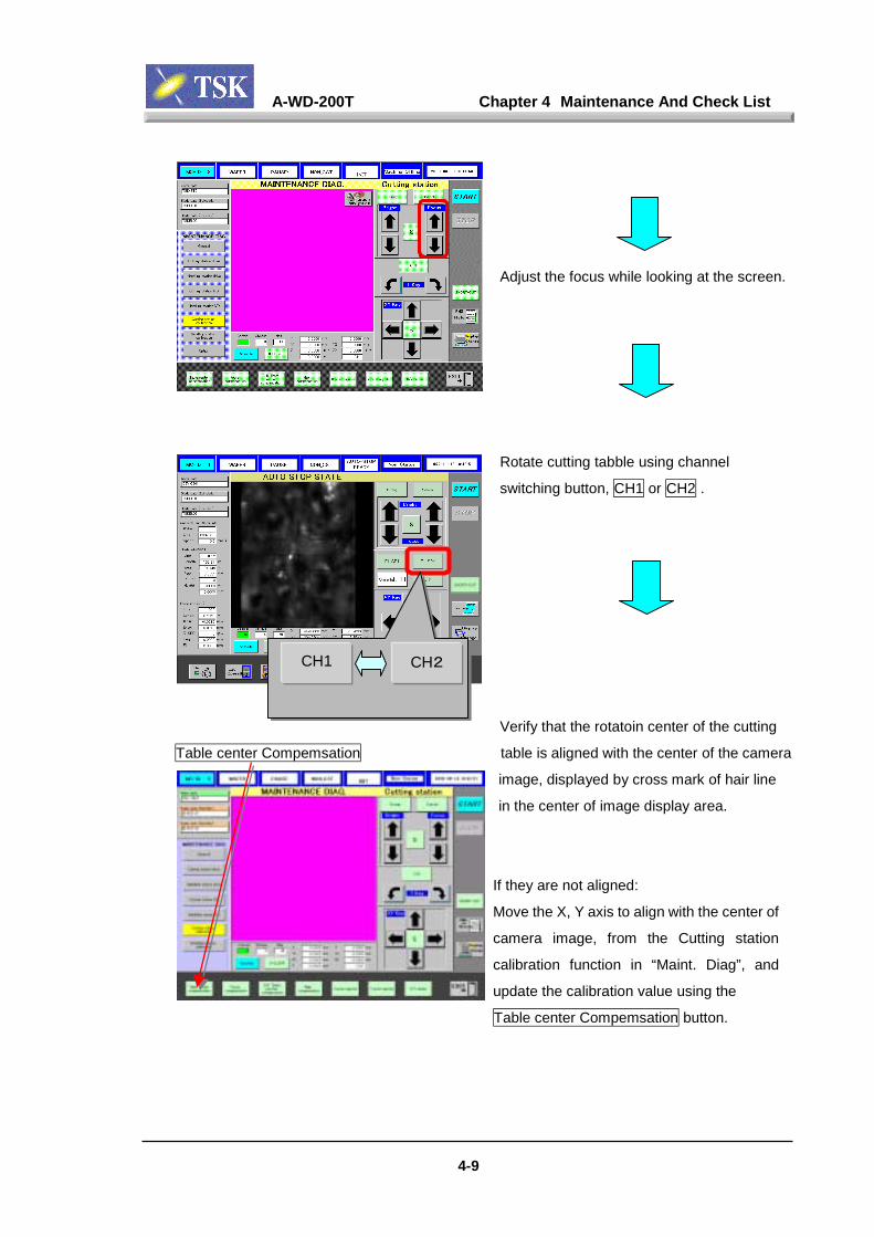
A-WD-200T Chapter 4 Maintenance And Check List
4-9
Adjust the focus while looking at the screen.
Rotate cutting tabble using channel
switching button, CH1 or CH2 .
Verify that the rotatoin center of the cutting
Table center Compemsation table is aligned with the center of the camera
image, displayed by cross mark of hair line
in the center of image display area.
If they are not aligned:
Move the X, Y axis to align with the center of
camera image, from the Cutting station
calibration function in “Maint. Diag”, and
update the calibration value using the
Table center Compemsation button.
CH1 CH2
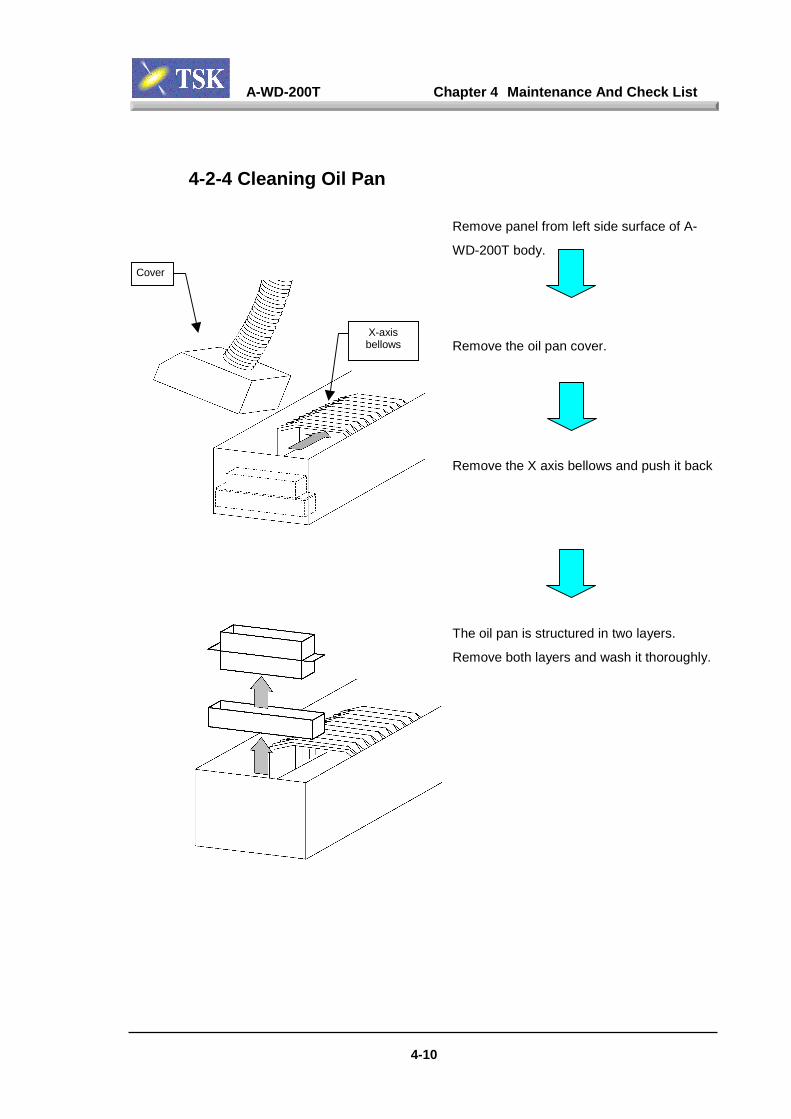
A-WD-200T Chapter 4 Maintenance And Check List
4-10
4-2-4 Cleaning Oil Pan
Remove panel from left side surface of A-
WD-200T body.
Remove the oil pan cover.
Remove the X axis bellows and push it back
The oil pan is structured in two layers.
Remove both layers and wash it thoroughly.
Cover
X-axisbellows
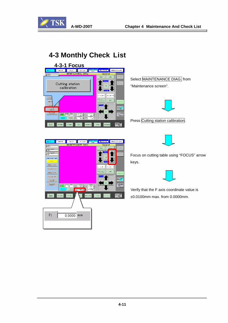
A-WD-200T Chapter 4 Maintenance And Check List
4-3 Monthly Check List4-3-1 Focus
Select MAINTENANCE DIAG. from
“Maintenance screen”.
Press Cutting station calibration.
Focus on cutting table using “FOCUS” arrow
keys.
Verify that the F axis coordinate value is
±0.0100mm max. from 0.0000mm.
F-axis coordinate value
4-11
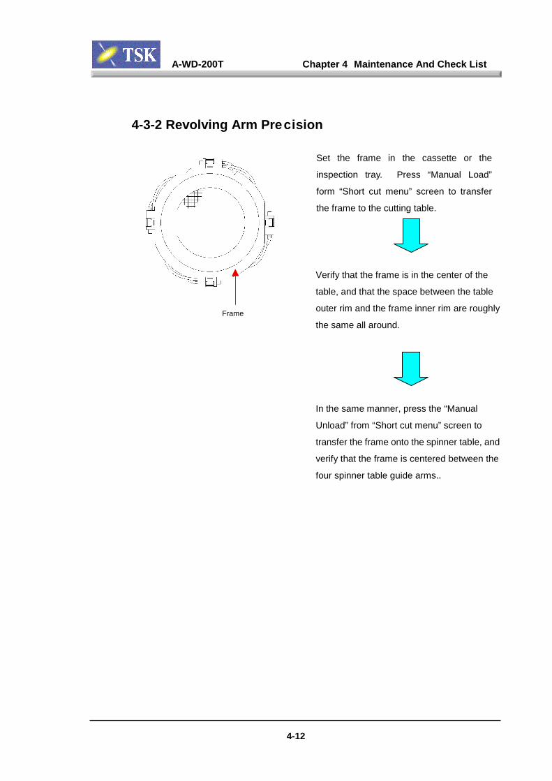
A-WD-200T Chapter 4 Maintenance And Check List
4-12
4-3-2 Revolving Arm Precision
Set the frame in the cassette or the
inspection tray. Press “Manual Load”
form “Short cut menu” screen to transfer
the frame to the cutting table.
Verify that the frame is in the center of the
table, and that the space between the table
outer rim and the frame inner rim are roughly
the same all around.
In the same manner, press the “Manual
Unload” from “Short cut menu” screen to
transfer the frame onto the spinner table, and
verify that the frame is centered between the
four spinner table guide arms..
Frame

A-WD-200T Chapter 4 Maintenance And Check List
4-3-3 Flange surface thrust direction runout
Remove the blade from the flange.
Place the electrical micrometer detecting
element to blade attaching surface of the
Electric micrometerBlade attaching
surface
4-13
flange.
Rotate the flange by hand, and verify that the
meter value is 0.002mm (peak to peak) or
less.
(See Chapter 5 Accuracy for details)
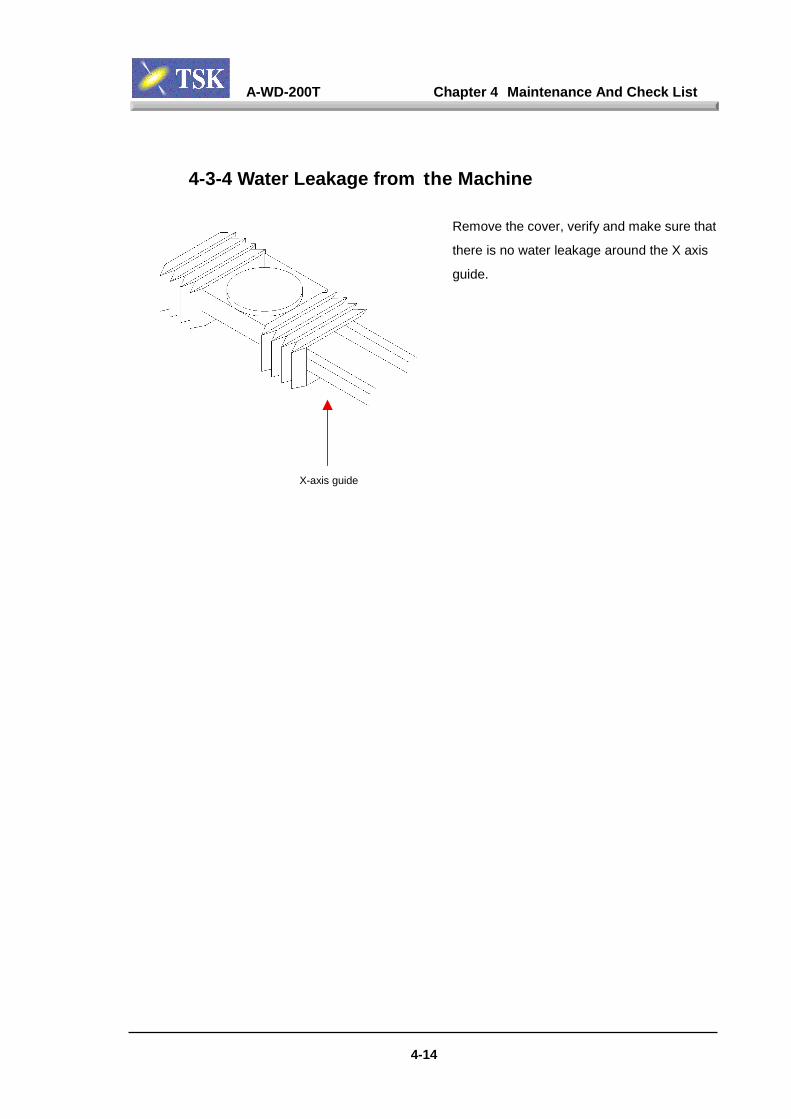
A-WD-200T Chapter 4 Maintenance And Check List
4-3-4 Water Leakage from the Machine
Remove the cover, verify and make sure that
there is no water leakage around the X axis
guide.
X-axis guide
4-14
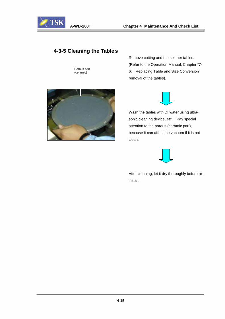
A-WD-200T Chapter 4 Maintenance And Check List
4-15
4-3-5 Cleaning the TablesRemove cutting and the spinner tables.
(Refer to the Operation Manual, Chapter “7-
6: Replacing Table and Size Conversion”
removal of the tables).
Wash the tables with DI water using ultra-
sonic cleaning device, etc. Pay special
attention to the porous (ceramic part),
because it can affect the vacuum if it is not
clean.
After cleaning, let it dry thoroughly before re-
install.
Porous part(ceramic)

A-WD-200T Chapter 4 Maintenance And Check List
4-16
4-3-6 Wafer Table Planarity MeasurementRefer to Chapter 5 “Accuracy”.

A-WD-200T Chapter 4 Maintenance And Check List
4-17
4-3-7 Y Axis Feed Precision
Load dummy wafer (with pattern) on the
cutting table, perform alignment manually or
automatically. Align the edge of the pattern
or street to the screen hair line.
Set “XY key” for I to perform index feed
from the “Operation (Manual Operation)”
screen.
Use the up/down (Y axis) arrow to perform
Y1 axis index feed. Verify and make sure
that the wafer pattern and the hairline are still
aligned.
Axis Speed Button
I: Index feed
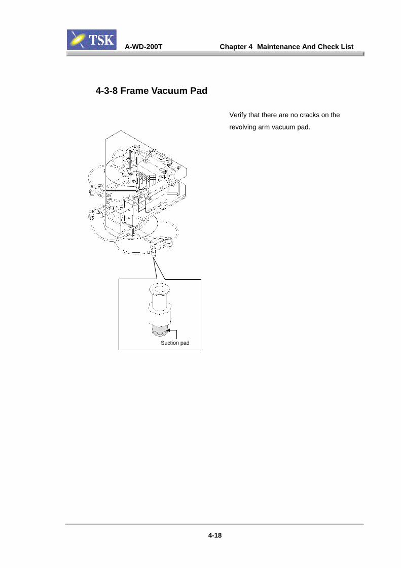
A-WD-200T Chapter 4 Maintenance And Check List
4-18
4-3-8 Frame Vacuum Pad
Verify that there are no cracks on the
revolving arm vacuum pad.
Suction pad

A-WD-200T Chapter 4 Maintenance And Check List
4-19
4-4 3 Months Check List4-4-1 Y Axis Linear Scale Lissajou Wave
The use of the oscilloscope is required for verifying the Litharge Wave. Pleasebe aware that there is a risk of damaging the board according to the deviceused. If problems should occur which require Litharge Wave inspections otherthan regular scheduled inspections, contact TSK.
NotesNotesNotesNotes
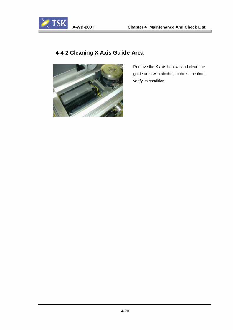
A-WD-200T Chapter 4 Maintenance And Check List
4-20
4-4-2 Cleaning X Axis Guide Area
Remove the X axis bellows and clean the
guide area with alcohol, at the same time,
verify its condition.

A-WD-200T Chapter 4 Maintenance And Check List
4-21
4-4-3 Camera Magnifica tion Offset
Load dummy wafer to the cutting table,
adjust the lighting and focus. For better
visibility, align the screen hairlines cross to
the street cross.
Select “Maintenance Diag.” from the
“Maintenance Screen” and then select
“Cutting station Calibration”.
Switch between high and low magnifications
and make sure that the hairline cross is stay
on the same point that aligned by above
procedure.
If it is not aligned, press the “Camera
High/Low Magnification Calibration” to adjust
the position and press “Enter”.
Hi.mag Low.mag
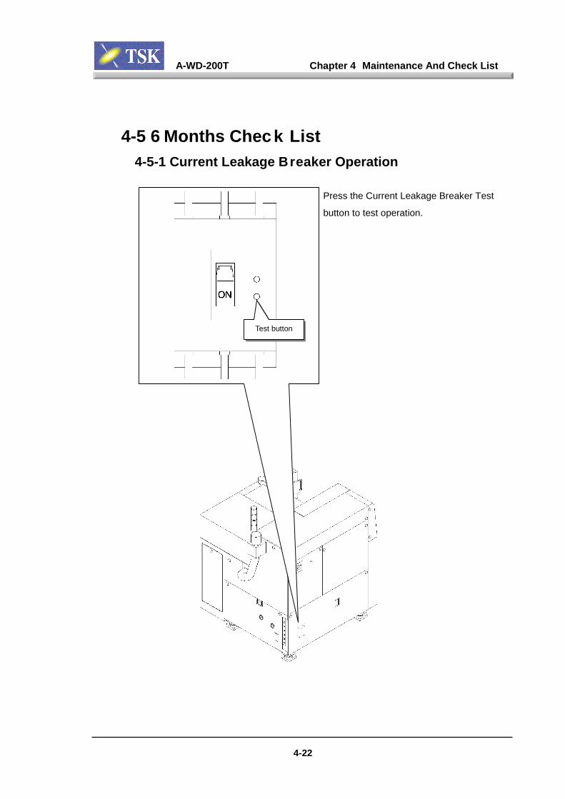
A-WD-200T Chapter 4 Maintenance And Check List
4-22
4-5 6 Months Check List4-5-1 Current Leakage Breaker Operation
Press the Current Leakage Breaker Test
button to test operation.
Test button
A-WD-200T Chapter 4 Maintenance And Check List
4-23
4-5-2 Greasing to the Y Axis Guide/Ball Screw* Refer to Chapter 4-9.
4-5-3 Greasing to the Z Axis Guide/Ball Screw* Refer to Chapter 4-9.
4-5-4 Greasing to the Elevator Axis Guide/Ball Screw* Refer to Chapter 4-9.
A-WD-200T Chapter 4 Maintenance And Check List
4-24
4-6 Yearly Check L ist4-6-1 X Axis Straightness (Vertically)
Refer to Chapter 5 “Accuracy”.
4-6-2 X Axis Straightness (Horizontally)Refer to Chapter 5 “Accuracy”.
4-6-3 Spindle Axis & X Axis PerpendicularityRefer to Chapter 5 “Accuracy”.
4-6-4 Z Axis Precision Repeatability MeasurementRefer to Chapter 5 “Accuracy”.
4-6-5 Spindle Run Out Measurement (Radial Direction)Refer to Chapter 5 “Accuracy”.

A-WD-200T Chapter 4 Maintenance And Check List
4-25
4-6-6 Replacement of the Air Filter Element
Remove the panel in the back and replace
the filter.
F300-2F Filter Element
MMF150 Filter Element
Air filters
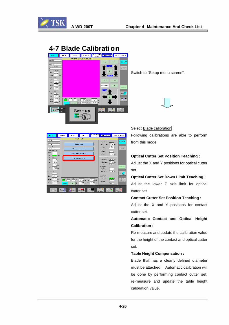
A-WD-200T Chapter 4 Maintenance And Check List
4-26
4-7 Blade Calibrati on
Switch to “Setup menu screen”.
Select Blade calibration.
Following calibrations are able to perform
from this mode.
Optical Cutter Set Position Teaching :
Adjust the X and Y positions for optical cutter
set.
Optical Cutter Set Down Limit Teaching :
Adjust the lower Z axis limit for optical
cutter.set.
Contact Cutter Set Position Teaching :
Adjust the X and Y positions for contact
cutter set.
Automatic Contact and Optical Height
Calibration :
Re-measure and update the calibration value
for the height of the contact and optical cutter
set.
Table Height Compensation :
Blade that has a clearly defined diameter
must be attached. Automatic calibration will
be done by performing contact cutter set,
re-measure and update the table height
calibration value.
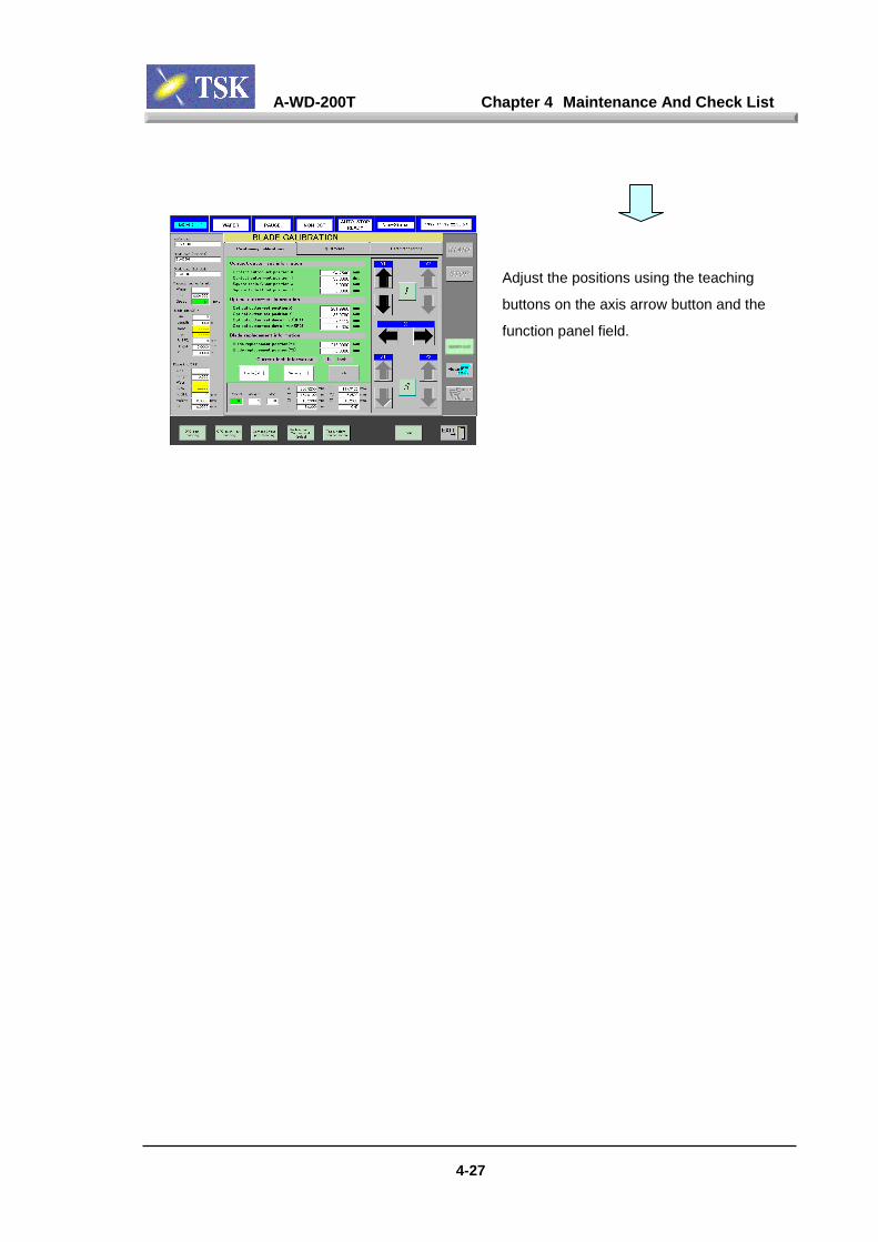
A-WD-200T Chapter 4 Maintenance And Check List
4-27
Adjust the positions using the teaching
buttons on the axis arrow button and the
function panel field.

A-WD-200T Chapter 4 Maintenance And Check List
4-28
4-8 Replace Came ra Lamp
Always replace with new lamp.
WARNINGWARNINGWARNINGWARNING
Do not touch the halogen lamp on the camera during orimmediately after shutting down the power. Wait for thesurface temperature to cool down below 50°°°°C before startingreplacement.
Do not touch the lamp with bare hand, hand oil on the glasscan reduce the amount of lighting.
IMPORTANTIMPORTANTIMPORTANTIMPORTANT
Microscope lamp
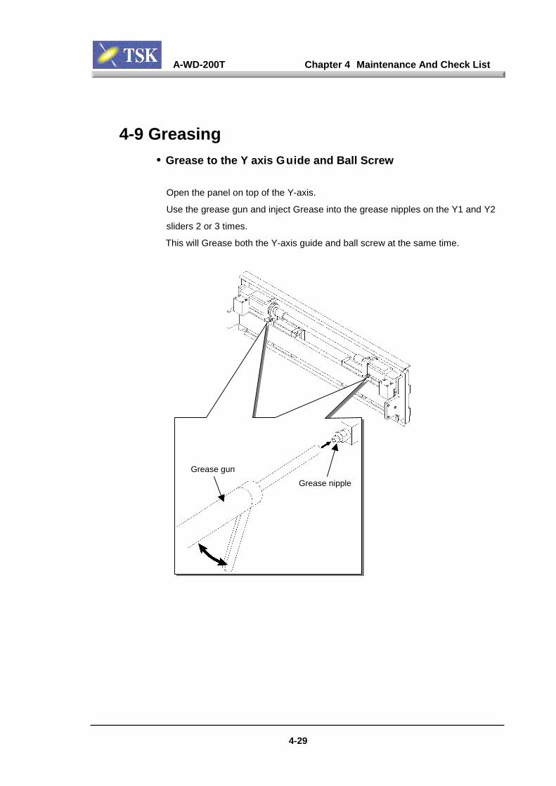
A-WD-200T Chapter 4 Maintenance And Check List
4-9 Greasing• Grease to the Y axis Guide and Ball Screw
Open the panel on top of the Y-axis.
Use the grease gun and inject Grease into the grease nipples on the Y1 and Y2
sliders 2 or 3 times.
This will Grease both the Y-axis guide and ball screw at the same time.
Grease gun
4-2
Grease nipple
9
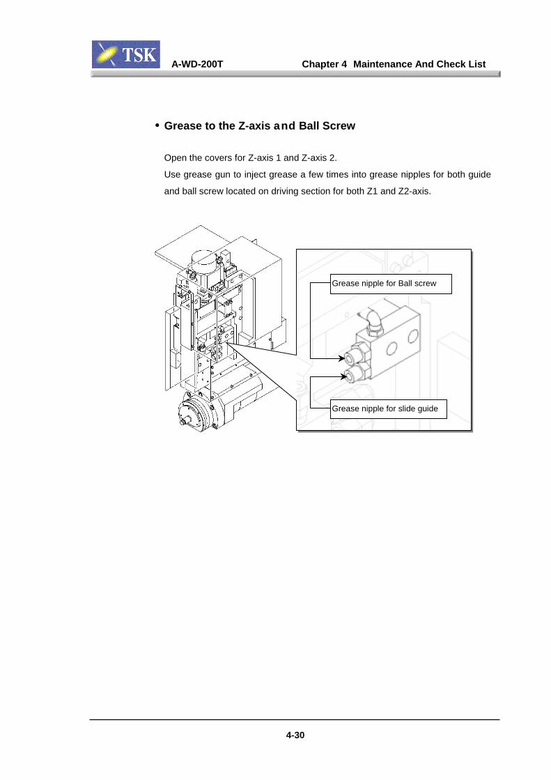
A-WD-200T Chapter 4 Maintenance And Check List
4-30
• Grease to the Z-axis and Ball Screw
Open the covers for Z-axis 1 and Z-axis 2.
Use grease gun to inject grease a few times into grease nipples for both guide
and ball screw located on driving section for both Z1 and Z2-axis.
Grease nipple for slide guide
Grease nipple for Ball screw
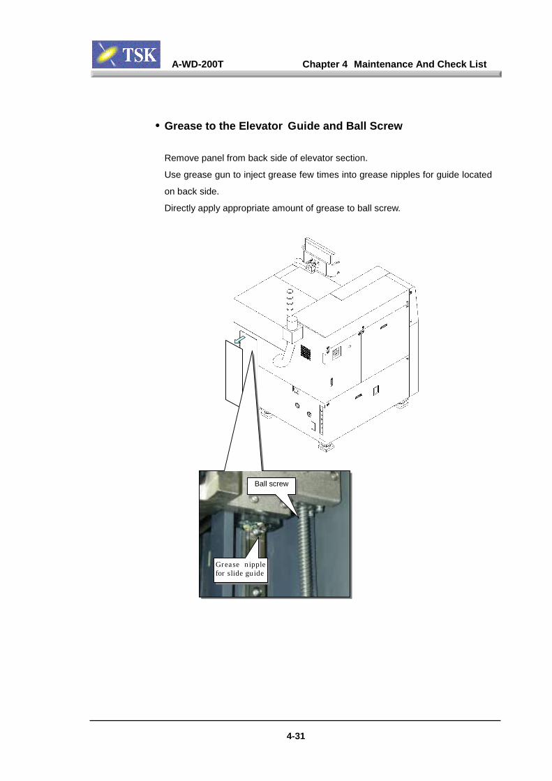
A-WD-200T Chapter 4 Maintenance And Check List
4-31
• Grease to the Elevator Guide and Ball Screw
Remove panel from back side of elevator section.
Use grease gun to inject grease few times into grease nipples for guide located
on back side.
Directly apply appropriate amount of grease to ball screw.
Grease nipplefor slide guide
Ball screw

Chapter 5 Accuracy
A-WD-200T Chapter 5 Accuracy
5-1
The machine accuracy should be measured in a regular basis in order to take
full advantage of its ability for stabilized and highly accurate cutting results.
When accuracy is measured, there should be air supplyed to the machine.
CAUTIONCAUTIONCAUTIONCAUTION
When accuracy is measured, set the axis to the lowest speed.
CAUTIONCAUTIONCAUTIONCAUTION
When adjusting straightness between the X axis and the stretch, set the stretchwithin measurement area.
CAUTIONCAUTIONCAUTIONCAUTION
Secure the cables of the detection devices so it does not get in the way of themeasuring process.
CAUTIONCAUTIONCAUTIONCAUTION
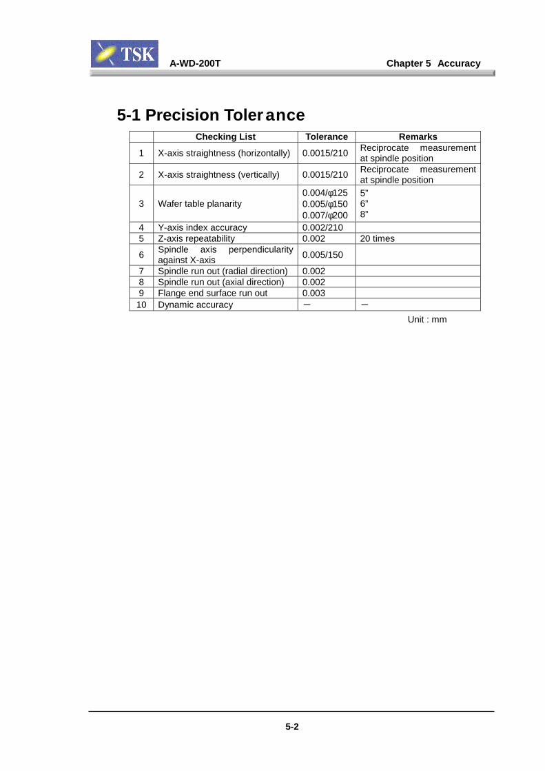
A-WD-200T Chapter 5 Accuracy
5-2
5-1 Precision ToleranceChecking List Tolerance Remarks
1 X-axis straightness (horizontally) 0.0015/210 Reciprocate measurementat spindle position
2 X-axis straightness (vertically) 0.0015/210 Reciprocate measurementat spindle position
3 Wafer table planarity0.004/φ1250.005/φ1500.007/φ200
5”6”8”
4 Y-axis index accuracy 0.002/2105 Z-axis repeatability 0.002 20 times
6 Spindle axis perpendicularityagainst X-axis 0.005/150
7 Spindle run out (radial direction) 0.0028 Spindle run out (axial direction) 0.0029 Flange end surface run out 0.00310 Dynamic accuracy - -
Unit : mm
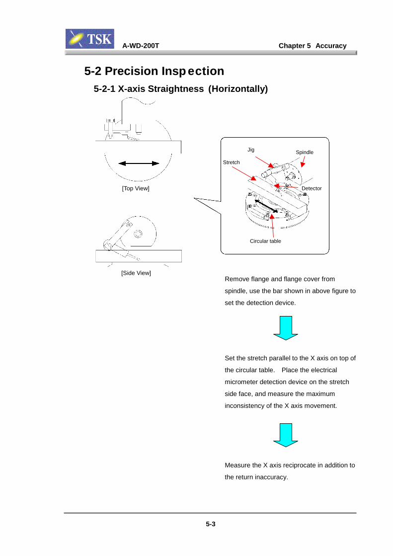
A-WD-200T Chapter 5 Accuracy
5-3
5-2 Precision Insp ection5-2-1 X-axis Straightness (Horizontally)
Remove flange and flan
spindle, use the bar sho
set the detection device
Set the stretch parallel
the circular table. Plac
micrometer detection d
side face, and measure
inconsistency of the X a
Measure the X axis rec
the return inaccuracy.
Stretch
Jig
Circular table
[Top View]
[Side View]
Spindle
ge cover from
wn in above figure to
.
to the X axis on top of
e the electrical
evice on the stretch
the maximum
xis movement.
iprocate in addition to
Detector
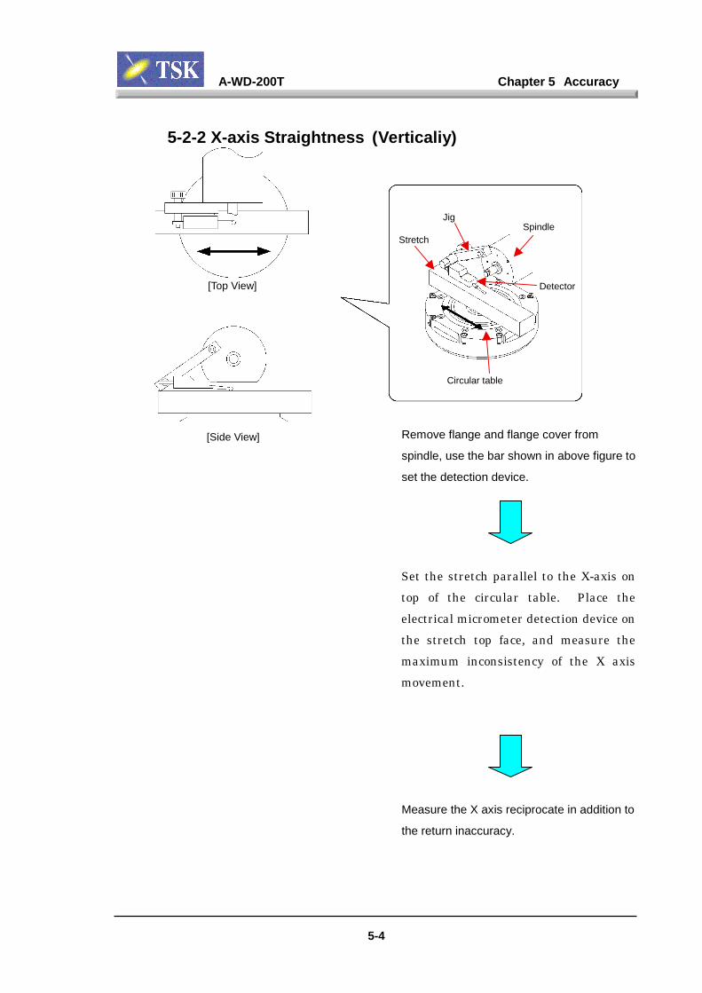
A-WD-200T Chapter 5 Accuracy
5-4
5-2-2 X-axis Straightness (Verticaliy)
Remove flange and flange cover from
spindle, use the bar shown in above figure to
set the detection device.
Set the stretch parallel to the X-axis on
top of the circular table. Place the
electrical micrometer detection device on
the stretch top face, and measure the
maximum inconsistency of the X axis
movement.
Measure the X axis reciprocate in addition to
the return inaccuracy.
StretchSpindle
Detector
Jig
Circular table
[Top View]
[Side View]

A-WD-200T Chapter 5 Accuracy
5-5
5-2-3 Wafer Table Planar ity
Set the detection device on the spindle in the
same manner as when measuring the X axis
straightness (vertically).
Place the detection device on the wafer table.
Take the measurement of the maximum
inconsistency value of the X and Y axis
movement.
Measurementpoints
Measurementpoints[Top View]
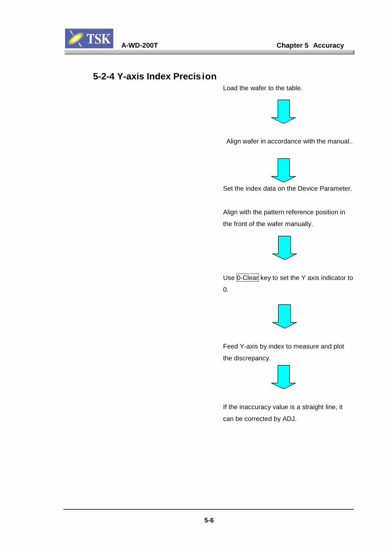
A-WD-200T Chapter 5 Accuracy
5-6
5-2-4 Y-axis Index Precis ionLoad the wafer to the table.
Align wafer in accordance with the manual..
Set the index data on the Device Parameter.
Align with the pattern reference position in
the front of the wafer manually.
Use 0-Clear key to set the Y axis indicator to
0.
Feed Y-axis by index to measure and plot
the discrepancy.
If the inaccuracy value is a straight line, it
can be corrected by ADJ.
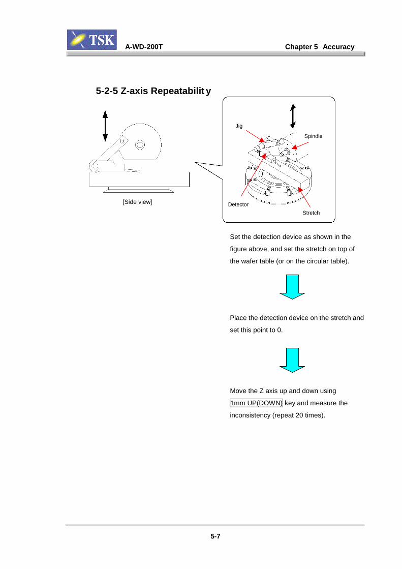
A-WD-200T Chapter 5 Accuracy
5-7
5-2-5 Z-axis Repeatabilit y
Set the detection device
figure above, and set th
the wafer table (or on th
Place the detection dev
set this point to 0.
Move the Z axis up and
1mm UP(DOWN) key a
inconsistency (repeat 20
Detector[Side view]
Spindle
Jig
Stretch
as shown in the
e stretch on top of
e circular table).
ice on the stretch and
down using
nd measure the
times).
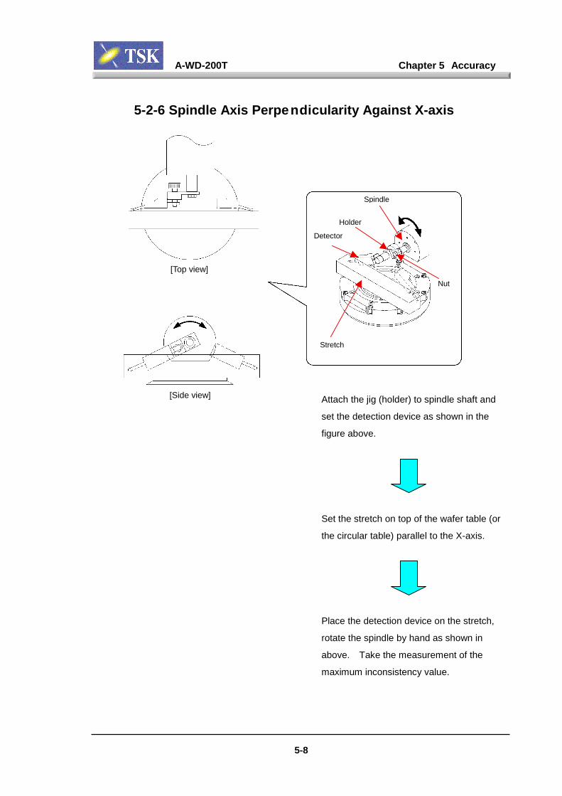
A-WD-200T Chapter 5 Accuracy
5-8
5-2-6 Spindle Axis Perpendicularity Against X-axis
Attach th
set the de
figure ab
Set the s
the circul
Place the
rotate the
above.
maximum
Detector
[Top view]
[Side view]
Spindle
Stretch
e jig (holder) to sp
tection device as
ove.
tretch on top of th
ar table) parallel t
detection device
spindle by hand
Take the measure
inconsistency va
Nut
Holder
indle shaft and
shown in the
e wafer table (or
o the X-axis.
on the stretch,
as shown in
ment of the
lue.
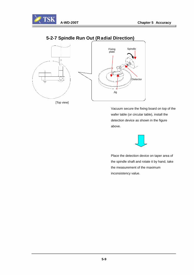
A-WD-200T Chapter 5 Accuracy
5-9
5-2-7 Spindle Run Out (Radial Direction)
Vacuum s
wafer tabl
detection
above.
Place the
the spindle
the measu
inconsiste
Fixingplate
[Top view]
Spindle
Jig
ecu
e (o
dev
det
sh
rem
ncy
Detector
re the fixing board on top of the
r circular table), install the
ice as shown in the figure
ection device on taper area of
aft and rotate it by hand, take
ent of the maximum
value.
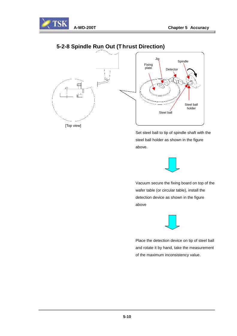
A-WD-200T Chapter 5 Accuracy
5-10
5-2-8 Spindle Run Out (Thrust Direction)
Set steel ball to tip of s
steel ball holder as sho
above.
Vacuum secure the fixi
wafer table (or circular
detection device as sh
above
Place the detection de
and rotate it by hand, t
of the maximum incons
DetectFixingplate
[Top view]
Spindle
Jigor
Steel ballholder
Steel ball
pindle shaft with the
wn in the figure
ng board on top of the
table), install the
own in the figure
vice on tip of steel ball
ake the measurement
istency value.
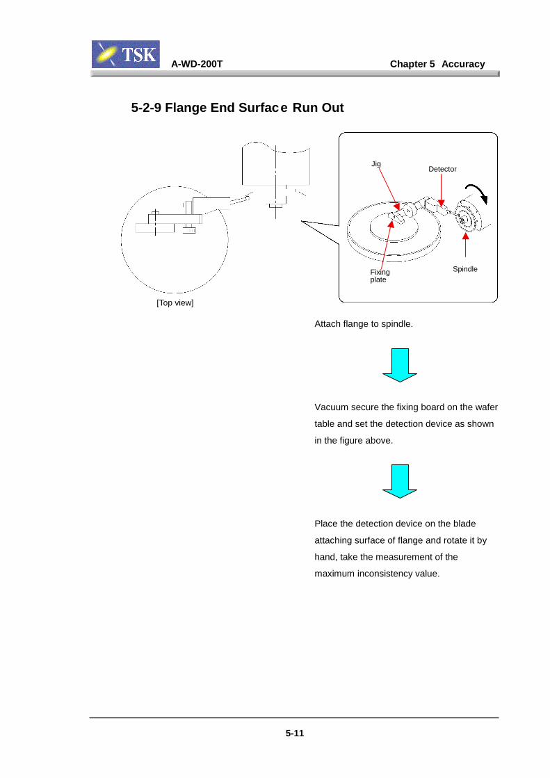
A-WD-200T Chapter 5 Accuracy
5-11
5-2-9 Flange End Surface Run Out
Attach flange to spindle.
Vacuum secure the fixing board
table and set the detection devic
in the figure above.
Place the detection device on the
attaching surface of flange and r
hand, take the measurement of t
maximum inconsistency value.
Fixingplate
[Top view]
Spindle
Jig
Detectoron the wafer
e as shown
blade
otate it by
he
A-WD-200T Chapter 5 Accuracy
5-12
5-2-10 Dynamic AccuracyPerform dicing with a wafer (dummy wafer
can be available) to measure the dynamic
accuracy.
Verify cutting accuracy.
・ Y-axis index accuracy (pitch
inconsistency).
・ Straightnes of sawn kerf
・ Cutting depth.
・ Chipping
・ Kerf width

Chapter 6 Troubleshooting
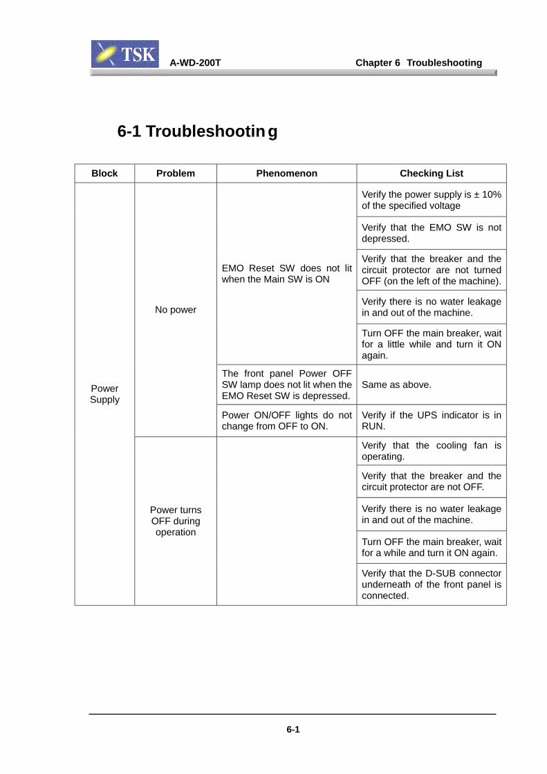
A-WD-200T Chapter 6 Troubleshooting
6-1
6-1 Troubleshooting
Block Problem Phenomenon Checking List
Verify the power supply is ± 10%of the specified voltage
Verify that the EMO SW is notdepressed.
Verify that the breaker and thecircuit protector are not turnedOFF (on the left of the machine).
Verify there is no water leakagein and out of the machine.
EMO Reset SW does not litwhen the Main SW is ON
Turn OFF the main breaker, waitfor a little while and turn it ONagain.
The front panel Power OFFSW lamp does not lit when theEMO Reset SW is depressed.
Same as above.
No power
Power ON/OFF lights do notchange from OFF to ON.
Verify if the UPS indicator is inRUN.
Verify that the cooling fan isoperating.
Verify that the breaker and thecircuit protector are not OFF.
Verify there is no water leakagein and out of the machine.
Turn OFF the main breaker, waitfor a while and turn it ON again.
PowerSupply
Power turnsOFF duringoperation
Verify that the D-SUB connectorunderneath of the front panel isconnected.

A-WD-200T Chapter 6 Troubleshooting
6-2
Block Problem Phenomenon Checking ListVerify the power is ON. (Is thePower LED ON?)No displays on the touch
panel.Verify VGA cable connection.
Unable to turnON the PC
Only few lines of the messageare displayed.
Verify that the PC cables areconnected correctly. Verify ifthe mouse and keyboard areconnected (they should not beconnected)
Verify that the network cable isconnected (PC~VME)Verify the RUN_LED of theVME rack slot 1 CPU board isflashing.Verify the FAIL_LED is lit.
Verify if the network cableconversion transceiver LED isflashing.
PC
No dicer displayUnable to start up the dicerGUI following the Windows-NT
Turn OFF the machine andrestart.
After start up the Window-NT,verify that the touch panel driverindicator is working properly.
Turn OFF the machine andrestart.
TouchPanel
No reaction fromthe touch panel.
Verify that the cable between thePC COM1 board and the touchpanel is connected.
Unable to openthe loader cover
Unable to release the coverlock at the specified timing
Verify that the connector for thepower control board (HA1118) atthe lower left of electrical frameis connected.
Unable to closethe loader cover
Unable to close the cover lockat the specified timing
Verify that the “LOCK” ”UNLOCK”on the right of the cover lock unitis not on “UNLOCK”.
Verify that the connector for thepower control board (HA1118) atthe lower left of the electricalframe is connected.
CoverInterlock
Warning saysthe cover isopen eventhough it is
closed.
Unable to operate the machine.
Verify that the lock key isinserted all the way in.

A-WD-200T Chapter 6 Troubleshooting
6-3
Block Problem Phenomenon Checking List
Verify that the UPS indicator isnot on ALM.
UPS malfunction Indicating “UPS” malfunction. Verify that the connector for thepower control board (HA1118) atthe lower left of the electricalframe is connected.
The alarm goes off every 3seconds.
Detecting input power failure.The machine shuts offautomatically, shuts the mainbreaker and restart again.
UPS
UPS alarm
Continuous sound of alarm Cooling fan malfunction inside ofthe UPS.
Verify the error message on theX-axis driver.
No motor torque Verify power supply to the X-axisdriver unit.Verify that the circuit protectorCB11 is ON.
Unable toinitialize the
X-axis
Unable to detect the originsensor
Verify that the origin sensor onthe right side of the X-axis isoperating.Verify the wiring is not open.Verify the X-axis driver unit errordisplay.Turn off the machine, move theX-axis by hand to see if themovement is smooth.
X-axis
X-axis servocontrol failure
Verify that there are no damageson the X-axis linear scale cablelines.

A-WD-200T Chapter 6 Troubleshooting
6-4
Block Problem Phenomenon Checking ListVerify the power supply to the Yaxis driver unit (AC 100V).Verify that the circuit protectorCB15 (Y1) and CB16 (Y2) areON.No motor torque
Verify for Y axis driver unit panelindication (TIM or OL) error.
Verify that both origin sensors,front (Y1) and rear (Y2) areoperating.Verify the wiring.
Unable toinitialize the
Y-axis
Unable to detect the originsensor. Verify that the fan sensor in the
center is operating.Verify its wiring.Verify that the connectors areconnected.
Verify for Y axis driver unit panelindication (TIM or OL) error.
Turn off the machine, move theY axis manually to see if themovement is smooth.
Y-axis
Y-axis servocontrol failure
Verify if the linear scale readingboard (DIVIDER) connector isconnected.
No motor torque
Verify power supply (DC 24V) tothe Z axis driver unit.Verify that the power LED(green) is lit.Unable to
initialize Z-axisUnable to detect the originsensor
Verify that the top origin sensoris operating.Verify the wiring.
Turn off the machine, move Z-axis by hand to see if themovement is smooth. (withopen Z-axis cover.)
Z-axis
Z-axis controlfailure
Verify that the Z-axis encoderline relay connector isconnected.Verify that the cables in Y-axismovable cable section are notdamaged.
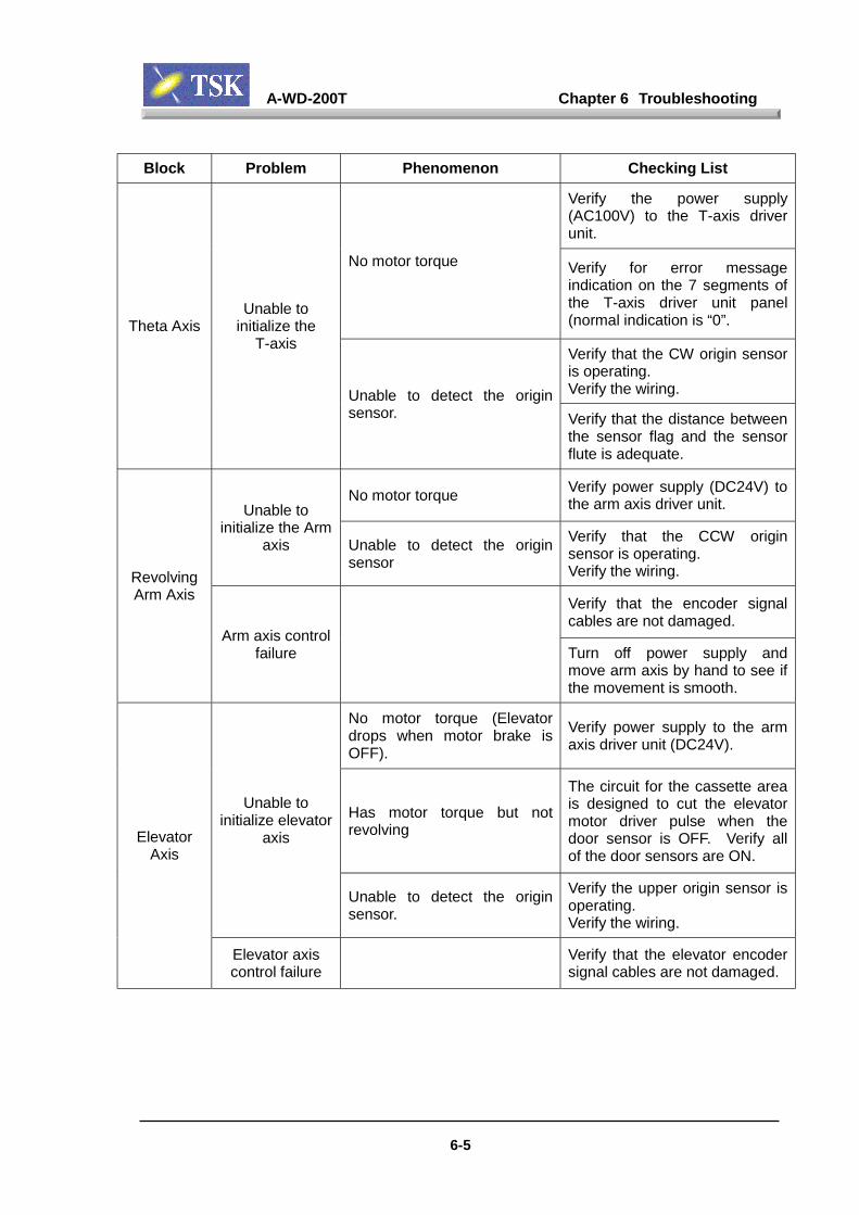
A-WD-200T Chapter 6 Troubleshooting
6-5
Block Problem Phenomenon Checking List
Verify the power supply(AC100V) to the T-axis driverunit.
No motor torque Verify for error messageindication on the 7 segments ofthe T-axis driver unit panel(normal indication is “0”.
Verify that the CW origin sensoris operating.Verify the wiring.
Theta AxisUnable to
initialize theT-axis
Unable to detect the originsensor. Verify that the distance between
the sensor flag and the sensorflute is adequate.
No motor torque Verify power supply (DC24V) tothe arm axis driver unit.Unable to
initialize the Armaxis Unable to detect the origin
sensor
Verify that the CCW originsensor is operating.Verify the wiring.
Verify that the encoder signalcables are not damaged.
RevolvingArm Axis
Arm axis controlfailure Turn off power supply and
move arm axis by hand to see ifthe movement is smooth.
No motor torque (Elevatordrops when motor brake isOFF).
Verify power supply to the armaxis driver unit (DC24V).
Has motor torque but notrevolving
The circuit for the cassette areais designed to cut the elevatormotor driver pulse when thedoor sensor is OFF. Verify allof the door sensors are ON.
Unable toinitialize elevator
axis
Unable to detect the originsensor.
Verify the upper origin sensor isoperating.Verify the wiring.
ElevatorAxis
Elevator axiscontrol failure
Verify that the elevator encodersignal cables are not damaged.

A-WD-200T Chapter 6 Troubleshooting
6-6
Block Problem Phenomenon Checking ListVerify the error message on thespinner driver unit.
Unable toinitialize the
spinnerNo motor torque Verify power supply for the
spinner driver unit (AC100V).Verify that the circuit protectorCB17 is ON.
Spinner
Spinner unableUp/Down
Verify that the Up/Down cylinderis operating.
No motor torque Verify the power supply to thefinger axis driver unit (DC24V)
Unable toinitialize finger
axis Unable to detect the originsensor
Verify that the rear origin driverunit is operating.Verify the wiring is in goodcondition.Verify that the finger movementis smooth from/to the cassette.If not, can it be corrected byadjusting the height?
Verify to see if the movement isnot smooth because of theframe or the cassette is notstraight.
Finger
Finger axiscontrol failure
Verify that the finger axisencoder signal cables are notdamaged.

A-WD-200T Chapter 6 Troubleshooting
6-7
Block Problem Phenomenon Checking ListVerify power supply to thespindle driver unit (AC100V).Verify that the circuit protectorCB13 (S1) and CB14 (S2) areON.No motor torqueVerify the error message on the7 segments indicator of thespindle driver unit panel. (“0” isindicated when it is normal.)
Error message for spindledriver.Error code “0”.
The power transistor in thespindle driver unit is overheated.Possibility of spindle drivermalfunction.
Error message for spindledriver.Error code “2”.
Abnormal output from thespindle rotation detection sensor(Phase A, B).Hole sensor wiring path failureor sensor malfunction.
Error message for spindledriver.Error code “3”.
Abnormal power supply(AC100V) to the spindle driverunit.
Error message for spindledriver.Error code “8”.
Spindle motor overheated.Verify cooling water supply.
Error message for spindledriver.Error code “A”.
Spindle motor overloaded.Verify that the type of cuttingperformed is not causingoverload to the motor.
Error message for spindledriver.Error code “P”.
Detected spindle driver overcurrent.Verify that the type of cuttingperformed is not causingoverload to the motor.
Spindle
Unable to rotatethe spindle
Rotation is notstable.
Error message for spindledriver.Error code “9”.
Abnormal spindle motor rotation.Possibility of abnormal holesensor output or driver unitmalfunction.

A-WD-200T Chapter 6 Troubleshooting
6-8
Block Problem Phenomenon Checking List
Water leakage under the cuttingtable (under the angular cover)
Disconnect the green and yellowwires (CT- and TSLD wires) infront of the X carriage, measurethe resistance value betweenthe table and the GND (Xcarriage GND).If it is more than 1MΩ, thecutting table is normal.If it is less than 1MΩ, it meansthat the resistance value is lowdue to water leakage. Blow dryunder the angular cover.
The table is notelectrically
floated.The cutting table is grounded.
Set the cutting set circuit forchecking mode (with thecommand from the maintenancediag.) If the cutter set signal isOFF , it indicates floating.
Verify the green and the yellowwires (CT- and TSLD), in front ofthe X carriage and see if there isopen circuit caused bydisconnection of connector.Table Circuit
Checking Error Open circuit.Set the cutter circuit on tablecircuit checking mode (Maint.Diag. Command), if the cutterset signal is ON, the circuit isOK.Set the cutter set circuit on lockchecking mode (Maint. Diag.Command), if the cutter setsignal is ON, the circuit is OK.
Spindle brushcircuit check
error
No contact from the brushbetween the spindle and theGND
Remove the brush and verify ifthe brush is damaged.
Set the cutter circuit in LockChecking mode (Maint. Diag.Command), if the cutter signal isOFF, the circuit is OK.
ContactCutter Set
Spindle lockcheck error
The spindle shaft is contactingthe outer tube (normallyinsulated by air). While supplying air to the
spindle, rotate the shaft by handand see if it will rotate slightly.(Verify that the power is OFF.)

A-WD-200T Chapter 6 Troubleshooting
6-9
Block Problem Phenomenon Checking List
Verify if the prism part of opticalcutter set unit (prism objectsurface) is dirty.Verify if the water flow forcleaning prism surface of theunit during cutting process istargeted for the entire object.
Pluscompensation
error.Compensation
error.
Excess in positive directioncompared to previous heightof cutter set.
Verify if the amp output voltageis lower than 7V.
Verify if there is water leakagefrom flange cover on the prismpart of optical cutter set unit(prism object surface).
Cutter setposition can not
defineVerify if the amp output voltageis lower than 7V.
Verify if the prism part of opticalcutter set unit (prism objectsurface) is dirty.Verify if the water flow forcleaning prism surface of theunit during cutting process istargeted for the entire object.
Insufficient initiallighting
The initial lighting check wasperformed under fullytransmitted condition beforeoptical cutter set.The checking result was under6V. Verify if too much water dripping
from the flange cover onto theprism part of optical cutter setunit (prism object surface).
Verify if water is continuouslydripping from the flange coveronto the prism part of opticalcutter set unit (prism objectsurface).
Verify there is sufficient air blow(Hi air) on the prism surface toblow off water drops.
Opticalcutter set
Unstable initiallight value
The initial light value checkwas performed under fullytransmitted condition beforeoptical cutter set.The checking result indicatesthat it could not reach to astabilized initial light value forthe specified period of time.
Verify if the air blow of Lo. air istoo strong.

Chapter 7 Error Messages

A-WD-200T Chapter 7 Error Messages
7-1
7-1 Error Message List
Code Contents Countermeasure
[0000] Undefined error. Install new error message file.
[0001] UPS is working. Check power supply, and restartmachine.
[0002] AC-failure detected. Check power supply, and restartmachine.
[0003] Emergency stop detected. Restart machine.
[0004] Power-off signal isdetected.
See you again.
[0005] Electrical power for driving unitsis not detected.
Check that electrical power fordriving units is on.
[0006] Cooling fan failure detected incontrol unit.
Check the fan motor, and restartagain.
[0007] System environment is notcorrect.
Reinstall System.
[0008] Air pressure drop detected. Check air supply; restartMachine.
[0009] Water leakage detected. Check machine for internalleakage.
[0010] Spindle cooling water flow rate isunder limit.
Check cooling water supply;restart Machine.
[0011] Spindle motor driver failure. Check spindle driver and spindle.
[0012] Drain overflow. Clean drain tube.
[0013] Cover open. Close cover; push STARTswitch.
[0014] Wafer diameter is bigger than thetable diameter.
Perform frame size conversion,or change wafer data.
[0015] Thickness of wafer with tapeexceeds 4 mm.
Check wafer data.
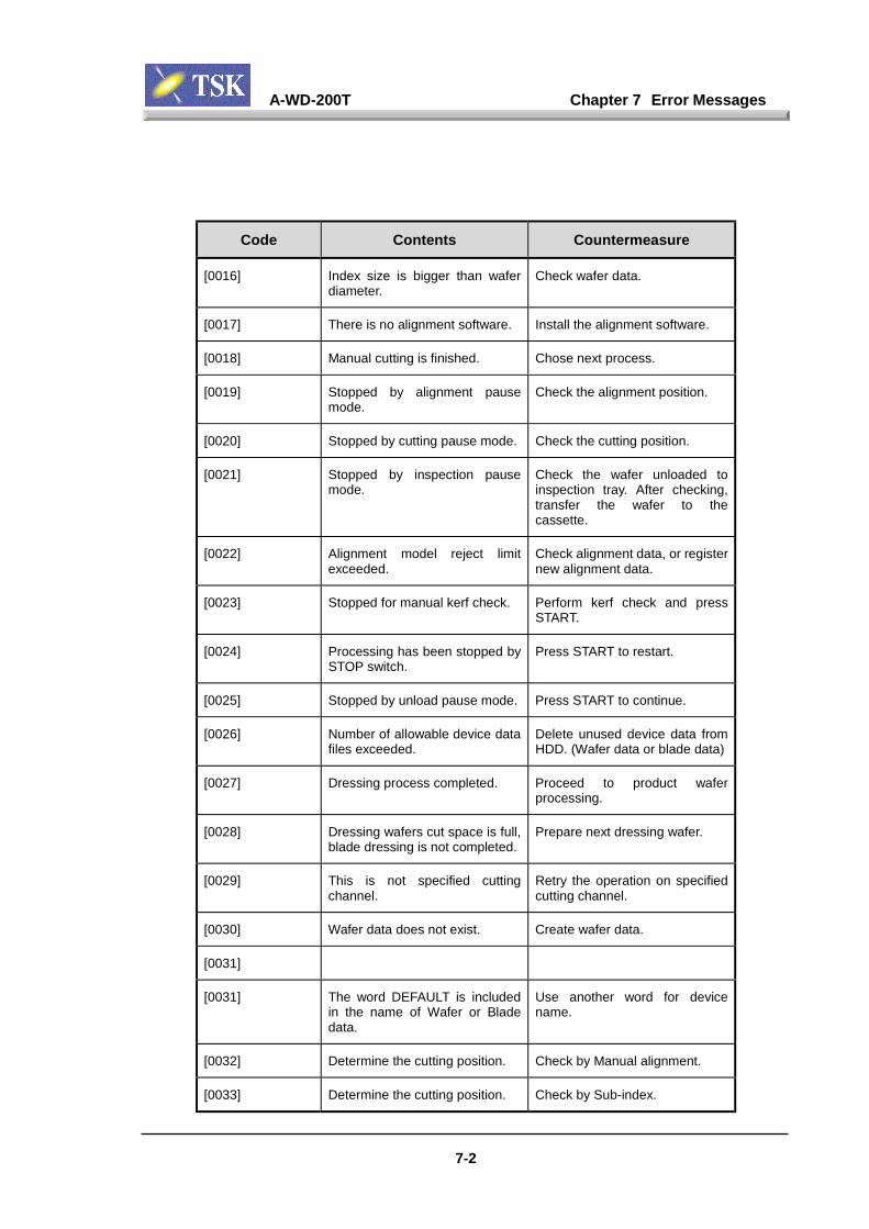
A-WD-200T Chapter 7 Error Messages
7-2
Code Contents Countermeasure
[0016] Index size is bigger than waferdiameter.
Check wafer data.
[0017] There is no alignment software. Install the alignment software.
[0018] Manual cutting is finished. Chose next process.
[0019] Stopped by alignment pausemode.
Check the alignment position.
[0020] Stopped by cutting pause mode. Check the cutting position.
[0021] Stopped by inspection pausemode.
Check the wafer unloaded toinspection tray. After checking,transfer the wafer to thecassette.
[0022] Alignment model reject limitexceeded.
Check alignment data, or registernew alignment data.
[0023] Stopped for manual kerf check. Perform kerf check and pressSTART.
[0024] Processing has been stopped bySTOP switch.
Press START to restart.
[0025] Stopped by unload pause mode. Press START to continue.
[0026] Number of allowable device datafiles exceeded.
Delete unused device data fromHDD. (Wafer data or blade data)
[0027] Dressing process completed. Proceed to product waferprocessing.
[0028] Dressing wafers cut space is full,blade dressing is not completed.
Prepare next dressing wafer.
[0029] This is not specified cuttingchannel.
Retry the operation on specifiedcutting channel.
[0030] Wafer data does not exist. Create wafer data.
[0031]
[0031] The word DEFAULT is includedin the name of Wafer or Bladedata.
Use another word for devicename.
[0032] Determine the cutting position. Check by Manual alignment.
[0033] Determine the cutting position. Check by Sub-index.

A-WD-200T Chapter 7 Error Messages
7-3
Code Contents Countermeasure
[0034] X/Y axis is out of cutting area. Move X/Y axis into the cuttingarea.
[0035] Rotation center correction has tobe performed in High mag.
Change-over to High mag. andretry.
[0036] Compensation value is out ofrange.,4
Check sensor position.
[0037] Autotatic cutter-set has beeninterrupted by pressing STOPswitch.,1
Execute cutter-set by manualoperation.
[0038] Function not available with thissystem software.
Re-install new system software.
[0039] Can't perform the dress cut usingproduction mode.
Check parameter setting for thecutting mode in wafer data.
[0040] Can't perform the production cutusing dress mode.
Check parameter setting for thecutting mode in wafer data.
[0041] Performing spinner cleaningprocess.
Operate after spinner cleaning iscompleted.
[0042]
[0043]
[0044] Cutting can not be peformed inthis status.
Perform operation in cuttingprocess or after alignment.
[0045] Completed single line cut.
[0046] Cutting parameters are notsatisfied.
Review the parameter setting.
[0047] Perform DRESS cutting. Production wafer will beprocessed by next START.
[0048] Ready to perform dressing fromthe cassette.
Unload the process wafers, andchange the cassette.
[0049] Multiple wafers can't beexecuted.
Reset catalog data of cassette 3.
[0050] Process can't be started. Wait for an enable signal.
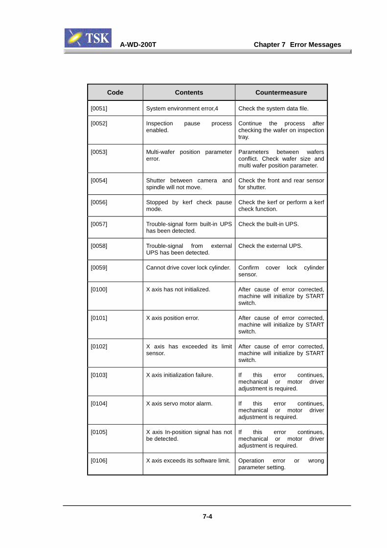
A-WD-200T Chapter 7 Error Messages
7-4
Code Contents Countermeasure
[0051] System environment error,4 Check the system data file.
[0052] Inspection pause processenabled.
Continue the process afterchecking the wafer on inspectiontray.
[0053] Multi-wafer position parametererror.
Parameters between wafersconflict. Check wafer size andmulti wafer position parameter.
[0054] Shutter between camera andspindle will not move.
Check the front and rear sensorfor shutter.
[0056] Stopped by kerf check pausemode.
Check the kerf or perform a kerfcheck function.
[0057] Trouble-signal form built-in UPShas been detected.
Check the built-in UPS.
[0058] Trouble-signal from externalUPS has been detected.
Check the external UPS.
[0059] Cannot drive cover lock cylinder. Confirm cover lock cylindersensor.
[0100] X axis has not initialized. After cause of error corrected,machine will initialize by STARTswitch.
[0101] X axis position error. After cause of error corrected,machine will initialize by STARTswitch.
[0102] X axis has exceeded its limitsensor.
After cause of error corrected,machine will initialize by STARTswitch.
[0103] X axis initialization failure. If this error continues,mechanical or motor driveradjustment is required.
[0104] X axis servo motor alarm. If this error continues,mechanical or motor driveradjustment is required.
[0105] X axis In-position signal has notbe detected.
If this error continues,mechanical or motor driveradjustment is required.
[0106] X axis exceeds its software limit. Operation error or wrongparameter setting.

A-WD-200T Chapter 7 Error Messages
7-5
Code Contents Countermeasure
[0107] Current position of X axis doesn'tmatch encoder pulse number.
If this error continues,mechanical or motor driveradjustment is required.
[0108] The interrupt signal of X-axisstopping can't be recieved.
If repeating, mechanical or motordriver adjustment is required.
[0110] Y axis has not initialized. If this error continues,mechanical or motor driveradjustment is required.
[0111] Y axis position error. If this error continues,mechanical or motor driveradjustment is required.
[0112] Y axis has exceeded its limitsensor.
If this error continues,mechanical adjustment isrequired.
[0113] Y axis initialization failure. If repeating, mechanical or motordriver adjustment is required.
[0114] Y axis scale alarm. If repeating, mechanical or motordriver adjustment is required.
[0115] Y axis exceeded its softwarelimit.
Operation error or wrongparameter setting.
[0116] Y axis closed control error. After cause of error corrected,machine will initialize by STARTswitch.
[0117] Current position of Y axis doesn'tmatch encoder pulse number.
After cause of error corrected,machine will initialize by STARTswitch.
[0118] The interrupt signal of Y axisstopping can't be received.
If repeating, mechanical or motordriver adjustment is required.
[0120] Z axis has not initialized. After cause of error corrected,machine will initialize by STARTswitch.
[0121] Z axis position error. After cause of error corrected,machine will initialize by STARTswitch.

A-WD-200T Chapter 7 Error Messages
7-6
Code Contents Countermeasure
[0122] Z axis has exceeded its limitsensor.
After cause of error corrected,machine will initialize by STARTswitch.
[0123] Z axis initialization failure. If this error continues,mechanical or motor driveradjustment is required.
[0124] Z axis exceeded its softwarelimit.
Operation error or wrongparameter setting.
[0125] Cutter-set signal for Z axis wasnot detected.
Check the blade diameter, orcutting table.
[0126] Current position of Z axis doesn'tmatch encoder pulse number.
After cause of error corrected,machine will initialize by STARTswitch.
[0127] Z axis limit sensor is ON. Check the limit sensor. If thesensor is OK, move Z axis toOFF status by manualmovement.
[0128] The interrupt signal of Z axisstopping can't be received.
If repeating, mechanical or motordriver adjustment is required.
[0130] Theta axis has not initialized. After cause of error corrected,machine will initialize by STARTswitch.
[0131] Theta axis position error. After cause of error corrected,machine will initialize by STARTswitch.
[0132] Theta axis has exceeded its limitsensor.
After cause of error corrected,machine will initialize by STARTswitch.
[0133] Theta axis initialization failure. If this error continues,mechanical or motor driveradjustment is required.
[0134] Theta axis exceeded its softwarelimit.
Operation error or wrongparameter setting.
[0135] Current position of Z axis doesn'tmatch encoder pulse number.
After cause of error corrected,machine will initialize by STARTswitch.
[0136] Brake sensor signal for Thetaaxis was not detected.
Check the brake sensor.
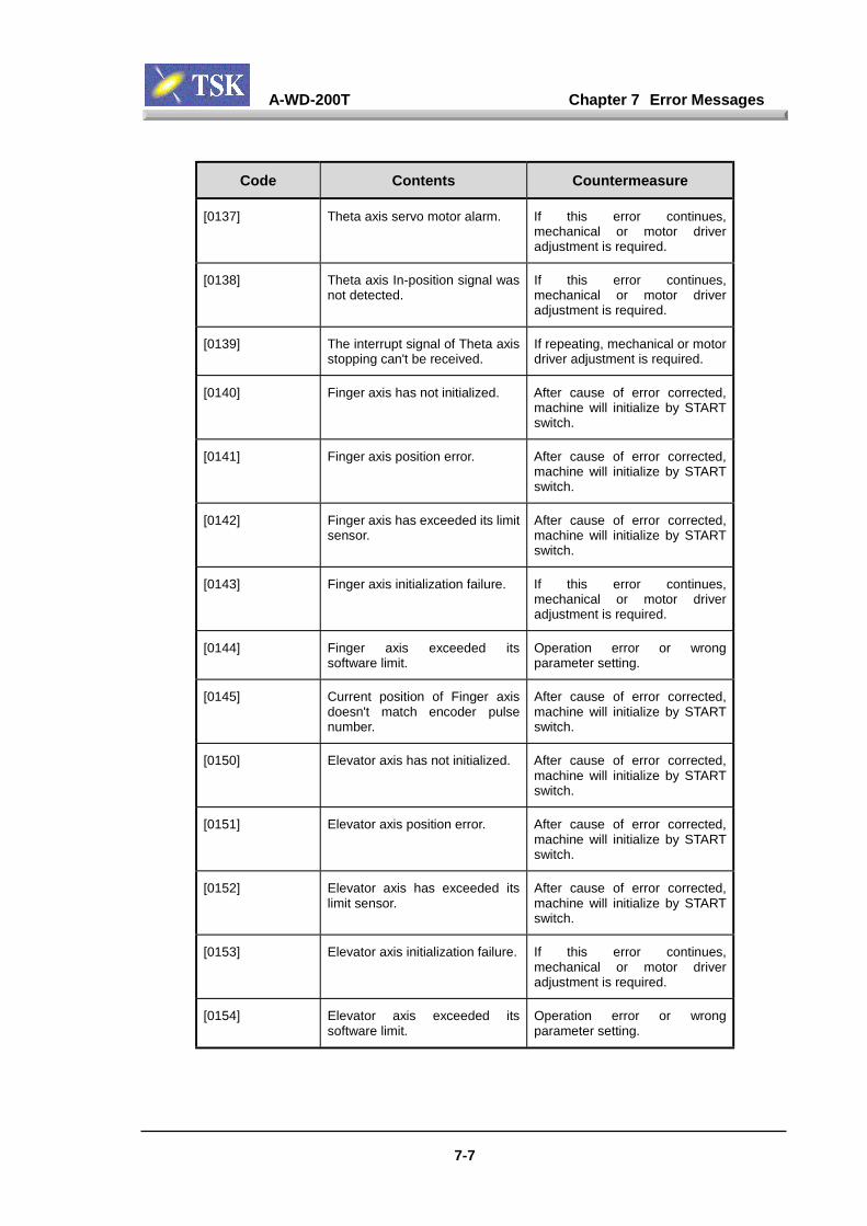
A-WD-200T Chapter 7 Error Messages
7-7
Code Contents Countermeasure
[0137] Theta axis servo motor alarm. If this error continues,mechanical or motor driveradjustment is required.
[0138] Theta axis In-position signal wasnot detected.
If this error continues,mechanical or motor driveradjustment is required.
[0139] The interrupt signal of Theta axisstopping can't be received.
If repeating, mechanical or motordriver adjustment is required.
[0140] Finger axis has not initialized. After cause of error corrected,machine will initialize by STARTswitch.
[0141] Finger axis position error. After cause of error corrected,machine will initialize by STARTswitch.
[0142] Finger axis has exceeded its limitsensor.
After cause of error corrected,machine will initialize by STARTswitch.
[0143] Finger axis initialization failure. If this error continues,mechanical or motor driveradjustment is required.
[0144] Finger axis exceeded itssoftware limit.
Operation error or wrongparameter setting.
[0145] Current position of Finger axisdoesn't match encoder pulsenumber.
After cause of error corrected,machine will initialize by STARTswitch.
[0150] Elevator axis has not initialized. After cause of error corrected,machine will initialize by STARTswitch.
[0151] Elevator axis position error. After cause of error corrected,machine will initialize by STARTswitch.
[0152] Elevator axis has exceeded itslimit sensor.
After cause of error corrected,machine will initialize by STARTswitch.
[0153] Elevator axis initialization failure. If this error continues,mechanical or motor driveradjustment is required.
[0154] Elevator axis exceeded itssoftware limit.
Operation error or wrongparameter setting.
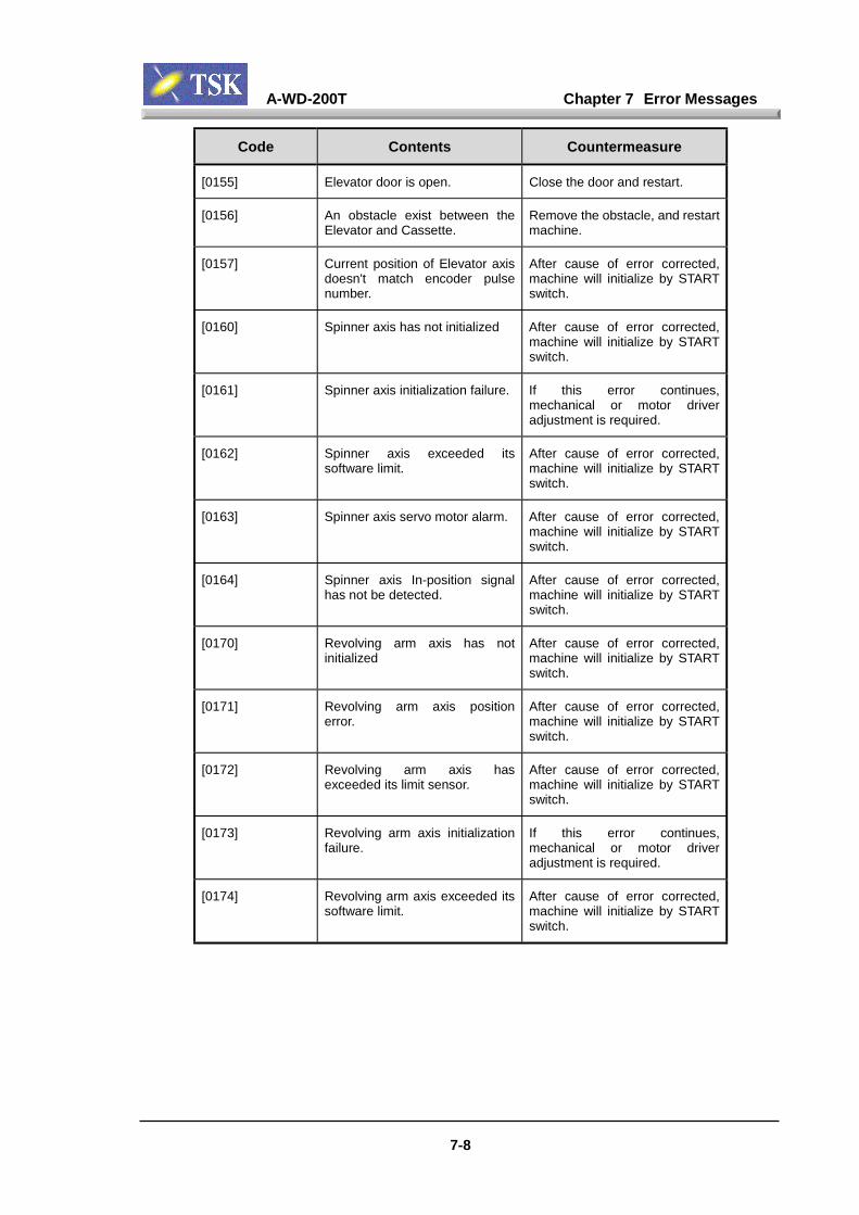
A-WD-200T Chapter 7 Error Messages
7-8
Code Contents Countermeasure
[0155] Elevator door is open. Close the door and restart.
[0156] An obstacle exist between theElevator and Cassette.
Remove the obstacle, and restartmachine.
[0157] Current position of Elevator axisdoesn't match encoder pulsenumber.
After cause of error corrected,machine will initialize by STARTswitch.
[0160] Spinner axis has not initialized After cause of error corrected,machine will initialize by STARTswitch.
[0161] Spinner axis initialization failure. If this error continues,mechanical or motor driveradjustment is required.
[0162] Spinner axis exceeded itssoftware limit.
After cause of error corrected,machine will initialize by STARTswitch.
[0163] Spinner axis servo motor alarm. After cause of error corrected,machine will initialize by STARTswitch.
[0164] Spinner axis In-position signalhas not be detected.
After cause of error corrected,machine will initialize by STARTswitch.
[0170] Revolving arm axis has notinitialized
After cause of error corrected,machine will initialize by STARTswitch.
[0171] Revolving arm axis positionerror.
After cause of error corrected,machine will initialize by STARTswitch.
[0172] Revolving arm axis hasexceeded its limit sensor.
After cause of error corrected,machine will initialize by STARTswitch.
[0173] Revolving arm axis initializationfailure.
If this error continues,mechanical or motor driveradjustment is required.
[0174] Revolving arm axis exceeded itssoftware limit.
After cause of error corrected,machine will initialize by STARTswitch.
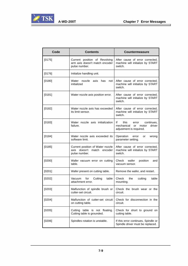
A-WD-200T Chapter 7 Error Messages
7-9
Code Contents Countermeasure
[0175] Current position of Revolvingarm axis doesn't match encoderpulse number.
After cause of error corrected,machine will initialize by STARTswitch.
[0176] Initialize handling unit.
[0180] Water nozzle axis has notinitialized
After cause of error corrected,machine will initialize by STARTswitch.
[0181] Water nozzle axis position error. After cause of error corrected,machine will initialize by STARTswitch.
[0182] Water nozzle axis has exceededits limit sensor.
After cause of error corrected,machine will initialize by STARTswitch.
[0183] Water nozzle axis initializationfailure.
If this error continues,mechanical or motor driveradjustment is required.
[0184] Water nozzle axis exceeded itssoftware limit.
Operation error or wrongparameter setting.
[0185] Current position of Water nozzleaxis doesn't match encoderpulse number.
After cause of error corrected,machine will initialize by STARTswitch.
[0200] Wafer vacuum error on cuttingtable.
Check wafer position andvacuum sensor.
[0201] Wafer present on cutting table. Remove the wafer, and restart.
[0202] Vacuum for Cutting tableattachment error.
Check the cutting tablemounting.
[0203] Malfunction of spindle brush orcutter-set circuit.
Check the brush wear or thecircuit.
[0204] Malfunction of cutter-set circuiton cutting table.
Check for disconnection in thecircuit.
[0205] Cutting table is not floating.Cutting table is grounded.
Check for short to ground oncutting table.
[0206] Spindles rotation is unstable. If this error continues, Spindle orSpindle driver must be replaced.
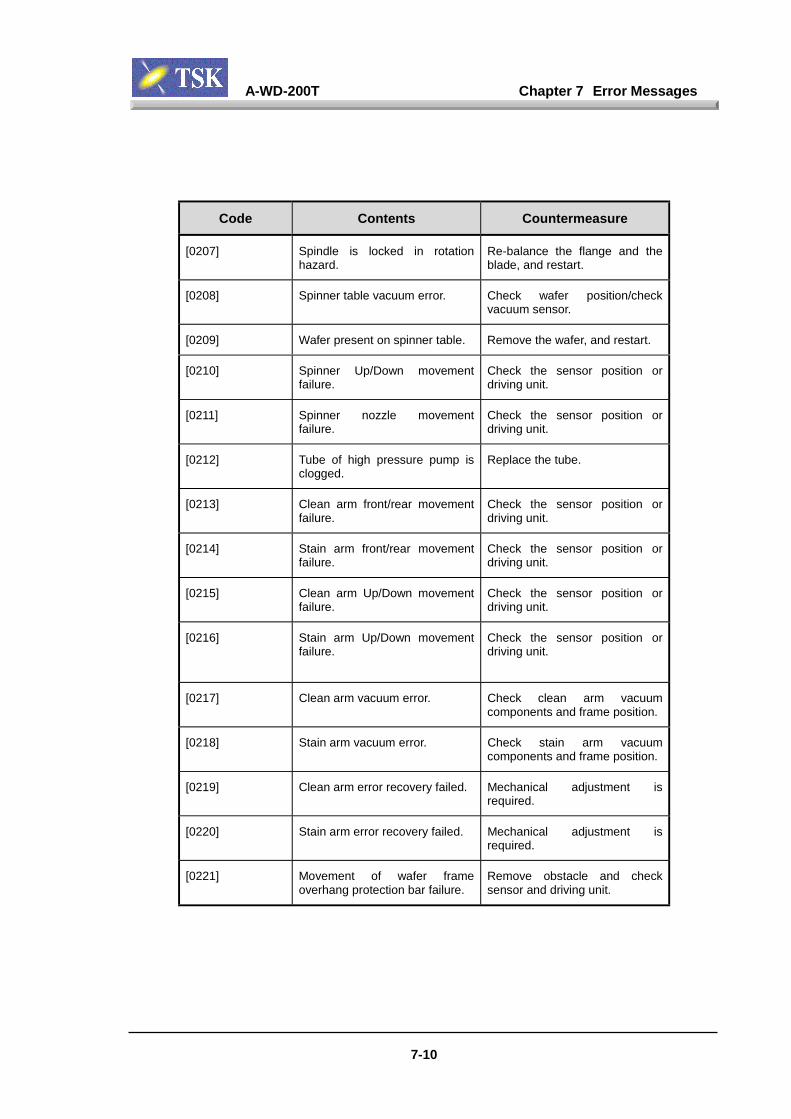
A-WD-200T Chapter 7 Error Messages
7-10
Code Contents Countermeasure
[0207] Spindle is locked in rotationhazard.
Re-balance the flange and theblade, and restart.
[0208] Spinner table vacuum error. Check wafer position/checkvacuum sensor.
[0209] Wafer present on spinner table. Remove the wafer, and restart.
[0210] Spinner Up/Down movementfailure.
Check the sensor position ordriving unit.
[0211] Spinner nozzle movementfailure.
Check the sensor position ordriving unit.
[0212] Tube of high pressure pump isclogged.
Replace the tube.
[0213] Clean arm front/rear movementfailure.
Check the sensor position ordriving unit.
[0214] Stain arm front/rear movementfailure.
Check the sensor position ordriving unit.
[0215] Clean arm Up/Down movementfailure.
Check the sensor position ordriving unit.
[0216] Stain arm Up/Down movementfailure.
Check the sensor position ordriving unit.
[0217] Clean arm vacuum error. Check clean arm vacuumcomponents and frame position.
[0218] Stain arm vacuum error. Check stain arm vacuumcomponents and frame position.
[0219] Clean arm error recovery failed. Mechanical adjustment isrequired.
[0220] Stain arm error recovery failed. Mechanical adjustment isrequired.
[0221] Movement of wafer frameoverhang protection bar failure.
Remove obstacle and checksensor and driving unit.
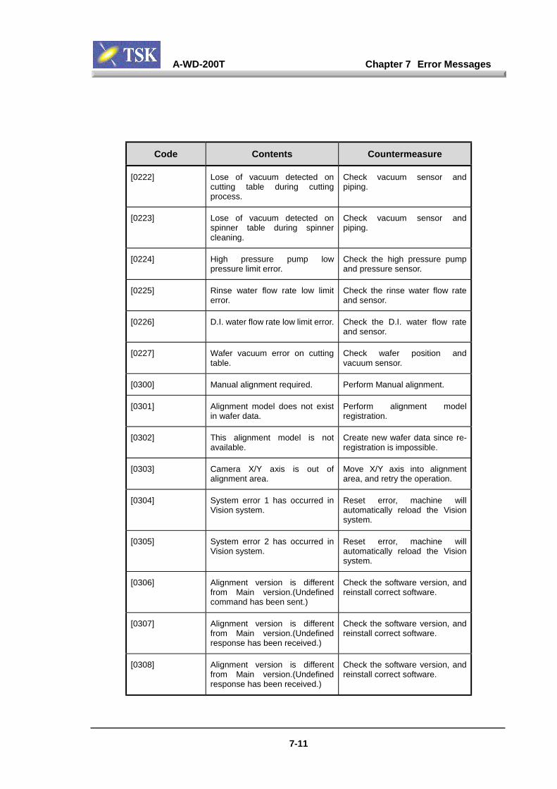
A-WD-200T Chapter 7 Error Messages
7-11
Code Contents Countermeasure
[0222] Lose of vacuum detected oncutting table during cuttingprocess.
Check vacuum sensor andpiping.
[0223] Lose of vacuum detected onspinner table during spinnercleaning.
Check vacuum sensor andpiping.
[0224] High pressure pump lowpressure limit error.
Check the high pressure pumpand pressure sensor.
[0225] Rinse water flow rate low limiterror.
Check the rinse water flow rateand sensor.
[0226] D.I. water flow rate low limit error. Check the D.I. water flow rateand sensor.
[0227] Wafer vacuum error on cuttingtable.
Check wafer position andvacuum sensor.
[0300] Manual alignment required. Perform Manual alignment.
[0301] Alignment model does not existin wafer data.
Perform alignment modelregistration.
[0302] This alignment model is notavailable.
Create new wafer data since re-registration is impossible.
[0303] Camera X/Y axis is out ofalignment area.
Move X/Y axis into alignmentarea, and retry the operation.
[0304] System error 1 has occurred inVision system.
Reset error, machine willautomatically reload the Visionsystem.
[0305] System error 2 has occurred inVision system.
Reset error, machine willautomatically reload the Visionsystem.
[0306] Alignment version is differentfrom Main version.(Undefinedcommand has been sent.)
Check the software version, andreinstall correct software.
[0307] Alignment version is differentfrom Main version.(Undefinedresponse has been received.)
Check the software version, andreinstall correct software.
[0308] Alignment version is differentfrom Main version.(Undefinedresponse has been received.)
Check the software version, andreinstall correct software.
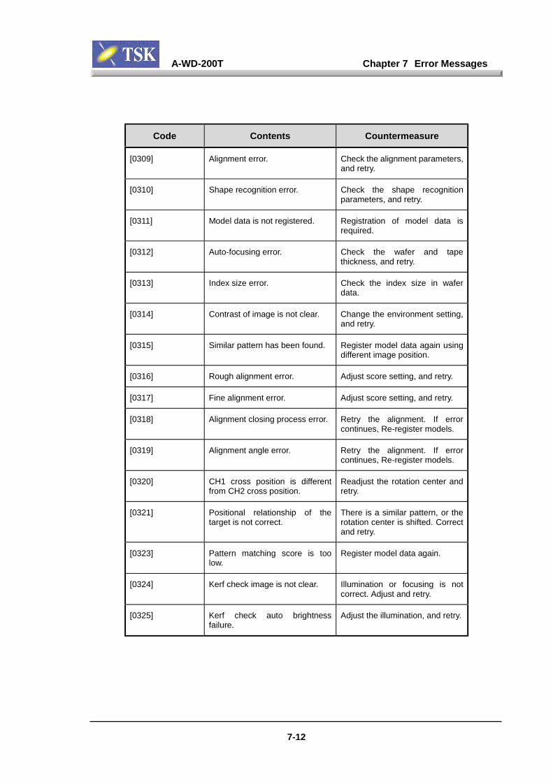
A-WD-200T Chapter 7 Error Messages
7-12
Code Contents Countermeasure
[0309] Alignment error. Check the alignment parameters,and retry.
[0310] Shape recognition error. Check the shape recognitionparameters, and retry.
[0311] Model data is not registered. Registration of model data isrequired.
[0312] Auto-focusing error. Check the wafer and tapethickness, and retry.
[0313] Index size error. Check the index size in waferdata.
[0314] Contrast of image is not clear. Change the environment setting,and retry.
[0315] Similar pattern has been found. Register model data again usingdifferent image position.
[0316] Rough alignment error. Adjust score setting, and retry.
[0317] Fine alignment error. Adjust score setting, and retry.
[0318] Alignment closing process error. Retry the alignment. If errorcontinues, Re-register models.
[0319] Alignment angle error. Retry the alignment. If errorcontinues, Re-register models.
[0320] CH1 cross position is differentfrom CH2 cross position.
Readjust the rotation center andretry.
[0321] Positional relationship of thetarget is not correct.
There is a similar pattern, or therotation center is shifted. Correctand retry.
[0323] Pattern matching score is toolow.
Register model data again.
[0324] Kerf check image is not clear. Illumination or focusing is notcorrect. Adjust and retry.
[0325] Kerf check auto brightnessfailure.
Adjust the illumination, and retry.

A-WD-200T Chapter 7 Error Messages
7-13
Code Contents Countermeasure
[0326] Check the kerf check result. Check the kerf check result, andstart again.
[0327] Manual kerf check error. Check the kerf check result, andstart again.
[0328] Manual alignment not completed. Try again, after realigning.
[0329] There is no phase data in waferdata.
Create the data for Phase 1 or 2.
[0330] Kerf edge alignment error, modelunrecognizable.
Correct Kerf center manually andcontinue.
[0331] Value of automaticedge(alignment) correction is toobig to correct.
Check the correction limit inwafer data.
[0332] Vision system HDD error Change the parameter of HHDfor Vision system in system datato ON.
[0333] Connection error with HDD forVision system.
Check the connection of HDD forVision system and re-install, orreplace the HDD.
[0334] Access error in HDD for Visionsystem.,4
Re-format HDD for Visionsystem, or replace the HDD.
[0335] Matching error in Shaperecognition system.
Remove the wafer on the cuttingtable.
[0336] Alignment angle error. Retry the alignment. If errorcontinues, Re-register models.
[0337] Kerf was detected in un-cutwafer.
This wafer has already been cut.Please remove it.
[0338] Wafer thickness allowance isover limit.
Check the wafer and tapethickness in wafer data.
[0339] Plese re-register models. Reload the model data, and retrythe operation.
[0400] Complete blade breakage hasbeen detected.
Replace the blade.
[0401] Partial blade breakage has beendetected.
Replace the blade.

A-WD-200T Chapter 7 Error Messages
7-14
Code Contents Countermeasure
[0402] Cutter-set signal has beendetected out of range.
Check the blade size or cuttingtable surface for water and retry.
[0403] Optical cutter-set unit stand-bylight level is too low
Clean the prism or check voltageon OPC control board.
[0404] Optic value is not stabilized. Adjust air blowing time.
[0405] Cutter-set position has not bedetected.
If this error recurs, adjust opticalunit.
[0406] Max. cut-line length has beenexceeded.
Replace the blade.
[0407] Permitted blade wear hasexceeded.
Replace the blade.
[0408] Cutter-set has not beenperformed.
Perform the cutter-set.
[0409] Automatic cutter-set correctionresult is over the limit.
Check by manual cutter-setting.
[0410] Automatic cutter-set correctionresult is over the limit(+).
Check by manual cutter-setting.
[0411] Blade exposure is improper forcorrect cutting conditions.
Replace the blade.
[0412] Cutter-setting is required. Perform the cutter-set.
[0413] Position data of Optical unit isnot correct.
Teach Optical unit position.
[0414] Current blade data is not forreference flange.
Change the blade data forreference flange.
[0415] Cutter-set for new blade has notbeen done.
Perform cutter-set in bladereplacement mode.
[0416] Optical spot diameter is too largeto detect blade edge.
Adjust the blade position in Ydirection to center of the spot.
[0417] Optical spot diameter is too smallto obtain uniform sampling data.
Adjust the blade position in Ydirection to center of the spot.
[0418] Over-ride data setting in bladedata is incorrect.
Check the over-ride data in bladedata.
[0419] This blade has not been used. This blade can be used as newblade.
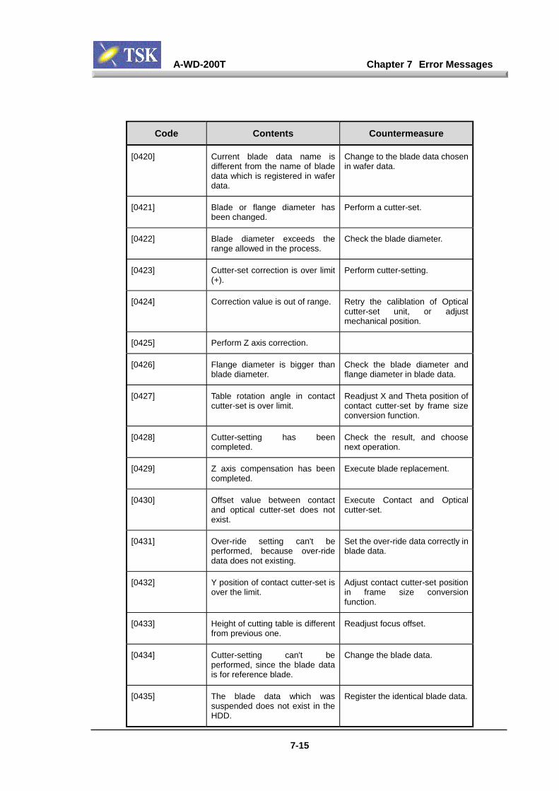
A-WD-200T Chapter 7 Error Messages
7-15
Code Contents Countermeasure
[0420] Current blade data name isdifferent from the name of bladedata which is registered in waferdata.
Change to the blade data chosenin wafer data.
[0421] Blade or flange diameter hasbeen changed.
Perform a cutter-set.
[0422] Blade diameter exceeds therange allowed in the process.
Check the blade diameter.
[0423] Cutter-set correction is over limit(+).
Perform cutter-setting.
[0424] Correction value is out of range. Retry the caliblation of Opticalcutter-set unit, or adjustmechanical position.
[0425] Perform Z axis correction.
[0426] Flange diameter is bigger thanblade diameter.
Check the blade diameter andflange diameter in blade data.
[0427] Table rotation angle in contactcutter-set is over limit.
Readjust X and Theta position ofcontact cutter-set by frame sizeconversion function.
[0428] Cutter-setting has beencompleted.
Check the result, and choosenext operation.
[0429] Z axis compensation has beencompleted.
Execute blade replacement.
[0430] Offset value between contactand optical cutter-set does notexist.
Execute Contact and Opticalcutter-set.
[0431] Over-ride setting can't beperformed, because over-ridedata does not existing.
Set the over-ride data correctly inblade data.
[0432] Y position of contact cutter-set isover the limit.
Adjust contact cutter-set positionin frame size conversionfunction.
[0433] Height of cutting table is differentfrom previous one.
Readjust focus offset.
[0434] Cutter-setting can't beperformed, since the blade datais for reference blade.
Change the blade data.
[0435] The blade data which wassuspended does not exist in theHDD.
Register the identical blade data.
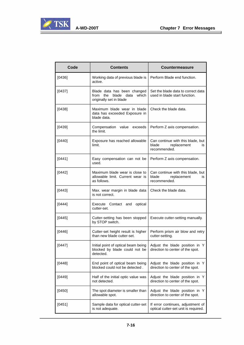
A-WD-200T Chapter 7 Error Messages
7-16
Code Contents Countermeasure
[0436] Working data of previous blade isactive.
Perform Blade end function.
[0437] Blade data has been changedfrom the blade data whichoriginally set in blade
Set the blade data to correct dataused in blade start function.
[0438] Maximum blade wear in bladedata has exceeded Exposure inblade data.
Check the blade data.
[0439] Compensation value exceedsthe limit.
Perform Z axis compensation.
[0440] Exposure has reached allowablelimit.
Can continue with this blade, butblade replacement isrecommended.
[0441] Easy compensation can not beused.
Perform Z axis compensation.
[0442] Maximum blade wear is close toallowable limit. Current wear isas follows.
Can continue with this blade, butblade replacement isrecommended.
[0443] Max. wear margin in blade datais not correct.
Check the blade data.
[0444] Execute Contact and opticalcutter-set.
[0445] Cutter-setting has been stoppedby STOP switch.
Execute cutter-setting manually.
[0446] Cutter-set height result is higherthan new blade cutter-set.
Perform prism air blow and retrycutter-setting.
[0447] Initial point of optical beam beingblocked by blade could not bedetected.
Adjust the blade position in Ydirection to center of the spot.
[0448] End point of optical beam beingblocked could not be detected .
Adjust the blade position in Ydirection to center of the spot.
[0449] Half of the initial optic value wasnot detected.
Adjust the blade position in Ydirection to center of the spot.
[0450] The spot diameter is smaller thanallowable spot.
Adjust the blade position in Ydirection to center of the spot.
[0451] Sample data for optical cutter-setis not adequate.
If error continues, adjustment ofoptical cutter-set unit is required.
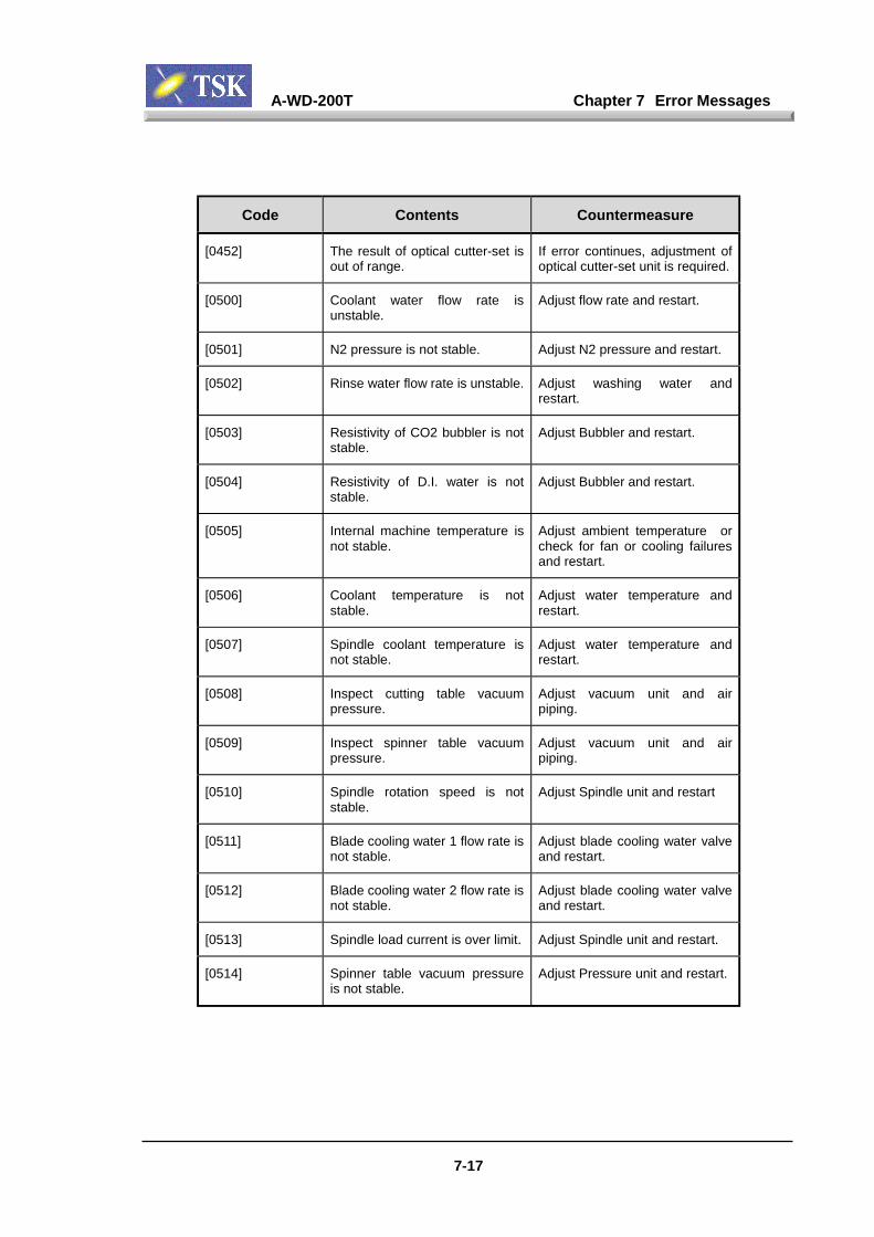
A-WD-200T Chapter 7 Error Messages
7-17
Code Contents Countermeasure
[0452] The result of optical cutter-set isout of range.
If error continues, adjustment ofoptical cutter-set unit is required.
[0500] Coolant water flow rate isunstable.
Adjust flow rate and restart.
[0501] N2 pressure is not stable. Adjust N2 pressure and restart.
[0502] Rinse water flow rate is unstable. Adjust washing water andrestart.
[0503] Resistivity of CO2 bubbler is notstable.
Adjust Bubbler and restart.
[0504] Resistivity of D.I. water is notstable.
Adjust Bubbler and restart.
[0505] Internal machine temperature isnot stable.
Adjust ambient temperature orcheck for fan or cooling failuresand restart.
[0506] Coolant temperature is notstable.
Adjust water temperature andrestart.
[0507] Spindle coolant temperature isnot stable.
Adjust water temperature andrestart.
[0508] Inspect cutting table vacuumpressure.
Adjust vacuum unit and airpiping.
[0509] Inspect spinner table vacuumpressure.
Adjust vacuum unit and airpiping.
[0510] Spindle rotation speed is notstable.
Adjust Spindle unit and restart
[0511] Blade cooling water 1 flow rate isnot stable.
Adjust blade cooling water valveand restart.
[0512] Blade cooling water 2 flow rate isnot stable.
Adjust blade cooling water valveand restart.
[0513] Spindle load current is over limit. Adjust Spindle unit and restart.
[0514] Spinner table vacuum pressureis not stable.
Adjust Pressure unit and restart.

A-WD-200T Chapter 7 Error Messages
7-18
Code Contents Countermeasure
[0515] Wafer vacuum pressure oncutting table is not stable.
Adjust Pressure unit and restart.
[0516] Air pressure is not stable. Adjust Pressure unit and restart.
[0517] Inspect air pressure. Adjust Pressure unit and restart.
[0518] Inspect N2 pressure. Adjust Pressure unit and restart.
[0519] Inspect internal temperature. Adjust room temperature.
[0520] Inspect coolant temperature. Adjust thermo-regulator.
[0521] Inspect spindle coolanttemperature.
Adjust thermo-regulator.
[0522] Inspect Blade cooling water 1temperature.
Adjust valve of blade coolingwater 1.
[0523] Inspect Blade cooling water 2temperature.
Adjust valve of blade coolingwater 2.
[0524] Inspect coolant flow rate. Adjust valve of coolant.
[0525] Inspect rinse water flow rate. Adjust valve of rinse water.
[0526] Inspect resistivity of D.I. water. Adjust controller of Bubbler.
[0527] Inspect spindle load current. Check cutting conditions andmotor driver.
[0528] Inspect resistivity of CO2bubbler.
Adjust controller of Bubbler.
[0600] Cassette process has beenfinished.
Prepare next cassette.
[0601] Last wafer is processing. Prepare next cassette.
[0602] Wafer is present in Inspectiontray.
Remove the wafer fromInspection tray.
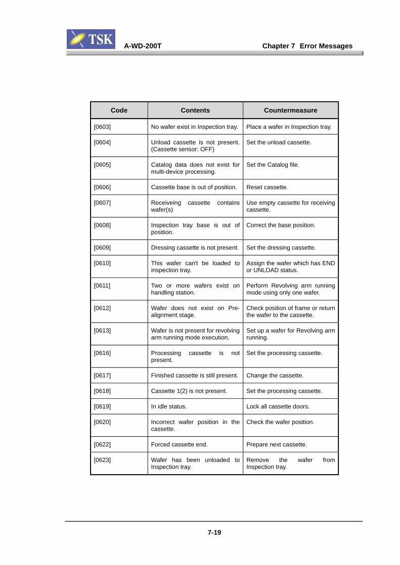
A-WD-200T Chapter 7 Error Messages
7-19
Code Contents Countermeasure
[0603] No wafer exist in Inspection tray. Place a wafer in Inspection tray.
[0604] Unload cassette is not present.(Cassette sensor: OFF)
Set the unload cassette.
[0605] Catalog data does not exist formulti-device processing.
Set the Catalog file.
[0606] Cassette base is out of position. Reset cassette.
[0607] Receiveing cassette containswafer(s)
Use empty cassette for receivingcassette.
[0608] Inspection tray base is out ofposition.
Correct the base position.
[0609] Dressing cassette is not present. Set the dressing cassette.
[0610] This wafer can't be loaded toinspection tray.
Assign the wafer which has ENDor UNLOAD status.
[0611] Two or more wafers exist onhandling station.
Perform Revolving arm runningmode using only one wafer.
[0612] Wafer does not exist on Pre-alignment stage.
Check position of frame or returnthe wafer to the cassette.
[0613] Wafer is not present for revolvingarm running mode execution.
Set up a wafer for Revolving armrunning.
[0616] Processing cassette is notpresent.
Set the processing cassette.
[0617] Finished cassette is still present. Change the cassette.
[0618] Cassette 1(2) is not present. Set the processing cassette.
[0619] In idle status. Lock all cassette doors.
[0620] Incorrect wafer position in thecassette.
Check the wafer position.
[0622] Forced cassette end. Prepare next cassette.
[0623] Wafer has been unloaded toInspection tray.
Remove the wafer fromInspection tray.
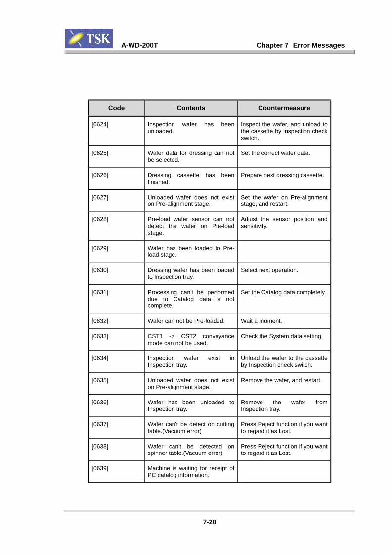
A-WD-200T Chapter 7 Error Messages
7-20
Code Contents Countermeasure
[0624] Inspection wafer has beenunloaded.
Inspect the wafer, and unload tothe cassette by Inspection checkswitch.
[0625] Wafer data for dressing can notbe selected.
Set the correct wafer data.
[0626] Dressing cassette has beenfinished.
Prepare next dressing cassette.
[0627] Unloaded wafer does not existon Pre-alignment stage.
Set the wafer on Pre-alignmentstage, and restart.
[0628] Pre-load wafer sensor can notdetect the wafer on Pre-loadstage.
Adjust the sensor position andsensitivity.
[0629] Wafer has been loaded to Pre-load stage.
[0630] Dressing wafer has been loadedto Inspection tray.
Select next operation.
[0631] Processing can't be performeddue to Catalog data is notcomplete.
Set the Catalog data completely.
[0632] Wafer can not be Pre-loaded. Wait a moment.
[0633] CST1 -> CST2 conveyancemode can not be used.
Check the System data setting.
[0634] Inspection wafer exist inInspection tray.
Unload the wafer to the cassetteby Inspection check switch.
[0635] Unloaded wafer does not existon Pre-alignment stage.
Remove the wafer, and restart.
[0636] Wafer has been unloaded toInspection tray.
Remove the wafer fromInspection tray.
[0637] Wafer can't be detect on cuttingtable.(Vacuum error)
Press Reject function if you wantto regard it as Lost.
[0638] Wafer can't be detected onspinner table.(Vacuum error)
Press Reject function if you wantto regard it as Lost.
[0639] Machine is waiting for receipt ofPC catalog information.

A-WD-200T Chapter 7 Error Messages
7-21
Code Contents Countermeasure
[0670] UV door can't move. Clear the obstruction, or adjustdoor sensor position.
[0671] Wafer does not exist in UV unit. Check the wafer in UV unit.
[0672] UV interference error. Clear the obstruction.
[0673] Wafer does not exist on Pre-alignment stage.
Check the wafer on Pre-alignment stage.
[0674] UV lamp intensity error. Check the UV lamps and sensor.
[0675] Cooling fan for UV lamp is notworking.
Check the fan rotation andcables of the sensor.
[0676] UV unit is not set correctly. Check the UV unit.
[0677] There is a Wafer present. Remove the Wafer, and retry.
[0678] There is a Wafer in UV unit. Remove the Wafer.
[0679] The UV unit door is open. Itinterfares with elevator motion.
Close the UV unit door.
[0680] UV unit error. Check the error code andcontinue operation.
[0681] Wafer cannot be put into UV unit. Check the unit and remove thewafer.
[0682] UV irradiation cannot be done. Check the unit.
[0683] Wafer cannot be taken out of UVunit.
Check the unit and remove thewafer.
[0684] UV irradiation time is notspecified.
Specify UV irradiation time inWafer data.
[0690] UV unit N2 flow error. Check the N2 valve for UV unit.

A-WD-200T Chapter 7 Error Messages
7-22
Code Contents Countermeasure
[0691] Lamp unit cannot be moved. Check the movement and thesensor.
[0692] UV light NG has been detected. Be advised it is time to replacethe lamp.
[0693] Lamp operating time is over theset limit.
Be advised it is time to replacethe lamp.
[0694] No tray is set in the UV unit. Set a tray that suits the Worksize.
[0695] Size of the tray in the UV unit isnot right.
Set a tray that suits the Worksize.
[0696] The number of lighting cycleshas reached the specified limit.
Be advised it is time to replacethe lamp.
[0697] UV execution is specified. To execute cutting, cancel thecassette.
[0698] The cassette is specified forcutting.
To execute UV, cancel thecassette.
[0699] A Cassette is being UVprocessed.
To cut a wafer, please cancel thecassette.
[0700] HDD I/O error. Replace or format the disk.
[0701] FDD I/O error. Replace or format the disk.
[0702] Following file was not found inHDD.
Check file or HDD
[0703] Following file was not found inFDD.
Check file or FDD
[0704] Following file was not found inHDD.
Set up HDD.
[0705] Following file was not found inFDD.
Set up FDD.
[0706] HDD is full. Delete unnecessary files orchange HDD.

A-WD-200T Chapter 7 Error Messages
7-23
Code Contents Countermeasure
[0707] FDD is full. Delete unnecessary files orchange FDD.
[0708] HDD drive error. Replace or format the disk.
[0709] FDD drive error. Replace or format the disk.
[0710] The HDD is write-protected. Check the disk.
[0711] The FDD is write-protected. Check the disk.
[0712] The following file exist in HDD. Check the disk.
[0713] The following file exist in FDD. Check the disk.
[0714] Following file is not correct inHDD.
Remake the file.
[0715] Following file is not correct inFDD.
Remake the file.
[0716] Following directory can not bedeleted in HDD.
Delete all data in the directory.
[0717] Following directory can not bedeleted in FDD.
Delete all data in the directory.
[0718] The file was not found. Check the disk.
[0719] The specified wafer data doesnot exist.
Data recovery is required.
[0720] Following disk isn't formated. Disk format is required.
[0721] The blade data does not exist. Data recovery is required.
[0722] Data base file can't be opened. Perform data recovery of database file.
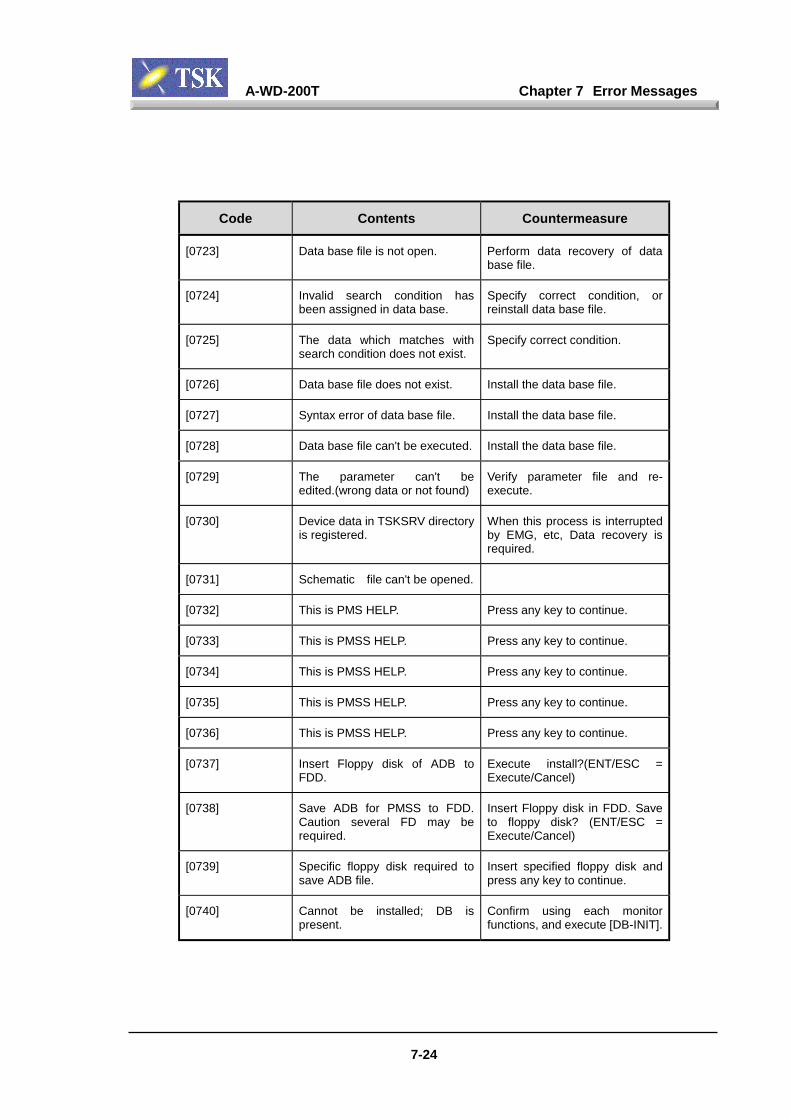
A-WD-200T Chapter 7 Error Messages
7-24
Code Contents Countermeasure
[0723] Data base file is not open. Perform data recovery of database file.
[0724] Invalid search condition hasbeen assigned in data base.
Specify correct condition, orreinstall data base file.
[0725] The data which matches withsearch condition does not exist.
Specify correct condition.
[0726] Data base file does not exist. Install the data base file.
[0727] Syntax error of data base file. Install the data base file.
[0728] Data base file can't be executed. Install the data base file.
[0729] The parameter can't beedited.(wrong data or not found)
Verify parameter file and re-execute.
[0730] Device data in TSKSRV directoryis registered.
When this process is interruptedby EMG, etc, Data recovery isrequired.
[0731] Schematic file can't be opened.
[0732] This is PMS HELP. Press any key to continue.
[0733] This is PMSS HELP. Press any key to continue.
[0734] This is PMSS HELP. Press any key to continue.
[0735] This is PMSS HELP. Press any key to continue.
[0736] This is PMSS HELP. Press any key to continue.
[0737] Insert Floppy disk of ADB toFDD.
Execute install?(ENT/ESC =Execute/Cancel)
[0738] Save ADB for PMSS to FDD.Caution several FD may berequired.
Insert Floppy disk in FDD. Saveto floppy disk? (ENT/ESC =Execute/Cancel)
[0739] Specific floppy disk required tosave ADB file.
Insert specified floppy disk andpress any key to continue.
[0740] Cannot be installed; DB ispresent.
Confirm using each monitorfunctions, and execute [DB-INIT].
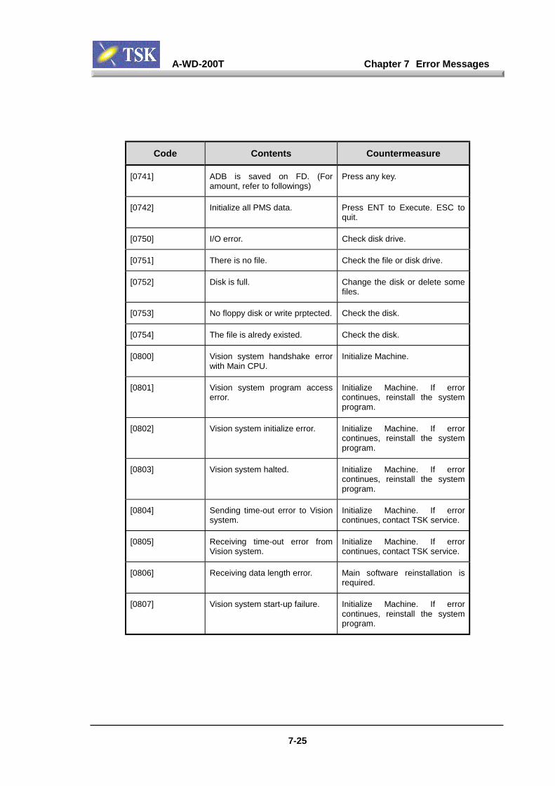
A-WD-200T Chapter 7 Error Messages
7-25
Code Contents Countermeasure
[0741] ADB is saved on FD. (Foramount, refer to followings)
Press any key.
[0742] Initialize all PMS data. Press ENT to Execute. ESC toquit.
[0750] I/O error. Check disk drive.
[0751] There is no file. Check the file or disk drive.
[0752] Disk is full. Change the disk or delete somefiles.
[0753] No floppy disk or write prptected. Check the disk.
[0754] The file is alredy existed. Check the disk.
[0800] Vision system handshake errorwith Main CPU.
Initialize Machine.
[0801] Vision system program accesserror.
Initialize Machine. If errorcontinues, reinstall the systemprogram.
[0802] Vision system initialize error. Initialize Machine. If errorcontinues, reinstall the systemprogram.
[0803] Vision system halted. Initialize Machine. If errorcontinues, reinstall the systemprogram.
[0804] Sending time-out error to Visionsystem.
Initialize Machine. If errorcontinues, contact TSK service.
[0805] Receiving time-out error fromVision system.
Initialize Machine. If errorcontinues, contact TSK service.
[0806] Receiving data length error. Main software reinstallation isrequired.
[0807] Vision system start-up failure. Initialize Machine. If errorcontinues, reinstall the systemprogram.
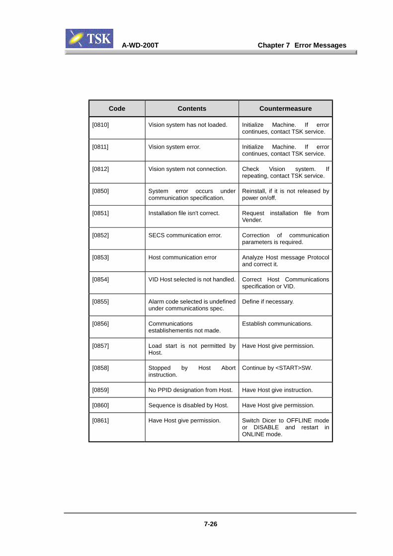
A-WD-200T Chapter 7 Error Messages
7-26
Code Contents Countermeasure
[0810] Vision system has not loaded. Initialize Machine. If errorcontinues, contact TSK service.
[0811] Vision system error. Initialize Machine. If errorcontinues, contact TSK service.
[0812] Vision system not connection. Check Vision system. Ifrepeating, contact TSK service.
[0850] System error occurs undercommunication specification.
Reinstall, if it is not released bypower on/off.
[0851] Installation file isn't correct. Request installation file fromVender.
[0852] SECS communication error. Correction of communicationparameters is required.
[0853] Host communication error Analyze Host message Protocoland correct it.
[0854] VID Host selected is not handled. Correct Host Communicationsspecification or VID.
[0855] Alarm code selected is undefinedunder communications spec.
Define if necessary.
[0856] Communicationsestablishementis not made.
Establish communications.
[0857] Load start is not permitted byHost.
Have Host give permission.
[0858] Stopped by Host Abortinstruction.
Continue by <START>SW.
[0859] No PPID designation from Host. Have Host give instruction.
[0860] Sequence is disabled by Host. Have Host give permission.
[0861] Have Host give permission. Switch Dicer to OFFLINE modeor DISABLE and restart inONLINE mode.

A-WD-200T Chapter 7 Error Messages
7-27
Code Contents Countermeasure
[0862] Cannot switch to ONLINE modebecause host is set in OFFLINEmode.
Switch host to ONLINE modefirst or restart with Dicer inOFFLINE mode.
[0863] Device name not sent by Host. Confirm host again or operatemanually in single LOT-START.
[0864] No. of wafers specified by Hostprocessed.
Select LOT-END.
[0900] Following file will be over-written.
[0901] Waiting for wafer from externalhandling station.
Wait a moment.
[0902] External handling station isworking.
Wait a moment.
[0903] RS232C communication portsare not initialized.
Turn off the machine and start upagain.
[0904] RS232C data send time-out. Check parameter and RS232Ccommunication hardware.
[0905] RS232C data received time-out. Check parameter and RS232Ccommunication hardware.
[0906] Bar-code data reading time outerror.
Check bar-code sheet and bar-code specification.
[0907] Wrong character was receivedwhile reading bar-code.
Check bar-code sheet and bar-code specification.
[0908] RS232C parity error. Check parameter and RS232Chardware.
[0909] RS232C over-run error. Check parameter and RS232Chardware.
[0910] RS232C framing error. Check parameter and RS232Chardware.
[0911] The wafer data which is assignedis not existing.
Check the wafer data name.
[0912] Bar-code can't be read. Confirm bar code sheet and/orbar code reader and restart.

A-WD-200T Chapter 7 Error Messages
7-28
Code Contents Countermeasure
[0913] Error form bar-code readerBL500.
Turn-off the machine, and startup again.
[0914] Mount a wafer on cutting table. Press any key to continue.
[0915] Mount a wafer on spinner table. Press any key to continue.
[0916] Press any key to turn offvacuum.
Remove wafer after vacuumturned off.
[0917] Good vacuum achieved. Press any key to continue.
[0918] Vacuum failure. Press any key to continue.
[0919] Incorrect frame size was set. Check and set correct frame sizedata.
[0920] Executing spinner washing... Wait for a while.
[0921] System debug only.
[0999] This machine can't beguaranteed by this systemsoftware.
Contact the Vendor.
[90000] Custom file for display does notexist.
Install necessary file(s), and set-up again.
[90001] Version of custom file does notmatch the version of Mainsoftware.
Install necessary file(s), and set-up again.
Related Documents