1 290 mm 170 mm 170 mm 210 mm 1 2 3 11 4 5 6 7 8 10 9 12 13 14 15 346310 03/10/2016 BT00680-c- Description Switchboard for 2 WIRE audio and video systems Allows access to various services (video door entry functions, door lock/staircase light management and apartment alarm monitoring) directly from the keypad or via the intuitive icon menu. The switchboard is supplied with an integrated table supporting frame and also features a 7” colour LCD display, receiver and speaker phone, dedicated keys for the main functions and keys which can be configured. The programming can be carried out directly from the device or via PC with TiSwitchBoardDevice software (supplied). The device can manage the phonics of the riser EP (i.e. wired downstream of interface 346851); it cannot however manage the apartment EP (i.e. wired downstream of interface 346850). The use of an additional power supply is recommended. It is possible to connect up to a max. of 16 switchboards (configured from 0 to 15). WARNING: the switchboard cannot be used in systems with 2 WIRE-IP interface 346890. The new HIERARCHICAL mode is available only with the entrance panels of the following series: Sfera New, Linea 100, Minisfera, Linea 300. Also check that: 351000 production week =/> 16W18 351100, 351200 & 351300 Firmware =/> 01.02.31 346851 production week =/> 16W28 Technical data Power supply from SCS BUS: 19 – 27 Vdc Absorptions from BUS (without additional supply): - stand by absorption: 35 mA - max. operating absorption: 450 mA Absorptions from BUS (with additional supply): - stand by absorption: 5 mA - max. operating absorption: 20 mA Operating temperature: 5 - 40 °C Relay contact output: 24 Vac / 24 Vdc 3 A, cosφ = 1 Dimensional data Legend 1. Handset 2. 7” colour LCD display for the displaying of the user and programming menu and of the images recorded by the entrance panel or cameras 3. Microphone 4. Navigation keypad. It enables navigating through the menus, with the pos- sibility of confirming the selection (OK key) 5. Cancel key 6. Direct call key 7. Door lock release key 8. Directory access key 9. Entrance panel and camera cycling activation key 10. Handsfree key 11. Alarm given indication LED 12. Operating status notification LED: LED ON (fixed)= device in stand-by LED ON (flashing quickly) = call active LED ON (flashing slowly) = conversation active 13.Alphanumeric keypad 14. Keypad + legend of configurable functions 15. Loudspeaker Related items 336982 LIVINGLIGHT white series 8 pole socket for table-top installation of the switchboard 336803 (8 poles - frayed) cable for table-top installation of the switchboard 346020 2 DIN additional power supply Front view 2 WIRE switchboard EN 2 WIRE Video Door Entry system

Welcome message from author
This document is posted to help you gain knowledge. Please leave a comment to let me know what you think about it! Share it to your friends and learn new things together.
Transcript
1
290 mm
170 mm
170 mm
210 mm
1 2
3
11
4
5
67
8
109
12131415
346310
03/10/2016BT00680-c-
Description
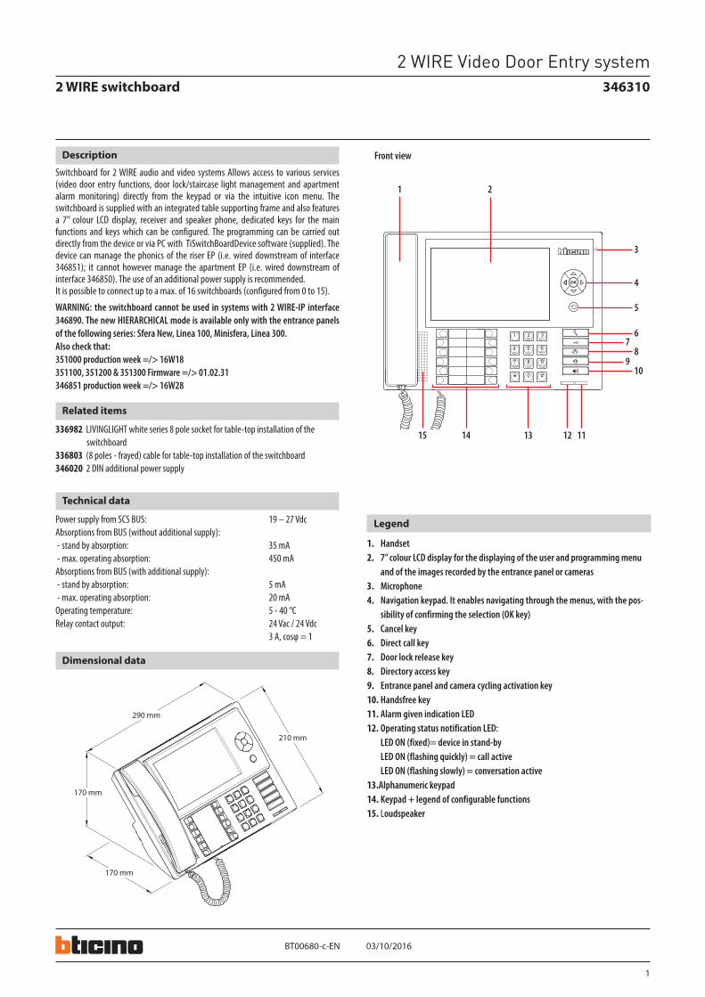
Switchboard for 2 WIRE audio and video systems Allows access to various services (video door entry functions, door lock/staircase light management and apartment alarm monitoring) directly from the keypad or via the intuitive icon menu. The switchboard is supplied with an integrated table supporting frame and also features a 7” colour LCD display, receiver and speaker phone, dedicated keys for the main functions and keys which can be configured. The programming can be carried out directly from the device or via PC with TiSwitchBoardDevice software (supplied). The device can manage the phonics of the riser EP (i.e. wired downstream of interface 346851); it cannot however manage the apartment EP (i.e. wired downstream of interface 346850). The use of an additional power supply is recommended.It is possible to connect up to a max. of 16 switchboards (configured from 0 to 15).
WARNING: the switchboard cannot be used in systems with 2 WIRE-IP interface 346890. The new HIERARCHICAL mode is available only with the entrance panels of the following series: Sfera New, Linea 100, Minisfera, Linea 300.Also check that:351000 production week =/> 16W18351100, 351200 & 351300 Firmware =/> 01.02.31346851 production week =/> 16W28
Technical data
Power supply from SCS BUS: 19 – 27 VdcAbsorptions from BUS (without additional supply): - stand by absorption: 35 mA - max. operating absorption: 450 mA Absorptions from BUS (with additional supply): - stand by absorption: 5 mA - max. operating absorption: 20 mA Operating temperature: 5 - 40 °C Relay contact output: 24 Vac / 24 Vdc 3 A, cosφ = 1
Dimensional data
Legend
1. Handset2. 7” colour LCD display for the displaying of the user and programming menu
and of the images recorded by the entrance panel or cameras 3. Microphone4. Navigation keypad. It enables navigating through the menus, with the pos-
sibility of confirming the selection (OK key)5. Cancel key6. Direct call key7. Door lock release key8. Directory access key9. Entrance panel and camera cycling activation key10. Handsfree key11. Alarm given indication LED12. Operating status notification LED: LED ON (fixed)= device in stand-by LED ON (flashing quickly) = call active LED ON (flashing slowly) = conversation active13.Alphanumeric keypad14. Keypad + legend of configurable functions15. Loudspeaker
Related items
336982 LIVINGLIGHT white series 8 pole socket for table-top installation of the switchboard
336803 (8 poles - frayed) cable for table-top installation of the switchboard346020 2 DIN additional power supply
Front view
2 WIRE switchboard
EN
2 WIRE Video Door Entry system
2
03/10/2016BT00680-c-
1 2
34
5
346310
EN
Legend
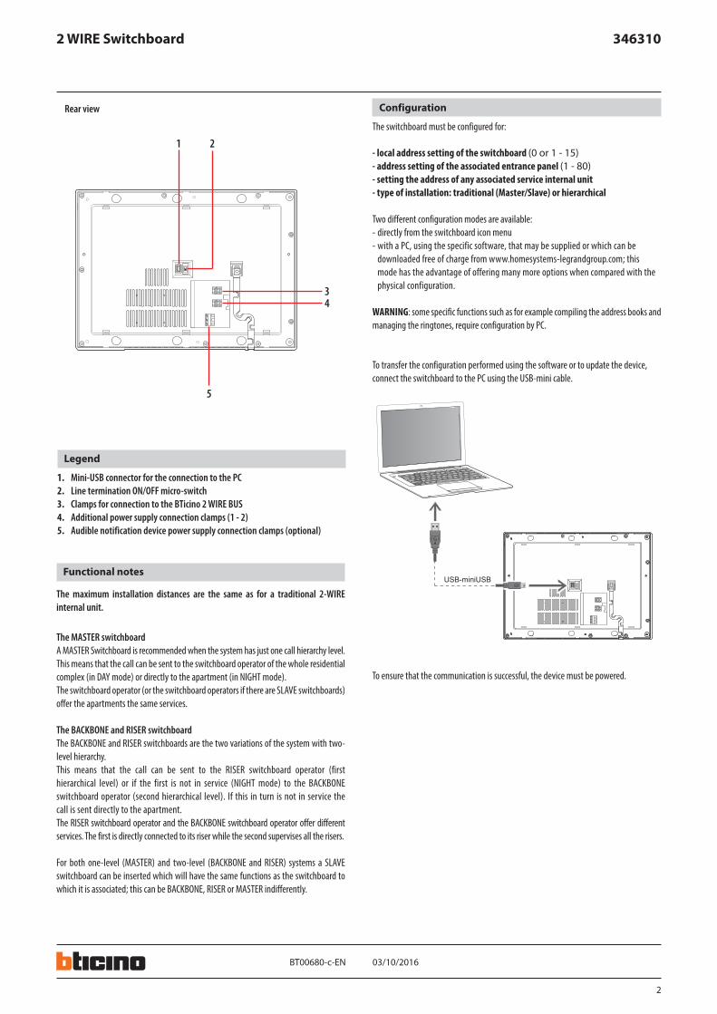
1. Mini-USB connector for the connection to the PC2. Line termination ON/OFF micro-switch3. Clamps for connection to the BTicino 2 WIRE BUS4. Additional power supply connection clamps (1 - 2)5. Audible notification device power supply connection clamps (optional)
Rear view Configuration
The switchboard must be configured for:
- local address setting of the switchboard (0 or 1 - 15)- address setting of the associated entrance panel (1 - 80)- setting the address of any associated service internal unit- type of installation: traditional (Master/Slave) or hierarchical
Two different configuration modes are available: - directly from the switchboard icon menu- with a PC, using the specific software, that may be supplied or which can be
downloaded free of charge from www.homesystems-legrandgroup.com; this mode has the advantage of offering many more options when compared with the physical configuration.
WARNING: some specific functions such as for example compiling the address books and managing the ringtones, require configuration by PC.
To transfer the configuration performed using the software or to update the device, connect the switchboard to the PC using the USB-mini cable.
Functional notes
The maximum installation distances are the same as for a traditional 2-WIRE internal unit.
The MASTER switchboardA MASTER Switchboard is recommended when the system has just one call hierarchy level.This means that the call can be sent to the switchboard operator of the whole residential complex (in DAY mode) or directly to the apartment (in NIGHT mode).The switchboard operator (or the switchboard operators if there are SLAVE switchboards) offer the apartments the same services.
The BACKBONE and RISER switchboardThe BACKBONE and RISER switchboards are the two variations of the system with two-level hierarchy.This means that the call can be sent to the RISER switchboard operator (first hierarchical level) or if the first is not in service (NIGHT mode) to the BACKBONE switchboard operator (second hierarchical level). If this in turn is not in service the call is sent directly to the apartment.The RISER switchboard operator and the BACKBONE switchboard operator offer different services. The first is directly connected to its riser while the second supervises all the risers.
For both one-level (MASTER) and two-level (BACKBONE and RISER) systems a SLAVE switchboard can be inserted which will have the same functions as the switchboard to which it is associated; this can be BACKBONE, RISER or MASTER indifferently.
To ensure that the communication is successful, the device must be powered.
2 WIRE Switchboard
3
03/10/2016BT00680-c-
346310
230 Vac
PRI
1- 2
2 1BUS
BUS 2 1
230 Vac
IP30
PRI
PRI 230 V~ 50 - 60 Hz 260 mA346000
}BUS2 - 1 27V 1,2A
CEBEC
N NF
(P = 1)
346310
346020
346000F441
EN
2 WIRE Switchboard
Wiring diagrams
Master SWB = 0
Main EP
(P = 1)
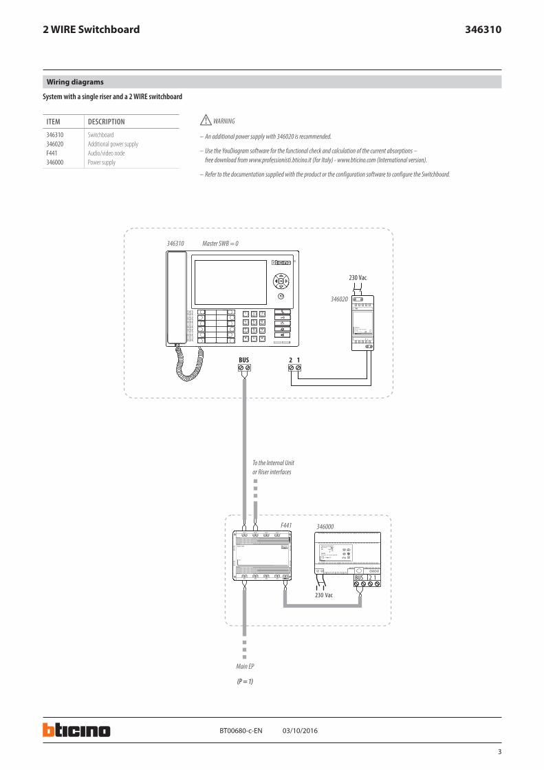
– An additional power supply with 346020 is recommended.
– Use the YouDiagram software for the functional check and calculation of the current absorptions – free download from www.professionisti.bticino.it (for Italy) - www.bticino.com (International version).
– Refer to the documentation supplied with the product or the configuration software to configure the Switchboard.
WARNING
To the Internal Unit or Riser interfaces
System with a single riser and a 2 WIRE switchboard
ITEM DESCRIPTION
346310 Switchboard346020 Additional power supplyF441 Audio/video node346000 Power supply
4
03/10/2016BT00680-c-
346310
N°AUXMOD
T - C + -
230 Vac
PRI
1- 2
2 1
ON
346851
ON OFF
ON
346851
ON OF F
BUS 2 1S C S
O U T 1 O U T 2 O U T 3 O U T 4
I N 1 I N 2 I N 3 I N 4
O U T
I N
230V a.c .
OFFON OFFONOFFON
ON
346851
ON OFF
BUS
OUT
IN
C
F422
230V a.c .
M= –= 1
MOD = 5
M= –= 3
MOD = 5
M= –= 2
MOD = 5
N° = 2AUX = 1-9MOD = –
Z1 = 9N1 = 1MOD1 = –Z2 = –N2 = –MOD2 = 1-9
I1 = –I2 = –I3 = –I4 = 1MOD = 3
346310
346851 346851 346851
F441 346000 346020
F422 E46ADCN
3480 4615
EN
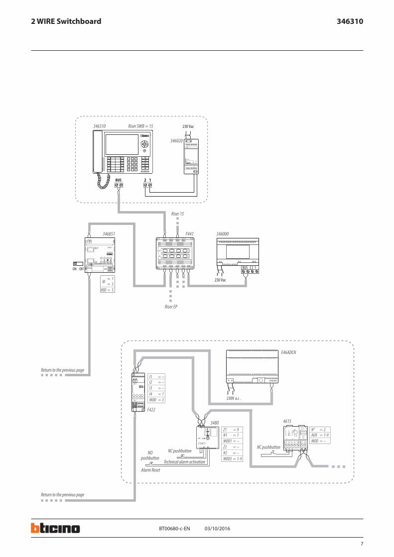
2 WIRE Switchboard
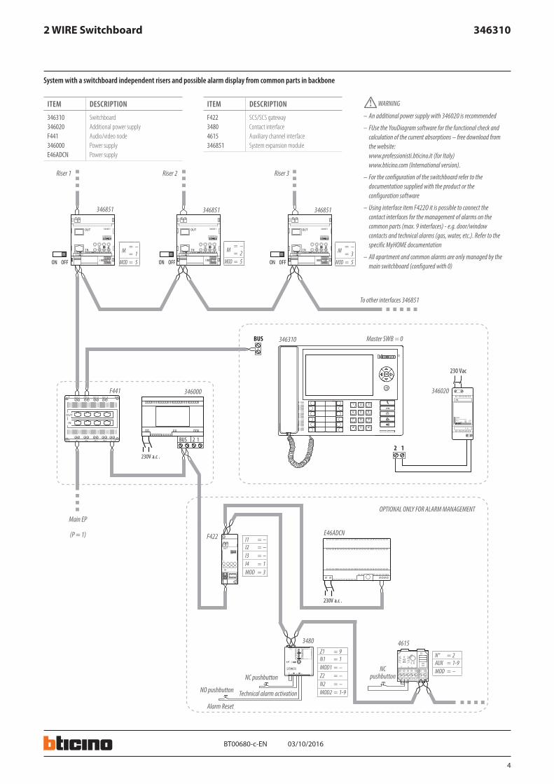
System with a switchboard independent risers and possible alarm display from common parts in backbone
ITEM DESCRIPTION
346310 Switchboard346020 Additional power supplyF441 Audio/video node346000 Power supplyE46ADCN Power supply
ITEM DESCRIPTION
F422 SCS/SCS gateway3480 Contact interface4615 Auxiliary channel interface346851 System expansion module
– An additional power supply with 346020 is recommended
– FUse the YouDiagram software for the functional check and calculation of the current absorptions – free download from the website: www.professionisti.bticino.it (for Italy) www.bticino.com (International version).
– For the configuration of the switchboard refer to the documentation supplied with the product or the configuration software
– Using interface item F422O it is possible to connect the contact interfaces for the management of alarms on the common parts (max. 9 interfaces) - e.g. door/window contacts and technical alarms (gas, water, etc.). Refer to the specific MyHOME documentation
– All apartment and common alarms are only managed by the main switchboard (configured with 0)
WARNING
Master SWB = 0
Riser 1 Riser 3Riser 2
To other interfaces 346851
Main EP
(P = 1)
OPTIONAL ONLY FOR ALARM MANAGEMENT
NC pushbuttonNC
pushbutton
Technical alarm activationNO pushbutton
Alarm Reset
5
03/10/2016BT00680-c-
346310
230 Vac
PRI
1- 2
2 1
230 Vac
PRI
1- 2
2 1
BUS 2 1S C S
O U T 1 O U T 2 O U T 3 O U T 4
I N 1 I N 2 I N 3 I N 4
O U T
I N
230V a.c .
ON
346851
ON OFF
BUS 2 1S C S
O U T 1 O U T 2 O U T 3 O U T 4
I N 1 I N 2 I N 3 I N 4
O U T
I N
ON
346851
ON OF F
BUS 2 1S C S
O U T 1 O U T 2 O U T 3 O U T 4
I N 1 I N 2 I N 3 I N 4
O U T
I N
230V a.c .
OFFONOFFON
230 Vac
BUS
BUS
M= –= 1
MOD = 5
M= –= 2
MOD = 5
346310
346020
346000F441
346000F441346000F441346851 346851
346310
346020
EN
2 WIRE Switchboard
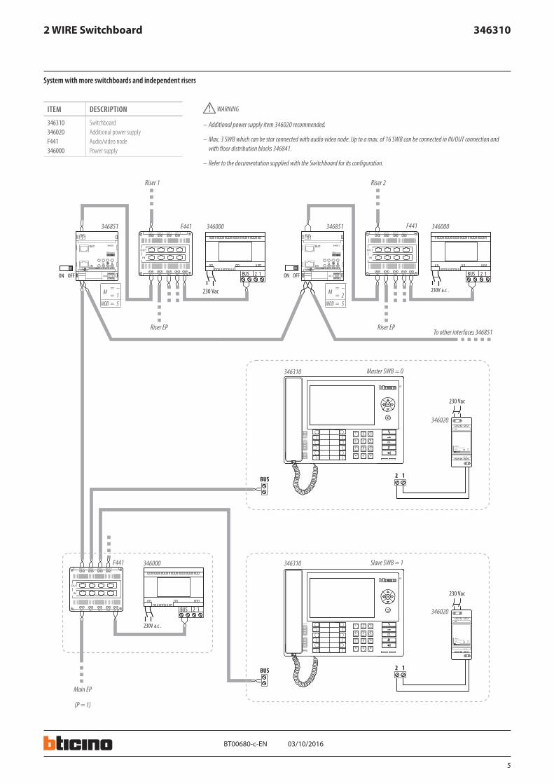
System with more switchboards and independent risers
ITEM DESCRIPTION
346310 Switchboard346020 Additional power supplyF441 Audio/video node346000 Power supply
– Additional power supply item 346020 recommended.
– Max. 3 SWB which can be star connected with audio video node. Up to a max. of 16 SWB can be connected in IN/OUT connection and with floor distribution blocks 346841.
– Refer to the documentation supplied with the Switchboard for its configuration.
WARNING
Master SWB = 0
Riser EP Riser EP
Riser 1 Riser 2
To other interfaces 346851
Main EP
(P = 1)
Slave SWB = 1
6
03/10/2016BT00680-c-
346310
230 Vac
PRI
1- 2
2 1
230 Vac
PRI
1- 2
2 1
BUS 2 1S C S
O U T 1 O U T 2 O U T 3 O U T 4
I N 1 I N 2 I N 3 I N 4
O U T
I N
230V a.c .
ON
346851
ON OFF
BUS 2 1S C S
O U T 1 O U T 2 O U T 3 O U T 4
I N 1 I N 2 I N 3 I N 4
O U T
I N
ON
346851
ON OF F
BUS 2 1S C S
O U T 1 O U T 2 O U T 3 O U T 4
I N 1 I N 2 I N 3 I N 4
O U T
I N
230V a.c .
OFFONOFFON
230 Vac
BUS
230 Vac
PRI
1- 2
2 1BUS BUS
M= –= 1
MOD = 5
M= –= 2
MOD = 5
346000F441
346000F441346000F441346851 346851
346020 346020
346310 346310
346020
346310
EN
2 WIRE Switchboard
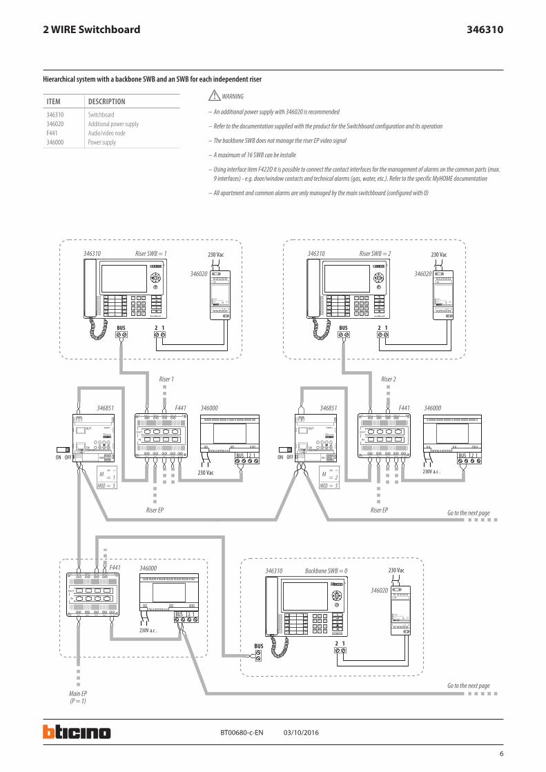
Hierarchical system with a backbone SWB and an SWB for each independent riser
ITEM DESCRIPTION
346310 Switchboard346020 Additional power supplyF441 Audio/video node346000 Power supply
– An additional power supply with 346020 is recommended
– Refer to the documentation supplied with the product for the Switchboard configuration and its operation
– The backbone SWB does not manage the riser EP video signal
– A maximum of 16 SWB can be installe
– Using interface item F422O it is possible to connect the contact interfaces for the management of alarms on the common parts (max. 9 interfaces) - e.g. door/window contacts and technical alarms (gas, water, etc.). Refer to the specific MyHOME documentation
– All apartment and common alarms are only managed by the main switchboard (configured with 0)
WARNING
Riser EP Riser EP
Riser SWB = 1 Riser SWB = 2
Go to the next page
Go to the next pageMain EP(P = 1)
Backbone SWB = 0
Riser 1 Riser 2
7
03/10/2016BT00680-c-
346310
N° = 2AUX = 1-9MOD = –
Z1 = 9N1 = 1MOD1 = –Z2 = –N2 = –MOD2 = 1-9
I1 = –I2 = –I3 = –I4 = 1MOD = 3
F422
E46ADCN
3480 4615
346020
346310
346000F441346851
M= 1= 5
MOD = 5
PRI
1- 2
2 1
BUS 2 1S C S
O U T 1 O U T 2 O U T 3 O U T 4
I N 1 I N 2 I N 3 I N 4
O U T
I N
ON
346851
ON OF F
OFFON
230 Vac
N°AUXMOD
T - C + -
OUT
IN
C
F422
230V a.c .
230 Vac
BUS
EN
2 WIRE Switchboard
Riser SWB = 15
Riser EP
Riser 15
NC pushbuttonNC pushbutton
Technical alarm activation
NO pushbutton
Alarm Reset
Return to the previous page
Return to the previous page
8
03/10/2016BT00680-c-
346310
230 Vac
PRI
1- 2
2 1
BUS 2 1S C S
O U T 1 O U T 2 O U T 3 O U T 4
I N 1 I N 2 I N 3 I N 4
O U T
I N
230V a.c .
ON
346851
ON OFF
BUS 2 1S C S
O U T 1 O U T 2 O U T 3 O U T 4
I N 1 I N 2 I N 3 I N 4
O U T
I N
ON
346851
ON OF F
BUS 2 1S C S
O U T 1 O U T 2 O U T 3 O U T 4
I N 1 I N 2 I N 3 I N 4
O U T
I N
230V a.c .
OFFONOFFON
230 Vac
BUS
230 Vac
PRI
1- 2
2 1BUS
230 Vac
PRI
1- 2
2 1BUS
230 Vac
PRI
1- 2
2 1BUS
230 Vac
PRI
1- 2
2 1BUS346020 346020 346020 346020
346310 346310 346310 346310
M= –= 1
MOD = 5
M= –= 2
MOD = 5
346000F441346000F441346851 346851
346000F441
346020
346310
EN
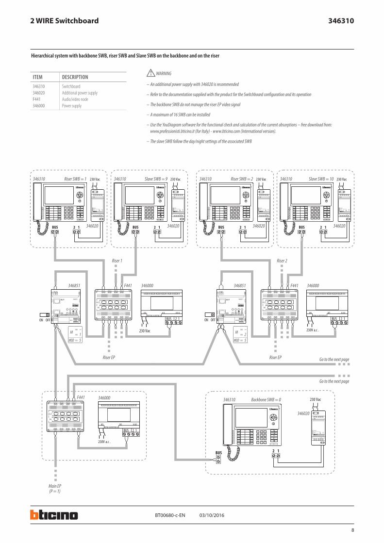
2 WIRE Switchboard
Hierarchical system with backbone SWB, riser SWB and Slave SWB on the backbone and on the riser
ITEM DESCRIPTION
346310 Switchboard346020 Additional power supplyF441 Audio/video node346000 Power supply
– An additional power supply with 346020 is recommended
– Refer to the documentation supplied with the product for the Switchboard configuration and its operation
– The backbone SWB do not manage the riser EP video signal
– A maximum of 16 SWB can be installed
– Use the YouDiagram software for the functional check and calculation of the current absorptions – free download from: www.professionisti.bticino.it (for Italy) - www.bticino.com (International version).
– The slave SWB follow the day/night settings of the associated SWB
WARNING
Riser SWB = 1 Slave SWB = 9 Riser SWB = 2 Slave SWB = 10
Riser EP Riser EP Go to the next page
Riser 1 Riser 2
Go to the next page
Main EP(P = 1)
Backbone SWB = 0
9
03/10/2016BT00680-c-
346310
230 Vac
PRI
1- 2
2 1BUS
BUS 2 1SC S
OUT1 OUT2 OUT3 OUT 4
IN 1 I N2 IN 3 IN 4
OUT
IN
230V a.c .
ON
346851
ON OFF
OFFON
230 Vac
PRI
1- 2
2 1BUS
230 Vac
PRI
1- 2
2 1BUS346020
346310
M= –= 7
MOD = 5
346000F441346851
346020
346310
346020
346310
EN
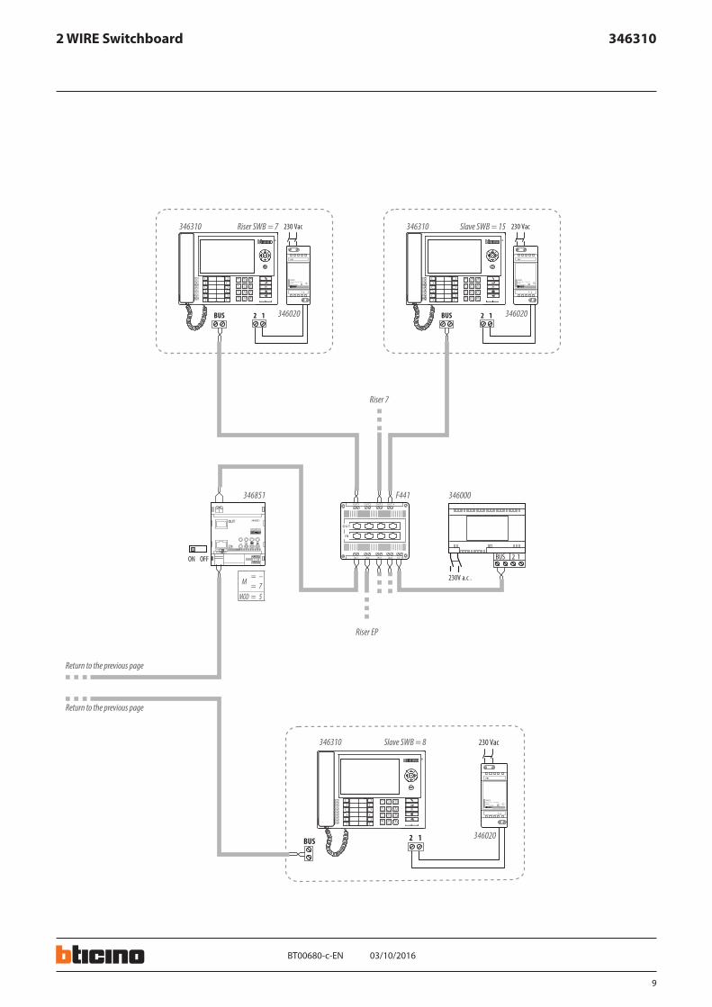
2 WIRE Switchboard
Return to the previous page
Return to the previous page
Riser SWB = 7
Riser 7
Slave SWB = 15
Riser EP
Slave SWB = 8
10
03/10/2016BT00680-c-
346310
230 Vac
2 3
1 32
346210
1
MOD M N/P T
8
BUS
89.24 89.1290.24 90.1291.24 91.12
230 Vac
2 3
1 32
346210
1
MOD M N/P T
8
BUS
89.24 89.1290.24 90.1291.24 91.12
230 Vac
NCC
NO
89.24 89.1290.24 90.1291.24 91.12
346210
EN
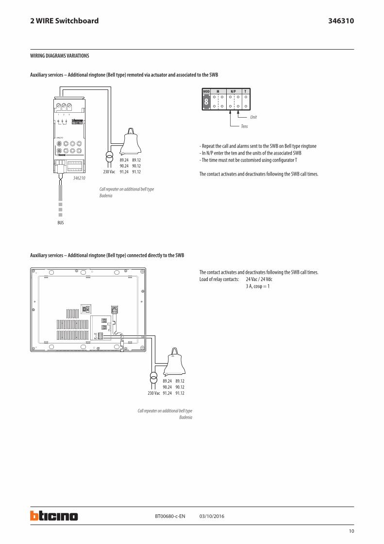
2 WIRE Switchboard
WIRING DIAGRAMS VARIATIONS
Auxiliary services – Additional ringtone (Bell type) remoted via actuator and associated to the SWB
- Repeat the call and alarms sent to the SWB on Bell type ringtone- In N/P enter the ten and the units of the associated SWB- The time must not be customised using configurator T
The contact activates and deactivates following the SWB call times.
Call repeater on additional bell type Badenia
Call repeater on additional bell type Badenia
Unit
Tens
Auxiliary services – Additional ringtone (Bell type) connected directly to the SWB
The contact activates and deactivates following the SWB call times.Load of relay contacts: 24 Vac / 24 Vdc 3 A, cosφ = 1
11
S C S
O U T 1 O U T 2 O U T 3 O U T 4
I N 1 I N 2 I N 3 I N 4
O U T
I N
BUS BUSBUS
03/10/2016BT00680-c-
346310
391670
347400
P= –= –
N = –Z = –M = –A = –PL = –
P= –= –
N = –Z = –M = –A = –PL = –
P= –= –
N = –Z = –M = –A = –PL = –
EN
2 WIRE Switchboard
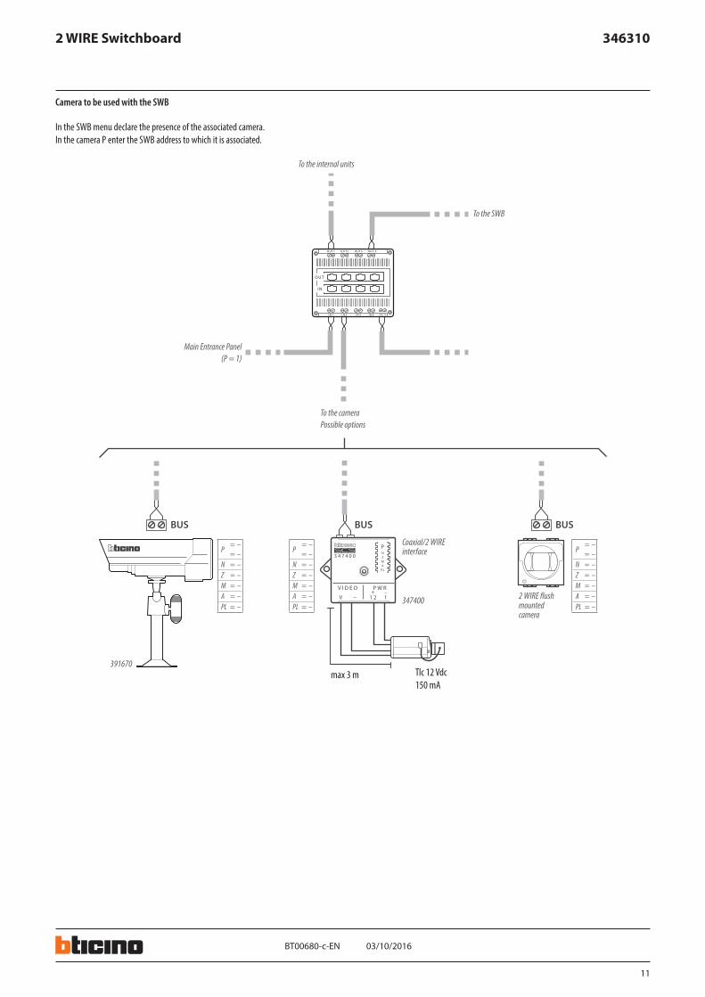
Camera to be used with the SWB
In the SWB menu declare the presence of the associated camera.In the camera P enter the SWB address to which it is associated.
Tlc 12 Vdc150 mA
max 3 m
To the internal units
To the SWB
Main Entrance Panel (P = 1)
To the cameraPossible options
Coaxial/2 WIRE interface
2 WIRE flush mounted camera
Related Documents