Fig. 2.2. Steam engine mechanism Fig. 2.3. I.C. engine mechanism Fig.2.1. Reciprocating steam engine 2. STRUCTURAL ANALYSE AND SYNTHESIS OF MECHANISMS 2.1 Link To a beginner, for short, the term machine may be defined as a device which receives energy in some available form and uses it to do certain particular kind of work. Mechanism may be defined as a contrivance which transforms motion from one form to another. A machine consists of a number of parts or bodies. In this chapter, we shall study the mechanisms of the various parts or bodies from which the machine is assembled. This is done by making one of the parts as fixed, and the relative motion of other parts is determined with respect to the fixed part. Each part of a machine, which moves relative to some other part, is known as a kinematic link (or simply link). A link may consist of several parts, which are rigidly fastened together, so that they do not move relative to one another. Even if two or more connected parts are manufactured separately, they cannot be treated as different links unless there is a relative motion between them. For example, in a reciprocating steam engine, as shown in Fig. 2.1, piston, piston rod and crosshead constitute one link; connecting rod with big and small end bearings constitute a second link; crank, crank shaft and flywheel third link and the cylinder, engine frame and main bearings fourth link. Therefore, slider-crank mechanisms of a steam engine (Fig. 2.2) and I.C. engine (2.3) are just the same. So, a link may be defined as a single part (or an assembly of rigidly connected parts) of a machine, which is a resistant body having a motion relative to other parts of the machine (mechanism).

Welcome message from author
This document is posted to help you gain knowledge. Please leave a comment to let me know what you think about it! Share it to your friends and learn new things together.
Transcript
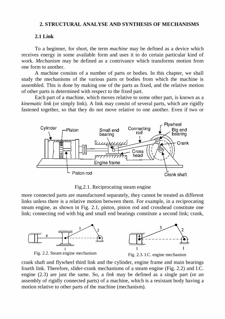
Fig. 2.2. Steam engine mechanism
Fig. 2.3. I.C. engine mechanism
Fig.2.1. Reciprocating steam engine
2. STRUCTURAL ANALYSE AND SYNTHESIS OF MECHANISMS
2.1 Link
To a beginner, for short, the term machine may be defined as a device which
receives energy in some available form and uses it to do certain particular kind of
work. Mechanism may be defined as a contrivance which transforms motion from
one form to another.
A machine consists of a number of parts or bodies. In this chapter, we shall
study the mechanisms of the various parts or bodies from which the machine is
assembled. This is done by making one of the parts as fixed, and the relative motion
of other parts is determined with respect to the fixed part.
Each part of a machine, which moves relative to some other part, is known as a
kinematic link (or simply link). A link may consist of several parts, which are rigidly
fastened together, so that they do not move relative to one another. Even if two or
more connected parts are manufactured separately, they cannot be treated as different
links unless there is a relative motion between them. For example, in a reciprocating
steam engine, as shown in Fig. 2.1, piston, piston rod and crosshead constitute one
link; connecting rod with big and small end bearings constitute a second link; crank,
crank shaft and flywheel third link and the cylinder, engine frame and main bearings
fourth link. Therefore, slider-crank mechanisms of a steam engine (Fig. 2.2) and I.C.
engine (2.3) are just the same. So, a link may be defined as a single part (or an
assembly of rigidly connected parts) of a machine, which is a resistant body having a
motion relative to other parts of the machine (mechanism).

Fig. 2.4. Four bar automobile-hood
mechanism
Fig. 2.5. Mechanism with belt-pulley
combination
combination
A link needs not to be rigid body, but it must be a resistant body. A body is
said to be a resistant one if it is capable of
transmitting the required forces with negligible
deformation. Based on above considerations a
spring which has no effect on the kinematics of
a device and has significant deformation in the
direction of applied force is not treated as a
link but only as a device to apply force
(Fig.2.4).They are usually ignored during
kinematic analysis, and their “force-effects” are
introduced during dynamic analysis.
There are machine members which
possess one-way rigidity. For instance, because
of their resistance to deformation under tensile load, belts (Fig. 2.5), ropes and chains
are treated as links only when they are in
tension. Similarly, liquids on account of their
incompressibility can be treated as links only
when transmitting compressive force.
Thus a link should have the following
two characteristics:
1. It should have relative motion, and
2. It must be a resistant body.
Structure is an assemblage of a number
of resistant bodies (known as members)
having no relative motion between them and
meant for carrying loads having straining action. A railway bridge, a roof truss,
machine frames etc., are the examples of a structure. The following differences
between a machine (mechanism) and a structure are important from the subject point
of view: 1. The parts of a machine move relative to one another, whereas the
members of a structure do not move relative to one another. 2. A machine transforms
the available energy into some useful work, whereas in a structure no energy is
transformed into useful work. 3. The links of a machine may transmit both power and
motion, while the members of a structure transmit forces only.
The kind of relative motion between links of a mechanism is controlled by the
form of the contacting surfaces of the adjacent (connected) links. These contacting
surfaces may be thought of as ‘working surfaces’ of the connection between adjacent
links. For instance, the connection between a lathe carriage and its bed is through
working surfaces (ways) which are so shaped that only motion of translation is
possible. Similarly, the working surface of I.C. engine piston and connecting rod at
piston pin are so shaped that relative motion of rotation alone is possible. Each of
these working surfaces is called an element.
An element may therefore be defined as a geometrical form provided on a link
so as to ensure a working surface that permits desired relative motion between
connected links.

Fig. 2.6. Conventional representation of different types of links
2.2 Classification of Links
A link can be called singular (unitary), binary, ternary, quaternary (etc.) link
depending on the
number of
elements it has for
pairing with other
links. Thus a link
carrying a single
element is called
a singular
(unitary) link and
a link with two
elements is called
a binary link.
Similarly, a link
having three
elements is called
a ternary link
while a link
having four
elements is called
a quaternary link.
These links, along
with their convention representation, are shown in Fig. 2.6.
2.3 Kinematic Pair
The two contacting elements of a connection constitute a kinematic pair. A pair
may also be defined as a connection between two adjacent links that permits a
definite relative motion between them. It may be noted that the above statement is
generally true. In the case of multiple joint, however, more than two links can be
connected at a kinematic pair (also known as joint). Cylindrical contacting surfaces
between I.C. engine cylinder and piston constitute a pair. Similarly, cylindrical
contacting surfaces of a rotating shaft and a journal bearing also constitute a pair.
When all the points in different links in a mechanism move in planes which are
mutually parallel the mechanism is said to have a planar motion. A motion other than
planar motion is spatial motion.
When the links are assumed to be rigid in kinematics, there can be no change in
relative positions of any two arbitrarily chosen points on the same link. In particular,
relative position(s) of pairing elements on the same link does not change. As a
consequence of assumption of rigidity, many of the intricate details, shape and size of
the actual part (link) become unimportant in kinematic analysis. For this reason it is
customary to draw highly simplified schematic diagrams which contain only the

Fig. 2.7. Turning (revolute)
pair R, F=1
important features in respect of the shape of each link (e.g., relative locations of
pairing elements). This necessarily requires to completely suppressing the
information about real geometry of manufactured parts. Schematic diagrams of
various links, showing relative location of pairing elements, are shown in Fig. 2.2.-
2.5. Conventions followed in drawing kinematic diagram are also shown there.
In drawing a kinematic diagram, it is customary to draw the parts (links) in the
most simplified form so that only those dimensions are considered which affect the
relative motion. One such simplified kinematic diagram of slider-crank mechanism of
an I.C. engine is shown in Fig. 2.3 in which connecting rod 3 and crank 2 are
represented by lines joining their respective pairing elements. The piston has been
represented by the slider 4 while cylinder (being a stationary member) has been
represented by frame link 1.
It may be noted, however, that these schematics, have a limitation in that they
have little resemblance to the physical hardware. And, one should remember that
kinematic diagrams are particularly useful in kinematic analysis and synthesis but
they have very little significance in designing the machine components of such a
mechanism.
2.4 Classification of Pairs
2.4.1 Classification of Pairs Based on Type of Relative Motion
The relative motion of a point on one element relative to the other on mating
element can be that of turning, sliding, screw (helical direction), planar, cylindrical or
spherical. The controlling factor that determines the relative motions allowed by a
given joint is the shapes of the mating surfaces or elements. Each type of joint has its
own characteristic shapes for the elements, and each permits a particular type of
motion, which is determined by the possible ways in which these elemental surfaces
can move with respect to each other. The shapes of mating elemental surfaces restrict
the totally arbitrary motion of two unconnected links to some prescribed type of
relative motion.
Turning Pair (Also called a hinge, a pin joint or
a revolute pair). This is the most common type of
kinematic pair and is designated by the letter R.
A pin joint has cylindrical element surfaces and
assuming that the links cannot slide axially, these
surfaces permit relative motion of rotation only. A pin
joint allows the two connected links to experience
relative rotation about the pin centre. Thus, the pair
permits only one degree of freedom. Thus, the pair at
piston pin, the pair at crank pin and the pair formed by
rotating crank-shaft in bearing are all example of
turning pairs.
Sliding or Prismatic Pair. This is also a
common type of pair and is designated as P (Fig.2.8).

Fig. 2.8. Prismatic or sliding pair P, F=1
Fig. 2.9. Screw (helical) pair S,
F=1
Fig. 2.10. Cylindrical pair C, F=2
Fig. 2.11. Globular or spherical pair
G, F=3
This type of pair permits relative motion of sliding only in one direction (along a line)
and as such has only one degree of freedom.
Pairs between piston and cylinder, cross-
head and guides, die-block and slot of slotted
lever are all examples of sliding pairs.
Screw Pair. This pair permits a
relative motion between coincident points,
on mating elements, along a helix curve.
Both axial sliding and rotational motions are
involved.
But as the
sliding and
rotational
motions are related through helix angle , the pair has
only one degree of freedom Fig (2.9.). The pair is
commonly designated by the letter S. Example of
such pairs are to be found in translatory screws
operating against rotating nuts to transmit large
forces at comparatively low speed, e.g. in screw-
jacks, screw-presses, valves and pressing screw of
rolling mills. Other examples are rotating lead screws
operating in nuts to transmit motion accurately as in lathes, machine tools, measuring
instruments, etc.
Cylindrical Pair. A cylindrical pair permits a relative motion which is a
combination of rotation and translation s
parallel to the axis of rotation between the
contacting elements (2.10). The pair has thus two
degrees of freedom and is designated by a letter
C. A shaft free to rotate in bearing and also free
to slide axially inside the bearing provides
example of a cylindrical pair.
Globular or Spherical Pair. Designated by
the letter G, the pair permits relative motion such
that coincident points on working surfaces of
elements move along spherical surface. In other
words, for a given position of spherical pair, the
joint permits relative rotation about three
mutually perpendicular axes. It has thus three
degrees of freedom. A ball and socket joint (e.g.,
the shoulder joint at arm-pit of a human being) is
the best example of spherical pair.
Flat pair (Planar Pair). A flat or planar

Fig. 2.12. Flat pair F, F=3
Fig. 2.13. Different paths of point P
(PC-cycloid, PD-involute)
pair is seldom, if ever, found in mechanisms. The pair permits a planar relative
motion between contacting elements. This
relative motion can be described in terms of
two translatory motions in x and y directions
and a rotation about third direction z, x, y, z
being mutually perpendicular directions. The
pair is designated as F and has three degrees
of freedom.
Rolling Pair. When surfaces of mating
elements have a relative motion of rolling, the
pair is called a rolling pair. Castor wheel of
trolleys, ball and roller bearings, wheels of
locomotive/wagon and rail are a few examples of this type.
2.4.2 Classification of Pairs Based on Type of Contact
This is the best known classification of kinematic pairs on the basis of nature of
contact:
Lower Pair. Kinematic pairs in which there is surfaces (area) contact between
the contacting elements are called lower pairs. All revolute pairs, sliding pairs, screw
pairs, globular pairs, cylindrical pairs and flat pairs fall in this category.
Higher Pair. Kinematic pairs in which there is point or line contact between
the contacting elements are called higher pairs. Meshing gear-teeth, cam follower
pair, wheel rolling on a surface, ball and roller bearings and pawl and ratchet are a
few examples of higher pairs.
Since lower pairs involve surface contact rather than line or point contact, it
follows that lower pairs can be more heavily loaded for the same unit pressure. They
are considerably more wear-resistant. For this reason, development in kinematics has
involved more and more number of lower pairs. As against this, use of higher pairs
implies lesser friction.
The real concept of lower pairs lies in the particular kind of relative motion
permitted by the connected links. For instance, let us assume that two mating
elements P and Q form kinematic pair. If the path traced by any point on the
element P , relative to element Q , is identical to
the path traced by a corresponding (coincident)
point in the element Q relative to element P ,
then the two elements P and Q are said to form
a lower pair. Elements not satisfying the above
condition obviously form the higher pairs
Since a turning pair involves relative
motion of rotation about pin-axis, coincident
points on the two contacting elements will have
circular areas of same radius as their path.
Similarly elements of sliding pair will have

straight lines as the path for coincident points. In the case of screw pair, the
coincident points on mating elements will have relative motion along helices. As
against this a point on periphery of a disk rolling along a straight line generates
cycloidal path, but the coincident point on straight line generates involute path when
the straight line rolls over the disk (Fig. 2.13). The two paths are thus different and
the pair is a higher pair. As a direct sequel to the above consideration, unlike a lower
pair, a higher pair cannot be inverted. That is, the two elements of the pair cannot be
interchanged with each other without affecting the overall motion of the mechanism.
Lower pairs are further subdivided into linear motion and surface motion pairs.
The distinction between these two sub-categories is based on the number of degrees
of freedom of the pair. Linear motion lower pairs are those having one degree of
freedom, i.e. each point on one element of the pair can move only along a single line
or curve relative to the other element. This category includes turning pairs, prismatic
pairs and screw pairs.
Surfaces-motion lower pairs have two or more degrees of freedom. This
category includes cylindrical pair, spherical pair and the planar (flat) pair.
2.4.3. Classification of Pairs Based on Degrees of Freedom
A free body in space has six degrees of freedom (d.o.f.=F=6). In forming a
kinematic pair, one or more degrees of freedom are lost. The remaining degrees of
freedom of the pair can then be used to classify pairs. Thus,
d.o.f. of a pair = 6 – ( Number of restrains).
Tab 2.1. Classification of pairs
No in
Fig.2.6
Geometrical
shapes of
elements in
contact
Number of Restraints on Total
Number of
Restraints
Class of pair
Translatory
motion
Rotary
motion
(a)
(b)
(c)
(d)
(e)
(f)
(g)
(h)
(i)
(j)
Sphere and plane
Sphere inside a
cylinder
Cylinder on plane
Sphere in
spherical socket
Sphere in slotted
cylinder
Prism on a plane
Spherical ball in
slotted socket
Cylinder in
cylindrical hollow
Collared cylinder
in hollow cylinder
Prism in prismatic
hollow
1
2
1
3
2
1
3
2
3
2
0
0
1
0
1
2
1
2
2
3
1
2
2
3
3
3
4
4
5
5
I
II
II
III
III
III
VI
IV
V
V

Fig. 2.14. Classification of pairs based on degrees of freedom
Fig. 2.15. Cam and roller-follower
A kinematic pair can therefore be classified on the basis of number of restrains
imposed on the relative motion of connected links. This is done in Tab. 2.1 for
different forms of pairing element shown in Fig. 2.14.
2.4.4. Classification of Pairs Based on Type of Closure
Another important way of classifying pairs is
to group them as closed or self closed kinematic
pairs and open kinematic pairs.
In closed pairs, one element completely
surrounds the other so that it is held in place in all
possible positions. Restraint is achieved only by
the form of pair and, therefore, the pair is called
closed or self-closed pair. Therefore, closed pairs
are those pairs in which elements are held together
mechanically. All the lower pairs and a few higher

Fig. 2.16. Weighing scale
pairs fall in the category of closed pairs
As against this, open kinematic pairs maintain relative positions only when
there is some external means to prevent separation of contacting elements. Open pairs
are also sometimes called as unclosed pairs. A cam and roller-follower mechanism,
held in contact due to spring and gravity force, is an example of this type (Fig. 2.15).
2.5. Kinematic Chain.
A kinematic chain can be defined as an assemblage of links which are inter-
connected through pairs, permitting relative motion between links. A chain is called a
closed chain when links are so connected in sequence that first link is connected to
the last, ensuring that all pairs are complete
because of mated elements forming working
surfaces at joints. As against this, when links
are connected in sequence, with first link not
connected to the last (leaving incomplete
pairs), the chain is called an open chain.
Examples of planar open loop chain are not
many but they have many applications in the
area of robotics and manipulators as space
mechanisms. An example of a planar open-loop chain, which permits the use of a
singular link (a link with only one element on it), is the common weighing scale
shown in Fig. 2.16.
Various links are numbered in the figure. Links 3, 1 and 4 are singular links.
From the subject point of view, a mechanism may now be defined as a
movable closed kinematic chain with one of its links fixed.
A mechanism with four links is known as simple mechanism, and the
mechanism with more than four links is known as compound mechanism. Let’s repeat
once again when a mechanism is required to transmit power or to do some particular
type of work, it then becomes a machine. In such cases, the various links or elements
have to be designed to withstand the forces (both static and kinetic) safely. A little
consideration will show that a mechanism may be regarded as a machine in which
each part is reduced to the simplest form to transmit the required motion.
Sometimes one prefers to reserve the term linkage to describe mechanisms
consisting of lower pairs only. But on a number of occasions this term has been used
rather loosely synonymous to the term mechanism.
2.6. Number of Degrees of Freedom of Mechanisms
Constrained motion is defined as that motion in which all points move in
predetermined paths, irrespective of the directions and magnitudes of the applied
forces. Mechanisms may be categorized in number of ways to emphasize their
similarities and differences. One such grouping can be to divide mechanisms into
planar, spherical and spatial categories. As seen earlier, a planar mechanism is one in

Fig. 2.17. Links in a plane motion
Fig. 2.18. Four bar mechanism
which all particles on any link of a mechanism describe plane curves in space and all
these curves lie in parallel planes.
In the design and analysis of a mechanism, one of the most important concerns
is the number of degrees of freedom, also called mobility, of the mechanism. The number of independent input parameters which must be controlled
independently so that a mechanism fulfills its useful engineering purpose is called its
degree of freedom or mobility. Degree of freedom equal to 1 (d.o.f. = F=1) implies
that when any point on the mechanism is moved in a prescribed way, all other points
have uniquely determined (constrained) motions. When d.o.f. =2, it follows that two
independent motions must be introduced at two different points in a mechanism, or
two different forces or moments must be present as output resistances (as is the case
in automotive differential
It is possible to determine the number of degrees of freedom of a mechanism
directly from the number of links and the number and types of pairs which it
includes. In order to
develop the
relationship in
general, consider two
links AB and CD in a
plane motion as
shown in Fig. 2.17 (a)
The link AB with co-
ordinate system OXY
is taken as the reference link (or fixed link). The position of point P on the moving
link CD can be completely specified by the three variables, i.e. the co-ordinates of
the point P denoted by x and y and the inclination of the link CD with X -axis or
link AB . In other words, we can say that each link of a planar mechanism has three
degrees of freedom before it is connected to any other link. But when the link CD is
connected to the link AB by a turning pair at A , as shown in Fig. 2.17 (b), the
position of link CD is now determined by a single variable θ and thus has one degree
of freedom.
From above, we see that when a link is connected to a fixed link by a turning
pair (i.e. lower pair) two degrees of freedom are destroyed (removed). This may be
clearly understood from Fig. 2.18, in which the resulting four bar mechanism has one
degree of freedom (i.e. 1F ).
Based on above discussions, expression for degree of freedom of a planar
kinematic chain, consisting of lower pairs (of d.o.f. =1) only, is given by-

3 2F n l ,
where n is a number of mobile links, l is a number of lower pairs.
In case of a mechanism which is obtained from a chain by fixing one link,
number of mobile links reduces to ( 1)n and therefore, expression for degrees of
freedom of a mechanism, consisting of lower pairs only, is given by-
3( 1) 2F n l . (2.1)
Equation (2.1) is known as Grubler’s equation, and is one of the most popular
mobility equations.
Therefore, Fig. 2.18 illustrates the process of losing degrees of freedom, each
time a turning pair is introduced, i.e. adding constraints, between two unconnected
links.
Just as a lower pair (linear motion lower pair) cuts down 2 d.o.f., a higher pair
cuts only 1 d.o.f. (this is because invariably rolling is associated with slipping,
permitting 2 d.o.f.). Hence equation (2.1) can be further modified to include the effect
of higher pairs also. Thus, for mechanism having lower and higher pairs
3( 1) 2F n l h , (2.2)
where h is a number of higher pairs.
Equation (2.2) is the modified Grubler’s equation. It is also as Kutzbach
criterion for the mobility of a planar mechanism. It would be more appropriate to
define, in equations (2.1) and (2.2), l to be the number of pairs of 1 d.o.f. and h to be
number of pairs of 2 d.o.f.
Spatial mechanisms do not incorporate any restriction on the relative motions
of the particles. A spatial mechanism may have particles describing paths of double
curvature. Grubler’s criterion was originally developed for planar mechanisms. If
similar criterion is to be developed for spatial mechanisms, we must remember that
an unconnected link has six in place of 3 degrees of freedom. As such, by fixing one
link of a chain the total d.o.f. of ( 1)n links separately will be 6( 1).n Again a
revolute and prismatic pair would provide 5 constrains (permitting 1 d.o.f), rolling
pairs will provide 4 constraints, and so on. Hence, taking into account the tab 2.1, an
expression for d.o.f. of a closed spatial mechanism can be written as:
1 2 3 4 56( 1) 5 4 3 2F n l l l l l , (2.3)
where N =total number of links,
1l number of pairs (joints) providing 5 constraints,
2l number of pairs providing 4 constraints,
3l number of pairs providing 3 constraints,
4l number of pairs providing 2 constraints, and
5l number of pairs providing only one constraint.
2.7. Application of Kutzbach Criterion to Plane Mechanisms
We have discussed that Kutzbach criterion for determining the number of
degrees of freedom (F) of a plane mechanism is
3( 1) 2F n l h .

Fig.2.19. Plane mechanisms
The number of degrees of freedom for some simple mechanisms having no
higher pair (i.e. 0h ), as shown in Fig. 2.19, are determined as follows:
Example 2.1. Find out degrees of freedom (F) of mechanisms shown in Fig.
2.17.
1. The mechanism, as shown in Fig. 2.19 (a), has three links and three lower
pairs, i.e. 3l and 3n ,
3 3 1 2 3 0F .
2. The mechanism, as shown in 2.19 (b), has four links and four pairs, i.e. 4l
and 4n ,
3 4 1 2 4 1F .
3. The mechanism, as shown in Fig. 2.19 (c), has five links and five pairs, i.e.
5l , and 5n ,
3 5 1 2 5 2F .
4. The mechanism, as shown in Fig. 2.19 (d), has five links and six pairs
(because there are two pairs at B and D , and four equivalent pairs at A and C ), i.e.
5l and 6n ,
3 5 1 2 6 0F .
5. The mechanism, as shown in Fig. 2.19 (e), has six links and eight pairs
(because there are two pairs separately at , ,A B C and D ), i.e. 6l and 8n ,
3 6 1 2 8 1F .
Therefore, it may be noted that
(a) When 0F , then the mechanism forms a structure and no relative motion
between the links is possible, as shown in Fig. 2.19 (a) and (d).
(b) When 1F , then the mechanism can be driven by a single input motion, as
shown in Fig. 2.19 (b)
(c) When 2F , then two separate input motions are necessary for the mechanism, as
shown in Fig. 2.19 (c).
(d) When 1F or less, then there are redundant constraints in the mechanism
(chain) and it forms indeterminate structure, as shown in Fig. 2.19 (e).
Let’s consider other examples.
Example 2.2. Find out degrees of freedom of mechanism shown in Figs.
2.20(a),(b),(c),(d) and (e).
Solution: (a) Here 9; 11n l ,
3(9 1) 2(11) 2F .

Fig. 2.20. Plane mechanisms
Fig. 2.21. Plane mechanisms
(b) Here 8n , 9 2l 11 ,
3(8 1) 2(11) 1F .
i.e. the mechanism at Fig. 2.20(b) is a statically indeterminate structure.
(c) As in case (b), here too there are double joints as A and B. Hence
10; 9 2(2) 13n l ,
3(10 1) 2(13) 1F .
(d) The mechanism at Fig. 2.20(d) has three ternary links (links 2,3 and 4) and
5 binary links (links 1,5,6,7 and 8) and one slider. It has 9 simple turning pairs
marked R , one sliding pair marked P and one double joint at .J Since the double
joint J joints 3 links, it may be taken equivalent to two simple turning pairs. Thus,
9; 11n l ,
3(9 1) 2(11) 2F .
(e) The mechanism at Fig. 2.20(e) has a roller pin at E and a spring at H . The
spring is only a device to apply force, and is not a link. Thus there are 7 links
numbered through 7, one sliding pair, one rolling (higher) pairs at E besides 6
turning pairs
7; 7n l and 1h ,
3(7 1) 2(7) (1)F 18 14 1 3 .
Example 2.3. Find out degrees of freedom of the mechanism shown in Fig.
2.21 (a), (b).

Fig. 2.22. Automobile window guidance linkage
Solution: ( ) 8; 9a n l ,
3(8 1) 2(9) 3F .
(b) 9, 10n l ,
3(9 1) 2(10) 4F .
Example 2.4. Show that the automobile window glass guiding mechanism in
Fig. 2.22 has a single degree of
freedom
Solution: As numbered, there
are total 7 links. There are seven
revolute pairs between link pairs
(1,2), (2,3), (3,4), (3,7), (4,6), (4,1)
and (1,5). Besides, there is one
sliding pair between links 6 and 7
and a geared pair between links 4
and 5.
Thus, 8l and 1h ,
3(7 1) 2(8) 1F =1.
2.8. Grubler’s Criterion for Plane Mechanisms
The Grubler’s criterion applies to mechanisms with only single degree of
freedom pairs where the overall mobility of the mechanism is unity. Substituting in
(2.2) 1F and 0h , we have
1 3 1 2n l or 3 2 4 0n l .
This equation is known as the Grubler's criterion for plane mechanisms with
constrained motion. A little consideration will show that a plane mechanism with a
mobility of 1 and only low pairs (of one degree of freedom) cannot have odd number
of links. The simplest possible mechanism of this type are a four bar mechanism and
a slider-crank mechanism in which 4n and 4l .
Consider some cases when Grubler’s equation gives incorrect results,
particularly when
(1) the mechanism has a lower pair which could replaced by a higher pair,
without influencing output motion;
(2) the mechanism has a kinematically redundant pair, and
(3) there is a link with redundant degree of freedom.
Inconsistency at (1) may be illustrated with the help of Figs. 2.23(a) and (b).
Fig. 2.23(a) depicts a mechanism with three sliding pairs. According to Grubler’s
theory, this combination of links has a degree of freedom of zero. But by inspection,
it is clear that the links have a constrained motion, because as the 2 is pushed to the
left, link 3 is lifted due to wedge action. But the sliding pair between; links 2 and 3
can be replaced by a slip rolling pair (Fig. 2.23(b)), ensuring constrained motion. In
the latter case, 3, 2n l and 1h which, according to Grubler’s equation,
gives 1F .
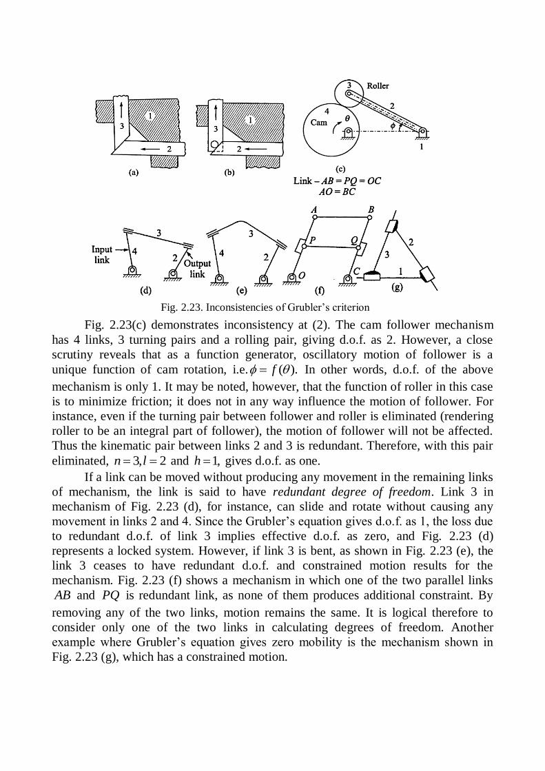
Fig. 2.23(c) demonstrates inconsistency at (2). The cam follower mechanism
has 4 links, 3 turning pairs and a rolling pair, giving d.o.f. as 2. However, a close
scrutiny reveals that as a function generator, oscillatory motion of follower is a
unique function of cam rotation, i.e. ( ).f In other words, d.o.f. of the above
mechanism is only 1. It may be noted, however, that the function of roller in this case
is to minimize friction; it does not in any way influence the motion of follower. For
instance, even if the turning pair between follower and roller is eliminated (rendering
roller to be an integral part of follower), the motion of follower will not be affected.
Thus the kinematic pair between links 2 and 3 is redundant. Therefore, with this pair
eliminated, 3, 2n l and 1,h gives d.o.f. as one.
If a link can be moved without producing any movement in the remaining links
of mechanism, the link is said to have redundant degree of freedom. Link 3 in
mechanism of Fig. 2.23 (d), for instance, can slide and rotate without causing any
movement in links 2 and 4. Since the Grubler’s equation gives d.o.f. as 1, the loss due
to redundant d.o.f. of link 3 implies effective d.o.f. as zero, and Fig. 2.23 (d)
represents a locked system. However, if link 3 is bent, as shown in Fig. 2.23 (e), the
link 3 ceases to have redundant d.o.f. and constrained motion results for the
mechanism. Fig. 2.23 (f) shows a mechanism in which one of the two parallel links
AB and PQ is redundant link, as none of them produces additional constraint. By
removing any of the two links, motion remains the same. It is logical therefore to
consider only one of the two links in calculating degrees of freedom. Another
example where Grubler’s equation gives zero mobility is the mechanism shown in
Fig. 2.23 (g), which has a constrained motion.
Fig. 2.23. Inconsistencies of Grubler’s criterion

(a) (b)
Fig 2.24. Rolling contact
(a) (b)
Fig. 2.25 Roll-Slide contact
(a) (b)
Fig. 2.26. Gear-tooth contact
2.9. Grubler’s Criterion Application for Mechanisms with Higher Pairs
As against one degree freedom of relative motion permitted by turning and
sliding pairs, higher pairs may permit a higher number of degrees of freedom. Each
such higher pair is equivalent to as many lower pairs as the number of degrees of
freedom of relative motion permitted by the given higher pair. This is elaborated for
different types of higher pairs, as discussed below:
(a) Rolling Contact without Sliding. This allows only one d.o.f. of relative
motion as only relative motion of rotation
exists. A pare rolling type of joint can
therefore be taken equivalent to lower pair
with one d.o.f.(Fig. 2.24) The lower pair
equivalent for instantaneous velocity is given
by a simple hinge joint at the relative instant
centre which is the point of contact between
rolling links. Note that instantaneous velocity
implies that in case a higher pair is replaced
by a lower pair equivalent, the instantaneous
relative velocity between the connecting links
remains the same, but the relative acceleration
may, in general, change.
(b) Roll-Slide Contact. Due to sliding motion associated with rolling only
one out of three planar motions is constrained
Fig. 2.25 (a). Thus, lower pair equivalence for
instantaneous velocity is given by a slider and
pin joint combination between the connected
links Fig. 2.25 (b). This implies degrees of
freedom of relative motion. Such a joint is also
taken care of, in Grubler’s equation, by making
contribution to the term .h
(c) Gear-Tooth Contact (Roll-Slide).
Gear tooth contact is a roll-slide pair and
therefore makes a contribution to the term h in Grubler’s equation. Thus, on account
of two turning pairs at gear centers together with a higher pair at contacting teeth
(Fig. 2.26 (a)),
3(3 1) 2(2) 1 1F .
Lower pair equivalent for
instantaneous velocity of such a pair is a
4-bar mechanism with fixed pivots at
gear centers and moving pivots at the
centers of curvature of contacting tooth
profiles (Fig. 2.26 (b)). In case of
involute teeth, these centers of curvature
will coincide with points of tangency of
common tangent drawn to base circles of
(a) (b)
Fig. 2.27. Spring Connection
(a) (b)
Fig. 2.28. Belt and pulley connection
the two gears. Such a 4-bar mechanism retains that d.o.f. equal to 1.
(d) A Spring Connection. Purpose of a spring is to exert force on the
connected links, but it does not
participate in relative motion between
connected links actively. Since the
spring permits elongation and
contraction in length, a pair of binary
links, with a turning pair connecting
them, can be considered to constitute
instantaneous velocity equivalent
lower pair mechanism. A pair of
binary links with a turning pair
permits variation in distance between
their other ends (unconnected), and allows same degree of freedom of relative motion
between links connected by the spring (for 4, 3, 3n l F ). It may be noted that in
the presence of spring, ( 2, 0, 0)n h the d.o.f. would be 3.
(e) The Belt and Pulley or Chain and Sprockets Connection. When the belt
or chain is maintained tight, it
provides planar connections
(Fig. 2.28 (a)). Instantaneous
velocity, lower pair equivalent
can be found in a ternary link
with three pin joints (sliding is
not allowed) as in (Fig. 2.28
(b)). It can be verified that d.o.f.
of equivalent six bar linkage is
3(6 1) 2(7) 1F .
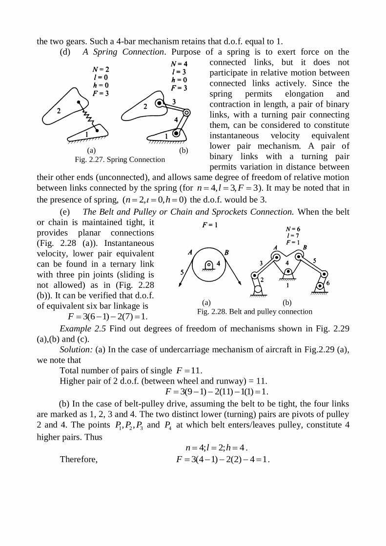
Example 2.5 Find out degrees of freedom of mechanisms shown in Fig. 2.29
(a),(b) and (c).
Solution: (a) In the case of undercarriage mechanism of aircraft in Fig.2.29 (a),
we note that
Total number of pairs of single 11F .
Higher pair of 2 d.o.f. (between wheel and runway) = 11.
3(9 1) 2(11) 1(1) 1F .
(b) In the case of belt-pulley drive, assuming the belt to be tight, the four links
are marked as 1, 2, 3 and 4. The two distinct lower (turning) pairs are pivots of pulley
2 and 4. The points 1 2 3, ,P P P and 4P at which belt enters/leaves pulley, constitute 4
higher pairs. Thus
4; 2; 4n l h .
Therefore, 3(4 1) 2(2) 4 1F .
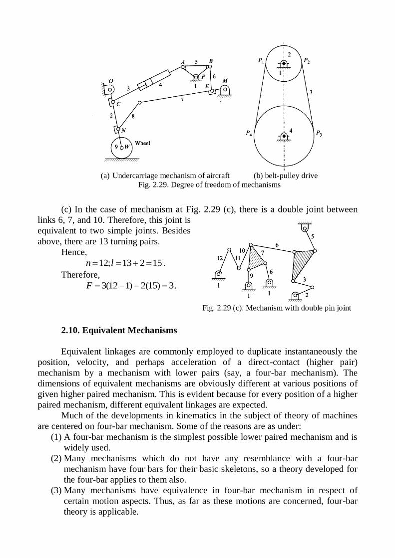
Fig. 2.29 (c). Mechanism with double pin joint
(c) In the case of mechanism at Fig. 2.29 (c), there is a double joint between
links 6, 7, and 10. Therefore, this joint is
equivalent to two simple joints. Besides
above, there are 13 turning pairs.
Hence,
12; 13 2 15n l .
Therefore,
3(12 1) 2(15) 3F .
2.10. Equivalent Mechanisms
Equivalent linkages are commonly employed to duplicate instantaneously the
position, velocity, and perhaps acceleration of a direct-contact (higher pair)
mechanism by a mechanism with lower pairs (say, a four-bar mechanism). The
dimensions of equivalent mechanisms are obviously different at various positions of
given higher paired mechanism. This is evident because for every position of a higher
paired mechanism, different equivalent linkages are expected.
Much of the developments in kinematics in the subject of theory of machines
are centered on four-bar mechanism. Some of the reasons are as under:
(1) A four-bar mechanism is the simplest possible lower paired mechanism and is
widely used.
(2) Many mechanisms which do not have any resemblance with a four-bar
mechanism have four bars for their basic skeletons, so a theory developed for
the four-bar applies to them also.
(3) Many mechanisms have equivalence in four-bar mechanism in respect of
certain motion aspects. Thus, as far as these motions are concerned, four-bar
theory is applicable.
(a) Undercarriage mechanism of aircraft (b) belt-pulley drive
Fig. 2.29. Degree of freedom of mechanisms

(a) (b)
Fig. 2.32. Spring to replace a pair of binary links and ternary pairs
Fig. 2.31. Mechanisms having identical relative motions
between links 2 and 4
(a) (b) (c)
Fig. 2.30. Equivalent mechanisms (kinematically identical mechanisms having the 4-bar basic
skeleton)
(4) Several complex mechanisms have four-bar loop as a basic element. Theory of
four-bar mechanism is, therefore, useful in the design of these mechanisms.
Point (2) above, is illustrated in Figs. 2.30 (a), (b) and (c). In Fig. 2.30 (b), the
link 4 in Fig. 2.30 (a) replaced by a curved slot and slider, with slot radius equal to
link length. In Fig. 2.30 (c) the link 3 is replaced by a slider, sliding in curved slotted
link 4 ensuring relative motion of
rotation of pinned and A relative
to B.
Point (3) is illustrated in
Figs. 2.30 (a), (b) and (c).
Mechanisms in which relative
motion between driver and driven
links 2 and 4 is identical are
illustrated in Fig. 2. 31.
In Fig. 2.31 (b) the centers
of curvature of circular cam and
roller constitute the end point of
link AB; link 3 becomes roller and
link 2 becomes circular cam. For d.o.f. 1 , however, the rolling pair in (b) should be
without slip.
Extension and compression in a spring is comparable to variation in length
between the turning
pairs accomplished by
a pair of binary links
connected through
another turning pair.
For instance pair of
binary links 4 and 5 of
a Stephenson’s chain can be replaced by a spring to obtain an equivalent mechanism.
This is shown in Figs. 2.32 (a) and (b).
When the belt or chain is maintained tight, a ternary link with three turning
pairs is the instantaneous-velocity equivalent lower pair connection to the belt and
pulley (sliding/slipping is disallowed).

2.11. Inversion of Mechanism
We have already discussed that when one of links is fixed in a kinematic chain,
it is called a mechanism. So we can obtain as many mechanisms as the number of
links in a kinematic chain by fixing, in turn, different links in a kinematic chain. This
method of obtaining different mechanisms by fixing different links in a kinematic
chain is known as inversion of the mechanism. It may be noted that the relative
motions between the various links is not changed in any manner through the process
of inversion, but their absolute motions (those measured with respect to the fixed
link) may be changed drastically.
The part of a mechanism which initially moves with respect to the frame or
fixed link is called driver and that part of the mechanism to which motion is
transmitted is called follower. Most of the mechanisms are reversible, so that same
link can play the role of a driver and follower at different times. For example, in a
reciprocating steam engine, the piston is the driver and flywheel is a follower while in
a reciprocating air compressor, the flywheel is a driver.
Important aspects of the concept of inversion can be summarized as under:
1. The concept of inversion enables us to categorize a group of mechanisms
arising out of inversions of a parent kinematic chain as a family of
mechanisms. Members of this family have a common characteristic in respect
of relative motion.
2. In case of direct inversions, as relative velocity and relative acceleration
between two links remain the same, it follows that complex problems of
velocity/acceleration analysis may often be simplified, by considering a
kinematically simpler direct inversion of the original mechanism.
3. In many cases of inversions by changing proportions of lengths of links,
desirable features of the inversion may be accentuated and many useful
mechanisms may be developed.
The most important kinematic chains are those which consist of four lower
pairs each pair being a sliding or a turning pair. The following three types of
kinematic chains with four lower pairs are important from the subject point of view:
1. Four bar chain or quadric cyclic chain,
2. Single slider crank chain, and
3. Double slider crank chain.
These kinematic chains are discussed, in detail, in the following articles.
2.12. Four Bar Chain or Quadric Cycle Chain
We have already discussed that the kinematic chain is a combination of four or
more kinematic pairs, such that the relative motion between the links or elements is
completely constrained. The simplest and the basic kinematic chain is a four bar
chain or quadric cycle chain, as shown in Fig. 2.33. It consists of four links, each of
them forms a turning pair at , ,A B C and D . The four links may be of different

Fig. 2.33. Four bar mechanism
Fig. 2.34. Coupling rod of a locomotive
lengths. According to Grashof’s law for a four bar mechanism, the sum of the
shortest and longest link lengths should not be greater
than the sum of the remaining two link lengths if there
is to be continuous relative motion between the two
links. Thus, if s and l be the lengths of shortest and
longest links respectively and p and q be the
remaining two link-lengths, then one of the links, in
particular the shortest link, will rotate continuously
relative to the other three links, if and only if
s l p q .
If this inequality is not satisfied, the chain is called non-Grashof chain in which
none of the links can have complete revolution relative to other links. It is important
to note that the Grashof”s law does not specify the order in which the links are to be
connected. Thus any of the links having length l , p and q can be the link opposite to
the link of length s . A chain satisfying Grashof”s law generates three distinct
inversions only. A non-Crashof chain, on the other hand, generates only one distinct
inversion, namely the “Rocker-Rocker mechanism”.
A very important consideration in designing a mechanism is to ensure that the
input crank makes a complete revolution relative to the other links. The mechanism
in which no link makes a complete revolution will not be useful. In a four bar chain,
one of the links, in particular the shortest link, will make a complete revolution
relative to the other three links, if it satisfies the Grashof ’s law. Such a link is known
as crank or driver. In Fig. 2.33 AD (link 4) is a crank. The link BC (link 2) which
makes a partial rotation or oscillates is known as lever or rocker or follower and the
link CD (link 3) which connects the crank and lever is called connecting rod or
coupler. The fixed link AB (link 1) is known as frame of the mechanism. When the
crank (link 4) is the driver, the mechanism is transforming rotary motion into
oscillating motion.
Though there are many inversions of the four bar chain, yet the following are
important from the subject point of view:
1. Double crank mechanism
(Coupling rod of a locomotive). The
mechanism of a coupling rod of a
locomotive (also known as double
crank mechanism) which consists of
four links is shown in Fig. 3.34.
In this mechanism, the links AD and
BC (having equal length) act as cranks
and are connected to the respective
wheels. The link CD acts as a coupling
rod and the link AB is fixed in order to maintain a constant center to center distance
between them. This mechanism is meant for transmitting rotary motion from one
wheel to the other wheel.

Fig. 2.35. Beam engine mechanism
Fig. 2.36. Double rocker mechanism
Fig. 2.37. Application of Grashow’s law
2. Crank-rocker mechanism (Beam engine).A part of the mechanism of a beam
engine (also known as cranks and lever
mechanism), which consists of four links, is
shown in Fig. 3.35. In this mechanism, when the
crank rotates about the fixed centre O, the lever
oscillates about a fixed centre C. The end D of
the lever BCD is connected to a piston rod which
reciprocates due to the rotation of the crank. In
other words,
the purpose
of this
mechanism is to convert rotary motion into
reciprocating motion.
3. Double rocker mechanism. When the
link, opposite to the shortest link is fixed, a
double rocker mechanism results. None of the
two links (driver and driven) connected to the
frame can have complete revolution but the
coupler link can have full revolution (Fig. 2.36)).
Example 2.6. Figure 2.37 shows a planar mechanism with link-lengths given in
some unit. If slider A is the driver, will link CG revolve or oscillate? Justify your
answer.
Solution: The loop formed by three links DE , EF and FD represents a
structure. Thus the loop can be taken to represent a ternary link.
In the 4-link loopCDEB ,
2s ; 4l ; and 7.p q Thus the 4-link
loop portion CDEB satisfies Grashof”s
criterion. And as the shortest link CD is
fixed, link CB is capable of complete
revolution. Also, 4-link loop GDFG
satisfies Grashof’s criterion ( )l s p q
and the shortest link CD is fixed. Thus
whether considered a part of 4-link loop
CDFBor that of CDFG , link BCG is
capable of full revolution
Example 2.7. In a 4-bar mechanism, the lengths of driver crank, coupler and
follower link are 150 mm, 250 mm and 300 mm respectively. The fixed link-length is
0L . Find the range of values for 0L , so as to make it a –
(1) Crank-rocker mechanism, (2) Crank-crank mechanism.
Solution:(1) For crank-rocker mechanism the conditions to be satisfied are:
(a) Link adjacent to fixed link must be the smallest link and, (b) s l p q .
We have to consider both the possibilities, namely, when 0L is the longest link
and when 0L is not the longest link.
When 0L is the longest link, it follows from Grashof’s criterion,
0 150 250 300L or 400oL mm
When 0L is not the longest link, it follows from Grashof’s criterion,
0300 150 250L or 0 200L
Thus, for crank-rocker mechanism, range of values for 0L is
0200 400L mm
(2) For crank-crank mechanism, the conditions to be satisfied are
(a) Shortest link must be the frame link and, (b) s l p q .
Thus, 0 300 150 250L
or 0 100L mm
2.13. Inversion of Single Slider Crank Chain
A single slider crank chain is a modification of the basic four bar chain. It
consists of one sliding pair and three turning pairs. It is, usually, found in
reciprocating steam engine mechanism. This type of mechanism converts rotary
motion into reciprocating motion and vice versa.
We know that by fixing, in turn, different links in a kinematic chain, an
inversion is obtained and we can obtain as many mechanisms as the links in a
kinematic chain. It is thus obvious, that four inversions of a single slider crank chain
are possible. These inversions are found in the following mechanisms.
A slider crank chain is as shown in Fig. 2.38(a).
First Inversion. It is obtained by fixing link 1 of the chain and the result is the
crank-slider mechanism as shown in Fig. 2.38(b). This mechanism is very commonly
used in I.C. engines, steam engines and reciprocating compressor mechanism.
Second Inversion. It is obtained by fixing link 3, the connecting rod. The
mechanism obtained by ‘verbatim inversion’, as shown in Fig. 2.39(a), has some
practical difficulties. For instance, the oscillating cylinder will have to be slotted for
clearing the pin through which slider is pivoted to frame. The problem may be
resolved if one remembers that any suitable alteration in shapes of links ensuring
same type of pairs between links 3 and 4 and also between links 1 and 4, is
permissible. This gives an inversion at Fig. 2.39 (b). The resulting mechanism is
oscillating cylinder engine mechanism. It is used in hoisting engine mechanism and
also in toys. In hoisting purposes its chief advantage lies in its compactness of
construction as it permits simple scheme of supplying steam to the cylinder.
Second application of the above inversion lies in ‘Slotted Lever Quick Return
Mechanism’, shown in Fig. 2.39 (c). The extreme position of lever 4 is decided by the
tangents drawn from lever-pivot to the crank-circle on either side. Corresponding
positions of crank 1 include angels and, which correspond to cutting stroke angle and
return stroke angle.

(a) Parent slider-crank chain (b) First inversion: slider-crank mechanism
Fig. 2.38. First inversion of a slider crank mechanism
(a) Verbatim inversion (b)Actual inversion (c) Actual inversion slotted lever
oscillating cylinder engine mechanism quick return mechanism
Fig. 2.39. Second inversion of a slider crank mechanism
Fig. 2.40. Third inversion of a slider crank mechanism
Whitworth quick return mechanism
Fig. 2.41. Rotary internal combustion engine
Third Inversion. The third inversion is obtained by fixing crank 2. It is the
slider-crank equivalent of Drag-
link mechanism and forms the
basis of Whitworth Quick
Return Mechanism. Basic
inversion is given by portionOAS . To derive advantage however, the slotted link 1 is
extended up to P and here it is connected to reciprocating tool-post through a
connecting link PQ and two turning pairs. The cutting stroke angle C and return
stroke angle R are shown in Fig. 2.40.
A yet another application of third inversion is in Rotary internal combustion
engine or Gnome engine (Fig. 2.41).

(a) Verbatim (b) Modified version - hand
inversion pump mechanism
Fig. 2.42. Forth inversion of a slider crank mechanism
Fig. 2.43. Crank and slotted lever quick return motion
mechanism
Fourth Inversion. The fourth inversion is obtained by fixing slider, the link 4.
Fixing of slider implies that the
slider should be position-fixed
and also fixed in respect of
rotation. The verbatim inversion
is shown in Fig. 2.42(a). This
form has certain practical
difficulties. As explained earlier,
the cylinder will have to be
slotted so as to clear piston pin
of connecting rod as cylinder
slides past piston. To overcome
this difficulty, the shapes of
piston and cylinder are
exchanged as shown in Fig.2.42
(b). This gives a hand pump mechanism. Lever 2 is extended.
2.14. Applications of Single Slider Crank Chain Inversion
Consider crank and slotted lever quick return motion mechanism in detail. This
mechanism is mostly used in shaping machines, slotting machines and in rotary
internal combustion engines.
In this mechanism, the link AC (i.e. link 3) forming the turning pair is fixed,
as shown in Fig. 2.43.
The link 3 corresponds
to the connecting rod of
a reciprocating steam
engine. The driving
crank CB revolves with
uniform angular speed
about the fixed
centerC . A sliding
block attached to the
crankpin at B slides
along the slotted bar
AP and thus causes
AP to oscillate about
the pivoted point A . A
short link PR transmits
the motion from AP to
the ram which carries
the tool and
reciprocates along the line of stroke 1 2R R . The line of stroke of the ram (i.e. 1 2R R ) is
perpendicular to AC produced.

Fig. 2.44. Whitworth quick return motion mechanism.
In the extreme positions, 1AP and
2AP are tangential to the circle and the
cutting tool is at the end of the stroke. The forward or cutting stroke occurs when the
crank rotates from the position 1CB to
2CB (or through an angle ) in the clockwise
direction. The return stroke occurs when the crank rotates from the position 2CB to
1CB (or through angle ) in the clockwise direction. Since the crank has uniform
angular speed, we have
0
Time of cutting stroke
Time of return stroke 360
=
0360
.
Since the tool travels a distance of 1 2R R during cutting and return stroke,
therefore travel of the tool or length of stroke is
1 2 1 2 1 1 12 2 sin R R PP PQ AP PAQ 0
12 sin 90 2 cos2 2
AP AP
12 CB
APAC
2 CB
APAC
.
From Fig. 2.43, we see that the angle made by the forward or cutting stroke
is greater than the angle described by the return stroke. Since the crank rotates
with uniform angular speed, therefore the return stroke is completed within shorter
time. Thus it is called quick return motion mechanism.
Now let’s analyze Whitworth quick return motion mechanism. In this
mechanism, the link
CD (link 2) forming
the turning pair is
fixed, as shown in
Fig. 2.44. The link 2
corresponds to a
crank in a
reciprocating steam
engine. The driving
crank CA (link 3)
rotates at a uniform
angular speed. The
slider (link 4)
attached to the crank
pin at A slides along the slotted bar PA (link 1) which oscillates at a pivoted point
D . The connecting rod PR carries the ram at R to which a cutting tool is fixed. The
motion of the tool is constrained along the line RD produced, i.e. along a line passing
through D and perpendicular to CD .
When the driving crank CA moves from the position 1CA to 2CA (or the link
DP from the position 1DP to 2DP ) through an angle α in the clockwise direction, the
tool moves from the left hand end of its stroke to the right hand end through a
distance 2PD . Now when the driving crank moves from the position 2CA to 1CA (or
the link DP from 2DP to 1DP ) through an angle β in the clockwise direction, the tool

Fig. 2.45. Extreme
positions of the crank
moves back from right hand end of its stroke to the left hand end. A little
consideration will show that the time taken during the left to right movement of the
ram (i.e. during forward or cutting stroke) will be equal to the time taken by the
driving crank to move from 1CA to
2CA . Similarly, the time taken during the right to
left movement of the ram (or during the idle or return stroke) will be equal to the time
taken by the driving crank to move from 2CA to
1CA .Since the crank link CA rotates
at uniform angular velocity therefore time taken during the cutting stroke (or forward
stroke) is more than the time taken during the return stroke. In other words, the mean
speed of the ram during cutting stroke is less than the mean speed during the return
stroke. The ratio between the time taken during the cutting and return strokes is given
by
0
Time of cutting stroke
Time of return stroke 360
=
0360
.
In order to find the length of effective stroke 1 2R R , mark
1 1 2 2PR P R PR . The
length of effective stroke is also equal to 2PD .
Example 2.8. A crank and slotted lever mechanism used in a shaper has a
center distance of 300 mm between the center of oscillation of the slotted lever and
the center of rotation of the crank. The radius of the crank is 120 mm. Find the ratio
of the time of cutting to the time of return stroke.
Solution. Given: 300AC mm; 1 120CD mm. The extreme positions of the
crank are shown in Fig. 2.45.
We know that
0
1sin sin 90 / 2CAB 1 1200.4
300
CB
AC ,
whence 0
1 90 / 2CAB 1 0sin 0.4 23.6 or 0 0 0/ 2 90 23.6 66.4 and 0 02 66.4 132.8 .
Finally we have 0Time of cutting stroke 360
Time of return stroke
=
0 0
0
360 132.81.72
132.8
.
Example 2.9. In a crank and slotted lever quick return motion mechanism, the
distance between the fixed centers is 240 mm and the length of the driving crank is
120 mm. Find the inclination of the slotted bar with the vertical in the extreme
position and the time ratio of cutting stroke to the return stroke. If the length of the
slotted bar is 450 mm, find the length of the stroke if the line of stroke passes through
the extreme positions of the free end of the lever.
Solution. Given: 240AC mm; 1 120CB mm; 1 450AP mm

Fig. 2.46. Extreme positions of the crank
Fig. 2.47. Quick return mechanism
Fig. 2.48. Extreme positions of the crank
Let 1CAB be an inclination of the
slotted bar with the vertical. The extreme
positions of the crank are shown in Fig. 2.46.
We know that
0
1sin sin 902
CAB
1 1200.5
240
B C
AC ,
hence, 0
1 902
CAB
1 0sin 0.5 30 .
We know that 0 090 / 2 30 , then 0 0 0/ 2 90 30 60 or 0 02 60 120 .
0 0 0
0
Time of cutting stroke 360 360 1202.
Time of return stroke 120
We know that length of the stroke,
0
1 2 1 2 1 12 2 sin 90 / 2R R PP PQ AP
0 02 250sin 90 60 900 0,5 450 mm.
Example 2.10. Fig. 2.47 shows the layout of a quick return mechanism of the
oscillating link type, for a special purpose
machine. The driving crank BC is 30 mm long
and time ratio of the working stroke to the return
stroke is to be 1.7. If the length of the working
stroke of R is 120 mm, determine the dimensions
of AC and AP .
Solution. Given: 30BC mm; 1 2 120R R
mm; Time ratio of working stroke to the return
stroke=1.7.
We know that
Time of working stroke 360
Time of return stroke
or
3601.7
Hence, 0133.3 or 0/ 2 66.65 .
The extreme positions of the crank
are shown in Fig. 2.48. From right angled
triangle 1ABC , we find that
0 1sin 90 / 2B C
AC or
1
0 cos / 2sin 90 / 2
B C BCAC
.

Fig. 2.49. Whitworth quick return motion mechanism
Fig. 2.50. Extreme positions of the
driving crank
Since 1 BC BC we obtain
0
30 3075.7 mm.
cos66.65 0.3963 AC
We know that length of stroke,
0
1 2 1 2 1 1 12 2 sin 90 / 2 2 cos / 2R R PP PQ AP AP , but 1 AP AP . Then
0120 2 cos66.65 0.7926 AP AP and 120 / 0.7926 151.4 mm AP
Example 2.11. In a Whitworth quick return motion mechanism, as shown in
Fig. 2.49, the distance between the
fixed centers is 50 mm and the
length of the driving crank is 75
mm. The length of the slotted lever
is 150 mm and the length of the
connecting rod is 135 mm. Find the
ratio of the time of cutting stroke to
the time of return stroke and also
the effective stroke.
Solution. Given:
50CD mm; 75CA mm; 150PA mm ;
135PR mm
The extreme positions of the driving
crank are shown in Fig. 2.50. From the
geometry of the figure,
2
50cos / 2 0.667
75
CD
CA, then
096.4
We know that 0 0
0
Time of cutting stroke 360 360 96.4 2.735.
Time of return stroke 96.4
In order to find the length of effective stroke (i.e. 1 2R R ), draw the space
diagram of the mechanism to some suitable scale, as shown in Fig. 2.50. Mark
1 2 2 2PR P R PR . Therefore by measurement we find that,
Length of effective stroke is 1 2 87.5 mmR R
2.15. Inversions of Double Slider Crank Chain
A kinematic chain which consists of two turning pairs and two sliding pairs is
known as double slider crank chain, as shown in Fig. 2.51. We see that the link 2 and
link 1 form one turning pair and link 2 and link 3 form the second turning pair. The
link 3 and link 4 form one sliding pair and link 1 and link 4 form the second sliding
pair.

Fig. 2.51. Elliptical trammels
Fig. 2.52. Scotch yoke mechanism
The following three inversions of a double slider crank chain are important
from the subject point of
view:
First inversion
(Elliptical trammels). It is
an instrument used for
drawing ellipses. This
inversion is obtained by
fixing the slotted plate
(link 4), as shown in Fig.
2.51. The fixed plate or
link 4 has two straight
grooves cut in it, at right
angles to each other. The
link 1 and link 3 are known as sliders and form sliding pairs with link 4. The link AB
(link 2) is a bar which forms turning pair with links 1 and 3.When the links 1 and 3
slide along their respective grooves, any point on the link 2 such as P traces out an
ellipse on the surface of link 4, as shown in Fig. 2.51 (a). A little consideration will
show that AP and BP are the semi-major axis and semi-minor axis of the ellipse
respectively. This can be proved as follows:
Let us take OX and OY as horizontal and vertical axes and let the link BA is
inclined at an angle with the horizontal, as shown in Fig. 2.51 (b). Now the co-
ordinates of the point P on the link BA will be
cosx PQ AP ; and siny PR BP or
cosx
AP ; and sin
y
BP .
Squaring and adding,
2 22 2
2 2cos sin 1
x y
AP BP .
This is the equation of an ellipse. Hence the path traced by point P is an
ellipse whose semi major axis is AP and semi-minor axis is BP .
If P is the mid-point of link BA , then AP BP . The above equation can be
written as
2 2
2 21
AP
x y
AP or
22 2x y AP .
This is the equation of a circle
whose radius is AP . Hence if P is the
mid-point of link BA , it will trace
circle.
Second inversion (Scotch yoke
mechanism). This mechanism is used
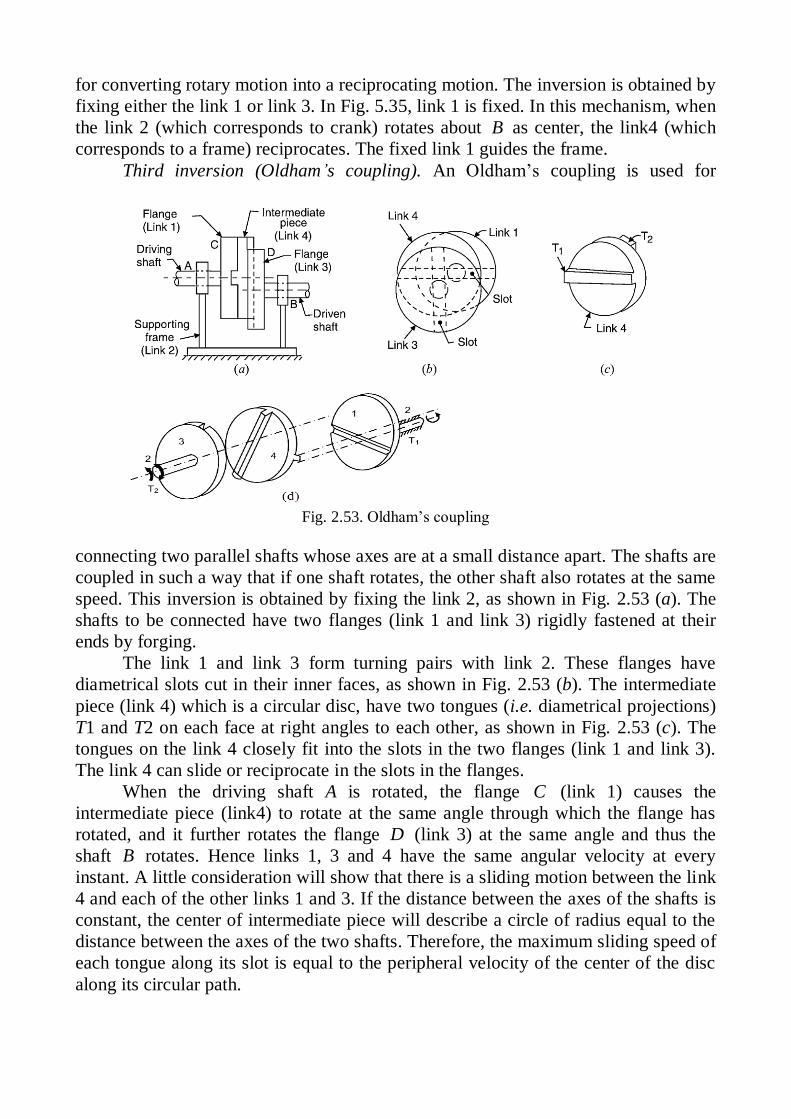
Fig. 2.53. Oldham’s coupling
for converting rotary motion into a reciprocating motion. The inversion is obtained by
fixing either the link 1 or link 3. In Fig. 5.35, link 1 is fixed. In this mechanism, when
the link 2 (which corresponds to crank) rotates about B as center, the link4 (which
corresponds to a frame) reciprocates. The fixed link 1 guides the frame.
Third inversion (Oldham’s coupling). An Oldham’s coupling is used for
connecting two parallel shafts whose axes are at a small distance apart. The shafts are
coupled in such a way that if one shaft rotates, the other shaft also rotates at the same
speed. This inversion is obtained by fixing the link 2, as shown in Fig. 2.53 (a). The
shafts to be connected have two flanges (link 1 and link 3) rigidly fastened at their
ends by forging.
The link 1 and link 3 form turning pairs with link 2. These flanges have
diametrical slots cut in their inner faces, as shown in Fig. 2.53 (b). The intermediate
piece (link 4) which is a circular disc, have two tongues (i.e. diametrical projections)
T1 and T2 on each face at right angles to each other, as shown in Fig. 2.53 (c). The
tongues on the link 4 closely fit into the slots in the two flanges (link 1 and link 3).
The link 4 can slide or reciprocate in the slots in the flanges.
When the driving shaft A is rotated, the flange C (link 1) causes the
intermediate piece (link4) to rotate at the same angle through which the flange has
rotated, and it further rotates the flange D (link 3) at the same angle and thus the
shaft B rotates. Hence links 1, 3 and 4 have the same angular velocity at every
instant. A little consideration will show that there is a sliding motion between the link
4 and each of the other links 1 and 3. If the distance between the axes of the shafts is
constant, the center of intermediate piece will describe a circle of radius equal to the
distance between the axes of the two shafts. Therefore, the maximum sliding speed of
each tongue along its slot is equal to the peripheral velocity of the center of the disc
along its circular path.

(a) (b) (c)
Fig. 2.54. Structural analysis of plane mechanism
Let be an angular velocity of each shaft in rad/s, and r is a distance between
the axes of the shafts in meters. Then maximum sliding speed of each tongue (in
m/s),
v r .
2.16. Assur-Artobolevsky Composition Principle and Structural Analysis
2.16.1. Composition Principle of Mechanisms
The links and the kinematic pairs of a mechanism can be divided into two
parts. The first part consists of the frame, the driver and the kinematic pair connecting
the frame and the driver. Other links and pairs belong to the second part. The first
part we will call the basic mechanism and the second part the system of driven links.
The mechanism in Fig. 2.54 can for example be divided into two such parts as shown
in Fig. 2.54 (b). During such division and classification, the sum of links, the sum and
types of kinematic pairs do not change. The sum of the d.o.f. of the two parts should
therefore be equal to the d.o.f. of the original mechanism.
We have learned that in any mechanism which has a determined motion, the
number of drivers must be equal to the d.o.f. of the mechanism. In the basic
mechanism, the driver is always connected to the frame by a lower pair. Every driver
(and its corresponding lower pair) has one d.o.f. Thus the d.o.f. of the basic
mechanism is equal to the number of drivers, or equal to the d.o.f. of the original
mechanism. The d.o.f. of the system of driven links must thus be zero. In some cases,
the system of driven links can be divided into smaller groups. If the d.o.f. of each
group is zero and no group can be divided further into two or more zero-d.o.f. groups,
then such groups are called Assur-Artobolevsky groups. For example, the system of
driven links in Fig. 2.54 (b) can be further divided into two Assur groups as shown in
Fig. 2.54 (c).
In each Assur group, one or more pairs are used to connect the links within the
group. Such a pair is called an inner pair. For example, the pair C in the group DCB
and the pair F in the group GFE are the inner pairs for the groups concerned. Some
pairs in an Assur group are used to connect the group to kinematically determined
links. Such pairs are called outer pairs. For example, the group DCB is connected to
the kinematically determined links (the frame and the driver) by lower pairs B and D.
The pairs B and D are therefore the outer pairs of the group DCB. When the group
DCB is connected to the determined links by the outer pairs D and B a four-bar
mechanism ABCD is created and all links in the group DCB become kinematically

(a) (b)
Fig. 2.55.
(a) (b)
Fig. 2.56.
determined. The group GFE is then connected to the determined link BCE and the
frame by lower pairs E and G. The pairs E and G are therefore the outer pairs of the
group GFE. Note: the revolute E is not an outer pair of the group DCB. From the
assembly order of the Assur groups, we can see that the group DCB is the first group,
while the group GFE is the second group.
Hence, as mentioned above, we can see that any mechanism which has a
determined motion can be assembled from a basic mechanism by connecting Assur
groups to the determined links using outer pairs, group by group. This is the
composition principle of mechanism. Only after the former Assur group is assembled
can the later one be assembled.
2.16.2. Classification of Assur Group and Mechanism
In a lower-pair Assur group, 3 2 0.F n l Therefore, 3
2
nl . Since l and n
are integers, the number n of links must be even. The groups in Fig. 2.54 (c) are the
simplest lower-pair Assur groups in which there are two links and three pairs. If n =
4, the lower-pair Assur group has two different constructions as shown in Fig. 2.55.
In Fig. 2.55 (a), lower pairs A, B and C are used to connect links within the group.
They are the inner pairs of the group. The group will be connected to determined
links by lower pairs D, E and F. Thus, the lower pairs D, E and F are the outer pairs
of the group. In Fig. 2.55 (b), lower pairs A, B, C and D are the inner pairs, while the
lower pairs E and F are the outer pairs. Assur groups have different grades according
to different number of links and different structure. The groups in Fig. 2.54 (c), Fig.
2.55 (a) and Fig. 2.55 (b) are classified as grade II, III and IV Assur groups,
respectively.
For the same kinematic chain, the composition can be changed if the frame
and/or the driving link is changed. For example, the kinematic chain in Fig. 2.56 (a)
is the same as that in Fig. 2.54 (a) but the driver in Fig. 2.56 (a) is the link GF. The
mechanism in Fig. 2.56 (a) is then composed of a basic mechanism and a grade III
Assur group, as shown in Fig. 2.56 (b).
The grade of a mechanism is defined as the highest grade of the Assur group in
the mechanism. Hence the mechanism in Fig. 2.54 is a grade II mechanism, while the
mechanism in Fig. 2.56 is of grade III. The basic mechanism is sometimes called the
grade I mechanism, e.g., a ceiling fan (consisting of only a single rotating link) is a
grade I mechanism.
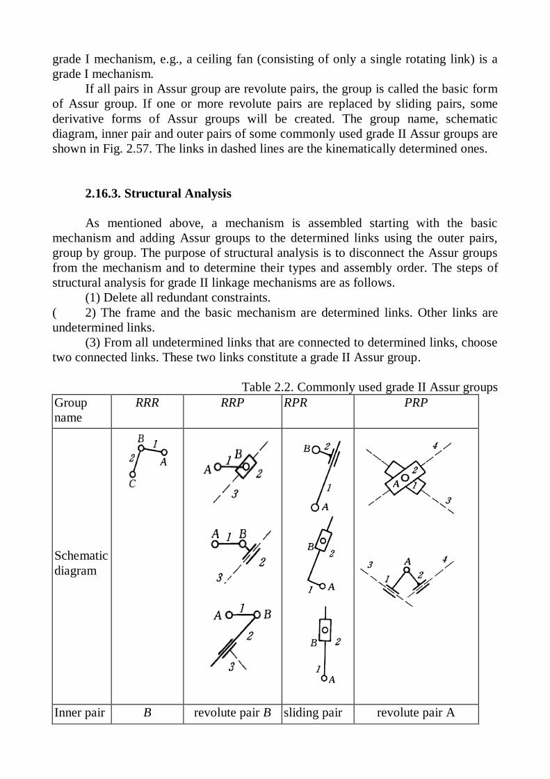
If all pairs in Assur group are revolute pairs, the group is called the basic form
of Assur group. If one or more revolute pairs are replaced by sliding pairs, some
derivative forms of Assur groups will be created. The group name, schematic
diagram, inner pair and outer pairs of some commonly used grade II Assur groups are
shown in Fig. 2.57. The links in dashed lines are the kinematically determined ones.
2.16.3. Structural Analysis
As mentioned above, a mechanism is assembled starting with the basic
mechanism and adding Assur groups to the determined links using the outer pairs,
group by group. The purpose of structural analysis is to disconnect the Assur groups
from the mechanism and to determine their types and assembly order. The steps of
structural analysis for grade II linkage mechanisms are as follows.
(1) Delete all redundant constraints.
( 2) The frame and the basic mechanism are determined links. Other links are
undetermined links.
(3) From all undetermined links that are connected to determined links, choose
two connected links. These two links constitute a grade II Assur group.
Table 2.2. Commonly used grade II Assur groups
Group
name
RRR RRP RPR PRP
Schematic
diagram
Inner pair B revolute pair B sliding pair revolute pair A

Fig. 2.57. Structural analysis of
mechanism
Outer
pairs C, A A, sliding pair A, revolute B
sliding pair 1-3 sliding
pair 2-4
The pair connecting these two links is the inner pair of the group. The two pairs
by which the group is connected to the determined links are the two outer pairs of the
group.
(4) When the group is connected to the determined links by the outer pairs, all
links in the group become kinematically determined. Now repeat step (3) until all
links become kinematically determined.
This procedure is sometimes called group
dividing. During group dividing, any link and
kinematic pair can only belong to one group and
cannot appear twice in different groups.
According to the steps mentioned above, for the
mechanism shown in Fig. 2.57, the assembly
order of groups, type of group, link serial
numbers, inner pair and outer pairs of each
group are listed in Table 2.3. Since the highest
grade of group in this mechanism is II, the
mechanism is a grade II mechanism. During
kinematic analysis of the mechanism, the first
group must be analyzed first. Only after that, can
the second group be analyzed.
Table 2.3. Structural analysis for the mechanism shown in Fig. 2.57.
Type Link serial
numbers Inner pair Outer pairs
First
group
RRR 2,3 A B,D
Second
group
RPR 4,5 sliding pair C4-5 F, revolute C3-5
The theory of structural analysis reveals the internal rule of the mechanism
composition. It can help us to understand the structure of a mechanism, to analyze the
transmission route in the mechanism, and to improve our ability in mechanism
design.
2.17. Structural Synthesis
Whereas kinematic analysis aims at analyzing the motion inherent in a given
machine or mechanism, kinematic synthesis aims at determining mechanisms that are
required to fulfill certain motion specifications. Kinematic synthesis can, therefore,
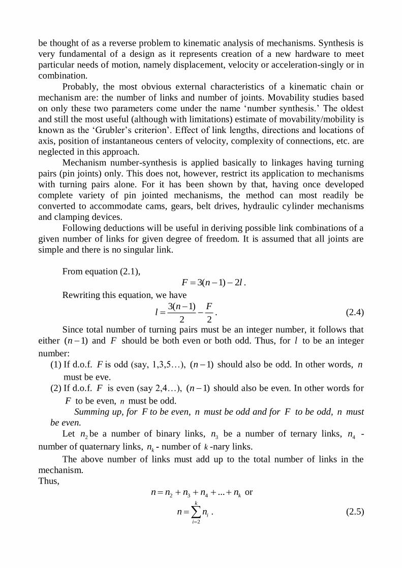
be thought of as a reverse problem to kinematic analysis of mechanisms. Synthesis is
very fundamental of a design as it represents creation of a new hardware to meet
particular needs of motion, namely displacement, velocity or acceleration-singly or in
combination.
Probably, the most obvious external characteristics of a kinematic chain or
mechanism are: the number of links and number of joints. Movability studies based
on only these two parameters come under the name ‘number synthesis.’ The oldest
and still the most useful (although with limitations) estimate of movability/mobility is
known as the ‘Grubler’s criterion’. Effect of link lengths, directions and locations of
axis, position of instantaneous centers of velocity, complexity of connections, etc. are
neglected in this approach.
Mechanism number-synthesis is applied basically to linkages having turning
pairs (pin joints) only. This does not, however, restrict its application to mechanisms
with turning pairs alone. For it has been shown by that, having once developed
complete variety of pin jointed mechanisms, the method can most readily be
converted to accommodate cams, gears, belt drives, hydraulic cylinder mechanisms
and clamping devices.
Following deductions will be useful in deriving possible link combinations of a
given number of links for given degree of freedom. It is assumed that all joints are
simple and there is no singular link.
From equation (2.1),
3( 1) 2F n l .
Rewriting this equation, we have
3( 1)
2 2
n Fl
. (2.4)
Since total number of turning pairs must be an integer number, it follows that
either ( 1)n and F should be both even or both odd. Thus, for l to be an integer
number:
(1) If d.o.f. F is odd (say, 1,3,5…), ( 1)n should also be odd. In other words, n
must be eve.
(2) If d.o.f. F is even (say 2,4…), ( 1)n should also be even. In other words for
F to be even, n must be odd.
Summing up, for F to be even, n must be odd and for F to be odd, n must
be even.
Let 2n be a number of binary links, 3n be a number of ternary links, 4n -
number of quaternary links, kn - number of k -nary links.
The above number of links must add up to the total number of links in the
mechanism.
Thus,
2 3 4 ... kn n n n n or
2
k
i
i
n n
. (2.5)
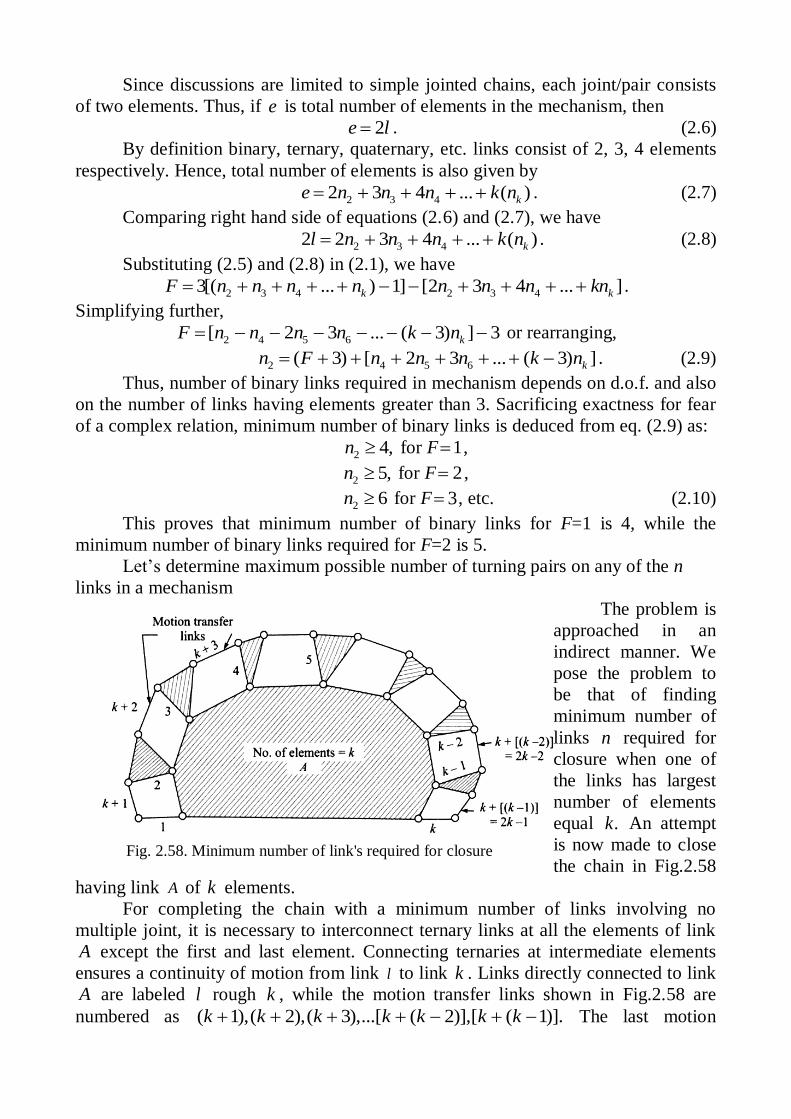
Fig. 2.58. Minimum number of link's required for closure
Since discussions are limited to simple jointed chains, each joint/pair consists
of two elements. Thus, if e is total number of elements in the mechanism, then
2e l . (2.6)
By definition binary, ternary, quaternary, etc. links consist of 2, 3, 4 elements
respectively. Hence, total number of elements is also given by
2 3 42 3 4 ... ( )ke n n n k n . (2.7)
Comparing right hand side of equations (2.6) and (2.7), we have
2 3 42 2 3 4 ... ( )kl n n n k n . (2.8)
Substituting (2.5) and (2.8) in (2.1), we have
2 3 4 2 3 43[( ... ) 1] [2 3 4 ... ]k kF n n n n n n n kn .
Simplifying further,
2 4 5 6[ 2 3 ... ( 3) ] 3kF n n n n k n or rearranging,
2 4 5 6( 3) [ 2 3 ... ( 3) ]kn F n n n k n . (2.9)
Thus, number of binary links required in mechanism depends on d.o.f. and also
on the number of links having elements greater than 3. Sacrificing exactness for fear
of a complex relation, minimum number of binary links is deduced from eq. (2.9) as:
2 4,n for F 1 ,
2 5,n for F 2 ,
2 6n for F 3 , etc. (2.10)
This proves that minimum number of binary links for F=1 is 4, while the
minimum number of binary links required for F=2 is 5.
Let’s determine maximum possible number of turning pairs on any of the n
links in a mechanism
The problem is
approached in an
indirect manner. We
pose the problem to
be that of finding
minimum number of
links n required for
closure when one of
the links has largest
number of elements
equal .k An attempt
is now made to close
the chain in Fig.2.58
having link A of k elements.
For completing the chain with a minimum number of links involving no
multiple joint, it is necessary to interconnect ternary links at all the elements of link
A except the first and last element. Connecting ternaries at intermediate elements
ensures a continuity of motion from link l to link k . Links directly connected to link
A are labeled l rough k , while the motion transfer links shown in Fig.2.58 are
numbered as ( 1),( 2),( 3),...[ ( 2)],[ ( 1)].k k k k k k k The last motion

transfer link is thus numbered as (2 1).k Clearly, minimum number of links
required to complete the chain is (2 1),k besides the link of highest elements.
In other words, for a given number of links 2n k , a link can have a maximum
of k elements. Hence,
2
nk . (2.11)
Thus when n is even, maximum possible number of elements which a link can
have is / 2n .
An important conclusion emerging out of eq. (2.9) is that the number of ternary
links does not have any influence on degrees of freedom of a mechanism.
For a mechanism with d.o.f. =1,
1( ) 1
2C n , (2.12)
where C is a number of independent circuit or loops, n is a number of links.
2.18. Enumeration of kinematic Chains
Let N be the number of links and F degree of freedom, for which all possible
planar chains are needed to be established.
Step 1. For given N and F establish the number of joints (hinges) using (2.4)
3 ( 3)
2
N Fl
.
For F=1, this reduces to
3 4
2
Nl
.
Step 2. For given N , establish maximum number of elements permissible on
any link, using
and ( 1)
,for 2,42
Nk F
.
Step 3. Substituting expression for N and 2l , namely,
2 3 4 ... kN n n n n , and 2 3 42 2 3 4 ... ( )kl n n n k n
in Grubler’s eq. (2.1) we have
2 3 4 2 3 43[( ... ) 1] [2 3 4 ... ]k kF n n n n n n n kn or
2 4 5[ ( 2 ... ( 3) ) 3]kF n n n k n .
Thus for 1F ,
2 4 52 ... ( 3) 4kn n n k n .
Above equations may be used to list all possible combinations of
2 4 5, , ,...n n n which satisfy given conditions.
Example 2.12. Enumerate all chains possible with 6N and 1F .
,for 1,3,52
Nk F

(a) Undesirable due to existence of 3-link loop 1-2-3; (b) Undesirable due to formation of link
loop 1-2-6; (c) Permissible combination as no3-link loop exists
Fig. 2.59
Solution: Total number of hinges 3(6) 4
72
l
.
Also, for even number of links ( 6)N , maximum number of hinges on any
link is 6/2=3. Thus the chains will consist of binary and ternary links only. Hence, we
have from eqs. (2.5) and (2.8),
2 3 6n n N and 2 32 3 2 14n n l . (2.13)
Substituting in Grubler’s criterion we have,
2 3 2 33( ) (2 3 ) 4 0n n n n or 2 4 0n .
Thus, 2 4n and from eq. (2.13),
3 2.n
We begin by considering the ways in which links of highest degree (i.e., links
having largest number of elements) can be interconnected. The two ternaries can be
either connected directly through a common pair or can be connected only through
one or two binary links.
In Fig.2.59 we consider the first possibility. The two ternaries of 2.59(a) and
(b) cannot be connected through a single link as it amounts to forming a structural
loop (3-link loop). The only way to connect them through 4 binaries (avoiding
formation of a 3-link loop) is therefore, as shown at Figs.2.59(c), which gives Watt’s
chain.
Considering the second alternative, Fig. 2.60 (a) shows the two ternary links 1
and 2 being connected through a single binary link 3. Then, between one of
remaining two pairs of elements of links 1 and 2, we may introduce a single binary
and between the other pair of elements, two remaining binaries. The resulting
arrangements are as at Fig.2.60 (b) and (c). It is easy to verify that arrangements at
Figs. 2.60 (b) and (c) are structurally the same.
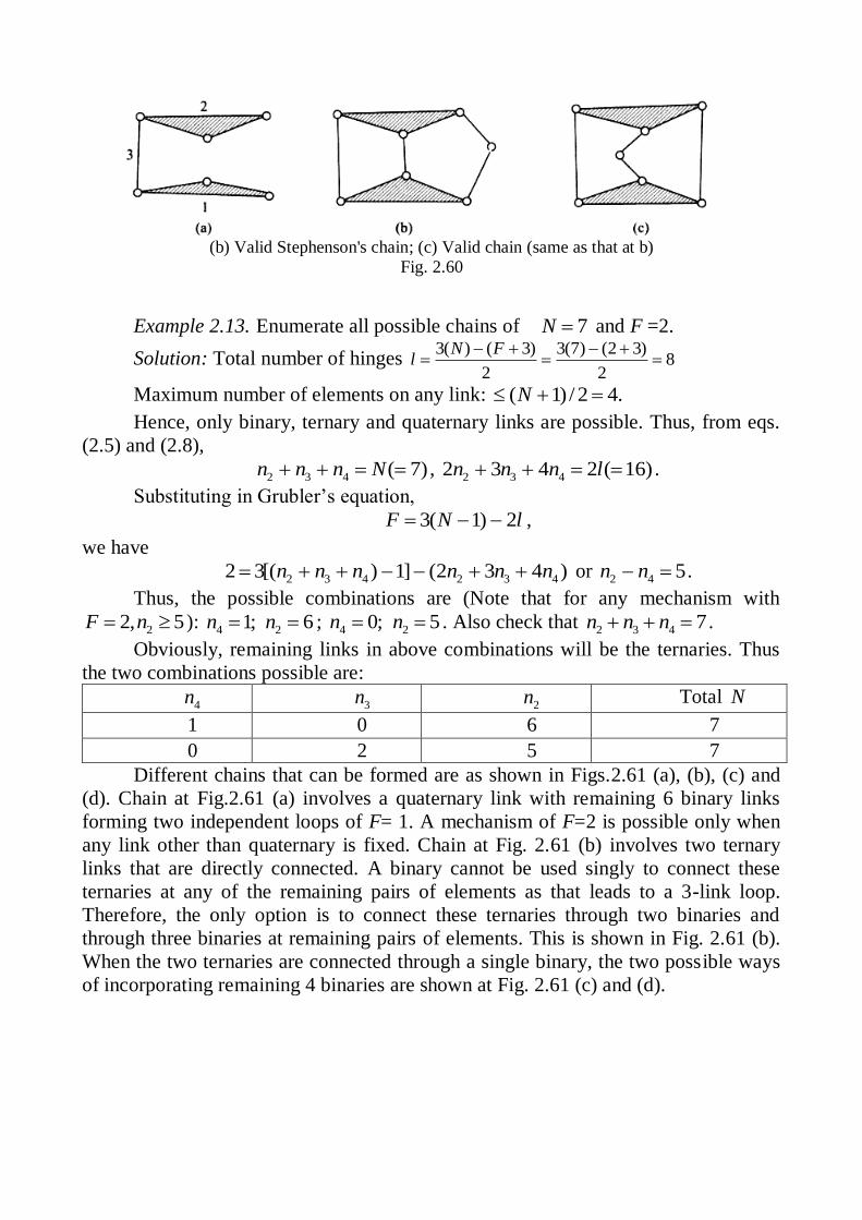
(b) Valid Stephenson's chain; (c) Valid chain (same as that at b)
Fig. 2.60
Example 2.13. Enumerate all possible chains of 7N and F =2.
Solution: Total number of hinges 3( ) ( 3) 3(7) (2 3)
82 2
N Fl
Maximum number of elements on any link: ( 1) / 2 4.N
Hence, only binary, ternary and quaternary links are possible. Thus, from eqs.
(2.5) and (2.8),
2 3 4 ( 7)n n n N , 2 3 42 3 4 2 ( 16)n n n l .
Substituting in Grubler’s equation,
3( 1) 2F N l ,
we have
2 3 4 2 3 42 3[( ) 1] (2 3 4 )n n n n n n or 2 4 5n n .
Thus, the possible combinations are (Note that for any mechanism with
22, 5F n ): 4 1;n 2 6n ; 4 0;n 2 5n . Also check that 2 3 4 7n n n .
Obviously, remaining links in above combinations will be the ternaries. Thus
the two combinations possible are:
4n 3n 2n Total N
1 0 6 7
0 2 5 7
Different chains that can be formed are as shown in Figs.2.61 (a), (b), (c) and
(d). Chain at Fig.2.61 (a) involves a quaternary link with remaining 6 binary links
forming two independent loops of F= 1. A mechanism of F=2 is possible only when
any link other than quaternary is fixed. Chain at Fig. 2.61 (b) involves two ternary
links that are directly connected. A binary cannot be used singly to connect these
ternaries at any of the remaining pairs of elements as that leads to a 3-link loop.
Therefore, the only option is to connect these ternaries through two binaries and
through three binaries at remaining pairs of elements. This is shown in Fig. 2.61 (b).
When the two ternaries are connected through a single binary, the two possible ways
of incorporating remaining 4 binaries are shown at Fig. 2.61 (c) and (d).

Fig. 2.61. Feasible chains of seven links
Fig. 2.62. Feasible chains for first combination
Example 2.14. Enumerate combination of links possible in case of a 8-link
chain with 1F .
Solution: Number, of hinges 3(8) 4
102
l
.
Maximum number of elements on one link is 8
4.2
Hence the chains can have binary, ternary and quaternary links only. From
equations (2.5) and (2.8),
2 3 4 8n n n and 2 3 42 3 4 20n n n .
Substituting in Grubler’s criterion,
2 3 4 2 3 4 2 43( ) (2 3 4 ) 4 0 ( ) 4n n n n n n or n n .
We study various combinations indicated by above expression in respect of
their viability:
4n
(assumed) 2 4 4n n 3 2 48 ( )n n n Remark
4 8 - Not acceptable as 2 4n n N
3 7 - Not acceptable as 2 4n n N
2 6 - acceptable
1 5 2 acceptable
0 4 4 acceptable
Thus the three valid combinations of links are:
(1) 4 2n ; 3 0n ; 2 6n ;
(2) 4 1n ; 3 2n ; 2 5n ;
(3) 4 0n ; 3 4n ; 2 4n .
The first combination yields the
following two chains
( 4 3 22; 0; 6n n n ). (Fig. 2.62).
The second combination of

Fig. 2.63. Feasible chains for second combination
Fig. 2.64. Feasible chains for third combination
links yields the following five chains (4 3 21; 2; 5n n n ) (see Fig. 2.63).
The third combination (4 3 20; 4; 4n n n ) of links yields following chains
(see Fig 2.64)
Related Documents