§2 stress in soil • Stress due to soil weight • Contact stress • Stress due to loading Civil Engineering Department of Shanghai University Civil Engineering Department of Shanghai University Soil Mechanics Chapter 2 Soil Mechanics Chapter 2

Welcome message from author
This document is posted to help you gain knowledge. Please leave a comment to let me know what you think about it! Share it to your friends and learn new things together.
Transcript
§2 stress in soil
• Stress due to soil weight• Contact stress• Stress due to loading
Civil Engineering Department of Shanghai University Soil Mechanics Chapter 2Civil Engineering Department of Shanghai University Soil Mechanics Chapter 2
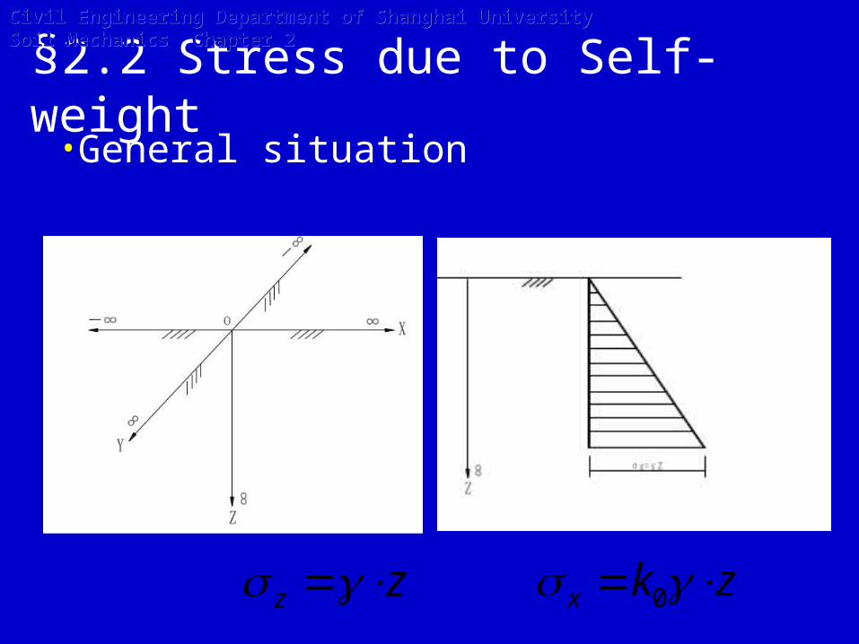
zkx 0zz
§2.2 Stress due to Self-weight•General situation
Civil Engineering Department of Shanghai University Soil Mechanics Chapter 2Civil Engineering Department of Shanghai University Soil Mechanics Chapter 2

n
iiinnz hhhh
12211 ......
-For Many Layers of soil, the vertical stress due to self-weight of soil is given as following.
Three Cases:
Civil Engineering Department of Shanghai University Soil Mechanics Chapter 2Civil Engineering Department of Shanghai University Soil Mechanics Chapter 2

-With uniform surcharge on infinite land surface
)( hzpzz
Civil Engineering Department of Shanghai University Soil Mechanics Chapter 2Civil Engineering Department of Shanghai University Soil Mechanics Chapter 2
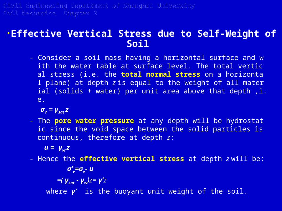
- Consider a soil mass having a horizontal surface and with the water table at surface level. The total vertical stress (i.e. the total normal stress on a horizontal plane) at depth z is equal to the weight of all material (solids + water) per unit area above that depth ,i.e.
σv = γsat z
- The pore water pressure at any depth will be hydrostatic since the void space between the solid particles is continuous, therefore at depth z:
u = γw z
- Hence the effective vertical stress at depth z will be:
σ’v=σv- u
=( γsat - γw)z= γ’z
where γ’ is the buoyant unit weight of the soil.
•Effective Vertical Stress due to Self-Weight of Soil
Civil Engineering Department of Shanghai University Soil Mechanics Chapter 2Civil Engineering Department of Shanghai University Soil Mechanics Chapter 2

3222111 ' hhhh satwz
General, for sand below water table, the γ’ is used; but for clay below water table, it is difficult to determine which one(γ’ or γsat) is suitable.
We often choose the buoyant unit weight when the index of liquid LI>=1; the saturated unit weight when the index of liquid LI<=0. When 0<LI<1, the disadvantageous one is choosen.
-Under water
Table
Civil Engineering Department of Shanghai University Soil Mechanics Chapter 2Civil Engineering Department of Shanghai University Soil Mechanics Chapter 2
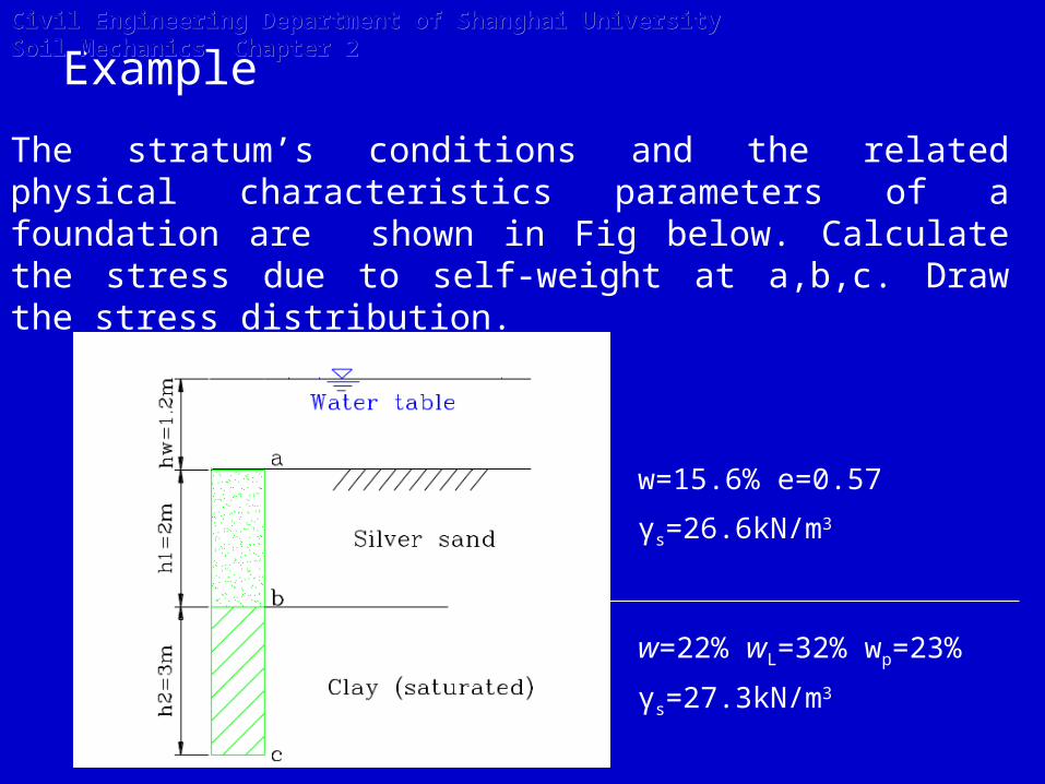
Example
The stratum’s conditions and the related physical characteristics parameters of a foundation are shown in Fig below. Calculate the stress due to self-weight at a,b,c. Draw the stress distribution.
w=15.6% e=0.57
γs=26.6kN/m3
w=22% wL=32% wp=23%
γs=27.3kN/m3
Civil Engineering Department of Shanghai University Soil Mechanics Chapter 2Civil Engineering Department of Shanghai University Soil Mechanics Chapter 2

3'1 /9.9
67.01
106.26
1mkN
ews
)(02332
2322Semisolid
ww
wwI
pL
pL
For silver sand, the buoyant unit
weight (γ‘)is used :
For saturated clay,
So, the clay can be considered
the watertight; then the saturated unit weight (γsat)is used :
32 /8.20
6.01
106.03.27
1
6.022.010/3.27
1
mkNe
e
wGee
wGS
wssat
s
sr
Civil Engineering Department of Shanghai University Soil Mechanics Chapter 2Civil Engineering Department of Shanghai University Soil Mechanics Chapter 2

a σz=0
b σz(upper)=γ’1h1=9.9×2=19.8kPa
σz(Down)=γ’1h1+ γw(h1+hw)=9.9×2+10×(2+1.2)=51.8kPa
c σz=γ’1h1+ γw(h1+hw)+ γsat2h2
= 9.9×2+10×(2+1.2)+20.8×3=114.2kPa
Civil Engineering Department of Shanghai University Soil Mechanics Chapter 2Civil Engineering Department of Shanghai University Soil Mechanics Chapter 2

Exercise 2-2
The stratum’s conditions and the related physical characteristics parameters of a foundation are shown in Fig below. Calculate the stress due to self-weight at 10m depth. Draw the stress distribution.
Note: For saturated clay, both cases (watertight and non-watertight) need to consider.
w=8% e=0.7
γs=26.5kN/m3
e=1.5
γs=27.2kN/m3
Civil Engineering Department of Shanghai University Soil Mechanics Chapter 2Civil Engineering Department of Shanghai University Soil Mechanics Chapter 2
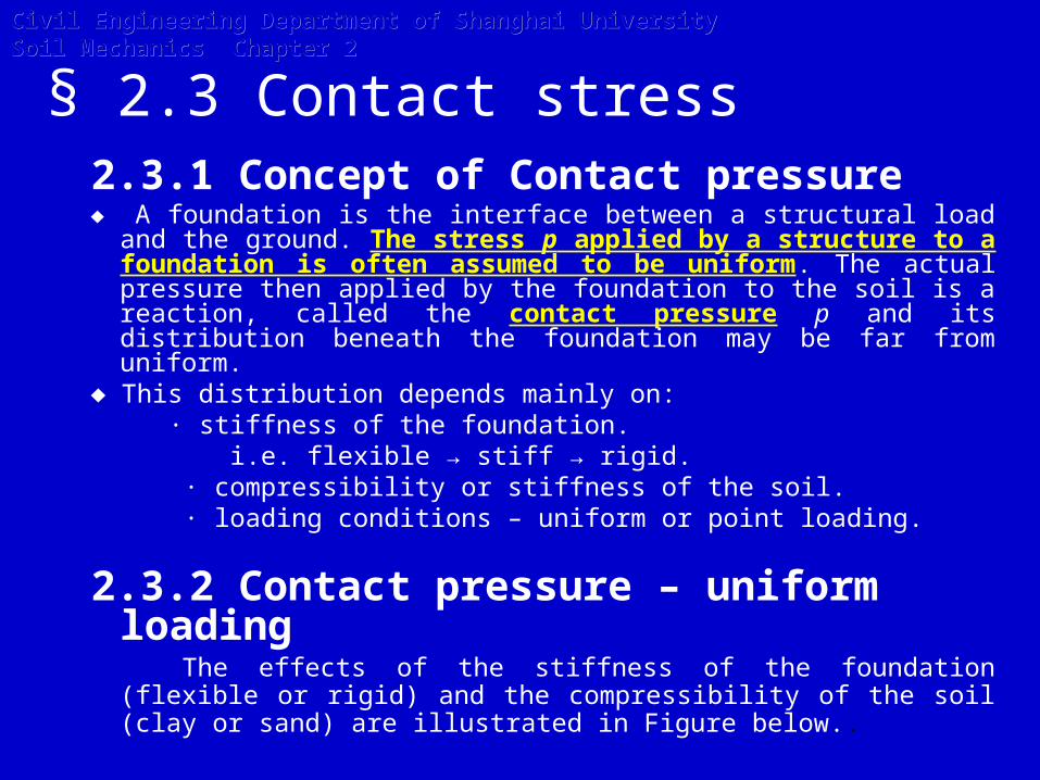
§ 2.3 Contact stress2.3.1 Concept of Contact pressure♦ A foundation is the interface between a structural load and the
ground. The stress p applied by a structure to a foundation is often assumed to be uniform. The actual pressure then applied by the foundation to the soil is a reaction, called the contact pressure p and its distribution beneath the foundation may be far from uniform.
♦ This distribution depends mainly on: · stiffness of the foundation. i.e. flexible → stiff → rigid. · compressibility or stiffness of the soil. · loading conditions – uniform or point loading.
2.3.2 Contact pressure – uniform loading
The effects of the stiffness of the foundation (flexible or rigid) and the compressibility of the soil (clay or sand) are illustrated in Figure below..
Civil Engineering Department of Shanghai University Soil Mechanics Chapter 2Civil Engineering Department of Shanghai University Soil Mechanics Chapter 2

Figure The distribution of contact pressure
Civil Engineering Department of Shanghai University Soil Mechanics Chapter 2Civil Engineering Department of Shanghai University Soil Mechanics Chapter 2
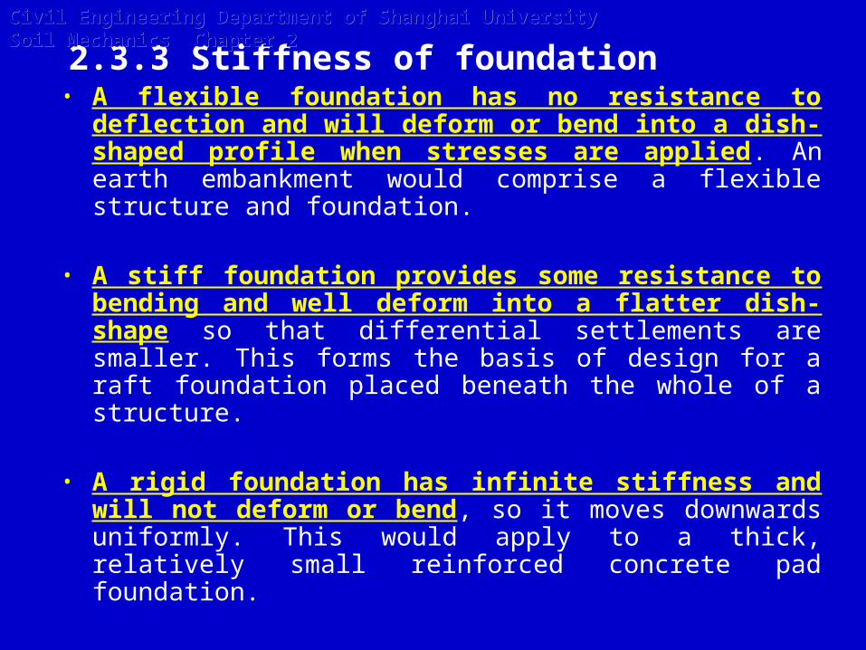
2.3.3 Stiffness of foundation• A flexible foundation has no resistance to deflection
and will deform or bend into a dish-shaped profile when stresses are applied. An earth embankment would comprise a flexible structure and foundation.
• A stiff foundation provides some resistance to bending and well deform into a flatter dish-shape so that differential settlements are smaller. This forms the basis of design for a raft foundation placed beneath the whole of a structure.
• A rigid foundation has infinite stiffness and will not deform or bend, so it moves downwards uniformly. This would apply to a thick, relatively small reinforced concrete pad foundation.
Civil Engineering Department of Shanghai University Soil Mechanics Chapter 2Civil Engineering Department of Shanghai University Soil Mechanics Chapter 2
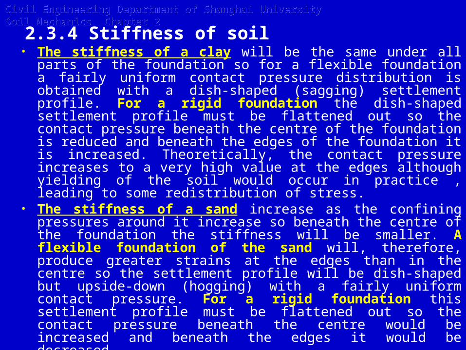
2.3.4 Stiffness of soil• The stiffness of a clay will be the same under all parts of
the foundation so for a flexible foundation a fairly uniform contact pressure distribution is obtained with a dish-shaped (sagging) settlement profile. For a rigid foundation the dish-shaped settlement profile must be flattened out so the contact pressure beneath the centre of the foundation is reduced and beneath the edges of the foundation it is increased. Theoretically, the contact pressure increases to a very high value at the edges although yielding of the soil would occur in practice , leading to some redistribution of stress.
• The stiffness of a sand increase as the confining pressures around it increase so beneath the centre of the foundation the stiffness will be smaller. A flexible foundation of the sand will, therefore, produce greater strains at the edges than in the centre so the settlement profile will be dish-shaped but upside-down (hogging) with a fairly uniform contact pressure. For a rigid foundation this settlement profile must be flattened out so the contact pressure beneath the centre would be increased and beneath the edges it would be decreased.
Civil Engineering Department of Shanghai University Soil Mechanics Chapter 2Civil Engineering Department of Shanghai University Soil Mechanics Chapter 2
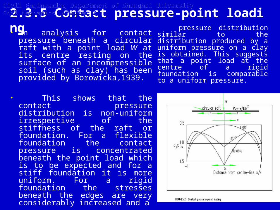
2.3.5 Contact pressure-point loading• An analysis for contact pressure
beneath a circular raft with a point load W at its centre resting on the surface of an incompressible soil (such as clay) has been provided by Borowicka,1939.
• This shows that the contact pressure distribution is non-uniform irrespective of the stiffness of the raft or foundation. For a flexible foundation the contact pressure is concentrated beneath the point load which is to be expected and for a stiff foundation it is more uniform. For a rigid foundation the stresses beneath the edges are very considerably increased and a
pressure distribution similar to the distribution produced by a uniform pressure on a clay is obtained. This suggests that a point load at the centre of a rigid foundation is comparable to a uniform pressure.
Civil Engineering Department of Shanghai University Soil Mechanics Chapter 2Civil Engineering Department of Shanghai University Soil Mechanics Chapter 2
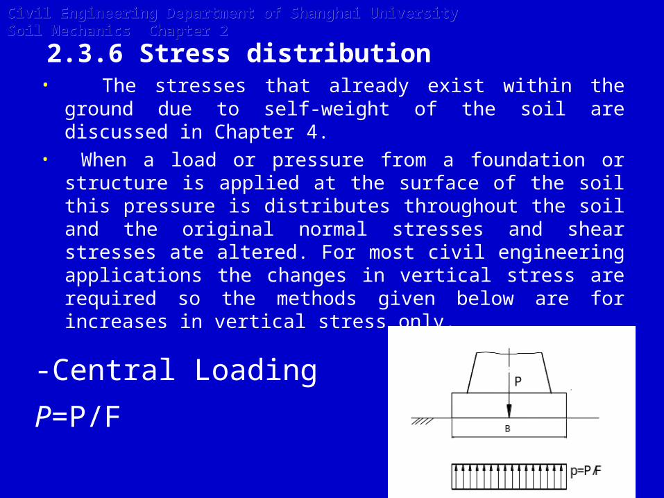
2.3.6 Stress distribution • The stresses that already exist within the ground due
to self-weight of the soil are discussed in Chapter 4. • When a load or pressure from a foundation or structure
is applied at the surface of the soil this pressure is distributes throughout the soil and the original normal stresses and shear stresses ate altered. For most civil engineering applications the changes in vertical stress are required so the methods given below are for increases in vertical stress only.
-Central Loading
P=P/F
Civil Engineering Department of Shanghai University Soil Mechanics Chapter 2Civil Engineering Department of Shanghai University Soil Mechanics Chapter 2
)6
1(2
1
B
e
F
P
W
Pe
F
P
p
p
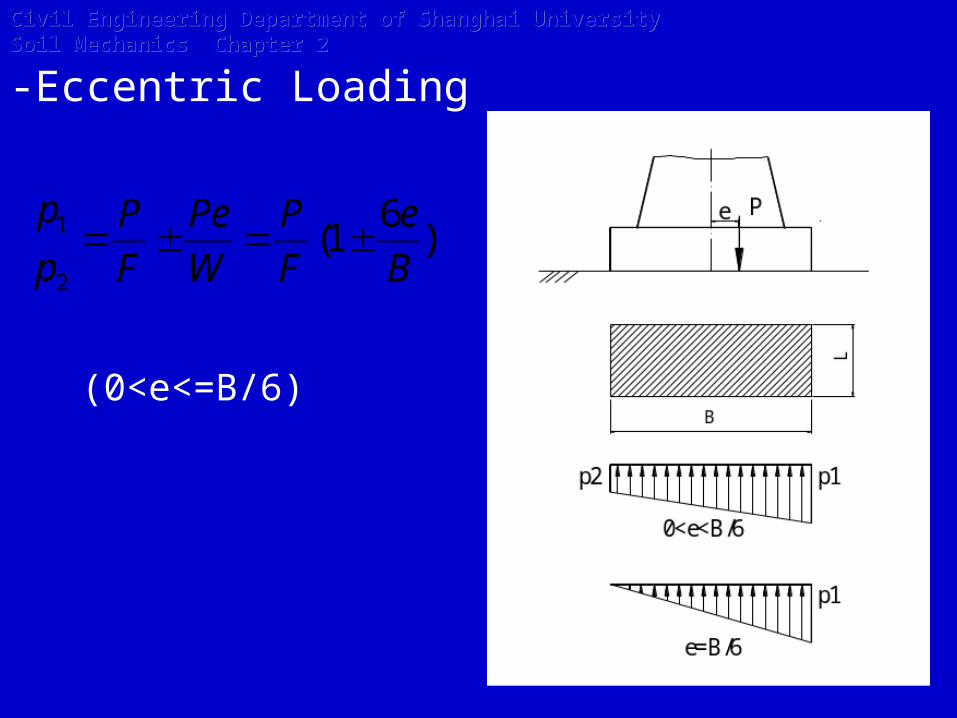
-Eccentric Loading
(0<e<=B/6)
Civil Engineering Department of Shanghai University Soil Mechanics Chapter 2Civil Engineering Department of Shanghai University Soil Mechanics Chapter 2
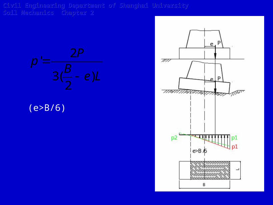
LeB
Pp
)2
(3
2'
(e>B/6)
Civil Engineering Department of Shanghai University Soil Mechanics Chapter 2Civil Engineering Department of Shanghai University Soil Mechanics Chapter 2

2.3.7 Additional pressure on the bottom of foundation
pa=p-γhWhere pa-additional pressure;
p-contact pressure;
γ-natural unit weight of soil( bouyant unit weight if below water surface);
h- buried depth of the foundation.
Civil Engineering Department of Shanghai University Soil Mechanics Chapter 2Civil Engineering Department of Shanghai University Soil Mechanics Chapter 2
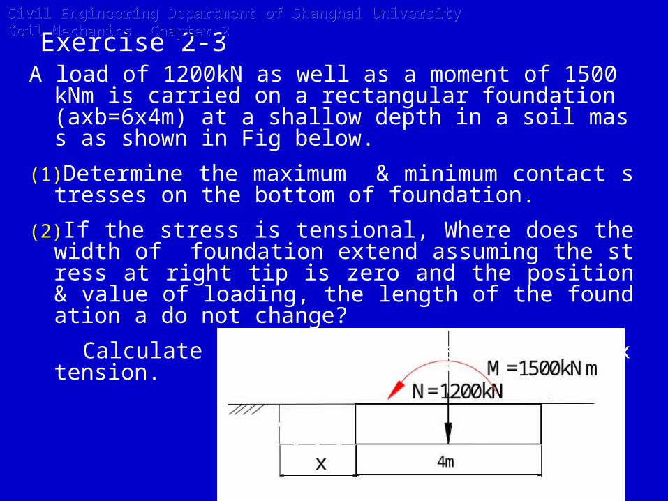
Exercise 2-3A load of 1200kN as well as a moment of 1500 kNm is carrie
d on a rectangular foundation (axb=6x4m) at a shallow depth in a soil mass as shown in Fig below.
(1)Determine the maximum & minimum contact stresses on the bottom of foundation.
(2) If the stress is tensional, Where does the width of foundation extend assuming the stress at right tip is zero and the position & value of loading, the length of the foundation a do not change?
Calculate the contact stress after the extension.
Civil Engineering Department of Shanghai University Soil Mechanics Chapter 2Civil Engineering Department of Shanghai University Soil Mechanics Chapter 2

§ 2.4 Stress due to loading
• Boussinesq published in 1885 a solution for the stresses beneath a point load on the surface of a material which had the following properties:
• semi-infinite – this means infinite below the surface therefore providing no boundaries of the material apart from the surface
• homogeneous – the same properties at all locations • isotropic –the same properties in all directions
• elastic –a linear stress-strain relationship.
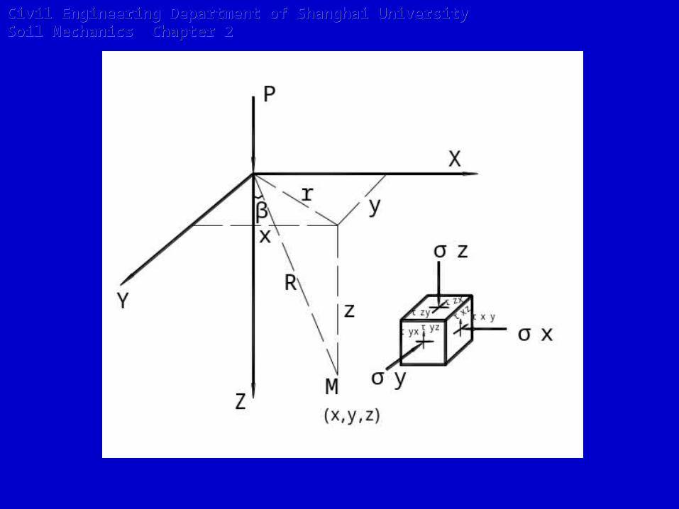
2.4.1 Stresses beneath point load(点荷载)
Civil Engineering Department of Shanghai University Soil Mechanics Chapter 2Civil Engineering Department of Shanghai University Soil Mechanics Chapter 2
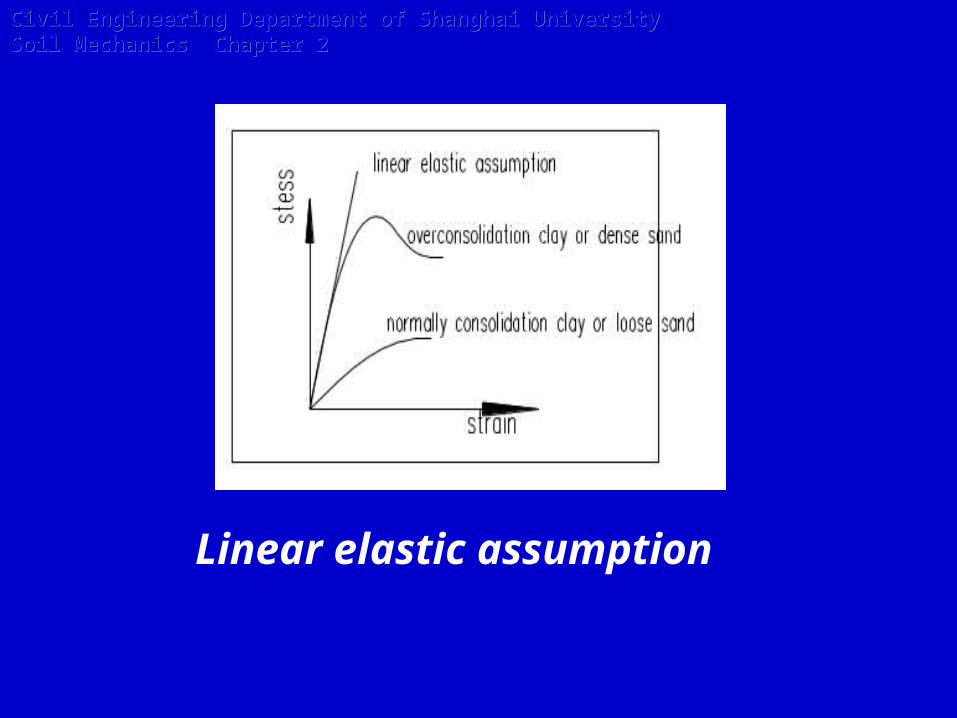
Linear elastic assumption
Civil Engineering Department of Shanghai University Soil Mechanics Chapter 2Civil Engineering Department of Shanghai University Soil Mechanics Chapter 2
Civil Engineering Department of Shanghai University Soil Mechanics Chapter 2Civil Engineering Department of Shanghai University Soil Mechanics Chapter 2

5
3
2
3
R
ZPz
Substitute Z/R for Cos β,
2
3cos
2
3
R
pz
22
52
2
1
1
2
3
Z
P
Zr
Z
Pz
2
52
12
3
Zr
Civil Engineering Department of Shanghai University Soil Mechanics Chapter 2Civil Engineering Department of Shanghai University Soil Mechanics Chapter 2
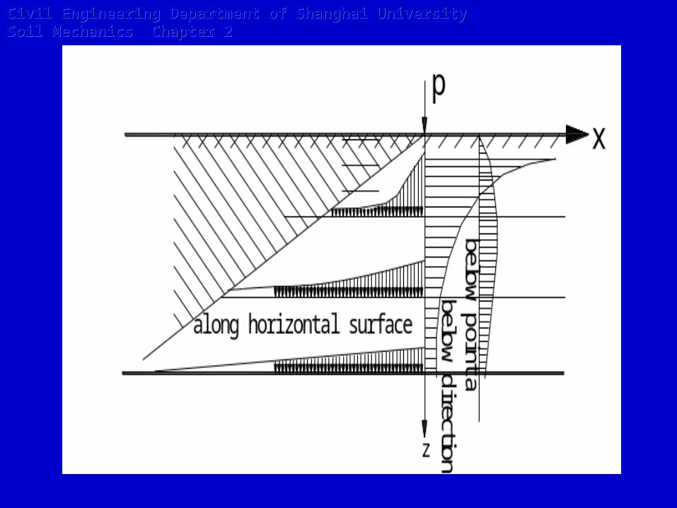
Properties
Civil Engineering Department of Shanghai University Soil Mechanics Chapter 2Civil Engineering Department of Shanghai University Soil Mechanics Chapter 2
Civil Engineering Department of Shanghai University Soil Mechanics Chapter 2Civil Engineering Department of Shanghai University Soil Mechanics Chapter 2
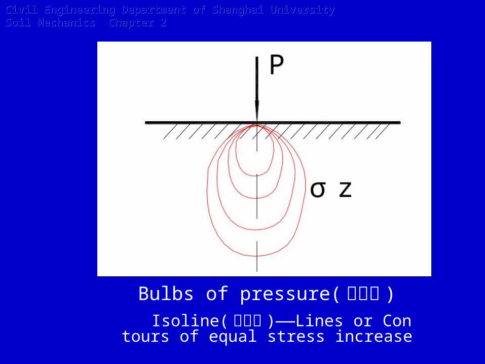
Bulbs of pressure(压力泡 ) Isoline(等值线 )——Lines or Contours
of equal stress increase

Civil Engineering Department of Shanghai University Soil Mechanics Chapter 2Civil Engineering Department of Shanghai University Soil Mechanics Chapter 2
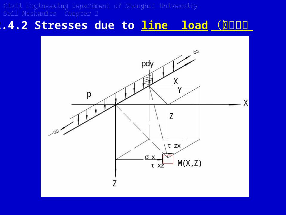
2.4.2 Stresses due to line load(线荷载)
Civil Engineering Department of Shanghai University Soil Mechanics Chapter 2Civil Engineering Department of Shanghai University Soil Mechanics Chapter 2
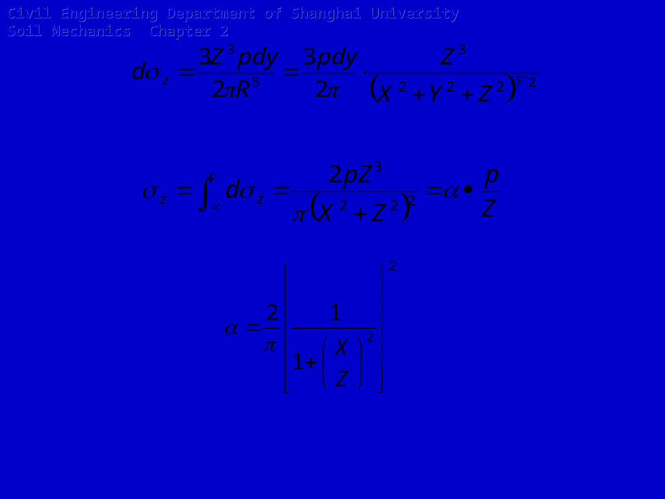
2222
3
5
3
5
2
3
2
3
ZYX
Zpdy
R
pdyZd z
Z
p
ZX
pZd zz
222
32
2
2
1
12
Z
X
Civil Engineering Department of Shanghai University Soil Mechanics Chapter 2Civil Engineering Department of Shanghai University Soil Mechanics Chapter 2
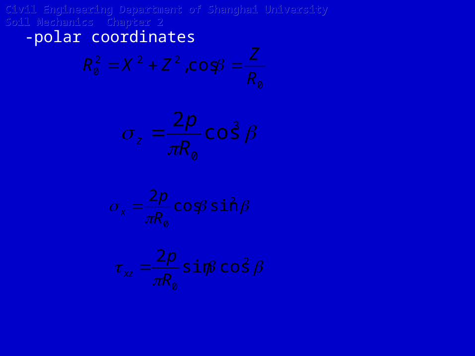
-polar coordinates
0
2220 cos,
R
ZZXR
3
0
cos2
R
pz
2
0
sincos2
R
px
2
0
cossin2
R
pxz
Civil Engineering Department of Shanghai University Soil Mechanics Chapter 2Civil Engineering Department of Shanghai University Soil Mechanics Chapter 2

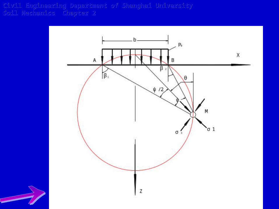
2.4.3 Stresses due to uniform vertical loading on an infinite strip (条形荷载)
Civil Engineering Department of Shanghai University Soil Mechanics Chapter 2Civil Engineering Department of Shanghai University Soil Mechanics Chapter 2

222
032
ZX
dpZd z
0
22
22
0
2
2/ 222
03
2
2/
2
2
2
222
2
p
bXZ
bXZ
bXZ
bXZ
Z
bX
arctgZ
bX
arctgp
ZX
dpZd
b
b
b
b zz
Civil Engineering Department of Shanghai University Soil Mechanics Chapter 2Civil Engineering Department of Shanghai University Soil Mechanics Chapter 2
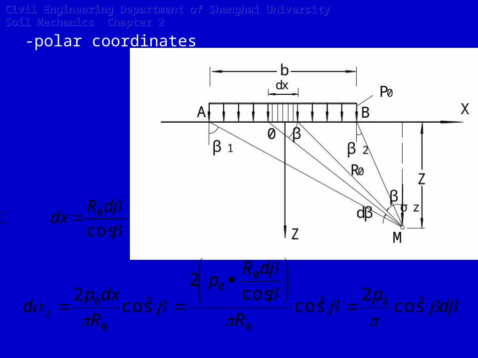
-polar coordinates
cos0dR
dx
dp
R
dRp
R
dxpd z
203
0
00
3
0
0 cos2
coscos
2
cos2
Civil Engineering Department of Shanghai University Soil Mechanics Chapter 2Civil Engineering Department of Shanghai University Soil Mechanics Chapter 2
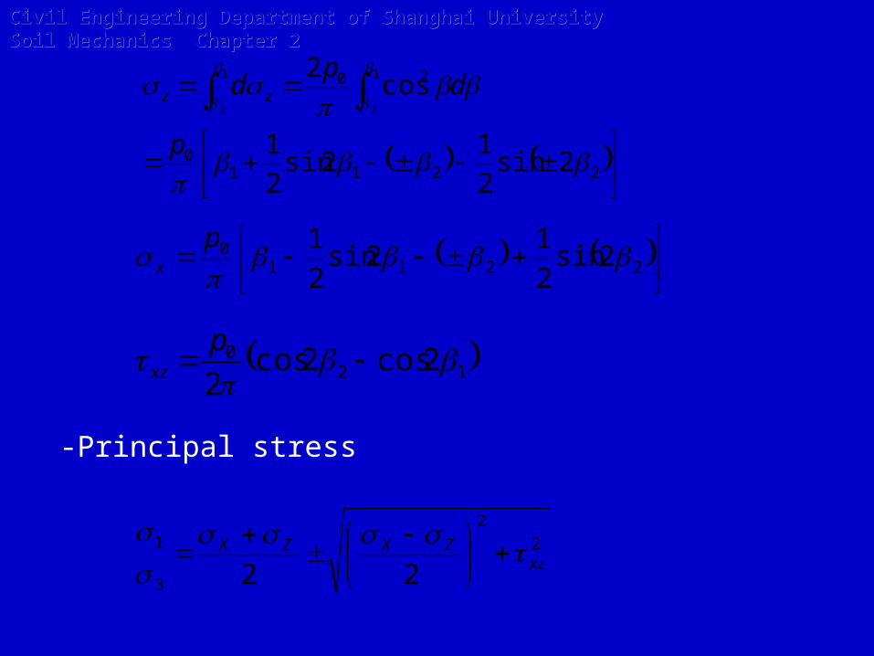
22110
20
2sin2
12sin
2
1
cos2 1
2
1
2
p
dp
d zz
2211
0 2sin2
12sin
2
1
p
x
120 2cos2cos
2
pxz
2
2
3
1
22 xzZXZX
-Principal stress
Civil Engineering Department of Shanghai University Soil Mechanics Chapter 2Civil Engineering Department of Shanghai University Soil Mechanics Chapter 2
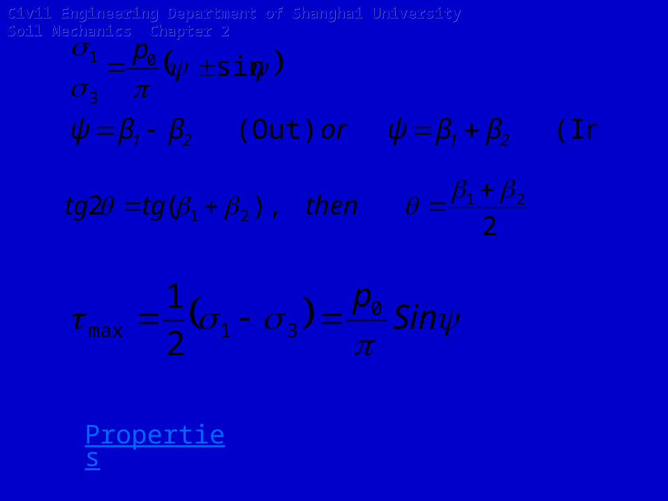
(In)(Out)
sin0
3
1
2121 ββψorββψ
p
2),(2 21
21
thentgtg
Sinp0
31max 2
1
Civil Engineering Department of Shanghai University Soil Mechanics Chapter 2Civil Engineering Department of Shanghai University Soil Mechanics Chapter 2
Properties

(1) Isoline(等值线 )
(2) Direction of principal stress
(3) The value of maximum shear stress
Civil Engineering Department of Shanghai University Soil Mechanics Chapter 2Civil Engineering Department of Shanghai University Soil Mechanics Chapter 2

Civil Engineering Department of Shanghai University Soil Mechanics Chapter 2Civil Engineering Department of Shanghai University Soil Mechanics Chapter 2

2.4.4 Stresses due to Linearly increasing vertical loading on an infinite Strip
Civil Engineering Department of Shanghai University Soil Mechanics Chapter 2Civil Engineering Department of Shanghai University Soil Mechanics Chapter 2
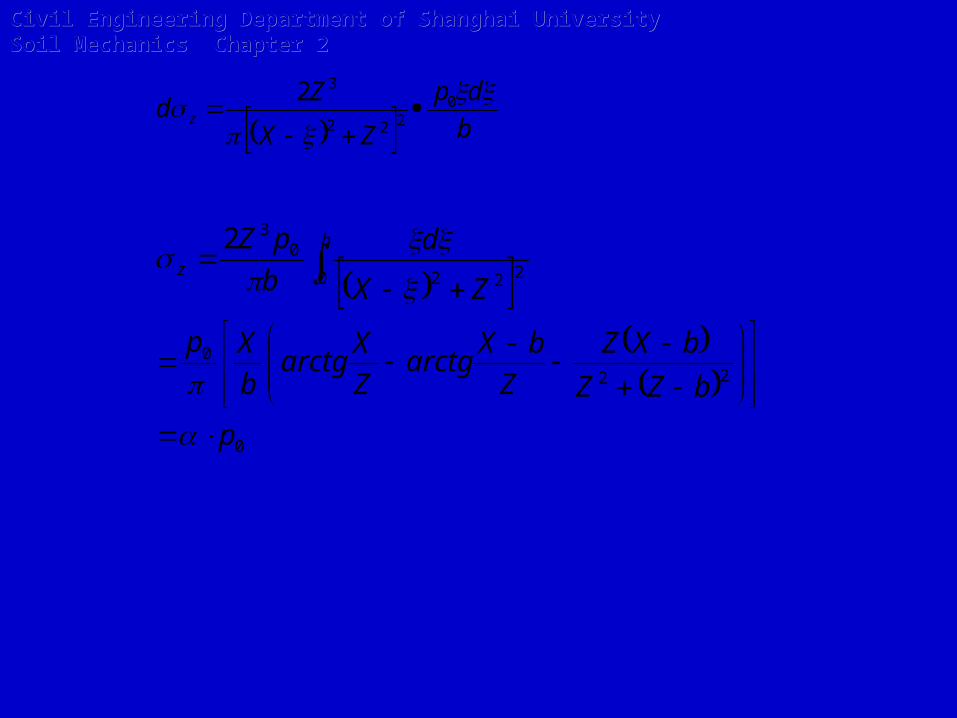
b
dp
ZX
Zd z
0
222
32
0
22
0
0 222
032
p
bZZ
bXZ
Z
bXarctg
Z
Xarctg
b
Xp
ZX
d
b
pZ b
z
Civil Engineering Department of Shanghai University Soil Mechanics Chapter 2Civil Engineering Department of Shanghai University Soil Mechanics Chapter 2
Civil Engineering Department of Shanghai University Soil Mechanics Chapter 2Civil Engineering Department of Shanghai University Soil Mechanics Chapter 2

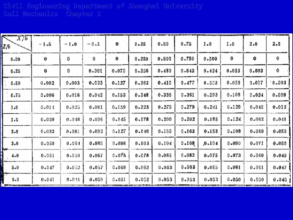
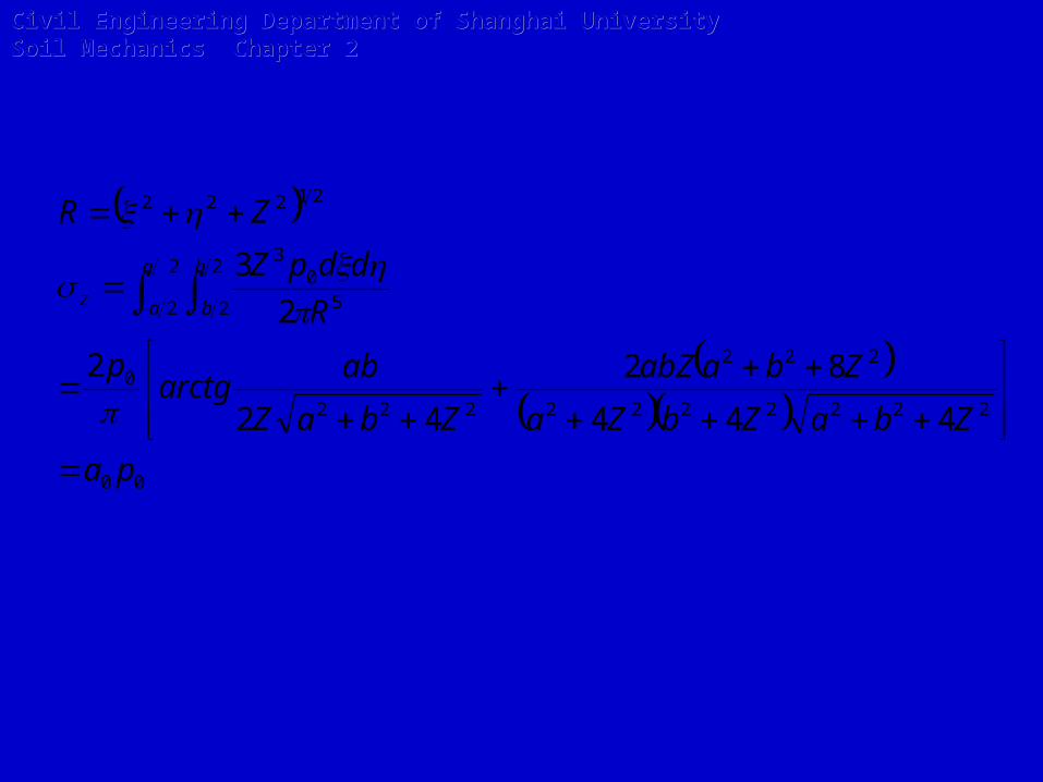
2.4.5 Stresses due to a uniform loaded rectangular area
-central point method(中点法)
Civil Engineering Department of Shanghai University Soil Mechanics Chapter 2Civil Engineering Department of Shanghai University Soil Mechanics Chapter 2
00
2222222
222
222
0
2
2
2
2 50
3
21222
444
82
42
2
2
3
pa
ZbaZbZa
ZbaabZ
ZbaZ
abarctg
p
R
ddpZ
ZR
a
a
b
bz
Civil Engineering Department of Shanghai University Soil Mechanics Chapter 2Civil Engineering Department of Shanghai University Soil Mechanics Chapter 2

-Corner method(角点法)Civil Engineering Department of Shanghai University Soil Mechanics Chapter 2Civil Engineering Department of Shanghai University Soil Mechanics Chapter 2

b
zn
b
amWhere
nmn
marctg
nmnnm
nmmn
p
ZbaZ
abarctg
ZbaZbZa
ZbaabZp
R
ddpZ
c
c
a
a
b
bZ
,,
11)1)((
)12(
2
1
2
2
2
3
2222222
22
0
2222222222
2220
2/
2/
2/
2/ 50
3

Civil Engineering Department of Shanghai University Soil Mechanics Chapter 2Civil Engineering Department of Shanghai University Soil Mechanics Chapter 2

Principle of superposition
For stresses beneath points other than the corner of the loaded area the principle of superposition should be used, as described in Fig below.
Civil Engineering Department of Shanghai University Soil Mechanics Chapter 2Civil Engineering Department of Shanghai University Soil Mechanics Chapter 2

Stresses beneath flexible area of any shape
Stresses beneath flexible area of any shape (Figure 5.9) Newmark (1942) devised charts to obtain the vertical stress at any
depth, beneath any point (inside or outside) of an irregular shape. Use of the charts is explained in Figure 2.9.
Civil Engineering Department of Shanghai University Soil Mechanics Chapter 2Civil Engineering Department of Shanghai University Soil Mechanics Chapter 2
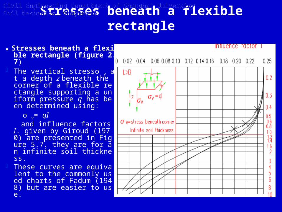
Stresses beneath a flexible rectangle
♦ Stresses beneath a flexible rectangle (figure 2.7)
The vertical stressσ y at a depth z beneath the corner of a flexible rectangle supporting a uniform pressure q has been determined using:
σ v= qI and influence factors I. given
by Giroud (1970) are presented in Figure 5.7. they are for an infinite soil thickness.
These curves are equivalent to the commonly used charts of Fadum (1948) but are easier to use.
Civil Engineering Department of Shanghai University Soil Mechanics Chapter 2Civil Engineering Department of Shanghai University Soil Mechanics Chapter 2

Civil Engineering Department of Shanghai University Soil Mechanics Chapter 2Civil Engineering Department of Shanghai University Soil Mechanics Chapter 2
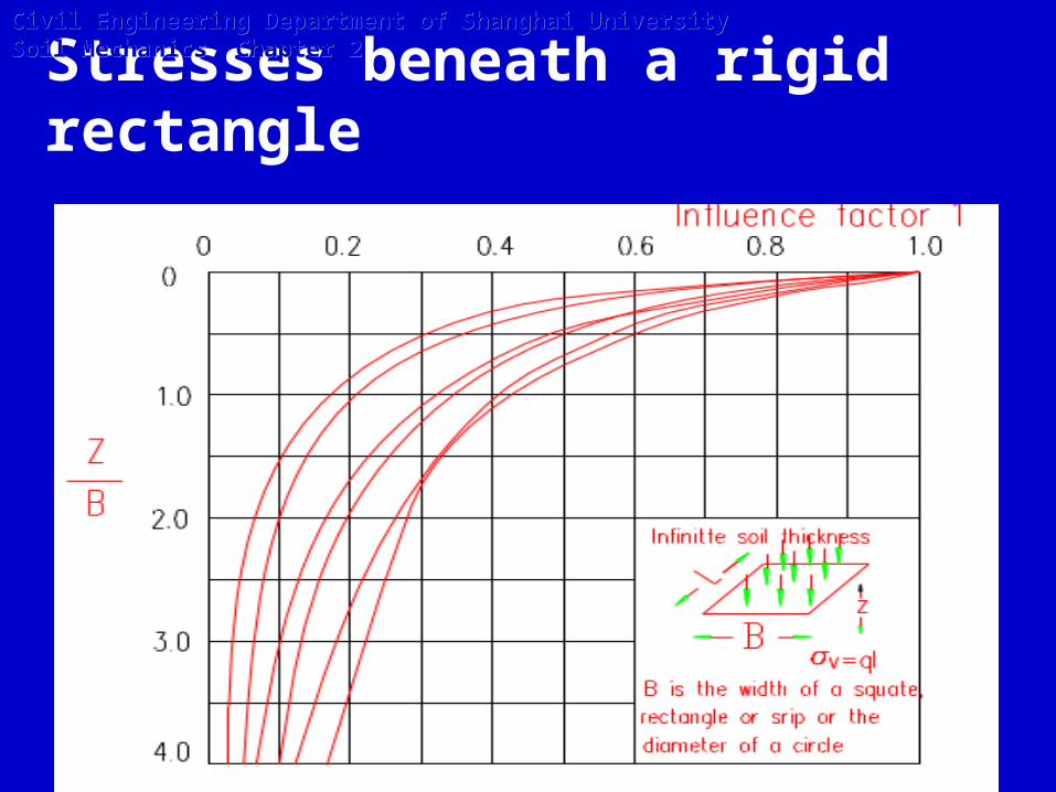
Stresses beneath a rigid rectangle
Civil Engineering Department of Shanghai University Soil Mechanics Chapter 2Civil Engineering Department of Shanghai University Soil Mechanics Chapter 2
A point load of P is applied at the ground surface.
Calculate the stress and plot the variation:
(1) Vertical stress due to load P along vertical line(r=0) at the different depths Z=1,2,3,4,5m.
(2) Vertical stress due to load P from different distances (r=0,1,2,3,4,5m, respectively) along horizontal surface (at the depth Z=2m).
(3) Vertical stress due to load P along vertical line(r=1.5m) at the different depths Z=0,0.5,1,2,3,4,5,6m.
Exercise 2-4
Civil Engineering Department of Shanghai University Soil Mechanics Chapter 2Civil Engineering Department of Shanghai University Soil Mechanics Chapter 2

A uniform load of p(=20kpa) is applied at the ground surface as shown in Fig below.
Calculate the stress due to load p beneath point A at 5m depth.
Exercise 2-5Civil Engineering Department of Shanghai University Soil Mechanics Chapter 2Civil Engineering Department of Shanghai University Soil Mechanics Chapter 2
Related Documents