Air Washington Electronics – Direct Current Page 1 of 41 2 Resistors This work is licensed under the Creative Commons Attribution 3.0 Unported License. To view a copy of this license, visit http://creativecommons.org/licenses/by/3.0/. Air Washington is an equal opportunity employer/program. Auxiliary aids and services are available upon request to individuals with disabilities. This workforce solution was funded (100%) by a grant awarded by the U.S. Department of Labor’s Employment and Training Administration. The solution was created by the grantee and does not necessarily reflect the official position of the U.S. Department of Labor. The Department of Labor makes no guarantees, warranties, or assurances of any kind, express or implied, with respect to such information, including any information on linked sites and including, but not limited to, accuracy of the information or its completeness, timeliness, usefulness, adequacy, continued availability, or ownership. This solution is copyrighted by the institution that created it. Internal use, by an organization and/or personal use by an individual for non-commercial purposes is permissible. All other uses require the prior authorization of the copyright owner. Revised: Tuesday, January 14, 2014

Welcome message from author
This document is posted to help you gain knowledge. Please leave a comment to let me know what you think about it! Share it to your friends and learn new things together.
Transcript

Air Washington Electronics – Direct Current
Page 1 of 41
2 Resistors
This work is licensed under the Creative Commons Attribution 3.0 Unported License. To view a copy of this license,
visit http://creativecommons.org/licenses/by/3.0/. Air Washington is an equal opportunity employer/program. Auxiliary aids and services are
available upon request to individuals with disabilities. This workforce solution was funded (100%) by a grant awarded by the U.S. Department of
Labor’s Employment and Training Administration. The solution was created by the grantee and does not necessarily reflect the official position
of the U.S. Department of Labor. The Department of Labor makes no guarantees, warranties, or assurances of any kind, express or implied, with
respect to such information, including any information on linked sites and including, but not limited to, accuracy of the information or its
completeness, timeliness, usefulness, adequacy, continued availability, or ownership. This solution is copyrighted by the institution that
created it. Internal use, by an organization and/or personal use by an individual for non-commercial purposes is permissible. All other uses
require the prior authorization of the copyright owner. Revised: Tuesday, January 14, 2014

Air Washington Electronics – Direct Current
Page 2 of 41
Resistors .......................................................................................................................................... 4
Types of Resistors ........................................................................................................................ 5
Carbon Composition ................................................................................................................ 5
Carbon Film Resistors .............................................................................................................. 7
Metal Film Resistors ................................................................................................................ 7
Surface Mount Resistors .......................................................................................................... 7
Thermistors .............................................................................................................................. 8
Fusible Resistors ...................................................................................................................... 8
Zero Ohm Resistors ................................................................................................................. 8
Wirewound .............................................................................................................................. 9
Variable Resistors ...................................................................................................................... 10
Knowledge Check ...................................................................................................................... 13
Resistor Color Coding .................................................................................................................... 15
Standard Color Code System ..................................................................................................... 15
Decoding the Color Code ....................................................................................................... 17
Engineering Notation Review ................................................................................................ 18
Simplifying the Color Code .................................................................................................... 18
Measuring Resistance ................................................................................................................... 20
Knowledge Check ...................................................................................................................... 23
Resistor Lab 1: Measuring Resistance .......................................................................................... 25
Components & Equipment Needed .......................................................................................... 25
Procedure .................................................................................................................................. 25
Tables for Resistor Lab 1: Measuring Resistance ...................................................................... 25
Observations and Conclusions .................................................................................................. 26
Resistor Lab 2: A Simple Resistive Circuit .................................................................................... 27
Components & Equipment Needed .......................................................................................... 27
Circuit Diagram ...................................................................................................................... 27
Procedure .................................................................................................................................. 27
Tables for Resistor Lab 2: A Simple Resistive Circuit ................................................................ 28
Observations and Conclusions .................................................................................................. 28
Resistor Lab 3: Variable Resistance ............................................................................................. 29
Components & Equipment Needed .......................................................................................... 29
Schematic............................................................................................................................... 29
Procedure .................................................................................................................................. 30
Tables for Resistor Lab 2: A Simple Resistive Circuit ................................................................ 31
Observations and Conclusions .................................................................................................. 31
Index of Important Terms ............................................................................................................. 32
Answers to Knowledge Checks ..................................................................................................... 33

Air Washington Electronics – Direct Current
Page 3 of 41
Introduction and Resistor Types ............................................................................................... 33
Resistor Color Codes ................................................................................................................. 34
Additional Resources .................................................................................................................... 37
Video References ...................................................................................................................... 37
Color Code Guides ..................................................................................................................... 37
Resources from All About Circuits............................................................................................. 37
References .................................................................................................................................... 38
Attributions ................................................................................................................................... 39
Table of Figures ............................................................................................................................. 40
Table of Tables .............................................................................................................................. 40
Table of Circuits ............................................................................................................................ 41
Table of Equations ........................................................................................................................ 41
Table of Embedded Videos and Simulations ................................................................................ 41

Air Washington Electronics – Direct Current
Page 4 of 41
Resistors
Resistance is a property of every electrical component. At times, its effects will be undesirable.
However, resistance is used in many varied ways. Resistors are components manufactured to
possess specific values of resistance. They are manufactured in many types and sizes. A table of
common resistor types and their schematic symbols is shown in Figure 1.
Figure 1: Table of Common Resistor Types

Air Washington Electronics – Direct Current
Page 5 of 41
Types of Resistors
Carbon Composition
One of the most common types of resistors is the molded composition, usually referred to as the
carbon resistor (Figure 2). These resistors are
manufactured in a variety of sizes and shapes. The
chemical composition of the resistor determines its
ohmic value and is accurately controlled by the
manufacturer in the development process. They are
made in ohmic values that range from one ohm to
millions of ohms. The physical size of the resistor is
related to its wattage rating, which is the ability of
resistor to dissipate heat caused by the resistance.
A carbon composition resistor consists of compressed carbon and a binder with insulating
properties such as ceramic. Carbon is a semiconductor and ceramic is an insulator. It is the
Video 1: Introduction to Resistors
Figure 2: Carbon Composition
Air Washington Electronics – Direct Current
Page 6 of 41
ratio of these which determines the resistor’s value. In the manufacture of carbon resistors,
fillers or binders are added to the carbon to obtain various resistor values. Examples of these
fillers are clay, Bakelite, rubber, and talc. These fillers are doping agents and cause the overall
conduction characteristics to change.
Carbon resistors are the most common resistors because they are easy to manufacture,
inexpensive, and have a tolerance that is adequate for most electrical and electronic
applications. A disadvantage, albeit slight, is that they may change value as they age. One other
disadvantage of carbon resistors is their limited power handling capacity.
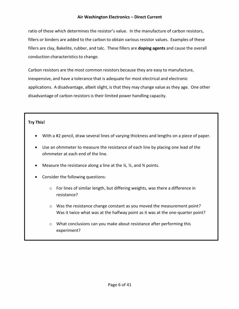
Try This!
With a #2 pencil, draw several lines of varying thickness and lengths on a piece of paper.
Use an ohmmeter to measure the resistance of each line by placing one lead of the
ohmmeter at each end of the line.
Measure the resistance along a line at the ¼, ½, and ¾ points.
Consider the following questions:
o For lines of similar length, but differing weights, was there a difference in
resistance?
o Was the resistance change constant as you moved the measurement point?
Was it twice what was at the halfway point as it was at the one-quarter point?
o What conclusions can you make about resistance after performing this
experiment?

Air Washington Electronics – Direct Current
Page 7 of 41
Carbon Film Resistors
A carbon film resistor (Figure 3) uses a film of
carbon attached to an insulator, then cut into a
spiral to determine the resistance. Carbon film
resistors are more accurate than carbon
composition resistors and are less susceptible to
noise, heat, and other external factors.
Metal Film Resistors
In a metal film resistor, a metal spiral of a specific width
and length allows for a more accurate resistance value.
These are used in electronics which have a higher
requirement for accuracy, such as military components,
satellites, and cell phones. There are applications where
environmental conditions, such as in outer space, or the
need for accuracy, such as for missile guidance systems,
require the use of precision resistors such as metal film. In
Figure 4, one of the resistors has had the coating removed
to better show the metal film construction.
Surface Mount Resistors
A surface mount resistor (Figure 5) is very small and is used for printed
circuits board. Resistance is printed on them with code – the first 2 or
3 numbers are the digits and the final number is the multiplier. For the
resistor shown, the value would be as follows:
205: Digit 1 = 2; Digit 2 = 0; Multiplier of 5 = x100,000 = 20 x 100,000 = 2,000,000 ohms = 2 MΩ
Figure 3: Carbon File Resistor
Figure 4: Metal File Resistor
Figure 5: Surface Mount

Air Washington Electronics – Direct Current
Page 8 of 41
Thermistors
Thermistors (Figure 6) are resistors that react to heat and are
used in situations where extreme temperature changes can
affect electronics or create dangerous situations. As an example,
high wattage electronics may use a thermistor near power
transistors. As the power transistors heat up, the surrounding
area will also heat up. A thermistor will react to the heat and can
be configured to activate a fan or kill-switch. Thermistors can have either a negative
temperature coefficient or a positive temperature coefficient. To review, a negative
temperature coefficient indicates that as the temperature increases, resistance decreases. A
positive temperature coefficient indicates that as the temperature increases, the resistance
increases.
Fusible Resistors
Fusible resistors (Figure 7) can be carbon, carbon
film, metal film, or wirewound. A fusible resistor is
designed to operate as a resistor during normal
operating conditions, but to respond as a fuse in case
of overloading. They are usually flame retardant and
are used in many consumer electronics such as
phones, televisions, and battery chargers.
Zero Ohm Resistors
Zero ohm resistors are used in situations where a jumper is
desired, but when a wire may not be feasible. Surface mounted
zero ohm resistors look like other surface mount resistors but
will have a “0” printed on the surface. As shown in Figure 8, the
color code scheme is a single black line.
Figure 6: Thermistors
Figure 7: Fusible Resistor
Figure 8: Zero Ohm Resistor

Air Washington Electronics – Direct Current
Page 9 of 41
Wirewound
The disadvantage of carbon resistors can be overcome by
the use of wirewound resistors. Wirewound resistors
(Figure 9) have very accurate values and possess a higher
current handling capability than carbon resistors. The
material that is frequently used to manufacture
wirewound resistors is German silver, or nickel silver,
which is composed of copper, nickel, and zinc. The
qualities and quantities of these elements present in the
wire determine the resistivity of the wire. (The resistivity
of the wire is the measure or ability of the wire to resist
current. Usually the percent of nickel in the wire
determines the resistivity.) One disadvantage of the wire-
wound resistor is that it takes a large amount of wire to
manufacture a resistor of high ohmic value, thereby increasing the cost. A variation of the
wirewound resistor provides an exposed surface to the resistance wire on one side. An
adjustable tap is attached to this side. Such resistors, sometimes with two or more adjustable
taps, are used as voltage dividers in power supplies and other applications where a specific
voltage is desired to be "tapped" off.
As shown in Figure 10, there are
several different ways the wire may
be wound. Windings are created in
such a manner as to create and
cancel electromagnetic fields, thus
allowing for a very precise resistance.
In future modules, you will learn
more about electromagnetic fields.
Figure 9: Wirewound Resistor
Figure 10: Wire Winding Styles

Air Washington Electronics – Direct Current
Page 10 of 41
Variable Resistors
There are two kinds of resistors, fixed and
variable. The fixed resistor will have one value
and will never change (other than through
temperature, age, etc.). The resistors that we
have discussed in the first part of this module
are classed as fixed resistors. The variable
resistor is constructed such that the value of
resistance can be easily adjusted.
There are two types of variable resistors, one called
a potentiometer and the other a rheostat (see
Figures 11 and 12 respectively). An example of the
potentiometer is the volume control on your radio,
and an example of the rheostat is the dimmer
control for the dash lights in an automobile. There
is a slight difference between them. Rheostats
usually have two connections, one fixed and the
other moveable. Any variable resistor can properly be called a rheostat. The potentiometer
always has three connections, two fixed and one moveable. Refer to Figure 1 for the schematic
symbols for potentiometers and rheostats. Generally, the rheostat has a limited range of values and
a high current-handling capability. The potentiometer has a wide range of values, but it usually
has a limited current-handling capability. Potentiometers are always connected as voltage
dividers. Refer to Video 2 for further information on this configuration.
Potentiometer 3 Terminals Wider Resistance Range Limited Current Capabilities
Rheostat 2 Terminals Limited Resistance Range Increased Current Capabilities
Table 1: Comparison of Potentiometers and Rheostats
Figure 11: Potentiometer
Figure 12: Rheostat

Air Washington Electronics – Direct Current
Page 11 of 41
Power Ratings
When current passes through a resistor, heat is developed within the resistor. The resistor must
be capable of dissipating this heat into the surrounding air; otherwise, the temperature of the
resistor rises, causing a change in resistance, or possibly causing the resistor to burn out.
The ability of the resistor to dissipate heat depends upon the design of the resistor itself. This
ability to dissipate heat depends on the amount of surface area which is exposed to the air. A
resistor designed to dissipate a large amount of heat must therefore have a large physical size.
The heat dissipating capability of a resistor is measured in watts. Some of the more common
wattage ratings of carbon resistors are: one-eighth watt, one-quarter (or one-fourth) watt, one-
half watt, one watt, and two watts. In some of the newer state-of-the-art circuits of today,
much smaller wattage resistors are used. The higher the wattage rating of the resistor the
larger is the physical size. Resistors that dissipate very large amounts of power (watts) are
usually wirewound resistors. Wirewound resistors with wattage ratings up to 50 watts are not
uncommon. Figure 13 shows some resistors which have different wattage ratings. Notice the
relative sizes of the resistors.
Figure 13: Size comparison by wattage

Air Washington Electronics – Direct Current
Page 12 of 41
Video 2: Types of Resistors

Air Washington Electronics – Direct Current
Page 13 of 41
Knowledge Check
1. Which of the following schematic symbols is used to represent a resistor?
2. How is the ability of a resistor to dissipate heat indicated?
a. By the wattage rating
b. By the voltage rating
c. By the resistance rating
d. By the tolerance
3. Carbon resistors have which of the following disadvantages?
a. A high cost factor
b. An extremely large physical size
c. The resistance value changes with age
d. A limited range of resistance values
4. Which of the following types of resistors will overcome the disadvantages of a carbon resistor?
a. Rheostat
b. Potentiometer
c. Molded composition
d. Wirewound resistor

Air Washington Electronics – Direct Current
Page 14 of 41
5. What is the total number of connections on (a) a rheostat and (b) a potentiometer?
a. (a) Two (b) two
b. (a) Two (b) three
c. (a) Three (b) two
d. (a) Three (b) three
6. Which, if any, of the following types of variable resistors is used to control a large amount of current?
a. Rheostat
b. Potentiometer
c. Wirewound potentiometer
d. None of the above

Air Washington Electronics – Direct Current
Page 15 of 41
Figure 14: Resistor Color Codes
Resistor Color Coding
Standard Color Code System
Resistors tend to be too small to write their value directly on them; therefore, a color-coding
system has been devised and standardized. The different colors correspond to specific
numbers while the band number corresponds to different factors depending on the number of
bands and their placement. Shown graphically in Figure 14 and as a table below is the color

Air Washington Electronics – Direct Current
Page 16 of 41
code scale for 4-band resistors. Gaining an understanding of the color code takes time, but,
with regular use and practice, it becomes second nature.
The color of the first band indicates the value of the first significant digit. The color of the
second band indicates the value of the second significant digit. The third color band represents
a decimal multiplier by which the first two digits must be multiplied to obtain the resistance
value of the resistor. The colors for the bands and their corresponding values are shown in
Table 2.
Table 2: Color code for 4-band resistors.
As evidenced by the tolerance column, acceptable resistor values can vary significantly. When a
device is designed using specific resistances, it needs to be taken into account that there will be
an acceptable range of variance, or tolerance. For example, a resistor with a nominal (or
labeled) value of 100 Ω and a tolerance level of ± 5% is considered within tolerance if it’s
measured value is between 95 Ω and 105 Ω. Precision resistors are available, but with greater
precision come greater cost.
Color 1st Band
First Digit
2nd Band
Second Digit
3rd Band
Multiplier
4th Band
Tolerance
Black 0 0 1 ± 20%
Brown 1 1 10 Military ± 1%
Red 2 2 100 Military ± 2%
Orange 3 3 1,000 Military ± 3%
Yellow 4 4 10,000 Military ± 4%
Green 5 5 100,000
Blue 6 6 1,000,000
Violet 7 7
Grey 8 8
White 9 9
None Military ± 20%
Gold 0.1 ± 5%
Silver 0.01 ± 10%

Air Washington Electronics – Direct Current
Page 17 of 41
How would you know if a resistor is within tolerance? The percent difference formula allows
you to input nominal values and measured values and calculates the difference in percent. The
formula subtracts the nominal (named, calculated, or expected) value from the measured (or
actual) value. The result is then divided by the nominal value. The end result is multiplied by
100 to provide the result as a percentage.
Decoding the Color Code
Figure 15 shows a 4-band resistor with the colors: Brown, Black, Red, and Gold. To decode this
this resistor’s color code start at first band (far left). Brown indicates that the first significant
digit is 1. The second band is black; therefore the second significant digit is 0. The third band is
red, which indicates that the number from the first two bands (10) is multiplied by 100. In this
case 10 x 100 = 1000 ohms = 1 k-ohm = 1 kΩ. The last band on the resistor indicates the
tolerance; that is, the manufacturer s allowable ohmic deviation above and below the numerical
value indicated by the resistor’s color code. In this example, gold indicates a tolerance of 5-
percent, indicated as ±5%. The actual value of the resistor may fall somewhere within 5% above
and 5% below the value indicated by the color code, as shown in Figure 16.
(
)
Equation 1: Percent difference formula
Figure 15: Decoding the color code, part 1.

Air Washington Electronics – Direct Current
Page 18 of 41
Engineering Notation Review
When measuring resistors, you will find situations
where the quantities measured are extremely large,
and the resulting number using the basic unit, the
ohm, may prove cumbersome. Therefore, a metric
system prefix is usually attached to the basic unit of
measurement to provide a more manageable unit.
Two of the most commonly used prefixes are kilo and
mega. Kilo is the prefix used to represent thousand and is abbreviated k. Mega is the prefix
used to represent million and is abbreviated M.
In the example given above, the 1,000 ohm resistor could have been written as 1 k-ohm or as 1
kΩ. Other examples are: 10,000 ohms = 10 kΩ; 100,000 ohms = 100 kΩ. Likewise, 1,000,000
ohms is written as 1 megaohm or 1 M and 10,000,000 ohms = 10 MΩ.
Simplifying the Color Code
Resistors are the most common components used in electronics. The technician must identify,
select, check, remove, and replace resistors. Resistors and resistive circuits are usually the
easiest branches of electronics to understand. The resistor color code sometimes presents
problems to a technician. However, there is a strategy that can help with recall.
There is a memory aid, or mnemonic, that will help you remember the code in its proper order.
In a mnemonic, each word starts with the first letter of the colors. If you match it up with the
color code, you will not forget the code.
Figure 16: Decoding the color code, part 2.
Figure 17: Metric prefixes

Air Washington Electronics – Direct Current
Page 19 of 41
What’s a Mnemonic?
A mnemonic is a memory aid where the first letter of each term to be remembered is used in
an easily remembered phrase. A very common one is H.O.M.E.S. This uses the first letter of the
names of the Great Lakes in order: Huron, Ontario, Michigan, Erie, Superior. Memory aids can
be very useful and it is helpful to create ones that are meaningful to you.
A common mnemonic for resistor color codes is: Bad Boys Run Over Yellow Gardenias Behind
Victory Garden Walls, or:
Black — Bad Brown — Boys Red — Run Orange — Over Yellow — Yellow Green — Gardenias Blue — Behind Violet — Victory Gray — Garden White — Walls
There are many other memory aid sentences that you might want to ask about from
experienced technicians. You might find one of the other sentences easier to remember.
Other mnemonics include:
Big Boys Race Our Young Girls But Violet Generally Wins
Better Be Right Or Your Great Big Venture Goes West
Big Brown Rabbits Often Yield Great Big Vocal Groans When Gingerly Slapped (the last two words are added for clarity)
There is still a good chance that you will make a mistake on a resistor s color band. Most
technicians do at one time or another. If you make a mistake on the first two significant colors,
it usually is not too serious. If you make a miscue on the third band, you are in trouble, because
the value is going to be at least 10 times too high or too low. Some important points to
remember about the third band are:

Air Washington Electronics – Direct Current
Page 20 of 41
Although you may find any of the above colors in the third band,
red, orange, and yellow are the most common. In some cases,
the third band will be silver or gold. You multiply the first two
bands by 0.01 if it is silver and 0.1 if it is gold.
The fourth band, which is the tolerance band, usually does not
present too much of a problem. If there is no fourth band, the
resistor has a 20-percent tolerance; a silver fourth band
indicates a 10-percent tolerance; and a gold fourth band
indicates a 5-percent tolerance. Resistors that conform to
military specifications have a fifth band. The fifth
band indicates the reliability level per 1,000 hours
of operation as shown in
.
For a resistor with the fifth band color coded
brown, the resistor’s chance of failure will not
exceed 1- percent for every 1,000 hours of
operation.
Some resistors, both wirewound and composition,
will not use the resistor color code. These
resistors will have the ohmic value and tolerance
imprinted on the resistor itself.
Measuring Resistance
Refer back to the module on Electricity for specific instructions on how to measure resistance
using a digital multimeter (DMM) or analog meter (VOM). Remember that when measuring
Color Resistance Range
Black < 100 ohms
Brown 100’s
Red 1,000’s
Orange 10,000’s
Yellow 100,000’s
Green 1,000,000’s
Blue 10,000,000’s +
5th Band Color Reliability Level per
1,000 hours
Brown 1.0%
Red 0.1%
Orange 0.01%
Yellow 0.001%
Table 3: 3rd Band - Multiplier
5th Band Color Reliability Level per
1,000 hours
Brown 1.0%
Red 0.1%
Orange 0.01%
Yellow 0.001%
Table 4: Reliability Levels for 5-Band Resistors

Air Washington Electronics – Direct Current
Page 21 of 41
resistors, the circuit must be disconnected from the power source, or deenergized. In addition,
it is important to ensure that the proper range setting is selected.
When measuring a resistor in circuit, the type of circuit configuration needs to be considered.
As you will learn in later modules, resistors in parallel will have have a lower measured
resistance compared to their nominal resistance. Therefore, ensure that parallel resistances
are are taken into account, or eliminated when taking measurements.
It is not uncommon for resistors to fail due to surges, heat, or other factors. In this case, the
resistor will become opened. When measured, the resistance will be infinite ohms. Do not
confuse this with zero ohms, however. Infinite ohms means that the resistance is very, very
high. Zero ohms means that there is no resistance and would indicate that the resistor is
shorted. However, it is virtually impossible for a resistor to become shorted within itself,
though it can be shorted by another part of the circuit.
Video 3: Resistor Color Codes

Air Washington Electronics – Direct Current
Page 22 of 41

Air Washington Electronics – Direct Current
Page 23 of 41
Knowledge Check
7. A carbon resistor is color-coded orange, orange, orange. What is the resistance value of this resistor?
a. 2.2 kΩ
b. 3.3 kΩ
c. 33.0 kΩ
d. 440.0 kΩ
8. What are the allowable limits of ohmic value in a resistor color coded blue, green, yellow, gold?
a. 682.5 kΩ to 617.5 kΩ
b. 715.0 kΩ to 585.0 kΩ
c. 7.98 MΩ to 7.22 MΩ
d. 8.36 MΩ to 6.84 MΩ
9. Of the following, which color of the fifth band on a resistor indicates the LEAST chance of failure?
a. Red
b. Brown
c. Yellow
d. Orange

Air Washington Electronics – Direct Current
Page 24 of 41
Figure 18: Resistor with color coding
10. Referring to Figure 18, what is the ohmic value of the resistor?
a. 8Ω
b. 79Ω
c. 790Ω
d. 800Ω
11. Referring to Figure 18, what is the specified tolerance of the resistor?
a. 1%
b. 5%
c. 10%
d. 20%
12. Referring to Figure 18, what is the specified reliability of the resistor?
a. 1.0%
b. 0.1%
c. 0.01%
d. 0.001%

Air Washington Electronics – Direct Current
Page 25 of 41
Resistor Lab 1: Measuring Resistance
Components & Equipment Needed
Digital Multimeter (DMM)
Resistors with values cooresponding to the following color codes: o Brown-Black-Red-Gold o Orange-Orange-Brown-Gold o Brown-Red-Green-Gold o Yellow-Orange-Gold-Gold
Procedure
Step 1: Determining the Resistances and Calculating Difference
Using the standard color code determine and record the resistor’s value in the “Nominal Value” column of Table 5.
Using the DMM, measure the value of each resistor and record in Table 5.
Calculate the percentage of difference between the nominal value and the measured value and record in Table 5.
Tables for Resistor Lab 1: Measuring Resistance
Resistor Nominal
Value
Measured
Value
Percent
Difference
Within
Tolerance?
Brown-Black-Red-Gold
Orange-Orange-Brown-Gold
Brown-Red-Green-Gold
Yellow-Orange-Gold-Gold
Table 5: Resistor Lab 1: Measuring Resistance

Air Washington Electronics – Direct Current
Page 26 of 41
Observations and Conclusions
In your lab report, include your results from Table 5 as well as any observations or conclusions
you may have made during this exercise.
Some questions to consider:
Was the difference between the nominal resistance and the measured resistance within tolerance?
Did the meter react differently when measuring the very largest and very smallest of the resistors compared to the other resistors?

Air Washington Electronics – Direct Current
Page 27 of 41
Resistor Lab 2: A Simple Resistive Circuit
A resistive circuit is a circuit comprised of a power source and a resistor. The relationship that
exists between voltage, current, and resistance is a major foundation of electronics.
Experimentation with a resistive circuit allows you to observe that relationship.
Components & Equipment Needed
Bread Board
Wire (22 AWG)
DC Power Supply
DMM
Resistors: 10 Ω, 100 Ω, 1k Ω, 3 MΩ
7382 Bulb, or similar
Circuit Diagram
Circuit 1: Resistor Lab 2 Circuit Diagram
Procedure
For this exercie, you will be swapping out resistors to determine the effect that they have on a
simple circuit. Be sure to follow the steps as described below.
Step 1: Build the circuit and make observations.
Starting with the 10Ω resistor, build the circuit as shown in Circuit 1.
Observe the bulb and record whether it is brightly lit or dim.
Measure and record the voltages across the resistor and across the lamp.
Resistor
7382 Bulb
V112 V

Air Washington Electronics – Direct Current
Page 28 of 41
Add the voltage drops across the resistor and lamp and record.
Measure and record the current. Review the previous module on how to measure current.
Repeat for each each resistor.
Tables for Resistor Lab 2: A Simple Resistive Circuit
Resistor Observation VResistor VLamp VResistor + VLamp Current
10 Ω
100 Ω
1 kΩ
3 MΩ
Table 6: Resistor Lab 2: A Simple Resistive Circuit
Observations and Conclusions
In your lab report, include your results from Table 6 as well as any observations or conclusions
you may have made during this exercise.
Some questions to consider:
Did the bulb react as you expected?
Is there a relationship between the applied voltage and the voltage drops at the resistor and the lamp?

Air Washington Electronics – Direct Current
Page 29 of 41
Resistor Lab 3: Variable Resistance
There are applications where a variable resistance is desired and in these cases, a
potentiometer is used. A pot, as it is known for short, allows the user to adjust the amount of
resistance in a circuit. Some pots are used for fine tuning precision resistance on circuit boards;
others are more general purpose, such as a dimmer dial for lights.
Components & Equipment Needed
Bread Board
Wire (22 AWG)
DC Power Supply
DMM
Poteniometer (random value)
7382 Bulb 2.
Schematic
Circuit 2: Resistor Lab 3 Circuit Diagram
Resistor
7382 Bulb
V112 V

Air Washington Electronics – Direct Current
Page 30 of 41
Procedure
For this exercise, you will be inserting a potentiometer into a simple resistive circuit and
analyzing the effects.
A potentiometer provides two different resistances: the full resistance for which it is rated and
a variable resistance between 0 and its full rated value. Most potentiometers are linear,
meaning that they increase or decrease on an even slope. However, there are potentiometers
which are logarithmic in scale.
Step 1: Measuring the Potentiometer
Following the directions below, take three measurements – one with the dial turned all the way
to the left, another with the dial midway, and finally another with the dial turned all the way to
the right. Read the directions below carefully to ensure that the measurements are taken at
the correct locations. Record your measurements in Table 7.
Measure and record the resistance between the left side terminal and the center terminal of the potentiometer.
Measure and record the resistance between the right side terminal and the center terminal of the potentiometer.
Measure and record the resistance between the left and right terminals of of the potentiometer.
Step 2: Build the Circuit
Following Circuit 2, connect the circuit using the variable resistor (potentiometer) in place of the static resistor shown. To allow for varying resistances, use only the outer terminals.
Step 3: Varying the Resistance
Vary the setting on the dial and observe the effect this has on the lamp.

Air Washington Electronics – Direct Current
Page 31 of 41
Tables for Resistor Lab 2: A Simple Resistive Circuit
Measured Between: Dial to the Right Dial Midway Dial to the Left
Left Terminal and Center
Right Terminal and Center
Left and Right Terminals
Table 7: Resistor Lab 3: Variable Resistance
Observations and Conclusions
In your lab report, include your results from Table 6 as well as any observations or conclusions
you may have made during this exercise.
Some questions to consider:
What are your conclusions regarding the potentiometer after analyzing these measurements?
What are some potential applications for variable resistances in a circuit?
How did the potentiometer affect the bulb?

Air Washington Electronics – Direct Current
Page 32 of 41
Index of Important Terms
carbon composition, 4 carbon film resistor, 5 carbon resistor, 3 doping agents, 4 fixed resistor, 8 Fusible resistors, 6 German silver, 7 kilo, 16 mega, 16 metal film resistor, 5 mnemonic, 16 negative temperature coefficient, 6 nominal, 14 ohmic value, 3 percent difference formula, 15 positive temperature coefficient, 6 potentiometer, 8 Resistance, 2 resistivity, 7 Resistors, 2 rheostat, 8 Thermistors, 6 tolerance, 14 variable resistor, 8 wattage rating, 3 watts, 9 Windings, 7 Wirewound resistors, 7 Zero ohm resistors, 6

Air Washington Electronics – Direct Current
Page 33 of 41
Answers to Knowledge Checks
Introduction and Resistor Types
1. Which of the following schematic symbols is used to represent a resistor? (4)
2. How is the ability of a resistor to dissipate heat indicated?
a. By the wattage rating (CORRECT)
b. By the voltage rating
c. By the resistance rating
d. By the tolerance
3. Carbon resistors have which of the following disadvantages?
a. A high cost factor
b. An extremely large physical size
c. The resistance value changes with age (CORRECT)
d. A limited range of resistance values

Air Washington Electronics – Direct Current
Page 34 of 41
4. Which of the following types of resistors will overcome the disadvantages of a carbon resistor?
a. Rheostat
b. Potentiometer
c. Molded composition
d. Wirewound resistor (CORRECT)
5. What is the total number of connections on (a) a rheostat and (b) a potentiometer?
a. (a) Two (b) two
b. (a) Two (b) three (CORRECT)
c. (a) Three (b) two
d. (a) Three (b) three
6. Which, if any, of the following types of variable resistors is used to control a large amount of current?
a. Rheostat (CORRECT)
b. Potentiometer
c. Wirewound potentiometer
d. None of the above
Resistor Color Codes
7. A carbon resistor is color-coded orange, orange, orange. What is the resistance value of this resistor?
a. 2.2 kΩ
b. 3.3 kΩ
c. 33.0 kΩ (CORRECT)
d. 440.0 kΩ

Air Washington Electronics – Direct Current
Page 35 of 41
8. What are the allowable limits of ohmic value in a resistor color coded blue, green, yellow, gold?
a. 682.5 kΩ to 617.5 kΩ (CORRECT)
b. 715.0 kΩ to 585.0 kΩ
c. 7.98 MΩ to 7.22 MΩ
d. 8.36 MΩ to 6.84 MΩ
9. Of the following, which color of the fifth band on a resistor indicates the LEAST chance of failure?
a. Red
b. Brown
c. Yellow (CORRECT)
d. Orange
Figure 19: Resistor with color coding
10. Referring to Figure 18, what is the ohmic value of the resistor?
a. 8Ω
b. 79Ω
c. 790Ω (CORRECT)
d. 800Ω
Air Washington Electronics – Direct Current
Page 36 of 41
11. Referring to Figure 18, what is the specified tolerance of the resistor?
a. 1%
b. 5% (CORRECT)
c. 10%
d. 20%
12. Referring to Figure 18, what is the specified reliability of the resistor?
a. 1.0%
b. 0.1% (CORRECT)
c. 0.01%
d. 0.001%

Air Washington Electronics – Direct Current
Page 37 of 41
Additional Resources
Video References
Sukubasukuba: Resistors (NEETS Module 1 Chapter 1) http://www.youtube.com/watch?v=a1nGFQqNLpM
MAKE Presents: The Resistor http://www.youtube.com/watch?v=VPVoY1QROMg
Color Code Guides
Sam’s Tech Library
o 4 Band Resistor Color Codes http://samstechlib.com/24614782/en/read/?history=610938
o 5 Band Resistor Color Codes http://samstechlib.com/15924820/en/read/?history=610938
o 6 Band Resistor Color Codes http://samstechlib.com/46436194/en/read/?history=610938
Resources from All About Circuits
A Lecture on Resistors by Tim Fiengenbaum of North Seattle Community College http://www.allaboutcircuits.com/videos/14.html
Air Washington Electronics – Direct Current
Page 38 of 41
References
Szymkewicz, M. (2010, September). Professor of Electronics, Olympic College. Bremerton,
Washington.
United States Navy. (1998). Module 19 - The Technican's Handbook. In Navy Electricity and
Electronics Training Series (NEETS). Pensacola, FL: Naval Education and Training
Professional Development and Technology Center.
United States Navy. (2003). Module 1 - Introduction to Matter, Energy, and Direct Current. In
Navy Electricity and Electronics Training Series (NEETS). Pensacola, FL: Naval Education
and Training Professional Development and Technology Center.

Air Washington Electronics – Direct Current
Page 39 of 41
Attributions
Agapetos at en.wikipedia [Public domain], from Wikimedia Commons
http://commons.wikimedia.org/wiki/File%3A0-ohm.jpg
Haragayato [GFDL (http://www.gnu.org/copyleft/fdl.html) or CC-BY-SA-3.0
(http://creativecommons.org/licenses/by-sa/3.0/)], via Wikimedia Commons
http://commons.wikimedia.org/wiki/File%3ARegister3.jpg
Harke (Own work) [GFDL (http://www.gnu.org/copyleft/fdl.html) or CC-BY-SA-3.0-2.5-2.0-1.0
(http://creativecommons.org/licenses/by-sa/3.0)], via Wikimedia Commons
http://commons.wikimedia.org/wiki/File%3APt100_Resistors.jpg
jjbeard (Own work, Made in Inkscape 0.43) [Public domain], via Wikimedia Commons
http://commons.wikimedia.org/wiki/File%3ACarbon-film_Resistor_Construction.svg
Ulfbastel (Own work) [Public domain], via Wikimedia Commons
http://commons.wikimedia.org/wiki/File%3ADrahtwid.jpg
United States Navy. Navy Electricity and Electronics Training Series (NEETS).
Public Domain per Distribution Statement A
http://www.dtic.mil/dtic/submit/guidance/distribstatement.html
vald kliper 22:19. 7 August 2007 (UTC) (Own work) [Public domain], via Wikimedia Commons
http://www.dtic.mil/dtic/submit/guidance/distribstatement.html
Zureks (Own work) [Public domain], via Wikimedia Commons
http://commons.wikimedia.org/wiki/File%3ATypes_of_winding_by_Zureks.png

Air Washington Electronics – Direct Current
Page 40 of 41
Table of Figures
Source of figures indicated in parentheses.
Figure 1: Table of Common Resistor Types (US Navy) ................................................................... 4
Figure 2: Carbon Composition (vald kliper 22:19) ......................................................................... 5
Figure 3: Carbon File Resistor(jjbeard) ........................................................................................... 7
Figure 4: Metal File Resistor(Olympic College) .............................................................................. 7
Figure 5: Surface Mount (Haragayato) .......................................................................................... 7
Figure 6: Thermistors (Harke) ........................................................................................................ 8
Figure 7: Fusible Resistor (Olympic College) .................................................................................. 8
Figure 8: Zero Ohm Resistor (Agapetos) ........................................................................................ 8
Figure 9: Wirewound Resistor (Ulfbastel) ...................................................................................... 9
Figure 10: Wire Winding Styles (Zureks) ........................................................................................ 9
Figure 11: Potentiometer (US Navy) ............................................................................................ 10
Figure 12: Rheostat (US Navy) ..................................................................................................... 10
Figure 13: Size comparison by wattage (US Navy)....................................................................... 11
Figure 14: Resistor Color Codes (Olympic College) ...................................................................... 15
Figure 15: Decoding the color code, part 1 (Olympic College). ................................................... 17
Figure 16: Decoding the color code, part 2 (Olympic College). ................................................... 18
Figure 17: Metric prefixes (Olympic College)............................................................................... 18
Figure 18: Resistor with color coding (US Navy) .......................................................................... 24
Table of Tables
Created by Olympic College
Table 1: Comparison of Potentiometers and Rheostats .............................................................. 10
Table 2: Color code for 4-band resistors. ..................................................................................... 16
Table 3: 3rd Band - Multiplier ....................................................................................................... 20
Table 4: Reliability Levels for 5-Band Resistors ........................................................................... 20
Table 5: Resistor Lab 1: Measuring Resistance ........................................................................... 25
Table 6: Resistor Lab 2: A Simple Resistive Circuit ...................................................................... 28
Table 7: Resistor Lab 3: Variable Resistance ............................................................................... 31

Air Washington Electronics – Direct Current
Page 41 of 41
Table of Circuits
Created using National Instruments Multisim v. 12.
Circuit 1: Resistor Lab 2 Circuit Diagram ...................................................................................... 27
Circuit 2: Resistor Lab 3 Circuit Diagram ...................................................................................... 29
Table of Equations
Created by Olympic College
Equation 1: Percent difference formula ...................................................................................... 17
Table of Embedded Videos and Simulations
Created by Olympic College
Video 1: Introduction to Resistors ................................................................................................. 5
Video 2: Types of Resistors .......................................................................................................... 12
Video 3: Resistor Color Codes ...................................................................................................... 21
Related Documents


