POWER LINE CARRIER COMMUNICATION S.T.U.USMANI SENIOR ENGINEER POWERGRID

2 Presentation at PLCC STU
Oct 15, 2014
Welcome message from author
This document is posted to help you gain knowledge. Please leave a comment to let me know what you think about it! Share it to your friends and learn new things together.
Transcript

POWER LINE CARRIER COMMUNICATION
S.T.U.USMANISENIOR ENGINEERPOWERGRID

POWER LINE CARRIER COMMUNICATION
The method involves superposition of radio frequency channel on a power circuit
without interference of / or from power system
Power Line Carrier Communication

POWER LINE CARRIER COMMUNICATION
Transmits and receives simultaneously speech and
multiplexed teleoperation and teleprotection signals in SSB
technique over high voltage lines
PLCC Equipment

POWER LINE CARRIER COMMUNICATION
• Economical
• Reliable
• Lower attenuation over long distances
• Convenient maintenance at line terminals
Advantages

POWER LINE CARRIER COMMUNICATION
Operates over band of frequencies between 30 Khz and 500 Khz.
Frequency Range
POWER LINE CARRIER COMMUNICATION
• Harmonics, switching & lightning surges and corona presents components in the frequency band between 100 hz and 30kHz
• Signal to noise ratio will be quite poor.
• Very difficult to separate power frequency and radio frequency components (mv)
• Cost of coupling equipment is high
Reasons for low Frequency Limit of 30 Khz
POWER LINE CARRIER COMMUNICATION
• Above 500Khz, The radiation losses are very high.
• Interference to and from other services increases
Reasons for high frequency limit of 500 Khz

POWER LINE CARRIER COMMUNICATION
• On-off mode (Used to block tripping in an unfaulted line Section)
• Frequency Shift Mode (Used for either blocking or transferring tripping)
• Sing Side Band Mode(Functions combined on a SSB Channel, Audio Tones are used to modulate the carrier
Mode of OperationMode of Operation

POWER LINE CARRIER COMMUNICATION
• Process whereby the amplitude or frequency or phase of a carrier wave is
varied as a function of the instantaneous value of another wave.
Modulation

POWER LINE CARRIER COMMUNICATION
• The Amplitude of the carrier wave is varied in accordance with the instantaneous value
of the signal.
Amplitude Modulation

POWER LINE CARRIER COMMUNICATION
AM WaveformAmplitude Modulation
POWER LINE CARRIER COMMUNICATION
• More Carrier channels can be accommodated in any given frequency range
• Better signal to noise ratio• Greater selectivity permitting closer channel
spacing.
Advantages of Single Side Band

POWER LINE CARRIER COMMUNICATION
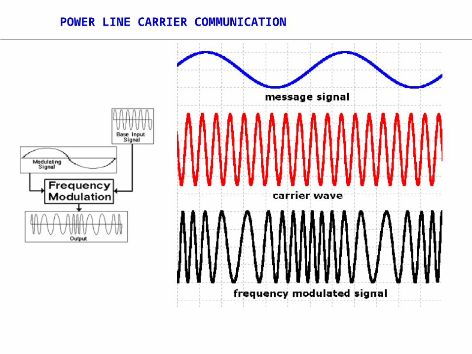
• The instantaneous frequency of the carrier wave is varied as a function of the instantaneous value of the modulation signal.
Frequency Modulation
POWER LINE CARRIER COMMUNICATION

POWER LINE CARRIER COMMUNICATION
• Frequency Modulation by a square wave modulating signal. This method is extensively used in the system of pulse transmission employed in the teleprinting, telemetering, Line protection, Supervisory control, etc.
Frequency Shift

POWER LINE CARRIER COMMUNICATION
• Ratio of single power to total noise power at any point. Ratio above 10db is considered satisfactory for frequency shift operation.
Signal to Noise Ratio

POWER LINE CARRIER COMMUNICATION

POWER LINE CARRIER COMMUNICATION

POWER LINE CARRIER COMMUNICATION
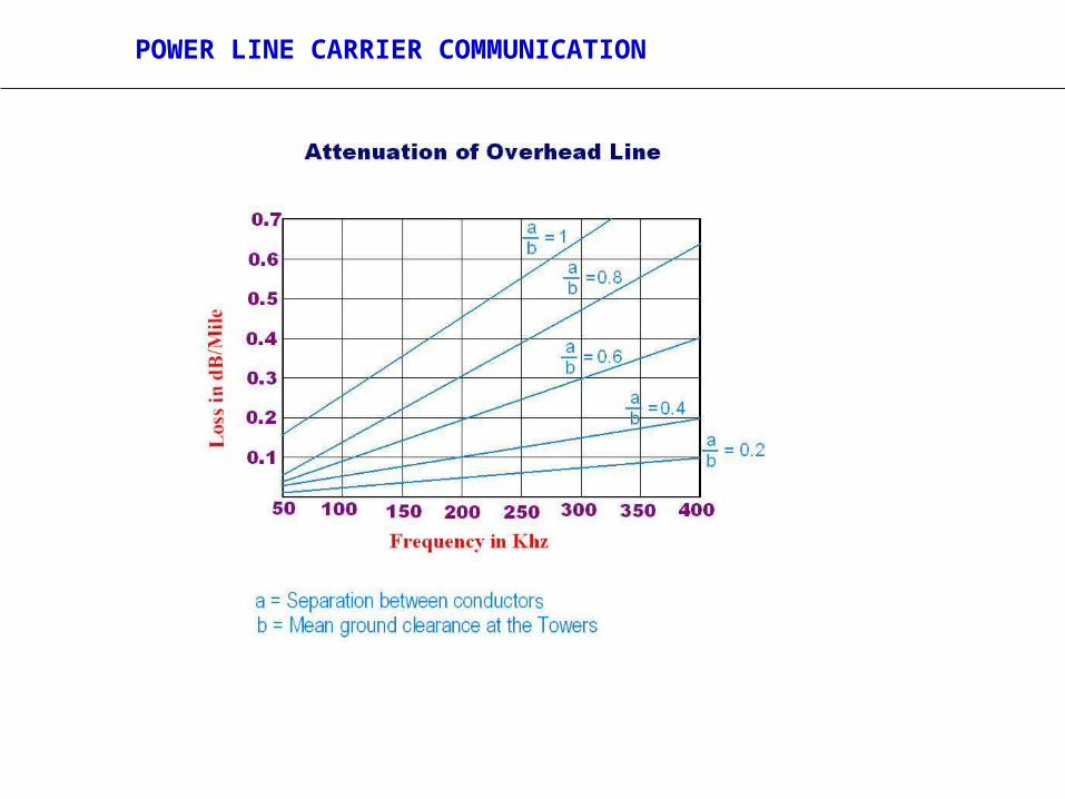
• Propagation loss and increases in the propagation length of the line.
• Ratio between the voltages, currents or power at any two points is a measure of the attenuation between these two points.
Attenuation

POWER LINE CARRIER COMMUNICATION
• Phase to Phase Clearance
• Phase to ground clearance
• Humidity of Air
• Carrier Frequency
Attenuation of Line for Carrier Signal Depends on:

POWER LINE CARRIER COMMUNICATION
• Ratio of applied voltage to the resulting current, flowing into the line.
Characteristic Impedance

POWER LINE CARRIER COMMUNICATION
• For maximum power transfer the line should be terminated with a resistive load equal to its characteristics impedance when all the energy from the line is absorbed by the load
• If the terminated load is not equal to the characteristic impedance part of the energy traveling down the line will be reflected back.
Matched LineMatched Line
POWER LINE CARRIER COMMUNICATION

POWER LINE CARRIER COMMUNICATION

POWER LINE CARRIER COMMUNICATION

POWER LINE CARRIER COMMUNICATION
Major Carrier Components

POWER LINE CARRIER COMMUNICATION
PLCC System

POWER LINE CARRIER COMMUNICATION
• Phase to Ground• Phase to Phase for carrier by-passing• Phase to Phase (Inter Phase)• Phase to Phase (Inter Circuit)• Three Phase• Insulated earth wire coupling• Intra-bundle coupling
Methods of Coupling

POWER LINE CARRIER COMMUNICATION

POWER LINE CARRIER COMMUNICATION
• Radiation losses are high as earth forms part of the circuit
• Noise pick-up is higher • Increased cross talk
• Used for smaller line sections.• Used where noise level is low.• Most economical
Phase to Ground Coupling

POWER LINE CARRIER COMMUNICATION
• Grounding or opening the coupled phase wire at the end of the lined section will cause mark reduction in signal level.
• Use of outside phase wire for ground coupling results higher attenuation in long lines.
Disadvantage
Phase to Ground Coupling Carrier By-Pass

POWER LINE CARRIER COMMUNICATION
• Higher Dependability• Lower line attenuation• Less Radiation• Suitable for long lines
where carrier protection is involved
Advantage
Phase to Phase Coupling
• Initially Expensive
Disadvantage

POWER LINE CARRIER COMMUNICATION

POWER LINE CARRIER COMMUNICATION
One Circuit can be taken out of service and grounded
Advantage
Possible only when both circuits are strung on same structure
Phase to Phase Coupling Inter Circuit Coupling

POWER LINE CARRIER COMMUNICATION

POWER LINE CARRIER COMMUNICATION
• Additional Redundancy• Better performance
during system distributions
• Ideal for long series compensated EVH line.
Advantage
• Initially Expensive
Disadvantage
Three Phase Coupling

POWER LINE CARRIER COMMUNICATION

POWER LINE CARRIER COMMUNICATION

POWER LINE CARRIER COMMUNICATION
• RF hybrid loss
• Coupling loss (Line Tuner loss + Coupling Capacitor loss)
• Shunt loss caused by carrier power flowing back through the line trap and station bus and ground
• Transposition loss
System Losses

POWER LINE CARRIER COMMUNICATION
• Inherent dissipation of signal power (3.5 db)
•Also small transformer loss and a mismatch loss
RF Hybrid Loss

POWER LINE CARRIER COMMUNICATION
Caused by resistive component of line tuner and coupling capacitor impedances ( 3 dB)
Coupling Loss

POWER LINE CARRIER COMMUNICATION
Carrier loss through the line trap impedance and any shunt path to ground (3 dB)
Shunt Loss

POWER LINE CARRIER COMMUNICATION
Carrier losses for the system

POWER LINE CARRIER COMMUNICATION
• Offers high impedance to carrier signal• Offers nil impedance to power frequency• To minimize loss of carrier energy• To minimize mutual interference between adjacent
line sections
ProposePropose
Wave Trap:Provided in the Coupled Conductor

POWER LINE CARRIER COMMUNICATION
• Single-frequency Traps
• Double-frequency Traps
• Broad-band Traps
Wave TrapTypes

POWER LINE CARRIER COMMUNICATION
C1 – Tuning capacitor
LA- Vacuum type arrester
Wave Trap(Double frequency
resonant type)

POWER LINE CARRIER COMMUNICATION
Mounted in the base of coupling capacitor
Provides low-impedance path for power frequency current and high-impedance for carrier frequency signal
Carrier loss introduced by drain coil is <0.5db
Drain Coil

POWER LINE CARRIER COMMUNICATION
• Coupling carrier Equipment to EHV line
• Offers high impedance at power frequency
• Offers very low impedance for high frequency
Coupling Capacitor
PurposePurpose

POWER LINE CARRIER COMMUNICATION
One end of the coupling capacitor must be securely earthed to prevent over voltage up to the magnitude of the operating voltage on the equipment side of the capacitor.
Capacitor voltage transformer used for measurement of voltage are used for carrier coupling.
CautionCaution
Coupling Capacitor: Provided with the coupled Phase

POWER LINE CARRIER COMMUNICATION
• To match the carrier equipment output impedance and the overhead line impedance with a view to ensure maximum power transfer from carrier equipment to the line.
Line Matching Unit

POWER LINE CARRIER COMMUNICATION
Ensures maximum power transfer from the carrier set to the line.
Provides an impedance match with low losses between the coaxial cable and the transmission line
Line Matching Unit

POWER LINE CARRIER COMMUNICATION
• Low loss concentric cable to connect the line matching unit and carrier transmitter – receiver assembly
• Generally grounded at terminal equipment end.
Coaxial Cable

POWER LINE CARRIER COMMUNICATION
• Consists of drainage coil, arresters, grounding switch.• Provides protection of carrier equipment & personnel
against undesirable high voltage• Drainage coil connected between carrier current lead
and ground to present low impedance path to ground only to power frequency current passed by the coupling capacitor.
• Drainage coil prevents loss of carrier frequency energy
Protective Device

POWER LINE CARRIER COMMUNICATION
• Teleprotection required for high speed relaying which is facilitated by:
• Comparing fault conditions at line terminal
• High speed simultaneous clearing of faults from both ends of the faulty section
• Blocking unwarranted isolation in the event of fault in the line section.
Teleprotection
POWER LINE CARRIER COMMUNICATION
• Carrier is employed to compare the phase relation between current entering one terminal of a transmission line section and leaving another
Teleprotection
Phase Comparison SchemePhase Comparison Scheme

POWER LINE CARRIER COMMUNICATION
• With the initiation of tripping of a line at one end, a signal is sent out over the carrier simultaneously to the other end and cause remote end beaker also to trip.
Trip Transfer SchemeTrip Transfer Scheme
Teleprotection

POWER LINE CARRIER COMMUNICATION
• A Blocking signal is sent out in the opposite direction of fault to prevent tripping of the remote end circuit breaker which is also sensing the fault.
Directional Comparison SchemeDirectional Comparison Scheme
Teleprotection

POWER LINE CARRIER COMMUNICATION
• Improved transient stability of the system• Reduced line damage & possible melting of
conductor• Minimum outage time with the help of high
speed autoreclosing
High Speed Relying ProvidesHigh Speed Relying Provides
Teleprotection

POWER LINE CARRIER COMMUNICATION
• Reliability
• Security
• Transmission Time
• Information signal should be of sufficient strength to overcome any line disturbance
Criteria for Selection of TeleprotectionCriteria for Selection of Teleprotection
Teleprotection

POWER LINE CARRIER COMMUNICATION
Fc-60 Fc+60Fc-30 Fc+30Fc
F2F1
A typical tone channel
Utilisation of Audio Frequency Band

POWER LINE CARRIER COMMUNICATION
Related Documents