TRUNNION DBB Ball Valve 2 Piece Cast

Welcome message from author
This document is posted to help you gain knowledge. Please leave a comment to let me know what you think about it! Share it to your friends and learn new things together.
Transcript

TRUNNIONDBB Ball Valve
2 Piece Cast

Table of Contents:
Features & Benefits 4 Range, Certifications & Standards 62 Piece DBB Drawings 7 Dimensions 9 Top Works 12Lifting Lug Data 15Torque Data 16Flow Coefficients (Cv) 17Pressure / Temperature Reference 18 How to Order 19

3The data provided in this document is subject to change without notice.
MeridianTM stands behind the products it sells and provides an industry leading warranty of 48 months from date of shipment or 24 months from the date of start-up (whichever is sooner) for all
MeridianTM brand API 6D check valves, flanged or buttweld trunnion ball valves, and floating ball valves.
WARRANTYStandard48/24

4 The data provided in this document is subject to change without notice.
GENERAL FEATURES • Body joint integrity and fire safety is ensured by dual
independent seals.
• A tight tolerance overlapping metal to metal body joint ensures valve is capable of handling pipeline stress and misalignment.
• Standard cast body and end cap construction.
• All designs use 2 antistatic devices.
• Manual body vent design allows safe relief of pressure prior to servicing.
• Manual body drain can be used to safely drain or flush the valve prior to being serviced or removed from line.
• All trunnion ball valves are equipped with a locking device to API 608. For gear operated valves, this feature is included on the gear operator.
• All trunnion ball valves are equipped with ISO 5211 actuator mounting flanges.
• All MeridianTM trunnion ball valves are low emission capable due to the o-ring design.
• All O-rings are of AED (anti-explosive decompression) design.
• Standard trim in either full stainless steel or 3 mil high phosphorus electroless nickel plated for superior corrosion protection.
STEM DESIGN FEATURES
• Blow out proof stem.
• Stems and trunnions are manufactured separately from the ball and supported by a bearing and thrust washer to ensure low consistent torques.
• Triple independent low emission stem seals ensure stem seal integrity.
• All valves include emergency secondary stem sealant injection system.
SEAT DESIGN FEATURES • Special wide seat insert design provides an increased
life in difficult service conditions.
• Seat ring sealing includes separate graphite seals for fire safe design and O-rings for tight sealing.
• Seat sealant injection: MeridianTM trunnion ball valves include seat sealant injection systems. For smaller size valves where space does not permit body cavity injection is used instead of seat sealant injection.
• All seat sealant injection fittings include an internal check valve and another independent buried check valve beneath the injection fitting. Should an injection fitting be damaged it can be replaced without the requirement of re-hydrotesting the valve.
• All valves are hydro-tested utilizing the check valve only (seat sealant injection fitting removed). This ensures check valve integrity.
• DBB - Double block and bleed design with self relieving body cavity per API 6D.
OPTIONAL FEATURES • Body may be coated for corrosion protection
• Cryogenic design and a world class cryogenic test and design facility also available.
• Top entry, welded body and high temperature designs also available.
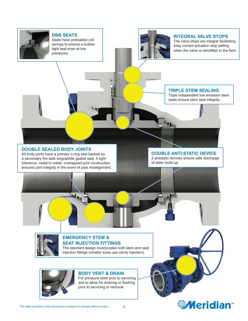
KEY FEATURES & BENEFITS
5The data provided in this document is subject to change without notice.
INTEGRAL VALVE STOPSThe valve stops are integral facilitating easy correct actuation stop setting when the valve is retrofitted in the field.
BODY VENT & DRAINFor pressure relief prior to servicing and to allow for draining or flushing prior to servicing or removal.
DOUBLE ANTI-STATIC DEVICE2 antistatic devices ensure safe discharge of static build up.
TRIPLE STEM SEALINGTriple independent low emission stem seals ensure stem seal integrity.
DBB SEATSSeats have preloaded coil springs to ensure a bubble tight seal even at low pressures.
DOUBLE SEALED BODY JOINTSAll body joints have a primary o-ring seal backed by a secondary fire safe ss/graphite gasket seal. A tight tolerance, metal to metal, overlapped joint construction ensures joint integrity in the event of pipe misalignment.
EMERGENCY STEM & SEAT INJECTION FITTINGSThe standard design incorporates both stem and seat injection fittings (smaller sizes use cavity injection).
6 The data provided in this document is subject to change without notice.
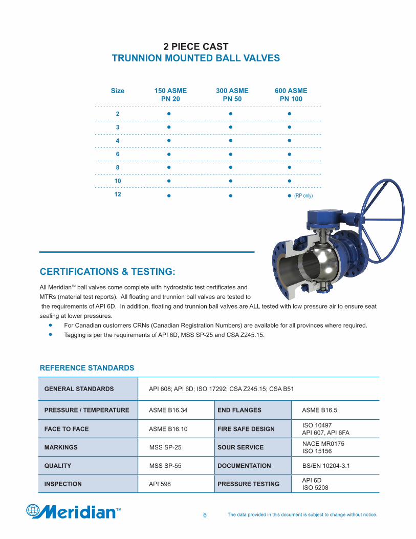
2 PIECE CAST TRUNNION MOUNTED BALL VALVES
GENERAL STANDARDS API 608; API 6D; ISO 17292; CSA Z245.15; CSA B51
PRESSURE / TEMPERATURE ASME B16.34 END FLANGES ASME B16.5
FACE TO FACE ASME B16.10 FIRE SAFE DESIGN ISO 10497 API 607, API 6FA
MARKINGS MSS SP-25 SOUR SERVICE NACE MR0175 ISO 15156
QUALITY MSS SP-55 DOCUMENTATION BS/EN 10204-3.1
INSPECTION API 598 PRESSURE TESTING API 6D ISO 5208
REFERENCE STANDARDS
CERTIFICATIONS & TESTING: All MeridianTM ball valves come complete with hydrostatic test certificates and MTRs (material test reports). All floating and trunnion ball valves are tested to the requirements of API 6D. In addition, floating and trunnion ball valves are ALL tested with low pressure air to ensure seat sealing at lower pressures. For Canadian customers CRNs (Canadian Registration Numbers) are available for all provinces where required. Tagging is per the requirements of API 6D, MSS SP-25 and CSA Z245.15.
600 ASMEPN 100
(RP only)
300 ASMEPN 50
150 ASMEPN 20
Size
2
3
4
6
8
10
12

7The data provided in this document is subject to change without notice.
2 PIECE CAST LEVER OPERATED DBB
CROSS SECTIONAL DRAWING
NOTE: Drawings are representative. Please contact Meridian for specific and current PDF drawings.
DESCRIPTIONSBODYEND CAPBALLSEATSTEMTRUNNIONLIMIT STOP PLATESEAT RINGFIRE SAFE GASKETFIRE SAFE GASKETFIRE SAFE PACKINGFIRE SAFE GASKETFIRE SAFE GASKETTRUNNION SEAL O-RINGBODY SEAL O-RING
ITEM123456789101112131415
DESCRIPTIONS SEAT SEAL O-RINGUPPER CAP SEAL O-RINGSTEM SEAL O-RINGALLEN HEAD BOLTSTUDNUTUPPER CAPSEAT SPRINGANTISTATIC SPRINGALLEN HEAD BOLTSEALANT INJECTION VALVEDRAIN VALVEHEX HEAD BOLTHEX HEAD BOLT
ITEM1617181920212224252627282931
DESCRIPTIONS LEVERLEVER HEADPINKEYVENT VALVESEALANT INJECTION VALVEPINBEARINGBEARINGANTISTATIC SPRINGANTISTATIC BALLALLEN HEAD BOLTTHRUST WASHERCHECK VALVE
ITEM3233343536373839404142434445

8 The data provided in this document is subject to change without notice.
2 PIECE CAST GEAR OPERATED DBB
CROSS SECTIONAL DRAWING
NOTE: Drawings are representative. Please contact Meridian for specific and current PDF drawings. Space permitting, most valves include seat sealant injection (item 38/41). Select small valves use body cavity injection due to space constraints.
DESCRIPTIONSBODYEND CAPBALLSEATSTEMTRUNNIONALLEN HEAD BOLTSEAT RINGFIRE SAFE GASKETFIRE SAFE GASKETFIRE SAFE PACKINGFIRE SAFE GASKETFIRE SAFE GASKETTRUNNION SEAL O-RING
ITEM1234567891011121314
DESCRIPTIONS BODY SEAL O-RING SEAT SEAL O-RINGUPPER CAP SEAL O-RINGSTEM SEAL O-RINGALLEN HEAD BOLTLIMIT STOP PLATESTUDNUTSEAL RINGSEGMENTSEAT SPRINGANTISTATIC SPRINGBEARINGBEARING
ITEM 1516171819202122232425262728
DESCRIPTIONS SEALANT INJECTION VALVEDRAIN VALVEKEYPINGEAR OPERATORSTUDNUTPINVENT VALVESEALANT INJECTION VALVELIFTING LUGSTHRUST WASHERCHECK VALVE
ITEM 29303132333435363738394041
9The data provided in this document is subject to change without notice.
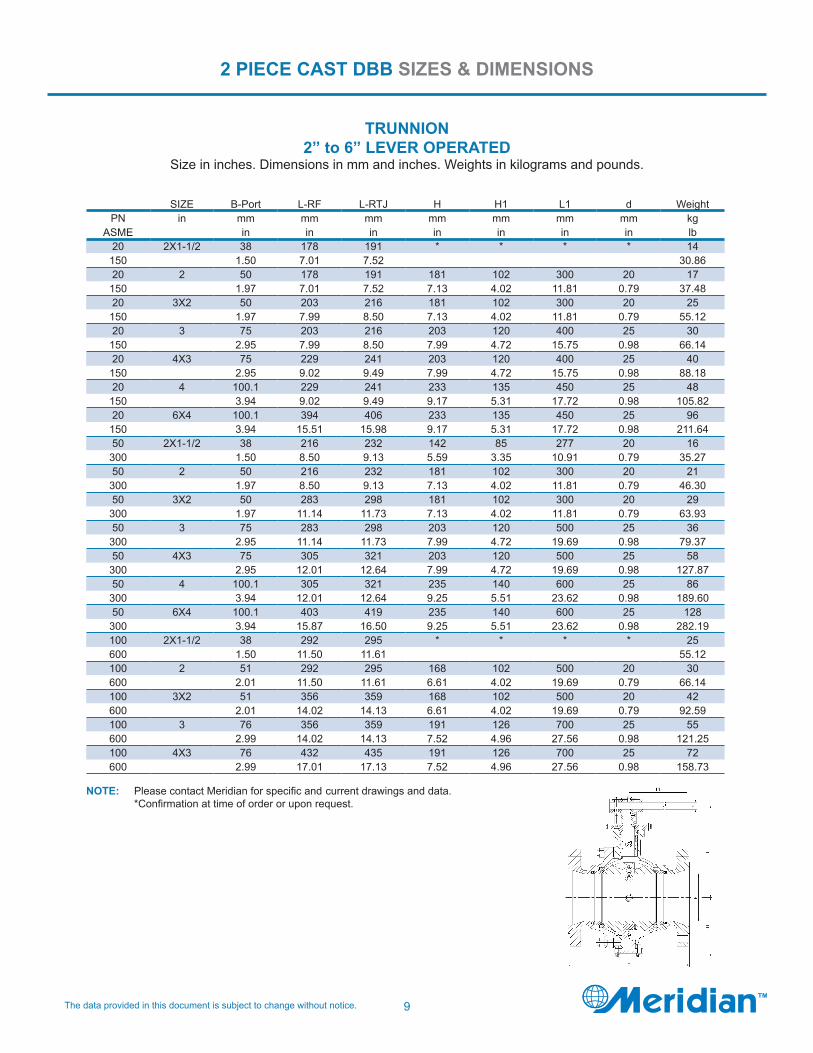
2 PIECE CAST DBB SIZES & DIMENSIONS
TRUNNION 2” to 6” LEVER OPERATED
Size in inches. Dimensions in mm and inches. Weights in kilograms and pounds.
SIZE B-Port L-RF L-RTJ H H1 L1 d WeightPN in mm mm mm mm mm mm mm kg
ASME in in in in in in in lb20 2X1-1/2 38 178 191 * * * * 14
150 1.50 7.01 7.52 30.8620 2 50 178 191 181 102 300 20 17
150 1.97 7.01 7.52 7.13 4.02 11.81 0.79 37.4820 3X2 50 203 216 181 102 300 20 25
150 1.97 7.99 8.50 7.13 4.02 11.81 0.79 55.1220 3 75 203 216 203 120 400 25 30
150 2.95 7.99 8.50 7.99 4.72 15.75 0.98 66.1420 4X3 75 229 241 203 120 400 25 40
150 2.95 9.02 9.49 7.99 4.72 15.75 0.98 88.1820 4 100.1 229 241 233 135 450 25 48
150 3.94 9.02 9.49 9.17 5.31 17.72 0.98 105.8220 6X4 100.1 394 406 233 135 450 25 96
150 3.94 15.51 15.98 9.17 5.31 17.72 0.98 211.6450 2X1-1/2 38 216 232 142 85 277 20 16
300 1.50 8.50 9.13 5.59 3.35 10.91 0.79 35.2750 2 50 216 232 181 102 300 20 21
300 1.97 8.50 9.13 7.13 4.02 11.81 0.79 46.3050 3X2 50 283 298 181 102 300 20 29
300 1.97 11.14 11.73 7.13 4.02 11.81 0.79 63.9350 3 75 283 298 203 120 500 25 36
300 2.95 11.14 11.73 7.99 4.72 19.69 0.98 79.3750 4X3 75 305 321 203 120 500 25 58
300 2.95 12.01 12.64 7.99 4.72 19.69 0.98 127.8750 4 100.1 305 321 235 140 600 25 86
300 3.94 12.01 12.64 9.25 5.51 23.62 0.98 189.6050 6X4 100.1 403 419 235 140 600 25 128
300 3.94 15.87 16.50 9.25 5.51 23.62 0.98 282.19100 2X1-1/2 38 292 295 * * * * 25600 1.50 11.50 11.61 55.12100 2 51 292 295 168 102 500 20 30600 2.01 11.50 11.61 6.61 4.02 19.69 0.79 66.14100 3X2 51 356 359 168 102 500 20 42600 2.01 14.02 14.13 6.61 4.02 19.69 0.79 92.59100 3 76 356 359 191 126 700 25 55600 2.99 14.02 14.13 7.52 4.96 27.56 0.98 121.25100 4X3 76 432 435 191 126 700 25 72600 2.99 17.01 17.13 7.52 4.96 27.56 0.98 158.73
NOTE: Please contact Meridian for specific and current drawings and data. *Confirmation at time of order or upon request.

10 The data provided in this document is subject to change without notice.
2 PIECE CAST DBB SIZES & DIMENSIONS
150 ASME TRUNNION 6” TO 12” GEAR OPERATED
Size in inches. Dimensions in mm and inches. Weights in kilograms and pounds.
300 ASME TRUNNION 6” TO 12” GEAR OPERATED
Size in inches. Dimensions in mm and inches. Weights in kilograms and pounds.
NOTE: Please contact Meridian for specific and current drawings and data.
NOTE: Please contact Meridian for specific and current drawings and data.
SIZE B-Port L-RF L-RTJ H H1 A Dia. A WeightPN in mm mm mm mm mm mm mm kg
ASME in in in in in in in lb20 6 151 394 406 278 190 229 465 100
150 5.94 15.51 15.98 10.94 7.48 9.02 18.31 220.4620 8X6 151 457 470 278 190 229 465 150
150 5.94 17.99 18.50 10.94 7.48 9.02 18.31 330.6920 8 202 457 470 330 238 360 600 172
150 7.95 17.99 18.50 12.99 9.37 14.17 23.62 379.1920 10X8 202 533 546 330 238 360 600 275
150 7.95 20.98 21.50 12.99 9.37 14.17 23.62 606.2720 10 252 533 546 382 291 402 600 284
150 9.92 20.98 21.50 15.04 11.46 15.83 23.62 626.1120 12X10 252 610 622 382 291 402 600 482
150 9.92 24.02 24.49 15.04 11.46 15.83 23.62 1062.6220 12 303 610 622 413 318 402 600 494
150 11.93 24.02 24.49 16.26 12.52 15.83 23.62 1089.07
SIZE B-Port L-RF L-RTJ H H1 A Dia. A WeightPN in mm mm mm mm mm mm mm kg
ASME in in in in in in in lb50 6 151 403 419 278 190 229 465 170
300 5.94 15.87 16.50 10.94 7.48 9.02 18.31 374.7850 8X6 151 502 518 278 190 229 465 202
300 5.94 19.76 20.39 10.94 7.48 9.02 18.31 445.3350 8 202 502 518 330 238 360 600 246
300 7.95 19.76 20.39 12.99 9.37 14.17 23.62 542.3350 10X8 202 568 584 330 238 360 600 300
300 7.95 22.36 22.99 12.99 9.37 14.17 23.62 661.3850 10 252 568 584 382 291 402 600 308
300 9.92 22.36 22.99 15.04 11.46 15.83 23.62 679.0250 12X10 252 648 664 382 291 402 600 496
300 9.92 25.51 26.14 15.04 11.46 15.83 23.62 1093.4850 12 303 648 664 513 350 520 600 512
300 11.93 25.51 26.14 20.20 13.78 20.47 23.62 1128.76
11The data provided in this document is subject to change without notice.
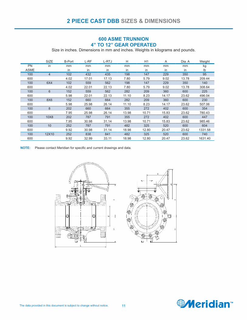
2 PIECE CAST DBB SIZES & DIMENSIONS
600 ASME TRUNNION 4” TO 12” GEAR OPERATED
Size in inches. Dimensions in mm and inches. Weights in kilograms and pounds.
NOTE: Please contact Meridian for specific and current drawings and data.
SIZE B-Port L-RF L-RTJ H H1 A Dia. A WeightPN in mm mm mm mm mm mm mm kg
ASME in in in in in in in lb100 4 102 432 435 198 147 229 350 95600 4.02 17.01 17.13 7.80 5.79 9.02 13.78 209.44100 6X4 102 559 562 198 147 229 350 140600 4.02 22.01 22.13 7.80 5.79 9.02 13.78 308.64100 6 152 559 562 282 209 360 600 225600 5.98 22.01 22.13 11.10 8.23 14.17 23.62 496.04100 8X6 152 660 664 282 209 360 600 230600 5.98 25.98 26.14 11.10 8.23 14.17 23.62 507.06100 8 202 660 664 355 272 402 600 354600 7.95 25.98 26.14 13.98 10.71 15.83 23.62 780.43100 10X8 202 787 791 355 272 402 600 447600 7.95 30.98 31.14 13.98 10.71 15.83 23.62 985.46100 10 252 787 791 482 325 520 600 604600 9.92 30.98 31.14 18.98 12.80 20.47 23.62 1331.58100 12X10 252 838 841 482 325 520 600 740600 9.92 32.99 33.11 18.98 12.80 20.47 23.62 1631.40
12 The data provided in this document is subject to change without notice.
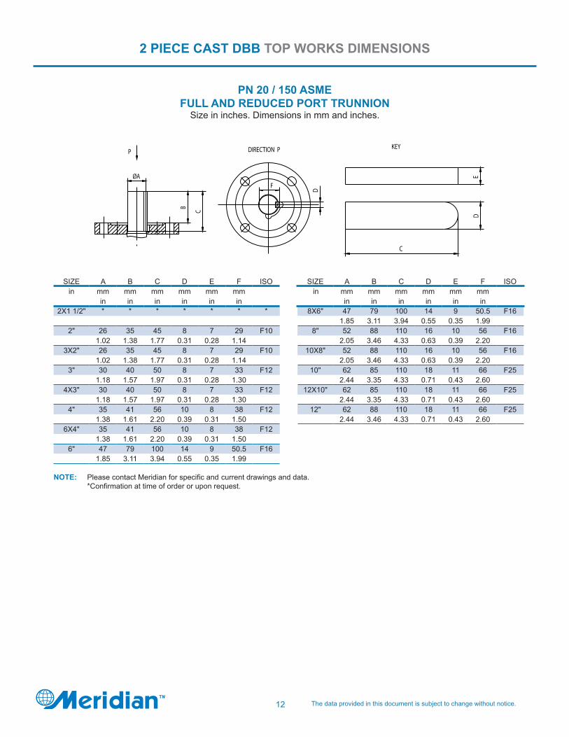
2 PIECE CAST DBB TOP WORKS DIMENSIONS
ØAB
D
F
P
C
DE
C
KEYDIRECTION P
PN 20 / 150 ASMEFULL AND REDUCED PORT TRUNNION
Size in inches. Dimensions in mm and inches.
SIZE A B C D E F ISOin mm mm mm mm mm mm
in in in in in in2X1 1/2" * * * * * * *
2" 26 35 45 8 7 29 F101.02 1.38 1.77 0.31 0.28 1.14
3X2" 26 35 45 8 7 29 F101.02 1.38 1.77 0.31 0.28 1.14
3" 30 40 50 8 7 33 F121.18 1.57 1.97 0.31 0.28 1.30
4X3" 30 40 50 8 7 33 F121.18 1.57 1.97 0.31 0.28 1.30
4" 35 41 56 10 8 38 F121.38 1.61 2.20 0.39 0.31 1.50
6X4" 35 41 56 10 8 38 F121.38 1.61 2.20 0.39 0.31 1.50
6" 47 79 100 14 9 50.5 F161.85 3.11 3.94 0.55 0.35 1.99
SIZE A B C D E F ISOin mm mm mm mm mm mm
in in in in in in8X6" 47 79 100 14 9 50.5 F16
1.85 3.11 3.94 0.55 0.35 1.998" 52 88 110 16 10 56 F16
2.05 3.46 4.33 0.63 0.39 2.2010X8" 52 88 110 16 10 56 F16
2.05 3.46 4.33 0.63 0.39 2.2010" 62 85 110 18 11 66 F25
2.44 3.35 4.33 0.71 0.43 2.6012X10" 62 85 110 18 11 66 F25
2.44 3.35 4.33 0.71 0.43 2.6012" 62 88 110 18 11 66 F25
2.44 3.46 4.33 0.71 0.43 2.60
NOTE: Please contact Meridian for specific and current drawings and data. *Confirmation at time of order or upon request.

13The data provided in this document is subject to change without notice.
2 PIECE CAST DBB TOP WORKS DIMENSIONS
ØAB
D
F
P
C
DE
C
KEYDIRECTION P
PN 50 / 300 ASMEFULL AND REDUCED PORT TRUNNION
Size in inches. Dimensions in mm and inches.
SIZE A B C D E F ISOin mm mm mm mm mm mm
in in in in in in2X1 1/2" 20 29.5 40 6 6 22.5 F10
0.79 1.16 1.57 0.24 0.24 0.892" 26 35 45 8 7 29 F10
1.02 1.38 1.77 0.31 0.28 1.143X2" 26 35 45 8 7 29 F10
1.02 1.38 1.77 0.31 0.28 1.143" 30 40 50 8 7 33 F12
1.18 1.57 1.97 0.31 0.28 1.304X3" 30 40 50 8 7 33 F12
1.18 1.57 1.97 0.31 0.28 1.304" 35 41 56 10 8 38 F12
1.38 1.61 2.20 0.39 0.31 1.506X4" 35 41 56 10 8 38 F12
1.38 1.61 2.20 0.39 0.31 1.506" 47 79 100 14 9 50.5 F16
1.85 3.11 3.94 0.55 0.35 1.99
SIZE A B C D E F ISOin mm mm mm mm mm mm
in in in in in in8X6" 47 79 100 14 9 50.5 F16
1.85 3.11 3.94 0.55 0.35 1.998" 52 88 110 16 10 56 F16
2.05 3.46 4.33 0.63 0.39 2.2010X8" 52 88 110 16 10 56 F16
2.05 3.46 4.33 0.63 0.39 2.2010" 62 85 110 18 11 66 F25
2.44 3.35 4.33 0.71 0.43 2.6012X10" 62 85 110 18 11 66 F25
2.44 3.35 4.33 0.71 0.43 2.6012" 62 88 110 18 11 66 F25
2.44 3.46 4.33 0.71 0.43 2.60
NOTE: Please contact Meridian for specific and current drawings and data.

14 The data provided in this document is subject to change without notice.
2 PIECE CAST DBB TOP WORKS DIMENSIONS
ØAB
D
F
P
C
DE
C
KEYDIRECTION P
PN 100 / 600 ASMEFULL AND REDUCED PORT TRUNNION
Size in inches. Dimensions in mm and inches.
SIZE A B C D E F ISOin mm mm mm mm mm mm
in in in in in in2X1 1/2" * * * * * * *
2" 26 35 45 8 7 29 F121.02 1.38 1.77 0.31 0.28 1.14
3X2" 26 35 45 8 7 29 F121.02 1.38 1.77 0.31 0.28 1.14
3" 30 40 50 8 7 33 F121.18 1.57 1.97 0.31 0.28 1.30
4X3" 30 40 50 8 7 33 F121.18 1.57 1.97 0.31 0.28 1.30
4" 35 52 70 10 8 38 F121.38 2.05 2.76 0.39 0.31 1.50
6X4" 35 52 70 10 8 38 F121.38 2.05 2.76 0.39 0.31 1.50
6" 42 73 95 12 8 45 F161.65 2.87 3.74 0.47 0.31 1.77
SIZE A B C D E F ISOin mm mm mm mm mm mm
in in in in in in8X6" 42 73 95 12 8 45 F16
1.65 2.87 3.74 0.47 0.31 1.778" 52 85 110 16 10 56 F25
2.05 3.35 4.33 0.63 0.39 2.2010X8" 52 85 110 16 10 56 F25
2.05 3.35 4.33 0.63 0.39 2.2010" 62 85 110 18 11 66 F25
2.44 3.35 4.33 0.71 0.43 2.6012X10" 62 85 110 18 11 66 F25
2.44 3.35 4.33 0.71 0.43 2.60
NOTE: Please contact Meridian for specific and current drawings and data. *Confirmation at time of order or upon request.

15The data provided in this document is subject to change without notice.
2 PIECE CAST DBB
SIZE Lifting Lugs Lifting Lugs Lifting Lugs
in
2X1 1/2" N/A N/A N/A
2" N/A N/A N/A
3X2" N/A N/A N/A
3" N/A N/A N/A
4X3" N/A N/A N/A
4" N/A N/A N/A
6X4" N/A N/A N/A
6" YES YES YES
8X6" YES YES YES
8" YES YES YES
10X8" YES YES YES
10" YES YES YES
12X10" YES YES YES
12" YES YES
150 ASME 300 ASME 600 ASME
LIFTING LUG DATA

16 The data provided in this document is subject to change without notice.
2 PIECE CAST DBB TORQUE DATA
Size (In) Open (break) torque (inch pounds) at Max. P150 ASME 300 ASME 600 ASME
2X1.5" 478 597 11952" 597 956 19713" 717 1195 31064" 1553 2509 54966" 4540 6930 113508" 8124 16727 24492
10" 13142 27479 3524512" 19116 32258 N/A
NOTE: 1. Torque values are in inch pounds. To convert to Newton meters divide inch pounds by 8.85. 2. For reduced port valves not shown select torque based on valve bore size. For example: 4” x 3” x 300 ASME valve – use torque for 3” x 300 ASME valve.3. Torque includes safety factor.4. For clean wet applications in low temperature service below -20 Deg C (-4 Deg F) add 10% safety.5. Add additional safety if service conditions dictate.6. Torque for sizes not shown is available upon request.7. Torques shown are based on the following seat materials:
· 2 piece trunnions (single piston seats): · Class 150 - 300 ASME valves have RPTFE seat rings; · Class 600 ASME valves have Devlon seat rings.

17The data provided in this document is subject to change without notice.
REDUCED BORE
NOTE: 1. Larger size data available on request. 2. Flow coefficient Cv is the volume (in US gallons) of water at 60°F that will flow per minute through a valve with a pressure drop of 1 psi across the valve.
Size (In) 150 ASME 300 ASME 600 ASME 2*1 1/2 306 306 306
3*2 377 377 3774*3 1043 1043 10436*4 1587 1587 15878*6 4364 4364 4364
10*8 7495 7495 749512*10 13470 13470 13470
2 PIECE CAST DBB CV VALUES
FULL BORE
Size (In) 150 ASME 300 ASME 600 ASME2 647 647 6473 2086 2086 20864 2694 2694 26946 6062 6062 60628 10885 10885 10885
10 17109 17109 1710912 24734 24734 N/A

18 The data provided in this document is subject to change without notice.
REFERENCE PRESSURE/TEMPERATURE CHART
TEMPERATURE °F
TEMPERATURE °C
GRAPHITERPTFE/PTFESEALS
PEEK
VITONO-RING
HNBR/HSNO-RING
DEVLON
PCTFE
DELRIN
RPTFE-20%
PR
ES
SU
RE
(p
si)
PR
ES
SU
RE
(b
ar)
Please consult ASME B16.34 for specific body material pressure / temperature ratings. The above chart is for reference only, please call for specific / additional seat and seal technical information if required.
MERIDIANTM “CHECKPOINT”
Critical Control Point Check System
Our internal manufacturing and process quality system leverages “critical control point” data to provide a high level of quality and manufacturing control. Key components of the CHECKPOINT process include:
A database that links CHECKPOINT manufacturing plant input to a specific valve serial number. Visual review and/or inspection and sign-off at each stage in the process. Checklist / traveler for each valve / component in production that tracks its progress from raw material to finished product. Ability to monitor CHECKPOINT data remotely.
19The data provided in this document is subject to change without notice.
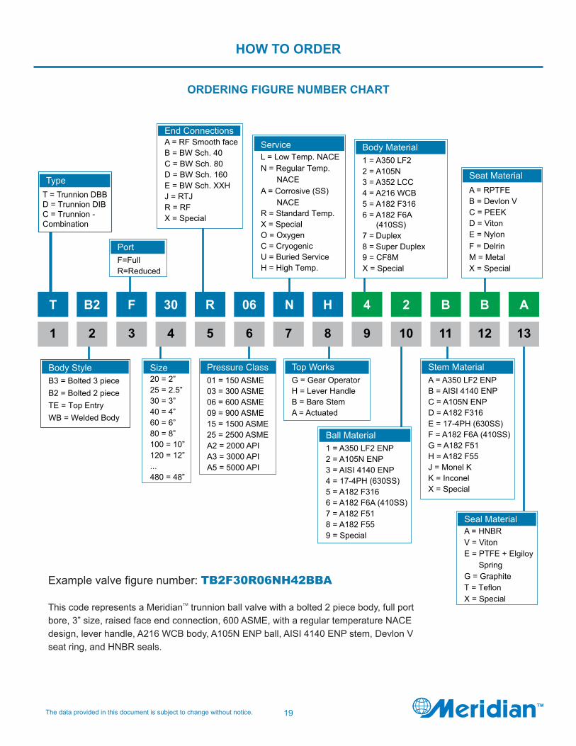
HOW TO ORDER
ORDERING FIGURE NUMBER CHART
4
9
H
8
N
7
06
6
R
5
30
4
F
Stem MaterialA = A350 LF2 ENPB = AISI 4140 ENPC = A105N ENPD = A182 F316E = 17-4PH (630SS)F = A182 F6A (410SS)G = A182 F51H = A182 F55J = Monel KK = InconelX = Special
Ball Material1 = A350 LF2 ENP2 = A105N ENP3 = AISI 4140 ENP4 = 17-4PH (630SS)5 = A182 F3166 = A182 F6A (410SS)7 = A182 F518 = A182 F559 = Special
Top WorksG = Gear OperatorH = Lever HandleB = Bare StemA = Actuated
3
B2
2
T
1
2
10
B
Body Material1 = A350 LF22 = A105N3 = A352 LCC4 = A216 WCB5 = A182 F3166 = A182 F6A (410SS)7 = 8 = 9 =
Pressure Class01 = 150 ASME03 = 300 ASME06 = 600 ASME09 = 900 ASME15 = 1500 ASME25 = 2500 ASMEA2 = 2000 APIA3 = 3000 APIA5 = 5000 API
Size20 = 2”25 = 2.5”30 = 3”40 = 4”60 = 6”80 = 8”100 = 10”120 = 12”...480 = 48”
TypeT = Trunnion
Body StyleB3 = Bolted 3 piece
PortF=FullR=Reduced
11
B
12
A
13
ServiceL = Low Temp. NACEN =
A = NACE
X = SpecialO = OxygenC = CryogenicU = Buried Service
End ConnectionsA = RF Smooth faceB = BW Sch. 40C = BW Sch. 80D = BW Sch. 160E = BW Sch. XXHJ = RTJR = RFX = Special
Seat MaterialA = RPTFEB = Devlon VC = PEEKD = Viton E = Nylon
M = X = Special
Seal MaterialA = HNBRV = Viton E = PTFE + Elgiloy
X = Special
F = Delrin
Example valve figure number: TB2F30R06NH42BBA
This code represents a MeridianTM trunnion ball valve with a bolted 2 piece body, full port bore, 3” size, raised face end connection, 600 ASME, with a regular temperature NACE design, lever handle, A216 WCB body, A105N ENP ball, AISI 4140 ENP stem, Devlon V seat ring, and HNBR seals.
To learn more about MeridianTM please visit our website at:
www.meridianvalve.ca
TM
MeridianTM TBV 3 Rev 11 2015
MeridianTM is a registered trademark of Wolseley Industrial Canada Inc. (Wolseley Industrial)The contents hereof are confidential and proprietary. Any unauthorized reproduction or disclosure, in whole or in part, is strictly prohibited. The material in this catalogue is for general information only, may not reflect the most current product information and is not guaranteed to be complete and may not be used or relied upon for specific performance data or for the purposes of material selection or determining suitability without first consulting Wolseley Industrial. Wolseley Industrial reserves the right to change this information without notice. Wolseley Industrial expressly disclaims any and all liability or damages arising or resulting from the use of or reliance upon the information in this catalogue.
Related Documents