1 / 5 2. Multiplexing

Welcome message from author
This document is posted to help you gain knowledge. Please leave a comment to let me know what you think about it! Share it to your friends and learn new things together.
Transcript

1 / 5
2차시 Multiplexing
2. Multiplexing
2 / 24
학습에 앞서
§학습개요
– 두개이상의장치가전송매체를공유하여통신하는방법을학습한다.
§학습목표
– 매체접근제어방식의필요성을설명할수있어야한다.– FDM, WDM, TDM 동작을설명할수있어야한다.
3 / 37
1. Multiplexing
Whenever the bandwidth of a medium linking two devices is greater than the bandwidth needs of the devices, the link can be shared. Multiplexing is the set of techniques that allows the simultaneous transmission of multiple signals across a single data link. As data and telecommunications use increases, so does traffic.
Topics discussed in this section:Frequency-Division MultiplexingWavelength-Division MultiplexingSynchronous Time-Division MultiplexingStatistical Time-Division Multiplexing
4 / 37
1. Multiplexing
§Multiplexing – The set of techniques that allows the simultaneous
transmission of multiple signals across a single data link èshare the high-bandwidth of a medium
§Transmission service is the most significant cost– Two approaches to achieve greater efficiency in the use of
transmission servicesl multiplexing: several information sources share a large
transmission capacityl compression: reduces the number of bits required to
represent a given amount of information– could be applied separately or, simultaneously
§Concept– combines many individual signals so they can be sent over
one transmission medium– contains equipment to do multiplexing (MUX) and
demultiplexing (DEMUX)
5 / 37
1. Multiplexing
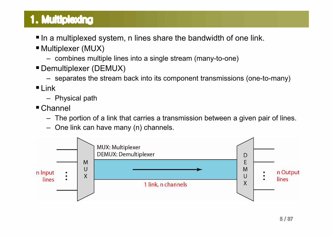
§ In a multiplexed system, n lines share the bandwidth of one link. §Multiplexer (MUX)
– combines multiple lines into a single stream (many-to-one)§Demultiplexer (DEMUX)
– separates the stream back into its component transmissions (one-to-many)§Link
– Physical path§Channel
– The portion of a link that carries a transmission between a given pair of lines.– One link can have many (n) channels.
6 / 37
1. Multiplexing
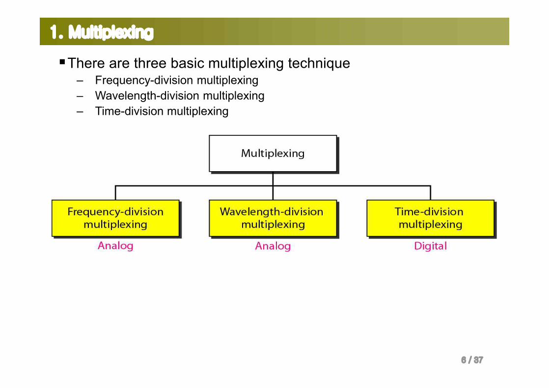
§There are three basic multiplexing technique– Frequency-division multiplexing– Wavelength-division multiplexing– Time-division multiplexing

7 / 37
1. Multiplexing
Frequency-Division Multiplexing (FDM)
§An analog technique that can be applied when the bandwidth of a link is greater than the combined bandwidth of the signals to be transmitted.
§Operation: – Signals generated by each device modulate different carrier frequencies. – These modulated signals are then combined into a single composite signal that
can be transport by the link. §Bandwidth:
– Carrier frequencies are separated by sufficient bandwidth accommodate the modulated signal.
– Channels can be separated by strips of unused bandwdith, guard bands, to prevent signals from overlapping.
– Output bandwidth = sum of inputs + guard bands
8 / 37
1. Multiplexing
Frequency-Division Multiplexing (FDM)
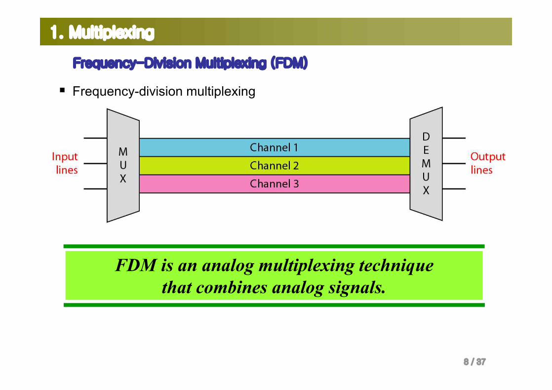
§ Frequency-division multiplexing
FDM is an analog multiplexing technique that combines analog signals.
9 / 37
1. Multiplexing
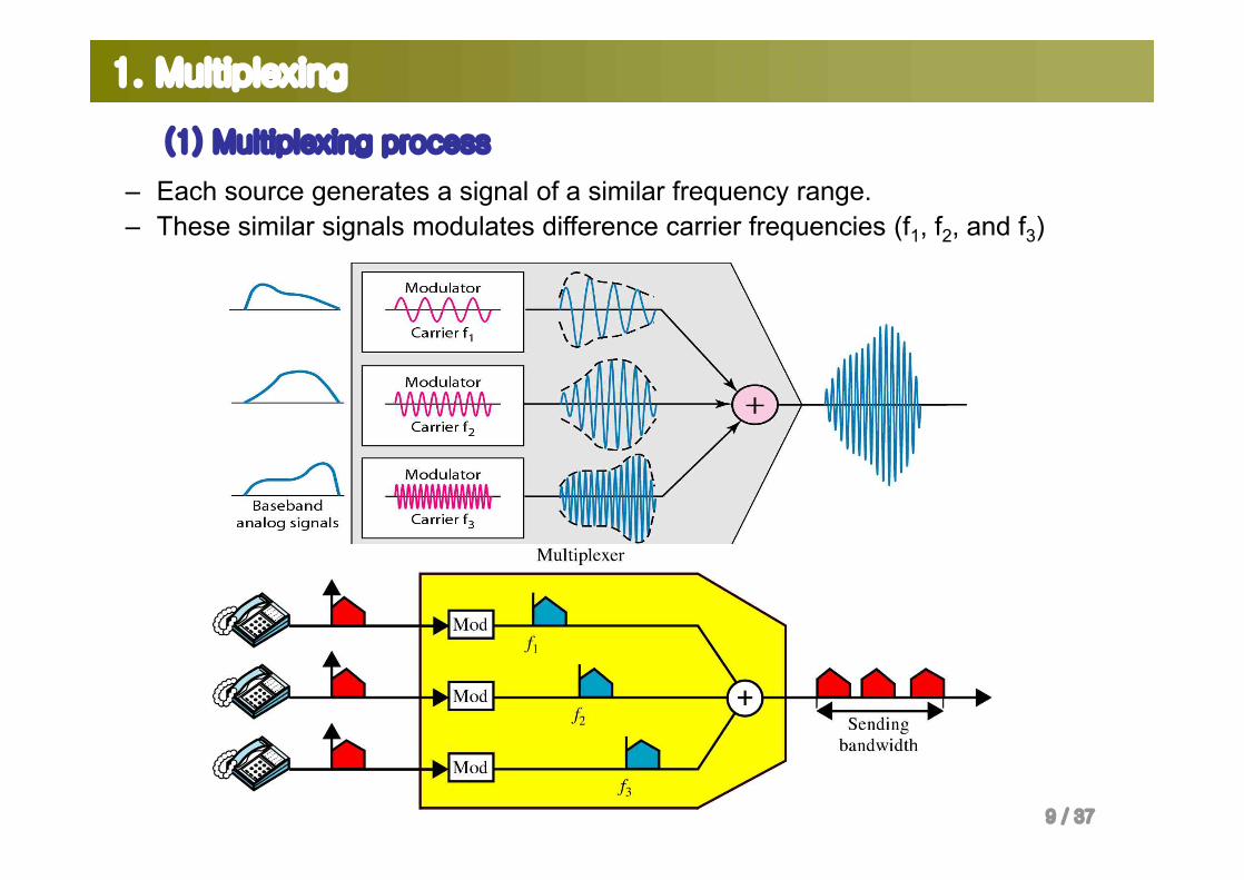
(1) Multiplexing process
– Each source generates a signal of a similar frequency range.– These similar signals modulates difference carrier frequencies (f1, f2, and f3)
10 / 37
1. Multiplexing
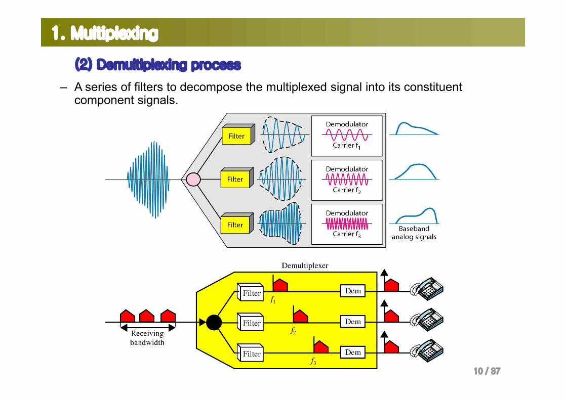
(2) Demultiplexing process
– A series of filters to decompose the multiplexed signal into its constituent component signals.
11 / 37
1. Multiplexing
Example 6.1
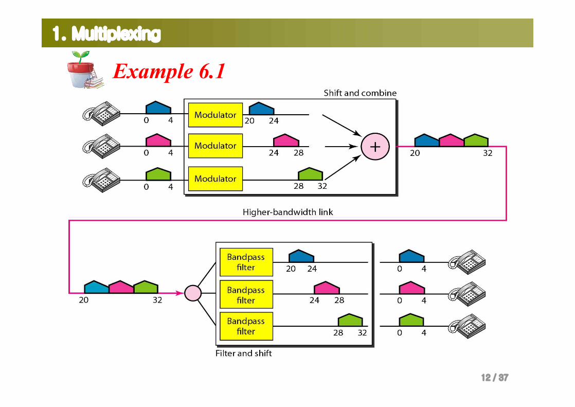
Assume that a voice channel occupies a bandwidth of 4 kHz. We need to combine three voice channels into a link with a bandwidth of 12 kHz, from 20 to 32 kHz. Show the configuration, using the frequency domain. Assume there are no guard bands.
SolutionWe shift (modulate) each of the three voice channels to a different bandwidth, as shown in Figure 6.6. We use the 20- to 24-kHz bandwidth for the first channel, the 24- to 28-kHz bandwidth for the second channel, and the 28- to 32-kHz bandwidth for the third one. Then we combine them as shown in Figure 6.6.
12 / 37
1. Multiplexing
Example 6.1
13 / 37
1. Multiplexing
Example 6.3Four data channels (digital), each transmitting at 1 Mbps, use asatellite channel of 1 MHz. Design an appropriate configuration,using FDM.
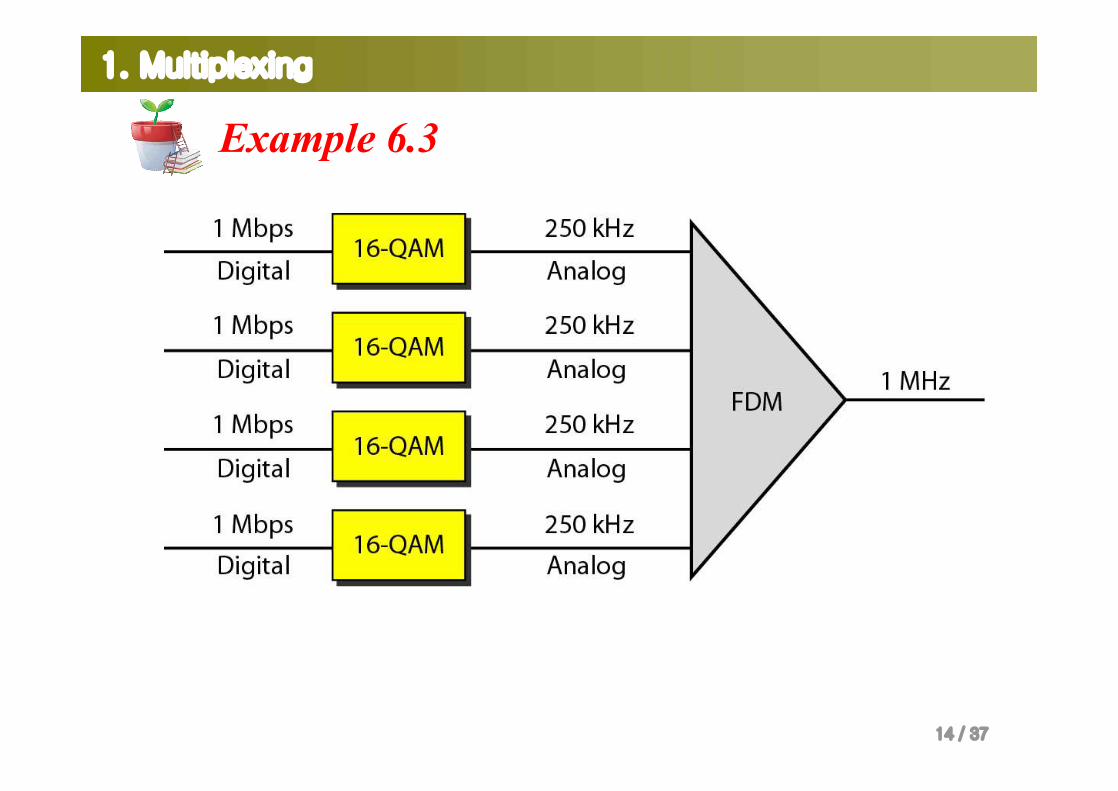
SolutionThe satellite channel is analog. We divide it into four channels,each channel having a 250-kHz bandwidth. Each digital channelof 1 Mbps is modulated such that each 4 bits is modulated to 1 Hz.One solution is 16-QAM modulation. Figure 6.8 shows onepossible configuration.
14 / 37
1. Multiplexing
Example 6.3
15 / 37
1. Multiplexing
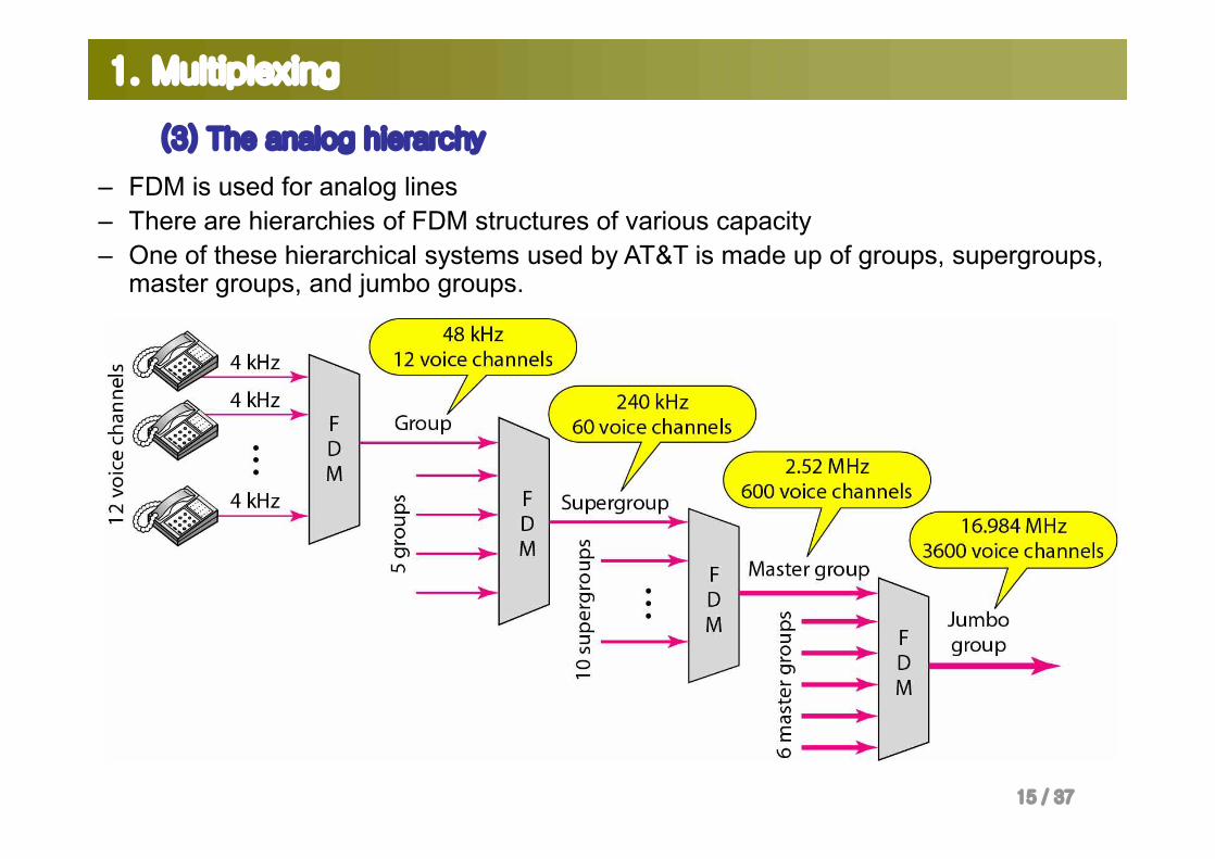
(3) The analog hierarchy
– FDM is used for analog lines– There are hierarchies of FDM structures of various capacity– One of these hierarchical systems used by AT&T is made up of groups, supergroups,
master groups, and jumbo groups.
16 / 37
1. Multiplexing
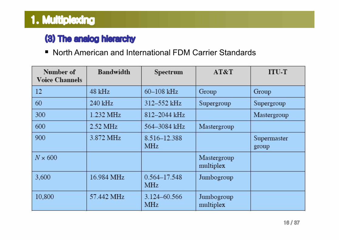
(3) The analog hierarchy
§ North American and International FDM Carrier Standards

17 / 37
1. Multiplexing
(4) Other applications of FDM
§ A very common application– AM and FM radio broadcasting– AM has a special band from 530 to 1700 kHz, and each station needs a
bandwidth of10 kHz.– FM has a wider band of 88 to 108 MHz and each station needs a
bandwidth of 200 kHz.§ Another common use
– TV broadcasting– each TV channel has its own bandwidth of 6 MHz
§ First generation of cellular telephones– Each user is assigned two 30-kHz channels, one for sending voice and
the other for receiving.– The voice signal has a bandwidth of 3 kHz (from 300 to 3300 Hz).– Note: Remember that an FM signal has a bandwidth 10 times that of the
modulating signal.
18 / 37
1. Multiplexing
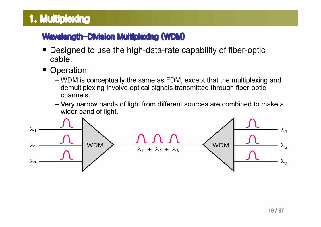
Wavelength-Division Multiplexing (WDM)
§ Designed to use the high-data-rate capability of fiber-optic cable.
§ Operation:– WDM is conceptually the same as FDM, except that the multiplexing and
demultiplexing involve optical signals transmitted through fiber-optic channels.
– Very narrow bands of light from different sources are combined to make a wider band of light.
19 / 37
1. Multiplexing
Wavelength-Division Multiplexing (WDM)
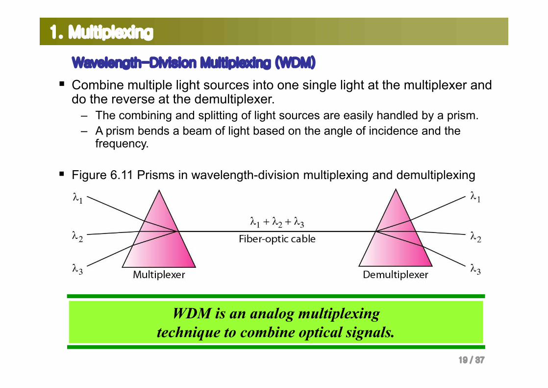
§ Combine multiple light sources into one single light at the multiplexer and do the reverse at the demultiplexer.
– The combining and splitting of light sources are easily handled by a prism. – A prism bends a beam of light based on the angle of incidence and the
frequency.
§ Figure 6.11 Prisms in wavelength-division multiplexing and demultiplexing
WDM is an analog multiplexing technique to combine optical signals.
20 / 37
1. Multiplexing
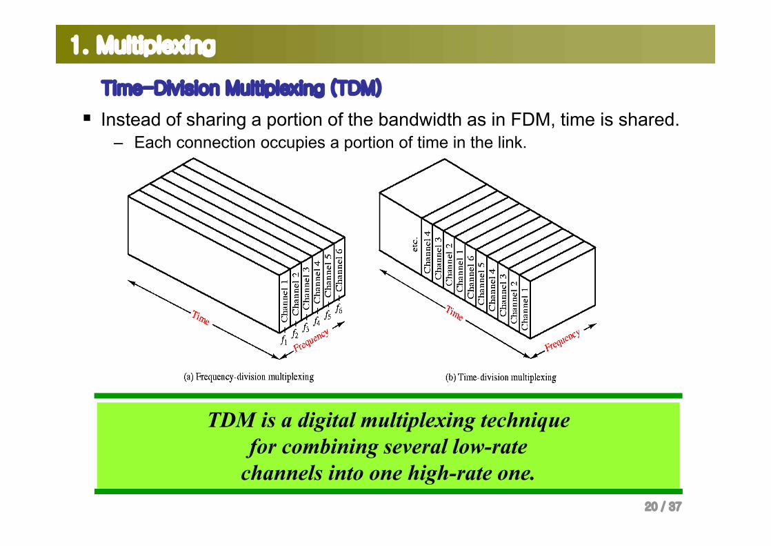
Time-Division Multiplexing (TDM)
§ Instead of sharing a portion of the bandwidth as in FDM, time is shared.– Each connection occupies a portion of time in the link.
TDM is a digital multiplexing technique for combining several low-rate
channels into one high-rate one.
21 / 37
1. Multiplexing
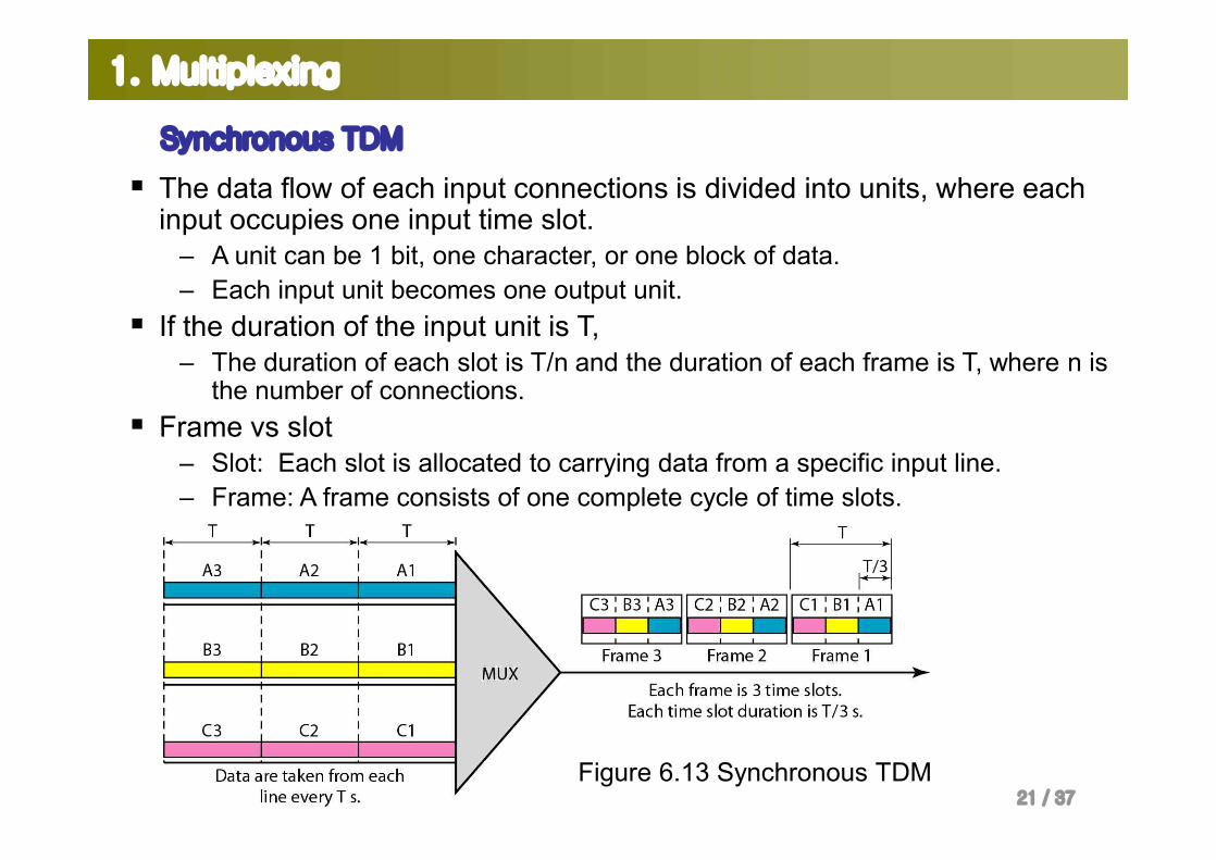
Synchronous TDM
§ The data flow of each input connections is divided into units, where each input occupies one input time slot.
– A unit can be 1 bit, one character, or one block of data. – Each input unit becomes one output unit.
§ If the duration of the input unit is T, – The duration of each slot is T/n and the duration of each frame is T, where n is
the number of connections. § Frame vs slot
– Slot: Each slot is allocated to carrying data from a specific input line.– Frame: A frame consists of one complete cycle of time slots.
Figure 6.13 Synchronous TDM
22 / 37
1. Multiplexing
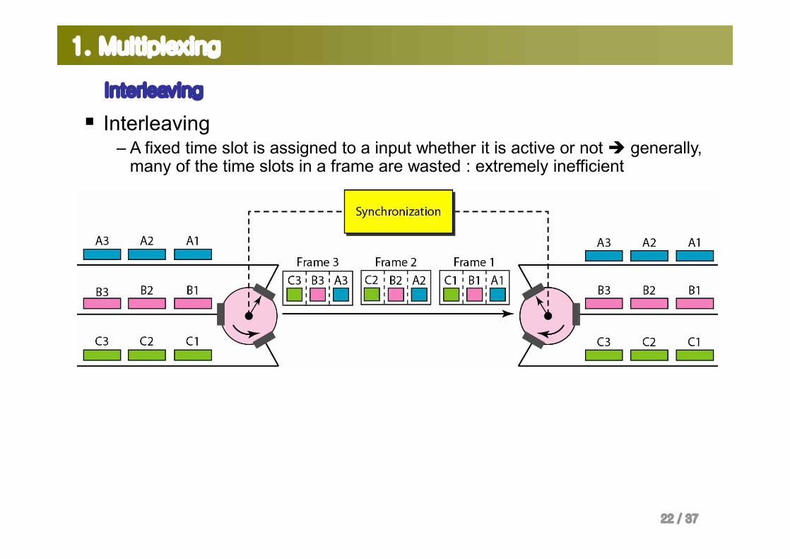
Interleaving
§ Interleaving– A fixed time slot is assigned to a input whether it is active or not è generally,
many of the time slots in a frame are wasted : extremely inefficient
23 / 37
1. Multiplexing
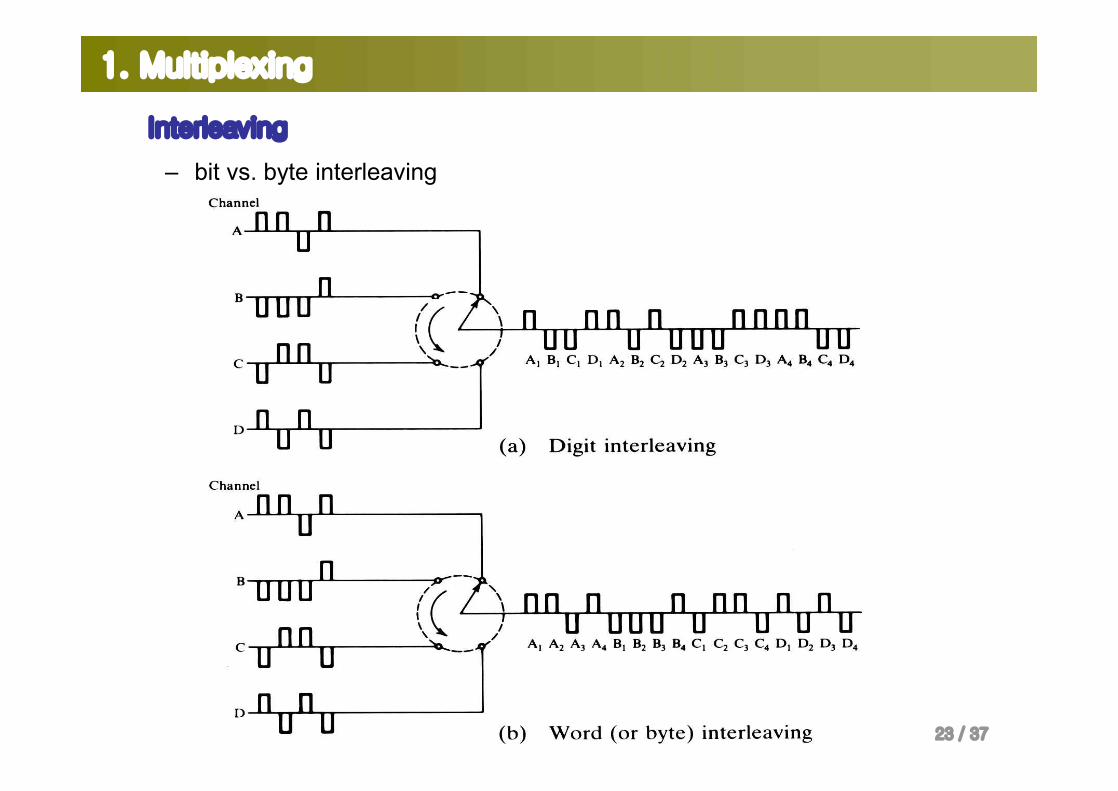
Interleaving
– bit vs. byte interleaving
24 / 37
1. Multiplexing
Interleaving
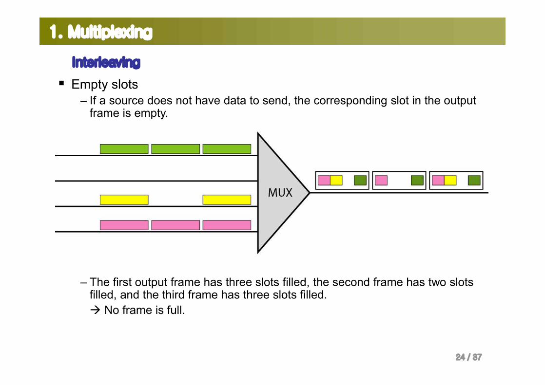
§ Empty slots– If a source does not have data to send, the corresponding slot in the output
frame is empty.
– The first output frame has three slots filled, the second frame has two slots filled, and the third frame has three slots filled.à No frame is full.
25 / 37
1. Multiplexing
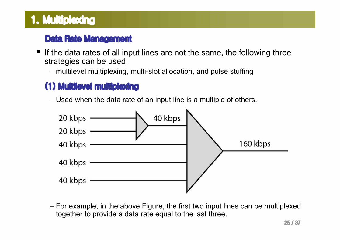
Data Rate Management
§ If the data rates of all input lines are not the same, the following three strategies can be used:
– multilevel multiplexing, multi-slot allocation, and pulse stuffing
(1) Multilevel multiplexing
– Used when the data rate of an input line is a multiple of others.
– For example, in the above Figure, the first two input lines can be multiplexed together to provide a data rate equal to the last three.

26 / 37
1. Multiplexing
(2) Multiple-Slot Allocation
§ Allocate more than one slot in a frame to a single input.

27 / 37
1. Multiplexing
(2) Multiple-Slot Allocation
– Multiplexing of different bit rate
28 / 37
1. Multiplexing
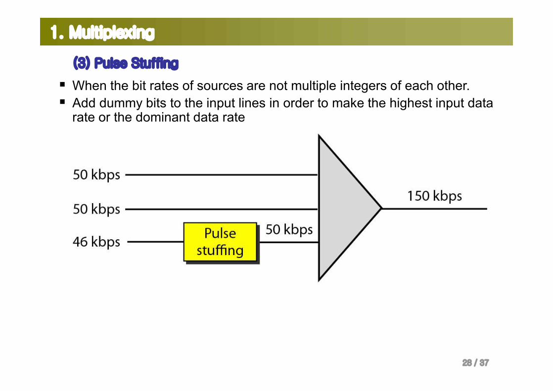
(3) Pulse Stuffing
§ When the bit rates of sources are not multiple integers of each other.§ Add dummy bits to the input lines in order to make the highest input data
rate or the dominant data rate
29 / 37
1. Multiplexing
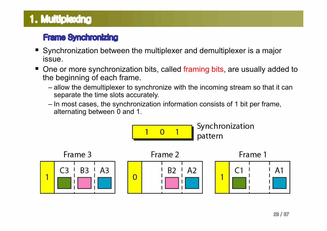
Frame Synchronizing
§ Synchronization between the multiplexer and demultiplexer is a major issue.
§ One or more synchronization bits, called framing bits, are usually added to the beginning of each frame.
– allow the demultiplexer to synchronize with the incoming stream so that it can separate the time slots accurately.
– In most cases, the synchronization information consists of 1 bit per frame, alternating between 0 and 1.

30 / 37
1. Multiplexing
Digital Signal Service
§ Digital signal (DS) service or digital hierarchy– Telephone companies implement TDM through a hierarchy of digital signals.
overhead = 8kbps
overhead = 168kbps
overhead = 1.368Mbps
overhead = 16.128Mbps
31 / 37
1. Multiplexing
Digital Signal Service
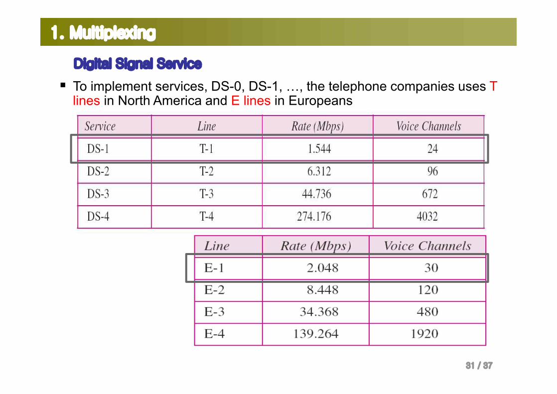
§ To implement services, DS-0, DS-1, …, the telephone companies uses T lines in North America and E lines in Europeans
32 / 37
1. Multiplexing
Digital Signal Service
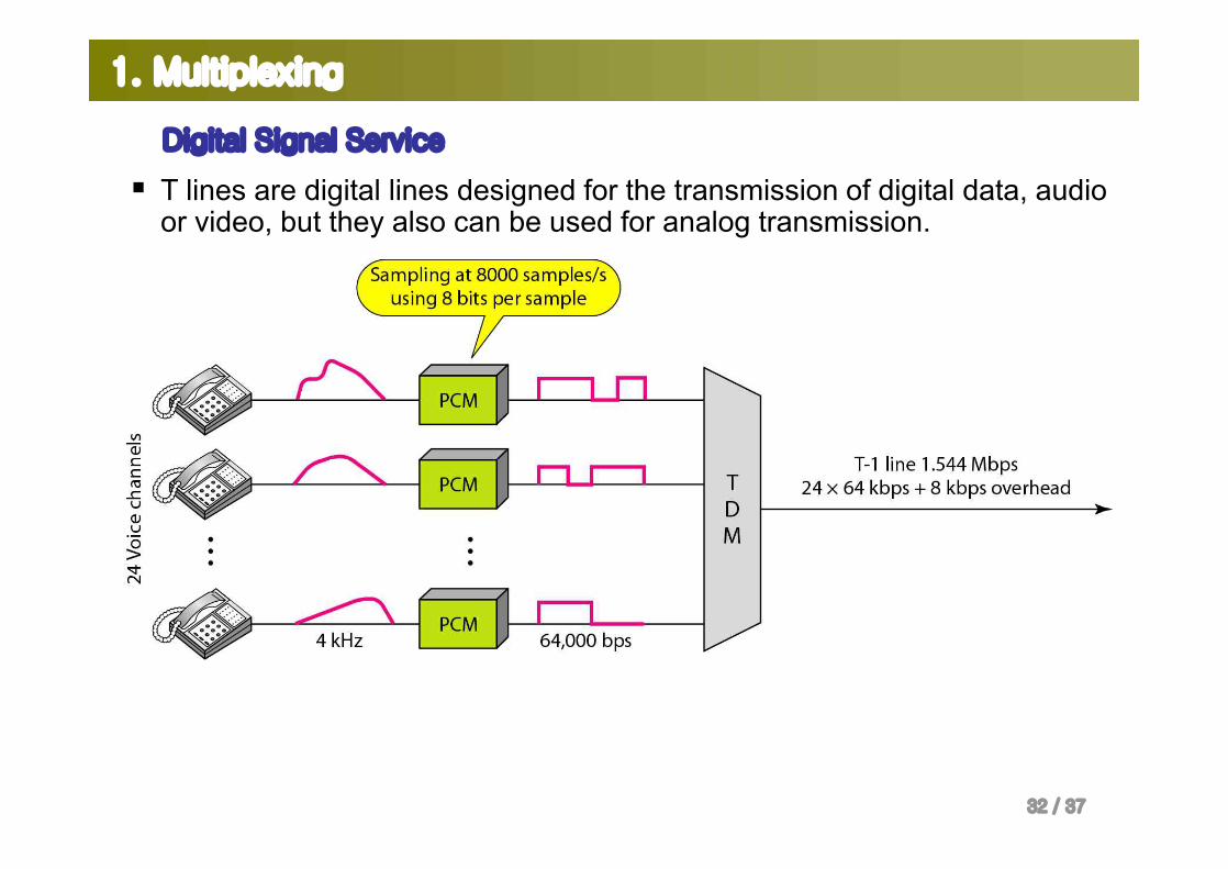
§ T lines are digital lines designed for the transmission of digital data, audio or video, but they also can be used for analog transmission.
33 / 37
1. Multiplexing
Digital Signal Service
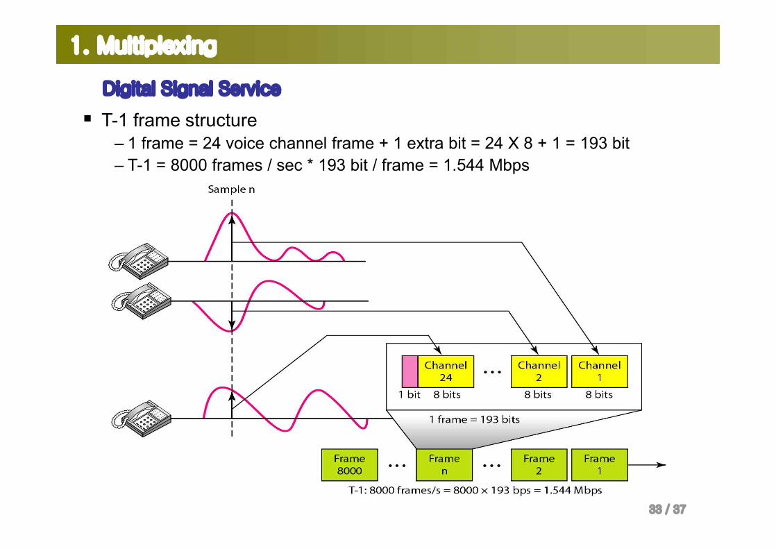
§ T-1 frame structure– 1 frame = 24 voice channel frame + 1 extra bit = 24 X 8 + 1 = 193 bit– T-1 = 8000 frames / sec * 193 bit / frame = 1.544 Mbps
34 / 37
1. Multiplexing
Digital Signal Service
§ TDM Applications– Some second-generation cellular telephone – The each band has 30-kHz band. – Six users share the band à The each band consists of six time slots.– 6 times greater capacity compared with the first-generation FDM
Cf . In the first-generation FDM cellular telephone, each user is assigned two 30-kHz channels
35 / 37
1. Multiplexing
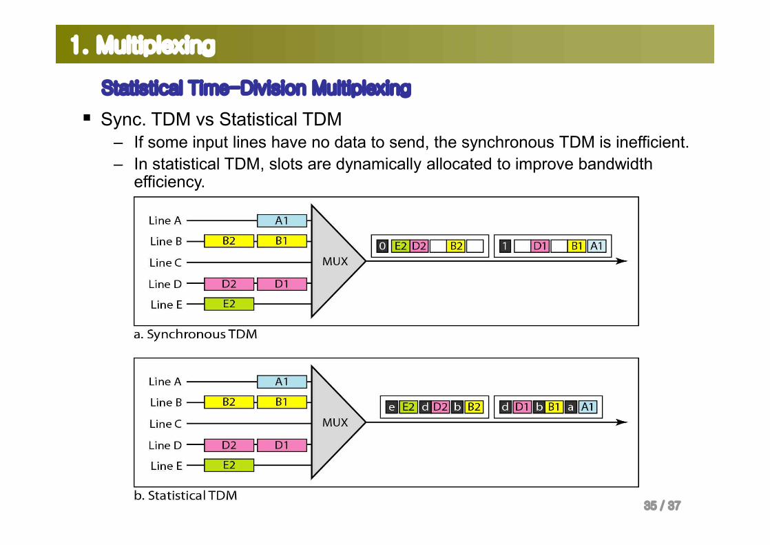
Statistical Time-Division Multiplexing
§ Sync. TDM vs Statistical TDM– If some input lines have no data to send, the synchronous TDM is inefficient. – In statistical TDM, slots are dynamically allocated to improve bandwidth
efficiency.
36 / 37
1. Multiplexing
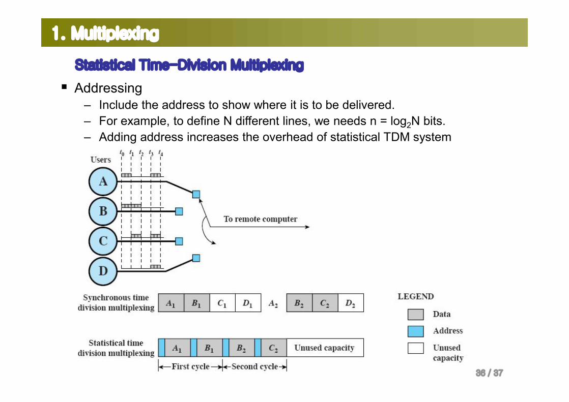
Statistical Time-Division Multiplexing
§ Addressing– Include the address to show where it is to be delivered. – For example, to define N different lines, we needs n = log2N bits.– Adding address increases the overhead of statistical TDM system
37 / 37
Summary
§ Multiplexing is the simultaneous transmission of multiple signals across a single data link.
§ Frequency-division multiplexing (FDM) and wave-division multiplexing (WDM) are techniques for analog signals, while time-division multiplexing (TDM) is for digital signals.
§ In FDM, each signal modulates a different carrier frequency. The modulated carriers are combined to form a new signal that is then sent across the link.
§ WDM is similar in concept to FDM. The signals being multiplexed, however, are light waves.
§ In TDM, digital signals from n devices are interleaved with one another, forming a frame of data (bits, bytes, or any other data unit).
Related Documents