Outline: I.Introduction • Where used • Advantages/Disadvantages (limitations) • Material Properties II. The P/M Manufacturing Process • Production of Metal Powders • Compaction • Sintering • Secondary Operations II. Design of P/M Components • Tooling/Design Considerations • Material Selection • Case Studies I. Intro - What is it? •Process where high purity, custom mixed alloy powders are fed into a die and compacted into the desired shape. – Green Compact •Part ejected from die and then sintered (heated) at a temperature below melting point of base material. – Yields finished product w/ structural properties •Mature, reliable process 5 Basic Manufacturing Processes: 1. Conventional Powder Metallurgy (P/M) 2. Metal Injection Molding (MIM) (> 50K /yr, intricate details) 3. Powder Forging (improved mechanical properties) 4. Cold Isostatic Pressing (CIP) 5. Hot Isostatic Pressing (HIP) Y 80% I. Intro – Where Used? Source: Metal Powder Industries Federation (MPIF), http://www.mpif.org/ Automotive accounts for 70% of P/M market! 2001: 35 lbs/car $5 Billion Market – North America

Welcome message from author
This document is posted to help you gain knowledge. Please leave a comment to let me know what you think about it! Share it to your friends and learn new things together.
Transcript
Outline:
I.Introduction
• Where used
• Advantages/Disadvantages (limitations)
• Material Properties
II. The P/M Manufacturing Process
• Production of Metal Powders
• Compaction
• Sintering
• Secondary Operations
II. Design of P/M Components
• Tooling/Design Considerations
• Material Selection
• Case Studies
I. Intro - What is it?
•Process where high purity, custom mixed alloy powders are fed into a die and compacted into the desired shape. – Green Compact
•Part ejected from die and then sintered (heated) at a temperature below melting point of base material. – Yields finished product w/ structural properties
•Mature, reliable process
5 Basic Manufacturing Processes:
1. Conventional Powder Metallurgy (P/M)
2. Metal Injection Molding (MIM) (> 50K /yr, intricate details)
3. Powder Forging (improved mechanical properties)
4. Cold Isostatic Pressing (CIP)
5. Hot Isostatic Pressing (HIP)
Y 80%
I. Intro – Where Used?
Source: Metal Powder Industries Federation (MPIF), http://www.mpif.org/
Automotive accounts for 70% of P/M market!
2001: 35 lbs/car
$5 Billion Market –North America

Typical Parts: Typical Parts:
Camshaft sprocket assembly – P/M
- Connecting Rod/Powder Forged
Source: Metal Powder Industries Federation (MPIF), http://www.mpif.org/Complex Gun Parts/MIM & P/M
Source: Metal Powder Industries Federation (MPIF), http://www.mpif.org/

I. Intro – Advantages:
1. Cost Effective
• May eliminate machining operation(s) see example
• Material and energy efficient (finished product: 97% of metal powder consumed)
• High production rates (i.e. 2,000/hr)
• Cost effective for moderate to high volume.
• Controlled porosity can be exploited (i.e. less dense parts can be used for non-structural applications or lightly loaded applications)
I. Intro – Advantages:
2. Design advantages:
• Good surface finish vs castings
• Controlled porosity (can make non structural parts cheaper since less dense)
• Good tolerances (die controlled +/- .001”, length +/-.005”)
• Do not require draft
• Large number of alloys available
• Can be heat treated
I. Intro – Advantages:
• Can create very complex parts
• Can be machined, plated or case hardened
• May be only option - Ideal for filters – controlled porosity
I. Intro – Disadvantages
1. Inferior mechanical properties versus wrought (machined) components!!
2. REFER TO HANDBOOKS (do not rely on CES)
3. Die cost
4. Geometry constraints – certain shapes CAN NOT do.
5. High material cost (cost more energy to make powder vs wrought or cast)
6. Poor elongation
7. Poor elongation
8. Size limitations
9. Variable density means properties are not uniform (higher compaction at ends = higher density at ends = higher strength at ends)

Sample Material Properties
http://www.mpif.org/
http://www.mpif.org/DesignCenter/mat_select.asp?linkid=46

The Powder Metal Process
II. Powder Metal Manufacturing Process:
1. Powder production
2. Blending
3. Compaction
4. Sintering
5. Finishing operations
1. Powder Production
• Higher in cost than equivalent alloy in ingot, bar or billet because more energy required (but remember less net waste!)
• Standard powders include: iron, steel, nickel, titanium, aluminum, brass, copper, high strength alloys.
• Particle sizes: 4 μin to 0.04 in
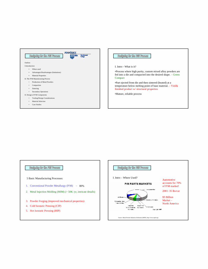
One method is the Gas Atomization Method. Gas is forced thru a small nozzle and shot at a very high speed into a small stream of molten metal.
Where does Powder Metal come from?
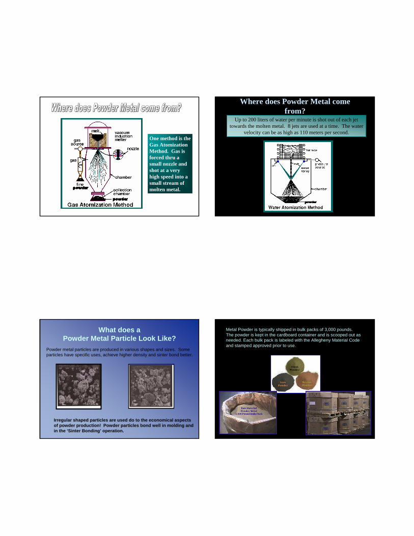
Up to 200 liters of water per minute is shot out of each jet towards the molten metal. 8 jets are used at a time. The water
velocity can be as high as 110 meters per second.
What does a Powder Metal Particle Look Like?
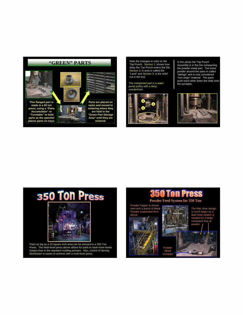
Irregular shaped particles are used do to the economical aspectsof powder production! Powder particles bond well in molding andin the ‘Sinter Bonding’ operation.
Powder metal particles are produced in various shapes and sizes. Some particles have specific uses, achieve higher density and sinter bond better.
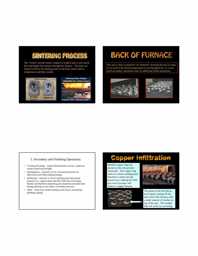
Metal Powder is typically shipped in bulk packs of 3,000 pounds.The powder is kept in the cardboard container and is scooped out as needed. Each bulk pack is labeled with the Allegheny Material Code and stamped approved prior to use.

2. Blending – why needed?
• Mix lubricant with powders to improve flow.
• Powders of different metals and other materials can be mixed to meet specific mechanical or physical properties of part.
• Always get better properties when powders with different sizes and shapes are blended together! Why?
3. Compaction
• Step where blended powders are pressed into shapes in dies.
• Presses can be either mechanical or hydraulic.• Critical process – determines density of part!• Sizes: 15, 30, 60, 200 and 350 tons• Rule of thumb: cross-sectional area of part (in2) * 35
tons/in2 = required press tonnage.• Mechanical bond holds part together – fragile – called
green compact.• See -
http://www.mpif.org/DesignCenter/videoclips.asp?linkid=68
Molding OperationA controlled amount of powder is automatically
gravity-fed into a precision die.
die
blockbacker
core pin
bottompunch
Diagram of a Filler Shoe approaching the Die
Filler Shoe
Filler Shoe Over Die CavityBottom punch
is dropping while the shoe is over the die, causing mix to be drawn into
the die.
Filler Shoe
bottompunch
die
backerblock
core pin

Filler Shoe Serves Two Purposes;Pushes Parts Away & Fills Die Cavity
Filler Shoe
Compacted part is pushed away using an extended piece called a kickoff plate and the
filler shoe begins to fill die cavity.
backerblock
core pin
die
bottompunch
kickoff plate
Compacted Part
Fill Ratio 2:1
LOOSE (fill)
RESTACKED (mild compaction)
COMPRESSED (fully compacted)
EJECTION
COMPACTION
FILL
BASIC MOTIONS of a MOLDING PRESS Neutral Zone
Also known as the“Density Line”
•The Area in the Compact with the Lowest Density
•Result of Least Relative Powder Movement During Compaction
•Powders are Particulate and Behave as Such, NOT LIKE A LIQUID
•Location is Adjustable

MOLDING PROCESS
1/3 of the total height of a press is underground. The press sets above a large pit. The pit depth allows for core rod installation, tool set-ups and easy maintenance on the presses. The presses shown below set over a pit which is 7’ deep and over 75’ in length.
MOLDING PRESSES
The photo above shows a powder hopper system. The drum holds 500+ pounds of powder.
30 & 60 TON PRESSES
The photo to the right shows the top punch entering the die.
The safety guard has been opened on this photo to show the die table and compacted parts sliding onto the tray.
DUEL CAVITY MOLD
Straight wall parts such as bushings, bearings and spacers can be produced in a two cavity die. This is usually done only when quantities are very high. Both sets of punches MUST be ground to the exact length to hold proper tolerance on parts.
This flanged part is made in a 60 ton
press, using a “Parts Accumulator” or
“Turntable” to hold parts as the operator places parts on trays.
Parts are placed on racks and moved to sintering where they
are held in the “Green Part Storage Area” until they are
sintered.
HANDLING GREEN PARTS“GREEN” PARTS200 Ton Press
Note the changes in color on the Top Punch. Section 1: shows how deep the Top Punch enters the Die. Section 2: is area is called the “Land” and Section 3: is the relief cut in the tool.
12
3
The compacted part is a water pump pulley with a deep counterbore.
In this photo the Top Punch Assembly is in the Die compacting the powder metal part. The loose powder around the parts in called “tailings” and is now considered “non-virgin” material. The parts push each other down the slide onto the turntable.
350 Ton Press
Parts as big as a 10 square inch area can be pressed in a 350 Ton Press. The Multi-level press above allows for parts to have more levels (steps) than in the standard molding presses. Also, control of density distribution is easier to achieve with a multi-level press.
350 Ton Press
Powder Feed System for 350 TonPowder hopper is shown here with a barrel of Metal Powder suspended from above.
The filler shoe design is much larger so a duel hose system is needed for a better consistent flow of powder.
Powder Metal
Compact

Pick-N-Place
The “Pick and Place Arm” allows the press to run faster and without compromising safety to the employee.
The design of the arm can be specific to a particular part or it can be modified to work on other presses.
Pick-N-Place
The “Pick and Place Arm” can be designed to grab parts off the bottom punch then back out of the die area and flip the part. The arm carefully places the part on the parts accumulator without damaging the O.D. or in this case gear teeth.
4. Sintering Process
• Done after compaction (warm compaction or cold compaction)
• Temperature mostly 70 – 80% of melting temperature of the base metal but high enough to allow bonding (fusion) of particles (bonds actually form between the powder particles as a result of solid-state atomic diffusion).
• Gives part mechanical properties (strength, elongation, hardness, etc.)
Sintering process
Sintering process II
The “Green” powder metal compact is loaded onto a wire-mesh belt and begins the journey through the furnace. The parts are heated to below the melting point of the base metal, held at temperature and then cooled.
Back of Furnace
The part is then considered “As Sintered” meaning the part is ready to be used in the desired application it was designed for, or it may need secondary operations and /or additional finish operations.
5. Secondary and Finishing Operations:
• Coining and sizing – imparts dimensional accuracy, improves surface finsih and strength.
• Impregnation – typically oil for corrosion protection of lubrication (self lubricating bearings)
• Infiltration – material w/ lower melting point than parent material (i.e. copper) melts and fills voids thus increasing density and therefore improving part properties (actually done during sintering so not really a secondary process).
• Other – Heat treat, steam treating (oxide layer), machining, grinding, plating.
Copper Infiltration
Molded copper rings are placed on the iron powder metal part. The copper ring melts at a lower melting point therefore it melts into the porous iron, making the P/M part much stronger and achieve a higher density.
The photo to the left shows bevel gears coming off the back end of the furnace with a small amount of residue on top of the part. The residue falls off easily by screening.

Rust Ban Dip
RUST INHIBITOR FINISH
“Rust Ban” dip directly off of furnace from belt into Rust Ban bath then onto conveyor and then hand picked and packed directly into shipping containers.
Oil DipPowder metal parts can have a number of finishes after sintering. One type of finish is known as “Oil Dipping”.
The parts drop off the belt into an “Automatic Oiler” for quenching (oil dipping) and the parts come out of the oiler by means of a conveyor belt and fall into a drum.
Oil impregnator
After the sintering process, some parts require specific finishes. A common finish to a Powder Metal Component is to add a lubricant using a method called “Oil Impregnation”
Finish Operations
Tumbling
Sizing
Steam Treat
Heat Treat
Zinc Chromate Finish
Machining Operations
Other Possible Finish Operations After Sintering a Powder Metal Components
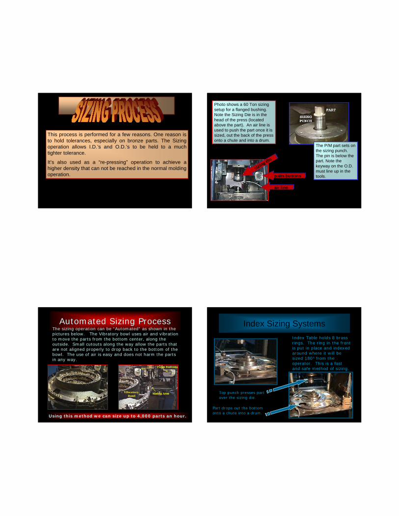
Sizing
This process is performed for a few reasons. One reason is to hold tolerances, especially on bronze parts. The Sizing operation allows I.D.’s and O.D.’s to be held to a much tighter tolerance.
It’s also used as a “re-pressing” operation to achieve a higher density that can not be reached in the normal molding operation.
Sizing-setupPhoto shows a 60 Ton sizing setup for a flanged bushing. Note the Sizing Die is in the head of the press (located above the part). An air line is used to push the part once it is sized, out the back of the press onto a chute and into a drum.
The P/M part sets on the sizing punch. The pin is below the part. Note the keyway on the O.D. must line up in the tools.palm buttons
air line
sizing die
Automated Sizing ProcessThe sizing operation can be “Automated” as shown in the pictures below. The Vibratory bowl uses air and vibration to move the parts from the bottom center, along the outside. Small cutouts along the way allow the parts that are not aligned properly to drop back to the bottom of the bowl. The use of air is easy and does not harm the parts in any way.
Using this method we can size up to 4,000 parts an hour.
Index Sizing SystemsIndex Table holds 8 brass rings. The ring in the front is put in place and indexed around where it will be sized 180° from the operator. This is a fast and safe method of sizing.
Top punch presses part over the sizing die.
Part drops out the bottom onto a chute into a drum.

Steam treat
STEAM TREAT
Steam Treat Finish gives some corrosion resistance and adds to surface hardness of the parts. It also decreases porosity slightly.
Heat Treat
Ferrous P/M parts containing 0.3% or higher combined carbon can be quench hardened and tempered for increased strength, hardnessand wear resistance. Matrix hardness values HRC 56 and higher can be obtained by quench hardening. The recommended procedure for heat treatment and/or carburization of ferrous P/M is with a gas type atmosphere.
HEAT TREAT
Heat Treat2HEAT TREATLow Density parts may carburize throughout while higher density parts (7.0 g/cm3 or higher) may develop a carburized case. Process control is necessary to ensure that specified carbon levels are maintained.
Tempering or stress relief is required after quenching for maximum strength and durability. A compromise between hardness and such properties as impact energy is necessary because the tempering temperature to achieve surface hardness will not necessarily provide optimum strength properties. The tempering temperature is a major factor in determining final hardness.
Zinc Chromate PlateZinc Chromate Finish
Plating: This finish is excellent for corrosion resistance and enhances part appearance. It also increases the density of the part.

Secondary Operations
Powder Metallurgy is a cost effective means of producing a consistent near net shape part, with little or no scrap. Parts designed originally for stampings, castings, screw machines and other forms of metalworking can usually be made by Powder Metal methods at a cheapercost. Sometimes a re-designs must take place to save money in the long run.
FINAL PRODUCT
Material Related Issues
• Density (Porosity) of P/M:– Compaction force and time– Hot or cold compaction– Shape of part– Metal particle sizes and shape– Time in sintering oven and temperature– Secondary operations
Ferrous P/M
Materials

Microstructure
It is the Hardenability of the Sintered Material as the Compact Exits the Hot Zone of the Sintering Furnace that, for a Given Cooling Rate, Controls the Microstructure that will be Developed.
Related Documents